US11420097B2 - Golf club head - Google Patents
Golf club headDownload PDFInfo
- Publication number
- US11420097B2 US11420097B2US17/106,575US202017106575AUS11420097B2US 11420097 B2US11420097 B2US 11420097B2US 202017106575 AUS202017106575 AUS 202017106575AUS 11420097 B2US11420097 B2US 11420097B2
- Authority
- US
- United States
- Prior art keywords
- golf club
- club head
- sole
- strike plate
- strike
- Prior art date
- Legal status (The legal status is an assumption and is not a legal conclusion. Google has not performed a legal analysis and makes no representation as to the accuracy of the status listed.)
- Active
Links
Images


Classifications
- A—HUMAN NECESSITIES
- A63—SPORTS; GAMES; AMUSEMENTS
- A63B—APPARATUS FOR PHYSICAL TRAINING, GYMNASTICS, SWIMMING, CLIMBING, OR FENCING; BALL GAMES; TRAINING EQUIPMENT
- A63B53/00—Golf clubs
- A63B53/04—Heads
- A63B53/047—Heads iron-type
- A—HUMAN NECESSITIES
- A63—SPORTS; GAMES; AMUSEMENTS
- A63B—APPARATUS FOR PHYSICAL TRAINING, GYMNASTICS, SWIMMING, CLIMBING, OR FENCING; BALL GAMES; TRAINING EQUIPMENT
- A63B53/00—Golf clubs
- A63B53/04—Heads
- A63B53/0408—Heads characterised by specific dimensions, e.g. thickness
- A—HUMAN NECESSITIES
- A63—SPORTS; GAMES; AMUSEMENTS
- A63B—APPARATUS FOR PHYSICAL TRAINING, GYMNASTICS, SWIMMING, CLIMBING, OR FENCING; BALL GAMES; TRAINING EQUIPMENT
- A63B53/00—Golf clubs
- A63B53/04—Heads
- A63B53/0416—Heads having an impact surface provided by a face insert
- A63B53/042—Heads having an impact surface provided by a face insert the face insert consisting of a material different from that of the head
- A—HUMAN NECESSITIES
- A63—SPORTS; GAMES; AMUSEMENTS
- A63B—APPARATUS FOR PHYSICAL TRAINING, GYMNASTICS, SWIMMING, CLIMBING, OR FENCING; BALL GAMES; TRAINING EQUIPMENT
- A63B53/00—Golf clubs
- A63B53/04—Heads
- A63B53/0466—Heads wood-type
- A—HUMAN NECESSITIES
- A63—SPORTS; GAMES; AMUSEMENTS
- A63B—APPARATUS FOR PHYSICAL TRAINING, GYMNASTICS, SWIMMING, CLIMBING, OR FENCING; BALL GAMES; TRAINING EQUIPMENT
- A63B60/00—Details or accessories of golf clubs, bats, rackets or the like
- A63B60/52—Details or accessories of golf clubs, bats, rackets or the like with slits
- A—HUMAN NECESSITIES
- A63—SPORTS; GAMES; AMUSEMENTS
- A63B—APPARATUS FOR PHYSICAL TRAINING, GYMNASTICS, SWIMMING, CLIMBING, OR FENCING; BALL GAMES; TRAINING EQUIPMENT
- A63B53/00—Golf clubs
- A63B53/04—Heads
- A63B53/0416—Heads having an impact surface provided by a face insert
- A—HUMAN NECESSITIES
- A63—SPORTS; GAMES; AMUSEMENTS
- A63B—APPARATUS FOR PHYSICAL TRAINING, GYMNASTICS, SWIMMING, CLIMBING, OR FENCING; BALL GAMES; TRAINING EQUIPMENT
- A63B53/00—Golf clubs
- A63B53/04—Heads
- A63B53/0433—Heads with special sole configurations
- A—HUMAN NECESSITIES
- A63—SPORTS; GAMES; AMUSEMENTS
- A63B—APPARATUS FOR PHYSICAL TRAINING, GYMNASTICS, SWIMMING, CLIMBING, OR FENCING; BALL GAMES; TRAINING EQUIPMENT
- A63B53/00—Golf clubs
- A63B53/04—Heads
- A63B53/047—Heads iron-type
- A63B53/0475—Heads iron-type with one or more enclosed cavities
Definitions
- This disclosurerelates generally to golf clubs, and more particularly to a golf club head with a strike plate that is separately attached to a body of the golf club head.
- a golf club head with a complex geometrythat might not otherwise be achievable using single-piece, fully-integrated manufacturing techniques, can be produced.
- a golf club head with a separately formed and attached strike platecan facilitate the use of strike plates and bodies made from different materials and/or manufacturing techniques.
- the strike plateis welded to the body using a peripheral weld that extends continuously around the entire outer peripheral edge of the strike plate.
- the strike platemay also introduce weaknesses to the golf club head.
- the subject matter of the present applicationhas been developed in response to the present state of the art, and in particular, in response to the shortcomings of golf clubs and associated golf club heads, that have not yet been fully solved by currently available techniques. Accordingly, the subject matter of the present application has been developed to provide a golf club and golf club head that overcome at least some of the above-discussed shortcomings of prior art techniques.
- a golf club headthat comprises a body and a strike plate.
- the bodycomprises a heel portion, a sole portion, a toe portion, and a top portion.
- the strike platecomprises an outer peripheral edge and at least a portion of a strike face. Furthermore, the strike plate is welded to the body via a peripheral weld between the outer peripheral edge of the strike plate and the body.
- the outer peripheral edge of the strike platecomprises at least one welded portion, welded to the body via the peripheral weld, and at least one non-welded portion, not welded to the body.
- the strike plateis located between the heel portion, the sole portion, the toe portion, and the top portion of the body.
- a ratio of the total length of the at least one welded portion of the outer peripheral edge to the total peripheral length of the outer peripheral edge of the strike plateis between 0.40 and 0.94.
- example 4 of the present disclosurecharacterizes example 4 of the present disclosure, wherein example 4 also includes the subject matter according to example 3, above.
- the strike platecomprises a sole wrap portion angled relative to the strike face.
- the at least one non-welded portion of the outer peripheral edgeextends along the sole wrap portion of the strike plate.
- the sole portion of the bodycomprises a slot edge.
- the at least one non-welded portion of the outer peripheral edge of the strike plateis spaced apart from the slot edge.
- the golf club headcomprises a sole slot defined between the slot edge of the sole portion of the body and the at least one non-welded portion of the outer peripheral edge of the strike plate.
- the golf club headfurther comprises a filler material located within the sole slot.
- example 7also includes the subject matter according to example 6, above.
- example 8 of the present disclosurecharacterizes example 8 of the present disclosure, wherein example 8 also includes the subject matter according to any one of examples 1-7, above.
- the outer peripheral edge of the strike platefurther comprises a plurality of welded portions and a plurality of non-welded portions.
- the plurality of welded portionsare spaced apart from each other by the plurality of non-welded portions.
- example 10 of the present disclosurecharacterizes example 10 of the present disclosure, wherein example 10 also includes the subject matter according to example 9, above.
- Example 11each of the plurality of welded portions of the outer peripheral edge of the strike plate has a different length.
- At least two of the at least one non-welded portion of the plurality of non-welded portionsis directly adjacent the heel portion of the body, the at least one non-welded portion of the plurality of non-welded portions is directly adjacent the toe portion of the body, the at least one non-welded portion of the plurality of non-welded portions is directly adjacent the top portion of the body, and the at least one non-welded portion of the plurality of non-welded portions is directly adjacent the sole portion of the body.
- At least three of the at least one non-welded portion of the plurality of non-welded portionsis directly adjacent the heel portion of the body, the at least one non-welded portion of the plurality of non-welded portions is directly adjacent the toe portion of the body, the at least one non-welded portion of the plurality of non-welded portions is directly adjacent the top portion of the body, and the at least one non-welded portion of the plurality of non-welded portions is directly adjacent the sole portion of the body.
- the at least one non-welded portion of the plurality of non-welded portionsis directly adjacent the heel portion of the body.
- the at least one non-welded portion of the plurality of non-welded portionsis directly adjacent the toe portion of the body.
- the at least one non-welded portion of the plurality of non-welded portionsis directly adjacent the top portion of the body.
- the at least one non-welded portion of the plurality of non-welded portionsis directly adjacent the sole portion of the body.
- example 15 of the present disclosurecharacterizes example 15 of the present disclosure, wherein example 15 also includes the subject matter according to any one of examples 1-14, above.
- the bodyfurther comprises a plate interface.
- the strike plateis in seated engagement with the plate interface.
- the peripheral weldis between the plate interface of the body and the strike plate.
- the golf club headis an iron-type golf club head.
- the preceding subject matter of this paragraphcharacterizes example 17 of the present disclosure, wherein example 17 also includes the subject matter according to any one of examples 1-16, above.
- the golf club headis a metal-wood-type golf club head.
- the preceding subject matter of this paragraphcharacterizes example 18 of the present disclosure, wherein example 18 also includes the subject matter according to any one of examples 1-16, above.
- a golf clubcomprising a golf club head, a shaft, and a grip.
- the golf club headcomprises a body and a strike plate.
- the bodycomprises a heel portion, a sole portion, a toe portion, a top portion, and a hosel, extending from the heel portion.
- the strike platecomprises an outer peripheral edge and at least a portion of a strike face.
- the outer peripheral edge of the strike plateis welded to the body via a peripheral weld.
- the peripheral weldhas a starting point and an ending point, the ending point being different than the starting point.
- the shaftis engaged with and extends from the hosel of the golf club head.
- the gripis secured to the shaft at a location on the shaft opposite that of the golf club head.
- a golf club headcomprising a body and a strike plate.
- the bodycomprises a heel portion, a sole portion, a toe portion, and a top portion.
- the strike platecomprises an outer peripheral edge and at least a portion of a strike face. Furthermore, the strike plate is welded to the body via a peripheral weld between the outer peripheral edge of the strike plate and the body. A ratio of a total weld length of the peripheral weld to a total peripheral length of the outer peripheral edge of the strike plate is less than one.
- FIG. 1is a perspective view from a top of an iron-type golf club head, according to one or more examples of the present disclosure
- FIG. 2is a front view of the golf club head of FIG. 1 , according to one or more examples of the present disclosure
- FIG. 3is perspective view from a bottom of the golf club head of FIG. 1 , shown with a filler material removed from a sole slot, according to one or more examples of the present disclosure;
- FIG. 4is a perspective view from a bottom of the golf club head of FIG. 1 , shown with the filler material in the sole slot, according to one or more examples of the present disclosure;
- FIG. 5is an exploded perspective view from a top of the golf club head of FIG. 1 , according to one or more examples of the present disclosure
- FIG. 6is a perspective view from a front of the golf club head of FIG. 1 , shown with a strike plate removed, according to one or more examples of the present disclosure
- FIG. 7is a bottom view of the golf club head of FIG. 1 , shown with the strike plate removed, according to one or more examples of the present disclosure
- FIG. 8is a perspective view from a front of the strike plate of the golf club head of FIG. 1 , according to one or more examples of the present disclosure
- FIG. 9is a perspective view from a back of the strike plate of the golf club head of FIG. 1 , according to one or more examples of the present disclosure.
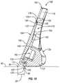
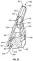
- FIG. 10is cross-sectional perspective view from a heel side of the golf club head of FIG. 1 , taken along the line 10 - 10 of FIG. 2 , according to one or more examples of the present disclosure;
- FIG. 11is cross-sectional side elevation view from a heel side of the golf club head of FIG. 1 , taken along the line 10 - 10 of FIG. 2 , according to one or more examples of the present disclosure;
- FIG. 12is a front view of an iron-type golf club head, according to one or more examples of the present disclosure.
- FIG. 13is an exploded perspective view from a front of the golf club head of FIG. 12 , according to one or more examples of the present disclosure
- FIG. 14is a front view of an iron-type golf club head, according to one or more examples of the present disclosure.
- FIG. 15is a front view of an iron-type golf club head, according to one or more examples of the present disclosure.
- FIG. 16is a front view of an iron-type golf club head, according to the prior art.
- FIG. 17is a front view of an iron-type golf club head, according to one or (j more examples of the present disclosure.
- FIG. 18is a front view of an iron-type golf club head, according to one or more examples of the present disclosure.
- FIG. 19is a front view of an iron-type golf club head, according to one or more examples of the present disclosure.
- FIG. 20is a side elevation view of a metal-wood-type golf club head, according to one or more examples of the present disclosure.
- FIG. 21is a cross-sectional side elevation view of the golf club head of FIG. 19 , taken along a midplane of the golf club head, according to one or more examples of the present disclosure
- FIG. 22is a cross-sectional side elevation view of an iron-type golf club head having a hollow cavity, according to one or more examples of the present disclosure.
- FIG. 23is a schematic flow chart of a method of making a golf club head, according to one or more examples of the present disclosure.
- golf club headsin the context of an iron-type golf club and a metal-wood-type golf club, but the principles, methods and designs described may be applicable in whole or in part to utility golf clubs (also known as hybrid golf clubs), driver-type golf clubs, putter-type golf clubs, and the like.
- utility golf clubsalso known as hybrid golf clubs
- driver-type golf clubsdriver-type golf clubs
- putter-type golf clubsand the like.
- a golf club head described hereinutilizes a peripheral weld to secure a strike plate to a body of the golf club head.
- Welding the strike plate to the body of the golf club headas opposed to integrally forming the strike plate and the body as a one-piece construction (such as by casting) allows the strike plate to be made from a different material or made by a different manufacturing process than the body.
- welding the strike plate to the bodypromotes the ability to make golf club head with unique and complex shapes and geometries.
- welding together the strike plate and the bodyalso introduces certain consequences, such as the development of heat effected zones and stress risers in the weld, which ultimately weakens the golf club head, and stiffness of the strike face of the golf club head.
- peripheral weld of the golf club head disclosed hereinintroduces portions of the outer peripheral edge of the strike plate that are not welded to the body, thereby increasing the strength of the golf club head compared to golf club heads with continuous or 360-degree welds welding the strike plate to the body. Additionally, introducing non-welded portions of the outer peripheral edge of the strike plate also promotes flex in the strike face of the golf club head, which promotes forgiveness and feel.
- non-welded portions in an outer peripheral edge of a strike platemay increase the potential for rust at the non-welded portions and stress risers at the intersection of non-welded and welded portions of the outer peripheral edge.
- the chrome plating often used to plate a golf club headmay crack or phantom lines may develop at the non-welded portions.
- a golf club head 100includes a body 102 and a strike plate 104 welded to the body 102 .
- the body 102has a toe portion 114 , a heel portion 112 , a top portion 116 (e.g., top-line portion for iron-type golf club heads and crown portion for driver-type, hybrid-type, and metal-wood-type golf club heads), and a sole portion 118 (e.g., bottom portion).
- the body 102additionally includes a hosel 108 extending from the heel portion 112 .
- the hosel 108is configured to receive and engage with a shaft and grip 110 of a golf club 101 .
- the shaftextends from the hosel 108 and the grip is secured to the shaft at a location on the shaft opposite that of the golf club head 100 .
- the strike plate 104includes at least a portion of a strike face 106 designed to impact a golf ball during a normal golf swing. In some implementations, the strike plate 104 include an entirety of the strike face 106 . Generally, the strike plate 104 is defined as any piece of the golf club head 100 that is welded to a body 102 of the golf club head 100 and includes at least a portion of the strike face.
- the strike face 106has a planar surface that is angled relative to a ground plane when the golf club head 100 is in an address position to define a loft of the golf club head 100 .
- the strike face 106 of an iron-type golf club headgenerally does not include a curved surface.
- the strike face 106 of the strike plate 104 of the iron-type golf club head 100is defined as the portion of the strike face 106 with an outwardly facing planar surface.
- a strike plate 104may include a curved surface, such as an outer surface of a sole wrap portion 122 of the strike plate 104 , the strike face 106 does not include such a curved surface.
- the strike face of a metal-wood, driver, or hybrid golf club headdoes have a curved surface that curves around a substantially upright axis. Because the sole wrap portion 122 wraps around a substantially horizontal axis, the strike face of the strike plate of the metal-wood, driver, and hybrid golf club head is defined as the portion of the strike face 106 with an outwardly facing surface curved about an upright axis, as opposed to a horizontal axis.
- the strike plate 104further includes grooves 107 formed in the strike face 106 to promote desirable flight characteristics (e.g., backspin) of the golf ball upon being impacted by the strike face 106 .
- the strike plate 104is formed separately from the body 102 and is separately attached to the body 102 .
- the body 102 and the strike plate 104can be formed using the same type of process or different types of processes.
- the body 102is formed to have a one-piece monolithic construction using a first manufacturing process and the strike plate 104 is formed to have a separate one-piece monolithic construction using a second manufacturing process.
- one or both of the body 102 and the strike plate 104has a multiple-piece construction with each piece being made from the same or a different material.
- the body 102can be formed of the same material as or a different material than the strike plate 104 .
- the body 102is made from a first material and the strike plate 104 is made from a second material. Separately forming and attaching together the body 102 and the strike plate 104 and making the body 102 and the strike plate 104 from the same or different materials, which allows flexibility in the types of manufacturing processes and materials used, promotes the ability to make a golf club head 100 that achieves a wide range of performance, aesthetic, and economic results.
- the first manufacturing processis the same type of process as the second manufacturing process.
- both the first and second manufacturing processesare casting processes in one implementation.
- both the first and second manufacturing processesare forging processes in one implementation.
- both the first and second manufacturing processesare machining processes in one implementation.
- the first manufacturing processis a different type of process than the second manufacturing process.
- the first manufacturing processis one of a casting process, a machining process, and a forging process and the second manufacturing process is another of a casting process, a machining process, and a forging process in some examples.
- the first manufacturing processis a casting process and the second manufacturing process is a forging process.
- the first manufacturing process and/or the second manufacturing processcan be a process as described in U.S. Pat. No. 9,044,653, which is incorporated herein in its entirety, such as hot press forging using a progressive series of dies and heat-treatment.
- the first material of the body 102can be the same as or different than the second material of the strike plate 104 .
- a first materialis different than a second material when the first material has a different composition than the second material. Accordingly, materials from the same family, such as steel, but with different compositional characteristics, such as different carbon constituencies, are considered different materials.
- the first and second manufacturing processesare different, but the first and second materials are the same.
- the first and second manufacturing processesare the same and the first and second materials are different.
- the first and second manufacturing processesare different and the first and second materials are different.
- the first and second materialsare different, but come from the same family of similar materials, such as steel.
- the first materialcan be 8620 carbon steel and the second material can be 1025 carbon steel.
- the first materialbeing within the same family as the second material promotes the quality of the weld between the body 102 and the strike plate 104 .
- the strike plate 104can be made from maraging steel, maraging stainless steel, or precipitation-hardened (PH) stainless steel.
- maraging steelshave high strength, toughness, and malleability. Being low in carbon, they derive their strength from precipitation of inter-metallic substances other than carbon.
- the principle alloying elementis nickel (15% to nearly 30%). Other alloying elements producing inter-metallic precipitates in these steels include cobalt, molybdenum, and titanium.
- the maraging steelcontains 18% nickel. Maraging stainless steels have less nickel than maraging steels but include significant chromium to inhibit rust. The chromium augments hardenability despite the reduced nickel content, which ensures the steel can transform to martensite when appropriately heat-treated.
- a maraging stainless steel C455is utilized as the strike plate 104 .
- the strike plate 104is a precipitation hardened stainless steel such as 17-4, 15-5, or 17-7.
- the body 102 of the golf club head 100is made from 17-4 steel in one implementation.
- another materialsuch as carbon steel (e.g., 1020, 1030, 8620, or 1040 carbon steel), chrome-molybdenum steel (e.g., 4140 Cr—Mo steel), Ni—Cr—Mo steel (e.g., 8620 Ni—Cr—Mo steel), austenitic stainless steel (e.g., 304, N50, or N60 stainless steel (e.g., 410 stainless steel) can be used.
- carbon steele.g., 1020, 1030, 8620, or 1040 carbon steel
- chrome-molybdenum steele.g., 4140 Cr—Mo steel
- Ni—Cr—Mo steele.g., 8620 Ni—Cr—Mo steel
- austenitic stainless steele.g., 304, N50, or N60 stainless steel (e.g., 410 stainless steel
- metals and metal alloysthat can be used to form the components of the parts described include, without limitation: titanium alloys (e.g., 3-2.5, 6-4, SP700, 15-3-3-3, 10-2-3, or other alpha/near alpha, alpha-beta, and beta/near beta titanium alloys), aluminum/aluminum alloys (e.g., 3000 series alloys, 5000 series alloys, 6000 series alloys, such as 6061-T6, and 7000 series alloys, such as 7075), magnesium alloys, copper alloys, and nickel alloys.
- titanium alloyse.g., 3-2.5, 6-4, SP700, 15-3-3-3, 10-2-3, or other alpha/near alpha, alpha-beta, and beta/near beta titanium alloys
- aluminum/aluminum alloyse.g., 3000 series alloys, 5000 series alloys, 6000 series alloys, such as 6061-T6, and 7000 series alloys, such as 7075
- magnesium alloyscopper
- the body 102 and/or the strike plate 104 of the golf club head 100are made from fiber-reinforced polymeric composite materials, and are not required to be homogeneous. Examples of composite materials and golf club components comprising composite materials are described in U.S. patent application Ser. No. 13/111,715, filed May 19, 2011, which is incorporated herein by reference in its entirety.
- the strike plate 104is welded to the body 102 via a peripheral weld 120 .
- the peripheral weld 120is peripherally discontinuous because it extends about less than all of the outer periphery of the strike plate 104 such that at least one portion of the outer periphery of the strike plate 104 is not welded to the body 102 .
- the peripheral weld 120extends about only a portion of an outer peripheral edge 133 of the strike plate 104 . Accordingly, less than 360-degrees of the outer peripheral edge 133 of the strike plate 104 is welded to the body 102 .
- the peripheral weld 120can be considered a discontinuous weld because it has an ending point that is different than it's starting point.
- the portion or portions of the outer periphery of the strike plate 104 not being welded to the body 102promotes an increase in the flexibility of the strike plate 104 relative to the body 102 .
- the entirety of the portion of the outer periphery of the strike plate 104 that defines the strike face 106is welded to the body 102 via the peripheral weld 120 .
- the portion of the outer periphery of the strike plate 104 not welded to the body 102is located along the sole wrap portion 122 . More specifically, an outer peripheral edge 133 , or perimeter, of the strike plate 104 defined along the sole wrap portion 122 of the strike plate 104 is not welded to the body 102 . In the embodiment shown in FIG.
- the outer peripheral edge 133 of the strike plate 104is not welded to the body 102 , but the outer peripheral edge 133 of the strike plate 104 is spaced apart from the body 102 such that a gap is defined between the outer peripheral edge 133 of the strike plate 104 and the body 102 .
- the gapdefines a sole slot 126 of the golf club head 100 .
- the sole slot 126is a groove or channel formed in a sole of the golf club head 100 .
- the sole slot 126is elongate in a lengthwise direction substantially parallel to the strike face 106 and has a length LSS (see, e.g., FIG. 3 ). As shown in FIGS.
- the sole slot 126is a through-slot, or a slot that is open on a sole portion side of the sole slot 126 and open on an internal cavity side or interior side of the sole slot 126 .
- the sole slot 126is not a through-slot, but rather is closed on an internal cavity side or interior side of the sole slot 126 .
- the sole slot 126can be any of various flexible boundary structures (FBS) as described in U.S. Pat. No. 9,044,653, filed Mar. 14, 2013, which is incorporated by reference herein in its entirety. Additionally, or alternatively, the golf club head 100 can include one or more other FBS at any of various other locations on the golf club head 100 .
- FBSflexible boundary structures
- the sole slot 126is filled with a filler material 128 (see, e.g., FIGS. 4 and 11 ).
- the filler material 128is made from a non-metal, such as a thermoplastic material, thermoset material, and the like, in some implementations.
- the sole slot 126is not filled with a filler material 128 , but rather maintains an open, vacant, space within the sole slot 126 .
- the filler material 128is initially a viscous material that is injected or otherwise inserted into the sole slot 126 .
- materialsthat may be suitable for use as a filler to be placed into a slot, channel, or other flexible boundary structure include, without limitation: viscoelastic elastomers; vinyl copolymers with or without inorganic fillers; polyvinyl acetate with or without mineral fillers such as barium sulfate; acrylics; polyesters; polyurethanes; polyethers; polyamides; polybutadienes; polystyrenes; polyisoprenes; polyethylenes; polyolefins; styrene/isoprene block copolymers; hydrogenated styrenic thermoplastic elastomers; metallized polyesters; metallized acrylics; epoxies; epoxy and graphite composites; natural and synthetic rubbers; piezoelectric ceramics; thermoset and thermoplastic rubbers; foamed polymers
- the metallized polyesters and acrylicscan comprise aluminum as the metal.
- Commercially available materialsinclude resilient polymeric materials such as ScotchweldTM (e.g., DP-105TM) and ScotchdampTM from 3M, SorbothaneTM from Sorbothane, Inc., DYADTM and GPTM from Soundcoat Company Inc., DynamatTM from Dynamat Control of North America, Inc., NoViFlexTM SylomerTM from Pole Star Maritime Group, LLC, IsoplastTM from The Dow Chemical Company, LegetolexTM from Piqua Technologies, Inc., and HybrarTM from the Kuraray Co., Ltd.
- ScotchweldTMe.g., DP-105TM
- ScotchdampTMfrom 3M
- SorbothaneTMfrom Sorbothane, Inc.
- DYADTM and GPTMfrom Soundcoat Company Inc.
- DynamatTMfrom Dynamat Control of North America, Inc.
- a solid filler materialmay be press-fit or adhesively bonded into a slot, channel, or other flexible boundary structure.
- a filler materialmay poured, injected, or otherwise inserted into a slot or channel and allowed to cure in place, forming a sufficiently hardened or resilient outer surface.
- a filler materialmay be placed into a slot or channel and sealed in place with a resilient cap or other structure formed of a metal, metal alloy, metallic, composite, hard plastic, resilient elastomeric, or other suitable material.
- the body 102is configured to receive the portions of an outer peripheral edge 133 of the strike plate 104 , to be welded to the body 102 via the peripheral weld 120 , in seated engagement. More specifically, the body 102 includes a plate opening 176 defined between the toe portion 114 , the heel portion 112 , the top portion 116 , and the sole portion 118 of the body 102 . Generally, the plate N opening 176 receives the strike plate 104 and helps to secure the strike plate 104 to the body 102 . The plate opening 176 extends from a front side of the body 102 to a back side of the body 102 .
- the body 102additionally includes a plate interface 132 formed in the body 102 along at least a portion of the periphery of the plate opening 176 .
- the plate interface 132promotes attachment of the strike plate 104 to the body 102 by supporting the strike plate 104 against the body 102 and promoting the formation of a peripheral weld 120 between the strike plate 104 and the body 102 .
- the plate interface 132is formed along at least the portion or portions of the periphery of the plate opening 176 that will be welded to the strike plate 104 . In the illustrated embodiment of FIGS.
- the plate interface 132does not extend along the periphery of the plate opening 176 at the sole portion 118 of the body 102 .
- the plate interface 132is formed in and extends continuously along the portions of the periphery of the plate opening 176 at the heel portion 112 , the toe portion 114 , and the top portion 116 . According to other embodiments, such as shown in FIGS.
- peripheral welddoes not extend along one or more portions of one or more of the heel portion 112 , the toe portion 114 , and the top portion 116 , although not shown, an plate interface may not be present along corresponding portions of the periphery of the plate opening.
- the plate interface 132includes a rim 136 and a ledge 138 .
- the rim 136defines a surface that faces an interior of the body 102 and the ledge 138 defines a surface that faces the front of the body 102 .
- the rim 136is transverse relative to the ledge 138 .
- the rim 136is sized to be substantially flush against or just off of the outer peripheral edge 133 of the strike plate 104 .
- the fit between the rim 136 of the plate interface 132 and the outer peripheral edge 133 of the strike plate 104facilitates the butt welding together of the rim 136 of the body 102 and the outer peripheral edge 133 of the strike plate 104 with the peripheral weld 120 .
- the peripheral weld 120is located between and welds together the rim 136 of the plate interface 132 and the outer peripheral edge 133 of the strike plate 104 .
- the rim 136may extend beyond the plate interface 132 , such as along the sole portion 118 of the body 102 , to facilitate welding of the welded portions 134 of the outer peripheral edge 133 located on the sole wrap portion 122 .
- the peripheral weld 120is formed using any of various welding techniques, such as those disclosed in U.S. Pat. No. 8,353,785, which is incorporated herein by reference in its entirety. Moreover, the characteristics and type (e.g., bead, groove, fillet, surface, tack, plug, slot, friction, and resistance welds) of the peripheral weld 120 can be that same or analogous to those described in U.S. Pat. No. 8,353,785.
- the peripheral weld 120is formed using one or more of a tungsten inert gas (TIG) or metal inert gas (MIG) welding technique. In other implementations, the peripheral weld 120 is formed using one or more of a laser welding technique or a plasma welding technique.
- TIGtungsten inert gas
- MIGmetal inert gas
- the ledge 138abuts a back surface of the strike plate 104 to support the strike plate 104 in place on the body 102 . Additionally, the ledge 138 , being abutted against the strike plate 104 , facilitates the transfer of ball-striking loads from the strike plate 104 to the body 102 .
- the body 102further includes a back portion 129 coupled to and extending rearwardly from the sole portion 118 .
- the back portion 129is also coupled to and extends rearwardly from lower parts of the heel portion 112 and the toe portion 114 .
- the back portion 129includes a sole bar 131 , which is located in a low, rearward portion of the golf club head 100 .
- the sole bar 131has a relatively large thickness in relation to the strike plate and other portions of the golf club head 100 , thereby accounting for a significant portion of the mass of the golf club head 100 , and thereby shifting a center of gravity (CG) of the golf club head 100 relatively lower and rearward.
- CGcenter of gravity
- the back portion 129also includes a lower shelf 130 and an upper shelf 140 protruding forwardly of the sole bar 131 .
- the lower shelf 130 and the upper shelf 140are spaced rearwardly of the strike plate 104 such that a gap is defined between each of the lower shelf 130 and the upper shelf 140 of the back portion 129 .
- Defined between the lower shelf 130 and the upper shelf 140is a portion of an internal cavity 142 , which may extend upwards to the top portion 116 .
- the internal cavity 142is open to the sole slot 126 .
- the plate opening 176is partially open to the back of the body 102 .
- a slot edge 144is formed in the sole portion 118 of the body 102 .
- the slot edge 144is elongate and extends lengthwise along the sole portion 118 in a direction substantially parallel to the strike face 106 .
- the slot edge 144is open to or faces the plate opening 176 .
- opposing ends of the slot edge 144may have a substantially button-hook shape such that opposing end portions of the slot edge 144 face away from the plate opening 176 .
- the strike plate 104has a back surface 154 that opposes the strike face 106 .
- the strike plate 104includes an inverted cone 152 protruding from the back surface 154 .
- the inverted cone 152is aligned with an ideal striking location on the strike face 106 .
- the inverted cone 152promotes a larger sweet spot for the golf club head 100 , which facilitates a reduction in loss of distance on mishits.
- the outer peripheral edge 133extends along and defines that outermost periphery of the strike plate 104 .
- the outer peripheral edge 133 of the strike plate 104includes at least one welded portion 134 and at least one non-welded portion 150 . In the (j illustrated embodiment of FIGS.
- the welded portion 134 of the strike plate 104is a continuous edge that extends from one end of the non-welded portion 150 , along the sole wrap portion 122 , around the strike face 106 , and along an opposite end of the non-welded portion.
- the non-welded portion 150extends along an entire length of the sole wrap portion 122 and faces a direction that is substantially perpendicular to that of the welded portion 134 .
- the sole wrap portion 122effectively wraps around the sole portion 118 of the body 102 to define a portion of the bottom of the golf club head 100 . Accordingly, the sole wrap portion 122 is angled relative to the strike face 106 . In the illustrated embodiment of FIGS. 10 and 11 , the sole wrap portion 122 also effectively wraps around the lower shelf 130 of the back portion 129 .
- the non-welded portion 150 of the outer peripheral edge 133 of the strike plate 104faces the slot edge 144 of the body 102 . In one implementation, the non-welded portion 150 is parallel to the slot edge 144 and has a length LNW (see, e.g., FIG. 3 ).
- the gap defined between the non-welded portion 150 of the outer peripheral edge 133 and the slot edge 144defines the sole slot 126 of the golf club head 100 . Accordingly, the non-welded portion 150 defines a forward slot wall of the sole slot 126 and the slot edge 144 defines a rearward slot wall of the sole slot 126 . There is no weld between the non-welded portion 150 of the outer peripheral edge 133 of the strike plate 104 and the slot edge 144 . In contrast, there is a weld between the welded portion 134 of the outer peripheral edge 133 of the strike plate 104 and the rim 136 of the body 102 .
- a distance D 1 between a first point 94 (which is the point at which the strike face 106 projects onto the ground plane 96 when the golf club head 100 is in a proper address position on the ground plane 96 ) and a second point 98 (which is the point at which a plane bisecting the sole slot 126 projects onto the ground plane 96 when the golf club head 100 is in a proper address position on the ground plane 96 )is between about 3.5 mm and about 8 mm in some implementations, and between about 4 mm and about 7 mm in other implementations.
- the filler material 128is located within the slot 126 .
- the filler material 128may also help to achieve other desired performance objectives, including desired changes to the sound and feel of the club head by damping vibrations that occur when the club head strikes a golf ball. Because the filler material 128 does not fuse with either the body 102 or the strike plate 104 , the filler material 128 is not considered a weld. Moreover, because the filler material 128 is considerably weaker than either the body 102 or the strike plate 104 , the filler material 128 is not considered a weld. Additionally, because the filler material 128 is a non-metal, it is not considered a weld.
- a total peripheral length of the outer peripheral edge 133 of the strike plate 104 of the golf club head 100is between about 185 mm and about 220 mm or between about 209 mm and about 214 mm.
- a height of the heel portion 112 of the body 102is between about 25 mm and about 27 mm.
- a height of the toe portion 114 of the body 102is between about 50 mm and about 52 mm.
- a length of the sole portion 118 of the body 102is between about 58 mm and about 64 mm.
- a total length of the body 102is between about 53 mm and about 65 mm.
- a width of the sole portion 118 at the heel of the golf club head 100is between about 10 mm and about 12 mm.
- FIGS. 12-15respective embodiments of a golf club head 200 , a golf club head 300 , and a golf club head 400 are shown.
- the respective golf club heads of FIGS. 12-15are analogous to the golf club head 100 of FIGS. 1-11 , with like numbers referring to like features. More specifically, features of the golf club heads of FIGS. 12-15 that are analogous to features of the golf club head 100 have the same number, but in a different series (e.g., 200-series, 300-series, 400-series, etc.) format rather than the 100-series format of the golf club head 100 . Therefore, unless otherwise noted, the description, including the structure, function, and advantages, of the features of the golf club head 100 presented above are applicable to the analogous features of the respective golf club heads of FIGS. 12-15 .
- each of the golf club head 200 , the golf club head 300 , and the golf club head 400includes at least one slot partially defined by a non-welded portion of a strike plate.
- the at least one slot of each of the golf club head 200 , the golf club head 300 , and the golf club head 400is not a sole slot (e.g., a slot formed in the sole portion of the golf club head).
- the slots of the golf club head 200 , the golf club head 300 , and the golf club head 400are face slots (e.g., slots formed in or directly adjacent the strike face of the golf club head).
- each of the face slots of the various illustrated embodiments described belowcan be filled with a filler material.
- the golf club head 200includes a face slot 260 at a toe portion 214 of the body 202 and a face slot 262 at a heel portion 212 of the body 202 .
- Each of the face slots 260 , 262is defined between a respective non-welded portion 250 of the outer peripheral edge 233 of the strike plate 204 and a respective slot edge 244 of the body 202 .
- the remaining portions of the outer peripheral edge 233 of the strike plate 204are welded portions welded to the body 202 via the peripheral weld 220 .
- each of the non-welded portions 250 of the outer peripheral edge 233 of the strike plate 204 and the slot edges 244 of the body 202define a groove formed into the respective outer peripheral edge 233 and the body 202 .
- the peripheral weld 220is made up of two separate weld sections, as opposed to a single weld section as with the peripheral weld 120 .
- the outer peripheral edge 233 of the strike plate 204includes two welded portions separated from each other by the two non-welded portions 250 .
- the welded portions of the peripheral weld 220are located adjacent the top portion 216 of the body 202 and the sole portion 218 of the body 202 , respectively.
- the face slots 260 , 262 at the heel portion 212 and the toe portion 214 , respectively, of the golf club head 200promotes flexibility and deflection of the golf club head 200 for heel-ward and toe-ward off-center hits, respectively, which improves the performance of the golf club head 200 .
- the golf club head 300includes a face slot 360 at a toe portion 314 of the body 302 , a face slot 362 at a heel portion 312 of the body 302 , and a face slot 364 at a top portion 316 of the body 302 .
- Each of the face slots 360 , 362 , 364is defined between a respective non-welded portion 350 of the outer peripheral edge 333 of the strike plate 304 and a respective slot edge 344 of the body 302 .
- the remaining portions of the outer peripheral edge 333 of the strike plate 304are welded portions welded to the body 302 via the peripheral weld 320 .
- the peripheral weld 320is made up of three separate weld sections, as opposed to two weld sections as with the peripheral weld 220 .
- the outer peripheral edge 333 of the strike plate 304includes three welded portions separated from each other by the three non-welded portions 350 .
- the welded portions of the peripheral weld 320are located adjacent the sole portion 318 of the body 202 , adjacent an intersection of the toe portion 314 and top portion 316 , and adjacent an intersection of the heel portion 312 and the top portion 316 , respectively.
- the face slots 360 , 362 , 364 at the heel portion 312 , toe portion 314 , and top portion 316 , respectively, of the golf club head 300promotes flexibility and deflection of the golf club head 200 for heel-ward, toe-ward, and high off-center hits, respectively, which improves the performance of the golf club head 200 .
- the golf club head 400includes a face slot 466 at a sole portion 418 of the body 202 .
- the face slot 266is defined between a non-welded portion 450 of the outer peripheral edge 433 of the strike plate 404 and a slot edge 444 of the body 402 .
- the remaining portions of the outer peripheral edge 433 of the strike plate 404are welded portions welded to the body 402 via the peripheral weld 420 .
- the face slot 466 at the sole portion 418 of the golf club head 400promotes flexibility and deflection of the golf club head 400 for low off-center hits, which improves the performance of the golf club head 400 .
- each of the face slots of the various embodiments of a golf club headis a groove or channel formed in a portion of the face (e.g., adjacent a strike face) of the golf club head.
- the face slotsare elongate in a lengthwise direction and each has a length LFS.
- the sole slots and face slots of the present disclosureare substantially straight in the illustrated embodiments, in other embodiments, the sole slots and face slots can be curved or non-straight.
- the face slotsare through-slots, or slots that is open on a strike face side of the face slots and open on an internal cavity side or back side of the face slots.
- the face slotsare not through-slots, but rather are closed on an internal cavity side or back side of the face slots.
- FIGS. 12-15illustrate golf club heads with several different configurations of face slots
- golf club headscan have other configurations of face slots without departing from the essence of the present disclosure.
- a golf club headmay have four separate face slots, one at each of the heel portion, toe portion, top portion, and sole portion of the golf club head.
- the golf club heads illustrated in FIGS. 12-15show a single face slot per respective heel, toe, top, and sole portion of the golf club head, in other embodiments, the golf club head includes two or more face slots at one or more of the heel, toe, top, and sole portions of the golf club head.
- each of the golf club headsincludes a strike plate that is welded to a body.
- the golf club heads 500 B-Dare analogous to the golf club head 100 , with like numbers referring to like features. More specifically, features of the golf club heads of FIGS. 17-19 that are analogous to features of the golf club head 100 have the same number, but in a different series (e.g., 500-series) format rather than the 100-series format of the golf club head 100 . Therefore, unless otherwise noted, the description, including the structure, function, and advantages, of the features of the golf club head 100 presented above are applicable to the analogous features of the respective golf club heads of FIGS. 17-19 .
- FIG. 16A representation of a conventional golf club head 500 A is shown in FIG. 16 .
- the golf club head 500 Ahas a continuous weld 520 A or a weld that extends around 360-degrees of the outer peripheral edge of the strike plate 504 A.
- the golf club head 500 B shown in FIG. 17has a peripheral weld 520 B or a weld that does not extend around 360-degrees of the outer peripheral edge 533 B of the strike plate 504 B. More specifically, the peripheral weld 520 B extends about only a portion (e.g., a portion adjacent the top portion 516 B and a portion adjacent the sole portion 518 B) of the outer peripheral edge 533 B of the strike plate 504 B.
- the outer peripheral edge 533 Bincludes two welded portions 534 B each adjacent a respective one of the top portion 516 B and the sole portion 518 B.
- the remaining portions of the outer peripheral edge 533 B of the strike plate 504 Bare non-welded portions 550 B located adjacent the heel portion 512 B and toe portion 514 B, respectively, of the body 502 B.
- the golf club head 500 C of FIG. 18has a peripheral weld 520 C or a weld that does not extend around 360-degrees of the outer peripheral edge 533 C of the strike plate 504 C.
- the peripheral weld 520 C of the golf club head 500 Cincludes multiple welded portions at each of the heel portion 512 C, the toe portion 514 C, the top portion 516 C, and the sole portion 518 C of the body 502 C.
- the outer peripheral edge 533 Cincludes at least two welded portions 534 C adjacent each of the heel portion 512 C, the toe portion 514 C, the top portion 516 C, and the sole portion 518 C of the body 502 C.
- the remaining portions of the outer peripheral edge 533 C of the strike plate 504 Care non-welded portions 550 C where at least two non-welded portions 550 C are located adjacent each of the heel portion 512 C, the toe portion 514 C, the top portion 516 C, and the sole portion 518 C of the body 502 C.
- the peripheral weld 520 Ccan be described to have a stich pattern about the strike plate 504 C.
- the golf club head 500 D shown in FIG. 18has a peripheral weld 520 D or a weld that does not extend around 360-degrees of the outer peripheral edge 533 D of the strike plate 504 D.
- the peripheral weld 520 Dis configured such that the outer peripheral edge 533 D of the strike plate 504 D includes four welded portions 534 B each at a respective one of four corners the outer peripheral edge 533 D.
- the remaining portions of the outer peripheral edge 533 D of the strike plate 504 Dare non-welded portions 550 D each located adjacent a respective one of the heel portion 512 D, toe portion 514 D, top portion 516 D, and sole portion 518 D, respectively, of the body 502 D.
- the golf club heads 500 B-Dare not shown to have face slots like the respective golf club heads 200 , 300 , 400 of FIGS. 12-15 , it is recognized that at any one or more of the non-welded portions of the outer peripheral edge of the strike plate of the golf club heads 500 B-D of FIGS. 17-19 , the golf club head can include a face slot that is partially defined by a corresponding one of the non-welded portions.
- the outer peripheral edge 133 of the strike plate 104has a total peripheral length.
- the total peripheral length of the outer peripheral edge 133is defined as the distance, circumferentially along the outer peripheral edge 133 , between a starting point and an ending point at the same location as the starting point.
- the peripheral weld 120has a total weld length.
- the total weld length of the peripheral weld 120is defined as the sum of the individual weld lengths of the weld segments.
- the individual length of a weld segmentis equal to the individual length LW of the welded portion 134 of the outer peripheral edge 133 defined by the weld segment.
- the total weld length of the peripheral weld 120is equal to a total length of the welded portion 134 of the outer peripheral edge 133 of the strike plate 104 .
- the total length of the welded portion 134is defined as the sum of the individual lengths LW of the welded portions 150 .
- a total length of the non-welded portion 150 of the outer peripheral edge 133is equal to the difference between the total peripheral length of the outer peripheral edge 133 and the total length of the welded portion 134 of the outer peripheral edge 133 .
- the total length of the non-welded portion 150is defined as the sum of the individual lengths LNW of the non-welded portions 150 .
- a ratio of the total length of the welded portion(s) 134 of the outer peripheral edge 133 to the total peripheral length of the strike plate 104is less than one. In some implementations, the ratio of the total length of the welded portion(s) 134 of the outer peripheral edge 133 to the total peripheral length of the strike plate 104 is between about 0.40 and about 0.94. In yet certain implementations, the ratio of the total length of the welded portion(s) 134 of the outer peripheral edge 133 to the total peripheral length of the strike plate 104 is between about 0.45 and about 0.80. According to further implementations, the ratio of the total length of the welded portion(s) 134 of the outer peripheral edge 133 to the total peripheral length of the strike plate 104 is between about 0.70 and about 0.75.
- the length LW of each welded portion 534 B of the outer peripheral edge 533 Bis more than the length LNW of each non-welded portion 550 B of the outer peripheral edge 533 B.
- the length LW of each welded portion 534 D of the outer peripheral edge 533 Dis less than the length LNW of each non-welded portion 550 D of the outer peripheral edge 533 D.
- at least two (e.g., all in some implementations) of the welded portions 534 D of the outer peripheral edge 533 Dhave different lengths.
- At least two of the welded portions 534 C of the outer peripheral edge 533 Chave the same length.
- all of the welded portions 534 C of the outer peripheral edge 533 Chave the same length.
- FIGS. 20 and 21another embodiment of a golf club head 600 is shown.
- the golf club head 600is analogous to the golf club head 100 , with like numbers referring to like features. More specifically, features of the golf club head 600 of FIGS. 20 and 21 that are analogous to features of the golf club head 100 have the same number, but in a different series (e.g., 600-series) format rather than the 100-series format of the golf club head 100 . Therefore, unless otherwise noted, the description, including the structure, function, and advantages, of the features of the golf club head 100 presented above are applicable to the analogous features of the golf club head 600 of FIGS. 20 and 21 .
- the golf club head 600is a metal-wood-type golf club head or a driver-type golf club head. Accordingly, the body 602 and strike plate 604 of the golf club head 600 define an internal cavity 642 that is much larger than the internal cavity 142 .
- the internal cavity 642facilitates a displaced volume of the golf club head 600 between about 120 cm 2 and 200 cm 2 in one implementation.
- the golf club head 60can be configured to have a head volume between about 110 cm 3 and about 600 cm 3 . In more particular implementations, the head volume may be between about 250 cm 3 and about 500 cm 3 .
- the head volumemay be between about 300 cm 3 and about 500 cm 3 , N between about 300 cm 3 and about 360 cm 3 , between about 300 cm 3 and about 420 cm 3 or between about 420 cm 3 and about 500 cm 3 .
- the golf club head 600may have a volume between about 300 cm 3 and about 460 cm 3 , and a total mass between about 145 g and about 245 g.
- the golf club headmay have a volume between about 100 cm 3 and about 250 cm 3 , and a total mass between about 145 g and about 260 g.
- the golf club head 600may have a volume between about 60 cm 3 and about 150 cm 3 , and a total mass between about 145 g and about 280 g.
- the outer peripheral edge 633 of the strike plate 604has a welded portion 634 , welded to the body 602 , and a non-welded portion 650 that is not welded to the body 602 . Rather, the non-welded portion 650 faces and is spaced apart from a slot edge 644 of the body 602 to define a sole slot 626 of the golf club head 600 . As shown in FIG. 20 , the sole slot 626 can be filled with a non-metal filler material 628 .
- iron-type golf club heads and metal-wood-type golf club headsshow iron-type golf club heads and metal-wood-type golf club heads, it is recognized that the features, functions, and advantages associated with the iron-type golf club heads and metal-wood-type golf club heads also applies to hybrid-type golf club heads, driver-type golf club heads, and putter-type golf club heads.
- a ratio of the total length of the welded portion(s) 634 of the outer peripheral edge 633 to the total peripheral length of the strike plate 604is less than one. In some implementations, the ratio of the total length of the welded portion(s) 634 of the outer peripheral edge 633 to the total peripheral length of the strike plate 604 is between about 0.40 and about 0.94. In yet certain implementations, the ratio of the total length of the welded portion(s) 634 of the outer peripheral edge 633 to the total peripheral length of the strike plate 604 is between about 0.45 and about 0.80. In one implementation, the ratio of the total length of the welded portion(s) 634 of the outer peripheral edge 633 to the total peripheral length of the strike plate 604 is about 0.625. According to further implementations, the ratio of the total length of the welded portion(s) 634 of the outer peripheral edge 633 to the total peripheral length of the strike plate 604 is between about 0.70 and about 0.75.
- the length LSS of the sole slotis between about 50 mm and about 65 mm. In one implementation, the length LSS of the sole slot is between about 50 mm and about 60 mm. In another implementation, the length LSS of the sole slot is between about 55 mm and about 65 mm.
- the length LFS of the face slot at the heelis between about 16 mm and about 19 mm. In some embodiments of a golf club head with a face slot at the toe of the golf club head, the length LFS of the face slot at the toe is between about 33 mm and about 40 mm. In certain implementations, the length LFS of the face slot at the toe is between about 33 mm and about 37 mm.
- FIG. 22one embodiment of a golf club head 800 is shown.
- the golf club head 800 of FIG. 22is analogous to the golf club head 100 of FIGS. 1-11 , with like numbers referring to like features. More specifically, features of the golf club head 800 of FIG. 22 that are analogous to features of the golf club head 100 have the same number, but in a different series (e.g., 800-series) format rather than the 100-series format of the golf club head 100 . Therefore, unless otherwise noted, the description, including the structure, function, and advantages, of the features of the golf club head 100 presented above are applicable to the analogous features of the golf club head 800 of FIG. 22 .
- the golf club head 800 of FIG. 22is a hollow-cavity-type golf club head. More specifically, while the internal cavity 142 and the back surface 154 of the strike plate 104 of the golf club head 100 are not enclosed, but rather are open to a rear of the golf club head 100 , the internal cavity 842 and the back surface 854 of the strike plate 804 of the golf club head 800 are enclosed or closed to a rear of the golf club head 800 .
- the back portion 829 of the golf club head 800further includes a rear wall 833 that encloses a rearward side of the internal cavity 842 .
- the golf club head 800 having a hollow internal cavity 842provides several advantages, such as an increased forgiveness for off-center hits on the strike face 806 of the strike plate 804 .
- the volume of the golf club head 800is between about 10 cm 3 and about 120 cm 3 .
- the golf club head 800has a volume between about 20 cm 3 and about 110 cm 3 , such as between about 30 cm 3 and about 100 cm 3 , such as between about 40 cm 3 and about 90 cm 3 , such as between about 50 cm 3 and about 80 cm 3 , and such as between about 60 cm 3 and about 80 cm 3 .
- the golf club head 800has an overall depth that is between about 15 mm and about 100 mm.
- the golf club head 800has an overall depth between about 20 mm and about 90 mm, such as between about 30 mm and about 80 mm and such as between about 40 mm and about 70 mm.
- cavity-back, muscle-back, and hollow-cavity iron-type golf club headsare described in U.S. patent application Ser. No. 14/981,330, filed Dec. 28, 2015, which is incorporated herein by reference.
- the golf club head 800includes weighted elements, such as a tungsten plug 896 , located at least partially within the internal cavity 842 in some implementations.
- the body of the golf club heads of the present disclosurecan include various features such as weighting elements, cartridges, and/or inserts or applied bodies as used for CG placement, vibration control or damping, or acoustic control or damping.
- U.S. Pat. No. 6,811,496, incorporated herein by reference in its entiretydiscloses the attachment of mass altering pins or cartridge weighting elements.
- a method 700 of making a golf club headincludes peripherally discontinuously welding an outer peripheral edge of a strike plate to a body with the strike plate located between a heel portion, a sole portion, a toe portion, and a top portion of the body at 702 . Additionally, the method 700 includes filling a gap between the outer peripheral edge of the strike plate and the body with a filler material at 704 .
- the schematic flow chart diagrams included hereinare generally set forth as logical flow chart diagrams. As such, the depicted order and labeled steps are indicative of one embodiment of the presented method. Other steps and methods may be conceived that are equivalent in function, logic, or effect to one or more steps, or portions thereof, of the illustrated method. Additionally, the format and symbols employed are provided to explain the logical steps of the method and are understood not to limit the scope of the method. Although various arrow types and line types may be employed in the flow chart diagrams, they are understood not to limit the scope of the corresponding method. Indeed, some arrows or other connectors may be used to indicate only the logical flow of the method. For instance, an arrow may indicate a waiting or monitoring period of unspecified duration between enumerated steps of the depicted method. Additionally, the order in which a particular method occurs may or may not strictly adhere to the order of the corresponding steps shown.
- instances in this specification where one element is “coupled” to another elementcan include direct and indirect coupling.
- Direct couplingcan be defined as one element coupled to and in some contact with another element.
- Indirect couplingcan be defined as coupling between two elements not in direct contact with each other, but having one or more additional elements between the coupled elements.
- securing one element to another elementcan include direct securing and indirect securing.
- adjacentdoes not necessarily denote contact. For example, one element can be adjacent another element without being in contact with that element.
- the phrase “at least one of”, when used with a list of N items,means different combinations of one or more of the listed items may be used and only one of the items in the list may be needed.
- the itemmay be a particular object, thing, or category.
- “at least one of”means any combination of items or number of items may be used from the list, but not all of the items in the list may be required.
- “at least one of item A, item B, and item C”may mean item A; item A and item B; item B; item A, item B, and item C; or item B and item C.
- “at least one of item A, item B, and item C”may mean, for example, without limitation, two of item A, one of item B, and ten of item C; four of item B and seven of item C; or some other suitable combination.
- first,” “second,” etc.are used herein merely as labels, and are not intended to impose ordinal, positional, or hierarchical requirements on the items to which these terms refer. Moreover, reference to, e.g., a “second” item does not require or preclude the existence of, e.g., a “first” or lower-numbered item, and/or, e.g., a “third” or higher-numbered item.
- a system, apparatus, structure, article, element, component, or hardware “configured to” perform a specified functionis indeed capable of performing the specified function without any alteration, rather than merely having potential to perform the specified function after further modification.
- the system, apparatus, structure, article, element, component, or hardware “configured to” perform a specified functionis specifically selected, created, implemented, utilized, programmed, and/or designed for the purpose of performing the specified function.
- “configured to”denotes existing characteristics of a system, apparatus, structure, article, element, component, or hardware which enable the system, apparatus, structure, article, element, component, or hardware to perform the specified function without further modification.
- a system, apparatus, structure, article, element, component, or hardware described as being “configured to” perform a particular functionmay additionally or alternatively be described as being N “adapted to” and/or as being “operative to” perform that function.
Landscapes
- Health & Medical Sciences (AREA)
- General Health & Medical Sciences (AREA)
- Physical Education & Sports Medicine (AREA)
- Life Sciences & Earth Sciences (AREA)
- Engineering & Computer Science (AREA)
- Wood Science & Technology (AREA)
- Golf Clubs (AREA)
Abstract
Description
Claims (19)
Priority Applications (6)
| Application Number | Priority Date | Filing Date | Title |
|---|---|---|---|
| US17/106,575US11420097B2 (en) | 2016-12-29 | 2020-11-30 | Golf club head |
| US17/864,007US11938383B2 (en) | 2016-12-29 | 2022-07-13 | Golf club head |
| US18/435,864US11992735B1 (en) | 2016-12-29 | 2024-02-07 | Golf club head |
| US18/642,372US12097414B2 (en) | 2016-12-29 | 2024-04-22 | Golf club head |
| US18/764,001US20240350873A1 (en) | 2016-12-29 | 2024-07-03 | Golf club head |
| US19/019,435US20250222322A1 (en) | 2016-12-29 | 2025-01-13 | Golf club head |
Applications Claiming Priority (3)
| Application Number | Priority Date | Filing Date | Title |
|---|---|---|---|
| US15/394,549US10543409B2 (en) | 2016-12-29 | 2016-12-29 | Golf club head |
| US16/720,678US10881925B2 (en) | 2016-12-29 | 2019-12-19 | Golf club head |
| US17/106,575US11420097B2 (en) | 2016-12-29 | 2020-11-30 | Golf club head |
Related Parent Applications (1)
| Application Number | Title | Priority Date | Filing Date |
|---|---|---|---|
| US16/720,678ContinuationUS10881925B2 (en) | 2016-12-29 | 2019-12-19 | Golf club head |
Related Child Applications (1)
| Application Number | Title | Priority Date | Filing Date |
|---|---|---|---|
| US17/864,007ContinuationUS11938383B2 (en) | 2016-12-29 | 2022-07-13 | Golf club head |
Publications (2)
| Publication Number | Publication Date |
|---|---|
| US20210162275A1 US20210162275A1 (en) | 2021-06-03 |
| US11420097B2true US11420097B2 (en) | 2022-08-23 |
Family
ID=62708735
Family Applications (8)
| Application Number | Title | Priority Date | Filing Date |
|---|---|---|---|
| US15/394,549ActiveUS10543409B2 (en) | 2016-12-29 | 2016-12-29 | Golf club head |
| US16/720,678ActiveUS10881925B2 (en) | 2016-12-29 | 2019-12-19 | Golf club head |
| US17/106,575ActiveUS11420097B2 (en) | 2016-12-29 | 2020-11-30 | Golf club head |
| US17/864,007ActiveUS11938383B2 (en) | 2016-12-29 | 2022-07-13 | Golf club head |
| US18/435,864ActiveUS11992735B1 (en) | 2016-12-29 | 2024-02-07 | Golf club head |
| US18/642,372ActiveUS12097414B2 (en) | 2016-12-29 | 2024-04-22 | Golf club head |
| US18/764,001PendingUS20240350873A1 (en) | 2016-12-29 | 2024-07-03 | Golf club head |
| US19/019,435PendingUS20250222322A1 (en) | 2016-12-29 | 2025-01-13 | Golf club head |
Family Applications Before (2)
| Application Number | Title | Priority Date | Filing Date |
|---|---|---|---|
| US15/394,549ActiveUS10543409B2 (en) | 2016-12-29 | 2016-12-29 | Golf club head |
| US16/720,678ActiveUS10881925B2 (en) | 2016-12-29 | 2019-12-19 | Golf club head |
Family Applications After (5)
| Application Number | Title | Priority Date | Filing Date |
|---|---|---|---|
| US17/864,007ActiveUS11938383B2 (en) | 2016-12-29 | 2022-07-13 | Golf club head |
| US18/435,864ActiveUS11992735B1 (en) | 2016-12-29 | 2024-02-07 | Golf club head |
| US18/642,372ActiveUS12097414B2 (en) | 2016-12-29 | 2024-04-22 | Golf club head |
| US18/764,001PendingUS20240350873A1 (en) | 2016-12-29 | 2024-07-03 | Golf club head |
| US19/019,435PendingUS20250222322A1 (en) | 2016-12-29 | 2025-01-13 | Golf club head |
Country Status (2)
| Country | Link |
|---|---|
| US (8) | US10543409B2 (en) |
| JP (3) | JP7004558B2 (en) |
Cited By (10)
| Publication number | Priority date | Publication date | Assignee | Title |
|---|---|---|---|---|
| US20230001271A1 (en)* | 2016-12-29 | 2023-01-05 | Taylor Made Golf Company, Inc. | Golf club head |
| US12005328B1 (en) | 2018-02-12 | 2024-06-11 | Parsons Xtreme Golf, LLC | Golf club heads and methods to manufacture golf club heads |
| US12036454B1 (en) | 2018-02-12 | 2024-07-16 | Parsons Xtreme Golf, LLC | Golf club heads and methods to manufacture golf club heads |
| US12097413B2 (en) | 2016-12-29 | 2024-09-24 | Taylor Made Golf Company, Inc. | Golf club head |
| US12109464B2 (en) | 2018-02-12 | 2024-10-08 | Parsons Xtreme Golf, LLC | Golf club heads and methods to manufacture golf club heads |
| US12172058B2 (en) | 2016-12-29 | 2024-12-24 | Taylor Made Golf Company, Inc. | Golf club head |
| US12194351B1 (en) | 2021-11-08 | 2025-01-14 | Parsons Xtreme Golf, LLC | Golf club heads and methods to manufacture golf club heads |
| US12303751B2 (en) | 2018-02-12 | 2025-05-20 | Parsons Xtreme Golf, LLC | Golf club heads and methods to manufacture golf club heads |
| US12324967B2 (en) | 2018-02-12 | 2025-06-10 | Parsons Xtreme Golf, LLC | Golf club heads and methods to manufacture golf club heads |
| US12350559B1 (en) | 2022-07-15 | 2025-07-08 | Parsons Xtreme Golf, LLC | Golf club heads and methods to manufacture golf club heads |
Families Citing this family (20)
| Publication number | Priority date | Publication date | Assignee | Title |
|---|---|---|---|---|
| US8409022B2 (en) | 2010-03-16 | 2013-04-02 | Nike, Inc. | Iron-type golf club head or other ball striking device |
| US11918867B2 (en)* | 2011-11-28 | 2024-03-05 | Acushnet Company | Co-forged golf club head and method of manufacture |
| JP5824593B1 (en)* | 2015-06-04 | 2015-11-25 | ダンロップスポーツ株式会社 | Iron type golf club head |
| EP3863739B1 (en)* | 2018-10-12 | 2024-12-04 | Karsten Manufacturing Corporation | Iron-type golf club head with flex structure |
| TWM585643U (en)* | 2019-05-02 | 2019-11-01 | 莊繼舜 | Club head with enhanced elasticity |
| US11406882B2 (en)* | 2019-05-10 | 2022-08-09 | Taylor Made Golf Company, Inc. | Iron-type golf club head |
| US11400351B2 (en) | 2019-05-10 | 2022-08-02 | Taylor Made Golf Company, Inc. | Golf club |
| US11413510B2 (en)* | 2019-05-10 | 2022-08-16 | Taylor Made Golf Company, Inc. | Golf club |
| US11458374B2 (en)* | 2019-05-10 | 2022-10-04 | Taylor Made Golf Company, Inc. | Golf club |
| US11351429B2 (en) | 2019-05-10 | 2022-06-07 | Taylor Made Golf Company, Inc. | Golf club |
| US20220111268A1 (en)* | 2019-05-10 | 2022-04-14 | Taylor Made Golf Company, Inc. | Clubheads for iron-type golf clubs |
| US10881926B1 (en) | 2019-07-29 | 2021-01-05 | Taylor Made Golf Company, Inc. | Iron golf club head |
| US11713367B2 (en)* | 2019-12-23 | 2023-08-01 | Carbon, Inc. | Inhibition of crystallization in polyurethane resins |
| GB2608974B (en)* | 2020-04-21 | 2024-03-20 | Karsten Mfg Corp | Golf club heads with internal undercuts |
| US20220212070A1 (en)* | 2020-04-21 | 2022-07-07 | Karsten Manufacturing Corporation | Golf club heads with internal undercuts |
| JP7516957B2 (en)* | 2020-07-30 | 2024-07-17 | 住友ゴム工業株式会社 | Golf Club Head |
| TWI824953B (en)* | 2021-01-22 | 2023-12-01 | 美商卡斯登製造公司 | Golf club head with l-shaped faceplate and dynamic lofting features |
| US11801426B1 (en)* | 2022-04-20 | 2023-10-31 | Cobra Golf Incorporated | Golf club head |
| US12186635B2 (en) | 2022-06-06 | 2025-01-07 | Karsten Manufacturing Corporation | Iron with mass pad |
| JP2025527542A (en)* | 2022-08-15 | 2025-08-22 | カーステン マニュファクチュアリング コーポレーション | Golf club head with L-shaped face plate and weight pad |
Citations (86)
| Publication number | Priority date | Publication date | Assignee | Title |
|---|---|---|---|---|
| US3660216A (en) | 1969-08-20 | 1972-05-02 | Minnesota Mining & Mfg | Semi-rigid paneling |
| US4180269A (en) | 1978-05-08 | 1979-12-25 | Thompson Stanley C | Weight adjustment of golfing iron heads |
| US4398965A (en)* | 1976-10-26 | 1983-08-16 | Pepsico, Inc. | Method of making iron golf clubs with flexible impact surface |
| US4728105A (en) | 1985-10-31 | 1988-03-01 | Maruman Golf Co., Ltd. | Golf club head |
| US5178392A (en) | 1990-01-31 | 1993-01-12 | Taylor Made Golf Company, Inc. | Golf club head |
| US5184823A (en) | 1989-11-22 | 1993-02-09 | Taylor Made Golf Company, Inc. | Golf club and golf club head |
| JPH0591732A (en) | 1991-09-26 | 1993-04-09 | Sumitomo Metal Ind Ltd | Step-down DC-DC converter |
| US5290036A (en) | 1993-04-12 | 1994-03-01 | Frank Fenton | Cavity back iron with vibration dampening material in rear cavity |
| US5447311A (en) | 1992-07-10 | 1995-09-05 | Taylor Made Golf Company, Inc. | Iron type golf club head |
| US5472203A (en)* | 1992-08-05 | 1995-12-05 | Callaway Golf Company | Iron golf club head with dual intersecting recesses |
| JPH08308967A (en) | 1995-05-19 | 1996-11-26 | Toru Takamura | Golf club |
| US5766092A (en) | 1993-04-16 | 1998-06-16 | Taylor Made Golf Company | "Iron"-type golf club head |
| US5807189A (en) | 1995-12-07 | 1998-09-15 | Memry Corporation | Golf club head |
| US5913735A (en) | 1997-11-14 | 1999-06-22 | Royal Collection Incorporated | Metallic golf club head having a weight and method of manufacturing the same |
| US6045456A (en)* | 1997-01-23 | 2000-04-04 | Cobra Golf Incorporated | Golf club with improved weighting and vibration dampening |
| US6117023A (en) | 1997-08-19 | 2000-09-12 | Sumitomo Rubber Industries, Ltd. | Golf club head |
| US6159109A (en)* | 1996-03-29 | 2000-12-12 | Langslet; Eric B. | Vibrationally damped golf club head |
| US6533679B1 (en) | 2000-04-06 | 2003-03-18 | Acushnet Company | Hollow golf club |
| US6638183B2 (en) | 2001-03-02 | 2003-10-28 | K.K. Endo Seisakusho | Golf club |
| US6688989B2 (en) | 2002-04-25 | 2004-02-10 | Acushnet Company | Iron club with captive third piece |
| US6811496B2 (en) | 2000-12-01 | 2004-11-02 | Taylor Made Golf Company, Inc. | Golf club head |
| JP2004313777A (en) | 2003-03-31 | 2004-11-11 | Mizuno Corp | Iron golf club head and manufacturing method thereof |
| US20050124437A1 (en) | 2003-12-05 | 2005-06-09 | Bridgestone Sports Co., Ltd. | Iron golf club head |
| US6991559B2 (en)* | 2002-06-07 | 2006-01-31 | Sri Sports Limited | Golf club head |
| JP2006110348A (en) | 2004-10-13 | 2006-04-27 | Acushnet Co | Forged iron-type golf club |
| US7121958B2 (en) | 2003-06-27 | 2006-10-17 | Advanced International Multitech Co., Ltd. | Positioning structure in a golf club head |
| US20060252575A1 (en)* | 2005-05-03 | 2006-11-09 | Nelson Precision Casting Co., Ltd. | Golf club head having a connecting structure for a high degree of flexibility |
| US7169057B2 (en) | 2004-01-28 | 2007-01-30 | Macgregor Golf Company | Hollow and metal iron golf club heads |
| US7182698B2 (en) | 2004-03-16 | 2007-02-27 | Wen-Cheng Tseng | Shock-absorbing golf club head |
| US7226366B2 (en)* | 2004-06-01 | 2007-06-05 | Callaway Golf Company | Golf club head with gasket |
| US20070129166A1 (en) | 2005-12-05 | 2007-06-07 | Bridgestone Sports Co., Ltd | Golf club head |
| US20070129162A1 (en) | 2005-12-07 | 2007-06-07 | Advanced International Multitech Co., Ltd. | Golf club head with elastic weighted part |
| US7273418B2 (en) | 2005-04-14 | 2007-09-25 | Acushnet Company | Iron-type golf clubs |
| US7281991B2 (en) | 2003-06-25 | 2007-10-16 | Acushnet Company | Hollow golf club with composite core |
| US7303485B2 (en) | 2003-12-31 | 2007-12-04 | Wen-Cheng Tseng | Shock-absorbing golf club head |
| JP2008036006A (en) | 2006-08-03 | 2008-02-21 | Sri Sports Ltd | Golf club head |
| JP2008080095A (en) | 2006-08-31 | 2008-04-10 | Daiwa Seiko Inc | Golf club head |
| JP2008272241A (en) | 2007-04-27 | 2008-11-13 | Daiwa Seiko Inc | Iron golf club |
| US7476162B2 (en)* | 2003-09-19 | 2009-01-13 | Nike, Inc. | Golf club head having a bridge member and a damping element |
| US20090062032A1 (en) | 2007-08-28 | 2009-03-05 | Nike, Inc. | Iron Type Golf Clubs and Golf Club Heads Having Weight Containing and/or Vibration Damping Insert Members |
| US7582024B2 (en)* | 2005-08-31 | 2009-09-01 | Acushnet Company | Metal wood club |
| US20100035017A1 (en) | 2008-08-08 | 2010-02-11 | Green David E | Thermoset polyurethane matrix fiber reinforced composite |
| US7662051B2 (en)* | 2007-09-11 | 2010-02-16 | Cindy Rhodes | Golf head |
| US20110028240A1 (en)* | 2009-07-29 | 2011-02-03 | Taylor Made Golf Company, Inc. | Golf club head |
| US8012040B2 (en) | 2008-06-30 | 2011-09-06 | Bridgestone Sports Co., Ltd. | Iron golf club head |
| US20110275451A1 (en) | 2007-12-19 | 2011-11-10 | Taylor Made Golf Company, Inc. | Textured golf club face |
| JP2012105821A (en) | 2010-11-17 | 2012-06-07 | Sri Sports Ltd | Iron-type golf club head |
| US8206241B2 (en)* | 2009-07-27 | 2012-06-26 | Nike, Inc. | Golf club assembly and golf club with sole plate |
| US8210965B2 (en) | 2010-04-15 | 2012-07-03 | Cobra Golf Incorporated | Golf club head with face insert |
| US8353785B2 (en) | 2009-04-23 | 2013-01-15 | Taylor Made Golf Company, Inc. | Golf club head |
| US8353786B2 (en) | 2007-09-27 | 2013-01-15 | Taylor Made Golf Company, Inc. | Golf club head |
| US20130150177A1 (en)* | 2011-12-07 | 2013-06-13 | Bridgestone Sports Co., Ltd | Golf club head |
| US8475293B2 (en)* | 2010-09-13 | 2013-07-02 | Acushnet Company | Iron golf club head with improved performance |
| US20130252751A1 (en) | 2008-11-10 | 2013-09-26 | Norman Douglas Bittner | Putter path detection and analysis |
| US20130281227A1 (en) | 2006-07-21 | 2013-10-24 | Cobra Golf Incorporated | Multi-material golf club head |
| US20130331201A1 (en)* | 2012-06-08 | 2013-12-12 | Taylor Made Golf Company, Inc. | Iron type golf club head |
| US8821313B1 (en)* | 2012-09-14 | 2014-09-02 | Callaway Golf Company | Iron-type golf club head |
| US20140274456A1 (en) | 2013-03-13 | 2014-09-18 | Nike, Inc. | Ball striking device having a covering element |
| US8911301B1 (en)* | 2013-01-15 | 2014-12-16 | Dillis V. Allen | Golf iron facetongue |
| US8956242B2 (en)* | 2011-12-21 | 2015-02-17 | Callaway Golf Company | Golf club head |
| US8974317B1 (en) | 2012-09-14 | 2015-03-10 | Callaway Golf Company | Multiple-material iron |
| US20150133232A1 (en)* | 2013-11-12 | 2015-05-14 | Taylor Made Golf Company, Inc. | Golf club |
| US9033817B2 (en) | 2013-03-15 | 2015-05-19 | Nike, Inc. | Golf club irons including backing material behind ball striking face |
| US9138622B1 (en)* | 2012-09-14 | 2015-09-22 | Callaway Golf Company | Multiple-material iron |
| US20150328504A1 (en) | 2012-05-31 | 2015-11-19 | Nike, Inc. | Golf Club Head or Other Ball Striking Device with Weighted Body Member |
| US9199143B1 (en) | 2014-08-25 | 2015-12-01 | Parsons Xtreme Golf, LLC | Golf club heads and methods to manufacture golf club heads |
| US9211451B1 (en)* | 2012-04-19 | 2015-12-15 | Callaway Golf Company | Weighted golf club head |
| US20150375065A1 (en) | 2013-03-07 | 2015-12-31 | Taylor Made Golf Company, Inc. | Adjustable golf club |
| US20160038796A1 (en) | 2013-11-12 | 2016-02-11 | Taylor Made Golf Company, Inc. | Golf club |
| US20160193508A1 (en) | 2014-12-31 | 2016-07-07 | Taylor Made Golf Company, Inc | Golf club |
| US20160287952A1 (en) | 2014-07-22 | 2016-10-06 | Taylor Made Golf Company, Inc. | Golf club |
| US9468821B2 (en) | 2014-08-25 | 2016-10-18 | Parsons Xtreme Golf, LLC | Golf club heads and methods to manufacture golf club heads |
| US9586105B1 (en)* | 2012-04-19 | 2017-03-07 | Callaway Golf Company | Weighted golf club head |
| US9623298B2 (en)* | 2014-05-29 | 2017-04-18 | Bridgestone Sports Co., Ltd. | Iron type golf club head |
| US9675850B2 (en)* | 2012-09-14 | 2017-06-13 | Acushnet Company | Golf club head with flexure |
| US9764208B1 (en) | 2016-05-31 | 2017-09-19 | Parsons Xtreme Golf, LLC | Golf club heads and methods to manufacture golf club heads |
| US9808685B1 (en) | 2017-02-09 | 2017-11-07 | Callaway Golf Company | Golf club head comprising glass bubble fill material |
| US20180028883A1 (en) | 2016-07-26 | 2018-02-01 | Acushnet Company | Golf club having an elastomer element for ball speed control |
| US20180185717A1 (en) | 2016-12-29 | 2018-07-05 | Taylor Made Golf Company, Inc | Golf club head |
| US10039965B1 (en)* | 2017-11-22 | 2018-08-07 | Callaway Golf Company | Iron-type golf club head with damping features |
| US10099092B2 (en)* | 2012-09-14 | 2018-10-16 | Acushnet Company | Golf club with flexure |
| US10112084B2 (en)* | 2016-03-25 | 2018-10-30 | Karsten Manufacturing Corporation | Golf club head having a support to limit faceplate deformation |
| US10293223B2 (en)* | 2017-04-14 | 2019-05-21 | Sumitomo Rubber Industries, Ltd. | Golf club head |
| US10543409B2 (en)* | 2016-12-29 | 2020-01-28 | Taylor Made Golf Company, Inc. | Golf club head |
| US10843046B2 (en)* | 2012-09-14 | 2020-11-24 | Acushnet Company | Golf club with flexure |
| US20210046360A1 (en) | 2016-12-29 | 2021-02-18 | Taylor Made Golf Company, Inc | Golf club head |
Family Cites Families (118)
| Publication number | Priority date | Publication date | Assignee | Title |
|---|---|---|---|---|
| US2034936A (en) | 1931-07-15 | 1936-03-24 | George E Barnhart | Golf club |
| GB1209466A (en)* | 1967-09-09 | 1970-10-21 | Stanley Benson Caldwell | Improvements in or relating to golf putters |
| US5255918A (en)* | 1989-06-12 | 1993-10-26 | Donald A. Anderson | Golf club head and method of forming same |
| GB9120600D0 (en) | 1991-09-28 | 1991-11-06 | Dunlop Ltd | Golf club heads |
| FR2689407A1 (en) | 1992-04-01 | 1993-10-08 | Taylor Made Golf Co | Golf club head composed of a plastic hollow body and a sealing element. |
| JP2564643Y2 (en)* | 1992-05-21 | 1998-03-09 | 横浜ゴム株式会社 | Golf club head |
| US5301946A (en)* | 1992-08-05 | 1994-04-12 | Callaway Golf Company | Iron golf club head with dual intersecting recesses and associated slits |
| FR2695836A1 (en) | 1992-09-18 | 1994-03-25 | Taylor Made Golf Co | Method of manufacturing a golf club head comprising flywheels. |
| US5316297A (en) | 1992-10-22 | 1994-05-31 | Dunlop Slazenger Corporation | Golf club sets |
| US5616086A (en) | 1992-10-22 | 1997-04-01 | Dunlop Maxfli Sports Corporation | Golf club set |
| JP3594330B2 (en)* | 1994-02-02 | 2004-11-24 | ブリヂストンスポーツ株式会社 | Iron golf club head |
| US5595548A (en) | 1995-02-15 | 1997-01-21 | Northrop Grumman Corporation | Method of manufacturing golf club head with integral insert |
| US5544885A (en) | 1995-08-31 | 1996-08-13 | Taylor Made Golf Co., Inc. | Iron with improved mass distribution |
| US5833551A (en) | 1996-09-09 | 1998-11-10 | Taylor Made Golf Company, Inc. | Iron golf club head |
| US5688188A (en) | 1996-08-29 | 1997-11-18 | Dunlop Maxfli Sports, Corp. | Golf club |
| US5792005A (en) | 1996-09-03 | 1998-08-11 | Taylor Made Golf Company, Inc. | Iron golf club head |
| US6309309B1 (en) | 1997-05-09 | 2001-10-30 | Taylor Made Golf Company, Inc | Oversized iron-type golf club |
| JPH11178961A (en)* | 1997-12-18 | 1999-07-06 | Jiro Hamada | Evaluation method of iron golf club head, iron golf club and golf club |
| JP2002523154A (en) | 1998-08-21 | 2002-07-30 | ダンロップ マックスフライ スポーツ コーポレーション | Golf club iron with multilayer structure |
| US6149534A (en) | 1998-11-02 | 2000-11-21 | Taylor Made Golf Company, Inc. | Bi-metallic golf club head with single plane interface |
| US7491134B2 (en)* | 1999-11-01 | 2009-02-17 | Callaway Golf Company | Multiple material golf club head |
| US6354962B1 (en)* | 1999-11-01 | 2002-03-12 | Callaway Golf Company | Golf club head with a face composed of a forged material |
| US7125344B2 (en)* | 1999-11-01 | 2006-10-24 | Callaway Golf Company | Multiple material golf club head |
| US6582323B2 (en)* | 1999-11-01 | 2003-06-24 | Callaway Golf Company | Multiple material golf club head |
| US7261643B2 (en)* | 2000-04-18 | 2007-08-28 | Acushnet Company | Metal wood club with improved hitting face |
| US7367899B2 (en) | 2000-04-18 | 2008-05-06 | Acushnet Company | Metal wood club with improved hitting face |
| US20060128501A1 (en)* | 2000-04-18 | 2006-06-15 | Rice Scott A | Composite metal wood club |
| US7207898B2 (en)* | 2000-04-18 | 2007-04-24 | Acushnet Company | Metal wood club with improved hitting face |
| US7704162B2 (en)* | 2000-04-18 | 2010-04-27 | Acushnet Company | Metal wood club with improved hitting face |
| WO2001083049A1 (en)* | 2000-05-02 | 2001-11-08 | Mizuno Corporation | Golf club |
| JP2001321473A (en)* | 2000-05-17 | 2001-11-20 | Mizuno Corp | Iron golf clubs |
| JP2002143356A (en) | 2000-11-07 | 2002-05-21 | Mizuno Corp | Iron golf club head and iron golf club set |
| US6592468B2 (en) | 2000-12-01 | 2003-07-15 | Taylor Made Golf Company, Inc. | Golf club head |
| US6824475B2 (en) | 2001-07-03 | 2004-11-30 | Taylor Made Golf Company, Inc. | Golf club head |
| US6551200B1 (en) | 2001-10-19 | 2003-04-22 | Taylor Made Golf Company, Inc. | Golf club head |
| JP2003260153A (en) | 2002-03-11 | 2003-09-16 | Sumitomo Rubber Ind Ltd | Golf club head |
| US6930150B2 (en) | 2002-08-29 | 2005-08-16 | Taylor Made Golf Company, Inc. | Method for making polymer mixtures and compositions thereof |
| JP3925360B2 (en)* | 2002-08-30 | 2007-06-06 | ブリヂストンスポーツ株式会社 | Golf club head |
| US6904663B2 (en) | 2002-11-04 | 2005-06-14 | Taylor Made Golf Company, Inc. | Method for manufacturing a golf club face |
| US8235844B2 (en) | 2010-06-01 | 2012-08-07 | Adams Golf Ip, Lp | Hollow golf club head |
| JP2004242938A (en)* | 2003-02-14 | 2004-09-02 | Sumitomo Rubber Ind Ltd | Golf club head |
| US6830519B2 (en) | 2003-04-23 | 2004-12-14 | Adams Golf Ip, Lp | Set of iron type golf clubs |
| US8342982B2 (en)* | 2003-05-01 | 2013-01-01 | Acushnet Company | Metal wood club with improved hitting face |
| US7077763B2 (en) | 2003-05-12 | 2006-07-18 | Taylor Made Golf Company, Inc. | Iron-type golf club head |
| US8777776B2 (en) | 2003-05-21 | 2014-07-15 | Taylor Made Golf Company, Inc. | Golf club head having a composite face insert |
| US6875124B2 (en)* | 2003-06-02 | 2005-04-05 | Acushnet Company | Golf club iron |
| US20040266550A1 (en)* | 2003-06-25 | 2004-12-30 | Gilbert Peter J. | Hollow golf club with composite core |
| US7278928B2 (en) | 2003-11-25 | 2007-10-09 | Taylor Made Golf Company, Inc. | Golf club striking face |
| JP4411990B2 (en)* | 2004-02-03 | 2010-02-10 | ブリヂストンスポーツ株式会社 | Golf club head |
| TW200538187A (en)* | 2004-05-26 | 2005-12-01 | Fu Sheng Ind Co Ltd | Vibration-absorbable golf club head |
| US7153219B2 (en) | 2004-06-14 | 2006-12-26 | Adams Golf Ip, L.P. | Golf club head |
| US8858364B2 (en) | 2005-03-04 | 2014-10-14 | Taylor Made Golf Company, Inc. | Welded iron-type clubhead with thin high-cor face |
| US7491136B2 (en) | 2005-03-04 | 2009-02-17 | Taylor Made Golf Company, Inc. | Low-density FeAlMn alloy golf-club heads and golf clubs comprising same |
| US7559850B2 (en)* | 2005-04-14 | 2009-07-14 | Acushnet Company | Iron-type golf clubs |
| US9616301B2 (en)* | 2005-04-21 | 2017-04-11 | Cobra Golf Incorporated | Releasable threaded component for a golf club having a mechanism for preventing over rotation |
| US20130178306A1 (en)* | 2005-04-21 | 2013-07-11 | Cobra Golf Incorporated | Golf club head with separable component |
| JP2007151828A (en) | 2005-12-05 | 2007-06-21 | Bridgestone Sports Co Ltd | Golf club head |
| US7922604B2 (en)* | 2006-07-21 | 2011-04-12 | Cobra Golf Incorporated | Multi-material golf club head |
| TW200806360A (en) | 2006-07-26 | 2008-02-01 | Chau Wei Technology Co Ltd | Manufacturing method and the structure of iron club head |
| US7811180B2 (en)* | 2006-09-25 | 2010-10-12 | Cobra Golf, Inc. | Multi-metal golf clubs |
| US7575524B2 (en) | 2006-12-06 | 2009-08-18 | Taylor Made Golf Company, Inc. | Golf clubs and club-heads comprising a face plate having a central recess and flanking recesses |
| GB2445056A (en)* | 2006-12-20 | 2008-06-25 | Karsten Mfg Coporation | A golf club head |
| US8608592B2 (en) | 2007-05-16 | 2013-12-17 | Taylor Made Golf Company, Inc. | Coated golf club head/component |
| US7927229B2 (en)* | 2007-08-30 | 2011-04-19 | Karsten Manufacturing Corporation | Golf club heads and methods to manufacture the same |
| US8535177B1 (en) | 2007-10-23 | 2013-09-17 | Taylor Made Golf Company, Inc. | Golf club head |
| JP5161546B2 (en)* | 2007-11-26 | 2013-03-13 | ダンロップスポーツ株式会社 | Golf club head |
| JP5102084B2 (en)* | 2008-03-26 | 2012-12-19 | ブリヂストンスポーツ株式会社 | Golf club head |
| US8727909B2 (en) | 2009-03-27 | 2014-05-20 | Taylor Made Golf Company | Advanced hybrid iron type golf club |
| US9079081B2 (en)* | 2009-07-22 | 2015-07-14 | Bridgestone Sports Co., Ltd. | Iron head |
| US8277337B2 (en)* | 2009-07-22 | 2012-10-02 | Bridgestone Sports Co., Ltd. | Iron head |
| US8033931B2 (en) | 2009-08-07 | 2011-10-11 | Taylor Made Golf Company, Inc. | Golf club head |
| US8157668B2 (en) | 2009-08-07 | 2012-04-17 | Taylor Made Golf Company, Inc. | Golf club head |
| US8535176B2 (en) | 2009-12-30 | 2013-09-17 | Taylor Made Golf Company, Inc. | Golf club set |
| US8409022B2 (en)* | 2010-03-16 | 2013-04-02 | Nike, Inc. | Iron-type golf club head or other ball striking device |
| US8821312B2 (en) | 2010-06-01 | 2014-09-02 | Taylor Made Golf Company, Inc. | Golf club head having a stress reducing feature with aperture |
| US8550933B2 (en) | 2011-07-29 | 2013-10-08 | Taylor Made Golf Company, Inc. | Swing-weight-adjustable golf clubs and clubheads |
| US9597562B2 (en) | 2011-12-23 | 2017-03-21 | Taylor Made Golf Company, Inc. | Iron type golf club head |
| US8926448B1 (en)* | 2012-04-19 | 2015-01-06 | Callaway Golf Company | Weighted golf club head |
| US8920261B2 (en) | 2012-12-17 | 2014-12-30 | Taylor Made Golf Company, Inc. | Badge for golf club head |
| JP5980194B2 (en)* | 2012-12-19 | 2016-08-31 | アクシュネット カンパニーAcushnet Company | Golf club head with bending member |
| US11771965B2 (en) | 2013-03-07 | 2023-10-03 | Taylor Made Golf Company, Inc. | Golf club |
| US9802089B2 (en) | 2013-03-15 | 2017-10-31 | Taylor Made Golf Company, Inc | Iron type golf club head and set |
| US10420991B2 (en)* | 2014-02-17 | 2019-09-24 | Karsten Manufacturing Corporation | Golf club heads with insert and related methods |
| GB2536398A (en) | 2014-02-20 | 2016-09-14 | Parsons Xtreme Golf Llc | Golf club heads and methods to manufacture golf club heads |
| US9192830B2 (en) | 2014-02-20 | 2015-11-24 | Parsons Xtreme Golf, LLC | Golf club heads and methods to manufacture golf club heads |
| US10596425B2 (en) | 2014-02-20 | 2020-03-24 | Parsons Xtreme Golf, LLC | Golf club heads and methods to manufacture golf club heads |
| US10874919B2 (en) | 2017-11-03 | 2020-12-29 | Parsons Xtreme Golf, LLC | Golf club heads and methods to manufacture golf club heads |
| US10729949B2 (en) | 2014-02-20 | 2020-08-04 | Parsons Xtreme Golf, LLC | Golf club heads and methods to manufacture golf club heads |
| US10258843B2 (en) | 2014-05-15 | 2019-04-16 | Karsten Manufacturing Corporation | Club heads having reinforced club head faces and related methods |
| US11185747B2 (en) | 2014-10-24 | 2021-11-30 | Karsten Manufacturing Corporation | Golf club head with open back cavity |
| US10343035B2 (en)* | 2014-11-26 | 2019-07-09 | Karsten Manufacturing Corporation | Golf club heads with cavities and inserts |
| US10493336B2 (en) | 2014-12-31 | 2019-12-03 | Taylor Made Golf Company, Inc. | Iron-type golf club head |
| US10004957B2 (en) | 2015-02-19 | 2018-06-26 | Acushnet Company | Weighted iron set |
| JP6301389B2 (en)* | 2015-04-13 | 2018-03-28 | アクシュネット カンパニーAcushnet Company | Golf club head with bending member |
| KR102607133B1 (en) | 2015-05-22 | 2023-11-27 | 카스턴 매뉴팩츄어링 코오포레이숀 | Golf club head with high-density body and low-density face |
| US10343037B2 (en) | 2016-06-16 | 2019-07-09 | Acushnet Company | Golf club having striking face with supporting wall |
| US10350468B2 (en)* | 2016-06-16 | 2019-07-16 | Acushnet Company | Golf club having striking face with supporting wall |
| US10737151B2 (en)* | 2016-06-16 | 2020-08-11 | Acushnet Company | Golf club having striking face with supporting wall |
| US11020639B2 (en)* | 2016-07-26 | 2021-06-01 | Acushnet Company | Golf club having an elastomer element for ball speed control |
| US10625127B2 (en)* | 2016-07-26 | 2020-04-21 | Acushnet Company | Golf club having an elastomer element for ball speed control |
| US11202946B2 (en)* | 2016-07-26 | 2021-12-21 | Acushnet Company | Golf club having a damping element for ball speed control |
| US20180339207A1 (en)* | 2016-07-26 | 2018-11-29 | Acushnet Company | Golf club set having an elastomer element for ball speed control |
| US10423945B2 (en)* | 2016-12-31 | 2019-09-24 | Taylor Made Golf Company, Inc. | Golf club head and method of manufacture |
| US10052535B1 (en) | 2017-02-09 | 2018-08-21 | Callaway Golf Company | Golf club head comprising microscopic bubble material |
| US10413789B1 (en) | 2017-11-22 | 2019-09-17 | Callaway Golf Company | Golf club head with face damping and stress-reduction features |
| US11235212B2 (en) | 2018-02-26 | 2022-02-01 | Karsten Manufacturing Corporation | Multi-material iron golf club head |
| US11504588B2 (en)* | 2018-06-06 | 2022-11-22 | Taylor Made Golf Company, Inc. | Rusty oxidizable metal face golf club head |
| US10518143B1 (en) | 2018-06-19 | 2019-12-31 | Taylor Made Golf Company, Inc. | Golf club head |
| US11167341B2 (en) | 2018-11-13 | 2021-11-09 | Taylor Made Golf Company, Inc. | Cluster for casting golf club heads |
| WO2020180735A1 (en) | 2019-03-01 | 2020-09-10 | Karsten Manufacturing Corporation | Hollow body club heads with filler materials |
| JP7319086B2 (en) | 2019-04-26 | 2023-08-01 | ブリヂストンスポーツ株式会社 | iron head |
| US11406882B2 (en) | 2019-05-10 | 2022-08-09 | Taylor Made Golf Company, Inc. | Iron-type golf club head |
| US11351429B2 (en) | 2019-05-10 | 2022-06-07 | Taylor Made Golf Company, Inc. | Golf club |
| US11458374B2 (en) | 2019-05-10 | 2022-10-04 | Taylor Made Golf Company, Inc. | Golf club |
| US11413510B2 (en) | 2019-05-10 | 2022-08-16 | Taylor Made Golf Company, Inc. | Golf club |
| US11400351B2 (en) | 2019-05-10 | 2022-08-02 | Taylor Made Golf Company, Inc. | Golf club |
| US10881926B1 (en) | 2019-07-29 | 2021-01-05 | Taylor Made Golf Company, Inc. | Iron golf club head |
| TWI824953B (en)* | 2021-01-22 | 2023-12-01 | 美商卡斯登製造公司 | Golf club head with l-shaped faceplate and dynamic lofting features |
- 2016
- 2016-12-29USUS15/394,549patent/US10543409B2/enactiveActive
- 2017
- 2017-12-06JPJP2017234079Apatent/JP7004558B2/enactiveActive
- 2019
- 2019-12-19USUS16/720,678patent/US10881925B2/enactiveActive
- 2020
- 2020-11-30USUS17/106,575patent/US11420097B2/enactiveActive
- 2022
- 2022-01-04JPJP2022000078Apatent/JP7244678B2/enactiveActive
- 2022-07-13USUS17/864,007patent/US11938383B2/enactiveActive
- 2023
- 2023-03-09JPJP2023036530Apatent/JP7586948B2/enactiveActive
- 2024
- 2024-02-07USUS18/435,864patent/US11992735B1/enactiveActive
- 2024-04-22USUS18/642,372patent/US12097414B2/enactiveActive
- 2024-07-03USUS18/764,001patent/US20240350873A1/enactivePending
- 2025
- 2025-01-13USUS19/019,435patent/US20250222322A1/enactivePending
Patent Citations (104)
| Publication number | Priority date | Publication date | Assignee | Title |
|---|---|---|---|---|
| US3660216A (en) | 1969-08-20 | 1972-05-02 | Minnesota Mining & Mfg | Semi-rigid paneling |
| US4398965A (en)* | 1976-10-26 | 1983-08-16 | Pepsico, Inc. | Method of making iron golf clubs with flexible impact surface |
| US4180269A (en) | 1978-05-08 | 1979-12-25 | Thompson Stanley C | Weight adjustment of golfing iron heads |
| US4728105A (en) | 1985-10-31 | 1988-03-01 | Maruman Golf Co., Ltd. | Golf club head |
| US5184823A (en) | 1989-11-22 | 1993-02-09 | Taylor Made Golf Company, Inc. | Golf club and golf club head |
| US5178392A (en) | 1990-01-31 | 1993-01-12 | Taylor Made Golf Company, Inc. | Golf club head |
| JPH0591732A (en) | 1991-09-26 | 1993-04-09 | Sumitomo Metal Ind Ltd | Step-down DC-DC converter |
| US5447311A (en) | 1992-07-10 | 1995-09-05 | Taylor Made Golf Company, Inc. | Iron type golf club head |
| US5472203A (en)* | 1992-08-05 | 1995-12-05 | Callaway Golf Company | Iron golf club head with dual intersecting recesses |
| US5290036A (en) | 1993-04-12 | 1994-03-01 | Frank Fenton | Cavity back iron with vibration dampening material in rear cavity |
| US5766092A (en) | 1993-04-16 | 1998-06-16 | Taylor Made Golf Company | "Iron"-type golf club head |
| JPH08308967A (en) | 1995-05-19 | 1996-11-26 | Toru Takamura | Golf club |
| US5807189A (en) | 1995-12-07 | 1998-09-15 | Memry Corporation | Golf club head |
| US6159109A (en)* | 1996-03-29 | 2000-12-12 | Langslet; Eric B. | Vibrationally damped golf club head |
| US6045456A (en)* | 1997-01-23 | 2000-04-04 | Cobra Golf Incorporated | Golf club with improved weighting and vibration dampening |
| US6117023A (en) | 1997-08-19 | 2000-09-12 | Sumitomo Rubber Industries, Ltd. | Golf club head |
| US5913735A (en) | 1997-11-14 | 1999-06-22 | Royal Collection Incorporated | Metallic golf club head having a weight and method of manufacturing the same |
| US6533679B1 (en) | 2000-04-06 | 2003-03-18 | Acushnet Company | Hollow golf club |
| US6811496B2 (en) | 2000-12-01 | 2004-11-02 | Taylor Made Golf Company, Inc. | Golf club head |
| US6638183B2 (en) | 2001-03-02 | 2003-10-28 | K.K. Endo Seisakusho | Golf club |
| US6688989B2 (en) | 2002-04-25 | 2004-02-10 | Acushnet Company | Iron club with captive third piece |
| US6991559B2 (en)* | 2002-06-07 | 2006-01-31 | Sri Sports Limited | Golf club head |
| JP2004313777A (en) | 2003-03-31 | 2004-11-11 | Mizuno Corp | Iron golf club head and manufacturing method thereof |
| US7281991B2 (en) | 2003-06-25 | 2007-10-16 | Acushnet Company | Hollow golf club with composite core |
| US7121958B2 (en) | 2003-06-27 | 2006-10-17 | Advanced International Multitech Co., Ltd. | Positioning structure in a golf club head |
| US7476162B2 (en)* | 2003-09-19 | 2009-01-13 | Nike, Inc. | Golf club head having a bridge member and a damping element |
| US20050124437A1 (en) | 2003-12-05 | 2005-06-09 | Bridgestone Sports Co., Ltd. | Iron golf club head |
| US7303485B2 (en) | 2003-12-31 | 2007-12-04 | Wen-Cheng Tseng | Shock-absorbing golf club head |
| US7169057B2 (en) | 2004-01-28 | 2007-01-30 | Macgregor Golf Company | Hollow and metal iron golf club heads |
| US7182698B2 (en) | 2004-03-16 | 2007-02-27 | Wen-Cheng Tseng | Shock-absorbing golf club head |
| US7226366B2 (en)* | 2004-06-01 | 2007-06-05 | Callaway Golf Company | Golf club head with gasket |
| JP2006110348A (en) | 2004-10-13 | 2006-04-27 | Acushnet Co | Forged iron-type golf club |
| US7273418B2 (en) | 2005-04-14 | 2007-09-25 | Acushnet Company | Iron-type golf clubs |
| US7371188B2 (en)* | 2005-05-03 | 2008-05-13 | Nelson Precision Casting Co., Ltd. | Golf club head having a connecting structure for a high degree of flexibility |
| US20060252575A1 (en)* | 2005-05-03 | 2006-11-09 | Nelson Precision Casting Co., Ltd. | Golf club head having a connecting structure for a high degree of flexibility |
| US7582024B2 (en)* | 2005-08-31 | 2009-09-01 | Acushnet Company | Metal wood club |
| US20070129166A1 (en) | 2005-12-05 | 2007-06-07 | Bridgestone Sports Co., Ltd | Golf club head |
| US20070129162A1 (en) | 2005-12-07 | 2007-06-07 | Advanced International Multitech Co., Ltd. | Golf club head with elastic weighted part |
| US20130281227A1 (en) | 2006-07-21 | 2013-10-24 | Cobra Golf Incorporated | Multi-material golf club head |
| JP4291836B2 (en) | 2006-08-03 | 2009-07-08 | Sriスポーツ株式会社 | Golf club head |
| JP2008036006A (en) | 2006-08-03 | 2008-02-21 | Sri Sports Ltd | Golf club head |
| JP2008080095A (en) | 2006-08-31 | 2008-04-10 | Daiwa Seiko Inc | Golf club head |
| JP2008272241A (en) | 2007-04-27 | 2008-11-13 | Daiwa Seiko Inc | Iron golf club |
| US20090062032A1 (en) | 2007-08-28 | 2009-03-05 | Nike, Inc. | Iron Type Golf Clubs and Golf Club Heads Having Weight Containing and/or Vibration Damping Insert Members |
| US7662051B2 (en)* | 2007-09-11 | 2010-02-16 | Cindy Rhodes | Golf head |
| US8353786B2 (en) | 2007-09-27 | 2013-01-15 | Taylor Made Golf Company, Inc. | Golf club head |
| US20110275451A1 (en) | 2007-12-19 | 2011-11-10 | Taylor Made Golf Company, Inc. | Textured golf club face |
| US8012040B2 (en) | 2008-06-30 | 2011-09-06 | Bridgestone Sports Co., Ltd. | Iron golf club head |
| US20100035017A1 (en) | 2008-08-08 | 2010-02-11 | Green David E | Thermoset polyurethane matrix fiber reinforced composite |
| US20130252751A1 (en) | 2008-11-10 | 2013-09-26 | Norman Douglas Bittner | Putter path detection and analysis |
| US8353785B2 (en) | 2009-04-23 | 2013-01-15 | Taylor Made Golf Company, Inc. | Golf club head |
| US8932150B2 (en) | 2009-04-23 | 2015-01-13 | Taylor Made Golf Company, Inc. | Golf club head |
| US8206241B2 (en)* | 2009-07-27 | 2012-06-26 | Nike, Inc. | Golf club assembly and golf club with sole plate |
| US8088025B2 (en) | 2009-07-29 | 2012-01-03 | Taylor Made Golf Company, Inc. | Golf club head |
| US20110028240A1 (en)* | 2009-07-29 | 2011-02-03 | Taylor Made Golf Company, Inc. | Golf club head |
| US8708837B2 (en) | 2010-04-15 | 2014-04-29 | Cobra Golf Incorporated | Golf club head with face insert |
| US8210965B2 (en) | 2010-04-15 | 2012-07-03 | Cobra Golf Incorporated | Golf club head with face insert |
| US9138621B2 (en) | 2010-04-15 | 2015-09-22 | Cobra Golf Incorporated | Golf club head with face insert |
| US8485918B2 (en) | 2010-04-15 | 2013-07-16 | Cobra Golf Incorporated | Golf club head with face insert |
| US8475293B2 (en)* | 2010-09-13 | 2013-07-02 | Acushnet Company | Iron golf club head with improved performance |
| US20140248977A1 (en) | 2010-09-13 | 2014-09-04 | Acushnet Company | Iron golf club head with improved performance |
| JP2012105821A (en) | 2010-11-17 | 2012-06-07 | Sri Sports Ltd | Iron-type golf club head |
| US20130150177A1 (en)* | 2011-12-07 | 2013-06-13 | Bridgestone Sports Co., Ltd | Golf club head |
| US9468819B2 (en)* | 2011-12-21 | 2016-10-18 | Callaway Golf Company | Golf club head |
| US8956242B2 (en)* | 2011-12-21 | 2015-02-17 | Callaway Golf Company | Golf club head |
| US9586105B1 (en)* | 2012-04-19 | 2017-03-07 | Callaway Golf Company | Weighted golf club head |
| US9211451B1 (en)* | 2012-04-19 | 2015-12-15 | Callaway Golf Company | Weighted golf club head |
| US20150328504A1 (en) | 2012-05-31 | 2015-11-19 | Nike, Inc. | Golf Club Head or Other Ball Striking Device with Weighted Body Member |
| US20130331201A1 (en)* | 2012-06-08 | 2013-12-12 | Taylor Made Golf Company, Inc. | Iron type golf club head |
| US10870042B2 (en)* | 2012-06-08 | 2020-12-22 | Taylor Made Golf Company, Inc. | Iron type golf club head |
| US9044653B2 (en) | 2012-06-08 | 2015-06-02 | Taylor Made Golf Company, Inc. | Iron type golf club head |
| US9849357B2 (en)* | 2012-06-08 | 2017-12-26 | Taylor Made Golf Company, Inc. | Iron type golf club head |
| US10625124B2 (en)* | 2012-09-14 | 2020-04-21 | Acushnet Company | Golf club with flexure |
| US8974317B1 (en) | 2012-09-14 | 2015-03-10 | Callaway Golf Company | Multiple-material iron |
| US10843046B2 (en)* | 2012-09-14 | 2020-11-24 | Acushnet Company | Golf club with flexure |
| US10099092B2 (en)* | 2012-09-14 | 2018-10-16 | Acushnet Company | Golf club with flexure |
| US8821313B1 (en)* | 2012-09-14 | 2014-09-02 | Callaway Golf Company | Iron-type golf club head |
| US9138622B1 (en)* | 2012-09-14 | 2015-09-22 | Callaway Golf Company | Multiple-material iron |
| US9675850B2 (en)* | 2012-09-14 | 2017-06-13 | Acushnet Company | Golf club head with flexure |
| US8911301B1 (en)* | 2013-01-15 | 2014-12-16 | Dillis V. Allen | Golf iron facetongue |
| US20150375065A1 (en) | 2013-03-07 | 2015-12-31 | Taylor Made Golf Company, Inc. | Adjustable golf club |
| US20140274456A1 (en) | 2013-03-13 | 2014-09-18 | Nike, Inc. | Ball striking device having a covering element |
| US9033817B2 (en) | 2013-03-15 | 2015-05-19 | Nike, Inc. | Golf club irons including backing material behind ball striking face |
| US20160038796A1 (en) | 2013-11-12 | 2016-02-11 | Taylor Made Golf Company, Inc. | Golf club |
| US9492722B2 (en)* | 2013-11-12 | 2016-11-15 | Taylor Made Golf Company, Inc. | Golf club |
| US20150133232A1 (en)* | 2013-11-12 | 2015-05-14 | Taylor Made Golf Company, Inc. | Golf club |
| US9937395B2 (en)* | 2013-11-12 | 2018-04-10 | Taylor Made Golf Company, Inc. | Golf club |
| US9623298B2 (en)* | 2014-05-29 | 2017-04-18 | Bridgestone Sports Co., Ltd. | Iron type golf club head |
| US20160287952A1 (en) | 2014-07-22 | 2016-10-06 | Taylor Made Golf Company, Inc. | Golf club |
| US9468821B2 (en) | 2014-08-25 | 2016-10-18 | Parsons Xtreme Golf, LLC | Golf club heads and methods to manufacture golf club heads |
| US9199143B1 (en) | 2014-08-25 | 2015-12-01 | Parsons Xtreme Golf, LLC | Golf club heads and methods to manufacture golf club heads |
| US20160193508A1 (en) | 2014-12-31 | 2016-07-07 | Taylor Made Golf Company, Inc | Golf club |
| US10112084B2 (en)* | 2016-03-25 | 2018-10-30 | Karsten Manufacturing Corporation | Golf club head having a support to limit faceplate deformation |
| US9764208B1 (en) | 2016-05-31 | 2017-09-19 | Parsons Xtreme Golf, LLC | Golf club heads and methods to manufacture golf club heads |
| US20180028883A1 (en) | 2016-07-26 | 2018-02-01 | Acushnet Company | Golf club having an elastomer element for ball speed control |
| US10543409B2 (en)* | 2016-12-29 | 2020-01-28 | Taylor Made Golf Company, Inc. | Golf club head |
| US10625126B2 (en)* | 2016-12-29 | 2020-04-21 | Taylor Made Golf Company, Inc. | Golf club head |
| US20200188740A1 (en) | 2016-12-29 | 2020-06-18 | Taylor Made Golf Company, Inc | Golf club head |
| US20180185717A1 (en) | 2016-12-29 | 2018-07-05 | Taylor Made Golf Company, Inc | Golf club head |
| US10881925B2 (en)* | 2016-12-29 | 2021-01-05 | Taylor Made Golf Company, Inc. | Golf club head |
| US20210046360A1 (en) | 2016-12-29 | 2021-02-18 | Taylor Made Golf Company, Inc | Golf club head |
| US9808685B1 (en) | 2017-02-09 | 2017-11-07 | Callaway Golf Company | Golf club head comprising glass bubble fill material |
| US10293223B2 (en)* | 2017-04-14 | 2019-05-21 | Sumitomo Rubber Industries, Ltd. | Golf club head |
| US10039965B1 (en)* | 2017-11-22 | 2018-08-07 | Callaway Golf Company | Iron-type golf club head with damping features |
Non-Patent Citations (1)
| Title |
|---|
| Japanese Office Action concerning Japanese Patent Application No. 2017-234079 dated Sep. 28, 2021. |
Cited By (21)
| Publication number | Priority date | Publication date | Assignee | Title |
|---|---|---|---|---|
| US20230001271A1 (en)* | 2016-12-29 | 2023-01-05 | Taylor Made Golf Company, Inc. | Golf club head |
| US11938383B2 (en)* | 2016-12-29 | 2024-03-26 | Taylor Made Golf Company, Inc. | Golf club head |
| US11992735B1 (en)* | 2016-12-29 | 2024-05-28 | Taylor Made Golf Company, Inc. | Golf club head |
| US20240173600A1 (en)* | 2016-12-29 | 2024-05-30 | Taylor Made Golf Company, Inc. | Golf club head |
| US12251606B2 (en) | 2016-12-29 | 2025-03-18 | Taylor Made Golf Company, Inc. | Golf club head |
| US12172058B2 (en) | 2016-12-29 | 2024-12-24 | Taylor Made Golf Company, Inc. | Golf club head |
| US20240269525A1 (en)* | 2016-12-29 | 2024-08-15 | Taylor Made Golf Company, Inc. | Golf club head |
| US12097413B2 (en) | 2016-12-29 | 2024-09-24 | Taylor Made Golf Company, Inc. | Golf club head |
| US12097414B2 (en)* | 2016-12-29 | 2024-09-24 | Taylor Made Golf Company, Inc. | Golf club head |
| US12109463B2 (en) | 2016-12-29 | 2024-10-08 | Taylor Made Golf Company, Inc. | Golf club head |
| US12109464B2 (en) | 2018-02-12 | 2024-10-08 | Parsons Xtreme Golf, LLC | Golf club heads and methods to manufacture golf club heads |
| US12121784B1 (en) | 2018-02-12 | 2024-10-22 | Parsons Xtreme Golf, LLC | Golf club heads and methods to manufacture golf club heads |
| US12036454B1 (en) | 2018-02-12 | 2024-07-16 | Parsons Xtreme Golf, LLC | Golf club heads and methods to manufacture golf club heads |
| US12005328B1 (en) | 2018-02-12 | 2024-06-11 | Parsons Xtreme Golf, LLC | Golf club heads and methods to manufacture golf club heads |
| US12303751B2 (en) | 2018-02-12 | 2025-05-20 | Parsons Xtreme Golf, LLC | Golf club heads and methods to manufacture golf club heads |
| US12324967B2 (en) | 2018-02-12 | 2025-06-10 | Parsons Xtreme Golf, LLC | Golf club heads and methods to manufacture golf club heads |
| US12330028B2 (en) | 2018-02-12 | 2025-06-17 | Parsons Xtreme Golf, LLC | Golf club heads and methods to manufacture golf club heads |
| US12194351B1 (en) | 2021-11-08 | 2025-01-14 | Parsons Xtreme Golf, LLC | Golf club heads and methods to manufacture golf club heads |
| US12257485B1 (en) | 2021-11-08 | 2025-03-25 | Parsons Xtreme Golf, LLC | Golf club heads and methods to manufacture golf club heads |
| US12350559B1 (en) | 2022-07-15 | 2025-07-08 | Parsons Xtreme Golf, LLC | Golf club heads and methods to manufacture golf club heads |
| US12420152B1 (en) | 2022-07-15 | 2025-09-23 | Parsons Xtreme Golf, LLC | Golf club heads and methods to manufacture golf club heads |
Also Published As
| Publication number | Publication date |
|---|---|
| US10543409B2 (en) | 2020-01-28 |
| JP2018110844A (en) | 2018-07-19 |
| US20250222322A1 (en) | 2025-07-10 |
| US20210162275A1 (en) | 2021-06-03 |
| US11992735B1 (en) | 2024-05-28 |
| JP2023085288A (en) | 2023-06-20 |
| US20200197761A1 (en) | 2020-06-25 |
| US20240269525A1 (en) | 2024-08-15 |
| JP2022058473A (en) | 2022-04-12 |
| US12097414B2 (en) | 2024-09-24 |
| JP7004558B2 (en) | 2022-02-04 |
| US20240173600A1 (en) | 2024-05-30 |
| JP7244678B2 (en) | 2023-03-22 |
| JP7586948B2 (en) | 2024-11-19 |
| US20230001271A1 (en) | 2023-01-05 |
| US10881925B2 (en) | 2021-01-05 |
| US20180185715A1 (en) | 2018-07-05 |
| US11938383B2 (en) | 2024-03-26 |
| US20240350873A1 (en) | 2024-10-24 |
Similar Documents
| Publication | Publication Date | Title |
|---|---|---|
| US11420097B2 (en) | Golf club head | |
| US12172058B2 (en) | Golf club head | |
| US12097413B2 (en) | Golf club head | |
| US11890516B2 (en) | Iron-type golf club head | |
| US11497972B2 (en) | Iron golf club head | |
| US8133133B2 (en) | Forged iron-type golf clubs | |
| JP2013255779A (en) | Iron type golf club head | |
| US20250222320A1 (en) | Golf club head | |
| US20240149120A1 (en) | Golf club head | |
| JP2000325506A (en) | Head for golf club |
Legal Events
| Date | Code | Title | Description |
|---|---|---|---|
| FEPP | Fee payment procedure | Free format text:ENTITY STATUS SET TO UNDISCOUNTED (ORIGINAL EVENT CODE: BIG.); ENTITY STATUS OF PATENT OWNER: LARGE ENTITY | |
| AS | Assignment | Owner name:TAYLOR MADE GOLF COMPANY, INC., CALIFORNIA Free format text:ASSIGNMENT OF ASSIGNORS INTEREST;ASSIGNORS:DEMKOWSKI, PAUL M.;WAHL, BRET H.;TAYLOR, SCOTT;SIGNING DATES FROM 20170221 TO 20170926;REEL/FRAME:054504/0012 | |
| STPP | Information on status: patent application and granting procedure in general | Free format text:DOCKETED NEW CASE - READY FOR EXAMINATION | |
| AS | Assignment | Owner name:KOOKMIN BANK, AS SECURITY AGENT, KOREA, REPUBLIC OF Free format text:NOTICE OF GRANT OF SECURITY INTEREST IN PATENTS;ASSIGNOR:TAYLOR MADE GOLF COMPANY, INC.;REEL/FRAME:057300/0058 Effective date:20210824 Owner name:KOOKMIN BANK, AS COLLATERAL AGENT, KOREA, REPUBLIC OF Free format text:NOTICE OF GRANT OF SECURITY INTEREST IN PATENTS;ASSIGNOR:TAYLOR MADE GOLF COMPANY, INC.;REEL/FRAME:057293/0207 Effective date:20210824 | |
| STPP | Information on status: patent application and granting procedure in general | Free format text:NON FINAL ACTION MAILED | |
| STPP | Information on status: patent application and granting procedure in general | Free format text:RESPONSE TO NON-FINAL OFFICE ACTION ENTERED AND FORWARDED TO EXAMINER | |
| STPP | Information on status: patent application and granting procedure in general | Free format text:NON FINAL ACTION MAILED | |
| AS | Assignment | Owner name:BANK OF AMERICA, N.A., AS COLLATERAL AGENT, NEW YORK Free format text:NOTICE OF GRANT OF SECURITY INTEREST IN PATENTS;ASSIGNOR:TAYLOR MADE GOLF COMPANY, INC.;REEL/FRAME:058962/0415 Effective date:20220207 Owner name:JPMORGAN CHASE BANK, N.A., AS COLLATERAL AGENT, NEW YORK Free format text:NOTICE OF GRANT OF SECURITY INTEREST IN PATENTS;ASSIGNOR:TAYLOR MADE GOLF COMPANY, INC.;REEL/FRAME:058963/0671 Effective date:20220207 | |
| AS | Assignment | Owner name:TAYLOR MADE GOLF COMPANY, INC., CALIFORNIA Free format text:RELEASE OF SECURITY INTEREST IN PATENTS;ASSIGNOR:KOOKMIN BANK;REEL/FRAME:058983/0516 Effective date:20220208 Owner name:TAYLOR MADE GOLF COMPANY, INC., CALIFORNIA Free format text:RELEASE OF SECURITY INTEREST IN PATENTS;ASSIGNOR:KOOKMIN BANK;REEL/FRAME:058978/0211 Effective date:20220208 | |
| STPP | Information on status: patent application and granting procedure in general | Free format text:RESPONSE TO NON-FINAL OFFICE ACTION ENTERED AND FORWARDED TO EXAMINER | |
| STPP | Information on status: patent application and granting procedure in general | Free format text:NOTICE OF ALLOWANCE MAILED -- APPLICATION RECEIVED IN OFFICE OF PUBLICATIONS | |
| STPP | Information on status: patent application and granting procedure in general | Free format text:AWAITING TC RESP., ISSUE FEE NOT PAID | |
| STPP | Information on status: patent application and granting procedure in general | Free format text:NOTICE OF ALLOWANCE MAILED -- APPLICATION RECEIVED IN OFFICE OF PUBLICATIONS | |
| STPP | Information on status: patent application and granting procedure in general | Free format text:PUBLICATIONS -- ISSUE FEE PAYMENT VERIFIED | |
| STCF | Information on status: patent grant | Free format text:PATENTED CASE | |
| AS | Assignment | Owner name:BANK OF AMERICA, N.A., AS COLLATERAL AGENT, NEW YORK Free format text:NOTICE OF GRANT OF SECURITY INTEREST IN PATENTS;ASSIGNOR:TAYLOR MADE GOLF COMPANY, INC.;REEL/FRAME:069895/0523 Effective date:20250113 | |
| AS | Assignment | Owner name:JPMORGAN CHASE BANK, N.A., AS COLLATERAL AGENT, DELAWARE Free format text:NOTICE OF GRANT OF SECURITY INTEREST IN PATENTS;ASSIGNOR:TAYLOR MADE GOLF COMPANY, INC.;REEL/FRAME:069986/0349 Effective date:20250110 |