US11419639B2 - Modular offset screw - Google Patents
Modular offset screwDownload PDFInfo
- Publication number
- US11419639B2 US11419639B2US16/498,722US201816498722AUS11419639B2US 11419639 B2US11419639 B2US 11419639B2US 201816498722 AUS201816498722 AUS 201816498722AUS 11419639 B2US11419639 B2US 11419639B2
- Authority
- US
- United States
- Prior art keywords
- post
- assembly
- bore
- modular
- screw
- Prior art date
- Legal status (The legal status is an assumption and is not a legal conclusion. Google has not performed a legal analysis and makes no representation as to the accuracy of the status listed.)
- Active, expires
Links
Images


Classifications
- A—HUMAN NECESSITIES
- A61—MEDICAL OR VETERINARY SCIENCE; HYGIENE
- A61B—DIAGNOSIS; SURGERY; IDENTIFICATION
- A61B17/00—Surgical instruments, devices or methods
- A61B17/56—Surgical instruments or methods for treatment of bones or joints; Devices specially adapted therefor
- A61B17/58—Surgical instruments or methods for treatment of bones or joints; Devices specially adapted therefor for osteosynthesis, e.g. bone plates, screws or setting implements
- A61B17/68—Internal fixation devices, including fasteners and spinal fixators, even if a part thereof projects from the skin
- A61B17/70—Spinal positioners or stabilisers, e.g. stabilisers comprising fluid filler in an implant
- A61B17/7001—Screws or hooks combined with longitudinal elements which do not contact vertebrae
- A61B17/7041—Screws or hooks combined with longitudinal elements which do not contact vertebrae with single longitudinal rod offset laterally from single row of screws or hooks
- A—HUMAN NECESSITIES
- A61—MEDICAL OR VETERINARY SCIENCE; HYGIENE
- A61B—DIAGNOSIS; SURGERY; IDENTIFICATION
- A61B17/00—Surgical instruments, devices or methods
- A61B17/56—Surgical instruments or methods for treatment of bones or joints; Devices specially adapted therefor
- A61B17/58—Surgical instruments or methods for treatment of bones or joints; Devices specially adapted therefor for osteosynthesis, e.g. bone plates, screws or setting implements
- A61B17/68—Internal fixation devices, including fasteners and spinal fixators, even if a part thereof projects from the skin
- A61B17/70—Spinal positioners or stabilisers, e.g. stabilisers comprising fluid filler in an implant
- A61B17/7074—Tools specially adapted for spinal fixation operations other than for bone removal or filler handling
- A61B17/7076—Tools specially adapted for spinal fixation operations other than for bone removal or filler handling for driving, positioning or assembling spinal clamps or bone anchors specially adapted for spinal fixation
- A—HUMAN NECESSITIES
- A61—MEDICAL OR VETERINARY SCIENCE; HYGIENE
- A61B—DIAGNOSIS; SURGERY; IDENTIFICATION
- A61B17/00—Surgical instruments, devices or methods
- A61B17/56—Surgical instruments or methods for treatment of bones or joints; Devices specially adapted therefor
- A61B17/58—Surgical instruments or methods for treatment of bones or joints; Devices specially adapted therefor for osteosynthesis, e.g. bone plates, screws or setting implements
- A61B17/68—Internal fixation devices, including fasteners and spinal fixators, even if a part thereof projects from the skin
- A61B17/84—Fasteners therefor or fasteners being internal fixation devices
- A61B17/86—Pins or screws or threaded wires; nuts therefor
- A61B17/8625—Shanks, i.e. parts contacting bone tissue
- A61B17/863—Shanks, i.e. parts contacting bone tissue with thread interrupted or changing its form along shank, other than constant taper
- A—HUMAN NECESSITIES
- A61—MEDICAL OR VETERINARY SCIENCE; HYGIENE
- A61B—DIAGNOSIS; SURGERY; IDENTIFICATION
- A61B17/00—Surgical instruments, devices or methods
- A61B17/56—Surgical instruments or methods for treatment of bones or joints; Devices specially adapted therefor
- A61B17/58—Surgical instruments or methods for treatment of bones or joints; Devices specially adapted therefor for osteosynthesis, e.g. bone plates, screws or setting implements
- A61B17/68—Internal fixation devices, including fasteners and spinal fixators, even if a part thereof projects from the skin
- A61B17/84—Fasteners therefor or fasteners being internal fixation devices
- A61B17/86—Pins or screws or threaded wires; nuts therefor
- A61B17/8605—Heads, i.e. proximal ends projecting from bone
- A—HUMAN NECESSITIES
- A61—MEDICAL OR VETERINARY SCIENCE; HYGIENE
- A61B—DIAGNOSIS; SURGERY; IDENTIFICATION
- A61B17/00—Surgical instruments, devices or methods
- A61B17/56—Surgical instruments or methods for treatment of bones or joints; Devices specially adapted therefor
- A61B17/58—Surgical instruments or methods for treatment of bones or joints; Devices specially adapted therefor for osteosynthesis, e.g. bone plates, screws or setting implements
- A61B17/68—Internal fixation devices, including fasteners and spinal fixators, even if a part thereof projects from the skin
- A61B17/84—Fasteners therefor or fasteners being internal fixation devices
- A61B17/86—Pins or screws or threaded wires; nuts therefor
- A61B17/8625—Shanks, i.e. parts contacting bone tissue
- A61B17/8635—Tips of screws
- A—HUMAN NECESSITIES
- A61—MEDICAL OR VETERINARY SCIENCE; HYGIENE
- A61B—DIAGNOSIS; SURGERY; IDENTIFICATION
- A61B17/00—Surgical instruments, devices or methods
- A61B17/56—Surgical instruments or methods for treatment of bones or joints; Devices specially adapted therefor
- A61B17/58—Surgical instruments or methods for treatment of bones or joints; Devices specially adapted therefor for osteosynthesis, e.g. bone plates, screws or setting implements
- A61B17/68—Internal fixation devices, including fasteners and spinal fixators, even if a part thereof projects from the skin
- A61B17/84—Fasteners therefor or fasteners being internal fixation devices
- A61B17/86—Pins or screws or threaded wires; nuts therefor
- A61B17/8685—Pins or screws or threaded wires; nuts therefor comprising multiple separate parts
- A—HUMAN NECESSITIES
- A61—MEDICAL OR VETERINARY SCIENCE; HYGIENE
- A61B—DIAGNOSIS; SURGERY; IDENTIFICATION
- A61B17/00—Surgical instruments, devices or methods
- A61B2017/00526—Methods of manufacturing
Definitions
- the present disclosurerelates to a device for spinal surgery and, more particularly, to a modular offset screw.
- the mechanical hardware used to immobilize the spinal columntypically involves a series of bone screws and metal spinal rods or plates.
- bone screwsWhen the spine surgery is performed posteriorly, it is common practice to place bone screws into the vertebral bodies and then connect a metal rod between the screws, thus creating a rigid structure between adjacent vertebral bodies.
- the use of these devicesmay be permanently implanted in the patient. In other cases, the devices may be implanted only as a temporary means of stabilizing or fixing the bones or bone fragments, with subsequent removal when no longer needed.
- the surgeondirects the screw into the vertebral body. Because different patients have different anatomies, there exists the potential that the screws may be inserted at different angles and at different heights relative to the operating field.
- fixation memberthat could reduce the time and labor required by a user to insert the fixation member, such as a screw, into a vertebra, while also providing the ability to adjust the angle and the height to ensure proper placement of medical hardware, such as spinal rods and bands.
- a modular screwincludes a first assembly and a second assembly.
- the first assemblyincludes a base portion having a head portion defining a slot dimensioned to receive a spinal rod, a securing portion defining a first bore and including a first set screw threadably received in the first bore, and a receiving portion defining a second bore.
- the second assemblyis operatively associated with the first assembly.
- the second assemblyincludes a first post defining a cavity, a second post including an engaging portion rotatably received in the cavity of the first post, and an elongate screw threadably engageable with the second post.
- the second postis dimensioned to be received through the second bore of the receiving portion of the first assembly such that when the first set screw of the securing portion is received in the first bore of the securing portion, the first set screw secures the base portion of the first assembly to the second post.
- the elongate screw received in the second postcauses radial expansion of the engaging portion of the second post, which, in turn, causes the engaging portion to be affixed to the cavity of the first post.
- the engaging portion of the second post and the cavity of the first postmay have a ball and socket configuration.
- the engaging portion of the second postmay define a slit configured to enable radial expansion of the engaging portion.
- the receiving portion of the first assemblymay define an annular groove concentrically arranged with the second bore.
- the second postmay define internal threads configured to threadably engage the elongate screw.
- the receiving portion of the first assemblymay include a ring defining a slit configured to provide radial contraction and expansion of the ring.
- the ringmay be configured to contract when the first set screw is threadably received in the first bore of the securing portion.
- a first longitudinal axis defined by the first bore of the first assemblymay define an acute angle with respect to a second longitudinal axis defined by the second bore.
- first post of the second assemblymay include external threads along a length of the first post.
- At least a portion of the first postmay be tapered along a length thereof.
- the at least a portion of the first postmay extend at least a quarter of the length of the first post.
- the first post of the second assemblymay include an inner surface having a keyed surface distal of the cavity.
- the head portion of the first assemblymay define a lateral opening configured to receive a band therethrough.
- the head portion of the first assemblymay include inner walls defining internal threads configured to threadably engage a set screw configured to secure the spinal rod received in the slot.
- the second postmay be configured for a polyaxial range of motion with respect to the first post.
- the polyaxial motionmay define an angle with respect to a longitudinal axis defined by the first post in the range of about 15 degrees and about 60 degrees.
- a modular screwin accordance with another embodiment of the present disclosure, includes a first assembly and a second assembly.
- the first assemblyincludes a base portion including a first set screw and a head portion configured to receive a spinal rod, the base portion defining a first bore configured to threadably receive the first set screw, and a second bore.
- the second assemblyincludes a first post configured to be at least partially received in tissue, a second post operatively associated with the first post, and an elongate screw operatively coupled with the second post to secure a relative orientation of the second post with respect to the first post.
- the second postis dimensioned to be received in the second bore of the first assembly, whereby a distance between the base portion of the first assembly and the first post is selectively adjustable.
- the first bore of the base portionmay define a first axis and the second bore of the base portion may define a second axis.
- the first and second axesmay define an acute angle with respect to each other.
- the second post of the second assemblymay include an engaging portion transitionable between a radially expanded state and a radially contracted state, wherein the engaging portion is configured to maintain the orientation of the second post with respect to the first post when the engaging portion is in the radially expanded state.
- the first postmay include a tapered portion extending along a length of the first post.
- the tapered portionmay extend partially along the length of the first post.
- the tapered portionmay include external threads.
- a post for use with a modular screw assemblyincludes a head including a keyed inner surface having a key feature for engagement with a driver, a tapered portion having external threads tapered along a length of the tapered portion, and a shank extending distally from the tapered portion.
- the tapered portionextends at least a quarter of a length of the post.
- the tapered portionmay extend at least a half of a length of the post.
- a major diameter of the external threads of the tapered portionmay be in the range of about 9 mm and about 13 mm.
- the major diameter of the external threadsmay be in the range of about 10 mm and about 12 mm.
- the major diametermay taper along the length of the post at a ratio of a major diameter at a proximal portion of the tapered portion to a major diameter at a distal portion of the tapered portion in the range of about 1 and about 2.
- the ratiomay be in the range of about 1.4 and about 1.7.
- an angle of taper of the tapered portion with respect to a longitudinal axis defined by the tapered portionmay be in the range of about 10 degrees and about 60 degrees.
- the angle of taper of the tapered portionmay be in the range of about 18 degrees and 56 degrees.
- a diameter of the postmay be in the range of about 2 mm and 5 mm.
- the diameter of the postmay be in the range of about 3 mm and 4 mm.
- the shankmay extend at least a half of a length of the post.
- the shankmay have a smooth surface.
- the shankmay include a gripping surface.
- the gripping surfacemay include shallow helical threads.
- a post for use with a modular screw assemblyincludes a housing assembly and a post.
- the housing assemblyincludes a base portion having a head portion defining a slot, a securing portion defining a first bore, and a receiving portion defining a second bore.
- the postincludes a head, a tapered portion including threads, and a shaft extending distally from the tapered portion.
- a proximal portion of the headincludes a multi-faceted surface configured to engage a tool.
- the headis configured to be slidably received in the second bore of the housing assembly.
- the securing portion of the housing assemblymay include a first set screw configured to secure the base portion to the head of the post when the head of the post is inserted through the second bore of the housing assembly.
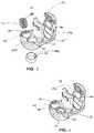
- FIG. 1is a perspective view of a modular screw in accordance with an embodiment of the present disclosure
- FIG. 2is a perspective view of the modular screw of FIG. 1 with a first assembly and a second assembly separated;
- FIG. 3is an exploded perspective view of the first assembly of FIG. 2 with parts separated;
- FIG. 4is a perspective view of the first assembly of FIG. 3 ;
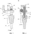
- FIG. 5Ais a perspective view of the second assembly of FIG. 2 ;
- FIG. 5Bis a perspective view of a second assembly in accordance with another embodiment of the present disclosure.
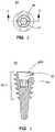
- FIG. 6is a top view of a post of the second assembly of FIG. 5 ;
- FIG. 7is a side cross-sectional view of the post of FIG. 6 cut along section line 7 - 7 of FIG. 6 ;
- FIG. 8is an exploded perspective view of the second assembly of FIG. 5 with parts separated;
- FIG. 9is a side view of the modular screw of FIG. 1 ;
- FIG. 10is a side cross-sectional view of the modular screw of FIG. 9 cut along section line 10 - 10 of FIG. 9 ;
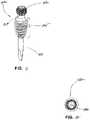
- FIG. 11is a perspective view of a post for use with a modular screw assembly in accordance with an embodiment of the present disclosure
- FIG. 12is a top view of the post of FIG. 11 ;
- FIG. 13is a front view of the post of FIG. 11 ;
- FIG. 14is a side view of the post of FIG. 11 ;
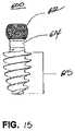
- FIG. 15is a side view of a post for use with a modular screw assembly in accordance with another embodiment of the present disclosure.
- FIG. 16is a perspective view of a modular screw in accordance with another embodiment of the present disclosure with a housing assembly and a post separated;
- FIG. 17is a perspective view of the modular screw of FIG. 16 ;
- FIG. 18is a side view of a post for use with a modular screw assembly in accordance with another embodiment of the present disclosure.
- FIG. 19is a perspective view of the post of FIG. 18 ;
- FIG. 20is a side view of a post for use with a modular screw assembly in accordance with another embodiment of the present disclosure.
- FIG. 21is a perspective view of the post of FIG. 20 .
- distalwill refer to that portion of the instrument, apparatus, device or component thereof which is farther from the user while, the term “proximal,” will refer to that portion of the instrument, apparatus, device or component thereof which is closer to the user.
- proximalwill refer to that portion of the instrument, apparatus, device or component thereof which is closer to the user.
- cephaladis used in this application to indicate a direction toward a patient's head, while the term “caudad” indicates a direction toward the patient's feet.
- the term “medial”indicates a direction toward the middle of the body of the patient
- the term “lateral”indicates a direction toward a side of the body of the patient, i.e., away from the middle of the body of the patient.
- the term “posterior”indicates a direction toward the patient's back
- the term “anterior”indicates a direction toward the patient's front.
- an embodiment of the present disclosureis shown generally as a modular screw 10 that is configured and adapted for use in a spinal surgical procedure.
- the modular screw 10includes a first assembly 12 and a second assembly 50 .
- the first assembly 12is selectively securable with the second assembly 50 .
- the modular screw 10provides the ability to selectively adjust the angle and the height to ensure proper placement of spinal rods and bands as will be described in detail hereinafter.
- the first assembly 12includes a base portion 15 including a head portion 14 , a receiving portion 17 , and a securing portion 21 .
- the head portion 14extends proximally from the base portion 15 , and defines a slot 14 a configured to receive, e.g., a spinal rod or a band (not shown).
- the slot 14 amay include an arcuate profile to facilitate securement of the spinal rod therein.
- the head portion 14includes inner walls 14 b having threads configured to threadably receive a set screw (not shown) to secure the spinal rod in the slot 14 a .
- the inner walls 14 bmay further define lateral openings 13 ( FIG. 1 ) configured to receive a band.
- the securing portion 21defines a first bore 20 and includes a set screw 16 dimensioned to be threadably received in the first bore 20 .
- the receiving portion 17defines a second bore 22 and a split ring 18 defining a slit 18 a configured to enable radial contraction and expansion of the split ring 18 to selectively engage a polyaxial post 54 ( FIG. 2 ) of the second assembly 50 .
- first bore 20may define, e.g., an acute angle, with respect to the second bore 22 such that when the set screw 16 is threadably received in the first bore 20 , the set screw 16 engages at least a portion of the split ring 18 disposed in the second bore 22 , which, in turn, causes radial contraction of the split ring 18 to frictionally engage the polyaxial post 54 ( FIG. 2 ) of the second assembly 50 .
- the first assembly 12may be selectively secured at a position along a length of the polyaxial post 54 of the second assembly 50 .
- the set screw 16includes a proximal portion 16 a defining a cavity 16 a having, e.g., a hex, key feature for non-slip engagement with a driver or other instrument (not shown) to drive the set screw 16 .
- the cavity 16 amay have any suitable configuration such as, e.g., slotted, square, star, or a Phillips head, for engagement with the driver.
- the receiving portion 17defines the second bore 22 and an annular groove 22 a concentrically arranged with the second bore 22 .
- the receiving portion 17includes the split ring 18 mounted in the annular groove 22 a such that the split ring 18 is transitionable between a radially expanded state and a radially contracted state.
- the annular groove 22 ainhibits axial displacement of the split ring 18 relative to the base portion 15 .
- the second bore 22 and the split ring 18are dimensioned to receive the polyaxial post 54 of the second assembly 50 therethrough.
- the set screw 16when the set screw 16 is threadably received in the first bore 20 , the set screw 16 engages the split ring 18 and transitions the split ring 18 to the contracted state, which, in turn, frictionally secures the base portion 15 on a position along a length of the polyaxial post 54 .
- the second assembly 50includes a post 52 , a polyaxial post 54 , and an elongate screw 56 .
- the post 52defines a cavity 53 having an opening 53 a dimensioned to receive a distal portion 58 of the polyaxial post 54 .
- the cavity 53may have a shape that is complementary to a distal portion 58 of the polyaxial post 54 .
- the cavity 53may include an arcuate or concave profile to receive a bulbous shape of the distal portion 58 of the polyaxial post 54 for polyaxial movement of the polyaxial post 54 relative to the post 52 .
- the post 52includes a tapered portion 55 extending along a length of the post 52 .
- the tapered portion 55may extend at least a quarter of the length of the post 52 .
- the tapered portion 55may extend at least a half of the length of the post 52 .
- the tapered portion 55may be less than a quarter of the length of the implant.
- the tapered portion 55includes external threads 55 a configured to engage, e.g., osseous tissue.
- the tapered portion 55may include a major diameter in the range of about 9 mm and about 13 mm.
- the tapered portion 55may include a major diameter in the range of about 10 mm and about 12 mm.
- the major diametermay be tapered along the length of the post 52 at a ratio of major diameter at the proximal portion 55 b of the tapered portion 55 to a major diameter at the distal portion 55 c of the tapered portion 55 in the range of about 1 and about 2.
- the ratiomay be in the range of about 1.4 and about 1.7.
- an angle of the tapermay vary from about 10 degrees to about 60 degrees.
- the anglemay vary from about 18 degrees to about 56 degrees.
- the post 52may include a diameter in the range of about 2 mm and 5 mm.
- the diameter of the post 52may be in the range of about 3 mm and about 4 mm.
- a second assembly 150 in accordance with another embodiment of the present disclosureincludes a post 152 , a poly axial post 54 , and an elongate screw 56 .
- the post 152is substantially identical to the post 52 .
- the post 152defines a cavity (not shown) having an opening (not shown) dimensioned to receive a distal portion 58 of the polyaxial post 54 for polyaxial movement of the polyaxial post 54 relative to the post 152 .
- the post 152includes a tapered portion 155 extending along a length of the post 152 .
- the tapered portion 155may extend at least a quarter of the length of the post 152 .
- the tapered portion 155may extend at least a half of the length of the post 152 . Alternatively, the tapered portion 155 may be less than a quarter of the length of the implant.
- the tapered portion 155includes external threads 155 a configured to engage, e.g., osseous tissue.
- the post 152further includes a distal portion 160 distal of the tapered portion 155 .
- the distal portion 160includes a non-threaded surface. While the post 52 ( FIG. 5A ) is shown to have an atraumatic blunt tip 51 , it is contemplated that the post 152 may include a pointed tip 151 .
- the post 52may further include a keyed inner surface 57 distal of the cavity 53 ( FIG. 8 ).
- the keyed inner surface 57may include, e.g., a hex, key feature for non-slip engagement with a driver or other instrument (not shown) to drive the post 52 . It is contemplated that the keyed inner surface 57 may have any suitable configuration such as, e.g., slotted, square, star, or a Phillips head, for engagement with the driver.
- the polyaxial post 54 of the second assembly 50includes a proximal portion 54 a and a distal portion 54 b .
- the proximal portion 54 amay include a multi-faceted outer surface 59 configured to engage a tool (not shown).
- the distal portion 54 bincludes an engaging portion 58 a having a bulbous shape.
- the engaging portion 58 a and the cavity 53 of the post 52provide, e.g., a ball and socket configuration, to enable polyaxial movement (i.e., rotation and pivoting) of the polyaxial post 54 relative to the post 52 .
- the engaging portion 58 adefines a plurality of slits 58 a extending along a length thereof.
- the slits 58may be circumferentially arranged about a central longitudinal axis “X-X” of the polyaxial post 54 .
- the plurality of slits 58 ais configured to enable radial expansion of the engaging portion 58 a in the presence of applied force, thereby providing, e.g., a friction fit, within the cavity 53 of the post 52 .
- the engaging portion 58 a and cavity 53 of the post 52may have, e.g., a ball and socket configuration, it is contemplated that other configuration may be utilized for expansion of the engaging portion 58 a to enable friction fit with the cavity 53 .
- the polyaxial post 54defines a channel 54 c dimensioned to, e.g., threadably, receive the elongate screw 56 .
- the elongate screw 56includes a proximal end 56 a and a distal end 56 b .
- the proximal end 56 adefines a cavity 56 c having, e.g., a hex, key feature for non-slip engagement with a driver or other instrument (not shown) to drive the elongate screw 56 .
- cavity 56 cmay have any suitable configuration such as, e.g., slotted, square, star, or a Phillips head, for engagement with the driver.
- the elongate screw 56further includes a threaded portion 57 a configured to threadably engage internal threads (not shown) of the polyaxial post 54 .
- a threaded portion 57 aconfigured to threadably engage internal threads (not shown) of the polyaxial post 54 .
- the distal end 56 b of the elongate screw 56engages an interior of the engaging portion 58 a of the polyaxial post 54 and urges the engaging portion 58 a to expand radially outward.
- the radially expanded engaging portion 58 aengages the cavity 53 of the post 52 and enables the clinician to selectively secure the polyaxial post 54 relative to the post 52 at a desired orientation.
- the polyaxial post 54 and the elongate screw 56may be positioned at various angles relative to a longitudinal axis “Y-Y” defined by the post 52 , thereby enabling polyaxial range of motion.
- the anglemay be in the range of about 0 degree and about 85 degrees.
- the anglemay be in the range of about 5 degrees and about 75 degrees.
- the anglemay be in the range of about 15 degrees and about 60 degrees.
- the clinicianmay selectively adjust the angle of the polyaxial post 54 relative to the longitudinal axis “Y-Y” of the post 52 , which, in turn, adjusts a position of the first assembly 12 .
- the clinicianmay threadably insert the elongate screw 56 into the channel 54 c of the polyaxial post 54 in order to expand the engaging portion 58 a of the polyaxial post 54 radially outward within the cavity 53 of the post 52 and thereby fixing or setting the angle through, e.g., a friction fit, between the engaging portion 58 a and the cavity 53 of the post 52 .
- the polyaxial post 54 and the elongate screw 56may be fixed at a particular angle relative to the longitudinal axis “Y-Y” of the post 52 by first selecting a desired orientation of the polyaxial post 54 and threadably inserting the elongate screw 56 into the polyaxial post 54 .
- the polyaxial post 54may be received through the second bore 22 of the first assembly 12 .
- the first assembly 12is selectively positionable at any position along a length of the polyaxial post 54 . In this manner, a relative distance between the first assembly 12 and the post 52 may be selectively adjustable.
- the clinicianmay tighten the set screw 16 such that the set screw 16 engages the split ring 18 , which, in turn, securely engages the polyaxial post 54 .
- each first assembly 12may be raised or lowered to a desired height for the construct. Additionally, each first assembly 12 may be rotated and/or pivoted into a desired orientation such that the slots 14 a of the head portions 14 are the correct orientation for receiving a spinal rod.
- the clinicianinitially prepares the vertebrae (not shown).
- the clinicianmay form an insertion hole in, e.g., osseous tissue, by preparing the surface with a burr or other like instrument and then an awl to start the hole.
- the insertion holemay be formed into, e.g., a cortical shell of an upper portion of a pedicle.
- the tapered portion 55 of the post 52may be inserted above and/or in, but not through, an isthmus of the pedicle such that the likelihood of breaching the pedicle and the need for navigation is eliminated. Thereafter the post 52 of the second assembly 50 may be inserted into the insertion hole.
- a driver(not shown) may be utilized to engage the keyed inner surface 57 of the post 52 to drive the tapered portion 55 of the post 52 into osseous tissue.
- the polyaxial post 54is inserted into the cavity 53 of the post 52 .
- the polyaxial post 54is selectively adjusted to a desired orientation and/or angle relative to the post 52 .
- the elongate screw 56is threadably inserted into the channel 54 c of the polyaxial post 54 to lock or securely fix the angle of the polyaxial post 54 relative to the post 52 .
- the polyaxial post 54is inserted through the second bore 22 of the first assembly 12 .
- a relative distance between the first assembly 12 and the post 52 of the second assembly 50is selectively adjusted.
- the base portion 15is selectively displaced at a position along a length of the polyaxial post 54 .
- Other spinal devicesmay be coupled to the modular screw 10 .
- a spinal rod(not shown) may be received in the slot 14 a of the head portion 14 of the first assembly 12 . It is also contemplated that a band (not shown) may be received through lateral openings 13 ( FIG. 1 ) of the head portion 14 . In this manner, the modular screw 10 enables selective height and angle adjustments to enable proper fit with other spinal devices.
- a post for use with a modular screw assembly in accordance with an embodiment of the present disclosureis shown generally as a post 500 .
- the post 500is configured to protect spinal nerves and eliminate the need for redirection in a spinal surgical procedure.
- the post 500includes a head 512 , a tapered portion 515 , a neck 514 interconnecting the head 512 and the tapered portion 515 , and a shank 517 extending distally from the tapered portion 515 .
- the head 512includes a keyed inner surface 520 having, e.g., a hex, key feature for non-slip engagement with a driver or other instrument (not shown) to drive the post 500 .
- the keyed inner surface 520may have any suitable configuration such as, e.g., slotted, square, star, or a Phillips head, for engagement with the driver.
- the head 512is configured to receive a modular screw assembly (not shown).
- the head 512is configured to provide polyaxial movement with the modular screw assembly.
- the head 512may have any shape.
- the head 512may include a roughened outer surface.
- the tapered portion 515 of the post 500may be configured and dimensioned to fit within an isthmus of a pedicle of a vertebra. It is envisioned that the tapered portion 515 is configured to fit within or stay above the isthmus of a pedicle and inhibit the post 500 from breaching the osseous tissue.
- the tapered portion 515includes helical threads 515 a .
- the tapered portion 515may extend at least a quarter of a length of the post 500 .
- the tapered portion 515may extend at least a half of a length of the post 500 .
- the tapered portion 515may be less than a quarter of the length of the post 500 .
- a major diameter of the helical threads 515 amay be in the range of about 9 mm and about 13 mm. Alternatively, the major diameter of the helical threads 515 a may be in the range of about 10 mm and about 12 mm.
- the major diametertapers along the length of the post 500 at a ratio of a major diameter at a proximal portion 515 b of the tapered portion 515 to a major diameter at a distal portion 515 c of the tapered portion 515 in the range of about 1 and about 2. Alternatively, the ratio may be in the range of about 1.4 and about 1.7.
- the angle of the tapermay vary from about 10 degrees to about 60 degrees.
- the angle of the tapermay be in the range of about 18 degrees and 56 degrees.
- a diameter of the post 500may be in the range of about 2 mm and 5 mm. In an embodiment, the diameter of the post 500 may be in the range of about 3 mm and 4 mm.
- the helical threads 515 amay rotate clockwise or counter-clockwise about the tapered portion 515 .
- the helical threads 515 ais configured to cut into or engage with osseous tissue.
- the tapered portion 515may be configured and dimensioned to be a steep taper or a narrow taper from the proximal portion 515 b to the distal portion 515 c.
- the shank 517is configured to protrude into a vertebral body.
- the shank 517is configured to extend through the isthmus and into the vertebral body while the tapered portion 515 resides or fits within the isthmus of a pedicle.
- the shank 517may extend at least a quarter of a length of the post 500 .
- the shank 517may extend at least a half of a length of the post 500 .
- the shank 517may include a smooth surface.
- the shank 517may include a gripping surface such as a shallow helical thread, a plurality of raised ridges, or any roughened surface.
- an insertion holeis formed in osseous tissue by preparing the surface with a burr or other like instrument and then an awl to start the hole.
- the post 500is inserted into the insertion hole.
- the post 500is inserted into the insertion hole until the tapered portion 515 abuts the osseous tissue, such as, e.g., fitting with an isthmus of the osseous tissue.
- the clinicianmay utilize a driver (not shown) to drive the head 512 of the post 500 .
- the post 500is rotated about its longitudinal axis within the insertion hole such that the helical threads 515 a of the tapered portion 515 engage the osseous tissue thereby fixing the post 500 to the osseous tissue.
- the post 600is substantially identical to the post 500 .
- the post 600includes a head 612 , a tapered portion 615 , and a neck 614 interconnecting the head 612 and the tapered portion 615 .
- the post 600does not include a shank extending distally from the tapered portion 615 .
- the method of use and operation of the post 600is substantially identical to the method of use and operation of the post 500 , and thus, will not be described herein.
- the housing assembly 220is selectively securable with the post 200 .
- the housing assembly 220includes a base portion 211 including a head portion 214 , a receiving portion 217 , and a securing portion 221 .
- the head portion 214extends proximally from the base portion 211 , and defines a slot 214 a configured to receive, e.g., a spinal rod or a band (not shown).
- the slot 214 amay include an arcuate profile to facilitate securement of the spinal rod therein.
- the head portion 214includes inner walls 214 b having threads configured to threadably receive a set screw (not shown) to secure the spinal rod in the slot 214 a .
- the inner walls 214 bmay further define recesses or notches 213 configured to engage an instrument (e.g., a rod reducer).
- the securing portion 221defines a first bore (not shown) and includes a set screw 216 dimensioned to be threadably received in the first bore.
- the receiving portion 217defines a second bore 222 and a split ring (not shown) defining a slit (not shown) configured to enable radial contraction and expansion of the split ring to selectively engage a head 212 of the post 200 .
- the receiving portion 217further defines an annular groove (not shown) concentrically arranged with the second bore 122 .
- the split ringis mounted in the annular groove. The annular groove inhibits axial displacement of the split ring relative to the base portion 211 .
- the split ringis transitionable between a radially expanded state and a radially contracted state.
- the second bore 222 and the split ringare dimensioned to receive the head 212 of the post 200 therethrough.
- the set screw 216engages the split ring and transitions the split ring to the contracted state, which, in turn, frictionally secures the base portion 211 on a position along a length of the head 212 .
- the set screw 216When the set screw 216 is threadably received in the first bore, the set screw 216 engages at least a portion of the split ring disposed in the second bore 222 , which, in turn, causes radial contraction of the split ring to frictionally engage the head 212 of the post 200 . In this manner, the first assembly 212 may be selectively secured at a position along a length of the head 212 of the post 200 .
- the set screw 216includes a proximal portion 216 a defining a cavity 216 a having, e.g., a hex, key feature for non-slip engagement with a driver or other instrument (not shown) to drive the set screw 216 . It is contemplated that the cavity 216 a may have any suitable configuration such as, e.g., slotted, square, star, or a Phillips head, for engagement with the driver.
- the post 200includes a head 212 having a proximal portion 212 a and a distal portion 212 b .
- the proximal portion 212includes a multi-faceted outer surface 213 configured to engage a tool (not shown).
- the proximal portion 212 ais connected to the tapered portion 215 .
- the tapered portion 215 and the shank 217are substantially identical to the tapered portion 15 and the shank 17 of the post 500 , and thus, will not be described herein.
- the method of use and operation of the post 200is substantially identical to the method of use and operation of the post 500 , and thus, will not be described herein.
- the post 300is substantially identical to the post 200 described hereinabove. Specifically, the post 300 includes a tapered portion 315 and a shank 317 extending distally from the tapered portion 315 . However, the post 300 includes a threaded shank 319 proximal of the tapered portion 315 . The threaded shank 319 includes external threads and defines a cavity 321 having, e.g., a hex, key feature for non-slip engagement with a driver or other instrument (not shown) to drive the post 300 .
- a cavity 321having, e.g., a hex, key feature for non-slip engagement with a driver or other instrument (not shown) to drive the post 300 .
- cavity 321may have any suitable configuration such as, e.g., slotted, square, star, or a Phillips head, for engagement with the driver.
- the method of use and operation of the post 300is substantially identical to the method of use and operation of the posts 200 , 500 , 600 described hereinabove, and thus, will not be described herein.
- the post 400is substantially identical to the post 500 in that the post 400 includes a tapered portion 415 and a shank 417 extending distally from the tapered portion 415 .
- the post 400does not include a head as shown in posts 200 , 300 , 500 , 600 .
- the tapered portion 415defines a cavity 421 having, e.g., a hex, key feature for non-slip engagement with a driver or other instrument (not shown) to drive the post 400 .
- cavity 421may have any suitable configuration such as, e.g., slotted, square, star, or a Phillips head, for engagement with the driver.
Landscapes
- Health & Medical Sciences (AREA)
- Orthopedic Medicine & Surgery (AREA)
- Neurology (AREA)
- Life Sciences & Earth Sciences (AREA)
- Surgery (AREA)
- Heart & Thoracic Surgery (AREA)
- Engineering & Computer Science (AREA)
- Biomedical Technology (AREA)
- Nuclear Medicine, Radiotherapy & Molecular Imaging (AREA)
- Medical Informatics (AREA)
- Molecular Biology (AREA)
- Animal Behavior & Ethology (AREA)
- General Health & Medical Sciences (AREA)
- Public Health (AREA)
- Veterinary Medicine (AREA)
- Surgical Instruments (AREA)
Abstract
Description
Claims (20)
Priority Applications (1)
| Application Number | Priority Date | Filing Date | Title |
|---|---|---|---|
| US16/498,722US11419639B2 (en) | 2017-03-30 | 2018-03-28 | Modular offset screw |
Applications Claiming Priority (4)
| Application Number | Priority Date | Filing Date | Title |
|---|---|---|---|
| US201762478698P | 2017-03-30 | 2017-03-30 | |
| US201762478686P | 2017-03-30 | 2017-03-30 | |
| US16/498,722US11419639B2 (en) | 2017-03-30 | 2018-03-28 | Modular offset screw |
| PCT/US2018/024829WO2018183486A1 (en) | 2017-03-30 | 2018-03-28 | Modular offset screw |
Publications (2)
| Publication Number | Publication Date |
|---|---|
| US20200038067A1 US20200038067A1 (en) | 2020-02-06 |
| US11419639B2true US11419639B2 (en) | 2022-08-23 |
Family
ID=63678116
Family Applications (1)
| Application Number | Title | Priority Date | Filing Date |
|---|---|---|---|
| US16/498,722Active2039-04-03US11419639B2 (en) | 2017-03-30 | 2018-03-28 | Modular offset screw |
Country Status (2)
| Country | Link |
|---|---|
| US (1) | US11419639B2 (en) |
| WO (1) | WO2018183486A1 (en) |
Families Citing this family (2)
| Publication number | Priority date | Publication date | Assignee | Title |
|---|---|---|---|---|
| US11284928B2 (en) | 2018-12-17 | 2022-03-29 | Warsaw Orthopedic, Inc. | Surgical implant and method of use |
| US11571244B2 (en) | 2019-05-22 | 2023-02-07 | Nuvasive, Inc. | Posterior spinal fixation screws |
Citations (111)
| Publication number | Priority date | Publication date | Assignee | Title |
|---|---|---|---|---|
| US5382248A (en) | 1992-09-10 | 1995-01-17 | H. D. Medical, Inc. | System and method for stabilizing bone segments |
| US5487744A (en) | 1993-04-08 | 1996-01-30 | Advanced Spine Fixation Systems, Inc. | Closed connector for spinal fixation systems |
| US5609592A (en)* | 1993-01-04 | 1997-03-11 | Danek Medical, Inc. | Spinal Fixation System |
| US5725528A (en) | 1997-02-12 | 1998-03-10 | Third Millennium Engineering, Llc | Modular polyaxial locking pedicle screw |
| US5735851A (en) | 1996-10-09 | 1998-04-07 | Third Millennium Engineering, Llc | Modular polyaxial locking pedicle screw |
| US5800435A (en) | 1996-10-09 | 1998-09-01 | Techsys, Llc | Modular spinal plate for use with modular polyaxial locking pedicle screws |
| US6004322A (en) | 1994-10-25 | 1999-12-21 | Sdgi Holdings, Inc. | Modular pedicle screw system |
| US6050997A (en) | 1999-01-25 | 2000-04-18 | Mullane; Thomas S. | Spinal fixation system |
| US6146383A (en) | 1998-02-02 | 2000-11-14 | Sulzer Orthopadie Ag | Pivotal securing system at a bone screw |
| US6482207B1 (en) | 2000-07-13 | 2002-11-19 | Fastenetix, Llc | Efficient assembling modular locking pedicle screw |
| US20030060823A1 (en) | 2001-09-24 | 2003-03-27 | Bryan Donald W. | Pedicle screw spinal fixation device |
| US6623485B2 (en) | 2001-10-17 | 2003-09-23 | Hammill Manufacturing Company | Split ring bone screw for a spinal fixation system |
| US6669697B1 (en) | 1998-09-25 | 2003-12-30 | Perumala Corporation | Self-retaining bolt for internal spinal stabilizers |
| US6887242B2 (en)* | 2001-10-17 | 2005-05-03 | Ortho Innovations, Llc | Split ring bone screw for a spinal fixation system |
| US7163538B2 (en)* | 2002-02-13 | 2007-01-16 | Cross Medical Products, Inc. | Posterior rod system |
| US7186255B2 (en) | 2004-08-12 | 2007-03-06 | Atlas Spine, Inc. | Polyaxial screw |
| US7314467B2 (en) | 2002-04-24 | 2008-01-01 | Medical Device Advisory Development Group, Llc. | Multi selective axis spinal fixation system |
| US20100057135A1 (en) | 2008-09-02 | 2010-03-04 | Heiges Bradley A | Modular pedicle screw system |
| US7766943B1 (en) | 2005-08-11 | 2010-08-03 | Medicine Lodge Inc. | Modular percutaneous spinal fusion system and method |
| US20110118783A1 (en) | 2009-11-16 | 2011-05-19 | Spartek Medical, Inc. | Load-sharing bone anchor having a flexible post and method for dynamic stabilization of the spine |
| US8007518B2 (en) | 2008-02-26 | 2011-08-30 | Spartek Medical, Inc. | Load-sharing component having a deflectable post and method for dynamic stabilization of the spine |
| US8012181B2 (en) | 2008-02-26 | 2011-09-06 | Spartek Medical, Inc. | Modular in-line deflection rod and bone anchor system and method for dynamic stabilization of the spine |
| US8016861B2 (en) | 2008-02-26 | 2011-09-13 | Spartek Medical, Inc. | Versatile polyaxial connector assembly and method for dynamic stabilization of the spine |
| US20110245876A1 (en)* | 2010-04-05 | 2011-10-06 | Brumfield David L | Fully-Adjustable bone fixation device |
| US8048115B2 (en) | 2007-06-05 | 2011-11-01 | Spartek Medical, Inc. | Surgical tool and method for implantation of a dynamic bone anchor |
| US8048126B2 (en) | 2005-10-20 | 2011-11-01 | Ebi, Llc | Bone fixation assembly |
| US8057515B2 (en) | 2008-02-26 | 2011-11-15 | Spartek Medical, Inc. | Load-sharing anchor having a deflectable post and centering spring and method for dynamic stabilization of the spine |
| US8075603B2 (en) | 2008-11-14 | 2011-12-13 | Ortho Innovations, Llc | Locking polyaxial ball and socket fastener |
| US20110307018A1 (en) | 2010-06-10 | 2011-12-15 | Spartek Medical, Inc. | Adaptive spinal rod and methods for stabilization of the spine |
| US8083775B2 (en) | 2008-02-26 | 2011-12-27 | Spartek Medical, Inc. | Load-sharing bone anchor having a natural center of rotation and method for dynamic stabilization of the spine |
| US8083777B2 (en) | 2007-06-15 | 2011-12-27 | Robert Reid, Inc. | System and method for polyaxially adjustable bone anchorage |
| US8083772B2 (en) | 2007-06-05 | 2011-12-27 | Spartek Medical, Inc. | Dynamic spinal rod assembly and method for dynamic stabilization of the spine |
| US8092501B2 (en) | 2007-06-05 | 2012-01-10 | Spartek Medical, Inc. | Dynamic spinal rod and method for dynamic stabilization of the spine |
| US8097024B2 (en) | 2008-02-26 | 2012-01-17 | Spartek Medical, Inc. | Load-sharing bone anchor having a deflectable post and method for stabilization of the spine |
| US8114134B2 (en) | 2007-06-05 | 2012-02-14 | Spartek Medical, Inc. | Spinal prosthesis having a three bar linkage for motion preservation and dynamic stabilization of the spine |
| US20120041490A1 (en) | 2009-11-18 | 2012-02-16 | Synthes Usa, Llc | Variable offset spine fixation system and method |
| US8192470B2 (en) | 2007-07-31 | 2012-06-05 | Biedermann Technologies Gmbh & Co. Kg | Bone anchoring device |
| US8192468B2 (en) | 2005-12-23 | 2012-06-05 | Biedermann Technologies Gmbh & Co. Kg | Dynamic stabilization device for bones or vertebrae |
| US8197518B2 (en) | 2007-05-16 | 2012-06-12 | Ortho Innovations, Llc | Thread-thru polyaxial pedicle screw system |
| US8211155B2 (en) | 2008-02-26 | 2012-07-03 | Spartek Medical, Inc. | Load-sharing bone anchor having a durable compliant member and method for dynamic stabilization of the spine |
| US8257397B2 (en) | 2009-12-02 | 2012-09-04 | Spartek Medical, Inc. | Low profile spinal prosthesis incorporating a bone anchor having a deflectable post and a compound spinal rod |
| US8333792B2 (en) | 2008-02-26 | 2012-12-18 | Spartek Medical, Inc. | Load-sharing bone anchor having a deflectable post and method for dynamic stabilization of the spine |
| US8337530B2 (en) | 2011-03-09 | 2012-12-25 | Zimmer Spine, Inc. | Polyaxial pedicle screw with increased angulation |
| US8337536B2 (en) | 2008-02-26 | 2012-12-25 | Spartek Medical, Inc. | Load-sharing bone anchor having a deflectable post with a compliant ring and method for stabilization of the spine |
| US8430916B1 (en) | 2012-02-07 | 2013-04-30 | Spartek Medical, Inc. | Spinal rod connectors, methods of use, and spinal prosthesis incorporating spinal rod connectors |
| US8506609B2 (en) | 2008-12-30 | 2013-08-13 | Biedermann Technologies Gmbh & Co. Kg | Receiving part for receiving a rod for coupling the rod to a bone anchoring element and a bone anchoring device with such a receiving part |
| US8636782B2 (en) | 2008-12-29 | 2014-01-28 | Biedermann Technologies Gmbh & Co. Kg | Receiving part for receiving a rod for coupling the rod to a bone anchoring element and bone anchoring device with such a receiving part |
| US8636781B2 (en) | 2008-11-28 | 2014-01-28 | Biedermann Technologies Gmbh & Co. Kg | Receiving part for receiving a rod for coupling the rod to a bone anchoring element and a bone anchoring device with such a receiving part |
| US8663291B2 (en) | 2011-10-28 | 2014-03-04 | Ortho Innovations, Llc | Top loading polyaxial ball and socket fastener |
| US8663290B2 (en) | 2011-10-28 | 2014-03-04 | Ortho Innovations, Llc | Top loading polyaxial ball and socket fastener with saddle |
| US20140243900A1 (en) | 2013-02-20 | 2014-08-28 | K2M Inc. | Iliosacral polyaxial screw |
| US8881358B2 (en) | 2010-05-05 | 2014-11-11 | Biedermann Technologies Gmbh & Co. Kg | Method and tool for assembling a bone anchoring device |
| US8900270B2 (en) | 2004-02-17 | 2014-12-02 | Gmedelaware 2 Llc | Facet joint replacement instruments and methods |
| US8926671B2 (en) | 2009-02-20 | 2015-01-06 | Biedermann Technologies Gmbh & Co. Kg | Receiving part for receiving a rod for coupling the rod to a bone anchoring element and a bone anchoring device with such a receiving part |
| US8961568B2 (en) | 2007-01-12 | 2015-02-24 | Lanx, Inc. | Bone fastener assembly |
| US8979904B2 (en) | 2007-05-01 | 2015-03-17 | Roger P Jackson | Connecting member with tensioned cord, low profile rigid sleeve and spacer with torsion control |
| US8986349B1 (en) | 2009-11-11 | 2015-03-24 | Nuvasive, Inc. | Systems and methods for correcting spinal deformities |
| US8992579B1 (en) | 2011-03-08 | 2015-03-31 | Nuvasive, Inc. | Lateral fixation constructs and related methods |
| US8998958B2 (en) | 2007-12-20 | 2015-04-07 | Aesculap Implant Systems, Llc | Locking device introducer instrument |
| US9017390B2 (en) | 2011-11-14 | 2015-04-28 | Biedermann Technologies Gmbh & Co. Kg | Polyaxial bone anchoring device |
| US9044273B2 (en) | 2013-10-07 | 2015-06-02 | Intelligent Implant Systems, Llc | Polyaxial plate rod system and surgical procedure |
| US9060814B2 (en) | 2011-10-28 | 2015-06-23 | Ortho Innovations, Llc | Spring clip bottom loading polyaxial ball and socket fastener |
| US9066759B2 (en) | 2010-12-10 | 2015-06-30 | Biedermann Technologies Gmbh & Co. Kg | Receiving part for receiving a rod for coupling the rod to a bone anchoring element and a bone anchoring device |
| US20150196338A1 (en) | 2014-01-13 | 2015-07-16 | Lutz Biedermann | Coupling assembly for coupling a rod to a bone anchoring element, and polyaxial bone anchoring device |
| US9119674B2 (en) | 2006-11-22 | 2015-09-01 | Biedermann Technologies Gmbh & Co. Kg | Bone anchoring device |
| US9131971B2 (en) | 2011-11-14 | 2015-09-15 | Biedermann Technologies Gmbh & Co. Kg | Polyaxial bone anchoring device |
| US9173684B2 (en) | 2010-12-10 | 2015-11-03 | Biedermann Technologies Gmbh & Co. Kg | Receiving part for receiving a rod for coupling the rod to a bone anchoring element and bone anchoring device with such a receiving part |
| US9186187B2 (en) | 2011-07-15 | 2015-11-17 | Globus Medical, Inc. | Orthopedic fixation devices and methods of installation thereof |
| US9198694B2 (en) | 2011-07-15 | 2015-12-01 | Globus Medical, Inc. | Orthopedic fixation devices and methods of installation thereof |
| US9247965B2 (en) | 2011-08-18 | 2016-02-02 | Biedermann Technologies Gmbh & Co. Kg | Polyaxial bone anchoring device with enlarged pivot angle |
| US20160030090A1 (en) | 2014-07-29 | 2016-02-04 | Transcendental Spine, Llc | Modular polyaxial bone screw |
| US9254150B2 (en) | 2009-08-20 | 2016-02-09 | Biedermann Technologies Gmbh & Co. Kg | Bone anchoring device, tool and method for assembling the same and tool for use with the same |
| US9277942B2 (en) | 2012-07-27 | 2016-03-08 | Biedermann Technologies Gmbh & Co. Kg | Polyaxial bone anchoring device with enlarged pivot angle |
| US9277938B2 (en) | 2011-08-18 | 2016-03-08 | Biedermann Technologies Gmbh & Co. Kg | Polyaxial bone anchoring system |
| US9277941B2 (en) | 2010-12-10 | 2016-03-08 | Biedermann Technologies Gmbh & Co. Kg | Bone anchoring device |
| US9333016B2 (en) | 2012-07-03 | 2016-05-10 | Biedermann Technologies Gmbh & Co. Kg | Polyaxial bone anchoring device |
| US9339304B2 (en) | 2011-10-27 | 2016-05-17 | Biedermann Technologies Gmbh & Co. Kg | High angulation polyaxial bone anchoring device |
| US9358047B2 (en) | 2011-07-15 | 2016-06-07 | Globus Medical, Inc. | Orthopedic fixation devices and methods of installation thereof |
| US9364266B2 (en) | 2012-05-29 | 2016-06-14 | Biedermann Technologies Gmbh & Co. Kg | Receiving part for receiving a rod for coupling the rod to a bone anchoring element and a bone anchoring device with such a receiving part |
| US20160220277A1 (en) | 2015-02-04 | 2016-08-04 | Warsaw Orthopedic, Inc. | Spinal implant system and methods of use |
| US9439680B2 (en) | 2013-07-24 | 2016-09-13 | Biedermann Technologies Gmbh & Co. Kg | Coupling assembly for coupling a rod to a bone anchoring element, kit of such a coupling assembly different rod receiving elements and bone anchoring device |
| US9452006B2 (en) | 2011-09-15 | 2016-09-27 | Biedermann Technologies Gmbh & Co. Kg | Polyaxial bone anchoring device with enlarged pivot angle |
| US20160302833A9 (en) | 2013-03-14 | 2016-10-20 | Atlas Spine, Inc. | Low profile spinal fixation system |
| US9486246B2 (en) | 2009-12-21 | 2016-11-08 | Biedermann Technologies Gmbh & Co. Kg | Bone anchoring device |
| US9492204B2 (en) | 2013-11-14 | 2016-11-15 | Biedermann Technologies Gmbh & Co. Kg | Polyaxial bone anchoring device with enlarged pivot angle |
| US9517089B1 (en)* | 2013-10-08 | 2016-12-13 | Nuvasive, Inc. | Bone anchor with offset rod connector |
| US20170020574A1 (en) | 2015-07-24 | 2017-01-26 | Timo Biedermann | Polyaxial bone anchoring device and instrument for use with the same |
| US20170049484A1 (en) | 2015-08-17 | 2017-02-23 | Globus Medical, Inc. | Modular uniplanar pedicle screw assembly for use with a polyaxial bone fastener |
| US20170049482A1 (en) | 2015-08-17 | 2017-02-23 | Spinal Usa, Inc. | Spinal screws and methods of using the same |
| US9579125B2 (en) | 2013-02-09 | 2017-02-28 | Vertiscrew, Llc | Bone screw |
| US9603635B2 (en) | 2011-07-15 | 2017-03-28 | Globus Medical, Inc | Orthopedic fixation devices and methods of installation thereof |
| US9615858B2 (en) | 2013-07-18 | 2017-04-11 | Spinal Llc | Spring clip-bottom loading polyaxial ball and socket fastener |
| US20170112542A1 (en) | 2015-10-21 | 2017-04-27 | Biedermann Technologies Gmbh & Co. Kg | Coupling device for coupling a bone anchor to a rod and bone anchoring device with such a coupling device |
| US9649142B2 (en) | 2015-03-10 | 2017-05-16 | Spinal Llc | Modular head assembly |
| US20170172630A1 (en) | 2015-12-21 | 2017-06-22 | Lutz Biedermann | Polyaxial bone anchoring device |
| US9707013B2 (en) | 2015-04-30 | 2017-07-18 | Warsaw Orthopedic, Inc. | Spinal implant system and methods of use |
| US20170245898A1 (en) | 2016-02-26 | 2017-08-31 | Warsaw Orthopedic, Inc | Spinal implant system and methods of use |
| US9820780B2 (en) | 2015-09-30 | 2017-11-21 | Amendia, Inc. | Angled offset tulip assembly |
| US20170333085A1 (en) | 2014-06-04 | 2017-11-23 | Roger P. Jackson | Snap-on multi-planar and mono-planar receiver assemblies having integral and multi-part multipurpose positioners for pivoting and non-pivoting retainers |
| US20180014858A1 (en) | 2016-07-13 | 2018-01-18 | Medos International Sarl | Bone anchor assemblies and related instrumentation |
| US20180014862A1 (en) | 2016-07-13 | 2018-01-18 | Medos International Sarl | Bone anchor assemblies and related instrumentation |
| US20180014863A1 (en) | 2016-07-13 | 2018-01-18 | Medos International Sarl | Bone anchor assemblies and related instrumentation |
| US9883892B2 (en) | 2009-06-15 | 2018-02-06 | Roger P. Jackson | Polyaxial bone anchor with pop-on shank, friction fit retainer, winged insert and low profile edge lock |
| US20180036039A1 (en) | 2016-08-04 | 2018-02-08 | Biedermann Technologies Gmbh & Co. Kg | Polyaxial bone anchoring device and system including an instrument and a polyaxial bone anchoring device |
| US9895170B2 (en) | 2013-02-11 | 2018-02-20 | Biedermann Technologies Gmbh & Co. Kg | Coupling assembly for coupling a rod to a bone anchoring element and bone anchoring device with such a coupling assembly |
| US20180055545A1 (en) | 2016-08-24 | 2018-03-01 | Biedermann Technologies Gmbh & Co. Kg | Instrument for locking and unlocking a head of a bone anchor in a polyaxial bone anchoring device |
| US9907574B2 (en) | 2008-08-01 | 2018-03-06 | Roger P. Jackson | Polyaxial bone anchors with pop-on shank, friction fit fully restrained retainer, insert and tool receiving features |
| US20180092679A1 (en) | 2016-10-04 | 2018-04-05 | Amendia, Inc. | Modular tulip assembly |
| US9936983B2 (en) | 2013-03-15 | 2018-04-10 | Si-Bone Inc. | Implants for spinal fixation or fusion |
| US20180110548A1 (en) | 2016-10-26 | 2018-04-26 | Warsaw Orthopedic, Inc | Spinal construct |
| US9980753B2 (en) | 2009-06-15 | 2018-05-29 | Roger P Jackson | pivotal anchor with snap-in-place insert having rotation blocking extensions |
- 2018
- 2018-03-28WOPCT/US2018/024829patent/WO2018183486A1/ennot_activeCeased
- 2018-03-28USUS16/498,722patent/US11419639B2/enactiveActive
Patent Citations (121)
| Publication number | Priority date | Publication date | Assignee | Title |
|---|---|---|---|---|
| US5382248A (en) | 1992-09-10 | 1995-01-17 | H. D. Medical, Inc. | System and method for stabilizing bone segments |
| US5609592A (en)* | 1993-01-04 | 1997-03-11 | Danek Medical, Inc. | Spinal Fixation System |
| US5487744A (en) | 1993-04-08 | 1996-01-30 | Advanced Spine Fixation Systems, Inc. | Closed connector for spinal fixation systems |
| US6004322A (en) | 1994-10-25 | 1999-12-21 | Sdgi Holdings, Inc. | Modular pedicle screw system |
| US5735851A (en) | 1996-10-09 | 1998-04-07 | Third Millennium Engineering, Llc | Modular polyaxial locking pedicle screw |
| US5800435A (en) | 1996-10-09 | 1998-09-01 | Techsys, Llc | Modular spinal plate for use with modular polyaxial locking pedicle screws |
| US5725528A (en) | 1997-02-12 | 1998-03-10 | Third Millennium Engineering, Llc | Modular polyaxial locking pedicle screw |
| US6146383A (en) | 1998-02-02 | 2000-11-14 | Sulzer Orthopadie Ag | Pivotal securing system at a bone screw |
| US6669697B1 (en) | 1998-09-25 | 2003-12-30 | Perumala Corporation | Self-retaining bolt for internal spinal stabilizers |
| US6050997A (en) | 1999-01-25 | 2000-04-18 | Mullane; Thomas S. | Spinal fixation system |
| US6482207B1 (en) | 2000-07-13 | 2002-11-19 | Fastenetix, Llc | Efficient assembling modular locking pedicle screw |
| US7722645B2 (en) | 2001-09-24 | 2010-05-25 | Bryan Donald W | Pedicle screw spinal fixation device |
| US20030060823A1 (en) | 2001-09-24 | 2003-03-27 | Bryan Donald W. | Pedicle screw spinal fixation device |
| US6887242B2 (en)* | 2001-10-17 | 2005-05-03 | Ortho Innovations, Llc | Split ring bone screw for a spinal fixation system |
| US6623485B2 (en) | 2001-10-17 | 2003-09-23 | Hammill Manufacturing Company | Split ring bone screw for a spinal fixation system |
| US7163538B2 (en)* | 2002-02-13 | 2007-01-16 | Cross Medical Products, Inc. | Posterior rod system |
| US7314467B2 (en) | 2002-04-24 | 2008-01-01 | Medical Device Advisory Development Group, Llc. | Multi selective axis spinal fixation system |
| US9451990B2 (en) | 2004-02-17 | 2016-09-27 | Globus Medical, Inc. | Facet joint replacement instruments and methods |
| US8900270B2 (en) | 2004-02-17 | 2014-12-02 | Gmedelaware 2 Llc | Facet joint replacement instruments and methods |
| US9693808B2 (en) | 2004-02-17 | 2017-07-04 | Globus Medical, Inc. | Facet joint replacement instruments and methods |
| US20170065306A1 (en) | 2004-02-17 | 2017-03-09 | Globus Medical, Inc. | Facet joint replacement instruments and methods |
| US7186255B2 (en) | 2004-08-12 | 2007-03-06 | Atlas Spine, Inc. | Polyaxial screw |
| US7766943B1 (en) | 2005-08-11 | 2010-08-03 | Medicine Lodge Inc. | Modular percutaneous spinal fusion system and method |
| US8048126B2 (en) | 2005-10-20 | 2011-11-01 | Ebi, Llc | Bone fixation assembly |
| US8192468B2 (en) | 2005-12-23 | 2012-06-05 | Biedermann Technologies Gmbh & Co. Kg | Dynamic stabilization device for bones or vertebrae |
| US9119674B2 (en) | 2006-11-22 | 2015-09-01 | Biedermann Technologies Gmbh & Co. Kg | Bone anchoring device |
| US8961568B2 (en) | 2007-01-12 | 2015-02-24 | Lanx, Inc. | Bone fastener assembly |
| US8979904B2 (en) | 2007-05-01 | 2015-03-17 | Roger P Jackson | Connecting member with tensioned cord, low profile rigid sleeve and spacer with torsion control |
| US8197518B2 (en) | 2007-05-16 | 2012-06-12 | Ortho Innovations, Llc | Thread-thru polyaxial pedicle screw system |
| US8048115B2 (en) | 2007-06-05 | 2011-11-01 | Spartek Medical, Inc. | Surgical tool and method for implantation of a dynamic bone anchor |
| US8083772B2 (en) | 2007-06-05 | 2011-12-27 | Spartek Medical, Inc. | Dynamic spinal rod assembly and method for dynamic stabilization of the spine |
| US8092501B2 (en) | 2007-06-05 | 2012-01-10 | Spartek Medical, Inc. | Dynamic spinal rod and method for dynamic stabilization of the spine |
| US8114134B2 (en) | 2007-06-05 | 2012-02-14 | Spartek Medical, Inc. | Spinal prosthesis having a three bar linkage for motion preservation and dynamic stabilization of the spine |
| US8083777B2 (en) | 2007-06-15 | 2011-12-27 | Robert Reid, Inc. | System and method for polyaxially adjustable bone anchorage |
| US8192470B2 (en) | 2007-07-31 | 2012-06-05 | Biedermann Technologies Gmbh & Co. Kg | Bone anchoring device |
| US8998958B2 (en) | 2007-12-20 | 2015-04-07 | Aesculap Implant Systems, Llc | Locking device introducer instrument |
| US8211155B2 (en) | 2008-02-26 | 2012-07-03 | Spartek Medical, Inc. | Load-sharing bone anchor having a durable compliant member and method for dynamic stabilization of the spine |
| US8016861B2 (en) | 2008-02-26 | 2011-09-13 | Spartek Medical, Inc. | Versatile polyaxial connector assembly and method for dynamic stabilization of the spine |
| US8097024B2 (en) | 2008-02-26 | 2012-01-17 | Spartek Medical, Inc. | Load-sharing bone anchor having a deflectable post and method for stabilization of the spine |
| US8083775B2 (en) | 2008-02-26 | 2011-12-27 | Spartek Medical, Inc. | Load-sharing bone anchor having a natural center of rotation and method for dynamic stabilization of the spine |
| US8333792B2 (en) | 2008-02-26 | 2012-12-18 | Spartek Medical, Inc. | Load-sharing bone anchor having a deflectable post and method for dynamic stabilization of the spine |
| US8057515B2 (en) | 2008-02-26 | 2011-11-15 | Spartek Medical, Inc. | Load-sharing anchor having a deflectable post and centering spring and method for dynamic stabilization of the spine |
| US8337536B2 (en) | 2008-02-26 | 2012-12-25 | Spartek Medical, Inc. | Load-sharing bone anchor having a deflectable post with a compliant ring and method for stabilization of the spine |
| US8007518B2 (en) | 2008-02-26 | 2011-08-30 | Spartek Medical, Inc. | Load-sharing component having a deflectable post and method for dynamic stabilization of the spine |
| US8012181B2 (en) | 2008-02-26 | 2011-09-06 | Spartek Medical, Inc. | Modular in-line deflection rod and bone anchor system and method for dynamic stabilization of the spine |
| US9907574B2 (en) | 2008-08-01 | 2018-03-06 | Roger P. Jackson | Polyaxial bone anchors with pop-on shank, friction fit fully restrained retainer, insert and tool receiving features |
| US20100057135A1 (en) | 2008-09-02 | 2010-03-04 | Heiges Bradley A | Modular pedicle screw system |
| US8137384B2 (en) | 2008-09-02 | 2012-03-20 | Bhdl Holdings, Llc | Modular pedicle screw system |
| US8075603B2 (en) | 2008-11-14 | 2011-12-13 | Ortho Innovations, Llc | Locking polyaxial ball and socket fastener |
| US8636781B2 (en) | 2008-11-28 | 2014-01-28 | Biedermann Technologies Gmbh & Co. Kg | Receiving part for receiving a rod for coupling the rod to a bone anchoring element and a bone anchoring device with such a receiving part |
| US8636782B2 (en) | 2008-12-29 | 2014-01-28 | Biedermann Technologies Gmbh & Co. Kg | Receiving part for receiving a rod for coupling the rod to a bone anchoring element and bone anchoring device with such a receiving part |
| US8506609B2 (en) | 2008-12-30 | 2013-08-13 | Biedermann Technologies Gmbh & Co. Kg | Receiving part for receiving a rod for coupling the rod to a bone anchoring element and a bone anchoring device with such a receiving part |
| US8926671B2 (en) | 2009-02-20 | 2015-01-06 | Biedermann Technologies Gmbh & Co. Kg | Receiving part for receiving a rod for coupling the rod to a bone anchoring element and a bone anchoring device with such a receiving part |
| US9918745B2 (en) | 2009-06-15 | 2018-03-20 | Roger P. Jackson | Polyaxial bone anchor with pop-on shank and winged insert with friction fit compressive collet |
| US9980753B2 (en) | 2009-06-15 | 2018-05-29 | Roger P Jackson | pivotal anchor with snap-in-place insert having rotation blocking extensions |
| US9883892B2 (en) | 2009-06-15 | 2018-02-06 | Roger P. Jackson | Polyaxial bone anchor with pop-on shank, friction fit retainer, winged insert and low profile edge lock |
| US9254150B2 (en) | 2009-08-20 | 2016-02-09 | Biedermann Technologies Gmbh & Co. Kg | Bone anchoring device, tool and method for assembling the same and tool for use with the same |
| US8986349B1 (en) | 2009-11-11 | 2015-03-24 | Nuvasive, Inc. | Systems and methods for correcting spinal deformities |
| US20110118783A1 (en) | 2009-11-16 | 2011-05-19 | Spartek Medical, Inc. | Load-sharing bone anchor having a flexible post and method for dynamic stabilization of the spine |
| US20120041490A1 (en) | 2009-11-18 | 2012-02-16 | Synthes Usa, Llc | Variable offset spine fixation system and method |
| US8257397B2 (en) | 2009-12-02 | 2012-09-04 | Spartek Medical, Inc. | Low profile spinal prosthesis incorporating a bone anchor having a deflectable post and a compound spinal rod |
| US9486246B2 (en) | 2009-12-21 | 2016-11-08 | Biedermann Technologies Gmbh & Co. Kg | Bone anchoring device |
| US20110245876A1 (en)* | 2010-04-05 | 2011-10-06 | Brumfield David L | Fully-Adjustable bone fixation device |
| US8881358B2 (en) | 2010-05-05 | 2014-11-11 | Biedermann Technologies Gmbh & Co. Kg | Method and tool for assembling a bone anchoring device |
| US20110307018A1 (en) | 2010-06-10 | 2011-12-15 | Spartek Medical, Inc. | Adaptive spinal rod and methods for stabilization of the spine |
| US8518085B2 (en) | 2010-06-10 | 2013-08-27 | Spartek Medical, Inc. | Adaptive spinal rod and methods for stabilization of the spine |
| US9066759B2 (en) | 2010-12-10 | 2015-06-30 | Biedermann Technologies Gmbh & Co. Kg | Receiving part for receiving a rod for coupling the rod to a bone anchoring element and a bone anchoring device |
| US9277941B2 (en) | 2010-12-10 | 2016-03-08 | Biedermann Technologies Gmbh & Co. Kg | Bone anchoring device |
| US9173684B2 (en) | 2010-12-10 | 2015-11-03 | Biedermann Technologies Gmbh & Co. Kg | Receiving part for receiving a rod for coupling the rod to a bone anchoring element and bone anchoring device with such a receiving part |
| US8992579B1 (en) | 2011-03-08 | 2015-03-31 | Nuvasive, Inc. | Lateral fixation constructs and related methods |
| US8337530B2 (en) | 2011-03-09 | 2012-12-25 | Zimmer Spine, Inc. | Polyaxial pedicle screw with increased angulation |
| US20160030086A1 (en) | 2011-07-15 | 2016-02-04 | Globus Medical, Inc. | Orthopedic fixation devices and methods of installation thereof |
| US9358047B2 (en) | 2011-07-15 | 2016-06-07 | Globus Medical, Inc. | Orthopedic fixation devices and methods of installation thereof |
| US9198694B2 (en) | 2011-07-15 | 2015-12-01 | Globus Medical, Inc. | Orthopedic fixation devices and methods of installation thereof |
| US9603635B2 (en) | 2011-07-15 | 2017-03-28 | Globus Medical, Inc | Orthopedic fixation devices and methods of installation thereof |
| US9186187B2 (en) | 2011-07-15 | 2015-11-17 | Globus Medical, Inc. | Orthopedic fixation devices and methods of installation thereof |
| US20170224386A1 (en) | 2011-07-15 | 2017-08-10 | Globus Medical, Inc. | Orthopedic fixation devices and methods of installation thereof |
| US9277938B2 (en) | 2011-08-18 | 2016-03-08 | Biedermann Technologies Gmbh & Co. Kg | Polyaxial bone anchoring system |
| US9247965B2 (en) | 2011-08-18 | 2016-02-02 | Biedermann Technologies Gmbh & Co. Kg | Polyaxial bone anchoring device with enlarged pivot angle |
| US9452006B2 (en) | 2011-09-15 | 2016-09-27 | Biedermann Technologies Gmbh & Co. Kg | Polyaxial bone anchoring device with enlarged pivot angle |
| US9339304B2 (en) | 2011-10-27 | 2016-05-17 | Biedermann Technologies Gmbh & Co. Kg | High angulation polyaxial bone anchoring device |
| US9060814B2 (en) | 2011-10-28 | 2015-06-23 | Ortho Innovations, Llc | Spring clip bottom loading polyaxial ball and socket fastener |
| US8663291B2 (en) | 2011-10-28 | 2014-03-04 | Ortho Innovations, Llc | Top loading polyaxial ball and socket fastener |
| US8663290B2 (en) | 2011-10-28 | 2014-03-04 | Ortho Innovations, Llc | Top loading polyaxial ball and socket fastener with saddle |
| US9131971B2 (en) | 2011-11-14 | 2015-09-15 | Biedermann Technologies Gmbh & Co. Kg | Polyaxial bone anchoring device |
| US9017390B2 (en) | 2011-11-14 | 2015-04-28 | Biedermann Technologies Gmbh & Co. Kg | Polyaxial bone anchoring device |
| US8430916B1 (en) | 2012-02-07 | 2013-04-30 | Spartek Medical, Inc. | Spinal rod connectors, methods of use, and spinal prosthesis incorporating spinal rod connectors |
| US9364266B2 (en) | 2012-05-29 | 2016-06-14 | Biedermann Technologies Gmbh & Co. Kg | Receiving part for receiving a rod for coupling the rod to a bone anchoring element and a bone anchoring device with such a receiving part |
| US9333016B2 (en) | 2012-07-03 | 2016-05-10 | Biedermann Technologies Gmbh & Co. Kg | Polyaxial bone anchoring device |
| US9277942B2 (en) | 2012-07-27 | 2016-03-08 | Biedermann Technologies Gmbh & Co. Kg | Polyaxial bone anchoring device with enlarged pivot angle |
| US9579125B2 (en) | 2013-02-09 | 2017-02-28 | Vertiscrew, Llc | Bone screw |
| US9895170B2 (en) | 2013-02-11 | 2018-02-20 | Biedermann Technologies Gmbh & Co. Kg | Coupling assembly for coupling a rod to a bone anchoring element and bone anchoring device with such a coupling assembly |
| US20140243900A1 (en) | 2013-02-20 | 2014-08-28 | K2M Inc. | Iliosacral polyaxial screw |
| US20160302833A9 (en) | 2013-03-14 | 2016-10-20 | Atlas Spine, Inc. | Low profile spinal fixation system |
| US9936983B2 (en) | 2013-03-15 | 2018-04-10 | Si-Bone Inc. | Implants for spinal fixation or fusion |
| US9615858B2 (en) | 2013-07-18 | 2017-04-11 | Spinal Llc | Spring clip-bottom loading polyaxial ball and socket fastener |
| US9439680B2 (en) | 2013-07-24 | 2016-09-13 | Biedermann Technologies Gmbh & Co. Kg | Coupling assembly for coupling a rod to a bone anchoring element, kit of such a coupling assembly different rod receiving elements and bone anchoring device |
| US9044273B2 (en) | 2013-10-07 | 2015-06-02 | Intelligent Implant Systems, Llc | Polyaxial plate rod system and surgical procedure |
| US9517089B1 (en)* | 2013-10-08 | 2016-12-13 | Nuvasive, Inc. | Bone anchor with offset rod connector |
| US9492204B2 (en) | 2013-11-14 | 2016-11-15 | Biedermann Technologies Gmbh & Co. Kg | Polyaxial bone anchoring device with enlarged pivot angle |
| US20150196338A1 (en) | 2014-01-13 | 2015-07-16 | Lutz Biedermann | Coupling assembly for coupling a rod to a bone anchoring element, and polyaxial bone anchoring device |
| US20170333085A1 (en) | 2014-06-04 | 2017-11-23 | Roger P. Jackson | Snap-on multi-planar and mono-planar receiver assemblies having integral and multi-part multipurpose positioners for pivoting and non-pivoting retainers |
| US9895171B2 (en) | 2014-07-29 | 2018-02-20 | Transcendental Spine, Llc | Modular polyaxial bone screw |
| US20160030090A1 (en) | 2014-07-29 | 2016-02-04 | Transcendental Spine, Llc | Modular polyaxial bone screw |
| US20160220277A1 (en) | 2015-02-04 | 2016-08-04 | Warsaw Orthopedic, Inc. | Spinal implant system and methods of use |
| US9649142B2 (en) | 2015-03-10 | 2017-05-16 | Spinal Llc | Modular head assembly |
| US9707013B2 (en) | 2015-04-30 | 2017-07-18 | Warsaw Orthopedic, Inc. | Spinal implant system and methods of use |
| US20170020574A1 (en) | 2015-07-24 | 2017-01-26 | Timo Biedermann | Polyaxial bone anchoring device and instrument for use with the same |
| US20170049484A1 (en) | 2015-08-17 | 2017-02-23 | Globus Medical, Inc. | Modular uniplanar pedicle screw assembly for use with a polyaxial bone fastener |
| US20170049482A1 (en) | 2015-08-17 | 2017-02-23 | Spinal Usa, Inc. | Spinal screws and methods of using the same |
| US9820780B2 (en) | 2015-09-30 | 2017-11-21 | Amendia, Inc. | Angled offset tulip assembly |
| US20170112542A1 (en) | 2015-10-21 | 2017-04-27 | Biedermann Technologies Gmbh & Co. Kg | Coupling device for coupling a bone anchor to a rod and bone anchoring device with such a coupling device |
| US20170172630A1 (en) | 2015-12-21 | 2017-06-22 | Lutz Biedermann | Polyaxial bone anchoring device |
| US20170245898A1 (en) | 2016-02-26 | 2017-08-31 | Warsaw Orthopedic, Inc | Spinal implant system and methods of use |
| US20180014858A1 (en) | 2016-07-13 | 2018-01-18 | Medos International Sarl | Bone anchor assemblies and related instrumentation |
| US20180014863A1 (en) | 2016-07-13 | 2018-01-18 | Medos International Sarl | Bone anchor assemblies and related instrumentation |
| US20180014862A1 (en) | 2016-07-13 | 2018-01-18 | Medos International Sarl | Bone anchor assemblies and related instrumentation |
| US20180036039A1 (en) | 2016-08-04 | 2018-02-08 | Biedermann Technologies Gmbh & Co. Kg | Polyaxial bone anchoring device and system including an instrument and a polyaxial bone anchoring device |
| US20180055545A1 (en) | 2016-08-24 | 2018-03-01 | Biedermann Technologies Gmbh & Co. Kg | Instrument for locking and unlocking a head of a bone anchor in a polyaxial bone anchoring device |
| US20180092679A1 (en) | 2016-10-04 | 2018-04-05 | Amendia, Inc. | Modular tulip assembly |
| US20180110548A1 (en) | 2016-10-26 | 2018-04-26 | Warsaw Orthopedic, Inc | Spinal construct |
Non-Patent Citations (1)
| Title |
|---|
| International Search Report for PCT/US2018/024829 dated Aug. 3, 2018. |
Also Published As
| Publication number | Publication date |
|---|---|
| US20200038067A1 (en) | 2020-02-06 |
| WO2018183486A1 (en) | 2018-10-04 |
Similar Documents
| Publication | Publication Date | Title |
|---|---|---|
| US11730462B2 (en) | Orthopedic tools for implantation | |
| US11786279B2 (en) | Modular spinal fixation device | |
| US7981142B2 (en) | Bone plate and screw system allowing bi-directional assembly | |
| US9615867B2 (en) | Multi-rod bone attachment member | |
| US7914561B2 (en) | Resilient bone plate and screw system allowing bi-directional assembly | |
| US7572280B2 (en) | Multi-axial anchor assemblies for spinal implants and methods | |
| US9808281B2 (en) | Patient-mounted retraction | |
| US7651517B2 (en) | Bone plate and resilient screw system allowing bi-directional assembly | |
| CN104010594B (en) | Surgical implants for percutaneous lengthening of pedicles to correct spinal stenosis | |
| US10499955B2 (en) | Self in-fusing pedicle screw implant | |
| US11259845B2 (en) | Bone anchor apparatus and method of use thereof | |
| US20120035667A1 (en) | Locking mechanisms for pivoting bone anchors | |
| EP3476340B1 (en) | Polyaxial bone anchoring device | |
| US11918262B2 (en) | Fixation device and method of using the same | |
| US11633219B2 (en) | Fenestrated pedicle nail | |
| US20090240291A1 (en) | Breached pedicle screw | |
| EP3193754B1 (en) | Single level fusion systems | |
| US11272959B2 (en) | Bone anchoring device | |
| US11419639B2 (en) | Modular offset screw | |
| US11298156B2 (en) | Modular screw | |
| US20230270466A1 (en) | Bone fixation system and device | |
| US12207855B2 (en) | Fixation device and method of using the same | |
| US11317958B2 (en) | Surgical fixation assembly and methods of use | |
| US10806494B2 (en) | Fixation devices, fixation systems, and methods of using the same | |
| JP6927556B2 (en) | Bone fixation system |
Legal Events
| Date | Code | Title | Description |
|---|---|---|---|
| FEPP | Fee payment procedure | Free format text:ENTITY STATUS SET TO UNDISCOUNTED (ORIGINAL EVENT CODE: BIG.); ENTITY STATUS OF PATENT OWNER: LARGE ENTITY | |
| AS | Assignment | Owner name:K2M, INC., VIRGINIA Free format text:ASSIGNMENT OF ASSIGNORS INTEREST;ASSIGNORS:ERRICO, THOMAS J.;NEWTON, PETER;SHUFFLEBARGER, HARRY;AND OTHERS;SIGNING DATES FROM 20200207 TO 20201103;REEL/FRAME:054534/0292 | |
| STPP | Information on status: patent application and granting procedure in general | Free format text:NON FINAL ACTION MAILED | |
| STPP | Information on status: patent application and granting procedure in general | Free format text:RESPONSE TO NON-FINAL OFFICE ACTION ENTERED AND FORWARDED TO EXAMINER | |
| STPP | Information on status: patent application and granting procedure in general | Free format text:NOTICE OF ALLOWANCE MAILED -- APPLICATION RECEIVED IN OFFICE OF PUBLICATIONS | |
| STPP | Information on status: patent application and granting procedure in general | Free format text:AWAITING TC RESP., ISSUE FEE NOT PAID | |
| STPP | Information on status: patent application and granting procedure in general | Free format text:NOTICE OF ALLOWANCE MAILED -- APPLICATION RECEIVED IN OFFICE OF PUBLICATIONS | |
| STPP | Information on status: patent application and granting procedure in general | Free format text:PUBLICATIONS -- ISSUE FEE PAYMENT VERIFIED | |
| STCF | Information on status: patent grant | Free format text:PATENTED CASE | |
| AS | Assignment | Owner name:STRYKER CORPORATION, MICHIGAN Free format text:ASSIGNMENT OF ASSIGNORS INTEREST;ASSIGNOR:K2M, INC.;REEL/FRAME:071271/0170 Effective date:20250328 |