US11419204B2 - Method and apparatus for operating traveling spark igniter at high pressure - Google Patents
Method and apparatus for operating traveling spark igniter at high pressureDownload PDFInfo
- Publication number
- US11419204B2 US11419204B2US16/826,123US202016826123AUS11419204B2US 11419204 B2US11419204 B2US 11419204B2US 202016826123 AUS202016826123 AUS 202016826123AUS 11419204 B2US11419204 B2US 11419204B2
- Authority
- US
- United States
- Prior art keywords
- plasma
- pulse
- switching element
- electrodes
- igniter
- Prior art date
- Legal status (The legal status is an assumption and is not a legal conclusion. Google has not performed a legal analysis and makes no representation as to the accuracy of the status listed.)
- Active
Links
Images


Classifications
- F—MECHANICAL ENGINEERING; LIGHTING; HEATING; WEAPONS; BLASTING
- F02—COMBUSTION ENGINES; HOT-GAS OR COMBUSTION-PRODUCT ENGINE PLANTS
- F02P—IGNITION, OTHER THAN COMPRESSION IGNITION, FOR INTERNAL-COMBUSTION ENGINES; TESTING OF IGNITION TIMING IN COMPRESSION-IGNITION ENGINES
- F02P3/00—Other installations
- F02P3/06—Other installations having capacitive energy storage
- F02P3/08—Layout of circuits
- F02P3/0807—Closing the discharge circuit of the storage capacitor with electronic switching means
- F02P3/0815—Closing the discharge circuit of the storage capacitor with electronic switching means using digital techniques
- F—MECHANICAL ENGINEERING; LIGHTING; HEATING; WEAPONS; BLASTING
- F02—COMBUSTION ENGINES; HOT-GAS OR COMBUSTION-PRODUCT ENGINE PLANTS
- F02P—IGNITION, OTHER THAN COMPRESSION IGNITION, FOR INTERNAL-COMBUSTION ENGINES; TESTING OF IGNITION TIMING IN COMPRESSION-IGNITION ENGINES
- F02P9/00—Electric spark ignition control, not otherwise provided for
- F02P9/002—Control of spark intensity, intensifying, lengthening, suppression
- F02P9/007—Control of spark intensity, intensifying, lengthening, suppression by supplementary electrical discharge in the pre-ionised electrode interspace of the sparking plug, e.g. plasma jet ignition
- F—MECHANICAL ENGINEERING; LIGHTING; HEATING; WEAPONS; BLASTING
- F02—COMBUSTION ENGINES; HOT-GAS OR COMBUSTION-PRODUCT ENGINE PLANTS
- F02P—IGNITION, OTHER THAN COMPRESSION IGNITION, FOR INTERNAL-COMBUSTION ENGINES; TESTING OF IGNITION TIMING IN COMPRESSION-IGNITION ENGINES
- F02P23/00—Other ignition
- F02P23/04—Other physical ignition means, e.g. using laser rays
- F—MECHANICAL ENGINEERING; LIGHTING; HEATING; WEAPONS; BLASTING
- F02—COMBUSTION ENGINES; HOT-GAS OR COMBUSTION-PRODUCT ENGINE PLANTS
- F02P—IGNITION, OTHER THAN COMPRESSION IGNITION, FOR INTERNAL-COMBUSTION ENGINES; TESTING OF IGNITION TIMING IN COMPRESSION-IGNITION ENGINES
- F02P3/00—Other installations
- F02P3/06—Other installations having capacitive energy storage
- F02P3/08—Layout of circuits
- F02P3/0807—Closing the discharge circuit of the storage capacitor with electronic switching means
- H—ELECTRICITY
- H01—ELECTRIC ELEMENTS
- H01T—SPARK GAPS; OVERVOLTAGE ARRESTERS USING SPARK GAPS; SPARKING PLUGS; CORONA DEVICES; GENERATING IONS TO BE INTRODUCED INTO NON-ENCLOSED GASES
- H01T13/00—Sparking plugs
- H01T13/50—Sparking plugs having means for ionisation of gap
- H—ELECTRICITY
- H05—ELECTRIC TECHNIQUES NOT OTHERWISE PROVIDED FOR
- H05H—PLASMA TECHNIQUE; PRODUCTION OF ACCELERATED ELECTRICALLY-CHARGED PARTICLES OR OF NEUTRONS; PRODUCTION OR ACCELERATION OF NEUTRAL MOLECULAR OR ATOMIC BEAMS
- H05H1/00—Generating plasma; Handling plasma
- H05H1/24—Generating plasma
- H05H1/48—Generating plasma using an arc
Definitions
- This inventionrelates to the fields of plasma generation, ignitions, and internal combustion (IC) engines.
- ICinternal combustion
- itrelates, but is not limited, to ignition methods and ignition apparatus for use therein; and, specifically, to ignition methods and apparatus for various applications, including but not limited to, high pressure engines.
- some aspectsrelate to the delivery of discharge current to traveling spark igniters in order to maximize their performance and longevity, especially in internal combustion engines operating at high pressures.
- TSItraveling spark igniter
- a TSI-based ignition systemprovides a large plasma kernel which is propagated along the igniter's electrodes by Lorentz force (along with thermal forces, to lesser degrees) and propelled into a combustion chamber.
- the Lorentz force acting on the ignition kerneli.e., plasma
- the magnitude of the Lorentz forceis proportional to the square of that current.
- traveling spark ignitersprovide significant advantages over conventional spark plugs due to the large plasma volume they generate, typically some 100-200 times larger than in a conventional spark plug, for comparable discharge energy. Increased efficiency and reduced emissions are attainable.
- the breakdown voltage required for initiating the discharge between the electrodes of the igniteris significantly higher than in engines operating at conventional pressures.
- the electrodes in a TSI, as in a conventional spark plugare maintained in a spaced apart relationship by a member called an isolator, which is formed of an insulating material such as a ceramic.
- the higher breakdown voltagecauses problems for both the isolator and the electrodes.
- the breakdown voltageis lower than it is further along the electrodes in a TSI, or in any conventional spark plug with a similar gap between the electrodes. Indeed, this difference in breakdown voltages varies directly with increasing pressure in the combustion chamber. Consequently, although the breakdown voltage along the isolator surface increases with pressure, that increase is less than the increase in the breakdown voltage between the exposed part of the electrodes away from the isolator surface. When breakdown occurs (as a result of which the resistance through the plasma rapidly drops), the current rises rapidly and a very large current is conducted in the forming plasma along the isolator surface, thus giving rise to the Lorentz force acting on the plasma.
- the high currentproduces very rapid erosion of the electrodes in the vicinity of the isolator surface, where they are attacked by the high current, thermal heating and thermionic emission that results therefrom.
- both the railplug and the TSIgenerate significant plasma motion at relatively low pressures
- the plasmabehaves differently and it is this difference in behavior that leads to unsatisfactory results.
- the force exerted on the plasma by the pressureis relatively small.
- the plasmamoves easily along the electrodes in response to the Lorentz force.
- that pressureprovides a force of significant magnitude that resists the Lorentz force and, thus, plasma motion. Consequently, the plasma tends to become more concentrated, and to collapse on itself; instead of having a diffused plasma cloud, a very localized plasma—an arc—is formed between the electrodes below a certain current threshold.
- This arcthough occupying a much smaller volume than the plasma cloud of the low-pressure case, receives similar energy.
- the current densityis higher and at the electrodes, where the arc exists, there is a higher localized temperature and more power density at the arc-electrode interfaces. That is, the current density is quite high at those interfaces, producing more localized heating of the electrodes than in the low pressure environment.
- the localized heating of the electrodesin turn, produces thermionic emission of electrons and ions.
- the plasmaaffected by the Lorentz and thermal forces, bows out from the arc attachment points. This causes the magnetic field lines to no longer be orthogonal to the current flow between the electrodes, reducing the magnitude of the Lorentz force produced by a given current. So, in addition to the other problems, there is a loss in motive force applied to the plasma.
- a traveling spark igniteris to be used in a high pressure combustion environment, a need further exists to overcome the above negative effects on the isolator material and electrodes of the igniter. See U.S. Pat. Nos. 5,704,321, 6,131,542, 6,321,733, 6,474,321, 6,662,793, and 6,553,981, for example, incorporated by reference herein. That is, a need exists for an igniter and ignition system for use in high pressure combustion engines, wherein the isolator and electrodes exhibit substantial lifetimes (preferably comparable to that of conventional spark plugs in low pressure engines) without being destroyed by the discharge process. Desirably, such a traveling spark igniter and ignition system will be usable and useful in internal combustion engines operating not only at high and very high pressures (i.e., several hundred psi), but also at lower, conventional pressures.
- a new method, and corresponding apparatusfor generating and sustaining a plasma, operating a traveling spark igniter and providing an ignition for internal combustion and other engines, particularly high pressure internal combustion engines.
- a high initial breakdown voltageis applied to the igniter to initiate a plasma kernel in a plasma initiation region of the igniter, but preferably at a current lower than that previously employed with TSI ignitions, as the breakdown current need not produce a large Lorentz force.
- various mechanismsmay be employed to prolong the plasma while recombination is occurring and to allow the plasma to become easily detached (or detachable) from the initiation region (typically, on or adjacent the surface of an isolator between the igniter electrodes.
- the currentis turned on again to provide a short follow-on pulse of energy (preferably at a current substantially less than that of the breakdown pulse).
- the follow-on current pulsegenerates a corresponding pulse of Lorentz force to move the plasma away from its previous location, further along the electrodes of the igniter.
- a number of such follow-on pulsesmay be provided, with an “off” interval between successive pulses, during which interval one or more mechanisms prolong the plasma and allow only partial recombination of the plasma. This is called “simmering.”
- the next follow-on pulse of currentPrior to total recombination of the plasma, the next follow-on pulse of current “kicks” the plasma even further along the electrodes; and the final follow-on pulse ejects the plasma from the electrodes.
- One mechanism for producing simmeringis to reduce the current through the igniter to a relatively low (but non-zero) level, called a “simmer current.”
- a summer currentmay be not applied, similar effects may be obtained by using any of a number of other techniques for prolonging recombination and preventing “total” recombination of the plasma kernel by the time the next follow-on pulse arrives.
- the follow-on pulsesmay be timed and possibly even waveform-shaped to more closely follow each other so that only partial recombination occurs between pulses; or each follow-on pulse may be preceded by a high sub-breakdown voltage; or the plasma may be excited by RF or laser energy. That is, numerous ways are contemplated of preventing total plasma recombination.
- totalin reference to recombination is meant that the plasma effectively has been extinguished and high energy is needed to reignite it.
- a method of plasma generationcomprising applying a high voltage to an igniter, said high voltage being of amplitude sufficient to cause breakdown to occur between the electrodes, resulting in a high current electrical discharge in the igniter in an initiation region, and formation of a plasma kernel adjacent said initiation region; and following breakdown, applying to said electrodes a sequence of at least two relatively lower voltage follow-on pulses, whereby the plasma kernel is forced to move toward a free end of said electrodes by said follow-on pulses.
- a method of plasma generationcomprising applying a high voltage to an igniter, said high voltage being of amplitude sufficient to cause breakdown to occur between the electrodes, resulting in a high current electrical discharge in the igniter in an initiation region, and formation of a plasma kernel adjacent said initiation region; and following breakdown, applying to said electrodes a sequence of one or more relatively lower voltage follow-on pulses of current sufficiently low as to maintain a diffuse attachment of the current arc to the electrodes, whereby the plasma kernel is forced to, and can, move toward a free end of said electrodes under the influence of said follow-on pulses.
- the initiation regionmay be on or adjacent the surface of an isolator disposed between said electrodes.
- a current of the follow-on pulses, for an internal combustion engine,may be between about 3 and 450 Amperes.
- the methodmay include preventing total kernel recombination of the plasma prior to at least one follow-on pulse. This may be done in various was, including between pulses of the sequence, maintaining a simmer current between the igniter electrodes sufficient to prevent total recombination of the plasma kernel. It also may include, in an interval between follow-on pulses, for at least part of said interval maintaining a voltage across electrodes of the igniter below a breakdown voltage but sufficient to sustain enough current to prevent total recombination before the end of the interval.
- the ignitermay be a traveling spark igniter.
- Successive pulses in said sequenceare separated by intervals of about 2-600 microseconds and preferably about 20-250 microseconds, most preferably 50-100 microseconds.
- Each of said follow-on pulsesmay have a maximum amplitude of about 3-450 Amperes. The amplitudes may not be uniform.
- the follow-on pulsesmay have a maximum amplitude of about 20-120 Amperes, which may not be uniform.
- Each of said follow-on current pulsespreferably may have an average duration of less than about 200 microseconds, which may not be uniform.
- the follow-on pulsesmay have an amplitude of about 10-5000 V and preferably about 20-275 V.
- the follow-on pulsesneed not all have the same polarity of voltage and current and the currents of the follow-on pulses need not be constant.
- a fuel ignition methodcomprising applying a high voltage to an igniter in the presence of a combustible fuel, said high voltage being of amplitude sufficient to cause breakdown to occur between the electrodes of the igniter, resulting in a high current electrical discharge in the igniter in an initiation region, and formation of a plasma kernel adjacent said initiation region; and following breakdown, applying to said electrodes a sequence of two or more relatively lower voltage follow-on pulses, whereby the plasma kernel is forced to move toward a free end of said electrodes by said follow-on pulses.
- the initiation regionmay be on or adjacent the surface of an isolator disposed between said electrodes.
- the ignitermay be in an internal combustion engine.
- a current of the follow-on pulses for a gasoline-fueled internal combustion enginemay be between about 3 and 450 Amperes.
- said methodincludes preventing total kernel recombination of the plasma prior to a follow-on pulse.
- Preventing total recombinationmay include, between pulses of the sequence, comprises maintaining a current (termed a simmer current) through the plasma kernel sufficient to prevent total recombination of the plasma kernel.
- Preventing total recombination of the plasma kernelalso may include, in an interval between follow-on pulses, for at least part of said interval maintaining a voltage across electrodes of the igniter below a breakdown voltage but sufficient to sustain enough current through the plasma to prevent total recombination before the end of the interval.
- the ignitermay be in an internal combustion engine in which there is a relatively high pressure at the time of ignition.
- the methodsmay further include, after a follow-on pulse, re-triggering or re-striking the plasma kernel at a time an ionization level of the plasma kernel has fallen below a desired level, with a current and at a relatively low voltage sufficient to cause the plasma kernel to grow before total recombination occurs, followed by a next follow-on pulse.
- the methodsalso may include simmering the plasma kernel between at least some follow-on pulse pairs.
- An ignition circuit for powering an igniter in an internal combustion enginecomprising means for providing a high voltage capable causing an electrical breakdown discharge, at a high current, between electrodes of an igniter, in an initiation region between said electrodes, when said igniter is disposed in a fuel-air mixture of an engine, whereby a plasma kernel is formed in said region by said discharge; and means for providing a sequence of one or more relatively lower voltage and lower current pulses having voltage and current amplitude and timing sufficient to force the plasma kernel to move toward a free end of said electrodes by said lower voltage, lower current pulses.
- the means for providing a high voltage capable of causing electrical breakdown dischargemay include a high voltage, low inductance ignition coil having a primary winding and a secondary winding, the secondary winding having a lead for connection to one electrode of an igniter, and a circuit for triggering a signal in the primary winding to induce a high voltage pulse in the secondary winding.
- the means for providing a sequence of relatively low voltage pulsesmay comprise a relatively low voltage source and, for each said pulse, a capacitor charged by the relatively low voltage source and a pulse transformer having a secondary winding connected to said lead and a primary winding through which the capacitor is discharged in response to a trigger signal, inducing said pulse in said lead.
- the ignition circuitmay further include means for providing to the igniter, in an interval between the breakdown discharge and a first follow-on pulse a simmer current sufficient to prevent total recombination of the plasma kernel in said interval. It also may include means for providing to the igniter, in an interval between each successive pair of follow-on pulses a simmer current sufficient to prevent total recombination of the plasma kernel in said interval.
- the ignition coilpreferably includes a saturable core on which the primary and secondary windings are formed and the core substantially saturates when said electrical breakdown occurs, whereby the secondary winding thereafter has substantially reduced inductance.
- An ignition circuit for powering an igniter in an internal combustion enginecomprising a high voltage pulse generator which generates on an output for connection to an igniter a pulse whose maximum voltage, when delivered to the igniter, is capable causing a breakdown discharge and consequent high current between electrodes of the igniter, in an initiation region between the electrodes, when said igniter is disposed in a fuel-air mixture, whereby a plasma kernel is formed adjacent said surface by said discharge; and a lower voltage pulse generator which generates on the output a sequence of one or more relatively lower voltage and lower current follow-on pulses having voltage and current amplitude and timing sufficient to force the plasma kernel to move toward a free end of said electrodes by said lower voltage, lower current pulses.
- a simmer current sourcewhich supplies on the output line, in an interval between the breakdown discharge and a first follow-on pulse a simmer current sufficient to prevent total recombination of the plasma kernel in said interval.
- a voltage sourcewhich maintains between follow-on pulses, for at least a portion of an interval between said follow-on pulses, a voltage on the igniter electrodes below a breakdown voltage but sufficient to prevent total recombination of the plasma kernel during said interval.
- the ignition circuitalso may include means operable after a follow-on pulse, for re-triggering or re-striking the plasma kernel at a time an ionization level of the plasma kernel has fallen below a desired level, with a current and at a relatively low voltage sufficient to cause the plasma kernel to grow before total recombination occurs, followed by a next follow-on pulse.
- FIG. 1is a schematic illustration, in cross section, of a prior art traveling spark igniter, illustrating the principle of its operation
- FIG. 2is a part-schematic, part-block diagram of a typical prior art ignition circuit for the TSI of FIG. 1 ;
- FIG. 3is a generalized representation of the voltage between the electrodes of an igniter as shown in FIG. 1 , using an ignition circuit of the type shown in FIG. 2 ;
- FIG. 4is a diagrammatic illustration of the creation of a plasma cloud by a current pulse in a TSI, and the subsequent collapse of the plasma, in a TSI operating in a high pressure environment;
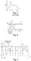
- FIG. 5is a waveform of an example of a drive current applied to a TSI in accordance with the teachings of the present invention
- FIGS. 6 and 7are diagrammatic illustrations of the motion of the plasma cloud of FIG. 4 in a TSI which is operated in accordance with the principles exemplified in the waveform of FIG. 5 ;
- FIG. 8is a simplified schematic circuit diagram for an example of an ignition drive circuit usable to generate a current drive waveform for a TSI as taught herein, including, for example, the waveform or drive signal of FIG. 5 ;
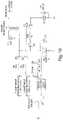
- FIG. 9is a simplified part-block, part schematic circuit diagram of another embodiment of an ignition circuit for generating an ignition drive to a TSI as taught herein;
- FIG. 10is a simplified part-block, part schematic circuit diagram of yet another embodiment of an ignition circuit for generating an ignition drive to a TSI as taught herein;
- FIG. 11is a simplified part-block, part schematic circuit diagram of a still further embodiment of an ignition circuit for generating an ignition drive to a TSI as taught herein.
- a method of operating an igniter in an internal combustion enginecomprising: applying a high voltage to electrodes of the igniter, said high voltage being of amplitude sufficient to cause electrical discharge breakdown to occur between the electrodes, in an initiation region (e.g., over a surface of an isolator) between the electrodes, resulting in a high current electrical discharge in the igniter, and formation of a plasma kernel in an air or fuel-air mixture adjacent said surface; and following breakdown, applying to said electrodes (preferably a simmer current) and a sequence of one or more lower voltage and lower current pulses, whereby the plasma kernel is forced to move toward a free end of said electrodes by said lower voltage, lower current pulses.
- a currentdesirably is maintained through the plasma kernel sufficient to prevent total recombination of the plasma.
- a currentneed not be maintained, if the intervals between breakdown and the first pulse of the sequence, and between additional follow-on pulses of the sequence, are sufficiently short, such that total recombination does not occur prior to the start of such pulses.
- the follow-on pulsecan be a relatively low current pulse (compared to a number of previous approaches, but still appreciable) and it will still provide a suitable Lorentz force to advance the plasma, and it will, itself, create a current arc that can move along the electrodes.
- recombinationcan be slowed by imposing a relatively high (but less than breakdown) voltage across the electrodes prior to the start of a follow-on pulse.
- All three mechanismsfacilitate the establishment of a moving plasma kernel without requiring re-generation of a high energy breakdown condition, reducing the tendency of the current path to “re-attach” to the electrodes at fixed locations.
- the number of follow-on pulsesvarying according to design requirements and/or operating conditions.
- the igniteris preferably a traveling spark igniter.
- a first pulse of the sequencefollows the breakdown discharge by an interval of from about 2 to about 100 microseconds, preferably from about 10 to about 20 microseconds, but this will depend on the recombination time for a plasma in the particular kind of fuel mixture being employed.
- each of said follow-on pulseshas a maximum amplitude of about 5-200 Amperes. But the amplitudes need not be uniform.
- said lower voltage, lower current pulseshave a maximum amplitude of about 25-105 Amperes, and more preferably about 40-80 Amperes.
- the pulsesmay have a duration of from about 2 to about 200 microseconds.
- Successive pulses in said sequencepreferably are separated by intervals of about 10-500 microseconds and even more preferably, 40-120 microseconds, but the intervals may not be uniform.
- each of said pulsestypically may have an amplitude of about 50-5000 V and, more preferably, about 300-500 V. All pulses need not have the same polarity of voltage or current; and neither the voltage nor the current in a pulse need be constant.
- the foregoing numbersare all representative only and are not intended to reflect any inherent limits on the invention. Other ranges may be employed in appropriate embodiments. These numbers may be useful, though, as an aid to identifying differences with other ignition systems and methods.
- an ignition circuitfor powering an igniter in an internal combustion engine, the circuit comprising means for providing a high voltage capable of causing a breakdown discharge, at a relatively high current (but preferably lower than prior TSI ignitions have used), between electrodes of an igniter, and in an initiation region (e.g., on or over a surface of an isolator which separates the electrodes), when said igniter is disposed in a fuel-air mixture, whereby a plasma kernel is formed adjacent said surface by said discharge; and means for providing a sequence of one or more relatively lower voltage and lower current follow-on pulses having voltage and current amplitude and timing sufficient to create Lorentz force pulses causing the plasma kernel to move toward a free end of said electrodes by said follow-on pulses.
- the means for providing a high voltage capable of causing breakdownmay include a high voltage, low inductance ignition coil having a primary winding and a secondary winding, the secondary winding having a lead for connection to one electrode of an igniter, and a circuit for triggering a signal in the primary winding to induce a high voltage pulse in the secondary winding.
- the means for providing a sequence of relatively lower voltage (i.e., sub-breakdown voltage) pulsesmay comprise a low voltage source and, for each said pulse, a capacitor charged by the low voltage source and a pulse transformer having a first winding connected to said lead and a second winding through which the capacitor is discharged in response to a trigger signal, inducing said pulse in said lead.
- the ignition circuitmay further include means for providing to the igniter, in an interval between the breakdown discharge and a first lower voltage pulse a simmer current sufficient to prevent total recombination of the plasma kernel in said interval. It also may include means for providing to the igniter, in an interval between successive follow-on pulses a simmer current sufficient to prevent total recombination of the plasma kernel in said interval.
- the means for providing a sequence of relatively low voltage pulsesincludes means for providing pulses separated in time by an interval sufficiently short that total recombination of the plasma kernel does not occur in said interval.
- the means for providing a sequence of relatively low voltage pulsesmay comprise a means for preceding each such follow-on pulse by a high, sub-breakdown voltage.
- an ignition circuitfor powering an igniter in an internal combustion engine, the circuit comprising a high voltage pulse generator which generates on an output for connection to an igniter a pulse whose maximum voltage, when delivered to the igniter, is capable causing a breakdown discharge, at a high current, in an initiation region between electrodes of the igniter (e.g., adjacent a surface of an isolator which separates the electrodes), when said igniter is disposed in a fuel-air mixture, whereby a plasma kernel is formed adjacent said surface by said discharge; and a low voltage pulse generator which generates on the output a sequence of one or more lower voltage and lower current pulses having voltage and current amplitude and timing sufficient to force the plasma kernel to move toward a free end of said electrodes by said lower voltage, lower current pulses.
- a high voltage pulse generatorwhich generates on an output for connection to an igniter a pulse whose maximum voltage, when delivered to the igniter, is capable causing a breakdown discharge, at a high current, in an initiation region between electrodes of
- the ignition circuitmay further include a simmer current source which supplies on the output, in an interval between the breakdown discharge and a first lower voltage pulse, a simmer current sufficient to prevent total recombination of the plasma kernel in said interval.
- the circuitmay include a follow-on pulse generator that supplies, on the output, follow-on pulses which follow each other so closely (i.e., are separated by a sufficiently short interval) that total recombination of the plasma does not occur in the interval between such pulses.
- the circuitmay include a pulse source providing a sequence of relatively low voltage pulses and a high voltage source which provides, preceding each such follow-on pulse, a sub-breakdown high voltage sufficient to delay total recombination such that total recombination has not occurred when the relatively low voltage pulse starts.
- a traveling spark igniteris an ignition device which is in the nature of a small plasma gun.
- a typical TSIis illustrated in FIG. 1 , taken from U.S. Pat. No. 6,321,733.
- An isolatore.g., ceramic
- a plasma 16is created along the surface of the isolator, due to a high voltage breakdown process occurring there.
- the discharge currentpasses through the plasma, the temperature and volume of the plasma increase, leading to a further decrease in plasma resistivity and resistance. This increases the current in the plasma, which is limited primarily by the impedance of the electrical discharge circuit that produces the current supplied to the igniter.
- FIG. 2A typical ignition circuit for operating a TSI is shown in FIG. 2 , which is also taken from U.S. Pat. No. 6,321,733.
- the circuitconsists of two main parts: (1) a conventional ignition system 42 and (2) a follow-on current generator comprising capacitors such as 46 and 48 , a low voltage power supply 44 and diode 50 .
- the conventional ignition system 42provides a high voltage for creating a breakdown (at a high current) in the spark gap along the isolator surface 56 between the electrodes 18 and 20 , to form an initial plasma in the gaseous combustion mixture near that surface.
- the follow-on current generatorprovides a current through the initial plasma, in the spark gap, after breakdown discharge, forming a much larger plasma volume.
- Resistor 54may (but need not) be used to limit the maximum current from capacitor 48 .
- a typical voltage discharge profile(not to scale) is shown in FIG. 3 , taken from U.S. Pat. No. 6,474,321.
- the following energy balance equationrelates the variables:
- V(t)is the voltage as a function of time, between the electrodes defining the discharge gap, such voltage having an initial value V t 2 at time t 2 and a final value V t 4 ⁇ 0 at t>t 4
- i(t)is the current in the spark gap as a function of time
- Cis the sum of the discharging capacitance (here, the sum of capacitances of capacitors 46 and 48 ).
- the net force available to move the plasmais the difference between the Lorentz force F L and the pressure force F p (assuming one can ignore the thermal force on the plasma as it is significant only at the earlier stages of plasma propagation and diminishes quickly as the plasma moves away from the isolator surface). It is useful to develop a model of the forces in order to understand how to overcome the pressure force.
- F pthe effective gas pressure from the combustion mixture (facing the plasma during its movement).
- the net force equationcan be simplified, and useful relationships derived from it, by making some rough assumptions.
- ⁇ ⁇ ⁇ t1 i 0 ⁇ ( 2 ⁇ l ⁇ ⁇ ⁇ p ⁇ ⁇ l ⁇ ⁇ ⁇ l l ⁇ ⁇ p ⁇ / ⁇ ⁇ 1 - p ⁇ / ⁇ ⁇ ⁇ ⁇ i 0 2 ) 1 ⁇ / ⁇ 2 From this equation, one observes that for relatively small pressure (i.e., p ⁇ i 0 2 ), ⁇ t i 0 ⁇ constant; and in this range of parameters, increasing i 0 leads to decreasing ⁇ t.
- the net plasma velocity along the electrodesis substantially zero and the plasma will seem to stay near the surface of the isolator during the entire discharge.
- the plasmaof course, recombines near the surface of the isolator, as well, though at a much slower rate because the gas there is much hotter than at the plasma's front edge. Consequently, plasma resistivity near the isolator surface is lower than at the front edge of the plasma and most of the discharge current will be concentrated in that region, preventing further plasma recombination near the isolator.
- the discharge currenthas to be raised, in order to increase the energy being fed into the plasma.
- the increased energy inputthough, is concentrated near the isolator. That is quite problematic. There are thermal stresses imposed on the isolator and shock waves are generated that can damage the isolator. There are also large thermal effects on the portions of the electrodes near the isolator. Assuming the ignition circuit supplies sufficient energy to create a net force that will effectively move the plasma, then the higher the pressure in the combustion chamber, the worse the negative effects on the isolator and electrodes. These conditions decrease isolator and electrode longevity in high pressure environments, unless something is done to prevent those negative impacts.
- the problem of decreasing longevity of traveling spark igniters with increasing gas (i.e., combustion mixture) pressureis significantly decreased, or even eliminated, at least in part by decreasing the difference between the speed of recombination at the front of the plasma (facing the combustion chamber) and the back of the plasma (facing the isolator). By making plasma recombination more symmetrical, a significant net force on the plasma is directed into the combustion chamber.
- FIG. 4diagrammatically illustrates the problem.
- a relatively short first current pulseforms a volume of plasma 42 , as indicated by the dashed line.
- the center of the plasmamoves to the right, away from isolator 14 , under the influence of the Lorentz force.
- the pulseis of relatively short duration, neither the isolator surface nor the gas near the surface is heated significantly. Therefore, after the first current pulse ends, the plasma recombines at its back (left) side and its front (right) side fairly symmetrically, leaving a relatively narrow plasma kernel 44 .
- the narrow plasma kernelstill can support an arc, as explained above.
- the present inventionimproves the symmetry of plasma recombination by using a different approach to energizing the igniter.
- Several short current discharge bursts(follow-on pulses) are applied after the breakdown pulse, between times t 2 and t 3 .
- the follow-on pulseshave moderately high peak current amplitude, but significantly less than the breakdown pulse.
- the (simmer) currentpreferably is maintained at a low, non-zero value, to prevent total recombination.
- FIG. 5in which the waveform is shown for one example of an igniter current that may be used to excite a TSI as explained above, breakdown occurs at time t 1 (peak voltage, followed by maximum current) and is complete at time t 1 *. Beginning at time t 2 , a series of (one or more) lower amplitude current pulses 52 A- 52 E (i.e., five pulses, in this example, though the number of pulses is variable) are provided between the electrodes of the igniter. The discharge interval ends at time t 3 , when the plasma reaches the end of the electrodes. The plasma started at the isolator at time t 1 . The durations ⁇ 1 , ⁇ 2 , . . .
- ⁇ n of the respective pulses 52 and their peak current magnitude, i 0should be chosen according to igniter design and gas pressure p.
- the pulse durations and magnitudesare selected, preferably, in accordance with the length of the electrodes and the gap between them. Experimentation is a satisfactory way, and for the moment probably the best way, of setting the values of those parameters for a given igniter design and maximum pressure of its operation.
- the time between pulsesalso depends on igniter design and pressure.
- the time between the breakdown current, when it reaches near-zero level at t 1 * and the first follow-on pulse 52 A, indicated as ⁇ t b,1depends on the breakdown voltage and the specifics of the isolator between the electrodes.
- the simmer current i sis non-zero and, as such, helps avoid total plasma recombination; otherwise, a large voltage (comparable to the breakdown voltage) would be needed for initiating the next pulse. So, the current i s facilitates each subsequence pulse and allows its formation without the need for an additional breakdown pulse.
- the following tableprovides parameter values which have been found useful with TSI igniters operating in a simulated combustion chamber at 400 psi pressure:
- the peak pulse values i 0 and pulse durations ⁇ k and the times between individual pulses ⁇ t k,k+1have been shown as constant, they need not be uniform or constant. For example, they could actually increase or decrease as a function of time.
- FIGS. 6 and 7diagrammatically illustrate the operation produced by this pulsed drive scheme. It is assumed the breakdown pulse has already occurred and the first follow-on pulse is in a position ⁇ 1 away from the surface of the isolator, as in FIG. 4 . After a time interval ⁇ t 1,2 following the first pulse, the next pulse ⁇ 2 occurs, after which the plasma is in a new position ⁇ 2 away from the surface of the isolator. With each successive pulse, the plasma kernel is moved to the right and then at the end of the pulse, allowed to recombine ( FIG. 6 , showing the plasma position after two pulses), until eventually ( FIG. 7 ) the plasma reaches the end of the electrodes after n current pulses, and is ejected into the combustion chamber.
- nThe number of follow-on pulses, n, will depend on the pressure p in chamber, igniter parameters (e.g., the length of the electrodes, the gap between the electrodes, and the shape of the electrodes) and current discharge parameters (e.g., peak values of pulses, their durations, the inter-pulse intervals, and minimum current value between pulses). Some experimentation may be required to find suitable values.
- igniter parameterse.g., the length of the electrodes, the gap between the electrodes, and the shape of the electrodes
- current discharge parameterse.g., peak values of pulses, their durations, the inter-pulse intervals, and minimum current value between pulses.
- the current pulsesare shown as positive pulses in FIG. 5 , it should be realized that negative pulses can also be used, or alternating pulses or some other pattern of pluralities.
- the Lorentz force F Lis proportional to the square of the current and is, therefore, independent of current polarity.
- the discharge current pulsesshown as rectangular in FIG. 5 , could have any suitable waveform, such as triangular shape or sinusoidal shape.
- the interval between the end of the breakdown current pulse and the first follow-on current pulse, ⁇ t b, t1depends on the peak value of the discharge current. Assuming that a resistor R b is used to achieve this current limiting effect, than the delay time depends on the value of that resistor, which depends on the applied breakdown voltage which, in turn, depends upon the pressure p. Thus, the value of resistor R b can be chosen to minimize stress on the isolator and electrode wear.
- FIG. 8shows a partial schematic circuit diagram for an example of an electronic circuit for producing the breakdown pulse and follow-on pulses as depicted in FIG. 5 .
- circuitryis shown for generating only the breakdown pulse and one follow-on pulse.
- the circuitry 110 enclosed in a dashed linecan be replicated and all such circuits can be connected with the secondary windings of their boost transformers 102 in series, so that each such circuit will, in turn, deliver one of the sequenced pulses to the igniter. (Note that a parallel arrangement is also possible.)
- a high voltage, for providing breakdown dischargeis generated by a high energy ignition coil 100 , triggered by a signal applied at 104 to cause switching of SCR 104 A.
- Coil 100may be any suitable ignition coil such as, but not limited to, coil model 8261 sold by Autotronic Controls Corporation of El Paso, Tex., d/b/a MSD Ignition. Though usually referred to in the industry as an “ignition coil,” element 100 actually is a transformer.
- the aforementioned model 8261 ignition coilhas a low inductance primary and provides a 42-43 kV output from its secondary coil when the primary coil is energized.
- the secondary coil of transformer 100is directly connected (through secondary coil 102 B of boost transformer 102 ) to one or more electrodes of igniter 101 , another electrode of which is grounded.
- the string 106 of diodeseach paralleled by a high resistance, limits the output voltage of the ignition coil 100 to a single polarity and prevents ringing.
- a trigger signalis applied at 105 to cause a follow-on pulse to be generated.
- the boost transformer 102feeds the high voltage line (HVL) to igniter 101 with a pulse of current induced by discharging capacitor 103 .
- Capacitor 103is charged to a relatively low voltage such as, for example, about 500V and then discharged through the primary coil 102 A of transformer 102 to ground through the SCR 105 A.
- the trigger signalscan be generated by any suitable circuit that may provide either fixed or programmable parameters.
- the igniter electrode(s) connected to the high voltage lineare also connected, through a string of diodes 107 , and an RC network 111 , to a low voltage supply, such as the indicated 500V supply.
- the resistor values in network 111are set to deliver the simmer current, i s
- the ignition circuit of FIG. 8represents just one way to generate the breakdown voltage and to deliver the initial current and the follow-on pulses of current that are desired. Any other suitable mechanism may be employed that generates comparable pulsing.
- a resonant current circuitthat could provide oscillating current pulses, such as sinusoidal current pulses, could be used instead of the indicated plurality of sub-circuits, each of which generates a single pulse.
- the circuit of FIG. 8could be used to generate negative pulses instead of positive pulses.
- FIG. 9Another example of an ignition circuit architecture (in simplified form) is shown in FIG. 9 at 130 . Only the basic circuit components are shown, it being understood that a practical implementation may require other customary components.
- Power supply 132supplies a voltage (termed the “high” voltage for purposes of distinguishing it, only). The voltage is high enough so that it can generate, when stepped up by transformer 134 , a breakdown voltage sufficient to create a plasma at the igniter (not shown).
- Power supplyis connected to a first end of primary winding 134 A through a diode 136 , to charge a capacitor 138 , connected between the other end of the primary winding and ground.
- a pulse generator 142supplies a train or sequence of pulses.
- Transformer 134is a saturable-core step-up transformer.
- the HV supply 132typically has an output voltage of a few hundred volts.
- the closing of switch 144generates a large voltage swing across the transformer primary.
- a turns ratio of about 1:35-1:40may be used in the transformer, and this will step up the several hundred volt swing on the primary up to the range of tens of thousands of volts across the secondary winding, 134 B.
- This latter voltageis sufficient to produce breakdown when applied to an igniter (connected to one end of the secondary winding, but not shown).
- the aforesaid pulsepreferably also saturates the core of transformer 134 .
- Capacitor 156is charged by a “low voltage” (LV) supply through a protective diode 164 .
- LVlow voltage
- Low Voltage supply 162may typically supply a voltage in the range of 0-1000 volts.
- Capacitor 156is a large capacitance in a typical ignition system and resistor 174 may be sized to limit the discharge current (pulled through the secondary winding 134 of the transformer) to about 50 Amperes (less if a lower current will suffice in the follow-on pulses).
- Diodes 182 and 184merely protect their respective switches from reverse polarity spikes that could be destructive to them.
- Supplies 132 and 162are shown as separate but a single supply may be used in some applications. Also, the terms low voltage and high voltage are not intended to require that the output of supply 132 be at a higher voltage than the output of supply 162 , though that is most typical.
- Diode 164is included for the same reason as diode 136 , to protect its associated power supply from having a short-circuited output when the associated switch is closed.
- the supplies 132 , 162it also may be desirable to place a resistance in series between the one or both of the supplies and corresponding switch 144 or 166 , as applicable, to limit the output current of the supply and the charging time of the corresponding capacitor.
- Switches 144 , 166may be implemented using various semiconductors, such as SCRs, IGBTs (especially for switch 144 ), MCTs and other high voltage switching elements as now or in the future may exist.
- a small capacitor, 159may bypass diode 158 , providing a low impedance path to ground for rapid voltage changes and protecting diode 158 against large reverse spikes.
- each switchmay be actuated by a different pulse generator, or one pulse generator may be employed with different outputs or differently conditioned output signals (possibly derived from a common signal) driving the switches.
- one switchmay be used, instead of two switches, as shown in FIG. 10 , referring to switching element (e.g., MCT) 186 .
- switching elemente.g., MCT
- the resistors Rare expressly shown though they may not be needed, depending on power supply details.
- different pulse generatorsdrive each of the switches, they can be controlled independently and this will permit a variety of modes of operation to be accommodated.
- resistor 174is shown in a dashed-line box, to indicate it is optional. Irrespective of the fact that supply 162 may be set in conjunction with capacitor 156 to control the desired amplitude of follow-on current pulses, all of the energy stored in capacitor 156 cannot be transferred to the arc. To sustain a current in the follow-on pulses over the interval of each pulse, the capacitor 156 must be discharged at a controlled rate. One way to do this is to discharge the capacitor through a resistor, such as resistor 174 . Unfortunately, the use of resistor 174 results in the dissipation of a lot of the stored energy as heat. Indeed, more energy may be lost as heat in resistor 156 than is expended in the movement of the plasma. Hence this circuit suffers from inefficient use of energy.
- the switch transistor(or like element) takes care of that need, providing controlled discharge. More specifically, as shown in FIG. 11 , an active switching element (here indicated as a MOSFET 166 ′), is connected from node 168 to ground through a resistor 192 . The voltage across that resistor is sensed as a proxy for measuring the actual current through transistor 166 ′.
- an active switching elementhere indicated as a MOSFET 166 ′
- Drive logic 194may be implemented in various ways and may include fixed logic or it may include programmable logic, possibly including a microcontroller to operate the logic. An advantage of using a microcontroller is that the logic can then be configured to operate the circuit to perform in the various modes discussed herein—e.g., with or without simmer current.
- pulses of positive polaritywill result from the illustrated examples of ignition circuits, those skilled in the art of electronics will readily be able to derive therefrom ignition circuits that will produce negative polarity pulses and even pulses of varied polarities, should it be desired to have same. It may also be desirable that some or all trigger pulses be o polarity differing from the output pulses.
- the detailed design of the drive logic and the parameters for the breakdown voltage, follow-on pulses, igniter, etc.will all depend on the particular engine specifications which the ignition system is required to meet. Those requirements, and considerations such as cost, component availability, and so forth will influence component selection, as well. Determination of some of these parameters may require a degree of experimentation on a model of the engine(s) for which the ignition system or circuit is intended.
Landscapes
- Engineering & Computer Science (AREA)
- Physics & Mathematics (AREA)
- Chemical & Material Sciences (AREA)
- Combustion & Propulsion (AREA)
- Mechanical Engineering (AREA)
- General Engineering & Computer Science (AREA)
- Plasma & Fusion (AREA)
- Spectroscopy & Molecular Physics (AREA)
- Optics & Photonics (AREA)
- Ignition Installations For Internal Combustion Engines (AREA)
- Spark Plugs (AREA)
- Plasma Technology (AREA)
Abstract
Description
where V(t) is the voltage as a function of time, between the electrodes defining the discharge gap, such voltage having an initial value Vt
Δt=CV0/2i0
This simple relationship provides information about pulse duration as a function of capacitance and average current i0during discharge, for a given operating (relatively low) voltage V0on the capacitors. For a given energy provided to the igniter (hence, given V0and C), this relationship teaches that for current i0to increase, the pulse duration Δt has to decrease. However, increasing current i0also increases the Lorentz force FL. Increasing the Lorentz force moves the plasma away from the isolator surface faster, toward the end of the electrodes, into the combustion chamber of the engine. Pressure in the combustion chamber, however, provides a countervailing pressure force Fpin the igniter. Force Fpworks against the Lorentz force preventing the speed of the plasma from increasing above some limiting value, independent of the length


(FL−Fp)=


where


(FL−Fp)Δt≈


where it was assumed that the initial plasma velocity θt

(αi02−p)Δt=


Because ½ Δt

From this equation, one observes that for relatively small pressure (i.e., p<<αi02), Δt i0≈constant; and in this range of parameters, increasing i0leads to decreasing Δt. Then from the above relationships, one can see that the plasma can be moved faster with increasing i0without really increasing the discharge energy (of course, this is only true for


- Electrode length:=2.5 mm

- Peak pulse current: i0≈20-40 Amperes,
- Duration of the k−pulse: τk10-20 microseconds,
- Time between two consecutive pulses k and k+1: Δtk,k+1≈50-100 microseconds,
- n (i.e., number of pulses)≈3 to 4,
- Simmer current: is≈1-3 Amperes,
- Time between end of breakdown and the first follow-on pulse: Δtb,1≈5-20 microseconds.
- Electrode length:
- i0≈60-80 Amperes,
- τk≈20-40 microseconds,
- Δtk,k+1≈30-40 microseconds,
- n≈7 to 10 pulses,
- is≈3-5 Amperes, and
- Δtb,1≈3-10 microseconds.


Claims (24)
Priority Applications (2)
| Application Number | Priority Date | Filing Date | Title |
|---|---|---|---|
| US16/826,123US11419204B2 (en) | 2005-04-19 | 2020-03-20 | Method and apparatus for operating traveling spark igniter at high pressure |
| US17/866,427US20230114936A1 (en) | 2005-04-19 | 2022-07-15 | Method and apparatus for operating traveling spark igniter at high pressure |
Applications Claiming Priority (10)
| Application Number | Priority Date | Filing Date | Title |
|---|---|---|---|
| US67289205P | 2005-04-19 | 2005-04-19 | |
| US11/407,850US7467612B2 (en) | 2005-04-19 | 2006-04-19 | Method and apparatus for operating traveling spark igniter at high pressure |
| US12/313,927US8186321B2 (en) | 2005-04-19 | 2008-11-26 | Method and apparatus for operating traveling spark igniter at high pressure |
| US13/222,298US8622041B2 (en) | 2005-04-19 | 2011-08-31 | Method and apparatus for operating traveling spark igniter at high pressure |
| US14/094,922US20140091712A1 (en) | 2005-04-19 | 2013-12-03 | Method and apparatus for operating traveling spark igniter at high pressure |
| US201514933938A | 2015-11-05 | 2015-11-05 | |
| US15/186,319US20160381779A1 (en) | 2005-04-19 | 2016-06-17 | Method and apparatus for operating traveling spark igniter at high pressure |
| US15/268,253US20170105275A1 (en) | 2005-04-19 | 2016-09-16 | Method and apparatus for operating traveling spark igniter at high pressure |
| US15/877,369US20180368247A1 (en) | 2005-04-19 | 2018-01-22 | Method and apparatus for operating traveling spark igniter at high pressure |
| US16/826,123US11419204B2 (en) | 2005-04-19 | 2020-03-20 | Method and apparatus for operating traveling spark igniter at high pressure |
Related Parent Applications (1)
| Application Number | Title | Priority Date | Filing Date |
|---|---|---|---|
| US15/877,369ContinuationUS20180368247A1 (en) | 2005-04-19 | 2018-01-22 | Method and apparatus for operating traveling spark igniter at high pressure |
Related Child Applications (1)
| Application Number | Title | Priority Date | Filing Date |
|---|---|---|---|
| US17/866,427ContinuationUS20230114936A1 (en) | 2005-04-19 | 2022-07-15 | Method and apparatus for operating traveling spark igniter at high pressure |
Publications (2)
| Publication Number | Publication Date |
|---|---|
| US20210059038A1 US20210059038A1 (en) | 2021-02-25 |
| US11419204B2true US11419204B2 (en) | 2022-08-16 |
Family
ID=36747126
Family Applications (12)
| Application Number | Title | Priority Date | Filing Date |
|---|---|---|---|
| US11/407,850Active2026-12-24US7467612B2 (en) | 2005-04-19 | 2006-04-19 | Method and apparatus for operating traveling spark igniter at high pressure |
| US12/313,927Active2026-08-25US8186321B2 (en) | 2005-04-19 | 2008-11-26 | Method and apparatus for operating traveling spark igniter at high pressure |
| US13/222,298ActiveUS8622041B2 (en) | 2005-04-19 | 2011-08-31 | Method and apparatus for operating traveling spark igniter at high pressure |
| US14/094,922AbandonedUS20140091712A1 (en) | 2005-04-19 | 2013-12-03 | Method and apparatus for operating traveling spark igniter at high pressure |
| US15/186,319AbandonedUS20160381779A1 (en) | 2005-04-19 | 2016-06-17 | Method and apparatus for operating traveling spark igniter at high pressure |
| US15/268,253AbandonedUS20170105275A1 (en) | 2005-04-19 | 2016-09-16 | Method and apparatus for operating traveling spark igniter at high pressure |
| US15/877,369AbandonedUS20180368247A1 (en) | 2005-04-19 | 2018-01-22 | Method and apparatus for operating traveling spark igniter at high pressure |
| US15/932,360AbandonedUS20180359844A1 (en) | 2005-04-19 | 2018-02-16 | Method and apparatus for operating traveling spark igniter at high pressure |
| US16/711,083AbandonedUS20200367352A1 (en) | 2005-04-19 | 2019-12-11 | Method and apparatus for operating traveling spark igniter at high pressure |
| US16/826,123ActiveUS11419204B2 (en) | 2005-04-19 | 2020-03-20 | Method and apparatus for operating traveling spark igniter at high pressure |
| US17/396,225ActiveUS12158132B2 (en) | 2005-04-19 | 2021-08-06 | Method and apparatus for operating traveling spark igniter at high pressure |
| US17/866,427PendingUS20230114936A1 (en) | 2005-04-19 | 2022-07-15 | Method and apparatus for operating traveling spark igniter at high pressure |
Family Applications Before (9)
| Application Number | Title | Priority Date | Filing Date |
|---|---|---|---|
| US11/407,850Active2026-12-24US7467612B2 (en) | 2005-04-19 | 2006-04-19 | Method and apparatus for operating traveling spark igniter at high pressure |
| US12/313,927Active2026-08-25US8186321B2 (en) | 2005-04-19 | 2008-11-26 | Method and apparatus for operating traveling spark igniter at high pressure |
| US13/222,298ActiveUS8622041B2 (en) | 2005-04-19 | 2011-08-31 | Method and apparatus for operating traveling spark igniter at high pressure |
| US14/094,922AbandonedUS20140091712A1 (en) | 2005-04-19 | 2013-12-03 | Method and apparatus for operating traveling spark igniter at high pressure |
| US15/186,319AbandonedUS20160381779A1 (en) | 2005-04-19 | 2016-06-17 | Method and apparatus for operating traveling spark igniter at high pressure |
| US15/268,253AbandonedUS20170105275A1 (en) | 2005-04-19 | 2016-09-16 | Method and apparatus for operating traveling spark igniter at high pressure |
| US15/877,369AbandonedUS20180368247A1 (en) | 2005-04-19 | 2018-01-22 | Method and apparatus for operating traveling spark igniter at high pressure |
| US15/932,360AbandonedUS20180359844A1 (en) | 2005-04-19 | 2018-02-16 | Method and apparatus for operating traveling spark igniter at high pressure |
| US16/711,083AbandonedUS20200367352A1 (en) | 2005-04-19 | 2019-12-11 | Method and apparatus for operating traveling spark igniter at high pressure |
Family Applications After (2)
| Application Number | Title | Priority Date | Filing Date |
|---|---|---|---|
| US17/396,225ActiveUS12158132B2 (en) | 2005-04-19 | 2021-08-06 | Method and apparatus for operating traveling spark igniter at high pressure |
| US17/866,427PendingUS20230114936A1 (en) | 2005-04-19 | 2022-07-15 | Method and apparatus for operating traveling spark igniter at high pressure |
Country Status (8)
| Country | Link |
|---|---|
| US (12) | US7467612B2 (en) |
| EP (3) | EP2426796B1 (en) |
| JP (1) | JP5377958B2 (en) |
| KR (1) | KR101250046B1 (en) |
| CN (1) | CN101218722B (en) |
| AT (1) | ATE535972T1 (en) |
| ES (1) | ES2968856T3 (en) |
| WO (1) | WO2006113850A1 (en) |
Cited By (2)
| Publication number | Priority date | Publication date | Assignee | Title |
|---|---|---|---|---|
| US20220030694A1 (en)* | 2005-04-19 | 2022-01-27 | Knite, Inc. | Method and apparatus for operating traveling spark igniter at high pressure |
| US11715935B2 (en) | 2011-07-26 | 2023-08-01 | Knite, Inc. | Traveling spark igniter |
Families Citing this family (46)
| Publication number | Priority date | Publication date | Assignee | Title |
|---|---|---|---|---|
| JP4967835B2 (en)* | 2006-12-20 | 2012-07-04 | 株式会社デンソー | Plasma ignition device |
| FR2913297B1 (en)* | 2007-03-01 | 2014-06-20 | Renault Sas | OPTIMIZING THE GENERATION OF A RADIO FREQUENCY IGNITION SPARK |
| WO2009008523A1 (en) | 2007-07-12 | 2009-01-15 | Imagineering, Inc. | Internal combustion engine |
| JP2009036123A (en)* | 2007-08-02 | 2009-02-19 | Nissan Motor Co Ltd | Non-equilibrium plasma discharge engine |
| US8783220B2 (en) | 2008-01-31 | 2014-07-22 | West Virginia University | Quarter wave coaxial cavity igniter for combustion engines |
| US8887683B2 (en)* | 2008-01-31 | 2014-11-18 | Plasma Igniter LLC | Compact electromagnetic plasma ignition device |
| JP4952641B2 (en)* | 2008-04-14 | 2012-06-13 | 株式会社デンソー | Ignition system for internal combustion engine |
| JP2011034953A (en)* | 2009-02-26 | 2011-02-17 | Ngk Insulators Ltd | Plasma igniter, and ignition device of internal combustion engine |
| JP5425575B2 (en)* | 2009-09-18 | 2014-02-26 | ダイハツ工業株式会社 | Method for determining the combustion state of a spark ignition internal combustion engine |
| DE102010015344B4 (en)* | 2010-04-17 | 2013-07-25 | Borgwarner Beru Systems Gmbh | A method for igniting a fuel-air mixture of a combustion chamber, in particular in an internal combustion engine by generating a corona discharge |
| US9181920B2 (en)* | 2011-04-04 | 2015-11-10 | Federal-Mogul Ignition Company | System and method for detecting arc formation in a corona discharge ignition system |
| US20130308245A1 (en)* | 2012-05-18 | 2013-11-21 | Honeywell International Inc. | Inductive start and capacitive sustain ignition exciter system |
| US9765750B2 (en) | 2012-11-29 | 2017-09-19 | Advanced Fuel And Ignition System Inc. | Multi-spark and continuous spark ignition module, system, and method |
| US9617965B2 (en)* | 2013-12-16 | 2017-04-11 | Transient Plasma Systems, Inc. | Repetitive ignition system for enhanced combustion |
| BR112016023543A2 (en) | 2014-04-08 | 2017-08-15 | Plasma Igniter Inc | dual signal coaxial cavity resonator plasma generator |
| US9828967B2 (en)* | 2015-06-05 | 2017-11-28 | Ming Zheng | System and method for elastic breakdown ignition via multipole high frequency discharge |
| CN105221319A (en)* | 2015-08-31 | 2016-01-06 | 中国科学院电工研究所 | A kind of for lighting a fire and the sliding discharge reactor of auxiliary combustion |
| US20170335801A1 (en) | 2016-05-20 | 2017-11-23 | Alphaport, Inc. | Spark Exciter Variable Control Unit |
| US10837369B2 (en) | 2017-08-23 | 2020-11-17 | General Electric Company | Igniter assembly for a gas turbine combustor |
| US12288673B2 (en) | 2017-11-29 | 2025-04-29 | COMET Technologies USA, Inc. | Retuning for impedance matching network control |
| US11290080B2 (en) | 2017-11-29 | 2022-03-29 | COMET Technologies USA, Inc. | Retuning for impedance matching network control |
| US20190186369A1 (en) | 2017-12-20 | 2019-06-20 | Plasma Igniter, LLC | Jet Engine with Plasma-assisted Combustion |
| US10995672B2 (en) | 2018-07-12 | 2021-05-04 | General Electric Company | Electrical waveform for gas turbine igniter |
| US10859058B1 (en) | 2019-01-31 | 2020-12-08 | Tom Rothenbuhler | Direct fuel injected spark igniter for internal combustion engines |
| US11114279B2 (en)* | 2019-06-28 | 2021-09-07 | COMET Technologies USA, Inc. | Arc suppression device for plasma processing equipment |
| US11527385B2 (en) | 2021-04-29 | 2022-12-13 | COMET Technologies USA, Inc. | Systems and methods for calibrating capacitors of matching networks |
| US11107661B2 (en) | 2019-07-09 | 2021-08-31 | COMET Technologies USA, Inc. | Hybrid matching network topology |
| US11596309B2 (en) | 2019-07-09 | 2023-03-07 | COMET Technologies USA, Inc. | Hybrid matching network topology |
| EP4022656A4 (en) | 2019-08-28 | 2023-10-04 | Comet Technologies USA, Inc | HIGH POWER LOW FREQUENCY COILS |
| US11830708B2 (en) | 2020-01-10 | 2023-11-28 | COMET Technologies USA, Inc. | Inductive broad-band sensors for electromagnetic waves |
| US11521832B2 (en) | 2020-01-10 | 2022-12-06 | COMET Technologies USA, Inc. | Uniformity control for radio frequency plasma processing systems |
| US12027351B2 (en) | 2020-01-10 | 2024-07-02 | COMET Technologies USA, Inc. | Plasma non-uniformity detection |
| US11887820B2 (en) | 2020-01-10 | 2024-01-30 | COMET Technologies USA, Inc. | Sector shunts for plasma-based wafer processing systems |
| US11670488B2 (en) | 2020-01-10 | 2023-06-06 | COMET Technologies USA, Inc. | Fast arc detecting match network |
| US11605527B2 (en) | 2020-01-20 | 2023-03-14 | COMET Technologies USA, Inc. | Pulsing control match network |
| US11961711B2 (en) | 2020-01-20 | 2024-04-16 | COMET Technologies USA, Inc. | Radio frequency match network and generator |
| US11373844B2 (en) | 2020-09-28 | 2022-06-28 | COMET Technologies USA, Inc. | Systems and methods for repetitive tuning of matching networks |
| US12057296B2 (en) | 2021-02-22 | 2024-08-06 | COMET Technologies USA, Inc. | Electromagnetic field sensing device |
| US11923175B2 (en) | 2021-07-28 | 2024-03-05 | COMET Technologies USA, Inc. | Systems and methods for variable gain tuning of matching networks |
| CN114109692B (en)* | 2021-11-26 | 2022-09-27 | 山东大学 | Fast pulse multipoint discharge system and engine combustion control method |
| CN114234940B (en)* | 2021-12-16 | 2023-08-15 | 国网四川省电力公司电力科学研究院 | Measurement system and method for tree line discharge basic data of high-voltage power line |
| US12243717B2 (en) | 2022-04-04 | 2025-03-04 | COMET Technologies USA, Inc. | Variable reactance device having isolated gate drive power supplies |
| US12040139B2 (en) | 2022-05-09 | 2024-07-16 | COMET Technologies USA, Inc. | Variable capacitor with linear impedance and high voltage breakdown |
| US11657980B1 (en) | 2022-05-09 | 2023-05-23 | COMET Technologies USA, Inc. | Dielectric fluid variable capacitor |
| US12051549B2 (en) | 2022-08-02 | 2024-07-30 | COMET Technologies USA, Inc. | Coaxial variable capacitor |
| US12132435B2 (en) | 2022-10-27 | 2024-10-29 | COMET Technologies USA, Inc. | Method for repeatable stepper motor homing |
Citations (79)
| Publication number | Priority date | Publication date | Assignee | Title |
|---|---|---|---|---|
| US3413518A (en) | 1967-01-31 | 1968-11-26 | Ass Elect Ind | Sliding spark ignition system with an inductance and capacitor in series with a three electrode spark plug |
| US3567987A (en) | 1968-06-06 | 1971-03-02 | Gerald L Schnurmacher | Spark plug construction |
| US3788293A (en) | 1972-11-10 | 1974-01-29 | Mcculloch Corp | Low impedance capacitor discharge system and method |
| US3842819A (en) | 1971-11-16 | 1974-10-22 | Ass Eng Ltd | Ignition devices |
| US3908146A (en) | 1972-12-11 | 1975-09-23 | Lacrex Brevetti Sa | Break ignition plug and ignition device |
| US4041922A (en) | 1974-07-08 | 1977-08-16 | Tokai Trw & Co. Ltd. | System and device for the ignition of an internal combustion engine using a lean air-fuel mixture |
| US4122816A (en) | 1976-04-01 | 1978-10-31 | The United States Of America As Represented By The Administrator Of The National Aeronautics And Space Administration | Plasma igniter for internal combustion engine |
| US4130101A (en) | 1975-07-24 | 1978-12-19 | Robert Bosch Gmbh | Transistorized ignition system for internal combustion engines |
| GB2073313A (en) | 1980-02-29 | 1981-10-14 | Nissan Motor | Plasma jet ignition system |
| GB2085076A (en) | 1980-09-18 | 1982-04-21 | Nissan Motor | Plasma ignition system |
| JPS57140567A (en) | 1981-02-23 | 1982-08-31 | Nissan Motor Co Ltd | Plasma ignition device for internal combustion engine |
| US4366801A (en) | 1980-09-18 | 1983-01-04 | Nissan Motor Company, Limited | Plasma ignition system |
| US4369756A (en) | 1980-01-11 | 1983-01-25 | Nissan Motor Co., Ltd. | Plasma jet ignition system for internal combustion engine |
| US4398526A (en) | 1980-07-31 | 1983-08-16 | Nissan Motor Company, Limited | Plasma ignition system for internal combustion engine |
| US4418660A (en) | 1981-04-07 | 1983-12-06 | Nissan Motor Company, Limited | Plasma ignition system using photothyristors for internal combustion engine |
| US4433669A (en) | 1981-06-12 | 1984-02-28 | Nissan Motor Company, Limited | Plasma ignition system for an internal combustion engine |
| US4448181A (en) | 1981-06-09 | 1984-05-15 | Nissan Motor Company, Limited | Plasma ignition system for an internal combustion engine |
| US4455989A (en) | 1981-06-16 | 1984-06-26 | Nissan Motor Company, Limited | Plasma ignition system for internal combustion engine |
| US4471732A (en) | 1983-07-20 | 1984-09-18 | Luigi Tozzi | Plasma jet ignition apparatus |
| US4487192A (en) | 1983-04-18 | 1984-12-11 | Ford Motor Co | Plasma jet ignition system |
| US4487177A (en) | 1982-03-23 | 1984-12-11 | Nissan Motor Company, Limited | Apparatus and method for starting a diesel engine using plasma ignition plugs |
| US4493297A (en) | 1982-09-27 | 1985-01-15 | Geo-Centers, Inc. | Plasma jet ignition device |
| US4677960A (en) | 1984-12-31 | 1987-07-07 | Combustion Electromagnetics, Inc. | High efficiency voltage doubling ignition coil for CD system producing pulsed plasma type ignition |
| WO1988004729A1 (en) | 1986-12-22 | 1988-06-30 | Combustion Electromagnetics, Inc. | Formation of electric field discharges |
| US4760341A (en) | 1985-11-27 | 1988-07-26 | Lucas Industries Public Limited Company | Method and apparatus for monitoring operation of a spark ignition device in a gas turbine engine |
| US4760820A (en) | 1983-07-20 | 1988-08-02 | Luigi Tozzi | Plasma jet ignition apparatus |
| US4766855A (en) | 1983-07-20 | 1988-08-30 | Cummins Engine Co., Inc. | Plasma jet ignition apparatus |
| US4774914A (en) | 1985-09-24 | 1988-10-04 | Combustion Electromagnetics, Inc. | Electromagnetic ignition--an ignition system producing a large size and intense capacitive and inductive spark with an intense electromagnetic field feeding the spark |
| US4795937A (en) | 1985-12-13 | 1989-01-03 | Beru Ruprecht Gmbh & Co. Kg | Spark plug with combined surface and air spark paths |
| US4805570A (en) | 1987-12-23 | 1989-02-21 | Brunswick Corporation | Multipoint spark ignition system |
| US4841925A (en) | 1986-12-22 | 1989-06-27 | Combustion Electromagnetics, Inc. | Enhanced flame ignition for hydrocarbon fuels |
| US4846129A (en) | 1988-02-09 | 1989-07-11 | Chrysler Motors Corporation | Ignition system improvements for internal combustion engines |
| US4893605A (en) | 1987-06-25 | 1990-01-16 | Mitsubishi Denki Kabushiki Kaisha | Ignition device for internal combustion engine |
| US4930473A (en) | 1988-12-09 | 1990-06-05 | Texas Ignitors Company, Inc. | Swirl chamber and spark plug assembly |
| US4996967A (en) | 1989-11-21 | 1991-03-05 | Cummins Engine Company, Inc. | Apparatus and method for generating a highly conductive channel for the flow of plasma current |
| US5007389A (en) | 1987-12-17 | 1991-04-16 | Ryohei Kashiwara | Ignition plug for internal combustion engines and a process for igniting gas mixture by the use thereof |
| WO1991015677A1 (en) | 1990-03-30 | 1991-10-17 | Board Of Regents, The University Of Texas System | Miniature railgun engine ignitor |
| US5131376A (en) | 1991-04-12 | 1992-07-21 | Combustion Electronics, Inc. | Distributorless capacitive discharge ignition system |
| US5187404A (en) | 1991-08-05 | 1993-02-16 | Cooper Industries, Inc. | Surface gap igniter |
| US5197448A (en) | 1991-08-23 | 1993-03-30 | Massachusetts Institute Of Technology | Dual energy ignition system |
| US5207208A (en) | 1991-09-06 | 1993-05-04 | Combustion Electromagnetics Inc. | Integrated converter high power CD ignition |
| US5211142A (en) | 1990-03-30 | 1993-05-18 | Board Of Regents, The University Of Texas System | Miniature railgun engine ignitor |
| WO1993010348A1 (en) | 1991-11-22 | 1993-05-27 | Ortech Corporation | Plasma-arc ignition system |
| US5215066A (en) | 1991-10-15 | 1993-06-01 | Mitsubishi Denki Kabushiki Kaisha | Ignition apparatus for an internal combustion engine |
| US5228425A (en) | 1991-01-04 | 1993-07-20 | Sylvan Simons | Ignition system for internal combustion engine |
| US5377633A (en) | 1993-07-12 | 1995-01-03 | Siemens Automotive L.P. | Railplug direct injector/ignitor assembly |
| US5423306A (en) | 1993-10-22 | 1995-06-13 | Trigger, Deceased; Vernon A. | Internal plasma-combustion engine system |
| US5429103A (en)* | 1991-09-18 | 1995-07-04 | Enox Technologies, Inc. | High performance ignition system |
| US5456241A (en) | 1993-05-25 | 1995-10-10 | Combustion Electromagnetics, Inc. | Optimized high power high energy ignition system |
| US5513605A (en) | 1994-08-22 | 1996-05-07 | Board Of Regents, The University Of Texas System | Cooled railplug |
| US5517961A (en) | 1995-02-27 | 1996-05-21 | Combustion Electromagnetics, Inc. | Engine with flow coupled spark discharge |
| US5555862A (en) | 1994-07-19 | 1996-09-17 | Cummins Engine Company, Inc. | Spark plug including magnetic field producing means for generating a variable length arc |
| US5564403A (en) | 1995-10-16 | 1996-10-15 | Caterpillar Inc. | Spark ignition system and spark plug for ultra lean fuel/air mixtures |
| US5619959A (en) | 1994-07-19 | 1997-04-15 | Cummins Engine Company, Inc. | Spark plug including magnetic field producing means for generating a variable length arc |
| US5704321A (en) | 1996-05-29 | 1998-01-06 | The Trustees Of Princeton University | Traveling spark ignition system |
| US5754011A (en) | 1995-07-14 | 1998-05-19 | Unison Industries Limited Partnership | Method and apparatus for controllably generating sparks in an ignition system or the like |
| US6131555A (en)* | 1998-04-20 | 2000-10-17 | Cummins Engine Company, Inc. | System for controlling ignition energy of an internal combustion engine |
| WO2001020160A1 (en) | 1999-09-15 | 2001-03-22 | Knite, Inc. | Long-life traveling spark ignitor and associated firing circuitry |
| US6321733B1 (en) | 1996-05-29 | 2001-11-27 | Knite, Inc. | Traveling spark ignition system and ignitor therefor |
| US20020170547A1 (en) | 2001-05-17 | 2002-11-21 | Altronic, Inc. | Capacitive discharge ignition system with extended duration spark |
| US6553981B1 (en) | 1999-06-16 | 2003-04-29 | Knite, Inc. | Dual-mode ignition system utilizing traveling spark ignitor |
| US6568362B2 (en) | 2001-06-12 | 2003-05-27 | Ut-Battelle, Llc | Rotating arc spark plug |
| US20030154954A1 (en) | 2000-06-03 | 2003-08-21 | Manfred Vogel | Method of ignition and corresponding ignition unit |
| US6662793B1 (en) | 1999-09-15 | 2003-12-16 | Knite, Inc. | Electronic circuits for plasma-generating devices |
| US6670777B1 (en) | 2002-06-28 | 2003-12-30 | Woodward Governor Company | Ignition system and method |
| US6729317B2 (en) | 2000-10-16 | 2004-05-04 | Jenbacher Aktiengesellschaft | Ignition system with an ignition coil |
| US20050000655A1 (en) | 2003-05-07 | 2005-01-06 | Soon-Im Wi | Inductive plasma chamber having multi discharge tube bridge |
| US20050000500A1 (en)* | 2001-11-29 | 2005-01-06 | Goede Simon Lucas | Combustion engine and ignition circuit for a combustion engine |
| US20050016511A1 (en) | 2003-07-23 | 2005-01-27 | Advanced Engine Management, Inc. | Capacitive discharge ignition system |
| US6924608B2 (en) | 2000-11-27 | 2005-08-02 | World Energy Systems Corporation | System and method for ignition and reignition of unstable electrical discharges |
| US20060137354A1 (en) | 2004-02-10 | 2006-06-29 | Ponziani Robert L | Passive, high-temperature amplifier for amplifying spark signals detected in igniter in gas turbine engine |
| US7121270B1 (en)* | 2005-08-29 | 2006-10-17 | Vimx Technologies Inc. | Spark generation method and ignition system using same |
| US20070062502A1 (en) | 2005-04-19 | 2007-03-22 | Suckewer Artur P | Method and apparatus for operating traveling spark igniter at high pressure |
| DE102006037039A1 (en) | 2006-08-08 | 2008-02-14 | Siemens Ag | High-frequency ignition device |
| US20080141967A1 (en) | 2006-12-19 | 2008-06-19 | Denso Corporation | Plasma ignition device |
| US7518085B1 (en) | 2003-05-30 | 2009-04-14 | Alameda Applied Sciences Corp. | Vacuum arc plasma thrusters with inductive energy storage driver |
| WO2009105273A1 (en) | 2008-02-22 | 2009-08-27 | Melvin Ehrlich | Plasma plug for an internal combustion engine |
| US7714488B2 (en) | 2005-11-22 | 2010-05-11 | Ngk Spark Plug. Co., Ltd. | Plasma jet spark plug and ignition system for the same |
| US20140232256A1 (en) | 2011-07-26 | 2014-08-21 | Knite, Inc. | Traveling spark igniter |
Family Cites Families (6)
| Publication number | Priority date | Publication date | Assignee | Title |
|---|---|---|---|---|
| US3394285A (en) | 1966-05-20 | 1968-07-23 | Donald E. Lindsay | Two-gap spark plug with series resistor for each gap |
| US6603245B1 (en) | 1988-09-23 | 2003-08-05 | Jay W. Fletcher | Three-dimensional multiple series gap spark plug |
| DE4331269C2 (en) | 1993-09-15 | 1995-07-13 | Bosch Gmbh Robert | Process for producing a spark plug with a spark gap and spark plugs produced by the process |
| US7098581B2 (en) | 2003-09-15 | 2006-08-29 | Cleeves James M | Spark plug |
| JP4669486B2 (en)* | 2006-03-22 | 2011-04-13 | 日本特殊陶業株式会社 | Plasma jet ignition plug and ignition system thereof |
| US10859058B1 (en) | 2019-01-31 | 2020-12-08 | Tom Rothenbuhler | Direct fuel injected spark igniter for internal combustion engines |
- 2006
- 2006-04-19WOPCT/US2006/014840patent/WO2006113850A1/enactiveApplication Filing
- 2006-04-19KRKR1020077026690Apatent/KR101250046B1/ennot_activeExpired - Fee Related
- 2006-04-19JPJP2008507856Apatent/JP5377958B2/enactiveActive
- 2006-04-19CNCN2006800220024Apatent/CN101218722B/enactiveActive
- 2006-04-19USUS11/407,850patent/US7467612B2/enactiveActive
- 2006-04-19ATAT06750792Tpatent/ATE535972T1/enactive
- 2006-04-19ESES14192645Tpatent/ES2968856T3/enactiveActive
- 2006-04-19EPEP11191178.0Apatent/EP2426796B1/enactiveActive
- 2006-04-19EPEP06750792Apatent/EP1878098B1/enactiveActive
- 2006-04-19EPEP14192645.1Apatent/EP2908393B1/enactiveActive
- 2008
- 2008-11-26USUS12/313,927patent/US8186321B2/enactiveActive
- 2011
- 2011-08-31USUS13/222,298patent/US8622041B2/enactiveActive
- 2013
- 2013-12-03USUS14/094,922patent/US20140091712A1/ennot_activeAbandoned
- 2016
- 2016-06-17USUS15/186,319patent/US20160381779A1/ennot_activeAbandoned
- 2016-09-16USUS15/268,253patent/US20170105275A1/ennot_activeAbandoned
- 2018
- 2018-01-22USUS15/877,369patent/US20180368247A1/ennot_activeAbandoned
- 2018-02-16USUS15/932,360patent/US20180359844A1/ennot_activeAbandoned
- 2019
- 2019-12-11USUS16/711,083patent/US20200367352A1/ennot_activeAbandoned
- 2020
- 2020-03-20USUS16/826,123patent/US11419204B2/enactiveActive
- 2021
- 2021-08-06USUS17/396,225patent/US12158132B2/enactiveActive
- 2022
- 2022-07-15USUS17/866,427patent/US20230114936A1/enactivePending
Patent Citations (100)
| Publication number | Priority date | Publication date | Assignee | Title |
|---|---|---|---|---|
| US3413518A (en) | 1967-01-31 | 1968-11-26 | Ass Elect Ind | Sliding spark ignition system with an inductance and capacitor in series with a three electrode spark plug |
| US3567987A (en) | 1968-06-06 | 1971-03-02 | Gerald L Schnurmacher | Spark plug construction |
| US3842819A (en) | 1971-11-16 | 1974-10-22 | Ass Eng Ltd | Ignition devices |
| US3788293A (en) | 1972-11-10 | 1974-01-29 | Mcculloch Corp | Low impedance capacitor discharge system and method |
| US3908146A (en) | 1972-12-11 | 1975-09-23 | Lacrex Brevetti Sa | Break ignition plug and ignition device |
| US4041922A (en) | 1974-07-08 | 1977-08-16 | Tokai Trw & Co. Ltd. | System and device for the ignition of an internal combustion engine using a lean air-fuel mixture |
| US4130101A (en) | 1975-07-24 | 1978-12-19 | Robert Bosch Gmbh | Transistorized ignition system for internal combustion engines |
| US4122816A (en) | 1976-04-01 | 1978-10-31 | The United States Of America As Represented By The Administrator Of The National Aeronautics And Space Administration | Plasma igniter for internal combustion engine |
| US4369756A (en) | 1980-01-11 | 1983-01-25 | Nissan Motor Co., Ltd. | Plasma jet ignition system for internal combustion engine |
| GB2073313A (en) | 1980-02-29 | 1981-10-14 | Nissan Motor | Plasma jet ignition system |
| US4398526A (en) | 1980-07-31 | 1983-08-16 | Nissan Motor Company, Limited | Plasma ignition system for internal combustion engine |
| US4369758A (en) | 1980-09-18 | 1983-01-25 | Nissan Motor Company, Limited | Plasma ignition system |
| GB2085076A (en) | 1980-09-18 | 1982-04-21 | Nissan Motor | Plasma ignition system |
| US4366801A (en) | 1980-09-18 | 1983-01-04 | Nissan Motor Company, Limited | Plasma ignition system |
| JPS57140567A (en) | 1981-02-23 | 1982-08-31 | Nissan Motor Co Ltd | Plasma ignition device for internal combustion engine |
| US4418660A (en) | 1981-04-07 | 1983-12-06 | Nissan Motor Company, Limited | Plasma ignition system using photothyristors for internal combustion engine |
| US4448181A (en) | 1981-06-09 | 1984-05-15 | Nissan Motor Company, Limited | Plasma ignition system for an internal combustion engine |
| US4433669A (en) | 1981-06-12 | 1984-02-28 | Nissan Motor Company, Limited | Plasma ignition system for an internal combustion engine |
| US4455989A (en) | 1981-06-16 | 1984-06-26 | Nissan Motor Company, Limited | Plasma ignition system for internal combustion engine |
| US4487177A (en) | 1982-03-23 | 1984-12-11 | Nissan Motor Company, Limited | Apparatus and method for starting a diesel engine using plasma ignition plugs |
| US4493297A (en) | 1982-09-27 | 1985-01-15 | Geo-Centers, Inc. | Plasma jet ignition device |
| US4487192A (en) | 1983-04-18 | 1984-12-11 | Ford Motor Co | Plasma jet ignition system |
| US4471732A (en) | 1983-07-20 | 1984-09-18 | Luigi Tozzi | Plasma jet ignition apparatus |
| US4760820A (en) | 1983-07-20 | 1988-08-02 | Luigi Tozzi | Plasma jet ignition apparatus |
| US4766855A (en) | 1983-07-20 | 1988-08-30 | Cummins Engine Co., Inc. | Plasma jet ignition apparatus |
| US4677960A (en) | 1984-12-31 | 1987-07-07 | Combustion Electromagnetics, Inc. | High efficiency voltage doubling ignition coil for CD system producing pulsed plasma type ignition |
| US4774914A (en) | 1985-09-24 | 1988-10-04 | Combustion Electromagnetics, Inc. | Electromagnetic ignition--an ignition system producing a large size and intense capacitive and inductive spark with an intense electromagnetic field feeding the spark |
| US4760341A (en) | 1985-11-27 | 1988-07-26 | Lucas Industries Public Limited Company | Method and apparatus for monitoring operation of a spark ignition device in a gas turbine engine |
| US4795937A (en) | 1985-12-13 | 1989-01-03 | Beru Ruprecht Gmbh & Co. Kg | Spark plug with combined surface and air spark paths |
| WO1988004729A1 (en) | 1986-12-22 | 1988-06-30 | Combustion Electromagnetics, Inc. | Formation of electric field discharges |
| US4841925A (en) | 1986-12-22 | 1989-06-27 | Combustion Electromagnetics, Inc. | Enhanced flame ignition for hydrocarbon fuels |
| US4893605A (en) | 1987-06-25 | 1990-01-16 | Mitsubishi Denki Kabushiki Kaisha | Ignition device for internal combustion engine |
| US5007389A (en) | 1987-12-17 | 1991-04-16 | Ryohei Kashiwara | Ignition plug for internal combustion engines and a process for igniting gas mixture by the use thereof |
| US4805570A (en) | 1987-12-23 | 1989-02-21 | Brunswick Corporation | Multipoint spark ignition system |
| US4846129A (en) | 1988-02-09 | 1989-07-11 | Chrysler Motors Corporation | Ignition system improvements for internal combustion engines |
| US4930473A (en) | 1988-12-09 | 1990-06-05 | Texas Ignitors Company, Inc. | Swirl chamber and spark plug assembly |
| US4996967A (en) | 1989-11-21 | 1991-03-05 | Cummins Engine Company, Inc. | Apparatus and method for generating a highly conductive channel for the flow of plasma current |
| US5076223A (en) | 1990-03-30 | 1991-12-31 | Board Of Regents, The University Of Texas System | Miniature railgun engine ignitor |
| WO1991015677A1 (en) | 1990-03-30 | 1991-10-17 | Board Of Regents, The University Of Texas System | Miniature railgun engine ignitor |
| US5211142A (en) | 1990-03-30 | 1993-05-18 | Board Of Regents, The University Of Texas System | Miniature railgun engine ignitor |
| US5228425A (en) | 1991-01-04 | 1993-07-20 | Sylvan Simons | Ignition system for internal combustion engine |
| US5131376A (en) | 1991-04-12 | 1992-07-21 | Combustion Electronics, Inc. | Distributorless capacitive discharge ignition system |
| US5187404A (en) | 1991-08-05 | 1993-02-16 | Cooper Industries, Inc. | Surface gap igniter |
| US5197448A (en) | 1991-08-23 | 1993-03-30 | Massachusetts Institute Of Technology | Dual energy ignition system |
| US5207208A (en) | 1991-09-06 | 1993-05-04 | Combustion Electromagnetics Inc. | Integrated converter high power CD ignition |
| US5429103A (en)* | 1991-09-18 | 1995-07-04 | Enox Technologies, Inc. | High performance ignition system |
| US5215066A (en) | 1991-10-15 | 1993-06-01 | Mitsubishi Denki Kabushiki Kaisha | Ignition apparatus for an internal combustion engine |
| WO1993010348A1 (en) | 1991-11-22 | 1993-05-27 | Ortech Corporation | Plasma-arc ignition system |
| US5456241A (en) | 1993-05-25 | 1995-10-10 | Combustion Electromagnetics, Inc. | Optimized high power high energy ignition system |
| US5377633A (en) | 1993-07-12 | 1995-01-03 | Siemens Automotive L.P. | Railplug direct injector/ignitor assembly |
| US5423306A (en) | 1993-10-22 | 1995-06-13 | Trigger, Deceased; Vernon A. | Internal plasma-combustion engine system |
| US5555862A (en) | 1994-07-19 | 1996-09-17 | Cummins Engine Company, Inc. | Spark plug including magnetic field producing means for generating a variable length arc |
| US5619959A (en) | 1994-07-19 | 1997-04-15 | Cummins Engine Company, Inc. | Spark plug including magnetic field producing means for generating a variable length arc |
| US5513605A (en) | 1994-08-22 | 1996-05-07 | Board Of Regents, The University Of Texas System | Cooled railplug |
| US5517961A (en) | 1995-02-27 | 1996-05-21 | Combustion Electromagnetics, Inc. | Engine with flow coupled spark discharge |
| US5754011A (en) | 1995-07-14 | 1998-05-19 | Unison Industries Limited Partnership | Method and apparatus for controllably generating sparks in an ignition system or the like |
| US7095181B2 (en) | 1995-07-14 | 2006-08-22 | Unsion Industries | Method and apparatus for controllably generating sparks in an ignition system or the like |
| US5564403A (en) | 1995-10-16 | 1996-10-15 | Caterpillar Inc. | Spark ignition system and spark plug for ultra lean fuel/air mixtures |
| US6321733B1 (en) | 1996-05-29 | 2001-11-27 | Knite, Inc. | Traveling spark ignition system and ignitor therefor |
| US5704321A (en) | 1996-05-29 | 1998-01-06 | The Trustees Of Princeton University | Traveling spark ignition system |
| US6131542A (en) | 1996-05-29 | 2000-10-17 | Knite, Inc. | High efficiency traveling spark ignition system and ignitor therefor |
| US6131555A (en)* | 1998-04-20 | 2000-10-17 | Cummins Engine Company, Inc. | System for controlling ignition energy of an internal combustion engine |
| US6553981B1 (en) | 1999-06-16 | 2003-04-29 | Knite, Inc. | Dual-mode ignition system utilizing traveling spark ignitor |
| US6474321B1 (en) | 1999-09-15 | 2002-11-05 | Knite, Inc. | Long-life traveling spark ignitor and associated firing circuitry |
| US6662793B1 (en) | 1999-09-15 | 2003-12-16 | Knite, Inc. | Electronic circuits for plasma-generating devices |
| WO2001020160A1 (en) | 1999-09-15 | 2001-03-22 | Knite, Inc. | Long-life traveling spark ignitor and associated firing circuitry |
| US20030154954A1 (en) | 2000-06-03 | 2003-08-21 | Manfred Vogel | Method of ignition and corresponding ignition unit |
| US6814047B2 (en) | 2000-06-30 | 2004-11-09 | Robert Bosch Gmbh | Method of ignition and corresponding ignition unit |
| US6729317B2 (en) | 2000-10-16 | 2004-05-04 | Jenbacher Aktiengesellschaft | Ignition system with an ignition coil |
| US6924608B2 (en) | 2000-11-27 | 2005-08-02 | World Energy Systems Corporation | System and method for ignition and reignition of unstable electrical discharges |
| US20020170547A1 (en) | 2001-05-17 | 2002-11-21 | Altronic, Inc. | Capacitive discharge ignition system with extended duration spark |
| US6568362B2 (en) | 2001-06-12 | 2003-05-27 | Ut-Battelle, Llc | Rotating arc spark plug |
| US20050000500A1 (en)* | 2001-11-29 | 2005-01-06 | Goede Simon Lucas | Combustion engine and ignition circuit for a combustion engine |
| US6670777B1 (en) | 2002-06-28 | 2003-12-30 | Woodward Governor Company | Ignition system and method |
| US20050000655A1 (en) | 2003-05-07 | 2005-01-06 | Soon-Im Wi | Inductive plasma chamber having multi discharge tube bridge |
| US7518085B1 (en) | 2003-05-30 | 2009-04-14 | Alameda Applied Sciences Corp. | Vacuum arc plasma thrusters with inductive energy storage driver |
| US20050016511A1 (en) | 2003-07-23 | 2005-01-27 | Advanced Engine Management, Inc. | Capacitive discharge ignition system |
| US20060137354A1 (en) | 2004-02-10 | 2006-06-29 | Ponziani Robert L | Passive, high-temperature amplifier for amplifying spark signals detected in igniter in gas turbine engine |
| US7467612B2 (en) | 2005-04-19 | 2008-12-23 | Knite, Inc. | Method and apparatus for operating traveling spark igniter at high pressure |
| US8622041B2 (en)* | 2005-04-19 | 2014-01-07 | Knite, Inc. | Method and apparatus for operating traveling spark igniter at high pressure |
| US20200367352A1 (en) | 2005-04-19 | 2020-11-19 | Knite, Inc. | Method and apparatus for operating traveling spark igniter at high pressure |
| US20170105275A1 (en) | 2005-04-19 | 2017-04-13 | Knite, Inc. | Method and apparatus for operating traveling spark igniter at high pressure |
| US20070062502A1 (en) | 2005-04-19 | 2007-03-22 | Suckewer Artur P | Method and apparatus for operating traveling spark igniter at high pressure |
| US20090194513A1 (en) | 2005-04-19 | 2009-08-06 | Knite, Inc. | Method and apparatus for operating traveling spark igniter at high pressure |
| US20180368247A1 (en) | 2005-04-19 | 2018-12-20 | Knite, Inc. | Method and apparatus for operating traveling spark igniter at high pressure |
| US20160381779A1 (en) | 2005-04-19 | 2016-12-29 | Knite, Inc. | Method and apparatus for operating traveling spark igniter at high pressure |
| US20110309749A1 (en) | 2005-04-19 | 2011-12-22 | Knite, Inc. | Method and apparatus for operating traveling spark igniter at high pressure |
| US8186321B2 (en) | 2005-04-19 | 2012-05-29 | Knite, Inc. | Method and apparatus for operating traveling spark igniter at high pressure |
| US20220030694A1 (en) | 2005-04-19 | 2022-01-27 | Knite, Inc. | Method and apparatus for operating traveling spark igniter at high pressure |
| US20140091712A1 (en) | 2005-04-19 | 2014-04-03 | Knite, Inc. | Method and apparatus for operating traveling spark igniter at high pressure |
| US20180359844A1 (en) | 2005-04-19 | 2018-12-13 | Knite, Inc. | Method and apparatus for operating traveling spark igniter at high pressure |
| US7121270B1 (en)* | 2005-08-29 | 2006-10-17 | Vimx Technologies Inc. | Spark generation method and ignition system using same |
| US7714488B2 (en) | 2005-11-22 | 2010-05-11 | Ngk Spark Plug. Co., Ltd. | Plasma jet spark plug and ignition system for the same |
| DE102006037039A1 (en) | 2006-08-08 | 2008-02-14 | Siemens Ag | High-frequency ignition device |
| US20080141967A1 (en) | 2006-12-19 | 2008-06-19 | Denso Corporation | Plasma ignition device |
| WO2009105273A1 (en) | 2008-02-22 | 2009-08-27 | Melvin Ehrlich | Plasma plug for an internal combustion engine |
| US20170085059A1 (en) | 2011-07-26 | 2017-03-23 | Knite, Inc. | Traveling spark igniter |
| US20140232256A1 (en) | 2011-07-26 | 2014-08-21 | Knite, Inc. | Traveling spark igniter |
| US20190027903A1 (en) | 2011-07-26 | 2019-01-24 | Knite, Inc. | Traveling spark igniter |
| US20200373742A1 (en) | 2011-07-26 | 2020-11-26 | Knite, Inc. | Traveling spark igniter |
Non-Patent Citations (6)
| Title |
|---|
| International Search Report and Written Opinion for International Application No. PCT/US2006/014840 dated Aug. 8, 2006. |
| International Search Report and Written Opinion for International Application No. PCT/US2012/048423 dated Dec. 20, 2012. |
| PCT/US2006/014840, dated Aug. 8, 2006, International Search Report and Written Opinion. |
| PCT/US2012/048423, dated Dec. 20, 2012, International Search Report and Written Opinion. |
| U.S. Appl. No. 17/368,515, filed Jul. 6, 2021, Suckewer. |
| U.S. Appl. No. 17/396,225, filed Aug. 6, 2021, Suckewer et al. |
Cited By (3)
| Publication number | Priority date | Publication date | Assignee | Title |
|---|---|---|---|---|
| US20220030694A1 (en)* | 2005-04-19 | 2022-01-27 | Knite, Inc. | Method and apparatus for operating traveling spark igniter at high pressure |
| US12158132B2 (en)* | 2005-04-19 | 2024-12-03 | Knite, Inc. | Method and apparatus for operating traveling spark igniter at high pressure |
| US11715935B2 (en) | 2011-07-26 | 2023-08-01 | Knite, Inc. | Traveling spark igniter |
Also Published As
| Publication number | Publication date |
|---|---|
| EP2908393A3 (en) | 2015-12-16 |
| JP5377958B2 (en) | 2013-12-25 |
| US7467612B2 (en) | 2008-12-23 |
| JP2008537061A (en) | 2008-09-11 |
| CN101218722A (en) | 2008-07-09 |
| EP2426796A3 (en) | 2013-03-20 |
| EP2908393A2 (en) | 2015-08-19 |
| US20200367352A1 (en) | 2020-11-19 |
| US20230114936A1 (en) | 2023-04-13 |
| US20070062502A1 (en) | 2007-03-22 |
| US20180368247A1 (en) | 2018-12-20 |
| US20160381779A1 (en) | 2016-12-29 |
| US20090194513A1 (en) | 2009-08-06 |
| EP2426796B1 (en) | 2014-11-12 |
| WO2006113850A1 (en) | 2006-10-26 |
| KR101250046B1 (en) | 2013-04-03 |
| ATE535972T1 (en) | 2011-12-15 |
| KR20080017314A (en) | 2008-02-26 |
| US20140091712A1 (en) | 2014-04-03 |
| US12158132B2 (en) | 2024-12-03 |
| US8622041B2 (en) | 2014-01-07 |
| ES2968856T3 (en) | 2024-05-14 |
| CN101218722B (en) | 2011-11-30 |
| US20170105275A1 (en) | 2017-04-13 |
| US8186321B2 (en) | 2012-05-29 |
| US20110309749A1 (en) | 2011-12-22 |
| EP2908393B1 (en) | 2023-10-04 |
| EP1878098A1 (en) | 2008-01-16 |
| US20210059038A1 (en) | 2021-02-25 |
| EP1878098B1 (en) | 2011-11-30 |
| US20180359844A1 (en) | 2018-12-13 |
| US20220030694A1 (en) | 2022-01-27 |
| EP2426796A2 (en) | 2012-03-07 |
Similar Documents
| Publication | Publication Date | Title |
|---|---|---|
| US11419204B2 (en) | Method and apparatus for operating traveling spark igniter at high pressure | |
| JP4240225B2 (en) | Ignition system and method for generating and sustaining a corona discharge for igniting a combustible gas mixture | |
| US4589398A (en) | Combustion initiation system employing hard discharge ignition | |
| KR101922545B1 (en) | Corona ignition system having selective enhanced arc formation | |
| JP5474120B2 (en) | Ignition device and ignition method for internal combustion engine | |
| JP3036735B2 (en) | Discharge ignition device for burner and discharge ignition method for fuel injection burner | |
| US20050000500A1 (en) | Combustion engine and ignition circuit for a combustion engine | |
| Chan et al. | Ignition System Designed to Extend the Plug Life, and the Lean Limit in a Natural Gas Engine |
Legal Events
| Date | Code | Title | Description |
|---|---|---|---|
| FEPP | Fee payment procedure | Free format text:ENTITY STATUS SET TO UNDISCOUNTED (ORIGINAL EVENT CODE: BIG.); ENTITY STATUS OF PATENT OWNER: SMALL ENTITY | |
| FEPP | Fee payment procedure | Free format text:ENTITY STATUS SET TO SMALL (ORIGINAL EVENT CODE: SMAL); ENTITY STATUS OF PATENT OWNER: SMALL ENTITY | |
| AS | Assignment | Owner name:KNITE, INC., NEW JERSEY Free format text:ASSIGNMENT OF ASSIGNORS INTEREST;ASSIGNORS:SUCKEWER, ARTUR P.;SUCKEWER, SZYMON;SELMON, FREDERICK H., III;SIGNING DATES FROM 20140325 TO 20140327;REEL/FRAME:054768/0686 | |
| STPP | Information on status: patent application and granting procedure in general | Free format text:DOCKETED NEW CASE - READY FOR EXAMINATION | |
| STPP | Information on status: patent application and granting procedure in general | Free format text:NON FINAL ACTION MAILED | |
| STPP | Information on status: patent application and granting procedure in general | Free format text:RESPONSE TO NON-FINAL OFFICE ACTION ENTERED AND FORWARDED TO EXAMINER | |
| STPP | Information on status: patent application and granting procedure in general | Free format text:FINAL REJECTION MAILED | |
| STPP | Information on status: patent application and granting procedure in general | Free format text:DOCKETED NEW CASE - READY FOR EXAMINATION | |
| STPP | Information on status: patent application and granting procedure in general | Free format text:NOTICE OF ALLOWANCE MAILED -- APPLICATION RECEIVED IN OFFICE OF PUBLICATIONS | |
| STPP | Information on status: patent application and granting procedure in general | Free format text:AWAITING TC RESP., ISSUE FEE NOT PAID | |
| STPP | Information on status: patent application and granting procedure in general | Free format text:NOTICE OF ALLOWANCE MAILED -- APPLICATION RECEIVED IN OFFICE OF PUBLICATIONS | |
| STPP | Information on status: patent application and granting procedure in general | Free format text:NOTICE OF ALLOWANCE MAILED -- APPLICATION RECEIVED IN OFFICE OF PUBLICATIONS | |
| STPP | Information on status: patent application and granting procedure in general | Free format text:NOTICE OF ALLOWANCE MAILED -- APPLICATION RECEIVED IN OFFICE OF PUBLICATIONS | |
| STPP | Information on status: patent application and granting procedure in general | Free format text:PUBLICATIONS -- ISSUE FEE PAYMENT VERIFIED | |
| STCF | Information on status: patent grant | Free format text:PATENTED CASE | |
| AS | Assignment | Owner name:CHAMPION AEROSPACE LLC, SOUTH CAROLINA Free format text:ASSIGNMENT OF ASSIGNORS INTEREST;ASSIGNOR:KNITE INC.;REEL/FRAME:071183/0378 Effective date:20240927 | |
| AS | Assignment | Owner name:GOLDMAN SACHS BANK USA, AS AGENT, NEW YORK Free format text:SECURITY INTEREST;ASSIGNORS:ADAMS RITE AEROSPACE, INC.;AEROSONIC LLC;AIRBORNE SYSTEMS NA INC.;AND OTHERS;REEL/FRAME:072167/0457 Effective date:20250903 | |
| AS | Assignment | Owner name:THE BANK OF NEW YORK MELLON TRUST COMPANY, N.A., ILLINOIS Free format text:SECURITY INTEREST;ASSIGNORS:ADAMS RITE AEROSPACE, INC.;AEROSONIC LLC;AIRBORNE SYSTEMS NA INC;AND OTHERS;SIGNING DATES FROM 20250902 TO 20250905;REEL/FRAME:072267/0935 Owner name:THE BANK OF NEW YORK MELLON TRUST COMPANY, N.A., ILLINOIS Free format text:SECURITY INTEREST;ASSIGNORS:ADAMS RITE AEROSPACE, INC.;AEROSONIC LLC;AIRBORNE SYSTEMS NA INC;AND OTHERS;SIGNING DATES FROM 20250902 TO 20250905;REEL/FRAME:072267/0977 Owner name:THE BANK OF NEW YORK MELLON TRUST COMPANY, N.A., ILLINOIS Free format text:SECURITY INTEREST;ASSIGNORS:ADAMS RITE AEROSPACE, INC.;AEROSONIC LLC;AIRBORNE SYSTEMS NA INC;AND OTHERS;SIGNING DATES FROM 20250902 TO 20250905;REEL/FRAME:072268/0176 Owner name:THE BANK OF NEW YORK MELLON TRUST COMPANY, N.A., ILLINOIS Free format text:SECURITY INTEREST;ASSIGNORS:ADAMS RITE AEROSPACE, INC.;AEROSONIC LLC;AIRBORNE SYSTEMS NA INC;AND OTHERS;SIGNING DATES FROM 20250902 TO 20250905;REEL/FRAME:072268/0018 Owner name:THE BANK OF NEW YORK MELLON TRUST COMPANY, N.A., ILLINOIS Free format text:SECURITY INTEREST;ASSIGNORS:ADAMS RITE AEROSPACE, INC.;AEROSONIC LLC;AIRBORNE SYSTEMS NA INC;AND OTHERS;SIGNING DATES FROM 20250902 TO 20250905;REEL/FRAME:072268/0193 Owner name:THE BANK OF NEW YORK MELLON TRUST COMPANY, N.A., ILLINOIS Free format text:SECURITY INTEREST;ASSIGNORS:ADAMS RITE AEROSPACE, INC.;AEROSONIC LLC;AIRBORNE SYSTEMS NA INC;AND OTHERS;SIGNING DATES FROM 20250902 TO 20250905;REEL/FRAME:072268/0030 |