US11418719B2 - Dual sensor imaging system and calibration method which includes a color sensor and an infrared ray sensor to perform image alignment and brightness matching - Google Patents
Dual sensor imaging system and calibration method which includes a color sensor and an infrared ray sensor to perform image alignment and brightness matchingDownload PDFInfo
- Publication number
- US11418719B2 US11418719B2US17/191,701US202117191701AUS11418719B2US 11418719 B2US11418719 B2US 11418719B2US 202117191701 AUS202117191701 AUS 202117191701AUS 11418719 B2US11418719 B2US 11418719B2
- Authority
- US
- United States
- Prior art keywords
- image
- color
- sensor
- test image
- brightness
- Prior art date
- Legal status (The legal status is an assumption and is not a legal conclusion. Google has not performed a legal analysis and makes no representation as to the accuracy of the status listed.)
- Active
Links
- 238000003384imaging methodMethods0.000titleclaimsabstractdescription89
- 230000009977dual effectEffects0.000titleclaimsabstractdescription55
- 238000000034methodMethods0.000titleclaimsabstractdescription41
- 238000004590computer programMethods0.000claimsabstractdescription6
- 238000004422calculation algorithmMethods0.000claimsdescription19
- 238000001514detection methodMethods0.000claimsdescription10
- 230000009466transformationEffects0.000claimsdescription9
- 239000011159matrix materialSubstances0.000claimsdescription6
- 230000003287optical effectEffects0.000claimsdescription3
- 238000010586diagramMethods0.000description6
- 230000000295complement effectEffects0.000description2
- 230000006870functionEffects0.000description2
- 238000004519manufacturing processMethods0.000description2
- 206010034960PhotophobiaDiseases0.000description1
- 206010034972Photosensitivity reactionDiseases0.000description1
- 230000004075alterationEffects0.000description1
- 230000008901benefitEffects0.000description1
- 238000004364calculation methodMethods0.000description1
- 238000005516engineering processMethods0.000description1
- 230000004927fusionEffects0.000description1
- 208000013469light sensitivityDiseases0.000description1
- 229910044991metal oxideInorganic materials0.000description1
- 150000004706metal oxidesChemical class0.000description1
- 230000036211photosensitivityEffects0.000description1
- 230000008569processEffects0.000description1
- 239000004065semiconductorSubstances0.000description1
Images


Classifications
- G—PHYSICS
- G03—PHOTOGRAPHY; CINEMATOGRAPHY; ANALOGOUS TECHNIQUES USING WAVES OTHER THAN OPTICAL WAVES; ELECTROGRAPHY; HOLOGRAPHY
- G03B—APPARATUS OR ARRANGEMENTS FOR TAKING PHOTOGRAPHS OR FOR PROJECTING OR VIEWING THEM; APPARATUS OR ARRANGEMENTS EMPLOYING ANALOGOUS TECHNIQUES USING WAVES OTHER THAN OPTICAL WAVES; ACCESSORIES THEREFOR
- G03B7/00—Control of exposure by setting shutters, diaphragms or filters, separately or conjointly
- G03B7/08—Control effected solely on the basis of the response, to the intensity of the light received by the camera, of a built-in light-sensitive device
- G03B7/091—Digital circuits
- G03B7/093—Digital circuits for control of exposure time
- H—ELECTRICITY
- H04—ELECTRIC COMMUNICATION TECHNIQUE
- H04N—PICTORIAL COMMUNICATION, e.g. TELEVISION
- H04N23/00—Cameras or camera modules comprising electronic image sensors; Control thereof
- H04N23/70—Circuitry for compensating brightness variation in the scene
- H04N23/71—Circuitry for evaluating the brightness variation
- H04N5/2351—
- G—PHYSICS
- G03—PHOTOGRAPHY; CINEMATOGRAPHY; ANALOGOUS TECHNIQUES USING WAVES OTHER THAN OPTICAL WAVES; ELECTROGRAPHY; HOLOGRAPHY
- G03B—APPARATUS OR ARRANGEMENTS FOR TAKING PHOTOGRAPHS OR FOR PROJECTING OR VIEWING THEM; APPARATUS OR ARRANGEMENTS EMPLOYING ANALOGOUS TECHNIQUES USING WAVES OTHER THAN OPTICAL WAVES; ACCESSORIES THEREFOR
- G03B15/00—Special procedures for taking photographs; Apparatus therefor
- G03B15/02—Illuminating scene
- H—ELECTRICITY
- H04—ELECTRIC COMMUNICATION TECHNIQUE
- H04N—PICTORIAL COMMUNICATION, e.g. TELEVISION
- H04N13/00—Stereoscopic video systems; Multi-view video systems; Details thereof
- H04N13/20—Image signal generators
- H04N13/204—Image signal generators using stereoscopic image cameras
- H04N13/246—Calibration of cameras
- H—ELECTRICITY
- H04—ELECTRIC COMMUNICATION TECHNIQUE
- H04N—PICTORIAL COMMUNICATION, e.g. TELEVISION
- H04N13/00—Stereoscopic video systems; Multi-view video systems; Details thereof
- H04N13/20—Image signal generators
- H04N13/204—Image signal generators using stereoscopic image cameras
- H04N13/25—Image signal generators using stereoscopic image cameras using two or more image sensors with different characteristics other than in their location or field of view, e.g. having different resolutions or colour pickup characteristics; using image signals from one sensor to control the characteristics of another sensor
- H—ELECTRICITY
- H04—ELECTRIC COMMUNICATION TECHNIQUE
- H04N—PICTORIAL COMMUNICATION, e.g. TELEVISION
- H04N17/00—Diagnosis, testing or measuring for television systems or their details
- H04N17/002—Diagnosis, testing or measuring for television systems or their details for television cameras
- H—ELECTRICITY
- H04—ELECTRIC COMMUNICATION TECHNIQUE
- H04N—PICTORIAL COMMUNICATION, e.g. TELEVISION
- H04N23/00—Cameras or camera modules comprising electronic image sensors; Control thereof
- H04N23/10—Cameras or camera modules comprising electronic image sensors; Control thereof for generating image signals from different wavelengths
- H04N23/11—Cameras or camera modules comprising electronic image sensors; Control thereof for generating image signals from different wavelengths for generating image signals from visible and infrared light wavelengths
- H—ELECTRICITY
- H04—ELECTRIC COMMUNICATION TECHNIQUE
- H04N—PICTORIAL COMMUNICATION, e.g. TELEVISION
- H04N23/00—Cameras or camera modules comprising electronic image sensors; Control thereof
- H04N23/45—Cameras or camera modules comprising electronic image sensors; Control thereof for generating image signals from two or more image sensors being of different type or operating in different modes, e.g. with a CMOS sensor for moving images in combination with a charge-coupled device [CCD] for still images
- H—ELECTRICITY
- H04—ELECTRIC COMMUNICATION TECHNIQUE
- H04N—PICTORIAL COMMUNICATION, e.g. TELEVISION
- H04N23/00—Cameras or camera modules comprising electronic image sensors; Control thereof
- H04N23/70—Circuitry for compensating brightness variation in the scene
- H04N23/73—Circuitry for compensating brightness variation in the scene by influencing the exposure time
- H—ELECTRICITY
- H04—ELECTRIC COMMUNICATION TECHNIQUE
- H04N—PICTORIAL COMMUNICATION, e.g. TELEVISION
- H04N23/00—Cameras or camera modules comprising electronic image sensors; Control thereof
- H04N23/70—Circuitry for compensating brightness variation in the scene
- H04N23/76—Circuitry for compensating brightness variation in the scene by influencing the image signals
- H—ELECTRICITY
- H04—ELECTRIC COMMUNICATION TECHNIQUE
- H04N—PICTORIAL COMMUNICATION, e.g. TELEVISION
- H04N13/00—Stereoscopic video systems; Multi-view video systems; Details thereof
- H04N13/20—Image signal generators
- H04N13/204—Image signal generators using stereoscopic image cameras
- H04N13/239—Image signal generators using stereoscopic image cameras using two 2D image sensors having a relative position equal to or related to the interocular distance
- H—ELECTRICITY
- H04—ELECTRIC COMMUNICATION TECHNIQUE
- H04N—PICTORIAL COMMUNICATION, e.g. TELEVISION
- H04N13/00—Stereoscopic video systems; Multi-view video systems; Details thereof
- H04N13/20—Image signal generators
- H04N13/257—Colour aspects
Definitions
- the disclosurerelates to an imaging system and a calibration method, and in particular, to a dual sensor imaging system and a calibration method thereof.
- the exposure conditions of cameramay affect the quality of a captured image. Therefore, many cameras automatically adjust the exposure conditions during the image capturing process to obtain clear and bright images. However, in high-contrast scenes such as low light sources or backlights, the result of adjusting the exposure conditions of the camera may result in excessive noise or overexposure in some areas, such that the image quality of all areas cannot be taken care of.
- FIG. 1is a schematic diagram of conventional image capture using an image sensor.
- a conventional image sensor 10is also interleaved with infrared (I) pixels.
- Iinfrared
- the exposure conditions of each pixel in the image sensorare the same. Therefore, only the exposure conditions more suitable for color pixels or I pixels can be selected to capture images. It is still impossible to effectively use the characteristics of the two types of pixels to improve the image quality of the captured image.
- the disclosureprovides a dual sensor imaging system and a calibration method thereof, which use independently configured color sensor and infrared ray (IR) sensor to capture multiple images under different capturing conditions, so as to perform image alignment and brightness matching, and then to be applied to a subsequently captured image, thereby improving the image quality of the captured image.
- IRinfrared ray
- the dual sensor imaging systemincludes at least one color sensor, at least one IR sensor, a storage device, and a processor coupled to the color sensor, the IR sensor, and the storage device.
- the processoris configured to load and execute a computer program stored in the storage device to: control the color sensor and the IR sensor to respectively capture multiple color images and multiple IR images of an imaging scene by adopting multiple capturing conditions; calculate multiple color image parameters of the color image captured under each capturing condition and multiple IR image parameters of the IR image captured under each capturing condition to be used to calculate a difference between a brightness of the color image and a brightness of the IR image; and determine an exposure setting suitable for the color sensor and the IR sensor according to the calculated difference.
- a calibration method of a dual sensor imaging system of the disclosureis suitable for the dual sensor system including at least one color sensor, at least one IR sensor, a storage device, and a processor.
- the methodincludes the following steps.
- the color sensor and the IR sensorare controlled to respectively capture multiple color images and multiple IR images of an imaging scene by adopting multiple capturing conditions.
- Multiple color image parameters of the color image captured under each capturing condition and multiple IR image parameters of the IR image captured under each capturing conditionare calculated to be used to calculate a difference between a brightness of the color image and a brightness of the IR image.
- An exposure setting suitable for the color sensor and the IR sensoris determined according to the calculated difference.
- the disclosureprovides a dual sensor imaging system and a calibration method thereof, which use independently configured color sensor and IR sensor to capture multiple images by adopting different capturing conditions, and determine the exposure and aligning settings of the color sensor and the IR sensor according to the positional relationship of the corresponding pixels in these images and the brightness difference between these images, so as to perform image alignment and brightness matching on the subsequently captured image, thereby improving the image quality of captured image.
- FIG. 1is a schematic diagram of conventional image capture using an image sensor.
- FIG. 2is a schematic diagram of image capture using an image sensor according to an embodiment of the disclosure.
- FIG. 3is a block diagram of a dual sensor imaging system according to an embodiment of the disclosure.
- FIG. 4is a flow chart of a calibration method of the dual sensor imaging system according to an embodiment of the disclosure.
- FIG. 5is a flow chart of an aligning calibration method of the dual sensor imaging system according to an embodiment of the disclosure.
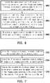
- FIG. 6is a flow chart of a brightness matching calibration method of the dual sensor imaging system according to an embodiment of the disclosure.
- FIG. 7is a flow chart of a calibration method of the dual sensor imaging system according to an embodiment of the disclosure.
- FIG. 2is a schematic diagram of capturing images by using an image sensor according to an embodiment of the disclosure.
- an image sensor 20 of an embodiment of the disclosureadopts a dual sensor architecture of independently configured color sensor 22 and infrared ray (IR) sensor 24 .
- IRinfrared ray
- multiple imagesare respectively captured by adopting multiple exposure conditions suitable for the current imaging scene, and a color image 22 a and an IR image 24 a with an appropriate exposure conditions are selected.
- the IR image 24 ais configured to complement the texture details lacking in the color image 22 a , so as to obtain a scene image 26 with good color and texture details.
- FIG. 3is a block diagram of a dual sensor imaging system according to an embodiment of the disclosure.
- a dual sensor imaging system 30 of the embodimentis configured in electronic device such as mobile phones, tablets, laptops, navigation devices, dashcams, digital cameras, digital video cameras, etc., and is configured to provide an imaging function.
- the dual sensor imaging system 30includes at least one color sensor 32 , at least one IR sensor 34 , a storage device 36 , and a processor 38 , and the functions thereof are as follows.
- the color sensor 32includes a charge coupled device (CCD), a complementary metal-oxide semiconductor (CMOS) element, or other types of photosensitive elements, and may sense light intensity to generate images of the imaging scene.
- CMOScomplementary metal-oxide semiconductor
- the color sensor 32is, for example, an RGB image sensor which includes red (R), green (G), and blue (B) color pixels, and is configured to capture color information of red light, green light, blue light, etc. in the imaging scene, and fuse the color information to generate a color image of the imaging scene.
- the IR sensor 34for example, includes CCD, a CMOS element, or other types of photosensitive elements, and can sense infrared ray by adjusting the wavelength sensing range of the photosensitive element.
- the IR sensor 34for example, uses the above photosensitive elements as pixels to capture infrared information in the imaging scene, and fuse the infrared information to generate an IR image of the imaging scene.
- the storage device 36is, for example, any type of fixed or removable random access memory (RAM), read-only memory (ROM), flash memory, hard disk, similar elements, or a combination of the above elements, and is configured to store a computer program executed by the processor 38 .
- the storage device 36may, for example, also store the color image captured by the color sensor 32 and the IR image captured by the IR sensor 34 .
- the processor 38is, for example, a central processing unit (CPU), other programmable general-purpose or specific-purpose microprocessors, microcontroller, digital signal processors (DSPs), programmable controller, application specific integrated circuits (ASICs), programmable logic devices (PLDs), other similar devices, or a combination of these devices, and the disclosure is not limited thereto.
- the processor 38may load a computer program from the storage device 36 to execute the calibration method of the dual sensor imaging system of the embodiment of the disclosure.
- the disclosureBased on the different characteristics (such as resolution, wavelength range, and field of view (FOV)) of the color sensor 32 and the IR sensor 34 , the disclosure provides a calibration method, which may calibrate the color sensor 32 and the IR sensor 34 assembled on the dual sensor imaging system 30 in the production stage to balance the difference between the color sensor 32 and the IR sensor 34 under different capturing conditions.
- the calibration resultwill be stored in the storage device 36 , and may be used as a basis for adjusting the captured image in the subsequent run stage.
- FIG. 4is a flow chart of a calibration method of the dual sensor imaging system according to an embodiment of the disclosure.
- the method of the embodimentis suitable for the dual sensor imaging system 30 , which is suitable for calibrating the color sensor 32 and the IR sensor 34 of the dual sensor imaging system 30 in the production stage.
- the followingis a description of the detailed steps of the calibration method of the embodiment in conjunction with the elements of the dual sensor imaging system 30 .
- Step S 402at least one color sensor 32 and at least one IR sensor 34 are assembled in the dual sensor imaging system 30 .
- the color sensor 32 and the IR sensor 34are assembled in the image sensor by, for example, a robot, such as the color sensor 22 and the IR sensor 24 assembled in the image sensor 20 shown in FIG. 2 .
- Step S 404the processor 38 executes alignment calibration between the color sensor 32 and the IR sensor 34 .
- the processor 38may, for example, execute an image alignment algorithm such as a brute force algorithm, an optical flow, homography transformation, or local warping to align the color image captured by the color sensor 32 and the IR image captured by the IR sensor 34 , and the detailed implementation will be described later.
- Step S 406the processor 38 executes brightness matching calibration of the color sensor 32 and the IR sensor 34 under different capturing conditions.
- the processor 38may, for example, calculate the difference between the color image and the IR image captured under different capturing conditions, so as to determine an exposure setting suitable for the color sensor 32 and the IR sensor 34 , and the detailed implementation will be described later.
- FIG. 5is a flow chart of an aligning calibration method of the dual sensor imaging system according to an embodiment of the disclosure.
- the method of the embodimentis suitable for the dual sensor imaging system 30 , and the following is a description of the detailed steps of the aligning calibration method of the embodiment in conjunction with the elements of the dual sensor imaging system 30 .
- Step S 502the processor 38 controls the color sensor 32 and the IR sensor 34 to respectively capture a test chart with a special pattern, so as to obtain a color test image and an IR test image.
- the special patternis, for example, a black and white checkerboard pattern, or other patterns with clearly distinguishable features, and is not limited thereto.
- Step S 504the processor 38 detects multiple feature points of the special pattern in the color test image and the IR test image.
- the processor 38may, for example, cut each color test image and IR test image into multiple blocks, and execute a feature detection algorithm to detect at least one feature point within each block.
- the processor 38determines the number of feature points detected from each block according to its own calculation ability.
- the feature detection algorithmis, for example, Harris corner detection.
- the processor 38may, for example, select edge pixels in each block or pixels with high local deviation in each block as the detected feature points, and is not limited thereto.
- Step S 506the processor 38 executes an image alignment algorithm to calculate the matching relationship between the color test image and the IR test image according to the position relationship between the corresponding feature points in the color test image and the IR test image, to be used to align the subsequently captured color image and IR image.
- the processor 38may, for example, obtain all the feature points in the color image and all the feature points in the IR image, so as to execute the image alignment algorithm for these feature points.
- the processor 38may move a patch including multiple pixels at a corresponding position in the IR test image for a specified feature point in the feature points detected from the color test image to search for a corresponding feature point corresponding to the specified feature point in the IR test image.
- the processor 38takes a pixel corresponding to the specified feature point in the IR test image as the center, and moves the patch around the pixel. Then, the pixels located in the patch is compared with the pixels located around the specified feature point in the color test image until the pixels in the patch match the pixels around the specified feature point (for example, the sum of difference values of pixel values of all pixels is less than a predetermined threshold). Finally, the processor 38 may determine a center point pixel at the location of the patch when the matching is achieved as the corresponding feature point corresponding to the specified feature point. The processor 38 may repeat the above matching actions until the corresponding relationship of all feature points is obtained.
- the processor 38may, for example, execute a random sample consensus (RANSAC) algorithm to establish a homography transformation matrix as follows:
- RANSACrandom sample consensus
- the processor 38may, for example, substitute the positions of each feature point in the color test image and the corresponding feature point in the IR test image into the above homography transformation matrix for solution, so as to use the obtained solution as the matching relationship between the color test image and the IR test image.
- the processor 38may use the color test image and the IR test image to calculate multiple depths of the imaging scene, so as to divide the imaging scene into multiple depth scenes with different depths (such as a close scene and a far scene).
- the processor 38may, for example, establish a quadratic equation for each depth scene, as follows:
- (x, y)represents the location of the specified feature point in the color test image
- (x′, y′)represents the location of the corresponding feature point in the IR test image
- a to frepresent the variables.
- the processor 38substitutes the positions of each feature point in the color test image and the corresponding feature point in the IR test image into the above quadratic equation for solution, so as to use the obtained solution as the matching relationship between the color test image and the IR test image.
- FIG. 6is a flow chart of a brightness matching method of the dual sensor imaging system according to an embodiment of the disclosure.
- the method of the embodimentis suitable for the dual sensor imaging system 30 , and the following is a description of the detailed steps of the brightness matching calibration method of the embodiment in conjunction with the elements of the dual sensor imaging system 30 .
- Step S 602the processor 38 controls the color sensor 32 and the IR sensor 34 to respectively capture multiple color images and multiple IR images of an imaging scene by adopting multiple capturing conditions.
- the capturing conditionsfor example, include one of the wavelength range and brightness of ambient light, the distance from the subject or background in the imaging scene, or a combination thereof, and is not limited thereto.
- Step S 604the processor 38 calculates multiple color image parameters of the color image captured under each capturing condition and multiple IR image parameters of the IR image captured under each capturing condition to be used to calculate a difference between a brightness of the color image and a brightness of the IR image.
- the processor 38calculates 3A (including auto focus (AF), auto exposure (AE), and auto white balance (AWB)) statistics of each image to be used to calculate the difference (such as a difference value or a ratio) between the brightness of the images.
- 3Aincluding auto focus (AF), auto exposure (AE), and auto white balance (AWB)
- AFauto focus
- AEauto exposure
- AVBauto white balance
- the processor 38may, for example, cut each color image and each IR image into multiple blocks, and calculate the average pixel value of all pixels in each block, so as to calculate a difference between the average pixel values of corresponding blocks to be used as the difference between the brightness of the color image and the brightness of the IR image.
- the processor 38may, for example, calculate the image histogram of each color image and each IR image, so as to calculate a difference between the image histograms of the color image and the IR image to be used as the difference between the brightness of the color image and the brightness of the IR image.
- Step S 606the processor 38 determines the exposure setting suitable for the color sensor and the IR sensor according to the calculated difference by.
- the processor 38may, for example, control the color sensor 32 and the IR sensor 34 to respectively capture the color image and the IR image of the imaging scene by adopting the same exposure time, and calculate the brightness difference between the color image and the IR image, so as to calculate the gain for adjusting the brightness of the color image and/or the brightness of the IR image. That is, the processor 38 may calculate the gain that may compensate for the brightness difference between the color image and the IR image, which may be the gain for the color image, the gain for the IR image, or the gain for both, and is not limited thereto.
- the gain for adjusting the brightness of the IR imagemay be calculated, so that the brightness of the IR image multiplied by the gain is equivalent to the brightness of the color image.
- the calculated gainmay, for example, be stored in the storage device 36 along with the corresponding capturing condition.
- the processor 38may obtain the gain corresponding to the capturing condition from the storage device 36 by identifying the capturing condition, and multiply the pixel value of the captured color image or IR image by the obtained gain, such that the brightness of the color image can match the brightness of the IR image.
- an IR projectormay be additionally configured in the dual sensor imaging system 30 , so as to assist the processor 38 in calculating the distances between the dual sensor camera system 30 and the subject and background in the imaging scene in conjunction with the IR sensor 32 .
- FIG. 7is a flow chart of a calibration method of the dual sensor imaging system according to an embodiment of the disclosure.
- the method of the embodimentis suitable for the dual sensor imaging system 30 , and the following is a description of the detailed steps of the calibration method of the embodiment in conjunction with the elements of the dual sensor imaging system 30 .
- Step S 702the processor 38 controls the IR projector to project an invisible light with a special pattern to the imaging scene.
- Step S 704the processor 38 controls two IR sensors in the IR sensor 32 to respectively capture multiple IR images of the imaging scene with the special pattern.
- Step S 706the processor 38 respectively calculates the distances between the dual sensor imaging system 30 and the subject and background in the imaging scene according to the special pattern of the captured IR image and the parallax between the two IR sensors. Since the special pattern projected by the IR projector to the imaging scene is not easily affected by the environment, the above method may obtain more accurate distances from the subject and/or background to be used to identify capturing conditions as a basis for subsequent image compensation.
- the color sensor and the IR sensor configured on the dual sensor imaging systemrespectively capture multiple images by adopting different capturing conditions, so as to perform image alignment and brightness matching calibration on the color sensor and IR sensor, and use the calibration result as the basis for adjusting the subsequently captured image.
- the image quality of the image captured by the dual sensor imaging systemcan be improved.
Landscapes
- Engineering & Computer Science (AREA)
- Multimedia (AREA)
- Signal Processing (AREA)
- Physics & Mathematics (AREA)
- General Physics & Mathematics (AREA)
- Human Computer Interaction (AREA)
- Health & Medical Sciences (AREA)
- Biomedical Technology (AREA)
- General Health & Medical Sciences (AREA)
- Color Television Image Signal Generators (AREA)
- Studio Devices (AREA)
Abstract
Description
Claims (20)
Priority Applications (1)
| Application Number | Priority Date | Filing Date | Title |
|---|---|---|---|
| US17/191,701US11418719B2 (en) | 2020-09-04 | 2021-03-04 | Dual sensor imaging system and calibration method which includes a color sensor and an infrared ray sensor to perform image alignment and brightness matching |
Applications Claiming Priority (4)
| Application Number | Priority Date | Filing Date | Title |
|---|---|---|---|
| US202063074477P | 2020-09-04 | 2020-09-04 | |
| TW109146764 | 2020-12-30 | ||
| TW109146764ATWI764484B (en) | 2020-09-04 | 2020-12-30 | Dual sensor imaging system and calibration method thereof |
| US17/191,701US11418719B2 (en) | 2020-09-04 | 2021-03-04 | Dual sensor imaging system and calibration method which includes a color sensor and an infrared ray sensor to perform image alignment and brightness matching |
Publications (2)
| Publication Number | Publication Date |
|---|---|
| US20210195082A1 US20210195082A1 (en) | 2021-06-24 |
| US11418719B2true US11418719B2 (en) | 2022-08-16 |
Family
ID=76441718
Family Applications (1)
| Application Number | Title | Priority Date | Filing Date |
|---|---|---|---|
| US17/191,701ActiveUS11418719B2 (en) | 2020-09-04 | 2021-03-04 | Dual sensor imaging system and calibration method which includes a color sensor and an infrared ray sensor to perform image alignment and brightness matching |
Country Status (1)
| Country | Link |
|---|---|
| US (1) | US11418719B2 (en) |
Families Citing this family (2)
| Publication number | Priority date | Publication date | Assignee | Title |
|---|---|---|---|---|
| US12254607B2 (en)* | 2022-01-14 | 2025-03-18 | Omnivision Technologies, Inc. | Image processing method and apparatus implementing the same |
| CN116723409B (en)* | 2022-02-28 | 2024-05-24 | 荣耀终端有限公司 | Automatic exposure method and electronic device |
Citations (33)
| Publication number | Priority date | Publication date | Assignee | Title |
|---|---|---|---|---|
| US20080024608A1 (en)* | 2005-02-11 | 2008-01-31 | Bayerische Motoren Werke Aktiengesellschaft | Method and device for visualizing the surroundings of a vehicle by fusing an infrared image and a visual image |
| US20110228096A1 (en) | 2010-03-18 | 2011-09-22 | Cisco Technology, Inc. | System and method for enhancing video images in a conferencing environment |
| US20110298898A1 (en) | 2010-05-11 | 2011-12-08 | Samsung Electronics Co., Ltd. | Three dimensional image generating system and method accomodating multi-view imaging |
| CN102461156A (en) | 2009-06-03 | 2012-05-16 | 弗莱尔系统公司 | Infrared camera systems and methods for dual sensor applications |
| US20120189293A1 (en) | 2011-01-25 | 2012-07-26 | Dongqing Cao | Imaging devices having arrays of image sensors and lenses with multiple aperture sizes |
| TWM458748U (en) | 2012-12-26 | 2013-08-01 | Chunghwa Telecom Co Ltd | Image type depth information retrieval device |
| US20130342703A1 (en)* | 2012-06-25 | 2013-12-26 | PSP Security Co., Ltd. | System and Method for Identifying Human Face |
| US20150245062A1 (en) | 2012-09-25 | 2015-08-27 | Nippon Telegraph And Telephone Corporation | Picture encoding method, picture decoding method, picture encoding apparatus, picture decoding apparatus, picture encoding program, picture decoding program and recording medium |
| US20150334283A1 (en) | 2007-03-05 | 2015-11-19 | Fotonation Limited | Tone Mapping For Low-Light Video Frame Enhancement |
| TW201711456A (en) | 2015-09-02 | 2017-03-16 | 財團法人工業技術研究院 | Depth photographing apparatus with self-calibration and self-calibration method thereof |
| US20170094141A1 (en) | 2015-09-24 | 2017-03-30 | Intel Corporation | Infrared and visible light dual sensor imaging system |
| TW201721269A (en) | 2015-12-11 | 2017-06-16 | 宏碁股份有限公司 | Automatic exposure system and auto exposure method thereof |
| US20170318222A1 (en)* | 2016-04-28 | 2017-11-02 | Qualcomm Incorporated | Performing intensity equalization with respect to mono and color images |
| US20170316554A1 (en) | 2014-11-12 | 2017-11-02 | Sony Corporation | Information processing apparatus, information processing method, and program |
| US20170330053A1 (en)* | 2016-05-11 | 2017-11-16 | Center For Integrated Smart Sensors Foundation | Color night vision system and operation method thereof |
| CN107431760A (en) | 2015-03-31 | 2017-12-01 | 富士胶片株式会社 | Camera device, the image processing method of camera device and program |
| CN107846537A (en) | 2017-11-08 | 2018-03-27 | 维沃移动通信有限公司 | A kind of CCD camera assembly, image acquiring method and mobile terminal |
| US20180139431A1 (en) | 2012-02-24 | 2018-05-17 | Matterport, Inc. | Capturing and aligning panoramic image and depth data |
| US20180278832A1 (en) | 2013-08-01 | 2018-09-27 | Corephotonics Ltd. | Thin multi-aperture imaging system with auto-focus and methods for using same |
| US20190197667A1 (en) | 2017-12-26 | 2019-06-27 | Facebook, Inc. | Computing high-resolution depth images using machine learning techniques |
| TW201931847A (en) | 2018-01-09 | 2019-08-01 | 呂官諭 | Image sensor of enhancing image recognition resolution and application thereof greatly reducing usage costs of image sensors and further saving mechanical costs |
| CN110462686A (en) | 2017-02-06 | 2019-11-15 | 弗托斯传感与算法公司 | For obtaining the device and method of depth information from scene |
| CN110706178A (en) | 2019-09-30 | 2020-01-17 | 杭州海康威视数字技术股份有限公司 | Image fusion device, method, equipment and storage medium |
| TW202008306A (en) | 2018-08-01 | 2020-02-16 | 大陸商Oppo廣東移動通信有限公司 | Camera calibration method and apparatus, electronic device |
| WO2020055619A1 (en) | 2018-09-16 | 2020-03-19 | Nephelai Research Llc | Calibration of a depth sensing array using color image data |
| WO2020062276A1 (en) | 2018-09-30 | 2020-04-02 | 浙江宇视科技有限公司 | Day and night switching method and apparatus, electronic device and readable storage medium |
| US20200126246A1 (en) | 2018-10-19 | 2020-04-23 | Samsung Electronics Co., Ltd. | Method and apparatus for active depth sensing and calibration method thereof |
| US20200166646A1 (en)* | 2018-11-28 | 2020-05-28 | Lumileds Holding B.V. | Method of obtaining a digital image |
| US20200193584A1 (en) | 2018-12-12 | 2020-06-18 | Samsung Electronics Co., Ltd. | Apparatus and method for determining image sharpness |
| CN111527743A (en) | 2017-12-28 | 2020-08-11 | 伟摩有限责任公司 | Multiple operating modes for extended dynamic range |
| CN111540003A (en) | 2020-04-27 | 2020-08-14 | 浙江光珀智能科技有限公司 | Depth image generation method and device |
| US20200294214A1 (en) | 2019-03-11 | 2020-09-17 | Canon Kabushiki Kaisha | Image processing apparatus, method for controlling image processing apparatus, and non-transitory computer-readable storage medium |
| US20210201476A1 (en) | 2019-12-30 | 2021-07-01 | GE Precision Healthcare LLC | Systems and methods for patient structure estimation during medical imaging |
- 2021
- 2021-03-04USUS17/191,701patent/US11418719B2/enactiveActive
Patent Citations (34)
| Publication number | Priority date | Publication date | Assignee | Title |
|---|---|---|---|---|
| US20080024608A1 (en)* | 2005-02-11 | 2008-01-31 | Bayerische Motoren Werke Aktiengesellschaft | Method and device for visualizing the surroundings of a vehicle by fusing an infrared image and a visual image |
| US20150334283A1 (en) | 2007-03-05 | 2015-11-19 | Fotonation Limited | Tone Mapping For Low-Light Video Frame Enhancement |
| CN102461156A (en) | 2009-06-03 | 2012-05-16 | 弗莱尔系统公司 | Infrared camera systems and methods for dual sensor applications |
| US20110228096A1 (en) | 2010-03-18 | 2011-09-22 | Cisco Technology, Inc. | System and method for enhancing video images in a conferencing environment |
| US20110298898A1 (en) | 2010-05-11 | 2011-12-08 | Samsung Electronics Co., Ltd. | Three dimensional image generating system and method accomodating multi-view imaging |
| US20120189293A1 (en) | 2011-01-25 | 2012-07-26 | Dongqing Cao | Imaging devices having arrays of image sensors and lenses with multiple aperture sizes |
| US20180139431A1 (en) | 2012-02-24 | 2018-05-17 | Matterport, Inc. | Capturing and aligning panoramic image and depth data |
| US20130342703A1 (en)* | 2012-06-25 | 2013-12-26 | PSP Security Co., Ltd. | System and Method for Identifying Human Face |
| US20150245062A1 (en) | 2012-09-25 | 2015-08-27 | Nippon Telegraph And Telephone Corporation | Picture encoding method, picture decoding method, picture encoding apparatus, picture decoding apparatus, picture encoding program, picture decoding program and recording medium |
| TWM458748U (en) | 2012-12-26 | 2013-08-01 | Chunghwa Telecom Co Ltd | Image type depth information retrieval device |
| US20180278832A1 (en) | 2013-08-01 | 2018-09-27 | Corephotonics Ltd. | Thin multi-aperture imaging system with auto-focus and methods for using same |
| US20170316554A1 (en) | 2014-11-12 | 2017-11-02 | Sony Corporation | Information processing apparatus, information processing method, and program |
| CN107431760A (en) | 2015-03-31 | 2017-12-01 | 富士胶片株式会社 | Camera device, the image processing method of camera device and program |
| TW201711456A (en) | 2015-09-02 | 2017-03-16 | 財團法人工業技術研究院 | Depth photographing apparatus with self-calibration and self-calibration method thereof |
| US20170094141A1 (en) | 2015-09-24 | 2017-03-30 | Intel Corporation | Infrared and visible light dual sensor imaging system |
| TW201721269A (en) | 2015-12-11 | 2017-06-16 | 宏碁股份有限公司 | Automatic exposure system and auto exposure method thereof |
| US20170318222A1 (en)* | 2016-04-28 | 2017-11-02 | Qualcomm Incorporated | Performing intensity equalization with respect to mono and color images |
| US20170330053A1 (en)* | 2016-05-11 | 2017-11-16 | Center For Integrated Smart Sensors Foundation | Color night vision system and operation method thereof |
| CN110462686A (en) | 2017-02-06 | 2019-11-15 | 弗托斯传感与算法公司 | For obtaining the device and method of depth information from scene |
| US20200134849A1 (en) | 2017-02-06 | 2020-04-30 | Photonic Sensors & Algorithms, S.L. | Device and method for obtaining depth information from a scene |
| CN107846537A (en) | 2017-11-08 | 2018-03-27 | 维沃移动通信有限公司 | A kind of CCD camera assembly, image acquiring method and mobile terminal |
| US20190197667A1 (en) | 2017-12-26 | 2019-06-27 | Facebook, Inc. | Computing high-resolution depth images using machine learning techniques |
| CN111527743A (en) | 2017-12-28 | 2020-08-11 | 伟摩有限责任公司 | Multiple operating modes for extended dynamic range |
| TW201931847A (en) | 2018-01-09 | 2019-08-01 | 呂官諭 | Image sensor of enhancing image recognition resolution and application thereof greatly reducing usage costs of image sensors and further saving mechanical costs |
| TW202008306A (en) | 2018-08-01 | 2020-02-16 | 大陸商Oppo廣東移動通信有限公司 | Camera calibration method and apparatus, electronic device |
| WO2020055619A1 (en) | 2018-09-16 | 2020-03-19 | Nephelai Research Llc | Calibration of a depth sensing array using color image data |
| WO2020062276A1 (en) | 2018-09-30 | 2020-04-02 | 浙江宇视科技有限公司 | Day and night switching method and apparatus, electronic device and readable storage medium |
| US20200126246A1 (en) | 2018-10-19 | 2020-04-23 | Samsung Electronics Co., Ltd. | Method and apparatus for active depth sensing and calibration method thereof |
| US20200166646A1 (en)* | 2018-11-28 | 2020-05-28 | Lumileds Holding B.V. | Method of obtaining a digital image |
| US20200193584A1 (en) | 2018-12-12 | 2020-06-18 | Samsung Electronics Co., Ltd. | Apparatus and method for determining image sharpness |
| US20200294214A1 (en) | 2019-03-11 | 2020-09-17 | Canon Kabushiki Kaisha | Image processing apparatus, method for controlling image processing apparatus, and non-transitory computer-readable storage medium |
| CN110706178A (en) | 2019-09-30 | 2020-01-17 | 杭州海康威视数字技术股份有限公司 | Image fusion device, method, equipment and storage medium |
| US20210201476A1 (en) | 2019-12-30 | 2021-07-01 | GE Precision Healthcare LLC | Systems and methods for patient structure estimation during medical imaging |
| CN111540003A (en) | 2020-04-27 | 2020-08-14 | 浙江光珀智能科技有限公司 | Depth image generation method and device |
Non-Patent Citations (6)
| Title |
|---|
| "Office Action of Taiwan Counterpart Application", dated Dec. 28, 2021, p. 1-p. 8, Application No. 109146764. |
| "Office Action of Taiwan Related Application, Application No. 109145614", dated Mar. 3, 2022, p. 1-p. 17. |
| "Office Action of Taiwan Related Application, application No. 109145632", dated Nov. 10, 2021, p. 1-p. 8. |
| "Office Action of Taiwan Related Application, application No. 109146831", dated Nov. 30, 2021, p. 1-p. 21. |
| "Office Action of Taiwan Related Application, application No. 109146922", dated Oct. 28, 2021, p. 1-p. 14. |
| "Office Action of U.S. Related Application, Application No. 17214946", dated Apr. 13, 2022, p. 1-p. 36. |
Also Published As
| Publication number | Publication date |
|---|---|
| US20210195082A1 (en) | 2021-06-24 |
Similar Documents
| Publication | Publication Date | Title |
|---|---|---|
| CN105191285B (en) | Solid photographic device, electronic device, lens control method and photographing module | |
| US7868915B2 (en) | Photographing apparatus, method and computer program product | |
| US20070177050A1 (en) | Exposure control apparatus and image pickup apparatus | |
| US20070195171A1 (en) | Face importance level determining apparatus and method, and image pickup apparatus | |
| US7733410B2 (en) | Electronic camera and focus control method which minimizes the time required for adjusting a focus | |
| KR20100011772A (en) | Method for controlling auto white balance | |
| US10764550B2 (en) | Image processing apparatus, image processing method, and storage medium | |
| US11418719B2 (en) | Dual sensor imaging system and calibration method which includes a color sensor and an infrared ray sensor to perform image alignment and brightness matching | |
| WO2012086127A1 (en) | Image processing apparatus, image pickup unit, and image processing method | |
| US20140307124A1 (en) | Imaging apparatus, control method of imaging apparatus, interchangeable lens and lens-interchangeable type imaging apparatus body | |
| US11593958B2 (en) | Imaging device, distance measurement method, distance measurement program, and recording medium | |
| CN114143421B (en) | Dual-sensor camera system and calibration method thereof | |
| US20070211165A1 (en) | Imaging device, method for controlling imaging device, program of method for controlling imaging device, recording medium in which program of method for controlling imaging device is recorded | |
| US11496660B2 (en) | Dual sensor imaging system and depth map calculation method thereof | |
| EP3051799A1 (en) | Imaging device and image processing method | |
| KR20070120012A (en) | Imaging Device and Imaging Method | |
| US6944398B2 (en) | Photometric device and camera | |
| JP2012085093A (en) | Imaging device and acquisition method | |
| WO2023074452A1 (en) | Camera device and method for controlling camera device | |
| US11258943B2 (en) | Imaging apparatus and method for controlling the same | |
| US20100259606A1 (en) | Imaging device and method for controlling imaging device | |
| CN114298951A (en) | Image processing method, related device, equipment and storage medium | |
| JP3510063B2 (en) | Exposure control device for still video camera | |
| US11843867B2 (en) | Imaging apparatus, imaging method, and storage medium for correcting brightness of an image based on a predetermined value of exposure | |
| US20240163568A1 (en) | Image capturing apparatus that generates images that can be depth-combined, method of controlling same, and storage medium |
Legal Events
| Date | Code | Title | Description |
|---|---|---|---|
| FEPP | Fee payment procedure | Free format text:ENTITY STATUS SET TO UNDISCOUNTED (ORIGINAL EVENT CODE: BIG.); ENTITY STATUS OF PATENT OWNER: SMALL ENTITY | |
| AS | Assignment | Owner name:ALTEK SEMICONDUCTOR CORP., TAIWAN Free format text:ASSIGNMENT OF ASSIGNORS INTEREST;ASSIGNORS:PENG, SHIH-YUAN;CHENG, SHU-CHUN;HUANG, HSU-LIEN;AND OTHERS;REEL/FRAME:055525/0048 Effective date:20210302 | |
| FEPP | Fee payment procedure | Free format text:ENTITY STATUS SET TO SMALL (ORIGINAL EVENT CODE: SMAL); ENTITY STATUS OF PATENT OWNER: SMALL ENTITY | |
| STPP | Information on status: patent application and granting procedure in general | Free format text:APPLICATION DISPATCHED FROM PREEXAM, NOT YET DOCKETED | |
| STPP | Information on status: patent application and granting procedure in general | Free format text:DOCKETED NEW CASE - READY FOR EXAMINATION | |
| STPP | Information on status: patent application and granting procedure in general | Free format text:NON FINAL ACTION MAILED | |
| STPP | Information on status: patent application and granting procedure in general | Free format text:RESPONSE TO NON-FINAL OFFICE ACTION ENTERED AND FORWARDED TO EXAMINER | |
| STPP | Information on status: patent application and granting procedure in general | Free format text:NOTICE OF ALLOWANCE MAILED -- APPLICATION RECEIVED IN OFFICE OF PUBLICATIONS | |
| STPP | Information on status: patent application and granting procedure in general | Free format text:PUBLICATIONS -- ISSUE FEE PAYMENT VERIFIED | |
| STCF | Information on status: patent grant | Free format text:PATENTED CASE |