US11414317B2 - Movable storage system - Google Patents
Movable storage systemDownload PDFInfo
- Publication number
- US11414317B2 US11414317B2US17/173,758US202117173758AUS11414317B2US 11414317 B2US11414317 B2US 11414317B2US 202117173758 AUS202117173758 AUS 202117173758AUS 11414317 B2US11414317 B2US 11414317B2
- Authority
- US
- United States
- Prior art keywords
- trailer
- wall
- tack
- moveable
- pivotable
- Prior art date
- Legal status (The legal status is an assumption and is not a legal conclusion. Google has not performed a legal analysis and makes no representation as to the accuracy of the status listed.)
- Active
Links
- 244000144972livestockSpecies0.000claimsabstractdescription26
- 230000008878couplingEffects0.000claimsabstractdescription6
- 238000010168coupling processMethods0.000claimsabstractdescription6
- 238000005859coupling reactionMethods0.000claimsabstractdescription6
- 230000004888barrier functionEffects0.000claimsdescription6
- 241001465754MetazoaSpecies0.000description7
- 241000283086EquidaeSpecies0.000description3
- 230000005484gravityEffects0.000description2
- 230000000694effectsEffects0.000description1
- 239000000463materialSubstances0.000description1
- 239000002184metalSubstances0.000description1
- 230000004048modificationEffects0.000description1
- 238000012986modificationMethods0.000description1
- 239000004033plasticSubstances0.000description1
Images


Classifications
- B—PERFORMING OPERATIONS; TRANSPORTING
- B68—SADDLERY; UPHOLSTERY
- B68C—SADDLES; STIRRUPS
- B68C1/00—Saddling equipment for riding- or pack-animals
- B68C1/002—Saddle-racks for supporting or cleaning purposes
- B—PERFORMING OPERATIONS; TRANSPORTING
- B68—SADDLERY; UPHOLSTERY
- B68B—HARNESS; DEVICES USED IN CONNECTION THEREWITH; WHIPS OR THE LIKE
- B68B9/00—Devices specially adapted for supporting harnesses when not in use
Definitions
- the present inventionrelates to a movable storage system for transport trailers, and in particular to a movable equipment storage wall.
- horses as a form of livestockwill be referenced throughout the present application because they are a common livestock animal that is carried in over-the-road trailers, such as behind pickup trucks, vans, and other towing vehicles, but it will be appreciated that livestock and equipment associated therewith are intended to represent substantially any equipment that is stored in a trailer or in proximity to the location of intended use of that equipment.
- Typical horse trailershave provisions to accommodate one or more horses in a main compartment, as well as saddles, bridles, blankets and other horse-related equipment known generally as “tack”. After transport, users often unload equipment and livestock from the trailer for use thereof. Saddles, while well suited for fitment on the back of a horse, are not particularly well suited for space-efficient storage.
- the present inventionprovides a movable storage system for the provision of storage locations for various types of equipment within a transport trailer, such as a livestock transport trailer.
- the storage systemincludes a vertical panel or wall that is pivotable about one of its sides and a plurality of storage arms that are fixed to one face of the vertical panel.
- the storage armsextend horizontally away from the panel and each define a storage location for equipment, such as saddles, blankets, leads, bridles, headstalls and other livestock related tack.
- the vertical panelis pivotably repositionable at various angular positions to provide selective access to the storage system and different portions of the trailer.
- references to horses or other livestock hereinare for purposes of providing examples of applications and features of the disclosed embodiments, and are not intended to limit the invention to livestock transport and containment applications.
- references to horses or other livestock hereinare for purposes of providing examples of applications and features of the disclosed embodiments, and are not intended to limit the invention to livestock transport and containment applications.
- the principles of the present inventionmay be adapted to campers and camper trailers, equipment and supply storage trailers, cargo vans, trucks, and self-powered recreational vehicles, and even to stationary structures such as barns, sheds, and homes where similar equipment storage is desired, without departing from the spirit and scope of the present invention.
- a movable storage systemfor storing equipment, such as saddles, blankets, and other livestock tack in a transport trailer.
- the storage systemincludes vertical moveable upright panel or wall that is pivotably mounted within the interior of the transport trailer for storing the various equipment.
- Horizontal storage armsare disposed on one face of the movable panel, such as the rear face of the panel when viewing the trailer from the rear end.
- the movable panelis pivotable about a vertical axis at one side of the movable panel such that the panel may be positioned at one of the desired angular positions.
- the desired angular positionsmay include a transport configuration for use when transporting the trailer, a tacking configuration for use when “tacking up” an animal, and an access configuration to provide access to an interior of the trailer.
- the movable storage systemincludes an upper pivot element and a lower pivot element disposed on one side of the vertical panel and pivotably coupled to a portion of the trailer.
- the pivot elementsdefine a vertical pivot axis of the storage system.
- the upper pivot lower pivot elementsare barrel hinges disposed between the side of the panel and a vertical support that is disposed vertically between the ceiling and the floor of the transport trailer.
- the vertical supportmay define a portion of a livestock living quarter or corral stall disposed in the trailer.
- each of the storage armsextends horizontally away from the vertical panel to define horizontal shelves for storing equipment.
- the horizontal shelvesmay be configured to support a saddle in an upright orientation.
- a compartmentis disposed along a face of the vertical panel and the compartment defines a storage space for large, narrow, and flat equipment, such as wheel covers.
- the compartmentmay be sized and shaped to receive and secure a wheel cover that covers a wheel section of the exterior of the trailer while the trailer is not in transport.
- the wheel covermay include a support bracket to couple the wheel cover to an exterior of the trailer, such as at a sidewall of the trailer above the wheel section.
- an equipment hanger bracketis coupled to the vertical panel to support equipment such as bridles, headstalls, extension cords, rope, and the like.
- the equipment hangerhas a hollow elongate main hanger body and an equipment support finger coupled to a portion of the main hanger body.
- the main hanger bodymay include a U-shaped cutout and a portion of the main hanger body extending into the center of the U-shaped cutout may form the equipment support finger.
- the movable storage systemincludes a spring loaded pin coupled to a side of the vertical panel opposite the vertical pivot axis.
- the spring loaded pinengages one of the pin receivers that are spaced along the interior of the transport trailer.
- the pin receiversare located to set the movable panel's angular positions and each provides a latching point for securing the movable panel at one of the desired angular positions.
- a transport trailerin another form of the present invention, includes a moveable tack wall for storing equipment inside the trailer, such as storing saddles, blankets, and other livestock tack.
- the trailerincludes stationary upright walls, a floor, a roof/ceiling, and a set of wheels.
- the trailerincludes a pivotable upright wall or moveable tack wall in the interior of the trailer.
- the tack wallis moveable between a various angular positions relative to the stationary upright walls.
- the tack wallincludes saddle racks extending from a face of the tack wall and equipment support bars also extending from the face of the tack wall.
- the saddle racksmay be positioned on the tack wall in an alternating spaced arrangement with the support bars.
- the tack wall of the transport trailerincludes a compartment that defines a storage space for large, narrow, and flat equipment.
- the compartmentis shaped and sized to receive and secure a wheel cover that is configured to cover one of the pair of wheels at the exterior of the trailer while the trailer is not in transport.
- the wheel coverincludes a support for coupling the wheel cover to an exterior of one of the stationary upright walls of the trailer.
- the transport trailerincludes a removable gate that is deployable to form a barrier along an opening defined between the tack wall and the stationary upright walls.
- the movable storage system of the present inventionprovides a repositionable storage location for livestock tack, including saddles and blankets, as well as for other equipment. While the system is particularly well suited for horse trailers, the system is also contemplated for use inside and outside of other types of transport trailers, other types of vehicles, or stationary structures.
- the systemcan be repositioned at different angular positions that define various configurations include a transport configuration, a tacking configuration, and an access configuration.
- the systemincludes hinges coupling one side of the storage system to the trailer to provide a vertical pivot axis about which the system is pivotable.
- the systemincludes horizontal storage arms or shelves that are configured to support the equipment to be stored thereon. Latches are used to secure the system at a desired angular position within the trailer.
- the systemmay include additional features such as storage compartments and barrier gates.
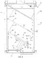
- FIG. 1is a perspective view of a movable storage system in accordance with the present invention
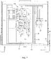
- FIG. 2is a top plan view of the movable storage system of FIG. 1 disposed in a rear portion of a transport trailer, depicting the movable storage system in a transport configuration;
- FIG. 3is another top plan view of the movable storage system of FIG. 2 , depicting the movable storage system in a tacking configuration;
- FIG. 4is another top plan view of the movable storage system of FIG. 2 , depicting the movable storage system in a load/unload or access configuration;
- FIG. 5is a front view of the movable storage system of FIG. 1 ;
- FIG. 6is a right side view of the movable storage system of FIG. 1 ;
- FIG. 7is a rear perspective view of the movable storage system of FIG. 1 disposed in a transport trailer, depicting the movable storage system in the tacking configuration;
- FIG. 8is another rear perspective view of the movable storage system of FIG. 7 , depicting the storage system in the load/unload or access configuration;
- FIG. 9is an enlarged partial perspective view of a plurality of bridle hangers disposed on the movable storage system of FIG. 1 ;
- FIG. 10is an enlarged perspective view of one of the bridle hangers of FIG. 9 ;
- FIG. 11is a perspective view of a wheel cover sized and shaped to fit within a compartment of the movable storage system of FIG. 1 .
- a movable storage system or tack wall 10provides a storage location within a transport trailer 12 for storing various types of equipment such as livestock tack, e.g. saddles 14 , blankets 15 , leads, headstalls, etc.
- the storage system 10may be utilized with various types of transport trailers or vehicles, such as livestock trailers, campers, recreational vehicles, and the like.
- the storage system 10may be coupled to the trailer 12 such that it is accessible from an interior or an exterior of the trailer 12 .
- the storage system 10is particularly well suited for use with horse transport trailers for storage of saddles 14 and other tack while allowing for repositioning of the storage system 10 to provide access to the various portions of the horse trailer and ergonomic access to the load or unload saddles 14 and tack thereon.
- the storage system 10is repositionable within the trailer 12 for various activities, including for loading and unloading livestock into the trailer 12 , for storing or removing equipment from the storage system 10 , and for transport of the trailer 12 .
- the movable storage system 10includes a vertical panel 16 defining a moveable wall or door, which is pivotably mountable within the interior of the transport trailer 12 .
- the panel 16is pivotably coupled to a portion of the interior of the trailer 12 to enable the storage system 10 to be selectively pivoted about a vertical pivot axis.
- the vertical pivot axisis proximate a left side 16 b of the vertical panel 16 when viewing the panel 16 from the rear of the trailer 12 ( FIGS. 1-5 and 7-8 ).
- the storage system 10includes a plurality of storage arms or shelves, including elongated saddle platform arms or racks 18 and elongated bar arms 20 for supporting various types of equipment, such as blankets 15 and leads.
- the storage arms 18 , 20are fixed to at least one face of the panel 16 , such as a rear face 16 a of the panel 16 , such that the storage arms 18 , 20 are extend generally horizontal and outward from the vertical panel 16 .
- the storage arms 18 , 20may be inclined and extend from the panel 16 at an upward angle relative to the floor of the trailer to retain equipment and prevent the equipment from accidently sliding off of the storage arms 18 , 20 .
- the storage arms 18 , 20may be movable vertically relative to the vertical panel 16 to adjust the height of the stored equipment to make loading and unloading at each storage arm 18 , 20 easier.
- the storage system 10includes hinges 22 to pivotably couple the panel 16 to a vertical support 24 that is disposed in the trailer 12 ( FIGS. 1-5 ).
- the vertical pivot axis of the storage system 10is defined by the pivoting axis of the hinges 22 .
- the vertical support 24defines a portion of a livestock corral or living quarter 26 , such as disclosed in commonly assigned U.S. Pat. No. 10,568,297, issued on Feb. 25, 2020, which is incorporated herein by reference in its entirety.
- the hinges 22may be barrel hinges or other types of hinges or pivot elements, such as cone and cup bearings.
- hingesmay be disposed in the ceiling and the floor of the trailer 12 , to pivotably support the storage system 10 directly at the ceiling and the floor of the trailer 12 .
- the movable storage system 10is pivotably repositionable to a plurality of angular positions within the trailer 12 to provide access to storage system 10 and the various portions of the trailer's interior.
- Angular positions of the system 10include a transport configuration 10 a depicted in FIGS. 2 and 7 , a tacking configuration 10 b depicted in FIG. 3 , and an access configuration 10 c depicted in FIGS. 4 and 8 .
- the vertical panel 16is at an oblique angle relative to the upright sidewalls 12 a , 12 b and rear end 12 c of the trailer 12 ( FIG. 2 ).
- the vertical panel 16cooperates with the corral 26 and functions as a stall wall to contain and/or support a rear quarter of the animal contained within the corral 26 , such as in the event that the animal stumbles or slides backward toward the rear of the trailer 12 ( FIG. 2 ).
- the vertical panel 16is substantially perpendicular to the sidewalls 12 a , 12 b of the trailer and parallel to the rear end 12 c of the trailer ( FIG. 3 ).
- a useris able to load or unload equipment on to the storage arms 18 , 20 while standing inside of the trailer 12 .
- the useris able to ergonomically lift the equipment substantially without straining to reach at an awkward angle or position relative to the storage system 10 , providing for safe and efficient loading and unloading of equipment.
- the vertical panel 16is positioned at an oblique angle, relative to the rear end 12 c , that is substantially greater than the oblique angle of the panel 16 in the transport configuration 10 b .
- an access opening 28is created between the panel 16 and sidewall 12 b to allow livestock or users to enter into living quarter 26 or the interior space of the trailer forward of the storage system 10 ( FIGS. 4 and 8 ).
- a gate or “butt bar” 30may be provided to form a barrier along the access opening 28 to temporarily pen livestock into the trailer 12 while the storage system 10 is in the access configuration 10 c ( FIG. 8 ).
- the storage system 10includes an upper latching pin 32 a and a lower latching pins 32 b disposed respectively at upper and lower portions of a right side 16 c of the vertical panel 16 .
- the latching pins 32 a , 32 bmay be manually operated and/or spring loaded pins that are spring-biased to extend and engage a portion of the trailer 12 to secure the storage system 10 at one of the plurality of angular positions.
- the latching pins 32 a , 32 bare selectively operable (via handles or knobs 33 a and 33 b ) to release the storage system 10 for repositioning it to a different configuration.
- the upper latching pin 32 amay be a spring-biased pin and the lower latching pin 32 b may be a gravity-biased pin.
- a userlifts the handle 33 b corresponding to the lower latch pin 32 b (against gravity) and lowers the handle 33 a corresponding to the upper latch pin 32 a (against spring force).
- the userreleases the handles 33 a and 33 b and the upper latch pin 32 a raises due to the spring force and the lower latch pin 32 b falls due to gravity.
- a plurality of latching points 34 a , 34 b , and 34 care disposed in spaced arrangement within the trailer 12 to provide receiver locations that receive the latch pins 32 a and 32 b when the vertical panel 16 is positioned at an angular position (configuration) corresponding to one of the latching points 34 a , 34 b , 34 c .
- the locations of the latching points 34 a , 34 b , and 34 ceach define a set angular position of the storage system 10 .
- Each latching point 34 a , 34 b , and 34 cincludes one latch plate 34 disposed in the floor of the trailer 12 and one latch plate disposed in the ceiling of the trailer 12 , such that each corresponding pair of plates are vertically aligned with one another.
- Each latch plate 34includes a hole 35 that defines a receiver slot that is sized and shaped to receive the extending end of a respective latch pin 32 a , 32 b .
- a single latch pin and single latch platemay be sufficient to secure the storage system 10 at a desired configuration.
- the upper latch pin 32 a and the ceiling latch plate(s)may be omitted such that only the lower latch pin 32 b and latch plate(s) 34 on the floor at latching points 34 a , 43 b , and 34 c are provided to secure the storage system 10 in the transport configuration ( FIG. 2 ), the tacking configuration ( FIG. 3 ), or the access configuration ( FIG. 4 ).
- the storage system 10includes a compartment 36 to store large, narrow or flat equipment, such as trailer wheel covers 38 ( FIGS. 1 and 5-8 ).
- the compartment 36is defined by a narrow vertical opening proximate the right side 16 c of the vertical panel 16 .
- the compartment 36at least partially defines rear face 16 a of the panel 16 and may extend from the bottom of the panel 16 to the top, and toward the left side 16 b of the panel.
- the wheel cover 38is provided for covering the wheels of the trailer 12 so that livestock animals near the exterior of trailer cannot fidget with the wheels or extends their bodies or limbs under the wheel wells of the trailer ( FIGS. 2-4 and 7-8 ).
- the wheel cover 38as best shown in FIG.
- the wheel cover 11may be dimensioned and shaped to cover various sizes of wheel well opening sections of the trailer, such as for single, double, or triple axle trailers, for example.
- the wheel covermay be formed of metal, plastic, wood, or the like, such that it is durable and resilient yet lightweight to allow a single user to carry the wheel cover 38 .
- the wheel cover 38includes cutouts 39 to receive or fit over wheel hubs of the wheels of the trailer 12 and a handle cutout 41 to provide a grip or handle for a user to transport the wheel cover 38 ( FIG. 11 ).
- the wheel cover 38includes a hanger or support bracket 40 for securing the wheel cover alongside an exterior wall of the trailer 12 such that the wheel cover is secured in place adjacent to the wheels 13 ( FIGS. 7 and 8 ) of the trailer 12 .
- the wheel cover 38can be secured to the trailer 12 so that an animal or person cannot easily dislodge or displace the wheel cover 38 from its position alongside the wheels 13 of the trailer.
- the bracket 40defines a gap forming a channel or track 42 in the bracket body.
- the channel 42is dimensioned to receive and engage a bolt, lug, or stud that is fixed to the exterior of the trailer 12 proximate the wheel well of the trailer.
- the width of the gap forming the channel 42is slightly larger than the thickness of the main body of the stud and the gap of the channel is smaller than the thickness of a head portion of the stud.
- the wheel cover 38is installed by placing the bracket channel 42 over the trailer stud and lowering the wheel cover 38 down so that the channel 42 straddles the body of the stud with the body of the bracket 40 positioned between the head of the stud and the trailer 12 .
- the bracket channel 42can receive or straddle the body of the stud when the wheel cover 38 is installed on the trailer 12 and the bracket 40 is secured on the stud by the stud's head.
- the bracket 40cannot slide off of the stud along the axial direction of the stud. In order to remove the wheel cover 38 , it must be lifted upward until the channel 42 has cleared the stud.
- bridle or equipment hangers 44are provided for supporting and organizing equipment, such as livestock bridles or headstalls.
- Each hanger 44extends generally horizontal and outward from the vertical panel 16 and may be inclined and extend from the panel 16 at an upward angle relative to the floor of the trailer 12 to retain equipment and prevent the equipment from accidently sliding off of the hanger 44 .
- Each hanger 44is defined by a round main body and includes an equipment support tab or finger 46 . The finger is formed by a portion of the main hanger body that is at the center of a horseshoe or U-shaped cutout 48 , as best shown in FIG. 10 , in the body of the hanger 44 .
- the finger 46may be bent or angled away from the main body of the hanger 44 and is provided for supporting an equipment article on a lower side of the hanger 44 .
- long equipment itemssuch as a bridle or headstall 50 for a horse ( FIGS. 7 and 9 )
- may be hung over the top of the hanger 44such extended portions of the equipment (e.g. the reins 50 a of the headstall 50 ( FIG. 9 )) hang downward from the hanger 44 and then route back upward and over the finger 46 .
- Embodiments of the movable storage systemmay support and store at least four saddles and a various additional tack and equipment including saddle blankets, head stalls, leads, etc.
- the storage systemcan be positioned or re-positioned in multiple positions or configurations to serve different functions, including a “load/unload” or access configuration to load or unload livestock, a transport configuration that creates a support for the rear quarter of a horse while the trailer is being transported, and a tacking or “tacking up” configuration in which a user can stand next to a saddle and slide it off the storage system more easily than if standing on the ground and reaching into the trailer to retrieve the saddle.
- the storage systemmay include latch elements to secure the movable storage system at desired angular positions.
- the storage systemmay also include storage compartments for storage of large and narrow equipment.
- the storage systemmay coordinate with the trailer to form a barrier or wall to form a pen or corral for an animal. It will be appreciated that although the illustrated embodiment of the storage system is disposed in a transport trailer, it may also be adapted for use in recreational vehicles, such as a camper, as well as in stationary structures, such as a barn.
Landscapes
- Engineering & Computer Science (AREA)
- Mechanical Engineering (AREA)
- Housing For Livestock And Birds (AREA)
Abstract
Description
Claims (20)
Priority Applications (1)
| Application Number | Priority Date | Filing Date | Title |
|---|---|---|---|
| US17/173,758US11414317B2 (en) | 2020-02-14 | 2021-02-11 | Movable storage system |
Applications Claiming Priority (2)
| Application Number | Priority Date | Filing Date | Title |
|---|---|---|---|
| US202062976652P | 2020-02-14 | 2020-02-14 | |
| US17/173,758US11414317B2 (en) | 2020-02-14 | 2021-02-11 | Movable storage system |
Publications (2)
| Publication Number | Publication Date |
|---|---|
| US20210253418A1 US20210253418A1 (en) | 2021-08-19 |
| US11414317B2true US11414317B2 (en) | 2022-08-16 |
Family
ID=77273429
Family Applications (1)
| Application Number | Title | Priority Date | Filing Date |
|---|---|---|---|
| US17/173,758ActiveUS11414317B2 (en) | 2020-02-14 | 2021-02-11 | Movable storage system |
Country Status (1)
| Country | Link |
|---|---|
| US (1) | US11414317B2 (en) |
Citations (83)
| Publication number | Priority date | Publication date | Assignee | Title |
|---|---|---|---|---|
| US238243A (en) | 1881-03-01 | Stock-car | ||
| US3019763A (en) | 1960-01-14 | 1962-02-06 | Starline | Mobile milking house and milk room |
| US3387825A (en) | 1966-06-02 | 1968-06-11 | Fred L. Kreeger | Portable fence |
| US3574388A (en) | 1968-03-25 | 1971-04-13 | Edwin A Stone | Convertible trailer |
| US3726256A (en) | 1971-07-12 | 1973-04-10 | B Bernhardt | Demountable horse corral and trailer structure |
| US3741529A (en) | 1972-06-06 | 1973-06-26 | L Blagg | Trailer-borne horse corral |
| US3828733A (en) | 1972-05-15 | 1974-08-13 | M Correia | Portable milking stall |
| US3943890A (en) | 1974-12-16 | 1976-03-16 | The Raymond Lee Organization, Inc. | Horse trailer waste unit |
| US3970045A (en) | 1975-05-07 | 1976-07-20 | Graham Jr Joseph A | Portable animal pen and gate structure |
| US4052098A (en) | 1974-08-21 | 1977-10-04 | Metz Lloyd E | Adjustable end gate assembly for pick-up truck or other vehicle |
| US4090472A (en) | 1976-11-01 | 1978-05-23 | York Leon V | Horse trailer and corral structure |
| US4153011A (en) | 1977-10-17 | 1979-05-08 | Richard Weissman | Water trough attachment for a horse trailer |
| US4168933A (en) | 1978-01-05 | 1979-09-25 | Kane Larry G | Convertible multi-purpose trailer |
| US4250836A (en) | 1979-01-18 | 1981-02-17 | Karl Smith | Portable corral |
| US4355594A (en) | 1979-10-17 | 1982-10-26 | Wagner Mary H | Loading device and loading method for horse trailers and the like |
| US4468046A (en) | 1983-05-02 | 1984-08-28 | Rutherford Frank E | Convertible horse wagon |
| US4494733A (en) | 1981-06-09 | 1985-01-22 | Jan Olsson | Enclosure for animals |
| US4537151A (en) | 1984-07-30 | 1985-08-27 | Bolton William W | Portable folding corral |
| US4659136A (en) | 1984-04-13 | 1987-04-21 | Martin John W | Collapsible enclosure apparatus |
| US4733899A (en) | 1987-03-02 | 1988-03-29 | Keys Orbrie L | Pickup truck-bed divider device |
| US4958594A (en) | 1989-12-20 | 1990-09-25 | Carl E. O'Bryant | Modular tack room |
| US4964768A (en) | 1989-05-15 | 1990-10-23 | Shomo Douglas A | Cargo stabilizing device |
| USRE33959E (en) | 1987-10-15 | 1992-06-16 | Livestock working system | |
| US5235468A (en) | 1992-02-13 | 1993-08-10 | Stephens Jon T | Trailer hitch viewing device with a readily detachable fixed alignment, storable mirror |
| US5240301A (en) | 1989-01-05 | 1993-08-31 | Arnold Richard E | Bed liner having integral cargo restraint capability |
| US5303947A (en) | 1991-09-12 | 1994-04-19 | Gerber Charles C | Trailer hitch and towing vehicle enclosure apparatus |
| US5361929A (en) | 1993-05-21 | 1994-11-08 | Mclain Mike D | Fluid tank with saddle rack top |
| US5427486A (en) | 1994-03-17 | 1995-06-27 | Green; Gerald D. | Adjustable load securing device for vehicles |
| US5490705A (en) | 1994-07-26 | 1996-02-13 | Barr; Christopher P. | Apparatus for configuring multiple compartments |
| US5513595A (en) | 1992-01-07 | 1996-05-07 | J. R. Floats Pty. Ltd. | Transportable animal enclosures |
| US5688087A (en) | 1995-11-13 | 1997-11-18 | Advanced Accessory Systems Llc | Pick-up bed rail assembly |
| US5715641A (en) | 1996-10-31 | 1998-02-10 | Sundowner Trailers, Inc. | Modular wall panel for towable trailers |
| US5738341A (en) | 1997-04-03 | 1998-04-14 | Lease; Joann R. | Retractable electric fence system |
| US5738037A (en) | 1996-04-30 | 1998-04-14 | Mahan; Joe B. | Watering trough for horses and other animals |
| US5810412A (en) | 1996-03-14 | 1998-09-22 | Sundowner Trailers, Inc. | Guard for animal transporting vehicles |
| US5887928A (en) | 1995-11-07 | 1999-03-30 | Featherlite Mfg., Inc. | Slam latch for horse trailer |
| US5924385A (en) | 1997-06-25 | 1999-07-20 | Cossel; Tim | Calf birthing pen |
| US6067940A (en) | 1998-05-20 | 2000-05-30 | Jerry J. Dunlap | Portable corral |
| US6077007A (en) | 1998-08-03 | 2000-06-20 | Elmi Inc. | Pick-up truck bed organizer and method |
| US6206624B1 (en) | 1998-01-04 | 2001-03-27 | Rachel B. Brandenburg | Cargo space divider |
| US6257558B1 (en) | 1999-05-17 | 2001-07-10 | Paul A. Levine | Reel for dispensing and collecting electrified wire |
| US6283537B1 (en) | 1997-07-09 | 2001-09-04 | Devore, Iii Phillip A. | Multifunction trailer |
| US6467433B1 (en) | 2000-06-19 | 2002-10-22 | Paul D. Stanton | Vehicle-mounted animal enclosure |
| US6477985B1 (en) | 2000-08-28 | 2002-11-12 | Ox Bow Manufacturing Equestrian Gates | Apparatus and method for converting a stock trailer into a horse trailer |
| US6499435B2 (en) | 2001-04-17 | 2002-12-31 | Donald A. Markham | Portable corral |
| US6557329B2 (en) | 2000-02-23 | 2003-05-06 | Allen Schmidt | Ball release snap hitch for horse cross ties |
| US6571744B1 (en) | 2002-04-12 | 2003-06-03 | Ronald Olson | Adjustable tethering device and method |
| US6595496B1 (en) | 2000-09-28 | 2003-07-22 | Waters Instruments, Inc. | Fence post assembly, portable fencing system and method |
| US6622436B1 (en) | 2000-06-02 | 2003-09-23 | Kevin Robert Kretsch | Goose barrier |
| US20030209206A1 (en) | 2002-05-07 | 2003-11-13 | Darrell D. Campbell | Expandable corral for attachment to a horse trailer |
| US20030209208A1 (en) | 2002-05-07 | 2003-11-13 | Campbell Darrell D. | Portable corral apparatus |
| US6662751B1 (en) | 2000-10-16 | 2003-12-16 | Khubli, Llc | Tie-out system |
| US6755155B2 (en) | 2002-06-24 | 2004-06-29 | Nancy May | Horse trailer |
| US6863029B1 (en) | 2003-06-20 | 2005-03-08 | Trailer | |
| US6866252B2 (en) | 2000-01-20 | 2005-03-15 | Bryan J. Pulliam | Portable fencing system and components therefor |
| US6895897B1 (en) | 2000-08-17 | 2005-05-24 | Exiss Aluminum Trailers, Inc. | Flush interlocking sidewall mounted slam latch |
| US7004525B1 (en) | 2004-05-28 | 2006-02-28 | Turnbow Carl D | Combination livestock trailer and travel trailer |
| US7040253B1 (en)* | 2003-04-18 | 2006-05-09 | Universal Trailer Corporation Horse?Livestock Group | Horse trailer interior partition latching system |
| US20070187345A1 (en)* | 2006-02-10 | 2007-08-16 | Perry Hought | Saddle rack |
| US7325513B1 (en) | 2005-07-22 | 2008-02-05 | David Paul Valesquez | Animal trailer with corral panels system |
| US7350480B1 (en) | 2003-07-02 | 2008-04-01 | Hughes Gabriel T | Portable electric fence systems |
| US7393042B2 (en) | 2005-11-10 | 2008-07-01 | Alfstad-Seibel Andrea D | Sliding feed door for horse trailer |
| US7500573B1 (en)* | 2005-01-21 | 2009-03-10 | Flynn James T | Saddle rack and harness rack lift |
| US7628436B1 (en)* | 2005-03-24 | 2009-12-08 | Rachel Cutler | Stock trailer with provision for forward ingress and egress of animal |
| US7637060B2 (en) | 2006-11-06 | 2009-12-29 | Starheim Scott A | Side access container, garage, building, or shelter |
| US7669809B1 (en)* | 2007-02-27 | 2010-03-02 | Terry Toner | Saddle lift apparatus |
| US7685970B1 (en) | 2007-02-01 | 2010-03-30 | Rains Clayton D | Aerial capture-and-carry of cattle by land vehicle, and apparatus |
| US7918465B2 (en)* | 2008-09-16 | 2011-04-05 | Metzger Donald C | Adjustable height trailer |
| US7942277B1 (en)* | 2007-06-15 | 2011-05-17 | Flynn James T | Multi-saddle rack |
| US8171889B2 (en) | 2004-08-05 | 2012-05-08 | Kristina Lindfors | Method and a device for safeguarding a horse in a transport |
| US8281969B2 (en) | 2007-01-30 | 2012-10-09 | Schmidlkofer David L | Equipment rack for trailers |
| US8281696B2 (en) | 2002-10-14 | 2012-10-09 | Illinois Tool Works, Inc. | Linear feed cutting apparatus and method |
| US8322580B1 (en) | 2010-07-12 | 2012-12-04 | Billy Hamilton | Retractable cargo carrying device |
| US8322966B2 (en) | 2004-04-05 | 2012-12-04 | David Lee Doskocil | Level lift trailer with detachable cargo bed |
| US8529184B1 (en)* | 2010-06-22 | 2013-09-10 | Hwh Corporation | Saddle rack lift mechanism |
| US8616383B1 (en)* | 2010-01-05 | 2013-12-31 | David J. Miller | Saddle rack assemblies |
| US8870243B2 (en) | 2008-02-28 | 2014-10-28 | Short Go, Inc. | Single-motion mechanically leveraged latch apparatus for horse trailer stall divider |
| US9132762B1 (en) | 2013-05-28 | 2015-09-15 | Horse Trailer Experts, Inc. | Livestock trailer having arrangement with improved livestock unloading characteristics |
| DE202014010012U1 (en)* | 2014-12-22 | 2016-03-23 | Böckmann Fahrzeugwerke GmbH | Holding device for holding a saddle |
| US20170215373A1 (en) | 2016-01-28 | 2017-08-03 | Monty L. Ruetenik | Equine Shoulder Brace for Slant Load Trailers |
| US20170341923A1 (en)* | 2016-05-27 | 2017-11-30 | DeWitt Innovations, LLC | Moveable Saddle Rack |
| US10206369B2 (en) | 2016-08-30 | 2019-02-19 | The Kingstar Company | Transport trailer with deployable corral |
| US10405516B2 (en) | 2016-08-30 | 2019-09-10 | The Kingstar Company | Transport trailer with deployable corral |
- 2021
- 2021-02-11USUS17/173,758patent/US11414317B2/enactiveActive
Patent Citations (84)
| Publication number | Priority date | Publication date | Assignee | Title |
|---|---|---|---|---|
| US238243A (en) | 1881-03-01 | Stock-car | ||
| US3019763A (en) | 1960-01-14 | 1962-02-06 | Starline | Mobile milking house and milk room |
| US3387825A (en) | 1966-06-02 | 1968-06-11 | Fred L. Kreeger | Portable fence |
| US3574388A (en) | 1968-03-25 | 1971-04-13 | Edwin A Stone | Convertible trailer |
| US3726256A (en) | 1971-07-12 | 1973-04-10 | B Bernhardt | Demountable horse corral and trailer structure |
| US3828733A (en) | 1972-05-15 | 1974-08-13 | M Correia | Portable milking stall |
| US3741529A (en) | 1972-06-06 | 1973-06-26 | L Blagg | Trailer-borne horse corral |
| US4052098A (en) | 1974-08-21 | 1977-10-04 | Metz Lloyd E | Adjustable end gate assembly for pick-up truck or other vehicle |
| US3943890A (en) | 1974-12-16 | 1976-03-16 | The Raymond Lee Organization, Inc. | Horse trailer waste unit |
| US3970045A (en) | 1975-05-07 | 1976-07-20 | Graham Jr Joseph A | Portable animal pen and gate structure |
| US4090472A (en) | 1976-11-01 | 1978-05-23 | York Leon V | Horse trailer and corral structure |
| US4153011A (en) | 1977-10-17 | 1979-05-08 | Richard Weissman | Water trough attachment for a horse trailer |
| US4168933A (en) | 1978-01-05 | 1979-09-25 | Kane Larry G | Convertible multi-purpose trailer |
| US4250836A (en) | 1979-01-18 | 1981-02-17 | Karl Smith | Portable corral |
| US4355594A (en) | 1979-10-17 | 1982-10-26 | Wagner Mary H | Loading device and loading method for horse trailers and the like |
| US4494733A (en) | 1981-06-09 | 1985-01-22 | Jan Olsson | Enclosure for animals |
| US4468046A (en) | 1983-05-02 | 1984-08-28 | Rutherford Frank E | Convertible horse wagon |
| US4659136A (en) | 1984-04-13 | 1987-04-21 | Martin John W | Collapsible enclosure apparatus |
| US4537151A (en) | 1984-07-30 | 1985-08-27 | Bolton William W | Portable folding corral |
| US4733899A (en) | 1987-03-02 | 1988-03-29 | Keys Orbrie L | Pickup truck-bed divider device |
| USRE33959E (en) | 1987-10-15 | 1992-06-16 | Livestock working system | |
| US5240301A (en) | 1989-01-05 | 1993-08-31 | Arnold Richard E | Bed liner having integral cargo restraint capability |
| US4964768A (en) | 1989-05-15 | 1990-10-23 | Shomo Douglas A | Cargo stabilizing device |
| US4958594A (en) | 1989-12-20 | 1990-09-25 | Carl E. O'Bryant | Modular tack room |
| US5303947A (en) | 1991-09-12 | 1994-04-19 | Gerber Charles C | Trailer hitch and towing vehicle enclosure apparatus |
| US5513595A (en) | 1992-01-07 | 1996-05-07 | J. R. Floats Pty. Ltd. | Transportable animal enclosures |
| US5235468A (en) | 1992-02-13 | 1993-08-10 | Stephens Jon T | Trailer hitch viewing device with a readily detachable fixed alignment, storable mirror |
| US5361929A (en) | 1993-05-21 | 1994-11-08 | Mclain Mike D | Fluid tank with saddle rack top |
| US5427486A (en) | 1994-03-17 | 1995-06-27 | Green; Gerald D. | Adjustable load securing device for vehicles |
| US5490705A (en) | 1994-07-26 | 1996-02-13 | Barr; Christopher P. | Apparatus for configuring multiple compartments |
| US5887928A (en) | 1995-11-07 | 1999-03-30 | Featherlite Mfg., Inc. | Slam latch for horse trailer |
| US5688087A (en) | 1995-11-13 | 1997-11-18 | Advanced Accessory Systems Llc | Pick-up bed rail assembly |
| US5810412A (en) | 1996-03-14 | 1998-09-22 | Sundowner Trailers, Inc. | Guard for animal transporting vehicles |
| US5738037A (en) | 1996-04-30 | 1998-04-14 | Mahan; Joe B. | Watering trough for horses and other animals |
| US5715641A (en) | 1996-10-31 | 1998-02-10 | Sundowner Trailers, Inc. | Modular wall panel for towable trailers |
| US5738341A (en) | 1997-04-03 | 1998-04-14 | Lease; Joann R. | Retractable electric fence system |
| US5924385A (en) | 1997-06-25 | 1999-07-20 | Cossel; Tim | Calf birthing pen |
| US6283537B1 (en) | 1997-07-09 | 2001-09-04 | Devore, Iii Phillip A. | Multifunction trailer |
| US6206624B1 (en) | 1998-01-04 | 2001-03-27 | Rachel B. Brandenburg | Cargo space divider |
| US6067940A (en) | 1998-05-20 | 2000-05-30 | Jerry J. Dunlap | Portable corral |
| US6077007A (en) | 1998-08-03 | 2000-06-20 | Elmi Inc. | Pick-up truck bed organizer and method |
| US6257558B1 (en) | 1999-05-17 | 2001-07-10 | Paul A. Levine | Reel for dispensing and collecting electrified wire |
| US6866252B2 (en) | 2000-01-20 | 2005-03-15 | Bryan J. Pulliam | Portable fencing system and components therefor |
| US6557329B2 (en) | 2000-02-23 | 2003-05-06 | Allen Schmidt | Ball release snap hitch for horse cross ties |
| US6622436B1 (en) | 2000-06-02 | 2003-09-23 | Kevin Robert Kretsch | Goose barrier |
| US6467433B1 (en) | 2000-06-19 | 2002-10-22 | Paul D. Stanton | Vehicle-mounted animal enclosure |
| US6895897B1 (en) | 2000-08-17 | 2005-05-24 | Exiss Aluminum Trailers, Inc. | Flush interlocking sidewall mounted slam latch |
| US6477985B1 (en) | 2000-08-28 | 2002-11-12 | Ox Bow Manufacturing Equestrian Gates | Apparatus and method for converting a stock trailer into a horse trailer |
| US6595496B1 (en) | 2000-09-28 | 2003-07-22 | Waters Instruments, Inc. | Fence post assembly, portable fencing system and method |
| US6662751B1 (en) | 2000-10-16 | 2003-12-16 | Khubli, Llc | Tie-out system |
| US6499435B2 (en) | 2001-04-17 | 2002-12-31 | Donald A. Markham | Portable corral |
| US6571744B1 (en) | 2002-04-12 | 2003-06-03 | Ronald Olson | Adjustable tethering device and method |
| US20030209206A1 (en) | 2002-05-07 | 2003-11-13 | Darrell D. Campbell | Expandable corral for attachment to a horse trailer |
| US20030209208A1 (en) | 2002-05-07 | 2003-11-13 | Campbell Darrell D. | Portable corral apparatus |
| US6755155B2 (en) | 2002-06-24 | 2004-06-29 | Nancy May | Horse trailer |
| US8281696B2 (en) | 2002-10-14 | 2012-10-09 | Illinois Tool Works, Inc. | Linear feed cutting apparatus and method |
| US7040253B1 (en)* | 2003-04-18 | 2006-05-09 | Universal Trailer Corporation Horse?Livestock Group | Horse trailer interior partition latching system |
| US6863029B1 (en) | 2003-06-20 | 2005-03-08 | Trailer | |
| US7350480B1 (en) | 2003-07-02 | 2008-04-01 | Hughes Gabriel T | Portable electric fence systems |
| US8322966B2 (en) | 2004-04-05 | 2012-12-04 | David Lee Doskocil | Level lift trailer with detachable cargo bed |
| US7004525B1 (en) | 2004-05-28 | 2006-02-28 | Turnbow Carl D | Combination livestock trailer and travel trailer |
| US8171889B2 (en) | 2004-08-05 | 2012-05-08 | Kristina Lindfors | Method and a device for safeguarding a horse in a transport |
| US7500573B1 (en)* | 2005-01-21 | 2009-03-10 | Flynn James T | Saddle rack and harness rack lift |
| US7628436B1 (en)* | 2005-03-24 | 2009-12-08 | Rachel Cutler | Stock trailer with provision for forward ingress and egress of animal |
| US7325513B1 (en) | 2005-07-22 | 2008-02-05 | David Paul Valesquez | Animal trailer with corral panels system |
| US7393042B2 (en) | 2005-11-10 | 2008-07-01 | Alfstad-Seibel Andrea D | Sliding feed door for horse trailer |
| US20070187345A1 (en)* | 2006-02-10 | 2007-08-16 | Perry Hought | Saddle rack |
| US7874436B2 (en)* | 2006-02-10 | 2011-01-25 | Perry Hought | Saddle rack |
| US7637060B2 (en) | 2006-11-06 | 2009-12-29 | Starheim Scott A | Side access container, garage, building, or shelter |
| US8281969B2 (en) | 2007-01-30 | 2012-10-09 | Schmidlkofer David L | Equipment rack for trailers |
| US7685970B1 (en) | 2007-02-01 | 2010-03-30 | Rains Clayton D | Aerial capture-and-carry of cattle by land vehicle, and apparatus |
| US7669809B1 (en)* | 2007-02-27 | 2010-03-02 | Terry Toner | Saddle lift apparatus |
| US7942277B1 (en)* | 2007-06-15 | 2011-05-17 | Flynn James T | Multi-saddle rack |
| US8870243B2 (en) | 2008-02-28 | 2014-10-28 | Short Go, Inc. | Single-motion mechanically leveraged latch apparatus for horse trailer stall divider |
| US7918465B2 (en)* | 2008-09-16 | 2011-04-05 | Metzger Donald C | Adjustable height trailer |
| US8616383B1 (en)* | 2010-01-05 | 2013-12-31 | David J. Miller | Saddle rack assemblies |
| US8529184B1 (en)* | 2010-06-22 | 2013-09-10 | Hwh Corporation | Saddle rack lift mechanism |
| US8322580B1 (en) | 2010-07-12 | 2012-12-04 | Billy Hamilton | Retractable cargo carrying device |
| US9132762B1 (en) | 2013-05-28 | 2015-09-15 | Horse Trailer Experts, Inc. | Livestock trailer having arrangement with improved livestock unloading characteristics |
| DE202014010012U1 (en)* | 2014-12-22 | 2016-03-23 | Böckmann Fahrzeugwerke GmbH | Holding device for holding a saddle |
| US20170215373A1 (en) | 2016-01-28 | 2017-08-03 | Monty L. Ruetenik | Equine Shoulder Brace for Slant Load Trailers |
| US20170341923A1 (en)* | 2016-05-27 | 2017-11-30 | DeWitt Innovations, LLC | Moveable Saddle Rack |
| US10206369B2 (en) | 2016-08-30 | 2019-02-19 | The Kingstar Company | Transport trailer with deployable corral |
| US10405516B2 (en) | 2016-08-30 | 2019-09-10 | The Kingstar Company | Transport trailer with deployable corral |
Non-Patent Citations (1)
| Title |
|---|
| Brochure entitled "TNC Travel N Corrals, Lightweight Portable Corrals", published on or before Jul. 6, 2016. |
Also Published As
| Publication number | Publication date |
|---|---|
| US20210253418A1 (en) | 2021-08-19 |
Similar Documents
| Publication | Publication Date | Title |
|---|---|---|
| US6189945B1 (en) | Rack assembly for van | |
| US20060102669A1 (en) | Toolbox conveyance system for a pickup truck | |
| US9533623B2 (en) | Modifiable rack system | |
| US9616820B2 (en) | Storage container attachable to vehicle hitch | |
| US8875963B2 (en) | Fishing rod holder | |
| US6698810B1 (en) | Telescoping, multifunction tailgate extender | |
| US5615813A (en) | Vehicle long load stabilizer | |
| US8910593B2 (en) | Livestock trailer corral assembly | |
| US8985418B1 (en) | Convertible cargo carrier cart system | |
| US6210087B1 (en) | Tail gate load organizing device | |
| US20070065264A1 (en) | Sliding load floor system | |
| US20070187345A1 (en) | Saddle rack | |
| US8882436B2 (en) | ATV ramp | |
| US6694918B2 (en) | Cage for transporting and stunning livestock | |
| US20090038558A1 (en) | Vehicle-suspended pet trailer | |
| US5466103A (en) | Article unloading system and method | |
| US20150047536A1 (en) | Tailgate-mounted work surface | |
| US9789804B2 (en) | Curved load support for use on a vehicle | |
| US20130239902A1 (en) | Pet cage for attachment to a vehicle | |
| US3621818A (en) | Device for the transportation and quick unloading of poultry and other commodities | |
| US20210300252A1 (en) | Vehicular Rear Compartment Cover Mounted Cargo Assembly | |
| US20060091689A1 (en) | Moveable truck toolbox and truck toolbox mounting system for moving a truck toolbox | |
| US7669809B1 (en) | Saddle lift apparatus | |
| US9616709B2 (en) | Castor assembly | |
| US11414317B2 (en) | Movable storage system |
Legal Events
| Date | Code | Title | Description |
|---|---|---|---|
| AS | Assignment | Owner name:NB4 BRAND L.L.C., D/B/A/ THE KINGSTAR COMPANY, MICHIGAN Free format text:ASSIGNMENT OF ASSIGNORS INTEREST;ASSIGNOR:NIEMELA, MARCUS;REEL/FRAME:055234/0578 Effective date:20200214 | |
| FEPP | Fee payment procedure | Free format text:ENTITY STATUS SET TO UNDISCOUNTED (ORIGINAL EVENT CODE: BIG.); ENTITY STATUS OF PATENT OWNER: SMALL ENTITY | |
| FEPP | Fee payment procedure | Free format text:ENTITY STATUS SET TO SMALL (ORIGINAL EVENT CODE: SMAL); ENTITY STATUS OF PATENT OWNER: SMALL ENTITY | |
| STPP | Information on status: patent application and granting procedure in general | Free format text:APPLICATION DISPATCHED FROM PREEXAM, NOT YET DOCKETED | |
| STPP | Information on status: patent application and granting procedure in general | Free format text:DOCKETED NEW CASE - READY FOR EXAMINATION | |
| STPP | Information on status: patent application and granting procedure in general | Free format text:NON FINAL ACTION MAILED | |
| STPP | Information on status: patent application and granting procedure in general | Free format text:RESPONSE TO NON-FINAL OFFICE ACTION ENTERED AND FORWARDED TO EXAMINER | |
| STPP | Information on status: patent application and granting procedure in general | Free format text:NOTICE OF ALLOWANCE MAILED -- APPLICATION RECEIVED IN OFFICE OF PUBLICATIONS | |
| STPP | Information on status: patent application and granting procedure in general | Free format text:NOTICE OF ALLOWANCE MAILED -- APPLICATION RECEIVED IN OFFICE OF PUBLICATIONS | |
| STPP | Information on status: patent application and granting procedure in general | Free format text:PUBLICATIONS -- ISSUE FEE PAYMENT VERIFIED | |
| STCF | Information on status: patent grant | Free format text:PATENTED CASE |