US11414036B2 - Torso stabilization restraint - Google Patents
Torso stabilization restraintDownload PDFInfo
- Publication number
- US11414036B2 US11414036B2US16/809,877US202016809877AUS11414036B2US 11414036 B2US11414036 B2US 11414036B2US 202016809877 AUS202016809877 AUS 202016809877AUS 11414036 B2US11414036 B2US 11414036B2
- Authority
- US
- United States
- Prior art keywords
- modules
- module
- torso
- seat
- inboard
- Prior art date
- Legal status (The legal status is an assumption and is not a legal conclusion. Google has not performed a legal analysis and makes no representation as to the accuracy of the status listed.)
- Active, expires
Links
- 230000006641stabilisationEffects0.000titleclaimsabstractdescription36
- 238000011105stabilizationMethods0.000titleclaimsabstractdescription36
- 239000003381stabilizerSubstances0.000claimsdescription13
- 230000007423decreaseEffects0.000claimsdescription7
- 229920001410MicrofiberPolymers0.000claimsdescription3
- 239000003658microfiberSubstances0.000claimsdescription3
- 230000002441reversible effectEffects0.000claimsdescription2
- 239000012530fluidSubstances0.000description3
- 230000000670limiting effectEffects0.000description3
- 239000000463materialSubstances0.000description3
- 238000000034methodMethods0.000description3
- 230000008859changeEffects0.000description2
- 210000000038chestAnatomy0.000description2
- 230000008569processEffects0.000description2
- 230000009467reductionEffects0.000description2
- 230000000452restraining effectEffects0.000description2
- 210000001015abdomenAnatomy0.000description1
- 239000000853adhesiveSubstances0.000description1
- 230000001070adhesive effectEffects0.000description1
- 238000006243chemical reactionMethods0.000description1
- 230000008602contractionEffects0.000description1
- 239000000835fiberSubstances0.000description1
- 230000002401inhibitory effectEffects0.000description1
- 230000003993interactionEffects0.000description1
- 238000005259measurementMethods0.000description1
- 238000012986modificationMethods0.000description1
- 230000004048modificationEffects0.000description1
- 230000002829reductive effectEffects0.000description1
- 238000000926separation methodMethods0.000description1
- 230000007704transitionEffects0.000description1
- 238000003466weldingMethods0.000description1
Images


Classifications
- B—PERFORMING OPERATIONS; TRANSPORTING
- B60—VEHICLES IN GENERAL
- B60R—VEHICLES, VEHICLE FITTINGS, OR VEHICLE PARTS, NOT OTHERWISE PROVIDED FOR
- B60R21/00—Arrangements or fittings on vehicles for protecting or preventing injuries to occupants or pedestrians in case of accidents or other traffic risks
- B60R21/02—Occupant safety arrangements or fittings, e.g. crash pads
- B60R21/16—Inflatable occupant restraints or confinements designed to inflate upon impact or impending impact, e.g. air bags
- B60R21/18—Inflatable occupant restraints or confinements designed to inflate upon impact or impending impact, e.g. air bags the inflatable member formed as a belt or harness or combined with a belt or harness arrangement
- B—PERFORMING OPERATIONS; TRANSPORTING
- B60—VEHICLES IN GENERAL
- B60R—VEHICLES, VEHICLE FITTINGS, OR VEHICLE PARTS, NOT OTHERWISE PROVIDED FOR
- B60R22/00—Safety belts or body harnesses in vehicles
- B60R22/12—Construction of belts or harnesses
- B60R22/14—Construction of belts or harnesses incorporating enlarged restraint areas, e.g. vests, nets, crash pads, optionally for children
- B—PERFORMING OPERATIONS; TRANSPORTING
- B60—VEHICLES IN GENERAL
- B60R—VEHICLES, VEHICLE FITTINGS, OR VEHICLE PARTS, NOT OTHERWISE PROVIDED FOR
- B60R21/00—Arrangements or fittings on vehicles for protecting or preventing injuries to occupants or pedestrians in case of accidents or other traffic risks
- B60R21/02—Occupant safety arrangements or fittings, e.g. crash pads
- B60R21/16—Inflatable occupant restraints or confinements designed to inflate upon impact or impending impact, e.g. air bags
- B60R21/20—Arrangements for storing inflatable members in their non-use or deflated condition; Arrangement or mounting of air bag modules or components
- B60R21/207—Arrangements for storing inflatable members in their non-use or deflated condition; Arrangement or mounting of air bag modules or components in vehicle seats
- B—PERFORMING OPERATIONS; TRANSPORTING
- B60—VEHICLES IN GENERAL
- B60R—VEHICLES, VEHICLE FITTINGS, OR VEHICLE PARTS, NOT OTHERWISE PROVIDED FOR
- B60R21/00—Arrangements or fittings on vehicles for protecting or preventing injuries to occupants or pedestrians in case of accidents or other traffic risks
- B60R21/02—Occupant safety arrangements or fittings, e.g. crash pads
- B60R21/16—Inflatable occupant restraints or confinements designed to inflate upon impact or impending impact, e.g. air bags
- B60R21/23—Inflatable members
- B60R21/231—Inflatable members characterised by their shape, construction or spatial configuration
- B60R21/233—Inflatable members characterised by their shape, construction or spatial configuration comprising a plurality of individual compartments; comprising two or more bag-like members, one within the other
- B—PERFORMING OPERATIONS; TRANSPORTING
- B60—VEHICLES IN GENERAL
- B60R—VEHICLES, VEHICLE FITTINGS, OR VEHICLE PARTS, NOT OTHERWISE PROVIDED FOR
- B60R21/00—Arrangements or fittings on vehicles for protecting or preventing injuries to occupants or pedestrians in case of accidents or other traffic risks
- B60R2021/003—Arrangements or fittings on vehicles for protecting or preventing injuries to occupants or pedestrians in case of accidents or other traffic risks characterised by occupant or pedestian
- B60R2021/0039—Body parts of the occupant or pedestrian affected by the accident
- B60R2021/0044—Chest
- B—PERFORMING OPERATIONS; TRANSPORTING
- B60—VEHICLES IN GENERAL
- B60R—VEHICLES, VEHICLE FITTINGS, OR VEHICLE PARTS, NOT OTHERWISE PROVIDED FOR
- B60R21/00—Arrangements or fittings on vehicles for protecting or preventing injuries to occupants or pedestrians in case of accidents or other traffic risks
- B60R21/02—Occupant safety arrangements or fittings, e.g. crash pads
- B60R21/16—Inflatable occupant restraints or confinements designed to inflate upon impact or impending impact, e.g. air bags
- B60R21/23—Inflatable members
- B60R21/231—Inflatable members characterised by their shape, construction or spatial configuration
- B60R2021/23107—Inflatable members characterised by their shape, construction or spatial configuration the bag being integrated in a multi-bag system
- B—PERFORMING OPERATIONS; TRANSPORTING
- B60—VEHICLES IN GENERAL
- B60R—VEHICLES, VEHICLE FITTINGS, OR VEHICLE PARTS, NOT OTHERWISE PROVIDED FOR
- B60R21/00—Arrangements or fittings on vehicles for protecting or preventing injuries to occupants or pedestrians in case of accidents or other traffic risks
- B60R21/02—Occupant safety arrangements or fittings, e.g. crash pads
- B60R21/16—Inflatable occupant restraints or confinements designed to inflate upon impact or impending impact, e.g. air bags
- B60R21/23—Inflatable members
- B60R21/231—Inflatable members characterised by their shape, construction or spatial configuration
- B60R21/233—Inflatable members characterised by their shape, construction or spatial configuration comprising a plurality of individual compartments; comprising two or more bag-like members, one within the other
- B60R2021/23316—Inner seams, e.g. creating separate compartments or used as tethering means
- B—PERFORMING OPERATIONS; TRANSPORTING
- B60—VEHICLES IN GENERAL
- B60R—VEHICLES, VEHICLE FITTINGS, OR VEHICLE PARTS, NOT OTHERWISE PROVIDED FOR
- B60R21/00—Arrangements or fittings on vehicles for protecting or preventing injuries to occupants or pedestrians in case of accidents or other traffic risks
- B60R21/02—Occupant safety arrangements or fittings, e.g. crash pads
- B60R21/16—Inflatable occupant restraints or confinements designed to inflate upon impact or impending impact, e.g. air bags
- B60R21/23—Inflatable members
- B60R21/231—Inflatable members characterised by their shape, construction or spatial configuration
- B60R21/23138—Inflatable members characterised by their shape, construction or spatial configuration specially adapted for side protection
Definitions
- a torso stabilization restraintincludes an inflatable first module, an inflatable second module, an inflatable third module, and connectors arranged on one or more of the modules and configured to reversibly connect a) the first module and the second module, and b) the second module and the third module when the first, second, and third modules are inflated.
- the torso stabilization restraintis configured to restrain a user in a seat. When the first, second, and third modules are inflated and connected, the torso stabilization restraint and the seat combine to exert radially inward directed pressure on a torso of the user.
- a torso stabilizerincludes an inflatable left module deployable from a seat, an inflatable right module deployable from the seat, an inflatable central module deployable from a seat belt associated with the seat.
- the central modulesis configured to couple to the left and right modules when the modules are inflated.
- FIG. 1is an inboard side view of a torso stabilization restraint according to the present subject matter.
- FIG. 2is a plan view of the torso stabilization restraint of FIG. 1 .
- FIG. 3is a front view of the torso stabilization restraint of FIG. 1 .
- FIG. 4is a front inboard perspective view of the torso stabilization restraint of FIG. 1 .
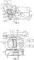
- FIG. 5is a horizontal cross-sectional view of a torso stabilization restraint according to the present subject matter.
- FIG. 6is a front inboard schematic perspective view of a torso stabilization restraint after having been deployed from storage according to the present subject matter.
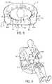
- FIG. 7is a front schematic view of a torso stabilization restraint while being inflated according to the present subject matter.
- FIG. 8is a front view of an inflatable module of a torso stabilization restraint according to the present subject matter.
- FIG. 9is a cross-sectional view taken along line 9 - 9 of the inflatable module of FIG. 8 .
- FIG. 10is a front schematic view of the inflatable module of FIG. 8 being inflated.
- the present inventionprovides a torso stabilization restraint 2 that offers torso stabilization and protection against high localized deflections from impact forces during vehicle collisions, including during oblique vehicle collisions.
- the torso stabilization restraint 2engages an occupant 4 (also referred to herein as “user”) during a collisions, and specifically surrounds the torso 6 of the occupant 4 , to inhibit localized torso deformations, including thorax deformations.
- the torso stabilization restraint 2includes three separate and distinct inflatable modules 8 , 10 , 12 .
- the three modules 8 , 10 , 12deploy from storage, inflate, and connect to one another to form a unified support 14 in contact with the front 16 and sides 18 , 20 of the torso 6 of the occupant 4 .
- a vehicle seat 22and specifically the seat back 24 , may contact a back 21 of the torso 6 , and optionally the sides 18 , 20 or the torso 6 .
- the unified support 14 in combination with the seat back 24may therefor form a perimeter around the torso 6 of the occupant 4 sitting in the seat 22 (see FIG. 5 ).
- the torso stabilization restraint 2may function in conjunctions with a seat belt 26 associated with the seat 22 and/or a seat frame within the seat 22 .
- the seat belt 26may include a lap belt 28 configured to be arranged over the lap 30 of the occupant 4 , and a shoulder belt 32 configured to be arranged diagonally in front 16 of the torso 6 of the occupant 4 .
- the seat belt 26may secure the occupant 4 in the seat 22 during a collision, while the unified support 14 supports the torso 6 against high localized deflections.
- the unified support 14After connection of the three modules 8 , 10 , 12 to form the unified support 14 , further inflation of the modules 8 , 10 , 12 may cause the unified support 14 to contract around the torso 6 , and may provide a certain stiffness level once fully inflated. In combination with the vehicle seat back 24 , the unified support 14 and the contraction and stiffness it provides, by may exert a radially inward directed pressure against the torso 6 (see arrows in FIG. 5 ). This radially inward directed pressure may thus offer support and stabilization to the torso 6 during the collision and inhibit localized deflections of the torso 6 .
- the inflatable modules 8 , 10 , 12may each be formed from a material configured to define an interior volume.
- the modules 8 , 10 , 12may each include one or more sheets or pieces of the material that are connected together to define the interior volume.
- the modules 8 , 10 , 12may each be in the configuration of an inflatable bag as depicted in the figures, which bag can be inflated with a fluid, e.g. gas.
- the modules 8 , 10 , 12may be stored in a stored condition, where the modules 8 , 10 , 12 may be compressed, deflated, and unconnected from one another.
- deflatedit is meant that the modules 8 , 10 , 12 are not fully inflated, which could be a state where the interior volume of the modules 8 , 10 , 12 is less than at a maximum.
- the interior volumemay be at a minimum and have no gas therein (fully deflated), or the interior volume may be somewhere between the minimum and the maximum and have some gas therein (i.e. partially inflated).
- the modules 8 , 10 , 12may be arranged separate and distinct from one another such that they are not connected, and each is deflated and compressed.
- the modules 8 , 10 , 12may be compressed by being in a rolled arrangement, a folded arrangement, a crumpled arrangement, or other arrangement where the modules 8 , 10 , 12 are compacted so as to take up a smaller area or volume than if not compressed.
- each of the modules 8 , 10 , 12take up less space than a deployed condition ( FIG. 6 ).
- a fluide.g. gas
- a fluidmay be introduced into the interior volume of each of the modules 8 , 10 , 12 to inflate each with gas to increase the interior volume and cause each to be deployed (see FIG. 6 ) from storage.
- the modules 8 , 10 , 12are partially opened (e.g. partially unfolded or partially unrolled) from the stored condition, and are partially inflated.
- the modules 8 , 10 , 12are still unconnected to one another.
- further inflation of the modules 8 , 10 , 12may continue until they are fully inflated to the fully inflated condition, where their interior volume is at a maximum and is filled with gas. This further inflation may cause the modules 8 , 10 , 12 to experience a change in width and/or height and/or thickness. For example, after the modules 8 , 10 , 12 are in the connected condition, further inflation the modules 8 , 10 , 12 may cause each to experience a decrease in width and an increase in height as indicated by the arrows in FIGS. 7 and 10 , and an increase in thickness.
- the transition of the modules 8 , 10 , 12 from the stored condition, to the deployed condition, to the connected condition, and then to the fully inflated conditionmay be a smooth one, as gas may be continually introduced in the interior volume of the modules 8 , 10 , 12 at a steady rate to produce a constant rate of inflation of the modules 8 , 10 , 12 .
- Introduction of the gas into the interior volume of each of the modules 8 , 10 , 12may be accomplished by injecting gas into the interior volume, or by producing gas (e.g. by a chemical reaction) directly inside the interior volume.
- Inflation of the modules 8 , 10 , 12may be instigated by an electronic control unit of a vehicle in which the torso stabilization restraint 2 is arranged, and may rely on measurements from sensors such as accelerometers which can sense a collision necessitating inflation of the modules 8 , 10 , 12 .
- the modules 8 , 10 , 12When in the stored condition, the modules 8 , 10 , 12 are unconnected from one another. That is, the modules 8 , 10 , 12 are stored separated from one another. During a collision however, the modules 8 , 10 , 12 are inflated, and thus connect to one another to form the unified support 14 .
- the inflatable first module 8may be an inboard module stored at an inboard side 34 of the seat 22 , e.g. near a center console 38 of the vehicle and opposite from a door 36 of the vehicle.
- the first module 8may be stored in a concealed manner on the inboard side 34 of the seat 22 , e.g. the inboard side 34 of the seat back 24 , or within a storage compartment 64 on the inboard side 34 of the seat 22 or seat back 24 .
- the first module 8may be deployable from the storage compartment 64 on or within the seat 22 during a collision. When deployed and inflated, the first module 8 is arranged near the inboard side 34 of the seat 22 .
- the first module 8may be anchored to the inboard side 34 of the seat 22 after it is deployed, and thus held in place there during a collision.
- the first module 8may be arranged on the inboard (e.g. right) side 34 of the seat 22 , and thus on the inboard (e.g. right) side 18 of the torso 6 of the occupant 4 .
- the inflatable second module 10may be a central module stored in a concealed manner on the lap belt 28 or shoulder belt 32 , or within a storage compartment 66 of the lap belt 28 or shoulder belt 32 .
- the second module 10may be deployable from the storage compartment 66 arranged on or within the seat belt 26 during a collision. When deployed and inflated, the second module 10 is arranged between the first module 8 and the third module 12 , and thus is central to the first and third modules 8 , 12 .
- the second module 10may be anchored to the seat belt 26 after it is deployed, and thus held in place there during a collision.
- the second module 10may be arranged central to the torso 6 of the occupant 4 .
- the inflatable third module 12may be an outboard module stored at an outboard side 40 of the seat 22 , e.g. near a door 36 of the vehicle and opposite from the center console 38 of the vehicle.
- the third module 12may be stored in a concealed manner on the outboard side 40 of the seat 22 , e.g. the outboard side 40 of the seat back 24 , or within a storage compartment 68 on the outboard side 40 of the seat 22 or seat back 24 .
- the third module 12may be deployable from the storage compartment 68 arranged on or within the seat 22 during a collision. When deployed and inflated, the third module 12 is arranged near the outboard side 40 of the seat 22 .
- the third module 12may be anchored to the outboard side 40 of the seat 22 after it is deployed, and thus held in place there during a collision.
- the third module 12may be arranged on the outboard (e.g. left) side 40 of the seat 22 , and thus on the outboard (e.g. left) side 20 of the torso 6 of the occupant 4 .
- the occupant 4may be seated on the other side of the vehicle from that depicted in the figures, such that the door is on the other side of the occupant as that shown. In this configuration, the outboard side of the seat or occupant would then be the left side of the seat or occupant, while the inboard side of the seat or occupant would be the right side of the seat or occupant.
- the modules 8 , 10 , 12may be stored in respective storage compartments 64 , 66 , 68 (see FIG. 6 ).
- the modules 8 , 10 , 12may each be deployed from respective storage compartment 64 , 66 , 68 by introducing gas in the interior volume of each module 8 , 10 , 12 . This introduction of gas causes each of the modules 8 , 10 , 12 to come out of respective storage compartments 64 , 66 , 68 to assume the deployed condition ( FIG. 6 ).
- the modules 8 , 10 , 12can then be further inflated to the connected condition ( FIG. 7 ), where each module 8 , 10 , 12 is fully opened (e.g. completely unfolded or unrolled), and can thereby connect to one another to form the unified support 14 .
- the modules 8 , 10 , 12 in the connected conditionare still not fully inflated, but are only partially inflated.
- the modules 8 , 10 , 12may be in a generally flat configuration.
- the modules 8 , 10 , 12When in the connected condition, i.e. fully opened and partially inflated, the modules 8 , 10 , 12 have an overall width W′. After they are connected, the modules 8 , 10 , 12 are then further inflated to the fully inflated condition, which results in each of their widths being reduced. That is, further inflation of the modules 8 , 10 , 12 from the connected condition to the fully inflated condition may result in a reduction of a width W of at least one of the modules 8 , 10 , 12 from a first width W 1 to a second width W 2 , while a height H of one or more of the modules 8 , 10 , 12 may increase from a first height H 1 to a second height H 2 . This is shown in FIGS. 7 and 10 for example.
- FIG. 10depicts a single module, which is representative of any of the modules 8 , 10 , 12 , in a connected condition (indicated “CC” in FIG. 10 ), and schematically depicts the process further inflating the module to a fully inflated condition (indicated “FIC” in FIG. 10 ).
- the width W of the moduledecreases as indicated by the two inward pointing horizontal arrows; and a height H of the module increases as indicated by the two outward pointing vertical arrows.
- FIG. 7shows a similar change in the size of each of the modules 8 , 10 , 12 during inflation, as indicated by the arrows.
- the reduction of the width Wand increase of the height H when the modules 8 , 10 , 12 are inflated between the connected condition and the fully inflated conditionmay be due to the modules 8 , 10 , 12 including the seams 52 and corresponding cells 54 .
- This decrease of the width W of one or more of the modules 8 , 10 , 12may result in an overall width W of the unified support 14 (i.e. a collective width of the modules 8 , 10 , 12 when connected) to also decrease when the modules 8 , 10 , 12 are further inflated from the connected condition to the fully inflated condition.
- further inflation of the modules 8 , 10 , 12 from the connected condition to the fully inflated conditionmay result in an increase in a thickness T of the modules 8 , 10 , 12 as measured from the first side 48 to the second side 50 .
- further inflation from the connected conditionresults in an increase in thickness T of the modules 8 , 10 , 12 .
- This increase in thickness T and decrease in overall width Wmay cause the unified support 14 , in combination with the seat back 24 , to exert pressure radially inwardly against the torso 6 of the occupant 4 , which is depicted in FIG. 5 by radially inward pointing arrows.
- Such inward directed pressure against the torso 6may provide support to, and help stabilize, the torso 6 during a collision, thus inhibiting high localized deflections of the torso 6 during a collision.
- Inflation of the modules 8 , 10 , 12may also provide protection against blunt impact to the torso 6 from interior vehicle components such as the steering wheel of the vehicle.
- One or more, and preferably all three modules 8 , 10 , 12include connectors 42 for reversibly connecting together the three modules 8 , 10 , 12 to form the unified support 14 .
- the connectors 42may include hook and loop connectors, reversible interlocking fibers or microfibers, or other reversibly linking connectors.
- the connectors 42may be arranged on edges of each of the modules 8 , 10 , 12 so as to connect the modules 8 , 10 , 12 along interfaces 44 , 46 between them.
- the first module 8is directly connected by connectors 42 A at a first interface 44 to the second module 10
- the second module 10is directly connected by connectors 42 B at a second interface 46 to the third module 12 .
- the first and second interfaces 44 , 46may each be generally vertical ( ⁇ 10 degrees from vertical) between the modules 8 , 10 , 12 .
- the connectors 42may extend along a portion of the interfaces 44 , 46 , or along the entire interfaces 44 , 46 .
- the modules 8 , 10 , 12may connect below a shoulder level and underneath the arms 62 of the occupant 4 as depicted in FIGS. 1-4 .
- the connected modules 8 , 10 , 12i.e. the unified support 14
- the unified support 14is not arranged over the arms 62 of the occupant 4 so as not to pin the arms 62 against the torso 6 during a collision.
- the first interface 44may be arranged under the occupant's inboard arm 62 A
- the second interface 46may be arranged under the occupant's outboard arm 62 B.
- the modules 8 , 10 , 12may each include a first side 48 and an opposite second side 50 .
- the first side 48may face away from the occupant 4
- the second side 50may face, and optionally contact, the occupant 4 .
- the first side 48may be connected to the second side 50 along seams 52 , which seams 52 may separate the modules 8 , 10 , 12 into cells 54 .
- the seams 52 and cells 54may be arranged generally vertically.
- the cells 54may each have a generally circular cross section ( FIG. 9 ).
- the seams 52may be formed by stitching, adhesive, welding, or other device or method.
- the seams 52may extend fully or partially between a bottom 56 and top 58 of each of the modules 8 , 10 , 12 .
- the seams 52extend only partially between the bottom 56 and top 58 of each of the modules 8 , 10 , 12 , such that the cells 54 are open at their ends 60 where there are no seams 52 , and are in fluid communications at their ends 60 with others of the cells 54 .
- the modules 8 , 10 , 12can each be deflated by removing gas from the interior volume.
- This deflationcan be accomplished passively by having apertures extending through the material of the modules 8 , 10 , 12 from the exterior to the interior volume, thus passively allowing gas to escape from the interior volume; or by actively sucking out gas from the interior volume by use of a vacuum/pump, for example.
- the unified support 14can be disassembled/decoupled at the interfaces 44 , 46 in order to allow the occupant 4 to be free from the unified support 14 .
- This disassembly/decouplingcan be accomplished after the modules 8 , 10 , 12 are deflated, and by unfastening the connectors 42 to separate the first module 8 from the second module 10 , and to separate the second module 10 from the third module 12 .
- the separation of the modules 8 , 10 , 12thus allows the occupant 4 to be free of the unified support 14 .
Landscapes
- Engineering & Computer Science (AREA)
- Mechanical Engineering (AREA)
- Textile Engineering (AREA)
- Air Bags (AREA)
Abstract
Description
Claims (19)
Priority Applications (1)
| Application Number | Priority Date | Filing Date | Title |
|---|---|---|---|
| US16/809,877US11414036B2 (en) | 2020-03-05 | 2020-03-05 | Torso stabilization restraint |
Applications Claiming Priority (1)
| Application Number | Priority Date | Filing Date | Title |
|---|---|---|---|
| US16/809,877US11414036B2 (en) | 2020-03-05 | 2020-03-05 | Torso stabilization restraint |
Publications (2)
| Publication Number | Publication Date |
|---|---|
| US20210276506A1 US20210276506A1 (en) | 2021-09-09 |
| US11414036B2true US11414036B2 (en) | 2022-08-16 |
Family
ID=77555406
Family Applications (1)
| Application Number | Title | Priority Date | Filing Date |
|---|---|---|---|
| US16/809,877Active2040-05-08US11414036B2 (en) | 2020-03-05 | 2020-03-05 | Torso stabilization restraint |
Country Status (1)
| Country | Link |
|---|---|
| US (1) | US11414036B2 (en) |
Families Citing this family (1)
| Publication number | Priority date | Publication date | Assignee | Title |
|---|---|---|---|---|
| EP3922517A4 (en)* | 2019-02-09 | 2022-12-14 | Autoliv Development AB | SIDE AIRBAG DEVICE |
Citations (51)
| Publication number | Priority date | Publication date | Assignee | Title |
|---|---|---|---|---|
| US3430979A (en)* | 1966-11-17 | 1969-03-04 | Chrysler Corp | Inflatable cushioning device |
| US3623768A (en)* | 1970-08-05 | 1971-11-30 | Stanford Research Inst | Vehicular safety seat |
| US3981518A (en)* | 1975-05-05 | 1976-09-21 | Liberty Mutual Insurance Company | Vehicle restraint system |
| US5184844A (en)* | 1990-11-27 | 1993-02-09 | Goor Associates, Inc. | Integral inflatable occupant restraint system |
| US5390952A (en)* | 1990-11-27 | 1995-02-21 | Goor Associates, Inc. | Integral inflatable occupant restraint system |
| CA2289525A1 (en)* | 1997-05-11 | 1998-11-19 | S. Jay Cross | Seatbelt system having seamless inflatable member |
| US6336656B1 (en)* | 1997-03-31 | 2002-01-08 | Simula, Inc. | Inflatable tubular torso restraint system with pivoting upper anchor point attachment |
| US20050236209A1 (en)* | 2004-04-22 | 2005-10-27 | Chernoff Adrian B | Variable seat belt |
| US20060049617A1 (en)* | 2004-09-03 | 2006-03-09 | Mowry Gregory A | Inflatable tubular or other cushions particularly useful for torso protection |
| US20060119085A1 (en)* | 2004-12-07 | 2006-06-08 | Nissan Motor Co., Ltd. | Vehicle occupant restraint system and vehicle occupant restraint method |
| US20060192367A1 (en)* | 1999-12-23 | 2006-08-31 | Zumpano Bernard J | Inflatable restraint assembly for vehicles |
| US20060202452A1 (en)* | 1994-05-23 | 2006-09-14 | Automotive Technologies International, Inc. | Side curtain and multi-compartment vehicular airbags |
| US20070096535A1 (en)* | 2005-11-03 | 2007-05-03 | Ford Global Technologies, Llc | Restraint system for a vehicle |
| WO2008139655A1 (en) | 2007-04-27 | 2008-11-20 | Takata Corporation | Seat belt device |
| JP2009137441A (en)* | 2007-12-06 | 2009-06-25 | Takata Corp | Occupant restraint system |
| US7571931B2 (en)* | 2004-04-15 | 2009-08-11 | Nissan Motor Co., Ltd. | Vehicle passenger restraint system |
| US20100025972A1 (en)* | 2008-08-01 | 2010-02-04 | Toyota Jidosha Kabushiki Kaisha | Vehicular occupant restraint system |
| US7669891B2 (en) | 2008-05-09 | 2010-03-02 | Nissan Motor Co., Ltd. | Vehicle occupant protection system |
| JP2011051448A (en) | 2009-09-01 | 2011-03-17 | Autoliv Development Ab | Seat belt device |
| US8038170B2 (en) | 2008-01-11 | 2011-10-18 | Toyota Jidosha Kabushiki Kaisha | Vehicle occupant restraint apparatus |
| WO2012003949A1 (en)* | 2010-07-08 | 2012-01-12 | Daimler Ag | Safety belt for a vehicle |
| US20120133114A1 (en)* | 2010-11-29 | 2012-05-31 | Hyundai Motor Company | Internal airbag device |
| US20150054264A1 (en)* | 2013-08-21 | 2015-02-26 | Toyota Jidosha Kabushiki Kaisha | Air belt device |
| US9085279B2 (en) | 2010-11-17 | 2015-07-21 | Toyota Jidosha Kabushiki Kaisha | Side airbag device for vehicle |
| US20150259071A1 (en)* | 2014-03-11 | 2015-09-17 | Airbus Helicopters | Device for protecting an individual sitting on a seat, a seat, and a vehicle |
| US20160039385A1 (en)* | 2014-08-06 | 2016-02-11 | Fuji Jukogyo Kabushiki Kaisha | Occupant protection apparatus for vehicle |
| US9517744B2 (en) | 2013-09-09 | 2016-12-13 | Toyota Jidosha Kabushiki Kaisha | Vehicle occupant protection device |
| US20170225788A1 (en)* | 2016-02-08 | 2017-08-10 | Amsafe, Inc. | Multi-chamber airbags and associated methods of manufacture and use |
| US20170282832A1 (en) | 2016-03-31 | 2017-10-05 | Fuji Jukogyo Kabushiki Kaisha | Occupant protection apparatus for vehicle |
| US20180043852A1 (en)* | 2014-10-21 | 2018-02-15 | Trw Vehicle Safety Systems Inc. | Self-conforming rearseat air bag |
| JP2018086990A (en)* | 2016-11-30 | 2018-06-07 | タカタ株式会社 | Occupant restraint device and seat |
| US20180281727A1 (en) | 2017-04-04 | 2018-10-04 | GM Global Technology Operations LLC | Motor vehicle with safety belt restraint system |
| CN108692953A (en)* | 2017-03-31 | 2018-10-23 | 福特全球技术公司 | Seat including air bag |
| DE102017209417A1 (en) | 2017-06-02 | 2018-12-06 | Volkswagen Aktiengesellschaft | Vehicle occupant protection device and vehicle with such |
| US20190023214A1 (en)* | 2017-07-24 | 2019-01-24 | Toyota Jidosha Kabushiki Kaisha | Vehicle occupant protection device, airbag control method, and airbag folding method |
| US20190047504A1 (en)* | 2017-08-09 | 2019-02-14 | Toyota Jidosha Kabushiki Kaisha | Side airbag device |
| US20190077359A1 (en) | 2017-09-08 | 2019-03-14 | Hyundai Mobis Co., Ltd. | Airbag device for vehicle |
| DE102017218331A1 (en) | 2017-10-13 | 2019-04-18 | Bayerische Motoren Werke Aktiengesellschaft | Airbag arrangement for a transversely mounted to the direction of travel vehicle seat of a motor vehicle |
| US10399529B2 (en)* | 2017-09-25 | 2019-09-03 | Ford Global Technologies, Llc | Seat assembly with moveable arms with airbags |
| US10407015B2 (en)* | 2017-06-27 | 2019-09-10 | Ford Global Technologies, Llc | Restraint system |
| DE102019203316A1 (en)* | 2018-03-12 | 2019-09-12 | Lear Corporation | Occupant protection system for a vehicle seat |
| US20190283700A1 (en)* | 2018-03-19 | 2019-09-19 | Hyundai Motor Company | Airbag for vehicle |
| WO2019197164A1 (en)* | 2018-03-27 | 2019-10-17 | Joyson Safety Systems Germany Gmbh | Airbag arrangement for a vehicle occupant restraint system |
| US10471923B2 (en)* | 2017-01-11 | 2019-11-12 | Zoox, Inc. | Occupant protection system including expandable curtain and/or expandable bladder |
| US10513206B2 (en)* | 2017-11-21 | 2019-12-24 | Ford Global Technologies, Llc | Vehicle seat |
| US20200324728A1 (en)* | 2019-04-10 | 2020-10-15 | Ford Global Technologies, Llc | Seat airbag |
| KR20200130765A (en)* | 2019-04-29 | 2020-11-20 | 아우토리브 디벨롭먼트 아베 | Airbag apparatus of vehicle |
| DE102019116586A1 (en)* | 2019-06-19 | 2020-12-24 | Zf Automotive Germany Gmbh | Gas bag module, vehicle seat with gas bag module and vehicle |
| US20210094504A1 (en)* | 2019-09-30 | 2021-04-01 | Toyoda Gosei Co., Ltd. | Occupant protection system |
| US20210138989A1 (en)* | 2019-11-08 | 2021-05-13 | Honda Motor Co., Ltd. | Occupant restraint system for a vehicle |
| US20210146874A1 (en)* | 2019-11-18 | 2021-05-20 | Hyundai Mobis Co., Ltd. | Airbag apparatus |
- 2020
- 2020-03-05USUS16/809,877patent/US11414036B2/enactiveActive
Patent Citations (54)
| Publication number | Priority date | Publication date | Assignee | Title |
|---|---|---|---|---|
| US3430979A (en)* | 1966-11-17 | 1969-03-04 | Chrysler Corp | Inflatable cushioning device |
| US3623768A (en)* | 1970-08-05 | 1971-11-30 | Stanford Research Inst | Vehicular safety seat |
| US3981518A (en)* | 1975-05-05 | 1976-09-21 | Liberty Mutual Insurance Company | Vehicle restraint system |
| US5184844A (en)* | 1990-11-27 | 1993-02-09 | Goor Associates, Inc. | Integral inflatable occupant restraint system |
| US5390952A (en)* | 1990-11-27 | 1995-02-21 | Goor Associates, Inc. | Integral inflatable occupant restraint system |
| US20060202452A1 (en)* | 1994-05-23 | 2006-09-14 | Automotive Technologies International, Inc. | Side curtain and multi-compartment vehicular airbags |
| US6336656B1 (en)* | 1997-03-31 | 2002-01-08 | Simula, Inc. | Inflatable tubular torso restraint system with pivoting upper anchor point attachment |
| CA2289525A1 (en)* | 1997-05-11 | 1998-11-19 | S. Jay Cross | Seatbelt system having seamless inflatable member |
| US20060192367A1 (en)* | 1999-12-23 | 2006-08-31 | Zumpano Bernard J | Inflatable restraint assembly for vehicles |
| US7571931B2 (en)* | 2004-04-15 | 2009-08-11 | Nissan Motor Co., Ltd. | Vehicle passenger restraint system |
| US20050236209A1 (en)* | 2004-04-22 | 2005-10-27 | Chernoff Adrian B | Variable seat belt |
| US20060049617A1 (en)* | 2004-09-03 | 2006-03-09 | Mowry Gregory A | Inflatable tubular or other cushions particularly useful for torso protection |
| US7163236B2 (en)* | 2004-12-07 | 2007-01-16 | Nissan Motor Co., Ltd. | Vehicle occupant restraint system and vehicle occupant restraint method |
| US20060119085A1 (en)* | 2004-12-07 | 2006-06-08 | Nissan Motor Co., Ltd. | Vehicle occupant restraint system and vehicle occupant restraint method |
| US20070096535A1 (en)* | 2005-11-03 | 2007-05-03 | Ford Global Technologies, Llc | Restraint system for a vehicle |
| WO2008139655A1 (en) | 2007-04-27 | 2008-11-20 | Takata Corporation | Seat belt device |
| JP2009137441A (en)* | 2007-12-06 | 2009-06-25 | Takata Corp | Occupant restraint system |
| US8038170B2 (en) | 2008-01-11 | 2011-10-18 | Toyota Jidosha Kabushiki Kaisha | Vehicle occupant restraint apparatus |
| US7669891B2 (en) | 2008-05-09 | 2010-03-02 | Nissan Motor Co., Ltd. | Vehicle occupant protection system |
| US8104790B2 (en) | 2008-08-01 | 2012-01-31 | Toyota Jidosha Kabushiki Kaisha | Vehicular occupant restraint system |
| US20100025972A1 (en)* | 2008-08-01 | 2010-02-04 | Toyota Jidosha Kabushiki Kaisha | Vehicular occupant restraint system |
| JP2011051448A (en) | 2009-09-01 | 2011-03-17 | Autoliv Development Ab | Seat belt device |
| WO2012003949A1 (en)* | 2010-07-08 | 2012-01-12 | Daimler Ag | Safety belt for a vehicle |
| US9085279B2 (en) | 2010-11-17 | 2015-07-21 | Toyota Jidosha Kabushiki Kaisha | Side airbag device for vehicle |
| US20120133114A1 (en)* | 2010-11-29 | 2012-05-31 | Hyundai Motor Company | Internal airbag device |
| US20150054264A1 (en)* | 2013-08-21 | 2015-02-26 | Toyota Jidosha Kabushiki Kaisha | Air belt device |
| US9517744B2 (en) | 2013-09-09 | 2016-12-13 | Toyota Jidosha Kabushiki Kaisha | Vehicle occupant protection device |
| US20150259071A1 (en)* | 2014-03-11 | 2015-09-17 | Airbus Helicopters | Device for protecting an individual sitting on a seat, a seat, and a vehicle |
| US20160039385A1 (en)* | 2014-08-06 | 2016-02-11 | Fuji Jukogyo Kabushiki Kaisha | Occupant protection apparatus for vehicle |
| US20180043852A1 (en)* | 2014-10-21 | 2018-02-15 | Trw Vehicle Safety Systems Inc. | Self-conforming rearseat air bag |
| US20170225788A1 (en)* | 2016-02-08 | 2017-08-10 | Amsafe, Inc. | Multi-chamber airbags and associated methods of manufacture and use |
| US20170282832A1 (en) | 2016-03-31 | 2017-10-05 | Fuji Jukogyo Kabushiki Kaisha | Occupant protection apparatus for vehicle |
| JP2018086990A (en)* | 2016-11-30 | 2018-06-07 | タカタ株式会社 | Occupant restraint device and seat |
| US10471923B2 (en)* | 2017-01-11 | 2019-11-12 | Zoox, Inc. | Occupant protection system including expandable curtain and/or expandable bladder |
| CN108692953A (en)* | 2017-03-31 | 2018-10-23 | 福特全球技术公司 | Seat including air bag |
| US20180281727A1 (en) | 2017-04-04 | 2018-10-04 | GM Global Technology Operations LLC | Motor vehicle with safety belt restraint system |
| DE102017209417A1 (en) | 2017-06-02 | 2018-12-06 | Volkswagen Aktiengesellschaft | Vehicle occupant protection device and vehicle with such |
| US10407015B2 (en)* | 2017-06-27 | 2019-09-10 | Ford Global Technologies, Llc | Restraint system |
| US20190023214A1 (en)* | 2017-07-24 | 2019-01-24 | Toyota Jidosha Kabushiki Kaisha | Vehicle occupant protection device, airbag control method, and airbag folding method |
| US20190047504A1 (en)* | 2017-08-09 | 2019-02-14 | Toyota Jidosha Kabushiki Kaisha | Side airbag device |
| US20190077359A1 (en) | 2017-09-08 | 2019-03-14 | Hyundai Mobis Co., Ltd. | Airbag device for vehicle |
| US10875486B2 (en)* | 2017-09-08 | 2020-12-29 | Hyundai Mobis Co., Ltd. | Airbag device for vehicle |
| US10399529B2 (en)* | 2017-09-25 | 2019-09-03 | Ford Global Technologies, Llc | Seat assembly with moveable arms with airbags |
| DE102017218331A1 (en) | 2017-10-13 | 2019-04-18 | Bayerische Motoren Werke Aktiengesellschaft | Airbag arrangement for a transversely mounted to the direction of travel vehicle seat of a motor vehicle |
| US10513206B2 (en)* | 2017-11-21 | 2019-12-24 | Ford Global Technologies, Llc | Vehicle seat |
| DE102019203316A1 (en)* | 2018-03-12 | 2019-09-12 | Lear Corporation | Occupant protection system for a vehicle seat |
| US20190283700A1 (en)* | 2018-03-19 | 2019-09-19 | Hyundai Motor Company | Airbag for vehicle |
| WO2019197164A1 (en)* | 2018-03-27 | 2019-10-17 | Joyson Safety Systems Germany Gmbh | Airbag arrangement for a vehicle occupant restraint system |
| US20200324728A1 (en)* | 2019-04-10 | 2020-10-15 | Ford Global Technologies, Llc | Seat airbag |
| KR20200130765A (en)* | 2019-04-29 | 2020-11-20 | 아우토리브 디벨롭먼트 아베 | Airbag apparatus of vehicle |
| DE102019116586A1 (en)* | 2019-06-19 | 2020-12-24 | Zf Automotive Germany Gmbh | Gas bag module, vehicle seat with gas bag module and vehicle |
| US20210094504A1 (en)* | 2019-09-30 | 2021-04-01 | Toyoda Gosei Co., Ltd. | Occupant protection system |
| US20210138989A1 (en)* | 2019-11-08 | 2021-05-13 | Honda Motor Co., Ltd. | Occupant restraint system for a vehicle |
| US20210146874A1 (en)* | 2019-11-18 | 2021-05-20 | Hyundai Mobis Co., Ltd. | Airbag apparatus |
Also Published As
| Publication number | Publication date |
|---|---|
| US20210276506A1 (en) | 2021-09-09 |
Similar Documents
| Publication | Publication Date | Title |
|---|---|---|
| JP6673392B2 (en) | Occupant protection device | |
| CN112020457B (en) | Overhead inflatable airbag assembly | |
| JP6426590B2 (en) | Occupant protection device | |
| KR102064844B1 (en) | Airbag apparatus of vehicle | |
| US11351950B2 (en) | Vehicle seat | |
| CN105564358B (en) | Airbag apparatus | |
| US12109967B2 (en) | Airbag device | |
| EP2581276B1 (en) | Tubular Airbag | |
| JP5958129B2 (en) | Seat cushion airbag device | |
| JP7138591B2 (en) | air bag device | |
| JP2011025909A (en) | Side airbag device | |
| US12109964B2 (en) | Airbag device | |
| CN111845613B (en) | Side airbag device | |
| CN116194344A (en) | Airbag device | |
| US11414036B2 (en) | Torso stabilization restraint | |
| CN116198446A (en) | Distal balloon device | |
| US11260819B2 (en) | Airbag apparatus | |
| CN115003560B (en) | Airbag device and vehicle seat | |
| JP6544263B2 (en) | Side airbag device | |
| JP6854358B2 (en) | Side airbag device | |
| JP2018161925A (en) | Side airbag device | |
| CN114802086B (en) | Distal balloon device | |
| JP6580926B2 (en) | Side airbag device | |
| US12269412B2 (en) | Side airbag | |
| JP7519393B2 (en) | Seat-mounted airbag device |
Legal Events
| Date | Code | Title | Description |
|---|---|---|---|
| AS | Assignment | Owner name:HONDA MOTOR CO., LTD., JAPAN Free format text:ASSIGNMENT OF ASSIGNORS INTEREST;ASSIGNOR:MARKUSIC, CRAIG A.;REEL/FRAME:052025/0686 Effective date:20200214 | |
| FEPP | Fee payment procedure | Free format text:ENTITY STATUS SET TO UNDISCOUNTED (ORIGINAL EVENT CODE: BIG.); ENTITY STATUS OF PATENT OWNER: LARGE ENTITY | |
| STPP | Information on status: patent application and granting procedure in general | Free format text:RESPONSE TO NON-FINAL OFFICE ACTION ENTERED AND FORWARDED TO EXAMINER | |
| STPP | Information on status: patent application and granting procedure in general | Free format text:NON FINAL ACTION MAILED | |
| STPP | Information on status: patent application and granting procedure in general | Free format text:RESPONSE TO NON-FINAL OFFICE ACTION ENTERED AND FORWARDED TO EXAMINER | |
| STPP | Information on status: patent application and granting procedure in general | Free format text:FINAL REJECTION MAILED | |
| STPP | Information on status: patent application and granting procedure in general | Free format text:RESPONSE AFTER FINAL ACTION FORWARDED TO EXAMINER | |
| STPP | Information on status: patent application and granting procedure in general | Free format text:NOTICE OF ALLOWANCE MAILED -- APPLICATION RECEIVED IN OFFICE OF PUBLICATIONS | |
| STPP | Information on status: patent application and granting procedure in general | Free format text:AWAITING TC RESP., ISSUE FEE NOT PAID | |
| STPP | Information on status: patent application and granting procedure in general | Free format text:NOTICE OF ALLOWANCE MAILED -- APPLICATION RECEIVED IN OFFICE OF PUBLICATIONS | |
| STPP | Information on status: patent application and granting procedure in general | Free format text:PUBLICATIONS -- ISSUE FEE PAYMENT VERIFIED | |
| STCF | Information on status: patent grant | Free format text:PATENTED CASE |