US11413102B2 - Multi-access port for surgical robotic systems - Google Patents
Multi-access port for surgical robotic systemsDownload PDFInfo
- Publication number
- US11413102B2 US11413102B2US16/454,741US201916454741AUS11413102B2US 11413102 B2US11413102 B2US 11413102B2US 201916454741 AUS201916454741 AUS 201916454741AUS 11413102 B2US11413102 B2US 11413102B2
- Authority
- US
- United States
- Prior art keywords
- surgical
- robotic
- motor
- control
- access port
- Prior art date
- Legal status (The legal status is an assumption and is not a legal conclusion. Google has not performed a legal analysis and makes no representation as to the accuracy of the status listed.)
- Active, expires
Links
Images


Classifications
- A—HUMAN NECESSITIES
- A61—MEDICAL OR VETERINARY SCIENCE; HYGIENE
- A61B—DIAGNOSIS; SURGERY; IDENTIFICATION
- A61B90/00—Instruments, implements or accessories specially adapted for surgery or diagnosis and not covered by any of the groups A61B1/00 - A61B50/00, e.g. for luxation treatment or for protecting wound edges
- A61B90/36—Image-producing devices or illumination devices not otherwise provided for
- A61B90/361—Image-producing devices, e.g. surgical cameras
- A—HUMAN NECESSITIES
- A61—MEDICAL OR VETERINARY SCIENCE; HYGIENE
- A61B—DIAGNOSIS; SURGERY; IDENTIFICATION
- A61B34/00—Computer-aided surgery; Manipulators or robots specially adapted for use in surgery
- A61B34/30—Surgical robots
- A61B34/35—Surgical robots for telesurgery
- A—HUMAN NECESSITIES
- A61—MEDICAL OR VETERINARY SCIENCE; HYGIENE
- A61B—DIAGNOSIS; SURGERY; IDENTIFICATION
- A61B17/00—Surgical instruments, devices or methods
- A61B17/02—Surgical instruments, devices or methods for holding wounds open, e.g. retractors; Tractors
- A61B17/0206—Surgical instruments, devices or methods for holding wounds open, e.g. retractors; Tractors with antagonistic arms as supports for retractor elements
- A—HUMAN NECESSITIES
- A61—MEDICAL OR VETERINARY SCIENCE; HYGIENE
- A61B—DIAGNOSIS; SURGERY; IDENTIFICATION
- A61B17/00—Surgical instruments, devices or methods
- A61B17/34—Trocars; Puncturing needles
- A—HUMAN NECESSITIES
- A61—MEDICAL OR VETERINARY SCIENCE; HYGIENE
- A61B—DIAGNOSIS; SURGERY; IDENTIFICATION
- A61B17/00—Surgical instruments, devices or methods
- A61B17/34—Trocars; Puncturing needles
- A61B17/3417—Details of tips or shafts, e.g. grooves, expandable, bendable; Multiple coaxial sliding cannulas, e.g. for dilating
- A61B17/3421—Cannulas
- A61B17/3439—Cannulas with means for changing the inner diameter of the cannula, e.g. expandable
- A—HUMAN NECESSITIES
- A61—MEDICAL OR VETERINARY SCIENCE; HYGIENE
- A61B—DIAGNOSIS; SURGERY; IDENTIFICATION
- A61B17/00—Surgical instruments, devices or methods
- A61B17/34—Trocars; Puncturing needles
- A61B17/3462—Trocars; Puncturing needles with means for changing the diameter or the orientation of the entrance port of the cannula, e.g. for use with different-sized instruments, reduction ports, adapter seals
- A—HUMAN NECESSITIES
- A61—MEDICAL OR VETERINARY SCIENCE; HYGIENE
- A61B—DIAGNOSIS; SURGERY; IDENTIFICATION
- A61B17/00—Surgical instruments, devices or methods
- A61B17/34—Trocars; Puncturing needles
- A61B17/3476—Powered trocars, e.g. electrosurgical cutting, lasers, powered knives
- A—HUMAN NECESSITIES
- A61—MEDICAL OR VETERINARY SCIENCE; HYGIENE
- A61B—DIAGNOSIS; SURGERY; IDENTIFICATION
- A61B34/00—Computer-aided surgery; Manipulators or robots specially adapted for use in surgery
- A61B34/20—Surgical navigation systems; Devices for tracking or guiding surgical instruments, e.g. for frameless stereotaxis
- A—HUMAN NECESSITIES
- A61—MEDICAL OR VETERINARY SCIENCE; HYGIENE
- A61B—DIAGNOSIS; SURGERY; IDENTIFICATION
- A61B34/00—Computer-aided surgery; Manipulators or robots specially adapted for use in surgery
- A61B34/30—Surgical robots
- A61B34/37—Leader-follower robots
- A—HUMAN NECESSITIES
- A61—MEDICAL OR VETERINARY SCIENCE; HYGIENE
- A61B—DIAGNOSIS; SURGERY; IDENTIFICATION
- A61B90/00—Instruments, implements or accessories specially adapted for surgery or diagnosis and not covered by any of the groups A61B1/00 - A61B50/00, e.g. for luxation treatment or for protecting wound edges
- A61B90/36—Image-producing devices or illumination devices not otherwise provided for
- A61B90/37—Surgical systems with images on a monitor during operation
- G—PHYSICS
- G16—INFORMATION AND COMMUNICATION TECHNOLOGY [ICT] SPECIALLY ADAPTED FOR SPECIFIC APPLICATION FIELDS
- G16H—HEALTHCARE INFORMATICS, i.e. INFORMATION AND COMMUNICATION TECHNOLOGY [ICT] SPECIALLY ADAPTED FOR THE HANDLING OR PROCESSING OF MEDICAL OR HEALTHCARE DATA
- G16H20/00—ICT specially adapted for therapies or health-improving plans, e.g. for handling prescriptions, for steering therapy or for monitoring patient compliance
- G16H20/40—ICT specially adapted for therapies or health-improving plans, e.g. for handling prescriptions, for steering therapy or for monitoring patient compliance relating to mechanical, radiation or invasive therapies, e.g. surgery, laser therapy, dialysis or acupuncture
- G—PHYSICS
- G16—INFORMATION AND COMMUNICATION TECHNOLOGY [ICT] SPECIALLY ADAPTED FOR SPECIFIC APPLICATION FIELDS
- G16H—HEALTHCARE INFORMATICS, i.e. INFORMATION AND COMMUNICATION TECHNOLOGY [ICT] SPECIALLY ADAPTED FOR THE HANDLING OR PROCESSING OF MEDICAL OR HEALTHCARE DATA
- G16H40/00—ICT specially adapted for the management or administration of healthcare resources or facilities; ICT specially adapted for the management or operation of medical equipment or devices
- G16H40/60—ICT specially adapted for the management or administration of healthcare resources or facilities; ICT specially adapted for the management or operation of medical equipment or devices for the operation of medical equipment or devices
- G16H40/63—ICT specially adapted for the management or administration of healthcare resources or facilities; ICT specially adapted for the management or operation of medical equipment or devices for the operation of medical equipment or devices for local operation
- A—HUMAN NECESSITIES
- A61—MEDICAL OR VETERINARY SCIENCE; HYGIENE
- A61B—DIAGNOSIS; SURGERY; IDENTIFICATION
- A61B17/00—Surgical instruments, devices or methods
- A61B2017/00017—Electrical control of surgical instruments
- A61B2017/00221—Electrical control of surgical instruments with wireless transmission of data, e.g. by infrared radiation or radiowaves
- A—HUMAN NECESSITIES
- A61—MEDICAL OR VETERINARY SCIENCE; HYGIENE
- A61B—DIAGNOSIS; SURGERY; IDENTIFICATION
- A61B17/00—Surgical instruments, devices or methods
- A61B2017/00477—Coupling
- A—HUMAN NECESSITIES
- A61—MEDICAL OR VETERINARY SCIENCE; HYGIENE
- A61B—DIAGNOSIS; SURGERY; IDENTIFICATION
- A61B34/00—Computer-aided surgery; Manipulators or robots specially adapted for use in surgery
- A61B34/20—Surgical navigation systems; Devices for tracking or guiding surgical instruments, e.g. for frameless stereotaxis
- A61B2034/2046—Tracking techniques
- A61B2034/2048—Tracking techniques using an accelerometer or inertia sensor
- A—HUMAN NECESSITIES
- A61—MEDICAL OR VETERINARY SCIENCE; HYGIENE
- A61B—DIAGNOSIS; SURGERY; IDENTIFICATION
- A61B34/00—Computer-aided surgery; Manipulators or robots specially adapted for use in surgery
- A61B34/20—Surgical navigation systems; Devices for tracking or guiding surgical instruments, e.g. for frameless stereotaxis
- A61B2034/2046—Tracking techniques
- A61B2034/2055—Optical tracking systems
- A—HUMAN NECESSITIES
- A61—MEDICAL OR VETERINARY SCIENCE; HYGIENE
- A61B—DIAGNOSIS; SURGERY; IDENTIFICATION
- A61B34/00—Computer-aided surgery; Manipulators or robots specially adapted for use in surgery
- A61B34/20—Surgical navigation systems; Devices for tracking or guiding surgical instruments, e.g. for frameless stereotaxis
- A61B2034/2046—Tracking techniques
- A61B2034/2059—Mechanical position encoders
- A—HUMAN NECESSITIES
- A61—MEDICAL OR VETERINARY SCIENCE; HYGIENE
- A61B—DIAGNOSIS; SURGERY; IDENTIFICATION
- A61B34/00—Computer-aided surgery; Manipulators or robots specially adapted for use in surgery
- A61B34/30—Surgical robots
- A61B2034/305—Details of wrist mechanisms at distal ends of robotic arms
- A—HUMAN NECESSITIES
- A61—MEDICAL OR VETERINARY SCIENCE; HYGIENE
- A61B—DIAGNOSIS; SURGERY; IDENTIFICATION
- A61B90/00—Instruments, implements or accessories specially adapted for surgery or diagnosis and not covered by any of the groups A61B1/00 - A61B50/00, e.g. for luxation treatment or for protecting wound edges
- A61B90/36—Image-producing devices or illumination devices not otherwise provided for
- A61B90/37—Surgical systems with images on a monitor during operation
- A61B2090/371—Surgical systems with images on a monitor during operation with simultaneous use of two cameras
- A—HUMAN NECESSITIES
- A61—MEDICAL OR VETERINARY SCIENCE; HYGIENE
- A61B—DIAGNOSIS; SURGERY; IDENTIFICATION
- A61B90/00—Instruments, implements or accessories specially adapted for surgery or diagnosis and not covered by any of the groups A61B1/00 - A61B50/00, e.g. for luxation treatment or for protecting wound edges
- A61B90/36—Image-producing devices or illumination devices not otherwise provided for
- A61B90/37—Surgical systems with images on a monitor during operation
- A61B2090/372—Details of monitor hardware
- A—HUMAN NECESSITIES
- A61—MEDICAL OR VETERINARY SCIENCE; HYGIENE
- A61B—DIAGNOSIS; SURGERY; IDENTIFICATION
- A61B2217/00—General characteristics of surgical instruments
- A61B2217/002—Auxiliary appliance
- A61B2217/005—Auxiliary appliance with suction drainage system
- A—HUMAN NECESSITIES
- A61—MEDICAL OR VETERINARY SCIENCE; HYGIENE
- A61B—DIAGNOSIS; SURGERY; IDENTIFICATION
- A61B2217/00—General characteristics of surgical instruments
- A61B2217/002—Auxiliary appliance
- A61B2217/007—Auxiliary appliance with irrigation system
- A—HUMAN NECESSITIES
- A61—MEDICAL OR VETERINARY SCIENCE; HYGIENE
- A61B—DIAGNOSIS; SURGERY; IDENTIFICATION
- A61B34/00—Computer-aided surgery; Manipulators or robots specially adapted for use in surgery
- A61B34/25—User interfaces for surgical systems
- A—HUMAN NECESSITIES
- A61—MEDICAL OR VETERINARY SCIENCE; HYGIENE
- A61B—DIAGNOSIS; SURGERY; IDENTIFICATION
- A61B34/00—Computer-aided surgery; Manipulators or robots specially adapted for use in surgery
- A61B34/70—Manipulators specially adapted for use in surgery
- A61B34/74—Manipulators with manual electric input means
- A—HUMAN NECESSITIES
- A61—MEDICAL OR VETERINARY SCIENCE; HYGIENE
- A61B—DIAGNOSIS; SURGERY; IDENTIFICATION
- A61B90/00—Instruments, implements or accessories specially adapted for surgery or diagnosis and not covered by any of the groups A61B1/00 - A61B50/00, e.g. for luxation treatment or for protecting wound edges
- A61B90/30—Devices for illuminating a surgical field, the devices having an interrelation with other surgical devices or with a surgical procedure
- A—HUMAN NECESSITIES
- A61—MEDICAL OR VETERINARY SCIENCE; HYGIENE
- A61B—DIAGNOSIS; SURGERY; IDENTIFICATION
- A61B90/00—Instruments, implements or accessories specially adapted for surgery or diagnosis and not covered by any of the groups A61B1/00 - A61B50/00, e.g. for luxation treatment or for protecting wound edges
- A61B90/50—Supports for surgical instruments, e.g. articulated arms
- A61B90/53—Supports for surgical instruments, e.g. articulated arms connected to the surgeon's body, e.g. by a belt
Definitions
- Robotic surgical systemscan include a central control unit, a surgeon's command console, and a robot having one or more robotic arms.
- Robotic surgical toolscan be releasably mounted to the robotic arm(s). The number and type of robotic surgical tools can depend on the type of surgical procedure.
- Robotic surgical systemscan be used in connection with one or more displays and/or one or more handheld surgical instruments during a surgical procedure.
- FIG. 1is a block diagram of a computer-implemented interactive surgical system, in accordance with at least one aspect of the present disclosure.
- FIG. 2is a surgical system being used to perform a surgical procedure in an operating room, in accordance with at least one aspect of the present disclosure.
- FIG. 3is a surgical hub paired with a visualization system, a robotic system, and an intelligent instrument, in accordance with at least one aspect of the present disclosure.
- FIG. 4is a schematic of a robotic surgical system, in accordance with at least one aspect of the present disclosure.
- FIG. 4Aillustrates another exemplification of a robotic arm and another exemplification of a tool assembly releasably coupled to the robotic arm, according to one aspect of the present disclosure.
- FIG. 5is a block diagram of control components for the robotic surgical system of FIG. 4 , in accordance with at least one aspect of the present disclosure.
- FIG. 6is a schematic of a robotic surgical system during a surgical procedure including a plurality of hubs and interactive secondary displays, in accordance with at least one aspect of the present disclosure.
- FIG. 7is a detail view of the interactive secondary displays of FIG. 6 , in accordance with at least one aspect of the present disclosure.
- FIG. 8illustrates a surgical data network comprising a modular communication hub configured to connect modular devices located in one or more operating theaters of a healthcare facility, or any room in a healthcare facility specially equipped for surgical operations, to the cloud, in accordance with at least one aspect of the present disclosure.
- FIG. 9illustrates a computer-implemented interactive surgical system, in accordance with at least one aspect of the present disclosure.
- FIG. 10illustrates a surgical hub comprising a plurality of modules coupled to the modular control tower, in accordance with at least one aspect of the present disclosure.
- FIG. 11illustrates one aspect of a Universal Serial Bus (USB) network hub device, in accordance with at least one aspect of the present disclosure.
- USBUniversal Serial Bus
- FIG. 12illustrates a logic diagram of a control system of a surgical instrument or tool, in accordance with at least one aspect of the present disclosure.
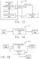
- FIG. 13illustrates a control circuit configured to control aspects of the surgical instrument or tool, in accordance with at least one aspect of the present disclosure.
- FIG. 14illustrates a combinational logic circuit configured to control aspects of the surgical instrument or tool, in accordance with at least one aspect of the present disclosure.
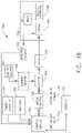
- FIG. 15illustrates a sequential logic circuit configured to control aspects of the surgical instrument or tool, in accordance with at least one aspect of the present disclosure.
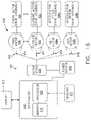
- FIG. 16illustrates a surgical instrument or tool comprising a plurality of motors which can be activated to perform various functions, in accordance with at least one aspect of the present disclosure.
- FIG. 17is a schematic diagram of a robotic surgical instrument configured to operate a surgical tool described herein, in accordance with at least one aspect of the present disclosure.
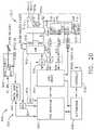
- FIG. 18illustrates a block diagram of a surgical instrument programmed to control the distal translation of a displacement member, in accordance with at least one aspect of the present disclosure.
- FIG. 19is a schematic diagram of a surgical instrument configured to control various functions, in accordance with at least one aspect of the present disclosure.
- FIG. 20is a simplified block diagram of a generator configured to provide inductorless tuning, among other benefits, in accordance with at least one aspect of the present disclosure.
- FIG. 21illustrates an example of a generator, which is one form of the generator of FIG. 20 , in accordance with at least one aspect of the present disclosure.
- FIG. 22is a schematic of a robotic surgical system, in accordance with one aspect of the present disclosure.
- FIG. 23illustrates a surgical visualization system including a robotic arm coupled to a visualization assembly, in accordance with at least one aspect of the present disclosure.
- FIG. 24illustrates a perspective view of a distal portion of the visualization assembly of FIG. 23 .
- FIG. 25illustrates a longitudinal cross-sectional view of the distal portion of the visualization assembly of FIG. 24 .
- FIG. 26is a logic flow diagram of a process depicting a control program or a logic configuration for detecting lens transparency of a surgical visualization system and reporting the same, in accordance with at least one aspect of the present disclosure.
- FIG. 26Ais a is a logic flow diagram of a process depicting a control program or a logic configuration for determining whether a visualization lens of a surgical visualization system needs cleaning and triggering the cleaning, in accordance with at least one aspect of the present disclosure.
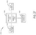
- FIG. 27is a schematic diagram of a surgical visualization system, in accordance with at least one aspect of the present disclosure.
- FIG. 28illustrates a perspective view of a distal portion of a visualization assembly of a surgical visualization system, in accordance with at least one aspect of the present disclosure.
- FIG. 29is a graph depicting time (t) on the x-axis and occlusion level through a visualization lens of a surgical visualization system on the y-axis, in accordance with at least one aspect of the present disclosure.
- FIG. 30illustrates two trocars inserted into a body cavity, the first trocar accommodating a visualization assembly, and the second trocar accommodating an electrosurgical instrument, in accordance with at least one aspect of the present disclosure.
- FIG. 31is a graph including a top graph that represents temperature on the Y-axis vs time on the X-axis and a bottom graph that represents lens visibility percentage on the Y-axis vs time on the X-axis, in accordance with at least one aspect of the present disclosure.
- FIG. 32is a graph including a top graph that represents temperature on the Y-axis vs time on the X-axis and a bottom graph that represents lens visibility percentage on the Y-axis vs time on the X-axis, in accordance with at least one aspect of the present disclosure.
- FIG. 33illustrates an imaging device including a distal end a distance D 1 from an iris seal of a seal assembly of a trocar, in accordance with at least one aspect of the present disclosure.
- FIG. 34illustrates the imaging device inserted into the iris seal of the seal assembly of the trocar of FIG. 33 , in accordance with at least one aspect of the present disclosure.
- FIG. 35illustrates a trocar connected to a lens cleaning system, in accordance with at least one aspect of the present disclosure.
- FIG. 36illustrates the trocar of FIG. 35 with an imaging device being cleaned inside the trocar by a flushing fluid from the lens cleaning system, in accordance with at least one aspect of the present disclosure.
- FIG. 37is an exploded view of a device.
- FIG. 38is an alternative embodiment of a portion of the device shown in FIG. 37 .
- FIG. 39is a cross-sectional view of a mounting structure and cannula assembly.
- FIG. 40is a partial cross-sectional view showing a seal body housing.
- FIG. 41is a perspective view with parts separated of a cannula assembly.
- FIG. 42is an enlarged view of the indicated area of detail of FIG. 41 .
- FIG. 43is a cross sectional view of a sealing cannula.
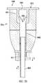
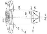
- FIG. 44is a perspective view of a pendent valve mounted to an end cap of a trocar.
- FIG. 45is an axial cross-section view illustrating operation of the pendent valve during off-axis insertion of an instrument.
- FIG. 46is an axial cross-section view showing an instrument fully inserted with effective seal formation notwithstanding an off-axis position of the instrument.
- FIG. 47is a cross-section view taken along lines 47 - 47 of FIG. 46 .
- FIG. 48is a cross-section view taken along lines 48 - 48 of FIG. 46 .
- FIG. 49is a perspective view of an assembled trocar.
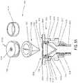
- FIG. 50is an exploded perspective view of the components of the trocar of FIG. 49 .
- FIG. 51is an exploded perspective view of a trocar assembly.
- FIG. 52is an exploded cross-sectional side view of an adaptor attached to a seal assembly positioned above a cannula.
- FIG. 53is a side cross-sectional view of a trocar assembly.
- FIG. 54is a cross-sectional side view of the trocar assembly of FIGS. 53 , in a first shifted condition.
- FIG. 55is an exploded view of an insertable seal system and a cross sectional view of a trocar assembly including the insertable seal system positioned therein.
- FIG. 56is an exploded view of a trocar assembly including a third seal with an insertable seal system.
- FIG. 57is a seal assembly positioned above a trocar assembly that is held by a robot arm of a robotic surgical system
- FIG. 58is a cross sectional view of a trocar assembly with a flexible seal housing.
- FIG. 59illustrates a surgical access device positioned in an intercostal space of a patient, in accordance with at least one aspect of the present disclosure.
- FIG. 60illustrates two ribs spread apart via a surgical retractor, and a surgical access device position between the ribs, in accordance with at least one aspect of the present disclosure.
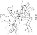
- FIG. 61illustrates a surgical access device with three access ports facilitating access of three surgical tools into a patient thoracic cavity, wherein the surgical tools are controlled by three robotic arms, in accordance with at least one aspect of the present disclosure.
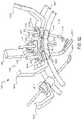
- FIG. 62illustrates a partial perspective view of the robotic arms and surgical tools of FIG. 61 .
- FIG. 63illustrates a surgical access device with a single access port facilitating access of three surgical tools into a patient cavity, in accordance with at least one aspect of the present disclosure.
- FIG. 64is a surgical access device with a translatable member in a first position, in accordance with at least one aspect of the present disclosure.
- FIG. 65illustrates a surgical access device with a translatable member in a second position, in accordance with at least one aspect of the present disclosure.
- FIG. 66illustrates a translatable member of a surgical access device, in accordance with at least one aspect of the present disclosure.
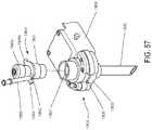
- FIG. 67is a block diagram illustrating a control circuit for moving a translatable member of a surgical access device, in accordance with at least one aspect of the present disclosure.
- FIG. 68illustrates a partial perspective view of a robotic arm before assembly with a surgical access device and a surgical instrument, in accordance with at least one aspect of the present disclosure.
- FIG. 69illustrates a partial cross-sectional view of the robotic arm of FIG. 68 assembled with a surgical instrument and a surgical access device, in accordance with at least one aspect of the present disclosure.
- FIG. 70illustrates a partial cross-sectional view of the robotic arm of FIG. 68 assembled with a surgical instrument and a surgical access device, in accordance with at least one aspect of the present disclosure.
- FIG. 71illustrates a partial cross-sectional view of a surgical access device including stabilizing compartments, in accordance with at least one aspect of the present disclosure.
- FIG. 72illustrates a partial elevational view of a surgical instrument including dampening features, in accordance with at least one aspect of the present disclosure.
- FIG. 73illustrates the surgical instrument of FIG. 72 assembled with the surgical access device of FIG. 71 , in accordance with at least one aspect of the present disclosure.
- FIG. 74illustrates a surgical access device with non-concentric instrument support features, in accordance with at least one aspect of the present disclosure.
- FIG. 75illustrates three transverse cross-sectional views of the surgical access device of FIG. 74 , in accordance with at least one aspect of the present disclosure.
- FIG. 76is a schematic diagram illustrating a top view of the surgical access device of FIG. 74 , in accordance with at least one aspect of the present disclosure.
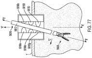
- FIG. 77is a cross-sectional view of a port assembly shown with a surgical instrument extending through the interior space of the port assembly at an angle.
- FIG. 78is a side cross-sectional view of an access apparatus.
- FIG. 79is a side plan view of the seal assembly of the access apparatus of FIG. 78 .
- FIG. 80is an enlarged isolated view in cross-section of FIG. 79 , detailing the components of the seal of the access apparatus.
- FIG. 81is a side cross-sectional view of the access apparatus.
- FIG. 82is a view similar to the view of FIG. 81 illustrating insertion and manipulation of a surgical instrument within the access apparatus with the instrument rotating about a central axis of rotation defined by the access apparatus.
- FIG. 83is a side view of an example radial biasing device that may be used with a trocar assembly.
- FIGS. 84 and 85are cross-sectional side views of the radial biasing device of FIG. 83 depicting example operation.
- FIG. 86is a perspective view illustrating the obturator assembly mounted to the cannula assembly to permit the penetration of tissue.
- a computer-implemented interactive surgical system 100includes one or more surgical systems 102 and a cloud-based system (e.g., the cloud 104 that may include a remote server 113 coupled to a storage device 105 ).
- Each surgical system 102includes at least one surgical hub 106 in communication with the cloud 104 that may include a remote server 113 .
- the surgical system 102includes a visualization system 108 , a robotic system 110 , and a handheld intelligent surgical instrument 112 , which are configured to communicate with one another and/or the hub 106 .
- a surgical system 102may include an M number of hubs 106 , an N number of visualization systems 108 , an O number of robotic systems 110 , and a P number of handheld intelligent surgical instruments 112 , where M, N, O, and P are integers greater than or equal to one.
- FIG. 3depicts an example of a surgical system 102 being used to perform a surgical procedure on a patient who is lying down on an operating table 114 in a surgical operating room 116 .
- a robotic system 110is used in the surgical procedure as a part of the surgical system 102 .
- the robotic system 110includes a surgeon's console 118 , a patient side cart 120 (surgical robot), and a surgical robotic hub 122 .
- the patient side cart 120can manipulate at least one removably coupled surgical tool 117 through a minimally invasive incision in the body of the patient while the surgeon views the surgical site through the surgeon's console 118 .
- An image of the surgical sitecan be obtained by a medical imaging device 124 , which can be manipulated by the patient side cart 120 to orient the imaging device 124 .
- the robotic hub 122can be used to process the images of the surgical site for subsequent display to the surgeon through the surgeon's console 118 .
- the imaging device 124includes at least one image sensor and one or more optical components.
- Suitable image sensorsinclude, but are not limited to, Charge-Coupled Device (CCD) sensors and Complementary Metal-Oxide Semiconductor (CMOS) sensors.
- CCDCharge-Coupled Device
- CMOSComplementary Metal-Oxide Semiconductor
- the optical components of the imaging device 124may include one or more illumination sources and/or one or more lenses.
- the one or more illumination sourcesmay be directed to illuminate portions of the surgical field.
- the one or more image sensorsmay receive light reflected or refracted from the surgical field, including light reflected or refracted from tissue and/or surgical instruments.
- the one or more illumination sourcesmay be configured to radiate electromagnetic energy in the visible spectrum as well as the invisible spectrum.
- the visible spectrumsometimes referred to as the optical spectrum or luminous spectrum, is that portion of the electromagnetic spectrum that is visible to (i.e., can be detected by) the human eye and may be referred to as visible light or simply light.
- a typical human eyewill respond to wavelengths in air that are from about 380 nm to about 750 nm.
- the invisible spectrumis that portion of the electromagnetic spectrum that lies below and above the visible spectrum (i.e., wavelengths below about 380 nm and above about 750 nm).
- the invisible spectrumis not detectable by the human eye.
- Wavelengths greater than about 750 nmare longer than the red visible spectrum, and they become invisible infrared (IR), microwave, and radio electromagnetic radiation.
- Wavelengths less than about 380 nmare shorter than the violet spectrum, and they become invisible ultraviolet, x-ray, and gamma ray electromagnetic radiation.
- the imaging device 124is configured for use in a minimally invasive procedure.
- imaging devices suitable for use with the present disclosureinclude, but not limited to, an arthroscope, angioscope, bronchoscope, choledochoscope, colonoscope, cytoscope, duodenoscope, enteroscope, esophagogastro-duodenoscope (gastroscope), endoscope, laryngoscope, nasopharyngo-neproscope, sigmoidoscope, thoracoscope, and ureteroscope.
- the imaging deviceemploys multi-spectrum monitoring to discriminate topography and underlying structures.
- a multi-spectral imageis one that captures image data within specific wavelength ranges across the electromagnetic spectrum. The wavelengths may be separated by filters or by the use of instruments that are sensitive to particular wavelengths, including light from frequencies beyond the visible light range, e.g., IR and ultraviolet. Spectral imaging can allow extraction of additional information the human eye fails to capture with its receptors for red, green, and blue.
- Multi-spectrum monitoringcan be a useful tool in relocating a surgical field after a surgical task is completed to perform one or more of the previously described tests on the treated tissue.
- the sterile fieldmay be considered a specified area, such as within a tray or on a sterile towel, that is considered free of microorganisms, or the sterile field may be considered an area, immediately around a patient, who has been prepared for a surgical procedure.
- the sterile fieldmay include the scrubbed team members, who are properly attired, and all furniture and fixtures in the area.
- the visualization system 108includes one or more imaging sensors, one or more image processing units, one or more storage arrays, and one or more displays that are strategically arranged with respect to the sterile field, as illustrated in FIG. 2 .
- the visualization system 108includes an interface for HL7, PACS, and EMR.
- Various components of the visualization system 108are described under the heading “Advanced Imaging Acquisition Module” in U.S. Provisional Patent Application Ser. No. 62/611,341, titled INTERACTIVE SURGICAL PLATFORM, filed Dec. 28, 2017, the disclosure of which is herein incorporated by reference in its entirety.
- a primary display 119is positioned in the sterile field to be visible to an operator at the operating table 114 .
- a visualization tower 111is positioned outside the sterile field.
- the visualization tower 111includes a first non-sterile display 107 and a second non-sterile display 109 , which face away from each other.
- the visualization system 108guided by the hub 106 , is configured to utilize the displays 107 , 109 , and 119 to coordinate information flow to operators inside and outside the sterile field.
- the hub 106may cause the visualization system 108 to display a snap-shot of a surgical site, as recorded by an imaging device 124 , on a non-sterile display 107 or 109 , while maintaining a live feed of the surgical site on the primary display 119 .
- the snap-shot on the non-sterile display 107 or 109can permit a non-sterile operator to perform a diagnostic step relevant to the surgical procedure, for example.
- the hub 106is also configured to route a diagnostic input or feedback entered by a non-sterile operator at the visualization tower 111 to the primary display 119 within the sterile field, where it can be viewed by a sterile operator at the operating table.
- the inputcan be in the form of a modification to the snap-shot displayed on the non-sterile display 107 or 109 , which can be routed to the primary display 119 by the hub 106 .
- a surgical instrument 112is being used in the surgical procedure as part of the surgical system 102 .
- the hub 106is also configured to coordinate information flow to a display of the surgical instrument 112 .
- a diagnostic input or feedback entered by a non-sterile operator at the visualization tower 111can be routed by the hub 106 to the surgical instrument display 115 within the sterile field, where it can be viewed by the operator of the surgical instrument 112 .
- Example surgical instrumentsthat are suitable for use with the surgical system 102 are described under the heading “Surgical Instrument Hardware” and in U.S. Provisional Patent Application Ser. No. 62/611,341, titled INTERACTIVE SURGICAL PLATFORM, filed Dec. 28, 2017, the disclosure of which is herein incorporated by reference in its entirety, for example.
- a hub 106is depicted in communication with a visualization system 108 , a robotic system 110 , and a handheld intelligent surgical instrument 112 .
- the hub 106includes a hub display 135 , an imaging module 138 , a generator module 140 , a communication module 130 , a processor module 132 , and a storage array 134 .
- the hub 106further includes a smoke evacuation module 126 and/or a suction/irrigation module 128 .
- the hub modular enclosure 136offers a unified environment for managing the power, data, and fluid lines, which reduces the frequency of entanglement between such lines.
- the surgical hubfor use in a surgical procedure that involves energy application to tissue at a surgical site.
- the surgical hubincludes a hub enclosure and a combo generator module slidably receivable in a docking station of the hub enclosure.
- the docking stationincludes data and power contacts.
- the combo generator moduleincludes two or more of an ultrasonic energy generator component, a bipolar RF energy generator component, and a monopolar RF energy generator component that are housed in a single unit.
- the combo generator modulealso includes a smoke evacuation component, at least one energy delivery cable for connecting the combo generator module to a surgical instrument, at least one smoke evacuation component configured to evacuate smoke, fluid, and/or particulates generated by the application of therapeutic energy to the tissue, and a fluid line extending from the remote surgical site to the smoke evacuation component.
- the fluid lineis a first fluid line and a second fluid line extends from the remote surgical site to a suction and irrigation module slidably received in the hub enclosure.
- the hub enclosurecomprises a fluid interface.
- Certain surgical proceduresmay require the application of more than one energy type to the tissue.
- One energy typemay be more beneficial for cutting the tissue, while another different energy type may be more beneficial for sealing the tissue.
- a bipolar generatorcan be used to seal the tissue while an ultrasonic generator can be used to cut the sealed tissue.
- the modular surgical enclosureincludes a first energy-generator module, configured to generate a first energy for application to the tissue, and a first docking station comprising a first docking port that includes first data and power contacts, wherein the first energy-generator module is slidably movable into an electrical engagement with the power and data contacts and wherein the first energy-generator module is slidably movable out of the electrical engagement with the first power and data contacts.
- the modular surgical enclosurealso includes a second energy-generator module configured to generate a second energy, different than the first energy, for application to the tissue, and a second docking station comprising a second docking port that includes second data and power contacts, wherein the second energy-generator module is slidably movable into an electrical engagement with the power and data contacts, and wherein the second energy-generator module is slidably movable out of the electrical engagement with the second power and data contacts.
- a second energy-generator moduleconfigured to generate a second energy, different than the first energy, for application to the tissue
- a second docking stationcomprising a second docking port that includes second data and power contacts
- the modular surgical enclosurealso includes a communication bus between the first docking port and the second docking port, configured to facilitate communication between the first energy-generator module and the second energy-generator module.
- a hub modular enclosure 136that allows the modular integration of a generator module 140 , a smoke evacuation module 126 , and a suction/irrigation module 128 .
- the hub modular enclosure 136further facilitates interactive communication between the modules 140 , 126 , 128 .
- the generator module 140can be a generator module with integrated monopolar, bipolar, and ultrasonic components supported in a single housing unit slidably insertable into the hub modular enclosure 136 .
- the hub modular enclosure 136can be configured to facilitate the insertion of multiple generators and interactive communication between the generators docked into the hub modular enclosure 136 so that the generators would act as a single generator.
- the hub modular enclosure 136comprises a modular power and communication backplane with external and wireless communication headers to enable the removable attachment of the modules 140 , 126 , 128 and interactive communication therebetween.
- the imaging module 138comprises an integrated video processor and a modular light source and is adapted for use with various imaging devices.
- the imaging deviceis comprised of a modular housing that can be assembled with a light source module and a camera module.
- the housingcan be a disposable housing.
- the disposable housingis removably coupled to a reusable controller, a light source module, and a camera module.
- the light source module and/or the camera modulecan be selectively chosen depending on the type of surgical procedure.
- the camera modulecomprises a CCD sensor.
- the camera modulecomprises a CMOS sensor.
- the camera moduleis configured for scanned beam imaging.
- the light source modulecan be configured to deliver a white light or a different light, depending on the surgical procedure.
- the module imaging device of the present disclosureis configured to permit the replacement of a light source module or a camera module midstream during a surgical procedure, without having to remove the imaging device from the surgical field.
- the imaging devicecomprises a tubular housing that includes a plurality of channels.
- a first channelis configured to slidably receive the camera module, which can be configured for a snap-fit engagement with the first channel.
- a second channelis configured to slidably receive the light source module, which can be configured for a snap-fit engagement with the second channel.
- the camera module and/or the light source modulecan be rotated into a final position within their respective channels.
- a threaded engagementcan be employed in lieu of the snap-fit engagement.
- multiple imaging devicesare placed at different positions in the surgical field to provide multiple views.
- the imaging module 138can be configured to switch between the imaging devices to provide an optimal view.
- the imaging module 138can be configured to integrate the images from the different imaging device.
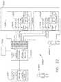
- the robotic surgical system 13000includes robotic arms 13002 , 13003 , a control device 13004 , and a console 13005 coupled to the control device 13004 .
- the surgical system 13000is configured for use on a patient 13013 lying on a patient table 13012 for performance of a minimally invasive surgical operation.
- the console 13005includes a display device 13006 and input devices 13007 , 13008 .
- the display device 13006is set up to display three-dimensional images, and the manual input devices 13007 , 13008 are configured to allow a clinician to telemanipulate the robotic arms 13002 , 13003 .
- Each of the robotic arms 13002 , 13003is made up of a plurality of members connected through joints and includes a surgical assembly 13010 connected to a distal end of a corresponding robotic arm 13002 , 13003 .
- Support of multiple armsis further described in U.S. Patent Application Publication No. 2017/0071693, filed Nov. 11, 2016, titled SURGICAL ROBOTIC ARM SUPPORT SYSTEMS AND METHODS OF USE, which is herein incorporated by reference in its entirety.
- Various robotic arm configurationsare further described in International Patent Publication No. WO2017/044406, filed Sep. 6, 2016, titled ROBOTIC SURGICAL CONTROL SCHEME FOR MANIPULATING ROBOTIC END EFFECTORS, which is herein incorporated by reference in its entirety.
- the surgical assembly 13010includes a surgical instrument 13020 supporting an end effector 13023 .
- the surgical system 13000may include a single robotic arm or more than two robotic arms 13002 , 13003 .
- Additional robotic armsare likewise connected to the control device 13004 and are telemanipulatable via the console 13005 . Accordingly, one or more additional surgical assemblies 13010 and/or surgical instruments 13020 may also be attached to the additional robotic arm(s).
- the robotic arms 13002 , 13003may be driven by electric drives that are connected to the control device 13004 .
- the control device 13004is configured to activate drives, for example, via a computer program, such that the robotic arms 13002 , 13003 and the surgical assemblies 13010 and/or surgical instruments 13020 corresponding to the robotic arms 13002 , 13003 , execute a desired movement received through the manual input devices 13007 , 13008 .
- the control device 13004may also be configured to regulate movement of the robotic arms 13002 , 13003 and/or of the drives.
- the control device 13004may control a plurality of motors (for example, Motor I . . . n) with each motor configured to drive a pushing or a pulling of one or more cables, such as cables coupled to the end effector 13023 of the surgical instrument 13020 .
- motorsfor example, Motor I . . . n
- the control device 13004coordinates the activation of the various motors to coordinate a pushing or a pulling motion of one or more cables in order to coordinate an operation and/or movement of one or more end effectors 13023 .
- articulation of an end effector by a robotic assemblysuch as the surgical assembly 13010 is further described in U.S. Patent Application Publication No.
- each motoris configured to actuate a drive rod or a lever arm to affect operation and/or movement of end effectors 13023 in addition to, or instead of, one or more cables.
- the control device 13004includes any suitable logic control circuit adapted to perform calculations and/or operate according to a set of instructions.
- the control device 13004can be configured to communicate with a remote system “RS,” either via a wireless (e.g., Wi-Fi, Bluetooth, LTE, etc.) and/or wired connection.
- the remote system “RS”can include data, instructions and/or information related to the various components, algorithms, and/or operations of system 13000 .
- the remote system “RS”can include any suitable electronic service, database, platform, cloud “C” (see FIG. 4 ), or the like.
- the control device 13004may include a central processing unit operably connected to memory.
- the memorymay include transitory type memory (e.g., RAM) and/or non-transitory type memory (e.g., flash media, disk media, etc.).
- transitory type memorye.g., RAM
- non-transitory type memorye.g., flash media, disk media, etc.
- the memoryis part of, and/or operably coupled to, the remote system “RS.”
- the control device 13004can include a plurality of inputs and outputs for interfacing with the components of the system 13000 , such as through a driver circuit.
- the control device 13004can be configured to receive input signals and/or generate output signals to control one or more of the various components (e.g., one or more motors) of the system 13000 .
- the output signalscan include, and/or can be based upon, algorithmic instructions which may be pre-programmed and/or input by a user.
- the control device 13004can be configured to accept a plurality of user inputs from a user interface (e.g., switches, buttons, touch screen, etc. of operating the console 13005 ) which may be coupled to remote system “RS.”
- a user interfacee.g., switches, buttons, touch screen, etc. of operating the console 13005
- a memory 13014can be directly and/or indirectly coupled to the control device 13004 to store instructions and/or databases including pre-operative data from living being(s) and/or anatomical atlas(es).
- the memory 13014can be part of, and/or or operatively coupled to, remote system “RS.”
- each robotic arm 13002 , 13003is configured to releasably secure the end effector 13023 (or other surgical tool) therein and may be configured to receive any number of surgical tools or instruments, such as a trocar or retractor, for example.
- the system architecture 13400includes a core module 13420 , a surgeon master module 13430 , a robotic arm module 13440 , and an instrument module 13450 .
- the core module 13420serves as a central controller for the robotic surgical system 13000 and coordinates operations of all of the other modules 13430 , 13440 , 13450 .
- the core module 13420maps control devices to the arms 13002 , 13003 , determines current status, performs all kinematics and frame transformations, and relays resulting movement commands.
- the core module 13420receives and analyzes data from each of the other modules 13430 , 13440 , 13450 in order to provide instructions or commands to the other modules 13430 , 13440 , 13450 for execution within the robotic surgical system 13000 .
- the modules 13420 , 13430 , 13440 , and 13450are a single component in other exemplifications.
- the core module 13420includes models 13422 , observers 13424 , a collision manager 13426 , controllers 13428 , and a skeleton 13429 .
- the models 13422include units that provide abstracted representations (base classes) for controlled components, such as the motors (for example, Motor I . . . n) and/or the arms 13002 , 13003 .
- the observers 13424create state estimates based on input and output signals received from the other modules 13430 , 13440 , 13450 .
- the collision manager 13426prevents collisions between components that have been registered within the system 13000 .
- the skeleton 13429tracks the system 13000 from a kinematic and dynamics point of view.
- the kinematics itemmay be implemented either as forward or inverse kinematics, in an exemplification.
- the dynamics itemmay be implemented as algorithms used to model dynamics of the system's components.
- the surgeon master module 13430communicates with surgeon control devices at the console 13005 and relays inputs received from the console 13005 to the core module 13420 .
- the surgeon master module 13430communicates button status and control device positions to the core module 13420 and includes a node controller 13432 that includes a state/mode manager 13434 , a fail-over controller 13436 , and a N-degree of freedom (“DOF”) actuator 13438 .
- DOFN-degree of freedom
- the robotic arm module 13440coordinates operation of a robotic arm subsystem, an arm cart subsystem, a set up arm, and an instrument subsystem in order to control movement of a corresponding arm 13002 , 13003 .
- a single robotic arm module 13440is included, it will be appreciated that the robotic arm module 13440 corresponds to and controls a single arm.
- additional robotic arm modules 13440are included in configurations in which the system 13000 includes multiple arms 13002 , 13003 .
- the robotic arm module 13440includes a node controller 13442 , a state/mode manager 13444 , a fail-over controller 13446 , and a N-degree of freedom (“DOF”) actuator 13348 .
- DOFN-degree of freedom
- the instrument module 13450controls movement of an instrument and/or tool component attached to the arm 13002 , 13003 .
- the instrument module 13450is configured to correspond to and control a single instrument. Thus, in configurations in which multiple instruments are included, additional instrument modules 13450 are likewise included.
- the instrument module 13450obtains and communicates data related to the position of the end effector or jaw assembly (which may include the pitch and yaw angle of the jaws), the width of or the angle between the jaws, and the position of an access port.
- the instrument module 13450has a node controller 13452 , a state/mode manager 13454 , a fail-over controller 13456 , and a N-degree of freedom (“DOF”) actuator 13458 .
- DOFN-degree of freedom
- the position data collected by the instrument module 13450is used by the core module 13420 to determine when the instrument is within the surgical site, within a cannula, adjacent to an access port, or above an access port in free space.
- the core module 13420can determine whether to provide instructions to open or close the jaws of the instrument based on the positioning thereof. For example, when the position of the instrument indicates that the instrument is within a cannula, instructions are provided to maintain a jaw assembly in a closed position. When the position of the instrument indicates that the instrument is outside of an access port, instructions are provided to open the jaw assembly.
- the robotic surgical systems and features disclosed hereincan be employed with the robotic surgical system of FIGS. 4 and 5 .
- the readerwill further appreciate that various systems and/or features disclosed herein can also be employed with alternative surgical systems including the computer-implemented interactive surgical system 100 , the computer-implemented interactive surgical system 200 , the robotic surgical system 110 , the robotic hub 122 , and/or the robotic hub 222 , for example.
- a robotic surgical systemcan include a robotic control tower, which can house the control unit of the system.
- the control unit 13004 of the robotic surgical system 13000( FIG. 4 ) can be housed within a robotic control tower.
- the robotic control towercan include a robotic hub such as the robotic hub 122 ( FIG. 2 ) or the robotic hub 222 ( FIG. 9 ), for example.
- Such a robotic hubcan include a modular interface for coupling with one or more generators, such as an ultrasonic generator and/or a radio frequency generator, and/or one or more modules, such as an imaging module, suction module, an irrigation module, a smoke evacuation module, and/or a communication module.
- a robotic hubcan include a situational awareness module, which can be configured to synthesize data from multiple sources to determine an appropriate response to a surgical event.
- a situational awareness modulecan determine the type of surgical procedure, step in the surgical procedure, type of tissue, and/or tissue characteristics, as further described herein.
- a modulecan recommend a particular course of action or possible choices to the robotic system based on the synthesized data.
- a sensor systemencompassing a plurality of sensors distributed throughout the robotic system can provide data, images, and/or other information to the situational awareness module.
- Such a situational awareness modulecan be incorporated into a control unit, such as the control unit 13004 , for example.
- the situational awareness modulecan obtain data and/or information from a non-robotic surgical hub and/or a cloud, such as the surgical hub 106 ( FIG. 1 ), the surgical hub 206 ( FIG. 10 ), the cloud 104 ( FIG. 1 ), and/or the cloud 204 ( FIG. 9 ), for example.
- Situational awareness of a surgical systemis further disclosed herein and in U.S. Provisional Patent Application Ser. No. 62/611,341, titled INTERACTIVE SURGICAL PLATFORM, filed Dec. 28, 2017, and U.S. Provisional Patent Application Ser. No. 62/611,340, titled CLOUD-BASED MEDICAL ANALYTICS, filed Dec. 28, 2017, the disclosure of each of which is herein incorporated by reference in its entirety.
- a robotic surgical systemcan utilize an electrosurgical tool having an energy delivery surface that should only be energized when a threshold condition is met.
- the energy delivery surfaceshould only be activated when the energy delivery surface is in contact with the appropriate, or targeted, tissue.
- a robotic surgical systemcan utilize a suction element that should only be activated when a threshold condition is met, such as when an appropriate volume of fluid is present. Due to visibility restrictions, evolving situations, and the multitude of moving parts during a robotic surgical procedure, it can be difficult for a clinician to determine and/or monitor certain conditions at the surgical site. For example, it can be difficult to determine if an energy delivery surface of an electrosurgical tool is in contact with tissue. It can also be difficult to determine if a particular suctioning pressure is sufficient for the volume of fluid in the proximity of the suctioning port.
- a plurality of surgical devicescan be used in certain robotic surgical procedures.
- a robotic surgical systemcan use one or more surgical tools during the surgical procedure.
- one or more handheld instrumentscan also be used during the surgical procedure.
- One or more of the surgical devicescan include a sensor.
- multiple sensorscan be positioned around the surgical site and/or the operating room.
- a sensor system including the one or more sensorscan be configured to detect one or more conditions at the surgical site.
- data from the sensor systemcan determine if a surgical tool mounted to the surgical robot is being used and/or if a feature of the surgical tool should be activated.
- a sensor systemcan detect if an electrosurgical device is positioned in abutting contact with tissue, for example.
- a sensor systemcan detect if a suctioning element of a surgical tool is applying a sufficient suctioning force to fluid at the surgical site.
- the robotic surgical systemcan automatically activate one or more features of one or more surgical tools based on data, images, and/or other information received from the sensor system.
- an energy delivery surface of an electrosurgical toolcan be activated upon detecting that the electrosurgical tool is in use (e.g. positioned in abutting contact with tissue).
- a suctioning element on a surgical toolcan be activated when the suction port is moved into contact with a fluid.
- the surgical toolcan be adjusted based on the sensed conditions.
- a robotic surgical system incorporating an automatic activation modecan automatically provide a scenario-specific result based on detected condition(s) at the surgical site.
- the scenario-specific resultcan be outcome-based, for example, and can streamline the decision-making process of the clinician.
- such an automatic activation modecan improve the efficiency and/or effectiveness of the clinician.
- the robotic surgical systemcan aggregate data to compile a more complete view of the surgical site and/or the surgical procedure in order to determine the best possible course of action. Additionally or alternatively, in instances in which the clinician makes fewer decisions, the clinician can be better focused on other tasks and/or can process other information more effectively.
- hubs 13380 , 13382include wireless communication modules such that a wireless communication link is established between the two hubs 13380 , 13382 .
- the robotic hub 13380is in signal communication with the interactive secondary displays 13362 , 13364 within the sterile field.
- the hub 13382is in signal communication with the handheld surgical instrument 13366 . If the surgeon 13371 moves over towards the patient 13361 and within the sterile field (as indicated by the reference character 13371 ′), the surgeon 13371 can use one of the wireless interactive displays 13362 , 13364 to operate the robot 13372 away from the remote command console 13370 .
- the plurality of secondary displays 13362 , 13364 within the sterile fieldallows the surgeon 13371 to move away from the remote command console 13370 without losing sight of important information for the surgical procedure and controls for the robotic tools utilized therein.
- the interactive secondary displays 13362 , 13364permit the clinician to step away from the remote command console 13370 and into the sterile field while maintaining control of the robot 13372 .
- the interactive secondary displays 13362 , 13364allow the clinician to maintain cooperative and/or coordinated control over the powered handheld surgical instrument(s) 13366 and the robotic surgical system at the same time.
- informationis communicated between the robotic surgical system, one or more powered handheld surgical instruments 13366 , surgical hubs 13380 , 13382 , and the interactive secondary displays 13362 , 13364 .
- Such informationmay include, for example, the images on the display of the robotic surgical system and/or the powered handheld surgical instruments, a parameter of the robotic surgical system and/or the powered handheld surgical instruments, and/or a control command for the robotic surgical system and/or the powered handheld surgical instruments.
- control unit of the robotic surgical systeme.g. the control unit 13113 of the robotic surgical system 13110
- the control unit of the robotic surgical systemis configured to communicate at least one display element from the surgeon's command console (e.g. the console 13116 ) to an interactive secondary display (e.g. the displays 13362 , 13364 ).
- an interactive secondary displaye.g. the displays 13362 , 13364
- a portion of the display at the surgeon's consoleis replicated on the display of the interactive secondary display, integrating the robot display with the interactive secondary display.
- the replication of the robot display on to the display of the interactive secondary displayallows the clinician to step away from the remote command console without losing the visual image that is displayed there.
- at least one of the interactive secondary displays 13362 , 13364can display information from the robot, such as information from the robot display and/or the surgeon's command console 13370 .
- the interactive secondary displays 13362 , 13364are configured to control and/or adjust at least one operating parameter of the robotic surgical system. Such control can occur automatically and/or in response to a clinician input. Interacting with a touch-sensitive screen and/or buttons on the interactive secondary display(s) 13362 , 13364 , the clinician is able to input a command to control movement and/or functionality of the one or more robotic tools. For example, when utilizing a handheld surgical instrument 13366 , the clinician may want to move the robotic tool 13374 to a different position.
- the clinicianapplies an input to the interactive secondary display(s) 13362 , 13364 , and the respective interactive secondary display(s) 13362 , 13364 communicates the clinician input to the control unit of the robotic surgical system in the robotic hub 13380 .
- a clinician positioned at the remote command console 13370 of the robotic surgical systemcan manually override any robot command initiated by a clinician input on the one or more interactive secondary displays 13362 , 13364 .
- a clinician positioned at the remote command console 13370can either allow the command to be issued and the desired function performed or the clinician can override the command by interacting with the remote command console 13370 and prohibiting the command from being issued.
- a clinician within the sterile fieldcan be required to request permission to control the robot 13372 and/or the robotic tool 13374 mounted thereto.
- the surgeon 13371 at the remote command console 13370can grant or deny the clinician's request.
- the surgeoncan receive a pop-up or other notification indicating the permission is being requested by another clinician operating a handheld surgical instrument and/or interacting with an interactive secondary display 13362 , 13364 .
- the processor of a robotic surgical systemsuch as the robotic surgical systems 13000 ( FIG. 4 ), 13400 ( FIG. 5 ), 13360 ( FIG. 6 ), and/or the surgical hub 13380 , 13382 , for example, is programmed with pre-approved functions of the robotic surgical system. For example, if a clinician input from the interactive secondary display 13362 , 13364 corresponds to a pre-approved function, the robotic surgical system allows for the interactive secondary display 13362 , 13364 to control the robotic surgical system and/or does not prohibit the interactive secondary display 13362 , 13364 from controlling the robotic surgical system.
- a clinician input from the interactive secondary display 13362 , 13364does not correspond to a pre-approved function, the interactive secondary display 13362 , 13364 is unable to command the robotic surgical system to perform the desired function.
- a situational awareness module in the robotic hub 13380 and/or the surgical hub 13382is configured to dictate and/or influence when the interactive secondary display can issue control motions to the robot surgical system.
- an interactive secondary display 13362 , 13364has control over a portion of the robotic surgical system upon making contact with the portion of the robotic surgical system. For example, when the interactive secondary display 13362 , 13364 is brought into contact with the robotic tool 13374 , control of the contacted robotic tool 13374 is granted to the interactive secondary display 13362 , 13364 . A clinician can then utilize a touch-sensitive screen and/or buttons on the interactive secondary display 13362 , 13364 to input a command to control movement and/or functionality of the contacted robotic tool 13374 .
- This control schemeallows for a clinician to reposition a robotic arm, reload a robotic tool, and/or otherwise reconfigure the robotic surgical system.
- the clinician 13371 positioned at the remote command console 13370 of the robotic surgical systemcan manually override any robot command initiated by the interactive secondary display 13362 , 13364 .
- the robotic surgical systemincludes a processor and a memory communicatively coupled to the processor, as described herein.
- the memorystores instructions executable by the processor to receive a first user input from a console and to receive a second user input from a mobile wireless control module for controlling a function of a robotic surgical tool, as described herein.
- the present disclosureprovides a control circuit to receive a first user input from a console and to receive a second user input from a mobile wireless control module for controlling a function of a robotic surgical tool, as described herein.
- the present disclosureprovides a non-transitory computer readable medium storing computer readable instructions which, when executed, cause a machine to receive a first user input from a console and to receive a second user input from a mobile wireless control module for controlling a function of a robotic surgical tool, as described herein.
- a robotic surgical systemmay include multiple robotic arms that are configured to assist the clinician during a surgical procedure. Each robotic arm may be operable independently of the others. A lack of communication may exist between each of the robotic arms as they are independently operated, which may increase the risk of tissue trauma. For example, in a scenario where one robotic arm is configured to apply a force that is stronger and in a different direction than a force configured to be applied by a second robotic arm, tissue trauma can result. For example, tissue trauma and/or tearing may occur when a first robotic arm applies a strong retracting force to the tissue while a second robotic arm is configured to rigidly hold the tissue in place.
- one or more sensorsare attached to each robotic arm of a robotic surgical system.
- the one or more sensorsare configured to sense a force applied to the surrounding tissue during the operation of the robotic arm.
- Such forcescan include, for example, a holding force, a retracting force, and/or a dragging force.
- the sensor from each robotic armis configured to communicate the magnitude and direction of the detected force to a control unit of the robotic surgical system.
- the control unitis configured to analyze the communicated forces and set limits for maximum loads to avoid causing trauma to the tissue in a surgical site. For example, the control unit may minimize the holding force applied by a first robotic arm if the retracting or dragging force applied by a second robotic arm increases.
- FIG. 4 aillustrates an exemplification of a robotic arm 13120 and a tool assembly 13130 releasably coupled to the robotic arm 13120 .
- the robotic arm 13120can support and move the associated tool assembly 13130 along one or more mechanical degrees of freedom (e.g., all six Cartesian degrees of freedom, five or fewer Cartesian degrees of freedom, etc.).
- the robotic arm 13120can include a tool driver 13140 at a distal end of the robotic arm 13120 , which can assist with controlling features associated with the tool assembly 13130 .
- the robotic arm 13120can also include a movable tool guide 13132 that can retract and extend relative to the tool driver 13140 .
- a shaft of the tool assembly 13130can extend parallel to a threaded shaft of the movable tool guide 13132 and can extend through a distal end feature 13133 (e.g., a ring) of the movable tool guide 13132 and into a patient.
- a barriercan be placed between the actuating portion of the surgical system (e.g., the robotic arm 13120 ) and the surgical instruments (e.g., the tool assembly 13130 ) in the sterile surgical field.
- a sterile componentsuch as an instrument sterile adapter (ISA)
- ISAinstrument sterile adapter
- the placement of an ISA between the tool assembly 13130 and the robotic arm 13120can ensure a sterile coupling point for the tool assembly 13130 and the robotic arm 13120 . This permits removal of tool assemblies 13130 from the robotic arm 13120 to exchange with other tool assemblies 13130 during the course of a surgery without compromising the sterile surgical field.
- the tool assembly 13130can be loaded from a top side of the tool driver 13140 with the shaft of the tool assembly 13130 being positioned in a shaft-receiving channel 13144 formed along the side of the tool driver 13140 .
- the shaft-receiving channel 13144allows the shaft, which extends along a central axis of the tool assembly 13130 , to extend along a central axis of the tool driver 13140 when the tool assembly 13130 is coupled to the tool driver 13140 .
- the shaftcan extend through on opening in the tool driver 13140 , or the two components can mate in various other configurations.
- the robotic surgical systemcan include one or more robotic arms with each robotic arm having a tool assembly coupled thereto.
- Each tool assemblycan include an end effector that has one or more of a variety of features, such as one or more tools for assisting with performing a surgical procedure.
- the end effectorcan include a cutting or boring tool that can be used to perforate or cut through tissue (e.g., create an incision).
- some end effectorsinclude one or more sensors that can sense a variety of characteristics associated with either the end effector or the tissue.
- Each robotic arm and end effectorcan be controlled by a control system to assist with creating a desired cut or bore and prevent against undesired cutting of tissue.
- the control systemcan control either the tool itself or the tool assembly.
- One or more aspects associated with the movement of the robotic armcan be controlled by the control system, such as either a direction or a velocity of movement.
- the robotic armwhen boring through tissue, can be controlled to perform jackhammer-like movements with the cutting tool.
- Such jackhammer movementscan include the robotic arm moving up and down along an axis (e.g., an axis that is approximately perpendicular to the tissue being perforated) in a rapid motion while also advancing the cutting tool in a downward direction towards the tissue to eventually perforate the tissue with the cutting tool (e.g. an ultrasonic blade).
- While performing such movements in a robotic surgical procedurenot only can it be difficult to see the tissue being perforated to thereby determine a relative position of the cutting tool, but it can also be difficult to determine when the cutting tool has completed perforating the tissue.
- Such position of the cutting tool relative to the tissuecan include the cutting tool approaching or not yet in contact with the tissue, the cutting tool drilling down or cutting into the tissue, and the cutting tool extending through or having perforated the tissue. These positions can be difficult for either a user controlling the robotic arm or the robotic surgical system to determine which can result in potential harm to the patient due to over or under-penetrating the tissue, as well as result in longer procedure times.
- the robotic surgical systemincludes a control system that communicates with at least one sensor assembly configured to sense a force applied at a distal end of the end effector or cutting tool.
- the control systemcan thereby determine and control, based on such sensed forces, one or more appropriate aspects associated with the movement of the robotic arm, such as when boring or cutting into tissue, as will be described in greater detail below.
- the sensor assembly of the present disclosurethat is in communication with the control system can be implemented in any number of robotic surgical systems for detecting any number of a variety of tools and/or end effectors used for performing any number of a variety of procedures without departing from the scope of this disclosure.
- any number of movementscan be performed by the robotic arm to perforate or cut tissue using the robotic surgical system including the sensor assembly and control system described herein and is not limited to the jackhammering or boring of tissue.
- FIG. 4 a and additional exemplificationsare further described in U.S. patent application Ser. No. 15/237,753, entitled CONTROL OF ADVANCEMENT RATE AND APPLICATION FORCE BASED ON MEASURED FORCES, filed Aug. 16, 2016, the entire disclosure of which is incorporated by reference herein.
- Surgical devicesinclude robotic surgical tools and handheld surgical instruments.
- Surgical devicesinclude robotic surgical tools and handheld surgical instruments.
- the readerwill readily appreciate that certain devices, systems, and methods disclosed herein are not limited to applications within a robotic surgical system.
- certain systems, devices, and methods for communicating, detecting, and/or control a surgical devicecan be implemented without a robotic surgical system.
- FIG. 8illustrates a surgical data network 201 comprising a modular communication hub 203 configured to connect modular devices located in one or more operating theaters of a healthcare facility, or any room in a healthcare facility specially equipped for surgical operations, to a cloud-based system (e.g., the cloud 204 that may include a remote server 213 coupled to a storage device 205 ).
- the modular communication hub 203comprises a network hub 207 and/or a network switch 209 in communication with a network router.
- the modular communication hub 203also can be coupled to a local computer system 210 to provide local computer processing and data manipulation.
- the surgical data network 201may be configured as passive, intelligent, or switching.
- a passive surgical data networkserves as a conduit for the data, enabling it to go from one device (or segment) to another and to the cloud computing resources.
- An intelligent surgical data networkincludes additional features to enable the traffic passing through the surgical data network to be monitored and to configure each port in the network hub 207 or network switch 209 .
- An intelligent surgical data networkmay be referred to as a manageable hub or switch.
- a switching hubreads the destination address of each packet and then forwards the packet to the correct port.
- Modular devices 1 a - 1 n located in the operating theatermay be coupled to the modular communication hub 203 .
- the network hub 207 and/or the network switch 209may be coupled to a network router 211 to connect the devices 1 a - 1 n to the cloud 204 or the local computer system 210 .
- Data associated with the devices 1 a - 1 nmay be transferred to cloud-based computers via the router for remote data processing and manipulation.
- Data associated with the devices 1 a - 1 nmay also be transferred to the local computer system 210 for local data processing and manipulation.
- Modular devices 2 a - 2 m located in the same operating theateralso may be coupled to a network switch 209 .
- the network switch 209may be coupled to the network hub 207 and/or the network router 211 to connect to the devices 2 a - 2 m to the cloud 204 .
- Data associated with the devices 2 a - 2 nmay be transferred to the cloud 204 via the network router 211 for data processing and manipulation.
- Data associated with the devices 2 a - 2 mmay also be transferred to the local computer system 210 for local data processing and manipulation.
- the surgical data network 201may be expanded by interconnecting multiple network hubs 207 and/or multiple network switches 209 with multiple network routers 211 .
- the modular communication hub 203may be contained in a modular control tower configured to receive multiple devices 1 a - 1 n / 2 a - 2 m .
- the local computer system 210also may be contained in a modular control tower.
- the modular communication hub 203is connected to a display 212 to display images obtained by some of the devices 1 a - 1 n / 2 a - 2 m , for example during surgical procedures.
- the devices 1 a - 1 n / 2 a - 2 mmay include, for example, various modules such as an imaging module 138 coupled to an endoscope, a generator module 140 coupled to an energy-based surgical device, a smoke evacuation module 126 , a suction/irrigation module 128 , a communication module 130 , a processor module 132 , a storage array 134 , a surgical device coupled to a display, and/or a non-contact sensor module, among other modular devices that may be connected to the modular communication hub 203 of the surgical data network 201 .
- various modulessuch as an imaging module 138 coupled to an endoscope, a generator module 140 coupled to an energy-based surgical device, a smoke evacuation module 126 , a suction/irrigation module 128 , a communication module 130 , a processor module 132 , a storage array 134 , a surgical device coupled to a display, and/or a non-contact sensor module, among other modular devices that may be connected to the
- the surgical data network 201may comprise a combination of network hub(s), network switch(es), and network router(s) connecting the devices 1 a - 1 n / 2 a - 2 m to the cloud. Any one of or all of the devices 1 a - 1 n / 2 a - 2 m coupled to the network hub or network switch may collect data in real time and transfer the data to cloud computers for data processing and manipulation. It will be appreciated that cloud computing relies on sharing computing resources rather than having local servers or personal devices to handle software applications.
- the word “cloud”may be used as a metaphor for “the Internet,” although the term is not limited as such.
- cloud computingmay be used herein to refer to “a type of Internet-based computing,” where different services—such as servers, storage, and applications—are delivered to the modular communication hub 203 and/or computer system 210 located in the surgical theater (e.g., a fixed, mobile, temporary, or field operating room or space) and to devices connected to the modular communication hub 203 and/or computer system 210 through the Internet.
- the cloud infrastructuremay be maintained by a cloud service provider.
- the cloud service providermay be the entity that coordinates the usage and control of the devices 1 a - 1 n / 2 a - 2 m located in one or more operating theaters.
- the cloud computing servicescan perform a large number of calculations based on the data gathered by smart surgical instruments, robots, and other computerized devices located in the operating theater.
- the hub hardwareenables multiple devices or connections to be connected to a computer that communicates with the cloud computing resources and storage.
- the surgical data networkprovides improved surgical outcomes, reduced costs, and improved patient satisfaction.
- At least some of the devices 1 a - 1 n / 2 a - 2 mmay be employed to view tissue states to assess leaks or perfusion of sealed tissue after a tissue sealing and cutting procedure.
- At least some of the devices 1 a - 1 n / 2 a - 2 mmay be employed to identify pathology, such as the effects of diseases, using the cloud-based computing to examine data including images of samples of body tissue for diagnostic purposes. This includes localization and margin confirmation of tissue and phenotypes.
- At least some of the devices 1 a - 1 n / 2 a - 2 mmay be employed to identify anatomical structures of the body using a variety of sensors integrated with imaging devices and techniques such as overlaying images captured by multiple imaging devices.
- the data gathered by the devices 1 a - 1 n / 2 a - 2 mmay be transferred to the cloud 204 or the local computer system 210 or both for data processing and manipulation including image processing and manipulation.
- the datamay be analyzed to improve surgical procedure outcomes by determining if further treatment, such as the application of endoscopic intervention, emerging technologies, a targeted radiation, targeted intervention, and precise robotics to tissue-specific sites and conditions, may be pursued.
- Such data analysismay further employ outcome analytics processing, and using standardized approaches may provide beneficial feedback to either confirm surgical treatments and the behavior of the surgeon or suggest modifications to surgical treatments and the behavior of the surgeon.
- the operating theater devices 1 a - 1 nmay be connected to the modular communication hub 203 over a wired channel or a wireless channel depending on the configuration of the devices 1 a - 1 n to a network hub.
- the network hub 207may be implemented, in one aspect, as a local network broadcast device that works on the physical layer of the Open System Interconnection (OSI) model.
- the network hubprovides connectivity to the devices 1 a - 1 n located in the same operating theater network.
- the network hub 207collects data in the form of packets and sends them to the router in half duplex mode.
- the network hub 207does not store any media access control/internet protocol (MAC/IP) to transfer the device data.
- MAC/IPmedia access control/internet protocol
- the network hub 207has no routing tables or intelligence regarding where to send information and broadcasts all network data across each connection and to a remote server 213 ( FIG. 9 ) over the cloud 204 .
- the network hub 207can detect basic network errors such as collisions, but having all information broadcast to multiple ports can be a security risk and cause bottlenecks.
- the operating theater devices 2 a - 2 mmay be connected to a network switch 209 over a wired channel or a wireless channel.
- the network switch 209works in the data link layer of the OSI model.
- the network switch 209is a multicast device for connecting the devices 2 a - 2 m located in the same operating theater to the network.
- the network switch 209sends data in the form of frames to the network router 211 and works in full duplex mode. Multiple devices 2 a - 2 m can send data at the same time through the network switch 209 .
- the network switch 209stores and uses MAC addresses of the devices 2 a - 2 m to transfer data.
- the network hub 207 and/or the network switch 209are coupled to the network router 211 for connection to the cloud 204 .
- the network router 211works in the network layer of the OSI model.
- the network router 211creates a route for transmitting data packets received from the network hub 207 and/or network switch 211 to cloud-based computer resources for further processing and manipulation of the data collected by any one of or all the devices 1 a - 1 n / 2 a - 2 m .
- the network router 211may be employed to connect two or more different networks located in different locations, such as, for example, different operating theaters of the same healthcare facility or different networks located in different operating theaters of different healthcare facilities.
- the network router 211sends data in the form of packets to the cloud 204 and works in full duplex mode. Multiple devices can send data at the same time.
- the network router 211uses IP addresses to transfer data.
- the network hub 207may be implemented as a USB hub, which allows multiple USB devices to be connected to a host computer.
- the USB hubmay expand a single USB port into several tiers so that there are more ports available to connect devices to the host system computer.
- the network hub 207may include wired or wireless capabilities to receive information over a wired channel or a wireless channel.
- a wireless USB short-range, high-bandwidth wireless radio communication protocolmay be employed for communication between the devices 1 a - 1 n and devices 2 a - 2 m located in the operating theater.
- the operating theater devices 1 a - 1 n / 2 a - 2 mmay communicate to the modular communication hub 203 via Bluetooth wireless technology standard for exchanging data over short distances (using short-wavelength UHF radio waves in the ISM band from 2.4 to 2.485 GHz) from fixed and mobile devices and building personal area networks (PANs).
- PANspersonal area networks
- the operating theater devices 1 a - 1 n / 2 a - 2 mmay communicate to the modular communication hub 203 via a number of wireless or wired communication standards or protocols, including but not limited to Wi-Fi (IEEE 802.11 family), WiMAX (IEEE 802.16 family), IEEE 802.20, long-term evolution (LTE), and Ev-DO, HSPA+, HSDPA+, HSUPA+, EDGE, GSM, GPRS, CDMA, TDMA, DECT, and Ethernet derivatives thereof, as well as any other wireless and wired protocols that are designated as 3G, 4G, 5G, and beyond.
- the computing modulemay include a plurality of communication modules.
- a first communication modulemay be dedicated to shorter-range wireless communications such as Wi-Fi and Bluetooth, and a second communication module may be dedicated to longer-range wireless communications such as GPS, EDGE, GPRS, CDMA, WiMAX, LTE, Ev-DO, and others.
- the modular communication hub 203may serve as a central connection for one or all of the operating theater devices 1 a - 1 n / 2 a - 2 m and handles a data type known as frames. Frames carry the data generated by the devices 1 a - 1 n / 2 a - 2 m . When a frame is received by the modular communication hub 203 , it is amplified and transmitted to the network router 211 , which transfers the data to the cloud computing resources by using a number of wireless or wired communication standards or protocols, as described herein.
- the modular communication hub 203can be used as a standalone device or be connected to compatible network hubs and network switches to form a larger network.
- the modular communication hub 203is generally easy to install, configure, and maintain, making it a good option for networking the operating theater devices 1 a - 1 n / 2 a - 2 m.
- FIG. 9illustrates a computer-implemented interactive surgical system 200 .
- the computer-implemented interactive surgical system 200is similar in many respects to the computer-implemented interactive surgical system 100 .
- the computer-implemented interactive surgical system 200includes one or more surgical systems 202 , which are similar in many respects to the surgical systems 102 .
- Each surgical system 202includes at least one surgical hub 206 in communication with a cloud 204 that may include a remote server 213 .
- the computer-implemented interactive surgical system 200comprises a modular control tower 236 connected to multiple operating theater devices such as, for example, intelligent surgical instruments, robots, and other computerized devices located in the operating theater. As shown in FIG.
- the modular control tower 236comprises a modular communication hub 203 coupled to a computer system 210 .
- the modular control tower 236is coupled to an imaging module 238 that is coupled to an endoscope 239 , a generator module 240 that is coupled to an energy device 241 , a smoke evacuator module 226 , a suction/irrigation module 228 , a communication module 230 , a processor module 232 , a storage array 234 , a smart device/instrument 235 optionally coupled to a display 237 , and a non-contact sensor module 242 .
- the operating theater devicesare coupled to cloud computing resources and data storage via the modular control tower 236 .
- a robot hub 222also may be connected to the modular control tower 236 and to the cloud computing resources.
- the devices/instruments 235 , visualization systems 208may be coupled to the modular control tower 236 via wired or wireless communication standards or protocols, as described herein.
- the modular control tower 236may be coupled to a hub display 215 (e.g., monitor, screen) to display and overlay images received from the imaging module, device/instrument display, and/or other visualization systems 208 .
- the hub displayalso may display data received from devices connected to the modular control tower in conjunction with images and overlaid images.
- FIG. 10illustrates a surgical hub 206 comprising a plurality of modules coupled to the modular control tower 236 .
- the modular control tower 236comprises a modular communication hub 203 , e.g., a network connectivity device, and a computer system 210 to provide local processing, visualization, and imaging, for example.
- the modular communication hub 203may be connected in a tiered configuration to expand the number of modules (e.g., devices) that may be connected to the modular communication hub 203 and transfer data associated with the modules to the computer system 210 , cloud computing resources, or both.
- each of the network hubs/switches in the modular communication hub 203includes three downstream ports and one upstream port.
- the upstream network hub/switchis connected to a processor to provide a communication connection to the cloud computing resources and a local display 217 . Communication to the cloud 204 may be made either through a wired or a wireless communication channel.
- the surgical hub 206employs a non-contact sensor module 242 to measure the dimensions of the operating theater and generate a map of the surgical theater using either ultrasonic or laser-type non-contact measurement devices.
- An ultrasound-based non-contact sensor modulescans the operating theater by transmitting a burst of ultrasound and receiving the echo when it bounces off the perimeter walls of an operating theater as described under the heading “Surgical Hub Spatial Awareness Within an Operating Room” in U.S. Provisional Patent Application Ser. No. 62/611,341, titled INTERACTIVE SURGICAL PLATFORM, filed Dec. 28, 2017, the disclosure of which is herein incorporated by reference in its entirety, in which the sensor module is configured to determine the size of the operating theater and to adjust Bluetooth-pairing distance limits.
- a laser-based non-contact sensor modulescans the operating theater by transmitting laser light pulses, receiving laser light pulses that bounce off the perimeter walls of the operating theater, and comparing the phase of the transmitted pulse to the received pulse to determine the size of the operating theater and to adjust Bluetooth pairing distance limits, for example.
- the computer system 210comprises a processor 244 and a network interface 245 .
- the processor 244is coupled to a communication module 247 , storage 248 , memory 249 , non-volatile memory 250 , and input/output interface 251 via a system bus.
- the system buscan be any of several types of bus structure(s) including the memory bus or memory controller, a peripheral bus or external bus, and/or a local bus using any variety of available bus architectures including, but not limited to, 9-bit bus, Industrial Standard Architecture (ISA), Micro-Channel Architecture (MSA), Extended ISA (EISA), Intelligent Drive Electronics (IDE), VESA Local Bus (VLB), Peripheral Component Interconnect (PCI), USB, Advanced Graphics Port (AGP), Personal Computer Memory Card International Association bus (PCMCIA), Small Computer Systems Interface (SCSI), or any other proprietary bus.
- ISAIndustrial Standard Architecture
- MSAMicro-Channel Architecture
- EISAExtended ISA
- IDEIntelligent Drive Electronics
- VLBVESA Local Bus
- PCIPeripheral Component Interconnect
- USBUniversal Serial Bus
- AGPAdvanced Graphics Port
- PCMCIAPersonal Computer Memory Card International Association bus
- SCSISmall Computer Systems Interface
- the processor 244may be any single-core or multicore processor such as those known under the trade name ARM Cortex by Texas Instruments.
- the processormay be an LM4F230H5QR ARM Cortex-M4F Processor Core, available from Texas Instruments, for example, comprising an on-chip memory of 256 KB single-cycle flash memory, or other non-volatile memory, up to 40 MHz, a prefetch buffer to improve performance above 40 MHz, a 32 KB single-cycle serial random access memory (SRAM), an internal read-only memory (ROM) loaded with StellarisWare® software, a 2 KB electrically erasable programmable read-only memory (EEPROM), and/or one or more pulse width modulation (PWM) modules, one or more quadrature encoder inputs (QEI) analogs, one or more 12-bit analog-to-digital converters (ADCs) with 12 analog input channels, details of which are available for the product datasheet.
- QEIquadrature encoder inputs
- the processor 244may comprise a safety controller comprising two controller-based families such as TMS570 and RM4x, known under the trade name Hercules ARM Cortex R4, also by Texas Instruments.
- the safety controllermay be configured specifically for IEC 61508 and ISO 26262 safety critical applications, among others, to provide advanced integrated safety features while delivering scalable performance, connectivity, and memory options.
- the system memoryincludes volatile memory and non-volatile memory.
- the basic input/output system (BIOS)containing the basic routines to transfer information between elements within the computer system, such as during start-up, is stored in non-volatile memory.
- the non-volatile memorycan include ROM, programmable ROM (PROM), electrically programmable ROM (EPROM), EEPROM, or flash memory.
- Volatile memoryincludes random-access memory (RAM), which acts as external cache memory.
- RAMis available in many forms such as SRAM, dynamic RAM (DRAM), synchronous DRAM (SDRAM), double data rate SDRAM (DDR SDRAM), enhanced SDRAM (ESDRAM), Synchlink DRAM (SLDRAM), and direct Rambus RAM (DRRAM).
- the computer system 210also includes removable/non-removable, volatile/non-volatile computer storage media, such as for example disk storage.
- the disk storageincludes, but is not limited to, devices like a magnetic disk drive, floppy disk drive, tape drive, Jaz drive, Zip drive, LS-60 drive, flash memory card, or memory stick.
- the disk storagecan include storage media separately or in combination with other storage media including, but not limited to, an optical disc drive such as a compact disc ROM device (CD-ROM), compact disc recordable drive (CD-R Drive), compact disc rewritable drive (CD-RW Drive), or a digital versatile disc ROM drive (DVD-ROM).
- CD-ROMcompact disc ROM
- CD-R Drivecompact disc recordable drive
- CD-RW Drivecompact disc rewritable drive
- DVD-ROMdigital versatile disc ROM drive
- a removable or non-removable interfacemay be employed.
- the computer system 210includes software that acts as an intermediary between users and the basic computer resources described in a suitable operating environment.
- Such softwareincludes an operating system.
- the operating systemwhich can be stored on the disk storage, acts to control and allocate resources of the computer system.
- System applicationstake advantage of the management of resources by the operating system through program modules and program data stored either in the system memory or on the disk storage. It is to be appreciated that various components described herein can be implemented with various operating systems or combinations of operating systems.
- a userenters commands or information into the computer system 210 through input device(s) coupled to the I/O interface 251 .
- the input devicesinclude, but are not limited to, a pointing device such as a mouse, trackball, stylus, touch pad, keyboard, microphone, joystick, game pad, satellite dish, scanner, TV tuner card, digital camera, digital video camera, web camera, and the like.
- These and other input devicesconnect to the processor through the system bus via interface port(s).
- the interface port(s)include, for example, a serial port, a parallel port, a game port, and a USB.
- the output device(s)use some of the same types of ports as input device(s).
- a USB portmay be used to provide input to the computer system and to output information from the computer system to an output device.
- An output adapteris provided to illustrate that there are some output devices like monitors, displays, speakers, and printers, among other output devices that require special adapters.
- the output adaptersinclude, by way of illustration and not limitation, video and sound cards that provide a means of connection between the output device and the system bus. It should be noted that other devices and/or systems of devices, such as remote computer(s), provide both input and output capabilities.
- the computer system 210can operate in a networked environment using logical connections to one or more remote computers, such as cloud computer(s), or local computers.
- the remote cloud computer(s)can be a personal computer, server, router, network PC, workstation, microprocessor-based appliance, peer device, or other common network node, and the like, and typically includes many or all of the elements described relative to the computer system. For purposes of brevity, only a memory storage device is illustrated with the remote computer(s).
- the remote computer(s)is logically connected to the computer system through a network interface and then physically connected via a communication connection.
- the network interfaceencompasses communication networks such as local area networks (LANs) and wide area networks (WANs).
- LAN technologiesinclude Fiber Distributed Data Interface (FDDI), Copper Distributed Data Interface (CDDI), Ethernet/IEEE 802.3, Token Ring/IEEE 802.5 and the like.
- WAN technologiesinclude, but are not limited to, point-to-point links, circuit-switching networks like Integrated Services Digital Networks (ISDN) and variations thereon, packet-switching networks, and Digital Subscriber Lines (DSL).
- ISDNIntegrated Services Digital Networks
- DSLDigital Subscriber Lines
- the computer system 210 of FIG. 10may comprise an image processor, image processing engine, media processor, or any specialized digital signal processor (DSP) used for the processing of digital images.
- the image processormay employ parallel computing with single instruction, multiple data (SIMD) or multiple instruction, multiple data (MIMD) technologies to increase speed and efficiency.
- SIMDsingle instruction, multiple data
- MIMDmultiple instruction, multiple data
- the digital image processing enginecan perform a range of tasks.
- the image processormay be a system on a chip with multicore processor architecture.
- the communication connection(s)refers to the hardware/software employed to connect the network interface to the bus. While the communication connection is shown for illustrative clarity inside the computer system, it can also be external to the computer system 210 .
- the hardware/software necessary for connection to the network interfaceincludes, for illustrative purposes only, internal and external technologies such as modems, including regular telephone-grade modems, cable modems, and DSL modems, ISDN adapters, and Ethernet cards.
- FIG. 11illustrates a functional block diagram of one aspect of a USB network hub 300 device, according to one aspect of the present disclosure.
- the USB network hub device 300employs a TUSB2036 integrated circuit hub by Texas Instruments.
- the USB network hub 300is a CMOS device that provides an upstream USB transceiver port 302 and up to three downstream USB transceiver ports 304 , 306 , 308 in compliance with the USB 2.0 specification.
- the upstream USB transceiver port 302is a differential root data port comprising a differential data minus (DM 0 ) input paired with a differential data plus (DP 0 ) input.
- the three downstream USB transceiver ports 304 , 306 , 308are differential data ports where each port includes differential data plus (DP 1 -DP 3 ) outputs paired with differential data minus (DM 1 -DM 3 ) outputs.
- the USB network hub 300 deviceis implemented with a digital state machine instead of a microcontroller, and no firmware programming is required. Fully compliant USB transceivers are integrated into the circuit for the upstream USB transceiver port 302 and all downstream USB transceiver ports 304 , 306 , 308 .
- the downstream USB transceiver ports 304 , 306 , 308support both full-speed and low-speed devices by automatically setting the slew rate according to the speed of the device attached to the ports.
- the USB network hub 300 devicemay be configured either in bus-powered or self-powered mode and includes a hub power logic 312 to manage power.
- the USB network hub 300 deviceincludes a serial interface engine 310 (SIE).
- SIE 310is the front end of the USB network hub 300 hardware and handles most of the protocol described in chapter 8 of the USB specification.
- the SIE 310typically comprehends signaling up to the transaction level.
- the functions that it handlescould include: packet recognition, transaction sequencing, SOP, EOP, RESET, and RESUME signal detection/generation, clock/data separation, non-return-to-zero invert (NRZI) data encoding/decoding and bit-stuffing, CRC generation and checking (token and data), packet ID (PID) generation and checking/decoding, and/or serial-parallel/parallel-serial conversion.
- NRZInon-return-to-zero invert
- the 310receives a clock input 314 and is coupled to a suspend/resume logic and frame timer 316 circuit and a hub repeater circuit 318 to control communication between the upstream USB transceiver port 302 and the downstream USB transceiver ports 304 , 306 , 308 through port logic circuits 320 , 322 , 324 .
- the SIE 310is coupled to a command decoder 326 via interface logic to control commands from a serial EEPROM via a serial EEPROM interface 330 .
- the USB network hub 300can connect 127 functions configured in up to six logical layers (tiers) to a single computer. Further, the USB network hub 300 can connect to all peripherals using a standardized four-wire cable that provides both communication and power distribution.
- the power configurationsare bus-powered and self-powered modes.
- the USB network hub 300may be configured to support four modes of power management: a bus-powered hub, with either individual-port power management or ganged-port power management, and the self-powered hub, with either individual-port power management or ganged-port power management.
- the USB network hub 300using a USB cable, the USB network hub 300 , the upstream USB transceiver port 302 is plugged into a USB host controller, and the downstream USB transceiver ports 304 , 306 , 308 are exposed for connecting USB compatible devices, and so forth.
- FIG. 12illustrates a logic diagram of a control system 470 of a surgical instrument or tool in accordance with one or more aspects of the present disclosure.
- the system 470comprises a control circuit.
- the control circuitincludes a microcontroller 461 comprising a processor 462 and a memory 468 .
- One or more of sensors 472 , 474 , 476for example, provide real-time feedback to the processor 462 .
- a motor 482driven by a motor driver 492 , operably couples a longitudinally movable displacement member to drive the I-beam knife element.
- a tracking system 480is configured to determine the position of the longitudinally movable displacement member.
- the position informationis provided to the processor 462 , which can be programmed or configured to determine the position of the longitudinally movable drive member as well as the position of a firing member, firing bar, and I-beam knife element. Additional motors may be provided at the tool driver interface to control !-beam firing, closure tube travel, shaft rotation, and articulation.
- a display 473displays a variety of operating conditions of the instruments and may include touch screen functionality for data input. Information displayed on the display 473 may be overlaid with images acquired via endoscopic imaging modules.
- the microcontroller 461may be any single-core or multicore processor such as those known under the trade name ARM Cortex by Texas Instruments.
- the main microcontroller 461may be an LM4F230H5QR ARM Cortex-M4F Processor Core, available from Texas Instruments, for example, comprising an on-chip memory of 256 KB single-cycle flash memory, or other non-volatile memory, up to 40 MHz, a prefetch buffer to improve performance above 40 MHz, a 32 KB single-cycle SRAM, and internal ROM loaded with StellarisWare® software, a 2 KB EEPROM, one or more PWM modules, one or more QEI analogs, and/or one or more 12-bit ADCs with 12 analog input channels, details of which are available for the product datasheet.
- the microcontroller 461may comprise a safety controller comprising two controller-based families such as TMS570 and RM4x, known under the trade name Hercules ARM Cortex R4, also by Texas Instruments.
- the safety controllermay be configured specifically for IEC 61508 and ISO 26262 safety critical applications, among others, to provide advanced integrated safety features while delivering scalable performance, connectivity, and memory options.
- the microcontroller 461may be programmed to perform various functions such as precise control over the speed and position of the knife and articulation systems.
- the microcontroller 461includes a processor 462 and a memory 468 .
- the electric motor 482may be a brushed direct current (DC) motor with a gearbox and mechanical links to an articulation or knife system.
- a motor driver 492may be an A3941 available from Allegro Microsystems, Inc. Other motor drivers may be readily substituted for use in the tracking system 480 comprising an absolute positioning system.
- a detailed description of an absolute positioning systemis described in U.S. Patent Application Publication No. 2017/0296213, titled SYSTEMS AND METHODS FOR CONTROLLING A SURGICAL STAPLING AND CUTTING INSTRUMENT, which published on Oct. 19, 2017, which is herein incorporated by reference in its entirety.
- the microcontroller 461may be programmed to provide precise control over the speed and position of displacement members and articulation systems.
- the microcontroller 461may be configured to compute a response in the software of the microcontroller 461 .
- the computed responseis compared to a measured response of the actual system to obtain an “observed” response, which is used for actual feedback decisions.
- the observed responseis a favorable, tuned value that balances the smooth, continuous nature of the simulated response with the measured response, which can detect outside influences on the system.
- the motor 482may be controlled by the motor driver 492 and can be employed by the firing system of the surgical instrument or tool.
- the motor 482may be a brushed DC driving motor having a maximum rotational speed of approximately 25,000 RPM.
- the motor 482may include a brushless motor, a cordless motor, a synchronous motor, a stepper motor, or any other suitable electric motor.
- the motor driver 492may comprise an H-bridge driver comprising field-effect transistors (FETs), for example.
- FETsfield-effect transistors
- the motor 482can be powered by a power assembly releasably mounted to the handle assembly or tool housing for supplying control power to the surgical instrument or tool.
- the power assemblymay comprise a battery which may include a number of battery cells connected in series that can be used as the power source to power the surgical instrument or tool.
- the battery cells of the power assemblymay be replaceable and/or rechargeable.
- the battery cellscan be lithium-ion batteries which can be couplable to and separable from the power assembly.
- the motor driver 492may be an A3941 available from Allegro Microsystems, Inc.
- the A3941 492is a full-bridge controller for use with external N-channel power metal-oxide semiconductor field-effect transistors (MOSFETs) specifically designed for inductive loads, such as brush DC motors.
- the driver 492comprises a unique charge pump regulator that provides full (>10 V) gate drive for battery voltages down to 7 V and allows the A3941 to operate with a reduced gate drive, down to 5.5 V.
- a bootstrap capacitormay be employed to provide the above battery supply voltage required for N-channel MOSFETs.
- An internal charge pump for the high-side driveallows DC (100% duty cycle) operation.
- the full bridgecan be driven in fast or slow decay modes using diode or synchronous rectification.
- current recirculationcan be through the high-side or the lowside FETs.
- the power FETsare protected from shoot-through by resistor-adjustable dead time.
- Integrated diagnosticsprovide indications of undervoltage, overtemperature, and power bridge faults and can be configured to protect the power MOSFETs under most short circuit conditions.
- Other motor driversmay be readily substituted for use in the tracking system 480 comprising an absolute positioning system.
- the tracking system 480comprises a controlled motor drive circuit arrangement comprising a position sensor 472 according to one aspect of this disclosure.
- the position sensor 472 for an absolute positioning systemprovides a unique position signal corresponding to the location of a displacement member.
- the displacement memberrepresents a longitudinally movable drive member comprising a rack of drive teeth for meshing engagement with a corresponding drive gear of a gear reducer assembly.
- the displacement memberrepresents the firing member, which could be adapted and configured to include a rack of drive teeth.
- the displacement memberrepresents a firing bar or the I-beam, each of which can be adapted and configured to include a rack of drive teeth.
- the term displacement memberis used generically to refer to any movable member of the surgical instrument or tool such as the drive member, the firing member, the firing bar, the I-beam, or any element that can be displaced.
- the longitudinally movable drive memberis coupled to the firing member, the firing bar, and the I-beam.
- the absolute positioning systemcan, in effect, track the linear displacement of the I-beam by tracking the linear displacement of the longitudinally movable drive member.
- the displacement membermay be coupled to any position sensor 472 suitable for measuring linear displacement.
- the longitudinally movable drive member, the firing member, the firing bar, or the I-beam, or combinations thereofmay be coupled to any suitable linear displacement sensor.
- Linear displacement sensorsmay include contact or non-contact displacement sensors.
- Linear displacement sensorsmay comprise linear variable differential transformers (LVDT), differential variable reluctance transducers (DVRT), a slide potentiometer, a magnetic sensing system comprising a movable magnet and a series of linearly arranged Hall effect sensors, a magnetic sensing system comprising a fixed magnet and a series of movable, linearly arranged Hall effect sensors, an optical sensing system comprising a movable light source and a series of linearly arranged photo diodes or photo detectors, an optical sensing system comprising a fixed light source and a series of movable linearly, arranged photo diodes or photo detectors, or any combination thereof.
- LVDTlinear variable differential transformers
- DVRTdifferential variable reluctance transducers
- slide potentiometera magnetic sensing system comprising a movable magnet and a series of linearly arranged Hall effect sensors
- a magnetic sensing systemcomprising a fixed magnet and
- the electric motor 482can include a rotatable shaft that operably interfaces with a gear assembly that is mounted in meshing engagement with a set, or rack, of drive teeth on the displacement member.
- a sensor elementmay be operably coupled to a gear assembly such that a single revolution of the position sensor 472 element corresponds to some linear longitudinal translation of the displacement member.
- An arrangement of gearing and sensorscan be connected to the linear actuator, via a rack and pinion arrangement, or a rotary actuator, via a spur gear or other connection.
- a power sourcesupplies power to the absolute positioning system and an output indicator may display the output of the absolute positioning system.
- the displacement memberrepresents the longitudinally movable drive member comprising a rack of drive teeth formed thereon for meshing engagement with a corresponding drive gear of the gear reducer assembly.
- the displacement memberrepresents the longitudinally movable firing member, firing bar, I-beam, or combinations thereof.
- a single revolution of the sensor element associated with the position sensor 472is equivalent to a longitudinal linear displacement d 1 of the of the displacement member, where d 1 is the longitudinal linear distance that the displacement member moves from point “a” to point “b” after a single revolution of the sensor element coupled to the displacement member.
- the sensor arrangementmay be connected via a gear reduction that results in the position sensor 472 completing one or more revolutions for the full stroke of the displacement member.
- the position sensor 472may complete multiple revolutions for the full stroke of the displacement member.
- a series of switchesmay be employed alone or in combination with a gear reduction to provide a unique position signal for more than one revolution of the position sensor 472 .
- the state of the switchesare fed back to the microcontroller 461 that applies logic to determine a unique position signal corresponding to the longitudinal linear displacement d 1 +d 2 + . . . dn of the displacement member.
- the output of the position sensor 472is provided to the microcontroller 461 .
- the position sensor 472 of the sensor arrangementmay comprise a magnetic sensor, an analog rotary sensor like a potentiometer, or an array of analog Hall-effect elements, which output a unique combination of position signals or values.
- the position sensor 472may comprise any number of magnetic sensing elements, such as, for example, magnetic sensors classified according to whether they measure the total magnetic field or the vector components of the magnetic field.
- the techniques used to produce both types of magnetic sensorsencompass many aspects of physics and electronics.
- the technologies used for magnetic field sensinginclude search coil, fluxgate, optically pumped, nuclear precession, SQUID, Hall-effect, anisotropic magnetoresistance, giant magnetoresistance, magnetic tunnel junctions, giant magnetoimpedance, magnetostrictive/piezoelectric composites, magnetodiode, magnetotransistor, fiber-optic, magneto-optic, and microelectromechanical systems-based magnetic sensors, among others.
- the position sensor 472 for the tracking system 480 comprising an absolute positioning systemcomprises a magnetic rotary absolute positioning system.
- the position sensor 472may be implemented as an AS5055EQFT single-chip magnetic rotary position sensor available from Austria Microsystems, AG.
- the position sensor 472is interfaced with the microcontroller 461 to provide an absolute positioning system.
- the position sensor 472is a low-voltage and low-power component and includes four Hall-effect elements in an area of the position sensor 472 that is located above a magnet.
- a high-resolution ADC and a smart power management controllerare also provided on the chip.
- a coordinate rotation digital computer (CORDIC) processoralso known as the digit-by-digit method and Volder's algorithm, is provided to implement a simple and efficient algorithm to calculate hyperbolic and trigonometric functions that require only addition, subtraction, bitshift, and table lookup operations.
- the angle position, alarm bits, and magnetic field informationare transmitted over a standard serial communication interface, such as a serial peripheral interface (SPI) interface, to the microcontroller 461 .
- the position sensor 472provides 12 or 14 bits of resolution.
- the position sensor 472may be an AS5055 chip provided in a small QFN 16-pin 4 ⁇ 4 ⁇ 0.85 mm package.
- the tracking system 480comprising an absolute positioning system may comprise and/or be programmed to implement a feedback controller, such as a PID, state feedback, and adaptive controller.
- a power sourceconverts the signal from the feedback controller into a physical input to the system: in this case the voltage.
- Other examplesinclude a PWM of the voltage, current, and force.
- Other sensor(s)may be provided to measure physical parameters of the physical system in addition to the position measured by the position sensor 472 .
- the other sensor(s)can include sensor arrangements such as those described in U.S. Pat. No. 9,345,481, titled STAPLE CARTRIDGE TISSUE THICKNESS SENSOR SYSTEM, which issued on May 24, 2016, which is herein incorporated by reference in its entirety; U.S.
- Patent Application Publication No. 2014/0263552titled STAPLE CARTRIDGE TISSUE THICKNESS SENSOR SYSTEM, which published on Sep. 18, 2014, which is herein incorporated by reference in its entirety; and U.S. patent application Ser. No. 15/628,175, titled TECHNIQUES FOR ADAPTIVE CONTROL OF MOTOR VELOCITY OF A SURGICAL STAPLING AND CUTTING INSTRUMENT, filed Jun. 20, 2017, which is herein incorporated by reference in its entirety.
- an absolute positioning systemis coupled to a digital data acquisition system where the output of the absolute positioning system will have a finite resolution and sampling frequency.
- the absolute positioning systemmay comprise a compare-and-combine circuit to combine a computed response with a measured response using algorithms, such as a weighted average and a theoretical control loop, that drive the computed response towards the measured response.
- the computed response of the physical systemtakes into account properties like mass, inertial, viscous friction, inductance resistance, etc., to predict what the states and outputs of the physical system will be by knowing the input.
- the absolute positioning systemprovides an absolute position of the displacement member upon power-up of the instrument, without retracting or advancing the displacement member to a reset (zero or home) position as may be required with conventional rotary encoders that merely count the number of steps forwards or backwards that the motor 482 has taken to infer the position of a device actuator, drive bar, knife, or the like.
- a sensor 474such as, for example, a strain gauge or a micro-strain gauge, is configured to measure one or more parameters of the end effector, such as, for example, the amplitude of the strain exerted on the anvil during a clamping operation, which can be indicative of the closure forces applied to the anvil.
- the measured strainis converted to a digital signal and provided to the processor 462 .
- a sensor 476such as, for example, a load sensor, can measure the closure force applied by the closure drive system to the anvil.
- the sensor 476such as, for example, a load sensor, can measure the firing force applied to an I-beam in a firing stroke of the surgical instrument or tool.
- the I-beamis configured to engage a wedge sled, which is configured to upwardly cam staple drivers to force out staples into deforming contact with an anvil.
- the I-beamalso includes a sharpened cutting edge that can be used to sever tissue as the I-beam is advanced distally by the firing bar.
- a current sensor 478can be employed to measure the current drawn by the motor 482 .
- the force required to advance the firing membercan correspond to the current drawn by the motor 482 , for example.
- the measured forceis converted to a digital signal and provided to the processor 462 .
- the strain gauge sensor 474can be used to measure the force applied to the tissue by the end effector.
- a strain gaugecan be coupled to the end effector to measure the force on the tissue being treated by the end effector.
- a system for measuring forces applied to the tissue grasped by the end effectorcomprises a strain gauge sensor 474 , such as, for example, a micro-strain gauge, that is configured to measure one or more parameters of the end effector, for example.
- the strain gauge sensor 474can measure the amplitude or magnitude of the strain exerted on a jaw member of an end effector during a clamping operation, which can be indicative of the tissue compression. The measured strain is converted to a digital signal and provided to a processor 462 of the microcontroller 461 .
- a load sensor 476can measure the force used to operate the knife element, for example, to cut the tissue captured between the anvil and the staple cartridge.
- a magnetic field sensorcan be employed to measure the thickness of the captured tissue. The measurement of the magnetic field sensor also may be converted to a digital signal and provided to the processor 462 .
- a memory 468may store a technique, an equation, and/or a lookup table which can be employed by the microcontroller 461 in the assessment.
- the control system 470 of the surgical instrument or toolalso may comprise wired or wireless communication circuits to communicate with the modular communication hub as shown in FIGS. 8-11 .
- FIG. 13illustrates a control circuit 500 configured to control aspects of the surgical instrument or tool according to one aspect of this disclosure.
- the control circuit 500can be configured to implement various processes described herein.
- the control circuit 500may comprise a microcontroller comprising one or more processors 502 (e.g., microprocessor, microcontroller) coupled to at least one memory circuit 504 .
- the memory circuit 504stores machine-executable instructions that, when executed by the processor 502 , cause the processor 502 to execute machine instructions to implement various processes described herein.
- the processor 502may be any one of a number of single-core or multicore processors known in the art.
- the memory circuit 504may comprise volatile and non-volatile storage media.
- the processor 502may include an instruction processing unit 506 and an arithmetic unit 508 .
- the instruction processing unitmay be configured to receive instructions from the memory circuit 504 of this disclosure.
- FIG. 14illustrates a combinational logic circuit 510 configured to control aspects of the surgical instrument or tool according to one aspect of this disclosure.
- the combinational logic circuit 510can be configured to implement various processes described herein.
- the combinational logic circuit 510may comprise a finite state machine comprising a combinational logic 512 configured to receive data associated with the surgical instrument or tool at an input 514 , process the data by the combinational logic 512 , and provide an output 516 .
- FIG. 15illustrates a sequential logic circuit 520 configured to control aspects of the surgical instrument or tool according to one aspect of this disclosure.
- the sequential logic circuit 520 or the combinational logic 522can be configured to implement various processes described herein.
- the sequential logic circuit 520may comprise a finite state machine.
- the sequential logic circuit 520may comprise a combinational logic 522 , at least one memory circuit 524 , and a clock 529 , for example.
- the at least one memory circuit 524can store a current state of the finite state machine.
- the sequential logic circuit 520may be synchronous or asynchronous.
- the combinational logic 522is configured to receive data associated with the surgical instrument or tool from an input 526 , process the data by the combinational logic 522 , and provide an output 528 .
- the circuitmay comprise a combination of a processor (e.g., processor 502 , FIG. 13 ) and a finite state machine to implement various processes herein.
- the finite state machinemay comprise a combination of a combinational logic circuit (e.g., combinational logic circuit 510 , FIG. 14 ) and the sequential logic circuit 520 .
- FIG. 16illustrates a surgical instrument or tool comprising a plurality of motors which can be activated to perform various functions.
- a first motorcan be activated to perform a first function
- a second motorcan be activated to perform a second function
- a third motorcan be activated to perform a third function
- a fourth motorcan be activated to perform a fourth function, and so on.
- the plurality of motors of robotic surgical instrument 600can be individually activated to cause firing, closure, and/or articulation motions in the end effector. The firing, closure, and/or articulation motions can be transmitted to the end effector through a shaft assembly, for example.
- the surgical instrument system or toolmay include a firing motor 602 .
- the firing motor 602may be operably coupled to a firing motor drive assembly 604 which can be configured to transmit firing motions, generated by the motor 602 to the end effector, in particular to displace the I-beam element.
- the firing motions generated by the motor 602may cause the staples to be deployed from the staple cartridge into tissue captured by the end effector and/or the cutting edge of the I-beam element to be advanced to cut the captured tissue, for example.
- the I-beam elementmay be retracted by reversing the direction of the motor 602 .
- the surgical instrument or toolmay include a closure motor 603 .
- the closure motor 603may be operably coupled to a closure motor drive assembly 605 which can be configured to transmit closure motions, generated by the motor 603 to the end effector, in particular to displace a closure tube to close the anvil and compress tissue between the anvil and the staple cartridge.
- the closure motionsmay cause the end effector to transition from an open configuration to an approximated configuration to capture tissue, for example.
- the end effectormay be transitioned to an open position by reversing the direction of the motor 603 .
- the surgical instrument or toolmay include one or more articulation motors 606 a , 606 b , for example.
- the motors 606 a , 606 bmay be operably coupled to respective articulation motor drive assemblies 608 a , 608 b , which can be configured to transmit articulation motions generated by the motors 606 a , 606 b to the end effector.
- the articulation motionsmay cause the end effector to articulate relative to the shaft, for example.
- the surgical instrument or toolmay include a plurality of motors which may be configured to perform various independent functions.
- the plurality of motors of the surgical instrument or toolcan be individually or separately activated to perform one or more functions while the other motors remain inactive.
- the articulation motors 606 a , 606 bcan be activated to cause the end effector to be articulated while the firing motor 602 remains inactive.
- the firing motor 602can be activated to fire the plurality of staples, and/or to advance the cutting edge, while the articulation motor 606 remains inactive.
- the closure motor 603may be activated simultaneously with the firing motor 602 to cause the closure tube and the I-beam element to advance distally as described in more detail hereinbelow.
- the surgical instrument or toolmay include a common control module 610 which can be employed with a plurality of motors of the surgical instrument or tool.
- the common control module 610may accommodate one of the plurality of motors at a time.
- the common control module 610can be couplable to and separable from the plurality of motors of the robotic surgical instrument individually.
- a plurality of the motors of the surgical instrument or toolmay share one or more common control modules such as the common control module 610 .
- a plurality of motors of the surgical instrument or toolcan be individually and selectively engaged with the common control module 610 .
- the common control module 610can be selectively switched from interfacing with one of a plurality of motors of the surgical instrument or tool to interfacing with another one of the plurality of motors of the surgical instrument or tool.
- the common control module 610can be selectively switched between operable engagement with the articulation motors 606 a , 606 b and operable engagement with either the firing motor 602 or the closure motor 603 .
- a switch 614can be moved or transitioned between a plurality of positions and/or states.
- the switch 614may electrically couple the common control module 610 to the firing motor 602 ; in a second position 617 , the switch 614 may electrically couple the common control module 610 to the closure motor 603 ; in a third position 618 a , the switch 614 may electrically couple the common control module 610 to the first articulation motor 606 a ; and in a fourth position 618 b , the switch 614 may electrically couple the common control module 610 to the second articulation motor 606 b , for example.
- separate common control modules 610can be electrically coupled to the firing motor 602 , the closure motor 603 , and the articulations motor 606 a , 606 b at the same time.
- the switch 614may be a mechanical switch, an electromechanical switch, a solid-state switch, or any suitable switching mechanism.
- Each of the motors 602 , 603 , 606 a , 606 bmay comprise a torque sensor to measure the output torque on the shaft of the motor.
- the force on an end effectormay be sensed in any conventional manner, such as by force sensors on the outer sides of the jaws or by a torque sensor for the motor actuating the jaws.
- the common control module 610may comprise a motor driver 626 which may comprise one or more H-Bridge FETs.
- the motor driver 626may modulate the power transmitted from a power source 628 to a motor coupled to the common control module 610 based on input from a microcontroller 620 (the “controller”), for example.
- the microcontroller 620can be employed to determine the current drawn by the motor, for example, while the motor is coupled to the common control module 610 , as described above.
- the microcontroller 620may include a microprocessor 622 (the “processor”) and one or more non-transitory computer-readable mediums or memory units 624 (the “memory”).
- the memory 624may store various program instructions, which when executed may cause the processor 622 to perform a plurality of functions and/or calculations described herein.
- one or more of the memory units 624may be coupled to the processor 622 , for example.
- the power source 628can be employed to supply power to the microcontroller 620 , for example.
- the power source 628may comprise a battery (or “battery pack” or “power pack”), such as a lithium-ion battery, for example.
- the battery packmay be configured to be releasably mounted to a handle for supplying power to the surgical instrument 600 .
- a number of battery cells connected in seriesmay be used as the power source 628 .
- the power source 628may be replaceable and/or rechargeable, for example.
- the processor 622may control the motor driver 626 to control the position, direction of rotation, and/or velocity of a motor that is coupled to the common control module 610 . In certain instances, the processor 622 can signal the motor driver 626 to stop and/or disable a motor that is coupled to the common control module 610 .
- processorincludes any suitable microprocessor, microcontroller, or other basic computing device that incorporates the functions of a computer's central processing unit (CPU) on an integrated circuit or, at most, a few integrated circuits.
- the processoris a multipurpose, programmable device that accepts digital data as input, processes it according to instructions stored in its memory, and provides results as output. It is an example of sequential digital logic, as it has internal memory. Processors operate on numbers and symbols represented in the binary numeral system.
- the processor 622may be any single-core or multicore processor such as those known under the trade name ARM Cortex by Texas Instruments.
- the microcontroller 620may be an LM 4F230H5QR, available from Texas Instruments, for example.
- the Texas Instruments LM4F230H5QRis an ARM Cortex-M4F Processor Core comprising an on-chip memory of 256 KB single-cycle flash memory, or other non-volatile memory, up to 40 MHz, a prefetch buffer to improve performance above 40 MHz, a 32 KB single-cycle SRAM, an internal ROM loaded with StellarisWare® software, a 2 KB EEPROM, one or more PWM modules, one or more QEI analogs, one or more 12-bit ADCs with 12 analog input channels, among other features that are readily available for the product datasheet.
- Other microcontrollersmay be readily substituted for use with the module 4410 . Accordingly, the present disclosure should not be limited in this context.
- the memory 624may include program instructions for controlling each of the motors of the surgical instrument 600 that are couplable to the common control module 610 .
- the memory 624may include program instructions for controlling the firing motor 602 , the closure motor 603 , and the articulation motors 606 a , 606 b .
- Such program instructionsmay cause the processor 622 to control the firing, closure, and articulation functions in accordance with inputs from algorithms or control programs of the surgical instrument or tool.
- one or more mechanisms and/or sensorssuch as, for example, sensors 630 can be employed to alert the processor 622 to the program instructions that should be used in a particular setting.
- the sensors 630may alert the processor 622 to use the program instructions associated with firing, closing, and articulating the end effector.
- the sensors 630may comprise position sensors which can be employed to sense the position of the switch 614 , for example.
- the processor 622may use the program instructions associated with firing the I-beam of the end effector upon detecting, through the sensors 630 for example, that the switch 614 is in the first position 616 ; the processor 622 may use the program instructions associated with closing the anvil upon detecting, through the sensors 630 for example, that the switch 614 is in the second position 617 ; and the processor 622 may use the program instructions associated with articulating the end effector upon detecting, through the sensors 630 for example, that the switch 614 is in the third or fourth position 618 a , 618 b.
- FIG. 17is a schematic diagram of a robotic surgical instrument 700 configured to operate a surgical tool described herein according to one aspect of this disclosure.
- the robotic surgical instrument 700may be programmed or configured to control distal/proximal translation of a displacement member, distal/proximal displacement of a closure tube, shaft rotation, and articulation, either with single or multiple articulation drive links.
- the surgical instrument 700may be programmed or configured to individually control a firing member, a closure member, a shaft member, and/or one or more articulation members.
- the surgical instrument 700comprises a control circuit 710 configured to control motor-driven firing members, closure members, shaft members, and/or one or more articulation members.
- the robotic surgical instrument 700comprises a control circuit 710 configured to control an anvil 716 and an I-beam 714 (including a sharp cutting edge) portion of an end effector 702 , a removable staple cartridge 718 , a shaft 740 , and one or more articulation members 742 a , 742 b via a plurality of motors 704 a - 704 e .
- a position sensor 734may be configured to provide position feedback of the I-beam 714 to the control circuit 710 .
- Other sensors 738may be configured to provide feedback to the control circuit 710 .
- a timer/counter 731provides timing and counting information to the control circuit 710 .
- An energy source 712may be provided to operate the motors 704 a - 704 e , and a current sensor 736 provides motor current feedback to the control circuit 710 .
- the motors 704 a - 704 ecan be operated individually by the control circuit 710 in an open-loop or closed-loop feedback control.
- control circuit 710may comprise one or more microcontrollers, microprocessors, or other suitable processors for executing instructions that cause the processor or processors to perform one or more tasks.
- a timer/counter 731provides an output signal, such as the elapsed time or a digital count, to the control circuit 710 to correlate the position of the I-beam 714 as determined by the position sensor 734 with the output of the timer/counter 731 such that the control circuit 710 can determine the position of the I-beam 714 at a specific time (t) relative to a starting position or the time (t) when the I-beam 714 is at a specific position relative to a starting position.
- the timer/counter 731may be configured to measure elapsed time, count external events, or time external events.
- control circuit 710may be programmed to control functions of the end effector 702 based on one or more tissue conditions.
- the control circuit 710may be programmed to sense tissue conditions, such as thickness, either directly or indirectly, as described herein.
- the control circuit 710may be programmed to select a firing control program or closure control program based on tissue conditions.
- a firing control programmay describe the distal motion of the displacement member. Different firing control programs may be selected to better treat different tissue conditions. For example, when thicker tissue is present, the control circuit 710 may be programmed to translate the displacement member at a lower velocity and/or with lower power. When thinner tissue is present, the control circuit 710 may be programmed to translate the displacement member at a higher velocity and/or with higher power.
- a closure control programmay control the closure force applied to the tissue by the anvil 716 .
- Other control programscontrol the rotation of the shaft 740 and the articulation members 742 a , 742 b.
- control circuit 710may generate motor set point signals.
- the motor set point signalsmay be provided to various motor controllers 708 a - 708 e .
- the motor controllers 708 a - 708 emay comprise one or more circuits configured to provide motor drive signals to the motors 704 a - 704 e to drive the motors 704 a - 704 e as described herein.
- the motors 704 a - 704 emay be brushed DC electric motors.
- the velocity of the motors 704 a - 704 emay be proportional to the respective motor drive signals.
- the motors 704 a - 704 emay be brushless DC electric motors, and the respective motor drive signals may comprise a PWM signal provided to one or more stator windings of the motors 704 a - 704 e .
- the motor controllers 708 a - 708 emay be omitted and the control circuit 710 may generate the motor drive signals directly.
- control circuit 710may initially operate each of the motors 704 a - 704 e in an open-loop configuration for a first open-loop portion of a stroke of the displacement member. Based on the response of the robotic surgical instrument 700 during the open-loop portion of the stroke, the control circuit 710 may select a firing control program in a closed-loop configuration.
- the response of the instrumentmay include a translation distance of the displacement member during the open-loop portion, a time elapsed during the open-loop portion, the energy provided to one of the motors 704 a - 704 e during the open-loop portion, a sum of pulse widths of a motor drive signal, etc.
- the control circuit 710may implement the selected firing control program for a second portion of the displacement member stroke. For example, during a closed-loop portion of the stroke, the control circuit 710 may modulate one of the motors 704 a - 704 e based on translation data describing a position of the displacement member in a closed-loop manner to translate the displacement member at a constant velocity.
- the motors 704 a - 704 emay receive power from an energy source 712 .
- the energy source 712may be a DC power supply driven by a main alternating current power source, a battery, a super capacitor, or any other suitable energy source.
- the motors 704 a - 704 emay be mechanically coupled to individual movable mechanical elements such as the I-beam 714 , anvil 716 , shaft 740 , articulation 742 a , and articulation 742 b via respective transmissions 706 a - 706 e .
- the transmissions 706 a - 706 emay include one or more gears or other linkage components to couple the motors 704 a - 704 e to movable mechanical elements.
- a position sensor 734may sense a position of the I-beam 714 .
- the position sensor 734may be or include any type of sensor that is capable of generating position data that indicate a position of the I-beam 714 .
- the position sensor 734may include an encoder configured to provide a series of pulses to the control circuit 710 as the I-beam 714 translates distally and proximally.
- the control circuit 710may track the pulses to determine the position of the I-beam 714 .
- the position sensor 734may be omitted. Where any of the motors 704 a - 704 e is a stepper motor, the control circuit 710 may track the position of the I-beam 714 by aggregating the number and direction of steps that the motor 704 has been instructed to execute. The position sensor 734 may be located in the end effector 702 or at any other portion of the instrument.
- the outputs of each of the motors 704 a - 704 einclude a torque sensor 744 a - 744 e to sense force and have an encoder to sense rotation of the drive shaft.
- control circuit 710is configured to drive a firing member such as the I-beam 714 portion of the end effector 702 .
- the control circuit 710provides a motor set point to a motor control 708 a , which provides a drive signal to the motor 704 a .
- the output shaft of the motor 704 ais coupled to a torque sensor 744 a .
- the torque sensor 744 ais coupled to a transmission 706 a which is coupled to the I-beam 714 .
- the transmission 706 acomprises movable mechanical elements such as rotating elements and a firing member to control the movement of the I-beam 714 distally and proximally along a longitudinal axis of the end effector 702 .
- the motor 704 amay be coupled to the knife gear assembly, which includes a knife gear reduction set that includes a first knife drive gear and a second knife drive gear.
- a torque sensor 744 aprovides a firing force feedback signal to the control circuit 710 .
- the firing force signalrepresents the force required to fire or displace the I-beam 714 .
- a position sensor 734may be configured to provide the position of the I-beam 714 along the firing stroke or the position of the firing member as a feedback signal to the control circuit 710 .
- the end effector 702may include additional sensors 738 configured to provide feedback signals to the control circuit 710 . When ready to use, the control circuit 710 may provide a firing signal to the motor control 708 a .
- the motor 704 amay drive the firing member distally along the longitudinal axis of the end effector 702 from a proximal stroke start position to a stroke end position distal to the stroke start position.
- an I-beam 714With a cutting element positioned at a distal end, advances distally to cut tissue located between the staple cartridge 718 and the anvil 716 .
- control circuit 710is configured to drive a closure member such as the anvil 716 portion of the end effector 702 .
- the control circuit 710provides a motor set point to a motor control 708 b , which provides a drive signal to the motor 704 b .
- the output shaft of the motor 704 bis coupled to a torque sensor 744 b .
- the torque sensor 744 bis coupled to a transmission 706 b which is coupled to the anvil 716 .
- the transmission 706 bcomprises movable mechanical elements such as rotating elements and a closure member to control the movement of the anvil 716 from the open and closed positions.
- the motor 704 bis coupled to a closure gear assembly, which includes a closure reduction gear set that is supported in meshing engagement with the closure spur gear.
- the torque sensor 744 bprovides a closure force feedback signal to the control circuit 710 .
- the closure force feedback signalrepresents the closure force applied to the anvil 716 .
- the position sensor 734may be configured to provide the position of the closure member as a feedback signal to the control circuit 710 . Additional sensors 738 in the end effector 702 may provide the closure force feedback signal to the control circuit 710 .
- the pivotable anvil 716is positioned opposite the staple cartridge 718 .
- the control circuit 710may provide a closure signal to the motor control 708 b .
- the motor 704 badvances a closure member to grasp tissue between the anvil 716 and the staple cartridge 718 .
- control circuit 710is configured to rotate a shaft member such as the shaft 740 to rotate the end effector 702 .
- the control circuit 710provides a motor set point to a motor control 708 c , which provides a drive signal to the motor 704 c .
- the output shaft of the motor 704 cis coupled to a torque sensor 744 c .
- the torque sensor 744 cis coupled to a transmission 706 c which is coupled to the shaft 740 .
- the transmission 706 ccomprises movable mechanical elements such as rotating elements to control the rotation of the shaft 740 clockwise or counterclockwise up to and over 360°.
- the motor 704 cis coupled to the rotational transmission assembly, which includes a tube gear segment that is formed on (or attached to) the proximal end of the proximal closure tube for operable engagement by a rotational gear assembly that is operably supported on the tool mounting plate.
- the torque sensor 744 cprovides a rotation force feedback signal to the control circuit 710 .
- the rotation force feedback signalrepresents the rotation force applied to the shaft 740 .
- the position sensor 734may be configured to provide the position of the closure member as a feedback signal to the control circuit 710 .
- Additional sensors 738such as a shaft encoder may provide the rotational position of the shaft 740 to the control circuit 710 .
- control circuit 710is configured to articulate the end effector 702 .
- the control circuit 710provides a motor set point to a motor control 708 d , which provides a drive signal to the motor 704 d .
- the output shaft of the motor 704 dis coupled to a torque sensor 744 d .
- the torque sensor 744 dis coupled to a transmission 706 d which is coupled to an articulation member 742 a .
- the transmission 706 dcomprises movable mechanical elements such as articulation elements to control the articulation of the end effector 702 ⁇ 65°.
- the motor 704 dis coupled to an articulation nut, which is rotatably journaled on the proximal end portion of the distal spine portion and is rotatably driven thereon by an articulation gear assembly.
- the torque sensor 744 dprovides an articulation force feedback signal to the control circuit 710 .
- the articulation force feedback signalrepresents the articulation force applied to the end effector 702 .
- Sensors 738such as an articulation encoder, may provide the articulation position of the end effector 702 to the control circuit 710 .
- the articulation function of the robotic surgical system 700may comprise two articulation members, or links, 742 a , 742 b .
- These articulation members 742 a , 742 bare driven by separate disks on the robot interface (the rack) which are driven by the two motors 708 d , 708 e .
- each of articulation links 742 a , 742 bcan be antagonistically driven with respect to the other link in order to provide a resistive holding motion and a load to the head when it is not moving and to provide an articulation motion as the head is articulated.
- the articulation members 742 a , 742 battach to the head at a fixed radius as the head is rotated. Accordingly, the mechanical advantage of the push-and-pull link changes as the head is rotated. This change in the mechanical advantage may be more pronounced with other articulation link drive systems.
- the one or more motors 704 a - 704 emay comprise a brushed DC motor with a gearbox and mechanical links to a firing member, closure member, or articulation member.
- Another exampleincludes electric motors 704 a - 704 e that operate the movable mechanical elements such as the displacement member, articulation links, closure tube, and shaft.
- An outside influenceis an unmeasured, unpredictable influence of things like tissue, surrounding bodies, and friction on the physical system. Such outside influence can be referred to as drag, which acts in opposition to one of electric motors 704 a - 704 e .
- the outside influence, such as dragmay cause the operation of the physical system to deviate from a desired operation of the physical system.
- the position sensor 734may be implemented as an absolute positioning system.
- the position sensor 734may comprise a magnetic rotary absolute positioning system implemented as an AS5055EQFT single-chip magnetic rotary position sensor available from Austria Microsystems, AG.
- the position sensor 734may interface with the control circuit 710 to provide an absolute positioning system.
- the positionmay include multiple Hall-effect elements located above a magnet and coupled to a CORDIC processor, also known as the digit-by-digit method and Volder's algorithm, that is provided to implement a simple and efficient algorithm to calculate hyperbolic and trigonometric functions that require only addition, subtraction, bitshift, and table lookup operations.
- CORDIC processoralso known as the digit-by-digit method and Volder's algorithm
- the control circuit 710may be in communication with one or more sensors 738 .
- the sensors 738may be positioned on the end effector 702 and adapted to operate with the robotic surgical instrument 700 to measure the various derived parameters such as the gap distance versus time, tissue compression versus time, and anvil strain versus time.
- the sensors 738may comprise a magnetic sensor, a magnetic field sensor, a strain gauge, a load cell, a pressure sensor, a force sensor, a torque sensor, an inductive sensor such as an eddy current sensor, a resistive sensor, a capacitive sensor, an optical sensor, and/or any other suitable sensor for measuring one or more parameters of the end effector 702 .
- the sensors 738may include one or more sensors.
- the sensors 738may be located on the staple cartridge 718 deck to determine tissue location using segmented electrodes.
- the torque sensors 744 a - 744 emay be configured to sense force such as firing force, closure force, and/or articulation force, among others. Accordingly, the control circuit 710 can sense (1) the closure load experienced by the distal closure tube and its position, (2) the firing member at the rack and its position, (3) what portion of the staple cartridge 718 has tissue on it, and (4) the load and position on both articulation rods.
- the sensors 738may be implemented as one or more limit switches, electromechanical devices, solid-state switches, Hall-effect devices, magneto-resistive (MR) devices, giant magneto-resistive (GMR) devices, magnetometers, among others.
- the sensors 738may be implemented as solid-state switches that operate under the influence of light, such as optical sensors, IR sensors, ultraviolet sensors, among others.
- the switchesmay be solid-state devices such as transistors (e.g., FET, junction FET, MOSFET, bipolar, and the like).
- the sensors 738may include electrical conductorless switches, ultrasonic switches, accelerometers, and inertial sensors, among others.
- the sensors 738may be configured to measure forces exerted on the anvil 716 by the closure drive system.
- one or more sensors 738can be at an interaction point between the closure tube and the anvil 716 to detect the closure forces applied by the closure tube to the anvil 716 .
- the forces exerted on the anvil 716can be representative of the tissue compression experienced by the tissue section captured between the anvil 716 and the staple cartridge 718 .
- the one or more sensors 738can be positioned at various interaction points along the closure drive system to detect the closure forces applied to the anvil 716 by the closure drive system.
- the one or more sensors 738may be sampled in real time during a clamping operation by the processor of the control circuit 710 .
- the control circuit 710receives real-time sample measurements to provide and analyze time-based information and assess, in real time, closure forces applied to the anvil 716 .
- a current sensor 736can be employed to measure the current drawn by each of the motors 704 a - 704 e .
- the force required to advance any of the movable mechanical elements such as the I-beam 714corresponds to the current drawn by one of the motors 704 a - 704 e .
- the forceis converted to a digital signal and provided to the control circuit 710 .
- the control circuit 710can be configured to simulate the response of the actual system of the instrument in the software of the controller.
- a displacement membercan be actuated to move an I-beam 714 in the end effector 702 at or near a target velocity.
- the robotic surgical instrument 700can include a feedback controller, which can be one of any feedback controllers, including, but not limited to a PID, a state feedback, a linear-quadratic (LQR), and/or an adaptive controller, for example.
- the robotic surgical instrument 700can include a power source to convert the signal from the feedback controller into a physical input such as case voltage, PWM voltage, frequency modulated voltage, current, torque, and/or force, for example. Additional details are disclosed in U.S. patent application Ser. No. 15/636,829, titled CLOSED LOOP VELOCITY CONTROL TECHNIQUES FOR ROBOTIC SURGICAL INSTRUMENT, filed Jun. 29, 2017, which is herein incorporated by reference in its entirety.
- FIG. 18illustrates a block diagram of a surgical instrument 750 programmed to control the distal translation of a displacement member according to one aspect of this disclosure.
- the surgical instrument 750is programmed to control the distal translation of a displacement member such as the I-beam 764 .
- the surgical instrument 750comprises an end effector 752 that may comprise an anvil 766 , an I-beam 764 (including a sharp cutting edge), and a removable staple cartridge 768 .
- the position, movement, displacement, and/or translation of a linear displacement member, such as the I-beam 764can be measured by an absolute positioning system, sensor arrangement, and position sensor 784 . Because the I-beam 764 is coupled to a longitudinally movable drive member, the position of the I-beam 764 can be determined by measuring the position of the longitudinally movable drive member employing the position sensor 784 . Accordingly, in the following description, the position, displacement, and/or translation of the I-beam 764 can be achieved by the position sensor 784 as described herein.
- a control circuit 760may be programmed to control the translation of the displacement member, such as the I-beam 764 .
- the control circuit 760may comprise one or more microcontrollers, microprocessors, or other suitable processors for executing instructions that cause the processor or processors to control the displacement member, e.g., the I-beam 764 , in the manner described.
- a timer/counter 781provides an output signal, such as the elapsed time or a digital count, to the control circuit 760 to correlate the position of the I-beam 764 as determined by the position sensor 784 with the output of the timer/counter 781 such that the control circuit 760 can determine the position of the I-beam 764 at a specific time (t) relative to a starting position.
- the timer/counter 781may be configured to measure elapsed time, count external events, or time external events.
- the control circuit 760may generate a motor set point signal 772 .
- the motor set point signal 772may be provided to a motor controller 758 .
- the motor controller 758may comprise one or more circuits configured to provide a motor drive signal 774 to the motor 754 to drive the motor 754 as described herein.
- the motor 754may be a brushed DC electric motor.
- the velocity of the motor 754may be proportional to the motor drive signal 774 .
- the motor 754may be a brushless DC electric motor and the motor drive signal 774 may comprise a PWM signal provided to one or more stator windings of the motor 754 .
- the motor controller 758may be omitted, and the control circuit 760 may generate the motor drive signal 774 directly.
- the motor 754may receive power from an energy source 762 .
- the energy source 762may be or include a battery, a super capacitor, or any other suitable energy source.
- the motor 754may be mechanically coupled to the I-beam 764 via a transmission 756 .
- the transmission 756may include one or more gears or other linkage components to couple the motor 754 to the I-beam 764 .
- a position sensor 784may sense a position of the I-beam 764 .
- the position sensor 784may be or include any type of sensor that is capable of generating position data that indicate a position of the I-beam 764 .
- the position sensor 784may include an encoder configured to provide a series of pulses to the control circuit 760 as the I-beam 764 translates distally and proximally.
- the control circuit 760may track the pulses to determine the position of the I-beam 764 .
- Other suitable position sensorsmay be used, including, for example, a proximity sensor. Other types of position sensors may provide other signals indicating motion of the I-beam 764 .
- the position sensor 784may be omitted. Where the motor 754 is a stepper motor, the control circuit 760 may track the position of the I-beam 764 by aggregating the number and direction of steps that the motor 754 has been instructed to execute.
- the position sensor 784may be located in the end effector 752 or at any other portion of the instrument.
- the control circuit 760may be in communication with one or more sensors 788 .
- the sensors 788may be positioned on the end effector 752 and adapted to operate with the surgical instrument 750 to measure the various derived parameters such as gap distance versus time, tissue compression versus time, and anvil strain versus time.
- the sensors 788may comprise a magnetic sensor, a magnetic field sensor, a strain gauge, a pressure sensor, a force sensor, an inductive sensor such as an eddy current sensor, a resistive sensor, a capacitive sensor, an optical sensor, and/or any other suitable sensor for measuring one or more parameters of the end effector 752 .
- the sensors 788may include one or more sensors.
- the one or more sensors 788may comprise a strain gauge, such as a micro-strain gauge, configured to measure the magnitude of the strain in the anvil 766 during a clamped condition.
- the strain gaugeprovides an electrical signal whose amplitude varies with the magnitude of the strain.
- the sensors 788may comprise a pressure sensor configured to detect a pressure generated by the presence of compressed tissue between the anvil 766 and the staple cartridge 768 .
- the sensors 788may be configured to detect impedance of a tissue section located between the anvil 766 and the staple cartridge 768 that is indicative of the thickness and/or fullness of tissue located therebetween.
- the sensors 788may be is configured to measure forces exerted on the anvil 766 by a closure drive system.
- one or more sensors 788can be at an interaction point between a closure tube and the anvil 766 to detect the closure forces applied by a closure tube to the anvil 766 .
- the forces exerted on the anvil 766can be representative of the tissue compression experienced by the tissue section captured between the anvil 766 and the staple cartridge 768 .
- the one or more sensors 788can be positioned at various interaction points along the closure drive system to detect the closure forces applied to the anvil 766 by the closure drive system.
- the one or more sensors 788may be sampled in real time during a clamping operation by a processor of the control circuit 760 .
- the control circuit 760receives real-time sample measurements to provide and analyze time-based information and assess, in real time, closure forces applied to the anvil 766 .
- a current sensor 786can be employed to measure the current drawn by the motor 754 .
- the force required to advance the I-beam 764corresponds to the current drawn by the motor 754 .
- the forceis converted to a digital signal and provided to the control circuit 760 .
- the control circuit 760can be configured to simulate the response of the actual system of the instrument in the software of the controller.
- a displacement membercan be actuated to move an I-beam 764 in the end effector 752 at or near a target velocity.
- the surgical instrument 750can include a feedback controller, which can be one of any feedback controllers, including, but not limited to a PID, a state feedback, LQR, and/or an adaptive controller, for example.
- the surgical instrument 750can include a power source to convert the signal from the feedback controller into a physical input such as case voltage, PWM voltage, frequency modulated voltage, current, torque, and/or force, for example.
- the actual drive system of the surgical instrument 750is configured to drive the displacement member, cutting member, or I-beam 764 , by a brushed DC motor with gearbox and mechanical links to an articulation and/or knife system.
- a brushed DC motor with gearbox and mechanical linksto an articulation and/or knife system.
- the electric motor 754that operates the displacement member and the articulation driver, for example, of an interchangeable shaft assembly.
- An outside influenceis an unmeasured, unpredictable influence of things like tissue, surrounding bodies and friction on the physical system. Such outside influence can be referred to as drag which acts in opposition to the electric motor 754 .
- the outside influence, such as dragmay cause the operation of the physical system to deviate from a desired operation of the physical system.
- a surgical instrument 750comprising an end effector 752 with motor-driven surgical stapling and cutting implements.
- a motor 754may drive a displacement member distally and proximally along a longitudinal axis of the end effector 752 .
- the end effector 752may comprise a pivotable anvil 766 and, when configured for use, a staple cartridge 768 positioned opposite the anvil 766 .
- a clinicianmay grasp tissue between the anvil 766 and the staple cartridge 768 , as described herein.
- the clinicianmay provide a firing signal, for example by depressing a trigger of the instrument 750 .
- the motor 754may drive the displacement member distally along the longitudinal axis of the end effector 752 from a proximal stroke begin position to a stroke end position distal of the stroke begin position.
- an I-beam 764 with a cutting element positioned at a distal endmay cut the tissue between the staple cartridge 768 and the anvil 766 .
- the surgical instrument 750may comprise a control circuit 760 programmed to control the distal translation of the displacement member, such as the I-beam 764 , for example, based on one or more tissue conditions.
- the control circuit 760may be programmed to sense tissue conditions, such as thickness, either directly or indirectly, as described herein.
- the control circuit 760may be programmed to select a firing control program based on tissue conditions.
- a firing control programmay describe the distal motion of the displacement member. Different firing control programs may be selected to better treat different tissue conditions. For example, when thicker tissue is present, the control circuit 760 may be programmed to translate the displacement member at a lower velocity and/or with lower power. When thinner tissue is present, the control circuit 760 may be programmed to translate the displacement member at a higher velocity and/or with higher power.
- control circuit 760may initially operate the motor 754 in an open loop configuration for a first open loop portion of a stroke of the displacement member. Based on a response of the instrument 750 during the open loop portion of the stroke, the control circuit 760 may select a firing control program.
- the response of the instrumentmay include, a translation distance of the displacement member during the open loop portion, a time elapsed during the open loop portion, energy provided to the motor 754 during the open loop portion, a sum of pulse widths of a motor drive signal, etc.
- the control circuit 760may implement the selected firing control program for a second portion of the displacement member stroke.
- control circuit 760may modulate the motor 754 based on translation data describing a position of the displacement member in a closed loop manner to translate the displacement member at a constant velocity. Additional details are disclosed in U.S. patent application Ser. No. 15/720,852, titled SYSTEM AND METHODS FOR CONTROLLING A DISPLAY OF A SURGICAL INSTRUMENT, filed Sep. 29, 2017, which is herein incorporated by reference in its entirety.
- FIG. 19is a schematic diagram of a surgical instrument 790 configured to control various functions according to one aspect of this disclosure.
- the surgical instrument 790is programmed to control distal translation of a displacement member such as the I-beam 764 .
- the surgical instrument 790comprises an end effector 792 that may comprise an anvil 766 , an I-beam 764 , and a removable staple cartridge 768 which may be interchanged with an RF cartridge 796 (shown in dashed line).
- sensors 788may be implemented as a limit switch, electromechanical device, solid-state switches, Hall-effect devices, MR devices, GMR devices, magnetometers, among others.
- the sensors 638may be solid-state switches that operate under the influence of light, such as optical sensors, IR sensors, ultraviolet sensors, among others.
- the switchesmay be solid-state devices such as transistors (e.g., FET, junction FET, MOSFET, bipolar, and the like).
- the sensors 788may include electrical conductorless switches, ultrasonic switches, accelerometers, and inertial sensors, among others.
- the position sensor 784may be implemented as an absolute positioning system comprising a magnetic rotary absolute positioning system implemented as an AS5055EQFT single-chip magnetic rotary position sensor available from Austria Microsystems, AG.
- the position sensor 784may interface with the control circuit 760 to provide an absolute positioning system.
- the positionmay include multiple Hall-effect elements located above a magnet and coupled to a CORDIC processor, also known as the digit-by-digit method and Volder's algorithm, that is provided to implement a simple and efficient algorithm to calculate hyperbolic and trigonometric functions that require only addition, subtraction, bitshift, and table lookup operations.
- CORDIC processoralso known as the digit-by-digit method and Volder's algorithm
- the I-beam 764may be implemented as a knife member comprising a knife body that operably supports a tissue cutting blade thereon and may further include anvil engagement tabs or features and channel engagement features or a foot.
- the staple cartridge 768may be implemented as a standard (mechanical) surgical fastener cartridge.
- the RF cartridge 796may be implemented as an RF cartridge.
- the position, movement, displacement, and/or translation of a linear displacement member, such as the I-beam 764can be measured by an absolute positioning system, sensor arrangement, and position sensor represented as position sensor 784 . Because the I-beam 764 is coupled to the longitudinally movable drive member, the position of the !-beam 764 can be determined by measuring the position of the longitudinally movable drive member employing the position sensor 784 . Accordingly, in the following description, the position, displacement, and/or translation of the I-beam 764 can be achieved by the position sensor 784 as described herein.
- a control circuit 760may be programmed to control the translation of the displacement member, such as the I-beam 764 , as described herein.
- the control circuit 760may comprise one or more microcontrollers, microprocessors, or other suitable processors for executing instructions that cause the processor or processors to control the displacement member, e.g., the I-beam 764 , in the manner described.
- a timer/counter 781provides an output signal, such as the elapsed time or a digital count, to the control circuit 760 to correlate the position of the I-beam 764 as determined by the position sensor 784 with the output of the timer/counter 781 such that the control circuit 760 can determine the position of the I-beam 764 at a specific time (t) relative to a starting position.
- the timer/counter 781may be configured to measure elapsed time, count external events, or time external events.
- the control circuit 760may generate a motor set point signal 772 .
- the motor set point signal 772may be provided to a motor controller 758 .
- the motor controller 758may comprise one or more circuits configured to provide a motor drive signal 774 to the motor 754 to drive the motor 754 as described herein.
- the motor 754may be a brushed DC electric motor.
- the velocity of the motor 754may be proportional to the motor drive signal 774 .
- the motor 754may be a brushless DC electric motor and the motor drive signal 774 may comprise a PWM signal provided to one or more stator windings of the motor 754 .
- the motor controller 758may be omitted, and the control circuit 760 may generate the motor drive signal 774 directly.
- the motor 754may receive power from an energy source 762 .
- the energy source 762may be or include a battery, a super capacitor, or any other suitable energy source.
- the motor 754may be mechanically coupled to the I-beam 764 via a transmission 756 .
- the transmission 756may include one or more gears or other linkage components to couple the motor 754 to the I-beam 764 .
- a position sensor 784may sense a position of the I-beam 764 .
- the position sensor 784may be or include any type of sensor that is capable of generating position data that indicate a position of the I-beam 764 .
- the position sensor 784may include an encoder configured to provide a series of pulses to the control circuit 760 as the I-beam 764 translates distally and proximally.
- the control circuit 760may track the pulses to determine the position of the I-beam 764 .
- Other suitable position sensorsmay be used, including, for example, a proximity sensor. Other types of position sensors may provide other signals indicating motion of the I-beam 764 .
- the position sensor 784may be omitted. Where the motor 754 is a stepper motor, the control circuit 760 may track the position of the I-beam 764 by aggregating the number and direction of steps that the motor has been instructed to execute.
- the position sensor 784may be located in the end effector 792 or at any other portion of the instrument.
- the control circuit 760may be in communication with one or more sensors 788 .
- the sensors 788may be positioned on the end effector 792 and adapted to operate with the surgical instrument 790 to measure the various derived parameters such as gap distance versus time, tissue compression versus time, and anvil strain versus time.
- the sensors 788may comprise a magnetic sensor, a magnetic field sensor, a strain gauge, a pressure sensor, a force sensor, an inductive sensor such as an eddy current sensor, a resistive sensor, a capacitive sensor, an optical sensor, and/or any other suitable sensor for measuring one or more parameters of the end effector 792 .
- the sensors 788may include one or more sensors.
- the one or more sensors 788may comprise a strain gauge, such as a micro-strain gauge, configured to measure the magnitude of the strain in the anvil 766 during a clamped condition.
- the strain gaugeprovides an electrical signal whose amplitude varies with the magnitude of the strain.
- the sensors 788may comprise a pressure sensor configured to detect a pressure generated by the presence of compressed tissue between the anvil 766 and the staple cartridge 768 .
- the sensors 788may be configured to detect impedance of a tissue section located between the anvil 766 and the staple cartridge 768 that is indicative of the thickness and/or fullness of tissue located therebetween.
- the sensors 788may be is configured to measure forces exerted on the anvil 766 by the closure drive system.
- one or more sensors 788can be at an interaction point between a closure tube and the anvil 766 to detect the closure forces applied by a closure tube to the anvil 766 .
- the forces exerted on the anvil 766can be representative of the tissue compression experienced by the tissue section captured between the anvil 766 and the staple cartridge 768 .
- the one or more sensors 788can be positioned at various interaction points along the closure drive system to detect the closure forces applied to the anvil 766 by the closure drive system.
- the one or more sensors 788may be sampled in real time during a clamping operation by a processor portion of the control circuit 760 .
- the control circuit 760receives real-time sample measurements to provide and analyze time-based information and assess, in real time, closure forces applied to the anvil 766 .
- a current sensor 786can be employed to measure the current drawn by the motor 754 .
- the force required to advance the I-beam 764corresponds to the current drawn by the motor 754 .
- the forceis converted to a digital signal and provided to the control circuit 760 .
- An RF energy source 794is coupled to the end effector 792 and is applied to the RF cartridge 796 when the RF cartridge 796 is loaded in the end effector 792 in place of the staple cartridge 768 .
- the control circuit 760controls the delivery of the RF energy to the RF cartridge 796 .
- FIG. 20is a simplified block diagram of a generator 800 configured to provide inductorless tuning, among other benefits. Additional details of the generator 800 are described in U.S. Pat. No. 9,060,775, titled SURGICAL GENERATOR FOR ULTRASONIC AND ELECTROSURGICAL DEVICES, which issued on Jun. 23, 2015, which is herein incorporated by reference in its entirety.
- the generator 800may comprise a patient isolated stage 802 in communication with a non-isolated stage 804 via a power transformer 806 .
- a secondary winding 808 of the power transformer 806is contained in the isolated stage 802 and may comprise a tapped configuration (e.g., a center-tapped or a non-center-tapped configuration) to define drive signal outputs 810 a , 810 b , 810 c for delivering drive signals to different surgical instruments, such as, for example, an ultrasonic surgical instrument, an RF electrosurgical instrument, and a multifunction surgical instrument which includes ultrasonic and RF energy modes that can be delivered alone or simultaneously.
- a tapped configuratione.g., a center-tapped or a non-center-tapped configuration
- drive signal outputs 810 a , 810 cmay output an ultrasonic drive signal (e.g., a 420V root-mean-square (RMS) drive signal) to an ultrasonic surgical instrument
- drive signal outputs 810 b , 810 cmay output an RF electrosurgical drive signal (e.g., a 100V RMS drive signal) to an RF electrosurgical instrument, with the drive signal output 810 b corresponding to the center tap of the power transformer 806 .
- an ultrasonic drive signale.g., a 420V root-mean-square (RMS) drive signal
- RMSroot-mean-square
- the ultrasonic and electrosurgical drive signalsmay be provided simultaneously to distinct surgical instruments and/or to a single surgical instrument, such as the multifunction surgical instrument, having the capability to deliver both ultrasonic and electrosurgical energy to tissue.
- the electrosurgical signalprovided either to a dedicated electrosurgical instrument and/or to a combined multifunction ultrasonic/electrosurgical instrument may be either a therapeutic or sub-therapeutic level signal where the sub-therapeutic signal can be used, for example, to monitor tissue or instrument conditions and provide feedback to the generator.
- the ultrasonic and RF signalscan be delivered separately or simultaneously from a generator with a single output port in order to provide the desired output signal to the surgical instrument, as will be discussed in more detail below.
- the generatorcan combine the ultrasonic and electrosurgical RF energies and deliver the combined energies to the multifunction ultrasonic/electrosurgical instrument.
- Bipolar electrodescan be placed on one or both jaws of the end effector. One jaw may be driven by ultrasonic energy in addition to electrosurgical RF energy, working simultaneously.
- the ultrasonic energymay be employed to dissect tissue, while the electrosurgical RF energy may be employed for vessel sealing.
- the non-isolated stage 804may comprise a power amplifier 812 having an output connected to a primary winding 814 of the power transformer 806 .
- the power amplifier 812may comprise a push-pull amplifier.
- the non-isolated stage 804may further comprise a logic device 816 for supplying a digital output to a digital-to-analog converter (DAC) circuit 818 , which in turn supplies a corresponding analog signal to an input of the power amplifier 812 .
- the logic device 816may comprise a programmable gate array (PGA), a FPGA, programmable logic device (PLD), among other logic circuits, for example.
- the logic device 816by virtue of controlling the input of the power amplifier 812 via the DAC circuit 818 , may therefore control any of a number of parameters (e.g., frequency, waveform shape, waveform amplitude) of drive signals appearing at the drive signal outputs 810 a , 810 b , 810 c .
- the logic device 816in conjunction with a processor (e.g., a DSP discussed below), may implement a number of DSP-based and/or other control algorithms to control parameters of the drive signals output by the generator 800 .
- Powermay be supplied to a power rail of the power amplifier 812 by a switch-mode regulator 820 , e.g., a power converter.
- the switch-mode regulator 820may comprise an adjustable buck regulator, for example.
- the non-isolated stage 804may further comprise a first processor 822 , which in one form may comprise a DSP processor such as an Analog Devices ADSP-21469 SHARC DSP, available from Analog Devices, Norwood, Mass., for example, although in various forms any suitable processor may be employed.
- the DSP processor 822may control the operation of the switch-mode regulator 820 responsive to voltage feedback data received from the power amplifier 812 by the DSP processor 822 via an ADC circuit 824 .
- the DSP processor 822may receive as input, via the ADC circuit 824 , the waveform envelope of a signal (e.g., an RF signal) being amplified by the power amplifier 812 .
- the DSP processor 822may then control the switch-mode regulator 820 (e.g., via a PWM output) such that the rail voltage supplied to the power amplifier 812 tracks the waveform envelope of the amplified signal.
- the switch-mode regulator 820e.g., via a PWM output
- the efficiency of the power amplifier 812may be significantly improved relative to a fixed rail voltage amplifier schemes.
- the logic device 816in conjunction with the DSP processor 822 , may implement a digital synthesis circuit such as a direct digital synthesizer control scheme to control the waveform shape, frequency, and/or amplitude of drive signals output by the generator 800 .
- the logic device 816may implement a DDS control algorithm by recalling waveform samples stored in a dynamically updated lookup table (LUT), such as a RAM LUT, which may be embedded in an FPGA.
- LUTdynamically updated lookup table
- This control algorithmis particularly useful for ultrasonic applications in which an ultrasonic transducer, such as an ultrasonic transducer, may be driven by a clean sinusoidal current at its resonant frequency.
- minimizing or reducing the total distortion of the motional branch currentmay correspondingly minimize or reduce undesirable resonance effects.
- voltage and current feedback data based on the drive signalmay be input into an algorithm, such as an error control algorithm implemented by the DSP processor 822 , which compensates for distortion by suitably pre-distorting or modifying the waveform samples stored in the LUT on a dynamic, ongoing basis (e.g., in real time).
- the amount or degree of pre-distortion applied to the LUT samplesmay be based on the error between a computed motional branch current and a desired current waveform shape, with the error being determined on a sample-by-sample basis.
- the pre-distorted LUT sampleswhen processed through the drive circuit, may result in a motional branch drive signal having the desired waveform shape (e.g., sinusoidal) for optimally driving the ultrasonic transducer.
- the LUT waveform sampleswill therefore not represent the desired waveform shape of the drive signal, but rather the waveform shape that is required to ultimately produce the desired waveform shape of the motional branch drive signal when distortion effects are taken into account.
- the non-isolated stage 804may further comprise a first ADC circuit 826 and a second ADC circuit 828 coupled to the output of the power transformer 806 via respective isolation transformers 830 , 832 for respectively sampling the voltage and current of drive signals output by the generator 800 .
- the ADC circuits 826 , 828may be configured to sample at high speeds (e.g., 80 mega samples per second (MSPS)) to enable oversampling of the drive signals.
- MSPSmega samples per second
- the sampling speed of the ADC circuits 826 , 828may enable approximately 200 ⁇ (depending on frequency) oversampling of the drive signals.
- the sampling operations of the ADC circuit 826 , 828may be performed by a single ADC circuit receiving input voltage and current signals via a two-way multiplexer.
- the use of high-speed sampling in forms of the generator 800may enable, among other things, calculation of the complex current flowing through the motional branch (which may be used in certain forms to implement DDS-based waveform shape control described above), accurate digital filtering of the sampled signals, and calculation of real power consumption with a high degree of precision.
- Voltage and current feedback data output by the ADC circuits 826 , 828may be received and processed (e.g., first-in-first-out (FIFO) buffer, multiplexer) by the logic device 816 and stored in data memory for subsequent retrieval by, for example, the DSP processor 822 .
- voltage and current feedback datamay be used as input to an algorithm for pre-distorting or modifying LUT waveform samples on a dynamic and ongoing basis. In certain forms, this may require each stored voltage and current feedback data pair to be indexed based on, or otherwise associated with, a corresponding LUT sample that was output by the logic device 816 when the voltage and current feedback data pair was acquired. Synchronization of the LUT samples and the voltage and current feedback data in this manner contributes to the correct timing and stability of the pre-distortion algorithm.
- the voltage and current feedback datamay be used to control the frequency and/or amplitude (e.g., current amplitude) of the drive signals.
- voltage and current feedback datamay be used to determine impedance phase.
- the frequency of the drive signalmay then be controlled to minimize or reduce the difference between the determined impedance phase and an impedance phase setpoint (e.g., 0°), thereby minimizing or reducing the effects of harmonic distortion and correspondingly enhancing impedance phase measurement accuracy.
- the determination of phase impedance and a frequency control signalmay be implemented in the DSP processor 822 , for example, with the frequency control signal being supplied as input to a DDS control algorithm implemented by the logic device 816 .
- the current feedback datamay be monitored in order to maintain the current amplitude of the drive signal at a current amplitude setpoint.
- the current amplitude setpointmay be specified directly or determined indirectly based on specified voltage amplitude and power setpoints.
- control of the current amplitudemay be implemented by control algorithm, such as, for example, a proportional-integral-derivative (PID) control algorithm, in the DSP processor 822 .
- PIDproportional-integral-derivative
- Variables controlled by the control algorithm to suitably control the current amplitude of the drive signalmay include, for example, the scaling of the LUT waveform samples stored in the logic device 816 and/or the full-scale output voltage of the DAC circuit 818 (which supplies the input to the power amplifier 812 ) via a DAC circuit 834 .
- the non-isolated stage 804may further comprise a second processor 836 for providing, among other things user interface (UI) functionality.
- the UI processor 836may comprise an Atmel AT91SAM9263 processor having an ARM 926EJ-S core, available from Atmel Corporation, San Jose, Calif., for example.
- Examples of UI functionality supported by the UI processor 836may include audible and visual user feedback, communication with peripheral devices (e.g., via a USB interface), communication with a foot switch, communication with an input device (e.g., a touch screen display) and communication with an output device (e.g., a speaker).
- the UI processor 836may communicate with the DSP processor 822 and the logic device 816 (e.g., via SPI buses).
- the UI processor 836may primarily support UI functionality, it may also coordinate with the DSP processor 822 to implement hazard mitigation in certain forms.
- the UI processor 836may be programmed to monitor various aspects of user input and/or other inputs (e.g., touch screen inputs, foot switch inputs, temperature sensor inputs) and may disable the drive output of the generator 800 when an erroneous condition is detected.
- both the DSP processor 822 and the UI processor 836may determine and monitor the operating state of the generator 800 .
- the operating state of the generator 800may dictate, for example, which control and/or diagnostic processes are implemented by the DSP processor 822 .
- the UI processor 836the operating state of the generator 800 may dictate, for example, which elements of a UI (e.g., display screens, sounds) are presented to a user.
- the respective DSP and UI processors 822 , 836may independently maintain the current operating state of the generator 800 and recognize and evaluate possible transitions out of the current operating state.
- the DSP processor 822may function as the master in this relationship and determine when transitions between operating states are to occur.
- the UI processor 836may be aware of valid transitions between operating states and may confirm if a particular transition is appropriate. For example, when the DSP processor 822 instructs the UI processor 836 to transition to a specific state, the UI processor 836 may verify that requested transition is valid. In the event that a requested transition between states is determined to be invalid by the UI processor 836 , the UI processor 836 may cause the generator 800 to enter a failure mode.
- the non-isolated stage 804may further comprise a controller 838 for monitoring input devices (e.g., a capacitive touch sensor used for turning the generator 800 on and off, a capacitive touch screen).
- the controller 838may comprise at least one processor and/or other controller device in communication with the UI processor 836 .
- the controller 838may comprise a processor (e.g., a Meg168 8-bit controller available from Atmel) configured to monitor user input provided via one or more capacitive touch sensors.
- the controller 838may comprise a touch screen controller (e.g., a QT5480 touch screen controller available from Atmel) to control and manage the acquisition of touch data from a capacitive touch screen.
- the controller 838may continue to receive operating power (e.g., via a line from a power supply of the generator 800 , such as the power supply 854 discussed below). In this way, the controller 838 may continue to monitor an input device (e.g., a capacitive touch sensor located on a front panel of the generator 800 ) for turning the generator 800 on and off.
- an input devicee.g., a capacitive touch sensor located on a front panel of the generator 800
- the controller 838may wake the power supply (e.g., enable operation of one or more DC/DC voltage converters 856 of the power supply 854 ) if activation of the “on/off” input device by a user is detected.
- the controller 838may therefore initiate a sequence for transitioning the generator 800 to a “power on” state. Conversely, the controller 838 may initiate a sequence for transitioning the generator 800 to the power off state if activation of the “on/off” input device is detected when the generator 800 is in the power on state. In certain forms, for example, the controller 838 may report activation of the “on/off” input device to the UI processor 836 , which in turn implements the necessary process sequence for transitioning the generator 800 to the power off state. In such forms, the controller 838 may have no independent ability for causing the removal of power from the generator 800 after its power on state has been established.
- the controller 838may cause the generator 800 to provide audible or other sensory feedback for alerting the user that a power on or power off sequence has been initiated. Such an alert may be provided at the beginning of a power on or power off sequence and prior to the commencement of other processes associated with the sequence.
- the isolated stage 802may comprise an instrument interface circuit 840 to, for example, provide a communication interface between a control circuit of a surgical instrument (e.g., a control circuit comprising handpiece switches) and components of the non-isolated stage 804 , such as, for example, the logic device 816 , the DSP processor 822 , and/or the UI processor 836 .
- the instrument interface circuit 840may exchange information with components of the non-isolated stage 804 via a communication link that maintains a suitable degree of electrical isolation between the isolated and non-isolated stages 802 , 804 , such as, for example, an IR-based communication link.
- Powermay be supplied to the instrument interface circuit 840 using, for example, a low-dropout voltage regulator powered by an isolation transformer driven from the non-isolated stage 804 .
- the instrument interface circuit 840may comprise a logic circuit 842 (e.g., logic circuit, programmable logic circuit, PGA, FPGA, PLD) in communication with a signal conditioning circuit 844 .
- the signal conditioning circuit 844may be configured to receive a periodic signal from the logic circuit 842 (e.g., a 2 kHz square wave) to generate a bipolar interrogation signal having an identical frequency.
- the interrogation signalmay be generated, for example, using a bipolar current source fed by a differential amplifier.
- the interrogation signalmay be communicated to a surgical instrument control circuit (e.g., by using a conductive pair in a cable that connects the generator 800 to the surgical instrument) and monitored to determine a state or configuration of the control circuit.
- the control circuitmay comprise a number of switches, resistors, and/or diodes to modify one or more characteristics (e.g., amplitude, rectification) of the interrogation signal such that a state or configuration of the control circuit is uniquely discernable based on the one or more characteristics.
- the signal conditioning circuit 844may comprise an ADC circuit for generating samples of a voltage signal appearing across inputs of the control circuit resulting from passage of interrogation signal therethrough.
- the logic circuit 842(or a component of the non-isolated stage 804 ) may then determine the state or configuration of the control circuit based on the ADC circuit samples.
- the instrument interface circuit 840may comprise a first data circuit interface 846 to enable information exchange between the logic circuit 842 (or other element of the instrument interface circuit 840 ) and a first data circuit disposed in or otherwise associated with a surgical instrument.
- a first data circuitmay be disposed in a cable integrally attached to a surgical instrument handpiece or in an adaptor for interfacing a specific surgical instrument type or model with the generator 800 .
- the first data circuitmay be implemented in any suitable manner and may communicate with the generator according to any suitable protocol, including, for example, as described herein with respect to the first data circuit.
- the first data circuitmay comprise a non-volatile storage device, such as an EEPROM device.
- the first data circuit interface 846may be implemented separately from the logic circuit 842 and comprise suitable circuitry (e.g., discrete logic devices, a processor) to enable communication between the logic circuit 842 and the first data circuit. In other forms, the first data circuit interface 846 may be integral with the logic circuit 842 .
- the first data circuitmay store information pertaining to the particular surgical instrument with which it is associated. Such information may include, for example, a model number, a serial number, a number of operations in which the surgical instrument has been used, and/or any other type of information. This information may be read by the instrument interface circuit 840 (e.g., by the logic circuit 842 ), transferred to a component of the non-isolated stage 804 (e.g., to logic device 816 , DSP processor 822 , and/or UI processor 836 ) for presentation to a user via an output device and/or for controlling a function or operation of the generator 800 .
- a component of the non-isolated stage 804e.g., to logic device 816 , DSP processor 822 , and/or UI processor 836
- any type of informationmay be communicated to the first data circuit for storage therein via the first data circuit interface 846 (e.g., using the logic circuit 842 ).
- Such informationmay comprise, for example, an updated number of operations in which the surgical instrument has been used and/or dates and/or times of its usage.
- a surgical instrumentmay be detachable from a handpiece (e.g., the multifunction surgical instrument may be detachable from the handpiece) to promote instrument interchangeability and/or disposability.
- conventional generatorsmay be limited in their ability to recognize particular instrument configurations being used and to optimize control and diagnostic processes accordingly.
- the addition of readable data circuits to surgical instruments to address this issueis problematic from a compatibility standpoint, however. For example, designing a surgical instrument to remain backwardly compatible with generators that lack the requisite data reading functionality may be impractical due to, for example, differing signal schemes, design complexity, and cost.
- Forms of instruments discussed hereinaddress these concerns by using data circuits that may be implemented in existing surgical instruments economically and with minimal design changes to preserve compatibility of the surgical instruments with current generator platforms.
- forms of the generator 800may enable communication with instrument-based data circuits.
- the generator 800may be configured to communicate with a second data circuit contained in an instrument (e.g., the multifunction surgical instrument).
- the second data circuitmay be implemented in a many similar to that of the first data circuit described herein.
- the instrument interface circuit 840may comprise a second data circuit interface 848 to enable this communication.
- the second data circuit interface 848may comprise a tri-state digital interface, although other interfaces may also be used.
- the second data circuitmay generally be any circuit for transmitting and/or receiving data.
- the second data circuitmay store information pertaining to the particular surgical instrument with which it is associated. Such information may include, for example, a model number, a serial number, a number of operations in which the surgical instrument has been used, and/or any other type of information.
- the second data circuitmay store information about the electrical and/or ultrasonic properties of an associated ultrasonic transducer, end effector, or ultrasonic drive system.
- the first data circuitmay indicate a burn-in frequency slope, as described herein.
- any type of informationmay be communicated to second data circuit for storage therein via the second data circuit interface 848 (e.g., using the logic circuit 842 ). Such information may comprise, for example, an updated number of operations in which the instrument has been used and/or dates and/or times of its usage.
- the second data circuitmay transmit data acquired by one or more sensors (e.g., an instrument-based temperature sensor).
- the second data circuitmay receive data from the generator 800 and provide an indication to a user (e.g., a light emitting diode indication or other visible indication) based on the received data.
- the second data circuit and the second data circuit interface 848may be configured such that communication between the logic circuit 842 and the second data circuit can be effected without the need to provide additional conductors for this purpose (e.g., dedicated conductors of a cable connecting a handpiece to the generator 800 ).
- informationmay be communicated to and from the second data circuit using a one-wire bus communication scheme implemented on existing cabling, such as one of the conductors used transmit interrogation signals from the signal conditioning circuit 844 to a control circuit in a handpiece. In this way, design changes or modifications to the surgical instrument that might otherwise be necessary are minimized or reduced.
- the presence of a second data circuitmay be “invisible” to generators that do not have the requisite data reading functionality, thus enabling backward compatibility of the surgical instrument.
- the isolated stage 802may comprise at least one blocking capacitor 850 - 1 connected to the drive signal output 810 b to prevent passage of DC current to a patient.
- a single blocking capacitormay be required to comply with medical regulations or standards, for example. While failure in single-capacitor designs is relatively uncommon, such failure may nonetheless have negative consequences.
- a second blocking capacitor 850 - 2may be provided in series with the blocking capacitor 850 - 1 , with current leakage from a point between the blocking capacitors 850 - 1 , 850 - 2 being monitored by, for example, an ADC circuit 852 for sampling a voltage induced by leakage current. The samples may be received by the logic circuit 842 , for example.
- the generator 800may determine when at least one of the blocking capacitors 850 - 1 , 850 - 2 has failed, thus providing a benefit over single-capacitor designs having a single point of failure.
- the non-isolated stage 804may comprise a power supply 854 for delivering DC power at a suitable voltage and current.
- the power supplymay comprise, for example, a 400 W power supply for delivering a 48 VDC system voltage.
- the power supply 854may further comprise one or more DC/DC voltage converters 856 for receiving the output of the power supply to generate DC outputs at the voltages and currents required by the various components of the generator 800 .
- one or more of the DC/DC voltage converters 856may receive an input from the controller 838 when activation of the “on/off” input device by a user is detected by the controller 838 to enable operation of, or wake, the DC/DC voltage converters 856 .
- FIG. 21illustrates an example of a generator 900 , which is one form of the generator 800 ( FIG. 21 ).
- the generator 900is configured to deliver multiple energy modalities to a surgical instrument.
- the generator 900provides RF and ultrasonic signals for delivering energy to a surgical instrument either independently or simultaneously.
- the RF and ultrasonic signalsmay be provided alone or in combination and may be provided simultaneously.
- at least one generator outputcan deliver multiple energy modalities (e.g., ultrasonic, bipolar or monopolar RF, irreversible and/or reversible electroporation, and/or microwave energy, among others) through a single port, and these signals can be delivered separately or simultaneously to the end effector to treat tissue.
- energy modalitiese.g., ultrasonic, bipolar or monopolar RF, irreversible and/or reversible electroporation, and/or microwave energy, among others
- the generator 900comprises a processor 902 coupled to a waveform generator 904 .
- the processor 902 and waveform generator 904are configured to generate a variety of signal waveforms based on information stored in a memory coupled to the processor 902 , not shown for clarity of disclosure.
- the digital information associated with a waveformis provided to the waveform generator 904 which includes one or more DAC circuits to convert the digital input into an analog output.
- the analog outputis fed to an amplifier 1106 for signal conditioning and amplification.
- the conditioned and amplified output of the amplifier 906is coupled to a power transformer 908 .
- the signalsare coupled across the power transformer 908 to the secondary side, which is in the patient isolation side.
- a first signal of a first energy modalityis provided to the surgical instrument between the terminals labeled ENERGY 1 and RETURN.
- a second signal of a second energy modalityis coupled across a capacitor 910 and is provided to the surgical instrument between the terminals labeled ENERGY 2 and RETURN.
- nis a positive integer greater than 1.
- up to “n” return paths RETURNnmay be provided without departing from the scope of the present disclosure.
- a first voltage sensing circuit 912is coupled across the terminals labeled ENERGY 1 and the RETURN path to measure the output voltage therebetween.
- a second voltage sensing circuit 924is coupled across the terminals labeled ENERGY 2 and the RETURN path to measure the output voltage therebetween.
- a current sensing circuit 914is disposed in series with the RETURN leg of the secondary side of the power transformer 908 as shown to measure the output current for either energy modality. If different return paths are provided for each energy modality, then a separate current sensing circuit should be provided in each return leg.
- the outputs of the first and second voltage sensing circuits 912 , 924are provided to respective isolation transformers 916 , 922 and the output of the current sensing circuit 914 is provided to another isolation transformer 918 .
- the outputs of the isolation transformers 916 , 928 , 922 in the on the primary side of the power transformer 908 (non-patient isolated side)are provided to a one or more ADC circuit 926 .
- the digitized output of the ADC circuit 926is provided to the processor 902 for further processing and computation.
- the output voltages and output current feedback informationcan be employed to adjust the output voltage and current provided to the surgical instrument and to compute output impedance, among other parameters.
- Input/output communications between the processor 902 and patient isolated circuitsis provided through an interface circuit 920 . Sensors also may be in electrical communication with the processor 902 by way of the interface circuit 920 .
- the impedancemay be determined by the processor 902 by dividing the output of either the first voltage sensing circuit 912 coupled across the terminals labeled ENERGY 1 /RETURN or the second voltage sensing circuit 924 coupled across the terminals labeled ENERGY 2 /RETURN by the output of the current sensing circuit 914 disposed in series with the RETURN leg of the secondary side of the power transformer 908 .
- the outputs of the first and second voltage sensing circuits 912 , 924are provided to separate isolations transformers 916 , 922 and the output of the current sensing circuit 914 is provided to another isolation transformer 916 .
- the digitized voltage and current sensing measurements from the ADC circuit 926are provided the processor 902 for computing impedance.
- the first energy modality ENERGY 1may be ultrasonic energy and the second energy modality ENERGY 2 may be RF energy.
- ultrasonic transducer impedancemay be measured by dividing the output of the first voltage sensing circuit 912 by the current sensing circuit 914 and the tissue impedance may be measured by dividing the output of the second voltage sensing circuit 924 by the current sensing circuit 914 .
- the generator 900comprising at least one output port can include a power transformer 908 with a single output and with multiple taps to provide power in the form of one or more energy modalities, such as ultrasonic, bipolar or monopolar RF, irreversible and/or reversible electroporation, and/or microwave energy, among others, for example, to the end effector depending on the type of treatment of tissue being performed.
- the generator 900can deliver energy with higher voltage and lower current to drive an ultrasonic transducer, with lower voltage and higher current to drive RF electrodes for sealing tissue, or with a coagulation waveform for spot coagulation using either monopolar or bipolar RF electrosurgical electrodes.
- the output waveform from the generator 900can be steered, switched, or filtered to provide the frequency to the end effector of the surgical instrument.
- the connection of an ultrasonic transducer to the generator 900 outputwould be preferably located between the output labeled ENERGY 1 and RETURN as shown in FIG. 21 .
- a connection of RF bipolar electrodes to the generator 900 outputwould be preferably located between the output labeled ENERGY 2 and RETURN.
- the preferred connectionswould be active electrode (e.g., pencil or other probe) to the ENERGY 2 output and a suitable return pad connected to the RETURN output.
- Robotic surgical systemscan be used in minimally invasive medical procedures.
- a patientcan be placed on a platform adjacent to a robotic surgical system, and a surgeon can be positioned at a console that is remote from the platform and/or from the robot.
- the surgeoncan be positioned outside the sterile field that surrounds the surgical site.
- the surgeonprovides input to a user interface via an input device at the console to manipulate a surgical tool coupled to an arm of the robotic system.
- the input devicecan be a mechanical input devices such as control handles or joysticks, for example, or contactless input devices such as optical gesture sensors, for example.
- the robotic surgical systemcan include a robot tower supporting one or more robotic arms.
- At least one surgical toole.g. an end effector and/or endoscope
- the surgical tool(s)can be configured to articulate relative to the respective robotic arm via an articulating wrist assembly and/or to translate relative to the robotic arm via a linear slide mechanism, for example.
- the surgical toolcan be inserted into a small incision in a patient via a cannula or trocar, for example, or into a natural orifice of the patient to position the distal end of the surgical tool at the surgical site within the body of the patient.
- the robotic surgical systemcan be employed in an open surgical procedure in certain instances.
- the robotic surgical system 15000includes a central control unit 15002 , a surgeon's console 15012 , a robot 15022 including one or more robotic arms 15024 , and a primary display 15040 operably coupled to the control unit 15002 .
- the surgeon's console 15012includes a display 15014 and at least one manual input device 15016 (e.g., switches, buttons, touch screens, joysticks, gimbals, etc.) that allow the surgeon to telemanipulate the robotic arms 15024 of the robot 15022 .
- the readerwill appreciate that additional and alternative input devices can be employed.
- the central control unit 15002includes a processor 15004 operably coupled to a memory 15006 .
- the processor 15004includes a plurality of inputs and outputs for interfacing with the components of the robotic surgical system 15000 .
- the processor 15004can be configured to receive input signals and/or generate output signals to control one or more of the various components (e.g., one or more motors, sensors, and/or displays) of the robotic surgical system 15000 .
- the output signalscan include, and/or can be based upon, algorithmic instructions which may be pre-programmed and/or input by the surgeon or another clinician.
- the processor 15004can be configured to accept a plurality of inputs from a user, such as the surgeon at the console 15012 , and/or may interface with a remote system.
- the memory 15006can be directly and/or indirectly coupled to the processor 15004 to store instructions and/or databases.
- the robot 15022includes one or more robotic arms 15024 .
- Each robotic arm 15024includes one or more motors 15026 and each motor 15026 is coupled to one or more motor drivers 15028 .
- the motors 15026which can be assigned to different drivers and/or mechanisms, can be housed in a carriage assembly or housing.
- a transmission intermediate a motor 15026 and one or more drivers 15028can permit coupling and decoupling of the motor 15026 to one or more drivers 15028 .
- the drivers 15028can be configured to implement one or more surgical functions.
- one or more drivers 15028can be tasked with moving a robotic arm 15024 by rotating the robotic arm 15024 and/or a linkage and/or joint thereof.
- one or more drivers 15028can be coupled to a surgical tool 15030 and can implement articulating, rotating, clamping, sealing, stapling, energizing, firing, cutting, and/or opening, for example.
- the surgical tools 15030can be interchangeable and/or replaceable. Examples of robotic surgical systems and surgical tools are further described herein.
- the computer-implemented interactive surgical system 100can incorporate the robotic surgical system 15000 .
- the robotic surgical system 15000can include various features and/or components of the computer-implemented interactive surgical systems 100 and 200 .
- the robotic surgical system 15000can encompass the robotic system 110 ( FIG. 2 ), which includes the surgeon's console 118 , the surgical robot 120 , and the robotic hub 122 . Additionally or alternatively, the robotic surgical system 15000 can communicate with another hub, such as the surgical hub 106 , for example. In one instance, the robotic surgical system 15000 can be incorporated into a surgical system, such as the computer-implemented interactive surgical system 100 ( FIG. 1 ) or the computer-implemented interactive surgical system 200 ( FIG. 9 ), for example. In such instances, the robotic surgical system 15000 may interact with the cloud 104 or the cloud 204 , respectively, and the surgical hub 106 or the surgical hub 206 , respectively.
- a robotic hub or a surgical hubcan include the central control unit 15002 and/or the central control unit 15002 can communicate with a cloud.
- a surgical hubcan embody a discrete unit that is separate from the central control unit 15002 and which can communicate with the central control unit 15002 .
- a surgical visualization system 13500includes a surgical visualization assembly 13502 coupled to a robotic arm 13200 , which is similar in many respects to the robotic arms 13002 , 13003 ( FIG. 4 ).
- the robotic arm 13200is part of a surgical robotic system 13360 ( FIG. 6 ) that includes a remote command console 13370 ( FIG. 6 ) and a surgical hub 13382 ( FIG. 6 ).
- Other surgical robotic systems suitable for use with the visualization assembly 13502include the surgical robotic systems 13000 ( FIG. 4 ), 13400 ( FIG. 5 ).
- the surgical visualization assembly 13502is integrated with the robotic arm 13200 .
- the surgical visualization assembly 13502is releasably coupled to the robotic arm 13200 .
- the visualization assembly 13502can be incorporated into a hand-held surgical visualization system for direct user manipulation in a laparoscopic or open surgery, for example.
- a side viewis provided of a robotic arm 13200 including a mounting assembly 13210 for securing surgical tools thereto such as, for example, the visualization assembly 13502 .
- the robotic arm 13200is made up of three members connected via joints.
- the mounting assembly 13210is coupled to a distal end 13220 of the arm 13200 and includes a mounting device 13230 and a longitudinally-extending support 13240 .
- the mounting device 13230is made up of a housing 13232 which supports a clamping and release assembly 13234 and is configured to selectively secure a variety of surgical tools therein to thereby secure a surgical tool to the robotic arm 13200 .
- the mounting device 13230may be adapted to receive a variety of surgical tools
- the mounting device 13230receives a trocar 13250 .
- the trocar 13250is releasably secured within the mounting device 13230 through a transition between an open configuration and a closed configuration of the clamping assembly 13234 .
- the trocar 13250includes a cannula 13252 configured to provide a pathway to a surgical site within the patient and has an access port 13254 for receiving a portion of the visualization assembly 13502 .
- the longitudinally-extending support 13240extends substantially perpendicularly relative to the housing 13232 of the mounting device 13230 and supports a vertical rail 13242 .
- the vertical rail 13242is coupled to the support 13240 and extends along a length of the support 13240 .
- the vertical rail 13242is configured such that the visualization assembly 13502 may be slidably coupled thereto and aligned with the trocar 13250 .
- a shaft 262 of the of the imaging device 13503is substantially aligned with the trocar 13250 so that it can be inserted into or removed from the access port 13254 of the trocar 13250 .
- the surgical visualization assembly 13502includes an imaging device 13503 and an outer housing 13504 in the form of a tubular member partially encapsulating the imaging device 13503 .
- a distal end 13505 of the imaging device 13503which includes a visualization lens 13506 and a light source 13508 , is exposed.
- the distal end 13505 of the imaging device 13503can be fully encapsulated by the outer housing 13504 .
- the outer housing 13504may include a transparent lens disposed in front of the distal end 13505 of the imaging device 13503 to protect the visualization lens 13506 and/or the light source 13508 from direct exposure to body fluids.
- a transparent lens positioned in front of the visualization lens 13506is considered part of the visualization lens 13506 .
- the imaging device 13503is similar in many respects to other imaging devices described in the present disclosure such as, for example, the imaging device 124 .
- the imaging device 13503is configured for use in a minimally invasive procedure.
- the imaging device 13503employs multi-spectrum monitoring to discriminate topography and underlying structures. The use of multi-spectral imaging is described in greater detail under the heading “Advanced Imaging Acquisition Module” in U.S. Provisional Patent Application Ser. No. 62/611,341, titled INTERACTIVE SURGICAL PLATFORM, filed Dec. 28, 2017, the disclosure of which is herein incorporated by reference in its entirety.
- the outer housing 13504supports components of a lens cleaning system 13510 that includes fluid ports 13512 in the form of nozzles that are disposed at chamfered edges 13514 of a distal portion 13516 of the outer housing 13504 and are directed toward the distal end 13505 of the imaging device 13503 .
- the fluid ports 13512are connected to one or more fluid tubes 13513 , and are configured to clean the distal end 13505 by ejecting fluids at and/or suctioning fluids in near proximity to the distal end 13505 to remove biological material, other debris, moisture/fog, contaminants, and/or any other materials accumulating onto the distal end 13505 against the visualization lens 13506 .
- the fluids utilized by the lens cleaning system 13510may include various suitable gases such as, for example carbon dioxide and/or liquids such as, for example saline.
- FIG. 26is a logic flow diagram of a process 13520 depicting a control program or a logic configuration for determining whether a visualization lens 13506 of a surgical visualization system 13500 needs cleaning and/or reporting the same.
- the process 13520includes monitoring 13526 a parameter indicative of lens transparency or lens occlusion.
- the process 13520further includes presenting 13528 through a user interface 13522 of the surgical visualization system 13500 a lens transparency level or lens occlusion level based on the monitored parameter.
- FIG. 26Ais a is a logic flow diagram of a process 13540 depicting a control program or a logic configuration for determining whether a visualization lens 13506 of a surgical visualization system 13500 needs cleaning and triggering the cleaning.
- the process 13540includes monitoring 13526 a parameter indicative of lens transparency or lens occlusion of the visualization lens 13506 .
- the process 13520further includes detecting 13542 an excessive deterioration of lens transparency based on the monitored parameter, and automatically activating 13544 , or triggering activation, of a lens cleaning system 13510 to remedy the excessive deterioration of the lens transparency.
- the surgical visualization system 13500includes a control circuit 13524 configured to perform the processes 13520 , 13540 .
- the processes 13520 , 13540can be embodied as a set of computer-executable instructions stored in a memory 13534 that, when executed by a processor 13533 , cause the processor 13533 to perform the processes 13520 , 13540 .
- the processes 13520 , 13540can be performed by other control circuits such as, for example, the control circuits 500 ( FIG. 13 ), 510 ( FIG. 14 ), 520 ( FIG. 15 ).
- processes 13520 , 13540is described as being executed by a control circuit 13524 , this is merely for brevity, and it should be understood that the depicted processes 13520 , 13540 can be executed by circuitry that can include a variety of hardware and/or software components and may be located in or associated with various systems integral or connected to a robotic surgical system.
- control circuit 13524is coupled to a parameter detector 13529 which can be configured to measure values of a parameter indicative of lens transparency or lens occlusion of the visualization lens 13506 , in accordance with the processes 13520 , 13540 .
- a parameter detector 13529which can be configured to measure values of a parameter indicative of lens transparency or lens occlusion of the visualization lens 13506 , in accordance with the processes 13520 , 13540 .
- lens transparency and lens occlusionalthough possessing opposite meanings, represent a degree of visibility through the visualization lens 13506 . Greater lens transparency correlates to a reduction in lens occlusion.
- control circuit 13524is coupled to a user interface 13522 .
- the user interface 13522can be at a remote command console 13370 ( FIG. 6 ).
- the user interface 13522can be in the form of an interactive secondary display that is similar in many respects to the interactive secondary displays 13362 , 13364 ( FIG. 7 ).
- the control circuit 13524is coupled to a lens cleaning system 13510 that may include, for example, fluid pumps for ejecting and/or suctioning fluids at, or near, the distal end 13505 of the imaging device 13503 .
- the parameteris time.
- the control circuit 13524is configured to trigger activation of the lens cleaning system 13510 at predetermined time intervals.
- the parameter detector 13529may include one or more capacitive sensors 13530 disposed at, or near, the distal end 13505 of the imaging device 13503 .
- the parameter detector 13529includes a series of capacitive sensors 13530 disposed at, or near, the distal end 13505 around the visualization lens 13506 , as illustrated in FIG. 28 .
- the capacitive sensors 13530detect biological materials and/or other debris accumulation at, or near, the visualization lens 130506 .
- the measured values of the capacitive sensors 13530represent lens occlusion or transparency levels of the visualization lens 13506 .
- a look-up table or databasecan be accessed by the control circuit to determine the lens occlusion or transparency levels based on the measured values of the capacitive sensors 13530 .
- the memory 13534 of the control circuit 13524may store an algorithm, an equation, or a look-up table for determining correlations between measurements of one or more of the capacitive sensors 13530 and the lens occlusion or transparency levels of the visualization lens 13506 .
- a processor 13533 of the control circuit 13524may employ such algorithm, equation, and/or look-up table to determine the lens occlusion or transparency levels based on the measurements of the capacitive sensors 13530 .
- each of the capacitive sensors 13530can be assigned to a specific area or portion of the distal end 13505 of the imaging device 13503 to detect biological materials and/or other debris accumulation at, or near, such area or portion.
- different lens occlusion or transparency levelscan be ascertained for different areas or portions of the distal end 13505 .
- the measurements of some or all of the capacitive sensors 13530can be aggregated to derive a common lens occlusion or transparency level at the distal end 13505 .
- the parameter detector 13529may include one or more optical sensors 13532 disposed at, or near, the distal end 13505 of the imaging device 13503 .
- the parameter detector 13529includes a series of optical sensors 13532 disposed at, or near, the distal end 13505 around the visualization lens 13506 .
- the optical sensors 13532detect biological materials and/or other debris accumulation at, or near, the visualization lens 130506 by measuring changes in light diffusion caused by the accumulation.
- the measured values of the optical sensors 13532represent lens occlusion or transparency levels of the visualization lens 13506 .
- a look-up table or databasecan be accessed by the control circuit to determine the lens occlusion or transparency levels based on the measured values of the optical sensors 13532 .
- the memory 13534 of the control circuit 13524may store an algorithm, an equation, or a look-up table for determining correlations between measurements of one or more of the optical sensors 13532 and the lens occlusion or transparency levels of the visualization lens 13506 .
- a processor 13533 of the control circuit 13524may employ such algorithm, equation, and/or look-up table to determine the lens occlusion or transparency levels based on the measurements of the optical sensors 13532 .
- each of the optical sensors 13532can be assigned to a specific area or portion of the distal end 13505 of the imaging device 13503 to detect biological materials and/or other debris accumulation at, or near, such area or portion.
- different lens occlusion or transparency levelscan be ascertained for different areas or portions of the distal end 13505 .
- the measurements of some or all of the optical sensors 13532can be aggregated to derive a common lens occlusion or transparency level at the distal end 13505 .
- a secondary light activatoris passed through the face of the visualization lens 13506 and is proportionate to the lens occlusion.
- an infrared light (“IR”)can be passed laterally through a transparent member in front of the visualization lens 13506 and, then, light diffusion in-between imaging passes can be detected. An increase in light diffusion would indicate accumulation of biological materials and/or other debris or contaminants against the visualization lens 13506 .
- the control circuit 13524can be configured to trigger activation of the lens cleaning system 13510 when the detected light diffusion is greater than or equal to a predetermined threshold that can be stored in the memory 13534 , for example.
- the measurements of the parameter detector 13529can be compared to a predetermined threshold to assess whether the lens cleaning system 13510 should be activated.
- the predetermined thresholdis a visibility threshold 13546
- the lens cleaning system 13510is activated by the control circuit 13524 when the lens occlusion level 13548 , as derived from the measurements of the parameter detector 13529 , passes 13545 the visibility threshold 13546 .
- the cleaning system 13510can be automatically deactivated by the control circuit 13524 when the lens occlusion level 13548 falls below the predetermined threshold 13546 .
- the control circuit 13524may utilize the imaging module 138 ( FIG. 3 ) to determine when to trigger the activation of the cleaning system 13510 .
- the imaging module 138can be utilized to analyze and/or compare frames captured by the imaging device 13503 looking for either known makers (on instruments) or distinguishable objects within the field of view of the visualization lens 13506 to identify irregular distortions or blurriness beyond accepted predetermined thresholds. Accordingly, the control circuit 13524 can trigger the activation of the cleaning system 13510 based on input from the imaging module 138 indicative of identification of irregular distortions from one or more frames capture by the imaging device 13503 through the visualization lens 13506 . If the irregular distortions remain after cleaning is completed, the control circuit 13524 may delay re-triggering of the activation of the lens cleaning system 13510 a predefined amount of time or ignore the irregular distortions in future determinations.
- lens foggingis another factor that affects the lens occlusion and transparency levels.
- Lens foggingoccurs when the temperature of a lens becomes lower than its surrounding environment.
- a visualization lens 13506is generally used inside a body cavity 13550 of a patient such as, for example, the abdominal cavity where the temperature is T 3 .
- the temperature of the lens outside a patient's body cavity 13550is room temperature, which is less than the temperature T 3 . Accordingly, the visualization lens 13506 may fog during, or directly after, introduction into the body cavity 13550 .
- lens foggingmay also occur after lens cleaning is performed by the lens cleaning system 13510 if the cleaning fluid ejected by the lens cleaning system 13510 is at a temperature T 1 below the temperature T 3 of the body cavity 13550 .
- the bottom graph of FIG. 31illustrates how lens visibility 13554 slowly and repeatedly decreases after application 13553 of a cleaning cycle by the lens cleaning system 13510 with a cleaning fluid at the temperature T 1 due to repeated fogging of the visualization lens 13506 .
- Lens foggingcontinues to occur because the cleaning fluid, at temperature T 1 , maintains a temperature T 2 of the visualization lens 13506 below the temperature T 3 of the body cavity 13550 .
- the cleaning fluidcools the visualization lens 13506 causing lens fogging that, in turn, causes the control circuit 13524 to trigger additional activations of the lens cleaning system 13510 .
- lens foggingmay occur because the temperature T 3 of the body cavity 13550 increases due to external factors. As illustrated in FIG. 30 , lens fogging may occur during a surgical procedure due to activation 13555 of an electrosurgical surgical instrument 13552 inside the body cavity 13550 , which raises the temperature T 3 of the body cavity 13550 , as illustrated in FIG. 31 .
- the parameter detector 13529may monitor the temperature of the visualization lens 13506 , the temperature of the body cavity 13550 , and/or the temperature of the cleaning fluid to track lens transparency or lens occlusion levels caused by lens fogging changes from the tracked temperatures. Furthermore, the control circuit 13524 may activate the lens cleaning system 13510 to improve lens transparency levels or reduce lens occlusion levels if it is determined, based on the measurements of the temperature of the visualization lens 13506 , the temperature of the body cavity 13550 , and/or the temperature of the cleaning fluid, that lens fogging has reached or exceeded a predetermined threshold.
- a visualization assembly 13502includes one or more temperature sensors 13556 for measuring the temperature T 3 of the body cavity 13550 .
- the temperature sensors 13556are disposed on a distal portion of the visualization assembly 13502 that is positioned within the body cavity 13550 during a surgical procedure. In other examples, the temperature sensors 13556 can be deployed in any suitable location within the body cavity 13550 .
- the surgical visualization assembly 13502further includes one or more temperature sensors 13558 form measuring the temperature T 2 of the visualization lens 13506 .
- the temperature sensors 13558are disposed at the distal end 13505 near the visualization lens 13506 .
- the surgical visualization assembly 13502further includes one or more heating elements 13560 configured to adjust the temperature T 1 of the cleaning fluid of the lens cleaning system.
- control circuit 13524may control the temperature T 1 of the cleaning fluid to a desired temperature through the heating elements 13560 in order to avoid, or at least reduce, lens fogging.
- the temperature T 1 of the cleaning fluidis raised above the temperature T 3 of the body cavity 13550 by an amount ( ⁇ T) sufficient to maintain the temperature T 2 of the visualization lens 13506 above, or at least at, the temperature T 3 of the body cavity 13550 .
- ⁇ Tamount sufficient to maintain the temperature T 2 of the visualization lens 13506 above, or at least at, the temperature T 3 of the body cavity 13550 .
- the result, as illustrated in bottom graph of FIG. 32is a reduction in visibility 13554 fluctuation due to lens fogging, as evident from comparing the bottom graphs of FIGS. 31 and 32 .
- control circuit 13524can predict instances of fog occurrences based on the readings of the temperature sensors 13556 , 13558 , and adjust the temperature T 1 of the cleaning fluid, the mount of cleaning fluid applied to the visualization lens 13506 , and/or the frequency of cleaning fluid application to the visualization lens 13506 to avoid, or at least reduce, lens fogging. For example, as illustrated in FIGS. 30 and 32 , activation of the electrosurgical instrument 13552 may increase the temperature T 3 of the body cavity 13550 . The control circuit 13524 may receive input from the temperature sensors 13556 indicative of the increase in the temperature T 3 .
- control circuit 13524may cause the heating elements 13560 to be activated to raise the temperature T 2 of the cleaning fluid an amount ( ⁇ T′) and/or cause the lens cleaning system 13510 to increase the amount and/or frequency of application of the heated cleaning fluid to the visualization lens 13506 to maintain the temperature T 2 above, or at least at, the increased temperature T 3 of the body cavity 13550 .
- the fluid ports 13512can be adjusted to control cleaning fluid direction and flow speed.
- the control circuit 13524can be coupled to one or more motors that can move the fluid ports to adjust a flow direction of the cleaning fluid.
- the fluid ports 13512may include adjustable openings to control the speed of flow.
- the control circuit 13524may adjust the flow speed of the cleaning fluid by adjusting power delivered to fluid pumps of the lens cleaning system 13510 .
- the control circuit 13524can adjust the control cleaning fluid direction and flow speed to effect removal or disposition of biological materials and/or other debris toward a portion of the abdomen which is not in use or toward predefined locations for collection or controlled re-introduction into the body.
- the control circuit 13524is configured to adjust the flow speed of the cleaning fluid based on input from the imaging module 138 indicative of the type and/or size of the debris to be removed.
- automatic control of the activation of the lens cleaning system 13510is further subject to a predetermined waiting period between consecutive activations.
- the control circuit 13524is prevented from triggering another lens cleaning system 13510 activation until the predetermined time period has passed.
- a visualization system 13600includes an insertion port or trocar 13601 , which is similar in many respects to the trocar 13250 , and an imaging device 13603 insertable into a body cavity through the trocar 13601 .
- the imaging device 13603is similar in many respects to the imaging device 124 ( FIG. 2 ).
- the visualization system 13600is coupled to a robotic arm 13200 .
- the robotic arm 13200is part of a surgical robotic system 13360 ( FIG. 6 ) that includes a remote command console 13370 ( FIG. 6 ) and a surgical hub 13382 ( FIG. 6 ).
- Other surgical robotic systems suitable for use with the visualization system 13600include the surgical robotic systems 13000 ( FIG.
- the visualization system 13600is integrated with the robotic arm 13200 .
- the surgical visualization system 13600is releasably coupled to the robotic arm 13200 .
- the visualization system 13600can be incorporated into a hand-held surgical visualization system for direct user manipulation in a laparoscopic or open surgery, for example.
- the trocar 13601includes a seal assembly 13610 including an outer housing 13611 .
- a tubular member 1612extends distally from the outer housing 13611 and cooperates with the seal assembly 13610 to define a longitudinal opening 13613 .
- the imaging device 13603includes a shaft 13604 that has a distal end 13605 including a visualization lens 13606 and one or more light sources 13607 .
- the trocar 13601is inserted through a body wall into a body cavity.
- the shaft 13604is then inserted through the longitudinal opening of the trocar 13601 to introduce the distal end 13605 into the body cavity.
- the seal assembly 13610is automatically transitioned from a closed configuration ( FIG. 34 ) to an open configuration ( FIG. 33 ) to accommodate insertion of the imaging device 13603 into the longitudinal opening 13613 .
- the seal assembly 13610returns to the closed configuration after insertion of shaft 13604 through the seal assembly 13610 , as illustrated in FIG. 34 .
- the seal assembly 13610includes an iris seal 13614 configured to constrict around the shaft 13604 of the imaging device 13603 in the closed configuration.
- the iris seal 13614includes leaf members that rotate from a first relative position, substantially open, to a second relative position, substantially closed.
- the iris seal 13614may be comprised of one or more elastic, flexible, and/or or shape changing elements that can be expanded, in the closed configuration, and retracted in the open configuration.
- the expandable elementsmay include a shape memory element such as, for example, Nitinol.
- an actuation mechanism for transitioning the iris seal 13614 between the open configuration and the closed configurationmay include a motor, one or more sensors, and a control circuit for determining when to transition the iris seal 13614 between the open configuration and the closed configuration based on input signals received from the one or more sensors.
- control circuitis configured to transition the iris seal 13614 between the open configuration and the closed configuration according to the position of the trocar 13601 with respect to the imaging device 13603 and/or with respect to one or more components of the robotic arm 13200 , for example.
- the trocar 13601 and the imaging device 13603are coupled to the robotic arm 13200 .
- the robotic arm 13200causes the imaging device 13603 to be moved toward the trocar 13601 such that the shaft 13604 of the imaging device 13603 is inserted into the longitudinal opening of the trocar 13601 .
- the distance between the distal end 13605 of the imaging device 13603 and the iris seal 13614can be tracked by the surgical robotic system 13360 , for example, by tracking the movement of the imaging device 13603 by the robotic arm 13200 and knowing the starting distance between the distal end 13605 of the imaging device 13603 and the iris seal 13614 .
- the iris seal 13614is automatically opened when the distance between the iris seal 13614 and distal end 13605 is less than or equal to a predetermined distance D 1 .
- the iris seal 13614is automatically closed or constricted around the shaft 13604 of the imaging device 13603 when the distal end 13605 has moved through the iris seal 13614 a distance greater than or equal to a predetermined distance D 2 , for example. This mechanism ensures that the biological material and/or other debris will not be repositioned on the cleaned visualization lens 13606 .
- the above-described mechanism for opening and closing the iris seal 13614can be similarly adopted with respect to other sealing features of the trocar 13601 such as, for example, an internal duckbill 13615 .
- the seals of a trocar 13601can be opened and closed sequentially.
- the iris seal 13614can be opened then closed or constricted around the shaft 13604 before the distal end 13605 reaches a more distal seal such as, for example, the duckbill 13615 .
- a more distal sealsuch as, for example, the duckbill 13615 is opened to allow passage of the distal end 13605 .
- the duckbill 13615is then constricted around the shaft 13604 .
- a trocar 13630includes an integrated lens cleaning system 13631 configured to clean a visualization lens 13606 with fully removing the imaging device 13603 from the trocar 13630 .
- the trocar 13630includes a seal assembly 13633 that defines a cleaning chamber 13634 for removing biological material and/or other debris from the distal end 13605 of the imaging device 13603 .
- the cleaning chamber 13634defines an empty space between a proximal seal such as, for example, an iris seal 13636 and a distal seal 13637 such as, for example, a duckbill seal, the empty space being dimensioned to receiving the distal end 13605 of the imaging device 13603 .
- An inlet port 13640is defined in an outer housing 13641 of the seal assembly 13633 .
- the inlet port 13640passes flushing fluid from a lens cleaning system 13631 into the empty space of the cleaning chamber 13634 .
- the flushing fluidremoves biological material and/or other debris from the distal end 13605 of the imaging device 13603 , and exits the cleaning chamber 13634 through the distal seal 13637 , for example.
- the an outlet portcan also be defined in the outer housing 13641 for facilitated removal of the flushing fluid and biological material and/or debris from the cleaning chamber 13634 to a collection chamber integrated with, or separate from, the cleaning system 13631 .
- the position of the imaging device 13603 with respect to a trocar 13630 that is connected to the robotic arm 136120is controlled and monitored by the robotic surgical system 13360 ( FIG. 6 ). Accordingly, the robotic surgical system 13360 can detect the presence of the distal end 13605 of the imaging device 13603 is in the empty space of the cleaning chamber 13634 . Alternatively, or additionally, one or more sensors and/or integrated encoders can be positioned at, or near, the distal end 13605 to detect the presence of the distal end 13605 in the empty space of the cleaning chamber 13634 .
- a control circuitsuch as, for example, the control circuit 500 can be configured to receive input indicating that the distal end 13605 is in the empty space of the cleaning chamber 13634 .
- control circuit 500automatically activates the lens cleaning system 13631 to cause the flushing fluid to remove biological material and/or other debris from the visualization lens 13606 , for example.
- control circuit 500may signal a user through a user interface that the imaging device 13603 is ready for cleaning.
- an invasive portion 50020comprises a cylindrical section 50022 having a central passageway 50024 .
- An invasive portion retainer 50026is located on an outer surface 50028 of the invasive portion.
- the invasive portion retainerfunctions to retain the invasive portion within the patient during surgery.
- the invasive portion retainercomprises threads helically surrounding the outer surface.
- Other invasive portion retainerswill be obvious to those skilled in the art.
- the invasive portion 50020further comprises an invasive portion coupler 50030 at its axially outer end 50032 .
- the invasive portion coupler 50030comprises a threaded receptacle having an internal diameter D 1 .
- a non-invasive portion 50034adaptively couples to the invasive portion 50020 at the coupler 50030 by matching threads.
- the non-invasive portionhas a cylindrical main section 50039 of an internal diameter D 4 , larger than the diameter D 2 of the central passageway 50024 .
- the non-invasive portion 50034tapers to a narrow section 50040 , where threads 50042 are located.
- the narrow sectionhas an internal diameter D 3 larger than or equal to the internal diameter D 2 of the central passageway and an external threaded diameter which firmly threadably engages into the threads of the internal diameter D 1 of coupler 50030 .
- cannula assembly 50600is shown extending through mounting structure 50500 .
- Cannula assembly 50600includes a cannula or trocar 50610 , an attachment member 50620 , a barrier 50630 , a first seal 50640 , and a second seal 50650 .
- cannula assembly 50600is configured to provide a passageway for a surgical instrument (e.g., surgical instrument) to be inserted through an incision in a patient's skin and adjacent target tissue.
- the cannula assembly 50600is configured to minimize or prevent gasses and/or fluids from exiting the patient proximally through cannula assembly 50600 , for example.
- Cannula 50610is an elongated, hollow tube that is configured to allow an elongated portion and an end effector of a surgical instrument to pass therethrough and access target tissue within a patient, for example.
- Cannula 50610is sized and dimensioned for insertion within a channel 50530 of mounting structure 50500 . More particularly, cannula 50610 is configured to be inserted into channel 50530 of mounting structure 50500 in a distal-to-proximal direction (in the general direction of arrow “B” in FIG. 39 ), and cannula 50610 may be removed from channel 50530 in a proximal-to-distal direction (in the general direction of arrow “C” in FIG. 39 ).
- An outer diameter of cannula 50610 and an inner diameter of barrier 50630 (e.g., a distal cylindrical section 50636 ) within channel 50530 of mounting structure 50500may be similarly sized to enable a frictional engagement therebetween.
- FIG. 40shows a shaft 50130 of a surgical instrument, such as trocar obturator, inserted through seal assembly 50100 and a duck bill valve or “zero” seal valve 50132 which prevents the escape of insufflation gases in the absence of an instrument in the trocar assembly.
- seal member 50118provides a seal about the periphery of instrument shaft 50130 .
- Cannula assemblyincludes a molded cylindrical base portion 50216 having transversely extending grip portions 50218 formed to extend from an annular flange formed at the proximal end of cylindrical base 50216 .
- a series of slots 50222are formed along the underside or distal side of grips 50218 .
- Slots 50222are particularly advantageous in two respects.
- cylindrical base portion 50216having outwardly directing finger grips 50218
- a duck bill valve element 50224having a flange 50226 which is configured and dimensioned to rest on annular flange 50220 of cylindrical base portion 50216 and a cannula housing cover portion such as proximal housing element 50228 which is configured and dimensioned to rest on duck bill flange 50226 and within the outwardly directed finger grips 50218 .
- FIG. 43shows the internal components of the sealing cannula.
- the sealing cannulacomprises a cannula cap 51074 having an access orifice 51076 formed thereon positioned on the upper cannula body.
- the cannula cap 51074may be attachable to the upper cannula body in a variety of ways, including for example, in snap fit, screw relation, or adhesively joined.
- An o-ring 51078 and sealing washer 51080 defining a washer orificeare positioned proximal the cannula cap 51074 , and act as a sealing conduit between the cannula cap 51074 and the guide member lumen 51086 formed in the guide member 51084 .
- the guide member 51084is attached to the upper cannula body in screw-like fashion. In alternative embodiments, the guide member 51084 may be attached to the upper cannula body 51066 in slip-fit relation, snap-fit relation, or other manners known in the art. As shown in FIG. 43 , the guide member lumen 51086 is tapered. In another embodiment the walls of the guide member 51084 forming the guide member lumen 51086 maybe substantially parallel.
- the embodimentfurther comprises a sealing member 51088 located within the lower cannula body and in communication with the guide member lumen 51086 and the device channel.
- the sealing member 51088prevents a backflow of blood or other material from entering the cannula.
- the sealing member 51088comprises a duckbill seal 51090 having at least two sealing leafs 51090 a and 51090 b forming a sealing receiver 51092 .
- various sealing devicesmay be incorporated into the sealing cannula, including, for example, sealing irises and flapper valve devices.
- an embodimentcomprises a suspended, pendent valve module 52040 which can be mounted to an end cap 52013 , within a trocar housing, and adapted to receive a wide range of instrument sizes.
- the end cap 52013is typically disposed in a radial plain generally perpendicular to the axis 52015 of the trocar.
- the module 52040also has an axis 52047 and is characterized by an elongate tube 52050 having a proximal end 52052 and a distal end 52054 .
- the proximal end 52052is coupled to the end cap 52013
- the distal end 52054carries a septum valve 52056 with an orifice 52057 , and a zero valve 52058 .
- an instrument 52021will often be introduced at some angle to the axis 52016 which will cause it to contact the inner surface of the tubular member 52061 .
- Thiswill cause the pendent valve module 52040 to pivot at the flexible coupler 52065 , thereby moving the septum valve 52056 and its orifice 52057 toward the distal tip of the instrument 52021 . If this tip contacts the frusto-conical edges of the valve 52056 , it would do so at a face angle which causes the orifice 52057 to move further toward the instrument 52021 .
- This face angleis advantageously increased due to the pendulating characteristics of the module 52040 .
- the highly flexible coupler 52065 of the second tubular membercomprises a series of thin, convoluted, folded or corrugated features that allow the pendulous seal module 52040 to move from side-to-side, to bend, to rotate or otherwise to be positioned by the inserted or approaching instrument 52021 .
- An additional embodiment of the highly flexible coupler 52065may comprise a thin material that stretches and folds to achieve the same goals.
- An additional embodiment of the highly flexible coupler 52065may include a support region made of a low durometer material that achieves the same goals.
- an assembled trocar 53010comprises a trocar obturator 53012 , a trocar tube 53014 , and a valve cartridge 53016 .
- the trocar obturatorcomprises a head 53012 a , an elongate shaft 53012 b extending downwardly from the head and terminating in a trocar tip 53012 c .
- the trocar tubeincludes an upper shell or housing 53018 and a depending tube 53020 through which pass the trocar obturator and surgical instruments (not shown) for endoscopic surgery.
- the housinghas a port 53022 (which may be fitted with a stop clock 53024 ) used for insufflating and desufflating an abdominal cavity, for example, through the trocar tube.
- the upper shellis shown cylindrical in shape, however, it can be any suitable shape, box-like for example.
- the shellhas an opening 53026 at its upper end and has an internally threaded flange 53028 or other suitable fastening means to receive and secure the valve cartridge 53016 .
- the cartridgecomprises an upper collar 53030 and a depending cylindrical skirt 53032 for receiving and positioning primary 53034 and secondary seals and the protective insert 53038 for the secondary seal, for attachment to the shell, for defining a sealed axial passage for the trocar as well as instruments passed through the trocar tube, and for admitting peritoneal pressure to the exterior surfaces of the secondary seal.
- the exterior and interior elements of the cartridge assemblyare shown in FIG. 50 and includes cap or collar 53030 and subjacent threaded section 53033 for securing the cartridge to the trocar shell.
- the remaining skirt portion 53032 of the cartridgeis long enough to cover entirely the secondary seal valve while having vents 53035 for the purpose of admitting peritoneal pressure to the exterior surface of the secondary seal.
- ventsare in the form of slits extending upward from the bottom edge of the skirt best shown in FIG. 50 , it being understood that other shaped openings in the skirt may be used for venting.
- a disclosed trocar assemblymay include a sleeve assembly 54012 and an obturator assembly 54014 .
- the trocar assembly 54010may additionally include an insufflation valve assembly 54016 coupled to the sleeve assembly 54012 .
- the sleeve assembly 54012may include a generally cylindrical or tubular cannula 54018 , a generally annular housing 54020 , a channel seal 54050 received in the housing 54020 and a cap 54056 attached to the housing 54020 .
- the cannula 54018may be elongated along a longitudinal axis A, and may include an open proximal end 54022 and an open distal end 54024 .
- the open distal end 54024may included a bevel 54026 that terminates in a pointed tip 54027 .
- a lumenmay extend along the axial length of the cannula 54018 between the open proximal end 54022 and the open distal end 54024 .
- the housing 54020may define an internal volume 54030 and may include an open proximal end 54032 and an open distal end 54034 .
- the open distal end 54034 of the housing 54020may be connected to the open proximal end 54022 of the cannula 54018 to couple the internal volume 54030 of the housing 54020 with the lumen of the cannula 54018 , thereby defining an elongated working channel 54036 that extends axially through the sleeve assembly 54012 .
- FIG. 52shows an adaptor 54300 connected to seal assembly 54400 .
- Threading of adaptor ( 54300 )is connected to threading 54425 of seal assembly 54400 .
- connections between distal surface 54422 of seal assembly 54400 and proximal end 54310 of adaptor 54300are sufficient to provide a seal maintaining pneumostasis in an insufflated body cavity of a patient.
- seal assembly housingis supporting seal assembly 54400 , so that if adaptor 54300 is stable, so is seal assembly 54400 .
- a seal between adaptor 54300 and flange 54240 maintaining pneumostasiscan be created using multiple materials, if adaptor 54300 is made entirely out of elastomeric material, interior taper 54330 could be dimensioned for interference with interior wall defining proximal angled opening 54230 , exterior taper 54340 could be dimensioned for interference with flange 54240 , or both interior taper 54330 and exterior taper 54340 could be dimensioned for interference with interior wall defining proximal angled opening 54230 and flange 54240 respectively. All of these possibilities could create a seal, in effect maintaining pneumostasis in an insufflated body cavity of a patient.
- housing 55102forms a substantially annular member having a partially closed proximal end 55102 a and a partially closed distal end 55102 b .
- Housing 55102may instead define an oval, square, rectangular or other suitable profile.
- Housing 55102may be constructed of metal, plastic, polymer or other suitable material.
- Housing 55102defines a passageway 55101 therethrough for receiving an instrument E ( FIG. 54 ).
- Proximal end 55102 a of housing 55102defines an opening 55103 configured to receive instrument E therethrough.
- distal end 55102 b of housing 55102defines a horizontal slot 55105 for receiving a flange 55115 formed on proximal end 55110 a of cannula 55110 .
- distal end 55102 b of housing 55102is configured to floatingly receive flange 55115 therein.
- a rubber or foam ring 55105 amay be included with slot 55105 . In the event that housing 55102 is pressurized, foam ring 55105 a may form a seal between the connection of housing 55102 and cannula 55110 to prevent leakage of the insufflation gas.
- slot 55105formed in distal end 55102 b of housing 55102 permits this movement of housing 55102 relative to cannula 55110 .
- housing 55102 and thus, instrument E inserted therethroughmay be manipulated relative to cannula 55110 without moving cannula 55110 .
- slot 55105may include a rubber or foam ring 55105 a that may compress as housing 55102 is moved about cannula 55110 .
- housing 55102may be moved any direction in a horizontal plane relative to cannula 55110 .
- a usermay more precisely manipulate and have greater control over instrument E inserted therethrough.
- a trocar assemblycan be introduced into a patient's abdominal wall to provide access to the patient's abdominal cavity.
- Surgical instrumentscan be inserted through the trocar assembly and into the abdominal cavity to perform laparoscopic surgical procedures.
- the abdominal cavityis generally insufflated in order to increase the volume of the working environment.
- a seal systemcan be provided in the trocar assembly to inhibit the escape of the insufflation gases therethough.
- the trocar assemblyis typically discarded. It is desirable that a portion of the trocar assembly be reprocessable and reusable for more than one surgical procedure to reduce the costs of performing surgical procedures.
- a trocar assembly 13700includes a reusable housing 13705 .
- the reusable housing 13705is made of a material that is able to be sterilized and used for more than one surgical procedure, such as metal.
- the reusable housing 13705includes a robot arm holding feature 13710 defined around the outside perimeter of the reusable housing 13705 .
- the robot arm holding feature 13710is sized and configured to be grasped by an arm of a robotic surgical system.
- the robot arm holding feature 13710allows for proper alignment between the arm of the robotic surgical system and the robot arm holding feature of the reusable housing 13705 .
- the reusable housing 13705 of the trocar assemblyincludes a distal end 13715 that includes a threaded portion 13720 .
- the threaded portion 13720is configured to releasably couple the reusable housing 13705 to a disposable cannula 13725 that includes a threaded portion 13730 , as is shown in FIG. 55 .
- the disposable cannula 13725can made of a material that is intended to be disposed of at the conclusion of a surgical procedure, such as plastic.
- the cannula 13725is configured to be coupled to the reusable housing 13705 before, or during, a surgical procedure and removed and disposed of after the completion of the surgical procedure.
- the cannula 13725facilitates passage of a surgical instrument through the reusable housing 13705 and into a patient.
- the reusable housing 13705further includes a proximal end 13735 defining a proximal opening 13740 into the reusable housing 13705 .
- the proximal opening 13740is configured to receive an insertable seal system 13750 that includes a first seal 13750 a and a second seal 13750 b.
- the second seal 13750 b of the insertable seal system 13750is configured to be inserted into the proximal opening 13740 of the reusable housing 13705 before the first seal 13750 a .
- the second seal 13750 bis configured as a “no-instrument seal”, such as a duckbill seal, as illustrated in FIG. 55 .
- a no-instrument sealis a seal that is configured to prevent insufflation gases from escaping a patient's abdominal cavity in the absence of a surgical instrument.
- the distal end 13752 of the second seal 13750 bis biased to a closed position when a surgical instrument is not inserted therethrough.
- the duckbill seal 13750 bincludes a flange 13755 that is configured to seat upon a shoulder 13760 of the reusable housing 13705 .
- the flange 13755 illustrated in FIG. 55is configured such that, when seated upon the shoulder 13760 of the reusable housing 13705 , a clearance gap is formed between the flange and an inside wall 13757 of the reusable housing 13705 .
- the flange 13755can be configured to extend and make contact with the inside wall 13757 of the reusable housing 13705 , leaving no clearance gap therebetween.
- the first seal 13750 a of the insertable seal system 13750is configured to be inserted into the proximal opening 13740 of the reusable housing 13705 and positioned on top of the second seal 13750 b .
- the first seal 13750 aincludes an instrument lip seal 13762 , which is configured to prevent insufflation gases from escaping the patient's abdominal cavity in the presence of a surgical instrument.
- the instrument lip seal 13762is configured to maintain contact with the surgical instrument and prevent insufflation gases from escaping through the first seal 13750 a .
- the first seal 13750 a and the second seal 13750 bcooperatively function to provide that, in either the absence or the presence of a surgical instrument, insufflation gases can be sealed in the patient's abdominal cavity.
- the first seal 13750 aincludes an outer sleeve 13765 made of polyisoprene.
- the first seal 13750 afurther includes a thin-walled polycarbonate cylinder 13770 configured to be positioned inside of the outer sleeve 13765 to provide structural support to the outer sleeve 13765 .
- the thin-walled cylinder 13770can have a thickness of approximately 0.02′′. In one example, the thin-walled cylinder can 13770 can have a thickness in the range of 0.01′′ and 0.03′′. In another example, the thin-walled cylinder can 13770 can have a thickness in the range of 0.015′′ and 0.025′′.
- the first seal 13750 a of insertable seal system 13750is configured to be inserted into the proximal opening 13740 of reusable housing 13705 and positioned on top of the second seal 13750 b .
- An exterior surface of the first seal 13750 acan include an interference lip 13780 extending laterally around the perimeter of the first seal 13750 a .
- the interference lip 13780is configured to extend from the first seal 13750 a and contact the inner wall 13757 of the reusable housing 13705 to create an additional seal to prevent insufflation gases from escaping the patient.
- the interference lip 13780can be configured as a continuous member such that the interference lip 13780 makes contact with the inner wall 13757 of the reusable housing 13705 around the entire perimeter of the first seal 13750 a .
- the interference lipcan include a plurality of interference lip members 13782 positioned at discrete points around the perimeter of the first seal 13750 a .
- the interference lip 13780 and interference lip members 13782can be configured to maintain the position of the first seal 13750 a within the reusable housing 13705 and relative to the second seal 13750 b.
- the bottom surface of the first seal 13750 acan also include a ridge member 13790 configured to extend around the bottom surface of the first seal 13750 a and contact a top surface of the second seal 13750 b .
- the ridge member 13790is configured to maintain the first seal 13750 a in seating alignment with the second seal 13750 b , as well as provide an additional seal to prevent insufflation gases from escaping the patient. Similar to the interference lip 13780 described above, in one embodiment, the ridge member 13790 can be configured to extend continuously around the bottom the bottom surface of the first seal 13750 a .
- the ridge membercan include a plurality of ridge members configured to contact the top surface of the second seal at a discrete number of points.
- surgical instrumentsare susceptible to being covered in bodily fluids and other biological materials, such as blood.
- bodily fluids and other biological materialssuch as blood.
- the surgical instrumentpasses through the second seal (duckbill seal) and then the first seal (instrument lip seal) before being removed from the trocar assembly.
- bodily fluids and other biological materialscan scrape against points of contact with the seals and be left behind on the seals.
- the surgical instrumentmay contact and be covered in these left behind bodily fluids and other biological materials.
- FIG. 56an exploded view of a trocar assembly 13800 is shown.
- the trocar assembly 13800 shown in FIG. 56is similar in many respects to the trocar assembly shown and described in FIG. 55 .
- the trocar assembly 13800 shown in FIG. 56includes a third 13805 seal for use with an insertable seal system 13750 .
- the third seal 13805is configured to be positioned in a reusable housing 13705 of the trocar assembly 13800 prior to insertion of the insertable seal system 13750 .
- the third seal 13805is configured as a scraper seal, which is configured to wipe, wick, and absorb fluids from a surgical instrument as the surgical instrument is being removed from a patient and before the surgical instrument reaches the insertable seal system 13750 , functioning to keep the first seal 13750 a and the second seal 13750 b clean.
- the third sealis configured to distribute the accumulated biological material away from the center of the third seal 13805 such that the surgical instrument would not contact the accumulated biological material as the surgical instrument passes through the third seal 13805 and into the patient. As an example, distribution of the biological material away from the center of the third seal 13805 allows that an imagining device will remain clean as it is inserted through the third seal 13805 and into a patient, thus allowing for an unobstructed view during a procedure.
- the trocar assembly 13800can include an insufflation port 13810 configured to extend from the reusable housing 13705 .
- the insufflation port 13810can facilitate passage of insufflation gases into a patient's abdominal cavity to increase the working environment during a surgical procedure.
- the insufflation port 13810can further include a lever 13815 , which can transition the insufflation port 13810 between an open configuration and a closed configuration. While a lever is illustrated, other means of transitioning the insufflation port between the open configuration and the closed configuration are contemplated, such as with a button or a valve, as an example.
- the insufflation port 13810In the open configuration, a clinician is able to pass insufflation gases through the insufflation port 13810 and into a patient abdominal cavity. In the closed configuration, the insufflation port 13810 is sealed such that insufflation gases may not escape through the insufflation port 13810 .
- the insufflation port 13810can further be configured to couple to a luer lock 13817 , which can facilitate insufflation gases from an insufflation source into the insufflation port 13810 .
- a reusable housing 13820 of a trocar assembly 13825is shown being fixably held by an arm 13830 of a robotic surgical system.
- the reusable housing 13820is aligned with the arm 13830 of the robotic surgical system by way of the robot arm holding feature 13835 described above.
- a cannula 13840is attached to a distal end of the reusable housing 13820 .
- the cannulacan be attached to the reusable housing 13820 by way of mating threads between the cannula and the reusable housing, described above.
- a seal assembly 13845is shown that is positionable in the reusable housing 13820 of the trocar assembly 13825 .
- the seal assembly 13845can include a first seal 13845 a and a second seal 13845 b , such as the instrument lip seal and duckbill seal, respectively, as described above.
- the seal assembly 13845can also include an insufflation port 13850 , which will be described in more detail below.
- the seal assembly 13845can further include a gripping feature 13852 configured to assist in positioning the seal assembly 13845 into the reusable housing 13820 .
- the gripping featurecan include two contact members 13853 extending away from the seal assembly 13845 in opposite directions. While two contact members 13853 are shown, more of less than two contact members 13853 can be used.
- the seal assembly 13845further includes a rigid coupling feature 13855 extending from a bottom surface of the seal assembly 13845 .
- the coupling featurecan be made of plastic.
- the coupling feature 13855includes a stepped configuration that is configured to mate with a stepped configuration 13857 on an inside surface of the reusable housing 13820 .
- the stepped configuration between the coupling feature 13855 and the stepping configuration 13857 on the inside surface of the reusable housing 13820provides for a proper alignment between the seal assembly 13845 and the reusable housing 13820 .
- the floating supportallows the seal assembly 13845 to adjust relative to the reusable housing 13820 and the cannula 13840 as surgical instruments are inserted and removed from the patient's abdomen.
- the reusable housing 13820rigidly supports the seal assembly 13845 such that the seal assembly 13845 cannot adjust relative to the reusable housing 13820 and the cannula 13840 as surgical instruments are inserted and removed from the patient's abdomen.
- the trocar assembly 13860is shown including a reusable housing 13865 and a seal assembly 13870 .
- the reusable housing 13865includes a robot arm holding feature 13875 configured to be grasped by an arm of a robotic surgical system and threads 13880 to threadably engage a disposable cannula (not shown).
- the seal assembly 13870includes an elastomer seal housing 13885 configured to house internal components of the seal assembly 13870 .
- the elastomer seal housing 13885is configured to be flexible, such that, when the elastomer seal housing 13885 experiences outside forces (F 1 as an example), the elastomer seal housing 13885 can transition from an unflexed configuration into flexed configuration (illustrated by dotted lines on FIG. 58 ). Once an outside force is removed, the elastomer seal housing 13885 can return to the unflexed configuration.
- the seal assembly 13870further includes a first seal 13870 a and a second seal 13870 b .
- the first seal 13870 asuch as an instrument lip seal, is configured to prevent insufflation gases from escaping the patient's abdomen when a surgical instrument is present through the first seal.
- the second seal 13870 bsuch as a duckbill seal, is configured to prevent insufflation gases from escaping the patient abdomen when a surgical instrument is not present through the second seal.
- the seal assembly 13870also includes a rigid seal housing 13890 extending from a bottom surface of the elastomer seal housing 13885 .
- the rigid seal housing 13890includes a threaded portion 13982 that is configured to engage a threaded portion 13983 on an inside surface of the reusable housing 13865 to bring the seal assembly 13870 into threaded engagement with the reusable housing 13865 . While coupling the reusable housing 13865 and the seal assembly 13870 by way of threads has been described, other embodiments are envisioned where the reusable housing 13865 and the seal assembly 13870 are coupled by way of snap-fit or press-fit connections, or by another suitable connections.
- the seal assembly 13870further includes an insufflation port 13895 extending from the elastomer seal housing 13885 .
- the insufflation port 13895is configured to bypass the first seal 13870 a and the second seal 13870 b of the seal assembly 13870 to provide access into the patient's abdomen.
- the insufflation portis configurable such that an insufflation stop cock is couplable therewith for use during a surgical procedure.
- the insufflation stop cockprevents insufflation gases from escaping the patient's abdominal cavity via the insufflation port during the surgical procedure.
- the insufflation port 13895can be rigid.
- the insufflation port 13985can be flexible, similar to the elastomer seal housing 13885 such that when the insufflation port 13895 experiences outside forces (F 2 and F 3 as an example), the elastomer seal housing 13885 can transition from an unflexed configuration into flexed configuration (illustrated by dotted lines on FIG. 58 )
- the elastomer seal housing 13885is movable from an unflexed configured to a flexed configuration when the elastomer seal housing 13885 experiences an outside force.
- the robot arm of the robotic surgical systempivots the reusable housing 13865 towards the side of the seal assembly 13870 that includes the insufflation port 13895 and the insufflation port 13895 make contact with an exterior body, such as the patient's abdomen.
- the insufflation port 13895is rigid, the insufflation port 13895 would contact the exterior body and pivot away from the exterior body as a result of the elastomer seal housing 13885 being flexible, reducing trauma on the patient.
- the insufflation port 13895is flexible
- the insufflation port 13895would contact the exterior body and one or both of the insufflation port 13895 and the elastomer seal housing 13885 would flex away from the exterior body. Because of the configuration between the insufflation port 13895 and the elastomer seal housing 13885 , the seal on an instrument and the guidance of the instrument into the patient's abdomen would be maintained.
- FIG. 59illustrates an example surgical access device 14002 of the surgical access system 14000 positioned at the fifth intercostal space 14001 of a patient.
- the surgical access device 14002includes three access ports 14006 , 14007 , 14008 that provide minimally invasive passageways into a thoracic cavity 14003 ( FIG. 62 ) of the patient for a variety of surgical tools.
- the access ports 14006 , 14007 , 14008reside and move within an outer perimeter defined by an atraumatic outer housing 14010 of the surgical access device 14002 .
- the access ports 14006 , 14007 , 14008include docking portions 14046 , 14047 , 14048 for releasably coupling to robotic arms 14026 , 14027 , 14028 , respectively, as illustrated in FIG. 62 .
- a surgical access systemmay include a surgical access device with more or less than three access ports and more or less than three robotic arms.
- a surgical access systemmay include a surgical access device with four access ports and four robotic arms.
- a surgical access systemmay include a surgical access device with two access ports and two robotic arms.
- a surgical access systemmay include a surgical access device with two access ports and three robotic arms.
- a surgical access systemmay include a surgical access device with three access ports and two robotic arms.
- robotic arms 14026 , 14027 , 14028include surgical mounting devices 14036 , 14037 , 14038 , which include clamping assemblies for releasably coupling to docking portions 14046 , 14047 , 14048 of the surgical access device 14002 .
- the clamping assemblies of the surgical mounting devices 14036 , 14037 , 14038are transitionable between an open configuration and a closed configuration to releasably couple to the docking portions 14046 , 14047 , 14048 , respectively. Additional information about the construction and operation of surgical mounting devices are described in U.S. 2018/0177557, titled MOUNTING DEVICE FOR SURGICAL SYSTEMS AND METHOD OF USE, and filed Jun. 6, 2016, which is hereby incorporated by reference herein in its entirety.
- an incisionis made intercostally, or between two ribs of the left chest wall.
- a surgical retractor 14009is then used to spread the ribs apart to accommodate the surgical access device 14002 .
- a separate access port 14011can also be placed intercostally a predetermined distance away from the surgical access device 14002 , and can be releasably coupled to a fourth robotic arm 14013 .
- the surgical retractor 14009is integrated with the surgical access device 14002 . In other examples, surgical retractor 14009 is separate from the surgical access device 14002 .
- the atraumatic outer housing 14010comprises a non-radial shape that corresponds to the shape of the ribs.
- the outer housing 14010comprises a crescent shape.
- the outer housing 14010comprises a general curvature that corresponds to the curvature of the ribs.
- the access ports 14006 , 14007 , 14008are arranged along the curvature of the outer housing 14010 .
- the access ports 14006 and 14008are located near ends 14014 , 14015 , respectively, of the outer housing 14010 , while the access port 14007 is located near its apex 14016 .
- the access port 14007is larger than the access ports 14006 , 14008 . It is, however, understood that the size, number, and/or arrangement of the access ports of a surgical access device 14002 can be selected to accommodate various surgical tools.
- a surgical stapler 14056is received through the access port 14006
- an imaging device 14057is received through the access port 14007
- a surgical grasper 14058is received through the access port 14008 .
- An additional surgical grasper 14051is received through the access port 14011 for triangulation with the surgical grasper 14058 and/or the surgical stapler 14056 , for example.
- the outer housing 14010includes three compartments 14076 , 14077 , 14078 accommodating the access ports 14006 , 14007 , 14008 , respectively.
- the access ports 14006 , 14007 , 14008are movable within the compartments 14076 , 14077 , 14078 relative to the outer housing 14010 .
- the robotic arms 14026 , 14027 , 14028are configured to cooperate to synchronously move the instruments 14056 , 14057 , 14058 relative to one another and/or relative to the surgical access device 14002 .
- the access ports 14006 , 14007 , 14008include seal assemblies 14066 , 14067 , 14068 , respectively, that may have one or more seals such as, for example, an iris seal and/or a duckbill seal configured to receive the instruments 14056 , 14057 , 14058 , respectively.
- the docking portions 14046 , 14047 , 14048are located at the seal assemblies 14066 , 14067 , 14068 , and the robotic arms 14026 , 14027 , 14028 are configured to releasably couple to the docking portions 14046 , 14047 , 14048 to define remote centers for the instruments 14056 , 14057 , 14058 at the seal assemblies 14066 , 14067 , 14068 , respectively.
- the robotic arms 14026 , 14027 , 14028are configured to cooperate to synchronously adjust the remote centers of the instruments 14056 , 14057 , 14058 .
- the seal assemblies 14066 , 14067 , 14068permit the instruments 14056 , 14057 , 14058 to move within boundaries defined by the compartments 14076 , 14077 , 14078 . Additional movement, however, requires a cooperative effort between the robotic arms 4026 , 14027 , 14028 .
- the robotic arms 14026 , 14027 , 14028may be driven by electric drives that are connected to the control device 13004 ( FIG. 4 ).
- the control device 13004automatically coordinates movement of the robotic arms 14026 , 14027 , 14028 in response to a user input concerning a subset of the robotic arms 14026 , 14027 , 14028 .
- a user input for moving one of a plurality of robotic arms coupled to a multi-port surgical access devicecauses a control device such as, for example, the control device 13004 to synchronously move the plurality of robotic arms to comply with the user input.
- the control device 13004may cause the robotic arms 14026 , 14027 , 14028 to synchronously move to achieve the desired position of the surgical stapler 14056 .
- the control device 13004may further cause the imaging device 14057 and/or the surgical grasper 14058 to move relative to their respective seal assemblies 14067 , 14068 to maintain their original orientations with respect to one another and/or with respect to a new orientation of the surgical stapler 14056 .
- the control device 13004may cause the robotic arms 14026 , 14027 , 14028 to synchronously move to adjust the surgical access device 14002 to a new orientation.
- a surgical access device 14100is similar in many respects to the surgical access device 14002 .
- the surgical access device 14100is also configured to facilitate access to a body cavity 14101 through a body wall 14103 for the instruments 14056 , 14057 , 14058 .
- the surgical access device 14100includes only a single access port 14102 configured to accommodate a plurality of instruments such as, for example, the instruments 14056 , 14057 , 14058 .
- the instruments 14056 , 14057 , 14058are passed through a seal assembly 14105 defined in the access port 14102 .
- the seal assembly 14105includes one or more seals such as, for example, an iris seal and/or a duckbill seal.
- the surgical access device 14100is releasably coupled to a robotic arm 14126 , which similar in many respects to the robotic arms 13002 , 13003 .
- the robotic arm 14126may be driven by electric drives that are connected to the control device 13004 ( FIG. 4 ).
- the robotic arm 14126includes a mounting device 14109 , which can be in the form of a clamp assembly, configured to releasably couple to a docking portion 14111 of the access port 14102 .
- one of the instruments 14056 , 14057 , 14058is controlled by the robotic arm 14126 , while the other instruments are controlled by separate robotic arms.
- This arrangementpermits the instruments 14056 , 14057 , 14058 to move relative to one another within a boundary defined by the seal assembly 14105 , which permits instrument triangulation.
- a control device 13004may respond to a user input concerning one of the robotic arms controlling the instruments 14056 , 14057 , 14058 by synchronously moving two or more of such robotic arms to comply with the user input.
- the instruments 14056 , 14057 , 14058 and the surgical access device 14100are controlled by separate robotic arms.
- This arrangementpermits the robotic arm 14126 to adjust a position and/or orientation of the surgical access device 14100 separately from the robotic arms controlling the instruments 14056 , 14057 , 14058 .
- a control device 13004may respond to a user input concerning one of the robotic arms controlling the instruments 14056 , 14057 , 14058 or the robotic arm 140100 by synchronously moving two or more of such robotic arms to comply with the user input.
- FIG. 63depicts three instruments inserted through the seal assembly 14105 , this is not limiting.
- the seal assembly 14105may accommodate two, three, four, or more instruments that may be controlled by separate robotic arms.
- multiple instrumentscan be controlled by the same robotic arm.
- a robotic arm, releasably coupled to a surgical access device 14100can be configured to support and move a plurality of instruments received through the seal assembly 14105 of the surgical access device 14100 .
- surgical access devicessuch as, for example, a surgical access device 14200 are configured to facilitate insertion of various surgical instruments into a body cavity 14205 of a patient.
- the surgical access device 14200includes a housing 14210 and a tubular member 14211 extending distally from the housing 14210 .
- the tubular member 14211 and the housing 14210define a common passageway 14201 .
- a shaft 14203 of a surgical instrument 14202can be inserted through the passageway 14201 to permit an end effector of the surgical instrument 14202 to perform a surgical function in the body cavity 14205 .
- the shaft 14203 of a surgical instrument 14202 inserted through the surgical access device 14200has a diameter “SD” that is significantly smaller than an inner diameter “ID” of the inner wall 14212 of the tubular member 14211 .
- the size discrepancymay cause the shaft 14203 to rattle, wobble, or unintentionally change position relative to the surgical access device 14200 .
- This wobbling effectis augmented when the surgical instrument is controlled by a robotic arm that transmits vibrations to the surgical instrument during operation. In situations where the surgical instrument 14202 and/or the surgical access device 14200 are controlled by a robotic arm, these unintended movements may prevent the robotic arm from accurately calculating a present and/or desired position of surgical instrument 14202 and/or the surgical access device 14200 .
- the surgical access device 14200includes a translatable member 14204 configured to stabilize a smaller size shaft such as, for example, the shaft 14203 to prevent unintentional movements of the shaft 142023 and/or dampens any vibrations transmitted to the shaft 14203 .
- the translatable member 14204is movable relative to the housing 14210 between a first position ( FIG. 64 ), which can be a proximal or starting position, and a second position ( FIG. 65 ), which can be a distal or end position, to stabilize the shaft 14203 .
- the translatable member 14204is configured to abut and align the shaft 14203 against an inner wall 14206 of the tubular member 14211 in the second position.
- the translatable member 14204is configured to move the shaft 14203 into parallel alignment with the inner wall 14206 such that a longitudinal axis “L” of the shaft 14203 extends in parallel with the inner wall 14206 .
- the translatable member 14204is integral with the housing 14210 . In other examples, the translatable member 14204 can be releasably coupled to the housing 14210 . Any suitable fastening mechanism can be employed to releasably and repeatedly couple the translatable member 14204 to the housing 14210 .
- the translatable member 14204has a partial conical shape, as illustrated in FIG. 66 .
- the translatable member 14204is configured to be wedged between the shaft 14203 and an inner wall 14216 opposite the inner wall 14206 causing a first wall 14208 of the translatable member 14204 to snuggly abut against the shaft 14203 , which causes the shaft 14203 to abut against and be aligned with the inner wall 14206 of the tubular member 14211 , as illustrated in FIG. 65 .
- the translatable member 14204includes a second wall 14212 extending at an acute angle ⁇ with the first wall 14208 .
- a distal end 14213 of the translatable member 14204is positioned closer to the inner wall 14206 , further away from the inner wall 14216 , and deeper into the passageway 14201 than in the first position.
- the second wall 14212includes a translation member 14214 with translation features 14217 .
- the translation member 14214is movably engaged with a translation driver 14215 .
- the translatable member 14214defines a linear gear on the second wall 14212
- the translation driver 14215defines a rotary driver in movable engagement with the linear gear of the translation member 14214 .
- rotational motion of the translation driver 14215causes the translatable member 14204 to move between a number of second or end positions including the second position of FIG. 65 .
- the translatable member 14204is movably adjustable between a number of second or end positions to accommodate different size shafts of different surgical instruments.
- a control circuit 14300includes the controller 14302 that may generally comprise a processor 14308 (“microprocessor”) and a storage medium, which may include one or more memory units 14310 , operationally coupled to the processor 14308 .
- the processor 14308may control movement of the translatable member 14204 via a motor 14316 , for example, in response to an input, which can be received from a user interface 14317 or one or more sensors 14320 .
- the user interface 14317is integrated with the remote command console 13370 ( FIG. 6 ).
- the sensors 14320can be disposed onto the first wall 14208 , and can be configured to detect insertion of a shaft 14203 through the passageway 14201 . Further, in various examples, the sensors 14320 can be any suitable motion sensors or any other sensors capable of detecting the insertion of a shaft 14203 through the passageway 14201 . Alternatively, the controller 14302 may receive input from the detection of a robotic surgical system to move to the translatable member 14204 between the first position and the second position, based on a determined position of the shaft 14203 .
- the sensors 14320include pressure sensors configured to assess the pressure exerted by the translatable member 14204 on the shaft 14203 .
- the controller 14302may adjust the position of the translatable member 14204 to adjust the pressure value within, or in accordance with, a predetermined threshold range.
- the controller 14302may be implemented using integrated and/or discrete hardware elements, software elements, and/or a combination of both.
- integrated hardware elementsmay include processors, microprocessors, controllers, integrated circuits, application specific integrated circuits (ASIC), programmable logic devices (PLD), digital signal processors (DSP), field programmable gate arrays (FPGA), logic gates, registers, semiconductor devices, chips, microchips, chip sets, controllers, system-on-chip (SoC), and/or system-in-package (SIP).
- Examples of discrete hardware elementsmay include circuits and/or circuit elements such as logic gates, field effect transistors, bipolar transistors, resistors, capacitors, inductors, and/or relays.
- the controller 14302may include a hybrid circuit comprising discrete and integrated circuit elements or components on one or more substrates, for example.
- the controller 14302may be a single core or multicore controller LM4F230H5QR.
- the motor 14316may be a DC brushed driving motor having a maximum rotation of, approximately, 25,000 RPM, for example.
- the motor 14316may include a brushless motor, a cordless motor, a synchronous motor, a stepper motor, or any other suitable electric motor.
- a power source 14318may supply power to the motor 14316 , for example.
- a motor driver 14305 in operable communication with the controller 14302can be configured to control a direction of rotation of the motor 14316 .
- the motor driver 14305may be configured to determine the voltage polarity applied to the motor 14316 by the power source 14318 and, in turn, determine the direction of rotation of the motor 14316 based on input from the controller 14302 .
- the motor 14316may reverse the direction of its rotation from a clockwise direction to a counterclockwise direction when the voltage polarity applied to the motor 14316 by the power source 14318 is reversed by the motor driver 14305 based on input from the controller 14302 .
- the motor 14316is operably coupled to the translation driver 14215 which can be rotated by the motor 14316 to move the translation member 14214 distally, toward the second position, or proximally, toward the first position, depending on the direction in which the motor 14316 rotates, for example.
- the translatable member 14204includes flexible or resilient features 14220 disposed onto the second wall 14212 .
- the features 14220are configured to seal the access port defined through the housing 14210 , as illustrated in FIG. 65 , to maintain insufflation fluid within a suitable range.
- a vibration dampening mechanism 14401is disclosed.
- the vibration dampening mechanism 14401automatically adjusted a mounting assembly 14402 of the robotic arm 14400 to maintain a direct contact between a surgical access device 14403 releasably coupled to the mounting assembly 14402 and the surgical instrument 14405 .
- the robotic arm 14400is similar in many respects to other robotic arms described herein such as, for example, the robotic arms 13002 , 13003 ( FIG. 4 ), 13200 ( FIG. 23 ).
- the surgical access device 14403is similar in many respects to other surgical access devices described herein such as, for example, the trocar 13250 .
- the mounting assembly 14402includes clamp arms 14 configured to hold the surgical access device 14403 .
- the mounting assembly 14402is configured to slightly adjust the orientation of the surgical access device 14403 to maintain a direct contact between an inner wall 14407 of the surgical access device 14403 and a shaft of 14408 of the surgical instrument 14405 extending through the surgical access device 14403 , as illustrated in FIG. 70 .
- the direct contactallows the surgical access device 14403 to act as a vibrations dampener for the surgical instrument 14405 .
- the robotic arm 14400causes the mounting assembly 14402 to be rotated with the surgical access device 14403 an angle ⁇ in a clockwise direction to establish and maintain the direct contact between the shaft 14408 and the inner wall 14407 .
- the axis Arepresents the surgical access device 14403 at a neutral position.
- the Axis A 1represents the surgical access device 14403 in a first tilted position.
- the robotic arm 14400is configured to rotate the tool mount assembly 14402 clockwise and counterclockwise to new positions defined by the axes A 1 and A 2 from a neutral position defined by the Axis A, for example.
- the robotic arm 14400is configured to rotate the tool mount assembly 14402 up and down to new positions defined by the axes B 1 and B 2 from a neutral position defined by the axis B, for example.
- the robotic arm 14400may be driven by electric drives that are connected to the control device 13004 ( FIG. 4 ) for rotation of the tool mount assembly 14402 to establish and maintain a direct contact between the shaft 14408 and the inner wall 14407 of the surgical access device 14403 .
- the inner wall 14407can include one or more pressure sensor to detect pressure applied by the inner wall 14407 onto the shaft 14408 .
- the control device 13004can be configured to receive input indicative of the pressure, and to adjust the position of the surgical access device 14403 in accordance with a predetermined threshold range. In various aspects, achieving or exceeding a predetermined minimum pressure threshold is indicative of the establishment of the direct contact between the shaft 14408 and the inner wall 14407 .
- FIGS. 71-73another vibration dampening mechanism 14501 is disclosed. Unlike the vibration dampening mechanism 14401 , the vibration dampening mechanism 14501 does not require manipulating a tool mounting assembly to maintain a direct contact between a surgical instrument and a surgical access device. Instead, the dampening mechanism 14501 equips a surgical instrument such as, for example, an obturator 14504 with dampening features 14505 , and a surgical access device 14500 with corresponding stabilizing compartments 14606 .
- a tubular member 14503 of the surgical access device 14500includes an outer wall that defines stability threads 14524 , as illustrated in FIG. 71 .
- the dampening features 14505are received in their respective stabilizing compartments 14506 . Vibrations from a robotic arm that are transferred to the obturator 14504 are absorbed and/or transferred by the dampening features 14505 to the surgical access device 14500 . Further, the dampening features 14505 cooperate with the stabilizing compartments 14506 to maintain the obturator 14504 along a central axis of the surgical access device 14500 .
- the dampening features 14505include a proximal dampening feature 14505 a and a distal dampening feature 14505 b that are spaced apart from one another along a length of the obturator 14504 .
- the stabilizing compartments 14506include a proximal stabilizing compartment 14506 a configured to receive the proximal dampening feature 14505 a and a distal stabilizing compartment 14506 b configured to receive the distal dampening feature 14505 b , as illustrated in FIG. 73 .
- a surgical access device 14600includes non-concentric instrument support features 14605 arranged along a length of the surgical access device 14600 .
- a shaft 14602 of a surgical instrument 14610extends through the surgical access device 14600 .
- the shaft 14602has an outer diameter “OD” smaller than an inner diameter “ID” of an inner wall 14620 of the surgical access device 14600 .
- the non-concentric instrument support features 14605cooperate to bias the shaft 14602 toward and/or maintain the shaft 14602 at a central axis 14608 defined through a common passageway 14612 of the surgical access device 14600 .
- the surgical access device 14600includes a housing 14614 and a tubular member 14616 extending distally from the housing 14614 .
- the common passageway 14612is defined through the tubular member 14616 and the housing 14614 .
- the non-concentric instrument support features 14605include a first instrument support feature 14605 a that has a first opening 14606 a therethrough, a second instrument support feature 14605 b that has a second opening 14606 b therethrough, and a third instrument support feature 14606 a that has a third opening 14606 c therethrough.
- the first opening 14606 a , the second opening 14606 b , and the third opening 14606 care all offset with respect to the central axis 14608 in different directions.
- each of the non-concentric instrument support featuresincludes a thicker section and a thinner section around its opening.
- the non-concentric instrument support features 14605 aare made from deformable, flexible, and/or biasing materials.
- the thick sectionsare elastically deformed by the shaft 14602 and, as such, exert biasing forces against the shaft 14602 to bias the shaft 14602 toward and/or maintain the shaft 14602 at the central axis 14608 .
- the non-concentric instrument support features 14605are made, or at least partially made, from any suitable polymeric material.
- the non-concentric instrument support features 14605comprise the same or different material compositions.
- the first opening 14606 aincludes a first center 14607 a that is offset from the central axis 14608 in a first direction 14609 a
- the second opening 14606 bincludes a second center 14607 b that is offset from the central axis 14608 in a second direction 14609 b
- the third opening 14606 cincludes a third center 14607 c that is offset from the central axis 14608 in a third direction 14609 c .
- the first direction 14609 a , the second direction 14609 b , and the third direction 14609 cextend away from the central axis 1608 .
- first direction 14609 a , the second direction 14609 b , and the third direction 14609 care transverse, or at least substantially transverse, to the central axis 14608 .
- first direction 14609 a , the second direction 14609 b , and the third direction 14609 care spaced apart by angles ⁇ , ⁇ , ⁇ that can be 120 degrees, as illustrated in FIG. 76 .
- one or more of the non-concentric instrument support features 14605could form part of a seal assembly of the surgical access device 14600 causing a high insertion and extraction load but tightly holding onto the shaft 14602 .
- the tubular member 14616includes an outer wall that defines stability threads 14622 , as illustrated in FIG. 74 . Further, a mounting assembly 14624 of a robotic arm can be threadably engaged to the surgical access device 14600 .
- one or more instrument support features for stabilizing a surgical instrument shaft within a surgical access deviceare in the form of inflatable members that can be expanded to at least partially fill an empty space between the outer diameter of the shaft and the inner diameter of the surgical access device to stabilize the surgical instrument.
- the instrument support featuresmay include inflator baffles to be charged once the surgical instrument is inserted through a surgical access device.
- an insufflation portcan be interconnected with the inflatable members.
- Insufflation portstypically inject a fluid such as, for example, carbon dioxide into a body cavity such as, for example, the abdominal cavity to inflate the body cavity creating space for a surgical procedure to be performed in the body cavity.
- insufflation portscan be integrated with the surgical access devices.
- an insufflation portcan automatically inflate the instrument support features of a surgical access device. Fluid from the insufflation port can be transmitted to the inflatable members of a surgical access device to stabilize a surgical instrument extending through the surgical access device.
- a control circuitcan be configured to detect the insertion of a surgical instrument through the surgical access device, and automatically inflate the inflatable members.
- control circuitcan be configured to detect the removal of the surgical instrument from the surgical access device, and automatically deflate the inflatable members.
- the control circuitcan be coupled to fluid pump, which can be activated to inflate and/or deflate the inflatable members.
- fluid pumpwhich can be activated to inflate and/or deflate the inflatable members.
- Detecting the insertion and/or removal of the surgical instrumentcan be accomplished by one or more suitable sensors that can be positioned along a length of the surgical access device.
- the sensorscould be light sensors, motion sensors, pressure sensors, or any other suitable sensors.
- the sensorsmay transmit sensor signals to the control circuit indicative of the detection of the insertion and/or removal of the surgical instrument.
- the control circuitmain then inflate or deflate the instrument support features based on the sensor signals.
- pressure sensorscan be employed to monitor pressure exerted onto the instrument support features by a shaft of the surgical instrument.
- pressure sensorscan be positioned inside the instrument support features to detect a change in fluid pressure caused by a change in instrument side loads exerted against the instrument support features.
- the control circuitmay adjust fluid pressure within the instrument support features to improve surgical instrument stability.
- pressure inside the instrument support featurescan be calculated based on the amount of fluid delivered to the instrument support features.
- port assemblyincludes nine inflatable members 56180 a - 56180 i associated therewith (Inflatable members 56180 b , 56180 e and 56180 h are not shown in FIG. 77 due to the particular cross-sectional view illustrated.).
- the inflatable members 56180 a - 56180 i of the illustrated embodimentinclude a first, proximal row of three inflatable members 56180 a - 56180 c radially disposed about interior surface of the body, a second, middle row of three inflatable members 56180 d - 56180 f radially disposed about interior surface of the body, and a third, distal row of three inflatable members 56180 g - 56180 i radially disposed about interior surface of the body.
- a sensoris configured to communicate the orientation and positioning information of the end effector assembly 56020 with control mechanism including a controller. Moreover, the sensor is configured to communicate the difference between the current orientation and positioning of the end effector assembly 56020 with the stored (e.g., initial) orientation and positioning information.
- the control mechanismis configured to distribute an inflatable medium to the appropriate inflatable member(s) 56180 in order to move the shaft 56012 of the surgical device 56010 to re-orient the end effector assembly 56020 , such that the end effector assembly 56020 moves to its stored (e.g., initial) orientation and position.
- inflatable members 56180 a and 56180 icould be inflated and/or inflatable members 56180 c and 56180 g could be deflated.
- an access apparatusi.e., cannula assembly IOU, includes cannula sleeve 57102 having proximal and distal ends 57101 , 57103 and cannula housing 57104 mounted to the proximal end 57101 of the sleeve 57102 .
- Cannula sleeve 57102defines a longitudinal axis “a” extending along the length of sleeve 57102 .
- Sleeve 57102includes an inner wall 57102 ′ that further defines an internal longitudinal passage 57106 dimensioned to permit passage of a surgical object such as surgical instrumentation.
- Sleeve 57102incorporates sleeve flange 57108 monolithically-formed at the proximal end 57101 .
- Sleeve 57102may be fabricated of stainless steel or another suitable rigid material such as a polymeric material or the like.
- Sleeve 57102may be clear or opaque.
- the diameter of sleeve 57102may vary, but, typically ranges from 5 to 15 mm.
- Sleeve flange 57108has a seal support integrally formed with or attached to the sleeve flange 57108 .
- Sleeve flange 57108further includes at least one circumferential recess or slot 57110 within its outer surface. Circumferential slot 57110 mates or cooperates with corresponding structure of cannula housing 57104 to secure cannula sleeve 57102 and cannula housing 57104 .
- Elongated seal 57204is coaxially arranged within cannula sleeve 57102 to define an outer passageway 57224 between the elongated seal 57204 and the internal surface of cannula sleeve 57102 .
- the outer passageway 57224communicates with channel 57138 and port.
- Elongated seal 57204further defines a gap 57226 or portion adjacent cannula tip 57216 devoid of the elastomer.
- the gap 57226permits the passage of insufflation gases between outer passageway 57224 and internal passageway 57222 of elongated seal 57204 .
- Insufflation gasesare introduced from port, through channel 57138 through outer passageway 57224 , out gap 57226 into the body cavity, to expand the body cavity.
- gap 57226permits the insufflation gases to pass from outer passageway 57224 to internal passageway 57222 , as well as from internal passageway 57222 into outer passageway 57224 , to substantially equalize the pressure within the two locations to allow the seal to adjust to instruments of different sizes.
- the gap 57226may be provided during the molding process or, alternatively, may be the result of a removal step where the elastomer is removed subsequent to molding to define the gap 57226 .
- the gap 57226may be created by perforating or forming a slit in the outer elastomeric material 57214 . It is further envisioned that cannula sleeve 57102 may include an opening in its outer wall in communication with the outer passageway 57224 to permit passage of gases to the abdominal cavity.
- Instrument seal 58114is mounted within sleeve 58102 and may be a generally annular or disk-shaped element having inner seal portions defining an internal passage 58116 for reception and passage of a surgical instrument in substantial sealed relation.
- Internal passage 58116may be an aperture, slit or the like adapted to permit a surgical instrument to pass through instrument seal 58114 .
- Instrument seal 58114may be mounted within sleeve 58102 by any conventional means envisioned by one skilled in the art including, e.g., with the use of adhesives, cements or mechanical mounting means.
- Instrument seal 58114may comprise any suitable elastomeric material.
- instrument seal 58114comprises an elastomeric material, a fabric material, and/or combinations of these materials.
- the fabric materialmay comprise braided, woven, knitted, non-woven materials.
- instrument seal 58114is a fabric seal and is arranged so as to have a constricted area.
- the fabricis constructed of a material that forms a constriction or closure.
- the sealmay also be molded with a resilient material so as to have a constriction.
- Instrument seal 58114they comprise a gel or foam material. Other arrangements for instrument seal 58114 are also envisioned.
- Instrument seal 58114is disposed at the rotational center “k” of the cannula assembly 58100 .
- the rotational center “k”may be at the axial midpoint (the midpoint of the axial length “I”) of cannula sleeve 58102 , or, at the axial midpoint of the combined length “y” of the cannula sleeve 58102 and cannula housing 58104 .
- instrument seal 58114 at the rotational center “k” of cannula sleeve 58102 or the combined cannula sleeve 58102 and cannula housing 58104will enable an inserted surgical instrument “in” to be manipulated through a range of motions as depicted by the directional arrows “b” in FIG. 82 (including angular movement and/or rotational movement) while minimizing distortion of the instrument seal 58114 .
- the surgical instrument “m”will angulate about the rotational center “k” thereby minimizing the distortion of at least the inner surface portions of instrument seal 58114 which is positioned adjacent to or exactly at the location of the rotational center “k”.
- instrument seal 58114may eliminate the need for cannula housing 58104 or, in the alternative, substantially reduce the height requirement of the cannula housing 58104 in that the instrument seal 58114 does not need to be incorporated within the cannula housing 58104 .
- U.S. patent application Ser. No. 13/445,023, now U.S. Patent Application Publication No. 2012/0238827the entire contents of which are incorporated herein by reference, for additional detailed discussion.
- FIG. 83is a side view of an example radial biasing device 59702 that may be used with a trocar assembly, according to one or more embodiments of the present disclosure.
- the radial biasing device 59702may be coupled to or otherwise arranged at or near the distal end 59106 b of the cannula 59104 at an interface 59704 between an annular body and the cannula 59104 .
- the radial biasing device 59702may include an annular body 59706 that also constitutes a compliant stabilizing member 59708 .
- the annular body 59706 and compliant stabilizing member 59708are in the form of a tube or hose that extends distally from the distal end 59106 b of the cannula 59104 .
- the annular body 59706 and compliant stabilizing member 59708may be bent or curved such that a centerline B of the radial biasing device 59702 diverges from the centerline A of the cannula 59104 as the annular body 59706 extends distally from the distal end 59106 b of the cannula 59104 .
- FIGS. 84 and 85are cross-sectional side views of the radial biasing device 59702 depicting example operation, according to one or more embodiments. All or a portion of the radial biasing device 59702 may be made of a pliable or elastic material to enable the radial biasing device 59702 to transition between a generally relaxed position, as shown in FIG. 84 , and an extended position, as shown in FIG. 85 .
- the peritoneal cavityis first insufflated with a suitable biocompatible gas such as, e.g., CO2 gas, such that the cavity wall is raised and lifted away from the internal organs and tissue housed therein, providing greater access thereto, as is known in the art.
- a suitable biocompatible gassuch as, e.g., CO2 gas
- the insufflationmay be performed with an insufflation needle or similar device.
- obturator assembly 59900is positioned within cannula assembly 59800 , specifically, first through a seal assembly (not shown), if any, and then through cannula housing 59802 and cannula member 59804 , respectively.
- obturator 59902is advanced such that contact is made between penetrating end 59908 of obturator 59902 and skin site “S” of tissue “T”.
- a forceis then applied to the proximal end of obturator assembly 59900 such that penetrating end 59908 may puncture tissue “T”.
- obturator assembly 59900is removed from cannula assembly 59800 .
- a variety of surgical instrumentationmay be inserted through cannula member 59804 of cannula assembly 59800 to carry out the remainder of the surgical procedure. Upon insertion, a substantially fluid-tight seal will be created between restrictor hinge 59814 and the surface of the instrument.
- restrictor hinge 59814may maintain the desired orientation of the instrument and may align its axis with that of cannula member 59804 .
- a machine-readable mediummay include any mechanism for storing or transmitting information in a form readable by a machine (e.g., a computer), but is not limited to, floppy diskettes, optical disks, compact disc, read-only memory (CD-ROMs), and magneto-optical disks, read-only memory (ROMs), random access memory (RAM), erasable programmable read-only memory (EPROM), electrically erasable programmable read-only memory (EEPROM), magnetic or optical cards, flash memory, or a tangible, machine-readable storage used in the transmission of information over the Internet via electrical, optical, acoustical or other forms of propagated signals (e.g., carrier waves, infrared signals, digital signals, etc.). Accordingly, the non-
- control circuitmay refer to, for example, hardwired circuitry, programmable circuitry (e.g., a computer processor comprising one or more individual instruction processing cores, processing unit, processor, microcontroller, microcontroller unit, controller, digital signal processor (DSP), programmable logic device (PLD), programmable logic array (PLA), or field programmable gate array (FPGA)), state machine circuitry, firmware that stores instructions executed by programmable circuitry, and any combination thereof.
- programmable circuitrye.g., a computer processor comprising one or more individual instruction processing cores, processing unit, processor, microcontroller, microcontroller unit, controller, digital signal processor (DSP), programmable logic device (PLD), programmable logic array (PLA), or field programmable gate array (FPGA)
- state machine circuitryfirmware that stores instructions executed by programmable circuitry, and any combination thereof.
- the control circuitmay, collectively or individually, be embodied as circuitry that forms part of a larger system, for example, an integrated circuit (IC), an application-specific integrated circuit (ASIC), a system on-chip (SoC), desktop computers, laptop computers, tablet computers, servers, smart phones, etc.
- ICintegrated circuit
- ASICapplication-specific integrated circuit
- SoCsystem on-chip
- control circuitincludes, but is not limited to, electrical circuitry having at least one discrete electrical circuit, electrical circuitry having at least one integrated circuit, electrical circuitry having at least one application specific integrated circuit, electrical circuitry forming a general purpose computing device configured by a computer program (e.g., a general purpose computer configured by a computer program which at least partially carries out processes and/or devices described herein, or a microprocessor configured by a computer program which at least partially carries out processes and/or devices described herein), electrical circuitry forming a memory device (e.g., forms of random access memory), and/or electrical circuitry forming a communications device (e.g., a modem, communications switch, or optical-electrical equipment).
- a computer programe.g., a general purpose computer configured by a computer program which at least partially carries out processes and/or devices described herein, or a microprocessor configured by a computer program which at least partially carries out processes and/or devices described herein
- electrical circuitry forming a memory device
- logicmay refer to an app, software, firmware and/or circuitry configured to perform any of the aforementioned operations.
- Softwaremay be embodied as a software package, code, instructions, instruction sets and/or data recorded on non-transitory computer readable storage medium.
- Firmwaremay be embodied as code, instructions or instruction sets and/or data that are hard-coded (e.g., nonvolatile) in memory devices.
- the terms “component,” “system,” “module” and the likecan refer to a computer-related entity, either hardware, a combination of hardware and software, software, or software in execution.
- an “algorithm”refers to a self-consistent sequence of steps leading to a desired result, where a “step” refers to a manipulation of physical quantities and/or logic states which may, though need not necessarily, take the form of electrical or magnetic signals capable of being stored, transferred, combined, compared, and otherwise manipulated. It is common usage to refer to these signals as bits, values, elements, symbols, characters, terms, numbers, or the like. These and similar terms may be associated with the appropriate physical quantities and are merely convenient labels applied to these quantities and/or states.
- a networkmay include a packet switched network.
- the communication devicesmay be capable of communicating with each other using a selected packet switched network communications protocol.
- One example communications protocolmay include an Ethernet communications protocol which may be capable permitting communication using a Transmission Control Protocol/Internet Protocol (TCP/IP).
- TCP/IPTransmission Control Protocol/Internet Protocol
- the Ethernet protocolmay comply or be compatible with the Ethernet standard published by the Institute of Electrical and Electronics Engineers (IEEE) titled “IEEE 802.3 Standard”, published in December, 2008 and/or later versions of this standard.
- the communication devicesmay be capable of communicating with each other using an X.25 communications protocol.
- the X.25 communications protocolmay comply or be compatible with a standard promulgated by the International Telecommunication Union-Telecommunication Standardization Sector (ITU-T).
- the communication devicesmay be capable of communicating with each other using a frame relay communications protocol.
- the frame relay communications protocolmay comply or be compatible with a standard promulgated by Consultative Committee for International Circuit and Telephone (CCITT) and/or the American National Standards Institute (ANSI).
- the transceiversmay be capable of communicating with each other using an Asynchronous Transfer Mode (ATM) communications protocol.
- ATMAsynchronous Transfer Mode
- the ATM communications protocolmay comply or be compatible with an ATM standard published by the ATM Forum titled “ATM-MPLS Network Interworking 2.0” published August 2001, and/or later versions of this standard.
- ATM-MPLS Network Interworking 2.0published August 2001
- One or more componentsmay be referred to herein as “configured to,” “configurable to,” “operable/operative to,” “adapted/adaptable,” “able to,” “conformable/conformed to,” etc.
- “configured to”can generally encompass active-state components and/or inactive-state components and/or standby-state components, unless context requires otherwise.
- proximal and distalare used herein with reference to a clinician manipulating the handle portion of the surgical instrument.
- proximalrefers to the portion closest to the clinician and the term “distal” refers to the portion located away from the clinician.
- distalrefers to the portion located away from the clinician.
- spatial termssuch as “vertical”, “horizontal”, “up”, and “down” may be used herein with respect to the drawings.
- surgical instrumentsare used in many orientations and positions, and these terms are not intended to be limiting and/or absolute.
- any reference to “one aspect,” “an aspect,” “an exemplification,” “one exemplification,” and the likemeans that a particular feature, structure, or characteristic described in connection with the aspect is included in at least one aspect.
- appearances of the phrases “in one aspect,” “in an aspect,” “in an exemplification,” and “in one exemplification” in various places throughout the specificationare not necessarily all referring to the same aspect.
- the particular features, structures or characteristicsmay be combined in any suitable manner in one or more aspects.
Landscapes
- Health & Medical Sciences (AREA)
- Surgery (AREA)
- Life Sciences & Earth Sciences (AREA)
- Engineering & Computer Science (AREA)
- Nuclear Medicine, Radiotherapy & Molecular Imaging (AREA)
- Biomedical Technology (AREA)
- Public Health (AREA)
- General Health & Medical Sciences (AREA)
- Medical Informatics (AREA)
- Molecular Biology (AREA)
- Veterinary Medicine (AREA)
- Heart & Thoracic Surgery (AREA)
- Animal Behavior & Ethology (AREA)
- Pathology (AREA)
- Oral & Maxillofacial Surgery (AREA)
- Robotics (AREA)
- Radiology & Medical Imaging (AREA)
- Gynecology & Obstetrics (AREA)
- Epidemiology (AREA)
- Primary Health Care (AREA)
- Business, Economics & Management (AREA)
- General Business, Economics & Management (AREA)
- Urology & Nephrology (AREA)
- Surgical Instruments (AREA)
Abstract
Description
- U.S. patent application Ser. No. 16/454,702, titled METHOD OF USING A SURGICAL MODULAR ROBOTIC ASSEMBLY, now U.S. Patent Application Publication No. 2020/0405403;
- U.S. patent application Ser. No. 16/454,710, titled SURGICAL SYSTEMS WITH INTERCHANGEABLE MOTOR PACKS, now U.S. Pat. No. 11,013,569;
- U.S. patent application Ser. No. 16/454,7151titled COOPERATIVE ROBOTIC SURGICAL SYSTEMS, now U.S. Patent Application Publication No. 2020/0405404;
- U.S. patent application Ser. No. 16/454,740, titled HEAT EXCHANGE SYSTEMS FOR ROBOTIC SURGICAL SYSTEMS, now U.S. Patent Application Publication No. 2020/0405415;
- U.S. patent application Ser. No. 16/454,757, titled DETERMINING ROBOTIC SURGICAL ASSEMBLY COUPLING STATUS, now U.S. Patent Application Publication No. 2020/0405406;
- U.S. patent application Ser. No. 14/454,780, titled ROBOTIC SURGICAL ASSEMBLY COUPLING SAFETY MECHANISMS, now U.S. Patent Application Publication No. 2020/0405408;
- U.S. patent application Ser. No. 16/454,707, titled ROBOTIC SURGICAL SYSTEM WITH SAFETY AND COOPERATIVE SENSING CONTROL, now U.S. Patent Application Publication No. 2020/0405375;
- U.S. patent application Ser. No. 16/454,726, titled ROBOTIC SURGICAL SYSTEM FOR CONTROLLING CLOSE OPERATION OF END-EFFECTORS, now U.S. Patent Application Publication No. 2020/0405414;
- U.S. patent application Ser. No. 16/454,737, titled ROBOTIC SURGICAL SYSTEM WITH LOCAL SENSING OF FUNCTIONAL PARAMETERS BASED ON MEASUREMENTS OF MULTIPLE PHYSICAL INPUTS, now U.S. Patent Application Publication No. 2020/0405405;
- U.S. patent application Ser. No. 16/454,751, titled COOPERATIVE OPERATION OF ROBOTIC ARMS, now U.S. Patent Application Publication No. 2020/0405417;
- U.S. patent application Ser. No. 16/454,760, titled SURGICAL INSTRUMENT DRIVE SYSTEMS, now U.S. Pat. No. 11,278,362;
- U.S. patent application Ser. No. 16/454,769, titled SURGICAL INSTRUMENT DRIVE SYSTEMS WITH CABLE-TIGHTENING SYSTEM, now U.S. Pat. No. 11,207,146; and
- U.S. patent application Ser. No. 16/454,727, titled VISUALIZATION SYSTEM WITH AUTOMATIC CONTAMINATION DETECTION AND CLEANING CONTROLS.
- U.S. Patent Application Publication No. 2016/0303743, filed Jun. 6, 2016, titled WRIST AND JAW ASSEMBLIES FOR ROBOTIC SURGICAL SYSTEMS;
- U.S. Patent Application Publication No. 2017/0071693, filed Nov. 11, 2016, titled SURGICAL ROBOTIC ARM SUPPORT SYSTEMS AND METHODS OF USE;
- International Patent Publication No. WO2016/144937, filed Mar. 8, 2016, titled MEASURING HEALTH OF A CONNECTOR MEMBER OF A ROBOTIC SURGICAL SYSTEM;
- International Patent Publication No. WO2016/144998, filed Mar. 9, 2016, titled ROBOTIC SURGICAL SYSTEMS, INSTRUMENT DRIVE UNITS, AND DRIVE ASSEMBLIES;
- International Patent Publication No. WO2016/183054, filed May 10, 2016, titled COUPLING INSTRUMENT DRIVE UNIT AND ROBOTIC SURGICAL INSTRUMENT;
- International Patent Publication No. WO2016/205266, filed Jun. 15, 2016, titled ROBOTIC SURGICAL SYSTEM TORQUE TRANSDUCTION SENSING;
- International Patent Publication No. WO2016/205452, filed Jun. 16, 2016, titled CONTROLLING ROBOTIC SURGICAL INSTRUMENTS WITH BIDIRECTIONAL COUPLING;
- International Patent Publication No. WO2016/209769, filed Jun. 20, 2016, titled ROBOTIC SURGICAL ASSEMBLIES;
- International Patent Publication No. WO2017/044406, filed Sep. 6, 2016, titled ROBOTIC SURGICAL CONTROL SCHEME FOR MANIPULATING ROBOTIC END EFFECTORS;
- International Patent Publication No. WO2017/053358, filed Sep. 21, 2016, titled SURGICAL ROBOTIC ASSEMBLIES AND INSTRUMENT ADAPTERS THEREOF;
- International Patent Publication No. WO2017/053363, filed Sep. 21, 2016, titled ROBOTIC SURGICAL ASSEMBLIES AND INSTRUMENT DRIVE CONNECTORS THEREOF;
- International Patent Publication No. WO2017/053507, filed Sep. 22, 2016, titled ELASTIC SURGICAL INTERFACE FOR ROBOTIC SURGICAL SYSTEMS;
- International Patent Publication No. WO2017/053698, filed Sep. 23, 2016, titled ROBOTIC SURGICAL ASSEMBLIES AND ELECTROMECHANICAL INSTRUMENTS THEREOF;
- International Patent Publication No. WO2017/075121, filed Oct. 27, 2016, titled HAPTIC FEEDBACK CONTROLS FOR A ROBOTIC SURGICAL SYSTEM INTERFACE;
- International Patent Publication No. WO2017/116793, filed Dec. 19, 2016, titled ROBOTIC SURGICAL SYSTEMS AND INSTRUMENT DRIVE ASSEMBLIES.
- U.S. Pat. No. 9,072,535, filed May 27, 2011, entitled SURGICAL STAPLING INSTRUMENTS WITH ROTATABLE STAPLE DEPLOYMENT ARRANGEMENTS, which issued Jul. 7, 2015;
- U.S. Pat. No. 9,072,536, filed Jun. 28, 2012, entitled DIFFERENTIAL LOCKING ARRANGEMENTS FOR ROTARY POWERED SURGICAL INSTRUMENTS, which issued Jul. 7, 2015;
- U.S. Pat. No. 9,204,879, filed Jun. 28, 2012, entitled FLEXIBLE DRIVE MEMBER, which issued on Dec. 8, 2015;
- U.S. Pat. No. 9,561,038, filed Jun. 28, 2012, entitled INTERCHANGEABLE CLIP APPLIER, which issued on Feb. 7, 2017;
- U.S. Pat. No. 9,757,128, filed Sep. 5, 2014, entitled MULTIPLE SENSORS WITH ONE SENSOR AFFECTING A SECOND SENSOR'S OUTPUT OR INTERPRETATION, which issued on Sep. 12, 2017;
- U.S. patent application Ser. No. 14/640,935, entitled OVERLAID MULTI SENSOR RADIO FREQUENCY (RF) ELECTRODE SYSTEM TO MEASURE TISSUE COMPRESSION, filed Mar. 6, 2015, now U.S. Patent Application Publication No. 2016/0256071;
- U.S. patent application Ser. No. 15/382,238, entitled MODULAR BATTERY POWERED HANDHELD SURGICAL INSTRUMENT WITH SELECTIVE APPLICATION OF ENERGY BASED ON TISSUE CHARACTERIZATION, filed Dec. 16, 2016, now U.S. Patent Application Publication No. 2017/0202591; and
- U.S. patent application Ser. No. 15/237,753, entitled CONTROL OF ADVANCEMENT RATE AND APPLICATION FORCE BASED ON MEASURED FORCES, filed Aug. 16, 2016, now U.S. Pat. No. 10,390,895, are hereby incorporated by reference herein in their respective entireties.
Claims (13)
Priority Applications (1)
| Application Number | Priority Date | Filing Date | Title |
|---|---|---|---|
| US16/454,741US11413102B2 (en) | 2019-06-27 | 2019-06-27 | Multi-access port for surgical robotic systems |
Applications Claiming Priority (1)
| Application Number | Priority Date | Filing Date | Title |
|---|---|---|---|
| US16/454,741US11413102B2 (en) | 2019-06-27 | 2019-06-27 | Multi-access port for surgical robotic systems |
Publications (2)
| Publication Number | Publication Date |
|---|---|
| US20200405416A1 US20200405416A1 (en) | 2020-12-31 |
| US11413102B2true US11413102B2 (en) | 2022-08-16 |
Family
ID=74044293
Family Applications (1)
| Application Number | Title | Priority Date | Filing Date |
|---|---|---|---|
| US16/454,741Active2040-05-08US11413102B2 (en) | 2019-06-27 | 2019-06-27 | Multi-access port for surgical robotic systems |
Country Status (1)
| Country | Link |
|---|---|
| US (1) | US11413102B2 (en) |
Cited By (116)
| Publication number | Priority date | Publication date | Assignee | Title |
|---|---|---|---|---|
| US11547404B2 (en) | 2014-12-18 | 2023-01-10 | Cilag Gmbh International | Surgical instrument assembly comprising a flexible articulation system |
| US11553916B2 (en) | 2015-09-30 | 2023-01-17 | Cilag Gmbh International | Compressible adjunct with crossing spacer fibers |
| US11559304B2 (en) | 2019-12-19 | 2023-01-24 | Cilag Gmbh International | Surgical instrument comprising a rapid closure mechanism |
| US11576673B2 (en) | 2005-08-31 | 2023-02-14 | Cilag Gmbh International | Stapling assembly for forming staples to different heights |
| US11617577B2 (en) | 2020-10-29 | 2023-04-04 | Cilag Gmbh International | Surgical instrument comprising a sensor configured to sense whether an articulation drive of the surgical instrument is actuatable |
| US11617575B2 (en) | 2008-09-23 | 2023-04-04 | Cilag Gmbh International | Motor-driven surgical cutting instrument |
| US11627960B2 (en) | 2020-12-02 | 2023-04-18 | Cilag Gmbh International | Powered surgical instruments with smart reload with separately attachable exteriorly mounted wiring connections |
| US11638582B2 (en) | 2020-07-28 | 2023-05-02 | Cilag Gmbh International | Surgical instruments with torsion spine drive arrangements |
| US11648008B2 (en) | 2006-01-31 | 2023-05-16 | Cilag Gmbh International | Surgical instrument having force feedback capabilities |
| US11653915B2 (en) | 2020-12-02 | 2023-05-23 | Cilag Gmbh International | Surgical instruments with sled location detection and adjustment features |
| US11653920B2 (en) | 2020-12-02 | 2023-05-23 | Cilag Gmbh International | Powered surgical instruments with communication interfaces through sterile barrier |
| US11678882B2 (en) | 2020-12-02 | 2023-06-20 | Cilag Gmbh International | Surgical instruments with interactive features to remedy incidental sled movements |
| US11684369B2 (en) | 2019-06-28 | 2023-06-27 | Cilag Gmbh International | Method of using multiple RFID chips with a surgical assembly |
| US11696757B2 (en) | 2021-02-26 | 2023-07-11 | Cilag Gmbh International | Monitoring of internal systems to detect and track cartridge motion status |
| US11701113B2 (en) | 2021-02-26 | 2023-07-18 | Cilag Gmbh International | Stapling instrument comprising a separate power antenna and a data transfer antenna |
| US11717289B2 (en) | 2020-10-29 | 2023-08-08 | Cilag Gmbh International | Surgical instrument comprising an indicator which indicates that an articulation drive is actuatable |
| US11717297B2 (en) | 2014-09-05 | 2023-08-08 | Cilag Gmbh International | Smart cartridge wake up operation and data retention |
| US11717291B2 (en) | 2021-03-22 | 2023-08-08 | Cilag Gmbh International | Staple cartridge comprising staples configured to apply different tissue compression |
| US11723657B2 (en) | 2021-02-26 | 2023-08-15 | Cilag Gmbh International | Adjustable communication based on available bandwidth and power capacity |
| US11723658B2 (en) | 2021-03-22 | 2023-08-15 | Cilag Gmbh International | Staple cartridge comprising a firing lockout |
| US11723662B2 (en) | 2021-05-28 | 2023-08-15 | Cilag Gmbh International | Stapling instrument comprising an articulation control display |
| US11730471B2 (en) | 2016-02-09 | 2023-08-22 | Cilag Gmbh International | Articulatable surgical instruments with single articulation link arrangements |
| US11730473B2 (en) | 2021-02-26 | 2023-08-22 | Cilag Gmbh International | Monitoring of manufacturing life-cycle |
| US11737751B2 (en) | 2020-12-02 | 2023-08-29 | Cilag Gmbh International | Devices and methods of managing energy dissipated within sterile barriers of surgical instrument housings |
| US11744583B2 (en) | 2021-02-26 | 2023-09-05 | Cilag Gmbh International | Distal communication array to tune frequency of RF systems |
| US11744588B2 (en) | 2015-02-27 | 2023-09-05 | Cilag Gmbh International | Surgical stapling instrument including a removably attachable battery pack |
| US11744603B2 (en) | 2021-03-24 | 2023-09-05 | Cilag Gmbh International | Multi-axis pivot joints for surgical instruments and methods for manufacturing same |
| US11749877B2 (en) | 2021-02-26 | 2023-09-05 | Cilag Gmbh International | Stapling instrument comprising a signal antenna |
| US11751869B2 (en) | 2021-02-26 | 2023-09-12 | Cilag Gmbh International | Monitoring of multiple sensors over time to detect moving characteristics of tissue |
| US11759202B2 (en) | 2021-03-22 | 2023-09-19 | Cilag Gmbh International | Staple cartridge comprising an implantable layer |
| US11766258B2 (en) | 2017-06-27 | 2023-09-26 | Cilag Gmbh International | Surgical anvil arrangements |
| US11779330B2 (en) | 2020-10-29 | 2023-10-10 | Cilag Gmbh International | Surgical instrument comprising a jaw alignment system |
| US11786239B2 (en) | 2021-03-24 | 2023-10-17 | Cilag Gmbh International | Surgical instrument articulation joint arrangements comprising multiple moving linkage features |
| US11786243B2 (en) | 2021-03-24 | 2023-10-17 | Cilag Gmbh International | Firing members having flexible portions for adapting to a load during a surgical firing stroke |
| US11793514B2 (en) | 2021-02-26 | 2023-10-24 | Cilag Gmbh International | Staple cartridge comprising sensor array which may be embedded in cartridge body |
| US11793516B2 (en) | 2021-03-24 | 2023-10-24 | Cilag Gmbh International | Surgical staple cartridge comprising longitudinal support beam |
| US11793518B2 (en) | 2006-01-31 | 2023-10-24 | Cilag Gmbh International | Powered surgical instruments with firing system lockout arrangements |
| US11793509B2 (en) | 2012-03-28 | 2023-10-24 | Cilag Gmbh International | Staple cartridge including an implantable layer |
| US11793511B2 (en) | 2005-11-09 | 2023-10-24 | Cilag Gmbh International | Surgical instruments |
| US11812964B2 (en) | 2021-02-26 | 2023-11-14 | Cilag Gmbh International | Staple cartridge comprising a power management circuit |
| US11812954B2 (en) | 2008-09-23 | 2023-11-14 | Cilag Gmbh International | Robotically-controlled motorized surgical instrument with an end effector |
| US11826048B2 (en) | 2017-06-28 | 2023-11-28 | Cilag Gmbh International | Surgical instrument comprising selectively actuatable rotatable couplers |
| US11826132B2 (en) | 2015-03-06 | 2023-11-28 | Cilag Gmbh International | Time dependent evaluation of sensor data to determine stability, creep, and viscoelastic elements of measures |
| US11832816B2 (en) | 2021-03-24 | 2023-12-05 | Cilag Gmbh International | Surgical stapling assembly comprising nonplanar staples and planar staples |
| US11839375B2 (en) | 2005-08-31 | 2023-12-12 | Cilag Gmbh International | Fastener cartridge assembly comprising an anvil and different staple heights |
| US11844518B2 (en) | 2020-10-29 | 2023-12-19 | Cilag Gmbh International | Method for operating a surgical instrument |
| US11849941B2 (en) | 2007-06-29 | 2023-12-26 | Cilag Gmbh International | Staple cartridge having staple cavities extending at a transverse angle relative to a longitudinal cartridge axis |
| US11849952B2 (en) | 2010-09-30 | 2023-12-26 | Cilag Gmbh International | Staple cartridge comprising staples positioned within a compressible portion thereof |
| US11849945B2 (en) | 2021-03-24 | 2023-12-26 | Cilag Gmbh International | Rotary-driven surgical stapling assembly comprising eccentrically driven firing member |
| US11849944B2 (en) | 2021-03-24 | 2023-12-26 | Cilag Gmbh International | Drivers for fastener cartridge assemblies having rotary drive screws |
| US11849943B2 (en) | 2020-12-02 | 2023-12-26 | Cilag Gmbh International | Surgical instrument with cartridge release mechanisms |
| US11849946B2 (en) | 2015-09-23 | 2023-12-26 | Cilag Gmbh International | Surgical stapler having downstream current-based motor control |
| US11857183B2 (en) | 2021-03-24 | 2024-01-02 | Cilag Gmbh International | Stapling assembly components having metal substrates and plastic bodies |
| US11871939B2 (en) | 2017-06-20 | 2024-01-16 | Cilag Gmbh International | Method for closed loop control of motor velocity of a surgical stapling and cutting instrument |
| US11871923B2 (en) | 2008-09-23 | 2024-01-16 | Cilag Gmbh International | Motorized surgical instrument |
| USD1013170S1 (en) | 2020-10-29 | 2024-01-30 | Cilag Gmbh International | Surgical instrument assembly |
| US11883025B2 (en) | 2010-09-30 | 2024-01-30 | Cilag Gmbh International | Tissue thickness compensator comprising a plurality of layers |
| US11890015B2 (en) | 2015-09-30 | 2024-02-06 | Cilag Gmbh International | Compressible adjunct with crossing spacer fibers |
| US11890010B2 (en) | 2020-12-02 | 2024-02-06 | Cllag GmbH International | Dual-sided reinforced reload for surgical instruments |
| US11890029B2 (en) | 2006-01-31 | 2024-02-06 | Cilag Gmbh International | Motor-driven surgical cutting and fastening instrument |
| US11896217B2 (en) | 2020-10-29 | 2024-02-13 | Cilag Gmbh International | Surgical instrument comprising an articulation lock |
| US11896218B2 (en) | 2021-03-24 | 2024-02-13 | Cilag Gmbh International | Method of using a powered stapling device |
| US11896219B2 (en) | 2021-03-24 | 2024-02-13 | Cilag Gmbh International | Mating features between drivers and underside of a cartridge deck |
| US11903582B2 (en) | 2021-03-24 | 2024-02-20 | Cilag Gmbh International | Leveraging surfaces for cartridge installation |
| US11918215B2 (en) | 2016-12-21 | 2024-03-05 | Cilag Gmbh International | Staple cartridge with array of staple pockets |
| US11918210B2 (en) | 2014-10-16 | 2024-03-05 | Cilag Gmbh International | Staple cartridge comprising a cartridge body including a plurality of wells |
| US11925349B2 (en) | 2021-02-26 | 2024-03-12 | Cilag Gmbh International | Adjustment to transfer parameters to improve available power |
| US11931025B2 (en) | 2020-10-29 | 2024-03-19 | Cilag Gmbh International | Surgical instrument comprising a releasable closure drive lock |
| US11931028B2 (en) | 2016-04-15 | 2024-03-19 | Cilag Gmbh International | Surgical instrument with multiple program responses during a firing motion |
| US11931038B2 (en) | 2014-10-29 | 2024-03-19 | Cilag Gmbh International | Cartridge assemblies for surgical staplers |
| US11931026B2 (en) | 2021-06-30 | 2024-03-19 | Cilag Gmbh International | Staple cartridge replacement |
| US11937816B2 (en) | 2021-10-28 | 2024-03-26 | Cilag Gmbh International | Electrical lead arrangements for surgical instruments |
| US11944336B2 (en) | 2021-03-24 | 2024-04-02 | Cilag Gmbh International | Joint arrangements for multi-planar alignment and support of operational drive shafts in articulatable surgical instruments |
| US11944296B2 (en) | 2020-12-02 | 2024-04-02 | Cilag Gmbh International | Powered surgical instruments with external connectors |
| US11950779B2 (en) | 2021-02-26 | 2024-04-09 | Cilag Gmbh International | Method of powering and communicating with a staple cartridge |
| US11950777B2 (en) | 2021-02-26 | 2024-04-09 | Cilag Gmbh International | Staple cartridge comprising an information access control system |
| US11957339B2 (en) | 2018-08-20 | 2024-04-16 | Cilag Gmbh International | Method for fabricating surgical stapler anvils |
| US11957345B2 (en) | 2013-03-01 | 2024-04-16 | Cilag Gmbh International | Articulatable surgical instruments with conductive pathways for signal communication |
| US11963680B2 (en) | 2017-10-31 | 2024-04-23 | Cilag Gmbh International | Cartridge body design with force reduction based on firing completion |
| US11974746B2 (en) | 2014-04-16 | 2024-05-07 | Cilag Gmbh International | Anvil for use with a surgical stapling assembly |
| US11974829B2 (en) | 2021-06-30 | 2024-05-07 | Cilag Gmbh International | Link-driven articulation device for a surgical device |
| US11980362B2 (en) | 2021-02-26 | 2024-05-14 | Cilag Gmbh International | Surgical instrument system comprising a power transfer coil |
| US11986183B2 (en) | 2008-02-14 | 2024-05-21 | Cilag Gmbh International | Surgical cutting and fastening instrument comprising a plurality of sensors to measure an electrical parameter |
| US11992214B2 (en) | 2013-03-14 | 2024-05-28 | Cilag Gmbh International | Control systems for surgical instruments |
| US11998206B2 (en) | 2008-02-14 | 2024-06-04 | Cilag Gmbh International | Detachable motor powered surgical instrument |
| US11998200B2 (en) | 2007-06-22 | 2024-06-04 | Cilag Gmbh International | Surgical stapling instrument with an articulatable end effector |
| US12035906B2 (en) | 2007-06-04 | 2024-07-16 | Cilag Gmbh International | Surgical instrument including a handle system for advancing a cutting member |
| US12042146B2 (en) | 2021-03-22 | 2024-07-23 | Cilag Gmbh International | Surgical stapling instrument comprising a retraction system |
| US12059224B2 (en) | 2019-06-27 | 2024-08-13 | Cilag Gmbh International | Robotic surgical system with safety and cooperative sensing control |
| US12076194B2 (en) | 2020-10-29 | 2024-09-03 | Cilag Gmbh International | Surgical instrument comprising an articulation indicator |
| US12076096B2 (en) | 2017-12-19 | 2024-09-03 | Cilag Gmbh International | Method for determining the position of a rotatable jaw of a surgical instrument attachment assembly |
| US12076008B2 (en) | 2018-08-20 | 2024-09-03 | Cilag Gmbh International | Method for operating a powered articulatable surgical instrument |
| US12076011B2 (en) | 2017-10-30 | 2024-09-03 | Cilag Gmbh International | Surgical stapler knife motion controls |
| US12082806B2 (en) | 2007-01-10 | 2024-09-10 | Cilag Gmbh International | Surgical instrument with wireless communication between control unit and sensor transponders |
| US12089849B2 (en) | 2014-04-16 | 2024-09-17 | Cilag Gmbh International | Staple cartridges including a projection |
| US12089841B2 (en) | 2021-10-28 | 2024-09-17 | Cilag CmbH International | Staple cartridge identification systems |
| US12102323B2 (en) | 2021-03-24 | 2024-10-01 | Cilag Gmbh International | Rotary-driven surgical stapling assembly comprising a floatable component |
| US12108951B2 (en) | 2021-02-26 | 2024-10-08 | Cilag Gmbh International | Staple cartridge comprising a sensing array and a temperature control system |
| US12156653B2 (en) | 2015-12-30 | 2024-12-03 | Cilag Gmbh International | Surgical instruments with motor control circuits |
| US12161326B2 (en) | 2017-06-27 | 2024-12-10 | Cilag Gmbh International | Surgical anvil manufacturing methods |
| US12161320B2 (en) | 2013-04-16 | 2024-12-10 | Cilag Gmbh International | Powered surgical stapler |
| US12178432B2 (en) | 2010-09-30 | 2024-12-31 | Cilag Gmbh International | Tissue thickness compensator comprising laterally offset layers |
| US12213671B2 (en) | 2008-02-14 | 2025-02-04 | Cilag Gmbh International | Motorized system having a plurality of power sources |
| US12232723B2 (en) | 2014-03-26 | 2025-02-25 | Cilag Gmbh International | Systems and methods for controlling a segmented circuit |
| US12239316B2 (en) | 2011-05-27 | 2025-03-04 | Cilag Gmbh International | Automated end effector component reloading system for use with a robotic system |
| US12245901B2 (en) | 2015-09-25 | 2025-03-11 | Cilag Gmbh International | Implantable layer comprising boundary indicators |
| US12245764B2 (en) | 2016-12-21 | 2025-03-11 | Cilag Gmbh International | Shaft assembly comprising a lockout |
| US12262888B2 (en) | 2018-08-20 | 2025-04-01 | Cilag Gmbh International | Surgical instruments with progressive jaw closure arrangements |
| US12324580B2 (en) | 2021-02-26 | 2025-06-10 | Cilag Gmbh International | Method of powering and communicating with a staple cartridge |
| US12358136B2 (en) | 2021-06-30 | 2025-07-15 | Cilag Gmbh International | Grasping work determination and indications thereof |
| US12383267B2 (en) | 2012-06-28 | 2025-08-12 | Cilag Gmbh International | Robotically powered surgical device with manually-actuatable reversing system |
| US12383259B2 (en) | 2014-09-26 | 2025-08-12 | Cilag Gmbh International | Method for creating a flexible staple line |
| US12414768B2 (en) | 2014-09-05 | 2025-09-16 | Cilag Gmbh International | Staple cartridge electrical contacts |
| US12432790B2 (en) | 2021-10-28 | 2025-09-30 | Cilag Gmbh International | Method and device for transmitting UART communications over a security short range wireless communication |
| US12433627B2 (en) | 2013-03-01 | 2025-10-07 | Cilag Gmbh International | Surgical instrument soft stop |
| US12440208B2 (en) | 2023-08-23 | 2025-10-14 | Cilag Gmbh International | Powered surgical instrument |
Families Citing this family (214)
| Publication number | Priority date | Publication date | Assignee | Title |
|---|---|---|---|---|
| US9060770B2 (en) | 2003-05-20 | 2015-06-23 | Ethicon Endo-Surgery, Inc. | Robotically-driven surgical instrument with E-beam driver |
| US20070084897A1 (en) | 2003-05-20 | 2007-04-19 | Shelton Frederick E Iv | Articulating surgical stapling instrument incorporating a two-piece e-beam firing mechanism |
| US11998198B2 (en) | 2004-07-28 | 2024-06-04 | Cilag Gmbh International | Surgical stapling instrument incorporating a two-piece E-beam firing mechanism |
| US9072535B2 (en) | 2011-05-27 | 2015-07-07 | Ethicon Endo-Surgery, Inc. | Surgical stapling instruments with rotatable staple deployment arrangements |
| US11890012B2 (en) | 2004-07-28 | 2024-02-06 | Cilag Gmbh International | Staple cartridge comprising cartridge body and attached support |
| US7669746B2 (en) | 2005-08-31 | 2010-03-02 | Ethicon Endo-Surgery, Inc. | Staple cartridges for forming staples having differing formed staple heights |
| US9237891B2 (en) | 2005-08-31 | 2016-01-19 | Ethicon Endo-Surgery, Inc. | Robotically-controlled surgical stapling devices that produce formed staples having different lengths |
| US7934630B2 (en) | 2005-08-31 | 2011-05-03 | Ethicon Endo-Surgery, Inc. | Staple cartridges for forming staples having differing formed staple heights |
| US11484312B2 (en) | 2005-08-31 | 2022-11-01 | Cilag Gmbh International | Staple cartridge comprising a staple driver arrangement |
| US8708213B2 (en) | 2006-01-31 | 2014-04-29 | Ethicon Endo-Surgery, Inc. | Surgical instrument having a feedback system |
| US7753904B2 (en) | 2006-01-31 | 2010-07-13 | Ethicon Endo-Surgery, Inc. | Endoscopic surgical instrument with a handle that can articulate with respect to the shaft |
| US20120292367A1 (en) | 2006-01-31 | 2012-11-22 | Ethicon Endo-Surgery, Inc. | Robotically-controlled end effector |
| US20110295295A1 (en) | 2006-01-31 | 2011-12-01 | Ethicon Endo-Surgery, Inc. | Robotically-controlled surgical instrument having recording capabilities |
| US8820603B2 (en) | 2006-01-31 | 2014-09-02 | Ethicon Endo-Surgery, Inc. | Accessing data stored in a memory of a surgical instrument |
| US11278279B2 (en) | 2006-01-31 | 2022-03-22 | Cilag Gmbh International | Surgical instrument assembly |
| US11224427B2 (en) | 2006-01-31 | 2022-01-18 | Cilag Gmbh International | Surgical stapling system including a console and retraction assembly |
| US8992422B2 (en) | 2006-03-23 | 2015-03-31 | Ethicon Endo-Surgery, Inc. | Robotically-controlled endoscopic accessory channel |
| US8322455B2 (en) | 2006-06-27 | 2012-12-04 | Ethicon Endo-Surgery, Inc. | Manually driven surgical cutting and fastening instrument |
| US10568652B2 (en) | 2006-09-29 | 2020-02-25 | Ethicon Llc | Surgical staples having attached drivers of different heights and stapling instruments for deploying the same |
| US11980366B2 (en) | 2006-10-03 | 2024-05-14 | Cilag Gmbh International | Surgical instrument |
| US8684253B2 (en) | 2007-01-10 | 2014-04-01 | Ethicon Endo-Surgery, Inc. | Surgical instrument with wireless communication between a control unit of a robotic system and remote sensor |
| US11291441B2 (en) | 2007-01-10 | 2022-04-05 | Cilag Gmbh International | Surgical instrument with wireless communication between control unit and remote sensor |
| US20080169333A1 (en) | 2007-01-11 | 2008-07-17 | Shelton Frederick E | Surgical stapler end effector with tapered distal end |
| US7673782B2 (en) | 2007-03-15 | 2010-03-09 | Ethicon Endo-Surgery, Inc. | Surgical stapling instrument having a releasable buttress material |
| US11564682B2 (en) | 2007-06-04 | 2023-01-31 | Cilag Gmbh International | Surgical stapler device |
| US7866527B2 (en) | 2008-02-14 | 2011-01-11 | Ethicon Endo-Surgery, Inc. | Surgical stapling apparatus with interlockable firing system |
| US9179912B2 (en) | 2008-02-14 | 2015-11-10 | Ethicon Endo-Surgery, Inc. | Robotically-controlled motorized surgical cutting and fastening instrument |
| JP5410110B2 (en) | 2008-02-14 | 2014-02-05 | エシコン・エンド−サージェリィ・インコーポレイテッド | Surgical cutting / fixing instrument with RF electrode |
| US7819298B2 (en) | 2008-02-14 | 2010-10-26 | Ethicon Endo-Surgery, Inc. | Surgical stapling apparatus with control features operable with one hand |
| US9585657B2 (en) | 2008-02-15 | 2017-03-07 | Ethicon Endo-Surgery, Llc | Actuator for releasing a layer of material from a surgical end effector |
| US11648005B2 (en) | 2008-09-23 | 2023-05-16 | Cilag Gmbh International | Robotically-controlled motorized surgical instrument with an end effector |
| US8608045B2 (en) | 2008-10-10 | 2013-12-17 | Ethicon Endo-Sugery, Inc. | Powered surgical cutting and stapling apparatus with manually retractable firing system |
| US8220688B2 (en) | 2009-12-24 | 2012-07-17 | Ethicon Endo-Surgery, Inc. | Motor-driven surgical cutting instrument with electric actuator directional control assembly |
| US8851354B2 (en) | 2009-12-24 | 2014-10-07 | Ethicon Endo-Surgery, Inc. | Surgical cutting instrument that analyzes tissue thickness |
| US8783543B2 (en) | 2010-07-30 | 2014-07-22 | Ethicon Endo-Surgery, Inc. | Tissue acquisition arrangements and methods for surgical stapling devices |
| US11298125B2 (en) | 2010-09-30 | 2022-04-12 | Cilag Gmbh International | Tissue stapler having a thickness compensator |
| US12213666B2 (en) | 2010-09-30 | 2025-02-04 | Cilag Gmbh International | Tissue thickness compensator comprising layers |
| US9788834B2 (en) | 2010-09-30 | 2017-10-17 | Ethicon Llc | Layer comprising deployable attachment members |
| US9351730B2 (en) | 2011-04-29 | 2016-05-31 | Ethicon Endo-Surgery, Llc | Tissue thickness compensator comprising channels |
| US9386988B2 (en) | 2010-09-30 | 2016-07-12 | Ethicon End-Surgery, LLC | Retainer assembly including a tissue thickness compensator |
| US9629814B2 (en) | 2010-09-30 | 2017-04-25 | Ethicon Endo-Surgery, Llc | Tissue thickness compensator configured to redistribute compressive forces |
| US11812965B2 (en) | 2010-09-30 | 2023-11-14 | Cilag Gmbh International | Layer of material for a surgical end effector |
| US9016542B2 (en) | 2010-09-30 | 2015-04-28 | Ethicon Endo-Surgery, Inc. | Staple cartridge comprising compressible distortion resistant components |
| US8695866B2 (en) | 2010-10-01 | 2014-04-15 | Ethicon Endo-Surgery, Inc. | Surgical instrument having a power control circuit |
| AU2012250197B2 (en) | 2011-04-29 | 2017-08-10 | Ethicon Endo-Surgery, Inc. | Staple cartridge comprising staples positioned within a compressible portion thereof |
| US9101358B2 (en) | 2012-06-15 | 2015-08-11 | Ethicon Endo-Surgery, Inc. | Articulatable surgical instrument comprising a firing drive |
| US20140005640A1 (en) | 2012-06-28 | 2014-01-02 | Ethicon Endo-Surgery, Inc. | Surgical end effector jaw and electrode configurations |
| BR112014032776B1 (en) | 2012-06-28 | 2021-09-08 | Ethicon Endo-Surgery, Inc | SURGICAL INSTRUMENT SYSTEM AND SURGICAL KIT FOR USE WITH A SURGICAL INSTRUMENT SYSTEM |
| US9289256B2 (en) | 2012-06-28 | 2016-03-22 | Ethicon Endo-Surgery, Llc | Surgical end effectors having angled tissue-contacting surfaces |
| US20140001231A1 (en) | 2012-06-28 | 2014-01-02 | Ethicon Endo-Surgery, Inc. | Firing system lockout arrangements for surgical instruments |
| JP6290201B2 (en) | 2012-06-28 | 2018-03-07 | エシコン・エンド−サージェリィ・インコーポレイテッドEthicon Endo−Surgery,Inc. | Lockout for empty clip cartridge |
| US9408606B2 (en) | 2012-06-28 | 2016-08-09 | Ethicon Endo-Surgery, Llc | Robotically powered surgical device with manually-actuatable reversing system |
| US11278284B2 (en) | 2012-06-28 | 2022-03-22 | Cilag Gmbh International | Rotary drive arrangements for surgical instruments |
| US9282974B2 (en) | 2012-06-28 | 2016-03-15 | Ethicon Endo-Surgery, Llc | Empty clip cartridge lockout |
| US9826976B2 (en) | 2013-04-16 | 2017-11-28 | Ethicon Llc | Motor driven surgical instruments with lockable dual drive shafts |
| US9775609B2 (en) | 2013-08-23 | 2017-10-03 | Ethicon Llc | Tamper proof circuit for surgical instrument battery pack |
| MX369362B (en) | 2013-08-23 | 2019-11-06 | Ethicon Endo Surgery Llc | Firing member retraction devices for powered surgical instruments. |
| BR112016021943B1 (en) | 2014-03-26 | 2022-06-14 | Ethicon Endo-Surgery, Llc | SURGICAL INSTRUMENT FOR USE BY AN OPERATOR IN A SURGICAL PROCEDURE |
| US20150272580A1 (en) | 2014-03-26 | 2015-10-01 | Ethicon Endo-Surgery, Inc. | Verification of number of battery exchanges/procedure count |
| US10013049B2 (en) | 2014-03-26 | 2018-07-03 | Ethicon Llc | Power management through sleep options of segmented circuit and wake up control |
| US10327764B2 (en) | 2014-09-26 | 2019-06-25 | Ethicon Llc | Method for creating a flexible staple line |
| CN106456159B (en) | 2014-04-16 | 2019-03-08 | 伊西康内外科有限责任公司 | Fastener Cartridge Assembly and Nail Retainer Cover Arrangement |
| US20150297225A1 (en) | 2014-04-16 | 2015-10-22 | Ethicon Endo-Surgery, Inc. | Fastener cartridges including extensions having different configurations |
| US10135242B2 (en) | 2014-09-05 | 2018-11-20 | Ethicon Llc | Smart cartridge wake up operation and data retention |
| US10105142B2 (en) | 2014-09-18 | 2018-10-23 | Ethicon Llc | Surgical stapler with plurality of cutting elements |
| CN107427300B (en) | 2014-09-26 | 2020-12-04 | 伊西康有限责任公司 | Surgical suture buttresses and auxiliary materials |
| US11141153B2 (en) | 2014-10-29 | 2021-10-12 | Cilag Gmbh International | Staple cartridges comprising driver arrangements |
| WO2016069998A1 (en) | 2014-10-30 | 2016-05-06 | Intuitive Surgical Operations, Inc. | System and method for articulated arm stabilization |
| US9844376B2 (en) | 2014-11-06 | 2017-12-19 | Ethicon Llc | Staple cartridge comprising a releasable adjunct material |
| US10736636B2 (en) | 2014-12-10 | 2020-08-11 | Ethicon Llc | Articulatable surgical instrument system |
| US10085748B2 (en) | 2014-12-18 | 2018-10-02 | Ethicon Llc | Locking arrangements for detachable shaft assemblies with articulatable surgical end effectors |
| US9943309B2 (en) | 2014-12-18 | 2018-04-17 | Ethicon Llc | Surgical instruments with articulatable end effectors and movable firing beam support arrangements |
| MX389118B (en) | 2014-12-18 | 2025-03-20 | Ethicon Llc | SURGICAL INSTRUMENT WITH AN ANVIL THAT CAN BE SELECTIVELY MOVED ON A DISCRETE, NON-MOBILE AXIS RELATIVE TO A STAPLE CARTRIDGE. |
| US9844375B2 (en) | 2014-12-18 | 2017-12-19 | Ethicon Llc | Drive arrangements for articulatable surgical instruments |
| US9844374B2 (en) | 2014-12-18 | 2017-12-19 | Ethicon Llc | Surgical instrument systems comprising an articulatable end effector and means for adjusting the firing stroke of a firing member |
| US10285698B2 (en)* | 2015-02-26 | 2019-05-14 | Covidien Lp | Surgical apparatus |
| US9993248B2 (en) | 2015-03-06 | 2018-06-12 | Ethicon Endo-Surgery, Llc | Smart sensors with local signal processing |
| US10441279B2 (en) | 2015-03-06 | 2019-10-15 | Ethicon Llc | Multiple level thresholds to modify operation of powered surgical instruments |
| US10548504B2 (en) | 2015-03-06 | 2020-02-04 | Ethicon Llc | Overlaid multi sensor radio frequency (RF) electrode system to measure tissue compression |
| US10433844B2 (en) | 2015-03-31 | 2019-10-08 | Ethicon Llc | Surgical instrument with selectively disengageable threaded drive systems |
| US10238386B2 (en) | 2015-09-23 | 2019-03-26 | Ethicon Llc | Surgical stapler having motor control based on an electrical parameter related to a motor current |
| US10478188B2 (en) | 2015-09-30 | 2019-11-19 | Ethicon Llc | Implantable layer comprising a constricted configuration |
| US10292704B2 (en) | 2015-12-30 | 2019-05-21 | Ethicon Llc | Mechanisms for compensating for battery pack failure in powered surgical instruments |
| BR112018016098B1 (en) | 2016-02-09 | 2023-02-23 | Ethicon Llc | SURGICAL INSTRUMENT |
| US11224426B2 (en) | 2016-02-12 | 2022-01-18 | Cilag Gmbh International | Mechanisms for compensating for drivetrain failure in powered surgical instruments |
| US10448948B2 (en) | 2016-02-12 | 2019-10-22 | Ethicon Llc | Mechanisms for compensating for drivetrain failure in powered surgical instruments |
| US11179150B2 (en) | 2016-04-15 | 2021-11-23 | Cilag Gmbh International | Systems and methods for controlling a surgical stapling and cutting instrument |
| US10426467B2 (en) | 2016-04-15 | 2019-10-01 | Ethicon Llc | Surgical instrument with detection sensors |
| US10456137B2 (en) | 2016-04-15 | 2019-10-29 | Ethicon Llc | Staple formation detection mechanisms |
| US10492783B2 (en) | 2016-04-15 | 2019-12-03 | Ethicon, Llc | Surgical instrument with improved stop/start control during a firing motion |
| US11607239B2 (en) | 2016-04-15 | 2023-03-21 | Cilag Gmbh International | Systems and methods for controlling a surgical stapling and cutting instrument |
| US10828028B2 (en) | 2016-04-15 | 2020-11-10 | Ethicon Llc | Surgical instrument with multiple program responses during a firing motion |
| US11317917B2 (en) | 2016-04-18 | 2022-05-03 | Cilag Gmbh International | Surgical stapling system comprising a lockable firing assembly |
| US10363037B2 (en) | 2016-04-18 | 2019-07-30 | Ethicon Llc | Surgical instrument system comprising a magnetic lockout |
| US20170296173A1 (en) | 2016-04-18 | 2017-10-19 | Ethicon Endo-Surgery, Llc | Method for operating a surgical instrument |
| US10500000B2 (en) | 2016-08-16 | 2019-12-10 | Ethicon Llc | Surgical tool with manual control of end effector jaws |
| CN110087565A (en) | 2016-12-21 | 2019-08-02 | 爱惜康有限责任公司 | Surgical stapling system |
| US11419606B2 (en) | 2016-12-21 | 2022-08-23 | Cilag Gmbh International | Shaft assembly comprising a clutch configured to adapt the output of a rotary firing member to two different systems |
| US10980536B2 (en) | 2016-12-21 | 2021-04-20 | Ethicon Llc | No-cartridge and spent cartridge lockout arrangements for surgical staplers |
| US20180168615A1 (en) | 2016-12-21 | 2018-06-21 | Ethicon Endo-Surgery, Llc | Method of deforming staples from two different types of staple cartridges with the same surgical stapling instrument |
| JP2020501815A (en) | 2016-12-21 | 2020-01-23 | エシコン エルエルシーEthicon LLC | Surgical stapling system |
| US10973516B2 (en) | 2016-12-21 | 2021-04-13 | Ethicon Llc | Surgical end effectors and adaptable firing members therefor |
| US10582928B2 (en) | 2016-12-21 | 2020-03-10 | Ethicon Llc | Articulation lock arrangements for locking an end effector in an articulated position in response to actuation of a jaw closure system |
| JP6983893B2 (en) | 2016-12-21 | 2021-12-17 | エシコン エルエルシーEthicon LLC | Lockout configuration for surgical end effectors and replaceable tool assemblies |
| MX2019007295A (en) | 2016-12-21 | 2019-10-15 | Ethicon Llc | Surgical instrument system comprising an end effector lockout and a firing assembly lockout. |
| US10813638B2 (en) | 2016-12-21 | 2020-10-27 | Ethicon Llc | Surgical end effectors with expandable tissue stop arrangements |
| US11090048B2 (en) | 2016-12-21 | 2021-08-17 | Cilag Gmbh International | Method for resetting a fuse of a surgical instrument shaft |
| US20180168625A1 (en) | 2016-12-21 | 2018-06-21 | Ethicon Endo-Surgery, Llc | Surgical stapling instruments with smart staple cartridges |
| US10542982B2 (en) | 2016-12-21 | 2020-01-28 | Ethicon Llc | Shaft assembly comprising first and second articulation lockouts |
| US11517325B2 (en) | 2017-06-20 | 2022-12-06 | Cilag Gmbh International | Closed loop feedback control of motor velocity of a surgical stapling and cutting instrument based on measured displacement distance traveled over a specified time interval |
| US10779820B2 (en) | 2017-06-20 | 2020-09-22 | Ethicon Llc | Systems and methods for controlling motor speed according to user input for a surgical instrument |
| US10881399B2 (en) | 2017-06-20 | 2021-01-05 | Ethicon Llc | Techniques for adaptive control of motor velocity of a surgical stapling and cutting instrument |
| US11653914B2 (en) | 2017-06-20 | 2023-05-23 | Cilag Gmbh International | Systems and methods for controlling motor velocity of a surgical stapling and cutting instrument according to articulation angle of end effector |
| US11382638B2 (en) | 2017-06-20 | 2022-07-12 | Cilag Gmbh International | Closed loop feedback control of motor velocity of a surgical stapling and cutting instrument based on measured time over a specified displacement distance |
| US11324503B2 (en) | 2017-06-27 | 2022-05-10 | Cilag Gmbh International | Surgical firing member arrangements |
| US11090049B2 (en) | 2017-06-27 | 2021-08-17 | Cilag Gmbh International | Staple forming pocket arrangements |
| USD906355S1 (en) | 2017-06-28 | 2020-12-29 | Ethicon Llc | Display screen or portion thereof with a graphical user interface for a surgical instrument |
| US10758232B2 (en) | 2017-06-28 | 2020-09-01 | Ethicon Llc | Surgical instrument with positive jaw opening features |
| US10765427B2 (en) | 2017-06-28 | 2020-09-08 | Ethicon Llc | Method for articulating a surgical instrument |
| US11564686B2 (en) | 2017-06-28 | 2023-01-31 | Cilag Gmbh International | Surgical shaft assemblies with flexible interfaces |
| US11246592B2 (en) | 2017-06-28 | 2022-02-15 | Cilag Gmbh International | Surgical instrument comprising an articulation system lockable to a frame |
| US11484310B2 (en) | 2017-06-28 | 2022-11-01 | Cilag Gmbh International | Surgical instrument comprising a shaft including a closure tube profile |
| US10932772B2 (en) | 2017-06-29 | 2021-03-02 | Ethicon Llc | Methods for closed loop velocity control for robotic surgical instrument |
| US11471155B2 (en) | 2017-08-03 | 2022-10-18 | Cilag Gmbh International | Surgical system bailout |
| US11944300B2 (en) | 2017-08-03 | 2024-04-02 | Cilag Gmbh International | Method for operating a surgical system bailout |
| US11974742B2 (en) | 2017-08-03 | 2024-05-07 | Cilag Gmbh International | Surgical system comprising an articulation bailout |
| US11304695B2 (en) | 2017-08-03 | 2022-04-19 | Cilag Gmbh International | Surgical system shaft interconnection |
| US10743872B2 (en) | 2017-09-29 | 2020-08-18 | Ethicon Llc | System and methods for controlling a display of a surgical instrument |
| US11399829B2 (en) | 2017-09-29 | 2022-08-02 | Cilag Gmbh International | Systems and methods of initiating a power shutdown mode for a surgical instrument |
| US10779826B2 (en) | 2017-12-15 | 2020-09-22 | Ethicon Llc | Methods of operating surgical end effectors |
| US11311290B2 (en) | 2017-12-21 | 2022-04-26 | Cilag Gmbh International | Surgical instrument comprising an end effector dampener |
| US11179151B2 (en) | 2017-12-21 | 2021-11-23 | Cilag Gmbh International | Surgical instrument comprising a display |
| US12336705B2 (en) | 2017-12-21 | 2025-06-24 | Cilag Gmbh International | Continuous use self-propelled stapling instrument |
| US11324501B2 (en) | 2018-08-20 | 2022-05-10 | Cilag Gmbh International | Surgical stapling devices with improved closure members |
| US11147553B2 (en) | 2019-03-25 | 2021-10-19 | Cilag Gmbh International | Firing drive arrangements for surgical systems |
| US11696761B2 (en) | 2019-03-25 | 2023-07-11 | Cilag Gmbh International | Firing drive arrangements for surgical systems |
| US11172929B2 (en) | 2019-03-25 | 2021-11-16 | Cilag Gmbh International | Articulation drive arrangements for surgical systems |
| US11184285B2 (en)* | 2019-04-23 | 2021-11-23 | Cesium GS, Inc. | Systems and methods for prioritizing requests for hierarchical level of detail content over a communications network |
| US11253254B2 (en) | 2019-04-30 | 2022-02-22 | Cilag Gmbh International | Shaft rotation actuator on a surgical instrument |
| US11452528B2 (en) | 2019-04-30 | 2022-09-27 | Cilag Gmbh International | Articulation actuators for a surgical instrument |
| US11648009B2 (en) | 2019-04-30 | 2023-05-16 | Cilag Gmbh International | Rotatable jaw tip for a surgical instrument |
| US11432816B2 (en) | 2019-04-30 | 2022-09-06 | Cilag Gmbh International | Articulation pin for a surgical instrument |
| US11426251B2 (en) | 2019-04-30 | 2022-08-30 | Cilag Gmbh International | Articulation directional lights on a surgical instrument |
| US11903581B2 (en) | 2019-04-30 | 2024-02-20 | Cilag Gmbh International | Methods for stapling tissue using a surgical instrument |
| US11471157B2 (en) | 2019-04-30 | 2022-10-18 | Cilag Gmbh International | Articulation control mapping for a surgical instrument |
| US11207146B2 (en) | 2019-06-27 | 2021-12-28 | Cilag Gmbh International | Surgical instrument drive systems with cable-tightening system |
| US11399906B2 (en) | 2019-06-27 | 2022-08-02 | Cilag Gmbh International | Robotic surgical system for controlling close operation of end-effectors |
| US11612445B2 (en) | 2019-06-27 | 2023-03-28 | Cilag Gmbh International | Cooperative operation of robotic arms |
| US11607278B2 (en) | 2019-06-27 | 2023-03-21 | Cilag Gmbh International | Cooperative robotic surgical systems |
| US11278362B2 (en) | 2019-06-27 | 2022-03-22 | Cilag Gmbh International | Surgical instrument drive systems |
| US11723729B2 (en) | 2019-06-27 | 2023-08-15 | Cilag Gmbh International | Robotic surgical assembly coupling safety mechanisms |
| US11376083B2 (en) | 2019-06-27 | 2022-07-05 | Cilag Gmbh International | Determining robotic surgical assembly coupling status |
| US11369443B2 (en) | 2019-06-27 | 2022-06-28 | Cilag Gmbh International | Method of using a surgical modular robotic assembly |
| US11547468B2 (en) | 2019-06-27 | 2023-01-10 | Cilag Gmbh International | Robotic surgical system with safety and cooperative sensing control |
| US11361176B2 (en) | 2019-06-28 | 2022-06-14 | Cilag Gmbh International | Surgical RFID assemblies for compatibility detection |
| US11291451B2 (en) | 2019-06-28 | 2022-04-05 | Cilag Gmbh International | Surgical instrument with battery compatibility verification functionality |
| US11399837B2 (en) | 2019-06-28 | 2022-08-02 | Cilag Gmbh International | Mechanisms for motor control adjustments of a motorized surgical instrument |
| US11523822B2 (en) | 2019-06-28 | 2022-12-13 | Cilag Gmbh International | Battery pack including a circuit interrupter |
| US11426167B2 (en) | 2019-06-28 | 2022-08-30 | Cilag Gmbh International | Mechanisms for proper anvil attachment surgical stapling head assembly |
| US11298132B2 (en) | 2019-06-28 | 2022-04-12 | Cilag GmbH Inlernational | Staple cartridge including a honeycomb extension |
| US11464601B2 (en) | 2019-06-28 | 2022-10-11 | Cilag Gmbh International | Surgical instrument comprising an RFID system for tracking a movable component |
| US11259803B2 (en) | 2019-06-28 | 2022-03-01 | Cilag Gmbh International | Surgical stapling system having an information encryption protocol |
| US11497492B2 (en) | 2019-06-28 | 2022-11-15 | Cilag Gmbh International | Surgical instrument including an articulation lock |
| US11224497B2 (en) | 2019-06-28 | 2022-01-18 | Cilag Gmbh International | Surgical systems with multiple RFID tags |
| US11478241B2 (en) | 2019-06-28 | 2022-10-25 | Cilag Gmbh International | Staple cartridge including projections |
| US11246678B2 (en) | 2019-06-28 | 2022-02-15 | Cilag Gmbh International | Surgical stapling system having a frangible RFID tag |
| US11638587B2 (en) | 2019-06-28 | 2023-05-02 | Cilag Gmbh International | RFID identification systems for surgical instruments |
| US11660163B2 (en) | 2019-06-28 | 2023-05-30 | Cilag Gmbh International | Surgical system with RFID tags for updating motor assembly parameters |
| US11553971B2 (en) | 2019-06-28 | 2023-01-17 | Cilag Gmbh International | Surgical RFID assemblies for display and communication |
| US12004740B2 (en) | 2019-06-28 | 2024-06-11 | Cilag Gmbh International | Surgical stapling system having an information decryption protocol |
| US11627959B2 (en) | 2019-06-28 | 2023-04-18 | Cilag Gmbh International | Surgical instruments including manual and powered system lockouts |
| US11298127B2 (en) | 2019-06-28 | 2022-04-12 | Cilag GmbH Interational | Surgical stapling system having a lockout mechanism for an incompatible cartridge |
| US11771419B2 (en) | 2019-06-28 | 2023-10-03 | Cilag Gmbh International | Packaging for a replaceable component of a surgical stapling system |
| US11853835B2 (en) | 2019-06-28 | 2023-12-26 | Cilag Gmbh International | RFID identification systems for surgical instruments |
| US11376098B2 (en) | 2019-06-28 | 2022-07-05 | Cilag Gmbh International | Surgical instrument system comprising an RFID system |
| US11684434B2 (en) | 2019-06-28 | 2023-06-27 | Cilag Gmbh International | Surgical RFID assemblies for instrument operational setting control |
| US11234698B2 (en) | 2019-12-19 | 2022-02-01 | Cilag Gmbh International | Stapling system comprising a clamp lockout and a firing lockout |
| US11911032B2 (en) | 2019-12-19 | 2024-02-27 | Cilag Gmbh International | Staple cartridge comprising a seating cam |
| US11844520B2 (en) | 2019-12-19 | 2023-12-19 | Cilag Gmbh International | Staple cartridge comprising driver retention members |
| US11931033B2 (en) | 2019-12-19 | 2024-03-19 | Cilag Gmbh International | Staple cartridge comprising a latch lockout |
| US11576672B2 (en) | 2019-12-19 | 2023-02-14 | Cilag Gmbh International | Surgical instrument comprising a closure system including a closure member and an opening member driven by a drive screw |
| US11291447B2 (en) | 2019-12-19 | 2022-04-05 | Cilag Gmbh International | Stapling instrument comprising independent jaw closing and staple firing systems |
| US12035913B2 (en) | 2019-12-19 | 2024-07-16 | Cilag Gmbh International | Staple cartridge comprising a deployable knife |
| US11701111B2 (en) | 2019-12-19 | 2023-07-18 | Cilag Gmbh International | Method for operating a surgical stapling instrument |
| US11607219B2 (en) | 2019-12-19 | 2023-03-21 | Cilag Gmbh International | Staple cartridge comprising a detachable tissue cutting knife |
| US11304696B2 (en) | 2019-12-19 | 2022-04-19 | Cilag Gmbh International | Surgical instrument comprising a powered articulation system |
| US11504122B2 (en) | 2019-12-19 | 2022-11-22 | Cilag Gmbh International | Surgical instrument comprising a nested firing member |
| US11446029B2 (en) | 2019-12-19 | 2022-09-20 | Cilag Gmbh International | Staple cartridge comprising projections extending from a curved deck surface |
| US11529137B2 (en) | 2019-12-19 | 2022-12-20 | Cilag Gmbh International | Staple cartridge comprising driver retention members |
| US11464512B2 (en) | 2019-12-19 | 2022-10-11 | Cilag Gmbh International | Staple cartridge comprising a curved deck surface |
| US11529139B2 (en) | 2019-12-19 | 2022-12-20 | Cilag Gmbh International | Motor driven surgical instrument |
| USD975851S1 (en) | 2020-06-02 | 2023-01-17 | Cilag Gmbh International | Staple cartridge |
| USD975850S1 (en) | 2020-06-02 | 2023-01-17 | Cilag Gmbh International | Staple cartridge |
| USD974560S1 (en) | 2020-06-02 | 2023-01-03 | Cilag Gmbh International | Staple cartridge |
| USD967421S1 (en) | 2020-06-02 | 2022-10-18 | Cilag Gmbh International | Staple cartridge |
| USD966512S1 (en) | 2020-06-02 | 2022-10-11 | Cilag Gmbh International | Staple cartridge |
| USD976401S1 (en) | 2020-06-02 | 2023-01-24 | Cilag Gmbh International | Staple cartridge |
| USD975278S1 (en) | 2020-06-02 | 2023-01-10 | Cilag Gmbh International | Staple cartridge |
| US12053175B2 (en) | 2020-10-29 | 2024-08-06 | Cilag Gmbh International | Surgical instrument comprising a stowed closure actuator stop |
| USD980425S1 (en) | 2020-10-29 | 2023-03-07 | Cilag Gmbh International | Surgical instrument assembly |
| US11452526B2 (en) | 2020-10-29 | 2022-09-27 | Cilag Gmbh International | Surgical instrument comprising a staged voltage regulation start-up system |
| US11517390B2 (en) | 2020-10-29 | 2022-12-06 | Cilag Gmbh International | Surgical instrument comprising a limited travel switch |
| US11744581B2 (en) | 2020-12-02 | 2023-09-05 | Cilag Gmbh International | Powered surgical instruments with multi-phase tissue treatment |
| US11826042B2 (en) | 2021-03-22 | 2023-11-28 | Cilag Gmbh International | Surgical instrument comprising a firing drive including a selectable leverage mechanism |
| US11806011B2 (en) | 2021-03-22 | 2023-11-07 | Cilag Gmbh International | Stapling instrument comprising tissue compression systems |
| US11826012B2 (en) | 2021-03-22 | 2023-11-28 | Cilag Gmbh International | Stapling instrument comprising a pulsed motor-driven firing rack |
| US12042133B2 (en) | 2021-05-07 | 2024-07-23 | Arthrex, Inc. | System providing improved visibility for minimally invasive surgery systems |
| US11957337B2 (en) | 2021-10-18 | 2024-04-16 | Cilag Gmbh International | Surgical stapling assembly with offset ramped drive surfaces |
| US11980363B2 (en) | 2021-10-18 | 2024-05-14 | Cilag Gmbh International | Row-to-row staple array variations |
| US12239317B2 (en) | 2021-10-18 | 2025-03-04 | Cilag Gmbh International | Anvil comprising an arrangement of forming pockets proximal to tissue stop |
| US11877745B2 (en) | 2021-10-18 | 2024-01-23 | Cilag Gmbh International | Surgical stapling assembly having longitudinally-repeating staple leg clusters |
| US11723528B1 (en)* | 2022-02-02 | 2023-08-15 | Mazor Robotics Ltd. | Retraction systems, assemblies, and devices |
| CN115005998B (en)* | 2022-08-08 | 2022-10-04 | 科弛医疗科技(北京)有限公司 | Surgical robot system and mechanical arm interference prevention adjusting method thereof |
| CN117049072B (en)* | 2023-10-12 | 2024-01-09 | 云南宜良西南水泥有限公司 | Automatic clinker chain bucket conveying device with dust-raising prevention function |
Citations (793)
| Publication number | Priority date | Publication date | Assignee | Title |
|---|---|---|---|---|
| US2366274A (en) | 1942-06-03 | 1945-01-02 | Brunswick Balke Collender Co | Plastic fastening means and method of applying the same |
| US2458152A (en) | 1945-04-03 | 1949-01-04 | Us Rubber Co | Plastic rivet and method of making same |
| US2510693A (en) | 1944-03-29 | 1950-06-06 | Lee B Green | Fastening member |
| US2867039A (en) | 1955-02-26 | 1959-01-06 | Artur Harter K G | Electric dry shaving apparatus |
| US3166971A (en) | 1960-11-23 | 1965-01-26 | Air Reduction | Riveting by electric discharge |
| US3525912A (en) | 1966-03-28 | 1970-08-25 | Scovill Manufacturing Co | Selectable power source for a motor driven appliance |
| US3580841A (en) | 1969-07-31 | 1971-05-25 | Us Interior | Ultrathin semipermeable membrane |
| US3703651A (en) | 1971-07-12 | 1972-11-21 | Kollmorgen Corp | Temperature-controlled integrated circuits |
| US3777760A (en) | 1971-09-09 | 1973-12-11 | H Essner | Surgical stick |
| US4005714A (en) | 1975-05-03 | 1977-02-01 | Richard Wolf Gmbh | Bipolar coagulation forceps |
| US4034762A (en) | 1975-08-04 | 1977-07-12 | Electro Medical Systems, Inc. | Vas cautery apparatus |
| SU578972A1 (en) | 1976-05-14 | 1977-11-05 | Харьковская Областная Клиническая Больница | Device for electrocoagulation of different duct |
| US4058126A (en) | 1973-08-02 | 1977-11-15 | Leveen Harry H | Device for the fracture of the blood vessel lining |
| US4220154A (en) | 1976-12-11 | 1980-09-02 | Kurt Semm | Device for coagulating biological tissue |
| US4237441A (en) | 1978-12-01 | 1980-12-02 | Raychem Corporation | Low resistivity PTC compositions |
| US4281785A (en) | 1979-12-21 | 1981-08-04 | Dayco Corporation | Stapling apparatus and method and thermoplastic stables used therewith |
| WO1981003272A1 (en) | 1980-05-13 | 1981-11-26 | American Hospital Supply Corp | A multipolar electrosurgical device |
| US4304987A (en) | 1978-09-18 | 1981-12-08 | Raychem Corporation | Electrical devices comprising conductive polymer compositions |
| US4463759A (en) | 1982-01-13 | 1984-08-07 | Garito Jon C | Universal finger/foot switch adaptor for tube-type electrosurgical instrument |
| US4492231A (en) | 1982-09-17 | 1985-01-08 | Auth David C | Non-sticking electrocautery system and forceps |
| US4535773A (en) | 1982-03-26 | 1985-08-20 | Inbae Yoon | Safety puncturing instrument and method |
| US4545926A (en) | 1980-04-21 | 1985-10-08 | Raychem Corporation | Conductive polymer compositions and devices |
| US4550870A (en) | 1983-10-13 | 1985-11-05 | Alchemia Ltd. Partnership | Stapling device |
| US4582236A (en) | 1983-08-23 | 1986-04-15 | Tokuzo Hirose | Apparatus for stitching with synthetic resin staples or tacks |
| US4617927A (en) | 1984-02-29 | 1986-10-21 | Aspen Laboratories, Inc. | Electrosurgical unit |
| US4633874A (en) | 1984-10-19 | 1987-01-06 | Senmed, Inc. | Surgical stapling instrument with jaw latching mechanism and disposable staple cartridge |
| US4735603A (en) | 1986-09-10 | 1988-04-05 | James H. Goodson | Laser smoke evacuation system and method |
| US4761871A (en) | 1986-11-21 | 1988-08-09 | Phillips Petroleum Company | Method of joining two thermoplastic articles |
| US4830462A (en) | 1987-04-10 | 1989-05-16 | Laser Industries Ltd. | Optical-fiber type power transmission device |
| US4849133A (en) | 1986-10-24 | 1989-07-18 | Nippon Mektron, Ltd. | PTC compositions |
| US4860745A (en) | 1986-07-17 | 1989-08-29 | Erbe Elektromedizin Gmbh | High frequency electrosurgical apparatus for thermal coagulation of biologic tissues |
| US4878493A (en) | 1983-10-28 | 1989-11-07 | Ninetronix Venture I | Hand-held diathermy apparatus |
| US4910389A (en) | 1988-06-03 | 1990-03-20 | Raychem Corporation | Conductive polymer compositions |
| US4920978A (en) | 1988-08-31 | 1990-05-01 | Triangle Research And Development Corporation | Method and apparatus for the endoscopic treatment of deep tumors using RF hyperthermia |
| US4936842A (en) | 1987-05-08 | 1990-06-26 | Circon Corporation | Electrosurgical probe apparatus |
| US5061269A (en) | 1989-02-07 | 1991-10-29 | Joseph J. Berke | Surgical rongeur power grip structure and method |
| US5099840A (en) | 1988-01-20 | 1992-03-31 | Goble Nigel M | Diathermy unit |
| US5104025A (en) | 1990-09-28 | 1992-04-14 | Ethicon, Inc. | Intraluminal anastomotic surgical stapler with detached anvil |
| US5106538A (en) | 1987-07-21 | 1992-04-21 | Raychem Corporation | Conductive polymer composition |
| US5108383A (en) | 1989-12-08 | 1992-04-28 | Allied-Signal Inc. | Membranes for absorbent packets |
| US5156633A (en) | 1990-05-10 | 1992-10-20 | Symbiosis Corporation | Maryland dissector laparoscopic instrument |
| US5160334A (en) | 1991-04-30 | 1992-11-03 | Utah Medical Products, Inc. | Electrosurgical generator and suction apparatus |
| US5190541A (en) | 1990-10-17 | 1993-03-02 | Boston Scientific Corporation | Surgical instrument and method |
| US5196007A (en) | 1991-06-07 | 1993-03-23 | Alan Ellman | Electrosurgical handpiece with activator |
| US5205459A (en) | 1991-08-23 | 1993-04-27 | Ethicon, Inc. | Surgical anastomosis stapling instrument |
| US5217460A (en) | 1991-03-22 | 1993-06-08 | Knoepfler Dennis J | Multiple purpose forceps |
| US5234428A (en) | 1991-06-11 | 1993-08-10 | Kaufman David I | Disposable electrocautery/cutting instrument with integral continuous smoke evacuation |
| US5258004A (en) | 1991-04-04 | 1993-11-02 | Symbiosis Corporation | Double acting, dual pivot thoracoscopic surgical lung clamps |
| US5258006A (en) | 1992-08-21 | 1993-11-02 | Everest Medical Corporation | Bipolar electrosurgical forceps |
| US5290286A (en) | 1991-11-12 | 1994-03-01 | Everest Medical Corporation | Bipolar instrument utilizing one stationary electrode and one movable electrode |
| US5293863A (en) | 1992-05-08 | 1994-03-15 | Loma Linda University Medical Center | Bladed endoscopic retractor |
| US5309927A (en) | 1992-10-22 | 1994-05-10 | Ethicon, Inc. | Circular stapler tissue retention spring method |
| US5318589A (en) | 1992-04-15 | 1994-06-07 | Microsurge, Inc. | Surgical instrument for endoscopic surgery |
| US5318564A (en) | 1992-05-01 | 1994-06-07 | Hemostatic Surgery Corporation | Bipolar surgical snare and methods of use |
| US5330471A (en) | 1991-06-07 | 1994-07-19 | Hemostatic Surgery Corporation | Bi-polar electrosurgical endoscopic instruments and methods of use |
| US5339723A (en) | 1993-09-30 | 1994-08-23 | Ethicon, Inc. | Pressurized fluid actuation system for amplifying operator input force in a surgical instrument |
| US5342359A (en) | 1993-02-05 | 1994-08-30 | Everest Medical Corporation | Bipolar coagulation device |
| US5361583A (en) | 1993-09-30 | 1994-11-08 | Ethicon, Inc. | Pressurized fluid actuation system with variable force and stroke output for use in a surgical instrument |
| US5383860A (en) | 1993-03-02 | 1995-01-24 | M.I.S. Technology International, Inc. | Two-part conductive cannula with adaptive disposable non-invasive element |
| US5383888A (en) | 1992-02-12 | 1995-01-24 | United States Surgical Corporation | Articulating endoscopic surgical apparatus |
| US5383874A (en) | 1991-11-08 | 1995-01-24 | Ep Technologies, Inc. | Systems for identifying catheters and monitoring their use |
| US5387207A (en) | 1991-08-12 | 1995-02-07 | The Procter & Gamble Company | Thin-unit-wet absorbent foam materials for aqueous body fluids and process for making same |
| US5389098A (en) | 1992-05-19 | 1995-02-14 | Olympus Optical Co., Ltd. | Surgical device for stapling and/or fastening body tissues |
| US5395363A (en) | 1993-06-29 | 1995-03-07 | Utah Medical Products | Diathermy coagulation and ablation apparatus and method |
| US5395312A (en) | 1991-10-18 | 1995-03-07 | Desai; Ashvin | Surgical tool |
| US5395033A (en) | 1993-05-24 | 1995-03-07 | Ethicon, Inc. | Endoscopic surgical instrument with electromagnetic sensor |
| US5395364A (en) | 1993-06-10 | 1995-03-07 | Symbiosis Corporation | Endoscopic instrument incorporating an elastomeric fluid seal |
| US5396900A (en) | 1991-04-04 | 1995-03-14 | Symbiosis Corporation | Endoscopic end effectors constructed from a combination of conductive and non-conductive materials and useful for selective endoscopic cautery |
| US5403312A (en) | 1993-07-22 | 1995-04-04 | Ethicon, Inc. | Electrosurgical hemostatic device |
| US5417709A (en) | 1994-04-12 | 1995-05-23 | Symbiosis Corporation | Endoscopic instrument with end effectors forming suction and/or irrigation lumens |
| US5428504A (en) | 1992-02-18 | 1995-06-27 | Motorola, Inc. | Cooling cover for RF power devices |
| US5429131A (en) | 1994-02-25 | 1995-07-04 | The Regents Of The University Of California | Magnetized electrode tip catheter |
| US5443463A (en) | 1992-05-01 | 1995-08-22 | Vesta Medical, Inc. | Coagulating forceps |
| US5445638A (en) | 1993-03-08 | 1995-08-29 | Everest Medical Corporation | Bipolar coagulation and cutting forceps |
| US5451227A (en) | 1989-04-24 | 1995-09-19 | Michaelson; Gary K. | Thin foot plate multi bite rongeur |
| US5458598A (en) | 1993-12-02 | 1995-10-17 | Cabot Technology Corporation | Cutting and coagulating forceps |
| US5465895A (en) | 1994-02-03 | 1995-11-14 | Ethicon Endo-Surgery, Inc. | Surgical stapler instrument |
| US5472443A (en) | 1991-06-07 | 1995-12-05 | Hemostatic Surgery Corporation | Electrosurgical apparatus employing constant voltage and methods of use |
| US5476479A (en) | 1991-09-26 | 1995-12-19 | United States Surgical Corporation | Handle for endoscopic surgical instruments and jaw structure |
| US5480409A (en) | 1994-05-10 | 1996-01-02 | Riza; Erol D. | Laparoscopic surgical instrument |
| US5484436A (en) | 1991-06-07 | 1996-01-16 | Hemostatic Surgery Corporation | Bi-polar electrosurgical instruments and methods of making |
| US5486189A (en) | 1990-10-05 | 1996-01-23 | United States Surgical Corporation | Endoscopic surgical instrument |
| US5496317A (en) | 1993-05-04 | 1996-03-05 | Gyrus Medical Limited | Laparoscopic surgical instrument |
| US5504650A (en) | 1992-05-28 | 1996-04-02 | Fujitsu Limited | Heat sink for cooling a heat producing element and application |
| EP0705571A1 (en) | 1994-10-07 | 1996-04-10 | United States Surgical Corporation | Self-contained powered surgical apparatus |
| US5509922A (en) | 1990-10-05 | 1996-04-23 | United States Surgical Corporation | Endoscopic surgical instrument |
| US5511556A (en) | 1994-04-11 | 1996-04-30 | Desantis; Stephen A. | Needle core biopsy instrument |
| US5520704A (en) | 1992-10-09 | 1996-05-28 | United States Surgical Corporation | Everting forceps with locking mechanism |
| US5522839A (en) | 1994-09-09 | 1996-06-04 | Pilling Weck Incorporated | Dissecting forceps |
| US5531744A (en) | 1991-11-01 | 1996-07-02 | Medical Scientific, Inc. | Alternative current pathways for bipolar surgical cutting tool |
| US5542916A (en) | 1992-08-12 | 1996-08-06 | Vidamed, Inc. | Dual-channel RF power delivery system |
| JPH08229050A (en) | 1994-12-22 | 1996-09-10 | Ethicon Endo Surgery Inc | Electric surgical device,electric surgical method,electric surgical processing method of tissue and electric surgical impedance feedback controller |
| US5558671A (en) | 1993-07-22 | 1996-09-24 | Yates; David C. | Impedance feedback monitor for electrosurgical instrument |
| US5563179A (en) | 1995-01-10 | 1996-10-08 | The Proctor & Gamble Company | Absorbent foams made from high internal phase emulsions useful for acquiring and distributing aqueous fluids |
| US5571121A (en) | 1995-03-28 | 1996-11-05 | Heifetz; Milton D. | Atraumatic clamp for temporary occlusion of blood vessels |
| US5573534A (en) | 1993-05-06 | 1996-11-12 | United States Surgical Corporation | Bipolar electrosurgical instruments |
| US5584830A (en) | 1994-03-30 | 1996-12-17 | Medtronic Cardiorhythm | Method and system for radiofrequency ablation of cardiac tissue |
| US5599350A (en) | 1995-04-03 | 1997-02-04 | Ethicon Endo-Surgery, Inc. | Electrosurgical clamping device with coagulation feedback |
| US5611813A (en) | 1992-04-15 | 1997-03-18 | Microsurge, Inc. | Surgical instrument |
| US5618307A (en) | 1995-04-03 | 1997-04-08 | Heartport, Inc. | Clamp assembly and method of use |
| US5624452A (en) | 1995-04-07 | 1997-04-29 | Ethicon Endo-Surgery, Inc. | Hemostatic surgical cutting or stapling instrument |
| US5647871A (en) | 1995-03-10 | 1997-07-15 | Microsurge, Inc. | Electrosurgery with cooled electrodes |
| US5658281A (en) | 1995-12-04 | 1997-08-19 | Valleylab Inc | Bipolar electrosurgical scissors and method of manufacture |
| US5662615A (en) | 1995-09-01 | 1997-09-02 | Blake, Iii; Joseph W. | Valve and valve cartridge for trocar |
| US5662667A (en) | 1995-09-19 | 1997-09-02 | Ethicon Endo-Surgery, Inc. | Surgical clamping mechanism |
| US5665085A (en) | 1991-11-01 | 1997-09-09 | Medical Scientific, Inc. | Electrosurgical cutting tool |
| US5665100A (en) | 1989-12-05 | 1997-09-09 | Yoon; Inbae | Multifunctional instrument with interchangeable operating units for performing endoscopic procedures |
| US5674219A (en) | 1994-10-06 | 1997-10-07 | Donaldson Company, Inc. | Electrosurgical smoke evacuator |
| US5674220A (en) | 1995-09-29 | 1997-10-07 | Ethicon Endo-Surgery, Inc. | Bipolar electrosurgical clamping device |
| DE29623113U1 (en) | 1996-09-18 | 1997-10-30 | Winter & Ibe Olympus | Axial handle for surgical, especially endoscopic, instruments |
| US5688270A (en) | 1993-07-22 | 1997-11-18 | Ethicon Endo-Surgery,Inc. | Electrosurgical hemostatic device with recessed and/or offset electrodes |
| US5693051A (en) | 1993-07-22 | 1997-12-02 | Ethicon Endo-Surgery, Inc. | Electrosurgical hemostatic device with adaptive electrodes |
| WO1998000069A1 (en) | 1996-07-01 | 1998-01-08 | University Of Massachusetts | Fingertip-mounted minimally invasive surgical instruments and methods of use |
| US5709680A (en) | 1993-07-22 | 1998-01-20 | Ethicon Endo-Surgery, Inc. | Electrosurgical hemostatic device |
| US5713896A (en) | 1991-11-01 | 1998-02-03 | Medical Scientific, Inc. | Impedance feedback electrosurgical system |
| US5735848A (en) | 1993-07-22 | 1998-04-07 | Ethicon, Inc. | Electrosurgical stapling device |
| US5743906A (en) | 1995-01-20 | 1998-04-28 | Everest Medical Corporation | Endoscopic bipolar biopsy forceps |
| US5752973A (en) | 1994-10-18 | 1998-05-19 | Archimedes Surgical, Inc. | Endoscopic surgical gripping instrument with universal joint jaw coupler |
| US5755717A (en) | 1996-01-16 | 1998-05-26 | Ethicon Endo-Surgery, Inc. | Electrosurgical clamping device with improved coagulation feedback |
| US5762255A (en) | 1996-02-20 | 1998-06-09 | Richard-Allan Medical Industries, Inc. | Surgical instrument with improvement safety lockout mechanisms |
| US5776130A (en) | 1995-09-19 | 1998-07-07 | Valleylab, Inc. | Vascular tissue sealing pressure control |
| US5779701A (en) | 1995-04-27 | 1998-07-14 | Symbiosis Corporation | Bipolar endoscopic surgical scissor blades and instrument incorporating the same |
| US5782834A (en) | 1993-01-29 | 1998-07-21 | Smith & Nephew, Inc. | Surgical instrument |
| US5792135A (en) | 1996-05-20 | 1998-08-11 | Intuitive Surgical, Inc. | Articulated surgical instrument for performing minimally invasive surgery with enhanced dexterity and sensitivity |
| US5792138A (en) | 1996-02-22 | 1998-08-11 | Apollo Camera, Llc | Cordless bipolar electrocautery unit with automatic power control |
| US5796188A (en) | 1995-10-05 | 1998-08-18 | Xomed Surgical Products, Inc. | Battery-powered medical instrument with power booster |
| US5797941A (en) | 1995-02-01 | 1998-08-25 | Ethicon Endo-Surgery, Inc. | Surgical instrument with expandable cutting element |
| US5800432A (en) | 1995-05-01 | 1998-09-01 | Ep Technologies, Inc. | Systems and methods for actively cooling ablation electrodes using diodes |
| US5800449A (en) | 1997-03-11 | 1998-09-01 | Ethicon Endo-Surgery, Inc. | Knife shield for surgical instruments |
| US5807393A (en) | 1992-12-22 | 1998-09-15 | Ethicon Endo-Surgery, Inc. | Surgical tissue treating device with locking mechanism |
| US5810811A (en) | 1993-07-22 | 1998-09-22 | Ethicon Endo-Surgery, Inc. | Electrosurgical hemostatic device |
| US5817033A (en) | 1994-04-11 | 1998-10-06 | Desantis; Stephen A. | Needle core biopsy device |
| US5817093A (en) | 1993-07-22 | 1998-10-06 | Ethicon Endo-Surgery, Inc. | Impedance feedback monitor with query electrode for electrosurgical instrument |
| US5817084A (en) | 1993-05-14 | 1998-10-06 | Sri International | Remote center positioning device with flexible drive |
| US5836943A (en) | 1996-08-23 | 1998-11-17 | Team Medical, L.L.C. | Electrosurgical generator |
| US5836909A (en) | 1996-09-13 | 1998-11-17 | Cosmescu; Ioan | Automatic fluid control system for use in open and laparoscopic laser surgery and electrosurgery and method therefor |
| US5853412A (en) | 1996-03-06 | 1998-12-29 | Aesculap Ag & Co. Kg | Bipolar surgical grasping instrument |
| US5876325A (en) | 1993-11-02 | 1999-03-02 | Olympus Optical Co., Ltd. | Surgical manipulation system |
| US5878193A (en) | 1992-08-10 | 1999-03-02 | Computer Motion, Inc. | Automated endoscope system for optimal positioning |
| US5880668A (en) | 1995-09-29 | 1999-03-09 | Littelfuse, Inc. | Electrical devices having improved PTC polymeric compositions |
| US5891142A (en) | 1996-12-06 | 1999-04-06 | Eggers & Associates, Inc. | Electrosurgical forceps |
| WO1999023960A1 (en) | 1997-11-12 | 1999-05-20 | Isothermix Inc | Methods and apparatus for welding blood vessels |
| US5906625A (en) | 1992-06-04 | 1999-05-25 | Olympus Optical Co., Ltd. | Tissue-fixing surgical instrument, tissue-fixing device, and method of fixing tissue |
| US5980493A (en) | 1995-10-20 | 1999-11-09 | United States Surgical Corporation | Modular trocar system and methods and assembly |
| US5984938A (en) | 1989-12-05 | 1999-11-16 | Yoon; Inbae | Surgical instrument with jaws and movable internal scissors and method for use thereof |
| US6003517A (en) | 1998-04-30 | 1999-12-21 | Ethicon Endo-Surgery, Inc. | Method for using an electrosurgical device on lung tissue |
| US6013052A (en) | 1997-09-04 | 2000-01-11 | Ep Technologies, Inc. | Catheter and piston-type actuation device for use with same |
| US6024744A (en) | 1997-08-27 | 2000-02-15 | Ethicon, Inc. | Combined bipolar scissor and grasper |
| US6033399A (en) | 1997-04-09 | 2000-03-07 | Valleylab, Inc. | Electrosurgical generator with adaptive power control |
| US6039734A (en) | 1995-10-24 | 2000-03-21 | Gyrus Medical Limited | Electrosurgical hand-held battery-operated instrument |
| US6050996A (en) | 1997-11-12 | 2000-04-18 | Sherwood Services Ag | Bipolar electrosurgical instrument with replaceable electrodes |
| WO2000024330A1 (en) | 1998-10-23 | 2000-05-04 | Sherwood Services Ag | Open vessel sealing forceps with disposable electrodes |
| US6063098A (en) | 1996-12-23 | 2000-05-16 | Houser; Kevin | Articulable ultrasonic surgical apparatus |
| US6068629A (en) | 1997-02-04 | 2000-05-30 | Medtronic, Inc. | System and methods for tissue mapping and ablation |
| US6091995A (en) | 1996-11-08 | 2000-07-18 | Surx, Inc. | Devices, methods, and systems for shrinking tissues |
| US6099550A (en) | 1989-12-05 | 2000-08-08 | Yoon; Inbae | Surgical instrument having jaws and an operating channel and method for use thereof |
| US6099483A (en) | 1995-05-12 | 2000-08-08 | Symbiosis Corporation | Jaw assembly for an endoscopic instrument |
| US6113598A (en) | 1998-02-17 | 2000-09-05 | Baker; James A. | Radiofrequency medical instrument and methods for vessel welding |
| DE20004812U1 (en) | 2000-03-16 | 2000-09-28 | Knop, Christian, Dr., 30163 Hannover | Endoscopic expanding pliers |
| USH1904H (en) | 1997-05-14 | 2000-10-03 | Ethicon Endo-Surgery, Inc. | Electrosurgical hemostatic method and device |
| US6132368A (en) | 1996-12-12 | 2000-10-17 | Intuitive Surgical, Inc. | Multi-component telepresence system and method |
| US6144402A (en) | 1997-07-08 | 2000-11-07 | Microtune, Inc. | Internet transaction acceleration |
| US6152923A (en) | 1999-04-28 | 2000-11-28 | Sherwood Services Ag | Multi-contact forceps and method of sealing, coagulating, cauterizing and/or cutting vessels and tissue |
| US6174309B1 (en) | 1999-02-11 | 2001-01-16 | Medical Scientific, Inc. | Seal & cut electrosurgical instrument |
| US6190386B1 (en) | 1999-03-09 | 2001-02-20 | Everest Medical Corporation | Electrosurgical forceps with needle electrodes |
| WO2001028444A1 (en) | 1999-10-15 | 2001-04-26 | Lina Medical Aps | An electrosurgical device for coagulating and for making incisions, a method of severing blood vessels and a method of coagulating and for making incisions in or severing tissue |
| US6231565B1 (en) | 1997-06-18 | 2001-05-15 | United States Surgical Corporation | Robotic arm DLUs for performing surgical tasks |
| US6241724B1 (en) | 1993-10-19 | 2001-06-05 | Ep Technologies, Inc. | Systems and methods for creating lesions in body tissue using segmented electrode assemblies |
| US6259230B1 (en) | 1999-08-20 | 2001-07-10 | Chroma Ate Inc. | Apparatus for charging and discharging a battery device |
| US6277117B1 (en) | 1998-10-23 | 2001-08-21 | Sherwood Services Ag | Open vessel sealing forceps with disposable electrodes |
| US6292700B1 (en) | 1999-09-10 | 2001-09-18 | Surx, Inc. | Endopelvic fascia treatment for incontinence |
| US6325799B1 (en) | 1997-04-24 | 2001-12-04 | Gyrus Medical Limited | Electrosurgical instrument |
| US6340878B1 (en) | 1999-10-22 | 2002-01-22 | Motorola, Inc. | Silicon equivalent PTC circuit |
| US20020022836A1 (en) | 1999-03-05 | 2002-02-21 | Gyrus Medical Limited | Electrosurgery system |
| US6364888B1 (en) | 1996-09-09 | 2002-04-02 | Intuitive Surgical, Inc. | Alignment of master and slave in a minimally invasive surgical apparatus |
| US6387094B1 (en) | 1998-10-30 | 2002-05-14 | Karl Storz Gmbh & Co. Kg | Medical instrument for dissecting tissue |
| US6391026B1 (en) | 1998-09-18 | 2002-05-21 | Pro Duct Health, Inc. | Methods and systems for treating breast tissue |
| US6398779B1 (en) | 1998-10-23 | 2002-06-04 | Sherwood Services Ag | Vessel sealing system |
| US20020072736A1 (en) | 1996-12-12 | 2002-06-13 | Intuitive Surgical, Inc. | Surgical robotic tools, data architecture, and use |
| USH2037H1 (en) | 1997-05-14 | 2002-07-02 | David C. Yates | Electrosurgical hemostatic device including an anvil |
| US6419675B1 (en) | 1999-09-03 | 2002-07-16 | Conmed Corporation | Electrosurgical coagulating and cutting instrument |
| US6430446B1 (en) | 1995-05-05 | 2002-08-06 | Thermage, Inc. | Apparatus for tissue remodeling |
| US6443968B1 (en) | 1997-10-09 | 2002-09-03 | Ethicon Endo-Surgery, Inc. | Dual cam trigger for a surgical instrument |
| US6458130B1 (en) | 1998-10-23 | 2002-10-01 | Sherwood Services Ag | Endoscopic bipolar electrosurgical forceps |
| US6458128B1 (en) | 2001-01-24 | 2002-10-01 | Ethicon, Inc. | Electrosurgical instrument with a longitudinal element for conducting RF energy and moving a cutting element |
| US6461363B1 (en) | 1997-03-10 | 2002-10-08 | Donald L. Gadberry | Surgical clips and clamps |
| US6464702B2 (en) | 2001-01-24 | 2002-10-15 | Ethicon, Inc. | Electrosurgical instrument with closing tube for conducting RF energy and moving jaws |
| US6475211B2 (en) | 1997-06-17 | 2002-11-05 | Cool Laser Optics, Inc. | Method and apparatus for temperature control of biologic tissue with simultaneous irradiation |
| US6491690B1 (en) | 1997-07-18 | 2002-12-10 | Gyrus Medical Limited | Electrosurgical instrument |
| US6500112B1 (en) | 1994-03-30 | 2002-12-31 | Brava, Llc | Vacuum dome with supporting rim and rim cushion |
| US6500176B1 (en) | 2000-10-23 | 2002-12-31 | Csaba Truckai | Electrosurgical systems and techniques for sealing tissue |
| US6503248B1 (en) | 2000-10-30 | 2003-01-07 | Seedling Enterprises, Llc | Cooled, non-sticking electrosurgical devices |
| US6506208B2 (en) | 2000-03-06 | 2003-01-14 | Robert B. Hunt | Surgical instrument |
| US20030014053A1 (en) | 1998-10-23 | 2003-01-16 | Nguyen Lap P. | Vessel sealing instrument |
| US6511480B1 (en) | 1998-10-23 | 2003-01-28 | Sherwood Services Ag | Open vessel sealing forceps with disposable electrodes |
| US6514252B2 (en) | 1998-05-01 | 2003-02-04 | Perfect Surgical Techniques, Inc. | Bipolar surgical instruments having focused electrical fields |
| US6517565B1 (en) | 1999-06-02 | 2003-02-11 | Power Medical Interventions, Inc. | Carriage assembly for controlling a steering wire steering mechanism within a flexible shaft |
| US6531846B1 (en) | 2001-05-03 | 2003-03-11 | National Semiconductor Corporation | Final discharge of a cell activated by a circuit that senses when a charging fault has occurred |
| US6533784B2 (en) | 2001-02-24 | 2003-03-18 | Csaba Truckai | Electrosurgical working end for transecting and sealing tissue |
| US6537272B2 (en) | 1998-07-07 | 2003-03-25 | Medtronic, Inc. | Apparatus and method for creating, maintaining, and controlling a virtual electrode used for the ablation of tissue |
| US6537290B2 (en) | 2001-03-05 | 2003-03-25 | Edwards Lifesciences Corporation | Sealing access cannula system |
| US6554829B2 (en) | 2001-01-24 | 2003-04-29 | Ethicon, Inc. | Electrosurgical instrument with minimally invasive jaws |
| US6558376B2 (en) | 2000-06-30 | 2003-05-06 | Gregory D. Bishop | Method of use of an ultrasonic clamp and coagulation apparatus with tissue support surface |
| US6572639B1 (en) | 1998-07-31 | 2003-06-03 | Surx, Inc. | Interspersed heating/cooling to shrink tissues for incontinence |
| US6575969B1 (en) | 1995-05-04 | 2003-06-10 | Sherwood Services Ag | Cool-tip radiofrequency thermosurgery electrode system for tumor ablation |
| US20030114851A1 (en) | 2001-12-13 | 2003-06-19 | Csaba Truckai | Electrosurgical jaws for controlled application of clamping pressure |
| US6584360B2 (en) | 2000-04-27 | 2003-06-24 | Medtronic Inc. | System and method for assessing transmurality of ablation lesions |
| US6585735B1 (en) | 1998-10-23 | 2003-07-01 | Sherwood Services Ag | Endoscopic bipolar electrosurgical forceps |
| US6589200B1 (en) | 1999-02-22 | 2003-07-08 | Ethicon Endo-Surgery, Inc. | Articulating ultrasonic surgical shears |
| US20030130693A1 (en) | 1999-05-18 | 2003-07-10 | Levin John M. | Laparoscopic/thorascopic insertion caps |
| US20030139741A1 (en) | 2000-10-31 | 2003-07-24 | Gyrus Medical Limited | Surgical instrument |
| DE10201569A1 (en) | 2002-01-11 | 2003-07-31 | Aesculap Ag & Co Kg | Surgical instrument, especially a bipolar shear for uses in endoscopic interventions, e.g. for hardening of soft tissue, has an improved, more reliable, cooling arrangement with a closed loop cooling channel |
| US6602252B2 (en) | 2002-01-03 | 2003-08-05 | Starion Instruments Corporation | Combined dissecting, cauterizing, and stapling device |
| US20030158548A1 (en) | 2002-02-19 | 2003-08-21 | Phan Huy D. | Surgical system including clamp and apparatus for securing an energy transmission device to the clamp and method of converting a clamp into an electrophysiology device |
| US6620161B2 (en) | 2001-01-24 | 2003-09-16 | Ethicon, Inc. | Electrosurgical instrument with an operational sequencing element |
| US6622731B2 (en) | 2001-01-11 | 2003-09-23 | Rita Medical Systems, Inc. | Bone-treatment instrument and method |
| US6635057B2 (en) | 1999-12-02 | 2003-10-21 | Olympus Optical Co. Ltd. | Electric operation apparatus |
| US6651669B1 (en) | 1999-09-07 | 2003-11-25 | Scimed Life Systems, Inc. | Systems and methods to identify and disable re-used single use devices based on cataloging catheter usage |
| US6656198B2 (en) | 2001-06-01 | 2003-12-02 | Ethicon-Endo Surgery, Inc. | Trocar with reinforced obturator shaft |
| US6656177B2 (en) | 2000-10-23 | 2003-12-02 | Csaba Truckai | Electrosurgical systems and techniques for sealing tissue |
| US20030229344A1 (en) | 2002-01-22 | 2003-12-11 | Dycus Sean T. | Vessel sealer and divider and method of manufacturing same |
| US6673248B2 (en) | 2000-02-02 | 2004-01-06 | S C Trade & Consult Ab | Apparatus and method of purifying water with ozone |
| US6679882B1 (en) | 1998-06-22 | 2004-01-20 | Lina Medical Aps | Electrosurgical device for coagulating and for making incisions, a method of severing blood vessels and a method of coagulating and for making incisions in or severing tissue |
| US6709445B2 (en) | 2000-02-21 | 2004-03-23 | Richard Wolf Gmbh | Forceps for dissecting free tissue in body cavities |
| US6719765B2 (en) | 2001-12-03 | 2004-04-13 | Bonutti 2003 Trust-A | Magnetic suturing system and method |
| US6722552B2 (en) | 1999-06-30 | 2004-04-20 | Axya Medical, Inc. | Surgical stapler and method of applying plastic staples to body tissue |
| US20040092992A1 (en) | 2002-10-23 | 2004-05-13 | Kenneth Adams | Disposable battery powered rotary tissue cutting instruments and methods therefor |
| US20040138621A1 (en) | 2003-01-14 | 2004-07-15 | Jahns Scott E. | Devices and methods for interstitial injection of biologic agents into tissue |
| US6770072B1 (en) | 2001-10-22 | 2004-08-03 | Surgrx, Inc. | Electrosurgical jaw structure for controlled energy delivery |
| US6773434B2 (en) | 2001-09-18 | 2004-08-10 | Ethicon, Inc. | Combination bipolar forceps and scissors instrument |
| US6775575B2 (en) | 2001-02-26 | 2004-08-10 | D. Bommi Bommannan | System and method for reducing post-surgical complications |
| US6773409B2 (en) | 2001-09-19 | 2004-08-10 | Surgrx Llc | Surgical system for applying ultrasonic energy to tissue |
| US20040167508A1 (en) | 2002-02-11 | 2004-08-26 | Robert Wham | Vessel sealing system |
| US6783524B2 (en) | 2001-04-19 | 2004-08-31 | Intuitive Surgical, Inc. | Robotic surgical tool with ultrasound cauterizing and cutting instrument |
| US6789939B2 (en) | 2002-01-30 | 2004-09-14 | Infineon Technologies Ag | Temperature sensor and method for operating a temperature sensor |
| WO2004078051A2 (en) | 2001-08-27 | 2004-09-16 | Gyrus Medial Limited | Electrosurgical system |
| US6796981B2 (en) | 1999-09-30 | 2004-09-28 | Sherwood Services Ag | Vessel sealing system |
| US20040193150A1 (en) | 1999-10-05 | 2004-09-30 | Oratec Interventions, Inc. | Surgical instrument for ablation and aspiration |
| US6800085B2 (en) | 1997-02-28 | 2004-10-05 | Lumend, Inc. | Methods and apparatus for treating vascular occlusions |
| US6802843B2 (en) | 2001-09-13 | 2004-10-12 | Csaba Truckai | Electrosurgical working end with resistive gradient electrodes |
| US6811842B1 (en) | 1999-06-29 | 2004-11-02 | The Procter & Gamble Company | Liquid transport member for high flux rates between two port regions |
| US6814731B2 (en) | 2002-05-20 | 2004-11-09 | Scimed Life Systems, Inc. | Methods for RF ablation using jet injection of conductive fluid |
| US6817974B2 (en) | 2001-06-29 | 2004-11-16 | Intuitive Surgical, Inc. | Surgical tool having positively positionable tendon-actuated multi-disk wrist joint |
| US20040249374A1 (en) | 1998-10-23 | 2004-12-09 | Tetzlaff Philip M. | Vessel sealing instrument |
| US20040260273A1 (en) | 2003-06-18 | 2004-12-23 | Wan Elaine Y. | Magnetic surgical instrument system |
| US6835199B2 (en) | 2001-01-31 | 2004-12-28 | Rex Medical, L.P. | Apparatus and method for resectioning gastro-esophageal tissue |
| US6840938B1 (en) | 2000-12-29 | 2005-01-11 | Intuitive Surgical, Inc. | Bipolar cauterizing instrument |
| US20050015125A1 (en) | 2003-03-14 | 2005-01-20 | Mioduski Paul C. | Hyperthermia treatment systems and methods |
| US20050033278A1 (en) | 2001-09-05 | 2005-02-10 | Mcclurken Michael | Fluid assisted medical devices, fluid delivery systems and controllers for such devices, and methods |
| US6860880B2 (en) | 1997-03-05 | 2005-03-01 | The Trustees Of Columbia University In The City Of New York | Electrothermal instrument for sealing and joining or cutting tissue |
| US20050090817A1 (en) | 2003-10-22 | 2005-04-28 | Scimed Life Systems, Inc. | Bendable endoscopic bipolar device |
| US6905497B2 (en) | 2001-10-22 | 2005-06-14 | Surgrx, Inc. | Jaw structure for electrosurgical instrument |
| US20050131390A1 (en) | 2002-04-25 | 2005-06-16 | Russell Heinrich | Surgical instruments including mems devices |
| US6913579B2 (en) | 2001-05-01 | 2005-07-05 | Surgrx, Inc. | Electrosurgical working end and method for obtaining tissue samples for biopsy |
| US20050165429A1 (en) | 2004-01-23 | 2005-07-28 | Peter Douglas | Surgical clamp possessing a combined parallel and scissor style clamp head |
| US20050171522A1 (en) | 2004-01-30 | 2005-08-04 | Christopherson Mark A. | Transurethral needle ablation system with needle position indicator |
| US6926716B2 (en) | 2001-11-09 | 2005-08-09 | Surgrx Inc. | Electrosurgical instrument |
| US6929644B2 (en) | 2001-10-22 | 2005-08-16 | Surgrx Inc. | Electrosurgical jaw structure for controlled energy delivery |
| US6929622B2 (en) | 2002-07-15 | 2005-08-16 | Lai-Wen Chian | Safety syringe cylinder |
| US6953461B2 (en) | 2002-05-16 | 2005-10-11 | Tissuelink Medical, Inc. | Fluid-assisted medical devices, systems and methods |
| US20050267464A1 (en) | 2001-10-18 | 2005-12-01 | Surgrx, Inc. | Electrosurgical instrument and method of use |
| US7000818B2 (en) | 2003-05-20 | 2006-02-21 | Ethicon, Endo-Surger, Inc. | Surgical stapling instrument having separate distinct closing and firing systems |
| US7004951B2 (en) | 2001-10-04 | 2006-02-28 | Gibbens Group Llc | Cycling suturing and knot-tying device |
| US7011657B2 (en) | 2001-10-22 | 2006-03-14 | Surgrx, Inc. | Jaw structure for electrosurgical instrument and method of use |
| US20060064086A1 (en) | 2003-03-13 | 2006-03-23 | Darren Odom | Bipolar forceps with multiple electrode array end effector assembly |
| US20060069306A1 (en) | 2004-09-30 | 2006-03-30 | Banik Michael S | Automated control of irrigation and aspiration in a single-use endoscope |
| US7041102B2 (en) | 2001-10-22 | 2006-05-09 | Surgrx, Inc. | Electrosurgical working end with replaceable cartridges |
| US7052496B2 (en) | 2001-12-11 | 2006-05-30 | Olympus Optical Co., Ltd. | Instrument for high-frequency treatment and method of high-frequency treatment |
| US7055731B2 (en) | 2003-07-09 | 2006-06-06 | Ethicon Endo-Surgery Inc. | Surgical stapling instrument incorporating a tapered firing bar for increased flexibility around the articulation joint |
| US20060135978A1 (en)* | 2004-12-17 | 2006-06-22 | Franer Paul T | Duckbill seal protector |
| US7066936B2 (en) | 2004-06-07 | 2006-06-27 | Ethicon, Inc. | Surgical cutting and tissue vaporizing instrument |
| US7070597B2 (en) | 2001-10-18 | 2006-07-04 | Surgrx, Inc. | Electrosurgical working end for controlled energy delivery |
| US20060159731A1 (en) | 2002-06-03 | 2006-07-20 | Yissum Research Development Company Of The Hebrew University Of Jerusalem | Multi-layer collagenic article useful for wounds healing and a method for its production thereof |
| US7083618B2 (en) | 2001-04-06 | 2006-08-01 | Sherwood Services Ag | Vessel sealer and divider |
| US7083619B2 (en) | 2001-10-22 | 2006-08-01 | Surgrx, Inc. | Electrosurgical instrument and method of use |
| US7087054B2 (en) | 2002-10-01 | 2006-08-08 | Surgrx, Inc. | Electrosurgical instrument and method of use |
| US7094235B2 (en) | 2001-04-26 | 2006-08-22 | Medtronic, Inc. | Method and apparatus for tissue ablation |
| US7101371B2 (en) | 2001-04-06 | 2006-09-05 | Dycus Sean T | Vessel sealer and divider |
| US7101373B2 (en) | 2001-04-06 | 2006-09-05 | Sherwood Services Ag | Vessel sealer and divider |
| US7101372B2 (en) | 2001-04-06 | 2006-09-05 | Sherwood Sevices Ag | Vessel sealer and divider |
| US7112201B2 (en) | 2001-10-22 | 2006-09-26 | Surgrx Inc. | Electrosurgical instrument and method of use |
| US7118570B2 (en) | 2001-04-06 | 2006-10-10 | Sherwood Services Ag | Vessel sealing forceps with disposable electrodes |
| US7125409B2 (en) | 2001-10-22 | 2006-10-24 | Surgrx, Inc. | Electrosurgical working end for controlled energy delivery |
| US7131970B2 (en) | 2003-11-19 | 2006-11-07 | Sherwood Services Ag | Open vessel sealing instrument with cutting mechanism |
| US7134587B2 (en) | 2003-12-30 | 2006-11-14 | Ethicon Endo-Surgery, Inc. | Knife retraction arm for a curved cutter stapler |
| US7137980B2 (en) | 1998-10-23 | 2006-11-21 | Sherwood Services Ag | Method and system for controlling output of RF medical generator |
| US20060270916A1 (en) | 2005-05-20 | 2006-11-30 | Medtronic, Inc. | Portable therapy delivery device with a removable connector board |
| US7143925B2 (en) | 2004-07-28 | 2006-12-05 | Ethicon Endo-Surgery, Inc. | Surgical instrument incorporating EAP blocking lockout mechanism |
| US7147138B2 (en) | 2004-07-28 | 2006-12-12 | Ethicon Endo-Surgery, Inc. | Surgical stapling instrument having an electroactive polymer actuated buttress deployment mechanism |
| US20060293656A1 (en) | 2001-10-22 | 2006-12-28 | Shadduck John H | Electrosurgical instrument and method of use |
| US7156846B2 (en) | 2003-06-13 | 2007-01-02 | Sherwood Services Ag | Vessel sealer and divider for use with small trocars and cannulas |
| US7160296B2 (en) | 2001-05-10 | 2007-01-09 | Rita Medical Systems, Inc. | Tissue ablation apparatus and method |
| US7169156B2 (en) | 1993-07-26 | 2007-01-30 | Innovasive Devices, Inc. | Suture grasping device |
| US7169146B2 (en) | 2003-02-14 | 2007-01-30 | Surgrx, Inc. | Electrosurgical probe and method of use |
| US20070032704A1 (en) | 2005-08-02 | 2007-02-08 | Marco Gandini | Retractor instruments |
| US7189233B2 (en) | 2001-10-22 | 2007-03-13 | Surgrx, Inc. | Electrosurgical instrument |
| US7195631B2 (en) | 2004-09-09 | 2007-03-27 | Sherwood Services Ag | Forceps with spring loaded end effector assembly |
| US20070073185A1 (en) | 2005-03-03 | 2007-03-29 | Nakao Naomi L | Needle biopsy forceps with integral sample ejector |
| US20070073341A1 (en) | 2005-07-26 | 2007-03-29 | Kms Medical Llc | Method for operating a surgical stapling and cutting device |
| US20070078395A1 (en)* | 2005-09-09 | 2007-04-05 | Cook Incorporated | Hemostatic valve system |
| US7207471B2 (en) | 2002-05-10 | 2007-04-24 | Tyco Healthcare Group Lp | Electrosurgical stapling apparatus |
| US7208005B2 (en) | 2001-08-06 | 2007-04-24 | The Penn State Research Foundation | Multifunctional tool and method for minimally invasive surgery |
| US7220951B2 (en) | 2004-04-19 | 2007-05-22 | Surgrx, Inc. | Surgical sealing surfaces and methods of use |
| US7226448B2 (en) | 2001-12-04 | 2007-06-05 | Estech, Inc. (Endoscopic Technologies, Inc.) | Cardiac treatment devices and methods |
| US7225964B2 (en) | 1995-08-28 | 2007-06-05 | Tyco Healthcare Group Lp | Surgical stapler |
| US7232440B2 (en) | 2003-11-17 | 2007-06-19 | Sherwood Services Ag | Bipolar forceps having monopolar extension |
| US7235073B2 (en) | 2000-07-06 | 2007-06-26 | Ethicon Endo-Surgery, Inc. | Cooled electrosurgical forceps |
| US7241294B2 (en) | 2003-11-19 | 2007-07-10 | Sherwood Services Ag | Pistol grip electrosurgical pencil with manual aspirator/irrigator and methods of using the same |
| US20070173813A1 (en) | 2006-01-24 | 2007-07-26 | Sherwood Services Ag | System and method for tissue sealing |
| US20070173803A1 (en) | 1998-10-23 | 2007-07-26 | Wham Robert H | System and method for terminating treatment in impedance feedback algorithm |
| US7251531B2 (en) | 2004-01-30 | 2007-07-31 | Ams Research Corporation | Heating method for tissue contraction |
| US7252667B2 (en) | 2003-11-19 | 2007-08-07 | Sherwood Services Ag | Open vessel sealing instrument with cutting mechanism and distal lockout |
| US20070185474A1 (en) | 2006-02-07 | 2007-08-09 | Ams Research Corporation | Laparoscopic Laser Device and Method |
| US20070191713A1 (en) | 2005-10-14 | 2007-08-16 | Eichmann Stephen E | Ultrasonic device for cutting and coagulating |
| US20070203483A1 (en) | 2006-01-27 | 2007-08-30 | David Kim | Ablation device with lockout feature |
| US7267677B2 (en) | 1998-10-23 | 2007-09-11 | Sherwood Services Ag | Vessel sealing instrument |
| US7267685B2 (en) | 2000-11-16 | 2007-09-11 | Cordis Corporation | Bilateral extension prosthesis and method of delivery |
| US20070232926A1 (en) | 2005-10-14 | 2007-10-04 | Stulen Foster B | Medical ultrasound system and handpiece and methods for making and tuning |
| US20070236213A1 (en) | 2006-03-30 | 2007-10-11 | Paden Bradley E | Telemetry method and apparatus using magnetically-driven mems resonant structure |
| US7287682B1 (en) | 2003-01-20 | 2007-10-30 | Hazem Ezzat | Surgical device and method |
| US20070265613A1 (en) | 2006-05-10 | 2007-11-15 | Edelstein Peter Seth | Method and apparatus for sealing tissue |
| US7300450B2 (en) | 2001-09-03 | 2007-11-27 | Vleugels Holding B.V. | Surgical instrument |
| US20070282358A1 (en) | 2006-05-19 | 2007-12-06 | Stan Remiszewski | Steerable medical instrument |
| US7307313B2 (en) | 2004-09-24 | 2007-12-11 | Hitachi, Ltd. | Semiconductor device including a vertical field effect transistor, having trenches, and a diode |
| US7309849B2 (en) | 2003-11-19 | 2007-12-18 | Surgrx, Inc. | Polymer compositions exhibiting a PTC property and methods of fabrication |
| US7311709B2 (en) | 2001-10-22 | 2007-12-25 | Surgrx, Inc. | Electrosurgical instrument and method of use |
| US20080015575A1 (en) | 2006-07-14 | 2008-01-17 | Sherwood Services Ag | Vessel sealing instrument with pre-heated electrodes |
| US7329257B2 (en) | 1999-01-25 | 2008-02-12 | Olympus Optical Co., Ltd. | Medical treatment instrument |
| US20080064921A1 (en) | 2006-06-13 | 2008-03-13 | Intuitive Surgical, Inc. | Guide tube control of minimally invasive surgical instruments |
| US20080071269A1 (en) | 2006-09-18 | 2008-03-20 | Cytyc Corporation | Curved Endoscopic Medical Device |
| US7354440B2 (en) | 2001-10-22 | 2008-04-08 | Surgrx, Inc. | Electrosurgical instrument and method of use |
| US7357287B2 (en) | 2005-09-29 | 2008-04-15 | Ethicon Endo-Surgery, Inc. | Surgical stapling instrument having preloaded firing assistance mechanism |
| US7364577B2 (en) | 2002-02-11 | 2008-04-29 | Sherwood Services Ag | Vessel sealing system |
| US7367976B2 (en) | 2003-11-17 | 2008-05-06 | Sherwood Services Ag | Bipolar forceps having monopolar extension |
| US7371227B2 (en) | 2004-12-17 | 2008-05-13 | Ethicon Endo-Surgery, Inc. | Trocar seal assembly |
| US20080114355A1 (en) | 2006-11-09 | 2008-05-15 | Ncontact Surgical, Inc. | Vacuum coagulation probes |
| US20080125794A1 (en) | 1998-02-24 | 2008-05-29 | Hansen Medical, Inc. | Surgical instrument |
| US20080147058A1 (en) | 2005-06-13 | 2008-06-19 | Horrell Robin S | Electrocautery system, provided with safe lighting during operational use |
| US7403224B2 (en) | 1998-09-01 | 2008-07-22 | Virage, Inc. | Embedded metadata engines in digital capture devices |
| US7407077B2 (en) | 2004-07-28 | 2008-08-05 | Ethicon Endo-Surgery, Inc. | Electroactive polymer-based actuation mechanism for linear surgical stapler |
| US20080188755A1 (en) | 2005-04-25 | 2008-08-07 | Koninklijke Philips Electronics, N.V. | Ultrasound Transducer Assembly Having Improved Thermal Management |
| US7422139B2 (en) | 2006-01-31 | 2008-09-09 | Ethicon Endo-Surgery, Inc. | Motor-driven surgical cutting fastening instrument with tactile position feedback |
| US7435582B2 (en) | 2002-01-30 | 2008-10-14 | Fraunhofer-Gesellschaft Zur Forderung Der Angewandten Forschung E.V. | Sample carrier for cryoconservation of biological samples |
| US7442193B2 (en) | 2003-11-20 | 2008-10-28 | Covidien Ag | Electrically conductive/insulative over-shoe for tissue fusion |
| US7451904B2 (en) | 2005-09-26 | 2008-11-18 | Ethicon Endo-Surgery, Inc. | Surgical stapling instrument having end effector gripping surfaces |
| US7464846B2 (en) | 2006-01-31 | 2008-12-16 | Ethicon Endo-Surgery, Inc. | Surgical instrument having a removable battery |
| US7473253B2 (en) | 2001-04-06 | 2009-01-06 | Covidien Ag | Vessel sealer and divider with non-conductive stop members |
| US20090012516A1 (en) | 2007-06-19 | 2009-01-08 | Gyrus Medical Limited | Electrosurgical system |
| US7488319B2 (en) | 2006-07-06 | 2009-02-10 | Yates Leroy L | Resecting device |
| US7491202B2 (en) | 2005-03-31 | 2009-02-17 | Covidien Ag | Electrosurgical forceps with slow closure sealing plates and method of sealing tissue |
| US7491201B2 (en) | 2003-05-15 | 2009-02-17 | Covidien Ag | Tissue sealer with non-conductive variable stop members and method of sealing tissue |
| US20090048589A1 (en) | 2007-08-14 | 2009-02-19 | Tomoyuki Takashino | Treatment device and treatment method for living tissue |
| US7494501B2 (en) | 2003-11-12 | 2009-02-24 | Applied Medical Resources Corporation | Overmolded grasper jaw |
| US7498080B2 (en) | 2005-06-10 | 2009-03-03 | Foxconn Technology Co., Ltd. | Ferromagnetic powder for dust core |
| US20090076506A1 (en) | 2007-09-18 | 2009-03-19 | Surgrx, Inc. | Electrosurgical instrument and method |
| US7510107B2 (en) | 2007-06-18 | 2009-03-31 | Ethicon Endo-Surgery, Inc. | Cable driven surgical stapling and cutting instrument with apparatus for preventing inadvertent cable disengagement |
| US7513025B2 (en) | 2004-12-28 | 2009-04-07 | The Boeing Company | Magnetic field concentrator for electromagnetic forming |
| US7517349B2 (en) | 2001-10-22 | 2009-04-14 | Vnus Medical Technologies, Inc. | Electrosurgical instrument and method |
| CN201223445Y (en) | 2008-06-23 | 2009-04-22 | 北京有色金属研究总院 | Radio frequency ablation catheter |
| EP2060238A1 (en) | 2007-11-15 | 2009-05-20 | Ewald Hensler | Coagulation instrument |
| US7540872B2 (en) | 2004-09-21 | 2009-06-02 | Covidien Ag | Articulating bipolar electrosurgical instrument |
| US7550216B2 (en) | 1999-03-03 | 2009-06-23 | Foster-Miller, Inc. | Composite solid polymer electrolyte membranes |
| US7559452B2 (en) | 2005-02-18 | 2009-07-14 | Ethicon Endo-Surgery, Inc. | Surgical instrument having fluid actuated opposing jaws |
| US20090182332A1 (en) | 2008-01-15 | 2009-07-16 | Ethicon Endo-Surgery, Inc. | In-line electrosurgical forceps |
| US7582086B2 (en) | 2004-10-20 | 2009-09-01 | Atricure, Inc. | Surgical clamp |
| US7586289B2 (en) | 2006-05-23 | 2009-09-08 | Ultralife Corporation | Complete discharge device |
| US7594925B2 (en) | 2005-04-21 | 2009-09-29 | Asthmatx, Inc. | Control systems for delivering energy |
| US20090248037A1 (en) | 2008-03-31 | 2009-10-01 | Intuitive Surgical, Inc. | Medical robotic system adapted to inhibit motions resulting in excessive end effector forces |
| US20090248021A1 (en) | 2008-03-31 | 2009-10-01 | Tyco Healthcare Group Lp | End Effector Assembly for Electrosurgical Devices and System for Using the Same |
| US7597693B2 (en) | 2003-06-13 | 2009-10-06 | Covidien Ag | Vessel sealer and divider for use with small trocars and cannulas |
| EP1747761B1 (en) | 2005-07-28 | 2009-10-14 | Covidien AG | An electrode assembly with electrode cooling element for an electrosurgical instrument |
| US7604150B2 (en) | 2007-06-22 | 2009-10-20 | Ethicon Endo-Surgery, Inc. | Surgical stapling instrument with an anti-back up mechanism |
| US7625370B2 (en) | 2002-02-13 | 2009-12-01 | Applied Medical Resources Corporation | Tissue fusion/welder apparatus and method |
| US7628792B2 (en) | 2004-10-08 | 2009-12-08 | Covidien Ag | Bilateral foot jaws |
| US7628791B2 (en) | 2005-08-19 | 2009-12-08 | Covidien Ag | Single action tissue sealer |
| US7632267B2 (en) | 2005-07-06 | 2009-12-15 | Arthrocare Corporation | Fuse-electrode electrosurgical apparatus |
| US7632269B2 (en) | 2004-01-16 | 2009-12-15 | Ethicon Endo-Surgery, Inc. | Electrosurgical instrument with replaceable cartridge |
| US7637410B2 (en) | 2006-10-06 | 2009-12-29 | Tyco Healthcare Group Lp | Surgical instrument including a locking assembly |
| US7641671B2 (en) | 2004-11-22 | 2010-01-05 | Design Standards Corporation | Closing assemblies for clamping device |
| US7641653B2 (en) | 2006-05-04 | 2010-01-05 | Covidien Ag | Open vessel sealing forceps disposable handswitch |
| US7644848B2 (en) | 2006-01-31 | 2010-01-12 | Ethicon Endo-Surgery, Inc. | Electronic lockouts and surgical instrument including same |
| US7645277B2 (en) | 2000-09-22 | 2010-01-12 | Salient Surgical Technologies, Inc. | Fluid-assisted medical device |
| US7648499B2 (en) | 2006-03-21 | 2010-01-19 | Covidien Ag | System and method for generating radio frequency energy |
| US7658311B2 (en) | 2007-06-22 | 2010-02-09 | Ethicon Endo-Surgery, Inc. | Surgical stapling instrument with a geared return mechanism |
| US20100036370A1 (en) | 2008-08-07 | 2010-02-11 | Al Mirel | Electrosurgical instrument jaw structure with cutting tip |
| US7662151B2 (en) | 2006-02-15 | 2010-02-16 | Boston Scientific Scimed, Inc. | Contact sensitive probes |
| US7665647B2 (en) | 2006-09-29 | 2010-02-23 | Ethicon Endo-Surgery, Inc. | Surgical cutting and stapling device with closure apparatus for limiting maximum tissue compression force |
| US7666206B2 (en) | 2002-07-30 | 2010-02-23 | Olympus Corporation | Surgical instrument |
| US20100081883A1 (en) | 2008-09-30 | 2010-04-01 | Ethicon Endo-Surgery, Inc. | Methods and devices for performing gastroplasties using a multiple port access device |
| US20100081864A1 (en) | 2008-09-30 | 2010-04-01 | Ethicon Endo-Surgery, Inc. | Methods and devices for performing gastrectomies and gastroplasties |
| US7691098B2 (en) | 2001-06-29 | 2010-04-06 | Intuitive Surgical, Inc. | Platform link wrist mechanism |
| US7703459B2 (en) | 2004-03-09 | 2010-04-27 | Usgi Medical, Inc. | Apparatus and methods for mapping out endoluminal gastrointestinal surgery |
| US7708751B2 (en) | 2004-05-21 | 2010-05-04 | Ethicon Endo-Surgery, Inc. | MRI biopsy device |
| US7708735B2 (en) | 2003-05-01 | 2010-05-04 | Covidien Ag | Incorporating rapid cooling in tissue fusion heating processes |
| US7708758B2 (en) | 2006-08-16 | 2010-05-04 | Cambridge Endoscopic Devices, Inc. | Surgical instrument |
| US7717312B2 (en) | 2005-06-03 | 2010-05-18 | Tyco Healthcare Group Lp | Surgical instruments employing sensors |
| US7717914B2 (en) | 2006-07-11 | 2010-05-18 | Olympus Medical Systems Corporation | Treatment device |
| US7722607B2 (en) | 2005-09-30 | 2010-05-25 | Covidien Ag | In-line vessel sealer and divider |
| US7722527B2 (en) | 2004-05-03 | 2010-05-25 | Ams Research Corporation | Surgical implants and related methods |
| US7727244B2 (en) | 1997-11-21 | 2010-06-01 | Intuitive Surgical Operation, Inc. | Sterile surgical drape |
| US7753908B2 (en) | 2002-02-19 | 2010-07-13 | Endoscopic Technologies, Inc. (Estech) | Apparatus for securing an electrophysiology probe to a clamp |
| US7753904B2 (en) | 2006-01-31 | 2010-07-13 | Ethicon Endo-Surgery, Inc. | Endoscopic surgical instrument with a handle that can articulate with respect to the shaft |
| US7766910B2 (en) | 2006-01-24 | 2010-08-03 | Tyco Healthcare Group Lp | Vessel sealer and divider for large tissue structures |
| US7776037B2 (en) | 2006-07-07 | 2010-08-17 | Covidien Ag | System and method for controlling electrode gap during tissue sealing |
| US7780663B2 (en) | 2006-09-22 | 2010-08-24 | Ethicon Endo-Surgery, Inc. | End effector coatings for electrosurgical instruments |
| US7784663B2 (en) | 2005-03-17 | 2010-08-31 | Ethicon Endo-Surgery, Inc. | Surgical stapling instrument having load sensing control circuitry |
| US20100222752A1 (en) | 2003-05-20 | 2010-09-02 | Collins Jr James F | Ophthalmic fluid delivery system |
| US7789883B2 (en) | 2007-02-14 | 2010-09-07 | Olympus Medical Systems Corp. | Curative treatment system, curative treatment device, and treatment method for living tissue using energy |
| WO2010104755A1 (en) | 2009-03-05 | 2010-09-16 | Tyco Healthcare Group Lp | Endoscopic vessel sealer and divider having a flexible articulating shaft |
| US7803156B2 (en) | 2006-03-08 | 2010-09-28 | Aragon Surgical, Inc. | Method and apparatus for surgical electrocautery |
| US7806891B2 (en) | 1998-11-20 | 2010-10-05 | Intuitive Surgical Operations, Inc. | Repositioning and reorientation of master/slave relationship in minimally invasive telesurgery |
| US7815641B2 (en) | 2006-01-25 | 2010-10-19 | The Regents Of The University Of Michigan | Surgical instrument and method for use thereof |
| US7819872B2 (en) | 2005-09-30 | 2010-10-26 | Covidien Ag | Flexible endoscopic catheter with ligasure |
| US7819299B2 (en) | 2007-06-04 | 2010-10-26 | Ethicon Endo-Surgery, Inc. | Surgical instrument having a common trigger for actuating an end effector closing system and a staple firing system |
| US7819298B2 (en) | 2008-02-14 | 2010-10-26 | Ethicon Endo-Surgery, Inc. | Surgical stapling apparatus with control features operable with one hand |
| US20100274278A1 (en) | 2009-04-22 | 2010-10-28 | Pare Surgical, Inc. | Endoscopic tissue grasping apparatus and method |
| US7824401B2 (en) | 2004-10-08 | 2010-11-02 | Intuitive Surgical Operations, Inc. | Robotic tool with wristed monopolar electrosurgical end effectors |
| US7832612B2 (en) | 2008-09-19 | 2010-11-16 | Ethicon Endo-Surgery, Inc. | Lockout arrangement for a surgical stapler |
| US7832408B2 (en) | 2007-06-04 | 2010-11-16 | Ethicon Endo-Surgery, Inc. | Surgical instrument having a directional switching mechanism |
| US7841980B2 (en) | 2006-05-11 | 2010-11-30 | Olympus Medical Systems Corp. | Treatment system, trocar, treatment method and calibration method |
| US7846159B2 (en) | 2000-11-07 | 2010-12-07 | Artemis Medical, Inc. | Tissue separating and localizing catheter assembly |
| US7846160B2 (en) | 2006-12-21 | 2010-12-07 | Cytyc Corporation | Method and apparatus for sterilization |
| US7850688B2 (en) | 2004-08-11 | 2010-12-14 | Erbe Elektromedizin Gmbh | Electrosurgical instrument |
| US7867228B2 (en) | 2006-04-28 | 2011-01-11 | Ethicon Endo-Surgery, Inc. | Apparatus and method for performing an endoscopic mucosal resection |
| US7879070B2 (en) | 2004-07-28 | 2011-02-01 | Ethicon Endo-Surgery, Inc. | Electroactive polymer-based actuation mechanism for grasper |
| US7879035B2 (en) | 2005-09-30 | 2011-02-01 | Covidien Ag | Insulating boot for electrosurgical forceps |
| US20110028964A1 (en) | 2009-07-28 | 2011-02-03 | Edwards Thomas R K | Electrosurgical instrument |
| US7896875B2 (en) | 2004-07-20 | 2011-03-01 | Microline Surgical, Inc. | Battery powered electrosurgical system |
| US7901400B2 (en) | 1998-10-23 | 2011-03-08 | Covidien Ag | Method and system for controlling output of RF medical generator |
| US7919184B2 (en) | 2006-08-21 | 2011-04-05 | Mohapatra Satish C | Hybrid nanoparticles |
| US7931649B2 (en) | 2002-10-04 | 2011-04-26 | Tyco Healthcare Group Lp | Vessel sealing instrument with electrical cutting mechanism |
| US7935114B2 (en) | 2007-02-14 | 2011-05-03 | Olympus Medical Systems Corp. | Curative treatment system, curative treatment device, and treatment method for living tissue using energy |
| US7935130B2 (en) | 2006-11-16 | 2011-05-03 | Intuitive Surgical Operations, Inc. | Two-piece end-effectors for robotic surgical tools |
| US7955331B2 (en) | 2004-03-12 | 2011-06-07 | Ethicon Endo-Surgery, Inc. | Electrosurgical instrument and method of use |
| US7955322B2 (en) | 2005-12-20 | 2011-06-07 | Intuitive Surgical Operations, Inc. | Wireless communication in a robotic surgical system |
| US7963963B2 (en) | 2002-10-30 | 2011-06-21 | Medtronic, Inc. | Electrosurgical hemostat |
| US7967602B2 (en) | 2008-10-07 | 2011-06-28 | John Theodore Lindquist | Pliers for forming orthodontic wires |
| US7982776B2 (en) | 2007-07-13 | 2011-07-19 | Ethicon Endo-Surgery, Inc. | SBI motion artifact removal apparatus and method |
| US7980443B2 (en) | 2008-02-15 | 2011-07-19 | Ethicon Endo-Surgery, Inc. | End effectors for a surgical cutting and stapling instrument |
| US7995045B2 (en) | 2007-04-13 | 2011-08-09 | Ethicon Endo-Surgery, Inc. | Combined SBI and conventional image processor |
| US7997278B2 (en) | 2005-11-23 | 2011-08-16 | Barrx Medical, Inc. | Precision ablating method |
| US8020743B2 (en) | 2008-10-15 | 2011-09-20 | Ethicon Endo-Surgery, Inc. | Powered articulatable surgical cutting and fastening instrument with flexible drive member |
| US20110230719A1 (en) | 2010-03-19 | 2011-09-22 | Fujifilm Corporation | Image capturing method and apparatus |
| US8048070B2 (en) | 2000-03-06 | 2011-11-01 | Salient Surgical Technologies, Inc. | Fluid-assisted medical devices, systems and methods |
| US8054184B2 (en) | 2008-07-31 | 2011-11-08 | Intuitive Surgical Operations, Inc. | Identification of surgical instrument attached to surgical robot |
| US8058771B2 (en) | 2008-08-06 | 2011-11-15 | Ethicon Endo-Surgery, Inc. | Ultrasonic device for cutting and coagulating with stepped output |
| US8066167B2 (en) | 2009-03-23 | 2011-11-29 | Ethicon Endo-Surgery, Inc. | Circular surgical stapling instrument with anvil locking system |
| US20110295295A1 (en) | 2006-01-31 | 2011-12-01 | Ethicon Endo-Surgery, Inc. | Robotically-controlled surgical instrument having recording capabilities |
| US8070036B1 (en) | 2007-09-06 | 2011-12-06 | Cardica, Inc | True multi-fire surgical stapler configured to fire staples of different sizes |
| US8070731B2 (en) | 2003-04-25 | 2011-12-06 | Tyco Healthcare Group Lp | Surgical access apparatus |
| US8075558B2 (en) | 2002-04-30 | 2011-12-13 | Surgrx, Inc. | Electrosurgical instrument and method |
| CN102274074A (en) | 2011-05-03 | 2011-12-14 | 上海微创电生理医疗科技有限公司 | Multi-electrode open-type radio frequency ablation catheter |
| US20110306967A1 (en) | 2010-06-10 | 2011-12-15 | Payne Gwendolyn P | Cooling configurations for electrosurgical instruments |
| US20110306840A1 (en) | 2009-01-30 | 2011-12-15 | The Trustees Of Columbia University In The City Of New York | Controllable magnetic source to fixture intracorporeal apparatus. |
| US20120016413A1 (en) | 2010-07-14 | 2012-01-19 | Ethicon Endo-Surgery, Inc. | Surgical fastening devices comprising rivets |
| US8100894B2 (en) | 2002-11-26 | 2012-01-24 | Thermal Corporation | Heat pipe for cautery surgical instrument |
| US20120022526A1 (en) | 2010-07-23 | 2012-01-26 | Ethicon Endo-Surgery, Inc. | Electrosurgical cutting and sealing instrument |
| US20120022519A1 (en) | 2010-07-22 | 2012-01-26 | Ethicon Endo-Surgery, Inc. | Surgical cutting and sealing instrument with controlled energy delivery |
| US8105324B2 (en) | 2004-09-24 | 2012-01-31 | The Board Of Trustees Of The Leland Stanford Junior University | Methods and devices for the non-thermal, electrically-induced closure of blood vessels |
| US20120041358A1 (en) | 2007-09-19 | 2012-02-16 | Dieter Mann | One-Hand Device for Ophthalmic Surgery |
| US8128624B2 (en) | 2003-05-01 | 2012-03-06 | Covidien Ag | Electrosurgical instrument that directs energy delivery and protects adjacent tissue |
| US8136712B2 (en) | 2009-12-10 | 2012-03-20 | Ethicon Endo-Surgery, Inc. | Surgical stapler with discrete staple height adjustment and tactile feedback |
| US8141762B2 (en) | 2009-10-09 | 2012-03-27 | Ethicon Endo-Surgery, Inc. | Surgical stapler comprising a staple pocket |
| US20120078244A1 (en) | 2010-09-24 | 2012-03-29 | Worrell Barry C | Control features for articulating surgical device |
| WO2012044606A2 (en) | 2010-10-01 | 2012-04-05 | Ethicon Endo-Surgery, Inc. | Surgical instrument with jaw member |
| US8157145B2 (en) | 2007-05-31 | 2012-04-17 | Ethicon Endo-Surgery, Inc. | Pneumatically powered surgical cutting and fastening instrument with electrical feedback |
| US8161977B2 (en) | 2006-01-31 | 2012-04-24 | Ethicon Endo-Surgery, Inc. | Accessing data stored in a memory of a surgical instrument |
| US20120109186A1 (en) | 2010-10-29 | 2012-05-03 | Parrott David A | Articulating laparoscopic surgical instruments |
| US20120116265A1 (en) | 2010-11-05 | 2012-05-10 | Houser Kevin L | Surgical instrument with charging devices |
| US20120116222A1 (en) | 2010-06-17 | 2012-05-10 | Olympus Medical Systems Corp. | Ultrasound treatment system and method of actuating the ultrasound treatment system |
| US8187267B2 (en) | 2007-05-23 | 2012-05-29 | St. Jude Medical, Atrial Fibrillation Division, Inc. | Ablation catheter with flexible tip and methods of making the same |
| US8186560B2 (en) | 2007-03-15 | 2012-05-29 | Ethicon Endo-Surgery, Inc. | Surgical stapling systems and staple cartridges for deploying surgical staples with tissue compression features |
| US20120132018A1 (en) | 2009-05-15 | 2012-05-31 | Hsiao-Wei Tang | Remote centre of motion positioner |
| US8197446B2 (en) | 2008-06-25 | 2012-06-12 | Tyco Healthcare Group Lp | Access cannula with hinge restrictor |
| US8197472B2 (en) | 2005-03-25 | 2012-06-12 | Maquet Cardiovascular, Llc | Tissue welding and cutting apparatus and method |
| US8197479B2 (en) | 2008-12-10 | 2012-06-12 | Tyco Healthcare Group Lp | Vessel sealer and divider |
| US8241283B2 (en) | 2007-09-28 | 2012-08-14 | Tyco Healthcare Group Lp | Dual durometer insulating boot for electrosurgical forceps |
| US8241235B2 (en) | 2006-12-07 | 2012-08-14 | Aesculap Ag | Surgical switch mode power supply and surgical DC power tool |
| US8246618B2 (en) | 2009-07-08 | 2012-08-21 | Tyco Healthcare Group Lp | Electrosurgical jaws with offset knife |
| US8246615B2 (en) | 2009-05-19 | 2012-08-21 | Vivant Medical, Inc. | Tissue impedance measurement using a secondary frequency |
| US8251994B2 (en) | 2009-04-07 | 2012-08-28 | Tyco Healthcare Group Lp | Vessel sealer and divider with blade deployment alarm |
| US8262563B2 (en) | 2008-07-14 | 2012-09-11 | Ethicon Endo-Surgery, Inc. | Endoscopic translumenal articulatable steerable overtube |
| US8267300B2 (en) | 2009-12-30 | 2012-09-18 | Ethicon Endo-Surgery, Inc. | Dampening device for endoscopic surgical stapler |
| US20120238827A1 (en) | 2009-05-21 | 2012-09-20 | Tyco Healthcare Group Lp | Access sheath with central seal |
| US8277446B2 (en) | 2009-04-24 | 2012-10-02 | Tyco Healthcare Group Lp | Electrosurgical tissue sealer and cutter |
| US8282669B2 (en) | 2009-02-24 | 2012-10-09 | Karl Storz Gmbh & Co. Kg | Medical instrument for grasping surgical suture material |
| US8292888B2 (en) | 2001-04-20 | 2012-10-23 | Tyco Healthcare Group Lp | Bipolar or ultrasonic surgical device |
| US8292886B2 (en) | 2009-10-06 | 2012-10-23 | Tyco Healthcare Group Lp | Apparatus, system, and method for performing an electrosurgical procedure |
| US8298232B2 (en) | 2006-01-24 | 2012-10-30 | Tyco Healthcare Group Lp | Endoscopic vessel sealer and divider for large tissue structures |
| US8303583B2 (en) | 2008-05-23 | 2012-11-06 | Gyrus Medical Limited | Electrosurgical generator and system |
| US8308040B2 (en) | 2007-06-22 | 2012-11-13 | Ethicon Endo-Surgery, Inc. | Surgical stapling instrument with an articulatable end effector |
| US8323310B2 (en) | 2009-09-29 | 2012-12-04 | Covidien Lp | Vessel sealing jaw with offset sealing surface |
| US8328834B2 (en) | 2007-10-10 | 2012-12-11 | Ethicon Endo-Surgery, Inc. | Ultrasonic device for cutting and coagulating |
| US8328761B2 (en) | 2008-09-30 | 2012-12-11 | Ethicon Endo-Surgery, Inc. | Variable surgical access device |
| US8328061B2 (en) | 2010-02-02 | 2012-12-11 | Covidien Lp | Surgical instrument for joining tissue |
| US8343146B2 (en) | 2007-02-25 | 2013-01-01 | Kimberly-Clark Inc. | Methods for control of energy delivery to multiple energy delivery devices |
| US8343171B2 (en) | 2007-07-12 | 2013-01-01 | Board Of Regents Of The University Of Nebraska | Methods and systems of actuation in robotic devices |
| US8348126B2 (en) | 2009-03-31 | 2013-01-08 | Covidien Lp | Crimp and release of suture holding buttress material |
| US8357158B2 (en) | 2008-04-22 | 2013-01-22 | Covidien Lp | Jaw closure detection system |
| US20130023925A1 (en) | 2011-07-20 | 2013-01-24 | Tyco Healthcare Group Lp | Articulating Surgical Apparatus |
| US20130023915A1 (en) | 2011-07-20 | 2013-01-24 | Tyco Healthcare Group Lp | Articulating Surgical Apparatus |
| US8377059B2 (en) | 2007-11-28 | 2013-02-19 | Covidien Ag | Cordless medical cauterization and cutting device |
| US8388646B2 (en) | 2008-02-22 | 2013-03-05 | Covidien Lp | Monocoque jaw design |
| US8397971B2 (en) | 2009-02-05 | 2013-03-19 | Ethicon Endo-Surgery, Inc. | Sterilizable surgical instrument |
| US8403926B2 (en) | 2008-06-05 | 2013-03-26 | Ethicon Endo-Surgery, Inc. | Manually articulating devices |
| US20130085510A1 (en) | 2011-09-30 | 2013-04-04 | Ethicon Endo-Surgery, Inc. | Robot-mounted surgical tables |
| US8414577B2 (en) | 2009-02-05 | 2013-04-09 | Ethicon Endo-Surgery, Inc. | Surgical instruments and components for use in sterile environments |
| US8425410B2 (en) | 2008-09-30 | 2013-04-23 | Ethicon Endo-Surgery, Inc. | Surgical access device with protective element |
| US8430876B2 (en) | 2009-08-27 | 2013-04-30 | Tyco Healthcare Group Lp | Vessel sealer and divider with knife lockout |
| US8430811B2 (en) | 2008-09-30 | 2013-04-30 | Ethicon Endo-Surgery, Inc. | Multiple port surgical access device |
| US20130123776A1 (en) | 2011-10-24 | 2013-05-16 | Ethicon Endo-Surgery, Inc. | Battery shut-off algorithm in a battery powered device |
| US8454599B2 (en) | 2008-08-13 | 2013-06-04 | Olympus Medical Systems Corp. | Treatment apparatus and electro-surgical device |
| US8453906B2 (en) | 2010-07-14 | 2013-06-04 | Ethicon Endo-Surgery, Inc. | Surgical instruments with electrodes |
| US8460288B2 (en) | 2009-10-28 | 2013-06-11 | Olympus Corporation | Biological-tissue joining apparatus |
| US8485970B2 (en) | 2008-09-30 | 2013-07-16 | Ethicon Endo-Surgery, Inc. | Surgical access device |
| US8484833B2 (en) | 2008-03-31 | 2013-07-16 | Covidien Lp | Automated assembly device to tolerate blade variation |
| US8491625B2 (en) | 2010-06-02 | 2013-07-23 | Covidien Lp | Apparatus for performing an electrosurgical procedure |
| US8491533B2 (en) | 2009-10-08 | 2013-07-23 | Ethicon Endo-Surgery, Inc. | Trocar assembly |
| US8496682B2 (en) | 2010-04-12 | 2013-07-30 | Ethicon Endo-Surgery, Inc. | Electrosurgical cutting and sealing instruments with cam-actuated jaws |
| US8529437B2 (en) | 2008-08-06 | 2013-09-10 | Encision, Inc. | Multifunctional surgical instrument with flexible end effector tools |
| US8535311B2 (en) | 2010-04-22 | 2013-09-17 | Ethicon Endo-Surgery, Inc. | Electrosurgical instrument comprising closing and firing systems |
| US8562604B2 (en) | 2003-08-19 | 2013-10-22 | Miyuki Nishimura | Bipolar high frequency treatment device |
| US8562592B2 (en) | 2010-05-07 | 2013-10-22 | Ethicon Endo-Surgery, Inc. | Compound angle laparoscopic methods and devices |
| US8562598B2 (en) | 2008-03-31 | 2013-10-22 | Applied Medical Resources Corporation | Electrosurgical system |
| US8568390B2 (en) | 2011-07-20 | 2013-10-29 | Covidien Lp | Articulating surgical apparatus |
| US8569997B2 (en) | 2010-01-29 | 2013-10-29 | Samsung Electronics Co., Ltd. | Apparatus and method for displaying capacity and charge/discharge state of battery in portable device |
| US8568412B2 (en) | 2009-09-09 | 2013-10-29 | Covidien Lp | Apparatus and method of controlling cutting blade travel through the use of etched features |
| US8574231B2 (en) | 2009-10-09 | 2013-11-05 | Ethicon Endo-Surgery, Inc. | Surgical instrument for transmitting energy to tissue comprising a movable electrode or insulator |
| US8579937B2 (en) | 2002-07-31 | 2013-11-12 | Covidien Lp | Tool member cover and cover deployment device |
| US8591459B2 (en) | 2009-12-21 | 2013-11-26 | Ethicon Endo-Surgery, Inc. | Use of biomarkers and therapeutic agents with surgical devices |
| US20130331730A1 (en) | 2012-06-11 | 2013-12-12 | Intuitive Surgical Operations, Inc. | Systems and Methods for Cleaning a Minimally Invasive Instrument |
| US8613727B2 (en) | 2002-10-04 | 2013-12-24 | Applied Medical Resources Corporation | Surgical access device with pendent valve |
| US8616431B2 (en) | 2007-06-04 | 2013-12-31 | Ethicon Endo-Surgery, Inc. | Shiftable drive interface for robotically-controlled surgical tool |
| US20140001234A1 (en) | 2012-06-28 | 2014-01-02 | Ethicon Endo-Surgery, Inc. | Coupling arrangements for attaching surgical end effectors to drive systems therefor |
| US20140005640A1 (en) | 2012-06-28 | 2014-01-02 | Ethicon Endo-Surgery, Inc. | Surgical end effector jaw and electrode configurations |
| US20140005718A1 (en) | 2012-06-28 | 2014-01-02 | Ethicon Endo-Surgery, Inc. | Multi-functional powered surgical device with external dissection features |
| US20140001231A1 (en) | 2012-06-28 | 2014-01-02 | Ethicon Endo-Surgery, Inc. | Firing system lockout arrangements for surgical instruments |
| US8623044B2 (en) | 2010-04-12 | 2014-01-07 | Ethicon Endo-Surgery, Inc. | Cable actuated end-effector for a surgical instrument |
| US8623016B2 (en) | 2004-06-28 | 2014-01-07 | Erbe Elektromedizin Gmbh | Electrosurgical instrument |
| US8622274B2 (en) | 2008-02-14 | 2014-01-07 | Ethicon Endo-Surgery, Inc. | Motorized cutting and fastening instrument having control circuit for optimizing battery usage |
| US8628529B2 (en) | 2010-10-26 | 2014-01-14 | Ethicon Endo-Surgery, Inc. | Surgical instrument with magnetic clamping force |
| US8632461B2 (en) | 2005-06-21 | 2014-01-21 | Koninklijke Philips N.V. | System, method and apparatus for navigated therapy and diagnosis |
| US8636736B2 (en) | 2008-02-14 | 2014-01-28 | Ethicon Endo-Surgery, Inc. | Motorized surgical cutting and fastening instrument |
| US8640788B2 (en) | 2009-11-13 | 2014-02-04 | Intuitive Surgical Operations, Inc. | Motor interface for parallel drive shafts within an independently rotating member |
| US8647350B2 (en) | 2009-08-11 | 2014-02-11 | Raptor Ridge, Llc | Delivery device and method for compliant tissue fasteners |
| US8652120B2 (en) | 2007-01-10 | 2014-02-18 | Ethicon Endo-Surgery, Inc. | Surgical instrument with wireless communication between control unit and sensor transponders |
| US8663222B2 (en) | 2010-09-07 | 2014-03-04 | Covidien Lp | Dynamic and static bipolar electrical sealing and cutting device |
| US20140066944A1 (en) | 2010-08-02 | 2014-03-06 | The Johns Hopkins University | Tool exchange interface and control algorithm for cooperative surgical robots |
| US8684253B2 (en) | 2007-01-10 | 2014-04-01 | Ethicon Endo-Surgery, Inc. | Surgical instrument with wireless communication between a control unit of a robotic system and remote sensor |
| US8685020B2 (en) | 2010-05-17 | 2014-04-01 | Ethicon Endo-Surgery, Inc. | Surgical instruments and end effectors therefor |
| US8696665B2 (en) | 2010-03-26 | 2014-04-15 | Ethicon Endo-Surgery, Inc. | Surgical cutting and sealing instrument with reduced firing force |
| US8702609B2 (en) | 2007-07-27 | 2014-04-22 | Meridian Cardiovascular Systems, Inc. | Image-guided intravascular therapy catheters |
| US8702704B2 (en) | 2010-07-23 | 2014-04-22 | Ethicon Endo-Surgery, Inc. | Electrosurgical cutting and sealing instrument |
| US8709035B2 (en) | 2010-04-12 | 2014-04-29 | Ethicon Endo-Surgery, Inc. | Electrosurgical cutting and sealing instruments with jaws having a parallel closure motion |
| US8715270B2 (en) | 2006-12-01 | 2014-05-06 | Boston Scientific Scimed, Inc. | Multi-part instrument systems and methods |
| US8715277B2 (en) | 2010-12-08 | 2014-05-06 | Ethicon Endo-Surgery, Inc. | Control of jaw compression in surgical instrument having end effector with opposing jaw members |
| US8721640B2 (en) | 2006-10-06 | 2014-05-13 | Covidien Lp | Endoscopic vessel sealer and divider having a flexible articulating shaft |
| US8734443B2 (en) | 2006-01-24 | 2014-05-27 | Covidien Lp | Vessel sealer and divider for large tissue structures |
| US8747238B2 (en) | 2012-06-28 | 2014-06-10 | Ethicon Endo-Surgery, Inc. | Rotary drive shaft assemblies for surgical instruments with articulatable end effectors |
| US8747404B2 (en) | 2009-10-09 | 2014-06-10 | Ethicon Endo-Surgery, Inc. | Surgical instrument for transmitting energy to tissue comprising non-conductive grasping portions |
| US8752749B2 (en) | 2008-02-14 | 2014-06-17 | Ethicon Endo-Surgery, Inc. | Robotically-controlled disposable motor-driven loading unit |
| US8752264B2 (en) | 2012-03-06 | 2014-06-17 | Covidien Lp | Surgical tissue sealer |
| US8753338B2 (en) | 2010-06-10 | 2014-06-17 | Ethicon Endo-Surgery, Inc. | Electrosurgical instrument employing a thermal management system |
| US8758342B2 (en) | 2007-11-28 | 2014-06-24 | Covidien Ag | Cordless power-assisted medical cauterization and cutting device |
| US8764747B2 (en) | 2010-06-10 | 2014-07-01 | Ethicon Endo-Surgery, Inc. | Electrosurgical instrument comprising sequentially activated electrodes |
| US8784418B2 (en) | 2010-11-29 | 2014-07-22 | Covidien Lp | Endoscopic surgical forceps |
| US20140207135A1 (en) | 2011-09-07 | 2014-07-24 | Olympus Winter & Ibe Gmbh | Electrosurgical instruments, electrosurgical device, and associated methods |
| US8790342B2 (en) | 2010-06-09 | 2014-07-29 | Ethicon Endo-Surgery, Inc. | Electrosurgical instrument employing pressure-variation electrodes |
| US8795276B2 (en) | 2010-06-09 | 2014-08-05 | Ethicon Endo-Surgery, Inc. | Electrosurgical instrument employing a plurality of electrodes |
| US8795274B2 (en) | 2008-08-28 | 2014-08-05 | Covidien Lp | Tissue fusion jaw angle improvement |
| US8795327B2 (en) | 2010-07-22 | 2014-08-05 | Ethicon Endo-Surgery, Inc. | Electrosurgical instrument with separate closure and cutting members |
| US8801752B2 (en) | 2008-08-04 | 2014-08-12 | Covidien Lp | Articulating surgical device |
| US8814856B2 (en) | 2007-04-30 | 2014-08-26 | Medtronic, Inc. | Extension and retraction mechanism for a hand-held device |
| US8827995B2 (en) | 2007-11-05 | 2014-09-09 | Erbe Elektromedizin Gmbh | Surgical instrument for sealing blood vessels |
| US8828023B2 (en) | 2010-11-08 | 2014-09-09 | Kuka Laboratories Gmbh | Medical workstation |
| US8834466B2 (en) | 2010-07-08 | 2014-09-16 | Ethicon Endo-Surgery, Inc. | Surgical instrument comprising an articulatable end effector |
| US8834518B2 (en) | 2010-04-12 | 2014-09-16 | Ethicon Endo-Surgery, Inc. | Electrosurgical cutting and sealing instruments with cam-actuated jaws |
| US20140263552A1 (en) | 2013-03-13 | 2014-09-18 | Ethicon Endo-Surgery, Inc. | Staple cartridge tissue thickness sensor system |
| US8851354B2 (en) | 2009-12-24 | 2014-10-07 | Ethicon Endo-Surgery, Inc. | Surgical cutting instrument that analyzes tissue thickness |
| US8864761B2 (en) | 2010-03-10 | 2014-10-21 | Covidien Lp | System and method for determining proximity relative to a critical structure |
| US8864757B2 (en) | 2008-12-31 | 2014-10-21 | St. Jude Medical, Atrial Fibrillation Division, Inc. | System and method for measuring force and torque applied to a catheter electrode tip |
| US8888809B2 (en) | 2010-10-01 | 2014-11-18 | Ethicon Endo-Surgery, Inc. | Surgical instrument with jaw member |
| US8888776B2 (en) | 2010-06-09 | 2014-11-18 | Ethicon Endo-Surgery, Inc. | Electrosurgical instrument employing an electrode |
| US20140343569A1 (en) | 2013-05-14 | 2014-11-20 | Intuitive Surgical Operations, Inc. | Grip force normalization for surgical instrument |
| US8906016B2 (en) | 2009-10-09 | 2014-12-09 | Ethicon Endo-Surgery, Inc. | Surgical instrument for transmitting energy to tissue comprising steam control paths |
| US8906017B2 (en) | 2007-11-13 | 2014-12-09 | Boston Scientific Scimed, Inc. | Apparatus system and method for coagulating and cutting tissue |
| US8912746B2 (en) | 2011-10-26 | 2014-12-16 | Intuitive Surgical Operations, Inc. | Surgical instrument motor pack latch |
| US8911438B2 (en) | 2004-08-10 | 2014-12-16 | Medtronic, Inc. | Tuna device with integrated saline reservoir |
| US8926608B2 (en) | 2007-09-25 | 2015-01-06 | Karl Storz Gmbh & Co. Kg | Bipolar medical instrument |
| US8926607B2 (en) | 2010-06-09 | 2015-01-06 | Ethicon Endo-Surgery, Inc. | Electrosurgical instrument employing multiple positive temperature coefficient electrodes |
| US8939974B2 (en) | 2009-10-09 | 2015-01-27 | Ethicon Endo-Surgery, Inc. | Surgical instrument comprising first and second drive systems actuatable by a common trigger mechanism |
| US20150038981A1 (en) | 2013-03-15 | 2015-02-05 | Sri International | Hyperdexterous surgical system |
| US8951248B2 (en) | 2009-10-09 | 2015-02-10 | Ethicon Endo-Surgery, Inc. | Surgical generator for ultrasonic and electrosurgical devices |
| US8961515B2 (en) | 2011-09-28 | 2015-02-24 | Covidien Lp | Electrosurgical instrument |
| US8979843B2 (en) | 2010-07-23 | 2015-03-17 | Ethicon Endo-Surgery, Inc. | Electrosurgical cutting and sealing instrument |
| US8979844B2 (en) | 2010-07-23 | 2015-03-17 | Ethicon Endo-Surgery, Inc. | Electrosurgical cutting and sealing instrument |
| US20150080876A1 (en) | 2013-09-16 | 2015-03-19 | Ethoicon Endo-Surgery, Inc | Integrated systems for electrosurgical steam or smoke control |
| US8992526B2 (en) | 2004-08-24 | 2015-03-31 | Erbe Elektromedizin Gmbh | Surgical instrument |
| US8992422B2 (en) | 2006-03-23 | 2015-03-31 | Ethicon Endo-Surgery, Inc. | Robotically-controlled endoscopic accessory channel |
| US9002518B2 (en) | 2003-06-30 | 2015-04-07 | Intuitive Surgical Operations, Inc. | Maximum torque driving of robotic surgical tools in robotic surgical systems |
| US9005199B2 (en) | 2010-06-10 | 2015-04-14 | Ethicon Endo-Surgery, Inc. | Heat management configurations for controlling heat dissipation from electrosurgical instruments |
| US9011437B2 (en) | 2010-07-23 | 2015-04-21 | Ethicon Endo-Surgery, Inc. | Electrosurgical cutting and sealing instrument |
| US9017333B2 (en) | 2008-04-17 | 2015-04-28 | Warsaw Orthopedic, Inc. | Surgical tool |
| US9017326B2 (en) | 2009-07-15 | 2015-04-28 | Ethicon Endo-Surgery, Inc. | Impedance monitoring apparatus, system, and method for ultrasonic surgical instruments |
| US20150114404A1 (en) | 2013-10-31 | 2015-04-30 | Contour Fabricators, Inc. | Sterile drape for an o-shaped ct scanner and method of draping an o-shaped ct scanner |
| US9028494B2 (en) | 2012-06-28 | 2015-05-12 | Ethicon Endo-Surgery, Inc. | Interchangeable end effector coupling arrangement |
| US9028519B2 (en) | 2008-09-23 | 2015-05-12 | Ethicon Endo-Surgery, Inc. | Motorized surgical instrument |
| US9039705B2 (en) | 2010-01-22 | 2015-05-26 | Olympus Medical Systems Corp. | Medical treatment apparatus and control method of medical treatment device |
| US9044243B2 (en) | 2011-08-30 | 2015-06-02 | Ethcon Endo-Surgery, Inc. | Surgical cutting and fastening device with descendible second trigger arrangement |
| US9044245B2 (en) | 2011-01-05 | 2015-06-02 | Medtronic Ablation Frontiers Llc | Multipolarity epicardial radiofrequency ablation |
| US9050098B2 (en) | 2007-11-28 | 2015-06-09 | Covidien Ag | Cordless medical cauterization and cutting device |
| US9055961B2 (en) | 2011-02-18 | 2015-06-16 | Intuitive Surgical Operations, Inc. | Fusing and cutting surgical instrument and related methods |
| US9060770B2 (en) | 2003-05-20 | 2015-06-23 | Ethicon Endo-Surgery, Inc. | Robotically-driven surgical instrument with E-beam driver |
| US9072535B2 (en) | 2011-05-27 | 2015-07-07 | Ethicon Endo-Surgery, Inc. | Surgical stapling instruments with rotatable staple deployment arrangements |
| US9072536B2 (en) | 2012-06-28 | 2015-07-07 | Ethicon Endo-Surgery, Inc. | Differential locking arrangements for rotary powered surgical instruments |
| US9089360B2 (en) | 2008-08-06 | 2015-07-28 | Ethicon Endo-Surgery, Inc. | Devices and techniques for cutting and coagulating tissue |
| US9095362B2 (en) | 2010-11-15 | 2015-08-04 | Intutitive Surgical Operations, Inc. | Method for passively decoupling torque applied by a remote actuator into an independently rotating member |
| US9101385B2 (en) | 2012-06-28 | 2015-08-11 | Ethicon Endo-Surgery, Inc. | Electrode connections for rotary driven surgical tools |
| US9106270B2 (en) | 2012-10-02 | 2015-08-11 | Covidien Lp | Transmitting data across a patient isolation barrier using an electric-field capacitive coupler module |
| US9107684B2 (en) | 2010-03-05 | 2015-08-18 | Covidien Lp | System and method for transferring power to intrabody instruments |
| US9119957B2 (en) | 2002-06-28 | 2015-09-01 | Cochlear Limited | Cochlear implant system component having multiple electrode assemblies |
| US9125667B2 (en) | 2004-09-10 | 2015-09-08 | Vessix Vascular, Inc. | System for inducing desirable temperature effects on body tissue |
| US9125662B2 (en) | 2012-06-28 | 2015-09-08 | Ethicon Endo-Surgery, Inc. | Multi-axis articulating and rotating surgical tools |
| US20150272659A1 (en) | 2014-03-27 | 2015-10-01 | Ethicon Endo-Surgery, Inc. | Two stage trigger, clamp and cut bipolar vessel sealer |
| US9149324B2 (en) | 2010-07-08 | 2015-10-06 | Ethicon Endo-Surgery, Inc. | Surgical instrument comprising an articulatable end effector |
| US9161803B2 (en) | 2010-11-05 | 2015-10-20 | Ethicon Endo-Surgery, Inc. | Motor driven electrosurgical device with mechanical and electrical feedback |
| US9168054B2 (en) | 2009-10-09 | 2015-10-27 | Ethicon Endo-Surgery, Inc. | Surgical generator for ultrasonic and electrosurgical devices |
| US9179912B2 (en) | 2008-02-14 | 2015-11-10 | Ethicon Endo-Surgery, Inc. | Robotically-controlled motorized surgical cutting and fastening instrument |
| US9192431B2 (en) | 2010-07-23 | 2015-11-24 | Ethicon Endo-Surgery, Inc. | Electrosurgical cutting and sealing instrument |
| US9198715B2 (en) | 2007-12-18 | 2015-12-01 | Bovie Medical Corporation | Surgical apparatus with removable tool cartridge |
| US9220559B2 (en) | 2010-09-24 | 2015-12-29 | Ethicon Endo-Surgery, Inc. | Articulation joint features for articulating surgical device |
| US9237891B2 (en) | 2005-08-31 | 2016-01-19 | Ethicon Endo-Surgery, Inc. | Robotically-controlled surgical stapling devices that produce formed staples having different lengths |
| US20160015261A1 (en) | 2013-01-29 | 2016-01-21 | Olympus Corporation | Endoscope |
| US9254165B2 (en) | 2007-10-26 | 2016-02-09 | Encision, Inc. | Multiple parameter fault detection in electrosurgical instrument shields |
| US9259265B2 (en) | 2011-07-22 | 2016-02-16 | Ethicon Endo-Surgery, Llc | Surgical instruments for tensioning tissue |
| US9259277B2 (en) | 2011-05-13 | 2016-02-16 | Intuitive Surgical Operations, Inc. | Instrument actuation interface |
| US9265567B2 (en) | 2008-06-30 | 2016-02-23 | Intuitive Surgical Operations, Inc. | Vessel sealing instrument with stepped jaw |
| US9265926B2 (en) | 2013-11-08 | 2016-02-23 | Ethicon Endo-Surgery, Llc | Electrosurgical devices |
| US20160051316A1 (en) | 2014-08-25 | 2016-02-25 | Ethicon Endo-Surgery, Inc. | Electrosurgical electrode mechanism |
| US9282974B2 (en) | 2012-06-28 | 2016-03-15 | Ethicon Endo-Surgery, Llc | Empty clip cartridge lockout |
| US9289256B2 (en) | 2012-06-28 | 2016-03-22 | Ethicon Endo-Surgery, Llc | Surgical end effectors having angled tissue-contacting surfaces |
| US9295514B2 (en) | 2013-08-30 | 2016-03-29 | Ethicon Endo-Surgery, Llc | Surgical devices with close quarter articulation features |
| US9308014B2 (en) | 2006-04-11 | 2016-04-12 | Erbe Elektromedizin Gmbh | Multifunction device for endoscopic surgery |
| US9320563B2 (en) | 2010-10-01 | 2016-04-26 | Applied Medical Resources Corporation | Electrosurgical instruments and connections thereto |
| US20160113728A1 (en) | 2013-03-15 | 2016-04-28 | Cameron Piron | Intelligent positioning system and methods therefore |
| US9339323B2 (en) | 2005-05-12 | 2016-05-17 | Aesculap Ag | Electrocautery method and apparatus |
| US9339342B2 (en) | 2008-09-30 | 2016-05-17 | Intuitive Surgical Operations, Inc. | Instrument interface |
| US9386983B2 (en) | 2008-09-23 | 2016-07-12 | Ethicon Endo-Surgery, Llc | Robotically-controlled motorized surgical instrument |
| US9408660B2 (en) | 2014-01-17 | 2016-08-09 | Ethicon Endo-Surgery, Llc | Device trigger dampening mechanism |
| US9492224B2 (en) | 2012-09-28 | 2016-11-15 | EthiconEndo-Surgery, LLC | Multi-function bi-polar forceps |
| US20160346930A1 (en) | 2015-05-29 | 2016-12-01 | Cambridge Medical Robotics Limited | Characterising robot environments |
| US20160361127A1 (en) | 2014-03-17 | 2016-12-15 | Intuitive Surgical Operations, Inc. | Detection Pins to Determine Presence of Surgical Instrument and Adapter on Manipulator |
| US20160361122A1 (en) | 2015-06-12 | 2016-12-15 | avateramedical GmBH | Apparatus and method for robot-assisted surgery |
| US9526565B2 (en) | 2013-11-08 | 2016-12-27 | Ethicon Endo-Surgery, Llc | Electrosurgical devices |
| US9526407B2 (en) | 2008-04-25 | 2016-12-27 | Karl Storz Imaging, Inc. | Wirelessly powered medical devices and instruments |
| US9554846B2 (en) | 2010-10-01 | 2017-01-31 | Ethicon Endo-Surgery, Llc | Surgical instrument with jaw member |
| US9554854B2 (en) | 2014-03-18 | 2017-01-31 | Ethicon Endo-Surgery, Llc | Detecting short circuits in electrosurgical medical devices |
| US20170028562A1 (en) | 2015-07-31 | 2017-02-02 | Fanuc Corporation | Machine learning device, robot system, and machine learning method for learning workpiece picking operation |
| US9561038B2 (en) | 2012-06-28 | 2017-02-07 | Ethicon Endo-Surgery, Llc | Interchangeable clip applier |
| US9572552B1 (en) | 2012-08-09 | 2017-02-21 | Integrated Medical Systems International, Inc. | Battery pack for power surgical hand piece with heat dissipating means |
| US9597104B2 (en) | 2012-06-01 | 2017-03-21 | Covidien Lp | Handheld surgical handle assembly, surgical adapters for use between surgical handle assembly and surgical end effectors, and methods of use |
| US9597143B2 (en) | 2010-11-05 | 2017-03-21 | Ethicon Endo-Surgery, Llc | Sterile medical instrument charging device |
| US20170079730A1 (en) | 2014-03-17 | 2017-03-23 | Intuitive Surgical Operations, Inc. | Methods and devices for tele-surgical table registration |
| US9642669B2 (en) | 2008-04-01 | 2017-05-09 | Olympus Corporation | Treatment system, and treatment method for living tissue using energy |
| US9649110B2 (en) | 2013-04-16 | 2017-05-16 | Ethicon Llc | Surgical instrument comprising a closing drive and a firing drive operated from the same rotatable output |
| US20170135771A1 (en) | 2015-11-13 | 2017-05-18 | Ethicon Endo-Surgery, Llc | Robotic surgical system |
| US9668806B2 (en) | 2011-09-29 | 2017-06-06 | Covidien Lp | Surgical forceps including a removable stop member |
| US20170188802A1 (en) | 2013-01-17 | 2017-07-06 | Hannah LAWRENCE | System for altering functions of at least one surgical device dependent upon information saved in an endoscope related to the endoscope |
| US9707027B2 (en) | 2010-05-21 | 2017-07-18 | Ethicon Endo-Surgery, Llc | Medical device |
| US20170202591A1 (en) | 2016-01-15 | 2017-07-20 | Ethicon Endo-Surgery, Llc | Modular battery powered handheld surgical instrument with selective application of energy based on tissue characterization |
| US20170224428A1 (en) | 2014-09-29 | 2017-08-10 | Covidien Lp | Dynamic input scaling for controls of robotic surgical system |
| US9737355B2 (en) | 2014-03-31 | 2017-08-22 | Ethicon Llc | Controlling impedance rise in electrosurgical medical devices |
| US9757128B2 (en) | 2014-09-05 | 2017-09-12 | Ethicon Llc | Multiple sensors with one sensor affecting a second sensor's output or interpretation |
| US9757186B2 (en) | 2014-04-17 | 2017-09-12 | Ethicon Llc | Device status feedback for bipolar tissue spacer |
| US9763661B2 (en) | 2014-06-26 | 2017-09-19 | Covidien Lp | Adapter assembly for interconnecting electromechanical surgical devices and surgical loading units, and surgical systems thereof |
| US9782214B2 (en) | 2010-11-05 | 2017-10-10 | Ethicon Llc | Surgical instrument with sensor and powered control |
| US20170296213A1 (en) | 2016-04-15 | 2017-10-19 | Ethicon Endo-Surgery, Llc | Systems and methods for controlling a surgical stapling and cutting instrument |
| US9795436B2 (en) | 2014-01-07 | 2017-10-24 | Ethicon Llc | Harvesting energy from a surgical generator |
| US9814514B2 (en) | 2013-09-13 | 2017-11-14 | Ethicon Llc | Electrosurgical (RF) medical instruments for cutting and coagulating tissue |
| US9820740B2 (en) | 2007-09-21 | 2017-11-21 | Covidien Lp | Hand held surgical handle assembly, surgical adapters for use between surgical handle assembly and surgical end effectors, and methods of use |
| US9820771B2 (en) | 2006-03-03 | 2017-11-21 | Axcess Instruments Inc. | Apparatus and method for minimally invasive surgery |
| US20170333145A1 (en) | 2014-10-27 | 2017-11-23 | Intuitive Surgical Operations, Inc. | System and method for monitoring control points during reactive motion |
| US9861428B2 (en) | 2013-09-16 | 2018-01-09 | Ethicon Llc | Integrated systems for electrosurgical steam or smoke control |
| US20180021062A1 (en)* | 2014-10-23 | 2018-01-25 | Covidien Lp | Methods and apparatus for controlling surgical instruments using a surgical port assembly |
| US9877776B2 (en) | 2014-08-25 | 2018-01-30 | Ethicon Llc | Simultaneous I-beam and spring driven cam jaw closure mechanism |
| US9888942B1 (en) | 2014-12-19 | 2018-02-13 | Ethicon Llc | Adaptor for robotics cannula and seal assembly |
| US9913680B2 (en) | 2014-04-15 | 2018-03-13 | Ethicon Llc | Software algorithms for electrosurgical instruments |
| US9913694B2 (en) | 2011-05-31 | 2018-03-13 | Intuitive Surgical Operations, Inc. | Grip force control in a robotic surgical instrument |
| US20180085175A1 (en) | 2015-08-19 | 2018-03-29 | Brainlab Ag | Determining a configuration of a medical robotic arm |
| US9937626B2 (en) | 2013-12-11 | 2018-04-10 | Covidien Lp | Wrist and jaw assemblies for robotic surgical systems |
| US9987008B2 (en) | 2013-02-18 | 2018-06-05 | Covidien Lp | Apparatus for endoscopic procedures |
| US10016207B2 (en) | 2012-04-12 | 2018-07-10 | Karl Storz Se & Co. Kg | Medical manipulator |
| US10070916B2 (en) | 2013-03-11 | 2018-09-11 | Covidien Lp | Surgical instrument with system and method for springing open jaw members |
| US10092310B2 (en) | 2014-03-27 | 2018-10-09 | Ethicon Llc | Electrosurgical devices |
| US20180289427A1 (en) | 2014-10-27 | 2018-10-11 | Intuitive Surgical Operations, Inc. | System and method for registering to a surgical table |
| US10098527B2 (en) | 2013-02-27 | 2018-10-16 | Ethidcon Endo-Surgery, Inc. | System for performing a minimally invasive surgical procedure |
| US20180296286A1 (en) | 2015-10-22 | 2018-10-18 | Covidien Lp | Variable sweeping for input devices |
| US10164466B2 (en) | 2014-04-17 | 2018-12-25 | Covidien Lp | Non-contact surgical adapter electrical interface |
| US10166080B2 (en) | 2015-06-12 | 2019-01-01 | The Johns Hopkins University | Cooperatively-controlled surgical robotic system with redundant force sensing |
| US10166082B1 (en) | 2018-05-18 | 2019-01-01 | Verb Surgical Inc. | System and method for controlling a robotic wrist |
| US20190000478A1 (en) | 2017-06-28 | 2019-01-03 | Ethicon Llc | Surgical system couplable with staple cartridge and radio frequency cartridge, and method of using same |
| US10172687B2 (en) | 2014-03-17 | 2019-01-08 | Intuitive Surgical Operations, Inc. | Surgical cannulas and related systems and methods of identifying surgical cannulas |
| US10172669B2 (en) | 2009-10-09 | 2019-01-08 | Ethicon Llc | Surgical instrument comprising an energy trigger lockout |
| US10194976B2 (en) | 2014-08-25 | 2019-02-05 | Ethicon Llc | Lockout disabling mechanism |
| US20190053866A1 (en) | 2015-09-25 | 2019-02-21 | Covidien Lp | Elastic surgical interface for robotic surgical |
| US10213266B2 (en) | 2014-02-07 | 2019-02-26 | Covidien Lp | Robotic surgical assemblies and adapter assemblies thereof |
| US20190059986A1 (en) | 2017-08-29 | 2019-02-28 | Ethicon Llc | Methods, systems, and devices for controlling electrosurgical tools |
| US10231775B2 (en) | 2016-08-16 | 2019-03-19 | Ethicon Llc | Robotic surgical system with tool lift control |
| US20190104919A1 (en) | 2012-05-20 | 2019-04-11 | Ethicon Llc | Method for situational awareness for surgical network or surgical network connected device capable of adjusting function based on a sensed situation or usage |
| US10258359B2 (en) | 2014-08-13 | 2019-04-16 | Covidien Lp | Robotically controlling mechanical advantage gripping |
| US10265118B2 (en) | 2010-05-04 | 2019-04-23 | Covidien Lp | Pinion blade drive mechanism for a laparoscopic vessel dissector |
| US20190133703A1 (en) | 2016-06-03 | 2019-05-09 | Covidien Lp | Robotic surgical assemblies and instrument drive units thereof |
| US20190167267A1 (en) | 2016-11-24 | 2019-06-06 | Olympus Corporation | Medical manipulator |
| US10321964B2 (en) | 2014-09-15 | 2019-06-18 | Covidien Lp | Robotically controlling surgical assemblies |
| US20190201047A1 (en) | 2017-12-28 | 2019-07-04 | Ethicon Llc | Method for smart energy device infrastructure |
| US20190201045A1 (en) | 2017-12-28 | 2019-07-04 | Ethicon Llc | Method for smoke evacuation for surgical hub |
| US20190206569A1 (en) | 2017-12-28 | 2019-07-04 | Ethicon Llc | Method of cloud based data analytics for use with the hub |
| US20190201046A1 (en) | 2017-12-28 | 2019-07-04 | Ethicon Llc | Method for controlling smart energy devices |
| US20190206563A1 (en) | 2017-12-28 | 2019-07-04 | Ethicon Llc | Method for adaptive control schemes for surgical network control and interaction |
| US20190200844A1 (en) | 2017-12-28 | 2019-07-04 | Ethicon Llc | Method of hub communication, processing, storage and display |
| US20190201120A1 (en) | 2017-12-28 | 2019-07-04 | Ethicon Llc | Sensing arrangements for robot-assisted surgical platforms |
| US20190201137A1 (en) | 2017-12-28 | 2019-07-04 | Ethicon Llc | Method of robotic hub communication, detection, and control |
| US20190206562A1 (en) | 2017-12-28 | 2019-07-04 | Ethicon Llc | Method of hub communication, processing, display, and cloud analytics |
| US20190208641A1 (en) | 2017-12-28 | 2019-07-04 | Ethicon Llc | Method of using reinforced flexible circuits with multiple sensors to optimize performance of radio frequency devices |
| US20190201594A1 (en) | 2017-12-28 | 2019-07-04 | Ethicon Llc | Method of sensing particulate from smoke evacuated from a patient, adjusting the pump speed based on the sensed information, and communicating the functional parameters of the system to the hub |
| US20190201136A1 (en) | 2017-12-28 | 2019-07-04 | Ethicon Llc | Method of hub communication |
| US20190200981A1 (en) | 2017-12-28 | 2019-07-04 | Ethicon Llc | Method of compressing tissue within a stapling device and simultaneously displaying the location of the tissue within the jaws |
| US20190206564A1 (en) | 2017-12-28 | 2019-07-04 | Ethicon Llc | Method for facility data collection and interpretation |
| US10376338B2 (en) | 2014-05-13 | 2019-08-13 | Covidien Lp | Surgical robotic arm support systems and methods of use |
| US10390895B2 (en) | 2016-08-16 | 2019-08-27 | Ethicon Llc | Control of advancement rate and application force based on measured forces |
| US10398517B2 (en) | 2016-08-16 | 2019-09-03 | Ethicon Llc | Surgical tool positioning based on sensed parameters |
| US10420620B2 (en) | 2015-03-10 | 2019-09-24 | Covidien Lp | Robotic surgical systems, instrument drive units, and drive assemblies |
| US10426516B2 (en) | 1997-05-28 | 2019-10-01 | Covidien Lp | Trocar seal system |
| US20190298471A1 (en) | 2016-07-14 | 2019-10-03 | Intuitive Surgical Operations, Inc. | A surgical apparatus including a sterile adapter having mechanical lockouts |
| US20190321112A1 (en) | 2016-06-03 | 2019-10-24 | Covidien Lp | Control arm for robotic surgical systems |
| US20190328469A1 (en) | 2017-01-13 | 2019-10-31 | A-Traction Inc. | Surgery assisting apparatus, method of controlling the same, storage medium, and surgery assisting system |
| US10463421B2 (en) | 2014-03-27 | 2019-11-05 | Ethicon Llc | Two stage trigger, clamp and cut bipolar vessel sealer |
| US10507068B2 (en) | 2015-06-16 | 2019-12-17 | Covidien Lp | Robotic surgical system torque transduction sensing |
| US10517686B2 (en) | 2015-10-30 | 2019-12-31 | Covidien Lp | Haptic feedback controls for a robotic surgical system interface |
| US10537351B2 (en) | 2016-01-15 | 2020-01-21 | Ethicon Llc | Modular battery powered handheld surgical instrument with variable motor control limits |
| US10548504B2 (en) | 2015-03-06 | 2020-02-04 | Ethicon Llc | Overlaid multi sensor radio frequency (RF) electrode system to measure tissue compression |
| US10561470B2 (en) | 2013-03-15 | 2020-02-18 | Intuitive Surgical Operations, Inc. | Software configurable manipulator degrees of freedom |
| US20200054412A1 (en) | 2018-08-14 | 2020-02-20 | Verb Surgical Inc. | Setup of surgical robots using an augmented mirror display |
| US10588706B2 (en) | 2013-08-05 | 2020-03-17 | Intuitive Surgical Operations, Inc. | Devices, systems, and methods for surgical instrument reprocessing |
| US10624691B2 (en) | 2015-09-30 | 2020-04-21 | Ethicon Llc | Techniques for operating generator for digitally generating electrical signal waveforms and surgical instruments |
| US10639111B2 (en) | 2015-09-25 | 2020-05-05 | Covidien Lp | Surgical robotic assemblies and instrument adapters thereof |
| US10653489B2 (en) | 2015-05-11 | 2020-05-19 | Covidien Lp | Coupling instrument drive unit and robotic surgical instrument |
| US10667877B2 (en) | 2015-06-19 | 2020-06-02 | Covidien Lp | Controlling robotic surgical instruments with bidirectional coupling |
| US10675104B2 (en) | 2015-06-19 | 2020-06-09 | Covidien Lp | Robotic surgical assemblies |
| US20200197108A1 (en) | 2017-05-26 | 2020-06-25 | Masaru Usui | Medical system, control device of medical support arm, and control method of medical support arm |
| US20200214776A1 (en) | 2016-11-11 | 2020-07-09 | Intuitive Surgical Operations, Inc. | Teleoperated surgical system with surgical instrument wear tracking |
| US10716639B2 (en) | 2015-03-10 | 2020-07-21 | Covidien Lp | Measuring health of a connector member of a robotic surgical system |
| US10736219B2 (en) | 2016-05-26 | 2020-08-04 | Covidien Lp | Instrument drive units |
| US10743872B2 (en) | 2017-09-29 | 2020-08-18 | Ethicon Llc | System and methods for controlling a display of a surgical instrument |
| US10751087B2 (en) | 2017-09-29 | 2020-08-25 | Ethicon Llc | Radial biasing devices for trocar assembly |
| US10765484B2 (en) | 2015-10-21 | 2020-09-08 | P Tech, Llc | Systems and methods for navigation and visualization |
| US10772688B2 (en) | 2015-10-30 | 2020-09-15 | Covidien Lp | Input handles for robotic surgical systems having visual feedback |
| US10779897B2 (en) | 2015-06-23 | 2020-09-22 | Covidien Lp | Robotic surgical assemblies |
| US10779900B2 (en) | 2015-12-29 | 2020-09-22 | Covidien Lp | Robotic surgical systems and instrument drive assemblies |
| US20200315721A1 (en) | 2016-06-09 | 2020-10-08 | Intuitive Surgical Operations, Inc. | Computer-assisted tele-operated surgery systems and methods |
| US20200315715A1 (en) | 2016-05-26 | 2020-10-08 | Covidien Lp | Robotic surgical assemblies |
| US10799304B2 (en) | 2015-06-08 | 2020-10-13 | Covidien Lp | Mounting device for surgical systems and method of use |
| US10806454B2 (en) | 2015-09-25 | 2020-10-20 | Covidien Lp | Robotic surgical assemblies and instrument drive connectors thereof |
| US10813703B2 (en) | 2016-08-16 | 2020-10-27 | Ethicon Llc | Robotic surgical system with energy application controls |
| US10849700B2 (en) | 2015-09-11 | 2020-12-01 | Covidien Lp | Robotic surgical system control scheme for manipulating robotic end effectors |
| US20200405417A1 (en) | 2019-06-27 | 2020-12-31 | Ethicon Llc | Cooperative operation of robotic arms |
| US20200405401A1 (en) | 2019-06-27 | 2020-12-31 | Ethicon Llc | Visualization system with automatic contamination detection and cleaning controls |
| US20200405407A1 (en) | 2019-06-27 | 2020-12-31 | Ethicon Llc | Surgical instrument drive systems |
| US20200405421A1 (en) | 2017-07-31 | 2020-12-31 | Transenterix Surgical, Inc. | Contactless data and power transmission for surgical robotic system |
| US20200405415A1 (en) | 2019-06-27 | 2020-12-31 | Ethicon Llc | Heat exchange systems for robotic surgical systems |
| US20200405404A1 (en) | 2019-06-27 | 2020-12-31 | Ethicon Llc | Cooperative robotic surgical systems |
| US20200405408A1 (en) | 2019-06-27 | 2020-12-31 | Ethicon Llc | Robotic surgical assembly coupling safety mechanisms |
| US20200405422A1 (en) | 2019-06-27 | 2020-12-31 | Ethicon Llc | Surgical instrument drive systems with cable-tightening system |
| US20200405414A1 (en) | 2019-06-27 | 2020-12-31 | Ethicon Llc | Robotic surgical system for controlling close operation of end-effectors |
| US20200405406A1 (en) | 2019-06-27 | 2020-12-31 | Ethicon Llc | Determining robotic surgical assembly coupling status |
| US20200405403A1 (en) | 2019-06-27 | 2020-12-31 | Ethicon Llc | Method of using a surgical modular robotic assembly |
| US20200405405A1 (en) | 2019-06-27 | 2020-12-31 | Ethicon Llc | Robotic surgical system with local sensing of functional parameters based on measurements of multiple physical inputs |
| US20200405375A1 (en) | 2019-06-27 | 2020-12-31 | Ethicon Llc | Robotic surgical system with safety and cooperative sensing control |
| US10881399B2 (en) | 2017-06-20 | 2021-01-05 | Ethicon Llc | Techniques for adaptive control of motor velocity of a surgical stapling and cutting instrument |
| US10893884B2 (en) | 2016-03-04 | 2021-01-19 | Covidien Lp | Ultrasonic instruments for robotic surgical systems |
| US20210015519A1 (en) | 2018-04-20 | 2021-01-21 | Covidien Lp | Surgical port manipulator |
| US10898280B2 (en) | 2015-09-25 | 2021-01-26 | Covidien Lp | Robotic surgical assemblies and electromechanical instruments thereof |
| US10932772B2 (en) | 2017-06-29 | 2021-03-02 | Ethicon Llc | Methods for closed loop velocity control for robotic surgical instrument |
| US10959788B2 (en) | 2015-06-03 | 2021-03-30 | Covidien Lp | Offset instrument drive unit |
| US10980610B2 (en) | 2016-06-03 | 2021-04-20 | Covidien Lp | Systems, methods, and computer-readable storage media for controlling aspects of a robotic surgical device and viewer adaptive stereoscopic display |
| US11013569B2 (en) | 2019-06-27 | 2021-05-25 | Cilag Gmbh International | Surgical systems with interchangeable motor packs |
| US11026764B2 (en) | 2016-05-26 | 2021-06-08 | Covidien Lp | Cannula assemblies for use with robotic surgical systems |
| US11045265B2 (en) | 2016-05-26 | 2021-06-29 | Covidien Lp | Robotic surgical assemblies and instrument drive units thereof |
| US11058504B2 (en) | 2016-06-03 | 2021-07-13 | Covidien Lp | Control arm assemblies for robotic surgical systems |
| US20210212777A1 (en) | 2016-03-04 | 2021-07-15 | Covidien Lp | Inverse kinematic control systems for robotic surgical system |
| US11090125B2 (en) | 2016-06-03 | 2021-08-17 | Covidien Lp | Passive axis system for robotic surgical systems |
| US11109866B2 (en) | 2017-12-28 | 2021-09-07 | Cilag Gmbh International | Method for circular stapler control algorithm adjustment based on situational awareness |
| US11160623B2 (en) | 2016-02-26 | 2021-11-02 | Covidien Lp | Robotic surgical systems and robotic arms thereof |
- 2019
- 2019-06-27USUS16/454,741patent/US11413102B2/enactiveActive
Patent Citations (882)
| Publication number | Priority date | Publication date | Assignee | Title |
|---|---|---|---|---|
| US2366274A (en) | 1942-06-03 | 1945-01-02 | Brunswick Balke Collender Co | Plastic fastening means and method of applying the same |
| US2510693A (en) | 1944-03-29 | 1950-06-06 | Lee B Green | Fastening member |
| US2458152A (en) | 1945-04-03 | 1949-01-04 | Us Rubber Co | Plastic rivet and method of making same |
| US2867039A (en) | 1955-02-26 | 1959-01-06 | Artur Harter K G | Electric dry shaving apparatus |
| US3166971A (en) | 1960-11-23 | 1965-01-26 | Air Reduction | Riveting by electric discharge |
| US3525912A (en) | 1966-03-28 | 1970-08-25 | Scovill Manufacturing Co | Selectable power source for a motor driven appliance |
| US3580841A (en) | 1969-07-31 | 1971-05-25 | Us Interior | Ultrathin semipermeable membrane |
| US3703651A (en) | 1971-07-12 | 1972-11-21 | Kollmorgen Corp | Temperature-controlled integrated circuits |
| US3777760A (en) | 1971-09-09 | 1973-12-11 | H Essner | Surgical stick |
| US4058126A (en) | 1973-08-02 | 1977-11-15 | Leveen Harry H | Device for the fracture of the blood vessel lining |
| US4005714A (en) | 1975-05-03 | 1977-02-01 | Richard Wolf Gmbh | Bipolar coagulation forceps |
| US4034762A (en) | 1975-08-04 | 1977-07-12 | Electro Medical Systems, Inc. | Vas cautery apparatus |
| SU578972A1 (en) | 1976-05-14 | 1977-11-05 | Харьковская Областная Клиническая Больница | Device for electrocoagulation of different duct |
| US4220154A (en) | 1976-12-11 | 1980-09-02 | Kurt Semm | Device for coagulating biological tissue |
| US4304987A (en) | 1978-09-18 | 1981-12-08 | Raychem Corporation | Electrical devices comprising conductive polymer compositions |
| US4237441A (en) | 1978-12-01 | 1980-12-02 | Raychem Corporation | Low resistivity PTC compositions |
| US4281785A (en) | 1979-12-21 | 1981-08-04 | Dayco Corporation | Stapling apparatus and method and thermoplastic stables used therewith |
| US4545926A (en) | 1980-04-21 | 1985-10-08 | Raychem Corporation | Conductive polymer compositions and devices |
| WO1981003272A1 (en) | 1980-05-13 | 1981-11-26 | American Hospital Supply Corp | A multipolar electrosurgical device |
| US4463759A (en) | 1982-01-13 | 1984-08-07 | Garito Jon C | Universal finger/foot switch adaptor for tube-type electrosurgical instrument |
| US4535773A (en) | 1982-03-26 | 1985-08-20 | Inbae Yoon | Safety puncturing instrument and method |
| US4492231A (en) | 1982-09-17 | 1985-01-08 | Auth David C | Non-sticking electrocautery system and forceps |
| US4582236A (en) | 1983-08-23 | 1986-04-15 | Tokuzo Hirose | Apparatus for stitching with synthetic resin staples or tacks |
| US4550870A (en) | 1983-10-13 | 1985-11-05 | Alchemia Ltd. Partnership | Stapling device |
| US4878493A (en) | 1983-10-28 | 1989-11-07 | Ninetronix Venture I | Hand-held diathermy apparatus |
| US4617927A (en) | 1984-02-29 | 1986-10-21 | Aspen Laboratories, Inc. | Electrosurgical unit |
| US4633874A (en) | 1984-10-19 | 1987-01-06 | Senmed, Inc. | Surgical stapling instrument with jaw latching mechanism and disposable staple cartridge |
| US4860745A (en) | 1986-07-17 | 1989-08-29 | Erbe Elektromedizin Gmbh | High frequency electrosurgical apparatus for thermal coagulation of biologic tissues |
| US4735603A (en) | 1986-09-10 | 1988-04-05 | James H. Goodson | Laser smoke evacuation system and method |
| US4849133A (en) | 1986-10-24 | 1989-07-18 | Nippon Mektron, Ltd. | PTC compositions |
| US4761871A (en) | 1986-11-21 | 1988-08-09 | Phillips Petroleum Company | Method of joining two thermoplastic articles |
| US4830462A (en) | 1987-04-10 | 1989-05-16 | Laser Industries Ltd. | Optical-fiber type power transmission device |
| US4936842A (en) | 1987-05-08 | 1990-06-26 | Circon Corporation | Electrosurgical probe apparatus |
| US5106538A (en) | 1987-07-21 | 1992-04-21 | Raychem Corporation | Conductive polymer composition |
| US5099840A (en) | 1988-01-20 | 1992-03-31 | Goble Nigel M | Diathermy unit |
| US4910389A (en) | 1988-06-03 | 1990-03-20 | Raychem Corporation | Conductive polymer compositions |
| US4920978A (en) | 1988-08-31 | 1990-05-01 | Triangle Research And Development Corporation | Method and apparatus for the endoscopic treatment of deep tumors using RF hyperthermia |
| US5061269A (en) | 1989-02-07 | 1991-10-29 | Joseph J. Berke | Surgical rongeur power grip structure and method |
| US5451227A (en) | 1989-04-24 | 1995-09-19 | Michaelson; Gary K. | Thin foot plate multi bite rongeur |
| US6099550A (en) | 1989-12-05 | 2000-08-08 | Yoon; Inbae | Surgical instrument having jaws and an operating channel and method for use thereof |
| US5665100A (en) | 1989-12-05 | 1997-09-09 | Yoon; Inbae | Multifunctional instrument with interchangeable operating units for performing endoscopic procedures |
| US5984938A (en) | 1989-12-05 | 1999-11-16 | Yoon; Inbae | Surgical instrument with jaws and movable internal scissors and method for use thereof |
| US5108383A (en) | 1989-12-08 | 1992-04-28 | Allied-Signal Inc. | Membranes for absorbent packets |
| US5156633A (en) | 1990-05-10 | 1992-10-20 | Symbiosis Corporation | Maryland dissector laparoscopic instrument |
| US5104025A (en) | 1990-09-28 | 1992-04-14 | Ethicon, Inc. | Intraluminal anastomotic surgical stapler with detached anvil |
| US5509922A (en) | 1990-10-05 | 1996-04-23 | United States Surgical Corporation | Endoscopic surgical instrument |
| US5486189A (en) | 1990-10-05 | 1996-01-23 | United States Surgical Corporation | Endoscopic surgical instrument |
| US5190541A (en) | 1990-10-17 | 1993-03-02 | Boston Scientific Corporation | Surgical instrument and method |
| US5217460A (en) | 1991-03-22 | 1993-06-08 | Knoepfler Dennis J | Multiple purpose forceps |
| US5258004A (en) | 1991-04-04 | 1993-11-02 | Symbiosis Corporation | Double acting, dual pivot thoracoscopic surgical lung clamps |
| US5396900A (en) | 1991-04-04 | 1995-03-14 | Symbiosis Corporation | Endoscopic end effectors constructed from a combination of conductive and non-conductive materials and useful for selective endoscopic cautery |
| US5160334A (en) | 1991-04-30 | 1992-11-03 | Utah Medical Products, Inc. | Electrosurgical generator and suction apparatus |
| US5484436A (en) | 1991-06-07 | 1996-01-16 | Hemostatic Surgery Corporation | Bi-polar electrosurgical instruments and methods of making |
| US5196007A (en) | 1991-06-07 | 1993-03-23 | Alan Ellman | Electrosurgical handpiece with activator |
| US5472443A (en) | 1991-06-07 | 1995-12-05 | Hemostatic Surgery Corporation | Electrosurgical apparatus employing constant voltage and methods of use |
| US5330471A (en) | 1991-06-07 | 1994-07-19 | Hemostatic Surgery Corporation | Bi-polar electrosurgical endoscopic instruments and methods of use |
| US5234428A (en) | 1991-06-11 | 1993-08-10 | Kaufman David I | Disposable electrocautery/cutting instrument with integral continuous smoke evacuation |
| US5387207A (en) | 1991-08-12 | 1995-02-07 | The Procter & Gamble Company | Thin-unit-wet absorbent foam materials for aqueous body fluids and process for making same |
| US5205459A (en) | 1991-08-23 | 1993-04-27 | Ethicon, Inc. | Surgical anastomosis stapling instrument |
| US5285945A (en) | 1991-08-23 | 1994-02-15 | Ethicon, Inc. | Surgical anastomosis stapling instrument |
| US5476479A (en) | 1991-09-26 | 1995-12-19 | United States Surgical Corporation | Handle for endoscopic surgical instruments and jaw structure |
| US5395312A (en) | 1991-10-18 | 1995-03-07 | Desai; Ashvin | Surgical tool |
| US5713896A (en) | 1991-11-01 | 1998-02-03 | Medical Scientific, Inc. | Impedance feedback electrosurgical system |
| US5665085A (en) | 1991-11-01 | 1997-09-09 | Medical Scientific, Inc. | Electrosurgical cutting tool |
| US5531744A (en) | 1991-11-01 | 1996-07-02 | Medical Scientific, Inc. | Alternative current pathways for bipolar surgical cutting tool |
| US5383874A (en) | 1991-11-08 | 1995-01-24 | Ep Technologies, Inc. | Systems for identifying catheters and monitoring their use |
| US5290286A (en) | 1991-11-12 | 1994-03-01 | Everest Medical Corporation | Bipolar instrument utilizing one stationary electrode and one movable electrode |
| US5383888A (en) | 1992-02-12 | 1995-01-24 | United States Surgical Corporation | Articulating endoscopic surgical apparatus |
| US5428504A (en) | 1992-02-18 | 1995-06-27 | Motorola, Inc. | Cooling cover for RF power devices |
| US5611813A (en) | 1992-04-15 | 1997-03-18 | Microsurge, Inc. | Surgical instrument |
| US5318589A (en) | 1992-04-15 | 1994-06-07 | Microsurge, Inc. | Surgical instrument for endoscopic surgery |
| US5318564A (en) | 1992-05-01 | 1994-06-07 | Hemostatic Surgery Corporation | Bipolar surgical snare and methods of use |
| US5443463A (en) | 1992-05-01 | 1995-08-22 | Vesta Medical, Inc. | Coagulating forceps |
| US5293863A (en) | 1992-05-08 | 1994-03-15 | Loma Linda University Medical Center | Bladed endoscopic retractor |
| US5389098A (en) | 1992-05-19 | 1995-02-14 | Olympus Optical Co., Ltd. | Surgical device for stapling and/or fastening body tissues |
| US5504650A (en) | 1992-05-28 | 1996-04-02 | Fujitsu Limited | Heat sink for cooling a heat producing element and application |
| US5906625A (en) | 1992-06-04 | 1999-05-25 | Olympus Optical Co., Ltd. | Tissue-fixing surgical instrument, tissue-fixing device, and method of fixing tissue |
| US5878193A (en) | 1992-08-10 | 1999-03-02 | Computer Motion, Inc. | Automated endoscope system for optimal positioning |
| US5542916A (en) | 1992-08-12 | 1996-08-06 | Vidamed, Inc. | Dual-channel RF power delivery system |
| US5258006A (en) | 1992-08-21 | 1993-11-02 | Everest Medical Corporation | Bipolar electrosurgical forceps |
| US5520704A (en) | 1992-10-09 | 1996-05-28 | United States Surgical Corporation | Everting forceps with locking mechanism |
| US5309927A (en) | 1992-10-22 | 1994-05-10 | Ethicon, Inc. | Circular stapler tissue retention spring method |
| US5807393A (en) | 1992-12-22 | 1998-09-15 | Ethicon Endo-Surgery, Inc. | Surgical tissue treating device with locking mechanism |
| US5782834A (en) | 1993-01-29 | 1998-07-21 | Smith & Nephew, Inc. | Surgical instrument |
| US5342359A (en) | 1993-02-05 | 1994-08-30 | Everest Medical Corporation | Bipolar coagulation device |
| US5383860A (en) | 1993-03-02 | 1995-01-24 | M.I.S. Technology International, Inc. | Two-part conductive cannula with adaptive disposable non-invasive element |
| US5445638A (en) | 1993-03-08 | 1995-08-29 | Everest Medical Corporation | Bipolar coagulation and cutting forceps |
| US5445638B1 (en) | 1993-03-08 | 1998-05-05 | Everest Medical Corp | Bipolar coagulation and cutting forceps |
| US5496317A (en) | 1993-05-04 | 1996-03-05 | Gyrus Medical Limited | Laparoscopic surgical instrument |
| US5573534A (en) | 1993-05-06 | 1996-11-12 | United States Surgical Corporation | Bipolar electrosurgical instruments |
| US5817084A (en) | 1993-05-14 | 1998-10-06 | Sri International | Remote center positioning device with flexible drive |
| US5395033A (en) | 1993-05-24 | 1995-03-07 | Ethicon, Inc. | Endoscopic surgical instrument with electromagnetic sensor |
| US5395364A (en) | 1993-06-10 | 1995-03-07 | Symbiosis Corporation | Endoscopic instrument incorporating an elastomeric fluid seal |
| US5395363A (en) | 1993-06-29 | 1995-03-07 | Utah Medical Products | Diathermy coagulation and ablation apparatus and method |
| US5817093A (en) | 1993-07-22 | 1998-10-06 | Ethicon Endo-Surgery, Inc. | Impedance feedback monitor with query electrode for electrosurgical instrument |
| US5735848A (en) | 1993-07-22 | 1998-04-07 | Ethicon, Inc. | Electrosurgical stapling device |
| US5693051A (en) | 1993-07-22 | 1997-12-02 | Ethicon Endo-Surgery, Inc. | Electrosurgical hemostatic device with adaptive electrodes |
| US5709680A (en) | 1993-07-22 | 1998-01-20 | Ethicon Endo-Surgery, Inc. | Electrosurgical hemostatic device |
| US5876401A (en) | 1993-07-22 | 1999-03-02 | Ethicon Endo Surgery, Inc. | Electrosurgical hemostatic device with adaptive electrodes |
| US5558671A (en) | 1993-07-22 | 1996-09-24 | Yates; David C. | Impedance feedback monitor for electrosurgical instrument |
| US6024741A (en) | 1993-07-22 | 2000-02-15 | Ethicon Endo-Surgery, Inc. | Surgical tissue treating device with locking mechanism |
| US5810811A (en) | 1993-07-22 | 1998-09-22 | Ethicon Endo-Surgery, Inc. | Electrosurgical hemostatic device |
| US5403312A (en) | 1993-07-22 | 1995-04-04 | Ethicon, Inc. | Electrosurgical hemostatic device |
| US5688270A (en) | 1993-07-22 | 1997-11-18 | Ethicon Endo-Surgery,Inc. | Electrosurgical hemostatic device with recessed and/or offset electrodes |
| US7169156B2 (en) | 1993-07-26 | 2007-01-30 | Innovasive Devices, Inc. | Suture grasping device |
| US5361583A (en) | 1993-09-30 | 1994-11-08 | Ethicon, Inc. | Pressurized fluid actuation system with variable force and stroke output for use in a surgical instrument |
| US5339723A (en) | 1993-09-30 | 1994-08-23 | Ethicon, Inc. | Pressurized fluid actuation system for amplifying operator input force in a surgical instrument |
| US6241724B1 (en) | 1993-10-19 | 2001-06-05 | Ep Technologies, Inc. | Systems and methods for creating lesions in body tissue using segmented electrode assemblies |
| US5876325A (en) | 1993-11-02 | 1999-03-02 | Olympus Optical Co., Ltd. | Surgical manipulation system |
| US5458598A (en) | 1993-12-02 | 1995-10-17 | Cabot Technology Corporation | Cutting and coagulating forceps |
| US5465895A (en) | 1994-02-03 | 1995-11-14 | Ethicon Endo-Surgery, Inc. | Surgical stapler instrument |
| US5429131A (en) | 1994-02-25 | 1995-07-04 | The Regents Of The University Of California | Magnetized electrode tip catheter |
| US6500112B1 (en) | 1994-03-30 | 2002-12-31 | Brava, Llc | Vacuum dome with supporting rim and rim cushion |
| US5584830A (en) | 1994-03-30 | 1996-12-17 | Medtronic Cardiorhythm | Method and system for radiofrequency ablation of cardiac tissue |
| US5511556A (en) | 1994-04-11 | 1996-04-30 | Desantis; Stephen A. | Needle core biopsy instrument |
| US5817033A (en) | 1994-04-11 | 1998-10-06 | Desantis; Stephen A. | Needle core biopsy device |
| US5417709A (en) | 1994-04-12 | 1995-05-23 | Symbiosis Corporation | Endoscopic instrument with end effectors forming suction and/or irrigation lumens |
| US5480409A (en) | 1994-05-10 | 1996-01-02 | Riza; Erol D. | Laparoscopic surgical instrument |
| US5522839A (en) | 1994-09-09 | 1996-06-04 | Pilling Weck Incorporated | Dissecting forceps |
| US5674219A (en) | 1994-10-06 | 1997-10-07 | Donaldson Company, Inc. | Electrosurgical smoke evacuator |
| EP0705571A1 (en) | 1994-10-07 | 1996-04-10 | United States Surgical Corporation | Self-contained powered surgical apparatus |
| US5752973A (en) | 1994-10-18 | 1998-05-19 | Archimedes Surgical, Inc. | Endoscopic surgical gripping instrument with universal joint jaw coupler |
| JPH08229050A (en) | 1994-12-22 | 1996-09-10 | Ethicon Endo Surgery Inc | Electric surgical device,electric surgical method,electric surgical processing method of tissue and electric surgical impedance feedback controller |
| US5563179A (en) | 1995-01-10 | 1996-10-08 | The Proctor & Gamble Company | Absorbent foams made from high internal phase emulsions useful for acquiring and distributing aqueous fluids |
| US5743906A (en) | 1995-01-20 | 1998-04-28 | Everest Medical Corporation | Endoscopic bipolar biopsy forceps |
| US5797941A (en) | 1995-02-01 | 1998-08-25 | Ethicon Endo-Surgery, Inc. | Surgical instrument with expandable cutting element |
| US5647871A (en) | 1995-03-10 | 1997-07-15 | Microsurge, Inc. | Electrosurgery with cooled electrodes |
| US6074389A (en) | 1995-03-10 | 2000-06-13 | Seedling Enterprises, Llc | Electrosurgery with cooled electrodes |
| US6206876B1 (en) | 1995-03-10 | 2001-03-27 | Seedling Enterprises, Llc | Electrosurgery with cooled electrodes |
| US5571121A (en) | 1995-03-28 | 1996-11-05 | Heifetz; Milton D. | Atraumatic clamp for temporary occlusion of blood vessels |
| US5599350A (en) | 1995-04-03 | 1997-02-04 | Ethicon Endo-Surgery, Inc. | Electrosurgical clamping device with coagulation feedback |
| US5618307A (en) | 1995-04-03 | 1997-04-08 | Heartport, Inc. | Clamp assembly and method of use |
| US5624452A (en) | 1995-04-07 | 1997-04-29 | Ethicon Endo-Surgery, Inc. | Hemostatic surgical cutting or stapling instrument |
| US5716366A (en) | 1995-04-07 | 1998-02-10 | Ethicon Endo-Surgery, Inc. | Hemostatic surgical cutting or stapling instrument |
| US5779701A (en) | 1995-04-27 | 1998-07-14 | Symbiosis Corporation | Bipolar endoscopic surgical scissor blades and instrument incorporating the same |
| US5800432A (en) | 1995-05-01 | 1998-09-01 | Ep Technologies, Inc. | Systems and methods for actively cooling ablation electrodes using diodes |
| US6575969B1 (en) | 1995-05-04 | 2003-06-10 | Sherwood Services Ag | Cool-tip radiofrequency thermosurgery electrode system for tumor ablation |
| US6430446B1 (en) | 1995-05-05 | 2002-08-06 | Thermage, Inc. | Apparatus for tissue remodeling |
| US6099483A (en) | 1995-05-12 | 2000-08-08 | Symbiosis Corporation | Jaw assembly for an endoscopic instrument |
| US7225964B2 (en) | 1995-08-28 | 2007-06-05 | Tyco Healthcare Group Lp | Surgical stapler |
| US5662615A (en) | 1995-09-01 | 1997-09-02 | Blake, Iii; Joseph W. | Valve and valve cartridge for trocar |
| US5662667A (en) | 1995-09-19 | 1997-09-02 | Ethicon Endo-Surgery, Inc. | Surgical clamping mechanism |
| US5776130A (en) | 1995-09-19 | 1998-07-07 | Valleylab, Inc. | Vascular tissue sealing pressure control |
| US5880668A (en) | 1995-09-29 | 1999-03-09 | Littelfuse, Inc. | Electrical devices having improved PTC polymeric compositions |
| US5674220A (en) | 1995-09-29 | 1997-10-07 | Ethicon Endo-Surgery, Inc. | Bipolar electrosurgical clamping device |
| US5796188A (en) | 1995-10-05 | 1998-08-18 | Xomed Surgical Products, Inc. | Battery-powered medical instrument with power booster |
| US5980493A (en) | 1995-10-20 | 1999-11-09 | United States Surgical Corporation | Modular trocar system and methods and assembly |
| US6039734A (en) | 1995-10-24 | 2000-03-21 | Gyrus Medical Limited | Electrosurgical hand-held battery-operated instrument |
| US5658281A (en) | 1995-12-04 | 1997-08-19 | Valleylab Inc | Bipolar electrosurgical scissors and method of manufacture |
| US5755717A (en) | 1996-01-16 | 1998-05-26 | Ethicon Endo-Surgery, Inc. | Electrosurgical clamping device with improved coagulation feedback |
| US5762255A (en) | 1996-02-20 | 1998-06-09 | Richard-Allan Medical Industries, Inc. | Surgical instrument with improvement safety lockout mechanisms |
| US5792138A (en) | 1996-02-22 | 1998-08-11 | Apollo Camera, Llc | Cordless bipolar electrocautery unit with automatic power control |
| US5853412A (en) | 1996-03-06 | 1998-12-29 | Aesculap Ag & Co. Kg | Bipolar surgical grasping instrument |
| US5792135A (en) | 1996-05-20 | 1998-08-11 | Intuitive Surgical, Inc. | Articulated surgical instrument for performing minimally invasive surgery with enhanced dexterity and sensitivity |
| WO1998000069A1 (en) | 1996-07-01 | 1998-01-08 | University Of Massachusetts | Fingertip-mounted minimally invasive surgical instruments and methods of use |
| US5836943A (en) | 1996-08-23 | 1998-11-17 | Team Medical, L.L.C. | Electrosurgical generator |
| US6364888B1 (en) | 1996-09-09 | 2002-04-02 | Intuitive Surgical, Inc. | Alignment of master and slave in a minimally invasive surgical apparatus |
| US5836909A (en) | 1996-09-13 | 1998-11-17 | Cosmescu; Ioan | Automatic fluid control system for use in open and laparoscopic laser surgery and electrosurgery and method therefor |
| DE29623113U1 (en) | 1996-09-18 | 1997-10-30 | Winter & Ibe Olympus | Axial handle for surgical, especially endoscopic, instruments |
| US6091995A (en) | 1996-11-08 | 2000-07-18 | Surx, Inc. | Devices, methods, and systems for shrinking tissues |
| US5891142A (en) | 1996-12-06 | 1999-04-06 | Eggers & Associates, Inc. | Electrosurgical forceps |
| US20020072736A1 (en) | 1996-12-12 | 2002-06-13 | Intuitive Surgical, Inc. | Surgical robotic tools, data architecture, and use |
| US6132368A (en) | 1996-12-12 | 2000-10-17 | Intuitive Surgical, Inc. | Multi-component telepresence system and method |
| US6063098A (en) | 1996-12-23 | 2000-05-16 | Houser; Kevin | Articulable ultrasonic surgical apparatus |
| US6068629A (en) | 1997-02-04 | 2000-05-30 | Medtronic, Inc. | System and methods for tissue mapping and ablation |
| US6800085B2 (en) | 1997-02-28 | 2004-10-05 | Lumend, Inc. | Methods and apparatus for treating vascular occlusions |
| US6860880B2 (en) | 1997-03-05 | 2005-03-01 | The Trustees Of Columbia University In The City Of New York | Electrothermal instrument for sealing and joining or cutting tissue |
| US6908463B2 (en) | 1997-03-05 | 2005-06-21 | The Trustees Of Columbia University In The City Of New York | Electrothermal device for coagulating, sealing and cutting tissue during surgery |
| US6461363B1 (en) | 1997-03-10 | 2002-10-08 | Donald L. Gadberry | Surgical clips and clamps |
| US5800449A (en) | 1997-03-11 | 1998-09-01 | Ethicon Endo-Surgery, Inc. | Knife shield for surgical instruments |
| US20080281315A1 (en) | 1997-04-09 | 2008-11-13 | David Lee Gines | Electrosurgical Generator With Adaptive Power Control |
| USRE40388E1 (en) | 1997-04-09 | 2008-06-17 | Covidien Ag | Electrosurgical generator with adaptive power control |
| US6228080B1 (en) | 1997-04-09 | 2001-05-08 | Sherwood Services Ag | Electrosurgical generator with adaptive power control |
| US6033399A (en) | 1997-04-09 | 2000-03-07 | Valleylab, Inc. | Electrosurgical generator with adaptive power control |
| US6325799B1 (en) | 1997-04-24 | 2001-12-04 | Gyrus Medical Limited | Electrosurgical instrument |
| USH1904H (en) | 1997-05-14 | 2000-10-03 | Ethicon Endo-Surgery, Inc. | Electrosurgical hemostatic method and device |
| USH2037H1 (en) | 1997-05-14 | 2002-07-02 | David C. Yates | Electrosurgical hemostatic device including an anvil |
| US10426516B2 (en) | 1997-05-28 | 2019-10-01 | Covidien Lp | Trocar seal system |
| US6475211B2 (en) | 1997-06-17 | 2002-11-05 | Cool Laser Optics, Inc. | Method and apparatus for temperature control of biologic tissue with simultaneous irradiation |
| US6231565B1 (en) | 1997-06-18 | 2001-05-15 | United States Surgical Corporation | Robotic arm DLUs for performing surgical tasks |
| US6144402A (en) | 1997-07-08 | 2000-11-07 | Microtune, Inc. | Internet transaction acceleration |
| US6491690B1 (en) | 1997-07-18 | 2002-12-10 | Gyrus Medical Limited | Electrosurgical instrument |
| US6024744A (en) | 1997-08-27 | 2000-02-15 | Ethicon, Inc. | Combined bipolar scissor and grasper |
| US6013052A (en) | 1997-09-04 | 2000-01-11 | Ep Technologies, Inc. | Catheter and piston-type actuation device for use with same |
| US6443968B1 (en) | 1997-10-09 | 2002-09-03 | Ethicon Endo-Surgery, Inc. | Dual cam trigger for a surgical instrument |
| WO1999023960A1 (en) | 1997-11-12 | 1999-05-20 | Isothermix Inc | Methods and apparatus for welding blood vessels |
| US6050996A (en) | 1997-11-12 | 2000-04-18 | Sherwood Services Ag | Bipolar electrosurgical instrument with replaceable electrodes |
| US7727244B2 (en) | 1997-11-21 | 2010-06-01 | Intuitive Surgical Operation, Inc. | Sterile surgical drape |
| US6113598A (en) | 1998-02-17 | 2000-09-05 | Baker; James A. | Radiofrequency medical instrument and methods for vessel welding |
| US20080125794A1 (en) | 1998-02-24 | 2008-05-29 | Hansen Medical, Inc. | Surgical instrument |
| US6003517A (en) | 1998-04-30 | 1999-12-21 | Ethicon Endo-Surgery, Inc. | Method for using an electrosurgical device on lung tissue |
| US6514252B2 (en) | 1998-05-01 | 2003-02-04 | Perfect Surgical Techniques, Inc. | Bipolar surgical instruments having focused electrical fields |
| US6679882B1 (en) | 1998-06-22 | 2004-01-20 | Lina Medical Aps | Electrosurgical device for coagulating and for making incisions, a method of severing blood vessels and a method of coagulating and for making incisions in or severing tissue |
| US6537272B2 (en) | 1998-07-07 | 2003-03-25 | Medtronic, Inc. | Apparatus and method for creating, maintaining, and controlling a virtual electrode used for the ablation of tissue |
| US6572639B1 (en) | 1998-07-31 | 2003-06-03 | Surx, Inc. | Interspersed heating/cooling to shrink tissues for incontinence |
| US7403224B2 (en) | 1998-09-01 | 2008-07-22 | Virage, Inc. | Embedded metadata engines in digital capture devices |
| US6391026B1 (en) | 1998-09-18 | 2002-05-21 | Pro Duct Health, Inc. | Methods and systems for treating breast tissue |
| US20030014053A1 (en) | 1998-10-23 | 2003-01-16 | Nguyen Lap P. | Vessel sealing instrument |
| US7267677B2 (en) | 1998-10-23 | 2007-09-11 | Sherwood Services Ag | Vessel sealing instrument |
| US9113900B2 (en) | 1998-10-23 | 2015-08-25 | Covidien Ag | Method and system for controlling output of RF medical generator |
| US7510556B2 (en) | 1998-10-23 | 2009-03-31 | Coviden Ag | Vessel sealing instrument |
| US6398779B1 (en) | 1998-10-23 | 2002-06-04 | Sherwood Services Ag | Vessel sealing system |
| US6511480B1 (en) | 1998-10-23 | 2003-01-28 | Sherwood Services Ag | Open vessel sealing forceps with disposable electrodes |
| US6277117B1 (en) | 1998-10-23 | 2001-08-21 | Sherwood Services Ag | Open vessel sealing forceps with disposable electrodes |
| US7901400B2 (en) | 1998-10-23 | 2011-03-08 | Covidien Ag | Method and system for controlling output of RF medical generator |
| US8105323B2 (en) | 1998-10-23 | 2012-01-31 | Covidien Ag | Method and system for controlling output of RF medical generator |
| US20070173803A1 (en) | 1998-10-23 | 2007-07-26 | Wham Robert H | System and method for terminating treatment in impedance feedback algorithm |
| US8591506B2 (en) | 1998-10-23 | 2013-11-26 | Covidien Ag | Vessel sealing system |
| US9168089B2 (en) | 1998-10-23 | 2015-10-27 | Covidien Ag | Method and system for controlling output of RF medical generator |
| US7303557B2 (en) | 1998-10-23 | 2007-12-04 | Sherwood Services Ag | Vessel sealing system |
| US20040249374A1 (en) | 1998-10-23 | 2004-12-09 | Tetzlaff Philip M. | Vessel sealing instrument |
| US7137980B2 (en) | 1998-10-23 | 2006-11-21 | Sherwood Services Ag | Method and system for controlling output of RF medical generator |
| WO2000024330A1 (en) | 1998-10-23 | 2000-05-04 | Sherwood Services Ag | Open vessel sealing forceps with disposable electrodes |
| US6458130B1 (en) | 1998-10-23 | 2002-10-01 | Sherwood Services Ag | Endoscopic bipolar electrosurgical forceps |
| US8287528B2 (en) | 1998-10-23 | 2012-10-16 | Covidien Ag | Vessel sealing system |
| US6585735B1 (en) | 1998-10-23 | 2003-07-01 | Sherwood Services Ag | Endoscopic bipolar electrosurgical forceps |
| US6387094B1 (en) | 1998-10-30 | 2002-05-14 | Karl Storz Gmbh & Co. Kg | Medical instrument for dissecting tissue |
| US7806891B2 (en) | 1998-11-20 | 2010-10-05 | Intuitive Surgical Operations, Inc. | Repositioning and reorientation of master/slave relationship in minimally invasive telesurgery |
| US7524320B2 (en) | 1998-12-08 | 2009-04-28 | Intuitive Surgical, Inc. | Mechanical actuator interface system for robotic surgical tools |
| US7329257B2 (en) | 1999-01-25 | 2008-02-12 | Olympus Optical Co., Ltd. | Medical treatment instrument |
| US6174309B1 (en) | 1999-02-11 | 2001-01-16 | Medical Scientific, Inc. | Seal & cut electrosurgical instrument |
| US6589200B1 (en) | 1999-02-22 | 2003-07-08 | Ethicon Endo-Surgery, Inc. | Articulating ultrasonic surgical shears |
| US7550216B2 (en) | 1999-03-03 | 2009-06-23 | Foster-Miller, Inc. | Composite solid polymer electrolyte membranes |
| US20020022836A1 (en) | 1999-03-05 | 2002-02-21 | Gyrus Medical Limited | Electrosurgery system |
| US6190386B1 (en) | 1999-03-09 | 2001-02-20 | Everest Medical Corporation | Electrosurgical forceps with needle electrodes |
| US6152923A (en) | 1999-04-28 | 2000-11-28 | Sherwood Services Ag | Multi-contact forceps and method of sealing, coagulating, cauterizing and/or cutting vessels and tissue |
| US20030130693A1 (en) | 1999-05-18 | 2003-07-10 | Levin John M. | Laparoscopic/thorascopic insertion caps |
| US6517565B1 (en) | 1999-06-02 | 2003-02-11 | Power Medical Interventions, Inc. | Carriage assembly for controlling a steering wire steering mechanism within a flexible shaft |
| US6811842B1 (en) | 1999-06-29 | 2004-11-02 | The Procter & Gamble Company | Liquid transport member for high flux rates between two port regions |
| US6722552B2 (en) | 1999-06-30 | 2004-04-20 | Axya Medical, Inc. | Surgical stapler and method of applying plastic staples to body tissue |
| US6259230B1 (en) | 1999-08-20 | 2001-07-10 | Chroma Ate Inc. | Apparatus for charging and discharging a battery device |
| US6419675B1 (en) | 1999-09-03 | 2002-07-16 | Conmed Corporation | Electrosurgical coagulating and cutting instrument |
| US6651669B1 (en) | 1999-09-07 | 2003-11-25 | Scimed Life Systems, Inc. | Systems and methods to identify and disable re-used single use devices based on cataloging catheter usage |
| US6292700B1 (en) | 1999-09-10 | 2001-09-18 | Surx, Inc. | Endopelvic fascia treatment for incontinence |
| US6796981B2 (en) | 1999-09-30 | 2004-09-28 | Sherwood Services Ag | Vessel sealing system |
| US20040193150A1 (en) | 1999-10-05 | 2004-09-30 | Oratec Interventions, Inc. | Surgical instrument for ablation and aspiration |
| WO2001028444A1 (en) | 1999-10-15 | 2001-04-26 | Lina Medical Aps | An electrosurgical device for coagulating and for making incisions, a method of severing blood vessels and a method of coagulating and for making incisions in or severing tissue |
| US6340878B1 (en) | 1999-10-22 | 2002-01-22 | Motorola, Inc. | Silicon equivalent PTC circuit |
| US6635057B2 (en) | 1999-12-02 | 2003-10-21 | Olympus Optical Co. Ltd. | Electric operation apparatus |
| US6673248B2 (en) | 2000-02-02 | 2004-01-06 | S C Trade & Consult Ab | Apparatus and method of purifying water with ozone |
| US6709445B2 (en) | 2000-02-21 | 2004-03-23 | Richard Wolf Gmbh | Forceps for dissecting free tissue in body cavities |
| US8048070B2 (en) | 2000-03-06 | 2011-11-01 | Salient Surgical Technologies, Inc. | Fluid-assisted medical devices, systems and methods |
| US6506208B2 (en) | 2000-03-06 | 2003-01-14 | Robert B. Hunt | Surgical instrument |
| DE20004812U1 (en) | 2000-03-16 | 2000-09-28 | Knop, Christian, Dr., 30163 Hannover | Endoscopic expanding pliers |
| US6584360B2 (en) | 2000-04-27 | 2003-06-24 | Medtronic Inc. | System and method for assessing transmurality of ablation lesions |
| US6558376B2 (en) | 2000-06-30 | 2003-05-06 | Gregory D. Bishop | Method of use of an ultrasonic clamp and coagulation apparatus with tissue support surface |
| US7235073B2 (en) | 2000-07-06 | 2007-06-26 | Ethicon Endo-Surgery, Inc. | Cooled electrosurgical forceps |
| US7645277B2 (en) | 2000-09-22 | 2010-01-12 | Salient Surgical Technologies, Inc. | Fluid-assisted medical device |
| US6500176B1 (en) | 2000-10-23 | 2002-12-31 | Csaba Truckai | Electrosurgical systems and techniques for sealing tissue |
| US6656177B2 (en) | 2000-10-23 | 2003-12-02 | Csaba Truckai | Electrosurgical systems and techniques for sealing tissue |
| US6503248B1 (en) | 2000-10-30 | 2003-01-07 | Seedling Enterprises, Llc | Cooled, non-sticking electrosurgical devices |
| US20030139741A1 (en) | 2000-10-31 | 2003-07-24 | Gyrus Medical Limited | Surgical instrument |
| US7846159B2 (en) | 2000-11-07 | 2010-12-07 | Artemis Medical, Inc. | Tissue separating and localizing catheter assembly |
| US7267685B2 (en) | 2000-11-16 | 2007-09-11 | Cordis Corporation | Bilateral extension prosthesis and method of delivery |
| US6840938B1 (en) | 2000-12-29 | 2005-01-11 | Intuitive Surgical, Inc. | Bipolar cauterizing instrument |
| US6622731B2 (en) | 2001-01-11 | 2003-09-23 | Rita Medical Systems, Inc. | Bone-treatment instrument and method |
| US6620161B2 (en) | 2001-01-24 | 2003-09-16 | Ethicon, Inc. | Electrosurgical instrument with an operational sequencing element |
| US7063699B2 (en) | 2001-01-24 | 2006-06-20 | Ethicon, Inc. | Electrosurgical instrument with minimally invasive jaws |
| US6458128B1 (en) | 2001-01-24 | 2002-10-01 | Ethicon, Inc. | Electrosurgical instrument with a longitudinal element for conducting RF energy and moving a cutting element |
| US6464702B2 (en) | 2001-01-24 | 2002-10-15 | Ethicon, Inc. | Electrosurgical instrument with closing tube for conducting RF energy and moving jaws |
| US6623482B2 (en) | 2001-01-24 | 2003-09-23 | Ethicon, Inc. | Electrosurgical instrument with minimally invasive jaws |
| US6695840B2 (en) | 2001-01-24 | 2004-02-24 | Ethicon, Inc. | Electrosurgical instrument with a longitudinal element for conducting RF energy and moving a cutting element |
| US6773435B2 (en) | 2001-01-24 | 2004-08-10 | Ethicon, Inc. | Electrosurgical instrument with closing tube for conducting RF energy and moving jaws |
| US6554829B2 (en) | 2001-01-24 | 2003-04-29 | Ethicon, Inc. | Electrosurgical instrument with minimally invasive jaws |
| US6835199B2 (en) | 2001-01-31 | 2004-12-28 | Rex Medical, L.P. | Apparatus and method for resectioning gastro-esophageal tissue |
| US6533784B2 (en) | 2001-02-24 | 2003-03-18 | Csaba Truckai | Electrosurgical working end for transecting and sealing tissue |
| US6775575B2 (en) | 2001-02-26 | 2004-08-10 | D. Bommi Bommannan | System and method for reducing post-surgical complications |
| US6537290B2 (en) | 2001-03-05 | 2003-03-25 | Edwards Lifesciences Corporation | Sealing access cannula system |
| US20070260242A1 (en) | 2001-04-06 | 2007-11-08 | Dycus Sean T | Vessel sealer and divider |
| US7473253B2 (en) | 2001-04-06 | 2009-01-06 | Covidien Ag | Vessel sealer and divider with non-conductive stop members |
| US7384420B2 (en) | 2001-04-06 | 2008-06-10 | Sherwood Services Ag | Vessel sealer and divider |
| US7083618B2 (en) | 2001-04-06 | 2006-08-01 | Sherwood Services Ag | Vessel sealer and divider |
| US7101371B2 (en) | 2001-04-06 | 2006-09-05 | Dycus Sean T | Vessel sealer and divider |
| US7101373B2 (en) | 2001-04-06 | 2006-09-05 | Sherwood Services Ag | Vessel sealer and divider |
| US7101372B2 (en) | 2001-04-06 | 2006-09-05 | Sherwood Sevices Ag | Vessel sealer and divider |
| US7118570B2 (en) | 2001-04-06 | 2006-10-10 | Sherwood Services Ag | Vessel sealing forceps with disposable electrodes |
| US6783524B2 (en) | 2001-04-19 | 2004-08-31 | Intuitive Surgical, Inc. | Robotic surgical tool with ultrasound cauterizing and cutting instrument |
| US8292888B2 (en) | 2001-04-20 | 2012-10-23 | Tyco Healthcare Group Lp | Bipolar or ultrasonic surgical device |
| US8221415B2 (en) | 2001-04-26 | 2012-07-17 | Medtronic, Inc. | Method and apparatus for tissue ablation |
| US7094235B2 (en) | 2001-04-26 | 2006-08-22 | Medtronic, Inc. | Method and apparatus for tissue ablation |
| US6913579B2 (en) | 2001-05-01 | 2005-07-05 | Surgrx, Inc. | Electrosurgical working end and method for obtaining tissue samples for biopsy |
| US6531846B1 (en) | 2001-05-03 | 2003-03-11 | National Semiconductor Corporation | Final discharge of a cell activated by a circuit that senses when a charging fault has occurred |
| US7160296B2 (en) | 2001-05-10 | 2007-01-09 | Rita Medical Systems, Inc. | Tissue ablation apparatus and method |
| US6656198B2 (en) | 2001-06-01 | 2003-12-02 | Ethicon-Endo Surgery, Inc. | Trocar with reinforced obturator shaft |
| US6817974B2 (en) | 2001-06-29 | 2004-11-16 | Intuitive Surgical, Inc. | Surgical tool having positively positionable tendon-actuated multi-disk wrist joint |
| US7691098B2 (en) | 2001-06-29 | 2010-04-06 | Intuitive Surgical, Inc. | Platform link wrist mechanism |
| US7208005B2 (en) | 2001-08-06 | 2007-04-24 | The Penn State Research Foundation | Multifunctional tool and method for minimally invasive surgery |
| WO2004078051A2 (en) | 2001-08-27 | 2004-09-16 | Gyrus Medial Limited | Electrosurgical system |
| US7300450B2 (en) | 2001-09-03 | 2007-11-27 | Vleugels Holding B.V. | Surgical instrument |
| US20050033278A1 (en) | 2001-09-05 | 2005-02-10 | Mcclurken Michael | Fluid assisted medical devices, fluid delivery systems and controllers for such devices, and methods |
| US6802843B2 (en) | 2001-09-13 | 2004-10-12 | Csaba Truckai | Electrosurgical working end with resistive gradient electrodes |
| US6773434B2 (en) | 2001-09-18 | 2004-08-10 | Ethicon, Inc. | Combination bipolar forceps and scissors instrument |
| US6773409B2 (en) | 2001-09-19 | 2004-08-10 | Surgrx Llc | Surgical system for applying ultrasonic energy to tissue |
| US7004951B2 (en) | 2001-10-04 | 2006-02-28 | Gibbens Group Llc | Cycling suturing and knot-tying device |
| US20050267464A1 (en) | 2001-10-18 | 2005-12-01 | Surgrx, Inc. | Electrosurgical instrument and method of use |
| US7070597B2 (en) | 2001-10-18 | 2006-07-04 | Surgrx, Inc. | Electrosurgical working end for controlled energy delivery |
| US7189233B2 (en) | 2001-10-22 | 2007-03-13 | Surgrx, Inc. | Electrosurgical instrument |
| US7041102B2 (en) | 2001-10-22 | 2006-05-09 | Surgrx, Inc. | Electrosurgical working end with replaceable cartridges |
| US7517349B2 (en) | 2001-10-22 | 2009-04-14 | Vnus Medical Technologies, Inc. | Electrosurgical instrument and method |
| US7981113B2 (en) | 2001-10-22 | 2011-07-19 | Surgrx, Inc. | Electrosurgical instrument |
| US7125409B2 (en) | 2001-10-22 | 2006-10-24 | Surgrx, Inc. | Electrosurgical working end for controlled energy delivery |
| US7112201B2 (en) | 2001-10-22 | 2006-09-26 | Surgrx Inc. | Electrosurgical instrument and method of use |
| US6929644B2 (en) | 2001-10-22 | 2005-08-16 | Surgrx Inc. | Electrosurgical jaw structure for controlled energy delivery |
| US20060293656A1 (en) | 2001-10-22 | 2006-12-28 | Shadduck John H | Electrosurgical instrument and method of use |
| US7311709B2 (en) | 2001-10-22 | 2007-12-25 | Surgrx, Inc. | Electrosurgical instrument and method of use |
| US20080147062A1 (en) | 2001-10-22 | 2008-06-19 | Surgrx, Inc. | Electrosurgical instrument and method of use |
| US7381209B2 (en) | 2001-10-22 | 2008-06-03 | Surgrx, Inc. | Electrosurgical instrument |
| US7354440B2 (en) | 2001-10-22 | 2008-04-08 | Surgrx, Inc. | Electrosurgical instrument and method of use |
| US7011657B2 (en) | 2001-10-22 | 2006-03-14 | Surgrx, Inc. | Jaw structure for electrosurgical instrument and method of use |
| US7186253B2 (en) | 2001-10-22 | 2007-03-06 | Surgrx, Inc. | Electrosurgical jaw structure for controlled energy delivery |
| US7083619B2 (en) | 2001-10-22 | 2006-08-01 | Surgrx, Inc. | Electrosurgical instrument and method of use |
| US6770072B1 (en) | 2001-10-22 | 2004-08-03 | Surgrx, Inc. | Electrosurgical jaw structure for controlled energy delivery |
| US6905497B2 (en) | 2001-10-22 | 2005-06-14 | Surgrx, Inc. | Jaw structure for electrosurgical instrument |
| US6926716B2 (en) | 2001-11-09 | 2005-08-09 | Surgrx Inc. | Electrosurgical instrument |
| US6719765B2 (en) | 2001-12-03 | 2004-04-13 | Bonutti 2003 Trust-A | Magnetic suturing system and method |
| US7226448B2 (en) | 2001-12-04 | 2007-06-05 | Estech, Inc. (Endoscopic Technologies, Inc.) | Cardiac treatment devices and methods |
| US7052496B2 (en) | 2001-12-11 | 2006-05-30 | Olympus Optical Co., Ltd. | Instrument for high-frequency treatment and method of high-frequency treatment |
| US20030114851A1 (en) | 2001-12-13 | 2003-06-19 | Csaba Truckai | Electrosurgical jaws for controlled application of clamping pressure |
| US6821273B2 (en) | 2002-01-03 | 2004-11-23 | Starion Instruments Corporation | Combined dissecting, cauterizing, and stapling device |
| US6602252B2 (en) | 2002-01-03 | 2003-08-05 | Starion Instruments Corporation | Combined dissecting, cauterizing, and stapling device |
| US7396356B2 (en) | 2002-01-03 | 2008-07-08 | Starion Instruments Corporation | Combined dissecting, cauterizing, and stapling device |
| DE10201569A1 (en) | 2002-01-11 | 2003-07-31 | Aesculap Ag & Co Kg | Surgical instrument, especially a bipolar shear for uses in endoscopic interventions, e.g. for hardening of soft tissue, has an improved, more reliable, cooling arrangement with a closed loop cooling channel |
| US20030229344A1 (en) | 2002-01-22 | 2003-12-11 | Dycus Sean T. | Vessel sealer and divider and method of manufacturing same |
| US7435582B2 (en) | 2002-01-30 | 2008-10-14 | Fraunhofer-Gesellschaft Zur Forderung Der Angewandten Forschung E.V. | Sample carrier for cryoconservation of biological samples |
| US6789939B2 (en) | 2002-01-30 | 2004-09-14 | Infineon Technologies Ag | Temperature sensor and method for operating a temperature sensor |
| US20040167508A1 (en) | 2002-02-11 | 2004-08-26 | Robert Wham | Vessel sealing system |
| US7364577B2 (en) | 2002-02-11 | 2008-04-29 | Sherwood Services Ag | Vessel sealing system |
| US7625370B2 (en) | 2002-02-13 | 2009-12-01 | Applied Medical Resources Corporation | Tissue fusion/welder apparatus and method |
| US20030158548A1 (en) | 2002-02-19 | 2003-08-21 | Phan Huy D. | Surgical system including clamp and apparatus for securing an energy transmission device to the clamp and method of converting a clamp into an electrophysiology device |
| US7753908B2 (en) | 2002-02-19 | 2010-07-13 | Endoscopic Technologies, Inc. (Estech) | Apparatus for securing an electrophysiology probe to a clamp |
| US20050131390A1 (en) | 2002-04-25 | 2005-06-16 | Russell Heinrich | Surgical instruments including mems devices |
| US8460292B2 (en) | 2002-04-30 | 2013-06-11 | Ethicon Endo-Surgery, Inc. | Electrosurgical instrument and method |
| US8075558B2 (en) | 2002-04-30 | 2011-12-13 | Surgrx, Inc. | Electrosurgical instrument and method |
| US7207471B2 (en) | 2002-05-10 | 2007-04-24 | Tyco Healthcare Group Lp | Electrosurgical stapling apparatus |
| US7762445B2 (en) | 2002-05-10 | 2010-07-27 | Tyco Healthcare Group Lp | Electrosurgical stapling apparatus |
| US6953461B2 (en) | 2002-05-16 | 2005-10-11 | Tissuelink Medical, Inc. | Fluid-assisted medical devices, systems and methods |
| US6814731B2 (en) | 2002-05-20 | 2004-11-09 | Scimed Life Systems, Inc. | Methods for RF ablation using jet injection of conductive fluid |
| US20060159731A1 (en) | 2002-06-03 | 2006-07-20 | Yissum Research Development Company Of The Hebrew University Of Jerusalem | Multi-layer collagenic article useful for wounds healing and a method for its production thereof |
| US9119957B2 (en) | 2002-06-28 | 2015-09-01 | Cochlear Limited | Cochlear implant system component having multiple electrode assemblies |
| US6929622B2 (en) | 2002-07-15 | 2005-08-16 | Lai-Wen Chian | Safety syringe cylinder |
| US7666206B2 (en) | 2002-07-30 | 2010-02-23 | Olympus Corporation | Surgical instrument |
| US8579937B2 (en) | 2002-07-31 | 2013-11-12 | Covidien Lp | Tool member cover and cover deployment device |
| US7087054B2 (en) | 2002-10-01 | 2006-08-08 | Surgrx, Inc. | Electrosurgical instrument and method of use |
| US8613727B2 (en) | 2002-10-04 | 2013-12-24 | Applied Medical Resources Corporation | Surgical access device with pendent valve |
| US7931649B2 (en) | 2002-10-04 | 2011-04-26 | Tyco Healthcare Group Lp | Vessel sealing instrument with electrical cutting mechanism |
| US20040092992A1 (en) | 2002-10-23 | 2004-05-13 | Kenneth Adams | Disposable battery powered rotary tissue cutting instruments and methods therefor |
| US7963963B2 (en) | 2002-10-30 | 2011-06-21 | Medtronic, Inc. | Electrosurgical hemostat |
| US8100894B2 (en) | 2002-11-26 | 2012-01-24 | Thermal Corporation | Heat pipe for cautery surgical instrument |
| US20040138621A1 (en) | 2003-01-14 | 2004-07-15 | Jahns Scott E. | Devices and methods for interstitial injection of biologic agents into tissue |
| US7287682B1 (en) | 2003-01-20 | 2007-10-30 | Hazem Ezzat | Surgical device and method |
| US7169146B2 (en) | 2003-02-14 | 2007-01-30 | Surgrx, Inc. | Electrosurgical probe and method of use |
| US20060064086A1 (en) | 2003-03-13 | 2006-03-23 | Darren Odom | Bipolar forceps with multiple electrode array end effector assembly |
| US20050015125A1 (en) | 2003-03-14 | 2005-01-20 | Mioduski Paul C. | Hyperthermia treatment systems and methods |
| US8070731B2 (en) | 2003-04-25 | 2011-12-06 | Tyco Healthcare Group Lp | Surgical access apparatus |
| US7708735B2 (en) | 2003-05-01 | 2010-05-04 | Covidien Ag | Incorporating rapid cooling in tissue fusion heating processes |
| US8128624B2 (en) | 2003-05-01 | 2012-03-06 | Covidien Ag | Electrosurgical instrument that directs energy delivery and protects adjacent tissue |
| US7491201B2 (en) | 2003-05-15 | 2009-02-17 | Covidien Ag | Tissue sealer with non-conductive variable stop members and method of sealing tissue |
| US9060770B2 (en) | 2003-05-20 | 2015-06-23 | Ethicon Endo-Surgery, Inc. | Robotically-driven surgical instrument with E-beam driver |
| US7000818B2 (en) | 2003-05-20 | 2006-02-21 | Ethicon, Endo-Surger, Inc. | Surgical stapling instrument having separate distinct closing and firing systems |
| US20100222752A1 (en) | 2003-05-20 | 2010-09-02 | Collins Jr James F | Ophthalmic fluid delivery system |
| US7156846B2 (en) | 2003-06-13 | 2007-01-02 | Sherwood Services Ag | Vessel sealer and divider for use with small trocars and cannulas |
| US7597693B2 (en) | 2003-06-13 | 2009-10-06 | Covidien Ag | Vessel sealer and divider for use with small trocars and cannulas |
| US20040260273A1 (en) | 2003-06-18 | 2004-12-23 | Wan Elaine Y. | Magnetic surgical instrument system |
| US9002518B2 (en) | 2003-06-30 | 2015-04-07 | Intuitive Surgical Operations, Inc. | Maximum torque driving of robotic surgical tools in robotic surgical systems |
| US7055731B2 (en) | 2003-07-09 | 2006-06-06 | Ethicon Endo-Surgery Inc. | Surgical stapling instrument incorporating a tapered firing bar for increased flexibility around the articulation joint |
| US8562604B2 (en) | 2003-08-19 | 2013-10-22 | Miyuki Nishimura | Bipolar high frequency treatment device |
| US20050090817A1 (en) | 2003-10-22 | 2005-04-28 | Scimed Life Systems, Inc. | Bendable endoscopic bipolar device |
| US7494501B2 (en) | 2003-11-12 | 2009-02-24 | Applied Medical Resources Corporation | Overmolded grasper jaw |
| US7445621B2 (en) | 2003-11-17 | 2008-11-04 | Covidien Ag | Bipolar forceps having monopolar extension |
| US7367976B2 (en) | 2003-11-17 | 2008-05-06 | Sherwood Services Ag | Bipolar forceps having monopolar extension |
| US7232440B2 (en) | 2003-11-17 | 2007-06-19 | Sherwood Services Ag | Bipolar forceps having monopolar extension |
| US7241294B2 (en) | 2003-11-19 | 2007-07-10 | Sherwood Services Ag | Pistol grip electrosurgical pencil with manual aspirator/irrigator and methods of using the same |
| US7309849B2 (en) | 2003-11-19 | 2007-12-18 | Surgrx, Inc. | Polymer compositions exhibiting a PTC property and methods of fabrication |
| US7252667B2 (en) | 2003-11-19 | 2007-08-07 | Sherwood Services Ag | Open vessel sealing instrument with cutting mechanism and distal lockout |
| US7131970B2 (en) | 2003-11-19 | 2006-11-07 | Sherwood Services Ag | Open vessel sealing instrument with cutting mechanism |
| US7442193B2 (en) | 2003-11-20 | 2008-10-28 | Covidien Ag | Electrically conductive/insulative over-shoe for tissue fusion |
| US7134587B2 (en) | 2003-12-30 | 2006-11-14 | Ethicon Endo-Surgery, Inc. | Knife retraction arm for a curved cutter stapler |
| US7632269B2 (en) | 2004-01-16 | 2009-12-15 | Ethicon Endo-Surgery, Inc. | Electrosurgical instrument with replaceable cartridge |
| US20050165429A1 (en) | 2004-01-23 | 2005-07-28 | Peter Douglas | Surgical clamp possessing a combined parallel and scissor style clamp head |
| US7251531B2 (en) | 2004-01-30 | 2007-07-31 | Ams Research Corporation | Heating method for tissue contraction |
| US20050171522A1 (en) | 2004-01-30 | 2005-08-04 | Christopherson Mark A. | Transurethral needle ablation system with needle position indicator |
| US7703459B2 (en) | 2004-03-09 | 2010-04-27 | Usgi Medical, Inc. | Apparatus and methods for mapping out endoluminal gastrointestinal surgery |
| US7955331B2 (en) | 2004-03-12 | 2011-06-07 | Ethicon Endo-Surgery, Inc. | Electrosurgical instrument and method of use |
| US7220951B2 (en) | 2004-04-19 | 2007-05-22 | Surgrx, Inc. | Surgical sealing surfaces and methods of use |
| US8075555B2 (en) | 2004-04-19 | 2011-12-13 | Surgrx, Inc. | Surgical sealing surfaces and methods of use |
| US7722527B2 (en) | 2004-05-03 | 2010-05-25 | Ams Research Corporation | Surgical implants and related methods |
| US7708751B2 (en) | 2004-05-21 | 2010-05-04 | Ethicon Endo-Surgery, Inc. | MRI biopsy device |
| US7066936B2 (en) | 2004-06-07 | 2006-06-27 | Ethicon, Inc. | Surgical cutting and tissue vaporizing instrument |
| US8623016B2 (en) | 2004-06-28 | 2014-01-07 | Erbe Elektromedizin Gmbh | Electrosurgical instrument |
| US7896875B2 (en) | 2004-07-20 | 2011-03-01 | Microline Surgical, Inc. | Battery powered electrosurgical system |
| US7143925B2 (en) | 2004-07-28 | 2006-12-05 | Ethicon Endo-Surgery, Inc. | Surgical instrument incorporating EAP blocking lockout mechanism |
| US7147138B2 (en) | 2004-07-28 | 2006-12-12 | Ethicon Endo-Surgery, Inc. | Surgical stapling instrument having an electroactive polymer actuated buttress deployment mechanism |
| US7407077B2 (en) | 2004-07-28 | 2008-08-05 | Ethicon Endo-Surgery, Inc. | Electroactive polymer-based actuation mechanism for linear surgical stapler |
| US7879070B2 (en) | 2004-07-28 | 2011-02-01 | Ethicon Endo-Surgery, Inc. | Electroactive polymer-based actuation mechanism for grasper |
| US8911438B2 (en) | 2004-08-10 | 2014-12-16 | Medtronic, Inc. | Tuna device with integrated saline reservoir |
| US7850688B2 (en) | 2004-08-11 | 2010-12-14 | Erbe Elektromedizin Gmbh | Electrosurgical instrument |
| US8992526B2 (en) | 2004-08-24 | 2015-03-31 | Erbe Elektromedizin Gmbh | Surgical instrument |
| US7195631B2 (en) | 2004-09-09 | 2007-03-27 | Sherwood Services Ag | Forceps with spring loaded end effector assembly |
| US9125667B2 (en) | 2004-09-10 | 2015-09-08 | Vessix Vascular, Inc. | System for inducing desirable temperature effects on body tissue |
| US7540872B2 (en) | 2004-09-21 | 2009-06-02 | Covidien Ag | Articulating bipolar electrosurgical instrument |
| US7307313B2 (en) | 2004-09-24 | 2007-12-11 | Hitachi, Ltd. | Semiconductor device including a vertical field effect transistor, having trenches, and a diode |
| US8105324B2 (en) | 2004-09-24 | 2012-01-31 | The Board Of Trustees Of The Leland Stanford Junior University | Methods and devices for the non-thermal, electrically-induced closure of blood vessels |
| US20060069306A1 (en) | 2004-09-30 | 2006-03-30 | Banik Michael S | Automated control of irrigation and aspiration in a single-use endoscope |
| US7628792B2 (en) | 2004-10-08 | 2009-12-08 | Covidien Ag | Bilateral foot jaws |
| US7824401B2 (en) | 2004-10-08 | 2010-11-02 | Intuitive Surgical Operations, Inc. | Robotic tool with wristed monopolar electrosurgical end effectors |
| US7582086B2 (en) | 2004-10-20 | 2009-09-01 | Atricure, Inc. | Surgical clamp |
| US7641671B2 (en) | 2004-11-22 | 2010-01-05 | Design Standards Corporation | Closing assemblies for clamping device |
| US20060135978A1 (en)* | 2004-12-17 | 2006-06-22 | Franer Paul T | Duckbill seal protector |
| US7371227B2 (en) | 2004-12-17 | 2008-05-13 | Ethicon Endo-Surgery, Inc. | Trocar seal assembly |
| US7513025B2 (en) | 2004-12-28 | 2009-04-07 | The Boeing Company | Magnetic field concentrator for electromagnetic forming |
| US7559452B2 (en) | 2005-02-18 | 2009-07-14 | Ethicon Endo-Surgery, Inc. | Surgical instrument having fluid actuated opposing jaws |
| US20070073185A1 (en) | 2005-03-03 | 2007-03-29 | Nakao Naomi L | Needle biopsy forceps with integral sample ejector |
| US7784663B2 (en) | 2005-03-17 | 2010-08-31 | Ethicon Endo-Surgery, Inc. | Surgical stapling instrument having load sensing control circuitry |
| US8197472B2 (en) | 2005-03-25 | 2012-06-12 | Maquet Cardiovascular, Llc | Tissue welding and cutting apparatus and method |
| US7491202B2 (en) | 2005-03-31 | 2009-02-17 | Covidien Ag | Electrosurgical forceps with slow closure sealing plates and method of sealing tissue |
| US7594925B2 (en) | 2005-04-21 | 2009-09-29 | Asthmatx, Inc. | Control systems for delivering energy |
| US20080188755A1 (en) | 2005-04-25 | 2008-08-07 | Koninklijke Philips Electronics, N.V. | Ultrasound Transducer Assembly Having Improved Thermal Management |
| US9339323B2 (en) | 2005-05-12 | 2016-05-17 | Aesculap Ag | Electrocautery method and apparatus |
| US20060270916A1 (en) | 2005-05-20 | 2006-11-30 | Medtronic, Inc. | Portable therapy delivery device with a removable connector board |
| US7717312B2 (en) | 2005-06-03 | 2010-05-18 | Tyco Healthcare Group Lp | Surgical instruments employing sensors |
| US7498080B2 (en) | 2005-06-10 | 2009-03-03 | Foxconn Technology Co., Ltd. | Ferromagnetic powder for dust core |
| US20080147058A1 (en) | 2005-06-13 | 2008-06-19 | Horrell Robin S | Electrocautery system, provided with safe lighting during operational use |
| US8632461B2 (en) | 2005-06-21 | 2014-01-21 | Koninklijke Philips N.V. | System, method and apparatus for navigated therapy and diagnosis |
| US7632267B2 (en) | 2005-07-06 | 2009-12-15 | Arthrocare Corporation | Fuse-electrode electrosurgical apparatus |
| US20070073341A1 (en) | 2005-07-26 | 2007-03-29 | Kms Medical Llc | Method for operating a surgical stapling and cutting device |
| US8579176B2 (en) | 2005-07-26 | 2013-11-12 | Ethicon Endo-Surgery, Inc. | Surgical stapling and cutting device and method for using the device |
| US7404508B2 (en) | 2005-07-26 | 2008-07-29 | Ethicon Endo-Surgery, Inc. | Surgical stapling and cutting device |
| EP1747761B1 (en) | 2005-07-28 | 2009-10-14 | Covidien AG | An electrode assembly with electrode cooling element for an electrosurgical instrument |
| US20070032704A1 (en) | 2005-08-02 | 2007-02-08 | Marco Gandini | Retractor instruments |
| US8277447B2 (en) | 2005-08-19 | 2012-10-02 | Covidien Ag | Single action tissue sealer |
| US7628791B2 (en) | 2005-08-19 | 2009-12-08 | Covidien Ag | Single action tissue sealer |
| US9237891B2 (en) | 2005-08-31 | 2016-01-19 | Ethicon Endo-Surgery, Inc. | Robotically-controlled surgical stapling devices that produce formed staples having different lengths |
| US20070078395A1 (en)* | 2005-09-09 | 2007-04-05 | Cook Incorporated | Hemostatic valve system |
| US7451904B2 (en) | 2005-09-26 | 2008-11-18 | Ethicon Endo-Surgery, Inc. | Surgical stapling instrument having end effector gripping surfaces |
| US7357287B2 (en) | 2005-09-29 | 2008-04-15 | Ethicon Endo-Surgery, Inc. | Surgical stapling instrument having preloaded firing assistance mechanism |
| US7722607B2 (en) | 2005-09-30 | 2010-05-25 | Covidien Ag | In-line vessel sealer and divider |
| US7879035B2 (en) | 2005-09-30 | 2011-02-01 | Covidien Ag | Insulating boot for electrosurgical forceps |
| US7819872B2 (en) | 2005-09-30 | 2010-10-26 | Covidien Ag | Flexible endoscopic catheter with ligasure |
| US20070232926A1 (en) | 2005-10-14 | 2007-10-04 | Stulen Foster B | Medical ultrasound system and handpiece and methods for making and tuning |
| US8277471B2 (en) | 2005-10-14 | 2012-10-02 | Ethicon Endo-Surgery, Inc. | Medical ultrasound system and handpiece and methods for making and tuning |
| US8147508B2 (en) | 2005-10-14 | 2012-04-03 | Ethicon Endo-Surgery, Inc. | Medical ultrasound system and handpiece and methods for making and tuning |
| US20070232928A1 (en) | 2005-10-14 | 2007-10-04 | Wiener Eitan T | Medical ultrasound system and handpiece and methods for making and tuning |
| US20070191713A1 (en) | 2005-10-14 | 2007-08-16 | Eichmann Stephen E | Ultrasonic device for cutting and coagulating |
| US8152825B2 (en) | 2005-10-14 | 2012-04-10 | Ethicon Endo-Surgery, Inc. | Medical ultrasound system and handpiece and methods for making and tuning |
| US20100094323A1 (en) | 2005-10-14 | 2010-04-15 | Isaacs Karen K | Tissue pad for an ultrasonic device for cutting and coagulating |
| US8512364B2 (en) | 2005-10-14 | 2013-08-20 | Ethicon Endo-Surgery, Inc. | Medical ultrasound system and handpiece and methods for making and tuning |
| US7997278B2 (en) | 2005-11-23 | 2011-08-16 | Barrx Medical, Inc. | Precision ablating method |
| US7955322B2 (en) | 2005-12-20 | 2011-06-07 | Intuitive Surgical Operations, Inc. | Wireless communication in a robotic surgical system |
| US7766910B2 (en) | 2006-01-24 | 2010-08-03 | Tyco Healthcare Group Lp | Vessel sealer and divider for large tissue structures |
| US8734443B2 (en) | 2006-01-24 | 2014-05-27 | Covidien Lp | Vessel sealer and divider for large tissue structures |
| US8298232B2 (en) | 2006-01-24 | 2012-10-30 | Tyco Healthcare Group Lp | Endoscopic vessel sealer and divider for large tissue structures |
| US20070173813A1 (en) | 2006-01-24 | 2007-07-26 | Sherwood Services Ag | System and method for tissue sealing |
| US7815641B2 (en) | 2006-01-25 | 2010-10-19 | The Regents Of The University Of Michigan | Surgical instrument and method for use thereof |
| US20070203483A1 (en) | 2006-01-27 | 2007-08-30 | David Kim | Ablation device with lockout feature |
| US20110295295A1 (en) | 2006-01-31 | 2011-12-01 | Ethicon Endo-Surgery, Inc. | Robotically-controlled surgical instrument having recording capabilities |
| US7644848B2 (en) | 2006-01-31 | 2010-01-12 | Ethicon Endo-Surgery, Inc. | Electronic lockouts and surgical instrument including same |
| US7464846B2 (en) | 2006-01-31 | 2008-12-16 | Ethicon Endo-Surgery, Inc. | Surgical instrument having a removable battery |
| US7753904B2 (en) | 2006-01-31 | 2010-07-13 | Ethicon Endo-Surgery, Inc. | Endoscopic surgical instrument with a handle that can articulate with respect to the shaft |
| US20110290856A1 (en) | 2006-01-31 | 2011-12-01 | Ethicon Endo-Surgery, Inc. | Robotically-controlled surgical instrument with force-feedback capabilities |
| US7422139B2 (en) | 2006-01-31 | 2008-09-09 | Ethicon Endo-Surgery, Inc. | Motor-driven surgical cutting fastening instrument with tactile position feedback |
| US8161977B2 (en) | 2006-01-31 | 2012-04-24 | Ethicon Endo-Surgery, Inc. | Accessing data stored in a memory of a surgical instrument |
| US20070185474A1 (en) | 2006-02-07 | 2007-08-09 | Ams Research Corporation | Laparoscopic Laser Device and Method |
| US7662151B2 (en) | 2006-02-15 | 2010-02-16 | Boston Scientific Scimed, Inc. | Contact sensitive probes |
| US9820771B2 (en) | 2006-03-03 | 2017-11-21 | Axcess Instruments Inc. | Apparatus and method for minimally invasive surgery |
| US7803156B2 (en) | 2006-03-08 | 2010-09-28 | Aragon Surgical, Inc. | Method and apparatus for surgical electrocautery |
| US7648499B2 (en) | 2006-03-21 | 2010-01-19 | Covidien Ag | System and method for generating radio frequency energy |
| US8992422B2 (en) | 2006-03-23 | 2015-03-31 | Ethicon Endo-Surgery, Inc. | Robotically-controlled endoscopic accessory channel |
| US20070236213A1 (en) | 2006-03-30 | 2007-10-11 | Paden Bradley E | Telemetry method and apparatus using magnetically-driven mems resonant structure |
| US9308014B2 (en) | 2006-04-11 | 2016-04-12 | Erbe Elektromedizin Gmbh | Multifunction device for endoscopic surgery |
| US7867228B2 (en) | 2006-04-28 | 2011-01-11 | Ethicon Endo-Surgery, Inc. | Apparatus and method for performing an endoscopic mucosal resection |
| US7641653B2 (en) | 2006-05-04 | 2010-01-05 | Covidien Ag | Open vessel sealing forceps disposable handswitch |
| US20070265613A1 (en) | 2006-05-10 | 2007-11-15 | Edelstein Peter Seth | Method and apparatus for sealing tissue |
| US7841980B2 (en) | 2006-05-11 | 2010-11-30 | Olympus Medical Systems Corp. | Treatment system, trocar, treatment method and calibration method |
| US20070282358A1 (en) | 2006-05-19 | 2007-12-06 | Stan Remiszewski | Steerable medical instrument |
| US7586289B2 (en) | 2006-05-23 | 2009-09-08 | Ultralife Corporation | Complete discharge device |
| US20080064921A1 (en) | 2006-06-13 | 2008-03-13 | Intuitive Surgical, Inc. | Guide tube control of minimally invasive surgical instruments |
| US7488319B2 (en) | 2006-07-06 | 2009-02-10 | Yates Leroy L | Resecting device |
| US7776037B2 (en) | 2006-07-07 | 2010-08-17 | Covidien Ag | System and method for controlling electrode gap during tissue sealing |
| US7717914B2 (en) | 2006-07-11 | 2010-05-18 | Olympus Medical Systems Corporation | Treatment device |
| US20080015575A1 (en) | 2006-07-14 | 2008-01-17 | Sherwood Services Ag | Vessel sealing instrument with pre-heated electrodes |
| US7708758B2 (en) | 2006-08-16 | 2010-05-04 | Cambridge Endoscopic Devices, Inc. | Surgical instrument |
| US7919184B2 (en) | 2006-08-21 | 2011-04-05 | Mohapatra Satish C | Hybrid nanoparticles |
| US20080071269A1 (en) | 2006-09-18 | 2008-03-20 | Cytyc Corporation | Curved Endoscopic Medical Device |
| US7780663B2 (en) | 2006-09-22 | 2010-08-24 | Ethicon Endo-Surgery, Inc. | End effector coatings for electrosurgical instruments |
| US7665647B2 (en) | 2006-09-29 | 2010-02-23 | Ethicon Endo-Surgery, Inc. | Surgical cutting and stapling device with closure apparatus for limiting maximum tissue compression force |
| US8721640B2 (en) | 2006-10-06 | 2014-05-13 | Covidien Lp | Endoscopic vessel sealer and divider having a flexible articulating shaft |
| US7637410B2 (en) | 2006-10-06 | 2009-12-29 | Tyco Healthcare Group Lp | Surgical instrument including a locking assembly |
| US20080114355A1 (en) | 2006-11-09 | 2008-05-15 | Ncontact Surgical, Inc. | Vacuum coagulation probes |
| US7935130B2 (en) | 2006-11-16 | 2011-05-03 | Intuitive Surgical Operations, Inc. | Two-piece end-effectors for robotic surgical tools |
| US8715270B2 (en) | 2006-12-01 | 2014-05-06 | Boston Scientific Scimed, Inc. | Multi-part instrument systems and methods |
| US8241235B2 (en) | 2006-12-07 | 2012-08-14 | Aesculap Ag | Surgical switch mode power supply and surgical DC power tool |
| US7846160B2 (en) | 2006-12-21 | 2010-12-07 | Cytyc Corporation | Method and apparatus for sterilization |
| US8684253B2 (en) | 2007-01-10 | 2014-04-01 | Ethicon Endo-Surgery, Inc. | Surgical instrument with wireless communication between a control unit of a robotic system and remote sensor |
| US8652120B2 (en) | 2007-01-10 | 2014-02-18 | Ethicon Endo-Surgery, Inc. | Surgical instrument with wireless communication between control unit and sensor transponders |
| US7789883B2 (en) | 2007-02-14 | 2010-09-07 | Olympus Medical Systems Corp. | Curative treatment system, curative treatment device, and treatment method for living tissue using energy |
| US7935114B2 (en) | 2007-02-14 | 2011-05-03 | Olympus Medical Systems Corp. | Curative treatment system, curative treatment device, and treatment method for living tissue using energy |
| US8343146B2 (en) | 2007-02-25 | 2013-01-01 | Kimberly-Clark Inc. | Methods for control of energy delivery to multiple energy delivery devices |
| US8186560B2 (en) | 2007-03-15 | 2012-05-29 | Ethicon Endo-Surgery, Inc. | Surgical stapling systems and staple cartridges for deploying surgical staples with tissue compression features |
| US7995045B2 (en) | 2007-04-13 | 2011-08-09 | Ethicon Endo-Surgery, Inc. | Combined SBI and conventional image processor |
| US8814856B2 (en) | 2007-04-30 | 2014-08-26 | Medtronic, Inc. | Extension and retraction mechanism for a hand-held device |
| US8187267B2 (en) | 2007-05-23 | 2012-05-29 | St. Jude Medical, Atrial Fibrillation Division, Inc. | Ablation catheter with flexible tip and methods of making the same |
| US8157145B2 (en) | 2007-05-31 | 2012-04-17 | Ethicon Endo-Surgery, Inc. | Pneumatically powered surgical cutting and fastening instrument with electrical feedback |
| US7819299B2 (en) | 2007-06-04 | 2010-10-26 | Ethicon Endo-Surgery, Inc. | Surgical instrument having a common trigger for actuating an end effector closing system and a staple firing system |
| US8931682B2 (en) | 2007-06-04 | 2015-01-13 | Ethicon Endo-Surgery, Inc. | Robotically-controlled shaft based rotary drive systems for surgical instruments |
| US7832408B2 (en) | 2007-06-04 | 2010-11-16 | Ethicon Endo-Surgery, Inc. | Surgical instrument having a directional switching mechanism |
| US8616431B2 (en) | 2007-06-04 | 2013-12-31 | Ethicon Endo-Surgery, Inc. | Shiftable drive interface for robotically-controlled surgical tool |
| US7588176B2 (en) | 2007-06-18 | 2009-09-15 | Ethicon Endo-Surgery, Inc. | Surgical cutting instrument with improved closure system |
| US7510107B2 (en) | 2007-06-18 | 2009-03-31 | Ethicon Endo-Surgery, Inc. | Cable driven surgical stapling and cutting instrument with apparatus for preventing inadvertent cable disengagement |
| US20090012516A1 (en) | 2007-06-19 | 2009-01-08 | Gyrus Medical Limited | Electrosurgical system |
| US7604150B2 (en) | 2007-06-22 | 2009-10-20 | Ethicon Endo-Surgery, Inc. | Surgical stapling instrument with an anti-back up mechanism |
| US7658311B2 (en) | 2007-06-22 | 2010-02-09 | Ethicon Endo-Surgery, Inc. | Surgical stapling instrument with a geared return mechanism |
| US8308040B2 (en) | 2007-06-22 | 2012-11-13 | Ethicon Endo-Surgery, Inc. | Surgical stapling instrument with an articulatable end effector |
| US8343171B2 (en) | 2007-07-12 | 2013-01-01 | Board Of Regents Of The University Of Nebraska | Methods and systems of actuation in robotic devices |
| US7982776B2 (en) | 2007-07-13 | 2011-07-19 | Ethicon Endo-Surgery, Inc. | SBI motion artifact removal apparatus and method |
| US8702609B2 (en) | 2007-07-27 | 2014-04-22 | Meridian Cardiovascular Systems, Inc. | Image-guided intravascular therapy catheters |
| US20090048589A1 (en) | 2007-08-14 | 2009-02-19 | Tomoyuki Takashino | Treatment device and treatment method for living tissue |
| US8070036B1 (en) | 2007-09-06 | 2011-12-06 | Cardica, Inc | True multi-fire surgical stapler configured to fire staples of different sizes |
| US20090076506A1 (en) | 2007-09-18 | 2009-03-19 | Surgrx, Inc. | Electrosurgical instrument and method |
| US20120041358A1 (en) | 2007-09-19 | 2012-02-16 | Dieter Mann | One-Hand Device for Ophthalmic Surgery |
| US9820740B2 (en) | 2007-09-21 | 2017-11-21 | Covidien Lp | Hand held surgical handle assembly, surgical adapters for use between surgical handle assembly and surgical end effectors, and methods of use |
| US8926608B2 (en) | 2007-09-25 | 2015-01-06 | Karl Storz Gmbh & Co. Kg | Bipolar medical instrument |
| US8241283B2 (en) | 2007-09-28 | 2012-08-14 | Tyco Healthcare Group Lp | Dual durometer insulating boot for electrosurgical forceps |
| US8328834B2 (en) | 2007-10-10 | 2012-12-11 | Ethicon Endo-Surgery, Inc. | Ultrasonic device for cutting and coagulating |
| US9254165B2 (en) | 2007-10-26 | 2016-02-09 | Encision, Inc. | Multiple parameter fault detection in electrosurgical instrument shields |
| US8827995B2 (en) | 2007-11-05 | 2014-09-09 | Erbe Elektromedizin Gmbh | Surgical instrument for sealing blood vessels |
| US8906017B2 (en) | 2007-11-13 | 2014-12-09 | Boston Scientific Scimed, Inc. | Apparatus system and method for coagulating and cutting tissue |
| EP2060238A1 (en) | 2007-11-15 | 2009-05-20 | Ewald Hensler | Coagulation instrument |
| US9050098B2 (en) | 2007-11-28 | 2015-06-09 | Covidien Ag | Cordless medical cauterization and cutting device |
| US8377059B2 (en) | 2007-11-28 | 2013-02-19 | Covidien Ag | Cordless medical cauterization and cutting device |
| US8758342B2 (en) | 2007-11-28 | 2014-06-24 | Covidien Ag | Cordless power-assisted medical cauterization and cutting device |
| US9198715B2 (en) | 2007-12-18 | 2015-12-01 | Bovie Medical Corporation | Surgical apparatus with removable tool cartridge |
| US20090182332A1 (en) | 2008-01-15 | 2009-07-16 | Ethicon Endo-Surgery, Inc. | In-line electrosurgical forceps |
| US8636736B2 (en) | 2008-02-14 | 2014-01-28 | Ethicon Endo-Surgery, Inc. | Motorized surgical cutting and fastening instrument |
| US7819298B2 (en) | 2008-02-14 | 2010-10-26 | Ethicon Endo-Surgery, Inc. | Surgical stapling apparatus with control features operable with one hand |
| US8752749B2 (en) | 2008-02-14 | 2014-06-17 | Ethicon Endo-Surgery, Inc. | Robotically-controlled disposable motor-driven loading unit |
| US9179912B2 (en) | 2008-02-14 | 2015-11-10 | Ethicon Endo-Surgery, Inc. | Robotically-controlled motorized surgical cutting and fastening instrument |
| US8622274B2 (en) | 2008-02-14 | 2014-01-07 | Ethicon Endo-Surgery, Inc. | Motorized cutting and fastening instrument having control circuit for optimizing battery usage |
| US7980443B2 (en) | 2008-02-15 | 2011-07-19 | Ethicon Endo-Surgery, Inc. | End effectors for a surgical cutting and stapling instrument |
| US8388646B2 (en) | 2008-02-22 | 2013-03-05 | Covidien Lp | Monocoque jaw design |
| US8562598B2 (en) | 2008-03-31 | 2013-10-22 | Applied Medical Resources Corporation | Electrosurgical system |
| US20090248037A1 (en) | 2008-03-31 | 2009-10-01 | Intuitive Surgical, Inc. | Medical robotic system adapted to inhibit motions resulting in excessive end effector forces |
| US8484833B2 (en) | 2008-03-31 | 2013-07-16 | Covidien Lp | Automated assembly device to tolerate blade variation |
| US20090248021A1 (en) | 2008-03-31 | 2009-10-01 | Tyco Healthcare Group Lp | End Effector Assembly for Electrosurgical Devices and System for Using the Same |
| US9642669B2 (en) | 2008-04-01 | 2017-05-09 | Olympus Corporation | Treatment system, and treatment method for living tissue using energy |
| US9017333B2 (en) | 2008-04-17 | 2015-04-28 | Warsaw Orthopedic, Inc. | Surgical tool |
| US8357158B2 (en) | 2008-04-22 | 2013-01-22 | Covidien Lp | Jaw closure detection system |
| US9526407B2 (en) | 2008-04-25 | 2016-12-27 | Karl Storz Imaging, Inc. | Wirelessly powered medical devices and instruments |
| US8303583B2 (en) | 2008-05-23 | 2012-11-06 | Gyrus Medical Limited | Electrosurgical generator and system |
| US8403926B2 (en) | 2008-06-05 | 2013-03-26 | Ethicon Endo-Surgery, Inc. | Manually articulating devices |
| CN201223445Y (en) | 2008-06-23 | 2009-04-22 | 北京有色金属研究总院 | Radio frequency ablation catheter |
| US8197446B2 (en) | 2008-06-25 | 2012-06-12 | Tyco Healthcare Group Lp | Access cannula with hinge restrictor |
| US9265567B2 (en) | 2008-06-30 | 2016-02-23 | Intuitive Surgical Operations, Inc. | Vessel sealing instrument with stepped jaw |
| US8262563B2 (en) | 2008-07-14 | 2012-09-11 | Ethicon Endo-Surgery, Inc. | Endoscopic translumenal articulatable steerable overtube |
| US8054184B2 (en) | 2008-07-31 | 2011-11-08 | Intuitive Surgical Operations, Inc. | Identification of surgical instrument attached to surgical robot |
| US8801752B2 (en) | 2008-08-04 | 2014-08-12 | Covidien Lp | Articulating surgical device |
| US9089360B2 (en) | 2008-08-06 | 2015-07-28 | Ethicon Endo-Surgery, Inc. | Devices and techniques for cutting and coagulating tissue |
| US8529437B2 (en) | 2008-08-06 | 2013-09-10 | Encision, Inc. | Multifunctional surgical instrument with flexible end effector tools |
| US8058771B2 (en) | 2008-08-06 | 2011-11-15 | Ethicon Endo-Surgery, Inc. | Ultrasonic device for cutting and coagulating with stepped output |
| US20100036370A1 (en) | 2008-08-07 | 2010-02-11 | Al Mirel | Electrosurgical instrument jaw structure with cutting tip |
| US8454599B2 (en) | 2008-08-13 | 2013-06-04 | Olympus Medical Systems Corp. | Treatment apparatus and electro-surgical device |
| US8795274B2 (en) | 2008-08-28 | 2014-08-05 | Covidien Lp | Tissue fusion jaw angle improvement |
| US7832612B2 (en) | 2008-09-19 | 2010-11-16 | Ethicon Endo-Surgery, Inc. | Lockout arrangement for a surgical stapler |
| US9028519B2 (en) | 2008-09-23 | 2015-05-12 | Ethicon Endo-Surgery, Inc. | Motorized surgical instrument |
| US9386983B2 (en) | 2008-09-23 | 2016-07-12 | Ethicon Endo-Surgery, Llc | Robotically-controlled motorized surgical instrument |
| US20100081863A1 (en) | 2008-09-30 | 2010-04-01 | Ethicon Endo-Surgery, Inc. | Methods and devices for performing gastrectomies and gastroplasties |
| US9339342B2 (en) | 2008-09-30 | 2016-05-17 | Intuitive Surgical Operations, Inc. | Instrument interface |
| US8425410B2 (en) | 2008-09-30 | 2013-04-23 | Ethicon Endo-Surgery, Inc. | Surgical access device with protective element |
| US8430811B2 (en) | 2008-09-30 | 2013-04-30 | Ethicon Endo-Surgery, Inc. | Multiple port surgical access device |
| US20100081883A1 (en) | 2008-09-30 | 2010-04-01 | Ethicon Endo-Surgery, Inc. | Methods and devices for performing gastroplasties using a multiple port access device |
| US8328761B2 (en) | 2008-09-30 | 2012-12-11 | Ethicon Endo-Surgery, Inc. | Variable surgical access device |
| US8485970B2 (en) | 2008-09-30 | 2013-07-16 | Ethicon Endo-Surgery, Inc. | Surgical access device |
| US20100081864A1 (en) | 2008-09-30 | 2010-04-01 | Ethicon Endo-Surgery, Inc. | Methods and devices for performing gastrectomies and gastroplasties |
| US7967602B2 (en) | 2008-10-07 | 2011-06-28 | John Theodore Lindquist | Pliers for forming orthodontic wires |
| US8020743B2 (en) | 2008-10-15 | 2011-09-20 | Ethicon Endo-Surgery, Inc. | Powered articulatable surgical cutting and fastening instrument with flexible drive member |
| US8197479B2 (en) | 2008-12-10 | 2012-06-12 | Tyco Healthcare Group Lp | Vessel sealer and divider |
| US8864757B2 (en) | 2008-12-31 | 2014-10-21 | St. Jude Medical, Atrial Fibrillation Division, Inc. | System and method for measuring force and torque applied to a catheter electrode tip |
| US20110306840A1 (en) | 2009-01-30 | 2011-12-15 | The Trustees Of Columbia University In The City Of New York | Controllable magnetic source to fixture intracorporeal apparatus. |
| US8397971B2 (en) | 2009-02-05 | 2013-03-19 | Ethicon Endo-Surgery, Inc. | Sterilizable surgical instrument |
| US8414577B2 (en) | 2009-02-05 | 2013-04-09 | Ethicon Endo-Surgery, Inc. | Surgical instruments and components for use in sterile environments |
| US8282669B2 (en) | 2009-02-24 | 2012-10-09 | Karl Storz Gmbh & Co. Kg | Medical instrument for grasping surgical suture material |
| WO2010104755A1 (en) | 2009-03-05 | 2010-09-16 | Tyco Healthcare Group Lp | Endoscopic vessel sealer and divider having a flexible articulating shaft |
| US8066167B2 (en) | 2009-03-23 | 2011-11-29 | Ethicon Endo-Surgery, Inc. | Circular surgical stapling instrument with anvil locking system |
| US8348126B2 (en) | 2009-03-31 | 2013-01-08 | Covidien Lp | Crimp and release of suture holding buttress material |
| US8251994B2 (en) | 2009-04-07 | 2012-08-28 | Tyco Healthcare Group Lp | Vessel sealer and divider with blade deployment alarm |
| US20100274278A1 (en) | 2009-04-22 | 2010-10-28 | Pare Surgical, Inc. | Endoscopic tissue grasping apparatus and method |
| US8277446B2 (en) | 2009-04-24 | 2012-10-02 | Tyco Healthcare Group Lp | Electrosurgical tissue sealer and cutter |
| US8668691B2 (en) | 2009-04-24 | 2014-03-11 | Covidien Lp | Electrosurgical tissue sealer and cutter |
| US20120132018A1 (en) | 2009-05-15 | 2012-05-31 | Hsiao-Wei Tang | Remote centre of motion positioner |
| US9504524B2 (en) | 2009-05-19 | 2016-11-29 | Covidien Lp | Tissue impedance measurement using a secondary frequency |
| US8246615B2 (en) | 2009-05-19 | 2012-08-21 | Vivant Medical, Inc. | Tissue impedance measurement using a secondary frequency |
| US8486057B2 (en) | 2009-05-19 | 2013-07-16 | Covidien Lp | Tissue impedance measurement using a secondary frequency |
| US20120238827A1 (en) | 2009-05-21 | 2012-09-20 | Tyco Healthcare Group Lp | Access sheath with central seal |
| US8246618B2 (en) | 2009-07-08 | 2012-08-21 | Tyco Healthcare Group Lp | Electrosurgical jaws with offset knife |
| US9017326B2 (en) | 2009-07-15 | 2015-04-28 | Ethicon Endo-Surgery, Inc. | Impedance monitoring apparatus, system, and method for ultrasonic surgical instruments |
| US20110028964A1 (en) | 2009-07-28 | 2011-02-03 | Edwards Thomas R K | Electrosurgical instrument |
| US8647350B2 (en) | 2009-08-11 | 2014-02-11 | Raptor Ridge, Llc | Delivery device and method for compliant tissue fasteners |
| US8430876B2 (en) | 2009-08-27 | 2013-04-30 | Tyco Healthcare Group Lp | Vessel sealer and divider with knife lockout |
| US8568412B2 (en) | 2009-09-09 | 2013-10-29 | Covidien Lp | Apparatus and method of controlling cutting blade travel through the use of etched features |
| US8323310B2 (en) | 2009-09-29 | 2012-12-04 | Covidien Lp | Vessel sealing jaw with offset sealing surface |
| US8292886B2 (en) | 2009-10-06 | 2012-10-23 | Tyco Healthcare Group Lp | Apparatus, system, and method for performing an electrosurgical procedure |
| US8491533B2 (en) | 2009-10-08 | 2013-07-23 | Ethicon Endo-Surgery, Inc. | Trocar assembly |
| US8747404B2 (en) | 2009-10-09 | 2014-06-10 | Ethicon Endo-Surgery, Inc. | Surgical instrument for transmitting energy to tissue comprising non-conductive grasping portions |
| US8986302B2 (en) | 2009-10-09 | 2015-03-24 | Ethicon Endo-Surgery, Inc. | Surgical generator for ultrasonic and electrosurgical devices |
| US8906016B2 (en) | 2009-10-09 | 2014-12-09 | Ethicon Endo-Surgery, Inc. | Surgical instrument for transmitting energy to tissue comprising steam control paths |
| US9039695B2 (en) | 2009-10-09 | 2015-05-26 | Ethicon Endo-Surgery, Inc. | Surgical generator for ultrasonic and electrosurgical devices |
| US9060776B2 (en) | 2009-10-09 | 2015-06-23 | Ethicon Endo-Surgery, Inc. | Surgical generator for ultrasonic and electrosurgical devices |
| US8574231B2 (en) | 2009-10-09 | 2013-11-05 | Ethicon Endo-Surgery, Inc. | Surgical instrument for transmitting energy to tissue comprising a movable electrode or insulator |
| US10172669B2 (en) | 2009-10-09 | 2019-01-08 | Ethicon Llc | Surgical instrument comprising an energy trigger lockout |
| US9060775B2 (en) | 2009-10-09 | 2015-06-23 | Ethicon Endo-Surgery, Inc. | Surgical generator for ultrasonic and electrosurgical devices |
| US9050093B2 (en) | 2009-10-09 | 2015-06-09 | Ethicon Endo-Surgery, Inc. | Surgical generator for ultrasonic and electrosurgical devices |
| US8951248B2 (en) | 2009-10-09 | 2015-02-10 | Ethicon Endo-Surgery, Inc. | Surgical generator for ultrasonic and electrosurgical devices |
| US8956349B2 (en) | 2009-10-09 | 2015-02-17 | Ethicon Endo-Surgery, Inc. | Surgical generator for ultrasonic and electrosurgical devices |
| US8939974B2 (en) | 2009-10-09 | 2015-01-27 | Ethicon Endo-Surgery, Inc. | Surgical instrument comprising first and second drive systems actuatable by a common trigger mechanism |
| US9168054B2 (en) | 2009-10-09 | 2015-10-27 | Ethicon Endo-Surgery, Inc. | Surgical generator for ultrasonic and electrosurgical devices |
| US8141762B2 (en) | 2009-10-09 | 2012-03-27 | Ethicon Endo-Surgery, Inc. | Surgical stapler comprising a staple pocket |
| US8460288B2 (en) | 2009-10-28 | 2013-06-11 | Olympus Corporation | Biological-tissue joining apparatus |
| US8640788B2 (en) | 2009-11-13 | 2014-02-04 | Intuitive Surgical Operations, Inc. | Motor interface for parallel drive shafts within an independently rotating member |
| US8136712B2 (en) | 2009-12-10 | 2012-03-20 | Ethicon Endo-Surgery, Inc. | Surgical stapler with discrete staple height adjustment and tactile feedback |
| US8591459B2 (en) | 2009-12-21 | 2013-11-26 | Ethicon Endo-Surgery, Inc. | Use of biomarkers and therapeutic agents with surgical devices |
| US8851354B2 (en) | 2009-12-24 | 2014-10-07 | Ethicon Endo-Surgery, Inc. | Surgical cutting instrument that analyzes tissue thickness |
| US8267300B2 (en) | 2009-12-30 | 2012-09-18 | Ethicon Endo-Surgery, Inc. | Dampening device for endoscopic surgical stapler |
| US9039705B2 (en) | 2010-01-22 | 2015-05-26 | Olympus Medical Systems Corp. | Medical treatment apparatus and control method of medical treatment device |
| US8569997B2 (en) | 2010-01-29 | 2013-10-29 | Samsung Electronics Co., Ltd. | Apparatus and method for displaying capacity and charge/discharge state of battery in portable device |
| US8328061B2 (en) | 2010-02-02 | 2012-12-11 | Covidien Lp | Surgical instrument for joining tissue |
| US9107684B2 (en) | 2010-03-05 | 2015-08-18 | Covidien Lp | System and method for transferring power to intrabody instruments |
| US8864761B2 (en) | 2010-03-10 | 2014-10-21 | Covidien Lp | System and method for determining proximity relative to a critical structure |
| US20110230719A1 (en) | 2010-03-19 | 2011-09-22 | Fujifilm Corporation | Image capturing method and apparatus |
| US9375232B2 (en) | 2010-03-26 | 2016-06-28 | Ethicon Endo-Surgery, Llc | Surgical cutting and sealing instrument with reduced firing force |
| US8696665B2 (en) | 2010-03-26 | 2014-04-15 | Ethicon Endo-Surgery, Inc. | Surgical cutting and sealing instrument with reduced firing force |
| US8496682B2 (en) | 2010-04-12 | 2013-07-30 | Ethicon Endo-Surgery, Inc. | Electrosurgical cutting and sealing instruments with cam-actuated jaws |
| US9610091B2 (en) | 2010-04-12 | 2017-04-04 | Ethicon Endo-Surgery, Llc | Electrosurgical cutting and sealing instruments with jaws having a parallel closure motion |
| US8834518B2 (en) | 2010-04-12 | 2014-09-16 | Ethicon Endo-Surgery, Inc. | Electrosurgical cutting and sealing instruments with cam-actuated jaws |
| US9808308B2 (en) | 2010-04-12 | 2017-11-07 | Ethicon Llc | Electrosurgical cutting and sealing instruments with cam-actuated jaws |
| US8623044B2 (en) | 2010-04-12 | 2014-01-07 | Ethicon Endo-Surgery, Inc. | Cable actuated end-effector for a surgical instrument |
| US8709035B2 (en) | 2010-04-12 | 2014-04-29 | Ethicon Endo-Surgery, Inc. | Electrosurgical cutting and sealing instruments with jaws having a parallel closure motion |
| US8535311B2 (en) | 2010-04-22 | 2013-09-17 | Ethicon Endo-Surgery, Inc. | Electrosurgical instrument comprising closing and firing systems |
| US10265118B2 (en) | 2010-05-04 | 2019-04-23 | Covidien Lp | Pinion blade drive mechanism for a laparoscopic vessel dissector |
| US8562592B2 (en) | 2010-05-07 | 2013-10-22 | Ethicon Endo-Surgery, Inc. | Compound angle laparoscopic methods and devices |
| US9456864B2 (en) | 2010-05-17 | 2016-10-04 | Ethicon Endo-Surgery, Llc | Surgical instruments and end effectors therefor |
| US8685020B2 (en) | 2010-05-17 | 2014-04-01 | Ethicon Endo-Surgery, Inc. | Surgical instruments and end effectors therefor |
| US9707027B2 (en) | 2010-05-21 | 2017-07-18 | Ethicon Endo-Surgery, Llc | Medical device |
| US8491625B2 (en) | 2010-06-02 | 2013-07-23 | Covidien Lp | Apparatus for performing an electrosurgical procedure |
| US8795276B2 (en) | 2010-06-09 | 2014-08-05 | Ethicon Endo-Surgery, Inc. | Electrosurgical instrument employing a plurality of electrodes |
| US8926607B2 (en) | 2010-06-09 | 2015-01-06 | Ethicon Endo-Surgery, Inc. | Electrosurgical instrument employing multiple positive temperature coefficient electrodes |
| US8790342B2 (en) | 2010-06-09 | 2014-07-29 | Ethicon Endo-Surgery, Inc. | Electrosurgical instrument employing pressure-variation electrodes |
| US8888776B2 (en) | 2010-06-09 | 2014-11-18 | Ethicon Endo-Surgery, Inc. | Electrosurgical instrument employing an electrode |
| US9737358B2 (en) | 2010-06-10 | 2017-08-22 | Ethicon Llc | Heat management configurations for controlling heat dissipation from electrosurgical instruments |
| US8764747B2 (en) | 2010-06-10 | 2014-07-01 | Ethicon Endo-Surgery, Inc. | Electrosurgical instrument comprising sequentially activated electrodes |
| US8753338B2 (en) | 2010-06-10 | 2014-06-17 | Ethicon Endo-Surgery, Inc. | Electrosurgical instrument employing a thermal management system |
| US20110306967A1 (en) | 2010-06-10 | 2011-12-15 | Payne Gwendolyn P | Cooling configurations for electrosurgical instruments |
| US9005199B2 (en) | 2010-06-10 | 2015-04-14 | Ethicon Endo-Surgery, Inc. | Heat management configurations for controlling heat dissipation from electrosurgical instruments |
| US20120116222A1 (en) | 2010-06-17 | 2012-05-10 | Olympus Medical Systems Corp. | Ultrasound treatment system and method of actuating the ultrasound treatment system |
| US8834466B2 (en) | 2010-07-08 | 2014-09-16 | Ethicon Endo-Surgery, Inc. | Surgical instrument comprising an articulatable end effector |
| US9149324B2 (en) | 2010-07-08 | 2015-10-06 | Ethicon Endo-Surgery, Inc. | Surgical instrument comprising an articulatable end effector |
| US8613383B2 (en) | 2010-07-14 | 2013-12-24 | Ethicon Endo-Surgery, Inc. | Surgical instruments with electrodes |
| US8453906B2 (en) | 2010-07-14 | 2013-06-04 | Ethicon Endo-Surgery, Inc. | Surgical instruments with electrodes |
| US20120016413A1 (en) | 2010-07-14 | 2012-01-19 | Ethicon Endo-Surgery, Inc. | Surgical fastening devices comprising rivets |
| US8795327B2 (en) | 2010-07-22 | 2014-08-05 | Ethicon Endo-Surgery, Inc. | Electrosurgical instrument with separate closure and cutting members |
| US10278721B2 (en) | 2010-07-22 | 2019-05-07 | Ethicon Llc | Electrosurgical instrument with separate closure and cutting members |
| US20120022519A1 (en) | 2010-07-22 | 2012-01-26 | Ethicon Endo-Surgery, Inc. | Surgical cutting and sealing instrument with controlled energy delivery |
| US8979843B2 (en) | 2010-07-23 | 2015-03-17 | Ethicon Endo-Surgery, Inc. | Electrosurgical cutting and sealing instrument |
| US8702704B2 (en) | 2010-07-23 | 2014-04-22 | Ethicon Endo-Surgery, Inc. | Electrosurgical cutting and sealing instrument |
| US20120022526A1 (en) | 2010-07-23 | 2012-01-26 | Ethicon Endo-Surgery, Inc. | Electrosurgical cutting and sealing instrument |
| US9011437B2 (en) | 2010-07-23 | 2015-04-21 | Ethicon Endo-Surgery, Inc. | Electrosurgical cutting and sealing instrument |
| US9192431B2 (en) | 2010-07-23 | 2015-11-24 | Ethicon Endo-Surgery, Inc. | Electrosurgical cutting and sealing instrument |
| US8979844B2 (en) | 2010-07-23 | 2015-03-17 | Ethicon Endo-Surgery, Inc. | Electrosurgical cutting and sealing instrument |
| US20140066944A1 (en) | 2010-08-02 | 2014-03-06 | The Johns Hopkins University | Tool exchange interface and control algorithm for cooperative surgical robots |
| US8663222B2 (en) | 2010-09-07 | 2014-03-04 | Covidien Lp | Dynamic and static bipolar electrical sealing and cutting device |
| US9402682B2 (en) | 2010-09-24 | 2016-08-02 | Ethicon Endo-Surgery, Llc | Articulation joint features for articulating surgical device |
| US9220559B2 (en) | 2010-09-24 | 2015-12-29 | Ethicon Endo-Surgery, Inc. | Articulation joint features for articulating surgical device |
| US20120078244A1 (en) | 2010-09-24 | 2012-03-29 | Worrell Barry C | Control features for articulating surgical device |
| US8888809B2 (en) | 2010-10-01 | 2014-11-18 | Ethicon Endo-Surgery, Inc. | Surgical instrument with jaw member |
| US9554846B2 (en) | 2010-10-01 | 2017-01-31 | Ethicon Endo-Surgery, Llc | Surgical instrument with jaw member |
| US9320563B2 (en) | 2010-10-01 | 2016-04-26 | Applied Medical Resources Corporation | Electrosurgical instruments and connections thereto |
| WO2012044606A2 (en) | 2010-10-01 | 2012-04-05 | Ethicon Endo-Surgery, Inc. | Surgical instrument with jaw member |
| US8628529B2 (en) | 2010-10-26 | 2014-01-14 | Ethicon Endo-Surgery, Inc. | Surgical instrument with magnetic clamping force |
| US20120109186A1 (en) | 2010-10-29 | 2012-05-03 | Parrott David A | Articulating laparoscopic surgical instruments |
| US20120116265A1 (en) | 2010-11-05 | 2012-05-10 | Houser Kevin L | Surgical instrument with charging devices |
| US9782214B2 (en) | 2010-11-05 | 2017-10-10 | Ethicon Llc | Surgical instrument with sensor and powered control |
| US9161803B2 (en) | 2010-11-05 | 2015-10-20 | Ethicon Endo-Surgery, Inc. | Motor driven electrosurgical device with mechanical and electrical feedback |
| US9597143B2 (en) | 2010-11-05 | 2017-03-21 | Ethicon Endo-Surgery, Llc | Sterile medical instrument charging device |
| US8828023B2 (en) | 2010-11-08 | 2014-09-09 | Kuka Laboratories Gmbh | Medical workstation |
| US9095362B2 (en) | 2010-11-15 | 2015-08-04 | Intutitive Surgical Operations, Inc. | Method for passively decoupling torque applied by a remote actuator into an independently rotating member |
| US8784418B2 (en) | 2010-11-29 | 2014-07-22 | Covidien Lp | Endoscopic surgical forceps |
| US8715277B2 (en) | 2010-12-08 | 2014-05-06 | Ethicon Endo-Surgery, Inc. | Control of jaw compression in surgical instrument having end effector with opposing jaw members |
| US9044245B2 (en) | 2011-01-05 | 2015-06-02 | Medtronic Ablation Frontiers Llc | Multipolarity epicardial radiofrequency ablation |
| US9055961B2 (en) | 2011-02-18 | 2015-06-16 | Intuitive Surgical Operations, Inc. | Fusing and cutting surgical instrument and related methods |
| CN102274074A (en) | 2011-05-03 | 2011-12-14 | 上海微创电生理医疗科技有限公司 | Multi-electrode open-type radio frequency ablation catheter |
| US9259277B2 (en) | 2011-05-13 | 2016-02-16 | Intuitive Surgical Operations, Inc. | Instrument actuation interface |
| US9072535B2 (en) | 2011-05-27 | 2015-07-07 | Ethicon Endo-Surgery, Inc. | Surgical stapling instruments with rotatable staple deployment arrangements |
| US9913694B2 (en) | 2011-05-31 | 2018-03-13 | Intuitive Surgical Operations, Inc. | Grip force control in a robotic surgical instrument |
| US8568390B2 (en) | 2011-07-20 | 2013-10-29 | Covidien Lp | Articulating surgical apparatus |
| US20130023925A1 (en) | 2011-07-20 | 2013-01-24 | Tyco Healthcare Group Lp | Articulating Surgical Apparatus |
| US20130023915A1 (en) | 2011-07-20 | 2013-01-24 | Tyco Healthcare Group Lp | Articulating Surgical Apparatus |
| US9259265B2 (en) | 2011-07-22 | 2016-02-16 | Ethicon Endo-Surgery, Llc | Surgical instruments for tensioning tissue |
| US10166060B2 (en) | 2011-08-30 | 2019-01-01 | Ethicon Llc | Surgical instruments comprising a trigger assembly |
| US9044243B2 (en) | 2011-08-30 | 2015-06-02 | Ethcon Endo-Surgery, Inc. | Surgical cutting and fastening device with descendible second trigger arrangement |
| US20140207135A1 (en) | 2011-09-07 | 2014-07-24 | Olympus Winter & Ibe Gmbh | Electrosurgical instruments, electrosurgical device, and associated methods |
| US8961515B2 (en) | 2011-09-28 | 2015-02-24 | Covidien Lp | Electrosurgical instrument |
| US9668806B2 (en) | 2011-09-29 | 2017-06-06 | Covidien Lp | Surgical forceps including a removable stop member |
| US20130085510A1 (en) | 2011-09-30 | 2013-04-04 | Ethicon Endo-Surgery, Inc. | Robot-mounted surgical tables |
| US9314292B2 (en) | 2011-10-24 | 2016-04-19 | Ethicon Endo-Surgery, Llc | Trigger lockout mechanism |
| US9414880B2 (en) | 2011-10-24 | 2016-08-16 | Ethicon Endo-Surgery, Llc | User interface in a battery powered device |
| US9283027B2 (en) | 2011-10-24 | 2016-03-15 | Ethicon Endo-Surgery, Llc | Battery drain kill feature in a battery powered device |
| US20130123776A1 (en) | 2011-10-24 | 2013-05-16 | Ethicon Endo-Surgery, Inc. | Battery shut-off algorithm in a battery powered device |
| US9421060B2 (en) | 2011-10-24 | 2016-08-23 | Ethicon Endo-Surgery, Llc | Litz wire battery powered device |
| US9333025B2 (en) | 2011-10-24 | 2016-05-10 | Ethicon Endo-Surgery, Llc | Battery initialization clip |
| US8912746B2 (en) | 2011-10-26 | 2014-12-16 | Intuitive Surgical Operations, Inc. | Surgical instrument motor pack latch |
| US8752264B2 (en) | 2012-03-06 | 2014-06-17 | Covidien Lp | Surgical tissue sealer |
| US10016207B2 (en) | 2012-04-12 | 2018-07-10 | Karl Storz Se & Co. Kg | Medical manipulator |
| US20190104919A1 (en) | 2012-05-20 | 2019-04-11 | Ethicon Llc | Method for situational awareness for surgical network or surgical network connected device capable of adjusting function based on a sensed situation or usage |
| US9597104B2 (en) | 2012-06-01 | 2017-03-21 | Covidien Lp | Handheld surgical handle assembly, surgical adapters for use between surgical handle assembly and surgical end effectors, and methods of use |
| US20130331730A1 (en) | 2012-06-11 | 2013-12-12 | Intuitive Surgical Operations, Inc. | Systems and Methods for Cleaning a Minimally Invasive Instrument |
| US9204879B2 (en) | 2012-06-28 | 2015-12-08 | Ethicon Endo-Surgery, Inc. | Flexible drive member |
| US9226751B2 (en) | 2012-06-28 | 2016-01-05 | Ethicon Endo-Surgery, Inc. | Surgical instrument system including replaceable end effectors |
| US20170296257A1 (en) | 2012-06-28 | 2017-10-19 | Ethicon Llc | Surgical end effector jaw and electrode configurations |
| US9028494B2 (en) | 2012-06-28 | 2015-05-12 | Ethicon Endo-Surgery, Inc. | Interchangeable end effector coupling arrangement |
| US9408606B2 (en) | 2012-06-28 | 2016-08-09 | Ethicon Endo-Surgery, Llc | Robotically powered surgical device with manually-actuatable reversing system |
| US9289256B2 (en) | 2012-06-28 | 2016-03-22 | Ethicon Endo-Surgery, Llc | Surgical end effectors having angled tissue-contacting surfaces |
| US9282974B2 (en) | 2012-06-28 | 2016-03-15 | Ethicon Endo-Surgery, Llc | Empty clip cartridge lockout |
| US20170105785A1 (en) | 2012-06-28 | 2017-04-20 | Ethicon Endo-Surgery, Llc | Surgical end effector jaw and electrode configurations |
| US9072536B2 (en) | 2012-06-28 | 2015-07-07 | Ethicon Endo-Surgery, Inc. | Differential locking arrangements for rotary powered surgical instruments |
| US8747238B2 (en) | 2012-06-28 | 2014-06-10 | Ethicon Endo-Surgery, Inc. | Rotary drive shaft assemblies for surgical instruments with articulatable end effectors |
| US20140005718A1 (en) | 2012-06-28 | 2014-01-02 | Ethicon Endo-Surgery, Inc. | Multi-functional powered surgical device with external dissection features |
| US9364230B2 (en) | 2012-06-28 | 2016-06-14 | Ethicon Endo-Surgery, Llc | Surgical stapling instruments with rotary joint assemblies |
| US20200246063A1 (en) | 2012-06-28 | 2020-08-06 | Ethicon Llc | Surgical end effector jaw and electrode configurations |
| US9101385B2 (en) | 2012-06-28 | 2015-08-11 | Ethicon Endo-Surgery, Inc. | Electrode connections for rotary driven surgical tools |
| US9649111B2 (en) | 2012-06-28 | 2017-05-16 | Ethicon Endo-Surgery, Llc | Replaceable clip cartridge for a clip applier |
| US20210068889A1 (en) | 2012-06-28 | 2021-03-11 | Ethicon Llc | Surgical end effector jaw and electrode configurations |
| US20140005678A1 (en) | 2012-06-28 | 2014-01-02 | Ethicon Endo-Surgery, Inc. | Rotary drive arrangements for surgical instruments |
| US20140005640A1 (en) | 2012-06-28 | 2014-01-02 | Ethicon Endo-Surgery, Inc. | Surgical end effector jaw and electrode configurations |
| US9561038B2 (en) | 2012-06-28 | 2017-02-07 | Ethicon Endo-Surgery, Llc | Interchangeable clip applier |
| US9125662B2 (en) | 2012-06-28 | 2015-09-08 | Ethicon Endo-Surgery, Inc. | Multi-axis articulating and rotating surgical tools |
| US20140001231A1 (en) | 2012-06-28 | 2014-01-02 | Ethicon Endo-Surgery, Inc. | Firing system lockout arrangements for surgical instruments |
| US20180125568A1 (en) | 2012-06-28 | 2018-05-10 | Ethicon Llc | Surgical end effector jaw and electrode configurations |
| US20140001234A1 (en) | 2012-06-28 | 2014-01-02 | Ethicon Endo-Surgery, Inc. | Coupling arrangements for attaching surgical end effectors to drive systems therefor |
| US9572552B1 (en) | 2012-08-09 | 2017-02-21 | Integrated Medical Systems International, Inc. | Battery pack for power surgical hand piece with heat dissipating means |
| US9492224B2 (en) | 2012-09-28 | 2016-11-15 | EthiconEndo-Surgery, LLC | Multi-function bi-polar forceps |
| US9106270B2 (en) | 2012-10-02 | 2015-08-11 | Covidien Lp | Transmitting data across a patient isolation barrier using an electric-field capacitive coupler module |
| US20170188802A1 (en) | 2013-01-17 | 2017-07-06 | Hannah LAWRENCE | System for altering functions of at least one surgical device dependent upon information saved in an endoscope related to the endoscope |
| US20160015261A1 (en) | 2013-01-29 | 2016-01-21 | Olympus Corporation | Endoscope |
| US9987008B2 (en) | 2013-02-18 | 2018-06-05 | Covidien Lp | Apparatus for endoscopic procedures |
| US10098527B2 (en) | 2013-02-27 | 2018-10-16 | Ethidcon Endo-Surgery, Inc. | System for performing a minimally invasive surgical procedure |
| US10070916B2 (en) | 2013-03-11 | 2018-09-11 | Covidien Lp | Surgical instrument with system and method for springing open jaw members |
| US9345481B2 (en) | 2013-03-13 | 2016-05-24 | Ethicon Endo-Surgery, Llc | Staple cartridge tissue thickness sensor system |
| US20140263552A1 (en) | 2013-03-13 | 2014-09-18 | Ethicon Endo-Surgery, Inc. | Staple cartridge tissue thickness sensor system |
| US20150038981A1 (en) | 2013-03-15 | 2015-02-05 | Sri International | Hyperdexterous surgical system |
| US20160113728A1 (en) | 2013-03-15 | 2016-04-28 | Cameron Piron | Intelligent positioning system and methods therefore |
| US10561470B2 (en) | 2013-03-15 | 2020-02-18 | Intuitive Surgical Operations, Inc. | Software configurable manipulator degrees of freedom |
| US9649110B2 (en) | 2013-04-16 | 2017-05-16 | Ethicon Llc | Surgical instrument comprising a closing drive and a firing drive operated from the same rotatable output |
| US20140343569A1 (en) | 2013-05-14 | 2014-11-20 | Intuitive Surgical Operations, Inc. | Grip force normalization for surgical instrument |
| US10588706B2 (en) | 2013-08-05 | 2020-03-17 | Intuitive Surgical Operations, Inc. | Devices, systems, and methods for surgical instrument reprocessing |
| US9295514B2 (en) | 2013-08-30 | 2016-03-29 | Ethicon Endo-Surgery, Llc | Surgical devices with close quarter articulation features |
| US9814514B2 (en) | 2013-09-13 | 2017-11-14 | Ethicon Llc | Electrosurgical (RF) medical instruments for cutting and coagulating tissue |
| US9861428B2 (en) | 2013-09-16 | 2018-01-09 | Ethicon Llc | Integrated systems for electrosurgical steam or smoke control |
| US20150080876A1 (en) | 2013-09-16 | 2015-03-19 | Ethoicon Endo-Surgery, Inc | Integrated systems for electrosurgical steam or smoke control |
| US20150114404A1 (en) | 2013-10-31 | 2015-04-30 | Contour Fabricators, Inc. | Sterile drape for an o-shaped ct scanner and method of draping an o-shaped ct scanner |
| US9265926B2 (en) | 2013-11-08 | 2016-02-23 | Ethicon Endo-Surgery, Llc | Electrosurgical devices |
| US9526565B2 (en) | 2013-11-08 | 2016-12-27 | Ethicon Endo-Surgery, Llc | Electrosurgical devices |
| US9937626B2 (en) | 2013-12-11 | 2018-04-10 | Covidien Lp | Wrist and jaw assemblies for robotic surgical systems |
| US10179413B2 (en) | 2013-12-11 | 2019-01-15 | Covidien Lp | Wrist and jaw assemblies for robotic surgical systems |
| US9795436B2 (en) | 2014-01-07 | 2017-10-24 | Ethicon Llc | Harvesting energy from a surgical generator |
| US9408660B2 (en) | 2014-01-17 | 2016-08-09 | Ethicon Endo-Surgery, Llc | Device trigger dampening mechanism |
| US10213266B2 (en) | 2014-02-07 | 2019-02-26 | Covidien Lp | Robotic surgical assemblies and adapter assemblies thereof |
| US10172687B2 (en) | 2014-03-17 | 2019-01-08 | Intuitive Surgical Operations, Inc. | Surgical cannulas and related systems and methods of identifying surgical cannulas |
| US20160361127A1 (en) | 2014-03-17 | 2016-12-15 | Intuitive Surgical Operations, Inc. | Detection Pins to Determine Presence of Surgical Instrument and Adapter on Manipulator |
| US20170079730A1 (en) | 2014-03-17 | 2017-03-23 | Intuitive Surgical Operations, Inc. | Methods and devices for tele-surgical table registration |
| US10912616B2 (en) | 2014-03-17 | 2021-02-09 | Intuitive Surgical Operations, Inc. | Coupler to transfer motion to surgical instrument from teleoperated actuator |
| US20190183596A1 (en) | 2014-03-17 | 2019-06-20 | Intuitive Surgical Operations, Inc. | Latch release for surgical instrument |
| US9554854B2 (en) | 2014-03-18 | 2017-01-31 | Ethicon Endo-Surgery, Llc | Detecting short circuits in electrosurgical medical devices |
| US10463421B2 (en) | 2014-03-27 | 2019-11-05 | Ethicon Llc | Two stage trigger, clamp and cut bipolar vessel sealer |
| US10092310B2 (en) | 2014-03-27 | 2018-10-09 | Ethicon Llc | Electrosurgical devices |
| US20150272659A1 (en) | 2014-03-27 | 2015-10-01 | Ethicon Endo-Surgery, Inc. | Two stage trigger, clamp and cut bipolar vessel sealer |
| US9737355B2 (en) | 2014-03-31 | 2017-08-22 | Ethicon Llc | Controlling impedance rise in electrosurgical medical devices |
| US9913680B2 (en) | 2014-04-15 | 2018-03-13 | Ethicon Llc | Software algorithms for electrosurgical instruments |
| US10164466B2 (en) | 2014-04-17 | 2018-12-25 | Covidien Lp | Non-contact surgical adapter electrical interface |
| US9757186B2 (en) | 2014-04-17 | 2017-09-12 | Ethicon Llc | Device status feedback for bipolar tissue spacer |
| US10376338B2 (en) | 2014-05-13 | 2019-08-13 | Covidien Lp | Surgical robotic arm support systems and methods of use |
| US9763661B2 (en) | 2014-06-26 | 2017-09-19 | Covidien Lp | Adapter assembly for interconnecting electromechanical surgical devices and surgical loading units, and surgical systems thereof |
| US10258359B2 (en) | 2014-08-13 | 2019-04-16 | Covidien Lp | Robotically controlling mechanical advantage gripping |
| US10194976B2 (en) | 2014-08-25 | 2019-02-05 | Ethicon Llc | Lockout disabling mechanism |
| US20160051316A1 (en) | 2014-08-25 | 2016-02-25 | Ethicon Endo-Surgery, Inc. | Electrosurgical electrode mechanism |
| US9877776B2 (en) | 2014-08-25 | 2018-01-30 | Ethicon Llc | Simultaneous I-beam and spring driven cam jaw closure mechanism |
| US9757128B2 (en) | 2014-09-05 | 2017-09-12 | Ethicon Llc | Multiple sensors with one sensor affecting a second sensor's output or interpretation |
| US10321964B2 (en) | 2014-09-15 | 2019-06-18 | Covidien Lp | Robotically controlling surgical assemblies |
| US20170224428A1 (en) | 2014-09-29 | 2017-08-10 | Covidien Lp | Dynamic input scaling for controls of robotic surgical system |
| US20180021062A1 (en)* | 2014-10-23 | 2018-01-25 | Covidien Lp | Methods and apparatus for controlling surgical instruments using a surgical port assembly |
| US10251672B2 (en) | 2014-10-23 | 2019-04-09 | Covidien Lp | Methods and apparatus for controlling surgical instruments using a surgical port assembly |
| US20180289427A1 (en) | 2014-10-27 | 2018-10-11 | Intuitive Surgical Operations, Inc. | System and method for registering to a surgical table |
| US20170333145A1 (en) | 2014-10-27 | 2017-11-23 | Intuitive Surgical Operations, Inc. | System and method for monitoring control points during reactive motion |
| US9888942B1 (en) | 2014-12-19 | 2018-02-13 | Ethicon Llc | Adaptor for robotics cannula and seal assembly |
| US10548504B2 (en) | 2015-03-06 | 2020-02-04 | Ethicon Llc | Overlaid multi sensor radio frequency (RF) electrode system to measure tissue compression |
| US10420620B2 (en) | 2015-03-10 | 2019-09-24 | Covidien Lp | Robotic surgical systems, instrument drive units, and drive assemblies |
| US10716639B2 (en) | 2015-03-10 | 2020-07-21 | Covidien Lp | Measuring health of a connector member of a robotic surgical system |
| US10653489B2 (en) | 2015-05-11 | 2020-05-19 | Covidien Lp | Coupling instrument drive unit and robotic surgical instrument |
| US20160346930A1 (en) | 2015-05-29 | 2016-12-01 | Cambridge Medical Robotics Limited | Characterising robot environments |
| US10959788B2 (en) | 2015-06-03 | 2021-03-30 | Covidien Lp | Offset instrument drive unit |
| US10799304B2 (en) | 2015-06-08 | 2020-10-13 | Covidien Lp | Mounting device for surgical systems and method of use |
| US20160361122A1 (en) | 2015-06-12 | 2016-12-15 | avateramedical GmBH | Apparatus and method for robot-assisted surgery |
| US10166080B2 (en) | 2015-06-12 | 2019-01-01 | The Johns Hopkins University | Cooperatively-controlled surgical robotic system with redundant force sensing |
| US10507068B2 (en) | 2015-06-16 | 2019-12-17 | Covidien Lp | Robotic surgical system torque transduction sensing |
| US10667877B2 (en) | 2015-06-19 | 2020-06-02 | Covidien Lp | Controlling robotic surgical instruments with bidirectional coupling |
| US10675104B2 (en) | 2015-06-19 | 2020-06-09 | Covidien Lp | Robotic surgical assemblies |
| US10779897B2 (en) | 2015-06-23 | 2020-09-22 | Covidien Lp | Robotic surgical assemblies |
| US20170028562A1 (en) | 2015-07-31 | 2017-02-02 | Fanuc Corporation | Machine learning device, robot system, and machine learning method for learning workpiece picking operation |
| US20180085175A1 (en) | 2015-08-19 | 2018-03-29 | Brainlab Ag | Determining a configuration of a medical robotic arm |
| US10849700B2 (en) | 2015-09-11 | 2020-12-01 | Covidien Lp | Robotic surgical system control scheme for manipulating robotic end effectors |
| US10639111B2 (en) | 2015-09-25 | 2020-05-05 | Covidien Lp | Surgical robotic assemblies and instrument adapters thereof |
| US10806454B2 (en) | 2015-09-25 | 2020-10-20 | Covidien Lp | Robotic surgical assemblies and instrument drive connectors thereof |
| US10898280B2 (en) | 2015-09-25 | 2021-01-26 | Covidien Lp | Robotic surgical assemblies and electromechanical instruments thereof |
| US20190053866A1 (en) | 2015-09-25 | 2019-02-21 | Covidien Lp | Elastic surgical interface for robotic surgical |
| US10624691B2 (en) | 2015-09-30 | 2020-04-21 | Ethicon Llc | Techniques for operating generator for digitally generating electrical signal waveforms and surgical instruments |
| US10765484B2 (en) | 2015-10-21 | 2020-09-08 | P Tech, Llc | Systems and methods for navigation and visualization |
| US20180296286A1 (en) | 2015-10-22 | 2018-10-18 | Covidien Lp | Variable sweeping for input devices |
| US10772688B2 (en) | 2015-10-30 | 2020-09-15 | Covidien Lp | Input handles for robotic surgical systems having visual feedback |
| US10517686B2 (en) | 2015-10-30 | 2019-12-31 | Covidien Lp | Haptic feedback controls for a robotic surgical system interface |
| US20170135771A1 (en) | 2015-11-13 | 2017-05-18 | Ethicon Endo-Surgery, Llc | Robotic surgical system |
| US10779900B2 (en) | 2015-12-29 | 2020-09-22 | Covidien Lp | Robotic surgical systems and instrument drive assemblies |
| US10779849B2 (en) | 2016-01-15 | 2020-09-22 | Ethicon Llc | Modular battery powered handheld surgical instrument with voltage sag resistant battery pack |
| US20170202591A1 (en) | 2016-01-15 | 2017-07-20 | Ethicon Endo-Surgery, Llc | Modular battery powered handheld surgical instrument with selective application of energy based on tissue characterization |
| US10537351B2 (en) | 2016-01-15 | 2020-01-21 | Ethicon Llc | Modular battery powered handheld surgical instrument with variable motor control limits |
| US11160623B2 (en) | 2016-02-26 | 2021-11-02 | Covidien Lp | Robotic surgical systems and robotic arms thereof |
| US10893884B2 (en) | 2016-03-04 | 2021-01-19 | Covidien Lp | Ultrasonic instruments for robotic surgical systems |
| US20210212777A1 (en) | 2016-03-04 | 2021-07-15 | Covidien Lp | Inverse kinematic control systems for robotic surgical system |
| US20170296213A1 (en) | 2016-04-15 | 2017-10-19 | Ethicon Endo-Surgery, Llc | Systems and methods for controlling a surgical stapling and cutting instrument |
| US10736219B2 (en) | 2016-05-26 | 2020-08-04 | Covidien Lp | Instrument drive units |
| US11045265B2 (en) | 2016-05-26 | 2021-06-29 | Covidien Lp | Robotic surgical assemblies and instrument drive units thereof |
| US20200315715A1 (en) | 2016-05-26 | 2020-10-08 | Covidien Lp | Robotic surgical assemblies |
| US11026764B2 (en) | 2016-05-26 | 2021-06-08 | Covidien Lp | Cannula assemblies for use with robotic surgical systems |
| US11090125B2 (en) | 2016-06-03 | 2021-08-17 | Covidien Lp | Passive axis system for robotic surgical systems |
| US20190321112A1 (en) | 2016-06-03 | 2019-10-24 | Covidien Lp | Control arm for robotic surgical systems |
| US20190133703A1 (en) | 2016-06-03 | 2019-05-09 | Covidien Lp | Robotic surgical assemblies and instrument drive units thereof |
| US11058504B2 (en) | 2016-06-03 | 2021-07-13 | Covidien Lp | Control arm assemblies for robotic surgical systems |
| US10980610B2 (en) | 2016-06-03 | 2021-04-20 | Covidien Lp | Systems, methods, and computer-readable storage media for controlling aspects of a robotic surgical device and viewer adaptive stereoscopic display |
| US20200315721A1 (en) | 2016-06-09 | 2020-10-08 | Intuitive Surgical Operations, Inc. | Computer-assisted tele-operated surgery systems and methods |
| US20190298471A1 (en) | 2016-07-14 | 2019-10-03 | Intuitive Surgical Operations, Inc. | A surgical apparatus including a sterile adapter having mechanical lockouts |
| US10390895B2 (en) | 2016-08-16 | 2019-08-27 | Ethicon Llc | Control of advancement rate and application force based on measured forces |
| US10231775B2 (en) | 2016-08-16 | 2019-03-19 | Ethicon Llc | Robotic surgical system with tool lift control |
| US10813703B2 (en) | 2016-08-16 | 2020-10-27 | Ethicon Llc | Robotic surgical system with energy application controls |
| US10398517B2 (en) | 2016-08-16 | 2019-09-03 | Ethicon Llc | Surgical tool positioning based on sensed parameters |
| US20200214776A1 (en) | 2016-11-11 | 2020-07-09 | Intuitive Surgical Operations, Inc. | Teleoperated surgical system with surgical instrument wear tracking |
| US20190167267A1 (en) | 2016-11-24 | 2019-06-06 | Olympus Corporation | Medical manipulator |
| US20190328469A1 (en) | 2017-01-13 | 2019-10-31 | A-Traction Inc. | Surgery assisting apparatus, method of controlling the same, storage medium, and surgery assisting system |
| US20200197108A1 (en) | 2017-05-26 | 2020-06-25 | Masaru Usui | Medical system, control device of medical support arm, and control method of medical support arm |
| US10881399B2 (en) | 2017-06-20 | 2021-01-05 | Ethicon Llc | Techniques for adaptive control of motor velocity of a surgical stapling and cutting instrument |
| US20190000478A1 (en) | 2017-06-28 | 2019-01-03 | Ethicon Llc | Surgical system couplable with staple cartridge and radio frequency cartridge, and method of using same |
| US10932772B2 (en) | 2017-06-29 | 2021-03-02 | Ethicon Llc | Methods for closed loop velocity control for robotic surgical instrument |
| US20200405421A1 (en) | 2017-07-31 | 2020-12-31 | Transenterix Surgical, Inc. | Contactless data and power transmission for surgical robotic system |
| US20190059986A1 (en) | 2017-08-29 | 2019-02-28 | Ethicon Llc | Methods, systems, and devices for controlling electrosurgical tools |
| US10751087B2 (en) | 2017-09-29 | 2020-08-25 | Ethicon Llc | Radial biasing devices for trocar assembly |
| US10743872B2 (en) | 2017-09-29 | 2020-08-18 | Ethicon Llc | System and methods for controlling a display of a surgical instrument |
| US20190206569A1 (en) | 2017-12-28 | 2019-07-04 | Ethicon Llc | Method of cloud based data analytics for use with the hub |
| US20190208641A1 (en) | 2017-12-28 | 2019-07-04 | Ethicon Llc | Method of using reinforced flexible circuits with multiple sensors to optimize performance of radio frequency devices |
| US11109866B2 (en) | 2017-12-28 | 2021-09-07 | Cilag Gmbh International | Method for circular stapler control algorithm adjustment based on situational awareness |
| US20190200844A1 (en) | 2017-12-28 | 2019-07-04 | Ethicon Llc | Method of hub communication, processing, storage and display |
| US20190201046A1 (en) | 2017-12-28 | 2019-07-04 | Ethicon Llc | Method for controlling smart energy devices |
| US20190206564A1 (en) | 2017-12-28 | 2019-07-04 | Ethicon Llc | Method for facility data collection and interpretation |
| US20190200981A1 (en) | 2017-12-28 | 2019-07-04 | Ethicon Llc | Method of compressing tissue within a stapling device and simultaneously displaying the location of the tissue within the jaws |
| US20190201120A1 (en) | 2017-12-28 | 2019-07-04 | Ethicon Llc | Sensing arrangements for robot-assisted surgical platforms |
| US20190201047A1 (en) | 2017-12-28 | 2019-07-04 | Ethicon Llc | Method for smart energy device infrastructure |
| US20190201136A1 (en) | 2017-12-28 | 2019-07-04 | Ethicon Llc | Method of hub communication |
| US20190201594A1 (en) | 2017-12-28 | 2019-07-04 | Ethicon Llc | Method of sensing particulate from smoke evacuated from a patient, adjusting the pump speed based on the sensed information, and communicating the functional parameters of the system to the hub |
| US20190201045A1 (en) | 2017-12-28 | 2019-07-04 | Ethicon Llc | Method for smoke evacuation for surgical hub |
| US20190206562A1 (en) | 2017-12-28 | 2019-07-04 | Ethicon Llc | Method of hub communication, processing, display, and cloud analytics |
| US20190201137A1 (en) | 2017-12-28 | 2019-07-04 | Ethicon Llc | Method of robotic hub communication, detection, and control |
| US20190206563A1 (en) | 2017-12-28 | 2019-07-04 | Ethicon Llc | Method for adaptive control schemes for surgical network control and interaction |
| US20210015519A1 (en) | 2018-04-20 | 2021-01-21 | Covidien Lp | Surgical port manipulator |
| US10166082B1 (en) | 2018-05-18 | 2019-01-01 | Verb Surgical Inc. | System and method for controlling a robotic wrist |
| US20200054412A1 (en) | 2018-08-14 | 2020-02-20 | Verb Surgical Inc. | Setup of surgical robots using an augmented mirror display |
| US20200405408A1 (en) | 2019-06-27 | 2020-12-31 | Ethicon Llc | Robotic surgical assembly coupling safety mechanisms |
| US20200405375A1 (en) | 2019-06-27 | 2020-12-31 | Ethicon Llc | Robotic surgical system with safety and cooperative sensing control |
| US20200405405A1 (en) | 2019-06-27 | 2020-12-31 | Ethicon Llc | Robotic surgical system with local sensing of functional parameters based on measurements of multiple physical inputs |
| US20200405403A1 (en) | 2019-06-27 | 2020-12-31 | Ethicon Llc | Method of using a surgical modular robotic assembly |
| US20200405406A1 (en) | 2019-06-27 | 2020-12-31 | Ethicon Llc | Determining robotic surgical assembly coupling status |
| US11013569B2 (en) | 2019-06-27 | 2021-05-25 | Cilag Gmbh International | Surgical systems with interchangeable motor packs |
| US20200405414A1 (en) | 2019-06-27 | 2020-12-31 | Ethicon Llc | Robotic surgical system for controlling close operation of end-effectors |
| US20200405422A1 (en) | 2019-06-27 | 2020-12-31 | Ethicon Llc | Surgical instrument drive systems with cable-tightening system |
| US20200405404A1 (en) | 2019-06-27 | 2020-12-31 | Ethicon Llc | Cooperative robotic surgical systems |
| US20200405415A1 (en) | 2019-06-27 | 2020-12-31 | Ethicon Llc | Heat exchange systems for robotic surgical systems |
| US20200405407A1 (en) | 2019-06-27 | 2020-12-31 | Ethicon Llc | Surgical instrument drive systems |
| US20200405401A1 (en) | 2019-06-27 | 2020-12-31 | Ethicon Llc | Visualization system with automatic contamination detection and cleaning controls |
| US20200405417A1 (en) | 2019-06-27 | 2020-12-31 | Ethicon Llc | Cooperative operation of robotic arms |
Non-Patent Citations (35)
| Title |
|---|
| "ATM-MPLS Network Interworking Version 2.0, af-aic-0178.001" ATM Standard, The ATM Forum Technical Committee, published Aug. 2003. |
| Arnoczky et al., "Thermal Modification of Conective Tissues: Basic Science Considerations and Clinical Implications," J. Am Acad Orthop Surg, vol. 8, No. 5, pp. 305-313 (Sep./Oct. 2000). |
| Chen et al., "Heat-Induced Changes in the Mechanics of a Collagenous Tissue: Isothermal Free Shrinkage," Transactions of the ASME, vol. 119, pp. 372-378 (Nov. 1997). |
| Chen et al., "Heat-Induced Changes in the Mechanics of a Collagenous Tissue: Isothermal, Isotonic Shrinkage," Transactions of the ASME, vol. 120, pp. 382-388 (Jun. 1998). |
| Chen et al., "Heat-induced changes in the mechanics of a collagenous tissue: pseudoelastic behavior at 37° C.," Journal of Biomechanics, 31, pp. 211-216 (1998). |
| Chen et al., "Phenomenological Evolution Equations for Heat-Induced Shrinkage of a Collagenous Tissue," IEEE Transactions on Biomedical Engineering, vol. 45, No. 10, pp. 1234-1240 (Oct. 1998). |
| Covidien Brochure, [Value Analysis Brief], LigaSure Advance™ Pistol Grip, dated Rev. Apr. 2010 (7 pages). |
| Covidien Brochure, LigaSure Atlas™ Hand Switching Instruments, dated Dec. 2008 (2 pages). |
| Covidien Brochure, LigaSure Impact™ Instrument LF4318, dated Feb. 2013 (3 pages). |
| Covidien Brochure, The LigaSure Precise™ Instrument, dated Mar. 2011 (2 pages). |
| Covidien Brochure, The LigaSure™ 5 mm Blunt Tip Sealer/Divider Family, dated Apr. 2013 (2 pages). |
| Douglas, S.C. "Introduction to Adaptive Filter". Digital Signal Processing Handbook. Ed. Vijay K. Madisetti and Douglas B. Williams. Boca Raton: CRC Press LLC, 1999. |
| Erbe Electrosurgery VIO® 200 S, (2012), p. 7, 12 pages, accessed Mar. 31, 2014 at http://www.erbe-med. com/erbe/media/Marketing materialien/85140170 ERBE EN VIO 200 S D027541. |
| Gibson, "Magnetic Refrigerator Successfully Tested," U.S. Department of Energy Research News, accessed online on Aug. 6, 2010 at http://www.eurekalert.org/features/doe/2001-11/dl-mrs062802.php (Nov. 1, 2001). |
| Glaser and Subak-Sharpe,Integrated Circuit Engineering, Addison-Wesley Publishing, Reading, MA (1979). (book—not attached). |
| Harris et al., "Altered Mechanical Behavior of Epicardium Due to Isothermal Heating Under Biaxial Isotonic Loads," Journal of Biomechanical Engineering, vol. 125, pp. 381-388 (Jun. 2003). |
| Harris et al., "Kinetics of Thermal Damage to a Collagenous Membrane Under Biaxial Isotonic Loading," IEEE Transactions on Biomedical Engineering, vol. 51, No. 2, pp. 371-379 (Feb. 2004). |
| Hayashi et al., "The Effect of Thermal Heating on the Length and Histologic Properties of the Glenohumeral Joint Capsule," American Journal of Sports Medicine, vol. 25, Issue 1, 11 pages (Jan. 1997), URL: http://www.mdconsult.com/das/article/body/156183648-2/jorg=journal&source=MI&sp=1 . . . , accessed Aug. 25, 2009. |
| Henriques. F.C., "Studies in thermal injury V. The predictability and the significance of thermally induced rate processes leading to irreversible epidermal injury." Archives of Pathology, 434, pp. 489-502 (1947). |
| https://www.kjmagnetics.com/fieldcalculator.asp, retrieved Jul. 11, 2016, backdated to Nov. 11, 2011 via https://web.archive.org/web/20111116164447/http://www.kjmagnetics.com/fieldcalculator.asp. |
| Humphrey, J.D., "Continuum Thermomechanics and the Clinical Treatment of Disease and Injury," Appl. Meeh. Rev., vol. 56, No. 2 pp. 231-260 (Mar. 2003). |
| IEEE Std 802.3-2012 (Revision of IEEE Std 802.3-2008, published Dec. 28, 2012. |
| International Preliminary Report on Patentability, Application No. PCT/US2013/046777, dated Dec. 31, 2014 (5 pages). |
| International Search Report, Application No. PCT/US2013/046777, dated Oct. 1, 2013 (4 pages). |
| Jang, J. et al. "Neuro-fuzzy and Soft Computing." Prentice Hall, 1997, pp. 13-89, 199-293, 335-393, 453-496, 535-549. |
| Kurt Gieck & Reiner Gieck, Engineering Formulas § Z.7 (7th ed. 1997). |
| Lee et al., "A multi-sample denaturation temperature tester for collagenous biomaterials," Med. Eng. Phy., vol. 17, No. 2, pp. 115-121 (Mar. 1995). |
| Moran et al., "Thermally Induced Shrinkage of Joint Capsule," Clinical Orthopaedics and Related Research, No. 281, pp. 248-255 (Dec. 2000). |
| National Semiconductors Temperature Sensor Handbook—http://www.national.com/appinfo/tempsensors/files/temphb.pdf; accessed online: Apr. 1, 2011. |
| Sullivan, "Cost-Constrained Selection of Strand Diameter and Number in a Litz-Wire Transformer Winding," IEEE Transactions on Power Electronics, vol. 16, No. 2, Mar. 2001, pp. 281-288. |
| Sullivan, "Optimal Choice for Number of Strands in a Litz-Wire Transformer Winding," IEEE Transactions on Power Electronics, vol. 14, No. 2, Mar. 1999, pp. 283-291. |
| Wall et al., "Thermal modification of collagen," J Shoulder Elbow Surg, No. 8, pp. 339-344 (Jul./Aug. 1999). |
| Weir, C.E., "Rate of shrinkage of tendon collagen—heat, entropy and free energy of activation of the shrinkage of untreated tendon. Effect of acid salt, pickle, and tannage on the activation of tendon collagen." Journal of the American Leather Chemists Association, 44, pp. 108-140 (1949). |
| Wells et al., "Altered Mechanical Behavior of Epicardium Under Isothermal Biaxial Loading," Transactions of the ASME, Journal of Biomedical Engineering, vol. 126, pp. 492-497 (Aug. 2004). |
| Wright, et al., "Time-Temperature Equivalence of Heat-Induced Changes in Cells and Proteins," Feb. 1998. ASME Journal of Biomechanical Engineering, vol. 120, pp. 22-26. |
Cited By (159)
| Publication number | Priority date | Publication date | Assignee | Title |
|---|---|---|---|---|
| US11576673B2 (en) | 2005-08-31 | 2023-02-14 | Cilag Gmbh International | Stapling assembly for forming staples to different heights |
| US11839375B2 (en) | 2005-08-31 | 2023-12-12 | Cilag Gmbh International | Fastener cartridge assembly comprising an anvil and different staple heights |
| US11793511B2 (en) | 2005-11-09 | 2023-10-24 | Cilag Gmbh International | Surgical instruments |
| US11648008B2 (en) | 2006-01-31 | 2023-05-16 | Cilag Gmbh International | Surgical instrument having force feedback capabilities |
| US11944299B2 (en) | 2006-01-31 | 2024-04-02 | Cilag Gmbh International | Surgical instrument having force feedback capabilities |
| US11890029B2 (en) | 2006-01-31 | 2024-02-06 | Cilag Gmbh International | Motor-driven surgical cutting and fastening instrument |
| US11793518B2 (en) | 2006-01-31 | 2023-10-24 | Cilag Gmbh International | Powered surgical instruments with firing system lockout arrangements |
| US12161329B2 (en) | 2006-01-31 | 2024-12-10 | Cilag Gmbh International | Surgical systems comprising a control circuit including a timer |
| US11890008B2 (en) | 2006-01-31 | 2024-02-06 | Cilag Gmbh International | Surgical instrument with firing lockout |
| US12082806B2 (en) | 2007-01-10 | 2024-09-10 | Cilag Gmbh International | Surgical instrument with wireless communication between control unit and sensor transponders |
| US12035906B2 (en) | 2007-06-04 | 2024-07-16 | Cilag Gmbh International | Surgical instrument including a handle system for advancing a cutting member |
| US11998200B2 (en) | 2007-06-22 | 2024-06-04 | Cilag Gmbh International | Surgical stapling instrument with an articulatable end effector |
| US11849941B2 (en) | 2007-06-29 | 2023-12-26 | Cilag Gmbh International | Staple cartridge having staple cavities extending at a transverse angle relative to a longitudinal cartridge axis |
| US11986183B2 (en) | 2008-02-14 | 2024-05-21 | Cilag Gmbh International | Surgical cutting and fastening instrument comprising a plurality of sensors to measure an electrical parameter |
| US11998206B2 (en) | 2008-02-14 | 2024-06-04 | Cilag Gmbh International | Detachable motor powered surgical instrument |
| US12213671B2 (en) | 2008-02-14 | 2025-02-04 | Cilag Gmbh International | Motorized system having a plurality of power sources |
| US11617575B2 (en) | 2008-09-23 | 2023-04-04 | Cilag Gmbh International | Motor-driven surgical cutting instrument |
| US11871923B2 (en) | 2008-09-23 | 2024-01-16 | Cilag Gmbh International | Motorized surgical instrument |
| US11812954B2 (en) | 2008-09-23 | 2023-11-14 | Cilag Gmbh International | Robotically-controlled motorized surgical instrument with an end effector |
| US11883025B2 (en) | 2010-09-30 | 2024-01-30 | Cilag Gmbh International | Tissue thickness compensator comprising a plurality of layers |
| US11849952B2 (en) | 2010-09-30 | 2023-12-26 | Cilag Gmbh International | Staple cartridge comprising staples positioned within a compressible portion thereof |
| US11925354B2 (en) | 2010-09-30 | 2024-03-12 | Cilag Gmbh International | Staple cartridge comprising staples positioned within a compressible portion thereof |
| US12178432B2 (en) | 2010-09-30 | 2024-12-31 | Cilag Gmbh International | Tissue thickness compensator comprising laterally offset layers |
| US12239316B2 (en) | 2011-05-27 | 2025-03-04 | Cilag Gmbh International | Automated end effector component reloading system for use with a robotic system |
| US11793509B2 (en) | 2012-03-28 | 2023-10-24 | Cilag Gmbh International | Staple cartridge including an implantable layer |
| US12121234B2 (en) | 2012-03-28 | 2024-10-22 | Cilag Gmbh International | Staple cartridge assembly comprising a compensator |
| US12383267B2 (en) | 2012-06-28 | 2025-08-12 | Cilag Gmbh International | Robotically powered surgical device with manually-actuatable reversing system |
| US12433627B2 (en) | 2013-03-01 | 2025-10-07 | Cilag Gmbh International | Surgical instrument soft stop |
| US11957345B2 (en) | 2013-03-01 | 2024-04-16 | Cilag Gmbh International | Articulatable surgical instruments with conductive pathways for signal communication |
| US11992214B2 (en) | 2013-03-14 | 2024-05-28 | Cilag Gmbh International | Control systems for surgical instruments |
| US12161320B2 (en) | 2013-04-16 | 2024-12-10 | Cilag Gmbh International | Powered surgical stapler |
| US12178429B2 (en) | 2013-04-16 | 2024-12-31 | Cilag Gmbh International | Surgical instruments having modular end effector selectively coupleable to housing assembly |
| US12232723B2 (en) | 2014-03-26 | 2025-02-25 | Cilag Gmbh International | Systems and methods for controlling a segmented circuit |
| US12256931B2 (en) | 2014-04-16 | 2025-03-25 | Cilag Gmbh International | Fastener cartridges including extensions having different configurations |
| US12324585B2 (en) | 2014-04-16 | 2025-06-10 | Cilag Gmbh International | Fastener cartridges including extensions having different configurations |
| US12285171B2 (en) | 2014-04-16 | 2025-04-29 | Cilag Gmbh International | Fastener cartridges including extensions having different configurations |
| US11974746B2 (en) | 2014-04-16 | 2024-05-07 | Cilag Gmbh International | Anvil for use with a surgical stapling assembly |
| US12089849B2 (en) | 2014-04-16 | 2024-09-17 | Cilag Gmbh International | Staple cartridges including a projection |
| US12274445B2 (en) | 2014-04-16 | 2025-04-15 | Cilag Gmbh International | Fastener cartridges including extensions having different configurations |
| US12414768B2 (en) | 2014-09-05 | 2025-09-16 | Cilag Gmbh International | Staple cartridge electrical contacts |
| US12336709B2 (en) | 2014-09-05 | 2025-06-24 | Cilag Gmbh International | Smart cartridge wake up operation and data retention |
| US11717297B2 (en) | 2014-09-05 | 2023-08-08 | Cilag Gmbh International | Smart cartridge wake up operation and data retention |
| US12042147B2 (en) | 2014-09-05 | 2024-07-23 | Cllag GmbH International | Smart cartridge wake up operation and data retention |
| US12383259B2 (en) | 2014-09-26 | 2025-08-12 | Cilag Gmbh International | Method for creating a flexible staple line |
| US11918210B2 (en) | 2014-10-16 | 2024-03-05 | Cilag Gmbh International | Staple cartridge comprising a cartridge body including a plurality of wells |
| US12004741B2 (en) | 2014-10-16 | 2024-06-11 | Cilag Gmbh International | Staple cartridge comprising a tissue thickness compensator |
| US11931038B2 (en) | 2014-10-29 | 2024-03-19 | Cilag Gmbh International | Cartridge assemblies for surgical staplers |
| US12108950B2 (en) | 2014-12-18 | 2024-10-08 | Cilag Gmbh International | Surgical instrument assembly comprising a flexible articulation system |
| US11547404B2 (en) | 2014-12-18 | 2023-01-10 | Cilag Gmbh International | Surgical instrument assembly comprising a flexible articulation system |
| US11744588B2 (en) | 2015-02-27 | 2023-09-05 | Cilag Gmbh International | Surgical stapling instrument including a removably attachable battery pack |
| US12076018B2 (en) | 2015-02-27 | 2024-09-03 | Cilag Gmbh International | Modular stapling assembly |
| US11826132B2 (en) | 2015-03-06 | 2023-11-28 | Cilag Gmbh International | Time dependent evaluation of sensor data to determine stability, creep, and viscoelastic elements of measures |
| US11849946B2 (en) | 2015-09-23 | 2023-12-26 | Cilag Gmbh International | Surgical stapler having downstream current-based motor control |
| US12245901B2 (en) | 2015-09-25 | 2025-03-11 | Cilag Gmbh International | Implantable layer comprising boundary indicators |
| US11944308B2 (en) | 2015-09-30 | 2024-04-02 | Cilag Gmbh International | Compressible adjunct with crossing spacer fibers |
| US11890015B2 (en) | 2015-09-30 | 2024-02-06 | Cilag Gmbh International | Compressible adjunct with crossing spacer fibers |
| US11553916B2 (en) | 2015-09-30 | 2023-01-17 | Cilag Gmbh International | Compressible adjunct with crossing spacer fibers |
| US12156653B2 (en) | 2015-12-30 | 2024-12-03 | Cilag Gmbh International | Surgical instruments with motor control circuits |
| US11730471B2 (en) | 2016-02-09 | 2023-08-22 | Cilag Gmbh International | Articulatable surgical instruments with single articulation link arrangements |
| US11931028B2 (en) | 2016-04-15 | 2024-03-19 | Cilag Gmbh International | Surgical instrument with multiple program responses during a firing motion |
| US11918215B2 (en) | 2016-12-21 | 2024-03-05 | Cilag Gmbh International | Staple cartridge with array of staple pockets |
| US12245764B2 (en) | 2016-12-21 | 2025-03-11 | Cilag Gmbh International | Shaft assembly comprising a lockout |
| US11871939B2 (en) | 2017-06-20 | 2024-01-16 | Cilag Gmbh International | Method for closed loop control of motor velocity of a surgical stapling and cutting instrument |
| US12161326B2 (en) | 2017-06-27 | 2024-12-10 | Cilag Gmbh International | Surgical anvil manufacturing methods |
| US11766258B2 (en) | 2017-06-27 | 2023-09-26 | Cilag Gmbh International | Surgical anvil arrangements |
| US12207820B2 (en) | 2017-06-27 | 2025-01-28 | Cilag Gmbh International | Surgical anvil arrangements |
| US11826048B2 (en) | 2017-06-28 | 2023-11-28 | Cilag Gmbh International | Surgical instrument comprising selectively actuatable rotatable couplers |
| US12324581B2 (en) | 2017-06-28 | 2025-06-10 | Cilag Gmbh International | Surgical instrument comprising selectively actuatable rotatable couplers |
| US12076011B2 (en) | 2017-10-30 | 2024-09-03 | Cilag Gmbh International | Surgical stapler knife motion controls |
| US11963680B2 (en) | 2017-10-31 | 2024-04-23 | Cilag Gmbh International | Cartridge body design with force reduction based on firing completion |
| US12076096B2 (en) | 2017-12-19 | 2024-09-03 | Cilag Gmbh International | Method for determining the position of a rotatable jaw of a surgical instrument attachment assembly |
| US12076008B2 (en) | 2018-08-20 | 2024-09-03 | Cilag Gmbh International | Method for operating a powered articulatable surgical instrument |
| US11957339B2 (en) | 2018-08-20 | 2024-04-16 | Cilag Gmbh International | Method for fabricating surgical stapler anvils |
| US12262888B2 (en) | 2018-08-20 | 2025-04-01 | Cilag Gmbh International | Surgical instruments with progressive jaw closure arrangements |
| US12059224B2 (en) | 2019-06-27 | 2024-08-13 | Cilag Gmbh International | Robotic surgical system with safety and cooperative sensing control |
| US11744593B2 (en) | 2019-06-28 | 2023-09-05 | Cilag Gmbh International | Method for authenticating the compatibility of a staple cartridge with a surgical instrument |
| US11684369B2 (en) | 2019-06-28 | 2023-06-27 | Cilag Gmbh International | Method of using multiple RFID chips with a surgical assembly |
| US11559304B2 (en) | 2019-12-19 | 2023-01-24 | Cilag Gmbh International | Surgical instrument comprising a rapid closure mechanism |
| US12220126B2 (en) | 2020-07-28 | 2025-02-11 | Cilag Gmbh International | Surgical instruments with double pivot articulation joint arrangements |
| US11871925B2 (en) | 2020-07-28 | 2024-01-16 | Cilag Gmbh International | Surgical instruments with dual spherical articulation joint arrangements |
| US11883024B2 (en) | 2020-07-28 | 2024-01-30 | Cilag Gmbh International | Method of operating a surgical instrument |
| US11737748B2 (en) | 2020-07-28 | 2023-08-29 | Cilag Gmbh International | Surgical instruments with double spherical articulation joints with pivotable links |
| US12161323B2 (en) | 2020-07-28 | 2024-12-10 | Cilag Gmbh International | Surgical instruments with torsion spine drive arrangements |
| US12064107B2 (en) | 2020-07-28 | 2024-08-20 | Cilag Gmbh International | Articulatable surgical instruments with articulation joints comprising flexible exoskeleton arrangements |
| US11638582B2 (en) | 2020-07-28 | 2023-05-02 | Cilag Gmbh International | Surgical instruments with torsion spine drive arrangements |
| US11857182B2 (en) | 2020-07-28 | 2024-01-02 | Cilag Gmbh International | Surgical instruments with combination function articulation joint arrangements |
| US11974741B2 (en) | 2020-07-28 | 2024-05-07 | Cilag Gmbh International | Surgical instruments with differential articulation joint arrangements for accommodating flexible actuators |
| US11896217B2 (en) | 2020-10-29 | 2024-02-13 | Cilag Gmbh International | Surgical instrument comprising an articulation lock |
| US12226099B2 (en) | 2020-10-29 | 2025-02-18 | Cilag Gmbh International | Surgical stapler with pulse width modulated driven adjustable speed staple firing stroke |
| US11931025B2 (en) | 2020-10-29 | 2024-03-19 | Cilag Gmbh International | Surgical instrument comprising a releasable closure drive lock |
| US12076194B2 (en) | 2020-10-29 | 2024-09-03 | Cilag Gmbh International | Surgical instrument comprising an articulation indicator |
| US11617577B2 (en) | 2020-10-29 | 2023-04-04 | Cilag Gmbh International | Surgical instrument comprising a sensor configured to sense whether an articulation drive of the surgical instrument is actuatable |
| US11779330B2 (en) | 2020-10-29 | 2023-10-10 | Cilag Gmbh International | Surgical instrument comprising a jaw alignment system |
| US11844518B2 (en) | 2020-10-29 | 2023-12-19 | Cilag Gmbh International | Method for operating a surgical instrument |
| USD1013170S1 (en) | 2020-10-29 | 2024-01-30 | Cilag Gmbh International | Surgical instrument assembly |
| US11717289B2 (en) | 2020-10-29 | 2023-08-08 | Cilag Gmbh International | Surgical instrument comprising an indicator which indicates that an articulation drive is actuatable |
| US12369912B2 (en) | 2020-12-02 | 2025-07-29 | Cilag Gmbh International | Surgical instruments with interactive features to remedy incidental sled movements |
| US12232724B2 (en) | 2020-12-02 | 2025-02-25 | Cilag Gmbh International | Surgical instruments with sled location detection and adjustment features |
| US11890010B2 (en) | 2020-12-02 | 2024-02-06 | Cllag GmbH International | Dual-sided reinforced reload for surgical instruments |
| US11653915B2 (en) | 2020-12-02 | 2023-05-23 | Cilag Gmbh International | Surgical instruments with sled location detection and adjustment features |
| US11627960B2 (en) | 2020-12-02 | 2023-04-18 | Cilag Gmbh International | Powered surgical instruments with smart reload with separately attachable exteriorly mounted wiring connections |
| US12171427B2 (en) | 2020-12-02 | 2024-12-24 | Cilag Gmbh International | Powered surgical instruments with smart reload with separately attachable exteriorly mounted wiring connections |
| US11944296B2 (en) | 2020-12-02 | 2024-04-02 | Cilag Gmbh International | Powered surgical instruments with external connectors |
| US11737751B2 (en) | 2020-12-02 | 2023-08-29 | Cilag Gmbh International | Devices and methods of managing energy dissipated within sterile barriers of surgical instrument housings |
| US11678882B2 (en) | 2020-12-02 | 2023-06-20 | Cilag Gmbh International | Surgical instruments with interactive features to remedy incidental sled movements |
| US12133648B2 (en) | 2020-12-02 | 2024-11-05 | Cilag Gmbh International | Surgical instrument with cartridge release mechanisms |
| US11849943B2 (en) | 2020-12-02 | 2023-12-26 | Cilag Gmbh International | Surgical instrument with cartridge release mechanisms |
| US11653920B2 (en) | 2020-12-02 | 2023-05-23 | Cilag Gmbh International | Powered surgical instruments with communication interfaces through sterile barrier |
| US11696757B2 (en) | 2021-02-26 | 2023-07-11 | Cilag Gmbh International | Monitoring of internal systems to detect and track cartridge motion status |
| US11723657B2 (en) | 2021-02-26 | 2023-08-15 | Cilag Gmbh International | Adjustable communication based on available bandwidth and power capacity |
| US11950779B2 (en) | 2021-02-26 | 2024-04-09 | Cilag Gmbh International | Method of powering and communicating with a staple cartridge |
| US11751869B2 (en) | 2021-02-26 | 2023-09-12 | Cilag Gmbh International | Monitoring of multiple sensors over time to detect moving characteristics of tissue |
| US12369909B2 (en) | 2021-02-26 | 2025-07-29 | Cilag Gmbh International | Monitoring of multiple sensors over time to detect moving characteristics of tissue |
| US12357309B2 (en) | 2021-02-26 | 2025-07-15 | Cilag Gmbh International | Staple cartridge comprising a power management circuit |
| US11749877B2 (en) | 2021-02-26 | 2023-09-05 | Cilag Gmbh International | Stapling instrument comprising a signal antenna |
| US11950777B2 (en) | 2021-02-26 | 2024-04-09 | Cilag Gmbh International | Staple cartridge comprising an information access control system |
| US12324580B2 (en) | 2021-02-26 | 2025-06-10 | Cilag Gmbh International | Method of powering and communicating with a staple cartridge |
| US11812964B2 (en) | 2021-02-26 | 2023-11-14 | Cilag Gmbh International | Staple cartridge comprising a power management circuit |
| US12108951B2 (en) | 2021-02-26 | 2024-10-08 | Cilag Gmbh International | Staple cartridge comprising a sensing array and a temperature control system |
| US11744583B2 (en) | 2021-02-26 | 2023-09-05 | Cilag Gmbh International | Distal communication array to tune frequency of RF systems |
| US11980362B2 (en) | 2021-02-26 | 2024-05-14 | Cilag Gmbh International | Surgical instrument system comprising a power transfer coil |
| US11701113B2 (en) | 2021-02-26 | 2023-07-18 | Cilag Gmbh International | Stapling instrument comprising a separate power antenna and a data transfer antenna |
| US12144501B2 (en) | 2021-02-26 | 2024-11-19 | Cilag Gmbh International | Monitoring of manufacturing life-cycle |
| US12035910B2 (en) | 2021-02-26 | 2024-07-16 | Cllag GmbH International | Monitoring of internal systems to detect and track cartridge motion status |
| US11793514B2 (en) | 2021-02-26 | 2023-10-24 | Cilag Gmbh International | Staple cartridge comprising sensor array which may be embedded in cartridge body |
| US12035911B2 (en) | 2021-02-26 | 2024-07-16 | Cilag Gmbh International | Stapling instrument comprising a separate power antenna and a data transfer antenna |
| US11730473B2 (en) | 2021-02-26 | 2023-08-22 | Cilag Gmbh International | Monitoring of manufacturing life-cycle |
| US11925349B2 (en) | 2021-02-26 | 2024-03-12 | Cilag Gmbh International | Adjustment to transfer parameters to improve available power |
| US12035912B2 (en) | 2021-02-26 | 2024-07-16 | Cilag Gmbh International | Adjustable communication based on available bandwidth and power capacity |
| US12042146B2 (en) | 2021-03-22 | 2024-07-23 | Cilag Gmbh International | Surgical stapling instrument comprising a retraction system |
| US11717291B2 (en) | 2021-03-22 | 2023-08-08 | Cilag Gmbh International | Staple cartridge comprising staples configured to apply different tissue compression |
| US12023026B2 (en) | 2021-03-22 | 2024-07-02 | Cilag Gmbh International | Staple cartridge comprising a firing lockout |
| US11759202B2 (en) | 2021-03-22 | 2023-09-19 | Cilag Gmbh International | Staple cartridge comprising an implantable layer |
| US11723658B2 (en) | 2021-03-22 | 2023-08-15 | Cilag Gmbh International | Staple cartridge comprising a firing lockout |
| US11896218B2 (en) | 2021-03-24 | 2024-02-13 | Cilag Gmbh International | Method of using a powered stapling device |
| US11744603B2 (en) | 2021-03-24 | 2023-09-05 | Cilag Gmbh International | Multi-axis pivot joints for surgical instruments and methods for manufacturing same |
| US11786243B2 (en) | 2021-03-24 | 2023-10-17 | Cilag Gmbh International | Firing members having flexible portions for adapting to a load during a surgical firing stroke |
| US11944336B2 (en) | 2021-03-24 | 2024-04-02 | Cilag Gmbh International | Joint arrangements for multi-planar alignment and support of operational drive shafts in articulatable surgical instruments |
| US11849944B2 (en) | 2021-03-24 | 2023-12-26 | Cilag Gmbh International | Drivers for fastener cartridge assemblies having rotary drive screws |
| US11857183B2 (en) | 2021-03-24 | 2024-01-02 | Cilag Gmbh International | Stapling assembly components having metal substrates and plastic bodies |
| US11832816B2 (en) | 2021-03-24 | 2023-12-05 | Cilag Gmbh International | Surgical stapling assembly comprising nonplanar staples and planar staples |
| US11793516B2 (en) | 2021-03-24 | 2023-10-24 | Cilag Gmbh International | Surgical staple cartridge comprising longitudinal support beam |
| US11896219B2 (en) | 2021-03-24 | 2024-02-13 | Cilag Gmbh International | Mating features between drivers and underside of a cartridge deck |
| US11903582B2 (en) | 2021-03-24 | 2024-02-20 | Cilag Gmbh International | Leveraging surfaces for cartridge installation |
| US12102323B2 (en) | 2021-03-24 | 2024-10-01 | Cilag Gmbh International | Rotary-driven surgical stapling assembly comprising a floatable component |
| US11849945B2 (en) | 2021-03-24 | 2023-12-26 | Cilag Gmbh International | Rotary-driven surgical stapling assembly comprising eccentrically driven firing member |
| US11786239B2 (en) | 2021-03-24 | 2023-10-17 | Cilag Gmbh International | Surgical instrument articulation joint arrangements comprising multiple moving linkage features |
| US11918217B2 (en) | 2021-05-28 | 2024-03-05 | Cilag Gmbh International | Stapling instrument comprising a staple cartridge insertion stop |
| US11723662B2 (en) | 2021-05-28 | 2023-08-15 | Cilag Gmbh International | Stapling instrument comprising an articulation control display |
| US11826047B2 (en) | 2021-05-28 | 2023-11-28 | Cilag Gmbh International | Stapling instrument comprising jaw mounts |
| US11998201B2 (en) | 2021-05-28 | 2024-06-04 | Cilag CmbH International | Stapling instrument comprising a firing lockout |
| US12358136B2 (en) | 2021-06-30 | 2025-07-15 | Cilag Gmbh International | Grasping work determination and indications thereof |
| US11974829B2 (en) | 2021-06-30 | 2024-05-07 | Cilag Gmbh International | Link-driven articulation device for a surgical device |
| US11931026B2 (en) | 2021-06-30 | 2024-03-19 | Cilag Gmbh International | Staple cartridge replacement |
| US12089841B2 (en) | 2021-10-28 | 2024-09-17 | Cilag CmbH International | Staple cartridge identification systems |
| US12432790B2 (en) | 2021-10-28 | 2025-09-30 | Cilag Gmbh International | Method and device for transmitting UART communications over a security short range wireless communication |
| US11937816B2 (en) | 2021-10-28 | 2024-03-26 | Cilag Gmbh International | Electrical lead arrangements for surgical instruments |
| US12440213B2 (en) | 2022-12-05 | 2025-10-14 | Cilag Gmbh International | Surgical instrument having a power control circuit |
| US12440208B2 (en) | 2023-08-23 | 2025-10-14 | Cilag Gmbh International | Powered surgical instrument |
Also Published As
| Publication number | Publication date |
|---|---|
| US20200405416A1 (en) | 2020-12-31 |
Similar Documents
| Publication | Publication Date | Title |
|---|---|---|
| US11413102B2 (en) | Multi-access port for surgical robotic systems | |
| US20200405401A1 (en) | Visualization system with automatic contamination detection and cleaning controls | |
| US12137991B2 (en) | Display arrangements for robot-assisted surgical platforms | |
| US11890065B2 (en) | Surgical system to limit displacement | |
| US11612445B2 (en) | Cooperative operation of robotic arms | |
| US11207146B2 (en) | Surgical instrument drive systems with cable-tightening system | |
| US11607278B2 (en) | Cooperative robotic surgical systems | |
| US11278362B2 (en) | Surgical instrument drive systems | |
| EP3635739A1 (en) | Sensing arrangements for robot-assisted surgical platforms |
Legal Events
| Date | Code | Title | Description |
|---|---|---|---|
| FEPP | Fee payment procedure | Free format text:ENTITY STATUS SET TO UNDISCOUNTED (ORIGINAL EVENT CODE: BIG.); ENTITY STATUS OF PATENT OWNER: LARGE ENTITY | |
| AS | Assignment | Owner name:ETHICON LLC, PUERTO RICO Free format text:ASSIGNMENT OF ASSIGNORS INTEREST;ASSIGNORS:SHELTON, FREDERICK E., IV;HARRIS, JASON L.;MUMAW, DANIEL J.;AND OTHERS;SIGNING DATES FROM 20190730 TO 20190801;REEL/FRAME:052109/0525 | |
| AS | Assignment | Owner name:CILAG GMBH INTERNATIONAL, SWITZERLAND Free format text:ASSIGNMENT OF ASSIGNORS INTEREST;ASSIGNOR:ETHICON LLC;REEL/FRAME:056601/0339 Effective date:20210405 | |
| STPP | Information on status: patent application and granting procedure in general | Free format text:NON FINAL ACTION MAILED | |
| STPP | Information on status: patent application and granting procedure in general | Free format text:RESPONSE TO NON-FINAL OFFICE ACTION ENTERED AND FORWARDED TO EXAMINER | |
| STPP | Information on status: patent application and granting procedure in general | Free format text:FINAL REJECTION MAILED | |
| STPP | Information on status: patent application and granting procedure in general | Free format text:DOCKETED NEW CASE - READY FOR EXAMINATION | |
| STPP | Information on status: patent application and granting procedure in general | Free format text:NOTICE OF ALLOWANCE MAILED -- APPLICATION RECEIVED IN OFFICE OF PUBLICATIONS | |
| STPP | Information on status: patent application and granting procedure in general | Free format text:AWAITING TC RESP., ISSUE FEE NOT PAID | |
| STPP | Information on status: patent application and granting procedure in general | Free format text:PUBLICATIONS -- ISSUE FEE PAYMENT VERIFIED | |
| STCF | Information on status: patent grant | Free format text:PATENTED CASE |