US11413032B2 - Surgical anchoring device, deployment device, and method of use - Google Patents
Surgical anchoring device, deployment device, and method of useDownload PDFInfo
- Publication number
- US11413032B2 US11413032B2US17/174,057US202117174057AUS11413032B2US 11413032 B2US11413032 B2US 11413032B2US 202117174057 AUS202117174057 AUS 202117174057AUS 11413032 B2US11413032 B2US 11413032B2
- Authority
- US
- United States
- Prior art keywords
- barb
- proximal
- anchoring device
- distal
- distal end
- Prior art date
- Legal status (The legal status is an assumption and is not a legal conclusion. Google has not performed a legal analysis and makes no representation as to the accuracy of the status listed.)
- Active
Links
Images


Classifications
- A—HUMAN NECESSITIES
- A61—MEDICAL OR VETERINARY SCIENCE; HYGIENE
- A61B—DIAGNOSIS; SURGERY; IDENTIFICATION
- A61B17/00—Surgical instruments, devices or methods
- A61B17/064—Surgical staples, i.e. penetrating the tissue
- A61B17/0642—Surgical staples, i.e. penetrating the tissue for bones, e.g. for osteosynthesis or connecting tendon to bone
- A—HUMAN NECESSITIES
- A61—MEDICAL OR VETERINARY SCIENCE; HYGIENE
- A61B—DIAGNOSIS; SURGERY; IDENTIFICATION
- A61B17/00—Surgical instruments, devices or methods
- A61B17/04—Surgical instruments, devices or methods for suturing wounds; Holders or packages for needles or suture materials
- A61B17/0401—Suture anchors, buttons or pledgets, i.e. means for attaching sutures to bone, cartilage or soft tissue; Instruments for applying or removing suture anchors
- A—HUMAN NECESSITIES
- A61—MEDICAL OR VETERINARY SCIENCE; HYGIENE
- A61B—DIAGNOSIS; SURGERY; IDENTIFICATION
- A61B17/00—Surgical instruments, devices or methods
- A61B17/068—Surgical staplers, e.g. containing multiple staples or clamps
- A61B17/0682—Surgical staplers, e.g. containing multiple staples or clamps for applying U-shaped staples or clamps, e.g. without a forming anvil
- A—HUMAN NECESSITIES
- A61—MEDICAL OR VETERINARY SCIENCE; HYGIENE
- A61B—DIAGNOSIS; SURGERY; IDENTIFICATION
- A61B17/00—Surgical instruments, devices or methods
- A61B2017/00367—Details of actuation of instruments, e.g. relations between pushing buttons, or the like, and activation of the tool, working tip, or the like
- A—HUMAN NECESSITIES
- A61—MEDICAL OR VETERINARY SCIENCE; HYGIENE
- A61B—DIAGNOSIS; SURGERY; IDENTIFICATION
- A61B17/00—Surgical instruments, devices or methods
- A61B17/04—Surgical instruments, devices or methods for suturing wounds; Holders or packages for needles or suture materials
- A61B17/0401—Suture anchors, buttons or pledgets, i.e. means for attaching sutures to bone, cartilage or soft tissue; Instruments for applying or removing suture anchors
- A61B2017/0412—Suture anchors, buttons or pledgets, i.e. means for attaching sutures to bone, cartilage or soft tissue; Instruments for applying or removing suture anchors having anchoring barbs or pins extending outwardly from suture anchor body
- A—HUMAN NECESSITIES
- A61—MEDICAL OR VETERINARY SCIENCE; HYGIENE
- A61B—DIAGNOSIS; SURGERY; IDENTIFICATION
- A61B17/00—Surgical instruments, devices or methods
- A61B17/04—Surgical instruments, devices or methods for suturing wounds; Holders or packages for needles or suture materials
- A61B17/0401—Suture anchors, buttons or pledgets, i.e. means for attaching sutures to bone, cartilage or soft tissue; Instruments for applying or removing suture anchors
- A61B2017/0427—Suture anchors, buttons or pledgets, i.e. means for attaching sutures to bone, cartilage or soft tissue; Instruments for applying or removing suture anchors having anchoring barbs or pins extending outwardly from the anchor body
- A—HUMAN NECESSITIES
- A61—MEDICAL OR VETERINARY SCIENCE; HYGIENE
- A61B—DIAGNOSIS; SURGERY; IDENTIFICATION
- A61B17/00—Surgical instruments, devices or methods
- A61B17/04—Surgical instruments, devices or methods for suturing wounds; Holders or packages for needles or suture materials
- A61B17/0401—Suture anchors, buttons or pledgets, i.e. means for attaching sutures to bone, cartilage or soft tissue; Instruments for applying or removing suture anchors
- A61B2017/0464—Suture anchors, buttons or pledgets, i.e. means for attaching sutures to bone, cartilage or soft tissue; Instruments for applying or removing suture anchors for soft tissue
- A—HUMAN NECESSITIES
- A61—MEDICAL OR VETERINARY SCIENCE; HYGIENE
- A61B—DIAGNOSIS; SURGERY; IDENTIFICATION
- A61B17/00—Surgical instruments, devices or methods
- A61B17/04—Surgical instruments, devices or methods for suturing wounds; Holders or packages for needles or suture materials
- A61B17/06—Needles ; Sutures; Needle-suture combinations; Holders or packages for needles or suture materials
- A61B17/06066—Needles, e.g. needle tip configurations
- A61B2017/061—Needles, e.g. needle tip configurations hollow or tubular
Definitions
- the present embodimentsrelate generally to medical devices, and in particular to medical devices used to repair tissue.
- Rotator cuff repairis a surgical procedure performed to repair torn (or partially torn) tendons in the shoulder. This procedure can be done with large incisions or with arthroscopic techniques. To repair a torn tendon (such as the supraspinatus tendon), a surgeon may use anchors and sutures to reattach the tendon to the humerus bone. The repaired area may then be covered with a graft to facilitate healing.
- torn tendonsuch as the supraspinatus tendon
- graftsmay be applied using anchors to fix the graft to the underlying tendon and/or bone.
- the anchorsmay cause inflammation.
- the anchorsare implanted by inserting a device through one or more openings at the top of the shoulder, which can make it difficult to access all of the desired joint spaces.
- the anchoring devicemay include a first beam and a second beam each extending along a longitudinal direction and a connecting member bridging a first proximal portion of the first beam to a second proximal portion of the second beam such that the first beam is substantially aligned with the second beam.
- the anchoring devicemay include a first barb protruding from a medial side of the first beam, wherein the first barb extends diagonally in a generally proximal direction.
- the first barbmay include a proximal facing surface that is separated from the first beam by a recess.
- the present disclosureis directed to a surgical anchoring device.
- the anchoring devicemay include a first beam and a second beam bridged by a connecting member.
- the anchoring devicemay further include a first set of barbs protruding from the first beam, the first set of barbs including a first barb and a second barb; and a second set of barbs protruding from the second beam, the second set of barbs including a third barb and a fourth barb.
- At least one of the barbsmay include a tip portion corresponding to an intersection of a proximal surface, a first side surface, a second side surface, and a distal ridge surface.
- the present disclosureis directed to method of implanting a surgical anchoring device.
- the methodmay include providing a deployment device loaded with a first anchoring device comprising a frame structure including a first beam and a second beam bridged together by a connecting member and having a retention portion proximate a distal end of the first anchoring device configured to resist withdrawal of the anchoring device from tissue.
- the deployment devicemay further include at least one pair of needle members, including a first needle member and a second needle member configured to receive the first beam and the second beam of the first anchoring device, at least one anchor engaging rod configured to engage with the first anchoring device when disposed within the needle members; and at least one pushing member configured engage the pair of needle members and the anchor engaging rod.
- the methodmay include actuating the at least one pushing member, thereby translating the pair of needles and the first anchoring device from a first position within the deployment device to a second position extending from the distal end of the deployment device.
- the methodmay also include retracting the needle members independent of the anchor engaging rod such that the anchor engaging rod maintains the anchoring device in the second position, thereby releasing the anchoring device from the needle members.
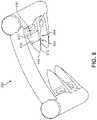
- FIG. 1is a schematic view of a step in a procedure for repairing a rotator cuff tendon, according to an embodiment
- FIG. 2is a schematic view of a step of applying a graft to a portion of a rotator cuff tendon to facilitate healing, according to an embodiment
- FIG. 3is a schematic view of an embodiment of an anchoring device
- FIG. 4Ais a schematic top-down view of an embodiment of an anchoring device
- FIG. 4Bis a schematic bottom-side view of an embodiment of an anchoring device
- FIG. 4Cis a schematic side view of an embodiment of an anchoring device
- FIG. 5is a schematic perspective side view of an anchoring device, according to an embodiment
- FIG. 6is a schematic perspective top view of an anchoring device, according to an embodiment
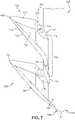
- FIG. 7is a schematic view of a portion of an anchoring device, according to another embodiment.
- FIG. 8is a schematic perspective side view of an anchoring device, according to an embodiment
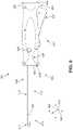
- FIG. 9is a schematic side view of a deployment device, according to an embodiment.
- FIG. 10is a schematic perspective rear view of a deployment device, according to an embodiment
- FIG. 11is a schematic bottom view of a deployment device, according to an embodiment
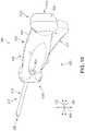
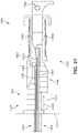
- FIG. 12is a schematic illustration of a deployment device, according to an embodiment viewed from a distal end of the device;
- FIG. 13Ais a schematic cutaway perspective view of a portion of a deployment device, according to an embodiment
- FIG. 13Bis a schematic exploded view of the body portion of the deployment device of FIG. 13A , according to an embodiment
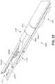
- FIG. 14Ais a schematic perspective view of a deployment tube assembly, according to an embodiment
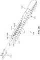
- FIG. 14Bis a schematic cutaway perspective view of a portion of a deployment device, according to an embodiment
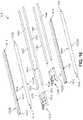
- FIG. 15is a schematic exploded view of the tube assembly of the deployment device of FIGS. 14A and 14B , according to an embodiment
- FIG. 16is a schematic exploded view of a distal portion of the tube assembly of the deployment device of FIGS. 14A and 14B , according to an embodiment
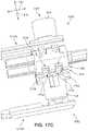
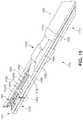
- FIGS. 17A-19present schematic views of a deployment device in a locked configuration with a pair of anchoring devices loaded onto the deployment device, according to an embodiment
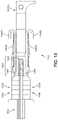
- FIGS. 20-23present schematic views of the deployment device in an actuated configuration, according to an embodiment
- FIGS. 24-26present schematic views of the deployment device in a deployed configuration whereby a first anchoring device is deployed, according to an embodiment
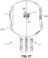
- FIGS. 27-29present schematic views of the deployment device in a locked configuration with a single anchoring device loaded onto the deployment device, according to an embodiment
- FIGS. 30 and 31present schematic views of the deployment device in an actuated configuration, according to an embodiment
- FIGS. 32 and 33present schematic views of the deployment device in a deployed configuration whereby a second anchoring device is deployed, according to an embodiment
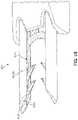
- FIGS. 34 and 35are schematic, perspective illustrations of needle members with an anchoring device disposed therein in a configuration in which the two elements are driven into tissue/graft material.
- the embodimentsprovide an anchoring system that can be used to secure a graft in place over underlying tissue (such as tendons and/or bones) within the body.
- the anchoring systemcan be used to secure the graft over a rotator cuff tendon and/or part of the humerus bone.
- the anchoring systemincludes an anchoring device and a deployment device (or instrument) that is used to insert portions of the anchoring device through a graft and underlying tissue.
- the anchoring device of the embodimentscomprises an arch-shaped body or frame structure that includes a plurality of barbs.
- the frame structureincludes a first beam and a second beam.
- the proximal end portions of the two beamsare bridged by a connecting member.
- Barbsprotrude from an interior-facing or medial side of each beam.
- Each barbis oriented diagonally inward and proximally upward in a direction toward a central longitudinal axis. As the anchoring device is inserted into tissue, the orientation of the barbs ensures that the anchoring device resists any forces that would act to pull out the anchoring device from the tissue.
- the deployment device of the embodimentscomprises a body that can be gripped in one hand by a user and an elongated deployment tube assembly that extends from the body to a tip.
- the deployment tube assemblyincludes a pair of tubes in which the anchoring device may be movably secured or retained.
- An internal pushing membercan be deployed using a trigger on the body. When the anchoring device is loaded in the deployment device and the deployment device is triggered, the pushing member can move an anchor engaging rod and needle members to extend both from the distal tip of the deployment device, thus driving the needle members through the graft and underlying tissue with the anchoring device disposed within the needle members. Then, the needle members are retracted, leaving the anchoring device behind in the graft/tissue.
- the diameter of the deployment tube assemblycan be kept sufficiently small and may be inserted through or directed toward very small arthroscopic incisions.
- the design of the deployment devicefacilitates a lateral approach to the shoulder. This enables access to the joint space under the acromion, which can be more difficult to access when approached head-on from the top aspect of the shoulder.
- FIG. 1is a schematic view illustrating a surgical procedure to repair a tendon in a patient's shoulder. Specifically, a patient 100 is undergoing arthroscopic surgery that is performed by surgeon 102 . Also shown in FIG. 1 is an enlarged view of a portion of humerus 110 and rotator cuff tendons 112 . In the present example, surgeon 102 has recently applied anchors and sutures to secure supraspinatus tendon 114 to humerus 110 .
- surgeon 102may insert a graft through an incision (possibly using another device to facilitate insertion).
- the graftcan then be placed over the repaired tendon and/or portion of the underlying bone in order to facilitate healing.
- FIG. 2shows a schematic view of a graft 202 that has been applied over the recently repaired tendon 114 as well as over a portion of humerus 110 .
- a graftcan be applied to one or more tendons without first reattaching a tendon.
- graftscould be applied to tendons that have only partial tears.
- the disclosed anchoring devicemay be utilized to secure materials other than grafts.
- the anchoring devicemay be used to secure soft tissue to other soft tissue or to secure soft tissue to bone.
- the anchorsmay be used to secure sheet-like implants (other than grafts), as well as provide anchor points for sutures.
- the present embodimentsdisclose both a filament with anchoring elements that can be used to hold a graft in place, as well as an instrument for deploying the filament with anchoring elements.
- FIG. 3is a schematic view of an anchoring device 300 that may be used to secure a graft in place along a tendon, bone, and/or at the interface of a tendon and bone.
- Anchoring device 300may comprise a frame structure 350 that includes a first beam 310 and a second beam 320 bridged by a connecting member 330 .
- the anchoring device 300includes a plurality of barbs (“barbs”) 360 extending or protruding outward from the first beam 310 and the second beam 320 .
- the first beam 310includes a first barb 362 and a second barb 366
- the second beam 320includes a third barb 364 and a fourth barb 368 .
- Portions or areas of the first beam 310 and/or second beam 320 that include barbswill be referred to as barbed regions, and portions or areas of the first beam 310 and/or second beam 320 without barbs will be referred to as unbarbed regions.
- exterior surfaces in the unbarbed regionsare generally smooth.
- the unbarbed beam portionsmay have an approximately constant cross-sectional size corresponding to the diameter of the beam and/or connecting member.
- the first beam 310 and second beam 320are substantially cylindrical in shape, such that the body of each beam will have a circular cross-section.
- the beam structuremay encompass any elongated geometry, including rods and bars of different curvatures and shapes.
- the connecting member 330may also have a substantially circular cross-sectional shape, but in other embodiments may have another shape.
- the components/elementsmay include any three-dimensional shape.
- the connecting member 330is curved in an arc-shape.
- barbscould have any suitable geometry. Exemplary geometries include, but are not limited to: T-bar geometries, arrowhead geometries, wedge geometries, pyramidal geometries, etc. It may be appreciated that embodiments could employ any suitable barb-like elements or elements that resist pull-out from a material along a particular direction.
- anchoring device 300could comprise a monolithic structure, with both the frame structure and barbs constructed of a single unitary piece of material.
- anchoring device 300could be a 3D printed structure formed from a single biocompatible material.
- the frame structure and barbscould comprise distinct structures mechanically joined.
- an anchoring devicecould be made by coating a beam comprised of a first biocompatible material with a second biocompatible material. At some locations along the beam, the second biocompatible material coating could be shaped into barbs.
- each set of barbscould be formed as a sleeve of material that can be placed over a beam and fixed in place, for example, using an adhesive.
- the beam and the sleevecould be made of different materials.
- the anchoring device 300could be hollow or solid, and/or portions of the anchoring device 300 may be filled or hollow.
- the anchoring device 300could be printed with some portions being hollow and lighter, and other portions being filled and heavier.
- bioabsorbable materialsit may be advantageous to vary the overall thickness of different portions of the anchoring device as a way to control the amount of time it takes each portion to dissolve in the body.
- the number of barbs associated with an anchoring device, as well as their distribution along the beams,could vary. In some cases, the barbs could be arranged in approximately regular patterns.
- the anchoring device 300comprises four barbs, symmetrically located on the opposing beams.
- the anchoring devicecould comprise any suitable different numbers of barbs, spaced at any suitable intervals.
- the number of barbscould be selected according to the intended depth of penetration of an anchor as well as the desired resistance to any pull-out forces that would act to tug the anchor out of the tissue after it has been installed.
- the length of the unbarbed portionsmay be selected so that they are long enough to allow movement of the anchoring device, but not too long to make implantation difficult.
- an anchoring devicemay be manufactured with any suitable length and include any number of barbs.
- distal directionis a direction oriented away from a user who is holding a device.
- proximal directionis a direction oriented toward a user who is holding a device.
- a distal side or regionrefers to a portion of the device that is disposed further from the user holding the device and a proximal side or region refers to a portion of a device that is disposed nearer to the user holding the device during normal use.
- medial and lateralrefer to sides of a device or component/element thereof, where a medial side of a component generally faces toward a center of the device, and a lateral side of a component generally faces away from the center of the device.
- longitudinal axisrefers to an axis that extends in a longitudinal direction, which is a direction extending the length of each device, including the anchoring device and the deployment device.
- a longitudinal axisextends in the proximal-distal direction.
- lateral axisrefers to an axis that extends in a lateral direction, which is a direction running a width of each device, including the anchoring device and the deployment device.
- transverse axisrefers to an axis that extends in a transverse direction, which is a direction running along a thickness of each device, including the anchoring device and the deployment device.
- Each axis of the three axesmay be understood to be orthogonal relative to the other two axes.
- a longitudinal axis 390 , lateral axis 370 , and transverse axis 380are indicated.
- the anchoring device 300is shown to include a distal end 374 and a proximal end 372 .
- a medial side 394is also labeled for purposes of example on the side of the first beam 310 closer to a central longitudinal axis 396 (shown in dotted line) that generally divides the anchoring device 300 in two equal parts.
- the side that faces outward or away from the centeris labeled as a lateral side 398 .
- a proximal end 372 of the anchoring device 300is the end that is above or toward the top of the drawing (e.g., the end including the connecting member 330 ), while a distal end 374 of the anchoring device 300 is the end that is below or toward the bottom in the drawing (e.g., the end including the barbs 360 ).
- terms such as below, bottom, lower, etc.may also be used to describe the distal end or distal portions of the anchoring device, while terms such as above, top, higher, etc. may also be used to describe proximal end or proximal portions of the anchoring device.
- a central lateral axis 398(shown in dotted line) is included that generally demarcates the lateral midline of the anchoring device 300 into a proximal region 342 and a distal region 344 .
- anchoring device 300is substantially symmetrical or mirror-images with respect to the central longitudinal axis 396
- anchoring device 300is asymmetrical with respect to the central lateral axis 398 .
- anchoring device 300can have a shape that resembles an archway.
- the connecting member 330can represent the top of the arch, and the first beam 310 and second beam 320 can correspond to the pillars supporting the arch.
- the lengths of the beams 310 and 320can be greater than the length of the connecting member 330 (extending from a first end 338 to a second end 336 ).
- a beamcan have a length that is 1.5-2 times greater than the length of the connecting member 330 .
- a straight-line distance between first end 338 and second end 336can correspond to half the length of a beam.
- the anchoring device 300may be understood to have a substantially U-shaped structure (in FIG. 3 , the “U” shape is upside-down).
- the outer components or elementsi.e., the first beam 310 , second beam 320 , and connecting member 330
- the interior area 340has a substantially parabolic shape or outline. It is within this interior area 340 that the barbs 360 are disposed.
- the barbs 360may be arranged in various positions along a medial surface of one or both of the beams.
- a first spacing between the first barb 362 and second barb 366is substantially similar to a second spacing between the third barb 364 and fourth barb 368 .
- the spacing between different barbed areascan alternate between a relatively longer spacing and a relatively shorter spacing (e.g., such that the anchoring device 300 is no longer symmetrical with respect to the central longitudinal axis 396 ). More specifically, in FIG.
- the space between the barbs on each beamis selected to ensure that the barbs 360 are disposed in the distal region 344 of the anchoring device 300 , while the proximal region 342 remains unbarbed, optimizing the resistance to pull-out forces that might tug on the anchoring device 300 after it has been implanted in tissue.
- the barbs 360will be inserted first (being located in the distal portion of the device) when the anchoring device 300 is pushed into tissue, while the proximal portion remains unbarbed to facilitate the ability of the deployment device to grip and move the anchoring device 300 , and then to extend through a graft and ultimately provide stability to the anchoring device 300 once it has been installed.
- the arrangement of barbscould occur in any other suitable pattern that supports the intended depth of penetration as well as the desired resistance to any pull-out forces.
- the orientation of the barbs 360serve to ensure that the anchoring device 300 resists any forces that would act to pull out the anchoring device from the tissue.
- the orientation depicted in FIG. 3has been shown to provide an increased resistance to pull-out.
- each barb of the anchoring device 300is oriented diagonally upward in a generally proximal direction.
- first barb 362is oriented along a first direction D 1
- second barb 366is oriented along a second direction D 2
- third barb 364is oriented along a third direction D 3
- fourth barb 368is oriented along a fourth direction D 4
- each direction D 1 -D 4corresponds to the average or general direction of the protruding barb (e.g., the proximal and distal surfaces of each barb extend in directions that are either less steep or steeper than the central direction labeled as D 1 -D 4 ).
- each direction D 1 -D 4corresponds to the average or general direction of the protruding barb (e.g., the proximal and distal surfaces of each barb extend in directions that are either less steep or steeper than the central direction labeled as D 1 -D 4 ).
- the first direction D 1corresponds to the first barb 362 extending in a direction toward the intersection between the connecting member 330 and second beam 320 (around second end 336 of connecting member 330 ), while the third direction D 3 is roughly opposite, corresponding to the third barb 364 extending in a direction toward the intersection between the connecting member 330 and first beam 320 (around first end 338 of connecting member 330 ).
- the second direction D 2corresponds to the second barb 366 extending in a direction toward the distal surface (lower side) of the third barb 364 , and then toward the portion of second beam 320 near the central lateral axis 398
- the fourth direction D 4corresponds to the fourth barb 368 extending in a direction toward the distal surface (lower side) of the first barb 362 , and then toward the portion of first beam 310 near the central lateral axis 398 .
- the orientation of the barbs 360forms a double crisscross shape.
- an anchoring devicecould be configured to have a variety of sizes for the frame structure and barbs.
- the frame structurecould have a diameter in-between 0.5 mm and 2 mm.
- the frame structurecould have a diameter of less than 0.5 mm.
- the frame structurecould have a diameter of greater than 2 mm.
- each barbcould have a maximum radial length of between 1 mm and 5 mm. In other cases, each barb could have a maximum radial length that is greater than 5 mm.
- An anchoring devicemay be made of a variety of materials.
- an anchoring devicecould be made of one or more biocompatible materials.
- a biocompatible materialmay be any natural or synthetic material that can be used to replace tissue or to function while being in contact with other tissue in a manner that does not damage the adjacent tissue.
- examples of biocompatible materialsinclude, but are not limited to: metals, ceramics, and polymers. More specific examples include nylon, prolene, dacron, polydioxanone (PDS), polypropylene and ultra high molecular weight polyethylene (UHMWPE).
- the biocompatible materialcould be a bioabsorbable polymer that is gradually absorbed by adjacent tissue.
- bioabsorbable materialsinclude poly L-lactic acid (PLLA), polyglycolic acid (PGA), polytetrafluorethylene (PTFE), polyaryletherketone (PAEK), polyetheretherketone (PEEK), and poly-(D, Lactic acid) (PDLLA).
- PLLApoly L-lactic acid
- PGApolyglycolic acid
- PTFEpolytetrafluorethylene
- PAEKpolyaryletherketone
- PEEKpolyetheretherketone
- PEEKpolyetheretherketone
- PLLApoly-(D, Lactic acid)
- FIG. 4Adepicts the anchoring device 300 in a top-down view, in which the viewer looks directly at proximal end 372 .
- first beam 310 and second beam 320while substantially smooth and have a constant cross-sectional size along a substantial majority of their exterior surface, can also include additional elements.
- first beam 310includes a first enlarged crown element (“first crown”) 410
- second beam 320includes a second enlarged crown element (“second crown”) 420 .
- a first width W 1(in this case also corresponding to a diameter of first crown 410 ) is also substantially equal to a second width W 2 (corresponding to a diameter of second crown 420 ), while a third width W 3 of the connecting member 330 is smaller than either first width W 1 or second width W 2 , where each width is measured along the transverse axis 380 .
- the crown elements of the anchoring devicemay have the same diameter as the inner diameter of the needle members ( 1512 A, 1512 B, 1522 A, and 1522 B) discussed below with respect to FIGS. 16, 34, and 35 , among other figures. This maintains stability of the anchoring device while the needle members are being retracted with respect to the anchor device. It will be understood that, although the crown elements are shown at the proximal ends of the beams, these enlarged needle engaging elements may be disposed at any location along the length of the beams.
- the shape of the distal tips of the anchoring devicemay have substantially the same shape as the distal tips of the needle members.
- the bevels at the distal tips of the anchoring devicesmay include a scalloped portion 397 along the side of the beams, as shown in FIG. 3 . This scalloped portion corresponds to a curved aspect of a Greene tip needle grind.
- the geometry at the distal tips of the anchoring deviceshelps prevent the anchors from going into compression during insertion through tissue/graft material. This feature is discussed in greater detail with respect to FIGS. 34 and 35 below.
- the beamsmay terminate in surfaces that have different shapes at the proximal end than at the distal end of the beams.
- the beamsmay have a proximal end that terminates in a substantially circular surface, and a distal end that terminates in a substantially teardrop-shaped surface.
- both the first crown 410 and second crown 420each have a proximal-side facing surface that is substantially circular (corresponding to the base ends of the cylindrical beams) and labeled here as a first disc 412 and a second disc 422 .
- the exterior surfaces of first disc 412 and second disc 422are substantially flat and planar and smooth.
- first disc 412 and second disc 422are selected to align with and rest flush against the pushing portions of the deployment device.
- the surface of first disc 412 and second disc 422is oriented in a substantially orthogonal direction relative to the orientation of the cylindrical portion of the beams.
- FIG. 4Bdepicts the anchoring device 300 in an upside-down view, in which the viewer looks directly at distal end 374 .
- a distal or first bottom surface 414 of second barb 364 and a second bottom surface 424 of fourth barb 368can be more clearly seen, as well as the distal surface of connecting member 330 .
- a fourth width W 4is also substantially equal to the first width W 1 (see FIG. 4A )
- a fifth width W 5is substantially equal to the second width W 2 (see FIG. 4A ), which allows for the smooth translation of the anchoring device 300 along the deployment tubes of deployment device, as will be discussed below.
- FIG. 4Balso depicts the tapered geometry of the bottom surfaces of the barbs having a teardrop-shape.
- first bottom surface 414 and second bottom surface 424are substantially flat or planar, and are oriented in a diagonally upward direction such that a tapered tip 474 is further proximal and medial relative to a rounded outer edge portion 472 of each surface. That is, first bottom surface 414 and second bottom surface 424 are oriented at an oblique angle relative to the lateral axis 370 (see also FIG. 3 ).
- FIG. 4Cpresents a lateral side view of anchoring device 300 .
- first crown 410is shown, comprising a cylindrical portion with a slightly greater diameter than that of the beam body below.
- the first crown 410includes an upper crown portion 416 and a lower crown portion 418 that is narrower than the upper crown portion 416 .
- the lower crown portion 418can smooth the transition between the beam body and the upper crown portion 416 .
- lower crown portion 418may be a beveled surface, as shown in FIG. 4C .
- the crown elementsmay be enlarged with respect to the beams.
- the lateral side viewillustrates the additional length of anchoring device 300 provided by the curvature of connecting member 330 . It can be seen that a top-most portion of connecting member 330 (corresponding to its center) extends further proximally relative to the proximal end of first beam 310 .
- each beamcan be understood to comprise three regions.
- the second beam 320is shown as including a proximal region 550 , an intermediate region 552 , and a distal region 554 . Descriptions of second beam 320 should be understood to apply to the first beam 310 (and vice-versa).
- the intermediate region 552extends between the proximal region 550 and distal region 554 and comprises an unbarbed and substantially smooth portion of the beam.
- the proximal region 552is joined on its medial side to the second end 336 of the connecting member 330 , and includes second crown 420 , while distal region 554 is barbed with third barb 364 and fourth barb 368 .
- each barbcan be understood to include a base portion 510 and a tapered portion 520 , where the two portions are joined to form a continuous element.
- the base portion 510protrudes outward from the medial side of the first beam 310 and provides structural support and reinforcement to the tapered portion 520 of the barb.
- the base portion 510has a smaller first lateral length 512 than a second lateral length 522 of the tapered portion 520 .
- FIG. 6depicts a perspective top view of the anchoring device 300 , in which a top surface 610 of the third barb 364 is discussed as an example. Details for the top surface 610 may be understood to be applicable to other barbs.
- the shape of top surface 610can be more clearly seen, comprising a substantially arrowhead-like shape, extending from a first side 630 with a first width 632 , decreasing to a second width 634 in a central region 620 , and tapering or diminishing to a narrow point or rounded tip portion 640 with a width of close to zero.
- top surface 610is substantially smooth and flat, and extends in a diagonally upward direction as it approaches the tip 640 .
- FIG. 7presents a magnified view of the distal region 554 of second beam 320 , including third barb 364 and fourth barb 368 .
- the anchoring device 300is substantially symmetrical it should be understood that details provided for third barb 364 may also be applicable to the first barb and details for fourth barb 368 may also be applicable to the second barb.
- a first tapered portion 792 of third barb 364can be seen to include multiple surface sides, including a proximal facing top surface 610 , a first lower surface 720 , a first side surface 722 , and a ridge surface 718 .
- the tapered portioncan include a roughly semi-pyramidal three-dimensional shape.
- the tapered portion 792also includes a second lower surface and a second side surface on the opposite side.
- Each of the four surfacescomprising ridge surface (“ridge”) 718 , top surface 610 , first lower surface 720 , and second lower surface (not shown) merge into tip portion 640 , which can have a narrow, rounded tip or a more pointed or sharp tip.
- first lower surface 720can be seen to extend partially underneath a first base portion 794 of third barb 364 .
- First base portion 794protrudes outward from a base 732 that is joined to the second beam 320 , and includes an arm portion 796 that extends distally downward toward fourth barb 368 until tapering to a point.
- First base portion 794also includes a first upper surface defining a recess 750 . That is, the proximal facing upper surface 610 may be separated from beam 320 by recess 750 .
- Recess 750provides barb 364 with a hooked shape, which prevents pull out from tissue. It also provides a narrower base profile, which facilitates penetration into tissue.
- a reinforcing rib 746may be disposed within recess 750 . The reinforcement rib 746 protrudes upward from recess 750 and extends into the body of the first tapered portion 792 that adds greater structural support to the barb.
- a spacing 754 between the two barbscan be more clearly seen in FIG. 7 , extending from the end of the arm portion 796 of the third barb 364 to a second upper surface 710 of the fourth barb 368 . While the two barbs can be understood to be very similar, one structural feature of fourth barb 368 that differs from third barb 364 is the shape of the lower surface. While third barb 364 had a first lower surface 720 that continued until reaching arm portion 796 , a lowermost surface 780 of the fourth barb 368 can be seen to extend further as a smooth and continuous plane from a tip 786 to an outer edge portion 788 , abutting the teardrop-shaped second bottom surface 424 (see FIG. 4B ), along a bottom-most end 770 of second beam 320 .
- first barb 362 and second barb 366are presented, more clearly illustrating the ridges of each.
- Second barb 366includes first bottom surface 414 extending diagonally in a proximal direction from a bottommost end 890 of first beam 310 until reaching a first ridge 718 .
- First ridge 718is a substantially rectangular panel that runs along the bottom of the tapered portion of the second barb 366 and extends in a more sharply upward direction than first bottom surface 414 .
- the first ridge 718corresponds to a central region of the barb where a first lower surface 880 and a second lower surface 882 come together.
- first lower surface 880 , second lower surface 882 , first ridge 718 , and top surfacemerge into a tip 884 .
- a second ridge 816 of first barb 362extends further along the distal surface of the barb, until forking into two prongs 818 toward opposing sides of the first beam 310 , thereby forming a Y-shape.
- the anchoring device of the embodimentscan be implanted using an assembly that extends needle pairs and anchoring devices from a distal tip of the deployment device.
- the needlespierce into the tissue of the patient.
- the needlesare retracted, while a pushing member maintains the position of the anchoring device relative to the deployment device, thus leaving the anchoring device in the graft and/or tissue.
- the general method for implanting an anchoring device described abovecan be accomplished using a deployment device such as that described below.
- the deployment devicemay include both a pushing member, as well as components that can actuate the pushing member to simultaneously drive the needle pairs and anchoring device through a graft and into underlying tissue. The deployment device can then release the anchoring device into the graft and/or tissue by retracting the needles.
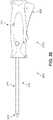
- FIG. 9is a schematic exterior side view of an example of a deployment device 900 . Additional schematic views of deployment device 900 are shown in FIGS. 10-12 .
- Deployment device 900can be used to deploy an anchoring device comprised of two beams with barbed portions and unbarbed portions (for example, anchoring device 300 of FIG. 3 ). In particular, deployment device 900 can be used to deploy the anchoring device discussed earlier into tissue.
- deployment device 900is comprised of a body portion (“body”) 920 that is coupled to a deployment tube assembly (“tube assembly”) 910 .
- the body 920can be seen to include an external housing 926 extending longitudinally between a forward end 952 and a rear end 950 , as well as a handgrip trigger 922 , a plurality of fasteners 928 , and an optional first selector button 924 that is currently in an unpressed, neutral, initial, protruding, or default state.
- the fasteners 928in this case are secured within recesses formed in the housing 926 .
- the handgrip trigger 922can have a forward portion that protrudes outward before curving up toward the housing 926 and then extending downward to provide a larger second portion, thereby providing contours that form a user-friendly gripping unit.
- terms such as forward, front, etc.may also be used to describe features disposed toward a distal end of the deployment device, while terms such as rearward, rear, back, etc. may also be used to describe features disposed toward a proximal end of the deployment device.
- the deployment tube assembly 910can be seen to comprise a tube housing 914 that is connected to a tip portion 912 .
- a maximum first transverse width 942 of the tube assembly 910is significantly smaller than a maximum second transverse width 944 of the body 920 .
- Deployment tube assembly 910may include provisions for inserting an anchoring device through a graft and/or tissue, and will be discussed further with reference to FIGS. 14A-16 .
- the deployment device 900is presented with directional labels, including a distal end 930 (toward the tip portion 912 ), a proximal end 934 (toward the rear end 950 ), a lower side 932 , and an upper side 936 .
- a first side 1030 and a second side 1032are also identified.
- first side 1030 and second side 1032represent two complementary, and in some cases, substantially symmetrical or mirror-image portions of deployment device 900 relative to central lateral axis 1270 .
- tube housing 914is substantially cylindrical (i.e., with a substantially circular cross-sectional shape in a lateral plane), where a first lateral width 1142 is equal or approximately the same as the first transverse width 942 in FIG. 9 .
- the tube housing 914may have an oval or oblong cross-sectional shape.
- the body 920has a second lateral width 1148 that is smaller than the second transverse width 944 of FIG. 9 .
- a first longitudinal length 1144 of the tube assembly 910is similar to a second longitudinal length 1146 of the body 920 , though in other embodiments, the dimensions of each component may differ based, for example, on the dimensions of the anchoring device being implanted. For example, in some embodiments, the tube assembly may be much longer than the body portion in order to provide greater flexibility of movement to an operator.
- FIG. 11also more clearly depicts the selector mechanism, including the two selector buttons, namely first selector button 924 and second selector button 1124 disposed on the opposite side. Second selector button 1124 is, for purposes of illustration, in the depressed state in FIG. 11 , and has an outer surface that is nearly flush with the outer surface of the housing 926 .
- the handgrip trigger 922may include a texturing or other surface patterns that can improve the security of a user's grip on the device.
- handgrip trigger 922may include nubs or bumps to improve grip.
- the tube assembly 910extends from the body 920 in the region surrounding a transverse midline 1270 (extending from upper side 936 to lower side 932 ) that demarcates the region in which a first housing side 1242 joins to a second housing side 1244 .
- the deployment device 900may be configured to deliver one anchoring device before requiring a ‘reload’, in some embodiments, the deployment device 900 can include a dual deployment system whereby two anchoring devices may be stored at the same time, allowing for delivery of two different anchoring devices in short order. Such a configuration is shown in FIG.
- the tip portion 912substantially surrounds a first anchoring device (“first anchor”) 1210 disposed above and a second anchoring device (“second anchor”) 1220 disposed below.
- first anchor 1210 and second anchor 1210may correspond to the anchoring device 300 described above.
- the two anchorsmay be arranged within deployment device 900 such that they are substantially symmetrical relative to a longitudinal axis extending through a central point 1250 . It may be appreciated that in embodiments in which the deployment device offers dual deployment as described herein, two or more selector buttons may be included. However, in cases where the deployment device includes a single deployment system, only one selector button, or no selector button, may be included.
- Body 920includes provisions to actuate components of the deployment tube assembly. Body 920 may also include provisions for easily holding deployment device 900 . To this end, body 920 may include handgrip trigger 922 . Handgrip trigger 922 may be designed to accommodate either a left or right hand. A user's hand may engage handgrip trigger 922 and wrap around a portion of housing 926 in order to squeeze the handgrip trigger 922 upward and actuate the device. It may be appreciated that in some embodiments, a variety of different materials, coatings and/or surface treatments can be used handgrip trigger 620 and housing 926 to improve grip and prevent slipping.
- the handgrip trigger 922may be coupled to additional actuating components that reside within body 920 , and which enable the actuation of a pushing member in the deployment device.
- the handgrip trigger 922may, when actuated, cause a change in a linkage assembly 1320 from a first configuration to a second configuration (see FIGS. 17A-26 below).
- linkage assembly 1320comprises a plurality of linking components for permitting the extending and contracting of the assembly, as will be discussed in greater detail below.
- the linkage assembly 1320can pivot and initiate an actuation sequence in conjunction with an actuation assembly 1300 .
- the actuation assembly 1300can include a slider assembly 1310 , a compression spring (“spring”) 1330 , and a set of anchor engaging rod drivers (“drivers”) 1340 .
- the spring 1330surrounds a spring-engaging post or protruding portion 1332 , which has an elongated geometry and extends from both sides of the slider assembly 1310 .
- the drivers 1340are connected to a set of pushing members (a first pushing member 1302 and a second pushing member 1304 ) that extend from the tube housing 914 into the body 920 (see FIGS. 14A-15 ).
- Pushing membersmay also be referred to herein as needle blocks.
- FIG. 13Ban exploded perspective view of the body 920 is illustrated in FIG. 13B .
- the housing 926can be seen to comprise first housing side 1242 and second housing side 1244 .
- the handgrip trigger 922includes a substantially hollow interior space 1322 designed to receive and movably connect with a lower portion of a first link 1320 a of linkage assembly 1320 .
- the trigger 922further includes a set of pivoting or rocker elements (shown here as two knobs extending outward from exterior surface of the trigger 922 ), operation of which will be discussed further below.
- trigger 922may include gripping elements 1326 that can improve a user's grip on the device.
- first link 1320 ais movably connected to a second link 1320 b
- second link 1320 bis movably connected to a third link 1320 c , which is movably connected to slider assembly 1310 , seen here to comprise a first sliding component 1310 a and a second sliding component 1310 b
- the second sliding component 1310 bis shown as comprising several regions, including a first region 1370 , a second region 1380 , a third region 1390 , and a fourth region 1392 .
- the first region 1370 and second region 1380together comprise a forward region 1376 of the sliding component.
- first region 1370 of the sliding componentincludes tongue portions or ridges 1308 that extend medially inward.
- the ridges 1308 in each sliding componentare sized and dimensioned to engage with a plurality of grooves formed along the sides of the pushing members (see FIGS. 17B and 17C ).
- the fourth region 1392includes portions that are configured to engaged with the linkage assembly 1320 . While only the second sliding component 1310 b includes the above labels, it should be understood that these regions are also present in first sliding component 1310 a .
- each sliding componentis complementary or a mirror-image with respect to the opposing sliding component, except for the location of the ridges in first region 1370 .
- the ridges in the first sliding component 1310 aare disposed near or abut an uppermost edge of the first region, and the ridges in the second sliding component 1310 a are disposed near or abut a lowermost edge of the first region.
- the third link 1310 cis configured to pivot around and relative to the protruding portion 1332 that extends from the medial-facing sides of the fourth region 1392 of each sliding component.
- selector assembly 1324Surrounding the first region 1370 is selector assembly 1324 , which comprises two selector buttons and a substantially rectangular opening into which slider assembly 1310 extends. Depression of a selector button on either side can push against the adjacent sliding component in a medial direction, in turn engaging the corresponding pushing member (see FIG. 20 ).
- the set of drivers 1340including a first driver 1340 a and a second driver 1340 b , are arranged symmetrically or mirror-images relative to one another and are disposed between first sliding component 1310 a and second sliding component 1310 b .
- the first driver 1340 afurther includes a first driver spring 1342 a and the second driver 1340 b includes a second driver spring 1342 b.
- the tube assembly 910includes a tip portion 930 with primary opening 1230 at its distal end from which the anchor is released.
- the tip portion 930is joined to the elongated tube housing 914 in which multiple components and portions thereof are disposed.
- Extending outward from a rear or proximal openingare a pair of pushing members 1420 (comprising the first pushing member and second pushing member).
- a first anchor engaging rod 1480Disposed within a channel formed along a first side of the upper pushing member is a first anchor engaging rod 1480 , and disposed within a channel formed along a first side of the lower pushing member is a second anchor engaging rod 1490 .
- each channelincludes a slit opening from which the anchor engaging rods can be seen.
- the interior components of the tube housing 914are arranged substantially symmetrically relative to a central longitudinal axis 1450 .
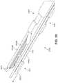
- FIG. 14Bthe tube assembly 910 is depicted without the exterior tube housing 914 , revealing the interior deployment components.
- the pushing members 1420can be seen to extend from a region adjacent to and behind tip portion 930 until entering the housing 926 of body 920 through an aperture 1472 formed on the distal end of the housing 926 .
- a rear portion 1436 of the pushing members 1420then extends proximally into housing 926 and contacts with components of actuation assembly 1300 .
- engaging portions 1434 of the pushing members 1420are partially disposed between the two sliding components comprising the slider assembly 1310 .
- the two anchor engaging rods 1482extending along the sides of the pushing members 1420 that are configured to engage with drivers 1342 (see FIG. 13B ).
- the anchor engaging rods 1482are further movably secured or retained within the channels formed in pushing members 1420 by retaining clips 1414 .
- tube assembly 910includes provisions to deploy one or more anchors from the tube assembly 910 .
- an exterior of tube assembly 910includes tube housing 914 and tip portion 912 , and provides a continuous interior compartment extending from primary opening 1230 and continuing into a secondary opening 1530 formed in a distal end of tube housing 914 .
- the compartmentis substantially cylindrical in shape.
- the tube housing 914also includes window openings 1510 that provide a view of the interior configuration or state of the pushing members.
- a first windowmay be present on an upper surface of the tube housing 914
- a second windowmay be present on a lower surface of the tube housing 914 .
- the two windowscan be aligned with one another relative to the transverse axis 380 .
- interior components of tube assembly 910includes first pushing member 1302 and second pushing member 1304 , the first anchor engaging rod 1480 , the second anchor engaging rod 1490 , a first retaining clip 1514 , a second retaining clip 1524 , a first needle member 1512 a , a second needle member 1512 b , a third needle member 1522 a , and a fourth needle member 1522 b .
- the tube assembly 910also includes one or both of first anchor 1210 and second anchor 1220 .
- first pushing member 1302 and second pushing member 1304can be substantially similar in shape and dimensions, though oriented in opposing directions.
- a substantially flat underside of first pushing member 1302faces directly toward and in some cases can be in contact with a substantially flat upper surface of second pushing member 1304 .
- the first pushing member 1302is shown as comprising several portions, including a forward portion 1530 (further including a nose portion 1528 ), an intermediate portion 1518 , a recessed portion 1532 , and an engaging portion 1534 . While only the first pushing member 1302 includes such labels in FIG. 15 , it should be understood that these portions are also present in second pushing member 1304 as well.
- both forward portion 1530 and intermediate portion 1518are disposed within the tube housing 914 .
- the nose portion 1528can move forward from tube housing 914 into the tip portion 912 in order to push the anchor and needle members in a distal direction out of primary opening (e.g., see FIG. 30 ).
- recessed portion 1532 and engaging portion 1534are discussed herein as comprising components of the tube assembly 910 , they are each configured to extend into the body housing and/or engage with components disposed in the body of the deployment device.
- each pushing memberfurther includes a plurality of grooves 1562 formed between the spaces between a pair of ledges 1560 , and an end portion 1564 (shown here with reference to second pushing member 1304 ). Further details regarding engaging portion 1534 will be discussed below in FIGS. 17A-C .
- first anchor engaging rod 1480 and the second anchor engaging rod 1490can be substantially similar in shape and dimensions, though oriented in opposing directions.
- each anchor engaging rodincludes an elongated U-shape comprising three portions.
- first anchor engaging rod 1480includes a first prong or arm 1582 that is substantially parallel to and aligned with a second prong or arm 1586 .
- the first prong 1582 and second prong 1586are bridged together by a first hook portion 1584 .
- second anchor engaging rod 1490includes a third prong or arm 1592 that is substantially parallel to and aligned with a fourth prong or arm 1596 .
- the third prong 1592 and fourth prong 1596are bridged together by a second hook portion 1594 .
- Central longitudinal axis 1410was first represented in FIG. 14A . It is also included in FIG. 15 , and should be understood to extend through a centerline of the tube assembly 910 . Thus, the medial direction (i.e., toward the center) from any component of tube assembly 910 should be understood to be a direction that extends toward the central longitudinal line 1410 . It may be appreciated that while the majority of the prong portions of each anchor engaging rod are substantially linear and parallel to the central longitudinal axis 1410 , the hook portions are U-shaped. Thus, each anchor engaging rod comprises a continuous, elongated U-shaped rod. Furthermore, each hook portion is oriented diagonally relative to the central longitudinal axis 1410 .
- each hook portionis slightly bent in a direction away from central longitudinal axis 1410 .
- first hook portion 1584is a U-shaped segment that bends or curves upward
- second hook portion 1594is a U-shaped segment that bends or curves downward. The functions of the hook portions will be discussed with reference to FIGS. 18-25 below.
- each pushing memberalso includes channels for receiving portions of each anchor engaging rod.
- first pushing member 1302can be seen to include a first channel 1516 that extends along the first side 1030 of a lower edge of the intermediate portion 1518 and recessed portion 1532 .
- second channelis similarly formed on the second side 1130 of the intermediate portion 1518 and recessed portion 1532 .
- second pushing member 1304includes a third channel 1526 and a fourth channel that is formed on the opposite side.
- Each channelis shaped and sized to snugly accommodate the prongs of each anchor engaging rod, providing a secure hold of the prong while also allowing smooth movement back and forth along the channel.
- the channelhas a longitudinal opening with a transverse width that is smaller than the diameter of the prong disposed within the channel in order to prevent the prong from escaping from the channel.
- the recessed portion 1532 of each pushing memberis configured to slide back and forth between the body of the deployment device and the tube housing 914 via the aperture formed in the body housing.
- the recessed portion 1532has a smaller transverse thickness and a substantially flat upper surface, allowing it to move smoothly through the body housing.
- the tube assembly 910includes provisions for releasing each anchor from the deployment device. As shown in FIG. 15 , the tube assembly 910 further includes needle members for holding anchors and to provide a space in which anchor engaging rods can interact with loaded anchors. More specifically, a first beam of first anchor 1210 is housed in or movably retained by an elongated chamber formed in first needle member 1512 a and a second beam of first anchor 1210 is housed in or movably retained by an elongated chamber formed in second needle member 1512 b .
- first beam of second anchor 1220is movably retained in or held by an elongated chamber formed in third needle member 1522 a and a second beam of second anchor 1220 is movably retained in or held by an elongated chamber fourth formed in fourth needle member 1522 b.
- each anchorextends outward from each needle member through an elongated slit formed along a medial side of each needle member, allowing the anchor to be disposed in both needle members simultaneously.
- the two needle membersare spaced apart a first distance 1582 that corresponds to the lateral width of the connecting member.
- the barbs and connecting member of each anchorare exposed within the tube assembly 910 relative to the first beam and second beam which are retained in the chambers of needle members. It can be understood that each chamber is shaped and sized to snugly accommodate the beams of each anchor, providing a secure hold of the beam while also allowing smooth movement of the anchor back and forth along the chamber.
- each elongated slithas a transverse width that is smaller than the diameter of the beam and larger than the diameter of the connecting member and transverse width of the barbs in order to securely retain the anchor in the two needle members, and allow retraction of the needle members until the anchors are released such that deployment occurs.
- first needle member 1512 a and second needle member 1512 bare held or joined to forward portion 1530 of the first pushing member 1302 by first retaining clip 1514 .
- third needle member 1522 a and fourth needle member 1522 bare held or joined to the forward portion of the second pushing member 1304 by second retaining clip 1524 .
- the curved retaining clipis secured within a recessed region provided in the forward portion 1530 sized and dimensioned to snugly receive the retaining clip, and the retaining clip ‘hugs’ the proximal ends of the needle member such that the needle member is held flush and securely in place against a substantially concave sidewall region of the forward portion.
- first needle member 1512 aincludes a forward opening 1616 and a rear opening 1620
- second needle member 1512 bincludes a forward opening 1610 and a rear opening 1620 .
- third needle member 1522 aincludes a forward opening 1636 and a rear opening 1640
- fourth needle member 1522 bincludes a forward opening 1630 and a rear opening 1634
- second needle member 1512 bcan be seen to include a first slit 1612 extending across the longitudinal length of the tube and fourth needle member 1522 b includes a second slit 1632 extending across the longitudinal length of the needle member. It should be understood that first needle member 1512 a and third needle member 1512 b also includes such slits, allowing for the free movement of the anchor through the needle members from the forward opening to the rear opening.
- first anchor 1210 and first anchor engaging rod 1480 and the similar view of second anchor 1220 and second anchor engaging rod 1490also offer more clarity regarding the pushing functionality of the deployment device.
- a second distance 1644 between the first prong 1582 and the second prong 1586is substantially equal to a third distance 1642 between the first beam and the second beam of first anchor 1210 , allowing the two components to be aligned in a longitudinal plane.
- a first disc 1652 of first anchor 1210has a surface area and shape that is substantially similar to that of a first distal end 1656 of the first prong 1582 .
- a second disc 1654 of first anchor 1220has a surface area and shape that is substantially similar to that of a second distal end 1658 of the second prong 1586 .
- Each distal endmay also be referred to as a pushing portion or pushing surface herein.
- the two surfacesface one another and are configured to press against one another when actuation occurs.
- FIGS. 9-16provide a way to convert the upward translation of the trigger into a corresponding distal translation of the pushing members. This allows the force generated by squeezing the trigger to be converted into a force that drives an anchor through a graft and underlying tissue.
- FIGS. 17A-26together show how an anchor is made to be deployed from tip portion 912 when the handgrip trigger 922 is squeezed.
- deployment device 900is shown in a primary locked configuration 1750 , with first pushing member 1302 and second pushing member 1304 retracted or stowed.
- the primary locked configuration 1750refers to the state in which the deployment device has not been actuated, but a depression of a selector button has occurred.
- the neutral positionnot shown here, refers to the state in which the deployment device has not been actuated, nor has a selector button been depressed.
- the spring 1330is also in its initial extended configuration around the protruding portion 1332 .
- the linkage assembly 1320is in an initial contracted position. In this first stage, for purposes of example, the second selector button 1124 is depressed, as shown in FIGS. 11 and 12 earlier. In other cases, the first selector button may be depressed first.
- depression of second selector button 1124causes a change in the relative position of the second sliding component 1310 b in the body 920 .
- This arrangementis now discussed with reference to FIGS. 17B and 17C .
- both sliding componentsremain spaced apart from the pushing members.
- FIGS. 17B and 17Cprovide two perspective cutaway views of the selector assembly 1324 . In FIGS.
- FIG. 17Bit can be seen that as a result of the depression of second selector button 1124 , the second sliding component 1310 b has been compressed or pushed inward, such that the two ridges (shown here as a first ridge 1776 and a second ridge 1778 ) are now inserted into or received by the engaging portion of the first pushing member 1302 . More specifically, first ridge 1776 has been inserted into a first groove 1772 and second ridge 1778 has been inserted into a second groove 1774 .
- the shape and size of each grooveis configured to snugly receive each corresponding ridge.
- each ridgelies flush against or directly adjacent to the three inner surfaces comprising each groove.
- the ridges and ledgesform a substantially continuous upper surface along the second side 1032 of the engaging portion of the first pushing member 1302 . Furthermore, a first rear ridge 1788 is now pressed against the outer side of the end portion of the first pushing member 1302 . Thus, the first pushing member 1302 is now ‘locked’ to the second sliding component 1310 b , such that it will hold its relative position with the second sliding component 1310 b if the second sliding component 1310 b moves forward or rearward.
- the first selector button 924remains in the un-pressed, neutral, or initial state.
- the adjacent sliding componentremains spaced apart from the engaging portion of the pushing members.
- a third ridge 1766is disposed outside of a third groove 1762 formed along the first side 1030 of second pushing member 1302
- a fourth ridge 1768is disposed outside of a fourth groove 1764 formed along the first side 1030 of the second pushing member 1304 .
- a second rear ridge 1786is also spaced apart from the end portion of the second pushing member 1304 .
- the second pushing member 1304is ‘unlocked’ with respect to the first sliding component 1310 a , such that it will not hold its relative position with the first sliding component 1310 a if the first sliding component 1310 a moves forward or rearward. It should be understood that when neither selector button has been depressed, both sides of the deployment device are in this arrangement, also referred to as the neutral configuration.
- each sliding componentcan be complementary or a mirror-image with respect to the opposing sliding component, except for the location of the ridges in the first region 1370 .
- the third ridge 1766 , fourth ridge 1768 , and second rear ridge 1786are disposed along the lower half of the first region of the first sliding component 1302 , and are therefore aligned with the grooves formed in the lowermost second pushing member 1304 .
- the first ridge 1776 and second ridge 1778 and first rear ridge 1788are disposed along the upper half of the first region of the second sliding component 1304 , and are therefore aligned with the grooves formed in the uppermost first pushing member 1302 .
- FIG. 17Cpresents the assembly of FIG. 17B with the second sliding component 1310 b removed from the assembly.
- the mechanism by which the second pushing member 1304 is locked into positionis now visible, as well as the stacking arrangement of the first pushing member 1302 over the second pushing member 1304 .
- depression of second selector button 1124also causes a change in the relative position of the second selector button 1124 in the body 920 .
- both selector buttonsremain spaced apart from the pushing members.
- a selector buttonis depressed, a set of locking projections shifts position in a medially inward direction in order to engage with the adjacent pushing member's engaging portion.
- FIG. 17Cit can be seen that as a result of the depression of second selector button 1124 , the second selector button 1124 has been compressed or pushed inward, such that the two locking projections (shown here as a first projection 1786 and a second projection 1788 ) are now inserted into or received by the engaging portion of the second pushing member 1304 . More specifically, first projection 1786 has been inserted into a fifth groove 1782 and second projection 1788 has been inserted into a sixth groove 1784 .
- the shape and size of each grooveis configured to snugly receive each corresponding projection.
- each projectionlies flush against or directly adjacent to the three inner surfaces comprising each groove.
- the projections and ledgesform a substantially continuous upper surface along the second side 1032 of the engaging portion of the second pushing member 1304 .
- the second pushing member 1304is now ‘locked’ to the second selector button 1124 , such that it will hold its relative position with the second selector button 1124 while other neighboring components move forward or rearward.
- the first set of grooves formed on the second side 1032 of the first pushing member 1302have been filled by the ridges of the second sliding component 1310 b
- the second set of grooves on the second side 1032 of the second pushing member 1304have been filled by the projections of the second selector button 1124 .
- the second set of groovescan be understood to be aligned with and disposed directly below the first set of grooves while deployment device is in the primary locked configuration 1750 .
- FIG. 18presents a cutaway side view of a portion of the deployment device in the primary locked configuration 1750 in which the housing and first sliding component have been removed to reveal the relative arrangement of the pushing members, anchor engaging rods, and drivers.
- the systemis substantially symmetrical with respect to the central longitudinal axis.
- the first pushing member 1302is disposed directly above and aligned with the second pushing member 1304
- the first anchor engaging rod 1480is disposed directly above and aligned with the second anchor engaging rod 1490
- the first driver 1340 ais disposed directly above and aligned with the second driver 1340 b .
- each anchor engaging rodcan be seen to extend through an opening or space formed between the L-shaped end portion 1564 of the two pushing members.
- the hook portions of each anchor engaging rodare disposed behind driver head portions 1860 , such that each hook portion surrounds or wraps around a lateral width of the adjacent driver.
- the proximal end of the hook portion, curving away from the central longitudinal axis,is in contact with and/or presses against a corner 1850 formed in the L-shaped end portion of each pushing member.
- the recessed portion 1532 of both pushing memberscan be understood to be disposed primarily within the body housing (not shown).
- FIG. 19presents a cutaway perspective view of a portion of the deployment device in the primary locked configuration 1750 in which the tube housing, tip portion, and two needle members have been removed to reveal the relative arrangement of the pushing members, anchor engaging rods, and anchors.
- the systemis substantially symmetrical with respect to the central longitudinal axis.
- the nose portions of the first pushing member 1302 and second pushing member 1304are aligned with one another
- the first anchor engaging rod 1480is disposed directly above and aligned with the second anchor engaging rod 1490
- the second needle member 1512 bis disposed directly above and aligned with the fourth needle member 1522 b
- the first anchor 1210is disposed directly above and aligned with the second anchor 1220 .
- the removal of the first needle member and third needle memberalso more clearly illustrates the relationship between the lower ends (discs) of the anchors with the distal ends of the anchor engaging rods, whereby the anchor engaging rods are in direct contact with each anchor.
- deployment device 900is shown in a primary actuated configuration 2050 , with first pushing member 1302 slid forward and second pushing member 1304 retaining its original position.
- the spring 1330is now in its compressed configuration around the protruding portion 1332 .
- the linkage assembly 1320has transitioned from its contracted position to an extended position.
- the second selector button 1124continues to be depressed, as described in FIGS. 17A-19 above.
- the trigger 922is configured to pivot in either a first rotary direction or an opposing second rotary direction via a pair of cylindrical rocker elements that extend outward from the trigger 922 and are movably or rotatably secured in small tubes formed in the housing.
- depression of the proximal end of the trigger 922causes rotation of the trigger 922 such that the proximal end moves upward in the first rotary direction while the distal end moves downward.
- the distal end of the trigger 922is at a lowermost position, and the proximal end of the trigger 922 is at an uppermost position.
- trigger 922pivots in a generally counter-clockwise direction. Furthermore, trigger 922 is biased to return to its neutral position, by way of spring 1330 which extends around the protruding portion 1332 .
- spring 1330extends around the protruding portion 1332 .
- the motion of the trigger 922 as it moves upwardis translated into further rotational motion by the pivoting portions of the linkage assembly 1320 , causing the linkage assembly 1320 to straighten and lengthen in the longitudinal direction.
- This same motioncauses the slider assembly 1310 to be pushed forward, resulting in a compression of the spring 1330 around protruding portion 1332 as it meets and presses against a distal surface 2032 of the fourth region 1392 of slider assembly 1310 .
- first pushing member 1302is locked to the sliding component 1310 b in this example (due to the depression of the second selector button).
- first pushing member 1302is also carried or pushed forward the same distance into the actuated position.
- second pushing member 1304being locked to the second selector button, retains its original, stowed position.
- the recessed portion of the first pushing memberis now disposed primarily within the tube housing (not shown), while the recessed portion of the second pushing member is disposed primarily within the body housing (not shown).
- the new relative positioning of the first pushing member 1302 to the second pushing member 1304is more clearly observable in the cutaway side view of the deployment device in FIG. 21 .
- the housing and first sliding componenthave again been removed to reveal the relative arrangement of the pushing members, anchor engaging rods, and drivers.
- FIG. 21it can be observed that the system, in this configuration, is no longer substantially symmetrical with respect to the central longitudinal axis.
- the first pushing member 1302is now disposed more distally relative to the second pushing member 1304 by a fourth distance 2100
- the first anchor engaging rod 1480is disposed more distally relative to the second anchor engaging rod 1490 by a fifth distance 2102 .
- fifth distance 2102is substantially similar to the fourth distance 2100 .
- both the first driver 1340 a and second driver 1340 bretain their positions during this stage and remain aligned relative to one another, even as the slider assembly 1310 has translated forward.
- the relative position of the slider assembly 1310 to the two drivershas changed such that both drivers are now disposed nearer to the fourth region 1392 of the slider assembly 1310 than in the first stage.
- the first anchor engaging rod 1480has moved forward such that it no longer extends around the head portion of either driver. Rather, the first anchor engaging rod 1480 is now completely distal relative to the first driver 1340 a , having been pushed forward by the distal surface of the corner 1850 of the L-shaped end portion of the first pushing member 1302 .
- FIGS. 22 and 23present cutaway perspective views of a portion of the deployment device in the primary actuated configuration 2050 in which the tube housing, tip portion, and two needle members have again been removed to reveal the relative arrangement of the pushing members, anchor engaging rods, and anchors.
- FIG. 22depicts an upper perspective view
- FIG. 23depicts a lower perspective view.
- the systemis no longer symmetrical with respect to the central longitudinal axis.
- the nose portion of the first pushing member 1302is distal relative to the nose portion of the second pushing member 1304 .
- first anchor engaging rod 1480 and second needle member 1512 balso project outward further relative to the second anchor engaging rod 1490 .
- the movement forward of the first anchor engaging rod 1480has caused a pushing force to be applied to the first anchor 1210 , such that first anchor 1210 now extends further outward by a sixth distance 2200 relative to the second anchor 1220 .
- fourth distance 2100 and fifth distance 2102are substantially similar to the sixth distance 2200 shown in FIG. 22 .
- the deployment devicemay be used in one of two ways.
- the tip of the deployment devicemay be held against the implant/graft/tissue and the trigger pulled in order to deploy the needle members and pierce the implant/graft/tissue.
- the needle membersmay be deployed first, before engaging the implant/graft/tissue, and then the deployment device may be advanced as a whole in order to sink the needle members into the implant/graft/tissue.
- deployment device 900is shown in an initial deployed configuration 2450 , with first pushing member 1302 having slid backward until again aligning with second pushing member 1304 .
- the spring 1330has returned to an extended configuration around the protruding portion 1332 .
- the linkage assembly 1320has transitioned back from the extended position to its contracted (neutral) position.
- the second selector button 1124continues to be depressed, as described in FIGS. 17A-19 above.
- the handgrip trigger 922in order for the transition from the primary actuated configuration 2050 (shown in FIGS. 20-23 ) to the initial deployed configuration 2450 to occur, the handgrip trigger 922 is rocked in the second rotary direction.
- the trigger 922would be pivoted in a generally clockwise direction.
- depression of the distal end of the trigger 922causes rotation of the trigger 922 such that the distal end moves upward in the second rotary direction while the proximal end moves downward.
- the deployment device operatorhas positioned the tip portion at the desired location, he or she can rock the trigger 922 in the opposite direction to release the first anchor 1210 .
- the spring 1330biases the trigger 922 to return to the neutral position, which is reflected in the depiction of FIG. 24 .
- rocking the trigger 922 in the second rotary directioncauses the linkage assembly 1320 to contract, which further causes the slider assembly 1310 to be pulled back in a rearward or proximal direction.
- the engaging portion of the first pushing member 1302is locked to the sliding component 1310 b .
- first pushing member 1302is also carried or moved backward the same distance.
- second pushing member 1304being locked to the second selector button, continues to retain its original position.
- the translational movement of the slider assembly 1310 in a proximal directionpulls the locked first pushing member 1302 until first pushing member 1302 is again aligned with second pushing member 1304 .
- the swift retraction of the first pushing member 1302retracts the needle members, thus releasing the first anchor 1210 from the deployment device 900 , as shown in FIG. 24 .
- the new relative positioning of the first pushing member 1302 to the second pushing member 1304is more clearly observable in the cutaway side view of the deployment device in FIG. 25 .
- the housing and first sliding componentare removed to reveal the relative arrangement of the pushing members, anchor engaging rods, and drivers.
- FIG. 25it can be observed that several components of the system are once again substantially symmetrical with respect to the central longitudinal axis.
- the first pushing member 1302is disposed directly above and aligned with the second pushing member 1304
- the first driver 1340 ais disposed directly above and aligned with the second driver 1340 b .
- the first driver 1340applies a force against the hook portion of first anchor engaging rod 1480 , ensuring that it remains in its actuated position, disposed forward relative to the second anchor engaging rod 1490 by the fifth distance 2102 .
- both the first driver 1340 a and second driver 1340 bretain their positions during this stage and remain aligned relative to one another, even as the slider assembly 1310 has translated backward. In this case, the position of the two drivers relative to the slider assembly 1310 has changed such that both drivers are disposed distally further from the fourth region 1392 of the slider assembly 1310 than in the second stage.
- FIG. 26presents a cutaway perspective view of a portion of the deployment device in the initial deployed configuration 2450 in which the tube housing, tip portion, and two needle members are removed to reveal the relative arrangement of the pushing members, anchor engaging rods, and anchors.
- the pushing membersare symmetrical with respect to the central longitudinal axis, the remaining components are staggered.
- the nose portions of the first pushing member 1302 and second pushing member 1304are aligned with one another, and the second needle member 1512 b has also been retracted and returned to its original position and thus is disposed directly above and aligned with the fourth needle member 1522 b .
- first anchor engaging rod 1480remains distal relative to the second anchor engaging rod 1490 by a seventh distance 2600 .
- seventh distance 2600is substantially equal to sixth distance 2200 of FIG. 22 . This results in a tip region 2680 of both prongs of the first anchor engaging rod 1480 to protrude outward from their needle members by a fourth distance 2610 , while both prongs of the second anchor engaging rod 1490 remain enclosed within their respective needle members. That is, because the first anchor engaging rod 1480 remains extended while first needle member 1512 b and the second needle member (not shown in FIG.
- the anchorremains in place (e.g., inserted into the patient's tissue) while the needle members are retracted, thus releasing/deploying the anchor from the deployment device. That is, because the needle members are withdrawn independent of the anchor engaging rod, the anchoring device remains static with respect to the tissue and with respect to the body of the deployment device. Accordingly, the anchoring device remains in place at the implanted location when the deployment device is withdrawn.
- the removal of the first needle member and third needle member in FIG. 26also more clearly illustrates the absence of the first anchor 1210 from the tube assembly, and the remaining loaded second anchor 1220 .
- FIGS. 27-33will illustrate the deployment sequence for the second anchor.
- a forward-facing view of deployment device 900depicts a secondary locked configuration 2750 whereby the first selector button 924 has been depressed and one of the two anchors has been previously deployed.
- the dual deployment systemnow has only a single anchor (second anchor 1220 ).
- Second selector button 1124has returned to its initial or neutral state.
- selection of one buttoncan automatically cause the other button to ‘pop’ back out to the neutral position.
- a press of an already depressed buttoncan return the button to its neutral state.
- deploymentcan automatically return the button to its neutral state.
- FIG. 28offers an exterior view of the deployment device 900 that includes body housing 926 , tube housing 914 , and tip portion 912 , in order to provide further understanding of the embodiments.
- FIG. 29presents a cutaway perspective view of a portion of the deployment device in the secondary locked configuration 2750 in which the tube housing, tip portion, and two needle members have been removed to reveal the relative arrangement of the pushing members, anchor engaging rods, and anchors.
- FIG. 29it can be observed that the components shown are arranged as they were in the initial deployed configuration 2450 of FIG. 26 .
- a secondary actuated configuration 3050is presented, whereby the first selector button 924 is depressed, one of the two anchors has been deployed, and the handgrip trigger 922 has been re-actuated.
- FIG. 30a side view of the exterior of deployment device 900 is illustrated, revealing that the secondary actuated configuration 3050 (as well as primary actuated configuration 2050 of FIG. 20 ) is associated with a protrusion of the third receiving tube 1522 a for second pushing member from the tip portion 912 .
- a projected portion 3022comprising the second anchor (not shown), third needle member 1522 a , and fourth needle member (not shown) is exposed and disposed outside of the tube assembly 910 . It can be understood that the complementary fourth receiving tube 1522 b , while not visible in FIG. 30 , also protrudes distally outward by the same amount.
- FIG. 31a cutaway perspective view of a portion of the deployment device in the secondary actuated configuration 3050 is shown in which the tube housing, tip portion, and two needle members have been removed to reveal the relative arrangement of the pushing members, anchor engaging rods, and anchors.
- the second pushing member 1304is now distal relative to the first pushing member 1302 .
- the first anchor engaging rod 1480 and the second anchor engaging rod 1490are once again aligned, while the fourth receiving tube 1512 b has moved in the distal direction by an eighth distance 3120 .
- eighth distance 3120is substantially equal to seventh distance 2600 .
- second pushing member 1304has translated in the distal direction until both prongs of the second anchor engaging rod 1490 have pushed the second anchor 1220 outside of tip portion 912 .
- the second anchor 1220 , third needle member (not shown), and fourth needle member 1522 b , collectively referred to as projected portion 3022are outside of the tube housing. It can be appreciated that, while disposed outside of the tube housing, second anchor 1220 remains stowed in the third and fourth needle members.
- FIG. 33depicts a cutaway perspective view that shows the distal ends 3310 of both anchor engaging rods protruding out from the ends of the receiving tubes by the same amount.
- both anchor engaging rodsare now in the same state as the first anchor engaging rod 1480 was during both the initial deployed configuration 2450 of FIG. 26 and the secondary locked configuration 2750 of FIG. 29 .
- the anchor engaging rodsare now the most distal component of the interior components comprising tube assembly 910 .
- FIGS. 34 and 35are schematic, perspective illustrations of needle members with an anchoring device disposed therein in a configuration in which the two elements are driven into tissue/graft material.
- FIG. 32illustrates anchoring device 1210 disposed within first needle member 1512 A and second needle member 1512 B.
- the connecting member 3400 of anchoring device 1210extends between first needle member 1512 A and second needle member 1512 B.
- the barbs of anchoring device 1210are also extending from the slots in the needle members.
- a first barb 3405 and a second barb 3410extend out of the slot in first needle member 1512 A and a third barb 3415 and a fourth barb 3420 extend out of the slot in second needle member 1512 B.
- the needle membersmay have Greene tip needle grinds, e.g., with an outer bevel and a curved edge.
- second needle member 1512 Bincludes a distal tip 3425 and an outer bevel 3430 on the outward edge.
- the distal end of second needle member 1512 Bmay include a curved edge 3435 . This curved edge 3435 generally corresponds to the scalloped portion 397 of the anchor device shown in FIG. 3 .
- the anchoring devicewhen in the piercing condition, may be recessed from the distal tips of the needle members.
- the beveled distal surface 3500 of anchoring device 1210is recessed from the distal end of second needle member 1512 B by a distance 3505 . This prevents the graft/tissue from compressing when the combination of the needle member and anchoring device pierces the graft/tissue.
- first needle member 1512 A and anchoring device 1210may also apply to first needle member 1512 A and anchoring device 1210 . Further, such configurations may also apply to third needle member 1522 A, fourth needle member 1522 B, and anchoring device 1220 shown in FIG. 16 . It will be further understood that, in some embodiments, the configuration between one anchoring device and the corresponding needle members may be different than the configuration between a second anchoring device and its, respectively corresponding needle members.
- the embodimentsdescribe an anchoring system that is used to secure tissue grafts to other tissue in the body, it may be appreciated that this system could also be used with synthetic structures.
- the anchoring systemcould be used to attach synthetic materials to other tissues in a body.
Landscapes
- Health & Medical Sciences (AREA)
- Surgery (AREA)
- Life Sciences & Earth Sciences (AREA)
- Medical Informatics (AREA)
- Animal Behavior & Ethology (AREA)
- Engineering & Computer Science (AREA)
- Biomedical Technology (AREA)
- Heart & Thoracic Surgery (AREA)
- Veterinary Medicine (AREA)
- Molecular Biology (AREA)
- Nuclear Medicine, Radiotherapy & Molecular Imaging (AREA)
- General Health & Medical Sciences (AREA)
- Public Health (AREA)
- Rheumatology (AREA)
- Orthopedic Medicine & Surgery (AREA)
- Surgical Instruments (AREA)
- Prostheses (AREA)
Abstract
Description
Claims (20)
Priority Applications (2)
| Application Number | Priority Date | Filing Date | Title |
|---|---|---|---|
| US17/174,057US11413032B2 (en) | 2020-02-11 | 2021-02-11 | Surgical anchoring device, deployment device, and method of use |
| US17/877,930US20230013066A1 (en) | 2020-02-11 | 2022-07-30 | Surgical Anchoring Device, Deployment Device, and Method of Use |
Applications Claiming Priority (3)
| Application Number | Priority Date | Filing Date | Title |
|---|---|---|---|
| US202062972722P | 2020-02-11 | 2020-02-11 | |
| US202062972718P | 2020-02-11 | 2020-02-11 | |
| US17/174,057US11413032B2 (en) | 2020-02-11 | 2021-02-11 | Surgical anchoring device, deployment device, and method of use |
Related Child Applications (1)
| Application Number | Title | Priority Date | Filing Date |
|---|---|---|---|
| US17/877,930DivisionUS20230013066A1 (en) | 2020-02-11 | 2022-07-30 | Surgical Anchoring Device, Deployment Device, and Method of Use |
Publications (2)
| Publication Number | Publication Date |
|---|---|
| US20210275161A1 US20210275161A1 (en) | 2021-09-09 |
| US11413032B2true US11413032B2 (en) | 2022-08-16 |
Family
ID=77292600
Family Applications (2)
| Application Number | Title | Priority Date | Filing Date |
|---|---|---|---|
| US17/174,057ActiveUS11413032B2 (en) | 2020-02-11 | 2021-02-11 | Surgical anchoring device, deployment device, and method of use |
| US17/877,930PendingUS20230013066A1 (en) | 2020-02-11 | 2022-07-30 | Surgical Anchoring Device, Deployment Device, and Method of Use |
Family Applications After (1)
| Application Number | Title | Priority Date | Filing Date |
|---|---|---|---|
| US17/877,930PendingUS20230013066A1 (en) | 2020-02-11 | 2022-07-30 | Surgical Anchoring Device, Deployment Device, and Method of Use |
Country Status (7)
| Country | Link |
|---|---|
| US (2) | US11413032B2 (en) |
| EP (1) | EP4103069A4 (en) |
| JP (1) | JP2023514194A (en) |
| CN (1) | CN115484875A (en) |
| AU (1) | AU2021220864B2 (en) |
| CA (1) | CA3170127A1 (en) |
| WO (1) | WO2021163342A1 (en) |
Cited By (2)
| Publication number | Priority date | Publication date | Assignee | Title |
|---|---|---|---|---|
| US20230181186A1 (en)* | 2020-09-10 | 2023-06-15 | Smith & Nephew, Inc. | Bone anchor delivery system |
| US12324577B1 (en) | 2024-03-05 | 2025-06-10 | Ocean Orthopedics, Inc. | Method of augmenting tissue |
Citations (139)
| Publication number | Priority date | Publication date | Assignee | Title |
|---|---|---|---|---|
| US4570623A (en) | 1983-06-02 | 1986-02-18 | Pfizer Hospital Products Group Inc. | Arched bridge staple |
| US4635637A (en) | 1984-03-29 | 1987-01-13 | Schreiber Saul N | Surgical suture |
| US5089009A (en) | 1989-06-27 | 1992-02-18 | United States Surgical Corporation | Inwardly biased skin fastener |
| US5195542A (en) | 1989-04-27 | 1993-03-23 | Dominique Gazielly | Reinforcement and supporting device for the rotator cuff of a shoulder joint of a person |
| US5269783A (en) | 1991-05-13 | 1993-12-14 | United States Surgical Corporation | Device and method for repairing torn tissue |
| US5318589A (en) | 1992-04-15 | 1994-06-07 | Microsurge, Inc. | Surgical instrument for endoscopic surgery |
| US5342376A (en) | 1993-05-03 | 1994-08-30 | Dermagraphics, Inc. | Inserting device for a barbed tissue connector |
| US5441508A (en) | 1989-04-27 | 1995-08-15 | Gazielly; Dominique | Reinforcement and supporting device for the rotator cuff of a shoulder joint of a person |
| US5584849A (en) | 1991-11-27 | 1996-12-17 | Yoon; Inbae | Retractable safety penetrating instrument with safety shield and multiple triggering and/or moving components |
| US5643319A (en) | 1991-05-13 | 1997-07-01 | United States Surgical Corporation | Device for applying a meniscal staple |
| US5662655A (en) | 1992-07-24 | 1997-09-02 | Laboureau; Jacques Philippe | Osteosynthesis plate-staple |
| US5947999A (en) | 1996-12-03 | 1999-09-07 | Groiso; Jorge A. | Surgical clip and method |
| US5997552A (en) | 1995-10-20 | 1999-12-07 | United States Surgical Corporation | Meniscal fastener applying device |
| EP0991359A1 (en) | 1997-05-21 | 2000-04-12 | Harry J. Buncke | Surgical methods using one-way suture |
| US6059787A (en) | 1999-04-26 | 2000-05-09 | Allen; Drew | Compression bone staple apparatus and method |
| US6179872B1 (en) | 1998-03-17 | 2001-01-30 | Tissue Engineering | Biopolymer matt for use in tissue repair and reconstruction |
| FR2800595A1 (en) | 1999-11-08 | 2001-05-11 | Advanced Technical Fabrication | Rotating shoulder muscle cap reinforcement is made from supple layer of biocompatible material with curved lateral edges |
| US6270517B1 (en) | 2000-02-04 | 2001-08-07 | Gregory R. Brotz | Suture assembly and method |
| US6387113B1 (en) | 1999-02-02 | 2002-05-14 | Biomet, Inc. | Method and apparatus for repairing a torn meniscus |
| US20020127265A1 (en) | 2000-12-21 | 2002-09-12 | Bowman Steven M. | Use of reinforced foam implants with enhanced integrity for soft tissue repair and regeneration |
| US6554852B1 (en) | 1999-08-25 | 2003-04-29 | Michael A. Oberlander | Multi-anchor suture |
| US6599310B2 (en) | 2001-06-29 | 2003-07-29 | Quill Medical, Inc. | Suture method |
| US6666872B2 (en) | 2000-04-11 | 2003-12-23 | United States Surgical | Single shot meniscal repair device |
| US6726705B2 (en) | 2002-06-25 | 2004-04-27 | Incisive Surgical, Inc. | Mechanical method and apparatus for bilateral tissue fastening |
| US6755863B2 (en) | 1999-10-08 | 2004-06-29 | Bret A. Ferree | Rotator cuff repair using engineered tissues |
| US20040138705A1 (en)* | 2003-01-09 | 2004-07-15 | Harri Heino | Surgical staple for tissue treatment |
| US6852330B2 (en) | 2000-12-21 | 2005-02-08 | Depuy Mitek, Inc. | Reinforced foam implants with enhanced integrity for soft tissue repair and regeneration |
| US20050113938A1 (en) | 2003-03-07 | 2005-05-26 | Jamiolkowski Dennis D. | Method of preparation of bioabsorbable porous reinforced tissue implants and implants thereof |
| US20060029633A1 (en) | 2004-08-03 | 2006-02-09 | Arthrotek, Inc | Biological patch for use in medical procedures |
| US7112214B2 (en) | 2002-06-25 | 2006-09-26 | Incisive Surgical, Inc. | Dynamic bioabsorbable fastener for use in wound closure |
| US20060247641A1 (en) | 2004-11-15 | 2006-11-02 | Paul Re | Method and apparatus for the repair of a rotator cuff (RTC) tendon or ligament |
| US7153312B1 (en) | 1999-12-02 | 2006-12-26 | Smith & Nephew Inc. | Closure device and method for tissue repair |
| US7175648B2 (en) | 2003-11-18 | 2007-02-13 | Granit Medical Innovations, Llc | Deep endoscopic staple and stapler |
| EP1761176A2 (en) | 2004-05-14 | 2007-03-14 | Quill Medical, Inc. | Suture methods and devices |
| US20070156174A1 (en) | 2006-01-03 | 2007-07-05 | Arthrotek, Inc. | Method and apparatus for repairing a meniscus |
| US20070162030A1 (en) | 2006-01-06 | 2007-07-12 | Ernest Aranyi | Multi-pronged compressive absorbable tack |
| US20070190108A1 (en) | 2004-05-17 | 2007-08-16 | Arindam Datta | High performance reticulated elastomeric matrix preparation, properties, reinforcement, and use in surgical devices, tissue augmentation and/or tissue repair |
| US20070288023A1 (en) | 2006-06-12 | 2007-12-13 | Greg Pellegrino | Soft tissue repair using tissue augments and bone anchors |
| US20080051809A1 (en) | 2004-08-09 | 2008-02-28 | Verde Bvba | Implant for Treating Rotator Cuff Injuiries |
| US7547326B2 (en) | 2005-04-29 | 2009-06-16 | Jmea Corporation | Disc annulus repair system |
| US20090156997A1 (en) | 2007-12-12 | 2009-06-18 | Rockford Orthopaedic Sports Medicine Services, Llc | Rotator cuff patch delivery device |
| WO2009086172A2 (en) | 2007-12-19 | 2009-07-09 | Angiotech Pharmaceuticals, Inc. | Self-retaining sutures with heat-contact mediated retainers |
| US7559941B2 (en) | 2003-06-30 | 2009-07-14 | Depuy Products, Inc. | Instrument for delivery of implant |
| US20090182375A1 (en) | 2004-06-30 | 2009-07-16 | Isse Nicanor G | Suture for wound closure, tissue approximation, tissue support, suspension and/or fixation |
| US7601165B2 (en) | 2006-09-29 | 2009-10-13 | Biomet Sports Medicine, Llc | Method and apparatus for forming a self-locking adjustable suture loop |
| US20090312791A1 (en) | 2008-06-17 | 2009-12-17 | Ethicon, Inc. | Collapsible barbed sutures having reduced drag and methods therefor |
| US20100146770A1 (en) | 2002-02-01 | 2010-06-17 | Steven David Morency | Method of manufacturing a barbed surgical suture |
| US7749250B2 (en) | 2006-02-03 | 2010-07-06 | Biomet Sports Medicine, Llc | Soft tissue repair assembly and associated method |
| US20100191332A1 (en) | 2009-01-08 | 2010-07-29 | Euteneuer Charles L | Implantable Tendon Protection Systems and Related Kits and Methods |
| US20100211098A1 (en)* | 2008-02-20 | 2010-08-19 | Ahmad Robert Hadba | Compound Barb Medical Device and Method |
| US7803395B2 (en) | 2003-05-15 | 2010-09-28 | Biomerix Corporation | Reticulated elastomeric matrices, their manufacture and use in implantable devices |
| US20100256675A1 (en) | 2009-04-03 | 2010-10-07 | Romans Matthew L | Absorbable surgical staple |
| USD625417S1 (en) | 2009-01-14 | 2010-10-12 | Biomedical Enterprise, Inc. | Barbed staple |
| US7819918B2 (en) | 2001-07-16 | 2010-10-26 | Depuy Products, Inc. | Implantable tissue repair device |
| US20100292715A1 (en)* | 2009-05-12 | 2010-11-18 | Ethicon, Inc. | Surgical fasteners, applicator instruments, and methods for deploying surgical fasteners |
| US20100312250A1 (en)* | 2009-06-04 | 2010-12-09 | Euteneuer Charles L | Methods and apparatus for delivering staples to a target tissue |
| US7887551B2 (en) | 1999-12-02 | 2011-02-15 | Smith & Nephew, Inc. | Soft tissue attachment and repair |
| US7909851B2 (en) | 2006-02-03 | 2011-03-22 | Biomet Sports Medicine, Llc | Soft tissue repair device and associated methods |
| US7963972B2 (en) | 2007-09-12 | 2011-06-21 | Arthrocare Corporation | Implant and delivery system for soft tissue repair |
| US7967841B2 (en) | 2008-06-02 | 2011-06-28 | Ethicon, Inc. | Methods for using looped tissue-grasping devices |
| US8080260B2 (en) | 2008-02-13 | 2011-12-20 | The Cleveland Clinic Foundation | Molecular enhancement of extracellular matrix and methods of use |
| US8084428B2 (en) | 2005-09-02 | 2011-12-27 | Ed. Geistlich Soehne Ag Fuer Chemische Industrie | Method of repairing meniscal tears |
| US8088130B2 (en) | 2006-02-03 | 2012-01-03 | Biomet Sports Medicine, Llc | Method and apparatus for coupling soft tissue to a bone |
| US8092529B2 (en) | 2001-07-16 | 2012-01-10 | Depuy Products, Inc. | Meniscus regeneration device |
| US8118836B2 (en) | 2004-11-05 | 2012-02-21 | Biomet Sports Medicine, Llc | Method and apparatus for coupling soft tissue to a bone |
| US8128658B2 (en) | 2004-11-05 | 2012-03-06 | Biomet Sports Medicine, Llc | Method and apparatus for coupling soft tissue to bone |
| US20120071566A1 (en) | 2010-09-22 | 2012-03-22 | Kelly Brian M | Bioabsorbable Polymeric Compositions, Processing Methods, and Medical Devices Therefrom |
| US20120109188A1 (en)* | 2010-10-28 | 2012-05-03 | Tyco Healthcare Group Lp | Wound Closure Device Including Barbed Pins |
| US20120211543A1 (en)* | 2011-02-15 | 2012-08-23 | Euteneuer Charles L | Methods and apparatus for fixing sheet-like materials to a target tissue |
| US8273105B2 (en) | 2008-02-20 | 2012-09-25 | Tyco Healthcare Group Lp | Compound barb medical device and method |
| US20120265219A1 (en) | 2010-11-08 | 2012-10-18 | Jamal Rushdy | Arthroscopic technique for load sharing with patch and suture assembly |
| US8361113B2 (en) | 2006-02-03 | 2013-01-29 | Biomet Sports Medicine, Llc | Method and apparatus for coupling soft tissue to a bone |
| US20130153627A1 (en)* | 2011-12-19 | 2013-06-20 | Charles L. Euteneuer | Fasteners and fastener delivery devices for affixing sheet-like materials to bone or tissue |
| US20130153628A1 (en)* | 2011-12-19 | 2013-06-20 | Charles L. Euteneuer | Fasteners and fastener delivery devices for affixing sheet-like materials to bone or tissue |
| US20130158554A1 (en)* | 2011-12-19 | 2013-06-20 | Charles L. Euteneuer | Fasteners and fastener delivery devices for affixing sheet-like materials to bone or tissue |
| US20130184716A1 (en) | 2011-12-29 | 2013-07-18 | Charles L. Euteneuer | Guidewire having a distal fixation member for delivering and positioning sheet-like materials in surgery |
| US8585773B1 (en) | 2010-04-15 | 2013-11-19 | Cannuflow, Inc. | Method and devices for implantation of biologic constructs |
| WO2014043610A1 (en) | 2012-09-17 | 2014-03-20 | Ethicon, Inc. | Barbed sutures having contoured barbs that facilitate passage through tissue and increase holding strength |
| US8702718B2 (en) | 2005-04-29 | 2014-04-22 | Jmea Corporation | Implantation system for tissue repair |
| USD705930S1 (en) | 2013-06-12 | 2014-05-27 | Biomedical Enterprises, Inc. | Orthopedic staple |
| US8734486B2 (en) | 2002-08-09 | 2014-05-27 | Ethicon, Inc. | Multiple suture thread configuration with an intermediate connector |
| US8734485B2 (en) | 2002-09-30 | 2014-05-27 | Ethicon, Inc. | Sutures with barbs that overlap and cover projections |
| USD706927S1 (en) | 2013-06-12 | 2014-06-10 | Biomedical Enterprises, Inc. | Orthopedic staple |
| USD707357S1 (en) | 2013-06-12 | 2014-06-17 | Biomedical Enterprises, Inc. | Orthopedic staple |
| US8753359B2 (en) | 2008-02-18 | 2014-06-17 | Covidien Lp | Device and method for deploying and attaching an implant to a biological tissue |
| US8821507B2 (en) | 2007-07-06 | 2014-09-02 | Howmedica Osteonics Corp. | Augmentation delivery device |
| US20140276968A1 (en)* | 2013-03-14 | 2014-09-18 | Ethicon, Inc. | Applicator systems for surgical fasteners |
| US8864780B2 (en) | 2011-02-15 | 2014-10-21 | Rotation Medical, Inc. | Methods and apparatus for delivering and positioning sheet-like materials |
| US8888811B2 (en) | 2008-10-20 | 2014-11-18 | Covidien Lp | Device and method for attaching an implant to biological tissue |
| US8888810B2 (en) | 2008-02-20 | 2014-11-18 | Covidien Lp | Compound barb medical device and method |
| US8906045B2 (en) | 2009-08-17 | 2014-12-09 | Covidien Lp | Articulating patch deployment device and method of use |
| US8936619B2 (en) | 2008-11-06 | 2015-01-20 | Aesculap Ag | Surgical suture material with barbs cut into it in the undrawn state |
| US9017331B2 (en) | 2011-07-27 | 2015-04-28 | William Casey Fox | Bone staple, instrument and method of use and manufacturing |
| US20150157310A1 (en)* | 2012-06-05 | 2015-06-11 | Jean-Yves Paul Albert Coillard-Lavirotte | Rotary medical anchor, and medical kit comprising said anchor |
| US9089379B2 (en) | 2012-07-18 | 2015-07-28 | Jmea Corporation | Multi-impact system for prosthesis deployment device |
| US20150313592A1 (en) | 2012-12-06 | 2015-11-05 | In2Bones | Compression Clip Having Convergent Legs |
| US9179961B2 (en) | 2009-06-04 | 2015-11-10 | Rotation Medical, Inc. | Methods and apparatus for deploying sheet-like materials |
| US9179910B2 (en) | 2009-03-20 | 2015-11-10 | Rotation Medical, Inc. | Medical device delivery system and method |
| US9198750B2 (en) | 2010-03-11 | 2015-12-01 | Rotation Medical, Inc. | Tendon repair implant and method of arthroscopic implantation |
| USD744646S1 (en)* | 2009-05-12 | 2015-12-01 | Ethicon, Inc. | Surgical fastener |
| US9198751B2 (en) | 2011-02-15 | 2015-12-01 | Rotation Medical, Inc. | Methods and apparatus for delivering and positioning sheet-like materials in surgery |
| US9204940B2 (en) | 2011-02-15 | 2015-12-08 | Rotation Medical, Inc. | Anatomical location markers and methods of use in positioning sheet-like materials during surgery |
| US9393002B2 (en) | 2008-02-18 | 2016-07-19 | Covidien Lp | Clip for implant deployment device |
| USD780311S1 (en) | 2014-11-20 | 2017-02-28 | Biomedical Enterprises, Inc. | Orthopedic implant |
| US20170065276A1 (en) | 2014-05-21 | 2017-03-09 | Nextremity Solutions, Inc. | Staples and staple delivery and drill guides |
| US9642891B2 (en) | 2006-06-30 | 2017-05-09 | Biomimetic Therapeutics, Llc | Compositions and methods for treating rotator cuff injuries |
| US9655709B2 (en) | 2013-09-26 | 2017-05-23 | Covidien Lp | Mesh deployment devices and kits |
| US9675395B2 (en) | 2011-11-07 | 2017-06-13 | Adsm | Osteosynthesis clip |
| US9687227B2 (en) | 2011-04-29 | 2017-06-27 | Covidien Lp | Apparatus and method of forming barbs on a suture |
| US20170252036A1 (en) | 2016-03-07 | 2017-09-07 | Arthrex, Inc. | Devices for generating and applying compression within a body |
| USD804666S1 (en)* | 2016-12-29 | 2017-12-05 | Ethicon, Inc. | Surgical fastener |
| US9855036B2 (en) | 2013-11-13 | 2018-01-02 | Arthrex, Inc. | Staples for generating and applying compression within a body |
| US9872679B2 (en) | 2013-02-05 | 2018-01-23 | Ethicon, Inc. | Locally reversible barbed sutures |
| US9987027B2 (en)* | 2012-01-15 | 2018-06-05 | Triticum Ltd. | Device and method for removing occlusions in a biological vessel |
| US20180153551A1 (en)* | 2016-12-07 | 2018-06-07 | Ethicon, Inc. | Surgical fasteners for mesh and tissue fixation |
| US10010320B2 (en) | 2015-02-14 | 2018-07-03 | In2Bones Usa, Llc | Surgical bending instrument |
| US10016198B2 (en) | 2014-11-13 | 2018-07-10 | Arthrex, Inc. | Staples for generating and applying compression within a body |
| US10064618B2 (en) | 2012-01-20 | 2018-09-04 | Zimmer, Inc. | Compression bone staple |
| US20180271521A1 (en) | 2016-02-11 | 2018-09-27 | In2Bones Usa, Llc | Surgical bending instrument |
| US10105134B2 (en) | 2015-05-20 | 2018-10-23 | Biedermann Technologies Gmbh & Co. Kg | Surgical staple and instrument for holding and implanting the surgical staple |
| US10123796B2 (en) | 2014-11-04 | 2018-11-13 | Rotation Medical, Inc. | Medical implant delivery system and related methods |
| US10166021B2 (en) | 2010-07-19 | 2019-01-01 | Wound Care Technologies, Inc. | Wound closure system |
| US10172703B2 (en) | 2015-10-01 | 2019-01-08 | Arthrex, Inc. | Joint kinematic reconstruction techniques |
| US20190038395A1 (en) | 2015-06-15 | 2019-02-07 | Rotation Medical, Inc. | Tendon repair implant and method of implantation |
| US20190059883A1 (en)* | 2014-11-04 | 2019-02-28 | Rotation Medical, Inc. | Medical implant delivery system and related methods |
| US10258459B2 (en) | 2014-05-09 | 2019-04-16 | Rotation Medical, Inc. | Medical implant delivery system and related methods |
| US20190110885A1 (en) | 2015-12-31 | 2019-04-18 | Rotation Medical, Inc. | Medical implant delivery system and related methods |
| US10278801B2 (en) | 2010-04-15 | 2019-05-07 | Cannuflow, Inc. | Method and devices for implantation of biologic constructs |
| US10292743B2 (en) | 2012-03-01 | 2019-05-21 | Wright Medical Technology, Inc. | Surgical staple |
| US10307238B2 (en) | 2010-04-15 | 2019-06-04 | Cannuflow, Inc. | Method and devices for implantation of biologic constructs |
| US20190175328A1 (en) | 2017-12-07 | 2019-06-13 | Rotation Medical, Inc. | Medical implant delivery system and related methods |
| US10336001B2 (en) | 2015-09-04 | 2019-07-02 | Ethicon, Inc. | End effector for wound closure device |
| US20190274675A1 (en) | 2015-10-30 | 2019-09-12 | New York Society For The Relief Of The Ruptured And Crippled, Maintaining The Ho | Suture sleeve patch and methods of delivery within an existing arthroscopic workflow |
| US20190282352A1 (en) | 2010-04-15 | 2019-09-19 | Cannuflow, Inc. | Method and Devices for Implantation of Biologic Constructs |
| US20190350608A1 (en) | 2017-02-02 | 2019-11-21 | Cannuflow, Inc. | System and Method for Delivery and Positioning of Surgical Implants |
| US20200197005A1 (en)* | 2018-12-19 | 2020-06-25 | DePuy Synthes Products, Inc. | Method and apparatus for a shape memory implant |
| USD895113S1 (en) | 2018-08-08 | 2020-09-01 | Medshape, Inc. | Low profile staple |
| US10813742B2 (en) | 2015-10-01 | 2020-10-27 | Arthrex, Inc. | Joint kinematic reconstruction techniques |
| US10820981B2 (en) | 2018-05-07 | 2020-11-03 | Arthrex, Inc. | Surgical tools and joint kinematic reconstruction techniques |
Family Cites Families (6)
| Publication number | Priority date | Publication date | Assignee | Title |
|---|---|---|---|---|
| US4090337A (en)* | 1977-08-10 | 1978-05-23 | Medina Plastic Products, Inc. | Flexible form for cementitious slurry |
| US9055945B2 (en)* | 2009-05-12 | 2015-06-16 | Ethicon, Inc. | Surgical fasteners having articulating joints and deflectable tips |
| USD768297S1 (en)* | 2014-10-13 | 2016-10-04 | Ethicon, Inc. | Multi-barbed anchor |
| US10368860B2 (en)* | 2014-11-21 | 2019-08-06 | Ethicon, Inc. | Absorbable surgical fasteners for securing prosthetic devices to tissue |
| US10499904B2 (en)* | 2015-02-17 | 2019-12-10 | Smith & Nephew, Inc. | Anchor insertion system and method of use thereof |
| CN107809963B (en)* | 2015-06-23 | 2019-12-24 | 心脏器械股份有限公司 | Anchors or pegs with barbs |
- 2021
- 2021-02-11AUAU2021220864Apatent/AU2021220864B2/enactiveActive
- 2021-02-11WOPCT/US2021/017680patent/WO2021163342A1/ennot_activeCeased
- 2021-02-11CNCN202180020802.7Apatent/CN115484875A/enactivePending
- 2021-02-11JPJP2022548555Apatent/JP2023514194A/enactivePending
- 2021-02-11CACA3170127Apatent/CA3170127A1/enactivePending
- 2021-02-11USUS17/174,057patent/US11413032B2/enactiveActive
- 2021-02-11EPEP21753611.9Apatent/EP4103069A4/enactivePending
- 2022
- 2022-07-30USUS17/877,930patent/US20230013066A1/enactivePending
Patent Citations (230)
| Publication number | Priority date | Publication date | Assignee | Title |
|---|---|---|---|---|
| US4570623A (en) | 1983-06-02 | 1986-02-18 | Pfizer Hospital Products Group Inc. | Arched bridge staple |
| US4635637A (en) | 1984-03-29 | 1987-01-13 | Schreiber Saul N | Surgical suture |
| US5195542A (en) | 1989-04-27 | 1993-03-23 | Dominique Gazielly | Reinforcement and supporting device for the rotator cuff of a shoulder joint of a person |
| US5441508A (en) | 1989-04-27 | 1995-08-15 | Gazielly; Dominique | Reinforcement and supporting device for the rotator cuff of a shoulder joint of a person |
| US5089009A (en) | 1989-06-27 | 1992-02-18 | United States Surgical Corporation | Inwardly biased skin fastener |
| US6190401B1 (en) | 1991-05-13 | 2001-02-20 | United States Surgical Corporation | Device for applying a meniscal staple |
| US5269783A (en) | 1991-05-13 | 1993-12-14 | United States Surgical Corporation | Device and method for repairing torn tissue |
| US5643319A (en) | 1991-05-13 | 1997-07-01 | United States Surgical Corporation | Device for applying a meniscal staple |
| US5374268A (en) | 1991-05-13 | 1994-12-20 | United States Surgical Corporation | Device and method for repairing torn tissue |
| US5584849A (en) | 1991-11-27 | 1996-12-17 | Yoon; Inbae | Retractable safety penetrating instrument with safety shield and multiple triggering and/or moving components |
| US5318589A (en) | 1992-04-15 | 1994-06-07 | Microsurge, Inc. | Surgical instrument for endoscopic surgery |
| US5662655A (en) | 1992-07-24 | 1997-09-02 | Laboureau; Jacques Philippe | Osteosynthesis plate-staple |
| US5342376A (en) | 1993-05-03 | 1994-08-30 | Dermagraphics, Inc. | Inserting device for a barbed tissue connector |
| US5997552A (en) | 1995-10-20 | 1999-12-07 | United States Surgical Corporation | Meniscal fastener applying device |
| US5947999A (en) | 1996-12-03 | 1999-09-07 | Groiso; Jorge A. | Surgical clip and method |
| EP0991359A1 (en) | 1997-05-21 | 2000-04-12 | Harry J. Buncke | Surgical methods using one-way suture |
| US6179872B1 (en) | 1998-03-17 | 2001-01-30 | Tissue Engineering | Biopolymer matt for use in tissue repair and reconstruction |
| US6387113B1 (en) | 1999-02-02 | 2002-05-14 | Biomet, Inc. | Method and apparatus for repairing a torn meniscus |
| US6059787A (en) | 1999-04-26 | 2000-05-09 | Allen; Drew | Compression bone staple apparatus and method |
| US6348054B1 (en) | 1999-04-26 | 2002-02-19 | Drew Allen | Stapling method for fastening a first bone segment to a second bone segment |
| US6783531B2 (en) | 1999-04-26 | 2004-08-31 | Drew Allen, DPM | Compression bone staple, apparatus and method |
| US6554852B1 (en) | 1999-08-25 | 2003-04-29 | Michael A. Oberlander | Multi-anchor suture |
| US6755863B2 (en) | 1999-10-08 | 2004-06-29 | Bret A. Ferree | Rotator cuff repair using engineered tissues |
| FR2800595A1 (en) | 1999-11-08 | 2001-05-11 | Advanced Technical Fabrication | Rotating shoulder muscle cap reinforcement is made from supple layer of biocompatible material with curved lateral edges |
| US7887551B2 (en) | 1999-12-02 | 2011-02-15 | Smith & Nephew, Inc. | Soft tissue attachment and repair |
| US7153312B1 (en) | 1999-12-02 | 2006-12-26 | Smith & Nephew Inc. | Closure device and method for tissue repair |
| US6270517B1 (en) | 2000-02-04 | 2001-08-07 | Gregory R. Brotz | Suture assembly and method |
| US6666872B2 (en) | 2000-04-11 | 2003-12-23 | United States Surgical | Single shot meniscal repair device |
| US6852330B2 (en) | 2000-12-21 | 2005-02-08 | Depuy Mitek, Inc. | Reinforced foam implants with enhanced integrity for soft tissue repair and regeneration |
| US20020127265A1 (en) | 2000-12-21 | 2002-09-12 | Bowman Steven M. | Use of reinforced foam implants with enhanced integrity for soft tissue repair and regeneration |
| US6599310B2 (en) | 2001-06-29 | 2003-07-29 | Quill Medical, Inc. | Suture method |
| US8092529B2 (en) | 2001-07-16 | 2012-01-10 | Depuy Products, Inc. | Meniscus regeneration device |
| US7819918B2 (en) | 2001-07-16 | 2010-10-26 | Depuy Products, Inc. | Implantable tissue repair device |
| US20100146770A1 (en) | 2002-02-01 | 2010-06-17 | Steven David Morency | Method of manufacturing a barbed surgical suture |
| US8066736B2 (en) | 2002-06-25 | 2011-11-29 | Incisive Surgical, Inc. | Dynamic bioabsorbable fastener for use in wound closure |
| US6726705B2 (en) | 2002-06-25 | 2004-04-27 | Incisive Surgical, Inc. | Mechanical method and apparatus for bilateral tissue fastening |
| US7112214B2 (en) | 2002-06-25 | 2006-09-26 | Incisive Surgical, Inc. | Dynamic bioabsorbable fastener for use in wound closure |
| US7686200B2 (en) | 2002-06-25 | 2010-03-30 | Incisive Surgical, Inc. | Mechanical method and apparatus for bilateral tissue fastening |
| US8734486B2 (en) | 2002-08-09 | 2014-05-27 | Ethicon, Inc. | Multiple suture thread configuration with an intermediate connector |
| US8734485B2 (en) | 2002-09-30 | 2014-05-27 | Ethicon, Inc. | Sutures with barbs that overlap and cover projections |
| US20040138705A1 (en)* | 2003-01-09 | 2004-07-15 | Harri Heino | Surgical staple for tissue treatment |
| US20050113938A1 (en) | 2003-03-07 | 2005-05-26 | Jamiolkowski Dennis D. | Method of preparation of bioabsorbable porous reinforced tissue implants and implants thereof |
| US7803395B2 (en) | 2003-05-15 | 2010-09-28 | Biomerix Corporation | Reticulated elastomeric matrices, their manufacture and use in implantable devices |
| US7559941B2 (en) | 2003-06-30 | 2009-07-14 | Depuy Products, Inc. | Instrument for delivery of implant |
| US7175648B2 (en) | 2003-11-18 | 2007-02-13 | Granit Medical Innovations, Llc | Deep endoscopic staple and stapler |
| EP1761176A2 (en) | 2004-05-14 | 2007-03-14 | Quill Medical, Inc. | Suture methods and devices |
| US20070190108A1 (en) | 2004-05-17 | 2007-08-16 | Arindam Datta | High performance reticulated elastomeric matrix preparation, properties, reinforcement, and use in surgical devices, tissue augmentation and/or tissue repair |
| US20090182375A1 (en) | 2004-06-30 | 2009-07-16 | Isse Nicanor G | Suture for wound closure, tissue approximation, tissue support, suspension and/or fixation |
| US20060029633A1 (en) | 2004-08-03 | 2006-02-09 | Arthrotek, Inc | Biological patch for use in medical procedures |
| US20080051809A1 (en) | 2004-08-09 | 2008-02-28 | Verde Bvba | Implant for Treating Rotator Cuff Injuiries |
| US8118836B2 (en) | 2004-11-05 | 2012-02-21 | Biomet Sports Medicine, Llc | Method and apparatus for coupling soft tissue to a bone |
| US8128658B2 (en) | 2004-11-05 | 2012-03-06 | Biomet Sports Medicine, Llc | Method and apparatus for coupling soft tissue to bone |
| US20060247641A1 (en) | 2004-11-15 | 2006-11-02 | Paul Re | Method and apparatus for the repair of a rotator cuff (RTC) tendon or ligament |
| US8070818B2 (en) | 2005-04-29 | 2011-12-06 | Jmea Corporation | Disc annulus repair system |
| US8702718B2 (en) | 2005-04-29 | 2014-04-22 | Jmea Corporation | Implantation system for tissue repair |
| US7547326B2 (en) | 2005-04-29 | 2009-06-16 | Jmea Corporation | Disc annulus repair system |
| US7632313B2 (en) | 2005-04-29 | 2009-12-15 | Jmea Corporation | Disc repair system |
| US8084428B2 (en) | 2005-09-02 | 2011-12-27 | Ed. Geistlich Soehne Ag Fuer Chemische Industrie | Method of repairing meniscal tears |
| US20070156174A1 (en) | 2006-01-03 | 2007-07-05 | Arthrotek, Inc. | Method and apparatus for repairing a meniscus |
| US20070162030A1 (en) | 2006-01-06 | 2007-07-12 | Ernest Aranyi | Multi-pronged compressive absorbable tack |
| US8088130B2 (en) | 2006-02-03 | 2012-01-03 | Biomet Sports Medicine, Llc | Method and apparatus for coupling soft tissue to a bone |
| US7909851B2 (en) | 2006-02-03 | 2011-03-22 | Biomet Sports Medicine, Llc | Soft tissue repair device and associated methods |
| US7749250B2 (en) | 2006-02-03 | 2010-07-06 | Biomet Sports Medicine, Llc | Soft tissue repair assembly and associated method |
| US8361113B2 (en) | 2006-02-03 | 2013-01-29 | Biomet Sports Medicine, Llc | Method and apparatus for coupling soft tissue to a bone |
| US20070288023A1 (en) | 2006-06-12 | 2007-12-13 | Greg Pellegrino | Soft tissue repair using tissue augments and bone anchors |
| US9642891B2 (en) | 2006-06-30 | 2017-05-09 | Biomimetic Therapeutics, Llc | Compositions and methods for treating rotator cuff injuries |
| US20170202920A1 (en) | 2006-06-30 | 2017-07-20 | Biomimetic Therapeutics, Llc | Compositions and Methods for Treating Rotator Cuff Injuries |
| US20180360914A1 (en) | 2006-06-30 | 2018-12-20 | Biomimetic Therapeutics, Llc | Compositions and Methods for Treating Rotator Cuff Injuries |
| US7658751B2 (en) | 2006-09-29 | 2010-02-09 | Biomet Sports Medicine, Llc | Method for implanting soft tissue |
| US7601165B2 (en) | 2006-09-29 | 2009-10-13 | Biomet Sports Medicine, Llc | Method and apparatus for forming a self-locking adjustable suture loop |
| US8821507B2 (en) | 2007-07-06 | 2014-09-02 | Howmedica Osteonics Corp. | Augmentation delivery device |
| US7963972B2 (en) | 2007-09-12 | 2011-06-21 | Arthrocare Corporation | Implant and delivery system for soft tissue repair |
| US20090156986A1 (en) | 2007-12-12 | 2009-06-18 | Rockford Orthopaedic Sports Medicine Services, Llc | Rotator cuff patch delivery device |
| US20090156997A1 (en) | 2007-12-12 | 2009-06-18 | Rockford Orthopaedic Sports Medicine Services, Llc | Rotator cuff patch delivery device |
| WO2009086172A2 (en) | 2007-12-19 | 2009-07-09 | Angiotech Pharmaceuticals, Inc. | Self-retaining sutures with heat-contact mediated retainers |
| US8080260B2 (en) | 2008-02-13 | 2011-12-20 | The Cleveland Clinic Foundation | Molecular enhancement of extracellular matrix and methods of use |
| US9107726B2 (en) | 2008-02-18 | 2015-08-18 | Covidien Lp | Device and method for deploying and attaching an implant to a biological tissue |
| US8753359B2 (en) | 2008-02-18 | 2014-06-17 | Covidien Lp | Device and method for deploying and attaching an implant to a biological tissue |
| US10695155B2 (en) | 2008-02-18 | 2020-06-30 | Covidien Lp | Device and method for deploying and attaching an implant to a biological tissue |
| US9393002B2 (en) | 2008-02-18 | 2016-07-19 | Covidien Lp | Clip for implant deployment device |
| US8739389B2 (en) | 2008-02-20 | 2014-06-03 | Covidien Lp | Compound barb medical device and method |
| US8454653B2 (en) | 2008-02-20 | 2013-06-04 | Covidien Lp | Compound barb medical device and method |
| US8888810B2 (en) | 2008-02-20 | 2014-11-18 | Covidien Lp | Compound barb medical device and method |
| US20100211098A1 (en)* | 2008-02-20 | 2010-08-19 | Ahmad Robert Hadba | Compound Barb Medical Device and Method |
| US9713467B2 (en) | 2008-02-20 | 2017-07-25 | Covidien Lp | Compound barb medical device and method |
| US9788832B2 (en) | 2008-02-20 | 2017-10-17 | Covidien Lp | Compound barb medical device and method |
| US8273105B2 (en) | 2008-02-20 | 2012-09-25 | Tyco Healthcare Group Lp | Compound barb medical device and method |
| US7967841B2 (en) | 2008-06-02 | 2011-06-28 | Ethicon, Inc. | Methods for using looped tissue-grasping devices |
| US20090312791A1 (en) | 2008-06-17 | 2009-12-17 | Ethicon, Inc. | Collapsible barbed sutures having reduced drag and methods therefor |
| US8888811B2 (en) | 2008-10-20 | 2014-11-18 | Covidien Lp | Device and method for attaching an implant to biological tissue |
| US8936619B2 (en) | 2008-11-06 | 2015-01-20 | Aesculap Ag | Surgical suture material with barbs cut into it in the undrawn state |
| US10413397B2 (en) | 2009-01-08 | 2019-09-17 | Rotation Medical, Inc. | Implantable tendon protection systems and related kits and methods |
| US20190388215A1 (en) | 2009-01-08 | 2019-12-26 | Rotation Medical, Inc. | Implantable tendon protection systems and related kits and methods |
| US9101460B2 (en) | 2009-01-08 | 2015-08-11 | Rotation Medical, Inc. | Implantable tendon protection systems and related kits and methods |
| US20100191332A1 (en) | 2009-01-08 | 2010-07-29 | Euteneuer Charles L | Implantable Tendon Protection Systems and Related Kits and Methods |
| US20200170780A1 (en) | 2009-01-08 | 2020-06-04 | Rotation Medical, Inc. | Implantable tendon protection systems and related kits and methods |
| USD625417S1 (en) | 2009-01-14 | 2010-10-12 | Biomedical Enterprise, Inc. | Barbed staple |
| US10806565B2 (en) | 2009-03-20 | 2020-10-20 | Rotation Medical, Inc. | Medical device delivery system and method |
| US9179910B2 (en) | 2009-03-20 | 2015-11-10 | Rotation Medical, Inc. | Medical device delivery system and method |
| US10226325B2 (en) | 2009-03-20 | 2019-03-12 | Rotation Medical, Inc. | Medical device delivery system and method |
| US20100256675A1 (en) | 2009-04-03 | 2010-10-07 | Romans Matthew L | Absorbable surgical staple |
| USD744646S1 (en)* | 2009-05-12 | 2015-12-01 | Ethicon, Inc. | Surgical fastener |
| US20100292715A1 (en)* | 2009-05-12 | 2010-11-18 | Ethicon, Inc. | Surgical fasteners, applicator instruments, and methods for deploying surgical fasteners |
| US8920464B2 (en) | 2009-06-04 | 2014-12-30 | Rotation Medical, Inc. | Methods and apparatus for fixing sheet-like materials to a target tissue |
| US20190015145A1 (en) | 2009-06-04 | 2019-01-17 | Rotation Medical, Inc. | Methods and apparatus for deploying sheet-like materials |
| US8840642B2 (en) | 2009-06-04 | 2014-09-23 | Rotation Medical, Inc. | Methods and apparatus for fixing sheet-like materials to a target tissue |
| US9675346B2 (en) | 2009-06-04 | 2017-06-13 | Rotation Medical, Inc. | Methods and apparatus for fixing sheet-like materials to a target tissue |
| US8668718B2 (en) | 2009-06-04 | 2014-03-11 | Rotation Medical, Inc. | Methods and apparatus for fixing sheet-like materials to a target tissue |
| US20200197003A1 (en) | 2009-06-04 | 2020-06-25 | Rotation Medical, Inc. | Methods and apparatus for delivering staples to a target tissue |
| US8821536B2 (en) | 2009-06-04 | 2014-09-02 | Rotation Medical, Inc. | Methods and apparatus for delivering staples to a target tissue |
| US10653415B2 (en) | 2009-06-04 | 2020-05-19 | Rotation Medical, Inc. | Methods and apparatus having bowstring-like staple delivery to a target tissue |
| US8821537B2 (en) | 2009-06-04 | 2014-09-02 | Rotation Medical, Inc. | Methods and apparatus for fixing sheet-like materials to a target tissue |
| US9027819B2 (en) | 2009-06-04 | 2015-05-12 | Rotation Medical, Inc. | Methods and apparatus having bowstring-like staple delivery to a target tissue |
| US10568622B2 (en) | 2009-06-04 | 2020-02-25 | Rotation Medical, Inc. | Methods and apparatus for delivering staples to a target tissue |
| US10085785B2 (en) | 2009-06-04 | 2018-10-02 | Rotation Medical, Inc. | Methods and apparatus for deploying sheet-like materials |
| US8763878B2 (en) | 2009-06-04 | 2014-07-01 | Rotation Medical, Inc. | Methods and apparatus having bowstring-like staple delivery to a target tissue |
| US9095337B2 (en) | 2009-06-04 | 2015-08-04 | Rotation Medical, Inc. | Methods and apparatus for delivering staples to a target issue |
| US20100312250A1 (en)* | 2009-06-04 | 2010-12-09 | Euteneuer Charles L | Methods and apparatus for delivering staples to a target tissue |
| US20200000462A1 (en) | 2009-06-04 | 2020-01-02 | Rotation Medical, Inc. | Methods and apparatus for fixing sheet-like materials to a target tissue |
| US9259220B2 (en) | 2009-06-04 | 2016-02-16 | Rotation Medical, Inc. | Methods and apparatus for fixing sheet-like materials to a target tissue |
| US9931119B2 (en) | 2009-06-04 | 2018-04-03 | Rotation Medical, Inc. | Methods and apparatus having bowstring-like staple delivery to a target tissue |
| US9179961B2 (en) | 2009-06-04 | 2015-11-10 | Rotation Medical, Inc. | Methods and apparatus for deploying sheet-like materials |
| US10426464B2 (en) | 2009-06-04 | 2019-10-01 | Rotation Medical, Inc. | Methods and apparatus for fixing sheet-like materials to a target tissue |
| US8906045B2 (en) | 2009-08-17 | 2014-12-09 | Covidien Lp | Articulating patch deployment device and method of use |
| US10123866B2 (en) | 2010-03-11 | 2018-11-13 | Rotation Medical, Inc. | Tendon repair implant and method of arthroscopic implantation |
| US9198750B2 (en) | 2010-03-11 | 2015-12-01 | Rotation Medical, Inc. | Tendon repair implant and method of arthroscopic implantation |
| US10105210B2 (en) | 2010-03-11 | 2018-10-23 | Rotation Medical, Inc. | Tendon repair implant and method of arthroscopic implantation |
| US10864072B2 (en) | 2010-03-11 | 2020-12-15 | Rotation Medical, Inc. | Tendon repair implant and method of arthroscopic implantation |
| US20190029802A1 (en) | 2010-03-11 | 2019-01-31 | Rotation Medical, Inc. | Tendon repair implant and method of arthroscopic implantation |
| US9393103B2 (en) | 2010-03-11 | 2016-07-19 | Rotation Medical, Inc. | Tendon repair implant and method of arthroscopic implantation |
| US9393104B2 (en) | 2010-03-11 | 2016-07-19 | Rotation Medical, Inc. | Tendon repair implant and method of arthroscopic implantation |
| US10307238B2 (en) | 2010-04-15 | 2019-06-04 | Cannuflow, Inc. | Method and devices for implantation of biologic constructs |
| US9878141B2 (en) | 2010-04-15 | 2018-01-30 | Cannuflow, Inc. | Method and devices for implantation of biologic constructs |
| US8585773B1 (en) | 2010-04-15 | 2013-11-19 | Cannuflow, Inc. | Method and devices for implantation of biologic constructs |
| US20190282352A1 (en) | 2010-04-15 | 2019-09-19 | Cannuflow, Inc. | Method and Devices for Implantation of Biologic Constructs |
| US10278801B2 (en) | 2010-04-15 | 2019-05-07 | Cannuflow, Inc. | Method and devices for implantation of biologic constructs |
| US20190254802A1 (en) | 2010-04-15 | 2019-08-22 | Cannuflow, Inc. | Method and Devices for Implantation of Biologic Constructs |
| US10166021B2 (en) | 2010-07-19 | 2019-01-01 | Wound Care Technologies, Inc. | Wound closure system |
| US20120071566A1 (en) | 2010-09-22 | 2012-03-22 | Kelly Brian M | Bioabsorbable Polymeric Compositions, Processing Methods, and Medical Devices Therefrom |
| US20120109188A1 (en)* | 2010-10-28 | 2012-05-03 | Tyco Healthcare Group Lp | Wound Closure Device Including Barbed Pins |
| US20120265219A1 (en) | 2010-11-08 | 2012-10-18 | Jamal Rushdy | Arthroscopic technique for load sharing with patch and suture assembly |
| US10245138B2 (en) | 2011-02-15 | 2019-04-02 | Rotation Medical, Inc. | Methods and apparatus for delivering and positioning sheet-like materials in surgery |
| US9743970B2 (en) | 2011-02-15 | 2017-08-29 | Rotation Medical, Inc. | Anatomical location markers and methods of use in positioning sheet-like materials during surgery |
| US20180256162A1 (en) | 2011-02-15 | 2018-09-13 | Rotation Medical, Inc. | Apparatus for fixing sheet-like materials to a target tissue |
| US9198751B2 (en) | 2011-02-15 | 2015-12-01 | Rotation Medical, Inc. | Methods and apparatus for delivering and positioning sheet-like materials in surgery |
| US8864780B2 (en) | 2011-02-15 | 2014-10-21 | Rotation Medical, Inc. | Methods and apparatus for delivering and positioning sheet-like materials |
| US20120211543A1 (en)* | 2011-02-15 | 2012-08-23 | Euteneuer Charles L | Methods and apparatus for fixing sheet-like materials to a target tissue |
| US10449031B2 (en) | 2011-02-15 | 2019-10-22 | Rotation Medical, Inc. | Methods and apparatus for delivering and positioning sheet-like materials |
| US10195016B2 (en) | 2011-02-15 | 2019-02-05 | Rotation Medical, Inc. | Methods and apparatus for delivering and positioning sheet-like materials in surgery |
| US9033201B2 (en) | 2011-02-15 | 2015-05-19 | Rotation Medical, Inc. | Methods and apparatus for fixing sheet-like materials to a target tissue |
| US9314331B2 (en) | 2011-02-15 | 2016-04-19 | Rotation Medical, Inc. | Methods and apparatus for delivering and positioning sheet-like materials in surgery |
| US9113977B2 (en) | 2011-02-15 | 2015-08-25 | Rotation Medical, Inc. | Guidewire having a distal fixation member for delivering and positioning sheet-like materials in surgery |
| US9993247B2 (en) | 2011-02-15 | 2018-06-12 | Rotation Medical, Inc. | Apparatus for fixing sheet-like materials to a target tissue |
| US9005224B2 (en) | 2011-02-15 | 2015-04-14 | Rotation Medical, Inc. | Methods and apparatus for delivering and positioning sheet-like materials |
| US9204940B2 (en) | 2011-02-15 | 2015-12-08 | Rotation Medical, Inc. | Anatomical location markers and methods of use in positioning sheet-like materials during surgery |
| US9687227B2 (en) | 2011-04-29 | 2017-06-27 | Covidien Lp | Apparatus and method of forming barbs on a suture |
| US9339268B2 (en) | 2011-07-27 | 2016-05-17 | William Casey Fox | Bone staple, instrument and method of use and manufacturing |
| US10512459B2 (en) | 2011-07-27 | 2019-12-24 | William Casey Fox | Bone staple, instrument and method of use and manufacturing |
| US9743926B2 (en) | 2011-07-27 | 2017-08-29 | William Casey Fox | Bone staple, instrument and method of use and manufacturing |
| US9017331B2 (en) | 2011-07-27 | 2015-04-28 | William Casey Fox | Bone staple, instrument and method of use and manufacturing |
| US9675395B2 (en) | 2011-11-07 | 2017-06-13 | Adsm | Osteosynthesis clip |
| US20130153628A1 (en)* | 2011-12-19 | 2013-06-20 | Charles L. Euteneuer | Fasteners and fastener delivery devices for affixing sheet-like materials to bone or tissue |
| US20130153627A1 (en)* | 2011-12-19 | 2013-06-20 | Charles L. Euteneuer | Fasteners and fastener delivery devices for affixing sheet-like materials to bone or tissue |
| US20130158554A1 (en)* | 2011-12-19 | 2013-06-20 | Charles L. Euteneuer | Fasteners and fastener delivery devices for affixing sheet-like materials to bone or tissue |
| US20130184716A1 (en) | 2011-12-29 | 2013-07-18 | Charles L. Euteneuer | Guidewire having a distal fixation member for delivering and positioning sheet-like materials in surgery |
| US20150327975A1 (en) | 2011-12-29 | 2015-11-19 | Rotation Medical, Inc. | Guidewire having a distal fixation member for delivering and positioning sheet-like materials in surgery |
| US20190274814A1 (en) | 2011-12-29 | 2019-09-12 | Rotation Medical, Inc. | Methods and apparatus for delivering and positioning sheet-like materials in surgery |
| US9987027B2 (en)* | 2012-01-15 | 2018-06-05 | Triticum Ltd. | Device and method for removing occlusions in a biological vessel |
| US10064618B2 (en) | 2012-01-20 | 2018-09-04 | Zimmer, Inc. | Compression bone staple |
| US10292743B2 (en) | 2012-03-01 | 2019-05-21 | Wright Medical Technology, Inc. | Surgical staple |
| US20190231404A1 (en) | 2012-03-01 | 2019-08-01 | Wright Medical Technology, Inc. | Surgical staple |
| US20150157310A1 (en)* | 2012-06-05 | 2015-06-11 | Jean-Yves Paul Albert Coillard-Lavirotte | Rotary medical anchor, and medical kit comprising said anchor |
| US10660686B2 (en) | 2012-07-18 | 2020-05-26 | Jmea Corporation | Methods and apparatus for implanting prostheses |
| US9089379B2 (en) | 2012-07-18 | 2015-07-28 | Jmea Corporation | Multi-impact system for prosthesis deployment device |
| US9572615B2 (en) | 2012-07-18 | 2017-02-21 | Jmea Corporation | Detachable front delivery assembly for a tissue repair system |
| US9463009B2 (en) | 2012-07-18 | 2016-10-11 | Jmea Corporation | Expandable prosthesis for a tissue repair system |
| US9433456B2 (en) | 2012-07-18 | 2016-09-06 | Jmea Corporation | Method and system for implanting multiple prostheses |
| US9198704B2 (en) | 2012-07-18 | 2015-12-01 | Jmea Corporation | Impact and drive system for prosthesis deployment device |
| WO2014043610A1 (en) | 2012-09-17 | 2014-03-20 | Ethicon, Inc. | Barbed sutures having contoured barbs that facilitate passage through tissue and increase holding strength |
| US20150313592A1 (en) | 2012-12-06 | 2015-11-05 | In2Bones | Compression Clip Having Convergent Legs |
| US9872679B2 (en) | 2013-02-05 | 2018-01-23 | Ethicon, Inc. | Locally reversible barbed sutures |
| US20140276968A1 (en)* | 2013-03-14 | 2014-09-18 | Ethicon, Inc. | Applicator systems for surgical fasteners |
| USD705930S1 (en) | 2013-06-12 | 2014-05-27 | Biomedical Enterprises, Inc. | Orthopedic staple |
| USD706927S1 (en) | 2013-06-12 | 2014-06-10 | Biomedical Enterprises, Inc. | Orthopedic staple |
| USD707357S1 (en) | 2013-06-12 | 2014-06-17 | Biomedical Enterprises, Inc. | Orthopedic staple |
| US10376352B2 (en) | 2013-09-26 | 2019-08-13 | Covidien Lp | Mesh deployment devices and kits |
| US9655709B2 (en) | 2013-09-26 | 2017-05-23 | Covidien Lp | Mesh deployment devices and kits |
| US9855036B2 (en) | 2013-11-13 | 2018-01-02 | Arthrex, Inc. | Staples for generating and applying compression within a body |
| US10610218B2 (en) | 2013-11-13 | 2020-04-07 | Arthrex, Inc. | Staples for generating and applying compression within a body |
| US10064619B2 (en) | 2013-11-13 | 2018-09-04 | Arthrex, Inc. | Staples for generating and applying compression within a body |
| US20190209287A1 (en) | 2014-05-09 | 2019-07-11 | Rotation Medical, Inc. | Medical implant delivery system and related methods |
| US10258459B2 (en) | 2014-05-09 | 2019-04-16 | Rotation Medical, Inc. | Medical implant delivery system and related methods |
| US20170065276A1 (en) | 2014-05-21 | 2017-03-09 | Nextremity Solutions, Inc. | Staples and staple delivery and drill guides |
| US20190059883A1 (en)* | 2014-11-04 | 2019-02-28 | Rotation Medical, Inc. | Medical implant delivery system and related methods |
| US10123796B2 (en) | 2014-11-04 | 2018-11-13 | Rotation Medical, Inc. | Medical implant delivery system and related methods |
| US10016198B2 (en) | 2014-11-13 | 2018-07-10 | Arthrex, Inc. | Staples for generating and applying compression within a body |
| USD780311S1 (en) | 2014-11-20 | 2017-02-28 | Biomedical Enterprises, Inc. | Orthopedic implant |
| US10610222B2 (en) | 2015-02-14 | 2020-04-07 | In2Bones Usa, Llc | Surgical bending instrument |
| US10610221B2 (en) | 2015-02-14 | 2020-04-07 | In2Bones Usa, Llc | Surgical bending instrument |
| US20200237366A1 (en) | 2015-02-14 | 2020-07-30 | In2Bones Usa, Llc | Surgical Bending Instrument |
| US20200214701A1 (en) | 2015-02-14 | 2020-07-09 | In2Bones Usa, Llc | Surgical Bending Instrument |
| US10010320B2 (en) | 2015-02-14 | 2018-07-03 | In2Bones Usa, Llc | Surgical bending instrument |
| US10052103B2 (en) | 2015-02-14 | 2018-08-21 | In2Bones Usa, Llc | Surgical bending instrument |
| US20200214700A1 (en) | 2015-05-20 | 2020-07-09 | Biedermann Technologies Gmbh & Co. Kg | Surgical Staple and Instrument for Holding and Implanting the Surgical Staple |
| US20190069892A1 (en) | 2015-05-20 | 2019-03-07 | Biedermann Technologies Gmbh & Co. Kg | Surgical Staple and Instrument for Holding and Implanting the Surgical Staple |
| US10105134B2 (en) | 2015-05-20 | 2018-10-23 | Biedermann Technologies Gmbh & Co. Kg | Surgical staple and instrument for holding and implanting the surgical staple |
| US10265156B2 (en) | 2015-06-15 | 2019-04-23 | Rotation Medical, Inc | Tendon repair implant and method of implantation |
| US20190038395A1 (en) | 2015-06-15 | 2019-02-07 | Rotation Medical, Inc. | Tendon repair implant and method of implantation |
| US10336001B2 (en) | 2015-09-04 | 2019-07-02 | Ethicon, Inc. | End effector for wound closure device |
| US10172703B2 (en) | 2015-10-01 | 2019-01-08 | Arthrex, Inc. | Joint kinematic reconstruction techniques |
| US10813742B2 (en) | 2015-10-01 | 2020-10-27 | Arthrex, Inc. | Joint kinematic reconstruction techniques |
| US10765423B2 (en) | 2015-10-30 | 2020-09-08 | New York Society For The Relief Of The Ruptured And Crippled, Maintaing The Hospital For Special Surgery | Suture sleeve patch and methods of delivery within an existing arthroscopic workflow |
| US20190274675A1 (en) | 2015-10-30 | 2019-09-12 | New York Society For The Relief Of The Ruptured And Crippled, Maintaining The Ho | Suture sleeve patch and methods of delivery within an existing arthroscopic workflow |
| US10675016B2 (en) | 2015-10-30 | 2020-06-09 | New York Society For The Relief Of The Ruptured And Crippled, Maintaining The Hospital For Special Surgery | Suture sleeve patch and methods of delivery within an existing arthroscopic workflow |
| US10835235B2 (en) | 2015-10-30 | 2020-11-17 | New York Society For The Relief Of The Ruptured And Crippled, Maintaining The Hospital For Special Surgery | Suture sleeve patch and methods of delivery within an existing arthroscopic workflow |
| US20190110885A1 (en) | 2015-12-31 | 2019-04-18 | Rotation Medical, Inc. | Medical implant delivery system and related methods |
| US10314689B2 (en) | 2015-12-31 | 2019-06-11 | Rotation Medical, Inc. | Medical implant delivery system and related methods |
| US20200237499A1 (en) | 2015-12-31 | 2020-07-30 | Rotation Medical, Inc. | Medical implant delivery system and related methods |
| US10874503B2 (en) | 2015-12-31 | 2020-12-29 | Rotation Medical, Inc. | Medical implant delivery system and related methods |
| US20180271521A1 (en) | 2016-02-11 | 2018-09-27 | In2Bones Usa, Llc | Surgical bending instrument |
| US20170252036A1 (en) | 2016-03-07 | 2017-09-07 | Arthrex, Inc. | Devices for generating and applying compression within a body |
| US10568627B2 (en) | 2016-12-07 | 2020-02-25 | Ethicon, Inc. | Surgical fasteners for mesh and tissue fixation |
| US20180153551A1 (en)* | 2016-12-07 | 2018-06-07 | Ethicon, Inc. | Surgical fasteners for mesh and tissue fixation |
| USD804666S1 (en)* | 2016-12-29 | 2017-12-05 | Ethicon, Inc. | Surgical fastener |
| US20190350608A1 (en) | 2017-02-02 | 2019-11-21 | Cannuflow, Inc. | System and Method for Delivery and Positioning of Surgical Implants |
| US10835368B2 (en) | 2017-12-07 | 2020-11-17 | Rotation Medical, Inc. | Medical implant delivery system and related methods |
| US20190175328A1 (en) | 2017-12-07 | 2019-06-13 | Rotation Medical, Inc. | Medical implant delivery system and related methods |
| US10820981B2 (en) | 2018-05-07 | 2020-11-03 | Arthrex, Inc. | Surgical tools and joint kinematic reconstruction techniques |
| USD895113S1 (en) | 2018-08-08 | 2020-09-01 | Medshape, Inc. | Low profile staple |
| US20200197005A1 (en)* | 2018-12-19 | 2020-06-25 | DePuy Synthes Products, Inc. | Method and apparatus for a shape memory implant |
Non-Patent Citations (5)
| Title |
|---|
| Covidien V-loc product catalog 2021. |
| Ethicon Stratafix product catalog 2018. |
| International Search Report and Written Opinion dated Jul. 14, 2021 in PCT/US2021/176680. |
| Quill product catalog 2007-2014. |
| Rotator Cuff Failure, UW Orthopaedics and Sports Medicine, Seattle, Jan. 25, 2005. (Available at; https://orthop.washington.edu/patient-care/articles/shoulder/rotator-cuff-failure.html). |
Cited By (4)
| Publication number | Priority date | Publication date | Assignee | Title |
|---|---|---|---|---|
| US20230181186A1 (en)* | 2020-09-10 | 2023-06-15 | Smith & Nephew, Inc. | Bone anchor delivery system |
| US12167848B2 (en)* | 2020-09-10 | 2024-12-17 | Smith & Nephew, Inc. | Bone anchor delivery system |
| US20250064449A1 (en)* | 2020-09-10 | 2025-02-27 | Smith & Nephew, Inc. | Bone anchor delivery system |
| US12324577B1 (en) | 2024-03-05 | 2025-06-10 | Ocean Orthopedics, Inc. | Method of augmenting tissue |
Also Published As
| Publication number | Publication date |
|---|---|
| US20210275161A1 (en) | 2021-09-09 |
| JP2023514194A (en) | 2023-04-05 |
| AU2021220864B2 (en) | 2024-03-07 |
| AU2021220864A1 (en) | 2022-09-22 |
| CA3170127A1 (en) | 2021-08-19 |
| WO2021163342A1 (en) | 2021-08-19 |
| CN115484875A (en) | 2022-12-16 |
| US20230013066A1 (en) | 2023-01-19 |
| EP4103069A4 (en) | 2024-06-05 |
| EP4103069A1 (en) | 2022-12-21 |
Similar Documents
| Publication | Publication Date | Title |
|---|---|---|
| US4994073A (en) | Skin fastener | |
| US20230013066A1 (en) | Surgical Anchoring Device, Deployment Device, and Method of Use | |
| CA2115131C (en) | Receiverless surgical fasteners | |
| EP2430993B1 (en) | Devices and methods for bone anchoring | |
| JP2002527121A (en) | Suture anchor insertion system | |
| WO1999034744A1 (en) | Suture buttress | |
| JP7008731B2 (en) | Multi-barrel drill guide | |
| US11406399B2 (en) | Multi-barrel drill guide and anchor deployment assembly | |
| JP7719847B2 (en) | Multi-Barrel Drill Guide and Anchor Placement Assembly | |
| JP2025148599A (en) | Multi-Barrel Drill Guide and Anchor Placement Assembly | |
| KR20250040012A (en) | Minimally invasive endoscopic suture device | |
| IL191180A (en) | Extracting device for surgical fasteners |
Legal Events
| Date | Code | Title | Description |
|---|---|---|---|
| FEPP | Fee payment procedure | Free format text:ENTITY STATUS SET TO UNDISCOUNTED (ORIGINAL EVENT CODE: BIG.); ENTITY STATUS OF PATENT OWNER: SMALL ENTITY | |
| FEPP | Fee payment procedure | Free format text:ENTITY STATUS SET TO SMALL (ORIGINAL EVENT CODE: SMAL); ENTITY STATUS OF PATENT OWNER: SMALL ENTITY | |
| STPP | Information on status: patent application and granting procedure in general | Free format text:RESPONSE TO NON-FINAL OFFICE ACTION ENTERED AND FORWARDED TO EXAMINER | |
| AS | Assignment | Owner name:HORIZON TECHNOLOGY FINANCE CORPORATION, CONNECTICUT Free format text:SECURITY INTEREST;ASSIGNOR:EMBODY, INC.;REEL/FRAME:057372/0332 Effective date:20210730 | |
| STPP | Information on status: patent application and granting procedure in general | Free format text:NON FINAL ACTION MAILED | |
| STPP | Information on status: patent application and granting procedure in general | Free format text:RESPONSE TO NON-FINAL OFFICE ACTION ENTERED AND FORWARDED TO EXAMINER | |
| STPP | Information on status: patent application and granting procedure in general | Free format text:FINAL REJECTION MAILED | |
| STPP | Information on status: patent application and granting procedure in general | Free format text:RESPONSE AFTER FINAL ACTION FORWARDED TO EXAMINER | |
| STPP | Information on status: patent application and granting procedure in general | Free format text:NOTICE OF ALLOWANCE MAILED -- APPLICATION RECEIVED IN OFFICE OF PUBLICATIONS | |
| AS | Assignment | Owner name:EMBODY, INC., VIRGINIA Free format text:ASSIGNMENT OF ASSIGNORS INTEREST;ASSIGNORS:RUNNING, ISAAC;BALL, ROBERT J.;SNELL, DOUGLAS;AND OTHERS;SIGNING DATES FROM 20220613 TO 20220711;REEL/FRAME:060474/0954 | |
| STPP | Information on status: patent application and granting procedure in general | Free format text:PUBLICATIONS -- ISSUE FEE PAYMENT VERIFIED | |
| STCF | Information on status: patent grant | Free format text:PATENTED CASE | |
| AS | Assignment | Owner name:EMBODY, INC., VIRGINIA Free format text:ASSIGNMENT OF ASSIGNORS INTEREST;ASSIGNOR:MCINTYRE, LOUIS;REEL/FRAME:061758/0374 Effective date:20221108 |