US11412998B2 - Multi-source medical display - Google Patents
Multi-source medical displayDownload PDFInfo
- Publication number
- US11412998B2 US11412998B2US14/048,913US201314048913AUS11412998B2US 11412998 B2US11412998 B2US 11412998B2US 201314048913 AUS201314048913 AUS 201314048913AUS 11412998 B2US11412998 B2US 11412998B2
- Authority
- US
- United States
- Prior art keywords
- image data
- overlay pattern
- image
- overlay
- interest
- Prior art date
- Legal status (The legal status is an assumption and is not a legal conclusion. Google has not performed a legal analysis and makes no representation as to the accuracy of the status listed.)
- Active, expires
Links
Images


Classifications
- A—HUMAN NECESSITIES
- A61—MEDICAL OR VETERINARY SCIENCE; HYGIENE
- A61B—DIAGNOSIS; SURGERY; IDENTIFICATION
- A61B5/00—Measuring for diagnostic purposes; Identification of persons
- A61B5/74—Details of notification to user or communication with user or patient; User input means
- A61B5/7475—User input or interface means, e.g. keyboard, pointing device, joystick
- A61B5/748—Selection of a region of interest, e.g. using a graphics tablet
- A—HUMAN NECESSITIES
- A61—MEDICAL OR VETERINARY SCIENCE; HYGIENE
- A61B—DIAGNOSIS; SURGERY; IDENTIFICATION
- A61B6/00—Apparatus or devices for radiation diagnosis; Apparatus or devices for radiation diagnosis combined with radiation therapy equipment
- A61B6/02—Arrangements for diagnosis sequentially in different planes; Stereoscopic radiation diagnosis
- A61B6/03—Computed tomography [CT]
- A61B6/032—Transmission computed tomography [CT]
- A—HUMAN NECESSITIES
- A61—MEDICAL OR VETERINARY SCIENCE; HYGIENE
- A61B—DIAGNOSIS; SURGERY; IDENTIFICATION
- A61B6/00—Apparatus or devices for radiation diagnosis; Apparatus or devices for radiation diagnosis combined with radiation therapy equipment
- A61B6/52—Devices using data or image processing specially adapted for radiation diagnosis
- A—HUMAN NECESSITIES
- A61—MEDICAL OR VETERINARY SCIENCE; HYGIENE
- A61B—DIAGNOSIS; SURGERY; IDENTIFICATION
- A61B8/00—Diagnosis using ultrasonic, sonic or infrasonic waves
- A61B8/52—Devices using data or image processing specially adapted for diagnosis using ultrasonic, sonic or infrasonic waves
- G—PHYSICS
- G01—MEASURING; TESTING
- G01R—MEASURING ELECTRIC VARIABLES; MEASURING MAGNETIC VARIABLES
- G01R33/00—Arrangements or instruments for measuring magnetic variables
- G01R33/20—Arrangements or instruments for measuring magnetic variables involving magnetic resonance
- G01R33/44—Arrangements or instruments for measuring magnetic variables involving magnetic resonance using nuclear magnetic resonance [NMR]
- G01R33/48—NMR imaging systems
- G01R33/54—Signal processing systems, e.g. using pulse sequences ; Generation or control of pulse sequences; Operator console
- G—PHYSICS
- G06—COMPUTING OR CALCULATING; COUNTING
- G06T—IMAGE DATA PROCESSING OR GENERATION, IN GENERAL
- G06T7/00—Image analysis
- G06T7/0002—Inspection of images, e.g. flaw detection
- G06T7/0012—Biomedical image inspection
- A—HUMAN NECESSITIES
- A61—MEDICAL OR VETERINARY SCIENCE; HYGIENE
- A61B—DIAGNOSIS; SURGERY; IDENTIFICATION
- A61B1/00—Instruments for performing medical examinations of the interior of cavities or tubes of the body by visual or photographical inspection, e.g. endoscopes; Illuminating arrangements therefor
- A61B1/00002—Operational features of endoscopes
- A61B1/00043—Operational features of endoscopes provided with output arrangements
- A61B1/00045—Display arrangement
- A61B1/0005—Display arrangement combining images e.g. side-by-side, superimposed or tiled
- A—HUMAN NECESSITIES
- A61—MEDICAL OR VETERINARY SCIENCE; HYGIENE
- A61B—DIAGNOSIS; SURGERY; IDENTIFICATION
- A61B5/00—Measuring for diagnostic purposes; Identification of persons
- A61B5/0059—Measuring for diagnostic purposes; Identification of persons using light, e.g. diagnosis by transillumination, diascopy, fluorescence
- A61B5/0077—Devices for viewing the surface of the body, e.g. camera, magnifying lens
- A—HUMAN NECESSITIES
- A61—MEDICAL OR VETERINARY SCIENCE; HYGIENE
- A61B—DIAGNOSIS; SURGERY; IDENTIFICATION
- A61B5/00—Measuring for diagnostic purposes; Identification of persons
- A61B5/74—Details of notification to user or communication with user or patient; User input means
- A61B5/742—Details of notification to user or communication with user or patient; User input means using visual displays
Definitions
- the present inventionrelates to a system for displaying medical images. Specifically, the present invention relates to a method and apparatus for generating an overlay aid on medical images.
- miniaturized camerasare inserted into the body of a patient, and the image taken by the camera is displayed to the physician on a monitor installed in his/her working area.
- the physiciancan, for example, examine an internal organ or a joint for diagnostic purposes and he/she can also carry out surgical operations in a minimally invasive fashion.
- the physicianmay track all the operations that he or she undertakes on the patient live on the monitor, the corresponding monitor image being picked up by the medical imaging system. Accordingly, during various types of minimally invasive surgeries, such as, endoscopic, arthroscopic and laparoscopic procedures, a surgeon is able to visibly examine the interior of an organ, joint or other anatomical structure while the surgeon is conducting the surgery.
- the image properties of the method and/or apparatus for indicating regions of interestbe configurable and adjustable.
- a configurable overlay pattern for indicating regions of interest on a medical or surgical imageis provided.
- the areas of interest defined by the overlay patternmay be labelled with coordinates, such as numbers and/or letters, for ease of reference. If, for example, the overlay pattern is a grid, the rows and columns of the grid may be labelled with Cartesian coordinates.
- the properties of the image in and/or around an identified region of interestmay be adjusted.
- the overlay patternmay be applied to displayed images recalled from an image archive. The applied overlay pattern may also be maintained on captured images that are subsequently saved to an archive.
- the novel method and apparatushave the advantage that the image including the overlay pattern is directly available for further processing outside the sterile area.
- This further processingcan include, for example, displaying on a remote training monitor and/or archiving in an electronic patient card file.
- the novel systemtherefore offers an extended field of application.
- a system for indicating an area of interest on a surgical imagecomprising a camera for generating surgical image data; a camera control unit receiving processing said surgical image data from said camera; software executing on said camera control unit for applying an overlay pattern to said surgical image data; and a display controlled by said camera control unit for displaying said surgical image data and said overlay pattern.
- the systemmay also include a storage device for saving the surgical image data and the overlay pattern.
- the surgical image datamay be video data, still frame data or combinations thereof.
- the overlay patternitself may comprise a grid, crosshairs, quadrants, one or more hash marks, a circle or an oval and the pattern may be applied centered on the image as displayed or at the edges.
- a key for indicating one or more regions of the overlay patternmay also be provided.
- At least one property of the overlay patternmay also be adjustable, including brightness, contrast, opacity, resolution and color.
- the properties of the overlaymay be adjusted via one or more buttons located on said camera, via a touch screen or via voice recognition software executing on the camera control unit.
- a system for indicating an area of interest on an imagecomprising a source of image data; an image processing unit in communication with said source, the image processing unit being configured to receive the image data and combine it with an overlay pattern for indicating an area of interest; and a destination (e.g., a monitor) in communication with said image processing unit for receiving said image data combined with said overlay pattern, is provided.
- the systemmay also include a plurality of overlay patterns and a user interface for receiving the plurality of overlay patterns and selecting at least one overlay pattern from the plurality of overlay patterns.
- the systemmay further include software executing on said image processing unit for combining the image data with the selected overlay pattern.
- the source of image datawhich may be video data, still frame data and combinations thereof, may be a camera, a storage medium, or a camera control unit.
- the destinationmay be a display, which may be configured to simultaneously display image data from more than one source in combination with an overlay pattern, or a storage medium.
- the source of image data, the image processing unit for receiving the image data and combining it with an overlay pattern, and the monitor for displaying the overlayed image data of the above systemmay be located at different places, remotely from each other.
- a source of image datamay be generated by a surgeon in an operating room; the image data may be processed and combined with an overlay pattern outside the operating room (for example in a pathology laboratory); and then the overlayed image data may be output to various different monitors both within, and outside of the operation room for being observed by the surgeon and/or other individuals assisting or observing, simultaneously or at different times, for a variety of different objectives.
- a method for indicating an area of interest on an imagecomprises the steps of providing a source of image data; transmitting the image data to an image processing unit from the source; combining the image data with an overlay pattern in the image processing unit to generate overlayed image data; transmitting the overlayed image data to a display; and displaying said image data combined with said overlay pattern on said display, is provided.
- Software executing on the image processing unit for combining the image data with the overlay patternmay also be provided.
- the methodmay also include the step of saving the overlayed image data to a storage medium in communication with the image processing unit.
- the methodmay further comprise the steps of providing a plurality of overlay patterns and selecting a desired pattern, adjusting the source of image data such that an area of interest is located near a region of said overlay pattern, and indicating an area of interest in said image data by referencing said overlay pattern.
- the overlay patterns for the displaymay comprise centric lines, concentric shapes, or a combination thereof.
- the concentric shapesare concentric ovals, concentric circles, and concentric polygons.
- the diameters of the concentric circlesare at 25% and 50% of the height of said display.
- the centric linesoriginate from a single point and are shown for every 15 degrees, 20 degrees, 30 degrees, 45 degrees, 60 degrees, or 90 degrees.
- the system in accordance with the present inventionmay comprise multiple sources of image data, which include, but are not limited to, sources of ultrasound, X-ray, Magnetic resonance imaging (MRI), nuclear magnetic resonance imaging (NMRI), magnetic resonance tomography (MRT), computed tomography (CT), and surgical image data.
- the sources of image datamay come from an archived image file.
- the image datamay be video data, still frame data or combinations thereof, which can be streaming in from a hospital system.
- FIG. 1is a schematic illustration of one embodiment of a system for indicating an area of interest on an image.
- FIG. 1 ais a schematic illustration of one embodiment of a system for indicating an area of interest on an image, which includes a plurality of designs for an overlay pattern available in an image process unit.
- FIG. 1 bis a schematic illustration of one embodiment of a system for indicating an area of interest on an image, which includes multiple image data sources for display.
- FIG. 2is a view of an embodiment of an input for use with the system for indicating an area of interest on an image as shown in FIG. 1, 1 a , or 1 b.
- FIG. 3is a view of an overlay pattern in the form of a grid with a key, both at 100% opacity, combined with image data, for use with the system for indicating an area of interest on an image as shown in FIG. 1, 1 a , or 1 b.
- FIG. 4is a view of an overlay pattern in the form of a grid with a key, both at 50% opacity, combined with image data, for use with the system for indicating an area of interest on an image as shown in FIG. 1, 1 a , or 1 b.
- FIG. 5is a view of an overlay pattern combined in the form of a grid at 50% opacity and a key at 100% opacity, combined with image data, for use with the system for indicating an area of interest on an image as shown in FIG. 1, 1 a , or 1 b.
- FIG. 6is a view of an overlay pattern in the form of a grid with a key, both at 100% opacity, combined with image data, for use with the system for indicating an area of interest on an image as shown in FIG. 1, 1 a , or 1 b.
- FIG. 7is a view of an overlay pattern in the form of a centered crosshairs, combined with image data, for use with the system for indicating an area of interest on an image as shown in FIG. 1, 1 a , or 1 b.
- FIG. 8is a view of an overlay pattern for use with the system for indicating an area of interest on an image as shown in FIG. 1, 1 a , or 1 b.
- FIG. 9is a view of an overlay pattern for use with the system for indicating an area of interest on an image as shown in FIG. 1, 1 a , or 1 b.
- FIG. 10is a view of an overlay pattern for use with the system for indicating an area of interest on an image as shown in FIG. 1, 1 a , or 1 b.
- FIG. 11is a view of an overlay pattern for use with the system for indicating an area of interest on an image as shown in FIG. 1, 1 a , or 1 b.
- FIG. 12is a view of an overlay pattern for use with the system for indicating an area of interest on an image as shown in FIG. 1, 1 a , or 1 b.
- FIG. 13is a view of an overlay pattern for use with the system for indicating an area of interest on an image as shown in FIG. 1, 1 a , or 1 b.
- FIG. 14is a view of an overlay pattern for use with the system for indicating an area of interest on an image as shown in FIG. 1, 1 a , or 1 b.
- FIG. 15is a view of an overlay pattern for use with the system for indicating an area of interest on an image as shown in FIG. 1, 1 a , or 1 b.
- FIG. 16is a view of an overlay pattern for use with the system for indicating an area of interest on an image as shown in FIG. 1, 1 a , or 1 b.
- FIG. 17is a view of an overlay pattern for use with the system for indicating an area of interest on an image as shown in FIG. 1, 1 a , or 1 b.
- FIG. 18is a view of an overlay pattern for use with the system for indicating an area of interest on an image as shown in FIG. 1, 1 a , or 1 b.
- FIG. 19is a view of an overlay pattern for use with the system for indicating an area of interest on an image as shown in FIG. 1, 1 a , or 1 b.
- FIG. 20is a view of an overlay pattern for use with the system for indicating an area of interest on an image as shown in FIG. 1, 1 a , or 1 b.
- FIG. 21is a view of an overlay pattern for use with the system for indicating an area of interest on an image as shown in FIG. 1, 1 a , or 1 b.
- FIG. 22is a view of an overlay pattern for use with the system for indicating an area of interest on an image as shown in FIG. 1, 1 a , or 1 b.
- FIG. 23is a view of an overlay pattern for use with the system for indicating an area of interest on an image as shown in FIG. 1, 1 a , or 1 b.
- FIG. 24is a view of an overlay pattern for use with the system for indicating an area of interest on an image as shown in FIG. 1, 1 a , or 1 b.
- FIG. 25is a view of an overlay pattern for use with the system for indicating an area of interest on an image as shown in FIG. 1, 1 a , or 1 b.
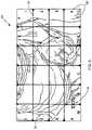
- the present inventionprovides a system 10 for indicating certain areas of interest in medical or surgical image data by applying an overlay pattern, such as a Cartesian grid, crosshairs, quadrants, etc., on the image.
- the overlay patternallows a doctor to then refer or call attention to areas of interest in the image data by referencing the overlay pattern or a portion thereof.
- the overlaymay also include an key, which may include alphanumeric labels or coordinates, which may assist the doctor in indicating the area or portion of the overlay to which he/she is referring.
- the system 10includes at least one source 12 of image data in communication with at least one processing unit 14 and at least one destination 16 for the image data.
- the at least one source 12 of image data connected to the processing unit 14may include any device, system, or network that generates, acquires, stores, monitors, modifies, or controls image data for use in generating medical images, such as still frame images or video.
- the at least one source 12may include an image acquisition device, such as endoscopic cameras, video endoscopes, room cameras, light cameras, and boom cameras.
- the at least one source 12may include any recording, storage, and/or archival device or system, such as traditional video cassette recorders or digital video recording devices (such as a linear tape deck, DVD (Digital Versatile Disc), or DVR (digital video recorder), image capture devices, a PACS (Picture Archiving and Communication System) computer, or an HIS (Hospital Information System).
- the at least one source 12may include any other device from which image data may be received, such as a patient monitor or a central computer for controlling various devices, or may simply be auxiliary inputs for connecting external devices that may supply image data to the system.
- a source 12may be a source of medical or surgical image data that receives the image data from yet another source.
- a sourcemay be a linear tape deck that is recording live video as it supplies the video to the computer.
- the linear tape deckmay receive the live video from an endoscopic camera presently being used on a patient, as is further described below.
- a source 12may be a processor for routing images from multiple other sources to the processing unit (i.e., a screen splitter), such as a quad image processor.
- the source 12 connected to the processing unitmay also be a CCU (camera control unit).
- the at least one processing unit 14may include any device, system, or network that can process images generated from image data.
- the processing unit 14may be a general processor, a computer, or a CCU, which may be integrated in a camera or may be a modular CCU external to the camera.
- the at least one destination 16 for the image data supplied by the at least one source 12may include any device, system, or network that displays images generated from the image data, or otherwise communicates the image data to viewers, or stores the image data.
- the at least one destinationmay include any of various displays, such as, for example, a flat panel display, a plasma screen, or a computer monitor. Additionally, the at least one destination may include a recording device or a storage medium.
- the at least one destination 16 for the surgical image datamay be located within the operating room, or it may be at a location remote from the operating room.
- One object of the inventionis to assist all those viewing or analyzing surgical image data to identify areas of interest in the surgical image data.
- an overlay pattern applied to surgical image datamay be used by a surgeon performing the surgery to communicate with an assisting surgeon that is not present in the operating room, but who is able to view the surgical image data with the overlay pattern on a destination 16 , such as a monitor, at some other remote location.
- the overlay patternmay be applied to surgical image data displayed on a monitor located in a lecture hall or classroom for teaching purposes.
- the destination 16may be capable of displaying image data from more than one source.
- the destination 16may be a monitor with picture-in-picture (PIP) capabilities.
- PIPpicture-in-picture
- the usermay choose to apply (or presets may set) an overlay pattern to all or some sets of image data displayed on the monitor.
- usermay choose to apply (or presets may set) an overlay pattern to all or some sets of image data sent to the destinations 16 .
- the system 10may also include at least one input 18 in communication with the at least on source 12 and/or the processing unit 14 .
- the at least one input 18may include any interface whereby a user to enable/disable and/or adjust the properties of the overlay pattern.
- the input 18may be a button or menu located on the source 12 , such as an endoscopic camera, itself.
- the input 18may be a user interface that may include physical buttons for a doctor to press, or may also include a touch-screen monitor.
- the input 18may include one or more icons on a touch screen 20 .
- the system 10may include software executing on the processing unit 14 that causes the touch screen 20 to simultaneously display several icons.
- the iconsare sensitive to the touch of the user and will cause a command to be sent to the processing unit 14 .
- the usercan select a particular source and destination by pressing the touch screen 20 at the locations of the icon.
- the usercan also manipulate or alter the images being displayed in the display window 26 on the touch screen in order to affect the images ultimately being communicated to the destinations.
- the touch screen 20may also include at least one icon 28 which allows the user to enable/disable the overlay pattern, adjust the properties of the overlay pattern, and select which image data to which the overlay pattern will be applied and to which destination 16 the combined image will be transmitted.
- the system 10may also be configured to accept voice commands, allowing the user to vocally enable or disable the overlay pattern and adjust properties of the overlay pattern itself without having to touch the imaging device or user interface.
- the at least one input 18may include voice recognition software executing on said processing unit 14 for accepting voice commands, allowing the doctor to vocally enable or disable the overlay and adjust properties of the overlay itself without having to physically touch the source 12 , processing unit 14 or input 18 themselves.
- the input 18may include accelerometer data (not shown) from the camera head or image motion vector detection.
- the overlay patternmay be automatically enabled or disabled or the properties of the overlay pattern may be adjusted in response to the input of this data.
- the input 18may also include preset data saved by the user that will act on the processing unit 14 to enable/disable the overlay pattern at certain times as preset by the user.
- the preset datamay also include the preferred type of overlay pattern and/or the properties of the overlay pattern the user desires to be sent to the destination 16 .
- the overlay pattern 30may be provided in any number of designs, which may be set by the user.
- the overlay pattern 30may be a grid.
- the overlay pattern 30may include a single crosshairs placed at the center of the image as displayed.
- the overlay patternmay be one or more hash marks or crosshairs overlaid across a portion of the image, the entire image, or at the edges of the image.
- the overlaymay also be separated into quadrants, with any number of circles, ovals hash marks or any combination thereof within the quadrants.
- the overlaymay also be one or more circles, ovals or other shapes.
- the desired overlay pattern 30may be chosen by the user through an input 18 , some examples of which are described above.
- the source 12such as an endoscopic camera, may include buttons for selecting and setting a desired overlay pattern 30 .
- the usermay also chose to apply the overlay pattern 30 to one, some, or all of the sources 12 of image data 34 .
- the image data 34 from the one or more selected sources 12may be combined with the overlay pattern 30 in the processing unit 14 and the combined image transmitted to the one or more selected destinations 18 .
- the overlay patternmay be applied to live images, in real time.
- the combined image data 34 and overlay pattern 30may be transmitted to a display 32 .
- the displaymay be located in the operating room and/or it may be located somewhere remote from the operating room for viewing by other surgeons assisting in the surgery or by students observing the surgery for educational purposes.
- the overlay pattern 30may be applied to image data 34 that has been recalled from an image archive, such as on a storage medium.
- the applied overlay pattern 30may also be maintained on captured image data 34 that is subsequently saved to an archive and may be recalled later for viewing on a display.
- the overlay pattern 30may be applied to the image data at a “fixed” position, meaning that the overlay 30 will be applied at a fixed position with respect to the displayed image, i.e., centered on the image.
- the usermay adjust the image data 34 separately with respect to the overlay pattern 30 .
- the userviews the image data with the overlay pattern 30 on a display 32 and adjusts the image captured by the source 12 (i.e., a camera) until the particular area of interest is located at or near an identifiable region of the overlay pattern 30 .
- the doctorwill adjust the field of view of the camera until the area of interest is centered at the crosshairs. This enables the doctor to unequivocally “point” to the area of interest, simply by adjusting the camera.
- the overlay patternmay also include a key 36 for assisting the user in indicating and discussing areas or portions of the overlay pattern 30 , and, in turn, indicating and discussing an area of interest on the underlying image data 34 .
- the key 36may include alphanumeric labels or coordinates.
- the rows and columns of a grid overlaymay be labeled with letters and numbers—the vertical axis labeled with letters and the horizontal axis labeled with numbers (or vice versa) allowing reference to an area of the image with a simple letter-number combination (e.g. “C3” or “D2”, etc.).
- the overlay pattern 30comprises hash-marks as shown in FIG. 11
- the hash marksmay be labeled with coordinates.
- the quadrants or other defining shapesmay be individually labeled with an alphanumeric key 36 .
- Certain properties of the overlay 30 and key 36may be adjustable, including, but not limited to, the resolution (i.e., number of rows by number of columns, number of circles, etc.) of the overlay, the opacity of the overlay pattern 30 and/or key 36 , the distribution of the opacity of the overlay pattern 30 and/or key 36 , the color of the overlay 30 and/or key 36 , the brightness of the overlay 30 and/or key 36 , the thickness of the lines of the overlay pattern 30 , the size of the font of the key 36 , etc.
- the usermay choose to enable the overlay pattern and set its properties prior to the start of the medical or surgical procedure, or the overlay may be enabled/disabled and the properties may be adjusted at any time during the medical or surgical procedure.
- the overlay pattern 30 and key 36can be applied to the image in varying levels of opacity.
- the overlaymay also include an indicator 38 , which may display certain properties of the overlay 30 as set by the user.
- FIG. 3illustrates the overlay 30 as a grid and key 36 applied at 100% opacity.
- FIG. 4illustrates the overlay 30 and the key 36 both applied at 50% opacity.
- the properties of the overlay 30can be constant or can vary across the display 32 .
- the overlay pattern 30can be more opaque at the edges of the display 32 and gradually become more transparent toward the center of the display 32 .
- the adjustable properties of the overlay pattern and coordinatesmay be adjusted independently of one another. For example, as shown in FIG. 5 , the overlay may be set to 50% opacity whereas the key 36 may be maintained at 100% opacity.
- Various properties of the camera control unitmay also be changed so as to effect a change in the image data 34 at and/or around certain coordinates or a region of the overlay 30 identified by the user.
- the brightness, contrast, color, or zoom of the image data 34may be adjusted at and/or around the coordinates or region identified.
- the coordinates or region of the overlay 30may be identified via an input 18 , for example by button press on the source 12 or by touching an icon or the display window 26 of a touch screen 20 .
- the system 10may also be configured to include voice recognition of certain regions or coordinates of the overlay pattern 30 to change the properties of the CCU.
- the zoom level of the image data 34may be adjusted independent of the overlay pattern 30 .
- the resolution of the overlay pattern 30will remain the same, while the image data 34 is zoomed in or out.
- FIG. 6illustrates a zoomed-in version of the image data 34 of FIG. 3 , where the resolution of the grid overlay pattern remains constant (4 rows by 6 columns).
- the usermay set or adjust the properties of the overlay pattern 30 and/or the key 36 at the beginning of, or during, a surgical or medical procedure. For example, the user may select a grid overlay, choose the number of columns and rows, and set the color all at prior to commencing a surgical or medical procedure.
- the usermay also establish presets to which the overlay 30 will default. In one embodiment shown in FIGS. 1-7 , the resolution of the grid overlay is four rows by six columns. However, other grid overlay resolutions are contemplated, such as 4 ⁇ 4.
- the overlaycan be of a varying number or a fixed number of columns, rows, quadrants, etc.
- the overlay pattern and/or resolutionmay be preset or chosen by the doctor in accordance with the aspect ratio of the display monitors.
- the doctormay chose a standard definition (SD) display having a 4 ⁇ 3 aspect ratio and the overlay pattern would be chosen or adjusted accordingly.
- the doctormay also chose a high definition (HD) display having a 16 ⁇ 9 aspect ratio and the overlay pattern would be chose or adjusted accordingly.
- Overlay patterns incorporating ovals, such as the pattern shown in FIG. 15are well suited for HD displays whereas overlay patterns incorporating circles, such as the pattern shown in FIG. 14 , are well suited for SD displays.
- the system 10may automatically enable the overlay if a motion vector detector senses a still image for a certain period of time. Conversely, the system 10 may automatically disable the overlay if a motion vector detector senses a moving image for a certain period of time. Further, the system 10 may automatically “time out” after the overlay has been enabled for a preset period of time, or “time-out” if the image has been still for a certain period of time.
- the overlayWhen the overlay is enabled or disabled, either by automatic sensing, “time-out”, or by direct input from the user, the overlay could be programmed to either immediately appear at 100% opacity or immediately disappear. Alternatively, the overlay could be programmed to gradually appear or disappear by gradual increase or decrease in opacity. These properties will be discussed further below.
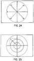
- the overlay patternmay include a set of centric lines originating from a single point, such as from the center of the monitor screen, and optionally ending near the edges of the monitor screen, as shown in FIGS. 22, 24 and 25 .
- the centric linesare shown for every 15 degrees, 20 degrees, 30 degrees, 45 degrees, 60 degrees, 90 degrees, or other predetermined degrees.
- the circular overlay patternis “clock” like.
- the centric linesare shown for every 45 degrees, the circular overlay pattern is “compass” like.
- the centric linesare shown for every 90 degrees, the circular overlay pattern is a “quadrant” like.
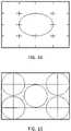
- the overlay patternmay include a series of concentric shapes.
- the concentric shapesare concentric circles, concentric ovals, or concentric polygons. More preferably, the concentric shapes are concentric circles (also called centric circles), as shown in FIGS. 22, 23 and 25 . In one embodiment, as shown in FIGS. 22 and 25 , the overlay pattern contains three concentric circles, at 25%, 50% and 100% of the monitor height.
- the overlay patternmay be formed by superimposing the centric lines on the concentric shapes, as shown in FIGS. 22, 24 and 25 .
- the overlay patternis formed by a wind rose going from 0 degree to 360 degrees with centric lines at every 20 degree or 30 degrees and two concentric circles at 25% and 50% of the monitor height.
- the single originating point of the centric linesis also the center of the concentric shapes.
- the overlay patternmay include an optional key 36 for assisting the user in indicating and discussing areas or portions of the overlay pattern 30 , and, in turn, indicating and discussing an area of interest on the underlying image data 34 .
- the centric linesmay be labeled as 1, 2, 3, . . . , 12, corresponding to the conventional positions of 1 o'clock, 2 o'clock, 3 o'clock, . . . 12 o'clock.
- the centric linescan be marked as N, NE, E, SE, S, SW, W, and NW, corresponding to a conventional compass.
- the “quadrant” like overlay patternas shown in FIG. 25 , may be labeled as x-axis and y-axis, which may in turn be labeled with numbers as conventional coordinates.
- the concentric circlescan be labeled with an alphanumeric key, or other suitable number and/or letter characters. If there are a total of three concentric circles, they can be referred as inner, medium, and outer circles, or small, middle, and large circles.
- the overlay patterns formed by superimposing the centric lines on the concentric circlesare particular useful for indicating areas of interest in some circumstances.
- the small circle of FIG. 22is suitable for showing a small circular image, such as an image of 4 mm scope or a magnified laparoscopic image.
- the small circle of FIG. 22can be used for indicating the precise targeting area of an image object, leaving the other area of the imaged object outside the small circle.
- the small circle of the concentric circlescan be made transparent, while the area outside the small circle gradually becomes opaque.
- the designs of concentric shapes, centric lines, concentric shapes superimposed on centric lines, and the previously described designs, such as grid, crosshair, quadrant, hash mark,can be used interchangeably for the overlay pattern 30 . Collectively, they form a plurality of designs for the overlay pattern 30 .
- the system 10 in accordance with the present inventionmay include a source 12 , an image processing unit 14 , and a destination 16 .
- the source 12is typically connected with the processing unit 14 by wires or cables to transmit image data 34 .
- the source 12may also wirelessly transmit signals to the processing unit 14 .
- the process unit 14includes a plurality of designs for the overlay pattern 30 to suit different display needs, and software executing on the image processing unit for combining the image data 34 from the source 12 with an overlay pattern 30 and further adjusting the properties of the overlay pattern, such as activation, deactivation, resolution, opacity, opacity distribution, color, brightness, thickness, and size.
- the softwarecan also be configured to select the desired overlay pattern 30 in response to a user input 18 .
- the user input 18can be provided by a manual command, a voice command, or preset by a user prior to a surgical or medical procedure.
- the softwareis configured with voice recognition features.
- the plurality of the overlay pattern designscan be numbered for easy identification and selection.
- the zoom level of the image data 34may be adjusted independent of the overlay pattern 30 , and the software executing on the image processing unit may be configured to enable this feature.
- the present inventionuses the overlay pattern as an aid to allow a doctor or other observers to identify an area of interest, which often requires keeping the overlay pattern 30 constant while zooming in or out of the areas of interest. Since size measurement of an imaged object is not required, the apparatus of the present invention does not include other components usually associated with the size measurement. As a result, the apparatus of the present invention is simple and cost effectiveness for its intended purpose.
- the present inventioneliminates the need of using a laser pointer, cursor, “circling,” or other annotating or marking means by a person to identify areas of interest, as required by the prior art.
- the present inventionprovides an effective and clear communication regarding certain areas of interest displayed on the live monitor.
- the system 10may comprise multiple sources of image data 34 , 34 ′, 34 ′′.
- the types of image datamay include, but are not limited to, ultrasound, X-ray, magnetic resonance imaging, nuclear magnetic resonance imaging, magnetic resonance tomography, computed tomography, and surgical image data.
- the image data 34 , 34 ′, 34 ′′may be in the form of video data, still frame data or combinations thereof.
- the image data 34 , 34 ′, 34 ′′may be retrieved from a non-imaging source, such as an image archive, PC, or other source of image data.
- the image data 34 , 34 ′, 34 ′′may also be streamed from a medical instrument that generates the image data 34 , 34 ′, 34 ′′.
- data type converters 42 , 42 ′, 42 ′′may be utilized to convert the image data 34 , 34 ′, 34 ′′ into a format that is readable by the image processing unit 14 before the image data 34 , 34 ′, 34 ′′ is transmitted to the image processing unit 14 .
- the formatted datamay be saved in a storage device.
- the system 10may include one data type converter for all the data conversions, or multiple data type converters for multiple sources of image data.
- each source of image datais provided with one data type converter, which is specifically adapted to convert the particular type of image data.
- Each of the data type converters 42 , 42 ′, 42 ′′may be a standalone unit.
- the communications among the image data 34 , 34 ′, 34 ′′, the data type converters 42 , 42 ′, 42 ′′, and the image processing unit 14are bi-directional. The communications are typically performed via wires or cables. However, the image data 34 , 34 ′, 34 ′′ and the formatted image data may also be wirelessly transmitted.
- An input multiplexer/combiner 44may be used to facilitate input to the processing unit 14 from multiple imaging sources. In principle, any practical number of input sources of any configuration or having any capabilities may be input in this way. Alternatively, the processing unit 14 may accept input from only one image source or otherwise omit the multiplexer 44 without departing from the invention.
- the multiplexer 44may include a data type converter 42 , 42 ′, 42 ′′ for converting or formatting the data type of incoming image data, thereby eliminating the need to have other data type convertors in the system.
- the multiplexer 44may be part of the image processing unit 14 as shown in FIG. 1 b . Alternatively, it can be a standalone unit outside the image processing unit 14 .
- the process unit 14includes a plurality of adjustable overlay patterns 30 to suit different display needs, and software (not shown) executing on the image processing unit for selecting the desired overlay pattern(s) in response to a user input and for combining the image data selected through the multiplexer/combiner 44 with the desired overlay pattern(s) to generate overlayed image data 50 .
- overlay pattern options 46may be transmitted to a user interface 40 for a user to select at least one overlay pattern from the plurality of adjustable overlay patterns 30 .
- the usermay provide input by a manual command, a voice command, or preset by a user prior to a surgical or medical procedure.
- the softwaremay be configured with voice recognition features.
- the plurality of the overlay pattern designsmay be numbered for easy identification and selection.
- the data containing the overlay pattern selection 48 by the usermay be transmitted to the processing unit 14 .
- the communications between the processing unit 14 and the user interface 40may be conducted through wires/cables or wireless.
- the imagemay be oriented so that an area of interest on the image is located near or at an identifiable region of the overlay pattern.
- a usermay identify the area of interest on the image without having to use a laser pointer or cursor, or otherwise “circle” or annotate on the image.
- an identifiable region of each overlay patternFor instance, for an overlay pattern of concentric circles, the identifiable region may be the smallest circle; for an overlay patter of quadrants, the identifiable region may be the upper left quadrant; and for an overlay pattern of crosshairs, the identifiable region may be one of the crosshairs.
- the regions of the overlay patternsmay be verbally identified by making reference to the shapes, alphanumeric labels, coordinates, etc.
- the softwaremay also be configured to be able to adjust the properties of the overlay pattern and of the images independently. For instance, the image may be zoomed in while the overlay pattern is kept constant in order to create an enlarged, detailed view of the area of interest on the image.
- the overlayed image data 50may be transmitted to destination 16 , which typically includes a display.
- the displaymay have picture-in-picture (PIP) capabilities which allow display of two images.
- PIPpicture-in-picture
- the PIP displaymay simultaneously show an ultrasound image and a magnetic resonance image, either with or without an overlay pattern.
- the PIP displaymay simultaneously show one overlayed image and one image without an overlay, each of the images may have different zoom levels.
- the destination 16may also include a storage device for saving the overlayed image data 50 .
Landscapes
- Health & Medical Sciences (AREA)
- Engineering & Computer Science (AREA)
- Life Sciences & Earth Sciences (AREA)
- Physics & Mathematics (AREA)
- Medical Informatics (AREA)
- General Health & Medical Sciences (AREA)
- Veterinary Medicine (AREA)
- Heart & Thoracic Surgery (AREA)
- Biomedical Technology (AREA)
- Molecular Biology (AREA)
- Surgery (AREA)
- Animal Behavior & Ethology (AREA)
- Pathology (AREA)
- Public Health (AREA)
- Biophysics (AREA)
- Radiology & Medical Imaging (AREA)
- Nuclear Medicine, Radiotherapy & Molecular Imaging (AREA)
- High Energy & Nuclear Physics (AREA)
- Computer Vision & Pattern Recognition (AREA)
- Theoretical Computer Science (AREA)
- Optics & Photonics (AREA)
- General Physics & Mathematics (AREA)
- Pulmonology (AREA)
- Quality & Reliability (AREA)
- Signal Processing (AREA)
- Condensed Matter Physics & Semiconductors (AREA)
- Measuring And Recording Apparatus For Diagnosis (AREA)
- Image Processing (AREA)
Abstract
Description
Claims (24)
Priority Applications (2)
| Application Number | Priority Date | Filing Date | Title |
|---|---|---|---|
| US14/048,913US11412998B2 (en) | 2011-02-10 | 2013-10-08 | Multi-source medical display |
| EP14188189.6AEP2866162B1 (en) | 2013-10-08 | 2014-10-08 | Multi-source medical display |
Applications Claiming Priority (3)
| Application Number | Priority Date | Filing Date | Title |
|---|---|---|---|
| US201161441473P | 2011-02-10 | 2011-02-10 | |
| US13/289,554US10631712B2 (en) | 2011-02-10 | 2011-11-04 | Surgeon's aid for medical display |
| US14/048,913US11412998B2 (en) | 2011-02-10 | 2013-10-08 | Multi-source medical display |
Related Parent Applications (1)
| Application Number | Title | Priority Date | Filing Date |
|---|---|---|---|
| US13/289,554Continuation-In-PartUS10631712B2 (en) | 2011-02-10 | 2011-11-04 | Surgeon's aid for medical display |
Publications (2)
| Publication Number | Publication Date |
|---|---|
| US20140037165A1 US20140037165A1 (en) | 2014-02-06 |
| US11412998B2true US11412998B2 (en) | 2022-08-16 |
Family
ID=50025516
Family Applications (1)
| Application Number | Title | Priority Date | Filing Date |
|---|---|---|---|
| US14/048,913Active2035-09-17US11412998B2 (en) | 2011-02-10 | 2013-10-08 | Multi-source medical display |
Country Status (1)
| Country | Link |
|---|---|
| US (1) | US11412998B2 (en) |
Families Citing this family (14)
| Publication number | Priority date | Publication date | Assignee | Title |
|---|---|---|---|---|
| JP5710917B2 (en)* | 2010-09-13 | 2015-04-30 | オリンパス株式会社 | Reception device, transmission device, transmission / reception system, reception method, transmission method, and program |
| US11412998B2 (en) | 2011-02-10 | 2022-08-16 | Karl Storz Imaging, Inc. | Multi-source medical display |
| US10631712B2 (en) | 2011-02-10 | 2020-04-28 | Karl Storz Imaging, Inc. | Surgeon's aid for medical display |
| US10674968B2 (en)* | 2011-02-10 | 2020-06-09 | Karl Storz Imaging, Inc. | Adjustable overlay patterns for medical display |
| US10366299B2 (en)* | 2011-10-25 | 2019-07-30 | Bull Hn Information Systems, Inc. | Sorting/scanning system camera upgrade apparatus with backwards compatibility |
| US9275349B2 (en) | 2013-07-19 | 2016-03-01 | Ricoh Company Ltd. | Healthcare system integration |
| US20150157197A1 (en)* | 2013-12-09 | 2015-06-11 | Omer Aslam Ilahi | Endoscopic image overlay |
| US20150310767A1 (en)* | 2014-04-24 | 2015-10-29 | Omnivision Technologies, Inc. | Wireless Typoscope |
| WO2015175848A1 (en)* | 2014-05-14 | 2015-11-19 | The Johns Hopkins University | System and method for automatic localization of structures in projection images |
| US20190216327A1 (en)* | 2014-09-19 | 2019-07-18 | DermSpectra LLC | Viewing grid and image display for viewing and recording skin images |
| EP3586717B1 (en)* | 2017-03-27 | 2023-07-05 | Sony Olympus Medical Solutions Inc. | Control device and endoscope system |
| US10573193B2 (en)* | 2017-05-11 | 2020-02-25 | Shadowbox, Llc | Video authoring and simulation training tool |
| US10475169B2 (en)* | 2017-11-28 | 2019-11-12 | Adobe Inc. | High dynamic range illumination estimation |
| CN116368524A (en)* | 2021-08-30 | 2023-06-30 | 京东方科技集团股份有限公司 | Display control method and device, computer readable storage medium and display device |
Citations (90)
| Publication number | Priority date | Publication date | Assignee | Title |
|---|---|---|---|---|
| US4216589A (en) | 1978-11-20 | 1980-08-12 | American Electronics, Inc. | Sighting device for surveillance camera |
| US4559705A (en) | 1983-11-25 | 1985-12-24 | Hodge Michaela W | Indexing overlay for video display devices |
| US5099846A (en)* | 1988-12-23 | 1992-03-31 | Hardy Tyrone L | Method and apparatus for video presentation from a variety of scanner imaging sources |
| US5174037A (en) | 1990-04-17 | 1992-12-29 | Marilyn Curtin | Method and apparatus for measuring physical attributes of a human body |
| JPH07184863A (en) | 1993-12-28 | 1995-07-25 | Topcon Corp | Ophthalmic image processing system |
| US5517278A (en) | 1991-06-12 | 1996-05-14 | Matsushita Electric Industrial Co., Ltd. | Viewfinder for video cameras |
| US5573492A (en) | 1994-12-28 | 1996-11-12 | Olympus America Inc. | Digitally measuring scopes using a high resolution encoder |
| US5836869A (en) | 1994-12-13 | 1998-11-17 | Olympus Optical Co., Ltd. | Image tracking endoscope system |
| US6037936A (en) | 1993-09-10 | 2000-03-14 | Criticom Corp. | Computer vision system with a graphic user interface and remote camera control |
| US20020026093A1 (en)* | 2000-08-23 | 2002-02-28 | Kabushiki Kaisha Toshiba | Endscope system |
| US6359644B1 (en) | 1998-09-01 | 2002-03-19 | Welch Allyn, Inc. | Measurement system for video colposcope |
| US20020049375A1 (en) | 1999-05-18 | 2002-04-25 | Mediguide Ltd. | Method and apparatus for real time quantitative three-dimensional image reconstruction of a moving organ and intra-body navigation |
| US6431768B1 (en) | 1999-03-25 | 2002-08-13 | Ricoh Company, Ltd. | Digital camera having rotatable optical viewfinder unit |
| US6535756B1 (en) | 2000-04-07 | 2003-03-18 | Surgical Navigation Technologies, Inc. | Trajectory storage apparatus and method for surgical navigation system |
| US20030069975A1 (en) | 2000-04-13 | 2003-04-10 | Abjanic John B. | Network apparatus for transformation |
| US20030083563A1 (en)* | 2001-10-25 | 2003-05-01 | Igor Katsman | Medical imaging data streaming |
| US20030114730A1 (en) | 2001-12-14 | 2003-06-19 | Hale Eric L. | Interface for a variable direction of view endoscope |
| US6630937B2 (en) | 1997-10-30 | 2003-10-07 | University Of South Florida | Workstation interface for use in digital mammography and associated methods |
| US6636254B1 (en)* | 1993-11-29 | 2003-10-21 | Olympus Optical Co., Ltd, | Image processing apparatus for performing turn or mirror inversion on an input video signal and outputting different images simultaneously |
| US6725080B2 (en) | 2000-03-01 | 2004-04-20 | Surgical Navigation Technologies, Inc. | Multiple cannula image guided tool for image guided procedures |
| US20040085455A1 (en) | 2000-01-18 | 2004-05-06 | Silverstein D. Amnon | Pointing device for digital camera display |
| US20050065435A1 (en)* | 2003-07-22 | 2005-03-24 | John Rauch | User interface for remote control of medical devices |
| US20050075535A1 (en) | 2003-05-16 | 2005-04-07 | Marc Shapiro | Data entry system for an endoscopic examination |
| US20050085717A1 (en)* | 2003-10-21 | 2005-04-21 | Ramin Shahidi | Systems and methods for intraoperative targetting |
| US20050093889A1 (en)* | 2001-03-27 | 2005-05-05 | Frank Sauer | Augmented reality guided instrument positioning with guiding graphics |
| US20050177026A1 (en) | 2004-02-09 | 2005-08-11 | Hoeg Hans D. | Endoscope with variable direction of view module |
| US20050187432A1 (en)* | 2004-02-20 | 2005-08-25 | Eric Lawrence Hale | Global endoscopic viewing indicator |
| US7033172B2 (en) | 2003-04-16 | 2006-04-25 | Eastman Kodak Company | Dental positioning grid |
| US20060098112A1 (en) | 2004-11-05 | 2006-05-11 | Kelly Douglas J | Digital camera having system for digital image composition and related method |
| US20060142657A1 (en)* | 2002-03-06 | 2006-06-29 | Mako Surgical Corporation | Haptic guidance system and method |
| US7075556B1 (en) | 1999-10-21 | 2006-07-11 | Sportvision, Inc. | Telestrator system |
| US20060152516A1 (en) | 2004-12-29 | 2006-07-13 | Karl Storz Endoscopy-America, Inc. | System for controlling the communication of medical imaging data |
| US20060217689A1 (en) | 2001-06-26 | 2006-09-28 | Carl Zeiss Meditec Ag | Method and device for the representation of an operation area during laser operations |
| US20060258938A1 (en) | 2005-05-16 | 2006-11-16 | Intuitive Surgical Inc. | Methods and system for performing 3-D tool tracking by fusion of sensor and/or camera derived data during minimally invasive robotic surgery |
| US20060257008A1 (en) | 2003-10-17 | 2006-11-16 | Martin Nolle | Method and apparatus for generating an image including editing comments in a sterile working area of a medical facility |
| US20060259193A1 (en) | 2005-05-12 | 2006-11-16 | Yulun Wang | Telerobotic system with a dual application screen presentation |
| US20070073161A1 (en) | 2005-09-09 | 2007-03-29 | Tal Davidson | Device, system and method for determining spacial measurements of anatomical objects for in-vivo pathology detection |
| US20070106282A1 (en) | 2003-05-02 | 2007-05-10 | Perception Raisonnement Action En Medecine | Determination of the position of an anatomical element |
| US20070147707A1 (en) | 2003-05-22 | 2007-06-28 | Inria Institut National De Recherche En Informatique Et En Automatique | Device and method for superimposing patterns on images in real-time, particularly for guiding by localisation |
| US20070156017A1 (en)* | 2005-12-30 | 2007-07-05 | Intuitive Surgical Inc. | Stereo telestration for robotic surgery |
| US20070269092A1 (en) | 2004-10-07 | 2007-11-22 | Koninklijke Philips Electronics N.V. | Method and System for Maintaining Consistent Anatomic Views in Displayed Image Data |
| US20080004603A1 (en) | 2006-06-29 | 2008-01-03 | Intuitive Surgical Inc. | Tool position and identification indicator displayed in a boundary area of a computer display screen |
| US20080015415A1 (en) | 2002-10-18 | 2008-01-17 | Olympus Corporation | Remote controllable endoscope |
| US20080071142A1 (en) | 2006-09-18 | 2008-03-20 | Abhishek Gattani | Visual navigation system for endoscopic surgery |
| US7366934B1 (en) | 2004-09-08 | 2008-04-29 | Stryker Corporation | Method of remotely controlling devices for endoscopy |
| US20080192116A1 (en) | 2005-03-29 | 2008-08-14 | Sportvu Ltd. | Real-Time Objects Tracking and Motion Capture in Sports Events |
| US7427263B2 (en) | 2004-03-03 | 2008-09-23 | Karl Storz Development Corp. | Method and interface for operating a variable direction of view endoscope |
| US20080303899A1 (en) | 2007-06-06 | 2008-12-11 | George Berci | Video System For Viewing An Object On A Body |
| US20090036902A1 (en) | 2006-06-06 | 2009-02-05 | Intuitive Surgical, Inc. | Interactive user interfaces for robotic minimally invasive surgical systems |
| US20090088634A1 (en) | 2007-09-30 | 2009-04-02 | Intuitive Surgical, Inc. | Tool tracking systems and methods for image guided surgery |
| US20090087067A1 (en) | 2007-10-02 | 2009-04-02 | George Allen Khorasani | Displaying breast tomosynthesis computer-aided detection results |
| US20090088897A1 (en) | 2007-09-30 | 2009-04-02 | Intuitive Surgical, Inc. | Methods and systems for robotic instrument tool tracking |
| US20090146950A1 (en) | 2004-10-29 | 2009-06-11 | Sr Labs S.R.L. | Method and system of visualisation, processing, and integrated analysis of medical images |
| US20090156895A1 (en) | 2007-01-31 | 2009-06-18 | The Penn State Research Foundation | Precise endoscopic planning and visualization |
| US20090171184A1 (en) | 2007-09-24 | 2009-07-02 | Surgi-Vision | Mri surgical systems for real-time visualizations using mri image data and predefined data of surgical tools |
| US20090190808A1 (en) | 2008-01-28 | 2009-07-30 | Advanced Medical Optics, Inc. | User adjustment measurement scale on video overlay |
| US7590335B2 (en) | 2006-03-22 | 2009-09-15 | Eastman Kodak Company | Digital camera, composition correction device, and composition correction method |
| US20090235570A1 (en) | 1997-12-08 | 2009-09-24 | Horus Vision | Apparatus and method for calculating aiming point information |
| US7607079B2 (en) | 2005-07-08 | 2009-10-20 | Bruce Reiner | Multi-input reporting and editing tool |
| US20090271738A1 (en) | 2008-04-08 | 2009-10-29 | Karlheinz Glaser-Seidnitzer | Method and user interface for the graphical presentation of medical data |
| US20090276725A1 (en) | 2008-04-08 | 2009-11-05 | Karlheinz Glaser-Seidnitzer | Method and user interface for the graphical presentation of medical data |
| US20100094085A1 (en) | 2007-01-31 | 2010-04-15 | National University Corporation Hamamatsu Universi Ty School Of Medicine | Device for Displaying Assistance Information for Surgical Operation, Method for Displaying Assistance Information for Surgical Operation, and Program for Displaying Assistance Information for Surgical Operation |
| US20100160789A1 (en) | 2008-06-18 | 2010-06-24 | Eyelab Group, Llc | System and Method for Determining Volume-Related Parameters of Ocular and Other Biological Tissues |
| US20100168765A1 (en) | 2008-09-25 | 2010-07-01 | Prosurgics Ltd. | Surgical mechanism control system |
| US20100166323A1 (en) | 2008-12-31 | 2010-07-01 | Intuitive Surgical. Inc. | Robust sparse image matching for robotic surgery |
| WO2010088515A1 (en) | 2009-01-30 | 2010-08-05 | Priya Narasimhan | Systems and methods for providing interactive video services |
| US20100228249A1 (en) | 2009-03-09 | 2010-09-09 | Intuitive Surgical, Inc. | User interfaces for electrosurgical tools in robotic surgical systems |
| US7811224B2 (en) | 2004-11-09 | 2010-10-12 | Karl Storz Development Corp. | Method for dealing with singularities in gravity referenced endoscopic imaging |
| US7849024B2 (en) | 2006-08-16 | 2010-12-07 | Drvision Technologies Llc | Imaging system for producing recipes using an integrated human-computer interface (HCI) for image recognition, and learning algorithms |
| US7864996B2 (en) | 2006-02-17 | 2011-01-04 | Lucid, Inc. | System for macroscopic and confocal imaging of tissue |
| US7949965B2 (en) | 2000-12-27 | 2011-05-24 | Sony Corporation | Apparatus and method for processing map data and storage medium having information for controlling the processing of map data |
| US20110137156A1 (en) | 2009-02-17 | 2011-06-09 | Inneroptic Technology, Inc. | Systems, methods, apparatuses, and computer-readable media for image management in image-guided medical procedures |
| US20110135149A1 (en) | 2009-12-09 | 2011-06-09 | Pvi Virtual Media Services, Llc | Systems and Methods for Tracking Objects Under Occlusion |
| US20110141140A1 (en)* | 2009-12-14 | 2011-06-16 | Paul Robert Duhamel | Visualization guided acl localization system |
| US20110170755A1 (en) | 2008-10-01 | 2011-07-14 | Koninklijke Philips Electronics N.V. | Selection of snapshots of a medical image sequence |
| US20110235891A1 (en) | 2008-12-10 | 2011-09-29 | Koninklijke Philips Electronics N.V. | Vessel analysis |
| US20120038744A1 (en) | 2010-08-13 | 2012-02-16 | Masafumi Naka | Automatic 3d content detection |
| US20120158019A1 (en) | 2010-12-21 | 2012-06-21 | Tenney John A | Methods and systems for directing movement of a tool in hair transplantation procedures |
| US8213788B2 (en) | 2010-11-29 | 2012-07-03 | Soll David B | Viewfinder |
| EP2486847A1 (en) | 2011-02-10 | 2012-08-15 | Karl Storz Imaging, Inc. | Surgeon's aid for medical display |
| US20130197357A1 (en) | 2012-01-30 | 2013-08-01 | Inneroptic Technology, Inc | Multiple medical device guidance |
| US20140037165A1 (en) | 2011-02-10 | 2014-02-06 | Timothy King | Multi-Source Medical Display |
| US20140051986A1 (en) | 2012-08-14 | 2014-02-20 | Intuitive Surgical Operations, Inc. | Systems and Methods for Registration of Multiple Vision Systems |
| US20140055489A1 (en) | 2006-06-29 | 2014-02-27 | Intuitive Surgical Operations, Inc. | Rendering tool information as graphic overlays on displayed images of tools |
| US20140111623A1 (en) | 2012-10-23 | 2014-04-24 | Intuitive Surgical Operations, Inc. | Stereo imaging system with automatic disparity adjustment for displaying close range objects |
| US20140142422A1 (en) | 2011-06-17 | 2014-05-22 | Robert Manzke | System and method for guided injection during endoscopic surgery |
| US20140176661A1 (en) | 2012-12-21 | 2014-06-26 | G. Anthony Reina | System and method for surgical telementoring and training with virtualized telestration and haptic holograms, including metadata tagging, encapsulation and saving multi-modal streaming medical imagery together with multi-dimensional [4-d] virtual mesh and multi-sensory annotation in standard file formats used for digital imaging and communications in medicine (dicom) |
| US8830224B2 (en) | 2008-12-31 | 2014-09-09 | Intuitive Surgical Operations, Inc. | Efficient 3-D telestration for local robotic proctoring |
| US20140267603A1 (en) | 2013-03-15 | 2014-09-18 | Intuitive Surgical Operations, Inc. | Depth based modification of captured images |
| US20140275760A1 (en) | 2013-03-13 | 2014-09-18 | Samsung Electronics Co., Ltd. | Augmented reality image display system and surgical robot system comprising the same |
- 2013
- 2013-10-08USUS14/048,913patent/US11412998B2/enactiveActive
Patent Citations (99)
| Publication number | Priority date | Publication date | Assignee | Title |
|---|---|---|---|---|
| US4216589A (en) | 1978-11-20 | 1980-08-12 | American Electronics, Inc. | Sighting device for surveillance camera |
| US4559705A (en) | 1983-11-25 | 1985-12-24 | Hodge Michaela W | Indexing overlay for video display devices |
| US5099846A (en)* | 1988-12-23 | 1992-03-31 | Hardy Tyrone L | Method and apparatus for video presentation from a variety of scanner imaging sources |
| US5174037A (en) | 1990-04-17 | 1992-12-29 | Marilyn Curtin | Method and apparatus for measuring physical attributes of a human body |
| US5517278A (en) | 1991-06-12 | 1996-05-14 | Matsushita Electric Industrial Co., Ltd. | Viewfinder for video cameras |
| US6037936A (en) | 1993-09-10 | 2000-03-14 | Criticom Corp. | Computer vision system with a graphic user interface and remote camera control |
| US6636254B1 (en)* | 1993-11-29 | 2003-10-21 | Olympus Optical Co., Ltd, | Image processing apparatus for performing turn or mirror inversion on an input video signal and outputting different images simultaneously |
| JPH07184863A (en) | 1993-12-28 | 1995-07-25 | Topcon Corp | Ophthalmic image processing system |
| US5836869A (en) | 1994-12-13 | 1998-11-17 | Olympus Optical Co., Ltd. | Image tracking endoscope system |
| US5573492A (en) | 1994-12-28 | 1996-11-12 | Olympus America Inc. | Digitally measuring scopes using a high resolution encoder |
| US6414696B1 (en) | 1996-06-12 | 2002-07-02 | Geo Vector Corp. | Graphical user interfaces for computer vision systems |
| US6630937B2 (en) | 1997-10-30 | 2003-10-07 | University Of South Florida | Workstation interface for use in digital mammography and associated methods |
| US20090235570A1 (en) | 1997-12-08 | 2009-09-24 | Horus Vision | Apparatus and method for calculating aiming point information |
| US6359644B1 (en) | 1998-09-01 | 2002-03-19 | Welch Allyn, Inc. | Measurement system for video colposcope |
| US6431768B1 (en) | 1999-03-25 | 2002-08-13 | Ricoh Company, Ltd. | Digital camera having rotatable optical viewfinder unit |
| US20020049375A1 (en) | 1999-05-18 | 2002-04-25 | Mediguide Ltd. | Method and apparatus for real time quantitative three-dimensional image reconstruction of a moving organ and intra-body navigation |
| US7492363B2 (en) | 1999-10-21 | 2009-02-17 | Sportsvision, Inc. | Telestrator system |
| US7075556B1 (en) | 1999-10-21 | 2006-07-11 | Sportvision, Inc. | Telestrator system |
| US20040085455A1 (en) | 2000-01-18 | 2004-05-06 | Silverstein D. Amnon | Pointing device for digital camera display |
| US20050146622A9 (en) | 2000-01-18 | 2005-07-07 | Silverstein D. A. | Pointing device for digital camera display |
| US6725080B2 (en) | 2000-03-01 | 2004-04-20 | Surgical Navigation Technologies, Inc. | Multiple cannula image guided tool for image guided procedures |
| US6535756B1 (en) | 2000-04-07 | 2003-03-18 | Surgical Navigation Technologies, Inc. | Trajectory storage apparatus and method for surgical navigation system |
| US20030069975A1 (en) | 2000-04-13 | 2003-04-10 | Abjanic John B. | Network apparatus for transformation |
| US20020026093A1 (en)* | 2000-08-23 | 2002-02-28 | Kabushiki Kaisha Toshiba | Endscope system |
| US7949965B2 (en) | 2000-12-27 | 2011-05-24 | Sony Corporation | Apparatus and method for processing map data and storage medium having information for controlling the processing of map data |
| US20050093889A1 (en)* | 2001-03-27 | 2005-05-05 | Frank Sauer | Augmented reality guided instrument positioning with guiding graphics |
| US20060217689A1 (en) | 2001-06-26 | 2006-09-28 | Carl Zeiss Meditec Ag | Method and device for the representation of an operation area during laser operations |
| US20030083563A1 (en)* | 2001-10-25 | 2003-05-01 | Igor Katsman | Medical imaging data streaming |
| US20040127769A1 (en)* | 2001-12-14 | 2004-07-01 | Hale Eric L. | Interface for a variable direction-of-view endoscope |
| US20030114730A1 (en) | 2001-12-14 | 2003-06-19 | Hale Eric L. | Interface for a variable direction of view endoscope |
| US20060142657A1 (en)* | 2002-03-06 | 2006-06-29 | Mako Surgical Corporation | Haptic guidance system and method |
| US20080015415A1 (en) | 2002-10-18 | 2008-01-17 | Olympus Corporation | Remote controllable endoscope |
| US7033172B2 (en) | 2003-04-16 | 2006-04-25 | Eastman Kodak Company | Dental positioning grid |
| US20070106282A1 (en) | 2003-05-02 | 2007-05-10 | Perception Raisonnement Action En Medecine | Determination of the position of an anatomical element |
| US20050075535A1 (en) | 2003-05-16 | 2005-04-07 | Marc Shapiro | Data entry system for an endoscopic examination |
| US20070147707A1 (en) | 2003-05-22 | 2007-06-28 | Inria Institut National De Recherche En Informatique Et En Automatique | Device and method for superimposing patterns on images in real-time, particularly for guiding by localisation |
| US20050065435A1 (en)* | 2003-07-22 | 2005-03-24 | John Rauch | User interface for remote control of medical devices |
| US20060257008A1 (en) | 2003-10-17 | 2006-11-16 | Martin Nolle | Method and apparatus for generating an image including editing comments in a sterile working area of a medical facility |
| US20050085717A1 (en)* | 2003-10-21 | 2005-04-21 | Ramin Shahidi | Systems and methods for intraoperative targetting |
| US20050177026A1 (en) | 2004-02-09 | 2005-08-11 | Hoeg Hans D. | Endoscope with variable direction of view module |
| US20050187432A1 (en)* | 2004-02-20 | 2005-08-25 | Eric Lawrence Hale | Global endoscopic viewing indicator |
| US7427263B2 (en) | 2004-03-03 | 2008-09-23 | Karl Storz Development Corp. | Method and interface for operating a variable direction of view endoscope |
| US7366934B1 (en) | 2004-09-08 | 2008-04-29 | Stryker Corporation | Method of remotely controlling devices for endoscopy |
| US20070269092A1 (en) | 2004-10-07 | 2007-11-22 | Koninklijke Philips Electronics N.V. | Method and System for Maintaining Consistent Anatomic Views in Displayed Image Data |
| US20090146950A1 (en) | 2004-10-29 | 2009-06-11 | Sr Labs S.R.L. | Method and system of visualisation, processing, and integrated analysis of medical images |
| US20060098112A1 (en) | 2004-11-05 | 2006-05-11 | Kelly Douglas J | Digital camera having system for digital image composition and related method |
| US7782384B2 (en) | 2004-11-05 | 2010-08-24 | Kelly Douglas J | Digital camera having system for digital image composition and related method |
| US7811224B2 (en) | 2004-11-09 | 2010-10-12 | Karl Storz Development Corp. | Method for dealing with singularities in gravity referenced endoscopic imaging |
| US20060152516A1 (en) | 2004-12-29 | 2006-07-13 | Karl Storz Endoscopy-America, Inc. | System for controlling the communication of medical imaging data |
| US20080192116A1 (en) | 2005-03-29 | 2008-08-14 | Sportvu Ltd. | Real-Time Objects Tracking and Motion Capture in Sports Events |
| US20060259193A1 (en) | 2005-05-12 | 2006-11-16 | Yulun Wang | Telerobotic system with a dual application screen presentation |
| US20060258938A1 (en) | 2005-05-16 | 2006-11-16 | Intuitive Surgical Inc. | Methods and system for performing 3-D tool tracking by fusion of sensor and/or camera derived data during minimally invasive robotic surgery |
| US7607079B2 (en) | 2005-07-08 | 2009-10-20 | Bruce Reiner | Multi-input reporting and editing tool |
| US20070073161A1 (en) | 2005-09-09 | 2007-03-29 | Tal Davidson | Device, system and method for determining spacial measurements of anatomical objects for in-vivo pathology detection |
| US7907166B2 (en) | 2005-12-30 | 2011-03-15 | Intuitive Surgical Operations, Inc. | Stereo telestration for robotic surgery |
| US20070156017A1 (en)* | 2005-12-30 | 2007-07-05 | Intuitive Surgical Inc. | Stereo telestration for robotic surgery |
| US7864996B2 (en) | 2006-02-17 | 2011-01-04 | Lucid, Inc. | System for macroscopic and confocal imaging of tissue |
| US7590335B2 (en) | 2006-03-22 | 2009-09-15 | Eastman Kodak Company | Digital camera, composition correction device, and composition correction method |
| US20090036902A1 (en) | 2006-06-06 | 2009-02-05 | Intuitive Surgical, Inc. | Interactive user interfaces for robotic minimally invasive surgical systems |
| US20140055489A1 (en) | 2006-06-29 | 2014-02-27 | Intuitive Surgical Operations, Inc. | Rendering tool information as graphic overlays on displayed images of tools |
| US20080004603A1 (en) | 2006-06-29 | 2008-01-03 | Intuitive Surgical Inc. | Tool position and identification indicator displayed in a boundary area of a computer display screen |
| US7849024B2 (en) | 2006-08-16 | 2010-12-07 | Drvision Technologies Llc | Imaging system for producing recipes using an integrated human-computer interface (HCI) for image recognition, and learning algorithms |
| US20080071142A1 (en) | 2006-09-18 | 2008-03-20 | Abhishek Gattani | Visual navigation system for endoscopic surgery |
| US20090156895A1 (en) | 2007-01-31 | 2009-06-18 | The Penn State Research Foundation | Precise endoscopic planning and visualization |
| US20100094085A1 (en) | 2007-01-31 | 2010-04-15 | National University Corporation Hamamatsu Universi Ty School Of Medicine | Device for Displaying Assistance Information for Surgical Operation, Method for Displaying Assistance Information for Surgical Operation, and Program for Displaying Assistance Information for Surgical Operation |
| US20080303899A1 (en) | 2007-06-06 | 2008-12-11 | George Berci | Video System For Viewing An Object On A Body |
| US20090171184A1 (en) | 2007-09-24 | 2009-07-02 | Surgi-Vision | Mri surgical systems for real-time visualizations using mri image data and predefined data of surgical tools |
| US20090088634A1 (en) | 2007-09-30 | 2009-04-02 | Intuitive Surgical, Inc. | Tool tracking systems and methods for image guided surgery |
| US8073528B2 (en) | 2007-09-30 | 2011-12-06 | Intuitive Surgical Operations, Inc. | Tool tracking systems, methods and computer products for image guided surgery |
| US20090088897A1 (en) | 2007-09-30 | 2009-04-02 | Intuitive Surgical, Inc. | Methods and systems for robotic instrument tool tracking |
| US20090087067A1 (en) | 2007-10-02 | 2009-04-02 | George Allen Khorasani | Displaying breast tomosynthesis computer-aided detection results |
| US20090190808A1 (en) | 2008-01-28 | 2009-07-30 | Advanced Medical Optics, Inc. | User adjustment measurement scale on video overlay |
| US20090271738A1 (en) | 2008-04-08 | 2009-10-29 | Karlheinz Glaser-Seidnitzer | Method and user interface for the graphical presentation of medical data |
| US20090276725A1 (en) | 2008-04-08 | 2009-11-05 | Karlheinz Glaser-Seidnitzer | Method and user interface for the graphical presentation of medical data |
| US20100160789A1 (en) | 2008-06-18 | 2010-06-24 | Eyelab Group, Llc | System and Method for Determining Volume-Related Parameters of Ocular and Other Biological Tissues |
| US20100168765A1 (en) | 2008-09-25 | 2010-07-01 | Prosurgics Ltd. | Surgical mechanism control system |
| US20110170755A1 (en) | 2008-10-01 | 2011-07-14 | Koninklijke Philips Electronics N.V. | Selection of snapshots of a medical image sequence |
| US8600133B2 (en) | 2008-10-01 | 2013-12-03 | Koninklijke Philips N.V. | Selection of snapshots of a medical image sequence |
| US20110235891A1 (en) | 2008-12-10 | 2011-09-29 | Koninklijke Philips Electronics N.V. | Vessel analysis |
| US8830224B2 (en) | 2008-12-31 | 2014-09-09 | Intuitive Surgical Operations, Inc. | Efficient 3-D telestration for local robotic proctoring |
| US20100166323A1 (en) | 2008-12-31 | 2010-07-01 | Intuitive Surgical. Inc. | Robust sparse image matching for robotic surgery |
| WO2010088515A1 (en) | 2009-01-30 | 2010-08-05 | Priya Narasimhan | Systems and methods for providing interactive video services |
| US20110137156A1 (en) | 2009-02-17 | 2011-06-09 | Inneroptic Technology, Inc. | Systems, methods, apparatuses, and computer-readable media for image management in image-guided medical procedures |
| US20100228249A1 (en) | 2009-03-09 | 2010-09-09 | Intuitive Surgical, Inc. | User interfaces for electrosurgical tools in robotic surgical systems |
| US20110135149A1 (en) | 2009-12-09 | 2011-06-09 | Pvi Virtual Media Services, Llc | Systems and Methods for Tracking Objects Under Occlusion |
| US20110141140A1 (en)* | 2009-12-14 | 2011-06-16 | Paul Robert Duhamel | Visualization guided acl localization system |
| US20120038744A1 (en) | 2010-08-13 | 2012-02-16 | Masafumi Naka | Automatic 3d content detection |
| US8213788B2 (en) | 2010-11-29 | 2012-07-03 | Soll David B | Viewfinder |
| US20120158019A1 (en) | 2010-12-21 | 2012-06-21 | Tenney John A | Methods and systems for directing movement of a tool in hair transplantation procedures |
| US20140037165A1 (en) | 2011-02-10 | 2014-02-06 | Timothy King | Multi-Source Medical Display |
| US20120209123A1 (en) | 2011-02-10 | 2012-08-16 | Timothy King | Surgeon's Aid for Medical Display |
| EP2486847A1 (en) | 2011-02-10 | 2012-08-15 | Karl Storz Imaging, Inc. | Surgeon's aid for medical display |
| US20140142422A1 (en) | 2011-06-17 | 2014-05-22 | Robert Manzke | System and method for guided injection during endoscopic surgery |
| US20130197357A1 (en) | 2012-01-30 | 2013-08-01 | Inneroptic Technology, Inc | Multiple medical device guidance |
| US20140051986A1 (en) | 2012-08-14 | 2014-02-20 | Intuitive Surgical Operations, Inc. | Systems and Methods for Registration of Multiple Vision Systems |
| US20140111623A1 (en) | 2012-10-23 | 2014-04-24 | Intuitive Surgical Operations, Inc. | Stereo imaging system with automatic disparity adjustment for displaying close range objects |
| US20140176661A1 (en) | 2012-12-21 | 2014-06-26 | G. Anthony Reina | System and method for surgical telementoring and training with virtualized telestration and haptic holograms, including metadata tagging, encapsulation and saving multi-modal streaming medical imagery together with multi-dimensional [4-d] virtual mesh and multi-sensory annotation in standard file formats used for digital imaging and communications in medicine (dicom) |
| US20140275760A1 (en) | 2013-03-13 | 2014-09-18 | Samsung Electronics Co., Ltd. | Augmented reality image display system and surgical robot system comprising the same |
| US20140267603A1 (en) | 2013-03-15 | 2014-09-18 | Intuitive Surgical Operations, Inc. | Depth based modification of captured images |
Non-Patent Citations (17)
| Title |
|---|
| Adler et al., "Overlay of Patient-Specific Anatomical Data for Advanced Navigation in Surgery Simulation", IWDE 2010 Magdeburg, Germany. |
| Canadian Office Action Application No. 2,766,595 dated May 3, 2015 Completed: Apr. 27, 2016 5 Pages. |
| European Office Action Application No. 12154966.1 Completed Date: Nov. 7, 2017 4 Pages. |
| European Office Action Application No. 12154966.1 dated Mar. 22, 2016 4 Pages. |
| European Office Action Application No. 14166034.0 Completed: Jul. 5, 2018 4 Pages. |
| European Office Action Application No. 14188189.6 Completed: Dec. 17, 2015 4 Pages. |
| European Search Report Application No. EP 12 15 4966 Completed: May 31, 2012; dated Jun. 12, 2012 6 pages. |
| European Search Report Application No. EP 14 18 8189 Completed: Mar. 19, 2015; dated Mar. 27, 2015 6 pages. |
| European Search Report Application No. EP14166034 Completed: Aug. 25, 2014; dated Sep. 1, 2014 pp. 6. |
| U.S. Office Action U.S. Appl. No. 13/289,554 dated Apr. 29, 2019 21 Pages. |
| U.S. Office Action U.S. Appl. No. 13/871,672 dated Apr. 11, 2016 16 Pages. |
| U.S. Office Action U.S. Appl. No. 13/871,672 dated Apr. 12, 2017 13 pages. |
| U.S. Office Action U.S. Appl. No. 13/871,672 dated Aug. 24, 2017 13 pages. |
| U.S. Office Action U.S. Appl. No. 13/871,672 dated Dec. 1, 2016 15 Pages. |
| U.S. Office Action U.S. Appl. No. 13/871,672 dated Jul. 28, 2016 14 Pages. |
| U.S. Office Action U.S. Appl. No. 14/048,913 dated Sep. 19, 2017 22 pages. |
| Yang et al., "Informatics in Radiology (infoRAD) Multimedia Extension of Medical Imaging Resource Center Teaching Files", RadioGraphics 2005; 25:1699-1708. |
Also Published As
| Publication number | Publication date |
|---|---|
| US20140037165A1 (en) | 2014-02-06 |
Similar Documents
| Publication | Publication Date | Title |
|---|---|---|
| US11412998B2 (en) | Multi-source medical display | |
| US10631712B2 (en) | Surgeon's aid for medical display | |
| US10674968B2 (en) | Adjustable overlay patterns for medical display | |
| US11950968B2 (en) | Surgical augmented reality | |
| US10169535B2 (en) | Annotation of endoscopic video using gesture and voice commands | |
| JP6950707B2 (en) | Information processing equipment and methods, and programs | |
| JP2004181229A (en) | System and method for supporting remote operation | |
| US11883120B2 (en) | Medical observation system, medical signal processing device, and medical signal processing device driving method | |
| US11694725B2 (en) | Information processing apparatus and information processing method | |
| JPWO2019155931A1 (en) | Surgical system, image processing equipment and image processing method | |
| US11599263B2 (en) | Information processing device, method, and program for generating a proxy image from a proxy file representing a moving image | |
| US10952596B2 (en) | Medical image processing device and image processing method | |
| EP2866162B1 (en) | Multi-source medical display | |
| US11902692B2 (en) | Video processing apparatus and video processing method | |
| US20170296035A1 (en) | Endoscope processor | |
| CN112654281B (en) | Medical image switcher | |
| EP2796107A1 (en) | Adjustable overlay patterns for medical display | |
| US20220256096A1 (en) | Image processing device, image processing method, and program |
Legal Events
| Date | Code | Title | Description |
|---|---|---|---|
| AS | Assignment | Owner name:KARL STORZ IMAGING, INC., CALIFORNIA Free format text:ASSIGNMENT OF ASSIGNORS INTEREST;ASSIGNORS:KING, TIMOTHY;PRESCHER, THOMAS;BARNHILL, KIM;SIGNING DATES FROM 20130927 TO 20130930;REEL/FRAME:031390/0718 | |
| STPP | Information on status: patent application and granting procedure in general | Free format text:DOCKETED NEW CASE - READY FOR EXAMINATION | |
| STPP | Information on status: patent application and granting procedure in general | Free format text:NON FINAL ACTION MAILED | |
| STPP | Information on status: patent application and granting procedure in general | Free format text:RESPONSE TO NON-FINAL OFFICE ACTION ENTERED AND FORWARDED TO EXAMINER | |
| STPP | Information on status: patent application and granting procedure in general | Free format text:FINAL REJECTION MAILED | |
| STPP | Information on status: patent application and granting procedure in general | Free format text:ADVISORY ACTION MAILED | |
| STPP | Information on status: patent application and granting procedure in general | Free format text:DOCKETED NEW CASE - READY FOR EXAMINATION | |
| STPP | Information on status: patent application and granting procedure in general | Free format text:NON FINAL ACTION MAILED | |
| STPP | Information on status: patent application and granting procedure in general | Free format text:RESPONSE TO NON-FINAL OFFICE ACTION ENTERED AND FORWARDED TO EXAMINER | |
| STPP | Information on status: patent application and granting procedure in general | Free format text:FINAL REJECTION MAILED | |
| STPP | Information on status: patent application and granting procedure in general | Free format text:RESPONSE AFTER FINAL ACTION FORWARDED TO EXAMINER | |
| STCV | Information on status: appeal procedure | Free format text:NOTICE OF APPEAL FILED | |
| STCV | Information on status: appeal procedure | Free format text:APPEAL BRIEF (OR SUPPLEMENTAL BRIEF) ENTERED AND FORWARDED TO EXAMINER | |
| STCV | Information on status: appeal procedure | Free format text:EXAMINER'S ANSWER TO APPEAL BRIEF MAILED | |
| STCV | Information on status: appeal procedure | Free format text:ON APPEAL -- AWAITING DECISION BY THE BOARD OF APPEALS | |
| STCV | Information on status: appeal procedure | Free format text:BOARD OF APPEALS DECISION RENDERED | |
| STPP | Information on status: patent application and granting procedure in general | Free format text:AMENDMENT / ARGUMENT AFTER BOARD OF APPEALS DECISION | |
| STPP | Information on status: patent application and granting procedure in general | Free format text:FINAL REJECTION MAILED | |
| STPP | Information on status: patent application and granting procedure in general | Free format text:DOCKETED NEW CASE - READY FOR EXAMINATION | |
| STPP | Information on status: patent application and granting procedure in general | Free format text:NOTICE OF ALLOWANCE MAILED -- APPLICATION RECEIVED IN OFFICE OF PUBLICATIONS | |
| STPP | Information on status: patent application and granting procedure in general | Free format text:PUBLICATIONS -- ISSUE FEE PAYMENT VERIFIED | |
| STCF | Information on status: patent grant | Free format text:PATENTED CASE |