US11412960B2 - Pedestal for sensor assembly packaging and sensor introducer removal - Google Patents
Pedestal for sensor assembly packaging and sensor introducer removalDownload PDFInfo
- Publication number
- US11412960B2 US11412960B2US15/688,603US201715688603AUS11412960B2US 11412960 B2US11412960 B2US 11412960B2US 201715688603 AUS201715688603 AUS 201715688603AUS 11412960 B2US11412960 B2US 11412960B2
- Authority
- US
- United States
- Prior art keywords
- sensor
- pedestal
- physiological characteristic
- base
- introducer
- Prior art date
- Legal status (The legal status is an assumption and is not a legal conclusion. Google has not performed a legal analysis and makes no representation as to the accuracy of the status listed.)
- Active, expires
Links
- NJPPVKZQTLUDBO-UHFFFAOYSA-NnovaluronChemical compoundC1=C(Cl)C(OC(F)(F)C(OC(F)(F)F)F)=CC=C1NC(=O)NC(=O)C1=C(F)C=CC=C1FNJPPVKZQTLUDBO-UHFFFAOYSA-N0.000titleclaimsabstractdescription261
- 238000004806packaging method and processMethods0.000titledescription10
- 238000004891communicationMethods0.000claimsabstractdescription10
- WQZGKKKJIJFFOK-GASJEMHNSA-NGlucoseNatural productsOC[C@H]1OC(O)[C@H](O)[C@@H](O)[C@@H]1OWQZGKKKJIJFFOK-GASJEMHNSA-N0.000claimsdescription58
- 239000008103glucoseSubstances0.000claimsdescription58
- 239000000853adhesiveSubstances0.000claimsdescription45
- 230000001070adhesive effectEffects0.000claimsdescription45
- 230000008878couplingEffects0.000claimsdescription35
- 238000010168coupling processMethods0.000claimsdescription35
- 238000005859coupling reactionMethods0.000claimsdescription35
- 125000002791glucosyl groupChemical groupC1([C@H](O)[C@@H](O)[C@H](O)[C@H](O1)CO)*0.000claimsdescription2
- 210000003484anatomyAnatomy0.000claims4
- 238000003780insertionMethods0.000description32
- 230000037431insertionEffects0.000description32
- 239000000463materialSubstances0.000description18
- -1polypropylenePolymers0.000description13
- 239000004810polytetrafluoroethyleneSubstances0.000description8
- 229920001343polytetrafluoroethylenePolymers0.000description8
- 239000012790adhesive layerSubstances0.000description7
- 239000004696Poly ether ether ketoneSubstances0.000description6
- 239000004743PolypropyleneSubstances0.000description6
- 239000004417polycarbonateSubstances0.000description6
- 229920000515polycarbonatePolymers0.000description6
- 229920002530polyetherether ketonePolymers0.000description6
- 229920001155polypropylenePolymers0.000description6
- 230000013011matingEffects0.000description5
- 239000002991molded plasticSubstances0.000description5
- 229920003023plasticPolymers0.000description5
- 239000004033plasticSubstances0.000description5
- LYCAIKOWRPUZTN-UHFFFAOYSA-NEthylene glycolChemical compoundOCCOLYCAIKOWRPUZTN-UHFFFAOYSA-N0.000description4
- 239000004677NylonSubstances0.000description4
- 239000004676acrylonitrile butadiene styreneSubstances0.000description4
- 206010012601diabetes mellitusDiseases0.000description4
- 238000004519manufacturing processMethods0.000description4
- 239000000203mixtureSubstances0.000description4
- 229920001778nylonPolymers0.000description4
- 239000004800polyvinyl chlorideSubstances0.000description4
- 238000007789sealingMethods0.000description4
- 229920006942ABS/PCPolymers0.000description3
- XECAHXYUAAWDEL-UHFFFAOYSA-Nacrylonitrile butadiene styreneChemical compoundC=CC=C.C=CC#N.C=CC1=CC=CC=C1XECAHXYUAAWDEL-UHFFFAOYSA-N0.000description3
- 229920000122acrylonitrile butadiene styrenePolymers0.000description3
- 235000019420glucose oxidaseNutrition0.000description3
- 238000001802infusionMethods0.000description3
- 206010033675panniculitisDiseases0.000description3
- 229920000915polyvinyl chloridePolymers0.000description3
- 210000004304subcutaneous tissueAnatomy0.000description3
- 239000010409thin filmSubstances0.000description3
- 239000008280bloodSubstances0.000description2
- 210000004369bloodAnatomy0.000description2
- 238000005516engineering processMethods0.000description2
- WGCNASOHLSPBMP-UHFFFAOYSA-NhydroxyacetaldehydeNatural productsOCC=OWGCNASOHLSPBMP-UHFFFAOYSA-N0.000description2
- NOESYZHRGYRDHS-UHFFFAOYSA-NinsulinChemical compoundN1C(=O)C(NC(=O)C(CCC(N)=O)NC(=O)C(CCC(O)=O)NC(=O)C(C(C)C)NC(=O)C(NC(=O)CN)C(C)CC)CSSCC(C(NC(CO)C(=O)NC(CC(C)C)C(=O)NC(CC=2C=CC(O)=CC=2)C(=O)NC(CCC(N)=O)C(=O)NC(CC(C)C)C(=O)NC(CCC(O)=O)C(=O)NC(CC(N)=O)C(=O)NC(CC=2C=CC(O)=CC=2)C(=O)NC(CSSCC(NC(=O)C(C(C)C)NC(=O)C(CC(C)C)NC(=O)C(CC=2C=CC(O)=CC=2)NC(=O)C(CC(C)C)NC(=O)C(C)NC(=O)C(CCC(O)=O)NC(=O)C(C(C)C)NC(=O)C(CC(C)C)NC(=O)C(CC=2NC=NC=2)NC(=O)C(CO)NC(=O)CNC2=O)C(=O)NCC(=O)NC(CCC(O)=O)C(=O)NC(CCCNC(N)=N)C(=O)NCC(=O)NC(CC=3C=CC=CC=3)C(=O)NC(CC=3C=CC=CC=3)C(=O)NC(CC=3C=CC(O)=CC=3)C(=O)NC(C(C)O)C(=O)N3C(CCC3)C(=O)NC(CCCCN)C(=O)NC(C)C(O)=O)C(=O)NC(CC(N)=O)C(O)=O)=O)NC(=O)C(C(C)CC)NC(=O)C(CO)NC(=O)C(C(C)O)NC(=O)C1CSSCC2NC(=O)C(CC(C)C)NC(=O)C(NC(=O)C(CCC(N)=O)NC(=O)C(CC(N)=O)NC(=O)C(NC(=O)C(N)CC=1C=CC=CC=1)C(C)C)CC1=CN=CN1NOESYZHRGYRDHS-UHFFFAOYSA-N0.000description2
- 238000012544monitoring processMethods0.000description2
- 239000005020polyethylene terephthalateSubstances0.000description2
- 229920000139polyethylene terephthalatePolymers0.000description2
- 229920005644polyethylene terephthalate glycol copolymerPolymers0.000description2
- 230000000717retained effectEffects0.000description2
- 102000004877InsulinHuman genes0.000description1
- 108090001061InsulinProteins0.000description1
- 229920007019PC/ABSPolymers0.000description1
- 239000004698PolyethyleneSubstances0.000description1
- 239000012491analyteSubstances0.000description1
- QVGXLLKOCUKJST-UHFFFAOYSA-Natomic oxygenChemical compound[O]QVGXLLKOCUKJST-UHFFFAOYSA-N0.000description1
- WQZGKKKJIJFFOK-VFUOTHLCSA-Nbeta-D-glucoseChemical compoundOC[C@H]1O[C@@H](O)[C@H](O)[C@@H](O)[C@@H]1OWQZGKKKJIJFFOK-VFUOTHLCSA-N0.000description1
- 238000006243chemical reactionMethods0.000description1
- 238000006073displacement reactionMethods0.000description1
- 210000003722extracellular fluidAnatomy0.000description1
- 239000004744fabricSubstances0.000description1
- 239000007943implantSubstances0.000description1
- 230000008676importEffects0.000description1
- 238000002347injectionMethods0.000description1
- 239000007924injectionSubstances0.000description1
- 229940125396insulinDrugs0.000description1
- 230000002452interceptive effectEffects0.000description1
- 238000000034methodMethods0.000description1
- 229910052760oxygenInorganic materials0.000description1
- 239000001301oxygenSubstances0.000description1
- 238000012536packaging technologyMethods0.000description1
- 229920000728polyesterPolymers0.000description1
- 229920000573polyethylenePolymers0.000description1
- 229920000642polymerPolymers0.000description1
- 229920002635polyurethanePolymers0.000description1
- 239000004814polyurethaneSubstances0.000description1
- 239000007787solidSubstances0.000description1
- 238000007920subcutaneous administrationMethods0.000description1
- 238000012360testing methodMethods0.000description1
- 230000007704transitionEffects0.000description1
- 238000011282treatmentMethods0.000description1
- 238000011269treatment regimenMethods0.000description1
- 230000000007visual effectEffects0.000description1
Images


Classifications
- A—HUMAN NECESSITIES
- A61—MEDICAL OR VETERINARY SCIENCE; HYGIENE
- A61B—DIAGNOSIS; SURGERY; IDENTIFICATION
- A61B5/00—Measuring for diagnostic purposes; Identification of persons
- A61B5/145—Measuring characteristics of blood in vivo, e.g. gas concentration or pH-value ; Measuring characteristics of body fluids or tissues, e.g. interstitial fluid or cerebral tissue
- A61B5/14532—Measuring characteristics of blood in vivo, e.g. gas concentration or pH-value ; Measuring characteristics of body fluids or tissues, e.g. interstitial fluid or cerebral tissue for measuring glucose, e.g. by tissue impedance measurement
- A—HUMAN NECESSITIES
- A61—MEDICAL OR VETERINARY SCIENCE; HYGIENE
- A61B—DIAGNOSIS; SURGERY; IDENTIFICATION
- A61B5/00—Measuring for diagnostic purposes; Identification of persons
- A61B5/145—Measuring characteristics of blood in vivo, e.g. gas concentration or pH-value ; Measuring characteristics of body fluids or tissues, e.g. interstitial fluid or cerebral tissue
- A61B5/1468—Measuring characteristics of blood in vivo, e.g. gas concentration or pH-value ; Measuring characteristics of body fluids or tissues, e.g. interstitial fluid or cerebral tissue using chemical or electrochemical methods, e.g. by polarographic means
- A61B5/1486—Measuring characteristics of blood in vivo, e.g. gas concentration or pH-value ; Measuring characteristics of body fluids or tissues, e.g. interstitial fluid or cerebral tissue using chemical or electrochemical methods, e.g. by polarographic means using enzyme electrodes, e.g. with immobilised oxidase
- A61B5/14865—Measuring characteristics of blood in vivo, e.g. gas concentration or pH-value ; Measuring characteristics of body fluids or tissues, e.g. interstitial fluid or cerebral tissue using chemical or electrochemical methods, e.g. by polarographic means using enzyme electrodes, e.g. with immobilised oxidase invasive, e.g. introduced into the body by a catheter or needle or using implanted sensors
- A—HUMAN NECESSITIES
- A61—MEDICAL OR VETERINARY SCIENCE; HYGIENE
- A61B—DIAGNOSIS; SURGERY; IDENTIFICATION
- A61B5/00—Measuring for diagnostic purposes; Identification of persons
- A61B5/68—Arrangements of detecting, measuring or recording means, e.g. sensors, in relation to patient
- A61B5/6846—Arrangements of detecting, measuring or recording means, e.g. sensors, in relation to patient specially adapted to be brought in contact with an internal body part, i.e. invasive
- A61B5/6847—Arrangements of detecting, measuring or recording means, e.g. sensors, in relation to patient specially adapted to be brought in contact with an internal body part, i.e. invasive mounted on an invasive device
- A61B5/6848—Needles
- A61B5/6849—Needles in combination with a needle set
- A—HUMAN NECESSITIES
- A61—MEDICAL OR VETERINARY SCIENCE; HYGIENE
- A61M—DEVICES FOR INTRODUCING MEDIA INTO, OR ONTO, THE BODY; DEVICES FOR TRANSDUCING BODY MEDIA OR FOR TAKING MEDIA FROM THE BODY; DEVICES FOR PRODUCING OR ENDING SLEEP OR STUPOR
- A61M5/00—Devices for bringing media into the body in a subcutaneous, intra-vascular or intramuscular way; Accessories therefor, e.g. filling or cleaning devices, arm-rests
- A61M5/002—Packages specially adapted therefor, e.g. for syringes or needles, kits for diabetics
- A61M5/003—Kits for diabetics
- B—PERFORMING OPERATIONS; TRANSPORTING
- B65—CONVEYING; PACKING; STORING; HANDLING THIN OR FILAMENTARY MATERIAL
- B65B—MACHINES, APPARATUS OR DEVICES FOR, OR METHODS OF, PACKAGING ARTICLES OR MATERIALS; UNPACKING
- B65B5/00—Packaging individual articles in containers or receptacles, e.g. bags, sacks, boxes, cartons, cans, jars
- B65B5/04—Packaging single articles
- B—PERFORMING OPERATIONS; TRANSPORTING
- B65—CONVEYING; PACKING; STORING; HANDLING THIN OR FILAMENTARY MATERIAL
- B65B—MACHINES, APPARATUS OR DEVICES FOR, OR METHODS OF, PACKAGING ARTICLES OR MATERIALS; UNPACKING
- B65B55/00—Preserving, protecting or purifying packages or package contents in association with packaging
- B65B55/02—Sterilising, e.g. of complete packages
- A—HUMAN NECESSITIES
- A61—MEDICAL OR VETERINARY SCIENCE; HYGIENE
- A61B—DIAGNOSIS; SURGERY; IDENTIFICATION
- A61B2560/00—Constructional details of operational features of apparatus; Accessories for medical measuring apparatus
- A61B2560/04—Constructional details of apparatus
- A61B2560/0456—Apparatus provided with a docking unit
- A—HUMAN NECESSITIES
- A61—MEDICAL OR VETERINARY SCIENCE; HYGIENE
- A61B—DIAGNOSIS; SURGERY; IDENTIFICATION
- A61B2560/00—Constructional details of operational features of apparatus; Accessories for medical measuring apparatus
- A61B2560/06—Accessories for medical measuring apparatus
- A61B2560/063—Devices specially adapted for delivering implantable medical measuring apparatus
- A—HUMAN NECESSITIES
- A61—MEDICAL OR VETERINARY SCIENCE; HYGIENE
- A61B—DIAGNOSIS; SURGERY; IDENTIFICATION
- A61B5/00—Measuring for diagnostic purposes; Identification of persons
- A61B5/0002—Remote monitoring of patients using telemetry, e.g. transmission of vital signals via a communication network
- A61B5/0031—Implanted circuitry
- A—HUMAN NECESSITIES
- A61—MEDICAL OR VETERINARY SCIENCE; HYGIENE
- A61B—DIAGNOSIS; SURGERY; IDENTIFICATION
- A61B5/00—Measuring for diagnostic purposes; Identification of persons
- A61B5/145—Measuring characteristics of blood in vivo, e.g. gas concentration or pH-value ; Measuring characteristics of body fluids or tissues, e.g. interstitial fluid or cerebral tissue
- A61B5/14503—Measuring characteristics of blood in vivo, e.g. gas concentration or pH-value ; Measuring characteristics of body fluids or tissues, e.g. interstitial fluid or cerebral tissue invasive, e.g. introduced into the body by a catheter or needle or using implanted sensors
- A—HUMAN NECESSITIES
- A61—MEDICAL OR VETERINARY SCIENCE; HYGIENE
- A61B—DIAGNOSIS; SURGERY; IDENTIFICATION
- A61B5/00—Measuring for diagnostic purposes; Identification of persons
- A61B5/145—Measuring characteristics of blood in vivo, e.g. gas concentration or pH-value ; Measuring characteristics of body fluids or tissues, e.g. interstitial fluid or cerebral tissue
- A61B5/1468—Measuring characteristics of blood in vivo, e.g. gas concentration or pH-value ; Measuring characteristics of body fluids or tissues, e.g. interstitial fluid or cerebral tissue using chemical or electrochemical methods, e.g. by polarographic means
- A61B5/1473—Measuring characteristics of blood in vivo, e.g. gas concentration or pH-value ; Measuring characteristics of body fluids or tissues, e.g. interstitial fluid or cerebral tissue using chemical or electrochemical methods, e.g. by polarographic means invasive, e.g. introduced into the body by a catheter
- A—HUMAN NECESSITIES
- A61—MEDICAL OR VETERINARY SCIENCE; HYGIENE
- A61B—DIAGNOSIS; SURGERY; IDENTIFICATION
- A61B5/00—Measuring for diagnostic purposes; Identification of persons
- A61B5/68—Arrangements of detecting, measuring or recording means, e.g. sensors, in relation to patient
- A61B5/6846—Arrangements of detecting, measuring or recording means, e.g. sensors, in relation to patient specially adapted to be brought in contact with an internal body part, i.e. invasive
- A61B5/6847—Arrangements of detecting, measuring or recording means, e.g. sensors, in relation to patient specially adapted to be brought in contact with an internal body part, i.e. invasive mounted on an invasive device
- A61B5/6848—Needles
- B—PERFORMING OPERATIONS; TRANSPORTING
- B65—CONVEYING; PACKING; STORING; HANDLING THIN OR FILAMENTARY MATERIAL
- B65B—MACHINES, APPARATUS OR DEVICES FOR, OR METHODS OF, PACKAGING ARTICLES OR MATERIALS; UNPACKING
- B65B7/00—Closing containers or receptacles after filling
- B65B7/16—Closing semi-rigid or rigid containers or receptacles not deformed by, or not taking-up shape of, contents, e.g. boxes or cartons
- B65B7/28—Closing semi-rigid or rigid containers or receptacles not deformed by, or not taking-up shape of, contents, e.g. boxes or cartons by applying separate preformed closures, e.g. lids, covers
- B65B7/2842—Securing closures on containers
Definitions
- Embodiments of the subject matter described hereinrelate generally to medical devices, such as a physiological characteristic sensor assembly and a pedestal for use with a physiological characteristic sensor assembly. More particularly, embodiments of the subject matter relate to a pedestal, which is used for packaging a physiological characteristic sensor assembly during shipping and is also used to remove a sensor introducer once the physiological characteristic sensor is coupled to a user.
- the physiological characteristic sensoris a glucose sensor.
- Sensorsmay be employed in the treatment of or monitoring of various medical conditions.
- thin film electrochemical sensorsare used to test analyte levels in patients or users. More specifically, thin film sensors have been designed for use in obtaining an indication of blood glucose (BG) levels and monitoring BG levels in a diabetic user, with the distal segment portion of the sensor positioned subcutaneously in direct contact with extracellular fluid. Such readings can be especially useful in adjusting a treatment regimen which typically includes regular administration of insulin to the user.
- BGblood glucose
- a glucose sensor of the type described abovemay be packaged and sold as a product that includes certain features or components that allow the user to position and subcutaneously implant the sensor.
- thin film glucose sensorsare often implanted subcutaneously/transcutaneously using a sensor introducer tool, which may be packaged with the glucose sensor.
- the sensor introducercontains a needle that is used to puncture the skin of a user at the same time as the sensor is introduced. The needle is then withdrawn, leaving the sensor in the skin of the user. The sensor introducer, commonly including the needle, is then discarded after inserting the sensor at the sensor site.
- the sensor introducercontains a needle
- it may be desirable to insert the glucose sensor at a sensor sitethat may be somewhat unconventional.
- due to the position of the sensor introducer at the sensor siteit may be difficult to remove the sensor introducer while holding the glucose sensor at the sensor site.
- a pedestalwhich is coupled to the physiological characteristic sensor assembly, such as a glucose sensor assembly, for packaging purposes and for protecting the needle of the sensor introducer during shipping and removal from the packaging.
- a pedestalwhich is useable to remove the sensor introducer once the physiological characteristic sensor, such as a glucose sensor, is introduced at the sensor site.
- a pedestal for a physiological characteristic sensor assemblyincludes a first side opposite a second side.
- the pedestalincludes a sidewall that interconnects the first side and the second side.
- the pedestalalso includes a first end opposite a second end.
- the pedestalincludes at least one post that extends from the first side adjacent to the first end to couple the pedestal to a physiological characteristic sensor of the physiological characteristic sensor assembly.
- the pedestalalso includes a recess defined in the sidewall at the second end.
- the recesshas a first portion in communication with a second portion.
- the first portionhas a first length that is less than a second length of the second portion along a perimeter of the sidewall, and the second portion is positionable to apply a force to the physiological characteristic sensor.
- the physiological characteristic sensor assemblyincludes a physiological characteristic sensor.
- the physiological characteristic sensorincludes a sensor coupled to a sensor base.
- the physiological characteristic sensor assemblyincludes an adhesive patch coupled to the physiological characteristic sensor.
- the physiological characteristic sensor assemblyalso includes a pedestal removably coupled to the physiological characteristic sensor.
- the pedestalincludes a first side opposite a second side.
- the pedestalincludes a sidewall that interconnects the first side and the second side.
- the pedestalalso includes at least one post that extends from the first side and forms an interference fit with the sensor base.
- the pedestalalso includes a recess defined through the sidewall having a first portion in communication with a second portion.
- the first portionhas a first length that is less than a second length of the second portion along a perimeter of the sidewall, and the second portion is positionable over the sensor base to apply a force to the sensor base.
- the physiological characteristic sensor assemblyincludes a glucose sensor.
- the glucose sensorincludes a sensor base having a first base side opposite a second base side.
- the physiological characteristic sensor assemblyincludes an adhesive patch coupled to the second base side of the sensor base.
- the adhesive patchdefines at least one coupling bore.
- the physiological characteristic sensor assemblyincludes a pedestal having a first side removably coupled to the adhesive patch and the second base side and an opposite second side.
- the pedestalincludes a sidewall that interconnects the first side and the second side.
- the pedestalhas a first end opposite the second end.
- the pedestalalso includes at least one post that extends outwardly from the first side adjacent to the first end and forms an interference fit with the sensor base.
- the at least one postis received through the at least one coupling bore of the adhesive patch.
- the pedestalalso includes a recess defined through the sidewall at the second end.
- the recesshas a first portion in communication with a second portion.
- the first portionhas a first length that is less than a second length of the second portion along a perimeter of the sidewall, and the second portion is positionable over the first base side to apply a force to the sensor base.
- FIG. 1is a rear perspective view of an exemplary embodiment of a physiological characteristic sensor assembly that includes a pedestal for sensor assembly packaging and sensor introducer removal enclosed in a package tray according to various teachings of the present disclosure
- FIG. 2is a front perspective view of the sensor assembly of FIG. 1 , which includes the pedestal, in which a material is removed from a package tray to provide access to the physiological characteristic sensor assembly;
- FIG. 3is a perspective view of the physiological characteristic sensor assembly of FIG. 1 , which includes the pedestal, and illustrates an inserter device exploded from the physiological characteristic sensor assembly;
- FIG. 4is an exploded view of the physiological characteristic sensor assembly of FIG. 1 , which includes the pedestal and the insertion device;
- FIG. 5Ais a top perspective view of a physiological characteristic sensor and an adhesive patch coupled to the pedestal of the physiological characteristic sensor assembly of FIG. 1 ;
- FIG. 5Bis a detail view of the physiological characteristic sensor and the adhesive patch coupled to the pedestal of the physiological characteristic sensor assembly taken at 5 B on FIG. 5A ;
- FIG. 5Cis a detail view of the physiological characteristic sensor and the adhesive patch coupled to the pedestal of the physiological characteristic sensor assembly taken at 5 C on FIG. 5A ;
- FIG. 6is a top view of the pedestal of the physiological characteristic sensor assembly of FIG. 1 ;
- FIG. 7is an end view of the pedestal of the physiological characteristic sensor assembly of FIG. 1 ;
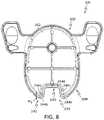
- FIG. 8is a bottom view of the pedestal of the physiological characteristic sensor assembly of FIG. 1 ;
- FIG. 9is a perspective view of the insertion device positioned over the physiological characteristic sensor assembly of FIG. 1 ;
- FIG. 10is a schematic cross-sectional exploded view of the insertion device and the physiological characteristic sensor assembly taken from the perspective of line 10 - 10 in FIG. 9 , which shows a sensor introducer, the physiological characteristic sensor and the adhesive patch removed from the pedestal;
- FIG. 11is a rear view of the insertion device, which shows the adhesive patch removed from the pedestal of FIG. 1 for deployment of the physiological characteristic sensor;
- FIG. 12is an end perspective view of the pedestal, which illustrates the pedestal positioned in one position of various positions for applying a holding force to a portion of the physiological characteristic sensor to enable removal of the sensor introducer;
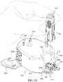
- FIG. 13is an end perspective view of the pedestal, which illustrates the pedestal positioned in another position of various positions for applying a holding force to a portion of the physiological characteristic sensor to enable removal of the sensor introducer;
- FIG. 14is a perspective view of the pedestal, which illustrates the various positions of the pedestal for applying a holding force to a portion of the physiological characteristic sensor to enable removal of the sensor introducer.
- the term “axial”refers to a direction that is generally parallel to or coincident with an axis of rotation, axis of symmetry, or centerline of a component or components.
- the “axial” directionmay refer to the direction that generally extends in parallel to the centerline between the opposite ends or faces.
- the term “axial”may be utilized with respect to components that are not cylindrical (or otherwise radially symmetric).
- the “axial” direction for a rectangular housing containing a rotating shaftmay be viewed as a direction that is generally parallel to or coincident with the rotational axis of the shaft.
- the term “radially” as used hereinmay refer to a direction or a relationship of components with respect to a line extending outward from a shared centerline, axis, or similar reference, for example in a plane of a cylinder or disc that is perpendicular to the centerline or axis.
- componentsmay be viewed as “radially” aligned even though one or both of the components may not be cylindrical (or otherwise radially symmetric).
- the terms “axial” and “radial” (and any derivatives)may encompass directional relationships that are other than precisely aligned with (e.g., oblique to) the true axial and radial dimensions, provided the relationship is predominately in the respective nominal axial or radial direction.
- the term “transverse”denotes an axis that crosses another axis at an angle such that the axis and the other axis are neither substantially perpendicular nor substantially parallel.
- the geometry of the pedestalenables the pedestal to be coupled to a physiological characteristic sensor, such as a glucose sensor, to provide a force that enables a user to remove a sensor introducer from the physiological characteristic sensor (and the sensor insertion site or sensor site).
- a physiological characteristic sensorsuch as a glucose sensor
- the pedestalas described herein, enables a user to insert a glucose sensor at an unconventional location, such as an upper arm, lower back or other hard to reach location, and remove the sensor introducer with a single hand, while holding the physiological characteristic sensor at the sensor site with the pedestal.
- the pedestalis described herein as being used with a glucose sensor, it will be understood that the pedestal may be employed with a variety of other sensors and/or medical devices.
- the non-limiting examples described belowrelate to a medical device used to treat diabetes (more specifically, a pedestal for a glucose sensor), embodiments of the disclosed subject matter are not so limited.
- the glucose sensor employed with the pedestalis a continuous glucose sensor of the type used by diabetic users.
- conventional aspects and technology related to glucose sensors and glucose sensor fabricationmay not be described in detail here.
- known and/or conventional aspects of glucose sensors and their manufacturingmay be of the type described in, but not limited to: U.S. Pat. Nos. 6,892,085, 7,468,033 and 9,295,786; and United States patent application number 2009/0299301 (which are each incorporated by reference herein).
- FIG. 1is a rear perspective view of an exemplary embodiment of a sensor package 100
- FIG. 2is a front perspective view of the sensor package 100
- the sensor package 100represents one exemplary form factor that can be used for purposes of boxing, shipping, storing, and distributing physiological characteristic sensors, such as glucose sensors, which have been manufactured, assembled, and sterilized.
- the sensor package 100generally includes, but is not limited to: a package tray 102 ; a physiological characteristic sensor assembly 104 (shown in phantom); and a piece of material 106 .
- the package tray 102is composed at least in part from a plastic material.
- the package tray 102is formed as a one-piece molded plastic component.
- the package tray 102is formed as a solid component that is free of holes, tears, punctures, etc.
- the package tray 102may be formed from a thermoformed or injection molded plastic material such as, without limitation: polypropylene, polycarbonate (PC), acrylonitrile butadiene styrene (ABS), a PC/ABS blend, nylon, polyvinyl chloride (PVC), and polyethylene terephthalate glycol (PETG) material.
- the package tray 102is composed of a polyethylene terephthalate glycol (PETG) material.
- the package tray 102can be formed from a transparent or clear plastic material such that the physiological characteristic sensor assembly 104 is visible.
- the physiological characteristic sensor assembly 104is positioned within an interior cavity 108 of the package tray 102 .
- the interior cavity 108is shaped and sized in a manner that generally conforms to the physiological characteristic sensor assembly 104 .
- the package tray 102may include a retaining feature 110 (also shown in FIG. 1 ) that accommodates a component of the physiological characteristic sensor assembly 104 .
- the retaining feature 110protects a portion of the physiological characteristic sensor assembly 104 during shipping and handling.
- the front of the package tray 102includes an opening 112 that leads to the interior cavity 108 .
- the front of the package tray 102also includes a sealing surface 114 , which surrounds the opening 112 .
- the sealing surface 114is shaded in FIG. 2 .
- the material 106( FIG. 1 ) covers the opening 112 and is coupled to the package tray 102 in a manner that forms a seal between the sealing surface 114 and the material 106 .
- the material 106serves as a cover that encloses the physiological characteristic sensor assembly 104 within the interior cavity 108 .
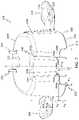
- the physiological characteristic sensor assembly 104includes a sensor inserter or sensor introducer 120 , a physiological characteristic sensor 122 , an adhesive patch 124 and a pedestal 126 .
- the components of the physiological characteristic sensor assembly 104are coupled together as a single unit for placement in the package tray 102 .
- an insertion device 130FIG. 4
- an insertion device 130may be used by a user to remove the sensor introducer 120 , the physiological characteristic sensor 122 and the adhesive patch 124 from the pedestal 126 , and used to insert the physiological characteristic sensor 122 at a sensor insertion site or sensor site.
- the sensor introducer 120is manipulated to introduce a portion of the physiological characteristic sensor 122 into the body of the user.
- the sensor introducer 120includes a body having a first end 132 and an opposite second end 134 .
- the first end 132defines a graspable portion 132 a, which enables the user to manipulate the sensor introducer 120 .
- the second end 134includes a spring loaded insertion needle 136 and a pair of opposed mating projections 138 .
- FIG. 4depicts the insertion needle 136 in its extended position, where the insertion needle 136 protrudes from the body of the sensor introducer 120 .
- Each of the pair of mating projections 138engage corresponding features on a portion of the physiological characteristic sensor 122 to couple the sensor introducer 120 to the physiological characteristic sensor 122 before introducing a portion of the physiological characteristic sensor 122 into the body of the user.
- the sensor introducer 120 and the physiological characteristic sensor 122can be pre-connected as part of a sensor set, which could also include a sensor electronics module (not shown), such as a wireless transmitter that communicates with an infusion pump, a monitor device, or the like, which connects to the physiological characteristic sensor 122 after the insertion or deployment of a portion of the physiological characteristic sensor 122 in the body of the user.
- the sensor introducer 120 and the physiological characteristic sensor 122can be packaged and provided together, as depicted in FIG. 2 .
- the sensor introducer 120is composed at least in part from a plastic material.
- the bulk of the sensor introducer 120is formed as a molded plastic component.
- the sensor introducer 120may be formed from ABS, nylon, an ABS/PC blend, PVC, polytetrafluoroethylene (PTFE), polypropylene, polyether ether ketone (PEEK), polycarbonate or the like.
- the sensor introducer 120is formed from polycarbonate.
- the physiological characteristic sensor 122includes a glucose sensor 140 and a sensor base 142 . It should be noted that the physiological characteristic sensor 122 is not limited to a glucose sensor, but rather, various other physiological characteristic sensors may be employed.
- the glucose sensor 140may be provided as an integral part of the sensor base 142 , as depicted in FIG. 4 .
- the sensor base 142gives structural support to the glucose sensor 140 , and facilitates entry of the glucose sensor 140 into the body of the user.
- the glucose sensor 140is an electrochemical sensor that includes the glucose oxidase enzyme, as is well understood by those familiar with glucose sensor technology. The glucose oxidase enzyme enables the glucose sensor 140 to monitor blood glucose levels in a diabetic patient or user by effecting a reaction of glucose and oxygen.
- the manufacturing and packaging technology described herecan be adapted for use with any one of the wide variety of sensors known in the art.
- the glucose sensor 140is positionable in subcutaneous tissue of the user by the insertion needle 136 of the sensor introducer 120 to measure the glucose oxidase enzyme.
- the sensor base 142is coupled to the sensor introducer 120 and is coupled to the pedestal 126 .
- the sensor base 142includes a body 144 that defines a first base side 146 opposite a second base side 148 .
- the body 144is coupled to the sensor introducer 120 prior to the deployment of the glucose sensor 140 into the subcutaneous tissue of the user such that the first base side 146 is adjacent to the second end 134 of the sensor introducer 120 .
- the second base side 146is coupled to the adhesive patch 124 .
- the sensor base 142may also feature electrical and physical interfaces and elements that accommodate the sensor electronics module (not shown), such as the wireless transmitter that communicates with the infusion pump, the monitor device, or the like.
- the sensor base 142is composed at least in part from a plastic material.
- the bulk of the sensor base 142is formed as a molded plastic component.
- the sensor base 142is formed from ABS, nylon, an ABS/PC blend, PVC, polytetrafluoroethylene (PTFE), polypropylene, polyether ether ketone (PEEK), polycarbonate, or the like.
- the sensor base 142is composed of polycarbonate.
- the body 144is shown in greater detail.
- the body 144also includes a pair of wings 150 , a pair of pedestal coupling pockets 152 and a pair of introducer coupling slots 154 .
- Each of the pair of wings 150are coupled to a first end 144 a of the body 144 so as to movable or flexible relative to the body 144 .
- the pair of pedestal coupling pockets 152provide for a reduced thickness of the body 144 at an end of each of the wings 150 , which enables the wings 150 to move or flex.
- the wings 150couple the sensor base 142 to the electronics module (not shown), such as the wireless transmitter, which can communicate the sensor signals from the glucose sensor 140 to the infusion pump, the monitor device, or the like.
- the pair of pedestal coupling pockets 152is defined on opposite sides of the body 144 at the first end 144 a of the body 144 so as to extend through the body 144 from the first base side 146 to the second base side 148 .
- the pair of pedestal coupling pockets 152each includes a first surface 156 , a second surface 158 and a third surface 160 .
- the first surface 156 , the second surface 158 and the third surface 160are coupled together via curved or arcuate sections 162 , such that each of the pair of pedestal coupling pockets 152 has rounded corners.
- the first surface 156is substantially flat or planar, and extends along an axis that intersects an axis of which the second surface 158 extends.
- the second surface 158is also substantially flat or planar.
- the third surface 160is substantially flat or planar, and extends along an axis that is substantially perpendicular to the axis along which the second surface 158 extends. As will be discussed, each of the first surface 156 , the second surface 158 and the third surface 160 cooperate with a portion of the pedestal 126 to couple the physiological characteristic sensor 122 to the pedestal 126 .
- the pair of introducer coupling slots 154is in communication with the pair of pedestal coupling pockets 152 .
- the pair of introducer coupling slots 154each has a length defined along the body 144 that receives an entirety of an end of the respective one of the mating projections 138 to couple the sensor introducer 120 to the sensor base 142 .
- each of the pair of introducer coupling slots 154include a recess 163 , which cooperates with a notched surface 138 a ( FIG. 4 ) of a respective one of the mating projections 138 to assist in coupling the sensor introducer 120 to the sensor base 142 .
- the adhesive patch 124is coupled to the sensor base 142 and affixes the sensor base 142 , and thus, the glucose sensor 140 , to the skin of the user.
- the adhesive patch 124is retained on, but not secured to, the pedestal 126 during packaging and shipping.
- the adhesive patch 124may be composed of a flexible and breathable material with one or more adhesive layers, such as cloth, a bandage-like material, and the like.
- suitable materialscould include polyurethane, polyethylene, polyester, polypropylene, polytetrafluoroethylene (PTFE), or other polymers, to which one or more adhesive layers are applied.
- the adhesive patch 124is substantially oval in shape, and has a first patch side 164 opposite a second patch side 166 .
- the first patch side 164includes an adhesive layer 164 a having a first portion 168 and a second portion 170 .
- the first portion 168couples the second base side 148 of the sensor base 142 to the adhesive patch 124 to couple the sensor base 142 to the adhesive patch 124 .
- the second portion 170couples to the sensor electronics module (such as the wireless transmitter not shown), and may be covered with a backing liner 172 .
- the second patch side 166includes a second adhesive layer 166 a that couples the adhesive patch 124 and the physiological characteristic sensor 122 to the skin of the user.
- the second adhesive layer 166 amay be coupled with a second backing liner 174 , which is removable by the user prior to the deployment of the glucose sensor 140 at the sensor site.
- an additional adhesive layer or adhesive stripmay also be provided on the bottom of the second backing liner 174 to temporarily secure the second backing liner 174 to the pedestal 126 during packaging, shipping, and handling.
- additional adhesive layer or adhesive stripmay be a double-sided adhesive element that maintains the second backing liner 174 in position atop the pedestal 126 .
- the adhesive patch 124also defines a pair of pedestal coupling bores 176 and a sensor bore 178 that extend through the adhesive patch 124 from the first patch side 164 to the second patch side 166 .
- the pair of pedestal coupling bores 176each receives a respective portion of the pedestal 126 to retain or couple the adhesive patch 124 to the pedestal 126 .
- the sensor bore 178enables the glucose sensor 140 to pass through the adhesive patch 124 for subcutaneous placement into the body of the user.
- the pedestal 126receives and protects the insertion needle 136 of the sensor introducer 120 during packaging, shipping, and handling before deployment of the glucose sensor 140 .
- the pedestal 126also serves to assist a user in the removal of the sensor introducer 120 after the deployment of the glucose sensor 140 .
- the pedestal 126includes a first pedestal side 200 opposite a second pedestal side 202 and a pedestal sidewall 204 that interconnects the first pedestal side 200 with the second pedestal side 202 .
- the pedestal 126also includes a first pedestal end 206 opposite a second pedestal end 208 .
- the pedestal 126is composed at least in part from a plastic material.
- the pedestal 126is formed as a molded plastic component.
- the pedestal 126is formed from ABS, nylon, an ABS/PC blend, PVC, polytetrafluoroethylene (PTFE), polypropylene, polyether ether ketone (PEEK), polycarbonate, or the like.
- the pedestal 126is composed of polypropylene, and may be recyclable.
- the first pedestal side 200includes a surface 200 a that receives the adhesive patch 124 .
- the first pedestal side 200is substantially oval in shape to correspond with the shape of the adhesive patch 124 .
- the first pedestal side 200includes a pair of posts 210 near the first pedestal end 206 and an inserter bore 212 spaced apart from the pair of posts 210 near the first pedestal end 206 .
- Each of the pair of posts 210extend for a height H, which is predetermined to enable each of the posts 210 to be received through the respective one of the pedestal coupling bores 176 and into the respective one of the pedestal coupling pockets 152 to couple the sensor base 142 to the pedestal 126 .
- each of the posts 210is substantially triangular.
- Each of the posts 210has a first post side 214 , a second post side 216 and a third post side 218 .
- Each of the first post side 214 , the second post side 216 and the third post side 218cooperate to define three points of contact 220 a, 220 b, 220 c that assist in securely coupling the sensor base 142 to the pedestal 126 .
- the first point of contact 220 acontacts the first surface 156
- the second point of contact 220 bcontacts the second surface 158
- the third point of contact 220 ccontacts the third surface 160 .
- These three points of contact 220 a, 220 b, 220 cform an interference fit with the pedestal coupling pockets 152 to securely retain the sensor base 142 on the pedestal 126 such that the insertion device 130 is required to remove the sensor base 142 from the pedestal 126 .
- the posts 210are spaced a distance D 1 from a center C of the inserter bore 212 .
- the posts 210may be rotated slightly relative to one another, such that the point of contact 220 a of a first post 210 a is spaced the distance D 1 from the center C of the inserter bore 122 and the third point of contact 220 c of a second post 210 b is spaced the distance D 1 from the center C of the inserter bore 122 .
- the third point of contact 220 c of the first post 210 ais spaced a distance D 2 from the center C of the inserter bore 122
- the first point of contact 220 a of the second post 210 bis spaced the distance D 2 from the center C of the inserter bore 122
- the posts 210are each spaced apart from the center C of the inserter bore 122 by a distance D 3 .
- the distance D 1may range from about 0.17 inches (in.) to about 0.21 inches (in.)
- the distance D 2may range from about 0.23 inches (in.) to about 0.27 inches (in.)
- the distance D 3may range from about 0.15 inches (in.) to about 0.19 inches (in.).
- the distances D 1 , D 2 and D 3may vary based on the size of the sensor base 142 ( FIG. 5A ).
- the inserter bore 212is defined through the pedestal 126 from the first pedestal side 200 to the second pedestal side 202 .
- the inserter bore 212generally transitions in diameter from the first pedestal side 200 to the second pedestal side 202 .
- the inserter bore 212is a stepped bore, with a plurality of steps 212 a, 212 b, 212 c that taper from a first diameter before the step 212 a to a second diameter at the step 212 c.
- the second diameteris less than the first diameter.
- the second diameter of the inserter bore 212is smaller than the first diameter to provide a guide for the insertion needle 136 during deployment of the glucose sensor 140 .
- the second pedestal side 202includes a pair of tabs or feet 224 near the first pedestal end 206 .
- the feet 224extend outwardly away from the pedestal sidewall 204 , and include a graspable recess 226 and a graphical indicator 228 .
- the graspable recesses 226enable a user to position a finger on the respective one of the feet 224 to remove the sensor introducer 120 from the pedestal 126 .
- the graphical indicator 228provides a visual cue to the user for the removal of the pedestal 126 from the package tray 102 ( FIG. 2 ).
- the graphical indicators 228are recessed into the feet 224 ; however, the graphical indicators 228 may be raised on the feet 224 , if desired.
- the pedestal sidewall 204extends about the perimeter of the pedestal 126 .
- the pedestal sidewall 204includes opposed grip surfaces 230 at the first pedestal end 206 and an introducer removal recess 232 at the second pedestal end 208 .
- the grip surfaces 230are spaced apart at the first pedestal end 206 so as to be positioned on the pedestal sidewall 204 adjacent to the feet 224 .
- the grip surfaces 230generally include a plurality of ribs 230 a, which enable the user to grasp the pedestal 126 and remove the pedestal 126 from the package tray 102 ( FIG. 2 ).
- the introducer removal recess 232is defined through the pedestal sidewall 204 so as to extend from the first pedestal side 200 to the second pedestal side 202 .
- the introducer removal recess 232extends along an axis A, which is substantially perpendicular to a longitudinal axis L of the pedestal 126 .
- the introducer removal recess 232is substantially symmetric about the axis A.
- the introducer removal recess 232has a first portion or introducer portion 240 and a second portion or base portion 242 .
- the introducer portion 240 of the introducer removal recess 232is positionable about the sensor introducer 120 and the base portion 242 of the introducer removal recess 232 is positionable over the first base side 146 of the sensor base 142 .
- the introducer portion 240extends from the first pedestal side 200 toward the second pedestal side 202 for a height H 2 .
- the introducer portion 240is recessed into the pedestal sidewall 204 by a width W 2 .
- the width W 2is generally at least the same as or greater than a width W 1 of the sensor introducer 120 ( FIG. 4 ).
- the introducer portion 240extends for a length L 2 along a perimeter of the pedestal sidewall 204 . Generally, the length L 2 is greater than a length L 4 of the sensor introducer 120 ( FIG. 4 ).
- the introducer portion 240is substantially U-shaped, and includes a first wall 246 , a second wall 248 and a third wall 250 . Each of the first wall 246 , the second wall 248 and the third wall 250 are interconnected to define the U-shape, which enables the sensor introducer 120 to be received within the introducer portion 240 .
- the sensor introducer 120is positionable within the introducer portion 240 of the introducer removal recess 232 to facilitate the removal of the sensor introducer 120 from the sensor base 142 , as will be discussed.
- the introducer portion 240provides a recess that receives the sensor introducer 120 to enable the base portion 242 to be positioned over the sensor base 142 to apply a holding force to the sensor base 142 .
- the first wall 246 and the third wall 250are coupled to the pedestal sidewall 204 via a rounded or arcuate surface.
- the base portion 242is in communication with the introducer portion 240 .
- the base portion 242is defined at the second pedestal side 202 and extends for a height H 3 from the second pedestal side 202 toward the first pedestal side 200 .
- the height H 3is less than the height H 2 of the introducer portion 240 defined between the first pedestal side 200 and the second pedestal side 202 .
- the base portion 242has a length L 3 along the perimeter of the pedestal sidewall 204 , which is greater than the length L 2 of the introducer portion 240 .
- the length L 3is greater than a length L 5 of the sensor base 142 ( FIG. 5A ).
- the base portion 242has a width W 3 , which is less than the width W 2 of the introducer portion 240 .
- the width W 3is the width of the pedestal sidewall 204 .
- the difference in heights H 2 , H 3 between the introducer portion 240 and the base portion 242 along a perimeter of the pedestal sidewall 204defines a respective contact surface 244 a, 244 b, 244 c, 244 d, 244 e along a perimeter of the introducer removal recess 232 .
- the contact surfaces 244 a - 244 emay apply a holding force to a portion of the sensor base 142 during the removal of the sensor introducer 120 from the sensor base 142 once the glucose sensor 140 has been deployed. As shown in FIG.
- the pedestal 126has a substantially hollow interior, such that a portion of the sensor base 142 may pass through the base portion 242 into an interior 252 of the pedestal 126 to assist the contact surfaces 244 a - 244 e in applying a holding force to the sensor base 142 at a variety of positions of the sensor base 142 , as will be discussed herein.
- the base portion 242cooperates with the interior 252 of the pedestal 126 to enable the pedestal 126 to be positioned over the sensor base 142 at a variety of angles to enable the contact surfaces 244 a - 244 e to apply a holding force to assist in removing the sensor introducer 120 from the sensor base 142 .
- the physiological characteristic sensor assembly 104may be assembled.
- the glucose sensor 140is coupled to the sensor base 142
- the physiological characteristic sensor 122is coupled to the first portion 168 of the adhesive patch 124 such that the glucose sensor 140 passes through the sensor bore 178 and is at least partially received within the inserter bore 212 of the pedestal 126 .
- the adhesive patch 124is coupled to the pedestal 126 such that each of the pedestal coupling bores 176 are received over each of the respective posts 210 , and the pedestal coupling pockets 152 are coupled to a respective one of the posts 210 to form the interference fit with the three points of contact 220 a, 220 b, 220 c ( FIG. 6 ).
- the sensor introducer 120is coupled to the sensor base 142 by inserting the mating projections 138 into the introducer coupling slots 154 .
- the physiological characteristic sensor assembly 104is positioned within the interior cavity 108 of the package tray 102 such that the sensor introducer 120 is received within the retaining feature 110 and the grip surfaces 230 are adjacent to the opening 112 .
- the material 106is applied over the opening 112 and cooperates with the sealing surface 114 to seal the physiological characteristic sensor assembly 104 within the package tray 102 .
- the physiological characteristic sensor assembly 104may then be shipped to a consumer or the user. Further detail regarding the manufacture and assembly of the packaging for the physiological characteristic sensor assembly 104 is described in U.S. Pat. No. 9,101,305 to Larson et al., which is incorporated herein by reference.
- the material 106may be peeled away and removed to expose the interior cavity 108 .
- the physiological characteristic sensor assembly 104may be removed from the interior cavity 108 by gripping the grip surfaces 230 of the pedestal 126 .
- the insertion device 130may be used to insert the glucose sensor 140 into the body of the user.
- FIG. 9is a perspective view of an insertion device 130 that can be used with the physiological characteristic sensor assembly 104 (see FIG. 4 ).
- FIG. 10is a phantom side view of the insertion device 130 in a loaded state
- FIG. 11is a bottom perspective view of the insertion device 130 in a loaded state.
- the insertion device 130is placed over the physiological characteristic sensor assembly 104 and is pressed down to engage the sensor introducer 120 and to spring-load the insertion needle 136 .
- the pedestal 126is separated from the other components of the physiological characteristic sensor assembly 104 by lifting the insertion device 130 away from the pedestal 126 while holding down the feet 224 of the pedestal 126 (see FIG. 4 ). Removal of the pedestal 126 causes the adhesive patch 124 to be removed from the surface 200 a of the pedestal 126 .
- the remainder of the physiological characteristic sensor assembly 104is retained within the interior of the insertion device 130 , ready for deployment on the skin of the user.
- the usermoves the loaded insertion device 130 to the desired deployment location, holds the insertion device 130 against the skin, and actuates triggering buttons 302 of the insertion device 130 (see FIG. 7 ).
- Triggering the insertion device 300moves the adhesive patch 124 into contact with the user's skin, and activates the insertion needle 136 to insert the glucose sensor 140 into the skin.
- the insertion device 130is removed and separated from the sensor introducer 120 and the glucose sensor 140 , which remains affixed to the skin by way of the adhesive patch 124 .
- the sensor introducer 120remains coupled to the sensor base 142 .
- a forceis needed to hold the sensor base 142 while pulling upward on the sensor introducer 120 to prevent accidental displacement of the glucose sensor 140 .
- the pedestal 126may be employed by the user to apply the holding force to the sensor base 142 as shown in FIGS. 12 and 13 .
- the pedestal 126is positioned over the sensor base 142 such that the first base side 146 of the sensor base 142 is adjacent to or in contact with one or more of the contact surfaces 244 a - 244 e.
- the introducer portion 240 of the introducer removal recess 232provides clearance for the pedestal 126 to be positioned over a portion of the first base side 146 without interfering with the removal of the sensor introducer 120 .
- the usermay hold the pedestal 126 down with a portion of their hand, for example, thereby applying a holding force F to the sensor base 142 via one or more of the contact surfaces 244 a - 244 e, and use their fingers to apply an upward force F 2 to remove the sensor introducer 120 from the sensor base 142 , without displacing the glucose sensor 140 .
- the pedestal 126may be removed from the sensor base 142 leaving the physiological characteristic sensor 122 coupled to the user via the adhesive patch 124 .
- the introducer removal recess 232 of the pedestal 126enables a user to remove the sensor introducer 120 from the sensor base 142 with a single hand, which enables the user to position the glucose sensor 140 in other hard to reach places, such as on an upper arm, without requiring assistance from another to remove the sensor introducer 120 .
- the pedestal 126need not be positioned over the first base side 146 of the sensor base 142 at a particular orientation. Rather, the base portion 242 of the introducer removal recess 232 cooperates with the interior 252 of the pedestal 126 to enable the pedestal 126 to be positioned over the sensor base 142 at a variety of orientations.
- the userapplies the holding force F to the pedestal 126 , and one or more of the contact surfaces 244 a - 244 e retain the sensor base 142 and the glucose sensor 140 at the sensor site. This enables the user, with a single hand, to apply the upward force F 2 to remove the sensor introducer 120 from the sensor base 142 at various orientations of the pedestal 126 .
- the pedestal 126may be positioned over the sensor base 142 to remove the sensor introducer 120 from the physiological characteristic sensor 122 .
- the pedestal 126may be positioned at various orientations to enable the contact surfaces 244 a - 244 e to apply the holding force against the sensor base 142 .
- any opposing two points of contact between the contact surfaces 244 a - 244 e of the introducer removal recess 232 and the sensor base 142 that are approximately 0.5 inches (in.) apart on the sensor base 142may be sufficient to hold down the sensor base 142 during a removal of the sensor introducer 120 .
- the pedestal 126both protects the insertion needle 136 and the physiological characteristic sensor assembly 104 during shipping and handling, while also enabling a user to remove the sensor introducer 120 with a single hand after deployment of the glucose sensor 140 .
- Thisenables the user to insert the glucose sensor 140 at unconventional or harder to reach places, such as an upper arm.
- the pedestal 126is positionable over the first base side 146 of the sensor base 142 at numerous positions and orientations.
- the ability of the pedestal 126 to be positioned at numerous positions and orientations relative to the sensor base 142provides the user with greater freedom to position the physiological characteristic sensor 122 at a desired sensor site, while still ensuring the user may remove the sensor introducer 120 with a single hand.
Landscapes
- Health & Medical Sciences (AREA)
- Life Sciences & Earth Sciences (AREA)
- Physics & Mathematics (AREA)
- Engineering & Computer Science (AREA)
- Veterinary Medicine (AREA)
- Animal Behavior & Ethology (AREA)
- Public Health (AREA)
- General Health & Medical Sciences (AREA)
- Heart & Thoracic Surgery (AREA)
- Biomedical Technology (AREA)
- Biophysics (AREA)
- Pathology (AREA)
- Medical Informatics (AREA)
- Molecular Biology (AREA)
- Surgery (AREA)
- Optics & Photonics (AREA)
- Chemical & Material Sciences (AREA)
- General Chemical & Material Sciences (AREA)
- Chemical Kinetics & Catalysis (AREA)
- Mechanical Engineering (AREA)
- Diabetes (AREA)
- Emergency Medicine (AREA)
- Vascular Medicine (AREA)
- Anesthesiology (AREA)
- Hematology (AREA)
- Measurement Of The Respiration, Hearing Ability, Form, And Blood Characteristics Of Living Organisms (AREA)
- Force Measurement Appropriate To Specific Purposes (AREA)
Abstract
Description
Claims (16)
Priority Applications (7)
| Application Number | Priority Date | Filing Date | Title |
|---|---|---|---|
| US15/688,603US11412960B2 (en) | 2017-08-28 | 2017-08-28 | Pedestal for sensor assembly packaging and sensor introducer removal |
| CN201880054232.1ACN111031914B (en) | 2017-08-28 | 2018-06-06 | Base for sensor assembly packaging and sensor guide removal |
| EP23186731.8AEP4248863A3 (en) | 2017-08-28 | 2018-06-06 | Pedestal for sensor assembly packaging and sensor introducer removal |
| PCT/US2018/036316WO2019045822A1 (en) | 2017-08-28 | 2018-06-06 | Pedestal for sensor assembly packaging and sensor introducer removal |
| EP18738402.9AEP3675735B1 (en) | 2017-08-28 | 2018-06-06 | Pedestal for sensor assembly packaging and sensor introducer removal |
| CA3071820ACA3071820A1 (en) | 2017-08-28 | 2018-06-06 | Pedestal for sensor assembly packaging and sensor introducer removal |
| US17/814,188US20220354393A1 (en) | 2017-08-28 | 2022-07-21 | Pedestal for sensor assembly packaging and sensor introducer removal |
Applications Claiming Priority (1)
| Application Number | Priority Date | Filing Date | Title |
|---|---|---|---|
| US15/688,603US11412960B2 (en) | 2017-08-28 | 2017-08-28 | Pedestal for sensor assembly packaging and sensor introducer removal |
Related Child Applications (1)
| Application Number | Title | Priority Date | Filing Date |
|---|---|---|---|
| US17/814,188DivisionUS20220354393A1 (en) | 2017-08-28 | 2022-07-21 | Pedestal for sensor assembly packaging and sensor introducer removal |
Publications (2)
| Publication Number | Publication Date |
|---|---|
| US20190059796A1 US20190059796A1 (en) | 2019-02-28 |
| US11412960B2true US11412960B2 (en) | 2022-08-16 |
Family
ID=62846239
Family Applications (2)
| Application Number | Title | Priority Date | Filing Date |
|---|---|---|---|
| US15/688,603Active2040-01-28US11412960B2 (en) | 2017-08-28 | 2017-08-28 | Pedestal for sensor assembly packaging and sensor introducer removal |
| US17/814,188PendingUS20220354393A1 (en) | 2017-08-28 | 2022-07-21 | Pedestal for sensor assembly packaging and sensor introducer removal |
Family Applications After (1)
| Application Number | Title | Priority Date | Filing Date |
|---|---|---|---|
| US17/814,188PendingUS20220354393A1 (en) | 2017-08-28 | 2022-07-21 | Pedestal for sensor assembly packaging and sensor introducer removal |
Country Status (5)
| Country | Link |
|---|---|
| US (2) | US11412960B2 (en) |
| EP (2) | EP4248863A3 (en) |
| CN (1) | CN111031914B (en) |
| CA (1) | CA3071820A1 (en) |
| WO (1) | WO2019045822A1 (en) |
Families Citing this family (5)
| Publication number | Priority date | Publication date | Assignee | Title |
|---|---|---|---|---|
| US12213782B2 (en)* | 2020-06-04 | 2025-02-04 | Medtronic Minimed, Inc. | Physiological characteristic sensor system |
| SE545876C2 (en) | 2021-09-28 | 2024-02-27 | Biolinq Incorporated | Microneedle enclosure and applicator device for microneedle array based continuous analyte monitoring device |
| USD1033641S1 (en) | 2021-12-17 | 2024-07-02 | Biolinq Incorporated | Microneedle array sensor applicator device |
| TWI776779B (en)* | 2022-02-08 | 2022-09-01 | 仁寶電腦工業股份有限公司 | Consumable component of injecting physiological monitor and injecting physiological monitor |
| USD1057153S1 (en) | 2022-04-29 | 2025-01-07 | Biolinq Incorporated | Microneedle array sensor applicator device |
Citations (84)
| Publication number | Priority date | Publication date | Assignee | Title |
|---|---|---|---|---|
| US4755173A (en) | 1986-02-25 | 1988-07-05 | Pacesetter Infusion, Ltd. | Soft cannula subcutaneous injection set |
| US5391250A (en) | 1994-03-15 | 1995-02-21 | Minimed Inc. | Method of fabricating thin film sensors |
| US5485408A (en) | 1992-09-09 | 1996-01-16 | Sims Deltec, Inc. | Pump simulation apparatus |
| US5522803A (en) | 1993-03-09 | 1996-06-04 | Pharma Plast International A/S | Infusion set for an intermittent or continuous administration of a therapeutical substance |
| US5665065A (en) | 1995-05-26 | 1997-09-09 | Minimed Inc. | Medication infusion device with blood glucose data input |
| US5800420A (en) | 1994-11-04 | 1998-09-01 | Elan Medical Technologies Limited | Analyte-controlled liquid delivery device and analyte monitor |
| US5925021A (en) | 1994-03-09 | 1999-07-20 | Visionary Medical Products, Inc. | Medication delivery device with a microprocessor and characteristic monitor |
| US5954643A (en) | 1997-06-09 | 1999-09-21 | Minimid Inc. | Insertion set for a transcutaneous sensor |
| US6017328A (en) | 1993-01-21 | 2000-01-25 | Magnolia Medical, Llc | Device for subcutaneous medication delivery |
| US6186982B1 (en) | 1998-05-05 | 2001-02-13 | Elan Corporation, Plc | Subcutaneous drug delivery device with improved filling system |
| US6246992B1 (en) | 1996-10-16 | 2001-06-12 | Health Hero Network, Inc. | Multiple patient monitoring system for proactive health management |
| US6248067B1 (en) | 1999-02-05 | 2001-06-19 | Minimed Inc. | Analyte sensor and holter-type monitor system and method of using the same |
| US6248093B1 (en) | 1998-10-29 | 2001-06-19 | Minimed Inc. | Compact pump drive system |
| US6355021B1 (en) | 1998-07-14 | 2002-03-12 | Maersk Medical A/S | Medical puncturing device |
| US6379301B1 (en) | 1997-01-10 | 2002-04-30 | Health Hero Network, Inc. | Diabetes management system and method for controlling blood glucose |
| US6544212B2 (en) | 2001-07-31 | 2003-04-08 | Roche Diagnostics Corporation | Diabetes management system |
| US6558351B1 (en) | 1999-06-03 | 2003-05-06 | Medtronic Minimed, Inc. | Closed loop system for controlling insulin infusion |
| US6591876B2 (en) | 1999-11-05 | 2003-07-15 | Medtronic Minimed, Inc. | Needle safe transfer guard |
| US6641533B2 (en) | 1998-08-18 | 2003-11-04 | Medtronic Minimed, Inc. | Handheld personal data assistant (PDA) with a medical device and method of using the same |
| US6736797B1 (en) | 1998-06-19 | 2004-05-18 | Unomedical A/S | Subcutaneous infusion set |
| US6749587B2 (en) | 2001-02-22 | 2004-06-15 | Insulet Corporation | Modular infusion device and method |
| US6766183B2 (en) | 1995-11-22 | 2004-07-20 | Medtronic Minimed, Inc. | Long wave fluorophore sensor compounds and other fluorescent sensor compounds in polymers |
| US6801420B2 (en) | 2001-04-19 | 2004-10-05 | Medtronic Minimed, Inc. | Selective potting for controlled failure and electronic devices employing the same |
| US6804544B2 (en) | 1995-11-22 | 2004-10-12 | Minimed, Inc. | Detection of biological molecules using chemical amplification and optical sensors |
| US6892085B2 (en) | 1999-02-25 | 2005-05-10 | Medtronic Minimed, Inc. | Glucose sensor package system |
| US7003336B2 (en) | 2000-02-10 | 2006-02-21 | Medtronic Minimed, Inc. | Analyte sensor method of making the same |
| US7029444B2 (en) | 2000-02-23 | 2006-04-18 | Medtronic Minimed, Inc. | Real time self-adjusting calibration algorithm |
| US7066909B1 (en) | 1997-04-23 | 2006-06-27 | Disetronic Licensing Ag | Propelling device for a piston in a container containing a liquid medicament |
| US7137964B2 (en) | 2000-09-08 | 2006-11-21 | Insulet Corporation | Devices, systems and methods for patient infusion |
| US20070123819A1 (en) | 2005-11-08 | 2007-05-31 | M2 Medical A/S | Infusion Pump System |
| US7303549B2 (en) | 2002-04-23 | 2007-12-04 | Insulet Corporation | Transcutaneous fluid delivery system |
| US7399277B2 (en) | 2001-12-27 | 2008-07-15 | Medtronic Minimed, Inc. | System for monitoring physiological characteristics |
| US7442186B2 (en) | 2002-02-28 | 2008-10-28 | Smiths Medical Md, Inc. | Syringe pump control systems using a light sensor |
| US20080269687A1 (en)* | 2007-04-30 | 2008-10-30 | Medtronic Minimed, Inc. | Adhesive Patch Systems and Methods |
| US7468033B2 (en) | 2004-09-08 | 2008-12-23 | Medtronic Minimed, Inc. | Blood contacting sensor |
| US7602310B2 (en) | 1998-10-08 | 2009-10-13 | Medtronic Minimed, Inc. | Telemetered characteristic monitor system and method of using the same |
| US20090299301A1 (en) | 2008-05-28 | 2009-12-03 | Medtronic Minimed, Inc. | Needle protective device for subcutaneous sensors |
| US7647237B2 (en) | 1998-04-29 | 2010-01-12 | Minimed, Inc. | Communication station and software for interfacing with an infusion pump, analyte monitor, analyte meter, or the like |
| US7699807B2 (en) | 2003-11-10 | 2010-04-20 | Smiths Medical Asd, Inc. | Device and method for insertion of a cannula of an infusion device |
| US7727148B2 (en) | 2004-07-27 | 2010-06-01 | Medtronic Minimed, Inc. | Sensing system with auxiliary display |
| US20100160861A1 (en) | 2000-03-23 | 2010-06-24 | Medtronic Minimed, Inc. | Control Tabs for Infusion Devices and Methods of Using the Same |
| US7785313B2 (en) | 2007-04-25 | 2010-08-31 | Medtronic Minimed, Inc. | Closed loop/semi-closed loop therapy modification system |
| US7806886B2 (en) | 1999-06-03 | 2010-10-05 | Medtronic Minimed, Inc. | Apparatus and method for controlling insulin infusion with state variable feedback |
| US7819843B2 (en) | 1998-08-18 | 2010-10-26 | Medtronic Minimed, Inc. | External infusion device with remote programming, bolus estimator and/or vibration alarm capabilities |
| US7828764B2 (en) | 2006-08-23 | 2010-11-09 | Medtronic Minimed, Inc. | Systems and methods allowing for reservoir filling and infusion medium delivery |
| US7879010B2 (en) | 2001-04-06 | 2011-02-01 | Roche Diagnostics International Ag | Infusion set |
| US7890295B2 (en) | 2000-02-23 | 2011-02-15 | Medtronic Minimed, Inc. | Real time self-adjusting calibration algorithm |
| US7892748B2 (en) | 2003-12-16 | 2011-02-22 | Precisense A/S | Reagent for detecting an analyte |
| US7892206B2 (en) | 1998-10-29 | 2011-02-22 | Medtronic Minimed, Inc. | Method and apparatus for detecting errors, fluid pressure, and occlusions in an ambulatory infusion pump |
| US7901394B2 (en) | 2002-07-24 | 2011-03-08 | Medtronic Minimed, Inc. | Physiological monitoring device for controlling a medication infusion device |
| US7942844B2 (en) | 2006-04-28 | 2011-05-17 | Medtronic Minimed, Inc. | Remote monitoring for networked fluid infusion systems |
| US7946985B2 (en) | 2006-12-29 | 2011-05-24 | Medtronic Minimed, Inc. | Method and system for providing sensor redundancy |
| US7955305B2 (en) | 2005-05-06 | 2011-06-07 | Medtronic Minimed, Inc. | Needle inserter and method for infusion device |
| US7963954B2 (en) | 2007-04-30 | 2011-06-21 | Medtronic Minimed, Inc. | Automated filling systems and methods |
| US7977112B2 (en) | 2003-06-20 | 2011-07-12 | Roche Diagnostics Operations, Inc. | System and method for determining an abused sensor during analyte measurement |
| US7985330B2 (en) | 2005-12-30 | 2011-07-26 | Medtronic Minimed, Inc. | Method and system for detecting age, hydration, and functional states of sensors using electrochemical impedance spectroscopy |
| US8024201B2 (en) | 1992-11-17 | 2011-09-20 | Health Hero Network, Inc. | Method and apparatus for remote health monitoring and providing health related information |
| US8100852B2 (en) | 2006-11-29 | 2012-01-24 | Medtronic Minimed, Inc. | Methods and apparatuses for detecting medical device acceleration, temperature, and humidity conditions |
| US8114268B2 (en) | 2005-12-30 | 2012-02-14 | Medtronic Minimed, Inc. | Method and system for remedying sensor malfunctions detected by electrochemical impedance spectroscopy |
| US8114269B2 (en) | 2005-12-30 | 2012-02-14 | Medtronic Minimed, Inc. | System and method for determining the point of hydration and proper time to apply potential to a glucose sensor |
| US8137314B2 (en) | 2006-08-23 | 2012-03-20 | Medtronic Minimed, Inc. | Infusion medium delivery device and method with compressible or curved reservoir or conduit |
| US8182462B2 (en) | 2005-09-13 | 2012-05-22 | Medtronic Minimed, Inc. | Modular external infusion device |
| US8181849B2 (en) | 2008-12-30 | 2012-05-22 | Medtronic Minimed, Inc. | Color detection system for detecting reservoir presence and content in device |
| US8192395B2 (en) | 2002-07-24 | 2012-06-05 | Medtronic Minimed, Inc. | System for providing blood glucose measurements to an infusion device |
| US8195265B2 (en) | 2003-08-22 | 2012-06-05 | Dexcom, Inc. | Systems and methods for replacing signal artifacts in a glucose sensor data stream |
| US8202250B2 (en) | 2006-08-23 | 2012-06-19 | Medtronic Minimed, Inc. | Infusion pumps and methods and delivery devices and methods with same |
| US8207859B2 (en) | 2008-04-28 | 2012-06-26 | Medtronic Minimed, Inc. | Automobile physiological monitoring system and method for using the same |
| US8226615B2 (en) | 2006-08-23 | 2012-07-24 | Medtronic Minimed, Inc. | Infusion medium delivery system, device and method with needle inserter and needle inserter device and method |
| US8257259B2 (en) | 2003-12-09 | 2012-09-04 | Dexcom, Inc. | Signal processing for continuous analyte sensor |
| US20120227358A1 (en)* | 2011-03-09 | 2012-09-13 | Medtronic Minimed, Inc. | Glucose sensor product and related manufacturing and packaging methods |
| US8267921B2 (en) | 2007-07-20 | 2012-09-18 | Medingo Ltd. | Manually operable portable infusion device |
| US8275437B2 (en) | 2003-08-01 | 2012-09-25 | Dexcom, Inc. | Transcutaneous analyte sensor |
| US8277415B2 (en) | 2006-08-23 | 2012-10-02 | Medtronic Minimed, Inc. | Infusion medium delivery device and method with drive device for driving plunger in reservoir |
| US8292849B2 (en) | 1997-02-05 | 2012-10-23 | Medtronic Minimed, Inc. | Insertion device for an insertion set and method of using the same |
| US8298172B2 (en) | 2005-04-13 | 2012-10-30 | Novo Nordisk A/S | Medical skin mountable device and system |
| US8305580B2 (en) | 2003-12-23 | 2012-11-06 | Precisense A/S | Fluorometers |
| US8303572B2 (en) | 1998-10-29 | 2012-11-06 | Medtronic Minimed, Inc. | Medication reservoir |
| US8308679B2 (en) | 2009-12-30 | 2012-11-13 | Medtronic Minimed, Inc. | Alignment systems and methods |
| US8313433B2 (en) | 2004-08-06 | 2012-11-20 | Medtronic Minimed, Inc. | Medical data management system and process |
| US20120296187A1 (en)* | 2011-04-29 | 2012-11-22 | Abbott Diabetes Care Inc. | Devices and Methods for Obtaining Analyte Sample |
| US8343092B2 (en) | 2005-03-21 | 2013-01-01 | Abbott Diabetes Care Inc. | Method and system for providing integrated medication infusion and analyte monitoring system |
| US8353829B2 (en) | 1998-04-30 | 2013-01-15 | Abbott Diabetes Care Inc. | Analyte monitoring device and methods of use |
| US20160008028A9 (en) | 2012-03-13 | 2016-01-14 | Terumo Kabushiki Kaisha | Sensor insertion device and method for operating said device |
| US20170231497A1 (en) | 2007-09-13 | 2017-08-17 | Dexcom, Inc. | Transcutaneous analyte sensor |
Family Cites Families (7)
| Publication number | Priority date | Publication date | Assignee | Title |
|---|---|---|---|---|
| US6713300B1 (en) | 1997-02-27 | 2004-03-30 | University Of Utah Research Foundation | Nucleic acid and amino acid sequences for ATP-binding cassette transporter and methods of screening for agents that modify ATP-binding cassette transporter |
| US20070060801A1 (en)* | 2005-08-31 | 2007-03-15 | Isense Corporation | Transcutaneous introducer assembly |
| DK3689237T3 (en)* | 2009-07-23 | 2021-08-16 | Abbott Diabetes Care Inc | Method of preparation and system for continuous analyte measurement |
| US8473020B2 (en)* | 2009-07-29 | 2013-06-25 | Cercacor Laboratories, Inc. | Non-invasive physiological sensor cover |
| US9737224B2 (en)* | 2013-09-25 | 2017-08-22 | Bardy Diagnostics, Inc. | Event alerting through actigraphy embedded within electrocardiographic data |
| WO2015122964A1 (en)* | 2014-02-11 | 2015-08-20 | Dexcom, Inc. | Packaging system for analyte sensors |
| CN105852942B (en)* | 2016-04-05 | 2019-12-13 | 江苏风和医疗器材股份有限公司 | fixed knot constructs and has its medical load handling device |
- 2017
- 2017-08-28USUS15/688,603patent/US11412960B2/enactiveActive
- 2018
- 2018-06-06EPEP23186731.8Apatent/EP4248863A3/enactivePending
- 2018-06-06CACA3071820Apatent/CA3071820A1/enactivePending
- 2018-06-06EPEP18738402.9Apatent/EP3675735B1/enactiveActive
- 2018-06-06CNCN201880054232.1Apatent/CN111031914B/enactiveActive
- 2018-06-06WOPCT/US2018/036316patent/WO2019045822A1/ennot_activeCeased
- 2022
- 2022-07-21USUS17/814,188patent/US20220354393A1/enactivePending
Patent Citations (93)
| Publication number | Priority date | Publication date | Assignee | Title |
|---|---|---|---|---|
| US4755173A (en) | 1986-02-25 | 1988-07-05 | Pacesetter Infusion, Ltd. | Soft cannula subcutaneous injection set |
| US5485408A (en) | 1992-09-09 | 1996-01-16 | Sims Deltec, Inc. | Pump simulation apparatus |
| US8024201B2 (en) | 1992-11-17 | 2011-09-20 | Health Hero Network, Inc. | Method and apparatus for remote health monitoring and providing health related information |
| US6017328A (en) | 1993-01-21 | 2000-01-25 | Magnolia Medical, Llc | Device for subcutaneous medication delivery |
| US5522803A (en) | 1993-03-09 | 1996-06-04 | Pharma Plast International A/S | Infusion set for an intermittent or continuous administration of a therapeutical substance |
| US5925021A (en) | 1994-03-09 | 1999-07-20 | Visionary Medical Products, Inc. | Medication delivery device with a microprocessor and characteristic monitor |
| US5391250A (en) | 1994-03-15 | 1995-02-21 | Minimed Inc. | Method of fabricating thin film sensors |
| US5800420A (en) | 1994-11-04 | 1998-09-01 | Elan Medical Technologies Limited | Analyte-controlled liquid delivery device and analyte monitor |
| US5807375A (en) | 1994-11-04 | 1998-09-15 | Elan Medical Technologies Limited | Analyte-controlled liquid delivery device and analyte monitor |
| US5665065A (en) | 1995-05-26 | 1997-09-09 | Minimed Inc. | Medication infusion device with blood glucose data input |
| US6804544B2 (en) | 1995-11-22 | 2004-10-12 | Minimed, Inc. | Detection of biological molecules using chemical amplification and optical sensors |
| US6766183B2 (en) | 1995-11-22 | 2004-07-20 | Medtronic Minimed, Inc. | Long wave fluorophore sensor compounds and other fluorescent sensor compounds in polymers |
| US6246992B1 (en) | 1996-10-16 | 2001-06-12 | Health Hero Network, Inc. | Multiple patient monitoring system for proactive health management |
| US6379301B1 (en) | 1997-01-10 | 2002-04-30 | Health Hero Network, Inc. | Diabetes management system and method for controlling blood glucose |
| US7979259B2 (en) | 1997-01-10 | 2011-07-12 | Health Hero Network, Inc. | Diabetes care management system |
| US8292849B2 (en) | 1997-02-05 | 2012-10-23 | Medtronic Minimed, Inc. | Insertion device for an insertion set and method of using the same |
| US7066909B1 (en) | 1997-04-23 | 2006-06-27 | Disetronic Licensing Ag | Propelling device for a piston in a container containing a liquid medicament |
| US5954643A (en) | 1997-06-09 | 1999-09-21 | Minimid Inc. | Insertion set for a transcutaneous sensor |
| US7647237B2 (en) | 1998-04-29 | 2010-01-12 | Minimed, Inc. | Communication station and software for interfacing with an infusion pump, analyte monitor, analyte meter, or the like |
| US8353829B2 (en) | 1998-04-30 | 2013-01-15 | Abbott Diabetes Care Inc. | Analyte monitoring device and methods of use |
| US6186982B1 (en) | 1998-05-05 | 2001-02-13 | Elan Corporation, Plc | Subcutaneous drug delivery device with improved filling system |
| US6736797B1 (en) | 1998-06-19 | 2004-05-18 | Unomedical A/S | Subcutaneous infusion set |
| US6355021B1 (en) | 1998-07-14 | 2002-03-12 | Maersk Medical A/S | Medical puncturing device |
| US6641533B2 (en) | 1998-08-18 | 2003-11-04 | Medtronic Minimed, Inc. | Handheld personal data assistant (PDA) with a medical device and method of using the same |
| US7819843B2 (en) | 1998-08-18 | 2010-10-26 | Medtronic Minimed, Inc. | External infusion device with remote programming, bolus estimator and/or vibration alarm capabilities |
| US7602310B2 (en) | 1998-10-08 | 2009-10-13 | Medtronic Minimed, Inc. | Telemetered characteristic monitor system and method of using the same |
| US8303572B2 (en) | 1998-10-29 | 2012-11-06 | Medtronic Minimed, Inc. | Medication reservoir |
| US7892206B2 (en) | 1998-10-29 | 2011-02-22 | Medtronic Minimed, Inc. | Method and apparatus for detecting errors, fluid pressure, and occlusions in an ambulatory infusion pump |
| US6248093B1 (en) | 1998-10-29 | 2001-06-19 | Minimed Inc. | Compact pump drive system |
| US6248067B1 (en) | 1999-02-05 | 2001-06-19 | Minimed Inc. | Analyte sensor and holter-type monitor system and method of using the same |
| US6892085B2 (en) | 1999-02-25 | 2005-05-10 | Medtronic Minimed, Inc. | Glucose sensor package system |
| US6558351B1 (en) | 1999-06-03 | 2003-05-06 | Medtronic Minimed, Inc. | Closed loop system for controlling insulin infusion |
| US7806886B2 (en) | 1999-06-03 | 2010-10-05 | Medtronic Minimed, Inc. | Apparatus and method for controlling insulin infusion with state variable feedback |
| US6591876B2 (en) | 1999-11-05 | 2003-07-15 | Medtronic Minimed, Inc. | Needle safe transfer guard |
| US7003336B2 (en) | 2000-02-10 | 2006-02-21 | Medtronic Minimed, Inc. | Analyte sensor method of making the same |
| US7890295B2 (en) | 2000-02-23 | 2011-02-15 | Medtronic Minimed, Inc. | Real time self-adjusting calibration algorithm |
| US7029444B2 (en) | 2000-02-23 | 2006-04-18 | Medtronic Minimed, Inc. | Real time self-adjusting calibration algorithm |
| US20100160861A1 (en) | 2000-03-23 | 2010-06-24 | Medtronic Minimed, Inc. | Control Tabs for Infusion Devices and Methods of Using the Same |
| US7137964B2 (en) | 2000-09-08 | 2006-11-21 | Insulet Corporation | Devices, systems and methods for patient infusion |
| US6749587B2 (en) | 2001-02-22 | 2004-06-15 | Insulet Corporation | Modular infusion device and method |
| US7879010B2 (en) | 2001-04-06 | 2011-02-01 | Roche Diagnostics International Ag | Infusion set |
| US6801420B2 (en) | 2001-04-19 | 2004-10-05 | Medtronic Minimed, Inc. | Selective potting for controlled failure and electronic devices employing the same |
| US6544212B2 (en) | 2001-07-31 | 2003-04-08 | Roche Diagnostics Corporation | Diabetes management system |
| US7399277B2 (en) | 2001-12-27 | 2008-07-15 | Medtronic Minimed, Inc. | System for monitoring physiological characteristics |
| US7442186B2 (en) | 2002-02-28 | 2008-10-28 | Smiths Medical Md, Inc. | Syringe pump control systems using a light sensor |
| US7303549B2 (en) | 2002-04-23 | 2007-12-04 | Insulet Corporation | Transcutaneous fluid delivery system |
| US8192395B2 (en) | 2002-07-24 | 2012-06-05 | Medtronic Minimed, Inc. | System for providing blood glucose measurements to an infusion device |
| US7901394B2 (en) | 2002-07-24 | 2011-03-08 | Medtronic Minimed, Inc. | Physiological monitoring device for controlling a medication infusion device |
| US7977112B2 (en) | 2003-06-20 | 2011-07-12 | Roche Diagnostics Operations, Inc. | System and method for determining an abused sensor during analyte measurement |
| US8275437B2 (en) | 2003-08-01 | 2012-09-25 | Dexcom, Inc. | Transcutaneous analyte sensor |
| US8195265B2 (en) | 2003-08-22 | 2012-06-05 | Dexcom, Inc. | Systems and methods for replacing signal artifacts in a glucose sensor data stream |
| US7699807B2 (en) | 2003-11-10 | 2010-04-20 | Smiths Medical Asd, Inc. | Device and method for insertion of a cannula of an infusion device |
| US8257259B2 (en) | 2003-12-09 | 2012-09-04 | Dexcom, Inc. | Signal processing for continuous analyte sensor |
| US7892748B2 (en) | 2003-12-16 | 2011-02-22 | Precisense A/S | Reagent for detecting an analyte |
| US8318443B2 (en) | 2003-12-16 | 2012-11-27 | Medtronic Minimed, Inc. | Reagent for detecting an analyte |
| US8305580B2 (en) | 2003-12-23 | 2012-11-06 | Precisense A/S | Fluorometers |
| US7727148B2 (en) | 2004-07-27 | 2010-06-01 | Medtronic Minimed, Inc. | Sensing system with auxiliary display |
| US8313433B2 (en) | 2004-08-06 | 2012-11-20 | Medtronic Minimed, Inc. | Medical data management system and process |
| US7468033B2 (en) | 2004-09-08 | 2008-12-23 | Medtronic Minimed, Inc. | Blood contacting sensor |
| US8352011B2 (en) | 2004-09-08 | 2013-01-08 | Medtronic Minimed, Inc. | Blood contacting sensor |
| US8343092B2 (en) | 2005-03-21 | 2013-01-01 | Abbott Diabetes Care Inc. | Method and system for providing integrated medication infusion and analyte monitoring system |
| US8298172B2 (en) | 2005-04-13 | 2012-10-30 | Novo Nordisk A/S | Medical skin mountable device and system |
| US7955305B2 (en) | 2005-05-06 | 2011-06-07 | Medtronic Minimed, Inc. | Needle inserter and method for infusion device |
| US8182462B2 (en) | 2005-09-13 | 2012-05-22 | Medtronic Minimed, Inc. | Modular external infusion device |
| US20070123819A1 (en) | 2005-11-08 | 2007-05-31 | M2 Medical A/S | Infusion Pump System |
| US7985330B2 (en) | 2005-12-30 | 2011-07-26 | Medtronic Minimed, Inc. | Method and system for detecting age, hydration, and functional states of sensors using electrochemical impedance spectroscopy |
| US8114269B2 (en) | 2005-12-30 | 2012-02-14 | Medtronic Minimed, Inc. | System and method for determining the point of hydration and proper time to apply potential to a glucose sensor |
| US8114268B2 (en) | 2005-12-30 | 2012-02-14 | Medtronic Minimed, Inc. | Method and system for remedying sensor malfunctions detected by electrochemical impedance spectroscopy |
| US7942844B2 (en) | 2006-04-28 | 2011-05-17 | Medtronic Minimed, Inc. | Remote monitoring for networked fluid infusion systems |
| US8202250B2 (en) | 2006-08-23 | 2012-06-19 | Medtronic Minimed, Inc. | Infusion pumps and methods and delivery devices and methods with same |
| US8226615B2 (en) | 2006-08-23 | 2012-07-24 | Medtronic Minimed, Inc. | Infusion medium delivery system, device and method with needle inserter and needle inserter device and method |
| US7828764B2 (en) | 2006-08-23 | 2010-11-09 | Medtronic Minimed, Inc. | Systems and methods allowing for reservoir filling and infusion medium delivery |
| US8137314B2 (en) | 2006-08-23 | 2012-03-20 | Medtronic Minimed, Inc. | Infusion medium delivery device and method with compressible or curved reservoir or conduit |
| US8277415B2 (en) | 2006-08-23 | 2012-10-02 | Medtronic Minimed, Inc. | Infusion medium delivery device and method with drive device for driving plunger in reservoir |
| US8100852B2 (en) | 2006-11-29 | 2012-01-24 | Medtronic Minimed, Inc. | Methods and apparatuses for detecting medical device acceleration, temperature, and humidity conditions |
| US7946985B2 (en) | 2006-12-29 | 2011-05-24 | Medtronic Minimed, Inc. | Method and system for providing sensor redundancy |
| US7785313B2 (en) | 2007-04-25 | 2010-08-31 | Medtronic Minimed, Inc. | Closed loop/semi-closed loop therapy modification system |
| US7963954B2 (en) | 2007-04-30 | 2011-06-21 | Medtronic Minimed, Inc. | Automated filling systems and methods |
| US8323250B2 (en) | 2007-04-30 | 2012-12-04 | Medtronic Minimed, Inc. | Adhesive patch systems and methods |
| US20080269687A1 (en)* | 2007-04-30 | 2008-10-30 | Medtronic Minimed, Inc. | Adhesive Patch Systems and Methods |
| US8267921B2 (en) | 2007-07-20 | 2012-09-18 | Medingo Ltd. | Manually operable portable infusion device |
| US20170231497A1 (en) | 2007-09-13 | 2017-08-17 | Dexcom, Inc. | Transcutaneous analyte sensor |
| US8207859B2 (en) | 2008-04-28 | 2012-06-26 | Medtronic Minimed, Inc. | Automobile physiological monitoring system and method for using the same |
| US20090299301A1 (en) | 2008-05-28 | 2009-12-03 | Medtronic Minimed, Inc. | Needle protective device for subcutaneous sensors |
| US9295786B2 (en) | 2008-05-28 | 2016-03-29 | Medtronic Minimed, Inc. | Needle protective device for subcutaneous sensors |
| US20160174884A1 (en) | 2008-05-28 | 2016-06-23 | Medtronic Minimed, Inc. | Needle protective device for subcutaneous sensors |
| US8181849B2 (en) | 2008-12-30 | 2012-05-22 | Medtronic Minimed, Inc. | Color detection system for detecting reservoir presence and content in device |
| US8308679B2 (en) | 2009-12-30 | 2012-11-13 | Medtronic Minimed, Inc. | Alignment systems and methods |
| US9101305B2 (en) | 2011-03-09 | 2015-08-11 | Medtronic Minimed, Inc. | Glucose sensor product and related manufacturing and packaging methods |
| US20150297822A1 (en) | 2011-03-09 | 2015-10-22 | Medtronic Minimed, Inc. | Glucose sensor product |
| US20120227358A1 (en)* | 2011-03-09 | 2012-09-13 | Medtronic Minimed, Inc. | Glucose sensor product and related manufacturing and packaging methods |
| US20120296187A1 (en)* | 2011-04-29 | 2012-11-22 | Abbott Diabetes Care Inc. | Devices and Methods for Obtaining Analyte Sample |
| US20160008028A9 (en) | 2012-03-13 | 2016-01-14 | Terumo Kabushiki Kaisha | Sensor insertion device and method for operating said device |
Also Published As
| Publication number | Publication date |
|---|---|
| EP4248863A2 (en) | 2023-09-27 |
| US20220354393A1 (en) | 2022-11-10 |
| EP4248863A3 (en) | 2023-11-08 |
| CN111031914B (en) | 2023-04-14 |
| US20190059796A1 (en) | 2019-02-28 |
| CN111031914A (en) | 2020-04-17 |
| EP3675735B1 (en) | 2023-08-02 |
| EP3675735A1 (en) | 2020-07-08 |
| CA3071820A1 (en) | 2019-03-07 |
| WO2019045822A1 (en) | 2019-03-07 |
Similar Documents
| Publication | Publication Date | Title |
|---|---|---|
| US20220354393A1 (en) | Pedestal for sensor assembly packaging and sensor introducer removal | |
| US11272884B2 (en) | Liner for adhesive skin patch | |
| US20050218024A1 (en) | Medical device package with deformable projections | |
| US12408871B2 (en) | Systems for skin patch gravity resistance | |
| US12213782B2 (en) | Physiological characteristic sensor system | |
| EP2554207A1 (en) | Prefilled syringe | |
| US20060196795A1 (en) | Medical device package kit | |
| US20170028171A1 (en) | Catheter assembly | |
| US20220125480A1 (en) | Systems, devices, and methods for analyte sensor applicators | |
| US11617522B2 (en) | Sensor inserter with disposal lockout state | |
| CN113164112A (en) | Double-rigid adhesive patch | |
| CN216060518U (en) | Medical equipment and medical auxiliary device | |
| US20250221636A1 (en) | Systems, devices, and methods for analyte monitoring | |
| US11375955B2 (en) | Systems for skin patch gravity resistance | |
| JP2024527596A (en) | Systems, devices, and methods for analyte monitoring | |
| US12433538B2 (en) | Liner for adhesive skin patch | |
| EP3763402B1 (en) | A jacket for watertight sealing a medical device | |
| US20230320626A1 (en) | Systems, devices, and methods for analyte monitoring | |
| CN216060519U (en) | Medical system, protective cover thereof and medical device | |
| CN115868974B (en) | Medical equipment and medical auxiliary device | |
| WO2025106332A1 (en) | Improved sharp for insertion of analyte sensor | |
| JP2025148487A (en) | Analyte monitoring systems, devices, and methods | |
| HK1081422A (en) | Medical device package with deformable retaining projections |
Legal Events
| Date | Code | Title | Description |
|---|---|---|---|
| FEPP | Fee payment procedure | Free format text:ENTITY STATUS SET TO UNDISCOUNTED (ORIGINAL EVENT CODE: BIG.); ENTITY STATUS OF PATENT OWNER: LARGE ENTITY | |
| AS | Assignment | Owner name:MEDTRONIC MINIMED, INC., CALIFORNIA Free format text:ASSIGNMENT OF ASSIGNORS INTEREST;ASSIGNORS:LARSON, ERIC ALLAN;URRUTIA-GAMEZ, ALEJANDRO J.;REEL/FRAME:043467/0954 Effective date:20170822 | |
| STPP | Information on status: patent application and granting procedure in general | Free format text:DOCKETED NEW CASE - READY FOR EXAMINATION | |
| STPP | Information on status: patent application and granting procedure in general | Free format text:NON FINAL ACTION MAILED | |
| STPP | Information on status: patent application and granting procedure in general | Free format text:RESPONSE TO NON-FINAL OFFICE ACTION ENTERED AND FORWARDED TO EXAMINER | |
| STPP | Information on status: patent application and granting procedure in general | Free format text:FINAL REJECTION MAILED | |
| STPP | Information on status: patent application and granting procedure in general | Free format text:DOCKETED NEW CASE - READY FOR EXAMINATION | |
| STPP | Information on status: patent application and granting procedure in general | Free format text:NON FINAL ACTION MAILED | |
| STPP | Information on status: patent application and granting procedure in general | Free format text:RESPONSE TO NON-FINAL OFFICE ACTION ENTERED AND FORWARDED TO EXAMINER | |
| STPP | Information on status: patent application and granting procedure in general | Free format text:NOTICE OF ALLOWANCE MAILED -- APPLICATION RECEIVED IN OFFICE OF PUBLICATIONS | |
| STPP | Information on status: patent application and granting procedure in general | Free format text:PUBLICATIONS -- ISSUE FEE PAYMENT VERIFIED | |
| STCF | Information on status: patent grant | Free format text:PATENTED CASE |