US11411441B2 - Systems and methods of protecting wireless power receivers using multiple rectifiers and establishing in-band communications using multiple rectifiers - Google Patents
Systems and methods of protecting wireless power receivers using multiple rectifiers and establishing in-band communications using multiple rectifiersDownload PDFInfo
- Publication number
- US11411441B2 US11411441B2US17/026,198US202017026198AUS11411441B2US 11411441 B2US11411441 B2US 11411441B2US 202017026198 AUS202017026198 AUS 202017026198AUS 11411441 B2US11411441 B2US 11411441B2
- Authority
- US
- United States
- Prior art keywords
- rectifier
- antenna
- depletion
- mode switch
- power
- Prior art date
- Legal status (The legal status is an assumption and is not a legal conclusion. Google has not performed a legal analysis and makes no representation as to the accuracy of the status listed.)
- Active
Links
Images


Classifications
- H—ELECTRICITY
- H02—GENERATION; CONVERSION OR DISTRIBUTION OF ELECTRIC POWER
- H02J—CIRCUIT ARRANGEMENTS OR SYSTEMS FOR SUPPLYING OR DISTRIBUTING ELECTRIC POWER; SYSTEMS FOR STORING ELECTRIC ENERGY
- H02J50/00—Circuit arrangements or systems for wireless supply or distribution of electric power
- H02J50/20—Circuit arrangements or systems for wireless supply or distribution of electric power using microwaves or radio frequency waves
- H02J50/27—Circuit arrangements or systems for wireless supply or distribution of electric power using microwaves or radio frequency waves characterised by the type of receiving antennas, e.g. rectennas
- H—ELECTRICITY
- H02—GENERATION; CONVERSION OR DISTRIBUTION OF ELECTRIC POWER
- H02J—CIRCUIT ARRANGEMENTS OR SYSTEMS FOR SUPPLYING OR DISTRIBUTING ELECTRIC POWER; SYSTEMS FOR STORING ELECTRIC ENERGY
- H02J50/00—Circuit arrangements or systems for wireless supply or distribution of electric power
- H02J50/40—Circuit arrangements or systems for wireless supply or distribution of electric power using two or more transmitting or receiving devices
- H—ELECTRICITY
- H02—GENERATION; CONVERSION OR DISTRIBUTION OF ELECTRIC POWER
- H02J—CIRCUIT ARRANGEMENTS OR SYSTEMS FOR SUPPLYING OR DISTRIBUTING ELECTRIC POWER; SYSTEMS FOR STORING ELECTRIC ENERGY
- H02J50/00—Circuit arrangements or systems for wireless supply or distribution of electric power
- H02J50/20—Circuit arrangements or systems for wireless supply or distribution of electric power using microwaves or radio frequency waves
- H02J50/23—Circuit arrangements or systems for wireless supply or distribution of electric power using microwaves or radio frequency waves characterised by the type of transmitting antennas, e.g. directional array antennas or Yagi antennas
- H—ELECTRICITY
- H02—GENERATION; CONVERSION OR DISTRIBUTION OF ELECTRIC POWER
- H02J—CIRCUIT ARRANGEMENTS OR SYSTEMS FOR SUPPLYING OR DISTRIBUTING ELECTRIC POWER; SYSTEMS FOR STORING ELECTRIC ENERGY
- H02J50/00—Circuit arrangements or systems for wireless supply or distribution of electric power
- H02J50/40—Circuit arrangements or systems for wireless supply or distribution of electric power using two or more transmitting or receiving devices
- H02J50/402—Circuit arrangements or systems for wireless supply or distribution of electric power using two or more transmitting or receiving devices the two or more transmitting or the two or more receiving devices being integrated in the same unit, e.g. power mats with several coils or antennas with several sub-antennas
- H—ELECTRICITY
- H02—GENERATION; CONVERSION OR DISTRIBUTION OF ELECTRIC POWER
- H02J—CIRCUIT ARRANGEMENTS OR SYSTEMS FOR SUPPLYING OR DISTRIBUTING ELECTRIC POWER; SYSTEMS FOR STORING ELECTRIC ENERGY
- H02J50/00—Circuit arrangements or systems for wireless supply or distribution of electric power
- H02J50/80—Circuit arrangements or systems for wireless supply or distribution of electric power involving the exchange of data, concerning supply or distribution of electric power, between transmitting devices and receiving devices
Definitions
- the embodiments hereingenerally relate to antennas, software, and devices used in wireless power transmission systems and, more specifically, to systems and methods of receivers with rectifiers capable of being used for communicating, warning of power fluctuations, and protecting against power surges.
- wireless charging systemse.g., radio frequency (RF) charging pads
- RFradio frequency
- systems and methodsare described herein that are capable of allowing receivers to communicate and prepare for changes in power without having a dedicated communication chip (e.g., a Bluetooth radio).
- a dedicated communication chipe.g., a Bluetooth radio
- such system and methodsuse to two rectifiers to solve the identified problems.
- a first rectifieris used to convert RF power to useable direct current (DC) to charge an electronic device while a second rectifier is configured to receive a smaller portion of power than the first rectifier, whereby this smaller portion of power is not used to charge the electronic device.
- outputs of rectifiersare coupled to capacitors capable of reducing ripple. These capacitors are sized to match the outputted direct current, and the larger the direct current, the larger the capacitor needs to be to reduce ripple. However, these capacitors delay the detection (by either not charging or discharging fast enough) in incoming power. As a result, a second smaller rectifier that receives a smaller portion of power is capable of detecting changes in power faster than the components coupled to the first (i.e., larger power handling) rectifier. And once the second (i.e. smaller power handling) rectifier detects the change in power, it can communicate with the components coupled to the output of the first rectifier, and warn them that a power change has occurred.
- this two rectifier embodimentallows for the second rectifier to adjust the impedance of the receiver causing a portion of the received RF power to be reflected back to the wireless power transmitter.
- the wireless power receivercan communicate with the wireless power transmitter.
- the wireless power transmittercan modulate its impedance (e.g., through control of the second rectifier) to signal the wireless power transmitter that a reduction in power is required by the wireless power receiver, or simply that power is no longer required.
- the solution explained abovecan be implemented on a wireless power receiver that includes a wireless-power-receiving antenna configured to receive radio frequency (RF) power signals, and convert energy from the received RF signals into an alternating current.
- the wireless power receiveralso includes a primary rectifier that is configured to: (i) receive a first portion of the alternating current, and (ii) rectify the first portion of the alternating current into primary direct current having a first power level, the primary direct current used to provide power or charge to an electronic device.
- the wireless power receiveralso includes a secondary rectifier that is configured to: (i) receive a second portion of the alternating current, and (ii) rectify the second portion of the alternating current into a secondary direct current having a second power level.
- the second power level of the secondary direct currentis less than the first power level of the primary direct current. While a first voltage associated with the primary direct current and a second voltage associated with the secondary direct current can be similar, the power levels (the first and second power levels above) differ because load resistances for the primary and secondary direct currents are different.
- the second power level of the secondary direct currentindicates whether the antenna is receiving RF signals from a wireless-power-transmitting device.
- an RF coupleris coupled to the antenna, and the RF coupler includes distinct first and second outputs. Furthermore, the primary rectifier is coupled to the first output of the RF coupler and the secondary rectifier is coupled to the second output of the RF coupler.
- At least one impedance matching networkis positioned between and coupled to the first output of the RF coupler and the secondary rectifier, whereby the at least one matching network is configured to match an impedance of a source of the RF signals.
- At least one impedance matching networkis positioned between and coupled to an input of the RF coupler and the antenna, whereby the at least one matching network is configured to match an impedance of a source of the RF signals.
- the wireless power receiveralso includes (i) one or more additional electrical components that are used to deliver the primary direct current that is used to power or charge to the electronic device and (ii) a controller configured to: (a) detect that the second power level of the secondary direct current satisfies one or more power-detection thresholds that indicate that the antenna is receiving RF signals from a wireless-power-transmitting device and (b) in response to detecting that the second direct current satisfies the one or more power-detection thresholds, send a signal that causes each of the one or more additional electrical components to prepare for receiving the primary direct current.
- the one or more power-detection thresholdsare satisfied when a voltage of the secondary direct current is in a range of approximately 5 volts to 30 volts. In some circumstances, the range can be either broadened (e.g., to be 1 volts to 40 volts), or narrowed (e.g., to be 5 volts to 10 volts).
- detecting that the second power level of the secondary direct current satisfies one or more power-detection thresholdsis performed by comparing the second power level to a respective power-detection threshold of the one or more power-detection thresholds at a first measurement point, a second measurement point, or both the first and second measurement points.
- the first measurement pointis located before a voltage divider that is configured to step down the voltage of the secondary direct current, and the second measurement point is located after the voltage divider.
- the second portion of the alternating currentis approximately less than 1% of the alternating current. In some embodiments, having the alternating current less than 1% minimizes impact on overall RF to DC conversion efficiency.
- the wireless power receiveralso includes: (i) a first storage component and (ii) a second storage component having a lower storage capacity that is less than the first storage component. Furthermore, the first storage component is coupled to an output of the primary rectifier while the second storage component is coupled to an output of the secondary rectifier. Moreover, the second storage component, due to its lower storage capacity, is configured to discharge faster than the first storage component, whereby discharge of the second storage component indicates to the wireless power receiver that RF signals are no longer being received at the antenna.
- the secondary rectifieris composed of: (i) an input configured to receive the second portion of the alternating current, (ii) a first diode, and (iii) a second diode.
- the input of the secondary rectifieris coupled to: a cathode of a first diode, wherein an anode of the first diode is coupled to a ground; and an anode of a second diode, wherein a cathode of the second diode is coupled to an output of the secondary rectifier.
- the secondary rectifieris composed of: (i) an input configured to receive the second portion of the alternating current, (ii) a first diode-connected transistor, and (iii) a second diode-connected transistor.
- the input of the secondary rectifieris coupled to: (i) a first diode-connected transistor, wherein the first diode-connected transistor is connected to a ground; and (ii) a second diode-connected transistor, wherein the second diode-connected transistor is connected to an output of the secondary rectifier.
- the RF coupleris a directional coupler.
- the RF coupleris a capacitive coupler.
- the RF coupleris a resistive coupler.
- a method of communication between a wireless power receiver to a wireless power transmitterincludes receiving, by an antenna of the wireless power receiver, radio frequency (RF) signals from the wireless power transmitter, whereby the wireless power receiver substantially matches an impedance of the wireless power transmitter.
- the methodalso includes, while receiving the RF signals from the wireless power transmitter: (i) determining whether a communication criterion is satisfied, and (ii) in accordance with a determination that the communication criterion is satisfied, introducing an impedance mismatch between the wireless power receiver and the wireless power transmitter that causes a portion of the RF signals to be reflected by the antenna as a modulated signal.
- the transmitteris configured to receive and interpret the modulated signal without using a separate communication radio.
- introducing the impedance mismatchincludes creating one or more impedance mismatches between the wireless power receiver and the wireless power transmitter interspersed with one or more impedance matches between the wireless power receiver and the wireless power transmitter forming the modulated signal.
- the wireless power transmitterinterprets the modulated signal as an instruction to cease sending the RF signals to the wireless power receiver.
- the wireless power transmitterinterprets the modulated signal as an instruction to adjust transmission characteristics of the RF signals to the wireless power receiver.
- the methodfurther includes, after introducing the impedance mismatch and while continuing to receive the RF signals from the wireless power transmitter, matching the impedance between the wireless power receiver and the wireless power transmitter, which stops reflection of the portion of the RF signals by the antenna.
- the wireless power transmitterceases to transmit the RF signals to the wireless power receiver in response to receiving the modulated signal.
- the wireless power receiverincludes an auxiliary rectifier, coupled to the antenna that receives some of the RF signals. Furthermore, introducing the impedance mismatch between the wireless power receiver and the wireless power transmitter includes adjusting a load of the auxiliary rectifier.
- the wireless power receiverincludes an auxiliary matching network coupled to and positioned between the antenna and the auxiliary rectifier. Furthermore, adjusting the load of the auxiliary rectifier causes an impedance mismatch between the auxiliary matching network of the wireless power receiver and the wireless power transmitter, which results the portion of the RF signals being reflected by the antenna.
- the wireless power receiverincludes a switch coupled to a load-adjusting mechanism, and the load-adjusting mechanism is coupled to the auxiliary rectifier. Moreover, the toggling the switch, which causes a change within the load-adjusting mechanism that produces a change in the load of the receiver, which results in the impedance mismatch between the wireless power receiver and the wireless power transmitter.
- a wireless power receiver(e.g., receiver 120 , FIG. 3 ) is provided.
- the wireless power receiverincludes: an antenna, a rectifier coupled to the antenna, a switch coupled to the rectifier, the switch being configured to create an impedance mismatch or match before an input of the rectifier, one or more processors; and memory storing one or more programs, which when executed by the one or more processors cause the transmitter to perform the method described in any one of B1-B9.
- a wireless power receiveris provided and the wireless power receiver (e.g., receiver 120 , FIG. 3 ) includes means for performing the method described in any one of B1-B9.
- a non-transitory computer-readable storage mediumstores executable instructions that, when executed by the wireless power receiver with one or more processors/cores, cause the wireless power receiver to perform the method described in any one of B1-B9.
- a method of power surge protection for a wireless power receiveris performed.
- this methodis performed at a wireless power receiver that includes: (i) an antenna, (ii) a rectifier coupled to the antenna, and (iii) a switch coupled to the rectifier, the switch configured to create an impedance mismatch or match before an input of the rectifier.
- the methodincludes, while the switch is in a default-closed state that grounds the switch and creates an impedance mismatch before an input of the rectifier: (i) receiving, by the antenna of the wireless power receiver, radio frequency (RF) signals as an alternating current, whereby a first portion of the alternating current is reflected away from the input of the rectifier due to the impedance mismatch between the wireless power receiver and the wireless power transmitter, and a second portion of the alternating current flows through the switch and to ground, and (ii) while the switch is in an open state that creates an impedance match between the wireless power receiver and the wireless power transmitter at the input of the rectifier: the first portion of the alternating current flows through the input of the rectifier, allowing the first portion of the alternating current to be converted into direct current that is used to charge or power a wireless electronic device. Moreover, the second portion of the alternating current flows through the switch and to the input of the rectifier, allowing the second portion of the alternating current to be converted into direct current that is used to charge or
- a negative voltage generatoris placed to drive the switch.
- the negative voltage generatormay be placed before the switch to drive the switch.
- the switchtransitions from the default-closed state to the open state gradually over a period of time, and during the period of time, a part of the first portion of the alternating current continues to be reflected away from the input of the rectifier.
- the switchtransitions from default-closed to open state by using a Gallium Nitride (GaN) switch or a depletion mode metal oxide semiconductor (MOS) switch.
- GaNGallium Nitride
- MOSmetal oxide semiconductor
- the methodalso includes, dynamically adjusting the period of time based on a detected voltage of the alternating current.
- dynamically adjustingincludes reducing the period of time based on a determination that the detected voltage does not satisfy a defined threshold value.
- dynamically adjustingincludes increasing the period of time based on a determination that the detected voltage satisfies a defined threshold value.
- the switchhas a voltage threshold that is met before it enters the open fully open.
- the voltage thresholdis zero volts.
- the methodfurther includes, while the switch is in the open state, ceasing to receive the RF signals by the antenna of the wireless power receiver. Ceasing to receive the RF signals causes the switch to transition back to the default-closed state from the open state.
- the wireless power receiverincludes a coupling mechanism that is coupled to the antenna, the coupling mechanism including a first output and a second output.
- the first output of the coupling mechanismis coupled to the rectifier and the second output of the coupling mechanism is coupled to the switch.
- the coupling mechanismpartitions the alternating current. Further, the coupling mechanism: (i) directs a first portion of the alternating current to the first output of the coupling mechanism and (ii) directs a second portion of the alternating current to the second output of the coupling mechanism.
- the switchis coupled to an output of the rectifier.
- the wireless power receiveralso includes a matching network having (i) an input coupled to the first output of the coupling mechanism and (ii) an output coupled to the rectifier.
- the switchis coupled to the matching network and the rectifier.
- a wireless power receiver(e.g., receiver 120 , FIG. 3 ) is provided.
- the wireless power receiverincludes: an antenna, a rectifier coupled to the antenna, a switch coupled to the rectifier, the switch being configured to create an impedance mismatch or match before an input of the rectifier, one or more processors; and memory storing one or more programs, which when executed by the one or more processors cause the transmitter to perform the method described in any one of C1-C15.
- a wireless power receiveris provided and the receiver (e.g., receiver 120 , FIG. 3 ) includes means for performing the method described in any one of C1-C15.
- a non-transitory computer-readable storage mediumstores executable instructions that, when executed by the wireless power receiver with one or more processors/cores, cause the wireless power receiver to perform the method described in any one of C1-C15.
- FIG. 1Ais a block diagram of an RF wireless power transmission system, in accordance with some embodiments.
- FIG. 1Bis another block diagram of an RF wireless power transmission system, in accordance with some embodiments.
- FIG. 1Cis a block diagram showing components of an example RF charging pad that includes an RF power transmitter integrated circuit and antenna zones, in accordance with some embodiments.
- FIG. 1Dis a block diagram showing components of an example RF charging pad that includes an RF power transmitter integrated circuit coupled to a switch, in accordance with some embodiments.
- FIG. 2is a block diagram showing components of an example RF transmitter, in accordance with some embodiments.
- FIG. 3is a block diagram showing components of an example RF receiver, in accordance with some embodiments.
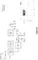
- FIG. 4Ais a circuit schematic illustrating an example RF receiver with two rectifiers for detecting changes in received RF power, in accordance with some embodiments.
- FIG. 4Bis a circuit schematic illustrating points at which a coupling mechanism may be added to the circuit, in accordance with some embodiments.
- FIG. 4Cillustrates circuit schematics for exemplary coupling mechanisms, in accordance with some embodiments, in accordance with some embodiments.
- FIG. 4Dillustrates circuit schematics for exemplary rectifiers, in accordance with some embodiments, in accordance with some embodiments.
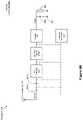
- FIG. 4Eillustrates a circuit schematics for detecting when RF power is no longer received at the antenna, in accordance with some embodiments.
- FIG. 4Fillustrates circuit schematics of simplified rectifiers, in accordance with some embodiments.
- FIG. 5Adepicts a circuit schematic illustrating a system for protecting sensitive electrical components from power surges, in accordance with some embodiments.
- FIG. 5Bdepicts a circuit schematic illustrating points at which a coupling mechanism may be added to the circuit, in accordance with some embodiments.
- FIG. 6Adepicts a circuit schematic illustrating a receiver capable of communicating with a transmitter, in accordance with some embodiments.
- FIG. 6Bdepicts a circuit schematic illustrating points at which a coupling mechanism may be added to the circuit, in accordance with some embodiments.
- FIG. 6Cillustrates is a circuit schematic illustrating exemplary components for adjusting the load of a rectifier to cause an impedance mismatch, in accordance with some embodiments.
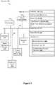
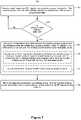
- FIG. 7is a flow diagram showing a process of a receiver communicating with a transmitter, in accordance with some embodiments.
- FIG. 1Ais a block diagram of components of wireless power transmission environment 100 , in accordance with some embodiments.
- Wireless power transmission environment 100includes, for example, transmitters 102 (e.g., transmitters 102 a , 102 b . . . 102 n ) and one or more receivers 120 (e.g., receivers 120 a , 120 b . . . 120 n ).
- each respective wireless power transmission environment 100includes a number of receivers 120 , each of which is associated with a respective electronic device 122 .
- the transmitter 102is referred to herein as a “wireless-power-transmitting device” or a “wireless power transmitter.”
- the receiver 120is referred to herein as a “wireless-power-receiving device” or a “wireless power receiver.”
- An example transmitter 102(e.g., transmitter 102 a ) includes, for example, one or more processor(s) 104 , a memory 106 , one or more antenna arrays 110 , one or more communications components 112 (also referred to herein as a “wireless communications radio,” a “communications radio” or simply a “radio”), and/or one or more transmitter sensors 114 . In some embodiments, these components are interconnected by way of a communications bus 107 . References to these components of transmitters 102 cover embodiments in which one or more of these components (and combinations thereof) are included. The components are discussed in further detail below with reference to FIG. 2 .
- a single processor 104executes software modules for controlling multiple transmitters 102 (e.g., transmitters 102 b . . . 102 n ).
- a single transmitter 102includes multiple processors 104 , such as one or more transmitter processors (configured to, e.g., control transmission of signals 116 by antenna array 110 ), one or more communications component processors (configured to, e.g., control communications transmitted by communications component 112 and/or receive communications by way of communications component 112 ) and/or one or more sensor processors (configured to, e.g., control operation of transmitter sensor 114 and/or receive output from transmitter sensor 114 ).
- the wireless power receiver 120receives power transmission signals 116 and/or communication signals 118 transmitted by transmitters 102 .
- the receiver 120includes one or more antennas 124 (e.g., an antenna array including multiple antenna elements), power converter 126 , receiver sensor 128 , and/or other components or circuitry (e.g., processor(s) 140 , memory 142 , and/or communication component(s) 144 .
- these componentsare interconnected by way of a communications bus 146 . References to these components of receiver 120 cover embodiments in which one or more of these components (and combinations thereof) are included.
- the receiver 120converts energy from received signals 116 (also referred to herein as RF power transmission signals, or simply, RF signals, RF waves, power waves, or power transmission signals) into electrical energy to power and/or charge electronic device 122 .
- the receiver 120uses the power converter 126 to convert energy derived from power waves 116 to alternating current (AC) electricity or direct current (DC) electricity to power and/or charge the electronic device 122 .
- the power converter 126include rectifiers, rectifying circuits, voltage conditioners, among suitable circuitry and devices.
- the receiver 120is a standalone device that is detachably coupled to one or more electronic devices 122 .
- the electronic device 122has processor(s) 132 for controlling one or more functions of the electronic device 122
- the receiver 120has processor(s) 140 for controlling one or more functions of the receiver 120 .
- the receiver 120is a component of the electronic device 122 .
- processors 132control functions of the electronic device 122 and the receiver 120 .
- the receiver 120includes one or more processors 140 , which communicates with processors 132 of the electronic device 122 .
- the electronic device 122includes one or more processors 132 , memory 134 , one or more communication components 136 , and/or one or more batteries 130 . In some embodiments, these components are interconnected by way of a communications bus 138 . In some embodiments, communications between electronic device 122 and receiver 120 occur via communications component(s) 136 and/or 144 . In some embodiments, communications between the electronic device 122 and the receiver 120 occur via a wired connection between communications bus 138 and communications bus 146 . In some embodiments, the electronic device 122 and the receiver 120 share a single communications bus.
- the receiver 120receives one or more power waves 116 directly from the transmitter 102 (e.g., via one or more antennas 124 ). In some embodiments, the receiver 120 harvests power waves from one or more pockets of energy created by one or more power waves 116 transmitted by the transmitter 102 .
- the transmitter 102is a near-field transmitter that transmits the one or more power waves 116 within a near-field distance (e.g., less than approximately six inches away from the transmitter 102 ). In other embodiments, the transmitter 102 is a far-field transmitter that transmits the one or more power waves 116 within a far-field distance (e.g., more than approximately six inches away from the transmitter 102 ).
- circuitrye.g., integrated circuits, amplifiers, rectifiers, and/or voltage conditioner
- circuitrye.g., integrated circuits, amplifiers, rectifiers, and/or voltage conditioner
- a rectifying circuit of the receiver 120translates the electrical energy from AC to DC for use by the electronic device 122 .
- a voltage conditioning circuitincreases or decreases the voltage of the electrical energy as required by the electronic device 122 .
- an electrical relayconveys electrical energy from the receiver 120 to the electronic device 122 .
- the electronic device 122obtains power from multiple transmitters 102 and/or using multiple receivers 120 .
- the wireless power transmission environment 100includes a plurality of electronic devices 122 , each having at least one respective receiver 120 that is used to harvest power waves from the transmitters 102 into power for charging the electronic devices 122 .
- the one or more transmitters 102adjust values of one or more characteristics (e.g., waveform characteristics, such as phase, gain, direction, amplitude, polarization, and/or frequency) of power waves 116 .
- a transmitter 102selects a subset of one or more antenna elements of antenna array 110 to initiate transmission of power waves 116 , cease transmission of power waves 116 , and/or adjust values of one or more characteristics used to transmit power waves 116 .
- the one or more transmitters 102adjust power waves 116 such that trajectories of power waves 116 converge at a predetermined location within a transmission field (e.g., a location or region in space), resulting in controlled constructive or destructive interference patterns.
- the transmitter 102may adjust values of one or more characteristics for transmitting the power waves 116 to account for changes at the wireless power receiver that may negatively impact transmission of the power waves 116 .
- the transmitter 102utilizes beamforming techniques to wirelessly transfer power to a receiver 120 , while in other embodiments, the transmitter 102 does not utilize beamforming techniques to wirelessly transfer power to a receiver 120 (e.g., in circumstances in which no beamforming techniques are used, the transmitter controller IC 160 discussed below might be designed without any circuitry to allow for use of beamforming techniques, or that circuitry may be present, but might be deactivated to eliminate any beamforming control capability).
- respective antenna arrays 110 of the one or more transmitters 102may include a set of one or more antennas configured to transmit the power waves 116 into respective transmission fields of the one or more transmitters 102 .
- Integrated circuits ( FIG. 1C ) of the respective transmitter 102such as a controller circuit (e.g., a radio frequency integrated circuit (RFIC)) and/or waveform generator, may control the behavior of the antennas. For example, based on the information received from the receiver 120 by way of the communication signal 118 , a controller circuit (e.g., processor 104 of the transmitter 102 , FIG.
- a controller circuite.g., processor 104 of the transmitter 102 , FIG.
- the controller circuitmay determine values of the waveform characteristics (e.g., amplitude, frequency, trajectory, direction, phase, polarization, among other characteristics) of power waves 116 that would effectively provide power to the receiver 120 , and in turn, the electronic device 122 .
- the controller circuitmay also identify a subset of antennas from the antenna arrays 110 that would be effective in transmitting the power waves 116 .
- a waveform generator circuit(not shown in FIG. 1A ) of the respective transmitter 102 coupled to the processor 104 may convert energy and generate the power waves 116 having the specific values for the waveform characteristics identified by the processor 104 /controller circuit, and then provide the power waves to the antenna arrays 110 for transmission.
- the communications component 112transmits communication signals 118 by way of a wired and/or wireless communication connection to the receiver 120 .
- the communications component 112generates communication signals 118 used for triangulation of the receiver 120 (e.g., test signals).
- the communication signals 118are used to convey information between the transmitter 102 and receiver 120 for adjusting values of one or more waveform characteristics used to transmit the power waves 116 (e.g., convey amounts of power derived from RF test signals).
- the communication signals 118include information related to status, efficiency, user data, power consumption, billing, geo-location, and other types of information.
- the communications component 112transmits communication signals 118 to the receiver 120 by way of the electronic device 122 a .
- the communications component 112may convey information to the communications component 136 of the electronic device 122 a , which the electronic device 122 a may in turn convey to the receiver 120 (e.g., via bus 138 ).
- the communications component 112includes a communications component antenna for communicating with the receiver 120 and/or other transmitters 102 (e.g., transmitters 102 b through 102 n ).
- these communication signals 118are sent using a first channel (e.g., a first frequency band) that is independent and distinct from a second channel (e.g., a second frequency band distinct from the first frequency band) used for transmission of the power waves 116 .
- the receiver 120includes a receiver-side communications component 144 configured to communicate various types of data with one or more of the transmitters 102 , through a respective communication signal 118 generated by the receiver-side communications component (in some embodiments, a respective communication signal 118 is referred to as an advertising signal).
- the datamay include location indicators for the receiver 120 and/or electronic device 122 , a power status of the device 122 , status information for the receiver 120 , status information for the electronic device 122 , status information about the power waves 116 , and/or status information for pockets of energy.
- the receiver 120may provide data to the transmitter 102 , by way of the communication signal 118 , regarding the current operation of the system 100 , including: information identifying a present location of the receiver 120 or the device 122 , an amount of energy (i.e., usable power) received by the receiver 120 , and an amount of power received and/or used by the electronic device 122 , among other possible data points containing other types of information.
- the data contained within communication signals 118is used by the electronic device 122 , the receiver 120 , and/or the transmitters 102 for determining adjustments to values of one or more waveform characteristics used by the antenna array 110 to transmit the power waves 116 .
- the transmitter 102uses a communication signal 118 to communicate data that is used, e.g., to identify receivers 120 within a transmission field, identify electronic devices 122 , determine safe and effective waveform characteristics for power waves, and/or hone the placement of pockets of energy.
- the receiver 120uses a communication signal 118 to communicate data for, e.g., alerting transmitters 102 that the receiver 120 has entered or is about to enter a transmission field(e.g., come within wireless-power-transmission range of a transmitter 102 ), provide information about the electronic device 122 , provide user information that corresponds to the electronic device 122 , indicate the effectiveness of received power waves 116 , and/or provide updated characteristics or transmission parameters that the one or more transmitters 102 use to adjust transmission of the power waves 116 .
- a communication signal 118to communicate data for, e.g., alerting transmitters 102 that the receiver 120 has entered or is about to enter a transmission field(e.g., come within wireless-power-transmission range of a transmitter 102 ), provide information about the electronic device 122 , provide user information that corresponds to the electronic device 122 , indicate the effectiveness of received power waves 116 , and/or provide updated characteristics or transmission parameters that the one or more transmitters 102 use to adjust transmission of the power waves
- the receiver 120does not include a distinct communications component 144 . Rather, the receiver 120 is configured to reflect RF signals transmitted by the transmitter 102 at the one or more antennas 124 and, importantly, modulate the reflected RF signals to convey data (or a message) to transmitter 102 . In such embodiments, the transmitter 102 may also lack a distinct communications component. Instead, the transmitter 102 may receive the reflected RF signals at the one or more antenna arrays 110 , and the transmitter 102 may demodulate the reflected RF signals in order to interpret them. Reflecting RF signals by the receiver 120 is discussed in further detail below with reference to FIGS. 6A-6C .
- transmitter sensor 114 and/or receiver sensor 128detect and/or identify conditions of the electronic device 122 , the receiver 120 , the transmitter 102 , and/or a transmission field.
- data generated by the transmitter sensor 114 and/or receiver sensor 128is used by the transmitter 102 to determine appropriate adjustments to values of one or more waveform characteristics used to transmit the power waves 116 .
- Data from transmitter sensor 114 and/or receiver sensor 128 received by the transmitter 102includes, e.g., raw sensor data and/or sensor data processed by a processor 104 , such as a sensor processor. Processed sensor data includes, e.g., determinations based upon sensor data output.
- sensor data received from sensors that are external to the receiver 120 and the transmitters 102is also used (such as thermal imaging data, information from optical sensors, and others).
- FIG. 1Bis another block diagram of an RF wireless power transmission system 150 in accordance with some embodiments.
- the RF wireless power transmission system 150includes a far-field transmitter (not shown).
- the RF wireless power transmission system 150includes a RF charging pad 151 (also referred to herein as a near-field (NF) charging pad 151 or RF charging pad 151 ).
- the RF charging pad 151may be an example of the transmitter 102 in FIG. 1A .
- the RF charging pad 151includes an RF power transmitter integrated circuit 160 (described in more detail below).
- the RF charging pad 151includes one or more optional communications components 112 (e.g., wireless communication components, such as WI-FI or BLUETOOTH radios).
- the RF charging pad 151does not include the optional communications components 112 .
- the RF charging pad 151includes alternative means for communicating with other devices (e.g., the RF charging pad 151 receives and interprets RF signals reflected by a receiver 120 ).
- the RF charging pad 151also connects to one or more power amplifier units 108 - 1 , . . .
- RF poweris controlled and modulated at the RF charging pad 151 via switch circuitry as to enable the RF wireless power transmission system to send RF power to one or more wireless receiving devices via the TX antenna array 110 .
- the optional communication component(s) 112enable communication between the RF charging pad 151 and one or more communication networks, and are discussed in further detail above with reference to FIG. 1A .
- the communication component(s) 112are not able to communicate with wireless power receivers for various reasons, e.g., because there is no power available for the communication component(s) to use for the transmission of data signals or because the wireless power receiver 120 itself does not actually include any communication component of its own. As such, it is important to design near-field charging pads that are still able to uniquely identify different types of devices and, when a wireless power receiver is detected, figure out if that wireless power receiver is authorized to receive wireless power.
- FIG. 1Cis a block diagram of the RF power transmitter integrated circuit 160 (the “integrated circuit”) in accordance with some embodiments.
- the integrated circuit 160includes a CPU subsystem 170 , an external device control interface, an RF subsection for DC to RF power conversion, and analog and digital control interfaces interconnected via an interconnection component, such as a bus or interconnection fabric block 171 .
- the CPU subsystem 170includes a microprocessor unit (CPU) 202 with related Read-Only-Memory (ROM) 172 for device program booting via a digital control interface, e.g.
- CPUmicroprocessor unit
- ROMRead-Only-Memory
- the CPU subsystem 170also includes an encryption module or block 176 to authenticate and secure communication exchanges with external devices, such as wireless power receivers that attempt to receive wirelessly delivered power from the RF charging pad 150 .
- the RF IC 160also includes (or is in communication with) a power amplifier controller IC 161 A (PA IC) that is responsible for controlling and managing operations of a power amplifier (or multiple power amplifiers), including for reading measurements of impedance at various measurement points within the power amplifier 108 , whereby these measurements are used, in some instances, for detecting of foreign objects.
- PA ICpower amplifier controller IC 161 A
- the PA IC 161 Amay be on the same integrated circuit at the RF IC 160 , or may be on its on integrated circuit that is separate from (but still in communication with) the RF IC 160 . Additional details regarding the architecture and operation of the PA IC are provided in U.S. Provisional Application No. 62/903,677, the disclosure of which is incorporated by reference herein in its entirety.
- executable instructions running on the CPUare used to manage operation of the RF charging pad 151 and to control external devices through a control interface, e.g., SPI control interface 175 , and the other analog and digital interfaces included in the RF power transmitter integrated circuit 160 .
- the CPU subsystemalso manages operation of the RF subsection of the RF power transmitter integrated circuit 160 , which includes an RF local oscillator (LO) 177 and an RF transmitter (TX) 178 .
- LORF local oscillator
- TXRF transmitter
- the RF LO 177is adjusted based on instructions from the CPU subsystem 170 and is thereby set to different desired frequencies of operation, while the RF TX converts, amplifies, modulates the RF output as desired to generate a viable RF power level.
- antenna zones and power-transfer zonesmay include antenna elements that transmit propagating radio frequency waves but, in other embodiments, the antenna/power transfer zones may instead include capacitive charging couplers that convey electrical signals but do not send propagating radio frequency waves.
- the RF power transmitter integrated circuit 160provides the viable RF power level (e.g., via the RF TX 178 ) to an optional beamforming integrated circuit (IC) 109 , which then provides phase-shifted signals to one or more power amplifiers 108 .
- the beamforming IC 109is used to ensure that power transmission signals sent using two or more antennas 210 (e.g., each antenna 210 may be associated with a different antenna zone 290 or may each belong to a single antenna zone 290 ) to a particular wireless power receiver are transmitted with appropriate characteristics (e.g., phases) to ensure that power transmitted to the particular wireless power receiver is maximized (e.g., the power transmission signals arrive in phase at the particular wireless power receiver).
- the beamforming IC 109forms part of the RF power transmitter IC 160 .
- capacitive couplerse.g., capacitive charging couplers 244
- optional beamforming IC 109may not be included in the RF power transmitter integrated circuit 160 .
- the RF power transmitter integrated circuit 160provides the viable RF power level (e.g., via the RF TX 178 ) directly to the one or more power amplifiers 108 and does not use the beamforming IC 109 (or bypasses the beamforming IC if phase-shifting is not required, such as when only a single antenna 210 is used to transmit power transmission signals to a wireless power receiver).
- the PA IC 161 Areceives the viable RF power level and provides that to the one or more power amplifiers 108 .
- the one or more power amplifiers 108then provide RF signals to the antenna zones 290 (also referred to herein as “power-transfer zones”) for transmission to wireless power receivers that are authorized to receive wirelessly delivered power from the RF charging pad 151 .
- each antenna zone 290is coupled with a respective PA 108 (e.g., antenna zone 290 - 1 is coupled with PA 108 - 1 and antenna zone 290 -N is coupled with PA 108 -N).
- multiple antenna zonesare each coupled with a same set of PAs 108 (e.g., all PAs 108 are coupled with each antenna zone 290 ).
- PAs 108to antenna zones 290 allow the RF charging pad 151 to sequentially or selectively activate different antenna zones in order to determine the most efficient antenna zone 290 to use for transmitting wireless power to a wireless power receiver.
- the one or more power amplifiers 108are also in communication with the CPU subsystem 170 to allow the CPU 202 to measure output power provided by the PAs 108 to the antenna zones 110 of the RF charging pad 151 .
- FIG. 1Calso shows that, in some embodiments, the antenna zones 290 of the RF charging pad 151 may include one or more antennas 210 A-N.
- each antenna zone of the plurality of antenna zones 290includes one or more antennas 210 (e.g., antenna zone 290 - 1 includes one antenna 210 -A and antenna zones 290 -N includes multiple antennas 210 ).
- a number of antennas included in each of the antenna zonesis dynamically defined based on various parameters, such as a location of a wireless power receiver on the RF charging pad 151 .
- each antenna zone 290may include antennas of different types, while in other embodiments each antenna zone 290 may include a single antenna of a same type, while in still other embodiments, the antennas zones may include some antenna zones that include a single antenna of a same type and some antenna zones that include antennas of different types. In some embodiments the antenna/power-transfer zones may also or alternatively include capacitive charging couplers that convey electrical signals but do not send propagating radio frequency waves.
- the RF charging pad 151may also include a temperature monitoring circuit that is in communication with the CPU subsystem 170 to ensure that the RF charging pad 151 remains within an acceptable temperature range. For example, if a determination is made that the RF charging pad 151 has reached a threshold temperature, then operation of the RF charging pad 151 may be temporarily suspended until the RF charging pad 151 falls below the threshold temperature.
- RF power transmitter circuit 160By including the components shown for RF power transmitter circuit 160 ( FIG. 1C ) on a single chip, such transmitter chips are able to manage operations at the transmitter chips more efficiently and quickly (and with lower latency), thereby helping to improve user satisfaction with the charging pads that are managed by these transmitter chips.
- the RF power transmitter circuit 160is cheaper to construct, has a smaller physical footprint, and is simpler to install.
- FIG. 1Dis a block diagram of a charging pad 294 in accordance with some embodiments.
- the charging pad 294is an example of the charging pad 151 ( FIG. 1B ), however, one or more components included in the charging pad 151 are not included in the charging pad 294 for ease of discussion and illustration.
- the charging pad 294includes an RF power transmitter integrated circuit 160 , one or more power amplifiers 108 , a PA IC 161 A (which may be on the same or a separate IC from the RF power transmitter IC 160 ), and a transmitter antenna array 290 having multiple antenna zones. Each of these components is described in detail above with reference to FIGS. 1A-1C . Additionally, the charging pad 294 includes a switch 295 (i.e., transmitter-side switch), positioned between the power amplifiers 108 and the antenna array 290 , having a plurality of switches 297 -A, 297 -B, . . . 297 -N. The switch 295 is configured to switchably connect one or more power amplifiers 108 with one or more antenna zones of the antenna array 290 in response to control signals provided by the RF power transmitter integrated circuit 160 .
- a switch 295i.e., transmitter-side switch
- each switch 297is coupled with (e.g., provides a signal pathway to) a different antenna zone of the antenna array 290 .
- switch 297 -Amay be coupled with a first antenna zone 290 - 1 ( FIG. 1C ) of the antenna array 290
- switch 297 -Bmay be coupled with a second antenna zone 290 - 2 of the antenna array 290 , and so on.
- Each of the plurality of switches 297 -A, 297 -B, . . . 297 -Nonce closed, creates a unique pathway between a respective power amplifier 108 (or multiple power amplifiers 108 ) and a respective antenna zone of the antenna array 290 .
- Each unique pathway through the switch 295is used to selectively provide RF signals to specific antenna zones of the antenna array 290 . It is noted that two or more of the plurality of switches 297 -A, 297 -B, . . . 297 -N may be closed at the same time, thereby creating multiple unique pathways to the antenna array 290 that may be used simultaneously.
- the RF power transmitter integrated circuit 160(or the PA IC 161 A, or both) is (are) coupled to the switch 295 and is configured to control operation of the plurality of switches 297 -A, 297 -B, . . . 297 -N (illustrated as a “control out” signal in FIGS. 1B and 1D ).
- the RF power transmitter integrated circuit 160may close a first switch 297 -A while keeping the other switches open.
- the RF power transmitter integrated circuit 160may close a first switch 297 -A and a second switch 297 -B, and keep the other switches open (various other combinations and configuration are possible).
- the RF power transmitter integrated circuit 160is coupled to the one or more power amplifiers 108 and is configured to generate a suitable RF signal (e.g., the “RF Out” signal) and provide the RF signal to the one or more power amplifiers 108 .
- the one or more power amplifiers 108are configured to provide the RF signal to one or more antenna zones of the antenna array 290 via the switch 295 , depending on which switches 297 in the switch 295 are closed by the RF power transmitter integrated circuit 160 .
- the charging padis configured to transmit test power transmission signals and/or regular power transmission signals using different antenna zones, e.g., depending on a location of a receiver on the charging pad. Accordingly, when a particular antenna zone is selected for transmitting test signals or regular power signals, a control signal is sent to the switch 295 from the RF power transmitter integrated circuit 160 to cause at least one switch 297 to close. In doing so, an RF signal from at least one power amplifier 108 can be provided to the particular antenna zone using a unique pathway created by the now-closed at least one switch 297 .
- the switch 295may be part of (e.g., internal to) the antenna array 290 .
- the switch 295is separate from the antenna array 290 (e.g., the switch 295 may be a distinct component, or may be part of another component, such as the power amplifier(s) 108 ). It is noted that any switch design capable of accomplishing the above may be used, and the design of the switch 295 illustrated in FIG. 1D is merely one example.
- FIG. 2is a block diagram illustrating a representative transmitter device 102 (also sometimes referred to herein as a transmitter 102 , a wireless power transmitter 102 , and a wireless-power-transmitting device 102 ) in accordance with some embodiments.
- the transmitter device 102includes one or more processors 104 (e.g., CPUs, ASICs, FPGAs, microprocessors, and the like), one or more optional communication components 112 (e.g., radios), memory 106 , one or more antennas 110 , and one or more communication buses 108 for interconnecting these components (sometimes called a chipset).
- the transmitter device 102includes one or more sensors 114 as described above with reference to FIG. 1A .
- the transmitter device 102includes one or more output devices such as one or more indicator lights, a sound card, a speaker, a small display for displaying textual information and error codes, etc.
- the transmitter device 102includes a location detection device, such as a GPS (global positioning satellite) or other geo-location receiver, for determining the location of the transmitter device 102 .
- GPSglobal positioning satellite
- the communication components 112enable communication between the transmitter 102 and the receiver 120 (e.g., one or more communication networks).
- the communication components 112include, e.g., hardware capable of data communications using any of a variety of wireless protocols (e.g., IEEE 802.15.4, Wi-Fi, ZigBee, 6LoWPAN, Thread, Z-Wave, Bluetooth Smart, ISA100.11a, WirelessHART, MiWi, etc.) wired protocols (e.g., Ethernet, HomePlug, etc.), and/or any other suitable communication protocol, including communication protocols not yet developed as of the filing date of this document.
- wireless protocolse.g., IEEE 802.15.4, Wi-Fi, ZigBee, 6LoWPAN, Thread, Z-Wave, Bluetooth Smart, ISA100.11a, WirelessHART, MiWi, etc.
- wired protocolse.g., Ethernet, HomePlug, etc.
- any other suitable communication protocolincluding communication protocols not yet developed as of the filing date of this document
- the memory 106includes high-speed random access memory, such as DRAM, SRAM, DDR SRAM, or other random access solid state memory devices; and, optionally, includes non-volatile memory, such as one or more magnetic disk storage devices, one or more optical disk storage devices, one or more flash memory devices, or one or more other non-volatile solid state storage devices.
- the memory 106or alternatively the non-volatile memory within memory 106 , includes a non-transitory computer-readable storage medium.
- Each of the above-identified elementsis optionally stored in one or more of the previously mentioned memory devices, and corresponds to a set of instructions for performing the function(s) described above.
- the above identified modules or programse.g., sets of instructions
- the memory 106optionally, stores a subset of the modules and data structures identified above.
- the memory 106optionally, stores additional modules and data structures not described above, such as a tracking module for tracking the movement and positioning of objects within a transmission field.
- FIG. 3is a block diagram illustrating a representative receiver device 120 (also referred to herein as a receiver 120 , a wireless power receiver 120 , and a wireless-power-receiving device 120 ) in accordance with some embodiments.
- the receiver device 120includes one or more processors 140 (e.g., CPUs, ASICs, FPGAs, microprocessors, and the like), one or more optional communication components 144 , memory 142 , one or more antennas 124 , power harvesting circuitry 310 , and one or more communication buses 308 for interconnecting these components (sometimes called a chipset).
- the receiver device 120includes one or more sensors 128 such as one or sensors described above with reference to FIG. 1A .
- the receiver device 120includes an energy storage device 312 for storing energy harvested via the power harvesting circuitry 310 .
- the energy storage device 312includes one or more batteries (e.g., battery 130 , FIG. 1A ), one or more capacitors, one or more inductors, and the like.
- the receiver 120is internally or externally connected to an electronic device (e.g., electronic device 122 a , FIG. 1A ) via a connection 138 (e.g., a bus).
- a connection 138e.g., a bus
- the energy storage device 312is part of the electronic device.
- the power harvesting circuitry 310includes one or more rectifying circuits and/or one or more power converters. In some embodiments, the power harvesting circuitry 310 includes one or more components (e.g., a power converter 126 ) configured to convert energy from power waves and/or energy pockets to electrical energy (e.g., electricity). In some embodiments, the power harvesting circuitry 310 is further configured to supply power to a coupled electronic device (e.g., an electronic device 122 ), such as a laptop or phone. In some embodiments, supplying power to a coupled electronic device include translating electrical energy from an AC form to a DC form (e.g., usable by the electronic device 122 ).
- a coupled electronic devicee.g., an electronic device 122
- supplying power to a coupled electronic deviceinclude translating electrical energy from an AC form to a DC form (e.g., usable by the electronic device 122 ).
- the communication component(s) 144enable communication between the receiver 120 and the transmitter 102 (e.g., via one or more communication networks).
- the communication component(s) 144include, e.g., hardware capable of data communications using any of a variety of custom or standard wireless protocols (e.g., IEEE 802.15.4, Wi-Fi, ZigBee, 6LoWPAN, Thread, Z-Wave, Bluetooth Smart, ISA100.11a, WirelessHART, MiWi, etc.) custom or standard wired protocols (e.g., Ethernet, HomePlug, etc.), and/or any other suitable communication protocol, including communication protocols not yet developed as of the filing date of this document.
- custom or standard wireless protocolse.g., IEEE 802.15.4, Wi-Fi, ZigBee, 6LoWPAN, Thread, Z-Wave, Bluetooth Smart, ISA100.11a, WirelessHART, MiWi, etc.
- custom or standard wired protocolse.g., Ethernet, HomePlug, etc.
- the receiver 120may utilize a built-in communication component (e.g., a Bluetooth radio) or an electronic device with which the receiver 120 is coupled, and therefore, in these embodiments, the receiver 120 may not include its own communication component. In some other embodiments, the receiver 120 does not include a distinct communication component 144 . Rather, the receiver 120 may use an in-band communication technique to communicate with other devices, as explained below with reference to FIGS. 6A-6C and FIG. 7 .
- a built-in communication componente.g., a Bluetooth radio
- the receiver 120does not include a distinct communication component 144 . Rather, the receiver 120 may use an in-band communication technique to communicate with other devices, as explained below with reference to FIGS. 6A-6C and FIG. 7 .
- the memory 142includes high-speed random access memory, such as DRAM, SRAM, DDR SRAM, or other random access solid state memory devices; and, optionally, includes non-volatile memory, such as one or more magnetic disk storage devices, one or more optical disk storage devices, one or more flash memory devices, or one or more other non-volatile solid state storage devices.
- the memory 142or alternatively the non-volatile memory within memory 142 , includes a non-transitory computer-readable storage medium.
- the power receiving module 320communicates the amount of power to the communication module 316 , which communicates the amount of power to other remote devices (e.g., transmitter 102 , FIGS. 1-2 ). Moreover, in some embodiments, the power receiving module 320 may communicate the amount of power to database 322 (e.g., the database 322 stores the amount of power derived from one or more power waves 116 ).
- the power receiving module 321instructs the communication module 316 to transmit distinct transmissions to the remote devices (e.g., a first communication signal that indicates a first amount of power received by the receiver (e.g., by a first test signal from the transmitter 102 ), a second communication signal that indicates a second amount of power received by the receiver (e.g., by a second test signal from the transmitter 102 ), and so on if needed).
- the power receiving module 320instructs the communication module 316 to transmit data packets to the remote devices (e.g., a respective data packet can include information for multiple test signals transmitted by the transmitter 102 ).
- Each of the above identified elementsis optionally stored in one or more of the previously mentioned memory devices, and corresponds to a set of instructions for performing the function(s) described above.
- the above identified modules or programs(e.g., sets of instructions) need not be implemented as separate software programs, procedures, or modules, and thus various subsets of these modules are optionally combined or otherwise rearranged in various embodiments.
- the memory 142optionally, stores a subset of the modules and data structures identified above.
- the memory 142optionally, stores additional modules and data structures not described above, such as an identifying module for identifying a device type of a connected device (e.g., a device type for an electronic device 122 ).
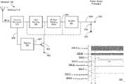
- FIG. 4Ais a schematic of a representative receiver 120 in accordance with some embodiments.
- the representative receiver 120is an example of the receiver 120 ( FIG. 3 ).
- the components in FIG. 4Aare illustrated in a particular arrangement for ease of illustration and one skilled in the art will appreciate that other arrangements are possible.
- various example featuresare illustrated, various other features have not been illustrated for the sake of brevity and so as not to obscure pertinent aspects of the example implementations disclosed herein.
- the receiver 120includes an antenna 413 capable of receiving wireless power transmission signals (e.g., power waves 116 ). Once the wireless power transmission signals are received at the antenna 413 and converted to an alternating current, the alternating current is sent to an input of the coupling mechanism 410 .
- Some examples of coupling mechanism 410are illustrated in FIG. 4C .
- the coupling mechanism 410has two outputs (a first output that supplies AC alternating current the first rectifier 401 , and a second output that supplies the alternating current to the second rectifier), and each output receives a portion of the alternating current received at the input of the coupling mechanism.
- the coupling mechanismis configured to send all but ⁇ 30 dB to ⁇ 40 dB of the alternating current to the first output of the coupling mechanism 410 , and sending the remaining ⁇ 30 to ⁇ 40 dB of the alternating current to the second output of the coupling mechanism 410 .
- the first output of the coupling mechanism 410is coupled to an input of an input matching network 403 , which is configured to match the impedance of the first rectifier with the impedance of the antenna 413 .
- an input matching network 403is shown, it is possible to have multiple input matching networks, as illustrated by numeral 403 - n in FIG. 4B .
- the matching networkis designed to match the impedance between the source (e.g., the antenna 413 ) and the load (e.g., the rectifier 401 ).
- the output of the matching network(s)is (are) coupled to the first rectifier 401 .
- the first rectifieris configured to convert all but ⁇ 30 dB to ⁇ 40 dB of the alternating current to direct current.
- the output of the first rectifier 401is coupled in parallel to both a capacitor 404 , and the charging components Z L 406 .
- the capacitor 404which is also coupled to the ground, is designed to reduce ripple in the direct current output by the first rectifier 401 , and has a capacitance that matches a direct current of the output of the first rectifier. With larger loads (i.e., rectifier outputs), a larger capacitance may be required, and when there is a larger capacitance, the capacitor takes a longer time to charge and discharge (i.e., the voltage to reach a steady state), which slows the response time of detecting whether power is no longer being received at the antenna 413 .
- the second output of the coupling mechanismis coupled to the second rectifier 402 .
- the second rectifier 402converts the remaining ⁇ 30 dB to ⁇ 40 dB of the wireless power transmission signals into direct current. Since this ⁇ 30 dB to ⁇ 40 dB is roughly less than 1% of the amount of wireless power transmission signals received at the antenna 413 , the capacitor 405 associated with the second rectifier 402 has a lower capacitance (relative to the capacitance of the capacitor 404 ). Consequently, the capacitor 405 in FIG. 4A can charge up and discharge rapidly in comparison to the capacitor 404 coupled to the output of the first rectifier 401 .
- the direct current and/or voltage measuring components (“V AUX ”) 409 - 1detect changes in direct current power levels and/or voltage levels in a shorter time span than the measuring components included in the charging components Z L 406 .
- the measuring components (“V AUX ”) 409 - 1detect the change in wireless power transmission signals by either a change in voltage and/or direct current, and can then instruct the charging components Z L 406 components to prepare for a change in power once the capacitor 404 is either discharging or fully charged.
- the second rectifier 402is also optionally coupled with two resistors in series (resistor 407 and resistor 408 ). Between these two resistors, a voltage measurement can also be taken, which acts as another measurement component (“V AUX_DIV ”) 409 - 2 .
- V AUX_DIVanother measurement component
- Such an arrangement of resistorsis capable of stepping down the voltage, which allows for measuring components to have a lower voltage threshold to determine whether power is increasing or no longer being received.
- the resistance of these resistorscan be varied depending on the acceptable voltage level of the direct current measuring components. In some embodiments, these resistors are variable resistors and are adjusted by a control.
- resistor 408is also coupled to the ground.
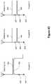
- graph 400 -Acompares a single rectifier system against a dual rectifier system.
- the graphshows at time “t 1 ” that the RF power (i.e. the wireless power transmission signals) starts to be received at the antenna 413 .
- V OUTshows the output of direct current at the output of the first rectifier.
- V AUXshows the measuring component 409 - 1 , which shows the output of the second rectifier 402 .
- V AUX_DIVshows a second measurement point 409 - 2 that has had its voltage stepped down by the two resistors, which can be used to activate a measuring component that has a lower voltage threshold.
- the received RF power inputremains constant and does not change.
- the “V OUT ” measuring componentsare still seeing a rise in voltage, as opposed to a constant voltage. Only once the voltage has settled can the system utilize the converted direct current (DC) (power). While the system is waiting for the voltage to settle, it is not aware that incoming power is going to the charging components Z L 406 .
- DCdirect current
- a second rectifier 402is used in conjunction with a capacitor 405 with a smaller capacitance (relative to capacitor 404 ) that allows the voltage to settle at time “t 2 .”
- the systemcan communicate with the charging components Z L 406 , (e.g., warn those components that incoming power is coming despite “V OUT ” not yet being settled).
- the first rectifier and capacitor 404Only at time “t 3 ” does the first rectifier and capacitor 404 produce a settled voltage that can be used by the system.
- the RF poweris no longer being received at the antenna 413 .
- the smaller capacitance capacitor 405is able to settle to a voltage level that indicates that there is no longer any RF power being received at the antenna 413 (e.g., 0 volts).
- the control systemcan notify the charging components Z L 406 that they should prepare for powering down.
- the charging components of the wireless power receiverbenefit from an early warning from the smaller capacitor 405 that power is no longer being received because the charging components avoid having to wait on the capacitor's 404 long discharge time before beginning shutdown. Consequently, the early warning from the smaller capacitor 405 allows the charging components to prepare for a power down in anticipation of a loss of power, thus prolonging a life of the wireless power receiver (and potentially components in the device to be charged).
- FIG. 4A at bottomdescribes a receiver 120 that can apportion a small amount of its received wireless power for the purpose of improving reliability of the main components of the circuit (i.e., Z L 406 components) by warning these components that a change in power is occurring. This improved reliability is achieved by anticipating a shutdown, which is discussed in detail in the preceding paragraph.
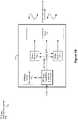
- FIG. 4Bis a schematic that illustrates alternative embodiments to those discussed with reference to FIG. 4A .
- FIG. 4Bshows alternative locations at which the coupling mechanism 410 can be coupled to the circuit, and still perform the same on-and-off detection as discussed in detail with respect to FIG. 4A . While some example features are illustrated, various other features, which were shown in FIG. 4A , have not been illustrated in FIG. 4D for the sake of brevity and so as not to obscure pertinent aspects of the example implementations disclosed herein.
- FIG. 4A and FIG. 4Binclude the addition of first capacitor 404 - a and second capacitor 404 - b , and at least a second matching network identified as N th input matching network 403 - n . Additionally, four vertical dotted lines represent the different locations that the coupling mechanism 410 can be coupled to the circuit. As shown, the coupling mechanism can be coupled to the circuit at a point before a first capacitor 404 - a . Alternatively, the coupling mechanism 410 may also be coupled after the first capacitor 404 - a , but before the second capacitor 404 - b . The next location at which the coupling mechanism 410 can be coupled to the circuit is the same location as the one shown in FIG. 4A .
- the coupling mechanism 410can be coupled to the circuit between any of the input matching networks. This is illustrated by the coupling mechanism 410 being placed after the input matching network 403 , but before the coupling mechanism 4 ′ 0 being placed before the N th input matching network 403 - n .
- the N th input matching network 403 - nrepresents the last input matching network.
- FIG. 4Cis schematic illustrating three separate coupling mechanism embodiments.
- the coupling mechanism 410is a directional coupler, shown in FIG. 4C as “Coupler A.”
- the directional couplerconsists of two separate paths, the first path 458 and the second path 459 .
- the first path 458is the path that is coupled to the antenna 413 .
- Path 458is also ultimately connected to the first rectifier 401 .
- the second path 459is placed within a certain proximity to the first path 458 so as to allow a portion of the RF signals to bleed off to the second path 459 .
- the second path 459is ultimately coupled to the second rectifier 402 , as shown in FIG. 4A .
- the second path 459includes a resistor 456 that is coupled to a ground 457 .
- FIG. 4Calso includes schematics for illustrating a capacitive coupler, shown in FIG. 4C as “Coupler B.”
- the capacitive couplerconsists of two separate paths, the first path 460 and the second path 461 .
- the first path 460is the path that is coupled to the antenna 413 .
- Path 460is also ultimately connected to the first rectifier 401 .
- the second path 461is coupled between the first capacitor 462 and second capacitor 463 .
- the second path 461is ultimately coupled to the second rectifier 402 , as shown in FIG. 4A .
- the second capacitor 463is also coupled to a ground 464 .
- FIG. 4Calso includes schematics for illustrating a resistive coupler, shown in FIG. 4C as “Coupler C.”
- the capacitive couplerconsists of two separate paths, the first path 465 and the second path 466 .
- the first path 465is the path that is coupled to the antenna 413 .
- Path 465is also ultimately connected to the first rectifier 401 .
- the second path 466is coupled between the first resistor 467 and second resistor 468 .
- the second path 466is ultimately coupled to the second rectifier 402 , as shown in FIG. 4A .
- the second resistor 486is also coupled to a ground 469 .
- FIG. 4Dshows two schematics for rectifiers.
- Rectifier “A”illustrates a diode based rectifier.
- the input to the rectifier systemis shown as input 448 , which is coupled to an anode of a diode 450 , and coupled in parallel to the cathode of a diode 451 .
- the cathode of the diode 450is coupled to the output of the rectifier system, as shown as output 449 , while the anode of the diode 451 is coupled to the ground 452 .
- FIG. 4Dalso shows a schematic for a second rectifier, rectifier “B.”
- Rectifier “B”is a diode connected transistor based rectifier.
- input 448the input to the rectifier system is shown as input 448 , which is coupled, in parallel, to a first diode connected transistor 453 , and a second diode connected transistor 454 .
- the first diode connected transistor 453is coupled to the output of the rectifier system, as shown as output 449
- the second diode connected transistor 454is coupled to the ground 455 .
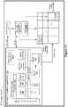
- FIG. 4Eshows a schematic of a receiver 120 that is similar to the receiver shown in FIG. 4A .
- the receiver shown in FIG. 4Edoes not include a coupling mechanism.
- the purpose of the circuit shown in FIG. 4Eis for detecting when the wireless power transmission signals are no longer being received at the antenna 413 , without the use of a coupling mechanism. When the power is no longer detected the receiver can warn components that are coupled to the output of the first rectifier 401 that the charging components 406 need to prepare for shutdown.
- the schematicitself shows an antenna 413 that is coupled to an input of an input matching network 403 .
- the output of the input matching network 403is coupled to two rectifiers 401 , 402 in parallel. Some examples of more simplified rectifiers are shown in FIG. 4F .
- the output of the rectifier 401is coupled in parallel to the both a capacitor 404 and charging components “Z L ” 406 .
- the capacitor 404which is also coupled to the ground 438 , is designed to reduce ripple in the DC output by the first rectifier 401 , and has a capacitance that matches the DC load of the output of the first rectifier 401 .
- the capacitor 404takes a longer time to charge and discharge (i.e., for the voltage to reach a steady state), which slows the response time of detecting whether power is no longer being received at the antenna 413 .
- the second output of the input matching network 403is coupled to the second rectifier 402 .
- the capacitor 405 in FIG. 4Ecan charge up and discharge more rapidly in comparison to the capacitor 404 coupled to the output of the first rectifier 401 .
- the components coupled to the output of the rectifier 402require a less drastic ripple reduction as compared to the components coupled to the output of the rectifier 401 .
- a smaller capacitance capacitor 405can be used that allows for faster discharge times and, consequently, the DC and/or voltage measuring components (“V AUX ”) 409 - 1 detect changes in DC power levels and/or voltage levels in a shorter time span than the measuring components included in the charging components Z L 406 .
- the measuring components (“V AUX ”) 409 - 1detect the change in wireless power transmission signals by a change in voltage and/or DC current, and can then instruct the charging components Z L 406 to prepare for a change in power once the capacitor 405 either starts discharging or is fully discharged.
- the second rectifier 402is also optionally coupled to two resistors in series (resistor 407 and resistor 408 , which are coupled to the ground 437 ). Between these two resistors a voltage measurement can also be taken, which acts as another measurement component (“V AUX_DIV ”) 409 - 2 .
- V AUX_DIVanother measurement component
- Such an arrangement of resistorsis capable of stepping down the voltage, which allows for measuring components to have a lower voltage threshold to determine whether power is no longer being received.
- the resistance of these resistorscan be varied depending on the acceptable voltage level of the DC measuring components. In some embodiments, these resistors are variable resistors and are adjusted by a control.
- graph 400 -Bcompares a single rectifier system to a dual rectifier system.
- the graphshows at time “t 1 ” that RF power (i.e. wireless power transmission signals) are received at the antenna 413 .
- V OUTshows the output of DC at the output of the first rectifier.
- V AUXshows the measuring component 409 - 1 , which shows the output of the second rectifier 402 .
- V AUX_DIVshows a second measurement point 409 - 2 that has had its voltage stepped down by the two resistors, which can be used to activate a measuring component that has a lower voltage threshold.
- the first rectifier 401 and capacitor 404produce a settled voltage that can be used by the charging components Z L 406 .
- the RF poweris no longer being received at the antenna 413 .
- the smaller capacitance capacitor 405is able to settle to a voltage level that indicates that there is no longer any RF power being received at the antenna 413 .
- the systemcan notify the charging components Z L 406 that they should prepare for powering down.
- Warningi.e., signaling
- the charging componentswould have to rely solely on the first rectifier 401 and the larger capacitor 404 to prepare for shutdown, which as explained above is not ideal because the larger capacitor 404 takes a significant amount of time to fully discharge (i.e., an adequate warning cannot be given to the charging components when the larger capacitance capacitor 404 is solely relied upon).
- FIG. 4Eultimately describes a receiver 120 that can apportion a small amount of its received wireless power for the purpose of improving reliability of the main components of the circuit (i.e., Z L 406 components) by warning these components that the RF power is no longer being received at the antenna 413 .
- FIG. 4Fillustrates two simplified rectifiers that are optionally used in rectifiers 401 and 402 in FIG. 4E .
- These simplified rectifiersare similar to those shown in FIG. 4D , however, since the input of the first rectifier is couple to the input of the second rectifier, the second rectifier can be made simpler.
- FIG. 4Fshows examples of some rectifiers, any possible diode connected configuration which has reverse bias cut-off characteristics can be used instead.
- the second rectifier 402in some embodiments the second rectifier 402 is on the same or separate integrated circuit as the first rectifier (i.e., main rectifier) 401 .
- the second rectifier (i.e., auxiliary rectifier) 402in some embodiments, is a discrete system on a printed circuit board, package, and/or module.
- FIG. 5Ais a schematic of a representative receiver 120 in accordance with some embodiments.
- the representative receiver 120is an example of the receiver 120 ( FIG. 3 ).
- the components in FIG. 5Aare illustrated in a particular arrangement for ease of illustration and one skilled in the art will appreciate that other arrangements are possible.
- various example featuresare illustrated, various other features have not been illustrated for the sake of brevity and so as not to obscure pertinent aspects of the example implementations disclosed herein.
- the receiver 120includes an antenna 413 capable of receiving wireless power transmission signals (also referred to as RF power). Once the wireless power transmission signals are received at the antenna 413 and converted to an alternating current, the alternating current is sent to an input of the coupling mechanism 410 .
- Some examples of coupling mechanism 410are illustrated in FIG. 4C .
- the coupling mechanism 410has two outputs (a first output that supplies the alternating current to the first rectifier, and a second output that supplies the alternating current to the second rectifier), and each output receives a portion of the alternating current received at the input of the coupling mechanism 410 .
- the coupling mechanism 410is optionally configured to send all but ⁇ 30 dB to ⁇ 40 dB of the alternating current to the first output of the coupling mechanism 410 , and sending the remaining ⁇ 30 to ⁇ 40 dB of the alternating current to the second output of the coupling mechanism 410 .
- a first output of the coupling mechanism 410is coupled to an input of an input matching network 403 , which is configured to match the impedance of the rectifier 401 with the impedance of the antenna 413 . Additionally, it is possible to have multiple input matching networks, as illustrated by numeral 403 - n .
- the matching networkis designed to match the impedance between the source (e.g., the antenna) and the load (e.g., the rectifier).
- the output of the matching network(s)is coupled to the first (i.e., primary) rectifier 401 .
- the output of the rectifier 401is coupled to a capacitor 503 .
- the capacitor 503which is also coupled to the ground 504 , is designed to reduce ripple in the system, and has a capacitance that matches the DC load of the output of the first rectifier 401 . With larger loads, a larger capacitance is required to reduce the ripple, so as to not damage the charging components represented by numeral 505 .
- a second output of the coupling mechanism 410is coupled to the second rectifier 510 (also referred to as an auxiliary or secondary rectifier).
- the second rectifier 510(also referred to as the negative voltage generator) converts its received wireless power transmission signals into negative voltage.
- the output of the second rectifier 510is coupled to a “normally on” active switch 501 that has a gate voltage of 0 volts when turned on (i.e., a switch that is in a normally closed state that couples the circuit to the ground 502 , which causes an impedance mismatch between the rectifier 401 and the antenna 413 , which in turn causes the wireless power transmission signals to be reflected by the antenna).
- the switch 501when coupled to the ground 502 , pulls the output of the rectifier 510 to 0 volts. In other words, when the voltage falls below 0 volts, the switch 501 will gradually begin to open, which causes some of the negative voltage to not be directed to the ground 502 , but instead back to the first output of the coupling mechanism 410 .
- the output of the rectifier 510can be coupled either to the first output of the coupling mechanism 410 , before or after the input matching network, between two or more matching networks, or before or after the first rectifier 401 .
- the switch 501allows for some of the current to be directed to the ground 502 , an impedance mismatch is created between the antenna and the first rectifier 401 . Once the gate 501 is fully opened and the current with the negative voltage is no longer being directed to the ground, then the first rectifier 401 can match the impedance of the antenna 413 , and the wireless power transmission signals will not be reflected by the antenna 413 .
- graph 500shows the gradual opening of the switch 501 stopping the rectifier 401 from receiving a power surge.
- the RF input poweri.e., the wireless power transmission signals that are converted to an alternating current
- the wireless power transmission signalsare constant beginning at time “t 1 .”
- the second row 500 -B, “Vi_coupled,”illustrates the amount of wireless power transmission signals harvested by the antenna 413 (and converted to the alternating current), and subsequently apportioned by the coupling mechanism 410 .
- Numeral 506illustrates the point at which “Vi_coupled” is measured.
- “Vi_coupled”is constant at time “t 1 ,” which corresponds to the amount of wireless power transmission signals being received at the antenna 413 . However, only a portion of the power is received at “Vi_coupled” because of the coupling mechanism 410 . Even at time “t 2 ”, the amount of the alternating current measured at “Vi-Coupled” remains constant, due to the coupling mechanism's 410 apportionment. In some embodiments, the coupling mechanism 410 can dynamically adjust the amount of power that is sent to the negative voltage rectifier 510 .
- the third row 500 -C of graph 500illustrates the negative voltage measured at point 507 in the circuit illustrated in FIG. 5A .
- the rectifier 510e.g., a negative voltage generator
- the negative voltageslowly starts to increase in magnitude until time “t 2 ,” which at that point the negative voltage has reached a negative voltage threshold.
- the fourth row 500 -Dillustrates the Q R switch's (i.e., the switch 501 ) status.
- the fourth row 500 -Dshows that, depending on the negative voltage produced by the negative voltage generator 510 , the switch 501 can exist in an on state (“ON”), a partially-on state that is below the negative voltage threshold (“Sub_Vth”), and a completely off state (“OFF”).
- the switch 501will be in the “ON” state, and will direct incoming current to the ground 502 causing an impedance mismatch at the rectifier 401 . This impedance mismatch causes the wireless power transmission signals to be reflected at the antenna 413 .
- the alternating currentstarts to be received at the negative voltage generator 510 , and then the negative voltage generator 510 starts producing negative voltage, as discussed above with reference to the row 500 -C.
- the switch 501begins to open, which gradually uncouples the circuit at that point from the ground 502 .
- the negative voltage thresholdis met, and the switch 501 is completely open and no longer couples the ground 502 to the circuit. This consequently reduces the impedance mismatch between the first rectifier 401 and the antenna 413 , and results in less reflection of the wireless power transmission signals.
- the fifth row 500 -E of graph 500illustrates the amount of power that is either reflected or received at the antenna 413 due to the impedance mismatch caused by the switch either being coupled, partially coupled, or uncoupled with the ground 502 .
- the amount of the wireless power transmission signals reflectedis at its highest, meaning that all but the wireless transmission signals apportioned by the coupling mechanism 410 to be sent to the negative voltage generator 510 are reflected at the antenna 413 , which is caused by the impedance mismatch between the antenna 413 and the first rectifier 401 .
- the switch 501begins to open between times “t 1 ” and “t 2 ”, the impedance mismatch begins to decrease, and as the mismatch begins to decrease, the wireless power transmission signals are reflected at a lesser rate. When the wireless power transmission signals are no longer reflected, they are directed to the first rectifier 401 . After time “t 2 ”, the voltage threshold of the switch 501 is met the amount of reflected wireless transmission signals is decreased to its lowest state.
- the sixth row 500 -F of graph 500illustrates the amount of wireless power transmission signals converted to direct current (“V RECT ”) by the first rectifier 401 .
- the measuring point of “V RECT ”occurs at point 509 .
- the rectifier 401rectifies a portion of the alternating current received at the antenna 413 corresponding to the impedance mismatch caused the state of the switch 501 .
- the switch 501is still primarily coupled to the ground 502 , and consequently, the impedance mismatch is still high, meaning that the wireless power transmission signals are reflected by the antenna 413 . Since the majority of the wireless power signals are being reflected, the rectifier 401 is not capable of producing a large amount of rectified power.
- the seventh row 500 -G of graph 500illustrates measuring point 508 in FIG. 5A .
- row 500 -Gillustrates what current would be received at the input of the rectifier 401 without the negative voltage generator 510 and switch 501 (i.e. the surge protector components).
- the current that is received at the input of the rectifier 401is referred to as “I RIN without surge protection.”
- time “t 1 ”a large current spike is shown, which can cause damage to the first rectifier 401 , and other related charging components. After the current spike, the current plateaus and no longer has any large variations in magnitude.
- the eighth row 500 -H of graph 500illustrates detected current at measuring point 508 in FIG. 5A .
- row 500 -Gshows the measurement of the current that is received at the input of the rectifier 401 , when the negative voltage generator 510 and switch 501 (i.e. the surge protector components coupled to the circuit) stop surges in power. This is shown to contrast row 500 -G, which shows the current that would be flowing to the rectifier 401 if there was no surge protection.
- the current with surge protectionis referred to as “I RIN with surge protection.”
- I RIN with surge protectionAs shown in 500 -H, after time “t 1 ” a gradual increase in current is shown, instead of a large spike as shown in 500 -G, that reduces damage to the first rectifier 401 and other related components. After the switch 501 is fully opened the current plateaus and no longer has any large variations in its magnitude.
- FIG. 5Bis a schematic that illustrates alternative embodiments to those presented in FIG. 5A .
- FIG. 5Bshows alternative locations at which the coupling mechanism 410 can be coupled to the circuit, and still perform the same surge protection as discussed in detail with respect to FIG. 5A . While some example features are illustrated, various other features, which were shown in FIG. 5A , have not been illustrated in FIG. 5B for the sake of brevity and so as not to obscure pertinent aspects of the example implementations disclosed herein.
- FIG. 5A and FIG. 5Binclude the addition of first capacitor 404 - a and second capacitor 404 - b , and at least a second matching network identified as N th input matching network 403 - n . Additionally, six vertical dotted lines represent the different locations that the coupling mechanism 410 can be coupled to the circuit. As shown, the coupling mechanism 410 can be coupled to the circuit at a point before a first capacitor 404 - a . Alternatively, the coupling mechanism 410 may be coupled after the first capacitor 404 - a , but before the second capacitor 404 - b . The next location at which the coupling mechanism 410 can be coupled to the circuit is at the same location as the one shown in FIG. 5A .
- the coupling mechanism 410can be coupled to the circuit between any of the input matching networks. This is illustrated by the coupling mechanism 410 being placed after the input matching network 403 , but before the coupling mechanism 410 being placed before the N th input matching network 403 - n .
- the N th input matching network 403 - nrepresents the last input matching network.
- the coupling mechanism 410can also be placed after the last input matching network in the series of input matching networks, but before the first rectifier 401 .
- the coupling mechanism 410may also be placed after the rectifier 401 , but before the capacitor 404 and Z L 406 , which represent the charging components that the receiver is coupled to.
- FIG. 6Aillustrates a way for in-band communication between a wireless power receiver 120 and a wireless power transmitter 102 without a dedicated communication radio for controlling the power of the wireless power transmission signals.
- the components in FIG. 6Aare illustrated in a particular arrangement for ease of illustration and one skilled in the art will appreciate that other arrangements are possible.
- various example featuresare illustrated, various other features have not been illustrated for the sake of brevity and so as not to obscure pertinent aspects of the example implementations disclosed herein.
- FIG. 6Aillustrates one embodiment of a receiver 120 .
- Receiver 120includes an antenna 413 capable of receiving wireless power transmission signals. Once the wireless power transmission signals are received at the antenna 413 and converted to an alternating current, the wireless power transmission signals are sent to an input of the coupling mechanism 410 .
- Some examples of coupling mechanism 410are illustrated in FIG. 4C .
- the coupling mechanism 410has two outputs (a first output that supplies alternating current to the first rectifier 401 , and a second output that supplies alternating current to the second rectifier 402 ), and each output receives a portion of the alternating current received at the input of the coupling mechanism 410 .
- the coupling mechanism 410is optionally configured to send all but ⁇ 30 dB to ⁇ 40 dB of the alternating current to the first output of the coupling mechanism 410 , and sending the remaining ⁇ 30 to ⁇ 40 dB of the alternating current to the second output of the coupling mechanism 410 .
- a first output of the coupling mechanism 410is coupled to an input of an input matching network 403 , which is configured to match the impedance of the rectifier 402 with the impedance of the antenna 413 . Additionally, it is possible to have multiple input matching networks, as illustrated by 403 - n in FIG. 6B .
- the matching networkis designed to match the impedance between the source (e.g., the antenna 4123 ) and the load (e.g., the rectifier 401 ).
- the output of the matching network(s)is (are) coupled to the first (i.e., primary) rectifier 401 .
- the output of the first rectifier 401is coupled in parallel to the both a capacitor 404 and Z L 406 , which represent the charging components that the receiver is coupled to.
- the capacitor 404which is also coupled to the ground, is designed to reduce ripple of the direct current output by the first rectifier 401 in the system, and has a capacitance that matches the direct-current load of the output of the first rectifier 401 .
- loadsi.e., the rectifier output
- a larger capacitanceis required, and when there is a larger capacitance, the capacitor takes a longer time to charge and discharge (i.e., for voltage to reach a steady state), which slows the response time of detecting whether power is no longer or is being received at the antenna 413 .
- a second output of the coupling mechanism 410is coupled to another input matching network 414 .
- a second rectifier 402(also referred to as an auxiliary or secondary rectifier) is coupled to the output of the other (also referred to as the auxiliary input matching network) input matching network 414 .
- the second rectifier 402converts the apportioned alternating current received from the coupling mechanism 410 to direct current with a voltage component.
- the second rectifier 402is coupled to an adjustable load 601 that can cause a slight impedance mismatch of the other matching network 414 . This ultimately causes a portion of wireless transmission signals to be reflected by the antenna 413 back to the transmitter 102 .
- the adjustable load 601is coupled to a toggle 602 , and when the toggle 602 is toggled, it causes the adjustable load 601 to be toggled between two different impedances.
- the purpose of such an adjustable load 601is to modulate the amount of power reflected by the receiver 120 in order to communicate with the transmitter 102 .
- input matching quality of an RF systemdetermines the amount of power reflected from the antenna 413 .
- In a perfectly matched systemthere is no reflected power.
- some of the wireless power transmission signalsare reflected from the antenna 413 .
- Reflected wireless power transmission signalscan be detected with a RF signal receiving circuitry at the transmitter 102 . These reflected signals can be used by the transmitter 102 to determine how much power to send to the receiver 120 , or when to stop transmitting power to the receiver 120 (e.g., the battery is sufficiently charged and no longer needs to receive power).
- the receiver 120needs to modulate the impedance (i.e., so that the reflected signals convey information). This process will be further discussed in relation to the graph 600 in FIG. 6A .
- FIG. 6A 's graph 600demonstrates how the receiver 120 is able to communicate with the transmitter 102 by modulating its impedance at the auxiliary matching network.
- FIG. 6Aincludes a first row 600 -A illustrating the amount of RF power (also referred to as wireless power transmission signals) that the antenna 413 is receiving. Between time “t 1 ” and “t 3 ”, there is no impedance mismatch, and the full amount of wireless power transmission signals is received by the antenna 413 (e.g., no signals are reflected at the antenna 413 ).
- RF poweralso referred to as wireless power transmission signals
- This modulationcan be used to communicate with the transmitter 102 by interpreting certain modulations as instructions regarding, e.g., how much power the transmitter 102 should be sending to the receiver 120 .
- the modulation received between times “t 4 ” to “t 5 ”causes the transmitter 102 to stop transmitting wireless transmission signals. As a result, after time “t 5 ” the antenna 413 no longer receives wireless power transmission signals from the transmitter 102 .
- the transmitter 102includes a demodulator that allows the transmitter 102 to demodulate and process the modulated signals generated by the receiver 120 .
- the modulated signalscan provide other information in addition to a power requirement for the receiver 120 .
- the modulated signalsindicate a location of the receiver 120 relative to the transmitter 102 .
- the modulated signalsmay be associated with an authorization key for the receiver 120 (i.e., once the transmitter 102 receives and processes the authorization key, the transmitter 102 initiates wireless charging of the receiver 120 ).
- an authorization keyfor the receiver 120 (i.e., once the transmitter 102 receives and processes the authorization key, the transmitter 102 initiates wireless charging of the receiver 120 ).
- Various other forms of informationmay conveyed using the modulated signals discussed herein.
- the second row 600 -Bshows the voltage that rectifier 401 is outputting.
- This measurement pointis taken after the capacitor 404 , and is represented by numeral 603 in the circuit schematic in FIG. 6A .
- the capacitor 404is charging up, and only once fully charged does the voltage plateau and remain at a constant magnitude.
- the impedanceis adjusted. This impedance adjustment, however, is made only in relation to the other input matching network 414 , which means that the alternating current sent to the first rectifier 401 by the coupling mechanism 410 remains the same. Therefore, between times “t 3 ” and “t 5 ”, the rectifier 401 is able to output the same amount of rectified power despite toggle 602 toggling the impedance of the other input matching network 414 .
- the third row 600 -Cshows the toggle 602 (also referred to as the (“V CTR ”)) toggling the load impedance of the input matching network 414 .
- V CTRthe toggle 602
- the toggle 602is in a first state causing a certain load impedance.
- there is no load impedance between the antenna 413 and the other input matching network 414and none of the wireless power transmission signals are reflected by the antenna 413 .
- the toggle 602is in a second state that causes a certain load impedence.
- the load impedance generated by the toggle 602 being toggledresults in a mismatch with the antenna's 413 impedance, which causes a portion of the wireless power transmission signals to be reflected back to the transmitter 102 .
- This reflected portion of the wireless power transmission signalsis normally not reflected by the antenna 413 (e.g., when the toggle is in the first state).
- the fourth row 600 -Dshows the output voltage by the second rectifier 402 in response to the toggling of the load impedance of the input matching network 414 .
- the toggle 602is in the first state (i.e., no impedance mismatch with antenna 413 ) while between times “t 3 ” to “t 4 ”, the toggle 602 is in the second state.
- the impedance mismatchis greater at the other input matching network 414 , and when the impedance mismatch is greater, a greater percentage of the wireless power transmission signals are reflected by the antenna 413 .
- the fifth row 600 -Eshows the amount of wireless power transmission signals that are reflected by antenna 413 when the toggle 602 is in the second state.
- the toggle 602when the toggle 602 is in the first state (discussed above), the toggle 602 causes the adjustable load 601 to be adjusted and cause a perfect impedance match between the other input matching network 414 and the antenna 413 , which is illustrated by times “t 1 ” to “t 3 ” and portions of “t 4 ” to “t 5 .” At these times, an amount of wireless power transmission signals reflected by the antenna 413 is minimal (if any).
- the toggle 602is in the second state, which causes the adjustable load 601 to be adjusted, which ultimately causes an impedance mismatch between the antenna 413 and the other input matching network 414 .
- the toggle 602is in the second state, which causes the adjustable load 601 to be adjusted, which ultimately causes an impedance mismatch between the antenna 413 and the other input matching network 414 .
- the antenna 413When there is an impedance mismatch, at least some of the wireless transmission signals are reflected by the antenna 413 , which is shown at times “t 3 ” to “t 4 ” and portions of time “t 4 ” to “t 5 .”
- two states of modulationare discussed, it is possible to modulate the toggles frequency, duty cycle, pulse, width, and patterns.
- FIG. 6Bis a schematic that illustrates alternative embodiments to those presented in FIG. 6A .
- FIG. 6Bshows alternative locations at which the coupling mechanism 410 can be coupled to the circuit and still perform the same in-band communication techniques discussed in detail with respect to FIG. 6A . While some example features are illustrated, various other features, which were shown in FIG. 6A , have not been illustrated in FIG. 6B for the sake of brevity and so as not to obscure pertinent aspects of the example implementations disclosed herein.
- FIG. 6A and FIG. 6Binclude the addition of first capacitor 404 - a and second capacitor 404 - b , and at least a second matching network that is coupled to the first rectifier 401 , which is identified as N th input matching network 403 - n . Additionally, five vertical dotted lines represent different locations that the coupling mechanism 410 can be coupled to the circuit. As shown, the coupling mechanism 410 can be coupled to the circuit at a point before a first capacitor 404 - a . Alternatively, the coupling mechanism 410 may be coupled after the first capacitor 404 - a , but before the second capacitor 404 - b .
- the next location at which the coupling mechanism 410 can be coupled to the circuit of receiver 120is at the same location as the one shown in FIG. 6A .
- the coupling mechanism 410can be coupled to the circuit between any of the input matching networks. This is illustrated by the coupling mechanism 410 being placed after the input matching network 403 , but before the coupling mechanism 410 being placed before the N th input matching network 403 - n . In this example, the N th input matching network 403 - n represents the last input matching network. Finally, the coupling mechanism 410 can be placed after the last input matching network in the series of input matching networks, but before the first rectifier 401 .
- FIG. 6Cillustrates three separate embodiments for adjusting the load of the adjustable load 601 , two of which are digital adjustable loads, and one of which that is an analog adjustable load.
- a single bit digital controlcan be used.
- multiple bitscan be utilized to increase the resolution/range of the signals that are being generated by the circuit (as shown in in the circuit schematic of FIG. 6A ).
- the adjustable loadis a tapped switch with a series of resistors, which is shown in the adjustable load 601 -A.
- adjustable load 601 -Ait includes an input point 616 , which corresponds to the input of the adjustable load where the adjustable load 601 -A receives rectified power from the second rectifier 402 , as shown in FIG. 6A 's circuit schematic.
- the input point 616is coupled in parallel to the input of a capacitor 617 and an input of a resistor 619 .
- the output of the capacitor 617is coupled to the ground 618 .
- the output of the resistor 619is coupled in parallel to the input of a resistor 620 and the input to a switch 622 .
- the output of the resistor 620is coupled to the ground 621 .
- the switch 622switches when the toggle 602 toggles between its two states (e.g., connected to the ground, or unconnected from the ground), as discussed in detail in FIG. 6A .
- the toggle 602causes the switch 622 to connect to the ground 641 , the impedance is subsequently changed, which can cause an impedance mismatch between the other input matching network 414 and the antenna 413 , as shown in FIG. 6A .
- the adjustable loadis a series switch with parallel resistors, which is shown in the adjustable load 601 -B.
- This adjustable load in this exampleis a digital adjustable load.
- a single bit digital controlcan be used.
- multiple bitscan be utilized to increase the resolution/range of the signals that are being generated by the circuit (as shown in in the circuit schematic of FIG. 6A ).
- adjustable load 601 -Bit includes an input point 616 , which corresponds to the input of the adjustable load where the adjustable load 601 -B receives rectified power from the second rectifier 402 , as shown in FIG. 6A 's circuit schematic.
- the input point 616is coupled in parallel with the input of a capacitor 623 , the input of resistor 625 , and the input of a resistor 627 .
- the output of the capacitor 623is coupled to the ground 624 .
- the output of the resistor 625is coupled to the ground 626 .
- the output of the resistor 627is coupled to a switch 628 .
- the switch 628switches when the toggle 602 toggles between its two states (e.g., connected to the ground 629 , or unconnected from the ground 629 ), as discussed in detail in FIG. 6A .
- the toggle 602causes the switch 628 to connect to the ground 629 , the impedance is subsequently changed. This causes an impedance mismatch between the other input matching network 414 and the antenna 413 , as shown in FIG. 6A .
- the adjustable loadis an analog control and load that allows for increased resolution/range of control of the load impedance, which is shown in the adjustable load 601 -C schematic.
- adjustable load 601 -Cit includes an input point 616 , which corresponds to the input of the adjustable load where the adjustable load 601 -C receives rectified power from the second rectifier 402 , as shown in FIG. 6A 's circuit schematic.
- the input point 616is coupled in parallel to the input of a capacitor 630 , the input of resistor of a variable resistor 632 , and the input of a resistor 627 .
- the output of the capacitor 623is coupled to the ground 624 .
- the output of the resistor 625is coupled to the ground 626 .
- the output of the resistor 627is coupled to a switch 628 .
- the switch 628switches when the toggle 602 toggles between its two states (e.g., connected to the ground, or unconnected from the ground), as discussed in detail in FIG. 6A , and the ground 629 .
- the toggle 602causes the switch 628 to connect to the ground 629 , the impedance is subsequently changed, which can cause an impedance mismatch between the other input matching network 414 and the antenna 413 , as shown in FIG. 6A .
- FIG. 7shows a method flowchart 700 that describes a process of communication between a wireless power receiver (e.g., receiver 120 in FIG. 6A ) and a wireless power transmitter (e.g., transmitter 102 ).
- the receiver 120includes a rectifier 402 (sometimes called a secondary rectifier or an auxiliary rectifier) that is not used to directly power the main system (e.g., the components that allow the wireless power receiver to use the received energy).
- One or more operations of the method 700may be performed by the wireless power receiver or by one or more components thereof (e.g., those described above with reference to FIG. 3 ).
- FIG. 7corresponds to instructions stored in a computer memory or computer-readable storage medium (e.g., memory 142 of the receiver 120 , FIG. 3 ).
- the method flowchart 700includes receiving ( 702 ), by an antenna (e.g., antenna 413 , FIG. 6A ) of the wireless power receiver, radio frequency (RF) signals from the wireless power transmitter.
- RFradio frequency
- the method 700further includes determining ( 704 ) whether a communication criterion is satisfied.
- the communication criterionis satisfied when an electronic device serviced by the wireless power receiver is fully charged.
- the communication criterionis satisfied when there is no obstruction (or less than a predetermined level of obstruction) between the wireless power receiver and the wireless power transmitter, and the communication criteria is not satisfied when there is an obstruction (or more than a predetermined level of obstruction).
- obstructionsmay include one or more of humans, pets, or other items that interfere with the wireless transmission of power, or cause harm to living things.
- the method 700in accordance with a determination that the communication criterion is not satisfied ( 704 -No), the method 700 remains unchanged. In other words, the wireless power receiver continues to receive the RF signals from the wireless power transmitter.
- the method 700includes introducing ( 706 ) an impedance mismatch between the wireless power receiver and the wireless power transmitter that causes a portion of the RF signals to be reflected by the receiver's antenna as a modulated signal.
- the wireless power transmitterreceives and interprets the modulated signal without using a separate communication radio (e.g., a Bluetooth radio is not needed to interpret the modulated signal). Rather, the wireless power transmitter is able to receive and interpret the modulated signal using the same antenna(s) that transmitted the RF signals in the first place.
- the portioncan be capped at a certain threshold to stop the receiver from reflecting too much power back to the transmitter.
- introducing ( 706 ) the impedance mismatchincludes creating ( 708 ) one or more impedance mismatches between the wireless power receiver and the wireless power transmitter interspersed with one or more impedance matches between the wireless power receiver and the wireless power transmitter forming the modulated signal. Interspersing impedance matches and mismatches to form a modulated signal is discussed in further detail above with reference to FIGS. 6A-6C .
- the wireless power receiverincludes an auxiliary rectifier, coupled to the antenna, that receives some of the RF signals.
- introducing ( 706 ) the impedance mismatch between the wireless power receiver and the wireless power transmitterincludes adjusting a load of the auxiliary rectifier.
- the auxiliary rectifiermay be a rectifier that is composed of: (i) an input configured to receive the second portion of the alternating current, (ii) a first diode, and (iii) a second diode, and the input of the secondary rectifier is coupled to: a cathode of a first diode, wherein an anode of the first diode is coupled to a ground; and an anode of a second diode, wherein a cathode of the second diode is coupled to an output of the secondary rectifier.
- the auxiliary rectifiermay be a rectifier that is composed of: (i) an input configured to receive the second portion of the alternating current, (ii) a first diode-connected transistor, and (iii) a second diode-connected transistor, and the input of the secondary rectifier is coupled to: (a) a first diode-connected transistor, wherein the first diode-connected transistor is connected to a ground, and (b) a second diode-connected transistor, wherein the second diode-connected transistor is connected to an output of the secondary rectifier.
- the wireless power receiverincludes an auxiliary matching network coupled to and positioned between the antenna and the auxiliary rectifier. Furthermore, adjusting the load of the auxiliary rectifier can cause a mismatch of the auxiliary matching network, which results the portion of the RF signals being reflected by the antenna.
- the wireless power receivermay also include a toggle coupled to a load-adjusting mechanism (e.g., a portion of the circuit may be connected by a switch when then toggle is in one state, and disconnected when the toggle is in another state, which can change the impedance of the circuit, see also FIG. 6C illustrating three different types of mechanisms for adjusting the load), and the load-adjusting mechanism is coupled to the auxiliary rectifier (e.g., the adjustable loads components shown in FIG. 6C ).
- a load-adjusting mechanisme.g., a portion of the circuit may be connected by a switch when then toggle is in one state, and disconnected when the toggle is in another state, which can change the impedance of the circuit, see also FIG. 6C illustrating three different types of mechanisms
- adjusting the load of the auxiliary rectifieris done by coupling an output of the auxiliary rectifier to a load adjusting mechanism, in parallel, to (i) a capacitor, which is coupled to a ground, and (ii) a first resistor, where the first resistor is coupled, in parallel, to a second resistor in series, which is coupled to a ground, and a tapped switch coupled to the output of the first resistor in series, and a ground.
- the tapped switchis coupled to a toggle for opening and closing the tapped switch.
- the load adjusting mechanismcomprises (i) a capacitor, which is coupled to a ground, (ii) a first resistor, and (iii) a second resistor, where the second resistor is coupled to a series switch, which is coupled to a ground.
- the series switchis coupled to a toggle for opening and closing the series switch.
- adjusting the load of the auxiliary rectifieris done by coupling the output of the auxiliary rectifier, in parallel, to (i) a capacitor, which is coupled to a ground, (ii) a variable resistor, which is coupled to a ground.
- the variable resistoris coupled to a toggle for adjusting the resistance of the variable resistor.
- the wireless power transmitterin response to the wireless power receiver sending the modulated signal, may interpret the modulated signal as an instruction to cease sending the RF signals to the wireless power receiver. In some other embodiments, in response to the wireless power receiver sending the modulated signal, the wireless power transmitter may interpret the modulated signal as an instruction to adjust transmission characteristics of the RF signals to the wireless power receiver (e.g., increase or decrease a power of the RF signals, among other adjustments). In some embodiments, the adjustment is dynamic and depends on the capabilities of the transmitter to handle reflected signals.
- the methodfurther includes matching ( 710 ) the impedance between the wireless power receiver and the wireless power transmitter, which stops reflection of the portion of the RF signals by the antenna.
- the wireless power transmitterceases to transmit the RF signals to the wireless power receiver in response to receiving the modulated signal from the wireless power receiver.
- the transmitterdetermines that a threshold amount of the reflected signal indicates that the receiver no longer requires RF signals, and as a result the wireless power transmitter stops transmitting RF signals to the wireless power receiver.
- the wireless power transmittercan adjust the amount of RF signals it is sending to the wireless power receiver.
- the following embodimentsrelate to converting energy from the received RF signals into an alternating current.
- a wireless power receivercomprises: a wireless-power-receiving antenna configured to receive radio frequency (RF) power signals, and convert energy from the received RF signals into an alternating current.
- the couplercan be coupled to an output of a first capacitor, and the capacitors input is coupled to the antenna.
- the couplercan be coupled to the output of a series of capacitors that are coupled to the antenna.
- the couplercan be coupled to the output of the primary rectifier.
- the couplercan be coupled after a series of capacitors. In such an embodiment, the capacitors are used to isolate the coupling point.
- a wireless power receivercomprises a primary rectifier configured to: (i) receive a first portion of the alternating current, and (ii) rectify the first portion of the alternating current into primary direct current having a first voltage and a first power level, the primary direct current used to provide power or charge to an electronic device.
- the primary rectifieris coupled to a capacitor to reduce ripple (e.g., remove the variations in direct current).
- the RF coupleris not used, and the antenna is directly coupled (e.g., a diode) to the primary rectifier and the secondary rectifier.
- a wireless power receivercomprises a secondary rectifier configured to: (i) receive a second portion of the alternating current, and (ii) rectify the second portion of the alternating current into a secondary direct current having a second voltage and a second power level.
- the direct currentflows to a capacitor, and then flows to the ground.
- the second power level of the secondary direct currentis less than the first power level of the primary direct current.
- the magnitude of the secondary direct currentis a small amount of the received RF signals, either represented by a decibel value or a percentage of the incoming RF signals.
- the power (i.e., voltage, or current) sent to the secondary rectifiercan be ⁇ 30 dB to ⁇ 40 dB, or roughly less than 1% of the RF signals.
- the wireless power receiver's second voltage of the secondary direct currentindicates whether the antenna is receiving RF signals from a wireless-power-transmitting device.
- the magnitude of the secondary direct currentcan indicate that the secondary direct current is a minimum current necessary to indicate that the antenna is receiving the RF signals from the wireless-power-transmitting device, where the magnitude corresponds to a value of approximately ⁇ 30 dB to ⁇ 40 dB, or roughly 1% of the alternating current, or a voltage level of 1 volt to 40 volts.
- the magnitude of the secondary direct currentcan be measured at multiple measurement points (e.g., at V AUX 409 - 1 and V AUX_DIV 409 - 2 in FIGS.
- an amount of voltage detected at each of the measurement pointscan be controlled by using one or more resistors (fixed and/or variable).
- a voltage detected at V AUXcan be stepped down by using two in-series resistors, labelled as numerals 407 and 408 .
- These measurement pointse.g., at V AUX 409 - 1 and V AUX_DIV 409 - 2 in FIGS. 4A and 4E ) may be set depending on the type of detection mechanism.
- a few example detection mechanismsare: digital logic detection mechanism, voltage comparator detection mechanism, and/or an analog to direct current converter (ADC) detection mechanism.
- the threshold voltageis set to half of the digital logic supply voltage (i.e. when supply voltage of digital logic is 5 volts, the logic threshold voltage can be set to be 2.5 volts).
- the digital logiccan output a “low” state that indicates that the input is lower than the logic threshold voltage.
- the digital logiccan output a “high” state that indicates that the input is higher than the logic threshold voltage.
- the threshold voltagecan be set to any desired voltage within the supply range by using a voltage generator (i.e. the threshold voltage can be set to any value within supply voltage of the voltage comparator).
- the voltage comparatorcan output a “low” state that indicates that the input is lower than the desired threshold voltage.
- the voltage comparatorcan output a “high” state indicating that the input voltage is higher than desired threshold voltage.
- the thresholdcan be set arbitrarily using an external reference voltage.
- the ADCalso digitizes the analog voltage value, which is used to tell how far apart the input voltage is from desired threshold (reference) voltage.
- the wireless power receiverincludes an RF coupler that is coupled to the antenna, the RF coupler comprises distinct first and second outputs, and the primary rectifier is coupled to the first output of the RF coupler, while the secondary rectifier is coupled to the second output of the RF coupler.
- the wireless power receivercomprises at least one impedance matching network positioned between and coupled to the first output of the RF coupler and the secondary rectifier.
- a series of matching networksmay be implemented, as shown as 403 - n in FIGS. 4B, 5B, and 6B .
- the at least one matching networkis configured to match an impedance of a source (e.g., a transmitter) of the RF signals.
- the wireless power receivercomprises at least one impedance matching network positioned between and coupled to an input of the RF coupler and the antenna, wherein the at least one matching network is configured to match an impedance of a source of the RF signals.
- the wireless power receiverfurther comprises one or more additional electrical components (e.g., the one or more additional electrical components are capacitor 404 , and Z L 406 , which represent the charging components the receiver is coupled to, as shown in FIGS.
- a controllerconfigured to: detect that the second voltage of the secondary direct current satisfies one or more power-detection thresholds that indicate that the antenna is receiving RF signals from a wireless-power-transmitting device; and in response to detecting that the second direct current satisfies the one or more power-detection thresholds, send a signal that causes each of the one or more additional electrical components to prepare for receiving the primary direct current.
- the power-detection thresholdis met when: (i) the voltage meets a value that corresponds to a received amount of the RF power signals (e.g., ⁇ 40 dB to ⁇ 1 dB), (ii) the voltage meets a value that corresponds to a percentage of the RF power signals (e.g., 0.001% to 2%), or (iii) the voltage is within a specified range (e.g., 1 volt to 40 volts, 5 volts to 30 volts, 5 volts to 10 volts).
- a received amount of the RF power signalse.g., ⁇ 40 dB to ⁇ 1 dB
- the voltagemeets a value that corresponds to a percentage of the RF power signals (e.g., 0.001% to 2%)
- the voltageis within a specified range (e.g., 1 volt to 40 volts, 5 volts to 30 volts, 5 volts to 10 volts).
- the one or more power-detection thresholdsare satisfied when the second voltage of the secondary direct current is in a range of approximately 5 volts to 30 volts.
- detecting that the second voltage of the secondary direct current satisfies one or more power-detection thresholdsis performed by comparing the second voltage to a respective power-detection threshold of the one or more power-detection thresholds at a first measurement point, a second measurement point, or both the first and second measurement points.
- the wireless power receivercomprises a first measurement point that is located before a voltage divider that is configured to step down the second voltage, and the second measurement point is located after the voltage divider.
- variable resistorsare used to adjust the resistance, and consequently adjust the voltage step down.
- the second portion of the alternating currentis approximately 0.01% to 0.1% of the alternating current. And, in other embodiments, this range can be expanded or retracted, e.g., so that the range is from approximately 0.001% to 10%. In some other embodiments, the second portion of the alternating current range is expanded to cover approximately less than 1% of the alternating current.
- the wireless power receivercomprises: (i) a first storage component (e.g., a first capacitor, or a battery) and (ii) a second storage component (e.g., a first capacitor, or a battery) having a lower storage capacity than the first storage component (e.g., a first capacitor, or a battery); the first storage component (e.g., a first capacitor, or a battery) is coupled to an output of the primary rectifier; the second storage component (e.g., a first capacitor, or a battery) is coupled to an output of the secondary rectifier; the second storage component (e.g., a first capacitor, or a battery), due to its lower storage capacity, is configured to discharge faster than the first storage component (e.g., a first capacitor, or a battery), wherein discharge of the second storage component (e.g., a first capacitor, or a battery) indicates to the wireless power receiver that RF signals are no longer being received at the antenna, and to prepare components of the wireless power receiver
- the secondary rectifierthat is composed of: (i) an input configured to receive the second portion of the alternating current, (ii) a first diode, and (iii) a second diode, and the input of the secondary rectifier is coupled to: a cathode of a first diode, wherein an anode of the first diode is coupled to a ground; and an anode of a second diode, wherein a cathode of the second diode is coupled to an output of the secondary rectifier.
- this embodimentincludes these components, it should be understood that other embodiments include these components in addition to other components.
- the secondary rectifieris composed of: (i) an input configured to receive the second portion of the alternating current, (ii) a first diode-connected transistor, and (iii) a second diode-connected transistor, and the input of the secondary rectifier is coupled to: (i) a first diode-connected transistor, wherein the first diode-connected transistor is connected to a ground; and (ii) a second diode-connected transistor, wherein the second diode-connected transistor is connected to an output of the secondary rectifier.
- this embodimentincludes these components, it should be understood that other embodiments include these components in addition to other components.
- the RF coupleris a directional coupler.
- a directional coupleris a first path (e.g., a primary RF path) that is coupled to an antenna configured to receive RF signals and convert them to alternating current, and a second path (e.g., a secondary RF path) that is not coupled, but placed in parallel with the first path.
- the second pathcan be coupled to a resistor that is coupled to a ground.
- the RF coupleris a capacitive coupler.
- a capacitive couplerincludes an antenna coupled in parallel with a first capacitor, and a first path (e.g., a primary RF path).
- the first capacitoris coupled in parallel to a second capacitor, and a second path (e.g., a secondary RF path).
- the second capacitorcan be coupled to a ground.
- the RF coupleris a resistive coupler.
- a resistive couplerincludes an antenna coupled in parallel with a first resistor, and a first path (e.g., a primary RF path).
- the first resistoris coupled in parallel to a second resistor, and a second path (e.g., a secondary RF path).
- the second resistorcan be coupled to a ground.
- a method of power surge protection for a wireless power receiveroccurs at a wireless power receiver comprising: (i) an antenna, (ii) a rectifier coupled to the antenna, and (iii) a switch coupled to the rectifier, the switch configured to create an impedance mismatch or match before an input of the rectifier.
- While the switchis in a default-closed state that grounds the switch and creates an impedance mismatch before an input of the rectifier: receiving, by the antenna of the wireless power receiver, radio frequency (RF) signals as an alternating current, wherein a first portion of the alternating current is reflected away from the input of the rectifier due to the impedance mismatch, and a second portion of the alternating current flows through the switch and to ground; and while the switch is in an open state that creates an impedance match at the input of the rectifier: the first portion of the alternating current flows through the input of the rectifier, allowing the first portion of the alternating current to be converted into direct current that is used to charge or power an electronic device; and the second portion of the alternating current flows through the switch and to the input of the rectifier, allowing the second portion of the alternating current to be converted into direct current that is used to charge or power an electronic device.
- RFradio frequency
- a switchcan be employed to protect a sensitive component (e.g., rectifier) in a wireless-power-receiving circuit from initial surges of RF energy that may otherwise damage that sensitive component.
- a capacitormay be placed between the antenna and the coupling mechanism.
- an output of the rectifieris coupled to a capacitor that is coupled to a ground, which reduces ripple from the conversion of RF signals to direct current (DC) signals.
- a negative voltage generatoris placed before the switch.
- the negative voltage generatori.e., a rectifier
- the switchtransitions from the default-closed state to the open state gradually over a period of time, and during the period of time, a part of the first portion of the alternating current continues to be reflected away from the input of the rectifier. In some embodiments, over this period of time, the impedance mismatch gradually decreases, until the mismatch is substantially removed (e.g., less than 5% of the mismatch remains). In some embodiments, the period of time is determined by the specifications of the switch. In some embodiments, the switch may be a GaN switch or a depletion mode metal oxide semiconductor (MOS) switch that is designed to open after a set period of time. In some embodiments, the period of time can be dynamically adjusted based on a detected voltage of the alternating current.
- MOSmetal oxide semiconductor
- dynamically adjustingincludes reducing the period of time based on a determination that the detected voltage does not satisfy (e.g., less than or equal to) a defined threshold value (e.g., the defined threshold can be between 4-10 volts, or another appropriate value that is slightly above a voltage used to charge a power source of the electronic device coupled to the wireless power receiver).
- a defined threshold valuee.g., the defined threshold can be between 4-10 volts, or another appropriate value that is slightly above a voltage used to charge a power source of the electronic device coupled to the wireless power receiver.
- dynamically adjustingincludes increasing the period of time based on a determination that the detected voltage satisfies (e.g., is greater than) a defined threshold value.
- the switchtransitions from default-closed to open state by using a Gallium Nitride (GaN) switch or a depletion mode metal oxide semiconductor (MOS) switch.
- GaNGallium Nitride
- MOSdepletion mode metal oxide semiconductor
- the switchhas a voltage threshold that is met before it enters the open fully open. In some embodiments, the voltage threshold is zero volts.
- the switchwhile the switch is in the open state: ceasing to receive the RF signals by the antenna of the wireless power receiver.
- the ceasing to receive the RF signalscauses the switch to transition back to the default-closed state from the open state (e.g., when the voltage falls below a threshold voltages for the switch, as a result of no longer receiving the RF signals ⁇ ⁇
- the switchchanges to the normally closed state when the voltage falls below a zero volt threshold).
- the wireless power receiverincludes a coupling mechanism that is coupled to the antenna, wherein the coupling mechanism includes a first output and a second output, and further wherein: the first output of the coupling mechanism is coupled to the rectifier; and the second output of the coupling mechanism is coupled to the switch.
- the coupling mechanismpartitions the alternating current, wherein the coupling mechanism: directs a first portion of the alternating current to the first output of the coupling mechanism; and directs a second portion of the alternating current to the second output of the coupling mechanism.
- the switchis coupled to an output of the rectifier.
- the wireless power receiverfurther comprises a matching network having (i) an input coupled to the first output of the coupling mechanism and (ii) an output coupled to the rectifier. In some embodiments, more than one matching network may be utilized to match the impedance of the system to the source.
- the switchis coupled to the matching network and the rectifier. In some embodiments, the switch can be coupled to the output of a plurality of matching networks in a series.
- stages which are not order dependentmay be reordered and other stages may be combined or broken out. While some reordering or other groupings are specifically mentioned, others will be obvious to those of ordinary skill in the art, so the ordering and groupings presented herein are not an exhaustive list of alternatives. Moreover, it should be recognized that the stages could be implemented in hardware, firmware, software, or any combination thereof.
Landscapes
- Engineering & Computer Science (AREA)
- Computer Networks & Wireless Communication (AREA)
- Power Engineering (AREA)
- Near-Field Transmission Systems (AREA)
- Charge And Discharge Circuits For Batteries Or The Like (AREA)
Abstract
Description
- operating
logic 216 including procedures for handling various basic system services and for performing hardware dependent tasks; communication module 218 for coupling to and/or communicating with remote devices (e.g., remote sensors, transmitters, receivers, servers, etc.), in conjunction with communication component(s)112 and/or antenna(s)110;sensor module 220 for obtaining and processing sensor data (e.g., in conjunction with sensor(s)114) to, for example, determine the presence, velocity, and/or positioning of object in the vicinity of thetransmitter 102;- optimal
phase setting module 222 for determining an optimal phase antenna for respective antennas in the transmitter'santenna array 110. In some embodiments, as discussed below with reference toFIGS. 5A-5C , the optimalphase setting module 222 determines the optimal phase setting using either a binary search method or a least squares method, or some combination thereof; - power
wave generating module 224 for generating and transmitting (e.g., in conjunction with antenna(s)110) power waves. In some embodiments, the powerwave generating module 224 is associated with (or includes) the optimalphase setting module 222 is used to determine the optimal phase; and database 226, including but not limited to:sensor information 228 for storing and managing data received, detected, and/or transmitted by one or more sensors (e.g.,sensors 114 and/or one or more remote sensors);- test phases230 for storing and managing predetermined test phases of test signals transmitted by the power
wave generating module 224. In some embodiments, as discussed below with reference toFIGS. 5A-5C , the test phases are separated by a predetermined interval corresponding to known characteristics of a pure sinusoidal wave; optimal phases 232 for storing and managing optimal antenna phases determined by the optimalphase setting module 222 for one ormore antennas 110; andcommunication protocol information 234 for storing and managing protocol information for one or more protocols (e.g., custom or standard wireless protocols, such as ZigBee, Z-Wave, etc., and/or custom or standard wired protocols, such as Ethernet).
- operating
- operating
logic 314 including procedures for handling various basic system services and for performing hardware dependent tasks; communication module 316 for coupling to and/or communicating with remote devices (e.g., remote sensors, transmitters, other receivers, servers, electronic devices, mapping memories, etc.) in conjunction with the optional communication component(s)144 and/or antenna(s)124;sensor module 318 for obtaining and processing sensor data (e.g., in conjunction with sensor(s)128) to, for example, determine the presence, velocity, and/or positioning of thereceiver 120, atransmitter 102, or an object in the vicinity of thereceiver 120;power receiving module 320 for receiving (e.g., in conjunction with antenna(s)124 and/or power harvesting circuitry310) and optionally converting (e.g., in conjunction with power harvesting circuitry310) the energy (e.g., to direct current); transferring the energy to a coupled electronic device (e.g., an electronic device122); and optionally storing the energy (e.g., in conjunction with energy storage device312)- power determining module321 for determining (in conjunction with operation of the power receiving module320) an amount of power received by the receiver based on energy extracted from power waves (or RF test signals) and/or pockets or energy at which the power waves converge (e.g., RF signals116,
FIG. 1A ). In some embodiments, as discussed below with reference toFIGS. 5A-5B , after determining an amount of power received by the receiver, thereceiver 120 transmits to thetransmitter 102 information identifying the amount of power; - a switch module330 for signaling when to open a switch of the
power harvesting circuity 310 in order to stop power surges from damaging sensitive components. In some embodiments, as discussed below with reference toFIGS. 5A-5B , the switch is a negative voltage switch that is in a default-closed state; - A
toggle module 332 for controlling the impedance mismatch in the system, which in turn can cause a portion of the incoming power to be reflected from the antenna of the wireless power receiver. By modulating the amount of power reflected by the antenna device can communicate with a wireless power transmitter without needing a dedicate communication component (e.g., ., IEEE 802.15.4, Wi-Fi, ZigBee, 6LoWPAN, Thread, Z-Wave, Bluetooth Smart, ISA100.11a, WirelessHART, MiWi, etc.) wired protocols (e.g., Ethernet, HomePlug, etc.). In some embodiments, as discussed with reference toFIGS. 6A-6C below, when thetoggle 602 toggles it causes the adjustable load601 to change the impedance of thereceiver 120, which further causes incoming power to be reflected atantenna 413; and database 322, including but not limited to:sensor information 324 for storing and managing data received, detected, and/or transmitted by one or more sensors (e.g.,sensors 128 and/or one or more remote sensors);device settings 326 for storing and managing operational settings for thereceiver 120, a coupled electronic device (e.g., an electronic device122), and/or one or more remote devices; andcommunication protocol information 328 for storing and managing protocol information for one or more protocols (e.g., custom or standard wireless protocols, such as ZigBee, Z-Wave, etc., and/or custom or standard wired protocols, such as Ethernet).
- operating
Claims (26)
Priority Applications (3)
| Application Number | Priority Date | Filing Date | Title |
|---|---|---|---|
| US17/026,198US11411441B2 (en) | 2019-09-20 | 2020-09-19 | Systems and methods of protecting wireless power receivers using multiple rectifiers and establishing in-band communications using multiple rectifiers |
| US17/845,937US11799328B2 (en) | 2019-09-20 | 2022-06-21 | Systems and methods of protecting wireless power receivers using surge protection provided by a rectifier, a depletion mode switch, and a coupling mechanism having multiple coupling locations |
| US18/359,806US12301020B2 (en) | 2019-09-20 | 2023-07-26 | Systems and methods of establishing in-band communications using a communication criterion |
Applications Claiming Priority (3)
| Application Number | Priority Date | Filing Date | Title |
|---|---|---|---|
| US201962903675P | 2019-09-20 | 2019-09-20 | |
| US201962907234P | 2019-09-27 | 2019-09-27 | |
| US17/026,198US11411441B2 (en) | 2019-09-20 | 2020-09-19 | Systems and methods of protecting wireless power receivers using multiple rectifiers and establishing in-band communications using multiple rectifiers |
Related Child Applications (1)
| Application Number | Title | Priority Date | Filing Date |
|---|---|---|---|
| US17/845,937ContinuationUS11799328B2 (en) | 2019-09-20 | 2022-06-21 | Systems and methods of protecting wireless power receivers using surge protection provided by a rectifier, a depletion mode switch, and a coupling mechanism having multiple coupling locations |
Publications (2)
| Publication Number | Publication Date |
|---|---|
| US20210091602A1 US20210091602A1 (en) | 2021-03-25 |
| US11411441B2true US11411441B2 (en) | 2022-08-09 |
Family
ID=74882282
Family Applications (3)
| Application Number | Title | Priority Date | Filing Date |
|---|---|---|---|
| US17/026,198ActiveUS11411441B2 (en) | 2019-09-20 | 2020-09-19 | Systems and methods of protecting wireless power receivers using multiple rectifiers and establishing in-band communications using multiple rectifiers |
| US17/845,937ActiveUS11799328B2 (en) | 2019-09-20 | 2022-06-21 | Systems and methods of protecting wireless power receivers using surge protection provided by a rectifier, a depletion mode switch, and a coupling mechanism having multiple coupling locations |
| US18/359,806ActiveUS12301020B2 (en) | 2019-09-20 | 2023-07-26 | Systems and methods of establishing in-band communications using a communication criterion |
Family Applications After (2)
| Application Number | Title | Priority Date | Filing Date |
|---|---|---|---|
| US17/845,937ActiveUS11799328B2 (en) | 2019-09-20 | 2022-06-21 | Systems and methods of protecting wireless power receivers using surge protection provided by a rectifier, a depletion mode switch, and a coupling mechanism having multiple coupling locations |
| US18/359,806ActiveUS12301020B2 (en) | 2019-09-20 | 2023-07-26 | Systems and methods of establishing in-band communications using a communication criterion |
Country Status (4)
| Country | Link |
|---|---|
| US (3) | US11411441B2 (en) |
| EP (1) | EP4032166A4 (en) |
| CN (1) | CN115104234A (en) |
| WO (1) | WO2021055899A1 (en) |
Cited By (2)
| Publication number | Priority date | Publication date | Assignee | Title |
|---|---|---|---|---|
| US11799328B2 (en) | 2019-09-20 | 2023-10-24 | Energous Corporation | Systems and methods of protecting wireless power receivers using surge protection provided by a rectifier, a depletion mode switch, and a coupling mechanism having multiple coupling locations |
| US12166363B2 (en) | 2012-07-06 | 2024-12-10 | Energous Corporation | System and methods of using electromagnetic waves to wirelessly deliver power to security cameras and adjusting wireless delivery of power to the security cameras as they move |
Families Citing this family (9)
| Publication number | Priority date | Publication date | Assignee | Title |
|---|---|---|---|---|
| US12074460B2 (en) | 2017-05-16 | 2024-08-27 | Wireless Electrical Grid Lan, Wigl Inc. | Rechargeable wireless power bank and method of using |
| US11462949B2 (en) | 2017-05-16 | 2022-10-04 | Wireless electrical Grid LAN, WiGL Inc | Wireless charging method and system |
| US12074452B2 (en) | 2017-05-16 | 2024-08-27 | Wireless Electrical Grid Lan, Wigl Inc. | Networked wireless charging system |
| KR102695523B1 (en)* | 2018-12-11 | 2024-08-14 | 삼성전자주식회사 | Wireless power receiver |
| EP3921945A1 (en) | 2019-02-06 | 2021-12-15 | Energous Corporation | Systems and methods of estimating optimal phases to use for individual antennas in an antenna array |
| IT201900022950A1 (en)* | 2019-12-04 | 2021-06-04 | St Microelectronics Srl | ENERGY COLLECTION CIRCUIT, SYSTEM AND CORRESPONDING OPERATING PROCEDURE |
| US11437867B2 (en) | 2020-01-03 | 2022-09-06 | Nucurrent, Inc. | Systems and methods for wireless power and data transfer utilizing multiple antenna receivers |
| CN111293756B (en)* | 2020-03-23 | 2021-10-01 | 电子科技大学 | A wireless charging device, system, method, mobile terminal, and storage medium |
| EP4187755B1 (en)* | 2021-11-26 | 2024-04-03 | Rohde & Schwarz GmbH & Co. KG | Devices and methods for testing of far-field wireless charging |
Citations (1116)
| Publication number | Priority date | Publication date | Assignee | Title |
|---|---|---|---|---|
| US787412A (en) | 1900-05-16 | 1905-04-18 | Nikola Tesla | Art of transmitting electrical energy through the natural mediums. |
| US2811624A (en) | 1954-01-07 | 1957-10-29 | Raytheon Mfg Co | Radiation systems |
| US2863148A (en) | 1954-06-17 | 1958-12-02 | Emi Ltd | Helical antenna enclosed in a dielectric |
| US3167775A (en) | 1959-10-07 | 1965-01-26 | Rudolf Guertler | Multi-band antenna formed of closely spaced folded dipoles of increasing length |
| US3434678A (en) | 1965-05-05 | 1969-03-25 | Raytheon Co | Microwave to dc converter |
| US3696384A (en) | 1971-07-08 | 1972-10-03 | Recognition Devices | Ultrasonic tracking and locating system |
| US3754269A (en) | 1972-03-07 | 1973-08-21 | Vorta Systems Inc | Omni-directional antenna mounted in circular radome |
| US4101895A (en) | 1977-02-14 | 1978-07-18 | The United States Of America As Represented By The Secretary Of The Army | Multifrequency antenna system integrated into a radome |
| US4360741A (en) | 1980-10-06 | 1982-11-23 | The Boeing Company | Combined antenna-rectifier arrays for power distribution systems |
| US4944036A (en) | 1970-12-28 | 1990-07-24 | Hyatt Gilbert P | Signature filter system |
| US4995010A (en) | 1989-07-21 | 1991-02-19 | Johnson Fishing, Inc. | Depth finding-trolling system |
| US5142292A (en) | 1991-08-05 | 1992-08-25 | Checkpoint Systems, Inc. | Coplanar multiple loop antenna for electronic article surveillance systems |
| US5200759A (en) | 1991-06-03 | 1993-04-06 | Mcginnis Henry J | Telecommunications tower equipment housing |
| US5211471A (en) | 1990-12-28 | 1993-05-18 | The Brinkmann Corporation | Flashlight with tailcap switch boot |
| US5276455A (en) | 1991-05-24 | 1994-01-04 | The Boeing Company | Packaging architecture for phased arrays |
| WO1995008125A1 (en) | 1993-09-17 | 1995-03-23 | Teradyne, Inc. | Printed circuit board tester |
| US5548292A (en) | 1993-05-07 | 1996-08-20 | Space Systems/Loral | Mobile communication satellite payload |
| US5556749A (en) | 1992-11-12 | 1996-09-17 | Hitachi Chemical Research Center, Inc. | Oligoprobe designstation: a computerized method for designing optimal DNA probes |
| US5568088A (en) | 1994-01-11 | 1996-10-22 | Ericsson Ge Mobile Communications Inc. | Waste energy control and management in power amplifier |
| US5646633A (en) | 1995-04-05 | 1997-07-08 | Mcdonnell Douglas Corporation | Microstrip antenna having a plurality of broken loops |
| US5697063A (en) | 1995-05-30 | 1997-12-09 | Matsushita Electric Industrial Co., Ltd. | Indoor radio communication system |
| US5712642A (en) | 1994-09-27 | 1998-01-27 | Hughes Missile Systems Company | Spatial power combiner using subharmonic beam position control |
| WO1998031070A1 (en) | 1997-01-14 | 1998-07-16 | Checkpoint Systems, Inc. | Multiple loop antenna |
| US5936527A (en) | 1998-02-10 | 1999-08-10 | E-Tag Systems, Inc. | Method and apparatus for locating and tracking documents and other objects |
| WO1999052173A2 (en) | 1998-03-16 | 1999-10-14 | Raytheon Company | Phased array antenna calibration system and method |
| US5982139A (en) | 1997-05-09 | 1999-11-09 | Parise; Ronald J. | Remote charging system for a vehicle |
| US6046708A (en) | 1998-02-03 | 2000-04-04 | Telefonaktiebolaget Lm Ericsson | Termination contact for an antenna with a nickel-titanium radiating element |
| US6061025A (en) | 1995-12-07 | 2000-05-09 | Atlantic Aerospace Electronics Corporation | Tunable microstrip patch antenna and control system therefor |
| EP1028482A2 (en) | 1999-02-11 | 2000-08-16 | Patria Vehicles Oy | Telescopic mast system |
| US6127942A (en) | 1998-10-27 | 2000-10-03 | The Aerospace Corporation | Ultrasonic power sensory system |
| US6127799A (en) | 1999-05-14 | 2000-10-03 | Gte Internetworking Incorporated | Method and apparatus for wireless powering and recharging |
| JP2000323916A (en) | 1999-05-10 | 2000-11-24 | Mitsubishi Electric Corp | Loop antenna |
| US6163296A (en) | 1999-07-12 | 2000-12-19 | Lockheed Martin Corp. | Calibration and integrated beam control/conditioning system for phased-array antennas |
| US6176433B1 (en) | 1997-05-15 | 2001-01-23 | Hitachi, Ltd. | Reader/writer having coil arrangements to restrain electromagnetic field intensity at a distance |
| WO2001011716A1 (en) | 1999-08-09 | 2001-02-15 | Franco Toninato | Antenna for mobile radiocommunications equipment |
| EP1081506A1 (en) | 1999-08-10 | 2001-03-07 | Armstrong World Industries, Inc. | Ceiling tile transmitter and receiver system |
| US6271799B1 (en) | 2000-02-15 | 2001-08-07 | Harris Corporation | Antenna horn and associated methods |
| US6289237B1 (en) | 1998-12-22 | 2001-09-11 | University Of Pittsburgh Of The Commonwealth System Of Higher Education | Apparatus for energizing a remote station and related method |
| US6329908B1 (en) | 2000-06-23 | 2001-12-11 | Armstrong World Industries, Inc. | Addressable speaker system |
| DE20016655U1 (en) | 2000-09-25 | 2002-02-14 | iC-Haus GmbH, 55294 Bodenheim | System for wireless energy and data transmission |
| US20020065052A1 (en) | 2000-02-01 | 2002-05-30 | Krishna Pande | Complete outdoor radio unit for LMDS |
| US6400586B2 (en) | 1993-03-29 | 2002-06-04 | Powerware Corporation | Power factor corrected UPS with improved connection of battery to neutral |
| US6421235B2 (en) | 1997-04-04 | 2002-07-16 | Richarad J. Ditzik | Portable electronic units including notebook computers, PDAs and battery operated units |
| US20020103447A1 (en) | 2000-09-12 | 2002-08-01 | Koninklijke Philips Electronic N.V. | Data transmission system |
| US6437685B2 (en) | 2000-06-30 | 2002-08-20 | Mitsubishi Denki Kabushiki Kaisha | Cordless power transmission system, power transmission terminal and electrical appliance |
| US6456253B1 (en) | 1999-11-02 | 2002-09-24 | RR Elektronische Geräte GmbH & Co. KG | Reflector antenna and method of producing a sub-reflector |
| JP2002319816A (en) | 2001-04-24 | 2002-10-31 | Ee C Ii Tec Kk | Antenna device |
| US6476795B1 (en) | 2000-01-20 | 2002-11-05 | Hewlett-Packard Company | Mouse recharging module |
| US20020171594A1 (en) | 2001-05-17 | 2002-11-21 | Wistron Neweb Corporation | Dual band slot antenna |
| US6501414B2 (en) | 2001-04-02 | 2002-12-31 | The United States Of America As Represented By The United States National Aeronautics And Space Administration | Method for locating a concealed object |
| US20030038750A1 (en) | 2001-08-24 | 2003-02-27 | Gemtek Technology Co., Ltd. | Indented planar inverted F-type antenna |
| US20030058187A1 (en) | 2001-09-24 | 2003-03-27 | Billiet Romain Louis | Ceramic-embedded micro-electromagnetic device and method of fabrication thereof |
| US6583723B2 (en) | 2001-02-23 | 2003-06-24 | Fujitsu Limited | Human interface system using a plurality of sensors |
| US6597897B2 (en) | 1998-12-14 | 2003-07-22 | Lear Automotive Dearborn, Inc. | Low power radio frequency transmitter with controllable gain |
| US6615074B2 (en) | 1998-12-22 | 2003-09-02 | University Of Pittsburgh Of The Commonwealth System Of Higher Education | Apparatus for energizing a remote station and related method |
| WO2003091943A1 (en) | 2002-04-24 | 2003-11-06 | Marconi Intellectual Property (Us) Inc | Energy source recharging device and method |
| US6650376B1 (en) | 1998-02-17 | 2003-11-18 | Fujitsu Limited | Controller of tuner apparatus and method for controlling power supply to tuner of tuner apparatus |
| US6664920B1 (en) | 1993-11-18 | 2003-12-16 | Raytheon Company | Near-range microwave detection for frequency-modulation continuous-wave and stepped frequency radar systems |
| US6680700B2 (en) | 2000-10-09 | 2004-01-20 | Koninklijke Philips Electronics N.V. | Miniaturized microwave antenna |
| US20040020100A1 (en) | 2002-08-05 | 2004-02-05 | O'brien Denis Michael | Apparatus for a wireless animal trap detection system |
| US20040130425A1 (en) | 2002-08-12 | 2004-07-08 | Tal Dayan | Enhanced RF wireless adaptive power provisioning system for small devices |
| US20040130442A1 (en) | 1995-06-07 | 2004-07-08 | Breed David S. | Wireless and powerless sensor and interrogator |
| US20040145342A1 (en) | 2003-01-28 | 2004-07-29 | Lyon Geoff M. | Adaptive charger system and method |
| US20040155832A1 (en) | 2002-12-16 | 2004-08-12 | Alps Electric Co., Ltd. | Compact and low-profile antenna device having wide range of resonance frequencies |
| WO2004077550A1 (en) | 2003-02-28 | 2004-09-10 | Innotron Co., Ltd. | Wireless battery charging system using rectenna |
| US6798716B1 (en) | 2003-06-19 | 2004-09-28 | Bc Systems, Inc. | System and method for wireless electrical power transmission |
| US6803744B1 (en) | 1999-11-01 | 2004-10-12 | Anthony Sabo | Alignment independent and self aligning inductive power transfer system |
| US20040207559A1 (en) | 2003-04-15 | 2004-10-21 | Filtronic Lk Oy | Adjustable multi-band antenna |
| US20040259604A1 (en) | 2003-05-20 | 2004-12-23 | Mickle Marlin H. | Recharging method and associated apparatus |
| US20050007276A1 (en) | 2003-07-10 | 2005-01-13 | Barrick Donald E. | Circular superdirective receive antenna arrays |
| GB2404497A (en) | 2003-07-30 | 2005-02-02 | Peter Bryan Webster | PCB mounted antenna |
| US6853197B1 (en) | 2001-12-03 | 2005-02-08 | Atheros Communications, Inc. | Method and apparatus for insuring integrity of a connectorized antenna |
| US6856291B2 (en) | 2002-08-15 | 2005-02-15 | University Of Pittsburgh- Of The Commonwealth System Of Higher Education | Energy harvesting circuits and associated methods |
| US20050116683A1 (en) | 2002-05-13 | 2005-06-02 | Splashpower Limited | Contact-less power transfer |
| US20050117660A1 (en) | 2002-04-30 | 2005-06-02 | Sandrine Vialle | Wireless transmission using an adaptive transmit antenna array |
| US20050134517A1 (en) | 2003-12-18 | 2005-06-23 | Kathrein-Werke Kg | Antenna having at least one dipole or an antenna element arrangement similar to a dipole |
| US6911945B2 (en) | 2003-02-27 | 2005-06-28 | Filtronic Lk Oy | Multi-band planar antenna |
| US20050227619A1 (en) | 2002-02-21 | 2005-10-13 | Lee Jong H | Broadband wireless repeater for mobile communication system |
| US20050237258A1 (en) | 2002-03-27 | 2005-10-27 | Abramov Oleg Y | Switched multi-beam antenna |
| US6960968B2 (en) | 2002-06-26 | 2005-11-01 | Koninklijke Philips Electronics N.V. | Planar resonator for wireless power transfer |
| US6967462B1 (en) | 2003-06-05 | 2005-11-22 | Nasa Glenn Research Center | Charging of devices by microwave power beaming |
| US20060013335A1 (en) | 2004-07-19 | 2006-01-19 | Michael Leabman | Multi-connection, non-simultaneous frequency diversity in radio communication systems |
| US20060019712A1 (en) | 2001-11-14 | 2006-01-26 | Seung-Won Choi | Calibration apparatus for smart antenna and method thereof |
| US20060030279A1 (en) | 2004-07-19 | 2006-02-09 | Michael Leabman | Non-simultaneous frequency diversity in radio communication systems |
| US7003350B2 (en) | 2003-11-03 | 2006-02-21 | Kenergy, Inc. | Intravenous cardiac pacing system with wireless power supply |
| US7012572B1 (en) | 2004-07-16 | 2006-03-14 | Hrl Laboratories, Llc | Integrated ultra wideband element card for array antennas |
| US7027311B2 (en) | 2003-10-17 | 2006-04-11 | Firefly Power Technologies, Inc. | Method and apparatus for a wireless power supply |
| US20060094425A1 (en) | 2004-10-28 | 2006-05-04 | Mickle Marlin H | Recharging apparatus |
| US20060092079A1 (en) | 2004-10-01 | 2006-05-04 | De Rochemont L P | Ceramic antenna module and methods of manufacture thereof |
| US20060113955A1 (en) | 2004-11-29 | 2006-06-01 | Patrick Nunally | Remote power charging of electronic devices |
| KR20060061776A (en) | 2006-05-12 | 2006-06-08 | 순천대학교 산학협력단 | Receiver integrated antenna power supply IC chip for power energy wireless transmission using radio waves |
| US20060119532A1 (en) | 2004-12-07 | 2006-06-08 | Jae-Seung Yun | Circular polarized helical radiation element and its array antenna operable in TX/RX band |
| JP2006157586A (en) | 2004-11-30 | 2006-06-15 | Keakomu:Kk | Portable radio equipment |
| US7068991B2 (en) | 1997-05-09 | 2006-06-27 | Parise Ronald J | Remote power recharge for electronic equipment |
| US7068234B2 (en) | 2003-05-12 | 2006-06-27 | Hrl Laboratories, Llc | Meta-element antenna and array |
| US7079079B2 (en) | 2004-06-30 | 2006-07-18 | Skycross, Inc. | Low profile compact multi-band meanderline loaded antenna |
| US20060160517A1 (en) | 2005-01-19 | 2006-07-20 | Samsung Electronics Co., Ltd. | Apparatus and method for using ambient RF power in a portable terminal |
| US20060199620A1 (en) | 2005-02-24 | 2006-09-07 | Firefly Power Technologies, Inc. | Method, apparatus and system for power transmission |
| US20060238365A1 (en) | 2005-04-24 | 2006-10-26 | Elio Vecchione | Short-range wireless power transmission and reception |
| WO2006122783A2 (en) | 2005-05-18 | 2006-11-23 | Electrolux Home Products Corporation N.V. | Food temperature setting using rfid technology |
| US20060266917A1 (en) | 2005-05-23 | 2006-11-30 | Baldis Sisinio F | Wireless Power Transmission System |
| US20060266564A1 (en) | 2005-05-24 | 2006-11-30 | Perlman Stephen G | System and method for powering a vehicle using radio frequency generators |
| US20060284593A1 (en) | 2005-06-21 | 2006-12-21 | Nagy Louis L | Wireless battery charging system and method |
| US20070007821A1 (en) | 2005-07-06 | 2007-01-11 | Nazzareno Rossetti | Untethered power supply of electronic devices |
| US20070019693A1 (en) | 2005-03-07 | 2007-01-25 | Graham David S | Wireless power beaming to common electronic devices |
| US20070021140A1 (en) | 2005-07-22 | 2007-01-25 | Keyes Marion A Iv | Wireless power transmission systems and methods |
| JP2007043432A (en) | 2005-08-02 | 2007-02-15 | Mitsubishi Materials Corp | Surface-mounted antenna |
| US7183748B1 (en) | 2000-02-07 | 2007-02-27 | Fujitsu Limited | Electric charger and power supply device for portable terminal |
| US7191013B1 (en) | 2004-11-08 | 2007-03-13 | The United States Of America As Represented By The Administrator Of The National Aeronautics And Space Administration | Hand held device for wireless powering and interrogation of biomems sensors and actuators |
| US20070060185A1 (en) | 2003-09-25 | 2007-03-15 | Gwendal Simon | Method for adjusting a transmitting power in a wireless communications network |
| US7193644B2 (en) | 2002-10-15 | 2007-03-20 | Revolutionary Concepts, Inc. | Automated audio video messaging and answering system |
| US7196663B2 (en) | 2002-09-09 | 2007-03-27 | Thomson Licensing | Dielectric resonator type antennas |
| US7205749B2 (en) | 2005-02-28 | 2007-04-17 | Texas Instruments Incorporated | Power line communication using power factor correction circuits |
| US20070090997A1 (en) | 2005-10-20 | 2007-04-26 | Raytheon Company | Reflect array antennas having monolithic sub-arrays with improved DC bias current paths |
| US20070093269A1 (en) | 2005-08-03 | 2007-04-26 | Michael Leabman | Beamforming using subset of antenna array |
| KR20070044302A (en) | 2005-10-24 | 2007-04-27 | 삼성전자주식회사 | Apparatus and method for sharing power wirelessly by induction |
| US20070097653A1 (en) | 2005-11-03 | 2007-05-03 | International Business Machines Corporation | Method and apparatus for grounding a heat sink in thermal contact with an electronic component using a grounding spring having multiple-jointed spring fingers |
| US20070106894A1 (en) | 2004-04-15 | 2007-05-10 | Yibo Zhang | Communication device, communication system and authentication method |
| US20070109121A1 (en) | 2005-08-04 | 2007-05-17 | Cohen Marc H | Harvesting ambient radio frequency electromagnetic energy for powering wireless electronic devices, sensors and sensor networks and applications thereof |
| US7222356B1 (en) | 1999-01-14 | 2007-05-22 | Canon Kabushiki Kaisha | Communication apparatus, storage medium, camera and processing method |
| WO2007070571A2 (en) | 2005-12-14 | 2007-06-21 | The University Of Kansas | Microstrip antenna for rfid device |
| US20070139000A1 (en) | 2005-03-03 | 2007-06-21 | Yosuke Kozuma | System, apparatus and method for supplying electric power, apparatus and method for receiving electric power, storage medium and program |
| US20070149162A1 (en) | 2005-02-24 | 2007-06-28 | Powercast, Llc | Pulse transmission method |
| US20070173214A1 (en) | 2006-01-05 | 2007-07-26 | University Of Pittsburgh-Of The Commonwealth System Of Higher Education | Wireless autonomous device system |
| US20070178945A1 (en) | 2006-01-18 | 2007-08-02 | Cook Nigel P | Method and system for powering an electronic device via a wireless link |
| US20070178857A1 (en) | 2005-10-24 | 2007-08-02 | Firefly Power Technologies, Inc. | Method and apparatus for high efficiency rectification for various loads |
| US20070182367A1 (en) | 2006-01-31 | 2007-08-09 | Afshin Partovi | Inductive power source and charging system |
| US20070191074A1 (en) | 2005-05-24 | 2007-08-16 | Powercast, Llc | Power transmission network and method |
| US20070191075A1 (en) | 2006-02-13 | 2007-08-16 | Powercast, Llc | Implementation of an RF power transmitter and network |
| KR100755144B1 (en) | 2006-06-02 | 2007-09-04 | 엘지전자 주식회사 | Refrigerator to communicate data wirelessly with sensors for detecting food storage conditions |
| US20070210960A1 (en) | 2006-03-10 | 2007-09-13 | Ahmadreza Rofougaran | Beamforming RF circuit and applications thereof |
| US7274334B2 (en) | 2005-03-24 | 2007-09-25 | Tdk Corporation | Stacked multi-resonator antenna |
| US7274336B2 (en) | 2002-01-25 | 2007-09-25 | The Boeing Company | Aircraft phased array antenna structure including adjacently supported equipment |
| US20070222681A1 (en) | 2006-03-22 | 2007-09-27 | Firefly Power Technologies, Inc. | Method and apparatus for implementation of a wireless power supply |
| US20070229261A1 (en) | 2006-04-03 | 2007-10-04 | Intermec Ip Corp. | Automatic data collection device, method and article |
| US20070228833A1 (en) | 2004-05-11 | 2007-10-04 | Stevens Michael C | Controlling Inductive Power Transfer Systems |
| US20070240297A1 (en) | 2003-11-19 | 2007-10-18 | Chang-Fa Yang | Chip Antenna |
| US20070273486A1 (en) | 2005-01-13 | 2007-11-29 | Fujitsu Limited | Information access system for accessing information in contactless information storage device, and method therefor |
| US20070298846A1 (en) | 2006-06-14 | 2007-12-27 | Powercast, Llc | Wireless power transmission |
| US20070296639A1 (en) | 2004-08-18 | 2007-12-27 | Anders Hook | Wave-Guide-Notch Antenna |
| US20080014897A1 (en) | 2006-01-18 | 2008-01-17 | Cook Nigel P | Method and apparatus for delivering energy to an electrical or electronic device via a wireless link |
| US20080024376A1 (en) | 2006-07-28 | 2008-01-31 | Iti Scotland Limited | Antenna arrangement |
| WO2008024993A2 (en) | 2006-08-25 | 2008-02-28 | Rayspan Corporation | Antennas based on metamaterial structures |
| US20080067874A1 (en) | 2006-09-14 | 2008-03-20 | Ryan Tseng | Method and apparatus for wireless power transmission |
| US20080074324A1 (en) | 2006-09-21 | 2008-03-27 | Puzella Angelo M | Tile sub-array and related circuits and techniques |
| US7351975B2 (en) | 2005-03-29 | 2008-04-01 | Duke University | Sensor system for identifying and tracking movements of multiple sources |
| US7359730B2 (en) | 2005-04-29 | 2008-04-15 | Telecordia Technologies, Inc. | Method and apparatus for reducing interference associated with wireless communication |
| US20080089277A1 (en) | 2006-10-16 | 2008-04-17 | Assa Abloy Hospitality, Inc. | Centralized wireless network for multi-room large properties |
| US7372408B2 (en) | 2006-01-13 | 2008-05-13 | International Business Machines Corporation | Apparatus and methods for packaging integrated circuit chips with antenna modules providing closed electromagnetic environment for integrated antennas |
| US20080110263A1 (en) | 2006-11-10 | 2008-05-15 | Penrith Corporation | Transducer array imaging system |
| US20080123383A1 (en) | 2006-11-29 | 2008-05-29 | Semiconductor Energy Laboratory Co., Ltd. | Rectifier circuit, power supply circuit, and semiconductor device |
| US20080122297A1 (en) | 2006-11-24 | 2008-05-29 | Semiconductor Energy Laboratory Co., Ltd. | Wireless Power Supply System and Wireless Power Supply Method |
| US7392068B2 (en) | 2002-03-01 | 2008-06-24 | Mobilewise | Alternative wirefree mobile device power supply method and system with free positioning |
| JP2008167017A (en) | 2006-12-27 | 2008-07-17 | Renesas Technology Corp | Power amplification and detection circuit, and transmitter and transceiver each using the same, |
| US20080169910A1 (en) | 2007-01-05 | 2008-07-17 | Powercast Corporation | Implementation of a wireless power transmitter and method |
| US20080197802A1 (en) | 2007-02-16 | 2008-08-21 | Seiko Epson Corporation | Power transmission control device, power reception control device, non-contact power transmission system, power transmission device, power reception device, and electronic instrument |
| US20080204350A1 (en) | 2007-02-23 | 2008-08-28 | Northrop Grumman Systems Corporation | Modular active phased array |
| US20080211458A1 (en) | 2007-03-01 | 2008-09-04 | Lawther Joel S | Charging display system |
| US20080210762A1 (en) | 2006-08-31 | 2008-09-04 | Semiconductor Energy Laboratory Co., Ltd. | Semiconductor device and power receiving device |
| US20080233890A1 (en) | 2007-03-19 | 2008-09-25 | Thomas Baker | Method and system for auto detecting and auto switching antennas in a multi-antenna fm transmit/receive system |
| US20080258993A1 (en) | 2007-03-16 | 2008-10-23 | Rayspan Corporation | Metamaterial Antenna Arrays with Radiation Pattern Shaping and Beam Switching |
| US20080266191A1 (en) | 2005-11-10 | 2008-10-30 | Nxp B.V. | Broadband Antenna For a Transponder of a Radio Frequency Identification System |
| US20080278378A1 (en) | 2007-05-07 | 2008-11-13 | National Taiwan University | Wideband dielectric resonator antenna |
| US7463201B2 (en) | 2002-02-01 | 2008-12-09 | Interdigital Corporation | Aperiodic array antenna |
| US20080309452A1 (en) | 2007-06-14 | 2008-12-18 | Hatem Zeine | Wireless power transmission system |
| US7471247B2 (en) | 2006-06-13 | 2008-12-30 | Nokia Siemens Networks, Oy | Antenna array and unit cell using an artificial magnetic layer |
| US20090002493A1 (en) | 2005-03-22 | 2009-01-01 | Lawrence Kates | System and method for pest detection |
| US20090010316A1 (en) | 2006-12-29 | 2009-01-08 | Broadcom Corporation | Reconfigurable mimo transceiver and method for use therewith |
| US20090019183A1 (en) | 2007-07-10 | 2009-01-15 | Qualcomm Incorporated | Methods and apparatus for data exchange in peer to peer communications |
| US20090036065A1 (en) | 2007-08-01 | 2009-02-05 | Crystalmedia Technology, Inc. | Transmit/receive switch |
| US20090039828A1 (en) | 2007-08-08 | 2009-02-12 | Daniel Benjamin Jakubowski | Wireless charging of electronic devices |
| US20090047998A1 (en) | 2007-08-16 | 2009-02-19 | Motorola, Inc. | Method and apparatus for controlling power transmission levels for a mobile station having transmit diversity |
| US20090058361A1 (en) | 2007-06-01 | 2009-03-05 | Michael Sasha John | Systems and Methods for Wireless Power |
| US20090060012A1 (en) | 2007-09-02 | 2009-03-05 | Mitsubishi Electric Corporation | System for transmitting information data from a transmitter to a receiver over a nested block channel |
| US20090058731A1 (en) | 2007-08-30 | 2009-03-05 | Gm Global Technology Operations, Inc. | Dual Band Stacked Patch Antenna |
| US20090067198A1 (en) | 2007-08-29 | 2009-03-12 | David Jeffrey Graham | Contactless power supply |
| US20090067208A1 (en) | 2007-09-11 | 2009-03-12 | Donald Corey Martin | Method and apparatus for providing power |
| US20090073066A1 (en) | 2007-09-14 | 2009-03-19 | M/A-Com, Inc. | Grid Antenna |
| US20090096412A1 (en) | 2007-10-10 | 2009-04-16 | Chuan-Pan Huang | Inductive charging device |
| US20090096413A1 (en) | 2006-01-31 | 2009-04-16 | Mojo Mobility, Inc. | System and method for inductive charging of portable devices |
| US20090102296A1 (en) | 2007-01-05 | 2009-04-23 | Powercast Corporation | Powering cell phones and similar devices using RF energy harvesting |
| US20090102292A1 (en) | 2007-09-19 | 2009-04-23 | Nigel Power, Llc | Biological Effects of Magnetic Power Transfer |
| US20090108679A1 (en) | 2007-10-30 | 2009-04-30 | Ati Technologies Ulc | Wireless energy transfer |
| US20090122847A1 (en) | 2007-09-04 | 2009-05-14 | Sierra Wireless, Inc. | Antenna Configurations for Compact Device Wireless Communication |
| US7535195B1 (en) | 2005-08-25 | 2009-05-19 | National Semiconductor Corporation | Battery charger that employs current sharing to simultaneously power an application and charge a battery |
| US20090128262A1 (en) | 2007-11-15 | 2009-05-21 | Samsung Electronics Co., Ltd. | Apparatus and system for transmitting power wirelessly |
| JP2009525715A (en) | 2006-01-31 | 2009-07-09 | エルエス ケーブル リミテッド | Non-contact charging device provided with coil array, non-contact charging system and charging method |
| US20090174604A1 (en) | 2005-06-28 | 2009-07-09 | Pasi Keskitalo | Internal Multiband Antenna and Methods |
| CN201278367Y (en) | 2008-04-21 | 2009-07-22 | 江苏华灿电讯股份有限公司 | 3500MHz 65DEG bi-polarized plate type antenna |
| US20090200985A1 (en) | 2005-10-21 | 2009-08-13 | Regan Zane | Systems and Methods for Receiving and Managing Power in Wireless Devices |
| US20090207092A1 (en) | 2008-02-15 | 2009-08-20 | Paul Nysen | Compact diversity antenna system |
| US20090206791A1 (en) | 2008-02-20 | 2009-08-20 | Chun-Kil Jung | Non-Contact Power Charging System and Control Method Thereof |
| JP2009201328A (en) | 2008-02-25 | 2009-09-03 | Toshiba Corp | Charger and charging system |
| US20090218891A1 (en) | 2008-02-29 | 2009-09-03 | Mccollough Jr Norman D | Method and apparatus for rfid based smart sensors |
| US20090218884A1 (en) | 2005-06-28 | 2009-09-03 | Soar Roger J | Contactless Battery Charging Apparel |
| US20090243397A1 (en) | 2008-03-05 | 2009-10-01 | Nigel Power, Llc | Packaging and Details of a Wireless Power device |
| US20090256752A1 (en) | 2008-04-14 | 2009-10-15 | International Business Machines Corporation | Radio frequency (rf) integrated circuit (ic) packages with integrated aperture-coupled patch antenna(s) in ring and/or offset cavities |
| US20090264069A1 (en) | 2008-04-17 | 2009-10-22 | Hiroyuki Yamasuge | Wireless communication apparatus, power supply method, program, and wireless communication system |
| US20090271048A1 (en) | 2008-04-28 | 2009-10-29 | Masataka Wakamatsu | Power Transmitting Apparatus, Power Transmission Method, Program, and Power Transmission System |
| US7614556B2 (en) | 2004-11-05 | 2009-11-10 | Goliath Solutions, Llc | Distributed RFID antenna array utilizing circular polarized helical antennas |
| US20090281678A1 (en) | 2008-05-12 | 2009-11-12 | Masataka Wakamatsu | Power Transmission Device, Power Transmission Method, Program, Power Receiving Device and Power Transfer System |
| US20090284220A1 (en) | 2008-05-13 | 2009-11-19 | Qualcomm Incorporated | Method and apparatus for adaptive tuning of wireless power transfer |
| US20090291634A1 (en) | 2006-04-24 | 2009-11-26 | Mikko Saarisalo | System and method for manage and control near field communication for a mobile multifunctional device when the device is uncharged or only partially charged |
| US20090312046A1 (en) | 2008-06-11 | 2009-12-17 | International Business Machines Corporation | Intelligent wireless power charging system |
| US7639994B2 (en) | 2006-07-29 | 2009-12-29 | Powercast Corporation | RF power transmission network and method |
| US20090322281A1 (en) | 2008-06-25 | 2009-12-31 | Seiko Epson Corporation | Power transmission control device, power transmission device, power receiving control device, power receiving device, electronic apparatus, method for controlling power transmission, and method for controlling power receiving |
| US20100001683A1 (en) | 2008-07-03 | 2010-01-07 | Chi Mei Communication Systems, Inc. | Charging apparatus, portable electronic device using the apparatus, and charging method thereof |
| US20100007307A1 (en) | 2008-07-09 | 2010-01-14 | Access Business Group International Llc | Wireless charging system |
| US20100007569A1 (en) | 2006-12-04 | 2010-01-14 | Dong-Uk Sim | Dipole tag antenna structure mountable on metallic objects using artificial magnetic conductor for wireless identification and wireless identification system using the dipole tag antenna structure |
| US7652577B1 (en) | 2006-02-04 | 2010-01-26 | Checkpoint Systems, Inc. | Systems and methods of beamforming in radio frequency identification applications |
| US20100019908A1 (en) | 2008-07-24 | 2010-01-28 | International Business Machines Corporation | Circuit structure and method of fabrication for facilitating radio frequency identification (rfid) |
| US20100034238A1 (en) | 2008-08-05 | 2010-02-11 | Broadcom Corporation | Spread spectrum wireless resonant power delivery |
| US20100033021A1 (en) | 2008-08-05 | 2010-02-11 | Broadcom Corporation | Phased array wireless resonant power delivery system |
| WO2010022181A1 (en) | 2008-08-19 | 2010-02-25 | Qualcomm Incorporated | Wireless power transmission for portable wireless power charging |
| US20100044123A1 (en) | 2005-05-24 | 2010-02-25 | Rearden, Llc | System and method for powering vehicle using radio frequency signals and feedback |
| US20100060534A1 (en) | 2008-09-09 | 2010-03-11 | Kabushiki Kaisha Toshiba | Antenna device |
| US7679576B2 (en) | 2006-08-10 | 2010-03-16 | Kathrein-Werke Kg | Antenna arrangement, in particular for a mobile radio base station |
| US20100066631A1 (en) | 2006-09-21 | 2010-03-18 | Raytheon Company | Panel Array |
| US20100075607A1 (en) | 2008-09-19 | 2010-03-25 | Kenichi Hosoya | Method of controlling wireless communication system and wireless communication system |
| US20100079005A1 (en) | 2008-09-30 | 2010-04-01 | Searete Llc, A Limited Liability Corporation Of The State Of Delaware | Beam power with multiple power zones |
| US20100079011A1 (en) | 2008-09-30 | 2010-04-01 | Searete Llc, A Limited Liability Corporation Of The State Of Delaware | Beam power with beam redirection |
| US20100087227A1 (en) | 2008-10-02 | 2010-04-08 | Alvarion Ltd. | Wireless base station design |
| WO2010039246A1 (en) | 2008-09-30 | 2010-04-08 | Searete, Llc | Beam power for local receivers |
| US20100090656A1 (en) | 2005-06-08 | 2010-04-15 | Shearer John G | Powering devices using rf energy harvesting |
| US7702771B2 (en) | 1996-07-23 | 2010-04-20 | Server Technology, Inc. | Electrical power distribution device having a current display |
| US20100109443A1 (en) | 2008-07-28 | 2010-05-06 | Qualcomm Incorporated | Wireless power transmission for electronic devices |
| US20100117926A1 (en) | 2008-11-13 | 2010-05-13 | Microsoft Corporation | Wireless antenna for emitting conical radiation |
| US20100123624A1 (en) | 2008-11-19 | 2010-05-20 | Harris Corporation | Systems and methods for determining element phase center locations for an array of antenna elements |
| US20100123618A1 (en) | 2008-11-19 | 2010-05-20 | Harris Corporation | Closed loop phase control between distant points |
| US20100142418A1 (en) | 2008-06-02 | 2010-06-10 | Shinichiro Nishioka | Data communication system, data communication request device, and data communication response device |
| US20100142509A1 (en) | 2008-12-08 | 2010-06-10 | Samsung Electronics Co., Ltd. | Method and system for integrated wireless power and data communication |
| US20100151808A1 (en) | 2008-11-21 | 2010-06-17 | Qualcomm Incorporated | Reduced jamming between receivers and wireless power transmitters |
| US20100148723A1 (en) | 2008-09-02 | 2010-06-17 | Qualcomm Incorporated | Bidirectional wireless power transmission |
| US20100156741A1 (en) | 2008-12-19 | 2010-06-24 | Enrique Ayala Vazquez | Electronic device with isolated antennas |
| US20100164433A1 (en) | 2008-12-30 | 2010-07-01 | Motorola, Inc. | Wireless Battery Charging Systems, Battery Systems and Charging Apparatus |
| US20100167664A1 (en) | 2008-12-31 | 2010-07-01 | Motorola, Inc. | Apparatus and Method for Providing Antenna Beamforming |
| US20100164296A1 (en) | 2008-09-27 | 2010-07-01 | Kurs Andre B | Wireless energy transfer using variable size resonators and system monitoring |
| US20100174629A1 (en) | 2009-01-06 | 2010-07-08 | Taylor Joshua B | Metered Delivery of Wireless Power |
| US20100171461A1 (en) | 2009-01-06 | 2010-07-08 | Access Business Group International Llc | Wireless charging system with device power compliance |
| US20100171676A1 (en) | 2007-09-06 | 2010-07-08 | Panasonic Corporation | Antenna element |
| US20100176934A1 (en) | 2009-01-14 | 2010-07-15 | Mstar Semiconductor, Inc. | Radio frequency charging system |
| US20100181964A1 (en) | 2009-01-22 | 2010-07-22 | Mark Huggins | Wireless power distribution system and method for power tools |
| US20100181961A1 (en) | 2009-01-22 | 2010-07-22 | Qualcomm Incorporated | Adaptive power control for wireless charging |
| US20100194206A1 (en) | 2009-02-05 | 2010-08-05 | Qualcomm Incorporated | Wireless power for charging devices |
| US20100201314A1 (en) | 2009-02-12 | 2010-08-12 | Qualcomm Incorporated | Wireless power transfer for low power devices |
| US20100201189A1 (en) | 2008-05-13 | 2010-08-12 | Qualcomm Incorporated | Wireless power transfer for vehicles |
| US20100201201A1 (en) | 2009-02-10 | 2010-08-12 | Qualcomm Incorporated | Wireless power transfer in public places |
| US20100207572A1 (en) | 2009-02-13 | 2010-08-19 | Qualcomm Incorporated | Wireless power from renewable energy |
| US20100210233A1 (en) | 2008-09-08 | 2010-08-19 | Qualcomm Incorporated | Receive antenna arrangement for wireless power |
| US20100213895A1 (en) | 2009-02-24 | 2010-08-26 | Qualcomm Incorporated | Wireless power charging timing and charging control |
| US20100214177A1 (en) | 2009-02-26 | 2010-08-26 | Harris Corporation, Corporation of the State of Delawre | Wireless communications including an antenna for wireless power transmission and data communication and associated methods |
| US20100222010A1 (en) | 2009-02-13 | 2010-09-02 | Qualcomm Incorporated | Antenna sharing for wirelessly powered devices |
| US20100227570A1 (en) | 2009-03-09 | 2010-09-09 | Palm, Inc. | Isolation techniques for multiple co-located radio modules |
| US20100225270A1 (en) | 2009-03-08 | 2010-09-09 | Qualcomm Incorporated | Wireless power transfer for chargeable devices |
| US20100244576A1 (en) | 2009-03-25 | 2010-09-30 | Qualcomm Incorporated | Optimization of wireless power devices |
| US20100253281A1 (en) | 2009-04-07 | 2010-10-07 | Qualcomm Incorporated | Wireless power transmission scheduling |
| US20100256831A1 (en) | 2009-04-03 | 2010-10-07 | Keith Abramo | Wireless power infrastructure |
| US20100259447A1 (en) | 2009-04-10 | 2010-10-14 | Raytheon Company | Wireless power transmission system and method |
| US20100264747A1 (en) | 2008-09-27 | 2010-10-21 | Hall Katherine L | Wireless energy transfer converters |
| US20100277003A1 (en) | 2009-03-20 | 2010-11-04 | Qualcomm Incorporated | Adaptive impedance tuning in wireless power transmission |
| US20100279606A1 (en) | 2009-02-13 | 2010-11-04 | Qualcomm Incorporated | Wireless power and wireless communication for electronic devices |
| US7830312B2 (en) | 2008-03-11 | 2010-11-09 | Intel Corporation | Wireless antenna array system architecture and methods to achieve 3D beam coverage |
| US20100289341A1 (en)* | 2009-02-10 | 2010-11-18 | Qualcomm Incorporated | Systems and methods relating to multi-dimensional wireless charging |
| US20100295372A1 (en) | 2008-09-15 | 2010-11-25 | Searete Llc | Methods, devices and systems for transmission between an implanted device and an external device |
| US7844306B2 (en) | 2005-05-24 | 2010-11-30 | Powercast Corporation | Power transmission network |
| US20100309088A1 (en) | 2009-06-05 | 2010-12-09 | Nokia Corporation | Near Field Communication |
| WO2010138994A1 (en) | 2009-06-02 | 2010-12-09 | Commonwealth Scientific Industrial Research Organisation | Power transmission to mobile devices on animals |
| US20100315045A1 (en) | 2007-06-14 | 2010-12-16 | Omnilectric, Inc. | Wireless power transmission system |
| US20100328044A1 (en) | 2006-10-26 | 2010-12-30 | Koninklijke Philips Electronics N.V. | Inductive power system and method of operation |
| US20110009057A1 (en) | 2009-07-07 | 2011-01-13 | Nokia Corporation | Wireless charging coil filtering |
| US20110013198A1 (en) | 2008-03-22 | 2011-01-20 | Shirley Lyle G | Dimensional probe and methods of use |
| US20110018360A1 (en) | 2009-07-24 | 2011-01-27 | Access Business Group International Llc | Power supply |
| US20110028114A1 (en) | 2008-03-21 | 2011-02-03 | Nxp B.V. | Apparatus comprising a broadcast receiver circuit and provided with an antenna |
| US20110034190A1 (en) | 2009-08-06 | 2011-02-10 | Leabman Michael A | System and Methods for Simultaneous Wireless Broadband Communication Between Multiple Base Stations |
| US20110043327A1 (en) | 2009-08-24 | 2011-02-24 | Baarman David W | Physical and virtual identification in a wireless power network |
| US20110043047A1 (en) | 2008-09-27 | 2011-02-24 | Aristeidis Karalis | Wireless energy transfer using field shaping to reduce loss |
| US7898105B2 (en) | 2006-09-01 | 2011-03-01 | Powercast Corporation | RF powered specialty lighting, motion, sound |
| US20110053500A1 (en)* | 2009-09-02 | 2011-03-03 | Qualcomm Incorporated | De-tuning in wireless power reception |
| US7904117B2 (en) | 2005-08-12 | 2011-03-08 | Sibeam | Wireless communication device using adaptive beamforming |
| US20110057853A1 (en) | 2009-09-08 | 2011-03-10 | Electronics And Telecommunications Research Institute | Patch antenna with wide bandwidth at millimeter wave band |
| US20110057607A1 (en) | 2009-09-10 | 2011-03-10 | Qualcomm Incorporated | Variable wireless power transmission |
| US20110062788A1 (en) | 2009-09-17 | 2011-03-17 | Yung-Hsiang Chen | Wirless power supply device |
| US7911386B1 (en) | 2006-05-23 | 2011-03-22 | The Regents Of The University Of California | Multi-band radiating elements with composite right/left-handed meta-material transmission line |
| US20110074349A1 (en) | 2008-05-28 | 2011-03-31 | Georgia Tech Research Corporation | Systems and methods for providing wireless power to a portable unit |
| US20110074342A1 (en) | 2009-09-30 | 2011-03-31 | Nellcor Puritan Bennett Llc | Wireless electricity for electronic devices |
| US7925308B2 (en) | 2005-11-21 | 2011-04-12 | Powercast Corporation | Radio-frequency (RF) power portal |
| US20110109167A1 (en) | 2009-11-09 | 2011-05-12 | Samsung Electronics Co., Ltd. | Load impedance decision device, wireless power transmission device, and wireless power transmission method |
| US20110115303A1 (en) | 2009-11-19 | 2011-05-19 | Access Business Group International Llc | Multiple use wireless power systems |
| US20110115605A1 (en) | 2009-11-17 | 2011-05-19 | Strattec Security Corporation | Energy harvesting system |
| US20110115432A1 (en) | 2009-11-17 | 2011-05-19 | Qualcomm Incorporated | Power management for electronic devices |
| US7948208B2 (en) | 2006-06-01 | 2011-05-24 | Mojo Mobility, Inc. | Power source, charging system, and inductive receiver for mobile devices |
| US20110122026A1 (en) | 2009-11-24 | 2011-05-26 | Delaquil Matthew P | Scalable and/or reconfigurable beamformer systems |
| US20110121660A1 (en) | 2008-06-02 | 2011-05-26 | Powermat Ltd. | Appliance mounted power outlets |
| US20110122018A1 (en) | 2009-11-24 | 2011-05-26 | Industrial Technology Research Institute | Electromagnetic conductor reflecting plate and antenna array thereof and radar thereof and communication apparatus thereof |
| US20110127952A1 (en) | 2009-11-30 | 2011-06-02 | Broadcom Corporation | Ic controlled wireless power operation and applications thereof |
| US20110127845A1 (en) | 2009-11-30 | 2011-06-02 | Broadcom Corporation | Wireless power circuit board and assembly |
| US20110133691A1 (en) | 2007-11-20 | 2011-06-09 | Nokia Corporation | Wireless Galvanic Charging Device,Method of Operation Thereof and Mobile Electric Device to be Charged |
| US20110151789A1 (en) | 2009-12-23 | 2011-06-23 | Louis Viglione | Wireless power transmission using phased array antennae |
| US20110154429A1 (en) | 2009-12-17 | 2011-06-23 | Winegard Company | Internal television antenna and method for a portable entertainment module |
| US20110156494A1 (en) | 2008-08-25 | 2011-06-30 | Governing Dynamics Llc | Wireless Energy Transfer System |
| US20110156640A1 (en) | 2009-12-25 | 2011-06-30 | Mehran Moshfeghi | Method and apparatus for wirelessly transferring power and communicating with one or more slave devices |
| EP2346136A1 (en) | 2010-01-13 | 2011-07-20 | Universität Duisburg-Essen | Apparatus for generating an alternating magnetic field and apparatus for providing an effective power from an alternating magnetic field |
| US20110175455A1 (en) | 2010-01-15 | 2011-07-21 | Sony Corporation | Wireless power supplying system |
| US20110175461A1 (en) | 2010-01-07 | 2011-07-21 | Audiovox Corporation | Method and apparatus for harvesting energy |
| US20110184842A1 (en) | 2010-01-28 | 2011-07-28 | Roger D Melen | Energy transfer systems and methods for mobile vehicles |
| US20110182245A1 (en) | 2008-03-20 | 2011-07-28 | Nokia Corporation | Data indicator for persistently allocated packets in a communications system |
| US20110181120A1 (en) | 2010-01-27 | 2011-07-28 | Honeywell International Inc. | Wireless energy transfer |
| US20110194543A1 (en) | 2010-02-11 | 2011-08-11 | Yang Zhao | Routing device and signal transmitting method for wireless local area network |
| US20110195722A1 (en) | 2010-02-09 | 2011-08-11 | Jerold Michael Walter | Method and system for tracking, monitoring and/or charging tracking devices including wireless energy transfer features |
| US20110199046A1 (en) | 2010-02-12 | 2011-08-18 | Fu Da Tong Technology Co., Ltd. | Frequency modulation type wirelss power supply and charger system |
| US20110215086A1 (en) | 2010-03-02 | 2011-09-08 | Winharbor Technology Co., Ltd. | Wirelessly-chargeable stretch-resistant light-emitting or heat-emitting structure |
| US20110217923A1 (en) | 2010-03-05 | 2011-09-08 | Tyco Healthcare Group Lp | System and method for transferring power to intrabody instruments |
| US20110220634A1 (en) | 2010-03-12 | 2011-09-15 | Winharbor Technology Co., Ltd. | Wirelessly-chargeable heating pad |
| US20110222272A1 (en) | 2010-03-09 | 2011-09-15 | Winharbor Technology Co., Ltd. | Removable wirelessly-chargeable light-emitting device |
| US20110221389A1 (en) | 2010-03-12 | 2011-09-15 | Samsung Electronics Co., Ltd. | Wireless power charging method and apparatus for electronic device |
| US20110227725A1 (en) | 2000-01-24 | 2011-09-22 | Muirhead Scott A W | Pallet with wireless transceiver for communicating pallet manifest, condition and location information |
| US20110243040A1 (en) | 2010-04-06 | 2011-10-06 | Samsung Electronics Co. Ltd. | Apparatus and method for spatial division duplex (sdd) for millimeter wave communication system |
| US20110243050A1 (en) | 2004-10-14 | 2011-10-06 | Alvarion Ltd. | Method and apparatus for power saving in wireless systems |
| US20110244913A1 (en) | 2010-04-02 | 2011-10-06 | Samsung Electronics Co., Ltd. | Method and apparatus for controlling wireless power transmission |
| US20110248575A1 (en) | 2010-04-08 | 2011-10-13 | Samsung Electronics Co., Ltd. | Television system with wireless power transmission function, television set, and set-top box |
| US20110248573A1 (en) | 2010-04-07 | 2011-10-13 | Panasonic Corporation | Wireless power transmission system |
| US20110249678A1 (en) | 2010-04-08 | 2011-10-13 | Hunt Technologies, Llc | Dynamic modulation selection |
| US20110254377A1 (en) | 2010-04-08 | 2011-10-20 | Qualcomm Incorporated | Wireless power transmission in electric vehicles |
| US20110254503A1 (en) | 2010-04-08 | 2011-10-20 | Qualcomm Incorporated | Wireless power antenna alignment adjustment system for vehicles |
| US20110259953A1 (en) | 2010-04-08 | 2011-10-27 | Access Business Group International Llc | Point of sale inductive systems and methods |
| US8049676B2 (en) | 2006-06-12 | 2011-11-01 | Broadcom Corporation | Planer antenna structure |
| US8055003B2 (en) | 2008-04-01 | 2011-11-08 | Apple Inc. | Acoustic systems for electronic devices |
| US20110273977A1 (en) | 2010-05-04 | 2011-11-10 | Nir Shapira | System and method for channel state related feedback in multi-user multiple-input-multiple-output systems |
| US20110282415A1 (en) | 2010-05-11 | 2011-11-17 | Searete Llc, A Limited Liability Corporation Of The State Of Delaware | Wearable wireless power transmitter |
| US20110278941A1 (en) | 2010-05-12 | 2011-11-17 | General Electric Company | Dielectric materials for power transfer system |
| US20110281535A1 (en) | 2010-05-14 | 2011-11-17 | Qualcomm Incorporated | Controlling field distribution of a wireless power transmitter |
| US20110279226A1 (en) | 2010-05-14 | 2011-11-17 | Topco Scientific Co.,Ltd. | Charging system and charging method thereof |
| US20110285213A1 (en) | 2009-02-04 | 2011-11-24 | Intel Mobile Communications Technology GmbH | Determining device, method for determining of transmitting parameter, energy transmitting device and method for wirelessly transmitting energy |
| US20110286374A1 (en) | 2010-05-20 | 2011-11-24 | Samsung Electronics Co., Ltd. | Method and system for wireless charging using radio wave |
| US20110291489A1 (en) | 2010-05-31 | 2011-12-01 | Tsai Ming-Chiu | Power transmission method of high-power wireless induction power supply system |
| US8070595B2 (en) | 2009-02-10 | 2011-12-06 | Cfph, Llc | Amusement devices and games including means for processing electronic data where ultimate outcome of the game is dependent on relative odds of a card combination and/or where chance is a factor: the monty hall paradox |
| KR20110132059A (en) | 2010-06-01 | 2011-12-07 | 심현섭 | LED lighting using contactless power supply |
| US20110302078A1 (en) | 2010-06-02 | 2011-12-08 | Bryan Marc Failing | Managing an energy transfer between a vehicle and an energy transfer system |
| US20110304521A1 (en) | 2009-03-06 | 2011-12-15 | Nec Corporation | Resonator antenna and communication apparatus |
| US20110304216A1 (en) | 2010-06-10 | 2011-12-15 | Access Business Group International Llc | Coil configurations for inductive power transer |
| US20110304437A1 (en) | 2010-06-09 | 2011-12-15 | Plus Location Systems USA LLC | Antenna and Sensor System for Sharply Defined Active Sensing Zones |
| KR20110135540A (en) | 2010-06-11 | 2011-12-19 | 삼성전자주식회사 | Receiver for wireless power reception and method of receiving wireless power thereof |
| EP2397973A1 (en) | 2010-06-18 | 2011-12-21 | Research In Motion Limited | Shared coil for inductive charging and hearing-aid-compliance requirements in mobile phones |
| US8092301B2 (en) | 2008-07-14 | 2012-01-10 | Cfph, Llc | Information aggregation games |
| US20120013296A1 (en) | 2010-07-15 | 2012-01-19 | Soudeh Heydari | Method and system for harvesting rf signals and wirelessly charging a device |
| US20120013198A1 (en) | 2010-07-15 | 2012-01-19 | Sony Corporation | Power relaying apparatus, power transmission system and method for manufacturing power relaying apparatus |
| JP2012016171A (en) | 2010-06-30 | 2012-01-19 | Toshiba Corp | Power transmission system and power transmission device |
| US20120013196A1 (en) | 2010-07-16 | 2012-01-19 | Young-Jae Kim | Fuel cell system and power managing method of the same |
| US20120019419A1 (en) | 2009-01-07 | 2012-01-26 | Christophe Prat | Flat Screen With Integrated Antenna |
| US20120025622A1 (en) | 2010-07-29 | 2012-02-02 | Electronics And Telecommunication Research Institute | Wireless power transmitter, wireless power receiver, and method for wireless power transfer using them |
| KR20120009843A (en) | 2010-07-21 | 2012-02-02 | 엘지전자 주식회사 | Mobile terminal and its application sharing method |
| US20120043887A1 (en) | 2010-08-18 | 2012-02-23 | Steven Mesibov | Wireless power transmission system and associated devices |
| US20120051109A1 (en) | 2010-08-27 | 2012-03-01 | Dong Zo Kim | Active rectifier with delay locked loop, wireless power receiving apparatus including active rectifier |
| US20120051294A1 (en) | 2007-12-21 | 2012-03-01 | Thomson Licensing | Method of transmission of at least a data packet by several antennas and corresponding reception method |
| US20120056741A1 (en) | 2010-09-07 | 2012-03-08 | Liping Julia Zhu | System to track one or more indoor persons, outdoor persons and vehicles |
| US20120056486A1 (en) | 2010-09-02 | 2012-03-08 | Advantest Corporation | Wireless power receiving apparatus |
| US20120068906A1 (en) | 2009-04-05 | 2012-03-22 | Elta Systems Ltd. | Phased array antenna and method for producing thereof |
| US20120075072A1 (en) | 2010-09-29 | 2012-03-29 | Ravikanth Pappu | Co-located radio-frequency identification fields |
| US20120074891A1 (en) | 2010-09-27 | 2012-03-29 | Noel Wayne Anderson | Robot power source charging station |
| US20120080944A1 (en) | 2006-03-28 | 2012-04-05 | Wireless Environment, Llc. | Grid Shifting System for a Lighting Circuit |
| US20120080957A1 (en) | 2008-08-20 | 2012-04-05 | Cooper Emily B | Wireless power transfer apparatus and method thereof |
| US20120086615A1 (en) | 2010-10-12 | 2012-04-12 | John Peter Norair | Method and Apparatus for an Integrated Antenna |
| US20120086284A1 (en) | 2008-09-27 | 2012-04-12 | Capanella Andrew J | Wireless transmission of solar generated power |
| US8159090B2 (en) | 2006-09-01 | 2012-04-17 | Powercast Corporation | Hybrid power harvesting and method |
| US20120095617A1 (en) | 2011-10-06 | 2012-04-19 | Ford Global Technologies, Llc | Vehicle guidance system |
| US20120098485A1 (en) | 2010-10-21 | 2012-04-26 | Samsung Electronics Co., Ltd. | Wireless charging method and apparatus |
| US20120099675A1 (en) | 2009-07-02 | 2012-04-26 | Panasonic Corporation | Transmission circuit and communication device |
| US20120098350A1 (en) | 2008-09-27 | 2012-04-26 | Campanella Andrew J | Wireless energy transfer for photovoltaic panels |
| US20120103562A1 (en) | 2010-11-02 | 2012-05-03 | Clayton Alexander | Heated or cooled dishwasher safe dishware and drinkware |
| US20120104849A1 (en) | 2010-02-17 | 2012-05-03 | Stewart John Robert Jackson | Electrical Supply Apparatus |
| US20120105252A1 (en) | 2010-10-28 | 2012-05-03 | Tongqing Wang | Wireless traffic sensor system |
| US20120112532A1 (en) | 2008-09-27 | 2012-05-10 | Kesler Morris P | Tunable wireless energy transfer for in-vehicle applications |
| US20120119914A1 (en) | 2009-07-23 | 2012-05-17 | Fujitsu Limited | Power transmission device, wireless power supply system, and wireless power supply device |
| JP2012095226A (en) | 2010-10-28 | 2012-05-17 | Toppan Printing Co Ltd | Cross dipole antenna and non-contact communication medium equipped with the same |
| US8184454B2 (en) | 2008-06-09 | 2012-05-22 | National Taipei University Of Technology | Wireless power transmitting apparatus |
| US20120126743A1 (en) | 2011-10-21 | 2012-05-24 | Rivers Jr Cecil | System, charging device, and method of charging a power storage device |
| US20120133214A1 (en) | 2010-11-26 | 2012-05-31 | Electronics And Telecommunications Research Institute | Direct feeding apparatus for impedance matching of wireless power transmission device, and transmitter and receiver using the same |
| US20120132647A1 (en) | 2010-11-30 | 2012-05-31 | Bose Corporation | Induction Cooking |
| US20120142291A1 (en) | 2010-11-26 | 2012-06-07 | Broadcom Corporation | Distribution of Transmit Signal to Multiple Transmit Antennas for Reduction of Measured Specific Absorption Rate |
| US20120149307A1 (en) | 2010-12-10 | 2012-06-14 | Hitachi, Ltd | Wireless Power Transmission System, Transmitter, and Receiver |
| US20120147802A1 (en) | 2010-06-18 | 2012-06-14 | Yosuke Ukita | Communication apparatus and communication method |
| US20120150670A1 (en) | 2009-01-06 | 2012-06-14 | Access Business Group International Llc | Wireless power delivery during payment |
| US20120146577A1 (en) | 2010-12-10 | 2012-06-14 | Canon Kabushiki Kaisha | Power supply apparatus, battery pack, method, and storage medium |
| US20120146576A1 (en) | 2010-06-11 | 2012-06-14 | Mojo Mobility, Inc. | System for wireless power transfer that supports interoperability, and multi-pole magnets for use therewith |
| US20120146426A1 (en) | 1999-11-01 | 2012-06-14 | Anthony Sabo | Alignment independent and self-aligning inductive power transfer system |
| US20120157019A1 (en) | 2010-12-16 | 2012-06-21 | Pai-Chi Li | Wireless power transmission system, wireless power transmitting apparatus and wireless power receiving apparatus |
| US20120153894A1 (en) | 2010-12-16 | 2012-06-21 | Qualcomm Incorporated | Wireless energy transfer and continuous radio station signal coexistence |
| US20120161544A1 (en) | 2009-12-25 | 2012-06-28 | Kabushiki Kaisha Toshiba | Wireless power transmission device and power receiving device |
| US20120161531A1 (en) | 2010-12-23 | 2012-06-28 | Sang Joon Kim | Wireless power and data transmission and reception system |
| US20120169276A1 (en) | 2011-01-04 | 2012-07-05 | Primax Electronics Ltd. | Wireless charging transmitter for portable electronic device |
| US20120173418A1 (en) | 2010-12-30 | 2012-07-05 | International Business Machines Corporation | Managing power distribution |
| US20120169278A1 (en) | 2011-01-03 | 2012-07-05 | Samsung Electronics Co., Ltd. | Wireless power transmission apparatus and system for wireless power transmission thereof |
| US20120179004A1 (en) | 2009-01-14 | 2012-07-12 | Bernd Roesicke | Medical monitoring network |
| US20120181973A1 (en) | 2003-08-29 | 2012-07-19 | Robert Lyden | Solar array resembling natural foliage including means for wireless transmission of electric power |
| US20120182427A1 (en) | 2011-06-06 | 2012-07-19 | Aaron Marshall | System and method for providing thermal gender recognition |
| US20120188142A1 (en) | 2009-08-06 | 2012-07-26 | Indian Space Research Organisation Of Isro | Printed quasi-tapered tape helical array antenna |
| US20120187851A1 (en) | 2009-01-22 | 2012-07-26 | Mark Huggins | Wireless power distribution system and method |
| US8234509B2 (en) | 2008-09-26 | 2012-07-31 | Hewlett-Packard Development Company, L.P. | Portable power supply device for mobile computing devices |
| US20120201153A1 (en) | 2011-02-03 | 2012-08-09 | Dinesh Bharadia | Adaptive techniques for full duplex communications |
| US20120200399A1 (en) | 2009-09-02 | 2012-08-09 | Kwang Muk Chae | Transmission apparatus for remotely indicating position and reception apparatus |
| US20120206299A1 (en) | 2011-02-10 | 2012-08-16 | International Business Machines Corporation | Millimeter-wave communications using a reflector |
| JP2012157167A (en) | 2011-01-26 | 2012-08-16 | Denso Corp | Onboard power supply unit, power supply unit on roadside, and power transmission system between road and vehicle |
| US20120214462A1 (en) | 2011-02-18 | 2012-08-23 | Chu Inchang | Wireless charging method and apparatus |
| US20120214536A1 (en) | 2009-08-27 | 2012-08-23 | Lg Electronics Inc. | Cooperative wireless power signal transmission method and device |
| US20120211214A1 (en) | 2010-12-09 | 2012-08-23 | Panasonic Avionics Corporation | Heatsink Device and Method |
| US20120212072A1 (en) | 2011-02-21 | 2012-08-23 | Sony Corporation | Power transmission device, power transmission method, and power transmission system |
| US20120212071A1 (en) | 2011-02-21 | 2012-08-23 | Sony Corporation | Power transmission device, power transmission method, and power transmission system |
| US8264291B2 (en) | 2009-06-19 | 2012-09-11 | Sony Corporation | Resonator and a method of manufacturing the same, and oscillator and electronic apparatus including the same |
| US20120228956A1 (en) | 2011-03-10 | 2012-09-13 | Semiconductor Energy Laboratory Co., Ltd. | Power-receiving device, wireless power-feeding system including power-receiving device, and wireless communication system including power-receiving device |
| US20120228392A1 (en) | 2011-03-11 | 2012-09-13 | Apple Inc. | Systems, methods, and computer-readable media for thermally managing electronic devices using dynamic optical components |
| US20120231856A1 (en) | 2011-03-08 | 2012-09-13 | Jae-Cheol Lee | Mobile terminal, method of controlling wireless charging thereof, and wireless charging system thereof |
| US20120235636A1 (en) | 2011-01-18 | 2012-09-20 | Afshin Partovi | Systems and methods for providing positioning freedom, and support of different voltages, protocols, and power levels in a wireless power system |
| US20120242283A1 (en) | 2011-03-25 | 2012-09-27 | Nam Yun Kim | Portable device and wireless power charging system for portable device |
| US8276325B2 (en) | 2009-12-31 | 2012-10-02 | The United States Of America As Represented By The Secretary Of The Navy | Vehicle and mast mounting assembly therefor |
| US20120248891A1 (en) | 2011-03-31 | 2012-10-04 | Qualcomm Incorporated | Systems and methods for detecting and protecting a wireless power communication device in a wireless power system |
| US20120248886A1 (en) | 2008-09-27 | 2012-10-04 | Kesler Morris P | Multi-resonator wireless energy transfer to mobile devices |
| US20120248888A1 (en) | 2008-09-27 | 2012-10-04 | Kesler Morris P | Wireless energy transfer with resonator arrays for medical applications |
| US20120249051A1 (en) | 2011-03-30 | 2012-10-04 | Samsung Electronics Co., Ltd. | Method and system for wireless charging in a portable terminal |
| US8284101B2 (en) | 2008-05-02 | 2012-10-09 | The Queen's University Of Belfast | Retrodirective antenna systems |
| US20120265272A1 (en) | 2011-04-13 | 2012-10-18 | Spinal Modulation, Inc. | Telemetry antennas for medical devices and medical devices including telemetry antennas |
| US20120262002A1 (en) | 2011-04-13 | 2012-10-18 | Qualcomm Incorporated | Antenna alignment and vehicle guidance for wireless charging of electric vehicles |
| US20120267900A1 (en) | 2011-04-19 | 2012-10-25 | Huffman James D | Energy harvesting device including mems composite transducer |
| US20120268238A1 (en) | 2011-04-25 | 2012-10-25 | Park Jinmoo | Apparatus and system for providing wireless charging service |
| US20120270592A1 (en) | 2011-03-04 | 2012-10-25 | Qualcomm Incorporated | Systems and methods for dynamic transmission power limit back-off for specific absorption rate compliance |
| US20120274154A1 (en) | 2011-04-27 | 2012-11-01 | Research In Motion Limited | Methods and apparatuses for wireless power transfer |
| US20120280650A1 (en) | 2011-05-05 | 2012-11-08 | Samsung Electro-Mechanics Company, Ltd. | Wireless Power Transfer System and Methods |
| US8310201B1 (en) | 2003-05-06 | 2012-11-13 | Cypress Semiconductor Corporation | Battery with electronic compartment |
| US20120286582A1 (en) | 2011-05-11 | 2012-11-15 | Samsung Electronics Co., Ltd. | Wireless power transmission system, and method of controlling resonance impedance and resonance frequency of wireless power transmission system |
| US20120294054A1 (en) | 2011-05-17 | 2012-11-22 | Dong Zo Kim | Method and apparatus for wireless power transmission using power receiver |
| US20120293021A1 (en) | 2011-03-22 | 2012-11-22 | Triune Ip Llc | Variable Power Energy Harvesting System |
| US20120293119A1 (en) | 2011-05-17 | 2012-11-22 | Samsung Electronics Co., Ltd. | Wireless charging apparatus and method |
| US20120292993A1 (en) | 2011-05-20 | 2012-11-22 | American Science And Technology Corporation | Energy Scavenging Power Supply |
| US20120300593A1 (en) | 2011-05-27 | 2012-11-29 | uBeam Inc. | Receiver transducer for wireless power transfer |
| US20120299389A1 (en) | 2011-05-27 | 2012-11-29 | Jaesung Lee | Establishing data communication connection using wireless power transmission |
| US20120306720A1 (en) | 2011-06-06 | 2012-12-06 | Kabushiki Kaisha Toshiba | Antenna unit and panel array antenna device |
| US20120309332A1 (en) | 2011-05-30 | 2012-12-06 | Shen-Yi Liao | RF Processing Circuit and Wireless Communication Device Using the Same |
| US20120307873A1 (en) | 2011-05-31 | 2012-12-06 | Nam Yun Kim | Apparatus and method for data communication using wireless power |
| US20120306572A1 (en) | 2011-06-01 | 2012-12-06 | Rf Micro Devices, Inc. | Method of power amplifier calibration for an envelope tracking system |
| US20120309308A1 (en) | 2011-06-01 | 2012-12-06 | Samsung Electronics Co., Ltd. | Wireless power transmission system, and method and apparatus for allocating communication channel and transmitting power in wireless power transmission system |
| US20120306707A1 (en) | 2011-06-01 | 2012-12-06 | Guangli Yang | Low-Profile Multiband Antenna For a Wireless Communication Device |
| US20120309295A1 (en) | 2011-05-31 | 2012-12-06 | Yael Maguire | Passively powering a wireless communications device |
| US20120306433A1 (en) | 2011-05-31 | 2012-12-06 | Nam Yun Kim | Wireless power transmission and charging system, and power control method of wireless power transmission and charging system |
| US20120306705A1 (en) | 2010-03-31 | 2012-12-06 | Nec Corporation | Radio communication apparatus and current reducing method |
| US20120306284A1 (en) | 2011-05-13 | 2012-12-06 | Samsung Electronics Co., Ltd. | Wireless power system comprising power transmitter and power receiver and method for receiving and transmitting power of the apparatuses |
| US20120313835A1 (en) | 2009-12-22 | 2012-12-13 | Saab Ab | Radiation element retainer device |
| US20120313449A1 (en) | 2008-09-27 | 2012-12-13 | Witricity Corporation | Resonator optimizations for wireless energy transfer |
| US20120313446A1 (en) | 2011-06-07 | 2012-12-13 | Samsung Electronics Co., Ltd. | Method and apparatus for controlling wireless power of a receiver in a wireless power transmission/reception system |
| US20120326660A1 (en) | 2011-06-27 | 2012-12-27 | Board Of Regents, The University Of Texas System | Wireless Power Transmission |
| WO2012177283A1 (en) | 2011-06-21 | 2012-12-27 | Intel Corporation | Apparatus, systems and methods for wireless charging for pc platforms and peripherals |
| US20130005252A1 (en) | 2011-06-29 | 2013-01-03 | Jaesung Lee | Wireless power transmission and communication between devices |
| US20130002550A1 (en) | 2008-05-30 | 2013-01-03 | Sony Computer Entertainment America Llc. | Determination of controller three-dimensional location using image analysis and ultrasonic communication |
| US20130018439A1 (en) | 2011-07-14 | 2013-01-17 | Cyberonics, Inc. | Implantable nerve wrap for nerve stimulation configured for far field radiative powering |
| US20130024059A1 (en) | 2011-07-21 | 2013-01-24 | Ut-Battelle, Llc | Wireless power transfer electric vehicle supply equipment installation and validation tool |
| US20130026982A1 (en) | 2011-07-29 | 2013-01-31 | Perry Rothenbaum | Wireless battery charging device, method and system |
| US20130026981A1 (en) | 2011-07-28 | 2013-01-31 | Broadcom Corporation | Dual mode wireless power |
| US20130032589A1 (en) | 2010-04-26 | 2013-02-07 | Korea Institute Of Industrial Technology | Contactlessly chargeable heater |
| US20130033571A1 (en) | 2011-08-03 | 2013-02-07 | General Electric Company | Method and system for cropping a 3-dimensional medical dataset |
| US20130038402A1 (en) | 2011-07-21 | 2013-02-14 | Witricity Corporation | Wireless power component selection |
| US20130038124A1 (en) | 2007-03-27 | 2013-02-14 | Ronald M. Newdoll | Pole-mounted power generation systems, structures and processes |
| US20130044035A1 (en) | 2010-09-07 | 2013-02-21 | Kunjie Zhuang | Dual-Polarized Microstrip Antenna |
| US20130043738A1 (en) | 2011-08-18 | 2013-02-21 | Samsung Electronics Co., Ltd. | Apparatus and method for sharing energy in wireless device |
| US8384600B2 (en) | 2009-03-11 | 2013-02-26 | Tyco Electronics Services Gmbh | High gain metamaterial antenna device |
| US20130049471A1 (en) | 2011-08-24 | 2013-02-28 | Vladislav Oleynik | Multipurpose, universal Converter with battery control and real-time Power Factor Correction. |
| US20130049484A1 (en) | 2010-04-30 | 2013-02-28 | Powermat Technologies Ltd. | System and method for transferring power inductively over an extended region |
| US20130049475A1 (en) | 2011-08-31 | 2013-02-28 | Samsung Electronics Co., Ltd. | Wireless power transmission system using solar cell module |
| US20130058379A1 (en) | 2011-09-05 | 2013-03-07 | Samsung Electronics Co., Ltd. | Communication apparatus and communication method in wireless power transmission system |
| US20130057210A1 (en) | 2011-09-02 | 2013-03-07 | Tesla Motors, Inc. | Method of Operating a Multiport Vehicle Charging System |
| US20130057205A1 (en) | 2011-09-05 | 2013-03-07 | Ls Cable & System Ltd. | Apparatus for wireless power transmission using multi antenna and method for controlling the same |
| US20130057364A1 (en) | 2008-09-27 | 2013-03-07 | Witricity Corporation | Resonator enclosure |
| WO2013031988A1 (en) | 2011-09-02 | 2013-03-07 | 富士通株式会社 | Power relay |
| US20130057078A1 (en) | 2011-06-29 | 2013-03-07 | Jaesung Lee | Wireless power transmitter and wireless power transfer method thereof in many-to-one communication |
| US20130063266A1 (en) | 2011-08-13 | 2013-03-14 | Geoff Yunker | Retail security display system |
| US20130062959A1 (en) | 2011-09-09 | 2013-03-14 | Qualcomm Incorporated | Systems and methods for detecting and identifying a wireless power device |
| WO2013035190A1 (en) | 2011-09-09 | 2013-03-14 | 中国電力株式会社 | Non-contact power supply system and non-contact power supply method |
| US20130063143A1 (en) | 2011-09-01 | 2013-03-14 | Siemens Aktiengesellschaft | Local SAR Constrained Parallel Transmission RF Pulse in Magnetic Resonance Imaging |
| US20130063082A1 (en) | 2011-09-08 | 2013-03-14 | Samsung Electronics Co., Ltd. | Wireless power receiver and control method thereof |
| KR20130026977A (en) | 2011-09-06 | 2013-03-14 | 삼성전자주식회사 | Communication method and apparatus in wireless charge system |
| WO2013038074A2 (en) | 2011-09-12 | 2013-03-21 | Valeo Systemes Thermiques | Inductive power transmission device |
| US20130069444A1 (en) | 2010-05-28 | 2013-03-21 | Koninklijke Philips Electronics N.V. | Transmitter module for use in a modular power transmitting system |
| US20130077650A1 (en) | 2010-04-08 | 2013-03-28 | Gerhard Traxler | Thermographic Test Method and Testing Device for Carrying Out the Test Method |
| US20130076308A1 (en) | 2010-06-03 | 2013-03-28 | Powerkiss Oy | Arrangement for a charger |
| US20130078918A1 (en) | 1996-02-20 | 2013-03-28 | Robert J. Crowley | Mobile wifi arrangement |
| WO2013042399A1 (en) | 2011-09-21 | 2013-03-28 | パナソニック 株式会社 | Non-contact power supply system |
| US8411963B2 (en) | 2008-08-08 | 2013-04-02 | The Nielsen Company (U.S.), Llc | Methods and apparatus to count persons in a monitored environment |
| US20130082651A1 (en) | 2011-09-30 | 2013-04-04 | Samsung Electronics Co., Ltd. | Apparatus and method for wireless charging |
| US20130083774A1 (en) | 2011-09-29 | 2013-04-04 | Samsung Electronics Co., Ltd | Method and apparatus for short handover latency in wireless communication system using beam forming |
| US20130082653A1 (en) | 2011-10-04 | 2013-04-04 | Samsung Electronics Co., Ltd. | Wireless power multi-charging method and power transmitter |
| WO2013052950A1 (en) | 2011-10-06 | 2013-04-11 | Rolls-Royce Corporation | Wireless battery charging system |
| US20130088192A1 (en) | 2011-10-05 | 2013-04-11 | Research In Motion Limited | Wireless charging and communication with power source devices and power charge devices in a communication system |
| US20130088090A1 (en) | 2011-10-07 | 2013-04-11 | Utah State University Research Foundation | Wireless power transfer magnetic couplers |
| US20130088331A1 (en) | 2011-10-10 | 2013-04-11 | Electronics And Telecommunications Reasearch Institute | Apparatus and method for recognizing location of object in location recognition system |
| US20130088082A1 (en) | 2011-10-11 | 2013-04-11 | Electronics And Telecommunications Research Institute | Wireless power transferring device, wireless power receiving device and wireless power transferring and receiving device |
| US20130093388A1 (en) | 2008-05-07 | 2013-04-18 | Mojo Mobility, Inc. | Inductive charging including use of after-market accessories |
| US20130099389A1 (en) | 2011-10-19 | 2013-04-25 | Samsung Electronics Co., Ltd. | Multilayered circuit type antenna package |
| US20130099586A1 (en) | 2011-10-19 | 2013-04-25 | Toshiba Tec Kabushiki Kaisha | Power transmission apparatus, power transmission device, power reception device, and power transmission method |
| US8432071B2 (en) | 2010-08-05 | 2013-04-30 | Taiwan Semiconductor Manufacturing Company, Ltd. | Method and apparatus for energy harvest from ambient sources |
| US20130107023A1 (en) | 2011-10-28 | 2013-05-02 | Mayuko Tanaka | Contact-less Power Transmitter and Contact-less Power Transmission System |
| US20130106197A1 (en) | 2011-11-02 | 2013-05-02 | Lg Innotek Co., Ltd. | Wireless power transmitter and power transmission method thereof |
| US20130120052A1 (en) | 2011-11-14 | 2013-05-16 | Andrew Siska | Conductive Shield for Shaping an Electric Field of a Conductive Wire |
| US20130120205A1 (en) | 2011-11-16 | 2013-05-16 | Andrew Llc | Flat panel array antenna |
| US20130119777A1 (en) | 2011-11-03 | 2013-05-16 | Shaw Industries Group | Wireless energy transfer systems |
| US20130120206A1 (en) | 2011-11-16 | 2013-05-16 | Andrew Llc | Modular Feed Network |
| US20130119778A1 (en) | 2011-11-10 | 2013-05-16 | Lg Innotek Co., Ltd. | Wireless power transmitter, wireless power receiver, wireless power transmission method and wireless power reception method |
| US20130120217A1 (en) | 2010-07-28 | 2013-05-16 | Tetsuya Ueda | Microwave resonator configured by composite right/left-handed meta-material and antenna apparatus provided with the microwave resonator |
| US20130132010A1 (en) | 2011-11-21 | 2013-05-23 | Research In Motion Limited | Method and apparatus for battery charge level estimation |
| US20130130621A1 (en) | 2011-11-17 | 2013-05-23 | Samsung Electronics Co., Ltd. | Method and apparatus for data communication in wireless power transmission |
| US8452235B2 (en) | 2009-03-28 | 2013-05-28 | Qualcomm, Incorporated | Tracking receiver devices with wireless power systems, apparatuses, and methods |
| US8451189B1 (en) | 2009-04-15 | 2013-05-28 | Herbert U. Fluhler | Ultra-wide band (UWB) artificial magnetic conductor (AMC) metamaterials for electrically thin antennas and arrays |
| US20130134923A1 (en) | 2011-11-25 | 2013-05-30 | Research In Motion Limited | Apparatus, and associated method, for providing charging energy to recharge a portable power supply |
| US20130137455A1 (en) | 2011-11-28 | 2013-05-30 | Sony Corporation | Wireless energy transfer system |
| US8457656B2 (en) | 2010-09-27 | 2013-06-04 | Awarepoint Corporation | Wireless tracking system and method utilizing multiple location algorithms |
| US20130141037A1 (en) | 2011-12-05 | 2013-06-06 | Jatupum Jenwatanavet | Apparatus for wireless device charging using radio frequency (rf) energy and device to be wirelessly charged |
| US20130149975A1 (en) | 2011-12-08 | 2013-06-13 | Apple Inc. | System and methods for performing antenna transmit diversity |
| US20130148341A1 (en) | 2010-08-23 | 2013-06-13 | Litonics Limited | Heatsink for lighting device |
| US20130154387A1 (en) | 2011-12-15 | 2013-06-20 | Samsung Electronics Co., Ltd. | Apparatus and method for transmitting wireless power |
| US20130155748A1 (en) | 2010-06-15 | 2013-06-20 | Telefonaktiebolaget L M Ericsson (Publ) | Conversion Circuit |
| US20130157729A1 (en) | 2011-12-16 | 2013-06-20 | Joseph Akwo Tabe | Energy harvesting computer device in association with a communication device configured with apparatus for boosting signal reception |
| US20130162335A1 (en) | 2011-12-26 | 2013-06-27 | Korea University Research And Business Foundation | Charge pumping apparatus using optimum power point tracking and method thereof |
| US20130169219A1 (en) | 2011-12-29 | 2013-07-04 | Research In Motion Corporation | Power supply management for portable electronic devices |
| US20130169061A1 (en) | 2010-09-02 | 2013-07-04 | Vladimir Vitalievich Miroshnichenko | Appliance with a wireless electrical energy transmission device |
| US20130169348A1 (en) | 2012-01-04 | 2013-07-04 | Futurewei Technologies, Inc. | SAR Control Using Capacitive Sensor and Transmission Duty Cycle Control in a Wireless Device |
| US20130171939A1 (en) | 2011-12-30 | 2013-07-04 | Robert Bosch Gmbh | Low cost proximity pairing mechanism in wireless personal area networks |
| US20130178253A1 (en) | 2002-09-12 | 2013-07-11 | Broadcom Corporation | Using location information to control transmission signal levels of wireless devices |
| US20130175877A1 (en) | 2011-01-28 | 2013-07-11 | Panasonic Corporation | Power supplying module for contactless power supplying device, method for using power supplying module of contactless power supplying device, and method for manufacturing power supplying module of contactless power supplying device |
| US20130181881A1 (en) | 2012-01-13 | 2013-07-18 | Sarantel Limited | Antenna assembly |
| WO2013105920A2 (en) | 2011-12-09 | 2013-07-18 | Intel Corporation | Implementing wireless power transfer with 60 ghz mmwave communication |
| US20130187475A1 (en) | 2012-01-10 | 2013-07-25 | Samsung Electronics Co., Ltd. | Reasonant apparatus for wireless power transfer |
| US20130190031A1 (en) | 2010-10-04 | 2013-07-25 | Håkan Persson | Minimizing drive test logged data reporting |
| US20130193769A1 (en) | 2012-01-27 | 2013-08-01 | Vinay Mehta | Solar Roof Shingles and Underlayment with Wireless Power Transfer |
| US20130197320A1 (en) | 2012-01-26 | 2013-08-01 | David E. Albert | Ultrasonic digital communication of biological parameters |
| US20130207477A1 (en) | 2012-02-15 | 2013-08-15 | Snu R&Db Foundation | Method, system and computer-readable recording medium for transferring wireless power by using antennas with high orders of spherical modes |
| US20130207879A1 (en) | 2010-04-26 | 2013-08-15 | Tyco Electronics Services Gmbh | Pcb antenna layout |
| US20130210357A1 (en) | 2012-02-10 | 2013-08-15 | Huawei Device Co., Ltd. | Method, device and system for radio frequency device pairing |
| JP2013162624A (en) | 2012-02-03 | 2013-08-19 | Sharp Corp | Power supply system |
| US20130221757A1 (en) | 2012-02-29 | 2013-08-29 | Electronics And Telecommunications Research Institute | Wireless power transmission apparatus |
| US20130222201A1 (en) | 2012-02-24 | 2013-08-29 | Futurewei Technologies, Inc. | Active Antenna System (AAS) Radio Frequency (RF) Module with Heat Sink Integrated Antenna Reflector |
| US20130234536A1 (en) | 2012-03-08 | 2013-09-12 | Sergey Chemishkian | Method and system to control ambient rf energy for wireless devices |
| US20130234658A1 (en) | 2012-03-12 | 2013-09-12 | Renesas Electronics Corporation | Wireless charging circuit, wireless charging system and semiconductor device |
| US20130234530A1 (en) | 2012-03-07 | 2013-09-12 | Hitachi Maxell, Ltd. | Wireless power transfer system and wireless power transfer method |
| US20130241474A1 (en) | 2012-03-15 | 2013-09-19 | Mehran Moshfeghi | Method and system for a battery charging station utilizing multiple types of power transmitters for wireless battery charging |
| US20130241306A1 (en) | 2010-12-10 | 2013-09-19 | Everheart Systems Inc. | Mobile wireless power system |
| US20130241468A1 (en) | 2010-12-27 | 2013-09-19 | Mehran Moshfeghi | Method and system for wireless battery charging utilizing ultrasonic transducer array based beamforming |
| US20130253612A1 (en)* | 2011-07-14 | 2013-09-26 | Cyberonics, Inc. | Circuit, system and method for far-field radiative powering of an implantable medical device |
| US20130254578A1 (en) | 2012-03-23 | 2013-09-26 | Hon Hai Precision Industry Co., Ltd. | Computing device and method for managing servers in data center |
| US20130249682A1 (en) | 2011-10-27 | 2013-09-26 | Ford Global Technologies, Llc | Vehicle wireless charger safety system |
| US20130249478A1 (en) | 2012-03-21 | 2013-09-26 | Kabushiki Kaisha Tokai Rika Denki Seisakusho | In-vehicle wireless charging system |
| US20130249479A1 (en) | 2011-01-18 | 2013-09-26 | Mojo Mobility, Inc. | Systems and methods for wireless power transfer |
| US20130250102A1 (en) | 2011-06-10 | 2013-09-26 | Flir Systems, Inc. | Electrical cabinet infrared monitor |
| US8552597B2 (en) | 2006-03-31 | 2013-10-08 | Siemens Corporation | Passive RF energy harvesting scheme for wireless sensor |
| CN103348563A (en) | 2011-02-17 | 2013-10-09 | 松下电器产业株式会社 | Power transmitting apparatus, power receiving apparatus, and power transmitting method |
| US20130268782A1 (en) | 2012-04-06 | 2013-10-10 | Broadcom Corporation | System and Method for Power Control in a Physical Layer Device |
| US20130264997A1 (en) | 2012-04-09 | 2013-10-10 | Samsung Electronics Co., Ltd. | Wireless charging apparatus and method |
| US8560026B2 (en) | 2010-11-23 | 2013-10-15 | Motorola Mobility Llc | Methods and devices for power-aware data synchronization in wireless devices |
| US20130270923A1 (en) | 2008-04-21 | 2013-10-17 | Qualcomm Incorporated | System and method for efficient wireless power transfer to devices located on and outside a charging base |
| US8564485B2 (en) | 2005-07-25 | 2013-10-22 | Pulse Finland Oy | Adjustable multiband antenna and methods |
| US20130278076A1 (en) | 2013-03-04 | 2013-10-24 | Hello Inc. | Telemetry system with wireless power receiver and monitoring devices |
| US20130288617A1 (en) | 2012-04-26 | 2013-10-31 | Samsung Electro-Mechanics Co., Ltd. | Circuit for Controlling Switching Time of Transmitting and Receiving Signal in Wireless Communication System |
| US20130285477A1 (en) | 2010-11-09 | 2013-10-31 | The Regents Of The University Of California | Wireless power mechanisms for lab-on-a-chip devices |
| US20130285464A1 (en) | 2012-04-26 | 2013-10-31 | Semiconductor Energy Laboratory., Ltd. | Power feeding system and power feeding method |
| US20130285606A1 (en) | 2011-01-10 | 2013-10-31 | Powermat Technologies Ltd. | System for transferring power inductively to items within a container |
| US20130288600A1 (en) | 2012-04-25 | 2013-10-31 | Nokia Corporation | Method, apparatus, and computer program product for wireless charging detection |
| US20130293423A1 (en) | 2008-03-31 | 2013-11-07 | Golba Llc | Method and system for determining the location of an electronic device using multi-tone frequeny signals |
| US20130300356A1 (en) | 2012-05-14 | 2013-11-14 | Lg Electronics Inc. | Charging area displayable wireless charger and controlling method thereof |
| US20130311798A1 (en) | 2012-05-18 | 2013-11-21 | Dell Products, Lp | System and Method for Providing Wireless Power Feedback in a Wireless Power Delivery System |
| US20130310020A1 (en) | 2010-10-25 | 2013-11-21 | Yamamoto Kazuhiro | Communication device |
| US20130307751A1 (en) | 2012-05-18 | 2013-11-21 | Research In Motion Limited | Compact Multi-Band Antenna for Worldwide Mobile Handset Applications |
| WO2013175596A1 (en) | 2012-05-23 | 2013-11-28 | パイオニア株式会社 | Power transmitting system, power transmitting method, power transmitting apparatus and power receiving apparatus |
| US8604746B2 (en) | 2010-05-31 | 2013-12-10 | Samsung Sdi Co., Ltd. | Contactless power charging system and energy storage system including the same |
| US20130339108A1 (en) | 2012-06-14 | 2013-12-19 | Sap Ag | Managing demand charge tariffs for electric power |
| US20130334883A1 (en) | 2012-06-19 | 2013-12-19 | Samsung Electronics Co., Ltd. | Battery charging method and electronic device |
| US20130343585A1 (en) | 2012-06-20 | 2013-12-26 | Broadcom Corporation | Multisensor hearing assist device for health |
| US20130343208A1 (en) | 2012-06-22 | 2013-12-26 | Research In Motion Limited | Apparatus and associated method for providing communication bandwidth in communication system |
| US20130343251A1 (en) | 2012-06-25 | 2013-12-26 | Huawei Device Co., Ltd. | Method and wi-fi device for setting communications mode |
| US20140001875A1 (en) | 2012-06-29 | 2014-01-02 | Broadcom Corporation | Portable device capable of wireless power reception and transmission |
| US20140006017A1 (en) | 2012-06-29 | 2014-01-02 | Qualcomm Incorporated | Systems, methods, apparatus, and computer-readable media for generating obfuscated speech signal |
| US20140001876A1 (en) | 2012-06-29 | 2014-01-02 | Ihi Aerospace Co., Ltd. | Rectenna |
| US20140001846A1 (en) | 2011-12-28 | 2014-01-02 | Lutron Electronics Co., Inc. | Load Control System Having A Broadcast Controller With A Diverse Wireless Communication System |
| US8626249B2 (en) | 2008-08-12 | 2014-01-07 | T-Mobile Usa, Inc. | Charging station that operates as an intermediary device between mobile devices and other devices |
| US20140009110A1 (en) | 2012-07-09 | 2014-01-09 | Samsung Electronics Co., Ltd. | Method and apparatus for providing wireless charging power to a wireless power receiver |
| US20140011531A1 (en) | 2011-03-22 | 2014-01-09 | Telefonaktiebolaget L M Ericsson (Publ) | Performing Coordinated Multipoint Transmission and Reception (CoMP) in a Wireless Communication Network |
| US20140008993A1 (en) | 2012-07-06 | 2014-01-09 | DvineWave Inc. | Methodology for pocket-forming |
| US8629576B2 (en) | 2008-03-28 | 2014-01-14 | Qualcomm Incorporated | Tuning and gain control in electro-magnetic power systems |
| US20140015344A1 (en) | 2012-07-10 | 2014-01-16 | Farrokh Mohamadi | Flat panel, stationary or mobile, spatially beam-formed wireless energy delivery system |
| US20140015336A1 (en) | 2012-07-15 | 2014-01-16 | Access Business Group International Llc | Variable mode wireless power supply systems |
| US20140021908A1 (en) | 2012-03-23 | 2014-01-23 | Hevo Inc. | Systems and mobile application for electric wireless charging stations |
| US20140021907A1 (en) | 2011-10-03 | 2014-01-23 | The Board Of Trustees Of The Leland Stanford Junior University | Wireless energy transfer |
| US20140035786A1 (en) | 2012-07-31 | 2014-02-06 | Cambium Networks Limited | Patch antenna |
| US20140035526A1 (en) | 2012-07-31 | 2014-02-06 | Qualcomm Incorporated | Selective communication based on distance from a plurality of electric vehicle wireless charging stations in a facility |
| US20140043248A1 (en) | 2012-08-13 | 2014-02-13 | Chih-Shan Yeh | Touch panel structure, touch and display panel structure, and integrated touch display panel structure having antenna pattern and method of forming touch panel having antenna pattern |
| US8653966B2 (en) | 2007-05-23 | 2014-02-18 | Ip Holdings, Inc. | System for seamless and secure networking of implantable medical devices, electronic patch devices and wearable devices |
| US20140049422A1 (en) | 2012-08-17 | 2014-02-20 | Qualcomm Incorporated | Wireless power system with capacitive proximity sensing |
| KR20140023410A (en) | 2012-03-23 | 2014-02-26 | 주식회사 엘지화학 | Substrate for organic electronic device |
| KR20140023409A (en) | 2014-01-06 | 2014-02-26 | 엘지이노텍 주식회사 | Wireless charging system and method of cotnrolligng the same |
| US20140057618A1 (en) | 2011-02-24 | 2014-02-27 | Nokia Siemens Networks Oy | Configuring Power Distribution Within Cooperation Areas of Cellular Communication Networks |
| US20140055098A1 (en) | 2012-08-23 | 2014-02-27 | Samsung Electronics Co., Ltd. | Method and apparatus for wireless charging an electronic device |
| US20140054971A1 (en) | 2012-08-24 | 2014-02-27 | Qualcomm Incorporated | Power supply control in wireless power transfer systems |
| US20140063666A1 (en)* | 2012-08-29 | 2014-03-06 | Qualcomm Incorporated | Wireless power overvoltage protection circuit with reduced power dissipation |
| US20140062395A1 (en) | 2012-09-05 | 2014-03-06 | Samsung Electronics Co., Ltd. | Wireless power transmitter for excluding cross-connected wireless power receiver and method for controlling the same |
| US8674551B2 (en) | 2008-06-06 | 2014-03-18 | University Of Florida Research Foundation, Inc. | Method and apparatus for contactless power transfer |
| US20140082435A1 (en) | 2012-09-19 | 2014-03-20 | Anritsu Coporation | Test system, test method, and test device |
| US20140086592A1 (en) | 2012-09-26 | 2014-03-27 | Rohm Co., Ltd. | Wireless power supply receiver-transmitter device, wireless power supply receiver and wireless power supply transmitter |
| US20140086125A1 (en) | 2012-09-24 | 2014-03-27 | Broadcom Corporation | Enhanced rate physical layer for bluetooth™ low energy |
| US8686905B2 (en) | 2007-01-08 | 2014-04-01 | Ruckus Wireless, Inc. | Pattern shaping of RF emission patterns |
| US20140091968A1 (en) | 2009-09-08 | 2014-04-03 | Google Inc. | System and method for adaptive beamforming for specific absorption rate control |
| US20140091756A1 (en) | 2012-10-02 | 2014-04-03 | Witricity Corporation | Wireless power transfer |
| US20140091974A1 (en) | 2008-03-05 | 2014-04-03 | Ethertronics, Inc. | Modal antenna-integrated battery assembly |
| US20140104157A1 (en) | 2012-10-15 | 2014-04-17 | Qualcomm Mems Technologies, Inc. | Transparent antennas on a display device |
| US20140103869A1 (en) | 2012-09-07 | 2014-04-17 | Qualcomm Incorporated | Protection device and method for power transmitter |
| US20140111153A1 (en) | 2012-10-19 | 2014-04-24 | Samsung Electronics Co., Ltd. | Wireless power transmitters and receivers, and method for permitting a wireless power receiver by a wireless power transmitter |
| US20140113689A1 (en) | 2012-10-19 | 2014-04-24 | Samsung Electronics Co., Ltd. | Wireless power receiver and method for setting sleep mode in wireless power receiver |
| JP2014075927A (en) | 2012-10-04 | 2014-04-24 | Sanyo Electric Co Ltd | Non-contact power supply system, power reception apparatus, power supply stand, and non-contact power supply method |
| US20140111147A1 (en) | 2007-12-21 | 2014-04-24 | Cynetic Designs Ltd. | Modular pocket with inductive power and data |
| US8712485B2 (en) | 2010-11-19 | 2014-04-29 | Apple Inc. | Proximity sensor arrangement in a mobile device |
| US8712355B2 (en) | 2011-08-30 | 2014-04-29 | Motorola Mobility Llc | Antenna tuning on an impedance trajectory |
| US20140118140A1 (en) | 2012-10-25 | 2014-05-01 | David Amis | Methods and systems for requesting the aid of security volunteers using a security network |
| US20140117946A1 (en) | 2012-10-31 | 2014-05-01 | GM Global Technology Operations LLC | Method and system for charging a plug-in electric vehicle |
| US8718773B2 (en) | 2007-05-23 | 2014-05-06 | Ebr Systems, Inc. | Optimizing energy transmission in a leadless tissue stimulation system |
| WO2014068992A1 (en) | 2012-11-02 | 2014-05-08 | パナソニック株式会社 | Wireless power transmission system |
| US20140128107A1 (en) | 2012-11-08 | 2014-05-08 | Samsung Electronics Co., Ltd. | Apparatus and method for outputting location of wireless charging device in portable terminal |
| US20140133279A1 (en) | 2012-11-13 | 2014-05-15 | The Board Of Trustees Of The Leland Stanford Junior University | Energy Harvesting |
| US20140132210A1 (en) | 2012-03-21 | 2014-05-15 | Mojo Mobility, Inc. | System and method for charging or powering devices, such as robots, electric vehicles, or other mobile devices or equipment |
| WO2014075103A1 (en) | 2012-11-09 | 2014-05-15 | California Institute Of Technology | Smart rf lensing: efficient, dynamic and mobile wireless power transfer |
| US8729737B2 (en) | 2008-09-27 | 2014-05-20 | Witricity Corporation | Wireless energy transfer using repeater resonators |
| US20140142876A1 (en) | 2012-11-16 | 2014-05-22 | Witricity Corporation | Systems And Methods For Wireless Power System With Improved Performance and/or Ease of Use |
| US20140139180A1 (en) | 2012-11-20 | 2014-05-22 | Samsung Electronics Co., Ltd. | Wireless power receiver for increased charging efficiency |
| US20140141838A1 (en) | 2012-11-16 | 2014-05-22 | UNU Electronics Inc. | Mobile device case with interchangeable display |
| US20140139034A1 (en) | 2012-09-07 | 2014-05-22 | Ganapathy Sankar | Multi-mode Multi-coupling Multi-protocol Ubiquitous Wireless Power Transmitter |
| US8736228B1 (en) | 2010-12-20 | 2014-05-27 | Amazon Technologies, Inc. | Charging an electronic device including traversing at least a portion of a path with an apparatus |
| US20140145879A1 (en) | 2011-03-15 | 2014-05-29 | Helen K. Pan | Mm-wave phased array antenna with beam tilting radiation pattern |
| US20140143933A1 (en) | 2012-11-27 | 2014-05-29 | Qualcomm Incorporated | Wireless charging systems and methods |
| US20140145884A1 (en) | 2012-11-27 | 2014-05-29 | International Business Machines Corporation | Package structures to improve on-chip antenna performance |
| US20140152117A1 (en) | 2012-12-03 | 2014-06-05 | WIPQTUS Inc. | Wireless Power System With A Self-regulating Wireless Power Receiver |
| US20140159651A1 (en) | 2012-12-12 | 2014-06-12 | Qualcomm Incorporated | Resolving communcations in a wireless power system with co-located transmitters |
| US20140159667A1 (en) | 2012-12-10 | 2014-06-12 | Electronics & Telecommunications Research Institute | Energy conversion apparatus |
| US20140159662A1 (en) | 2011-07-24 | 2014-06-12 | Makita Corporation | Portable battery pack charging system, method for recharging a battery pack, and adapter therefor |
| US20140169385A1 (en) | 2011-05-26 | 2014-06-19 | Cohere Technologies, Inc. | Modulation and equalization in an orthonormal time-frequency shifting communications system |
| JP2014112063A (en) | 2012-10-31 | 2014-06-19 | Nissan Motor Co Ltd | Non-contact power supply device |
| EP2747195A1 (en) | 2012-12-21 | 2014-06-25 | Stichting IMEC Nederland | Antenna arrangement for wireless powering |
| US20140176054A1 (en) | 2012-12-20 | 2014-06-26 | Shahar Porat | Wireless charging optimization |
| US20140177399A1 (en) | 2012-12-24 | 2014-06-26 | Hon Hai Precision Industry Co., Ltd. | Electronic wrist watch having wireless charging function |
| US20140176061A1 (en) | 2012-12-26 | 2014-06-26 | Elwha Llc | Ad-hoc Wireless Sensor Package |
| US20140183964A1 (en) | 2012-12-28 | 2014-07-03 | Broadcom Corporation | Power Transmitting Device Having Power Theft Detection and Prevention |
| US20140184148A1 (en) | 2012-12-28 | 2014-07-03 | Broadcom Corporation | Power Transfer Architecture With Charging History |
| US20140184170A1 (en) | 2013-01-02 | 2014-07-03 | Kt Corporation | Management of electric power demand in electric vehicle charging stations |
| US20140184155A1 (en) | 2012-12-27 | 2014-07-03 | Korea Electronics Technology Institute | Transmitting antenna and transmitter for wireless power charging |
| US20140184163A1 (en) | 2012-12-28 | 2014-07-03 | Ripan Das | Battery charge management for electronic device |
| KR20140085200A (en) | 2012-12-27 | 2014-07-07 | 전자부품연구원 | In-band communication for wireless power transfer |
| US8772960B2 (en) | 2011-05-23 | 2014-07-08 | Denso Corporation | Power transmitting and receiving system for vehicle |
| US8770482B2 (en) | 2006-04-26 | 2014-07-08 | Roche Diagnostics Operations, Inc. | Apparatus and method to administer and manage an intelligent base unit for a handheld medical device |
| US20140194092A1 (en) | 2011-08-25 | 2014-07-10 | Telefonaktiebolaget L M Ericsson (Publ) | Charging of Battery-Operated Devices Over Wireless Connections |
| US20140191818A1 (en) | 2011-08-16 | 2014-07-10 | Koninklijke Philips N.V. | Dynamic resonant matching circuit for wireless power receivers |
| US20140191568A1 (en) | 2013-01-04 | 2014-07-10 | Mojo Mobility, Inc. | System and method for powering or charging multiple receivers wirelessly with a power transmitter |
| US20140194095A1 (en) | 2013-01-06 | 2014-07-10 | Wavemarket, Inc. | System and method for message identification and notification |
| US20140197691A1 (en) | 2013-01-14 | 2014-07-17 | Mitsubishi Electric Research Laboratories, Inc | Wireless Energy Transfer for Misaligned Resonators |
| US20140203629A1 (en) | 2013-01-18 | 2014-07-24 | Delphi Technologies, Inc. | Foreign object detection system and method suitable for source resonator of wireless energy transfer system |
| US20140206384A1 (en) | 2013-01-24 | 2014-07-24 | Electronics And Telecommunications Research Institute | Wireless power charging apparatus and method of charging the apparatus |
| US20140210281A1 (en) | 2013-01-29 | 2014-07-31 | Canon Kabushiki Kaisha | Power supply system, power transmission device, power receiving device, method for controlling power transmission device, method for controlling power receiving device, and program |
| US20140217967A1 (en) | 2013-02-04 | 2014-08-07 | Ossia, Inc. | Systems and methods for optimally delivering pulsed wireless power |
| US20140217955A1 (en) | 2010-07-09 | 2014-08-07 | Industrial Technology Research Institute | Charge apparatus |
| US20140232320A1 (en) | 2013-02-18 | 2014-08-21 | Maurice Ento July | Unit |
| US20140232610A1 (en) | 2011-02-02 | 2014-08-21 | Mitsubishi Steel Mfg. Co., Ltd. | Antenna device |
| US20140241231A1 (en) | 2013-02-22 | 2014-08-28 | Ossia, Inc. | Method and apparatus for focused data communications |
| US20140239733A1 (en) | 2012-01-08 | 2014-08-28 | Powermat Technologies, Ltd. | System and method for providing and controlling inductive power charging |
| US20140245036A1 (en) | 2011-11-18 | 2014-08-28 | Sony Corporation | Electronic apparatus, charging control method, charging system, and data transmission system |
| US20140246416A1 (en) | 2013-03-04 | 2014-09-04 | Black & Decker Inc. | Electrically heated garment |
| US20140247152A1 (en) | 2013-03-04 | 2014-09-04 | Hello Inc. | Telemetry system with tracking receiver devices |
| WO2014132258A1 (en) | 2013-02-28 | 2014-09-04 | Powermat Technologies Ltd. | Systems and methods for managing a distributed wireless power transfer network for electrical devices |
| US8832646B1 (en) | 2005-01-18 | 2014-09-09 | The Mathworks, Inc. | Obfuscation of automatically generated code |
| CN203826555U (en) | 2014-05-15 | 2014-09-10 | 重庆大学 | Dual-band micro strip antenna based on split resonance ring |
| US20140252866A1 (en) | 2011-11-03 | 2014-09-11 | Jim Walsh | Presence and range detection of wireless power receiving devices and method thereof |
| US20140252813A1 (en) | 2013-03-11 | 2014-09-11 | Robert Bosch Gmbh | Contactless Power Transfer System |
| WO2014134996A1 (en) | 2013-11-07 | 2014-09-12 | 中兴通讯股份有限公司 | Transmitting power control method and apparatus |
| US20140265725A1 (en) | 2013-03-15 | 2014-09-18 | uBeam Inc. | Ultrasonic Driver |
| US20140266946A1 (en) | 2013-03-15 | 2014-09-18 | Searete Llc | Surface scattering antenna improvements |
| US20140265943A1 (en) | 2013-03-15 | 2014-09-18 | uBeam Inc. | Ultrasonic Transducer Control |
| US20140273819A1 (en) | 2013-03-13 | 2014-09-18 | Qualcomm Incorporated | Near-field equivalent source representation for sar estimation |
| US20140265727A1 (en) | 2013-03-15 | 2014-09-18 | uBeam Inc. | Ultrasonic Transducer |
| US20140273892A1 (en) | 2013-03-14 | 2014-09-18 | Farhad Nourbakhsh | Integrated networking equipment and diversity antenna in light bulb |
| US20140266025A1 (en) | 2013-03-15 | 2014-09-18 | Daniel B. Jakubowski | Wireless interrogation and wireless charging of electronic devices |
| US20140281655A1 (en) | 2013-03-15 | 2014-09-18 | uBeam Inc. | Transducer Clock Signal Distribution |
| JP2014176131A (en) | 2013-03-06 | 2014-09-22 | Toshiba Corp | Coil, power reception apparatus, and power transmission apparatus |
| US20140292451A1 (en) | 2011-12-22 | 2014-10-02 | Andrew Llc | Capacitive blind-mate module interconnection |
| CN104090265A (en) | 2014-07-04 | 2014-10-08 | 北京智谷睿拓技术服务有限公司 | Positioning method and device |
| US20140300452A1 (en) | 2013-04-05 | 2014-10-09 | Powermat Technologies, Ltd. | System and method for determining proximity |
| US8860364B2 (en) | 2010-04-23 | 2014-10-14 | Qualcomm Incorporated | Wireless power distribution among a plurality of receivers |
| US20140312706A1 (en) | 2008-09-27 | 2014-10-23 | Witricity Corporation | Temperature compensation in a wireless transfer system |
| US20140325218A1 (en) | 2013-04-26 | 2014-10-30 | Toyota Jidosha Kabushiki Kaisha | Wireless Charging System Using Secure Wireless Charging Protocols |
| US20140327320A1 (en) | 2013-05-01 | 2014-11-06 | Witricity Corporation | Wireless energy transfer |
| US20140327390A1 (en) | 2013-05-02 | 2014-11-06 | Electronics And Telecommunications Research Institute | Apparatus and method for wireless charging |
| US20140333142A1 (en) | 2013-05-08 | 2014-11-13 | Broadcom Corporation | Limiting wireless power receiver voltage |
| US8897770B1 (en) | 2014-08-18 | 2014-11-25 | Sunlight Photonics Inc. | Apparatus for distributed airborne wireless communications |
| CN104167773A (en) | 2013-05-15 | 2014-11-26 | 福特全球技术公司 | Vehicle wireless charger safety system |
| US20140355718A1 (en) | 2011-09-12 | 2014-12-04 | Rwth Aachen | Device for modifying trajectories |
| US20140354063A1 (en) | 2013-05-10 | 2014-12-04 | DvineWave Inc. | Tracking surface for determining optimal charging position |
| US20140354221A1 (en) | 2013-05-10 | 2014-12-04 | DvineWave Inc. | Antenna arrangement for pocket-forming |
| US20140368048A1 (en) | 2013-05-10 | 2014-12-18 | DvineWave Inc. | Wireless charging with reflectors |
| US20140368161A1 (en) | 2013-06-17 | 2014-12-18 | DvineWave Inc. | Battery life of portable electronic devices |
| US20140368405A1 (en) | 2013-06-18 | 2014-12-18 | Telefonaktiebolaget L M Ericsson (Publ) | Inverted F-Antennas at a Wireless Communication Node |
| US8917057B2 (en) | 2002-06-10 | 2014-12-23 | City University Of Hong Kong | Battery charging system |
| US20140375261A1 (en) | 2012-02-05 | 2014-12-25 | Humavox Ltd. | Remote charging system |
| US20140375258A1 (en) | 2013-06-19 | 2014-12-25 | Samsung Electronics Co., Ltd. | Wireless charger for electronic device |
| US20140375253A1 (en) | 2013-06-24 | 2014-12-25 | DvineWave Inc. | Methodology for multiple pocket-forming |
| US20140375139A1 (en) | 2012-10-05 | 2014-12-25 | Canon Kabushiki Kaisha | Power supply apparatus, power supply method, and computer program |
| US20150001949A1 (en) | 2013-07-01 | 2015-01-01 | DvineWave Inc. | Hybrid charging method for wireless power transmission based on pocket-forming |
| US20150003207A1 (en) | 2013-06-27 | 2015-01-01 | Electronics And Telecommunications Research Institute | Wireless power transmission apparatus using ultrasound |
| US8928544B2 (en) | 2011-02-21 | 2015-01-06 | Her Majesty The Queen In Right Of Canada As Represented By The Minister Of National Defence | Wideband circularly polarized hybrid dielectric resonator antenna |
| US20150011160A1 (en) | 2013-07-08 | 2015-01-08 | Research In Motion Limited | Docking station connectivity monitor/controller |
| US20150008980A1 (en) | 2013-07-05 | 2015-01-08 | Samsung Electronics Co., Ltd. | Apparatus and method for matching harmonics |
| US20150015192A1 (en) | 2013-07-11 | 2015-01-15 | DvineWave Inc. | Wireless tracking pocket-forming |
| US20150015180A1 (en) | 2013-03-20 | 2015-01-15 | Garold C. Miller | Portable Power Charger with Wireless and Direct Charging Connectivity |
| US20150015182A1 (en) | 2012-02-07 | 2015-01-15 | Puck Charger Systems Pty Ltd | System and method for charging mobile devices at a venue |
| US8937408B2 (en) | 2008-09-27 | 2015-01-20 | Witricity Corporation | Wireless energy transfer for medical applications |
| US20150022010A1 (en) | 2013-05-10 | 2015-01-22 | DvineWave Inc. | Wireless charging and powering of electronic sensors in a vehicle |
| US20150022194A1 (en) | 2013-07-18 | 2015-01-22 | Blackberry Limited | Magnetometer for aligning a portable device on a planar charging surface of an inductive charging unit |
| US20150021990A1 (en) | 2007-02-02 | 2015-01-22 | Inovus Solar, Inc. | Energy-efficient solar-powered outdoor lighting |
| US20150023204A1 (en) | 2013-07-19 | 2015-01-22 | General Electric Company | Systems and methods for combined wireless power charging and network pairing |
| US20150022008A1 (en) | 2013-05-10 | 2015-01-22 | DvineWave Inc. | Home base station for multiple room coverage with multiple transmitters |
| US20150028697A1 (en) | 2013-07-29 | 2015-01-29 | Kabushiki Kaisha Yaskawa Denki | Linear motor |
| US20150028875A1 (en) | 2012-03-09 | 2015-01-29 | Panasonic Corporation | Metal detection method, metal detection device, metal detection method for wireless power supply device, and wireless power supply device |
| US20150028694A1 (en) | 2013-07-25 | 2015-01-29 | DvineWave Inc. | Power couplings in transmitters for wireless power transmission |
| US20150028688A1 (en) | 2012-02-29 | 2015-01-29 | The Chugoku Electric Power Co., Inc. | Wireless power transfer system, power transmission device, power receiving device, and control method of wireless power transfer system |
| US8946940B2 (en) | 2011-03-23 | 2015-02-03 | Samsung Electronics Co., Ltd. | Wireless power transmission system, and method for controlling wireless power transmission and wireless power reception |
| US20150035709A1 (en) | 2013-07-31 | 2015-02-05 | Samsung Electronics Co., Ltd. | Antenna device and electronic device with the same |
| US20150035715A1 (en) | 2013-08-01 | 2015-02-05 | Samsung Electronics Co., Ltd. | Antenna device and electronic apparatus having the same |
| US20150039482A1 (en) | 2013-07-31 | 2015-02-05 | Canon Kabushiki Kaisha | Control apparatus, method and computer-readable storage medium |
| US20150035378A1 (en) | 2012-02-17 | 2015-02-05 | University Of Virginia Patent Foundation | Energy harvesting and control for sensor node |
| CN104347915A (en) | 2013-07-31 | 2015-02-11 | 深圳光启创新技术有限公司 | Space angle filtering device and antenna |
| US20150046526A1 (en) | 2013-08-01 | 2015-02-12 | Google Inc. | Magnetic Induction Network Device |
| US20150042265A1 (en) | 2013-05-10 | 2015-02-12 | DvineWave Inc. | Wireless powering of electronic devices |
| US20150041459A1 (en) | 2013-08-06 | 2015-02-12 | DvineWave Inc. | Wireless electrical temperature regulator for food and beverages |
| US20150044977A1 (en) | 2013-08-06 | 2015-02-12 | Motorola Mobility Llc | Method and wireless communication device for using an antenna as a sensor device in guiding selection of optimized tuning networks |
| JP2015027345A (en) | 2013-07-30 | 2015-02-12 | 佐古 曜一郎 | Vacuum cleaning device |
| DE102013216953A1 (en) | 2013-08-26 | 2015-02-26 | Robert Bosch Gmbh | Inductive energy transfer device and method for operating an inductive energy transfer device |
| US8970070B2 (en) | 2010-07-02 | 2015-03-03 | Panasonic Intellectual Property Management Co., Ltd. | Wireless power transmission system |
| US20150061404A1 (en) | 2010-08-31 | 2015-03-05 | Witricity Corporation | Communication in wireless energy transfer systems |
| US20150076927A1 (en) | 2013-05-10 | 2015-03-19 | DvineWave Inc. | Wireless power supply for rescue devices |
| US20150077037A1 (en) | 2013-05-10 | 2015-03-19 | DvineWave Inc. | Wireless power transmission utilizing alternate energy sources |
| US20150076917A1 (en) | 2013-05-10 | 2015-03-19 | DvineWave Inc. | Wireless power supply for logistic services |
| US20150077036A1 (en) | 2013-05-10 | 2015-03-19 | DvineWave Inc. | Wireless power distribution system for military applications |
| US8989053B1 (en) | 2013-11-29 | 2015-03-24 | Fedex Corporate Services, Inc. | Association management in a wireless node network |
| US20150091706A1 (en) | 2013-09-30 | 2015-04-02 | Sergey Chemishkian | Real-time wireless power transfer control for passive backscattering devices |
| US20150091520A1 (en) | 2013-09-27 | 2015-04-02 | Siemens Aktiengesellschaft | Electrically powered vehicle and method of charging an electrical energy storage device of an electrically powered vehicle |
| US20150097442A1 (en) | 2013-10-08 | 2015-04-09 | Nokia Corporation | Method and apparatus for wireless power transfer |
| US20150097663A1 (en) | 2013-10-07 | 2015-04-09 | Google Inc. | Smart-home multi-functional hazard detector providing location-specific feature configuration |
| US9006934B2 (en) | 2010-04-09 | 2015-04-14 | Sony Corporation | Power feeding apparatus, power receiving apparatus, wireless power feeding system and method for wireless transfer of power |
| US20150102769A1 (en) | 2013-05-10 | 2015-04-16 | DvineWave Inc. | Wireless charging of tools using a toolbox transmitter |
| US20150102764A1 (en) | 2013-05-10 | 2015-04-16 | DvineWave Inc. | Wireless charging methods and systems for game controllers, based on pocket-forming |
| US20150102973A1 (en) | 2013-10-15 | 2015-04-16 | Northrop Grumman Systems Corporation | Reflectarray antenna system |
| US20150102942A1 (en) | 2013-10-11 | 2015-04-16 | Northrop Grumman Systems Corporation | System and method for providing a distributed directional aperture |
| US20150108848A1 (en) | 2013-10-22 | 2015-04-23 | Nxp B.V. | Antenna resonance frequency control driver |
| US20150109181A1 (en) | 2013-10-21 | 2015-04-23 | Elwha LLC, a limited liability company of the State of Delaware | Antenna system facilitating reduction of interfering signals |
| US20150115877A1 (en) | 2013-10-31 | 2015-04-30 | Honda Motor Co., Ltd. | Method and system to mount a portable electronic device to wirelessly charge |
| US20150116153A1 (en) | 2013-10-28 | 2015-04-30 | Skycross, Inc. | Antenna structures and methods thereof for selecting antenna configurations |
| US20150115878A1 (en) | 2013-10-31 | 2015-04-30 | Samsung Electro-Mechanics Co., Ltd. | Wireless charging device and control method thereof |
| US20150128733A1 (en) | 2013-11-12 | 2015-05-14 | Qualcomm Incorporated | Methods, devices and systems for self charging sensors |
| US20150130285A1 (en) | 2013-05-10 | 2015-05-14 | DvineWave Inc. | Portable transmitter for wireless power transmission |
| US20150137612A1 (en) | 2012-05-17 | 2015-05-21 | Equos Research Co., Ltd. | Antenna coil |
| US20150148664A1 (en) | 2013-11-27 | 2015-05-28 | Clear Guide Medical | Ultrasound system with stereo image guidance or tracking |
| US20150145350A1 (en)* | 2013-11-22 | 2015-05-28 | California Institute Of Technology | Active cmos recovery units for wireless power transmission |
| US20150155738A1 (en) | 2013-05-10 | 2015-06-04 | DvineWave Inc. | Wireless power distribution system for law enforcement equipment |
| US20150155737A1 (en) | 2013-12-02 | 2015-06-04 | Qualcomm Incorporated | Wireless power orthogonal polarization antenna array |
| US20150162751A1 (en) | 2013-05-10 | 2015-06-11 | DvineWave Inc. | Wireless charging of clothing and smart fabrics |
| US20150162779A1 (en) | 2011-12-15 | 2015-06-11 | Samsung Electronics Co., Ltd. | Method and apparatus for transmitting wireless power |
| US20150162662A1 (en) | 2012-02-17 | 2015-06-11 | Skycross, Inc. | Method and apparatus for controlling an antenna |
| US9059599B2 (en) | 2012-04-20 | 2015-06-16 | Korea Electronics Technology Institute | Method and system for multi wireless charging |
| US20150171656A1 (en) | 2013-05-10 | 2015-06-18 | DvineWave Inc. | Laptop computer as a transmitter for wireless charging |
| US20150171931A1 (en) | 2012-07-31 | 2015-06-18 | Intellectual Discovery Co., Ltd. | Wireless power transmission network and wireless power transmission method |
| US20150171513A1 (en) | 2013-12-17 | 2015-06-18 | Elwha Llc | System wirelessly transferring power to a target device over a tested transmission pathway |
| US20150171658A1 (en) | 2012-05-29 | 2015-06-18 | Humavox Ltd. | Wireless charging device |
| US20150180133A1 (en) | 2008-08-22 | 2015-06-25 | Duke University | Metamaterial waveguide lens |
| US20150180284A1 (en) | 2013-12-20 | 2015-06-25 | Samsung Electro-Mechanics Co., Ltd. | Apparatus for transmitting and receiving wireless power |
| US20150177326A1 (en) | 2013-12-20 | 2015-06-25 | Texas Instruments Deutschland Gmbh | Waveform Calibration Using Built In Self Test Mechanism |
| US20150181117A1 (en) | 2013-12-20 | 2015-06-25 | Qualcomm Incorporated | Thermal and power management |
| US20150180249A1 (en) | 2013-12-19 | 2015-06-25 | Byung-chul Jeon | Charging circuits, charging systems, and wireless power reception devices including the same |
| US20150188352A1 (en) | 2013-12-28 | 2015-07-02 | Gregory A. Peek | Wireless charging device for wearable electronic device |
| WO2015097809A1 (en) | 2013-12-26 | 2015-07-02 | 三菱電機エンジニアリング株式会社 | Resonant transmitting power-supply device and resonant transmitting power-supply system |
| US20150187491A1 (en) | 2013-12-27 | 2015-07-02 | Canon Kabushiki Kaisha | Wireless power supply system |
| KR20150077678A (en) | 2013-12-30 | 2015-07-08 | 전자부품연구원 | Wireless power transmitting method and wireless power transmitter performing the same |
| JP2015128370A (en) | 2013-11-28 | 2015-07-09 | Tdk株式会社 | Wireless power transmission system |
| US9083595B2 (en) | 2010-05-28 | 2015-07-14 | Cohere Technologies, Inc. | Signal modulation method resistant to echo reflections and frequency offsets |
| US20150201385A1 (en) | 2014-01-10 | 2015-07-16 | Microsoft Corporation | Antenna coupling for sensing and dynamic transmission |
| US20150199665A1 (en) | 2014-01-10 | 2015-07-16 | Htc Corporation | Method of Payment for Wireless Charging Service |
| US9088216B2 (en) | 2009-01-19 | 2015-07-21 | Power Systems Technologies, Ltd. | Controller for a synchronous rectifier switch |
| US20150207333A1 (en) | 2012-09-11 | 2015-07-23 | Access Business Group International Llc | Wireless power control |
| US20150207542A1 (en) | 2014-01-21 | 2015-07-23 | Ossia, Inc. | Systems and methods for wireless power and communication |
| US20150222126A1 (en) | 2013-05-10 | 2015-08-06 | Energous | External or internal receiver for smart mobile devices |
| US20150233987A1 (en) | 2014-02-14 | 2015-08-20 | Qualcomm Incorporated | Device detection through dynamic impedance change measurement |
| US20150236877A1 (en) | 2014-02-14 | 2015-08-20 | Mediatek Inc. | Methods and apparatus for envelope tracking system |
| US20150244070A1 (en) | 2013-04-27 | 2015-08-27 | Commsky Technologies, Inc. | Switchable Antennas for Wireless Applications |
| US20150244187A1 (en) | 2014-02-26 | 2015-08-27 | Kabushiki Kaisha Toshiba | Electronic device |
| US20150244341A1 (en) | 2014-02-23 | 2015-08-27 | Apple Inc. | Impedance Matching for Inductive Power Transfer Systems |
| US20150244201A1 (en) | 2014-02-26 | 2015-08-27 | Htc Corporation | Method of Handling Wireless Charging Authentication |
| US20150244080A1 (en) | 2011-04-07 | 2015-08-27 | Hrl Laboratories, Llc. | Polarization independent active artificial magentic conductor |
| US9124125B2 (en) | 2013-05-10 | 2015-09-01 | Energous Corporation | Wireless power transmission with selective range |
| WO2015130902A1 (en) | 2014-02-28 | 2015-09-03 | L'oreal | Charge current monitoring or control in a resonance-tuned inductive charger |
| US20150249484A1 (en) | 2012-10-11 | 2015-09-03 | Powermat Technologies, Ltd. | Inductive power transmission system and method for concurrently transmitting digital messages |
| US9130397B2 (en) | 2013-05-10 | 2015-09-08 | Energous Corporation | Wireless charging and powering of electronic devices in a vehicle |
| US20150255989A1 (en) | 2014-03-04 | 2015-09-10 | Broadcom Corporation | Resonant Tuning Through Rectifier Time Shifting |
| US20150256097A1 (en) | 2014-03-05 | 2015-09-10 | Ken Gudan | System for ambient energy harvesting |
| US20150260835A1 (en) | 2014-03-17 | 2015-09-17 | Qualcomm Incorporated | Systems, methods, and apparatus for radar-based detection of objects in a predetermined space |
| US20150263534A1 (en) | 2014-03-14 | 2015-09-17 | Research & Business Foundation Sungkyunkwan University | Active rectifier and wireless power receiving apparatus using the same that can reduce reverse current leakage |
| US20150263548A1 (en) | 2014-03-14 | 2015-09-17 | Emily Cooper | Systems and methods for wireless power distribution allocation |
| US20150262465A1 (en) | 2014-03-14 | 2015-09-17 | Wilbert Pritchett | Child Proximity Alarm Assembly |
| US9143000B2 (en) | 2012-07-06 | 2015-09-22 | Energous Corporation | Portable wireless charging pad |
| US9143010B2 (en) | 2010-12-28 | 2015-09-22 | Tdk Corporation | Wireless power transmission system for selectively powering one or more of a plurality of receivers |
| US20150270618A1 (en) | 2014-03-20 | 2015-09-24 | Apple Inc. | Electronic Device With Indirectly Fed Slot Antennas |
| US20150270622A1 (en) | 2014-03-20 | 2015-09-24 | Canon Kabushiki Kaisha | Antenna device |
| US20150278558A1 (en) | 2014-03-28 | 2015-10-01 | Avi Priev | Methods, Systems and Apparatus to Secure Devices Via Physical and/or Virtual Locking |
| US20150280484A1 (en) | 2014-03-27 | 2015-10-01 | Piezo Energy Technologies, LLC | Electro-Acoustic Device Charging and Power Supply |
| US20150280429A1 (en) | 2013-05-20 | 2015-10-01 | Nec Tokin Corporation | Communication apparatus and electronic device |
| US9153074B2 (en) | 2011-07-18 | 2015-10-06 | Dylan T X Zhou | Wearable augmented reality eyeglass communication device including mobile phone and mobile computing via virtual touch screen gesture control and neuron command |
| US20150288074A1 (en) | 2012-10-24 | 2015-10-08 | Microsoft Corporation | Sar reduction in radio transmitting devices |
| US20150288438A1 (en) | 2012-12-10 | 2015-10-08 | Intel Corporation | Modular antenna array with rf and baseband beamforming |
| WO2015161323A1 (en) | 2014-04-18 | 2015-10-22 | Transsip, Inc. | Metamaterial substrate for circuit design |
| US20150311585A1 (en) | 2012-06-12 | 2015-10-29 | United States Government As Represented By The Secretary Of The Navy | Near Field Tunable Parasitic Antenna |
| US20150312721A1 (en) | 2014-04-25 | 2015-10-29 | Aruba Networks, Inc. | Determining location based on both a detected location and a predicted location |
| US9178389B2 (en) | 2011-08-29 | 2015-11-03 | Samsung Electro-Mechanics Co., Ltd. | Wireless power transmission system and method of controlling the same |
| US20150318729A1 (en) | 2013-05-10 | 2015-11-05 | Energous Corporation | Wireless sound tracking pocket-forming |
| US20150327085A1 (en) | 2010-05-28 | 2015-11-12 | Cohere Technologies, Inc. | Otfs methods of data channel characterization and uses thereof |
| US20150326143A1 (en) | 2014-05-07 | 2015-11-12 | Energous Corporation | Synchronous Rectifier Design for Wireless Power Receiver |
| US20150326024A1 (en) | 2014-05-07 | 2015-11-12 | Energous Corporation | Systems and Methods for Device and Power Receiver Pairing |
| US20150326072A1 (en) | 2014-05-07 | 2015-11-12 | Energous Corporation | Boost-Charger-Boost System for Enhanced Power Delivery |
| US20150326070A1 (en) | 2014-05-07 | 2015-11-12 | Energous Corporation | Methods and Systems for Maximum Power Point Transfer in Receivers |
| US20150333528A1 (en) | 2013-06-12 | 2015-11-19 | Energous Corporation | Wireless sound powered house |
| US20150333573A1 (en) | 2013-05-10 | 2015-11-19 | Energous Corporation | Wireless sound power distribution system for law enforcement equipment |
| US20150333800A1 (en) | 2011-05-27 | 2015-11-19 | uBeam Inc. | Motion prediction for wireless power transfer |
| US20150341087A1 (en) | 2011-01-20 | 2015-11-26 | Triune Ip, Llc | Multi-use wireless power and data system |
| US20150340759A1 (en) | 2014-05-20 | 2015-11-26 | University Of North Dakota | Conformal antennas for unmanned and piloted vehicles and method of antenna operation |
| US20150340903A1 (en) | 2014-05-23 | 2015-11-26 | Energous Corporation | Systems and Methods for Power Payment Based on Proximity |
| US20150339497A1 (en) | 2014-05-23 | 2015-11-26 | Bank Of America Corporation | Secure media container |
| US20150358222A1 (en) | 2012-05-01 | 2015-12-10 | Time Warner Cable Enterprises Llc | Power fluctuation detection and analysis |
| US20150365137A1 (en) | 2014-06-11 | 2015-12-17 | Enovate Medical, Llc | Variable wireless transfer |
| US9225196B2 (en) | 2013-05-14 | 2015-12-29 | Richtek Technology Corp. | Rectifying-and-modulating circuit and wireless power receiver incorporating the same |
| US20160005068A1 (en) | 2014-07-02 | 2016-01-07 | Sk Planet Co., Ltd. | Service providing device, terminal, wireless charging system comprising the same, control method thereof and computer readable medium having computer program recorded therefor |
| US20160013855A1 (en) | 2013-02-16 | 2016-01-14 | Cable Television Laboratories, Inc. | Multiple-input multiple-output (mimo) communication system |
| US20160013560A1 (en) | 2014-07-10 | 2016-01-14 | Google Inc. | Robust Antenna Configurations for Wireless Connectivity of Smart Home Devices |
| US20160013661A1 (en) | 2014-07-08 | 2016-01-14 | Witricity Corporation | Resonators for wireless power transfer systems |
| US20160013677A1 (en) | 2014-07-14 | 2016-01-14 | Energous Corporation | System and Method for Enabling Automatic Charging Schedules in a Wireless Power Network to One or More Devices |
| US20160012695A1 (en) | 2014-07-14 | 2016-01-14 | Energous Corporation | Off-Premises Alert System and Method for Wireless Power Receivers in a Wireless Power Network |
| US9240469B2 (en) | 2012-11-07 | 2016-01-19 | Southeast University | Transverse ultra-thin insulated gate bipolar transistor having high current density |
| US20160020636A1 (en) | 2014-07-15 | 2016-01-21 | Rf Micro Devices, Inc. | Radio frequency (rf) power harvesting circuit |
| US9242411B2 (en) | 2009-01-06 | 2016-01-26 | Stratasys Ltd. | Method and apparatus for monitoring electro-magnetic radiation power in solid freeform fabrication systems |
| US9244500B2 (en) | 2011-05-23 | 2016-01-26 | Intel Corporation | System integration supporting completely wireless peripheral applications |
| US20160028403A1 (en) | 2013-03-11 | 2016-01-28 | Massachusetts Institute Of Technology | Superconducting three-terminal device and logic gates |
| US20160033254A1 (en) | 2014-07-31 | 2016-02-04 | Ossia, Inc. | Techniques for determining distance between radiating objects in multipath wireless power delivery environments |
| US20160043571A1 (en) | 2008-09-27 | 2016-02-11 | Witricity Corporation | Resonator enclosure |
| US20160043562A1 (en) | 2014-08-08 | 2016-02-11 | Texas Instruments Incorporated | Adaptive Rectifier And Method Of Operation |
| US20160043572A1 (en) | 2010-12-21 | 2016-02-11 | Intel Corporation | Range adaptation mechanism for wireless power transfer |
| US20160042206A1 (en) | 2013-03-14 | 2016-02-11 | Alberto Pesavento | Powering rfid tags using multiple synthesized-beam rfid readers |
| WO2016024869A1 (en) | 2014-08-12 | 2016-02-18 | Powerbyproxi Limited | System and method for power transfer |
| US9270344B2 (en) | 2013-02-01 | 2016-02-23 | Creating Revolutions, LLC | Combination process interaction |
| US20160056640A1 (en) | 2014-08-25 | 2016-02-25 | NuVolta Technologies | Zero Voltage Switching Half-Bridge Converters |
| US20160054440A1 (en) | 2014-08-25 | 2016-02-25 | Younis Technologies, Inc. | Indoor position location using delayed scanned directional reflectors |
| US20160056635A1 (en) | 2014-08-21 | 2016-02-25 | Energous Corporation | Systems and Methods for Tracking the Status and Usage Information of a Wireless Power Transmission System |
| US9276329B2 (en) | 2012-11-22 | 2016-03-01 | Commscope Technologies Llc | Ultra-wideband dual-band cellular basestation antenna |
| US20160065005A1 (en) | 2013-04-17 | 2016-03-03 | Intellectual Discovery Co., Ltd. | Wireless power transmission apparatus and method therefor |
| US9282582B1 (en) | 2014-10-31 | 2016-03-08 | Aruba Networks, Inc. | Sleep control for network of bluetooth low energy devices |
| US20160079799A1 (en) | 2014-09-16 | 2016-03-17 | Rf Micro Devices, Inc. | Method for wireless charging power control |
| US9294840B1 (en) | 2010-12-17 | 2016-03-22 | Logitech Europe S. A. | Ease-of-use wireless speakers |
| US20160087486A1 (en) | 2014-09-24 | 2016-03-24 | Oleg POGORELIK | Methods and systems for optimizing location-based wireless charging |
| US20160087483A1 (en) | 2014-09-19 | 2016-03-24 | Rf Micro Devices, Inc. | Antenna array calibration for wireless charging |
| US9297896B1 (en) | 2011-05-24 | 2016-03-29 | Garmin International, Inc. | Electronically steered weather radar |
| US20160094091A1 (en) | 2014-09-25 | 2016-03-31 | Agency For Defense Development | Wideband rectenna and rectifying apparatus for rectenna |
| US20160094092A1 (en) | 2014-09-25 | 2016-03-31 | Supply, Inc. | Wireless Power Transmission |
| US20160099755A1 (en) | 2012-07-06 | 2016-04-07 | Energous Corporation | Methodology for multiple pocket-forming |
| US20160099614A1 (en) | 2014-02-06 | 2016-04-07 | Energous Corporation | External or Internal Receiver for Smart Mobile Devices |
| US20160099611A1 (en) | 2012-07-06 | 2016-04-07 | Energous Corporation | Wireless power transmission with selective range |
| US20160099601A1 (en) | 2012-07-06 | 2016-04-07 | Energous Corporation | Receivers for Wireless Power Transmission |
| US20160099612A1 (en) | 2012-07-06 | 2016-04-07 | Energous Corporation | Method for 3 dimensional pocket-forming |
| US20160099757A1 (en) | 2012-07-06 | 2016-04-07 | Energous Corporation | Systems and methods for wireless power transmission |
| US20160112787A1 (en) | 2014-10-17 | 2016-04-21 | Apple Inc. | Audio class-compliant charging accessories for wireless headphones and headsets |
| US20160126752A1 (en) | 2013-06-17 | 2016-05-05 | Nokia Technologies Oy | Method and apparatus for wireless power transfer |
| US20160126749A1 (en) | 2013-07-29 | 2016-05-05 | Canon Kabushiki Kaisha | Power transfer system, and power receiving apparatus, power transmitting apparatus, and control method thereof |
| US20160126776A1 (en) | 2014-01-29 | 2016-05-05 | Sk Planet Co., Ltd. | Wireless charging equipment, terminal, wireless charging system comprising the same, control method thereof and non-transitory computer readable storage medium having computer program recorded thereon |
| US20160141908A1 (en) | 2014-11-14 | 2016-05-19 | Motorola Solutions, Inc | Method and apparatus for efficiency compliance in wireless charging systems |
| WO2016088261A1 (en) | 2014-12-05 | 2016-06-09 | 三菱電機エンジニアリング株式会社 | Resonance-type power transmission system, transmission device, and power feed position control system |
| US20160164563A1 (en) | 2014-12-05 | 2016-06-09 | Microsoft Technology Licensing, Llc | Selective specific absorption rate adjustment |
| US9368020B1 (en) | 2013-05-10 | 2016-06-14 | Energous Corporation | Off-premises alert system and method for wireless power receivers in a wireless power network |
| US20160174162A1 (en) | 2014-12-16 | 2016-06-16 | Qualcomm Incorporated | Determining transmit power limits using a combined specific absorption measurement for multiple transmitters |
| US20160181873A1 (en) | 2013-08-09 | 2016-06-23 | Drayson Wireless Limited | RF Energy Harvester |
| US20160181867A1 (en) | 2014-12-23 | 2016-06-23 | Palo Alto Research Center Incorporated | Rectifying Circuit For Multiband Radio Frequency (RF) Energy Harvesting |
| US20160181849A1 (en) | 2014-12-22 | 2016-06-23 | Qualcomm Incorporated | System and method for thermal management in wireless charging devices |
| US20160197522A1 (en) | 2015-01-05 | 2016-07-07 | Ossia Inc. | Techniques for reducing human exposure to wireless energy in wireless power delivery environments |
| CN105765821A (en) | 2013-11-22 | 2016-07-13 | 加州理工学院 | Generator unit for wireless power transfer |
| US20160204642A1 (en) | 2013-08-13 | 2016-07-14 | Samsung Electronics Co., Ltd. | Wireless charging control method and apparatus in wireless power transmission system |
| US20160202343A1 (en) | 2015-01-09 | 2016-07-14 | Fujitsu Limited | Location information determination system |
| US9401977B1 (en) | 2013-10-28 | 2016-07-26 | David Curtis Gaw | Remote sensing device, system, and method utilizing smartphone hardware components |
| US20160218545A1 (en) | 2015-01-22 | 2016-07-28 | Jeffrey Mark Schroeder | Integrating a wireless charging device with a human machine interface (hmi) |
| US9409490B2 (en) | 2013-09-27 | 2016-08-09 | Qualcomm Incorporated | Device alignment in inductive power transfer systems |
| US20160233582A1 (en) | 2015-02-11 | 2016-08-11 | Google Inc. | Multi-Band Antenna with a Battery Resonator |
| US9419335B2 (en) | 2013-05-31 | 2016-08-16 | Commissariat A L'energie Atomique Et Aux Energies Alternatives | Electromagnetic wave propagation disruption device and method for producing same |
| US9419443B2 (en) | 2013-05-10 | 2016-08-16 | Energous Corporation | Transducer sound arrangement for pocket-forming |
| US20160240908A1 (en) | 2015-02-13 | 2016-08-18 | Cambium Networks Limited | Radio frequency connection arrangement |
| US20160238365A1 (en) | 2015-01-14 | 2016-08-18 | Barry Douglas Wixey | Crown Molding Protractor |
| US20160248276A1 (en) | 2015-02-23 | 2016-08-25 | Electronics And Telecommunications Research Institute | Wireless power transmission apparatus, wireless power transmission system including the same and wireless power transmission method thereof |
| US9438046B1 (en) | 2013-05-10 | 2016-09-06 | Energous Corporation | Methods and systems for maximum power point transfer in receivers |
| US9444283B2 (en) | 2012-02-28 | 2016-09-13 | Samsung Electronics Co., Ltd | Method and apparatus for wirelessly charging multiple wireless power receivers |
| EP3067983A1 (en) | 2015-03-09 | 2016-09-14 | Trimble Navigation Limited | Polarization diversity in array antennas |
| US9450449B1 (en) | 2012-07-06 | 2016-09-20 | Energous Corporation | Antenna arrangement for pocket-forming |
| US9461502B2 (en) | 2013-05-03 | 2016-10-04 | Samsung Electronics Co., Ltd | Control method for wireless charging |
| US20160294225A1 (en) | 2014-12-15 | 2016-10-06 | PogoTec, Inc. | Wireless power systems and methods suitable for charging wearable electronic devices |
| US20160301240A1 (en) | 2015-04-10 | 2016-10-13 | Ossia Inc. | Wirelessly chargeable battery apparatus |
| US20160299210A1 (en) | 2015-04-10 | 2016-10-13 | Ossia Inc. | Techniques for imaging wireless power delivery environments and tracking objects therein |
| US20160322868A1 (en) | 2013-12-26 | 2016-11-03 | Mitsubishi Electric Engineering Company, Limited | Resonant type transmission power supply device and resonant type transmission power supply system |
| US20160323000A1 (en) | 2013-12-16 | 2016-11-03 | The Regents Of The University Of California | Wireless wearable big data brain machine interface |
| US20160336804A1 (en) | 2014-01-03 | 2016-11-17 | Wilus Institute Of Standards And Technology Inc. | Wireless power transmission apparatus and wireless power transmission method |
| US20160339258A1 (en) | 2014-05-12 | 2016-11-24 | Micron Devices Llc | Remote rf power system with low profile transmitting antenna |
| WO2016187357A1 (en) | 2015-05-18 | 2016-11-24 | Lasermotive, Inc. | Locating power receivers |
| US20160344098A1 (en) | 2014-12-12 | 2016-11-24 | The Boeing Company | Switchable transmit and receive phased array antenna |
| US20160359367A1 (en) | 2011-09-03 | 2016-12-08 | Ariel Inventions, Llc | Transferring power to a mobile device |
| US9520748B2 (en) | 2013-04-17 | 2016-12-13 | El Wha Llc | Systems and methods for providing wireless power to a power-receiving device, and related power-receiving devices |
| US9520725B2 (en) | 2011-12-27 | 2016-12-13 | The Chugoku Electric Power Co., Inc. | Wireless power transfer system, transmission device, and controlling method of wireless power transfer system |
| US9522270B2 (en) | 2014-07-10 | 2016-12-20 | Micron Devices, LLC | Circuit for an implantable device |
| US20160380464A1 (en) | 2015-06-24 | 2016-12-29 | Verizon Patent And Licensing Inc. | Contextual assistance for wireless charging |
| US20160380466A1 (en) | 2015-02-03 | 2016-12-29 | Intel Corporation | Device dependent maximum coil current |
| US9532748B2 (en) | 2013-04-22 | 2017-01-03 | Personal Neuro Devices Inc. | Methods and devices for brain activity monitoring supporting mental state development and training |
| US9537358B2 (en) | 2013-05-10 | 2017-01-03 | Energous Corporation | Laptop computer as a transmitter for wireless sound charging |
| US9538382B2 (en) | 2013-05-10 | 2017-01-03 | Energous Corporation | System and method for smart registration of wireless power receivers in a wireless power network |
| US20170005481A1 (en) | 2015-07-02 | 2017-01-05 | Qualcomm Incorporated | Controlling field distribution of a wireless power transmitter |
| US20170005530A1 (en) | 2015-06-30 | 2017-01-05 | Ossia Inc. | Energy delivery modulation in wireless power delivery environments |
| US9544640B2 (en) | 2010-03-02 | 2017-01-10 | Harman International Industries, Incorporated | Wireless theater system |
| CN106329116A (en) | 2016-08-31 | 2017-01-11 | 武汉虹信通信技术有限责任公司 | Small-scale LTE multi-array antenna |
| US20170012448A1 (en) | 2014-09-09 | 2017-01-12 | Halo International SEZC Ltd. | Multi-functional portable power charger |
| US20170025903A1 (en) | 2014-02-20 | 2017-01-26 | Samsung Electronics Co., Ltd. | Wireless power transmitter and method for controlling wireless power transmitter |
| US20170025887A1 (en) | 2015-07-23 | 2017-01-26 | Samsung Electronics Co., Ltd. | Operating method of an electronic device and electronic device supporting the same |
| US20170026087A1 (en) | 2015-07-22 | 2017-01-26 | Canon Kabushiki Kaisha | Electronic device capable of performing wireless communication, method of controlling the electronic device, and program |
| US9559553B2 (en) | 2015-02-16 | 2017-01-31 | Lg Innotek Co., Ltd. | Wireless power transmission apparatus and wireless power transmission method |
| US20170040700A1 (en) | 2015-08-03 | 2017-02-09 | City University Of Hong Kong | Antenna |
| US9571974B2 (en) | 2014-10-20 | 2017-02-14 | Samsung Electronics Co., Ltd. | Device searching method and electronic device supporting the same |
| US20170043675A1 (en) | 2015-08-14 | 2017-02-16 | Jaguar Land Rover Limited | System and method for charging portable electronic devices within a vehicle |
| US20170047784A1 (en) | 2015-08-12 | 2017-02-16 | Samsung Electronics Co., Ltd. | Electronic device and method for controlling fan of electronic device |
| US20170063168A1 (en) | 2014-05-20 | 2017-03-02 | Fujitsu Limited | Wireless power transfer control method and wireless power transfer system |
| US9590317B2 (en) | 2009-08-31 | 2017-03-07 | Commscope Technologies Llc | Modular type cellular antenna assembly |
| US9590444B2 (en) | 2009-11-30 | 2017-03-07 | Broadcom Corporation | Device with integrated wireless power receiver configured to make a charging determination based on a level of battery life and charging efficiency |
| US20170077995A1 (en) | 2015-09-15 | 2017-03-16 | Energous Corporation | Identifying receivers in a wireless charging transmission field |
| US20170077765A1 (en) | 2015-09-16 | 2017-03-16 | Energous Corporation | Systems and methods of object detection in wireless power charging systems |
| US20170077733A1 (en) | 2015-09-10 | 2017-03-16 | Qualcomm Incorporated | Wireless power transmitting unit using metal plates |
| US20170077979A1 (en) | 2015-09-11 | 2017-03-16 | Parallel Wireless, Inc. | Antenna-integrated radio with wireless fronthaul |
| US20170085437A1 (en) | 2015-09-22 | 2017-03-23 | Veniam, Inc. | Systems and methods for monitoring a network of moving things |
| US20170085120A1 (en) | 2015-09-22 | 2017-03-23 | Energous Corporation | Systems and methods for identifying sensitive objects in a wireless charging transmission field |
| US9620996B2 (en) | 2015-04-10 | 2017-04-11 | Ossia Inc. | Wireless charging with multiple power receiving facilities on a wireless device |
| US20170110886A1 (en) | 2015-10-16 | 2017-04-20 | uBeam Inc. | Performance adjustment for wireless power transfer devices |
| US20170110910A1 (en) | 2015-10-19 | 2017-04-20 | Ossia Inc. | Techniques for authenticating devices in wireless power delivery environments |
| US20170127196A1 (en) | 2015-10-29 | 2017-05-04 | PogoTec, Inc. | Hearing aid adapted for wireless power reception |
| US9647328B2 (en) | 2011-11-04 | 2017-05-09 | Kathrein-Werke Kg | Patch radiator |
| KR20170050971A (en) | 2015-11-02 | 2017-05-11 | 현대자동차주식회사 | Active rectifier for wireless power transfer system and vehicle assembly using same and operating method thereof |
| US20170134686A9 (en) | 2013-05-10 | 2017-05-11 | Energous Corporation | Tv system with wireless power transmitter |
| US20170141583A1 (en) | 2015-11-13 | 2017-05-18 | Google Inc. | Wireless Power Delivery Over Medium Range Distances Using Magnetic, and Common and Differential Mode-Electric, Near-Field Coupling |
| US20170141582A1 (en) | 2015-11-13 | 2017-05-18 | Google Inc. | Wireless Power Near-Field Repeater System That Includes Metamaterial Arrays to Suppress Far-Field Radiation and Power Loss |
| US20170163076A1 (en) | 2015-12-03 | 2017-06-08 | Samsung Electronics Co. Ltd. | Device for performing wireless charging and method thereof |
| US20170168595A1 (en) | 2015-12-11 | 2017-06-15 | SomniQ, Inc. | Apparatus, system, and methods for interfacing with a user and/or external apparatus by stationary state detection |
| US20170179763A9 (en) | 2012-07-06 | 2017-06-22 | Energous Corporation | Methodology for pocket-forming |
| US20170214422A1 (en) | 2016-01-27 | 2017-07-27 | Lg Electronics Inc. | Watch-type mobile terminal including antenna |
| US9723635B2 (en) | 2014-02-21 | 2017-08-01 | Sony Corporation | NFC collision avoidance with controllable NFC transmission delay timing |
| US20170274787A1 (en) | 2016-03-24 | 2017-09-28 | Ford Global Technologies, Llc | Inductive charger alignment systems for vehicles |
| US9793758B2 (en) | 2014-05-23 | 2017-10-17 | Energous Corporation | Enhanced transmitter using frequency control for wireless power transmission |
| US9800172B1 (en) | 2014-05-07 | 2017-10-24 | Energous Corporation | Integrated rectifier and boost converter for boosting voltage received from wireless power transmission waves |
| US9806564B2 (en) | 2014-05-07 | 2017-10-31 | Energous Corporation | Integrated rectifier and boost converter for wireless power transmission |
| US9819230B2 (en) | 2014-05-07 | 2017-11-14 | Energous Corporation | Enhanced receiver for wireless power transmission |
| US9825674B1 (en) | 2014-05-23 | 2017-11-21 | Energous Corporation | Enhanced transmitter that selects configurations of antenna elements for performing wireless power transmission and receiving functions |
| US9824815B2 (en) | 2013-05-10 | 2017-11-21 | Energous Corporation | Wireless charging and powering of healthcare gadgets and sensors |
| US20170338695A1 (en) | 2014-11-05 | 2017-11-23 | Powerbyproxi Limited | Received wireless power regulation |
| US9831718B2 (en) | 2013-07-25 | 2017-11-28 | Energous Corporation | TV with integrated wireless power transmitter |
| US9838083B2 (en) | 2014-07-21 | 2017-12-05 | Energous Corporation | Systems and methods for communication with remote management systems |
| US9843213B2 (en) | 2013-08-06 | 2017-12-12 | Energous Corporation | Social power sharing for mobile devices based on pocket-forming |
| US9847679B2 (en) | 2014-05-07 | 2017-12-19 | Energous Corporation | System and method for controlling communication between wireless power transmitter managers |
| US9847677B1 (en) | 2013-10-10 | 2017-12-19 | Energous Corporation | Wireless charging and powering of healthcare gadgets and sensors |
| US9853361B2 (en) | 2014-05-02 | 2017-12-26 | The Invention Science Fund I Llc | Surface scattering antennas with lumped elements |
| US9853692B1 (en) | 2014-05-23 | 2017-12-26 | Energous Corporation | Systems and methods for wireless power transmission |
| US9859756B2 (en) | 2012-07-06 | 2018-01-02 | Energous Corporation | Transmittersand methods for adjusting wireless power transmission based on information from receivers |
| US20180006611A1 (en) | 2016-06-30 | 2018-01-04 | Nxp B.V. | Doherty amplifier circuits |
| US9867032B2 (en) | 2011-01-14 | 2018-01-09 | Samsung Electronics Co., Ltd. | Method and apparatus for transmitting user input from a sink device to a source device in a Wi-Fi direct communication system |
| US9866279B2 (en) | 2013-05-10 | 2018-01-09 | Energous Corporation | Systems and methods for selecting which power transmitter should deliver wireless power to a receiving device in a wireless power delivery network |
| US9871301B2 (en) | 2014-07-21 | 2018-01-16 | Energous Corporation | Integrated miniature PIFA with artificial magnetic conductor metamaterials |
| US9876536B1 (en) | 2014-05-23 | 2018-01-23 | Energous Corporation | Systems and methods for assigning groups of antennas to transmit wireless power to different wireless power receivers |
| US9876648B2 (en) | 2014-08-21 | 2018-01-23 | Energous Corporation | System and method to control a wireless power transmission system by configuration of wireless power transmission control parameters |
| US9876380B1 (en) | 2013-09-13 | 2018-01-23 | Energous Corporation | Secured wireless power distribution system |
| US9876394B1 (en) | 2014-05-07 | 2018-01-23 | Energous Corporation | Boost-charger-boost system for enhanced power delivery |
| US9882427B2 (en) | 2013-05-10 | 2018-01-30 | Energous Corporation | Wireless power delivery using a base station to control operations of a plurality of wireless power transmitters |
| US9882394B1 (en) | 2014-07-21 | 2018-01-30 | Energous Corporation | Systems and methods for using servers to generate charging schedules for wireless power transmission systems |
| US9887584B1 (en) | 2014-08-21 | 2018-02-06 | Energous Corporation | Systems and methods for a configuration web service to provide configuration of a wireless power transmitter within a wireless power transmission system |
| US9887739B2 (en) | 2012-07-06 | 2018-02-06 | Energous Corporation | Systems and methods for wireless power transmission by comparing voltage levels associated with power waves transmitted by antennas of a plurality of antennas of a transmitter to determine appropriate phase adjustments for the power waves |
| US20180040929A1 (en) | 2014-05-30 | 2018-02-08 | Duracell U.S. Operations, Inc. | Indicator circuit decoupled from a ground plane |
| US9893564B2 (en) | 2009-06-17 | 2018-02-13 | L. Pierre de Rochemont | R.F. energy collection circuit for wireless devices |
| US9893554B2 (en) | 2014-07-14 | 2018-02-13 | Energous Corporation | System and method for providing health safety in a wireless power transmission system |
| US9893555B1 (en) | 2013-10-10 | 2018-02-13 | Energous Corporation | Wireless charging of tools using a toolbox transmitter |
| US9891669B2 (en) | 2014-08-21 | 2018-02-13 | Energous Corporation | Systems and methods for a configuration web service to provide configuration of a wireless power transmitter within a wireless power transmission system |
| US20180048178A1 (en) | 2013-06-25 | 2018-02-15 | Energous Corporation | System and methods of using electromagnetic waves to wirelessly deliver power to electronic devices |
| US9899861B1 (en) | 2013-10-10 | 2018-02-20 | Energous Corporation | Wireless charging methods and systems for game controllers, based on pocket-forming |
| US9899744B1 (en) | 2015-10-28 | 2018-02-20 | Energous Corporation | Antenna for wireless charging systems |
| US9899873B2 (en) | 2014-05-23 | 2018-02-20 | Energous Corporation | System and method for generating a power receiver identifier in a wireless power network |
| US9912199B2 (en) | 2012-07-06 | 2018-03-06 | Energous Corporation | Receivers for wireless power transmission |
| US9917477B1 (en) | 2014-08-21 | 2018-03-13 | Energous Corporation | Systems and methods for automatically testing the communication between power transmitter and wireless receiver |
| US9916485B1 (en) | 2015-09-09 | 2018-03-13 | Cpg Technologies, Llc | Method of managing objects using an electromagnetic guided surface waves over a terrestrial medium |
| US9923386B1 (en) | 2012-07-06 | 2018-03-20 | Energous Corporation | Systems and methods for wireless power transmission by modifying a number of antenna elements used to transmit power waves to a receiver |
| US20180090992A1 (en) | 2009-12-22 | 2018-03-29 | View, Inc. | Window antennas for emitting radio frequency signals |
| US9939864B1 (en) | 2014-08-21 | 2018-04-10 | Energous Corporation | System and method to control a wireless power transmission system by configuration of wireless power transmission control parameters |
| US9941747B2 (en) | 2014-07-14 | 2018-04-10 | Energous Corporation | System and method for manually selecting and deselecting devices to charge in a wireless power network |
| US20180102675A1 (en)* | 2016-10-11 | 2018-04-12 | Qualcomm Incorporated | Hybrid rectification for wireless power |
| US9965009B1 (en) | 2014-08-21 | 2018-05-08 | Energous Corporation | Systems and methods for assigning a power receiver to individual power transmitters based on location of the power receiver |
| US9966765B1 (en) | 2013-06-25 | 2018-05-08 | Energous Corporation | Multi-mode transmitter |
| US9966784B2 (en) | 2014-06-03 | 2018-05-08 | Energous Corporation | Systems and methods for extending battery life of portable electronic devices charged by sound |
| US9973008B1 (en) | 2014-05-07 | 2018-05-15 | Energous Corporation | Wireless power receiver with boost converters directly coupled to a storage element |
| GB2556620A (en) | 2016-09-27 | 2018-06-06 | Zoneart Networks Ltd | Antenna array |
| US10003211B1 (en) | 2013-06-17 | 2018-06-19 | Energous Corporation | Battery life of portable electronic devices |
| RU2658332C1 (en) | 2017-08-04 | 2018-06-20 | Самсунг Электроникс Ко., Лтд. | Wireless power transmission system for a multi-path environment |
| US10008889B2 (en) | 2014-08-21 | 2018-06-26 | Energous Corporation | Method for automatically testing the operational status of a wireless power receiver in a wireless power transmission system |
| US10008777B1 (en) | 2017-04-13 | 2018-06-26 | Tekcem | Method for automatically adjusting a tunable passive antenna and a tuning unit, and apparatus for radio communication using this method |
| US10027159B2 (en) | 2015-12-24 | 2018-07-17 | Energous Corporation | Antenna for transmitting wireless power signals |
| US20180212523A1 (en) | 2014-05-07 | 2018-07-26 | Energous Corporation | Synchronous rectifier design for wireless power receiver |
| US10038337B1 (en) | 2013-09-16 | 2018-07-31 | Energous Corporation | Wireless power supply for rescue devices |
| US20180226840A1 (en) | 2012-07-06 | 2018-08-09 | Energous Corporation | Systems and methods of wirelessly delivering power to a receiver device |
| US10050462B1 (en) | 2013-08-06 | 2018-08-14 | Energous Corporation | Social power sharing for mobile devices based on pocket-forming |
| US20180241255A1 (en) | 2012-07-06 | 2018-08-23 | Energous Corporation | System and methods of using electromagnetic waves to wirelessly deliver power to electronic devices |
| US10063105B2 (en) | 2013-07-11 | 2018-08-28 | Energous Corporation | Proximity transmitters for wireless power charging systems |
| US10063064B1 (en) | 2014-05-23 | 2018-08-28 | Energous Corporation | System and method for generating a power receiver identifier in a wireless power network |
| US10063106B2 (en) | 2014-05-23 | 2018-08-28 | Energous Corporation | System and method for a self-system analysis in a wireless power transmission network |
| US10068703B1 (en) | 2014-07-21 | 2018-09-04 | Energous Corporation | Integrated miniature PIFA with artificial magnetic conductor metamaterials |
| US10075008B1 (en) | 2014-07-14 | 2018-09-11 | Energous Corporation | Systems and methods for manually adjusting when receiving electronic devices are scheduled to receive wirelessly delivered power from a wireless power transmitter in a wireless power network |
| US20180262050A1 (en) | 2015-09-11 | 2018-09-13 | Yank Technologies, Inc. | Wireless charging platforms via three-dimensional phased coil arrays |
| US10079515B2 (en) | 2016-12-12 | 2018-09-18 | Energous Corporation | Near-field RF charging pad with multi-band antenna element with adaptive loading to efficiently charge an electronic device at any position on the pad |
| US10090886B1 (en) | 2014-07-14 | 2018-10-02 | Energous Corporation | System and method for enabling automatic charging schedules in a wireless power network to one or more devices |
| US10090699B1 (en) | 2013-11-01 | 2018-10-02 | Energous Corporation | Wireless powered house |
| US10090714B2 (en) | 2013-11-12 | 2018-10-02 | California Institute Of Technology | Wireless power transfer |
| US10103582B2 (en) | 2012-07-06 | 2018-10-16 | Energous Corporation | Transmitters for wireless power transmission |
| US10103552B1 (en) | 2013-06-03 | 2018-10-16 | Energous Corporation | Protocols for authenticated wireless power transmission |
| US20180301934A1 (en) | 2017-04-18 | 2018-10-18 | Infineon Technologies Austria Ag | Flexible bridge amplifier for wireless power |
| US10110046B1 (en) | 2015-06-25 | 2018-10-23 | Marvell International Ltd. | Mobile to mobile wireless charging |
| US20180309314A1 (en)* | 2017-04-24 | 2018-10-25 | Qualcomm Incorporated | Wireless power transfer protection |
| US10122415B2 (en) | 2014-12-27 | 2018-11-06 | Energous Corporation | Systems and methods for assigning a set of antennas of a wireless power transmitter to a wireless power receiver based on a location of the wireless power receiver |
| US10122219B1 (en) | 2017-10-10 | 2018-11-06 | Energous Corporation | Systems, methods, and devices for using a battery as a antenna for receiving wirelessly delivered power from radio frequency power waves |
| US10128686B1 (en) | 2015-09-22 | 2018-11-13 | Energous Corporation | Systems and methods for identifying receiver locations using sensor technologies |
| US10124754B1 (en) | 2013-07-19 | 2018-11-13 | Energous Corporation | Wireless charging and powering of electronic sensors in a vehicle |
| US10128699B2 (en) | 2014-07-14 | 2018-11-13 | Energous Corporation | Systems and methods of providing wireless power using receiver device sensor inputs |
| US10135294B1 (en) | 2015-09-22 | 2018-11-20 | Energous Corporation | Systems and methods for preconfiguring transmission devices for power wave transmissions based on location data of one or more receivers |
| US10135295B2 (en) | 2015-09-22 | 2018-11-20 | Energous Corporation | Systems and methods for nullifying energy levels for wireless power transmission waves |
| US10135112B1 (en) | 2015-11-02 | 2018-11-20 | Energous Corporation | 3D antenna mount |
| US10141791B2 (en) | 2014-05-07 | 2018-11-27 | Energous Corporation | Systems and methods for controlling communications during wireless transmission of power using application programming interfaces |
| US10141771B1 (en) | 2015-12-24 | 2018-11-27 | Energous Corporation | Near field transmitters with contact points for wireless power charging |
| US10141768B2 (en) | 2013-06-03 | 2018-11-27 | Energous Corporation | Systems and methods for maximizing wireless power transfer efficiency by instructing a user to change a receiver device's position |
| US20180343040A1 (en) | 2017-05-26 | 2018-11-29 | Nucurrent, Inc. | Wireless electrical energy transmission system for flexible device orientation |
| US10148097B1 (en) | 2013-11-08 | 2018-12-04 | Energous Corporation | Systems and methods for using a predetermined number of communication channels of a wireless power transmitter to communicate with different wireless power receivers |
| US10153653B1 (en) | 2014-05-07 | 2018-12-11 | Energous Corporation | Systems and methods for using application programming interfaces to control communications between a transmitter and a receiver |
| US10153645B1 (en) | 2014-05-07 | 2018-12-11 | Energous Corporation | Systems and methods for designating a master power transmitter in a cluster of wireless power transmitters |
| US10153660B1 (en) | 2015-09-22 | 2018-12-11 | Energous Corporation | Systems and methods for preconfiguring sensor data for wireless charging systems |
| US10158259B1 (en) | 2015-09-16 | 2018-12-18 | Energous Corporation | Systems and methods for identifying receivers in a transmission field by transmitting exploratory power waves towards different segments of a transmission field |
| US10158257B2 (en) | 2014-05-01 | 2018-12-18 | Energous Corporation | System and methods for using sound waves to wirelessly deliver power to electronic devices |
| US10164478B2 (en) | 2015-12-29 | 2018-12-25 | Energous Corporation | Modular antenna boards in wireless power transmission systems |
| US20180376235A1 (en) | 2017-06-23 | 2018-12-27 | Energous Corporation | Systems, Methods, and Devices for Utilizing a Wire of a Sound-Producing Device as an Antenna for Receipt of Wirelessly Delivered Power |
| US20180375368A1 (en) | 2015-12-24 | 2018-12-27 | Energous Corporation | Unit cell of a wireless power transmitter for wireless power charging |
| US10170917B1 (en) | 2014-05-07 | 2019-01-01 | Energous Corporation | Systems and methods for managing and controlling a wireless power network by establishing time intervals during which receivers communicate with a transmitter |
| US10177594B2 (en) | 2015-10-28 | 2019-01-08 | Energous Corporation | Radiating metamaterial antenna for wireless charging |
| US10186893B2 (en) | 2015-09-16 | 2019-01-22 | Energous Corporation | Systems and methods for real time or near real time wireless communications between a wireless power transmitter and a wireless power receiver |
| US10193396B1 (en) | 2014-05-07 | 2019-01-29 | Energous Corporation | Cluster management of transmitters in a wireless power transmission system |
| US10199849B1 (en) | 2014-08-21 | 2019-02-05 | Energous Corporation | Method for automatically testing the operational status of a wireless power receiver in a wireless power transmission system |
| US10199835B2 (en) | 2015-12-29 | 2019-02-05 | Energous Corporation | Radar motion detection using stepped frequency in wireless power transmission system |
| US10199850B2 (en) | 2015-09-16 | 2019-02-05 | Energous Corporation | Systems and methods for wirelessly transmitting power from a transmitter to a receiver by determining refined locations of the receiver in a segmented transmission field associated with the transmitter |
| US10205239B1 (en) | 2014-05-07 | 2019-02-12 | Energous Corporation | Compact PIFA antenna |
| US10206185B2 (en) | 2013-05-10 | 2019-02-12 | Energous Corporation | System and methods for wireless power transmission to an electronic device in accordance with user-defined restrictions |
| US20190052979A1 (en) | 2017-01-05 | 2019-02-14 | Ohio State Innovation Foundation | Systems and methods for wirelessly charging a hearing device |
| US10211685B2 (en) | 2015-09-16 | 2019-02-19 | Energous Corporation | Systems and methods for real or near real time wireless communications between a wireless power transmitter and a wireless power receiver |
| US10211680B2 (en) | 2013-07-19 | 2019-02-19 | Energous Corporation | Method for 3 dimensional pocket-forming |
| US10211674B1 (en) | 2013-06-12 | 2019-02-19 | Energous Corporation | Wireless charging using selected reflectors |
| US10211682B2 (en) | 2014-05-07 | 2019-02-19 | Energous Corporation | Systems and methods for controlling operation of a transmitter of a wireless power network based on user instructions received from an authenticated computing device powered or charged by a receiver of the wireless power network |
| US10218227B2 (en) | 2014-05-07 | 2019-02-26 | Energous Corporation | Compact PIFA antenna |
| US10223717B1 (en) | 2014-05-23 | 2019-03-05 | Energous Corporation | Systems and methods for payment-based authorization of wireless power transmission service |
| US10224982B1 (en) | 2013-07-11 | 2019-03-05 | Energous Corporation | Wireless power transmitters for transmitting wireless power and tracking whether wireless power receivers are within authorized locations |
| US10224758B2 (en) | 2013-05-10 | 2019-03-05 | Energous Corporation | Wireless powering of electronic devices with selective delivery range |
| US20190074862A1 (en) | 2017-09-01 | 2019-03-07 | Qualcomm Incorporated | High selectivity tdd rf front end |
| US10230266B1 (en) | 2014-02-06 | 2019-03-12 | Energous Corporation | Wireless power receivers that communicate status data indicating wireless power transmission effectiveness with a transmitter using a built-in communications component of a mobile device, and methods of use thereof |
| US10243414B1 (en) | 2014-05-07 | 2019-03-26 | Energous Corporation | Wearable device with wireless power and payload receiver |
| US10256657B2 (en) | 2015-12-24 | 2019-04-09 | Energous Corporation | Antenna having coaxial structure for near field wireless power charging |
| US10256677B2 (en) | 2016-12-12 | 2019-04-09 | Energous Corporation | Near-field RF charging pad with adaptive loading to efficiently charge an electronic device at any position on the pad |
| US10263432B1 (en) | 2013-06-25 | 2019-04-16 | Energous Corporation | Multi-mode transmitter with an antenna array for delivering wireless power and providing Wi-Fi access |
| US10270261B2 (en) | 2015-09-16 | 2019-04-23 | Energous Corporation | Systems and methods of object detection in wireless power charging systems |
| US20190131827A1 (en) | 2017-10-30 | 2019-05-02 | Energous Corporation | Systems and methods for managing coexistence of wireless-power signals and data signals operating in a same frequency band |
| US10291066B1 (en) | 2014-05-07 | 2019-05-14 | Energous Corporation | Power transmission control systems and methods |
| US10291056B2 (en) | 2015-09-16 | 2019-05-14 | Energous Corporation | Systems and methods of controlling transmission of wireless power based on object indentification using a video camera |
| US10291055B1 (en) | 2014-12-29 | 2019-05-14 | Energous Corporation | Systems and methods for controlling far-field wireless power transmission based on battery power levels of a receiving device |
| US10298024B2 (en) | 2012-07-06 | 2019-05-21 | Energous Corporation | Wireless power transmitters for selecting antenna sets for transmitting wireless power based on a receiver's location, and methods of use thereof |
| US10305315B2 (en) | 2013-07-11 | 2019-05-28 | Energous Corporation | Systems and methods for wireless charging using a cordless transceiver |
| US10320446B2 (en) | 2015-12-24 | 2019-06-11 | Energous Corporation | Miniaturized highly-efficient designs for near-field power transfer system |
| US20190180157A1 (en)* | 2017-09-14 | 2019-06-13 | Omron Corporation | Rf tag circuit |
| US10333332B1 (en) | 2015-10-13 | 2019-06-25 | Energous Corporation | Cross-polarized dipole antenna |
| US20190245389A1 (en)* | 2018-02-02 | 2019-08-08 | Energous Corporation | Systems and Methods for Detecting Wireless Power Receivers and Other Objects at a Near-Field Charging Pad |
| US10381880B2 (en) | 2014-07-21 | 2019-08-13 | Energous Corporation | Integrated antenna structure arrays for wireless power transmission |
| US10389161B2 (en) | 2017-03-15 | 2019-08-20 | Energous Corporation | Surface mount dielectric antennas for wireless power transmitters |
| US10396588B2 (en) | 2013-07-01 | 2019-08-27 | Energous Corporation | Receiver for wireless power reception having a backup battery |
| US10396604B2 (en) | 2014-05-07 | 2019-08-27 | Energous Corporation | Systems and methods for operating a plurality of antennas of a wireless power transmitter |
| US20190288567A1 (en) | 2018-03-14 | 2019-09-19 | Energous Corporation | Loop antennas with selectively-activated feeds to control propagation patterns of wireless power signals |
| US10439448B2 (en) | 2014-08-21 | 2019-10-08 | Energous Corporation | Systems and methods for automatically testing the communication between wireless power transmitter and wireless power receiver |
| US10439442B2 (en) | 2017-01-24 | 2019-10-08 | Energous Corporation | Microstrip antennas for wireless power transmitters |
| US20190326782A1 (en) | 2018-04-24 | 2019-10-24 | Apple Inc. | Wireless Charging System With Metallic Object Detection |
| US10483768B2 (en) | 2015-09-16 | 2019-11-19 | Energous Corporation | Systems and methods of object detection using one or more sensors in wireless power charging systems |
| US10498144B2 (en) | 2013-08-06 | 2019-12-03 | Energous Corporation | Systems and methods for wirelessly delivering power to electronic devices in response to commands received at a wireless power transmitter |
| US10511196B2 (en) | 2015-11-02 | 2019-12-17 | Energous Corporation | Slot antenna with orthogonally positioned slot segments for receiving electromagnetic waves having different polarizations |
| US10511097B2 (en) | 2017-05-12 | 2019-12-17 | Energous Corporation | Near-field antennas for accumulating energy at a near-field distance with minimal far-field gain |
| US20190386522A1 (en) | 2018-06-15 | 2019-12-19 | Lg Innotek Co., Ltd. | Method and apparatus for controlling wireless power transmission |
| US20190393729A1 (en) | 2018-06-25 | 2019-12-26 | Energous Corporation | Power wave transmission techniques to focus wirelessly delivered power at a receiving device |
| US10523033B2 (en) | 2015-09-15 | 2019-12-31 | Energous Corporation | Receiver devices configured to determine location within a transmission field |
| US20200006988A1 (en) | 2012-07-06 | 2020-01-02 | Energous Corporation | Systems and methods of using electromagnetic waves to wirelessly deliver power to electronic devices |
| US10594165B2 (en) | 2015-11-02 | 2020-03-17 | Energous Corporation | Stamped three-dimensional antenna |
| US20200091608A1 (en) | 2016-12-21 | 2020-03-19 | Intel Corporation | Wireless communication technology, apparatuses, and methods |
| US20200153117A1 (en) | 2018-11-14 | 2020-05-14 | Energous Corporation | Systems for receiving electromagnetic energy using antennas that are minimally affected by the presence of the human body |
| US10680319B2 (en) | 2017-01-06 | 2020-06-09 | Energous Corporation | Devices and methods for reducing mutual coupling effects in wireless power transmission systems |
| US20200235614A1 (en) | 2019-01-18 | 2020-07-23 | Ossia Inc. | Optimizing pairing of a wireless power transmission system with a wireless power receiver client |
| US20200244104A1 (en) | 2019-01-28 | 2020-07-30 | Energous Corporation | Systems and methods for miniaturized antenna for wireless power transmissions |
| US10734717B2 (en) | 2015-10-13 | 2020-08-04 | Energous Corporation | 3D ceramic mold antenna |
| US20200252141A1 (en) | 2019-02-06 | 2020-08-06 | Energous Corporation | Systems And Methods Of Estimating Optimal Phases To Use For Individual Antennas In An Antenna Array |
| US20200274397A1 (en) | 2016-06-13 | 2020-08-27 | Maps, Inc. | Wireless power transmitter capable of automatic adjustment according to impedance change |
| US10778041B2 (en) | 2015-09-16 | 2020-09-15 | Energous Corporation | Systems and methods for generating power waves in a wireless power transmission system |
| US20200313642A1 (en)* | 2019-03-26 | 2020-10-01 | Lapis Semiconductor Co., Ltd. | Wireless communication apparatus |
| US10923954B2 (en) | 2016-11-03 | 2021-02-16 | Energous Corporation | Wireless power receiver with a synchronous rectifier |
| US20210091602A1 (en) | 2019-09-20 | 2021-03-25 | Energous Corporation | Systems and methods of protecting wireless power receivers using multiple rectifiers and establishing in-band communications using multiple rectifiers |
| US10985617B1 (en) | 2019-12-31 | 2021-04-20 | Energous Corporation | System for wirelessly transmitting energy at a near-field distance without using beam-forming control |
| US11011942B2 (en) | 2017-03-30 | 2021-05-18 | Energous Corporation | Flat antennas having two or more resonant frequencies for use in wireless power transmission systems |
Family Cites Families (9)
| Publication number | Priority date | Publication date | Assignee | Title |
|---|---|---|---|---|
| JP3905418B2 (en) | 2001-05-18 | 2007-04-18 | セイコーインスツル株式会社 | Power supply device and electronic device |
| SG143030A1 (en)* | 2004-01-30 | 2008-06-27 | Agency Science Tech & Res | Radio frequency identification and communication device |
| JP5385298B2 (en)* | 2008-10-29 | 2014-01-08 | 株式会社日立製作所 | Frequency variable Fresnel region power transmitter and receiver, and power transmission system |
| US8390249B2 (en)* | 2009-11-30 | 2013-03-05 | Broadcom Corporation | Battery with integrated wireless power receiver and/or RFID |
| US10014570B2 (en) | 2013-05-13 | 2018-07-03 | The Board Of Trustees Of The Leland Stanford Junior University | Single transducer for data and power in wirelessly powered devices |
| US9504842B2 (en)* | 2013-07-23 | 2016-11-29 | Ado Holding Sa | Electronic medical system with implantable medical device, having wireless power supply transfer |
| JP6332484B1 (en)* | 2017-01-24 | 2018-05-30 | オムロン株式会社 | Tag circuit |
| US11133717B2 (en)* | 2017-09-29 | 2021-09-28 | University Of Washington | Wireless power systems including determination of channel transfer function from backscatter signals |
| KR20200106076A (en)* | 2018-01-10 | 2020-09-10 | 구루, 인크. | Method and apparatus for tracking wireless power supply |
- 2020
- 2020-09-19WOPCT/US2020/051693patent/WO2021055899A1/ennot_activeCeased
- 2020-09-19USUS17/026,198patent/US11411441B2/enactiveActive
- 2020-09-19CNCN202080081008.9Apatent/CN115104234A/enactivePending
- 2020-09-19EPEP20866090.2Apatent/EP4032166A4/enactivePending
- 2022
- 2022-06-21USUS17/845,937patent/US11799328B2/enactiveActive
- 2023
- 2023-07-26USUS18/359,806patent/US12301020B2/enactiveActive
Patent Citations (1282)
| Publication number | Priority date | Publication date | Assignee | Title |
|---|---|---|---|---|
| US787412A (en) | 1900-05-16 | 1905-04-18 | Nikola Tesla | Art of transmitting electrical energy through the natural mediums. |
| US2811624A (en) | 1954-01-07 | 1957-10-29 | Raytheon Mfg Co | Radiation systems |
| US2863148A (en) | 1954-06-17 | 1958-12-02 | Emi Ltd | Helical antenna enclosed in a dielectric |
| US3167775A (en) | 1959-10-07 | 1965-01-26 | Rudolf Guertler | Multi-band antenna formed of closely spaced folded dipoles of increasing length |
| US3434678A (en) | 1965-05-05 | 1969-03-25 | Raytheon Co | Microwave to dc converter |
| US4944036A (en) | 1970-12-28 | 1990-07-24 | Hyatt Gilbert P | Signature filter system |
| US3696384A (en) | 1971-07-08 | 1972-10-03 | Recognition Devices | Ultrasonic tracking and locating system |
| US3754269A (en) | 1972-03-07 | 1973-08-21 | Vorta Systems Inc | Omni-directional antenna mounted in circular radome |
| US4101895A (en) | 1977-02-14 | 1978-07-18 | The United States Of America As Represented By The Secretary Of The Army | Multifrequency antenna system integrated into a radome |
| US4360741A (en) | 1980-10-06 | 1982-11-23 | The Boeing Company | Combined antenna-rectifier arrays for power distribution systems |
| US4995010A (en) | 1989-07-21 | 1991-02-19 | Johnson Fishing, Inc. | Depth finding-trolling system |
| US5211471A (en) | 1990-12-28 | 1993-05-18 | The Brinkmann Corporation | Flashlight with tailcap switch boot |
| US5276455A (en) | 1991-05-24 | 1994-01-04 | The Boeing Company | Packaging architecture for phased arrays |
| US5200759A (en) | 1991-06-03 | 1993-04-06 | Mcginnis Henry J | Telecommunications tower equipment housing |
| US5142292A (en) | 1991-08-05 | 1992-08-25 | Checkpoint Systems, Inc. | Coplanar multiple loop antenna for electronic article surveillance systems |
| US5556749A (en) | 1992-11-12 | 1996-09-17 | Hitachi Chemical Research Center, Inc. | Oligoprobe designstation: a computerized method for designing optimal DNA probes |
| US6400586B2 (en) | 1993-03-29 | 2002-06-04 | Powerware Corporation | Power factor corrected UPS with improved connection of battery to neutral |
| US5548292A (en) | 1993-05-07 | 1996-08-20 | Space Systems/Loral | Mobile communication satellite payload |
| WO1995008125A1 (en) | 1993-09-17 | 1995-03-23 | Teradyne, Inc. | Printed circuit board tester |
| US5631572A (en) | 1993-09-17 | 1997-05-20 | Teradyne, Inc. | Printed circuit board tester using magnetic induction |
| US6664920B1 (en) | 1993-11-18 | 2003-12-16 | Raytheon Company | Near-range microwave detection for frequency-modulation continuous-wave and stepped frequency radar systems |
| US5568088A (en) | 1994-01-11 | 1996-10-22 | Ericsson Ge Mobile Communications Inc. | Waste energy control and management in power amplifier |
| US5712642A (en) | 1994-09-27 | 1998-01-27 | Hughes Missile Systems Company | Spatial power combiner using subharmonic beam position control |
| US5646633A (en) | 1995-04-05 | 1997-07-08 | Mcdonnell Douglas Corporation | Microstrip antenna having a plurality of broken loops |
| US5697063A (en) | 1995-05-30 | 1997-12-09 | Matsushita Electric Industrial Co., Ltd. | Indoor radio communication system |
| US20040130442A1 (en) | 1995-06-07 | 2004-07-08 | Breed David S. | Wireless and powerless sensor and interrogator |
| US6988026B2 (en) | 1995-06-07 | 2006-01-17 | Automotive Technologies International Inc. | Wireless and powerless sensor and interrogator |
| US6061025A (en) | 1995-12-07 | 2000-05-09 | Atlantic Aerospace Electronics Corporation | Tunable microstrip patch antenna and control system therefor |
| US20130078918A1 (en) | 1996-02-20 | 2013-03-28 | Robert J. Crowley | Mobile wifi arrangement |
| US7702771B2 (en) | 1996-07-23 | 2010-04-20 | Server Technology, Inc. | Electrical power distribution device having a current display |
| WO1998031070A1 (en) | 1997-01-14 | 1998-07-16 | Checkpoint Systems, Inc. | Multiple loop antenna |
| US6421235B2 (en) | 1997-04-04 | 2002-07-16 | Richarad J. Ditzik | Portable electronic units including notebook computers, PDAs and battery operated units |
| US5982139A (en) | 1997-05-09 | 1999-11-09 | Parise; Ronald J. | Remote charging system for a vehicle |
| US7068991B2 (en) | 1997-05-09 | 2006-06-27 | Parise Ronald J | Remote power recharge for electronic equipment |
| US6176433B1 (en) | 1997-05-15 | 2001-01-23 | Hitachi, Ltd. | Reader/writer having coil arrangements to restrain electromagnetic field intensity at a distance |
| US6046708A (en) | 1998-02-03 | 2000-04-04 | Telefonaktiebolaget Lm Ericsson | Termination contact for an antenna with a nickel-titanium radiating element |
| US5936527A (en) | 1998-02-10 | 1999-08-10 | E-Tag Systems, Inc. | Method and apparatus for locating and tracking documents and other objects |
| US6650376B1 (en) | 1998-02-17 | 2003-11-18 | Fujitsu Limited | Controller of tuner apparatus and method for controlling power supply to tuner of tuner apparatus |
| WO1999052173A2 (en) | 1998-03-16 | 1999-10-14 | Raytheon Company | Phased array antenna calibration system and method |
| US6127942A (en) | 1998-10-27 | 2000-10-03 | The Aerospace Corporation | Ultrasonic power sensory system |
| US6597897B2 (en) | 1998-12-14 | 2003-07-22 | Lear Automotive Dearborn, Inc. | Low power radio frequency transmitter with controllable gain |
| US6289237B1 (en) | 1998-12-22 | 2001-09-11 | University Of Pittsburgh Of The Commonwealth System Of Higher Education | Apparatus for energizing a remote station and related method |
| US6615074B2 (en) | 1998-12-22 | 2003-09-02 | University Of Pittsburgh Of The Commonwealth System Of Higher Education | Apparatus for energizing a remote station and related method |
| US7222356B1 (en) | 1999-01-14 | 2007-05-22 | Canon Kabushiki Kaisha | Communication apparatus, storage medium, camera and processing method |
| EP1028482A2 (en) | 1999-02-11 | 2000-08-16 | Patria Vehicles Oy | Telescopic mast system |
| JP2000323916A (en) | 1999-05-10 | 2000-11-24 | Mitsubishi Electric Corp | Loop antenna |
| US6127799A (en) | 1999-05-14 | 2000-10-03 | Gte Internetworking Incorporated | Method and apparatus for wireless powering and recharging |
| US6163296A (en) | 1999-07-12 | 2000-12-19 | Lockheed Martin Corp. | Calibration and integrated beam control/conditioning system for phased-array antennas |
| WO2001011716A1 (en) | 1999-08-09 | 2001-02-15 | Franco Toninato | Antenna for mobile radiocommunications equipment |
| EP1081506A1 (en) | 1999-08-10 | 2001-03-07 | Armstrong World Industries, Inc. | Ceiling tile transmitter and receiver system |
| US20120146426A1 (en) | 1999-11-01 | 2012-06-14 | Anthony Sabo | Alignment independent and self-aligning inductive power transfer system |
| US6803744B1 (en) | 1999-11-01 | 2004-10-12 | Anthony Sabo | Alignment independent and self aligning inductive power transfer system |
| US6456253B1 (en) | 1999-11-02 | 2002-09-24 | RR Elektronische Geräte GmbH & Co. KG | Reflector antenna and method of producing a sub-reflector |
| US6476795B1 (en) | 2000-01-20 | 2002-11-05 | Hewlett-Packard Company | Mouse recharging module |
| US20110227725A1 (en) | 2000-01-24 | 2011-09-22 | Muirhead Scott A W | Pallet with wireless transceiver for communicating pallet manifest, condition and location information |
| US20020065052A1 (en) | 2000-02-01 | 2002-05-30 | Krishna Pande | Complete outdoor radio unit for LMDS |
| US7183748B1 (en) | 2000-02-07 | 2007-02-27 | Fujitsu Limited | Electric charger and power supply device for portable terminal |
| US6271799B1 (en) | 2000-02-15 | 2001-08-07 | Harris Corporation | Antenna horn and associated methods |
| US6329908B1 (en) | 2000-06-23 | 2001-12-11 | Armstrong World Industries, Inc. | Addressable speaker system |
| US6437685B2 (en) | 2000-06-30 | 2002-08-20 | Mitsubishi Denki Kabushiki Kaisha | Cordless power transmission system, power transmission terminal and electrical appliance |
| US20020103447A1 (en) | 2000-09-12 | 2002-08-01 | Koninklijke Philips Electronic N.V. | Data transmission system |
| DE20016655U1 (en) | 2000-09-25 | 2002-02-14 | iC-Haus GmbH, 55294 Bodenheim | System for wireless energy and data transmission |
| US6680700B2 (en) | 2000-10-09 | 2004-01-20 | Koninklijke Philips Electronics N.V. | Miniaturized microwave antenna |
| US6583723B2 (en) | 2001-02-23 | 2003-06-24 | Fujitsu Limited | Human interface system using a plurality of sensors |
| US6501414B2 (en) | 2001-04-02 | 2002-12-31 | The United States Of America As Represented By The United States National Aeronautics And Space Administration | Method for locating a concealed object |
| JP2002319816A (en) | 2001-04-24 | 2002-10-31 | Ee C Ii Tec Kk | Antenna device |
| US20020171594A1 (en) | 2001-05-17 | 2002-11-21 | Wistron Neweb Corporation | Dual band slot antenna |
| US20030038750A1 (en) | 2001-08-24 | 2003-02-27 | Gemtek Technology Co., Ltd. | Indented planar inverted F-type antenna |
| US20030058187A1 (en) | 2001-09-24 | 2003-03-27 | Billiet Romain Louis | Ceramic-embedded micro-electromagnetic device and method of fabrication thereof |
| US20060019712A1 (en) | 2001-11-14 | 2006-01-26 | Seung-Won Choi | Calibration apparatus for smart antenna and method thereof |
| US6853197B1 (en) | 2001-12-03 | 2005-02-08 | Atheros Communications, Inc. | Method and apparatus for insuring integrity of a connectorized antenna |
| US7274336B2 (en) | 2002-01-25 | 2007-09-25 | The Boeing Company | Aircraft phased array antenna structure including adjacently supported equipment |
| US7463201B2 (en) | 2002-02-01 | 2008-12-09 | Interdigital Corporation | Aperiodic array antenna |
| US20050227619A1 (en) | 2002-02-21 | 2005-10-13 | Lee Jong H | Broadband wireless repeater for mobile communication system |
| US7392068B2 (en) | 2002-03-01 | 2008-06-24 | Mobilewise | Alternative wirefree mobile device power supply method and system with free positioning |
| US20050237258A1 (en) | 2002-03-27 | 2005-10-27 | Abramov Oleg Y | Switched multi-beam antenna |
| US7215296B2 (en) | 2002-03-27 | 2007-05-08 | Airgain, Inc. | Switched multi-beam antenna |
| WO2003091943A1 (en) | 2002-04-24 | 2003-11-06 | Marconi Intellectual Property (Us) Inc | Energy source recharging device and method |
| US20050117660A1 (en) | 2002-04-30 | 2005-06-02 | Sandrine Vialle | Wireless transmission using an adaptive transmit antenna array |
| US20050116683A1 (en) | 2002-05-13 | 2005-06-02 | Splashpower Limited | Contact-less power transfer |
| US8917057B2 (en) | 2002-06-10 | 2014-12-23 | City University Of Hong Kong | Battery charging system |
| US6960968B2 (en) | 2002-06-26 | 2005-11-01 | Koninklijke Philips Electronics N.V. | Planar resonator for wireless power transfer |
| US20040020100A1 (en) | 2002-08-05 | 2004-02-05 | O'brien Denis Michael | Apparatus for a wireless animal trap detection system |
| US20040130425A1 (en) | 2002-08-12 | 2004-07-08 | Tal Dayan | Enhanced RF wireless adaptive power provisioning system for small devices |
| US6856291B2 (en) | 2002-08-15 | 2005-02-15 | University Of Pittsburgh- Of The Commonwealth System Of Higher Education | Energy harvesting circuits and associated methods |
| US7196663B2 (en) | 2002-09-09 | 2007-03-27 | Thomson Licensing | Dielectric resonator type antennas |
| US20130178253A1 (en) | 2002-09-12 | 2013-07-11 | Broadcom Corporation | Using location information to control transmission signal levels of wireless devices |
| US7193644B2 (en) | 2002-10-15 | 2007-03-20 | Revolutionary Concepts, Inc. | Automated audio video messaging and answering system |
| US20040155832A1 (en) | 2002-12-16 | 2004-08-12 | Alps Electric Co., Ltd. | Compact and low-profile antenna device having wide range of resonance frequencies |
| US20040145342A1 (en) | 2003-01-28 | 2004-07-29 | Lyon Geoff M. | Adaptive charger system and method |
| US6911945B2 (en) | 2003-02-27 | 2005-06-28 | Filtronic Lk Oy | Multi-band planar antenna |
| WO2004077550A1 (en) | 2003-02-28 | 2004-09-10 | Innotron Co., Ltd. | Wireless battery charging system using rectenna |
| US20040207559A1 (en) | 2003-04-15 | 2004-10-21 | Filtronic Lk Oy | Adjustable multi-band antenna |
| US8310201B1 (en) | 2003-05-06 | 2012-11-13 | Cypress Semiconductor Corporation | Battery with electronic compartment |
| US7068234B2 (en) | 2003-05-12 | 2006-06-27 | Hrl Laboratories, Llc | Meta-element antenna and array |
| US20040259604A1 (en) | 2003-05-20 | 2004-12-23 | Mickle Marlin H. | Recharging method and associated apparatus |
| US7403803B2 (en) | 2003-05-20 | 2008-07-22 | University Of Pittsburgh - Of The Commonwealth System Of Higher Education | Recharging method and associated apparatus |
| US6967462B1 (en) | 2003-06-05 | 2005-11-22 | Nasa Glenn Research Center | Charging of devices by microwave power beaming |
| US6798716B1 (en) | 2003-06-19 | 2004-09-28 | Bc Systems, Inc. | System and method for wireless electrical power transmission |
| US20050007276A1 (en) | 2003-07-10 | 2005-01-13 | Barrick Donald E. | Circular superdirective receive antenna arrays |
| GB2404497A (en) | 2003-07-30 | 2005-02-02 | Peter Bryan Webster | PCB mounted antenna |
| US20120181973A1 (en) | 2003-08-29 | 2012-07-19 | Robert Lyden | Solar array resembling natural foliage including means for wireless transmission of electric power |
| US20070060185A1 (en) | 2003-09-25 | 2007-03-15 | Gwendal Simon | Method for adjusting a transmitting power in a wireless communications network |
| US7027311B2 (en) | 2003-10-17 | 2006-04-11 | Firefly Power Technologies, Inc. | Method and apparatus for a wireless power supply |
| US7643312B2 (en) | 2003-10-17 | 2010-01-05 | Powercast Corporation | Method and apparatus for a wireless power supply |
| US7003350B2 (en) | 2003-11-03 | 2006-02-21 | Kenergy, Inc. | Intravenous cardiac pacing system with wireless power supply |
| US20070240297A1 (en) | 2003-11-19 | 2007-10-18 | Chang-Fa Yang | Chip Antenna |
| US20050134517A1 (en) | 2003-12-18 | 2005-06-23 | Kathrein-Werke Kg | Antenna having at least one dipole or an antenna element arrangement similar to a dipole |
| US20070106894A1 (en) | 2004-04-15 | 2007-05-10 | Yibo Zhang | Communication device, communication system and authentication method |
| US20070228833A1 (en) | 2004-05-11 | 2007-10-04 | Stevens Michael C | Controlling Inductive Power Transfer Systems |
| US7079079B2 (en) | 2004-06-30 | 2006-07-18 | Skycross, Inc. | Low profile compact multi-band meanderline loaded antenna |
| US7012572B1 (en) | 2004-07-16 | 2006-03-14 | Hrl Laboratories, Llc | Integrated ultra wideband element card for array antennas |
| US20060030279A1 (en) | 2004-07-19 | 2006-02-09 | Michael Leabman | Non-simultaneous frequency diversity in radio communication systems |
| US20060013335A1 (en) | 2004-07-19 | 2006-01-19 | Michael Leabman | Multi-connection, non-simultaneous frequency diversity in radio communication systems |
| US20070296639A1 (en) | 2004-08-18 | 2007-12-27 | Anders Hook | Wave-Guide-Notch Antenna |
| US20060092079A1 (en) | 2004-10-01 | 2006-05-04 | De Rochemont L P | Ceramic antenna module and methods of manufacture thereof |
| US20110243050A1 (en) | 2004-10-14 | 2011-10-06 | Alvarion Ltd. | Method and apparatus for power saving in wireless systems |
| US20060094425A1 (en) | 2004-10-28 | 2006-05-04 | Mickle Marlin H | Recharging apparatus |
| US8228194B2 (en) | 2004-10-28 | 2012-07-24 | University Of Pittsburgh - Of The Commonwealth System Of Higher Education | Recharging apparatus |
| US7614556B2 (en) | 2004-11-05 | 2009-11-10 | Goliath Solutions, Llc | Distributed RFID antenna array utilizing circular polarized helical antennas |
| US7191013B1 (en) | 2004-11-08 | 2007-03-13 | The United States Of America As Represented By The Administrator Of The National Aeronautics And Space Administration | Hand held device for wireless powering and interrogation of biomems sensors and actuators |
| US20060113955A1 (en) | 2004-11-29 | 2006-06-01 | Patrick Nunally | Remote power charging of electronic devices |
| US7443057B2 (en) | 2004-11-29 | 2008-10-28 | Patrick Nunally | Remote power charging of electronic devices |
| JP2006157586A (en) | 2004-11-30 | 2006-06-15 | Keakomu:Kk | Portable radio equipment |
| US20060119532A1 (en) | 2004-12-07 | 2006-06-08 | Jae-Seung Yun | Circular polarized helical radiation element and its array antenna operable in TX/RX band |
| US20070273486A1 (en) | 2005-01-13 | 2007-11-29 | Fujitsu Limited | Information access system for accessing information in contactless information storage device, and method therefor |
| US8832646B1 (en) | 2005-01-18 | 2014-09-09 | The Mathworks, Inc. | Obfuscation of automatically generated code |
| US20060160517A1 (en) | 2005-01-19 | 2006-07-20 | Samsung Electronics Co., Ltd. | Apparatus and method for using ambient RF power in a portable terminal |
| US20070149162A1 (en) | 2005-02-24 | 2007-06-28 | Powercast, Llc | Pulse transmission method |
| US20060199620A1 (en) | 2005-02-24 | 2006-09-07 | Firefly Power Technologies, Inc. | Method, apparatus and system for power transmission |
| US7205749B2 (en) | 2005-02-28 | 2007-04-17 | Texas Instruments Incorporated | Power line communication using power factor correction circuits |
| US20070139000A1 (en) | 2005-03-03 | 2007-06-21 | Yosuke Kozuma | System, apparatus and method for supplying electric power, apparatus and method for receiving electric power, storage medium and program |
| US20070019693A1 (en) | 2005-03-07 | 2007-01-25 | Graham David S | Wireless power beaming to common electronic devices |
| US20090002493A1 (en) | 2005-03-22 | 2009-01-01 | Lawrence Kates | System and method for pest detection |
| US7274334B2 (en) | 2005-03-24 | 2007-09-25 | Tdk Corporation | Stacked multi-resonator antenna |
| US7351975B2 (en) | 2005-03-29 | 2008-04-01 | Duke University | Sensor system for identifying and tracking movements of multiple sources |
| US20060238365A1 (en) | 2005-04-24 | 2006-10-26 | Elio Vecchione | Short-range wireless power transmission and reception |
| US7359730B2 (en) | 2005-04-29 | 2008-04-15 | Telecordia Technologies, Inc. | Method and apparatus for reducing interference associated with wireless communication |
| WO2006122783A2 (en) | 2005-05-18 | 2006-11-23 | Electrolux Home Products Corporation N.V. | Food temperature setting using rfid technology |
| US20060266917A1 (en) | 2005-05-23 | 2006-11-30 | Baldis Sisinio F | Wireless Power Transmission System |
| US8380255B2 (en) | 2005-05-24 | 2013-02-19 | Powercast Corporation | Power transmission network |
| US7844306B2 (en) | 2005-05-24 | 2010-11-30 | Powercast Corporation | Power transmission network |
| US7451839B2 (en) | 2005-05-24 | 2008-11-18 | Rearden, Llc | System and method for powering a vehicle using radio frequency generators |
| US20070191074A1 (en) | 2005-05-24 | 2007-08-16 | Powercast, Llc | Power transmission network and method |
| US20060266564A1 (en) | 2005-05-24 | 2006-11-30 | Perlman Stephen G | System and method for powering a vehicle using radio frequency generators |
| US20100044123A1 (en) | 2005-05-24 | 2010-02-25 | Rearden, Llc | System and method for powering vehicle using radio frequency signals and feedback |
| US8621245B2 (en) | 2005-06-08 | 2013-12-31 | Powercast Corporation | Powering devices using RF energy harvesting |
| US20100090656A1 (en) | 2005-06-08 | 2010-04-15 | Shearer John G | Powering devices using rf energy harvesting |
| US9021277B2 (en) | 2005-06-08 | 2015-04-28 | Powercast Corporation | Powering devices using RF energy harvesting |
| US20060284593A1 (en) | 2005-06-21 | 2006-12-21 | Nagy Louis L | Wireless battery charging system and method |
| US20090218884A1 (en) | 2005-06-28 | 2009-09-03 | Soar Roger J | Contactless Battery Charging Apparel |
| US20090174604A1 (en) | 2005-06-28 | 2009-07-09 | Pasi Keskitalo | Internal Multiband Antenna and Methods |
| US20070007821A1 (en) | 2005-07-06 | 2007-01-11 | Nazzareno Rossetti | Untethered power supply of electronic devices |
| US20070021140A1 (en) | 2005-07-22 | 2007-01-25 | Keyes Marion A Iv | Wireless power transmission systems and methods |
| US8564485B2 (en) | 2005-07-25 | 2013-10-22 | Pulse Finland Oy | Adjustable multiband antenna and methods |
| JP2007043432A (en) | 2005-08-02 | 2007-02-15 | Mitsubishi Materials Corp | Surface-mounted antenna |
| US20070093269A1 (en) | 2005-08-03 | 2007-04-26 | Michael Leabman | Beamforming using subset of antenna array |
| US20070109121A1 (en) | 2005-08-04 | 2007-05-17 | Cohen Marc H | Harvesting ambient radio frequency electromagnetic energy for powering wireless electronic devices, sensors and sensor networks and applications thereof |
| US7904117B2 (en) | 2005-08-12 | 2011-03-08 | Sibeam | Wireless communication device using adaptive beamforming |
| US7535195B1 (en) | 2005-08-25 | 2009-05-19 | National Semiconductor Corporation | Battery charger that employs current sharing to simultaneously power an application and charge a battery |
| US20070090997A1 (en) | 2005-10-20 | 2007-04-26 | Raytheon Company | Reflect array antennas having monolithic sub-arrays with improved DC bias current paths |
| US20090200985A1 (en) | 2005-10-21 | 2009-08-13 | Regan Zane | Systems and Methods for Receiving and Managing Power in Wireless Devices |
| KR20070044302A (en) | 2005-10-24 | 2007-04-27 | 삼성전자주식회사 | Apparatus and method for sharing power wirelessly by induction |
| US7868482B2 (en) | 2005-10-24 | 2011-01-11 | Powercast Corporation | Method and apparatus for high efficiency rectification for various loads |
| US20070103110A1 (en) | 2005-10-24 | 2007-05-10 | Samsung Electronics Co., Ltd. | Apparatus and method of wirelessly sharing power by inductive method |
| US20070178857A1 (en) | 2005-10-24 | 2007-08-02 | Firefly Power Technologies, Inc. | Method and apparatus for high efficiency rectification for various loads |
| US9000616B2 (en) | 2005-10-24 | 2015-04-07 | Powercast Corporation | Method and apparatus for high efficiency rectification for various loads |
| US20070097653A1 (en) | 2005-11-03 | 2007-05-03 | International Business Machines Corporation | Method and apparatus for grounding a heat sink in thermal contact with an electronic component using a grounding spring having multiple-jointed spring fingers |
| US20080266191A1 (en) | 2005-11-10 | 2008-10-30 | Nxp B.V. | Broadband Antenna For a Transponder of a Radio Frequency Identification System |
| US7925308B2 (en) | 2005-11-21 | 2011-04-12 | Powercast Corporation | Radio-frequency (RF) power portal |
| US20070164868A1 (en) | 2005-12-14 | 2007-07-19 | Deavours Daniel D | Microstrip antenna for rfid device |
| WO2007070571A2 (en) | 2005-12-14 | 2007-06-21 | The University Of Kansas | Microstrip antenna for rfid device |
| US20070173214A1 (en) | 2006-01-05 | 2007-07-26 | University Of Pittsburgh-Of The Commonwealth System Of Higher Education | Wireless autonomous device system |
| US7372408B2 (en) | 2006-01-13 | 2008-05-13 | International Business Machines Corporation | Apparatus and methods for packaging integrated circuit chips with antenna modules providing closed electromagnetic environment for integrated antennas |
| US20080014897A1 (en) | 2006-01-18 | 2008-01-17 | Cook Nigel P | Method and apparatus for delivering energy to an electrical or electronic device via a wireless link |
| US8447234B2 (en) | 2006-01-18 | 2013-05-21 | Qualcomm Incorporated | Method and system for powering an electronic device via a wireless link |
| US9130602B2 (en) | 2006-01-18 | 2015-09-08 | Qualcomm Incorporated | Method and apparatus for delivering energy to an electrical or electronic device via a wireless link |
| US20070178945A1 (en) | 2006-01-18 | 2007-08-02 | Cook Nigel P | Method and system for powering an electronic device via a wireless link |
| US20110050166A1 (en) | 2006-01-18 | 2011-03-03 | Qualcomm Incorporated | Method and system for powering an electronic device via a wireless link |
| US20070182367A1 (en) | 2006-01-31 | 2007-08-09 | Afshin Partovi | Inductive power source and charging system |
| US20090096413A1 (en) | 2006-01-31 | 2009-04-16 | Mojo Mobility, Inc. | System and method for inductive charging of portable devices |
| JP2009525715A (en) | 2006-01-31 | 2009-07-09 | エルエス ケーブル リミテッド | Non-contact charging device provided with coil array, non-contact charging system and charging method |
| US7652577B1 (en) | 2006-02-04 | 2010-01-26 | Checkpoint Systems, Inc. | Systems and methods of beamforming in radio frequency identification applications |
| US20070191075A1 (en) | 2006-02-13 | 2007-08-16 | Powercast, Llc | Implementation of an RF power transmitter and network |
| US20070210960A1 (en) | 2006-03-10 | 2007-09-13 | Ahmadreza Rofougaran | Beamforming RF circuit and applications thereof |
| US20070222681A1 (en) | 2006-03-22 | 2007-09-27 | Firefly Power Technologies, Inc. | Method and apparatus for implementation of a wireless power supply |
| US7812771B2 (en) | 2006-03-22 | 2010-10-12 | Powercast, Llc | Method and apparatus for implementation of a wireless power supply |
| US20120080944A1 (en) | 2006-03-28 | 2012-04-05 | Wireless Environment, Llc. | Grid Shifting System for a Lighting Circuit |
| US8552597B2 (en) | 2006-03-31 | 2013-10-08 | Siemens Corporation | Passive RF energy harvesting scheme for wireless sensor |
| US20070229261A1 (en) | 2006-04-03 | 2007-10-04 | Intermec Ip Corp. | Automatic data collection device, method and article |
| US20090291634A1 (en) | 2006-04-24 | 2009-11-26 | Mikko Saarisalo | System and method for manage and control near field communication for a mobile multifunctional device when the device is uncharged or only partially charged |
| US8770482B2 (en) | 2006-04-26 | 2014-07-08 | Roche Diagnostics Operations, Inc. | Apparatus and method to administer and manage an intelligent base unit for a handheld medical device |
| KR20060061776A (en) | 2006-05-12 | 2006-06-08 | 순천대학교 산학협력단 | Receiver integrated antenna power supply IC chip for power energy wireless transmission using radio waves |
| US7911386B1 (en) | 2006-05-23 | 2011-03-22 | The Regents Of The University Of California | Multi-band radiating elements with composite right/left-handed meta-material transmission line |
| US7948208B2 (en) | 2006-06-01 | 2011-05-24 | Mojo Mobility, Inc. | Power source, charging system, and inductive receiver for mobile devices |
| KR100755144B1 (en) | 2006-06-02 | 2007-09-04 | 엘지전자 주식회사 | Refrigerator to communicate data wirelessly with sensors for detecting food storage conditions |
| US8049676B2 (en) | 2006-06-12 | 2011-11-01 | Broadcom Corporation | Planer antenna structure |
| US7471247B2 (en) | 2006-06-13 | 2008-12-30 | Nokia Siemens Networks, Oy | Antenna array and unit cell using an artificial magnetic layer |
| US20070298846A1 (en) | 2006-06-14 | 2007-12-27 | Powercast, Llc | Wireless power transmission |
| US20080024376A1 (en) | 2006-07-28 | 2008-01-31 | Iti Scotland Limited | Antenna arrangement |
| US7639994B2 (en) | 2006-07-29 | 2009-12-29 | Powercast Corporation | RF power transmission network and method |
| US7679576B2 (en) | 2006-08-10 | 2010-03-16 | Kathrein-Werke Kg | Antenna arrangement, in particular for a mobile radio base station |
| US20080048917A1 (en) | 2006-08-25 | 2008-02-28 | Rayspan Corporation | Antennas Based on Metamaterial Structures |
| WO2008024993A2 (en) | 2006-08-25 | 2008-02-28 | Rayspan Corporation | Antennas based on metamaterial structures |
| US20080210762A1 (en) | 2006-08-31 | 2008-09-04 | Semiconductor Energy Laboratory Co., Ltd. | Semiconductor device and power receiving device |
| US8432062B2 (en) | 2006-09-01 | 2013-04-30 | Powercast Corporation | RF powered specialty lighting, motion, sound |
| US8159090B2 (en) | 2006-09-01 | 2012-04-17 | Powercast Corporation | Hybrid power harvesting and method |
| US7898105B2 (en) | 2006-09-01 | 2011-03-01 | Powercast Corporation | RF powered specialty lighting, motion, sound |
| US20080067874A1 (en) | 2006-09-14 | 2008-03-20 | Ryan Tseng | Method and apparatus for wireless power transmission |
| US20100066631A1 (en) | 2006-09-21 | 2010-03-18 | Raytheon Company | Panel Array |
| US20080074324A1 (en) | 2006-09-21 | 2008-03-27 | Puzella Angelo M | Tile sub-array and related circuits and techniques |
| US20080089277A1 (en) | 2006-10-16 | 2008-04-17 | Assa Abloy Hospitality, Inc. | Centralized wireless network for multi-room large properties |
| US20100328044A1 (en) | 2006-10-26 | 2010-12-30 | Koninklijke Philips Electronics N.V. | Inductive power system and method of operation |
| US20080110263A1 (en) | 2006-11-10 | 2008-05-15 | Penrith Corporation | Transducer array imaging system |
| US8099140B2 (en) | 2006-11-24 | 2012-01-17 | Semiconductor Energy Laboratory Co., Ltd. | Wireless power supply system and wireless power supply method |
| US20080122297A1 (en) | 2006-11-24 | 2008-05-29 | Semiconductor Energy Laboratory Co., Ltd. | Wireless Power Supply System and Wireless Power Supply Method |
| US20080123383A1 (en) | 2006-11-29 | 2008-05-29 | Semiconductor Energy Laboratory Co., Ltd. | Rectifier circuit, power supply circuit, and semiconductor device |
| US20100007569A1 (en) | 2006-12-04 | 2010-01-14 | Dong-Uk Sim | Dipole tag antenna structure mountable on metallic objects using artificial magnetic conductor for wireless identification and wireless identification system using the dipole tag antenna structure |
| JP2008167017A (en) | 2006-12-27 | 2008-07-17 | Renesas Technology Corp | Power amplification and detection circuit, and transmitter and transceiver each using the same, |
| US20090010316A1 (en) | 2006-12-29 | 2009-01-08 | Broadcom Corporation | Reconfigurable mimo transceiver and method for use therewith |
| US20080169910A1 (en) | 2007-01-05 | 2008-07-17 | Powercast Corporation | Implementation of a wireless power transmitter and method |
| US20090102296A1 (en) | 2007-01-05 | 2009-04-23 | Powercast Corporation | Powering cell phones and similar devices using RF energy harvesting |
| US8686905B2 (en) | 2007-01-08 | 2014-04-01 | Ruckus Wireless, Inc. | Pattern shaping of RF emission patterns |
| US20150021990A1 (en) | 2007-02-02 | 2015-01-22 | Inovus Solar, Inc. | Energy-efficient solar-powered outdoor lighting |
| US20080197802A1 (en) | 2007-02-16 | 2008-08-21 | Seiko Epson Corporation | Power transmission control device, power reception control device, non-contact power transmission system, power transmission device, power reception device, and electronic instrument |
| US20080204350A1 (en) | 2007-02-23 | 2008-08-28 | Northrop Grumman Systems Corporation | Modular active phased array |
| US20080211458A1 (en) | 2007-03-01 | 2008-09-04 | Lawther Joel S | Charging display system |
| US20080258993A1 (en) | 2007-03-16 | 2008-10-23 | Rayspan Corporation | Metamaterial Antenna Arrays with Radiation Pattern Shaping and Beam Switching |
| US20080233890A1 (en) | 2007-03-19 | 2008-09-25 | Thomas Baker | Method and system for auto detecting and auto switching antennas in a multi-antenna fm transmit/receive system |
| US20130038124A1 (en) | 2007-03-27 | 2013-02-14 | Ronald M. Newdoll | Pole-mounted power generation systems, structures and processes |
| US20080278378A1 (en) | 2007-05-07 | 2008-11-13 | National Taiwan University | Wideband dielectric resonator antenna |
| US8653966B2 (en) | 2007-05-23 | 2014-02-18 | Ip Holdings, Inc. | System for seamless and secure networking of implantable medical devices, electronic patch devices and wearable devices |
| US8718773B2 (en) | 2007-05-23 | 2014-05-06 | Ebr Systems, Inc. | Optimizing energy transmission in a leadless tissue stimulation system |
| US8115448B2 (en) | 2007-06-01 | 2012-02-14 | Michael Sasha John | Systems and methods for wireless power |
| US20120007441A1 (en) | 2007-06-01 | 2012-01-12 | Michael Sasha John | Wireless Power Harvesting and Transmission with Heterogeneous Signals. |
| US9318898B2 (en) | 2007-06-01 | 2016-04-19 | Witricity Corporation | Wireless power harvesting and transmission with heterogeneous signals |
| US20090058361A1 (en) | 2007-06-01 | 2009-03-05 | Michael Sasha John | Systems and Methods for Wireless Power |
| US20130207604A1 (en) | 2007-06-14 | 2013-08-15 | Omnilectric, Inc. | Wireless power transmission system |
| US20100315045A1 (en) | 2007-06-14 | 2010-12-16 | Omnilectric, Inc. | Wireless power transmission system |
| US20140035524A1 (en) | 2007-06-14 | 2014-02-06 | Omnilectric, Inc. | Wireless power transmission system |
| US20080309452A1 (en) | 2007-06-14 | 2008-12-18 | Hatem Zeine | Wireless power transmission system |
| US8854176B2 (en) | 2007-06-14 | 2014-10-07 | Ossia, Inc. | Wireless power transmission system |
| US8558661B2 (en) | 2007-06-14 | 2013-10-15 | Omnilectric, Inc. | Wireless power transmission system |
| US8446248B2 (en) | 2007-06-14 | 2013-05-21 | Omnilectric, Inc. | Wireless power transmission system |
| US20120193999A1 (en) | 2007-06-14 | 2012-08-02 | Omnilectric, Inc. | Wireless power transmission system |
| US8410953B2 (en) | 2007-06-14 | 2013-04-02 | Omnilectric, Inc. | Wireless power transmission system |
| WO2008156571A2 (en) | 2007-06-14 | 2008-12-24 | Hatem Zeine | Wireless power transmission system |
| US8159364B2 (en) | 2007-06-14 | 2012-04-17 | Omnilectric, Inc. | Wireless power transmission system |
| US20090019183A1 (en) | 2007-07-10 | 2009-01-15 | Qualcomm Incorporated | Methods and apparatus for data exchange in peer to peer communications |
| US20090036065A1 (en) | 2007-08-01 | 2009-02-05 | Crystalmedia Technology, Inc. | Transmit/receive switch |
| US20090039828A1 (en) | 2007-08-08 | 2009-02-12 | Daniel Benjamin Jakubowski | Wireless charging of electronic devices |
| US20090047998A1 (en) | 2007-08-16 | 2009-02-19 | Motorola, Inc. | Method and apparatus for controlling power transmission levels for a mobile station having transmit diversity |
| US20090067198A1 (en) | 2007-08-29 | 2009-03-12 | David Jeffrey Graham | Contactless power supply |
| US20090058731A1 (en) | 2007-08-30 | 2009-03-05 | Gm Global Technology Operations, Inc. | Dual Band Stacked Patch Antenna |
| US20090060012A1 (en) | 2007-09-02 | 2009-03-05 | Mitsubishi Electric Corporation | System for transmitting information data from a transmitter to a receiver over a nested block channel |
| US20090122847A1 (en) | 2007-09-04 | 2009-05-14 | Sierra Wireless, Inc. | Antenna Configurations for Compact Device Wireless Communication |
| US20100171676A1 (en) | 2007-09-06 | 2010-07-08 | Panasonic Corporation | Antenna element |
| US8461817B2 (en) | 2007-09-11 | 2013-06-11 | Powercast Corporation | Method and apparatus for providing wireless power to a load device |
| US20090067208A1 (en) | 2007-09-11 | 2009-03-12 | Donald Corey Martin | Method and apparatus for providing power |
| US20090073066A1 (en) | 2007-09-14 | 2009-03-19 | M/A-Com, Inc. | Grid Antenna |
| US20090102292A1 (en) | 2007-09-19 | 2009-04-23 | Nigel Power, Llc | Biological Effects of Magnetic Power Transfer |
| US20090096412A1 (en) | 2007-10-10 | 2009-04-16 | Chuan-Pan Huang | Inductive charging device |
| US20090108679A1 (en) | 2007-10-30 | 2009-04-30 | Ati Technologies Ulc | Wireless energy transfer |
| US20090128262A1 (en) | 2007-11-15 | 2009-05-21 | Samsung Electronics Co., Ltd. | Apparatus and system for transmitting power wirelessly |
| US20110133691A1 (en) | 2007-11-20 | 2011-06-09 | Nokia Corporation | Wireless Galvanic Charging Device,Method of Operation Thereof and Mobile Electric Device to be Charged |
| US20140111147A1 (en) | 2007-12-21 | 2014-04-24 | Cynetic Designs Ltd. | Modular pocket with inductive power and data |
| US20120051294A1 (en) | 2007-12-21 | 2012-03-01 | Thomson Licensing | Method of transmission of at least a data packet by several antennas and corresponding reception method |
| US20090207092A1 (en) | 2008-02-15 | 2009-08-20 | Paul Nysen | Compact diversity antenna system |
| US20090206791A1 (en) | 2008-02-20 | 2009-08-20 | Chun-Kil Jung | Non-Contact Power Charging System and Control Method Thereof |
| JP2009201328A (en) | 2008-02-25 | 2009-09-03 | Toshiba Corp | Charger and charging system |
| US20090218891A1 (en) | 2008-02-29 | 2009-09-03 | Mccollough Jr Norman D | Method and apparatus for rfid based smart sensors |
| US20090243397A1 (en) | 2008-03-05 | 2009-10-01 | Nigel Power, Llc | Packaging and Details of a Wireless Power device |
| US20140091974A1 (en) | 2008-03-05 | 2014-04-03 | Ethertronics, Inc. | Modal antenna-integrated battery assembly |
| US7830312B2 (en) | 2008-03-11 | 2010-11-09 | Intel Corporation | Wireless antenna array system architecture and methods to achieve 3D beam coverage |
| US20110182245A1 (en) | 2008-03-20 | 2011-07-28 | Nokia Corporation | Data indicator for persistently allocated packets in a communications system |
| US20110028114A1 (en) | 2008-03-21 | 2011-02-03 | Nxp B.V. | Apparatus comprising a broadcast receiver circuit and provided with an antenna |
| US20110013198A1 (en) | 2008-03-22 | 2011-01-20 | Shirley Lyle G | Dimensional probe and methods of use |
| US8629576B2 (en) | 2008-03-28 | 2014-01-14 | Qualcomm Incorporated | Tuning and gain control in electro-magnetic power systems |
| US20130293423A1 (en) | 2008-03-31 | 2013-11-07 | Golba Llc | Method and system for determining the location of an electronic device using multi-tone frequeny signals |
| US8055003B2 (en) | 2008-04-01 | 2011-11-08 | Apple Inc. | Acoustic systems for electronic devices |
| US20090256752A1 (en) | 2008-04-14 | 2009-10-15 | International Business Machines Corporation | Radio frequency (rf) integrated circuit (ic) packages with integrated aperture-coupled patch antenna(s) in ring and/or offset cavities |
| US8180286B2 (en) | 2008-04-17 | 2012-05-15 | Sony Corporation | Wireless power and communication system |
| US20090264069A1 (en) | 2008-04-17 | 2009-10-22 | Hiroyuki Yamasuge | Wireless communication apparatus, power supply method, program, and wireless communication system |
| CN201278367Y (en) | 2008-04-21 | 2009-07-22 | 江苏华灿电讯股份有限公司 | 3500MHz 65DEG bi-polarized plate type antenna |
| US20140139039A1 (en) | 2008-04-21 | 2014-05-22 | Qualcomm Incorporated | Short range efficient wireless power transfer |
| US20130270923A1 (en) | 2008-04-21 | 2013-10-17 | Qualcomm Incorporated | System and method for efficient wireless power transfer to devices located on and outside a charging base |
| US20090271048A1 (en) | 2008-04-28 | 2009-10-29 | Masataka Wakamatsu | Power Transmitting Apparatus, Power Transmission Method, Program, and Power Transmission System |
| US8284101B2 (en) | 2008-05-02 | 2012-10-09 | The Queen's University Of Belfast | Retrodirective antenna systems |
| US20130093388A1 (en) | 2008-05-07 | 2013-04-18 | Mojo Mobility, Inc. | Inductive charging including use of after-market accessories |
| US20090281678A1 (en) | 2008-05-12 | 2009-11-12 | Masataka Wakamatsu | Power Transmission Device, Power Transmission Method, Program, Power Receiving Device and Power Transfer System |
| US20100201189A1 (en) | 2008-05-13 | 2010-08-12 | Qualcomm Incorporated | Wireless power transfer for vehicles |
| US20090284220A1 (en) | 2008-05-13 | 2009-11-19 | Qualcomm Incorporated | Method and apparatus for adaptive tuning of wireless power transfer |
| US20090284082A1 (en) | 2008-05-13 | 2009-11-19 | Qualcomm Incorporated | Method and apparatus with negative resistance in wireless power transfers |
| US20090286476A1 (en) | 2008-05-13 | 2009-11-19 | Qualcomm Incorporated | Reverse link signaling via receive antenna impedance modulation |
| US20090286475A1 (en) | 2008-05-13 | 2009-11-19 | Qualcomm Incorporated | Signaling charging in wireless power environment |
| US20090284227A1 (en) | 2008-05-13 | 2009-11-19 | Qualcomm Incorporated | Receive antenna for wireless power transfer |
| US20110074349A1 (en) | 2008-05-28 | 2011-03-31 | Georgia Tech Research Corporation | Systems and methods for providing wireless power to a portable unit |
| US20130002550A1 (en) | 2008-05-30 | 2013-01-03 | Sony Computer Entertainment America Llc. | Determination of controller three-dimensional location using image analysis and ultrasonic communication |
| US20110121660A1 (en) | 2008-06-02 | 2011-05-26 | Powermat Ltd. | Appliance mounted power outlets |
| US20100142418A1 (en) | 2008-06-02 | 2010-06-10 | Shinichiro Nishioka | Data communication system, data communication request device, and data communication response device |
| US8674551B2 (en) | 2008-06-06 | 2014-03-18 | University Of Florida Research Foundation, Inc. | Method and apparatus for contactless power transfer |
| US8184454B2 (en) | 2008-06-09 | 2012-05-22 | National Taipei University Of Technology | Wireless power transmitting apparatus |
| US20090312046A1 (en) | 2008-06-11 | 2009-12-17 | International Business Machines Corporation | Intelligent wireless power charging system |
| US20090322281A1 (en) | 2008-06-25 | 2009-12-31 | Seiko Epson Corporation | Power transmission control device, power transmission device, power receiving control device, power receiving device, electronic apparatus, method for controlling power transmission, and method for controlling power receiving |
| US20100001683A1 (en) | 2008-07-03 | 2010-01-07 | Chi Mei Communication Systems, Inc. | Charging apparatus, portable electronic device using the apparatus, and charging method thereof |
| US20100007307A1 (en) | 2008-07-09 | 2010-01-14 | Access Business Group International Llc | Wireless charging system |
| US8092301B2 (en) | 2008-07-14 | 2012-01-10 | Cfph, Llc | Information aggregation games |
| US20100019908A1 (en) | 2008-07-24 | 2010-01-28 | International Business Machines Corporation | Circuit structure and method of fabrication for facilitating radio frequency identification (rfid) |
| US8278784B2 (en) | 2008-07-28 | 2012-10-02 | Qualcomm Incorporated | Wireless power transmission for electronic devices |
| US20100109443A1 (en) | 2008-07-28 | 2010-05-06 | Qualcomm Incorporated | Wireless power transmission for electronic devices |
| US20100034238A1 (en) | 2008-08-05 | 2010-02-11 | Broadcom Corporation | Spread spectrum wireless resonant power delivery |
| US20100033021A1 (en) | 2008-08-05 | 2010-02-11 | Broadcom Corporation | Phased array wireless resonant power delivery system |
| US20110156493A1 (en) | 2008-08-05 | 2011-06-30 | Broadcom Corporation | Phased array wireless resonant power delivery system |
| US8411963B2 (en) | 2008-08-08 | 2013-04-02 | The Nielsen Company (U.S.), Llc | Methods and apparatus to count persons in a monitored environment |
| US8626249B2 (en) | 2008-08-12 | 2014-01-07 | T-Mobile Usa, Inc. | Charging station that operates as an intermediary device between mobile devices and other devices |
| WO2010022181A1 (en) | 2008-08-19 | 2010-02-25 | Qualcomm Incorporated | Wireless power transmission for portable wireless power charging |
| US20100127660A1 (en) | 2008-08-19 | 2010-05-27 | Qualcomm Incorporated | Wireless power transmission for portable wireless power charging |
| US20120080957A1 (en) | 2008-08-20 | 2012-04-05 | Cooper Emily B | Wireless power transfer apparatus and method thereof |
| US20150180133A1 (en) | 2008-08-22 | 2015-06-25 | Duke University | Metamaterial waveguide lens |
| US20110156494A1 (en) | 2008-08-25 | 2011-06-30 | Governing Dynamics Llc | Wireless Energy Transfer System |
| US20100148723A1 (en) | 2008-09-02 | 2010-06-17 | Qualcomm Incorporated | Bidirectional wireless power transmission |
| US20100210233A1 (en) | 2008-09-08 | 2010-08-19 | Qualcomm Incorporated | Receive antenna arrangement for wireless power |
| US20100060534A1 (en) | 2008-09-09 | 2010-03-11 | Kabushiki Kaisha Toshiba | Antenna device |
| US20100295372A1 (en) | 2008-09-15 | 2010-11-25 | Searete Llc | Methods, devices and systems for transmission between an implanted device and an external device |
| US20100075607A1 (en) | 2008-09-19 | 2010-03-25 | Kenichi Hosoya | Method of controlling wireless communication system and wireless communication system |
| US8234509B2 (en) | 2008-09-26 | 2012-07-31 | Hewlett-Packard Development Company, L.P. | Portable power supply device for mobile computing devices |
| US20120248888A1 (en) | 2008-09-27 | 2012-10-04 | Kesler Morris P | Wireless energy transfer with resonator arrays for medical applications |
| US20120086284A1 (en) | 2008-09-27 | 2012-04-12 | Capanella Andrew J | Wireless transmission of solar generated power |
| US20160043571A1 (en) | 2008-09-27 | 2016-02-11 | Witricity Corporation | Resonator enclosure |
| US20120248886A1 (en) | 2008-09-27 | 2012-10-04 | Kesler Morris P | Multi-resonator wireless energy transfer to mobile devices |
| US20120313449A1 (en) | 2008-09-27 | 2012-12-13 | Witricity Corporation | Resonator optimizations for wireless energy transfer |
| US20120112532A1 (en) | 2008-09-27 | 2012-05-10 | Kesler Morris P | Tunable wireless energy transfer for in-vehicle applications |
| US20110043047A1 (en) | 2008-09-27 | 2011-02-24 | Aristeidis Karalis | Wireless energy transfer using field shaping to reduce loss |
| US20120098350A1 (en) | 2008-09-27 | 2012-04-26 | Campanella Andrew J | Wireless energy transfer for photovoltaic panels |
| US8729737B2 (en) | 2008-09-27 | 2014-05-20 | Witricity Corporation | Wireless energy transfer using repeater resonators |
| US20100264747A1 (en) | 2008-09-27 | 2010-10-21 | Hall Katherine L | Wireless energy transfer converters |
| US20130057364A1 (en) | 2008-09-27 | 2013-03-07 | Witricity Corporation | Resonator enclosure |
| US20140312706A1 (en) | 2008-09-27 | 2014-10-23 | Witricity Corporation | Temperature compensation in a wireless transfer system |
| US8937408B2 (en) | 2008-09-27 | 2015-01-20 | Witricity Corporation | Wireless energy transfer for medical applications |
| US20100164296A1 (en) | 2008-09-27 | 2010-07-01 | Kurs Andre B | Wireless energy transfer using variable size resonators and system monitoring |
| US8497601B2 (en) | 2008-09-27 | 2013-07-30 | Witricity Corporation | Wireless energy transfer converters |
| US20140159652A1 (en) | 2008-09-27 | 2014-06-12 | Witricity Corporation | Wireless energy transfer converters |
| US7786419B2 (en) | 2008-09-30 | 2010-08-31 | The Invention Science Fund I, Llc | Beam power with beam redirection |
| WO2010039246A1 (en) | 2008-09-30 | 2010-04-08 | Searete, Llc | Beam power for local receivers |
| US20100079011A1 (en) | 2008-09-30 | 2010-04-01 | Searete Llc, A Limited Liability Corporation Of The State Of Delaware | Beam power with beam redirection |
| US20100079005A1 (en) | 2008-09-30 | 2010-04-01 | Searete Llc, A Limited Liability Corporation Of The State Of Delaware | Beam power with multiple power zones |
| US8264101B2 (en) | 2008-09-30 | 2012-09-11 | The Invention Science Fund I, Llc | Beam power with multiple power zones |
| CN102227884A (en) | 2008-09-30 | 2011-10-26 | 希尔莱特有限责任公司 | Power transmission for local receivers |
| US20100087227A1 (en) | 2008-10-02 | 2010-04-08 | Alvarion Ltd. | Wireless base station design |
| US20100117926A1 (en) | 2008-11-13 | 2010-05-13 | Microsoft Corporation | Wireless antenna for emitting conical radiation |
| US20100123618A1 (en) | 2008-11-19 | 2010-05-20 | Harris Corporation | Closed loop phase control between distant points |
| US20100123624A1 (en) | 2008-11-19 | 2010-05-20 | Harris Corporation | Systems and methods for determining element phase center locations for an array of antenna elements |
| US20100151808A1 (en) | 2008-11-21 | 2010-06-17 | Qualcomm Incorporated | Reduced jamming between receivers and wireless power transmitters |
| US20100142509A1 (en) | 2008-12-08 | 2010-06-10 | Samsung Electronics Co., Ltd. | Method and system for integrated wireless power and data communication |
| US20100156741A1 (en) | 2008-12-19 | 2010-06-24 | Enrique Ayala Vazquez | Electronic device with isolated antennas |
| US20100164433A1 (en) | 2008-12-30 | 2010-07-01 | Motorola, Inc. | Wireless Battery Charging Systems, Battery Systems and Charging Apparatus |
| US20100167664A1 (en) | 2008-12-31 | 2010-07-01 | Motorola, Inc. | Apparatus and Method for Providing Antenna Beamforming |
| US20100174629A1 (en) | 2009-01-06 | 2010-07-08 | Taylor Joshua B | Metered Delivery of Wireless Power |
| US20120150670A1 (en) | 2009-01-06 | 2012-06-14 | Access Business Group International Llc | Wireless power delivery during payment |
| US20100171461A1 (en) | 2009-01-06 | 2010-07-08 | Access Business Group International Llc | Wireless charging system with device power compliance |
| US9242411B2 (en) | 2009-01-06 | 2016-01-26 | Stratasys Ltd. | Method and apparatus for monitoring electro-magnetic radiation power in solid freeform fabrication systems |
| US20120019419A1 (en) | 2009-01-07 | 2012-01-26 | Christophe Prat | Flat Screen With Integrated Antenna |
| US20120179004A1 (en) | 2009-01-14 | 2012-07-12 | Bernd Roesicke | Medical monitoring network |
| US20100176934A1 (en) | 2009-01-14 | 2010-07-15 | Mstar Semiconductor, Inc. | Radio frequency charging system |
| US9088216B2 (en) | 2009-01-19 | 2015-07-21 | Power Systems Technologies, Ltd. | Controller for a synchronous rectifier switch |
| CN102292896A (en) | 2009-01-22 | 2011-12-21 | 高通股份有限公司 | Adaptive power control for wireless charging |
| US20100181964A1 (en) | 2009-01-22 | 2010-07-22 | Mark Huggins | Wireless power distribution system and method for power tools |
| US20100181961A1 (en) | 2009-01-22 | 2010-07-22 | Qualcomm Incorporated | Adaptive power control for wireless charging |
| US20130278209A1 (en) | 2009-01-22 | 2013-10-24 | Qualcomm Incorporated | Adaptive power control for wireless charging of devices |
| US8497658B2 (en) | 2009-01-22 | 2013-07-30 | Qualcomm Incorporated | Adaptive power control for wireless charging of devices |
| US8823319B2 (en) | 2009-01-22 | 2014-09-02 | Qualcomm Incorporated | Adaptive power control for wireless charging of devices |
| US20120187851A1 (en) | 2009-01-22 | 2012-07-26 | Mark Huggins | Wireless power distribution system and method |
| US20110285213A1 (en) | 2009-02-04 | 2011-11-24 | Intel Mobile Communications Technology GmbH | Determining device, method for determining of transmitting parameter, energy transmitting device and method for wirelessly transmitting energy |
| US20100194206A1 (en) | 2009-02-05 | 2010-08-05 | Qualcomm Incorporated | Wireless power for charging devices |
| US8070595B2 (en) | 2009-02-10 | 2011-12-06 | Cfph, Llc | Amusement devices and games including means for processing electronic data where ultimate outcome of the game is dependent on relative odds of a card combination and/or where chance is a factor: the monty hall paradox |
| US20100201201A1 (en) | 2009-02-10 | 2010-08-12 | Qualcomm Incorporated | Wireless power transfer in public places |
| US20100289341A1 (en)* | 2009-02-10 | 2010-11-18 | Qualcomm Incorporated | Systems and methods relating to multi-dimensional wireless charging |
| US20100201314A1 (en) | 2009-02-12 | 2010-08-12 | Qualcomm Incorporated | Wireless power transfer for low power devices |
| US20100279606A1 (en) | 2009-02-13 | 2010-11-04 | Qualcomm Incorporated | Wireless power and wireless communication for electronic devices |
| US20100222010A1 (en) | 2009-02-13 | 2010-09-02 | Qualcomm Incorporated | Antenna sharing for wirelessly powered devices |
| US8963486B2 (en) | 2009-02-13 | 2015-02-24 | Qualcomm Incorporated | Wireless power from renewable energy |
| US20100207572A1 (en) | 2009-02-13 | 2010-08-19 | Qualcomm Incorporated | Wireless power from renewable energy |
| EP3118970A1 (en) | 2009-02-24 | 2017-01-18 | QUALCOMM Incorporated | Wireless power charging timing and charging control |
| US8760113B2 (en) | 2009-02-24 | 2014-06-24 | Qualcomm Incorporated | Wireless power charging timing and charging control |
| US20100213895A1 (en) | 2009-02-24 | 2010-08-26 | Qualcomm Incorporated | Wireless power charging timing and charging control |
| US20100214177A1 (en) | 2009-02-26 | 2010-08-26 | Harris Corporation, Corporation of the State of Delawre | Wireless communications including an antenna for wireless power transmission and data communication and associated methods |
| US20110304521A1 (en) | 2009-03-06 | 2011-12-15 | Nec Corporation | Resonator antenna and communication apparatus |
| US20100225270A1 (en) | 2009-03-08 | 2010-09-09 | Qualcomm Incorporated | Wireless power transfer for chargeable devices |
| US20100227570A1 (en) | 2009-03-09 | 2010-09-09 | Palm, Inc. | Isolation techniques for multiple co-located radio modules |
| US8384600B2 (en) | 2009-03-11 | 2013-02-26 | Tyco Electronics Services Gmbh | High gain metamaterial antenna device |
| US20100277003A1 (en) | 2009-03-20 | 2010-11-04 | Qualcomm Incorporated | Adaptive impedance tuning in wireless power transmission |
| US8338991B2 (en) | 2009-03-20 | 2012-12-25 | Qualcomm Incorporated | Adaptive impedance tuning in wireless power transmission |
| US20100244576A1 (en) | 2009-03-25 | 2010-09-30 | Qualcomm Incorporated | Optimization of wireless power devices |
| US8452235B2 (en) | 2009-03-28 | 2013-05-28 | Qualcomm, Incorporated | Tracking receiver devices with wireless power systems, apparatuses, and methods |
| US20100256831A1 (en) | 2009-04-03 | 2010-10-07 | Keith Abramo | Wireless power infrastructure |
| US20120068906A1 (en) | 2009-04-05 | 2012-03-22 | Elta Systems Ltd. | Phased array antenna and method for producing thereof |
| US20100253281A1 (en) | 2009-04-07 | 2010-10-07 | Qualcomm Incorporated | Wireless power transmission scheduling |
| US20100259447A1 (en) | 2009-04-10 | 2010-10-14 | Raytheon Company | Wireless power transmission system and method |
| US8072380B2 (en) | 2009-04-10 | 2011-12-06 | Raytheon Company | Wireless power transmission system and method |
| US8451189B1 (en) | 2009-04-15 | 2013-05-28 | Herbert U. Fluhler | Ultra-wide band (UWB) artificial magnetic conductor (AMC) metamaterials for electrically thin antennas and arrays |
| WO2010138994A1 (en) | 2009-06-02 | 2010-12-09 | Commonwealth Scientific Industrial Research Organisation | Power transmission to mobile devices on animals |
| US20100309088A1 (en) | 2009-06-05 | 2010-12-09 | Nokia Corporation | Near Field Communication |
| US9893564B2 (en) | 2009-06-17 | 2018-02-13 | L. Pierre de Rochemont | R.F. energy collection circuit for wireless devices |
| US8264291B2 (en) | 2009-06-19 | 2012-09-11 | Sony Corporation | Resonator and a method of manufacturing the same, and oscillator and electronic apparatus including the same |
| US20120099675A1 (en) | 2009-07-02 | 2012-04-26 | Panasonic Corporation | Transmission circuit and communication device |
| US8655272B2 (en) | 2009-07-07 | 2014-02-18 | Nokia Corporation | Wireless charging coil filtering |
| US20110009057A1 (en) | 2009-07-07 | 2011-01-13 | Nokia Corporation | Wireless charging coil filtering |
| US20120119914A1 (en) | 2009-07-23 | 2012-05-17 | Fujitsu Limited | Power transmission device, wireless power supply system, and wireless power supply device |
| US20110018360A1 (en) | 2009-07-24 | 2011-01-27 | Access Business Group International Llc | Power supply |
| US20120188142A1 (en) | 2009-08-06 | 2012-07-26 | Indian Space Research Organisation Of Isro | Printed quasi-tapered tape helical array antenna |
| US20110034191A1 (en) | 2009-08-06 | 2011-02-10 | Leabman Michael A | System and Methods for Wireless Broadband Delivery of Data |
| US20110032866A1 (en) | 2009-08-06 | 2011-02-10 | Leabman Michael A | System and Methods for Scalable Processing of Received Radio Frequency Beamform Signal |
| US8923189B2 (en) | 2009-08-06 | 2014-12-30 | Truepath Technologies, Llc | System and methods for scalable processing of received radio frequency beamform signal |
| US20110032149A1 (en) | 2009-08-06 | 2011-02-10 | Leabman Michael A | System and Methods for Antenna Optimization for Wireless Broadband Communication |
| US8467733B2 (en) | 2009-08-06 | 2013-06-18 | Truepath Holdings Llc | System and methods for wireless broadband delivery of data |
| US8614643B2 (en) | 2009-08-06 | 2013-12-24 | Truepath Holdings Llc | System and methods for antenna optimization for wireless broadband communication |
| US20110034190A1 (en) | 2009-08-06 | 2011-02-10 | Leabman Michael A | System and Methods for Simultaneous Wireless Broadband Communication Between Multiple Base Stations |
| US20110043327A1 (en) | 2009-08-24 | 2011-02-24 | Baarman David W | Physical and virtual identification in a wireless power network |
| US20110043163A1 (en) | 2009-08-24 | 2011-02-24 | Access Business Group International Llc | Wireless power distribution and control system |
| US20120214536A1 (en) | 2009-08-27 | 2012-08-23 | Lg Electronics Inc. | Cooperative wireless power signal transmission method and device |
| US9590317B2 (en) | 2009-08-31 | 2017-03-07 | Commscope Technologies Llc | Modular type cellular antenna assembly |
| US20110053500A1 (en)* | 2009-09-02 | 2011-03-03 | Qualcomm Incorporated | De-tuning in wireless power reception |
| CN102860037A (en) | 2009-09-02 | 2013-01-02 | 蔡光默 | Transmission apparatus for remotely indicating position and reception apparatus |
| US20120200399A1 (en) | 2009-09-02 | 2012-08-09 | Kwang Muk Chae | Transmission apparatus for remotely indicating position and reception apparatus |
| US20110057853A1 (en) | 2009-09-08 | 2011-03-10 | Electronics And Telecommunications Research Institute | Patch antenna with wide bandwidth at millimeter wave band |
| US20140091968A1 (en) | 2009-09-08 | 2014-04-03 | Google Inc. | System and method for adaptive beamforming for specific absorption rate control |
| US20110057607A1 (en) | 2009-09-10 | 2011-03-10 | Qualcomm Incorporated | Variable wireless power transmission |
| US20110062788A1 (en) | 2009-09-17 | 2011-03-17 | Yung-Hsiang Chen | Wirless power supply device |
| US20110074342A1 (en) | 2009-09-30 | 2011-03-31 | Nellcor Puritan Bennett Llc | Wireless electricity for electronic devices |
| US20110109167A1 (en) | 2009-11-09 | 2011-05-12 | Samsung Electronics Co., Ltd. | Load impedance decision device, wireless power transmission device, and wireless power transmission method |
| US20110115432A1 (en) | 2009-11-17 | 2011-05-19 | Qualcomm Incorporated | Power management for electronic devices |
| US20110115605A1 (en) | 2009-11-17 | 2011-05-19 | Strattec Security Corporation | Energy harvesting system |
| US20110115303A1 (en) | 2009-11-19 | 2011-05-19 | Access Business Group International Llc | Multiple use wireless power systems |
| US20110122026A1 (en) | 2009-11-24 | 2011-05-26 | Delaquil Matthew P | Scalable and/or reconfigurable beamformer systems |
| US20110122018A1 (en) | 2009-11-24 | 2011-05-26 | Industrial Technology Research Institute | Electromagnetic conductor reflecting plate and antenna array thereof and radar thereof and communication apparatus thereof |
| US20110127845A1 (en) | 2009-11-30 | 2011-06-02 | Broadcom Corporation | Wireless power circuit board and assembly |
| US9590444B2 (en) | 2009-11-30 | 2017-03-07 | Broadcom Corporation | Device with integrated wireless power receiver configured to make a charging determination based on a level of battery life and charging efficiency |
| US20110127952A1 (en) | 2009-11-30 | 2011-06-02 | Broadcom Corporation | Ic controlled wireless power operation and applications thereof |
| US20110154429A1 (en) | 2009-12-17 | 2011-06-23 | Winegard Company | Internal television antenna and method for a portable entertainment module |
| US20120313835A1 (en) | 2009-12-22 | 2012-12-13 | Saab Ab | Radiation element retainer device |
| US20180090992A1 (en) | 2009-12-22 | 2018-03-29 | View, Inc. | Window antennas for emitting radio frequency signals |
| US20110151789A1 (en) | 2009-12-23 | 2011-06-23 | Louis Viglione | Wireless power transmission using phased array antennae |
| US20110156640A1 (en) | 2009-12-25 | 2011-06-30 | Mehran Moshfeghi | Method and apparatus for wirelessly transferring power and communicating with one or more slave devices |
| US8686685B2 (en) | 2009-12-25 | 2014-04-01 | Golba, Llc | Secure apparatus for wirelessly transferring power and communicating with one or more slave devices |
| US20120161544A1 (en) | 2009-12-25 | 2012-06-28 | Kabushiki Kaisha Toshiba | Wireless power transmission device and power receiving device |
| US20190296586A1 (en) | 2009-12-25 | 2019-09-26 | Golba Llc | Portable Pad for Wireless Charging |
| US8276325B2 (en) | 2009-12-31 | 2012-10-02 | The United States Of America As Represented By The Secretary Of The Navy | Vehicle and mast mounting assembly therefor |
| US20110175461A1 (en) | 2010-01-07 | 2011-07-21 | Audiovox Corporation | Method and apparatus for harvesting energy |
| US8362745B2 (en) | 2010-01-07 | 2013-01-29 | Audiovox Corporation | Method and apparatus for harvesting energy |
| EP2346136A1 (en) | 2010-01-13 | 2011-07-20 | Universität Duisburg-Essen | Apparatus for generating an alternating magnetic field and apparatus for providing an effective power from an alternating magnetic field |
| US20110175455A1 (en) | 2010-01-15 | 2011-07-21 | Sony Corporation | Wireless power supplying system |
| US20110181120A1 (en) | 2010-01-27 | 2011-07-28 | Honeywell International Inc. | Wireless energy transfer |
| US20110184842A1 (en) | 2010-01-28 | 2011-07-28 | Roger D Melen | Energy transfer systems and methods for mobile vehicles |
| US20110195722A1 (en) | 2010-02-09 | 2011-08-11 | Jerold Michael Walter | Method and system for tracking, monitoring and/or charging tracking devices including wireless energy transfer features |
| US20110194543A1 (en) | 2010-02-11 | 2011-08-11 | Yang Zhao | Routing device and signal transmitting method for wireless local area network |
| US20110199046A1 (en) | 2010-02-12 | 2011-08-18 | Fu Da Tong Technology Co., Ltd. | Frequency modulation type wirelss power supply and charger system |
| US20120104849A1 (en) | 2010-02-17 | 2012-05-03 | Stewart John Robert Jackson | Electrical Supply Apparatus |
| US20110215086A1 (en) | 2010-03-02 | 2011-09-08 | Winharbor Technology Co., Ltd. | Wirelessly-chargeable stretch-resistant light-emitting or heat-emitting structure |
| US9544640B2 (en) | 2010-03-02 | 2017-01-10 | Harman International Industries, Incorporated | Wireless theater system |
| US20110217923A1 (en) | 2010-03-05 | 2011-09-08 | Tyco Healthcare Group Lp | System and method for transferring power to intrabody instruments |
| US20110222272A1 (en) | 2010-03-09 | 2011-09-15 | Winharbor Technology Co., Ltd. | Removable wirelessly-chargeable light-emitting device |
| EP2545635A2 (en) | 2010-03-12 | 2013-01-16 | Samsung Electronics Co., Ltd. | Wireless power charging method and apparatus for electronic device |
| US20110220634A1 (en) | 2010-03-12 | 2011-09-15 | Winharbor Technology Co., Ltd. | Wirelessly-chargeable heating pad |
| US20110221389A1 (en) | 2010-03-12 | 2011-09-15 | Samsung Electronics Co., Ltd. | Wireless power charging method and apparatus for electronic device |
| WO2011112022A2 (en) | 2010-03-12 | 2011-09-15 | Samsung Electronics Co., Ltd. | Wireless power charging method and apparatus for electronic device |
| US20120306705A1 (en) | 2010-03-31 | 2012-12-06 | Nec Corporation | Radio communication apparatus and current reducing method |
| US20110244913A1 (en) | 2010-04-02 | 2011-10-06 | Samsung Electronics Co., Ltd. | Method and apparatus for controlling wireless power transmission |
| US20110243040A1 (en) | 2010-04-06 | 2011-10-06 | Samsung Electronics Co. Ltd. | Apparatus and method for spatial division duplex (sdd) for millimeter wave communication system |
| US20110248573A1 (en) | 2010-04-07 | 2011-10-13 | Panasonic Corporation | Wireless power transmission system |
| US20130077650A1 (en) | 2010-04-08 | 2013-03-28 | Gerhard Traxler | Thermographic Test Method and Testing Device for Carrying Out the Test Method |
| US20110248575A1 (en) | 2010-04-08 | 2011-10-13 | Samsung Electronics Co., Ltd. | Television system with wireless power transmission function, television set, and set-top box |
| US20110249678A1 (en) | 2010-04-08 | 2011-10-13 | Hunt Technologies, Llc | Dynamic modulation selection |
| US20110254377A1 (en) | 2010-04-08 | 2011-10-20 | Qualcomm Incorporated | Wireless power transmission in electric vehicles |
| US20110259953A1 (en) | 2010-04-08 | 2011-10-27 | Access Business Group International Llc | Point of sale inductive systems and methods |
| US20110254503A1 (en) | 2010-04-08 | 2011-10-20 | Qualcomm Incorporated | Wireless power antenna alignment adjustment system for vehicles |
| US9006934B2 (en) | 2010-04-09 | 2015-04-14 | Sony Corporation | Power feeding apparatus, power receiving apparatus, wireless power feeding system and method for wireless transfer of power |
| US8860364B2 (en) | 2010-04-23 | 2014-10-14 | Qualcomm Incorporated | Wireless power distribution among a plurality of receivers |
| US20130207879A1 (en) | 2010-04-26 | 2013-08-15 | Tyco Electronics Services Gmbh | Pcb antenna layout |
| US20130032589A1 (en) | 2010-04-26 | 2013-02-07 | Korea Institute Of Industrial Technology | Contactlessly chargeable heater |
| US20130049484A1 (en) | 2010-04-30 | 2013-02-28 | Powermat Technologies Ltd. | System and method for transferring power inductively over an extended region |
| US20110273977A1 (en) | 2010-05-04 | 2011-11-10 | Nir Shapira | System and method for channel state related feedback in multi-user multiple-input-multiple-output systems |
| US20110282415A1 (en) | 2010-05-11 | 2011-11-17 | Searete Llc, A Limited Liability Corporation Of The State Of Delaware | Wearable wireless power transmitter |
| US20110278941A1 (en) | 2010-05-12 | 2011-11-17 | General Electric Company | Dielectric materials for power transfer system |
| US20110281535A1 (en) | 2010-05-14 | 2011-11-17 | Qualcomm Incorporated | Controlling field distribution of a wireless power transmitter |
| US20110279226A1 (en) | 2010-05-14 | 2011-11-17 | Topco Scientific Co.,Ltd. | Charging system and charging method thereof |
| US20110286374A1 (en) | 2010-05-20 | 2011-11-24 | Samsung Electronics Co., Ltd. | Method and system for wireless charging using radio wave |
| US9083595B2 (en) | 2010-05-28 | 2015-07-14 | Cohere Technologies, Inc. | Signal modulation method resistant to echo reflections and frequency offsets |
| US20130069444A1 (en) | 2010-05-28 | 2013-03-21 | Koninklijke Philips Electronics N.V. | Transmitter module for use in a modular power transmitting system |
| US20150327085A1 (en) | 2010-05-28 | 2015-11-12 | Cohere Technologies, Inc. | Otfs methods of data channel characterization and uses thereof |
| US20110291489A1 (en) | 2010-05-31 | 2011-12-01 | Tsai Ming-Chiu | Power transmission method of high-power wireless induction power supply system |
| US8604746B2 (en) | 2010-05-31 | 2013-12-10 | Samsung Sdi Co., Ltd. | Contactless power charging system and energy storage system including the same |
| KR20110132059A (en) | 2010-06-01 | 2011-12-07 | 심현섭 | LED lighting using contactless power supply |
| US20110302078A1 (en) | 2010-06-02 | 2011-12-08 | Bryan Marc Failing | Managing an energy transfer between a vehicle and an energy transfer system |
| US20130076308A1 (en) | 2010-06-03 | 2013-03-28 | Powerkiss Oy | Arrangement for a charger |
| US20110304437A1 (en) | 2010-06-09 | 2011-12-15 | Plus Location Systems USA LLC | Antenna and Sensor System for Sharply Defined Active Sensing Zones |
| US20110304216A1 (en) | 2010-06-10 | 2011-12-15 | Access Business Group International Llc | Coil configurations for inductive power transer |
| US20150236520A1 (en) | 2010-06-10 | 2015-08-20 | Access Business Group International Llc | Coil configurations for inductive power transfer |
| KR20110135540A (en) | 2010-06-11 | 2011-12-19 | 삼성전자주식회사 | Receiver for wireless power reception and method of receiving wireless power thereof |
| US20120146576A1 (en) | 2010-06-11 | 2012-06-14 | Mojo Mobility, Inc. | System for wireless power transfer that supports interoperability, and multi-pole magnets for use therewith |
| US20130155748A1 (en) | 2010-06-15 | 2013-06-20 | Telefonaktiebolaget L M Ericsson (Publ) | Conversion Circuit |
| US20120147802A1 (en) | 2010-06-18 | 2012-06-14 | Yosuke Ukita | Communication apparatus and communication method |
| EP2397973A1 (en) | 2010-06-18 | 2011-12-21 | Research In Motion Limited | Shared coil for inductive charging and hearing-aid-compliance requirements in mobile phones |
| JP2012016171A (en) | 2010-06-30 | 2012-01-19 | Toshiba Corp | Power transmission system and power transmission device |
| US8970070B2 (en) | 2010-07-02 | 2015-03-03 | Panasonic Intellectual Property Management Co., Ltd. | Wireless power transmission system |
| US20140217955A1 (en) | 2010-07-09 | 2014-08-07 | Industrial Technology Research Institute | Charge apparatus |
| US20120013296A1 (en) | 2010-07-15 | 2012-01-19 | Soudeh Heydari | Method and system for harvesting rf signals and wirelessly charging a device |
| US20120013198A1 (en) | 2010-07-15 | 2012-01-19 | Sony Corporation | Power relaying apparatus, power transmission system and method for manufacturing power relaying apparatus |
| US20120013196A1 (en) | 2010-07-16 | 2012-01-19 | Young-Jae Kim | Fuel cell system and power managing method of the same |
| KR20120009843A (en) | 2010-07-21 | 2012-02-02 | 엘지전자 주식회사 | Mobile terminal and its application sharing method |
| US20130120217A1 (en) | 2010-07-28 | 2013-05-16 | Tetsuya Ueda | Microwave resonator configured by composite right/left-handed meta-material and antenna apparatus provided with the microwave resonator |
| US20120025622A1 (en) | 2010-07-29 | 2012-02-02 | Electronics And Telecommunication Research Institute | Wireless power transmitter, wireless power receiver, and method for wireless power transfer using them |
| US8432071B2 (en) | 2010-08-05 | 2013-04-30 | Taiwan Semiconductor Manufacturing Company, Ltd. | Method and apparatus for energy harvest from ambient sources |
| US20120043887A1 (en) | 2010-08-18 | 2012-02-23 | Steven Mesibov | Wireless power transmission system and associated devices |
| US20130148341A1 (en) | 2010-08-23 | 2013-06-13 | Litonics Limited | Heatsink for lighting device |
| US20120051109A1 (en) | 2010-08-27 | 2012-03-01 | Dong Zo Kim | Active rectifier with delay locked loop, wireless power receiving apparatus including active rectifier |
| US20150061404A1 (en) | 2010-08-31 | 2015-03-05 | Witricity Corporation | Communication in wireless energy transfer systems |
| US20130169061A1 (en) | 2010-09-02 | 2013-07-04 | Vladimir Vitalievich Miroshnichenko | Appliance with a wireless electrical energy transmission device |
| US20120056486A1 (en) | 2010-09-02 | 2012-03-08 | Advantest Corporation | Wireless power receiving apparatus |
| US20130044035A1 (en) | 2010-09-07 | 2013-02-21 | Kunjie Zhuang | Dual-Polarized Microstrip Antenna |
| US20120056741A1 (en) | 2010-09-07 | 2012-03-08 | Liping Julia Zhu | System to track one or more indoor persons, outdoor persons and vehicles |
| US8457656B2 (en) | 2010-09-27 | 2013-06-04 | Awarepoint Corporation | Wireless tracking system and method utilizing multiple location algorithms |
| US20120074891A1 (en) | 2010-09-27 | 2012-03-29 | Noel Wayne Anderson | Robot power source charging station |
| US20120075072A1 (en) | 2010-09-29 | 2012-03-29 | Ravikanth Pappu | Co-located radio-frequency identification fields |
| CN103380561A (en) | 2010-09-30 | 2013-10-30 | 英特尔公司 | Wireless power transfer apparatus and method thereof |
| US20130190031A1 (en) | 2010-10-04 | 2013-07-25 | Håkan Persson | Minimizing drive test logged data reporting |
| US20120086615A1 (en) | 2010-10-12 | 2012-04-12 | John Peter Norair | Method and Apparatus for an Integrated Antenna |
| US20120098485A1 (en) | 2010-10-21 | 2012-04-26 | Samsung Electronics Co., Ltd. | Wireless charging method and apparatus |
| US9059598B2 (en) | 2010-10-21 | 2015-06-16 | Samsung Electronics Co., Ltd | Wireless charging method and apparatus |
| US20130310020A1 (en) | 2010-10-25 | 2013-11-21 | Yamamoto Kazuhiro | Communication device |
| US20120105252A1 (en) | 2010-10-28 | 2012-05-03 | Tongqing Wang | Wireless traffic sensor system |
| JP2012095226A (en) | 2010-10-28 | 2012-05-17 | Toppan Printing Co Ltd | Cross dipole antenna and non-contact communication medium equipped with the same |
| US20130200064A1 (en) | 2010-11-02 | 2013-08-08 | Piatto Technologies, Inc. | Heated or cooled dishwasher safe dishware and drinkware |
| US20120103562A1 (en) | 2010-11-02 | 2012-05-03 | Clayton Alexander | Heated or cooled dishwasher safe dishware and drinkware |
| US20130285477A1 (en) | 2010-11-09 | 2013-10-31 | The Regents Of The University Of California | Wireless power mechanisms for lab-on-a-chip devices |
| US8712485B2 (en) | 2010-11-19 | 2014-04-29 | Apple Inc. | Proximity sensor arrangement in a mobile device |
| US8560026B2 (en) | 2010-11-23 | 2013-10-15 | Motorola Mobility Llc | Methods and devices for power-aware data synchronization in wireless devices |
| US20120133214A1 (en) | 2010-11-26 | 2012-05-31 | Electronics And Telecommunications Research Institute | Direct feeding apparatus for impedance matching of wireless power transmission device, and transmitter and receiver using the same |
| US20120142291A1 (en) | 2010-11-26 | 2012-06-07 | Broadcom Corporation | Distribution of Transmit Signal to Multiple Transmit Antennas for Reduction of Measured Specific Absorption Rate |
| US20120132647A1 (en) | 2010-11-30 | 2012-05-31 | Bose Corporation | Induction Cooking |
| US20120211214A1 (en) | 2010-12-09 | 2012-08-23 | Panasonic Avionics Corporation | Heatsink Device and Method |
| US20120149307A1 (en) | 2010-12-10 | 2012-06-14 | Hitachi, Ltd | Wireless Power Transmission System, Transmitter, and Receiver |
| US20120146577A1 (en) | 2010-12-10 | 2012-06-14 | Canon Kabushiki Kaisha | Power supply apparatus, battery pack, method, and storage medium |
| US20130241306A1 (en) | 2010-12-10 | 2013-09-19 | Everheart Systems Inc. | Mobile wireless power system |
| US20120153894A1 (en) | 2010-12-16 | 2012-06-21 | Qualcomm Incorporated | Wireless energy transfer and continuous radio station signal coexistence |
| US20120157019A1 (en) | 2010-12-16 | 2012-06-21 | Pai-Chi Li | Wireless power transmission system, wireless power transmitting apparatus and wireless power receiving apparatus |
| US9294840B1 (en) | 2010-12-17 | 2016-03-22 | Logitech Europe S. A. | Ease-of-use wireless speakers |
| US8736228B1 (en) | 2010-12-20 | 2014-05-27 | Amazon Technologies, Inc. | Charging an electronic device including traversing at least a portion of a path with an apparatus |
| US20160043572A1 (en) | 2010-12-21 | 2016-02-11 | Intel Corporation | Range adaptation mechanism for wireless power transfer |
| US20120161531A1 (en) | 2010-12-23 | 2012-06-28 | Sang Joon Kim | Wireless power and data transmission and reception system |
| US20130241468A1 (en) | 2010-12-27 | 2013-09-19 | Mehran Moshfeghi | Method and system for wireless battery charging utilizing ultrasonic transducer array based beamforming |
| US9143010B2 (en) | 2010-12-28 | 2015-09-22 | Tdk Corporation | Wireless power transmission system for selectively powering one or more of a plurality of receivers |
| US20120173418A1 (en) | 2010-12-30 | 2012-07-05 | International Business Machines Corporation | Managing power distribution |
| US20120169278A1 (en) | 2011-01-03 | 2012-07-05 | Samsung Electronics Co., Ltd. | Wireless power transmission apparatus and system for wireless power transmission thereof |
| US20120169276A1 (en) | 2011-01-04 | 2012-07-05 | Primax Electronics Ltd. | Wireless charging transmitter for portable electronic device |
| US20130285606A1 (en) | 2011-01-10 | 2013-10-31 | Powermat Technologies Ltd. | System for transferring power inductively to items within a container |
| US9867032B2 (en) | 2011-01-14 | 2018-01-09 | Samsung Electronics Co., Ltd. | Method and apparatus for transmitting user input from a sink device to a source device in a Wi-Fi direct communication system |
| US20130119929A1 (en) | 2011-01-18 | 2013-05-16 | Mojo Mobility, Inc. | Multi-dimensional inductive charger and applications thereof |
| US20130249479A1 (en) | 2011-01-18 | 2013-09-26 | Mojo Mobility, Inc. | Systems and methods for wireless power transfer |
| US20120235636A1 (en) | 2011-01-18 | 2012-09-20 | Afshin Partovi | Systems and methods for providing positioning freedom, and support of different voltages, protocols, and power levels in a wireless power system |
| US20150341087A1 (en) | 2011-01-20 | 2015-11-26 | Triune Ip, Llc | Multi-use wireless power and data system |
| JP2012157167A (en) | 2011-01-26 | 2012-08-16 | Denso Corp | Onboard power supply unit, power supply unit on roadside, and power transmission system between road and vehicle |
| US20130175877A1 (en) | 2011-01-28 | 2013-07-11 | Panasonic Corporation | Power supplying module for contactless power supplying device, method for using power supplying module of contactless power supplying device, and method for manufacturing power supplying module of contactless power supplying device |
| US20140232610A1 (en) | 2011-02-02 | 2014-08-21 | Mitsubishi Steel Mfg. Co., Ltd. | Antenna device |
| US20120201153A1 (en) | 2011-02-03 | 2012-08-09 | Dinesh Bharadia | Adaptive techniques for full duplex communications |
| US20120201173A1 (en) | 2011-02-03 | 2012-08-09 | Mayank Jain | Single channel full duplex wireless communications |
| US20120206299A1 (en) | 2011-02-10 | 2012-08-16 | International Business Machines Corporation | Millimeter-wave communications using a reflector |
| CN103348563A (en) | 2011-02-17 | 2013-10-09 | 松下电器产业株式会社 | Power transmitting apparatus, power receiving apparatus, and power transmitting method |
| US20130328417A1 (en) | 2011-02-17 | 2013-12-12 | Panasonic Corporation | Power transmitting apparatus, power receiving apparatus, and power transmitting method |
| US20120214462A1 (en) | 2011-02-18 | 2012-08-23 | Chu Inchang | Wireless charging method and apparatus |
| US8903456B2 (en) | 2011-02-18 | 2014-12-02 | Lg Electronics Inc. | Wireless charging method and apparatus |
| US20120212071A1 (en) | 2011-02-21 | 2012-08-23 | Sony Corporation | Power transmission device, power transmission method, and power transmission system |
| US20120212072A1 (en) | 2011-02-21 | 2012-08-23 | Sony Corporation | Power transmission device, power transmission method, and power transmission system |
| US8928544B2 (en) | 2011-02-21 | 2015-01-06 | Her Majesty The Queen In Right Of Canada As Represented By The Minister Of National Defence | Wideband circularly polarized hybrid dielectric resonator antenna |
| US20140057618A1 (en) | 2011-02-24 | 2014-02-27 | Nokia Siemens Networks Oy | Configuring Power Distribution Within Cooperation Areas of Cellular Communication Networks |
| US20120270592A1 (en) | 2011-03-04 | 2012-10-25 | Qualcomm Incorporated | Systems and methods for dynamic transmission power limit back-off for specific absorption rate compliance |
| US20120231856A1 (en) | 2011-03-08 | 2012-09-13 | Jae-Cheol Lee | Mobile terminal, method of controlling wireless charging thereof, and wireless charging system thereof |
| US20120228956A1 (en) | 2011-03-10 | 2012-09-13 | Semiconductor Energy Laboratory Co., Ltd. | Power-receiving device, wireless power-feeding system including power-receiving device, and wireless communication system including power-receiving device |
| US20150234144A1 (en) | 2011-03-11 | 2015-08-20 | Apple Inc. | Systems, methods, and computer-readable media for thermally managing electronic devices using dynamic optical components |
| US20120228392A1 (en) | 2011-03-11 | 2012-09-13 | Apple Inc. | Systems, methods, and computer-readable media for thermally managing electronic devices using dynamic optical components |
| US20140145879A1 (en) | 2011-03-15 | 2014-05-29 | Helen K. Pan | Mm-wave phased array antenna with beam tilting radiation pattern |
| US20140225805A1 (en) | 2011-03-15 | 2014-08-14 | Helen K. Pan | Conformal phased array antenna with integrated transceiver |
| US20140011531A1 (en) | 2011-03-22 | 2014-01-09 | Telefonaktiebolaget L M Ericsson (Publ) | Performing Coordinated Multipoint Transmission and Reception (CoMP) in a Wireless Communication Network |
| US20120293021A1 (en) | 2011-03-22 | 2012-11-22 | Triune Ip Llc | Variable Power Energy Harvesting System |
| US8946940B2 (en) | 2011-03-23 | 2015-02-03 | Samsung Electronics Co., Ltd. | Wireless power transmission system, and method for controlling wireless power transmission and wireless power reception |
| KR20120108759A (en) | 2011-03-25 | 2012-10-05 | 삼성전자주식회사 | Portable device and wireless power charging system |
| US20120242283A1 (en) | 2011-03-25 | 2012-09-27 | Nam Yun Kim | Portable device and wireless power charging system for portable device |
| US20120249051A1 (en) | 2011-03-30 | 2012-10-04 | Samsung Electronics Co., Ltd. | Method and system for wireless charging in a portable terminal |
| US20120248891A1 (en) | 2011-03-31 | 2012-10-04 | Qualcomm Incorporated | Systems and methods for detecting and protecting a wireless power communication device in a wireless power system |
| US20150244080A1 (en) | 2011-04-07 | 2015-08-27 | Hrl Laboratories, Llc. | Polarization independent active artificial magentic conductor |
| US20120262002A1 (en) | 2011-04-13 | 2012-10-18 | Qualcomm Incorporated | Antenna alignment and vehicle guidance for wireless charging of electric vehicles |
| US20120265272A1 (en) | 2011-04-13 | 2012-10-18 | Spinal Modulation, Inc. | Telemetry antennas for medical devices and medical devices including telemetry antennas |
| US20120267900A1 (en) | 2011-04-19 | 2012-10-25 | Huffman James D | Energy harvesting device including mems composite transducer |
| US20120268238A1 (en) | 2011-04-25 | 2012-10-25 | Park Jinmoo | Apparatus and system for providing wireless charging service |
| US20120274154A1 (en) | 2011-04-27 | 2012-11-01 | Research In Motion Limited | Methods and apparatuses for wireless power transfer |
| US20120280650A1 (en) | 2011-05-05 | 2012-11-08 | Samsung Electro-Mechanics Company, Ltd. | Wireless Power Transfer System and Methods |
| US20120286582A1 (en) | 2011-05-11 | 2012-11-15 | Samsung Electronics Co., Ltd. | Wireless power transmission system, and method of controlling resonance impedance and resonance frequency of wireless power transmission system |
| US20120306284A1 (en) | 2011-05-13 | 2012-12-06 | Samsung Electronics Co., Ltd. | Wireless power system comprising power transmitter and power receiver and method for receiving and transmitting power of the apparatuses |
| US20120293119A1 (en) | 2011-05-17 | 2012-11-22 | Samsung Electronics Co., Ltd. | Wireless charging apparatus and method |
| US20120294054A1 (en) | 2011-05-17 | 2012-11-22 | Dong Zo Kim | Method and apparatus for wireless power transmission using power receiver |
| US20120292993A1 (en) | 2011-05-20 | 2012-11-22 | American Science And Technology Corporation | Energy Scavenging Power Supply |
| US9244500B2 (en) | 2011-05-23 | 2016-01-26 | Intel Corporation | System integration supporting completely wireless peripheral applications |
| US8772960B2 (en) | 2011-05-23 | 2014-07-08 | Denso Corporation | Power transmitting and receiving system for vehicle |
| US9297896B1 (en) | 2011-05-24 | 2016-03-29 | Garmin International, Inc. | Electronically steered weather radar |
| US20140169385A1 (en) | 2011-05-26 | 2014-06-19 | Cohere Technologies, Inc. | Modulation and equalization in an orthonormal time-frequency shifting communications system |
| US20120300588A1 (en) | 2011-05-27 | 2012-11-29 | uBeam Inc. | Receiver communications for wireless power transfer |
| US9793764B2 (en) | 2011-05-27 | 2017-10-17 | uBeam Inc. | Sender transducer for wireless power transfer |
| US20120299389A1 (en) | 2011-05-27 | 2012-11-29 | Jaesung Lee | Establishing data communication connection using wireless power transmission |
| US20120299541A1 (en) | 2011-05-27 | 2012-11-29 | uBeam Inc. | Sender controller for wireless power transfer |
| US9001622B2 (en) | 2011-05-27 | 2015-04-07 | uBeam Inc. | Receiver communications for wireless power transfer |
| US20120299542A1 (en) | 2011-05-27 | 2012-11-29 | uBeam Inc. | Receiver controller for wireless power transfer |
| US20120300592A1 (en) | 2011-05-27 | 2012-11-29 | uBeam Inc. | Sender transducer for wireless power transfer |
| US20150333800A1 (en) | 2011-05-27 | 2015-11-19 | uBeam Inc. | Motion prediction for wireless power transfer |
| US20120299540A1 (en) | 2011-05-27 | 2012-11-29 | uBeam Inc. | Sender communications for wireless power transfer |
| US20120300593A1 (en) | 2011-05-27 | 2012-11-29 | uBeam Inc. | Receiver transducer for wireless power transfer |
| US20120309332A1 (en) | 2011-05-30 | 2012-12-06 | Shen-Yi Liao | RF Processing Circuit and Wireless Communication Device Using the Same |
| US20120306433A1 (en) | 2011-05-31 | 2012-12-06 | Nam Yun Kim | Wireless power transmission and charging system, and power control method of wireless power transmission and charging system |
| US20120309295A1 (en) | 2011-05-31 | 2012-12-06 | Yael Maguire | Passively powering a wireless communications device |
| US20120307873A1 (en) | 2011-05-31 | 2012-12-06 | Nam Yun Kim | Apparatus and method for data communication using wireless power |
| US20120306707A1 (en) | 2011-06-01 | 2012-12-06 | Guangli Yang | Low-Profile Multiband Antenna For a Wireless Communication Device |
| US20120309308A1 (en) | 2011-06-01 | 2012-12-06 | Samsung Electronics Co., Ltd. | Wireless power transmission system, and method and apparatus for allocating communication channel and transmitting power in wireless power transmission system |
| US20120306572A1 (en) | 2011-06-01 | 2012-12-06 | Rf Micro Devices, Inc. | Method of power amplifier calibration for an envelope tracking system |
| US20120306720A1 (en) | 2011-06-06 | 2012-12-06 | Kabushiki Kaisha Toshiba | Antenna unit and panel array antenna device |
| US20120182427A1 (en) | 2011-06-06 | 2012-07-19 | Aaron Marshall | System and method for providing thermal gender recognition |
| US20120313446A1 (en) | 2011-06-07 | 2012-12-13 | Samsung Electronics Co., Ltd. | Method and apparatus for controlling wireless power of a receiver in a wireless power transmission/reception system |
| US9706137B2 (en) | 2011-06-10 | 2017-07-11 | Flir Systems, Inc. | Electrical cabinet infrared monitor |
| US20130250102A1 (en) | 2011-06-10 | 2013-09-26 | Flir Systems, Inc. | Electrical cabinet infrared monitor |
| US20150002086A1 (en) | 2011-06-21 | 2015-01-01 | Gary N. Matos | Apparatus, systems and methods for wireless charging for pc platforms and peripherals |
| WO2012177283A1 (en) | 2011-06-21 | 2012-12-27 | Intel Corporation | Apparatus, systems and methods for wireless charging for pc platforms and peripherals |
| US20120326660A1 (en) | 2011-06-27 | 2012-12-27 | Board Of Regents, The University Of Texas System | Wireless Power Transmission |
| US9030161B2 (en) | 2011-06-27 | 2015-05-12 | Board Of Regents, The University Of Texas System | Wireless power transmission |
| US20130057078A1 (en) | 2011-06-29 | 2013-03-07 | Jaesung Lee | Wireless power transmitter and wireless power transfer method thereof in many-to-one communication |
| US20130005252A1 (en) | 2011-06-29 | 2013-01-03 | Jaesung Lee | Wireless power transmission and communication between devices |
| US20130018439A1 (en) | 2011-07-14 | 2013-01-17 | Cyberonics, Inc. | Implantable nerve wrap for nerve stimulation configured for far field radiative powering |
| US20130253612A1 (en)* | 2011-07-14 | 2013-09-26 | Cyberonics, Inc. | Circuit, system and method for far-field radiative powering of an implantable medical device |
| US9153074B2 (en) | 2011-07-18 | 2015-10-06 | Dylan T X Zhou | Wearable augmented reality eyeglass communication device including mobile phone and mobile computing via virtual touch screen gesture control and neuron command |
| US20130038402A1 (en) | 2011-07-21 | 2013-02-14 | Witricity Corporation | Wireless power component selection |
| US20130024059A1 (en) | 2011-07-21 | 2013-01-24 | Ut-Battelle, Llc | Wireless power transfer electric vehicle supply equipment installation and validation tool |
| US20140159662A1 (en) | 2011-07-24 | 2014-06-12 | Makita Corporation | Portable battery pack charging system, method for recharging a battery pack, and adapter therefor |
| US20130026981A1 (en) | 2011-07-28 | 2013-01-31 | Broadcom Corporation | Dual mode wireless power |
| US20130026982A1 (en) | 2011-07-29 | 2013-01-31 | Perry Rothenbaum | Wireless battery charging device, method and system |
| US20130033571A1 (en) | 2011-08-03 | 2013-02-07 | General Electric Company | Method and system for cropping a 3-dimensional medical dataset |
| US20130063266A1 (en) | 2011-08-13 | 2013-03-14 | Geoff Yunker | Retail security display system |
| US20140191818A1 (en) | 2011-08-16 | 2014-07-10 | Koninklijke Philips N.V. | Dynamic resonant matching circuit for wireless power receivers |
| US20130043738A1 (en) | 2011-08-18 | 2013-02-21 | Samsung Electronics Co., Ltd. | Apparatus and method for sharing energy in wireless device |
| US20130049471A1 (en) | 2011-08-24 | 2013-02-28 | Vladislav Oleynik | Multipurpose, universal Converter with battery control and real-time Power Factor Correction. |
| US20140194092A1 (en) | 2011-08-25 | 2014-07-10 | Telefonaktiebolaget L M Ericsson (Publ) | Charging of Battery-Operated Devices Over Wireless Connections |
| US9178389B2 (en) | 2011-08-29 | 2015-11-03 | Samsung Electro-Mechanics Co., Ltd. | Wireless power transmission system and method of controlling the same |
| US8712355B2 (en) | 2011-08-30 | 2014-04-29 | Motorola Mobility Llc | Antenna tuning on an impedance trajectory |
| US20130049475A1 (en) | 2011-08-31 | 2013-02-28 | Samsung Electronics Co., Ltd. | Wireless power transmission system using solar cell module |
| US20130063143A1 (en) | 2011-09-01 | 2013-03-14 | Siemens Aktiengesellschaft | Local SAR Constrained Parallel Transmission RF Pulse in Magnetic Resonance Imaging |
| WO2013031988A1 (en) | 2011-09-02 | 2013-03-07 | 富士通株式会社 | Power relay |
| US20130057210A1 (en) | 2011-09-02 | 2013-03-07 | Tesla Motors, Inc. | Method of Operating a Multiport Vehicle Charging System |
| US20160359367A1 (en) | 2011-09-03 | 2016-12-08 | Ariel Inventions, Llc | Transferring power to a mobile device |
| US20130057205A1 (en) | 2011-09-05 | 2013-03-07 | Ls Cable & System Ltd. | Apparatus for wireless power transmission using multi antenna and method for controlling the same |
| US20130058379A1 (en) | 2011-09-05 | 2013-03-07 | Samsung Electronics Co., Ltd. | Communication apparatus and communication method in wireless power transmission system |
| KR20130026977A (en) | 2011-09-06 | 2013-03-14 | 삼성전자주식회사 | Communication method and apparatus in wireless charge system |
| US20130063082A1 (en) | 2011-09-08 | 2013-03-14 | Samsung Electronics Co., Ltd. | Wireless power receiver and control method thereof |
| US20130062959A1 (en) | 2011-09-09 | 2013-03-14 | Qualcomm Incorporated | Systems and methods for detecting and identifying a wireless power device |
| WO2013035190A1 (en) | 2011-09-09 | 2013-03-14 | 中国電力株式会社 | Non-contact power supply system and non-contact power supply method |
| US20140346860A1 (en) | 2011-09-12 | 2014-11-27 | Valeo Systemes Thermiques | Inductive power transmission device |
| WO2013038074A2 (en) | 2011-09-12 | 2013-03-21 | Valeo Systemes Thermiques | Inductive power transmission device |
| US20140355718A1 (en) | 2011-09-12 | 2014-12-04 | Rwth Aachen | Device for modifying trajectories |
| WO2013042399A1 (en) | 2011-09-21 | 2013-03-28 | パナソニック 株式会社 | Non-contact power supply system |
| US20130083774A1 (en) | 2011-09-29 | 2013-04-04 | Samsung Electronics Co., Ltd | Method and apparatus for short handover latency in wireless communication system using beam forming |
| US20130082651A1 (en) | 2011-09-30 | 2013-04-04 | Samsung Electronics Co., Ltd. | Apparatus and method for wireless charging |
| US9142998B2 (en) | 2011-10-03 | 2015-09-22 | The Board Of Trustees Of The Leland Stanford Junior University | Wireless energy transfer |
| US20140021907A1 (en) | 2011-10-03 | 2014-01-23 | The Board Of Trustees Of The Leland Stanford Junior University | Wireless energy transfer |
| US20130082653A1 (en) | 2011-10-04 | 2013-04-04 | Samsung Electronics Co., Ltd. | Wireless power multi-charging method and power transmitter |
| US20130088192A1 (en) | 2011-10-05 | 2013-04-11 | Research In Motion Limited | Wireless charging and communication with power source devices and power charge devices in a communication system |
| US20120095617A1 (en) | 2011-10-06 | 2012-04-19 | Ford Global Technologies, Llc | Vehicle guidance system |
| WO2013052950A1 (en) | 2011-10-06 | 2013-04-11 | Rolls-Royce Corporation | Wireless battery charging system |
| US20130088090A1 (en) | 2011-10-07 | 2013-04-11 | Utah State University Research Foundation | Wireless power transfer magnetic couplers |
| US20130088331A1 (en) | 2011-10-10 | 2013-04-11 | Electronics And Telecommunications Reasearch Institute | Apparatus and method for recognizing location of object in location recognition system |
| US20130088082A1 (en) | 2011-10-11 | 2013-04-11 | Electronics And Telecommunications Research Institute | Wireless power transferring device, wireless power receiving device and wireless power transferring and receiving device |
| US20130099586A1 (en) | 2011-10-19 | 2013-04-25 | Toshiba Tec Kabushiki Kaisha | Power transmission apparatus, power transmission device, power reception device, and power transmission method |
| US20130099389A1 (en) | 2011-10-19 | 2013-04-25 | Samsung Electronics Co., Ltd. | Multilayered circuit type antenna package |
| US20120126743A1 (en) | 2011-10-21 | 2012-05-24 | Rivers Jr Cecil | System, charging device, and method of charging a power storage device |
| US20130249682A1 (en) | 2011-10-27 | 2013-09-26 | Ford Global Technologies, Llc | Vehicle wireless charger safety system |
| US20130107023A1 (en) | 2011-10-28 | 2013-05-02 | Mayuko Tanaka | Contact-less Power Transmitter and Contact-less Power Transmission System |
| JP2013099249A (en) | 2011-11-02 | 2013-05-20 | Lg Innotek Co Ltd | Radio power transmission device and its power transmission method |
| US10181756B2 (en) | 2011-11-02 | 2019-01-15 | Lg Innotek Co., Ltd. | Wireless power transmitter and power transmission method thereof |
| US20130106197A1 (en) | 2011-11-02 | 2013-05-02 | Lg Innotek Co., Ltd. | Wireless power transmitter and power transmission method thereof |
| US20140252866A1 (en) | 2011-11-03 | 2014-09-11 | Jim Walsh | Presence and range detection of wireless power receiving devices and method thereof |
| US20130119777A1 (en) | 2011-11-03 | 2013-05-16 | Shaw Industries Group | Wireless energy transfer systems |
| US9647328B2 (en) | 2011-11-04 | 2017-05-09 | Kathrein-Werke Kg | Patch radiator |
| US20130119778A1 (en) | 2011-11-10 | 2013-05-16 | Lg Innotek Co., Ltd. | Wireless power transmitter, wireless power receiver, wireless power transmission method and wireless power reception method |
| US20130120052A1 (en) | 2011-11-14 | 2013-05-16 | Andrew Siska | Conductive Shield for Shaping an Electric Field of a Conductive Wire |
| US20130120206A1 (en) | 2011-11-16 | 2013-05-16 | Andrew Llc | Modular Feed Network |
| US20130120205A1 (en) | 2011-11-16 | 2013-05-16 | Andrew Llc | Flat panel array antenna |
| US20130130621A1 (en) | 2011-11-17 | 2013-05-23 | Samsung Electronics Co., Ltd. | Method and apparatus for data communication in wireless power transmission |
| US20140245036A1 (en) | 2011-11-18 | 2014-08-28 | Sony Corporation | Electronic apparatus, charging control method, charging system, and data transmission system |
| US20130132010A1 (en) | 2011-11-21 | 2013-05-23 | Research In Motion Limited | Method and apparatus for battery charge level estimation |
| US20130134923A1 (en) | 2011-11-25 | 2013-05-30 | Research In Motion Limited | Apparatus, and associated method, for providing charging energy to recharge a portable power supply |
| US20130137455A1 (en) | 2011-11-28 | 2013-05-30 | Sony Corporation | Wireless energy transfer system |
| CN103151848A (en) | 2011-11-28 | 2013-06-12 | 索尼公司 | Wireless energy transfer system |
| US20130141037A1 (en) | 2011-12-05 | 2013-06-06 | Jatupum Jenwatanavet | Apparatus for wireless device charging using radio frequency (rf) energy and device to be wirelessly charged |
| US20130149975A1 (en) | 2011-12-08 | 2013-06-13 | Apple Inc. | System and methods for performing antenna transmit diversity |
| US20140292090A1 (en) | 2011-12-09 | 2014-10-02 | Carlos Cordeiro | Implementing wireless power transfer with 60 ghz mmwave communication |
| WO2013105920A2 (en) | 2011-12-09 | 2013-07-18 | Intel Corporation | Implementing wireless power transfer with 60 ghz mmwave communication |
| US20150162779A1 (en) | 2011-12-15 | 2015-06-11 | Samsung Electronics Co., Ltd. | Method and apparatus for transmitting wireless power |
| US20130154387A1 (en) | 2011-12-15 | 2013-06-20 | Samsung Electronics Co., Ltd. | Apparatus and method for transmitting wireless power |
| US20130157729A1 (en) | 2011-12-16 | 2013-06-20 | Joseph Akwo Tabe | Energy harvesting computer device in association with a communication device configured with apparatus for boosting signal reception |
| US20140292451A1 (en) | 2011-12-22 | 2014-10-02 | Andrew Llc | Capacitive blind-mate module interconnection |
| US20130162335A1 (en) | 2011-12-26 | 2013-06-27 | Korea University Research And Business Foundation | Charge pumping apparatus using optimum power point tracking and method thereof |
| US9520725B2 (en) | 2011-12-27 | 2016-12-13 | The Chugoku Electric Power Co., Inc. | Wireless power transfer system, transmission device, and controlling method of wireless power transfer system |
| US20140001846A1 (en) | 2011-12-28 | 2014-01-02 | Lutron Electronics Co., Inc. | Load Control System Having A Broadcast Controller With A Diverse Wireless Communication System |
| US20130169219A1 (en) | 2011-12-29 | 2013-07-04 | Research In Motion Corporation | Power supply management for portable electronic devices |
| US20130171939A1 (en) | 2011-12-30 | 2013-07-04 | Robert Bosch Gmbh | Low cost proximity pairing mechanism in wireless personal area networks |
| US20130169348A1 (en) | 2012-01-04 | 2013-07-04 | Futurewei Technologies, Inc. | SAR Control Using Capacitive Sensor and Transmission Duty Cycle Control in a Wireless Device |
| US20140239733A1 (en) | 2012-01-08 | 2014-08-28 | Powermat Technologies, Ltd. | System and method for providing and controlling inductive power charging |
| US20130187475A1 (en) | 2012-01-10 | 2013-07-25 | Samsung Electronics Co., Ltd. | Reasonant apparatus for wireless power transfer |
| US20130181881A1 (en) | 2012-01-13 | 2013-07-18 | Sarantel Limited | Antenna assembly |
| US20130197320A1 (en) | 2012-01-26 | 2013-08-01 | David E. Albert | Ultrasonic digital communication of biological parameters |
| US20130193769A1 (en) | 2012-01-27 | 2013-08-01 | Vinay Mehta | Solar Roof Shingles and Underlayment with Wireless Power Transfer |
| JP2013162624A (en) | 2012-02-03 | 2013-08-19 | Sharp Corp | Power supply system |
| US20140375261A1 (en) | 2012-02-05 | 2014-12-25 | Humavox Ltd. | Remote charging system |
| US20150015182A1 (en) | 2012-02-07 | 2015-01-15 | Puck Charger Systems Pty Ltd | System and method for charging mobile devices at a venue |
| US20130210357A1 (en) | 2012-02-10 | 2013-08-15 | Huawei Device Co., Ltd. | Method, device and system for radio frequency device pairing |
| US20130207477A1 (en) | 2012-02-15 | 2013-08-15 | Snu R&Db Foundation | Method, system and computer-readable recording medium for transferring wireless power by using antennas with high orders of spherical modes |
| US20150035378A1 (en) | 2012-02-17 | 2015-02-05 | University Of Virginia Patent Foundation | Energy harvesting and control for sensor node |
| US20150162662A1 (en) | 2012-02-17 | 2015-06-11 | Skycross, Inc. | Method and apparatus for controlling an antenna |
| US20130222201A1 (en) | 2012-02-24 | 2013-08-29 | Futurewei Technologies, Inc. | Active Antenna System (AAS) Radio Frequency (RF) Module with Heat Sink Integrated Antenna Reflector |
| US9444283B2 (en) | 2012-02-28 | 2016-09-13 | Samsung Electronics Co., Ltd | Method and apparatus for wirelessly charging multiple wireless power receivers |
| US20130221757A1 (en) | 2012-02-29 | 2013-08-29 | Electronics And Telecommunications Research Institute | Wireless power transmission apparatus |
| US20150028688A1 (en) | 2012-02-29 | 2015-01-29 | The Chugoku Electric Power Co., Inc. | Wireless power transfer system, power transmission device, power receiving device, and control method of wireless power transfer system |
| US20130234530A1 (en) | 2012-03-07 | 2013-09-12 | Hitachi Maxell, Ltd. | Wireless power transfer system and wireless power transfer method |
| US20130234536A1 (en) | 2012-03-08 | 2013-09-12 | Sergey Chemishkian | Method and system to control ambient rf energy for wireless devices |
| US20150028875A1 (en) | 2012-03-09 | 2015-01-29 | Panasonic Corporation | Metal detection method, metal detection device, metal detection method for wireless power supply device, and wireless power supply device |
| US20130234658A1 (en) | 2012-03-12 | 2013-09-12 | Renesas Electronics Corporation | Wireless charging circuit, wireless charging system and semiconductor device |
| US9077188B2 (en) | 2012-03-15 | 2015-07-07 | Golba Llc | Method and system for a battery charging station utilizing multiple types of power transmitters for wireless battery charging |
| US20130241474A1 (en) | 2012-03-15 | 2013-09-19 | Mehran Moshfeghi | Method and system for a battery charging station utilizing multiple types of power transmitters for wireless battery charging |
| US20130249478A1 (en) | 2012-03-21 | 2013-09-26 | Kabushiki Kaisha Tokai Rika Denki Seisakusho | In-vehicle wireless charging system |
| US20140132210A1 (en) | 2012-03-21 | 2014-05-15 | Mojo Mobility, Inc. | System and method for charging or powering devices, such as robots, electric vehicles, or other mobile devices or equipment |
| US20140021908A1 (en) | 2012-03-23 | 2014-01-23 | Hevo Inc. | Systems and mobile application for electric wireless charging stations |
| US20130254578A1 (en) | 2012-03-23 | 2013-09-26 | Hon Hai Precision Industry Co., Ltd. | Computing device and method for managing servers in data center |
| KR20140023410A (en) | 2012-03-23 | 2014-02-26 | 주식회사 엘지화학 | Substrate for organic electronic device |
| US20130268782A1 (en) | 2012-04-06 | 2013-10-10 | Broadcom Corporation | System and Method for Power Control in a Physical Layer Device |
| US20130264997A1 (en) | 2012-04-09 | 2013-10-10 | Samsung Electronics Co., Ltd. | Wireless charging apparatus and method |
| US9059599B2 (en) | 2012-04-20 | 2015-06-16 | Korea Electronics Technology Institute | Method and system for multi wireless charging |
| US20130288600A1 (en) | 2012-04-25 | 2013-10-31 | Nokia Corporation | Method, apparatus, and computer program product for wireless charging detection |
| US20130285464A1 (en) | 2012-04-26 | 2013-10-31 | Semiconductor Energy Laboratory., Ltd. | Power feeding system and power feeding method |
| US20130288617A1 (en) | 2012-04-26 | 2013-10-31 | Samsung Electro-Mechanics Co., Ltd. | Circuit for Controlling Switching Time of Transmitting and Receiving Signal in Wireless Communication System |
| US20150358222A1 (en) | 2012-05-01 | 2015-12-10 | Time Warner Cable Enterprises Llc | Power fluctuation detection and analysis |
| US20130300356A1 (en) | 2012-05-14 | 2013-11-14 | Lg Electronics Inc. | Charging area displayable wireless charger and controlling method thereof |
| US20150137612A1 (en) | 2012-05-17 | 2015-05-21 | Equos Research Co., Ltd. | Antenna coil |
| US20130311798A1 (en) | 2012-05-18 | 2013-11-21 | Dell Products, Lp | System and Method for Providing Wireless Power Feedback in a Wireless Power Delivery System |
| US20130307751A1 (en) | 2012-05-18 | 2013-11-21 | Research In Motion Limited | Compact Multi-Band Antenna for Worldwide Mobile Handset Applications |
| WO2013175596A1 (en) | 2012-05-23 | 2013-11-28 | パイオニア株式会社 | Power transmitting system, power transmitting method, power transmitting apparatus and power receiving apparatus |
| US20150171658A1 (en) | 2012-05-29 | 2015-06-18 | Humavox Ltd. | Wireless charging device |
| US20150311585A1 (en) | 2012-06-12 | 2015-10-29 | United States Government As Represented By The Secretary Of The Navy | Near Field Tunable Parasitic Antenna |
| US20130339108A1 (en) | 2012-06-14 | 2013-12-19 | Sap Ag | Managing demand charge tariffs for electric power |
| US20130334883A1 (en) | 2012-06-19 | 2013-12-19 | Samsung Electronics Co., Ltd. | Battery charging method and electronic device |
| US20130343585A1 (en) | 2012-06-20 | 2013-12-26 | Broadcom Corporation | Multisensor hearing assist device for health |
| US20130343208A1 (en) | 2012-06-22 | 2013-12-26 | Research In Motion Limited | Apparatus and associated method for providing communication bandwidth in communication system |
| US20130343251A1 (en) | 2012-06-25 | 2013-12-26 | Huawei Device Co., Ltd. | Method and wi-fi device for setting communications mode |
| US20140001876A1 (en) | 2012-06-29 | 2014-01-02 | Ihi Aerospace Co., Ltd. | Rectenna |
| US20140006017A1 (en) | 2012-06-29 | 2014-01-02 | Qualcomm Incorporated | Systems, methods, apparatus, and computer-readable media for generating obfuscated speech signal |
| US20140001875A1 (en) | 2012-06-29 | 2014-01-02 | Broadcom Corporation | Portable device capable of wireless power reception and transmission |
| US20200006988A1 (en) | 2012-07-06 | 2020-01-02 | Energous Corporation | Systems and methods of using electromagnetic waves to wirelessly deliver power to electronic devices |
| US9912199B2 (en) | 2012-07-06 | 2018-03-06 | Energous Corporation | Receivers for wireless power transmission |
| US20160099612A1 (en) | 2012-07-06 | 2016-04-07 | Energous Corporation | Method for 3 dimensional pocket-forming |
| US9450449B1 (en) | 2012-07-06 | 2016-09-20 | Energous Corporation | Antenna arrangement for pocket-forming |
| US10298024B2 (en) | 2012-07-06 | 2019-05-21 | Energous Corporation | Wireless power transmitters for selecting antenna sets for transmitting wireless power based on a receiver's location, and methods of use thereof |
| US20180241255A1 (en) | 2012-07-06 | 2018-08-23 | Energous Corporation | System and methods of using electromagnetic waves to wirelessly deliver power to electronic devices |
| US20180226840A1 (en) | 2012-07-06 | 2018-08-09 | Energous Corporation | Systems and methods of wirelessly delivering power to a receiver device |
| US20170005516A9 (en) | 2012-07-06 | 2017-01-05 | Energous Corporation | Method for 3 dimensional pocket-forming |
| US10186913B2 (en) | 2012-07-06 | 2019-01-22 | Energous Corporation | System and methods for pocket-forming based on constructive and destructive interferences to power one or more wireless power receivers using a wireless power transmitter including a plurality of antennas |
| US10103582B2 (en) | 2012-07-06 | 2018-10-16 | Energous Corporation | Transmitters for wireless power transmission |
| US20160099601A1 (en) | 2012-07-06 | 2016-04-07 | Energous Corporation | Receivers for Wireless Power Transmission |
| US9887739B2 (en) | 2012-07-06 | 2018-02-06 | Energous Corporation | Systems and methods for wireless power transmission by comparing voltage levels associated with power waves transmitted by antennas of a plurality of antennas of a transmitter to determine appropriate phase adjustments for the power waves |
| US20170179763A9 (en) | 2012-07-06 | 2017-06-22 | Energous Corporation | Methodology for pocket-forming |
| US20140008993A1 (en) | 2012-07-06 | 2014-01-09 | DvineWave Inc. | Methodology for pocket-forming |
| US20160099611A1 (en) | 2012-07-06 | 2016-04-07 | Energous Corporation | Wireless power transmission with selective range |
| US9923386B1 (en) | 2012-07-06 | 2018-03-20 | Energous Corporation | Systems and methods for wireless power transmission by modifying a number of antenna elements used to transmit power waves to a receiver |
| US20160099757A1 (en) | 2012-07-06 | 2016-04-07 | Energous Corporation | Systems and methods for wireless power transmission |
| US20160099755A1 (en) | 2012-07-06 | 2016-04-07 | Energous Corporation | Methodology for multiple pocket-forming |
| US9143000B2 (en) | 2012-07-06 | 2015-09-22 | Energous Corporation | Portable wireless charging pad |
| US9859756B2 (en) | 2012-07-06 | 2018-01-02 | Energous Corporation | Transmittersand methods for adjusting wireless power transmission based on information from receivers |
| US20140009110A1 (en) | 2012-07-09 | 2014-01-09 | Samsung Electronics Co., Ltd. | Method and apparatus for providing wireless charging power to a wireless power receiver |
| US20140015344A1 (en) | 2012-07-10 | 2014-01-16 | Farrokh Mohamadi | Flat panel, stationary or mobile, spatially beam-formed wireless energy delivery system |
| US20140015336A1 (en) | 2012-07-15 | 2014-01-16 | Access Business Group International Llc | Variable mode wireless power supply systems |
| US20150171931A1 (en) | 2012-07-31 | 2015-06-18 | Intellectual Discovery Co., Ltd. | Wireless power transmission network and wireless power transmission method |
| US20140035526A1 (en) | 2012-07-31 | 2014-02-06 | Qualcomm Incorporated | Selective communication based on distance from a plurality of electric vehicle wireless charging stations in a facility |
| US20140035786A1 (en) | 2012-07-31 | 2014-02-06 | Cambium Networks Limited | Patch antenna |
| US20140043248A1 (en) | 2012-08-13 | 2014-02-13 | Chih-Shan Yeh | Touch panel structure, touch and display panel structure, and integrated touch display panel structure having antenna pattern and method of forming touch panel having antenna pattern |
| US20140049422A1 (en) | 2012-08-17 | 2014-02-20 | Qualcomm Incorporated | Wireless power system with capacitive proximity sensing |
| US20140055098A1 (en) | 2012-08-23 | 2014-02-27 | Samsung Electronics Co., Ltd. | Method and apparatus for wireless charging an electronic device |
| US20140054971A1 (en) | 2012-08-24 | 2014-02-27 | Qualcomm Incorporated | Power supply control in wireless power transfer systems |
| US20140063666A1 (en)* | 2012-08-29 | 2014-03-06 | Qualcomm Incorporated | Wireless power overvoltage protection circuit with reduced power dissipation |
| US20140062395A1 (en) | 2012-09-05 | 2014-03-06 | Samsung Electronics Co., Ltd. | Wireless power transmitter for excluding cross-connected wireless power receiver and method for controlling the same |
| US20140139034A1 (en) | 2012-09-07 | 2014-05-22 | Ganapathy Sankar | Multi-mode Multi-coupling Multi-protocol Ubiquitous Wireless Power Transmitter |
| US20140103869A1 (en) | 2012-09-07 | 2014-04-17 | Qualcomm Incorporated | Protection device and method for power transmitter |
| US20150207333A1 (en) | 2012-09-11 | 2015-07-23 | Access Business Group International Llc | Wireless power control |
| US20140082435A1 (en) | 2012-09-19 | 2014-03-20 | Anritsu Coporation | Test system, test method, and test device |
| US20140086125A1 (en) | 2012-09-24 | 2014-03-27 | Broadcom Corporation | Enhanced rate physical layer for bluetooth™ low energy |
| US20140086592A1 (en) | 2012-09-26 | 2014-03-27 | Rohm Co., Ltd. | Wireless power supply receiver-transmitter device, wireless power supply receiver and wireless power supply transmitter |
| US20140091756A1 (en) | 2012-10-02 | 2014-04-03 | Witricity Corporation | Wireless power transfer |
| JP2014075927A (en) | 2012-10-04 | 2014-04-24 | Sanyo Electric Co Ltd | Non-contact power supply system, power reception apparatus, power supply stand, and non-contact power supply method |
| US20140375139A1 (en) | 2012-10-05 | 2014-12-25 | Canon Kabushiki Kaisha | Power supply apparatus, power supply method, and computer program |
| US20150249484A1 (en) | 2012-10-11 | 2015-09-03 | Powermat Technologies, Ltd. | Inductive power transmission system and method for concurrently transmitting digital messages |
| US20140104157A1 (en) | 2012-10-15 | 2014-04-17 | Qualcomm Mems Technologies, Inc. | Transparent antennas on a display device |
| US20140111153A1 (en) | 2012-10-19 | 2014-04-24 | Samsung Electronics Co., Ltd. | Wireless power transmitters and receivers, and method for permitting a wireless power receiver by a wireless power transmitter |
| US20140113689A1 (en) | 2012-10-19 | 2014-04-24 | Samsung Electronics Co., Ltd. | Wireless power receiver and method for setting sleep mode in wireless power receiver |
| US20150288074A1 (en) | 2012-10-24 | 2015-10-08 | Microsoft Corporation | Sar reduction in radio transmitting devices |
| US20140118140A1 (en) | 2012-10-25 | 2014-05-01 | David Amis | Methods and systems for requesting the aid of security volunteers using a security network |
| US20140117946A1 (en) | 2012-10-31 | 2014-05-01 | GM Global Technology Operations LLC | Method and system for charging a plug-in electric vehicle |
| JP2014112063A (en) | 2012-10-31 | 2014-06-19 | Nissan Motor Co Ltd | Non-contact power supply device |
| WO2014068992A1 (en) | 2012-11-02 | 2014-05-08 | パナソニック株式会社 | Wireless power transmission system |
| US9240469B2 (en) | 2012-11-07 | 2016-01-19 | Southeast University | Transverse ultra-thin insulated gate bipolar transistor having high current density |
| US20140128107A1 (en) | 2012-11-08 | 2014-05-08 | Samsung Electronics Co., Ltd. | Apparatus and method for outputting location of wireless charging device in portable terminal |
| US20150130293A1 (en) | 2012-11-09 | 2015-05-14 | California Institute Of Technology | Generator unit for wireless power transfer |
| US20140175893A1 (en) | 2012-11-09 | 2014-06-26 | California Institute Of Technology | Smart rf lensing: efficient, dynamic and mobile wireless power transfer |
| WO2014075103A1 (en) | 2012-11-09 | 2014-05-15 | California Institute Of Technology | Smart rf lensing: efficient, dynamic and mobile wireless power transfer |
| US20140133279A1 (en) | 2012-11-13 | 2014-05-15 | The Board Of Trustees Of The Leland Stanford Junior University | Energy Harvesting |
| US20140142876A1 (en) | 2012-11-16 | 2014-05-22 | Witricity Corporation | Systems And Methods For Wireless Power System With Improved Performance and/or Ease of Use |
| US20140141838A1 (en) | 2012-11-16 | 2014-05-22 | UNU Electronics Inc. | Mobile device case with interchangeable display |
| US20140139180A1 (en) | 2012-11-20 | 2014-05-22 | Samsung Electronics Co., Ltd. | Wireless power receiver for increased charging efficiency |
| US9276329B2 (en) | 2012-11-22 | 2016-03-01 | Commscope Technologies Llc | Ultra-wideband dual-band cellular basestation antenna |
| US20140145884A1 (en) | 2012-11-27 | 2014-05-29 | International Business Machines Corporation | Package structures to improve on-chip antenna performance |
| US20140143933A1 (en) | 2012-11-27 | 2014-05-29 | Qualcomm Incorporated | Wireless charging systems and methods |
| US20140152117A1 (en) | 2012-12-03 | 2014-06-05 | WIPQTUS Inc. | Wireless Power System With A Self-regulating Wireless Power Receiver |
| US20150288438A1 (en) | 2012-12-10 | 2015-10-08 | Intel Corporation | Modular antenna array with rf and baseband beamforming |
| US20140159667A1 (en) | 2012-12-10 | 2014-06-12 | Electronics & Telecommunications Research Institute | Energy conversion apparatus |
| US20140159651A1 (en) | 2012-12-12 | 2014-06-12 | Qualcomm Incorporated | Resolving communcations in a wireless power system with co-located transmitters |
| US20140176054A1 (en) | 2012-12-20 | 2014-06-26 | Shahar Porat | Wireless charging optimization |
| US20140176082A1 (en) | 2012-12-21 | 2014-06-26 | Stichting Imec Nederland | Antenna Arrangement for Wireless Powering |
| EP2747195A1 (en) | 2012-12-21 | 2014-06-25 | Stichting IMEC Nederland | Antenna arrangement for wireless powering |
| US20140177399A1 (en) | 2012-12-24 | 2014-06-26 | Hon Hai Precision Industry Co., Ltd. | Electronic wrist watch having wireless charging function |
| US20140176061A1 (en) | 2012-12-26 | 2014-06-26 | Elwha Llc | Ad-hoc Wireless Sensor Package |
| US20140184155A1 (en) | 2012-12-27 | 2014-07-03 | Korea Electronics Technology Institute | Transmitting antenna and transmitter for wireless power charging |
| KR20140085200A (en) | 2012-12-27 | 2014-07-07 | 전자부품연구원 | In-band communication for wireless power transfer |
| US20140184163A1 (en) | 2012-12-28 | 2014-07-03 | Ripan Das | Battery charge management for electronic device |
| US20140183964A1 (en) | 2012-12-28 | 2014-07-03 | Broadcom Corporation | Power Transmitting Device Having Power Theft Detection and Prevention |
| US20140184148A1 (en) | 2012-12-28 | 2014-07-03 | Broadcom Corporation | Power Transfer Architecture With Charging History |
| US20140184170A1 (en) | 2013-01-02 | 2014-07-03 | Kt Corporation | Management of electric power demand in electric vehicle charging stations |
| US20140191568A1 (en) | 2013-01-04 | 2014-07-10 | Mojo Mobility, Inc. | System and method for powering or charging multiple receivers wirelessly with a power transmitter |
| US20140194095A1 (en) | 2013-01-06 | 2014-07-10 | Wavemarket, Inc. | System and method for message identification and notification |
| US20140197691A1 (en) | 2013-01-14 | 2014-07-17 | Mitsubishi Electric Research Laboratories, Inc | Wireless Energy Transfer for Misaligned Resonators |
| WO2014113093A1 (en) | 2013-01-18 | 2014-07-24 | Delphi Technologies, Inc. | Object detection system for source resonator |
| US20140203629A1 (en) | 2013-01-18 | 2014-07-24 | Delphi Technologies, Inc. | Foreign object detection system and method suitable for source resonator of wireless energy transfer system |
| US20140206384A1 (en) | 2013-01-24 | 2014-07-24 | Electronics And Telecommunications Research Institute | Wireless power charging apparatus and method of charging the apparatus |
| US20140210281A1 (en) | 2013-01-29 | 2014-07-31 | Canon Kabushiki Kaisha | Power supply system, power transmission device, power receiving device, method for controlling power transmission device, method for controlling power receiving device, and program |
| US9270344B2 (en) | 2013-02-01 | 2016-02-23 | Creating Revolutions, LLC | Combination process interaction |
| US20140217967A1 (en) | 2013-02-04 | 2014-08-07 | Ossia, Inc. | Systems and methods for optimally delivering pulsed wireless power |
| US20160013855A1 (en) | 2013-02-16 | 2016-01-14 | Cable Television Laboratories, Inc. | Multiple-input multiple-output (mimo) communication system |
| US20140232320A1 (en) | 2013-02-18 | 2014-08-21 | Maurice Ento July | Unit |
| US20140241231A1 (en) | 2013-02-22 | 2014-08-28 | Ossia, Inc. | Method and apparatus for focused data communications |
| WO2014132258A1 (en) | 2013-02-28 | 2014-09-04 | Powermat Technologies Ltd. | Systems and methods for managing a distributed wireless power transfer network for electrical devices |
| US20140246416A1 (en) | 2013-03-04 | 2014-09-04 | Black & Decker Inc. | Electrically heated garment |
| US20140247152A1 (en) | 2013-03-04 | 2014-09-04 | Hello Inc. | Telemetry system with tracking receiver devices |
| US20130278076A1 (en) | 2013-03-04 | 2013-10-24 | Hello Inc. | Telemetry system with wireless power receiver and monitoring devices |
| JP2014176131A (en) | 2013-03-06 | 2014-09-22 | Toshiba Corp | Coil, power reception apparatus, and power transmission apparatus |
| US20140252813A1 (en) | 2013-03-11 | 2014-09-11 | Robert Bosch Gmbh | Contactless Power Transfer System |
| US20160028403A1 (en) | 2013-03-11 | 2016-01-28 | Massachusetts Institute Of Technology | Superconducting three-terminal device and logic gates |
| US20140273819A1 (en) | 2013-03-13 | 2014-09-18 | Qualcomm Incorporated | Near-field equivalent source representation for sar estimation |
| US20160042206A1 (en) | 2013-03-14 | 2016-02-11 | Alberto Pesavento | Powering rfid tags using multiple synthesized-beam rfid readers |
| US20140273892A1 (en) | 2013-03-14 | 2014-09-18 | Farhad Nourbakhsh | Integrated networking equipment and diversity antenna in light bulb |
| US20140266946A1 (en) | 2013-03-15 | 2014-09-18 | Searete Llc | Surface scattering antenna improvements |
| US20140265943A1 (en) | 2013-03-15 | 2014-09-18 | uBeam Inc. | Ultrasonic Transducer Control |
| US20140265727A1 (en) | 2013-03-15 | 2014-09-18 | uBeam Inc. | Ultrasonic Transducer |
| US20140266025A1 (en) | 2013-03-15 | 2014-09-18 | Daniel B. Jakubowski | Wireless interrogation and wireless charging of electronic devices |
| US20140281655A1 (en) | 2013-03-15 | 2014-09-18 | uBeam Inc. | Transducer Clock Signal Distribution |
| US20140265725A1 (en) | 2013-03-15 | 2014-09-18 | uBeam Inc. | Ultrasonic Driver |
| US20150015180A1 (en) | 2013-03-20 | 2015-01-15 | Garold C. Miller | Portable Power Charger with Wireless and Direct Charging Connectivity |
| US20140300452A1 (en) | 2013-04-05 | 2014-10-09 | Powermat Technologies, Ltd. | System and method for determining proximity |
| US9520748B2 (en) | 2013-04-17 | 2016-12-13 | El Wha Llc | Systems and methods for providing wireless power to a power-receiving device, and related power-receiving devices |
| US20160065005A1 (en) | 2013-04-17 | 2016-03-03 | Intellectual Discovery Co., Ltd. | Wireless power transmission apparatus and method therefor |
| US9532748B2 (en) | 2013-04-22 | 2017-01-03 | Personal Neuro Devices Inc. | Methods and devices for brain activity monitoring supporting mental state development and training |
| US20140325218A1 (en) | 2013-04-26 | 2014-10-30 | Toyota Jidosha Kabushiki Kaisha | Wireless Charging System Using Secure Wireless Charging Protocols |
| US20150244070A1 (en) | 2013-04-27 | 2015-08-27 | Commsky Technologies, Inc. | Switchable Antennas for Wireless Applications |
| US20140327320A1 (en) | 2013-05-01 | 2014-11-06 | Witricity Corporation | Wireless energy transfer |
| US20140327390A1 (en) | 2013-05-02 | 2014-11-06 | Electronics And Telecommunications Research Institute | Apparatus and method for wireless charging |
| US9461502B2 (en) | 2013-05-03 | 2016-10-04 | Samsung Electronics Co., Ltd | Control method for wireless charging |
| US20140333142A1 (en) | 2013-05-08 | 2014-11-13 | Broadcom Corporation | Limiting wireless power receiver voltage |
| US20150130285A1 (en) | 2013-05-10 | 2015-05-14 | DvineWave Inc. | Portable transmitter for wireless power transmission |
| US9419443B2 (en) | 2013-05-10 | 2016-08-16 | Energous Corporation | Transducer sound arrangement for pocket-forming |
| US20150076927A1 (en) | 2013-05-10 | 2015-03-19 | DvineWave Inc. | Wireless power supply for rescue devices |
| US9843229B2 (en) | 2013-05-10 | 2017-12-12 | Energous Corporation | Wireless sound charging and powering of healthcare gadgets and sensors |
| US9847669B2 (en) | 2013-05-10 | 2017-12-19 | Energous Corporation | Laptop computer as a transmitter for wireless charging |
| US10206185B2 (en) | 2013-05-10 | 2019-02-12 | Energous Corporation | System and methods for wireless power transmission to an electronic device in accordance with user-defined restrictions |
| US20150077037A1 (en) | 2013-05-10 | 2015-03-19 | DvineWave Inc. | Wireless power transmission utilizing alternate energy sources |
| US20140368048A1 (en) | 2013-05-10 | 2014-12-18 | DvineWave Inc. | Wireless charging with reflectors |
| US10224758B2 (en) | 2013-05-10 | 2019-03-05 | Energous Corporation | Wireless powering of electronic devices with selective delivery range |
| US20150076917A1 (en) | 2013-05-10 | 2015-03-19 | DvineWave Inc. | Wireless power supply for logistic services |
| US9866279B2 (en) | 2013-05-10 | 2018-01-09 | Energous Corporation | Systems and methods for selecting which power transmitter should deliver wireless power to a receiving device in a wireless power delivery network |
| US20150222126A1 (en) | 2013-05-10 | 2015-08-06 | Energous | External or internal receiver for smart mobile devices |
| US20150077036A1 (en) | 2013-05-10 | 2015-03-19 | DvineWave Inc. | Wireless power distribution system for military applications |
| US9882427B2 (en) | 2013-05-10 | 2018-01-30 | Energous Corporation | Wireless power delivery using a base station to control operations of a plurality of wireless power transmitters |
| US20150022010A1 (en) | 2013-05-10 | 2015-01-22 | DvineWave Inc. | Wireless charging and powering of electronic sensors in a vehicle |
| US20140354221A1 (en) | 2013-05-10 | 2014-12-04 | DvineWave Inc. | Antenna arrangement for pocket-forming |
| US20170134686A9 (en) | 2013-05-10 | 2017-05-11 | Energous Corporation | Tv system with wireless power transmitter |
| US9538382B2 (en) | 2013-05-10 | 2017-01-03 | Energous Corporation | System and method for smart registration of wireless power receivers in a wireless power network |
| US9537354B2 (en) | 2013-05-10 | 2017-01-03 | Energous Corporation | System and method for smart registration of wireless power receivers in a wireless power network |
| US9537357B2 (en) | 2013-05-10 | 2017-01-03 | Energous Corporation | Wireless sound charging methods and systems for game controllers, based on pocket-forming |
| US9537358B2 (en) | 2013-05-10 | 2017-01-03 | Energous Corporation | Laptop computer as a transmitter for wireless sound charging |
| US9124125B2 (en) | 2013-05-10 | 2015-09-01 | Energous Corporation | Wireless power transmission with selective range |
| US20150042265A1 (en) | 2013-05-10 | 2015-02-12 | DvineWave Inc. | Wireless powering of electronic devices |
| US20140354063A1 (en) | 2013-05-10 | 2014-12-04 | DvineWave Inc. | Tracking surface for determining optimal charging position |
| US20150171656A1 (en) | 2013-05-10 | 2015-06-18 | DvineWave Inc. | Laptop computer as a transmitter for wireless charging |
| US9130397B2 (en) | 2013-05-10 | 2015-09-08 | Energous Corporation | Wireless charging and powering of electronic devices in a vehicle |
| US9843763B2 (en) | 2013-05-10 | 2017-12-12 | Energous Corporation | TV system with wireless power transmitter |
| US20150022008A1 (en) | 2013-05-10 | 2015-01-22 | DvineWave Inc. | Home base station for multiple room coverage with multiple transmitters |
| US9252628B2 (en) | 2013-05-10 | 2016-02-02 | Energous Corporation | Laptop computer as a transmitter for wireless charging |
| US20150102769A1 (en) | 2013-05-10 | 2015-04-16 | DvineWave Inc. | Wireless charging of tools using a toolbox transmitter |
| US20150102764A1 (en) | 2013-05-10 | 2015-04-16 | DvineWave Inc. | Wireless charging methods and systems for game controllers, based on pocket-forming |
| US9824815B2 (en) | 2013-05-10 | 2017-11-21 | Energous Corporation | Wireless charging and powering of healthcare gadgets and sensors |
| US20150162751A1 (en) | 2013-05-10 | 2015-06-11 | DvineWave Inc. | Wireless charging of clothing and smart fabrics |
| US9368020B1 (en) | 2013-05-10 | 2016-06-14 | Energous Corporation | Off-premises alert system and method for wireless power receivers in a wireless power network |
| US20150155738A1 (en) | 2013-05-10 | 2015-06-04 | DvineWave Inc. | Wireless power distribution system for law enforcement equipment |
| US10128695B2 (en) | 2013-05-10 | 2018-11-13 | Energous Corporation | Hybrid Wi-Fi and power router transmitter |
| WO2014182788A2 (en) | 2013-05-10 | 2014-11-13 | Energous Corporation | Methodology for pocket-forming |
| US20150270741A1 (en) | 2013-05-10 | 2015-09-24 | Energous Corporation | Wireless charging and powering of electronic devices in a vehicle |
| US9800080B2 (en) | 2013-05-10 | 2017-10-24 | Energous Corporation | Portable wireless charging pad |
| US9967743B1 (en) | 2013-05-10 | 2018-05-08 | Energous Corporation | Systems and methods for using a transmitter access policy at a network service to determine whether to provide power to wireless power receivers in a wireless power network |
| US20150333573A1 (en) | 2013-05-10 | 2015-11-19 | Energous Corporation | Wireless sound power distribution system for law enforcement equipment |
| US10056782B1 (en) | 2013-05-10 | 2018-08-21 | Energous Corporation | Methods and systems for maximum power point transfer in receivers |
| US9438045B1 (en) | 2013-05-10 | 2016-09-06 | Energous Corporation | Methods and systems for maximum power point transfer in receivers |
| US20150318729A1 (en) | 2013-05-10 | 2015-11-05 | Energous Corporation | Wireless sound tracking pocket-forming |
| US9438046B1 (en) | 2013-05-10 | 2016-09-06 | Energous Corporation | Methods and systems for maximum power point transfer in receivers |
| US10134260B1 (en) | 2013-05-10 | 2018-11-20 | Energous Corporation | Off-premises alert system and method for wireless power receivers in a wireless power network |
| US9225196B2 (en) | 2013-05-14 | 2015-12-29 | Richtek Technology Corp. | Rectifying-and-modulating circuit and wireless power receiver incorporating the same |
| CN104167773A (en) | 2013-05-15 | 2014-11-26 | 福特全球技术公司 | Vehicle wireless charger safety system |
| US20150280429A1 (en) | 2013-05-20 | 2015-10-01 | Nec Tokin Corporation | Communication apparatus and electronic device |
| US9419335B2 (en) | 2013-05-31 | 2016-08-16 | Commissariat A L'energie Atomique Et Aux Energies Alternatives | Electromagnetic wave propagation disruption device and method for producing same |
| US20190393928A1 (en) | 2013-06-03 | 2019-12-26 | Energous Corporation | Wireless power receivers that are externally attachable to electronic devices |
| US10103552B1 (en) | 2013-06-03 | 2018-10-16 | Energous Corporation | Protocols for authenticated wireless power transmission |
| WO2014197472A1 (en) | 2013-06-03 | 2014-12-11 | Energous Corporation | Tracking surface for determining optimal charging position |
| US10291294B2 (en) | 2013-06-03 | 2019-05-14 | Energous Corporation | Wireless power transmitter that selectively activates antenna elements for performing wireless power transmission |
| US10141768B2 (en) | 2013-06-03 | 2018-11-27 | Energous Corporation | Systems and methods for maximizing wireless power transfer efficiency by instructing a user to change a receiver device's position |
| US20150333528A1 (en) | 2013-06-12 | 2015-11-19 | Energous Corporation | Wireless sound powered house |
| US10211674B1 (en) | 2013-06-12 | 2019-02-19 | Energous Corporation | Wireless charging using selected reflectors |
| US20140368161A1 (en) | 2013-06-17 | 2014-12-18 | DvineWave Inc. | Battery life of portable electronic devices |
| US20160126752A1 (en) | 2013-06-17 | 2016-05-05 | Nokia Technologies Oy | Method and apparatus for wireless power transfer |
| US10003211B1 (en) | 2013-06-17 | 2018-06-19 | Energous Corporation | Battery life of portable electronic devices |
| US20140368405A1 (en) | 2013-06-18 | 2014-12-18 | Telefonaktiebolaget L M Ericsson (Publ) | Inverted F-Antennas at a Wireless Communication Node |
| US20140375258A1 (en) | 2013-06-19 | 2014-12-25 | Samsung Electronics Co., Ltd. | Wireless charger for electronic device |
| WO2014209587A1 (en) | 2013-06-24 | 2014-12-31 | Energous Corporation | Methodology for multiple pocket-forming |
| US20140375253A1 (en) | 2013-06-24 | 2014-12-25 | DvineWave Inc. | Methodology for multiple pocket-forming |
| US9966765B1 (en) | 2013-06-25 | 2018-05-08 | Energous Corporation | Multi-mode transmitter |
| US20180048178A1 (en) | 2013-06-25 | 2018-02-15 | Energous Corporation | System and methods of using electromagnetic waves to wirelessly deliver power to electronic devices |
| US10263432B1 (en) | 2013-06-25 | 2019-04-16 | Energous Corporation | Multi-mode transmitter with an antenna array for delivering wireless power and providing Wi-Fi access |
| US20150003207A1 (en) | 2013-06-27 | 2015-01-01 | Electronics And Telecommunications Research Institute | Wireless power transmission apparatus using ultrasound |
| US10396588B2 (en) | 2013-07-01 | 2019-08-27 | Energous Corporation | Receiver for wireless power reception having a backup battery |
| US20150001949A1 (en) | 2013-07-01 | 2015-01-01 | DvineWave Inc. | Hybrid charging method for wireless power transmission based on pocket-forming |
| US20150008980A1 (en) | 2013-07-05 | 2015-01-08 | Samsung Electronics Co., Ltd. | Apparatus and method for matching harmonics |
| US20150011160A1 (en) | 2013-07-08 | 2015-01-08 | Research In Motion Limited | Docking station connectivity monitor/controller |
| US10305315B2 (en) | 2013-07-11 | 2019-05-28 | Energous Corporation | Systems and methods for wireless charging using a cordless transceiver |
| US10224982B1 (en) | 2013-07-11 | 2019-03-05 | Energous Corporation | Wireless power transmitters for transmitting wireless power and tracking whether wireless power receivers are within authorized locations |
| US10063105B2 (en) | 2013-07-11 | 2018-08-28 | Energous Corporation | Proximity transmitters for wireless power charging systems |
| US20150015192A1 (en) | 2013-07-11 | 2015-01-15 | DvineWave Inc. | Wireless tracking pocket-forming |
| US10523058B2 (en) | 2013-07-11 | 2019-12-31 | Energous Corporation | Wireless charging transmitters that use sensor data to adjust transmission of power waves |
| US20150022194A1 (en) | 2013-07-18 | 2015-01-22 | Blackberry Limited | Magnetometer for aligning a portable device on a planar charging surface of an inductive charging unit |
| US10211680B2 (en) | 2013-07-19 | 2019-02-19 | Energous Corporation | Method for 3 dimensional pocket-forming |
| US10124754B1 (en) | 2013-07-19 | 2018-11-13 | Energous Corporation | Wireless charging and powering of electronic sensors in a vehicle |
| US20150023204A1 (en) | 2013-07-19 | 2015-01-22 | General Electric Company | Systems and methods for combined wireless power charging and network pairing |
| US9831718B2 (en) | 2013-07-25 | 2017-11-28 | Energous Corporation | TV with integrated wireless power transmitter |
| US20150028694A1 (en) | 2013-07-25 | 2015-01-29 | DvineWave Inc. | Power couplings in transmitters for wireless power transmission |
| US20150028697A1 (en) | 2013-07-29 | 2015-01-29 | Kabushiki Kaisha Yaskawa Denki | Linear motor |
| US20160126749A1 (en) | 2013-07-29 | 2016-05-05 | Canon Kabushiki Kaisha | Power transfer system, and power receiving apparatus, power transmitting apparatus, and control method thereof |
| JP2015027345A (en) | 2013-07-30 | 2015-02-12 | 佐古 曜一郎 | Vacuum cleaning device |
| CN104347915A (en) | 2013-07-31 | 2015-02-11 | 深圳光启创新技术有限公司 | Space angle filtering device and antenna |
| US20150039482A1 (en) | 2013-07-31 | 2015-02-05 | Canon Kabushiki Kaisha | Control apparatus, method and computer-readable storage medium |
| US20150035709A1 (en) | 2013-07-31 | 2015-02-05 | Samsung Electronics Co., Ltd. | Antenna device and electronic device with the same |
| US20150046526A1 (en) | 2013-08-01 | 2015-02-12 | Google Inc. | Magnetic Induction Network Device |
| US20150035715A1 (en) | 2013-08-01 | 2015-02-05 | Samsung Electronics Co., Ltd. | Antenna device and electronic apparatus having the same |
| US10050462B1 (en) | 2013-08-06 | 2018-08-14 | Energous Corporation | Social power sharing for mobile devices based on pocket-forming |
| US20150041459A1 (en) | 2013-08-06 | 2015-02-12 | DvineWave Inc. | Wireless electrical temperature regulator for food and beverages |
| US20150044977A1 (en) | 2013-08-06 | 2015-02-12 | Motorola Mobility Llc | Method and wireless communication device for using an antenna as a sensor device in guiding selection of optimized tuning networks |
| US10498144B2 (en) | 2013-08-06 | 2019-12-03 | Energous Corporation | Systems and methods for wirelessly delivering power to electronic devices in response to commands received at a wireless power transmitter |
| US9843213B2 (en) | 2013-08-06 | 2017-12-12 | Energous Corporation | Social power sharing for mobile devices based on pocket-forming |
| US20160181873A1 (en) | 2013-08-09 | 2016-06-23 | Drayson Wireless Limited | RF Energy Harvester |
| US20160204642A1 (en) | 2013-08-13 | 2016-07-14 | Samsung Electronics Co., Ltd. | Wireless charging control method and apparatus in wireless power transmission system |
| DE102013216953A1 (en) | 2013-08-26 | 2015-02-26 | Robert Bosch Gmbh | Inductive energy transfer device and method for operating an inductive energy transfer device |
| US9876380B1 (en) | 2013-09-13 | 2018-01-23 | Energous Corporation | Secured wireless power distribution system |
| US10038337B1 (en) | 2013-09-16 | 2018-07-31 | Energous Corporation | Wireless power supply for rescue devices |
| WO2015038773A1 (en) | 2013-09-16 | 2015-03-19 | Energous Corporation | Wireless power supply for logistic services |
| US9409490B2 (en) | 2013-09-27 | 2016-08-09 | Qualcomm Incorporated | Device alignment in inductive power transfer systems |
| US20150091520A1 (en) | 2013-09-27 | 2015-04-02 | Siemens Aktiengesellschaft | Electrically powered vehicle and method of charging an electrical energy storage device of an electrically powered vehicle |
| US20150091706A1 (en) | 2013-09-30 | 2015-04-02 | Sergey Chemishkian | Real-time wireless power transfer control for passive backscattering devices |
| US20150097663A1 (en) | 2013-10-07 | 2015-04-09 | Google Inc. | Smart-home multi-functional hazard detector providing location-specific feature configuration |
| US20170092115A1 (en) | 2013-10-07 | 2017-03-30 | Google Inc. | Smart-home multi-functional device with guided installation |
| US20150097442A1 (en) | 2013-10-08 | 2015-04-09 | Nokia Corporation | Method and apparatus for wireless power transfer |
| US9893555B1 (en) | 2013-10-10 | 2018-02-13 | Energous Corporation | Wireless charging of tools using a toolbox transmitter |
| US9847677B1 (en) | 2013-10-10 | 2017-12-19 | Energous Corporation | Wireless charging and powering of healthcare gadgets and sensors |
| US9899861B1 (en) | 2013-10-10 | 2018-02-20 | Energous Corporation | Wireless charging methods and systems for game controllers, based on pocket-forming |
| US20150102942A1 (en) | 2013-10-11 | 2015-04-16 | Northrop Grumman Systems Corporation | System and method for providing a distributed directional aperture |
| US20150102973A1 (en) | 2013-10-15 | 2015-04-16 | Northrop Grumman Systems Corporation | Reflectarray antenna system |
| US20150109181A1 (en) | 2013-10-21 | 2015-04-23 | Elwha LLC, a limited liability company of the State of Delaware | Antenna system facilitating reduction of interfering signals |
| US20150108848A1 (en) | 2013-10-22 | 2015-04-23 | Nxp B.V. | Antenna resonance frequency control driver |
| US20150116153A1 (en) | 2013-10-28 | 2015-04-30 | Skycross, Inc. | Antenna structures and methods thereof for selecting antenna configurations |
| US9401977B1 (en) | 2013-10-28 | 2016-07-26 | David Curtis Gaw | Remote sensing device, system, and method utilizing smartphone hardware components |
| US20150115878A1 (en) | 2013-10-31 | 2015-04-30 | Samsung Electro-Mechanics Co., Ltd. | Wireless charging device and control method thereof |
| US20150115877A1 (en) | 2013-10-31 | 2015-04-30 | Honda Motor Co., Ltd. | Method and system to mount a portable electronic device to wirelessly charge |
| US10090699B1 (en) | 2013-11-01 | 2018-10-02 | Energous Corporation | Wireless powered house |
| WO2014134996A1 (en) | 2013-11-07 | 2014-09-12 | 中兴通讯股份有限公司 | Transmitting power control method and apparatus |
| US10148097B1 (en) | 2013-11-08 | 2018-12-04 | Energous Corporation | Systems and methods for using a predetermined number of communication channels of a wireless power transmitter to communicate with different wireless power receivers |
| US20150128733A1 (en) | 2013-11-12 | 2015-05-14 | Qualcomm Incorporated | Methods, devices and systems for self charging sensors |
| US10090714B2 (en) | 2013-11-12 | 2018-10-02 | California Institute Of Technology | Wireless power transfer |
| CN105765821A (en) | 2013-11-22 | 2016-07-13 | 加州理工学院 | Generator unit for wireless power transfer |
| US20150145350A1 (en)* | 2013-11-22 | 2015-05-28 | California Institute Of Technology | Active cmos recovery units for wireless power transmission |
| US20150148664A1 (en) | 2013-11-27 | 2015-05-28 | Clear Guide Medical | Ultrasound system with stereo image guidance or tracking |
| JP2015128370A (en) | 2013-11-28 | 2015-07-09 | Tdk株式会社 | Wireless power transmission system |
| US8989053B1 (en) | 2013-11-29 | 2015-03-24 | Fedex Corporate Services, Inc. | Association management in a wireless node network |
| US20150155737A1 (en) | 2013-12-02 | 2015-06-04 | Qualcomm Incorporated | Wireless power orthogonal polarization antenna array |
| US20160323000A1 (en) | 2013-12-16 | 2016-11-03 | The Regents Of The University Of California | Wireless wearable big data brain machine interface |
| US20150171512A1 (en) | 2013-12-17 | 2015-06-18 | Elwha Llc | Sub-nyquist holographic aperture antenna configured to define selectable, arbitrary complex electromagnetic fields |
| US20150171513A1 (en) | 2013-12-17 | 2015-06-18 | Elwha Llc | System wirelessly transferring power to a target device over a tested transmission pathway |
| US20150180249A1 (en) | 2013-12-19 | 2015-06-25 | Byung-chul Jeon | Charging circuits, charging systems, and wireless power reception devices including the same |
| US20150181117A1 (en) | 2013-12-20 | 2015-06-25 | Qualcomm Incorporated | Thermal and power management |
| US20150180284A1 (en) | 2013-12-20 | 2015-06-25 | Samsung Electro-Mechanics Co., Ltd. | Apparatus for transmitting and receiving wireless power |
| US20150177326A1 (en) | 2013-12-20 | 2015-06-25 | Texas Instruments Deutschland Gmbh | Waveform Calibration Using Built In Self Test Mechanism |
| US20160322868A1 (en) | 2013-12-26 | 2016-11-03 | Mitsubishi Electric Engineering Company, Limited | Resonant type transmission power supply device and resonant type transmission power supply system |
| WO2015097809A1 (en) | 2013-12-26 | 2015-07-02 | 三菱電機エンジニアリング株式会社 | Resonant transmitting power-supply device and resonant transmitting power-supply system |
| US20170005524A1 (en) | 2013-12-26 | 2017-01-05 | Mitsubishi Electric Engineering Company, Limited | Resonant type transmission power supply device and resonant type transmission power supply system |
| JP2015128349A (en) | 2013-12-27 | 2015-07-09 | キヤノン株式会社 | Power transmission device, radio power supply system, control method and program |
| US20150187491A1 (en) | 2013-12-27 | 2015-07-02 | Canon Kabushiki Kaisha | Wireless power supply system |
| US20150188352A1 (en) | 2013-12-28 | 2015-07-02 | Gregory A. Peek | Wireless charging device for wearable electronic device |
| KR20150077678A (en) | 2013-12-30 | 2015-07-08 | 전자부품연구원 | Wireless power transmitting method and wireless power transmitter performing the same |
| US20160336804A1 (en) | 2014-01-03 | 2016-11-17 | Wilus Institute Of Standards And Technology Inc. | Wireless power transmission apparatus and wireless power transmission method |
| KR20140023409A (en) | 2014-01-06 | 2014-02-26 | 엘지이노텍 주식회사 | Wireless charging system and method of cotnrolligng the same |
| US20150201385A1 (en) | 2014-01-10 | 2015-07-16 | Microsoft Corporation | Antenna coupling for sensing and dynamic transmission |
| US20150199665A1 (en) | 2014-01-10 | 2015-07-16 | Htc Corporation | Method of Payment for Wireless Charging Service |
| US20150207542A1 (en) | 2014-01-21 | 2015-07-23 | Ossia, Inc. | Systems and methods for wireless power and communication |
| US20160126776A1 (en) | 2014-01-29 | 2016-05-05 | Sk Planet Co., Ltd. | Wireless charging equipment, terminal, wireless charging system comprising the same, control method thereof and non-transitory computer readable storage medium having computer program recorded thereon |
| US10230266B1 (en) | 2014-02-06 | 2019-03-12 | Energous Corporation | Wireless power receivers that communicate status data indicating wireless power transmission effectiveness with a transmitter using a built-in communications component of a mobile device, and methods of use thereof |
| US20160099614A1 (en) | 2014-02-06 | 2016-04-07 | Energous Corporation | External or Internal Receiver for Smart Mobile Devices |
| US20150233987A1 (en) | 2014-02-14 | 2015-08-20 | Qualcomm Incorporated | Device detection through dynamic impedance change measurement |
| US20150236877A1 (en) | 2014-02-14 | 2015-08-20 | Mediatek Inc. | Methods and apparatus for envelope tracking system |
| US20170025903A1 (en) | 2014-02-20 | 2017-01-26 | Samsung Electronics Co., Ltd. | Wireless power transmitter and method for controlling wireless power transmitter |
| US9723635B2 (en) | 2014-02-21 | 2017-08-01 | Sony Corporation | NFC collision avoidance with controllable NFC transmission delay timing |
| US20150244341A1 (en) | 2014-02-23 | 2015-08-27 | Apple Inc. | Impedance Matching for Inductive Power Transfer Systems |
| US20150244201A1 (en) | 2014-02-26 | 2015-08-27 | Htc Corporation | Method of Handling Wireless Charging Authentication |
| US20150244187A1 (en) | 2014-02-26 | 2015-08-27 | Kabushiki Kaisha Toshiba | Electronic device |
| WO2015130902A1 (en) | 2014-02-28 | 2015-09-03 | L'oreal | Charge current monitoring or control in a resonance-tuned inductive charger |
| US20150255989A1 (en) | 2014-03-04 | 2015-09-10 | Broadcom Corporation | Resonant Tuning Through Rectifier Time Shifting |
| US20150256097A1 (en) | 2014-03-05 | 2015-09-10 | Ken Gudan | System for ambient energy harvesting |
| US20150262465A1 (en) | 2014-03-14 | 2015-09-17 | Wilbert Pritchett | Child Proximity Alarm Assembly |
| US20150263534A1 (en) | 2014-03-14 | 2015-09-17 | Research & Business Foundation Sungkyunkwan University | Active rectifier and wireless power receiving apparatus using the same that can reduce reverse current leakage |
| US20150263548A1 (en) | 2014-03-14 | 2015-09-17 | Emily Cooper | Systems and methods for wireless power distribution allocation |
| US20150260835A1 (en) | 2014-03-17 | 2015-09-17 | Qualcomm Incorporated | Systems, methods, and apparatus for radar-based detection of objects in a predetermined space |
| US20150270618A1 (en) | 2014-03-20 | 2015-09-24 | Apple Inc. | Electronic Device With Indirectly Fed Slot Antennas |
| US20150270622A1 (en) | 2014-03-20 | 2015-09-24 | Canon Kabushiki Kaisha | Antenna device |
| US20150280484A1 (en) | 2014-03-27 | 2015-10-01 | Piezo Energy Technologies, LLC | Electro-Acoustic Device Charging and Power Supply |
| US20150278558A1 (en) | 2014-03-28 | 2015-10-01 | Avi Priev | Methods, Systems and Apparatus to Secure Devices Via Physical and/or Virtual Locking |
| WO2015161323A1 (en) | 2014-04-18 | 2015-10-22 | Transsip, Inc. | Metamaterial substrate for circuit design |
| US20150312721A1 (en) | 2014-04-25 | 2015-10-29 | Aruba Networks, Inc. | Determining location based on both a detected location and a predicted location |
| US10158257B2 (en) | 2014-05-01 | 2018-12-18 | Energous Corporation | System and methods for using sound waves to wirelessly deliver power to electronic devices |
| US10516301B2 (en) | 2014-05-01 | 2019-12-24 | Energous Corporation | System and methods for using sound waves to wirelessly deliver power to electronic devices |
| US9853361B2 (en) | 2014-05-02 | 2017-12-26 | The Invention Science Fund I Llc | Surface scattering antennas with lumped elements |
| US9800172B1 (en) | 2014-05-07 | 2017-10-24 | Energous Corporation | Integrated rectifier and boost converter for boosting voltage received from wireless power transmission waves |
| US10396604B2 (en) | 2014-05-07 | 2019-08-27 | Energous Corporation | Systems and methods for operating a plurality of antennas of a wireless power transmitter |
| US9876394B1 (en) | 2014-05-07 | 2018-01-23 | Energous Corporation | Boost-charger-boost system for enhanced power delivery |
| US10218227B2 (en) | 2014-05-07 | 2019-02-26 | Energous Corporation | Compact PIFA antenna |
| US9847679B2 (en) | 2014-05-07 | 2017-12-19 | Energous Corporation | System and method for controlling communication between wireless power transmitter managers |
| US10205239B1 (en) | 2014-05-07 | 2019-02-12 | Energous Corporation | Compact PIFA antenna |
| US10211682B2 (en) | 2014-05-07 | 2019-02-19 | Energous Corporation | Systems and methods for controlling operation of a transmitter of a wireless power network based on user instructions received from an authenticated computing device powered or charged by a receiver of the wireless power network |
| US10193396B1 (en) | 2014-05-07 | 2019-01-29 | Energous Corporation | Cluster management of transmitters in a wireless power transmission system |
| US9973008B1 (en) | 2014-05-07 | 2018-05-15 | Energous Corporation | Wireless power receiver with boost converters directly coupled to a storage element |
| US10186911B2 (en) | 2014-05-07 | 2019-01-22 | Energous Corporation | Boost converter and controller for increasing voltage received from wireless power transmission waves |
| US9819230B2 (en) | 2014-05-07 | 2017-11-14 | Energous Corporation | Enhanced receiver for wireless power transmission |
| US20150326143A1 (en) | 2014-05-07 | 2015-11-12 | Energous Corporation | Synchronous Rectifier Design for Wireless Power Receiver |
| US20190074728A1 (en) | 2014-05-07 | 2019-03-07 | Energous Corporation | Boost-charger-boost system for enhanced power delivery |
| US10170917B1 (en) | 2014-05-07 | 2019-01-01 | Energous Corporation | Systems and methods for managing and controlling a wireless power network by establishing time intervals during which receivers communicate with a transmitter |
| US20150326024A1 (en) | 2014-05-07 | 2015-11-12 | Energous Corporation | Systems and Methods for Device and Power Receiver Pairing |
| US10243414B1 (en) | 2014-05-07 | 2019-03-26 | Energous Corporation | Wearable device with wireless power and payload receiver |
| US10291066B1 (en) | 2014-05-07 | 2019-05-14 | Energous Corporation | Power transmission control systems and methods |
| US10153645B1 (en) | 2014-05-07 | 2018-12-11 | Energous Corporation | Systems and methods for designating a master power transmitter in a cluster of wireless power transmitters |
| US10153653B1 (en) | 2014-05-07 | 2018-12-11 | Energous Corporation | Systems and methods for using application programming interfaces to control communications between a transmitter and a receiver |
| US20150326072A1 (en) | 2014-05-07 | 2015-11-12 | Energous Corporation | Boost-Charger-Boost System for Enhanced Power Delivery |
| US10298133B2 (en) | 2014-05-07 | 2019-05-21 | Energous Corporation | Synchronous rectifier design for wireless power receiver |
| US9806564B2 (en) | 2014-05-07 | 2017-10-31 | Energous Corporation | Integrated rectifier and boost converter for wireless power transmission |
| US10014728B1 (en) | 2014-05-07 | 2018-07-03 | Energous Corporation | Wireless power receiver having a charger system for enhanced power delivery |
| US20150326070A1 (en) | 2014-05-07 | 2015-11-12 | Energous Corporation | Methods and Systems for Maximum Power Point Transfer in Receivers |
| US10141791B2 (en) | 2014-05-07 | 2018-11-27 | Energous Corporation | Systems and methods for controlling communications during wireless transmission of power using application programming interfaces |
| US20180212523A1 (en) | 2014-05-07 | 2018-07-26 | Energous Corporation | Synchronous rectifier design for wireless power receiver |
| US20160339258A1 (en) | 2014-05-12 | 2016-11-24 | Micron Devices Llc | Remote rf power system with low profile transmitting antenna |
| US9859758B1 (en) | 2014-05-14 | 2018-01-02 | Energous Corporation | Transducer sound arrangement for pocket-forming |
| CN203826555U (en) | 2014-05-15 | 2014-09-10 | 重庆大学 | Dual-band micro strip antenna based on split resonance ring |
| JPWO2015177859A1 (en) | 2014-05-20 | 2017-04-20 | 富士通株式会社 | Wireless power transmission control method and wireless power transmission system |
| US20170063168A1 (en) | 2014-05-20 | 2017-03-02 | Fujitsu Limited | Wireless power transfer control method and wireless power transfer system |
| US20150340759A1 (en) | 2014-05-20 | 2015-11-26 | University Of North Dakota | Conformal antennas for unmanned and piloted vehicles and method of antenna operation |
| US10063064B1 (en) | 2014-05-23 | 2018-08-28 | Energous Corporation | System and method for generating a power receiver identifier in a wireless power network |
| US9853692B1 (en) | 2014-05-23 | 2017-12-26 | Energous Corporation | Systems and methods for wireless power transmission |
| US20150339497A1 (en) | 2014-05-23 | 2015-11-26 | Bank Of America Corporation | Secure media container |
| US20150340903A1 (en) | 2014-05-23 | 2015-11-26 | Energous Corporation | Systems and Methods for Power Payment Based on Proximity |
| US9876536B1 (en) | 2014-05-23 | 2018-01-23 | Energous Corporation | Systems and methods for assigning groups of antennas to transmit wireless power to different wireless power receivers |
| US9793758B2 (en) | 2014-05-23 | 2017-10-17 | Energous Corporation | Enhanced transmitter using frequency control for wireless power transmission |
| US9825674B1 (en) | 2014-05-23 | 2017-11-21 | Energous Corporation | Enhanced transmitter that selects configurations of antenna elements for performing wireless power transmission and receiving functions |
| US9899873B2 (en) | 2014-05-23 | 2018-02-20 | Energous Corporation | System and method for generating a power receiver identifier in a wireless power network |
| US10223717B1 (en) | 2014-05-23 | 2019-03-05 | Energous Corporation | Systems and methods for payment-based authorization of wireless power transmission service |
| US10063106B2 (en) | 2014-05-23 | 2018-08-28 | Energous Corporation | System and method for a self-system analysis in a wireless power transmission network |
| US20180040929A1 (en) | 2014-05-30 | 2018-02-08 | Duracell U.S. Operations, Inc. | Indicator circuit decoupled from a ground plane |
| US9966784B2 (en) | 2014-06-03 | 2018-05-08 | Energous Corporation | Systems and methods for extending battery life of portable electronic devices charged by sound |
| US20150365138A1 (en) | 2014-06-11 | 2015-12-17 | Enovate Medical, Llc | Interference Detection for a Wireless Transfer Station |
| US20150365137A1 (en) | 2014-06-11 | 2015-12-17 | Enovate Medical, Llc | Variable wireless transfer |
| US20160005068A1 (en) | 2014-07-02 | 2016-01-07 | Sk Planet Co., Ltd. | Service providing device, terminal, wireless charging system comprising the same, control method thereof and computer readable medium having computer program recorded therefor |
| CN104090265A (en) | 2014-07-04 | 2014-10-08 | 北京智谷睿拓技术服务有限公司 | Positioning method and device |
| US20160013661A1 (en) | 2014-07-08 | 2016-01-14 | Witricity Corporation | Resonators for wireless power transfer systems |
| US20160013560A1 (en) | 2014-07-10 | 2016-01-14 | Google Inc. | Robust Antenna Configurations for Wireless Connectivity of Smart Home Devices |
| US9522270B2 (en) | 2014-07-10 | 2016-12-20 | Micron Devices, LLC | Circuit for an implantable device |
| US10554052B2 (en) | 2014-07-14 | 2020-02-04 | Energous Corporation | Systems and methods for determining when to transmit power waves to a wireless power receiver |
| US9893554B2 (en) | 2014-07-14 | 2018-02-13 | Energous Corporation | System and method for providing health safety in a wireless power transmission system |
| US10075008B1 (en) | 2014-07-14 | 2018-09-11 | Energous Corporation | Systems and methods for manually adjusting when receiving electronic devices are scheduled to receive wirelessly delivered power from a wireless power transmitter in a wireless power network |
| US20160013677A1 (en) | 2014-07-14 | 2016-01-14 | Energous Corporation | System and Method for Enabling Automatic Charging Schedules in a Wireless Power Network to One or More Devices |
| US10128699B2 (en) | 2014-07-14 | 2018-11-13 | Energous Corporation | Systems and methods of providing wireless power using receiver device sensor inputs |
| US20160012695A1 (en) | 2014-07-14 | 2016-01-14 | Energous Corporation | Off-Premises Alert System and Method for Wireless Power Receivers in a Wireless Power Network |
| US9941747B2 (en) | 2014-07-14 | 2018-04-10 | Energous Corporation | System and method for manually selecting and deselecting devices to charge in a wireless power network |
| US10090886B1 (en) | 2014-07-14 | 2018-10-02 | Energous Corporation | System and method for enabling automatic charging schedules in a wireless power network to one or more devices |
| US20160020636A1 (en) | 2014-07-15 | 2016-01-21 | Rf Micro Devices, Inc. | Radio frequency (rf) power harvesting circuit |
| US9838083B2 (en) | 2014-07-21 | 2017-12-05 | Energous Corporation | Systems and methods for communication with remote management systems |
| US9871301B2 (en) | 2014-07-21 | 2018-01-16 | Energous Corporation | Integrated miniature PIFA with artificial magnetic conductor metamaterials |
| US10490346B2 (en) | 2014-07-21 | 2019-11-26 | Energous Corporation | Antenna structures having planar inverted F-antenna that surrounds an artificial magnetic conductor cell |
| US10068703B1 (en) | 2014-07-21 | 2018-09-04 | Energous Corporation | Integrated miniature PIFA with artificial magnetic conductor metamaterials |
| US9882394B1 (en) | 2014-07-21 | 2018-01-30 | Energous Corporation | Systems and methods for using servers to generate charging schedules for wireless power transmission systems |
| US10381880B2 (en) | 2014-07-21 | 2019-08-13 | Energous Corporation | Integrated antenna structure arrays for wireless power transmission |
| US20160033254A1 (en) | 2014-07-31 | 2016-02-04 | Ossia, Inc. | Techniques for determining distance between radiating objects in multipath wireless power delivery environments |
| US20160043562A1 (en) | 2014-08-08 | 2016-02-11 | Texas Instruments Incorporated | Adaptive Rectifier And Method Of Operation |
| WO2016024869A1 (en) | 2014-08-12 | 2016-02-18 | Powerbyproxi Limited | System and method for power transfer |
| US8897770B1 (en) | 2014-08-18 | 2014-11-25 | Sunlight Photonics Inc. | Apparatus for distributed airborne wireless communications |
| US9939864B1 (en) | 2014-08-21 | 2018-04-10 | Energous Corporation | System and method to control a wireless power transmission system by configuration of wireless power transmission control parameters |
| US10790674B2 (en) | 2014-08-21 | 2020-09-29 | Energous Corporation | User-configured operational parameters for wireless power transmission control |
| US10199849B1 (en) | 2014-08-21 | 2019-02-05 | Energous Corporation | Method for automatically testing the operational status of a wireless power receiver in a wireless power transmission system |
| US9876648B2 (en) | 2014-08-21 | 2018-01-23 | Energous Corporation | System and method to control a wireless power transmission system by configuration of wireless power transmission control parameters |
| US20160056635A1 (en) | 2014-08-21 | 2016-02-25 | Energous Corporation | Systems and Methods for Tracking the Status and Usage Information of a Wireless Power Transmission System |
| US10439448B2 (en) | 2014-08-21 | 2019-10-08 | Energous Corporation | Systems and methods for automatically testing the communication between wireless power transmitter and wireless power receiver |
| US9899844B1 (en) | 2014-08-21 | 2018-02-20 | Energous Corporation | Systems and methods for configuring operational conditions for a plurality of wireless power transmitters at a system configuration interface |
| US9887584B1 (en) | 2014-08-21 | 2018-02-06 | Energous Corporation | Systems and methods for a configuration web service to provide configuration of a wireless power transmitter within a wireless power transmission system |
| US9965009B1 (en) | 2014-08-21 | 2018-05-08 | Energous Corporation | Systems and methods for assigning a power receiver to individual power transmitters based on location of the power receiver |
| US10008889B2 (en) | 2014-08-21 | 2018-06-26 | Energous Corporation | Method for automatically testing the operational status of a wireless power receiver in a wireless power transmission system |
| US9917477B1 (en) | 2014-08-21 | 2018-03-13 | Energous Corporation | Systems and methods for automatically testing the communication between power transmitter and wireless receiver |
| US9891669B2 (en) | 2014-08-21 | 2018-02-13 | Energous Corporation | Systems and methods for a configuration web service to provide configuration of a wireless power transmitter within a wireless power transmission system |
| US20160056640A1 (en) | 2014-08-25 | 2016-02-25 | NuVolta Technologies | Zero Voltage Switching Half-Bridge Converters |
| US20160054440A1 (en) | 2014-08-25 | 2016-02-25 | Younis Technologies, Inc. | Indoor position location using delayed scanned directional reflectors |
| US20170012448A1 (en) | 2014-09-09 | 2017-01-12 | Halo International SEZC Ltd. | Multi-functional portable power charger |
| US20160079799A1 (en) | 2014-09-16 | 2016-03-17 | Rf Micro Devices, Inc. | Method for wireless charging power control |
| US20160087483A1 (en) | 2014-09-19 | 2016-03-24 | Rf Micro Devices, Inc. | Antenna array calibration for wireless charging |
| US9711999B2 (en) | 2014-09-19 | 2017-07-18 | Qorvo Us, Inc. | Antenna array calibration for wireless charging |
| WO2016048512A1 (en) | 2014-09-24 | 2016-03-31 | Intel IP Corporation | Methods and systems for optimizing location-based wireless charging |
| US9564773B2 (en) | 2014-09-24 | 2017-02-07 | Intel IP Corportation | Methods and systems for optimizing location-based wireless charging |
| US20160087486A1 (en) | 2014-09-24 | 2016-03-24 | Oleg POGORELIK | Methods and systems for optimizing location-based wireless charging |
| US20160094091A1 (en) | 2014-09-25 | 2016-03-31 | Agency For Defense Development | Wideband rectenna and rectifying apparatus for rectenna |
| US20160094092A1 (en) | 2014-09-25 | 2016-03-31 | Supply, Inc. | Wireless Power Transmission |
| US20160112787A1 (en) | 2014-10-17 | 2016-04-21 | Apple Inc. | Audio class-compliant charging accessories for wireless headphones and headsets |
| US9571974B2 (en) | 2014-10-20 | 2017-02-14 | Samsung Electronics Co., Ltd. | Device searching method and electronic device supporting the same |
| US9282582B1 (en) | 2014-10-31 | 2016-03-08 | Aruba Networks, Inc. | Sleep control for network of bluetooth low energy devices |
| US20170338695A1 (en) | 2014-11-05 | 2017-11-23 | Powerbyproxi Limited | Received wireless power regulation |
| US20160141908A1 (en) | 2014-11-14 | 2016-05-19 | Motorola Solutions, Inc | Method and apparatus for efficiency compliance in wireless charging systems |
| WO2016088261A1 (en) | 2014-12-05 | 2016-06-09 | 三菱電機エンジニアリング株式会社 | Resonance-type power transmission system, transmission device, and power feed position control system |
| US20160164563A1 (en) | 2014-12-05 | 2016-06-09 | Microsoft Technology Licensing, Llc | Selective specific absorption rate adjustment |
| US20160344098A1 (en) | 2014-12-12 | 2016-11-24 | The Boeing Company | Switchable transmit and receive phased array antenna |
| US20160294225A1 (en) | 2014-12-15 | 2016-10-06 | PogoTec, Inc. | Wireless power systems and methods suitable for charging wearable electronic devices |
| US20160174162A1 (en) | 2014-12-16 | 2016-06-16 | Qualcomm Incorporated | Determining transmit power limits using a combined specific absorption measurement for multiple transmitters |
| US20160181849A1 (en) | 2014-12-22 | 2016-06-23 | Qualcomm Incorporated | System and method for thermal management in wireless charging devices |
| US20160181867A1 (en) | 2014-12-23 | 2016-06-23 | Palo Alto Research Center Incorporated | Rectifying Circuit For Multiband Radio Frequency (RF) Energy Harvesting |
| US10122415B2 (en) | 2014-12-27 | 2018-11-06 | Energous Corporation | Systems and methods for assigning a set of antennas of a wireless power transmitter to a wireless power receiver based on a location of the wireless power receiver |
| US10291055B1 (en) | 2014-12-29 | 2019-05-14 | Energous Corporation | Systems and methods for controlling far-field wireless power transmission based on battery power levels of a receiving device |
| US20160197522A1 (en) | 2015-01-05 | 2016-07-07 | Ossia Inc. | Techniques for reducing human exposure to wireless energy in wireless power delivery environments |
| US20160202343A1 (en) | 2015-01-09 | 2016-07-14 | Fujitsu Limited | Location information determination system |
| US20160238365A1 (en) | 2015-01-14 | 2016-08-18 | Barry Douglas Wixey | Crown Molding Protractor |
| US20160218545A1 (en) | 2015-01-22 | 2016-07-28 | Jeffrey Mark Schroeder | Integrating a wireless charging device with a human machine interface (hmi) |
| US20160380466A1 (en) | 2015-02-03 | 2016-12-29 | Intel Corporation | Device dependent maximum coil current |
| US20160233582A1 (en) | 2015-02-11 | 2016-08-11 | Google Inc. | Multi-Band Antenna with a Battery Resonator |
| US20160240908A1 (en) | 2015-02-13 | 2016-08-18 | Cambium Networks Limited | Radio frequency connection arrangement |
| US9559553B2 (en) | 2015-02-16 | 2017-01-31 | Lg Innotek Co., Ltd. | Wireless power transmission apparatus and wireless power transmission method |
| US20160248276A1 (en) | 2015-02-23 | 2016-08-25 | Electronics And Telecommunications Research Institute | Wireless power transmission apparatus, wireless power transmission system including the same and wireless power transmission method thereof |
| EP3067983A1 (en) | 2015-03-09 | 2016-09-14 | Trimble Navigation Limited | Polarization diversity in array antennas |
| US9620996B2 (en) | 2015-04-10 | 2017-04-11 | Ossia Inc. | Wireless charging with multiple power receiving facilities on a wireless device |
| US20160301240A1 (en) | 2015-04-10 | 2016-10-13 | Ossia Inc. | Wirelessly chargeable battery apparatus |
| US20160299210A1 (en) | 2015-04-10 | 2016-10-13 | Ossia Inc. | Techniques for imaging wireless power delivery environments and tracking objects therein |
| WO2016187357A1 (en) | 2015-05-18 | 2016-11-24 | Lasermotive, Inc. | Locating power receivers |
| US20160380464A1 (en) | 2015-06-24 | 2016-12-29 | Verizon Patent And Licensing Inc. | Contextual assistance for wireless charging |
| US10110046B1 (en) | 2015-06-25 | 2018-10-23 | Marvell International Ltd. | Mobile to mobile wireless charging |
| US20170005530A1 (en) | 2015-06-30 | 2017-01-05 | Ossia Inc. | Energy delivery modulation in wireless power delivery environments |
| US20170005481A1 (en) | 2015-07-02 | 2017-01-05 | Qualcomm Incorporated | Controlling field distribution of a wireless power transmitter |
| US20170026087A1 (en) | 2015-07-22 | 2017-01-26 | Canon Kabushiki Kaisha | Electronic device capable of performing wireless communication, method of controlling the electronic device, and program |
| US20170025887A1 (en) | 2015-07-23 | 2017-01-26 | Samsung Electronics Co., Ltd. | Operating method of an electronic device and electronic device supporting the same |
| US20170040700A1 (en) | 2015-08-03 | 2017-02-09 | City University Of Hong Kong | Antenna |
| US20170047784A1 (en) | 2015-08-12 | 2017-02-16 | Samsung Electronics Co., Ltd. | Electronic device and method for controlling fan of electronic device |
| US20170043675A1 (en) | 2015-08-14 | 2017-02-16 | Jaguar Land Rover Limited | System and method for charging portable electronic devices within a vehicle |
| US9916485B1 (en) | 2015-09-09 | 2018-03-13 | Cpg Technologies, Llc | Method of managing objects using an electromagnetic guided surface waves over a terrestrial medium |
| US20170077733A1 (en) | 2015-09-10 | 2017-03-16 | Qualcomm Incorporated | Wireless power transmitting unit using metal plates |
| US20170077979A1 (en) | 2015-09-11 | 2017-03-16 | Parallel Wireless, Inc. | Antenna-integrated radio with wireless fronthaul |
| US20180262050A1 (en) | 2015-09-11 | 2018-09-13 | Yank Technologies, Inc. | Wireless charging platforms via three-dimensional phased coil arrays |
| US20170077995A1 (en) | 2015-09-15 | 2017-03-16 | Energous Corporation | Identifying receivers in a wireless charging transmission field |
| EP3145052A1 (en) | 2015-09-15 | 2017-03-22 | Energous Corporation | Identifying receivers in a wireless charging transmission field |
| US10523033B2 (en) | 2015-09-15 | 2019-12-31 | Energous Corporation | Receiver devices configured to determine location within a transmission field |
| US10186893B2 (en) | 2015-09-16 | 2019-01-22 | Energous Corporation | Systems and methods for real time or near real time wireless communications between a wireless power transmitter and a wireless power receiver |
| US10312715B2 (en) | 2015-09-16 | 2019-06-04 | Energous Corporation | Systems and methods for wireless power charging |
| US10211685B2 (en) | 2015-09-16 | 2019-02-19 | Energous Corporation | Systems and methods for real or near real time wireless communications between a wireless power transmitter and a wireless power receiver |
| US20200021128A1 (en) | 2015-09-16 | 2020-01-16 | Energous Corporation | Systems and methods of object detection in wireless power charging systems |
| US20170077765A1 (en) | 2015-09-16 | 2017-03-16 | Energous Corporation | Systems and methods of object detection in wireless power charging systems |
| US10483768B2 (en) | 2015-09-16 | 2019-11-19 | Energous Corporation | Systems and methods of object detection using one or more sensors in wireless power charging systems |
| US10291056B2 (en) | 2015-09-16 | 2019-05-14 | Energous Corporation | Systems and methods of controlling transmission of wireless power based on object indentification using a video camera |
| US10199850B2 (en) | 2015-09-16 | 2019-02-05 | Energous Corporation | Systems and methods for wirelessly transmitting power from a transmitter to a receiver by determining refined locations of the receiver in a segmented transmission field associated with the transmitter |
| US10270261B2 (en) | 2015-09-16 | 2019-04-23 | Energous Corporation | Systems and methods of object detection in wireless power charging systems |
| US10158259B1 (en) | 2015-09-16 | 2018-12-18 | Energous Corporation | Systems and methods for identifying receivers in a transmission field by transmitting exploratory power waves towards different segments of a transmission field |
| US10778041B2 (en) | 2015-09-16 | 2020-09-15 | Energous Corporation | Systems and methods for generating power waves in a wireless power transmission system |
| US10135294B1 (en) | 2015-09-22 | 2018-11-20 | Energous Corporation | Systems and methods for preconfiguring transmission devices for power wave transmissions based on location data of one or more receivers |
| US10135295B2 (en) | 2015-09-22 | 2018-11-20 | Energous Corporation | Systems and methods for nullifying energy levels for wireless power transmission waves |
| US20170085120A1 (en) | 2015-09-22 | 2017-03-23 | Energous Corporation | Systems and methods for identifying sensitive objects in a wireless charging transmission field |
| US20170085437A1 (en) | 2015-09-22 | 2017-03-23 | Veniam, Inc. | Systems and methods for monitoring a network of moving things |
| US10128686B1 (en) | 2015-09-22 | 2018-11-13 | Energous Corporation | Systems and methods for identifying receiver locations using sensor technologies |
| US10153660B1 (en) | 2015-09-22 | 2018-12-11 | Energous Corporation | Systems and methods for preconfiguring sensor data for wireless charging systems |
| US10333332B1 (en) | 2015-10-13 | 2019-06-25 | Energous Corporation | Cross-polarized dipole antenna |
| US10734717B2 (en) | 2015-10-13 | 2020-08-04 | Energous Corporation | 3D ceramic mold antenna |
| US20170110886A1 (en) | 2015-10-16 | 2017-04-20 | uBeam Inc. | Performance adjustment for wireless power transfer devices |
| US20170110910A1 (en) | 2015-10-19 | 2017-04-20 | Ossia Inc. | Techniques for authenticating devices in wireless power delivery environments |
| US10177594B2 (en) | 2015-10-28 | 2019-01-08 | Energous Corporation | Radiating metamaterial antenna for wireless charging |
| US9899744B1 (en) | 2015-10-28 | 2018-02-20 | Energous Corporation | Antenna for wireless charging systems |
| US20170127196A1 (en) | 2015-10-29 | 2017-05-04 | PogoTec, Inc. | Hearing aid adapted for wireless power reception |
| US10511196B2 (en) | 2015-11-02 | 2019-12-17 | Energous Corporation | Slot antenna with orthogonally positioned slot segments for receiving electromagnetic waves having different polarizations |
| US10135112B1 (en) | 2015-11-02 | 2018-11-20 | Energous Corporation | 3D antenna mount |
| KR20170050971A (en) | 2015-11-02 | 2017-05-11 | 현대자동차주식회사 | Active rectifier for wireless power transfer system and vehicle assembly using same and operating method thereof |
| US10594165B2 (en) | 2015-11-02 | 2020-03-17 | Energous Corporation | Stamped three-dimensional antenna |
| US20170141582A1 (en) | 2015-11-13 | 2017-05-18 | Google Inc. | Wireless Power Near-Field Repeater System That Includes Metamaterial Arrays to Suppress Far-Field Radiation and Power Loss |
| US20170141583A1 (en) | 2015-11-13 | 2017-05-18 | Google Inc. | Wireless Power Delivery Over Medium Range Distances Using Magnetic, and Common and Differential Mode-Electric, Near-Field Coupling |
| US20170163076A1 (en) | 2015-12-03 | 2017-06-08 | Samsung Electronics Co. Ltd. | Device for performing wireless charging and method thereof |
| US20170168595A1 (en) | 2015-12-11 | 2017-06-15 | SomniQ, Inc. | Apparatus, system, and methods for interfacing with a user and/or external apparatus by stationary state detection |
| US10277054B2 (en) | 2015-12-24 | 2019-04-30 | Energous Corporation | Near-field charging pad for wireless power charging of a receiver device that is temporarily unable to communicate |
| US10218207B2 (en) | 2015-12-24 | 2019-02-26 | Energous Corporation | Receiver chip for routing a wireless signal for wireless power charging or data reception |
| US20180375368A1 (en) | 2015-12-24 | 2018-12-27 | Energous Corporation | Unit cell of a wireless power transmitter for wireless power charging |
| US10958095B2 (en) | 2015-12-24 | 2021-03-23 | Energous Corporation | Near-field wireless power transmission techniques for a wireless-power receiver |
| US10256657B2 (en) | 2015-12-24 | 2019-04-09 | Energous Corporation | Antenna having coaxial structure for near field wireless power charging |
| US10879740B2 (en) | 2015-12-24 | 2020-12-29 | Energous Corporation | Electronic device with antenna elements that follow meandering patterns for receiving wireless power from a near-field antenna |
| US10027159B2 (en) | 2015-12-24 | 2018-07-17 | Energous Corporation | Antenna for transmitting wireless power signals |
| US10320446B2 (en) | 2015-12-24 | 2019-06-11 | Energous Corporation | Miniaturized highly-efficient designs for near-field power transfer system |
| US10516289B2 (en) | 2015-12-24 | 2019-12-24 | Energous Corportion | Unit cell of a wireless power transmitter for wireless power charging |
| US10447093B2 (en) | 2015-12-24 | 2019-10-15 | Energous Corporation | Near-field antenna for wireless power transmission with four coplanar antenna elements that each follows a respective meandering pattern |
| US10186892B2 (en) | 2015-12-24 | 2019-01-22 | Energous Corporation | Receiver device with antennas positioned in gaps |
| US20190372384A1 (en) | 2015-12-24 | 2019-12-05 | Energous Corporation | Transmitter and receiver structures for near-field wireless power charging |
| US10141771B1 (en) | 2015-12-24 | 2018-11-27 | Energous Corporation | Near field transmitters with contact points for wireless power charging |
| US10491029B2 (en) | 2015-12-24 | 2019-11-26 | Energous Corporation | Antenna with electromagnetic band gap ground plane and dipole antennas for wireless power transfer |
| US10199835B2 (en) | 2015-12-29 | 2019-02-05 | Energous Corporation | Radar motion detection using stepped frequency in wireless power transmission system |
| US10164478B2 (en) | 2015-12-29 | 2018-12-25 | Energous Corporation | Modular antenna boards in wireless power transmission systems |
| US10263476B2 (en) | 2015-12-29 | 2019-04-16 | Energous Corporation | Transmitter board allowing for modular antenna configurations in wireless power transmission systems |
| US20170214422A1 (en) | 2016-01-27 | 2017-07-27 | Lg Electronics Inc. | Watch-type mobile terminal including antenna |
| US20170274787A1 (en) | 2016-03-24 | 2017-09-28 | Ford Global Technologies, Llc | Inductive charger alignment systems for vehicles |
| US20200274397A1 (en) | 2016-06-13 | 2020-08-27 | Maps, Inc. | Wireless power transmitter capable of automatic adjustment according to impedance change |
| US20180006611A1 (en) | 2016-06-30 | 2018-01-04 | Nxp B.V. | Doherty amplifier circuits |
| CN106329116A (en) | 2016-08-31 | 2017-01-11 | 武汉虹信通信技术有限责任公司 | Small-scale LTE multi-array antenna |
| GB2556620A (en) | 2016-09-27 | 2018-06-06 | Zoneart Networks Ltd | Antenna array |
| US20180102675A1 (en)* | 2016-10-11 | 2018-04-12 | Qualcomm Incorporated | Hybrid rectification for wireless power |
| US10923954B2 (en) | 2016-11-03 | 2021-02-16 | Energous Corporation | Wireless power receiver with a synchronous rectifier |
| US10256677B2 (en) | 2016-12-12 | 2019-04-09 | Energous Corporation | Near-field RF charging pad with adaptive loading to efficiently charge an electronic device at any position on the pad |
| US10355534B2 (en) | 2016-12-12 | 2019-07-16 | Energous Corporation | Integrated circuit for managing wireless power transmitting devices |
| US10476312B2 (en) | 2016-12-12 | 2019-11-12 | Energous Corporation | Methods of selectively activating antenna zones of a near-field charging pad to maximize wireless power delivered to a receiver |
| US10840743B2 (en) | 2016-12-12 | 2020-11-17 | Energous Corporation | Circuit for managing wireless power transmitting devices |
| US10079515B2 (en) | 2016-12-12 | 2018-09-18 | Energous Corporation | Near-field RF charging pad with multi-band antenna element with adaptive loading to efficiently charge an electronic device at any position on the pad |
| US20200091608A1 (en) | 2016-12-21 | 2020-03-19 | Intel Corporation | Wireless communication technology, apparatuses, and methods |
| US20190052979A1 (en) | 2017-01-05 | 2019-02-14 | Ohio State Innovation Foundation | Systems and methods for wirelessly charging a hearing device |
| US10680319B2 (en) | 2017-01-06 | 2020-06-09 | Energous Corporation | Devices and methods for reducing mutual coupling effects in wireless power transmission systems |
| US10439442B2 (en) | 2017-01-24 | 2019-10-08 | Energous Corporation | Microstrip antennas for wireless power transmitters |
| US20200112204A1 (en) | 2017-01-24 | 2020-04-09 | Energous Corporation | Microstrip antennas for wireless power transmitters |
| US10389161B2 (en) | 2017-03-15 | 2019-08-20 | Energous Corporation | Surface mount dielectric antennas for wireless power transmitters |
| US11011942B2 (en) | 2017-03-30 | 2021-05-18 | Energous Corporation | Flat antennas having two or more resonant frequencies for use in wireless power transmission systems |
| US10008777B1 (en) | 2017-04-13 | 2018-06-26 | Tekcem | Method for automatically adjusting a tunable passive antenna and a tuning unit, and apparatus for radio communication using this method |
| US20180301934A1 (en) | 2017-04-18 | 2018-10-18 | Infineon Technologies Austria Ag | Flexible bridge amplifier for wireless power |
| US20180309314A1 (en)* | 2017-04-24 | 2018-10-25 | Qualcomm Incorporated | Wireless power transfer protection |
| US10511097B2 (en) | 2017-05-12 | 2019-12-17 | Energous Corporation | Near-field antennas for accumulating energy at a near-field distance with minimal far-field gain |
| US20200203837A1 (en) | 2017-05-12 | 2020-06-25 | Energous Corporation | Near-field antennas for accumulating energy at a near-field distance with minimal far-field gain |
| US20180343040A1 (en) | 2017-05-26 | 2018-11-29 | Nucurrent, Inc. | Wireless electrical energy transmission system for flexible device orientation |
| US20180376235A1 (en) | 2017-06-23 | 2018-12-27 | Energous Corporation | Systems, Methods, and Devices for Utilizing a Wire of a Sound-Producing Device as an Antenna for Receipt of Wirelessly Delivered Power |
| RU2658332C1 (en) | 2017-08-04 | 2018-06-20 | Самсунг Электроникс Ко., Лтд. | Wireless power transmission system for a multi-path environment |
| US20190074862A1 (en) | 2017-09-01 | 2019-03-07 | Qualcomm Incorporated | High selectivity tdd rf front end |
| US20190180157A1 (en)* | 2017-09-14 | 2019-06-13 | Omron Corporation | Rf tag circuit |
| US10122219B1 (en) | 2017-10-10 | 2018-11-06 | Energous Corporation | Systems, methods, and devices for using a battery as a antenna for receiving wirelessly delivered power from radio frequency power waves |
| US10714984B2 (en) | 2017-10-10 | 2020-07-14 | Energous Corporation | Systems, methods, and devices for using a battery as an antenna for receiving wirelessly delivered power from radio frequency power waves |
| US20190131827A1 (en) | 2017-10-30 | 2019-05-02 | Energous Corporation | Systems and methods for managing coexistence of wireless-power signals and data signals operating in a same frequency band |
| US20200244111A1 (en) | 2018-02-02 | 2020-07-30 | Energous Corporation | Systems and Methods for Detecting Wireless Power Receivers and Other Objects at a Near-Field Charging Pad |
| US20190245389A1 (en)* | 2018-02-02 | 2019-08-08 | Energous Corporation | Systems and Methods for Detecting Wireless Power Receivers and Other Objects at a Near-Field Charging Pad |
| US10615647B2 (en) | 2018-02-02 | 2020-04-07 | Energous Corporation | Systems and methods for detecting wireless power receivers and other objects at a near-field charging pad |
| US20190288567A1 (en) | 2018-03-14 | 2019-09-19 | Energous Corporation | Loop antennas with selectively-activated feeds to control propagation patterns of wireless power signals |
| US20190326782A1 (en) | 2018-04-24 | 2019-10-24 | Apple Inc. | Wireless Charging System With Metallic Object Detection |
| US20190386522A1 (en) | 2018-06-15 | 2019-12-19 | Lg Innotek Co., Ltd. | Method and apparatus for controlling wireless power transmission |
| US20190393729A1 (en) | 2018-06-25 | 2019-12-26 | Energous Corporation | Power wave transmission techniques to focus wirelessly delivered power at a receiving device |
| US20200153117A1 (en) | 2018-11-14 | 2020-05-14 | Energous Corporation | Systems for receiving electromagnetic energy using antennas that are minimally affected by the presence of the human body |
| US20200235614A1 (en) | 2019-01-18 | 2020-07-23 | Ossia Inc. | Optimizing pairing of a wireless power transmission system with a wireless power receiver client |
| US20200244104A1 (en) | 2019-01-28 | 2020-07-30 | Energous Corporation | Systems and methods for miniaturized antenna for wireless power transmissions |
| US20200252141A1 (en) | 2019-02-06 | 2020-08-06 | Energous Corporation | Systems And Methods Of Estimating Optimal Phases To Use For Individual Antennas In An Antenna Array |
| US20200313642A1 (en)* | 2019-03-26 | 2020-10-01 | Lapis Semiconductor Co., Ltd. | Wireless communication apparatus |
| US20210091602A1 (en) | 2019-09-20 | 2021-03-25 | Energous Corporation | Systems and methods of protecting wireless power receivers using multiple rectifiers and establishing in-band communications using multiple rectifiers |
| US10985617B1 (en) | 2019-12-31 | 2021-04-20 | Energous Corporation | System for wirelessly transmitting energy at a near-field distance without using beam-forming control |
Non-Patent Citations (143)
| Title |
|---|
| Adamiuk et al. "Compact, Dual-Polarized UWB-Antanna, Embedded in a Dielectric," IEEE Transactions on Antenna and Propagation, IEEE Service Center, Piscataway, NJ, US vol. 56, No. 2, Feb. 1, 2010, 8 pgs. |
| Energous Corp., IPRP, PCT/US2014/040697, Dec. 8, 2015, 9 pgs. |
| Energous Corp., IPRP, PCT/US2014/040705, Dec. 8, 2015, 6 pgs. |
| Energous Corp., IPRP, PCT/US2014/045119, Jan. 12, 2016, 9 pgs. |
| Energous Corp., IPRP, PCT/US2014/048002, Feb. 12, 2015, 8 pgs. |
| Energous Corp., IPRP, PCT/US2014/049669, Feb. 9, 2016, 8 pgs. |
| Energous Corp., IPRP, PCT/US2014/059317, Apr. 12, 2016, 10 pgs. |
| Energous Corp., IPRP, PCT/US2014/059340, Apr. 12, 2016, 11 pgs. |
| Energous Corp., IPRP, PCT/US2014/059871, Apr. 12, 2016, 9 pgs. |
| Energous Corp., IPRP, PCT/US2014/062661, May 3, 2016, 10 pgs. |
| Energous Corp., IPRP, PCT/US2014/068282, Jun. 7, 2016, 10 pgs. |
| Energous Corp., IPRP, PCT/US2014/068586, Jun. 14, 2016, 8 pgs. |
| Energous Corp., IPRP, PCT/US2015/067242, Jun. 27, 2017, 7 pgs. |
| Energous Corp., IPRP, PCT/US2015/067243, Jun. 27, 2017, 7 pgs. |
| Energous Corp., IPRP, PCT/US2015/067245, Jun. 27, 2017, 7 pgs. |
| Energous Corp., IPRP, PCT/US2015/067246, Jun. 27, 2017, 9 pgs. |
| Energous Corp., IPRP, PCT/US2015/067249, Jun. 27, 2017, 7 pgs. |
| Energous Corp., IPRP, PCT/US2015/067250, Mar. 30, 2016, 10 pgs. |
| Energous Corp., IPRP, PCT/US2015/067271, Jul. 4, 2017, 5 pgs. |
| Energous Corp., IPRP, PCT/US2015/067275, Jul. 4, 2017, 7 pgs. |
| Energous Corp., IPRP, PCT/US2015/067279, Jul. 4, 2017, 7 pgs. |
| Energous Corp., IPRP, PCT/US2015/067282, Jul. 4, 2017, 6 pgs. |
| Energous Corp., IPRP, PCT/US2015/067287, Jul. 4, 2017, 6 pgs. |
| Energous Corp., IPRP, PCT/US2015/067291, Jul. 4, 2017, 4 pgs. |
| Energous Corp., IPRP, PCT/US2015/067294, Jul. 4, 2017, 6 pgs. |
| Energous Corp., IPRP, PCT/US2015/067325, Jul. 4, 2017, 8 pgs. |
| Energous Corp., IPRP, PCT/US2015/067334, Jul. 4, 2017, 5 pgs. |
| Energous Corp., IPRP, PCT/US2016/068495, Jun. 26, 2018, 7 pgs. |
| Energous Corp., IPRP, PCT/US2016/068551, Jun. 26, 2018, 6 pgs. |
| Energous Corp., IPRP, PCT/US2016/068987, Jul. 3, 2018, 7 pgs. |
| Energous Corp., IPRP, PCT/US2016/068993, Jul. 3, 2018, 10 pgs. |
| Energous Corp., IPRP, PCT/US2017/046800, Feb. 12, 2019, 10 pgs. |
| Energous Corp., IPRP, PCT/US2017/065886, Jun. 18, 2019, 10 pgs. |
| Energous Corp., IPRP, PCT/US2018/012806, Jul. 9, 2019, 6 pgs. |
| Energous Corp., IPRP, PCT/US2018/025465, Oct. 1, 2019, 8 pgs. |
| Energous Corp., IPRP, PCT/US2018/031768, Nov. 12, 2019, 8 pgs. |
| Energous Corp., IPRP, PCT/US2018/031786, Apr. 14, 2020, 7 pgs. |
| Energous Corp., IPRP, PCT/US2018/039334, Dec. 24, 2019, 8 pgs. |
| Energous Corp., IPRP, PCT/US2018/051082, Mar. 17, 2020, 9 pgs. |
| Energous Corp., IPRP, PCT/US2018/058178, May 5, 2020, 7 pgs. |
| Energous Corp., IPRP, PCT/US2019/015 820, Aug. 4, 2020, 7 pgs. |
| Energous Corp., IPRP, PCT/US2019/021817, Sep. 15, 2020, 7 pgs. |
| Energous Corp., ISRWO, PCT/US2014/037072, Sep. 12, 2014, 8 pgs. |
| Energous Corp., ISRWO, PCT/US2014/037109, Apr. 8, 2016, 12 pgs. |
| Energous Corp., ISRWO, PCT/US2014/037170, Sep. 15, 2014, 11 pgs. |
| Energous Corp., ISRWO, PCT/US2014/040648, Oct. 10, 2014, 11 pgs. |
| Energous Corp., ISRWO, PCT/US2014/040697, Oct. 1, 2014, 12 pgs. |
| Energous Corp., ISRWO, PCT/US2014/040705, Sep. 23, 2014, 8 pgs. |
| Energous Corp., ISRWO, PCT/US2014/041323, Oct. 1, 2014, 10 pgs. |
| Energous Corp., ISRWO, PCT/US2014/041342, Jan. 27, 2015, 10 pgs. |
| Energous Corp., ISRWO, PCT/US2014/041534, Oct. 13, 2014, 10 pgs. |
| Energous Corp., ISRWO, PCT/US2014/041546, Oct. 16, 2014, 12 pgs. |
| Energous Corp., ISRWO, PCT/US2014/041558, Oct. 10, 2014, 8 pgs. |
| Energous Corp., ISRWO, PCT/US2014/044810 Oct. 21, 2014, 12 pgs. |
| Energous Corp., ISRWO, PCT/US2014/045102, Oct. 28, 2014, 14 pgs. |
| Energous Corp., ISRWO, PCT/US2014/045119, Oct. 13, 2014, 11 pgs. |
| Energous Corp., ISRWO, PCT/US2014/045237, Oct. 13, 2014, 16 pgs. |
| Energous Corp., ISRWO, PCT/US2014/046941, Nov. 6, 2014, 11 pgs. |
| Energous Corp., ISRWO, PCT/US2014/046956, Nov. 12, 2014, 10 pgs. |
| Energous Corp., ISRWO, PCT/US2014/046961, Nov. 24, 2014, 16 pgs. |
| Energous Corp., ISRWO, PCT/US2014/047963, Nov. 7, 2014, 13 pgs. |
| Energous Corp., ISRWO, PCT/US2014/048002, Nov. 13, 2014, 11 pgs. |
| Energous Corp., ISRWO, PCT/US2014/049666, Nov. 10, 2014, 7 pgs. |
| Energous Corp., ISRWO, PCT/US2014/049669, Nov. 13, 2014, 10 pgs. |
| Energous Corp., ISRWO, PCT/US2014/049673, Nov. 18, 2014, 10 pgs. |
| Energous Corp., ISRWO, PCT/US2014/054891, Dec. 18, 2014, 12 pgs. |
| Energous Corp., ISRWO, PCT/US2014/054897, Feb. 17, 2015, 10 pgs. |
| Energous Corp., ISRWO, PCT/US2014/054953, Dec. 4, 2014, 7 pgs. |
| Energous Corp., ISRWO, PCT/US2014/055195, Dec. 22, 2014, 11 pgs. |
| Energous Corp., ISRWO, PCT/US2014/059317, Feb. 24, 2015, 13 pgs. |
| Energous Corp., ISRWO, PCT/US2014/059340, Jan. 15, 2015, 13 pgs. |
| Energous Corp., ISRWO, PCT/US2014/059871, Jan. 23, 2015, 12 pgs. |
| Energous Corp., ISRWO, PCT/US2014/062661, Jan. 27, 2015, 12 pgs. |
| Energous Corp., ISRWO, PCT/US2014/062672, Jan. 26, 2015, 11 pgs. |
| Energous Corp., ISRWO, PCT/US2014/062682, Feb. 12, 2015, 10 pgs. |
| Energous Corp., ISRWO, PCT/US2014/068282, Mar. 19, 2015, 13 pgs. |
| Energous Corp., ISRWO, PCT/US2014/068568, Mar. 20, 2015, 10 pgs. |
| Energous Corp., ISRWO, PCT/US2014/068586, Mar. 20, 2015, 11 pgs. |
| Energous Corp., ISRWO, PCT/US2015/067242, Mar. 16, 2016, 9 pgs. |
| Energous Corp., ISRWO, PCT/US2015/067243, Mar. 10, 2016, 11 pgs. |
| Energous Corp., ISRWO, PCT/US2015/067245, Mar. 17, 2016, 8 pgs. |
| Energous Corp., ISRWO, PCT/US2015/067246, May 11, 2016, 18 pgs. |
| Energous Corp., ISRWO, PCT/US2015/067249, Mar. 29, 2016, 8 pgs. |
| Energous Corp., ISRWO, PCT/US2015/067250, Mar. 30, 2016, 11 pgs. |
| Energous Corp., ISRWO, PCT/US2015/067271, Mar. 11, 2016, 6 pgs. |
| Energous Corp., ISRWO, PCT/US2015/067275, Mar. 3, 2016, 8 pgs. |
| Energous Corp., ISRWO, PCT/US2015/067279, Mar. 11, 2015, 13 pgs. |
| Energous Corp., ISRWO, PCT/US2015/067282, Jul. 5, 2016, 7 pgs. |
| Energous Corp., ISRWO, PCT/US2015/067287, Feb. 2, 2016, 8 pgs. |
| Energous Corp., ISRWO, PCT/US2015/067291, Mar. 4, 2016, 10 pgs. |
| Energous Corp., ISRWO, PCT/US2015/067294, Mar. 29, 2016, 7 pgs. |
| Energous Corp., ISRWO, PCT/US2015/067325, Mar. 10, 2016, 9 pgs. |
| Energous Corp., ISRWO, PCT/US2015/067334, Mar. 3, 2016, 6 pgs. |
| Energous Corp., ISRWO, PCT/US2016/068495, Mar. 30, 2017, 9 pgs. |
| Energous Corp., ISRWO, PCT/US2016/068498, May 17, 2017, 8 pgs. |
| Energous Corp., ISRWO, PCT/US2016/068504, Mar. 30, 2017, 8 pgs. |
| Energous Corp., ISRWO, PCT/US2016/068551, Mar. 17, 2017, 8 pgs. |
| Energous Corp., ISRWO, PCT/US2016/068565, Mar. 8, 2017, 11 pgs. |
| Energous Corp., ISRWO, PCT/US2016/068987, May 8, 2017, 10 pgs. |
| Energous Corp., ISRWO, PCT/US2016/068993, Mar. 13, 2017, 12 pgs. |
| Energous Corp., ISRWO, PCT/US2016/069313, Nov. 13, 2017, 10 pgs. |
| Energous Corp., ISRWO, PCT/US2016/069316, Mar. 16, 2017, 15 pgs. |
| Energous Corp., ISRWO, PCT/US2017/046800, Sep. 11, 2017, 13 pgs. |
| Energous Corp., ISRWO, PCT/US2017/065886, Apr. 6, 2018, 13 pgs. |
| Energous Corp., ISRWO, PCT/US2018/012806, Mar. 23, 2018, 9 pgs. |
| Energous Corp., ISRWO, PCT/US2018/025465, Jun. 22, 2018, 9 pgs. |
| Energous Corp., ISRWO, PCT/US2018/031768, Jul. 3, 2018, 9 pgs. |
| Energous Corp., ISRWO, PCT/US2018/031786, Aug. 8, 2018, 9 pgs. |
| Energous Corp., ISRWO, PCT/US2018/039334, Sep. 11, 2018, 9 pgs. |
| Energous Corp., ISRWO, PCT/US2018/051082, Dec. 12, 2018, 9 pgs. |
| Energous Corp., ISRWO, PCT/US2018/058178, Mar. 13, 2019, 10 pgs. |
| Energous Corp., ISRWO, PCT/US2018/064289, Apr. 25, 2019, 12 pgs. |
| Energous Corp., ISRWO, PCT/US2019/015 820, May 14, 2019, 9 pgs. |
| Energous Corp., ISRWO, PCT/US2019/021817, Apr. 6, 2019, 11 pgs. |
| Energous Corp., ISRWO, PCT/US2019/039014, Oct. 4, 2019, 15 pgs. |
| Energous Corp., ISRWO, PCT/US2019/061445, Jan. 7, 2020, 19 pgs. |
| Energous Corp., ISRWO, PCT/US2020/051693, Jan. 7, 2021, 18 pgs. |
| Gill et al. "A System for Change Detection and Human Recognition in Voxel Space using the Microsoft Kinect Sensor," 2011 IEEE Applied Imagery Pattern Recognition Workshop. 8 pgs. |
| Han et al. Enhanced Computer Vision with Microsoft Kinect Sensor: A Review, IEEE Transactions on Cybernetics vol. 43, No. 5, pp. 1318-1334, Oct. 3, 2013. |
| Hsieh et al. "Development of a Retrodirective Wireless Microwave Power Transmission System", IEEE, 2003 pp. 393-396. |
| Leabman "Adaptive Band-partitioning for Interference Cancellation in Communication System," Thesis Massachusetts Institute of Technology, Feb. 1997, pp. 1-70. |
| Li et al. High-Efficiency Switching-Mode Charger System Design Considerations with Dynamic Power Path Management, Mar./Apr. 2012 Issue, 8 pgs. |
| Mao et al. "BeamStar: An Edge-Based Approach to Routing in Wireless Sensors Networks", IEEE Transactions on Mobile Computing, IEEE Service Center, Los Alamitos, CA US, vol. 6, No. 11, Nov. 1, 2007, 13 pgs. |
| Mascarenas et al. "Experimental Studies of Using Wireless Energy Transmission for Powering Embedded Sensor Nodes," Nov. 28, 2009, Journal of Sound and Vibration, 13 pgs. |
| Mishra et al. "SIW-based Slot Array Antenna and Power Management Circuit for Wireless Energy Harvesting Applications", IEEE APSURSI, Jul. 2012, 2 pgs. |
| Nenzi et al. "U-Helix: On-Chip Short Conical Antenna", 2013 7th European Conference on Antennas and Propagation (EUCAP), ISBN:978-1-4673-2187-7, IEEE, Apr. 8, 2013, 5 pgs. |
| Notice of Intent to Issue Reexam Certificate: U.S. Appl. No. 90/013,793 dated Feb. 2, 2017, 8 pgs. |
| Order Granting Reexamination Request, U.S. Appl. No. 90/013,793 dated Aug. 31, 2016, 23 pgs. |
| Ossia Inc. vs Energous Corp., Declaration of Stephen B. Heppe in Support of Petition for Post-Grant Review of U.S. Pat. No. 9,124,125, PGR2016-00023, May 31, 2016, 144 pgs. |
| Ossia Inc. vs Energous Corp., Declaration of Stephen B. Heppe in Support of Petition for Post-Grant Review of U.S. Pat. No. 9,124,125, PGR2016-00024, May 31, 2016, 122 pgs. |
| Ossia Inc. vs Energous Corp., Patent Owner Preliminary Response, Sep. 8, 2016, 95 pgs. |
| Ossia Inc. vs Energous Corp., Petition for Post Grant Review of U.S. Pat. No. 9,124,125, May 31, 2016, 86 pgs. |
| Ossia Inc. vs Energous Corp., Petition for Post-Grant Review of U.S. Pat. No. 9,124,125, May 31, 2016, 92 pgs. |
| Ossia Inc. vs Energous Corp., PGR2016-00023-Institution Decision, Nov. 29, 2016, 29 pgs. |
| Ossia Inc. vs Energous Corp., PGR2016-00024-Institution Decision, Nov. 29, 2016, 50 pgs. |
| Ossia Inc. vs Energous Corp., PGR2016-00024-Judgement-Adverse, Jan. 20, 2017, 3 pgs. |
| Qing et al. "UHF Near-Field Segmented Loop Antennas with Enlarged Interrogation Zone," 2012 IEEE International Workshop on Antenna Technology (iWAT), Mar. 1, 2012, pp. 132-135, XP055572059, ISBN: 978-1-4673-0035-3. |
| Singh "Wireless Power Transfer Using Metamaterial Bonded Microstrip Antenna for Smart Grid WSN", Fourth International Conference on Advances in Computing and Communications (ICACC), Aug. 27-29, 2014, Abstract 1 pg. |
| Smolders "Broadband Microstrip Array Antennas" Institute of Electrical 1-15 and Electronics Engineers, Digest of the Antennas and Propagation Society International Symposium. Seattle, WA, Jun. 19-24, 1994, Abstract 3 pgs. |
| Van Veen et al., "Beamforming: A Versatile Approach to Spatial Filtering", IEEE, ASSP Magazine, Apr. 1988, pp. 4-24. |
| Wei et al. "Design of a Wideband Horizontally Polarized Omnidirectional Printed Loop Antenna," IEEE Antennas and Wireless Propagation Letters, vol. 11, Jan. 3, 2012, 4 pgs. |
| Zeng et al. "A Compact Fractal Loop Rectenna for RF Energy Harvesting," IEEE Antennas and Wireless Propagation Letters, vol. 16, Jun. 26, 2017, 4 pgs. |
| Zhai et al. "A Practical Wireless Charging System Based on Ultra-Wideband Retro-Reflective Beamforming" 2010 IEEE Antennas and Propagation Society International Symposium, Toronto, ON 2010, 4 pgs. |
Cited By (3)
| Publication number | Priority date | Publication date | Assignee | Title |
|---|---|---|---|---|
| US12166363B2 (en) | 2012-07-06 | 2024-12-10 | Energous Corporation | System and methods of using electromagnetic waves to wirelessly deliver power to security cameras and adjusting wireless delivery of power to the security cameras as they move |
| US11799328B2 (en) | 2019-09-20 | 2023-10-24 | Energous Corporation | Systems and methods of protecting wireless power receivers using surge protection provided by a rectifier, a depletion mode switch, and a coupling mechanism having multiple coupling locations |
| US12301020B2 (en) | 2019-09-20 | 2025-05-13 | Energous Corporation | Systems and methods of establishing in-band communications using a communication criterion |
Also Published As
| Publication number | Publication date |
|---|---|
| EP4032166A4 (en) | 2023-10-18 |
| US12301020B2 (en) | 2025-05-13 |
| US20230369898A1 (en) | 2023-11-16 |
| US20220393513A1 (en) | 2022-12-08 |
| CN115104234A (en) | 2022-09-23 |
| EP4032166A1 (en) | 2022-07-27 |
| US20210091602A1 (en) | 2021-03-25 |
| US11799328B2 (en) | 2023-10-24 |
| WO2021055899A1 (en) | 2021-03-25 |
Similar Documents
| Publication | Publication Date | Title |
|---|---|---|
| US11799328B2 (en) | Systems and methods of protecting wireless power receivers using surge protection provided by a rectifier, a depletion mode switch, and a coupling mechanism having multiple coupling locations | |
| US12074459B2 (en) | Classifying and detecting foreign objects using a power amplifier controller integrated circuit in wireless power transmission systems | |
| US11411437B2 (en) | System for wirelessly transmitting energy without using beam-forming control | |
| US20230361583A1 (en) | Circuit for Managing Wireless Power Transmitting Devices | |
| US11095159B2 (en) | Method for distributing wireless charge power for multiple wireless power receivers | |
| US20190260237A1 (en) | Wireless power transfer | |
| US9379573B2 (en) | Power transmitter and method for controlling power transmission | |
| US10559970B2 (en) | Method for wireless charging power control | |
| US10224759B2 (en) | Radio frequency (RF) power harvesting circuit | |
| US12224599B2 (en) | Systems and methods for secure wireless transmission of power using unidirectional communication signals from a wireless-power-receiving device | |
| KR102425109B1 (en) | A system for charging batteries using wireless charging signals | |
| US10566843B2 (en) | Wireless charging circuit | |
| US10243403B2 (en) | Power transmitting apparatus, power receiving apparatus, wireless power transfer system, control method, and storage medium | |
| US20160352155A1 (en) | Wireless power receiving apparatus | |
| JP2015012761A (en) | Power-receiving device and non-contact power-feeding system | |
| CN100388160C (en) | Adaptive Current Limiter for Wireless Modems | |
| US20200343720A1 (en) | Electronic device wirelessly receiving power and method of operating same | |
| CN114930677A (en) | Wireless power transfer with load sharing receiver | |
| US10998769B2 (en) | Power transmission circuitry, power reception circuitry, wireless power transmission system, and wireless power transmission method | |
| KR102816427B1 (en) | Electronic device for wirelessly receiving power and method for operating thereof |
Legal Events
| Date | Code | Title | Description |
|---|---|---|---|
| FEPP | Fee payment procedure | Free format text:ENTITY STATUS SET TO UNDISCOUNTED (ORIGINAL EVENT CODE: BIG.); ENTITY STATUS OF PATENT OWNER: LARGE ENTITY | |
| STPP | Information on status: patent application and granting procedure in general | Free format text:DOCKETED NEW CASE - READY FOR EXAMINATION | |
| STPP | Information on status: patent application and granting procedure in general | Free format text:NON FINAL ACTION MAILED | |
| STPP | Information on status: patent application and granting procedure in general | Free format text:RESPONSE TO NON-FINAL OFFICE ACTION ENTERED AND FORWARDED TO EXAMINER | |
| STPP | Information on status: patent application and granting procedure in general | Free format text:NOTICE OF ALLOWANCE MAILED -- APPLICATION RECEIVED IN OFFICE OF PUBLICATIONS | |
| STPP | Information on status: patent application and granting procedure in general | Free format text:AWAITING TC RESP., ISSUE FEE NOT PAID | |
| AS | Assignment | Owner name:ENERGOUS CORPORATION, CALIFORNIA Free format text:ASSIGNMENT OF ASSIGNORS INTEREST;ASSIGNOR:WOO, WAYNE EUMCHAN;REEL/FRAME:059628/0021 Effective date:20220413 | |
| STPP | Information on status: patent application and granting procedure in general | Free format text:NOTICE OF ALLOWANCE MAILED -- APPLICATION RECEIVED IN OFFICE OF PUBLICATIONS | |
| STPP | Information on status: patent application and granting procedure in general | Free format text:PUBLICATIONS -- ISSUE FEE PAYMENT RECEIVED | |
| STCF | Information on status: patent grant | Free format text:PATENTED CASE | |
| FEPP | Fee payment procedure | Free format text:ENTITY STATUS SET TO SMALL (ORIGINAL EVENT CODE: SMAL); ENTITY STATUS OF PATENT OWNER: SMALL ENTITY |