US11406526B2 - Oral device to eliminate air space in oral cavity - Google Patents
Oral device to eliminate air space in oral cavityDownload PDFInfo
- Publication number
- US11406526B2 US11406526B2US14/153,336US201414153336AUS11406526B2US 11406526 B2US11406526 B2US 11406526B2US 201414153336 AUS201414153336 AUS 201414153336AUS 11406526 B2US11406526 B2US 11406526B2
- Authority
- US
- United States
- Prior art keywords
- tube
- shield
- posterior
- oral device
- flexible
- Prior art date
- Legal status (The legal status is an assumption and is not a legal conclusion. Google has not performed a legal analysis and makes no representation as to the accuracy of the status listed.)
- Active
Links
- 210000000214mouthAnatomy0.000titleclaimsabstractdescription47
- 210000003254palateAnatomy0.000claimsabstractdescription58
- 230000001012protectorEffects0.000claimsabstractdescription49
- 238000000034methodMethods0.000claimsabstractdescription6
- 238000007373indentationMethods0.000claimsdescription12
- 206010049244Ankyloglossia congenitalDiseases0.000claimsdescription6
- 210000005182tip of the tongueAnatomy0.000claimsdescription6
- 201000002859sleep apneaDiseases0.000abstractdescription6
- 206010041235SnoringDiseases0.000abstractdescription3
- 230000029058respiratory gaseous exchangeEffects0.000abstractdescription3
- 210000001584soft palateAnatomy0.000description10
- 210000004872soft tissueAnatomy0.000description9
- 210000003484anatomyAnatomy0.000description8
- 238000007789sealingMethods0.000description7
- 206010063968Upper airway resistance syndromeDiseases0.000description5
- 239000000463materialSubstances0.000description5
- 208000001797obstructive sleep apneaDiseases0.000description5
- 239000013642negative controlSubstances0.000description4
- 239000007787solidSubstances0.000description4
- 230000037007arousalEffects0.000description2
- 230000008901benefitEffects0.000description2
- 238000010586diagramMethods0.000description2
- 210000001847jawAnatomy0.000description2
- 206010002091AnaesthesiaDiseases0.000description1
- 206010021079HypopnoeaDiseases0.000description1
- 108010064719OxyhemoglobinsProteins0.000description1
- 206010062519Poor quality sleepDiseases0.000description1
- 208000010340Sleep DeprivationDiseases0.000description1
- 206010067775Upper airway obstructionDiseases0.000description1
- 230000037005anaesthesiaEffects0.000description1
- QVGXLLKOCUKJST-UHFFFAOYSA-Natomic oxygenChemical compound[O]QVGXLLKOCUKJST-UHFFFAOYSA-N0.000description1
- 230000000903blocking effectEffects0.000description1
- 239000011248coating agentSubstances0.000description1
- 238000000576coating methodMethods0.000description1
- 230000007423decreaseEffects0.000description1
- 208000037265diseases, disorders, signs and symptomsDiseases0.000description1
- 208000035475disorderDiseases0.000description1
- 210000001983hard palateAnatomy0.000description1
- 201000000615hard palate cancerDiseases0.000description1
- 238000010348incorporationMethods0.000description1
- 230000000414obstructive effectEffects0.000description1
- 229910052760oxygenInorganic materials0.000description1
- 239000001301oxygenSubstances0.000description1
- 230000004044responseEffects0.000description1
- 208000019116sleep diseaseDiseases0.000description1
- 238000006467substitution reactionMethods0.000description1
- 238000009423ventilationMethods0.000description1
Images


Classifications
- A—HUMAN NECESSITIES
- A61—MEDICAL OR VETERINARY SCIENCE; HYGIENE
- A61F—FILTERS IMPLANTABLE INTO BLOOD VESSELS; PROSTHESES; DEVICES PROVIDING PATENCY TO, OR PREVENTING COLLAPSING OF, TUBULAR STRUCTURES OF THE BODY, e.g. STENTS; ORTHOPAEDIC, NURSING OR CONTRACEPTIVE DEVICES; FOMENTATION; TREATMENT OR PROTECTION OF EYES OR EARS; BANDAGES, DRESSINGS OR ABSORBENT PADS; FIRST-AID KITS
- A61F5/00—Orthopaedic methods or devices for non-surgical treatment of bones or joints; Nursing devices ; Anti-rape devices
- A61F5/56—Devices for preventing snoring
- A61F5/566—Intra-oral devices
Definitions
- Obstructive sleep apnea(OSA), hypopnea, and upper airway resistance syndrome (UARS) are among a variety of known disorders characterized by episodes of complete or partial upper airway obstruction during such as sleep, anesthetization, or post anesthesia.
- OSA, hypopnea, and UARScause intermittent interruption of ventilation during sleep with the consequence of potentially severe oxyhemoglobin desaturation.
- those afflicted with OSA, hypopnea, and/or UARSexperience repeated, frequent arousal from sleep in response to the oxygen deprivation. The arousals result in sleep fragmentation and poor sleep continuity.
- an oral device for eliminating air space in oral cavitycomprising a shield situated between lips and front teeth, a tube passing through the shield, and a negative pressure deliverable part connected to the shield or the tube, wherein the negative pressure deliverable part is situated at the space between tongue and upper palate conformable to the contour of the upper palate, whereby the oral device delivers negative pressure via the negative pressure deliverable part to the oral cavity to eliminate air space between the tongue and the upper palate.
- the shieldis flexible. In some embodiments, the shield comprises a bendable structure which is conformable to the shape of front teeth and lips. In some embodiments, the shield further functions as a seal. In some embodiments, the shield further comprises at least one air vent. In some embodiments, the at least one air vent is in place at positions that allow the lips cover the air vent. In certain embodiments, the air vent comprises a one-way vale. In certain embodiments, the flexible tube comprises 1-20 middle openings. In certain embodiments, the flexible tube comprises two middle openings.
- the negative pressure deliverable partcomprises a flexible tube.
- the flexible tubecomprises an anterior end to connect to a vacuum source.
- the vacuum sourceis delivered by a negative control system.
- the flexible tubecomprises a bendable middle part, which is conformable to the contours of the upper palate and the tongue.
- the middle partis thinner than the rest part of the tube.
- the flexible tubehas a wider structure near the posterior end to provide rigidity of the tube. In certain embodiments, the wider structure near the posterior end has a curved edge.
- the oral devicefurther comprises a tongue protector to prevent direct impingement of teeth on the tip of the tongue hi certain embodiments, the tongue protector is disposed between the bottom of the tongue tip and the back side of the lower front teeth. In certain embodiments, the tongue protector further comprises an indentation to accommodate the shape of tongue frenulum.
- the flexible tube and the shieldare detachable.
- the detachable shield parthas an inner chamber to accommodate part of a bendable middle part of the detachable flexible tube part.
- the detachable tube parthas an outer surface which contacts with an inner surface of the detachable shield part to form a sealing interface to maintain negative pressure environment within oral cavity.
- the detachable tube part and detachable shield parthave different sizes and are interchangeable to accommodate different anatomy of patients.
- the flexible tubeis slidable.
- the oral devicefurther comprises a shield with multiple anchor stops in different positions.
- the flexible tubefurther comprises open channels along the flexible tube. In some embodiments, the number of open channels is corresponding to the number of middle openings on the flexible tube. In certain embodiments, the flexible tube comprises two open channels on the flexible tube.
- the flexible tubecomprises a bendable middle pan. In some embodiments, the bendable middle part is thinner than the rest part of the tube. In some embodiments, the tube has a wider structure than the rest of the tube near the posterior end. In certain embodiments, the structure near the posterior end has a curved edge. In certain embodiments, the open channels are extended to the posterior end of the flexible tubes. In certain embodiments, the section of the flexible tube having said open channels is solid. In certain embodiments, the flexible tube further comprises 1 to 20, 1 to 15, 1 to 10, or 1 to 7 support means to support the open channel from collapsing during the application of negative pressure.
- the negative pressure deliverable partcomprises an extended tongue protector conformable the contour of the upper palate and is connected to the shield.
- the extended tongue protectorcomprises at least one open channel.
- the extended tongue protectoris pre-shaped to conform the shape of upper palate.
- the at least one open channelis connected to the at least one middle opening.
- the tongue protectoris integrated on the negative pressure deliverable part.
- an oral device for eliminating air space in oral cavitycomprising a shield to be situated between lips and front teeth, and a tube passing through the shield, wherein the tube comprises a flexible negative pressure deliverable part to be situated at the space between tongue and upper palate conformable to the contour of the upper palate, whereby the oral device delivers negative pressure via the negative pressure deliverable part to the oral cavity to eliminate air space between the tongue and the upper palate.
- the flexible negative pressure deliverable partfurther comprises at least one open channel along the flexible negative pressure deliverable part whereby the oral device delivers negative pressure via the negative pressure deliverable part and the at least one open channel to front and back of the oral cavity to eliminate air space between the tongue and the upper palate.
- the shieldhas fold lines allowing the shield to be pliable and compliant to the tooth orientations and shapes.
- the shieldhas recesses near the joint where the tube passing through allowing the tube to bend freely.
- the shieldis flexible.
- the shieldcomprises a bendable structure which is conformable to the shape of front teeth and lips.
- the shieldfurther functions as a seal.
- the shieldfurther comprises at least one air vent.
- the at least one air ventis in place at positions that allow the lips cover the air vent.
- the air ventcomprises a one-way vale.
- the flexible tubecomprises 1-20 middle openings.
- the flexible tubecomprises two middle openings.
- the negative pressure deliverable partcomprises a flexible tube.
- the flexible tubecomprises an anterior end to connect to a vacuum source.
- the vacuum sourceis delivered by a negative control system.
- the flexible tubecomprises a bendable middle part, which is conformable to the contours of the upper palate and the tongue. In some embodiments, the middle part is thinner than the rest part of the tube.
- the flexible tubehas a wider structure near the posterior end to provide rigidity of the tube. In certain embodiments, the wider structure near the posterior end has a curved edge.
- the oral devicefurther comprises a tongue protector to prevent direct impingement of teeth on the tip of the tongue. In certain embodiments, the tongue protector is disposed between the bottom of the tongue tip and the back side of the lower front teeth.
- the tongue protectorfurther comprises an indentation to accommodate the shape of tongue frenulum.
- the flexible tube and the shieldare detachable.
- the detachable shield panhas an inner chamber to accommodate part of a bendable middle pan of the detachable flexible tube part.
- the detachable tube parthas an outer surface which contacts with an inner surface of the detachable shield part to form a sealing interface to maintain negative pressure environment within oral cavity.
- the detachable tube part and detachable shield parthave different sizes and are interchangeable to accommodate different anatomy of patients.
- the flexible tubeis slidable.
- the oral devicefurther comprises a shield with multiple anchor stops in different positions.
- the flexible tubefurther comprises open channels along the flexible tube.
- the number of open channelsis corresponding to the number of middle openings on the flexible tube.
- the flexible tubecomprises two open channels on the flexible tube.
- the flexible tubecomprises a bendable middle part.
- the bendable middle partis thinner than the rest part of the tube.
- the tubehas a wider structure than the rest of the tube near the posterior end.
- the structure near the posterior endhas a curved edge.
- the open channelsare extended to the posterior end of the flexible tubes.
- the section of the flexible tube having said open channelsis solid.
- the flexible tubefurther comprises 1 to 20, 1 to 15, 1 to 10, or 1 to 7 support means to support the open channel from collapsing during the application of negative pressure.
- the negative pressure deliverable partcomprises an extended tongue protector conformable the contour of the upper palate and is connected to the shield.
- the extended tongue protectorcomprises at least one open channel.
- the extended tongue protectoris pre-shaped to conform the shape of upper palate.
- the at least one open channelis connected to the at least one middle opening.
- the tongue protectoris integrated on the negative pressure deliverable part.
- the shieldis flexible.
- the shieldcomprises a bendable structure which is conformable to the shape of front teeth and lips.
- the shieldfurther functions as a seal.
- the shieldfurther comprises at least one air vent.
- the at least one air ventis in place at positions that allow the lips cover the air vent.
- the air ventcomprises a one-way vale.
- the flexible tubecomprises 1-20 middle openings. In certain embodiments, the flexible tube comprises two middle openings. In some embodiments, the negative pressure deliverable part comprises a flexible tube. In some embodiments, the flexible tube comprises an anterior end to connect to a vacuum source. In certain embodiments, the vacuum source is delivered by a negative control system. In some embodiments, the flexible tube comprises a bendable middle part, which is conformable to the contours of the upper palate and the tongue. In some embodiments, the middle part is thinner than the rest part of the tube. In some embodiments, the flexible tube has a wider structure near the posterior end to provide rigidity of the tube. In certain embodiments, the wider structure near the posterior end has a curved edge.
- the oral devicefurther comprises a tongue protector to prevent direct impingement of teeth on the tip of the tongue.
- the tongue protectoris disposed between the bottom of the tongue tip and the back side of the lower front teeth.
- the tongue protectorfurther comprises an indentation to accommodate the shape of tongue frenulum.
- the flexible tube and the shieldare detachable.
- the detachable shield parthas an inner chamber to accommodate part of a bendable middle part of the detachable flexible tube part.
- the detachable tube parthas an outer surface which contacts with an inner surface of the detachable shield part to form a sealing interface to maintain negative pressure environment within oral cavity.
- the detachable tube part and detachable shield parthave different sizes and are interchangeable to accommodate different anatomy of patients.
- the flexible tubeis slidable.
- the oral devicefurther comprises a shield with multiple anchor stops in different positions.
- the flexible tubefurther comprises open channels along the flexible tube.
- the number of open channelsis corresponding to the number of middle openings on the flexible tube.
- the flexible tubecomprises two open channels on the flexible tube.
- the flexible tubecomprises a bendable middle part.
- the bendable middle partis thinner than the rest part of the tube.
- the tubehas a wider structure than the rest of the tube near the posterior end.
- the structure near the posterior endhas a curved edge.
- the open channelsare extended to the posterior end of the flexible tubes.
- the section of the flexible tube having said open channelsis solid.
- the flexible tubefurther comprises 1 to 20, 1 to 15, 1 to 10, or 1 to 7 support means to support the open channel from collapsing during the application of negative pressure.
- the negative pressure deliverable partcomprises an extended tongue protector conformable the contour of the upper palate and is connected to the shield.
- the extended tongue protectorcomprises at least one open channel.
- the extended tongue protectoris pre-shaped to conform the shape of upper palate.
- the at least one open channelis connected to the at least one middle opening.
- the tongue protectoris integrated on the negative pressure deliverable part.
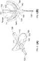
- FIG. 1illustrates one aspect of the present invention showing schematic diagrams of an exemplary system with an oral device comprising a negative pressure deliverable part (e.g., a flexible tube) conformable to the contour of the upper palate to eliminate air space in a patient's oral cavity during sleep.
- a negative pressure deliverable parte.g., a flexible tube
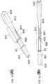
- FIGS. 2A and 2Bshow isometric and top views, respectively, of an exemplary oral device having a flexible tube conformable to the contour of the upper palate to eliminate air space in a patient's oral cavity during sleep.
- FIGS. 3A-3Dillustrate another aspect of the present invention showing various views of an exemplary oral device.
- FIGS. 3A and 3Bshow side views of an oral device having a flexible tube without and with negative pressure applied, respectively.
- FIG. 3Cshows front cross-section view of an oral device having a flexible tube conformable to the contour of the upper palate with air space between tongue and soft palate eliminated.
- FIG. 3Dshows side view of an oral device having a flexible tube conformable to a flatter upper palate with air space between tongue and soft palate eliminated.
- FIGS. 4A-4Cshow side views of an exemplary oral device having a flexible shield conformable to inline, backward, and forward lower jaws, respectively, with air space between tongue and soft palate eliminated.
- FIGS. 5A-5Cillustrate another aspect of the present invention showing top, back, and side cross-section views, respectively, of an oral device having a flexible tube and a shield.
- FIGS. 6A to 6Dshow various views of an exemplary oral device having a detachable flexible tube and a detachable shield.
- FIG. 6Ashows side cross-section view of an exemplary detachable tube part.
- FIG. 6Bshows side cross-section view of an exemplary detachable shield part.
- FIG. 6Cshows isometric, view of an exemplary detachable shield part.
- FIG. 6Dshows side cross-section view of an exemplary oral device having a detachable flexible tube and a detachable shield.
- FIGS. 7A to 7Dillustrate another aspect of the present invention showing various views of an exemplary detachable shield with a tongue protector.
- FIGS. 7A and 7Bshow the side and side cross-section views of an exemplary detachable shield part with a tongue protector, respectively.
- FIG. 7Cis a top view.
- FIG. 7Dis a front view.
- FIG. 8illustrates another aspect of the present invention showing a side cross-section view of a detachable shield with air vents.
- FIGS. 9A and 9Bshow side cross-section views of an oral device having a slidable flexible tube in original position and forward position, respectively.
- FIGS. 10A and 10Bshow side cross-section views of an oral device having a slidable flexible tube in original position and forward position, respectively, with air space between tongue and soft palate eliminated.
- FIGS. 11A-11Cshow side cross-section views of an oral device having a slidable flexible tube with anchor points in different positions.
- FIGS. 12A and 12Bshow isometric and side views of a detachable flexible tube with open channels, respectively.
- FIGS. 13A-13Eshow side cross-section views of variations of flexible tubes including tubes without opening at the posterior end with various open channels.
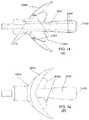
- FIGS. 14A to 14Fillustrate another aspect of the present invention showing various views of an exemplary oral device comprising open channels connecting with the posterior end without middle openings to deliver negative pressure from posterior part to anterior part of oral cavity.
- FIG. 14Ais a top cross-section view.
- FIG. 14Bis a top view.
- FIG. 14Cis a side view.
- FIG. 14Dis a side cross-section view.
- FIG. 14Eis a front view.
- FIG. 14Fis a rear view.
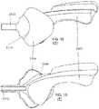
- FIGS. 15A to 15Eillustrate another aspect of the present invention showing various views of an exemplary oral device with extended tongue protector which combines the tongue protector described herein with the function of a flexible tube pre-shaped and conformable to the shape of the upper plate.
- FIG. 15Ais a top view.
- FIG. 15Bis a front view.
- FIG. 15Cis a rear view.
- FIG. 15Dis a side view.
- FIG. 15Eshows a side cross-section view.
- FIGS. 16A to 16Eillustrate yet another aspect of the present invention showing various views of an exemplary oral device comprising a flexible tube and a tongue protector where the tongue protector is integrated on the flexible tube.
- FIG. 16Ais a top view.
- FIG. 16Bis a side view.
- FIG. 16Cis a side cross-section view.
- FIG. 16Dis a front view.
- FIG. 16Eshows a rear view of an exemplary oral device.
- an oral device for treatment of obstructive sleep disordersis characterized in that the tongue is protected and separated from the teeth when the device is in use.
- the oral devicefurther comprises a tongue shaped cavity for receiving the tongue where a negative pressure is applied directly on the soft tissues of the tongue to hold the tongue within the cavity.
- negative pressuremay cause damage to the soft tissues of the tongue.
- the present inventionprovides devices and systems for properly controlling negative pressure applied to oral cavity, facilitating breathing and treating sleep apnea and snoring.
- FIG. 1a schematic diagram of an exemplary invention system comprising a negative pressure control system 190 and an oral device 100 comprising a negative pressure deliverable part (e.g., a flexible tube 110 ), an optional tongue protector 160 , and a shield 150 is shown.
- the oral device 100 for placement in a patient's oral cavitycomprises a shield 150 to be situated between lips and front teeth, where a tube 110 passes through the shield is connected to a portion flexible and conformable to the contour of the upper palate (i.e., a negative pressure deliverable part).
- the flexible tube 110has an anterior end 120 connected the negative pressure control system 190 which provides a vacuum source and a posterior end 130 to be situated between tongue and upper palate.
- the flexible tube 110further optionally has at least one middle opening 140 near the shield 150 .
- the flexible tube 110has 1 to 20, 1 to 15, 1 to 10, 1 to 5, 1 to 3, or 1 to 2 middle openings. As shown in FIG. 1 , the position of the middle opening 140 , in some embodiments, is on the side of the tube where it has less chance to be blocked by the soft tissue in patient's oral cavity.
- the flexible tube 110has two middle openings 140 positioned on the side of the tube.
- the flexible tube 110delivers negative pressure to both front and back of the oral cavity to eliminate air space between the tongue and the upper palate.
- a vacuum sourcee.g. by an electronic pump disclosed in US2009/0288660, which is incorporated herein by reference, or the like.
- the shield 150also functions as a seal to facilitate proper control of negative pressure applied to oral cavity.
- An ordinary skilled in the artwould readily appreciate that the proper control of negative pressure applied to oral cavity is achieved via the opening of the posterior end 130 and at least one middle opening 140 of the tube and optionally via the shield which functions as a seal.
- FIGS. 2A and 2Bfurther illustrate an exemplary oral device in accordance with FIG. 1 .
- FIG. 2Aillustrates an isometric view of an oral device 100 comprising a flexible tube 110 passing through a shield 150 .
- the shield 150comprises a bendable structure 151 , which is conformable to the shape of patient's front teeth and lips.
- the flexible tube 110has a bendable middle part 111 , which is conformable to the contours of the upper palate and the tongue. In some embodiments, the middle part 111 is thinner than the rest part of the tube.
- the flexible tube 110has an anterior end 120 to connect to a vacuum source (e.g., via a negative pressure control unit) and a posterior end 130 in place at the space between the tongue and the upper palate.
- the optional middle opening 140is shown in FIG. 2A near the center of the shield 150 .
- FIG. 2Billustrates a top view of an exemplary oral device in accordance with the embodiment shown in FIG. 1 .
- the shield 150is disposed between the front teeth and the lips and the flexible tube 110 , in some embodiments, is disposed along the center line of the tongue.
- the flexible tube 110in some embodiments, has a wider structure 131 near the posterior end 130 to provide rigidity of the tube, which prevent from collapsing due to being compressed by the tongue and the upper palate.
- FIG. 3Ashows the side views of an exemplary oral device comprising a flexible tube without applying negative pressure.
- An oral device 100is placed in a patient's oral cavity.
- the oral device 100has a negative pressure deliverable part (i.e., a flexible tube 110 ) disposed between the tongue and the upper palate.
- the shield 150is disposed between the front teeth and the lips.
- the anterior end 120 of the oral device 100is connected to a vacuum source.
- the posterior end 130 and optionally at least one middle opening 140 of the oral device 100is disposed between the tongue and upper palate and near the middle part of the shield 150 , respectively.
- FIG. 3Billustrates the tongue is drawn forward and upward to push and deform the flexible tube 110 to conform to the contour of the upper palate by application of negative pressure via the optionally at least one middle opening 140 and via posterior end 130 which further eliminates air space between the tongue and the soft palate.
- FIG. 3Cshows front cross-section view of an oral device having a flexible tube conformable to the contour of the upper palate in accordance with FIG. 3B where air space between tongue and soft palate is reduced.
- the flexible tube 110has a minimal cross section and occupies very little space in the oral cavity.
- FIG. 3Dshows a side view of an oral device having a flexible tube conformable to a flatter upper palate (compared to one shown in FIG. 3(B) ) with air space between tongue and soft palate eliminated.
- the flexible tube 111further comprises a more bendable part 111 (see FIG. 3B ) to accommodate different anatomy of upper palate of different patients.
- the bendable part 111is not limited to the particular section shown in FIG. 3B , but any part that is conformable to the contour of the upper palate.
- FIGS. 4A-4Cillustrate a further variation of an oral device 100 .
- FIG. 4Ashows a side view of an oral device 100 comprising a flexible shield conformable to an inline lower jaw (in relative to upper jaw).
- the shield 150is flexible and may further have a bendable structure (not shown), which can accommodate different anatomy of front teeth and lips of different patients, for patient with backward lower jaw e.g., as shown in FIG. 4B ) and forward lower jaw (e.g., as shown in FIG. 4C ), respectively.
- FIGS. 5A-5Cillustrate another variation of invention oral devices showing top, back, and side cross-section views of an oral device 200 comprising a flexible tube 210 and a shield 250 where the flexible tube 210 passes through a shield 250 .
- the shield 250has a bendable structure 251 , which is conformable to the shape of from teeth and lips.
- the flexible tube 210in some embodiments, further has a bendable middle part 211 (i.e., a negative pressure deliverable part), which is conformable to the contours of the upper palate and the tongue.
- the tube passing through the shieldis part of or directed connected to a flexible tube as described herein where the flexible tube functions as a negative pressure deliverable part.
- the middle part 211is thinner than the rest part of the tube allowing more flexibility. In certain embodiments, the middle part 211 remains the same thickness as the rest part of the tube but still maintains the desired flexibility. An ordinary skilled in the art would readily realize it via the structure design (e.g., by a reinforced coating) or the material used (e.g., a more rigid produced material). In some embodiments, the material used to construct the middle part 211 is the same as the rest of the tube where the middle part is thinner than the rest of the tube. In certain embodiments, the material used to construct the middle part 211 is not the same as the rest of the tube and provides more flexible characteristic.
- the flexible tube 210in some embodiments, has a wider structure near the posterior end 230 to provide rigidity of the tube, which prevent from collapsing due to being compressed by the tongue and the upper palate. In certain embodiments, the wider structure near the posterior end 230 has a curved edge.
- the flexible tube 210has an anterior end 220 to connect to a vacuum source and a posterior end 230 in place at the space between the tongue and the upper palate.
- the flexible tube 210further optionally has at least one middle opening 240 near the center of the shield 250 .
- the flexible tube 210is one piece from the anterior end 220 to the posterior end 230 .
- the flexible tube 210connects to a tube passing through the shield.
- the oral device 200further has a tongue protector 260 to prevent direct impingement of teeth on the tip of the tongue.
- the tongue protector 260is disposed between the bottom of the tongue tip and the back side of the lower front teeth.
- the tongue protect 260further has an indentation 261 to accommodate the shape of tongue frenulum.
- an oral device 300comprises a detachable tube part 301 and a detachable shield part 302 shown in various views in FIGS. 6A to 6D .
- FIG. 6Aillustrates an exemplary detachable tube part 301 having a flexible tube 310 which is conformable to the contours of the upper palate and the tongue.
- the flexible tube 310comprises a bendable middle part 311 .
- the middle part 311is thinner than the rest part of the tube.
- the middle part 311remains the same thickness as the rest part of the tube but still maintains the desired flexibility.
- the flexible tube 310in some embodiments, has a wider structure near the posterior end 330 to provide rigidity of the tube, which prevent from collapsing due to being compressed by the tongue and the upper palate. In certain embodiments, the wider structure near the posterior end 330 has a curved edge.
- the flexible tube 310has an anterior end 320 to connect to a vacuum source and a posterior end 330 in place at the space between the tongue and the upper palate.
- the flexible tube 310further optionally has at least one middle opening 340 near the center of the shield 350 (see FIG. 6A and FIG.
- FIG. 6Billustrate a detachable shield part 302 , having a shield 350 which comprises a bendable structure 351 being conformable to the shape of front teeth and the lips.
- the detachable shield part 302has an inner chamber 33 (see FIG. 6B ) to accommodate part of the bendable middle part 311 (see FIG. 6A ) of the flexible tube 310 .
- the detachable tube part 301 and detachable shield part 302may have different sizes and are interchangeable to accommodate different anatomy of patients.
- the detachable tube part 301has an outer surface 31 (see FIG. 6A ) which contacts with an inner surface 32 (see FIG.
- FIGS. 7A to 7Dillustrate another embodiment of the invention showing various views of a detachable shield part 402 with a tongue protector 460 where the tongue protector 460 is disposed between the bottom of the tongue tip and the back side of the lower front teeth.
- FIG. 7A /Bshow the side-cross views of a detachable shield part 402 comprising a bendable middle part 451 , a shield 450 and a tongue protector 460 .
- the detachable shield part 402further comprises an inner surface 42 to accommodate a detachable tube part to form a sealing interface (see FIGS. 7B and 7D ).
- the tongue protect 460further comprises an indentation 461 (e.g., see FIG. 7 C) to accommodate the shape of tongue frenulum.
- FIG. 8shows the side cross-section view of a detachable shield part 502 comprising a tongue protector 560 , a shield 550 and air vents 570 wherein the detachable shield part comprises a bendable middle part 551 .
- the detachable shield partfurther comprises an inner surface 52 to accommodate a detachable tube part to form a sealing interface.
- the air vents 570allow the patient to breathe more freely when the patient tries to open mouth or exhale through mouth.
- the air ventscomprise one-way vale to preserve the seal function of the detachable shield. A one-way vale restricts air entering from outside but allowing air to go out from the oral cavity.
- the air ventsare in place at positions that allow the lips to cover the air vents.
- the air ventsare positioned slightly above or below incisal face, where the air vents is in front of the upper front teeth or the bottom front teeth, and behind the lips.
- FIGS. 9A-9Billustrate another aspect of the present invention showing an oral device 600 comprising a slidable flexible tube 610 in original position (W 1 , FIG. 9A ) and forward position (W 2 , FIG. 9B ), respectively.
- the oral devicecomprises a flexible tube 610 and a shield 650 comprising a bendable middle part 651 where the flexible tube 610 passes through the shield 650 .
- the flexible tube 610further optionally comprises at least one middle opening 640 .
- the flexible tube 610has an anterior end 620 to connect to a vacuum source and a posterior end 630 in place at the space between the tongue and the upper palate.
- the slidable flexible tube 610allows a patient to adjust the position of the posterior end 630 to provide a more comfortable or effective location to deliver negative pressure between the tongue and the upper palate.
- FIGS. 10A-10Bshow the side cross-section views of an oral device 700 comprising a slidable flexible tube 710 in original position (W 1 , FIG. 10A ) and forward position (W 2 , FIG. 10B ), respectively, with air space between tongue and soft palate eliminated.
- An oral device 700is placed in a patient's oral cavity.
- the oral device 700has a slidable flexible tube 710 disposed between the tongue and the upper palate.
- the shield 750is disposed between the front teeth and the lips.
- the anterior end 720 of the oral device 700is connected to a vacuum source (not shown).
- the posterior end 730 and at least one middle opening 740 of the oral device 700is disposed between the tongue and upper palate and near the middle part of the shield 750 , respectively.
- the detachable tube part 701can be moved away from the detachable shield part 702 which also move the position of the posterior end 730 forward.
- the posterior open end 730is located anteriorly to the boundary between the hard palate and the soft palate, thus prevents the soft tissue on soft palate from blocking or being sucked into the posterior open end 730 .
- the oral device 700can further have as tongue protector 710 to prevent direct impingement of teeth on the tip of the tongue.
- an oral device 800comprises a slidable flexible tube 810 with anchor points 880 in different positions.
- the oral device 800further comprises a shield 850 with multiple anchor stops 870 , which allow a patient to adjust the slide tube 810 to distinct positions (e.g., at W 1 , W 2 , W 3 ).
- the oral devicecomprises a slidable flexible tube 810 and a shield 850 comprising a bendable middle part 851 where the flexible tube 810 passes through the shield 850 .
- the flexible tube 810further comprises at least one middle opening 840 .
- the flexible tube 810has an anterior end 820 to connect to a vacuum source and a posterior end 830 in place at the space between the tongue and the upper palate.
- the slidable flexible tube 810allows a patient to adjust the position of the posterior end 830 to distinct positions (e.g., at W 1 , W 2 , W 3 ) with anchor points 880 in different positions to provide a more comfortable or effective location to deliver negative pressure between the tongue and the upper palate.
- the flexible tube 810in some embodiments, further comprises open channels 841 (e.g., shown at both sides of the flexible tube). The open channels 841 along the flexible tube 810 allow negative pressure distribution and prevent the middle opening 840 from obstruction by the soft tissue or tongue.
- the flexible tube 910comprises a bendable middle part 911 .
- the middle part 911is thinner than the rest part of the tube.
- the middle part 911remains the same thickness as the rest part of the tube but still maintains the desired flexibility.
- the flexible tube 910has an anterior end 920 to connect to a vacuum source and a posterior end 930 in place at the space between the tongue and the upper palate.
- the flexible tube 910in some embodiments, has a wider structure near the posterior end 930 to provide rigidity of the tube, which prevent from collapsing due to being compressed by the tongue and the upper palate.
- the posterior end 930has a curved edge which decreases the risk of complete blockage by the soft tissue or tongue.
- the flexible tube 910further comprises at least one middle opening 940 near an anchor stop 980 .
- the detachable tube part 901has an outer surface 91 (see FIG. 12A ) which contacts with an inner surface of the detachable shield pan to form a sealing interface to maintain negative pressure environment within oral cavity.
- the open channels 941 along, the flexible tube 910allow negative pressure distribution and prevent the middle opening 940 from obstruction by the soft tissue or tongue.
- the flexible tube 910comprises at least one open channel, two open channels, three open channels, four open channels or more.
- the number of open channelsis corresponding to the number of middle openings on the flexible tube.
- the flexible tube 910comprises two open channels 940 connecting the middle openings 940 on two sides of flexible tube 910 .
- FIGS. 13B-13Efurther illustrate various embodiments of the present invention showing flexible tubes 1110 ( FIG. 13B ), 1210 ( FIG. 13C ), 1310 ( FIG. 13D ) and 1410 ( FIG. 13E ), with various designs of open channels 1141 , 1241 , 1341 and 1441 , respectively.
- the open channels along the flexible tubeallow negative pressure distribution and prevent the middle openings 1140 , 1240 , 1340 and 1440 from obstruction by the soft tissue or tongue.
- FIG. 13Bshows that the open channel 1141 is located within the limitation of bendable part and does not extend to the posterior end.
- the open channelsare extended to the posterior end of the flexible tubes (see the open channels 1241 , 1341 and 1441 extended to the posterior end of the flexible tubes 1210 , 1310 and 1410 ) where these sections of the flexible tube are solid, and therefore replace the function of the posterior end ( 1030 and 1130 ) to deliver negative pressure between tongue and upper palate (see e.g., FIGS. 13C to 13E ).
- the flexible tubefurther comprises several support means 1342 or 1442 within the flexible tube to support the open channel from collapsing during the application of negative pressure.
- the flexible tubecomprises 1 to 20, 1 to 15, 1 to 10, 1 to 7, 1 to 6, 1 to 5, 1 to 4, 1 to 2, or one support means.
- the size and the position of the support meansdepend on the length of the open channel. One of ordinary skilled in the art would readily realize the suitable numbers with proper position and size to support open channels from collapsing when negative pressure applies to the flexible tube.
- FIGS. 14A-Fanother variation of the invention oral device comprising open channels connected with the posterior end without middle openings to deliver negative pressure from posterior part to anterior pan of oral cavity is shown in various views.
- the oral device showncomprises a shield 1450 to be situated between lips and front teeth, a tube passing through the shield, and a negative pressure deliverable part (i.e., a flexible tube 1410 , which is part of or in connection with the tube passing through the shield), several open channels 1441 (e.g., two shown in the figures) connecting with the posterior end 1430 with indentation, and a tongue protector 1460 , in some embodiments, as illustrated in FIGS.
- the flexible tubefurther comprises several support means within the flexible tube to support the open channel from collapsing during the application of negative pressure.
- the flexible tubecomprises 1 to 20, 1 to 15, 1 to 10, 1 to 7, 1 to 6, 1 to 5, 1 to 4, 1 to 2, or one support means.
- the size and the position of the support meansdepend on the length of the open channel. One of ordinary skilled in the art would readily realize the suitable numbers with proper position and size to support open channels from collapsing when negative pressure applies to the flexible tube.
- the oral devicehas fold lines 1454 (which are bendable) and recesses 1453 to allow the device conformable to different anatomy of jaws, front teeth and lips of different patients.
- the fold lines 1454 on the shieldallow the shield to be pliable and compliant to the tooth orientations and shapes.
- the recesses 1453 near the joint where the tube passing throughallows the flexible tube 1410 to bend freely.
- the indentation at the posterior endprevents the posterior end opening to be totally blocked by soft tissues. In this embodiment, there are no middle openings but yet the negative pressure is delivered from posterior part to anterior part of oral cavity via the open channels.
- FIGS. 15A to 15Eanother variation of the invention oral device comprising an extended tongue protector combining the function of tongue protection and a flexible negative pressure deliverable part is shown in various views.
- the oral device showncomprises a shield 1550 (which is disposed between the front teeth and the lips), a tube 1542 passing through the shield, an extended tongue protector 1560 , one or more middle opening 1540 (e.g., one shown) near the center of the shield 1550 where the middle opening is connected to several open channels 1541 (e.g., three open channels shown).
- the flexible extended tongue protectorcovers both anterior and top regions of the tongue, which is pre-shaped to adapt (conform) the shape of upper palate (providing better fit of tongue shapes), thus allow patients to easily wear the oral device.
- the open channels on the extended tongue protectorare connected to the middle opening (without posterior end openings) to deliver negative pressure from anterior part to posterior part of oral cavity. Multiple open channels distribute negative pressure more evenly.
- FIGS. 16A to 16Eanother variation of the invention oral device comprising a pre-bended flexible tube with an integrated tongue protector is shown in various views.
- the oral device showncomprises a shield 1650 (which is disposed between the front teeth and the lips), a negative pressure deliverable part (i.e., a pre-bended flexible tube 1660 ) passing through the shield, a tongue protector 1660 , where the tongue protector is integrated on the pre-bended tube.
- the pre-bended tubeis shaped to adapt (conform) the shape of upper palate allowing patients to easily wear the oral device.
- the integrated tongue protector on the pre-bended tubeadapts (conform) to tongue shapes allowing proper tongue protection.
Landscapes
- Health & Medical Sciences (AREA)
- Otolaryngology (AREA)
- Pulmonology (AREA)
- Nursing (AREA)
- Orthopedic Medicine & Surgery (AREA)
- Engineering & Computer Science (AREA)
- Biomedical Technology (AREA)
- Heart & Thoracic Surgery (AREA)
- Vascular Medicine (AREA)
- Life Sciences & Earth Sciences (AREA)
- Animal Behavior & Ethology (AREA)
- General Health & Medical Sciences (AREA)
- Public Health (AREA)
- Veterinary Medicine (AREA)
- Orthopedics, Nursing, And Contraception (AREA)
- Surgical Instruments (AREA)
Abstract
Description
Claims (33)
Priority Applications (1)
| Application Number | Priority Date | Filing Date | Title |
|---|---|---|---|
| US14/153,336US11406526B2 (en) | 2013-01-11 | 2014-01-13 | Oral device to eliminate air space in oral cavity |
Applications Claiming Priority (2)
| Application Number | Priority Date | Filing Date | Title |
|---|---|---|---|
| US201361751559P | 2013-01-11 | 2013-01-11 | |
| US14/153,336US11406526B2 (en) | 2013-01-11 | 2014-01-13 | Oral device to eliminate air space in oral cavity |
Publications (2)
| Publication Number | Publication Date |
|---|---|
| US20140190489A1 US20140190489A1 (en) | 2014-07-10 |
| US11406526B2true US11406526B2 (en) | 2022-08-09 |
Family
ID=51060033
Family Applications (3)
| Application Number | Title | Priority Date | Filing Date |
|---|---|---|---|
| US14/760,429Active2034-11-12US11246742B2 (en) | 2013-01-11 | 2014-01-10 | Oral device to eliminate air space in oral cavity |
| US14/153,336ActiveUS11406526B2 (en) | 2013-01-11 | 2014-01-13 | Oral device to eliminate air space in oral cavity |
| US29/571,132ActiveUSD871571S1 (en) | 2013-01-11 | 2016-07-14 | Oral device for negative pressure device for treating sleep disorder |
Family Applications Before (1)
| Application Number | Title | Priority Date | Filing Date |
|---|---|---|---|
| US14/760,429Active2034-11-12US11246742B2 (en) | 2013-01-11 | 2014-01-10 | Oral device to eliminate air space in oral cavity |
Family Applications After (1)
| Application Number | Title | Priority Date | Filing Date |
|---|---|---|---|
| US29/571,132ActiveUSD871571S1 (en) | 2013-01-11 | 2016-07-14 | Oral device for negative pressure device for treating sleep disorder |
Country Status (11)
| Country | Link |
|---|---|
| US (3) | US11246742B2 (en) |
| EP (1) | EP2943170B1 (en) |
| JP (2) | JP6242914B2 (en) |
| KR (1) | KR101661639B1 (en) |
| CN (1) | CN104540480B (en) |
| AU (1) | AU2014205191B2 (en) |
| DE (1) | DE202014010625U1 (en) |
| ES (1) | ES2714091T3 (en) |
| MY (1) | MY172914A (en) |
| TW (1) | TWI542337B (en) |
| WO (1) | WO2014110432A2 (en) |
Families Citing this family (27)
| Publication number | Priority date | Publication date | Assignee | Title |
|---|---|---|---|---|
| TWI396690B (en) | 2006-04-27 | 2013-05-21 | Yakult Honsha Kk | Process for preparing camptothecin analogs |
| AU2012255625B2 (en) | 2011-05-19 | 2016-03-31 | Open Airway Dental Solutions Ltd | Breathing assist device |
| KR101636436B1 (en)* | 2012-08-03 | 2016-07-05 | 솜닉스 인코포레이티드 | Oral interface and method using the same |
| MY172914A (en)* | 2013-01-11 | 2019-12-13 | Somnics Inc | Oral device to eliminate air space in oral cavity |
| CA3193175A1 (en)* | 2014-04-01 | 2015-10-08 | Open Airway Dental Solutions Ltd. | Breathing assist device |
| US10251774B2 (en) | 2015-12-18 | 2019-04-09 | Real 3D Polymers Group Llc | Sleep apnea and anti-snoring system |
| US10376202B2 (en) | 2015-12-18 | 2019-08-13 | Real 3D Polymers Group Llc | Sleep apnea and anti-snoring system |
| RU2019143446A (en)* | 2017-05-25 | 2021-06-25 | Космоаэстетикс Пти Лтд | SYSTEMS AND METHODS OF INTERNAL AND EXTRAORDINARY PHOTOTHERAPY |
| CA181444S (en)* | 2017-11-21 | 2019-06-06 | Farrell Christopher John | Oral appliance |
| TWI678199B (en)* | 2017-11-27 | 2019-12-01 | 萊鎂醫療器材股份有限公司 | Adjustable oral interface for negative-pressure therapy system |
| JP6374078B1 (en)* | 2017-12-26 | 2018-08-15 | 株式会社壮健 | Auxiliary device for improving symptoms of sleep apnea syndrome |
| US10463873B1 (en)* | 2018-05-11 | 2019-11-05 | JiPhoton Therapeutics Inc. | Non-invasive phototherapeutic system |
| AU201812943S (en)* | 2018-05-18 | 2019-01-09 | Oral exerciser | |
| AU201813151S (en)* | 2018-05-25 | 2019-01-24 | An oral appliance | |
| AU201813153S (en)* | 2018-05-25 | 2019-01-25 | An oral appliance | |
| USD909586S1 (en)* | 2018-05-25 | 2021-02-02 | Christopher John Farrell | Oral appliance |
| CA188766S (en)* | 2019-01-25 | 2020-12-21 | Farrell Dr Christopher John | Oral appliance |
| US12349880B2 (en) | 2019-07-25 | 2025-07-08 | Paprica Lab. Co., Ltd. | Oral fixation apparatus |
| KR102388513B1 (en)* | 2019-07-25 | 2022-04-20 | 주식회사 파프리카랩 | Mouth Fixing Apparatus |
| CA3175946A1 (en) | 2020-05-21 | 2021-11-25 | Good News Medical Co., Ltd. | Device for alleviating obstructive sleep apnea |
| CN114795610B (en)* | 2020-05-21 | 2024-11-22 | 番禺得意精密电子工业有限公司 | Devices for improving sleep apnea |
| US12121368B2 (en)* | 2020-11-11 | 2024-10-22 | International Business Machines Corporation | Embedded oral sensor platform |
| AU2022215124B2 (en)* | 2021-01-29 | 2024-06-06 | Wilfried Gerhard Hermann ENGELKE | Device for determining tongue position by measuring negative pressure in the oral cavity, for measuring inhalation pressure in the nasopharyngeal cavity, and associated terminal |
| US11723760B2 (en)* | 2021-08-06 | 2023-08-15 | Gregory Prior | Aerosol deflecting dental shield and containment device |
| KR102495982B1 (en)* | 2021-11-24 | 2023-02-06 | 차영길 | A device for preventing from snoring and sleep apnea |
| TWI844076B (en) | 2022-01-06 | 2024-06-01 | 萊鎂醫療器材股份有限公司 | Nasal dilator with epap valve inserts and an assembly thereof as well as its application |
| US11793665B1 (en) | 2022-04-14 | 2023-10-24 | Gregory Todd Steiger | Vented dental appliance for bruxism relief |
Citations (62)
| Publication number | Priority date | Publication date | Assignee | Title |
|---|---|---|---|---|
| US2599521A (en)* | 1949-06-02 | 1952-06-03 | Robert A Berman | Respiratory device |
| US2937445A (en)* | 1956-10-19 | 1960-05-24 | Norman R Erickson | Dental appliance |
| US3091859A (en) | 1961-07-19 | 1963-06-04 | Herbert A Baughan | Dental saliva ejectors |
| US3132647A (en) | 1962-04-19 | 1964-05-12 | Corniello Giuseppe | Anti-snoring device |
| US4063552A (en)* | 1976-04-02 | 1977-12-20 | Going Robert E | User formed mouthguard |
| US4169473A (en) | 1978-03-03 | 1979-10-02 | Samelson Charles F | Anti-snoring and anti-bruxism device |
| US4304227A (en) | 1978-03-03 | 1981-12-08 | Samelson Charles F | Device for treatment of snoring, bruxism or for avoidance of sleep apnea |
| US4368737A (en) | 1980-07-07 | 1983-01-18 | Purdue Research Foundation | Implantable catheter |
| US4669459A (en) | 1985-11-29 | 1987-06-02 | Spiewak Martin H | Anti-snoring device |
| US4676240A (en) | 1985-09-09 | 1987-06-30 | Gardy Victor R | Tongue locking device to minimize effects of sleep apnea and to reduce snoring |
| US5050616A (en) | 1990-03-14 | 1991-09-24 | The United States Of America As Represented By The Secretary Of The Department Of Health And Human Services | Universal collector for submandibular-sublingual saliva |
| US5094616A (en)* | 1990-12-21 | 1992-03-10 | Myron Levenson | Dental appliance |
| US5104315A (en) | 1990-04-11 | 1992-04-14 | Mckinley Earl O | Oral hygiene device |
| US5361921A (en)* | 1993-06-29 | 1994-11-08 | Becton Dickinson And Company | Combination stopper-shield closure |
| US5465734A (en) | 1994-01-12 | 1995-11-14 | Snorex, Inc. | Adjustable tongue positioning device and method |
| US5513986A (en)* | 1993-10-21 | 1996-05-07 | Erika B. Feltham | Intraoral dental apparatus |
| US5533523A (en) | 1995-05-16 | 1996-07-09 | Bass, Jr.; Robert | Medical mouthpiece |
| US5588836A (en) | 1995-10-23 | 1996-12-31 | Op-D-Op, Inc. | Mouth prop and tongue deflector apparatus |
| TW318428U (en) | 1997-03-20 | 1997-10-21 | Polymac Machinery Co Ltd | Crank type open/close mechanism for mold |
| US5692523A (en)* | 1996-10-15 | 1997-12-02 | Theodore P. Croll | Two-piece mouthguard |
| US5718225A (en)* | 1994-01-05 | 1998-02-17 | Novametrix Medical Systems, Inc. | System for supporting endotracheal tubes in pediatric patients and method of using same |
| US5876199A (en)* | 1997-08-28 | 1999-03-02 | Ortho-Tain, Inc. | Appliance adapted to fit many mouth and tooth sizes for orthodontic correction and other uses |
| US5915385A (en) | 1997-04-02 | 1999-06-29 | Hakimi; Farhad | Snore and stress relieving device |
| US5957131A (en) | 1997-07-31 | 1999-09-28 | The United States Of America As Represented By The Secretary Of The Army | Biological warfare mask |
| US5957133A (en) | 1997-07-21 | 1999-09-28 | Hart; William T. | Oral appliance with negative air supply for reducing sleep apnea and snoring |
| US6186783B1 (en)* | 1997-10-17 | 2001-02-13 | Dentsply Research & Development Corp. | Evacuation hand piece for use during dental procedures |
| US20010044593A1 (en) | 1995-10-06 | 2001-11-22 | Lundy Ellen F. | Hands-free portable breast pump system |
| US20010047805A1 (en) | 2000-01-21 | 2001-12-06 | Respironics, Inc. | Intraoral apparatus for enhancing airway patency |
| EP1192928A2 (en)* | 2000-09-25 | 2002-04-03 | Alba Quiros de, Miguel | Comforter adaptable to the tongue and palate |
| US6494209B2 (en) | 2001-04-02 | 2002-12-17 | George Kulick | Method and apparatus for treatment of snoring, hypopnea and apnea |
| US20030208149A1 (en) | 2000-05-22 | 2003-11-06 | Coffey Arthur C. | Combination sis and vacuum bandage and method |
| US6679257B1 (en) | 1998-08-13 | 2004-01-20 | Fisher & Paykel Limited | Breathing assistance apparatus |
| US6820617B2 (en) | 1998-08-13 | 2004-11-23 | Fisher & Paykel Limited | Breathing assistance apparatus |
| US20050166928A1 (en) | 2004-01-30 | 2005-08-04 | Yandong Jiang | Methods and devices for maintaining an open airway |
| US20050217678A1 (en)* | 2004-04-01 | 2005-10-06 | Mccormick James J | Respiratory mask having intraoral mouthpiece with large sealing area and multiple sealing configuration |
| US6955172B2 (en) | 2002-09-06 | 2005-10-18 | Apneon, Inc. | Systems and methods for moving and/or restraining the tongue in the oral cavity |
| US20050236003A1 (en) | 2004-04-16 | 2005-10-27 | Meader Charles R | Apnea nipple and oral airway and mandibular advancement device |
| US6976491B2 (en) | 2003-10-30 | 2005-12-20 | D Agosto Joseph | Gag-less airway for snoring prevention |
| US20060096600A1 (en) | 2004-10-29 | 2006-05-11 | Ric Invenstments, Llc | Oral appliance |
| US7073505B2 (en) | 2002-09-06 | 2006-07-11 | Apneon, Inc. | Systems and methods for moving and/or restraining tissue in the oral cavity |
| US7073506B2 (en) | 1999-12-15 | 2006-07-11 | Innovative Health Technologies (Nz) Limited | Tongue stabilizing device |
| US20060282010A1 (en) | 2005-05-03 | 2006-12-14 | Martin Ruth E | Oral device |
| US7182082B2 (en) | 2001-07-12 | 2007-02-27 | Hoffrichter Gmbh | Respiratory therapy device for keeping free natural respiratory tract of a human body and the use thereof in order to prevent the sound of snoring |
| US20070277818A1 (en) | 2006-05-30 | 2007-12-06 | Industrial Technology Research Institute | Method and apparatus for treating obstructive sleep apnea by using negative oral pressure to a patient |
| CN101143115A (en) | 2006-05-30 | 2008-03-19 | 财团法人工业技术研究院 | Negative pressure type sleep apnea treatment method and device |
| EP1913968A1 (en)* | 2006-10-18 | 2008-04-23 | Sin-Bum Kang | Fixing device for endotracheal tube |
| US20080188947A1 (en) | 2004-02-26 | 2008-08-07 | Ira Sanders | Methods and devices for treating sleep apnea and snoring |
| JP2008183388A (en) | 2007-01-29 | 2008-08-14 | Masakatsu Shikura | Tongue locking device |
| US20080210244A1 (en) | 2005-06-23 | 2008-09-04 | Bryan Keropian | Sleep appliance |
| US20080216843A1 (en) | 2004-01-30 | 2008-09-11 | The General Hospital Corporation D/B/A Massachusetts General Hospital | Methods and devices for relieving upper airway obstructions |
| US20080216839A1 (en)* | 2007-03-07 | 2008-09-11 | Rutter Michael John | Tracheostomy Tube |
| US7451776B2 (en) | 2006-07-19 | 2008-11-18 | Nengsen Chen | Portable awning with a collapsible supporting frame |
| US7451766B2 (en)* | 2003-04-01 | 2008-11-18 | Miller Chipp St Kevin | Enhanced breathing device |
| US20090120446A1 (en) | 2007-11-13 | 2009-05-14 | Apnicure, Inc. | Methods and systems for improving airway patency |
| US20100147302A1 (en) | 2005-04-01 | 2010-06-17 | Resmed Limited | Ventless Mask CPAP System |
| US20100268107A1 (en) | 2009-04-20 | 2010-10-21 | De Heer Robert | Systems and Methods for Breathing Assistance |
| US20100304324A1 (en) | 2008-11-26 | 2010-12-02 | Centrix, Inc. | Dental unilateral bite block |
| US20110073119A1 (en)* | 2009-09-28 | 2011-03-31 | Somnics, Inc. | Negative pressure oral apparatus |
| US20110220124A1 (en)* | 2007-11-13 | 2011-09-15 | Apnicure, Inc. | Methods and systems for improving airway patency |
| US20110259346A1 (en) | 2008-10-30 | 2011-10-27 | Satoru Tsuiki | Tongue position controller |
| US20130213409A1 (en) | 2007-11-13 | 2013-08-22 | Apnicure, Inc. | Airway device with tongue-engaging member |
| US20140034064A1 (en)* | 2012-08-03 | 2014-02-06 | Somnics, Inc. | Oral Interface and Method using the Same |
Family Cites Families (35)
| Publication number | Priority date | Publication date | Assignee | Title |
|---|---|---|---|---|
| US2068496A (en)* | 1934-01-05 | 1937-01-19 | Electrolux Corp | Suction nozzle |
| US2521084A (en)* | 1949-09-01 | 1950-09-05 | William T Oberto | Mandible cushion for oxygen masks |
| US2669988A (en)* | 1951-05-08 | 1954-02-23 | Victor H Carpenter | Teeth protector |
| US2857911A (en)* | 1956-11-19 | 1958-10-28 | Bennett Respiration Products I | Respiratory mouthpiece |
| US2939445A (en)* | 1957-03-18 | 1960-06-07 | Holley Carburetor Co | Means for starting and operating internal combustion engines |
| US3013554A (en)* | 1958-08-08 | 1961-12-19 | Johnson & Johnson | Airway |
| US3508543A (en)* | 1967-04-27 | 1970-04-28 | Orlando T Aulicono | Mouth-to-mouth and nose resuscitation device |
| US4270531A (en)* | 1978-12-11 | 1981-06-02 | Blachly Paul H | Oropharyngeal airway and bite block assembly and method of use for closed pulmonary ventilation |
| US4360017A (en)* | 1981-03-18 | 1982-11-23 | Harry Barlett | Mouthpiece for resuscitation |
| US5071347A (en)* | 1989-08-14 | 1991-12-10 | Mcguire Jimmie L | Dental instrument for removing saliva |
| US5253658A (en)* | 1992-05-11 | 1993-10-19 | Medi-Nuclean Corporation, Inc. | Patient mouthpiece device with contamination shield |
| US5884625A (en)* | 1996-07-09 | 1999-03-23 | Hart; William T. | Oral appliance for delivering gas to the retroglossal area |
| US6536424B2 (en)* | 2001-06-14 | 2003-03-25 | Russell P. Fitton | Anatomical mouthpiece with retaining wings and method of use |
| USD479876S1 (en)* | 2001-10-12 | 2003-09-23 | Fisher & Paykel Healthcare Limited | Mouthpiece |
| US7137393B2 (en)* | 2003-04-28 | 2006-11-21 | Pivovarov Alexander R | Breathing normalizer apparatus |
| US7633073B2 (en)* | 2005-11-23 | 2009-12-15 | Asml Netherlands B.V. | Lithographic apparatus and device manufacturing method |
| US7883499B2 (en)* | 2007-03-09 | 2011-02-08 | Icu Medical, Inc. | Vial adaptors and vials for regulating pressure |
| US8104467B2 (en)* | 2007-03-19 | 2012-01-31 | Hanu Surgical Devices Llc | Rapid orotracheal intubation guide |
| US7549423B1 (en)* | 2007-07-02 | 2009-06-23 | Jr286 Technologies, Inc. | Mouthguard having breathing holes incorporated therein |
| USD593714S1 (en)* | 2007-07-02 | 2009-06-02 | Jr286 Technologies, Inc. | Mouthguard with incorporated breathing holes |
| TWI396526B (en) | 2008-05-20 | 2013-05-21 | Ind Tech Res Inst | Oral interface apparatus with negative pressure and method for maintianing oral negative pressure and collecting saliva |
| CA129761S (en)* | 2009-02-20 | 2009-10-28 | O Two Medical Technologies Inc | Patient airway tube with face shield and jaw position holder |
| IL197330A0 (en)* | 2009-03-01 | 2009-12-24 | Eran Lavi | An intra-oral self-adaptable continuous positive airway pressure (cpap) interface and nethod |
| USD629909S1 (en)* | 2010-06-03 | 2010-12-28 | Susanna Chiu | Anti-snore mouthguard |
| USD636074S1 (en)* | 2010-06-14 | 2011-04-12 | Levine Jonathan B | Mouthpiece |
| WO2012138459A1 (en)* | 2011-04-05 | 2012-10-11 | Airway Technologies, Llc | Oral appliance for treating particular disorders associated with sleep |
| US8662084B2 (en)* | 2011-04-05 | 2014-03-04 | Airway Technologies, Llc | Universal oral appliance with a universal coupler |
| MY172914A (en)* | 2013-01-11 | 2019-12-13 | Somnics Inc | Oral device to eliminate air space in oral cavity |
| USD727570S1 (en)* | 2013-05-24 | 2015-04-21 | Sportsguard Laboratories, Inc. | Lipguard |
| CA2935263A1 (en)* | 2014-03-03 | 2015-09-11 | Sleep Innovations Pty Ltd | Device and method for sleep apnoea treatment |
| CA3193175A1 (en)* | 2014-04-01 | 2015-10-08 | Open Airway Dental Solutions Ltd. | Breathing assist device |
| USD765255S1 (en)* | 2014-05-29 | 2016-08-30 | Jbl Radical Innovations, Llc | Mouthpiece |
| WO2016057719A1 (en)* | 2014-10-07 | 2016-04-14 | Allrest Technologies | Oral and nasal devices for the treatment of sleep apnea and/or snoring with filter and sensors to provide remote digital monitoring and remote data analysis |
| AU360284S (en)* | 2014-12-05 | 2015-02-13 | Sleep Innovations Pty Ltd | Device for treating sleep apnoea |
| US10568757B2 (en)* | 2016-01-22 | 2020-02-25 | Achaemenid, Llc | Hybrid oral device |
- 2014
- 2014-01-10MYMYPI2016700012Apatent/MY172914A/enunknown
- 2014-01-10KRKR1020157021033Apatent/KR101661639B1/enactiveActive
- 2014-01-10EPEP14737494.6Apatent/EP2943170B1/enactiveActive
- 2014-01-10AUAU2014205191Apatent/AU2014205191B2/enactiveActive
- 2014-01-10JPJP2015552829Apatent/JP6242914B2/enactiveActive
- 2014-01-10CNCN201480001034.0Apatent/CN104540480B/enactiveActive
- 2014-01-10DEDE202014010625.8Upatent/DE202014010625U1/ennot_activeExpired - Lifetime
- 2014-01-10USUS14/760,429patent/US11246742B2/enactiveActive
- 2014-01-10ESES14737494Tpatent/ES2714091T3/enactiveActive
- 2014-01-10WOPCT/US2014/011129patent/WO2014110432A2/enactiveApplication Filing
- 2014-01-13TWTW103101121Apatent/TWI542337B/enactive
- 2014-01-13USUS14/153,336patent/US11406526B2/enactiveActive
- 2016
- 2016-07-14USUS29/571,132patent/USD871571S1/enactiveActive
- 2017
- 2017-08-23JPJP2017160181Apatent/JP6357573B2/enactiveActive
Patent Citations (68)
| Publication number | Priority date | Publication date | Assignee | Title |
|---|---|---|---|---|
| US2599521A (en)* | 1949-06-02 | 1952-06-03 | Robert A Berman | Respiratory device |
| US2937445A (en)* | 1956-10-19 | 1960-05-24 | Norman R Erickson | Dental appliance |
| US3091859A (en) | 1961-07-19 | 1963-06-04 | Herbert A Baughan | Dental saliva ejectors |
| US3132647A (en) | 1962-04-19 | 1964-05-12 | Corniello Giuseppe | Anti-snoring device |
| US4063552A (en)* | 1976-04-02 | 1977-12-20 | Going Robert E | User formed mouthguard |
| US4304227A (en) | 1978-03-03 | 1981-12-08 | Samelson Charles F | Device for treatment of snoring, bruxism or for avoidance of sleep apnea |
| US4169473A (en) | 1978-03-03 | 1979-10-02 | Samelson Charles F | Anti-snoring and anti-bruxism device |
| US4368737A (en) | 1980-07-07 | 1983-01-18 | Purdue Research Foundation | Implantable catheter |
| US4676240A (en) | 1985-09-09 | 1987-06-30 | Gardy Victor R | Tongue locking device to minimize effects of sleep apnea and to reduce snoring |
| US4669459A (en) | 1985-11-29 | 1987-06-02 | Spiewak Martin H | Anti-snoring device |
| US5050616A (en) | 1990-03-14 | 1991-09-24 | The United States Of America As Represented By The Secretary Of The Department Of Health And Human Services | Universal collector for submandibular-sublingual saliva |
| US5104315A (en) | 1990-04-11 | 1992-04-14 | Mckinley Earl O | Oral hygiene device |
| US5094616A (en)* | 1990-12-21 | 1992-03-10 | Myron Levenson | Dental appliance |
| US5361921A (en)* | 1993-06-29 | 1994-11-08 | Becton Dickinson And Company | Combination stopper-shield closure |
| US5513986A (en)* | 1993-10-21 | 1996-05-07 | Erika B. Feltham | Intraoral dental apparatus |
| US5718225A (en)* | 1994-01-05 | 1998-02-17 | Novametrix Medical Systems, Inc. | System for supporting endotracheal tubes in pediatric patients and method of using same |
| US5465734A (en) | 1994-01-12 | 1995-11-14 | Snorex, Inc. | Adjustable tongue positioning device and method |
| US5533523A (en) | 1995-05-16 | 1996-07-09 | Bass, Jr.; Robert | Medical mouthpiece |
| US20010044593A1 (en) | 1995-10-06 | 2001-11-22 | Lundy Ellen F. | Hands-free portable breast pump system |
| US5588836A (en) | 1995-10-23 | 1996-12-31 | Op-D-Op, Inc. | Mouth prop and tongue deflector apparatus |
| US5692523A (en)* | 1996-10-15 | 1997-12-02 | Theodore P. Croll | Two-piece mouthguard |
| TW318428U (en) | 1997-03-20 | 1997-10-21 | Polymac Machinery Co Ltd | Crank type open/close mechanism for mold |
| US5915385A (en) | 1997-04-02 | 1999-06-29 | Hakimi; Farhad | Snore and stress relieving device |
| US5957133A (en) | 1997-07-21 | 1999-09-28 | Hart; William T. | Oral appliance with negative air supply for reducing sleep apnea and snoring |
| US5957131A (en) | 1997-07-31 | 1999-09-28 | The United States Of America As Represented By The Secretary Of The Army | Biological warfare mask |
| US5876199A (en)* | 1997-08-28 | 1999-03-02 | Ortho-Tain, Inc. | Appliance adapted to fit many mouth and tooth sizes for orthodontic correction and other uses |
| US6186783B1 (en)* | 1997-10-17 | 2001-02-13 | Dentsply Research & Development Corp. | Evacuation hand piece for use during dental procedures |
| US6679257B1 (en) | 1998-08-13 | 2004-01-20 | Fisher & Paykel Limited | Breathing assistance apparatus |
| US6997186B2 (en) | 1998-08-13 | 2006-02-14 | Fisher & Paykel Healthcare Limited | Breathing assistance apparatus |
| US6820617B2 (en) | 1998-08-13 | 2004-11-23 | Fisher & Paykel Limited | Breathing assistance apparatus |
| US7073506B2 (en) | 1999-12-15 | 2006-07-11 | Innovative Health Technologies (Nz) Limited | Tongue stabilizing device |
| US20010047805A1 (en) | 2000-01-21 | 2001-12-06 | Respironics, Inc. | Intraoral apparatus for enhancing airway patency |
| US6877513B2 (en) | 2000-01-21 | 2005-04-12 | Respironics, Inc. | Intraoral apparatus for enhancing airway patency |
| US7328698B2 (en) | 2000-01-21 | 2008-02-12 | Ric Investments, Llc | Intraoral apparatus for enhancing airway patency |
| US20030208149A1 (en) | 2000-05-22 | 2003-11-06 | Coffey Arthur C. | Combination sis and vacuum bandage and method |
| EP1192928A2 (en)* | 2000-09-25 | 2002-04-03 | Alba Quiros de, Miguel | Comforter adaptable to the tongue and palate |
| US6494209B2 (en) | 2001-04-02 | 2002-12-17 | George Kulick | Method and apparatus for treatment of snoring, hypopnea and apnea |
| US7182082B2 (en) | 2001-07-12 | 2007-02-27 | Hoffrichter Gmbh | Respiratory therapy device for keeping free natural respiratory tract of a human body and the use thereof in order to prevent the sound of snoring |
| US7073505B2 (en) | 2002-09-06 | 2006-07-11 | Apneon, Inc. | Systems and methods for moving and/or restraining tissue in the oral cavity |
| US6955172B2 (en) | 2002-09-06 | 2005-10-18 | Apneon, Inc. | Systems and methods for moving and/or restraining the tongue in the oral cavity |
| US7451766B2 (en)* | 2003-04-01 | 2008-11-18 | Miller Chipp St Kevin | Enhanced breathing device |
| US6976491B2 (en) | 2003-10-30 | 2005-12-20 | D Agosto Joseph | Gag-less airway for snoring prevention |
| US20050166928A1 (en) | 2004-01-30 | 2005-08-04 | Yandong Jiang | Methods and devices for maintaining an open airway |
| US20050166929A1 (en) | 2004-01-30 | 2005-08-04 | Massachusetts General Hospital | Methods and devices for relieving upper airway obstructions |
| US20080216843A1 (en) | 2004-01-30 | 2008-09-11 | The General Hospital Corporation D/B/A Massachusetts General Hospital | Methods and devices for relieving upper airway obstructions |
| US20080188947A1 (en) | 2004-02-26 | 2008-08-07 | Ira Sanders | Methods and devices for treating sleep apnea and snoring |
| US20050217678A1 (en)* | 2004-04-01 | 2005-10-06 | Mccormick James J | Respiratory mask having intraoral mouthpiece with large sealing area and multiple sealing configuration |
| US20050236003A1 (en) | 2004-04-16 | 2005-10-27 | Meader Charles R | Apnea nipple and oral airway and mandibular advancement device |
| US20060096600A1 (en) | 2004-10-29 | 2006-05-11 | Ric Invenstments, Llc | Oral appliance |
| US20100147302A1 (en) | 2005-04-01 | 2010-06-17 | Resmed Limited | Ventless Mask CPAP System |
| US20060282010A1 (en) | 2005-05-03 | 2006-12-14 | Martin Ruth E | Oral device |
| US20080210244A1 (en) | 2005-06-23 | 2008-09-04 | Bryan Keropian | Sleep appliance |
| US7918222B2 (en)* | 2006-05-30 | 2011-04-05 | Industrial Technology Research Institute | Method and apparatus for treating obstructive sleep apnea by using negative oral pressure to a patient |
| CN101143115A (en) | 2006-05-30 | 2008-03-19 | 财团法人工业技术研究院 | Negative pressure type sleep apnea treatment method and device |
| US20070277818A1 (en) | 2006-05-30 | 2007-12-06 | Industrial Technology Research Institute | Method and apparatus for treating obstructive sleep apnea by using negative oral pressure to a patient |
| US7451776B2 (en) | 2006-07-19 | 2008-11-18 | Nengsen Chen | Portable awning with a collapsible supporting frame |
| EP1913968A1 (en)* | 2006-10-18 | 2008-04-23 | Sin-Bum Kang | Fixing device for endotracheal tube |
| JP2008183388A (en) | 2007-01-29 | 2008-08-14 | Masakatsu Shikura | Tongue locking device |
| US20080216839A1 (en)* | 2007-03-07 | 2008-09-11 | Rutter Michael John | Tracheostomy Tube |
| US20090120446A1 (en) | 2007-11-13 | 2009-05-14 | Apnicure, Inc. | Methods and systems for improving airway patency |
| US20110220124A1 (en)* | 2007-11-13 | 2011-09-15 | Apnicure, Inc. | Methods and systems for improving airway patency |
| US20120132215A1 (en) | 2007-11-13 | 2012-05-31 | Apnicure, Inc. | Methods and systems for improving airway patency |
| US20130213409A1 (en) | 2007-11-13 | 2013-08-22 | Apnicure, Inc. | Airway device with tongue-engaging member |
| US20110259346A1 (en) | 2008-10-30 | 2011-10-27 | Satoru Tsuiki | Tongue position controller |
| US20100304324A1 (en) | 2008-11-26 | 2010-12-02 | Centrix, Inc. | Dental unilateral bite block |
| US20100268107A1 (en) | 2009-04-20 | 2010-10-21 | De Heer Robert | Systems and Methods for Breathing Assistance |
| US20110073119A1 (en)* | 2009-09-28 | 2011-03-31 | Somnics, Inc. | Negative pressure oral apparatus |
| US20140034064A1 (en)* | 2012-08-03 | 2014-02-06 | Somnics, Inc. | Oral Interface and Method using the Same |
Non-Patent Citations (18)
| Title |
|---|
| Australian Patent Examination Report No. 1 for Application No. 2014205191, dated Mar. 16, 2016, 3 pages. |
| Chinese Notification of the Grant of the Patent Right for Application No. 201480001034.0 with English translation, dated May 24, 2016, 4 pages. |
| Chinese Office action for Application No. 201480001034.0 with English translation, dated Sep. 2, 2015, 16 pages. |
| Colrain et al. "A Multi-center Evaluation of Oral Pressure Therapy for the Treatment of Obstructive Sleep Apnea: Sleep architecture effects." SRI International, ApniCure, Inc. Abstract/Pamphlet. |
| Colrain et al. "A Multi-Centre Evaluation of Oral Pressure Therapy for the Treatment of Obstructive Sleep Apnoea." SRI International, ApniCure, Inc. Abstract/Pamphlet. |
| Engelke et al. "Functional treatment of snoring based on the tongue-repositioning manoeuvre." European Journal of Orthodontics, 2010, 32:490-495, Oxford University Press. |
| Engelke et al. "Functional Treatment of Snoring Using Oral Shields in Conjunction with the Tongue Repositioning Manoevre." Int. J. Odontostomat, 2007, 1(2):133-139. |
| Engelke et al. "Preliminary radiographic observations of the tongue-repositioning manoeuvre." European Journal of Orthodontics, 2006, 28:618-623, Oxford University Press. |
| Final Office Action for U.S. Appl. No. 14/760,429, dated Apr. 26, 2018, 23 pages. |
| Final Office Action issued for U.S. Appl. No. 14/760,426 dated Nov. 23, 2018, 22 pages. |
| International Search Report for PCT Application No. PCT/US2014/011129, dated Jul. 17, 2014, 2 pages. |
| Lazard et al. "The Tongue-Retaining Device: Efficacy and Side Effects in Apnea Syndrome." Journal of Clinical Sleep Medicine, 2009, 5(5): 431-438. |
| Malhotra et al. "Oral Pressure Therapy Improves Obstructive Sleep Apnea." Am J Respir Crit Care Med 2012, Abstract. |
| Office action for U.S. Appl. No. 14/760,429, filed Sep. 22, 2107, 31 pages. |
| Schwab et al. "Examining the mechanism of action of a new device using oral pressure therapy for the treatment of obstructive sleep apnoea," Sleep disordered breathing—Treatment, 21st Congress of the European Sleep Research Society, Paris, France, Sep. 8, 2012, Abstract. |
| Schwab et al. "Mechanism of Action of a Novel Device Using Oral Pressure Therapy (OPT) for the Treatment of OSA." Center for Sleep and Circadian Neurobiology, Univ. of Pennsylvania School of Medicine, Pamphlet. |
| Taiwanese Notice of Allowance for Application No. 103 101 121 with English translation, dated May 24, 2016, 3 pages. |
| Taiwanese Office action for Application No. 103 101 121 with English translation, dated Dec. 7, 2015, 18 pages. |
Also Published As
| Publication number | Publication date |
|---|---|
| AU2014205191A1 (en) | 2015-08-20 |
| JP6357573B2 (en) | 2018-07-11 |
| DE202014010625U1 (en) | 2016-03-03 |
| EP2943170A2 (en) | 2015-11-18 |
| CN104540480A (en) | 2015-04-22 |
| JP2016502918A (en) | 2016-02-01 |
| US20140190489A1 (en) | 2014-07-10 |
| WO2014110432A2 (en) | 2014-07-17 |
| KR20150105387A (en) | 2015-09-16 |
| TW201427654A (en) | 2014-07-16 |
| JP2017202366A (en) | 2017-11-16 |
| ES2714091T3 (en) | 2019-05-27 |
| JP6242914B2 (en) | 2017-12-06 |
| KR101661639B1 (en) | 2016-09-30 |
| CN104540480B (en) | 2016-09-28 |
| TWI542337B (en) | 2016-07-21 |
| EP2943170B1 (en) | 2018-12-26 |
| AU2014205191B2 (en) | 2017-04-06 |
| US11246742B2 (en) | 2022-02-15 |
| MY172914A (en) | 2019-12-13 |
| EP2943170A4 (en) | 2016-11-23 |
| USD871571S1 (en) | 2019-12-31 |
| WO2014110432A3 (en) | 2015-01-22 |
| US20150342778A1 (en) | 2015-12-03 |
Similar Documents
| Publication | Publication Date | Title |
|---|---|---|
| US11406526B2 (en) | Oral device to eliminate air space in oral cavity | |
| US8573223B2 (en) | Airway device with tongue-engaging member | |
| US10010444B2 (en) | Breathing assist device | |
| US9387118B2 (en) | Oral device for anterior advancement and medial constraint of the tongue | |
| JP6545882B2 (en) | Oral Device for Mandibular Anterior Fixation and Middle Tongue Restraint | |
| CN102014814B (en) | anti-snoring device | |
| US20170151086A1 (en) | Custom made oral appliance for airway management of those with obstructive sleep apnea (osa) | |
| ES2968430T3 (en) | Adjustable oral interface for negative pressure therapy system | |
| US10117773B2 (en) | Oral device for anterior advancement of the tongue | |
| US20150101615A1 (en) | Systems, Devices, and Methods for Retaining Oral Devices for Airway Treatment | |
| US20160331575A1 (en) | Device for facilitating nasal breathing for snorers | |
| WO2018218229A2 (en) | Systems, methods and oral appliance devices | |
| KR20200140661A (en) | Snore preventing device |
Legal Events
| Date | Code | Title | Description |
|---|---|---|---|
| AS | Assignment | Owner name:SOMNICS, INC., CALIFORNIA Free format text:ASSIGNMENT OF ASSIGNORS INTEREST;ASSIGNOR:SOMNICS, INC.;REEL/FRAME:031956/0307 Effective date:20140110 | |
| AS | Assignment | Owner name:SOMNICS, INC. (TAIWAN), TAIWAN Free format text:NUNC PRO TUNC ASSIGNMENT;ASSIGNOR:SOMNICS, INC.(USA);REEL/FRAME:035394/0828 Effective date:20150408 | |
| AS | Assignment | Owner name:SOMNICS, INC., TAIWAN Free format text:ASSIGNMENT OF ASSIGNORS INTEREST;ASSIGNORS:CHEN, CHUNG-CHU;CHEN, YIN-RUEI;YOU, MING-JIAN;AND OTHERS;REEL/FRAME:036565/0518 Effective date:20130111 | |
| STPP | Information on status: patent application and granting procedure in general | Free format text:RESPONSE TO NON-FINAL OFFICE ACTION ENTERED AND FORWARDED TO EXAMINER | |
| STPP | Information on status: patent application and granting procedure in general | Free format text:NON FINAL ACTION MAILED | |
| STPP | Information on status: patent application and granting procedure in general | Free format text:RESPONSE TO NON-FINAL OFFICE ACTION ENTERED AND FORWARDED TO EXAMINER | |
| STPP | Information on status: patent application and granting procedure in general | Free format text:FINAL REJECTION MAILED | |
| STPP | Information on status: patent application and granting procedure in general | Free format text:ADVISORY ACTION MAILED | |
| STPP | Information on status: patent application and granting procedure in general | Free format text:DOCKETED NEW CASE - READY FOR EXAMINATION | |
| STPP | Information on status: patent application and granting procedure in general | Free format text:NON FINAL ACTION MAILED | |
| STPP | Information on status: patent application and granting procedure in general | Free format text:FINAL REJECTION MAILED | |
| STCV | Information on status: appeal procedure | Free format text:NOTICE OF APPEAL FILED | |
| STCV | Information on status: appeal procedure | Free format text:APPEAL BRIEF (OR SUPPLEMENTAL BRIEF) ENTERED AND FORWARDED TO EXAMINER | |
| STCV | Information on status: appeal procedure | Free format text:APPEAL BRIEF (OR SUPPLEMENTAL BRIEF) ENTERED AND FORWARDED TO EXAMINER | |
| STPP | Information on status: patent application and granting procedure in general | Free format text:NON FINAL ACTION MAILED | |
| STPP | Information on status: patent application and granting procedure in general | Free format text:RESPONSE TO NON-FINAL OFFICE ACTION ENTERED AND FORWARDED TO EXAMINER | |
| STPP | Information on status: patent application and granting procedure in general | Free format text:NOTICE OF ALLOWANCE MAILED -- APPLICATION RECEIVED IN OFFICE OF PUBLICATIONS | |
| STPP | Information on status: patent application and granting procedure in general | Free format text:AWAITING TC RESP., ISSUE FEE NOT PAID | |
| STPP | Information on status: patent application and granting procedure in general | Free format text:NOTICE OF ALLOWANCE MAILED -- APPLICATION RECEIVED IN OFFICE OF PUBLICATIONS | |
| STCF | Information on status: patent grant | Free format text:PATENTED CASE |