US11406519B2 - Protuberant aneurysm bridging device deployment method - Google Patents
Protuberant aneurysm bridging device deployment methodDownload PDFInfo
- Publication number
- US11406519B2 US11406519B2US16/816,612US202016816612AUS11406519B2US 11406519 B2US11406519 B2US 11406519B2US 202016816612 AUS202016816612 AUS 202016816612AUS 11406519 B2US11406519 B2US 11406519B2
- Authority
- US
- United States
- Prior art keywords
- region
- distal
- aneurysm
- proximal
- artery
- Prior art date
- Legal status (The legal status is an assumption and is not a legal conclusion. Google has not performed a legal analysis and makes no representation as to the accuracy of the status listed.)
- Active, expires
Links
Images


Classifications
- A—HUMAN NECESSITIES
- A61—MEDICAL OR VETERINARY SCIENCE; HYGIENE
- A61F—FILTERS IMPLANTABLE INTO BLOOD VESSELS; PROSTHESES; DEVICES PROVIDING PATENCY TO, OR PREVENTING COLLAPSING OF, TUBULAR STRUCTURES OF THE BODY, e.g. STENTS; ORTHOPAEDIC, NURSING OR CONTRACEPTIVE DEVICES; FOMENTATION; TREATMENT OR PROTECTION OF EYES OR EARS; BANDAGES, DRESSINGS OR ABSORBENT PADS; FIRST-AID KITS
- A61F2/00—Filters implantable into blood vessels; Prostheses, i.e. artificial substitutes or replacements for parts of the body; Appliances for connecting them with the body; Devices providing patency to, or preventing collapsing of, tubular structures of the body, e.g. stents
- A61F2/95—Instruments specially adapted for placement or removal of stents or stent-grafts
- A61F2/954—Instruments specially adapted for placement or removal of stents or stent-grafts for placing stents or stent-grafts in a bifurcation
- A—HUMAN NECESSITIES
- A61—MEDICAL OR VETERINARY SCIENCE; HYGIENE
- A61B—DIAGNOSIS; SURGERY; IDENTIFICATION
- A61B17/00—Surgical instruments, devices or methods
- A61B17/12—Surgical instruments, devices or methods for ligaturing or otherwise compressing tubular parts of the body, e.g. blood vessels or umbilical cord
- A61B17/12022—Occluding by internal devices, e.g. balloons or releasable wires
- A61B17/12099—Occluding by internal devices, e.g. balloons or releasable wires characterised by the location of the occluder
- A61B17/12109—Occluding by internal devices, e.g. balloons or releasable wires characterised by the location of the occluder in a blood vessel
- A61B17/12113—Occluding by internal devices, e.g. balloons or releasable wires characterised by the location of the occluder in a blood vessel within an aneurysm
- A61B17/12118—Occluding by internal devices, e.g. balloons or releasable wires characterised by the location of the occluder in a blood vessel within an aneurysm for positioning in conjunction with a stent
- A—HUMAN NECESSITIES
- A61—MEDICAL OR VETERINARY SCIENCE; HYGIENE
- A61B—DIAGNOSIS; SURGERY; IDENTIFICATION
- A61B17/00—Surgical instruments, devices or methods
- A61B17/12—Surgical instruments, devices or methods for ligaturing or otherwise compressing tubular parts of the body, e.g. blood vessels or umbilical cord
- A61B17/12022—Occluding by internal devices, e.g. balloons or releasable wires
- A61B17/12131—Occluding by internal devices, e.g. balloons or releasable wires characterised by the type of occluding device
- A61B17/12168—Occluding by internal devices, e.g. balloons or releasable wires characterised by the type of occluding device having a mesh structure
- A61B17/12172—Occluding by internal devices, e.g. balloons or releasable wires characterised by the type of occluding device having a mesh structure having a pre-set deployed three-dimensional shape
- A—HUMAN NECESSITIES
- A61—MEDICAL OR VETERINARY SCIENCE; HYGIENE
- A61F—FILTERS IMPLANTABLE INTO BLOOD VESSELS; PROSTHESES; DEVICES PROVIDING PATENCY TO, OR PREVENTING COLLAPSING OF, TUBULAR STRUCTURES OF THE BODY, e.g. STENTS; ORTHOPAEDIC, NURSING OR CONTRACEPTIVE DEVICES; FOMENTATION; TREATMENT OR PROTECTION OF EYES OR EARS; BANDAGES, DRESSINGS OR ABSORBENT PADS; FIRST-AID KITS
- A61F2/00—Filters implantable into blood vessels; Prostheses, i.e. artificial substitutes or replacements for parts of the body; Appliances for connecting them with the body; Devices providing patency to, or preventing collapsing of, tubular structures of the body, e.g. stents
- A61F2/82—Devices providing patency to, or preventing collapsing of, tubular structures of the body, e.g. stents
- A61F2/86—Stents in a form characterised by the wire-like elements; Stents in the form characterised by a net-like or mesh-like structure
- A61F2/88—Stents in a form characterised by the wire-like elements; Stents in the form characterised by a net-like or mesh-like structure the wire-like elements formed as helical or spiral coils
- A61F2/885—Stents in a form characterised by the wire-like elements; Stents in the form characterised by a net-like or mesh-like structure the wire-like elements formed as helical or spiral coils comprising a coil including a plurality of spiral or helical sections with alternate directions around a central axis
- A—HUMAN NECESSITIES
- A61—MEDICAL OR VETERINARY SCIENCE; HYGIENE
- A61F—FILTERS IMPLANTABLE INTO BLOOD VESSELS; PROSTHESES; DEVICES PROVIDING PATENCY TO, OR PREVENTING COLLAPSING OF, TUBULAR STRUCTURES OF THE BODY, e.g. STENTS; ORTHOPAEDIC, NURSING OR CONTRACEPTIVE DEVICES; FOMENTATION; TREATMENT OR PROTECTION OF EYES OR EARS; BANDAGES, DRESSINGS OR ABSORBENT PADS; FIRST-AID KITS
- A61F2/00—Filters implantable into blood vessels; Prostheses, i.e. artificial substitutes or replacements for parts of the body; Appliances for connecting them with the body; Devices providing patency to, or preventing collapsing of, tubular structures of the body, e.g. stents
- A61F2/82—Devices providing patency to, or preventing collapsing of, tubular structures of the body, e.g. stents
- A61F2/86—Stents in a form characterised by the wire-like elements; Stents in the form characterised by a net-like or mesh-like structure
- A61F2/89—Stents in a form characterised by the wire-like elements; Stents in the form characterised by a net-like or mesh-like structure the wire-like elements comprising two or more adjacent rings flexibly connected by separate members
- A—HUMAN NECESSITIES
- A61—MEDICAL OR VETERINARY SCIENCE; HYGIENE
- A61F—FILTERS IMPLANTABLE INTO BLOOD VESSELS; PROSTHESES; DEVICES PROVIDING PATENCY TO, OR PREVENTING COLLAPSING OF, TUBULAR STRUCTURES OF THE BODY, e.g. STENTS; ORTHOPAEDIC, NURSING OR CONTRACEPTIVE DEVICES; FOMENTATION; TREATMENT OR PROTECTION OF EYES OR EARS; BANDAGES, DRESSINGS OR ABSORBENT PADS; FIRST-AID KITS
- A61F2/00—Filters implantable into blood vessels; Prostheses, i.e. artificial substitutes or replacements for parts of the body; Appliances for connecting them with the body; Devices providing patency to, or preventing collapsing of, tubular structures of the body, e.g. stents
- A61F2/82—Devices providing patency to, or preventing collapsing of, tubular structures of the body, e.g. stents
- A61F2/86—Stents in a form characterised by the wire-like elements; Stents in the form characterised by a net-like or mesh-like structure
- A61F2/90—Stents in a form characterised by the wire-like elements; Stents in the form characterised by a net-like or mesh-like structure characterised by a net-like or mesh-like structure
- A61F2/91—Stents in a form characterised by the wire-like elements; Stents in the form characterised by a net-like or mesh-like structure characterised by a net-like or mesh-like structure made from perforated sheets or tubes, e.g. perforated by laser cuts or etched holes
- A61F2/915—Stents in a form characterised by the wire-like elements; Stents in the form characterised by a net-like or mesh-like structure characterised by a net-like or mesh-like structure made from perforated sheets or tubes, e.g. perforated by laser cuts or etched holes with bands having a meander structure, adjacent bands being connected to each other
- A—HUMAN NECESSITIES
- A61—MEDICAL OR VETERINARY SCIENCE; HYGIENE
- A61B—DIAGNOSIS; SURGERY; IDENTIFICATION
- A61B17/00—Surgical instruments, devices or methods
- A61B17/12—Surgical instruments, devices or methods for ligaturing or otherwise compressing tubular parts of the body, e.g. blood vessels or umbilical cord
- A61B17/12022—Occluding by internal devices, e.g. balloons or releasable wires
- A61B17/12027—Type of occlusion
- A61B17/12036—Type of occlusion partial occlusion
- A—HUMAN NECESSITIES
- A61—MEDICAL OR VETERINARY SCIENCE; HYGIENE
- A61B—DIAGNOSIS; SURGERY; IDENTIFICATION
- A61B17/00—Surgical instruments, devices or methods
- A61B17/12—Surgical instruments, devices or methods for ligaturing or otherwise compressing tubular parts of the body, e.g. blood vessels or umbilical cord
- A61B17/12022—Occluding by internal devices, e.g. balloons or releasable wires
- A61B17/12099—Occluding by internal devices, e.g. balloons or releasable wires characterised by the location of the occluder
- A61B17/12109—Occluding by internal devices, e.g. balloons or releasable wires characterised by the location of the occluder in a blood vessel
- A—HUMAN NECESSITIES
- A61—MEDICAL OR VETERINARY SCIENCE; HYGIENE
- A61B—DIAGNOSIS; SURGERY; IDENTIFICATION
- A61B17/00—Surgical instruments, devices or methods
- A61B17/12—Surgical instruments, devices or methods for ligaturing or otherwise compressing tubular parts of the body, e.g. blood vessels or umbilical cord
- A61B17/12022—Occluding by internal devices, e.g. balloons or releasable wires
- A61B17/12131—Occluding by internal devices, e.g. balloons or releasable wires characterised by the type of occluding device
- A61B17/1214—Coils or wires
- A61B17/1215—Coils or wires comprising additional materials, e.g. thrombogenic, having filaments, having fibers, being coated
- A—HUMAN NECESSITIES
- A61—MEDICAL OR VETERINARY SCIENCE; HYGIENE
- A61B—DIAGNOSIS; SURGERY; IDENTIFICATION
- A61B90/00—Instruments, implements or accessories specially adapted for surgery or diagnosis and not covered by any of the groups A61B1/00 - A61B50/00, e.g. for luxation treatment or for protecting wound edges
- A61B90/39—Markers, e.g. radio-opaque or breast lesions markers
- A61B2090/3966—Radiopaque markers visible in an X-ray image
- A—HUMAN NECESSITIES
- A61—MEDICAL OR VETERINARY SCIENCE; HYGIENE
- A61F—FILTERS IMPLANTABLE INTO BLOOD VESSELS; PROSTHESES; DEVICES PROVIDING PATENCY TO, OR PREVENTING COLLAPSING OF, TUBULAR STRUCTURES OF THE BODY, e.g. STENTS; ORTHOPAEDIC, NURSING OR CONTRACEPTIVE DEVICES; FOMENTATION; TREATMENT OR PROTECTION OF EYES OR EARS; BANDAGES, DRESSINGS OR ABSORBENT PADS; FIRST-AID KITS
- A61F2/00—Filters implantable into blood vessels; Prostheses, i.e. artificial substitutes or replacements for parts of the body; Appliances for connecting them with the body; Devices providing patency to, or preventing collapsing of, tubular structures of the body, e.g. stents
- A61F2/82—Devices providing patency to, or preventing collapsing of, tubular structures of the body, e.g. stents
- A61F2002/823—Stents, different from stent-grafts, adapted to cover an aneurysm
- A—HUMAN NECESSITIES
- A61—MEDICAL OR VETERINARY SCIENCE; HYGIENE
- A61F—FILTERS IMPLANTABLE INTO BLOOD VESSELS; PROSTHESES; DEVICES PROVIDING PATENCY TO, OR PREVENTING COLLAPSING OF, TUBULAR STRUCTURES OF THE BODY, e.g. STENTS; ORTHOPAEDIC, NURSING OR CONTRACEPTIVE DEVICES; FOMENTATION; TREATMENT OR PROTECTION OF EYES OR EARS; BANDAGES, DRESSINGS OR ABSORBENT PADS; FIRST-AID KITS
- A61F2/00—Filters implantable into blood vessels; Prostheses, i.e. artificial substitutes or replacements for parts of the body; Appliances for connecting them with the body; Devices providing patency to, or preventing collapsing of, tubular structures of the body, e.g. stents
- A61F2/82—Devices providing patency to, or preventing collapsing of, tubular structures of the body, e.g. stents
- A61F2/86—Stents in a form characterised by the wire-like elements; Stents in the form characterised by a net-like or mesh-like structure
- A61F2/90—Stents in a form characterised by the wire-like elements; Stents in the form characterised by a net-like or mesh-like structure characterised by a net-like or mesh-like structure
- A61F2/91—Stents in a form characterised by the wire-like elements; Stents in the form characterised by a net-like or mesh-like structure characterised by a net-like or mesh-like structure made from perforated sheets or tubes, e.g. perforated by laser cuts or etched holes
- A61F2/915—Stents in a form characterised by the wire-like elements; Stents in the form characterised by a net-like or mesh-like structure characterised by a net-like or mesh-like structure made from perforated sheets or tubes, e.g. perforated by laser cuts or etched holes with bands having a meander structure, adjacent bands being connected to each other
- A61F2002/9155—Adjacent bands being connected to each other
- A61F2002/91575—Adjacent bands being connected to each other connected peak to trough
- A—HUMAN NECESSITIES
- A61—MEDICAL OR VETERINARY SCIENCE; HYGIENE
- A61F—FILTERS IMPLANTABLE INTO BLOOD VESSELS; PROSTHESES; DEVICES PROVIDING PATENCY TO, OR PREVENTING COLLAPSING OF, TUBULAR STRUCTURES OF THE BODY, e.g. STENTS; ORTHOPAEDIC, NURSING OR CONTRACEPTIVE DEVICES; FOMENTATION; TREATMENT OR PROTECTION OF EYES OR EARS; BANDAGES, DRESSINGS OR ABSORBENT PADS; FIRST-AID KITS
- A61F2230/00—Geometry of prostheses classified in groups A61F2/00 - A61F2/26 or A61F2/82 or A61F9/00 or A61F11/00 or subgroups thereof
- A61F2230/0002—Two-dimensional shapes, e.g. cross-sections
- A61F2230/0004—Rounded shapes, e.g. with rounded corners
- A61F2230/0008—Rounded shapes, e.g. with rounded corners elliptical or oval
- A—HUMAN NECESSITIES
- A61—MEDICAL OR VETERINARY SCIENCE; HYGIENE
- A61F—FILTERS IMPLANTABLE INTO BLOOD VESSELS; PROSTHESES; DEVICES PROVIDING PATENCY TO, OR PREVENTING COLLAPSING OF, TUBULAR STRUCTURES OF THE BODY, e.g. STENTS; ORTHOPAEDIC, NURSING OR CONTRACEPTIVE DEVICES; FOMENTATION; TREATMENT OR PROTECTION OF EYES OR EARS; BANDAGES, DRESSINGS OR ABSORBENT PADS; FIRST-AID KITS
- A61F2230/00—Geometry of prostheses classified in groups A61F2/00 - A61F2/26 or A61F2/82 or A61F9/00 or A61F11/00 or subgroups thereof
- A61F2230/0063—Three-dimensional shapes
- A61F2230/0067—Three-dimensional shapes conical
- A—HUMAN NECESSITIES
- A61—MEDICAL OR VETERINARY SCIENCE; HYGIENE
- A61F—FILTERS IMPLANTABLE INTO BLOOD VESSELS; PROSTHESES; DEVICES PROVIDING PATENCY TO, OR PREVENTING COLLAPSING OF, TUBULAR STRUCTURES OF THE BODY, e.g. STENTS; ORTHOPAEDIC, NURSING OR CONTRACEPTIVE DEVICES; FOMENTATION; TREATMENT OR PROTECTION OF EYES OR EARS; BANDAGES, DRESSINGS OR ABSORBENT PADS; FIRST-AID KITS
- A61F2230/00—Geometry of prostheses classified in groups A61F2/00 - A61F2/26 or A61F2/82 or A61F9/00 or A61F11/00 or subgroups thereof
- A61F2230/0063—Three-dimensional shapes
- A61F2230/0069—Three-dimensional shapes cylindrical
- A—HUMAN NECESSITIES
- A61—MEDICAL OR VETERINARY SCIENCE; HYGIENE
- A61F—FILTERS IMPLANTABLE INTO BLOOD VESSELS; PROSTHESES; DEVICES PROVIDING PATENCY TO, OR PREVENTING COLLAPSING OF, TUBULAR STRUCTURES OF THE BODY, e.g. STENTS; ORTHOPAEDIC, NURSING OR CONTRACEPTIVE DEVICES; FOMENTATION; TREATMENT OR PROTECTION OF EYES OR EARS; BANDAGES, DRESSINGS OR ABSORBENT PADS; FIRST-AID KITS
- A61F2230/00—Geometry of prostheses classified in groups A61F2/00 - A61F2/26 or A61F2/82 or A61F9/00 or A61F11/00 or subgroups thereof
- A61F2230/0063—Three-dimensional shapes
- A61F2230/0073—Quadric-shaped
- A61F2230/0076—Quadric-shaped ellipsoidal or ovoid
- A—HUMAN NECESSITIES
- A61—MEDICAL OR VETERINARY SCIENCE; HYGIENE
- A61F—FILTERS IMPLANTABLE INTO BLOOD VESSELS; PROSTHESES; DEVICES PROVIDING PATENCY TO, OR PREVENTING COLLAPSING OF, TUBULAR STRUCTURES OF THE BODY, e.g. STENTS; ORTHOPAEDIC, NURSING OR CONTRACEPTIVE DEVICES; FOMENTATION; TREATMENT OR PROTECTION OF EYES OR EARS; BANDAGES, DRESSINGS OR ABSORBENT PADS; FIRST-AID KITS
- A61F2250/00—Special features of prostheses classified in groups A61F2/00 - A61F2/26 or A61F2/82 or A61F9/00 or A61F11/00 or subgroups thereof
- A61F2250/0014—Special features of prostheses classified in groups A61F2/00 - A61F2/26 or A61F2/82 or A61F9/00 or A61F11/00 or subgroups thereof having different values of a given property or geometrical feature, e.g. mechanical property or material property, at different locations within the same prosthesis
- A61F2250/0037—Special features of prostheses classified in groups A61F2/00 - A61F2/26 or A61F2/82 or A61F9/00 or A61F11/00 or subgroups thereof having different values of a given property or geometrical feature, e.g. mechanical property or material property, at different locations within the same prosthesis differing in height or in length
- A—HUMAN NECESSITIES
- A61—MEDICAL OR VETERINARY SCIENCE; HYGIENE
- A61F—FILTERS IMPLANTABLE INTO BLOOD VESSELS; PROSTHESES; DEVICES PROVIDING PATENCY TO, OR PREVENTING COLLAPSING OF, TUBULAR STRUCTURES OF THE BODY, e.g. STENTS; ORTHOPAEDIC, NURSING OR CONTRACEPTIVE DEVICES; FOMENTATION; TREATMENT OR PROTECTION OF EYES OR EARS; BANDAGES, DRESSINGS OR ABSORBENT PADS; FIRST-AID KITS
- A61F2250/00—Special features of prostheses classified in groups A61F2/00 - A61F2/26 or A61F2/82 or A61F9/00 or A61F11/00 or subgroups thereof
- A61F2250/0014—Special features of prostheses classified in groups A61F2/00 - A61F2/26 or A61F2/82 or A61F9/00 or A61F11/00 or subgroups thereof having different values of a given property or geometrical feature, e.g. mechanical property or material property, at different locations within the same prosthesis
- A61F2250/0039—Special features of prostheses classified in groups A61F2/00 - A61F2/26 or A61F2/82 or A61F9/00 or A61F11/00 or subgroups thereof having different values of a given property or geometrical feature, e.g. mechanical property or material property, at different locations within the same prosthesis differing in diameter
Definitions
- the inventions described belowrelate to the field of treatments for wide-necked aneurysms.
- Hemorrhagic strokeaccounts for 20% of the annual stroke population. Hemorrhagic stroke often occurs due to rupture of an aneurysm, causing bleeding into the brain tissue and resultant infarction of brain tissue. This can cause immediate death, as well as several well-known neurological defects such as paralysis, loss of sight, hearing or balance. Even if aneurysms in the brain do not rupture, they can cause severe neurological symptoms. Aneurysms may be filled with occlusive material, such as embolic coils, flow modifiers, stents or embolic polymers (ethylene vinyl alcohol, cyanoacrylate, etc.), to prevent rupture and alleviate neurological symptoms. This treatment is promising for many aneurysm in the cerebral vasculature.
- embolic coilssuch as embolic coils, flow modifiers, stents or embolic polymers (ethylene vinyl alcohol, cyanoacrylate, etc.
- the cerebral vasculatureincludes many branches and bifurcations where an inlet artery branches into two outlet arteries.
- Large necked aneurysms(greater than 4 mm, with dome to neck ratios of greater than two) often form at these bifurcations, and the location and openings of these aneurysms often make it difficult to keep occlusive material, once placed in the aneurysm, from falling out of the aneurysm and into the arteries, thus blocking the outlet arteries. This can lead to an embolic stroke, which is just as severe as the hemorrhagic stroke the therapy is intended to prevent.
- the devices and methods described belowprovide for occlusion of a wide necked aneurysm near a vascular bifurcation or trifurcation and placement of an occlusive material in the aneurysm while maintaining or creating a patent flow path for blood to flow from the feeding vessel into both branches of the bifurcation.
- the devicecomprises a vessel conforming, protuberant aneurysm bridging device, and is delivered with a delivery system capable of being deployed in the vicinity of a cerebrovascular aneurysm and allow for patent arterial flow while holding embolic material at the neck or slightly herniating into the neck of the aneurysm.
- the geometry and mechanics of the protuberant aneurysm bridging deviceare configured to cause retention of the device within the vessel in which the device is placed and maintain patency of the vessels into which the device is placed.
- the device delivery systemis configured to deliver the device, through a microcatheter, with a high degree of accuracy under visualization by fluoroscopy, ultrasound, MM, or the like.
- the device delivery systemallows for the manipulation and expansion of the protuberant section of the device to conform to the vasculature.
- the protuberant aneurysm bridging deviceis configured to be placed in a parent vessel, across an aneurysm.
- the aneurysmcan be located within or near a bifurcation.
- Bifurcation anatomiesinclude the distal end of the basilar artery as well as the location where the middle cerebral artery begins, among many other examples.
- the protuberant aneurysm bridging devicecan also be placed across an aneurysm that is not at a bifurcation but formed into the sidewall of a generally non-bifurcated vessel.
- the protuberant aneurysm bridging deviceis configured to be coarse enough to allow blood to pass through its open walls but tight enough to keep embolizing coils trapped within an aneurysm such that they cannot protrude out of the aneurysm into the parent vessel or vessels.
- the protuberant aneurysm bridging devicecan comprise a cylindrical first end and a cylindrical second end.
- the central region of the devicecan comprise a protuberant, or generally hemispherical, configuration.
- the central regioncan comprise a greater open area than the cylindrical first end, the cylindrical second end, or both ends.
- the devicecan be configured with a cylindrical first end having a hollow lumen and be closed at the other ends.
- the closed other endscan comprise openings between the mesh or strut elements that are larger in some areas than the central areas of the device.
- the devicecan comprise a mesh.
- the devicecan comprise an expanded metal structure formed by slitting or laser-cutting a tube to form struts, for example.
- the device's mesh or strutscan extend slightly into the aneurysm to insure the embolic material is not covering branching arteries.
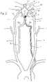
- FIG. 1is a schematic diagram of the vasculature of the brain showing the placement of a protuberant aneurysm bridging device.
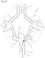
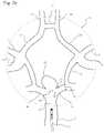
- FIG. 2is schematic diagram of the vasculature of the brain illustrating the Circle of Willis and arteries supplying the Circle of Willis, also showing the placement of the protuberant aneurysm bridging device.
- FIGS. 3 and 4illustrate a protuberant aneurysm bridging device for use in bridging a bifurcation aneurysm.
- FIGS. 5 and 6illustrate a protuberant aneurysm bridging device for use in bridging a bifurcation aneurysm with a proximal region modified to provide additional holding power in an inlet vessel.
- FIG. 7illustrates the placement of radiopaque markers in various positions on the bridging device.
- FIG. 8illustrates the attachment mechanism for securing the bridging device to the site of a bifurcation aneurysm.
- FIG. 9 a -9 gillustrate several steps of delivering the bridging device to the site of a bifurcation aneurysm.
- FIG. 10illustrate the bridging device fully deployed at the site of a bifurcation aneurysm.
- FIG. 11illustrates the step of filling the aneurysm sac with occlusive material, after placement of the bridging device.
- FIG. 12illustrates a protuberant aneurysm bridging device following initial forming being wrapped around a construction mandrel for final shaping.
- FIG. 13illustrates a protuberant aneurysm bridging device side view wherein the device includes a proximal end, a distal end, and several distinct segments there between.
- FIG. 14illustrates one end of a protuberant aneurysm bridging device wherein the device includes an end segment, a first intermediate segment, a second intermediate segment, and a central segment.
- FIG. 15illustrates a complete protuberant aneurysm bridging device formed in the manner of the device of FIG. 14 but showing all the device segments.
- FIG. 16illustrates a flat pattern diagram of a protuberant aneurysm bridging device fabricated from the flat pattern of FIG. 13 and formed around an axially elongate cylindrical shape with further forming generating different patterns in the proximal and distal first intermediate segments as well as the central segment.
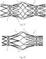
- FIG. 17illustrates a protuberant aneurysm bridging device fabricated from the flat pattern of FIG. 13 and formed around an axially elongate cylindrical shape with further forming generating different patterns in the proximal and distal first intermediate segments as well as the central segment.
- FIG. 18illustrates a protuberant aneurysm bridging device fabricated into its cylindrical shape but having larger 15 length second intermediate segments and shorter length end segments.
- FIG. 19illustrates a protuberant aneurysm bridging device fabricated into an axially elongate cylindrical shape with shorter second intermediate segments than the device of FIG. 18 .
- FIG. 20illustrates a flat pattern of a protuberant aneurysm bridging device similar to the flat pattern of FIG. 13 except that the two first intermediate segments and the central segment are longer and more laterally disposed than that of the flat pattern of FIG. 16 .
- FIG. 21illustrates a protuberant aneurysm bridging device fabricated from the flat pattern shown in FIG. 20 and formed into a cylindrical shape.
- FIG. 22illustrates a close-up of a protuberant aneurysm bridging device flat pattern such as that of FIG. 20 illustrating details of the bar geometry.
- FIG. 23illustrates an oblique view of a protuberant aneurysm bridging device formed into a cylindrical shape and constructed from a flat pattern such as that shown in FIG. 20 .
- FIG. 24illustrates an oblique view of a cylindrically formed protuberant aneurysm bridging device with less severe bending than that of the device in FIG. 23 .
- FIG. 25 aillustrates a cerebrovascular aneurysm located at a vessel bifurcation.
- FIG. 25 billustrates a cerebrovascular aneurysm located at a vessel bifurcation with a commercially available cerebrovascular stent placed across the neck of the aneurysm.
- FIG. 25 cillustrates a cerebrovascular aneurysm located at a vessel bifurcation with a protuberant aneurysm bridging device placed across and partially within the neck of the aneurysm.
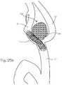
- FIG. 26 aillustrates a giant cerebrovascular aneurysm located at a vessel bifurcation.
- FIG. 26 billustrates a giant cerebrovascular aneurysm with illustrates a cerebrovascular aneurysm located at a vessel bifurcation with a commercially available cerebrovascular stent placed across the neck of the aneurysm.
- FIG. 26 cillustrates a giant cerebrovascular aneurysm with a stylized device slightly herniating into the aneurysm neck and the second of two bifurcation outflow vessels.
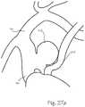
- FIG. 27 aillustrates a cerebrovascular aneurysm located at a vessel bifurcation.
- FIG. 27 billustrates a giant cerebrovascular aneurysm located at a vessel bifurcation with a commercially available cerebrovascular stent placed across the neck of the aneurysm.
- FIG. 27 cillustrates a cerebrovascular aneurysm with a stylized device placed across the aneurysm neck and the bifurcation inflow vessel.
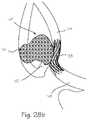
- FIG. 28 aillustrates a small cerebrovascular aneurysm at a trifurcation with a stylized device slightly herniating into the aneurysm neck and two of the trifurcation exit vessels.
- FIG. 28 billustrates a cerebrovascular aneurysm located at a vessel bifurcation with a commercially available cerebrovascular stent placed across the neck of the aneurysm.
- FIG. 28 cillustrates a cerebrovascular aneurysm with a stylized device placed across the aneurysm neck and the bifurcation inflow vessel.
- FIGS. 1 and 2show the vasculature of the brain in sufficient detail to illustrate the use of the protuberant aneurysm bridging device shown in the following illustrations.
- the bridging device 1is shown in an exemplary placement.
- the bridging deviceis delivered to this site of a vascular defect with the delivery catheter 2 .
- the neuro-vasculaturewhich is the intended environment of use for the embolic implant, supplies the brain 3 with blood through the carotid and the vertebral arteries on each side of the neck.
- the important arteriesinclude the common carotid artery 4 in the neck and the internal carotid artery 5 which supplies the ophthalmic artery 6 .
- the external carotid 7supplies the maxillary artery 8 , the middle meningeal artery 9 , and the superficial temporal arteries 10 (frontal) and 11 (parietal).
- the vertebral artery 12supplies the basilar artery 13 and the cerebral arteries including the posterior cerebral artery 14 and the Circle of Willis indicated generally at 15 .
- the siphon 12 a of the vertebral arteryappears in the intra-cranial vasculature on the vertebral approach to the Circle of Willis.
- Also supplied by the internal carotid arteryare the anterior cerebral artery 16 and the middle cerebral artery 17 , as well as the Circle of Willis, including the posterior communicating artery 18 and the anterior communicating artery 19 .
- the siphon 5 a of the internal carotid artery 5appears in the intra-cranial vasculature on the carotid approach into the Circle of Willis. These arteries typically have an internal diameter of about 1 mm to 5 mm, most commonly from 2-4 mm.
- the methods and devices described hereinallow access to these arteries and placement of a bridging device across aneurysm near bifurcations of these arteries. In FIG.
- the insertion catheter 2 and a bridging device 1are shown threaded through the common carotid artery 4 and the internal carotid artery 5 , which will be a common access pathway for the bridging devices, with the bridging device disposed within the basilar artery 13 and posterior cerebral artery 14 , spanning the neck of the basilar tip aneurysm 20 .
- FIG. 2shows the same blood vessels in a schematic view that better illustrates the Circle of Willis and the arteries which supply this important anatomic feature.
- the Circle of Willis 15is a ring of arteries connecting the internal carotid arteries and the basilar artery (and hence the left and right vertebral arteries) to the anterior cerebral arteries 16 , middle cerebral arteries 17 and posterior cerebral arteries 14 .
- the systemprovides a redundant supply of blood to the cerebral arteries.
- the carotid siphon 5 awhich forms an integral part of the internal carotid artery 5 , is more clearly visible in this view.
- FIG. 2shows an exemplary use in which a delivery catheter 2 is inserted through the vertebral artery to the basilar artery to treat a vascular defect 20 (a basilar tip aneurysm, in this case) with a bridging device.
- a delivery catheter 2is inserted through the vertebral artery to the basilar artery to treat a vascular defect 20 (a basilar tip aneurysm, in this case) with a bridging device.
- FIGS. 3 and 4illustrates a protuberant bridging device for use in bridging a bifurcation aneurysm.
- the bridging device 1comprises a stent-like wire-frame structure, substantially tubular in out-line but with most of its wall material removed.
- the bridging deviceis highly flexible, compressible and expandable longitudinally, and compressible and expandable radially, and can be manipulated within the vasculature to shape it to obtain a bulbous center while fixing the ends to segments of blood vessel bifurcation on either side of a bifurcation aneurysm.
- the bridging deviceis characterized by a distal region 21 and a proximal region 22 and a central region 23 .
- the distal regionserves as an anchoring portion, to secure the distal end of the device in a first outlet vessel.
- the proximal regionserves as an anchoring portion, to secure the proximal end of the device in the inlet vessel.
- the central regionserves as a bridging region and a scaffold, to bridge the neck of the aneurysm and hold embolic material in the aneurysm and maintain patency of a second outflow vessel.
- the distal regionwhich corresponds to the distal end of the device (distal referring to the region intended to be disposed deepest within the vasculature (farthest for the origin of an artery), which generally corresponds to the end of the device farthest from the delivery catheter or insertion point in the body) comprises two zigzag segments 24 and 25 disposed with opposing vertices 26 and 27 aligned (the two opposing zigzag segments form a diamond-cell segment 28 , characterized by diamond shaped opening between defined by the struts of opposing V-shaped pairs of struts).
- the zigzag segmentsare superelastically or resiliently biased to open to the generally cylindrical configuration shown in order to expand to engage the walls artery in which it is place with sufficient compliance mismatch to fix the distal region within the artery.
- the proximal regionwhich corresponds to the proximal end of the device (proximal referring to the region intended to be disposed closest to the origin of an artery, which generally corresponds to the end of the device closest to the delivery catheter or insertion point in the body) comprises a zigzag segment 29 and several V-shaped elements 30 disposed with tops 31 aligned with proximally pointing vertices 32 (forming spaced, non-contiguous diamond-cell segments 33 , characterized by diamond-shaped opening defined by the struts of opposing V-shaped pairs of struts).
- the zigzag segmentsare superelastically or resiliently biased to open to the generally cylindrical configuration shown in order to expand to engage the walls of the artery in which it is placed with sufficient compliance mismatch to fix the proximal region within the artery.
- the distal region and proximal regionestablish a cylindrical structure with dimensions, in their expanded configurations, that match or slightly exceed the diameter of the blood vessel in which they are to be placed.
- V-shaped elementsare preferred (for both the distal region and proximal region), the zigzag segments can be configured instead as sinusoidal or wavy segments, with U-shaped elements, for use in larger environments.
- the central region 23is intended to be bulbous, and protrude radially from the cylinder established by the distal end and proximal end, in its expanded configuration.
- the central regioncomprises a pair of opposing zigzag segments 34 and 35 with the vertices aligned to meet near the center of the device, again forming a diamond-cell segment 36 (that is, the centrally pointing vertices of the first central zigzag segment 34 are aligned with centrally pointing vertices of the second central zigzag segment 35 ).
- This paired zigzag or diamond cell segmentis joined, on its proximal end, to the distal end of proximal region.
- the proximally pointing vertices 37are connected to the distally pointing vertices 38 of zigzag segment 29 with spirally oriented strut segments 39 which run, along a helical or spiral course relative to the cylinder established by the distal and proximal regions, from the distally pointing vertices 38 to the proximally pointing vertices 37 .
- the paired zigzag or diamond cell segment 36is joined, on its distal end, to the proximal end of distal region.
- the distally pointing vertices 40are connected to the proximally pointing vertices 41 of zigzag segment 29 with spirally oriented strut segments 42 which run, along a helical or spiral course relative to the cylinder established by the distal and proximal regions, from the distally pointing vertices 40 to the proximally pointing vertices 41 .
- the zigzag segments and spiral strutsare superelastically or resiliently biased to open to the generally cylindrical configuration shown (larger diameter than the distal region and proximal region) in order to expand to engage both the walls of the artery in which it is placed and bridge the open neck of the aneurysm.
- the spirally oriented strutsprovide a hinged connection between the central region and both the proximal region and distal region. Because the central region is intended to bulge and protrude from the central axis of the device, it is preferably devoid of additional structures, beyond the spiral struts, zigzag segments and markers, so that it is not constricted from deforming during installation according to the procedure described below.
- the deviceis removably attached to the delivery wire 43 through an electrolytic detachment joint 44 and several tethers 45 .
- the tethersare additional struts, formed integrally with the remainder of the device, extending around the cylindrical volume established by the proximal region segments, to join the detachment joint along the side of the device.
- the delivery wireruns through insertion catheter 2 .
- the bridging deviceis collapsible to a small diameter configuration which fits inside the distal end of the delivery catheter, and can pass through the lumen of the delivery catheter, for insertion into the body, navigation through the patient's vasculature, and deployment from the distal end.
- the bridging deviceas illustrated, is in its expanded, large diameter configuration, which it assumes after ejection from the distal end of the delivery catheter.
- the bridging deviceincludes several radiopaque markers 46 disposed on the distal region. As illustrated, the distal markers are disposed on the distally pointing vertices of the distal-most zigzag segment of the device. Three markers are provided at this longitudinal location, the distal vertices of the distal zigzag segment 24 . An additional marker 47 is disposed on a spiral strut near the distal region, marking the proximal extent of the distal region. Several radiopaque markers 48 are disposed at the central vertices of the central paired zigzag segment (in this embodiment, each central vertex is marked with its own marker).
- a radiopaque marker 49is disposed near the proximal region, on a spiral strut, marking the distal extent of the proximal region. As illustrated, the proximal marker is disposed on a spiral strut just distal to a distally pointing vertex of the proximal-most zigzag segment of the device. The radiopaque markers facilitate the method of placing the device, which is described below.
- FIG. 4is a schematic illustration of the bridging device of FIG. 3 , showing the device as it would appear if opened and splayed out on a flat surface.
- FIG. 4shows all the same detail of FIG. 3 , and provides an additional view of the zigzag segments, the spiral struts, and the tethers.
- the spiral struts 39connect a proximally pointing vertices 41 of the distal zigzag segment 25 with a distally pointing vertices 40 of the central region which is circumferentially displaced by at least two other vertices.
- the first central zigzag segment 34(which opposes the distal region) is characterized by distally pointing vertices
- the second central zigzag segment 35(which opposes the proximal region) is characterized by proximally pointing vertices.
- the distally pointing vertices of the first central zigzag segmentare joined by the spirally oriented struts 42 extending from an originating distally pointing vertex of the first central zigzag segment to a vertex of the distal zigzag segment 25 which is circumferentially displaced from the originating vertex.
- the proximally pointing vertices of the second central zigzag segment 35are joined by a spirally oriented strut extending from an originating proximally pointing vertex of the second central zigzag segment to a vertex of the proximal zigzag segment 29 which is circumferentially displaced from the originating vertex.
- the displacementmay be one, two or three vertices or more (using a vertex of the zigzag segments as a unit of measure around the circumference of the device).
- FIGS. 5 and 6illustrate a protuberant aneurysm bridging device for use in bridging a bifurcation aneurysm with a proximal region modified to provide additional holding power in an inlet vessel.
- This deviceis modified, vis-a-vis the device shown in FIGS. 3 and 4 , with the addition of another zigzag segment 50 in the proximal region.
- the V-segments of this additional zigzag segmentare aligned with the V-segments of the zigzag segment 29 , with the distally pointing vertices 51 of zigzag segment 50 aligned with the proximally pointing vertices 52 of the zigzag segment 29 .
- zigzag segmentsform a diamond celled segment, which is longer than the corresponding single zigzag segment of FIGS. 3 and 4 , and provides additional holding power within the inlet vessel when implanted at a bifurcation.
- the other elements of bridging device of FIGS. 5 and 6may be identical to the corresponding elements shown in FIGS. 3 and 4 .
- FIG. 7illustrates the placement of radiopaque markers in various positions on the bridging device.
- the markers 46comprise any radiopaque material, disposed around a small portion of the wire frame structure in the vicinity of the extreme distal tip of the V-shaped elements of the zigzag segment 24 . Similar markers are placed at the center region, at the joint between vertices 31 and 32 of the paired zigzag segments 34 and 35 , and also at the proximal regions at the distal vertices of the V-shaped elements of the zigzag segment 29 .
- FIG. 8illustrates the attachment mechanism for securing the bridging device to the delivery wire.
- the attachment mechanismcomprises a detent ball 53 at the distal end of the delivery wire 43 and detent receiver 54 at the proximal end of the tether 45 .
- the detent ballis forced into the detent receiver.
- the jointis covered with a radiopaque marker 55 .
- the electrolytic detachment joint 44is severed electrolytically, upon application of electrical current to the joint through the delivery wire or associated conductor.
- Mechanical detachment mechanismsincluding screw-thread detachment mechanisms, may be used in place of the electrolytic detachment joint.
- FIG. 9 a -9 gillustrate several steps of delivering the bridging device to the site of a bifurcation aneurysm.
- the method of treating bifurcations aneurysmsis illustrated in these Figures in the basilar tip aneurysm because this is a common wide-necked aneurysm that can be treated with the bridging device.
- FIG. 9 a -9 gare set in the Circle of Willis 15 , treating a wide-necked aneurysm 20 at the point where the basilar artery 13 divides into the left and right posterior cerebral arteries 18 .
- the procedurewill be performed by a surgeon, under visualization with fluoroscopy.
- the surgeonhas inserted the delivery catheter 2 , with the delivery wire disposed within the catheter, and the bridging device mounted on the distal tip of the delivery wire, through the patient's vasculature so that the distal tip of the catheter 2 is disposed within the posterior cerebral artery 14 .
- the surgeonpulls the delivery catheter proximally, while holding the bridging device distally, partially deploying it from the delivery catheter so that the distal region is outside the catheter and free to expand (superelastically or elastically, depending on the material comprising the device).
- the distal region of the bridging deviceengages the inner wall of the posterior cerebral artery.
- the release of the distal region from the insertion catheteris seen under fluoroscopy.
- the struts and wires of the devicewill likely not be visible under current fluoroscopy systems, so the surgeon will rely on the radiopaque markers.
- the distal set of markers 46appears outside the delivery catheter, confirming that the distal region is deployed.
- the surgeonhas withdrawn the insertion catheter 2 to release the region of the device bearing the radiopaque marker 47 , which marks the proximal extent of the distal segment.
- the surgeonwill deploy the device, pulling the device proximally or pushing it distally, to align this distal “edge” marker with the edge of the distal (farthest from the catheter tip) margin of the neck of the aneurysm, at this point or later in the method.
- the surgeonhas further withdrawn the insertion catheter 2 to release the central region, so that region of the device bearing the radiopaque markers 48 is deployed, and the markers appear on the fluoroscope. All six of the central region radiopaque markers should be visible.
- the single edge markeris still visible near the distal margin, and the distal markers 46 are visible deeper in the posterior cerebral artery, confirming that the distal region 21 is still properly located.
- the surgeonhas withdrawn the delivery catheter 2 to fully release the central region, so that the proximal radiopaque marker 49 appears on the fluoroscope.
- the surgeonwill manipulate the device, pushing proximally and/or pulling distally, to align this distal “edge” marker with the edge of the proximal (nearest to the catheter tip) margin of the neck of the aneurysm, at this point or later in the method.
- the surgeonhas pushed the delivery wire 43 distally, maintaining the delivery catheter 2 in position, to fully release the central region, to push the proximal region distally toward the bifurcation.
- Thisresults in expansion of the central region, and spreading of the individual spiral struts and zigzag segments through the bifurcation, urging at least one or two of the struts or V-shaped elements into apposition with the aneurysm neck.
- Thisis indicated by the movement of the radiopaque markers toward the neck, as illustrated, so that the proximal radiopaque marker 49 appears on the fluoroscope.
- the single distal edge markeris still visible near the distal margin, and the distal markers 46 are visible deeper in the posterior cerebral artery, confirming that the distal region 21 is still properly located within the posterior cerebral artery.
- the surgeonhas continued manipulating the bridging device with the delivery wire 43 , pushing and pulling as necessary to achieve the shape for the central region that best bridges the aneurysm neck.
- the surgeonhas withdrawn delivery catheter 2 proximally to fully release the bridging device, including the radiopaque marker 55 which is fixed that the distal end of the tethers. Further manipulations may be necessary to ensure that the central region struts and V-shaped elements are best located over the aneurysm neck, the distal edge marker is still co-located with the distal edge of the neck, and the proximal radiopaque marker 49 is co-located with the distal extent of the basilar artery.
- the surgeonis satisfied with the placement, he operates a power supply connected to the electrolytic detachment joint 44 to sever the delivery wire 43 from the bridging device.
- the bridging deviceis shown in this FIG. 9 g , to illustrate a typical placement.
- the bridging deviceis lodged within the bifurcation, with the proximal region expanded to engage the wall of the basilar artery, as shown in FIG. 9 g .
- the devicemay be used as a temporary scaffold to assist in placement of the coils, and the method may be completed in such cases by leaving the detachment joint 44 intact as shown in FIG.
- the surgeondeforms (or re-forms) the bridging device in situ, typically deforming the device into a shape which is different from its unrestrained unstressed, large diameter configuration illustrated in FIG. 6 .
- the surgeondeploys the distal end of the bridging device from the distal end of the delivery catheter as shown in FIG. 9 a .
- the distal region of the bridging deviceself-expands and becomes lodged in the outlet artery.
- Lodgment in the outlet arteryprovides sufficient fixation such that subsequent manipulation, including pushing, pulling and twisting to deform the central region, is accomplished without holding the distal region with any device associated with the delivery system, and without applying proximally compressive force on the distal end or distal region of the bridging device, and without squeezing the device or pulling the distal region toward the proximal region. That is, no portion of the delivery system or other device is used to restrain the distal region, or pull it proximally toward the proximal region, and lodgment within the outlet vessel is relied upon to hold the distal region in place while the proximal region and central region are pushed, pulled and twisted by the surgeon implanting the device.
- the central regionUpon deployment of the central region, as illustrated in FIG. 9 c , the central region twists, or rotates about the longitudinal axis of the bridging device, relative to the distal region (which is lodged in the outlet vessel). Release of the proximal region also causes the proximal region to rotate about the longitudinal axis of the bridging device, relative to the central and distal regions.
- twisting of the central region and proximal region, relative the distal regioncan be accomplished by releasing the central region and proximal region from the delivery catheter. While pushing and pulling the device with the delivery wire to manipulate the central region while the proximal region is still within the distal tip of the delivery catheter ( FIG.
- the surgeonmay twist the proximal region, which causes opening of the spiral struts (proximal spiral struts 39 , or distal spiral struts 42 , or both) and further bulging of the central region.
- the surgeoncontinues to push, pull and twist the bridging device, using the delivery wire, until the central region is deformed such that the central region struts and V-shaped elements are best located over the aneurysm neck.
- the bridging deviceis fabricated to be self-expandable, and is elastically or pseudoelastically deformable to a small diameter configuration for delivery through a delivery catheter, and elastically or pseudoelastically deformable to expand and revert to, or toward, its original large diameter configuration when released from the delivery catheter, it may also be further elastically or pseudoelastically deformed to enlarge or reduce the diameter of the central section, or deform it non-uniformly to bulge toward the neck of the aneurysm.
- FIG. 11illustrates the step of filling the aneurysm sac with occlusive material, after placement of the bridging device.
- the delivery catheter and delivery wirehave been withdrawn, and another delivery catheter 56 has been inserted through the vasculature, through the lumen defined by the proximal region 22 , out of the device, through spaces between the struts or segments of the central region 23 , and into the aneurysm 20 .
- the surgeonwill use this catheter to deliver occlusive material, which may include the illustrated embolic framing coil 57 , embolic coils, hydrocoils, or embolic substances.
- the central struts and V-shaped elementswhich protrude from the main axis of the device (relative to the diameter established by the distal and proximal regions) will act as scaffolds to hold the embolic material (especially the finest embolic coil loops) in place and prevent it from dropping out of the aneurysm sac to occlude the opposite posterior cerebral artery.
- the methodcan be used to treat bifurcation aneurysms at bifurcations of the middle cerebral artery 17 , the internal carotid artery 5 , the anterior communicating artery 19 (at the anterior cerebral artery 16 ), the superior cerebellar artery, the pericallosal artery (a continuation of the anterior cerebral artery), the posterior inferior cerebellar artery, or any other bifurcation.
- Each bifurcationis characterized by an inlet artery, and first outlet artery and a second outlet artery, which in the illustration of FIGS. 9 a through 9 g correspond to the basilar artery, the left posterior communicating artery and the right posterior communicating artery.
- FIG. 12illustrates an embodiment of a protuberant aneurysm bridging device 61 assembled over a mandrel 62 .
- the device 61comprises a distal end region 21 , comprising a zigzag segment 63 d comprising V-shaped segments 64 d and a proximal end region 22 comprising a zigzag segment 63 p comprising V-shaped segments 64 p , and a central region 23 .
- the central regioncomprises two first intermediate spiral strut regions 65 , each comprising a plurality of first intermediate spirally oriented struts 66 , two second intermediate zigzag segments 67 d and 67 p each with a plurality of second intermediate V-shaped struts 68 , and a plurality of spirally oriented center struts 69 joining vertices of the zigzag segment of the second intermediate V-shaped struts on either end of the spirally oriented center struts.
- This protuberant aneurysm bridging devicecan be symmetric about an axis running laterally to the longitudinal axis.
- FIG. 13illustrates a side view of the protuberant aneurysm bridging device 61 clarifying the end regions 63 d and 63 p , the central region 69 , and first intermediate strut regions 65 .
- the spirally oriented struts that join each of the zigzag segmentsextend, as described in relation to the spirally oriented struts of FIGS. 3 and 4 , circumferentially around the volume defined by the device, from a vertex of one zigzag segment to a vertex of the next zigzag segment which is circumferentially displaced from the originating vertex.
- the displacementmay be one, two or three vertices or more (using a vertex of the zigzag segments as a unit of measure around the circumference of the device).
- the protuberant aneurysm bridging device 61is fabricated by cutting a pattern.
- the patterncan be cut into a flat sheet of device material which is then rolled and the ends affixed to each other.
- the flat sheet embodimentcan be fabricated using laser cutting, electrical discharge machining (EDM), wire EDM, photochemical etching, mechanically machined, or otherwise machined.
- EDMelectrical discharge machining
- the device 61can be cut from a tubular blank using methodology itemized above for the flat sheet embodiment.
- the protuberant aneurysm bridging device 61can be fabricated from materials such as nitinol, shape memory nitinol, martensitic nitinol, superelastic or pseudoelastic nitinol, stainless steel, titanium, cobalt nickel alloys, tantalum, and the like.
- the device 61can be malleable or it can be elastically biased outward to be self-expanding.
- the protubererant aneurysm bridging device 61can be expanded or dilated from a first, smaller inside diameter, to a second, larger inside diameter.
- the device 61can next be temporarily affixed about the mandrel 62 .
- the device 61can next be selectively twisted to expand and re-configure specific regions, especially the spiral regions such as the central region 69 or one or both of the first intermediate regions 65 .
- the device 61can next be heat set to retain its shape.
- the device 61is fabricated from nitinol which can be heat set at temperatures of about 450° C. to about 550° C.
- FIG. 12illustrates one of many configurations possible for a device using different flat patterns, different materials, different numbers of struts, and different strut thicknesses, widths, and lengths.
- the number of strutscan vary between about 6 and about 16 or more, and preferably between about 8 and 14, with a generally similar number of slots interspaced between the struts.
- FIG. 14illustrates a side view of the distal end of a protuberant aneurysm bridging device 70 comprising an end region 71 , a first intermediate region 72 , a second intermediate region 73 , and a central region 74 .
- the device 70is generally the same or similar as that of the device 61 of FIG. 12 .
- FIG. 15illustrates a side view of a protuberant aneurysm bridging device 75 comprising two end regions 76 , two first intermediate regions 77 , two second intermediate regions 78 , and a central region 79 .
- the two first intermediate regions 80are configured to provide bending out of the longitudinal axis.
- the central region 81is further configured for axial bending.
- the two end regions 82 and the two second intermediate regions 83comprise zigzag segments, maintain partial diamond, diamond, or wave structures that are generally stiff and resist bending out of the longitudinal axis but provide superior hoop strength and holding power within an artery or vessel.
- the central region 79is generally loosely configured with large spaces between struts or elements and permits blood flow therethrough.
- the first intermediate regions 77are further configured for greater open space than the end regions 76 or the second intermediate regions 78 .
- the first intermediate region 77can be beneficial when placed across a bifurcation or trifurcation outlet vessel and permit continued blood flow without embolization.
- the end regions 76can be configured, as illustrated, with an outward taper to facilitate holding within the vessel wall.
- FIG. 16illustrates a flat pattern 84 corresponding to the tubular protuberant aneurysm bridging device 61 , 70 or 75 .
- the flat pattern 84comprises a plurality of end bars 85 , a plurality of first intermediate bars 86 , a plurality of second intermediate bars 87 , and a plurality of central bars 88 .
- the flat pattern 84comprises a plurality of repeating patterns, for example 10 repeat patterns in the lateral direction, but this number can vary as described herein.
- the end regions 85are formed as undulations or “V” patterns interconnected to each other.
- the end regions 85can also be formed as a plurality of approximately diamond-shaped patterns.
- the end regions 85are interconnected at their interior ends to the outside ends of the first intermediate region bars or struts 86 .
- the inner ends of the first intermediate struts 86are connected to the outer ends of the second intermediate struts 87 but the connection is not symmetrical but slightly off-center of the arc connecting the “V” patterns.
- the first intermediate strutsare configured with a slight wave but can also be straight, more strongly “S” shaped, or shaped in some other suitable wave or geometric pattern.
- This flat pattern 84can be used to program a cutting system to create the pattern in a tubular blank. Alternately, this flat pattern 84 can be fabricated into a flat sheet of material which is then rolled circumferentially and the ends welded or otherwise affixed.
- a preferred specificationprovides for three longitudinal cells and ten repeat patterns circumferentially.
- the width of the barsis about 65 micrometers and the wall thickness of the material is about 74 micrometers.
- the illustrated flat pattern 84can be suitable for, or cut from, a tube having a diameter of about 2.464 mm.
- the diameter of the tubing blankcan vary depending on the application.
- the wall thicknesscan vary from about 0.25 mm to about 0.5 mm to about 0.20 mm.
- the bar or strut widthcan vary from about 0.25 mm to about 0.1 mm with a preferred range of about 0.3 mm to about 0.5 mm.
- FIG. 17illustrates a protuberant aneurysm bridging device 89 fabricated from a flat pattern similar to, or the same as, that illustrated in FIG. 16 .
- the device 89comprises two end sections 90 , two first intermediate sections 91 , two second intermediate sections 92 , and a central section 93 .
- the wavy patterns in the end sections 90are relatively large with large strut lengths.
- the overall length of the device 89is about 15 mm but this length can vary between about 8 mm and about 25 mm.
- FIG. 18illustrates a protuberant aneurysm bridging device 89 comprising two end sections 94 and a central region comprising two first intermediate sections 95 , two second intermediate sections 96 , and a central spiral strut section 97 .
- the wavy patterns in the end sections 94are relatively short and provide for a stiffer end section 94 than in the end sections 90 of the device 89 .
- the second intermediate sections 96are relatively long compared to the second intermediate sections 96 of the device 89 of FIG. 17 .
- These types of strut length changesare typically performed at the stage of fabricating the flat pattern such as in FIG. 16 .
- the overall length of the device 89is about 15 mm but can range from about 8 mm to about 25 mm.
- the central region 97 and the two secondary intermediate regions 96 togethercomprise a length of about 10 mm but this length can vary between about 5 mm and about 15 mm.
- the outside diameter of the two end sectionsis about 4 mm in FIG. 18 but this diameter can vary between about 2 mm and about 6 mm.
- the diameter of the enlarged central region, at its greatestis about 8 mm but can vary between about 3 mm and about 12 mm.
- FIG. 19illustrates a side view of a protuberant aneurysm bridging device 99 comprising two end sections 100 and a central region comprising two first intermediate sections 101 , two second intermediate sections 102 , and a central spiral strut section 103 .
- the device 99comprises second intermediate regions 102 which have shorter struts than those 96 of device 89 and about the same as the intermediate regions 92 of device 89 .
- the central region 103is longer than the central region 97 of device 89 and about the same as the central region 93 of device 89 .
- the overall length of the protuberant aneurysm bridging device 99is about 15 mm but can vary between about 8 and 25 mm.
- the central region 103 and the two secondary intermediate regions 102comprise about 8.5 mm length but this can vary between about 5 mm and about 15 mm.
- the overall diameter of the unstressed, expanded central region 103is about 6 mm but can vary between about 4 mm and about 12 mm.
- the outside diameter of the end regions 100is about 4 mm with a range of about 2 mm to about 8 mm.
- FIG. 20illustrates a flat pattern 104 of a protuberant aneurysm bridging device comprising 16 repeat patterns in the circumferential direction.
- the flat pattern 104comprises two end regions 105 and a central region comprising two first intermediate regions 106 , two secondary intermediate regions 107 and a central spiral strut region 108 .
- the flat pattern 104is denser in the circumferential direction than the flat pattern 84 since it has more struts.
- the flat pattern 104comprises three cells, wherein two cells comprise an end region 105 and a secondary intermediate region 107 as well as the connecting first intermediate region 106 .
- the third cellcomprises the central region 108 and the two secondary intermediate regions 107 .
- the tube diameter preferred for this configurationis about 2.462 mm on the outside but can range from about 1 mm to about 4 mm.
- the wall thicknessesare similar to those specified for the flat pattern 84 in FIG. 16 .
- the bar widthswould generally be somewhat smaller for the embodiment 104 than in the flat pattern 84 since there are more bars (and spaces) in flat pattern 104 than in flat pattern 84 .
- FIG. 21illustrates a side view of a protuberant aneurysm bridging device 109 fabricated from the flat pattern 104 .
- the device 109comprises two end regions 110 , one at each end.
- the device 109further comprises a central region comprising two first intermediate sections 111 and two second intermediate sections 112 , on both sides of the central spiral strut section 113 . All sections and struts are preferably formed integrally, as is the case for most devices disclosed within this document.
- the number of repeat patterns in FIG. 21is 16 resulting in a device 109 with a high metal to open space ratio relative to the devices fabricated from the flat pattern in FIG. 16 .
- the first intermediate sections 111 and the central section 113comprise more open space than the rest of the device 109 .
- FIG. 22illustrates a close-up of a protuberant aneurysm bridging device 114 , which is similar to the device 109 of FIG. 21 .
- the device 114comprises the central region 115 , the second intermediate region 116 , the arcuate ends 117 of the second intermediate region 116 , and the connector region 118 .
- the connector region 118is slightly thicker than the majority of the bar structure of the device 114 . This increased thickness or bar width in the connector region 118 provides additional stiffness and strength in the connector region.
- the connector region 118is affixed to the arcuate region 117 connecting the adjacent bars of the secondary intermediate region 116 .
- FIG. 23illustrates an oblique view of a protuberant aneurysm bridging device 119 having eight repeat patterns in the circumferential direction.
- the device 119comprises the first and second end regions 120 , and a central region comprising two first intermediate regions 121 , two secondary intermediate regions 122 , and a central spiral strut region 123 .
- the protuberant aneurysm bridging device 119has more open space ratio than devices having greater numbers of repeat patterns such as shown in FIGS. 17, 18 , and FIG. 21 .
- the secondary intermediate region 122comprises relatively short strut lengths.
- FIG. 24illustrates a protuberant aneurysm bridging device 124 in oblique view comprising two end regions 125 , two first intermediate regions 126 (with spiral struts), two secondary intermediate regions 127 (zigzag segments) and a central region 128 .
- This protuberant aneurysm bridging device 124is similar to the device 119 of FIG. 23 except that the bars in the secondary intermediate region 127 are longer than those in the secondary intermediate region 122 of FIG. 23 .
- Both the device 124 and the device 119comprise eight bars and eight spaces moving circumferentially in the central sections 123 and 128 .
- FIG. 25 aillustrates a cerebrovascular aneurysm 129 taken with fluoroscopy and dye injection wherein the aneurysm 129 is located at the junction of a bifurcation comprising an inflow artery 130 , a first exit artery 131 , and a second outflow artery 132 .
- FIG. 25 billustrates a cerebrovascular aneurysm 125 taken with fluoroscopy and dye injection wherein the aneurysm 129 is located at the junction of a bifurcation comprising an inflow artery 130 , a first exit artery 131 , and a second outflow artery 132 .
- a simplified example of a commercially available cerebrovascular stent 133is illustrated placed within the bifurcation such that the inlet to the device 133 is coaxial with the inlet artery 130 and the outlet of the device 133 is coaxial with the first outlet artery 131 .
- An embolizing masssuch as platinum coils 134 , is shown within the aneurysm 129 .
- the stent 133is shown placed across the entrance to, or the neck of, the aneurysm 129 allowing the coil mass to occlude the entrance to the secondary outlet artery 132 .
- FIG. 25 cillustrates a cerebrovascular aneurysm 129 taken with fluoroscopy and dye injection wherein the aneurysm 129 is located at the junction of a bifurcation comprising an inflow artery 130 , a first exit artery 131 , and a second outflow artery 132 .
- a simplified example of a protuberant aneurysm bridging device 135is illustrated placed within the bifurcation such that the inlet to the device 135 is coaxial with the inlet artery 130 and the outlet of the device 135 is coaxial with the first outlet artery 131 .
- An embolizing platinum coil massis shown within the aneurysm 129 .
- the protuberant aneurysm bridging device 135is shown placed across the entrance to, or the neck of, the aneurysm 129 and protruding into the aneurysm neck holding, via the central bulge 136 of the device and supporting the platinum coil mass 137 to allow flow into the entrance to the secondary outlet artery 132 .
- the bars of the device 135are widely spaced in the region of the secondary outlet artery 138 inlet as well as in the region of the aneurysm 129 neck such that blood is free to flow through these widely spaced device bars while providing some holding power to the embolizing coil mass 137 .
- FIG. 26 aillustrates a giant bifurcate cerebrovascular aneurysm 139 at a bifurcation with an entrance vessel 140 to the bifurcation, a first outflow vessel 141 and a second outlet vessel 142 .
- FIG. 26 billustrates a giant bifurcate cerebrovascular aneurysm 139 taken with fluoroscopy and dye injection wherein the aneurysm 139 is located at the junction of a bifurcation comprising an inflow artery 140 , a first exit artery 141 , and a second outflow artery 142 .
- a simplified example of a commercially available cerebrovascular stent 133is illustrated placed within the bifurcation such that the inlet to the device 133 is coaxial with the inlet artery 140 and the outlet of the device 133 is coaxial with the first outlet artery 141 .
- An embolizing masssuch as platinum coils 134 , is shown within the aneurysm 139 .
- the stent 133is shown placed across the entrance to, or the neck of, the aneurysm 139 allowing the coil mass to occlude the entrance to the secondary outlet artery 142 .
- FIG. 26 cillustrates a giant bifurcate cerebrovascular aneurysm 139 taken with fluoroscopy and dye injection wherein the aneurysm 139 is located at the junction of a bifurcation comprising an inflow artery 140 , a first exit artery 141 , and a second outflow artery 142 .
- a simplified example of a protuberant aneurysm bridging device 135is illustrated placed within the bifurcation such that the inlet to the device 135 is coaxial with the inlet artery 140 and the outlet of the device 135 is coaxial with the first outlet artery 141 .
- An embolizing platinum coil massis shown within the aneurysm 139 .
- the protuberant aneurysm bridging device 135is shown placed across the entrance to, or the neck of, the aneurysm 139 and protruding into the aneurysm neck holding, via the central bulge of the device 135 and supporting the platinum coil mass 134 to allow flow into the entrance to the secondary outlet artery 142 .
- the bars of the device 135are widely spaced in the region of the secondary outlet artery 142 inlet as well as in the region of the aneurysm 139 neck such that blood is free to flow through these widely spaced device bars while providing some holding power to the embolizing coil mass 134 .
- FIG. 27 aillustrates a cerebrovascular aneurysm 143 taken with fluoroscopy and dye injection wherein the aneurysm is located at the junction of a bifurcation comprising an inflow artery 144 , a first exit artery 145 , and a second outflow artery 146 .
- FIG. 27 billustrates a cerebrovascular aneurysm 143 taken with fluoroscopy and dye injection wherein the aneurysm 143 is located at the junction of a bifurcation comprising an inflow artery 144 , a first exit artery 145 , and a second outflow artery 146 .
- a simplified example of a commercially available cerebrovascular stent 133is illustrated placed within the bifurcation such that the inlet to the device 133 is coaxial with the inlet artery 144 and the outlet of the device 133 is coaxial with the first outlet artery 145 .
- An embolizing masssuch as platinum coils 134 , is shown within the aneurysm 143 .
- the stent 133is shown placed across the entrance to, or the neck of, the aneurysm 143 allowing the coil mass to occlude the entrance to the secondary outlet artery 146 .
- FIG. 27 cillustrates a cerebrovascular aneurysm 143 taken with fluoroscopy and dye injection wherein the aneurysm 143 is located at the junction of a bifurcation comprising an inflow artery 144 , a first exit artery 145 , and a second outflow artery 146 .
- a simplified example of a protuberant aneurysm bridging device 135is illustrated placed within the bifurcation such that the inlet to the device 135 is coaxial with the inlet artery 144 and the outlet of the device 135 is coaxial with the first outlet artery 145 .
- An embolizing platinum coil massis shown within the aneurysm 143 .
- the protuberant aneurysm bridging device 135is shown placed across the entrance to, or the neck of, the aneurysm 143 and protruding into the aneurysm neck, and holding, via the central bulge of the device 135 , and supporting the platinum coil mass 134 to allow flow into the entrance to the secondary outlet artery 146 .
- the bars of the device 135are widely spaced in the region of the secondary outlet artery 146 inlet as well as in the region of the aneurysm 143 neck such that blood is free to flow through these widely spaced device bars while providing some holding power to the embolizing coil mass 134 .
- FIG. 28 aillustrates a cerebrovascular aneurysm 147 taken with fluoroscopy and dye injection wherein the aneurysm 147 is located at the junction of a bifurcation comprising an inflow artery 148 , a first exit artery 149 , and a second outflow artery 150 .
- FIG. 28 billustrates a cerebrovascular aneurysm 147 taken with fluoroscopy and dye injection wherein the aneurysm 147 is located at the junction of a bifurcation comprising an inflow artery 148 , a first exit artery 149 , and a second outflow artery 150 .
- a simplified example of a commercially available cerebrovascular stent 133is illustrated placed within the bifurcation such that the inlet to the device 133 is coaxial with the inlet artery 148 and the outlet of the device 133 is coaxial with the first outlet artery 149 .
- An embolizing masssuch as platinum coils 134 , is shown within the aneurysm 147 .
- the stent 133is shown placed across the entrance to, or the neck of, the aneurysm 147 allowing the coil mass to occlude the entrance to the secondary outlet artery 150 .
- FIG. 28 cillustrates a cerebrovascular aneurysm 147 taken with fluoroscopy and dye injection wherein the aneurysm 147 is located at the junction of a bifurcation comprising an inflow artery 148 , a first exit artery 149 , and a second outflow artery 150 .
- a simplified example of a protuberant aneurysm bridging device 135is illustrated placed within the bifurcation such that the inlet to the device 135 is coaxial with the inlet artery 148 and the outlet of the device 135 is coaxial with the first outlet artery 149 .
- An embolizing platinum coil massis shown within the aneurysm 147 .
- the protuberant aneurysm bridging device 135is shown placed across the entrance to, or the neck of, the aneurysm 147 and protruding into the aneurysm neck, holding, via the central bulge of the device 135 , and supporting the platinum coil mass 134 to allow flow into the entrance to the secondary outlet artery 150 .
- the bars of the device 135are widely spaced in the region of the secondary outlet artery 150 inlet as well as in the region of the aneurysm 147 neck such that blood is free to flow through these widely spaced device bars while providing some holding power to the embolizing coil mass 134 .
- Nitinolis preferred because its biocompatibility is well proven, and it is available in numerous compositions with well-controlled, predictable transition temperatures.
- Other shape memory or pseudoelastic materialscan also be used, and normally elastic stainless steel, cobalt nickel alloys, and plastics may be used.
- the nitinol used for the devicemay be used in its shape memory formulation, with a transition temperature just above body temperature, in which case the device may be returned to its memorized shape upon the injection of warm water (just above body temperature).
- the nitinol used for the devicemay be used in its pseudoelastic formulations, in which the nitinol is superelastic (also called pseudoelastic) at body temperature, in which case the device will automatically revert to its memorized shape when inside the body.
- the superelastic devicecan be deformed to fit within the delivery catheter so that it can be inserted into the body, and it reverts to the memorized shape, utilizing elasticity, phase changes, or both, when released from the catheter in the blood stream.
- the occluding structureenhance formation of thrombus within the aneurysm.
- the occluding structuremay be coated with known thrombogenic materials such as platinum.
- the struts which remain outside the aneurysm sac and within the blood streampreferably remain uncoated with such a thrombogenic coating, and are preferably coated with an anti-thrombogenic coating such as heparin, tin, or other such coatings as previously disclosed in the medical device art.
- the occluding devicecan comprise segments of varying thrombo-active coatings, depending on the desired characteristic of each segment.
- the devicescan also be coated with materials such as tantalum, gold and platinum in order to enhance the visibility of the devices under fluoroscopy.
- the devicescan be clearly visualized under intravascular ultrasound which can be used to aid in deployment and proper placement. While the devices will provide for the primary treatment of aneurysms, they may also be used in conjunction with embolic materials such as, but not limited to, baskets, embolic coils, hardenable polymers, and the like in order to hold these foreign materials within the aneurysm and prevent their migration from the aneurysm into the blood stream.
- Certain aspects of the inventionsinclude methods of implantation of the protuberant aneurysm bridging device.
- the deviceis loaded into a delivery microcatheter.
- a Seldinger techniquecan be used to obtain percutaneous access to the femoral artery and an optional introducer sheath can be retained within the arterial access site to aid in device insertion and removal.
- a guide cathetercan be routed through the femoral access site to the cerebrovasculature, or as close as possible, with the aid of a guidewire.
- the guidewirecan be removed and the device delivery microcatheter can be introduced through the guide catheter and advanced into the Basilar artery, the Circle of Willis, or other location.
- the device delivery microcathetercan be advanced under fluoroscopic guidance, single or bi-planar, to the target region.
- the distal end of the device delivery microcathetercan be advanced into the first outlet vessel of a bifurcation.
- the proximal end of the device delivery microcathetercan be retained well within the inlet vessel to the bifurcation.
- the radiopaque markerscan be aligned at this time to ensure the device deploys with the open mesh directed toward the entrance to the second exit vessel.
- the protuberant aneurysm bridging devicecan be expanded using an angioplasty type balloon or using internal recovery such as spring biasing, shape memory transformation, or the like.
- the position of the protuberant aneurysm bridging devicecan be confirmed using fluoroscopy, IVUS, MM, or the like. Further expansion of the protuberant aneurysm bridging device can be performed, if necessary, prior to final detachment of the device from the delivery catheter and removal of the device delivery catheter from the patient. Following placement of the device, a microcatheter can be used to delivery embolic devices into the aneurysm through the open walls of the central region of the device. When the procedure is completed and fully interrogated to ensure correct treatment (e.g., no embolic coils protruding into the parent vessel), the embolic device delivery devices can be removed from the patient.
Landscapes
- Health & Medical Sciences (AREA)
- Engineering & Computer Science (AREA)
- Biomedical Technology (AREA)
- Life Sciences & Earth Sciences (AREA)
- Veterinary Medicine (AREA)
- Public Health (AREA)
- General Health & Medical Sciences (AREA)
- Animal Behavior & Ethology (AREA)
- Heart & Thoracic Surgery (AREA)
- Vascular Medicine (AREA)
- Oral & Maxillofacial Surgery (AREA)
- Cardiology (AREA)
- Transplantation (AREA)
- Surgery (AREA)
- Medical Informatics (AREA)
- Molecular Biology (AREA)
- Reproductive Health (AREA)
- Nuclear Medicine, Radiotherapy & Molecular Imaging (AREA)
- Optics & Photonics (AREA)
- Physics & Mathematics (AREA)
- Neurosurgery (AREA)
- Surgical Instruments (AREA)
- Prostheses (AREA)
- Gastroenterology & Hepatology (AREA)
- Pulmonology (AREA)
Abstract
Description
Claims (11)
Priority Applications (1)
| Application Number | Priority Date | Filing Date | Title |
|---|---|---|---|
| US16/816,612US11406519B2 (en) | 2011-11-04 | 2020-03-12 | Protuberant aneurysm bridging device deployment method |
Applications Claiming Priority (7)
| Application Number | Priority Date | Filing Date | Title |
|---|---|---|---|
| US201161556122P | 2011-11-04 | 2011-11-04 | |
| US13/647,315US8771341B2 (en) | 2011-11-04 | 2012-10-08 | Protuberant aneurysm bridging device and method of use |
| US13/850,266US8808361B2 (en) | 2011-11-04 | 2013-03-25 | Protuberant aneurysm bridging device and method of use |
| US14/274,212US9072620B2 (en) | 2011-11-04 | 2014-05-09 | Protuberant aneurysm bridging device deployment method |
| US14/745,672US9763815B2 (en) | 2011-11-04 | 2015-06-22 | Protuberant aneurysm bridging device deployment method |
| US15/669,544US10624772B2 (en) | 2011-11-04 | 2017-08-04 | Protuberant aneurysm bridging device deployment method |
| US16/816,612US11406519B2 (en) | 2011-11-04 | 2020-03-12 | Protuberant aneurysm bridging device deployment method |
Related Parent Applications (1)
| Application Number | Title | Priority Date | Filing Date |
|---|---|---|---|
| US15/669,544ContinuationUS10624772B2 (en) | 2011-11-04 | 2017-08-04 | Protuberant aneurysm bridging device deployment method |
Publications (2)
| Publication Number | Publication Date |
|---|---|
| US20200206005A1 US20200206005A1 (en) | 2020-07-02 |
| US11406519B2true US11406519B2 (en) | 2022-08-09 |
Family
ID=51421340
Family Applications (4)
| Application Number | Title | Priority Date | Filing Date |
|---|---|---|---|
| US14/274,212ActiveUS9072620B2 (en) | 2011-11-04 | 2014-05-09 | Protuberant aneurysm bridging device deployment method |
| US14/745,672Active2032-11-13US9763815B2 (en) | 2011-11-04 | 2015-06-22 | Protuberant aneurysm bridging device deployment method |
| US15/669,544Active2033-08-03US10624772B2 (en) | 2011-11-04 | 2017-08-04 | Protuberant aneurysm bridging device deployment method |
| US16/816,612Active2033-02-25US11406519B2 (en) | 2011-11-04 | 2020-03-12 | Protuberant aneurysm bridging device deployment method |
Family Applications Before (3)
| Application Number | Title | Priority Date | Filing Date |
|---|---|---|---|
| US14/274,212ActiveUS9072620B2 (en) | 2011-11-04 | 2014-05-09 | Protuberant aneurysm bridging device deployment method |
| US14/745,672Active2032-11-13US9763815B2 (en) | 2011-11-04 | 2015-06-22 | Protuberant aneurysm bridging device deployment method |
| US15/669,544Active2033-08-03US10624772B2 (en) | 2011-11-04 | 2017-08-04 | Protuberant aneurysm bridging device deployment method |
Country Status (1)
| Country | Link |
|---|---|
| US (4) | US9072620B2 (en) |
Families Citing this family (18)
| Publication number | Priority date | Publication date | Assignee | Title |
|---|---|---|---|---|
| EP1951129B1 (en) | 2005-10-19 | 2012-11-21 | Pulsar Vascular, Inc. | Methods and systems for endovascularly clipping and repairing lumen and tissue defects |
| US10716573B2 (en) | 2008-05-01 | 2020-07-21 | Aneuclose | Janjua aneurysm net with a resilient neck-bridging portion for occluding a cerebral aneurysm |
| US10028747B2 (en) | 2008-05-01 | 2018-07-24 | Aneuclose Llc | Coils with a series of proximally-and-distally-connected loops for occluding a cerebral aneurysm |
| WO2010028314A1 (en) | 2008-09-05 | 2010-03-11 | Pulsar Vascular, Inc. | Systems and methods for supporting or occluding a physiological opening or cavity |
| EP2805680B1 (en) | 2009-09-04 | 2017-10-25 | Pulsar Vascular, Inc. | Systems for enclosing an anatomical opening |
| US9358140B1 (en) | 2009-11-18 | 2016-06-07 | Aneuclose Llc | Stent with outer member to embolize an aneurysm |
| CN103547222B (en) | 2011-05-11 | 2016-02-10 | 柯惠有限合伙公司 | Vascular remodeling device |
| CN103582460B (en) | 2011-06-03 | 2019-03-19 | 帕尔萨维斯库勒公司 | Aneurysm devices and related systems and methods with additional anchoring mechanism |
| EP2713905B1 (en) | 2011-06-03 | 2022-03-16 | Pulsar Vascular, Inc. | Systems for enclosing an anatomical opening, including shock absorbing aneurysm devices |
| US9119625B2 (en) | 2011-10-05 | 2015-09-01 | Pulsar Vascular, Inc. | Devices, systems and methods for enclosing an anatomical opening |
| US8771341B2 (en) | 2011-11-04 | 2014-07-08 | Reverse Medical Corporation | Protuberant aneurysm bridging device and method of use |
| US9072620B2 (en) | 2011-11-04 | 2015-07-07 | Covidien Lp | Protuberant aneurysm bridging device deployment method |
| US10342686B2 (en)* | 2017-08-10 | 2019-07-09 | Covidien Lp | Thin film mesh hybrid for treating vascular defects |
| JP7648607B2 (en)* | 2019-09-09 | 2025-03-18 | シファメド・ホールディングス・エルエルシー | ADJUSTABLE SHUNTS AND ASSOCIATED SYSTEMS AND METHODS - Patent application |
| JP2023540220A (en) | 2020-08-25 | 2023-09-22 | シファメド・ホールディングス・エルエルシー | Adjustable interatrial flow diverter and related systems and methods |
| EP4243915A4 (en) | 2020-11-12 | 2024-08-07 | Shifamed Holdings, LLC | ADJUSTABLE IMPLANTABLE DEVICES AND RELATED METHODS |
| US12090290B2 (en) | 2021-03-09 | 2024-09-17 | Shifamed Holdings, Llc | Shape memory actuators for adjustable shunting systems, and associated systems and methods |
| US20250221834A1 (en)* | 2024-01-09 | 2025-07-10 | Route 92 Medical, Inc. | Systems and methods for treating vascular disease |
Citations (123)
| Publication number | Priority date | Publication date | Assignee | Title |
|---|---|---|---|---|
| US4577631A (en) | 1984-11-16 | 1986-03-25 | Kreamer Jeffry W | Aneurysm repair apparatus and method |
| US5354295A (en) | 1990-03-13 | 1994-10-11 | Target Therapeutics, Inc. | In an endovascular electrolytically detachable wire and tip for the formation of thrombus in arteries, veins, aneurysms, vascular malformations and arteriovenous fistulas |
| US5669931A (en) | 1995-03-30 | 1997-09-23 | Target Therapeutics, Inc. | Liquid coils with secondary shape |
| CN1186423A (en) | 1995-04-26 | 1998-07-01 | 梅迪诺尔有限公司 | Articulated stent |
| US5894929A (en) | 1997-06-19 | 1999-04-20 | Yugenkaisha Kusaka Raremetal Kenkyusho | Vacuum packaging bag and vacuum packaging method |
| WO1999040873A1 (en) | 1998-02-12 | 1999-08-19 | Marotta Thomas R | Endovascular prosthesis |
| US5951599A (en) | 1997-07-09 | 1999-09-14 | Scimed Life Systems, Inc. | Occlusion system for endovascular treatment of an aneurysm |
| US5980554A (en) | 1997-05-05 | 1999-11-09 | Micro Therapeutics, Inc. | Wire frame partial flow obstruction for aneurysm treatment |
| WO2000007524A1 (en) | 1998-08-05 | 2000-02-17 | Advanced Cardiovascular Systems, Inc. | Intra-luminal device for treatment of body cavities and lumens and method of use |
| US6063111A (en) | 1998-03-31 | 2000-05-16 | Cordis Corporation | Stent aneurysm treatment system and method |
| US6168616B1 (en) | 1997-06-02 | 2001-01-02 | Global Vascular Concepts | Manually expandable stent |
| US20010000797A1 (en) | 1996-01-24 | 2001-05-03 | Microvena Corporation | Method and apparatus for occluding aneurysms |
| US20010001835A1 (en) | 1998-07-06 | 2001-05-24 | Greene George R. | Vascular embolization with an expansible implant |
| US6309367B1 (en) | 1999-07-23 | 2001-10-30 | Neurovasx, Inc. | Aneurysm shield |
| JP2002536112A (en) | 1999-02-12 | 2002-10-29 | ノボ・アールピーエス・ユーエルシー | Inflatable endovascular inflammation prosthesis |
| US20030018294A1 (en) | 2001-07-20 | 2003-01-23 | Cox Brian J. | Aneurysm treatment device and method of use |
| US20030028209A1 (en) | 2001-07-31 | 2003-02-06 | Clifford Teoh | Expandable body cavity liner device |
| US20030040772A1 (en) | 1999-02-01 | 2003-02-27 | Hideki Hyodoh | Delivery devices |
| US20030065384A1 (en) | 1994-03-17 | 2003-04-03 | Gregory Pinchasik | Articulated stent |
| US20030105517A1 (en) | 2001-12-05 | 2003-06-05 | White Geoffrey Hamilton | Non-foreshortening stent |
| US6602261B2 (en) | 1999-10-04 | 2003-08-05 | Microvention, Inc. | Filamentous embolic device with expansile elements |
| US6605101B1 (en) | 2000-09-26 | 2003-08-12 | Microvention, Inc. | Microcoil vaso-occlusive device with multi-axis secondary configuration |
| US20040002752A1 (en)* | 2002-06-26 | 2004-01-01 | Scimed Life Systems, Inc. | Sacrificial anode stent system |
| US20040059407A1 (en) | 2002-09-23 | 2004-03-25 | Angeli Escamilla | Expandable stent and delivery system |
| US20040158311A1 (en) | 2003-02-06 | 2004-08-12 | Berhow Steven W. | Intravascular stent |
| US20040172056A1 (en) | 2002-07-12 | 2004-09-02 | Guterman Lee R. | Bifurcated aneurysm buttress arrangement |
| US20050010281A1 (en) | 2001-07-09 | 2005-01-13 | Ofer Yodfat | Implantable intraluminal device and method of using same in treating aneurysms |
| WO2005011527A1 (en) | 2003-07-30 | 2005-02-10 | Jotec Gmbh | Woven stent to be implanted in a blood vessel |
| US6878384B2 (en) | 2001-03-13 | 2005-04-12 | Microvention, Inc. | Hydrogels that undergo volumetric expansion in response to changes in their environment and their methods of manufacture and use |
| US20050096728A1 (en) | 2003-10-29 | 2005-05-05 | Marc Ramer | Neck covering device for an aneurysm |
| US20050267511A1 (en) | 1999-06-02 | 2005-12-01 | Marks Michael P | Intracorporeal occlusive device and method |
| US20060064151A1 (en) | 2004-09-22 | 2006-03-23 | Guterman Lee R | Cranial aneurysm treatment arrangement |
| US20060100684A1 (en) | 2003-02-26 | 2006-05-11 | Elliott Christopher J | Endoluminal device having enhanced affixation characteristics |
| US20060155323A1 (en) | 2005-01-07 | 2006-07-13 | Porter Stephen C | Intra-aneurysm devices |
| US20060200234A1 (en) | 2005-03-03 | 2006-09-07 | Hines Richard A | Endovascular aneurysm treatment device and delivery system |
| US20060206199A1 (en) | 2005-03-12 | 2006-09-14 | Churchwell Stacey D | Aneurysm treatment devices |
| US20070100426A1 (en) | 2004-03-31 | 2007-05-03 | Leon Rudakov | Medical device |
| US7220275B2 (en) | 1996-11-04 | 2007-05-22 | Advanced Stent Technologies, Inc. | Stent with protruding branch portion for bifurcated vessels |
| US7229461B2 (en) | 1997-07-10 | 2007-06-12 | Boston Scientific Scimed, Inc. | Removable occlusion system for aneurysm neck |
| EP1795151A1 (en) | 2005-12-07 | 2007-06-13 | Dr. Karel Volenec - ELLA - CS | Biodegradable stent |
| US20070175536A1 (en) | 2005-11-17 | 2007-08-02 | Microvention, Inc. | Three-Dimensional Complex Coil |
| US20070191924A1 (en) | 2004-03-21 | 2007-08-16 | Leon Rudakov | Method for treating aneurysms |
| US20070219610A1 (en) | 2006-03-20 | 2007-09-20 | Israel Henry M | Stent with flap |
| US20070276468A1 (en) | 2005-05-24 | 2007-11-29 | Inspiremd Ltd. | Bifurcated stent assemblies |
| US20070282428A1 (en) | 2004-11-12 | 2007-12-06 | Keiji Igaki | Stent for Vessel |
| US20070288083A1 (en) | 2006-05-12 | 2007-12-13 | Hines Richard A | Exclusion Device and System For Delivery |
| WO2008016626A2 (en) | 2006-08-01 | 2008-02-07 | Flexible Stenting Solutions, Llc | Helical stent |
| WO2008042778A2 (en) | 2006-09-29 | 2008-04-10 | Donald Schomer | Method and tools for the treatment of intracranial aneurysms |
| DE102007012964A1 (en) | 2007-03-06 | 2008-09-11 | Phenox Gmbh | Implant for influencing blood flow |
| WO2008151204A1 (en) | 2007-06-04 | 2008-12-11 | Sequent Medical Inc. | Methods and devices for treatment of vascular defects |
| WO2009017827A1 (en) | 2007-08-02 | 2009-02-05 | Flexible Stenting Solutions, Inc. | Flexible stent |
| US20090132024A1 (en) | 2006-02-23 | 2009-05-21 | Wolfgang Berkhoff | Vascular Prosthesis for Aneurysms, Set of Vascular Prostheses, Method for Manufacturing a Vascular Prosthesis and Method for Inserting a Vascular Prosthesis |
| US20090210048A1 (en) | 2008-02-18 | 2009-08-20 | Aga Medical Corporation | Stent/stent graft for reinforcement of vascular abnormalities and associated method |
| US20090228088A1 (en) | 2008-03-06 | 2009-09-10 | Xtent, Inc. | Apparatus having variable strut length and methods of use |
| US7601160B2 (en) | 2005-02-04 | 2009-10-13 | Zuli Holdings, Ltd | Device and methods for non-surgical clipping of aneurysms |
| US20090264979A1 (en) | 2003-01-17 | 2009-10-22 | Xtent, Inc. | Multiple independent nested stent structures and methods for their preparation and deployment |
| US20090287291A1 (en) | 2008-04-21 | 2009-11-19 | Becking Frank P | Embolic Device Delivery Systems |
| US7645296B2 (en) | 2003-10-16 | 2010-01-12 | Minvasys | Catheter system for protected angioplasty and stenting at a carotid bifurcation |
| US7686846B2 (en) | 1996-06-06 | 2010-03-30 | Devax, Inc. | Bifurcation stent and method of positioning in a body lumen |
| US20100094390A1 (en) | 2006-12-22 | 2010-04-15 | Aesculap Ag, A Corporation Of Germany | Woven aortic sinus prosthesis having a bulb |
| US20100144895A1 (en) | 2001-08-20 | 2010-06-10 | Boston Scientific Scimed, Inc. | Embolic compositions with non-cyanoacrylate rheology modifying agents |
| US7744643B2 (en) | 2006-05-04 | 2010-06-29 | Boston Scientific Scimed, Inc. | Displaceable stent side branch structure |
| US20100274276A1 (en) | 2009-04-22 | 2010-10-28 | Ricky Chow | Aneurysm treatment system, device and method |
| US20100286760A1 (en)* | 2009-04-24 | 2010-11-11 | Bradley Beach | Flexible devices |
| US7842081B2 (en) | 2005-11-14 | 2010-11-30 | Boston Scientific Scimed, Inc. | Stent with spiral side-branch |
| WO2010150208A2 (en) | 2009-06-23 | 2010-12-29 | Endospan Ltd. | Vascular prostheses for treating aneurysms |
| US20110009941A1 (en) | 2009-07-08 | 2011-01-13 | Concentric Medical, Inc. | Vascular and bodily duct treatment devices and methods |
| US20110046719A1 (en) | 2004-06-03 | 2011-02-24 | Noureddine Frid | Luminal Endoprosthesis For the Occlusion of an Aneurysm and Method of Manufacturing Such an Endoprosthesis |
| US20110137405A1 (en) | 2003-10-02 | 2011-06-09 | Lawrence Livermore National Security, Llc | Stent with Expandable Foam |
| WO2011066962A1 (en) | 2009-12-01 | 2011-06-09 | Acandis Gmbh & Co. Kg | Medical device |
| US20110166643A1 (en) | 1993-12-28 | 2011-07-07 | Endovascular Technologies, Inc. | Stent |
| US20110184452A1 (en) | 2010-01-28 | 2011-07-28 | Micro Therapeutics, Inc. | Vascular remodeling device |
| USRE42625E1 (en) | 1990-03-13 | 2011-08-16 | The Regents Of The University Of California | Endovascular electrolytically detachable wire and tip for the formation of thrombus in arteries, veins, aneurysms, vascular malformations and arteriovenous fistulas |
| WO2011130579A1 (en) | 2010-04-14 | 2011-10-20 | Abbott Cardiovascular Systems Inc. | Intraluminal scaffold and method of making and using same |
| US8043326B2 (en) | 2000-03-22 | 2011-10-25 | Abbott Cardiobascular Systems, Inc. | Self-expanding pseudo-braided intravascular device |
| US20120041540A1 (en) | 2009-02-06 | 2012-02-16 | Keio University | Stent to be used in tubular organ in vivo |
| US20120143317A1 (en) | 2010-12-06 | 2012-06-07 | Tyco Healthcare Group Lp | Vascular remodeling device |
| US8262720B2 (en) | 2004-12-02 | 2012-09-11 | Nitinol Development Corporation | Prosthesis comprising dual tapered stent |
| US20120290067A1 (en) | 2011-05-11 | 2012-11-15 | Tyco Healthcare Group Lp | Vascular remodeling device |
| WO2012166804A1 (en) | 2011-06-03 | 2012-12-06 | Reverse Medical Corporation | Embolic implant and method of use |
| US20120316632A1 (en) | 2011-06-13 | 2012-12-13 | Bulang Gao | Retrievable covered stent for bifurcation aneurysms |
| US8425541B2 (en) | 2007-04-27 | 2013-04-23 | Wisconsin Alumni Research Foundation | Aneurysm occlusion device containing bioactive and biocompatible copolymer shell and a liquid embolic agent |
| US8470013B2 (en) | 2008-10-20 | 2013-06-25 | Imds Corporation | Systems and methods for aneurysm treatment and vessel occlusion |
| US20130197624A1 (en) | 2011-01-14 | 2013-08-01 | W. L. Gore & Associates, Inc. | Stent |
| US20140012307A1 (en) | 2011-01-17 | 2014-01-09 | Novita Therapeutics, Llc | Detachable metal balloon delivery device and method |
| US20140058420A1 (en) | 2011-02-22 | 2014-02-27 | Ralf Hannes | Implant, especially for the occlusion of bifurcation aneurysms |
| US20140100650A1 (en) | 2012-10-10 | 2014-04-10 | Trivascular, Inc. | Endovascular graft for aneurysms involving major branch vessels |
| US8715317B1 (en) | 2013-07-29 | 2014-05-06 | Insera Therapeutics, Inc. | Flow diverting devices |
| US8771341B2 (en) | 2011-11-04 | 2014-07-08 | Reverse Medical Corporation | Protuberant aneurysm bridging device and method of use |
| US20140249616A1 (en) | 2011-11-04 | 2014-09-04 | Reverse Medical Corporation | Protuberant aneurysm bridging device deployment method |
| US20140316012A1 (en) | 2013-03-15 | 2014-10-23 | Toby Freyman | In-Situ Forming Foams for Embolizing or Occluding a Cavity |
| US8906057B2 (en) | 2010-01-04 | 2014-12-09 | Aneuclose Llc | Aneurysm embolization by rotational accumulation of mass |
| US20140371734A1 (en) | 2003-06-05 | 2014-12-18 | Dfine, Inc. | Polymer composites for biomedical applications and methods of making |
| US20150216684A1 (en) | 2012-08-17 | 2015-08-06 | The Regents Of The University Of California | Dual rotational stent apparatus and method for endovascular treatment of aneurysms |
| US20150250628A1 (en) | 2012-08-22 | 2015-09-10 | Phenox Gmbh | Implant |
| US20150313737A1 (en) | 2012-10-31 | 2015-11-05 | Evysio Medical Devices Ulc | Endovascular prosthesis and method for delivery of an endovascular prosthesis |
| US20150327843A1 (en) | 2014-05-16 | 2015-11-19 | Silk Road Medical, Inc. | Vessel access and closure assist system and method |
| US9211202B2 (en) | 2008-10-24 | 2015-12-15 | Wisconsin Alumni Research Foundation | Apparatus and method for treating an aneurysm |
| US20160066921A1 (en) | 2014-02-21 | 2016-03-10 | Neuravi Limited | DEVICE AND METHOD FOR ENDOVASCULAR TREATMENT OF ANEURYSMS USING EMBOLIC ePTFE |
| US20160135984A1 (en) | 2010-06-29 | 2016-05-19 | Artventive Medical Group, Inc. | Reversible occlusion device |
| US20160206320A1 (en) | 2008-05-01 | 2016-07-21 | Aneuclose Llc | Coils with a Series of Proximally-and-Distally-Connected Loops for Occluding a Cerebral Aneurysm |
| US20160206321A1 (en) | 2008-05-01 | 2016-07-21 | Aneuclose Llc | Aneurysm Occlusion Device with Sequence of Shape-Changing Embolic Members |
| US9486224B2 (en) | 2007-12-11 | 2016-11-08 | Cornell University | Method and apparatus for restricting flow through an opening in the side wall of a body lumen, and/or for reinforcing a weakness in the side wall of a body lumen, while still maintaining substantially normal flow through the body lumen |
| WO2017074411A1 (en) | 2015-10-30 | 2017-05-04 | Blockade Medical, LLC | Devices and methods for aneurysm treatment |
| US20170156903A1 (en) | 2014-02-19 | 2017-06-08 | Biomedical Solutions Inc. | Highly flexible stent |
| US20170189035A1 (en) | 2015-12-30 | 2017-07-06 | Stryker Corporation | Embolic devices and methods of manufacturing same |
| US20170266023A1 (en) | 2014-05-12 | 2017-09-21 | Jeffrey E. Thomas | Photo-Activatable Gel Coated Intracranial Stent and Embolic Coil |
| US20170340333A1 (en) | 2015-02-25 | 2017-11-30 | Galaxy Therapeutics, Llc | System for and method of treating aneurysms |
| US9833309B2 (en) | 2009-03-06 | 2017-12-05 | The Regents Of The University Of California | Thin film vascular stent and biocompatible surface treatment |
| US9844380B2 (en) | 2013-11-15 | 2017-12-19 | Cook Medical Technologies Llc | Aneurysm closure device |
| US20170367708A1 (en) | 2014-12-31 | 2017-12-28 | Endostream Medical Ltd. | Device for restricting blood flow to aneurysms |
| US20180049859A1 (en) | 2016-08-16 | 2018-02-22 | Spartan Micro, Inc. | Intravascular flow diversion devices |
| US9907684B2 (en) | 2013-05-08 | 2018-03-06 | Aneuclose Llc | Method of radially-asymmetric stent expansion |
| WO2018051187A1 (en) | 2016-09-14 | 2018-03-22 | Medinol Ltd. | Aneurysm closure device |
| US9962146B2 (en) | 2015-01-20 | 2018-05-08 | Neurogami Medical, Inc. | Micrograft for the treatment of intracranial aneurysms and method for use |
| US20180125686A1 (en) | 2016-11-08 | 2018-05-10 | Yiran LU | Stent delivery system, corresponding flow diversion device, and assembly method of flow diversion device |
| US20180140305A1 (en) | 2008-05-01 | 2018-05-24 | Aneuclose Llc | Janjua Aneurysm Net with a Resilient Neck-Bridging Portion for Occluding a Cerebral Aneurysm |
| US20180161185A1 (en) | 2016-12-14 | 2018-06-14 | eLum Technologies, Inc. | Electrospun stents, flow diverters, and occlusion devices and methods of making the same |
| US20180193025A1 (en) | 2016-12-05 | 2018-07-12 | Daniel E. Walzman | Alternative use for hydrogel intrasaccular occlusion device with an umbrella member for structural support |
| US20180193026A1 (en) | 2017-01-06 | 2018-07-12 | Incept, Llc | Thromboresistant coatings for aneurysm treatment devices |
| US10028745B2 (en) | 2011-03-30 | 2018-07-24 | Noha, Llc | Advanced endovascular clip and method of using same |
| US20180206852A1 (en) | 2017-01-20 | 2018-07-26 | Cook Medical Technologies Llc | Aneurysm treatment apparatus |
| US20190053811A1 (en) | 2017-08-17 | 2019-02-21 | Incumedx, Inc. | Flow attenuation device |
Family Cites Families (1)
| Publication number | Priority date | Publication date | Assignee | Title |
|---|---|---|---|---|
| US6139564A (en) | 1998-06-16 | 2000-10-31 | Target Therapeutics Inc. | Minimally occlusive flow disruptor stent for bridging aneurysm necks |
- 2014
- 2014-05-09USUS14/274,212patent/US9072620B2/enactiveActive
- 2015
- 2015-06-22USUS14/745,672patent/US9763815B2/enactiveActive
- 2017
- 2017-08-04USUS15/669,544patent/US10624772B2/enactiveActive
- 2020
- 2020-03-12USUS16/816,612patent/US11406519B2/enactiveActive
Patent Citations (145)
| Publication number | Priority date | Publication date | Assignee | Title |
|---|---|---|---|---|
| US4577631A (en) | 1984-11-16 | 1986-03-25 | Kreamer Jeffry W | Aneurysm repair apparatus and method |
| US5354295A (en) | 1990-03-13 | 1994-10-11 | Target Therapeutics, Inc. | In an endovascular electrolytically detachable wire and tip for the formation of thrombus in arteries, veins, aneurysms, vascular malformations and arteriovenous fistulas |
| USRE42625E1 (en) | 1990-03-13 | 2011-08-16 | The Regents Of The University Of California | Endovascular electrolytically detachable wire and tip for the formation of thrombus in arteries, veins, aneurysms, vascular malformations and arteriovenous fistulas |
| US20110166643A1 (en) | 1993-12-28 | 2011-07-07 | Endovascular Technologies, Inc. | Stent |
| US20030065384A1 (en) | 1994-03-17 | 2003-04-03 | Gregory Pinchasik | Articulated stent |
| US20030195616A1 (en) | 1994-03-17 | 2003-10-16 | Gregory Pinchasik | Articulated stent |
| US5669931A (en) | 1995-03-30 | 1997-09-23 | Target Therapeutics, Inc. | Liquid coils with secondary shape |
| CN1186423A (en) | 1995-04-26 | 1998-07-01 | 梅迪诺尔有限公司 | Articulated stent |
| US20010000797A1 (en) | 1996-01-24 | 2001-05-03 | Microvena Corporation | Method and apparatus for occluding aneurysms |
| US7686846B2 (en) | 1996-06-06 | 2010-03-30 | Devax, Inc. | Bifurcation stent and method of positioning in a body lumen |
| US7220275B2 (en) | 1996-11-04 | 2007-05-22 | Advanced Stent Technologies, Inc. | Stent with protruding branch portion for bifurcated vessels |
| US6183495B1 (en) | 1997-05-05 | 2001-02-06 | Micro Therapeutics, Inc. | Wire frame partial flow obstruction device for aneurysm treatment |
| US5980554A (en) | 1997-05-05 | 1999-11-09 | Micro Therapeutics, Inc. | Wire frame partial flow obstruction for aneurysm treatment |
| US6168616B1 (en) | 1997-06-02 | 2001-01-02 | Global Vascular Concepts | Manually expandable stent |
| US5894929A (en) | 1997-06-19 | 1999-04-20 | Yugenkaisha Kusaka Raremetal Kenkyusho | Vacuum packaging bag and vacuum packaging method |
| US5951599A (en) | 1997-07-09 | 1999-09-14 | Scimed Life Systems, Inc. | Occlusion system for endovascular treatment of an aneurysm |
| US7229461B2 (en) | 1997-07-10 | 2007-06-12 | Boston Scientific Scimed, Inc. | Removable occlusion system for aneurysm neck |
| JP2002502664A (en) | 1998-02-12 | 2002-01-29 | マロッタ、トーマス・アール | Endovascular prosthesis |
| US6261305B1 (en) | 1998-02-12 | 2001-07-17 | Eclips Systems Inc. | Endovascular prothesis with expandable leaf portion |
| WO1999040873A1 (en) | 1998-02-12 | 1999-08-19 | Marotta Thomas R | Endovascular prosthesis |
| US6063111A (en) | 1998-03-31 | 2000-05-16 | Cordis Corporation | Stent aneurysm treatment system and method |
| US20010001835A1 (en) | 1998-07-06 | 2001-05-24 | Greene George R. | Vascular embolization with an expansible implant |
| WO2000007524A1 (en) | 1998-08-05 | 2000-02-17 | Advanced Cardiovascular Systems, Inc. | Intra-luminal device for treatment of body cavities and lumens and method of use |
| US20030040772A1 (en) | 1999-02-01 | 2003-02-27 | Hideki Hyodoh | Delivery devices |
| JP2002536112A (en) | 1999-02-12 | 2002-10-29 | ノボ・アールピーエス・ユーエルシー | Inflatable endovascular inflammation prosthesis |
| US20050267511A1 (en) | 1999-06-02 | 2005-12-01 | Marks Michael P | Intracorporeal occlusive device and method |
| US6309367B1 (en) | 1999-07-23 | 2001-10-30 | Neurovasx, Inc. | Aneurysm shield |
| US6602261B2 (en) | 1999-10-04 | 2003-08-05 | Microvention, Inc. | Filamentous embolic device with expansile elements |
| US8043326B2 (en) | 2000-03-22 | 2011-10-25 | Abbott Cardiobascular Systems, Inc. | Self-expanding pseudo-braided intravascular device |
| US6605101B1 (en) | 2000-09-26 | 2003-08-12 | Microvention, Inc. | Microcoil vaso-occlusive device with multi-axis secondary configuration |
| US6878384B2 (en) | 2001-03-13 | 2005-04-12 | Microvention, Inc. | Hydrogels that undergo volumetric expansion in response to changes in their environment and their methods of manufacture and use |
| US20050010281A1 (en) | 2001-07-09 | 2005-01-13 | Ofer Yodfat | Implantable intraluminal device and method of using same in treating aneurysms |
| US7942925B2 (en) | 2001-07-09 | 2011-05-17 | Surpass Medical Ltd. | Implantable intraluminal device and method of using same in treating aneurysms |
| US20030018294A1 (en) | 2001-07-20 | 2003-01-23 | Cox Brian J. | Aneurysm treatment device and method of use |
| US7572288B2 (en) | 2001-07-20 | 2009-08-11 | Microvention, Inc. | Aneurysm treatment device and method of use |
| US20090287297A1 (en) | 2001-07-20 | 2009-11-19 | Cox Brian J | Aneurysm Treatment Device And Method Of Use |
| US20030028209A1 (en) | 2001-07-31 | 2003-02-06 | Clifford Teoh | Expandable body cavity liner device |
| US20100144895A1 (en) | 2001-08-20 | 2010-06-10 | Boston Scientific Scimed, Inc. | Embolic compositions with non-cyanoacrylate rheology modifying agents |
| US20030105517A1 (en) | 2001-12-05 | 2003-06-05 | White Geoffrey Hamilton | Non-foreshortening stent |
| US20040002752A1 (en)* | 2002-06-26 | 2004-01-01 | Scimed Life Systems, Inc. | Sacrificial anode stent system |
| US20040172056A1 (en) | 2002-07-12 | 2004-09-02 | Guterman Lee R. | Bifurcated aneurysm buttress arrangement |
| US20040059407A1 (en) | 2002-09-23 | 2004-03-25 | Angeli Escamilla | Expandable stent and delivery system |
| US20090264979A1 (en) | 2003-01-17 | 2009-10-22 | Xtent, Inc. | Multiple independent nested stent structures and methods for their preparation and deployment |
| US20040158311A1 (en) | 2003-02-06 | 2004-08-12 | Berhow Steven W. | Intravascular stent |
| US20060100684A1 (en) | 2003-02-26 | 2006-05-11 | Elliott Christopher J | Endoluminal device having enhanced affixation characteristics |
| US20140371734A1 (en) | 2003-06-05 | 2014-12-18 | Dfine, Inc. | Polymer composites for biomedical applications and methods of making |
| US20060184238A1 (en) | 2003-07-30 | 2006-08-17 | Ralf Kaufmann | Braided stent to be implanted in a blood vessel |
| WO2005011527A1 (en) | 2003-07-30 | 2005-02-10 | Jotec Gmbh | Woven stent to be implanted in a blood vessel |
| US20110137405A1 (en) | 2003-10-02 | 2011-06-09 | Lawrence Livermore National Security, Llc | Stent with Expandable Foam |
| US7645296B2 (en) | 2003-10-16 | 2010-01-12 | Minvasys | Catheter system for protected angioplasty and stenting at a carotid bifurcation |
| US20050096728A1 (en) | 2003-10-29 | 2005-05-05 | Marc Ramer | Neck covering device for an aneurysm |
| US20070191924A1 (en) | 2004-03-21 | 2007-08-16 | Leon Rudakov | Method for treating aneurysms |
| US20070100426A1 (en) | 2004-03-31 | 2007-05-03 | Leon Rudakov | Medical device |
| US20110046719A1 (en) | 2004-06-03 | 2011-02-24 | Noureddine Frid | Luminal Endoprosthesis For the Occlusion of an Aneurysm and Method of Manufacturing Such an Endoprosthesis |
| US20060064151A1 (en) | 2004-09-22 | 2006-03-23 | Guterman Lee R | Cranial aneurysm treatment arrangement |
| US20070282428A1 (en) | 2004-11-12 | 2007-12-06 | Keiji Igaki | Stent for Vessel |
| US8262720B2 (en) | 2004-12-02 | 2012-09-11 | Nitinol Development Corporation | Prosthesis comprising dual tapered stent |
| US20060155323A1 (en) | 2005-01-07 | 2006-07-13 | Porter Stephen C | Intra-aneurysm devices |
| US7601160B2 (en) | 2005-02-04 | 2009-10-13 | Zuli Holdings, Ltd | Device and methods for non-surgical clipping of aneurysms |
| US20060200234A1 (en) | 2005-03-03 | 2006-09-07 | Hines Richard A | Endovascular aneurysm treatment device and delivery system |
| US20060206199A1 (en) | 2005-03-12 | 2006-09-14 | Churchwell Stacey D | Aneurysm treatment devices |
| US20070276468A1 (en) | 2005-05-24 | 2007-11-29 | Inspiremd Ltd. | Bifurcated stent assemblies |
| US7842081B2 (en) | 2005-11-14 | 2010-11-30 | Boston Scientific Scimed, Inc. | Stent with spiral side-branch |
| US20070175536A1 (en) | 2005-11-17 | 2007-08-02 | Microvention, Inc. | Three-Dimensional Complex Coil |
| EP1795151A1 (en) | 2005-12-07 | 2007-06-13 | Dr. Karel Volenec - ELLA - CS | Biodegradable stent |
| US20090132024A1 (en) | 2006-02-23 | 2009-05-21 | Wolfgang Berkhoff | Vascular Prosthesis for Aneurysms, Set of Vascular Prostheses, Method for Manufacturing a Vascular Prosthesis and Method for Inserting a Vascular Prosthesis |
| US20070219610A1 (en) | 2006-03-20 | 2007-09-20 | Israel Henry M | Stent with flap |
| US7744643B2 (en) | 2006-05-04 | 2010-06-29 | Boston Scientific Scimed, Inc. | Displaceable stent side branch structure |
| US20170150971A1 (en) | 2006-05-12 | 2017-06-01 | Electroformed Stents, Inc. | Exclusion Device and System for Delivery |
| US20070288083A1 (en) | 2006-05-12 | 2007-12-13 | Hines Richard A | Exclusion Device and System For Delivery |
| WO2008016626A2 (en) | 2006-08-01 | 2008-02-07 | Flexible Stenting Solutions, Llc | Helical stent |
| WO2008042778A2 (en) | 2006-09-29 | 2008-04-10 | Donald Schomer | Method and tools for the treatment of intracranial aneurysms |
| US20100094390A1 (en) | 2006-12-22 | 2010-04-15 | Aesculap Ag, A Corporation Of Germany | Woven aortic sinus prosthesis having a bulb |
| US20100152834A1 (en) | 2007-03-06 | 2010-06-17 | Ralf Hannes | Implant for influencing blood flow |
| DE102007012964A1 (en) | 2007-03-06 | 2008-09-11 | Phenox Gmbh | Implant for influencing blood flow |
| US8425541B2 (en) | 2007-04-27 | 2013-04-23 | Wisconsin Alumni Research Foundation | Aneurysm occlusion device containing bioactive and biocompatible copolymer shell and a liquid embolic agent |
| WO2008151204A1 (en) | 2007-06-04 | 2008-12-11 | Sequent Medical Inc. | Methods and devices for treatment of vascular defects |
| US20130274866A1 (en) | 2007-06-04 | 2013-10-17 | Sequent Medical Inc. | Methods and devices for treatment of vascular defects |
| US20110022149A1 (en) | 2007-06-04 | 2011-01-27 | Cox Brian J | Methods and devices for treatment of vascular defects |
| CN101868195A (en) | 2007-08-02 | 2010-10-20 | 可挠支架设备股份有限公司 | Flexible stent |
| WO2009017827A1 (en) | 2007-08-02 | 2009-02-05 | Flexible Stenting Solutions, Inc. | Flexible stent |
| JP2010535075A (en) | 2007-08-02 | 2010-11-18 | フレキシブル ステンティング ソリューションズ,インク. | Flexible stent |
| US9486224B2 (en) | 2007-12-11 | 2016-11-08 | Cornell University | Method and apparatus for restricting flow through an opening in the side wall of a body lumen, and/or for reinforcing a weakness in the side wall of a body lumen, while still maintaining substantially normal flow through the body lumen |
| US20090210048A1 (en) | 2008-02-18 | 2009-08-20 | Aga Medical Corporation | Stent/stent graft for reinforcement of vascular abnormalities and associated method |
| US20090228088A1 (en) | 2008-03-06 | 2009-09-10 | Xtent, Inc. | Apparatus having variable strut length and methods of use |
| US20090287291A1 (en) | 2008-04-21 | 2009-11-19 | Becking Frank P | Embolic Device Delivery Systems |
| US20180140305A1 (en) | 2008-05-01 | 2018-05-24 | Aneuclose Llc | Janjua Aneurysm Net with a Resilient Neck-Bridging Portion for Occluding a Cerebral Aneurysm |
| US20160206320A1 (en) | 2008-05-01 | 2016-07-21 | Aneuclose Llc | Coils with a Series of Proximally-and-Distally-Connected Loops for Occluding a Cerebral Aneurysm |
| US20160206321A1 (en) | 2008-05-01 | 2016-07-21 | Aneuclose Llc | Aneurysm Occlusion Device with Sequence of Shape-Changing Embolic Members |
| US8470013B2 (en) | 2008-10-20 | 2013-06-25 | Imds Corporation | Systems and methods for aneurysm treatment and vessel occlusion |
| US9211202B2 (en) | 2008-10-24 | 2015-12-15 | Wisconsin Alumni Research Foundation | Apparatus and method for treating an aneurysm |
| US20120041540A1 (en) | 2009-02-06 | 2012-02-16 | Keio University | Stent to be used in tubular organ in vivo |
| US9833309B2 (en) | 2009-03-06 | 2017-12-05 | The Regents Of The University Of California | Thin film vascular stent and biocompatible surface treatment |
| US20100274276A1 (en) | 2009-04-22 | 2010-10-28 | Ricky Chow | Aneurysm treatment system, device and method |
| US20100286760A1 (en)* | 2009-04-24 | 2010-11-11 | Bradley Beach | Flexible devices |
| WO2010150208A2 (en) | 2009-06-23 | 2010-12-29 | Endospan Ltd. | Vascular prostheses for treating aneurysms |
| US20110009941A1 (en) | 2009-07-08 | 2011-01-13 | Concentric Medical, Inc. | Vascular and bodily duct treatment devices and methods |
| WO2011066962A1 (en) | 2009-12-01 | 2011-06-09 | Acandis Gmbh & Co. Kg | Medical device |
| US8906057B2 (en) | 2010-01-04 | 2014-12-09 | Aneuclose Llc | Aneurysm embolization by rotational accumulation of mass |
| US20110184452A1 (en) | 2010-01-28 | 2011-07-28 | Micro Therapeutics, Inc. | Vascular remodeling device |
| WO2011130579A1 (en) | 2010-04-14 | 2011-10-20 | Abbott Cardiovascular Systems Inc. | Intraluminal scaffold and method of making and using same |
| US20160135984A1 (en) | 2010-06-29 | 2016-05-19 | Artventive Medical Group, Inc. | Reversible occlusion device |
| US20120143317A1 (en) | 2010-12-06 | 2012-06-07 | Tyco Healthcare Group Lp | Vascular remodeling device |
| US20130197624A1 (en) | 2011-01-14 | 2013-08-01 | W. L. Gore & Associates, Inc. | Stent |
| US20140012307A1 (en) | 2011-01-17 | 2014-01-09 | Novita Therapeutics, Llc | Detachable metal balloon delivery device and method |
| US20140058420A1 (en) | 2011-02-22 | 2014-02-27 | Ralf Hannes | Implant, especially for the occlusion of bifurcation aneurysms |
| US10028745B2 (en) | 2011-03-30 | 2018-07-24 | Noha, Llc | Advanced endovascular clip and method of using same |
| US20120290067A1 (en) | 2011-05-11 | 2012-11-15 | Tyco Healthcare Group Lp | Vascular remodeling device |
| WO2012154782A1 (en) | 2011-05-11 | 2012-11-15 | Tyco Healthcare Group Lp | Vascular remodeling device |
| US8956399B2 (en) | 2011-05-11 | 2015-02-17 | Covidien Lp | Vascular remodeling device |
| US20150209133A1 (en) | 2011-05-11 | 2015-07-30 | Covidien Lp | Vascular remodeling device |
| US8641777B2 (en) | 2011-06-03 | 2014-02-04 | Reverse Medical Corporation | Embolic implant and method of use |
| WO2012166804A1 (en) | 2011-06-03 | 2012-12-06 | Reverse Medical Corporation | Embolic implant and method of use |
| US20120316632A1 (en) | 2011-06-13 | 2012-12-13 | Bulang Gao | Retrievable covered stent for bifurcation aneurysms |
| US9241815B2 (en) | 2011-11-04 | 2016-01-26 | Covidien Lp | Protuberant aneurysm bridging device and method of use |
| US8771341B2 (en) | 2011-11-04 | 2014-07-08 | Reverse Medical Corporation | Protuberant aneurysm bridging device and method of use |
| US9072620B2 (en) | 2011-11-04 | 2015-07-07 | Covidien Lp | Protuberant aneurysm bridging device deployment method |
| US20140364930A1 (en) | 2011-11-04 | 2014-12-11 | Reverse Medical Corporation | Protuberant Aneurysm Bridging Device and Method of Use |
| US20140249616A1 (en) | 2011-11-04 | 2014-09-04 | Reverse Medical Corporation | Protuberant aneurysm bridging device deployment method |
| US8808361B2 (en) | 2011-11-04 | 2014-08-19 | Reverse Medical Corporation | Protuberant aneurysm bridging device and method of use |
| US20150216684A1 (en) | 2012-08-17 | 2015-08-06 | The Regents Of The University Of California | Dual rotational stent apparatus and method for endovascular treatment of aneurysms |
| US20150250628A1 (en) | 2012-08-22 | 2015-09-10 | Phenox Gmbh | Implant |
| US20140100650A1 (en) | 2012-10-10 | 2014-04-10 | Trivascular, Inc. | Endovascular graft for aneurysms involving major branch vessels |
| US20150313737A1 (en) | 2012-10-31 | 2015-11-05 | Evysio Medical Devices Ulc | Endovascular prosthesis and method for delivery of an endovascular prosthesis |
| US20140316012A1 (en) | 2013-03-15 | 2014-10-23 | Toby Freyman | In-Situ Forming Foams for Embolizing or Occluding a Cavity |
| US9907684B2 (en) | 2013-05-08 | 2018-03-06 | Aneuclose Llc | Method of radially-asymmetric stent expansion |
| US8715317B1 (en) | 2013-07-29 | 2014-05-06 | Insera Therapeutics, Inc. | Flow diverting devices |
| US9844380B2 (en) | 2013-11-15 | 2017-12-19 | Cook Medical Technologies Llc | Aneurysm closure device |
| US20170156903A1 (en) | 2014-02-19 | 2017-06-08 | Biomedical Solutions Inc. | Highly flexible stent |
| US20160066921A1 (en) | 2014-02-21 | 2016-03-10 | Neuravi Limited | DEVICE AND METHOD FOR ENDOVASCULAR TREATMENT OF ANEURYSMS USING EMBOLIC ePTFE |
| US20170266023A1 (en) | 2014-05-12 | 2017-09-21 | Jeffrey E. Thomas | Photo-Activatable Gel Coated Intracranial Stent and Embolic Coil |
| US20150327843A1 (en) | 2014-05-16 | 2015-11-19 | Silk Road Medical, Inc. | Vessel access and closure assist system and method |
| US20170367708A1 (en) | 2014-12-31 | 2017-12-28 | Endostream Medical Ltd. | Device for restricting blood flow to aneurysms |
| US9962146B2 (en) | 2015-01-20 | 2018-05-08 | Neurogami Medical, Inc. | Micrograft for the treatment of intracranial aneurysms and method for use |
| US20170340333A1 (en) | 2015-02-25 | 2017-11-30 | Galaxy Therapeutics, Llc | System for and method of treating aneurysms |
| WO2017074411A1 (en) | 2015-10-30 | 2017-05-04 | Blockade Medical, LLC | Devices and methods for aneurysm treatment |
| US20170189035A1 (en) | 2015-12-30 | 2017-07-06 | Stryker Corporation | Embolic devices and methods of manufacturing same |
| US20180049859A1 (en) | 2016-08-16 | 2018-02-22 | Spartan Micro, Inc. | Intravascular flow diversion devices |
| WO2018051187A1 (en) | 2016-09-14 | 2018-03-22 | Medinol Ltd. | Aneurysm closure device |
| US20180125686A1 (en) | 2016-11-08 | 2018-05-10 | Yiran LU | Stent delivery system, corresponding flow diversion device, and assembly method of flow diversion device |
| US20180193025A1 (en) | 2016-12-05 | 2018-07-12 | Daniel E. Walzman | Alternative use for hydrogel intrasaccular occlusion device with an umbrella member for structural support |
| US20180161185A1 (en) | 2016-12-14 | 2018-06-14 | eLum Technologies, Inc. | Electrospun stents, flow diverters, and occlusion devices and methods of making the same |
| US20180193026A1 (en) | 2017-01-06 | 2018-07-12 | Incept, Llc | Thromboresistant coatings for aneurysm treatment devices |
| US20180206852A1 (en) | 2017-01-20 | 2018-07-26 | Cook Medical Technologies Llc | Aneurysm treatment apparatus |
| US20190053811A1 (en) | 2017-08-17 | 2019-02-21 | Incumedx, Inc. | Flow attenuation device |
Also Published As
| Publication number | Publication date |
|---|---|
| US20200206005A1 (en) | 2020-07-02 |
| US9763815B2 (en) | 2017-09-19 |
| US20170333229A1 (en) | 2017-11-23 |
| US10624772B2 (en) | 2020-04-21 |
| US20140249616A1 (en) | 2014-09-04 |
| US20150282962A1 (en) | 2015-10-08 |
| US9072620B2 (en) | 2015-07-07 |
Similar Documents
| Publication | Publication Date | Title |
|---|---|---|
| US11406519B2 (en) | Protuberant aneurysm bridging device deployment method | |
| AU2017203337B2 (en) | Protuberant aneurysm bridging device and method of use | |
| US11974754B2 (en) | Systems and methods for treating aneurysms | |
| JP7562380B2 (en) | Implant delivery system having a braided cup shape - Patents.com | |
| US9962164B2 (en) | Wing bifurcation reconstruction device | |
| US7195648B2 (en) | Intravascular stent device | |
| US6096034A (en) | Aneurysm closure device assembly | |
| JP4472525B2 (en) | Embolizer for vascular lesions | |
| CN118593044A (en) | Silk device with flexible connector for treating vascular defects | |
| JP2021513905A (en) | New enhanced orb-shaped intracapsular device | |
| US20030199919A1 (en) | Intrasaccular embolic device | |
| WO2024102366A1 (en) | Devices for treatment of vascular defects |
Legal Events
| Date | Code | Title | Description |
|---|---|---|---|
| AS | Assignment | Owner name:COVIDIEN LP, MASSACHUSETTS Free format text:ASSIGNMENT OF ASSIGNORS INTEREST;ASSIGNOR:REVERSE MEDICAL LLC;REEL/FRAME:052097/0111 Effective date:20140927 Owner name:REVERSE MEDICAL CORPORATION, CALIFORNIA Free format text:ASSIGNMENT OF ASSIGNORS INTEREST;ASSIGNORS:STRAUSS, BRIAN M.;VALKO, JEFFREY J.;HENSON, MICHAEL R.;AND OTHERS;SIGNING DATES FROM 20140725 TO 20140806;REEL/FRAME:052097/0031 Owner name:REVERSE MEDICAL LLC, CALIFORNIA Free format text:CHANGE OF NAME;ASSIGNOR:REVERSE MEDICAL CORPORATION;REEL/FRAME:052180/0330 Effective date:20140926 | |
| FEPP | Fee payment procedure | Free format text:ENTITY STATUS SET TO UNDISCOUNTED (ORIGINAL EVENT CODE: BIG.); ENTITY STATUS OF PATENT OWNER: LARGE ENTITY | |
| STPP | Information on status: patent application and granting procedure in general | Free format text:DOCKETED NEW CASE - READY FOR EXAMINATION | |
| STPP | Information on status: patent application and granting procedure in general | Free format text:NON FINAL ACTION MAILED | |
| STPP | Information on status: patent application and granting procedure in general | Free format text:RESPONSE TO NON-FINAL OFFICE ACTION ENTERED AND FORWARDED TO EXAMINER | |
| STPP | Information on status: patent application and granting procedure in general | Free format text:NOTICE OF ALLOWANCE MAILED -- APPLICATION RECEIVED IN OFFICE OF PUBLICATIONS | |
| STCF | Information on status: patent grant | Free format text:PATENTED CASE |