US11406250B2 - Methods and apparatus for treatment of atrial fibrillation - Google Patents
Methods and apparatus for treatment of atrial fibrillationDownload PDFInfo
- Publication number
- US11406250B2 US11406250B2US15/594,318US201715594318AUS11406250B2US 11406250 B2US11406250 B2US 11406250B2US 201715594318 AUS201715594318 AUS 201715594318AUS 11406250 B2US11406250 B2US 11406250B2
- Authority
- US
- United States
- Prior art keywords
- tissue
- hood
- catheter
- imaging
- deployment catheter
- Prior art date
- Legal status (The legal status is an assumption and is not a legal conclusion. Google has not performed a legal analysis and makes no representation as to the accuracy of the status listed.)
- Active, expires
Links
Images


Classifications
- A—HUMAN NECESSITIES
- A61—MEDICAL OR VETERINARY SCIENCE; HYGIENE
- A61B—DIAGNOSIS; SURGERY; IDENTIFICATION
- A61B1/00—Instruments for performing medical examinations of the interior of cavities or tubes of the body by visual or photographical inspection, e.g. endoscopes; Illuminating arrangements therefor
- A61B1/005—Flexible endoscopes
- A—HUMAN NECESSITIES
- A61—MEDICAL OR VETERINARY SCIENCE; HYGIENE
- A61B—DIAGNOSIS; SURGERY; IDENTIFICATION
- A61B1/00—Instruments for performing medical examinations of the interior of cavities or tubes of the body by visual or photographical inspection, e.g. endoscopes; Illuminating arrangements therefor
- A61B1/00064—Constructional details of the endoscope body
- A61B1/00071—Insertion part of the endoscope body
- A61B1/0008—Insertion part of the endoscope body characterised by distal tip features
- A61B1/00082—Balloons
- A—HUMAN NECESSITIES
- A61—MEDICAL OR VETERINARY SCIENCE; HYGIENE
- A61B—DIAGNOSIS; SURGERY; IDENTIFICATION
- A61B1/00—Instruments for performing medical examinations of the interior of cavities or tubes of the body by visual or photographical inspection, e.g. endoscopes; Illuminating arrangements therefor
- A61B1/00064—Constructional details of the endoscope body
- A61B1/00071—Insertion part of the endoscope body
- A61B1/0008—Insertion part of the endoscope body characterised by distal tip features
- A61B1/00085—Baskets
- A—HUMAN NECESSITIES
- A61—MEDICAL OR VETERINARY SCIENCE; HYGIENE
- A61B—DIAGNOSIS; SURGERY; IDENTIFICATION
- A61B1/00—Instruments for performing medical examinations of the interior of cavities or tubes of the body by visual or photographical inspection, e.g. endoscopes; Illuminating arrangements therefor
- A61B1/00064—Constructional details of the endoscope body
- A61B1/00071—Insertion part of the endoscope body
- A61B1/0008—Insertion part of the endoscope body characterised by distal tip features
- A61B1/00089—Hoods
- A—HUMAN NECESSITIES
- A61—MEDICAL OR VETERINARY SCIENCE; HYGIENE
- A61B—DIAGNOSIS; SURGERY; IDENTIFICATION
- A61B1/00—Instruments for performing medical examinations of the interior of cavities or tubes of the body by visual or photographical inspection, e.g. endoscopes; Illuminating arrangements therefor
- A61B1/00064—Constructional details of the endoscope body
- A61B1/00071—Insertion part of the endoscope body
- A61B1/0008—Insertion part of the endoscope body characterised by distal tip features
- A61B1/00097—Sensors
- A—HUMAN NECESSITIES
- A61—MEDICAL OR VETERINARY SCIENCE; HYGIENE
- A61B—DIAGNOSIS; SURGERY; IDENTIFICATION
- A61B1/00—Instruments for performing medical examinations of the interior of cavities or tubes of the body by visual or photographical inspection, e.g. endoscopes; Illuminating arrangements therefor
- A61B1/012—Instruments for performing medical examinations of the interior of cavities or tubes of the body by visual or photographical inspection, e.g. endoscopes; Illuminating arrangements therefor characterised by internal passages or accessories therefor
- A61B1/015—Control of fluid supply or evacuation
- A—HUMAN NECESSITIES
- A61—MEDICAL OR VETERINARY SCIENCE; HYGIENE
- A61B—DIAGNOSIS; SURGERY; IDENTIFICATION
- A61B1/00—Instruments for performing medical examinations of the interior of cavities or tubes of the body by visual or photographical inspection, e.g. endoscopes; Illuminating arrangements therefor
- A61B1/012—Instruments for performing medical examinations of the interior of cavities or tubes of the body by visual or photographical inspection, e.g. endoscopes; Illuminating arrangements therefor characterised by internal passages or accessories therefor
- A61B1/018—Instruments for performing medical examinations of the interior of cavities or tubes of the body by visual or photographical inspection, e.g. endoscopes; Illuminating arrangements therefor characterised by internal passages or accessories therefor for receiving instruments
- A—HUMAN NECESSITIES
- A61—MEDICAL OR VETERINARY SCIENCE; HYGIENE
- A61B—DIAGNOSIS; SURGERY; IDENTIFICATION
- A61B1/00—Instruments for performing medical examinations of the interior of cavities or tubes of the body by visual or photographical inspection, e.g. endoscopes; Illuminating arrangements therefor
- A61B1/04—Instruments for performing medical examinations of the interior of cavities or tubes of the body by visual or photographical inspection, e.g. endoscopes; Illuminating arrangements therefor combined with photographic or television appliances
- A—HUMAN NECESSITIES
- A61—MEDICAL OR VETERINARY SCIENCE; HYGIENE
- A61B—DIAGNOSIS; SURGERY; IDENTIFICATION
- A61B5/00—Measuring for diagnostic purposes; Identification of persons
- A61B5/02—Detecting, measuring or recording for evaluating the cardiovascular system, e.g. pulse, heart rate, blood pressure or blood flow
- A61B5/02007—Evaluating blood vessel condition, e.g. elasticity, compliance
- A—HUMAN NECESSITIES
- A61—MEDICAL OR VETERINARY SCIENCE; HYGIENE
- A61B—DIAGNOSIS; SURGERY; IDENTIFICATION
- A61B5/00—Measuring for diagnostic purposes; Identification of persons
- A61B5/68—Arrangements of detecting, measuring or recording means, e.g. sensors, in relation to patient
- A61B5/6846—Arrangements of detecting, measuring or recording means, e.g. sensors, in relation to patient specially adapted to be brought in contact with an internal body part, i.e. invasive
- A61B5/6879—Means for maintaining contact with the body
- A61B5/6882—Anchoring means
- A—HUMAN NECESSITIES
- A61—MEDICAL OR VETERINARY SCIENCE; HYGIENE
- A61B—DIAGNOSIS; SURGERY; IDENTIFICATION
- A61B18/00—Surgical instruments, devices or methods for transferring non-mechanical forms of energy to or from the body
- A61B18/02—Surgical instruments, devices or methods for transferring non-mechanical forms of energy to or from the body by cooling, e.g. cryogenic techniques
- A61B2018/0212—Surgical instruments, devices or methods for transferring non-mechanical forms of energy to or from the body by cooling, e.g. cryogenic techniques using an instrument inserted into a body lumen, e.g. catheter
- A—HUMAN NECESSITIES
- A61—MEDICAL OR VETERINARY SCIENCE; HYGIENE
- A61B—DIAGNOSIS; SURGERY; IDENTIFICATION
- A61B5/00—Measuring for diagnostic purposes; Identification of persons
- A61B5/0002—Remote monitoring of patients using telemetry, e.g. transmission of vital signals via a communication network
- A61B5/0031—Implanted circuitry
- A—HUMAN NECESSITIES
- A61—MEDICAL OR VETERINARY SCIENCE; HYGIENE
- A61B—DIAGNOSIS; SURGERY; IDENTIFICATION
- A61B8/00—Diagnosis using ultrasonic, sonic or infrasonic waves
- A61B8/12—Diagnosis using ultrasonic, sonic or infrasonic waves in body cavities or body tracts, e.g. by using catheters
- A—HUMAN NECESSITIES
- A61—MEDICAL OR VETERINARY SCIENCE; HYGIENE
- A61B—DIAGNOSIS; SURGERY; IDENTIFICATION
- A61B90/00—Instruments, implements or accessories specially adapted for surgery or diagnosis and not covered by any of the groups A61B1/00 - A61B50/00, e.g. for luxation treatment or for protecting wound edges
- A61B90/30—Devices for illuminating a surgical field, the devices having an interrelation with other surgical devices or with a surgical procedure
Definitions
- the present inventionrelates generally to medical devices used for accessing, visualizing, and/or treating regions of tissue within a body. More particularly, the present invention relates to methods and apparatus for accessing, visualizing, and/or treating conditions such as atrial fibrillation within a patient heart.
- ultrasound deviceshave been used to produce images from within a body in vivo.
- Ultrasoundhas been used both with and without contrast agents, which typically enhance ultrasound-derived images.
- catheters or probes having position sensors deployed within the body lumensuch as the interior of a cardiac chamber.
- positional sensorsare typically used to determine the movement of a cardiac tissue surface or the electrical activity within the cardiac tissue. When a sufficient number of points have been sampled by the sensors, a “map” of the cardiac tissue may be generated.
- Another conventional deviceutilizes an inflatable balloon which is typically introduced intravascularly in a deflated state and then inflated against the tissue region to be examined. Imaging is typically accomplished by an optical fiber or other apparatus such as electronic chips for viewing the tissue through the membrane(s) of the inflated balloon. Moreover, the balloon must generally be inflated for imaging.
- Other conventional balloonsutilize a cavity or depression formed at a distal end of the inflated balloon. This cavity or depression is pressed against the tissue to be examined and is flushed with a clear fluid to provide a clear pathway through the blood.
- such imaging balloonshave many inherent disadvantages. For instance, such balloons generally require that the balloon be inflated to a relatively large size which may undesirably displace surrounding tissue and interfere with fine positioning of the imaging system against the tissue. Moreover, the working area created by such inflatable balloons are generally cramped and limited in size. Furthermore, inflated balloons may be susceptible to pressure changes in the surrounding fluid. For example, if the environment surrounding the inflated balloon undergoes pressure changes, e.g., during systolic and diastolic pressure cycles in a beating heart, the constant pressure change may affect the inflated balloon volume and its positioning to produce unsteady or undesirable conditions for optimal tissue imaging.
- these types of imaging modalitiesare generally unable to provide desirable images useful for sufficient diagnosis and therapy of the endoluminal structure, due in part to factors such as dynamic forces generated by the natural movement of the heart.
- anatomic structures within the bodycan occlude or obstruct the image acquisition process.
- the presence and movement of opaque bodily fluids such as bloodgenerally make in vivo imaging of tissue regions within the heart difficult.
- CTcomputed tomography
- MRImagnetic resonance imaging
- fluoroscopic imagingis widely used to identify anatomic landmarks within the heart and other regions of the body.
- fluoroscopyfails to provide an accurate image of the tissue quality or surface and also fails to provide for instrumentation for performing tissue manipulation or other therapeutic procedures upon the visualized tissue regions.
- fluoroscopyprovides a shadow of the intervening tissue onto a plate or sensor when it may be desirable to view the intraluminal surface of the tissue to diagnose pathologies or to perform some form of therapy on it.
- tissue imaging systemwhich is able to provide real-time in vivo images of tissue regions within body lumens such as the heart through opaque media such as blood and which also provide instruments for therapeutic procedures upon the visualized tissue are desirable.
- tissue imaging and manipulation apparatusthat may be utilized for procedures within a body lumen, such as the heart, in which visualization of the surrounding tissue is made difficult, if not impossible, by medium contained within the lumen such as blood, is described below.
- a tissue imaging and manipulation apparatuscomprises an optional delivery catheter or sheath through which a deployment catheter and imaging hood may be advanced for placement against or adjacent to the tissue to be imaged.
- the deployment cathetermay define a fluid delivery lumen therethrough as well as an imaging lumen within which an optical imaging fiber or assembly may be disposed for imaging tissue.
- the imaging hoodWhen deployed, the imaging hood may be expanded into any number of shapes, e.g., cylindrical, conical as shown, semi-spherical, etc., provided that an open area or field is defined by the imaging hood.
- the open areais the area within which the tissue region of interest may be imaged.
- the imaging hoodmay also define an atraumatic contact lip or edge for placement or abutment against the tissue region of interest.
- the distal end of the deployment catheter or separate manipulatable cathetersmay be articulated through various controlling mechanisms such as push-pull wires manually or via computer control
- the deployment cathetermay also be stabilized relative to the tissue surface through various methods. For instance, inflatable stabilizing balloons positioned along a length of the catheter may be utilized, or tissue engagement anchors may be passed through or along the deployment catheter for temporary engagement of the underlying tissue.
- fluidmay be pumped at a positive pressure through the fluid delivery lumen until the fluid fills the open area completely and displaces any blood from within the open area.
- the fluidmay comprise any biocompatible fluid, e.g., saline, water, plasma, FluorinertTM, etc., which is sufficiently transparent to allow for relatively undistorted visualization through the fluid.
- the fluidmay be pumped continuously or intermittently to allow for image capture by an optional processor which may be in communication with the assembly.
- the tissue imaging and treatment systemmay generally comprise a catheter body having a lumen defined therethrough, a visualization element disposed adjacent the catheter body, the visualization element having a field of view, a transparent fluid source in fluid communication with the lumen, and a barrier or membrane extendable from the catheter body to localize, between the visualization element and the field of view, displacement of blood by transparent fluid that flows from the lumen, and a piercing instrument translatable through the displaced blood for piercing into the tissue surface within the field of view.
- the imaging hoodmay be formed into any number of configurations and the imaging assembly may also be utilized with any number of therapeutic tools which may be deployed through the deployment catheter.
- the tissue visualization systemmay comprise components including the imaging hood, where the hood may further include a membrane having a main aperture and additional optional openings disposed over the distal end of the hood.
- An introducer sheath or the deployment catheter upon which the imaging hood is disposedmay further comprise a steerable segment made of multiple adjacent links which are pivotably connected to one another and which may be articulated within a single plane or multiple planes.
- the deployment catheter itselfmay be comprised of a multiple lumen extrusion, such as a four-lumen catheter extrusion, which is reinforced with braided stainless steel fibers to provide structural support.
- the proximal end of the cathetermay be coupled to a handle for manipulation and articulation of the system.
- the various assembliesmay be configured in particular for treating conditions such as atrial fibrillation while under direct visualization.
- the devices and assembliesmay be configured to facilitate the application of energy to the underlying tissue in a controlled manner while directly visualizing the tissue to monitor as well as confirm appropriate treatment.
- the imaging and manipulation assemblymay be advanced intravascularly into the patient's heart, e.g., through the inferior vena cava and into the right atrium where the hood may be deployed and positioned against the atrial septum and the hood may be infused with saline to clear the blood from within to view the underlying tissue surface.
- a piercing instrumente.g., a hollow needle
- a guidewiremay then be advanced through the piercing instrument and introduced into the left atrium, where it may be further advanced into one of the pulmonary veins.
- the piercing instrumentmay be withdrawn or the hood may be further retracted into its low profile configuration and the catheter and sheath may be optionally withdrawn as well while leaving the guidewire in place crossing the atrial septum.
- a dilatormay be advanced along the guidewire to dilate the opening through the atrial septum to provide a larger transseptal opening for the introduction of the hood and other instruments into the left atrium.
- Further examples of methods and devices for transseptal accessare shown and described in further detail in commonly owned U.S. patent application Ser. No. 11/763,399 filed Jun. 14, 2007, which is incorporated herein by reference in its entirety. Those transseptal access methods and devices may be fully utilized with the methods and devices described herein, as practicable.
- the deployment catheter and/or hoodmay be articulated to be placed into contact with or over the ostia of the pulmonary veins.
- the open area within the hoodmay be cleared of blood with the translucent or transparent fluid for directly visualizing the underlying tissue such that the tissue may be ablated.
- An ablation probewhich may be configured in a number of different shapes, may be advanced into and through the hood interior while under direct visualization and brought into contact against the tissue region of interest for ablation treatment.
- One or more of the ostiamay be ablated either partially or entirely around the opening to create a conduction block.
- the hoodmay be pressed against the tissue utilizing the steering and/or articulation capabilities of the deployment catheter as well as the Sheath.
- a negative pressuremay be created within the hood by drawing in the transparent fluid back through the deployment catheter to create a seal with respect to the tissue surface.
- the hoodmay be further approximated against the tissue by utilizing one or more tissue graspers which may be advanced through the hood, such as helical tissue graspers, to temporarily adhere onto the tissue and create a counter-traction force.
- the hoodmay be used to visually confirm that the appropriate regions of tissue have been ablated and/or that the tissue has been sufficiently ablated. Visual monitoring and confirmation may be accomplished in real-time during a procedure or after the procedure has been completed. Additionally, the hood may be utilized post-operatively to image tissue which has been ablated in a previous procedure to determine whether appropriate tissue ablation had been accomplished.
- one or more ostia of the pulmonary veins or other tissue regions within the left atriummay be ablated by moving the ablation probe within the area defined by the hood and/or moving the hood itself to tissue regions to be treated, such as around the pulmonary vein ostium.
- Visual monitoring of the ablation procedurenot only provides real-time visual feedback to maintain the probe-to-tissue contact, but also provides real-time color feedback of the ablated tissue surface as an indicator when irreversible tissue damage may occur. This color change during lesion formation may be correlated to parameters such as impedance, time of ablation, power applied, etc.
- real-time visual feedbackalso enables the user to precisely position and move the ablation probe to desired locations along the tissue surface fore creating precise lesion patterns.
- the visual feedbackalso provides a safety mechanism by which the user can visually detect endocardial disruptions and/or complications, such as steam formation or bubble formation.
- any resulting tissue debriscan be contained within the hood and removed from the body by suctioning the contents of the hood proximally into the deployment catheter before the debris is released into the body.
- the hoodalso provides a relatively isolated environment with little or no blood so as to reduce any risk of coagulation.
- the displacement fluidmay also provide a cooling mechanism for the tissue surface to prevent over-heating by introducing and purging the saline into and through the hood.
- the hoodmay be utilized to visually evaluate the post-ablation lesion for contiguous lesion formation and/or for visual confirmation of any endocardial disruptions by identifying cratering or coagulated tissue or charred tissue. If determined desirable or necessary upon visual inspection, the tissue area around the pulmonary vein ostium or other tissue region may be ablated again without having to withdraw or re-introduce the ablation instrument.
- ablation probehaving at least one ablation electrode utilizing, e.g., radio-frequency (RF), microwave, ultrasound, laser, cryo-ablation, etc.
- RFradio-frequency
- variously configured ablation probesmay be utilized, such as linear or circularly-configured ablation probes depending upon the desired lesion pattern and the region of tissue to be ablated.
- the ablation electrodesmay be placed upon the various regions of the hood as well.
- Ablation treatment under direct visualizationmay also be accomplished utilizing alternative visualization catheters which may additionally provide for stability of the catheter with respect to the dynamically moving tissue and blood flow.
- one or more grasping support membersmay be passed through the catheter and deployed from the hood to allow for the hood to be walked or moved along the tissue surfaces of the heart chambers.
- Other variationsmay also utilize intra-atrial balloons which occupy a relatively large volume of the left atrium and provide direct visualization of the tissue surfaces.
- a number of safety mechanismsmay also be utilized.
- a light source or ultrasound transducermay be attached to or through a catheter which can be inserted transorally into the esophagus and advanced until the catheter light source is positioned proximate to or adjacent to the heart.
- the operatormay utilize the imaging element to visually (or otherwise such as through ultrasound) detect the light source in the form of a background glow behind the tissue to be ablated as an indication of the location of the esophagus.
- Another safety measure which may be utilized during tissue ablationis the utilization of color changes in the tissue being ablated.
- One particular advantage of a direct visualization system described hereinis the ability to view and monitor the tissue in real-time and in detailed color.
- ablating the pulmonary vein ostia and/or endocardiac tissue under direct visualizationprovides real-time visual feedback on contact between the ablation probe and the tissue surface as well as visual feedback on the precise position and movement of the ablation probe to create desired lesion patterns.
- Real-time visual feedbackis also provided for confirming a position of the hood within the atrial chamber itself by visualizing anatomical landmarks, such as a location of a pulmonary vein ostium or a left atrial appendage, a left atrial septum, etc.
- Real-time visual feedbackis further provided for the early detection of endocardiac disruptions and/or complications, such as visual detection of steam or bubble formation.
- Real-time visual feedbackis additionally provided for color feedback of the ablated endocardiac tissue as an indicator when irreversible tissue damage occurs by enabling the detection of changes in the tissue color.
- the hooditself provides a relatively isolated environment with little or no blood so as to reduce any risk of coagulation.
- the displacement fluidmay also provide a cooling mechanism for the tissue surface to prevent over-heating.
- direct visualizationfurther provides the capability for visually inspecting for contiguous lesion formation as well as inspecting color differences of the tissue surface. Also, visual inspection of endocardiac disruptions and/or complications is possible, for example, inspecting the ablated tissue for visual confirmation for the presence of tissue craters or coagulated blood on the tissue.
- the hoodalso provides a barrier or membrane for containing the disruption and rapidly evacuating any tissue debris. Moreover, the hood provides for the establishment of stable contact with the ostium of the pulmonary vein or other targeted tissue, for example, by the creation of negative pressure within the space defined within the hood for drawing in or suctioning the tissue to be ablated against the hood for secure contact.
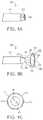
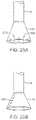
- FIG. 1Ashows a side view of one variation of a tissue imaging apparatus during deployment from a sheath or delivery catheter.
- FIG. 1Bshows the deployed tissue imaging apparatus of FIG. 1A having an optionally expandable hood or Sheath attached to an imaging and/or diagnostic catheter.
- FIG. 1Cshows an end view of a deployed imaging apparatus.
- FIGS. 1D to 1Fshow the apparatus of FIGS. 1A to 1C with an additional lumen, e.g., for passage of a guidewire therethrough.
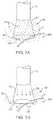
- FIGS. 2A and 2Bshow one example of a deployed tissue imager positioned against or adjacent to the tissue to be imaged and a flow of fluid, such as saline, displacing blood from within the expandable hood.
- a flow of fluidsuch as saline
- FIG. 3Ashows an articulatable imaging assembly which may be manipulated via push-pull wires or by computer control.
- FIGS. 3B and 3Cshow steerable instruments, respectively, where an articulatable delivery catheter may be steered within the imaging hood or a distal portion of the deployment catheter itself may be steered.
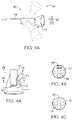
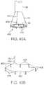
- FIGS. 4A to 4Cshow side and cross-sectional end views, respectively, of another variation having an off-axis imaging capability.
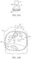
- FIG. 5shows an illustrative view of an example of a tissue imager advanced intravascularly within a heart for imaging tissue regions within an atrial chamber.
- FIGS. 6A to 6Cillustrate deployment catheters having one or more optional inflatable balloons or anchors for stabilizing the device during a procedure.
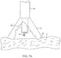
- FIGS. 7A and 7Billustrate a variation of an anchoring mechanism such as a helical tissue piercing device for temporarily stabilizing the imaging hood relative to a tissue surface.
- an anchoring mechanismsuch as a helical tissue piercing device for temporarily stabilizing the imaging hood relative to a tissue surface.
- FIG. 7Cshows another variation for anchoring the imaging hood having one or more tubular support members integrated with the imaging hood; each support members may define a lumen therethrough for advancing a helical tissue anchor within.
- FIG. 8Ashows an illustrative example of one variation of how a tissue imager may be utilized with an imaging device.
- FIG. 8Bshows a further illustration of a hand-held variation of the fluid delivery and tissue manipulation system.
- FIGS. 9A to 9Cillustrate an example of capturing several images of the tissue at multiple regions.
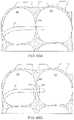
- FIGS. 10A and 10Bshow charts illustrating how fluid pressure within the imaging hood may be coordinated with the surrounding blood pressure; the fluid pressure in the imaging hood may be coordinated with the blood pressure or it may be regulated based upon pressure feedback from the blood.
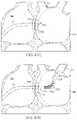
- FIG. 11Ashows a side view of another variation of a tissue imager having an imaging balloon within an expandable hood.
- FIG. 11Bshows another variation of a tissue imager utilizing a translucent or transparent imaging balloon.
- FIG. 12Ashows another variation in which a flexible expandable or distensible membrane may be incorporated within the imaging hood to alter the volume of fluid dispensed.
- FIGS. 12B and 12Cshow another variation in which the imaging hood may be partially or selectively deployed from the catheter to alter the area of the tissue being visualized as well as the volume of the dispensed fluid.
- FIGS. 13A and 13Bshow exemplary side and cross-sectional views, respectively, of another variation in which the injected fluid may be drawn back into the device for minimizing fluid input into a body being treated.
- FIGS. 14A to 14Dshow various configurations and methods for configuring an imaging hood into a low-profile for delivery and/or deployment.
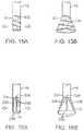
- FIGS. 15A and 15Bshow an imaging hood having an helically expanding frame or support.
- FIGS. 16A and 16Bshow another imaging hood having one or more hood support members, which are pivotably attached at their proximal ends to deployment catheter, integrated with a hood membrane.
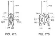
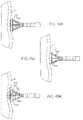
- FIGS. 17A and 17Bshow yet another variation of the imaging hood having at least two or more longitudinally positioned support members supporting the imaging hood membrane where the support members are movable relative to one another via a torquing or pulling or pushing force.
- FIGS. 18A and 18Bshow another variation where a distal portion of the deployment catheter may have several pivoting members which form a tubular shape in its low profile configuration.
- FIGS. 19A and 19Bshow another variation where the distal portion of deployment catheter may be fabricated from a flexible metallic or polymeric material to form a radially expanding hood.
- FIGS. 20A and 20Bshow another variation where the imaging hood may be formed from a plurality of overlapping hood members which overlie one another in an overlapping pattern.
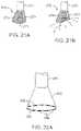
- FIGS. 21A and 21Bshow another example of an expandable hood which is highly conformable against tissue anatomy with varying geography.
- FIG. 22Ashows yet another example of an expandable hood having a number of optional electrodes placed about the contact edge or lip of the hood for sensing tissue contact or detecting arrhythmias.
- FIG. 22Bshows another variation for conforming the imaging hood against the underlying tissue where an inflatable contact edge may be disposed around the circumference of the imaging hood.
- FIG. 23shows a variation of the system which may be instrumented with a transducer for detecting the presence of blood seeping back into the imaging hood.
- FIGS. 24A and 24Bshow variations of the imaging hood instrumented with sensors for detecting various physical parameters; the sensors may be instrumented around the outer surface of the imaging hood and also within the imaging hood.
- FIGS. 25A and 25Bshow a variation where the imaging hood may have one or more LEDs over the hood itself for providing illumination of the tissue to be visualized.
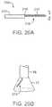
- FIGS. 26A and 26Bshow another variation in which a separate illumination tool having one or more LEDs mounted thereon may be utilized within the imaging hood.
- FIG. 27shows one example of how a therapeutic tool may be advanced through the tissue imager for treating a tissue region of interest.
- FIG. 28shows another example of a helical therapeutic tool for treating the tissue region of interest.
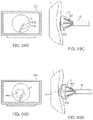
- FIG. 29shows a variation of how a therapeutic tool may be utilized with an expandable imaging balloon.
- FIGS. 30A and 30Bshow alternative configurations for therapeutic instruments which may be utilized; one variation is shown having an angled instrument arm and another variation is shown with an off-axis instrument arm.
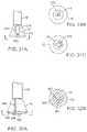
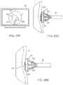
- FIGS. 31A to 31Cshow side and end views, respectively, of an imaging system which may be utilized with an ablation probe.
- FIGS. 32A and 32Bshow side and end views, respectively, of another variation of the imaging hood with an ablation probe, where the imaging hood may be enclosed for regulating a temperature of the underlying tissue.
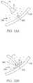
- FIGS. 33A and 33Bshow an example in which the imaging fluid itself may be altered in temperature to facilitate various procedures upon the underlying tissue.
- FIGS. 34A and 34Bshow an example of a laser ring generator which may be utilized with the imaging system and an example for applying the laser ring generator within the left atrium of a heart for treating atrial fibrillation.
- FIGS. 35A to 35Cshow an example of an extendible cannula generally comprising an elongate tubular member which may be positioned within the deployment catheter during delivery and then projected distally through the imaging hood and optionally beyond.
- FIGS. 36A and 36Bshow side and end views, respectively, of an imaging hood having one or more tubular support members integrated with the hood for passing instruments or tools therethrough for treatment upon the underlying tissue.
- FIGS. 37A and 37Billustrate how an imaging device may be guided within a heart chamber to a region of interest utilizing a lighted probe positioned temporarily within, e.g., a lumen of the coronary sinus.
- FIGS. 38A and 38Bshow an imaging hood having a removable disk-shaped member for implantation upon the tissue surface.
- FIGS. 39A to 39Cshow one method for implanting the removable disk of FIGS. 38A and 38B .
- FIGS. 40A and 40Billustrate an imaging hood having a deployable anchor assembly attached to the tissue contact edge and an assembly view of the anchors and the suture or wire connected to the anchors respectively
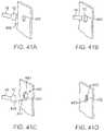
- FIGS. 41A to 41Dshow one method for deploying the anchor assembly of FIGS. 40A and 40B for closing an opening or wound.
- FIG. 42shows another variation in which the imaging system may be fluidly coupled to a dialysis unit for filtering a patient's blood.
- FIGS. 43A and 43Bshow a variation of the deployment catheter having a first deployable hood and a second deployable hood positioned distal to the first hood; the deployment catheter may also have a side-viewing imaging element positioned between the first and second hoods for imaging tissue between the expanded hoods.
- FIGS. 44A and 44Bshow side and end views, respectively, of a deployment catheter having a side-imaging balloon in an un-inflated low-profile configuration.
- FIGS. 45A to 45Cshow side, top, and end views, respectively, of the inflated balloon of FIGS. 44A and 44B defining a visualization field in the inflated balloon.
- FIGS. 46A and 46Bshow side and cross-sectional end views, respectively, for one method of use in visualizing a lesion upon a vessel wall within the visualization field of the inflated balloon from FIGS. 45A to 45C .
- FIGS. 47A to 47Oillustrate an example for intravascularly advancing the imaging and manipulation catheter into the heart and into the left atrium for ablating tissue around the ostia of the pulmonary veins for the treatment of atrial fibrillation.
- FIGS. 48A and 48Billustrate partial cross-sectional views of a hood which is advanced into the left atrium to examine discontiguous lesions.
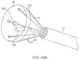
- FIG. 49Ashows a perspective view of a variation of the transmural lesion ablation device with, in this variation, a single RF ablation probe inserted through the working channel of the tissue visualization catheter.
- FIG. 49Bshows a side view of the device performing tissue ablation within the hood under real time visualization.
- FIG. 49Cshows the perspective view of the device performing tissue ablation within the hood under real time visualization.
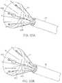
- FIG. 50Ashows a perspective view of a variation of the device when an angled ablation probe is used for linear transmural lesion formation.
- FIG. 50Bshows a perspective view of another variation of the device when a circular ablation probe is used for circular transmural lesion formation.
- FIG. 51Ashows a perspective view of another variation of the transmural lesion ablation device with a circularly-shaped RF electrode end effector placed on the outer circumference of an expandable membrane covering the hood of the tissue visualization catheter.
- FIG. 51Bshows a perspective view of another variation of an expandable balloon also with a circularly-shaped RF electrode end effector and without the hood.
- FIG. 52shows a perspective view of another variation of the transmural lesion ablation device with RF electrodes disposed circumferentially around the contact lip or edge of the hood.
- FIGS. 53A and 53Bshow perspective and side views, respectively, of another variation of the transmural lesion ablation device with an ablation probe positioned within the hood which also includes at least one layer of a transparent elastomeric membrane over the distal opening of the hood.
- FIG. 54Ashows a perspective view of another variation of the transmural lesion ablation device having an expandable linear ablation electrode strip inserted through the working channel of the tissue visualization catheter.
- FIG. 54Bshows the perspective view of the device with the linear ablation electrode strip in its expanded configuration.
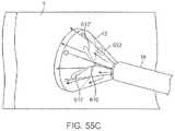
- FIGS. 55A and 55Billustrate perspective views of another variation where a laser probe, e.g., an optical fiber bundle coupled to a laser generator, may be inserted through the work channel of the tissue visualization catheter and activated for ablation treatment.
- a laser probee.g., an optical fiber bundle coupled to a laser generator
- FIG. 55Cshows the device of FIGS. 55A and 55B performing tissue ablation or transmural lesion formation under direct visualization while working within the hood of the visualization catheter apparatus.
- FIG. 56shows a partial cross-sectional view of the tissue visualization catheter with an inflated occlusion balloon to temporarily occlude blood flow through the pulmonary vein while viewing the pulmonary vein's ostia.
- FIG. 57shows a perspective view of first and second tissue graspers deployed through the hood for facilitating movement of the hood along the tissue surface.
- FIGS. 58A to 58Cillustrate the tissue visualization catheter navigating around a body lumen, such as the left atrium of the heart, utilizing two tissue graspers to “walk” the catheter along the tissue surface.
- FIG. 59shows a partial cross-sectional view of the tissue visualization catheter in a retroflexed position for accessing the right inferior pulmonary vein ostium.
- FIG. 60show a partial cross-sectional view of the tissue visualization catheter intravascularly accessing the left atrium via a trans-femoral introduction through the aorta, the aortic valve, the left ventricle, and into the left atrium.
- FIG. 61Ashows a side view of the tissue visualization catheter retroflexed at a tight angle accessing the right inferior pulmonary vein ostium with a first tissue grasper and length of wire or suture configured as a pulley mechanism.
- FIG. 61Billustrates the tissue visualization catheter pulling itself to access the right inferior PV ostium at a tight angle using a suture pulley mechanism.
- FIG. 61Cillustrates the tissue visualization catheter prior to the suture being tensioned.
- FIG. 61Dillustrates the tissue visualization catheter being moved and approximated towards the ostium as the suture is tensioned.
- FIG. 62Ashows a partial cross-sectional view of a tissue visualization catheter having an intra-atrial balloon inflated within the left atrium.
- FIG. 62Bshows the partial cross-sectional view with a fiberscope introduced into the balloon interior.
- FIG. 62Cshows the partial cross-sectional view with the fiberscope advancing and articulating within the balloon.
- FIG. 62Dshows the partial cross-sectional view of the intra-atrial balloon having radio-opaque fiducial markers and an ablation probe deployed within the balloon.
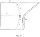
- FIG. 63shows a detail side view of an ablation probe deployed within the balloon and penetrating through the balloon wall.
- FIGS. 64A and 64Bshow perspective views of ablation needles deployable from a retracted position to a deployed position.
- FIG. 64Cshows the perspective view of an ablation needle having a bipolar electrode configuration.
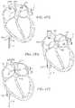
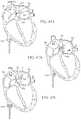
- FIG. 65A to 65Eillustrate a stabilizing catheter accessing the left atrium with a stabilizing balloon deployed in the right atrium and examples of the articulation and translation capabilities for directing the hood towards the tissue region to be treated.
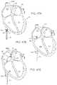
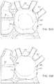
- FIG. 66A to 66Eillustrate another variation of a stabilizing catheter accessing the left atrium with proximal and distal stabilizing balloons deployed about the atrial septum and examples of the articulation and translation capabilities for directing the hood towards the tissue region to be treated.
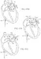
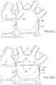
- FIG. 67A to 67Fillustrate another variation of a stabilizing catheter accessing the left atrium with a combination of proximal and distal stabilizing balloons deployed about the atrial septum and an intra-atrial balloon expanded within the left atrium with a hollow needle for piercing through the balloon and deploying the hood external to the balloon.
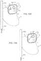
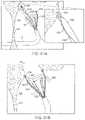
- FIG. 68Aillustrates a side view of the tissue visualization catheter deploying an intra-atrial balloon with an articulatable imager capturing multiple images representing different segments of the heart chamber wall from different angles.
- FIG. 68Bschematically illustrates the mapping of the multiple captured images processed to create a panoramic visual map of heart chamber.
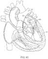
- FIG. 69Ashows a partial cross-sectional view of the tissue visualization catheter in the left atrium performing RF ablation, with a light source or ultrasound crystal source inserted transorally into the esophagus to prevent esophageal perforation.
- FIGS. 69B and 69Cillustrate the image viewed by the user prior to the ablation probe being activated.
- FIGS. 69D and 69Eillustrate the image viewed by the user of the ablated tissue changing color as the ablation probe heats the underlying tissue.
- FIGS. 69F and 69Gillustrate the image viewed by the user of an endocardiac disruption and the resulting tissue debris captured or contained within the hood.
- FIG. 69Hillustrates the evacuation of the captured tissue debris into the catheter.
- FIGS. 69I to 69Killustrate one method for adhering the tissue to be ablated via a suction force applied to the underlying tissue to be ablated.
- a tissue-imaging and manipulation apparatus described belowis able to provide real-time images in vivo of tissue regions within a body lumen such as a heart, which is filled with blood flowing dynamically therethrough and is also able to provide intravascular tools and instruments for per forcing various procedures upon the imaged tissue regions.
- Such an apparatusmay be utilized for many procedures, e.g., facilitating transseptal access to the left atrium, cannulating the coronary sinus, diagnosis of valve regurgitation/stenosis, valvuloplasty, atrial appendage closure, arrhythmogenic focus ablation, among other procedures.
- tissue imaging and manipulation assembly 10may be delivered intravascularly through the patient's body in a low-profile configuration via a delivery catheter or sheath 14 .
- tissuesuch as the mitral valve located at the outflow tract of the left atrium of the heart
- itis generally desirable to enter or access the left atrium while minimizing trauma to the patient.
- one conventional approachinvolves puncturing the intra-atrial septum from the right atrial chamber to the left atrial chamber in a procedure commonly called a transseptal procedure or septostomy.
- transseptal access to the left atrial chamber of the heartmay allow for larger devices to be introduced into the venous system than can generally be introduced percutaneously into the arterial system.
- imaging hood 12When the imaging and manipulation assembly 10 is ready to be utilized for imaging tissue, imaging hood 12 may be advanced relative to catheter 14 and deployed from a distal opening of catheter 14 , as shown by the arrow. Upon deployment, imaging hood 12 may be unconstrained to expand or open into a deployed imaging configuration, as shown in FIG. 1B .
- Imaging hood 12may be fabricated from a variety of pliable or conformable biocompatible material including but not limited to, e.g., polymeric, plastic, or woven materials.
- a woven materialis Kevlar® (E. I.
- imaging hood 12may be fabricated from a translucent or opaque material and in a variety of different colors to optimize or attenuate any reflected lighting from surrounding fluids or structures, i.e., anatomical or mechanical structures or instruments. In either case, imaging hood 12 may be fabricated into a uniform structure or a scaffold-supported structure, in which case a scaffold made of a shape memory alloy, such as Nitinol, or a spring steel, or plastic, etc., may be fabricated and covered with the polymeric, plastic, or woven material.
- a shape memory alloysuch as Nitinol, or a spring steel, or plastic, etc.
- imaging hood 12may comprise any of a wide variety of barriers or membrane structures, as may generally be used to localize displacement of blood or the like from a selected volume of a body lumen or heart chamber.
- a volume within an inner surface 13 of imaging hood 12will be significantly less than a volume of the hood 12 between inner surface 13 and outer surface 11 .
- Imaging hood 12may be attached at interface 24 to a deployment catheter 16 which may be translated independently of deployment catheter or sheath 14 . Attachment of interface 24 may be accomplished through any number of conventional methods.
- Deployment catheter 16may define a fluid delivery lumen 18 as well as an imaging lumen 20 within which an optical imaging fiber or assembly may be disposed for imaging tissue.
- imaging hood 12When deployed, imaging hood 12 may expand into any number of shapes, e.g., cylindrical, conical as shown, semi-spherical, etc., provided that an open area or field 26 is defined by imaging hood 12 . The open area 26 is the area within which the tissue region of interest may be imaged.
- Imaging hood 12may also define an atraumatic contact lip or edge 22 for placement or abutment against the tissue region of interest.
- the diameter of imaging hood 12 at its maximum fully deployed diameteris typically greater relative to a diameter of the deployment catheter 16 (although a diameter of contact lip or edge 22 may be made to have a smaller or equal diameter of deployment catheter 16 ).
- the contact edge diametermay range anywhere from 1 to 5 times even greater, as practicable) a diameter of deployment catheter 16 .
- FIG. 1Cshows an end view of the imaging hood 12 in its deployed configuration. Also shown are the contact lip or edge 22 and fluid delivery lumen 18 and imaging lumen 20 .
- the imaging and manipulation assembly 10may additionally define a guidewire lumen therethrough, e.g., a concentric or eccentric lumen, as shown in the side and end views, respectively, of FIGS. 1D to 1F .
- the deployment catheter 16may define guidewire lumen 19 for facilitating the passage of the system over or along a guidewire 17 , which may be advanced intravascularly within a body lumen. The deployment catheter 16 may then be advanced over the guidewire 17 , as generally known in the art.
- the displacing fluidmay be pumped at positive pressure through fluid delivery lumen 18 until the fluid fills open area 26 completely and displaces any fluid 28 from within open area 26 .
- the displacing fluid flowmay be laminarized to improve its clearing effect and to help prevent blood from re-entering the imaging hood 12 .
- fluid flowmay be started before the deployment takes place.
- the displacing fluid, also described herein as imaging fluidmay comprise any biocompatible fluid, e.g., saline, water, plasma, etc., which is sufficiently transparent to allow for relatively undistorted visualization through the fluid.
- any number of therapeutic drugsmay be suspended within the fluid or may comprise the fluid itself which is pumped into open area 26 and which is subsequently passed into and through the heart and the patient body.
- deployment catheter 16may be manipulated to position deployed imaging hood 12 against or near the underlying tissue region of interest to be imaged, in this example a portion of annulus A of mitral valve MV within the left atrial chamber.
- the surrounding blood 30flows around imaging hood 12 and within open area 26 defined within imaging hood 12 , as seen in FIG. 2A , the underlying annulus A is obstructed by the opaque blood 31 ) and is difficult to view through the imaging lumen 20 .
- the translucent fluid 28such as saline, may then be pumped through fluid delivery lumen 18 , intermittently or continuously, until the blood 30 is at least partially, and preferably completely, displaced from within open area 26 by fluid 28 , as shown in FIG. 2B .
- contact edge 22need not directly contact the underlying tissue, it is at least preferably brought into close proximity to the tissue such that the flow of clear fluid 28 from open area 26 may be maintained to inhibit significant backflow of blood 30 back into open area 26 .
- Contact edge 22may also be made of a soft elastomeric material such as certain soft grades of silicone or polyurethane, as typically known, to help contact edge 22 conform to an uneven or rough underlying anatomical tissue surface.
- the fluid 28may be pumped temporarily or sporadically only until a clear view of the tissue is available to be imaged and recorded, at which point the fluid flow 28 may cease and blood 30 may be allowed to seep or flow back into imaging hood 12 . This process may be repeated a number of times at the same tissue region or at multiple tissue regions.
- a number of articulation and manipulation controlsmay be utilized.
- one or more push-pull wires 42may be routed through deployment catheter 16 for steering the distal end portion of the device in various directions 46 to desirably position the imaging hood 12 adjacent to a region of tissue to be visualized.
- deployment catheter 16 and imaging hood 12may be articulated into any number of configurations 44 .
- the push-pull wire or wires 42may be articulated via their proximal ends from outside the patient body manually utilizing one or more controls.
- deployment catheter 16may be articulated by computer control, as further described below.
- an articulatable delivery catheter 48which may be articulated via one or more push-pull wires and having an imaging lumen and one or more working lumens, may be delivered through the deployment catheter 16 and into imaging hood 12 .
- the clear displacing fluidmay be pumped through delivery catheter 48 or deployment catheter 16 to clear the field within imaging hood 12 .
- the articulatable delivery catheter 48may be articulated within the imaging hood to obtain a better image of tissue adjacent to the imaging hood 12 .
- articulatable delivery catheter 48may be articulated to direct an instrument or tool passed through the catheter 48 , as described in detail below, to specific areas of tissue imaged through imaging hood 12 without having to reposition deployment catheter 16 and re-clear the imaging field within hood 12 .
- a distal portion of the deployment catheter 16itself may comprise a distal end 49 which is articulatable within imaging hood 12 , as shown in FIG. 3C .
- Directed imaging, instrument delivery, etc.may be accomplished directly through one or more lumens within deployment catheter 16 to specific regions of the underlying tissue imaged within imaging hood 12 .
- Visualization within the imaging hood 12may be accomplished through an imaging lumen 20 defined through deployment catheter 16 , as described above. In such a configuration, visualization is available in a straight-line manner, i.e., images are generated from the field distally along a longitudinal axis defined by the deployment catheter 16 .
- an articulatable imaging assembly having a pivotable support member 50may be connected to, mounted to, or otherwise passed through deployment catheter 16 to provide for visualization off-axis relative to the longitudinal axis defined by deployment catheter 16 , as shown in FIG. 4A .
- Support member 50may have an imaging element 52 , e.g., a CCD or CMOS imager or optical fiber, attached at its distal end with its proximal end connected to deployment catheter 16 via a pivoting connection 54 .
- the optical fibers 58may be passed through deployment catheter 16 , as shown in the cross-section of FIG. 4B , and routed through the support member 50 .
- the use of optical fibers 58may provide for increased diameter sizes of the one or several lumens 56 through deployment catheter 16 for the passage of diagnostic and/or therapeutic tools therethrough.
- electronic chipssuch as a charge coupled device (CCD) or a CMOS imager, which are typically known, may be utilized in place of the optical fibers 58 , in which case the electronic imager may be positioned in the distal portion of the deployment catheter 16 with electric wires being routed proximally through the deployment catheter 16 .
- CCDcharge coupled device
- CMOS imagerwhich are typically known
- the electronic imagersmay be wirelessly coupled to a receiver for the wireless transmission of images.
- Additional optical fibers or light emitting diodes (LEDs)can be used to provide lighting for the image or operative theater, as described below in farther detail.
- Support member 50may be pivoted via connection 54 such that the member 50 can be positioned in a low-profile configuration within channel or groove 60 defined in a distal portion of catheter 16 , as shown in the cross-section of FIG. 4C .
- support member 50can be positioned within channel or groove 60 with imaging hood 12 also in its low-profile configuration.
- imaging hood 12may be expanded into its deployed configuration and support member 50 may be deployed into its off-axis configuration for imaging the tissue adjacent to hood 12 , as in FIG. 4A .
- Other configurations for support member 50 for off axis visualizationmay be utilized, as desired.
- FIG. 5shows an illustrative cross-sectional view of a heart H having tissue regions of interest being viewed via an imaging assembly 10 .
- delivery catheter assembly 70may be introduced percutaneously into the patient's vasculature and advanced through the superior vena cava SVC and into the right avium RA.
- the delivery catheter or sheath 72may be articulated through the atrial septum AS and into the left atrium LA for viewing or treating the tissue, e.g., the annulus A, surrounding the mitral valve MV.
- deployment catheter 16 and imaging hood 12may be advanced out of delivery catheter 72 and brought into contact or in proximity to the tissue region of interest.
- delivery catheter assembly 70may be advanced through the inferior vena cava IVC, if so desired.
- other regions of the heart He.g., the right ventricle RV or left ventricle LV, may also be accessed and imaged or treated by imaging assembly 10 .
- the delivery catheter or sheath 14may comprise a conventional intra-vascular catheter or an endoluminal delivery device.
- robotically-controlled delivery cathetersmay also be optionally utilized with the imaging assembly described herein, in which case a computer-controller 74 may be used to control the articulation and positioning of the delivery catheter 14 .
- An example of a robotically-controlled delivery catheter which may be utilizedis described in further detail in US Pat. Pub. 2002/0087169 A1 to Brock et al. entitled “Flexible Instrument”, which is incorporated herein by reference in its entirety.
- Other robotically-controlled delivery catheters manufactured by Hansen Medical, Inc.may also be utilized with the delivery catheter 14 .
- one or more inflatable balloons or anchors 76may be positioned along the length of catheter 16 , as shown in FIG. 6A .
- the inflatable balloons 76may be inflated from a low-profile into their expanded configuration to temporarily anchor or stabilize the catheter 16 position relative to the heart H.
- FIG. 6Bshows a first balloon 78 inflated while FIG. 6C also shows a second balloon 80 inflated proximal to the first balloon 78 .
- the septal wall ASmay be wedged or sandwiched between the balloons 78 , 80 to temporarily stabilize the catheter 16 and imaging hood 12 .
- a single balloon 78 or both balloons 78 , 80may be used. Other alternatives may utilize expandable mesh members, malecots, or any other temporary expandable structure.
- the balloon assembly 76may be deflated or re-configured into a low-profile for removal of the deployment catheter 16 .
- various anchoring mechanismsmay be optionally employed for temporarily holding the imaging hood 12 against the tissue.
- Such anchoring mechanismsmay be particularly useful for imaging tissue which is subject to movement, e.g., when imaging tissue within the chambers of a beating heart.
- a tool delivery catheter 82 having at least one instrument lumen and an optional visualization lumenmay be delivered through deployment catheter 16 and into an expanded imaging hood 12 .
- anchoring mechanismssuch as a helical tissue piercing device 84 may be passed through the tool delivery catheter 82 , as shown in FIG. 7A , and into imaging hood 12 .
- the helical tissue engaging device 84may be torqued from its proximal end outside the patient body to temporarily anchor itself into the underlying tissue surface T. Once embedded within the tissue T, the helical tissue engaging device 84 may be pulled proximally relative to deployment catheter 16 while the deployment catheter 16 and imaging hood 12 are pushed distally, as indicated by the arrows in FIG. 7B , to gently force the contact edge or lip 22 of imaging hood against the tissue T. The positioning of the tissue engaging device 84 may be locked temporarily relative to the deployment catheter 16 to ensure secure positioning of the imaging hood 12 during a diagnostic or therapeutic procedure within the imaging hood 12 .
- tissue engaging device 84may be disengaged from the tissue by torquing its proximal end in the opposite direction to remove the anchor form the tissue T and the deployment catheter 16 may be repositioned to another region of tissue where the anchoring process may be repeated or removed from the patient body.
- the tissue engaging device 84may also be constructed from other known tissue engaging devices such as vacuum-assisted engagement or grasper-assisted engagement tools, among others.
- helical anchor 84is shown, this is intended to be illustrative and other types of temporary anchors may be utilized, e.g., hooked or barbed anchors, graspers, etc.
- the tool delivery catheter 82may be omitted entirely and the anchoring device may be delivered directly through a lumen defined through the deployment catheter 16 .
- FIG. 7Cshows an imaging hood 12 having one or more tubular support members 86 , e.g., four support members 86 as shown, integrated with the imaging hood 12 .
- the tubular support members 86may define lumens therethrough each having helical tissue engaging devices 88 positioned within.
- the helical tissue engaging devices 88may be urged distally to extend from imaging hood 12 and each may be torqued from its proximal end to engage the underlying tissue T.
- Each of the helical tissue engaging devices 88may be advanced through the length of deployment catheter 16 or they may be positioned within tubular support members 86 during the delivery and deployment of imaging hood 12 . Once the procedure within imaging hood 12 is finished, each of the tissue engaging devices 88 may be disengaged from the tissue and the imaging hood 12 may be repositioned to another region of tissue or removed from the patient body.
- FIG. 8AAn illustrative example is shown in FIG. 8A of a tissue imaging assembly connected to a fluid delivery system 90 and to an optional processor 98 and image recorder and/or viewer 100 .
- the fluid delivery system 90may generally comprise a pump 92 and an optional valve 94 for controlling the flow rate of the fluid into the system.
- a fluid reservoir 96fluidly connected to pump 92 , may hold the fluid to be pumped through imaging hood 12 .
- An optional central processing unit or processor 98may be in electrical communication with fluid delivery system 90 for controlling flow parameters such as the flow rate and/or velocity of the pumped fluid.
- the processor 98may also be in electrical communication with an image recorder and/or viewer 100 for directly viewing the images of tissue received from within imaging hood 12 .
- Imager recorder and/or viewer 100may also be used not only to record the image but also the location of the viewed tissue region, if so desired.
- processor 98may also be utilized to coordinate the fluid flow and the image capture.
- processor 98may be programmed to provide for fluid flow from reservoir 96 until the tissue area has been displaced of blood to obtain a clear image. Once the image has been determined to be sufficiently clear, either visually by a practitioner or by computer, an image of the tissue may be captured automatically by recorder 100 and pump 92 may be automatically stopped or slowed by processor 98 to cease the fluid flow into the patient.
- Other variations for fluid delivery and image captureare, of course, possible and the aforementioned configuration is intended only to be illustrative and not limiting.
- FIG. 8Bshows a farther illustration of a hand-held variation of the fluid delivery and tissue manipulation system 110 .
- system 110may have a housing or handle assembly 112 which can be held or manipulated by the physician from outside the patient body.
- the fluid reservoir 114shown in this variation as a syringe, can be fluidly coupled to the handle assembly 112 and actuated via a pumping mechanism 116 , e.g., lead screw.
- Fluid reservoir 114may be a simple reservoir separated from the handle assembly 112 and fluidly coupled to handle assembly 112 via one or more tubes. The fluid flow rate and other mechanisms may be metered by the electronic controller 118 .
- Deployment of imaging hood 12may be actuated by a hood deployment switch 120 located on the handle assembly 112 while dispensation of the fluid from reservoir 114 may be actuated by a fluid deployment switch 122 , which can be electrically coupled to the controller 118 .
- Controller 118may also be electrically coupled to a wired or wireless antenna 124 optionally integrated with the handle assembly 112 , as shown in the figure.
- the wireless antenna 124can be used to wirelessly transmit images captured from the imaging hood 12 to a receiver, e.g., via Bluetooth® wireless technology (Bluetooth SIG, Inc., Bellevue, Wash.), RF, etc., for viewing on a monitor 128 or for recording for later viewing.
- Articulation control of the deployment catheter 16 , or a delivery catheter or sheath 14 through which the deployment catheter 16 may be deliveredmay be accomplished by computer control, as described above, in which case an additional controller may be utilized with handle assembly 112 .
- handle assembly 112may incorporate one or more articulation controls 126 for manual manipulation of the position of deployment catheter 16 .
- Handle assembly 112may also define one or more instrument ports 130 through which a number of intravascular tools may be passed for tissue manipulation and treatment within imaging hood 12 , as described further below.
- fluid or debrismay be sucked into imaging hood 12 for evacuation from the patient body by optionally fluidly coupling a suction pump 132 to handle assembly 112 or directly to deployment catheter 16 .
- fluidmay be pumped continuously into imaging hood 12 to provide for clear viewing of the underlying tissue.
- fluidmay be pumped temporarily or sporadically only until a clear view of the tissue is available to be imaged and recorded, at which point the fluid flow may cease and the blood may be allowed to seep or flow back into imaging hood 12 .
- FIGS. 9A to 9Cillustrate an example of capturing several images of the tissue at multiple regions.
- Deployment catheter 16may be desirably positioned and imaging hood 12 deployed and brought into position against a region of tissue to be imaged, in this example the tissue surrounding a mitral valve MV within the left atrium of a patient's heart.
- the imaging hood 12may be optionally anchored to the tissue, as described above, and then cleared by pumping the imaging fluid into the hood 12 . Once sufficiently clear, the tissue may be visualized and the image captured by control electronics 118 .
- the first captured image 140may be stored and/or transmitted wirelessly 124 to a monitor 128 for viewing by the physician, as shown in FIG. 9A .
- the deployment catheter 16may be then repositioned to an adjacent portion of mitral valve MV, as shown in FIG. 9B , where the process may be repeated to capture a second image 142 for viewing and/or recording.
- the deployment catheter 16may again be repositioned to another region of tissue, as shown in FIG. 9C , where a third image 144 may be captured for viewing and/or recording. This procedure may be repeated as many times as necessary for capturing a comprehensive image of the tissue surrounding mitral valve MV, or any other tissue region.
- the pumpmay be stopped during positioning and blood or surrounding fluid may be allowed to enter within imaging hood 12 until the tissue is to be imaged, where the imaging hood 12 may be cleared, as above.
- the fluidwhen the imaging hood 12 is cleared by pumping the imaging fluid within for clearing the blood or other bodily fluid, the fluid may be pumped continuously to maintain the imaging fluid within the hood 12 at a positive pressure or it may be pumped under computer control for slowing or stopping the fluid flow into the hood 12 upon detection of various parameters or until a clear image of the underlying tissue is obtained.
- the control electronics 118may also be programmed to coordinate the fluid flow into the imaging hood 12 with various physical parameters to maintain a clear image within imaging hood 12 .
- FIG. 10Ashows a chart 150 illustrating how fluid pressure within the imaging hood 12 may be coordinated with the surrounding blood pressure.
- Chart 150shows the cyclical blood pressure 156 alternating between diastolic pressure 152 and systolic pressure 154 over time T due to the beating motion of the patient heart.
- the fluid pressure of the imaging fluid, indicated by plot 160within imaging hood 12 may be automatically timed to correspond to the blood pressure changes 160 such that an increased pressure is maintained within imaging hood 12 which is consistently above the blood pressure 156 by a slight increase ⁇ P, as illustrated by the pressure difference at the peak systolic pressure 158 .
- This pressure difference, ⁇ Pmay be maintained within imaging hood. 12 over the pressure variance of the surrounding blood pressure to maintain a positive imaging fluid pressure within imaging hood 12 to maintain a clear view of the underlying tissue.
- One benefit of maintaining a constant ⁇ Pis a constant flow and maintenance of a clear field.
- FIG. 10Bshows a chart 162 illustrating another variation for maintaining a clear view of the underlying tissue
- one or more sensors within the imaging hood 12may be configured to sense pressure changes within the imaging hood. 12 and to correspondingly increase the imaging fluid pressure within imaging hood 12 .
- Thismay result in a time delay, ⁇ T, as illustrated by the shifted fluid pressure 160 relative to the cycling blood pressure 156 , although the time delays ⁇ T may be negligible in maintaining the clear image of the underlying tissue.
- Predictive software algorithmscan also be used to substantially eliminate this time delay by predicting when the next pressure wave peak will arrive and by increasing the pressure ahead of the pressure wave's arrival by an amount of time equal to the aforementioned time delay to essentially cancel the time delay out.
- imaging hood 12The variations in fluid pressure within imaging hood 12 may be accomplished in part due to the nature of imaging hood 12 .
- An inflatable balloonwhich is conventionally utilized for imaging tissue, may be affected by the surrounding blood pressure changes.
- an imaging hood 12retains a constant volume therewithin and is structurally unaffected by the surrounding blood pressure changes, thus allowing for pressure increases therewithin.
- the material that hood 12 is made frommay also contribute to the manner in which the pressure is modulated within this hood 12 .
- a stiffer hood materialsuch as hi durometer polyurethane or Nylon, may facilitate the maintaining of an open hood when deployed.
- a relatively lower durometer or softer materialsuch as a low durometer PVC or polyurethane, may collapse from the surrounding fluid pressure and may not adequately maintain a deployed or expanded hood.
- FIG. 11Ashows another variation comprising an additional imaging balloon 172 within an imaging hood 174 .
- an expandable balloon 172 having a translucent skinmay be positioned within imaging hood 174 .
- Balloon 172may be made from any distensible biocompatible material having sufficient translucent properties which allow for visualization therethrough.
- the balloon 172can also be filled with contrast media to allow it to be viewed on fluoroscopy to aid in its positioning.
- the imagere.g., fiber optic, positioned within deployment catheter 170 may then be utilized to view the tissue region through the balloon 172 and any additional fluid which may be pumped into imaging hood 174 via one or more optional fluid ports 176 , which may be positioned proximally of balloon 172 along a portion of deployment catheter 170 .
- balloon 172may define one or more holes over its surface which allow for seepage or passage of the fluid contained therein to escape and displace the blood from within imaging hood 174 .
- FIG. 11Bshows another alternative in which balloon 180 may be utilized alone.
- Balloon 180attached to deployment catheter 178 , may be filled with fluid, such as saline or contrast media, and is preferably allowed to come into direct contact with the tissue region to be imaged.
- FIG. 12Ashows another alternative in which deployment catheter 16 incorporates imaging hood 12 , as above, and includes an additional flexible membrane 182 within imaging hood 12 .
- Flexible membrane 182may be attached at a distal end of catheter. 16 and optionally at contact edge 22 .
- Imaging hood 12may be utilized, as above, and membrane 182 may be deployed from catheter 16 in vivo or prior to placing catheter 16 within a patient to reduce the volume within imaging hood 12 . The volume ma be reduced or minimized to reduce the amount of fluid dispensed for visualization or simply reduced depending upon the area of tissue to be visualized.
- FIGS. 12B and 12Cshow yet another alternative in which imagining hood 186 may be withdrawn proximally within deployment catheter 184 or deployed distally from catheter 186 , as shown, to vary the volume of imaging hood 186 and thus the volume of dispensed fluid.
- Imaging hood 186may be seen in FIG. 12B as being partially deployed from, e.g., a circumferentially defined lumen within catheter 184 , such as annular lumen 188 .
- the underlying tissuemay be visualized with imaging hood 186 only partially deployed.
- imaging hood 186 ′may be fully deployed, as shown in FIG. 12C , by urging hood 186 ′ distally out from annular lumen 188 .
- the area of tissue to be visualizedmay be increased as hood 186 ′ is expanded circumferentially.
- FIGS. 13A and 13Bshow perspective and cross-sectional side views, respectively, of yet another variation of imaging assembly which may utilize a fluid suction system for minimizing the amount of fluid injected into the patient's heart or other body lumen during tissue visualization.
- Deployment catheter 190 in this variationmay define an inner tubular member 196 which may be integrated with deployment catheter 190 or independently translatable.
- Fluid delivery lumen 198 defined through member 196may be fluidly connected to imaging hood 192 , which may also define one or more open channels 194 over its contact lip region. Fluid pumped through fluid delivery lumen 198 may thus fill open area 202 to displace any blood or other fluids or objects therewithin.
- Tubular member 196may also define one or more additional working channels 200 for the passage of any tools or visualization devices.
- the imaging hoodmay take on any number of configurations when positioned or configured for a low-profile delivery within the delivery catheter, as shown in the examples of FIGS. 14A to 14D . These examples are intended to be illustrative and are not intended to be limiting in scope.
- FIG. 14Ashows one example in which imaging hood 212 may be compressed within catheter 210 by folding hood 212 along a plurality of pleats.
- Hood 212may also comprise scaffolding or frame 214 made of a super-elastic or shape memory material or alloy, e.g., Nitinol, shape memory polymers, electroactive polymers, or a spring stainless steel.
- the shape memory materialmay act to expand or deploy imaging hood 212 into its expanded configuration when urged in the direction of the arrow from the constraints of catheter 210 .
- FIG. 14Bshows another example in which imaging hood 216 may be expanded or deployed from catheter 210 from a folded and overlapping configuration.
- Frame or scaffolding 214may also be utilized in this example.
- FIG. 14Cshows yet another example in which imaging hood 218 may be rolled, inverted, or everted upon itself for deployment.
- FIG. 14Dshows a configuration in which imaging hood 220 may be fabricated from an extremely compliant material which allows for hood 220 to be simply compressed into a low-profile shape. From this low-profile compressed shape, simply releasing hood 220 may allow for it to expand into its deployed configuration, especially if a scaffold or frame of a shape memory or superelastic material, e.g., Nitinol, is utilized in its construction.
- a scaffold or frame of a shape memory or superelastic materiale.g., Nitinol
- FIGS. 15A and 15Billustrates an helically expanding frame or support 230 .
- helical frame 230may be integrated with the imaging hood 12 membrane.
- helical frame 230may expand into a conical or tapered shape.
- Helical frame 230may alternatively be made out of heat-activated Nitinol to allow it to expand upon application of a current.
- FIGS. 16A and 16Bshow yet another variation in which imaging hood. 12 may comprise one or more hood support members 232 integrated with the hood membrane. These longitudinally attached support members 232 may be pivotably attached at their proximal ends to deployment catheter 16 .
- One or more pullwires 234may be routed through the length of deployment catheter 16 and extend through one or more openings 238 defined in deployment catheter 16 proximally to imaging hood 12 into attachment with a corresponding support member 232 at a pullwire attachment point 236 .
- the support members 232may be fabricated from a plastic or metal, such as stainless steel.
- the support members 232may be made from a superelastic or shape memory alloy, such as Nitinol, which may self-expand into its deployed configuration without the use or need of pullwires. A heat-activated Nitinol may also be used which expands upon the application of thermal energy or electrical energy.
- support members 232may also be constructed as inflatable lumens utilizing, e.g., PET balloons. From its low-profile delivery configuration shown in FIG. 16A , the one or more pullwires 234 may be tensioned from their proximal ends outside the patient body to pull a corresponding support member 232 into a deployed configuration, as shown in FIG. 16B , to expand imaging hood 12 . To reconfigure imaging hood 12 back into its low profile, deployment catheter 16 may be pulled proximally into a constraining catheter or the pullwires 234 may be simply pushed distally to collapse imaging hood 12 .
- FIGS. 17A and 17Bshow yet another variation of imaging hood 240 having at least two or more longitudinally positioned support members 242 supporting the imaging hood membrane.
- the support members 242each have cross-support members 244 which extend diagonally between and are pivotably attached to the support members 242 .
- Each of the cross-support members 244may be pivotably attached to one another where they intersect between the support members 242 .
- a jack or screw member 246may be coupled to each cross-support member 244 at this intersection point and a torquing member, such as a torqueable wire 248 , may be coupled to each jack or screw member 246 and extend proximally through deployment catheter 16 to outside the patient body.
- the torqueable wires 248may be torqued to turn the jack or screw member 246 which in turn urges the cross-support members 244 to angle relative to one another and thereby urge the support members 242 away from one another.
- the imaging hood 240may be transitioned from its low-profile, shown in FIG. 17A , to its expanded profile, shown in FIG. 17B , and back into its low-profile by torquing wires 248 .
- FIGS. 18A and 18Bshow yet another variation on the imaging hood and its deployment.
- a distal portion of deployment catheter 16may have several pivoting members 250 , e.g., two to four sections, winch form a tubular shape in its low profile configuration, as shown in FIG. 18A .
- pivoting members 250When pivoted radially about deployment catheter 16 , pivoting members 250 may open into a deployed configuration having distensible or expanding membranes 252 extending over the gaps in-between the pivoting members 250 , as shown in FIG. 18B .
- the distensible membrane 252may be attached to the pivoting members 250 through various methods, e.g., adhesives, such that when the pivoting members 250 are fully extended into a conical shape, the pivoting members 250 and membrane 252 form a conical shape for use as an imaging hood.
- the distensible membrane 252may be made out of a porous material such as a mesh or PTFE or out of a translucent or transparent polymer such as polyurethane, PVC, Nylon, etc.
- FIGS. 19A and 19Bshow yet another variation where the distal portion of deployment catheter 16 may be fabricated from a flexible metallic or polymeric material to form a radially expanding hood 254 .
- a plurality of slots 256may be formed in a uniform pattern over the distal portion of deployment catheter 16 , as shown in FIG. 19A .
- the slots 256may be formed in a pattern such that when the distal portion is urged radially open, utilizing any of the methods described above, a radially expanded and conically-shaped hood 254 may be formed by each of the slots 256 expanding into an opening, as shown in FIG. 19B .
- a distensible membrane 258may overlie the exterior surface or the interior surface of the hood 254 to form a fluid-impermeable hood 254 such that the hood 254 may be utilized as an imaging hood.
- the distensible membrane 258may alternatively be formed in each opening 258 to form the fluid-impermeable hood 254 .
- FIGS. 20A and 20BYet another configuration for the imaging hood may be seen in FIGS. 20A and 20B where the imaging hood may be formed from a plurality of overlapping hood members 260 which overlie one another in an overlapping pattern. When expanded, each of the hood members 260 may extend radially outward relative to deployment catheter 16 to forma conically-shaped imaging hood, as shown in FIG. 20B . Adjacent hood members 260 may overlap one another along an overlapping interface 262 to form a fluid-retaining surface within the imaging hood. Moreover, the hood members 260 may be made from any number of biocompatible materials, e.g., Nitinol, stainless steel, polymers, etc., which are sufficiently strong to optionally retract surrounding tissue from the tissue region of interest.
- biocompatible materialse.g., Nitinol, stainless steel, polymers, etc.
- imaging hood 272may be alternatively configured to contact the tissue surface at an acute angle.
- An imaging hood configured for such contact against tissuemay also be especially suitable for contact against tissue surfaces having an unpredictable or uneven anatomical geography.
- deployment catheter 270may have an imaging hood 272 that is configured to be especially compliant.
- imaging hood 272may be comprised of one or more sections 274 that are configured to fold or collapse, e.g., by utilizing a pleated surface.
- FIG. 21Bwhen imaging hood 272 is contacted against uneven tissue surface T, sections 274 are able to conform closely against the tissue.
- These sections 274may be individually collapsible by utilizing an accordion style construction to allow conformation, e.g., to the trabeculae in the heart or the uneven anatomy that may be found inside the various body lumens.
- FIG. 22Ashows another variation in which an imaging hood 282 is attached to deployment catheter 280 .
- the contact lip or edge 284may comprise one or more electrical contacts 286 positioned circumferentially around contact edge 284 .
- the electrical contacts 286may be configured to contact the tissue and indicate affirmatively whether tissue contact was achieved, e.g., by measuring the differential impedance between blood and tissue.
- a processore.g., processor 98
- in electrical communication with contacts 286may be configured to determine what type of tissue is in contact with electrical contacts 286 .
- the processor 98may be configured to measure any electrical activity that may be occurring in the underlying tissue, e.g., accessory pathways, for the purposes of electrically mapping the cardiac tissue and subsequently treating, as described below, any arrhythmias which may be detected.
- FIG. 22BAnother variation for ensuring contact between imaging hood 282 and the underlying tissue may be seen in FIG. 22B .
- This variationmay have an inflatable contact edge 288 around the circumference of imaging hood 282 .
- the inflatable contact edge 288may be inflated with a fluid or gas through inflation lumen 289 when the imaging hood 282 is to be placed against a tissue surface having an uneven or varied anatomy.
- the inflated circumferential surface 288may provide for continuous contact over the hood edge by conforming against the tissue surface and facilitating imaging fluid retention within hood 282 .
- various instrumentationmay be utilized with the imaging and manipulation system. For instance, after the field within imaging hood 12 has been cleared of the opaque blood and the underlying tissue is visualized through the clear fluid, blood may seep back into the imaging hood 12 and obstruct the view.
- One method for automatically maintaining a clear imaging fieldmay utilize a transducer, e.g., an ultrasonic transducer 290 , positioned at the distal end of deployment catheter within the imaging hood 12 , as shown in FIG. 23 .
- the transducer 290may send an energy pulse 292 into the imaging hood 12 and wait to detect back-scattered energy 294 reflected from debris or blood within the imaging hood 12 . If back-scattered energy is detected, the pump may be actuated automatically to dispense more fluid into the imaging hood until the debris or blood is no longer detected.
- sensors 300may be positioned on the imaging hood 12 itself, as shown in FIG. 24A , to detect a number of different parameters.
- sensors 300may be configured to detect for the presence of oxygen in the surrounding blood, blood and/or imaging fluid pressure, color of the fluid within the imaging hood, etc. Fluid color may be particularly useful in detecting the presence of blood within the imaging hood 12 by utilizing a reflective type sensor to detect back reflection from blood. Any reflected light from blood which may be present within imaging hood 12 may be optically or electrically transmitted through deployment catheter 16 and to a red colored filter within control electronics 118 . Any red color which may be detected may indicate the presence of blood and trigger a signal to the physician or automatically actuate the pump to dispense more fluid into the imaging hood 12 to clear the blood.
- Alternative methods for detecting the presence of blood within the hood 12may include detecting transmitted light through the imaging fluid within imaging hood 12 . If a source of white light, e.g., utilizing LEDs or optical fibers, is illuminated inside imaging hood 12 , the presence of blood may cause the color red to be filtered through this fluid. The degree or intensity of the red color detected may correspond to the amount of blood present within imaging hood 12 .
- a red color sensorcan simply comprise, in one variation, a phototransistor with a red transmitting filter over it which can establish how much red light is detected, which in turn can indicate, the presence of blood within imaging hood 12 . Once blood is detected, the system may pump more clearing fluid through and enable closed loop feedback control of the clearing fluid pressure and flow level.
- Any number of sensorsmay be positioned along the exterior 302 of imaging hood 12 or within the interior 304 of imaging hood 12 to detect parameters not only exteriorly to imaging hood 12 but also within imaging hood 12 .
- Such a configurationas shown in FIG. 24B , may be particularly useful for automatically maintaining a clear imaging field based upon physical parameters such as blood pressure, as described above for FIGS. 10A and 10B .
- one or more light emitting diodesmay be utilized to provide lighting within the imaging hood 12 .
- illuminationmay be provided by optical fibers routed through deployment catheter 16
- the use of LEDs over the imaging hood 12may eliminate the need for additional optical fibers for providing illumination.
- the electrical wires connected to the one or more LEDsmay be routed through or over the hood 12 and along an exterior surface or extruded within deployment catheter 16 .
- One or more LEDsmay be positioned in a circumferential pattern 306 around imaging hood. 12 , as shown in FIG. 25A , or in a linear longitudinal pattern 308 along imaging hood 12 , as shown in FIG. 25B .
- Other patterns, such as a helical or spiral patternmay also be utilized.
- LEDsmay be positioned along a support member forming part of imaging hood 12 .
- a separate illumination tool 310may be utilized, as shown in FIG. 26A .
- An example of such a toolmay comprise a flexible intravascular delivery member 312 having a carrier member 314 pivotably connected 316 to a distal end of delivery member 312 .
- One or more LEDs 318may be mounted along carrier member 314 .
- delivery member 312may be advanced through deployment catheter 16 until carrier member 314 is positioned within imaging hood 12 .
- carrier member 314may be pivoted in any number of directions to facilitate or optimize the illumination within the imaging hood 12 , as shown in FIG. 26B .
- the LEDsmay comprise a single LED color, e.g., white light.
- LEDs of other colorse.g., red, blue, yellow, etc.
- sources of infrared or ultraviolet lightmay be employed to enable imaging beneath the tissue surface or cause fluorescence of tissue for use in system guidance, diagnosis, or therapy.
- the imaging assemblymay also be utilized to provide a therapeutic platform for treating tissue being visualized.
- deployment catheter 320may have imaging hood 322 , as described above, and fluid delivery lumen 324 and imaging lumen 326 .
- a therapeutic toolsuch as needle 328 may be delivered through fluid delivery lumen 324 or in another working lumen and advanced through open area 332 for treating the tissue which is visualized.
- needle 328may define one or several ports 330 for delivering drugs therethrough.
- needle 328may be advanced and pierced into the underlying tissue where a therapeutic agent may be delivered through ports 330 .
- needle 328may be in electrical communication with a power source 334 , e.g., radio-frequency, microwave, etc., for ablating the underlying tissue area of interest.
- FIG. 28shows another alternative in which deployment catheter 340 may have imaging hood 342 attached thereto, as above, but with a therapeutic tool 344 in the configuration of a helical tissue piercing device 344 . Also shown and described above in FIGS. 7A and 7 l 3 for use in stabilizing the imaging hood relative to the underlying tissue, the helical tissue piercing device 344 may also be utilized to manipulate the tissue for a variety of therapeutic procedures.
- the helical portion 346may also define one or several ports for delivery of therapeutic agents therethrough.
- FIG. 29shows a deployment catheter 350 having an expandable imaging balloon 352 filled with, e.g., saline 356 .
- a therapeutic tool 344as above, may be translatable relative to balloon 352 .
- a stop 354may be formed on balloon 352 to prevent the proximal passage of portion 346 past stop 354 .
- FIGS. 30A and 30BAlternative configurations for tools which may be delivered through deployment catheter 16 for use in tissue manipulation within imaging hood 12 are shown in FIGS. 30A and 30B .
- FIG. 30Ashows one variation of an angled instrument 360 , such as a tissue grasper, which may be configured to have an elongate shaft for intravascular delivery through deployment catheter 16 with a distal end which may be angled relative to its elongate shaft upon deployment into imaging hood 12 .
- the elongate shaftmay be configured to angle itself automatically, e.g., by the elongate shaft being made at least partially from a shape memory alloy, or upon actuation, e.g., by tensioning a pullwire.
- FIG. 30Ashows one variation of an angled instrument 360 , such as a tissue grasper, which may be configured to have an elongate shaft for intravascular delivery through deployment catheter 16 with a distal end which may be angled relative to its elongate shaft upon deployment into imaging hood 12 .
- FIG. 30Bshows another configuration for an instrument 362 being configured to reconfigure its distal portion into an off-axis configuration within imaging hood 12 .
- the instruments 360 , 362may be reconfigured into a low-profile shape upon withdrawing them proximally back into deployment catheter 16 .
- FIG. 31Ashows a probe 370 having a distal end effector 372 , which may be reconfigured from a low-profile shape to a curved profile.
- the end effector 372may be configured as an ablation probe utilizing radio-frequency energy, microwave energy, ultrasound energy, laser energy or even cryo-ablation.
- the end effector 372may have several electrodes upon it for detecting or mapping electrical signals transmitted through the underlying tissue.
- an additional temperature sensorsuch as a thermocouple or thermistor 374 positioned upon an elongate member 376 may be advanced into the imaging hood 12 adjacent to the distal end effector 372 for contacting and monitoring a temperature of the ablated tissue.
- FIG. 31Bshows an example in the end view of one configuration for the distal end effector 372 which may be simply angled into a perpendicular configuration for contacting the tissue.
- FIG. 31Cshows another example where the end effector may be reconfigured into a curved end effector 378 for increased tissue contact.
- FIGS. 32A and 32Bshow another variation of an ablation tool utilized with an imaging hood 12 having an enclosed bottom portion.
- an ablation probesuch as a cryo-ablation probe 380 having a distal end effector 382
- a cryo-ablation probe 380having a distal end effector 382
- the shaft of probe 380may pass through an opening 386 defined through the membrane 384 .
- the clear fluidmay be pumped into imaging hood 12 , as described above, and the distal end effector 382 may be placed against a tissue region to be ablated with the imaging hood 12 and the membrane 384 positioned atop or adjacent to the ablated tissue.
- the imaging fluidmay be warmed prior to dispensing into the imaging hood. 12 such that the tissue contacted by the membrane 384 may be warmed during the cryo-ablation procedure.
- the fluid dispensed into the imaging hood 12may be cooled such that the tissue contacted by the membrane 384 and adjacent to the ablation probe during the ablation procedure is likewise cooled.
- the imaging fluidmay be varied in its temperature to facilitate various procedures to be performed upon the tissue.
- the imaging fluiditself may be altered to facilitate various procedures.
- a deployment catheter 16 and imaging hood 12may be advanced within a hollow body organ, such as a bladder filled with urine 394 , towards a lesion or tumor 392 on the bladder wall.
- the imaging hood 12may be placed entirely over the lesion 392 , or over a portion of the lesion.
- a cryo-fluidi.e., a fluid which has been cooled to below freezing temperatures of, e.g., water or blood, may be pumped into the imaging hood. 12 to cryo-ablate the lesion 390 , as shown in FIG. 33B while avoiding the creation of ice on the instrument or surface of tissue.
- the cryo-fluidmay be warmed naturally by the patient body and ultimately removed.
- the cryo-fluidmay be a colorless and translucent fluid which enables visualization therethrough of the underlying tissue.
- An example of such a fluidis FluorinertTM (3M, St. Paul, Minn.), which is a colorless and odorless perfluorinated liquid.
- FluorinertTM3M, St. Paul, Minn.
- the use of a liquid such as FluorinertTMenables the cryo-ablation procedure without the formation of ice within or outside of the imaging hood 12 .
- hyperthermic treatmentsmay also be effected by heating the FluorinertTM liquid to elevated temperatures for ablating the lesion 392 within the imaging hood 12 .
- FluorinertTMmay be utilized in various other parts of the body, such as within the heart.
- FIG. 34Ashows another variation of an instrument which may be utilized with the imaging system.
- a laser ring generator 400may be passed through the deployment catheter 16 and partially into imaging hood 12 .
- a laser ring generator 400is typically used to create a circular ring of laser energy 402 for generating a conduction block around the pulmonary veins typically in the treatment of atrial fibrillation.
- the circular ring of laser energy 402may be generated such that a diameter of the ring 402 is contained within a diameter of the imaging hood 12 to allow for tissue ablation directly upon tissue being imaged.
- Signals which cause atrial fibrillationtypically come from the entry area of the pulmonary veins into the left atrium and treatments may sometimes include delivering ablation energy to the ostia of the pulmonary veins within the atrium.
- the ablated areas of the tissuemay produce a circular scar which blocks the impulses for atrial fibrillation.
- the imaging fluidmay be generally desirable to maintain the integrity and health of the tissue overlying the surface while ablating the underlying tissue. This may be accomplished, for example, by cooling the imaging fluid to a temperature below the body temperature of the patient but which is above the freezing point of blood (e.g., 2° C. to 35° C.).
- the cooled imaging fluidmay thus maintain the surface tissue at the cooled fluid temperature while the deeper underlying tissue remains at the patient body temperature.
- the laser energyor other types of energy such as radio frequency energy, microwave energy, ultrasound energy, etc.
- both the cooled tissue surface as well as the deeper underlying tissuewill rise in temperature uniformly.
- the deeper underlying tissue, which was maintained at the body temperaturewill increase to temperatures which are sufficiently high to destroy the underlying tissue. Meanwhile, the temperature of the cooled surface tissue will also rise but only to temperatures that are near body temperature or slightly above.
- one example for treatmentmay include passing deployment catheter 16 across the atrial septum AS and into the left atrium LA of the patient's heart H. Other methods of accessing the left atrium LA may also be utilized.
- the imaging hood 12 and laser ring generator 400may be positioned adjacent to or over one or more of the ostium OT of the pulmonary veins PV and the laser generator 400 may ablate the tissue around the ostium OT with the circular ring of laser energy 402 to create a conduction block. Once one or more of the tissue around the ostium OT have been ablated, the imaging hood 12 may be reconfigured into a low profile for removal from the patient heart H.
- an extendible cannula 410having a cannula lumen 412 defined therethrough, as shown in FIG. 35A .
- the extendible cannula 410may generally comprise an elongate tubular member Which may be positioned within the deployment catheter 16 during delivery and then projected distally through the imaging hood 12 and optionally beyond, as shown in FIG. 35B .
- the extendible cannula 410may be projected distally from the deployment catheter 16 while optionally imaging the tissue through the imaging hood 12 , as described above.
- the extendible cannula 410may be projected distally until its distal end is extended at least partially into the ostium OT.
- an instrument or energy ablation devicemay be extended through and out of the cannula lumen 412 for treatment within the ostium OT.
- the cannula 410may be withdrawn proximally and removed from the patient body.
- the extendible cannula 410may also include an inflatable occlusion balloon at or near its distal end to block the blood flow out of the PV to maintain a clear view of the tissue region.
- the extendible cannula 410may define a lumen therethrough beyond the occlusion balloon to bypass at least a portion of the blood that normally exits the pulmonary vein 1 W by directing the blood through the cannula 410 to exit proximal of the imaging hood.
- imaging hood 12may have one or more tubular support members 420 integrated with the hood 12 .
- Each of the tubular support members 420may define an access lumen 422 through which one or more instruments or tools may be delivered for treatment upon the underlying tissue.
- FIG. 7COne particular example is shown and described above for FIG. 7C .
- one methodmay include facilitating the initial delivery and placement of a device into the patient's heart.
- a separate guiding probe 430may be utilized, as shown in FIGS. 37A and 37B .
- Guiding probe 430may, for example, comprise an optical fiber through which a light source 434 may be used to illuminate a distal tip portion 432 .
- the tip portion 432may be advanced into the heart through, e.g., the coronary sinus CS, until the tip is positioned adjacent to the mitral valve MV.
- the tip 432may be illuminated, as shown in FIG. 37A , and imaging assembly 10 may then be guided towards the illuminated tip 432 , which is visible from within the atrial chamber, towards mitral valve MV.
- the imaging systemmay be utilized to facilitate various other procedures.
- the imaging hood of the devicein particular may be utilized.
- a collapsible membrane or disk-shaped member 440may be temporarily secured around the contact edge or lip of imaging hood 12 .
- the imaging hood 12 and the attached member 440may both be in a collapsed configuration to maintain a low profile for delivery.
- both the imaging hood 12 and the member 440may extend into their expanded configurations.
- the disk-shaped member 440may be comprised of a variety of materials depending upon the application.
- member 440may be fabricated from a porous polymeric material infused with a drug eluting medicament 442 for implantation against a tissue surface for slow infusion of the medicament into the underlying tissue.
- the member 440may be fabricated from a non-porous material, e.g., metal or polymer, for implantation and closure of a wound or over a cavity to prevent fluid leakage.
- the member 440may be made from a distensible material which is secured to imaging hood 12 in an expanded condition. Once implanted or secured on a tissue surface or wound, the expanded member 440 may be released from imaging hood 12 . Upon release, the expanded member 440 may shrink to a smaller size while approximating the attached underlying tissue, e.g., to close a wound or opening.
- One method for securing the disk-shaped member 440 to a tissue surfacemay include a plurality of tissue anchors 444 , e.g., barbs, hooks, projections, etc., which are attached to a surface of the member 440 .
- Other methods of attachmentsmay include adhesives, suturing, etc.
- the imaging hood 12may be deployed, in its expanded configuration with member 440 attached thereto with the plurality of tissue anchors 444 projecting distally.
- the tissue anchors 444may be urged into a tissue region to be treated 446 , as seen in FIG. 39A , until the anchors 444 are secured in the tissue and member 440 is positioned directly against the tissue, as shown in FIG. 39B .
- a pullwiremay be actuated to release the member 440 from the imaging hood 12 and deployment catheter 16 may be withdrawn proximally to leave member 440 secured against the tissue 446 .
- FIG. 40Aillustrates an imaging hood 12 having a deployable anchor assembly 450 attached to the tissue contact edge 22 .
- FIG. 40Billustrates the anchor assembly 450 detached from the imaging hood 12 for clarity.
- the anchor assembly 450may be seen as having a plurality of discrete tissue anchors 456 , e.g., barbs, hooks, projections, etc., each having a suture retaining end, e.g., an eyelet or opening 458 in a proximal end of the anchors 456 .
- a suture member or wire 452may be slidingly connected to each anchor 456 through the openings 458 and through a cinching element 454 , which may be configured to slide uni-directionally over the suture or wire 452 to approximate each of the anchors 456 towards one another.
- Each of the anchors 456may be temporarily attached to the imaging hood. 12 through a variety of methods. For instance, a pullwire or retaining wire may hold each of the anchors within a receiving ring around the circumference of the imaging hood 12 . When the anchors 456 are released, the pullwire or retaining wire may be tensioned from its proximal end outside the patient body to thereby free the anchors 456 from the imaging hood 12 .
- FIGS. 41A to 41DOne example for use of the anchor assembly 450 is shown in FIGS. 41A to 41D for closure of an opening or wound 460 , e.g., patent foramen ovale (PFO).
- the deployment catheter 16 and imaging hood 12may be delivered intravascularly into, e.g., a patient heart. As the imaging hood 12 is deployed into its expanded configuration, the imaging hood 12 may be positioned adjacent to the opening or wound 460 , as shown in FIG. 41A . With the anchor assembly 450 positioned upon the expanded imaging hood 12 , deployment catheter 16 may be directed to urge the contact edge of imaging hood 12 and anchor assembly 450 into the region surrounding the tissue opening 460 , as shown in FIG. 41B .
- the anchorsmay be released from imaging hood 12 leaving the anchor assembly 450 and suture member 452 trailing from the anchors, as shown in FIG. 41C .
- the suture or wire member 452may be tightened by pulling it proximally from outside the patient body to approximate the anchors of anchor assembly 450 towards one another in a purse-string manner to close the tissue opening 462 , as shown in FIG. 41D .
- the cinching element 454may also be pushed distally over the suture or wire member 452 to prevent the approximated anchor assembly 450 from loosening or widening.
- FIG. 42Another example for an alternative use is shown in FIG. 42 , where the deployment catheter 16 and deployed imaging hood 12 may be positioned within a patient body for drawing blood 472 into deployment catheter 16 .
- the drawn blood 472may be pumped through a dialysis unit 470 located externally of the patient body for filtering the drawn blood 472 and the filtered blood may be reintroduced back into the patient.
- FIGS. 43A and 43Bshow a variation of the deployment catheter 480 having a first deployable hood 482 and a second deployable hood 484 positioned distal to the first hood 482 .
- the deployment catheter 480may also have a side-viewing imaging element 486 positioned between the first and second hoods 482 , 484 along the length of the deployment catheter 480 .
- such a devicemay be introduced through a lumen 488 of a vessel VS, where one or both hoods 482 , 484 may be expanded to gently contact the surrounding walls of vessel VS.
- the clear imaging fluidmay be pumped in the space defined between the hoods 482 , 484 to displace any blood and to create an imaging space 490 , as shown in FIG. 43B .
- the imaging element 486may be used to view the surrounding tissue surface contained between hoods 482 , 484 .
- Other instruments or toolsmay be passed through deployment catheter 480 and through one or more openings defined along the catheter 480 for additionally performing therapeutic procedures upon the vessel wall.
- FIGS. 44A to 45Bshow side and end views of deployment catheter 500 having a side-imaging balloon 502 in an un-inflated low-profile configuration.
- a side-imaging element 504may be positioned within a distal portion of the catheter 500 where the balloon 502 is disposed.
- balloon 502When balloon 502 is inflated, it may expand radially to contact the surrounding tissue, but where the imaging element 504 is located, a visualization field 506 may be created by the balloon 502 , as shown in the side, top, and end views of FIGS. 45A to 45B , respectively.
- the visualization field 506may simply be a cavity or channel which is defined within the inflated balloon 502 such that the visualization element 504 is provided an image of the area within field 506 which is clear and unobstructed by balloon 502 .
- deployment catheter 500may be advanced intravascularly through vessel lumen 488 towards a lesion or tumor 508 to be visualized and/or treated.
- deployment catheter 500may be positioned adjacently to the lesion 508 and balloon 502 may be inflated such that the lesion 508 is contained within the visualization field 506 .
- balloon 502Once balloon 502 is fully inflated, and in contact against the vessel wall, clear fluid may be pumped into visualization field 506 through deployment catheter 500 to displace any blood or opaque fluids from the field 506 , as shown in the side and end views of FIGS. 46A and 46B , respectively.
- the lesion 508may then be visually inspected and treated by passing any number of instruments through deployment catheter 500 and into field 506 .
- the various assembliesmay be configured in particular for treating conditions such as atrial fibrillation while under direct visualization.
- the devices and assembliesmay be configured to facilitate the application of energy to the underlying tissue in a controlled manner while directly visualizing the tissue to monitor as well as confirm appropriate treatment.
- the imaging and manipulation assemblymay be advanced intravascularly into the patient's heart H, e.g., through the inferior vena cava IVC and into the right atrium RA, as shown in FIGS. 47A and 47B .
- hood 12may be deployed and positioned against the atrial septum AS and the hood 12 may be infused with saline to clear the blood from within to view the underlying tissue surface, as described above.
- Hood 12may be further manipulated or articulated into a desirable location along the tissue wall, e.g., over the fossa ovalis FO, for puncturing through to the left atrium LA, as shown in FIG. 47C .
- a piercing instrument 510e.g., a hollow needle, may be advanced from catheter 16 and through hood 12 to pierce through the atrial septum AS until the left atrium LA has been accessed, as shown in FIG. 47D .
- a guidewire 17may then be advanced through the piercing instrument 510 and introduced into the left atrium LA, where it may be further advanced into one of the pulmonary veins PV, as shown in FIG. 47E .
- the piercing instrument 510With the guidewire 17 crossing the atrial septum AS into the left atrium LA, the piercing instrument 510 may be withdrawn, as shown in FIG. 47F , or the hood 12 may be further retracted into its low profile configuration and catheter 16 and sheath 14 may be optionally withdrawn as well while leaving the guidewire 17 in place crossing the atrial septum AS, as shown in FIG. 47G .
- an optional dilator 512may be advanced through sheath 14 and along guidewire 17 , as shown in FIG. 47H , where it may be used to dilate the transseptal puncture through the atrial septum AS to allow for other instruments to be advanced transseptally into the left atrium LA, as shown in FIG. 47I .
- hood 12With the transseptal opening dilated, hood 12 in its low profile configuration and catheter 16 may be re-introduced through sheath 16 over guidewire 17 and advanced transseptally into the left atrium LA, as shown in FIG. 47J .
- guidewire 17may be withdrawn prior to or after introduction of hood 12 into the left atrium LA.
- hood 12With hood 12 advanced into and expanded within the left atrium LA, as shown in FIG. 47K , deployment catheter 16 and/or hood 12 may be articulated to be placed into contact with or over the ostia of the pulmonary veins PV, as shown in FIG. 47L .
- the open area within hood 12may be cleared of blood with the translucent or transparent fluid for directly visualizing the underlying tissue such that the tissue may be ablated, as indicated by the circumferentially ablated tissue 514 about the ostium of the pulmonary veins shown in FIG. 47M .
- One or more of the ostiamay be ablated either partially or entirely around the opening to create a conduction block, as shown respectively in FIGS. 47N and 47O .
- hood 12may be used to visually confirm that the appropriate regions of tissue have been ablated and/or that the tissue has been sufficiently ablated. Visual monitoring and confirmation may be accomplished in real-time during a procedure or after the procedure has been completed. Additionally, hood 12 may be utilized post-operatively to image tissue which has been ablated in a previous procedure to determine whether appropriate tissue ablation had been accomplished. In the partial cross-sectional views of FIGS. 48A and 48B , hood 12 is shown advanced into the left atrium LA to examine discontiguous lesions 520 which have been made around an ostium of a pulmonary vein PV. If desired or determined to be necessary, the untreated tissue may be further ablated under direct visualization utilizing hood 12 .
- an ablation probe 534 having at least one ablation electrode 536 utilizing, e.g., radio-frequency (RF), microwave, ultrasound, laser, cryo-ablation, etc.may be advanced through deployment catheter 16 and into the open area 26 of hood 12 , as shown in the perspective view of FIG. 49A .
- Hood 12is also shown with several-support struts 530 extending longitudinally along hood 12 to provide structural support as well as to provide a platform upon which imaging element 532 may be positioned.
- imaging element 532may comprise a number of imaging devices, such as optical fibers or electronic imagers such as CCD or CMOS imagining elements.
- imaging element 532may be positioned along a support strut 530 off-axis relative to a longitudinal axis of catheter 16 such that element 532 is angled to provide a visual field of the underlying tissue and ablation probe 536 .
- the distal portion of ablation probe 536may be configured to be angled or articulatable such that probe 536 may be positioned off-axis relative to the longitudinal axis of catheter 16 to allow for probe 536 to reach over the area of tissue visualized within open field 26 and to also allow for a variety of lesion patterns depending upon the desired treatment.
- FIGS. 49B and 49Cshow side and perspective views, respectively, of hood 12 placed against a tissue region T to be treated where the translucent or transparent displacing fluid 538 is injected into the open area 26 of hood 12 to displace the blood therewithin. While under direct visualization from imaging element 532 , the blood may be displaced with the clear fluid to allow for inspection of the tissue T, whereupon ablation probe 536 may be activated and/or optionally angled to contact the underlying tissue for treatment.
- FIG. 50Ashows a perspective view of a variation of the ablation probe where a distal end effector 542 of the probe 540 may be angled along pivoting hinge 544 from a longitudinal low-profile configuration to a right-angled straight electrode to provide for linear transmural lesions.
- Probe 540is similarly configured to the variation shown in FIGS. 31A and 31B above. Utilizing this configuration, an entire line of tissue can be ablated simultaneously-rather than a spot of tissue being ablated.
- FIG. 50Bshows another variation where an ablation probe 546 may be configured to have a circularly-shaped ablation end effector 548 which circumscribes the opening of hood 12 . This particular variation is also similarly configured to the variation shown above in FIG. 31C .
- the diameter of the probe 548may be varied and other circular or elliptical configurations, as well as partially circular configurations, may be utilized to provide for the ablation of an entire ring of tissue
- the saline flow from the hood 12can be controlled such that the saline is injected over the heated electrodes after every ablation process to cool the electrodes. This is a safety measure which may be optionally implemented to prevent a heated electrode from undesirably ablating other regions of the tissue inadvertently.
- FIG. 51Ashows an embodiment of hood 12 having an expandable distal membrane 550 covering the open area of hood 12 .
- a circularly-shaped RF electrode end effector 552 having electrodes 554 spaced between insulating sections 556may be coated or otherwise disposed, e.g., by chemical vapor deposition or any other suitable process, circumferentially around the expandable distal membrane 550 .
- the electrode end effector 552may be energized by an external power source which is in electrical communication by wires 558 .
- electrode end effector 552may be retractable into the work channels of deployment catheter 16 .
- Imaging element 532may be attached to a support strut of the hood 12 to provide the visualization during the ablation process, as described above, for viewing through the clear fluid infused within hood 12 .
- FIG. 51Bshows a similar variation where an inflatable balloon 560 is utilized and hood 12 has been omitted entirely. In this case, electrode end effector 552 may be disposed circumferentially over the balloon distal end in a similar manner.
- circular transmural lesionsmay be created by inflating infusing saline into hood 12 to extend membrane 550 or directly into balloon 560 such that pressure may be exerted upon the contacted target tissue, such as the pulmonary ostia area, by the end effector 552 which may then be energized to channel energy to the ablated tissue for lesion formation.
- the amount of power delivered to each electrode end effector 552can be varied and controlled to enable the operator to ablate areas where different segments of the tissue may have different thicknesses, hence requiring different amounts of power to create a lesion.
- FIG. 52illustrates a perspective view of another variation having a circularly-shaped electrode end effector 570 with electrodes 572 spaced between insulating sections 574 and disposed circumferentially around the contact lip or edge of hood 12 .
- This variationis similar to the configuration shown above in FIG. 22A .
- electrode end effector 570 in this variationmay be utilized to contact the tissue and to create circularly-Shaped lesions around the target tissue.
- the hood 12may have an open field which is uncovered and clear to provide direct tissue contact between the hood interior and the underlying tissue to effect any number of treatments upon the tissue, as described above. Yet in additional variations, imaging hood 12 may utilize other configurations, as also described above. An additional variation of the imaging hood 12 is shown in the perspective and side views, respectively, of FIGS. 53A and 53B , where imaging hood 12 includes at least one layer of a transparent elastomeric membrane 580 over the distal opening of hood 12 .
- An aperture 582 having a diameter which is less than a diameter of the outer lip of imaging hood 12may be defined over the center of membrane 580 where a longitudinal axis of the hood intersects the membrane such that the interior of hood 12 remains open and in fluid communication with the environment external to hood 12 .
- aperture 582may be sized, e.g., between 1 to 2 mm or more in diameter and membrane 580 be made from any number of transparent elastomers such as silicone, polyurethane, latex, etc. such that contacted tissue may also be visualized through membrane 580 as well as through aperture 582 .
- Aperture 582may function generally as a restricting passageway to reduce the rate of fluid out-flow from the hood 12 when the interior of the hood 12 is infused with the clear fluid through which underlying tissue regions may be visualized. Aside from restricting out-flow of clear fluid from within hood 12 , aperture 582 may also restrict external surrounding fluids from entering hood 12 too rapidly. The reduction in the rate of fluid out-flow from the hood and blood in-flow into the hood may improve visualization conditions as hood 12 may be more readily filled with transparent fluid rather than being filled by opaque blood which may obstruct direct visualization by the visualization instruments.
- aperture 582may be aligned with catheter 16 such that any instruments (e.g., piercing instruments, guidewires, tissue engagers, etc.) that axe advanced into the hood interior may directly access the underlying tissue uninhibited or unrestricted for treatment through aperture 582 .
- instruments passed through catheter 16may still access the underlying tissue by simply piercing through membrane 580 .
- FIG. 54Ashows yet another variation where a single RF ablation probe 590 may be inserted through the work channel of the tissue visualization catheter in its closed configuration where a first half 592 and a second half 594 are closed with respect to one another.
- first half 592 and second half 594may open up laterally via a hinged pivot 602 into a “Y” configuration to expose an ablation electrode strip 596 connected at attachment points 598 , 600 to halves 592 , 594 , respectively and as shown in the perspective view of FIG. 54B .
- Tensionis created along the axis of the electrode strip 596 to maintain its linear configuration. Linear transmural lesion ablation may be then accomplished by channeling energy from the RF electrode to the target tissue surface in contact while visualized within hood 12 .
- FIGS. 55A and 55Billustrate perspective views of another variation where a laser probe 610 , e.g., an optical fiber bundle coupled to a laser generator, may be inserted through the work channel of the tissue visualization catheter.
- laser energy 612may be channeled through probe 610 and applied to the underlying tissue T at different angles 612 ′ to form a variety of lesion patterns, as shown in FIG. 55C .
- occluding the blood flow through the pulmonary veins PVmay facilitate the visualization and stabilization of hood 12 with respect to the tissue, particularly when applying ablation energy.
- guidewire 17may be advanced into the pulmonary vein PV to be treated.
- An expandable occlusion balloon 620may be advanced into the pulmonary vein PV distal to the region of tissue to be treated where it may then be expanded into contact with the walls of the pulmonary vein PV, as shown in FIG. 56 .
- occlusion balloon 620With occlusion balloon 620 expanded, the vessel may be occluded and blood flow temporarily halted from entering the left atrium LA. Hood 12 may then be positioned along or around the ostium OT and the contained space encompassed between the hood 12 and occlusion balloon 620 may be infused with the clear fluid 528 to create a cleared visualization area 622 within which the ostium OT and surrounding tissue may be visualized via imaging element 532 and accordingly treated using any of the ablation instruments described herein, as practicable.
- FIG. 57shows a perspective view of hood 12 with a first tissue grasping support member 630 having a first tissue grasper 634 positioned at a distal end of member 630 .
- a distal portion of member 630may be angled via first angled or curved portion 632 to allow for tissue grasper 634 to more directly approach and adhere onto the tissue surface.
- second tissue grasping support member 636may extend through hood 12 with second angled or curved portion 638 and second tissue grasper 640 positioned at a distal end of member 638 .
- second tissue grasping support member 636may extend through hood 12 with second angled or curved portion 638 and second tissue grasper 640 positioned at a distal end of member 638 .
- tissue grasping mechanismsmay be alternatively utilized.
- first and second tissue graspers 634 , 640may be deployed and advanced distally of hood 12 .
- First tissue grasper 634may be advanced into contact with a first tissue region adjacent to the ostium OT and torqued until grasper 634 is engaged to the tissue, as shown in FIG. 58A .
- second tissue grasper 640may be moved and positioned against a tissue region adjacent to first tissue grasper 636 where it may then be torqued and temporarily adhered to the tissue, as shown in FIG. 58B .
- first grasper 636may be released from the tissue and hood 12 and first tissue grasper 636 may be angled to another region of tissue utilizing first second grasper 640 as a pivoting point to facilitate movement of hood 12 along the tissue wall, as shown in FIG. 58C . This process may be repeated as many times as desired until hood 12 has been positioned along a tissue region to be treated or inspected.
- FIG. 59shows another view illustrating first tissue grasper 634 extended from hood 12 and temporarily engaged onto the tissue adjacent to the pulmonary vein, specifically the right inferior pulmonary vein PV RI which is generally difficult to access in particular because of its close proximity and tight angle relative to the transseptal point of entry through the atrial septum AS into the left atrium LA.
- catheter 16retroflexed to point hood 12 generally in the direction of the right inferior pulmonary vein PV RI and with first tissue grasper 634 engaged onto the tissue, hood 12 and deployment catheter 16 may be approximated towards the right inferior pulmonary vein ostium with the help of the grasper 634 to inspect and/or treat the tissue.
- FIG. 60illustrates an alternative method for the tissue visualization catheter to access the left atrium LA of the heart H to inspect and/or treat the areas around the pulmonary veins PV.
- deployment catheter 16may be advanced through the aorta AO, through the aortic valve AV and into the left ventricle LV, through the mitral valve MV and into the left atrium LA.
- a helical tissue grasper 84may be extended through hood 12 and into contact against the desired tissue region to facilitate inspection and/or treatment.
- the first tissue grasper 634can be used optionally to loop a length of wire or suture 650 affixed to one end of hood 12 and through the secured end of the first grasper 634 , as shown in FIG. 61A .
- the suture 650routed through catheter 16 , can be subsequently pulled from its proximal end from outside the patient body (as indicated by the direction of tension 652 ) to provide additional pulling strength for the catheter 16 to move distally along the length of member 630 like a pulley system (as indicated by the direction of hood movement 654 , as illustrated in FIG. 61B .
- FIGS. 61C and 61Dfurther illustrate the tightly-angled configuration which catheter 16 and hood 12 must conform to and the relative movement of tensioned suture 650 with the resulting direction of movement 654 of hood 12 into position against the ostium OT. Under such a pulley mechanism, the hood 12 may also provide additional pressure on the target tissue to provide a better seal between the hood 12 and the tissue surface.
- FIG. 62Ashows sheath 14 positioned transseptally with a transparent intra-atrial balloon 660 inflated to such a size as to occupy a relatively large portion of the atrial chamber, e.g., 75% or more of the volume of the left atrium LA.
- Balloon 660may be inflated by a clear fluid such as saline or a gas. Visualization. of tissue surfaces in contact against the intra-atrial balloon 660 becomes possible as bodily opaque fluids, such as blood, is displaced by the balloon 660 . It may also be possible to visualize and identify a number of ostia of the pulmonary veins 1 W through balloon 660 . With the position of the pulmonary veins PV identified, the user may orient instruments inside the cardiac chamber by using the pulmonary veins PV as anatomical landmarks.
- FIGS. 62B and 62Cillustrate an imaging instrument, such as a fiberscope 662 , advanced at least partially within the intra-atrial balloon 660 to survey the cardiac chamber as well as articulating the fiberscope 662 to obtain closer images of tissue regions of interest as well as to navigate a wide range of motion.
- FIG. 62Dillustrates a variation of balloon 660 where one or more radio-opaque fiducial markers 664 may be positioned over the balloon such that a position and inflation size of the balloon 660 may be tracked or monitored by extracorporeal imaging modalities, such as fluoroscopy, magnetic resonance imaging, computed tomography, etc.
- a needle catheter 666 having a piercing ablation tip 668may be advanced through a lumen of the deployment catheter and into the interior of the balloon 660 .
- the needle catheter 666may be articulated to direct the ablation tip 668 to the tissue to be treated and the ablation tip 668 may be simply advanced to pierce through the balloon 660 and into the underlying tissue, where ablation treatment may be effected, as shown in FIG. 63 .
- the needles projecting from ablation tip 668are sized sufficiently small in diameter and are gently inserted through the balloon 660 , leakage or bursting of the balloon 660 may be avoided.
- balloon 660may be fabricated from a porous material such that the injected clear fluid, such as saline, may diffuse out of the balloon 660 to provide a medium for RF tissue ablation by enabling a circuit between the positive and negative electrode to be closed through the balloon wall by allowing the diffused saline to be an intermediate conductor.
- Other ablation instrumentssuch as laser probes can also be utilized and inserted from within the balloon 660 to access the tissue region to be treated.
- FIGS. 64A and 64Billustrate detail views of a safety feature where one or more ablation probes 672 are deployable from a retracted configuration, as shown in FIG. 64A , where each probe is hidden its respective opening 670 when unused. This prevents an unintended penetration of the balloon 660 or inadvertent ablation to surrounding tissue around the treatment area.
- the one or more probes 672may be projected from their respective openings 670 , as shown in FIG. 64B .
- the ablation probes 672may be configured as a monopolar electrode assembly.
- FIG. 64Cillustrates a perspective view of an ablation catheter 666 configured as a bipolar probe including a return electrode 674 . Return electrode 674 may be positioned proximally of probes 672 , e.g., about 10 mm, along shaft 666 .
- FIG. 65Ashows a stabilizing sheath 14 which may be advanced through the inferior vena cava IVC, as above, in a flexible state.
- sheath 14Once sheath 14 has been desirably positioned within the right atrium RA, its configuration may be optionally locked or secured such that its shape is retained independently of instruments which may be advanced therethrough or independently of the motion of the heart.
- Such a locking configurationmay be utilized via any number of mechanisms as known in the art.
- sheath 14may have a stabilizing balloon 680 , similar to that described above, which may be expanded within the right atrium RA to inflate until the balloon 680 touches the walls of the chamber to provide stability to the sheath 14 , as shown in FIG. 65B .
- the tip of the sheath 14may be further advanced to perform a transseptal procedure to the left atrium LA utilizing any of the methods and/or devices as described in further detail in U.S. patent application Ser. No. 11/763,399 filed Jun. 14, 2007 which has been incorporated above.
- an articulatable section 682may be steered as indicated by the direction of articulation 684 into any number of directions, such as by pullwires, to direct the sheath 14 towards a region of tissue to be treated, such as the pulmonary vein ostium, as shown in FIG. 65C .
- the steerable section 682desirably pointed towards the tissue to be treated, the amount of force transmission and steering of the tissue visualization catheter towards the tissue region is reduced and simplified.
- FIG. 65Dshows illustrates an example of the telescoping capability of the deployment catheter 16 and hoed 12 from the steerable sheath 14 into the left atrium LA, as indicated by the direction of translation 686 .
- FIG. 65Ealso illustrates an example of the articulating ability of the sheath 14 with deployment catheter 16 and hood 12 extended from sheath 14 , as indicated by the direction of articulation 690 .
- Deployment catheter 16may also comprise a steerable section 688 as well. With each degree of articulation and translation capability, hood 12 may be directed to any number of locations within the right atrium RA to effect treatment.
- FIGS. 66A and 66Billustrate yet another variation where sheath 14 may be advanced transseptally at least partially along its length, as shown in FIG. 66A , as above.
- a proximal stabilization balloon 700 inflatable along the atrial septum within the right atrium RA and a distal stabilization balloon 702 inflatable along the atrial septum within the left atrium LAmay be inflated along the sheath 14 to sandwich the atrial septum AS between the balloons 700 , 702 to provide stabilization to the sheath 14 , as shown in FIG. 66B .
- a separate inner sheath 704may be introduced from sheath 14 into the left atrium LA.
- Inner sheath 704may comprise an articulatable section 706 as indicated by the direction of articulation 708 and as shown in FIG. 66C .
- inner sheath 704may also be translated distally further into the left atrium LA as indicated by the direction of translation 710 to establish as short a trajectory for hood 12 to access any part of the left atrium LA tissue wall.
- deployment catheter 16may be advanced with hood 12 to expand within the left atrium LA with a relatively direct approach to the tissue region to be treated, such as the ostium OT of the pulmonary veins, as shown in FIG. 66E .
- FIGS. 67A and 67Billustrate yet another variation where sheath 14 may be advanced at least partially through the atrial septum AS and proximal and distal stabilization balloons 700 , 702 may be expanded against the septal wall. Similar to the variation above in FIGS. 62A to 62C , an intra-atrial balloon 660 may be expanded from the distal opening of sheath 14 to expand and occupy a volume within the right atrium RA. Fiberscope 662 may be advanced at least partially within the intra-atrial balloon 660 to survey the cardiac chamber, as illustrated in FIG. 67C .
- inner sheath 704may be introduced from sheath 14 into the left atrium LA and articulated and/or translated to direct its opening towards the targeted tissue region to be treated.
- a penetrating needle 720having a piercing tip 722 and a hollow lumen sufficiently sized to accommodate hood 12 and deployment catheter 16 , may be advanced from inner sheath 704 and into contact against the balloon 660 to pierce through and access the targeted tissue for treatment, as shown in FIGS. 67D and 67E .
- penetrating needle 720may be withdrawn to allow for the advancement of hood 12 in its low profile shape to be advanced through the pierced balloon 660 or hood 12 and deployment catheter 16 may be advanced distally through the lumen of needle 720 where hood 12 may be expanded externally of balloon 660 .
- catheter 16With the hood 12 deployed, catheter 16 may be retracted partially into inner sheath 704 such that hood 12 occupies and seals the pierced opening through balloon 660 .
- Hood 12may also placed into direct contact with the targeted tissue for treatment externally of balloon 660 , as illustrated in FIG. 67F .
- a direct visual image of the atrial chambermay be provided through the balloon interior. Because an imager such as fiberscope 662 has a limited field of view, multiple separate images captured by the fiberscope 662 may be processed to provide a combined panoramic image or visual map of the entire atrial chamber.
- An exampleis illustrated in FIG. 68A where a first recorded image 730 (represented by “A”) may be taken by the fiberscope 662 at a first location within the atrial chamber.
- a second recorded image 732(represented by “B”) may likewise be taken at a second location adjacent to the first location.
- a third recorded image 734(represented by “C”) may be taken at a third location adjacent to the second location.
- the individual captured images 730 , 732 , 734can be sent to an external CPU via wireless technology such as Bluetooth® (BLUETOOTH SIG, INC, Bellevue, Wash.) or other wireless protocols while the tissue visualization catheter is within the cardiac chamber.
- the CPUcan process the pictures taken by monitoring the trajectory of articulation of the fiberscope or CCD camera, and process a two-dimensional or three-dimensional visual map of the patient's heart chamber simultaneously while the pictures are being taken by the catheter utilizing any number of known imaging software to combine the images into a single panoramic image 736 as illustrated schematically in FIG. 68B .
- the operatorcan subsequently use this visual map to perform a therapeutic treatment within the heart chamber with the visualization catheter still within the cardiac chamber of the patient.
- the panoramic image 736 of the heart chamber generatedcan also be used in conjunction with conventional catheters that are able to track the position of the catheter within the cardiac chamber by imaging techniques such as fluoroscopy but which are unable to provide direct real time visualization.
- a potential complication in ablating the atrial tissueis potentially piercing or ablating outside of the heart H and injuring the esophagus ES (or other adjacent structures), which is located in close proximity to the left atrium LA. Such a complication may arise when the operator is unable to estimate the location of the esophagus ES relative to the tissue being ablated.
- a light source or ultrasound transducer 742may be attached to or through a catheter 740 which can be inserted transorally into the esophagus ES and advanced until the catheter light source 742 is positioned proximate to or adjacent to the heart H.
- the operatormay utilize the imaging element to visually (or otherwise such as through ultrasound) detect the light source 742 in the form of a background glow behind the tissue to be ablated as an indication of the location of the esophagus ES.
- Different light intensities providing different brightness or glow in the tissuecan be varied to represent different safety tolerances, e.g., the stronger the light source 742 , the easier detection of the glow in the left atrium LA by the imaging element and potentially greater safety margin in preventing an esophageal perforation.
- An alternative methodis to insert an ultrasound crystal source at the end of the transoral catheter instead of a light source.
- An ultrasound crystal receiverbe attached to the distal end of the hood 12 in the left atrium LA.
- a warringe.g., in the form of a beep or vibration on the handle of the ablation tools, can activate when the source in the heart H approaches the receiver located in the esophagus ES indicating that the ablation probe is approaching the esophagus ES at the ablation site.
- the RF sourcecan also cut off its supply to the electrodes when this occurs as part of the safety measure.
- Another safety measure which may be utilized during tissue ablationis the utilization of color changes in the tissue being ablated.
- One particular advantage of a direct visualization system described hereinis the ability to view and monitor the tissue in real-time and in detailed color.
- Imaging element 532may provide the off-axis visualization of the ablation probe 536 placed against the tissue surface for treatment, as illustrated in FIG. 69B by the displayed image of a representative real-time view that the user would see on monitor 128 .
- As the tissue is heated by ablation probe 536represented by heated tissue 745 in FIG.
- the resulting color change of the ablated tissue 744may be detected and monitored on monitor 128 as the ablated tissue 744 turns from a pink color to a pale white color indicative of ablation or irreversible tissue damage, as shown in FIG. 69D .
- the usermay monitor the real-time image to ensure that an appropriate amount and location of tissue is ablated and is not over-heated by tracking the color changes on the tissue surface.
- the real-time imagemay be monitored for the presence of any steam or micro-bubbles, which are typically indications of endocardial disruptions, emanating from the ablated tissue. If detected, the user may cease ablation of the tissue to prevent any further damage from occurring.
- FIGS. 69F and 69Gshow the release of tissue debris 747 , e.g., charred tissue fragments, coagulated blood, etc., resulting from an endocardial disruption or tissue “popping” effect.
- tissue debris 747e.g., charred tissue fragments, coagulated blood, etc.
- the resulting tissue crater 746may be visualized, as shown in FIG. 69F , as well as the resulting tissue debris 747 .
- ablationmay be ceased by the user and the debris 747 may be contained within hood 12 and prevented from release into the surrounding environment, as shown in FIG. 69G .
- the contained or captured debris 747 within hood 12may be evacuated and removed from the patient body by drawing the debris 747 via suction proximally from within hood 12 into the deployment catheter, as indicated by the direction of suction 748 in FIG. 69H . Once the captured debris 747 has been removed, ablation may be completed upon the tissue and/or the hood 12 may be repositioned to treat another region of tissue.
- FIGS. 69I to 69KYet another method for improving the ablation treatment upon the tissue and improving safety to the patient is shown in FIGS. 69I to 69K .
- the hood 12may be placed against the tissue to be treated T and the blood within the hood 12 displaced by saline, as above and as shown in FIG. 69I .
- negative pressuremay be formed within the hood 12 by withdrawing the saline within the hood 12 to create a suction force until the underlying tissue is drawn at least partially into the hood interior, as shown in FIG. 69J .
- the temporarily adhered tissue 749may be in stable contact with hood 12 and ablation probe 536 may be placed into contact with the adhered tissue 749 such that the tissue 749 is heated in a consistent manner, as illustrated in FIG. 69K .
- the adhered tissue 749may be released and hood 12 may be re-positioned to effect further treatment on another tissue region.
Landscapes
- Health & Medical Sciences (AREA)
- Life Sciences & Earth Sciences (AREA)
- Surgery (AREA)
- General Health & Medical Sciences (AREA)
- Medical Informatics (AREA)
- Veterinary Medicine (AREA)
- Pathology (AREA)
- Public Health (AREA)
- Biophysics (AREA)
- Engineering & Computer Science (AREA)
- Biomedical Technology (AREA)
- Heart & Thoracic Surgery (AREA)
- Physics & Mathematics (AREA)
- Molecular Biology (AREA)
- Animal Behavior & Ethology (AREA)
- Nuclear Medicine, Radiotherapy & Molecular Imaging (AREA)
- Radiology & Medical Imaging (AREA)
- Optics & Photonics (AREA)
- Vascular Medicine (AREA)
- Cardiology (AREA)
- Physiology (AREA)
- Surgical Instruments (AREA)
Abstract
Description
Claims (18)
Priority Applications (2)
| Application Number | Priority Date | Filing Date | Title |
|---|---|---|---|
| US15/594,318US11406250B2 (en) | 2005-02-02 | 2017-05-12 | Methods and apparatus for treatment of atrial fibrillation |
| US17/852,635US12329360B2 (en) | 2005-02-02 | 2022-06-29 | Methods and apparatus for treatment of atrial fibrillation |
Applications Claiming Priority (7)
| Application Number | Priority Date | Filing Date | Title |
|---|---|---|---|
| US64924605P | 2005-02-02 | 2005-02-02 | |
| US11/259,498US7860555B2 (en) | 2005-02-02 | 2005-10-25 | Tissue visualization and manipulation system |
| US80692406P | 2006-07-10 | 2006-07-10 | |
| US80692606P | 2006-07-10 | 2006-07-10 | |
| US80692306P | 2006-07-10 | 2006-07-10 | |
| US11/775,819US20080015569A1 (en) | 2005-02-02 | 2007-07-10 | Methods and apparatus for treatment of atrial fibrillation |
| US15/594,318US11406250B2 (en) | 2005-02-02 | 2017-05-12 | Methods and apparatus for treatment of atrial fibrillation |
Related Parent Applications (1)
| Application Number | Title | Priority Date | Filing Date |
|---|---|---|---|
| US11/775,819ContinuationUS20080015569A1 (en) | 2005-02-02 | 2007-07-10 | Methods and apparatus for treatment of atrial fibrillation |
Related Child Applications (1)
| Application Number | Title | Priority Date | Filing Date |
|---|---|---|---|
| US17/852,635ContinuationUS12329360B2 (en) | 2005-02-02 | 2022-06-29 | Methods and apparatus for treatment of atrial fibrillation |
Publications (2)
| Publication Number | Publication Date |
|---|---|
| US20180000314A1 US20180000314A1 (en) | 2018-01-04 |
| US11406250B2true US11406250B2 (en) | 2022-08-09 |
Family
ID=46328986
Family Applications (3)
| Application Number | Title | Priority Date | Filing Date |
|---|---|---|---|
| US11/775,819AbandonedUS20080015569A1 (en) | 2005-02-02 | 2007-07-10 | Methods and apparatus for treatment of atrial fibrillation |
| US15/594,318Active2026-11-19US11406250B2 (en) | 2005-02-02 | 2017-05-12 | Methods and apparatus for treatment of atrial fibrillation |
| US17/852,635Active2027-02-15US12329360B2 (en) | 2005-02-02 | 2022-06-29 | Methods and apparatus for treatment of atrial fibrillation |
Family Applications Before (1)
| Application Number | Title | Priority Date | Filing Date |
|---|---|---|---|
| US11/775,819AbandonedUS20080015569A1 (en) | 2005-02-02 | 2007-07-10 | Methods and apparatus for treatment of atrial fibrillation |
Family Applications After (1)
| Application Number | Title | Priority Date | Filing Date |
|---|---|---|---|
| US17/852,635Active2027-02-15US12329360B2 (en) | 2005-02-02 | 2022-06-29 | Methods and apparatus for treatment of atrial fibrillation |
Country Status (1)
| Country | Link |
|---|---|
| US (3) | US20080015569A1 (en) |
Cited By (17)
| Publication number | Priority date | Publication date | Assignee | Title |
|---|---|---|---|---|
| US11653947B2 (en) | 2016-10-05 | 2023-05-23 | Evalve, Inc. | Cardiac valve cutting device |
| US11779195B2 (en) | 2006-09-01 | 2023-10-10 | Intuitive Surgical Operations, Inc. | Precision control systems for tissue visualization and manipulation assemblies |
| US11819190B2 (en) | 2005-02-02 | 2023-11-21 | Intuitive Surgical Operations, Inc. | Methods and apparatus for efficient purging |
| US11882996B2 (en) | 2006-06-14 | 2024-01-30 | Intuitive Surgical Operations, Inc. | In-vivo visualization systems |
| US11889982B2 (en) | 2005-02-02 | 2024-02-06 | Intuitive Surgical Operations, Inc. | Electrophysiology mapping and visualization system |
| US12048448B2 (en) | 2020-05-06 | 2024-07-30 | Evalve, Inc. | Leaflet grasping and cutting device |
| USD1043981S1 (en)* | 2019-01-15 | 2024-09-24 | Olympus Corporation | Stone retrieval basket for medical device |
| US12102531B2 (en)* | 2018-10-22 | 2024-10-01 | Evalve, Inc. | Tissue cutting systems, devices and methods |
| US12133631B2 (en) | 2006-12-21 | 2024-11-05 | Intuitive Surgical Operations, Inc. | Off-axis visualization systems |
| US12171486B2 (en) | 2020-05-06 | 2024-12-24 | Evalve, Inc. | Devices and methods for clip separation |
| US12171485B2 (en) | 2020-05-06 | 2024-12-24 | Evalve, Inc. | Systems and methods for leaflet cutting using a hook catheter |
| US12178444B2 (en) | 2020-05-06 | 2024-12-31 | Evalve, Inc. | Clip removal systems and methods |
| US12213661B2 (en) | 2014-03-17 | 2025-02-04 | Evalve, Inc. | Mitral valve fixation device removal devices and methods |
| US12329360B2 (en) | 2005-02-02 | 2025-06-17 | Intuitive Surgical Operations, Inc. | Methods and apparatus for treatment of atrial fibrillation |
| US12408824B2 (en) | 2005-02-02 | 2025-09-09 | Intuitive Surgical Operations, Inc. | Tissue visualization and manipulation system |
| US12408917B2 (en) | 2016-07-06 | 2025-09-09 | Evalve, Inc. | Methods and devices for valve clip excision |
| US12414811B2 (en) | 2020-05-06 | 2025-09-16 | Evalve, Inc. | Devices and methods for leaflet cutting |
Families Citing this family (115)
| Publication number | Priority date | Publication date | Assignee | Title |
|---|---|---|---|---|
| US5665062A (en)* | 1995-01-23 | 1997-09-09 | Houser; Russell A. | Atherectomy catheter and RF cutting method |
| US20080109030A1 (en)* | 2001-04-24 | 2008-05-08 | Houser Russell A | Arteriotomy closure devices and techniques |
| US8992567B1 (en) | 2001-04-24 | 2015-03-31 | Cardiovascular Technologies Inc. | Compressible, deformable, or deflectable tissue closure devices and method of manufacture |
| US8961541B2 (en)* | 2007-12-03 | 2015-02-24 | Cardio Vascular Technologies Inc. | Vascular closure devices, systems, and methods of use |
| US20090143808A1 (en)* | 2001-04-24 | 2009-06-04 | Houser Russell A | Guided Tissue Cutting Device, Method of Use and Kits Therefor |
| US7338441B2 (en)* | 2001-09-06 | 2008-03-04 | Houser Russell A | Superelastic/shape memory tissue stabilizers and surgical instruments |
| US7223266B2 (en)* | 2003-02-04 | 2007-05-29 | Cardiodex Ltd. | Methods and apparatus for hemostasis following arterial catheterization |
| EP1814478A4 (en)* | 2004-11-22 | 2011-05-18 | Cardiodex Ltd | Techniques for heat-treating varicose veins |
| US7860556B2 (en)* | 2005-02-02 | 2010-12-28 | Voyage Medical, Inc. | Tissue imaging and extraction systems |
| US8078266B2 (en) | 2005-10-25 | 2011-12-13 | Voyage Medical, Inc. | Flow reduction hood systems |
| US8137333B2 (en) | 2005-10-25 | 2012-03-20 | Voyage Medical, Inc. | Delivery of biological compounds to ischemic and/or infarcted tissue |
| US7918787B2 (en) | 2005-02-02 | 2011-04-05 | Voyage Medical, Inc. | Tissue visualization and manipulation systems |
| US8050746B2 (en)* | 2005-02-02 | 2011-11-01 | Voyage Medical, Inc. | Tissue visualization device and method variations |
| US10064540B2 (en) | 2005-02-02 | 2018-09-04 | Intuitive Surgical Operations, Inc. | Visualization apparatus for transseptal access |
| US20080009747A1 (en)* | 2005-02-02 | 2008-01-10 | Voyage Medical, Inc. | Transmural subsurface interrogation and ablation |
| US7930016B1 (en) | 2005-02-02 | 2011-04-19 | Voyage Medical, Inc. | Tissue closure system |
| US8221310B2 (en)* | 2005-10-25 | 2012-07-17 | Voyage Medical, Inc. | Tissue visualization device and method variations |
| US8784401B2 (en)* | 2006-06-30 | 2014-07-22 | Bernard Alfons Lucie B. Cambier | Steerable catheter device and method for the chemoembolization and/or embolization of vascular structures, tumours and/or organs |
| US20080033241A1 (en)* | 2006-08-01 | 2008-02-07 | Ruey-Feng Peh | Left atrial appendage closure |
| WO2008028149A2 (en) | 2006-09-01 | 2008-03-06 | Voyage Medical, Inc. | Electrophysiology mapping and visualization system |
| US10004388B2 (en) | 2006-09-01 | 2018-06-26 | Intuitive Surgical Operations, Inc. | Coronary sinus cannulation |
| JPWO2008041755A1 (en)* | 2006-10-04 | 2010-02-04 | 東京電力株式会社 | AC / DC converter |
| US10335131B2 (en)* | 2006-10-23 | 2019-07-02 | Intuitive Surgical Operations, Inc. | Methods for preventing tissue migration |
| US20080183036A1 (en) | 2006-12-18 | 2008-07-31 | Voyage Medical, Inc. | Systems and methods for unobstructed visualization and ablation |
| US8131350B2 (en)* | 2006-12-21 | 2012-03-06 | Voyage Medical, Inc. | Stabilization of visualization catheters |
| WO2009094237A1 (en)* | 2008-01-23 | 2009-07-30 | Cvdevices, Llc | Devices, systems and methods for percutaneous trans-septal left atrial appendage occlusion |
| US8265731B2 (en)* | 2007-02-13 | 2012-09-11 | Siemens Medical Solutions Usa, Inc. | Apparatus and method for aligning a light pointer with a medical interventional device trajectory |
| US8821376B2 (en)* | 2007-03-12 | 2014-09-02 | David Tolkowsky | Devices and methods for performing medical procedures in tree-like luminal structures |
| EP2148608A4 (en) | 2007-04-27 | 2010-04-28 | Voyage Medical Inc | Complex shape steerable tissue visualization and manipulation catheter |
| US8657805B2 (en)* | 2007-05-08 | 2014-02-25 | Intuitive Surgical Operations, Inc. | Complex shape steerable tissue visualization and manipulation catheter |
| WO2008141238A1 (en)* | 2007-05-11 | 2008-11-20 | Voyage Medical, Inc. | Visual electrode ablation systems |
| EP2182875A4 (en)* | 2007-08-15 | 2011-08-24 | Cardiodex Ltd | Systems and methods for puncture closure |
| US8235985B2 (en)* | 2007-08-31 | 2012-08-07 | Voyage Medical, Inc. | Visualization and ablation system variations |
| WO2009045265A1 (en) | 2007-10-05 | 2009-04-09 | Maquet Cardiovascular, Llc | Devices and methods for minimally-invasive surgical procedures |
| US20090143640A1 (en)* | 2007-11-26 | 2009-06-04 | Voyage Medical, Inc. | Combination imaging and treatment assemblies |
| US8308683B2 (en)* | 2007-12-14 | 2012-11-13 | Abbott Cardiovascular Systems Inc. | Perfusion catheter having array of funnel shaped membranes |
| US8568353B2 (en)* | 2007-12-14 | 2013-10-29 | Abbott Cardiovascular Systems Inc. | Low profile agent delivery perfusion catheter having a funnel shaped membrane |
| US20090198093A1 (en)* | 2008-02-06 | 2009-08-06 | Oliver Meissner | System and method for combined embolization and ablation therapy |
| US8858609B2 (en) | 2008-02-07 | 2014-10-14 | Intuitive Surgical Operations, Inc. | Stent delivery under direct visualization |
| US20100256713A1 (en)* | 2008-04-08 | 2010-10-07 | Stuart D. Edwards | Devices and methods for treatment of hollow organs |
| US20090326572A1 (en)* | 2008-06-27 | 2009-12-31 | Ruey-Feng Peh | Apparatus and methods for rapid tissue crossing |
| US9101735B2 (en)* | 2008-07-07 | 2015-08-11 | Intuitive Surgical Operations, Inc. | Catheter control systems |
| US8333012B2 (en)* | 2008-10-10 | 2012-12-18 | Voyage Medical, Inc. | Method of forming electrode placement and connection systems |
| US8894643B2 (en) | 2008-10-10 | 2014-11-25 | Intuitive Surgical Operations, Inc. | Integral electrode placement and connection systems |
| US20100099981A1 (en)* | 2008-10-21 | 2010-04-22 | Fishel Robert S | Trans-Septal Catheterization Device And Method |
| US9468364B2 (en) | 2008-11-14 | 2016-10-18 | Intuitive Surgical Operations, Inc. | Intravascular catheter with hood and image processing systems |
| CN102368947A (en)* | 2009-01-08 | 2012-03-07 | 美国生物光学公司 | Detection device for identifying abnormal tissue |
| US9885834B2 (en) | 2009-01-08 | 2018-02-06 | Northwestern University | Probe apparatus for measuring depth-limited properties with low-coherence enhanced backscattering |
| US20100204561A1 (en)* | 2009-02-11 | 2010-08-12 | Voyage Medical, Inc. | Imaging catheters having irrigation |
| JP5415925B2 (en)* | 2009-03-02 | 2014-02-12 | オリンパス株式会社 | Endoscope |
| US8747297B2 (en)* | 2009-03-02 | 2014-06-10 | Olympus Corporation | Endoscopic heart surgery method |
| US20100256629A1 (en)* | 2009-04-06 | 2010-10-07 | Voyage Medical, Inc. | Methods and devices for treatment of the ostium |
| EP2416711A4 (en) | 2009-04-09 | 2017-06-07 | Cardiovascular Technologies, Inc. | Tissue closure devices, device and systems for delivery, kits and methods therefor |
| EP2481377A4 (en)* | 2009-09-22 | 2017-12-20 | Olympus Corporation | Space-securing device |
| US8702688B2 (en)* | 2009-10-06 | 2014-04-22 | Cardiofocus, Inc. | Cardiac ablation image analysis system and process |
| CN102665569B (en) | 2009-10-12 | 2015-05-13 | 硅谷医疗器械有限公司 | Intravascular ultrasound system for co-registered imaging |
| EP3556308B1 (en) | 2009-11-05 | 2023-12-20 | Stratus Medical, LLC | Systems for spinal radio frequency neurotomy |
| AU2009355181A1 (en)* | 2009-11-11 | 2012-06-07 | Hiroshima University | Device for modulating PGC-1 expression, and treating device and treating method for ischemic disease |
| WO2011079222A2 (en) | 2009-12-23 | 2011-06-30 | Boston Scientific Scimed, Inc. | Less traumatic method of delivery of mesh-based devices into human body |
| US8694071B2 (en) | 2010-02-12 | 2014-04-08 | Intuitive Surgical Operations, Inc. | Image stabilization techniques and methods |
| US9814522B2 (en) | 2010-04-06 | 2017-11-14 | Intuitive Surgical Operations, Inc. | Apparatus and methods for ablation efficacy |
| US10220134B2 (en) | 2010-04-23 | 2019-03-05 | Mark D. Wieczorek | Transseptal access device and method of use |
| US11419632B2 (en) | 2010-04-23 | 2022-08-23 | Mark D. Wieczorek, P.C. | Transseptal access device and method of use |
| WO2011133977A2 (en) | 2010-04-23 | 2011-10-27 | Assist Medical Llc | Transseptal access device and method of use |
| US20190282749A1 (en)* | 2010-04-23 | 2019-09-19 | Mark D. Wieczorek | Transseptal access device and method of uses |
| KR101632429B1 (en) | 2010-05-21 | 2016-06-21 | 님버스 컨셉츠, 엘엘씨 | Systems and methods for tissue ablation |
| US9254090B2 (en)* | 2010-10-22 | 2016-02-09 | Intuitive Surgical Operations, Inc. | Tissue contrast imaging systems |
| FR2977135B1 (en)* | 2011-06-29 | 2014-10-10 | Univ Paris Curie | ENDOSCOPIC INSTRUMENT WITH SUPPORT FOOT |
| US9492113B2 (en) | 2011-07-15 | 2016-11-15 | Boston Scientific Scimed, Inc. | Systems and methods for monitoring organ activity |
| AU2012312066C1 (en) | 2011-09-22 | 2016-06-16 | 460Medical, Inc. | Systems and methods for visualizing ablated tissue |
| US9014789B2 (en) | 2011-09-22 | 2015-04-21 | The George Washington University | Systems and methods for visualizing ablated tissue |
| WO2013052852A1 (en) | 2011-10-07 | 2013-04-11 | Boston Scientific Scimed, Inc. | Methods and systems for detection and thermal treatment of lower urinary tract conditions |
| WO2013052848A1 (en)* | 2011-10-07 | 2013-04-11 | Boston Scientific Scimed, Inc. | Methods for detection and thermal treatment of lower urinary tract conditions |
| WO2013134600A1 (en)* | 2012-03-08 | 2013-09-12 | The Cleveland Clinic Foundation | Devices, systems, and methods for visualizing and manipulating tissue |
| JP5963505B2 (en)* | 2012-04-02 | 2016-08-03 | オリンパス株式会社 | Ultrasonic therapy device |
| US9693754B2 (en) | 2013-05-15 | 2017-07-04 | Acist Medical Systems, Inc. | Imaging processing systems and methods |
| JP6353038B2 (en) | 2013-10-07 | 2018-07-04 | アシスト・メディカル・システムズ,インコーポレイテッド | Signal processing for intravascular imaging |
| JP6737705B2 (en) | 2013-11-14 | 2020-08-12 | ザ・ジョージ・ワシントン・ユニバーシティThe George Washingtonuniversity | Method of operating system for determining depth of injury site and system for generating images of heart tissue |
| JP2017500550A (en) | 2013-11-20 | 2017-01-05 | ザ・ジョージ・ワシントン・ユニバーシティThe George Washingtonuniversity | System and method for hyperspectral analysis of cardiac tissue |
| WO2015077584A2 (en) | 2013-11-22 | 2015-05-28 | Massachusetts Institute Of Technology | Steering techniques for surgical instruments |
| US20160095505A1 (en)* | 2013-11-22 | 2016-04-07 | Massachusetts Institute Of Technology | Instruments for minimally invasive surgical procedures |
| EP3215001A4 (en) | 2014-11-03 | 2018-04-04 | Luxcath, LLC | Systems and methods for assessment of contact quality |
| KR102499045B1 (en) | 2014-11-03 | 2023-02-10 | 더 조지 워싱턴 유니버시티 | Systems and methods for lesion assessment |
| CN107405083B (en) | 2015-02-12 | 2020-11-03 | 方德里创新研究第一有限公司 | Implantable devices for heart failure monitoring and related methods |
| US20160302791A1 (en)* | 2015-04-17 | 2016-10-20 | Covidien Lp | Powered surgical instrument with a deployable ablation catheter |
| US10376363B2 (en)* | 2015-04-30 | 2019-08-13 | Edwards Lifesciences Cardiaq Llc | Replacement mitral valve, delivery system for replacement mitral valve and methods of use |
| US10779904B2 (en) | 2015-07-19 | 2020-09-22 | 460Medical, Inc. | Systems and methods for lesion formation and assessment |
| EP3331426B1 (en)* | 2015-08-03 | 2024-07-24 | Foundry Innovation&Research 1, Ltd. | Catheter for measurement of vena cava dimension |
| CN105250021B (en)* | 2015-09-08 | 2018-01-05 | 吴东 | Transparent caps for assisted digestive endoscopic resection |
| US10653393B2 (en) | 2015-10-08 | 2020-05-19 | Acist Medical Systems, Inc. | Intravascular ultrasound imaging with frequency selective imaging methods and systems |
| US10909661B2 (en) | 2015-10-08 | 2021-02-02 | Acist Medical Systems, Inc. | Systems and methods to reduce near-field artifacts |
| JP6785301B2 (en) | 2015-11-04 | 2020-11-18 | ボストン サイエンティフィック サイムド,インコーポレイテッドBoston Scientific Scimed,Inc. | Medical devices and related methods |
| US11369337B2 (en) | 2015-12-11 | 2022-06-28 | Acist Medical Systems, Inc. | Detection of disturbed blood flow |
| WO2017117389A1 (en) | 2015-12-31 | 2017-07-06 | Acist Medical Systems, Inc. | Semi-automated image segmentation system and method |
| US11344365B2 (en) | 2016-01-05 | 2022-05-31 | Cardiofocus, Inc. | Ablation system with automated sweeping ablation energy element |
| USD815744S1 (en) | 2016-04-28 | 2018-04-17 | Edwards Lifesciences Cardiaq Llc | Valve frame for a delivery system |
| US10489919B2 (en) | 2016-05-16 | 2019-11-26 | Acist Medical Systems, Inc. | Motion-based image segmentation systems and methods |
| US11701018B2 (en) | 2016-08-11 | 2023-07-18 | Foundry Innovation & Research 1, Ltd. | Wireless resonant circuit and variable inductance vascular monitoring implants and anchoring structures therefore |
| EP3496606A1 (en) | 2016-08-11 | 2019-06-19 | Foundry Innovation & Research 1, Ltd. | Systems and methods for patient fluid management |
| US11206992B2 (en) | 2016-08-11 | 2021-12-28 | Foundry Innovation & Research 1, Ltd. | Wireless resonant circuit and variable inductance vascular monitoring implants and anchoring structures therefore |
| JP7241405B2 (en) | 2016-11-29 | 2023-03-17 | ファウンドリー イノベーション アンド リサーチ 1,リミテッド | Wireless resonant circuit and variable inductance vascular implant for monitoring vascular and fluid status in patients, and systems and methods utilizing same |
| US10448971B2 (en) | 2016-12-21 | 2019-10-22 | Medtronic, Inc. | Apparatus for forming a passageway in tissue and associated interventional medical systems |
| CN110325121B (en)* | 2017-02-27 | 2022-04-19 | 波士顿科学国际有限公司 | System for Navigation and Visualization of Body Pathways |
| US11944495B2 (en) | 2017-05-31 | 2024-04-02 | Foundry Innovation & Research 1, Ltd. | Implantable ultrasonic vascular sensor |
| EP3629921B1 (en) | 2017-05-31 | 2025-04-02 | Foundry Innovation & Research 1, Ltd. | Implantable sensors for vascular monitoring |
| JP7142086B2 (en)* | 2017-10-25 | 2022-09-26 | ボストン サイエンティフィック サイムド,インコーポレイテッド | Direct visualization catheters and systems |
| EP3740147B1 (en) | 2018-01-15 | 2024-03-27 | Cardiofocus, Inc. | Ablation system with automated ablation energy element |
| WO2019154847A1 (en)* | 2018-02-06 | 2019-08-15 | Septulus Ab | Negative pressure-based gripping system and method |
| US20210196199A1 (en)* | 2018-05-30 | 2021-07-01 | Foundry Innovation & Research 1, Ltd. | Wireless Resonant Circuit and Variable Inductance Vascular Monitoring Implants and Anchoring Structures Therefore |
| US11024034B2 (en) | 2019-07-02 | 2021-06-01 | Acist Medical Systems, Inc. | Image segmentation confidence determination |
| CN114727842A (en)* | 2019-09-30 | 2022-07-08 | 北极星医疗公司 | Sheath or catheter with dilator for transseptal puncture visualization and perforation and method of use thereof |
| EP4087511A4 (en) | 2020-01-08 | 2024-02-14 | 460Medical, Inc. | Systems and methods for optical interrogation of ablation lesions |
| WO2022061059A1 (en)* | 2020-09-17 | 2022-03-24 | Shifamed Holdings, Llc | Tissue piercing assemblies and methods of use |
| US11516406B2 (en)* | 2020-10-28 | 2022-11-29 | Baker Hughes Oilfield Operations Llc | Adaptive borescope inspection |
| US20240153113A1 (en)* | 2021-03-10 | 2024-05-09 | Intuitive Surgical Operations, Inc. | Systems and methods for registering intraoperative image data |
Citations (563)
| Publication number | Priority date | Publication date | Assignee | Title |
|---|---|---|---|---|
| US623022A (en) | 1899-04-11 | johnson | ||
| US2305462A (en) | 1940-06-20 | 1942-12-15 | Wolf Richard | Cystoscopic instrument |
| US2453862A (en) | 1947-06-02 | 1948-11-16 | Salisbury Peter Frederic | Gastroscope |
| US3559651A (en) | 1968-10-14 | 1971-02-02 | David H Moss | Body-worn all disposable urinal |
| US3831587A (en) | 1973-02-08 | 1974-08-27 | Mc Anally R | Multipurpose vaginal and cervical device |
| US3874388A (en) | 1973-02-12 | 1975-04-01 | Ochsner Med Found Alton | Shunt defect closure system |
| US3903877A (en) | 1973-06-13 | 1975-09-09 | Olympus Optical Co | Endoscope |
| DE2853466A1 (en) | 1977-12-11 | 1979-06-13 | Medos Kenkyusho Kk | Endoscope sighting tube guide system - has adjustable tilting arm to control curvature of tube over ridge at outlet end |
| US4175545A (en) | 1977-03-10 | 1979-11-27 | Zafmedico Corp. | Method and apparatus for fiber-optic cardiovascular endoscopy |
| US4198981A (en) | 1978-03-27 | 1980-04-22 | Manfred Sinnreich | Intrauterine surgical device |
| US4326529A (en) | 1978-05-26 | 1982-04-27 | The United States Of America As Represented By The United States Department Of Energy | Corneal-shaping electrode |
| US4403612A (en) | 1980-10-20 | 1983-09-13 | Fogarty Thomas J | Dilatation method |
| US4445892A (en) | 1982-05-06 | 1984-05-01 | Laserscope, Inc. | Dual balloon catheter device |
| JPS5993413A (en) | 1982-11-18 | 1984-05-29 | Olympus Optical Co Ltd | Endoscope |
| US4470407A (en) | 1982-03-11 | 1984-09-11 | Laserscope, Inc. | Endoscopic device |
| JPS59181315A (en) | 1983-03-31 | 1984-10-15 | Kiyoshi Inoue | Fiber scope |
| US4517976A (en) | 1981-10-20 | 1985-05-21 | Fuji Photo Film Co., Ltd. | High frequency scalpel and endoscope system and method of operating same |
| US4569335A (en) | 1983-04-12 | 1986-02-11 | Sumitomo Electric Industries, Ltd. | Fiberscope |
| US4576146A (en) | 1983-03-22 | 1986-03-18 | Sumitomo Electric Industries, Ltd. | Fiberscope |
| US4615333A (en) | 1984-02-03 | 1986-10-07 | Olympus Optical Co., Ltd. | Rigid endoscope of oblique window type |
| US4619247A (en) | 1983-03-31 | 1986-10-28 | Sumitomo Electric Industries, Ltd. | Catheter |
| US4676258A (en) | 1983-01-24 | 1987-06-30 | Kureha Kagaku Kogyo Kabushiki Kaisha | Device for hyperthermia |
| US4681093A (en) | 1982-12-13 | 1987-07-21 | Sumitomo Electric Industries, Ltd. | Endoscope |
| US4696668A (en) | 1985-07-17 | 1987-09-29 | Wilcox Gilbert M | Double balloon nasobiliary occlusion catheter for treating gallstones and method of using the same |
| US4709698A (en) | 1986-05-14 | 1987-12-01 | Thomas J. Fogarty | Heatable dilation catheter |
| US4710192A (en) | 1985-12-30 | 1987-12-01 | Liotta Domingo S | Diaphragm and method for occlusion of the descending thoracic aorta |
| US4727418A (en) | 1985-07-02 | 1988-02-23 | Olympus Optical Co., Ltd. | Image processing apparatus |
| US4772260A (en) | 1986-05-02 | 1988-09-20 | Heyden Eugene L | Rectal catheter |
| EP0283661A2 (en) | 1987-01-28 | 1988-09-28 | Robert A. Mackin | Angioscope having a balloon with a recess |
| EP0301288A1 (en) | 1987-07-31 | 1989-02-01 | Confida S.P.A. | Flexible endoscope |
| US4838246A (en) | 1986-08-13 | 1989-06-13 | Messerschmitt-Bolkow-Blohm Gmbh | Application part for an endoscope |
| US4848323A (en) | 1987-02-11 | 1989-07-18 | Daniel Den Hoed Stichting | Apparatus for, and method of, examining and/or illuminating a body cavity |
| US4880015A (en) | 1988-06-03 | 1989-11-14 | Nierman David M | Biopsy forceps |
| US4911148A (en) | 1989-03-14 | 1990-03-27 | Intramed Laboratories, Inc. | Deflectable-end endoscope with detachable flexible shaft assembly |
| US4914521A (en) | 1989-02-03 | 1990-04-03 | Adair Edwin Lloyd | Sterilizable video camera cover |
| US4943290A (en) | 1987-06-23 | 1990-07-24 | Concept Inc. | Electrolyte purging electrode tip |
| US4950285A (en) | 1989-11-27 | 1990-08-21 | Wilk Peter J | Suture device |
| US4957484A (en) | 1988-07-26 | 1990-09-18 | Automedix Sciences, Inc. | Lymph access catheters and methods of administration |
| US4960411A (en) | 1984-09-18 | 1990-10-02 | Medtronic Versaflex, Inc. | Low profile sterrable soft-tip catheter |
| US4961738A (en) | 1987-01-28 | 1990-10-09 | Mackin Robert A | Angioplasty catheter with illumination and visualization within angioplasty balloon |
| US4976710A (en) | 1987-01-28 | 1990-12-11 | Mackin Robert A | Working well balloon method |
| US4991578A (en) | 1989-04-04 | 1991-02-12 | Siemens-Pacesetter, Inc. | Method and system for implanting self-anchoring epicardial defibrillation electrodes |
| US4994069A (en) | 1988-11-02 | 1991-02-19 | Target Therapeutics | Vaso-occlusion coil and method |
| US4998916A (en) | 1989-01-09 | 1991-03-12 | Hammerslag Julius G | Steerable medical device |
| US4998972A (en) | 1988-04-28 | 1991-03-12 | Thomas J. Fogarty | Real time angioscopy imaging system |
| US5025778A (en) | 1990-03-26 | 1991-06-25 | Opielab, Inc. | Endoscope with potential channels and method of using the same |
| US5047028A (en) | 1989-05-12 | 1991-09-10 | Quinghua Qian | Method for inducing thrombosis in blood vessels |
| US5057106A (en) | 1986-02-27 | 1991-10-15 | Kasevich Associates, Inc. | Microwave balloon angioplasty |
| JPH03284265A (en) | 1990-03-30 | 1991-12-13 | Toray Ind Inc | Balloon catheter for endoscope |
| US5090959A (en) | 1987-04-30 | 1992-02-25 | Advanced Cardiovascular Systems, Inc. | Imaging balloon dilatation catheter |
| US5123428A (en) | 1988-10-11 | 1992-06-23 | Schwarz Gerald R | Laparoscopically implanting bladder control apparatus |
| USRE34002E (en) | 1989-02-03 | 1992-07-21 | Sterilizable video camera cover | |
| US5156141A (en) | 1991-03-11 | 1992-10-20 | Helmut Krebs | Connector for coupling an endoscope to a video camera |
| WO1992021292A2 (en) | 1991-05-29 | 1992-12-10 | Origin Medsystems, Inc. | Retraction apparatus and methods for endoscopic surgery |
| US5171259A (en) | 1990-04-02 | 1992-12-15 | Kanji Inoue | Device for nonoperatively occluding a defect |
| US5197457A (en) | 1990-09-12 | 1993-03-30 | Adair Edwin Lloyd | Deformable and removable sheath for optical catheter |
| JPH05103746A (en) | 1991-10-18 | 1993-04-27 | Olympus Optical Co Ltd | Metabolism information measuring device |
| US5281238A (en) | 1991-11-22 | 1994-01-25 | Chin Albert K | Endoscopic ligation instrument |
| US5282827A (en) | 1991-11-08 | 1994-02-01 | Kensey Nash Corporation | Hemostatic puncture closure system and method of use |
| WO1994007413A1 (en) | 1992-09-25 | 1994-04-14 | Ep Technologies, Inc. | Catheters and methods for performing cardiac diagnosis and treatment |
| US5305121A (en)* | 1992-06-08 | 1994-04-19 | Origin Medsystems, Inc. | Stereoscopic endoscope system |
| US5306234A (en) | 1993-03-23 | 1994-04-26 | Johnson W Dudley | Method for closing an atrial appendage |
| US5313934A (en) | 1992-09-10 | 1994-05-24 | Deumed Group Inc. | Lens cleaning means for invasive viewing medical instruments |
| US5330496A (en) | 1991-05-06 | 1994-07-19 | Alferness Clifton A | Vascular catheter assembly for tissue penetration and for cardiac stimulation and methods thereof |
| US5334159A (en) | 1992-03-30 | 1994-08-02 | Symbiosis Corporation | Thoracentesis needle assembly utilizing check valve |
| US5334193A (en) | 1992-11-13 | 1994-08-02 | American Cardiac Ablation Co., Inc. | Fluid cooled ablation catheter |
| US5336252A (en) | 1992-06-22 | 1994-08-09 | Cohen Donald M | System and method for implanting cardiac electrical leads |
| US5339800A (en) | 1992-09-10 | 1994-08-23 | Devmed Group Inc. | Lens cleaning means for invasive viewing medical instruments with anti-contamination means |
| US5345927A (en) | 1990-03-02 | 1994-09-13 | Bonutti Peter M | Arthroscopic retractors |
| US5348554A (en) | 1992-12-01 | 1994-09-20 | Cardiac Pathways Corporation | Catheter for RF ablation with cooled electrode |
| US5353792A (en) | 1992-09-25 | 1994-10-11 | Avl Medical Instruments Ag | Sensing device |
| US5370647A (en) | 1991-01-23 | 1994-12-06 | Surgical Innovations, Inc. | Tissue and organ extractor |
| US5373840A (en) | 1992-10-02 | 1994-12-20 | Knighton; David R. | Endoscope and method for vein removal |
| US5375612A (en) | 1992-04-07 | 1994-12-27 | B. Braun Celsa | Possibly absorbable blood filter |
| US5385146A (en) | 1993-01-08 | 1995-01-31 | Goldreyer; Bruce N. | Orthogonal sensing for use in clinical electrophysiology |
| US5385148A (en) | 1993-07-30 | 1995-01-31 | The Regents Of The University Of California | Cardiac imaging and ablation catheter |
| WO1995003843A1 (en) | 1993-07-30 | 1995-02-09 | The Regents Of The University Of California | Endocardial infusion catheter |
| US5391182A (en) | 1993-08-03 | 1995-02-21 | Origin Medsystems, Inc. | Apparatus and method for closing puncture wounds |
| US5391199A (en) | 1993-07-20 | 1995-02-21 | Biosense, Inc. | Apparatus and method for treating cardiac arrhythmias |
| US5403311A (en) | 1993-03-29 | 1995-04-04 | Boston Scientific Corporation | Electro-coagulation and ablation and other electrotherapeutic treatments of body tissue |
| US5403326A (en) | 1993-02-01 | 1995-04-04 | The Regents Of The University Of California | Method for performing a gastric wrap of the esophagus for use in the treatment of esophageal reflux |
| US5405360A (en) | 1992-02-24 | 1995-04-11 | United States Surgical Corporation | Resilient arm mesh deployer |
| US5405376A (en) | 1993-08-27 | 1995-04-11 | Medtronic, Inc. | Method and apparatus for ablation |
| US5409483A (en) | 1993-01-22 | 1995-04-25 | Jeffrey H. Reese | Direct visualization surgical probe |
| US5411016A (en) | 1994-02-22 | 1995-05-02 | Scimed Life Systems, Inc. | Intravascular balloon catheter for use in combination with an angioscope |
| US5413104A (en) | 1992-11-10 | 1995-05-09 | Drager Medical Electronics B.V. | Invasive MRI transducers |
| US5421338A (en) | 1988-03-21 | 1995-06-06 | Boston Scientific Corporation | Acoustic imaging catheter and the like |
| US5431649A (en) | 1993-08-27 | 1995-07-11 | Medtronic, Inc. | Method and apparatus for R-F ablation |
| US5453785A (en) | 1992-04-30 | 1995-09-26 | Jos. Schneider Optische Werke Kreuznach Gmbh & Co. Kg | Measurement camera with fixed geometry and rigid length support |
| US5458612A (en) | 1994-01-06 | 1995-10-17 | Origin Medsystems, Inc. | Prostatic ablation method and apparatus for perineal approach |
| US5462521A (en) | 1993-12-21 | 1995-10-31 | Angeion Corporation | Fluid cooled and perfused tip for a catheter |
| US5471515A (en) | 1994-01-28 | 1995-11-28 | California Institute Of Technology | Active pixel sensor with intra-pixel charge transfer |
| US5498230A (en) | 1994-10-03 | 1996-03-12 | Adair; Edwin L. | Sterile connector and video camera cover for sterile endoscope |
| US5505730A (en) | 1994-06-24 | 1996-04-09 | Stuart D. Edwards | Thin layer ablation apparatus |
| US5515853A (en) | 1995-03-28 | 1996-05-14 | Sonometrics Corporation | Three-dimensional digital ultrasound tracking system |
| US5527338A (en) | 1992-09-02 | 1996-06-18 | Board Of Regents, The University Of Texas System | Intravascular device |
| US5549603A (en) | 1990-05-07 | 1996-08-27 | Feiring; Andrew J. | Method and apparatus for inducing the permeation of medication into internal tissue |
| US5558619A (en) | 1991-04-23 | 1996-09-24 | Olympus Optical Co., Ltd. | Endoscope system with automatic control according to movement of an operator |
| US5571088A (en) | 1993-07-01 | 1996-11-05 | Boston Scientific Corporation | Ablation catheters |
| US5575810A (en) | 1993-10-15 | 1996-11-19 | Ep Technologies, Inc. | Composite structures and methods for ablating tissue to form complex lesion patterns in the treatment of cardiac conditions and the like |
| US5575756A (en) | 1993-08-16 | 1996-11-19 | Olympus Optical Co., Ltd. | Endoscope apparatus |
| US5584872A (en) | 1992-11-13 | 1996-12-17 | Scimed Life Systems, Inc. | Electrophysiology energy treatment devices and methods of use |
| US5591119A (en) | 1994-12-07 | 1997-01-07 | Adair; Edwin L. | Sterile surgical coupler and drape |
| US5593424A (en) | 1994-08-10 | 1997-01-14 | Segmed, Inc. | Apparatus and method for reducing and stabilizing the circumference of a vascular structure |
| US5593405A (en) | 1994-07-16 | 1997-01-14 | Osypka; Peter | Fiber optic endoscope |
| US5593422A (en) | 1989-05-29 | 1997-01-14 | Muijs Van De Moer; Wouter M. | Occlusion assembly for sealing openings in blood vessels and a method for sealing openings in blood vessels |
| JPH0951897A (en) | 1995-08-14 | 1997-02-25 | Fuji Photo Optical Co Ltd | Ultrasonic diagnostic system |
| US5643282A (en) | 1994-08-22 | 1997-07-01 | Kieturakis; Maciej J. | Surgical instrument and method for removing tissue from an endoscopic workspace |
| US5653677A (en) | 1994-04-12 | 1997-08-05 | Fuji Photo Optical Co. Ltd | Electronic endoscope apparatus with imaging unit separable therefrom |
| US5662671A (en) | 1996-07-17 | 1997-09-02 | Embol-X, Inc. | Atherectomy device having trapping and excising means for removal of plaque from the aorta and other arteries |
| US5665062A (en) | 1995-01-23 | 1997-09-09 | Houser; Russell A. | Atherectomy catheter and RF cutting method |
| US5672153A (en) | 1992-08-12 | 1997-09-30 | Vidamed, Inc. | Medical probe device and method |
| US5676693A (en) | 1992-11-13 | 1997-10-14 | Scimed Life Systems, Inc. | Electrophysiology device |
| US5681308A (en) | 1994-06-24 | 1997-10-28 | Stuart D. Edwards | Ablation apparatus for cardiac chambers |
| WO1997040880A1 (en) | 1996-04-29 | 1997-11-06 | Medtronic, Inc. | Introducer system having kink resistant splittable sheath |
| US5695448A (en) | 1994-08-29 | 1997-12-09 | Olympus Optical Co., Ltd. | Endoscopic sheath |
| US5697882A (en) | 1992-01-07 | 1997-12-16 | Arthrocare Corporation | System and method for electrosurgical cutting and ablation |
| US5697281A (en) | 1991-10-09 | 1997-12-16 | Arthrocare Corporation | System and method for electrosurgical cutting and ablation |
| US5709224A (en) | 1995-06-07 | 1998-01-20 | Radiotherapeutics Corporation | Method and device for permanent vessel occlusion |
| US5713907A (en) | 1995-07-20 | 1998-02-03 | Endotex Interventional Systems, Inc. | Apparatus and method for dilating a lumen and for inserting an intraluminal graft |
| US5716321A (en) | 1995-10-10 | 1998-02-10 | Conceptus, Inc. | Method for maintaining separation between a falloposcope and a tubal wall |
| US5722403A (en)* | 1996-10-28 | 1998-03-03 | Ep Technologies, Inc. | Systems and methods using a porous electrode for ablating and visualizing interior tissue regions |
| US5725523A (en) | 1996-03-29 | 1998-03-10 | Mueller; Richard L. | Lateral-and posterior-aspect method and apparatus for laser-assisted transmyocardial revascularization and other surgical applications |
| US5746747A (en) | 1994-05-13 | 1998-05-05 | Mckeating; John A. | Polypectomy instrument |
| WO1998018388A1 (en) | 1996-10-28 | 1998-05-07 | Ep Technologies, Inc. | Systems and methods for visualizing interior tissue regions |
| US5749846A (en) | 1992-08-12 | 1998-05-12 | Vidamed, Inc. | Medical probe device with optical viewing capability |
| US5749890A (en) | 1996-12-03 | 1998-05-12 | Shaknovich; Alexander | Method and system for stent placement in ostial lesions |
| US5749889A (en) | 1996-02-13 | 1998-05-12 | Imagyn Medical, Inc. | Method and apparatus for performing biopsy |
| US5754313A (en) | 1996-07-17 | 1998-05-19 | Welch Allyn, Inc. | Imager assembly |
| EP0842673A1 (en) | 1996-11-08 | 1998-05-20 | Medtronic, Inc. | Stabilized electrophysiology catheter and method for use |
| US5766137A (en) | 1995-09-20 | 1998-06-16 | Axiom Co., Ltd. | Frequency deviation detecting circuit and measuring apparatus using the frequency deviation detecting circuit |
| US5792045A (en) | 1994-10-03 | 1998-08-11 | Adair; Edwin L. | Sterile surgical coupler and drape |
| US5797903A (en) | 1996-04-12 | 1998-08-25 | Ep Technologies, Inc. | Tissue heating and ablation systems and methods using porous electrode structures with electrically conductive surfaces |
| US5823947A (en)* | 1988-07-22 | 1998-10-20 | Yoon; Inbae | Method of creating an operating space endoscopically at an obstructed site |
| US5827268A (en) | 1996-10-30 | 1998-10-27 | Hearten Medical, Inc. | Device for the treatment of patent ductus arteriosus and method of using the device |
| US5827175A (en) | 1996-09-30 | 1998-10-27 | Fuji Photo Optical Co., Ltd. | Endoscopically inserting ultrasound probe |
| US5829447A (en) | 1993-02-22 | 1998-11-03 | Heartport, Inc. | Method and apparatus for thoracoscopic intracardiac procedures |
| US5843118A (en) | 1995-12-04 | 1998-12-01 | Target Therapeutics, Inc. | Fibered micro vaso-occlusive devices |
| US5842973A (en) | 1994-05-17 | 1998-12-01 | Bullard; James Roger | Nasal intubation apparatus |
| US5846221A (en) | 1996-02-09 | 1998-12-08 | Catheter Imaging Systems, Inc. | Steerable catheter having disposable module and sterilizable handle and method of connecting same |
| US5846239A (en) | 1996-04-12 | 1998-12-08 | Ep Technologies, Inc. | Tissue heating and ablation systems and methods using segmented porous electrode structures |
| US5848969A (en) | 1996-10-28 | 1998-12-15 | Ep Technologies, Inc. | Systems and methods for visualizing interior tissue regions using expandable imaging structures |
| US5860974A (en) | 1993-07-01 | 1999-01-19 | Boston Scientific Corporation | Heart ablation catheter with expandable electrode and method of coupling energy to an electrode on a catheter shaft |
| US5860991A (en) | 1992-12-10 | 1999-01-19 | Perclose, Inc. | Method for the percutaneous suturing of a vascular puncture site |
| US5865791A (en) | 1995-06-07 | 1999-02-02 | E.P. Technologies Inc. | Atrial appendage stasis reduction procedure and devices |
| US5879366A (en) | 1996-12-20 | 1999-03-09 | W.L. Gore & Associates, Inc. | Self-expanding defect closure device and method of making and using |
| US5895417A (en) | 1996-03-06 | 1999-04-20 | Cardiac Pathways Corporation | Deflectable loop design for a linear lesion ablation apparatus |
| US5897487A (en) | 1997-04-15 | 1999-04-27 | Asahi Kogaku Kogyo Kabushiki Kaisha | Front end hood for endoscope |
| US5897553A (en) | 1995-11-02 | 1999-04-27 | Medtronic, Inc. | Ball point fluid-assisted electrocautery device |
| US5904651A (en) | 1996-10-28 | 1999-05-18 | Ep Technologies, Inc. | Systems and methods for visualizing tissue during diagnostic or therapeutic procedures |
| US5908445A (en) | 1996-10-28 | 1999-06-01 | Ep Technologies, Inc. | Systems for visualizing interior tissue regions including an actuator to move imaging element |
| US5916147A (en) | 1997-09-22 | 1999-06-29 | Boury; Harb N. | Selectively manipulable catheter |
| US5925038A (en) | 1996-01-19 | 1999-07-20 | Ep Technologies, Inc. | Expandable-collapsible electrode structures for capacitive coupling to tissue |
| US5929901A (en) | 1997-10-06 | 1999-07-27 | Adair; Edwin L. | Reduced area imaging devices incorporated within surgical instruments |
| US5928250A (en) | 1997-01-30 | 1999-07-27 | Nissho Corporation | Catheter assembly for intracardiac suture |
| US5937614A (en) | 1994-02-01 | 1999-08-17 | Watkins; David Leonard | Bag sealing apparatus |
| US5941845A (en) | 1997-08-05 | 1999-08-24 | Irvine Biomedical, Inc. | Catheter having multiple-needle electrode and methods thereof |
| US5944690A (en) | 1997-03-17 | 1999-08-31 | C.R. Bard, Inc. | Slidable control mechanism for steerable catheter |
| US5964755A (en) | 1994-06-24 | 1999-10-12 | Vioacare International, Inc. | Thin layer ablation apparatus |
| US5968053A (en) | 1997-01-31 | 1999-10-19 | Cardiac Assist Technologies, Inc. | Method and apparatus for implanting a graft in a vessel of a patient |
| US5971983A (en) | 1997-05-09 | 1999-10-26 | The Regents Of The University Of California | Tissue ablation device and method of use |
| JPH11299725A (en) | 1998-04-21 | 1999-11-02 | Olympus Optical Co Ltd | Hood for endoscope |
| US5980484A (en) | 1993-04-29 | 1999-11-09 | Scimed Life Systems, Inc. | Dilation balloon for a single operator exchange catheter or similar device |
| US5986693A (en) | 1997-10-06 | 1999-11-16 | Adair; Edwin L. | Reduced area imaging devices incorporated within surgical instruments |
| US5985307A (en) | 1993-04-14 | 1999-11-16 | Emory University | Device and method for non-occlusive localized drug delivery |
| US5997571A (en) | 1997-12-17 | 1999-12-07 | Cardiofocus, Inc. | Non-occluding phototherapy probe stabilizers |
| US6004269A (en) | 1993-07-01 | 1999-12-21 | Boston Scientific Corporation | Catheters for imaging, sensing electrical potentials, and ablating tissue |
| US6007521A (en) | 1997-01-07 | 1999-12-28 | Bidwell; Robert E. | Drainage catheter system |
| US6013024A (en) | 1997-01-20 | 2000-01-11 | Suzuki Motor Corporation | Hybrid operation system |
| US6012457A (en) | 1997-07-08 | 2000-01-11 | The Regents Of The University Of California | Device and method for forming a circumferential conduction block in a pulmonary vein |
| US6024740A (en) | 1997-07-08 | 2000-02-15 | The Regents Of The University Of California | Circumferential ablation device assembly |
| US6027501A (en) | 1995-06-23 | 2000-02-22 | Gyrus Medical Limited | Electrosurgical instrument |
| US6043839A (en) | 1997-10-06 | 2000-03-28 | Adair; Edwin L. | Reduced area imaging devices |
| WO2000024310A1 (en) | 1998-10-23 | 2000-05-04 | Amundson David C | Infrared endoscopic imaging in a liquid with suspended particles: method and apparatus |
| US6063077A (en) | 1996-04-08 | 2000-05-16 | Cardima, Inc. | Linear ablation device and assembly |
| US6063081A (en) | 1995-02-22 | 2000-05-16 | Medtronic, Inc. | Fluid-assisted electrocautery device |
| US6068653A (en) | 1992-11-13 | 2000-05-30 | Scimed Life Systems, Inc. | Electrophysiology catheter device |
| US6071279A (en) | 1996-12-19 | 2000-06-06 | Ep Technologies, Inc. | Branched structures for supporting multiple electrode elements |
| US6071302A (en) | 1997-12-31 | 2000-06-06 | Cardiofocus, Inc. | Phototherapeutic apparatus for wide-angle diffusion |
| US6081740A (en) | 1997-04-23 | 2000-06-27 | Accumed International, Inc. | Method and apparatus for imaging and sampling diseased tissue |
| US6086528A (en) | 1997-09-11 | 2000-07-11 | Adair; Edwin L. | Surgical devices with removable imaging capability and methods of employing same |
| US6086534A (en) | 1997-03-07 | 2000-07-11 | Cardiogenesis Corporation | Apparatus and method of myocardial revascularization using ultrasonic pulse-echo distance ranging |
| US6099514A (en) | 1996-08-13 | 2000-08-08 | Oratec Interventions, Inc. | Method and apparatus for delivering or removing material from the interior of an intervertebral disc |
| US6099498A (en) | 1998-09-02 | 2000-08-08 | Embol-X, Inc | Cardioplegia access view probe and methods of use |
| US6102905A (en) | 1994-09-09 | 2000-08-15 | Cardiofocus, Inc. | Phototherapy device including housing for an optical element and method of making |
| US6112123A (en) | 1998-07-28 | 2000-08-29 | Endonetics, Inc. | Device and method for ablation of tissue |
| US6115626A (en) | 1998-03-26 | 2000-09-05 | Scimed Life Systems, Inc. | Systems and methods using annotated images for controlling the use of diagnostic or therapeutic instruments in instruments in interior body regions |
| US6123718A (en) | 1998-11-02 | 2000-09-26 | Polymerex Medical Corp. | Balloon catheter |
| US6123703A (en) | 1998-09-19 | 2000-09-26 | Tu; Lily Chen | Ablation catheter and methods for treating tissues |
| US6129724A (en) | 1993-10-14 | 2000-10-10 | Ep Technologies, Inc. | Systems and methods for forming elongated lesion patterns in body tissue using straight or curvilinear electrode elements |
| US6139508A (en) | 1998-08-04 | 2000-10-31 | Endonetics, Inc. | Articulated medical device |
| US6142993A (en) | 1998-02-27 | 2000-11-07 | Ep Technologies, Inc. | Collapsible spline structure using a balloon as an expanding actuator |
| US6152144A (en) | 1998-11-06 | 2000-11-28 | Appriva Medical, Inc. | Method and device for left atrial appendage occlusion |
| US6156350A (en) | 1999-12-02 | 2000-12-05 | Corazon Technologies, Inc. | Methods and kits for use in preventing restenosis |
| US6159203A (en) | 1985-07-31 | 2000-12-12 | Cardiofocus, Inc. | Infrared laser catheter system |
| DE10028155A1 (en) | 1999-06-07 | 2000-12-14 | Asahi Optical Co Ltd | Endoscope that can be completely swallowed by patient has transmitter-receiver for sending image signals and receiving control commands allowing it be maintained accurately in body for long periods |
| US6161543A (en) | 1993-02-22 | 2000-12-19 | Epicor, Inc. | Methods of epicardial ablation for creating a lesion around the pulmonary veins |
| US6164283A (en) | 1997-07-08 | 2000-12-26 | The Regents Of The University Of California | Device and method for forming a circumferential conduction block in a pulmonary vein |
| US6167297A (en) | 1999-05-05 | 2000-12-26 | Benaron; David A. | Detecting, localizing, and targeting internal sites in vivo using optical contrast agents |
| US6168591B1 (en) | 1994-09-09 | 2001-01-02 | Cardiofocus, Inc. | Guide for penetrating phototherapy |
| US6174307B1 (en) | 1996-03-29 | 2001-01-16 | Eclipse Surgical Technologies, Inc. | Viewing surgical scope for minimally invasive procedures |
| US6190381B1 (en) | 1995-06-07 | 2001-02-20 | Arthrocare Corporation | Methods for tissue resection, ablation and aspiration |
| US6211904B1 (en) | 1997-09-11 | 2001-04-03 | Edwin L. Adair | Surgical devices incorporating reduced area imaging devices |
| US6224553B1 (en) | 1997-03-10 | 2001-05-01 | Robin Medical, Inc. | Method and apparatus for the assessment and display of variability in mechanical activity of the heart, and enhancement of ultrasound contrast imaging by variability analysis |
| US6231561B1 (en) | 1999-09-20 | 2001-05-15 | Appriva Medical, Inc. | Method and apparatus for closing a body lumen |
| US6234995B1 (en) | 1998-11-12 | 2001-05-22 | Advanced Interventional Technologies, Inc. | Apparatus and method for selectively isolating a proximal anastomosis site from blood in an aorta |
| US6235044B1 (en) | 1999-08-04 | 2001-05-22 | Scimed Life Systems, Inc. | Percutaneous catheter and guidewire for filtering during ablation of mycardial or vascular tissue |
| US6238393B1 (en) | 1998-07-07 | 2001-05-29 | Medtronic, Inc. | Method and apparatus for creating a bi-polar virtual electrode used for the ablation of tissue |
| US6237605B1 (en) | 1996-10-22 | 2001-05-29 | Epicor, Inc. | Methods of epicardial ablation |
| US6240312B1 (en) | 1997-10-23 | 2001-05-29 | Robert R. Alfano | Remote-controllable, micro-scale device for use in in vivo medical diagnosis and/or treatment |
| US6254598B1 (en) | 1994-06-24 | 2001-07-03 | Curon Medical, Inc. | Sphincter treatment apparatus |
| WO2001049356A1 (en) | 2000-01-06 | 2001-07-12 | Bedell Raymond L | Steerable fiberoptic epidural balloon catheter and scope |
| US6263224B1 (en) | 1996-08-08 | 2001-07-17 | Medtronic, Inc. | Handle for catheter assembly with multifunction wire |
| US6261226B1 (en)* | 1994-03-30 | 2001-07-17 | Medical Media Systems | Electronically Steerable Endoscope |
| US6266551B1 (en) | 1996-02-15 | 2001-07-24 | Biosense, Inc. | Catheter calibration and usage monitoring system |
| US6270492B1 (en) | 1994-09-09 | 2001-08-07 | Cardiofocus, Inc. | Phototherapeutic apparatus with diffusive tip assembly |
| US6280450B1 (en) | 1997-07-24 | 2001-08-28 | Rex Medical, Lp | Breast surgery method and apparatus |
| US6290689B1 (en) | 1999-10-22 | 2001-09-18 | Corazón Technologies, Inc. | Catheter devices and methods for their use in the treatment of calcified vascular occlusions |
| JP2001258822A (en) | 2000-03-14 | 2001-09-25 | Olympus Optical Co Ltd | Endoscope |
| WO2001072368A2 (en) | 2000-03-31 | 2001-10-04 | Medtronic, Inc. | Intralumenal visualization system with deflectable mechanism |
| US6310642B1 (en) | 1997-11-24 | 2001-10-30 | Micro-Medical Devices, Inc. | Reduced area imaging devices incorporated within surgical instruments |
| US6311692B1 (en) | 1996-10-22 | 2001-11-06 | Epicor, Inc. | Apparatus and method for diagnosis and therapy of electrophysiological disease |
| US20010039416A1 (en) | 1999-06-17 | 2001-11-08 | Vivant Medical | Needle kit and method for microwave ablation, track coagulation, and biopsy |
| US6315778B1 (en) | 1999-09-10 | 2001-11-13 | C. R. Bard, Inc. | Apparatus for creating a continuous annular lesion |
| US6315777B1 (en) | 1998-07-07 | 2001-11-13 | Medtronic, Inc. | Method and apparatus for creating a virtual electrode used for the ablation of tissue |
| US6322536B1 (en) | 1998-03-06 | 2001-11-27 | Cornell Research Foundation, Inc. | Minimally invasive gene therapy delivery and method |
| US20010047136A1 (en) | 2000-01-21 | 2001-11-29 | Domanik Richard A. | In-vivo tissue inspection and sampling |
| US20010047184A1 (en) | 1997-02-06 | 2001-11-29 | Arteria Medical Science, Inc. | ICA angioplasty with cerebral protection |
| US6325797B1 (en) | 1999-04-05 | 2001-12-04 | Medtronic, Inc. | Ablation catheter and method for isolating a pulmonary vein |
| US20020004644A1 (en) | 1999-11-22 | 2002-01-10 | Scimed Life Systems, Inc. | Methods of deploying helical diagnostic and therapeutic element supporting structures within the body |
| US20020026145A1 (en) | 1997-03-06 | 2002-02-28 | Bagaoisan Celso J. | Method and apparatus for emboli containment |
| US6358247B1 (en) | 1997-03-13 | 2002-03-19 | Peter A. Altman | Cardiac drug delivery system |
| US20020035311A1 (en) | 2000-09-18 | 2002-03-21 | Asahi Kogaku Kogyo Kabushiki Kaisha | Tip portion of an endoscope |
| WO2002030310A1 (en) | 2000-10-10 | 2002-04-18 | Medtronic, Inc. | Heart wall ablation/mapping catheter and method |
| US6375654B1 (en) | 2000-05-19 | 2002-04-23 | Cardiofocus, Inc. | Catheter system with working portion radially expandable upon rotation |
| US6379345B1 (en) | 1998-07-15 | 2002-04-30 | Corazon Technologies, Inc. | Methods and devices for reducing the mineral content of vascular calcified lesions |
| US6385476B1 (en) | 1999-09-21 | 2002-05-07 | Biosense, Inc. | Method and apparatus for intracardially surveying a condition of a chamber of a heart |
| US6383195B1 (en) | 1998-04-13 | 2002-05-07 | Endoline, Inc. | Laparoscopic specimen removal apparatus |
| US20020054852A1 (en) | 1995-01-19 | 2002-05-09 | Cate Folkert Jan Ten | System and method for the local delivery of drugs |
| US6387043B1 (en) | 1998-05-13 | 2002-05-14 | Inbae Yoon | Penetrating endoscope and endoscopic surgical instrument with CMOS image sensor and display |
| US6387071B1 (en) | 1998-07-15 | 2002-05-14 | Corazon Technologies, Inc. | Methods and devices for reducing the mineral content of vascular calcified lesions |
| US6396873B1 (en) | 1999-02-25 | 2002-05-28 | Envision Advanced Medical Systems | Optical device |
| US20020065455A1 (en) | 1995-01-24 | 2002-05-30 | Shlomo Ben-Haim | Medical diagnosis, treatment and imaging systems |
| US6398780B1 (en) | 1997-09-11 | 2002-06-04 | Vnus Medical Technologies, Inc. | Expandable vein ligator catheter and method of use |
| US20020077594A1 (en) | 2000-12-19 | 2002-06-20 | Scimed Life Systems, Inc. | Drug delivery catheter having a highly compliant balloon with infusion holes |
| US20020077642A1 (en) | 2000-12-20 | 2002-06-20 | Fox Hollow Technologies, Inc. | Debulking catheter |
| US6409722B1 (en) | 1998-07-07 | 2002-06-25 | Medtronic, Inc. | Apparatus and method for creating, maintaining, and controlling a virtual electrode used for the ablation of tissue |
| US20020087169A1 (en) | 1998-02-24 | 2002-07-04 | Brock David L. | Flexible instrument |
| US20020091304A1 (en) | 2000-10-02 | 2002-07-11 | Takeshi Ogura | Endoscope |
| US6423055B1 (en) | 1999-07-14 | 2002-07-23 | Cardiofocus, Inc. | Phototherapeutic wave guide apparatus |
| US6423051B1 (en) | 1999-09-16 | 2002-07-23 | Aaron V. Kaplan | Methods and apparatus for pericardial access |
| US6423058B1 (en) | 1998-02-19 | 2002-07-23 | Curon Medical, Inc. | Assemblies to visualize and treat sphincters and adjoining tissue regions |
| US6436118B1 (en) | 2000-02-25 | 2002-08-20 | General Surgical Innovations, Inc. | IMA dissection device |
| US6440061B1 (en) | 2000-03-24 | 2002-08-27 | Donald E. Wenner | Laparoscopic instrument system for real-time biliary exploration and stone removal |
| US6440119B1 (en) | 1997-07-22 | 2002-08-27 | Terumo Kabushiki Kaisha | Indwelling catheter assembly |
| US20020138088A1 (en) | 1996-07-26 | 2002-09-26 | Kensey Nash Corporation | System and method of use for agent delivery and revascularizing of grafts and vessels |
| US6458151B1 (en) | 1999-09-10 | 2002-10-01 | Frank S. Saltiel | Ostial stent positioning device and method |
| US6461327B1 (en) | 1998-08-07 | 2002-10-08 | Embol-X, Inc. | Atrial isolator and method of use |
| US6464697B1 (en) | 1998-02-19 | 2002-10-15 | Curon Medical, Inc. | Stomach and adjoining tissue regions in the esophagus |
| US20020161377A1 (en) | 2001-04-27 | 2002-10-31 | Dmitry Rabkin | Apparatus for delivering, repositioning and/or retrieving self-expanding stents |
| US6475223B1 (en) | 1997-08-29 | 2002-11-05 | Stereotaxis, Inc. | Method and apparatus for magnetically controlling motion direction of a mechanically pushed catheter |
| US20020165598A1 (en) | 2001-05-01 | 2002-11-07 | Velocimed | Emboli Protection devices and related methods of use |
| US6478769B1 (en) | 2000-02-22 | 2002-11-12 | The Board Of Trustees Of The University Of Arkansas | Anatomical fluid evacuation apparatus and method |
| US20020169377A1 (en) | 2000-04-13 | 2002-11-14 | Khairkhahan Alexander K. | Method and apparatus for accessing the left atrial appendage |
| US6482162B1 (en) | 1998-12-08 | 2002-11-19 | Scimed Life Systems, Inc. | Loop imaging catheter |
| US6485489B2 (en) | 1999-10-02 | 2002-11-26 | Quantum Cor, Inc. | Catheter system for repairing a mitral valve annulus |
| US6488671B1 (en) | 1999-10-22 | 2002-12-03 | Corazon Technologies, Inc. | Methods for enhancing fluid flow through an obstructed vascular site, and systems and kits for use in practicing the same |
| US6494902B2 (en) | 1998-07-07 | 2002-12-17 | Medtronic, Inc. | Method for creating a virtual electrode for the ablation of tissue and for selected protection of tissue during an ablation |
| US6497651B1 (en) | 1999-03-18 | 2002-12-24 | Hitachi, Ltd. | Operating instrument insertion apparatus and operation supporting apparatus |
| US6500174B1 (en) | 1997-07-08 | 2002-12-31 | Atrionix, Inc. | Circumferential ablation device assembly and methods of use and manufacture providing an ablative circumferential band along an expandable member |
| US20030009085A1 (en) | 2001-06-04 | 2003-01-09 | Olympus Optical Co., Ltd. | Treatment apparatus for endoscope |
| US20030014010A1 (en) | 2001-07-10 | 2003-01-16 | Carpenter Kenneth W. | Flexible tissue injection catheter with controlled depth penetration |
| US20030018358A1 (en) | 1999-06-25 | 2003-01-23 | Vahid Saadat | Apparatus and methods for treating tissue |
| US6514249B1 (en) | 1997-07-08 | 2003-02-04 | Atrionix, Inc. | Positioning system and method for orienting an ablation element within a pulmonary vein ostium |
| US6517533B1 (en) | 1997-07-29 | 2003-02-11 | M. J. Swaminathan | Balloon catheter for controlling tissue remodeling and/or tissue proliferation |
| US20030035156A1 (en) | 2001-08-15 | 2003-02-20 | Sony Corporation | System and method for efficiently performing a white balance operation |
| US20030036698A1 (en) | 2001-08-16 | 2003-02-20 | Robert Kohler | Interventional diagnostic catheter and a method for using a catheter to access artificial cardiac shunts |
| US6527979B2 (en) | 1999-08-27 | 2003-03-04 | Corazon Technologies, Inc. | Catheter systems and methods for their use in the treatment of calcified vascular occlusions |
| US6532380B1 (en) | 2000-06-30 | 2003-03-11 | Cedars Sinai Medical Center | Image guidance for coronary stent deployment |
| US6533767B2 (en) | 2000-03-20 | 2003-03-18 | Corazon Technologies, Inc. | Methods for enhancing fluid flow through an obstructed vascular site, and systems and kits for use in practicing the same |
| US6538375B1 (en)* | 2000-08-17 | 2003-03-25 | General Electric Company | Oled fiber light source |
| US6537272B2 (en) | 1998-07-07 | 2003-03-25 | Medtronic, Inc. | Apparatus and method for creating, maintaining, and controlling a virtual electrode used for the ablation of tissue |
| US6540744B2 (en) | 1997-06-27 | 2003-04-01 | St. Jude Medical, Daig Division, Inc. | Process and device for the treatment of atrial arrhythmia |
| US6540733B2 (en) | 2000-12-29 | 2003-04-01 | Corazon Technologies, Inc. | Proton generating catheters and methods for their use in enhancing fluid flow through a vascular site occupied by a calcified vascular occlusion |
| US20030065267A1 (en) | 2001-09-28 | 2003-04-03 | Scimed Life Systems, Inc. | Systems and methods for magnetic resonance imaging elastography |
| US6544195B2 (en) | 2000-03-04 | 2003-04-08 | Joseph F. Wilson | Tissue of foreign body extractor |
| US20030069593A1 (en) | 2001-08-31 | 2003-04-10 | Tremulis William S. | Method and apparatus for valve repair |
| US6547780B1 (en) | 1985-07-31 | 2003-04-15 | Cardiofocus, Inc. | Infrared laser catheter system |
| US6549800B1 (en) | 1996-04-25 | 2003-04-15 | Johns Hopkins Unversity School Of Medicine | Methods for in vivo magnetic resonance imaging |
| US6558375B1 (en) | 2000-07-14 | 2003-05-06 | Cardiofocus, Inc. | Cardiac ablation instrument |
| US6558382B2 (en) | 2000-04-27 | 2003-05-06 | Medtronic, Inc. | Suction stabilized epicardial ablation devices |
| WO2003037416A1 (en) | 2001-11-01 | 2003-05-08 | Sean Carroll | Defined deflection structure |
| US6562020B1 (en) | 1998-07-15 | 2003-05-13 | Corazon Technologies, Inc. | Kits for use in the treatment of vascular calcified lesions |
| WO2003039350A2 (en) | 2001-11-09 | 2003-05-15 | Cardio-Optics, Inc. | Direct, real-time imaging guidance of cardiac catheterization |
| US6572609B1 (en) | 1999-07-14 | 2003-06-03 | Cardiofocus, Inc. | Phototherapeutic waveguide apparatus |
| US6579285B2 (en) | 1994-09-09 | 2003-06-17 | Cardiofocus, Inc. | Photoablation with infrared radiation |
| US20030120142A1 (en) | 2001-09-28 | 2003-06-26 | Marc Dubuc | Method for identification and visualization of atrial tissue and therapeutical use thereof |
| US6587709B2 (en) | 2001-03-28 | 2003-07-01 | Koninklijke Philips Electronics N.V. | Method of and imaging ultrasound system for determining the position of a catheter |
| US20030130572A1 (en) | 1999-11-22 | 2003-07-10 | Phan Huy D. | Apparatus for mapping and coagulating soft tissue in or around body orifices |
| US6593884B1 (en) | 1998-08-02 | 2003-07-15 | Super Dimension Ltd. | Intrabody navigation system for medical applications |
| US20030144657A1 (en) | 2002-01-28 | 2003-07-31 | Cardiac Pacemakers, Inc. | Inner and outer telescoping catheter delivery system |
| US6605055B1 (en) | 2000-09-13 | 2003-08-12 | Cardiofocus, Inc. | Balloon catheter with irrigation sheath |
| US6613062B1 (en) | 1999-10-29 | 2003-09-02 | Medtronic, Inc. | Method and apparatus for providing intra-pericardial access |
| US20030171741A1 (en) | 2001-11-14 | 2003-09-11 | Latis, Inc. | Catheters for clot removal |
| WO2003073942A2 (en) | 2002-02-28 | 2003-09-12 | Medtronic Inc. | Improved system and method of positioning implantable medical devices |
| US20030181939A1 (en) | 1990-03-02 | 2003-09-25 | Bonutti Peter M. | Active cannulas |
| US6626855B1 (en) | 1999-11-26 | 2003-09-30 | Therus Corpoation | Controlled high efficiency lesion formation using high intensity ultrasound |
| US6632171B2 (en) | 1997-12-22 | 2003-10-14 | Given Imaging Ltd. | Method for in vivo delivery of autonomous capsule |
| US6635070B2 (en) | 2001-05-21 | 2003-10-21 | Bacchus Vascular, Inc. | Apparatus and methods for capturing particulate material within blood vessels |
| US20030208222A1 (en) | 1996-05-20 | 2003-11-06 | Gholam-Reza Zadno-Azizi | Method and apparatus for emboli containment |
| US6645202B1 (en) | 1996-10-22 | 2003-11-11 | Epicor Medical, Inc. | Apparatus and method for ablating tissue |
| US20030212394A1 (en) | 2001-05-10 | 2003-11-13 | Rob Pearson | Tissue ablation apparatus and method |
| US6650923B1 (en) | 2000-04-13 | 2003-11-18 | Ev3 Sunnyvale, Inc. | Method for accessing the left atrium of the heart by locating the fossa ovalis |
| US20030220574A1 (en) | 2002-03-18 | 2003-11-27 | Sarcos Investments Lc. | Miniaturized imaging device including utility aperture and SSID |
| US20030222325A1 (en) | 2002-03-18 | 2003-12-04 | Sarcos Investments Lc. | Miniaturized imaging device with integrated circuit connector system |
| US6659940B2 (en) | 2000-04-10 | 2003-12-09 | C2Cure Inc. | Image sensor and an endoscope using the same |
| WO2003101287A2 (en) | 2002-05-30 | 2003-12-11 | The Board Of Trustees Of The Leland Stanford Junior University | Apparatus and method for coronary sinus access |
| US6663821B2 (en) | 2000-03-09 | 2003-12-16 | The Regents Of The University Of California | Bistable microvalve and microcatheter system |
| US20030236493A1 (en) | 2002-06-25 | 2003-12-25 | Medamicus, Inc. | Articulating handle for a deflectable catheter and method therefor |
| US6676656B2 (en) | 1994-09-09 | 2004-01-13 | Cardiofocus, Inc. | Surgical ablation with radiant energy |
| US6679836B2 (en)* | 2002-06-21 | 2004-01-20 | Scimed Life Systems, Inc. | Universal programmable guide catheter |
| US6682526B1 (en) | 1997-09-11 | 2004-01-27 | Vnus Medical Technologies, Inc. | Expandable catheter having two sets of electrodes, and method of use |
| US6689128B2 (en) | 1996-10-22 | 2004-02-10 | Epicor Medical, Inc. | Methods and devices for ablation |
| US6689051B2 (en) | 2000-05-26 | 2004-02-10 | Olympus Corporation | Endoscope hood for mucous membrane resection |
| US6692430B2 (en) | 2000-04-10 | 2004-02-17 | C2Cure Inc. | Intra vascular imaging apparatus |
| US20040044350A1 (en) | 1999-04-09 | 2004-03-04 | Evalve, Inc. | Steerable access sheath and methods of use |
| US6702780B1 (en) | 1999-09-08 | 2004-03-09 | Super Dimension Ltd. | Steering configuration for catheter with rigid distal device |
| US6701581B2 (en) | 2002-08-10 | 2004-03-09 | Epicor Industries, Inc. | Clamp retention device |
| US20040049211A1 (en) | 2002-06-12 | 2004-03-11 | Mitral Interventions, Inc. | Method and apparatus for tissue connection |
| US6706039B2 (en) | 1998-07-07 | 2004-03-16 | Medtronic, Inc. | Method and apparatus for creating a bi-polar virtual electrode used for the ablation of tissue |
| US20040054389A1 (en) | 2002-07-19 | 2004-03-18 | Osypka Thomas P. | Implantable cardiac lead having removable fluid delivery port |
| US6712798B2 (en) | 2002-03-18 | 2004-03-30 | Corazon Technologies, Inc. | Multilumen catheters and methods for their use |
| US20040097805A1 (en) | 2002-11-19 | 2004-05-20 | Laurent Verard | Navigation system for cardiac therapies |
| US20040097792A1 (en) | 1991-05-29 | 2004-05-20 | Moll Frederic H. | Endoscopic inflatable retraction device, method of using, and method of making |
| US20040098031A1 (en) | 1998-11-06 | 2004-05-20 | Van Der Burg Erik J. | Method and device for left atrial appendage occlusion |
| WO2004043272A1 (en) | 2002-11-14 | 2004-05-27 | Sydney West Area Health Service | An intramural needle-tipped surgical device |
| US6751492B2 (en) | 1993-07-20 | 2004-06-15 | Biosense, Inc. | System for mapping a heart using catheters having ultrasonic position sensors |
| US6749617B1 (en) | 1997-11-04 | 2004-06-15 | Scimed Life Systems, Inc. | Catheter and implants for the delivery of therapeutic agents to tissues |
| US20040117032A1 (en) | 1993-02-22 | 2004-06-17 | Roth Alex T. | Devices for less-invasive intracardiac interventions |
| US6755811B1 (en) | 1999-08-25 | 2004-06-29 | Corazon Technologies, Inc. | Methods and devices for reducing the mineral content of a region of non-intimal vascular tissue |
| US6755790B2 (en) | 2002-10-14 | 2004-06-29 | Medtronic, Inc. | Transseptal access tissue thickness sensing dilator devices and methods for fabricating and using same |
| US20040133113A1 (en) | 2002-08-24 | 2004-07-08 | Krishnan Subramaniam C. | Method and apparatus for locating the fossa ovalis and performing transseptal puncture |
| US20040138529A1 (en) | 2003-01-15 | 2004-07-15 | Usgi Medical Corp. | Endoluminal tool deployment system |
| US20040138707A1 (en) | 2003-01-14 | 2004-07-15 | Greenhalgh E. Skott | Anchor removable from a substrate |
| US20040147913A1 (en) | 1999-08-25 | 2004-07-29 | Cardiofocus, Inc. | Surgical ablation instruments with irrigation features |
| US6771996B2 (en) | 2001-05-24 | 2004-08-03 | Cardiac Pacemakers, Inc. | Ablation and high-resolution mapping catheter system for pulmonary vein foci elimination |
| US6770070B1 (en) | 2000-03-17 | 2004-08-03 | Rita Medical Systems, Inc. | Lung treatment apparatus and method |
| US6773402B2 (en) | 2001-07-10 | 2004-08-10 | Biosense, Inc. | Location sensing with real-time ultrasound imaging |
| US20040158143A1 (en) | 1995-10-13 | 2004-08-12 | Transvascular Inc. | Stabilized tissue penetrating catheters |
| US20040158289A1 (en) | 2002-11-30 | 2004-08-12 | Girouard Steven D. | Method and apparatus for cell and electrical therapy of living tissue |
| US6780151B2 (en) | 1999-10-26 | 2004-08-24 | Acmi Corporation | Flexible ureteropyeloscope |
| US20040167503A1 (en) | 1999-08-25 | 2004-08-26 | Cardiofocus, Inc. | Malleable surgical ablation instruments |
| US20040165766A1 (en) | 1996-10-08 | 2004-08-26 | Yoshihiro Goto | Method and apparatus for forming and displaying projection image from a plurality of sectional images |
| US20040181237A1 (en) | 2003-03-12 | 2004-09-16 | Sean Forde | Medical device for manipulation of a medical implant |
| WO2004080508A2 (en) | 2003-03-12 | 2004-09-23 | Advanced Cardiovascular Systems, Inc. | Infusion treatment agents, catheters, filter devices, and occlusion devices, and use thereof |
| US20040199052A1 (en) | 2003-04-01 | 2004-10-07 | Scimed Life Systems, Inc. | Endoscopic imaging system |
| US6805128B1 (en) | 1996-10-22 | 2004-10-19 | Epicor Medical, Inc. | Apparatus and method for ablating tissue |
| US20040210239A1 (en) | 1996-07-26 | 2004-10-21 | Nash John E. | System and method of use for treating occluded vessels and diseased tissue |
| US20040210111A1 (en) | 2002-12-02 | 2004-10-21 | Olympus Corporation | Mucosa excision device using endoscope |
| US20040210278A1 (en) | 2003-04-21 | 2004-10-21 | James Boll | Esophageal treatment arrangement |
| US20040215180A1 (en) | 2003-04-25 | 2004-10-28 | Medtronic, Inc. | Ablation of stomach lining to treat obesity |
| US6811562B1 (en) | 2000-07-31 | 2004-11-02 | Epicor, Inc. | Procedures for photodynamic cardiac ablation therapy and devices for those procedures |
| US20040220471A1 (en) | 2003-04-29 | 2004-11-04 | Yitzhack Schwartz | Method and device for transseptal facilitation using location system |
| US20040230131A1 (en) | 2003-02-21 | 2004-11-18 | Kassab Ghassan S. | System and method for measuring cross-sectional areas and pressure gradients in luminal organs |
| US20040248837A1 (en) | 2002-11-01 | 2004-12-09 | Eyal Raz | Methods of treating pulmonary fibrotic disorders |
| US20040249367A1 (en) | 2003-01-15 | 2004-12-09 | Usgi Medical Corp. | Endoluminal tool deployment system |
| US20040254523A1 (en) | 2003-03-18 | 2004-12-16 | Fitzgerald Peter J. | Methods and devices for retrieval of a medical agent from a physiological efferent fluid collection site |
| US20040260182A1 (en) | 2003-06-23 | 2004-12-23 | Zuluaga Andres F. | Intraluminal spectroscope with wall contacting probe |
| US20040267084A1 (en) | 2003-02-25 | 2004-12-30 | The Cleveland Clinic Foundation | Apparatus and method for auto-retroperfusion of a coronary vein |
| US20050004597A1 (en) | 2003-04-29 | 2005-01-06 | Mcguckin James F. | Distal protection device |
| US6840923B1 (en) | 1999-06-24 | 2005-01-11 | Colocare Holdings Pty Limited | Colostomy pump device |
| US6840936B2 (en) | 1996-10-22 | 2005-01-11 | Epicor Medical, Inc. | Methods and devices for ablation |
| US20050020914A1 (en) | 2002-11-12 | 2005-01-27 | David Amundson | Coronary sinus access catheter with forward-imaging |
| US20050027163A1 (en) | 2003-07-29 | 2005-02-03 | Scimed Life Systems, Inc. | Vision catheter |
| US20050038419A9 (en) | 1994-09-09 | 2005-02-17 | Cardiofocus, Inc. | Coaxial catheter instruments for ablation with radiant energy |
| US6858005B2 (en) | 2000-04-03 | 2005-02-22 | Neo Guide Systems, Inc. | Tendon-driven endoscope and methods of insertion |
| US6858905B2 (en) | 2001-06-28 | 2005-02-22 | Sharp Laboratories Of America, Inc. | Methods of manufacturing low cross-talk electrically programmable resistance cross point memory structures |
| US6863668B2 (en) | 2002-08-16 | 2005-03-08 | Edwards Lifesciences Corporation | Articulation mechanism for medical devices |
| US6866651B2 (en) | 2002-03-20 | 2005-03-15 | Corazon Technologies, Inc. | Methods and devices for the in situ dissolution of renal calculi |
| US20050059965A1 (en) | 2003-09-15 | 2005-03-17 | Scimed Life Systems, Inc. | Catheter balloons |
| US20050059862A1 (en) | 2003-09-12 | 2005-03-17 | Scimed Life Systems, Inc. | Cannula with integrated imaging and optical capability |
| US20050059984A1 (en) | 2003-09-11 | 2005-03-17 | Andrzej Chanduszko | Devices, systems, and methods for suturing tissue |
| US20050065504A1 (en) | 1999-07-14 | 2005-03-24 | Gerald Melsky | Guided cardiac ablation catheters |
| US20050090818A1 (en) | 2003-10-27 | 2005-04-28 | Pike Robert W.Jr. | Method for ablating with needle electrode |
| US6887237B2 (en) | 2002-07-22 | 2005-05-03 | Medtronic, Inc. | Method for treating tissue with a wet electrode and apparatus for using same |
| US20050096643A1 (en) | 2003-10-30 | 2005-05-05 | Medical Cv, Inc. | Apparatus and method for laser treatment |
| US20050096502A1 (en) | 2003-10-29 | 2005-05-05 | Khalili Theodore M. | Robotic surgical device |
| US6892091B1 (en) | 2000-02-18 | 2005-05-10 | Biosense, Inc. | Catheter, method and apparatus for generating an electrical map of a chamber of the heart |
| US20050101984A1 (en) | 2003-11-06 | 2005-05-12 | Nmt Medical, Inc. | Transseptal puncture apparatus |
| US20050107736A1 (en) | 2001-10-12 | 2005-05-19 | Jaime Landman | High flow-low pressure irrigation system |
| US6896690B1 (en) | 2000-01-27 | 2005-05-24 | Viacor, Inc. | Cardiac valve procedure methods and devices |
| US6899672B2 (en) | 2002-11-08 | 2005-05-31 | Scimed Life Systems, Inc. | Endoscopic imaging system including removable deflection device |
| US20050119523A1 (en)* | 2003-09-03 | 2005-06-02 | Guided Delivery Systems, Inc. | Cardiac visualization devices and methods |
| US20050124969A1 (en) | 2003-03-18 | 2005-06-09 | Fitzgerald Peter J. | Methods and devices for retrieval of a medical agent from a physiological efferent fluid collection site |
| US20050131401A1 (en) | 2003-03-27 | 2005-06-16 | Cierra, Inc. | Energy based devices and methods for treatment of anatomic tissue defects |
| US6915154B1 (en) | 1999-09-24 | 2005-07-05 | National Research Council Of Canada | Method and apparatus for performing intra-operative angiography |
| US6916286B2 (en) | 2001-08-09 | 2005-07-12 | Smith & Nephew, Inc. | Endoscope with imaging probe |
| US6916284B2 (en) | 2002-02-07 | 2005-07-12 | Olympus Corporation | Endoscope hood |
| US20050154252A1 (en) | 2004-01-09 | 2005-07-14 | Cardiokinetix, Inc. | Ventricular partitioning device |
| US20050159702A1 (en) | 2003-12-25 | 2005-07-21 | Tadashi Sekiguchi | Balloon control apparatus |
| US20050165391A1 (en) | 1997-07-08 | 2005-07-28 | Maguire Mark A. | Tissue ablation device assembly and method for electrically isolating a pulmonary vein ostium from an atrial wall |
| US20050165466A1 (en) | 1999-10-29 | 2005-07-28 | Medtronic, Inc. | Methods and systems for accessing the pericardial space |
| US20050165272A1 (en) | 2003-12-01 | 2005-07-28 | Yuta Okada | Endoscope system |
| US20050165279A1 (en) | 2001-12-11 | 2005-07-28 | Doron Adler | Apparatus, method and system for intravascular photographic imaging |
| US6923805B1 (en) | 1992-11-13 | 2005-08-02 | Scimed Life Systems, Inc. | Electrophysiology energy treatment devices and methods of use |
| US6932809B2 (en) | 2002-05-14 | 2005-08-23 | Cardiofocus, Inc. | Safety shut-off device for laser surgical instruments employing blackbody emitters |
| WO2005077435A1 (en) | 2004-01-19 | 2005-08-25 | Atul Kumar | A system for distending body tissue cavities by continuous flow irrigation |
| WO2005081202A1 (en) | 2004-02-17 | 2005-09-01 | Acumen Medical, Inc. | Variable steerable catheters and methods for using them |
| US6939348B2 (en) | 2003-03-27 | 2005-09-06 | Cierra, Inc. | Energy based devices and methods for treatment of patent foramen ovale |
| US20050197530A1 (en) | 2003-09-25 | 2005-09-08 | Wallace Daniel T. | Balloon visualization for traversing a tissue wall |
| US20050197623A1 (en) | 2004-02-17 | 2005-09-08 | Leeflang Stephen A. | Variable steerable catheters and methods for using them |
| US20050215895A1 (en) | 2003-11-12 | 2005-09-29 | Popp Richard L | Devices and methods for obtaining three-dimensional images of an internal body site |
| US20050222558A1 (en) | 1999-07-14 | 2005-10-06 | Cardiofocus, Inc. | Methods of cardiac ablation employing a deflectable sheath catheter |
| US20050222554A1 (en) | 2004-03-05 | 2005-10-06 | Wallace Daniel T | Robotic catheter system |
| US20050222557A1 (en) | 1999-07-14 | 2005-10-06 | Cardiofocus, Inc. | Deflectable sheath catheters |
| US20050234437A1 (en) | 1999-07-14 | 2005-10-20 | Cardiofocus, Inc. | Deflectable sheath catheters with out-of-plane bent tip |
| US20050234436A1 (en) | 1999-07-14 | 2005-10-20 | Cardiofocus, Inc. | Methods of cardiac ablation in the vicinity of the right inferior pulmonary vein |
| US6958069B2 (en) | 2001-01-17 | 2005-10-25 | Mark LoGuidice | Instruments and methods for use in laparoscopic surgery |
| US20050267328A1 (en) | 2002-05-16 | 2005-12-01 | C2Cure Inc. | Miniature camera head |
| US6974464B2 (en) | 2002-02-28 | 2005-12-13 | 3F Therapeutics, Inc. | Supportless atrioventricular heart valve and minimally invasive delivery systems thereof |
| US20050288632A1 (en) | 2004-06-23 | 2005-12-29 | Willard Martin R | Intravascular dilatation infusion catheter |
| US6982740B2 (en) | 1997-11-24 | 2006-01-03 | Micro-Medical Devices, Inc. | Reduced area imaging devices utilizing selected charge integration periods |
| US6984232B2 (en) | 2003-01-17 | 2006-01-10 | St. Jude Medical, Daig Division, Inc. | Ablation catheter assembly having a virtual electrode comprising portholes |
| US20060009737A1 (en) | 2004-07-12 | 2006-01-12 | Whiting James S | Methods and devices for transseptal access |
| US20060015096A1 (en) | 2004-05-28 | 2006-01-19 | Hauck John A | Radio frequency ablation servo catheter and method |
| US20060025787A1 (en) | 2002-06-13 | 2006-02-02 | Guided Delivery Systems, Inc. | Devices and methods for heart valve repair |
| US20060022234A1 (en) | 1997-10-06 | 2006-02-02 | Adair Edwin L | Reduced area imaging device incorporated within wireless endoscopic devices |
| US20060025651A1 (en) | 2004-07-29 | 2006-02-02 | Doron Adler | Endoscope electronics assembly |
| US6994094B2 (en) | 2003-04-29 | 2006-02-07 | Biosense, Inc. | Method and device for transseptal facilitation based on injury patterns |
| WO2006017517A2 (en) | 2004-08-04 | 2006-02-16 | Cardio-Optics, Inc. | Transparent electrode for the radiofrequency ablation of tissue |
| US7001329B2 (en) | 2002-07-23 | 2006-02-21 | Pentax Corporation | Capsule endoscope guidance system, capsule endoscope holder, and capsule endoscope |
| WO2006024015A1 (en) | 2004-08-24 | 2006-03-02 | The General Hospital Corporation | Method and apparatus for imaging of vessel segments |
| US20060058598A1 (en) | 2004-09-14 | 2006-03-16 | Richard Esposito | Catheter having anchoring and stabilizing devices |
| US7019610B2 (en) | 2002-01-23 | 2006-03-28 | Stereotaxis, Inc. | Magnetic navigation system |
| US20060069313A1 (en)* | 2004-09-30 | 2006-03-30 | Couvillon Lucien A Jr | Medical devices with light emitting regions |
| US20060069303A1 (en) | 2004-09-30 | 2006-03-30 | Couvillon Lucien A Jr | Endoscopic apparatus with integrated hemostasis device |
| US20060074398A1 (en) | 2004-09-30 | 2006-04-06 | Whiting James S | Transmembrane access systems and methods |
| US7025746B2 (en) | 2001-12-26 | 2006-04-11 | Yale University | Vascular access device |
| US20060084945A1 (en) | 2004-03-05 | 2006-04-20 | Hansen Medical, Inc. | Instrument driver for robotic catheter system |
| US20060089637A1 (en) | 2004-10-14 | 2006-04-27 | Werneth Randell L | Ablation catheter |
| US7042487B2 (en) | 2000-08-21 | 2006-05-09 | Pentax Corporation | Imaging element for electronic endoscopes and electronic endoscope equipped with the imaging element |
| US20060111614A1 (en) | 2002-06-13 | 2006-05-25 | Usgi Medical Inc. | Shape lockable apparatus and method for advancing an instrument through unsupported anatomy |
| US20060111692A1 (en) | 2004-07-19 | 2006-05-25 | Hlavka Edwin J | Robotically controlled intravascular tissue injection system |
| US7052493B2 (en) | 1996-10-22 | 2006-05-30 | Epicor Medical, Inc. | Methods and devices for ablation |
| US20060122587A1 (en) | 2004-11-17 | 2006-06-08 | Shiva Sharareh | Apparatus for real time evaluation of tissue ablation |
| US20060149129A1 (en) | 2005-01-05 | 2006-07-06 | Watts H D | Catheter with multiple visual elements |
| US20060149331A1 (en) | 2003-12-19 | 2006-07-06 | Brian Mann | Method for digital cardiac rhythm management |
| US20060146172A1 (en) | 2002-03-18 | 2006-07-06 | Jacobsen Stephen C | Miniaturized utility device having integrated optical capabilities |
| US20060161133A1 (en) | 2003-07-17 | 2006-07-20 | Corazon Technologies, Inc. | Devices and methods for percutaneously treating aortic valve stenosis |
| US20060167439A1 (en) | 2005-01-26 | 2006-07-27 | Gary Kalser | Illuminating balloon catheter and method for using the catheter |
| WO2006083794A2 (en) | 2005-02-02 | 2006-08-10 | Voyage Medical, Inc. | Tissue visualization and manipulation system |
| US7090683B2 (en) | 1998-02-24 | 2006-08-15 | Hansen Medical, Inc. | Flexible instrument |
| US20060183992A1 (en) | 2003-06-06 | 2006-08-17 | Olympus Corporation | Ultrasonic endoscope device |
| WO2006091597A1 (en) | 2005-02-22 | 2006-08-31 | Cardiofocus, Inc. | Deflectable sheath catheters |
| US20060195060A1 (en) | 2003-02-25 | 2006-08-31 | Navia Jose L | Apparatus for auto-retroperfusion of a coronary vein |
| US20060217755A1 (en) | 2004-10-04 | 2006-09-28 | Eversull Christian S | Expandable guide sheath with steerable backbone and methods for making and using them |
| US20060224167A1 (en) | 2005-03-30 | 2006-10-05 | Weisenburgh William B Ii | Anchors for use in anastomotic procedures |
| US7118566B2 (en) | 2002-05-16 | 2006-10-10 | Medtronic, Inc. | Device and method for needle-less interstitial injection of fluid for ablation of cardiac tissue |
| US20060258909A1 (en) | 2005-04-08 | 2006-11-16 | Usgi Medical, Inc. | Methods and apparatus for maintaining sterility during transluminal procedures |
| WO2006126979A2 (en) | 2003-12-04 | 2006-11-30 | Ev3, Inc. | System and method for delivering a left atrial appendage containment device |
| US20060271032A1 (en) | 2005-05-26 | 2006-11-30 | Chin Albert K | Ablation instruments and methods for performing abalation |
| US20070005019A1 (en) | 2005-06-24 | 2007-01-04 | Terumo Kabushiki Kaisha | Catheter assembly |
| US20070016130A1 (en) | 2005-05-06 | 2007-01-18 | Leeflang Stephen A | Complex Shaped Steerable Catheters and Methods for Making and Using Them |
| US7179224B2 (en) | 2003-12-30 | 2007-02-20 | Cardiothoracic Systems, Inc. | Organ manipulator and positioner and methods of using the same |
| US20070043413A1 (en) | 2005-08-16 | 2007-02-22 | Eversull Christian S | Apparatus and methods for delivering transvenous leads |
| US20070043338A1 (en) | 2004-03-05 | 2007-02-22 | Hansen Medical, Inc | Robotic catheter system and methods |
| US7186214B2 (en) | 2004-02-12 | 2007-03-06 | Medtronic, Inc. | Instruments and methods for accessing an anatomic space |
| US20070055142A1 (en) | 2003-03-14 | 2007-03-08 | Webler William E | Method and apparatus for image guided position tracking during percutaneous procedures |
| US20070083187A1 (en) | 2005-08-16 | 2007-04-12 | Eversull Christian S | Apparatus and methods for delivering stem cells and other agents into cardiac tissue |
| US20070083217A1 (en) | 2002-05-30 | 2007-04-12 | Eversull Christian S | Apparatus and Methods for Placing Leads Using Direct Visualization |
| US20070083099A1 (en) | 2005-09-29 | 2007-04-12 | Henderson Stephen W | Path related three dimensional medical imaging |
| US20070100324A1 (en) | 2005-10-17 | 2007-05-03 | Coaptus Medical Corporation | Systems and methods for applying vacuum to a patient, including via a disposable liquid collection unit |
| US20070106146A1 (en) | 2005-10-28 | 2007-05-10 | Altmann Andres C | Synchronization of ultrasound imaging data with electrical mapping |
| US20070106287A1 (en) | 2005-09-26 | 2007-05-10 | O'sullivan Martin F | System and method for measuring esophagus proximity |
| WO2007067323A2 (en) | 2005-12-02 | 2007-06-14 | Abbott Cardiovascular Systems Inc. | Image-guidance in medical image processing |
| US20070135826A1 (en) | 2005-12-01 | 2007-06-14 | Steve Zaver | Method and apparatus for delivering an implant without bias to a left atrial appendage |
| US7242832B2 (en) | 2004-07-27 | 2007-07-10 | Medeikon Corporation | Device for tissue characterization |
| WO2007079268A2 (en) | 2005-12-30 | 2007-07-12 | C.R. Bard, Inc. | Methods and apparatus for ablation of cardiac tissue |
| US7263397B2 (en) | 1998-06-30 | 2007-08-28 | St. Jude Medical, Atrial Fibrillation Division, Inc. | Method and apparatus for catheter navigation and location and mapping in the heart |
| US7276061B2 (en) | 1998-05-06 | 2007-10-02 | Atrionix, Inc. | Irrigated ablation device assembly |
| US20070239010A1 (en) | 2006-04-11 | 2007-10-11 | Medtronic Vascular, Inc. | Catheters with Laterally Deployable Elements and Linear Ultrasound Arrays |
| US20070265609A1 (en) | 2006-05-12 | 2007-11-15 | Thapliyal Hira V | Method for Ablating Body Tissue |
| US20070270639A1 (en) | 2006-05-17 | 2007-11-22 | Long Gary L | Medical instrument having a catheter and having a catheter accessory device and method for using |
| WO2007133845A2 (en) | 2006-03-20 | 2007-11-22 | Medtronic, Inc. | Removable valves and methods for making them |
| US20070270686A1 (en) | 2006-05-03 | 2007-11-22 | Ritter Rogers C | Apparatus and methods for using inertial sensing to navigate a medical device |
| US20070282371A1 (en) | 2006-06-05 | 2007-12-06 | Cambridge Endoscopic Devices, Inc. | Surgical instrument |
| US20070293724A1 (en) | 2005-02-02 | 2007-12-20 | Voyage Medical, Inc. | Visualization apparatus for transseptal access |
| US20070299456A1 (en)* | 2006-06-06 | 2007-12-27 | Teague James A | Light responsive medical retrieval devices |
| US20080009859A1 (en) | 2003-02-13 | 2008-01-10 | Coaptus Medical Corporation | Transseptal left atrial access and septal closure |
| US20080009747A1 (en) | 2005-02-02 | 2008-01-10 | Voyage Medical, Inc. | Transmural subsurface interrogation and ablation |
| US20080015569A1 (en) | 2005-02-02 | 2008-01-17 | Voyage Medical, Inc. | Methods and apparatus for treatment of atrial fibrillation |
| US7322934B2 (en) | 2003-06-24 | 2008-01-29 | Olympus Corporation | Endoscope |
| US7323001B2 (en) | 2003-01-30 | 2008-01-29 | Ev3 Inc. | Embolic filters with controlled pore size |
| US20080027464A1 (en) | 2006-07-26 | 2008-01-31 | Moll Frederic H | Systems and methods for performing minimally invasive surgical operations |
| US20080033241A1 (en) | 2006-08-01 | 2008-02-07 | Ruey-Feng Peh | Left atrial appendage closure |
| WO2008015625A2 (en) | 2006-08-02 | 2008-02-07 | Koninklijke Philips Electronics N.V. | 3d segmentation by voxel classification based on intensity histogram thresholding initialised by k-means clustering |
| WO2008024261A2 (en) | 2006-08-23 | 2008-02-28 | Cardio-Optics, Inc | Image-guided therapy of the fossa ovalis and septal defects |
| US20080058590A1 (en) | 2006-09-01 | 2008-03-06 | Nidus Medical, Llc. | Tissue visualization device having multi-segmented frame |
| US20080058836A1 (en) | 2006-08-03 | 2008-03-06 | Hansen Medical, Inc. | Systems and methods for performing minimally invasive procedures |
| US20080058650A1 (en) | 2006-09-01 | 2008-03-06 | Voyage Medical, Inc. | Coronary sinus cannulation |
| US20080057106A1 (en) | 2006-08-29 | 2008-03-06 | Erickson Signe R | Low profile bioactive agent delivery device |
| US20080097476A1 (en) | 2006-09-01 | 2008-04-24 | Voyage Medical, Inc. | Precision control systems for tissue visualization and manipulation assemblies |
| WO2008079828A2 (en) | 2006-12-20 | 2008-07-03 | Onset Medical Corporation | Expandable trans-septal sheath |
| US20080183081A1 (en) | 1997-08-26 | 2008-07-31 | Philips Solid-State Lighting Solutions | Precision illumination methods and systems |
| US7416552B2 (en) | 2005-08-22 | 2008-08-26 | St. Jude Medical, Atrial Fibrillation Division, Inc. | Multipolar, multi-lumen, virtual-electrode catheter with at least one surface electrode and method for ablation |
| US20080214889A1 (en) | 2006-10-23 | 2008-09-04 | Voyage Medical, Inc. | Methods and apparatus for preventing tissue migration |
| US20080234834A1 (en) | 2003-12-09 | 2008-09-25 | Gi Dynamics, Inc. | Gastrointestinal implant with drawstring |
| US7435248B2 (en) | 2003-09-26 | 2008-10-14 | Boston Scientific Scimed, Inc. | Medical probes for creating and diagnosing circumferential lesions within or around the ostium of a vessel |
| US20080275300A1 (en) | 2007-04-27 | 2008-11-06 | Voyage Medical, Inc. | Complex shape steerable tissue visualization and manipulation catheter |
| US20080287805A1 (en) | 2007-05-16 | 2008-11-20 | General Electric Company | System and method to guide an instrument through an imaged subject |
| US20080287790A1 (en) | 2007-05-16 | 2008-11-20 | General Electric Company | Imaging system and method of delivery of an instrument to an imaged subject |
| US20080319258A1 (en) | 2005-07-15 | 2008-12-25 | Thompson Christopher C | Sterile Access Conduit |
| US20090030412A1 (en) | 2007-05-11 | 2009-01-29 | Willis N Parker | Visual electrode ablation systems |
| US20090030276A1 (en) | 2007-07-27 | 2009-01-29 | Voyage Medical, Inc. | Tissue visualization catheter with imaging systems integration |
| US20090048480A1 (en) | 2007-08-13 | 2009-02-19 | Paracor Medical, Inc. | Cardiac harness delivery device |
| US20090054805A1 (en) | 2005-07-26 | 2009-02-26 | Precision Thoracic Corporation | Minimally invasive methods and apparatus |
| US20090062871A1 (en) | 2007-08-27 | 2009-03-05 | Singfatt Chin | Balloon cannula system for accessing and visualizing spine and related methods |
| US20090062790A1 (en) | 2007-08-31 | 2009-03-05 | Voyage Medical, Inc. | Direct visualization bipolar ablation systems |
| US20090076489A1 (en) | 2007-06-08 | 2009-03-19 | Richard Shaun Welches | Thermal surgery safety apparatus and method |
| US20090082623A1 (en) | 2006-06-07 | 2009-03-26 | Rothe Chris A | Visualization and treatment via percutaneous methods and devices |
| US20090125022A1 (en) | 2007-11-12 | 2009-05-14 | Voyage Medical, Inc. | Tissue visualization and ablation systems |
| US7534294B1 (en) | 2008-04-14 | 2009-05-19 | Xerox Corporation | Quinacridone nanoscale pigment particles and methods of making same |
| US20090143640A1 (en) | 2007-11-26 | 2009-06-04 | Voyage Medical, Inc. | Combination imaging and treatment assemblies |
| US20090187074A1 (en) | 2008-01-17 | 2009-07-23 | Nidus Medical, Llc | Epicardial access and treatment systems |
| US7569952B1 (en) | 2003-04-18 | 2009-08-04 | Ferro Solutions, Inc. | High efficiency, inductive vibration energy harvester |
| US7569052B2 (en) | 2003-09-12 | 2009-08-04 | Boston Scientific Scimed, Inc. | Ablation catheter with tissue protecting assembly |
| US20090203962A1 (en) | 2008-02-07 | 2009-08-13 | Voyage Medical, Inc. | Stent delivery under direct visualization |
| WO2009112262A2 (en) | 2008-03-12 | 2009-09-17 | Afreeze Gmbh | Handle for an ablation device |
| US20090264727A1 (en) | 2008-04-18 | 2009-10-22 | Markowitz H Toby | Method and apparatus for mapping a structure |
| US20090267773A1 (en) | 2008-04-18 | 2009-10-29 | Markowitz H Toby | Multiple Sensor for Structure Identification |
| US20090326572A1 (en) | 2008-06-27 | 2009-12-31 | Ruey-Feng Peh | Apparatus and methods for rapid tissue crossing |
| US20100004633A1 (en) | 2008-07-07 | 2010-01-07 | Voyage Medical, Inc. | Catheter control systems |
| US20100004506A1 (en) | 2005-02-02 | 2010-01-07 | Voyage Medical, Inc. | Tissue visualization and manipulation systems |
| US20100004661A1 (en) | 2006-07-12 | 2010-01-07 | Les Hopitaux Universitaires De Geneve | Medical device for tissue ablation |
| US20100130836A1 (en) | 2008-11-14 | 2010-05-27 | Voyage Medical, Inc. | Image processing systems |
| US7860556B2 (en) | 2005-02-02 | 2010-12-28 | Voyage Medical, Inc. | Tissue imaging and extraction systems |
| US7919610B2 (en) | 2004-08-31 | 2011-04-05 | Fox Chase Cancer Center | Yeast bacterial two-hybrid system and methods of use thereof |
| US7930016B1 (en) | 2005-02-02 | 2011-04-19 | Voyage Medical, Inc. | Tissue closure system |
| US20110144576A1 (en) | 2009-12-14 | 2011-06-16 | Voyage Medical, Inc. | Catheter orientation control system mechanisms |
| US20110196237A1 (en) | 2010-02-05 | 2011-08-11 | Ultrasonix Medical Corporation | Ultrasound pulse-wave doppler measurement of blood flow velocity and/or turbulence |
| US8050746B2 (en) | 2005-02-02 | 2011-11-01 | Voyage Medical, Inc. | Tissue visualization device and method variations |
| US8078266B2 (en) | 2005-10-25 | 2011-12-13 | Voyage Medical, Inc. | Flow reduction hood systems |
| US20120016221A1 (en) | 2010-02-12 | 2012-01-19 | Voyage Medical, Inc. | Image stabilization techniques and methods |
| US8131350B2 (en) | 2006-12-21 | 2012-03-06 | Voyage Medical, Inc. | Stabilization of visualization catheters |
| US20120059366A1 (en) | 2010-04-06 | 2012-03-08 | Voyage Medical, Inc. | Apparatus and methods for ablation efficacy |
| US8137333B2 (en) | 2005-10-25 | 2012-03-20 | Voyage Medical, Inc. | Delivery of biological compounds to ischemic and/or infarcted tissue |
| US20120095332A1 (en) | 2009-06-09 | 2012-04-19 | Unex Corporation | Blood vessel function inspecting apparatus |
| US20120150046A1 (en) | 2010-10-22 | 2012-06-14 | Voyage Medical, Inc. | Tissue contrast imaging systems |
| US8221310B2 (en) | 2005-10-25 | 2012-07-17 | Voyage Medical, Inc. | Tissue visualization device and method variations |
| US8235985B2 (en) | 2007-08-31 | 2012-08-07 | Voyage Medical, Inc. | Visualization and ablation system variations |
| US8333012B2 (en) | 2008-10-10 | 2012-12-18 | Voyage Medical, Inc. | Method of forming electrode placement and connection systems |
| US8475361B2 (en) | 2006-01-06 | 2013-07-02 | Olympus Medical Systems Corp. | Percutaneous or natural-orifice medical procedure and system therefor |
| US20130172745A1 (en) | 2011-12-28 | 2013-07-04 | Samsung Medison Co., Ltd | Providing vector doppler image based on decision data in ultrasound system |
| US20140012074A1 (en) | 2009-02-06 | 2014-01-09 | Endoclear Llc | Tracheostomy visualization |
| US8657805B2 (en) | 2007-05-08 | 2014-02-25 | Intuitive Surgical Operations, Inc. | Complex shape steerable tissue visualization and manipulation catheter |
| US8758229B2 (en) | 2006-12-21 | 2014-06-24 | Intuitive Surgical Operations, Inc. | Axial visualization systems |
| US8906007B2 (en) | 2009-09-28 | 2014-12-09 | Covidien Lp | Electrosurgical devices, directional reflector assemblies coupleable thereto, and electrosurgical systems including same |
| US8934962B2 (en) | 2005-02-02 | 2015-01-13 | Intuitive Surgical Operations, Inc. | Electrophysiology mapping and visualization system |
| US20150094582A1 (en) | 2012-04-18 | 2015-04-02 | Hitachi Aloka Medical, Ltd. | Ultrasound image capture device and ultrasound image capture method |
| US9055906B2 (en) | 2006-06-14 | 2015-06-16 | Intuitive Surgical Operations, Inc. | In-vivo visualization systems |
| US9510732B2 (en) | 2005-10-25 | 2016-12-06 | Intuitive Surgical Operations, Inc. | Methods and apparatus for efficient purging |
| US20160361040A1 (en) | 2014-02-28 | 2016-12-15 | Hitachi, Ltd. | Ultrasonic image pickup device and method |
| US20190307331A1 (en) | 2005-02-02 | 2019-10-10 | Intuitive Surgical Operations, Inc. | Electrophysiology mapping and visualization system |
Family Cites Families (42)
| Publication number | Priority date | Publication date | Assignee | Title |
|---|---|---|---|---|
| JP3034898B2 (en) | 1990-04-04 | 2000-04-17 | オリンパス光学工業株式会社 | Endoscope device |
| JP2953079B2 (en) | 1991-02-14 | 1999-09-27 | 富士写真光機株式会社 | Electronic endoscope device |
| US20020115941A1 (en) | 1993-04-15 | 2002-08-22 | Scimed Life Systems, Inc. | Systems and methods using annotated images for controlling the use of diagnostic or therapeutic instruments in interior body regions |
| US5484412A (en) | 1994-04-19 | 1996-01-16 | Pierpont; Brien E. | Angioplasty method and means for performing angioplasty |
| US5697946A (en) | 1994-10-07 | 1997-12-16 | Origin Medsystems, Inc. | Method and apparatus for anchoring laparoscopic instruments |
| US5879553A (en)* | 1996-12-17 | 1999-03-09 | Caterpillar Inc. | Apparatus for filtering particulate matter from a fluid and method of making same |
| IL122111A (en) | 1997-11-04 | 2004-06-01 | Sightline Techn Ltd | Video rectoscope |
| US6908474B2 (en) | 1998-05-13 | 2005-06-21 | Gore Enterprise Holdings, Inc. | Apparatus and methods for reducing embolization during treatment of carotid artery disease |
| US6352503B1 (en) | 1998-07-17 | 2002-03-05 | Olympus Optical Co., Ltd. | Endoscopic surgery apparatus |
| US6283948B1 (en) | 1999-07-13 | 2001-09-04 | Ethicon, Inc. | Trocar obturator having grooved passageway |
| EP1305772A2 (en) | 2000-05-23 | 2003-05-02 | Koninklijke Philips Electronics N.V. | Image processing method, system and examination apparatus for a total extraction of a threadlike structure in a digital image |
| AU2002235159A1 (en)* | 2000-12-05 | 2002-06-18 | Lumend, Inc. | Catheter system for vascular re-entry from a sub-intimal space |
| US6659981B2 (en) | 2000-12-08 | 2003-12-09 | Medtronic, Inc. | Medical device delivery catheter with distal locator |
| US6986738B2 (en) | 2001-08-06 | 2006-01-17 | Given Imaging Ltd | System and method for maneuvering a device in vivo |
| US6669693B2 (en) | 2001-11-13 | 2003-12-30 | Mayo Foundation For Medical Education And Research | Tissue ablation device and methods of using |
| DE10162272A1 (en) | 2001-12-19 | 2003-07-10 | Philips Intellectual Property | Procedure to support orientation in the vascular system |
| US8721655B2 (en) | 2002-04-10 | 2014-05-13 | Stereotaxis, Inc. | Efficient closed loop feedback navigation |
| US7314446B2 (en) | 2002-07-22 | 2008-01-01 | Ep Medsystems, Inc. | Method and apparatus for time gating of medical images |
| AU2003290979A1 (en)* | 2002-11-15 | 2004-06-15 | The Government Of The United States Of America As Represented By The Secretary Of Health And Human Services | Method and device for catheter-based repair of cardiac valves |
| WO2005050563A2 (en) | 2003-11-17 | 2005-06-02 | Aureon Biosciences Corporation | Pathological tissue mapping |
| US7232409B2 (en) | 2003-11-20 | 2007-06-19 | Karl Storz Development Corp. | Method and apparatus for displaying endoscopic images |
| ES2552252T3 (en) | 2004-03-23 | 2015-11-26 | Boston Scientific Limited | Live View System |
| US8528565B2 (en) | 2004-05-28 | 2013-09-10 | St. Jude Medical, Atrial Fibrillation Division, Inc. | Robotic surgical system and method for automated therapy delivery |
| US8755864B2 (en) | 2004-05-28 | 2014-06-17 | St. Jude Medical, Atrial Fibrillation Division, Inc. | Robotic surgical system and method for diagnostic data mapping |
| US7974674B2 (en) | 2004-05-28 | 2011-07-05 | St. Jude Medical, Atrial Fibrillation Division, Inc. | Robotic surgical system and method for surface modeling |
| US10258285B2 (en) | 2004-05-28 | 2019-04-16 | St. Jude Medical, Atrial Fibrillation Division, Inc. | Robotic surgical system and method for automated creation of ablation lesions |
| WO2006036842A2 (en) | 2004-09-24 | 2006-04-06 | The University Of North Carolina At Chapel Hill | Methods, systems, and computer program products for hierarchical registration between a blood vessel and tissue surface model for a subject and blood vessel and tissue surface image for the subject |
| US8289381B2 (en) | 2005-01-05 | 2012-10-16 | Avantis Medical Systems, Inc. | Endoscope with an imaging catheter assembly and method of configuring an endoscope |
| US9289267B2 (en) | 2005-06-14 | 2016-03-22 | Siemens Medical Solutions Usa, Inc. | Method and apparatus for minimally invasive surgery using endoscopes |
| US20070106113A1 (en) | 2005-11-07 | 2007-05-10 | Biagio Ravo | Combination endoscopic operative delivery system |
| WO2007063904A1 (en) | 2005-12-01 | 2007-06-07 | Olympus Medical Systems Corp. | Guiding long medical member and long medical device |
| WO2007087421A2 (en) | 2006-01-23 | 2007-08-02 | Avantis Medical Systems, Inc. | Endoscope |
| US20070213584A1 (en) | 2006-03-10 | 2007-09-13 | Kim Daniel H | Percutaneous access and visualization of the spine |
| US7774051B2 (en) | 2006-05-17 | 2010-08-10 | St. Jude Medical, Atrial Fibrillation Division, Inc. | System and method for mapping electrophysiology information onto complex geometry |
| US7927272B2 (en) | 2006-08-04 | 2011-04-19 | Avantis Medical Systems, Inc. | Surgical port with embedded imaging device |
| US8292801B2 (en) | 2006-12-22 | 2012-10-23 | Olympus Medical Systems Corp. | Surgical treatment apparatus |
| EP2142071B1 (en) | 2007-04-20 | 2018-04-04 | Cook Medical Technologies LLC | Steerable overtube |
| US8428690B2 (en) | 2007-05-16 | 2013-04-23 | General Electric Company | Intracardiac echocardiography image reconstruction in combination with position tracking system |
| TW200908804A (en)* | 2007-08-01 | 2009-02-16 | Lite On Technology Corp | Light emitting diode module and driving apparatus |
| US20090076476A1 (en) | 2007-08-15 | 2009-03-19 | Hansen Medical, Inc. | Systems and methods employing force sensing for mapping intra-body tissue |
| US9125562B2 (en) | 2009-07-01 | 2015-09-08 | Avinger, Inc. | Catheter-based off-axis optical coherence tomography imaging system |
| WO2015149044A1 (en) | 2014-03-28 | 2015-10-01 | Dorin Panescu | Surgical system with haptic feedback based upon quantitative three-dimensional imaging |
- 2007
- 2007-07-10USUS11/775,819patent/US20080015569A1/ennot_activeAbandoned
- 2017
- 2017-05-12USUS15/594,318patent/US11406250B2/enactiveActive
- 2022
- 2022-06-29USUS17/852,635patent/US12329360B2/enactiveActive
Patent Citations (707)
| Publication number | Priority date | Publication date | Assignee | Title |
|---|---|---|---|---|
| US623022A (en) | 1899-04-11 | johnson | ||
| US2305462A (en) | 1940-06-20 | 1942-12-15 | Wolf Richard | Cystoscopic instrument |
| US2453862A (en) | 1947-06-02 | 1948-11-16 | Salisbury Peter Frederic | Gastroscope |
| US3559651A (en) | 1968-10-14 | 1971-02-02 | David H Moss | Body-worn all disposable urinal |
| US3831587A (en) | 1973-02-08 | 1974-08-27 | Mc Anally R | Multipurpose vaginal and cervical device |
| US3874388A (en) | 1973-02-12 | 1975-04-01 | Ochsner Med Found Alton | Shunt defect closure system |
| US3903877A (en) | 1973-06-13 | 1975-09-09 | Olympus Optical Co | Endoscope |
| US4175545A (en) | 1977-03-10 | 1979-11-27 | Zafmedico Corp. | Method and apparatus for fiber-optic cardiovascular endoscopy |
| DE2853466A1 (en) | 1977-12-11 | 1979-06-13 | Medos Kenkyusho Kk | Endoscope sighting tube guide system - has adjustable tilting arm to control curvature of tube over ridge at outlet end |
| US4198981A (en) | 1978-03-27 | 1980-04-22 | Manfred Sinnreich | Intrauterine surgical device |
| US4326529A (en) | 1978-05-26 | 1982-04-27 | The United States Of America As Represented By The United States Department Of Energy | Corneal-shaping electrode |
| US4403612A (en) | 1980-10-20 | 1983-09-13 | Fogarty Thomas J | Dilatation method |
| US4517976A (en) | 1981-10-20 | 1985-05-21 | Fuji Photo Film Co., Ltd. | High frequency scalpel and endoscope system and method of operating same |
| US4470407A (en) | 1982-03-11 | 1984-09-11 | Laserscope, Inc. | Endoscopic device |
| US4445892A (en) | 1982-05-06 | 1984-05-01 | Laserscope, Inc. | Dual balloon catheter device |
| JPS5993413A (en) | 1982-11-18 | 1984-05-29 | Olympus Optical Co Ltd | Endoscope |
| US4681093A (en) | 1982-12-13 | 1987-07-21 | Sumitomo Electric Industries, Ltd. | Endoscope |
| US4676258A (en) | 1983-01-24 | 1987-06-30 | Kureha Kagaku Kogyo Kabushiki Kaisha | Device for hyperthermia |
| US4576146A (en) | 1983-03-22 | 1986-03-18 | Sumitomo Electric Industries, Ltd. | Fiberscope |
| US4619247A (en) | 1983-03-31 | 1986-10-28 | Sumitomo Electric Industries, Ltd. | Catheter |
| JPS59181315A (en) | 1983-03-31 | 1984-10-15 | Kiyoshi Inoue | Fiber scope |
| US4569335A (en) | 1983-04-12 | 1986-02-11 | Sumitomo Electric Industries, Ltd. | Fiberscope |
| US4615333A (en) | 1984-02-03 | 1986-10-07 | Olympus Optical Co., Ltd. | Rigid endoscope of oblique window type |
| US4960411A (en) | 1984-09-18 | 1990-10-02 | Medtronic Versaflex, Inc. | Low profile sterrable soft-tip catheter |
| US4727418A (en) | 1985-07-02 | 1988-02-23 | Olympus Optical Co., Ltd. | Image processing apparatus |
| US4696668A (en) | 1985-07-17 | 1987-09-29 | Wilcox Gilbert M | Double balloon nasobiliary occlusion catheter for treating gallstones and method of using the same |
| US6547780B1 (en) | 1985-07-31 | 2003-04-15 | Cardiofocus, Inc. | Infrared laser catheter system |
| US6159203A (en) | 1985-07-31 | 2000-12-12 | Cardiofocus, Inc. | Infrared laser catheter system |
| US4710192A (en) | 1985-12-30 | 1987-12-01 | Liotta Domingo S | Diaphragm and method for occlusion of the descending thoracic aorta |
| US5057106A (en) | 1986-02-27 | 1991-10-15 | Kasevich Associates, Inc. | Microwave balloon angioplasty |
| US4772260A (en) | 1986-05-02 | 1988-09-20 | Heyden Eugene L | Rectal catheter |
| US4709698A (en) | 1986-05-14 | 1987-12-01 | Thomas J. Fogarty | Heatable dilation catheter |
| US4838246A (en) | 1986-08-13 | 1989-06-13 | Messerschmitt-Bolkow-Blohm Gmbh | Application part for an endoscope |
| JPH01221133A (en) | 1987-01-28 | 1989-09-04 | Robert A Mackin | Blood vessel microscope |
| US4784133A (en) | 1987-01-28 | 1988-11-15 | Mackin Robert A | Working well balloon angioscope and method |
| US4961738A (en) | 1987-01-28 | 1990-10-09 | Mackin Robert A | Angioplasty catheter with illumination and visualization within angioplasty balloon |
| US4976710A (en) | 1987-01-28 | 1990-12-11 | Mackin Robert A | Working well balloon method |
| EP0283661A2 (en) | 1987-01-28 | 1988-09-28 | Robert A. Mackin | Angioscope having a balloon with a recess |
| US4848323A (en) | 1987-02-11 | 1989-07-18 | Daniel Den Hoed Stichting | Apparatus for, and method of, examining and/or illuminating a body cavity |
| US5090959A (en) | 1987-04-30 | 1992-02-25 | Advanced Cardiovascular Systems, Inc. | Imaging balloon dilatation catheter |
| US4943290A (en) | 1987-06-23 | 1990-07-24 | Concept Inc. | Electrolyte purging electrode tip |
| EP0301288A1 (en) | 1987-07-31 | 1989-02-01 | Confida S.P.A. | Flexible endoscope |
| US5421338A (en) | 1988-03-21 | 1995-06-06 | Boston Scientific Corporation | Acoustic imaging catheter and the like |
| US4998972A (en) | 1988-04-28 | 1991-03-12 | Thomas J. Fogarty | Real time angioscopy imaging system |
| US4880015A (en) | 1988-06-03 | 1989-11-14 | Nierman David M | Biopsy forceps |
| US5823947A (en)* | 1988-07-22 | 1998-10-20 | Yoon; Inbae | Method of creating an operating space endoscopically at an obstructed site |
| US4957484A (en) | 1988-07-26 | 1990-09-18 | Automedix Sciences, Inc. | Lymph access catheters and methods of administration |
| US5123428A (en) | 1988-10-11 | 1992-06-23 | Schwarz Gerald R | Laparoscopically implanting bladder control apparatus |
| US4994069A (en) | 1988-11-02 | 1991-02-19 | Target Therapeutics | Vaso-occlusion coil and method |
| US4998916A (en) | 1989-01-09 | 1991-03-12 | Hammerslag Julius G | Steerable medical device |
| US4914521A (en) | 1989-02-03 | 1990-04-03 | Adair Edwin Lloyd | Sterilizable video camera cover |
| USRE34002E (en) | 1989-02-03 | 1992-07-21 | Sterilizable video camera cover | |
| US4911148A (en) | 1989-03-14 | 1990-03-27 | Intramed Laboratories, Inc. | Deflectable-end endoscope with detachable flexible shaft assembly |
| US4991578A (en) | 1989-04-04 | 1991-02-12 | Siemens-Pacesetter, Inc. | Method and system for implanting self-anchoring epicardial defibrillation electrodes |
| US5047028A (en) | 1989-05-12 | 1991-09-10 | Quinghua Qian | Method for inducing thrombosis in blood vessels |
| US5593422A (en) | 1989-05-29 | 1997-01-14 | Muijs Van De Moer; Wouter M. | Occlusion assembly for sealing openings in blood vessels and a method for sealing openings in blood vessels |
| US4950285A (en) | 1989-11-27 | 1990-08-21 | Wilk Peter J | Suture device |
| US5345927A (en) | 1990-03-02 | 1994-09-13 | Bonutti Peter M | Arthroscopic retractors |
| US5716325A (en) | 1990-03-02 | 1998-02-10 | General Surgical Innovations, Inc. | Arthroscopic retractors and method of using the same |
| US20030181939A1 (en) | 1990-03-02 | 2003-09-25 | Bonutti Peter M. | Active cannulas |
| US5025778A (en) | 1990-03-26 | 1991-06-25 | Opielab, Inc. | Endoscope with potential channels and method of using the same |
| JPH03284265A (en) | 1990-03-30 | 1991-12-13 | Toray Ind Inc | Balloon catheter for endoscope |
| US5171259A (en) | 1990-04-02 | 1992-12-15 | Kanji Inoue | Device for nonoperatively occluding a defect |
| US5549603A (en) | 1990-05-07 | 1996-08-27 | Feiring; Andrew J. | Method and apparatus for inducing the permeation of medication into internal tissue |
| US5197457A (en) | 1990-09-12 | 1993-03-30 | Adair Edwin Lloyd | Deformable and removable sheath for optical catheter |
| US5370647A (en) | 1991-01-23 | 1994-12-06 | Surgical Innovations, Inc. | Tissue and organ extractor |
| US5156141A (en) | 1991-03-11 | 1992-10-20 | Helmut Krebs | Connector for coupling an endoscope to a video camera |
| US5558619A (en) | 1991-04-23 | 1996-09-24 | Olympus Optical Co., Ltd. | Endoscope system with automatic control according to movement of an operator |
| US5330496A (en) | 1991-05-06 | 1994-07-19 | Alferness Clifton A | Vascular catheter assembly for tissue penetration and for cardiac stimulation and methods thereof |
| JPH06507809A (en) | 1991-05-29 | 1994-09-08 | オリジン・メドシステムズ・インク | Organ retraction device and method for endoscopic surgery |
| US20040097792A1 (en) | 1991-05-29 | 2004-05-20 | Moll Frederic H. | Endoscopic inflatable retraction device, method of using, and method of making |
| WO1992021292A2 (en) | 1991-05-29 | 1992-12-10 | Origin Medsystems, Inc. | Retraction apparatus and methods for endoscopic surgery |
| US5743851A (en) | 1991-05-29 | 1998-04-28 | Origin Medsystems, Inc. | Retraction apparatus and methods for endoscopic surgery |
| US5697281A (en) | 1991-10-09 | 1997-12-16 | Arthrocare Corporation | System and method for electrosurgical cutting and ablation |
| JPH05103746A (en) | 1991-10-18 | 1993-04-27 | Olympus Optical Co Ltd | Metabolism information measuring device |
| US5282827A (en) | 1991-11-08 | 1994-02-01 | Kensey Nash Corporation | Hemostatic puncture closure system and method of use |
| US5281238A (en) | 1991-11-22 | 1994-01-25 | Chin Albert K | Endoscopic ligation instrument |
| US5697882A (en) | 1992-01-07 | 1997-12-16 | Arthrocare Corporation | System and method for electrosurgical cutting and ablation |
| US5405360A (en) | 1992-02-24 | 1995-04-11 | United States Surgical Corporation | Resilient arm mesh deployer |
| US5334159A (en) | 1992-03-30 | 1994-08-02 | Symbiosis Corporation | Thoracentesis needle assembly utilizing check valve |
| US5375612A (en) | 1992-04-07 | 1994-12-27 | B. Braun Celsa | Possibly absorbable blood filter |
| US5453785A (en) | 1992-04-30 | 1995-09-26 | Jos. Schneider Optische Werke Kreuznach Gmbh & Co. Kg | Measurement camera with fixed geometry and rigid length support |
| US5305121A (en)* | 1992-06-08 | 1994-04-19 | Origin Medsystems, Inc. | Stereoscopic endoscope system |
| US5336252A (en) | 1992-06-22 | 1994-08-09 | Cohen Donald M | System and method for implanting cardiac electrical leads |
| US5749846A (en) | 1992-08-12 | 1998-05-12 | Vidamed, Inc. | Medical probe device with optical viewing capability |
| US5672153A (en) | 1992-08-12 | 1997-09-30 | Vidamed, Inc. | Medical probe device and method |
| US5527338A (en) | 1992-09-02 | 1996-06-18 | Board Of Regents, The University Of Texas System | Intravascular device |
| US5339800A (en) | 1992-09-10 | 1994-08-23 | Devmed Group Inc. | Lens cleaning means for invasive viewing medical instruments with anti-contamination means |
| US5313934A (en) | 1992-09-10 | 1994-05-24 | Deumed Group Inc. | Lens cleaning means for invasive viewing medical instruments |
| WO1994007413A1 (en) | 1992-09-25 | 1994-04-14 | Ep Technologies, Inc. | Catheters and methods for performing cardiac diagnosis and treatment |
| US5353792A (en) | 1992-09-25 | 1994-10-11 | Avl Medical Instruments Ag | Sensing device |
| US5313943A (en) | 1992-09-25 | 1994-05-24 | Ep Technologies, Inc. | Catheters and methods for performing cardiac diagnosis and treatment |
| US5373840A (en) | 1992-10-02 | 1994-12-20 | Knighton; David R. | Endoscope and method for vein removal |
| US5413104A (en) | 1992-11-10 | 1995-05-09 | Drager Medical Electronics B.V. | Invasive MRI transducers |
| US5584872A (en) | 1992-11-13 | 1996-12-17 | Scimed Life Systems, Inc. | Electrophysiology energy treatment devices and methods of use |
| US5676693A (en) | 1992-11-13 | 1997-10-14 | Scimed Life Systems, Inc. | Electrophysiology device |
| US6923805B1 (en) | 1992-11-13 | 2005-08-02 | Scimed Life Systems, Inc. | Electrophysiology energy treatment devices and methods of use |
| US5902328A (en) | 1992-11-13 | 1999-05-11 | Scimed Life Systems, Inc. | Electrophysiology energy treatment device and method of use |
| US6068653A (en) | 1992-11-13 | 2000-05-30 | Scimed Life Systems, Inc. | Electrophysiology catheter device |
| US6168594B1 (en) | 1992-11-13 | 2001-01-02 | Scimed Life Systems, Inc. | Electrophysiology RF energy treatment device |
| US5334193A (en) | 1992-11-13 | 1994-08-02 | American Cardiac Ablation Co., Inc. | Fluid cooled ablation catheter |
| US5348554A (en) | 1992-12-01 | 1994-09-20 | Cardiac Pathways Corporation | Catheter for RF ablation with cooled electrode |
| US5860991A (en) | 1992-12-10 | 1999-01-19 | Perclose, Inc. | Method for the percutaneous suturing of a vascular puncture site |
| US5385146A (en) | 1993-01-08 | 1995-01-31 | Goldreyer; Bruce N. | Orthogonal sensing for use in clinical electrophysiology |
| US5409483A (en) | 1993-01-22 | 1995-04-25 | Jeffrey H. Reese | Direct visualization surgical probe |
| US5403326A (en) | 1993-02-01 | 1995-04-04 | The Regents Of The University Of California | Method for performing a gastric wrap of the esophagus for use in the treatment of esophageal reflux |
| US20040117032A1 (en) | 1993-02-22 | 2004-06-17 | Roth Alex T. | Devices for less-invasive intracardiac interventions |
| US5829447A (en) | 1993-02-22 | 1998-11-03 | Heartport, Inc. | Method and apparatus for thoracoscopic intracardiac procedures |
| US6161543A (en) | 1993-02-22 | 2000-12-19 | Epicor, Inc. | Methods of epicardial ablation for creating a lesion around the pulmonary veins |
| US5306234A (en) | 1993-03-23 | 1994-04-26 | Johnson W Dudley | Method for closing an atrial appendage |
| US5403311A (en) | 1993-03-29 | 1995-04-04 | Boston Scientific Corporation | Electro-coagulation and ablation and other electrotherapeutic treatments of body tissue |
| US5985307A (en) | 1993-04-14 | 1999-11-16 | Emory University | Device and method for non-occlusive localized drug delivery |
| US5980484A (en) | 1993-04-29 | 1999-11-09 | Scimed Life Systems, Inc. | Dilation balloon for a single operator exchange catheter or similar device |
| US5571088A (en) | 1993-07-01 | 1996-11-05 | Boston Scientific Corporation | Ablation catheters |
| US6004269A (en) | 1993-07-01 | 1999-12-21 | Boston Scientific Corporation | Catheters for imaging, sensing electrical potentials, and ablating tissue |
| US5860974A (en) | 1993-07-01 | 1999-01-19 | Boston Scientific Corporation | Heart ablation catheter with expandable electrode and method of coupling energy to an electrode on a catheter shaft |
| US5713946A (en) | 1993-07-20 | 1998-02-03 | Biosense, Inc. | Apparatus and method for intrabody mapping |
| US6751492B2 (en) | 1993-07-20 | 2004-06-15 | Biosense, Inc. | System for mapping a heart using catheters having ultrasonic position sensors |
| US5391199A (en) | 1993-07-20 | 1995-02-21 | Biosense, Inc. | Apparatus and method for treating cardiac arrhythmias |
| US20040054335A1 (en) | 1993-07-30 | 2004-03-18 | Lesh Michael D. | Catheter system for delivery of therapeutic compounds to cardiac tissue |
| US5385148A (en) | 1993-07-30 | 1995-01-31 | The Regents Of The University Of California | Cardiac imaging and ablation catheter |
| WO1995003843A1 (en) | 1993-07-30 | 1995-02-09 | The Regents Of The University Of California | Endocardial infusion catheter |
| US5391182A (en) | 1993-08-03 | 1995-02-21 | Origin Medsystems, Inc. | Apparatus and method for closing puncture wounds |
| US5575756A (en) | 1993-08-16 | 1996-11-19 | Olympus Optical Co., Ltd. | Endoscope apparatus |
| US5431649A (en) | 1993-08-27 | 1995-07-11 | Medtronic, Inc. | Method and apparatus for R-F ablation |
| US5405376A (en) | 1993-08-27 | 1995-04-11 | Medtronic, Inc. | Method and apparatus for ablation |
| US6129724A (en) | 1993-10-14 | 2000-10-10 | Ep Technologies, Inc. | Systems and methods for forming elongated lesion patterns in body tissue using straight or curvilinear electrode elements |
| US5575810A (en) | 1993-10-15 | 1996-11-19 | Ep Technologies, Inc. | Composite structures and methods for ablating tissue to form complex lesion patterns in the treatment of cardiac conditions and the like |
| US5462521A (en) | 1993-12-21 | 1995-10-31 | Angeion Corporation | Fluid cooled and perfused tip for a catheter |
| US5458612A (en) | 1994-01-06 | 1995-10-17 | Origin Medsystems, Inc. | Prostatic ablation method and apparatus for perineal approach |
| US5471515A (en) | 1994-01-28 | 1995-11-28 | California Institute Of Technology | Active pixel sensor with intra-pixel charge transfer |
| US5937614A (en) | 1994-02-01 | 1999-08-17 | Watkins; David Leonard | Bag sealing apparatus |
| US5411016A (en) | 1994-02-22 | 1995-05-02 | Scimed Life Systems, Inc. | Intravascular balloon catheter for use in combination with an angioscope |
| US6261226B1 (en)* | 1994-03-30 | 2001-07-17 | Medical Media Systems | Electronically Steerable Endoscope |
| US5653677A (en) | 1994-04-12 | 1997-08-05 | Fuji Photo Optical Co. Ltd | Electronic endoscope apparatus with imaging unit separable therefrom |
| US7217268B2 (en) | 1994-05-10 | 2007-05-15 | Arthrocare Corporation | Method for electrosurgical tissue treatment near a patient's heart |
| US5746747A (en) | 1994-05-13 | 1998-05-05 | Mckeating; John A. | Polypectomy instrument |
| US5842973A (en) | 1994-05-17 | 1998-12-01 | Bullard; James Roger | Nasal intubation apparatus |
| US5769846A (en) | 1994-06-24 | 1998-06-23 | Stuart D. Edwards | Ablation apparatus for cardiac chambers |
| US5964755A (en) | 1994-06-24 | 1999-10-12 | Vioacare International, Inc. | Thin layer ablation apparatus |
| US5505730A (en) | 1994-06-24 | 1996-04-09 | Stuart D. Edwards | Thin layer ablation apparatus |
| US6254598B1 (en) | 1994-06-24 | 2001-07-03 | Curon Medical, Inc. | Sphincter treatment apparatus |
| US5681308A (en) | 1994-06-24 | 1997-10-28 | Stuart D. Edwards | Ablation apparatus for cardiac chambers |
| US5593405A (en) | 1994-07-16 | 1997-01-14 | Osypka; Peter | Fiber optic endoscope |
| US5593424A (en) | 1994-08-10 | 1997-01-14 | Segmed, Inc. | Apparatus and method for reducing and stabilizing the circumference of a vascular structure |
| US5643282A (en) | 1994-08-22 | 1997-07-01 | Kieturakis; Maciej J. | Surgical instrument and method for removing tissue from an endoscopic workspace |
| US5695448A (en) | 1994-08-29 | 1997-12-09 | Olympus Optical Co., Ltd. | Endoscopic sheath |
| US20050038419A9 (en) | 1994-09-09 | 2005-02-17 | Cardiofocus, Inc. | Coaxial catheter instruments for ablation with radiant energy |
| US6270492B1 (en) | 1994-09-09 | 2001-08-07 | Cardiofocus, Inc. | Phototherapeutic apparatus with diffusive tip assembly |
| US6102905A (en) | 1994-09-09 | 2000-08-15 | Cardiofocus, Inc. | Phototherapy device including housing for an optical element and method of making |
| US6168591B1 (en) | 1994-09-09 | 2001-01-02 | Cardiofocus, Inc. | Guide for penetrating phototherapy |
| US6579285B2 (en) | 1994-09-09 | 2003-06-17 | Cardiofocus, Inc. | Photoablation with infrared radiation |
| US20070078451A1 (en) | 1994-09-09 | 2007-04-05 | Cardiofocus, Inc. | Treatment of atrial fibrillation by overlapping curvilinear lesions |
| US6676656B2 (en) | 1994-09-09 | 2004-01-13 | Cardiofocus, Inc. | Surgical ablation with radiant energy |
| US20060253113A1 (en) | 1994-09-09 | 2006-11-09 | Cardiofocus, Inc. | Methods for ablation with radiant energy |
| US5498230A (en) | 1994-10-03 | 1996-03-12 | Adair; Edwin L. | Sterile connector and video camera cover for sterile endoscope |
| US5792045A (en) | 1994-10-03 | 1998-08-11 | Adair; Edwin L. | Sterile surgical coupler and drape |
| US5591119A (en) | 1994-12-07 | 1997-01-07 | Adair; Edwin L. | Sterile surgical coupler and drape |
| US20020054852A1 (en) | 1995-01-19 | 2002-05-09 | Cate Folkert Jan Ten | System and method for the local delivery of drugs |
| US5665062A (en) | 1995-01-23 | 1997-09-09 | Houser; Russell A. | Atherectomy catheter and RF cutting method |
| US20020065455A1 (en) | 1995-01-24 | 2002-05-30 | Shlomo Ben-Haim | Medical diagnosis, treatment and imaging systems |
| US6764487B2 (en) | 1995-02-22 | 2004-07-20 | Medtronic, Inc. | Fluid-assisted electrosurgical device |
| US6358248B1 (en) | 1995-02-22 | 2002-03-19 | Medtronic, Inc. | Ball point fluid-assisted electrocautery device |
| US6063081A (en) | 1995-02-22 | 2000-05-16 | Medtronic, Inc. | Fluid-assisted electrocautery device |
| US7247155B2 (en) | 1995-02-22 | 2007-07-24 | Medtronic, Inc. | Apparatus and method for creating, maintaining, and controlling a virtual electrode used for the ablation of tissue |
| US6585732B2 (en) | 1995-02-22 | 2003-07-01 | Medtronic, Inc. | Fluid-assisted electrosurgical device |
| US20080015563A1 (en) | 1995-02-22 | 2008-01-17 | Hoey Michael F | Apparatus and method for creating, maintaining, and controlling a virtual electrode used for the ablation of tissue |
| US5515853A (en) | 1995-03-28 | 1996-05-14 | Sonometrics Corporation | Three-dimensional digital ultrasound tracking system |
| US5865791A (en) | 1995-06-07 | 1999-02-02 | E.P. Technologies Inc. | Atrial appendage stasis reduction procedure and devices |
| US6190381B1 (en) | 1995-06-07 | 2001-02-20 | Arthrocare Corporation | Methods for tissue resection, ablation and aspiration |
| US5709224A (en) | 1995-06-07 | 1998-01-20 | Radiotherapeutics Corporation | Method and device for permanent vessel occlusion |
| US6027501A (en) | 1995-06-23 | 2000-02-22 | Gyrus Medical Limited | Electrosurgical instrument |
| US5713907A (en) | 1995-07-20 | 1998-02-03 | Endotex Interventional Systems, Inc. | Apparatus and method for dilating a lumen and for inserting an intraluminal graft |
| JPH0951897A (en) | 1995-08-14 | 1997-02-25 | Fuji Photo Optical Co Ltd | Ultrasonic diagnostic system |
| US5766137A (en) | 1995-09-20 | 1998-06-16 | Axiom Co., Ltd. | Frequency deviation detecting circuit and measuring apparatus using the frequency deviation detecting circuit |
| US5716321A (en) | 1995-10-10 | 1998-02-10 | Conceptus, Inc. | Method for maintaining separation between a falloposcope and a tubal wall |
| US5873815A (en) | 1995-10-10 | 1999-02-23 | Conceptus, Inc. | Access catheter and method for maintaining separation between a falloposcope and a tubal wall |
| US20040158143A1 (en) | 1995-10-13 | 2004-08-12 | Transvascular Inc. | Stabilized tissue penetrating catheters |
| US5897553A (en) | 1995-11-02 | 1999-04-27 | Medtronic, Inc. | Ball point fluid-assisted electrocautery device |
| US5843118A (en) | 1995-12-04 | 1998-12-01 | Target Therapeutics, Inc. | Fibered micro vaso-occlusive devices |
| US6428536B2 (en) | 1996-01-19 | 2002-08-06 | Ep Technologies, Inc. | Expandable-collapsible electrode structures made of electrically conductive material |
| US5925038A (en) | 1996-01-19 | 1999-07-20 | Ep Technologies, Inc. | Expandable-collapsible electrode structures for capacitive coupling to tissue |
| US5846221A (en) | 1996-02-09 | 1998-12-08 | Catheter Imaging Systems, Inc. | Steerable catheter having disposable module and sterilizable handle and method of connecting same |
| US5749889A (en) | 1996-02-13 | 1998-05-12 | Imagyn Medical, Inc. | Method and apparatus for performing biopsy |
| US6266551B1 (en) | 1996-02-15 | 2001-07-24 | Biosense, Inc. | Catheter calibration and usage monitoring system |
| US5895417A (en) | 1996-03-06 | 1999-04-20 | Cardiac Pathways Corporation | Deflectable loop design for a linear lesion ablation apparatus |
| US6036685A (en) | 1996-03-29 | 2000-03-14 | Eclipse Surgical Technologies. Inc. | Lateral- and posterior-aspect method for laser-assisted transmyocardial revascularization and other surgical applications |
| US6258083B1 (en) | 1996-03-29 | 2001-07-10 | Eclipse Surgical Technologies, Inc. | Viewing surgical scope for minimally invasive procedures |
| US6174307B1 (en) | 1996-03-29 | 2001-01-16 | Eclipse Surgical Technologies, Inc. | Viewing surgical scope for minimally invasive procedures |
| US5725523A (en) | 1996-03-29 | 1998-03-10 | Mueller; Richard L. | Lateral-and posterior-aspect method and apparatus for laser-assisted transmyocardial revascularization and other surgical applications |
| US6063077A (en) | 1996-04-08 | 2000-05-16 | Cardima, Inc. | Linear ablation device and assembly |
| US5846239A (en) | 1996-04-12 | 1998-12-08 | Ep Technologies, Inc. | Tissue heating and ablation systems and methods using segmented porous electrode structures |
| US5797903A (en) | 1996-04-12 | 1998-08-25 | Ep Technologies, Inc. | Tissue heating and ablation systems and methods using porous electrode structures with electrically conductive surfaces |
| US6549800B1 (en) | 1996-04-25 | 2003-04-15 | Johns Hopkins Unversity School Of Medicine | Methods for in vivo magnetic resonance imaging |
| WO1997040880A1 (en) | 1996-04-29 | 1997-11-06 | Medtronic, Inc. | Introducer system having kink resistant splittable sheath |
| US20030208222A1 (en) | 1996-05-20 | 2003-11-06 | Gholam-Reza Zadno-Azizi | Method and apparatus for emboli containment |
| US5662671A (en) | 1996-07-17 | 1997-09-02 | Embol-X, Inc. | Atherectomy device having trapping and excising means for removal of plaque from the aorta and other arteries |
| US5754313A (en) | 1996-07-17 | 1998-05-19 | Welch Allyn, Inc. | Imager assembly |
| US20040210239A1 (en) | 1996-07-26 | 2004-10-21 | Nash John E. | System and method of use for treating occluded vessels and diseased tissue |
| US20020138088A1 (en) | 1996-07-26 | 2002-09-26 | Kensey Nash Corporation | System and method of use for agent delivery and revascularizing of grafts and vessels |
| US6263224B1 (en) | 1996-08-08 | 2001-07-17 | Medtronic, Inc. | Handle for catheter assembly with multifunction wire |
| US6099514A (en) | 1996-08-13 | 2000-08-08 | Oratec Interventions, Inc. | Method and apparatus for delivering or removing material from the interior of an intervertebral disc |
| US5827175A (en) | 1996-09-30 | 1998-10-27 | Fuji Photo Optical Co., Ltd. | Endoscopically inserting ultrasound probe |
| US20040165766A1 (en) | 1996-10-08 | 2004-08-26 | Yoshihiro Goto | Method and apparatus for forming and displaying projection image from a plurality of sectional images |
| US6840936B2 (en) | 1996-10-22 | 2005-01-11 | Epicor Medical, Inc. | Methods and devices for ablation |
| US6314963B1 (en) | 1996-10-22 | 2001-11-13 | Epicor, Inc. | Method of ablating tissue from an epicardial location |
| US6805129B1 (en) | 1996-10-22 | 2004-10-19 | Epicor Medical, Inc. | Apparatus and method for ablating tissue |
| US6949095B2 (en) | 1996-10-22 | 2005-09-27 | Epicor Medical, Inc. | Apparatus and method for diagnosis and therapy of electrophysiological disease |
| US6719755B2 (en) | 1996-10-22 | 2004-04-13 | Epicor Medical, Inc. | Methods and devices for ablation |
| US6645202B1 (en) | 1996-10-22 | 2003-11-11 | Epicor Medical, Inc. | Apparatus and method for ablating tissue |
| US6314962B1 (en) | 1996-10-22 | 2001-11-13 | Epicor, Inc. | Method of ablating tissue around the pulmonary veins |
| US6929010B2 (en) | 1996-10-22 | 2005-08-16 | Epicor Medical, Inc. | Apparatus and method for diagnosis and therapy of electrophysiological disease |
| US6701931B2 (en) | 1996-10-22 | 2004-03-09 | Epicor Medical, Inc. | Methods and devices for ablation |
| US6858026B2 (en) | 1996-10-22 | 2005-02-22 | Epicor Medical, Inc. | Methods and devices for ablation |
| US6484727B1 (en) | 1996-10-22 | 2002-11-26 | Epicor, Inc. | Apparatus and method for diagnosis and therapy of electrophysiological disease |
| US7052493B2 (en) | 1996-10-22 | 2006-05-30 | Epicor Medical, Inc. | Methods and devices for ablation |
| US6805128B1 (en) | 1996-10-22 | 2004-10-19 | Epicor Medical, Inc. | Apparatus and method for ablating tissue |
| US6689128B2 (en) | 1996-10-22 | 2004-02-10 | Epicor Medical, Inc. | Methods and devices for ablation |
| US6474340B1 (en) | 1996-10-22 | 2002-11-05 | Epicor, Inc. | Apparatus and method for diagnosis and therapy of electrophysiological disease |
| US6971394B2 (en) | 1996-10-22 | 2005-12-06 | Epicor Medical, Inc. | Methods and devices for ablation |
| US6311692B1 (en) | 1996-10-22 | 2001-11-06 | Epicor, Inc. | Apparatus and method for diagnosis and therapy of electrophysiological disease |
| US6237605B1 (en) | 1996-10-22 | 2001-05-29 | Epicor, Inc. | Methods of epicardial ablation |
| US5908445A (en) | 1996-10-28 | 1999-06-01 | Ep Technologies, Inc. | Systems for visualizing interior tissue regions including an actuator to move imaging element |
| US5904651A (en) | 1996-10-28 | 1999-05-18 | Ep Technologies, Inc. | Systems and methods for visualizing tissue during diagnostic or therapeutic procedures |
| US6658279B2 (en) | 1996-10-28 | 2003-12-02 | Ep Technologies, Inc. | Ablation and imaging catheter |
| JP2001504363A (en) | 1996-10-28 | 2001-04-03 | イーピー テクノロジーズ,インコーポレイテッド | System for visualizing internal organization area |
| US6047218A (en)* | 1996-10-28 | 2000-04-04 | Ep Technologies, Inc. | Systems and methods for visualizing interior tissue regions |
| US5722403A (en)* | 1996-10-28 | 1998-03-03 | Ep Technologies, Inc. | Systems and methods using a porous electrode for ablating and visualizing interior tissue regions |
| WO1998018388A1 (en) | 1996-10-28 | 1998-05-07 | Ep Technologies, Inc. | Systems and methods for visualizing interior tissue regions |
| US20010020126A1 (en) | 1996-10-28 | 2001-09-06 | David K. Swanson | Systems and methods for visualizing tissue during diagnostic or therapeutic procedures |
| US5848969A (en) | 1996-10-28 | 1998-12-15 | Ep Technologies, Inc. | Systems and methods for visualizing interior tissue regions using expandable imaging structures |
| US5827268A (en) | 1996-10-30 | 1998-10-27 | Hearten Medical, Inc. | Device for the treatment of patent ductus arteriosus and method of using the device |
| EP0842673A1 (en) | 1996-11-08 | 1998-05-20 | Medtronic, Inc. | Stabilized electrophysiology catheter and method for use |
| US5749890A (en) | 1996-12-03 | 1998-05-12 | Shaknovich; Alexander | Method and system for stent placement in ostial lesions |
| US6071279A (en) | 1996-12-19 | 2000-06-06 | Ep Technologies, Inc. | Branched structures for supporting multiple electrode elements |
| US5879366A (en) | 1996-12-20 | 1999-03-09 | W.L. Gore & Associates, Inc. | Self-expanding defect closure device and method of making and using |
| US6007521A (en) | 1997-01-07 | 1999-12-28 | Bidwell; Robert E. | Drainage catheter system |
| US6013024A (en) | 1997-01-20 | 2000-01-11 | Suzuki Motor Corporation | Hybrid operation system |
| US5928250A (en) | 1997-01-30 | 1999-07-27 | Nissho Corporation | Catheter assembly for intracardiac suture |
| US5968053A (en) | 1997-01-31 | 1999-10-19 | Cardiac Assist Technologies, Inc. | Method and apparatus for implanting a graft in a vessel of a patient |
| US20010047184A1 (en) | 1997-02-06 | 2001-11-29 | Arteria Medical Science, Inc. | ICA angioplasty with cerebral protection |
| US20020026145A1 (en) | 1997-03-06 | 2002-02-28 | Bagaoisan Celso J. | Method and apparatus for emboli containment |
| US6086534A (en) | 1997-03-07 | 2000-07-11 | Cardiogenesis Corporation | Apparatus and method of myocardial revascularization using ultrasonic pulse-echo distance ranging |
| US6224553B1 (en) | 1997-03-10 | 2001-05-01 | Robin Medical, Inc. | Method and apparatus for the assessment and display of variability in mechanical activity of the heart, and enhancement of ultrasound contrast imaging by variability analysis |
| US6358247B1 (en) | 1997-03-13 | 2002-03-19 | Peter A. Altman | Cardiac drug delivery system |
| US5944690A (en) | 1997-03-17 | 1999-08-31 | C.R. Bard, Inc. | Slidable control mechanism for steerable catheter |
| US5897487A (en) | 1997-04-15 | 1999-04-27 | Asahi Kogaku Kogyo Kabushiki Kaisha | Front end hood for endoscope |
| US6081740A (en) | 1997-04-23 | 2000-06-27 | Accumed International, Inc. | Method and apparatus for imaging and sampling diseased tissue |
| US6955173B2 (en) | 1997-05-09 | 2005-10-18 | The Regents Of The University Of California | Device and method for forming a circumferential conduction block in a pulmonary vein |
| US7044135B2 (en) | 1997-05-09 | 2006-05-16 | The Regents Of The University Of California | Device and method for forming a circumferential conduction block in a pulmonary vein |
| US5971983A (en) | 1997-05-09 | 1999-10-26 | The Regents Of The University Of California | Tissue ablation device and method of use |
| US6416511B1 (en) | 1997-05-09 | 2002-07-09 | The Regents Of The University Of California | Circumferential ablation device assembly |
| US6540744B2 (en) | 1997-06-27 | 2003-04-01 | St. Jude Medical, Daig Division, Inc. | Process and device for the treatment of atrial arrhythmia |
| US6502576B1 (en) | 1997-07-08 | 2003-01-07 | The Regents Of The University Of California | Device and method for forming a circumferential conduction block in a pulmonary vein |
| US6012457A (en) | 1997-07-08 | 2000-01-11 | The Regents Of The University Of California | Device and method for forming a circumferential conduction block in a pulmonary vein |
| US6500174B1 (en) | 1997-07-08 | 2002-12-31 | Atrionix, Inc. | Circumferential ablation device assembly and methods of use and manufacture providing an ablative circumferential band along an expandable member |
| US6164283A (en) | 1997-07-08 | 2000-12-26 | The Regents Of The University Of California | Device and method for forming a circumferential conduction block in a pulmonary vein |
| US6024740A (en) | 1997-07-08 | 2000-02-15 | The Regents Of The University Of California | Circumferential ablation device assembly |
| US6514249B1 (en) | 1997-07-08 | 2003-02-04 | Atrionix, Inc. | Positioning system and method for orienting an ablation element within a pulmonary vein ostium |
| US20050165391A1 (en) | 1997-07-08 | 2005-07-28 | Maguire Mark A. | Tissue ablation device assembly and method for electrically isolating a pulmonary vein ostium from an atrial wall |
| US6440119B1 (en) | 1997-07-22 | 2002-08-27 | Terumo Kabushiki Kaisha | Indwelling catheter assembly |
| US6280450B1 (en) | 1997-07-24 | 2001-08-28 | Rex Medical, Lp | Breast surgery method and apparatus |
| US6517533B1 (en) | 1997-07-29 | 2003-02-11 | M. J. Swaminathan | Balloon catheter for controlling tissue remodeling and/or tissue proliferation |
| US5941845A (en) | 1997-08-05 | 1999-08-24 | Irvine Biomedical, Inc. | Catheter having multiple-needle electrode and methods thereof |
| US20080183081A1 (en) | 1997-08-26 | 2008-07-31 | Philips Solid-State Lighting Solutions | Precision illumination methods and systems |
| US6475223B1 (en) | 1997-08-29 | 2002-11-05 | Stereotaxis, Inc. | Method and apparatus for magnetically controlling motion direction of a mechanically pushed catheter |
| US6682526B1 (en) | 1997-09-11 | 2004-01-27 | Vnus Medical Technologies, Inc. | Expandable catheter having two sets of electrodes, and method of use |
| US6398780B1 (en) | 1997-09-11 | 2002-06-04 | Vnus Medical Technologies, Inc. | Expandable vein ligator catheter and method of use |
| US6401719B1 (en) | 1997-09-11 | 2002-06-11 | Vnus Medical Technologies, Inc. | Method of ligating hollow anatomical structures |
| US6086528A (en) | 1997-09-11 | 2000-07-11 | Adair; Edwin L. | Surgical devices with removable imaging capability and methods of employing same |
| US6211904B1 (en) | 1997-09-11 | 2001-04-03 | Edwin L. Adair | Surgical devices incorporating reduced area imaging devices |
| US7041098B2 (en) | 1997-09-11 | 2006-05-09 | Vnus Medical Technologies, Inc. | Expandable vein ligator catheter and method of use |
| US5916147A (en) | 1997-09-22 | 1999-06-29 | Boury; Harb N. | Selectively manipulable catheter |
| US6275255B1 (en) | 1997-10-06 | 2001-08-14 | Micro-Medical Devices, Inc. | Reduced area imaging devices |
| US20060022234A1 (en) | 1997-10-06 | 2006-02-02 | Adair Edwin L | Reduced area imaging device incorporated within wireless endoscopic devices |
| US7030904B2 (en) | 1997-10-06 | 2006-04-18 | Micro-Medical Devices, Inc. | Reduced area imaging device incorporated within wireless endoscopic devices |
| US5929901A (en) | 1997-10-06 | 1999-07-27 | Adair; Edwin L. | Reduced area imaging devices incorporated within surgical instruments |
| US6043839A (en) | 1997-10-06 | 2000-03-28 | Adair; Edwin L. | Reduced area imaging devices |
| US5986693A (en) | 1997-10-06 | 1999-11-16 | Adair; Edwin L. | Reduced area imaging devices incorporated within surgical instruments |
| US6240312B1 (en) | 1997-10-23 | 2001-05-29 | Robert R. Alfano | Remote-controllable, micro-scale device for use in in vivo medical diagnosis and/or treatment |
| US6749617B1 (en) | 1997-11-04 | 2004-06-15 | Scimed Life Systems, Inc. | Catheter and implants for the delivery of therapeutic agents to tissues |
| US6982740B2 (en) | 1997-11-24 | 2006-01-03 | Micro-Medical Devices, Inc. | Reduced area imaging devices utilizing selected charge integration periods |
| US6310642B1 (en) | 1997-11-24 | 2001-10-30 | Micro-Medical Devices, Inc. | Reduced area imaging devices incorporated within surgical instruments |
| US5997571A (en) | 1997-12-17 | 1999-12-07 | Cardiofocus, Inc. | Non-occluding phototherapy probe stabilizers |
| US6632171B2 (en) | 1997-12-22 | 2003-10-14 | Given Imaging Ltd. | Method for in vivo delivery of autonomous capsule |
| US6071302A (en) | 1997-12-31 | 2000-06-06 | Cardiofocus, Inc. | Phototherapeutic apparatus for wide-angle diffusion |
| US6464697B1 (en) | 1998-02-19 | 2002-10-15 | Curon Medical, Inc. | Stomach and adjoining tissue regions in the esophagus |
| US6423058B1 (en) | 1998-02-19 | 2002-07-23 | Curon Medical, Inc. | Assemblies to visualize and treat sphincters and adjoining tissue regions |
| US7090683B2 (en) | 1998-02-24 | 2006-08-15 | Hansen Medical, Inc. | Flexible instrument |
| US20020087169A1 (en) | 1998-02-24 | 2002-07-04 | Brock David L. | Flexible instrument |
| US6142993A (en) | 1998-02-27 | 2000-11-07 | Ep Technologies, Inc. | Collapsible spline structure using a balloon as an expanding actuator |
| US6322536B1 (en) | 1998-03-06 | 2001-11-27 | Cornell Research Foundation, Inc. | Minimally invasive gene therapy delivery and method |
| US6115626A (en) | 1998-03-26 | 2000-09-05 | Scimed Life Systems, Inc. | Systems and methods using annotated images for controlling the use of diagnostic or therapeutic instruments in instruments in interior body regions |
| US6383195B1 (en) | 1998-04-13 | 2002-05-07 | Endoline, Inc. | Laparoscopic specimen removal apparatus |
| JPH11299725A (en) | 1998-04-21 | 1999-11-02 | Olympus Optical Co Ltd | Hood for endoscope |
| US6306081B1 (en) | 1998-04-21 | 2001-10-23 | Olympus Optical Co., Ltd. | Hood for an endoscope |
| US7276061B2 (en) | 1998-05-06 | 2007-10-02 | Atrionix, Inc. | Irrigated ablation device assembly |
| US6387043B1 (en) | 1998-05-13 | 2002-05-14 | Inbae Yoon | Penetrating endoscope and endoscopic surgical instrument with CMOS image sensor and display |
| US7263397B2 (en) | 1998-06-30 | 2007-08-28 | St. Jude Medical, Atrial Fibrillation Division, Inc. | Method and apparatus for catheter navigation and location and mapping in the heart |
| US6497705B2 (en) | 1998-07-07 | 2002-12-24 | Medtronic, Inc. | Method and apparatus for creating a virtual electrode used for the ablation of tissue |
| US7261711B2 (en) | 1998-07-07 | 2007-08-28 | Medtronic, Inc. | Electrosurgical instrument |
| US6494902B2 (en) | 1998-07-07 | 2002-12-17 | Medtronic, Inc. | Method for creating a virtual electrode for the ablation of tissue and for selected protection of tissue during an ablation |
| US20070093808A1 (en) | 1998-07-07 | 2007-04-26 | Mulier Peter M J | Method and apparatus for creating a bi-polar virtual electrode used for the ablation of tissue |
| US6315777B1 (en) | 1998-07-07 | 2001-11-13 | Medtronic, Inc. | Method and apparatus for creating a virtual electrode used for the ablation of tissue |
| US6238393B1 (en) | 1998-07-07 | 2001-05-29 | Medtronic, Inc. | Method and apparatus for creating a bi-polar virtual electrode used for the ablation of tissue |
| US6736810B2 (en) | 1998-07-07 | 2004-05-18 | Medtronic, Inc. | Apparatus and method for creating, maintaining, and controlling a virtual electrode used for the ablation of tissue |
| US6849073B2 (en) | 1998-07-07 | 2005-02-01 | Medtronic, Inc. | Apparatus and method for creating, maintaining, and controlling a virtual electrode used for the ablation of tissue |
| US6409722B1 (en) | 1998-07-07 | 2002-06-25 | Medtronic, Inc. | Apparatus and method for creating, maintaining, and controlling a virtual electrode used for the ablation of tissue |
| US7169144B2 (en) | 1998-07-07 | 2007-01-30 | Medtronic, Inc. | Apparatus and method for creating, maintaining, and controlling a virtual electrode used for the ablation of tissue |
| US6706039B2 (en) | 1998-07-07 | 2004-03-16 | Medtronic, Inc. | Method and apparatus for creating a bi-polar virtual electrode used for the ablation of tissue |
| US7156845B2 (en) | 1998-07-07 | 2007-01-02 | Medtronic, Inc. | Method and apparatus for creating a bi-polar virtual electrode used for the ablation of tissue |
| US6962589B2 (en) | 1998-07-07 | 2005-11-08 | Medtronic, Inc. | Method and apparatus for creating a bi-polar virtual electrode used for the ablation of tissue |
| US6537272B2 (en) | 1998-07-07 | 2003-03-25 | Medtronic, Inc. | Apparatus and method for creating, maintaining, and controlling a virtual electrode used for the ablation of tissue |
| US6387071B1 (en) | 1998-07-15 | 2002-05-14 | Corazon Technologies, Inc. | Methods and devices for reducing the mineral content of vascular calcified lesions |
| US6379345B1 (en) | 1998-07-15 | 2002-04-30 | Corazon Technologies, Inc. | Methods and devices for reducing the mineral content of vascular calcified lesions |
| US6394096B1 (en) | 1998-07-15 | 2002-05-28 | Corazon Technologies, Inc. | Method and apparatus for treatment of cardiovascular tissue mineralization |
| US6562020B1 (en) | 1998-07-15 | 2003-05-13 | Corazon Technologies, Inc. | Kits for use in the treatment of vascular calcified lesions |
| US6622732B2 (en) | 1998-07-15 | 2003-09-23 | Corazon Technologies, Inc. | Methods and devices for reducing the mineral content of vascular calcified lesions |
| US6112123A (en) | 1998-07-28 | 2000-08-29 | Endonetics, Inc. | Device and method for ablation of tissue |
| US6593884B1 (en) | 1998-08-02 | 2003-07-15 | Super Dimension Ltd. | Intrabody navigation system for medical applications |
| US6833814B2 (en) | 1998-08-02 | 2004-12-21 | Super Dimension Ltd. | Intrabody navigation system for medical applications |
| US6139508A (en) | 1998-08-04 | 2000-10-31 | Endonetics, Inc. | Articulated medical device |
| US6461327B1 (en) | 1998-08-07 | 2002-10-08 | Embol-X, Inc. | Atrial isolator and method of use |
| US6099498A (en) | 1998-09-02 | 2000-08-08 | Embol-X, Inc | Cardioplegia access view probe and methods of use |
| US6123703A (en) | 1998-09-19 | 2000-09-26 | Tu; Lily Chen | Ablation catheter and methods for treating tissues |
| WO2000024310A1 (en) | 1998-10-23 | 2000-05-04 | Amundson David C | Infrared endoscopic imaging in a liquid with suspended particles: method and apparatus |
| US6178346B1 (en) | 1998-10-23 | 2001-01-23 | David C. Amundson | Infrared endoscopic imaging in a liquid with suspended particles: method and apparatus |
| US6123718A (en) | 1998-11-02 | 2000-09-26 | Polymerex Medical Corp. | Balloon catheter |
| US20040098031A1 (en) | 1998-11-06 | 2004-05-20 | Van Der Burg Erik J. | Method and device for left atrial appendage occlusion |
| US6152144A (en) | 1998-11-06 | 2000-11-28 | Appriva Medical, Inc. | Method and device for left atrial appendage occlusion |
| US6234995B1 (en) | 1998-11-12 | 2001-05-22 | Advanced Interventional Technologies, Inc. | Apparatus and method for selectively isolating a proximal anastomosis site from blood in an aorta |
| US6482162B1 (en) | 1998-12-08 | 2002-11-19 | Scimed Life Systems, Inc. | Loop imaging catheter |
| US6704043B2 (en) | 1999-02-25 | 2004-03-09 | Visionsense Ltd. | Optical device |
| US6396873B1 (en) | 1999-02-25 | 2002-05-28 | Envision Advanced Medical Systems | Optical device |
| US6497651B1 (en) | 1999-03-18 | 2002-12-24 | Hitachi, Ltd. | Operating instrument insertion apparatus and operation supporting apparatus |
| US6325797B1 (en) | 1999-04-05 | 2001-12-04 | Medtronic, Inc. | Ablation catheter and method for isolating a pulmonary vein |
| US20040044350A1 (en) | 1999-04-09 | 2004-03-04 | Evalve, Inc. | Steerable access sheath and methods of use |
| US6167297A (en) | 1999-05-05 | 2000-12-26 | Benaron; David A. | Detecting, localizing, and targeting internal sites in vivo using optical contrast agents |
| DE10028155A1 (en) | 1999-06-07 | 2000-12-14 | Asahi Optical Co Ltd | Endoscope that can be completely swallowed by patient has transmitter-receiver for sending image signals and receiving control commands allowing it be maintained accurately in body for long periods |
| US20010039416A1 (en) | 1999-06-17 | 2001-11-08 | Vivant Medical | Needle kit and method for microwave ablation, track coagulation, and biopsy |
| US6840923B1 (en) | 1999-06-24 | 2005-01-11 | Colocare Holdings Pty Limited | Colostomy pump device |
| US20030018358A1 (en) | 1999-06-25 | 2003-01-23 | Vahid Saadat | Apparatus and methods for treating tissue |
| US6626899B2 (en) | 1999-06-25 | 2003-09-30 | Nidus Medical, Llc | Apparatus and methods for treating tissue |
| US6572609B1 (en) | 1999-07-14 | 2003-06-03 | Cardiofocus, Inc. | Phototherapeutic waveguide apparatus |
| US20050222557A1 (en) | 1999-07-14 | 2005-10-06 | Cardiofocus, Inc. | Deflectable sheath catheters |
| US6423055B1 (en) | 1999-07-14 | 2002-07-23 | Cardiofocus, Inc. | Phototherapeutic wave guide apparatus |
| US6953457B2 (en) | 1999-07-14 | 2005-10-11 | Cardiofocus, Inc. | Phototherapeutic wave guide apparatus |
| US20050222558A1 (en) | 1999-07-14 | 2005-10-06 | Cardiofocus, Inc. | Methods of cardiac ablation employing a deflectable sheath catheter |
| US7207984B2 (en) | 1999-07-14 | 2007-04-24 | Cardiofocus, Inc. | Methods for projection of energy |
| US6942657B2 (en) | 1999-07-14 | 2005-09-13 | Cardiofocus, Inc. | Intralumenal contact sensor |
| US6626900B1 (en) | 1999-07-14 | 2003-09-30 | Cardiofocus, Inc. | Intralumenal contact sensor |
| US20050234437A1 (en) | 1999-07-14 | 2005-10-20 | Cardiofocus, Inc. | Deflectable sheath catheters with out-of-plane bent tip |
| US20050234436A1 (en) | 1999-07-14 | 2005-10-20 | Cardiofocus, Inc. | Methods of cardiac ablation in the vicinity of the right inferior pulmonary vein |
| US20050065504A1 (en) | 1999-07-14 | 2005-03-24 | Gerald Melsky | Guided cardiac ablation catheters |
| US6673090B2 (en) | 1999-08-04 | 2004-01-06 | Scimed Life Systems, Inc. | Percutaneous catheter and guidewire for filtering during ablation of myocardial or vascular tissue |
| US6235044B1 (en) | 1999-08-04 | 2001-05-22 | Scimed Life Systems, Inc. | Percutaneous catheter and guidewire for filtering during ablation of mycardial or vascular tissue |
| US20050059954A1 (en) | 1999-08-25 | 2005-03-17 | Constantz Brent R. | Methods and devices for reducing the mineral content of a region of non-intimal vascular tissue |
| US20040147912A1 (en) | 1999-08-25 | 2004-07-29 | Cardiofocus, Inc. | Surgical ablation system with sliding ablation device |
| US20040147913A1 (en) | 1999-08-25 | 2004-07-29 | Cardiofocus, Inc. | Surgical ablation instruments with irrigation features |
| US20040147911A1 (en) | 1999-08-25 | 2004-07-29 | Cardiofocus, Inc. | Surgical ablation instruments for forming an encircling lesion |
| US20040167503A1 (en) | 1999-08-25 | 2004-08-26 | Cardiofocus, Inc. | Malleable surgical ablation instruments |
| US6755811B1 (en) | 1999-08-25 | 2004-06-29 | Corazon Technologies, Inc. | Methods and devices for reducing the mineral content of a region of non-intimal vascular tissue |
| US20060155242A1 (en) | 1999-08-25 | 2006-07-13 | Constantz Brent R | Methods and devices for reducing the mineral content of a region of non-intimal vascular tissue |
| US6527979B2 (en) | 1999-08-27 | 2003-03-04 | Corazon Technologies, Inc. | Catheter systems and methods for their use in the treatment of calcified vascular occlusions |
| US6702780B1 (en) | 1999-09-08 | 2004-03-09 | Super Dimension Ltd. | Steering configuration for catheter with rigid distal device |
| US6315778B1 (en) | 1999-09-10 | 2001-11-13 | C. R. Bard, Inc. | Apparatus for creating a continuous annular lesion |
| US6458151B1 (en) | 1999-09-10 | 2002-10-01 | Frank S. Saltiel | Ostial stent positioning device and method |
| US6423051B1 (en) | 1999-09-16 | 2002-07-23 | Aaron V. Kaplan | Methods and apparatus for pericardial access |
| US7736347B2 (en) | 1999-09-16 | 2010-06-15 | Aaron V. Kaplan | Methods and apparatus for pericardial access |
| US7309328B2 (en) | 1999-09-16 | 2007-12-18 | Aaron V. Kaplan | Methods and apparatus for pericardial access |
| US6328727B1 (en) | 1999-09-20 | 2001-12-11 | Appriva Medical, Inc. | Transluminal anastomosis method and apparatus |
| US6419669B1 (en) | 1999-09-20 | 2002-07-16 | Appriva Medical, Inc. | Method and apparatus for patching a tissue opening |
| US6231561B1 (en) | 1999-09-20 | 2001-05-15 | Appriva Medical, Inc. | Method and apparatus for closing a body lumen |
| US6385476B1 (en) | 1999-09-21 | 2002-05-07 | Biosense, Inc. | Method and apparatus for intracardially surveying a condition of a chamber of a heart |
| US6915154B1 (en) | 1999-09-24 | 2005-07-05 | National Research Council Of Canada | Method and apparatus for performing intra-operative angiography |
| US6485489B2 (en) | 1999-10-02 | 2002-11-26 | Quantum Cor, Inc. | Catheter system for repairing a mitral valve annulus |
| US6730063B2 (en) | 1999-10-22 | 2004-05-04 | Corazon Technologies, Inc. | Catheter devices and methods for their use in the treatment of calcified vascular occlusions |
| US6488671B1 (en) | 1999-10-22 | 2002-12-03 | Corazon Technologies, Inc. | Methods for enhancing fluid flow through an obstructed vascular site, and systems and kits for use in practicing the same |
| US6290689B1 (en) | 1999-10-22 | 2001-09-18 | Corazón Technologies, Inc. | Catheter devices and methods for their use in the treatment of calcified vascular occlusions |
| US6780151B2 (en) | 1999-10-26 | 2004-08-24 | Acmi Corporation | Flexible ureteropyeloscope |
| US6613062B1 (en) | 1999-10-29 | 2003-09-02 | Medtronic, Inc. | Method and apparatus for providing intra-pericardial access |
| US20050165466A1 (en) | 1999-10-29 | 2005-07-28 | Medtronic, Inc. | Methods and systems for accessing the pericardial space |
| US20020004644A1 (en) | 1999-11-22 | 2002-01-10 | Scimed Life Systems, Inc. | Methods of deploying helical diagnostic and therapeutic element supporting structures within the body |
| US20030130572A1 (en) | 1999-11-22 | 2003-07-10 | Phan Huy D. | Apparatus for mapping and coagulating soft tissue in or around body orifices |
| US6626855B1 (en) | 1999-11-26 | 2003-09-30 | Therus Corpoation | Controlled high efficiency lesion formation using high intensity ultrasound |
| US6156350A (en) | 1999-12-02 | 2000-12-05 | Corazon Technologies, Inc. | Methods and kits for use in preventing restenosis |
| WO2001049356A1 (en) | 2000-01-06 | 2001-07-12 | Bedell Raymond L | Steerable fiberoptic epidural balloon catheter and scope |
| US20010047136A1 (en) | 2000-01-21 | 2001-11-29 | Domanik Richard A. | In-vivo tissue inspection and sampling |
| US6896690B1 (en) | 2000-01-27 | 2005-05-24 | Viacor, Inc. | Cardiac valve procedure methods and devices |
| US6892091B1 (en) | 2000-02-18 | 2005-05-10 | Biosense, Inc. | Catheter, method and apparatus for generating an electrical map of a chamber of the heart |
| US6478769B1 (en) | 2000-02-22 | 2002-11-12 | The Board Of Trustees Of The University Of Arkansas | Anatomical fluid evacuation apparatus and method |
| US6436118B1 (en) | 2000-02-25 | 2002-08-20 | General Surgical Innovations, Inc. | IMA dissection device |
| US6544195B2 (en) | 2000-03-04 | 2003-04-08 | Joseph F. Wilson | Tissue of foreign body extractor |
| US6663821B2 (en) | 2000-03-09 | 2003-12-16 | The Regents Of The University Of California | Bistable microvalve and microcatheter system |
| JP2001258822A (en) | 2000-03-14 | 2001-09-25 | Olympus Optical Co Ltd | Endoscope |
| US6770070B1 (en) | 2000-03-17 | 2004-08-03 | Rita Medical Systems, Inc. | Lung treatment apparatus and method |
| US6533767B2 (en) | 2000-03-20 | 2003-03-18 | Corazon Technologies, Inc. | Methods for enhancing fluid flow through an obstructed vascular site, and systems and kits for use in practicing the same |
| US6440061B1 (en) | 2000-03-24 | 2002-08-27 | Donald E. Wenner | Laparoscopic instrument system for real-time biliary exploration and stone removal |
| WO2001072368A2 (en) | 2000-03-31 | 2001-10-04 | Medtronic, Inc. | Intralumenal visualization system with deflectable mechanism |
| US6858005B2 (en) | 2000-04-03 | 2005-02-22 | Neo Guide Systems, Inc. | Tendon-driven endoscope and methods of insertion |
| US6659940B2 (en) | 2000-04-10 | 2003-12-09 | C2Cure Inc. | Image sensor and an endoscope using the same |
| US20040082833A1 (en) | 2000-04-10 | 2004-04-29 | Doron Adler | Image sensor and an endoscope using the same |
| US6692430B2 (en) | 2000-04-10 | 2004-02-17 | C2Cure Inc. | Intra vascular imaging apparatus |
| US20040147806A1 (en) | 2000-04-10 | 2004-07-29 | Doron Adler | Intra vascular imaging method and apparatus |
| US6650923B1 (en) | 2000-04-13 | 2003-11-18 | Ev3 Sunnyvale, Inc. | Method for accessing the left atrium of the heart by locating the fossa ovalis |
| US20060009715A1 (en) | 2000-04-13 | 2006-01-12 | Khairkhahan Alexander K | Method and apparatus for accessing the left atrial appendage |
| US20020169377A1 (en) | 2000-04-13 | 2002-11-14 | Khairkhahan Alexander K. | Method and apparatus for accessing the left atrial appendage |
| US6558382B2 (en) | 2000-04-27 | 2003-05-06 | Medtronic, Inc. | Suction stabilized epicardial ablation devices |
| US6375654B1 (en) | 2000-05-19 | 2002-04-23 | Cardiofocus, Inc. | Catheter system with working portion radially expandable upon rotation |
| US6689051B2 (en) | 2000-05-26 | 2004-02-10 | Olympus Corporation | Endoscope hood for mucous membrane resection |
| US6532380B1 (en) | 2000-06-30 | 2003-03-11 | Cedars Sinai Medical Center | Image guidance for coronary stent deployment |
| US6558375B1 (en) | 2000-07-14 | 2003-05-06 | Cardiofocus, Inc. | Cardiac ablation instrument |
| US6811562B1 (en) | 2000-07-31 | 2004-11-02 | Epicor, Inc. | Procedures for photodynamic cardiac ablation therapy and devices for those procedures |
| US6538375B1 (en)* | 2000-08-17 | 2003-03-25 | General Electric Company | Oled fiber light source |
| US7042487B2 (en) | 2000-08-21 | 2006-05-09 | Pentax Corporation | Imaging element for electronic endoscopes and electronic endoscope equipped with the imaging element |
| US6605055B1 (en) | 2000-09-13 | 2003-08-12 | Cardiofocus, Inc. | Balloon catheter with irrigation sheath |
| US20020035311A1 (en) | 2000-09-18 | 2002-03-21 | Asahi Kogaku Kogyo Kabushiki Kaisha | Tip portion of an endoscope |
| US20020091304A1 (en) | 2000-10-02 | 2002-07-11 | Takeshi Ogura | Endoscope |
| WO2002030310A1 (en) | 2000-10-10 | 2002-04-18 | Medtronic, Inc. | Heart wall ablation/mapping catheter and method |
| US20020077594A1 (en) | 2000-12-19 | 2002-06-20 | Scimed Life Systems, Inc. | Drug delivery catheter having a highly compliant balloon with infusion holes |
| US20020077642A1 (en) | 2000-12-20 | 2002-06-20 | Fox Hollow Technologies, Inc. | Debulking catheter |
| US6719747B2 (en) | 2000-12-29 | 2004-04-13 | Corazon Technologies, Inc. | Proton generating catheters and methods for their use in enhancing fluid flow through a vascular site occupied by a calcified vascular occulation |
| US6540733B2 (en) | 2000-12-29 | 2003-04-01 | Corazon Technologies, Inc. | Proton generating catheters and methods for their use in enhancing fluid flow through a vascular site occupied by a calcified vascular occlusion |
| US6958069B2 (en) | 2001-01-17 | 2005-10-25 | Mark LoGuidice | Instruments and methods for use in laparoscopic surgery |
| US6587709B2 (en) | 2001-03-28 | 2003-07-01 | Koninklijke Philips Electronics N.V. | Method of and imaging ultrasound system for determining the position of a catheter |
| US20020161377A1 (en) | 2001-04-27 | 2002-10-31 | Dmitry Rabkin | Apparatus for delivering, repositioning and/or retrieving self-expanding stents |
| US20020165598A1 (en) | 2001-05-01 | 2002-11-07 | Velocimed | Emboli Protection devices and related methods of use |
| US20030212394A1 (en) | 2001-05-10 | 2003-11-13 | Rob Pearson | Tissue ablation apparatus and method |
| US6635070B2 (en) | 2001-05-21 | 2003-10-21 | Bacchus Vascular, Inc. | Apparatus and methods for capturing particulate material within blood vessels |
| US6771996B2 (en) | 2001-05-24 | 2004-08-03 | Cardiac Pacemakers, Inc. | Ablation and high-resolution mapping catheter system for pulmonary vein foci elimination |
| US20030009085A1 (en) | 2001-06-04 | 2003-01-09 | Olympus Optical Co., Ltd. | Treatment apparatus for endoscope |
| US6858905B2 (en) | 2001-06-28 | 2005-02-22 | Sharp Laboratories Of America, Inc. | Methods of manufacturing low cross-talk electrically programmable resistance cross point memory structures |
| US6773402B2 (en) | 2001-07-10 | 2004-08-10 | Biosense, Inc. | Location sensing with real-time ultrasound imaging |
| US20030014010A1 (en) | 2001-07-10 | 2003-01-16 | Carpenter Kenneth W. | Flexible tissue injection catheter with controlled depth penetration |
| US6916286B2 (en) | 2001-08-09 | 2005-07-12 | Smith & Nephew, Inc. | Endoscope with imaging probe |
| US7758499B2 (en) | 2001-08-10 | 2010-07-20 | C2Cure, Inc. | Method and apparatus for viewing through blood |
| US20030035156A1 (en) | 2001-08-15 | 2003-02-20 | Sony Corporation | System and method for efficiently performing a white balance operation |
| US20030036698A1 (en) | 2001-08-16 | 2003-02-20 | Robert Kohler | Interventional diagnostic catheter and a method for using a catheter to access artificial cardiac shunts |
| US20030069593A1 (en) | 2001-08-31 | 2003-04-10 | Tremulis William S. | Method and apparatus for valve repair |
| US20030065267A1 (en) | 2001-09-28 | 2003-04-03 | Scimed Life Systems, Inc. | Systems and methods for magnetic resonance imaging elastography |
| US20030120142A1 (en) | 2001-09-28 | 2003-06-26 | Marc Dubuc | Method for identification and visualization of atrial tissue and therapeutical use thereof |
| US20050107736A1 (en) | 2001-10-12 | 2005-05-19 | Jaime Landman | High flow-low pressure irrigation system |
| WO2003037416A1 (en) | 2001-11-01 | 2003-05-08 | Sean Carroll | Defined deflection structure |
| US20050014995A1 (en) | 2001-11-09 | 2005-01-20 | David Amundson | Direct, real-time imaging guidance of cardiac catheterization |
| WO2003053491A2 (en) | 2001-11-09 | 2003-07-03 | Cardio-Optics, Inc. | Coronary sinus access catheter with forward-imaging |
| WO2003039350A2 (en) | 2001-11-09 | 2003-05-15 | Cardio-Optics, Inc. | Direct, real-time imaging guidance of cardiac catheterization |
| US20030171741A1 (en) | 2001-11-14 | 2003-09-11 | Latis, Inc. | Catheters for clot removal |
| US20050165279A1 (en) | 2001-12-11 | 2005-07-28 | Doron Adler | Apparatus, method and system for intravascular photographic imaging |
| US7025746B2 (en) | 2001-12-26 | 2006-04-11 | Yale University | Vascular access device |
| US7019610B2 (en) | 2002-01-23 | 2006-03-28 | Stereotaxis, Inc. | Magnetic navigation system |
| US20030144657A1 (en) | 2002-01-28 | 2003-07-31 | Cardiac Pacemakers, Inc. | Inner and outer telescoping catheter delivery system |
| US6916284B2 (en) | 2002-02-07 | 2005-07-12 | Olympus Corporation | Endoscope hood |
| WO2003073942A2 (en) | 2002-02-28 | 2003-09-12 | Medtronic Inc. | Improved system and method of positioning implantable medical devices |
| US6974464B2 (en) | 2002-02-28 | 2005-12-13 | 3F Therapeutics, Inc. | Supportless atrioventricular heart valve and minimally invasive delivery systems thereof |
| US20030220574A1 (en) | 2002-03-18 | 2003-11-27 | Sarcos Investments Lc. | Miniaturized imaging device including utility aperture and SSID |
| US6712798B2 (en) | 2002-03-18 | 2004-03-30 | Corazon Technologies, Inc. | Multilumen catheters and methods for their use |
| US20060146172A1 (en) | 2002-03-18 | 2006-07-06 | Jacobsen Stephen C | Miniaturized utility device having integrated optical capabilities |
| US7166537B2 (en) | 2002-03-18 | 2007-01-23 | Sarcos Investments Lc | Miniaturized imaging device with integrated circuit connector system |
| US20030222325A1 (en) | 2002-03-18 | 2003-12-04 | Sarcos Investments Lc. | Miniaturized imaging device with integrated circuit connector system |
| US6866651B2 (en) | 2002-03-20 | 2005-03-15 | Corazon Technologies, Inc. | Methods and devices for the in situ dissolution of renal calculi |
| US6932809B2 (en) | 2002-05-14 | 2005-08-23 | Cardiofocus, Inc. | Safety shut-off device for laser surgical instruments employing blackbody emitters |
| US20050267328A1 (en) | 2002-05-16 | 2005-12-01 | C2Cure Inc. | Miniature camera head |
| US20070049923A1 (en) | 2002-05-16 | 2007-03-01 | Jahns Scott E | Device and method for needle-less interstitial injection of fluid for ablation of cardiac tissue |
| US7118566B2 (en) | 2002-05-16 | 2006-10-10 | Medtronic, Inc. | Device and method for needle-less interstitial injection of fluid for ablation of cardiac tissue |
| US20070083217A1 (en) | 2002-05-30 | 2007-04-12 | Eversull Christian S | Apparatus and Methods for Placing Leads Using Direct Visualization |
| WO2003101287A2 (en) | 2002-05-30 | 2003-12-11 | The Board Of Trustees Of The Leland Stanford Junior University | Apparatus and method for coronary sinus access |
| US20070015964A1 (en) | 2002-05-30 | 2007-01-18 | Eversull Christian S | Apparatus and Methods for Coronary Sinus Access |
| US6979290B2 (en) | 2002-05-30 | 2005-12-27 | The Board Of Trustees Of The Leland Stanford Junior University | Apparatus and methods for coronary sinus access |
| US20060084839A1 (en) | 2002-05-30 | 2006-04-20 | Mourlas Nicholas J | Apparatus and methods for coronary sinus access |
| US20040049211A1 (en) | 2002-06-12 | 2004-03-11 | Mitral Interventions, Inc. | Method and apparatus for tissue connection |
| US20060025787A1 (en) | 2002-06-13 | 2006-02-02 | Guided Delivery Systems, Inc. | Devices and methods for heart valve repair |
| US20060111614A1 (en) | 2002-06-13 | 2006-05-25 | Usgi Medical Inc. | Shape lockable apparatus and method for advancing an instrument through unsupported anatomy |
| US6679836B2 (en)* | 2002-06-21 | 2004-01-20 | Scimed Life Systems, Inc. | Universal programmable guide catheter |
| US20030236493A1 (en) | 2002-06-25 | 2003-12-25 | Medamicus, Inc. | Articulating handle for a deflectable catheter and method therefor |
| US20040054389A1 (en) | 2002-07-19 | 2004-03-18 | Osypka Thomas P. | Implantable cardiac lead having removable fluid delivery port |
| US6887237B2 (en) | 2002-07-22 | 2005-05-03 | Medtronic, Inc. | Method for treating tissue with a wet electrode and apparatus for using same |
| US7001329B2 (en) | 2002-07-23 | 2006-02-21 | Pentax Corporation | Capsule endoscope guidance system, capsule endoscope holder, and capsule endoscope |
| US6701581B2 (en) | 2002-08-10 | 2004-03-09 | Epicor Industries, Inc. | Clamp retention device |
| US6863668B2 (en) | 2002-08-16 | 2005-03-08 | Edwards Lifesciences Corporation | Articulation mechanism for medical devices |
| US20040133113A1 (en) | 2002-08-24 | 2004-07-08 | Krishnan Subramaniam C. | Method and apparatus for locating the fossa ovalis and performing transseptal puncture |
| US6755790B2 (en) | 2002-10-14 | 2004-06-29 | Medtronic, Inc. | Transseptal access tissue thickness sensing dilator devices and methods for fabricating and using same |
| US20040248837A1 (en) | 2002-11-01 | 2004-12-09 | Eyal Raz | Methods of treating pulmonary fibrotic disorders |
| US6899672B2 (en) | 2002-11-08 | 2005-05-31 | Scimed Life Systems, Inc. | Endoscopic imaging system including removable deflection device |
| US20050020914A1 (en) | 2002-11-12 | 2005-01-27 | David Amundson | Coronary sinus access catheter with forward-imaging |
| WO2004043272A1 (en) | 2002-11-14 | 2004-05-27 | Sydney West Area Health Service | An intramural needle-tipped surgical device |
| US20040097805A1 (en) | 2002-11-19 | 2004-05-20 | Laurent Verard | Navigation system for cardiac therapies |
| US20040158289A1 (en) | 2002-11-30 | 2004-08-12 | Girouard Steven D. | Method and apparatus for cell and electrical therapy of living tissue |
| US20040210111A1 (en) | 2002-12-02 | 2004-10-21 | Olympus Corporation | Mucosa excision device using endoscope |
| US20040138707A1 (en) | 2003-01-14 | 2004-07-15 | Greenhalgh E. Skott | Anchor removable from a substrate |
| US20040138529A1 (en) | 2003-01-15 | 2004-07-15 | Usgi Medical Corp. | Endoluminal tool deployment system |
| US20040249367A1 (en) | 2003-01-15 | 2004-12-09 | Usgi Medical Corp. | Endoluminal tool deployment system |
| US6984232B2 (en) | 2003-01-17 | 2006-01-10 | St. Jude Medical, Daig Division, Inc. | Ablation catheter assembly having a virtual electrode comprising portholes |
| US7323001B2 (en) | 2003-01-30 | 2008-01-29 | Ev3 Inc. | Embolic filters with controlled pore size |
| US20080009859A1 (en) | 2003-02-13 | 2008-01-10 | Coaptus Medical Corporation | Transseptal left atrial access and septal closure |
| US20040230131A1 (en) | 2003-02-21 | 2004-11-18 | Kassab Ghassan S. | System and method for measuring cross-sectional areas and pressure gradients in luminal organs |
| US20040267084A1 (en) | 2003-02-25 | 2004-12-30 | The Cleveland Clinic Foundation | Apparatus and method for auto-retroperfusion of a coronary vein |
| US20060195060A1 (en) | 2003-02-25 | 2006-08-31 | Navia Jose L | Apparatus for auto-retroperfusion of a coronary vein |
| WO2004080508A2 (en) | 2003-03-12 | 2004-09-23 | Advanced Cardiovascular Systems, Inc. | Infusion treatment agents, catheters, filter devices, and occlusion devices, and use thereof |
| US20050015048A1 (en) | 2003-03-12 | 2005-01-20 | Chiu Jessica G. | Infusion treatment agents, catheters, filter devices, and occlusion devices, and use thereof |
| US20040181237A1 (en) | 2003-03-12 | 2004-09-16 | Sean Forde | Medical device for manipulation of a medical implant |
| US20070055142A1 (en) | 2003-03-14 | 2007-03-08 | Webler William E | Method and apparatus for image guided position tracking during percutaneous procedures |
| US20040254523A1 (en) | 2003-03-18 | 2004-12-16 | Fitzgerald Peter J. | Methods and devices for retrieval of a medical agent from a physiological efferent fluid collection site |
| US20050124969A1 (en) | 2003-03-18 | 2005-06-09 | Fitzgerald Peter J. | Methods and devices for retrieval of a medical agent from a physiological efferent fluid collection site |
| US6939348B2 (en) | 2003-03-27 | 2005-09-06 | Cierra, Inc. | Energy based devices and methods for treatment of patent foramen ovale |
| US20050131401A1 (en) | 2003-03-27 | 2005-06-16 | Cierra, Inc. | Energy based devices and methods for treatment of anatomic tissue defects |
| US20040199052A1 (en) | 2003-04-01 | 2004-10-07 | Scimed Life Systems, Inc. | Endoscopic imaging system |
| US7569952B1 (en) | 2003-04-18 | 2009-08-04 | Ferro Solutions, Inc. | High efficiency, inductive vibration energy harvester |
| US20040210278A1 (en) | 2003-04-21 | 2004-10-21 | James Boll | Esophageal treatment arrangement |
| US20040215180A1 (en) | 2003-04-25 | 2004-10-28 | Medtronic, Inc. | Ablation of stomach lining to treat obesity |
| US6994094B2 (en) | 2003-04-29 | 2006-02-07 | Biosense, Inc. | Method and device for transseptal facilitation based on injury patterns |
| US20050004597A1 (en) | 2003-04-29 | 2005-01-06 | Mcguckin James F. | Distal protection device |
| US20040220471A1 (en) | 2003-04-29 | 2004-11-04 | Yitzhack Schwartz | Method and device for transseptal facilitation using location system |
| US20060183992A1 (en) | 2003-06-06 | 2006-08-17 | Olympus Corporation | Ultrasonic endoscope device |
| US20040260182A1 (en) | 2003-06-23 | 2004-12-23 | Zuluaga Andres F. | Intraluminal spectroscope with wall contacting probe |
| US7322934B2 (en) | 2003-06-24 | 2008-01-29 | Olympus Corporation | Endoscope |
| US20060161133A1 (en) | 2003-07-17 | 2006-07-20 | Corazon Technologies, Inc. | Devices and methods for percutaneously treating aortic valve stenosis |
| US20050027163A1 (en) | 2003-07-29 | 2005-02-03 | Scimed Life Systems, Inc. | Vision catheter |
| US7534204B2 (en) | 2003-09-03 | 2009-05-19 | Guided Delivery Systems, Inc. | Cardiac visualization devices and methods |
| US20050119523A1 (en)* | 2003-09-03 | 2005-06-02 | Guided Delivery Systems, Inc. | Cardiac visualization devices and methods |
| US20080228032A1 (en) | 2003-09-03 | 2008-09-18 | Guided Delivery Systems, Inc. | Cardiac visualization devices and methods |
| US20050059984A1 (en) | 2003-09-11 | 2005-03-17 | Andrzej Chanduszko | Devices, systems, and methods for suturing tissue |
| US20050059862A1 (en) | 2003-09-12 | 2005-03-17 | Scimed Life Systems, Inc. | Cannula with integrated imaging and optical capability |
| US7569052B2 (en) | 2003-09-12 | 2009-08-04 | Boston Scientific Scimed, Inc. | Ablation catheter with tissue protecting assembly |
| US20050059965A1 (en) | 2003-09-15 | 2005-03-17 | Scimed Life Systems, Inc. | Catheter balloons |
| US20050197530A1 (en) | 2003-09-25 | 2005-09-08 | Wallace Daniel T. | Balloon visualization for traversing a tissue wall |
| US7435248B2 (en) | 2003-09-26 | 2008-10-14 | Boston Scientific Scimed, Inc. | Medical probes for creating and diagnosing circumferential lesions within or around the ostium of a vessel |
| US20050090818A1 (en) | 2003-10-27 | 2005-04-28 | Pike Robert W.Jr. | Method for ablating with needle electrode |
| US20050096502A1 (en) | 2003-10-29 | 2005-05-05 | Khalili Theodore M. | Robotic surgical device |
| US7163534B2 (en) | 2003-10-30 | 2007-01-16 | Medical Cv, Inc. | Laser-based maze procedure for atrial fibrillation |
| US20050096643A1 (en) | 2003-10-30 | 2005-05-05 | Medical Cv, Inc. | Apparatus and method for laser treatment |
| US20050101984A1 (en) | 2003-11-06 | 2005-05-12 | Nmt Medical, Inc. | Transseptal puncture apparatus |
| US20050215895A1 (en) | 2003-11-12 | 2005-09-29 | Popp Richard L | Devices and methods for obtaining three-dimensional images of an internal body site |
| US20050165272A1 (en) | 2003-12-01 | 2005-07-28 | Yuta Okada | Endoscope system |
| WO2006126979A2 (en) | 2003-12-04 | 2006-11-30 | Ev3, Inc. | System and method for delivering a left atrial appendage containment device |
| US20080234834A1 (en) | 2003-12-09 | 2008-09-25 | Gi Dynamics, Inc. | Gastrointestinal implant with drawstring |
| US20060149331A1 (en) | 2003-12-19 | 2006-07-06 | Brian Mann | Method for digital cardiac rhythm management |
| US20050159702A1 (en) | 2003-12-25 | 2005-07-21 | Tadashi Sekiguchi | Balloon control apparatus |
| US7179224B2 (en) | 2003-12-30 | 2007-02-20 | Cardiothoracic Systems, Inc. | Organ manipulator and positioner and methods of using the same |
| WO2005070330A1 (en) | 2004-01-09 | 2005-08-04 | Cardiokinetix, Inc. | Ventricular partitioning device |
| US20050154252A1 (en) | 2004-01-09 | 2005-07-14 | Cardiokinetix, Inc. | Ventricular partitioning device |
| WO2005077435A1 (en) | 2004-01-19 | 2005-08-25 | Atul Kumar | A system for distending body tissue cavities by continuous flow irrigation |
| US20050228452A1 (en) | 2004-02-11 | 2005-10-13 | Mourlas Nicholas J | Steerable catheters and methods for using them |
| US7186214B2 (en) | 2004-02-12 | 2007-03-06 | Medtronic, Inc. | Instruments and methods for accessing an anatomic space |
| US20050197623A1 (en) | 2004-02-17 | 2005-09-08 | Leeflang Stephen A. | Variable steerable catheters and methods for using them |
| WO2005081202A1 (en) | 2004-02-17 | 2005-09-01 | Acumen Medical, Inc. | Variable steerable catheters and methods for using them |
| US20050222554A1 (en) | 2004-03-05 | 2005-10-06 | Wallace Daniel T | Robotic catheter system |
| US20060084945A1 (en) | 2004-03-05 | 2006-04-20 | Hansen Medical, Inc. | Instrument driver for robotic catheter system |
| US20070043338A1 (en) | 2004-03-05 | 2007-02-22 | Hansen Medical, Inc | Robotic catheter system and methods |
| US20060015096A1 (en) | 2004-05-28 | 2006-01-19 | Hauck John A | Radio frequency ablation servo catheter and method |
| US20050288632A1 (en) | 2004-06-23 | 2005-12-29 | Willard Martin R | Intravascular dilatation infusion catheter |
| US20060009737A1 (en) | 2004-07-12 | 2006-01-12 | Whiting James S | Methods and devices for transseptal access |
| US20060111692A1 (en) | 2004-07-19 | 2006-05-25 | Hlavka Edwin J | Robotically controlled intravascular tissue injection system |
| US7242832B2 (en) | 2004-07-27 | 2007-07-10 | Medeikon Corporation | Device for tissue characterization |
| US20060025651A1 (en) | 2004-07-29 | 2006-02-02 | Doron Adler | Endoscope electronics assembly |
| US7527625B2 (en) | 2004-08-04 | 2009-05-05 | Olympus Corporation | Transparent electrode for the radiofrequency ablation of tissue |
| WO2006017517A2 (en) | 2004-08-04 | 2006-02-16 | Cardio-Optics, Inc. | Transparent electrode for the radiofrequency ablation of tissue |
| WO2006024015A1 (en) | 2004-08-24 | 2006-03-02 | The General Hospital Corporation | Method and apparatus for imaging of vessel segments |
| US7919610B2 (en) | 2004-08-31 | 2011-04-05 | Fox Chase Cancer Center | Yeast bacterial two-hybrid system and methods of use thereof |
| US20060058598A1 (en) | 2004-09-14 | 2006-03-16 | Richard Esposito | Catheter having anchoring and stabilizing devices |
| US20060069303A1 (en) | 2004-09-30 | 2006-03-30 | Couvillon Lucien A Jr | Endoscopic apparatus with integrated hemostasis device |
| US20060074398A1 (en) | 2004-09-30 | 2006-04-06 | Whiting James S | Transmembrane access systems and methods |
| US20060069313A1 (en)* | 2004-09-30 | 2006-03-30 | Couvillon Lucien A Jr | Medical devices with light emitting regions |
| US20060217755A1 (en) | 2004-10-04 | 2006-09-28 | Eversull Christian S | Expandable guide sheath with steerable backbone and methods for making and using them |
| US20060089637A1 (en) | 2004-10-14 | 2006-04-27 | Werneth Randell L | Ablation catheter |
| US20060122587A1 (en) | 2004-11-17 | 2006-06-08 | Shiva Sharareh | Apparatus for real time evaluation of tissue ablation |
| US20060149129A1 (en) | 2005-01-05 | 2006-07-06 | Watts H D | Catheter with multiple visual elements |
| US20060167439A1 (en) | 2005-01-26 | 2006-07-27 | Gary Kalser | Illuminating balloon catheter and method for using the catheter |
| US20070293724A1 (en) | 2005-02-02 | 2007-12-20 | Voyage Medical, Inc. | Visualization apparatus for transseptal access |
| US20100004506A1 (en) | 2005-02-02 | 2010-01-07 | Voyage Medical, Inc. | Tissue visualization and manipulation systems |
| US10772492B2 (en) | 2005-02-02 | 2020-09-15 | Intuitive Surgical Operations, Inc. | Methods and apparatus for efficient purging |
| US20200069166A1 (en) | 2005-02-02 | 2020-03-05 | Intuitive Surgical Operations, Inc. | Methods and apparatus for efficient purging |
| US20200054200A1 (en) | 2005-02-02 | 2020-02-20 | Intuitive Surgical Operations, Inc. | Delivery of biological compounds to ischemic and/or infarcted tissue |
| US10463237B2 (en) | 2005-02-02 | 2019-11-05 | Intuitive Surgical Operations, Inc. | Delivery of biological compounds to ischemic and/or infarcted tissue |
| US20190307331A1 (en) | 2005-02-02 | 2019-10-10 | Intuitive Surgical Operations, Inc. | Electrophysiology mapping and visualization system |
| US10368729B2 (en) | 2005-02-02 | 2019-08-06 | Intuitive Surgical Operations, Inc. | Methods and apparatus for efficient purging |
| US10278588B2 (en) | 2005-02-02 | 2019-05-07 | Intuitive Surgical Operations, Inc. | Electrophysiology mapping and visualization system |
| US20190125166A1 (en) | 2005-02-02 | 2019-05-02 | Intuitive Surgical Operations, Inc. | Tissue visualization and manipulation system |
| US20190046013A1 (en) | 2005-02-02 | 2019-02-14 | Intuitive Surgical Operations, Inc. | Visualization apparatus and methods for transseptal access |
| US20190014975A1 (en) | 2005-02-02 | 2019-01-17 | Intuitive Surgical Operations, Inc. | Tissue visualization and manipulation system |
| US10064540B2 (en) | 2005-02-02 | 2018-09-04 | Intuitive Surgical Operations, Inc. | Visualization apparatus for transseptal access |
| US9526401B2 (en) | 2005-02-02 | 2016-12-27 | Intuitive Surgical Operations, Inc. | Flow reduction hood systems |
| US20080009747A1 (en) | 2005-02-02 | 2008-01-10 | Voyage Medical, Inc. | Transmural subsurface interrogation and ablation |
| US20080015569A1 (en) | 2005-02-02 | 2008-01-17 | Voyage Medical, Inc. | Methods and apparatus for treatment of atrial fibrillation |
| US20160227989A1 (en) | 2005-02-02 | 2016-08-11 | Institute Surgical Operations, Inc. | Delivery Of Biological Compounds To Ischemic And/Or Infarcted Tissue |
| US9332893B2 (en) | 2005-02-02 | 2016-05-10 | Intuitive Surgical Operations, Inc. | Delivery of biological compounds to ischemic and/or infarcted tissue |
| US20150190036A1 (en) | 2005-02-02 | 2015-07-09 | Intuitive Surgical Operations, Inc. | Tissue Visualization And Manipulation System |
| US20150094577A1 (en) | 2005-02-02 | 2015-04-02 | Intuitive Surgical Operations, Inc. | Electrophysiology Mapping And Visualization System |
| US8934962B2 (en) | 2005-02-02 | 2015-01-13 | Intuitive Surgical Operations, Inc. | Electrophysiology mapping and visualization system |
| US8814845B2 (en) | 2005-02-02 | 2014-08-26 | Intuitive Surgical Operations, Inc. | Delivery of biological compounds to ischemic and/or infarcted tissue |
| US20130131448A1 (en) | 2005-02-02 | 2013-05-23 | Voyage Medical, Inc. | Flow reduction hood systems |
| US8419613B2 (en) | 2005-02-02 | 2013-04-16 | Voyage Medical, Inc. | Tissue visualization device |
| US8417321B2 (en) | 2005-02-02 | 2013-04-09 | Voyage Medical, Inc | Flow reduction hood systems |
| US8050746B2 (en) | 2005-02-02 | 2011-11-01 | Voyage Medical, Inc. | Tissue visualization device and method variations |
| US7930016B1 (en) | 2005-02-02 | 2011-04-19 | Voyage Medical, Inc. | Tissue closure system |
| WO2006083794A2 (en) | 2005-02-02 | 2006-08-10 | Voyage Medical, Inc. | Tissue visualization and manipulation system |
| US7918787B2 (en) | 2005-02-02 | 2011-04-05 | Voyage Medical, Inc. | Tissue visualization and manipulation systems |
| US20110060298A1 (en) | 2005-02-02 | 2011-03-10 | Voyage Medical, Inc. | Tissue imaging and extraction systems |
| US20110060227A1 (en) | 2005-02-02 | 2011-03-10 | Voyage Medical, Inc. | Tissue visualization and manipulation system |
| US7860555B2 (en) | 2005-02-02 | 2010-12-28 | Voyage Medical, Inc. | Tissue visualization and manipulation system |
| US7860556B2 (en) | 2005-02-02 | 2010-12-28 | Voyage Medical, Inc. | Tissue imaging and extraction systems |
| WO2006091597A1 (en) | 2005-02-22 | 2006-08-31 | Cardiofocus, Inc. | Deflectable sheath catheters |
| US20060224167A1 (en) | 2005-03-30 | 2006-10-05 | Weisenburgh William B Ii | Anchors for use in anastomotic procedures |
| US20060258909A1 (en) | 2005-04-08 | 2006-11-16 | Usgi Medical, Inc. | Methods and apparatus for maintaining sterility during transluminal procedures |
| US20070016130A1 (en) | 2005-05-06 | 2007-01-18 | Leeflang Stephen A | Complex Shaped Steerable Catheters and Methods for Making and Using Them |
| US20060271032A1 (en) | 2005-05-26 | 2006-11-30 | Chin Albert K | Ablation instruments and methods for performing abalation |
| US20070005019A1 (en) | 2005-06-24 | 2007-01-04 | Terumo Kabushiki Kaisha | Catheter assembly |
| US20080319258A1 (en) | 2005-07-15 | 2008-12-25 | Thompson Christopher C | Sterile Access Conduit |
| US20090054805A1 (en) | 2005-07-26 | 2009-02-26 | Precision Thoracic Corporation | Minimally invasive methods and apparatus |
| US20070043413A1 (en) | 2005-08-16 | 2007-02-22 | Eversull Christian S | Apparatus and methods for delivering transvenous leads |
| US20070083187A1 (en) | 2005-08-16 | 2007-04-12 | Eversull Christian S | Apparatus and methods for delivering stem cells and other agents into cardiac tissue |
| US7416552B2 (en) | 2005-08-22 | 2008-08-26 | St. Jude Medical, Atrial Fibrillation Division, Inc. | Multipolar, multi-lumen, virtual-electrode catheter with at least one surface electrode and method for ablation |
| US20070106287A1 (en) | 2005-09-26 | 2007-05-10 | O'sullivan Martin F | System and method for measuring esophagus proximity |
| US20070083099A1 (en) | 2005-09-29 | 2007-04-12 | Henderson Stephen W | Path related three dimensional medical imaging |
| US20070106214A1 (en) | 2005-10-17 | 2007-05-10 | Coaptus Medical Corporation | Systems and methods for securing cardiovascular tissue, including via asymmetric inflatable members |
| US20070100324A1 (en) | 2005-10-17 | 2007-05-03 | Coaptus Medical Corporation | Systems and methods for applying vacuum to a patient, including via a disposable liquid collection unit |
| US8221310B2 (en) | 2005-10-25 | 2012-07-17 | Voyage Medical, Inc. | Tissue visualization device and method variations |
| US8137333B2 (en) | 2005-10-25 | 2012-03-20 | Voyage Medical, Inc. | Delivery of biological compounds to ischemic and/or infarcted tissue |
| US9510732B2 (en) | 2005-10-25 | 2016-12-06 | Intuitive Surgical Operations, Inc. | Methods and apparatus for efficient purging |
| US8078266B2 (en) | 2005-10-25 | 2011-12-13 | Voyage Medical, Inc. | Flow reduction hood systems |
| US20160038005A1 (en) | 2005-10-25 | 2016-02-11 | Intuitive Surgical Operations, Inc. | Tissue Visualization Device And Method Variations |
| US9192287B2 (en) | 2005-10-25 | 2015-11-24 | Intuitive Surgical Operations, Inc. | Tissue visualization device and method variations |
| US20070106146A1 (en) | 2005-10-28 | 2007-05-10 | Altmann Andres C | Synchronization of ultrasound imaging data with electrical mapping |
| US20070135826A1 (en) | 2005-12-01 | 2007-06-14 | Steve Zaver | Method and apparatus for delivering an implant without bias to a left atrial appendage |
| WO2007067323A2 (en) | 2005-12-02 | 2007-06-14 | Abbott Cardiovascular Systems Inc. | Image-guidance in medical image processing |
| US20070167801A1 (en) | 2005-12-02 | 2007-07-19 | Webler William E | Methods and apparatuses for image guided medical procedures |
| WO2007079268A2 (en) | 2005-12-30 | 2007-07-12 | C.R. Bard, Inc. | Methods and apparatus for ablation of cardiac tissue |
| US8475361B2 (en) | 2006-01-06 | 2013-07-02 | Olympus Medical Systems Corp. | Percutaneous or natural-orifice medical procedure and system therefor |
| WO2007133845A2 (en) | 2006-03-20 | 2007-11-22 | Medtronic, Inc. | Removable valves and methods for making them |
| US20070239010A1 (en) | 2006-04-11 | 2007-10-11 | Medtronic Vascular, Inc. | Catheters with Laterally Deployable Elements and Linear Ultrasound Arrays |
| US20070270686A1 (en) | 2006-05-03 | 2007-11-22 | Ritter Rogers C | Apparatus and methods for using inertial sensing to navigate a medical device |
| US20070265610A1 (en) | 2006-05-12 | 2007-11-15 | Thapliyal Hira V | Device for Ablating Body Tissue |
| US20070265609A1 (en) | 2006-05-12 | 2007-11-15 | Thapliyal Hira V | Method for Ablating Body Tissue |
| WO2007134258A2 (en) | 2006-05-12 | 2007-11-22 | Vytronus, Inc. | Device for ablating body tissue |
| US20070270639A1 (en) | 2006-05-17 | 2007-11-22 | Long Gary L | Medical instrument having a catheter and having a catheter accessory device and method for using |
| US20070282371A1 (en) | 2006-06-05 | 2007-12-06 | Cambridge Endoscopic Devices, Inc. | Surgical instrument |
| US20070299456A1 (en)* | 2006-06-06 | 2007-12-27 | Teague James A | Light responsive medical retrieval devices |
| US20090082623A1 (en) | 2006-06-07 | 2009-03-26 | Rothe Chris A | Visualization and treatment via percutaneous methods and devices |
| US20200000319A1 (en) | 2006-06-14 | 2020-01-02 | Intuitive Surgical Operations, Inc. | In-vivo visualization systems |
| US10470643B2 (en) | 2006-06-14 | 2019-11-12 | Intuitive Surgical Operations, Inc. | In-vivo visualization systems |
| US20150250382A1 (en) | 2006-06-14 | 2015-09-10 | Intuitive Surgical Operations, Inc. | In-Vivo Visualization Systems |
| US9055906B2 (en) | 2006-06-14 | 2015-06-16 | Intuitive Surgical Operations, Inc. | In-vivo visualization systems |
| US20100004661A1 (en) | 2006-07-12 | 2010-01-07 | Les Hopitaux Universitaires De Geneve | Medical device for tissue ablation |
| US20080027464A1 (en) | 2006-07-26 | 2008-01-31 | Moll Frederic H | Systems and methods for performing minimally invasive surgical operations |
| US20080033241A1 (en) | 2006-08-01 | 2008-02-07 | Ruey-Feng Peh | Left atrial appendage closure |
| WO2008015625A2 (en) | 2006-08-02 | 2008-02-07 | Koninklijke Philips Electronics N.V. | 3d segmentation by voxel classification based on intensity histogram thresholding initialised by k-means clustering |
| US20080058836A1 (en) | 2006-08-03 | 2008-03-06 | Hansen Medical, Inc. | Systems and methods for performing minimally invasive procedures |
| WO2008021997A2 (en) | 2006-08-16 | 2008-02-21 | Medtronic, Inc. | Apparatus and methods for delivering transvenous leads |
| WO2008021998A2 (en) | 2006-08-16 | 2008-02-21 | Acumen Medical, Inc. | Apparatus and methods for placing leads using direct visualization |
| WO2008021994A2 (en) | 2006-08-16 | 2008-02-21 | Acumen Medical, Inc. | Apparatus and methods for delivering stem cells and other agents into cardiac tissue |
| WO2008024261A2 (en) | 2006-08-23 | 2008-02-28 | Cardio-Optics, Inc | Image-guided therapy of the fossa ovalis and septal defects |
| US20080057106A1 (en) | 2006-08-29 | 2008-03-06 | Erickson Signe R | Low profile bioactive agent delivery device |
| US20180228350A1 (en) | 2006-09-01 | 2018-08-16 | Intuitive Surgical Operations, Inc. | Coronary Sinus Cannulation |
| US20080058650A1 (en) | 2006-09-01 | 2008-03-06 | Voyage Medical, Inc. | Coronary sinus cannulation |
| US20190008360A1 (en) | 2006-09-01 | 2019-01-10 | Intuitive Surgical Operations, Inc. | Precision control systems for tissue visualization and manipulation assemblies |
| US20080058590A1 (en) | 2006-09-01 | 2008-03-06 | Nidus Medical, Llc. | Tissue visualization device having multi-segmented frame |
| US10004388B2 (en) | 2006-09-01 | 2018-06-26 | Intuitive Surgical Operations, Inc. | Coronary sinus cannulation |
| US10070772B2 (en) | 2006-09-01 | 2018-09-11 | Intuitive Surgical Operations, Inc. | Precision control systems for tissue visualization and manipulation assemblies |
| US20090221871A1 (en) | 2006-09-01 | 2009-09-03 | Voyage Medical, Inc. | Precision control systems for tissue visualization and manipulation assemblies |
| US20080097476A1 (en) | 2006-09-01 | 2008-04-24 | Voyage Medical, Inc. | Precision control systems for tissue visualization and manipulation assemblies |
| US20080214889A1 (en) | 2006-10-23 | 2008-09-04 | Voyage Medical, Inc. | Methods and apparatus for preventing tissue migration |
| WO2008079828A2 (en) | 2006-12-20 | 2008-07-03 | Onset Medical Corporation | Expandable trans-septal sheath |
| US10390685B2 (en) | 2006-12-21 | 2019-08-27 | Intuitive Surgical Operations, Inc. | Off-axis visualization systems |
| US8131350B2 (en) | 2006-12-21 | 2012-03-06 | Voyage Medical, Inc. | Stabilization of visualization catheters |
| US9226648B2 (en) | 2006-12-21 | 2016-01-05 | Intuitive Surgical Operations, Inc. | Off-axis visualization systems |
| US20160095501A1 (en) | 2006-12-21 | 2016-04-07 | Intuitive Surgical Operations, Inc. | Off-axis visualization systems |
| US20190343373A1 (en) | 2006-12-21 | 2019-11-14 | Intuitive Surgical Operations, Inc. | Off-axis visualization systems |
| US8758229B2 (en) | 2006-12-21 | 2014-06-24 | Intuitive Surgical Operations, Inc. | Axial visualization systems |
| US20150366440A1 (en) | 2007-04-27 | 2015-12-24 | Intuitive Surgical Operations, Inc. | Complex Shape Steerable Tissue Visualization And Manipulation Catheter |
| US20080275300A1 (en) | 2007-04-27 | 2008-11-06 | Voyage Medical, Inc. | Complex shape steerable tissue visualization and manipulation catheter |
| US20190021577A1 (en) | 2007-05-08 | 2019-01-24 | Intuitive Surgical Operations, Inc. | Complex shape steerable tissue visualization and manipulation catheter |
| US10092172B2 (en) | 2007-05-08 | 2018-10-09 | Intuitive Surgical Operations, Inc. | Complex shape steerable tissue visualization and manipulation catheter |
| US20140114129A1 (en) | 2007-05-08 | 2014-04-24 | Intuitive Surgical Operations, Inc. | Complex Shape Steerable Tissue Visualization and Manipulation Catheter |
| US8657805B2 (en) | 2007-05-08 | 2014-02-25 | Intuitive Surgical Operations, Inc. | Complex shape steerable tissue visualization and manipulation catheter |
| US20090030412A1 (en) | 2007-05-11 | 2009-01-29 | Willis N Parker | Visual electrode ablation systems |
| US9155587B2 (en) | 2007-05-11 | 2015-10-13 | Intuitive Surgical Operations, Inc. | Visual electrode ablation systems |
| US20090227999A1 (en) | 2007-05-11 | 2009-09-10 | Voyage Medical, Inc. | Visual electrode ablation systems |
| US20080287805A1 (en) | 2007-05-16 | 2008-11-20 | General Electric Company | System and method to guide an instrument through an imaged subject |
| US20080287790A1 (en) | 2007-05-16 | 2008-11-20 | General Electric Company | Imaging system and method of delivery of an instrument to an imaged subject |
| US20090076489A1 (en) | 2007-06-08 | 2009-03-19 | Richard Shaun Welches | Thermal surgery safety apparatus and method |
| US20090030276A1 (en) | 2007-07-27 | 2009-01-29 | Voyage Medical, Inc. | Tissue visualization catheter with imaging systems integration |
| US20090048480A1 (en) | 2007-08-13 | 2009-02-19 | Paracor Medical, Inc. | Cardiac harness delivery device |
| US20090062871A1 (en) | 2007-08-27 | 2009-03-05 | Singfatt Chin | Balloon cannula system for accessing and visualizing spine and related methods |
| US20090062790A1 (en) | 2007-08-31 | 2009-03-05 | Voyage Medical, Inc. | Direct visualization bipolar ablation systems |
| US8235985B2 (en) | 2007-08-31 | 2012-08-07 | Voyage Medical, Inc. | Visualization and ablation system variations |
| US20090125022A1 (en) | 2007-11-12 | 2009-05-14 | Voyage Medical, Inc. | Tissue visualization and ablation systems |
| US20090143640A1 (en) | 2007-11-26 | 2009-06-04 | Voyage Medical, Inc. | Combination imaging and treatment assemblies |
| US20090187074A1 (en) | 2008-01-17 | 2009-07-23 | Nidus Medical, Llc | Epicardial access and treatment systems |
| US20090203962A1 (en) | 2008-02-07 | 2009-08-13 | Voyage Medical, Inc. | Stent delivery under direct visualization |
| WO2009112262A2 (en) | 2008-03-12 | 2009-09-17 | Afreeze Gmbh | Handle for an ablation device |
| US7534294B1 (en) | 2008-04-14 | 2009-05-19 | Xerox Corporation | Quinacridone nanoscale pigment particles and methods of making same |
| US20090264727A1 (en) | 2008-04-18 | 2009-10-22 | Markowitz H Toby | Method and apparatus for mapping a structure |
| US20090267773A1 (en) | 2008-04-18 | 2009-10-29 | Markowitz H Toby | Multiple Sensor for Structure Identification |
| US20090326572A1 (en) | 2008-06-27 | 2009-12-31 | Ruey-Feng Peh | Apparatus and methods for rapid tissue crossing |
| US20100004633A1 (en) | 2008-07-07 | 2010-01-07 | Voyage Medical, Inc. | Catheter control systems |
| US8333012B2 (en) | 2008-10-10 | 2012-12-18 | Voyage Medical, Inc. | Method of forming electrode placement and connection systems |
| US20100130836A1 (en) | 2008-11-14 | 2010-05-27 | Voyage Medical, Inc. | Image processing systems |
| US20140012074A1 (en) | 2009-02-06 | 2014-01-09 | Endoclear Llc | Tracheostomy visualization |
| US20120095332A1 (en) | 2009-06-09 | 2012-04-19 | Unex Corporation | Blood vessel function inspecting apparatus |
| US8906007B2 (en) | 2009-09-28 | 2014-12-09 | Covidien Lp | Electrosurgical devices, directional reflector assemblies coupleable thereto, and electrosurgical systems including same |
| US20110144576A1 (en) | 2009-12-14 | 2011-06-16 | Voyage Medical, Inc. | Catheter orientation control system mechanisms |
| US20110196237A1 (en) | 2010-02-05 | 2011-08-11 | Ultrasonix Medical Corporation | Ultrasound pulse-wave doppler measurement of blood flow velocity and/or turbulence |
| US20120016221A1 (en) | 2010-02-12 | 2012-01-19 | Voyage Medical, Inc. | Image stabilization techniques and methods |
| US20120059366A1 (en) | 2010-04-06 | 2012-03-08 | Voyage Medical, Inc. | Apparatus and methods for ablation efficacy |
| US20120150046A1 (en) | 2010-10-22 | 2012-06-14 | Voyage Medical, Inc. | Tissue contrast imaging systems |
| US20130172745A1 (en) | 2011-12-28 | 2013-07-04 | Samsung Medison Co., Ltd | Providing vector doppler image based on decision data in ultrasound system |
| US20150094582A1 (en) | 2012-04-18 | 2015-04-02 | Hitachi Aloka Medical, Ltd. | Ultrasound image capture device and ultrasound image capture method |
| US20160361040A1 (en) | 2014-02-28 | 2016-12-15 | Hitachi, Ltd. | Ultrasonic image pickup device and method |
Non-Patent Citations (92)
| Title |
|---|
| Avitall B., et al., "Right-Sided Driven Atrial Fibrillation in a Sterile Pericarditis Dog Model," Pacing and Clinical Electrophysiology, 1994, vol. 17, pp. 774. |
| Avitall, "Vagally Mediated Atrial Fibrillation in a Dog Model can be Ablated by Placing Linear Radiofrequency Lesions at the Junction of the Right Atrial Appendage and the Superior Vena Cava," Pacing and Clinical Electrophysiology, 1995, vol. 18, pp. 857. |
| Avitall, et al. "A Catheter System to Ablate Atrial Fibrillation in a Sterile Pericarditis Dog Model," Pacing and Clinical Electrophysiology, 1994, vol. 17, pp. 774. |
| Baker B.M., et al., "Nonpharmacologic Approaches to the Treatment of Atrial Fibrillation and Atrial Flutter," Journal of Cardiovascular Electrophysiology, 1995, vol. 6 (10 Pt 2), pp. 972-978. |
| Bhakta D., et al., "Principles of Electroanatomic Mapping," Indian Pacing and Electrophysiology Journal, 2008, vol. 8 (1), pp. 32-50. |
| Bidoggia H., et al., "Transseptal Left Heart Catheterization: Usefulness of the Intracavitary Electrocardiogram in the Localization of the Fossa Ovalis," Cathet Cardiovasc Diagn, 1991, vol. 24 (3), pp. 221-225, PMID: 1764747 [online], [retrieved Feb. 15, 2010]. Retrieved from the Internet:< URL: http://www.ncbi.nlm.nih.gov/sites/entrez>. |
| Bredikis J.J., et al., "Surgery of Tachyarrhythmia: Intracardiac Closed Heart Cryoablation," Pacing and Clinical Electrophysiology, 1990, vol. 13 (Part 2), pp. 1980-1984. |
| Communication from the Examining Division for Application No. EP06734083.6 dated Nov. 12, 2010, 3 pages. |
| Communication from the Examining Division for Application No. EP06734083.6 dated Oct. 23, 2009, 1 page. |
| Communication from the Examining Division for Application No. EP08746822.9 dated Jul. 13, 2010, 1 page. |
| Co-pending U.S. Appl. No. 61/286,283, filed Dec. 14, 2009. |
| Co-pending U.S. Appl. No. 61/297,462, filed Jan. 22, 2010. |
| Cox J.L., "Cardiac Surgery for Arrhythmias," Journal of Cardiovascular Electrophysiology, 2004, vol. 15, pp. 250-262. |
| Cox J.L., "The Status of Surgery for Cardiac Arrhythmias," Circulation, 1985, vol. 71, pp. 413-417. |
| Cox J.L., "The Surgical Treatment of Atrial Fibrillation," The Journal of Thoracic and Cardiovascular Surgery, 1991, vol. 101, pp. 584-592. |
| Cox J.L., et al., "Five-Year Experience With the Maze Procedure for Atrial Fibrillation," The Annals of Thoracic Surgery, 1993, vol. 56, pp. 814-824. |
| Cox J.L., et al., "Modification of the Maze Procedure for Atrial Flutter and Atrial Fibrillation," The Journal of Thoracic and Cardiovascular Surgery, 1995, vol. 110, pp. 473-484. |
| Elvan A., et al., "Radiofrequency Catheter Ablation (RFCA) of the Atria Effectively Abolishes Pacing Induced Chronic Atrial Fibrillation," Pacing and Clinical Electrophysiology, 1995, vol. 18, pp. 856. |
| Elvan A., et al., "Radiofrequency Catheter Ablation of the Atria Reduces Inducibility and Duration of Atrial Fibrillation in Dogs," Circulation, vol. 91, 1995, pp. 2235-2244 [online], [retrieved Feb. 4, 2013]. Retrieved from the Internet:< URL: http://circ.ahajournals.org/cgi/content/full/91/8/2235>. |
| Elvan, et al., "Replication of the ‘Maze’ Procedure by Radiofrequency Catheter Ablation Reduces the Ability to Induce Atrial Fibrillation," Pacing and Clinical Electrophysiology, 1994, vol. 17, pp. 774. |
| European Search Report for Application No. EP07799466.3 dated Nov. 18, 2010, 9 pages. |
| European Search Report for Application No. EP08746822.9 dated Mar. 29, 2010, 7 Pages. |
| Examination Communication for Application No. EP06734083.6 dated May 18, 2010, 3 Pages. |
| Extended European Search Report for Application No. EP06734083.6 dated Jul. 1, 2009, 6 pages. |
| Extended European search report for Application No. EP20070758716 dated Feb. 28, 2011, 8 Pages. |
| Extended European search report for Application No. EP20070799466 dated Nov. 18, 2010, 9 Pages. |
| Fieguth H.G., et al., "Inhibition of Atrial Fibrillation by Pulmonary Vein Isolation and Auricular Resection—Experimental Study in a Sheep Model," The European Journal of Cardio-Thoracic Surgery, 1997, vol. 11, pp. 714-721. |
| Final Office Action dated Jun. 2, 2011 for U.S. Appl. No. 12/117,655, filed May 8, 2008. |
| Final Office Action dated Mar. 1, 2010 for U.S. Appl. No. 12/117,655, filed May 8, 2008. |
| Final Office Action dated May 12, 2011 for U.S. Appl. No. 11/775,771, filed Jul. 10, 2007. |
| Final Office Action dated Oct. 5, 2010 for U.S. Appl. No. 11/810,850, filed Jun. 7, 2007. |
| Final Office Action dated Sep. 16, 2010 for U.S. Appl. No. 11/828,267, filed Jul. 25, 2007. |
| Hoey M.F., et al., "Intramural Ablation Using Radiofrequency Energy Via Screw-Tip Catheter and Saline Electrode," Pacing and Clinical Electrophysiology, 1995, vol. 18, Part II, 487. |
| Huang, "Increase in the Lesion Size and Decrease in the Impedance Rise with a Saline Infusion Electrode Catheter for Radiofrequency," Circulation, 1989, vol. 80 (4), II-324. |
| International Search Report and Written Opinion for Application No. PCT/US2007/073184, dated Aug. 12, 2012, 7 pages. |
| International Search Report for Application No. PCT/US2006/003288, dated Aug. 9, 2007, 1 page. |
| International Search Report for Application No. PCT/US2007/064195, dated Dec. 7, 2007, 1 page. |
| International Search Report for Application No. PCT/US2007/071226, dated Sep. 4, 2008, 1 page. |
| International Search Report for Application No. PCT/US2007/077429, dated Apr. 7, 2008, 1 page. |
| Moser K.M ., et al., "Angioscopic Visualization of Pulmonary Emboli," Chest, 1980, vol. 77 (2), pp. 198-201. |
| Nakamura F., et al., "Percutaneous Intracardiac Surgery With Cardioscopic Guidance," SPIE, 1992, vol. 1642, pp. 214-216. |
| Non-Final Office Action dated Apr. 11, 2011 for U.S. Appl. No. 11/763,399, filed Jun. 14, 2007. |
| Non-Final Office Action dated Apr. 12, 2011 for U.S. Appl. No. 12/499,011, filed Jul. 7, 2009. |
| Non-Final Office Action dated Apr. 22, 2011 for U.S. Appl. No. 12/367,019, filed Feb. 6, 2009. |
| Non-Final Office Action dated Apr. 25, 2011 for U.S. Appl. No. 11/959,158, filed Dec. 18, 2007. |
| Non-Final Office Action dated Apr. 26, 2011 for U.S. Appl. No. 11/848,532, filed Aug. 31, 2007. |
| Non-Final Office Action dated Apr. 27, 2011 for U.S. Appl. No. 11/828,281, filed Jul. 25, 2007. |
| Non-Final Office Action dated Aug. 27, 2010 for U.S. Appl. No. 11/775,771, filed Jul. 10, 2007. |
| Non-Final Office Action dated Aug. 8, 2011 for U.S. Appl. No. 12/464,800, filed May 12, 2009. |
| Non-Final Office Action dated Dec. 16, 2010 for U.S. Appl. No. 12/117,655, filed May 8, 2008. |
| Non-Final Office Action dated Dec. 27, 2010 for U.S. Appl. No. 12/026,455, filed Feb. 5, 2008. |
| Non-Final Office Action dated Feb. 18, 2011 for U.S. Appl. No. 12/947,198, filed Nov. 16, 2010. |
| Non-Final Office Action dated Feb. 18, 2011 for U.S. Appl. No. 12/947,246, filed Nov. 16, 2006. |
| Non-Final Office Action dated Feb. 25, 2010 for U.S. Appl. No. 11/259,498, filed Oct. 25, 2005. |
| Non-Final Office Action dated Feb. 25, 2011 for U.S. Appl. No. 11/848,207, filed Aug. 30, 2007. |
| Non-Final Office Action dated Jan. 14, 2010 for U.S. Appl. No. 11/828,267, filed Jul. 25, 2007. |
| Non-Final Office Action dated Jul. 21, 2010 for U S. U.S. Appl. No. 11/687,597, filed Mar. 16, 2007. |
| Non-Final Office Action dated Jun. 10, 2010 for U.S. Appl. No. 11/560,742, filed Nov. 16, 2006. |
| Non-Final Office Action dated Jun. 7, 2011 for U.S. Appl. No. 12/323,281, filed Nov. 25, 2008. |
| Non-Final Office Action dated Jun. 8, 2009 for U.S. Appl. No. 12/117,655, filed May 8, 2008. |
| Non-Final Office Action dated Mar. 11, 2011 for U.S. Appl. No. 11/848,202, filed Aug. 30, 2007. |
| Non-Final Office Action dated Mar. 16, 2010 for U.S. Appl. No. 11/810,850, filed Jun. 7, 2007. |
| Non-Final Office Action dated May 11, 2011 for U.S. Appl. No. 11/828,267, filed Jul. 25, 2007. |
| Non-Final Office Action dated May 20, 2011 for U.S. Appl. No. 11/775,819, filed Jul. 10, 2007. |
| Non-Final Office Action dated May 20, 2011 for U.S. Appl. No. 11/877,386, filed Oct. 23, 2007. |
| Non-Final Office Action dated May 23, 2011 for U.S. Appl. No. 11/775,837, filed Jul. 10, 2007. |
| Non-Final Office Action dated May 9, 2011 for U.S. Appl. No. 11/961,950, filed Dec. 20, 2007. |
| Non-Final Office Action dated May 9, 2011 for U.S. Appl. No. 11/961,995, filed Dec. 20, 2007. |
| Non-Final Office Action dated May 9, 2011 for U.S. Appl. No. 11/962,029, filed Dec. 20, 2007. |
| Non-Final Office Action dated Nov. 24, 2010 for U.S. Appl. No. 11/848,429, filed Aug. 31, 2007. |
| Non-Final Office Action dated Nov. 24, 2010 for U.S. Appl. No. 12/464,800, filed May 12, 2009. |
| Notice of Allowance dated Feb. 24, 2011 for U.S. Appl. No. 11/560,732, filed Mar. 16, 2007. |
| Notice of Allowance dated Feb. 24, 2011 for U.S. Appl. No. 11/687,597, filed Mar. 16, 2007. |
| Notice of Allowance dated Feb. 3, 2011 for U.S. Appl. No. 11/560,732, filed Nov. 16, 2006. |
| Notice of Allowance dated Jun. 13, 2011 for Japanese Application No. 2007-554156 filed Jan. 30, 2006. |
| Notice of Allowance dated Nov. 15, 2010 for U.S. Appl. No. 11/259,498, filed Oct. 25, 2005. |
| Notice of Allowance dated Nov. 15, 2010 for U.S. Appl. No. 11/560,742, filed Nov. 16, 2006. |
| Office Action dated Apr. 27, 2011 for Japanese Application No. 2009-500630 filed Mar. 16, 2007. |
| Office Action dated Feb. 15, 2011 for Japanese Application No. 2007-554156 filed Jan. 30, 2006. |
| Pappone C., et al., "Circumferential Radiofrequency Ablation of Pulmonary Vein Ostia," Circulation, 2000, vol. 102, pp. 2619-2628. |
| Sethi K.K., et al., "Transseptal catheterization for the electrophysiologist: modification with a ‘view’," Journal of Interventional Cardiac Electrophysiology, 2001, vol. 5 (1), pp. 97-99. |
| Supplemental European Search Report for Application No. EP07758716 dated Feb. 28, 2011, 8 Pages. |
| Supplementary European search report for Application No. EP07812146.4 dated Nov. 18, 2010, 8 Pages. |
| Supplementary European Search Report for Application No. EP07841754, dated Jun. 30, 2010, 6 pages. |
| Thiagalingam A., et al., "Cooled Needle Catheter Ablation Creates Deeper and Wider Lesions than Irrigated Tip Catheter Ablation," Journal of Cardiovascular Electrophysiology, 2005, vol. 16(5), pp. 1-8. |
| Tse HF., et al., "Angiogenesis in Ischaemic Myocardium by Intramyocardial Autologous Bone Marrow Mononuclear Cell Implantation," LANCET, 2003, vol. 361, pp. 47-49. |
| Uchida Y., "Developmental History of Cardioscopes", in: Coronary Angioscopy, Chapter 19, Futura Publishing Company, Inc., 2001, pp. 187-197. |
| Willkampf F.H., et al., "Radiofrequency Ablation with a Cooled Porous Electrode Catheter," JACC, Abstract, 1988, vol. 11 (2), pp. 17A. |
| Written Opinion for Application No. PCT/US2006/003288, dated Aug. 9, 2007, 6 pages. |
| Written Opinion for Application No. PCT/US2007/064195, dated Dec. 7, 2007, 5 pages. |
| Written Opinion for Application No. PCT/US2007/071226, dated Sep. 4, 2008, 4 page. |
| Written Opinion for Application No. PCT/US2007/077429, dated Apr. 7, 2008, 5 pages. |
Cited By (18)
| Publication number | Priority date | Publication date | Assignee | Title |
|---|---|---|---|---|
| US12329360B2 (en) | 2005-02-02 | 2025-06-17 | Intuitive Surgical Operations, Inc. | Methods and apparatus for treatment of atrial fibrillation |
| US11819190B2 (en) | 2005-02-02 | 2023-11-21 | Intuitive Surgical Operations, Inc. | Methods and apparatus for efficient purging |
| US11889982B2 (en) | 2005-02-02 | 2024-02-06 | Intuitive Surgical Operations, Inc. | Electrophysiology mapping and visualization system |
| US12408824B2 (en) | 2005-02-02 | 2025-09-09 | Intuitive Surgical Operations, Inc. | Tissue visualization and manipulation system |
| US11882996B2 (en) | 2006-06-14 | 2024-01-30 | Intuitive Surgical Operations, Inc. | In-vivo visualization systems |
| US12376735B2 (en) | 2006-06-14 | 2025-08-05 | Intuitive Surgical Operations, Inc. | In-vivo visualization systems |
| US11779195B2 (en) | 2006-09-01 | 2023-10-10 | Intuitive Surgical Operations, Inc. | Precision control systems for tissue visualization and manipulation assemblies |
| US12133631B2 (en) | 2006-12-21 | 2024-11-05 | Intuitive Surgical Operations, Inc. | Off-axis visualization systems |
| US12213661B2 (en) | 2014-03-17 | 2025-02-04 | Evalve, Inc. | Mitral valve fixation device removal devices and methods |
| US12408917B2 (en) | 2016-07-06 | 2025-09-09 | Evalve, Inc. | Methods and devices for valve clip excision |
| US11653947B2 (en) | 2016-10-05 | 2023-05-23 | Evalve, Inc. | Cardiac valve cutting device |
| US12102531B2 (en)* | 2018-10-22 | 2024-10-01 | Evalve, Inc. | Tissue cutting systems, devices and methods |
| USD1043981S1 (en)* | 2019-01-15 | 2024-09-24 | Olympus Corporation | Stone retrieval basket for medical device |
| US12171486B2 (en) | 2020-05-06 | 2024-12-24 | Evalve, Inc. | Devices and methods for clip separation |
| US12171485B2 (en) | 2020-05-06 | 2024-12-24 | Evalve, Inc. | Systems and methods for leaflet cutting using a hook catheter |
| US12178444B2 (en) | 2020-05-06 | 2024-12-31 | Evalve, Inc. | Clip removal systems and methods |
| US12048448B2 (en) | 2020-05-06 | 2024-07-30 | Evalve, Inc. | Leaflet grasping and cutting device |
| US12414811B2 (en) | 2020-05-06 | 2025-09-16 | Evalve, Inc. | Devices and methods for leaflet cutting |
Also Published As
| Publication number | Publication date |
|---|---|
| US20180000314A1 (en) | 2018-01-04 |
| US20080015569A1 (en) | 2008-01-17 |
| US20220338712A1 (en) | 2022-10-27 |
| US12329360B2 (en) | 2025-06-17 |
Similar Documents
| Publication | Publication Date | Title |
|---|---|---|
| US12329360B2 (en) | Methods and apparatus for treatment of atrial fibrillation | |
| US11337594B2 (en) | Coronary sinus cannulation | |
| US11889982B2 (en) | Electrophysiology mapping and visualization system | |
| US12408824B2 (en) | Tissue visualization and manipulation system | |
| US10278588B2 (en) | Electrophysiology mapping and visualization system | |
| US20190046013A1 (en) | Visualization apparatus and methods for transseptal access | |
| US20080009747A1 (en) | Transmural subsurface interrogation and ablation | |
| US7918787B2 (en) | Tissue visualization and manipulation systems | |
| US8419613B2 (en) | Tissue visualization device | |
| US8221310B2 (en) | Tissue visualization device and method variations | |
| WO2008008796A2 (en) | Methods and apparatus for treatment of atrial fibrillation | |
| WO2007109554A2 (en) | Tissue visualization and manipulation systems |
Legal Events
| Date | Code | Title | Description |
|---|---|---|---|
| STPP | Information on status: patent application and granting procedure in general | Free format text:DOCKETED NEW CASE - READY FOR EXAMINATION | |
| AS | Assignment | Owner name:INTUITIVE SURGICAL OPERATIONS, INC., CALIFORNIA Free format text:ASSIGNMENT OF ASSIGNORS INTEREST;ASSIGNOR:VOYAGE MEDICAL, INC.;REEL/FRAME:049301/0549 Effective date:20130816 Owner name:VOYAGE MEDICAL, INC., CALIFORNIA Free format text:ASSIGNMENT OF ASSIGNORS INTEREST;ASSIGNORS:SAADAT, VAHID;PEH, RUEY-FENG;TAM, EDMUND A.;AND OTHERS;SIGNING DATES FROM 20070716 TO 20070720;REEL/FRAME:049301/0470 | |
| STPP | Information on status: patent application and granting procedure in general | Free format text:NON FINAL ACTION MAILED | |
| STPP | Information on status: patent application and granting procedure in general | Free format text:FINAL REJECTION MAILED | |
| STPP | Information on status: patent application and granting procedure in general | Free format text:ADVISORY ACTION MAILED | |
| STPP | Information on status: patent application and granting procedure in general | Free format text:DOCKETED NEW CASE - READY FOR EXAMINATION | |
| STPP | Information on status: patent application and granting procedure in general | Free format text:NON FINAL ACTION MAILED | |
| STPP | Information on status: patent application and granting procedure in general | Free format text:RESPONSE TO NON-FINAL OFFICE ACTION ENTERED AND FORWARDED TO EXAMINER | |
| STPP | Information on status: patent application and granting procedure in general | Free format text:FINAL REJECTION MAILED | |
| STPP | Information on status: patent application and granting procedure in general | Free format text:RESPONSE AFTER FINAL ACTION FORWARDED TO EXAMINER | |
| STPP | Information on status: patent application and granting procedure in general | Free format text:ADVISORY ACTION MAILED | |
| STPP | Information on status: patent application and granting procedure in general | Free format text:NON FINAL ACTION MAILED | |
| STPP | Information on status: patent application and granting procedure in general | Free format text:RESPONSE TO NON-FINAL OFFICE ACTION ENTERED AND FORWARDED TO EXAMINER | |
| STPP | Information on status: patent application and granting procedure in general | Free format text:NOTICE OF ALLOWANCE MAILED -- APPLICATION RECEIVED IN OFFICE OF PUBLICATIONS | |
| STCF | Information on status: patent grant | Free format text:PATENTED CASE | |
| CC | Certificate of correction |