US11400680B2 - Converting machine - Google Patents
Converting machineDownload PDFInfo
- Publication number
- US11400680B2 US11400680B2US15/901,089US201815901089AUS11400680B2US 11400680 B2US11400680 B2US 11400680B2US 201815901089 AUS201815901089 AUS 201815901089AUS 11400680 B2US11400680 B2US 11400680B2
- Authority
- US
- United States
- Prior art keywords
- converting
- roller
- sheet material
- assembly
- eccentric bearing
- Prior art date
- Legal status (The legal status is an assumption and is not a legal conclusion. Google has not performed a legal analysis and makes no representation as to the accuracy of the status listed.)
- Active, expires
Links
Images


Classifications
- B—PERFORMING OPERATIONS; TRANSPORTING
- B26—HAND CUTTING TOOLS; CUTTING; SEVERING
- B26D—CUTTING; DETAILS COMMON TO MACHINES FOR PERFORATING, PUNCHING, CUTTING-OUT, STAMPING-OUT OR SEVERING
- B26D1/00—Cutting through work characterised by the nature or movement of the cutting member or particular materials not otherwise provided for; Apparatus or machines therefor; Cutting members therefor
- B26D1/01—Cutting through work characterised by the nature or movement of the cutting member or particular materials not otherwise provided for; Apparatus or machines therefor; Cutting members therefor involving a cutting member which does not travel with the work
- B26D1/12—Cutting through work characterised by the nature or movement of the cutting member or particular materials not otherwise provided for; Apparatus or machines therefor; Cutting members therefor involving a cutting member which does not travel with the work having a cutting member moving about an axis
- B26D1/14—Cutting through work characterised by the nature or movement of the cutting member or particular materials not otherwise provided for; Apparatus or machines therefor; Cutting members therefor involving a cutting member which does not travel with the work having a cutting member moving about an axis with a circular cutting member, e.g. disc cutter
- B26D1/157—Cutting through work characterised by the nature or movement of the cutting member or particular materials not otherwise provided for; Apparatus or machines therefor; Cutting members therefor involving a cutting member which does not travel with the work having a cutting member moving about an axis with a circular cutting member, e.g. disc cutter rotating about a movable axis
- B26D1/18—Cutting through work characterised by the nature or movement of the cutting member or particular materials not otherwise provided for; Apparatus or machines therefor; Cutting members therefor involving a cutting member which does not travel with the work having a cutting member moving about an axis with a circular cutting member, e.g. disc cutter rotating about a movable axis mounted on a movable carriage
- B26D1/185—Cutting through work characterised by the nature or movement of the cutting member or particular materials not otherwise provided for; Apparatus or machines therefor; Cutting members therefor involving a cutting member which does not travel with the work having a cutting member moving about an axis with a circular cutting member, e.g. disc cutter rotating about a movable axis mounted on a movable carriage for thin material, e.g. for sheets, strips or the like
- B—PERFORMING OPERATIONS; TRANSPORTING
- B26—HAND CUTTING TOOLS; CUTTING; SEVERING
- B26D—CUTTING; DETAILS COMMON TO MACHINES FOR PERFORATING, PUNCHING, CUTTING-OUT, STAMPING-OUT OR SEVERING
- B26D1/00—Cutting through work characterised by the nature or movement of the cutting member or particular materials not otherwise provided for; Apparatus or machines therefor; Cutting members therefor
- B26D1/01—Cutting through work characterised by the nature or movement of the cutting member or particular materials not otherwise provided for; Apparatus or machines therefor; Cutting members therefor involving a cutting member which does not travel with the work
- B26D1/12—Cutting through work characterised by the nature or movement of the cutting member or particular materials not otherwise provided for; Apparatus or machines therefor; Cutting members therefor involving a cutting member which does not travel with the work having a cutting member moving about an axis
- B26D1/14—Cutting through work characterised by the nature or movement of the cutting member or particular materials not otherwise provided for; Apparatus or machines therefor; Cutting members therefor involving a cutting member which does not travel with the work having a cutting member moving about an axis with a circular cutting member, e.g. disc cutter
- B26D1/157—Cutting through work characterised by the nature or movement of the cutting member or particular materials not otherwise provided for; Apparatus or machines therefor; Cutting members therefor involving a cutting member which does not travel with the work having a cutting member moving about an axis with a circular cutting member, e.g. disc cutter rotating about a movable axis
- B26D1/18—Cutting through work characterised by the nature or movement of the cutting member or particular materials not otherwise provided for; Apparatus or machines therefor; Cutting members therefor involving a cutting member which does not travel with the work having a cutting member moving about an axis with a circular cutting member, e.g. disc cutter rotating about a movable axis mounted on a movable carriage
- B—PERFORMING OPERATIONS; TRANSPORTING
- B31—MAKING ARTICLES OF PAPER, CARDBOARD OR MATERIAL WORKED IN A MANNER ANALOGOUS TO PAPER; WORKING PAPER, CARDBOARD OR MATERIAL WORKED IN A MANNER ANALOGOUS TO PAPER
- B31B—MAKING CONTAINERS OF PAPER, CARDBOARD OR MATERIAL WORKED IN A MANNER ANALOGOUS TO PAPER
- B31B50/00—Making rigid or semi-rigid containers, e.g. boxes or cartons
- B31B50/14—Cutting, e.g. perforating, punching, slitting or trimming
- B—PERFORMING OPERATIONS; TRANSPORTING
- B26—HAND CUTTING TOOLS; CUTTING; SEVERING
- B26D—CUTTING; DETAILS COMMON TO MACHINES FOR PERFORATING, PUNCHING, CUTTING-OUT, STAMPING-OUT OR SEVERING
- B26D5/00—Arrangements for operating and controlling machines or devices for cutting, cutting-out, stamping-out, punching, perforating, or severing by means other than cutting
- B—PERFORMING OPERATIONS; TRANSPORTING
- B26—HAND CUTTING TOOLS; CUTTING; SEVERING
- B26D—CUTTING; DETAILS COMMON TO MACHINES FOR PERFORATING, PUNCHING, CUTTING-OUT, STAMPING-OUT OR SEVERING
- B26D7/00—Details of apparatus for cutting, cutting-out, stamping-out, punching, perforating, or severing by means other than cutting
- B26D7/26—Means for mounting or adjusting the cutting member; Means for adjusting the stroke of the cutting member
- B26D7/2628—Means for adjusting the position of the cutting member
- B26D7/2635—Means for adjusting the position of the cutting member for circular cutters
- B—PERFORMING OPERATIONS; TRANSPORTING
- B26—HAND CUTTING TOOLS; CUTTING; SEVERING
- B26D—CUTTING; DETAILS COMMON TO MACHINES FOR PERFORATING, PUNCHING, CUTTING-OUT, STAMPING-OUT OR SEVERING
- B26D9/00—Cutting apparatus combined with punching or perforating apparatus or with dissimilar cutting apparatus
- B—PERFORMING OPERATIONS; TRANSPORTING
- B31—MAKING ARTICLES OF PAPER, CARDBOARD OR MATERIAL WORKED IN A MANNER ANALOGOUS TO PAPER; WORKING PAPER, CARDBOARD OR MATERIAL WORKED IN A MANNER ANALOGOUS TO PAPER
- B31B—MAKING CONTAINERS OF PAPER, CARDBOARD OR MATERIAL WORKED IN A MANNER ANALOGOUS TO PAPER
- B31B50/00—Making rigid or semi-rigid containers, e.g. boxes or cartons
- B31B50/02—Feeding or positioning sheets, blanks or webs
- B31B50/04—Feeding sheets or blanks
- B—PERFORMING OPERATIONS; TRANSPORTING
- B31—MAKING ARTICLES OF PAPER, CARDBOARD OR MATERIAL WORKED IN A MANNER ANALOGOUS TO PAPER; WORKING PAPER, CARDBOARD OR MATERIAL WORKED IN A MANNER ANALOGOUS TO PAPER
- B31B—MAKING CONTAINERS OF PAPER, CARDBOARD OR MATERIAL WORKED IN A MANNER ANALOGOUS TO PAPER
- B31B50/00—Making rigid or semi-rigid containers, e.g. boxes or cartons
- B31B50/14—Cutting, e.g. perforating, punching, slitting or trimming
- B31B50/20—Cutting sheets or blanks
- B—PERFORMING OPERATIONS; TRANSPORTING
- B65—CONVEYING; PACKING; STORING; HANDLING THIN OR FILAMENTARY MATERIAL
- B65H—HANDLING THIN OR FILAMENTARY MATERIAL, e.g. SHEETS, WEBS, CABLES
- B65H29/00—Delivering or advancing articles from machines; Advancing articles to or into piles
- B65H29/52—Stationary guides or smoothers
- B—PERFORMING OPERATIONS; TRANSPORTING
- B26—HAND CUTTING TOOLS; CUTTING; SEVERING
- B26D—CUTTING; DETAILS COMMON TO MACHINES FOR PERFORATING, PUNCHING, CUTTING-OUT, STAMPING-OUT OR SEVERING
- B26D7/00—Details of apparatus for cutting, cutting-out, stamping-out, punching, perforating, or severing by means other than cutting
- B26D2007/0012—Details, accessories or auxiliary or special operations not otherwise provided for
- B26D2007/0093—Details, accessories or auxiliary or special operations not otherwise provided for for embossing, forming, creasing, flange forming
- B—PERFORMING OPERATIONS; TRANSPORTING
- B26—HAND CUTTING TOOLS; CUTTING; SEVERING
- B26D—CUTTING; DETAILS COMMON TO MACHINES FOR PERFORATING, PUNCHING, CUTTING-OUT, STAMPING-OUT OR SEVERING
- B26D3/00—Cutting work characterised by the nature of the cut made; Apparatus therefor
- B26D3/08—Making a superficial cut in the surface of the work without removal of material, e.g. scoring, incising
- B—PERFORMING OPERATIONS; TRANSPORTING
- B26—HAND CUTTING TOOLS; CUTTING; SEVERING
- B26F—PERFORATING; PUNCHING; CUTTING-OUT; STAMPING-OUT; SEVERING BY MEANS OTHER THAN CUTTING
- B26F1/00—Perforating; Punching; Cutting-out; Stamping-out; Apparatus therefor
- B—PERFORMING OPERATIONS; TRANSPORTING
- B31—MAKING ARTICLES OF PAPER, CARDBOARD OR MATERIAL WORKED IN A MANNER ANALOGOUS TO PAPER; WORKING PAPER, CARDBOARD OR MATERIAL WORKED IN A MANNER ANALOGOUS TO PAPER
- B31B—MAKING CONTAINERS OF PAPER, CARDBOARD OR MATERIAL WORKED IN A MANNER ANALOGOUS TO PAPER
- B31B50/00—Making rigid or semi-rigid containers, e.g. boxes or cartons
- B31B50/14—Cutting, e.g. perforating, punching, slitting or trimming
- B31B50/146—Cutting, e.g. perforating, punching, slitting or trimming using tools mounted on a drum
- B—PERFORMING OPERATIONS; TRANSPORTING
- B31—MAKING ARTICLES OF PAPER, CARDBOARD OR MATERIAL WORKED IN A MANNER ANALOGOUS TO PAPER; WORKING PAPER, CARDBOARD OR MATERIAL WORKED IN A MANNER ANALOGOUS TO PAPER
- B31B—MAKING CONTAINERS OF PAPER, CARDBOARD OR MATERIAL WORKED IN A MANNER ANALOGOUS TO PAPER
- B31B50/00—Making rigid or semi-rigid containers, e.g. boxes or cartons
- B31B50/25—Surface scoring
- B31B50/256—Surface scoring using tools mounted on a drum
- B—PERFORMING OPERATIONS; TRANSPORTING
- B65—CONVEYING; PACKING; STORING; HANDLING THIN OR FILAMENTARY MATERIAL
- B65B—MACHINES, APPARATUS OR DEVICES FOR, OR METHODS OF, PACKAGING ARTICLES OR MATERIALS; UNPACKING
- B65B2210/00—Specific aspects of the packaging machine
- B65B2210/04—Customised on demand packaging by determining a specific characteristic, e.g. shape or height, of articles or material to be packaged and selecting, creating or adapting a packaging accordingly, e.g. making a carton starting from web material
Definitions
- Exemplary embodiments of the inventionrelate to systems, methods, and devices for converting sheet materials. More specifically, exemplary embodiments relate to a converting machine for converting paperboard, corrugated board, cardboard, and similar sheet materials into templates for boxes and other packaging.
- Shipping and packaging industriesfrequently use paperboard and other sheet material processing equipment that converts sheet materials into box templates.
- One advantage of such equipmentis that a shipper may prepare boxes of required sizes as needed in lieu of keeping a stock of standard, pre-made boxes of various sizes. Consequently, the shipper can eliminate the need to forecast its requirements for particular box sizes as well as to store pre-made boxes of standard sizes. Instead, the shipper may store one or more bales of fanfold material, which can be used to generate a variety of box sizes based on the specific box size requirements at the time of each shipment. This allows the shipper to reduce storage space normally required for periodically used shipping supplies as well as reduce the waste and costs associated with the inherently inaccurate process of forecasting box size requirements, as the items shipped and their respective dimensions vary from time to time.
- custom sized boxesIn addition to reducing the inefficiencies associated with storing pre-made boxes of numerous sizes, creating custom sized boxes also reduces packaging and shipping costs. In the fulfillment industry it is estimated that shipped items are typically packaged in boxes that are about 65% larger than the shipped items. Boxes that are too large for a particular item are more expensive than a box that is custom sized for the item due to the cost of the excess material used to make the larger box.
- filling materiale.g., Styrofoam, foam peanuts, paper, air pillows, etc.
- pressuree.g., when boxes are taped closed or stacked.
- Customized sized boxesalso reduce the shipping costs associated with shipping items compared to shipping the items in oversized boxes.
- a shipping vehicle filled with boxes that are 65% larger than the packaged itemsis much less cost efficient to operate than a shipping vehicle filled with boxes that are custom sized to fit the packaged items.
- a shipping vehicle filled with custom sized packagescan carry a significantly larger number of packages, which can reduce the number of shipping vehicles required to ship the same number of items. Accordingly, in addition or as an alternative to calculating shipping prices based on the weight of a package, shipping prices are often affected by the size of the shipped package. Thus, reducing the size of an item's package can reduce the price of shipping the item.
- sheet material processing machines and related equipmentcan potentially alleviate the inconveniences associated with stocking standard sized shipping supplies and reduce the amount of space required for storing such shipping supplies
- previously available machines and associated equipmenthave various drawbacks. For instance, previously available machines have had a significant footprint and have occupied a lot of floor space. The floor space occupied by these large machines and equipment could be better used, for example, for storage of goods to be shipped.
- the size of the previously available machines and related equipmentmakes manufacturing, transportation, installation, maintenance, repair, and replacement thereof time consuming and expensive. For example, some of the existing machines and related equipment have a length of about 22 feet and a height of 12 feet.
- previous converting machineshave been quite complex and have required access to sources of high power and compressed air. More specifically, previous converting machines have included both electrically powered components as well as pneumatic components. Including both electric and pneumatic components increases the complexity of the machines and requires the machines to have access to both electrical power and compressed air, as well as increases the size of the machines.
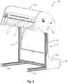
- FIG. 1illustrates a perspective view of an exemplary embodiment of a system for creating packaging templates
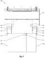
- FIG. 2illustrates a front perspective view of the converting machine from the system illustrated in FIG. 1 ;
- FIG. 3illustrates a rear perspective view of the converting machine from the system illustrated in FIG. 1 ;
- FIG. 4illustrates a top view of the converting machine and fanfold bales from the system illustrated in FIG. 1 ;
- FIG. 5is a perspective view of a converting cartridge from the converting machine of FIGS. 2-4 ;
- FIG. 6Ais a perspective views of feed rollers of the converting cartridge of FIG. 5 , which selectively advance sheet material through the converting machine of FIGS. 2-4 ;
- FIG. 6Bis an end view of the feed rollers of FIG. 6A , with a pressure feed roller in an activated position;
- FIG. 6Cis an end view of the feed rollers of FIG. 6A , with the pressure feed roller in a deactivated position;
- FIG. 7Ais a perspective view of a crosshead converting tool of the converting cartridge of FIG. 5 , with a cutting wheel in a raised position;
- FIG. 7Bis a perspective view of the crosshead converting tool of FIG. 7A , with the cutting wheel in a lowered position;
- FIG. 8is a perspective view of a longhead converting tool of the converting cartridge of FIG. 5 ;
- FIG. 9Ais a partial cross-sectional view of the converting cartridge of FIG. 5 showing a braking mechanism for securing a longhead converting tool in place;
- FIG. 9Bis a partial cross-sectional view of the converting cartridge of FIG. 5 showing the braking mechanism released to allow for movement of the longhead converting tool;
- FIG. 10illustrates a converting roller in a lowered position to enable repositioning of longhead converting tools
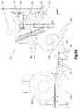
- FIG. 11illustrates a converting roller assembly
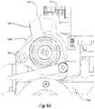
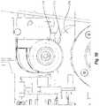
- FIG. 12Aillustrates an eccentric bearing assembly of the converting roller assembly of FIG. 11 ;
- FIG. 12Billustrates a cross sectional view of the eccentric bearing assembly FIG. 12A ;
- FIG. 12Cillustrates a first exploded view of the eccentric bearing assembly of FIG. 12A ;
- FIG. 12Dillustrates a second exploded view of the eccentric bearing assembly of FIG. 12A ;
- FIG. 13illustrates the eccentric bearing assembly of FIG. 12 in a lowered position
- FIG. 14illustrates a biasing mechanism for biasing an eccentric bearing assembly into a raised position
- FIG. 15illustrates a perspective view of an outfeed guide of the converting machine of FIG. 2 ;
- FIG. 16illustrates a cutaway view of the converting machine of FIG. 2 to show the outfeed guide of FIG. 15 ;
- FIG. 17illustrates a perspective view of the converting machine of FIG. 2 showing two access doors of a cover assembly open
- FIG. 18illustrates a perspective view of the converting machine of FIG. 2 showing the entire cover assembly opened.
- the embodiments described hereingenerally relate to systems, methods, and devices for processing sheet materials and converting the same into packaging templates. More specifically, the described embodiments relate to a compact converting machine for converting sheet materials (e.g., paperboard, corrugated board, cardboard) into templates for boxes and other packaging.
- sheet materialse.g., paperboard, corrugated board, cardboard
- baleshall refer to a stock of sheet material that is generally rigid in at least one direction, and may be used to make a packaging template.
- the balemay be formed of continuous sheet of material or a sheet of material of any specific length, such as corrugated cardboard and paperboard sheet materials.
- the balemay have stock material that is substantially flat, folded, or wound onto a bobbin.
- packaging templateshall refer to a substantially flat stock of material that can be folded into a box-like shape.
- a packaging templatemay have notches, cutouts, divides, and/or creases that allow the packaging template to be bent and/or folded into a box.
- a packaging templatemay be made of any suitable material, generally known to those skilled in the art. For example, cardboard or corrugated paperboard may be used as the template material.
- a suitable materialalso may have any thickness and weight that would permit it to be bent and/or folded into a box-like shape.
- creaseshall refer to a line along which the template may be folded.
- a creasemay be an indentation in the template material, which may aid in folding portions of the template separated by the crease, with respect to one another.
- a suitable indentationmay be created by applying sufficient pressure to reduce the thickness of the material in the desired location and/or by removing some of the material along the desired location, such as by scoring.
- notchrefers to a shape created by removing material from the template or by separating portions of the template, such that a cut through the template is created.
- FIG. 1illustrates a perspective view of a system 100 that may be used to create packaging templates.
- System 100includes one or more bales 102 of sheet material 104 .
- System 100also includes a converting machine 106 that performs one or more conversion functions on sheet material 104 , as described in further detail below, in order to create packaging templates 108 .
- Excess or waste sheet material 104 produced during the conversion processmay be collected in a collection bin 110 .
- packaging templates 108may be formed into packaging containers, such as boxes.
- converting machine 106includes a support structure 112 and a converting assembly 114 mounted on support structure 112 .
- Support structure 112includes base members 116 that rest upon a support surface, such as a floor. Extending generally upwardly from base members 116 are supports 118 . Supports 118 may be integrally formed with or coupled to base members 116 .
- Converting assembly 114is mounted on or coupled to supports 118 .
- converting assembly 114is elevated above and spaced apart from a support surface when converting assembly 114 is mounted on supports 118 .
- converting assembly 114may be elevated above the height of bale 102 .
- converting assembly 114may be elevated to a height that would allow relatively long packaging templates 108 to hang therefrom without hitting the support surface below.
- a platform 120may optionally be connected to support structure 112 so that an operator may stand thereon when loading sheet material 104 into or servicing converting assembly 114 .
- bale guides 122are connected to and extending from support structure 112 and/or platform 120 .
- Bale guides 122are generally vertically oriented and spaced apart from one another along the width of converting machine 106 . Bale guides 122 may facilitate proper alignment of bales 102 with converting machine 106 .
- converting machine 106is designed to receive sheet material 104 from two bales 102 a , 102 b .
- Each of bales 102 a , 102 bmay be positioned between adjacent bale guides 122 in order to properly align bales 102 a , 102 b with converting assembly 114 .
- bale guides 122may be angled or may include flared portions that act to funnel bales 102 into the proper positions relative to converting assembly 114 .
- bale guides 122may be movably or slidably connected to structure 112 and/or platform 120 , such that one or more of bale guides 122 may be moved along the width of converting machine 106 to increase or decrease the distance between adjacent bale guides 122 .
- the movability of guides 122may accommodate bales 102 of different widths.
- bales 102may be disposed proximate to the backside of converting machine 106 , and sheet material 104 may be fed into converting assembly 114 .
- Sheet material 104may be arranged in bales 102 in multiple stacked layers. The layers of sheet material 104 in each bale 102 may have generally equal lengths and widths and may be folded one on top of the other in alternating directions. In other embodiments, sheet material 104 may be a rolled-up single-facer corrugate or similar semi-rigid paper or plastic products, or other forms and materials.
- converting machine 106may also have one or more infeed guides 124 .
- Each infeed guide 124may include a lower infeed wheel 126 and an upper infeed wheel 128 .
- lower infeed wheels 126are connected to support structure 112 and upper infeed wheels 128 are connected to converting assembly 114 .
- lower infeed wheels 126 or upper infeed wheels 128may be omitted.
- Each set of lower and upper infeed wheels 126 , 128are designed and arranged to guide sheet material 104 into converting assembly 114 while creating few if any bends, folds, or creases in sheet material 104 . More specifically, lower infeed wheels 126 are positioned such that the axes of rotation of lower infeed wheels 126 are both vertically and horizontally offset from the axes of rotation of upper infeed wheels 128 . As shown, the axes of rotation of lower infeed wheels 126 are positioned vertically lower than the axes of rotation of upper infeed wheels 128 . Additionally, the axes of rotation of lower infeed wheels 126 are positioned horizontally further away from converting assembly 114 than the axes of rotation of upper infeed wheels 128 .
- lower and upper infeed wheels 126 , 128may intersect a common horizontal plane and/or a common vertical plane. In any case, lower and upper infeed wheels 126 , 128 are positioned relative to one another such that sheet material 104 may be fed therebetween and into converting assembly 114 .
- Lower and upper infeed wheels 126 , 128may rotate to facilitate smooth movement of sheet material 104 into converting assembly 114 . Additionally, lower infeed wheels 126 and/or upper infeed wheels 128 may be at least somewhat deformable so as to limit or prevent the formation of bends, folds, or creases in sheet material 104 as it is fed into converting assembly 114 . That is, lower infeed wheels 126 and/or upper infeed wheels 128 may be able to at least partially deform as sheet material 104 is fed therebetween. When lower infeed wheels 126 and/or upper infeed wheels 128 partially deform, lower infeed wheels 126 and/or upper infeed wheels 128 may more closely conform to the shape of sheet material 104 .
- sheet material 104may be pulled around infeed wheels 126 , 128 (e.g., over lower infeed wheels 126 or under upper infeed wheels 126 ). If infeed wheels 126 , 128 were not at least partially deformable, sheet material 104 may be bent or folded as it is pulled around infeed wheels. However, when infeed wheels 126 , 128 are at least partially deformable, infeed wheels 126 , 128 may deform so that the area of infeed wheels 126 , 128 that contacts sheet material 104 is flatter than the normal radius of infeed wheels 126 , 128 . As a result, less folds or creases will be formed in sheet material 104 as it is fed into converting machine 114 .
- Lower infeed wheels 126 and/or upper infeed wheels 128may include an outer surface formed of a deformable and/or elastic material (e.g., foam, rubber) or may include a low pressure tube/tire thereabout.
- the deformable/elastic material or low pressure tubes/tiresmay deform and/or absorb the forces applied to sheet material 104 in order to prevent or limit the formation of folds, bends, or creases in sheet material 104 during the feeding process. Additionally, the deformable/elastic material or low pressure tubes/tires may also limit noises associated with feeding sheet material 104 into converting assembly 114 .
- converting assembly 114may perform one or more conversion functions (e.g., crease, bend, fold, perforate, cut, score) on sheet material 104 in order to create packaging templates 108 .
- Converting assembly 114may include therein a converting cartridge 130 that feeds sheet material 104 through converting assembly 114 and performs the conversion functions thereon.
- FIGS. 5-13illustrate converting cartridge 130 separate from the rest of converting assembly 114 and converting machine 106 .
- Converting cartridge 130may be formed as a unit such that converting cartridge 130 may be selectively removed from converting assembly 114 as a single unit, such as for servicing or replacement.
- converting cartridge 130may include a frame upon which the various components of converting cartridge 130 are assembled or to which they are connected. The converting cartridge frame may be connected to support structure 112 so that the converting cartridge frame does not bend or become twisted, which could adversely impact the performance of the components of converting cartridge 130 .
- the converting cartridge framemay be connected to support structure 112 at three connection points.
- each of the connection pointsmay be flexible connections to allow converting cartridge frame to move slightly or “float” relative to support structure 112 .
- the flexible connectionsmay be achieved using resilient materials (e.g., rubber washers) at the connection sites, for example.
- the three connection pointsmay be arranged so that two of the connection points control the longitudinal movement of the converting cartridge frame, but not the transverse movement of the converting cartridge frame.
- the third connection pointmay control the transverse movement of the converting cartridge frame, but not the longitudinal movement of the converting cartridge frame. In this way, converting cartridge 130 may remain straight and the functional aspects of converting cartridge 130 will not be adversely affected due to misalignment or other results of bending or twisting of the converting cartridge frame.
- converting cartridge 130may include one or more guide channels 132 .
- Guide channels 132may be configured to flatten sheet S material 104 so as to feed a substantially flat sheet thereof through converting assembly 114 .
- each guide channel 132includes opposing upper and lower guide plates that are spaced apart sufficiently to allow sheet material 104 to pass therebetween, but also sufficiently close enough together to flatten sheet material 104 .
- the upper and lower guide platesmay be flared or spaced further apart at on opening end to facilitate insertion of sheet material 104 therebetween.
- guide channels 132may be held or secured in a fixed position along the width of converting cartridge 130 while other guide channels 132 are able to move along at least a portion of the width of converting cartridge 130 .
- converting cartridge 130includes movable guide channels 132 a and fixed guide channels 132 b . More specifically, fixed guide channels 132 b may be secured in place between the opposing sides of converting cartridge 130 .
- Movable guide channels 132 aare disposed between left and right sides of converting cartridge 130 and fixed guide channels 132 b such that movable guide channels 132 a are able to move back and forth between the left and right sides of converting cartridge 130 and fixed guide channels 132 b.
- Movable guide channels 132 amay be able to move so that guide channels 132 a , 132 b are able to accommodate sheet materials 104 of different widths. For instance, movable guide channels 132 a may be able to move closer to fixed guide channels 132 b when a narrower sheet material 104 is being converted than when a wider sheet material 104 is being converted. When a wider sheet material 104 is being converted, movable guide channels 132 a may be moved away from fixed guide channels 132 b so that the wider sheet material 104 may be passed between guide channels 132 a , 132 b .
- Movable guide channels 132 amay be biased toward fixed guide channels 132 b so that, regardless of how wide sheet material 104 is, movable and fixed guide channels 132 ab , 132 b will be properly spaced apart to guide sheet material 104 straight through converting assembly 114 . Movable guide channels 132 a may be biased toward fixed guide channels 132 b with a spring or other resilient mechanism.
- Fixed guide channels 132 bmay act as “zero” or reference points for the positioning of converting tools, which will be discussed in greater detail below. More specifically, the converting tools may reference the positions of fixed guide channels 132 b to determine the location of sheet material 104 or an edge thereof. When the converting tools have been properly positioned using fixed guide channels 132 b as zero points, the converting tools can perform the desired conversion functions at the proper locations on sheet material 104 . In addition to providing an zero or reference point to the converting tools, the location of fixed guide channels 132 b and/or the relative distance between guide channels 132 a , 132 b can also indicate to a control system the width of the sheet material 104 that is being used. Furthermore, allowing movable guide channel 132 a to move relative to fixed guide channel 132 b allows for small deviations in the width of sheet material 104 .
- converting cartridge 130includes two sets of guide channels 132 (e.g., movable guide channel 132 a and fixed guide channel 132 b ) that guide lengths of sheet material 104 through converting assembly 114 . It will be understood, however, that converting cartridge 130 may include one or multiple sets of guide channels for feeding one or multiple, side-by-side lengths of sheet material 104 (e.g., from multiple bales 102 ) through converting assembly 114 .
- the illustrated guide channels 132 a , 132 bform a first (or left) track for feeding a first length of sheet material 104 from bale 102 a ( FIG. 4 ) through converting assembly 114 and a second (or right) track for feeding a second length of sheet material 104 from bale 102 b through converting assembly 114 .
- converting cartridge 130also includes one or more sets of feed rollers 134 that pull sheet material 104 into converting assembly 114 and advance sheet material 104 therethrough.
- Each track formed by sets of guide channels 132may include its own set of feed rollers 134 .
- Feed rollers 134may be configured to pull sheet material 104 with limited or no slip and may be smooth, textured, dimpled, and/or teethed.
- Feed rollers 134may be positioned, angled, shaped (e.g., tapered), or adjusted so as to apply at least a slight side force on sheet material 104 .
- the side force applied to sheet material 104 by feed rollers 134may be generally in the direction of fixed guide channel 132 b .
- sheet material 104will be at least slightly pushed toward/against fixed guide channel 132 b as sheet material 104 is advanced through converting assembly 114 .
- One benefit of at least slightly pushing sheet material 104 toward/against fixed guide channel 132 bis that the biasing force required to bias movable guide channel 132 a toward fixed guide channel 132 b (e.g., the zero point for the converting tools) is reduced.
- each set of feed rollers 134includes an active roller 134 a and a pressure roller 134 b .
- active rollers 134 amay be actively rolled by an actuator or motor in order to advance sheet material 104 through converting assembly 114 .
- pressure rollers 134 bare not typically actively rolled by an actuator, pressure rollers 134 b may nevertheless roll to assist with the advancement of sheet material 104 through converting assembly 114 .
- Active rollers 134 aare secured to converting cartridge 130 such that active rollers 134 a are maintained in generally the same position. More specifically, active rollers 134 a are mounted on shaft 136 . In contrast, pressure rollers 134 b are able to be moved closer to and further away from active rollers 134 a . When pressure rollers 134 b are moved toward active rollers 134 a , feed rollers 134 a , 134 b cooperate to advance sheet material 104 through converting assembly 114 . In contrast, when pressure rollers 134 b are moved away from active rollers 134 a , sheet material 104 is not advanced through converting assembly 114 . That is, when pressure rollers 134 b are moved away from active rollers 134 a , there is insufficient pressure applied to sheet material 104 to advance sheet material 104 through converting assembly 114 .
- FIGS. 6A-6Cillustrate one set of feed rollers 134 and a mechanism for moving pressure roller 134 b closer to and further away from active roller 134 a .
- pressure roller 134 bis rotatably secured to pressure roller block 138 , which is pivotally connected to converting cartridge 130 via hinge 140 .
- pressure roller block 138is pivoted about hinge 140 , pressure roller 134 b is moved toward ( FIG. 6B ) or away from ( FIG. 6C ) active roller 134 a .
- pressure roller 134 bis moved toward active roller 134 a
- pressure roller 134 bis activated or in an activated position.
- pressure roller 134 bis moved away from active roller 134 a , pressure roller 134 b is deactivated or in a deactivated position.
- Pressure roller 134 bmay be selectively moved from the activated position to the deactivated position by engaging a pressure roller cam 142 on pressure roller block 138 .
- the engagement of pressure roller cam 142will be discussed in greater detail below. Briefly, however, when sheet material 104 is not to be advanced through converting assembly 114 , pressure roller cam 142 may be engaged to cause pressure roller block 138 and pressure roller 134 b to pivot about hinge 140 so that pressure roller 134 b is moved to the deactivated position, as shown in FIG. 6C . Similarly, when sheet material 104 is to be advanced through converting assembly 114 , pressure roller cam 142 may be disengaged. Disengagement of pressure roller cam 142 allows pressure roller block 138 and pressure roller 134 b to pivot about hinge 140 so that pressure roller 134 b is moved to the activated position, as shown in FIG. 6B .
- Pressure roller 134 bmay be biased toward either the activated position or the deactivated position.
- pressure roller 134 bmay be biased toward the activated position so that pressure roller 134 b remains in the activated position unless actively moved to the deactivated position (e.g., by engagement of pressure roller cam 142 ).
- pressure roller 134 bmay be biased toward the deactivated position so that pressure roller 134 b remains in the deactivated position unless actively moved to the activated position.
- pressure roller 134 bmay be selectively held in the deactivated position.
- a locking mechanism 144may hold pressure roller 134 b in the deactivated position until it is desired to move pressure roller 134 b to the activated position.
- locking mechanism 144may be an electromagnet that holds pressure roller block 138 and pressure roller 134 b in the deactivated position.
- locking mechanism 144may be released, such as by deactivating its magnetic force. The magnetic force may be deactivated by turning off the electromagnetic field of the electromagnet.
- a permanent magnetmay be used to hold pressure roller block 138 and pressure roller 134 b in the deactivated position
- the magnetic force of the permanent magnetmay be deactivated by applying an electric field around the magnet that counteracts the magnet's magnetic field.
- locking mechanism 144may be a mechanical mechanism, solenoid, or other device than can selectively hold pressure roller 134 b in the deactivated position. Locking mechanism 144 enables pressure roller 134 b to be held in the deactivated position without require the continuous engagement of pressure roller cam 142 .
- pressure roller 134 bWhen it is desired to advance sheet material 104 through converting assembly 114 , pressure roller 134 b may be moved to the activated position as described above. One or both of feed rollers 134 may be actively rotated to advance sheet material 104 .
- shaft 136on which active roller 134 a is mounted
- stepper motor 146may rotate belt 148 , which causes shaft 136 and active roller 134 a to rotate.
- pressure roller 134 bpresses sheet material 104 against active roller 134 a , which causes sheet material 104 to advance through converting assembly 114 .
- pressure roller 134 bwhen pressure roller 134 b is in the deactivated position, pressure roller 134 b does not press sheet material 104 against active roller 134 a . Without pressure roller 134 b pressing sheet material 104 against active roller 134 a , active roller 134 a may rotate/spin underneath sheet material 104 without advancing sheet material 104 through converting assembly 114 .
- converting cartridge 130includes one or more converting tools, such as a crosshead 150 and longheads 152 , that perform the conversion functions (e.g., crease, bend, fold, perforate, cut, score) on sheet material 104 in order to create packaging templates 108 .
- Some of the conversion functionsmay be made on sheet material 104 in a direction substantially perpendicular to the direction of movement and/or the length of sheet material 104 . In other words, some conversion functions may be made across (e.g., between the sides) sheet material 104 . Such conversions may be considered “transverse conversions.”
- crosshead 150may move along at least a portion of the width of converting cartridge 130 in a direction generally perpendicular to the direction in which sheet material 104 is fed through converting assembly 114 and/or the length of sheet material 104 . In other words, crosshead 150 may move across sheet material 104 in order to perform transverse conversions on sheet material 104 .
- Crosshead 150may be movably mounted on a track 154 to allow crosshead 150 to move along at least a portion of the width of converting cartridge 130 .
- FIGS. 7A-7Billustrate perspective views of crosshead 150 and a portion of track 154 separate from the rest of converting cartridge 130 .
- Crosshead 150includes a body 156 with a slider 158 and a sensor 161 .
- Slider 158connects crosshead 150 to track 154 to allow crosshead 150 to move back and forth along track 154 .
- Crosshead 150also includes one or more converting instruments, such as a cutting wheel 160 and creasing wheels 162 , which may perform one or more transverse conversions on sheet material 104 . More specifically, as crosshead 150 moves back and forth over sheet material 104 , cutting wheel 160 and creasing wheels 162 may create creases, bends, folds, perforations, cuts, and/or scores in sheet material 104 .
- creasing wheels 162While creasing wheels 162 are able to rotate, creasing wheels 162 may remain in substantially the same vertical position relative to body 156 .
- cutting wheel 160may be selectively raised and lowered relative to body 156 . For instance, as shown in FIG. 7A , cutting wheel 160 may be raised so that cutting wheel 160 does not cut sheet material 104 as crosshead 150 moves over sheet material 104 . Alternatively, as shown in FIG. 7B , cutting wheel 160 may be lowered in order to cut sheet material 104 as crosshead 150 moves over sheet material 104 .
- cutting wheel 160is rotatably mounted on a cutting wheel frame 164 .
- Cutting wheel frame 164is movably connected to body 156 .
- cutting wheel frame 164is slidably mounted on one or more shafts 163 .
- Cutting wheel frame 164is held on shafts 163 and biased toward the raised position by one or more springs 165 that are connected between body 156 and cutting wheel frame 164 .
- One or more solenoids 166may be used to selectively move cutting wheel frame 164 and cutting wheel 160 from the raised position ( FIG. 7A ) to the lowered position ( FIG. 7B ).
- Solenoids 166each include a solenoid plunger 168 that extends and retracts upon activation and deactivation of solenoids 166 .
- solenoid plungers 168When solenoid plungers 168 are retracted, cutting wheel frame 164 and cutting wheel 160 are raised (via springs 165 and/or the normal forces from sheet material 104 ) so that cutting wheel 160 does not cut sheet material 104 .
- solenoids 166are activated, solenoid plungers 168 extend, thereby causing cutting wheel frame 164 and cutting wheel 160 to be lowered ( FIG. 7B ) so that cutting wheel 160 cuts sheet material 104 .
- solenoidsto move various components
- Other types of actuatorsmay be used to perform the functions described herein.
- other linear or non-linear actuatorsmay be used, including voice coils, linear motors, rotational motor, lead screws, and the like.
- reference to solenoidsis not intended to limit the scope of the present invention. Rather, the present invention may employ solenoids or any other actuator capable of performing the functions described herein in connection with solenoids.
- converting cartridge 130includes a support plate 167 positioned below crosshead 150 .
- Support plate 167supports sheet material 104 as cutting wheel 160 and creasing wheels 162 perform the transverse conversions on sheet material 104 .
- support plate 167includes a channel 169 that is aligned with and able to receive at least a portion of cutting wheel 160 .
- cutting wheel 160may extend through sheet material 104 and at least partially into channel 169 .
- cutting wheel 160may extend entirely through sheet material 104 without engaging support plate 167 , which could result in undue wear.
- the kinetic energy of the moving components of crosshead 150may be used to assist in cutting through sheet material 104 . More specifically, the activation of solenoids 166 causes solenoid plungers 168 to move as they extend out of solenoids 166 . The movement of solenoid plungers 168 causes cutting wheel frame 164 and cutting wheel 160 to move as well. As solenoid plungers 168 , cutting wheel frame 164 , and cutting wheel 160 begin to move, they build up momentum, and thus kinetic energy, until cutting wheel 160 engages sheet material 104 .
- a cutis made in a material by moving a cutting tool over the material to a location where the cut needs to begin. Prior to initiating the cut, the cross movement of the cutting tool is stopped. Then the cutting tool is lowered to penetrate the material and the cross movement of the cutting tool is resumed. In such a situation, a relatively significant amount of force may be required to lower the cutting tool and penetrate the material. This is partially due to the fact that some of the force used to lower the cutting tool will be used to compress the material before the cutting tool actually penetrates through the material. The compression of the material is at least partially due to a relatively large chord of the cutting tool trying to cut through the material at the same time.
- converting machine 100may include an “on-the-fly” mode where the movement of crosshead 150 over sheet material 104 and the lowering of cutting wheel 160 are combined to initiate a cut through sheet material 104 .
- crosshead 150may begin moving across sheet material 104 toward the location where a cut needs to be made in sheet material 104 .
- cutting wheel 160is lowered while crosshead 150 continues to move across sheet material 104 .
- the cross movement of crosshead 150 and the lowering of cut wheel 160may be timed so that cutting wheel 160 engages and initiates a cut in sheet material 104 at the desired location.
- a pulse-width modulation (PWM) circuit board or other voltage adjusting electric componentsmay generate sufficiently high currents within solenoids 166 so that solenoids 166 are able to generate enough force to cut through sheet material 104 .
- the PWM circuit board or other voltage adjusting electric componentsmay reduce the current in solenoids 166 , while still enabling solenoids 166 to maintain cutting wheel 160 in the lowered position.
- a relatively high currentmay be generated in solenoids 166 to provide enough force to enable cutting wheel 160 to penetrate sheet material 104 .
- the current in solenoids 166may be reduced, while still enabling solenoids 166 to continue cutting through sheet material 104 .
- solderoidshave unique force-to-stroke curve profiles. In the beginning of a solenoid's stroke, the solenoid has a relatively limited force. Further into the solenoid's stroke, the force increases dramatically. Accordingly, a relatively high voltage/current can be used during the solenoid's stroke in order to generate the relative large force at the end of the stroke so that the cutting wheel may penetrate the sheet material. At the end of the solenoid's stroke (e.g., when the plunger is fully extended), the voltage/current can be reduced while still maintaining a relative high holding force. That is, even with the reduced voltage/current, the solenoid may have enough force to hold the cutting wheel in place so that the cutting wheel continues cutting sheet material 104 .
- solenoids 166Being able to adjust to the voltage level supplied to solenoids 166 (and thus the current in solenoids 166 ) can also be beneficial for various reasons. For instance, less power can be used to achieve the desired results. For example, high voltage can be used for a short time in order to initiate a cut, while lower voltage can be used to continue making the cut. Not only does this reduce the overall amount of power required, but it can improve the performance of certain components. For instance, limiting high voltage supplies to relatively short durations can prevent the temperature of solenoids 166 from increasing or overheating due to high currents in solenoids 166 . Higher temperatures or overheating of solenoids 166 can cause damage thereto and/or reduce their activation force.
- the ability to adjust the voltagecan also be beneficial when activating solenoids 166 when no sheet material 104 is below cutting wheel 160 (“dry-firing”). For instance, if solenoids 166 were dry-fired with a high voltage, cutting wheel 160 may be lowered too far or too rapidly, potentially resulting in damage and/or excessive mechanical wear.
- crosshead 150When crosshead 150 has finished performing the transverse conversions on sheet material 104 , crosshead 150 may be used to move pressure roller 134 b from the activated position to the deactivated position. More specifically, when it is desired to stop advancing sheet material 104 , crosshead 150 may be moved adjacent to pressure roller block 138 such that a portion of crosshead 150 engages pressure roller cam 142 . As noted above, engagement of pressure roller cam 142 causes pressure roller block 138 and pressure roller 134 to pivot about hinge 140 to the deactivated position. As shown in FIG. 6C , crosshead 150 includes a horizontally oriented wheel 171 that can engage pressure roller cam 142 to move pressure roller 134 b to the deactivated position.
- conversion functionsmay also be made on sheet material 104 in a direction substantially parallel to the direction of movement and/or the length of sheet material 104 . Conversions made along the length of and/or generally parallel to the direction of movement of sheet material 104 may be considered “longitudinal conversions.”
- Longheads 152may be used to create the longitudinal conversions on sheet material 104 . More specifically, longheads 152 may be selectively repositioned along the width of converting cartridge 130 (e.g., back and forth in a direction that is perpendicular to the length of sheet material 104 ) in order to properly position longheads 152 relative to the sides of sheet material 104 .
- converting cartridge 130e.g., back and forth in a direction that is perpendicular to the length of sheet material 104
- one of longheads 152may be moved perpendicularly across sheet material 104 to properly position longhead 152 so as to be able to make the cut or crease at the desired location.
- longheads 152may be moved transversely across sheet material 104 to position longheads 152 at the proper location to make the longitudinal conversions on sheet material 104 .
- FIG. 8illustrates a close up view of a portion of converting cartridge 130 , including one of longheads 152 .
- longhead 152includes a body 170 with a slider 172 .
- Slider 172connects longhead 152 to a track 174 to allow longhead 152 to move back and forth along at least a portion of the width of converting cartridge 130 .
- Longhead 152may include one or more converting instruments, such as cutting wheel 176 and creasing wheel 178 , which may perform the longitudinal conversions on sheet material 104 . More specifically, as sheet material 104 moves underneath longhead 152 , cutting wheel 176 and creasing wheel 178 may create creases, bends, folds, perforations, cuts, and/or scores in sheet material 104 .
- converting assembly 130may also include a converting roller 200 positioned below longheads 152 so that sheet material 104 passes between converting roller 200 and cutting wheel 176 and creasing wheel 178 .
- Converting roller 200may support sheet material 104 while the longitudinal conversions are performed on sheet material 104 .
- converting roller 200may advance packaging templates 108 out of converting assembly 114 after the conversion functions are completed. Additional detail regarding converting roller 200 will be provided below.
- Cutting wheel 176 and creasing wheel 178are rotatably connected to body 170 and oriented to be able to make the longitudinal conversions.
- cutting wheel 176 and creasing wheel 178may be pivotally connected to body 170 and/or longhead 152 may be pivotally connected to slider 172 .
- sheet material 104may not advance in a perfectly straight line.
- the orientation of cutting wheel 176 and creasing wheel 178may change to more closely follow the feeding direction of sheet material 104 .
- the braking force (discussed below) required to maintain longhead 152 in placemay be reduced because sheet material 104 will apply less side force to cutting wheel 176 and creasing wheel 178 .
- the biasing force required to bias movable guide channels 132 a toward fixed channels 132 bmay likewise be reduced.
- longhead 152When longhead 152 has been repositioned at the desired location along the width of converting cartridge 130 , longhead 152 may be secured in place. More specifically, once positioned as desired, longhead 152 may be secured to a brake belt 180 , other another portion of converting cartridge 130 .
- FIGS. 9A and 9Billustrate cross-sectional views of longhead 152 and one exemplary mechanism for securing longhead 152 to brake belt 180 .
- longhead 152includes a brake pivot arm 182 that is pivotally connected to body 170 .
- a spring 184is connected between brake pivot arm 182 and body 170 to bias brake pivot arm 182 to the locked position, shown in FIG. 9A .
- brake pivot arm 182When it is desired to reposition longhead 152 along the length of track 174 , brake pivot arm 182 may be pivoted to disengage engagement member 186 from brake belt 180 , as shown in FIG. 9B .
- the pivoting of brake pivot arm 182may be accomplished using a solenoid 188 that is mounted on crosshead 150 ( FIGS. 7A, 7B, 9B ).
- solenoid 188In order to pivot brake pivot arm 182 with solenoid 188 , crosshead 150 is first moved into alignment with longhead 152 . Solenoid 188 is then activated, which causes a solenoid plunger 190 to extend and engage brake pivot arm 182 , as shown in FIG. 9B .
- solenoid plunger 190engages brake pivot arm 182
- brake pivot arm 182pivots, which causes engagement member 186 to disengagement brake belt 180 .
- spring 184is connected between body 170 and brake pivot arm 182 in such a way that the force required of solenoid 188 to pivot brake pivot arm 182 remains substantially constant.
- spring 184is stretched.
- the force that would normally be required to continue pivoting pivot brake arm 182would continue to increase.
- the connection location between spring 184 and brake pivot arm 182begins to move over the pivot location of brake pivot arm 182 and the connection location between spring 184 and body 170 so that spring 184 is oriented more vertically.
- the more vertical orientation of spring 184reduces the horizontal force that spring 184 applies to brake pivot arm 182 .
- the increased force normally required to stretch spring 184is generally offset by the reduced horizontal force applied to brake pivot arm 182 by spring 184 .
- longhead 152may be repositioned along the length of track 174 .
- crosshead 150may be used to reposition longhead 150 . More specifically, crosshead 150 and longhead 152 may be connected together or otherwise engaged such that movement of crosshead 150 results in movement of longhead 152 . This arrangement, therefore, only requires the ability to actively control crosshead 150 , while longhead 152 may be passively moved by crosshead 150 . Furthermore, longheads 152 do not require electric sensors and electric or pneumatic actuators.
- longheads 152do not need to be connected to electrical power or compressed air, such as with electrical cables/wires and hoses in a cable chain. This enables a much more cost effective design of longheads 152 , as well as enables a more cost effective manufacturing and maintenance friendly design of the whole converting assembly 114 and converting machine 106 .
- FIG. 9BOne exemplary manner for selectively connecting longhead 152 to crosshead 150 is shown in FIG. 9B .
- brake pivot arm 182When crosshead 150 is aligned with longhead 152 and brake pivot arm 182 is pivoted (e.g., to disengage engagement member 186 from brake belt 180 ), a portion of brake pivot arm 182 may engage crosshead 150 so as to connect longhead 152 to crosshead 150 .
- an extension 192 on brake pivot arm 182may pivot into a notch 194 on body 156 of crosshead 150 .
- extension 192is positioned within notch 194
- the movements of crosshead 150 and longhead 152will be linked together. That is, when extension 192 is positioned within notch 194 and crosshead 150 is moved, longhead 152 will move with crosshead 150 .
- FIGS. 7A-7Bshow notch 194 formed on the side of body 156 of crosshead 150 .
- notch 194can include a flared opening that can assist with guiding extension 192 into notch 194 .
- the flared openingcan guide extension 192 in notch 194 and thereby correct minor position errors of longhead 152 .
- extension 192is released from notch 194 and longhead 152 is locked into place.
- longhead 152will be locked into place at the correct location since any positioning errors of longhead 152 will have been corrected when extension 192 was pivoted into notch 194 .
- converting machine 106can be operating without requiring frequent resetting or manual adjustments to longheads 152 .
- Notch 194can also include substantially vertical interior walls.
- the vertical interior walls of notch 194apply the forces to extension 192 that result in the movement of longhead 152 .
- the vertically walls of notch 194only apply horizontal forces on extension 192 . Since notch 194 does not apply any downward forces on extension 192 , the force required of solenoid 188 to maintain brake pivot arm 182 in the unlocked position is reduced. In connection therewith, a relatively low amount of power is required by solenoid 188 to maintain brake pivot arm 182 in the unlocked position while longhead 152 is moved.
- solenoid plunger 190may be used to reduce the amount of force required of solenoid 188 (and thus the power required to activate solenoid 188 ). More specifically, the activation of solenoid 188 causes solenoid plunger 190 to move as it extends out of solenoid 188 . As solenoid plunger 190 begins to move, it builds up momentum, and thus kinetic energy. When plunger 190 engages brake pivot arm 182 , the built-up kinetic energy of plunger 190 works with the force provided by solenoid 188 to pivot brake pivot arm 182 so as to disengage engagement member 186 from brake belt 180 .
- pivoting of brake pivot arm 182causes brake pivot arm 182 to build up kinetic energy.
- the combined kinetic energy of plunger 190 and brake pivot arm 182similarly reduces the force required of solenoid to correct minor position errors of longhead 152 and to connect crosshead 150 to longhead 152 .
- the kinetic energy of plunger 190 and brake pivot arm 182facilitates insertion of extension 192 into notch 194 , which both corrects position errors of longhead 152 and connects crosshead 150 and longhead 152 together.
- the illustrated embodimentincludes two longheads 152 .
- the converting cartridge 130may include one or more longheads 152 .
- crosshead 150may be used to selectively move each longhead 152 individually.
- a normal setup for creating regular slotted box (RSC) packaging templatesrequires at least three longheads, of which two are equipped with crease tools, and one with a side-trim knife. In order to enable side-trimming on the outer side of each track of the sheet material, a forth longhead with a knife is added on the opposite side of the first knife longhead.
- RSCregular slotted box
- two additional crease toolsmay be added in the middle.
- a set of two crease longheads and one cut longheadare mainly used for one track, and another identical—but mirrored—setup is used mainly for the other track.
- Thisalso enables conversion to more complicated packaging template designs, where the four creasing longheads can each create a longitudinal crease, while either of the cut longheads may be used for side-trimming.
- a seventh longhead equipped with a knifemay be added in the middle, thereby enabling two packaging templates to be created in parallel, side-by-side.
- crosshead 150includes a sensor 161 .
- Sensor 161may be used to detect the presence of longheads 152 adjacent to crosshead 150 . For instance, when it is desired to reposition a longhead 152 , crosshead 150 may move across converting cartridge 130 to the location where a longhead 152 is supposed to be (according to a control system). Once crosshead 150 is so positioned, sensor 161 may be used to confirm that longhead 152 is at the proper position. Upon detection of the longhead 152 by sensor 161 , solenoid 188 may be activated so as to release the braking mechanism of the longhead 152 and connect the longhead 152 to crosshead 150 . Once crosshead 150 has moved the longhead 152 to the desired location, sensor 161 may be used to confirm the proper positioning of the longhead 152 at the desired location (either before or after disengagement between crosshead 150 and longhead 152 ).
- Converting machine 100may include control circuitry or be connected to a computer that monitors the positions of longheads 152 and controls crosshead 150 . In the event that sensor 161 does not detect a longhead 152 at the last known position, the control circuitry can direct crosshead 150 to move across converting cartridge 130 so that sensor 161 may detect the location of the missing longhead 152 . If sensor 161 is unable to locate each of the longheads 152 after a predetermined number of attempts, an error message may be generated to direct an operator to manually locate the longheads 152 or call for maintenance or service.
- crosshead 150may include a sensor 196 ( FIG. 9B ) that detects the position of guide channels 132 . For instance, as crosshead 150 move back and forth across converting cartridge 130 , sensor 196 may detect the current location of each guide channel 132 . Based on the detected locations, the control circuitry may determine if each guide channel 132 is in the proper location. For example, if the detected location of fixed guide channel 132 b does not match the previously set location, it may be that fixed guide channel 132 b has slipped or an operator adjusted fixed guide channel 132 b without updating the control circuitry.
- control circuitrymay generate an error message indicating that fixed guide channel 132 b needs to be repositioned.
- control circuitrymay simply update the stored location of fixed guide channel 132 b to the detected location and thereby determine the width of the sheet material 104 is being used.
- Sensor 196may similarly detect the current location of movable guide channel 132 a so that the control circuitry may determine if movable guide channel 132 a is in the proper position.
- movable guide channel 132 ais able to move to accommodate sheet material 104 of different widths.
- movable guide channel 132 amay not be in the proper location if sheet material 104 has run out, if sheet material 104 is damaged, or converting machine 100 is loaded with sheet material 104 that is wider or narrower than what control circuitry is set for.
- the control circuitrymay generate an error message indicating that fixed guide channel 132 b needs to be repositioned, new sheet material 104 needs to be loaded, or the like.
- converting roller 200supports sheet material 104 as longheads 152 perform the longitudinal conversions on sheet material 104 .
- Longheads 152 and converting roller 200may be positioned relative to one another such that the conversion functions are performed on sheet material 104 as sheet material 104 passes between longheads 152 and converting roller 200 .
- cutting wheel 176may extend into converting roller 200 so that there is no clearance between cutting wheel 176 and converting roller 200 .
- sheet material 104will be cut as it passes cutting wheel 176 .
- creasing wheel 178does not need to penetrate through sheet material 104 , creasing wheel 178 may be positioned such that there is some clearance between creasing wheel 178 and converting roller 200 .
- converting roller 200cutting wheel 176 , and creasing wheel 178 are also possible.
- the rotational axis of cutting wheel 176may be horizontally offset from the rotational axis of converting roller 200 such that cutting wheel 176 is positioned slightly behind converting roller 200 .
- cutting wheel 176may be positioned lower without extending further (or at all) into converting roller 200 .
- the lower positioning of cutting wheel 176may also ensure that cutting wheel 176 cuts through the entire thickness of sheet material 104 .
- converting roller 200is selectively raised and lowered to engage or disengage converting roller 200 from cutting wheel 176 and/or creasing wheel 178 .
- converting roller 200may be lowered as shown in FIG.
- Lowering converting roller 200 to disengage longheads 152eliminates any need to have sensors, actuators, or cables chains (for electrical power, compressed air) connected to longheads 152 , giving the advantages noted above. This is especially important in an all-electric machine that does not include pneumatic actuators or that does not have access to compressed air.
- converting roller 200is mounted on shaft 202 . Like feed roller 134 a , converting roller 200 is rotated by stepper motor 146 via belt 148 .
- stepper motor 146rotates belt 148 in a first direction (e.g., clockwise as shown in FIG. 6A )
- converting roller 200is likewise rotated in the first direction, which advances sheet material 104 under longheads 152 and/or advances packaging templates 108 out of converting assembly 114 .
- stepper motor 146rotates belt 148 in a second direction (e.g., counterclockwise as shown in FIG. 6A )
- converting roller 200is lowered to the position shown in FIG. 10 .
- FIGS. 11-14illustrate (separate from the rest of converting cartridge 130 ) converting roller 200 and the mechanism used to lower converting roller 200 .
- converting roller 200is mounted on shaft 202 .
- a first end of shaft 202extends through a bearing block 204 and has a gear 206 mounted thereon.
- belt 148engages gear 206 in order to rotate shaft 202 and converting roller 200 .
- a second end of shaft 202extends into a bearing block 208 .
- FIGS. 12A-13illustrate an eccentric bearing assembly 210 that enables converting roller 200 to rotate in the first direction and be lowered when rotated in the second direction.
- FIGS. 12A-13illustrate bearing block 204 and eccentric bearing assembly 210 mounted on the first end of shaft 202 . More specifically, FIG. 12A illustrates a side view of eccentric bearing assembly 210 disposed in bearing block 204 , FIG. 12B illustrates a cross sectional view of eccentric bearing assembly 210 and bearing block 204 , and FIGS. 12C and 12D illustrate exploded views of eccentric bearing assembly 210 and bearing block 204 . As shown in FIG. 11 , the second end of shaft 202 also has an eccentric bearing assembly 212 that is substantially similar to eccentric bearing assembly 210 .
- bearing block 204includes a generally square recess 214 in which eccentric bearing assembly 210 is positioned and is able to rotate.
- Bearing block 204also includes a generally rectangular recess 215 formed therein.
- Shaft 202extends through recesses 214 , 215 and has eccentric bearing assembly 210 and a bearing 217 mounted thereon, as shown in FIG. 12B .
- Bearing 217is mounted on shaft 202 and positioned within recess 215 to enable shaft 202 to move within recess 215 (e.g., when converting roller 200 is raised or lowered) in a low friction and long lasting manner.
- Eccentric bearing assembly 210includes a one-way bearing 216 , an eccentric bearing block 218 , and a two-way bearing 219 .
- eccentric bearing block 218includes a recess 221 in which one-way bearing 216 is disposed.
- Eccentric bearing block 218also includes a projection 223 on which bearing 219 is mounted.
- Bearing 219enables eccentric bearing block 218 to rotate within and relative to recess 214 (e.g., when converting roller 200 is raised or lowered) in a low friction and long lasting manner.
- eccentric bearing block 218includes an aperture 225 through which shaft 202 extends.
- shaft 202has a central rotational axis A about which converting roller 200 rotates when belt 148 rotates shaft 202 in the first direction.
- One-way bearing 216 , bearing 217 , recess 221 , and aperture 225are mounted on or disposed around shaft 202 so as to have central axes that are coaxial with axis A.
- eccentric bearing block 218 , projection 223 , and bearing 219share a common rotational axis B that is offset from axis A.
- one-way bearing 216allows shaft 202 to rotate in the first direction, relative to eccentric bearing block 218 , and about axis A.
- one-way bearing 216locks together with eccentric bearing block 218 to prevent relative movement between shaft 202 and eccentric bearing block 218 .
- eccentric bearing block 218also rotates in the second direction.
- eccentric bearing block 218When eccentric bearing block 218 is rotated in the second direction, eccentric bearing block 218 rotates about axis B. Rotation of eccentric bearing block 218 about axis B causes shaft 202 to revolve around axis B. As shown in FIG. 13 , when eccentric bearing block 218 is rotated in the second direction about axis B, shaft 202 revolves around axis B so that shaft 202 is lowered from the position shown in FIG. 12A . As a result, converting roller 200 is lowered when rotated in the second (e.g., reverse) direction.
- the seconde.g., reverse
- a spring loaded tensioner 220creates tension in belt 148 .
- the tension in belt 148applies a force on gear 206 that has both an upward vertical component and a horizontal component.
- a spring mechanismapplies a similar force on eccentric bearing assembly 212 .
- eccentric bearing assembly 210 and eccentric bearing assembly 212automatically rotate back to the raised position shown in FIG. 12 when belt 148 begins rotating shaft 202 in the first direction again. In this way, eccentric bearing assembly 210 and eccentric bearing assembly 212 are synchronized (both raised or both lowered).
- belt 148rotates shaft 202 in the second direction, which causes the eccentric bearing blocks in eccentric bearing assemblies 210 , 212 to rotate about axis B. If the eccentric bearing blocks are rotated in the second direction more or less than 180 degrees, then the upward forces on eccentric bearing assemblies 210 , 212 will have enough of a mechanical advantage to automatically rotate eccentric bearing assemblies 210 , 212 back to the raised position when belt 148 begins to rotate shaft 202 in the first direction. This is due to the fact that the upward forces will not be acting directly under axis B.
- eccentric bearing blocksare rotated 180 degrees in the second direction (e.g., so the upward forces are acting directly under axis B), then the upward forces on eccentric bearing assemblies 210 , 212 may not have enough of a mechanical advantage to automatically rotate eccentric bearing assemblies 210 , 212 back to the raised position.
- belt 148may be rotated further in the second direction so that the upward forces will have enough of a mechanical advantage to automatically rotate eccentric bearing assemblies 210 , 212 back to the raised position.
- belt 148may be rotated in the second direction and then in the first direction to reset eccentric bearing assemblies 210 , 212 .
- belt 148may be rotated 45 degrees in the second direction and then 45 degrees in the first direction.
- By rotating in the second direction less than 180 degreesit is assured that the upward forces are not acting directly under axis B.
- the upward forceswill have a sufficient mechanical advantage to cause eccentric bearing assemblies 210 , 212 to automatically rotate to the raised position.
- tensioner 220also counter most downward forces applied to converting roller 200 by sheet material 104 and longheads 152 , thereby a preventing eccentric bearing assembly 210 from rotating and lowering converting roller 200 when belt 148 is not rotating in the second direction.
- recess 214 , eccentric bearing block 218 , and bearing 219are sized and arranged to prevent eccentric bearing assembly 210 from unintentionally rotating and lowering converting roller 200 in the event that a downward force is applied to converting roller 200 that would overcome the upward force provided by tensioner 220 .
- bearing 219allows for eccentric bearing assembly 210 to operate as described above. More specifically, as can best be seen in FIG. 12B , bearing 219 has a slightly smaller outer diameter than eccentric bearing block 218 and recess 214 includes a notch 227 directly above eccentric bearing block 218 . As a result, the upward forces provided by tensioner 220 cause bearing 219 to engage the upper interior surface of recess 214 . At the same time, however, eccentric bearing block 218 does not engage the upper surface of recess 214 . Rather, the upper surface of eccentric bearing block 218 extends into notch 227 . This arrangement allows for eccentric bearing block 218 to rotate about axis B when belt 148 rotates shaft 202 in the second direction.
- converting roller 200is lowered slightly until eccentric bearing block 218 engages the lower surface of recess 214 .
- the larger outer diameter of eccentric bearing block 218causes eccentric bearing block 218 to engage the lower surface of recess 214 while still providing clearance between bearing 219 and the lower surface of recess 214 .
- frictionis created between eccentric bearing block 218 and the lower surface of recess 214 . The friction created therebetween can be sufficient to prevent eccentric bearing block 218 from rotating about axis B, and thereby preventing the unintentional lowering of converting roller 200 .
- Tensioner 220allows for converting roller 200 to be lowered and raised as well as providing a relatively consistent rotational force to active roller 134 a .
- Tensioner 220is connected to belt 148 between stepper motor 146 and converting roller 200 , as opposed to being connected to belt 148 between stepper motor 146 and active roller 134 a . Not having tensioner 220 connected to belt 148 between stepper motor 146 and active roller 134 a ensures that belt 148 provides a relatively consistent force to active roller 134 a , which allows for relatively consistent feeding of sheet material 104 through converting assembly 114 .
- connecting tensioner 220 between stepper motor 146 and converting roller 200allows for the force applied by belt 148 to converting roller 200 to vary. For instance, when belt rotates converting roller 200 in the first direction, belt 148 provides a given force on converting roller 200 . When belt 148 rotates converting roller 200 in the second direction, tensioner 200 reduces the upward force applied to converting roller 200 , thereby allowing converting roller 200 to be lowered as described above.
- Eccentric bearing assembly 212 on the second end of shaft 202provides the same functionality as eccentric bearing assembly 210 . Specifically, when shaft 202 is rotated in the first direction, eccentric bearing assembly 212 allows shaft 202 and converting roller 200 to rotate to advance sheet material 104 . When shaft 202 is rotated in the second direction, eccentric bearing assembly 212 causes shaft 202 and converting roller 200 to be lowered.
- bearing block 208includes a biasing mechanism to return eccentric bearing assembly 212 to the raised position.
- the biasing mechanismincludes a pivot arm 222 pivotally connected to bearing block 208 .
- a spring 224is disposed between bearing block 208 and a first end of pivot arm 222 .
- Spring 224causes a second end of pivot arm 222 to rotate up against eccentric bearing assembly 212 , thereby biasing eccentric bearing assembly 212 toward the raised position.
- the second end of pivot arm 222can include a bearing 226 that can reduce wear between pivot arm 222 and eccentric bearing assembly 212 .
- stepper motor 146may be used to advance sheet material 104 through converting assembly 114 by rotating active roller 134 a .
- stepper motor 146may also be used to advance packaging templates 108 out of converting assembly 114 by rotating converting roller 200 in a first direction.
- stepper motor 146may disengage longheads 152 for repositioning by rotating converting roller 200 in a second direction in order to lower converting roller 200 .
- Stepper motorsare more cost effective and accommodate a more favorable torque-curve, which enables a slimmer mechanical design.
- One common short-coming of stepper motorsis that they lose much of their torque at higher speeds. In the present context, however, this property is advantageous because it requires a less rigid support structure to handle the higher torque of other motors.
- the lower torque at high speedsprevents moving components (e.g., crosshead 150 , longheads 152 , converting roller 200 , etc.) from being damaged as a result of high energy collisions.
- stepper motorsimmediately stall when speeds are too high, thereby reducing the likelihood of a damaging collision, increasing reliability of components, as well as personal safety.
- outfeed guide 230may be configured to deflect and/or redirect packaging templates 108 from moving in one direction to another.
- outfeed guide 230may be configured to redirect packaging templates 108 from a first direction, which may be in a substantially horizontal plane (e.g., as sheet material 104 moves through converting assembly 114 ), to a second direction.
- the second directionmay be angled relative to the first direction.
- the first directionmay be substantially horizontal, while the second direction may be at about a 70 degree angle relative to the first direction.
- the first direction and the second directionmay form an acute or obtuse angle with respect to one another.
- outfeed guide 230includes a lower guide plate 232 and one or more upper guide teeth 234 .
- Packaging templates 108may be fed between lower guide plate 232 and one or more upper guide teeth 234 .
- lower guide plate 232 and the one or more upper guide teeth 234are curved and taper towards one another.
- lower guide plate 232 and the one or more upper guide teeth 234cooperate to consistently guide packaging templates 108 out of converting assembly 114 at a predetermined and predictable location.
- lower guide plate 232may support packaging templates 108 as they are fed out of converting assembly 114 so that packaging templates 108 consistently exit converting assembly at the same location.
- the one or more upper guide teeth 234may be configured to deflect and/or redirect packaging templates 108 from moving in the first direction to the second direction.
- the one or more upper guide teeth 234may also be configured to maintain packaging templates 108 at a predetermined maximum distance from support structure 112 .
- the one or more upper guide teeth 234may have a generally arcuate surface that deflect and/or redirect packaging templates 108 toward the second direction so that packaging templates 108 do not extend significantly out of converting assembly 114 in a horizontal direction.
- a cover 236is positioned over the one or more upper guide teeth 234 .
- Cover 236may prevent excess sheet material 104 from exiting converting assembly 114 without being deflected downward by the one or more upper guide teeth 234 .
- Cover 236may optionally be clear to allow for inspection of outfeed guide 230 as well as the interior of converting assembly 114 .
- outfeed guide 230may also include outfeed extensions 238 , 240 .
- Extensions 238extend from lower guide plate 232 so as to form an angle (e.g., between about 30 degrees and about 100 degree; about 70 degrees, etc.) with the first direction of movement of sheet material 104 .
- Extensions 238are generally rigid so as to be able to guide packaging templates 108 horizontally away from support structure 112 and support at least a portion of packaging templates 108 after packaging templates 108 exit converting assembly 114 .
- extensions 238may guide and support packaging templates 108 so that packaging templates 108 hang from converting assembly 114 outside of collection bin 110 , as shown in FIG. 1 .
- Extensions 240extend from cover 236 near opposing sides of converting assembly 114 .
- Extensions 240may be flexible or rigid. In any case, extensions 240 may extend generally straight down from cover 236 . Extensions 240 may be configured to deflect and/or direct excess sheet material 104 (such as side material cut off when forming packaging templates 108 ) into collection bin 110 .
- Converting assembly 114may be connected to support structure 112 such that sheet material 104 is fed through converting assembly 114 in a first direction that is not in a horizontal plane.
- converting assembly 114may be connected to support structure 112 such that sheet material 104 is fed through converting assembly 114 at an angle relative to a support surface on which converting machine 100 is positioned.
- the angle between the first direction and the support surfacemay be anywhere between 0 degrees to 90 degrees.
- converting assembly 114may be movably connected to support structure 112 such that the angle between the first direction and the support surface may be selectively changed.
- outfeed guide 230may feed packaging templates 108 out of converting assembly 114 in the same direction (e.g., so as to form a 45 degree angle with the support surface).
- outfeed guide 230may feed packaging templates 108 out of converting assembly 114 at an angle relative to sheet material 104 's direction of movement through converting assembly 114 (e.g., between about 30 degrees and about 100 degree; about 70 degrees, etc.).
- converting assembly 114may be configured and arranged such that these relative terms require adjustment. For instance, if converting assembly 114 is mounted on support structure 112 at an angle, converting roller 200 may move between a “forward position” and a “backward position” rather than between a “raised position” and a “lowered position.”
- Converting assembly 114may include a cover assembly having one or more covers or doors that allow for ready access to converting cartridge 130 .
- converting assembly 114may include covers on one or both sides and/or one or more front and rear covers. The one or more covers may provide ready and convenient access to various portions of converting cartridge 130 .
- converting assembly 114includes a cover assembly having a front cover 242 , a rear cover 244 , and opposing side covers 246 , 248 .
- Front cover 242 and rear cover 244may be opened individually or together as shown in FIG. 17 in order to gain access to the interior of converting assembly 114 , including converting cartridge 130 .
- front cover 242 and rear cover 244are pivotally connected to and between opposing side covers 246 , 248 .
- the cover assembly(e.g., covers 242 , 244 , 246 , 248 ) may also be opened as a unit as shown in FIG. 18 in order to provide greater access to or replacement of converting cartridge 130 .
- rear cover 244may be opened (as shown in FIG. 17 ) after which side covers 246 , 248 may be pivoted back as shown in FIG. 18 . Since front and rear covers 242 , 244 are connected between side covers 246 , 248 , front and rear covers 242 , 244 also rotate back when side covers 246 , 248 are rotated back. Once covers 242 , 244 , 246 , 248 are all rotated back, converting cartridge 130 may be serviced or replaced.
Landscapes
- Engineering & Computer Science (AREA)
- Mechanical Engineering (AREA)
- Life Sciences & Earth Sciences (AREA)
- Forests & Forestry (AREA)
- Making Paper Articles (AREA)
- Auxiliary Devices For And Details Of Packaging Control (AREA)
- Folding Of Thin Sheet-Like Materials, Special Discharging Devices, And Others (AREA)
- Details Of Cutting Devices (AREA)
- Nonmetal Cutting Devices (AREA)
- Toys (AREA)
- Cartons (AREA)
- Treatment Of Liquids With Adsorbents In General (AREA)
- Apparatus For Radiation Diagnosis (AREA)
- Extraction Or Liquid Replacement (AREA)
Abstract
Description
Claims (25)
Priority Applications (3)
| Application Number | Priority Date | Filing Date | Title |
|---|---|---|---|
| US15/901,089US11400680B2 (en) | 2011-11-10 | 2018-02-21 | Converting machine |
| US17/082,294US11731385B2 (en) | 2011-11-10 | 2020-10-28 | Converting machine |
| US18/214,362US12053949B2 (en) | 2011-11-10 | 2023-06-26 | Converting machine |
Applications Claiming Priority (6)
| Application Number | Priority Date | Filing Date | Title |
|---|---|---|---|
| US201161558298P | 2011-11-10 | 2011-11-10 | |
| US201261640686P | 2012-04-30 | 2012-04-30 | |
| US201261643267P | 2012-05-05 | 2012-05-05 | |
| PCT/US2012/064403WO2013071073A1 (en) | 2011-11-10 | 2012-11-09 | Converting machine |
| US201414357190A | 2014-05-08 | 2014-05-08 | |
| US15/901,089US11400680B2 (en) | 2011-11-10 | 2018-02-21 | Converting machine |
Related Parent Applications (2)
| Application Number | Title | Priority Date | Filing Date |
|---|---|---|---|
| PCT/US2012/064403ContinuationWO2013071073A1 (en) | 2011-11-10 | 2012-11-09 | Converting machine |
| US14/357,190ContinuationUS9969142B2 (en) | 2011-11-10 | 2012-11-09 | Converting machine |
Related Child Applications (1)
| Application Number | Title | Priority Date | Filing Date |
|---|---|---|---|
| US17/082,294DivisionUS11731385B2 (en) | 2011-11-10 | 2020-10-28 | Converting machine |
Publications (2)
| Publication Number | Publication Date |
|---|---|
| US20180178476A1 US20180178476A1 (en) | 2018-06-28 |
| US11400680B2true US11400680B2 (en) | 2022-08-02 |
Family
ID=48290592
Family Applications (5)
| Application Number | Title | Priority Date | Filing Date |
|---|---|---|---|
| US14/357,183ActiveUS9352526B2 (en) | 2011-11-10 | 2012-11-09 | Elevated converting machine with outfeed guide |
| US14/357,190Active2034-09-26US9969142B2 (en) | 2011-11-10 | 2012-11-09 | Converting machine |
| US15/901,089Active2032-12-07US11400680B2 (en) | 2011-11-10 | 2018-02-21 | Converting machine |
| US17/082,294Active2033-05-24US11731385B2 (en) | 2011-11-10 | 2020-10-28 | Converting machine |
| US18/214,362ActiveUS12053949B2 (en) | 2011-11-10 | 2023-06-26 | Converting machine |
Family Applications Before (2)
| Application Number | Title | Priority Date | Filing Date |
|---|---|---|---|
| US14/357,183ActiveUS9352526B2 (en) | 2011-11-10 | 2012-11-09 | Elevated converting machine with outfeed guide |
| US14/357,190Active2034-09-26US9969142B2 (en) | 2011-11-10 | 2012-11-09 | Converting machine |
Family Applications After (2)
| Application Number | Title | Priority Date | Filing Date |
|---|---|---|---|
| US17/082,294Active2033-05-24US11731385B2 (en) | 2011-11-10 | 2020-10-28 | Converting machine |
| US18/214,362ActiveUS12053949B2 (en) | 2011-11-10 | 2023-06-26 | Converting machine |
Country Status (9)
| Country | Link |
|---|---|
| US (5) | US9352526B2 (en) |
| EP (9) | EP2776221B1 (en) |
| JP (9) | JP6077556B2 (en) |
| CN (4) | CN104169073B (en) |
| BR (2) | BR112014011396A2 (en) |
| ES (5) | ES2767321T3 (en) |
| PL (4) | PL3623123T3 (en) |
| RU (4) | RU2614483C2 (en) |
| WO (2) | WO2013071080A1 (en) |
Cited By (3)
| Publication number | Priority date | Publication date | Assignee | Title |
|---|---|---|---|---|
| US12023887B2 (en) | 2018-04-05 | 2024-07-02 | Avercon BVBA | Packaging machine infeed, separation, and creasing mechanisms |
| US12053949B2 (en)* | 2011-11-10 | 2024-08-06 | Packsize Llc | Converting machine |
| US12291365B2 (en) | 2018-06-21 | 2025-05-06 | Packsize, Llc | Packaging machine and systems |
Families Citing this family (32)
| Publication number | Priority date | Publication date | Assignee | Title |
|---|---|---|---|---|
| EP2802448B1 (en)* | 2012-01-09 | 2016-10-26 | Packsize LLC | Converting machine with an upward outfeed guide |
| US20140336027A1 (en)* | 2013-05-13 | 2014-11-13 | Xerox Corporation | System and method for creating customized boxes |
| US11312098B2 (en)* | 2014-01-29 | 2022-04-26 | Futura S.P.A. | Equipment and method for the production of cardboard tubes |
| DE102014102604A1 (en)* | 2014-02-27 | 2015-08-27 | Windmöller & Hölscher Kg | Device for automatic cutting and removal of a material web and method for this purpose |
| US10071472B2 (en)* | 2014-05-09 | 2018-09-11 | Packsize Llc | Outfeed table |
| US10093438B2 (en) | 2014-12-29 | 2018-10-09 | Packsize Llc | Converting machine |
| CN104708852B (en)* | 2015-03-20 | 2017-09-15 | 安徽宸瑞节能环保科技工程有限公司 | Full-automatic impression mould guillotine |
| PL3426447T3 (en)* | 2016-03-11 | 2020-08-24 | Panotec Srl | Machine and method for working a material suitable to make containers |
| ITUA20163729A1 (en)* | 2016-05-24 | 2017-11-24 | F L Auto Srl | CUTTING STATION OF A CARDBOARD SHEET FROM A CONTINUOUS CARDBOARD STRIP AND MACHINE FOR PACKING AN ARTICLE INSIDE A CARDBOARD BOX OBTAINED FROM THE CARDBOARD SHEET |
| US10850469B2 (en)* | 2016-06-16 | 2020-12-01 | Packsize Llc | Box forming machine |
| SE541881C2 (en)* | 2016-12-19 | 2020-01-02 | Packsize Llc | A box template production system and method |
| WO2017218296A1 (en)* | 2016-06-16 | 2017-12-21 | Packsize Llc | A box template production system and method |
| US10781896B2 (en) | 2016-07-12 | 2020-09-22 | Wagner Spray Tech Corporation | Belt tightening mechanism for a fluid delivery system |
| EP3284687B1 (en)* | 2016-08-16 | 2020-11-04 | Quadient Technologies France | System and method for automatically packaging items varying in size and number for shipment |
| US11242214B2 (en)* | 2017-01-18 | 2022-02-08 | Packsize Llc | Converting machine with fold sensing mechanism |
| SE541921C2 (en) | 2017-03-06 | 2020-01-07 | Packsize Llc | A box erecting method and system |
| SE1750727A1 (en)* | 2017-06-08 | 2018-10-09 | Packsize Llc | Tool head positioning mechanism for a converting machine, and method for positioning a plurality of tool heads in a converting machine |
| CN107984801B (en)* | 2017-11-16 | 2023-05-02 | 江苏力维智能装备有限公司 | Paper warehouse calling device of intelligent carton cutting machine |
| US11173685B2 (en) | 2017-12-18 | 2021-11-16 | Packsize Llc | Method for erecting boxes |
| US11305903B2 (en) | 2018-04-05 | 2022-04-19 | Avercon BVBA | Box template folding process and mechanisms |
| WO2020009689A1 (en)* | 2018-07-02 | 2020-01-09 | Hewlett-Packard Development Company, L.P. | Cutter module and method |
| SE543046C2 (en) | 2018-09-05 | 2020-09-29 | Packsize Llc | A box erecting method and system |
| CN109177307A (en)* | 2018-10-10 | 2019-01-11 | 温州市顺福包装有限公司 | A kind of irregular box process equipment with waste recovery function |
| US11524474B2 (en)* | 2018-11-30 | 2022-12-13 | Packsize Llc | Adjustable cutting and creasing heads for creating angled cuts and creases |
| DE112020000348T5 (en) | 2019-01-07 | 2021-09-16 | Packsize Llc | Carton erecting machine |
| US11701854B2 (en)* | 2019-03-14 | 2023-07-18 | Packsize Llc | Packaging machine and systems |
| CN109896313B (en)* | 2019-03-28 | 2024-01-30 | 东莞市奥奇包装机械有限公司 | Paper feed driving mechanism for tail of paper folding machine |
| MX2022002659A (en) | 2019-10-07 | 2022-04-07 | Fuller H B Co | Spindle free tape article and method. |
| US12165437B2 (en)* | 2020-10-14 | 2024-12-10 | Scientific Games, Llc | Lottery ticket dispensing unit with a shuttle separator device |
| CN113002058B (en)* | 2021-03-09 | 2022-08-26 | 寻乌县桔都果业有限公司 | Hard paper shell creasing machine for navel orange packaging |
| CN113276177B (en)* | 2021-04-26 | 2022-03-15 | 宁波经纬数控股份有限公司 | Graph-text cutting machine |
| US12172791B2 (en)* | 2022-09-15 | 2024-12-24 | Amazon Technologies, Inc. | Systems and methods for longitudinal scoring of roll-formed containers |
Citations (397)
| Publication number | Priority date | Publication date | Assignee | Title |
|---|---|---|---|---|
| FR428967A (en) | 1910-07-04 | 1911-09-12 | Francois Joseph Charles Taupin | Rotary folding machine for paper and cardboard boxes |
| GB166622A (en) | 1920-03-05 | 1921-07-05 | Henry Jeffrey Poole | Improvements in machines for cutting paper, cardboard and the like |
| US1809853A (en) | 1927-08-29 | 1931-06-16 | Hoague Sprague Corp | Art of box making |
| SU40025A1 (en) | 1933-08-01 | 1934-12-31 | И.К. Соколов | Stitching machine |
| US2077428A (en) | 1934-12-14 | 1937-04-20 | Gilman Fanfold Corp | Strip controlling attachment |
| US2083351A (en) | 1935-07-29 | 1937-06-08 | Specialty Automatic Machine Co | Manufacture of corrugated paper cartons |
| US2181117A (en) | 1938-04-09 | 1939-11-28 | Autographic Register Co | Method of making continuous manifolding stationery |
| US2256082A (en) | 1940-02-12 | 1941-09-16 | Cons Cover Co | Paper converting machine |
| US2353419A (en) | 1942-06-11 | 1944-07-11 | Eugene S Smithson | Machine for forming box blanks |
| US2449663A (en) | 1946-09-28 | 1948-09-21 | Marcalus Nicholas | Interfolding |
| US2609736A (en) | 1948-06-03 | 1952-09-09 | Hugh E Montgomery | Machine for folding paper box blanks on a stack thereof |
| FR1020458A (en) | 1950-06-17 | 1953-02-06 | Automatic transfer machine for making one-piece cardboard boxes | |
| US2631509A (en) | 1944-07-18 | 1953-03-17 | American Viscose Corp | Method for forming tubular articles |
| US2679195A (en) | 1944-07-18 | 1954-05-25 | American Viscose Corp | Apparatus for forming tubular articles |
| US2699711A (en) | 1951-09-15 | 1955-01-18 | Bloomer Bros Co | Carton erecting machine |
| US2798582A (en) | 1948-04-15 | 1957-07-09 | Ex Cell O Corp | Web control for carton converting machine |
| US2904789A (en) | 1956-12-20 | 1959-09-22 | Victory Container Corp | Folding machine |
| DE1082227B (en) | 1957-07-19 | 1960-05-25 | Papierverarbeitungsmaschinenwe | Cutting machine for paper, cardboard or the like. |
| US3096692A (en) | 1962-03-16 | 1963-07-09 | Fmc Corp | Box making machine |
| US3105419A (en) | 1960-09-19 | 1963-10-01 | Bombard Leon E La | Adhesive applying apparatus and method |
| US3108515A (en) | 1962-08-01 | 1963-10-29 | Anderson Bros Mfg Co | Method and apparatus for erecting flattened cartons |
| US3153991A (en) | 1963-03-04 | 1964-10-27 | St Regis Paper Co | Apparatus for the manufacture of composite carton blanks |
| GB983946A (en) | 1962-07-18 | 1965-02-24 | Charles Edward Palmer | Synthetic plastic container and blank and method of folding same |
| DE1212854B (en) | 1963-07-30 | 1966-03-17 | Internat Machinery Corp N V | Packing machine |
| US3285145A (en) | 1963-11-18 | 1966-11-15 | Somerville Ind Ltd | Carton setting up machine |
| US3303759A (en) | 1964-05-11 | 1967-02-14 | Peters Leo | Converting machine for butter patty plate |
| US3308723A (en) | 1964-08-06 | 1967-03-14 | Jr Charles J Bergh | Apparatus for slitting and scoring carton blanks |
| US3332207A (en) | 1963-12-11 | 1967-07-25 | H G Weber And Company Inc | Carton forming, filling and sealing machine |
| US3406611A (en) | 1965-10-13 | 1968-10-22 | Nat Packaging Products | Apparatus for producing and stacking sheetlike items |
| US3418893A (en) | 1965-12-30 | 1968-12-31 | Anderson Bros Mfg Co | Carton feeding and erecting apparatus |
| US3469508A (en) | 1966-04-09 | 1969-09-30 | Eickhoff Geb | Apparatus for forming glued or coated folding box stock |
| FR1592372A (en) | 1968-11-20 | 1970-05-11 | ||
| US3511496A (en) | 1967-06-09 | 1970-05-12 | Optische Ind De Oude Delft Nv | Device for removing individual sheets from a stack |
| US3543469A (en) | 1966-04-25 | 1970-12-01 | Huntingdon Ind Inc | Packaging apparatus |
| US3555776A (en) | 1966-05-04 | 1971-01-19 | Johns Nigrelli Johns | Machine for forming a tray around a group of articles |
| US3566755A (en) | 1969-01-14 | 1971-03-02 | Weyerhaeuser Co | Apparatus for erecting cartons |
| US3611884A (en) | 1970-01-26 | 1971-10-12 | William J Hottendorf | Box making machine |
| US3618479A (en) | 1970-04-08 | 1971-11-09 | S & S Corrugated Paper Mach | Automatic positioner for hold-down means |
| US3628408A (en) | 1969-10-08 | 1971-12-21 | Xerox Corp | Stamp dispenser |
| US3646418A (en)* | 1969-07-22 | 1972-02-29 | Logic Systems Inc | Positioning of multiple elements |
| US3743154A (en) | 1972-01-03 | 1973-07-03 | Minnesota Mining & Mfg | Paper guide |
| US3756586A (en) | 1971-12-16 | 1973-09-04 | Ibm | Selective cut sheet feed device |
| US3776109A (en) | 1972-04-06 | 1973-12-04 | Union Camp Corp | Folder for large box blanks |
| US3803798A (en) | 1972-09-11 | 1974-04-16 | Colgate Palmolive Co | Folded towelette guide and feed mechanism |
| US3804514A (en) | 1972-09-26 | 1974-04-16 | Xerox Corp | Dual function document stop for a caping device |
| US3807726A (en) | 1973-03-08 | 1974-04-30 | H Hope | Film receiving apparatus |
| GB1362060A (en) | 1970-11-23 | 1974-07-30 | Fmc Corp | Web handling machines |
| JPS4999239A (en) | 1973-01-25 | 1974-09-19 | ||
| US3866391A (en) | 1973-02-20 | 1975-02-18 | Emhart Corp | Wrap-around packer |
| US3882764A (en)* | 1972-04-27 | 1975-05-13 | Simon Ltd Henry | Case making machinery |
| US3886833A (en) | 1974-05-01 | 1975-06-03 | Elworthy & Co Ltd | Apparatus to effect remote automatic positioning of web slitter |
| US3891203A (en) | 1973-12-27 | 1975-06-24 | Joseph Schiff | Office machine including flat article feeder |
| JPS5078616A (en) | 1973-11-15 | 1975-06-26 | ||
| US3912389A (en) | 1973-10-05 | 1975-10-14 | Canon Kk | Copy medium receiving tray |
| US3913464A (en) | 1974-11-22 | 1975-10-21 | S & S Corrugated Paper Mach | Positioning means for hold-down |
| FR2280484A1 (en) | 1974-07-29 | 1976-02-27 | Glaverbel | Glass sheet cutting appts moving at high speed - comprises cutting tool carriers moving in sequence along a support beam across the glass |
| JPS5127619A (en) | 1974-09-02 | 1976-03-08 | Mitsubishi Motors Corp | TASHIRINDANAINENKIKAN |
| US3949654A (en)* | 1974-06-21 | 1976-04-13 | S. A. Martin | Assembly for use in a machine for processing sheet or similar material |
| US3986319A (en) | 1973-02-20 | 1976-10-19 | Emhart Industries, Inc. | Wrap-around packer |
| US4033217A (en)* | 1976-01-13 | 1977-07-05 | S&S Corrugated Paper Machinery Co., Inc. | Slitter having carrier for selective adjustment of a plurality of heads |
| US4044658A (en) | 1976-04-01 | 1977-08-30 | Union Camp Corporation | Apparatus for folding panels of carton blank |
| US4052048A (en) | 1976-03-11 | 1977-10-04 | Paper Converting Machine Company | Longitudinally interfolding device and method |
| US4053152A (en) | 1975-10-16 | 1977-10-11 | Rank Xerox, Ltd. | Sheet feeding device |
| US4056025A (en)* | 1976-04-02 | 1977-11-01 | Rubel Laurence P | Strip cutting apparatus |
| US4094451A (en) | 1976-11-04 | 1978-06-13 | Granite State Machine Co., Inc. | Lottery ticket dispenser for break-resistant web material |
| DE2700004A1 (en) | 1977-01-03 | 1978-07-06 | Sick Optik Elektronik Erwin | ELECTRO-OPTICAL FOLDING MONITORING DEVICE |
| US4121506A (en) | 1977-03-23 | 1978-10-24 | The Continental Group, Inc. | Carton forming apparatus |
| US4123966A (en) | 1976-12-08 | 1978-11-07 | Nolex Corporation | Carton forming apparatus |
| DE2819000A1 (en) | 1977-05-05 | 1978-11-16 | Meccanica V D Di Valenti Dante | MACHINE FOR THE PRODUCTION OF CORRUGATED CARDBOARD BOXES, IN PARTICULAR FOR HORTICULTURE PRODUCTS |
| GB1546789A (en) | 1976-05-28 | 1979-05-31 | Simon Container Mach Ltd | Web feeding apparatus |
| US4164171A (en) | 1977-10-25 | 1979-08-14 | American Can Company | Carton forming apparatus |
| US4173106A (en) | 1977-04-13 | 1979-11-06 | Mira-Pak Inc. | Carton forming method |
| US4191467A (en) | 1979-04-04 | 1980-03-04 | Xerox Corporation | Dual mode catch tray |
| JPS5557984A (en) | 1978-10-25 | 1980-04-30 | Hitachi Ltd | Ticket printing issusing machine |
| US4221373A (en) | 1977-03-18 | 1980-09-09 | Grapha-Holding Ag | Apparatus for folding paper sheets or the like |
| US4222557A (en) | 1978-05-16 | 1980-09-16 | Wang Laboratories, Inc. | Printer feeding and stacking |
| US4224847A (en)* | 1977-10-20 | 1980-09-30 | Rengo Co., Ltd. | Tool positioning apparatus |
| US4252233A (en) | 1979-06-04 | 1981-02-24 | Joice Richard L | Plastic bag-wicketing pin adjustment apparatus |
| US4261239A (en)* | 1978-12-13 | 1981-04-14 | Nihon Electronic Industry Co., Ltd. | Positioning head for cutting and marking apparatus |
| US4264200A (en) | 1979-09-17 | 1981-04-28 | Xerox Corporation | Platen module for computer fanfold reproduction |
| EP0030366A1 (en) | 1979-12-11 | 1981-06-17 | Ab Tetra Pak | A method and an arrangement for the feed of a material web |
| US4295841A (en) | 1979-10-19 | 1981-10-20 | The Ward Machinery Company | Box blank folding apparatus |
| US4320960A (en) | 1979-09-17 | 1982-03-23 | Xerox Corporation | Sensor controlling in computer fanfold reproduction |
| US4342562A (en) | 1978-12-21 | 1982-08-03 | Molnlycke Aktiebolag | Package and method and apparatus for manufacturing the same |
| US4368052A (en) | 1980-08-18 | 1983-01-11 | Peerless Metal Industries, Inc. | Method and apparatus for lining bulk box blanks |
| SU992220A1 (en) | 1980-12-15 | 1983-01-30 | Тбилисское Производственное Трикотажное Объединение "Бахтриони" | Machine for making box blanks from cardboard web |
| US4373412A (en)* | 1980-07-10 | 1983-02-15 | Gerber Garment Technology, Inc. | Method and apparatus for cutting sheet material with a cutting wheel |
| US4375970A (en) | 1980-10-06 | 1983-03-08 | Westvaco Corporation | Converting machine gum box |
| SU1054863A1 (en) | 1981-07-02 | 1983-11-15 | Новосибирский Научно-Исследовательский,Проектно-Конструкторский И Технологический Институт Комплектного Электропривода | Ac electric drive (its versions) |
| US4449349A (en) | 1980-12-03 | 1984-05-22 | Involvo Ag | Packing machine with adjustable means for weakening selected portions of cardboard blanks or the like |
| JPS59176836A (en) | 1983-03-25 | 1984-10-06 | Sanyo Electric Co Ltd | Processing system for sound input data |
| SU1121156A1 (en) | 1981-10-08 | 1984-10-30 | Челябинская Обувная Фабрика "Чпоо" | Machine for making packing boxes from cardboard web |
| JPS59198243A (en) | 1983-04-26 | 1984-11-10 | Canon Inc | Sheet separation conveying device |
| US4487696A (en) | 1978-08-14 | 1984-12-11 | Ferrara Louis T | Blood separator and dispenser |
| DE3343523A1 (en) | 1983-12-01 | 1985-06-13 | ERO-Etikett GmbH, 7318 Lenningen | Station for a device processing concertina-folded continuous webs, in particular printer |
| US4578054A (en) | 1983-11-17 | 1986-03-25 | Herrin Robert M | Carton erection and sealing apparatus |
| JPS61118720A (en) | 1984-11-15 | 1986-06-06 | Matsushita Electric Ind Co Ltd | Sukyana |
| USD286044S (en) | 1983-08-31 | 1986-10-07 | Canon Kabushiki Kaisha | Paper discharging tray for a facsimile |
| US4638696A (en)* | 1984-09-17 | 1987-01-27 | Simtek Inc. | Apparatus for dispensing strip material or the like |
| US4663169A (en) | 1985-08-14 | 1987-05-05 | Snow Brand Milk Products Co., Ltd. | Method for automatic measurement and control in curd making process |
| US4674734A (en) | 1984-12-05 | 1987-06-23 | Sharp Kabushiki Kaisha | Automatic document feeder |
| JPS62172032A (en) | 1986-01-23 | 1987-07-29 | Kanegafuchi Chem Ind Co Ltd | Improved heat-resistant polyimide film |
| SE450829B (en) | 1981-02-25 | 1987-08-03 | Tetra Pak Ab | SET AND DEVICE FOR PROMOTING A MATERIAL COURSE IN REGISTERED WITH A BIG LINING SAMPLE SIZE |
| US4684360A (en) | 1985-02-14 | 1987-08-04 | Rengo Co., Ltd. | Tool positioning device |
| US4695006A (en) | 1985-08-12 | 1987-09-22 | Minnesota Mining And Manufacturing | Paper converting machine |
| US4714946A (en) | 1985-11-27 | 1987-12-22 | International Business Machines Corporation | Continuous form feeder for a reproducing machine and process |
| US4743131A (en) | 1986-08-06 | 1988-05-10 | Atwell J Dwayne | Tractor feed continuous paper system for printers |
| US4749295A (en) | 1985-12-26 | 1988-06-07 | Bankier Companies, Inc. | Fan-fold paper catcher for a printer |
| US4773781A (en) | 1985-12-26 | 1988-09-27 | Bankier Companies, Inc. | Fan-fold paper catcher for a printer |
| JPH01133164A (en) | 1987-11-18 | 1989-05-25 | Nec Corp | Power supply circuit for memory testing device |
| US4838468A (en) | 1983-03-31 | 1989-06-13 | Ab Tetra Pak | Reel for registry of a material web provided with crease lines |
| US4844316A (en) | 1983-07-08 | 1989-07-04 | Molins Machine Company, Inc. | Web director |
| US4847632A (en) | 1988-06-03 | 1989-07-11 | Polaroid Corporation | Printer apparatus having foldable catcher assembly |
| FR2626642A1 (en) | 1988-01-29 | 1989-08-04 | Parrier Henri | Device for driving a component with a reciprocating translational movement |
| US4878521A (en)* | 1988-10-28 | 1989-11-07 | Mac Engineering & Equipment Company, Inc. | Apparatus for parting and pasting battery plate grids |
| US4887412A (en) | 1987-08-07 | 1989-12-19 | Fuji Pack Systems, Ltd. | Wrapping machine |
| DE3825506A1 (en) | 1988-07-27 | 1990-02-01 | Bhs Bayerische Berg | Device for punching and, if desired, embossing, flat materials |
| EP0359005A1 (en) | 1988-09-14 | 1990-03-21 | Ab Profor | An arrangement for the intermittent forward feeding of a material web provided with transverse crease lines |
| US4923188A (en) | 1988-10-26 | 1990-05-08 | Spectra-Physics | Z-fold paper sheet carrier |
| US4932930A (en) | 1988-03-22 | 1990-06-12 | Embal-Systems | Method and machine for forming cases with polygonal section made from a sheet material and cases thus obtained |
| US4979932A (en) | 1989-03-02 | 1990-12-25 | International Paper Box Machine Co., Inc. | Apparatus and method for sealing box blanks |
| US4994008A (en) | 1989-06-01 | 1991-02-19 | Rsr Machine Builders, Inc. | Machine for producing container blanks from flat stock |
| JPH0370927A (en) | 1989-08-11 | 1991-03-26 | Toshiba Corp | Room heater and cooler |
| US5005816A (en) | 1988-06-13 | 1991-04-09 | Winkler & Dunnebier Maschinenfabrik Und Eisengiesserei Kg | Interfolder device with dynamic pressure section connected at the outlet side of the folding rollers |
| US5030192A (en) | 1990-09-07 | 1991-07-09 | Ncr Corporation | Programmable fan fold mechanism |
| US5039242A (en) | 1989-12-22 | 1991-08-13 | Spectra-Physics, Inc. | Z-fold paper retainer |
| US5046716A (en) | 1989-01-31 | 1991-09-10 | Eastman Kodak Company | Lighttight film box having a film clasping tray |
| SU1676825A1 (en) | 1989-04-05 | 1991-09-15 | Научно-производственное объединение "Легпроммеханизация" | Apparatus for making blanks of cartons |
| US5058872A (en) | 1989-08-08 | 1991-10-22 | Didde Web Press Corp. | Chain cam |
| US5072641A (en)* | 1989-11-17 | 1991-12-17 | Jagenberg Aktiengesellschaft | Apparatus for positioning devices for operating upon sheets or webs |
| US5074836A (en) | 1990-08-03 | 1991-12-24 | Storage Technology Corporation | Automated stacker for previously fan folded for continuous feed print media |
| US5081487A (en) | 1991-01-25 | 1992-01-14 | Xerox Corporation | Cut sheet and computer form document output tray unit |
| US5090281A (en)* | 1990-03-08 | 1992-02-25 | Marquip, Inc. | Slitting apparatus for corrugated paperboard and the like |
| US5094660A (en) | 1988-06-15 | 1992-03-10 | Fuji Photo Film Co., Ltd. | Image recording apparatus |
| SU1718783A1 (en) | 1989-10-04 | 1992-03-15 | Молдавский научно-исследовательский институт табака | Tobacco pressing device |
| US5106359A (en) | 1991-09-16 | 1992-04-21 | Lott Michael E | Carton formation system |
| US5111252A (en) | 1989-08-23 | 1992-05-05 | Sanyo Electric Co., Ltd. | Electrophotographic copying machine with paper feeding and discharge trays |
| US5116034A (en) | 1990-12-14 | 1992-05-26 | Hewlett-Packard Company | Envelope/sheet feed mechanism |
| US5118093A (en) | 1988-09-27 | 1992-06-02 | Mita Industrial Co., Ltd. | Image-forming machine |
| US5120297A (en)* | 1989-06-21 | 1992-06-09 | Fosber S.R.L. | Machine for creasing and cutting endless webs of cardboard and the like |
| US5120279A (en) | 1987-07-03 | 1992-06-09 | Ina Walzlager Schaeffler Kg | Structural bearing element |
| US5123894A (en) | 1991-05-02 | 1992-06-23 | Hewlett-Packard Company | Paper guide and stacking apparatus for collecting fan fold paper for a printer or the like |
| US5123890A (en) | 1990-03-29 | 1992-06-23 | G. Fordyce Company | Apparatus and method for separating forms in a stack |
| US5137172A (en) | 1990-12-24 | 1992-08-11 | Hollymatic Corporation | Paper feed system |
| US5137174A (en) | 1991-01-30 | 1992-08-11 | Xerox Corporation | Pivoting paper tray |
| SU1756211A1 (en) | 1990-01-04 | 1992-08-23 | Проектно-Конструкторское Бюро "Пунтукас" | Method for attaching label to surface of thermoplastic container |
| US5148654A (en) | 1990-06-05 | 1992-09-22 | Kisters Maschinenbau Gmbh | Packaging system |
| US5154041A (en) | 1991-07-08 | 1992-10-13 | Schneider Packaging Equipment Co., Inc. | Wrap-around carton packing apparatus and method |
| US5157903A (en) | 1989-11-10 | 1992-10-27 | Ishida Scales Mfg. Co., Ltd. | Film-folding device for packaging apparatus |
| US5197366A (en)* | 1992-07-29 | 1993-03-30 | Marquip, Inc. | Roller assembly for paperboard slitting apparatus |
| US5240243A (en) | 1990-02-28 | 1993-08-31 | Hewlett-Packard Company | Hanging bin for uniformly stacking cut sheets at the output of a plotter |
| US5241353A (en) | 1990-11-17 | 1993-08-31 | Mita Industrial Co., Ltd. | Paper-discharging tray |
| US5259255A (en) | 1989-11-17 | 1993-11-09 | Jagenberg Aktiengesellschaft | Apparatus for positioning devices for operating upon sheets or webs |
| US5263785A (en) | 1988-07-29 | 1993-11-23 | Asahi Kogaku Kogyo Kabushiki Kaisha | Sheet guide mechanism for use in an imaging device |
| USD344751S (en) | 1990-03-29 | 1994-03-01 | Artwright Marketing SDN. BHD. | Paper hopper |
| JPH06123606A (en) | 1992-10-09 | 1994-05-06 | Kawasaki Steel Corp | Detection method for overlapping parts of strips |
| CN2164350Y (en) | 1992-12-21 | 1994-05-11 | 吴火木 | Cardboard groove forming machine |
| US5321464A (en) | 1992-08-31 | 1994-06-14 | International Business Machines Corporation | Jam-free continuous-forms printer |
| RU2015030C1 (en) | 1991-05-27 | 1994-06-30 | Альберт-Франкенталь АГ | Folding apparatus |
| US5335777A (en) | 1993-10-15 | 1994-08-09 | Jervis B. Webb Company | Method and apparatus for belt conveyor load tracking |
| US5358345A (en) | 1994-02-16 | 1994-10-25 | Output Technology Corporation | Printer outfeed paper collector for refolding and restacking fanfold paper discharged from a continuous form printer or the like |
| US5369939A (en) | 1993-03-23 | 1994-12-06 | Moen Industries, Inc. | High speed lidder |
| US5375390A (en) | 1991-05-22 | 1994-12-27 | Technopac, Inc. | Machine for making and positioning bags made of hot-melt plastic material |
| US5397423A (en) | 1993-05-28 | 1995-03-14 | Kulicke & Soffa Industries | Multi-head die bonding system |
| US5411252A (en) | 1994-04-18 | 1995-05-02 | Pitney Bowes Inc. | Two way adjustable side guide device |
| EP0650827A2 (en) | 1993-10-27 | 1995-05-03 | Mercamer Oy | Package padding material and apparatus for forming package padding material |
| JPH07156305A (en) | 1993-12-10 | 1995-06-20 | Miyakoshi:Kk | Cardboard sheet processing equipment |
| FR2721301A1 (en) | 1994-06-17 | 1995-12-22 | Sodeme Sa | Compact folding machine with oscillating arms for sheets of cardboard |
| WO1996010518A1 (en) | 1994-10-03 | 1996-04-11 | Riverwood International Corporation | Carrier sleeve erecting apparatus and method |
| WO1996014773A1 (en) | 1994-11-09 | 1996-05-23 | Becher Textil- Und Stahlbau Gmbh | Shade, especially stand-up shade |
| JPH08238690A (en) | 1994-12-15 | 1996-09-17 | Griffin Automation Inc | Method and device for forming box material having slot and fold |
| DE19541061C1 (en) | 1995-11-03 | 1996-11-07 | Siemens Nixdorf Inf Syst | Electrophotographic printer with compensating device esp. ED1 printer station with web tension |
| JPH08333036A (en) | 1995-06-09 | 1996-12-17 | Toshiba Corp | Paper transport device |
| US5584633A (en) | 1994-05-10 | 1996-12-17 | General Binding Corporation | Binder element conveying mechanism |
| US5586758A (en) | 1994-03-03 | 1996-12-24 | Canon Kabushiki Kaisha | Sheet discharge apparatus and image forming apparatus having such sheet discharge apparatus |
| US5667468A (en) | 1994-11-10 | 1997-09-16 | Battenfeld Gloucester Engineering Co., Inc. | Screw adjustable wicket pins |
| US5671593A (en) | 1995-12-28 | 1997-09-30 | Wrap-It-Up, Inc. | Semiautomatic package wrapping machine |
| US5716313A (en) | 1991-05-16 | 1998-02-10 | Philip Morris Incorporated | Apparatus and method for folding blanks |
| US5727725A (en) | 1996-10-22 | 1998-03-17 | Genicom Corporation | Fan-fold paper stacking receptacle with angled bottom and canted back wall |
| US5767975A (en) | 1994-03-21 | 1998-06-16 | Tetra Laval Holdings And Finance | Method and device for detecting the position for a crease line of a packaging web |
| CN1191833A (en) | 1997-02-20 | 1998-09-02 | G·D·公司 | Method and device for wrapping groups of products, in particular packets of cigarettes |
| US5836498A (en) | 1996-04-10 | 1998-11-17 | Interlott Technologies, Inc. | Lottery ticket dispenser |
| EP0889779A2 (en) | 1996-02-28 | 1999-01-13 | Ranpak Corp. | Cushioning conversion machine |
| EP0903219A2 (en) | 1997-08-18 | 1999-03-24 | Ranpak Corp. | Cushioning conversion system with universal output chute |
| US5887867A (en) | 1995-02-15 | 1999-03-30 | Canon Kabushiki Kaisha | Sheet supplying apparatus including first and second sheet supply rollers and a separation roller all made of the same material |
| WO1999017923A1 (en) | 1997-10-02 | 1999-04-15 | Ranpak Corp. | Packing material product and method and apparatus for making, monitoring and controlling the same |
| FR2770445A1 (en) | 1997-11-06 | 1999-05-07 | Jean Claude Serre | METHOD AND BARREL MACHINE FOR THE VOLUME OF CASES OR THE LIKE FROM A FLAT CARDBOARD CUT |
| US5902223A (en) | 1995-10-06 | 1999-05-11 | Ranpak Corp. | Cushoning conversion machine |
| US5927702A (en) | 1996-07-11 | 1999-07-27 | Canon Kabushiki Kaisha | Sheet feeder and image forming apparatus using the same |
| US5941451A (en) | 1996-05-27 | 1999-08-24 | Dexter; William P. | Contact adhesive patterns for sheet stock precluding adhesion of facing sheets in storage |
| US5964686A (en) | 1997-11-07 | 1999-10-12 | Griffin Automation, Inc. | Method for forming slotted and creased box blanks |
| JPH11320492A (en) | 1998-02-06 | 1999-11-24 | Adolf Mohr Mas Fab Gmbh & Co Kg | Cutting blade adjustment in blade exchange and cutting machine with blade exchanging device |
| US6000525A (en) | 1997-06-16 | 1999-12-14 | Sig Pack Systems Ag | Apparatus for aligning items having an approximately rectangular footprint |
| WO2000021713A1 (en) | 1998-10-09 | 2000-04-20 | Emsize Ab | Apparatus for the positioning of a tool or a tool holder in a machine designed for processing a sheet material |
| US6071223A (en) | 1997-11-13 | 2000-06-06 | Pentax Technologies Corporation | System for directing a leading edge of continuous form paper onto a stack |
| TW394741B (en) | 1996-10-04 | 2000-06-21 | Bell & Howell Postal Systems | Linerless label applicator |
| US6113525A (en) | 1997-05-16 | 2000-09-05 | Topack Verpackungstechnik Gmbh | Method of and apparatus for folding flaps on blanks of packets for rod-shaped smokers' products |
| US6135438A (en) | 1999-04-15 | 2000-10-24 | Lexmark International, Inc. | Apparatus for feeding sheets from two separate sources |
| JP2000323324A (en) | 1999-05-14 | 2000-11-24 | Yuken Kogyo Co Ltd | Electromagnetic operating device |
| US6164045A (en) | 1998-05-18 | 2000-12-26 | Focke & Co. (Gmbh & Co.) | Device for packaging groups of (Individual) packages |
| EP1065162A2 (en) | 1999-06-28 | 2001-01-03 | Engico S.r.l. | Cross-lapping machine for continuisly creasing, folding and cross-lapping corrugated board material |
| WO2001004017A1 (en) | 1999-07-09 | 2001-01-18 | Zambelli, Alberto | Box for packaging and method and equipment for producing and employing same |
| US6189933B1 (en) | 1999-06-06 | 2001-02-20 | Lyle Ely Felderman | Technique for reducing a large map into a compact paging format |
| US6245004B1 (en) | 1999-07-28 | 2001-06-12 | Michael A. Waters | Machine for performing a manufacturing operation on a sheet of material and method of operation |
| WO2001085408A2 (en) | 2000-05-12 | 2001-11-15 | Wilhelm Bilstein KG Spezialfabrik für Maschinenmesser und Kompressorventile | Method for positioning lower blades on a device for longitudinally partitioning a material web |
| FR2808722A1 (en) | 2000-05-09 | 2001-11-16 | Naturembal Sa | Cutting tool for cutting material in strip form, is made of two cutting blades slightly offset one with the other, fitted to blade holders driven by an electric motor via gearing and operates with a sawing operation |
| US6321650B1 (en)* | 1999-06-17 | 2001-11-27 | Tokyo Kikai Seisakusho, Ltd. | Paper web feed unit used in a rotary press and equipped with a paper web traveling tension controller |
| US20020017754A1 (en) | 2000-08-10 | 2002-02-14 | Il-Kwon Kang | Output paper stacking device of a printing apparatus and method for completing the same |
| FR2814393A1 (en) | 2000-09-26 | 2002-03-29 | Marcel Mary | Eight-sided cardboard box is made from single cut and folded panel on machine with shaping jig |
| US6397557B1 (en) | 2000-01-17 | 2002-06-04 | Tetra Laval Holdings & Finance S.A. | Packaging machine for producing sealed packages of pourable food products |
| US20020066683A1 (en)* | 1997-04-18 | 2002-06-06 | Alpha Packinging Systems | Shipping and storage container for laptop computers |
| US20020091050A1 (en) | 2001-01-11 | 2002-07-11 | Silvano Bacciottini | Machine for the creasing, perforation or circular cutting of paper and the like |
| EP1223107A1 (en) | 2001-01-12 | 2002-07-17 | CASMATIC S.p.A. | Method and device for unloading orderly groups of rolls of paper |
| US6428000B1 (en) | 1999-12-01 | 2002-08-06 | Sharp Kabushiki Kaisha | Sheet tray of image forming apparatus |
| US20020108476A1 (en) | 2001-02-09 | 2002-08-15 | Dario Guidetti | Method and device for cutting film-like materials, for instance for automatic packaging installations |
| US20020115548A1 (en)* | 2001-02-16 | 2002-08-22 | Lin Chuan Sheng | Cutting apparatus with fold-mark function |
| CN1366487A (en) | 2000-04-27 | 2002-08-28 | 里弗伍德国际公司 | Paperboard cartons with laminated reinforcing ribbons and method of making same |
| US20020125712A1 (en) | 2001-03-05 | 2002-09-12 | Felderman Lyle Ely | Technique for reducing the vertical dimension of compact paging format |
| US20020139890A1 (en) | 2001-03-29 | 2002-10-03 | Zsolt Toth | Automatic roll tensioner and material dispensing system using the same |
| JP3089399U (en) | 2001-12-27 | 2002-10-25 | 株式会社坂本製作所 | Synthetic resin case and synthetic resin case manufacturing device |
| JP2003079446A (en) | 2001-09-10 | 2003-03-18 | Matsushita Electric Ind Co Ltd | Elevating cooking equipment |
| JP2003112849A (en) | 2001-10-05 | 2003-04-18 | Hokushin Ind Inc | Sheet long material feeding mechanism for elastic sheet long material cutting device |
| US6553207B2 (en) | 2000-09-29 | 2003-04-22 | Brother Kogyo Kabushiki Kaisha | Image forming apparatus capable of single-sided and double-sided printing |
| US6568865B1 (en) | 1999-10-29 | 2003-05-27 | Seiko Epson Corporation | Ejected paper receiving unit for large printer and large printer equipped with the same |
| US20030102244A1 (en)* | 1997-04-18 | 2003-06-05 | Sanders C. W. | Shipping and storage container for laptop computers |
| JP2003194516A (en) | 2001-12-27 | 2003-07-09 | Nihon Tetra Pak Kk | Fold detection device |
| CN1449966A (en) | 2002-04-09 | 2003-10-22 | 富士胶片株式会社 | Method and apparatus for automatically packaging products |
| WO2003089163A2 (en) | 2002-04-22 | 2003-10-30 | Ranpak Corp. | Dunnage converter system |
| WO2003097340A1 (en) | 2002-05-20 | 2003-11-27 | L.C.R. S.N.C. Di Lorenzoni Remo & Co. | Machine for manufacturing cardboard blanks |
| US20030217628A1 (en) | 2002-05-21 | 2003-11-27 | Michalski Wayne A. | Rotary plunge slitter with clam style slotted anvil |
| US6673001B2 (en) | 2001-03-29 | 2004-01-06 | Zsolt Toth | Compact apparatus and system for creating and dispensing cushioning dunnage |
| US6690476B1 (en) | 1999-03-16 | 2004-02-10 | International Business Machines Corporation | Full form utilization feature of an image forming device |
| US6709177B1 (en) | 2000-04-06 | 2004-03-23 | Fuji Xerox Co., Ltd. | Paper feeding apparatus and image forming apparatus |
| US20040060264A1 (en)* | 2002-09-27 | 2004-04-01 | Miller Michael E. | Package wrapping method and apparatus |
| US20040082453A1 (en)* | 1998-10-09 | 2004-04-29 | Emsize Ab | Apparatus for the positioning of a tool or a tool holder in a machine designed for processing a sheet material |
| US20040092374A1 (en) | 2002-11-08 | 2004-05-13 | Chiu-Fu Cheng | Processing structure for plastic film folding |
| EP1428759A2 (en) | 2002-12-09 | 2004-06-16 | Focke & Co. (GmbH & Co.) | Method and apparatus for removing flat carton blanks from a magazine and for erecting the blanks |
| US20040144555A1 (en) | 2002-11-30 | 2004-07-29 | Valere Buekers | Longitudinally activated compression sealing device for elongate members and methods for using the same |
| US20040198577A1 (en) | 2003-01-08 | 2004-10-07 | Martin Blumle | Device and process for blank separation in a machine producing pieces of flat material cut out of a web |
| US20040214703A1 (en) | 2003-01-28 | 2004-10-28 | Berthold Berens | Punching and scoring backing plate, method for producing the backing plate, machine equipped with the backing plate and method for punching and scoring with the backing plate |
| JP2004330351A (en) | 2003-05-07 | 2004-11-25 | Isowa Corp | Slitter with circular slitter blade correction device |
| US6830328B2 (en) | 2002-11-05 | 2004-12-14 | Oki Data Americas, Inc. | Combination input and output tray assembly for a printing device |
| US20040261365A1 (en) | 2003-06-30 | 2004-12-30 | White Barton J. | Vertically oriented lateral transfer system for interfolded sheets |
| US6837135B2 (en)* | 2002-05-21 | 2005-01-04 | Marquip, Llc | Plunge slitter with clam style anvil rollers |
| JP2005067019A (en) | 2003-08-25 | 2005-03-17 | Rengo Co Ltd | Device for discriminating defective blank in lengthy sheet cutting line |
| US20050079965A1 (en) | 2003-10-10 | 2005-04-14 | James Moshier | Container forming machine |
| US20050103923A1 (en) | 2003-11-14 | 2005-05-19 | Niklas Pettersson | Web guide and method |
| US6910997B1 (en) | 2004-03-26 | 2005-06-28 | Free-Flow Packaging International, Inc. | Machine and method for making paper dunnage |
| DE10355544A1 (en) | 2003-11-27 | 2005-06-30 | Sig Technology Ltd. | Transfer method e.g. for transfer of packages to processing unit, involves supplying cartons in piles and cutting transverse side of cartons open with two backs pressed into carton along top side and lower surface |
| JP2005219798A (en) | 2004-02-09 | 2005-08-18 | Teraoka Seiko Co Ltd | Packaging device |
| US20050215409A1 (en) | 2004-03-23 | 2005-09-29 | Richard Abramson | Folding machine with stacking arm |
| US20050280202A1 (en) | 2004-06-16 | 2005-12-22 | Ignasi Vila | Printer having media bin and method for operation |
| RU2004136918A (en) | 2003-12-17 | 2006-05-27 | Кхс Машинен-Унд Анлагенбау Аг (De) | DEVICE AND METHOD FOR PRODUCING PACKAGES FOR VESSELS |
| US7060016B2 (en) | 2002-01-24 | 2006-06-13 | Bobst S.A. | Device for rotary converting a web or sheet matter |
| US20060178248A1 (en) | 2005-01-28 | 2006-08-10 | Gerard Coullery | Device for maintaining side tabs of box blanks running through a folder-gluer |
| US20060181008A1 (en) | 2004-11-01 | 2006-08-17 | Oce-Technologies B.V. | Sheet collecting device |
| US20060180991A1 (en)* | 2004-08-24 | 2006-08-17 | Seiko Epson Corporation | Paper feeding method and paper feeder |
| US20060180438A1 (en) | 2005-01-31 | 2006-08-17 | Muller Martini Holding Ag | Apparatus for gathering signatures along a conveying section of a circulating conveyor |
| US7115086B1 (en) | 2004-08-20 | 2006-10-03 | Automated Solutions, Llc | Queue-based bag forming system and method |
| US7121543B2 (en) | 2002-01-22 | 2006-10-17 | Seiko Epson Corporation | Recording medium receiver and recording apparatus incorporating the same |
| JP2006289914A (en) | 2005-04-14 | 2006-10-26 | Rengo Co Ltd | Crease device |
| CN1876361A (en) | 2005-06-10 | 2006-12-13 | 鲍勃斯脱股份有限公司 | Transformation station for a packaging production machine |
| US7201089B2 (en) | 2001-10-09 | 2007-04-10 | Heidelberger Druckmaschinen Ag | Feeder, gatherer-stitcher and method for index punching |
| US20070079575A1 (en) | 2005-09-28 | 2007-04-12 | Marchesini Group S.P.A. | Method for Packaging Articles in Boxes and a Machine Which Carries Out the Method |
| US7237969B2 (en) | 2005-10-05 | 2007-07-03 | Xerox Corporation | Dual output tray |
| DE102005063193A1 (en) | 2005-12-30 | 2007-07-05 | Krones Ag | Packaged goods e.g. container, grouping device, has position detecting device to detect position of part of packaged goods with respect to transport plane and to output position signal, which is characterized for detected position of goods |
| CN2925862Y (en) | 2006-07-19 | 2007-07-25 | 广州市万世德包装机械有限公司 | Linear transmitting paper-box forming machine |
| US20070227927A1 (en) | 2006-03-29 | 2007-10-04 | Andrea Coltri-Johnson | Carrier packages and methods of erecting carrier packages |
| US20070228119A1 (en) | 2006-03-29 | 2007-10-04 | Smurfit-Stone Container Enterprises, Inc. | Blank, apparatus and method for constructing container |
| US20070287623A1 (en) | 2006-06-10 | 2007-12-13 | Carlson Daniel L | Compact dunnage converter |
| JP2007331810A (en) | 2006-06-16 | 2007-12-27 | Suntory Ltd | Boxing method and boxing apparatus for container |
| US20080020916A1 (en) | 2006-07-12 | 2008-01-24 | Greg Magnell | System and method for making custom boxes for objects of random size or shape |
| US20080037273A1 (en) | 2006-08-04 | 2008-02-14 | Illumination Technologies, Inc. | Modular optical light line unit |
| US20080066632A1 (en)* | 2006-09-19 | 2008-03-20 | Reinhard Raueiser | Device for cutting and/or embossing a pre-cut blank or a material web |
| US20080115641A1 (en) | 2005-07-25 | 2008-05-22 | Megaspirea Production | Device for longitudinally cutting a continuously conveyed width of material in order to form a strip with a variable longitudinal profile |
| US20080148917A1 (en)* | 2005-02-25 | 2008-06-26 | Niklas Pettersson | Cutting-and Creasing-Wheel Assembly, and a Method for Cutting and Creasing a Compressible Material |
| JP2008254789A (en) | 2007-04-06 | 2008-10-23 | Ishida Co Ltd | Bag-making packaging machine |
| EP1997736A2 (en) | 2007-05-30 | 2008-12-03 | BAUMER S.r.l. | Method to form a two-piece package comprising a cover and a tray and package obtained by this method |
| US20080300120A1 (en) | 2007-05-28 | 2008-12-04 | Mitsubishi Heavy Industries, Ltd. | Creasing device for corrugated board sheet and corrugated-box making machine |
| JP2009023074A (en) | 2007-07-24 | 2009-02-05 | Toraiyaan:Kk | Cutter for plate-like member |
| RU2345893C2 (en) | 2003-05-23 | 2009-02-10 | Колгейт-Палмолив Компани | Method for packing of products |
| US7537557B2 (en) | 2006-04-10 | 2009-05-26 | Müller Martini Holding AG | Folder feeder |
| JP2009132049A (en) | 2007-11-30 | 2009-06-18 | Tomei Kogyo Kk | Processing apparatus for corrugated cardboard sheet |
| US20090178528A1 (en)* | 2004-10-12 | 2009-07-16 | Fosber S.P.A. | Device for longitudinal cutting of a continuous web material, such as corrugated cardboard |
| WO2009093936A1 (en) | 2008-01-23 | 2009-07-30 | Tetra Laval Holdings & Finance S.A. | Method for controlling the register between a printed pattern and a three-dimensional pattern on a packaging material |
| US20090199527A1 (en) | 2008-02-13 | 2009-08-13 | Mary Ann Wehr | Fanfold media dust inhibitor |
| US7641190B2 (en) | 2002-07-12 | 2010-01-05 | Oki Data Corporation | Medium tray and image recording apparatus using the same |
| US7648451B2 (en) | 2004-06-29 | 2010-01-19 | Emmeci S.P.A. | Machine for covering packaging boxes |
| US7648596B2 (en) | 2002-07-25 | 2010-01-19 | Philip Morris Usa Inc. | Continuous method of rolling a powder metallurgical metallic workpiece |
| DE102008035278A1 (en) | 2008-07-29 | 2010-02-04 | Dgr-Graphic Gmbh | Longitudinal cutter for cutting e.g. spine tape material to book block height in spine taping station of adhesive binder, has quetsch roller blade pivotable around pivoting axis and supported at holder that is movable upto height dimension |
| US20100041534A1 (en)* | 2002-04-22 | 2010-02-18 | Ranpak Corp. | Dunnage converter system |
| US20100111584A1 (en) | 2008-11-05 | 2010-05-06 | Seiko Epson Corporation | Recording apparatus |
| US7735299B2 (en) | 2007-04-11 | 2010-06-15 | Meadwestvaco Packaging Systems, Llc | Packaging machine with gluing station and folding station |
| US7739856B2 (en) | 2007-04-11 | 2010-06-22 | Meadwestvaco Packaging Systems, Llc | Packaging machine with gluing station and folding station |
| WO2010091043A1 (en) | 2009-02-04 | 2010-08-12 | Packsize, Llc | Infeed system |
| US20100206582A1 (en) | 2009-02-11 | 2010-08-19 | Schlumberger Technology Corporation | Control line hybrid junction assembly |
| US20100210439A1 (en) | 2007-10-12 | 2010-08-19 | Idemitsu Unitech Co., Ltd. | Device for cutting packing bag, device for producing packing bag and method for producing packing bag |
| RU2398674C1 (en) | 2008-03-21 | 2010-09-10 | Макита Корпорейшн | Desk-top cutter |
| EP2228206A1 (en) | 2008-07-01 | 2010-09-15 | Mitsubishi Heavy Industries, Ltd. | Method and device for making box of corrugated cardboard sheet |
| WO2011007237A1 (en) | 2009-07-13 | 2011-01-20 | Panotec Srl | Machine for cutting and/or pre-creasing a relatively rigid material, such as for example cardboard, a cutting and/or pre-creasing unit and the relative cutting and/or pre-creasing method |
| US20110026999A1 (en) | 2009-07-29 | 2011-02-03 | Hiroyuki Kohira | Cutter mechanism and printer with a cutter |
| US20110053746A1 (en) | 2008-02-04 | 2011-03-03 | Otor Societe Anonyme | Method and device for making boxes from a set of blanks |
| JP2011053284A (en) | 2009-08-31 | 2011-03-17 | Riso Kagaku Corp | Transfer system |
| US20110099782A1 (en) | 2008-05-28 | 2011-05-05 | Winkler + Duennebier Ag | Method for converting a letter envelope production machine from set-up mode into a normal production mode |
| US20110110749A1 (en)* | 2008-01-17 | 2011-05-12 | Ra Corporation Pty Ltd | Notepad Forming Method and Apparatus Therefor |
| US20110171002A1 (en) | 2008-07-03 | 2011-07-14 | Niklas Pettersson | Zero velocity stacking device |
| US7997578B2 (en) | 2009-08-03 | 2011-08-16 | Seiko Epson Corporation | Recording apparatus with removable stacker |
| WO2011100078A2 (en) | 2010-02-15 | 2011-08-18 | Ranpak Corp. | Void-fill dunnage conversion machine, stock material support, and method |
| CN201941185U (en) | 2010-12-23 | 2011-08-24 | 瑞安市百益机械有限公司 | Bottom turning and folding device of portable paper bag machine |
| US20110229191A1 (en)* | 2010-03-17 | 2011-09-22 | Fuji Xerox Co., Ltd. | Cover opening/closing unit and image forming apparatus |
| CN201990294U (en) | 2011-02-17 | 2011-09-28 | 东莞市鸿铭机械有限公司 | Belt feeding mechanism of carton forming machine |
| US20110240707A1 (en) | 2008-12-08 | 2011-10-06 | Boris Beguin | Arrangement for driving a flat substrate in a packaging production machine |
| EP2377764A1 (en) | 2010-04-15 | 2011-10-19 | MSK - Verpackungs-Systeme GmbH | Carton folding device and method for folding a carton |
| WO2011135433A1 (en) | 2010-04-27 | 2011-11-03 | Panotec Srl | Machine and method for making packing boxes |
| US20110269995A1 (en) | 2008-12-16 | 2011-11-03 | Basf Se | Reactor and process for preparing phosgene |
| JP2011230385A (en) | 2010-04-28 | 2011-11-17 | Rengo Co Ltd | Identifying device of poor surface blank in blanking line |
| WO2012003167A1 (en) | 2010-07-02 | 2012-01-05 | Packsize Llc | Infeed guide system |
| US20120021884A1 (en) | 2010-07-23 | 2012-01-26 | Ricoh Company, Limited | Creasing device, image forming system, and creasing method |
| US20120037680A1 (en) | 2010-08-10 | 2012-02-16 | Seiko Epson Corporation | Transportation device and recording apparatus |
| CN102371705A (en) | 2011-10-13 | 2012-03-14 | 苏州华日金菱机械有限公司 | Equipment structure combination |
| US20120106963A1 (en) | 2009-03-17 | 2012-05-03 | China Mobile Communications Corporation | System, Method And Relevant Device For Signal Transmission |
| US20120129670A1 (en) | 2008-11-13 | 2012-05-24 | Niklas Pettersson | Box gluing device |
| US20120139670A1 (en) | 2009-01-21 | 2012-06-07 | Katsutoshi Yamagata | Sealed contact device |
| US20120142512A1 (en) | 2006-11-20 | 2012-06-07 | Pack-Tiger Gmbh | Machine For The Manufacture Of Paper Cushions |
| CN102574654A (en) | 2009-08-05 | 2012-07-11 | Mtc-机械加工卡尔塔公司 | Structure of multipurpose sheet folding and stacking machine |
| CN202412794U (en) | 2012-01-11 | 2012-09-05 | 郑如朋 | Safety grooving machine convenient to operate |
| US20120242512A1 (en) | 2003-05-28 | 2012-09-27 | Horstemeyer Scott A | Systems and Methods for a Notification System That Enable User Changes to Stop Location for Delivery and/or Pickup of Good and/or Service |
| CN102753442A (en) | 2009-12-12 | 2012-10-24 | 派克赛斯有限责任公司 | Creating on-demand packaging based on custom arrangement of items |
| CN102791581A (en) | 2010-01-20 | 2012-11-21 | 弗朗西斯科·迪纳尔多 | Packaging machine and method for packaging products |
| US20120319920A1 (en) | 2010-02-25 | 2012-12-20 | Telefonaktiebolaget L M Ericsson (Publ) | Communication system node comprising a re-configuration network |
| FR2976561A1 (en) | 2011-06-15 | 2012-12-21 | Jean Claude Serre | Sidewall dispenser for dispensing flat package formed by packaging machine, has receiving region tilted between loading and horizontal positions, and set of sidewalls of stack of set of packages supported on stop plate |
| US20120328253A1 (en) | 2011-06-22 | 2012-12-27 | Hurley William C | Multi-fiber, fiber optic cable assemblies providing constrained optical fibers within an optical fiber sub-unit, and related fiber optic components, cables, and methods |
| CN102941592A (en) | 2012-12-03 | 2013-02-27 | 温州宁泰机械有限公司 | Cutting machine |
| US20130108227A1 (en) | 2011-10-26 | 2013-05-02 | Mark Edward Conner | Composite cable breakout assembly |
| US20130104718A1 (en) | 2010-06-23 | 2013-05-02 | Try-Yearn Co., Ltd. | Cutter for sheet-like member |
| WO2013071073A1 (en) | 2011-11-10 | 2013-05-16 | Packsize, Llc | Converting machine |
| US20130130877A1 (en) | 2011-11-18 | 2013-05-23 | Shun-Fa Su | Paper Box Forming Machine |
| US20130146355A1 (en) | 2010-09-21 | 2013-06-13 | Huber+Suhner Ag | Environmentally sealed cable breakout assemblies |
| WO2013106180A1 (en) | 2012-01-09 | 2013-07-18 | Packsize Llc | Converting machine with an upward outfeed guide |
| WO2013114057A2 (en) | 2012-02-03 | 2013-08-08 | Otor | Method and device for forming a corrugated cardboard box around a mandrel with reference edge |
| US20130294735A1 (en) | 2012-05-02 | 2013-11-07 | Donald Andrew Burris | Cable assembly |
| US20130333538A1 (en) | 2012-06-13 | 2013-12-19 | International Paper Company | Divider Fin Assembly For Die-Cut Blanks |
| CN103534069A (en) | 2011-01-26 | 2014-01-22 | Gimatt有限责任公司 | Apparatus and method for making blanks |
| US20140078635A1 (en) | 2012-09-19 | 2014-03-20 | Mark Edward Conner | Integrated surge protection for remote radio head power cable assemblies |
| US20140091511A1 (en) | 2012-08-18 | 2014-04-03 | Sean Martin | Apparatus for Manipulating Substrates |
| WO2014048934A1 (en) | 2012-09-28 | 2014-04-03 | Kronoplus Technical Ag | Apparatus and process for applying labels to boxes |
| US20140101929A1 (en) | 2011-07-01 | 2014-04-17 | Gs Nanotech Co., Ltd. | Method for packaging a thin film battery and apparatus for manufacturing a thin film battery package |
| USD703246S1 (en) | 2012-05-02 | 2014-04-22 | Packsize Llc | Converting machine |
| US20140140671A1 (en) | 2012-11-19 | 2014-05-22 | Andrew Llc | Optical fiber / electrical composite cable assembly with sealed breakout kit |
| WO2014117817A1 (en) | 2013-01-29 | 2014-08-07 | Neopost Technologies | A method and system for automatically forming packaging boxes |
| WO2014117816A1 (en) | 2013-01-29 | 2014-08-07 | Neopost Technologies | A method and system for automatically processing blanks for packaging boxes |
| CN104044166A (en) | 2013-03-13 | 2014-09-17 | 施乐公司 | Apparatus, system and method for cutting and creasing media |
| US20140318336A1 (en) | 2013-04-26 | 2014-10-30 | Tecnau S.R.L. | Transversal Cutting Equipment for Sheets Separable from Overlapped Continuous Forms |
| US20140357463A1 (en) | 2012-05-01 | 2014-12-04 | Horizon International Inc. | Creasing and folding machine |
| US20150019387A1 (en) | 2012-01-09 | 2015-01-15 | Packsize Llc | Box-last packaging system |
| US20150053349A1 (en) | 2013-08-26 | 2015-02-26 | Kabushiki Kaisha Isowa | Corrugated sheet manufacturing apparatus |
| US8999108B2 (en) | 2011-02-08 | 2015-04-07 | Panasonic Intellectual Property Management Co., Ltd. | Tape feeder and method of mounting tape on tape feeder |
| US20150103923A1 (en) | 2013-10-14 | 2015-04-16 | Qualcomm Incorporated | Device and method for scalable coding of video information |
| US20150148210A1 (en) | 2012-06-06 | 2015-05-28 | Services De Marketing Sibthorpe Inc. | Assembly for custom box blank preparation and method |
| US20150155697A1 (en) | 2012-03-21 | 2015-06-04 | Huber+Suhner Ag | Environmentally sealed cable breakout assemblies |
| CN104812560A (en) | 2012-11-30 | 2015-07-29 | 印刷包装国际公司 | Heating Assisted Carton Forming |
| US20150224731A1 (en) | 2012-08-31 | 2015-08-13 | F.L. Auto S.R.L. | Method for realising cartons for packing and an apparatus actuating the method |
| CN104890208A (en) | 2015-05-30 | 2015-09-09 | 广东达诚机械有限公司 | Disc cutter trimming mechanism of sheet extrusion machine |
| US20150273897A1 (en) | 2014-03-28 | 2015-10-01 | Seiko Epson Corporation | Recording apparatus |
| CN104985868A (en) | 2015-06-30 | 2015-10-21 | 蚌埠市振华包装机械有限责任公司 | Corrugated paper creasing device |
| CN204773785U (en) | 2015-06-30 | 2015-11-18 | 蚌埠市振华包装机械有限责任公司 | Carton indentation cutting device |
| WO2015173745A1 (en) | 2014-05-16 | 2015-11-19 | System S.P.A. | A machine and method for making blanks for boxes to measure |
| US9199794B2 (en) | 2012-02-10 | 2015-12-01 | Mitsubishi Heavy Industries Printing & Packaging Machinery, Ltd. | Conveyor, printing device, and box making machine |
| US20150355429A1 (en) | 2014-06-04 | 2015-12-10 | Commscope Technologies Llc | Assembly for distributing hybrid cable and transitioning from trunk cable to jumper cable |
| US20150360801A1 (en) | 2013-01-29 | 2015-12-17 | Neopost Technologies | System for packaging items in a custom sized box |
| US20160001441A1 (en) | 2014-05-09 | 2016-01-07 | Packsize Llc | Outfeed table |
| US9329565B2 (en)* | 2014-04-16 | 2016-05-03 | Kyocera Document Solutions Inc. | Image forming apparatus and sheet conveying device |
| US20160122044A1 (en) | 2013-05-31 | 2016-05-05 | Meurer Verpackungssysteme Gmbh | Packaging machine |
| JP2016074133A (en) | 2014-10-06 | 2016-05-12 | 三菱重工印刷紙工機械株式会社 | Pasting device and carton former having pasting device |
| US20160185475A1 (en) | 2014-12-29 | 2016-06-30 | Packsize Llc | Converting machine |
| US20160184142A1 (en) | 2013-12-20 | 2016-06-30 | The Proctor& Gamble Company | Dual skid absorbent article converter |
| US20160185065A1 (en) | 2013-01-29 | 2016-06-30 | Neopost Technologies | Method and system for automatically forming packaging boxes |
| US20160241468A1 (en) | 2013-10-04 | 2016-08-18 | Telefonaktiebolaget L M Ericsson (Publ) | A Method and Apparatus For Configuring Optical Network Nodes |
| WO2016176271A1 (en) | 2015-04-29 | 2016-11-03 | Packsize Llc | Profiling of packaging systems |
| CN106079570A (en) | 2016-07-27 | 2016-11-09 | 江苏悦达包装储运有限公司 | A kind of packing box folding forming device |
| US20160340067A1 (en) | 2014-02-03 | 2016-11-24 | Ssi Schafer Peem Gmbh | Packaging aid, packing method and packing workplace |
| US20170190134A1 (en) | 2015-12-31 | 2017-07-06 | Neopost Technologies | Folding unit for folding cardboard blanks, folding apparatus comprising such folding unit and method for folding cardboard blanks |
| EP3231594A1 (en) | 2015-01-14 | 2017-10-18 | Mitsubishi Heavy Industries Printing & Packaging Machinery, Ltd. | Slotter head, slotter apparatus, and carton manufacturing machine |
| WO2017203399A1 (en) | 2016-05-24 | 2017-11-30 | F.L. Auto S.R.L. | A folding station of a cardboard blank for packing an article rested on the cardboard blank and a machine for packaging an article internally of a cardboard box obtained from the cardboard blank |
| WO2017203401A1 (en) | 2016-05-24 | 2017-11-30 | F.L. Auto S.R.L. | A closing station for closing a cardboard box formed about an article and a machine for packing an article internally of a cardboard box obtained from a cardboard blank |
| US20170355166A1 (en)* | 2016-06-09 | 2017-12-14 | Neopost Technologies | Creasing unit for creating fold lines in cardboard, blank forming apparatus comprising such creasing unit and method for creating fold lines in cardboard |
| WO2017218297A1 (en) | 2016-06-16 | 2017-12-21 | Packsize Llc | Box forming machine |
| WO2017218296A1 (en) | 2016-06-16 | 2017-12-21 | Packsize Llc | A box template production system and method |
| US9924502B2 (en) | 2011-11-11 | 2018-03-20 | Lg Electronics Inc. | Method and device for obtaining and receiving control information in wireless communication system |
| US20180201465A1 (en) | 2017-01-18 | 2018-07-19 | Packsize Llc | Converting machine with fold sensing mechanism |
| US20180265228A1 (en) | 2017-03-16 | 2018-09-20 | Lukas Hagestedt | Dunnage and packaging optimization |
| US10286621B2 (en) | 2014-05-16 | 2019-05-14 | System S.P.A. | Machine and method for making blanks for boxes to measure |
| US20190184670A1 (en) | 2017-12-18 | 2019-06-20 | Setpoint Systems, Inc. | Apparatus, system, and method for erecting boxes |
| US20190308761A1 (en) | 2018-04-05 | 2019-10-10 | Avercon BVBA | Box template folding process and mechanisms |
| US20190308383A1 (en) | 2018-04-05 | 2019-10-10 | Avercon BVBA | Packaging machine infeed, separation, and creasing mechanisms |
| US20200101686A1 (en) | 2017-06-08 | 2020-04-02 | Packsize Llc | Tool head positioning mechanism for a converting machine, and method for positioning a plurality of tool heads in a converting machine |
| US20210261281A1 (en) | 2018-06-21 | 2021-08-26 | Packsize Llc | Packaging machine and systems |
Family Cites Families (116)
| Publication number | Priority date | Publication date | Assignee | Title |
|---|---|---|---|---|
| US1183744A (en) | 1915-05-21 | 1916-05-16 | Jesse C Leach | Machine for making paper boxes and like articles. |
| US1924160A (en) | 1928-07-21 | 1933-08-29 | Hoague Sprague Corp | Machine for making blanks |
| US2395352A (en) | 1941-06-23 | 1946-02-19 | E G Staude Mfg Company | Box making machine |
| US2853177A (en) | 1956-06-19 | 1958-09-23 | Redington Co F B | Conveyer loading mechanism |
| US3039369A (en) | 1960-03-23 | 1962-06-19 | Ormonde P Welsh | Box folding apparatus |
| US3057267A (en) | 1960-06-28 | 1962-10-09 | Emhart Mfg Co | Carton opening mechanism |
| US3152526A (en) | 1962-11-01 | 1964-10-13 | Forgrove Mach | Mechanism for the production of carton blanks |
| US3218940A (en) | 1963-09-26 | 1965-11-23 | Pearson Co R A | Carton setting up machine |
| NL6716485A (en) | 1967-12-04 | 1969-06-06 | ||
| US3620114A (en)* | 1970-03-09 | 1971-11-16 | Judelshon Inc Oscar I | Sheet material cutting machine |
| US3744106A (en)* | 1971-11-23 | 1973-07-10 | Foster Grant Co Inc | Apparatus for stretching plastic sheet material |
| US3763750A (en) | 1972-02-01 | 1973-10-09 | Abc Packaging Machine Corp | Box forming machine |
| JPS5078616U (en)* | 1973-11-24 | 1975-07-08 | ||
| US4036115A (en) | 1974-08-08 | 1977-07-19 | St. Regis-Aci Pty. Limited | Sack making equipment |
| JPS5127619U (en)* | 1974-08-20 | 1976-02-28 | ||
| JPS5443955B2 (en) | 1975-02-22 | 1979-12-22 | ||
| JPS516358Y1 (en) | 1975-04-15 | 1976-02-21 | ||
| US4133254A (en) | 1976-07-27 | 1979-01-09 | Bemis Company, Inc. | Case opener and bottom sealer |
| US4162870A (en) | 1977-09-22 | 1979-07-31 | Storm Donald W | Horizontal stacker for baked goods and the like |
| FR2411700A1 (en) | 1977-12-13 | 1979-07-13 | Agrafor | Cardboard box forming and cutting machine - has upper and lower tools operated from main driving shaft acting through connecting rods |
| JPS5591652A (en) | 1978-12-29 | 1980-07-11 | Kato Mamoru | Method and device of cutting and molding laminar body |
| WO1982002534A1 (en) | 1981-01-16 | 1982-08-05 | Sword Ltd Wilkinson | A method of,and apparatus for,manufacturing a flip-top box |
| US4563169A (en) | 1982-06-01 | 1986-01-07 | Virta Arthur W | Method and apparatus for folding container blanks |
| US4480827A (en)* | 1982-11-23 | 1984-11-06 | Burroughs Corporation | Pivotal feed head for printing apparatus |
| JPS59176836U (en)* | 1983-05-12 | 1984-11-26 | 伏木 保夫 | roller with ring |
| CH660464A5 (en) | 1984-11-21 | 1987-04-30 | Bobst Sa | MACHINE FOR PROCESSING A WEB MATERIAL. |
| JPH0312501Y2 (en)* | 1985-01-07 | 1991-03-25 | ||
| DE3606093A1 (en) | 1986-02-26 | 1987-08-27 | Bosch Gmbh Robert | DEVICE FOR SEPARATING AND RAISING FOLDING BOXES |
| JPS62172032U (en)* | 1986-03-25 | 1987-10-31 | ||
| US5035373A (en)* | 1986-04-08 | 1991-07-30 | John Brown, Inc. | Constant contact lay-on roll winder |
| US5024641A (en) | 1987-03-06 | 1991-06-18 | Vega Automation | Programmable dynamically adjustable plunger and tray former apparatus |
| US4996898A (en) | 1988-06-03 | 1991-03-05 | Tidland Corporation | System for automatically positioning multiple tool-holding carriages |
| US4931031A (en) | 1989-06-30 | 1990-06-05 | Elopak Systems Ag | Method for improved container internal raw edge protection |
| JPH0370927U (en)* | 1989-11-16 | 1991-07-17 | ||
| US5865918A (en) | 1991-10-07 | 1999-02-02 | Pti, Inc. | Label applicator |
| JPH0710219B2 (en) | 1992-05-06 | 1995-02-08 | 正文 ▲ます▼岡 | Tofu cutting equipment |
| JP3255990B2 (en)* | 1992-09-14 | 2002-02-12 | イースタン技研株式会社 | Equipment for attaching cutting blades to cartons |
| JP3401032B2 (en) | 1992-11-11 | 2003-04-28 | 株式会社フジシール | Adhesive application device |
| AU1940295A (en)* | 1994-03-10 | 1995-09-25 | Marquip Inc. | Paper and paperboard web slitting apparatus and method |
| JPH08132388A (en) | 1994-11-09 | 1996-05-28 | Copyer Co Ltd | Sheet cutting device for image forming device |
| IT1278645B1 (en) | 1995-04-14 | 1997-11-27 | Fosber Spa | PLANT FOR CREAMING AND CUTTING OF LAMINAR MATERIAL, SUCH AS CARDBOARD OR SIMILAR |
| DE19604090C2 (en) | 1996-02-06 | 1998-02-12 | Siemens Ag | Device for automatically determining the weight of mail items |
| US5779617A (en) | 1996-07-08 | 1998-07-14 | United Container Machinery, Inc. | Tool head positioning device |
| JP3089399B2 (en) | 1997-02-28 | 2000-09-18 | 科学技術庁防災科学技術研究所長 | 3-component seismometer |
| JP3808588B2 (en)* | 1997-05-30 | 2006-08-16 | 四国化工機株式会社 | Packaging container manufacturing apparatus and packaging container manufacturing method |
| DE19754799A1 (en) | 1997-12-10 | 1999-06-17 | Bhs Corr Masch & Anlagenbau | Slitting and creasing machine for corrugated cardboard webs |
| JP2000025130A (en) | 1998-07-14 | 2000-01-25 | Dainippon Ink & Chem Inc | Bag making machine |
| US6179765B1 (en)* | 1998-10-30 | 2001-01-30 | Ft Acquisition, L.P. | Paper dispensing system and method |
| US6076764A (en)* | 1998-10-30 | 2000-06-20 | F.T. Acquisitions, L.P. | Combination paper roll core and paper tube plug |
| US6190297B1 (en) | 1998-12-04 | 2001-02-20 | Gerber Scientific Products, Inc. | Apparatus for cutting and creasing sheet material |
| IT1309976B1 (en) | 1999-04-16 | 2002-02-05 | Gd Spa | SLACKED OF WRAPPING MATERIAL FOR THE PACKAGING OF A RIGID ENVELOPE WITH HINGED LID FOR AN ORDERED GROUP OF |
| US6460313B1 (en) | 1999-05-24 | 2002-10-08 | Andrew Cooper | Packaging filler product and machine for producing same |
| IT1316185B1 (en) | 2000-01-24 | 2003-04-03 | Engico Srl | AUTOMATIC MACHINE FOR SLOTTING AND CORDING CARDBOARD SHEETS AND SIMILAR |
| US6467682B2 (en) | 2000-03-07 | 2002-10-22 | Zsolt Toth | Carton, a blank for producing a carton, and methods and apparatus for erecting, closing, and sealing a carton |
| FR2811254B1 (en) | 2000-07-06 | 2003-02-14 | Rapidex Sm | SHEET PROCESSING MACHINE FOR MANUFACTURING PACKAGING |
| SE516863C2 (en) | 2000-07-13 | 2002-03-12 | Emsize Ab | Exchangers for material webs, as well as a method for switching between two or more material webs, which will be individually treated in a subsequent work step |
| US6550230B2 (en) | 2001-05-23 | 2003-04-22 | Deere & Company | Harvester unit for narrowly spaced plants with transverse feeding of offset plants |
| JP2003165167A (en) | 2001-11-30 | 2003-06-10 | Dainippon Printing Co Ltd | Blank folding device |
| CA2469549A1 (en) | 2001-12-12 | 2003-07-03 | Revopop Inc. | Container for microwave popcorn, and method and apparatus for making the same |
| ITMI20020273A1 (en) | 2002-02-12 | 2003-08-12 | Engico Srl | DIE CUTTER DEVICE SUITABLE FOR PERFORMING SLITS PERPENDICULAR TO THE DIRECTION FOR ADVANCING CARDBOARD SHEETS USED FOR THE FABBR |
| US6926653B2 (en) | 2002-12-04 | 2005-08-09 | Winkler + Dunnebier, Ag | Two piece pin and sleeve stripping system |
| US20040173068A1 (en) | 2003-02-28 | 2004-09-09 | Kabushiki Kaisha Isowa | Method for cutting continuous sheet |
| JP4361460B2 (en)* | 2004-10-20 | 2009-11-11 | 株式会社沖データ | Image forming apparatus and medium supply mechanism |
| US20100012628A1 (en) | 2006-06-30 | 2010-01-21 | Mcmaster University | Abrasion assisted wire electrical discharge machining process |
| GB0705260D0 (en) | 2007-03-19 | 2007-04-25 | Field Group Plc | Rotary embossing |
| JP5173341B2 (en) | 2007-09-26 | 2013-04-03 | 三菱重工印刷紙工機械株式会社 | Defective product removal device for box making machine and box making machine |
| US7819791B1 (en) | 2007-09-28 | 2010-10-26 | Packaging Equipment Inc. | Cartoner for cartons having concave sides |
| US7624855B2 (en) | 2008-03-04 | 2009-12-01 | Graphic West Packaging Machinery, Llc | Transporting system for packaging machine |
| DE102008033776B4 (en) | 2008-07-18 | 2017-05-11 | Bhs Corrugated Maschinen- Und Anlagenbau Gmbh | Corrugating machine |
| US8646248B2 (en) | 2009-02-16 | 2014-02-11 | Ishida Co., Ltd. | Packaging apparatus |
| TWI353306B (en) | 2009-09-01 | 2011-12-01 | Kinpo Elect Inc | Paper tray of printer |
| CN101746076B (en) | 2009-12-16 | 2012-09-05 | 张权 | Sealing and cutting device and method for manufacturing small-opening zipper bag by using same |
| US10759079B2 (en) | 2010-02-19 | 2020-09-01 | Container Graphics Corporation | Rotary cutting die apparatus for cutting corrugated board including retainers for maintaining trim strippers closely adjacent trim cutting blades |
| FR2957905B1 (en) | 2010-03-29 | 2012-04-06 | Otor Sa | METHOD AND DEVICE FOR TRANSFERRING CUTTERS FOR PACKAGING BOXES |
| US20110270025A1 (en) | 2010-04-30 | 2011-11-03 | Allergan, Inc. | Remotely powered remotely adjustable gastric band system |
| DE102010019634B3 (en) | 2010-05-06 | 2011-11-17 | Multivac Sepp Haggenmüller Gmbh & Co. Kg | Cutting device for a packaging machine |
| US8647247B2 (en) | 2010-05-13 | 2014-02-11 | Douglas Machine Inc. | Continuous motion case former |
| US8312798B2 (en) | 2010-05-18 | 2012-11-20 | Eastman Kodak Company | Slitter with translating cutting devices |
| US20140316336A1 (en) | 2011-01-11 | 2014-10-23 | Abu Dhabi National Industrial Projects Co. | Auto-disable safety syringe |
| US8141868B1 (en)* | 2011-02-15 | 2012-03-27 | Foxlink Image Technology Co., Ltd. | Sheet guiding apparatus |
| US9027737B2 (en) | 2011-03-04 | 2015-05-12 | Geo. M. Martin Company | Scrubber layboy |
| EP2511088A1 (en) | 2011-04-12 | 2012-10-17 | Boegli-Gravures S.A. | Method and device for producing a package for tobacco articles |
| US8897691B2 (en) | 2011-04-27 | 2014-11-25 | Nisca Corporation | Sheet folding apparatus and image formation system provided with the apparatus |
| JP5351946B2 (en) | 2011-08-10 | 2013-11-27 | 株式会社安川電機 | Packing equipment |
| CN202491466U (en) | 2012-03-13 | 2012-10-17 | 江阴市汇通包装机械有限公司 | Cutter device on middle-sealed bag-manufacturing machine |
| US9221226B2 (en) | 2012-04-09 | 2015-12-29 | Xerox Corporation | Personalized packaging production system |
| TWI535629B (en) | 2012-08-15 | 2016-06-01 | 亞比斯包材工場股份有限公司 | Continuous sealing device and its storage and delivery table |
| JP5798997B2 (en) | 2012-10-10 | 2015-10-21 | 京セラドキュメントソリューションズ株式会社 | Sheet folding apparatus, sheet post-processing apparatus including the same, and image forming apparatus |
| EP2727869B8 (en) | 2012-10-30 | 2016-03-16 | Müller Martini Holding AG | Device and method for folding printed sheets |
| JP6007742B2 (en) | 2012-11-16 | 2016-10-12 | 株式会社リコー | Paper processing apparatus, image forming system, and paper folding method |
| JP6116218B2 (en) | 2012-12-07 | 2017-04-19 | 株式会社Isowa | Corrugated sheet box making machine and sheet separating machine with sheet separating function |
| JP2014118241A (en) | 2012-12-14 | 2014-06-30 | Ricoh Co Ltd | Sheet folding device, image formation apparatus, and image formation system |
| JP2014122085A (en) | 2012-12-20 | 2014-07-03 | Ricoh Co Ltd | Sheet folding device, image formation apparatus, and image formation system |
| JP6086307B2 (en) | 2013-01-18 | 2017-03-01 | 株式会社リコー | Sheet processing apparatus and image forming system |
| JP6236789B2 (en)* | 2013-01-29 | 2017-11-29 | 株式会社リコー | Paper feeding device and image forming apparatus having the same |
| WO2014188010A2 (en) | 2013-05-24 | 2014-11-27 | Neopost Technologies | Apparatus and method for rigidifying cardboard, system and method for automatically forming packaging boxes using said apparatus and said method for rigidifying cardboard |
| EP3003703B1 (en) | 2013-05-29 | 2017-08-23 | Bobst Mex Sa | Processing unit of a continuous-strip support and machine for producing packaging provided therewith |
| JP6221493B2 (en) | 2013-08-12 | 2017-11-01 | 株式会社リコー | Sheet processing apparatus, image forming system, and sheet bundle additional folding method |
| WO2015173671A1 (en) | 2014-05-16 | 2015-11-19 | System S.P.A. | A weakening device and method for realizing a weakening line in packaging sheets |
| CN104339709A (en) | 2014-08-04 | 2015-02-11 | 中山火炬职业技术学院 | Continuous material supply and seal-cutting structure and method for bag making machine |
| CN204263619U (en) | 2014-11-21 | 2015-04-15 | 纷美(北京)贸易有限公司 | The marking press of continuous seepage bottle placer coiled material |
| WO2016136609A1 (en) | 2015-02-27 | 2016-09-01 | 二プロ株式会社 | Guide wire |
| CN205112506U (en) | 2015-10-18 | 2016-03-30 | 北京金彩精机科技发展有限责任公司 | Inserted liquid packaging carton indentation roller of multilayer |
| CN105459454B (en) | 2015-11-16 | 2017-11-14 | 安徽兰兮工程技术开发有限公司 | A kind of new packing box production system with the second material stirring-up mechanism |
| EP3380284B1 (en) | 2015-11-23 | 2020-08-12 | Koenig & Bauer AG | Device and method for processing of substrates |
| CN205674551U (en) | 2016-03-24 | 2016-11-09 | 纷美(北京)贸易有限公司 | Impression and perforating device, packaging material and packing container |
| EP3246140B1 (en) | 2016-05-16 | 2019-06-26 | Tetra Laval Holdings & Finance S.A. | Cutting unit and method for cutting |
| CN106003823B (en) | 2016-05-24 | 2018-03-27 | 合肥东彩印刷科技有限公司 | A kind of full-automatic cutter device of printed paperboard |
| EP3284687B1 (en) | 2016-08-16 | 2020-11-04 | Quadient Technologies France | System and method for automatically packaging items varying in size and number for shipment |
| KR101752372B1 (en) | 2016-09-28 | 2017-06-30 | 주식회사 원익큐브 | Variable device of feeding belt for palte paper sheet |
| CN206579192U (en) | 2017-01-20 | 2017-10-24 | 苏州嘉得隆包装彩印有限公司 | A kind of multiple roll coordinated type carton cutting means |
| SE541921C2 (en) | 2017-03-06 | 2020-01-07 | Packsize Llc | A box erecting method and system |
| CN106926513A (en) | 2017-03-08 | 2017-07-07 | 瑞安市豪兴机械有限公司 | Window laminator |
| EP3375600B1 (en) | 2017-03-15 | 2020-10-07 | HP Scitex Ltd | Contact and non-contact substrate processing |
| MX2021000248A (en) | 2018-07-09 | 2021-03-25 | Graphic Packaging Int Llc | Method and system for forming packages. |
| US11701854B2 (en) | 2019-03-14 | 2023-07-18 | Packsize Llc | Packaging machine and systems |
- 2012
- 2012-11-09EPEP12848083.7Apatent/EP2776221B1/enactiveActive
- 2012-11-09WOPCT/US2012/064414patent/WO2013071080A1/enactiveApplication Filing
- 2012-11-09PLPL19207125Tpatent/PL3623123T3/enunknown
- 2012-11-09ESES16169030Tpatent/ES2767321T3/enactiveActive
- 2012-11-09CNCN201280066652.4Apatent/CN104169073B/enactiveActive
- 2012-11-09JPJP2014541318Apatent/JP6077556B2/enactiveActive
- 2012-11-09ESES17175751Tpatent/ES2770357T3/enactiveActive
- 2012-11-09USUS14/357,183patent/US9352526B2/enactiveActive
- 2012-11-09PLPL17175751Tpatent/PL3243615T3/enunknown
- 2012-11-09EPEP19196016.0Apatent/EP3597382B1/enactiveActive
- 2012-11-09RURU2014123562Apatent/RU2614483C2/enactive
- 2012-11-09WOPCT/US2012/064403patent/WO2013071073A1/enactiveApplication Filing
- 2012-11-09JPJP2014541321Apatent/JP6126614B2/enactiveActive
- 2012-11-09CNCN201280066695.2Apatent/CN104185538B/enactiveActive
- 2012-11-09EPEP17175751.1Apatent/EP3243615B1/enactiveActive
- 2012-11-09RURU2014123534Apatent/RU2612924C2/enactive
- 2012-11-09EPEP16169030.0Apatent/EP3138672B1/enactiveActive
- 2012-11-09ESES19207125Tpatent/ES2882719T3/enactiveActive
- 2012-11-09CNCN201610320485.1Apatent/CN106003821B/enactiveActive
- 2012-11-09RURU2017107207Apatent/RU2740090C2/enactive
- 2012-11-09RURU2017108705Apatent/RU2731337C2/enactive
- 2012-11-09EPEP16157235.9Apatent/EP3050684B1/enactiveActive
- 2012-11-09PLPL21163151.0Tpatent/PL3854549T3/enunknown
- 2012-11-09CNCN201710077527.8Apatent/CN107053752B/enactiveActive
- 2012-11-09EPEP19207125.6Apatent/EP3623123B1/enactiveActive
- 2012-11-09EPEP21164400.0Apatent/EP3957449B1/enactiveActive
- 2012-11-09EPEP21163151.0Apatent/EP3854549B1/enactiveActive
- 2012-11-09PLPL16169030Tpatent/PL3138672T3/enunknown
- 2012-11-09ESES21163151Tpatent/ES2939598T3/enactiveActive
- 2012-11-09BRBR112014011396-3Apatent/BR112014011396A2/enactiveSearch and Examination
- 2012-11-09EPEP12848321.1Apatent/EP2776239B1/enactiveActive
- 2012-11-09ESES21164400Tpatent/ES3008182T3/enactiveActive
- 2012-11-09BRBR112014011395Apatent/BR112014011395A2/ennot_activeApplication Discontinuation
- 2012-11-09USUS14/357,190patent/US9969142B2/enactiveActive
- 2016
- 2016-11-22JPJP2016226424Apatent/JP6356767B2/enactiveActive
- 2017
- 2017-01-04JPJP2017000038Apatent/JP2017077734A/enactivePending
- 2017-01-13JPJP2017004061Apatent/JP6410852B2/ennot_activeExpired - Fee Related
- 2018
- 2018-01-05JPJP2018000475Apatent/JP6599486B2/ennot_activeExpired - Fee Related
- 2018-01-05JPJP2018000477Apatent/JP6599487B2/ennot_activeExpired - Fee Related
- 2018-02-21USUS15/901,089patent/US11400680B2/enactiveActive
- 2018-07-12JPJP2018132051Apatent/JP6772219B2/ennot_activeExpired - Fee Related
- 2019
- 2019-05-15JPJP2019091914Apatent/JP6799636B2/ennot_activeExpired - Fee Related
- 2020
- 2020-10-28USUS17/082,294patent/US11731385B2/enactiveActive
- 2023
- 2023-06-26USUS18/214,362patent/US12053949B2/enactiveActive
Patent Citations (452)
| Publication number | Priority date | Publication date | Assignee | Title |
|---|---|---|---|---|
| FR428967A (en) | 1910-07-04 | 1911-09-12 | Francois Joseph Charles Taupin | Rotary folding machine for paper and cardboard boxes |
| GB166622A (en) | 1920-03-05 | 1921-07-05 | Henry Jeffrey Poole | Improvements in machines for cutting paper, cardboard and the like |
| US1809853A (en) | 1927-08-29 | 1931-06-16 | Hoague Sprague Corp | Art of box making |
| SU40025A1 (en) | 1933-08-01 | 1934-12-31 | И.К. Соколов | Stitching machine |
| US2077428A (en) | 1934-12-14 | 1937-04-20 | Gilman Fanfold Corp | Strip controlling attachment |
| US2083351A (en) | 1935-07-29 | 1937-06-08 | Specialty Automatic Machine Co | Manufacture of corrugated paper cartons |
| US2181117A (en) | 1938-04-09 | 1939-11-28 | Autographic Register Co | Method of making continuous manifolding stationery |
| US2256082A (en) | 1940-02-12 | 1941-09-16 | Cons Cover Co | Paper converting machine |
| US2353419A (en) | 1942-06-11 | 1944-07-11 | Eugene S Smithson | Machine for forming box blanks |
| US2631509A (en) | 1944-07-18 | 1953-03-17 | American Viscose Corp | Method for forming tubular articles |
| US2679195A (en) | 1944-07-18 | 1954-05-25 | American Viscose Corp | Apparatus for forming tubular articles |
| US2449663A (en) | 1946-09-28 | 1948-09-21 | Marcalus Nicholas | Interfolding |
| US2798582A (en) | 1948-04-15 | 1957-07-09 | Ex Cell O Corp | Web control for carton converting machine |
| US2609736A (en) | 1948-06-03 | 1952-09-09 | Hugh E Montgomery | Machine for folding paper box blanks on a stack thereof |
| FR1020458A (en) | 1950-06-17 | 1953-02-06 | Automatic transfer machine for making one-piece cardboard boxes | |
| US2699711A (en) | 1951-09-15 | 1955-01-18 | Bloomer Bros Co | Carton erecting machine |
| US2904789A (en) | 1956-12-20 | 1959-09-22 | Victory Container Corp | Folding machine |
| DE1082227B (en) | 1957-07-19 | 1960-05-25 | Papierverarbeitungsmaschinenwe | Cutting machine for paper, cardboard or the like. |
| US3105419A (en) | 1960-09-19 | 1963-10-01 | Bombard Leon E La | Adhesive applying apparatus and method |
| US3096692A (en) | 1962-03-16 | 1963-07-09 | Fmc Corp | Box making machine |
| GB983946A (en) | 1962-07-18 | 1965-02-24 | Charles Edward Palmer | Synthetic plastic container and blank and method of folding same |
| US3108515A (en) | 1962-08-01 | 1963-10-29 | Anderson Bros Mfg Co | Method and apparatus for erecting flattened cartons |
| US3153991A (en) | 1963-03-04 | 1964-10-27 | St Regis Paper Co | Apparatus for the manufacture of composite carton blanks |
| DE1212854B (en) | 1963-07-30 | 1966-03-17 | Internat Machinery Corp N V | Packing machine |
| US3285145A (en) | 1963-11-18 | 1966-11-15 | Somerville Ind Ltd | Carton setting up machine |
| US3332207A (en) | 1963-12-11 | 1967-07-25 | H G Weber And Company Inc | Carton forming, filling and sealing machine |
| US3303759A (en) | 1964-05-11 | 1967-02-14 | Peters Leo | Converting machine for butter patty plate |
| US3308723A (en) | 1964-08-06 | 1967-03-14 | Jr Charles J Bergh | Apparatus for slitting and scoring carton blanks |
| US3406611A (en) | 1965-10-13 | 1968-10-22 | Nat Packaging Products | Apparatus for producing and stacking sheetlike items |
| US3418893A (en) | 1965-12-30 | 1968-12-31 | Anderson Bros Mfg Co | Carton feeding and erecting apparatus |
| US3469508A (en) | 1966-04-09 | 1969-09-30 | Eickhoff Geb | Apparatus for forming glued or coated folding box stock |
| US3543469A (en) | 1966-04-25 | 1970-12-01 | Huntingdon Ind Inc | Packaging apparatus |
| US3555776A (en) | 1966-05-04 | 1971-01-19 | Johns Nigrelli Johns | Machine for forming a tray around a group of articles |
| US3511496A (en) | 1967-06-09 | 1970-05-12 | Optische Ind De Oude Delft Nv | Device for removing individual sheets from a stack |
| FR1592372A (en) | 1968-11-20 | 1970-05-11 | ||
| US3566755A (en) | 1969-01-14 | 1971-03-02 | Weyerhaeuser Co | Apparatus for erecting cartons |
| US3646418A (en)* | 1969-07-22 | 1972-02-29 | Logic Systems Inc | Positioning of multiple elements |
| US3628408A (en) | 1969-10-08 | 1971-12-21 | Xerox Corp | Stamp dispenser |
| US3611884A (en) | 1970-01-26 | 1971-10-12 | William J Hottendorf | Box making machine |
| US3618479A (en) | 1970-04-08 | 1971-11-09 | S & S Corrugated Paper Mach | Automatic positioner for hold-down means |
| GB1362060A (en) | 1970-11-23 | 1974-07-30 | Fmc Corp | Web handling machines |
| US3756586A (en) | 1971-12-16 | 1973-09-04 | Ibm | Selective cut sheet feed device |
| US3743154A (en) | 1972-01-03 | 1973-07-03 | Minnesota Mining & Mfg | Paper guide |
| US3776109A (en) | 1972-04-06 | 1973-12-04 | Union Camp Corp | Folder for large box blanks |
| US3882764A (en)* | 1972-04-27 | 1975-05-13 | Simon Ltd Henry | Case making machinery |
| US3803798A (en) | 1972-09-11 | 1974-04-16 | Colgate Palmolive Co | Folded towelette guide and feed mechanism |
| US3804514A (en) | 1972-09-26 | 1974-04-16 | Xerox Corp | Dual function document stop for a caping device |
| JPS4999239A (en) | 1973-01-25 | 1974-09-19 | ||
| US3986319A (en) | 1973-02-20 | 1976-10-19 | Emhart Industries, Inc. | Wrap-around packer |
| US3866391A (en) | 1973-02-20 | 1975-02-18 | Emhart Corp | Wrap-around packer |
| US3807726A (en) | 1973-03-08 | 1974-04-30 | H Hope | Film receiving apparatus |
| US3912389A (en) | 1973-10-05 | 1975-10-14 | Canon Kk | Copy medium receiving tray |
| JPS5078616A (en) | 1973-11-15 | 1975-06-26 | ||
| US3891203A (en) | 1973-12-27 | 1975-06-24 | Joseph Schiff | Office machine including flat article feeder |
| US3886833A (en) | 1974-05-01 | 1975-06-03 | Elworthy & Co Ltd | Apparatus to effect remote automatic positioning of web slitter |
| US3949654A (en)* | 1974-06-21 | 1976-04-13 | S. A. Martin | Assembly for use in a machine for processing sheet or similar material |
| FR2280484A1 (en) | 1974-07-29 | 1976-02-27 | Glaverbel | Glass sheet cutting appts moving at high speed - comprises cutting tool carriers moving in sequence along a support beam across the glass |
| JPS5127619A (en) | 1974-09-02 | 1976-03-08 | Mitsubishi Motors Corp | TASHIRINDANAINENKIKAN |
| US3913464A (en) | 1974-11-22 | 1975-10-21 | S & S Corrugated Paper Mach | Positioning means for hold-down |
| US4053152A (en) | 1975-10-16 | 1977-10-11 | Rank Xerox, Ltd. | Sheet feeding device |
| US4033217A (en)* | 1976-01-13 | 1977-07-05 | S&S Corrugated Paper Machinery Co., Inc. | Slitter having carrier for selective adjustment of a plurality of heads |
| US4052048A (en) | 1976-03-11 | 1977-10-04 | Paper Converting Machine Company | Longitudinally interfolding device and method |
| US4044658A (en) | 1976-04-01 | 1977-08-30 | Union Camp Corporation | Apparatus for folding panels of carton blank |
| US4056025A (en)* | 1976-04-02 | 1977-11-01 | Rubel Laurence P | Strip cutting apparatus |
| GB1546789A (en) | 1976-05-28 | 1979-05-31 | Simon Container Mach Ltd | Web feeding apparatus |
| US4094451A (en) | 1976-11-04 | 1978-06-13 | Granite State Machine Co., Inc. | Lottery ticket dispenser for break-resistant web material |
| US4123966A (en) | 1976-12-08 | 1978-11-07 | Nolex Corporation | Carton forming apparatus |
| US4184770A (en) | 1977-01-03 | 1980-01-22 | Erwin Sick Gesellschaft Mit Beschrankter Haftung Optik-Elektronik | Monitoring systems |
| DE2700004A1 (en) | 1977-01-03 | 1978-07-06 | Sick Optik Elektronik Erwin | ELECTRO-OPTICAL FOLDING MONITORING DEVICE |
| US4221373A (en) | 1977-03-18 | 1980-09-09 | Grapha-Holding Ag | Apparatus for folding paper sheets or the like |
| US4121506A (en) | 1977-03-23 | 1978-10-24 | The Continental Group, Inc. | Carton forming apparatus |
| US4173106A (en) | 1977-04-13 | 1979-11-06 | Mira-Pak Inc. | Carton forming method |
| DE2819000A1 (en) | 1977-05-05 | 1978-11-16 | Meccanica V D Di Valenti Dante | MACHINE FOR THE PRODUCTION OF CORRUGATED CARDBOARD BOXES, IN PARTICULAR FOR HORTICULTURE PRODUCTS |
| US4224847A (en)* | 1977-10-20 | 1980-09-30 | Rengo Co., Ltd. | Tool positioning apparatus |
| US4164171A (en) | 1977-10-25 | 1979-08-14 | American Can Company | Carton forming apparatus |
| US4222557A (en) | 1978-05-16 | 1980-09-16 | Wang Laboratories, Inc. | Printer feeding and stacking |
| US4487696A (en) | 1978-08-14 | 1984-12-11 | Ferrara Louis T | Blood separator and dispenser |
| JPS5557984A (en) | 1978-10-25 | 1980-04-30 | Hitachi Ltd | Ticket printing issusing machine |
| US4261239A (en)* | 1978-12-13 | 1981-04-14 | Nihon Electronic Industry Co., Ltd. | Positioning head for cutting and marking apparatus |
| US4342562A (en) | 1978-12-21 | 1982-08-03 | Molnlycke Aktiebolag | Package and method and apparatus for manufacturing the same |
| US4191467A (en) | 1979-04-04 | 1980-03-04 | Xerox Corporation | Dual mode catch tray |
| US4252233A (en) | 1979-06-04 | 1981-02-24 | Joice Richard L | Plastic bag-wicketing pin adjustment apparatus |
| US4320960A (en) | 1979-09-17 | 1982-03-23 | Xerox Corporation | Sensor controlling in computer fanfold reproduction |
| US4264200A (en) | 1979-09-17 | 1981-04-28 | Xerox Corporation | Platen module for computer fanfold reproduction |
| US4295841A (en) | 1979-10-19 | 1981-10-20 | The Ward Machinery Company | Box blank folding apparatus |
| JPS5689937A (en) | 1979-12-11 | 1981-07-21 | Tetra Pak Int | Method and device for feeding web material |
| EP0030366A1 (en) | 1979-12-11 | 1981-06-17 | Ab Tetra Pak | A method and an arrangement for the feed of a material web |
| US4373412A (en)* | 1980-07-10 | 1983-02-15 | Gerber Garment Technology, Inc. | Method and apparatus for cutting sheet material with a cutting wheel |
| US4368052A (en) | 1980-08-18 | 1983-01-11 | Peerless Metal Industries, Inc. | Method and apparatus for lining bulk box blanks |
| US4375970A (en) | 1980-10-06 | 1983-03-08 | Westvaco Corporation | Converting machine gum box |
| US4449349A (en) | 1980-12-03 | 1984-05-22 | Involvo Ag | Packing machine with adjustable means for weakening selected portions of cardboard blanks or the like |
| SU992220A1 (en) | 1980-12-15 | 1983-01-30 | Тбилисское Производственное Трикотажное Объединение "Бахтриони" | Machine for making box blanks from cardboard web |
| SE450829B (en) | 1981-02-25 | 1987-08-03 | Tetra Pak Ab | SET AND DEVICE FOR PROMOTING A MATERIAL COURSE IN REGISTERED WITH A BIG LINING SAMPLE SIZE |
| SU1054863A1 (en) | 1981-07-02 | 1983-11-15 | Новосибирский Научно-Исследовательский,Проектно-Конструкторский И Технологический Институт Комплектного Электропривода | Ac electric drive (its versions) |
| SU1121156A1 (en) | 1981-10-08 | 1984-10-30 | Челябинская Обувная Фабрика "Чпоо" | Machine for making packing boxes from cardboard web |
| JPS59176836A (en) | 1983-03-25 | 1984-10-06 | Sanyo Electric Co Ltd | Processing system for sound input data |
| US4838468A (en) | 1983-03-31 | 1989-06-13 | Ab Tetra Pak | Reel for registry of a material web provided with crease lines |
| JPS59198243A (en) | 1983-04-26 | 1984-11-10 | Canon Inc | Sheet separation conveying device |
| US4844316A (en) | 1983-07-08 | 1989-07-04 | Molins Machine Company, Inc. | Web director |
| USD286044S (en) | 1983-08-31 | 1986-10-07 | Canon Kabushiki Kaisha | Paper discharging tray for a facsimile |
| US4578054A (en) | 1983-11-17 | 1986-03-25 | Herrin Robert M | Carton erection and sealing apparatus |
| DE3343523A1 (en) | 1983-12-01 | 1985-06-13 | ERO-Etikett GmbH, 7318 Lenningen | Station for a device processing concertina-folded continuous webs, in particular printer |
| US4638696A (en)* | 1984-09-17 | 1987-01-27 | Simtek Inc. | Apparatus for dispensing strip material or the like |
| JPS61118720A (en) | 1984-11-15 | 1986-06-06 | Matsushita Electric Ind Co Ltd | Sukyana |
| US4674734A (en) | 1984-12-05 | 1987-06-23 | Sharp Kabushiki Kaisha | Automatic document feeder |
| US4684360A (en) | 1985-02-14 | 1987-08-04 | Rengo Co., Ltd. | Tool positioning device |
| US4695006A (en) | 1985-08-12 | 1987-09-22 | Minnesota Mining And Manufacturing | Paper converting machine |
| US4663169A (en) | 1985-08-14 | 1987-05-05 | Snow Brand Milk Products Co., Ltd. | Method for automatic measurement and control in curd making process |
| US4714946A (en) | 1985-11-27 | 1987-12-22 | International Business Machines Corporation | Continuous form feeder for a reproducing machine and process |
| US4749295A (en) | 1985-12-26 | 1988-06-07 | Bankier Companies, Inc. | Fan-fold paper catcher for a printer |
| US4773781A (en) | 1985-12-26 | 1988-09-27 | Bankier Companies, Inc. | Fan-fold paper catcher for a printer |
| JPS62172032A (en) | 1986-01-23 | 1987-07-29 | Kanegafuchi Chem Ind Co Ltd | Improved heat-resistant polyimide film |
| US4743131A (en) | 1986-08-06 | 1988-05-10 | Atwell J Dwayne | Tractor feed continuous paper system for printers |
| US5120279A (en) | 1987-07-03 | 1992-06-09 | Ina Walzlager Schaeffler Kg | Structural bearing element |
| US4887412A (en) | 1987-08-07 | 1989-12-19 | Fuji Pack Systems, Ltd. | Wrapping machine |
| JPH01133164A (en) | 1987-11-18 | 1989-05-25 | Nec Corp | Power supply circuit for memory testing device |
| FR2626642A1 (en) | 1988-01-29 | 1989-08-04 | Parrier Henri | Device for driving a component with a reciprocating translational movement |
| US4932930A (en) | 1988-03-22 | 1990-06-12 | Embal-Systems | Method and machine for forming cases with polygonal section made from a sheet material and cases thus obtained |
| US4847632A (en) | 1988-06-03 | 1989-07-11 | Polaroid Corporation | Printer apparatus having foldable catcher assembly |
| US5005816A (en) | 1988-06-13 | 1991-04-09 | Winkler & Dunnebier Maschinenfabrik Und Eisengiesserei Kg | Interfolder device with dynamic pressure section connected at the outlet side of the folding rollers |
| US5094660A (en) | 1988-06-15 | 1992-03-10 | Fuji Photo Film Co., Ltd. | Image recording apparatus |
| DE3825506A1 (en) | 1988-07-27 | 1990-02-01 | Bhs Bayerische Berg | Device for punching and, if desired, embossing, flat materials |
| US5263785A (en) | 1988-07-29 | 1993-11-23 | Asahi Kogaku Kogyo Kabushiki Kaisha | Sheet guide mechanism for use in an imaging device |
| EP0359005A1 (en) | 1988-09-14 | 1990-03-21 | Ab Profor | An arrangement for the intermittent forward feeding of a material web provided with transverse crease lines |
| US5118093A (en) | 1988-09-27 | 1992-06-02 | Mita Industrial Co., Ltd. | Image-forming machine |
| US4923188A (en) | 1988-10-26 | 1990-05-08 | Spectra-Physics | Z-fold paper sheet carrier |
| US4878521A (en)* | 1988-10-28 | 1989-11-07 | Mac Engineering & Equipment Company, Inc. | Apparatus for parting and pasting battery plate grids |
| US5046716A (en) | 1989-01-31 | 1991-09-10 | Eastman Kodak Company | Lighttight film box having a film clasping tray |
| US4979932A (en) | 1989-03-02 | 1990-12-25 | International Paper Box Machine Co., Inc. | Apparatus and method for sealing box blanks |
| SU1676825A1 (en) | 1989-04-05 | 1991-09-15 | Научно-производственное объединение "Легпроммеханизация" | Apparatus for making blanks of cartons |
| US4994008A (en) | 1989-06-01 | 1991-02-19 | Rsr Machine Builders, Inc. | Machine for producing container blanks from flat stock |
| US5120297A (en)* | 1989-06-21 | 1992-06-09 | Fosber S.R.L. | Machine for creasing and cutting endless webs of cardboard and the like |
| US5058872A (en) | 1989-08-08 | 1991-10-22 | Didde Web Press Corp. | Chain cam |
| JPH0370927A (en) | 1989-08-11 | 1991-03-26 | Toshiba Corp | Room heater and cooler |
| US5111252A (en) | 1989-08-23 | 1992-05-05 | Sanyo Electric Co., Ltd. | Electrophotographic copying machine with paper feeding and discharge trays |
| SU1718783A1 (en) | 1989-10-04 | 1992-03-15 | Молдавский научно-исследовательский институт табака | Tobacco pressing device |
| US5157903A (en) | 1989-11-10 | 1992-10-27 | Ishida Scales Mfg. Co., Ltd. | Film-folding device for packaging apparatus |
| US5072641A (en)* | 1989-11-17 | 1991-12-17 | Jagenberg Aktiengesellschaft | Apparatus for positioning devices for operating upon sheets or webs |
| US5259255A (en) | 1989-11-17 | 1993-11-09 | Jagenberg Aktiengesellschaft | Apparatus for positioning devices for operating upon sheets or webs |
| US5039242A (en) | 1989-12-22 | 1991-08-13 | Spectra-Physics, Inc. | Z-fold paper retainer |
| SU1756211A1 (en) | 1990-01-04 | 1992-08-23 | Проектно-Конструкторское Бюро "Пунтукас" | Method for attaching label to surface of thermoplastic container |
| US5240243A (en) | 1990-02-28 | 1993-08-31 | Hewlett-Packard Company | Hanging bin for uniformly stacking cut sheets at the output of a plotter |
| US5090281A (en)* | 1990-03-08 | 1992-02-25 | Marquip, Inc. | Slitting apparatus for corrugated paperboard and the like |
| US5123890A (en) | 1990-03-29 | 1992-06-23 | G. Fordyce Company | Apparatus and method for separating forms in a stack |
| USD344751S (en) | 1990-03-29 | 1994-03-01 | Artwright Marketing SDN. BHD. | Paper hopper |
| US5148654A (en) | 1990-06-05 | 1992-09-22 | Kisters Maschinenbau Gmbh | Packaging system |
| US5074836A (en) | 1990-08-03 | 1991-12-24 | Storage Technology Corporation | Automated stacker for previously fan folded for continuous feed print media |
| US5030192A (en) | 1990-09-07 | 1991-07-09 | Ncr Corporation | Programmable fan fold mechanism |
| US5241353A (en) | 1990-11-17 | 1993-08-31 | Mita Industrial Co., Ltd. | Paper-discharging tray |
| US5116034A (en) | 1990-12-14 | 1992-05-26 | Hewlett-Packard Company | Envelope/sheet feed mechanism |
| US5137172A (en) | 1990-12-24 | 1992-08-11 | Hollymatic Corporation | Paper feed system |
| US5081487A (en) | 1991-01-25 | 1992-01-14 | Xerox Corporation | Cut sheet and computer form document output tray unit |
| US5137174A (en) | 1991-01-30 | 1992-08-11 | Xerox Corporation | Pivoting paper tray |
| US5123894A (en) | 1991-05-02 | 1992-06-23 | Hewlett-Packard Company | Paper guide and stacking apparatus for collecting fan fold paper for a printer or the like |
| US5716313A (en) | 1991-05-16 | 1998-02-10 | Philip Morris Incorporated | Apparatus and method for folding blanks |
| US5375390A (en) | 1991-05-22 | 1994-12-27 | Technopac, Inc. | Machine for making and positioning bags made of hot-melt plastic material |
| RU2015030C1 (en) | 1991-05-27 | 1994-06-30 | Альберт-Франкенталь АГ | Folding apparatus |
| US5154041A (en) | 1991-07-08 | 1992-10-13 | Schneider Packaging Equipment Co., Inc. | Wrap-around carton packing apparatus and method |
| US5106359A (en) | 1991-09-16 | 1992-04-21 | Lott Michael E | Carton formation system |
| US5197366A (en)* | 1992-07-29 | 1993-03-30 | Marquip, Inc. | Roller assembly for paperboard slitting apparatus |
| US5321464A (en) | 1992-08-31 | 1994-06-14 | International Business Machines Corporation | Jam-free continuous-forms printer |
| JPH06123606A (en) | 1992-10-09 | 1994-05-06 | Kawasaki Steel Corp | Detection method for overlapping parts of strips |
| CN2164350Y (en) | 1992-12-21 | 1994-05-11 | 吴火木 | Cardboard groove forming machine |
| US5369939A (en) | 1993-03-23 | 1994-12-06 | Moen Industries, Inc. | High speed lidder |
| US5397423A (en) | 1993-05-28 | 1995-03-14 | Kulicke & Soffa Industries | Multi-head die bonding system |
| US5335777A (en) | 1993-10-15 | 1994-08-09 | Jervis B. Webb Company | Method and apparatus for belt conveyor load tracking |
| EP0650827A2 (en) | 1993-10-27 | 1995-05-03 | Mercamer Oy | Package padding material and apparatus for forming package padding material |
| JPH07156305A (en) | 1993-12-10 | 1995-06-20 | Miyakoshi:Kk | Cardboard sheet processing equipment |
| US5358345A (en) | 1994-02-16 | 1994-10-25 | Output Technology Corporation | Printer outfeed paper collector for refolding and restacking fanfold paper discharged from a continuous form printer or the like |
| US5586758A (en) | 1994-03-03 | 1996-12-24 | Canon Kabushiki Kaisha | Sheet discharge apparatus and image forming apparatus having such sheet discharge apparatus |
| US5767975A (en) | 1994-03-21 | 1998-06-16 | Tetra Laval Holdings And Finance | Method and device for detecting the position for a crease line of a packaging web |
| US5411252A (en) | 1994-04-18 | 1995-05-02 | Pitney Bowes Inc. | Two way adjustable side guide device |
| US5584633A (en) | 1994-05-10 | 1996-12-17 | General Binding Corporation | Binder element conveying mechanism |
| FR2721301A1 (en) | 1994-06-17 | 1995-12-22 | Sodeme Sa | Compact folding machine with oscillating arms for sheets of cardboard |
| JPH09506847A (en) | 1994-10-03 | 1997-07-08 | リヴァーウッド インターナショナル コーポレーション | Device and method for assembling a carrier sleeve |
| WO1996010518A1 (en) | 1994-10-03 | 1996-04-11 | Riverwood International Corporation | Carrier sleeve erecting apparatus and method |
| WO1996014773A1 (en) | 1994-11-09 | 1996-05-23 | Becher Textil- Und Stahlbau Gmbh | Shade, especially stand-up shade |
| US5667468A (en) | 1994-11-10 | 1997-09-16 | Battenfeld Gloucester Engineering Co., Inc. | Screw adjustable wicket pins |
| JPH08238690A (en) | 1994-12-15 | 1996-09-17 | Griffin Automation Inc | Method and device for forming box material having slot and fold |
| US5624369A (en)* | 1994-12-15 | 1997-04-29 | Griffin Automation, Inc. | Method and apparatus for forming slotted and creased box blanks |
| US5887867A (en) | 1995-02-15 | 1999-03-30 | Canon Kabushiki Kaisha | Sheet supplying apparatus including first and second sheet supply rollers and a separation roller all made of the same material |
| JPH08333036A (en) | 1995-06-09 | 1996-12-17 | Toshiba Corp | Paper transport device |
| US5902223A (en) | 1995-10-06 | 1999-05-11 | Ranpak Corp. | Cushoning conversion machine |
| DE19541061C1 (en) | 1995-11-03 | 1996-11-07 | Siemens Nixdorf Inf Syst | Electrophotographic printer with compensating device esp. ED1 printer station with web tension |
| US5671593A (en) | 1995-12-28 | 1997-09-30 | Wrap-It-Up, Inc. | Semiautomatic package wrapping machine |
| EP0889779A2 (en) | 1996-02-28 | 1999-01-13 | Ranpak Corp. | Cushioning conversion machine |
| US5836498A (en) | 1996-04-10 | 1998-11-17 | Interlott Technologies, Inc. | Lottery ticket dispenser |
| US5941451A (en) | 1996-05-27 | 1999-08-24 | Dexter; William P. | Contact adhesive patterns for sheet stock precluding adhesion of facing sheets in storage |
| US5927702A (en) | 1996-07-11 | 1999-07-27 | Canon Kabushiki Kaisha | Sheet feeder and image forming apparatus using the same |
| TW394741B (en) | 1996-10-04 | 2000-06-21 | Bell & Howell Postal Systems | Linerless label applicator |
| US5727725A (en) | 1996-10-22 | 1998-03-17 | Genicom Corporation | Fan-fold paper stacking receptacle with angled bottom and canted back wall |
| CN1191833A (en) | 1997-02-20 | 1998-09-02 | G·D·公司 | Method and device for wrapping groups of products, in particular packets of cigarettes |
| US20020066683A1 (en)* | 1997-04-18 | 2002-06-06 | Alpha Packinging Systems | Shipping and storage container for laptop computers |
| US20030102244A1 (en)* | 1997-04-18 | 2003-06-05 | Sanders C. W. | Shipping and storage container for laptop computers |
| US6113525A (en) | 1997-05-16 | 2000-09-05 | Topack Verpackungstechnik Gmbh | Method of and apparatus for folding flaps on blanks of packets for rod-shaped smokers' products |
| US6000525A (en) | 1997-06-16 | 1999-12-14 | Sig Pack Systems Ag | Apparatus for aligning items having an approximately rectangular footprint |
| EP0903219A2 (en) | 1997-08-18 | 1999-03-24 | Ranpak Corp. | Cushioning conversion system with universal output chute |
| WO1999017923A1 (en) | 1997-10-02 | 1999-04-15 | Ranpak Corp. | Packing material product and method and apparatus for making, monitoring and controlling the same |
| FR2770445A1 (en) | 1997-11-06 | 1999-05-07 | Jean Claude Serre | METHOD AND BARREL MACHINE FOR THE VOLUME OF CASES OR THE LIKE FROM A FLAT CARDBOARD CUT |
| US5964686A (en) | 1997-11-07 | 1999-10-12 | Griffin Automation, Inc. | Method for forming slotted and creased box blanks |
| US6071223A (en) | 1997-11-13 | 2000-06-06 | Pentax Technologies Corporation | System for directing a leading edge of continuous form paper onto a stack |
| JPH11320492A (en) | 1998-02-06 | 1999-11-24 | Adolf Mohr Mas Fab Gmbh & Co Kg | Cutting blade adjustment in blade exchange and cutting machine with blade exchanging device |
| US6164045A (en) | 1998-05-18 | 2000-12-26 | Focke & Co. (Gmbh & Co.) | Device for packaging groups of (Individual) packages |
| WO2000021713A1 (en) | 1998-10-09 | 2000-04-20 | Emsize Ab | Apparatus for the positioning of a tool or a tool holder in a machine designed for processing a sheet material |
| US20040082453A1 (en)* | 1998-10-09 | 2004-04-29 | Emsize Ab | Apparatus for the positioning of a tool or a tool holder in a machine designed for processing a sheet material |
| US6840898B2 (en)* | 1998-10-09 | 2005-01-11 | Emsize Ab | Apparatus for the positioning of a tool or a tool holder in a machine designed for processing a sheet material |
| US6690476B1 (en) | 1999-03-16 | 2004-02-10 | International Business Machines Corporation | Full form utilization feature of an image forming device |
| US6135438A (en) | 1999-04-15 | 2000-10-24 | Lexmark International, Inc. | Apparatus for feeding sheets from two separate sources |
| JP2000323324A (en) | 1999-05-14 | 2000-11-24 | Yuken Kogyo Co Ltd | Electromagnetic operating device |
| US6968859B1 (en) | 1999-05-14 | 2005-11-29 | Yuken Kogyo Kabushiki Kaisha | Electromagnetic operating device |
| US6189933B1 (en) | 1999-06-06 | 2001-02-20 | Lyle Ely Felderman | Technique for reducing a large map into a compact paging format |
| US6321650B1 (en)* | 1999-06-17 | 2001-11-27 | Tokyo Kikai Seisakusho, Ltd. | Paper web feed unit used in a rotary press and equipped with a paper web traveling tension controller |
| EP1065162A2 (en) | 1999-06-28 | 2001-01-03 | Engico S.r.l. | Cross-lapping machine for continuisly creasing, folding and cross-lapping corrugated board material |
| WO2001004017A1 (en) | 1999-07-09 | 2001-01-18 | Zambelli, Alberto | Box for packaging and method and equipment for producing and employing same |
| US6245004B1 (en) | 1999-07-28 | 2001-06-12 | Michael A. Waters | Machine for performing a manufacturing operation on a sheet of material and method of operation |
| US6568865B1 (en) | 1999-10-29 | 2003-05-27 | Seiko Epson Corporation | Ejected paper receiving unit for large printer and large printer equipped with the same |
| US6428000B1 (en) | 1999-12-01 | 2002-08-06 | Sharp Kabushiki Kaisha | Sheet tray of image forming apparatus |
| US6397557B1 (en) | 2000-01-17 | 2002-06-04 | Tetra Laval Holdings & Finance S.A. | Packaging machine for producing sealed packages of pourable food products |
| US6709177B1 (en) | 2000-04-06 | 2004-03-23 | Fuji Xerox Co., Ltd. | Paper feeding apparatus and image forming apparatus |
| CN1366487A (en) | 2000-04-27 | 2002-08-28 | 里弗伍德国际公司 | Paperboard cartons with laminated reinforcing ribbons and method of making same |
| FR2808722A1 (en) | 2000-05-09 | 2001-11-16 | Naturembal Sa | Cutting tool for cutting material in strip form, is made of two cutting blades slightly offset one with the other, fitted to blade holders driven by an electric motor via gearing and operates with a sawing operation |
| WO2001085408A2 (en) | 2000-05-12 | 2001-11-15 | Wilhelm Bilstein KG Spezialfabrik für Maschinenmesser und Kompressorventile | Method for positioning lower blades on a device for longitudinally partitioning a material web |
| US20020017754A1 (en) | 2000-08-10 | 2002-02-14 | Il-Kwon Kang | Output paper stacking device of a printing apparatus and method for completing the same |
| FR2814393A1 (en) | 2000-09-26 | 2002-03-29 | Marcel Mary | Eight-sided cardboard box is made from single cut and folded panel on machine with shaping jig |
| US6553207B2 (en) | 2000-09-29 | 2003-04-22 | Brother Kogyo Kabushiki Kaisha | Image forming apparatus capable of single-sided and double-sided printing |
| US20020091050A1 (en) | 2001-01-11 | 2002-07-11 | Silvano Bacciottini | Machine for the creasing, perforation or circular cutting of paper and the like |
| EP1223107A1 (en) | 2001-01-12 | 2002-07-17 | CASMATIC S.p.A. | Method and device for unloading orderly groups of rolls of paper |
| US20020108476A1 (en) | 2001-02-09 | 2002-08-15 | Dario Guidetti | Method and device for cutting film-like materials, for instance for automatic packaging installations |
| US20020115548A1 (en)* | 2001-02-16 | 2002-08-22 | Lin Chuan Sheng | Cutting apparatus with fold-mark function |
| US20020125712A1 (en) | 2001-03-05 | 2002-09-12 | Felderman Lyle Ely | Technique for reducing the vertical dimension of compact paging format |
| EP1373112A1 (en) | 2001-03-29 | 2004-01-02 | Zsolt Toth | Automatic roll tensioner and material dispending system using the same |
| US6471154B2 (en) | 2001-03-29 | 2002-10-29 | Zsolt Design Engineering, Inc. | Automatic roll tensioner and material dispensing system using the same |
| US20020139890A1 (en) | 2001-03-29 | 2002-10-03 | Zsolt Toth | Automatic roll tensioner and material dispensing system using the same |
| US6673001B2 (en) | 2001-03-29 | 2004-01-06 | Zsolt Toth | Compact apparatus and system for creating and dispensing cushioning dunnage |
| JP2003079446A (en) | 2001-09-10 | 2003-03-18 | Matsushita Electric Ind Co Ltd | Elevating cooking equipment |
| JP2003112849A (en) | 2001-10-05 | 2003-04-18 | Hokushin Ind Inc | Sheet long material feeding mechanism for elastic sheet long material cutting device |
| US7201089B2 (en) | 2001-10-09 | 2007-04-10 | Heidelberger Druckmaschinen Ag | Feeder, gatherer-stitcher and method for index punching |
| JP2003194516A (en) | 2001-12-27 | 2003-07-09 | Nihon Tetra Pak Kk | Fold detection device |
| JP3089399U (en) | 2001-12-27 | 2002-10-25 | 株式会社坂本製作所 | Synthetic resin case and synthetic resin case manufacturing device |
| US7121543B2 (en) | 2002-01-22 | 2006-10-17 | Seiko Epson Corporation | Recording medium receiver and recording apparatus incorporating the same |
| US7060016B2 (en) | 2002-01-24 | 2006-06-13 | Bobst S.A. | Device for rotary converting a web or sheet matter |
| CN1449966A (en) | 2002-04-09 | 2003-10-22 | 富士胶片株式会社 | Method and apparatus for automatically packaging products |
| US20100041534A1 (en)* | 2002-04-22 | 2010-02-18 | Ranpak Corp. | Dunnage converter system |
| WO2003089163A2 (en) | 2002-04-22 | 2003-10-30 | Ranpak Corp. | Dunnage converter system |
| EP1497049A2 (en) | 2002-04-22 | 2005-01-19 | Ranpak Corp. | Dunnage converter system |
| US20110230325A1 (en) | 2002-04-22 | 2011-09-22 | Ranpak Corp. | Dunnage converter system |
| WO2003097340A1 (en) | 2002-05-20 | 2003-11-27 | L.C.R. S.N.C. Di Lorenzoni Remo & Co. | Machine for manufacturing cardboard blanks |
| US20030217628A1 (en) | 2002-05-21 | 2003-11-27 | Michalski Wayne A. | Rotary plunge slitter with clam style slotted anvil |
| US6837135B2 (en)* | 2002-05-21 | 2005-01-04 | Marquip, Llc | Plunge slitter with clam style anvil rollers |
| US7641190B2 (en) | 2002-07-12 | 2010-01-05 | Oki Data Corporation | Medium tray and image recording apparatus using the same |
| US7648596B2 (en) | 2002-07-25 | 2010-01-19 | Philip Morris Usa Inc. | Continuous method of rolling a powder metallurgical metallic workpiece |
| US20070289253A1 (en) | 2002-09-27 | 2007-12-20 | Met-Tech Corp. | Package wrapping method and apparatus |
| US20040060264A1 (en)* | 2002-09-27 | 2004-04-01 | Miller Michael E. | Package wrapping method and apparatus |
| US6830328B2 (en) | 2002-11-05 | 2004-12-14 | Oki Data Americas, Inc. | Combination input and output tray assembly for a printing device |
| US20040092374A1 (en) | 2002-11-08 | 2004-05-13 | Chiu-Fu Cheng | Processing structure for plastic film folding |
| US20040144555A1 (en) | 2002-11-30 | 2004-07-29 | Valere Buekers | Longitudinally activated compression sealing device for elongate members and methods for using the same |
| EP1428759A2 (en) | 2002-12-09 | 2004-06-16 | Focke & Co. (GmbH & Co.) | Method and apparatus for removing flat carton blanks from a magazine and for erecting the blanks |
| US20040198577A1 (en) | 2003-01-08 | 2004-10-07 | Martin Blumle | Device and process for blank separation in a machine producing pieces of flat material cut out of a web |
| US20040214703A1 (en) | 2003-01-28 | 2004-10-28 | Berthold Berens | Punching and scoring backing plate, method for producing the backing plate, machine equipped with the backing plate and method for punching and scoring with the backing plate |
| JP2004330351A (en) | 2003-05-07 | 2004-11-25 | Isowa Corp | Slitter with circular slitter blade correction device |
| RU2345893C2 (en) | 2003-05-23 | 2009-02-10 | Колгейт-Палмолив Компани | Method for packing of products |
| US20120242512A1 (en) | 2003-05-28 | 2012-09-27 | Horstemeyer Scott A | Systems and Methods for a Notification System That Enable User Changes to Stop Location for Delivery and/or Pickup of Good and/or Service |
| US20040261365A1 (en) | 2003-06-30 | 2004-12-30 | White Barton J. | Vertically oriented lateral transfer system for interfolded sheets |
| JP2005067019A (en) | 2003-08-25 | 2005-03-17 | Rengo Co Ltd | Device for discriminating defective blank in lengthy sheet cutting line |
| US20050079965A1 (en) | 2003-10-10 | 2005-04-14 | James Moshier | Container forming machine |
| US20050103923A1 (en) | 2003-11-14 | 2005-05-19 | Niklas Pettersson | Web guide and method |
| US7100811B2 (en) | 2003-11-14 | 2006-09-05 | Emsize Ab | Web guide and method |
| DE10355544A1 (en) | 2003-11-27 | 2005-06-30 | Sig Technology Ltd. | Transfer method e.g. for transfer of packages to processing unit, involves supplying cartons in piles and cutting transverse side of cartons open with two backs pressed into carton along top side and lower surface |
| RU2004136918A (en) | 2003-12-17 | 2006-05-27 | Кхс Машинен-Унд Анлагенбау Аг (De) | DEVICE AND METHOD FOR PRODUCING PACKAGES FOR VESSELS |
| RU2334668C2 (en) | 2003-12-17 | 2008-09-27 | Кхс Машинен- Унд Анлагенбау Аг | Method and device for producing vessels packages |
| JP2005219798A (en) | 2004-02-09 | 2005-08-18 | Teraoka Seiko Co Ltd | Packaging device |
| US20050215409A1 (en) | 2004-03-23 | 2005-09-29 | Richard Abramson | Folding machine with stacking arm |
| US6910997B1 (en) | 2004-03-26 | 2005-06-28 | Free-Flow Packaging International, Inc. | Machine and method for making paper dunnage |
| US20050280202A1 (en) | 2004-06-16 | 2005-12-22 | Ignasi Vila | Printer having media bin and method for operation |
| US7648451B2 (en) | 2004-06-29 | 2010-01-19 | Emmeci S.P.A. | Machine for covering packaging boxes |
| US7115086B1 (en) | 2004-08-20 | 2006-10-03 | Automated Solutions, Llc | Queue-based bag forming system and method |
| US20060180991A1 (en)* | 2004-08-24 | 2006-08-17 | Seiko Epson Corporation | Paper feeding method and paper feeder |
| US20090178528A1 (en)* | 2004-10-12 | 2009-07-16 | Fosber S.P.A. | Device for longitudinal cutting of a continuous web material, such as corrugated cardboard |
| US20060181008A1 (en) | 2004-11-01 | 2006-08-17 | Oce-Technologies B.V. | Sheet collecting device |
| US20060178248A1 (en) | 2005-01-28 | 2006-08-10 | Gerard Coullery | Device for maintaining side tabs of box blanks running through a folder-gluer |
| US7637857B2 (en) | 2005-01-28 | 2009-12-29 | Bobst, S.A. | Device for maintaining side tabs of box blanks running through a folder-gluer |
| US20060180438A1 (en) | 2005-01-31 | 2006-08-17 | Muller Martini Holding Ag | Apparatus for gathering signatures along a conveying section of a circulating conveyor |
| US20080148917A1 (en)* | 2005-02-25 | 2008-06-26 | Niklas Pettersson | Cutting-and Creasing-Wheel Assembly, and a Method for Cutting and Creasing a Compressible Material |
| JP2006289914A (en) | 2005-04-14 | 2006-10-26 | Rengo Co Ltd | Crease device |
| US20090062098A1 (en)* | 2005-04-14 | 2009-03-05 | Hamada Printing Press Co., Ltd. | Creasing device |
| US7690099B2 (en) | 2005-06-10 | 2010-04-06 | Bobst S.A. | Transformation station for a packaging production machine |
| CN1876361A (en) | 2005-06-10 | 2006-12-13 | 鲍勃斯脱股份有限公司 | Transformation station for a packaging production machine |
| US20080115641A1 (en) | 2005-07-25 | 2008-05-22 | Megaspirea Production | Device for longitudinally cutting a continuously conveyed width of material in order to form a strip with a variable longitudinal profile |
| US20070079575A1 (en) | 2005-09-28 | 2007-04-12 | Marchesini Group S.P.A. | Method for Packaging Articles in Boxes and a Machine Which Carries Out the Method |
| US7237969B2 (en) | 2005-10-05 | 2007-07-03 | Xerox Corporation | Dual output tray |
| DE102005063193A1 (en) | 2005-12-30 | 2007-07-05 | Krones Ag | Packaged goods e.g. container, grouping device, has position detecting device to detect position of part of packaged goods with respect to transport plane and to output position signal, which is characterized for detected position of goods |
| US20070227927A1 (en) | 2006-03-29 | 2007-10-04 | Andrea Coltri-Johnson | Carrier packages and methods of erecting carrier packages |
| US20070228119A1 (en) | 2006-03-29 | 2007-10-04 | Smurfit-Stone Container Enterprises, Inc. | Blank, apparatus and method for constructing container |
| US7537557B2 (en) | 2006-04-10 | 2009-05-26 | Müller Martini Holding AG | Folder feeder |
| US20070287623A1 (en) | 2006-06-10 | 2007-12-13 | Carlson Daniel L | Compact dunnage converter |
| JP2007331810A (en) | 2006-06-16 | 2007-12-27 | Suntory Ltd | Boxing method and boxing apparatus for container |
| US20080020916A1 (en) | 2006-07-12 | 2008-01-24 | Greg Magnell | System and method for making custom boxes for objects of random size or shape |
| US7647752B2 (en) | 2006-07-12 | 2010-01-19 | Greg Magnell | System and method for making custom boxes for objects of random size or shape |
| CN2925862Y (en) | 2006-07-19 | 2007-07-25 | 广州市万世德包装机械有限公司 | Linear transmitting paper-box forming machine |
| US20080037273A1 (en) | 2006-08-04 | 2008-02-14 | Illumination Technologies, Inc. | Modular optical light line unit |
| US20080066632A1 (en)* | 2006-09-19 | 2008-03-20 | Reinhard Raueiser | Device for cutting and/or embossing a pre-cut blank or a material web |
| US20120142512A1 (en) | 2006-11-20 | 2012-06-07 | Pack-Tiger Gmbh | Machine For The Manufacture Of Paper Cushions |
| JP2008254789A (en) | 2007-04-06 | 2008-10-23 | Ishida Co Ltd | Bag-making packaging machine |
| US7735299B2 (en) | 2007-04-11 | 2010-06-15 | Meadwestvaco Packaging Systems, Llc | Packaging machine with gluing station and folding station |
| US7739856B2 (en) | 2007-04-11 | 2010-06-22 | Meadwestvaco Packaging Systems, Llc | Packaging machine with gluing station and folding station |
| US20080300120A1 (en) | 2007-05-28 | 2008-12-04 | Mitsubishi Heavy Industries, Ltd. | Creasing device for corrugated board sheet and corrugated-box making machine |
| EP1997736A2 (en) | 2007-05-30 | 2008-12-03 | BAUMER S.r.l. | Method to form a two-piece package comprising a cover and a tray and package obtained by this method |
| JP2009023074A (en) | 2007-07-24 | 2009-02-05 | Toraiyaan:Kk | Cutter for plate-like member |
| US20100210439A1 (en) | 2007-10-12 | 2010-08-19 | Idemitsu Unitech Co., Ltd. | Device for cutting packing bag, device for producing packing bag and method for producing packing bag |
| JP2009132049A (en) | 2007-11-30 | 2009-06-18 | Tomei Kogyo Kk | Processing apparatus for corrugated cardboard sheet |
| US20110110749A1 (en)* | 2008-01-17 | 2011-05-12 | Ra Corporation Pty Ltd | Notepad Forming Method and Apparatus Therefor |
| WO2009093936A1 (en) | 2008-01-23 | 2009-07-30 | Tetra Laval Holdings & Finance S.A. | Method for controlling the register between a printed pattern and a three-dimensional pattern on a packaging material |
| US20110053746A1 (en) | 2008-02-04 | 2011-03-03 | Otor Societe Anonyme | Method and device for making boxes from a set of blanks |
| US20090199527A1 (en) | 2008-02-13 | 2009-08-13 | Mary Ann Wehr | Fanfold media dust inhibitor |
| RU2398674C1 (en) | 2008-03-21 | 2010-09-10 | Макита Корпорейшн | Desk-top cutter |
| JP2011520674A (en) | 2008-05-28 | 2011-07-21 | ヴィンクラー ウント デュンネビアー アクチエンゲゼルシャフト | Method for shifting envelope production machine from setup operation to normal production operation |
| US20110099782A1 (en) | 2008-05-28 | 2011-05-05 | Winkler + Duennebier Ag | Method for converting a letter envelope production machine from set-up mode into a normal production mode |
| EP2228206A1 (en) | 2008-07-01 | 2010-09-15 | Mitsubishi Heavy Industries, Ltd. | Method and device for making box of corrugated cardboard sheet |
| US20110092351A1 (en) | 2008-07-01 | 2011-04-21 | Mitsubishi Heavy Industries, Ltd. | Method and device for producing box of corrugated board sheet |
| US20110171002A1 (en) | 2008-07-03 | 2011-07-14 | Niklas Pettersson | Zero velocity stacking device |
| DE102008035278A1 (en) | 2008-07-29 | 2010-02-04 | Dgr-Graphic Gmbh | Longitudinal cutter for cutting e.g. spine tape material to book block height in spine taping station of adhesive binder, has quetsch roller blade pivotable around pivoting axis and supported at holder that is movable upto height dimension |
| US20100111584A1 (en) | 2008-11-05 | 2010-05-06 | Seiko Epson Corporation | Recording apparatus |
| US20120129670A1 (en) | 2008-11-13 | 2012-05-24 | Niklas Pettersson | Box gluing device |
| US20110240707A1 (en) | 2008-12-08 | 2011-10-06 | Boris Beguin | Arrangement for driving a flat substrate in a packaging production machine |
| US20110269995A1 (en) | 2008-12-16 | 2011-11-03 | Basf Se | Reactor and process for preparing phosgene |
| US20120139670A1 (en) | 2009-01-21 | 2012-06-07 | Katsutoshi Yamagata | Sealed contact device |
| US20110319242A1 (en) | 2009-02-04 | 2011-12-29 | Packsize Llc | Infeed system |
| WO2010091043A1 (en) | 2009-02-04 | 2010-08-12 | Packsize, Llc | Infeed system |
| US20100206582A1 (en) | 2009-02-11 | 2010-08-19 | Schlumberger Technology Corporation | Control line hybrid junction assembly |
| US20120106963A1 (en) | 2009-03-17 | 2012-05-03 | China Mobile Communications Corporation | System, Method And Relevant Device For Signal Transmission |
| US9120284B2 (en) | 2009-07-13 | 2015-09-01 | Panotec Srl | Machine for cutting and/or pre-creasing a relatively rigid material, such as for example cardboard, a cutting and/or pre-creasing unit and the relative cutting and/or pre-creasing method |
| WO2011007237A1 (en) | 2009-07-13 | 2011-01-20 | Panotec Srl | Machine for cutting and/or pre-creasing a relatively rigid material, such as for example cardboard, a cutting and/or pre-creasing unit and the relative cutting and/or pre-creasing method |
| US20110026999A1 (en) | 2009-07-29 | 2011-02-03 | Hiroyuki Kohira | Cutter mechanism and printer with a cutter |
| US7997578B2 (en) | 2009-08-03 | 2011-08-16 | Seiko Epson Corporation | Recording apparatus with removable stacker |
| CN102574654A (en) | 2009-08-05 | 2012-07-11 | Mtc-机械加工卡尔塔公司 | Structure of multipurpose sheet folding and stacking machine |
| JP2011053284A (en) | 2009-08-31 | 2011-03-17 | Riso Kagaku Corp | Transfer system |
| US20130000252A1 (en) | 2009-12-12 | 2013-01-03 | Packsize, Llc | Creating on-demand packaging based on custom arrangement of items |
| CN102753442A (en) | 2009-12-12 | 2012-10-24 | 派克赛斯有限责任公司 | Creating on-demand packaging based on custom arrangement of items |
| CN102791581A (en) | 2010-01-20 | 2012-11-21 | 弗朗西斯科·迪纳尔多 | Packaging machine and method for packaging products |
| WO2011100078A2 (en) | 2010-02-15 | 2011-08-18 | Ranpak Corp. | Void-fill dunnage conversion machine, stock material support, and method |
| US20120319920A1 (en) | 2010-02-25 | 2012-12-20 | Telefonaktiebolaget L M Ericsson (Publ) | Communication system node comprising a re-configuration network |
| US20110229191A1 (en)* | 2010-03-17 | 2011-09-22 | Fuji Xerox Co., Ltd. | Cover opening/closing unit and image forming apparatus |
| EP2377764A1 (en) | 2010-04-15 | 2011-10-19 | MSK - Verpackungs-Systeme GmbH | Carton folding device and method for folding a carton |
| WO2011135433A1 (en) | 2010-04-27 | 2011-11-03 | Panotec Srl | Machine and method for making packing boxes |
| US20130045847A1 (en)* | 2010-04-27 | 2013-02-21 | Panotec Srl | Machine for making packing boxes |
| JP2011230385A (en) | 2010-04-28 | 2011-11-17 | Rengo Co Ltd | Identifying device of poor surface blank in blanking line |
| US20130104718A1 (en) | 2010-06-23 | 2013-05-02 | Try-Yearn Co., Ltd. | Cutter for sheet-like member |
| US20130210597A1 (en) | 2010-07-02 | 2013-08-15 | Packsize, Llc | Infeed guide system |
| WO2012003167A1 (en) | 2010-07-02 | 2012-01-05 | Packsize Llc | Infeed guide system |
| US20120021884A1 (en) | 2010-07-23 | 2012-01-26 | Ricoh Company, Limited | Creasing device, image forming system, and creasing method |
| US20120037680A1 (en) | 2010-08-10 | 2012-02-16 | Seiko Epson Corporation | Transportation device and recording apparatus |
| US20150055926A1 (en) | 2010-09-21 | 2015-02-26 | Huber+Suhner Ag | Environmentally sealed cable breakout assemblies |
| US20160049782A1 (en) | 2010-09-21 | 2016-02-18 | Huber+Suhner Ag | Environmentally sealed cable breakout assemblies |
| US20130146355A1 (en) | 2010-09-21 | 2013-06-13 | Huber+Suhner Ag | Environmentally sealed cable breakout assemblies |
| CN201941185U (en) | 2010-12-23 | 2011-08-24 | 瑞安市百益机械有限公司 | Bottom turning and folding device of portable paper bag machine |
| CN103534069A (en) | 2011-01-26 | 2014-01-22 | Gimatt有限责任公司 | Apparatus and method for making blanks |
| US8999108B2 (en) | 2011-02-08 | 2015-04-07 | Panasonic Intellectual Property Management Co., Ltd. | Tape feeder and method of mounting tape on tape feeder |
| CN201990294U (en) | 2011-02-17 | 2011-09-28 | 东莞市鸿铭机械有限公司 | Belt feeding mechanism of carton forming machine |
| FR2976561A1 (en) | 2011-06-15 | 2012-12-21 | Jean Claude Serre | Sidewall dispenser for dispensing flat package formed by packaging machine, has receiving region tilted between loading and horizontal positions, and set of sidewalls of stack of set of packages supported on stop plate |
| US20120328253A1 (en) | 2011-06-22 | 2012-12-27 | Hurley William C | Multi-fiber, fiber optic cable assemblies providing constrained optical fibers within an optical fiber sub-unit, and related fiber optic components, cables, and methods |
| US20140101929A1 (en) | 2011-07-01 | 2014-04-17 | Gs Nanotech Co., Ltd. | Method for packaging a thin film battery and apparatus for manufacturing a thin film battery package |
| CN102371705A (en) | 2011-10-13 | 2012-03-14 | 苏州华日金菱机械有限公司 | Equipment structure combination |
| US20130108227A1 (en) | 2011-10-26 | 2013-05-02 | Mark Edward Conner | Composite cable breakout assembly |
| US9069151B2 (en) | 2011-10-26 | 2015-06-30 | Corning Cable Systems Llc | Composite cable breakout assembly |
| US20150018189A1 (en) | 2011-11-10 | 2015-01-15 | Packsize Llc | Converting machine |
| US9969142B2 (en) | 2011-11-10 | 2018-05-15 | Packsize Llc | Converting machine |
| JP2015502273A (en) | 2011-11-10 | 2015-01-22 | パックサイズ,エルエルシー | Conversion machine |
| US9352526B2 (en) | 2011-11-10 | 2016-05-31 | Packsize Llc | Elevated converting machine with outfeed guide |
| US20210039347A1 (en) | 2011-11-10 | 2021-02-11 | Packsize Llc | Converting machine |
| WO2013071080A1 (en) | 2011-11-10 | 2013-05-16 | Packsize, Llc | Elevated converting machine with outfeed guide |
| CN104185538A (en) | 2011-11-10 | 2014-12-03 | 派克赛泽有限责任公司 | Converter |
| RU2014123562A (en) | 2011-11-10 | 2015-12-20 | ПЭКСАЙЗ, ЭлЭлСи | PROCESSING MACHINE |
| RU2014123534A (en) | 2011-11-10 | 2015-12-20 | ПЭКСАЙЗ, ЭлЭлСи | VERTICAL CARTOGRAPHY INSTALLATION WITH UNLOADING GUIDE |
| CN104169073A (en) | 2011-11-10 | 2014-11-26 | 派克赛泽有限责任公司 | Elevated conversion machine with outfeed guide |
| WO2013071073A1 (en) | 2011-11-10 | 2013-05-16 | Packsize, Llc | Converting machine |
| US20140315701A1 (en) | 2011-11-10 | 2014-10-23 | Packsize Llc | Elevated converting machine with outfeed guide |
| US9924502B2 (en) | 2011-11-11 | 2018-03-20 | Lg Electronics Inc. | Method and device for obtaining and receiving control information in wireless communication system |
| US20130130877A1 (en) | 2011-11-18 | 2013-05-23 | Shun-Fa Su | Paper Box Forming Machine |
| US20140336026A1 (en) | 2012-01-09 | 2014-11-13 | Packsize Llc | Converting machine with an upward outfeed guide |
| US20150019387A1 (en) | 2012-01-09 | 2015-01-15 | Packsize Llc | Box-last packaging system |
| WO2013106180A1 (en) | 2012-01-09 | 2013-07-18 | Packsize Llc | Converting machine with an upward outfeed guide |
| CN202412794U (en) | 2012-01-11 | 2012-09-05 | 郑如朋 | Safety grooving machine convenient to operate |
| WO2013114057A2 (en) | 2012-02-03 | 2013-08-08 | Otor | Method and device for forming a corrugated cardboard box around a mandrel with reference edge |
| US9199794B2 (en) | 2012-02-10 | 2015-12-01 | Mitsubishi Heavy Industries Printing & Packaging Machinery, Ltd. | Conveyor, printing device, and box making machine |
| US20150155697A1 (en) | 2012-03-21 | 2015-06-04 | Huber+Suhner Ag | Environmentally sealed cable breakout assemblies |
| US20140357463A1 (en) | 2012-05-01 | 2014-12-04 | Horizon International Inc. | Creasing and folding machine |
| USD703246S1 (en) | 2012-05-02 | 2014-04-22 | Packsize Llc | Converting machine |
| US20130294735A1 (en) | 2012-05-02 | 2013-11-07 | Donald Andrew Burris | Cable assembly |
| US20150148210A1 (en) | 2012-06-06 | 2015-05-28 | Services De Marketing Sibthorpe Inc. | Assembly for custom box blank preparation and method |
| US20130333538A1 (en) | 2012-06-13 | 2013-12-19 | International Paper Company | Divider Fin Assembly For Die-Cut Blanks |
| US20140091511A1 (en) | 2012-08-18 | 2014-04-03 | Sean Martin | Apparatus for Manipulating Substrates |
| US20150224731A1 (en) | 2012-08-31 | 2015-08-13 | F.L. Auto S.R.L. | Method for realising cartons for packing and an apparatus actuating the method |
| US20140078635A1 (en) | 2012-09-19 | 2014-03-20 | Mark Edward Conner | Integrated surge protection for remote radio head power cable assemblies |
| WO2014048934A1 (en) | 2012-09-28 | 2014-04-03 | Kronoplus Technical Ag | Apparatus and process for applying labels to boxes |
| US20140140671A1 (en) | 2012-11-19 | 2014-05-22 | Andrew Llc | Optical fiber / electrical composite cable assembly with sealed breakout kit |
| CN104812560A (en) | 2012-11-30 | 2015-07-29 | 印刷包装国际公司 | Heating Assisted Carton Forming |
| CN102941592A (en) | 2012-12-03 | 2013-02-27 | 温州宁泰机械有限公司 | Cutting machine |
| US10155352B2 (en) | 2013-01-29 | 2018-12-18 | Neopost Technologies | Method and system for automatically forming packaging boxes |
| US20160185065A1 (en) | 2013-01-29 | 2016-06-30 | Neopost Technologies | Method and system for automatically forming packaging boxes |
| WO2014117816A1 (en) | 2013-01-29 | 2014-08-07 | Neopost Technologies | A method and system for automatically processing blanks for packaging boxes |
| US10583943B2 (en) | 2013-01-29 | 2020-03-10 | Neopost Technologies | Method and system for automatically processing blanks for packaging boxes |
| US20150360433A1 (en) | 2013-01-29 | 2015-12-17 | Neopost Technologies | A method and system for automatically processing blanks for packaging boxes |
| US20150360801A1 (en) | 2013-01-29 | 2015-12-17 | Neopost Technologies | System for packaging items in a custom sized box |
| WO2014117817A1 (en) | 2013-01-29 | 2014-08-07 | Neopost Technologies | A method and system for automatically forming packaging boxes |
| US9434496B2 (en) | 2013-01-29 | 2016-09-06 | Neopost Technologies | System for packaging items in a custom sized box |
| CN104044166A (en) | 2013-03-13 | 2014-09-17 | 施乐公司 | Apparatus, system and method for cutting and creasing media |
| US20140318336A1 (en) | 2013-04-26 | 2014-10-30 | Tecnau S.R.L. | Transversal Cutting Equipment for Sheets Separable from Overlapped Continuous Forms |
| US20160122044A1 (en) | 2013-05-31 | 2016-05-05 | Meurer Verpackungssysteme Gmbh | Packaging machine |
| US20150053349A1 (en) | 2013-08-26 | 2015-02-26 | Kabushiki Kaisha Isowa | Corrugated sheet manufacturing apparatus |
| US20160241468A1 (en) | 2013-10-04 | 2016-08-18 | Telefonaktiebolaget L M Ericsson (Publ) | A Method and Apparatus For Configuring Optical Network Nodes |
| US20150103923A1 (en) | 2013-10-14 | 2015-04-16 | Qualcomm Incorporated | Device and method for scalable coding of video information |
| US20160184142A1 (en) | 2013-12-20 | 2016-06-30 | The Proctor& Gamble Company | Dual skid absorbent article converter |
| US20160340067A1 (en) | 2014-02-03 | 2016-11-24 | Ssi Schafer Peem Gmbh | Packaging aid, packing method and packing workplace |
| US20150273897A1 (en) | 2014-03-28 | 2015-10-01 | Seiko Epson Corporation | Recording apparatus |
| US9329565B2 (en)* | 2014-04-16 | 2016-05-03 | Kyocera Document Solutions Inc. | Image forming apparatus and sheet conveying device |
| US20160001441A1 (en) | 2014-05-09 | 2016-01-07 | Packsize Llc | Outfeed table |
| WO2015173745A1 (en) | 2014-05-16 | 2015-11-19 | System S.P.A. | A machine and method for making blanks for boxes to measure |
| US10286621B2 (en) | 2014-05-16 | 2019-05-14 | System S.P.A. | Machine and method for making blanks for boxes to measure |
| US20150355429A1 (en) | 2014-06-04 | 2015-12-10 | Commscope Technologies Llc | Assembly for distributing hybrid cable and transitioning from trunk cable to jumper cable |
| JP2016074133A (en) | 2014-10-06 | 2016-05-12 | 三菱重工印刷紙工機械株式会社 | Pasting device and carton former having pasting device |
| US10093438B2 (en) | 2014-12-29 | 2018-10-09 | Packsize Llc | Converting machine |
| US20190002137A1 (en) | 2014-12-29 | 2019-01-03 | Packsize Llc | Converting machine |
| US20200407087A1 (en) | 2014-12-29 | 2020-12-31 | Packsize Llc | Converting machine |
| US10836516B2 (en) | 2014-12-29 | 2020-11-17 | Packsize Llc | Methods of forming packaging templates |
| US20160185475A1 (en) | 2014-12-29 | 2016-06-30 | Packsize Llc | Converting machine |
| CN107614253A (en) | 2014-12-29 | 2018-01-19 | 派克赛泽有限责任公司 | Converter |
| EP3231594A1 (en) | 2015-01-14 | 2017-10-18 | Mitsubishi Heavy Industries Printing & Packaging Machinery, Ltd. | Slotter head, slotter apparatus, and carton manufacturing machine |
| WO2016176271A1 (en) | 2015-04-29 | 2016-11-03 | Packsize Llc | Profiling of packaging systems |
| CN104890208A (en) | 2015-05-30 | 2015-09-09 | 广东达诚机械有限公司 | Disc cutter trimming mechanism of sheet extrusion machine |
| CN204773785U (en) | 2015-06-30 | 2015-11-18 | 蚌埠市振华包装机械有限责任公司 | Carton indentation cutting device |
| CN104985868A (en) | 2015-06-30 | 2015-10-21 | 蚌埠市振华包装机械有限责任公司 | Corrugated paper creasing device |
| US20170190134A1 (en) | 2015-12-31 | 2017-07-06 | Neopost Technologies | Folding unit for folding cardboard blanks, folding apparatus comprising such folding unit and method for folding cardboard blanks |
| WO2017203401A1 (en) | 2016-05-24 | 2017-11-30 | F.L. Auto S.R.L. | A closing station for closing a cardboard box formed about an article and a machine for packing an article internally of a cardboard box obtained from a cardboard blank |
| WO2017203399A1 (en) | 2016-05-24 | 2017-11-30 | F.L. Auto S.R.L. | A folding station of a cardboard blank for packing an article rested on the cardboard blank and a machine for packaging an article internally of a cardboard box obtained from the cardboard blank |
| US20200031506A1 (en) | 2016-05-24 | 2020-01-30 | F. L. Auto S.R.L. | A closing station for closing a cardboard box formed about an article and a machine for packing an article internally of a cardboard box obtained from a cardboard blank |
| US10836517B2 (en) | 2016-05-24 | 2020-11-17 | F.L. Auto S.R.L. | Closing station for closing a cardboard box formed about an article and machine for packing an article internally of a cardboard box obtained from a cardboard blank |
| US20170355166A1 (en)* | 2016-06-09 | 2017-12-14 | Neopost Technologies | Creasing unit for creating fold lines in cardboard, blank forming apparatus comprising such creasing unit and method for creating fold lines in cardboard |
| US20170361560A1 (en) | 2016-06-16 | 2017-12-21 | Packsize Llc | Box forming machine |
| US20210001583A1 (en) | 2016-06-16 | 2021-01-07 | Packsize Llc | Box forming machine |
| US20190329513A1 (en) | 2016-06-16 | 2019-10-31 | Packsize Llc | A box template production system and method |
| WO2017218297A1 (en) | 2016-06-16 | 2017-12-21 | Packsize Llc | Box forming machine |
| WO2017218296A1 (en) | 2016-06-16 | 2017-12-21 | Packsize Llc | A box template production system and method |
| CN106079570A (en) | 2016-07-27 | 2016-11-09 | 江苏悦达包装储运有限公司 | A kind of packing box folding forming device |
| US20210371229A1 (en) | 2017-01-18 | 2021-12-02 | Packsize Llc | Converting machine with fold sensing mechanism |
| US20180201465A1 (en) | 2017-01-18 | 2018-07-19 | Packsize Llc | Converting machine with fold sensing mechanism |
| US20180265228A1 (en) | 2017-03-16 | 2018-09-20 | Lukas Hagestedt | Dunnage and packaging optimization |
| US20200101686A1 (en) | 2017-06-08 | 2020-04-02 | Packsize Llc | Tool head positioning mechanism for a converting machine, and method for positioning a plurality of tool heads in a converting machine |
| US20190184670A1 (en) | 2017-12-18 | 2019-06-20 | Setpoint Systems, Inc. | Apparatus, system, and method for erecting boxes |
| US20190308383A1 (en) | 2018-04-05 | 2019-10-10 | Avercon BVBA | Packaging machine infeed, separation, and creasing mechanisms |
| US20190308761A1 (en) | 2018-04-05 | 2019-10-10 | Avercon BVBA | Box template folding process and mechanisms |
| US20210370633A1 (en) | 2018-04-05 | 2021-12-02 | Avercon BVBA | Packaging machine infeed, separation, and creasing mechanisms |
| US20210261281A1 (en) | 2018-06-21 | 2021-08-26 | Packsize Llc | Packaging machine and systems |
Non-Patent Citations (67)
| Title |
|---|
| European Search Report for application No. EP17175751 dated Sep. 22, 2017. |
| European Search Report for EP10739040 dated Jan. 31, 2013. |
| European Search Report for EP12848321 dated Jul. 1, 2015. |
| European Search Report for EP12865028 dated Jul. 7, 2015. |
| European Search Report for EP16169030 dated Dec. 16, 2016, dated Jan. 5, 2017. |
| European Search Report for EP80107577.1 dated Feb. 3, 1981. |
| European Search Report for EP89115688.7 dated Feb. 11, 1989. |
| Final Office Action received for U.S. Appl. No. 16/619,818, dated Feb. 3, 2022, 10 pages. |
| International Preliminary Report on Patentability received for PCT Patent Application No. PCT/US2019/038142, dated Dec. 30, 2020, 8 pages. |
| International Search Report and Wirtten Opinion from PCT/US2012/064403 dated Apr. 8, 2013. |
| International Search Report and Written Opininon for application No. PCT/US2017/036606 dated Oct. 24, 2017. |
| International Search Report and Written Opinion for application No. PCT/US2010/022983 dated Apr. 13, 2010. |
| International Search Report and Written Opinion for application No. PCT/US2012/070719 dated Feb. 25, 2013. |
| International Search Report and Written Opinion for application No. PCT/US2017/036603 dated Oct. 27, 2017. |
| International Search Report and Written Opinion for corresponding PCT Application No. PCT/IB2015/054179, dated Aug. 28, 2015, 13 pages. |
| International Search Report and Written Opinion for PCT/US18/14275 dated Apr. 4, 2018. |
| International Search Report and Written Opinion for PCT/US19/62696 dated Feb. 4, 2020. |
| International Search Report and Written Opinion for PCT/US2012/064403 dated Apr. 8, 2013. |
| International Search Report and Written Opinion for PCT/US2012/064414 dated Jan. 25, 2013. |
| International Search Report and Written Opinion for PCT/US2015/67375 dated Mar. 11, 2016. |
| International Search Report and Written Opinion for PCT/US2018/020928 dated Jun. 7, 2018. |
| International Search Report and Written Opinion for PCT/US2019/038142 dated Aug. 2, 2019. |
| International Search Report and Written Opinion for PCT/US2019/049102 dated Dec. 2, 2019. |
| International Search Report and Written Opinion issued in PCT/US2018/032311 dated Sep. 20, 2018. |
| International Search Report and Written Opinion PCT/IB2019/052793 dated Nov. 11, 2019. |
| International Search Report and Written Opinion PCT/IB2019/052794 dated Jun. 19, 2019. |
| International Search Report for PCT/US2011/042096 dated Oct. 28, 2011. |
| Japanese Office Action for application No. 2017-000038 dated Sep. 22, 2017. |
| Non-Final Office Action received for U.S. Appl. No. 15/872,770, dated Nov. 10, 2020, 24 pages. |
| Non-Final Office Action received for U.S. Appl. No. 16/310,406, dated Aug. 19, 2020, 22 pages. |
| Non-Final Office Action received for U.S. Appl. No. 16/375,579, dated Feb. 18, 2021, 12 pages. |
| Non-Final Office Action received for U.S. Appl. No. 16/375,588, dated Jul. 2, 2021, 15 pages. |
| Non-Final Office Action received for U.S. Appl. No. 16/619,818, dated Aug. 31, 2021, 13 pages. |
| Notification Concerning Transmittal of International Preliminary Report on Patentability for corresponding PCT Application No. PCT/IB2015/054179, dated Dec. 15, 2016, 10 pages. |
| Office Action received for U.S. Appl. No. 15/901,089, dated Apr. 13, 2020. |
| U.S. Appl. No. 13/147,787, Apr. 17, 2015, Final Office Action. |
| U.S. Appl. No. 13/147,787, Aug. 27, 2014, Office Action. |
| U.S. Appl. No. 13/147,787, Feb. 16, 2016, Final Office Action. |
| U.S. Appl. No. 13/147,787, Jun. 26, 2017, Notice of Allowance. |
| U.S. Appl. No. 13/147,787, Mar. 7, 2017, Final Office Action. |
| U.S. Appl. No. 13/147,787, Oct. 28, 2016, Office Action. |
| U.S. Appl. No. 13/147,787, Sep. 30, 2015, Office Action. |
| U.S. Appl. No. 13/805,602, Dec. 2, 2015, Office Action. |
| U.S. Appl. No. 13/805,602, Mar. 21, 2016, Notice of Allowance. |
| U.S. Appl. No. 14/357,183, Jan. 29, 2016, Notice of Allowance. |
| U.S. Appl. No. 14/357,183, Jul. 16, 2015, Office Action. |
| U.S. Appl. No. 14/357,183, Nov. 12, 2015, Final Office Action. |
| U.S. Appl. No. 14/357,190, Aug. 1, 2017, Final Office Action. |
| U.S. Appl. No. 14/357,190, Dec. 1, 2017, Notice of Allowance. |
| U.S. Appl. No. 14/357,190, Feb. 17, 2017, Office Action. |
| U.S. Appl. No. 14/357,190, Jan. 12, 2018, Notice of Allowance. |
| U.S. Appl. No. 14/370,729, Dec. 15, 2017, Office Action. |
| U.S. Appl. No. 14/370,729, Jan. 26, 2017, Office Action. |
| U.S. Appl. No. 14/370,729, Jul. 12, 2017, Final Office Action. |
| U.S. Appl. No. 14/370,729, May 21, 2018, Notice of Allowance. |
| U.S. Appl. No. 14/970,224, Aug. 13, 2018, Notice of Allowance. |
| U.S. Appl. No. 14/970,224, May 30, 2018, Office Action. |
| U.S. Appl. No. 15/616,688, Mar. 19, 2020, Office Action. |
| U.S. Appl. No. 15/872,770, filed Jan. 16, 2018, Osterhout. |
| U.S. Appl. No. 15/872,770, Mar. 27, 2020, OfifceAction. |
| U.S. Appl. No. 16/109,261, Apr. 28, 2020, Office Action. |
| U.S. Appl. No. 16/310,406, filed Dec. 14, 2018, Pettersson et al. |
| U.S. Appl. No. 16/435,252, filed Jun. 7, 2019. |
| U.S. Appl. No. 29/419,922, Aug. 6, 2013, Office Action. |
| U.S. Appl. No. 29/419,922, Nov. 29, 2013, Notice of Allowance. |
| U.S. Appl. No. 62/447,714 dated Jan. 18, 2017, filed by Osterhout. |
| U.S. Appl. No. 62/447,714, filed Jan. 18, 2017, Osterhout. |
Cited By (3)
| Publication number | Priority date | Publication date | Assignee | Title |
|---|---|---|---|---|
| US12053949B2 (en)* | 2011-11-10 | 2024-08-06 | Packsize Llc | Converting machine |
| US12023887B2 (en) | 2018-04-05 | 2024-07-02 | Avercon BVBA | Packaging machine infeed, separation, and creasing mechanisms |
| US12291365B2 (en) | 2018-06-21 | 2025-05-06 | Packsize, Llc | Packaging machine and systems |
Also Published As
Similar Documents
| Publication | Publication Date | Title |
|---|---|---|
| US12053949B2 (en) | Converting machine | |
| US11752724B2 (en) | Box forming machine | |
| US10052838B2 (en) | Converting machine with an upward outfeed guide |
Legal Events
| Date | Code | Title | Description |
|---|---|---|---|
| FEPP | Fee payment procedure | Free format text:ENTITY STATUS SET TO UNDISCOUNTED (ORIGINAL EVENT CODE: BIG.); ENTITY STATUS OF PATENT OWNER: SMALL ENTITY | |
| FEPP | Fee payment procedure | Free format text:ENTITY STATUS SET TO SMALL (ORIGINAL EVENT CODE: SMAL); ENTITY STATUS OF PATENT OWNER: SMALL ENTITY | |
| STPP | Information on status: patent application and granting procedure in general | Free format text:DOCKETED NEW CASE - READY FOR EXAMINATION | |
| AS | Assignment | Owner name:PACKSIZE LLC, UTAH Free format text:ASSIGNMENT OF ASSIGNORS INTEREST;ASSIGNORS:PETTERSSON, NIKLAS;OSTERHOUT, RYAN;SIGNING DATES FROM 20180530 TO 20180615;REEL/FRAME:049178/0976 | |
| STPP | Information on status: patent application and granting procedure in general | Free format text:NON FINAL ACTION MAILED | |
| STPP | Information on status: patent application and granting procedure in general | Free format text:NON FINAL ACTION MAILED | |
| STPP | Information on status: patent application and granting procedure in general | Free format text:RESPONSE TO NON-FINAL OFFICE ACTION ENTERED AND FORWARDED TO EXAMINER | |
| AS | Assignment | Owner name:JPMORGAN CHASE BANK, N.A., ILLINOIS Free format text:SECURITY INTEREST;ASSIGNOR:PACKSIZE LLC;REEL/FRAME:053240/0637 Effective date:20200710 | |
| STPP | Information on status: patent application and granting procedure in general | Free format text:NOTICE OF ALLOWANCE MAILED -- APPLICATION RECEIVED IN OFFICE OF PUBLICATIONS | |
| STPP | Information on status: patent application and granting procedure in general | Free format text:NOTICE OF ALLOWANCE MAILED -- APPLICATION RECEIVED IN OFFICE OF PUBLICATIONS | |
| STPP | Information on status: patent application and granting procedure in general | Free format text:DOCKETED NEW CASE - READY FOR EXAMINATION | |
| STPP | Information on status: patent application and granting procedure in general | Free format text:NOTICE OF ALLOWANCE MAILED -- APPLICATION RECEIVED IN OFFICE OF PUBLICATIONS | |
| STPP | Information on status: patent application and granting procedure in general | Free format text:NOTICE OF ALLOWANCE MAILED -- APPLICATION RECEIVED IN OFFICE OF PUBLICATIONS | |
| STPP | Information on status: patent application and granting procedure in general | Free format text:AWAITING TC RESP., ISSUE FEE NOT PAID | |
| STPP | Information on status: patent application and granting procedure in general | Free format text:NOTICE OF ALLOWANCE MAILED -- APPLICATION RECEIVED IN OFFICE OF PUBLICATIONS | |
| STPP | Information on status: patent application and granting procedure in general | Free format text:PUBLICATIONS -- ISSUE FEE PAYMENT RECEIVED | |
| STPP | Information on status: patent application and granting procedure in general | Free format text:PUBLICATIONS -- ISSUE FEE PAYMENT VERIFIED | |
| STCF | Information on status: patent grant | Free format text:PATENTED CASE | |
| STPP | Information on status: patent application and granting procedure in general | Free format text:DOCKETED NEW CASE - READY FOR EXAMINATION | |
| STPP | Information on status: patent application and granting procedure in general | Free format text:NOTICE OF ALLOWANCE MAILED -- APPLICATION RECEIVED IN OFFICE OF PUBLICATIONS | |
| STPP | Information on status: patent application and granting procedure in general | Free format text:AWAITING TC RESP., ISSUE FEE NOT PAID | |
| STPP | Information on status: patent application and granting procedure in general | Free format text:NOTICE OF ALLOWANCE MAILED -- APPLICATION RECEIVED IN OFFICE OF PUBLICATIONS | |
| STPP | Information on status: patent application and granting procedure in general | Free format text:NOTICE OF ALLOWANCE MAILED -- APPLICATION RECEIVED IN OFFICE OF PUBLICATIONS | |
| STPP | Information on status: patent application and granting procedure in general | Free format text:PUBLICATIONS -- ISSUE FEE PAYMENT RECEIVED | |
| STPP | Information on status: patent application and granting procedure in general | Free format text:PUBLICATIONS -- ISSUE FEE PAYMENT VERIFIED | |
| STCF | Information on status: patent grant | Free format text:PATENTED CASE | |
| STPP | Information on status: patent application and granting procedure in general | Free format text:AWAITING TC RESP., ISSUE FEE NOT PAID | |
| STPP | Information on status: patent application and granting procedure in general | Free format text:NOTICE OF ALLOWANCE MAILED -- APPLICATION RECEIVED IN OFFICE OF PUBLICATIONS | |
| STPP | Information on status: patent application and granting procedure in general | Free format text:PUBLICATIONS -- ISSUE FEE PAYMENT VERIFIED | |
| STPP | Information on status: patent application and granting procedure in general | Free format text:AWAITING TC RESP., ISSUE FEE NOT PAID | |
| STPP | Information on status: patent application and granting procedure in general | Free format text:WITHDRAW FROM ISSUE AWAITING ACTION | |
| STPP | Information on status: patent application and granting procedure in general | Free format text:DOCKETED NEW CASE - READY FOR EXAMINATION | |
| STPP | Information on status: patent application and granting procedure in general | Free format text:NOTICE OF ALLOWANCE MAILED -- APPLICATION RECEIVED IN OFFICE OF PUBLICATIONS | |
| STPP | Information on status: patent application and granting procedure in general | Free format text:AWAITING TC RESP., ISSUE FEE NOT PAID | |
| STPP | Information on status: patent application and granting procedure in general | Free format text:NOTICE OF ALLOWANCE MAILED -- APPLICATION RECEIVED IN OFFICE OF PUBLICATIONS | |
| STCF | Information on status: patent grant | Free format text:PATENTED CASE | |
| FEPP | Fee payment procedure | Free format text:ENTITY STATUS SET TO UNDISCOUNTED (ORIGINAL EVENT CODE: BIG.); ENTITY STATUS OF PATENT OWNER: LARGE ENTITY | |
| AS | Assignment | Owner name:JPMORGAN CHASE BANK, N.A., ILLINOIS Free format text:SECURITY INTEREST;ASSIGNOR:PACKSIZE LLC;REEL/FRAME:068730/0393 Effective date:20240819 | |
| AS | Assignment | Owner name:JPMORGAN CHASE BANK, N.A., ILLINOIS Free format text:SECURITY INTEREST;ASSIGNOR:PACKSIZE LLC;REEL/FRAME:071282/0082 Effective date:20250515 |