US11400650B2 - Methods and systems for stereolithography three-dimensional printing - Google Patents
Methods and systems for stereolithography three-dimensional printingDownload PDFInfo
- Publication number
- US11400650B2 US11400650B2US16/842,082US202016842082AUS11400650B2US 11400650 B2US11400650 B2US 11400650B2US 202016842082 AUS202016842082 AUS 202016842082AUS 11400650 B2US11400650 B2US 11400650B2
- Authority
- US
- United States
- Prior art keywords
- mixture
- light
- polymeric material
- ratio
- formation
- Prior art date
- Legal status (The legal status is an assumption and is not a legal conclusion. Google has not performed a legal analysis and makes no representation as to the accuracy of the status listed.)
- Active
Links
Images


Classifications
- B—PERFORMING OPERATIONS; TRANSPORTING
- B29—WORKING OF PLASTICS; WORKING OF SUBSTANCES IN A PLASTIC STATE IN GENERAL
- B29C—SHAPING OR JOINING OF PLASTICS; SHAPING OF MATERIAL IN A PLASTIC STATE, NOT OTHERWISE PROVIDED FOR; AFTER-TREATMENT OF THE SHAPED PRODUCTS, e.g. REPAIRING
- B29C64/00—Additive manufacturing, i.e. manufacturing of three-dimensional [3D] objects by additive deposition, additive agglomeration or additive layering, e.g. by 3D printing, stereolithography or selective laser sintering
- B29C64/20—Apparatus for additive manufacturing; Details thereof or accessories therefor
- B29C64/264—Arrangements for irradiation
- B29C64/277—Arrangements for irradiation using multiple radiation means, e.g. micromirrors or multiple light-emitting diodes [LED]
- B29C64/282—Arrangements for irradiation using multiple radiation means, e.g. micromirrors or multiple light-emitting diodes [LED] of the same type, e.g. using different energy levels
- B—PERFORMING OPERATIONS; TRANSPORTING
- B29—WORKING OF PLASTICS; WORKING OF SUBSTANCES IN A PLASTIC STATE IN GENERAL
- B29C—SHAPING OR JOINING OF PLASTICS; SHAPING OF MATERIAL IN A PLASTIC STATE, NOT OTHERWISE PROVIDED FOR; AFTER-TREATMENT OF THE SHAPED PRODUCTS, e.g. REPAIRING
- B29C31/00—Handling, e.g. feeding of the material to be shaped, storage of plastics material before moulding; Automation, i.e. automated handling lines in plastics processing plants, e.g. using manipulators or robots
- B29C31/04—Feeding of the material to be moulded, e.g. into a mould cavity
- B29C31/042—Feeding of the material to be moulded, e.g. into a mould cavity using dispensing heads, e.g. extruders, placed over or apart from the moulds
- B29C31/044—Feeding of the material to be moulded, e.g. into a mould cavity using dispensing heads, e.g. extruders, placed over or apart from the moulds with moving heads for distributing liquid or viscous material into the moulds
- B29C31/045—Feeding of the material to be moulded, e.g. into a mould cavity using dispensing heads, e.g. extruders, placed over or apart from the moulds with moving heads for distributing liquid or viscous material into the moulds moving along predetermined circuits or distributing the material according to predetermined patterns
- B—PERFORMING OPERATIONS; TRANSPORTING
- B29—WORKING OF PLASTICS; WORKING OF SUBSTANCES IN A PLASTIC STATE IN GENERAL
- B29C—SHAPING OR JOINING OF PLASTICS; SHAPING OF MATERIAL IN A PLASTIC STATE, NOT OTHERWISE PROVIDED FOR; AFTER-TREATMENT OF THE SHAPED PRODUCTS, e.g. REPAIRING
- B29C31/00—Handling, e.g. feeding of the material to be shaped, storage of plastics material before moulding; Automation, i.e. automated handling lines in plastics processing plants, e.g. using manipulators or robots
- B29C31/04—Feeding of the material to be moulded, e.g. into a mould cavity
- B29C31/042—Feeding of the material to be moulded, e.g. into a mould cavity using dispensing heads, e.g. extruders, placed over or apart from the moulds
- B29C31/047—Feeding of the material to be moulded, e.g. into a mould cavity using dispensing heads, e.g. extruders, placed over or apart from the moulds combined with moving moulds
- B—PERFORMING OPERATIONS; TRANSPORTING
- B29—WORKING OF PLASTICS; WORKING OF SUBSTANCES IN A PLASTIC STATE IN GENERAL
- B29C—SHAPING OR JOINING OF PLASTICS; SHAPING OF MATERIAL IN A PLASTIC STATE, NOT OTHERWISE PROVIDED FOR; AFTER-TREATMENT OF THE SHAPED PRODUCTS, e.g. REPAIRING
- B29C35/00—Heating, cooling or curing, e.g. crosslinking or vulcanising; Apparatus therefor
- B29C35/02—Heating or curing, e.g. crosslinking or vulcanizing during moulding, e.g. in a mould
- B29C35/08—Heating or curing, e.g. crosslinking or vulcanizing during moulding, e.g. in a mould by wave energy or particle radiation
- B29C35/0888—Heating or curing, e.g. crosslinking or vulcanizing during moulding, e.g. in a mould by wave energy or particle radiation using transparant moulds
- B—PERFORMING OPERATIONS; TRANSPORTING
- B29—WORKING OF PLASTICS; WORKING OF SUBSTANCES IN A PLASTIC STATE IN GENERAL
- B29C—SHAPING OR JOINING OF PLASTICS; SHAPING OF MATERIAL IN A PLASTIC STATE, NOT OTHERWISE PROVIDED FOR; AFTER-TREATMENT OF THE SHAPED PRODUCTS, e.g. REPAIRING
- B29C64/00—Additive manufacturing, i.e. manufacturing of three-dimensional [3D] objects by additive deposition, additive agglomeration or additive layering, e.g. by 3D printing, stereolithography or selective laser sintering
- B29C64/10—Processes of additive manufacturing
- B29C64/106—Processes of additive manufacturing using only liquids or viscous materials, e.g. depositing a continuous bead of viscous material
- B29C64/124—Processes of additive manufacturing using only liquids or viscous materials, e.g. depositing a continuous bead of viscous material using layers of liquid which are selectively solidified
- B29C64/129—Processes of additive manufacturing using only liquids or viscous materials, e.g. depositing a continuous bead of viscous material using layers of liquid which are selectively solidified characterised by the energy source therefor, e.g. by global irradiation combined with a mask
- B29C64/135—Processes of additive manufacturing using only liquids or viscous materials, e.g. depositing a continuous bead of viscous material using layers of liquid which are selectively solidified characterised by the energy source therefor, e.g. by global irradiation combined with a mask the energy source being concentrated, e.g. scanning lasers or focused light sources
- B—PERFORMING OPERATIONS; TRANSPORTING
- B33—ADDITIVE MANUFACTURING TECHNOLOGY
- B33Y—ADDITIVE MANUFACTURING, i.e. MANUFACTURING OF THREE-DIMENSIONAL [3-D] OBJECTS BY ADDITIVE DEPOSITION, ADDITIVE AGGLOMERATION OR ADDITIVE LAYERING, e.g. BY 3-D PRINTING, STEREOLITHOGRAPHY OR SELECTIVE LASER SINTERING
- B33Y10/00—Processes of additive manufacturing
- B—PERFORMING OPERATIONS; TRANSPORTING
- B33—ADDITIVE MANUFACTURING TECHNOLOGY
- B33Y—ADDITIVE MANUFACTURING, i.e. MANUFACTURING OF THREE-DIMENSIONAL [3-D] OBJECTS BY ADDITIVE DEPOSITION, ADDITIVE AGGLOMERATION OR ADDITIVE LAYERING, e.g. BY 3-D PRINTING, STEREOLITHOGRAPHY OR SELECTIVE LASER SINTERING
- B33Y30/00—Apparatus for additive manufacturing; Details thereof or accessories therefor
- B—PERFORMING OPERATIONS; TRANSPORTING
- B33—ADDITIVE MANUFACTURING TECHNOLOGY
- B33Y—ADDITIVE MANUFACTURING, i.e. MANUFACTURING OF THREE-DIMENSIONAL [3-D] OBJECTS BY ADDITIVE DEPOSITION, ADDITIVE AGGLOMERATION OR ADDITIVE LAYERING, e.g. BY 3-D PRINTING, STEREOLITHOGRAPHY OR SELECTIVE LASER SINTERING
- B33Y70/00—Materials specially adapted for additive manufacturing
- B33Y70/10—Composites of different types of material, e.g. mixtures of ceramics and polymers or mixtures of metals and biomaterials
Definitions
- additive manufacturing techniquessuch as three-dimensional (3D) printing
- 3D printingare rapidly being adopted as useful techniques for a number of different applications, including rapid prototyping and fabrication of specialty components.
- 3D printinginclude powder-based printing, fused deposition modeling (FDM), and stereolithography (SLA).
- Photopolymer-based 3D printing technologymay produce a 3D structure in a layer-by-layer fashion by using light to selectively cure polymeric precursors into a polymeric material within a photoactive resin.
- Photopolymer-based 3D printersmay project light through an optically transparent window of a vat containing photoactive resin to cure at least a portion of the resin. Such printers may build a 3D structure by forming one layer at a time, where a subsequent layer adheres to the previous layer.
- the present disclosuredescribes technologies relating to three-dimensional (3D) printing adhesion reduction using photoinhibition, and more specifically, the present disclosure describes using two lights with different wavelengths to respectively control a photopolymerization process within a mixture comprising a polymeric precursor.
- the present disclosuredescribes configurations for performing multi-material 3D printing, wherein one or more mixtures may be used to print a 3D structure.
- Adhesion at the interface between an optically transparent window and the mixture adjacent to the optically transparent window in a 3D printing systemmay be reduced by reducing an amount of incidental curing of the resin at a wavelength selected to cause photoinhibition in the resin.
- reducing adhesion at the window-mixture interfaceincreases the speed of printing a 3D printed structure in the 3D printing system by reducing a frequency with which at least a portion of the liquid resin in the reservoir must be refreshed.
- a resolution of features of the 3D printed structureis improved by reducing incidental curing at the wavelength selected to cause photoinhibition.
- An aspect of the present disclosureprovides a method for printing a three-dimensional (3D) object, comprising: (a) providing, adjacent to a build surface, a mixture comprising (i) a polymeric precursor, (ii) a photoinitiator configured to initiate formation of a polymeric material from the polymeric precursor, and (iii) a photoinhibitor configured to inhibit formation of the polymeric material from the polymeric precursor; and (b) exposing the mixture to (i) a first light having a first wavelength sufficient to cause the photoinitiator to initiate formation of the polymeric material from the polymeric precursor at a location disposed away from the build surface, to print at least a portion of the 3D object, and (ii) a second light having a second wavelength sufficient to cause the photoinhibitor to inhibit formation of the polymeric material from the polymeric precursor at a location adjacent to the build surface, wherein during printing of the at least the portion of the 3D object, a ratio of (i) an energy of the second light sufficient to initiate formation of
- the ratiois greater than 5. In some embodiments, the ratio is greater than 10. In some embodiments, the ratio is greater than 20.
- an additional ratio of (i) a rate of formation of the polymeric material upon exposure to the first light relative to (ii) a rate of formation of the polymeric material upon exposure to the second lightis greater than 1. In some embodiments, the additional ratio is greater than 5. In some embodiments, the additional ratio is greater than 10. In some embodiments, the additional ratio is greater than 20.
- the photoinhibitoris present in the mixture at an amount from 0.001% to 5% by weight.
- the photoinhibitorcomprises a hexaarylbiimidazole or a functional variant thereof.
- the hexaarylbiimidazolecomprises a phenyl group with a halogen and/or an alkoxy substitution.
- the phenyl groupcomprises an ortho-chloro-substitution.
- the phenyl groupcomprises an ortho-methoxy-substitution.
- the phenyl groupcomprises an ortho-ethoxy-substitution.
- the photoinitiatoris present in the mixture at an amount from 0.001% to 5% by weight. In some embodiments, the photoinitiator comprises camphorquinone or a functional variant thereof.
- the mixturefurther comprises a stabilizer configured to inhibit formation of the polymeric material from at least a portion of the polymeric precursor.
- the stabilizeris present in the mixture at an amount from 0.0001% to 0.5% by weight.
- the stabilizeris a radical inhibitor.
- the radical inhibitorcomprises phenothiazine or butylated hydroxytoluene.
- the mixturefurther comprises a co-initiator configured to initiate formation of the polymeric material from the polymeric precursor.
- the co-initiatoris present in the mixture at an amount from 0.01% to 3% by weight.
- the co-initiatorcomprises a tertiary amine.
- the co-initiatorcomprises an ethyl-dimethyl-amino benzoate or a functional variant thereof.
- the mixturefurther comprises a light absorber configured to absorb at least the first wavelength or the second wavelength.
- the light absorberis present in the mixture at an amount from 0.001% to 5% by weight.
- the light absorberis configured to absorb at the second wavelength.
- exposing the mixture to the second light having the second wavelengthinitiates the light absorber to reduce an amount of the second light exposed to at least a portion of the mixture.
- the polymeric precursorcomprises one or more acrylates.
- the polymeric precursorcomprises monomers configured to polymerize to form the polymeric material.
- the monomersare present in the mixture at an amount from 1% to 80% by weight.
- the monomerscomprise (i) tricyclodecanediol diacrylate, or a functional variant thereof, or (ii) phenoxy ethyl acrylate or a functional variant thereof.
- the polymeric precursorcomprises one or more oligomers configured to cross-link to form the polymeric material.
- the one or more oligomersare present in the mixture at an amount from 1% to 30% by weight.
- the one or more oligomerscomprises urethane (meth)acrylate, polyester urethane (meth)acrylate, epoxy(meth)acrylate, polyether (meth)acrylate, polyol (meth)acrylate, dendritic (meth)acrylate, silicone (meth)acrylate, polybutadiene (meth)acrylate, phenolic (meth)acrylate, or a combination thereof.
- the mixturefurther comprises one or more particles.
- the one or more particlesis present in the mixture at an amount from 10% to 97% by weight.
- the one or more particlescomprises at least one metal particle, at least one ceramic particle, or a combination thereof.
- the first wavelength and the second wavelengthare different wavelengths.
- the first wavelengthis from 400 nanometers (nm) to 500 nm.
- the second wavelengthmay be from 300 nm to 400 nm.
- the methodfurther comprises receiving or generating a computer model of the 3D object.
- the at least the portion of the 3D objectis in accordance to the computer model of the 3D object.
- the methodfurther comprises repeating the steps (a) and (b) one or more times.
- the methodfurther comprises providing a build head adjacent to the build surface.
- the at least the portion of the 3D objectis formed adjacent to the build head.
- the build headis moved along a direction away from the build surface.
- the build surfaceis part of a vat configured to contain the mixture.
- the build surfaceis part of an open platform, and the method further comprises providing a film of the mixture adjacent to the open platform.
- the build surfacecomprises a window. The method may further comprise directing the first light and the second light through the window and into the mixture.
- Another aspect of the present disclosureprovides a method for printing a three-dimensional (3D) object, comprising: (a) providing, adjacent to a build surface, a mixture comprising (i) a polymeric precursor, (ii) a photoinitiator configured to initiate formation of a polymeric material from the polymeric precursor, and (iii) a photoinhibitor configured to inhibit formation of the polymeric material from the polymeric precursor; and (b) exposing the mixture to (i) a first light having a first wavelength sufficient to cause the photoinitiator to initiate formation of the polymeric material from the polymeric precursor at a location disposed away from the build surface, to print at least a portion of the 3D object, and (ii) a second light having a second wavelength sufficient to cause the photoinhibitor to inhibit formation of the polymeric material from the polymeric precursor at a location adjacent to the build surface, wherein during printing of the at least the portion of the 3D object, a ratio of (i) a rate of formation of the polymeric material upon
- Another aspect of the present disclosureprovides a mixture for printing a three-dimensional (3D) object, comprising: a polymeric precursor; a photoinitiator configured to initiate formation of a polymeric material from the polymeric precursor upon exposure to a first light having a first wavelength; and a photoinhibitor configured to inhibit formation of the polymeric material from the polymeric precursor upon exposure to a second light having a second wavelength, wherein during printing of the at least the portion of the 3D object, a ratio of (i) an energy of the second light sufficient to initiate formation of the polymeric material relative to (ii) an energy of the first light sufficient to initiate formation of the polymeric material is greater than 1.
- the ratiois greater than 5. In some embodiments, the ratio is greater than 10. In some embodiments, the ratio is greater than 20.
- an additional ratio of (i) a rate of formation of the polymeric material upon exposure to the first light relative to (ii) a rate of formation of the polymeric material upon exposure to the second lightis greater than 1. In some embodiments, the additional ratio is greater than 5. In some embodiments, the additional ratio is greater than 10. In some embodiments, the additional ratio is greater than 20.
- the mixturefurther comprises a stabilizer configured to inhibit formation of the polymeric material from at least a portion of the polymeric precursor.
- the stabilizeris a radical inhibitor.
- the mixturefurther comprises a co-initiator configured to initiate formation of the polymeric material from the polymeric precursor.
- the co-initiatorcomprises a tertiary amine.
- the mixturefurther comprises a light absorber configured to absorb at least the first wavelength or the second wavelength.
- the polymeric precursorcomprises one or more acrylates. In some embodiments, the polymeric precursor comprises monomers configured to polymerize to form the polymeric material. In some embodiments, the polymeric precursor comprises oligomers configured to cross-link to form the polymeric material.
- the mixturefurther comprises one or more particles.
- the one or more particlescomprises at least one metal particle, at least one ceramic particle, or both.
- the first wavelength and the second wavelengthare different wavelengths.
- Another aspect of the present disclosureprovides a mixture for printing a three-dimensional (3D) object, comprising: a polymeric precursor; a photoinitiator configured to initiate formation of a polymeric material from the polymeric precursor upon exposure to a first light having a first wavelength; and a photoinhibitor configured to inhibit formation of the polymeric material from the polymeric precursor upon exposure to a second light having a second wavelength, wherein during printing of the at least the portion of the 3D object, a ratio of (i) a rate of formation of the polymeric material upon exposure to the first light relative to (ii) a rate of formation of the polymeric material upon exposure to the second light may be greater than 1. In some embodiments, the ratio is greater than 5. In some embodiments, the ratio is greater than 10. In some embodiments, the ratio is greater than 20.
- a system for printing a three-dimensional (3D) objectcomprising: a build surface configured to support a mixture comprising (i) a polymeric precursor, (ii) a photoinitiator configured to initiate formation of a polymeric material from the polymeric precursor, and (iii) a photoinhibitor configured to inhibit formation of the polymeric material from the polymeric precursor; one or more optical sources; and a controller operatively coupled to the one or more optical sources, which controller is configured to direct the one or more optical sources to expose the mixture to (i) a first light having a first wavelength sufficient to cause the photoinitiator to initiate formation of the polymeric material from the polymeric precursor at a location disposed away from the build surface, to print at least a portion of the 3D object, and (ii) a second light having a second wavelength sufficient to cause the photoinhibitor to inhibit formation of the polymeric material from the polymeric precursor at a location adjacent to the build surface, wherein during printing of the at least the portion
- the ratiois greater than 5. In some embodiments, the ratio is greater than 10. In some embodiments, the ratio is greater than 20.
- an additional ratio of (i) a rate of formation of the polymeric material upon exposure to the first light relative to (ii) a rate of formation of the polymeric material upon exposure to the second lightis greater than 1. In some embodiments, the additional ratio is greater than 5. In some embodiments, the additional ratio is greater than 10. In some embodiments, the additional ratio is greater than 20.
- the mixturefurther comprises a stabilizer configured to inhibit formation of the polymeric material from at least a portion of the polymeric precursor.
- the stabilizeris a radical inhibitor.
- the mixturefurther comprises a co-initiator configured to initiate formation of the polymeric material from the polymeric precursor.
- the co-initiatorcomprises a tertiary amine.
- the mixturefurther comprises a light absorber configured to absorb at least the first wavelength or the second wavelength.
- the polymeric precursorcomprises monomers configured to polymerize to form the polymeric material. In some embodiments, the polymeric precursor comprises oligomers configured to cross-link to form the polymeric material.
- the mixturefurther comprises one or more particles.
- the first wavelength and the second wavelengthare different wavelengths.
- the controlleris configured to receive or generate a computer model of the 3D object. In some embodiments, the at least the portion of the 3D object is in accordance to the computer model of the 3D object.
- systemfurther comprises a build head arranged to move along a direction away from the build surface during formation of the at least the portion of the 3D object.
- the build headis configured to support the at least the portion of the 3D object.
- the build surfaceis a part of a vat configured to contain the mixture.
- the build surfaceis a part of an open platform configured to support a film of the mixture adjacent to the open platform.
- the systemfurther comprises a deposition head configured to generate the film of the mixture over the build surface.
- a system for printing a three-dimensional (3D) objectcomprising: a build surface configured to support a mixture comprising (i) a polymeric precursor, (ii) a photoinitiator configured to initiate formation of a polymeric material from the polymeric precursor, and (iii) a photoinhibitor configured to inhibit formation of the polymeric material from the polymeric precursor; one or more optical sources; and a controller operatively coupled to the one or more optical sources, which controller is configured to direct the one or more optical sources to expose the mixture to (i) a first light having a first wavelength sufficient to cause the photoinitiator to initiate formation of the polymeric material from the polymeric precursor at a location disposed away from the build surface, to print at least a portion of the 3D object, and (ii) a second light having a second wavelength sufficient to cause the photoinhibitor to inhibit formation of the polymeric material from the polymeric precursor at a location adjacent to the build surface, wherein during printing of the at least the portion
- Another aspect of the present disclosureprovides a non-transitory computer readable medium comprising machine executable code that, upon execution by one or more computer processors, implements any of the methods above or elsewhere herein.
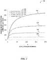
- FIG. 2shows a model graph of the average speed of 3D printing
- FIG. 3shows an example of a 3D printing system
- FIG. 4shows an example of another 3D printing system
- FIG. 5shows a computer system that is programmed or otherwise configured to implement methods provided herein.
- three-dimensional objectgenerally refers to an objector apart of an object that is printed by three-dimensional (3D) printing.
- the 3D objectmay be at least a portion of a larger 3D object or an entirety of the 3D object.
- the 3D objectmay be fabricated (e.g., printed) in accordance with a computer model of the 3D object.
- the mixturemay be referred to as a liquid or resin.
- the mixturemay be held inside a vat.
- a layer of the mixture to be subjected to the lightmay be confined between a bottom of the vat (e.g., a window) and the build head.
- the bottom of the vatmay be a build surface.
- a layer of the mixture to be subjected to the lightmay be confined between the build head and the surface of the mixture.
- the surface of the mixturemay be a build surface.
- the mixturemay be deposited on or adjacent to an open platform.
- a layer of the mixture to be subjected to the lightmay be defined by pressing the mixture (e.g., by a blade or a build head) into a film of the mixture.
- the open platformmay be a build surface.
- a thickness of the layer of the mixturemay be adjustable.
- the mixturemay include a photoactive resin.
- the photoactive resinmay include a polymerizable and/or cross-linkable component (e.g., a precursor) and a photoinitiator that activates curing of the polymerizable and/or cross-linkable component, to thereby subject the polymerizable and/or cross-linkable component to polymerization and/or cross-linking.
- the photoactive resinmay include a photoinhibitor that inhibits curing of the polymerizable and/or cross-linkable component.
- the 3D printingmay be performed with greater than or equal to about 1, 2, 3, 4, 5, 6, 7, 8, 9, 10 or more mixtures.
- the 3D printingmay be performed with less than or equal to about 10, 9, 8, 7, 6, 5, 4, 3, 2 mixtures, or no mixture (e.g., a single component).
- a plurality of mixturesmay be used for printing a multi-material 3D object.
- the mixturemay include a plurality of particles (e.g., metal, non-metal, or a combination thereof).
- the mixturemay be a slurry or a paste.
- the plurality of particlesmay be solids or semi-solids (e.g., gels).
- the plurality of particlesmay be suspended throughout the mixture in a monodisperse distribution or a polydisperse distribution.
- the term “particles,” as used herein,generally refers to any particulate material that may be melted or sintered (e.g., not completely melted).
- the particulate materialmay be in powder form.
- the particlesmay be inorganic materials.
- the inorganic materialsmay be metallic (e.g., aluminum or titanium), intermetallic (e.g., steel alloys), ceramic (e.g., metal oxides) materials, or any combination thereof.
- the term “metal” or “metallic”may refer to both metallic and intermetallic materials.
- the metallic materialsmay include ferromagnetic metals (e.g., iron and/or nickel).
- the particlesmay have various shapes and sizes.
- a particlemay be in the shape of a sphere, cuboid, or disc, or any partial shape or combination of shapes thereof.
- the particlemay have a cross-section that is circular, triangular, square, rectangular, pentagonal, hexagonal, or any partial shape or combination of shapes thereof.
- the particlesmay sinter (or coalesce) into a solid or porous object that may be at least a portion of a larger 3D object or an entirety of the 3D object.
- the 3D printingmay be performed with at least about 1, 2, 3, 4, 5, 6, 7, 8, 9, 10 or more types of particles.
- the 3D printingmay be performed with less than or equal to about 10, 9, 8, 7, 6, 5, 4, 3, 2, or 1 particle, or no particles.
- photoinitiationgenerally refers to a process of subjecting a portion of a mixture to a light to cure (or gel) a photoactive resin in the portion of the mixture.
- the lightmay have a wavelength that activates a photoinitiator that initiates curing of a polymerizable and/or cross-linkable component in the photoactive resin.
- photoinhibitiongenerally refers to a process of subjecting a portion of a mixture to a light to inhibit curing of a photoactive resin in the portion of the mixture.
- the lightmay have a wavelength that activates a photoinhibitor that inhibit curing of a polymerizable and/or cross-linkable component in the photoactive resin.
- the wavelength of the photoinhibition light and another wavelength of a photoinitiation lightmay be different wavelengths.
- the photoinhibition light and the photoinitiation lightmay be projected from the same optical source.
- the photoinhibition light and the photoinitiation lightmay be projected from different optical sources.
- photoinitiation lightand “first light” may be used synonymously herein.
- photoinhibition lightand “second light” may be used synonymously herein.
- energygenerally refers to an electromagnetic (e.g., ultraviolet ray or visible light) exposure per unit area (e.g., millijoule per square centimeter; mJ/cm 2 ).
- intensitygenerally refers to the energy (as described above) per time (e.g., milliwatt per square centimeter; mW/cm 2 ).
- vatgenerally refers to a structure (e.g., a container, holder, reservoir, etc.) that holds a mixture during 3D printing.
- the mixturemay be usable for 3D printing.
- One or more sides of the vate.g., a bottom or side surface
- an optically transparent or semi-transparent windowe.g., glass or a polymer
- the windowmay be precluded.
- lightmay be provided to the mixture from above the vat, and it may be desirable to prevent curing of a portion of the mixture adjacent to the surface of the mixture.
- open platformgenerally refers to a structure that supports a mixture or a film of the mixture during 3D printing.
- the mixturemay have a viscosity that is sufficient to permit the mixture to remain on or adjacent to the open platform during 3D printing.
- the open platformmay be flat.
- the open platformmay include an optically transparent or semi-transparent print window (e.g., glass or a polymer) to direct light through the window and to the mixture or the film of the mixture. In some cases, the window may be precluded. In such a scenario, light may be provided to the mixture of the film of the mixture from above the open platform, such as directly above or from a side of the open platform.
- windowgenerally refers to a structure that is part of a vat or a container.
- the windowmay be in contact with the mixture. In some cases, the window may not be in contact with the mixture.
- the windowmay be transparent or semitransparent (translucent).
- the windowmay be comprised of an optical window material, such as, for example, glass or a polymeric material (e.g., polymethylmethacrylate (PMMA)).
- PMMApolymethylmethacrylate
- the windowmay be comprised of polydimethylsiloxane (PDMS) or other polymeric materials that are permeable to oxygen.
- PDMSpolydimethylsiloxane
- the oxygen dissolved in the windowmay (i) diffuse into a contact surface between the window and the mixture comprising the photoactive resin (the window-mixture interface) and (ii) inhibit curing of the photoactive resin at the contact surface.
- the windowmay be positioned above an optical source for photopolymer-based 3D printing using bottom-up illumination. As an alternative, the window may be positioned below the optical source. As another alternative, the window may be positioned between a first optical source and a second optical source.
- the term “build head,” as used herein,generally refers to a structure that supports and/or holds at least a portion (e.g., a layer) of a 3D object.
- the build headmay be configured to move along a direction away from a bottom of a vat or an open platform. Such movement may be relative movement, and thus the moving piece may be (i) the build head, (ii) the vat or the open platform, or (iii) both.
- the moving piecemay comprise a mechanical gantry capable of motion in one or more axes of control (e.g., one or more of the XYZ planes) via one or more actuators during 3D printing.
- An aspect of the present disclosureprovides methods for printing a 3D object. Methods of the present disclosure may be implemented using systems provided herein, such as, for example, the system 300 of FIG. 3 or the system 400 of FIG. 4 .
- a method for printing a 3D objectmay comprise (a) providing, adjacent to a build surface, a mixture comprising (i) a polymeric precursor, (ii) a photoinitiator configured to initiate formation of a polymeric material from the polymeric precursor, and (iii) a photoinhibitor configured to inhibit formation of the polymeric material from the polymeric precursor.
- the mixturemay be exposed to (i) a first light having a first wavelength sufficient to cause the photoinitiator to initiate formation of the polymeric material from the polymeric precursor at a location disposed away from the build surface, to print at least a portion of the 3D object, and (ii) a second light having a second wavelength sufficient to cause the photoinhibitor to inhibit formation of the polymeric material from the polymeric precursor at a location adjacent to the build surface.
- a ratio of (i) an energy of the second light sufficient to initiate formation of the polymeric material relative to (ii) an energy of the first light sufficient to initiate formation of the polymeric materialmay be greater than 1. Such energy may be an activation energy.
- the second light having the second wavelengthmay not cause (e.g., activate) the photoinitiator to initiate formation of the polymeric material from the polymeric precursor.
- the photoinitiatormay not absorb at the second wavelength of the second light, or one or more other wavelengths of the second light.
- the energy of the second light sufficient to initiate formation of the polymeric material from the polymeric precursor in the mixturemay considered to be positive infinity.
- the ratio of (i) the energy of the second light sufficient to initiate formation of the polymeric material relative to (ii) the energy of the first light sufficient to initiate formation of the polymeric materialmay be substantially greater than 1.
- the second light having the second wavelengthmay cause the photoinitiator to initiate formation of the polymeric material from the polymeric precursor.
- the photoinitiatormay be activated by absorbing at the second wavelength of the second light, or one or more other wavelengths of the second light.
- the photoinitiatormay be activatable by alternative activation pathways, such as an energy transfer (e.g., Förster resonance energy transfer (FRET)) from another component in the mixture (e.g., a dye) that absorbs at the second wavelength of the second light, or at the one or more other wavelengths of the second light.
- FRETFörster resonance energy transfer
- the entire build surfacemay be exposed or flooded by the second light during printing the 3D object, such activation of the photoinitiator by the second light may yield (i) undesirable formation of the polymeric material at the location adjacent to the build surface and (ii) adhesion of the at least the portion of the 3D object to the build surface during printing. Such adhesion may reduce the speed of printing the 3D object or result in a print failure.
- it may be desirable that (i) the energy of the second light sufficient to initiate formation of the polymericis greater than (ii) the energy of the first light sufficient to initiate formation of the polymeric material.
- the ratio of (i) the energy of the second light sufficient to initiate formation of the polymeric material relative to (ii) the energy of the first light sufficient to initiate formation of the polymeric materialis greater than at least about 1, 2, 3, 4, 5, 6, 7, 8, 9, 10, 11, 12, 13, 14, 15, 16, 17, 18, 19, 20, 25, 30, 40, 50, 100, or more. In an example, the ratio is greater than 1. In another example, the ratio is greater than 5. In another example, the ratio is greater than 10. In another example, the ratio is greater than 20. As an alternative, the ratio may be less than or equal to about 100, 50, 40, 30, 25, 20, 19, 18, 17, 16, 15, 14, 13, 12, 11, 10, 9, 8, 7, 6, 5, 4, 3, or 2.
- Equation 1This ratio may be described by the figure of merit, as shown in Equation 1:
- Equation 2a working curve equation based on a modified form of the Beer-Lambert law that uses energy in an analogy to the intensity of the light:
- the working curve of a mixture using a lightmay be obtained by: (a) placing a transparent or semi-transparent substrate (e.g., a glass slide) on the build surface comprising a window; (b) depositing a layer (e.g., film, coating, etc.) of the mixture comprising a photoactive resin on or adjacent to the substrate; (c) directing a series of the light through the window, through the substrate, and into the layer of the mixture, such that different positions of the layer of the mixture receive a wide range of discrete doses of the light or energies from the light; (d) washing off any excess mixture that is uncured; and (e) measuring (e.g., via a micrometer) the height (thickness) of any polymeric materials in the different positions of the layer.
- a transparent or semi-transparent substratee.g., a glass slide
- a layere.g., film, coating, etc.
- the working curve of a mixture using a lightmay be obtained by: (a)
- the mixturemay not comprise a photoinhibitor. In other cases, the mixture may comprise one or more photoinhibitors to determine the effect of the one or more photoinhibitors on the working curve of the mixture.
- the transparent or semi-transparent substratemay not be oxygen permeable as oxygen may act as an inhibitor of radical polymerization. In other cases, the transparent or semi-transparent substrate may be oxygen permeable to determine the effect of different substrates on the working curve of the mixture.
- the figure of meritmay affect the speed of printing the at least the portion of the 3D object.
- the first lightphotoinitiation light
- the second lightphotoinhibition light
- rThe ratio of the critical energies of the two lights for a mixture may be denoted as r:
- the photoinitiation and the photoinhibition lightsmay be projected through a window of a vat containing the mixture, and a printed part that is on or adjacent to a build head may be lifted at a constant rate in a direction away from the window to yield a continuous 3D printing.
- a surface of the window in contact with the mixturemay be a build surface.
- a portion of the mixture adjacent to the build surfacemay be a photoinhibition layer.
- Another potion of the mixture at a location disposed away from the build surface (adjacent to the photoinhibition layer)may be a photoinitiation layer.
- Equation 2an analogous equation to Equation 2 may be derived to determine a maximum speed (v max ) of 3D printing. This may be achieved by integrating the amount of energy absorbed by an infinitely thin photoinitiation layer adjacent to the photoinhibition layer having a thickness ( ⁇ to infinity):
- Equation 4Equation 4 may be solved for v max as shown in Equation 5:
- Equation 6a dose of the photoinitiation light greater than the critical energy of the photoinitiation light for the mixture (E C, ⁇ 1 or 460 nm ) may be used for the 3D printing, and thus the 3D printing speed (v) may be described as shown in Equation 6:
- an equationmay be generated to describe an average speed (v avg ) of 3D printing over the entire duration of the 3D printing. This may be achieved by dividing a total distance printed by a sum of the exposure time (t exp ) and the separation time (t sep ):
- the exposure dose of the lightmay be a fraction (f 2 ) of the critical energy of the photoinhibition light at the wavelength of 365 nm (E C, 365 nm ).
- the exposure timemay be described as:
- Equation ⁇ ⁇ 8I 365 nm is the intensity of the photoinhibition light having the wavelength of 365 nm. Equations 3, 7, and 8 may be combined to generate the following equation to describe the average speed (v avg ) of 3D printing as a function of the ratio r and the photoinitiation and the photoinhibition lights:
- the average speed (v avg ) of 3D printing using the multi-wavelength methodmay increase as (i) the critical energy of the photoinitiation light for the mixture (E C, ⁇ 1 or E C,460nm ) decreases and/or (ii) the ratio (r) of the critical energies of the two lights for the mixture (as described in Equations 1 and 3) increases.
- the average speed (v avg ) of 3D printing using the multi-wavelength methodmay be related to the intensity of the photoinitiation light (I ⁇ 1 or I 460 ), and inversely related to the intensity of the photoinhibition light (I ⁇ 2 or I 365 ).
- the method for printing the 3D objectmay be described by a rate of formation of the polymeric material from the polymeric precursor upon exposure to the light.
- the rate of formation of the polymeric material upon exposure to the lightmay be inversely proportional to the energy of the light sufficient to initiate formation of the polymeric material.
- a ratio of (i) a rate of formation of the polymeric material upon exposure to the photoinitiation light (first light) relative to (ii) a rate of formation of the polymeric material upon exposure to the photoinhibition light (second light)may be greater than at least about 1, 2, 3, 4, 5, 6, 7, 8, 9, 10, 11, 12, 13, 14, 15, 16, 17, 18, 19, 20, 25, 30, 40, 50, 100, or more.
- the ratiois greater than 5.
- the ratiois greater than 10.
- the ratiois greater than 20.
- the ratiomay be less than or equal to about 100, 50, 40, 30, 25, 20, 19, 18, 17, 16, 15, 14, 13, 12, 11, 10, 9, 8, 7, 6, 5, 4, 3, or 2.
- the critical energy of the light sufficient to initiate formation of the polymeric material from the polymeric precursormay depend on a myriad of factors. Additionally, the rate of formation of the polymeric material upon exposure to the light and/or the time sufficient to initiate formation of the polymeric material upon exposure to the light may depend on the myriad of factors. Examples of the factors include intensity of the light, temperature of the mixture, and compositions of the mixture (e.g., polymeric precursors, photoinitiators, photoinhibitors, co-initiators for curing, other light absorbers, radical inhibitors, organic and/or inorganic particulate materials, solvent, etc.).
- the factorsinclude intensity of the light, temperature of the mixture, and compositions of the mixture (e.g., polymeric precursors, photoinitiators, photoinhibitors, co-initiators for curing, other light absorbers, radical inhibitors, organic and/or inorganic particulate materials, solvent, etc.).
- the photoinhibitormay be present in the mixture at an amount from about 0.001 percent by weight (wt. %) to about 5 wt. %.
- the photoinhibitormay be present in the mixture at amount greater than or equal to about 0.001 wt. %, 0.002 wt. %, 0.003 wt. %, 0.004 wt. %, 0.005 wt. %, 0.006 wt. %, 0.007 wt. %, 0.008 wt. %, 0.009 wt. %, 0.01 wt. %, 0.02 wt. %, 0.03 wt. %, 0.04 wt.
- radical speciesexamples include sulfanylthiocarbonyl and other radicals generated in photoiniferter (photo-initiator, transfer agent, and terminator) mediated polymerizations; sulfanylthiocarbonyl radicals used in reversible addition-fragmentation chain transfer polymerization; and nitrosyl radicals used in nitroxide mediate polymerization.
- lophyl radicalsmay be non-reactive towards the polymerization of acrylates in the absence of strong chain transfer agents.
- Other non-radical species that may be generated to terminate growing radical chainsmay include the numerous metal/ligand complexes used as deactivators in atom-transfer radical polymerization (ATRP).
- Non-limiting examples of the photoinhibitorinclude thiocarbamates, xanthates, dithiobenzoates, photoinititators that generate ketyl and other radicals that tend to terminate growing polymer chains radicals (i.e., camphorquinone and benzophenones), ATRP deactivators, and polymeric versions thereof.
- the photoinhibitormay comprise a hexaarylbiimidazole (HABI) or a functional variant thereof.
- the hexaarylbiimidazolemay comprise a phenyl group with a halogen and/or an alkoxy substitution.
- the phenyl groupcomprises an ortho-chloro-substitution.
- the phenyl groupcomprises an ortho-methoxy-substitution.
- the phenyl groupcomprises an ortho-ethoxy-substitution.
- photoinhibitor in the mixtureinclude one or more of: zinc dimethyl dithiocarbamate:zinc dimethyl dithiocarbamate; zinc diethyl dithiocarbamate; zinc dibutyl dithiocarbamate; nickel dibutyl dithiocarbamate; zinc dibenzyl dithiocarbamate; tetramethylthiuram disulfide; tetraethylthiuram disulfide (TEDS); tetramethylthiuram monosulfide; tetrabenzylthiuram disulfide; tetraisobutylthiuram disulfide; dipentamethylene thiuram hexasulfide; N,N′-dimethyl N,N′-di(4-pyridinyl)thiuram disulfide; 3-Butenyl 2-(dodecylthiocarbonothioylthio)-2-methylpropionate; 4-Cyano-4-[(d
- the amount of the photoinhibitor in the mixturemay be sufficient to generate inhibiting radicals at a greater rate that initiating radicals are generated.
- One skilled in the artwill understand how to manipulate the ratio of the amount of the photoinhibitor and/or the photoinitiator based on the intensity of the optical sources available, as well as the quantum yields and light absorption properties of the photoinhibitor and the photoinitiator in the mixture.
- the photoinitiatoris present in the mixture at an amount from about 0.001 wt. % to about 5 wt. %.
- the photoinitiatormay be present in the mixture at an amount greater than or equal to about 0.001 wt. %, 0.002 wt. %, 0.003 wt. %, 0.004 wt. %, 0.005 wt. %, 0.006 wt. %, 0.007 wt. %, 0.008 wt. %, 0.009 wt. % 0.01 wt. %, 0.02 wt. %, 0.03 wt. %, 0.04 wt. %, 0.05 wt.
- the photoinitiatormay be present in the mixture at an amount less than or equal to about 5 wt. %, 1 wt. %, 0.5 wt. % 0.1 wt. %, 0.05 wt. %, 0.04 wt. %, 0.03 wt. %, 0.02 wt. %, 0.01 wt. %, 0.009 wt. %, 0.008 wt. % 0.007 wt. %, 0.006 wt. %, 0.005 wt. %, 0.004 wt. %, 0.003 wt. %, 0.002 wt. %, 0.001 wt. %, or less.
- the photoinitiatormay be selected to absorb little (e.g., less than or equal to about 10%, 5%, 4%, 3%, 2%, 1%, 0.1%, or less) or no light at the one or more wavelengths used to activate the photoinhibitor. In some cases, some overlap of the light absorption spectra of the photoinitiator and the photoinhibitor may be tolerated depending on the relative reaction rates (e.g., the figure of merit described above).
- Suitable photoinitiatorsinclude one or more of benzophenones, thioxanthones, anthraquinones, benzoylformate esters, hydroxyacetophenones, alkylaminoacetophenones, benzil ketals, dialkoxyacetophenones, benzoin ethers, phosphine oxides, acyloximino esters, alphahaloacetophenones, trichloromethyl-S-triazines, titanocenes, dibenzylidene ketones, ketocoumarins, dye sensitized photoinitiation systems, maleimides, and functional variants thereof.
- the photoinitiatormay comprise camphorquinone (CQ) and/or a functional variant thereof.
- the mixturemay comprise a stabilizer configured to inhibit formation of the polymeric material from at least a portion of the polymeric precursor.
- the stabilizermay be present in the mixture at an amount from about 0.0001 wt. % to about 0.5 wt. %.
- the stabilizermay be present in the mixture at an amount greater than or equal to about 0.0001 wt. %, 0.0002 wt. %, 0.0003 wt. %, 0.0004 wt. %, 0.0005 wt. %, 0.0006 wt. %, 0.0007 wt. %, 0.0008 wt. %, 0.0009 wt. %, 0.001 wt. %, 0.002 wt.
- %0.0008 wt. %, 0.0007 wt. %, 0.0006 wt. %, 0.0005 wt. %, 0.0004 wt. %, 0.0003 wt. %, 0.0002 wt. %, 0.0001 wt. %, or less.
- the stabilizermay be a radical inhibitor.
- the radical inhibitorinclude a quinone, hydroquinoe, nitrosamine, copper-comprising compound, stable free radical (e.g., (2,2,6,6-tetramethylpiperidin-1-yl)oxidanyl), substituted phenol, mequinol, t-butyl catechol, Nitorosophenylhydroxylamine alminium salt, functional variants thereof, or mixtures thereof.
- the radical inhibitormay comprise phenothiazine, copper napthalate, butylated hydroxytoluene, or functional variants thereof.
- the addition of the stabilizer to the mixturemay disproportionally increase the critical energy of the photoinhibition light for the mixture relative to the critical energy of the photoinitiation light for the mixture. In some cases, the addition of the stabilizer to the mixture may disproportionally increase the critical energy of the photoinitiation light for the mixture relative to the critical energy of the photoinhibition light for the mixture.
- the mixturemay further comprise a co-initiator configured to initiate formation of the polymeric material from the polymeric precursor.
- the co-initiatoris present in the mixture at an amount from about 0.01 wt. % to about 10 wt. %.
- the co-initiatormay be present in the mixture at an amount greater than or equal to about 0.01 wt. %, 0.02 wt. %, 0.03 wt. %, 0.04 wt. %, 0.05 wt. %, 0.06 wt. %, 0.07 wt. %, 0.08 wt. %, 0.09 wt. %, 0.1 wt. %, 0.2 wt.
- the co-initiatormay be present in the mixture at an amount less than or equal to about 10 wt. %, 9 wt. %, 8 wt. %, 7 wt. % 6 wt. %, 5 wt. %, 4 wt. %, 0.5 wt. %, 1 wt. %, 2 wt. %, 3 wt. %, 4 wt. %, 5 wt. %, 6 wt. %, 7 wt. %, 8 wt. %, 9 wt. %, 10 wt. %, or more.
- the co-initiatormay be present in the mixture at an amount less than or equal to about 10 wt. %, 9 wt. %, 8 wt. %, 7 wt. % 6 wt. %, 5 wt. %, 4 wt.
- wt. %3 wt. %, 2 wt. %, 1 wt. %, 0.5 wt. %, 0.4 wt. %, 0.3 wt. %, 0.2 wt. %, 0.1 wt. %, 0.09 wt. %, 0.08 wt. %, 0.07 wt. %, 0.06 wt. %, 0.05 wt. %, 0.04 wt. %, 0.03 wt. %, 0.02 wt. %, 0.01 wt. %, or less.
- the co-initiator configured to initiate formation of the polymeric materialcomprises one or more functional groups that act as a co-initiator.
- the one or more functional groupsmay be diluted by being attached to a larger molecule.
- the co-initiatormay be present in the mixture at an amount greater than or equal to about 0.01 wt. %, 0.02 wt. %, 0.03 wt. %, 0.04 wt. %, 0.05 wt. %, 0.06 wt. %, 0.07 wt. %, 0.08 wt. %, 0.09 wt. %, 0.1 wt. %, 0.2 wt. %, 0.3 wt.
- wt. %0.4 wt. %, 0.5 wt. %, 1 wt. %, 2 wt. %, 3 wt. %, 4 wt. %, 5 wt. %, 6 wt. %, 7 wt. %, 8 wt. %, 9 wt. %, 10 wt. %, 11 wt. %, 12 wt. %, 13 wt. %, 14 wt. % 15 wt. %, 16 wt. %, 17 wt. %, 18 wt. %, 19 wt. %, 20 wt. %, 21 wt.
- the co-initiatormay be present in the mixture at an amount less than or equal to about 25 wt. %, 24 wt. %, 23 wt. %, 22 wt. %, 21 wt. %, 20 wt. %, 19 wt. %, 18 wt. %, 17 wt. %, 16 wt. %, 15 wt. %, 14 wt. %, 13 wt. %, 12 wt. %, 11 wt. %, 10 wt. %, 9 wt.
- wt. %8 wt. %, 7 wt. %, 6 wt. %, 5 wt. %, 4 wt. %, 3 wt. %, 2 wt. %, 1 wt. %, 0.5 wt. %, 0.4 wt. %, 0.3 wt. %, 0.2 wt. %, 0.1 wt. %, 0.09 wt. %, 0.08 wt. %, 0.07 wt. %, 0.06 wt. %, 0.05 wt. %, 0.04 wt. %, 0.03 wt. %, 0.02 wt. %, 0.01 wt. %, or less.
- the co-initiator in the mixturemay enhance the rate of formation of the polymeric material from the polymeric precursor.
- the co-initiatormay comprise primary, secondary, and tertiary amines, alcohols, and thiols. In some cases, the co-initiator may comprise a tertiary amine. In some cases, the co-initiator may comprise ethyl-dimethyl-amino benzoate (EDMAB) or a functional variant thereof.
- EDMABethyl-dimethyl-amino benzoate
- co-initiatorexamples include one or more of: isoamyl 4-(dimethylamino)benzoate, 2-ethylhexyl 4-(dimethylamino)benzoate; ethyl 4-(dimethylamino)benzoate; 3-(dimethylamino)propyl acrylate; 2-(dimethylamino)ethyl methacrylate; 4-(dimethylamino)benzophenones, 4-(diethylamino)benzophenones; 4,4′-Bis(diethylamino)benzophenones; methyl diethanolamine; triethylamine; hexane thiol; heptane thiol; octane thiol; nonane thiol; decane thiol; undecane thiol; dodecane thiol; isooctyl 3-mercaptopropionate; pentaeryth
- the mixturemay further comprise a light absorber configured to absorb at least the first wavelength of the first light or the second wavelength of the second light.
- the light absorberis present in the mixture at an amount from about 0.001 wt. % to about 5 wt. %.
- the light absorbermay be present in the mixture at amount greater than or equal to about 0.001 wt. %, 0.002 wt. %, 0.003 wt. %, 0.004 wt. %, 0.005 wt. %, 0.006 wt. % 0.007 wt. %, 0.008 wt. %, 0.009 wt. % 0.01 wt.
- the light absorbermay be present in the mixture at an amount less than or equal to about 5 wt. %, 1 wt. %, 0.5 wt. % 0.1 wt. %, 0.05 wt. %, 0.04 wt. %, 0.03 wt. %, 0.02 wt. %, 0.01 wt. %, 0.009 wt. %, 0.008 wt.
- %0.007 wt. %, 0.006 wt. %, 0.005 wt. %, 0.004 wt. %, 0.003 wt. %, 0.002 wt. %, 0.001 wt. %, or less.
- the light absorbermay be a dye or pigment.
- the light absorbercan be used to both attenuate light and to transfer energy (e.g., via Förster resonance energy transfer (FRET)) to photoactive species (e.g., the photoinitiator or the photoinhibitor), thereby to increase the sensitivity of the resulting mixture to a given wavelength suitable for the photoinitiation and/or the photoinhibition process.
- FRETFörster resonance energy transfer
- a concentration of the light absorbermay be highly dependent on the light absorption properties of the light absorber, as well as the optical attenuation from other components in the mixtures.
- the light absorbermay be configured to absorb at the second wavelength, and exposing the mixture to the second light having the second wavelength may initiate the light absorber to reduce an amount of the second light exposed to at least a portion of the mixture.
- One skilled in the artwill understand how to utilize of one or more light absorbers at a plurality of concentrations to restrict the penetration of the photoinhibition light to a given thickness such that the photoinhibition layer is thick enough to permit separation of the newly formed layer of the 3D object from the print surface (e.g., the window). Additionally, one skilled in the art will understand how to utilize the one or more light absorbers at the plurality of concentrations to restrict penetration and/or propagation of the photoinitiating light during printing at least a portion of the 3D object. In some cases, a plurality of light absorbers may be used to independently control both photoinhibition and photoinitiation processes.
- Examples of the light absorberinclude compounds commonly used as UV absorbers for decreasing weathering of coatings, such as: 2-hydroxyphenyl-benzophenones; 2-(2-hydroxyphenyl)-benzotriazoles (and chlorinated derivatives); and 2-hydroxyphenyl-s-triazines. Additional examples of the light absorber include those used for histological staining or dying of fabrics. Pigments such as carbon black, pthalocyanine, toluidine red, quinacridone, titanium dioxide, and functional variants thereof may also be used as light absorbers in the mixture.
- Dyes that may be used as light absorbersinclude: Martius yellow; quinolone yellow; Sudan red, Sudan I, Sudan IV, eosin, eosin Y, neutral red, acid red, Sun Chemical UVDS 150; Sun Chemical UVDS 350; Penn Color Cyan; Sun Chemical UVDJ107; 2-tert-Butyl-6-(5-chloro-2H-benzotriazol-2-yl)-4-methylphenol; 2-(2H-Benzotriazol-2-yl)-4,6-di-tert-pentylphenol; 7-diethylamino-4-methyl coumarin; 9,10-Dibutoxyanthracene; 9-phenyl acridine; and functional variants thereof.
- the polymeric precursor in the mixturemay comprise monomers, one or more oligomers, or both.
- the monomersmay be configured to polymerize to form the polymeric material.
- the one or more oligomersmay be configured to cross-link to form the polymeric material.
- the monomersmay be of the same or different types.
- An oligomermay comprise two or more monomers that are covalently linked to each other.
- the oligomermay be of any length, such as greater than or equal to about 2 (dimer), 3 (trimer), 4 (tetramer), 5 (pentamer), 6 (hexamer), 7, 8, 9, 10, 20, 30, 40, 50, 100, 200, 300, 400, 500, or more monomers.
- the oligomermay be of a length less than or equal to about 500, 400, 300, 200, 100, 50, 40, 30, 20, 10, 9, 8, 7, 6, 5, 4, 3, 2, or less monomers.
- the polymeric precursormay include a dendritic precursor (monodisperse or polydisperse).
- the dendritic precursormay be a first generation (G1), second generation (G2), third generation (G3), fourth generation (G4), or higher with functional groups remaining on the surface of the dendritic precursor.
- the resulting polymeric materialmay comprise a monopolymer and/or a copolymer.
- the copolymermay be a linear copolymer or a branched copolymer.
- the copolymermay be an alternating copolymer, periodic copolymer, statistical copolymer, random copolymer, and/or block copolymer.
- the polymeric precursore.g., monomer, oligomer, or both
- the monomersis present in the mixture at an amount from about 1 wt. % to about 80 wt. %.
- the monomersmay be present in the mixture at an amount greater than or equal to about 1 wt. %, 2 wt. %, 3 wt. %, 4 wt. %, 5 wt. %, 6 wt. %, 7 wt. % 8 wt. %, 9 wt. %, 10 wt. %, 15 wt. %, 20 wt. %, 25 wt. %, 30 wt. %, 35 wt. %, 40 wt. %, 45 wt. % 50 wt.
- the monomersmay be present in the mixture at an amount less than or equal to about 80 wt. %, 75 wt. %, 70 wt. %, 65 wt. %, 60 wt. %, 55 wt. %,50 wt. %, 45 wt. %, 40 wt. %, 35 wt. %, 30 wt. %, 25 wt. %, 20 wt. % 15 wt. %, 10 wt.
- the mixturemay not have any monomers. In such a scenario, the mixture may have one or more oligomers.
- Examples of monomersinclude one or more of hydroxyethyl methacrylate; n-Lauryl acrylate; tetrahydrofurfuryl methacrylate; 2,2,2-trifluoroethyl methacrylate; isobornyl methacrylate; polypropylene glycol monomethacrylates, aliphatic urethane acrylate (i.e., Rahn Genomer 1122); hydroxyethyl acrylate; n-Lauryl methacrylate; tetrahydrofurfuryl acrylate; 2,2,2-trifluoroethyl acrylate; isobornyl acrylate; polypropylene glycol monoacrylates; trimethylpropane triacrylate; trimethylpropane trimethacrylate; pentaerythritol tetraacrylate; pentaerythritol tetraacrylate; triethyleneglycol diacrylate; triethylene glycol dimethacrylate; tetrathylene
- the one or more oligomersis present in the mixture at an amount from about 1 wt. % to about 30 wt. %.
- the one or more oligomersmay be present in the mixture at an amount greater than or equal to about 1 wt. %, 2 wt. %, 3 wt. %, 4 wt. %, 5 wt. %, 6 wt. %, 7 wt. %, 8 wt. %, 9 wt. %, 10 wt. %, 15 wt. %, 20 wt. %, 25 wt. %, 30 wt. %, or more.
- the one or more oligomersmay be present in the mixture at an amount less than or equal to about 30 wt. %, 25 wt. %, 20 wt. %, 15 wt. %, 10 wt. %, 9 wt. %, 8 wt. %, 7 wt. %, 6 wt. %, 5 wt. %, 4 wt. %, 3 wt. %, 2 wt. %, 1 wt. %, or less.
- the mixturemay not have the one or more oligomers. In such a scenario, the mixture may have the monomers.
- the one or more oligomersmay include one or more of: polyether; polyol; epoxy; thioether; polyester; urethane; silicon; polybutadiene; phenolic based acrylates; methacrylates; and functional variants thereof.
- the one or more oligomersmay comprise one or more of urethane (meth)acrylate, polyester urethane (meth)acrylate, epoxy(meth)acrylate, polyether (meth)acrylate, polyol (meth)acrylate, dendritic (meth)acrylate, silicone (meth)acrylate, polybutadiene (meth)acrylate, phenolic (meth)acrylate, or a functional variant thereof.
- Additional examples of the one or more oligomersinclude Esstech Exothane 126, Esstech Exothane 108, and Sartomer CN9009.
- a ratio of the monomers and the one or more oligomers in the polymeric precursor of the mixturemay be based on one or more properties of the mixture (e.g., viscosity, curing rate, etc.) that is optimal for each particular 3D printing method.
- the ratio of the monomer and the one or more oligomersmay be optimized to yield a viscosity below 3000 centipoise (cP). In some cases, the viscosity of the mixture may be below 300 cP.
- the viscosity of the mixtureis less than or equal to about 3000 cP, 2900 cP, 2800 cP, 2700 cP, 2600 cP, 2500 cP, 2400 cP, 2300 cP, 2200 cP, 2100 cP, 2000 cP, 1500 cP, 1000 cP, 500 cP, 100 cP, or less.
- the viscosity of the mixturemay be greater than or equal to about 100 cP, 500 cP, 1000 cP, 1500 cP, 2000 cP, 2100 cP, 2200 cP, 2300 cP, 2400 cP, 2500 cP, 2600 cP, 2700 cP, 2800 cP, 2900 cP, 3000 cP, or more.
- the mixturemay further comprise one or more particles.
- the one or more particlesmay comprise any particulate material (a particle) that can be melted or sintered (e.g., not completely melted).
- the particulate materialmay be in powder form.
- the particular materialmay be inorganic materials.
- the inorganic materialsmay be metallic, intermetallic, ceramic materials, or any combination thereof.
- the one or more particlesmay comprise at least one metallic material, at least one intermetallic material, at least one ceramic material, or any combination thereof.
- the metallic materials for the one or more particlesmay include one or more of aluminum, calcium, magnesium, barium, scandium, titanium, vanadium, chromium, manganese, iron, cobalt, nickel, copper, zinc, yttrium, niobium, molybdenum, ruthenium, rhodium, silver, cadmium, actinium, and gold.
- the particlesmay comprise a rare earth element.
- the rare earth elementmay include one or more of scandium, yttrium, and elements of the lanthanide series having atomic numbers from 57-71.
- An intermetallic material for the one or more particlesmay be a solid-state compound exhibiting metallic bonding, defined stoichiometry and ordered crystal structure (i.e., alloys).
- the intermetallic materialsmay be in prealloyed powder form. Examples of such prealloyed powders may include, but are not limited to, brass (copper and zinc), bronze (copper and tin), duralumin (aluminum, copper, manganese, and/or magnesium), gold alloys (gold and copper), rose-gold alloys (gold, copper, and zinc), nichrome (nickel and chromium), and stainless steel (iron, carbon, and additional elements including manganese, nickel, chromium, molybdenum, boron, titanium, silicon, vanadium, tungsten, cobalt, and/or niobium).
- the prealloyed powdersmay include superalloys.
- the superalloysmay be based on elements including iron, nickel, cobalt, chromium, tungsten, molybdenum, tantalum, niobium, titanium, and/or aluminum.
- the ceramic materials for the one or more particlesmay comprise metal (e.g., aluminum, titanium, etc.), non-metal (e.g., oxygen, nitrogen, etc.), and/or metalloid (e.g., germanium, silicon, etc.) atoms primarily held in ionic and covalent bonds.
- metale.g., aluminum, titanium, etc.
- non-metale.g., oxygen, nitrogen, etc.
- metalloide.g., germanium, silicon, etc.
- examples of the ceramic materialsinclude, but are not limited to, an aluminide, boride, beryllia, carbide, chromium oxide, hydroxide, sulfide, nitride, mullite, kyanite, ferrite, titania zirconia, yttria, and magnesia.
- the mixturemay comprise a pre-ceramic material.
- the pre-ceramic materialmay be a polymer that can be heated (or pyrolyzed) to form a ceramic material.
- the pre-ceramic materialmay include polyorganozirconates, polyorganoaluminates, polysiloxanes, polysilanes, polysilazanes, polycarbosilanes, polyborosilanes, etc.
- pre-ceramic materialexamples include zirconium tetramethacrylate, zirconyl dimethacrylate, or zirconium 2-ethylhexanoate; aluminum III s-butoxide, aluminum III diisopropoxide-ethylacetoacetate; 1,3-bis(chloromethyl) 1,1,3,3-Tetrakis(trimethylsiloxy)disiloxane; 1,3-bis(3-carboxypropyl)tetramethyldisiloxane; 1,3,5,7-tetraethyl-2,4,6,8-tetramethylcyclotetrasilazane; tris(trimethylsilyl)phosphate; tris(trimethylsiloxy)boron; and mixtures thereof.
- a cross-sectional dimension of the plurality of particlesmay range between about 1 nanometers (nm) to about 500 micrometers ( ⁇ m).
- the cross-sectional dimension of the plurality of particlesmay be greater than or equal to about 1 nm, 2 nm, 3 nm, 4 nm, 5 nm, 6 nm, 7 nm, 8 nm, 9 nm, 10 nm, 20 nm, 30 nm, 40 nm, 50 nm, 60 nm, 70 nm, 80 nm, 90 nm, 100 nm, 200 nm, 300 nm, 400 nm, 500 nm, 600 nm, 700 nm, 800 nm, 900 nm, 1 ⁇ m, 2 ⁇ m, 3 ⁇ m, 4 ⁇ m, 5 ⁇ m, 6 ⁇ m, 7 ⁇ m, 8 ⁇ m, 9 ⁇ m, 10 ⁇ m, 20 ⁇ m, 30 ⁇ m, 40
- the cross-sectional dimension of the plurality of particlesmay be less than or equal to about 500 ⁇ m, 400 ⁇ m, 300 ⁇ m, 200 ⁇ m, 100 ⁇ m, 90 ⁇ m, 80 ⁇ m, 70 ⁇ m, 60 ⁇ m, 50 ⁇ m, 40 ⁇ m, 30 ⁇ m, 20 ⁇ m, 10 ⁇ m, 9 ⁇ m, 8 ⁇ m, 7 ⁇ m, 6 ⁇ m, 5 ⁇ m, 4 ⁇ m, 3 ⁇ m, 2 ⁇ m, 1 ⁇ m, 900 nm, 800 nm, 700 nm, 600 nm, 500 nm, 400 nm, 300 nm, 200 nm, 100 nm, 90 nm, 80 nm, 70 nm, 60 nm, 50 nm, 40 nm, 30 nm, 20 nm, 10 nm, 9 nm, 8 nm, 7 nm, 6 nm, 5 nm, 4 n
- the one or more particlesmay be present in the mixture in an amount from about 10 wt. % to about 97 wt. %.
- the one or more particlesmay be present in the mixture in an amount greater than or equal to about 10 wt. %, 11 wt. %, 12 wt. %, 13 wt. %, 14 wt. %, 15 wt. %, 16 wt. %, 17 wt. %, 18 wt. %, 19 wt. %, 20 wt. %, 25 wt. %, 30 wt. %, 35 wt. %, 40 wt. %, 45 wt. %, 50 wt.
- the one or more particlesmay be present in the mixture in an amount less than or equal to about 97 wt. %, 96 wt. % 95 wt. % 90 wt. % 85 wt. % 80 wt. % 75 wt. % 70 wt. % 65 wt. % 60 wt. %, 55 wt.
- the mixturemay have a viscosity ranging from about 4,000 cP to about 2,000,000 cP.
- the mixturemay have a viscosity greater than or equal to about 4,000 cP, 10,000 cP, 20,000 cP, 30,000 cP, 40,000 cP, 50,000 cP, 60,000 cP, 70,000 cP, 80,000 cP, 90,000 cP, 100,000 cP, 200,000 cP, 300,000 cP, 400,000 cP, 500,000 cP, 600,000 cP, 700,000 cP, 800,000 cP, 900,000 cP, 1,000,000 cP, 2,000,000 cP, or more.
- the mixturemay have a viscosity less than or equal to about 2,000,000 cP, 1,000,000 cP, 900,000 cP, 800,000 cP, 700,000 cP, 600,000 cP, 500,000 cP, 400,000 cP, 300,000 cP, 200,000 cP, 100,000 cP, 90,000 cP, 80,000 cP, 70,000 cP, 60,000 cP, 50,000 cP, 40,000 cP, 30,000 cP, 20,000 cP, 10,000 cP, 4,000 cP, or less.
- the first wavelength of the first light and the second wavelength of the second lightmay be different wavelengths.
- the first light and the second lightmay be directed by the same light source.
- the first lightmay be directed by a first light source and the second light may be directed by a second light source.
- the first lightmay comprise wavelengths ranging between about 420 nanometers (nm) to about 510 nm.
- the second lightmay comprise wavelengths ranging between about 350 nm to about 410 nm.
- the first wavelength to induce photoinitiationmay be about 460 nm.
- the second wavelength to induce photoinhibitionmay be about 365 nm.
- the methodmay further comprise, prior to printing the 3D object, receiving or generating a computer model of the 3D object. At least a portion of the 3D object may be in accordance to the computer model of the 3D object. In some cases, the method may further comprise repeating the steps (a) and (b) one or more times.
- the methodmay further comprise providing a build head adjacent to the build surface.
- the at least the portion of the 3D objectmay be formed adjacent to the build head.
- the build headmay be moved along a direction away from the build surface.
- the build headmay be operatively coupled to a controller.
- the controllermay be configured or programmed to direct the build head to move along a direction away from the build surface during printing the 3D object. Such movement may be relative movement, and thus the moving piece may be (i) the build head, (ii) the build surface, or (iii) both.
- the methodmay comprise using a vat.
- the build surfacemay be part of a vat configured to contain the mixture.
- the vatmay comprise an inlet and/or an outlet.
- the inletmay be in fluid communication with a source of the mixture.
- the outletmay be in fluid communication with a container configured to collect any excess mixture from the vat.
- the vatmay be operatively coupled to the controller.
- the controllermay be configured or programmed to direct flow of the mixture (i) from the source towards the vat through the inlet and/or (ii) from the vat towards the container, thereby to adjust an amount of the mixture in the vat.
- the vatmay comprise a plurality of inlets that are in fluid communication a plurality of sources.
- Each of the plurality of sourcesmay comprise the polymeric precursor, the photoinitiator, the photoinhibitor, and/or additional components that can be added to the mixture (e.g., co-initiators, dyes, inorganic particles, etc.).
- the controllermay be configured or programmed to direct flow from each of the plurality of sources towards the vat to adjust an amount of the polymeric precursor, the photoinitiator, the photoinhibitor, and/or the additional components in the mixture contained in the vat.
- the bottom of the vatmay comprise a window, and the window may be the build surface.
- the build headmay be moved along a direction away from the window.
- the location adjacent to the windowmay be a photoinhibition layer.
- the location disposed away from the window and adjacent to the build head or a previously deposited layer of the 3D object adjacent to the build headmay be a photoinitiation layer.
- the photoinitiation light or the photoinhibition lightmay be directed from the bottom of the vat, through the window and into the mixture held inside the vat.
- one or more sides of the vatmay comprise a window, and the photoinitiation light or the photoinhibition light may be directed from the one or more sides of the vat and into the mixture.
- the photoinhibition layermay prevent adhesion of the polymeric material adjacent to any of the sides of the vat.
- the open surface of the mixture not in contact with any of the surfaces of the vatmay be the build surface.
- the build headmay be moved along a direction away from the open surface of the mixture.
- the location adjacent to the open surface of the mixturemay be a photoinhibition layer.
- the location disposed away from the open surface of the mixture and adjacent to the build head or a previously deposited layer of the 3D object adjacent to the build headmay be a photoinitiation layer. In such case, the photoinitiation light and the photoinhibition light may be directed from above open surface of the mixture.
- the photoinhibition layermay prevent the portion of the mixture adjacent to the open surface of the mixture from being used to form the polymeric material during 3D printing.
- the portion of the mixture adjacent to the open surfacemay be used as a protective layer for the mixture during 3D printing.
- the methodmay comprise using an open platform.
- the open platformmay be used instead of the vat.
- the build surfacemay be part of the open platform.
- the methodmay further comprise providing the mixture or a film of the mixture adjacent to the open platform prior to printing each layer of the 3D object.
- the open platformmay be configured to hold a film the mixture.
- the open platformmay comprise a window.
- the open platformmay comprise at least one deposition head comprising a nozzle in fluid communication with a source of the mixture.
- the open platformmay comprise an optical source that provides light (e.g., the photoinitiation light and/or the photoinhibition light) through the window for initiating formation of the polymeric material in at least a portion of the film of the mixture.
- the open platformmay be operatively coupled to a controller.
- the controllermay be programmed to (i) direct the deposition head to move across the open platform and dispense the mixture through the nozzle to deposit the film over the window, and (ii) direct the optical source to provide the light to initiate formation of the polymeric material in at least the portion of the film of the mixture, thereby printing at least a portion of the 3D object.
- the at least one deposition head of the open platformmay comprise a wiper that is configured to (i) reduce or inhibit flow of the mixture out of the deposition head, (ii) flatten the film of the mixture, and/or (iii) remove any excess of the mixture.
- the wipermay be a blade (e.g., a doctor blade), a roller, or a rod (e.g., a wire wound rod).
- the open platformmay comprise a cleaning zone configured to clean the deposition head.
- the cleaning zonemay comprise a wiper, a nozzle configured to provide a cleaning solvent, or both.
- the open platformmay comprise a container configured to collect any excess mixture during or after the 3D printing.
- the open platformmay comprise a transparent film adjacent to the build surface comprising the window.
- the transparent filmmay be configured to hold the film of the mixture.
- the transparent filmmay comprise one or more fluoropolymers (e.g., polyvinylidene fluoride (PVDF), ethylenetetrafluoroethylene (ETFE), etc.) that reduce adhesion of the cured portion of the mixture on the transparent film.
- PVDFpolyvinylidene fluoride
- ETFEethylenetetrafluoroethylene
- the build headPrior to printing a layer of the 3D object, the build head may come in contact with the film of the mixture adjacent to the open platform. Within a portion of the film of the mixture defined between the window and the build head, the location adjacent to the window may be a photoinhibition layer. The location disposed away from the window and adjacent to the build head or a surface of a previously deposited layer of the 3D object adjacent to the build head may be a photoinitiation layer.
- FIG. 1shows an example working curve plot for a mixture.
- Different positions of a layer of the mixturemay be exposed to different doses of either the photoinitiation light (“Vis”) or the photoinhibition light (“UV”).
- the thickness of the newly formed polymeric material at each of the different positionsmay be measured and plotted against their respective doses of light.
- doses of the photoinitiation light less than 100 millijoule per square centimeter (mJ/cm 2 )may be sufficient to initiate formation of the polymeric material in the mixture.
- doses of the photoinhibition light greater than 100 mJ/cm 2may in some instances be insufficient to initiate formation of the polymeric material in the mixture.
- the dotted plots 110 and 120can be fitted to the working curve equation (see Equation 2) to generate the calculated working curves 112 and 122 , respectively.
- the x-intercepts 114 and 124 of the calculated working curvesmay represent the critical energy of the photoinitiation light and the photoinitiation light, respectively, that may be sufficient to initiate formation of the polymeric material in the mixture.
- the critical energy 124 of the photoinhibition light (E C, ⁇ 2 )is greater than the critical energy 114 of the photoinitiation light (E C, ⁇ 1 ), and the resulting figure of merit (Equation 1) is therefore greater than 1.
- FIG. 2shows a model graph of the average speed (v avg ) of 3D printing as a function of the ratio r.
- the ratio rmay be the ratio of the critical energies of the photoinhibition light (e.g., a wavelength at 365 nm) and the photoinitiation light (e.g., a wavelength of 460 nm), as shown in Equation 2.
- Tables 1 and 2show effects of different stabilizers (e.g., radical inhibitors) on the value of the ratio r (Equation 3) of a mixture.
- Table 1lists the components and their amounts in a base mixture without a stabilizer.
- Table 2lists different types and concentrations of the stabilizers added to the base mixture, as well as the effective critical energy of the photoinitiation light (E C,460 nm ), the effective critical energy of the photoinhibition light (E C,373 nm ), and the value of the ratio r.
- the addition of t-butyl catechol or butylated hydroxy tolueneresults in the highest increase in the value of the ratio r.
- a mixture for printing a 3D objectmay comprise a polymeric precursor, a photoinitiator configured to initiate formation of a polymeric material from the polymeric precursor upon exposure to a first light having a first wavelength, and a photoinhibitor configured to inhibit formation of the polymeric material from the polymeric precursor upon exposure to a second light having a second wavelength.
- a ratio of (i) an energy of the second light sufficient to initiate formation of the polymeric material relative to (ii) an energy of the first light sufficient to initiate formation of the polymeric materialmay be greater than 1.
- the mixturemay include other components of mixtures described herein, such as described above in the context of methods for 3D printing.
- the ratio of (i) the energy of the second light sufficient to initiate formation of the polymeric material relative to (ii) the energy of the first light sufficient to initiate formation of the polymeric materialis greater than at least about 1, 2, 3, 4, 5, 6, 7, 8, 9, 10, 11, 12, 13, 14, 15, 16, 17, 18, 19, 20, 25, 30, 40, 50, 100, or more. In an example, the ratio is greater than 5. In another example, the ratio is greater than 10. In another example, the ratio is greater than 20. As an alternative, the ratio may be less than or equal to about 100, 50, 40, 30, 25, 20, 19, 18, 17, 16, 15, 14, 13, 12, 11, 10, 9, 8, 7, 6, 5, 4, 3, or 2.
- Table 3shows mixtures comprising different components that may be usable for 3D printing.
- the controllermay be configured to direct the one or more optical sources to expose the mixture to (i) a first light having a first wavelength sufficient to cause the photoinitiator to initiate formation of the polymeric material from the polymeric precursor at a location disposed away from the build surface, to print at least a portion of the 3D object, and (ii) a second light having a second wavelength sufficient to cause the photoinhibitor to inhibit formation of the polymeric material from the polymeric precursor at a location adjacent to the build surface.
- a ratio of (i) an energy of the second light sufficient to initiate formation of the polymeric material relative to (ii) an energy of the first light sufficient to initiate formation of the polymeric materialmay be greater than 1.
- the ratio of (i) the energy of the second light sufficient to initiate formation of the polymeric material relative to (ii) the energy of the first light sufficient to initiate formation of the polymeric materialmay be greater than at least about 1, 2, 3, 4, 5, 6, 7, 8, 9, 10, 11, 12, 13, 14, 15, 16, 17, 18, 19, 20, 25, 30, 40, 50, 100, or more. In an example, the ratio is greater than 5. In another example, the ratio is greater than 10. In another example, the ratio is greater than 20. As an alternative, the ratio may be less than or equal to about 100, 50, 40, 30, 25, 20, 19, 18, 17, 16, 15, 14, 13, 12, 11, 10, 9, 8, 7, 6, 5, 4, 3, or 2.
- the controllermay be operatively coupled to a computer system and the system for printing the 3D object.
- the controllermay be configured or programmed to receive or generate a computer model of the 3D object.
- the at least the portion of the 3D objectmay be in accordance to the computer model of the 3D object.
- the controllermay be operatively coupled to the build head.
- the controllermay be configured or programmed to direct movement of the build head along a direction away from the build surface during printing the at least the portion of the 3D object.
- the controllermay be operatively coupled to the vat or the open platform.
- the controllermay be configured or programmed to direct movement of the vat or the open platform relative to the build head during printing the at least the portion of the 3D object.
- the controllermay direct movement of both (i) the build head and (ii) the vat or the open plat form, thereby to direct their relative movement during printing the 3D object.
- the controllermay be operatively coupled to other components and their configurations described in the aforementioned method for printing a 3D object.
- FIG. 3shows an example of a 3D printing system 300 .
- the system 300includes a vat 302 to hold a mixture 304 , which includes a polymeric precursor.
- the vat 302includes a window 306 in its bottom through which illumination is transmitted to cure a 3D printed structure 308 .
- the 3D printed structure 308is shown in FIG. 3 as a block, however, in practice a wide variety of complicated shapes can be 3D printed. In some cases, the 3D printed structure 308 includes entirely solid structures, hollow core prints, lattice core prints and generative design geometries. Additionally, a 3D printed structure 308 can be partially cured such that the 3D printed structure 308 has a gel-like or viscous mixture characteristic.
- the 3D printed structure 308is 3D printed on a build head 310 , which is connected by a rod 312 to one or more 3D printing mechanisms 314 .
- the 3D printing mechanisms 314can include various mechanical structures for moving the build head 310 within and above the vat 302 . This movement is a relative movement, and thus moving pieces can be the build head 310 , the vat 302 , or both, in various cases.
- the 3D printing mechanisms 314include Cartesian (xyz) type 3D printer motion systems or delta type 3D printer motion systems.
- the 3D printing mechanisms 314include one or more controllers 316 which can be implemented using integrated circuit technology, such as an integrated circuit board with embedded processors and firmware. Such controllers 316 can be in communication with a computer or computer systems 318 .
- the 3D printing system 100includes a computer 318 that connects to the 3D printing mechanisms 314 and operates as a controller for the 3D printing system 100 .
- a computer 318can include one or more hardware (or computer) processors 320 and a memory 322 .
- a 3D printing program 324can be stored in the memory 322 and run on the one or more processors 320 to implement the techniques described herein.
- the controller 318including the one or more hardware processors 320 , may be individually or collectively programmed to implement methods of the present disclosure.
- Multiple devices emitting various wavelengths and/or intensities of lightcan be positioned below the window 306 and in communication to the computer 318 (or other controller).
- the multiple devicesinclude the light projection device 326 and the light sources 328 .
- the light sources 328can include greater than or equal to about 2, 3, 4, 5, 6, 7, 8, 9, 10, or more light sources.
- the light sources 328may include less than or equal to about 10, 9, 8 7, 6, 5, 4, 3, 2 or less light sources.
- a single light sourcemay be used.
- the light projection device 326directs a first light having a first wavelength into the mixture 304 within the vat 302 through window 306 .
- the first wavelength emitted by the light projection device 326is selected to produce photoinitiation and is used to create the 3D printed structure 308 on the build head 310 by curing the photoactive resin in the mixture 304 within a photoinitiation layer 330 .
- the light projection device 326is utilized in combination with one or more projection optics 332 (e.g. a projection lens for a digital light processing (DLP) device), such that the light output from the light projection device 326 passes through one or more projection optics 332 prior to illuminating the mixture 304 within the vat 302 .
- DLPdigital light processing
- the light projection device 326is a DLP device including a digital micro-mirror device (DMD) for producing patterned light that can selectively illuminate and cure 3D printed structures 308 .
- the light projection device 326in communication with the computer 318 , can receive instructions from the 3D printing program 324 defining a pattern of illumination to be projected from the light projection device 326 into the photoinitiation layer 330 to cure a layer of the photoactive resin onto the 3D printed structure 308 .
- the light projection device 326 and projection optics 332are a laser and a scanning mirror system, respectively (e.g., stereolithography apparatus).
- the light sourceincludes a second laser and a second scanning mirror system. Such light source may emit a beam of a second light having a second wavelength. The second wavelength may be different from the first wavelength. This may permit photoinhibition to be separately controlled from photoinitiation.
- the platform 338is separately supported on adjustable axis rails 340 from the projection optics 332 such that the platform 338 and the projection optics 332 can be moved independently.
- the relative position (e.g., vertical position) of the platform 338 and the vat 302may be adjusted.
- the platform 338is moved and the vat 302 is kept stationary.
- the platform 338is kept stationary and the vat 302 is moved.
- both the platform 338 and the vat 302are moved.
- the light sources 328direct a second light having a second wavelength into the mixture 304 in the vat 302 .
- the second lightmay be provided as multiple beams from the light sources 328 into the build area simultaneously.
- the second lightmay be generated from the light sources 328 and provided as a single beam (e.g., uniform beam) into the beam area.
- the second wavelength emitted by the light sources 328is selected to produce photoinhibition in the photoactive resin in the mixture 304 and is used to create a photoinhibition layer 334 within the mixture 304 directly adjacent to the window 306 .
- the light sources 328can produce a floodlight to create the photoinhibition layer 334 , the flood light being a non-patterned, high-intensity light.
- the light sources 328are light emitting diodes (LEDs) 336 .
- the light sources 328can be arranged on a platform 338 .
- the platform 338is mounted on adjustable axis rails 340 .
- the adjustable axis rails 340allow for movement of the platform 338 along an axis. Further details about the arrangement of the light sources 328 on the platform 338 and the positioning of the platform in the 3D printing system 100 will be described in more detail with reference to FIGS. 3A-3C .
- the platform 338additionally acts as a heat-sink for at least the light sources 328 arranged on the platform 338 .
- a beam path for light emitted from the respective light source under normal operating conditionse.g., device is “on”.
- a depiction of a beam path for light projection device 326is shown in FIG. 1 as a projection beam path 342 .
- Beam paths 344are a depiction of exemplary beam paths for two LEDs 336 .
- beam paths 342 and 344are depicted in FIG. 1 as two-dimensional, a beam path can be three-dimensional with a cross-section that can be circular, elliptical, rectangular, or the like.
- the photoinitiation wavelengthis approximately 460 nm
- the photoinhibition wavelengthis approximately 365 nm.
- the overall rate of polymerizationcan be controlled. This process can thus be used to prevent polymerization from occurring at the resin-window interface and control the rate at which polymerization takes place in the direction normal to the resin-window interface.
- an intensity of the light sources 328 emitting a photoinhibiting wavelength to create a photoinhibition layer 334is altered in order to change a thickness of the photoinhibition layer 334 .
- Altering the intensity of the light sources 328can include increasing the intensity or decreasing the intensity of the light sources 328 .
- Increasing the intensity of the light sources 328e.g., LEDs
- Decreasing the intensity of the light sources 328can be achieved by decreasing a power input to the light sources 328 by controllers 316 and/or computer 318 .
- increasing the intensity of the light sources 328 , and thereby increasing the thickness of the photoinhibition layer 334will result in a decrease in thickness of the photoinitiation layer 330 .
- a decreased photoinitiation layer thicknesscan result in a thinner 3D printed layer on the 3D printed structure 308 .
- the intensities of all of the light sources 328are altered equally (e.g., decreased by a same level by reducing power input to all the light sources by an equal amount).
- the intensities of the light sources 328can also be altered where each light source of a set of light sources 328 produces a different intensity. For example, for a set of four LEDs generating a photoinhibition layer 334 , two of the four LEDs can be decreased in intensity by 10% (by reducing power input to the LEDs) while the other two of the four LEDs can be increased in intensity by 10% (by increasing power input to the LEDs).
- Setting different intensities for a set of light sources 328can produce a gradient of thickness in a cured layer of the 3D printed structure or other desirable effects.
- the computer 318(in combination with controllers 316 ) adjusts an amount of a photoinitiator species and/or a photoinhibitor species in the mixture 304 .
- the photoinitiator and photoinhibitor speciescan be delivered to the vat 302 via an inlet 346 and evacuated from the vat 302 via an outlet 348 .
- one aspect of the photoinhibitor speciesis to prevent curing (e.g., suppress cross-linking of the polymers) of the photoactive resin in the mixture 304 .
- one aspect of the photoinitiation speciesis to promote curing (e.g., enhance cross-linking of the polymers) of the photoactive resin in the mixture 304 .
- the 3D printing system 100includes multiple containment units to hold input/output flow from the vat 302 .
- an intensity of the light sources 328 for a mixture 304 including a first photoinhibitor species of a high sensitivitycan be reduced when compared to the intensity of the light sources 328 for a mixture 304 including a second photoinhibitor species of a low sensitivity (e.g., a low reactivity or conversion ratio to a wavelength of the light sources 328 ).
- the changes to layer thickness(es)is performed during the creation of the 3D printed structure 308 based on one or more details of the 3D printed structure 308 at one or more points in the 3D printing process.
- the respective layer thickness(es)can be adjusted to improve resolution of the 3D printed structure 308 in the dimension that is the direction of the movement of the build head 310 relative to the vat 302 (e.g., z-axis) in the layers that require it.
- the 3D printing system 300is described in FIG. 3 as a bottom-up system where the light projection device 326 and the light sources 328 are located below the vat 302 and build head 310 , other configurations can be utilized.
- a top-down systemwhere the light projection device 326 and the light sources 328 are located above the vat 302 and build head 310 , can also be employed.
- FIG. 4shows an example of another 3D printing system 400 .
- the system 400includes an open platform 401 comprising a print window 402 to hold a film of a mixture (e.g., a viscous liquid) 404 , which includes a photoactive resin.
- the mixture 404may also include a plurality of particles (e.g., metal, intermetallic, and/or ceramic particles).
- the system 400includes a deposition head 405 that comprises a nozzle 407 that is in fluid communication with a source of the mixture 409 .
- the source of the mixture 409may be a syringe.
- the syringemay be operatively coupled to a syringe pump.
- the syringe pumpcan direct the syringe in a positive direction (from the source of the mixture 409 towards the nozzle 407 ) to dispense the mixture.
- the syringe pumpcan direct the syringe in a negative direction (away from the nozzle 407 towards the source of the mixture 409 ) to retract any excess mixture in the nozzle and/or on the print window back into the syringe.
- the deposition head 405is configured to move across the open platform 401 comprising the print window 402 to deposit the film of the mixture 404 .
- the system 400may comprise an additional source of an additional mixture that is in fluid communication with the nozzle 407 or an additional nozzle of the deposition head 405 .
- the system 400may comprise an additional deposition head comprising an additional nozzle that is in fluid communication with an additional source of an additional mixture.
- the system 400may comprise three or more deposition heads and three or more sources of the same or different mixtures.
- Illuminationmay be transmitted through the print window 402 to cure at least a portion of the film of the mixture 404 to print at least a portion of a 3D structure 408 .
- the at least the portion of the 3D structure 408is shown as a block, however, in practice a wide variety of complicated shapes may be printed. In some cases, the at least the portion of the 3D structure 408 includes entirely solid structures, hollow core prints, lattice core prints, and generative design geometries.
- the at least the portion of the 3D structure 408may be printed on a build head 410 , which may be connected by a rod 412 to one or more 3D printing mechanisms 414 .
- the 3D printing mechanisms 414may include various mechanical structures for moving the build head 410 in a direction towards and/or away from the open platform 401 . This movement is a relative movement, and thus moving pieces can be the build head 410 , the open platform 401 , or both, in various embodiments.
- the 3D printing mechanisms 414include Cartesian (xyz) type 3D printer motion systems or delta type 3D printer motion systems.
- the 3D printing mechanisms 414include one or more controllers to direct movement of the build head 410 , the open platform 401 , or both.
- a light projection device 426 and light sources 428may be positioned below the print window 402 and in communication with the one or more controllers.
- the light sources 428include greater than or equal to about 2, 3, 4, 5, 6, 7, 8, 9, 10, or more light sources.
- the light sources 428can include less than or equal to about 10, 9, 8, 7, 6, 5, 4, 3, 2, or less light sources.
- a single light sourcemay be used.
- the light projection device 426directs a first light having a first wavelength through the print window 402 and into the film of the mixture 404 adjacent to the print window 402 .
- the first wavelength emitted by the light projection device 426is selected to produce photoinitiation and is used to create at least a portion of the 3D structure on the at least the portion of the 3D structure 408 that is adjacent to the build head 410 by curing the photoactive resin in the film of the mixture 404 within a photoinitiation layer 430 .
- the light projection device 426is utilized in combination with one or more projection optics 432 (e.g. a projection lens for a digital light processing (DLP) device), such that the light output from the light projection device 426 passes through the one or more projection optics 432 prior to illuminating the film of the mixture 404 adjacent to the print window 402 .
- one or more projection optics 432e.g. a projection lens for a digital light processing (DLP) device
- the light projection device 426is a DLP device including a digital micro-mirror device (DMD) for producing patterned light that can selectively illuminate and cure the photoactive resin in the photoinitiation layer 430 .
- the light projection device 426in communication with the one or more controllers, may receive instructions defining a pattern of illumination to be projected from the light projection device 426 into the photoinitiation layer 430 to cure a layer of the photoactive resin onto the at least the portion of the 3D structure 408 .
- the light sources 428direct a second light having a second wavelength into the film of the mixture 404 adjacent to the open platform 401 comprising the print window 402 .
- the second lightmay be provided as multiple beams from the light sources 428 through the print window 402 simultaneously.
- the second lightmay be generated from the light sources 428 and provided as a single beam through the print window 402 .
- the second wavelength emitted by the light sources 428is selected to produce photoinhibition in the photoactive resin in the film of the mixture 404 and is used to create a photoinhibition layer 434 within the film of the mixture 404 directly adjacent to the print window 402 .
- a relative position of the light platform comprising the light sourcesmay be adjusted to project the second light into the photoinhibition layer 434 at the respective peak intensity and/or in a uniform projection manner.
- the light platform 438functions as a heat-sink for at least the light sources 428 arranged on the light platform 438 .
- the respective thicknesses of the photoinitiation layer 430 and the photoinhibition layer 434may be adjusted by the one or more controllers. In some cases, this change in layer thickness(es) is performed for each new 3D printed layer, depending on the desired thickness of the 3D printed layer, and/or the type of mixture in the film of the mixture 404 .
- the thickness(es) of the photoinitiation layer 430 and the photoinhibition layer 434may be changed, for example, by changing the intensity of the respective light emitting devices ( 426 and/or 428 ), exposure times for the respective light emitting devices, or both.
- the overall rate of curing of the photoactive resin in the photoinitiation layer 430 and/or the photoinhibition layer 434may be controlled. This process can thus be used to prevent curing from occurring at the film of the mixture-print window interface and control the rate at which curing of the photoactive resin takes place in the direction normal to the film of the photoactive resin-print window interface.
- the present disclosureprovides computer systems that are programmed to implement methods of the disclosure.
- Computer systems of the present disclosuremay be used to regulate various operations of 3D printing, such as (i) providing a vat containing a mixture comprising a photoactive resin or a film of the mixture adjacent to an open platform and (ii) directing an optical source to provide light to the mixture to cure at least a portion of the mixture.
- FIG. 5shows a computer system 501 that is programmed or otherwise configured to communicate with and regulate various aspects of a 3D printer of the present disclosure.
- the computer system 501can communicate with the light sources, build head, the inlet and/or outlet of a vat containing the mixture, and/or the open platform configured to hold a film of the mixture.
- the computer system 501may also communicate with the 3D printing mechanisms or one or more controllers of the present disclosure.
- the computer system 501can be an electronic device of a user or a computer system that is remotely located with respect to the electronic device.
- the electronic devicecan be a mobile electronic device.
- the computer system 501includes a central processing unit (CPU, also “processor” and “computer processor” herein) 505 , which can be a single core or multi core processor, or a plurality of processors for parallel processing.
- the computer system 501also includes memory or memory location 510 (e.g., random-access memory, read-only memory, flash memory), electronic storage unit 515 (e.g., hard disk), communication interface 520 (e.g., network adapter) for communicating with one or more other systems, and peripheral devices 525 , such as cache, other memory, data storage and/or electronic display adapters.
- the memory 510 , storage unit 515 , interface 520 and peripheral devices 525are in communication with the CPU 505 through a communication bus (solid lines), such as a motherboard.
- the storage unit 515can be a data storage unit (or data repository) for storing data.
- the computer system 501can be operatively coupled to a computer network (“network”) 530 with the aid of the communication interface 520 .
- the network 530can be the Internet, an internet and/or extranet, or an intranet and/or extranet that is in communication with the Internet.
- the network 530in some cases is a telecommunication and/or data network.
- the network 530can include one or more computer servers, which can enable distributed computing, such as cloud computing.
- the network 530in some cases with the aid of the computer system 501 , can implement a peer-to-peer network, which may enable devices coupled to the computer system 501 to behave as a client or a server.
- the CPU 505can execute a sequence of machine-readable instructions, which can be embodied in a program or software.
- the instructionsmay be stored in a memory location, such as the memory 510 .
- the instructionscan be directed to the CPU 505 , which can subsequently program or otherwise configure the CPU 505 to implement methods of the present disclosure. Examples of operations performed by the CPU 505 can include fetch, decode, execute, and writeback.
- the CPU 505can be part of a circuit, such as an integrated circuit.
- a circuitsuch as an integrated circuit.
- One or more other components of the system 501can be included in the circuit.
- the circuitis an application specific integrated circuit (ASIC).
- the storage unit 515can store files, such as drivers, libraries and saved programs.
- the storage unit 515can store user data, e.g., user preferences and user programs.
- the computer system 501in some cases can include one or more additional data storage units that are external to the computer system 501 , such as located on a remote server that is in communication with the computer system 501 through an intranet or the Internet.
- the computer system 501can communicate with one or more remote computer systems through the network 530 .
- the computer system 501can communicate with a remote computer system of a user.
- remote computer systemsinclude personal computers (e.g., portable PC), slate or tablet PC's (e.g., Apple® iPad, Samsung® Galaxy Tab), telephones, Smart phones (e.g., Apple® iPhone, Android-enabled device, Blackberry®), or personal digital assistants.
- the usercan access the computer system 501 via the network 530 .
- the codecan be pre-compiled and configured for use with a machine having a processer adapted to execute the code, or can be compiled during runtime.
- the codecan be supplied in a programming language that can be selected to enable the code to execute in a pre-compiled or as-compiled fashion.
- aspects of the systems and methods provided hereincan be embodied in programming.
- Various aspects of the technologymay be thought of as “products” or “articles of manufacture” typically in the form of machine (or processor) executable code and/or associated data that is carried on or embodied in a type of machine readable medium.
- Machine-executable codecan be stored on an electronic storage unit, such as memory (e.g., read-only memory, random-access memory, flash memory) or a hard disk.
- “Storage” type mediacan include any or all of the tangible memory of the computers, processors or the like, or associated modules thereof, such as various semiconductor memories, tape drives, disk drives and the like, which may provide non-transitory storage at any time for the software programming. All or portions of the software may at times be communicated through the Internet or various other telecommunication networks. Such communications, for example, may enable loading of the software from one computer or processor into another, for example, from a management server or host computer into the computer platform of an application server.
- another type of media that may bear the software elementsincludes optical, electrical and electromagnetic waves, such as used across physical interfaces between local devices, through wired and optical landline networks and over various air-links.
- a machine readable mediumsuch as computer-executable code
- a tangible storage mediumsuch as computer-executable code
- Non-volatile storage mediainclude, for example, optical or magnetic disks, such as any of the storage devices in any computer(s) or the like, such as may be used to implement the databases, etc. shown in the drawings.
- Volatile storage mediainclude dynamic memory, such as main memory of such a computer platform.
- Tangible transmission mediainclude coaxial cables; copper wire and fiber optics, including the wires that comprise a bus within a computer system.
- Carrier-wave transmission mediamay take the form of electric or electromagnetic signals, or acoustic or light waves such as those generated during radio frequency (RF) and infrared (IR) data communications.
- RFradio frequency
- IRinfrared
- Common forms of computer-readable mediatherefore include for example: a floppy disk, a flexible disk, hard disk, magnetic tape, any other magnetic medium, a CD-ROM, DVD or DVD-ROM, any other optical medium, punch cards paper tape, any other physical storage medium with patterns of holes, a RAM, a ROM, a PROM and EPROM, a FLASH-EPROM, any other memory chip or cartridge, a carrier wave transporting data or instructions, cables or links transporting such a carrier wave, or any other medium from which a computer may read programming code and/or data.
- Many of these forms of computer readable mediamay be involved in carrying one or more sequences of one or more instructions to a processor for execution.
- the computer system 501can include or be in communication with an electronic display 535 that comprises a user interface (UI) 540 for providing, for example, a window displaying a plurality of mixtures that the user can select to use for 3D printing.
- UIuser interface
- Examples of UI'sinclude, without limitation, a graphical user interface (GUI) and web-based user interface.
- Methods and systems of the present disclosurecan be implemented by way of one or more algorithms.
- An algorithmcan be implemented by way of software upon execution by the central processing unit 505 .
- the algorithmcan, for example, determine appropriate intensity and exposure time of (i) the photoinitiation light and/or (ii) the photoinitiation light during the 3D printing.
Landscapes
- Engineering & Computer Science (AREA)
- Chemical & Material Sciences (AREA)
- Materials Engineering (AREA)
- Manufacturing & Machinery (AREA)
- Mechanical Engineering (AREA)
- Physics & Mathematics (AREA)
- Optics & Photonics (AREA)
- Health & Medical Sciences (AREA)
- Toxicology (AREA)
- Robotics (AREA)
- Microelectronics & Electronic Packaging (AREA)
- Composite Materials (AREA)
- Structural Engineering (AREA)
- Civil Engineering (AREA)
- Ceramic Engineering (AREA)
- Thermal Sciences (AREA)
- Oral & Maxillofacial Surgery (AREA)
Abstract
Description
In some cases, the higher the value of the figure of merit, the more contrast there may be between the photoinitiation and the photoinhibition processes during the 3D printing.
A thickness (l) of a printed film (e.g., each layer of the 3D object) may be described as a function of the penetration depth of the light into the mixture (dp), a total dose of energy supplied to the system (E), and the critical energy (EC) of the light for the mixture. In an example, the working curve of a mixture using a light (e.g., the photoinitiation light or the photoinhibition light) may be obtained by: (a) placing a transparent or semi-transparent substrate (e.g., a glass slide) on the build surface comprising a window; (b) depositing a layer (e.g., film, coating, etc.) of the mixture comprising a photoactive resin on or adjacent to the substrate; (c) directing a series of the light through the window, through the substrate, and into the layer of the mixture, such that different positions of the layer of the mixture receive a wide range of discrete doses of the light or energies from the light; (d) washing off any excess mixture that is uncured; and (e) measuring (e.g., via a micrometer) the height (thickness) of any polymeric materials in the different positions of the layer. The height (y-axis) of the materials in the different positions of the layer may be plotted against the doses of the light (x-axis) directed towards the different positions of the layer. In such plot, the critical energy (EC) of the light for the mixture may be the value of the light doses at the x-intercept.
The photoinitiation and the photoinhibition lights may be projected through a window of a vat containing the mixture, and a printed part that is on or adjacent to a build head may be lifted at a constant rate in a direction away from the window to yield a continuous 3D printing. A surface of the window in contact with the mixture may be a build surface. A portion of the mixture adjacent to the build surface may be a photoinhibition layer. Another potion of the mixture at a location disposed away from the build surface (adjacent to the photoinhibition layer) may be a photoinitiation layer. In such a scenario, an analogous equation to
where I460is an intensity of the photoinitiation light. Equation 4 may be solved for vmaxas shown in Equation 5:
In some cases, a dose of the photoinitiation light greater than the critical energy of the photoinitiation light for the mixture (EC,λ
where f1is a constant to relate (i) the dose of the photoinitiation light used for the 3D printing to (ii) the critical energy of the photoinitiation light for the mixture. In some cases, the value of f1ranges from about 1 to about 10. In some cases, the value of f1is greater than or equal to about 1, 2, 3, 4, 5, 6, 7, 8, 9, 10 or more. As an alternative, the value of f1may be less than or equal to about 10, 9, 8, 7, 6, 5, 4, 3, 2, 1, or less.
where v is the 3D printing speed from Equation 6. In some cases, for a reliable 3D printing process, the exposure dose of the light may be a fraction (f2) of the critical energy of the photoinhibition light at the wavelength of 365 nm (EC, 365 nm). Thus, the exposure time may be described as:
where I365 nmis the intensity of the photoinhibition light having the wavelength of 365 nm. Equations 3, 7, and 8 may be combined to generate the following equation to describe the average speed (vavg) of 3D printing as a function of the ratio r and the photoinitiation and the photoinhibition lights:
In some cases, based on Equation 9, the average speed (vavg) of 3D printing using the multi-wavelength method (i.e., using the photoinitiation and the photoinhibition lights) may increase as (i) the critical energy of the photoinitiation light for the mixture (EC,λ
| TABLE 1 | |||
| Component | (wt. %) | ||
| Exothane 126 | 19.3 | ||
| Tricyclodecanediol diacrylate | 57.8 | ||
| Phenoxy ethyl acrylate | 19.3 | ||
| Camphorquinone | 0.96 | ||
| Ethyl dimethyl amino benzoate | 0.58 | ||
| 2, 2'4-tris(2-chloropheny1)-5-(3, 4- | 0.96 | ||
| dimethoxypheny1)-4', | |||
| 5'-dipheny1-1, l'-biimidazole | |||
| 0.12 | |||
| Tinuvin 326 | 0.96 | ||
| TABLE 2 | ||||
| Stabilizer | EC,λ1 | EC,λ2 | ||
| w/w (%) | (mJ/cm2) | (mJ/cm2) | ||
| Base mixture |
| 0 | 23.1 | 577 | 25 | |
| without a stabilizer | ||||
| t-butyl catchol | 0.00019 | 25.9 | 900 | 35 |
| phenothiazine | 0.00025 | 50.34 | 824 | 16 |
| (2,2,6,6- | 0.00031 | 232 | 3000 | 13 |
| Tetramethylpiperidin- | ||||
| 1-yl)oxyl | ||||
| 1-Phenyl-3- | 0.00021 | 35.6 | 774 | 22 |
| pyrazolidinone | ||||
| Mequinol | 0.00014 | 26.1 | 655 | 25 |
| Hydroquinone | 0.00013 | 27.1 | 818 | 30 |
| Copper napthalate | 0.00047 | 36.54 | 858 | 23 |
| tetrabenzyl | 0.00156 | 122 | 900 | 7 |
| dithiocarbamate | ||||
| Butylated hydroxy | 0.00050 | 21.8 | 1400 | 64 |
| toluene | ||||
Mixtures and Compositions for 3D Printing
| TABLE 3 | |||||||||||||
| Esstech | 0 | 19 | 19 | 19 | 19 | 19 | 19 | 19 | 0 | 0 | 0 | ||
| (wt. %) | Exothane 106 | ||||||||||||
| Monomer | SR494 | 30 | 0 | 0 | 0 | 0 | 0 | 0 | 0 | 33 | 33 | 9 | |
| (wt. %) | SR368 | 41 | 0 | 0 | 0 | 0 | 0 | 0 | 0 | 38 | 38 | 0 | |
| 0 | 56 | 57 | 56 | 56 | 58 | 58 | 58 | 0 | 0 | 0 | |||
| PEA | 24 | 19 | 20 | 21 | 21 | 19 | 19 | 19 | 24 | 24 | 48 | ||
| Byk Ceraflour | 0 | 0 | 0 | 0 | 1 | 0 | 0 | 0 | 0 | 0 | 0 | ||
| (wt. %) | 1000 | ||||||||||||
| 0 | 0 | 0 | 0 | 0 | 0 | 0 | 0 | 0 | 0 | 31 | |||
| Benzoate | |||||||||||||
| Byk Ceraflour 929 | 0 | 0 | 0 | 0 | 0 | 0 | 0 | 0 | 0 | 0 | 9 | ||
| Photoinitiator | camphorquinone | 0.99 | 2.00 | 1.00 | 1.00 | 0.99 | 0.96 | 0.96 | 0.96 | 1.89 | 1.90 | 0.99 | |
| (wt. %) | |||||||||||||
| Co-initiator | ethyldimethylamino | 0.60 | 1.20 | 0.60 | 0.60 | 0.60 | 0.58 | 0.58 | 0.58 | 1.26 | 1.19 | 0.60 | |
| (wt. %) | benzoate | ||||||||||||
| Photoinhibitor | Tronly HABI - | 2.00 | 2.00 | 1.27 | 1.50 | 1.49 | 0.96 | 0.96 | 0.96 | 1.07 | 1.07 | 0.99 | |
| (wt. %) | 102 | ||||||||||||
| Light | Sunchemical | 0.11 | 0.11 | 0.17 | 0.16 | 0.16 | 0.12 | 0.12 | 0.12 | 0.13 | 0.11 | 0.10 | |
| absorber | UVDS150 | ||||||||||||
| (wt. %) | Blue-Penn | 0.00 | 0.00 | 0.00 | 0.00 | 0.03 | 0.00 | 0.00 | 0.00 | 0.03 | 0.10 | 0.00 | |
| Tinuvin | |||||||||||||
| 326 | 0.99 | 1.00 | 1.00 | 1.00 | 0.99 | 0.96 | 0.97 | 0.96 | 0.95 | 0.48 | 0.44 | ||
| Stabilizer | butylated | 0.00 | 0.00 | 0.00 | 0.00 | 0.00 | 0.22 | 0.05 | 0.10 | 0.02 | 0.03 | 0.03 | |
| (wt. %) | hydroxy | ||||||||||||
| toluene | |||||||||||||
| EC,λ | 14 | 13 | 31 | 42 | 26 | 42 | 34 | 36 | 6 | 7 | 23 |
| dP(micrometers) | 281 | 261 | 248 | 245 | 253 | 210 | 224 | 204 | 218 | 247 | 149 |
| EC,λ | 244 | 195 | 600 | 490 | 574 | 15000 | 1200 | 4200 | 329 | 252 | 584 |
| r(EC,λ | 18 | 15 | 19 | 12 | 22 | 354 | 36 | 116 | 54 | 36 | 25 |
Systems for 3D Printing
Claims (25)
Priority Applications (1)
| Application Number | Priority Date | Filing Date | Title |
|---|---|---|---|
| US16/842,082US11400650B2 (en) | 2017-06-16 | 2020-04-07 | Methods and systems for stereolithography three-dimensional printing |
Applications Claiming Priority (5)
| Application Number | Priority Date | Filing Date | Title |
|---|---|---|---|
| US201762521117P | 2017-06-16 | 2017-06-16 | |
| PCT/US2018/037630WO2018232175A1 (en) | 2017-06-16 | 2018-06-14 | Methods and systems for stereolithography three-dimensional printing |
| US16/049,288US10245785B2 (en) | 2017-06-16 | 2018-07-30 | Methods for stereolithography three-dimensional printing |
| US16/276,148US20190176398A1 (en) | 2017-06-16 | 2019-02-14 | Methods and systems for sterolithography three-dimensional printing |
| US16/842,082US11400650B2 (en) | 2017-06-16 | 2020-04-07 | Methods and systems for stereolithography three-dimensional printing |
Related Parent Applications (1)
| Application Number | Title | Priority Date | Filing Date |
|---|---|---|---|
| US16/276,148ContinuationUS20190176398A1 (en) | 2017-06-16 | 2019-02-14 | Methods and systems for sterolithography three-dimensional printing |
Publications (2)
| Publication Number | Publication Date |
|---|---|
| US20200316865A1 US20200316865A1 (en) | 2020-10-08 |
| US11400650B2true US11400650B2 (en) | 2022-08-02 |
Family
ID=64657020
Family Applications (3)
| Application Number | Title | Priority Date | Filing Date |
|---|---|---|---|
| US16/049,288ActiveUS10245785B2 (en) | 2017-06-16 | 2018-07-30 | Methods for stereolithography three-dimensional printing |
| US16/276,148AbandonedUS20190176398A1 (en) | 2017-06-16 | 2019-02-14 | Methods and systems for sterolithography three-dimensional printing |
| US16/842,082ActiveUS11400650B2 (en) | 2017-06-16 | 2020-04-07 | Methods and systems for stereolithography three-dimensional printing |
Family Applications Before (2)
| Application Number | Title | Priority Date | Filing Date |
|---|---|---|---|
| US16/049,288ActiveUS10245785B2 (en) | 2017-06-16 | 2018-07-30 | Methods for stereolithography three-dimensional printing |
| US16/276,148AbandonedUS20190176398A1 (en) | 2017-06-16 | 2019-02-14 | Methods and systems for sterolithography three-dimensional printing |
Country Status (1)
| Country | Link |
|---|---|
| US (3) | US10245785B2 (en) |
Cited By (2)
| Publication number | Priority date | Publication date | Assignee | Title |
|---|---|---|---|---|
| US20200324466A1 (en)* | 2018-01-12 | 2020-10-15 | University Of Florida Research Foundation, Incorporated | Three-dimensional fabrication at inert immiscible liquid interface |
| US11845225B2 (en) | 2015-12-09 | 2023-12-19 | Holo, Inc. | Multi-material stereolithographic three dimensional printing |
Families Citing this family (30)
| Publication number | Priority date | Publication date | Assignee | Title |
|---|---|---|---|---|
| US10668709B2 (en)* | 2014-08-12 | 2020-06-02 | Carbon, Inc. | Three-dimensional printing using carriers with release mechanisms |
| GB2564956B (en) | 2017-05-15 | 2020-04-29 | Holo Inc | Viscous film three-dimensional printing systems and methods |
| CN111032687A (en) | 2017-05-25 | 2020-04-17 | 普瑞利思生物制品公司 | Three-dimensional printed organs, devices and substrates |
| US10245785B2 (en) | 2017-06-16 | 2019-04-02 | Holo, Inc. | Methods for stereolithography three-dimensional printing |
| WO2019164808A1 (en) | 2018-02-20 | 2019-08-29 | The Regents Of The University Of Michigan | Polymerization photoinhibitor |
| US11235515B2 (en)* | 2018-07-28 | 2022-02-01 | CALT Dynamics Limited | Methods, systems, and devices for three-dimensional object generation and physical mask curing |
| WO2020028436A1 (en)* | 2018-07-31 | 2020-02-06 | Prellis Biologics, Inc. | Optically-induced auto-encapsulation |
| US11426818B2 (en) | 2018-08-10 | 2022-08-30 | The Research Foundation for the State University | Additive manufacturing processes and additively manufactured products |
| US11104066B2 (en) | 2018-12-23 | 2021-08-31 | General Electric Company | Additive manufacturing method for functionally graded material |
| EP3902659A4 (en) | 2018-12-26 | 2022-09-07 | Holo, Inc. | Sensors for three-dimensional printing systems and methods |
| JP2022518805A (en)* | 2019-01-24 | 2022-03-16 | ボイト、ウォルター | Systems, methods, and materials for ultra-high throughput additive manufacturing |
| US11794412B2 (en) | 2019-02-20 | 2023-10-24 | General Electric Company | Method and apparatus for layer thickness control in additive manufacturing |
| EP3969829A4 (en) | 2019-05-14 | 2023-01-18 | Holo, Inc. | Devices, systems and methods for thermal management |
| US11590693B2 (en) | 2019-05-31 | 2023-02-28 | The Procter & Gamble Company | Methods of making a deflection member |
| CN110667108B (en)* | 2019-09-25 | 2020-09-04 | 深圳市纵维立方科技有限公司 | Energy-saving method and system for LCD photocuring 3D printer |
| CN110884127B (en)* | 2019-12-28 | 2024-05-07 | 上海唯视锐光电技术有限公司 | Spliced 3D printing device and printing method |
| CN111531875B (en)* | 2020-02-29 | 2021-10-22 | 湖南大学 | A high-precision large-area fast 3D printing device and method with adjustable light source wavelength |
| US11155028B1 (en)* | 2020-04-24 | 2021-10-26 | Sprintray Inc. | Apparatus and method for three-dimensional printing |
| CN111546632B (en)* | 2020-07-02 | 2021-08-24 | 岳阳哈工三维科技有限公司 | Digital light processing 3D printer |
| US12128608B2 (en) | 2020-12-04 | 2024-10-29 | Stratasys, Inc. | Thermal control in a stereolithographic 3D printer |
| US11794411B2 (en) | 2020-12-04 | 2023-10-24 | Stratasys, Inc. | Part quality monitoring in a stereolithographic additive manufacturing system |
| CN116802044A (en)* | 2020-12-23 | 2023-09-22 | 依视路国际公司 | Method and machine for producing optical elements by additive manufacturing |
| WO2022137640A1 (en)* | 2020-12-25 | 2022-06-30 | 株式会社フジクラ | Stereolithography device and structure manufacturing method |
| GB2626904A (en) | 2021-11-04 | 2024-08-07 | Procter & Gamble | Web material structuring belt, method for making structured web material and structured web material made by the method |
| GB2627654A (en) | 2021-11-04 | 2024-08-28 | Procter & Gamble | Web material structuring belt, method for making and method for using |
| CA3181031A1 (en) | 2021-11-04 | 2023-05-04 | The Procter & Gamble Company | Web material structuring belt, method for making and method for using |
| US12397528B2 (en) | 2021-11-04 | 2025-08-26 | The Procter & Gamble Company | Web material structuring belt, method for making and method for using |
| US12390989B2 (en)* | 2022-02-11 | 2025-08-19 | University Of Florida Research Foundation, Incorporated | Methods and apparatuses for hollow and multi-material stereolithography |
| US20230391935A1 (en)* | 2022-06-06 | 2023-12-07 | Toyota Motor Engineering & Manufacturing North America, Inc. | Resins for digital light processing 3d printing |
| WO2024229080A1 (en) | 2023-05-02 | 2024-11-07 | The Procter & Gamble Company | Web material structuring belt comprising a seam and method for making and using |
Citations (231)
| Publication number | Priority date | Publication date | Assignee | Title |
|---|---|---|---|---|
| US4252887A (en) | 1979-08-14 | 1981-02-24 | E. I. Du Pont De Nemours And Company | Dimers derived from unsymmetrical 2,4,5-triphenylimidazole compounds as photoinitiators |
| US4269933A (en) | 1978-06-08 | 1981-05-26 | E. I. Du Pont De Nemours And Company | Methods of developing photopolymerizable compositions containing an 0-nitroaromatic compound as photoinhibitor |
| US4801477A (en) | 1987-09-29 | 1989-01-31 | Fudim Efrem V | Method and apparatus for production of three-dimensional objects by photosolidification |
| US4814370A (en) | 1987-01-27 | 1989-03-21 | Air Products And Chemicals, Inc. | CO2 copolymer ceramic-binder composition |
| US4961154A (en) | 1986-06-03 | 1990-10-02 | Scitex Corporation Ltd. | Three dimensional modelling apparatus |
| DE3926869A1 (en) | 1989-08-16 | 1991-02-21 | Basf Ag | Inorganic sintered mouldings |
| US5006364A (en) | 1989-08-24 | 1991-04-09 | E. I. Du Pont De Nemours And Company | Solid imaging method utilizing compositions comprising thermally coalescible materials |
| US5096530A (en) | 1990-06-28 | 1992-03-17 | 3D Systems, Inc. | Resin film recoating method and apparatus |
| US5137662A (en) | 1988-11-08 | 1992-08-11 | 3-D Systems, Inc. | Method and apparatus for production of three-dimensional objects by stereolithography |
| US5143668A (en) | 1988-10-06 | 1992-09-01 | Benchmark Structural Ceramics Corporation | Process for making a reaction-sintered carbide-based composite body with controlled combustion synthesis |
| US5182056A (en) | 1988-04-18 | 1993-01-26 | 3D Systems, Inc. | Stereolithography method and apparatus employing various penetration depths |
| US5184307A (en) | 1988-04-18 | 1993-02-02 | 3D Systems, Inc. | Method and apparatus for production of high resolution three-dimensional objects by stereolithography |
| US5236326A (en) | 1990-07-05 | 1993-08-17 | E. I. Du Pont De Nemours And Company | Solid imaging system using photohardening inhibition |
| US5248456A (en) | 1989-06-12 | 1993-09-28 | 3D Systems, Inc. | Method and apparatus for cleaning stereolithographically produced objects |
| US5330701A (en) | 1992-02-28 | 1994-07-19 | Xform, Inc. | Process for making finely divided intermetallic |
| US5474719A (en) | 1991-02-14 | 1995-12-12 | E. I. Du Pont De Nemours And Company | Method for forming solid objects utilizing viscosity reducible compositions |
| US5531958A (en) | 1993-10-01 | 1996-07-02 | Basf Corporation | Process for improving the debinding rate of ceramic and metal injection molded products |
| US5545367A (en) | 1992-04-15 | 1996-08-13 | Soane Technologies, Inc. | Rapid prototype three dimensional stereolithography |
| US5656297A (en) | 1992-03-12 | 1997-08-12 | Alkermes Controlled Therapeutics, Incorporated | Modulated release from biocompatible polymers |
| US5676745A (en) | 1995-06-07 | 1997-10-14 | The United States Of America, As Represented By The Secretary Of Commerce | Pre-ceramic polymers in fabrication of ceramic composites |
| US5877270A (en) | 1994-03-14 | 1999-03-02 | Kabushiki Kaisha Komatsu Seisakusho | Water solvent extraction degreasing method and molded products produced therewith |
| US5922507A (en) | 1996-02-26 | 1999-07-13 | Agfa-Gevaert, N.V. | Imaging element comprising a two-phase layer having a disperse hydrophobic photopolymerisable phase |
| US5998496A (en) | 1995-10-31 | 1999-12-07 | Spectra Group Limited, Inc. | Photosensitive intramolecular electron transfer compounds |
| US6090865A (en) | 1996-05-04 | 2000-07-18 | Ciba Specialty Chemicals Corporation | Polymerizable composition |
| US6093761A (en) | 1999-04-14 | 2000-07-25 | Stanton Advanced Materials, Inc. | Binder system and method for particulate material |
| US6100007A (en) | 1998-04-06 | 2000-08-08 | Ciba Specialty Chemicals Corp. | Liquid radiation-curable composition especially for producing cured articles by stereolithography having high heat deflection temperatures |
| WO2001040866A2 (en) | 1999-11-29 | 2001-06-07 | Carl Johannes Fruth | Method and device for coating a substrate |
| US6259962B1 (en) | 1999-03-01 | 2001-07-10 | Objet Geometries Ltd. | Apparatus and method for three dimensional model printing |
| US20010035597A1 (en) | 2000-01-11 | 2001-11-01 | Grigg Ford B. | Stereolithographically marked semiconductor devices and methods |
| WO2002000569A2 (en) | 2000-06-26 | 2002-01-03 | Apex Advanced Technologies, Llc | Binder system and method for forming sintered parts by powder injection molding |
| US6399010B1 (en) | 1999-02-08 | 2002-06-04 | 3D Systems, Inc. | Method and apparatus for stereolithographically forming three dimensional objects with reduced distortion |
| US20030043360A1 (en) | 2001-08-30 | 2003-03-06 | Farnworth Warren M. | Methods and apparatus for stereolithographic processing of components and assemblies |
| CN1418974A (en) | 2002-12-19 | 2003-05-21 | 北京科技大学 | Method for synthesizing NiTi shape memory alloy porous material |
| US20030114936A1 (en) | 1998-10-12 | 2003-06-19 | Therics, Inc. | Complex three-dimensional composite scaffold resistant to delimination |
| US6658314B1 (en) | 1999-10-06 | 2003-12-02 | Objet Geometries Ltd. | System and method for three dimensional model printing |
| US6664354B2 (en) | 1999-10-27 | 2003-12-16 | 3M Innovative Properties Company | Fluorochemical sulfonamide surfactants |
| US20040138049A1 (en) | 2003-01-10 | 2004-07-15 | Pcc Structurals, Inc. | Method and composition for solvent extraction of material from a molding |
| US6780472B2 (en) | 1996-09-13 | 2004-08-24 | 3M Innovative Properties Company | Floor finish compositions |
| US20040187714A1 (en) | 2000-03-13 | 2004-09-30 | Eduardo Napadensky | Compositons and methods for use in three dimensional model printing |
| US6833043B1 (en) | 1997-12-19 | 2004-12-21 | 3M Innovative Properties Company | Elastomer compositions for bonding to fluoropolymers |
| US6850334B1 (en) | 2000-01-18 | 2005-02-01 | Objet Geometries Ltd | System and method for three dimensional model printing |
| US20060054039A1 (en) | 2002-12-03 | 2006-03-16 | Eliahu Kritchman | Process of and apparratus for three-dimensional printing |
| US7022410B2 (en) | 2003-12-16 | 2006-04-04 | General Electric Company | Combinations of resin compositions and methods of use thereof |
| US7079915B2 (en) | 2004-10-28 | 2006-07-18 | National Cheng Kung University | Method for rapid prototyping by using plane light as sources |
| US20060163774A1 (en) | 2005-01-25 | 2006-07-27 | Norbert Abels | Methods for shaping green bodies and articles made by such methods |
| US7101618B2 (en) | 2004-05-07 | 2006-09-05 | 3M Innovative Properties Company | Article comprising fluorochemical surface layer |
| US20060257785A1 (en) | 2005-05-13 | 2006-11-16 | Johnson Donald W | Method of forming a photoresist element |
| US7173778B2 (en) | 2004-05-07 | 2007-02-06 | 3M Innovative Properties Company | Stain repellent optical hard coating |
| CN1916034A (en) | 2006-08-25 | 2007-02-21 | 南京大学 | Solidifiable composition material by ultraviolet light and application |
| WO2007020634A2 (en) | 2005-08-15 | 2007-02-22 | Carboshield Ltd | Resistant ceramic material and method for making same |
| US7195472B2 (en) | 2001-04-23 | 2007-03-27 | Envisiontec Gmbh | Apparatus and method for the non-destructive separation of hardened material layers from a flat construction plane |
| US7209797B2 (en) | 2002-01-03 | 2007-04-24 | Objet Geometries Ltd. | System and method for accurate printing of three dimensional models utilizing adjustment parameters |
| US7223826B2 (en) | 2003-01-30 | 2007-05-29 | 3M Innovative Properties Company | Amide-functional polymers, compositions, and methods |
| US7288514B2 (en) | 2005-04-14 | 2007-10-30 | The Clorox Company | Polymer-fluorosurfactant associative complexes |
| US7288469B2 (en) | 2004-12-03 | 2007-10-30 | Eastman Kodak Company | Methods and apparatuses for forming an article |
| US20070264481A1 (en) | 2003-12-19 | 2007-11-15 | Desimone Joseph M | Isolated and fixed micro and nano structures and methods thereof |
| US20080169586A1 (en) | 2007-01-17 | 2008-07-17 | Hull Charles W | Imager Assembly and Method for Solid Imaging |
| US20080181977A1 (en) | 2007-01-17 | 2008-07-31 | Sperry Charles R | Brush assembly for removal of excess uncured build material |
| US7433627B2 (en) | 2005-06-28 | 2008-10-07 | Xerox Corporation | Addressable irradiation of images |
| US20080252682A1 (en) | 2004-09-21 | 2008-10-16 | Z Corporation | Apparatus and Methods for Servicing 3D Printers |
| US7491441B2 (en) | 2004-12-30 | 2009-02-17 | 3M Innovative Properties Company | High refractive index, durable hard coats |
| US20090196946A1 (en) | 2007-12-04 | 2009-08-06 | Sony Corporation | Stereolithography apparatus |
| US7575847B2 (en) | 2006-06-13 | 2009-08-18 | 3M Innovative Properties Company | Low refractive index composition comprising fluoropolyether urethane compound |
| US20090304952A1 (en) | 2008-06-05 | 2009-12-10 | Kritchman Eliahu M | Apparatus and method for solid freeform fabrication |
| US7632560B2 (en) | 2005-07-21 | 2009-12-15 | C.B.G. Acciai S.R.L. | Doctor blade coated with polymeric material and coating method |
| US20100029801A1 (en) | 2008-07-30 | 2010-02-04 | Ivoclar Vivadent Ag | Light-curing slips for the stereolithographic preparation of dental ceramics |
| US20100028994A1 (en) | 2006-07-27 | 2010-02-04 | Desimone Joseph M | Nanoparticle fabrication methods, systems, and materials for fabricating artificial red blood cells |
| JP2010030322A (en) | 2009-11-18 | 2010-02-12 | Roland Dg Corp | Optical shaping apparatus |
| US7718264B2 (en) | 2005-03-23 | 2010-05-18 | 3M Innovative Properties Company | Perfluoropolyether urethane additives having (meth)acryl groups and hard coats |
| US20100125356A1 (en) | 2008-11-18 | 2010-05-20 | Global Filtration Systems | System and Method for Manufacturing |
| US20100173096A1 (en) | 2009-01-06 | 2010-07-08 | Kritchman Eliahu M | Method and apparatus for monitoring electro-magnetic radiation power in solid freeform fabrication systems |
| US7845930B2 (en) | 2004-05-07 | 2010-12-07 | Envisiontec Gmbh | Process for the production of a three-dimensional object with an improved separation of hardened material layers from a construction plane |
| CN101956091A (en) | 2010-09-29 | 2011-01-26 | 北京科技大学 | Method for preparing titanium alloy material through gelcasting-selfpropagation high-temperature synthesis |
| US7907878B2 (en) | 2004-06-09 | 2011-03-15 | Bridgestone Corporation | Developing roller and imaging apparatus using the same |
| US7912411B2 (en) | 2004-06-09 | 2011-03-22 | Bridgestone Corporation | Developing roller and imaging apparatus using the same |
| US20110089610A1 (en) | 2009-10-19 | 2011-04-21 | Global Filtration Systems | Resin Solidification Substrate and Assembly |
| US7961154B2 (en) | 2002-12-12 | 2011-06-14 | Research In Motion Limited | Antenna with near-field radiation control |
| US20110181941A1 (en) | 2005-05-20 | 2011-07-28 | Huntsman Advanced Materials (Switzwerland) GmbH | Rapid prototyping apparatus and method of rapid prototyping |
| US20110182805A1 (en) | 2005-06-17 | 2011-07-28 | Desimone Joseph M | Nanoparticle fabrication methods, systems, and materials |
| CN102171305A (en) | 2008-10-04 | 2011-08-31 | 三键股份有限公司 | Photocurable adhesive composition |
| US20110287185A1 (en) | 2008-11-27 | 2011-11-24 | Felstead Michael W | Adaptive Manufacturing Device and Method |
| US20110310370A1 (en) | 2008-10-20 | 2011-12-22 | Technische Universitat Wien | Device And Method For Processing Light-Polymerizable Material For Building Up An Object In Layers |
| US20110318595A1 (en) | 2009-03-30 | 2011-12-29 | Evonik Roehm Gmbh | Coating composition, (meth)acrylic polymer and monomer mixture for producing the (meth)acrylic polymer |
| US8110135B2 (en) | 2007-10-26 | 2012-02-07 | Envisiontec Gmbh | Process and freeform fabrication system for producing a three-dimensional object |
| US20120046376A1 (en) | 2009-05-18 | 2012-02-23 | Agfa Graphics Nv | Polymerizable polymeric photoinitiators and radiation curable compositions |
| US8133551B2 (en) | 2007-10-24 | 2012-03-13 | Agfa Graphics Nv | Radiation curable inkjet printing methods |
| US20120107625A1 (en) | 2010-11-03 | 2012-05-03 | Noel Smith | Composition and process for the generation of a clear or translucent emissive coating |
| US20120195994A1 (en) | 2011-01-31 | 2012-08-02 | Global Filtration Systems | Method and apparatus for making three-dimensional objects from multiple solidifiable materials |
| US20130000553A1 (en) | 2009-12-02 | 2013-01-03 | Exone Gmbh | Installation for the layered construction of a shaped body, comprising a coating device cleaner |
| US20130001834A1 (en) | 2011-06-28 | 2013-01-03 | Global Filtration Systems | Apparatus and method for forming three-dimensional objects using linear solidification |
| US20130056910A1 (en) | 2010-05-11 | 2013-03-07 | Fraunhofer-Gesellschaft Zur Foederung Der Angewandten Forschung E. V. | Device and method for producing three-dimensional structures |
| US20130123988A1 (en) | 2010-07-16 | 2013-05-16 | Georgia Institute Of Technology | Fabricating parts from photopolymer resin |
| CN103317140A (en) | 2013-06-25 | 2013-09-25 | 武汉理工大学 | Method for manufacturing gradient composite of W-Cu system by aid of tape casting process |
| US20130252178A1 (en) | 2012-03-22 | 2013-09-26 | The Regents of the University of Colorada, a body corporate | Liquid Deposition Photolithography |
| US8551285B2 (en) | 2006-10-04 | 2013-10-08 | 3M Innovative Properties Company | Method of making multilayer polyurethane protective film |
| US20140084517A1 (en) | 2012-09-25 | 2014-03-27 | 3D Systems, Inc. | Solid Imaging Systems, Components Thereof, and Methods of Solid Imaging |
| US8696971B2 (en) | 2006-07-18 | 2014-04-15 | Nederlandse Organisatie Voor Toegepast-Natuurwetenschappelijk Onderzoek Tno | Method and system for layerwise production of a tangible object |
| US8716377B2 (en) | 2008-05-09 | 2014-05-06 | Henkel Ag & Co. Kgaa | Polymerizable composition |
| US8734715B2 (en) | 2011-01-13 | 2014-05-27 | Ut-Battelle, Llc | Method for the preparation of ferrous low carbon porous material |
| US8741203B2 (en) | 2008-10-20 | 2014-06-03 | Ivoclar Vivadent Ag | Device and method for processing light-polymerizable material for building up an object in layers |
| US8753714B2 (en) | 2007-04-02 | 2014-06-17 | The Trustees Of Columbia University In The City Of New York | Forming or patterning composite microstructures using microfluidics |
| US8753464B2 (en) | 2004-09-17 | 2014-06-17 | The Curators Of The University Of Missouri | Transparent composites and laminates and methods for making |
| WO2014126830A2 (en) | 2013-02-12 | 2014-08-21 | Eipi Systems, Inc. | Method and apparatus for three-dimensional fabrication |
| US8829070B2 (en) | 2009-08-31 | 2014-09-09 | Kabushiki Kaisha Toshiba | Ultraviolet-curable resin material for pattern transfer and magnetic recording medium manufacturing method using the same |
| US20140265032A1 (en) | 2013-03-14 | 2014-09-18 | Stratasys Ltd. | System and method for three-dimensional printing |
| US8859642B2 (en) | 2009-01-15 | 2014-10-14 | Kaneka Corporation | Curable composition, cured article obtained therefrom and process for preparation of the same |
| US20140339741A1 (en) | 2013-05-14 | 2014-11-20 | Arian Aghababaie | Apparatus for fabrication of three dimensional objects |
| US20140361463A1 (en) | 2013-02-12 | 2014-12-11 | Eipi Systems, Inc. | Method and apparatus for three-dimensional fabrication |
| US8916335B2 (en) | 2003-10-07 | 2014-12-23 | Bridgestone Corporation | Photo-curable transfer sheet, process for the preparation of optical information recording medium using the sheet, and optical information recording medium |
| US20150019000A1 (en) | 2013-07-10 | 2015-01-15 | Roland Dg Corporation | Image projection system and image projection method |
| WO2015031227A1 (en) | 2013-08-27 | 2015-03-05 | Syao Kao-Chih | Stereolithography apparatus |
| US20150072293A1 (en) | 2013-08-14 | 2015-03-12 | Eipi Systems, Inc. | Continuous liquid interphase printing |
| US20150077215A1 (en) | 2012-04-26 | 2015-03-19 | Northeastern University | Device and Method to Additively Fabricate Structures Containing Embedded Electronics or Sensors |
| US20150097316A1 (en) | 2013-02-12 | 2015-04-09 | Carbon3D, Inc. | Method and apparatus for three-dimensional fabrication with feed through carrier |
| CN104609859A (en) | 2015-01-19 | 2015-05-13 | 常州大学 | Method for preparing 0-3 magnetic-electricity composite ceramic through low-temperature sintering realized by induction of nanometer sintering additive through self-propagating |
| CN104725050A (en) | 2015-04-20 | 2015-06-24 | 福建华清电子材料科技有限公司 | Method for preparing high-heat-conductivity aluminum nitride ceramics by self-propagating powder |
| US20150183168A1 (en) | 2014-01-02 | 2015-07-02 | Old World Labs | Apparatus for production of three-dimensional objects by stereolithography |
| WO2015107066A1 (en) | 2014-01-15 | 2015-07-23 | Admatec Europe B.V. | Additive manufacturing system for manufacturing a three dimensional object |
| US20150202805A1 (en) | 2014-01-22 | 2015-07-23 | Toyota Jidosha Kabushiki Kaisha | Optical shaping apparatus and optical shaping method |
| US20150224710A1 (en) | 2014-02-10 | 2015-08-13 | Global Filtration Systems, A Dba Of Gulf Filtration Systems Inc. | Apparatus and method for forming three-dimensional objects from solidifiable paste |
| US9108358B1 (en) | 2014-04-10 | 2015-08-18 | Xerox Corporation | System for real time monitoring for defects in an object during three-dimensional printing using a terahertz sensor |
| US20150231831A1 (en) | 2014-02-20 | 2015-08-20 | Global Filtration Systems, A Dba Of Gulf Filtration Systems Inc. | Apparatus and method for forming three-dimensional objects using a tilting solidification substrate |
| US20150231828A1 (en) | 2014-02-20 | 2015-08-20 | Global Filtration Systems, A Dba Of Gulf Filtration Systems Inc. | Apparatus and method for forming three-dimensional objects using a tilting solidification substrate |
| US9120270B2 (en) | 2012-04-27 | 2015-09-01 | University Of Southern California | Digital mask-image-projection-based additive manufacturing that applies shearing force to detach each added layer |
| CN104890245A (en) | 2015-04-28 | 2015-09-09 | 北京金达雷科技有限公司 | Photosensitive resin pool, photocuring 3D (three-dimensional) printer using photosensitive resin pool and printing method |
| CN104923781A (en) | 2015-06-25 | 2015-09-23 | 武汉大学 | 3D printing method based on self-propagating reaction |
| US20150273632A1 (en) | 2014-03-31 | 2015-10-01 | Forelux Inc. | Apparatus and method for forming three-dimensional objects |
| US20150287169A1 (en) | 2014-04-08 | 2015-10-08 | Roland Dg Corporation | Image projection system and image projection method |
| US20150290881A1 (en) | 2012-11-25 | 2015-10-15 | Voxeljet Ag | Construction of a 3d printing device for producing components |
| US20150328839A1 (en) | 2014-05-13 | 2015-11-19 | Autodesk, Inc. | Dynamic real-time slice engine for 3d printing |
| US20150331402A1 (en) | 2014-05-13 | 2015-11-19 | Autodesk, Inc. | Intelligent 3d printing through optimization of 3d print parameters |
| CN105081325A (en) | 2015-08-28 | 2015-11-25 | 许昌学院 | Surface quality control device for three-dimensional (3D) part formed through metal drop printing and control method of surface quality control device |
| US20150344682A1 (en) | 2012-11-19 | 2015-12-03 | Hewlett-Packard Development Company, Lp. | Compositions for three-dimensional (3d) printing |
| US20150343745A1 (en) | 2012-12-19 | 2015-12-03 | E.I. Du Pont De Nemours And Company | Cross-linkable acid copolymer composition and its use in glass laminates |
| US20150360419A1 (en) | 2014-05-13 | 2015-12-17 | Autodesk, Inc. | 3d print adhesion reduction during cure process |
| US20160023467A1 (en) | 2014-07-22 | 2016-01-28 | Xyzprinting, Inc. | Printing head module |
| US20160023403A1 (en) | 2014-07-28 | 2016-01-28 | Massachusetts Institute Of Technology | Systems and methods of machine vision assisted additive fabrication |
| US20160046075A1 (en) | 2014-08-12 | 2016-02-18 | Carbon3D, Inc. | Three-dimensional printing with supported build plates |
| US20160067921A1 (en) | 2014-09-08 | 2016-03-10 | Autodesk, Inc. | Three dimensional printing adhesion reduction using photoinhibition |
| US9306218B2 (en) | 2011-08-11 | 2016-04-05 | Arizona Board Of Regents On Behalf Of The University Of Arizona | High sulfur content copolymers and composite materials and electrochemical cells and optical elements using them |
| US20160122539A1 (en) | 2013-06-07 | 2016-05-05 | Kaneka Corporation | Curable resin composition, structural adhesive, coating material or fiber reinforced composite material using the same, foam body using the same, laminate using the same, and cured material thereof |
| US20160121547A1 (en) | 2014-10-31 | 2016-05-05 | Roland Dg Corporation | Three-dimensional printing device |
| US20160131974A1 (en) | 2013-06-04 | 2016-05-12 | Hitachi Chemical Company, Ltd. | Method of manufacturing transparent substrate provided with cured film, photosensitive resin composition, photosensitive element, and electrical component |
| US20160141535A1 (en) | 2013-06-18 | 2016-05-19 | Isis Innovation Limited | Photoactive layer production process |
| US20160136889A1 (en) | 2014-06-23 | 2016-05-19 | Carbon3D, Inc. | Methods of producing three-dimensional objects from materials having multiple mechanisms of hardening |
| US20160164031A1 (en) | 2013-07-24 | 2016-06-09 | 3M Innovative Properties Company | Adhesive barrier film construction |
| US20160158889A1 (en) | 2013-12-16 | 2016-06-09 | General Electric Company | Control of solidification in laser powder bed fusion additive manufacturing using a diode laser fiber array |
| US20160170218A1 (en) | 2014-11-07 | 2016-06-16 | Uvlrx Therapeutics, Inc. | High efficiency optical combiner for multiple non-coherent light sources |
| US20160167301A1 (en) | 2014-12-12 | 2016-06-16 | Autodesk, Inc. | Polymeric photoinitiators for 3d printing applications |
| WO2016094827A1 (en) | 2014-12-12 | 2016-06-16 | Velo3D, Inc. | Feedback control systems for three-dimensional printing |
| CN105729812A (en) | 2016-04-22 | 2016-07-06 | 珠海天威飞马打印耗材有限公司 | Three-dimensional printing device and forming method for three-dimensional object |
| US20160193786A1 (en) | 2015-01-06 | 2016-07-07 | Carbon3D, Inc. | Three-dimensional printing with build plates having a rough or patterned surface and related methods |
| US20160200052A1 (en) | 2015-01-13 | 2016-07-14 | Carbon3D, Inc. | Three-dimensional printing with build plates having surface topologies for increasing permeability and related methods |
| US20160214321A1 (en) | 2015-01-28 | 2016-07-28 | Adam P. Tow | 3D Printing Syringe-Cartridge Dispensing Apparatus and Methods |
| WO2016123499A1 (en) | 2015-01-30 | 2016-08-04 | Carbon3D, Inc. | Build plates for continuous liquid interface printing having permeable base and adhesive for increasing permeability and related methods, systems and devices |
| US9415418B2 (en) | 2013-08-19 | 2016-08-16 | Board Of Regents, The University Of Texas System | Programmable deposition of thin films of a user-defined profile with nanometer scale accuracy |
| CN105922587A (en) | 2016-05-19 | 2016-09-07 | 深圳长朗三维科技有限公司 | Continuous light curing three-dimensional printing equipment and use method thereof |
| US20160271875A1 (en) | 2015-03-20 | 2016-09-22 | Chevron Phillips Chemical Company Lp | System and method for writing an article of manufacture into bulk material |
| US20160271870A1 (en) | 2015-03-20 | 2016-09-22 | Chevron Phillips Chemical Company Lp | Phonon generation in bulk material for manufacturing |
| US20160303795A1 (en) | 2015-04-15 | 2016-10-20 | Lehigh University | All Dimension Fabrication Apparatus and Methods |
| US20160303793A1 (en) | 2015-02-05 | 2016-10-20 | Carbon3D, Inc. | Method of additive manufacturing by fabrication through multiple zones |
| US20160325493A1 (en) | 2013-11-26 | 2016-11-10 | Carbon3D, Inc. | Rapid 3d continuous printing of casting molds for metals and other materials |
| US9492969B2 (en) | 2010-05-28 | 2016-11-15 | Lawrence Livermore National Security, Llc | High resolution projection micro stereolithography system and method |
| US20160368054A1 (en) | 2015-06-19 | 2016-12-22 | Applied Materials Inc. | Material dispensing and compaction in additive manufacturing |
| US20160368221A1 (en) | 2015-06-18 | 2016-12-22 | Roland Dg Corporation | Three-dimensional printing apparatus |
| US20160368210A1 (en) | 2015-06-18 | 2016-12-22 | University Of Southern California | Mask Video Projection Based Stereolithography with Continuous Resin Flow |
| KR20170005209A (en) | 2015-07-01 | 2017-01-12 | 한국기계연구원 | multi-photopolymerized extruding type composite 3D printer |
| CN205889910U (en) | 2016-08-11 | 2017-01-18 | 上海数造机电科技股份有限公司 | A top-exposure light-curing 3D printing device |
| US20170015058A1 (en) | 2015-07-15 | 2017-01-19 | Roland Dg Corporation | Three-dimensional printing apparatus and three-dimensional object printing method |
| WO2017011533A1 (en) | 2015-07-13 | 2017-01-19 | The Arizona Board Of Regents On Behalf Of The University Of Arizona | Copolymerization of elemental sulfur to synthesize high sulfur content polymeric materials |
| WO2017009368A1 (en) | 2015-07-15 | 2017-01-19 | Admatec Europe B.V. | Additive manufacturing device for manufacturing a three dimensional object |
| US20170022312A1 (en) | 2014-07-22 | 2017-01-26 | Full Spectrum Laser, LLC | Additive use for enhancing the performance of photopolymer resin for 3d printing |
| US9567439B1 (en) | 2011-08-11 | 2017-02-14 | The Arizona Board Of Regents On Behalf Of The University Of Arizona | Sulfur composites and polymeric materials from elemental sulfur |
| US20170080641A1 (en) | 2014-02-20 | 2017-03-23 | Global Filtration Systems, A Dba Of Gulf Filtration Systems Inc. | Apparatus and method for forming three-dimensional objects using a tilting solidification substrate |
| US20170087765A1 (en) | 2015-03-25 | 2017-03-30 | Dsm Ip Asset B.V. | Color and/or opacity changing liquid radiation curable resins, and methods for using the same in additive fabrication |
| US20170087769A1 (en) | 2015-09-28 | 2017-03-30 | Apple Inc. | Three-dimensional printing plastic onto metal |
| WO2017053783A1 (en) | 2015-09-25 | 2017-03-30 | Carbon3D, Inc. | Build plate assemblies for continuous liquid interphase printing having lighting panels and related methods, systems and devices |
| WO2017051084A1 (en) | 2015-09-25 | 2017-03-30 | Bluestar Silicones France Sas | Crosslinkable silicone composition for the production of non-stick coatings for flexible substrates and an attachment-promoting additive contained in this composition |
| WO2017066546A1 (en) | 2015-10-15 | 2017-04-20 | Board Of Regents, The University Of Texas System | Versatile process for precision nanoscale manufacturing |
| US20170106603A1 (en) | 2014-03-07 | 2017-04-20 | Sgat Pty Ltd | Three dimensional printer |
| US20170113416A1 (en) | 2014-07-10 | 2017-04-27 | Carbon, Inc. | Methods and Apparatus for Continuous Liquid Interface Production with Rotation |
| US20170113406A1 (en) | 2015-10-22 | 2017-04-27 | Young Optics Inc. | Three-dimensional printing apparatus and three-dimensional printing method |
| US20170120326A1 (en) | 2013-07-11 | 2017-05-04 | Tundra Composites, LLC | Surface modified particulate and sintered or injection molded products |
| US20170120515A1 (en) | 2015-10-30 | 2017-05-04 | Carbon, Inc. | Dual cure article of manufacture with portions of differing solubility |
| US20170173881A1 (en) | 2015-12-22 | 2017-06-22 | Carbon, Inc. | Three-Dimensional Printing Using Selectively Lockable Carriers |
| US20170182708A1 (en) | 2015-12-09 | 2017-06-29 | Autodesk, Inc. | Multi-material stereolithographic three dimensional printing |
| WO2017112682A1 (en) | 2015-12-22 | 2017-06-29 | Carbon, Inc. | Fabrication of compound products from multiple intermediates by additive manufacturing with dual cure resins |
| WO2017112483A2 (en) | 2015-12-22 | 2017-06-29 | Carbon, Inc. | Accelerants for additive manufacturing with dual cure resins |
| WO2017112751A1 (en) | 2015-12-22 | 2017-06-29 | Carbon, Inc. | Blocked silicone dual cure resins for additive manufacturing |
| US20170210077A1 (en) | 2014-08-12 | 2017-07-27 | Carbon, Inc | Three-Dimensional Printing Using Carriers with Release Mechanisms |
| US9718096B2 (en) | 2013-08-19 | 2017-08-01 | Board Of Regents, The University Of Texas System | Programmable deposition of thin films of a user-defined profile with nanometer scale accuracy |
| US20170246804A1 (en) | 2013-10-11 | 2017-08-31 | Global Filtration Systems, A Dba Of Gulf Filtration Systems Inc. | Apparatus and method for forming three-dimensional objects using a curved build platform or curved solidification substrate |
| US20170246660A1 (en) | 2014-09-16 | 2017-08-31 | 3M Innovative Properties Company | Free-radical polymerization methods and articles thereby |
| US20170291356A1 (en) | 2014-09-17 | 2017-10-12 | Kabushiki Kaisha Toshiba | Stereolithographic apparatus and stereolithographic method |
| US20170297099A1 (en) | 2016-04-14 | 2017-10-19 | Desktop Metal, Inc. | Fused filament fabrication system configured to fabricate interface layers for breakaway support |
| US20170334129A1 (en) | 2014-11-19 | 2017-11-23 | Ivoclar Vivadent Ag | Stereolithography Device Having A Heating Unit |
| JP2017210620A (en) | 2013-03-15 | 2017-11-30 | スリーディー システムズ インコーポレーテッド | 3D printing material system |
| JP6241944B2 (en) | 2014-05-06 | 2017-12-06 | 公立大学法人兵庫県立大学 | Self-propagating exothermic formed body, self-propagating exothermic formed body manufacturing apparatus and manufacturing method |
| WO2017210298A1 (en) | 2016-05-31 | 2017-12-07 | Northwestern University | Method for the fabrication of three-dimensional objects and apparatus for same |
| WO2017214007A1 (en) | 2016-06-07 | 2017-12-14 | 3M Innovative Properties Company | Acrylic polyvinyl acetal film for a light directing article |
| US20170369633A1 (en) | 2014-12-23 | 2017-12-28 | 3M Innovative Properties Company | Curable and cured epoxy resin compositions |
| WO2018006029A1 (en) | 2016-07-01 | 2018-01-04 | Carbon, Inc. | Three-dimensional printing with build plates having reduced pressure and/or channels for increased fluid flow |
| US20180001552A1 (en) | 2016-06-30 | 2018-01-04 | Carbon, Inc. | Method and apparatus for three-dimensional fabrication of continuous sheets of material |
| CN107573058A (en) | 2017-09-28 | 2018-01-12 | 天津大学 | A kind of method that copper titanate lanthanum bismuth sodium dielectric material is prepared based on sol-gal process |
| US20180044448A1 (en) | 2015-02-20 | 2018-02-15 | 3M Innovative Properties Company | Addition-fragmentation oligomers |
| WO2018047479A1 (en) | 2016-09-06 | 2018-03-15 | 株式会社スリーボンド | Curable resin composition, fuel cell using same and sealing method using same |
| US20180071977A1 (en) | 2015-03-13 | 2018-03-15 | Carbon, Inc. | Three- Dimensional Printing with Flexible Build Plates |
| US20180079865A1 (en) | 2014-02-14 | 2018-03-22 | Arizona Board Of Regents On Behalf Of The University Of Arizona | CATHODE MATERIALS FOR Li-S BATTERIES |
| US20180100037A1 (en) | 2015-07-13 | 2018-04-12 | Arizona Board Of Regents On Behalf Of The University Of Arizona | Copolymerization of elemental sulfur and epoxy functional styrenics |
| US20180105649A1 (en) | 2011-08-11 | 2018-04-19 | Arizona Board Of Regents On Behalf Of The University Of Arizona | 3d-printing of ultra-high refractive index polymers |
| WO2018081053A1 (en) | 2016-10-27 | 2018-05-03 | Bridgestone Americas Tire Operations, Llc | Processes for producing cured polymeric products by additive manufacturing |
| US20180126630A1 (en) | 2016-11-04 | 2018-05-10 | Carbon, Inc. | Continuous liquid interface production with upconversion photopolymerization |
| US20180126631A1 (en) | 2015-07-23 | 2018-05-10 | Hewlett-Packard Development Company, L.P. | Three-dimensional (3d) printing build material composition |
| US20180133959A1 (en) | 2015-01-30 | 2018-05-17 | Carbon, Inc. | Build plates for continuous liquid interface printing having permeable sheets and related methods, systems and devices |
| US9975295B2 (en) | 2014-08-12 | 2018-05-22 | Carbon, Inc. | Acceleration of stereolithography |
| WO2018094131A1 (en) | 2016-11-21 | 2018-05-24 | Carbon, Inc. | Method of making three-dimensional object by delivering reactive component for subsequent cure |
| WO2018102341A1 (en) | 2016-11-30 | 2018-06-07 | Basf Se | Photocurable hardcoat compositions, methods, and articles derived therefrom |
| US20180162048A1 (en) | 2016-12-14 | 2018-06-14 | Desktop Metal, Inc. | Decomposing polymer binders for additive manufacturing feedstock |
| WO2018106472A1 (en) | 2016-12-01 | 2018-06-14 | Global Filtration Systems, A Dba Of Gulf Filtration Systems Inc. | Apparatus and method for forming three-dimensional objects using a tilting solidification substrate |
| US10072921B2 (en) | 2014-12-05 | 2018-09-11 | Kla-Tencor Corporation | Methods and systems for spectroscopic beam profile metrology having a first two dimensional detector to detect collected light transmitted by a first wavelength dispersive element |
| US20180333913A1 (en) | 2017-05-15 | 2018-11-22 | Holo, Inc. | Viscous film three-dimensional printing systems and methods |
| WO2018213356A1 (en) | 2017-05-15 | 2018-11-22 | Holo, Inc. | Viscous film three-dimensional printing systems and methods |
| US20180348646A1 (en) | 2017-03-13 | 2018-12-06 | Holo, Inc. | Multi wavelength stereolithography hardware configurations |
| WO2018232175A1 (en) | 2017-06-16 | 2018-12-20 | Holo, Inc. | Methods and systems for stereolithography three-dimensional printing |
| US20180361666A1 (en) | 2017-06-16 | 2018-12-20 | Holo, Inc. | Methods and systems for stereolithography three-dimensional printing |
| US20190212572A1 (en) | 2016-09-29 | 2019-07-11 | Canon Kabushiki Kaisha | Optical shaping apparatus, manufacturing method, and storage medium |
| US20190210285A1 (en) | 2016-09-29 | 2019-07-11 | Canon Kabushiki Kaisha | Optical shaping apparatus, manufacturing method, and storage medium |
| US10354445B2 (en) | 2015-10-07 | 2019-07-16 | Holo, Inc. | Sub-pixel grayscale three-dimensional printing |
| US20190224918A1 (en) | 2016-07-13 | 2019-07-25 | Virginia Tech Intellectual Properties, Inc. | 3d printing systems and methods thereof |
| US20190322033A1 (en) | 2014-09-08 | 2019-10-24 | Holo, Inc. | Three dimensional printing adhesion reduction using photoinhibition |
| WO2020139858A1 (en) | 2018-12-26 | 2020-07-02 | Holo, Inc. | Sensors for three-dimensional printing systems and methods |
Family Cites Families (3)
| Publication number | Priority date | Publication date | Assignee | Title |
|---|---|---|---|---|
| US1001107A (en) | 1907-05-10 | 1911-08-22 | John Thomas Whittome | Combined street-sweeper and collector. |
| US1001693A (en) | 1910-10-25 | 1911-08-29 | Walter E Sanders | Packing. |
| EP0462906B1 (en)* | 1990-06-21 | 1996-04-24 | Sumitomo Electric Industries, Ltd. | Process and apparatus for preparing superconducting thin films |
- 2018
- 2018-07-30USUS16/049,288patent/US10245785B2/enactiveActive
- 2019
- 2019-02-14USUS16/276,148patent/US20190176398A1/ennot_activeAbandoned
- 2020
- 2020-04-07USUS16/842,082patent/US11400650B2/enactiveActive
Patent Citations (310)
| Publication number | Priority date | Publication date | Assignee | Title |
|---|---|---|---|---|
| US4269933A (en) | 1978-06-08 | 1981-05-26 | E. I. Du Pont De Nemours And Company | Methods of developing photopolymerizable compositions containing an 0-nitroaromatic compound as photoinhibitor |
| US4252887A (en) | 1979-08-14 | 1981-02-24 | E. I. Du Pont De Nemours And Company | Dimers derived from unsymmetrical 2,4,5-triphenylimidazole compounds as photoinitiators |
| US4961154A (en) | 1986-06-03 | 1990-10-02 | Scitex Corporation Ltd. | Three dimensional modelling apparatus |
| US4814370A (en) | 1987-01-27 | 1989-03-21 | Air Products And Chemicals, Inc. | CO2 copolymer ceramic-binder composition |
| US4801477A (en) | 1987-09-29 | 1989-01-31 | Fudim Efrem V | Method and apparatus for production of three-dimensional objects by photosolidification |
| US5184307A (en) | 1988-04-18 | 1993-02-02 | 3D Systems, Inc. | Method and apparatus for production of high resolution three-dimensional objects by stereolithography |
| US5182056A (en) | 1988-04-18 | 1993-01-26 | 3D Systems, Inc. | Stereolithography method and apparatus employing various penetration depths |
| US5143668A (en) | 1988-10-06 | 1992-09-01 | Benchmark Structural Ceramics Corporation | Process for making a reaction-sintered carbide-based composite body with controlled combustion synthesis |
| US5137662A (en) | 1988-11-08 | 1992-08-11 | 3-D Systems, Inc. | Method and apparatus for production of three-dimensional objects by stereolithography |
| US5248456A (en) | 1989-06-12 | 1993-09-28 | 3D Systems, Inc. | Method and apparatus for cleaning stereolithographically produced objects |
| DE3926869A1 (en) | 1989-08-16 | 1991-02-21 | Basf Ag | Inorganic sintered mouldings |
| US5006364A (en) | 1989-08-24 | 1991-04-09 | E. I. Du Pont De Nemours And Company | Solid imaging method utilizing compositions comprising thermally coalescible materials |
| US5096530A (en) | 1990-06-28 | 1992-03-17 | 3D Systems, Inc. | Resin film recoating method and apparatus |
| US5236326A (en) | 1990-07-05 | 1993-08-17 | E. I. Du Pont De Nemours And Company | Solid imaging system using photohardening inhibition |
| US5474719A (en) | 1991-02-14 | 1995-12-12 | E. I. Du Pont De Nemours And Company | Method for forming solid objects utilizing viscosity reducible compositions |
| US5330701A (en) | 1992-02-28 | 1994-07-19 | Xform, Inc. | Process for making finely divided intermetallic |
| US5656297A (en) | 1992-03-12 | 1997-08-12 | Alkermes Controlled Therapeutics, Incorporated | Modulated release from biocompatible polymers |
| US5545367A (en) | 1992-04-15 | 1996-08-13 | Soane Technologies, Inc. | Rapid prototype three dimensional stereolithography |
| US5531958A (en) | 1993-10-01 | 1996-07-02 | Basf Corporation | Process for improving the debinding rate of ceramic and metal injection molded products |
| US5877270A (en) | 1994-03-14 | 1999-03-02 | Kabushiki Kaisha Komatsu Seisakusho | Water solvent extraction degreasing method and molded products produced therewith |
| US5676745A (en) | 1995-06-07 | 1997-10-14 | The United States Of America, As Represented By The Secretary Of Commerce | Pre-ceramic polymers in fabrication of ceramic composites |
| US5998496A (en) | 1995-10-31 | 1999-12-07 | Spectra Group Limited, Inc. | Photosensitive intramolecular electron transfer compounds |
| US5922507A (en) | 1996-02-26 | 1999-07-13 | Agfa-Gevaert, N.V. | Imaging element comprising a two-phase layer having a disperse hydrophobic photopolymerisable phase |
| US6090865A (en) | 1996-05-04 | 2000-07-18 | Ciba Specialty Chemicals Corporation | Polymerizable composition |
| US6780472B2 (en) | 1996-09-13 | 2004-08-24 | 3M Innovative Properties Company | Floor finish compositions |
| US6833043B1 (en) | 1997-12-19 | 2004-12-21 | 3M Innovative Properties Company | Elastomer compositions for bonding to fluoropolymers |
| US6100007A (en) | 1998-04-06 | 2000-08-08 | Ciba Specialty Chemicals Corp. | Liquid radiation-curable composition especially for producing cured articles by stereolithography having high heat deflection temperatures |
| US6204316B1 (en) | 1998-04-27 | 2001-03-20 | Stanton Advanced Materials, Inc. | Binder system method for particular material |
| US20030114936A1 (en) | 1998-10-12 | 2003-06-19 | Therics, Inc. | Complex three-dimensional composite scaffold resistant to delimination |
| US6399010B1 (en) | 1999-02-08 | 2002-06-04 | 3D Systems, Inc. | Method and apparatus for stereolithographically forming three dimensional objects with reduced distortion |
| US6259962B1 (en) | 1999-03-01 | 2001-07-10 | Objet Geometries Ltd. | Apparatus and method for three dimensional model printing |
| US6093761A (en) | 1999-04-14 | 2000-07-25 | Stanton Advanced Materials, Inc. | Binder system and method for particulate material |
| US6658314B1 (en) | 1999-10-06 | 2003-12-02 | Objet Geometries Ltd. | System and method for three dimensional model printing |
| US7662896B2 (en) | 1999-10-27 | 2010-02-16 | 3M Innovative Properties Company | Fluorochemical sulfonamide surfactants |
| US7417099B2 (en) | 1999-10-27 | 2008-08-26 | 3M Innovative Properties Company | Fluorochemical sulfonamide surfactants |
| US6852781B2 (en) | 1999-10-27 | 2005-02-08 | 3M Innovative Properties Company | Fluorochemical sulfonamide surfactants |
| US6664354B2 (en) | 1999-10-27 | 2003-12-16 | 3M Innovative Properties Company | Fluorochemical sulfonamide surfactants |
| WO2001040866A2 (en) | 1999-11-29 | 2001-06-07 | Carl Johannes Fruth | Method and device for coating a substrate |
| US20010035597A1 (en) | 2000-01-11 | 2001-11-01 | Grigg Ford B. | Stereolithographically marked semiconductor devices and methods |
| US6850334B1 (en) | 2000-01-18 | 2005-02-01 | Objet Geometries Ltd | System and method for three dimensional model printing |
| US20040187714A1 (en) | 2000-03-13 | 2004-09-30 | Eduardo Napadensky | Compositons and methods for use in three dimensional model printing |
| US6376585B1 (en) | 2000-06-26 | 2002-04-23 | Apex Advanced Technologies, Llc | Binder system and method for particulate material with debind rate control additive |
| WO2002000569A2 (en) | 2000-06-26 | 2002-01-03 | Apex Advanced Technologies, Llc | Binder system and method for forming sintered parts by powder injection molding |
| US6846862B2 (en) | 2000-06-26 | 2005-01-25 | Apex Advanced Technologies, Llc | Binder system and method for particulate material cross-reference to related application |
| US7195472B2 (en) | 2001-04-23 | 2007-03-27 | Envisiontec Gmbh | Apparatus and method for the non-destructive separation of hardened material layers from a flat construction plane |
| US7438846B2 (en) | 2001-04-23 | 2008-10-21 | Envisiontec Gmbh | Apparatus and method for the non-destructive separation of hardened material layers from a flat construction plane |
| US20030043360A1 (en) | 2001-08-30 | 2003-03-06 | Farnworth Warren M. | Methods and apparatus for stereolithographic processing of components and assemblies |
| US7209797B2 (en) | 2002-01-03 | 2007-04-24 | Objet Geometries Ltd. | System and method for accurate printing of three dimensional models utilizing adjustment parameters |
| US20060054039A1 (en) | 2002-12-03 | 2006-03-16 | Eliahu Kritchman | Process of and apparratus for three-dimensional printing |
| US7961154B2 (en) | 2002-12-12 | 2011-06-14 | Research In Motion Limited | Antenna with near-field radiation control |
| CN1418974A (en) | 2002-12-19 | 2003-05-21 | 北京科技大学 | Method for synthesizing NiTi shape memory alloy porous material |
| US20040138049A1 (en) | 2003-01-10 | 2004-07-15 | Pcc Structurals, Inc. | Method and composition for solvent extraction of material from a molding |
| US7223826B2 (en) | 2003-01-30 | 2007-05-29 | 3M Innovative Properties Company | Amide-functional polymers, compositions, and methods |
| US8916335B2 (en) | 2003-10-07 | 2014-12-23 | Bridgestone Corporation | Photo-curable transfer sheet, process for the preparation of optical information recording medium using the sheet, and optical information recording medium |
| US7022410B2 (en) | 2003-12-16 | 2006-04-04 | General Electric Company | Combinations of resin compositions and methods of use thereof |
| US20070264481A1 (en) | 2003-12-19 | 2007-11-15 | Desimone Joseph M | Isolated and fixed micro and nano structures and methods thereof |
| US8394313B2 (en) | 2004-05-07 | 2013-03-12 | Envisiontec Gmbh | Process for the production of a three-dimensional object with an improved separation of hardened material layers from a construction plane |
| US7267850B2 (en) | 2004-05-07 | 2007-09-11 | 3M Innovative Properties Company | Article comprising fluorochemical surface layer |
| US7845930B2 (en) | 2004-05-07 | 2010-12-07 | Envisiontec Gmbh | Process for the production of a three-dimensional object with an improved separation of hardened material layers from a construction plane |
| US7332217B2 (en) | 2004-05-07 | 2008-02-19 | 3M Innovative Properties Company | Article and comprising fluorochemical surface layer |
| US7173778B2 (en) | 2004-05-07 | 2007-02-06 | 3M Innovative Properties Company | Stain repellent optical hard coating |
| US7101618B2 (en) | 2004-05-07 | 2006-09-05 | 3M Innovative Properties Company | Article comprising fluorochemical surface layer |
| US7907878B2 (en) | 2004-06-09 | 2011-03-15 | Bridgestone Corporation | Developing roller and imaging apparatus using the same |
| US7912411B2 (en) | 2004-06-09 | 2011-03-22 | Bridgestone Corporation | Developing roller and imaging apparatus using the same |
| US8753464B2 (en) | 2004-09-17 | 2014-06-17 | The Curators Of The University Of Missouri | Transparent composites and laminates and methods for making |
| US20080252682A1 (en) | 2004-09-21 | 2008-10-16 | Z Corporation | Apparatus and Methods for Servicing 3D Printers |
| US7079915B2 (en) | 2004-10-28 | 2006-07-18 | National Cheng Kung University | Method for rapid prototyping by using plane light as sources |
| US7288469B2 (en) | 2004-12-03 | 2007-10-30 | Eastman Kodak Company | Methods and apparatuses for forming an article |
| US7491441B2 (en) | 2004-12-30 | 2009-02-17 | 3M Innovative Properties Company | High refractive index, durable hard coats |
| US20060163774A1 (en) | 2005-01-25 | 2006-07-27 | Norbert Abels | Methods for shaping green bodies and articles made by such methods |
| US8476398B2 (en) | 2005-03-23 | 2013-07-02 | 3M Innovative Properties Company | Perfluoropolyether urethane additives having (meth)acryl groups and hard coats |
| US8147966B2 (en) | 2005-03-23 | 2012-04-03 | 3M Innovative Properties Company | Perfluoropolyether urethane additives having (meth)acryl groups and hard coats |
| US7718264B2 (en) | 2005-03-23 | 2010-05-18 | 3M Innovative Properties Company | Perfluoropolyether urethane additives having (meth)acryl groups and hard coats |
| US8729211B2 (en) | 2005-03-23 | 2014-05-20 | 3M Innovative Properties Company | Perfluoropolyether urethane additives having (meth)acryl groups and hard coats |
| US7511008B2 (en) | 2005-04-14 | 2009-03-31 | The Clorox Company | Polymer-fluorosurfactant associative complexes |
| US7288514B2 (en) | 2005-04-14 | 2007-10-30 | The Clorox Company | Polymer-fluorosurfactant associative complexes |
| US20060257785A1 (en) | 2005-05-13 | 2006-11-16 | Johnson Donald W | Method of forming a photoresist element |
| US20110181941A1 (en) | 2005-05-20 | 2011-07-28 | Huntsman Advanced Materials (Switzwerland) GmbH | Rapid prototyping apparatus and method of rapid prototyping |
| US20110182805A1 (en) | 2005-06-17 | 2011-07-28 | Desimone Joseph M | Nanoparticle fabrication methods, systems, and materials |
| US7433627B2 (en) | 2005-06-28 | 2008-10-07 | Xerox Corporation | Addressable irradiation of images |
| US7632560B2 (en) | 2005-07-21 | 2009-12-15 | C.B.G. Acciai S.R.L. | Doctor blade coated with polymeric material and coating method |
| WO2007020634A2 (en) | 2005-08-15 | 2007-02-22 | Carboshield Ltd | Resistant ceramic material and method for making same |
| US7575847B2 (en) | 2006-06-13 | 2009-08-18 | 3M Innovative Properties Company | Low refractive index composition comprising fluoropolyether urethane compound |
| US8696971B2 (en) | 2006-07-18 | 2014-04-15 | Nederlandse Organisatie Voor Toegepast-Natuurwetenschappelijk Onderzoek Tno | Method and system for layerwise production of a tangible object |
| US20130336884A1 (en) | 2006-07-27 | 2013-12-19 | The University Of North Carolina At Chapel Hill | Nanoparticle fabrication methods, systems, and materials for fabricating artificial red blood cells |
| US20100028994A1 (en) | 2006-07-27 | 2010-02-04 | Desimone Joseph M | Nanoparticle fabrication methods, systems, and materials for fabricating artificial red blood cells |
| CN1916034A (en) | 2006-08-25 | 2007-02-21 | 南京大学 | Solidifiable composition material by ultraviolet light and application |
| US8551285B2 (en) | 2006-10-04 | 2013-10-08 | 3M Innovative Properties Company | Method of making multilayer polyurethane protective film |
| US20080181977A1 (en) | 2007-01-17 | 2008-07-31 | Sperry Charles R | Brush assembly for removal of excess uncured build material |
| US20080169586A1 (en) | 2007-01-17 | 2008-07-17 | Hull Charles W | Imager Assembly and Method for Solid Imaging |
| US8753714B2 (en) | 2007-04-02 | 2014-06-17 | The Trustees Of Columbia University In The City Of New York | Forming or patterning composite microstructures using microfluidics |
| US8133551B2 (en) | 2007-10-24 | 2012-03-13 | Agfa Graphics Nv | Radiation curable inkjet printing methods |
| US8372913B2 (en) | 2007-10-24 | 2013-02-12 | Agfa Graphics Nv | Radiation curable inkjet printing methods |
| US8110135B2 (en) | 2007-10-26 | 2012-02-07 | Envisiontec Gmbh | Process and freeform fabrication system for producing a three-dimensional object |
| US20090196946A1 (en) | 2007-12-04 | 2009-08-06 | Sony Corporation | Stereolithography apparatus |
| US8716377B2 (en) | 2008-05-09 | 2014-05-06 | Henkel Ag & Co. Kgaa | Polymerizable composition |
| US20090304952A1 (en) | 2008-06-05 | 2009-12-10 | Kritchman Eliahu M | Apparatus and method for solid freeform fabrication |
| US20100029801A1 (en) | 2008-07-30 | 2010-02-04 | Ivoclar Vivadent Ag | Light-curing slips for the stereolithographic preparation of dental ceramics |
| CN102171305A (en) | 2008-10-04 | 2011-08-31 | 三键股份有限公司 | Photocurable adhesive composition |
| CN102171305B (en) | 2008-10-04 | 2013-07-17 | 三键股份有限公司 | Photocurable adhesive composition |
| US9796138B2 (en) | 2008-10-20 | 2017-10-24 | Ivoclar Vivadent Ag | Device and method for processing light-polymerizable material for building up an object in layers |
| US20110310370A1 (en) | 2008-10-20 | 2011-12-22 | Technische Universitat Wien | Device And Method For Processing Light-Polymerizable Material For Building Up An Object In Layers |
| US8741203B2 (en) | 2008-10-20 | 2014-06-03 | Ivoclar Vivadent Ag | Device and method for processing light-polymerizable material for building up an object in layers |
| US8623264B2 (en) | 2008-10-20 | 2014-01-07 | Ivoclar Vivadent Ag | Device and method for processing light-polymerizable material for building up an object in layers |
| US20100125356A1 (en) | 2008-11-18 | 2010-05-20 | Global Filtration Systems | System and Method for Manufacturing |
| US20110287185A1 (en) | 2008-11-27 | 2011-11-24 | Felstead Michael W | Adaptive Manufacturing Device and Method |
| US20100173096A1 (en) | 2009-01-06 | 2010-07-08 | Kritchman Eliahu M | Method and apparatus for monitoring electro-magnetic radiation power in solid freeform fabrication systems |
| US8859642B2 (en) | 2009-01-15 | 2014-10-14 | Kaneka Corporation | Curable composition, cured article obtained therefrom and process for preparation of the same |
| US20110318595A1 (en) | 2009-03-30 | 2011-12-29 | Evonik Roehm Gmbh | Coating composition, (meth)acrylic polymer and monomer mixture for producing the (meth)acrylic polymer |
| US20120046376A1 (en) | 2009-05-18 | 2012-02-23 | Agfa Graphics Nv | Polymerizable polymeric photoinitiators and radiation curable compositions |
| US8829070B2 (en) | 2009-08-31 | 2014-09-09 | Kabushiki Kaisha Toshiba | Ultraviolet-curable resin material for pattern transfer and magnetic recording medium manufacturing method using the same |
| US9486944B2 (en) | 2009-10-19 | 2016-11-08 | Global Filtration Systems | Resin solidification substrate and assembly |
| US20110089610A1 (en) | 2009-10-19 | 2011-04-21 | Global Filtration Systems | Resin Solidification Substrate and Assembly |
| US20170021562A1 (en) | 2009-10-19 | 2017-01-26 | Global Filtration Systems, A Dba Of Gulf Filtration Systems Inc. | Resin solidification substrate and assembly |
| US8372330B2 (en) | 2009-10-19 | 2013-02-12 | Global Filtration Systems | Resin solidification substrate and assembly |
| JP2010030322A (en) | 2009-11-18 | 2010-02-12 | Roland Dg Corp | Optical shaping apparatus |
| US20130000553A1 (en) | 2009-12-02 | 2013-01-03 | Exone Gmbh | Installation for the layered construction of a shaped body, comprising a coating device cleaner |
| US20130056910A1 (en) | 2010-05-11 | 2013-03-07 | Fraunhofer-Gesellschaft Zur Foederung Der Angewandten Forschung E. V. | Device and method for producing three-dimensional structures |
| US9492969B2 (en) | 2010-05-28 | 2016-11-15 | Lawrence Livermore National Security, Llc | High resolution projection micro stereolithography system and method |
| US9367049B2 (en) | 2010-07-16 | 2016-06-14 | Georgia Tech Research Corporation | Fabricating parts from photopolymer resin |
| US20130123988A1 (en) | 2010-07-16 | 2013-05-16 | Georgia Institute Of Technology | Fabricating parts from photopolymer resin |
| CN101956091A (en) | 2010-09-29 | 2011-01-26 | 北京科技大学 | Method for preparing titanium alloy material through gelcasting-selfpropagation high-temperature synthesis |
| US20120107625A1 (en) | 2010-11-03 | 2012-05-03 | Noel Smith | Composition and process for the generation of a clear or translucent emissive coating |
| US8734715B2 (en) | 2011-01-13 | 2014-05-27 | Ut-Battelle, Llc | Method for the preparation of ferrous low carbon porous material |
| US9561623B2 (en) | 2011-01-31 | 2017-02-07 | Global Filtration Systems | Method and apparatus for making three-dimensional objects from multiple solidifiable materials |
| US9533450B2 (en) | 2011-01-31 | 2017-01-03 | Global Filtration Systems | Method and apparatus for making three-dimensional objects from multiple solidifiable materials |
| US8801418B2 (en) | 2011-01-31 | 2014-08-12 | Global Filtration Systems | Method and apparatus for making three-dimensional objects from multiple solidifiable materials |
| US9987804B2 (en) | 2011-01-31 | 2018-06-05 | Global Filtration Systems | Method and apparatus for making three-dimensional objects from multiple solidifiable materials |
| US20120195994A1 (en) | 2011-01-31 | 2012-08-02 | Global Filtration Systems | Method and apparatus for making three-dimensional objects from multiple solidifiable materials |
| US20130001834A1 (en) | 2011-06-28 | 2013-01-03 | Global Filtration Systems | Apparatus and method for forming three-dimensional objects using linear solidification |
| US9306218B2 (en) | 2011-08-11 | 2016-04-05 | Arizona Board Of Regents On Behalf Of The University Of Arizona | High sulfur content copolymers and composite materials and electrochemical cells and optical elements using them |
| US20180105649A1 (en) | 2011-08-11 | 2018-04-19 | Arizona Board Of Regents On Behalf Of The University Of Arizona | 3d-printing of ultra-high refractive index polymers |
| US9567439B1 (en) | 2011-08-11 | 2017-02-14 | The Arizona Board Of Regents On Behalf Of The University Of Arizona | Sulfur composites and polymeric materials from elemental sulfur |
| US20130252178A1 (en) | 2012-03-22 | 2013-09-26 | The Regents of the University of Colorada, a body corporate | Liquid Deposition Photolithography |
| US20150077215A1 (en) | 2012-04-26 | 2015-03-19 | Northeastern University | Device and Method to Additively Fabricate Structures Containing Embedded Electronics or Sensors |
| US9120270B2 (en) | 2012-04-27 | 2015-09-01 | University Of Southern California | Digital mask-image-projection-based additive manufacturing that applies shearing force to detach each added layer |
| US20140084517A1 (en) | 2012-09-25 | 2014-03-27 | 3D Systems, Inc. | Solid Imaging Systems, Components Thereof, and Methods of Solid Imaging |
| US20150344682A1 (en) | 2012-11-19 | 2015-12-03 | Hewlett-Packard Development Company, Lp. | Compositions for three-dimensional (3d) printing |
| US20150290881A1 (en) | 2012-11-25 | 2015-10-15 | Voxeljet Ag | Construction of a 3d printing device for producing components |
| US20170342182A1 (en) | 2012-12-19 | 2017-11-30 | E I Du Pont De Nemours And Company | Cross-linked polymers and their use in packaging films and injection molded articles |
| US20150343745A1 (en) | 2012-12-19 | 2015-12-03 | E.I. Du Pont De Nemours And Company | Cross-linkable acid copolymer composition and its use in glass laminates |
| US20160059484A1 (en) | 2013-02-12 | 2016-03-03 | Carbon3D, Inc. | Method and apparatus for three-dimensional fabrication |
| US9993974B2 (en) | 2013-02-12 | 2018-06-12 | Carbon, Inc. | Method and apparatus for three-dimensional fabrication |
| US20150097316A1 (en) | 2013-02-12 | 2015-04-09 | Carbon3D, Inc. | Method and apparatus for three-dimensional fabrication with feed through carrier |
| US9498920B2 (en) | 2013-02-12 | 2016-11-22 | Carbon3D, Inc. | Method and apparatus for three-dimensional fabrication |
| WO2014126830A2 (en) | 2013-02-12 | 2014-08-21 | Eipi Systems, Inc. | Method and apparatus for three-dimensional fabrication |
| US9205601B2 (en) | 2013-02-12 | 2015-12-08 | Carbon3D, Inc. | Continuous liquid interphase printing |
| US20160059486A1 (en) | 2013-02-12 | 2016-03-03 | Carbon3D, Inc. | Method and apparatus for three-dimensional fabrication with feed through carrier |
| US20150102532A1 (en) | 2013-02-12 | 2015-04-16 | Carbon3D, Inc. | Method and apparatus for three-dimensional fabrication |
| US20140361463A1 (en) | 2013-02-12 | 2014-12-11 | Eipi Systems, Inc. | Method and apparatus for three-dimensional fabrication |
| US20160059487A1 (en) | 2013-02-12 | 2016-03-03 | Carbon3D, Inc. | Continuous liquid interphase printing |
| US9216546B2 (en) | 2013-02-12 | 2015-12-22 | Carbon3D, Inc. | Method and apparatus for three-dimensional fabrication with feed through carrier |
| US20150097315A1 (en) | 2013-02-12 | 2015-04-09 | Carbon3D, Inc. | Continuous liquid interphase printing |
| US9211678B2 (en) | 2013-02-12 | 2015-12-15 | Carbon3D, Inc. | Method and apparatus for three-dimensional fabrication |
| US20140265032A1 (en) | 2013-03-14 | 2014-09-18 | Stratasys Ltd. | System and method for three-dimensional printing |
| JP2017210620A (en) | 2013-03-15 | 2017-11-30 | スリーディー システムズ インコーポレーテッド | 3D printing material system |
| US20140339741A1 (en) | 2013-05-14 | 2014-11-20 | Arian Aghababaie | Apparatus for fabrication of three dimensional objects |
| US10150280B2 (en) | 2013-05-14 | 2018-12-11 | Holo, Inc. | Apparatus for fabrication of three dimensional objects |
| US20160131974A1 (en) | 2013-06-04 | 2016-05-12 | Hitachi Chemical Company, Ltd. | Method of manufacturing transparent substrate provided with cured film, photosensitive resin composition, photosensitive element, and electrical component |
| US20160122539A1 (en) | 2013-06-07 | 2016-05-05 | Kaneka Corporation | Curable resin composition, structural adhesive, coating material or fiber reinforced composite material using the same, foam body using the same, laminate using the same, and cured material thereof |
| US20160141535A1 (en) | 2013-06-18 | 2016-05-19 | Isis Innovation Limited | Photoactive layer production process |
| CN103317140A (en) | 2013-06-25 | 2013-09-25 | 武汉理工大学 | Method for manufacturing gradient composite of W-Cu system by aid of tape casting process |
| US20150019000A1 (en) | 2013-07-10 | 2015-01-15 | Roland Dg Corporation | Image projection system and image projection method |
| US20170120326A1 (en) | 2013-07-11 | 2017-05-04 | Tundra Composites, LLC | Surface modified particulate and sintered or injection molded products |
| US20160164031A1 (en) | 2013-07-24 | 2016-06-09 | 3M Innovative Properties Company | Adhesive barrier film construction |
| US10016938B2 (en) | 2013-08-14 | 2018-07-10 | Carbon, Inc. | Continuous liquid interphase printing |
| US20150072293A1 (en) | 2013-08-14 | 2015-03-12 | Eipi Systems, Inc. | Continuous liquid interphase printing |
| US9360757B2 (en) | 2013-08-14 | 2016-06-07 | Carbon3D, Inc. | Continuous liquid interphase printing |
| US9415418B2 (en) | 2013-08-19 | 2016-08-16 | Board Of Regents, The University Of Texas System | Programmable deposition of thin films of a user-defined profile with nanometer scale accuracy |
| US9718096B2 (en) | 2013-08-19 | 2017-08-01 | Board Of Regents, The University Of Texas System | Programmable deposition of thin films of a user-defined profile with nanometer scale accuracy |
| US20150064298A1 (en) | 2013-08-27 | 2015-03-05 | Kao-Chih Syao | Stereolithography apparatus |
| WO2015031227A1 (en) | 2013-08-27 | 2015-03-05 | Syao Kao-Chih | Stereolithography apparatus |
| US9452567B2 (en) | 2013-08-27 | 2016-09-27 | Kao-Chih Syao | Stereolithography apparatus |
| US20170246804A1 (en) | 2013-10-11 | 2017-08-31 | Global Filtration Systems, A Dba Of Gulf Filtration Systems Inc. | Apparatus and method for forming three-dimensional objects using a curved build platform or curved solidification substrate |
| US20160325493A1 (en) | 2013-11-26 | 2016-11-10 | Carbon3D, Inc. | Rapid 3d continuous printing of casting molds for metals and other materials |
| US20160158889A1 (en) | 2013-12-16 | 2016-06-09 | General Electric Company | Control of solidification in laser powder bed fusion additive manufacturing using a diode laser fiber array |
| US20150183168A1 (en) | 2014-01-02 | 2015-07-02 | Old World Labs | Apparatus for production of three-dimensional objects by stereolithography |
| WO2015107066A1 (en) | 2014-01-15 | 2015-07-23 | Admatec Europe B.V. | Additive manufacturing system for manufacturing a three dimensional object |
| US20160332386A1 (en) | 2014-01-15 | 2016-11-17 | Admatec Europe B.V. | Additive manufacturing system for manufacturing a three dimensional object |
| US20150202805A1 (en) | 2014-01-22 | 2015-07-23 | Toyota Jidosha Kabushiki Kaisha | Optical shaping apparatus and optical shaping method |
| US20150224710A1 (en) | 2014-02-10 | 2015-08-13 | Global Filtration Systems, A Dba Of Gulf Filtration Systems Inc. | Apparatus and method for forming three-dimensional objects from solidifiable paste |
| US9527244B2 (en) | 2014-02-10 | 2016-12-27 | Global Filtration Systems | Apparatus and method for forming three-dimensional objects from solidifiable paste |
| US9975296B2 (en) | 2014-02-10 | 2018-05-22 | Global Filtration Systems | Apparatus and method for forming three-dimensional objects from solidifiable paste |
| US20180079865A1 (en) | 2014-02-14 | 2018-03-22 | Arizona Board Of Regents On Behalf Of The University Of Arizona | CATHODE MATERIALS FOR Li-S BATTERIES |
| US20170080641A1 (en) | 2014-02-20 | 2017-03-23 | Global Filtration Systems, A Dba Of Gulf Filtration Systems Inc. | Apparatus and method for forming three-dimensional objects using a tilting solidification substrate |
| US10011076B2 (en) | 2014-02-20 | 2018-07-03 | Global Filtration Systems | Apparatus and method for forming three-dimensional objects using a tilting solidification substrate |
| US20150231828A1 (en) | 2014-02-20 | 2015-08-20 | Global Filtration Systems, A Dba Of Gulf Filtration Systems Inc. | Apparatus and method for forming three-dimensional objects using a tilting solidification substrate |
| US20150231831A1 (en) | 2014-02-20 | 2015-08-20 | Global Filtration Systems, A Dba Of Gulf Filtration Systems Inc. | Apparatus and method for forming three-dimensional objects using a tilting solidification substrate |
| US20170106603A1 (en) | 2014-03-07 | 2017-04-20 | Sgat Pty Ltd | Three dimensional printer |
| US20150273632A1 (en) | 2014-03-31 | 2015-10-01 | Forelux Inc. | Apparatus and method for forming three-dimensional objects |
| US20150287169A1 (en) | 2014-04-08 | 2015-10-08 | Roland Dg Corporation | Image projection system and image projection method |
| US9108358B1 (en) | 2014-04-10 | 2015-08-18 | Xerox Corporation | System for real time monitoring for defects in an object during three-dimensional printing using a terahertz sensor |
| JP6241944B2 (en) | 2014-05-06 | 2017-12-06 | 公立大学法人兵庫県立大学 | Self-propagating exothermic formed body, self-propagating exothermic formed body manufacturing apparatus and manufacturing method |
| US20150331402A1 (en) | 2014-05-13 | 2015-11-19 | Autodesk, Inc. | Intelligent 3d printing through optimization of 3d print parameters |
| US9782934B2 (en) | 2014-05-13 | 2017-10-10 | Autodesk, Inc. | 3D print adhesion reduction during cure process |
| US20150360419A1 (en) | 2014-05-13 | 2015-12-17 | Autodesk, Inc. | 3d print adhesion reduction during cure process |
| US10073424B2 (en) | 2014-05-13 | 2018-09-11 | Autodesk, Inc. | Intelligent 3D printing through optimization of 3D print parameters |
| US20150328839A1 (en) | 2014-05-13 | 2015-11-19 | Autodesk, Inc. | Dynamic real-time slice engine for 3d printing |
| US20160136889A1 (en) | 2014-06-23 | 2016-05-19 | Carbon3D, Inc. | Methods of producing three-dimensional objects from materials having multiple mechanisms of hardening |
| US9453142B2 (en) | 2014-06-23 | 2016-09-27 | Carbon3D, Inc. | Polyurethane resins having multiple mechanisms of hardening for use in producing three-dimensional objects |
| US20160160077A1 (en) | 2014-06-23 | 2016-06-09 | Carbon3D, Inc. | Three-dimensional objects produced from materials having multiple mechanisms of hardening |
| US20170239887A1 (en) | 2014-06-23 | 2017-08-24 | Carbon, Inc. | Methods of producing three-dimensional objects from materials having multiple mechanisms of hardening |
| US9598606B2 (en) | 2014-06-23 | 2017-03-21 | Carbon, Inc. | Methods of producing polyurethane three-dimensional objects from materials having multiple mechanisms of hardening |
| US20170151718A1 (en) | 2014-06-23 | 2017-06-01 | Carbon, Inc. | Methods of producing polyurethane three-dimensional objects from materials having multiple mechanisms of hardening |
| US9676963B2 (en) | 2014-06-23 | 2017-06-13 | Carbon, Inc. | Methods of producing three-dimensional objects from materials having multiple mechanisms of hardening |
| US9982164B2 (en) | 2014-06-23 | 2018-05-29 | Carbon, Inc. | Polyurea resins having multiple mechanisms of hardening for use in producing three-dimensional objects |
| US20170113416A1 (en) | 2014-07-10 | 2017-04-27 | Carbon, Inc. | Methods and Apparatus for Continuous Liquid Interface Production with Rotation |
| US20170022312A1 (en) | 2014-07-22 | 2017-01-26 | Full Spectrum Laser, LLC | Additive use for enhancing the performance of photopolymer resin for 3d printing |
| US20160023467A1 (en) | 2014-07-22 | 2016-01-28 | Xyzprinting, Inc. | Printing head module |
| US20180194066A1 (en) | 2014-07-28 | 2018-07-12 | Massachusetts Institute Of Technology | Systems and methods of machine vision assisted additive fabrication |
| EP3194145A2 (en) | 2014-07-28 | 2017-07-26 | Massachusetts Institute of Technology | Systems and methods of machine vision assisted additive fabrication |
| WO2016022336A2 (en) | 2014-07-28 | 2016-02-11 | Massachusetts Institute Of Technology | Systems and methods of machine vision assisted additive fabrication |
| US20160023403A1 (en) | 2014-07-28 | 2016-01-28 | Massachusetts Institute Of Technology | Systems and methods of machine vision assisted additive fabrication |
| US20160046075A1 (en) | 2014-08-12 | 2016-02-18 | Carbon3D, Inc. | Three-dimensional printing with supported build plates |
| US20170210077A1 (en) | 2014-08-12 | 2017-07-27 | Carbon, Inc | Three-Dimensional Printing Using Carriers with Release Mechanisms |
| US9975295B2 (en) | 2014-08-12 | 2018-05-22 | Carbon, Inc. | Acceleration of stereolithography |
| US10213956B2 (en) | 2014-09-08 | 2019-02-26 | Holo, Inc. | Three dimensional printing adhesion reduction using photoinhibition |
| US20190134886A1 (en) | 2014-09-08 | 2019-05-09 | Holo, Inc. | Three dimensional printing adhesion reduction using photoinhibition |
| US10166725B2 (en) | 2014-09-08 | 2019-01-01 | Holo, Inc. | Three dimensional printing adhesion reduction using photoinhibition |
| US20160067921A1 (en) | 2014-09-08 | 2016-03-10 | Autodesk, Inc. | Three dimensional printing adhesion reduction using photoinhibition |
| US20190322033A1 (en) | 2014-09-08 | 2019-10-24 | Holo, Inc. | Three dimensional printing adhesion reduction using photoinhibition |
| US20170246660A1 (en) | 2014-09-16 | 2017-08-31 | 3M Innovative Properties Company | Free-radical polymerization methods and articles thereby |
| US20170291356A1 (en) | 2014-09-17 | 2017-10-12 | Kabushiki Kaisha Toshiba | Stereolithographic apparatus and stereolithographic method |
| US20160121547A1 (en) | 2014-10-31 | 2016-05-05 | Roland Dg Corporation | Three-dimensional printing device |
| US20160170218A1 (en) | 2014-11-07 | 2016-06-16 | Uvlrx Therapeutics, Inc. | High efficiency optical combiner for multiple non-coherent light sources |
| US20170334129A1 (en) | 2014-11-19 | 2017-11-23 | Ivoclar Vivadent Ag | Stereolithography Device Having A Heating Unit |
| US10072921B2 (en) | 2014-12-05 | 2018-09-11 | Kla-Tencor Corporation | Methods and systems for spectroscopic beam profile metrology having a first two dimensional detector to detect collected light transmitted by a first wavelength dispersive element |
| WO2016094827A1 (en) | 2014-12-12 | 2016-06-16 | Velo3D, Inc. | Feedback control systems for three-dimensional printing |
| US20160167301A1 (en) | 2014-12-12 | 2016-06-16 | Autodesk, Inc. | Polymeric photoinitiators for 3d printing applications |
| US20170369633A1 (en) | 2014-12-23 | 2017-12-28 | 3M Innovative Properties Company | Curable and cured epoxy resin compositions |
| US20160193786A1 (en) | 2015-01-06 | 2016-07-07 | Carbon3D, Inc. | Three-dimensional printing with build plates having a rough or patterned surface and related methods |
| US20160200052A1 (en) | 2015-01-13 | 2016-07-14 | Carbon3D, Inc. | Three-dimensional printing with build plates having surface topologies for increasing permeability and related methods |
| CN104609859A (en) | 2015-01-19 | 2015-05-13 | 常州大学 | Method for preparing 0-3 magnetic-electricity composite ceramic through low-temperature sintering realized by induction of nanometer sintering additive through self-propagating |
| US20160214321A1 (en) | 2015-01-28 | 2016-07-28 | Adam P. Tow | 3D Printing Syringe-Cartridge Dispensing Apparatus and Methods |
| US20180015669A1 (en) | 2015-01-30 | 2018-01-18 | Carbon, Inc. | Build plates for continuous liquid interface printing having permeable base and adhesive for increasing permeability and related methods, systems and devices |
| US20180133959A1 (en) | 2015-01-30 | 2018-05-17 | Carbon, Inc. | Build plates for continuous liquid interface printing having permeable sheets and related methods, systems and devices |
| WO2016123499A1 (en) | 2015-01-30 | 2016-08-04 | Carbon3D, Inc. | Build plates for continuous liquid interface printing having permeable base and adhesive for increasing permeability and related methods, systems and devices |
| US20160303793A1 (en) | 2015-02-05 | 2016-10-20 | Carbon3D, Inc. | Method of additive manufacturing by fabrication through multiple zones |
| US20180044448A1 (en) | 2015-02-20 | 2018-02-15 | 3M Innovative Properties Company | Addition-fragmentation oligomers |
| US20180071977A1 (en) | 2015-03-13 | 2018-03-15 | Carbon, Inc. | Three- Dimensional Printing with Flexible Build Plates |
| US20160271870A1 (en) | 2015-03-20 | 2016-09-22 | Chevron Phillips Chemical Company Lp | Phonon generation in bulk material for manufacturing |
| US20160271875A1 (en) | 2015-03-20 | 2016-09-22 | Chevron Phillips Chemical Company Lp | System and method for writing an article of manufacture into bulk material |
| US20170087765A1 (en) | 2015-03-25 | 2017-03-30 | Dsm Ip Asset B.V. | Color and/or opacity changing liquid radiation curable resins, and methods for using the same in additive fabrication |
| US20160303795A1 (en) | 2015-04-15 | 2016-10-20 | Lehigh University | All Dimension Fabrication Apparatus and Methods |
| CN104725050B (en) | 2015-04-20 | 2017-01-18 | 福建华清电子材料科技有限公司 | Method for preparing high-heat-conductivity aluminum nitride ceramics by self-propagating powder |
| CN104725050A (en) | 2015-04-20 | 2015-06-24 | 福建华清电子材料科技有限公司 | Method for preparing high-heat-conductivity aluminum nitride ceramics by self-propagating powder |
| CN104890245A (en) | 2015-04-28 | 2015-09-09 | 北京金达雷科技有限公司 | Photosensitive resin pool, photocuring 3D (three-dimensional) printer using photosensitive resin pool and printing method |
| US20160368210A1 (en) | 2015-06-18 | 2016-12-22 | University Of Southern California | Mask Video Projection Based Stereolithography with Continuous Resin Flow |
| US20160368221A1 (en) | 2015-06-18 | 2016-12-22 | Roland Dg Corporation | Three-dimensional printing apparatus |
| US20160368054A1 (en) | 2015-06-19 | 2016-12-22 | Applied Materials Inc. | Material dispensing and compaction in additive manufacturing |
| CN104923781B (en) | 2015-06-25 | 2017-03-29 | 武汉大学 | A kind of 3D printing method based on self-propagating reaction |
| CN104923781A (en) | 2015-06-25 | 2015-09-23 | 武汉大学 | 3D printing method based on self-propagating reaction |
| KR20170005209A (en) | 2015-07-01 | 2017-01-12 | 한국기계연구원 | multi-photopolymerized extruding type composite 3D printer |
| US20180100037A1 (en) | 2015-07-13 | 2018-04-12 | Arizona Board Of Regents On Behalf Of The University Of Arizona | Copolymerization of elemental sulfur and epoxy functional styrenics |
| WO2017011533A1 (en) | 2015-07-13 | 2017-01-19 | The Arizona Board Of Regents On Behalf Of The University Of Arizona | Copolymerization of elemental sulfur to synthesize high sulfur content polymeric materials |
| US20180208686A1 (en) | 2015-07-13 | 2018-07-26 | The Arizona Board Of Regents On Behalf Of The University Of Arizona | Copolymerization of elemental sulfur to synthesize high sulfur content polymeric materials |
| WO2017009368A1 (en) | 2015-07-15 | 2017-01-19 | Admatec Europe B.V. | Additive manufacturing device for manufacturing a three dimensional object |
| US20170015058A1 (en) | 2015-07-15 | 2017-01-19 | Roland Dg Corporation | Three-dimensional printing apparatus and three-dimensional object printing method |
| US20180200948A1 (en) | 2015-07-15 | 2018-07-19 | Admatec Europe B.V. | Additive manufacturing device for manufacturing a three dimensional object |
| US20180126631A1 (en) | 2015-07-23 | 2018-05-10 | Hewlett-Packard Development Company, L.P. | Three-dimensional (3d) printing build material composition |
| CN105081325A (en) | 2015-08-28 | 2015-11-25 | 许昌学院 | Surface quality control device for three-dimensional (3D) part formed through metal drop printing and control method of surface quality control device |
| WO2017051084A1 (en) | 2015-09-25 | 2017-03-30 | Bluestar Silicones France Sas | Crosslinkable silicone composition for the production of non-stick coatings for flexible substrates and an attachment-promoting additive contained in this composition |
| WO2017053783A1 (en) | 2015-09-25 | 2017-03-30 | Carbon3D, Inc. | Build plate assemblies for continuous liquid interphase printing having lighting panels and related methods, systems and devices |
| US20170087769A1 (en) | 2015-09-28 | 2017-03-30 | Apple Inc. | Three-dimensional printing plastic onto metal |
| US10354445B2 (en) | 2015-10-07 | 2019-07-16 | Holo, Inc. | Sub-pixel grayscale three-dimensional printing |
| US20170106399A1 (en) | 2015-10-15 | 2017-04-20 | Board Of Regents, The University Of Texas System | Versatile process for precision nanoscale manufacturing |
| US9987653B2 (en) | 2015-10-15 | 2018-06-05 | Board Of Regents, The University Of Texas System | Versatile process for precision nanoscale manufacturing |
| WO2017066546A1 (en) | 2015-10-15 | 2017-04-20 | Board Of Regents, The University Of Texas System | Versatile process for precision nanoscale manufacturing |
| US20170113406A1 (en) | 2015-10-22 | 2017-04-27 | Young Optics Inc. | Three-dimensional printing apparatus and three-dimensional printing method |
| US20170120515A1 (en) | 2015-10-30 | 2017-05-04 | Carbon, Inc. | Dual cure article of manufacture with portions of differing solubility |
| US20170182708A1 (en) | 2015-12-09 | 2017-06-29 | Autodesk, Inc. | Multi-material stereolithographic three dimensional printing |
| US20170173881A1 (en) | 2015-12-22 | 2017-06-22 | Carbon, Inc. | Three-Dimensional Printing Using Selectively Lockable Carriers |
| WO2017112682A1 (en) | 2015-12-22 | 2017-06-29 | Carbon, Inc. | Fabrication of compound products from multiple intermediates by additive manufacturing with dual cure resins |
| WO2017112751A1 (en) | 2015-12-22 | 2017-06-29 | Carbon, Inc. | Blocked silicone dual cure resins for additive manufacturing |
| WO2017112483A2 (en) | 2015-12-22 | 2017-06-29 | Carbon, Inc. | Accelerants for additive manufacturing with dual cure resins |
| US9833839B2 (en) | 2016-04-14 | 2017-12-05 | Desktop Metal, Inc. | Fabricating an interface layer for removable support |
| US20170297099A1 (en) | 2016-04-14 | 2017-10-19 | Desktop Metal, Inc. | Fused filament fabrication system configured to fabricate interface layers for breakaway support |
| CN105729812A (en) | 2016-04-22 | 2016-07-06 | 珠海天威飞马打印耗材有限公司 | Three-dimensional printing device and forming method for three-dimensional object |
| CN105922587A (en) | 2016-05-19 | 2016-09-07 | 深圳长朗三维科技有限公司 | Continuous light curing three-dimensional printing equipment and use method thereof |
| WO2017210298A1 (en) | 2016-05-31 | 2017-12-07 | Northwestern University | Method for the fabrication of three-dimensional objects and apparatus for same |
| WO2017214007A1 (en) | 2016-06-07 | 2017-12-14 | 3M Innovative Properties Company | Acrylic polyvinyl acetal film for a light directing article |
| US20180001552A1 (en) | 2016-06-30 | 2018-01-04 | Carbon, Inc. | Method and apparatus for three-dimensional fabrication of continuous sheets of material |
| WO2018006018A1 (en) | 2016-07-01 | 2018-01-04 | Carbon, Inc. | Three-dimensional printing method and apparatus for reducing bubbles by de-gassing through build plate |
| WO2018006029A1 (en) | 2016-07-01 | 2018-01-04 | Carbon, Inc. | Three-dimensional printing with build plates having reduced pressure and/or channels for increased fluid flow |
| US20190224918A1 (en) | 2016-07-13 | 2019-07-25 | Virginia Tech Intellectual Properties, Inc. | 3d printing systems and methods thereof |
| CN205889910U (en) | 2016-08-11 | 2017-01-18 | 上海数造机电科技股份有限公司 | A top-exposure light-curing 3D printing device |
| WO2018047479A1 (en) | 2016-09-06 | 2018-03-15 | 株式会社スリーボンド | Curable resin composition, fuel cell using same and sealing method using same |
| US20190210285A1 (en) | 2016-09-29 | 2019-07-11 | Canon Kabushiki Kaisha | Optical shaping apparatus, manufacturing method, and storage medium |
| US20190212572A1 (en) | 2016-09-29 | 2019-07-11 | Canon Kabushiki Kaisha | Optical shaping apparatus, manufacturing method, and storage medium |
| WO2018081053A1 (en) | 2016-10-27 | 2018-05-03 | Bridgestone Americas Tire Operations, Llc | Processes for producing cured polymeric products by additive manufacturing |
| US20180126630A1 (en) | 2016-11-04 | 2018-05-10 | Carbon, Inc. | Continuous liquid interface production with upconversion photopolymerization |
| WO2018094131A1 (en) | 2016-11-21 | 2018-05-24 | Carbon, Inc. | Method of making three-dimensional object by delivering reactive component for subsequent cure |
| WO2018102341A1 (en) | 2016-11-30 | 2018-06-07 | Basf Se | Photocurable hardcoat compositions, methods, and articles derived therefrom |
| WO2018106472A1 (en) | 2016-12-01 | 2018-06-14 | Global Filtration Systems, A Dba Of Gulf Filtration Systems Inc. | Apparatus and method for forming three-dimensional objects using a tilting solidification substrate |
| US20180162047A1 (en) | 2016-12-14 | 2018-06-14 | Desktop Metal, Inc. | Binder distribution in additively manufactured parts |
| US20180162048A1 (en) | 2016-12-14 | 2018-06-14 | Desktop Metal, Inc. | Decomposing polymer binders for additive manufacturing feedstock |
| US20180348646A1 (en) | 2017-03-13 | 2018-12-06 | Holo, Inc. | Multi wavelength stereolithography hardware configurations |
| US20180333913A1 (en) | 2017-05-15 | 2018-11-22 | Holo, Inc. | Viscous film three-dimensional printing systems and methods |
| US20180333911A1 (en) | 2017-05-15 | 2018-11-22 | Holo, Inc. | Viscous film three-dimensional printing systems and methods |
| US10421233B2 (en) | 2017-05-15 | 2019-09-24 | Holo, Inc. | Viscous film three-dimensional printing systems and methods |
| WO2018213356A1 (en) | 2017-05-15 | 2018-11-22 | Holo, Inc. | Viscous film three-dimensional printing systems and methods |
| US10464259B2 (en) | 2017-05-15 | 2019-11-05 | Holo, Inc. | Viscous film three-dimensional printing systems and methods |
| US20200031044A1 (en) | 2017-05-15 | 2020-01-30 | Holo, Inc. | Viscous film three-dimensional printing systems and methods |
| CN110914058A (en) | 2017-05-15 | 2020-03-24 | 霍洛公司 | Adhesive film three-dimensional printing system and method |
| US20180361666A1 (en) | 2017-06-16 | 2018-12-20 | Holo, Inc. | Methods and systems for stereolithography three-dimensional printing |
| US20190176398A1 (en) | 2017-06-16 | 2019-06-13 | Holo, Inc. | Methods and systems for sterolithography three-dimensional printing |
| WO2018232175A1 (en) | 2017-06-16 | 2018-12-20 | Holo, Inc. | Methods and systems for stereolithography three-dimensional printing |
| US10245785B2 (en) | 2017-06-16 | 2019-04-02 | Holo, Inc. | Methods for stereolithography three-dimensional printing |
| CN107573058A (en) | 2017-09-28 | 2018-01-12 | 天津大学 | A kind of method that copper titanate lanthanum bismuth sodium dielectric material is prepared based on sol-gal process |
| WO2020139858A1 (en) | 2018-12-26 | 2020-07-02 | Holo, Inc. | Sensors for three-dimensional printing systems and methods |
Non-Patent Citations (89)
| Title |
|---|
| "Anilox." Wikipedia, Wikimedia Foundation, May 16, 2018, en.wikipedia.org/wiki/Anilox. |
| "Capabilities." Technical Coatings International Capabilities, Mar. 14, 2017, http://www.tciinc.com/capabilities/. |
| "Final Office action dated Jan. 7, 2019 for U.S. Appl. No. 14/967,055". |
| "Flexography." Wikipedia, Wikimedia Foundation, May 23, 2018, en.wikipedia.org/wiki/Flexography. |
| "Reverse Roll Coating." Wikipedia, Wikimedia Foundation, Apr. 10, 2018, en.wikipedia.org/wiki/Reverse_roll_coating. |
| "Screen Printing." Wikipedia, Wikimedia Foundation, May 17, 2018, en.Wikipedia.org/wiki/Screen_printing#1960s_to_present. |
| "Spin Coating." Wikipedia, Wikimedia Foundation, Apr. 10, 2018, en.wikipedia.org/wiki/Spin_coating. |
| Amine photochemical coinitiators, [online] [Retrieved on Aug. 4, 2014]; Retrieved from the Internet URL: httQ://www.sigmaaldrich.com/materials-science/material-scienceproducts. htrnl?TablePage=20204246; 2 pages. |
| Benoit, et al. Development of a universal alkoxyamine for ‘living’ free radical polymerizations. J. Am. Chern. Soc., 121 (1999): 3904-3920. |
| Berg, et al. A dual-cure, solid-state photoresist combining a thermoreversible Diels-Alder network and a chain growth acrylate network. Macromolecules, 47.10 (2014): 3473-3482. |
| Chen, et al. Novel multifunctional hyperbranched polymeric photoinitiators with built-in amine coinitiators for UV curing. J. Mater. Chern., 17 (2007): 3389-3392. |
| Coenen. Industry trends are boosting Jet Printing. 2015. |
| Corrales, et al. Free radical macrophotoinitiators: an overview on recent advances. Journal of Photochemistry and Photobiology A: Chemistry, 159 (2003): 103-114. |
| Deckers, et al. Additive Manufacturing of Ceramics: A Review, J. Ceram. Sci. Tech., 05 [04] 245-260 (2014). |
| Dendukuri, et al. Continuous-Flow Lithography for High-Throughput Microparticle Synthesis. Nature Materials, 5 (May 2006): 365-369. |
| EP18801929.3 Extended European Search Report dated Feb. 17, 2021. |
| Essemtec AG. Essemtec Scorpion—Versatile High Speed Jetting of Solder Paste and Glue. YouTube Web Video. Published on Nov. 13, 2014. 2 pages. URL https://www.youtube.com/watch?v=SZ-Kq2Gkm5Y. |
| Essemtec AG. Essemtec—Spider—Compact High Speed Jetter and Dispenser. YouTube Web Video. Published on Jul. 5, 2016. 2 pages. URL https://www.youtube.com/watch?v=NpgBurid2wU. |
| Fairbanks, et al. Photoinitiated polymerization ofPEG-diacrylate with lithium phenyl-2,4,6-trimethylbenzoylphosphinate: polymerization rate and cytocompatibility. Biomaterials, 30 (2009): 6702-6707. |
| GB1809886.3 Office Action dated May 16, 2019. |
| German, et al. Injection Molding of Metals and Ceramics. Metal Powder Industries Federation, 1997. |
| Gonsalvi, et al. Novel synthetic pathways for bis(acyl)phosphine oxide photoinitiators. Angew. Chern. Int. Ed., 51 (2012): 7895-7897. |
| Green, Industrial photoinitiators—a technical guide, CRC Press,© 2010 Taylor and Francis Group, LLC, 191 pages. |
| Houben. Equipment for printing of high viscosity liquids and molten metals. Universiteit Twente. Sep. 27, 2012. |
| Ikemura, et al. Design of a new dental adhesive—effect of a water-soluble sodium acyl phosphine oxide with crown ether on adhesion to dental hard tissues. Dental Materials Journal, 28.3 (2009): 267-276. |
| Kloxin, et al. Photodegradable hydro gels for dynamic tuning of physical and chemical properties. Science, 324 (2009): 59-63. |
| Kyzen. Stencil Cleaning & Misprinted PCB Cleaners. 2018. http://www.kyzen.com/electronics-manufacturing-cleaning/stencils-and-misprints/. |
| Lambert, et al. Design considerations for mask projection microstereolithography systems. (Jun. 22, 2016) [online] (retrieved from https://sffsymposium.engr.utexas.edu/Manuscripts/2013/2013-09-Lambert.pdf), 20 pages. |
| Lee, et al. Solvent Compatibility of Poly(dimethylsiloxane)-Based Microfluidic Devices, Anal. Chem. 75 (2003): 6544-6554. |
| Massey, L. Permeability Properties of Plastics and Elastomers-A Guide to Packaging and Barrier Materials. Published Jan. 1, 2003. pp. 1-5, 19-29. |
| Matyjaszewski, et al. Atom transfer radical polymerization. Chern. Rev., 101 (2001): 2921-2990. |
| McDonald, et al. Fabrication ofmicrofluidic systems in poly(dimethylsiloxane). Electrophoresis, 21(2000): 27-40. |
| Miller. Slot Die Coating Technology. Aug. 3, 2009. |
| Moad, et al. Living radical polymerization by the RAFT process. Aust. J. Chern., 58 (2005): 379-410. |
| Murata, et al. Photopolymerization-induced phase separation in binary blends of photocurable/linear polymers. Polymer. vol. 43, Issue 9, Apr. 2002, pp. 2845-2859. |
| Myiconnect007. Taiyo's Inkjet Solder Mask Applied with Meyer Burger's PIXDRO IP410 Printer. YouTube Web Video. Published on Feb. 13, 2015. 2 pages. URL https://www.youtube.com/watch? v=jm_JteEkQWE. |
| Organic photoinitiators, [online] [Retrieved on Aug. 4, 2014]; Retrieved from the Internet URL: httQ://www.sigmaaldrich.com/materials-science/material-scienceproducts.html?TablePage=16374997; 1 page. |
| Otsu, et al. Polymer design by iniferter technique in radical polymerization: synthesis of AB and ABA block copolymers containing random and alternating copolymer se_guences. Polymer Journal, 17.1 (1985): 97-104. |
| Pan, et al. Rapid manufacturing in minutes: the development of a mask projection stereolithography process for high-speed fabrication. Proceedings of the ASME 2012 International Manufacturing Science and Engineering Conferences, Jun. 4-8, 2012, Notre Dame, Indiana, US, 10 pages. |
| PCT/US2018/032837 International Search Report and Written Opinion dated Sep. 24, 2018. |
| PCT/US2018/037630 International Search Report and Written Opinion dated Oct. 3, 2018. |
| PCT/US2019/068413 Search Report & Written Opinion dated Apr. 23, 2020. |
| Pinnau, et al. Gas and vapor properties of amorphous perfluorinated copolymer membranes based on 2,2-bistrifluoromethyl-4,5-difluoro-1 ,3-dioxole/tetrafluoroethylene. Journal of Membrane Science, 109: 125-133 (1996). |
| Raft agents, [online] [Retrieved on Aug. 4, 2014]; Retrieved from the Internet URL: h!!Q ://www.sigmaaldrich.com/materials-science/material-sc ienceproducts. htrnl?TablePage=I 03936134; 4 pages. |
| Scott, et al. Two-color single-photon photoinitiation and photoinhibition for subdiffraction photolithography. Science, 324 (2009): 913-917. |
| Szczepanski, et al. A new approach to network heterogeneity: Polymerization Induced Phase Separation in photo-initiated, free-radical methacrylic systems. Polymer (Guildf). Sep. 28, 2012;53(21):4694-4701. |
| Temel, et al. Synthesis of main chain polymeric benzophenone photoinitiator via thiol-ene click chemistry and its use in free radical polymerization. J. Polym. Sci. A: Polym. Chern., 48 (2010): 5306-5312. |
| U.S. Appl. No. 14/711,703 Notice of Allowance dated Jun. 8, 2017. |
| U.S. Appl. No. 14/711,703 Office Action dated Apr. 22, 2016. |
| U.S. Appl. No. 14/711,703 Office Action dated Dec. 1, 2016. |
| U.S. Appl. No. 14/848,162 Notice of Allowance dated Oct. 3, 2018. |
| U.S. Appl. No. 14/848,162 Office Action dated Jun. 5, 2018. |
| U.S. Appl. No. 14/848,162 Office Action dated Sep. 18, 2017. |
| U.S. Appl. No. 14/967,055 Office Action dated Jan. 7, 2019. |
| U.S. Appl. No. 14/967,055 Office Action dated Jul. 12, 2018. |
| U.S. Appl. No. 14/967,055 Office Action dated May 19, 2017. |
| U.S. Appl. No. 14/967,055 Office Action dated Nov. 1, 2017. |
| U.S. Appl. No. 15/374,734 Office Action dated Feb. 26, 2020. |
| U.S. Appl. No. 15/374,734 Office Action dated Sep. 4, 2020. |
| U.S. Appl. No. 15/374,734 Office Action dated Sep. 6, 2019. |
| U.S. Appl. No. 15/919,124 Notice of Allowance dated Nov. 27, 2020. |
| U.S. Appl. No. 15/919,124 Office Action dated Jun. 25, 2020. |
| U.S. Appl. No. 15/983,962 Notice of Allowance dated Dec. 20, 2018. |
| U.S. Appl. No. 15/983,962 Notice of Allowance dated Oct. 12, 2018. |
| U.S. Appl. No. 16/016,253 Notice of Allowance dated Aug. 18, 2020. |
| U.S. Appl. No. 16/016,253 Notice of Allowance dated Oct. 2, 2020. |
| U.S. Appl. No. 16/016,253 Office Action dated Feb. 21, 2019. |
| U.S. Appl. No. 16/016,253 Office Action dated Oct. 16, 2018. |
| U.S. Appl. No. 16/016,253 Office Action dated Oct. 21, 2019. |
| U.S. Appl. No. 16/016,257 Notice of Allowance dated Jul. 17, 2019. |
| U.S. Appl. No. 16/016,257 Office Action dated Mar. 21, 2019. |
| U.S. Appl. No. 16/016,257 Office Action dated Sep. 27, 2018. |
| U.S. Appl. No. 16/016,262 Notice of Allowance dated Jul. 5, 2019. |
| U.S. Appl. No. 16/016,262 Office Action dated Mar. 21, 2019. |
| U.S. Appl. No. 16/016,262 Office Action dated Sep. 28, 2018. |
| U.S. Appl. No. 16/049,288 Notice of Allowance dated Jan. 3, 2019. |
| U.S. Appl. No. 16/049,288 Office Action dated Oct. 11, 2018. |
| U.S. Appl. No. 16/202,039 Office Action dated Apr. 15, 2020. |
| U.S. Appl. No. 16/202,039 Office Action dated Aug. 27, 2020. |
| U.S. Appl. No. 16/276,148 Office Action dated May 20, 2019. |
| U.S. Appl. No. 16/276,148 Office Action dated Nov. 29, 2019. |
| U.S. Appl. No. 16/539,333 Office Action dated Jan. 7, 2021. |
| Unknown author, "DuPont™ Teflon® AF amorphous fluoroplastic resin," (Jun. 22, 2016) [online] (retrieved from http://www2.dupont.com/Teflon_Industrial/en_US/assets/downloads/h44587.pdf), 4 pages. |
| Unknown author, "Teflon™ AF amorphous fluoroplastic resins," (Jun. 22, 2016) [online] (retrieved from https://www.chemours.com/Teflon_Industrial/en_us/assets/downloads/teflon-af-product-information.pdf), 3 pages. |
| Varma et al. Solution Combustion Synthesis of Nanoscale Materials. Chem Rev. Dec. 14, 2016;116(23):14493-14586. |
| Wei, et al. A highly efficient polyurethane-type polymeric photoinitiator containing in-chain benzophenone and coinitiator amine for photopolymerization of PU prepolymers. Macromol. Chern. Phys., 207 (2006): 2321-2328. |
| Yang, et al. Synthesis of 1 ,6-hexanediol diacrylate, 2010. |
| Yang, H. et al. "High Viscosity Jetting System for 3d Reactive Inkjet Printing." (2013). |
| Zhang, Teflon AF composite materials in membrane separation and molecular recognition in fluorous media. Ph.D. dissertation, University of Pittsburgh, 2013, 207 pages. |
Cited By (2)
| Publication number | Priority date | Publication date | Assignee | Title |
|---|---|---|---|---|
| US11845225B2 (en) | 2015-12-09 | 2023-12-19 | Holo, Inc. | Multi-material stereolithographic three dimensional printing |
| US20200324466A1 (en)* | 2018-01-12 | 2020-10-15 | University Of Florida Research Foundation, Incorporated | Three-dimensional fabrication at inert immiscible liquid interface |
Also Published As
| Publication number | Publication date |
|---|---|
| US20190176398A1 (en) | 2019-06-13 |
| US20200316865A1 (en) | 2020-10-08 |
| US10245785B2 (en) | 2019-04-02 |
| US20180361666A1 (en) | 2018-12-20 |
Similar Documents
| Publication | Publication Date | Title |
|---|---|---|
| US11400650B2 (en) | Methods and systems for stereolithography three-dimensional printing | |
| US11161301B2 (en) | Viscous film three-dimensional printing systems and methods | |
| EP3638485A1 (en) | Methods and systems for stereolithography three-dimensional printing | |
| EP3625056B1 (en) | Viscous film three-dimensional printing systems and methods | |
| US11351735B2 (en) | Sensors for three-dimensional printing systems and methods | |
| US10213956B2 (en) | Three dimensional printing adhesion reduction using photoinhibition | |
| US10935891B2 (en) | Multi wavelength stereolithography hardware configurations | |
| US20220176622A1 (en) | Stereolithography three-dimensional printing systems and methods | |
| US20220379525A1 (en) | Compositions and methods for three-dimensional printing | |
| US20240140030A1 (en) | Systems and methods for stereolithography three-dimensional printing | |
| US20230112036A1 (en) | Compositions and methods for particle three-dimensional printing | |
| EP4605227A2 (en) | Systems and methods for stereolithography three-dimensional printing | |
| WO2024178383A2 (en) | Systems and methods for stereolithography three-dimensional printing |
Legal Events
| Date | Code | Title | Description |
|---|---|---|---|
| FEPP | Fee payment procedure | Free format text:ENTITY STATUS SET TO UNDISCOUNTED (ORIGINAL EVENT CODE: BIG.); ENTITY STATUS OF PATENT OWNER: SMALL ENTITY | |
| FEPP | Fee payment procedure | Free format text:ENTITY STATUS SET TO SMALL (ORIGINAL EVENT CODE: SMAL); ENTITY STATUS OF PATENT OWNER: SMALL ENTITY | |
| STPP | Information on status: patent application and granting procedure in general | Free format text:APPLICATION DISPATCHED FROM PREEXAM, NOT YET DOCKETED | |
| AS | Assignment | Owner name:SILICON VALLEY BANK, CALIFORNIA Free format text:SECURITY INTEREST;ASSIGNOR:HOLO, INC.;REEL/FRAME:054687/0658 Effective date:20201217 | |
| AS | Assignment | Owner name:HOLO, INC., CALIFORNIA Free format text:RELEASE BY SECURED PARTY;ASSIGNOR:SILICON VALLEY BANK;REEL/FRAME:056339/0040 Effective date:20210524 | |
| STPP | Information on status: patent application and granting procedure in general | Free format text:DOCKETED NEW CASE - READY FOR EXAMINATION | |
| STPP | Information on status: patent application and granting procedure in general | Free format text:NON FINAL ACTION MAILED | |
| STPP | Information on status: patent application and granting procedure in general | Free format text:RESPONSE TO NON-FINAL OFFICE ACTION ENTERED AND FORWARDED TO EXAMINER | |
| STPP | Information on status: patent application and granting procedure in general | Free format text:NOTICE OF ALLOWANCE MAILED -- APPLICATION RECEIVED IN OFFICE OF PUBLICATIONS | |
| STPP | Information on status: patent application and granting procedure in general | Free format text:AWAITING TC RESP., ISSUE FEE NOT PAID | |
| STPP | Information on status: patent application and granting procedure in general | Free format text:NOTICE OF ALLOWANCE MAILED -- APPLICATION RECEIVED IN OFFICE OF PUBLICATIONS | |
| STPP | Information on status: patent application and granting procedure in general | Free format text:PUBLICATIONS -- ISSUE FEE PAYMENT RECEIVED | |
| STCF | Information on status: patent grant | Free format text:PATENTED CASE | |
| AS | Assignment | Owner name:WTI FUND X, INC., CALIFORNIA Free format text:SECURITY INTEREST;ASSIGNOR:HOLO, INC.;REEL/FRAME:060893/0058 Effective date:20220822 Owner name:VENTURE LENDING & LEASING IX, INC., CALIFORNIA Free format text:SECURITY INTEREST;ASSIGNOR:HOLO, INC.;REEL/FRAME:060893/0058 Effective date:20220822 | |
| AS | Assignment | Owner name:HOLO, INC., CALIFORNIA Free format text:ASSIGNMENT OF ASSIGNORS INTEREST;ASSIGNOR:ADZIMA, BRIAN;REEL/FRAME:066873/0068 Effective date:20180829 | |
| AS | Assignment | Owner name:SOUTHWEST GREENE INTERNATIONAL, INC., CALIFORNIA Free format text:UCC ARTICLE 9 SALE;ASSIGNORS:VENTURE LENDING & LEASING IX, INC.;WTI FUND X, INC.;REEL/FRAME:066908/0833 Effective date:20240322 |