US11399956B2 - Bodiless bone fusion device, apparatus and method - Google Patents
Bodiless bone fusion device, apparatus and methodDownload PDFInfo
- Publication number
- US11399956B2 US11399956B2US16/789,128US202016789128AUS11399956B2US 11399956 B2US11399956 B2US 11399956B2US 202016789128 AUS202016789128 AUS 202016789128AUS 11399956 B2US11399956 B2US 11399956B2
- Authority
- US
- United States
- Prior art keywords
- plates
- positioning element
- plate
- extending
- blocks
- Prior art date
- Legal status (The legal status is an assumption and is not a legal conclusion. Google has not performed a legal analysis and makes no representation as to the accuracy of the status listed.)
- Active, expires
Links
Images


Classifications
- A—HUMAN NECESSITIES
- A61—MEDICAL OR VETERINARY SCIENCE; HYGIENE
- A61F—FILTERS IMPLANTABLE INTO BLOOD VESSELS; PROSTHESES; DEVICES PROVIDING PATENCY TO, OR PREVENTING COLLAPSING OF, TUBULAR STRUCTURES OF THE BODY, e.g. STENTS; ORTHOPAEDIC, NURSING OR CONTRACEPTIVE DEVICES; FOMENTATION; TREATMENT OR PROTECTION OF EYES OR EARS; BANDAGES, DRESSINGS OR ABSORBENT PADS; FIRST-AID KITS
- A61F2/00—Filters implantable into blood vessels; Prostheses, i.e. artificial substitutes or replacements for parts of the body; Appliances for connecting them with the body; Devices providing patency to, or preventing collapsing of, tubular structures of the body, e.g. stents
- A61F2/02—Prostheses implantable into the body
- A61F2/30—Joints
- A61F2/44—Joints for the spine, e.g. vertebrae, spinal discs
- A61F2/4455—Joints for the spine, e.g. vertebrae, spinal discs for the fusion of spinal bodies, e.g. intervertebral fusion of adjacent spinal bodies, e.g. fusion cages
- A61F2/447—Joints for the spine, e.g. vertebrae, spinal discs for the fusion of spinal bodies, e.g. intervertebral fusion of adjacent spinal bodies, e.g. fusion cages substantially parallelepipedal, e.g. having a rectangular or trapezoidal cross-section
- A—HUMAN NECESSITIES
- A61—MEDICAL OR VETERINARY SCIENCE; HYGIENE
- A61F—FILTERS IMPLANTABLE INTO BLOOD VESSELS; PROSTHESES; DEVICES PROVIDING PATENCY TO, OR PREVENTING COLLAPSING OF, TUBULAR STRUCTURES OF THE BODY, e.g. STENTS; ORTHOPAEDIC, NURSING OR CONTRACEPTIVE DEVICES; FOMENTATION; TREATMENT OR PROTECTION OF EYES OR EARS; BANDAGES, DRESSINGS OR ABSORBENT PADS; FIRST-AID KITS
- A61F2/00—Filters implantable into blood vessels; Prostheses, i.e. artificial substitutes or replacements for parts of the body; Appliances for connecting them with the body; Devices providing patency to, or preventing collapsing of, tubular structures of the body, e.g. stents
- A61F2/02—Prostheses implantable into the body
- A61F2/30—Joints
- A61F2002/30001—Additional features of subject-matter classified in A61F2/28, A61F2/30 and subgroups thereof
- A61F2002/30108—Shapes
- A61F2002/30199—Three-dimensional shapes
- A61F2002/30261—Three-dimensional shapes parallelepipedal
- A61F2002/30266—Three-dimensional shapes parallelepipedal wedge-shaped parallelepipeds
- A—HUMAN NECESSITIES
- A61—MEDICAL OR VETERINARY SCIENCE; HYGIENE
- A61F—FILTERS IMPLANTABLE INTO BLOOD VESSELS; PROSTHESES; DEVICES PROVIDING PATENCY TO, OR PREVENTING COLLAPSING OF, TUBULAR STRUCTURES OF THE BODY, e.g. STENTS; ORTHOPAEDIC, NURSING OR CONTRACEPTIVE DEVICES; FOMENTATION; TREATMENT OR PROTECTION OF EYES OR EARS; BANDAGES, DRESSINGS OR ABSORBENT PADS; FIRST-AID KITS
- A61F2/00—Filters implantable into blood vessels; Prostheses, i.e. artificial substitutes or replacements for parts of the body; Appliances for connecting them with the body; Devices providing patency to, or preventing collapsing of, tubular structures of the body, e.g. stents
- A61F2/02—Prostheses implantable into the body
- A61F2/30—Joints
- A61F2002/30001—Additional features of subject-matter classified in A61F2/28, A61F2/30 and subgroups thereof
- A61F2002/30316—The prosthesis having different structural features at different locations within the same prosthesis; Connections between prosthetic parts; Special structural features of bone or joint prostheses not otherwise provided for
- A61F2002/30329—Connections or couplings between prosthetic parts, e.g. between modular parts; Connecting elements
- A61F2002/30383—Connections or couplings between prosthetic parts, e.g. between modular parts; Connecting elements made by laterally inserting a protrusion, e.g. a rib into a complementarily-shaped groove
- A61F2002/3039—Connections or couplings between prosthetic parts, e.g. between modular parts; Connecting elements made by laterally inserting a protrusion, e.g. a rib into a complementarily-shaped groove with possibility of relative movement of the rib within the groove
- A61F2002/30398—Sliding
- A61F2002/304—Sliding with additional means for limiting said sliding
- A—HUMAN NECESSITIES
- A61—MEDICAL OR VETERINARY SCIENCE; HYGIENE
- A61F—FILTERS IMPLANTABLE INTO BLOOD VESSELS; PROSTHESES; DEVICES PROVIDING PATENCY TO, OR PREVENTING COLLAPSING OF, TUBULAR STRUCTURES OF THE BODY, e.g. STENTS; ORTHOPAEDIC, NURSING OR CONTRACEPTIVE DEVICES; FOMENTATION; TREATMENT OR PROTECTION OF EYES OR EARS; BANDAGES, DRESSINGS OR ABSORBENT PADS; FIRST-AID KITS
- A61F2/00—Filters implantable into blood vessels; Prostheses, i.e. artificial substitutes or replacements for parts of the body; Appliances for connecting them with the body; Devices providing patency to, or preventing collapsing of, tubular structures of the body, e.g. stents
- A61F2/02—Prostheses implantable into the body
- A61F2/30—Joints
- A61F2002/30001—Additional features of subject-matter classified in A61F2/28, A61F2/30 and subgroups thereof
- A61F2002/30316—The prosthesis having different structural features at different locations within the same prosthesis; Connections between prosthetic parts; Special structural features of bone or joint prostheses not otherwise provided for
- A61F2002/30329—Connections or couplings between prosthetic parts, e.g. between modular parts; Connecting elements
- A61F2002/30383—Connections or couplings between prosthetic parts, e.g. between modular parts; Connecting elements made by laterally inserting a protrusion, e.g. a rib into a complementarily-shaped groove
- A61F2002/3039—Connections or couplings between prosthetic parts, e.g. between modular parts; Connecting elements made by laterally inserting a protrusion, e.g. a rib into a complementarily-shaped groove with possibility of relative movement of the rib within the groove
- A61F2002/30398—Sliding
- A61F2002/30401—Sliding with additional means for preventing or locking said sliding
- A—HUMAN NECESSITIES
- A61—MEDICAL OR VETERINARY SCIENCE; HYGIENE
- A61F—FILTERS IMPLANTABLE INTO BLOOD VESSELS; PROSTHESES; DEVICES PROVIDING PATENCY TO, OR PREVENTING COLLAPSING OF, TUBULAR STRUCTURES OF THE BODY, e.g. STENTS; ORTHOPAEDIC, NURSING OR CONTRACEPTIVE DEVICES; FOMENTATION; TREATMENT OR PROTECTION OF EYES OR EARS; BANDAGES, DRESSINGS OR ABSORBENT PADS; FIRST-AID KITS
- A61F2/00—Filters implantable into blood vessels; Prostheses, i.e. artificial substitutes or replacements for parts of the body; Appliances for connecting them with the body; Devices providing patency to, or preventing collapsing of, tubular structures of the body, e.g. stents
- A61F2/02—Prostheses implantable into the body
- A61F2/30—Joints
- A61F2002/30001—Additional features of subject-matter classified in A61F2/28, A61F2/30 and subgroups thereof
- A61F2002/30316—The prosthesis having different structural features at different locations within the same prosthesis; Connections between prosthetic parts; Special structural features of bone or joint prostheses not otherwise provided for
- A61F2002/30329—Connections or couplings between prosthetic parts, e.g. between modular parts; Connecting elements
- A61F2002/30405—Connections or couplings between prosthetic parts, e.g. between modular parts; Connecting elements made by screwing complementary threads machined on the parts themselves
- A61F2002/30411—Connections or couplings between prosthetic parts, e.g. between modular parts; Connecting elements made by screwing complementary threads machined on the parts themselves having two threaded end parts connected by a threaded central part with opposite threads at its opposite ends, i.e. for adjusting the distance between both end parts by rotating the central part
- A—HUMAN NECESSITIES
- A61—MEDICAL OR VETERINARY SCIENCE; HYGIENE
- A61F—FILTERS IMPLANTABLE INTO BLOOD VESSELS; PROSTHESES; DEVICES PROVIDING PATENCY TO, OR PREVENTING COLLAPSING OF, TUBULAR STRUCTURES OF THE BODY, e.g. STENTS; ORTHOPAEDIC, NURSING OR CONTRACEPTIVE DEVICES; FOMENTATION; TREATMENT OR PROTECTION OF EYES OR EARS; BANDAGES, DRESSINGS OR ABSORBENT PADS; FIRST-AID KITS
- A61F2/00—Filters implantable into blood vessels; Prostheses, i.e. artificial substitutes or replacements for parts of the body; Appliances for connecting them with the body; Devices providing patency to, or preventing collapsing of, tubular structures of the body, e.g. stents
- A61F2/02—Prostheses implantable into the body
- A61F2/30—Joints
- A61F2002/30001—Additional features of subject-matter classified in A61F2/28, A61F2/30 and subgroups thereof
- A61F2002/30316—The prosthesis having different structural features at different locations within the same prosthesis; Connections between prosthetic parts; Special structural features of bone or joint prostheses not otherwise provided for
- A61F2002/30329—Connections or couplings between prosthetic parts, e.g. between modular parts; Connecting elements
- A61F2002/30476—Connections or couplings between prosthetic parts, e.g. between modular parts; Connecting elements locked by an additional locking mechanism
- A61F2002/305—Snap connection
- A—HUMAN NECESSITIES
- A61—MEDICAL OR VETERINARY SCIENCE; HYGIENE
- A61F—FILTERS IMPLANTABLE INTO BLOOD VESSELS; PROSTHESES; DEVICES PROVIDING PATENCY TO, OR PREVENTING COLLAPSING OF, TUBULAR STRUCTURES OF THE BODY, e.g. STENTS; ORTHOPAEDIC, NURSING OR CONTRACEPTIVE DEVICES; FOMENTATION; TREATMENT OR PROTECTION OF EYES OR EARS; BANDAGES, DRESSINGS OR ABSORBENT PADS; FIRST-AID KITS
- A61F2/00—Filters implantable into blood vessels; Prostheses, i.e. artificial substitutes or replacements for parts of the body; Appliances for connecting them with the body; Devices providing patency to, or preventing collapsing of, tubular structures of the body, e.g. stents
- A61F2/02—Prostheses implantable into the body
- A61F2/30—Joints
- A61F2002/30001—Additional features of subject-matter classified in A61F2/28, A61F2/30 and subgroups thereof
- A61F2002/30316—The prosthesis having different structural features at different locations within the same prosthesis; Connections between prosthetic parts; Special structural features of bone or joint prostheses not otherwise provided for
- A61F2002/30329—Connections or couplings between prosthetic parts, e.g. between modular parts; Connecting elements
- A61F2002/30476—Connections or couplings between prosthetic parts, e.g. between modular parts; Connecting elements locked by an additional locking mechanism
- A61F2002/30505—Connections or couplings between prosthetic parts, e.g. between modular parts; Connecting elements locked by an additional locking mechanism spring biased
- A—HUMAN NECESSITIES
- A61—MEDICAL OR VETERINARY SCIENCE; HYGIENE
- A61F—FILTERS IMPLANTABLE INTO BLOOD VESSELS; PROSTHESES; DEVICES PROVIDING PATENCY TO, OR PREVENTING COLLAPSING OF, TUBULAR STRUCTURES OF THE BODY, e.g. STENTS; ORTHOPAEDIC, NURSING OR CONTRACEPTIVE DEVICES; FOMENTATION; TREATMENT OR PROTECTION OF EYES OR EARS; BANDAGES, DRESSINGS OR ABSORBENT PADS; FIRST-AID KITS
- A61F2/00—Filters implantable into blood vessels; Prostheses, i.e. artificial substitutes or replacements for parts of the body; Appliances for connecting them with the body; Devices providing patency to, or preventing collapsing of, tubular structures of the body, e.g. stents
- A61F2/02—Prostheses implantable into the body
- A61F2/30—Joints
- A61F2002/30001—Additional features of subject-matter classified in A61F2/28, A61F2/30 and subgroups thereof
- A61F2002/30316—The prosthesis having different structural features at different locations within the same prosthesis; Connections between prosthetic parts; Special structural features of bone or joint prostheses not otherwise provided for
- A61F2002/30535—Special structural features of bone or joint prostheses not otherwise provided for
- A61F2002/30537—Special structural features of bone or joint prostheses not otherwise provided for adjustable
- A61F2002/30556—Special structural features of bone or joint prostheses not otherwise provided for adjustable for adjusting thickness
- A—HUMAN NECESSITIES
- A61—MEDICAL OR VETERINARY SCIENCE; HYGIENE
- A61F—FILTERS IMPLANTABLE INTO BLOOD VESSELS; PROSTHESES; DEVICES PROVIDING PATENCY TO, OR PREVENTING COLLAPSING OF, TUBULAR STRUCTURES OF THE BODY, e.g. STENTS; ORTHOPAEDIC, NURSING OR CONTRACEPTIVE DEVICES; FOMENTATION; TREATMENT OR PROTECTION OF EYES OR EARS; BANDAGES, DRESSINGS OR ABSORBENT PADS; FIRST-AID KITS
- A61F2/00—Filters implantable into blood vessels; Prostheses, i.e. artificial substitutes or replacements for parts of the body; Appliances for connecting them with the body; Devices providing patency to, or preventing collapsing of, tubular structures of the body, e.g. stents
- A61F2/02—Prostheses implantable into the body
- A61F2/30—Joints
- A61F2002/30001—Additional features of subject-matter classified in A61F2/28, A61F2/30 and subgroups thereof
- A61F2002/30316—The prosthesis having different structural features at different locations within the same prosthesis; Connections between prosthetic parts; Special structural features of bone or joint prostheses not otherwise provided for
- A61F2002/30535—Special structural features of bone or joint prostheses not otherwise provided for
- A61F2002/30563—Special structural features of bone or joint prostheses not otherwise provided for having elastic means or damping means, different from springs, e.g. including an elastomeric core or shock absorbers
- A—HUMAN NECESSITIES
- A61—MEDICAL OR VETERINARY SCIENCE; HYGIENE
- A61F—FILTERS IMPLANTABLE INTO BLOOD VESSELS; PROSTHESES; DEVICES PROVIDING PATENCY TO, OR PREVENTING COLLAPSING OF, TUBULAR STRUCTURES OF THE BODY, e.g. STENTS; ORTHOPAEDIC, NURSING OR CONTRACEPTIVE DEVICES; FOMENTATION; TREATMENT OR PROTECTION OF EYES OR EARS; BANDAGES, DRESSINGS OR ABSORBENT PADS; FIRST-AID KITS
- A61F2/00—Filters implantable into blood vessels; Prostheses, i.e. artificial substitutes or replacements for parts of the body; Appliances for connecting them with the body; Devices providing patency to, or preventing collapsing of, tubular structures of the body, e.g. stents
- A61F2/02—Prostheses implantable into the body
- A61F2/30—Joints
- A61F2002/30001—Additional features of subject-matter classified in A61F2/28, A61F2/30 and subgroups thereof
- A61F2002/30316—The prosthesis having different structural features at different locations within the same prosthesis; Connections between prosthetic parts; Special structural features of bone or joint prostheses not otherwise provided for
- A61F2002/30535—Special structural features of bone or joint prostheses not otherwise provided for
- A61F2002/30565—Special structural features of bone or joint prostheses not otherwise provided for having spring elements
- A—HUMAN NECESSITIES
- A61—MEDICAL OR VETERINARY SCIENCE; HYGIENE
- A61F—FILTERS IMPLANTABLE INTO BLOOD VESSELS; PROSTHESES; DEVICES PROVIDING PATENCY TO, OR PREVENTING COLLAPSING OF, TUBULAR STRUCTURES OF THE BODY, e.g. STENTS; ORTHOPAEDIC, NURSING OR CONTRACEPTIVE DEVICES; FOMENTATION; TREATMENT OR PROTECTION OF EYES OR EARS; BANDAGES, DRESSINGS OR ABSORBENT PADS; FIRST-AID KITS
- A61F2/00—Filters implantable into blood vessels; Prostheses, i.e. artificial substitutes or replacements for parts of the body; Appliances for connecting them with the body; Devices providing patency to, or preventing collapsing of, tubular structures of the body, e.g. stents
- A61F2/02—Prostheses implantable into the body
- A61F2/30—Joints
- A61F2002/30001—Additional features of subject-matter classified in A61F2/28, A61F2/30 and subgroups thereof
- A61F2002/30316—The prosthesis having different structural features at different locations within the same prosthesis; Connections between prosthetic parts; Special structural features of bone or joint prostheses not otherwise provided for
- A61F2002/30535—Special structural features of bone or joint prostheses not otherwise provided for
- A61F2002/30579—Special structural features of bone or joint prostheses not otherwise provided for with mechanically expandable devices, e.g. fixation devices
- A—HUMAN NECESSITIES
- A61—MEDICAL OR VETERINARY SCIENCE; HYGIENE
- A61F—FILTERS IMPLANTABLE INTO BLOOD VESSELS; PROSTHESES; DEVICES PROVIDING PATENCY TO, OR PREVENTING COLLAPSING OF, TUBULAR STRUCTURES OF THE BODY, e.g. STENTS; ORTHOPAEDIC, NURSING OR CONTRACEPTIVE DEVICES; FOMENTATION; TREATMENT OR PROTECTION OF EYES OR EARS; BANDAGES, DRESSINGS OR ABSORBENT PADS; FIRST-AID KITS
- A61F2/00—Filters implantable into blood vessels; Prostheses, i.e. artificial substitutes or replacements for parts of the body; Appliances for connecting them with the body; Devices providing patency to, or preventing collapsing of, tubular structures of the body, e.g. stents
- A61F2/02—Prostheses implantable into the body
- A61F2/30—Joints
- A61F2/30767—Special external or bone-contacting surface, e.g. coating for improving bone ingrowth
- A61F2/30771—Special external or bone-contacting surface, e.g. coating for improving bone ingrowth applied in original prostheses, e.g. holes or grooves
- A61F2002/30772—Apertures or holes, e.g. of circular cross section
- A61F2002/30784—Plurality of holes
- A61F2002/30785—Plurality of holes parallel
- A—HUMAN NECESSITIES
- A61—MEDICAL OR VETERINARY SCIENCE; HYGIENE
- A61F—FILTERS IMPLANTABLE INTO BLOOD VESSELS; PROSTHESES; DEVICES PROVIDING PATENCY TO, OR PREVENTING COLLAPSING OF, TUBULAR STRUCTURES OF THE BODY, e.g. STENTS; ORTHOPAEDIC, NURSING OR CONTRACEPTIVE DEVICES; FOMENTATION; TREATMENT OR PROTECTION OF EYES OR EARS; BANDAGES, DRESSINGS OR ABSORBENT PADS; FIRST-AID KITS
- A61F2/00—Filters implantable into blood vessels; Prostheses, i.e. artificial substitutes or replacements for parts of the body; Appliances for connecting them with the body; Devices providing patency to, or preventing collapsing of, tubular structures of the body, e.g. stents
- A61F2/02—Prostheses implantable into the body
- A61F2/30—Joints
- A61F2/30767—Special external or bone-contacting surface, e.g. coating for improving bone ingrowth
- A61F2/30771—Special external or bone-contacting surface, e.g. coating for improving bone ingrowth applied in original prostheses, e.g. holes or grooves
- A61F2002/3082—Grooves
- A61F2002/30825—Grooves arcuate
- A—HUMAN NECESSITIES
- A61—MEDICAL OR VETERINARY SCIENCE; HYGIENE
- A61F—FILTERS IMPLANTABLE INTO BLOOD VESSELS; PROSTHESES; DEVICES PROVIDING PATENCY TO, OR PREVENTING COLLAPSING OF, TUBULAR STRUCTURES OF THE BODY, e.g. STENTS; ORTHOPAEDIC, NURSING OR CONTRACEPTIVE DEVICES; FOMENTATION; TREATMENT OR PROTECTION OF EYES OR EARS; BANDAGES, DRESSINGS OR ABSORBENT PADS; FIRST-AID KITS
- A61F2/00—Filters implantable into blood vessels; Prostheses, i.e. artificial substitutes or replacements for parts of the body; Appliances for connecting them with the body; Devices providing patency to, or preventing collapsing of, tubular structures of the body, e.g. stents
- A61F2/02—Prostheses implantable into the body
- A61F2/30—Joints
- A61F2/30767—Special external or bone-contacting surface, e.g. coating for improving bone ingrowth
- A61F2/30771—Special external or bone-contacting surface, e.g. coating for improving bone ingrowth applied in original prostheses, e.g. holes or grooves
- A61F2002/30904—Special external or bone-contacting surface, e.g. coating for improving bone ingrowth applied in original prostheses, e.g. holes or grooves serrated profile, i.e. saw-toothed
Definitions
- This inventionrelates generally to bone fusion devices. More specifically, the present invention relates to bodiless devices for fusing vertebrae of the spine or other bones.
- the spinal columnis made up of vertebrae stacked on top of one another. Between the vertebrae are discs which are gel-like cushions that act as shock-absorbers and keep the spine flexible. Injury, disease, or excessive pressure on the discs can cause degenerative disc disease or other disorders where the disc becomes thinner and allows the vertebrae to move closer together or become misaligned. Similarly, vertebrae are able to weaken due to impact or disease reducing their ability to properly distribute forces on the spine. As a result, nerves may become pinched, causing pain that radiates into other parts of the body, or instability of the vertebrae may ensue.
- One method for correcting disc and/or vertebrae-related disordersis to insert a fusion cage as a replacement for and/or in between the vertebrae to act as a structural replacement for the deteriorated disc and/or vertebrae.
- the fusion cageis typically a hollow metal device usually made of titanium. Once inserted, the fusion cage maintains the proper separation between the vertebrae to prevent nerves from being pinched and provides structural stability to the spine. Also, the inside of the cage is filled with bone graft material which eventually fuses permanently with the adjacent vertebrae into a single unit. However, it is difficult to retain this bone graft material in the cage and in the proper positions to stimulate bone growth.
- U.S. Pat. No. 4,961,740 to Ray, et al. entitled, “V-Thread Fusion Cage and Method of Fusing a Bone Joint,”discloses a fusion cage with a threaded outer surface, where the crown of the thread is sharp and cuts into the bone. Perforations are provided in valleys between adjacent turns of the thread.
- the cagecan be screwed into a threaded bore provided in the bone structure at the surgical site and then packed with bone chips which promote fusion.
- U.S. Pat. No. 5,015,247 to Michelson entitled, “Threaded Spinal Implant,”discloses a fusion implant comprising a cylindrical member having a series of threads on the exterior of the cylindrical member for engaging the vertebrae to maintain the implant in place and a plurality of openings in the cylindrical surface.
- U.S. Pat. No. 6,342,074 to Simpson entitled, “Anterior Lumbar Underbody Fusion Implant and Method For Fusing Adjacent Vertebrae,”discloses a one-piece spinal fusion implant comprising a hollow body having an access passage for insertion of bone graft material into the intervertebral space after the implant has been affixed to adjacent vertebrae.
- the implantprovides a pair of screw-receiving passages that are oppositely inclined relative to a central plane.
- the screw-receiving passagesenable the head of an orthopaedic screw to be retained entirely within the access passage.
- U.S. Pat. No. 5,885,287 to Bagby entitled, “Self-tapping Interbody Bone Implant,”discloses a bone joining implant with a rigid, implantable base body having an outer surface with at least one bone bed engaging portion configured for engaging between a pair of bone bodies to be joined, wherein at least one spline is provided by the bone bed engaging portion, the spline being constructed and arranged to extend outwardly of the body and having an undercut portion.
- U.S. Pat. No. 6,582,467 to Teitelbaum et al. entitled, “Expandable Fusion Cage,”discloses an expandable fusion cage where the surfaces of the cage have multiple portions cut out of the metal to form sharp barbs. As the cage is expanded, the sharp barbs protrude into the subcortical bone of the vertebrae to secure the cage in place.
- the cageis filled with bone or bone matrix material.
- U.S. Pat. No. 5,800,550 to Sertich entitled, “Interbody Fusion Cage,”discloses a prosthetic device which includes an inert generally rectangularly shaped support body adapted to be seated on hard end plates of vertebrae.
- the support bodyhas top and bottom faces.
- a first pegis movably mounted in a first aperture located in the support body, and the first aperture terminates at one of the top and bottom faces of the support body. Further, the first peg projects away from the one of the top and bottom faces and into an adjacent vertebra to secure the support body in place relative to the vertebra.
- U.S. Pat. No. 6,436,140 to Liu et al. entitled, “Expandable Interbody Fusion Cage and Method for Insertion,”discloses an expandable hollow interbody fusion device, wherein the body is divided into a number of branches connected to one another at a fixed end and separated at an expandable end.
- the expandable cagemay be inserted in its substantially cylindrical form and may be expanded by movement of an expansion member to establish lordosis of the spine.
- An expansion memberinteracts with the interior surfaces of the device to maintain the cage in the expanded condition and provide a large internal chamber for receiving bone in-growth material.
- These patentsall disclose fusion cage devices that can be inserted between vertebrae of the spine in an invasive surgical procedure. Such an invasive surgical procedure requires a long recovery period.
- the present applicationis directed to a bodiless bone fusion method, apparatus and device for insertion between bones that are to be fused together and/or in place of one or more of the bones, such as, for example, the vertebrae of a spinal column.
- the bodiless bone fusion devicecomprises one or more extendable plates, one or more extending blocks in communication with the extendable plates, one or more positioning elements for adjusting the extendable plates by manipulating the extending blocks, and one or more support panels for holding the positioning elements and guiding the extendable plates.
- the bodiless bone fusion deviceis able to be inserted between or replace the vertebrae by using a minimally invasive procedure. After the device has been positioned between the vertebrae, and the positioning elements are able to be rotated to position the plates.
- the platesare able to be positioned by rotating the positioning elements causing extending blocks to move and push outwards against the plates as the extending blocks approach the ends of the bodiless bone fusion device.
- a single plateis extended.
- the platesare able to be advantageously positioned in the confined space between the vertebrae to help brace the device until the bone has fused.
- a first aspectis directed to a bodiless bone fusion device for insertion into a desired location.
- the bodiless bone fusion devicecomprises an extending mechanism including one or more extending blocks mechanically coupled with a positioning element such that rotation of the positioning element causes the blocks to move with respect to the positioning element and a pair of plates straddling the extending mechanism and mechanically coupled with the extending blocks such that when the extending blocks move with respect to the positioning element, the plates move along a path with respect to each other between a retracted position in which the plates are adjacent to each other to an extended positioned in which the plates are spread apart from each other, wherein the plates are sized such that at least a portion of the perimeter of the plates about the path align with the outermost perimeter of the device about the path.
- the platesare sized such that the entirety of the perimeter of the plates about the path align with the outermost perimeter of the device about the path.
- the devicefurther comprises one or more biasing elements physically coupled with both of the plates and positioned such that the biasing elements apply a force resisting the movement of the plates from the retracted position to the extended position.
- the biasing elementshave a shape selected from the group consisting of a ring, a C-shape and a ring-shaped coil.
- the extending blockseach comprise an angled surface between a left side and a right side, wherein the left sides of the blocks are aligned with a left face of the plates and the right sides of the blocks are aligned with a right face of the plates.
- angled surfaceforms a continuous sheet between the left and right sides of the blocks in order to increase the surface area of the angled surface.
- the devicefurther comprises a locking mechanism coupled with the positioning element and configured to physically bias the rotational orientation of the positioning element into one of a plurality of positions.
- the locking mechanismcomprises one or more stoppers each having a bump and a dial having one or more dimples and coupled with the positioning element such that the dial rotates with the positioning element, wherein the bumps do not rotate with the dial and the stoppers are positioned adjacent to the dial such that, when aligned, one or more of the bumps spring into one or more of the dimples.
- the devicefurther comprises one or more support panels coupled with the locking mechanism and the extending mechanism, wherein each of the support panels are positioned within a panel aperture on each of the plates such that as the plates move between the retracted and the extended positions the plates slide up or down the panels via the panels apertures.
- at least one of the support panelscomprises a pair of grip tabs that protrude from the sides of the support panel into a pair of grip apertures formed by the plates when the plates are in the retracted position.
- a second aspectis directed to a method of implanting a bodiless bone fusion device into a desired location.
- the methodcomprises inserting the bodiless bone fusion device in the desired location, wherein the bodiless bone fusion device comprises an extending mechanism including one or more extending blocks mechanically coupled with a positioning element such that rotation of the positioning element causes the blocks to move with respect to the positioning element and a pair of plates straddling the extending mechanism and mechanically coupled with the extending blocks such that when the extending blocks move with respect to the positioning element, the plates move along a path with respect to each other between a retracted position in which the plates are adjacent to each other to an extended positioned in which the plates are spread apart from each other, wherein the plates are sized such that at least a portion of the perimeter of the plates about the path align with the outermost perimeter of the device about the path and moving the plates between the retracted position and the extended position with the extending mechanism.
- the platesare sized such that the entirety of the perimeter of the plates about the path align with the outermost perimeter of the device about the path.
- the bodiless bone fusion devicefurther comprises one or more biasing elements physically coupled with both of the plates and positioned such that the biasing elements apply a force resisting the movement of the plates from the retracted position to the extended position.
- the biasing elementshave a shape selected from the group consisting of a ring, a C-shape and a ring-shaped coil.
- the extending blockseach comprise an angled surface between a left side and a right side, wherein the left sides of the blocks are aligned with a left face of the plates and the right sides of the blocks are aligned with a right face of the plates.
- the angled surfaceforms a continuous sheet between the left and right sides of the blocks in order to increase the surface area of the angled surface.
- the bodiless bone fusion devicefurther comprises a locking mechanism coupled with the positioning element and configured to physically bias the rotational orientation of the positioning element into one of a plurality of positions.
- the locking mechanismcomprises one or more stoppers each having a bump and a dial having one or more dimples and coupled with the positioning element such that the dial rotates with the positioning element, wherein the bumps do not rotate with the dial and the stoppers are positioned adjacent to the dial such that, when aligned, one or more of the bumps spring into one or more of the dimples.
- the bodiless bone fusion devicefurther comprises one or more support panels coupled with the locking mechanism and the extending mechanism, wherein each of the support panels are positioned within a panel aperture on each of the plates such that as the plates move between the retracted and the extended positions the plates slide up or down the panels via the panels apertures.
- at least one of the support panelscomprises a pair of grip tabs that protrude from the sides of the support panel into a pair of grip apertures formed by the plates when the plates are in the retracted position.
- FIG. 1Aillustrates a retracted perspective view of a bodiless bone fusion device according to some embodiments.
- FIG. 1Billustrates an extended perspective view of a bodiless bone fusion device according to some embodiments.
- FIG. 2illustrates a cross-sectional view of components of the bodiless bone fusion device according to some embodiments.
- FIG. 3Aillustrates a profile view of the bodiless bone fusion device with the plates retracted according to some embodiments.
- FIG. 3Billustrates a profile view of the bodiless bone fusion device with the plates extended according to some embodiments.
- FIG. 4illustrates a bodiless bone fusion device having a position locking mechanism according to some embodiments.
- FIG. 5illustrates a flow chart of a method of using the bodiless bone fusion device according to some embodiments.
- FIG. 6Aillustrates a front view of the bodiless bone fusion device having a loop biasing element according to some embodiments.
- FIG. 6Billustrates a front view of the bodiless bone fusion device having a C shape biasing element according to some embodiments.
- FIG. 6Cillustrates a front view of the bodiless bone fusion device having a garter spring biasing element according to some embodiments.
- FIG. 7illustrates a side up-close view of a positioning element and stopper according to some embodiments.
- FIG. 8illustrates a close-up view of support panels having retention tips according to some embodiments.
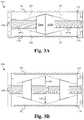
- FIG. 9Aillustrates a retracted perspective view of a bodiless bone fusion device having stretched extending blocks according to some embodiments.
- FIG. 9Billustrates an extended perspective view of a bodiless bone fusion device having stretched extending blocks according to some embodiments.
- FIGS. 1A and 1Billustrate retracted and extended perspective views, respectively, of a bodiless bone fusion device 100 according to some embodiments.
- the bodiless bone fusion device 100is able to be constructed from a high strength biocompatible material, such as titanium, which has the strength to withstand compressive and shear forces in the spine that are generated by a patient's body weight and daily movements.
- a high strength biocompatible materialsuch as titanium
- part of all of the bodiless bone fusion device 100is able to be constructed from one or more of the group consisting of high strength biocompatible material or a polymer such as PEEK, PEKK, and other polymeric materials know to be biocompatible and having sufficient strength.
- the materials used to construct the bodiless bone fusion deviceinclude using additives, such as carbon fibers for better performance of the materials under various circumstances.
- the base biocompatible materialis often textured or coated with a porous material conducive to the growth of new bone cells on the bodiless bone fusion device 100 .
- the bodiless bone fusion device 100is able to have several conduits or holes 120 which permit the bone graft material to be inserted into the device 100 and to contact the vertebral bone before or after the device 100 has been inserted between the vertebrae of the patient.
- one or more holes 120are able to be positioned on the lateral faces of the device 100 through one or both of the plates 102 such that the bone graft material is able to be inserted into the open spaces within the device 100 when the device is in the contracted position. It is understood that although only one conduit 120 on a lateral face is shown in FIG. 1A , any number of conduits 120 on lateral faces or other parts of the device 100 is contemplated.
- the bone graft material and the surface texturing of the device 100encourage the growth and fusion of bone from the neighboring vertebrae.
- the fusion and healing processwill result in the bodiless bone fusion device 100 aiding in the bridging of the bone between the two adjacent vertebral bodies of the spine which eventually fuse together during the healing period.
- the bodiless bone fusion device 100comprises one or more extendable plates 102 , one or more support panels 104 , one or more extending blocks 106 , one or more positioning elements 108 and one or more biasing elements 110 .
- the positioning element 108is rotatably positioned within panel apertures 103 of the support panels 104 and operably coupled with the one or more extending blocks 106 .
- the support panels 104are slidably positioned within plate apertures 118 of the extendable plates 102 and within a grip channel 114 of the extendable plates 102 when the device 100 is in the retracted position as shown in FIG. 1A .
- the biasing element 110is positioned within biasing channels 112 on one or both ends of the extendable plates 102 .
- one or more of the holes 120 , the grip channels 114 , the biasing elements 110 and/or biasing channels 112are able to be omitted.
- one or more additional componentsare able to be added as are well known in the art. Additionally, it is noted that although FIGS. 1A and 1B only show two plates 102 , a single positioning element 108 , two extending blocks 106 , two support panels 104 and two biasing elements 110 , any number of plates 102 , positioning elements 108 , extending blocks 106 , support panels 104 and/or biasing elements 110 is contemplated.
- the one or more extending blocks 106each are able to comprise a threaded conduit 122 for operably coupling to the positioning elements 108 .
- the positioning elements 108are able to comprise a plurality of threaded screws having different diameters wherein the threaded conduits 122 of the extending blocks 106 are able to be configured to screw onto or otherwise engage with one of the threaded screws of the positioning elements 108 .
- one or more of the screwsare able to have the same diameter.
- each of the extending blocks 106are able to comprise angled upper and/or lower outer surfaces for contacting/engaging angled inner surfaces 123 (see FIGS. 3A and 3B ) of the extending plates 102 .
- the angled outer surfacesare able to be configured such that as the blocks 106 move along the positioning element 108 the angles outer surfaces push against the angled inner surfaces 123 causing the plates 102 to move outwards.
- the support panels 104are able to be sized/configured to slidably fit within one or more plate apertures 118 within the extendable plates 102 .
- one or more of the plate apertures 118extend completely through the corresponding plate 102 .
- one or more of the plate aperture 118are able to only extend partially through the corresponding plate 102 .
- the top and bottom portions of the support panels 104are able to be positioned fully within a plate aperture 118 of each of the extendable plates 102 (e.g. such that the edge of the support panels 104 is substantially flush with the surface of the plates 102 if the plate aperture 118 extends through the top of the plate 102 ).
- the plates 102slide up the panels 104 , but the panels 104 remain at least partially within the plate apertures 118 even when in the fully extended position.
- the top and/or bottom of the panels 104comprise one or more retention tips 101 that bow out or otherwise protrude out from the top and/or bottom of the panels 104 in order to block or mechanically stop the plates 102 from sliding off the top of the panels 104 .
- the retention tips 101are able to extend out from the panels 104 and if the plates 102 slide up to the retention tips on the panel 104 , the tips 101 provide a biasing force that pushes the plates 102 back down the panels 104 until they no longer contact the retention tips 101 .
- other types of fasteners or stopping mechanismsare able to be used to prevent the plates 102 from sliding of the panels 104 as are well known in the art.
- the panels 104are able to maintain the alignment of the plates 102 with each other and with the positioning element 108 and extending blocks 106 .
- the support panels 104are each able to comprise one of the panel apertures 103 such that the panels 104 are able to receive one end of the positioning element 108 .
- the panel apertures 103are able to be configured to receive a non-threaded portion of an end of the positioning element 108 such that the positioning element 108 is held in place relative to the support panels 104 , but allowed to rotate within the panel apertures 103 .
- One or more of the support panels 104are also able to comprise one or more grip tabs 105 that extend out the sides of the support panels 105 .
- the grip tabs 105are configured to fit within the grip channels 114 of the plates 102 and provide a gripping point to an insertion instrument used to insert and otherwise manipulate the device 100 .
- the grip tabs 105comprise one or more indentations, conduits and/or fasteners for receiving detachably coupling with an insertion tool.
- the grip tabs 105are able to be configured such that they create a profile that matches the profile of the insertion tool such that the tool is able to securely grip the device 100 via the grip tabs 105 .
- the extendable plates 102are able to be located on opposite sides of the device 100 and face is opposite directions. Internally, the plates 102 are able to have one or more angled inner surfaces 123 (see FIGS. 3A and 3B ) that have end thicknesses that are larger than their middle thicknesses such that the thickness of the angled surfaces 123 gradually increases while going from the middle to the ends of the plate 102 . Alternatively, the angled inner surfaces 123 are able to be configured such that they have end thicknesses that are smaller than their middle thicknesses such that the thickness of the angled surfaces 123 gradually decreases while going from the middle to the ends of the plate 102 .
- the angles surfaces 123are able to interact with the extending blocks 106 to cause the plates 102 to retract or extend between the retracted and extended positions.
- the plates 102each comprise one or more plate apertures 118 that are sized to slidably receive the top or bottom of the support panels 104 .
- the panels 104are able to keep the plates 102 in alignment with each other as the plate 102 slide up and down along the support panels 104 .
- the panels 104are able to be shaped similar to the grip tabs 105 and/or other shapes such that the panels 104 are able to both support the plates 102 as well as enable the plates 102 to slide along the panels 104 .
- the plates 102each able to comprise the one or more biasing channels 112 .
- the biasing channels 112are able to be configured such that when the device 100 is in the retracted position the biasing channels 112 of the plates 102 align to form a continuous channel that crosses between the plates 102 .
- the biasing channels 112are able to align at two or more positions between the plates 102 to form a continuous loop or other shape that crosses multiple times between the plates 102 .
- the biasing channels 112include a lip guard 111 that holds the biasing elements 110 within the biasing channels 112 .
- the biasing channels 112are able to comprise coupling elements (not shown) that enable the biasing elements 110 to directly couple to the biasing channels 112 in order to stay within the channels 112 .
- the lip guard 111is substantially straight forming a square-like channel 112 , it is contemplated that the guard 111 is able to be angled, rounded, indented or otherwise shaped such that the guard 111 is able to retain the biasing elements 110 within the biasing channels 112 .
- the biasing channels 112are able to each include one or more portions that are nonparallel to the direction in which the plates 102 are able to be extended in order to fit a biasing element 110 that provides resistance to the extension of and biases the plates 102 in the retracted position.
- the biasing channels 112form a C shape.
- the biasing channels 112are able to form a loop (see FIGS. 6 A- 6 C), snake or other shapes having nonparallel portions as are well known in the art.
- the biasing channels 112are able to be entirely parallel but be coupled to the biasing element 110 such that a nonparallel portion is unnecessary to provide the force resisting extension of the plates 102 .
- the biasing channels 112are positioned on the ends of the plates 102 as shown in FIGS. 1A and 1B .
- one or more of the biasing channels 112are able to be positioned on another lateral face or faces of the plates 102 .
- the plates 102are able to have serrated edges or teeth 136 to further increase the bodiless bone fusion device's gripping ability and therefore ability to be secured in place between the bones for both a long-term purchase and a short-term purchase.
- the serrated edges or teeth 136are able to be in a triangular or form a triangular wave formation as shown in FIG. 2 .
- the serrated edges or teethare able to be filleted, chamfered, or comprise other teeth shapes or edge waves as are well known in the art.
- the plates 102are able to comprise the grip channels 114 positioned on opposite sides of one or more ends of the plates 102 .
- the grip channels 114are able to be configured such that when the device 100 is in the retracted position the grip channels 114 of the plates 102 align and are partially filled by grip tabs 105 of the support panels 105 .
- the remainder of the grip channels 114is able to be configured to receive gripping fingers of an insertion instrument (not shown).
- the grip channels 114enable the insertion instrument to grip the grip tabs 105 of one of the support panels 104 to manipulate the device 100 and to prevent the device 100 from slipping or during insertion into a patient.
- the grip tabs 105are able to comprise one or more screw holes or other types of fasteners for fastening to an insertion instrument as are well known in the art.
- the plates 102are able to be configured such that when in the retracted position the extendable plates 102 house or surround the remainder of the components of the device 100 .
- the bodiless bone fusion device 100provides the advantage of maximizing the plate size to device size ratio because the size of the plates 102 is equal to the size of the device 100 in the retracted position creating a 1 to 1 ratio. This enables the device 100 to incorporate larger plates 102 that increase stability and surface area, which would not be possible with devices that incorporate a body.
- one or more of the plates 102are able to be non-flat, non-parallel to each other, or otherwise non-uniform.
- one or more of the plates 102are able to be partially or fully concave, convex and/or angled. Further, in some embodiments one or more of the plates 102 are able to be adjustable or interchangeable such that they enable adjustments to their surface/body shape.
- the positioning element 108is able to comprise a positioning aperture 109 , a first screw 107 A and a second screw 107 B coupled together (see FIG. 2 ).
- the positioning aperture 109is configured to receive a drive/engaging mechanism of a tool (not shown) such that the tool is able to rotate the positioning element 108 .
- the positioning aperture 109is able to comprise numerous shapes and sizes as are well known in the art. Alternatively, the positioning aperture 109 is able to be omitted and/or the end of the positioning element 108 is able to be shaped to fit within the drive/engaging mechanism of the tool.
- the first screw 107 Ais threaded opposite of the second screw 107 B.
- the positioning element 108is able to be operably coupled to one or more of the extending blocks 106 .
- a first one of the extending blocks 106is able to be threaded onto the first screw 107 A and a second one of the extending blocks 106 is able to be threaded on to the second screw 107 B.
- the extending blocks 102When coupled to the positioning element 108 , the extending blocks 102 are able to be positioned in the middle of the bodiless bone fusion device 100 in the retracted position.
- the positioning element 108When the positioning element 108 is turned appropriately, the extending blocks 106 each travel outwardly on their respective screws 107 A and 107 B. As the extending blocks 106 travel outwardly, they push the angles surfaces 123 of the plates 102 causing the plates 102 to extend outward along the support panels 104 . In other words, the inner plate surface 123 when in contact with the extending blocks 106 act in such a manner so as to push the respective plates 102 apart. Thus, the plates 102 will be fully extended when the extending blocks 106 reach the opposite ends of the screws 107 A, 107 B.
- the positioning device 108is turned in the opposite direction and the extending blocks 106 will each travel back to the middle on their respective screws 107 A and 107 B. It is contemplated that the operation of the device 100 is able to be reversed such that the plates 102 , extending blocks 106 , and positioning element 108 are configured such that the extending blocks 106 travel inwardly to extend the plates 102 into the extended position and travel outwardly to retract the plates 102 into the compact position.
- the nonextended plates 102 of the bodiless bone fusion device 100provide a compact assembly that is suitable for insertion into the patient's body through a open, or minimally invasive surgical procedure.
- an open or a minimally invasive procedurecomprises a procedure wherein a smaller surgical incision is employed as compared to the size of the incision required for conventional invasive surgery, for example arthroscopic procedures.
- minimally invasive proceduresminimize or eliminate the need for excessive retraction of a patient's tissues such as muscles and nerves, thereby minimizing trauma and injury to the muscles and nerves and further reducing the patient's recovery time.
- the biasing elements 110are able to be configured to fit within the biasing channels 112 of two or more plates 102 when the plates 102 are in alignment.
- one or more of the biasing elements 110are able to shaped in a C shape or broken loop shape.
- one or more of the biasing elements 110are able to have a circular, oval or loop shape.
- one or more of the biasing elements 110are able to have a garter spring shape or any other type of shape formed by the biasing channels 112 .
- the biasing element 110are able to be shaped to fit behind the lip guard 111 such that the lip guard 111 holds the biasing element 110 in place within the biasing channels 112 .
- the biasing element 110is able to directly couple to the plates 102 in order to stay within the biasing channels 112 .
- the biasing elements 110are able to be structured and/or positioned such that their body blocks the extension of the plates 102 and thus the extension of the plates 102 causes deformation and/or stretching of the body of the biasing elements 110 .
- the body deformation and/or stretching resistence of the biasing elements 100provides an extension-resisting force that biases the plates 102 in the retracted position.
- biasingprovides the advantage of ensuring that the plates 102 remain in contact with extending blocks 106 as the plates 102 are extended and/or retracted.
- the biasing elements 110comprise nitinol to provide the deformation resistant and/or flexible structure.
- the biasing elements 110are able to comprise other material having deformation resistant, springing and/or elastic properties as are well known in the art.
- FIG. 2illustrates a cross-sectional view of components of the bodiless bone fusion device 100 according to some embodiments.
- the positioning element 108is able to comprise a first screw 107 A and a second screw 107 B wherein the first screw 107 A is threaded differently than that of the second screw 107 B and is a different size than the second screw 107 B.
- the first screw 107 Ais an 8-32 screw and the second screw is a 6-32 screw.
- a first extending block 106 A and a second extending block 106 Bare utilized with the positioning element 108 to extend and retract one or more of the plates 107 A with respect to each other and/or the positioning element 108 .
- the first extending block 106 Ahas an internal opening and threading to fit around the first screw 107 A.
- the second extending block 106 Bhas an internal opening and threading to fit around the second screw 107 B.
- the support panels 104are coupled with the positioning element 108 via the plate apertures 118 of the plates 102 . Specifically, because the plate apertures 118 receive the ends of the support panels 104 , they prevent the panel apertures 103 of the support panels 104 from moving axially with respect to the positioning element 108 thereby keeping the ends of the positioning element 108 within the panel apertures 103 . Further, the plates 102 are each coupled with each other via the support panels 104 that maintain the alignment of the plates 102 and the biasing elements 110 that hold the plates 102 onto the support panels 104 .
- FIG. 3Aillustrates a profile view of the bodiless bone fusion device 100 with the plates 102 retracted according to some embodiments.
- the extending blocks 106are positioned in the middle of the positioning element 108 with the first screw 107 A and the second screw 107 B, the plates 102 are positioned adjacent and/or in contact with each other.
- FIG. 3Billustrates a profile view of the bodiless bone fusion device 100 with the plates 102 extended according to some embodiments.
- the bodiless bone fusion device 100is compressed/retracted when the extending blocks 106 are in the middle of the bodiless bone fusion device 100 .
- the positioning element 108via the positioning aperture 109
- the extending blocks 106gradually move outward from the middle.
- the extending blocksmove back towards the middle.
- the extending blocks 106are moving outward, the extending blocks 106 A, 106 B push on inner angles surfaces 123 of the plates 102 .
- the plates 102extend because the extending blocks 106 exert force against the angled inner surfaces 123 of the plates 102 outwardly as shown by the arrows 140 .
- the plates 102extend beyond the outer edges of the ends of the support panels 104 of the bodiless bone fusion device 100 and ultimately secure the bodiless bone fusion device 100 between two bones.
- the bodiless bone fusion device 100is initially configured in a compact position such that the extending blocks 106 A, 106 B are located in the middle of the bodiless bone fusion device 100 thereby allowing the plates 102 to contact each other and/or the edges of the ends of the support panels 104 to be substantially flush with the outer surfaces of the plates 102 through the plate apertures 118 .
- the compact bodiless bone fusion device 100is then inserted into position within the patient and surgeon is able to expand the bodiless bone fusion device 100 by rotating the positioning element 108 which moves the extending blocks 106 A, 106 B towards the opposing ends of the bodiless bone fusion device 100 —one near the head of the positioning element 108 and the other towards the tail of the positioning element 108 .
- the plates 102are pushed outwardly from the pressure of the extending blocks 106 A, 106 B against the angled inner surfaces 123 .
- the extending blocks 106 A, 106 Bexert a satisfactory force between the extended plates 102 and the bones to be fused.
- the bodiless bone fusion device 100is able to remain in place. If the plates 102 are extended too far, the surgeon is able to rotate the positioning element 108 in the opposite direction moving the extending blocks 106 A, 106 B back towards the middle.
- the biasing elements 110exert a retraction force in the opposite direction of the force 140 that ensures the plates 102 retract as the extending blocks 106 A, 106 B move back towards the middle of the device 100 .
- the retraction forceis able to be applied to the plates 102 by biasing elements 110 throughout operation of the device 100 in order to both keep the plates 102 from sliding off the support panels 104 and keep the plates 102 in contact with the extending blocks 106 as the blocks 106 move along the positioning element 108 .
- material for fusing the bones togetheris inserted through the holes and openings 120 within the bodiless bone fusion device 100 .
- the insertion of the material for fusing the bones togetheris able to be omitted.
- FIG. 4illustrates a bodiless bone fusion device 400 having a position locking mechanism 402 according to some embodiments.
- the bodiless bone fusion device 400 shown in FIG. 4is substantially similar to the bodiless bone fusion device 100 except for the differences described herein. It is noted that the plates 102 of the bone fusion device 400 have been omitted from FIG. 4 for the sake of clarity.
- at least one of the support panels 104comprises one or more additional panel apertures 99 configured to receive a position locking mechanism 402 , wherein the position locking mechanism 402 comprises one or more dials 404 and one or more stoppers 406 .
- the dial 404is configured to rotatably fit within the panel apertures 99 and comprises a dial aperture 412 and one or more dimples 410 along the edge or perimeter of the dial 202 .
- the dial aperture 412is able to be sized or otherwise configured to receive an end of the positioning element 108 such that if the positioning element 108 is within the dial aperture 412 , the end of the positioning element 108 will cause the dial 404 to rotate along with the positioning element 108 .
- the positioning element 108causes the dial 404 to rotate by directly physically contacting the dial aperture 412 .
- the positioning element 108is able to cause the dial 404 to rotate via indirect contact.
- the one or more dimples 410are able to be configured to receive one or more bumps 408 of the stoppers 406 .
- the dimples 410are able to have concave dimensions that substantially match convex dimensions of the bumps 408 .
- the stoppers 406are able to be configured to fit within the panel apertures 99 adjacent to the dial 404 and comprise one or more bumps 408 .
- the stoppers 406 , dials 404 and apertures 99are configured such that when within the apertures 99 , the stoppers 406 are adjacent or in contact with the dial 404 and the bumps 408 of the stoppers 406 snap or spring fit within the dimples 410 of the dial 404 when a dimple 410 and a bump 408 are aligned. Additionally, when a dimple 410 and a bump 408 are not aligned, the bump 408 is compressed against the dimple-less edge of the dial 404 and primed to spring or decompress into a dimple 410 when alignment is achieved.
- the dial 404is held in place within the additional panel apertures 99 by force applied by the bumps 408 of the stoppers 406 .
- the dimples 410are able to be concave and centered along the perimeter of the dial 404 such that when the bumps 408 are within the dimples 410 the outer walls of the concavity of the dimples 410 prevents the dial 404 and/or the stoppers 406 from falling out of place.
- the dial 404is able to be omitted or incorporated into the positioning element 108 , wherein the perimeter of the positioning element 108 that is adjacent the stoppers 406 forms a trough or channel 401 that receives the stoppers 406 such that the positioning element 108 is unable to come out of position with respect to the stoppers 406 .
- the bottom of the troughis able to comprise the dimples 410 for receiving the bumps 408 of the stoppers 406 .
- the dial 404is able to be otherwise coupled or uncoupled within the apertures 99 by one or more fastening elements as are well known in the art.
- the stoppers 406are held in place within the additional panel apertures 99 by place holders 407 .
- the place holders 407are able to be tensioned and/or compressed by the wall of the apertures 99 when the stoppers 406 are inserted into the apertures 99 and thus provide a spring force against the walls of the apertures 99 to try and relieve that tensioning/compression. Accordingly, the spring force holds the stoppers 406 within the apertures 99 .
- one or more of the stoppers 406are able to be otherwise coupled or uncoupled within the apertures 99 by one or more fastening elements as are well known in the art.
- the device 400comprises one of the panels 104 including the position locking mechanism 402 , wherein the position locking mechanism 402 comprises a single dial 404 having sixteen dimples 410 and two stoppers 406 , it is understood that any number of the panels 104 are able to include a position locking mechanism 402 and the position locking mechanism is able to include any number of dials 404 having any number of dimples 410 coupled to any number of stoppers 406 .
- the additional panel apertures 99are able to replace the panel aperture 103 and/or the dial aperture 410 is able to be substantially similar to the panel aperture 103 in size and shape.
- the dial 404is rotated along with the positioning element 108 and the bumps 408 compress and decompress into and out of the dimples 410 as they move in an out of alignment with the bumps 408 .
- each point during the rotation of the positioning element 108 that results in an alignment of a bump 408 and a dimple 410serves as a demarcated degree of rotation and/or degree of extension/retraction of the plates 102 .
- the position locking mechanism 402provides the advantage of enabling a user to rotate the positioning element 108 and thereby extend the plates 102 to predetermined rotation/extension amounts and/or by predetermined rotation/extension intervals represented by the spacing and number of dimple 410 and bump 408 alignment points.
- the position and/or number of dimples 410 and/or bumps 408 of the position locking mechanism 402is able to be adjusted to adjust the number and/or position of the alignment points and therefore the number and/or position of plate extension points.
- the position locking mechanism 402 of the bodiless bone fusion device 400is able to be tuned to different size devices 400 based on the number of extension increments needed and the desired extension distance interval between each of the increments.
- the incrementsare configured to be constant. Alternatively, the increments are able to be configured to decrease in size as the plates 102 approach the maximum extension level. Alternatively, other increment profiles are able to be used as are well known in the art.
- the compression of the bumps 408 and their resistance thereto during rotation of the positioning element 108 between alignment pointsprovides a slipping resistance force the resists unintended rotation of the positioning element 108 out of an alignment point.
- the position locking mechanism 402provides the advantage of reducing the chance of the positioning element 108 unintentionally rotating and/or the plates 102 unintentionally extending or retracting.
- FIG. 5illustrates a flow chart of a method of using a bodiless bone fusion device according to some embodiments.
- a userpre-configures the one or more plates 102 of the bodiless bone fusion device to the retracted position with the positioning element 108 and the one or more extending blocks 106 such that the device has a minimized form factor at the step 502 .
- the userinserts the bodiless bone fusion device into a desired position in between the bones at the step 504 .
- the userextends the plates 102 to a desired extension level between the bones by rotating the positioning element 108 causing the extending blocks 106 to push the plates 102 outward to the desired extension level at the step 506 .
- the rotating of the positioning element 108comprises rotating the positioning element 108 through a number of alignment points of the position locking mechanism 402 until a desired alignment point is reached.
- FIGS. 9A and 9Billustrate a retracted perspective view and an extended perspective view of a bodiless bone fusion device 900 having stretched or expanded extending blocks according to some embodiments.
- the bodiless bone fusion device 900 shown in FIGS. 9A and 9Bis substantially similar to the bodiless bone fusion device 100 except for the differences described herein.
- the sides 902 of the extending blocks 106 shown in FIGS. 9A and 9Bextend such that the sides 902 substantially align with the outer surface of the device 900 .
- the extending blocks 106span the entire width of the plates 102 which creates greater surface area for the blocks 106 to contact the plates 102 as well as greater stability in the extended position as a wider portion of the plates 102 is directly contacted/supported by the blocks 106 .
- the skirt or sides 904 of the plates 102are able to comprise a block cavity 906 configured to receive the sides 902 of the blocks 106 when the device 900 is in the retracted position.
- both sides 902 of both blocks 106are expanded to align with the exterior surface of the sides 904 of the plates 102 , one or more of the sides 902 of one or more of the blocks 106 are able to not be expanded and/or be expanded less.
- one of the sides 902 of one of the blocks 106is able to extend part way into the cavity 906 on one of the sides 904 of the plates 102 .
- the bodiless bone fusion deviceprovides the advantage of maximizing the plate size to device size ratio because the size of the plates is equal to the size of the device in the retracted position creating a 1 to 1 ratio.
- the deviceprovides the advantage of the grip channels that ensure the non-slippage of the driving mechanism during the operation of the bone fusion apparatus.
- the position locking mechanismprovides the advantage of reducing the chance of the positioning element unintentionally rotating and/or the plates unintentionally extending or retracting.
- the method of userequires only a small incision and minimally invasive surgical procedure advantageously promoting health and rapid recovery by the patient.
- bone growthoccurs around the bodiless bone fusion device and particularly at the locations of the extended plates, such that the bodiless bone fusion device is further secured by the bone growth, which further promotes a superior, robust bone fusion result.
- the deviceprovides the advantage of extending blocks that span the entire width of the plates thereby creating greater surface area for the blocks to contact the plates as well as providing greater stability in the extended position as a wider portion of the plates is directly contacted/supported by the blocks.
- each plateis shaped such that one end is larger than the opposite end, and the size of the plate gradually increases going from the smaller end to the larger end.
Landscapes
- Health & Medical Sciences (AREA)
- Engineering & Computer Science (AREA)
- Biomedical Technology (AREA)
- Neurology (AREA)
- Orthopedic Medicine & Surgery (AREA)
- Cardiology (AREA)
- Oral & Maxillofacial Surgery (AREA)
- Transplantation (AREA)
- Heart & Thoracic Surgery (AREA)
- Vascular Medicine (AREA)
- Life Sciences & Earth Sciences (AREA)
- Animal Behavior & Ethology (AREA)
- General Health & Medical Sciences (AREA)
- Public Health (AREA)
- Veterinary Medicine (AREA)
- Prostheses (AREA)
- Surgical Instruments (AREA)
Abstract
Description
Claims (19)
Priority Applications (3)
| Application Number | Priority Date | Filing Date | Title |
|---|---|---|---|
| US16/789,128US11399956B2 (en) | 2013-03-15 | 2020-02-12 | Bodiless bone fusion device, apparatus and method |
| US17/872,305US11963884B2 (en) | 2013-03-15 | 2022-07-25 | Bodiless bone fusion device, apparatus and method |
| US18/641,692US12409050B2 (en) | 2013-03-15 | 2024-04-22 | Bone fusion device, apparatus and method |
Applications Claiming Priority (5)
| Application Number | Priority Date | Filing Date | Title |
|---|---|---|---|
| US201361794789P | 2013-03-15 | 2013-03-15 | |
| US201361858505P | 2013-07-25 | 2013-07-25 | |
| US14/210,094US10098757B2 (en) | 2013-03-15 | 2014-03-13 | Bodiless bone fusion device, apparatus and method |
| US16/119,809US10575966B2 (en) | 2013-03-15 | 2018-08-31 | Bodiless bone fusion device, apparatus and method |
| US16/789,128US11399956B2 (en) | 2013-03-15 | 2020-02-12 | Bodiless bone fusion device, apparatus and method |
Related Parent Applications (1)
| Application Number | Title | Priority Date | Filing Date |
|---|---|---|---|
| US16/119,809ContinuationUS10575966B2 (en) | 2013-03-15 | 2018-08-31 | Bodiless bone fusion device, apparatus and method |
Related Child Applications (1)
| Application Number | Title | Priority Date | Filing Date |
|---|---|---|---|
| US17/872,305ContinuationUS11963884B2 (en) | 2013-03-15 | 2022-07-25 | Bodiless bone fusion device, apparatus and method |
Publications (2)
| Publication Number | Publication Date |
|---|---|
| US20200179132A1 US20200179132A1 (en) | 2020-06-11 |
| US11399956B2true US11399956B2 (en) | 2022-08-02 |
Family
ID=51531329
Family Applications (5)
| Application Number | Title | Priority Date | Filing Date |
|---|---|---|---|
| US14/210,094Active2034-08-31US10098757B2 (en) | 2013-03-15 | 2014-03-13 | Bodiless bone fusion device, apparatus and method |
| US16/119,809ActiveUS10575966B2 (en) | 2013-03-15 | 2018-08-31 | Bodiless bone fusion device, apparatus and method |
| US16/789,128Active2034-09-19US11399956B2 (en) | 2013-03-15 | 2020-02-12 | Bodiless bone fusion device, apparatus and method |
| US17/872,305ActiveUS11963884B2 (en) | 2013-03-15 | 2022-07-25 | Bodiless bone fusion device, apparatus and method |
| US18/641,692ActiveUS12409050B2 (en) | 2013-03-15 | 2024-04-22 | Bone fusion device, apparatus and method |
Family Applications Before (2)
| Application Number | Title | Priority Date | Filing Date |
|---|---|---|---|
| US14/210,094Active2034-08-31US10098757B2 (en) | 2013-03-15 | 2014-03-13 | Bodiless bone fusion device, apparatus and method |
| US16/119,809ActiveUS10575966B2 (en) | 2013-03-15 | 2018-08-31 | Bodiless bone fusion device, apparatus and method |
Family Applications After (2)
| Application Number | Title | Priority Date | Filing Date |
|---|---|---|---|
| US17/872,305ActiveUS11963884B2 (en) | 2013-03-15 | 2022-07-25 | Bodiless bone fusion device, apparatus and method |
| US18/641,692ActiveUS12409050B2 (en) | 2013-03-15 | 2024-04-22 | Bone fusion device, apparatus and method |
Country Status (6)
| Country | Link |
|---|---|
| US (5) | US10098757B2 (en) |
| EP (1) | EP2967659B1 (en) |
| AU (1) | AU2014236698B2 (en) |
| CA (1) | CA2906531C (en) |
| MX (1) | MX366061B (en) |
| WO (1) | WO2014151934A1 (en) |
Cited By (1)
| Publication number | Priority date | Publication date | Assignee | Title |
|---|---|---|---|---|
| US12409050B2 (en) | 2013-03-15 | 2025-09-09 | Neuropro Technologies, Inc. | Bone fusion device, apparatus and method |
Families Citing this family (87)
| Publication number | Priority date | Publication date | Assignee | Title |
|---|---|---|---|---|
| US7041309B2 (en) | 2002-06-13 | 2006-05-09 | Neuropro Technologies, Inc. | Spinal fusion using an HMG-CoA reductase inhibitor |
| US8597360B2 (en) | 2004-11-03 | 2013-12-03 | Neuropro Technologies, Inc. | Bone fusion device |
| US9801733B2 (en) | 2005-03-31 | 2017-10-31 | Life Spine, Inc. | Expandable spinal interbody and intravertebral body devices |
| US9526525B2 (en) | 2006-08-22 | 2016-12-27 | Neuropro Technologies, Inc. | Percutaneous system for dynamic spinal stabilization |
| US9301788B2 (en) | 2008-04-10 | 2016-04-05 | Life Spine, Inc. | Adjustable spine distraction implant |
| US8353963B2 (en)* | 2010-01-12 | 2013-01-15 | Globus Medical | Expandable spacer and method for use thereof |
| US10420654B2 (en) | 2011-08-09 | 2019-09-24 | Neuropro Technologies, Inc. | Bone fusion device, system and method |
| US9358123B2 (en) | 2011-08-09 | 2016-06-07 | Neuropro Spinal Jaxx, Inc. | Bone fusion device, apparatus and method |
| WO2013023096A1 (en) | 2011-08-09 | 2013-02-14 | Neuropro Technologies, Inc. | Bone fusion device, system and method |
| WO2013149134A2 (en)* | 2012-03-30 | 2013-10-03 | Olympus Biotech Corporation | Alif spinal implant |
| US9532883B2 (en) | 2012-04-13 | 2017-01-03 | Neuropro Technologies, Inc. | Bone fusion device |
| US10159583B2 (en) | 2012-04-13 | 2018-12-25 | Neuropro Technologies, Inc. | Bone fusion device |
| US8663332B1 (en) | 2012-12-13 | 2014-03-04 | Ouroboros Medical, Inc. | Bone graft distribution system |
| US9492288B2 (en) | 2013-02-20 | 2016-11-15 | Flexuspine, Inc. | Expandable fusion device for positioning between adjacent vertebral bodies |
| US10383741B2 (en) | 2013-03-13 | 2019-08-20 | Life Spine, Inc. | Expandable spinal interbody assembly |
| US12193948B2 (en) | 2013-03-13 | 2025-01-14 | Life Spine, Inc. | Expandable implant assembly |
| US11304818B2 (en) | 2013-03-13 | 2022-04-19 | Life Spine, Inc. | Expandable spinal interbody assembly |
| US10154911B2 (en) | 2013-03-13 | 2018-12-18 | Life Spine, Inc. | Expandable implant assembly |
| US10426632B2 (en) | 2013-03-13 | 2019-10-01 | Life Spine, Inc. | Expandable spinal interbody assembly |
| US9987143B2 (en) | 2013-03-15 | 2018-06-05 | Spectrum Spine Ip Holdings, Llc | Expandable inter-body fusion devices and methods |
| US11311312B2 (en) | 2013-03-15 | 2022-04-26 | Medtronic, Inc. | Subcutaneous delivery tool |
| US9186259B2 (en) | 2013-09-09 | 2015-11-17 | Ouroboros Medical, Inc. | Expandable trials |
| WO2016069796A1 (en) | 2014-10-28 | 2016-05-06 | Spectrum Spine Ip Holdings, Llc | Expandable, adjustable inter-body fusion devices and methods |
| US10575964B2 (en) | 2014-10-28 | 2020-03-03 | Spectrum Spine Ip Holdings, Llc | Expandable, adjustable inter-body fusion devices and methods |
| US9937053B2 (en)* | 2014-11-04 | 2018-04-10 | Warsaw Orthopedic, Inc. | Expandable interbody implant |
| US9060876B1 (en) | 2015-01-20 | 2015-06-23 | Ouroboros Medical, Inc. | Stabilized intervertebral scaffolding systems |
| US9907670B2 (en)* | 2015-01-21 | 2018-03-06 | Warsaw Orthopedic, Inc. | Unitarily formed expandable spinal implant and method of manufacturing and implanting same |
| EP3095416A1 (en)* | 2015-05-18 | 2016-11-23 | Life Spine, Inc. | Expandable spinal interbody and intravertebral body devices |
| US10076423B2 (en) | 2016-01-04 | 2018-09-18 | Warsaw Orthopedic, Inc. | Pivoting wedge expanding spinal implant and method of implanting same |
| US9974662B2 (en)* | 2016-06-29 | 2018-05-22 | Globus Medical, Inc. | Expandable fusion device and method of installation thereof |
| US10052215B2 (en)* | 2016-06-29 | 2018-08-21 | Globus Medical, Inc. | Expandable fusion device and method of installation thereof |
| AU2017228529B2 (en)* | 2016-09-12 | 2022-03-10 | Vb Spine Us Opco Llc | Interbody implant with independent control of expansion at multiple locations |
| US9883953B1 (en) | 2016-09-21 | 2018-02-06 | Integrity Implants Inc. | Stabilized laterovertically-expanding fusion cage systems with tensioner |
| US10888433B2 (en)* | 2016-12-14 | 2021-01-12 | DePuy Synthes Products, Inc. | Intervertebral implant inserter and related methods |
| EP3345575B1 (en)* | 2017-01-06 | 2023-08-16 | Ke Ling Biotech Limited | Expandable spinal interbody cage |
| JP7085554B2 (en) | 2017-01-10 | 2022-06-16 | インテグリティ インプランツ インコーポレイテッド | Deployable intervertebral fusion device |
| US10111760B2 (en) | 2017-01-18 | 2018-10-30 | Neuropro Technologies, Inc. | Bone fusion system, device and method including a measuring mechanism |
| US10213321B2 (en) | 2017-01-18 | 2019-02-26 | Neuropro Technologies, Inc. | Bone fusion system, device and method including delivery apparatus |
| US10973657B2 (en) | 2017-01-18 | 2021-04-13 | Neuropro Technologies, Inc. | Bone fusion surgical system and method |
| US10729560B2 (en) | 2017-01-18 | 2020-08-04 | Neuropro Technologies, Inc. | Bone fusion system, device and method including an insertion instrument |
| US11896494B2 (en) | 2017-07-10 | 2024-02-13 | Life Spine, Inc. | Expandable implant assembly |
| US11033403B2 (en) | 2017-07-10 | 2021-06-15 | Life Spine, Inc. | Expandable implant assembly |
| CN111031969A (en) | 2017-07-24 | 2020-04-17 | 整体植入有限公司 | Surgical implants and related methods |
| US10709578B2 (en) | 2017-08-25 | 2020-07-14 | Integrity Implants Inc. | Surgical biologics delivery system and related methods |
| US11273047B2 (en)* | 2017-12-18 | 2022-03-15 | Nuvasive, Inc. | Expandable implant device |
| EP3755273B1 (en) | 2018-02-22 | 2025-04-30 | Warsaw Orthopedic, Inc. | Expandable spinal implant system |
| US11806250B2 (en) | 2018-02-22 | 2023-11-07 | Warsaw Orthopedic, Inc. | Expandable spinal implant system and method of using same |
| CN111655203A (en) | 2018-02-22 | 2020-09-11 | 华沙整形外科股份有限公司 | Expandable spinal implant system and method of use |
| JP7572857B2 (en) | 2018-03-01 | 2024-10-24 | インテグリティ インプランツ インコーポレイテッド | Expandable Fusion Device with Independent Deployment System |
| US10980644B2 (en)* | 2018-06-20 | 2021-04-20 | Astura Medical Inc | Expandable cage |
| USD948048S1 (en) | 2019-04-26 | 2022-04-05 | Warsaw Orthopedic, Inc. | Surgical implant |
| USD955579S1 (en) | 2019-04-26 | 2022-06-21 | Warsaw Orthopedic, Inc. | Surgical implant |
| US11382764B2 (en) | 2019-06-10 | 2022-07-12 | Life Spine, Inc. | Expandable implant assembly with compression features |
| US12042395B2 (en) | 2019-06-11 | 2024-07-23 | Life Spine, Inc. | Expandable implant assembly |
| US12133805B2 (en)* | 2019-09-11 | 2024-11-05 | Gary R. McLuen | Bone fusion device, system and method |
| US11376131B2 (en) | 2020-04-07 | 2022-07-05 | Ethicon, Inc. | Cortical rim-supporting interbody device and method |
| US11857432B2 (en) | 2020-04-13 | 2024-01-02 | Life Spine, Inc. | Expandable implant assembly |
| US11602439B2 (en) | 2020-04-16 | 2023-03-14 | Life Spine, Inc. | Expandable implant assembly |
| US12336917B2 (en) | 2020-05-15 | 2025-06-24 | Life Spine, Inc. | Steerable implant assembly |
| KR102192022B1 (en)* | 2020-05-22 | 2020-12-16 | 힐로 이노베이션 | Lumbar Intervertebral expandable cage and the method of the Lumbar Intervertebral expandable cage insertion |
| KR20210144539A (en)* | 2020-05-22 | 2021-11-30 | 힐로 이노베이션 | Lumbar Intervertebral expandable cage and the method of the Lumbar Intervertebral expandable cage insertion |
| US11602440B2 (en) | 2020-06-25 | 2023-03-14 | Life Spine, Inc. | Expandable implant assembly |
| EP4171448A4 (en) | 2020-07-20 | 2025-02-12 | Integrity Implants Inc. | EXPANDABLE FUSION DEVICE WITH INDEPENDENT EXPANSION SYSTEMS |
| US11554020B2 (en) | 2020-09-08 | 2023-01-17 | Life Spine, Inc. | Expandable implant with pivoting control assembly |
| US11638653B2 (en) | 2020-11-05 | 2023-05-02 | Warsaw Orthopedic, Inc. | Surgery instruments with a movable handle |
| US12318308B2 (en) | 2020-11-05 | 2025-06-03 | Warsaw Orthopedic, Inc. | Dual expandable inter-body device |
| US11285014B1 (en) | 2020-11-05 | 2022-03-29 | Warsaw Orthopedic, Inc. | Expandable inter-body device, system, and method |
| US11833059B2 (en) | 2020-11-05 | 2023-12-05 | Warsaw Orthopedic, Inc. | Expandable inter-body device, expandable plate system, and associated methods |
| US12171439B2 (en) | 2020-11-05 | 2024-12-24 | Warsaw Orthopedic, Inc. | Protected drill |
| US12121453B2 (en) | 2020-11-05 | 2024-10-22 | Warsaw Orthopedic, Inc. | Dual wedge expandable implant with eyelets, system, and method of use |
| US11376134B1 (en) | 2020-11-05 | 2022-07-05 | Warsaw Orthopedic, Inc. | Dual expanding spinal implant, system, and method of use |
| US12239544B2 (en) | 2020-11-05 | 2025-03-04 | Warsaw Orthopedic, Inc. | Rhomboid shaped implants |
| US11395743B1 (en) | 2021-05-04 | 2022-07-26 | Warsaw Orthopedic, Inc. | Externally driven expandable interbody and related methods |
| US11963881B2 (en) | 2020-11-05 | 2024-04-23 | Warsaw Orthopedic, Inc. | Expandable inter-body device, system, and method |
| US11517363B2 (en) | 2020-11-05 | 2022-12-06 | Warsaw Orthopedic, Inc. | Screw driver and complimentary screws |
| US11517443B2 (en) | 2020-11-05 | 2022-12-06 | Warsaw Orthopedic, Inc. | Dual wedge expandable implant, system and method of use |
| US11291554B1 (en) | 2021-05-03 | 2022-04-05 | Medtronic, Inc. | Unibody dual expanding interbody implant |
| EP4312890A1 (en) | 2021-04-02 | 2024-02-07 | Nuvasive, Inc. | Expansion driver |
| JP2024514536A (en) | 2021-04-04 | 2024-04-02 | ニューヴェイジヴ,インコーポレイテッド | expandable implant |
| WO2022232957A1 (en) | 2021-05-02 | 2022-11-10 | Caratsch Alexander | Expandable and flexible intervertebral implant |
| US11612499B2 (en) | 2021-06-24 | 2023-03-28 | Warsaw Orthopedic, Inc. | Expandable interbody implant |
| WO2022271280A1 (en) | 2021-06-24 | 2022-12-29 | Warsaw Orthopedic, Inc. | Expandable interbody implant and corresponding surgical tool |
| US12295865B2 (en) | 2021-06-24 | 2025-05-13 | Warsaw Orthopedic, Inc. | Expandable interbody implant and corresponding inserter |
| US12268614B2 (en) | 2021-06-24 | 2025-04-08 | Warsaw Orthopedic, Inc. | Interbody implant with adjusting shims |
| US11730608B2 (en) | 2021-07-13 | 2023-08-22 | Warsaw Orthopedic, Inc. | Monoblock expandable interbody implant |
| WO2023285675A1 (en) | 2021-07-16 | 2023-01-19 | Blue Ocean Spine Gmbh | Adjustable intervertebral cage, associated instrument and manufacturing process therefor |
| US11850163B2 (en)* | 2022-02-01 | 2023-12-26 | Warsaw Orthopedic, Inc. | Interbody implant with adjusting shims |
Citations (506)
| Publication number | Priority date | Publication date | Assignee | Title |
|---|---|---|---|---|
| US4309777A (en) | 1980-11-13 | 1982-01-12 | Patil Arun A | Artificial intervertebral disc |
| US4388921A (en) | 1980-05-28 | 1983-06-21 | Institut Straumann Ag | Device comprising a plate and screws for fastening a plate to a bone |
| US4863476A (en) | 1986-08-29 | 1989-09-05 | Shepperd John A N | Spinal implant |
| US4961740A (en) | 1988-10-17 | 1990-10-09 | Surgical Dynamics, Inc. | V-thread fusion cage and method of fusing a bone joint |
| JPH02274243A (en) | 1989-02-02 | 1990-11-08 | Pfizer Hospital Prod Group Inc | Fractural part-fixing device |
| US5015247A (en) | 1988-06-13 | 1991-05-14 | Michelson Gary K | Threaded spinal implant |
| US5059193A (en) | 1989-11-20 | 1991-10-22 | Spine-Tech, Inc. | Expandable spinal implant and surgical method |
| WO1991017723A1 (en) | 1990-05-16 | 1991-11-28 | Chas F Thackray Limited | Dummy device for moulding bone cavity form |
| US5123926A (en) | 1991-02-22 | 1992-06-23 | Madhavan Pisharodi | Artificial spinal prosthesis |
| US5171278A (en) | 1991-02-22 | 1992-12-15 | Madhavan Pisharodi | Middle expandable intervertebral disk implants |
| US5443514A (en) | 1993-10-01 | 1995-08-22 | Acromed Corporation | Method for using spinal implants |
| US5458642A (en) | 1994-01-18 | 1995-10-17 | Beer; John C. | Synthetic intervertebral disc |
| US5489307A (en) | 1993-02-10 | 1996-02-06 | Spine-Tech, Inc. | Spinal stabilization surgical method |
| US5522899A (en) | 1988-06-28 | 1996-06-04 | Sofamor Danek Properties, Inc. | Artificial spinal fusion implants |
| US5554191A (en) | 1994-01-26 | 1996-09-10 | Biomat | Intersomatic vertebral cage |
| US5653763A (en) | 1996-03-29 | 1997-08-05 | Fastenetix, L.L.C. | Intervertebral space shape conforming cage device |
| US5658335A (en) | 1995-03-09 | 1997-08-19 | Cohort Medical Products Group, Inc. | Spinal fixator |
| US5665122A (en) | 1995-01-31 | 1997-09-09 | Kambin; Parviz | Expandable intervertebral cage and surgical method |
| US5693100A (en) | 1991-02-22 | 1997-12-02 | Pisharodi; Madhavan | Middle expandable intervertebral disk implant |
| US5702391A (en) | 1995-05-16 | 1997-12-30 | Lin; Chih-I | Intervertebral fusion device |
| US5716415A (en) | 1993-10-01 | 1998-02-10 | Acromed Corporation | Spinal implant |
| US5782832A (en) | 1996-10-01 | 1998-07-21 | Surgical Dynamics, Inc. | Spinal fusion implant and method of insertion thereof |
| US5800547A (en) | 1994-08-20 | 1998-09-01 | Schafer Micomed Gmbh | Ventral intervertebral implant |
| US5800550A (en) | 1996-03-13 | 1998-09-01 | Sertich; Mario M. | Interbody fusion cage |
| US5827328A (en) | 1996-11-22 | 1998-10-27 | Buttermann; Glenn R. | Intervertebral prosthetic device |
| US5865848A (en) | 1997-09-12 | 1999-02-02 | Artifex, Ltd. | Dynamic intervertebral spacer and method of use |
| US5885287A (en) | 1995-12-19 | 1999-03-23 | Spine-Tech, Inc. | Self-tapping interbody bone implant |
| US5928284A (en) | 1998-07-09 | 1999-07-27 | Mehdizadeh; Hamid M. | Disc replacement prosthesis |
| DE29911382U1 (en) | 1999-06-30 | 1999-08-26 | Aesculap AG & Co. KG, 78532 Tuttlingen | Surgical measuring instrument |
| US5980522A (en) | 1994-07-22 | 1999-11-09 | Koros; Tibor | Expandable spinal implants |
| US6019765A (en) | 1998-05-06 | 2000-02-01 | Johnson & Johnson Professional, Inc. | Morsellized bone allograft applicator device |
| US6045579A (en) | 1997-05-01 | 2000-04-04 | Spinal Concepts, Inc. | Adjustable height fusion device |
| US6080158A (en) | 1999-08-23 | 2000-06-27 | Lin; Chih-I | Intervertebral fusion device |
| US6088402A (en) | 1995-08-01 | 2000-07-11 | Canon Kabushiki Kaisha | QAM spread spectrum demodulation system |
| US6102949A (en) | 1997-12-03 | 2000-08-15 | Biedermann Motech Gmbh | Intervertebrae implant |
| US6102950A (en) | 1999-01-19 | 2000-08-15 | Vaccaro; Alex | Intervertebral body fusion device |
| US6117174A (en) | 1998-09-16 | 2000-09-12 | Nolan; Wesley A. | Spinal implant device |
| US6129763A (en) | 1996-09-13 | 2000-10-10 | Chauvin; Jean-Luc | Expandable osteosynthesis cage |
| US6156067A (en) | 1994-11-14 | 2000-12-05 | Spinal Dynamics Corporation | Human spinal disc prosthesis |
| US6159244A (en) | 1999-07-30 | 2000-12-12 | Suddaby; Loubert | Expandable variable angle intervertebral fusion implant |
| US6174311B1 (en) | 1998-10-28 | 2001-01-16 | Sdgi Holdings, Inc. | Interbody fusion grafts and instrumentation |
| US6174334B1 (en) | 1998-12-16 | 2001-01-16 | Loubert Suddaby | Expandable intervertebral fusion implant and applicator |
| US6176882B1 (en) | 1998-02-20 | 2001-01-23 | Biedermann Motech Gmbh | Intervertebral implant |
| US6176881B1 (en) | 1997-04-15 | 2001-01-23 | Synthes | Telescopic vertebral prosthesis |
| US6179873B1 (en) | 1995-08-11 | 2001-01-30 | Bernhard Zientek | Intervertebral implant, process for widening and instruments for implanting an intervertebral implant |
| US6190414B1 (en) | 1996-10-31 | 2001-02-20 | Surgical Dynamics Inc. | Apparatus for fusion of adjacent bone structures |
| US6231609B1 (en) | 1998-07-09 | 2001-05-15 | Hamid M. Mehdizadeh | Disc replacement prosthesis |
| US6267968B1 (en) | 1995-04-07 | 2001-07-31 | Vacsyn S.A. | MDP derivatives and conjugates having haematipoietic function stimulating activity, and compositions containing same |
| US20010021852A1 (en) | 2000-04-10 | 2001-09-13 | Chappius James L. | Fenestrated surgical screw and method |
| US6319257B1 (en) | 1999-12-20 | 2001-11-20 | Kinamed, Inc. | Inserter assembly |
| US6342074B1 (en) | 1999-04-30 | 2002-01-29 | Nathan S. Simpson | Anterior lumbar interbody fusion implant and method for fusing adjacent vertebrae |
| US20020033305A1 (en) | 2000-09-20 | 2002-03-21 | Masaki Koyama | Displacement type fluid machine |
| US6368351B1 (en) | 2001-03-27 | 2002-04-09 | Bradley J. Glenn | Intervertebral space implant for use in spinal fusion procedures |
| US6371987B1 (en) | 1998-04-23 | 2002-04-16 | Medinorm Ag Medizintechnische Produkte | Device for connecting vertebrae of the vertebral column |
| US6371968B1 (en) | 1996-05-09 | 2002-04-16 | Olympus Optical Co., Ltd. | Cavity retaining tool for bone surgery, a cavity retaining tool for general surgery, an endoscopic surgery system involving the use of a cavity retaining tool, and a procedure for surgery |
| US6375655B1 (en) | 1995-03-27 | 2002-04-23 | Sdgi Holdings, Inc. | Interbody fusion device and method for restoration of normal spinal anatomy |
| US6375683B1 (en) | 1997-05-02 | 2002-04-23 | Stryker France S.A. | Implant in particular for replacing a vertebral body in surgery of the spine |
| US20020049445A1 (en) | 2000-04-04 | 2002-04-25 | Hall Harry Thomas | Device for rotational stabilization of bone segments |
| US6383190B1 (en) | 1998-04-01 | 2002-05-07 | Parallax Medical, Inc. | High pressure applicator |
| US6409766B1 (en) | 1998-07-30 | 2002-06-25 | Expanding Concepts, Llc | Collapsible and expandable interbody fusion device |
| US6419705B1 (en) | 1999-06-23 | 2002-07-16 | Sulzer Spine-Tech Inc. | Expandable fusion device and method |
| US6436140B1 (en) | 1998-08-28 | 2002-08-20 | Sofamor S.N.C. | Expandable interbody fusion cage and method for insertion |
| US6443989B1 (en) | 2000-12-04 | 2002-09-03 | Roger P. Jackson | Posterior expandable fusion cage |
| US20020128713A1 (en) | 1999-08-13 | 2002-09-12 | Bret Ferree | Spinal fusion cage with lordosis correction |
| US20020128716A1 (en) | 1999-07-26 | 2002-09-12 | Howard Cohen | Spinal surgical prosthesis |
| US6454806B1 (en) | 1999-07-26 | 2002-09-24 | Advanced Prosthetic Technologies, Inc. | Spinal surgical prosthesis |
| US6454807B1 (en) | 2000-11-30 | 2002-09-24 | Roger P. Jackson | Articulated expandable spinal fusion cage system |
| US6464727B1 (en) | 1999-09-01 | 2002-10-15 | Hugh R. Sharkey | Intervertebral spacer implant |
| US20020165613A1 (en) | 2001-05-04 | 2002-11-07 | Chih-I Lin | Intervertebral fixation device having one or more bracing elements |
| US6488710B2 (en) | 1999-07-02 | 2002-12-03 | Petrus Besselink | Reinforced expandable cage and method of deploying |
| US6491695B1 (en) | 1999-11-05 | 2002-12-10 | Carl Roggenbuck | Apparatus and method for aligning vertebrae |
| US20030036762A1 (en) | 2001-08-20 | 2003-02-20 | Kerr Sean H. | Threaded syringe for delivery of a bone substitute material |
| US6527803B1 (en) | 1998-06-23 | 2003-03-04 | Dimso (Distribution Medicale Du Sud-Ouest) | Intersomatic spine implant having anchoring elements |
| US6562041B1 (en) | 1997-08-29 | 2003-05-13 | Sulzer Spine-Tech Inc. | Apparatus and method for spinal stabilization |
| US6572619B2 (en) | 2001-02-23 | 2003-06-03 | Albert N. Santilli | Cage plate for spinal fusion and method of operation |
| US6572653B1 (en) | 2001-12-07 | 2003-06-03 | Rush E. Simonson | Vertebral implant adapted for posterior insertion |
| US6575042B1 (en) | 2002-02-13 | 2003-06-10 | Beere Precision Medical Instruments, Inc. | Beam-type torsion applying and measuring tool |
| US20030109932A1 (en) | 2000-01-03 | 2003-06-12 | Ory Keynan | Intramedullary support strut |
| US6582467B1 (en) | 2000-10-31 | 2003-06-24 | Vertelink Corporation | Expandable fusion cage |
| US6582431B1 (en) | 1997-02-06 | 2003-06-24 | Howmedica Osteonics Corp. | Expandable non-threaded spinal fusion device |
| US6582451B1 (en) | 1999-03-16 | 2003-06-24 | The University Of Sydney | Device for use in surgery |
| US6595995B2 (en) | 1995-03-27 | 2003-07-22 | Sdgi Holdings, Inc. | Methods and instruments for interbody fusion |
| US20030149484A1 (en) | 2002-02-02 | 2003-08-07 | Michelson Gary K. | Spinal fusion implant having deployable bone engaging projections, instrumentation, and methods for use thereof |
| US6610090B1 (en) | 1998-01-30 | 2003-08-26 | Königsee Implantate und Instrumente zur Ostheosynthese GmbH | Height-adjustable vertebral implant |
| US6613091B1 (en) | 1995-03-27 | 2003-09-02 | Sdgi Holdings, Inc. | Spinal fusion implants and tools for insertion and revision |
| US6616695B1 (en) | 1998-01-30 | 2003-09-09 | Stryker Spine | Implant for replacing a vertebra |
| US6641614B1 (en) | 1997-05-01 | 2003-11-04 | Spinal Concepts, Inc. | Multi-variable-height fusion device |
| US6645249B2 (en) | 2001-10-18 | 2003-11-11 | Spinecore, Inc. | Intervertebral spacer device having a multi-pronged domed spring |
| US6652584B2 (en) | 2000-02-04 | 2003-11-25 | Gary K. Michelson | Expandable threaded arcuate interbody spinal fusion implant with lordotic configuration during insertion |
| US20030229355A1 (en) | 2002-06-10 | 2003-12-11 | Link Spine Group, Inc. | Surgical instrument for inserting intervertebral prosthesis |
| US20030232065A1 (en) | 2002-06-13 | 2003-12-18 | Remington Benjamin J. | Spinal fusion using an HMG-CoA reductase inhibitor |
| US6666888B1 (en) | 2000-08-23 | 2003-12-23 | Roger P. Jackson | Threaded fusion cage with enhanced anterior support |
| US20030236520A1 (en) | 2002-06-25 | 2003-12-25 | Roy Lim | Minimally invasive expanding spacer and method |
| US6685742B1 (en) | 2002-11-12 | 2004-02-03 | Roger P. Jackson | Articulated anterior expandable spinal fusion cage system |
| US20040024461A1 (en) | 2002-05-10 | 2004-02-05 | Ferree Bret A. | Spring and spherical joint artificial disc replacements |
| US20040039448A1 (en) | 2000-07-28 | 2004-02-26 | Madhavan Pisharodi | Method and apparatus for stabilizing adjacent vertebrae |
| US6709458B2 (en) | 2000-02-04 | 2004-03-23 | Gary Karlin Michelson | Expandable push-in arcuate interbody spinal fusion implant with tapered configuration during insertion |
| US20040068269A1 (en) | 2002-10-07 | 2004-04-08 | Bonati Alfred O. | Clamping screw extractor |
| US6723128B2 (en) | 2000-10-17 | 2004-04-20 | Chang Jong Uk | Prosthetic device for correcting deformity of spine |
| US6723126B1 (en) | 2002-11-01 | 2004-04-20 | Sdgi Holdings, Inc. | Laterally expandable cage |
| US20040087949A1 (en) | 2002-10-31 | 2004-05-06 | Bono Frank S. | Snap-in washers and assemblies thereof |
| US20040087947A1 (en) | 2002-08-28 | 2004-05-06 | Roy Lim | Minimally invasive expanding spacer and method |
| US20040102077A1 (en) | 2002-11-19 | 2004-05-27 | Sumitomo Wiring Systems, Ltd. | Connector and a method of assembling it |
| US20040102774A1 (en) | 2002-11-21 | 2004-05-27 | Trieu Hai H. | Systems and techniques for intravertebral spinal stabilization with expandable devices |
| US20040106998A1 (en) | 2002-10-04 | 2004-06-03 | Ferree Bret A. | Multiaxial artificial disc replacements |
| US6746454B2 (en) | 2000-11-07 | 2004-06-08 | Osteotech, Inc. | Implant insertion tool |
| US20040127993A1 (en) | 2002-10-16 | 2004-07-01 | Erich Kast | Spreader implant for placement between vertebrae |
| US20040138750A1 (en) | 2002-10-29 | 2004-07-15 | St. Francis Medical Technologies, Inc. | Artificial vertebral disk replacement implant with a spacer and method |
| US20040148027A1 (en) | 2001-07-16 | 2004-07-29 | Errico Joseph P. | Intervertebral spacer device having an engagement hole for manipulation using a surgical tool |
| US6770095B2 (en) | 2002-06-18 | 2004-08-03 | Depuy Acroned, Inc. | Intervertebral disc |
| US6770096B2 (en) | 1999-07-01 | 2004-08-03 | Spinevision S.A. | Interbody spinal stabilization cage and spinal stabilization method |
| US20040153065A1 (en) | 2003-02-03 | 2004-08-05 | Lim Roy K. | Expanding interbody implant and articulating inserter and method |
| US20040181285A1 (en) | 2001-12-07 | 2004-09-16 | Simonson Rush E. | Vertebral implants adapted for posterior insertion |
| US20040204762A1 (en) | 2001-10-01 | 2004-10-14 | Ralph James D. | Intervertebral spacer device utilizing a spirally slotted belleville washer having radially spaced concentric grooves |
| US20040204715A1 (en) | 2001-02-12 | 2004-10-14 | Evans Avery J. | Multi-use surgical cement dispenser apparatus and kit for same |
| US6808537B2 (en) | 2000-07-07 | 2004-10-26 | Gary Karlin Michelson | Expandable implant with interlocking walls |
| US20040225292A1 (en) | 2003-05-05 | 2004-11-11 | Sasso Ricardo C. | Bone anchor and methods of using the same |
| US20040230309A1 (en) | 2003-02-14 | 2004-11-18 | Depuy Spine, Inc. | In-situ formed intervertebral fusion device and method |
| US6821298B1 (en) | 2000-04-18 | 2004-11-23 | Roger P. Jackson | Anterior expandable spinal fusion cage system |
| US20040243238A1 (en) | 2003-06-02 | 2004-12-02 | Uri Arnin | Spinal disc prosthesis |
| US20050015149A1 (en) | 2001-02-04 | 2005-01-20 | Michelson Gary K. | Instrumentation with inwardly moveable extensions for inserting an expandable interbody spinal fusion implant |
| US20050021042A1 (en) | 2003-07-21 | 2005-01-27 | Theirry Marnay | Instruments and method for inserting an intervertebral implant |
| US20050027360A1 (en) | 2003-08-01 | 2005-02-03 | Webb Scott A. | Spinal implant |
| US20050038515A1 (en) | 2003-06-20 | 2005-02-17 | Sdgi Holdings, Inc. | Lumbar composite nucleus |
| US20050065610A1 (en) | 1994-03-18 | 2005-03-24 | Madhavan Pisharodi | Rotating, locking, spring-loaded artificial disk |
| US20050107877A1 (en) | 2003-10-30 | 2005-05-19 | Nu Vasive, Inc. | System and methods for restoring the structural integrity of bone |
| US20050107878A1 (en) | 2000-12-05 | 2005-05-19 | Stryker Spine | Spinal intervertebral implant adjustable in situ |
| US6902568B2 (en) | 2002-03-19 | 2005-06-07 | Hassan Serhan | Vertebral endplate milling device |
| US20050182416A1 (en) | 2004-02-13 | 2005-08-18 | Roy Lim | Spacer with height and angle adjustments for spacing vertebral members |
| US6962606B2 (en) | 2000-02-04 | 2005-11-08 | Gary Karlin Michelson | Expandable push-in interbody spinal fusion implant |
| US20050278036A1 (en) | 2004-06-09 | 2005-12-15 | Ceravic | Method for restoration of human or animal bone anatomy, and expansible prosthetic implant allowing implementation of this method |
| US20050283236A1 (en) | 2002-11-12 | 2005-12-22 | Hassan Razian | Intervertebral cage with medial fixing plate |
| US6979353B2 (en) | 2001-12-03 | 2005-12-27 | Howmedica Osteonics Corp. | Apparatus for fusing adjacent bone structures |
| US6989011B2 (en) | 2003-05-23 | 2006-01-24 | Globus Medical, Inc. | Spine stabilization system |
| US20060052872A1 (en) | 2003-03-24 | 2006-03-09 | Armin Studer | Intervertebral disc prosthesis |
| US7018415B1 (en) | 2002-09-23 | 2006-03-28 | Sdgi Holdings, Inc. | Expandable spinal fusion device and methods of promoting spinal fusion |
| US20060069436A1 (en) | 2004-09-30 | 2006-03-30 | Depuy Spine, Inc. | Trial disk implant |
| US20060074431A1 (en) | 2004-09-28 | 2006-04-06 | Depuy Spine, Inc. | Disc distraction instrument and measuring device |
| US20060095136A1 (en) | 2004-11-03 | 2006-05-04 | Mcluen Design, Inc. | Bone fusion device |
| US7048763B2 (en) | 2001-10-01 | 2006-05-23 | Spinecore, Inc. | Intervertebral spacer device having a radially thinning belleville spring |
| CN1777352A (en) | 2004-11-15 | 2006-05-24 | 华晶科技股份有限公司 | Buckle shrapnel |
| US20060116769A1 (en) | 2004-11-26 | 2006-06-01 | Theirry Marnay | Intervertebral implant |
| US20060122701A1 (en) | 2004-11-23 | 2006-06-08 | Kiester P D | Posterior lumbar interbody fusion expandable cage with lordosis and method of deploying the same |
| US20060129244A1 (en) | 2004-10-25 | 2006-06-15 | Alphaspine, Inc. | Expandable intervertebral spacer method and apparatus |
| US20060149381A1 (en) | 2004-12-30 | 2006-07-06 | Kim Chong C | Prosthetic spinal discs |
| US20060155295A1 (en) | 2002-07-05 | 2006-07-13 | Walter Supper | Ligament tensing device with displaceable lug |
| US7094257B2 (en) | 2003-02-14 | 2006-08-22 | Zimmer Spine, Inc. | Expandable intervertebral implant cage |
| US20060190084A1 (en) | 2005-02-23 | 2006-08-24 | Joint Synergy Llc | Interior insert ball and dual socket joint |
| US7097648B1 (en) | 1999-01-27 | 2006-08-29 | Disc-O-Tech Medical Technologies Ltd. | Expandable element delivery system |
| US20060200243A1 (en) | 2005-03-03 | 2006-09-07 | Accin Corporation | Cervical intervertebral stabilizer |
| US20060200244A1 (en) | 2003-02-05 | 2006-09-07 | Richard Assaker | Vertebral replacement and distraction device for placing said implant |
| US20060235426A1 (en) | 2005-04-15 | 2006-10-19 | Sdgi Holdings, Inc. | Instruments, implants and methods for positioning implants into a spinal disc space |
| US20060241766A1 (en) | 2005-04-20 | 2006-10-26 | Sdgi Holdings, Inc. | Method and apparatus for preventing articulation in an artificial joint |
| US20060241767A1 (en) | 2005-04-22 | 2006-10-26 | Doty Keith L | Spinal disc prosthesis and methods of use |
| US20060241643A1 (en) | 2002-06-25 | 2006-10-26 | Roy Lim | Minimally invasive expanding spacer and method |
| US20060241770A1 (en) | 2005-04-21 | 2006-10-26 | Rhoda William S | Expandable vertebral prosthesis |
| US7128760B2 (en) | 2001-03-27 | 2006-10-31 | Warsaw Orthopedic, Inc. | Radially expanding interbody spinal fusion implants, instrumentation, and methods of insertion |
| US20060247679A1 (en) | 2005-04-29 | 2006-11-02 | Sdgi Holdings, Inc. | Compression device and method for shape memory alloy implants |
| US20060276899A1 (en) | 2005-06-03 | 2006-12-07 | Zipnick Richard I | Minimally invasive apparatus to manipulate and revitalize spinal column disc |
| WO2006134262A1 (en) | 2005-06-15 | 2006-12-21 | Hassan Razian | Device insertable between two successive vertebras |
| US20060293752A1 (en) | 2005-06-27 | 2006-12-28 | Missoum Moumene | Intervertebral disc prosthesis and associated methods |
| US20060293753A1 (en) | 2002-08-19 | 2006-12-28 | Lanx, Llc | Corrective artificial disc |
| US7166130B2 (en) | 2002-06-27 | 2007-01-23 | Ferree Bret A | Artificial disc replacements with deployable fixation components |
| US7172561B2 (en) | 2002-09-20 | 2007-02-06 | Depuy Acromed | Spreader tensiometer for measuring tension in an intervertebral disc space |
| US20070050030A1 (en) | 2005-08-23 | 2007-03-01 | Kim Richard C | Expandable implant device with interchangeable spacer |
| US20070067038A1 (en) | 2004-04-02 | 2007-03-22 | Armin Studer | Intervertebral disk prosthesis or artificial vertebral body |
| US20070093897A1 (en) | 2005-10-21 | 2007-04-26 | Stryker Spine (In France) | System and method for fusion cage implantation |
| US20070093901A1 (en) | 2005-09-26 | 2007-04-26 | Thomas Grotz | Selectively Expanding Spine Cage, Hydraulically Controllable in Three Dimensions for Enhanced Spinal Fusion |
| US7211112B2 (en) | 2004-02-10 | 2007-05-01 | Atlas Spine | Spinal fusion device |
| US7217293B2 (en) | 2003-11-21 | 2007-05-15 | Warsaw Orthopedic, Inc. | Expandable spinal implant |
| US7217291B2 (en) | 2003-12-08 | 2007-05-15 | St. Francis Medical Technologies, Inc. | System and method for replacing degenerated spinal disks |
| US7220280B2 (en) | 2002-10-16 | 2007-05-22 | Advanced Medical Technologies Ag | Spreader implant for placement between vertebrae |
| US7235103B2 (en) | 2004-01-13 | 2007-06-26 | Rivin Evgeny I | Artificial intervertebral disc |
| US20070179610A1 (en) | 2005-12-23 | 2007-08-02 | Lutz Biedermann | Multi-walled placeholder |
| US20070191954A1 (en) | 2005-04-21 | 2007-08-16 | Noah Hansell | Expandable Vertebral Prosthesis |
| US20070209222A1 (en) | 2004-09-08 | 2007-09-13 | Kay Fischer | Surgical instrument |
| US20070213641A1 (en) | 2006-02-08 | 2007-09-13 | Sdgi Holdings, Inc. | Constrained balloon disc sizer |
| US20070233254A1 (en) | 2005-09-26 | 2007-10-04 | Thomas Grotz | Selectively expanding spine cage, hydraulically controllable in three dimensions for vertebral body replacement |
| US20070255415A1 (en) | 2006-05-01 | 2007-11-01 | Sdgi Holdings, Inc. | Expandable intervertebral spacers and methods of use |
| US20070255409A1 (en) | 2006-04-27 | 2007-11-01 | Sdgi Holdings, Inc. | Expandable implant, instrument, and method |
| US20070255413A1 (en) | 2006-04-27 | 2007-11-01 | Sdgi Holdings, Inc. | Expandable intervertebral spacers and methods of use |
| US20070255407A1 (en) | 2006-04-27 | 2007-11-01 | Sdgi Holdings, Inc. | Self-contained expandable implant and method |
| US20070260260A1 (en) | 2006-03-29 | 2007-11-08 | Hahn Michael R | Sizing instrument for a bodily joint such as an intervertebral disc space |
| US20070270954A1 (en) | 2006-04-05 | 2007-11-22 | Shing-Sheng Wu | Human bone substitutional implant |
| US20070270968A1 (en) | 2004-02-10 | 2007-11-22 | Baynham Bret O | Plif opposing wedge ramp |
| US20070282372A1 (en) | 2006-06-01 | 2007-12-06 | Yedlicka Joseph W | Guide forceps device for use with vertebral treatment device, system and methods of use |
| US20070282441A1 (en) | 2006-05-19 | 2007-12-06 | Katie Stream | Spinal Stabilization Device and Methods |
| US20080009868A1 (en) | 2006-07-07 | 2008-01-10 | Bruce Gotfried | Device and method for treating compression fractures |
| US20080009880A1 (en) | 2006-03-22 | 2008-01-10 | Warnick David R | Pivotable Vetrebral Spacer |
| US20080015701A1 (en) | 2001-11-09 | 2008-01-17 | Javier Garcia | Spinal implant |
| US20080021476A1 (en) | 2003-09-30 | 2008-01-24 | X-Spine Systems, Inc. | Spinal fusion system utilizing an implant plate having at least one integral lock and ratchet lock |
| US20080021555A1 (en) | 2006-07-19 | 2008-01-24 | John White | Expandable vertebral body implants and methods of use |
| US20080021559A1 (en) | 2006-07-06 | 2008-01-24 | Lanx, Llc | Expandable spinal fusion cage |
| US20080021558A1 (en) | 2006-07-06 | 2008-01-24 | Lanx, Llc. | Expandable spinal fusion cage |
| US7326251B2 (en) | 2003-04-01 | 2008-02-05 | Sdgi Holdings, Inc. | Interbody fusion device |
| US7331994B2 (en) | 1999-05-17 | 2008-02-19 | Vanderbilt University | Intervertebral disc replacement prosthesis |
| US7331996B2 (en) | 2002-08-20 | 2008-02-19 | Showa Ika Kohgyo Co., Ltd. | Intervertebral spacer |
| US20080046083A1 (en) | 2006-08-15 | 2008-02-21 | Motionback Llc | Spinal implant |
| US20080051787A1 (en) | 2006-08-22 | 2008-02-28 | Neuropro Technologies, Inc. | Percutaneous system for dynamic spinal stabilization |
| US20080051902A1 (en) | 2006-08-10 | 2008-02-28 | James Dwyer | Modular intervertebral disc prosthesis and method of replacing an intervertebral disc |
| US20080077153A1 (en) | 2006-09-22 | 2008-03-27 | Pioneer Surgical Technology, Inc. | System and methods for inserting a spinal disc device into an intervertebral space |
| WO2008035849A1 (en) | 2006-09-23 | 2008-03-27 | Nam Soo Song | Expandable jacking curette for bone fusion surgery |
| US20080097435A1 (en) | 2006-09-19 | 2008-04-24 | Warsaw Orthopedic Inc. | Instruments and methods for spinal implant revision |
| US20080114367A1 (en) | 2006-11-10 | 2008-05-15 | Syberspine Limited | Method and relaxable distracters for in-situ formation of intervertebral disc prosthesis |
| US20080125778A1 (en) | 2004-10-05 | 2008-05-29 | Kung-Chia Li | Method for fixing an augmenter for vertebral body reconstruction |
| US20080132949A1 (en) | 2005-12-29 | 2008-06-05 | Joseph Aferzon | Apparatus and method for anterior intervertebral spinal fixation and fusion |
| WO2008070863A2 (en) | 2006-12-07 | 2008-06-12 | Interventional Spine, Inc. | Intervertebral implant |
| US20080147193A1 (en) | 2006-11-23 | 2008-06-19 | Wilfried Matthis | Expandable intervertebral implant |
| US20080154381A1 (en) | 2006-12-21 | 2008-06-26 | Rob Gene Parrish | Intervertebral disc spacer |
| US20080161817A1 (en) | 2006-09-28 | 2008-07-03 | Depuy Spine, Inc. | Intervertebral distraction device |
| WO2008086276A2 (en) | 2007-01-05 | 2008-07-17 | Universtiy Of Virginia Patent Foundation | Expandable intervertebral prosthesis device for posterior implantation and related method thereof |
| US20080177275A1 (en) | 2006-12-01 | 2008-07-24 | Charles Wing | Interbody distractor |
| US20080208264A1 (en) | 2007-02-01 | 2008-08-28 | Sargon Lazarof | Securing mechanism with dual expandable ends |
| US20080269756A1 (en) | 2007-04-27 | 2008-10-30 | Spinemedica, Inc. | Surgical instruments for spinal disc implants and related methods |
| US20080269905A1 (en) | 2003-10-20 | 2008-10-30 | Cervitech, Inc. | Cervical intervertebral prosthesis system |
| US20080288076A1 (en) | 2006-09-27 | 2008-11-20 | Teck Soo | Spinal interbody spacer |
| US20080287995A1 (en) | 2007-05-17 | 2008-11-20 | Gauthier Michael T | Compressor Distractor Tool |
| US20080288073A1 (en) | 2007-05-17 | 2008-11-20 | Depuy Spine, Inc. | Self-Distracting Cage |
| US20080306489A1 (en) | 2007-06-07 | 2008-12-11 | Moti Altarac | Inserter for a spinal implant |
| US20090030422A1 (en) | 2007-07-23 | 2009-01-29 | Depuy Spine, Inc. | Implant insertion device and method |
| CN201194047Y (en) | 2008-04-03 | 2009-02-11 | 施静蓉 | Spectacle frame with temple interchangable |
| US20090099601A1 (en) | 2007-10-11 | 2009-04-16 | International Spinal Innovations, Llc | Minimally invasive lateral intervertbral fixation system, device and method |
| US20090105828A1 (en) | 2007-10-22 | 2009-04-23 | Gimbel Jonathan A | Posterior stabilization system with isolated, dual dampener systems |
| US20090112220A1 (en) | 2007-10-30 | 2009-04-30 | Kilian Kraus | Manipulating Tool for a Medical Implant, Medical Implant and Kit of Parts Comprising a Manipulating Tool and Implant |
| US20090112325A1 (en) | 2007-10-30 | 2009-04-30 | Biospine, Llc | Footplate member and a method for use in a vertebral body replacement device |
| US20090112217A1 (en) | 2007-10-31 | 2009-04-30 | Douglas Hester | Implant insertion device |
| US20090112324A1 (en) | 2007-10-30 | 2009-04-30 | Biospine, Llc | Vertebral body replacement device and method for use to maintain a space between two vertebral bodies within a spine |
| US20090164018A1 (en) | 2007-12-19 | 2009-06-25 | Robert Sommerich | Instruments For Expandable Corpectomy Spinal Fusion Cage |
| US20090164020A1 (en) | 2007-11-28 | 2009-06-25 | Pioneer Surgical Technology, Inc. | Device for Securing an Implant to Tissue |
| US20090182343A1 (en) | 2006-08-10 | 2009-07-16 | Trudeau Jeffrey L | Intervertebral disc space sizing tools and methods |
| US20090192611A1 (en) | 2008-01-29 | 2009-07-30 | Aesculap Ag | Vertebral body replacement implant and instrument for handling the vertebral body replacement implant |
| US20090198245A1 (en) | 2008-02-04 | 2009-08-06 | Phan Christopher U | Tools and methods for insertion and removal of medical implants |
| US20090198338A1 (en) | 2008-02-04 | 2009-08-06 | Phan Christopher U | Medical implants and methods |
| US20090210061A1 (en) | 2008-02-14 | 2009-08-20 | U. S. Spinal Technologies, L.L.C. | Anterior lumbar interbody fusion cage device and associated method |
| US7578849B2 (en) | 2006-01-27 | 2009-08-25 | Warsaw Orthopedic, Inc. | Intervertebral implants and methods of use |
| US20090222101A1 (en) | 2003-05-27 | 2009-09-03 | Spinalmotion, Inc. | Prosthetic Disc for Intervertebral Insertion |
| US20090222100A1 (en) | 2008-02-28 | 2009-09-03 | Stryker Spine | Tool for implanting expandable intervertebral implant |
| US7584682B2 (en) | 2007-08-07 | 2009-09-08 | Chern Shing Top Co., Ltd. | Adjustment device with a dual-guiding structure |
| US20090228110A1 (en) | 2008-03-07 | 2009-09-10 | K2M, Inc. | Intervertebral instrument, implant, and method |
| US7588573B2 (en) | 2002-09-23 | 2009-09-15 | Warsaw Orthopedic, Inc. | Expansion tool for adjustable spinal implant |
| US20090265008A1 (en) | 2008-03-31 | 2009-10-22 | Stryker Spine | Spinal implant apparatus and methods |
| US7621956B2 (en) | 2003-07-31 | 2009-11-24 | Globus Medical, Inc. | Prosthetic spinal disc replacement |
| US20090292361A1 (en) | 2008-05-26 | 2009-11-26 | Rudolf Morgenstern Lopez | Intervertebral implant and installation tool |
| US20090299478A1 (en) | 2008-06-03 | 2009-12-03 | Warsaw Orthopedic, Inc. | Lordotic Implant for Posterior Approach |
| US20090306672A1 (en) | 2008-06-05 | 2009-12-10 | Alphatec Spine,Inc. | Alif inserter/distractor |
| US7637952B2 (en) | 2002-03-11 | 2009-12-29 | Zimmer Spine, Inc. | Instrumentation and procedure for implanting spinal implant devices |
| US20100010494A1 (en) | 2008-07-11 | 2010-01-14 | Q-Spine, Llc | Spinal measuring device and distractor |
| US20100015747A1 (en) | 2006-08-10 | 2010-01-21 | Samsung Electronics Co., Ltd. | Methods of fabricating image sensors including impurity layer isolation regions |
| US20100023057A1 (en) | 2006-09-20 | 2010-01-28 | Woodwelding Ag | Device to be implanted in human or animal tissue and method for implanting and assembling the device |
| US20100024487A1 (en) | 2008-07-31 | 2010-02-04 | Abbott Spine Inc. | Surgical Instrument With Integrated Reduction And Distraction Mechanisms |
| US20100057204A1 (en) | 2008-02-22 | 2010-03-04 | Murali Kadaba | Hydraulically Actuated Expanding Spine Cage With Extendable Locking Anchor |
| US7678148B2 (en) | 2004-07-23 | 2010-03-16 | Warsaw Orthopedic, Inc. | Expandable spinal implant having interlocking geometry for structural support |
| US7682376B2 (en) | 2006-01-27 | 2010-03-23 | Warsaw Orthopedic, Inc. | Interspinous devices and methods of use |
| US7691147B2 (en) | 2002-12-06 | 2010-04-06 | Synthes Usa, Llc | Intervertebral implant |
| US20100100100A1 (en) | 2008-10-16 | 2010-04-22 | Daniel Refai | Surgical instrument and method of use for inserting an implant between two bones |
| US7703727B2 (en) | 2004-07-21 | 2010-04-27 | Selness Jerry N | Universal adjustable spacer assembly |
| US20100114183A1 (en) | 2008-10-31 | 2010-05-06 | K2M, Inc. | Implant insertion tool |
| US20100114106A1 (en) | 2008-04-21 | 2010-05-06 | Helmut Weber | Surgical instrument to measure an intervertebral space |
| US7749252B2 (en) | 2005-03-21 | 2010-07-06 | Kyphon Sarl | Interspinous process implant having deployable wing and method of implantation |
| US7753958B2 (en) | 2003-08-05 | 2010-07-13 | Gordon Charles R | Expandable intervertebral implant |
| US20100179657A1 (en) | 2009-01-14 | 2010-07-15 | Stout Medical Group, L.P. | Expandable support device and method of use |
| US7758617B2 (en) | 2005-04-27 | 2010-07-20 | Globus Medical, Inc. | Percutaneous vertebral stabilization system |
| US20100204795A1 (en) | 2008-11-12 | 2010-08-12 | Stout Medical Group, L.P. | Fixation device and method |
| US20100211119A1 (en) | 2009-02-19 | 2010-08-19 | Daniel Refai | Multi-functional surgical instrument and method of use for inserting an implant between two bones |
| US20100211176A1 (en) | 2008-11-12 | 2010-08-19 | Stout Medical Group, L.P. | Fixation device and method |
| US20100217404A1 (en) | 2009-02-23 | 2010-08-26 | Kane Seth A | Electro-magnet based telescoping artificial muscle actuator |
| US20100234956A1 (en) | 2007-03-28 | 2010-09-16 | David Attia | Expanding cage for vertebral surgery |
| US7799081B2 (en) | 2004-09-14 | 2010-09-21 | Aeolin, Llc | System and method for spinal fusion |
| US20100241231A1 (en) | 2009-02-20 | 2010-09-23 | Marino James F | Intervertebral fixation device |
| US20100262247A1 (en) | 2007-11-08 | 2010-10-14 | Uri Arnin | Spinal implant having a post-operative adjustable dimension |
| WO2010121030A2 (en) | 2009-04-16 | 2010-10-21 | Coalign Innovations, Inc. | Insertion handle for surgical implants |
| US20100274357A1 (en) | 2009-04-23 | 2010-10-28 | Warsaw Orthopedic, Inc. | Expandable implant, instrument, and method |
| US20100286780A1 (en) | 2005-01-20 | 2010-11-11 | Dryer Randall F | Expandable spinal fusion cage and associated instrumentation |
| US20100286779A1 (en) | 2009-05-06 | 2010-11-11 | Thibodeau Lee L | Expandable spinal implant apparatus and method of use |
| US20100292796A1 (en) | 2009-05-14 | 2010-11-18 | Stout Medical Group, L.P. | Expandable support device and method of use |
| US7837688B2 (en) | 2005-06-13 | 2010-11-23 | Globus Medical | Spinous process spacer |
| US20100298939A1 (en) | 2005-06-03 | 2010-11-25 | Mathys Ag Bettlach | Intervertebral Disc Implant |
| US20100324606A1 (en) | 2005-08-23 | 2010-12-23 | Nathan Moskowitz | Bi-directional fixating transvertebral body screws, zero-profile horizontal intervertebral miniplates, total intervertebral body fusion devices, and posterior motion-calibrating interarticulating joint stapling device for spinal fusion |
| US20100331885A1 (en) | 2009-06-24 | 2010-12-30 | Neuropro Technologies, Inc. | Percutaneous system for dynamic spinal stabilization |
| US20110015747A1 (en) | 2008-03-07 | 2011-01-20 | Mcmanus Joshua | Expandable interbody spacer device |
| US20110015741A1 (en) | 2009-07-16 | 2011-01-20 | Warsaw Orthopedic, Inc. | Spinal implant configured to apply radiation treatment and method |
| US20110015682A1 (en) | 2009-07-15 | 2011-01-20 | Orthohelix Surgical Designs, Inc. | Variable axis locking mechanism for use in orthopedic implants |
| US20110015742A1 (en) | 2009-07-20 | 2011-01-20 | Wei-Chen Hong | Spine fusion cage |
| US20110015638A1 (en) | 2009-07-17 | 2011-01-20 | Pischl Susanne | Spinal-column distractor |
| US20110035011A1 (en) | 2008-04-05 | 2011-02-10 | Synthes Usa, Llc | Expandable intervertebral implant |
| US20110035007A1 (en) | 2009-08-06 | 2011-02-10 | Alphatec Spine, Inc. | Stand-alone interbody fixation system |
| US20110077738A1 (en) | 2009-09-28 | 2011-03-31 | Lfc Sp. Z.O.O. | Device for surgical displacement of vertebrae |
| US20110087329A1 (en) | 2009-10-13 | 2011-04-14 | Nicholas Poulos | Lumbar implant |
| US20110093074A1 (en) | 2009-10-15 | 2011-04-21 | Chad Glerum | Expandable Fusion Device and Method of Installation Thereof |
| US7931688B2 (en) | 2004-08-25 | 2011-04-26 | Spine Wave, Inc. | Expandable interbody fusion device |
| US7932825B2 (en) | 2004-05-07 | 2011-04-26 | Berger J Lee | Medical implant device with RFID tag and method of identification of device |
| US7935117B2 (en) | 2007-05-02 | 2011-05-03 | Depuy Products, Inc. | Expandable proximal reamer |
| US20110112587A1 (en) | 2009-11-11 | 2011-05-12 | Nirali Patel | Instrument for insertion and deployment of features on an implant |
| US20110130835A1 (en) | 2008-12-10 | 2011-06-02 | Innvotec Surgical, Inc. | Adjustable Distraction Cage With Linked Locking Mechanisms |
| US20110138948A1 (en) | 2009-07-22 | 2011-06-16 | Jimenez Omar F | Coaxial screw gear sleeve mechanism |
| US20110172716A1 (en) | 2010-01-12 | 2011-07-14 | Chad Glerum | Expandable Spacer and Method For Use Thereof |
| US20110172774A1 (en) | 2010-01-11 | 2011-07-14 | Armando Varela | Expandable intervertebral implant and associated surgical method |
| US7985231B2 (en) | 2007-12-31 | 2011-07-26 | Kyphon Sarl | Bone fusion device and methods |
| US20110202135A1 (en) | 2008-03-24 | 2011-08-18 | Lanx, Inc. | Expandable spinal interbody cage and methods |
| US8002834B2 (en) | 2004-07-30 | 2011-08-23 | Spinalmotion, Inc. | Intervertebral prosthetic disc with metallic core |
| US20110218627A1 (en) | 2010-03-03 | 2011-09-08 | Warsaw Orthopedic, Inc. | System and method for replacing at least a portion of a vertebral body |
| US20110230970A1 (en) | 2010-03-16 | 2011-09-22 | Pinnacle Spine Group, Llc | Intervertebral implants and graft delivery systems and methods |
| US20110238184A1 (en) | 1995-03-27 | 2011-09-29 | Thomas Zdeblick | Methods and instruments for interbody fusion |
| US20110251692A1 (en) | 2010-04-12 | 2011-10-13 | Mclaughlin Colm | Expandable Vertebral Implant |
| US20110251691A1 (en) | 2010-04-12 | 2011-10-13 | Mclaughlin Colm | Expandable Vertebral Implant |
| US8043295B2 (en) | 2004-10-27 | 2011-10-25 | Brainlab Ag | Vertebral spreading instrument comprising markers |
| US20110282453A1 (en) | 2010-05-13 | 2011-11-17 | Stout Medical Group, L.P. | Fixation device and method |
| US20110301712A1 (en) | 2010-06-02 | 2011-12-08 | Warsaw Orthopedic, Inc. | System and methods for a laterally expanding implant |
| US20110319997A1 (en) | 2010-06-25 | 2011-12-29 | Chad Glerum | Expandable Fusion Device and Method of Installation Thereof |
| US8110004B2 (en) | 2008-08-21 | 2012-02-07 | The Trustees Of The Stevens Institute Of Technology | Expandable interbody fusion cage with rotational insert |
| US8114092B2 (en) | 2007-06-07 | 2012-02-14 | Exactech, Inc. | Inserter for a spinal implant |
| US20120059473A1 (en) | 2010-09-03 | 2012-03-08 | Mark Weiman | Expandable Fusion Device and Method of Installation Thereof |
| US20120059472A1 (en) | 2010-09-03 | 2012-03-08 | Mark Weiman | Expandable Fusion Device and Method of Installation Thereof |
| US20120059475A1 (en) | 2010-09-03 | 2012-03-08 | Mark Weiman | Expandable Fusion Device and Method of Installation Thereof |
| US20120059470A1 (en) | 2010-09-03 | 2012-03-08 | Mark Weiman | Expandable Fusion Device and Method of Installation Thereof |
| US20120059481A1 (en) | 2005-03-16 | 2012-03-08 | Dennis Lee Abernathie | Spinal Fusion Cage, Method of Design, and Method of Use |
| US20120059474A1 (en) | 2010-09-03 | 2012-03-08 | Mark Weiman | Expandable Fusion Device and Method of Installation Thereof |
| CN202165357U (en) | 2011-06-02 | 2012-03-14 | 延锋伟世通汽车电子有限公司 | Buckle structure with location and constraint functions |
| US20120071979A1 (en) | 2005-06-03 | 2012-03-22 | Zipnick Richard I | Minimally invasive apparatus to manipulate and revitalize spinal column disk |
| US20120089228A1 (en) | 2010-10-07 | 2012-04-12 | Nicholas Poulos | Lordotic expandable interbody implant and method |
| CN102429805A (en) | 2011-12-09 | 2012-05-02 | 宁波康福特健身器械有限公司 | Massager |
| US20120130494A1 (en) | 2006-09-13 | 2012-05-24 | Synthes Usa, Llc | Allograft intervertebral implant and method of manufacturing the same |
| US20120130493A1 (en) | 2010-04-12 | 2012-05-24 | Mclaughlin Colm | Expandable Vertebral Implant |
| US8187331B2 (en) | 2006-04-27 | 2012-05-29 | Warsaw Orthopedic, Inc. | Expandable vertebral implant and methods of use |
| US20120136448A1 (en) | 2008-08-29 | 2012-05-31 | Jody L Seifert | Devices and Methods for Treating Bone |
| US20120158071A1 (en) | 2009-12-31 | 2012-06-21 | Jimenez Omar F | Methods and apparatus for insertion of vertebral body distraction and fusion devices |
| US20120197403A1 (en) | 2011-01-27 | 2012-08-02 | Warsaw Orthopedic. Inc. | Expandable medical implant |
| US20120197404A1 (en) | 2011-02-02 | 2012-08-02 | Philipp Brun | Intervertebral implant having extendable bone fixation members |
| US20120209384A1 (en) | 2009-03-12 | 2012-08-16 | Nu Vasive Inc. | Vertebral body replacement |
| US20120209386A1 (en) | 2011-02-14 | 2012-08-16 | Medicinelodge, Inc. Dba Imds Co-Innovation | Expandable intervertebral implants and instruments |
| US20120226357A1 (en) | 2010-01-11 | 2012-09-06 | Innova Spinal Technologies, Llc | Expandable intervertebral implant and associated surgical method |
| US8262666B2 (en) | 2007-04-27 | 2012-09-11 | Atlas Spine, Inc. | Implantable distractor |
| US20120232660A1 (en) | 2010-04-12 | 2012-09-13 | Daniel Davenport | Expandable Trial Assembly For Expandable Vertebral Implant |
| US20120232552A1 (en) | 2011-03-10 | 2012-09-13 | Interventional Spine, Inc. | Method and apparatus for minimally invasive insertion of intervertebral implants |
| US20120232659A1 (en) | 2010-04-12 | 2012-09-13 | James Himmelberger | Angling Inserter Tool For Expandable Vertebral Implant |
| US20120232601A1 (en) | 2011-03-11 | 2012-09-13 | Kyphon Sarl | Surgical tool for adjusting a spinal implant |
| US8273129B2 (en) | 2004-02-10 | 2012-09-25 | Atlas Spine, Inc. | PLIF opposing wedge ramp |
| US20120245691A1 (en) | 2011-03-23 | 2012-09-27 | Alphatec Spine, Inc. | Expandable interbody spacer |
| US20120253412A1 (en) | 2011-04-04 | 2012-10-04 | K2M, Inc. | Adjustable apparatus and methods for inserting an implant |
| US20120265303A1 (en) | 2007-10-30 | 2012-10-18 | Aesculap Implant Systems, Llc | Vertebral body replacement device and method for use to maintain a space between two vertebral bodies within a spine |
| US20120271422A1 (en) | 2011-04-19 | 2012-10-25 | Warsaw Orthopedic, Inc. | Expandable implant system and methods of use |
| US20120277810A1 (en) | 2011-04-29 | 2012-11-01 | Medacta International Sa | Instrument for positioning an intervertebral implant for the fusion between two vertebral bodies of a vertebral column |
| US20120277875A1 (en) | 2009-11-24 | 2012-11-01 | Spine21 Ltd. | Spinal fusion cage having post-operative adjustable dimensions |
| US8303601B2 (en) | 2006-06-07 | 2012-11-06 | Stryker Spine | Collet-activated distraction wedge inserter |
| US8308801B2 (en) | 2007-02-12 | 2012-11-13 | Brigham Young University | Spinal implant |
| US8308804B2 (en) | 2008-11-14 | 2012-11-13 | David Krueger | Spinal fusion device |
| US20120290090A1 (en) | 2009-10-15 | 2012-11-15 | Chad Glerum | Expandable Fusion Device and Method of Installation Thereof |
| US8317025B1 (en) | 2007-03-01 | 2012-11-27 | San Diego Composites, Inc. | Self-adjusting wedge bumper |
| US20120303124A1 (en) | 2004-11-03 | 2012-11-29 | Mcluen Gary R | Bone fusion device |
| US20120300124A1 (en) | 2011-05-26 | 2012-11-29 | Shigeyuki Yamashita | Signal transmission apparatus, signal transmission method, signal reception apparatus, signal reception method, and signal transmission system |
| US20120310350A1 (en) | 2011-06-03 | 2012-12-06 | Biospine, Llc | Unidirectional dynamic interbody fusion device and method of use |
| US8328962B2 (en) | 2005-09-30 | 2012-12-11 | Acandis Gmbh & Co. Kg | Damping apparatus, use of a shape memory alloy and method for changing damping characteristics |
| US20120323328A1 (en) | 2010-09-03 | 2012-12-20 | Mark Weiman | Expandable Fusion Device and Method of Installation Thereof |
| US20120323327A1 (en) | 2011-06-17 | 2012-12-20 | Mcafee Paul C | Expandable Spinal Implant and Flexible Driver |
| US20120330421A1 (en) | 2010-09-03 | 2012-12-27 | Mark Weiman | Expandable Fusion Device and Method of Installation Thereof |
| US20120330422A1 (en) | 2010-09-03 | 2012-12-27 | Mark Weiman | Expandable Fusion Device and Method of Installation Thereof |
| US8343222B2 (en) | 2005-04-28 | 2013-01-01 | Aiden Cope | Spinal disc prosthesis and instruments |
| US20130006359A1 (en) | 2011-06-30 | 2013-01-03 | Blackstone Medical, Inc. | Posterior insertion instrument for an expandable support device |
| US20130006358A1 (en) | 2011-06-30 | 2013-01-03 | Blackstone Medical, Inc. | Spring device for locking an expandable support device |
| US20130006364A1 (en) | 2008-06-06 | 2013-01-03 | Providence Medical Technology, Inc. | Facet joint implants and delivery tools |
| US20130006361A1 (en) | 2009-10-15 | 2013-01-03 | Chad Glerum | Expandable Fusion Device and Method of Installation Thereof |
| US20130018468A1 (en) | 2005-04-12 | 2013-01-17 | Moskowitz Ahmnon D | Bi-directional fixating transvertebral body screws and posterior cervical and lumbar interarticulating joint calibrated stapling devices for spinal fusion |
| US20130018470A1 (en) | 2005-04-12 | 2013-01-17 | Moskowitz Nathan C | Bi-directional fixating/locking transvertebral body screw/intervertebral cage stand-alone constructs with vertical hemi-bracket screw locking mechanism |
| US20130023994A1 (en) | 2009-10-15 | 2013-01-24 | Chad Glerum | Expandable Fusion Device and Method of Installation Thereof |
| US20130023993A1 (en) | 2010-09-03 | 2013-01-24 | Mark Weiman | Expandable Fusion Device and Method of Installation Thereof |
| US20130023992A1 (en) | 2005-04-12 | 2013-01-24 | Moskowitz Nathan C | Bi-directional fixating/locking transvertebral body screw/intervertebral cage stand-alone constructs |
| US8361152B2 (en) | 2008-06-06 | 2013-01-29 | Providence Medical Technology, Inc. | Facet joint implants and delivery tools |
| US20130035724A1 (en) | 2010-04-23 | 2013-02-07 | Fitzbionics Limited | Spinal Implants and Spinal Fixings |
| WO2013023098A1 (en) | 2011-08-09 | 2013-02-14 | Neuropro Spinal Jaxx Inc. | Bone fusion device, apparatus and method |
| WO2013023096A1 (en) | 2011-08-09 | 2013-02-14 | Neuropro Technologies, Inc. | Bone fusion device, system and method |
| WO2013025876A1 (en) | 2011-08-16 | 2013-02-21 | Stryker Spine | Expandable implant |
| US20130073046A1 (en) | 2011-09-16 | 2013-03-21 | Jillian Zaveloff | Multi-piece Intervertebral Implants |
| US20130079793A1 (en) | 2011-09-23 | 2013-03-28 | Orthosensor | Sensored head for a measurement tool for the muscular-skeletal system |
| US20130079790A1 (en) | 2011-09-23 | 2013-03-28 | Orthosensor | Spine Tool For Measuring Vertebral Load and Position of Load |
| US20130085572A1 (en) | 2011-09-30 | 2013-04-04 | Chad Glerum | Expandable Fusion Device and Method of Installation Thereof |
| US20130103156A1 (en) | 2011-10-19 | 2013-04-25 | Evan PACKER | Laterally expandable spinal prosthesis |
| US20130103153A1 (en) | 2011-10-24 | 2013-04-25 | Warsaw Orthopedic, Inc. | Interbody implant system and methods of use |
| US20130110248A1 (en) | 2011-11-02 | 2013-05-02 | Arthrodisc, L.L.C. | Lockable implant members |
| US20130123927A1 (en) | 2010-07-15 | 2013-05-16 | Spine Wave, Inc. | Plastically deformable inter-osseous device |
| US8444697B1 (en) | 2010-11-18 | 2013-05-21 | Daniel Butler | Spinal fusion implant and methods of use thereof |
| US8444696B2 (en) | 1995-06-07 | 2013-05-21 | Warsaw Orthopedic, Inc. | Anatomic spinal implant having anatomic bearing surfaces |
| US20130158664A1 (en) | 2011-12-19 | 2013-06-20 | Warsaw Orthopedic, Inc. | Expandable interbody implant and methods of use |
| US20130158668A1 (en) | 2011-12-14 | 2013-06-20 | Biospine, Llc | Unilateral moveable interbody fusion device and method of use |
| US20130158663A1 (en) | 2011-12-19 | 2013-06-20 | Warsaw Orthopedic, Inc | Expandable interbody implant and methods of use |
| US20130158669A1 (en) | 2012-02-13 | 2013-06-20 | Arno Sungarian | Expandable Self-Anchoring Interbody Cage for Orthopedic Applications |
| US8485075B1 (en) | 2010-05-18 | 2013-07-16 | Gauthier Biomedical, Inc. | Electronic torque wrench |
| US20130197642A1 (en) | 2012-01-28 | 2013-08-01 | Mark J. Ernst | Expandable implant for mammalian bony segment stabilization |
| US20130253650A1 (en) | 2008-12-10 | 2013-09-26 | Coalign Innovations, Inc. | Adjustable Distraction Cage With Linked Locking Mechanisms |
| US20130274883A1 (en) | 2012-04-13 | 2013-10-17 | Gary R. McLuen | Bone fusion device |
| US20130310938A1 (en) | 2011-02-03 | 2013-11-21 | Medicrea International | Corporectomy implant |
| US20130317554A1 (en) | 2012-05-23 | 2013-11-28 | Thomas Purcell | Locking mechanism for an implantable medical device |
| US20140012383A1 (en) | 2011-02-14 | 2014-01-09 | Imds Corporation | Expandable intervertebral implants and instruments |
| US20140039622A1 (en) | 2010-09-03 | 2014-02-06 | Chad Glerum | Expandable Fusion Device and Method of Installation Thereof |
| US20140066941A1 (en) | 2007-07-06 | 2014-03-06 | Luis Antonio Mignucci | Anterior spinal interbody fusion delivery system |
| US20140094917A1 (en) | 2012-10-02 | 2014-04-03 | Anthony A. Salerni | Expandable fusion cage with cam adjuster |
| US20140114414A1 (en) | 2012-10-22 | 2014-04-24 | Cogent Spine, LLC | Devices and methods for spinal stabilization and instrumentation |
| US20140121774A1 (en) | 2009-10-15 | 2014-05-01 | Chad Glerum | Expandable Fusion Device and Method of Installation Thereof |
| US20140143577A1 (en) | 2011-12-22 | 2014-05-22 | Murugasamy K. Nachimuthu | Power conservation by way of memory channel shutdown |
| US8734337B2 (en) | 2012-04-12 | 2014-05-27 | Coloplast A/S | Surgical device for internally manipulating an organ |
| US20140156007A1 (en) | 2012-11-26 | 2014-06-05 | Spontech Spine Intelligence Ag | Expandable Cage for the Intercorporal Fusion of Lumbar Vertebrae |
| US20140156008A1 (en) | 2012-12-03 | 2014-06-05 | Meditech Spine, Llc | Spinal implant alignment guide systems |
| US20140156006A1 (en) | 2009-03-12 | 2014-06-05 | Nuvasive, Inc. | Vertebral Body Replacement |
| US20140180421A1 (en) | 2010-06-25 | 2014-06-26 | Globus Medical, Inc | Expandable Fusion Device and Method of Installation Thereof |
| US20140214166A1 (en) | 2013-01-25 | 2014-07-31 | K2M, Inc. | Spinal implants, spinal implant kits, and surgical methods |
| US20140214167A1 (en) | 2013-01-25 | 2014-07-31 | K2M, Inc. | Spinal implants, spinal implant kits, and surgical methods |
| US20140236297A1 (en) | 2009-10-15 | 2014-08-21 | Andrew Iott | Expandable Fusion Device and Method Installation Thereof |
| US20140236296A1 (en) | 2013-02-20 | 2014-08-21 | Erik Wagner | Expandable fusion device for positioning between adjacent vertebral bodies |
| US20140243982A1 (en) | 2013-02-28 | 2014-08-28 | William Miller | Expandable Intervertebral Implant, System, Kit and Method |
| US20140249629A1 (en) | 2005-04-12 | 2014-09-04 | Ahmnon D. Moskowitz | Zero-profile expandable intervertebral spacer devices for distraction and spinal fusion and a universal tool for their placement and expansion |
| US20140257296A1 (en) | 2013-03-11 | 2014-09-11 | Interventional Spine, Inc. | Method and apparatus for minimally invasive insertion of intervertebral implants |
| US20140277510A1 (en) | 2013-03-15 | 2014-09-18 | Spectrum Spine Ip Holdings, Llc | Expandable vertebral body replacement device, system, and methods |
| US20140277504A1 (en) | 2013-03-14 | 2014-09-18 | Osteomed Llc | Bone Fusion Implant Device |
| US20140277509A1 (en) | 2013-03-15 | 2014-09-18 | Spectrum Spine Ip Holdings, Llc | Expandable vertebral body replacement and methods |
| US20140277470A1 (en) | 2013-03-14 | 2014-09-18 | Atlas Spine, Inc. | Expandable corpectomy device |
| US20140277490A1 (en) | 2012-05-30 | 2014-09-18 | Jonathan Perloff | Expandable Interbody Spacer |
| US20140277500A1 (en) | 2013-03-15 | 2014-09-18 | Neuropro Technologies, INC | Bodiless bone fusion device, apparatus and method |
| US20140288652A1 (en) | 2013-03-12 | 2014-09-25 | Heinrich Boehm | Expandable implant for the spinal column |
| US20140343677A1 (en) | 2013-05-14 | 2014-11-20 | Spine View, Inc. | Intervertebral devices and related methods |
| US20140343678A1 (en) | 2013-05-20 | 2014-11-20 | K2M, Inc. | Adjustable Implant and Insertion Tool |
| US20150012097A1 (en) | 2013-07-03 | 2015-01-08 | Spinefrontier Inc | System amd method for an expandable intervertebral implant |
| US20150018957A1 (en) | 2012-02-07 | 2015-01-15 | Medivest, Llc | Tissue spacer implants, insertion and adjustment tools, and method of use |
| US20150018954A1 (en) | 2013-07-09 | 2015-01-15 | Nlt Spine Ltd. | Orthopedic Implant with Adjustable Angle between Tissue Contact Surfaces |
| US20150025633A1 (en) | 2010-04-12 | 2015-01-22 | Globus Medical, Inc | Expandable Vertebral Implant |
| US8940049B1 (en) | 2014-04-01 | 2015-01-27 | Ex Technology, Llc | Expandable intervertebral cage |
| US20150066145A1 (en) | 2013-08-29 | 2015-03-05 | Andrew Rogers | Expandable and adjustable lordosis interbody fusion system |
| US20150066031A1 (en) | 2012-03-06 | 2015-03-05 | Lfc Spolka Z O.O. | Distance interbody device for introducing a biomaterial to a vertebral body and a method of its use |
| US20150094814A1 (en) | 2012-04-16 | 2015-04-02 | Biomet Spine, Llc | Multiple spindle adjustable interbody fusion devices and methods of use |
| US20150148907A1 (en) | 2009-09-18 | 2015-05-28 | Jeffrey B. Kleiner | Fusion cage with combined biological delivery system |
| US20150148906A1 (en) | 2013-11-27 | 2015-05-28 | Coalign Innovations, Inc. | Structurally supporting insert for spinal fusion cage |
| US20150157469A1 (en) | 2013-11-26 | 2015-06-11 | Xenco Medical LLC | Lock and release implant delivery system |
| US20150190242A1 (en) | 2013-12-05 | 2015-07-09 | Spinal Elements, Inc. | Expandable interbody device |
| US20150241925A1 (en) | 2014-02-21 | 2015-08-27 | Samsung Electronics Co., Ltd. | Foldable device |
| US20150238327A1 (en) | 2014-02-27 | 2015-08-27 | Alphatec Spine, Inc. | Spinal Implants and Insertion Instruments |
| US9119725B2 (en) | 2008-12-22 | 2015-09-01 | DePuy Synthes Products, Inc. | Expandable vertebral body replacement system and method |
| US20150250606A1 (en) | 2014-03-06 | 2015-09-10 | Spine Wave, Inc. | Method of expanding a spinal interbody fusion device |
| US20150250609A1 (en) | 2014-03-06 | 2015-09-10 | Spine Wave, Inc. | Expandable spinal interbody fusion device and inserter |
| US20150257894A1 (en) | 2013-03-15 | 2015-09-17 | Mark M. Levy | Orthopedic expandable devices |
| US20150272743A1 (en) | 2014-04-01 | 2015-10-01 | Ex Technology, Llc | Expandable intervertebral cage |
| US20150282797A1 (en) | 2014-04-08 | 2015-10-08 | Michael J. O'Neil | Methods and devices for spinal correction |
| US20150366675A1 (en) | 2009-10-15 | 2015-12-24 | Globus Medical, Inc. | Expandable fusion device and method of installation thereof |
| US20150374507A1 (en) | 2005-03-31 | 2015-12-31 | Life Spine, Inc. | Expandable spinal interbody and intravertebral body devices |
| US20150374509A1 (en) | 2014-06-25 | 2015-12-31 | Spine Wave, Inc. | Expandable interbody fusion device with nested correction surface |
| US20160015523A1 (en) | 2014-07-16 | 2016-01-21 | Amedica Corporation | Intervertebral spacers and related methods and instruments |
| US20160022438A1 (en) | 2013-03-15 | 2016-01-28 | Lanx, Inc. | Expandable fusion cage system |
| US20160030195A1 (en) | 2014-08-01 | 2016-02-04 | Warsaw Orthopedic, Inc. | Surgical instrument system and method |
| US20160038305A1 (en) | 2014-02-07 | 2016-02-11 | Globus Medical, Inc. | Variable lordosis spacer and related methods of use |
| US20160045326A1 (en) | 2014-08-18 | 2016-02-18 | Eric Hansen | Interbody spacer system |
| US20160058575A1 (en) | 2013-03-14 | 2016-03-03 | K2M, Inc. | Spinal fixation device |
| US20160089247A1 (en) | 2013-05-13 | 2016-03-31 | Biomet Spine, Llc | Adjustable interbody fusion devices |
| US9301853B2 (en) | 2010-04-09 | 2016-04-05 | DePuy Synthes Products, Inc. | Holder for implantation and extraction of prosthesis |
| US9308098B2 (en) | 2010-10-11 | 2016-04-12 | Heinrich Boehm | Implant for the spinal column and actuating instrument |
| US20160106551A1 (en) | 2009-09-18 | 2016-04-21 | Spinal Surgical Strategies, Llc | Biological delivery system with adaptable fusion cage interface |
| US9358672B2 (en) | 2010-05-18 | 2016-06-07 | Gauthier Biomedical, Inc. | Electronic torque wrench |
| US20160256291A1 (en) | 2015-03-06 | 2016-09-08 | DePuy Synthes Products, Inc. | Expandable intervertebral implant, system, kit and method |
| US9445920B2 (en) | 2014-06-03 | 2016-09-20 | Atlas Spine, Inc. | Spinal implant device |
| US20160278933A1 (en) | 2015-03-23 | 2016-09-29 | Musc Foundation For Research Development | Expandable vertebral body replacement device and method |
| US20160317323A1 (en) | 2015-04-28 | 2016-11-03 | Intai Technology Corporation | Spinal Fusion Surgery Instrument for Implanting and Intervertebral Cage Thereof |
| US20160354211A1 (en) | 2011-10-19 | 2016-12-08 | P&H Medical Products, Llc | Laterally expandable spinal prosthesis |
| US20160374735A1 (en) | 2015-06-23 | 2016-12-29 | Medos International Sarl | Surgical devices and methods for driving an implant and applying counter torque |
| US9545283B2 (en) | 2013-12-23 | 2017-01-17 | Jmea Corporation | Devices and methods for preparation of vertebral members |
| US20170056197A1 (en) | 2015-09-02 | 2017-03-02 | Globus Medical, Inc. | Expandable intervertebral fusion devices and methods of installation thereof |
| US20170071750A1 (en) | 2011-09-16 | 2017-03-16 | Globus Medical, Inc. | Low profile plate |
| US20170071753A1 (en) | 2015-09-14 | 2017-03-16 | Warsaw Orthopedic, Inc. | Spinal implant system and method |
| US20170100260A1 (en) | 2015-10-12 | 2017-04-13 | Institute for Musculoskeletal Science and Education, Ltd. | Insertion tool for implant and methods of use |
| US20170119542A1 (en) | 2011-08-09 | 2017-05-04 | Neuropro Technologies , INC | Bone fusion device, system and method |
| US20170119543A1 (en) | 2012-04-13 | 2017-05-04 | Neuropro Technologies, INC | Bone fusion device |
| US9655740B1 (en) | 2016-04-28 | 2017-05-23 | Spine Wave, Inc. | Expandable sizer instrument for spacing vertebral bodies |
| US9700425B1 (en) | 2011-03-20 | 2017-07-11 | Nuvasive, Inc. | Vertebral body replacement and insertion methods |
| US20170202684A1 (en) | 2016-01-19 | 2017-07-20 | K2M, Inc. | Surgical instrument and methods of use thereof |
| US20170215767A1 (en) | 2016-02-01 | 2017-08-03 | Zimmer Biomet Spine, Inc. | Expandable paddle distractor |
| US20170216050A1 (en) | 2015-03-23 | 2017-08-03 | Musc Foundation For Research Development | Expandable vertebral body replacement device and method |
| US9737316B2 (en) | 2006-02-17 | 2017-08-22 | Paradigm Spine, Llc | Method and system for performing interspinous space preparation for receiving an implant |
| US20170245997A1 (en) | 2014-11-12 | 2017-08-31 | Medivest, Llc | Spinal spacing implant, spinal spacer assembly, expander and insertion instrument, kit and methods of assembly and use |
| US9750618B1 (en) | 2016-11-29 | 2017-09-05 | Amendia, Inc. | Intervertebral implant device with independent distal-proximal expansion |
| US9757111B2 (en) | 2012-08-16 | 2017-09-12 | Fehling Instruments Middle East Fcz | Surgical instrument |
| US9757249B2 (en) | 2013-12-19 | 2017-09-12 | Amendia, Inc. | Expandable spinal implant |
| US20170273804A1 (en) | 2012-06-06 | 2017-09-28 | Medivest, Llc | Expandable tissue spacer implant and method of use |
| US20170290671A1 (en) | 2016-04-07 | 2017-10-12 | Howmedica Osteonics Corp. | Expandable interbody implant |
| US9801734B1 (en) | 2013-08-09 | 2017-10-31 | Nuvasive, Inc. | Lordotic expandable interbody implant |
| US20170325969A1 (en) | 2016-05-13 | 2017-11-16 | Spine Wave, Inc. | Graft delivery apparatus |
| US20170333198A1 (en) | 2014-10-28 | 2017-11-23 | Spectrum Spine Ip Holdings, Llc | Expandable, adjustable inter-body fusion devices and methods |
| US20180014944A1 (en) | 2015-07-17 | 2018-01-18 | John Davis | Intervertebral devices and related methods |
| US20180036138A1 (en) | 2014-10-28 | 2018-02-08 | Spectrum Spine Ip Holdings, Llc | Expandable, adjustable inter-body fusion devices and methods |
| US20180036137A1 (en) | 2015-03-06 | 2018-02-08 | Spineart Sa | Intervertebral cages and their uses |
| US20180042735A1 (en) | 2014-10-04 | 2018-02-15 | Mis Ip Holdings Llc | System and method for spinal surgery utilizing a low-diameter sheathed portal shielding an oblique lateral approach through kambin's triangle |
| US20180049890A1 (en) | 2016-08-19 | 2018-02-22 | Stryker European Holdings I, Llc | Bone graft delivery loading assembly |
| US9931224B2 (en) | 2009-11-05 | 2018-04-03 | DePuy Synthes Products, Inc. | Self-pivoting spinal implant and associated instrumentation |
| US9949841B2 (en) | 2009-10-15 | 2018-04-24 | Globus Medical, Inc. | Expandable fusion device and method of installation thereof |
| US20180116815A1 (en) | 2016-11-01 | 2018-05-03 | Warsaw Orthopedic, Inc. | Expandable spinal implant system with a biased tip and method of using same |
| US20180185163A1 (en) | 2010-09-03 | 2018-07-05 | Globus Medical, Inc. | Expandable fusion device and method of installation thereof |
| US20180200077A1 (en) | 2017-01-18 | 2018-07-19 | Neuropro Technologies, INC | Bone fusion system, device and method including delivery apparatus |
| US20180200076A1 (en) | 2017-01-18 | 2018-07-19 | Neuropro Technologies, INC | Bone fusion system, device and method including a measuring mechanism |
| US20180200078A1 (en) | 2017-01-18 | 2018-07-19 | Neuropro Technologies, INC | Bone fusion surgical system and method |
| US20180200075A1 (en) | 2017-01-18 | 2018-07-19 | Neuropro Technologies, INC | Bone fusion system, device and method including an insertion instrument |
| US10052215B2 (en) | 2016-06-29 | 2018-08-21 | Globus Medical, Inc. | Expandable fusion device and method of installation thereof |
| US20180289506A1 (en) | 2017-01-31 | 2018-10-11 | Solco Biomedical Co., Ltd. | Cage inserted between vertebrae |
| US20180296361A1 (en) | 2013-03-13 | 2018-10-18 | Life Spine, Inc. | Expandable spinal interbody assembly |
| US20180303530A1 (en) | 2015-10-19 | 2018-10-25 | L&K Biomed Co., Ltd. | Surgical screw and fusion device using same |
| US20180318107A1 (en) | 2017-05-08 | 2018-11-08 | Zavation Medical Products Llc | Expandable spinal cage assemblies for supporting bone structures |
| US20190083283A1 (en) | 2017-09-15 | 2019-03-21 | Howmedica Osteonics Corp. | Instruments For Expandable Interbody Implants |
| US20190105183A1 (en) | 2017-10-05 | 2019-04-11 | Spine Wave, Inc. | Modular scoring trial for anterior cervical cage |
| US20190183656A1 (en) | 2015-12-30 | 2019-06-20 | Nuvasive, Inc. | Lordotic Expandable Fusion Implant |
| US20190254841A1 (en) | 2013-09-09 | 2019-08-22 | Integrity Implants Inc. | System for distracting and measuring an intervertebral space |
| US10398563B2 (en) | 2017-05-08 | 2019-09-03 | Medos International Sarl | Expandable cage |
| US20220107207A1 (en) | 2020-10-01 | 2022-04-07 | Allegro Microsystems, Llc | Magnetic field sensor with an adjustable threshold |
| US20220104950A1 (en) | 2017-09-08 | 2022-04-07 | Pioneer Surgical Technology, Inc. | Intervertebral implants, instruments, and methods |
Family Cites Families (27)
| Publication number | Priority date | Publication date | Assignee | Title |
|---|---|---|---|---|
| US811004A (en) | 1903-08-21 | 1906-01-30 | Levi L Rowe | Machine for cutting wooden dishes. |
| AU4246000A (en) | 1999-04-16 | 2000-11-02 | Nuvasive, Inc. | Articulation systems for positioning minimally invasive surgical tools |
| US6648917B2 (en) | 2001-10-17 | 2003-11-18 | Medicinelodge, Inc. | Adjustable bone fusion implant and method |
| US7909869B2 (en) | 2003-08-05 | 2011-03-22 | Flexuspine, Inc. | Artificial spinal unit assemblies |
| KR20060117986A (en) | 2003-12-08 | 2006-11-17 | 신세스 게엠바하 | Surgical Mallet |
| US7740649B2 (en) | 2004-02-26 | 2010-06-22 | Pioneer Surgical Technology, Inc. | Bone plate system and methods |
| US7362251B2 (en) | 2006-05-18 | 2008-04-22 | Broadcom Corporation | Method and system for digital to analog conversion for power amplifier driver amplitude modulation |
| US7731752B2 (en) | 2006-07-21 | 2010-06-08 | Warsaw Orthopedic, Inc. | Implant with nested members and methods of use |
| US20110098628A1 (en) | 2007-07-25 | 2011-04-28 | Yeung Jeffrey E | Internal and external disc shunts alleviate back pain |
| KR100940525B1 (en) | 2007-11-21 | 2010-02-10 | 한국전자통신연구원 | Socket level virtual private network communication device and method |
| US8241363B2 (en) | 2007-12-19 | 2012-08-14 | Depuy Spine, Inc. | Expandable corpectomy spinal fusion cage |
| US8932355B2 (en) | 2008-02-22 | 2015-01-13 | Coalign Innovations, Inc. | Spinal implant with expandable fixation |
| US8491598B2 (en) | 2008-03-03 | 2013-07-23 | Us Spine, Inc. | Surgical positioning assembly and associated spinal implant device and surgical methods |
| US8163022B2 (en) | 2008-10-14 | 2012-04-24 | Anulex Technologies, Inc. | Method and apparatus for the treatment of the intervertebral disc annulus |
| US8849335B2 (en) | 2008-11-25 | 2014-09-30 | At&T Intellectual Property I, L.P. | Adaptive SINR control |
| WO2011080404A1 (en) | 2009-12-28 | 2011-07-07 | Sterispine Sas | Device for positioning an implant |
| US8303879B2 (en) | 2010-02-01 | 2012-11-06 | Sb Technologies, Llc | Composite interbody device and method of manufacture |
| US9526623B2 (en) | 2012-05-30 | 2016-12-27 | Newvert Ltd. | Spinal disc annulus closure device |
| US20150157496A1 (en) | 2012-07-09 | 2015-06-11 | Konklijke Philips N.V. | Method and apparatus for treating a skin tissue |
| US9351851B2 (en) | 2012-11-09 | 2016-05-31 | Bevenue Medical, Inc. | Disc space sizing devices and methods for using the same |
| EP2948106B1 (en) | 2013-01-24 | 2021-05-26 | BioSpine, LLC | Adjustable interbody fusion device |
| US9782265B2 (en) | 2013-02-15 | 2017-10-10 | Globus Medical, Inc | Articulating and expandable vertebral implant |
| US10019743B1 (en) | 2014-09-19 | 2018-07-10 | Altisource S.á r.l. | Methods and systems for auto expanding vendor selection |
| US9833338B2 (en) | 2015-06-30 | 2017-12-05 | Expanding Orthopedics Inc. | Tool for intervertebral cage |
| US10543106B2 (en) | 2016-04-05 | 2020-01-28 | Alphatec Spine, Inc. | Inserter with impact and rotational drive advancement and implant holder with implant auto release |
| AU2017228529B2 (en) | 2016-09-12 | 2022-03-10 | Vb Spine Us Opco Llc | Interbody implant with independent control of expansion at multiple locations |
| US20180161175A1 (en) | 2016-12-14 | 2018-06-14 | DePuy Synthes Products, Inc. | Intervertebral implant inserter and related methods |
- 2014
- 2014-03-13CACA2906531Apatent/CA2906531C/enactiveActive
- 2014-03-13MXMX2015013252Apatent/MX366061B/enactiveIP Right Grant
- 2014-03-13EPEP14769005.1Apatent/EP2967659B1/enactiveActive
- 2014-03-13AUAU2014236698Apatent/AU2014236698B2/enactiveActive
- 2014-03-13WOPCT/US2014/026697patent/WO2014151934A1/enactiveApplication Filing
- 2014-03-13USUS14/210,094patent/US10098757B2/enactiveActive
- 2018
- 2018-08-31USUS16/119,809patent/US10575966B2/enactiveActive
- 2020
- 2020-02-12USUS16/789,128patent/US11399956B2/enactiveActive
- 2022
- 2022-07-25USUS17/872,305patent/US11963884B2/enactiveActive
- 2024
- 2024-04-22USUS18/641,692patent/US12409050B2/enactiveActive
Patent Citations (643)
| Publication number | Priority date | Publication date | Assignee | Title |
|---|---|---|---|---|
| US4388921A (en) | 1980-05-28 | 1983-06-21 | Institut Straumann Ag | Device comprising a plate and screws for fastening a plate to a bone |
| US4309777A (en) | 1980-11-13 | 1982-01-12 | Patil Arun A | Artificial intervertebral disc |
| US4863476A (en) | 1986-08-29 | 1989-09-05 | Shepperd John A N | Spinal implant |
| US5015247A (en) | 1988-06-13 | 1991-05-14 | Michelson Gary K | Threaded spinal implant |
| US20060241764A1 (en) | 1988-06-28 | 2006-10-26 | Michelson Gary K | Spinal implant |
| US5522899A (en) | 1988-06-28 | 1996-06-04 | Sofamor Danek Properties, Inc. | Artificial spinal fusion implants |
| US4961740A (en) | 1988-10-17 | 1990-10-09 | Surgical Dynamics, Inc. | V-thread fusion cage and method of fusing a bone joint |
| US4961740B1 (en) | 1988-10-17 | 1997-01-14 | Surgical Dynamics Inc | V-thread fusion cage and method of fusing a bone joint |
| JPH02274243A (en) | 1989-02-02 | 1990-11-08 | Pfizer Hospital Prod Group Inc | Fractural part-fixing device |
| US5059193A (en) | 1989-11-20 | 1991-10-22 | Spine-Tech, Inc. | Expandable spinal implant and surgical method |
| WO1991017723A1 (en) | 1990-05-16 | 1991-11-28 | Chas F Thackray Limited | Dummy device for moulding bone cavity form |
| US5123926A (en) | 1991-02-22 | 1992-06-23 | Madhavan Pisharodi | Artificial spinal prosthesis |
| US5171278A (en) | 1991-02-22 | 1992-12-15 | Madhavan Pisharodi | Middle expandable intervertebral disk implants |
| US5693100A (en) | 1991-02-22 | 1997-12-02 | Pisharodi; Madhavan | Middle expandable intervertebral disk implant |
| US5489307A (en) | 1993-02-10 | 1996-02-06 | Spine-Tech, Inc. | Spinal stabilization surgical method |
| US5443514A (en) | 1993-10-01 | 1995-08-22 | Acromed Corporation | Method for using spinal implants |
| US5716415A (en) | 1993-10-01 | 1998-02-10 | Acromed Corporation | Spinal implant |
| US5458642A (en) | 1994-01-18 | 1995-10-17 | Beer; John C. | Synthetic intervertebral disc |
| US5554191A (en) | 1994-01-26 | 1996-09-10 | Biomat | Intersomatic vertebral cage |
| US20050065610A1 (en) | 1994-03-18 | 2005-03-24 | Madhavan Pisharodi | Rotating, locking, spring-loaded artificial disk |
| US5980522A (en) | 1994-07-22 | 1999-11-09 | Koros; Tibor | Expandable spinal implants |
| US5800547A (en) | 1994-08-20 | 1998-09-01 | Schafer Micomed Gmbh | Ventral intervertebral implant |
| USRE42480E1 (en) | 1994-11-14 | 2011-06-21 | Warsaw Orthopedic, Inc. | Human spinal disc prothesis with hinges |
| US6156067A (en) | 1994-11-14 | 2000-12-05 | Spinal Dynamics Corporation | Human spinal disc prosthesis |
| US5665122A (en) | 1995-01-31 | 1997-09-09 | Kambin; Parviz | Expandable intervertebral cage and surgical method |
| US5658335A (en) | 1995-03-09 | 1997-08-19 | Cohort Medical Products Group, Inc. | Spinal fixator |
| US6613091B1 (en) | 1995-03-27 | 2003-09-02 | Sdgi Holdings, Inc. | Spinal fusion implants and tools for insertion and revision |
| US20110238184A1 (en) | 1995-03-27 | 2011-09-29 | Thomas Zdeblick | Methods and instruments for interbody fusion |
| US7238186B2 (en) | 1995-03-27 | 2007-07-03 | Warsaw Orthopedic, Inc. | Interbody fusion device and method for restoration of normal spinal anatomy |
| US6595995B2 (en) | 1995-03-27 | 2003-07-22 | Sdgi Holdings, Inc. | Methods and instruments for interbody fusion |
| US6375655B1 (en) | 1995-03-27 | 2002-04-23 | Sdgi Holdings, Inc. | Interbody fusion device and method for restoration of normal spinal anatomy |
| US6267968B1 (en) | 1995-04-07 | 2001-07-31 | Vacsyn S.A. | MDP derivatives and conjugates having haematipoietic function stimulating activity, and compositions containing same |
| US5702391A (en) | 1995-05-16 | 1997-12-30 | Lin; Chih-I | Intervertebral fusion device |
| US8444696B2 (en) | 1995-06-07 | 2013-05-21 | Warsaw Orthopedic, Inc. | Anatomic spinal implant having anatomic bearing surfaces |
| US6088402A (en) | 1995-08-01 | 2000-07-11 | Canon Kabushiki Kaisha | QAM spread spectrum demodulation system |
| US6179873B1 (en) | 1995-08-11 | 2001-01-30 | Bernhard Zientek | Intervertebral implant, process for widening and instruments for implanting an intervertebral implant |
| US5885287A (en) | 1995-12-19 | 1999-03-23 | Spine-Tech, Inc. | Self-tapping interbody bone implant |
| US5800550A (en) | 1996-03-13 | 1998-09-01 | Sertich; Mario M. | Interbody fusion cage |
| US5653763A (en) | 1996-03-29 | 1997-08-05 | Fastenetix, L.L.C. | Intervertebral space shape conforming cage device |
| US6371968B1 (en) | 1996-05-09 | 2002-04-16 | Olympus Optical Co., Ltd. | Cavity retaining tool for bone surgery, a cavity retaining tool for general surgery, an endoscopic surgery system involving the use of a cavity retaining tool, and a procedure for surgery |
| US6129763A (en) | 1996-09-13 | 2000-10-10 | Chauvin; Jean-Luc | Expandable osteosynthesis cage |
| US20060241774A1 (en) | 1996-09-13 | 2006-10-26 | David Attali | Apparatus for providing proper vertebral spacing |
| US5782832A (en) | 1996-10-01 | 1998-07-21 | Surgical Dynamics, Inc. | Spinal fusion implant and method of insertion thereof |
| US6190414B1 (en) | 1996-10-31 | 2001-02-20 | Surgical Dynamics Inc. | Apparatus for fusion of adjacent bone structures |
| US5827328A (en) | 1996-11-22 | 1998-10-27 | Buttermann; Glenn R. | Intervertebral prosthetic device |
| US6582431B1 (en) | 1997-02-06 | 2003-06-24 | Howmedica Osteonics Corp. | Expandable non-threaded spinal fusion device |
| US6176881B1 (en) | 1997-04-15 | 2001-01-23 | Synthes | Telescopic vertebral prosthesis |
| US6045579A (en) | 1997-05-01 | 2000-04-04 | Spinal Concepts, Inc. | Adjustable height fusion device |
| US6576016B1 (en) | 1997-05-01 | 2003-06-10 | Spinal Concepts, Inc. | Adjustable height fusion device |
| US6706070B1 (en) | 1997-05-01 | 2004-03-16 | Spinal Concepts, Inc. | Multi-variable-height fusion device |
| US6641614B1 (en) | 1997-05-01 | 2003-11-04 | Spinal Concepts, Inc. | Multi-variable-height fusion device |
| US6080193A (en) | 1997-05-01 | 2000-06-27 | Spinal Concepts, Inc. | Adjustable height fusion device |
| US6375683B1 (en) | 1997-05-02 | 2002-04-23 | Stryker France S.A. | Implant in particular for replacing a vertebral body in surgery of the spine |
| US6562041B1 (en) | 1997-08-29 | 2003-05-13 | Sulzer Spine-Tech Inc. | Apparatus and method for spinal stabilization |
| US5865848A (en) | 1997-09-12 | 1999-02-02 | Artifex, Ltd. | Dynamic intervertebral spacer and method of use |
| US6102949A (en) | 1997-12-03 | 2000-08-15 | Biedermann Motech Gmbh | Intervertebrae implant |
| US6610090B1 (en) | 1998-01-30 | 2003-08-26 | Königsee Implantate und Instrumente zur Ostheosynthese GmbH | Height-adjustable vertebral implant |
| US6616695B1 (en) | 1998-01-30 | 2003-09-09 | Stryker Spine | Implant for replacing a vertebra |
| US6176882B1 (en) | 1998-02-20 | 2001-01-23 | Biedermann Motech Gmbh | Intervertebral implant |
| US6383190B1 (en) | 1998-04-01 | 2002-05-07 | Parallax Medical, Inc. | High pressure applicator |
| US6371987B1 (en) | 1998-04-23 | 2002-04-16 | Medinorm Ag Medizintechnische Produkte | Device for connecting vertebrae of the vertebral column |
| US6019765A (en) | 1998-05-06 | 2000-02-01 | Johnson & Johnson Professional, Inc. | Morsellized bone allograft applicator device |
| US6527803B1 (en) | 1998-06-23 | 2003-03-04 | Dimso (Distribution Medicale Du Sud-Ouest) | Intersomatic spine implant having anchoring elements |
| US5928284A (en) | 1998-07-09 | 1999-07-27 | Mehdizadeh; Hamid M. | Disc replacement prosthesis |
| US6231609B1 (en) | 1998-07-09 | 2001-05-15 | Hamid M. Mehdizadeh | Disc replacement prosthesis |
| US6409766B1 (en) | 1998-07-30 | 2002-06-25 | Expanding Concepts, Llc | Collapsible and expandable interbody fusion device |
| US7431735B2 (en) | 1998-08-28 | 2008-10-07 | Sofamor S.N.C. | Expandable interbody fusion cage |
| US6436140B1 (en) | 1998-08-28 | 2002-08-20 | Sofamor S.N.C. | Expandable interbody fusion cage and method for insertion |
| US6117174A (en) | 1998-09-16 | 2000-09-12 | Nolan; Wesley A. | Spinal implant device |
| US6174311B1 (en) | 1998-10-28 | 2001-01-16 | Sdgi Holdings, Inc. | Interbody fusion grafts and instrumentation |
| US7479160B2 (en) | 1998-10-28 | 2009-01-20 | Warsaw Orthopedic, Inc. | Interbody fusion grafts and instrumentation |
| US6183517B1 (en) | 1998-12-16 | 2001-02-06 | Loubert Suddaby | Expandable intervertebral fusion implant and applicator |
| US6174334B1 (en) | 1998-12-16 | 2001-01-16 | Loubert Suddaby | Expandable intervertebral fusion implant and applicator |
| US6102950A (en) | 1999-01-19 | 2000-08-15 | Vaccaro; Alex | Intervertebral body fusion device |
| US7097648B1 (en) | 1999-01-27 | 2006-08-29 | Disc-O-Tech Medical Technologies Ltd. | Expandable element delivery system |
| US6582451B1 (en) | 1999-03-16 | 2003-06-24 | The University Of Sydney | Device for use in surgery |
| US6342074B1 (en) | 1999-04-30 | 2002-01-29 | Nathan S. Simpson | Anterior lumbar interbody fusion implant and method for fusing adjacent vertebrae |
| US7331994B2 (en) | 1999-05-17 | 2008-02-19 | Vanderbilt University | Intervertebral disc replacement prosthesis |
| US6419705B1 (en) | 1999-06-23 | 2002-07-16 | Sulzer Spine-Tech Inc. | Expandable fusion device and method |
| US6830589B2 (en) | 1999-06-23 | 2004-12-14 | Zimmer Spine, Inc. | Expandable fusion device and method |
| DE29911382U1 (en) | 1999-06-30 | 1999-08-26 | Aesculap AG & Co. KG, 78532 Tuttlingen | Surgical measuring instrument |
| US6770096B2 (en) | 1999-07-01 | 2004-08-03 | Spinevision S.A. | Interbody spinal stabilization cage and spinal stabilization method |
| US6488710B2 (en) | 1999-07-02 | 2002-12-03 | Petrus Besselink | Reinforced expandable cage and method of deploying |
| US7282063B2 (en) | 1999-07-26 | 2007-10-16 | Advanced Prosthetic Technologies, Inc. | Artificial disc spinal surgical prosthesis |
| US20020128716A1 (en) | 1999-07-26 | 2002-09-12 | Howard Cohen | Spinal surgical prosthesis |
| US6454806B1 (en) | 1999-07-26 | 2002-09-24 | Advanced Prosthetic Technologies, Inc. | Spinal surgical prosthesis |
| US6159244A (en) | 1999-07-30 | 2000-12-12 | Suddaby; Loubert | Expandable variable angle intervertebral fusion implant |
| US20020128713A1 (en) | 1999-08-13 | 2002-09-12 | Bret Ferree | Spinal fusion cage with lordosis correction |
| US6080158A (en) | 1999-08-23 | 2000-06-27 | Lin; Chih-I | Intervertebral fusion device |
| US6464727B1 (en) | 1999-09-01 | 2002-10-15 | Hugh R. Sharkey | Intervertebral spacer implant |
| US6491695B1 (en) | 1999-11-05 | 2002-12-10 | Carl Roggenbuck | Apparatus and method for aligning vertebrae |
| US6319257B1 (en) | 1999-12-20 | 2001-11-20 | Kinamed, Inc. | Inserter assembly |
| US20030109932A1 (en) | 2000-01-03 | 2003-06-12 | Ory Keynan | Intramedullary support strut |
| US6709458B2 (en) | 2000-02-04 | 2004-03-23 | Gary Karlin Michelson | Expandable push-in arcuate interbody spinal fusion implant with tapered configuration during insertion |
| US7008453B1 (en) | 2000-02-04 | 2006-03-07 | Sdgi Holdings, Inc. | Expandable push-in arcuate interbody spinal fusion implant with cylindrical configuration during insertion |
| US6652584B2 (en) | 2000-02-04 | 2003-11-25 | Gary K. Michelson | Expandable threaded arcuate interbody spinal fusion implant with lordotic configuration during insertion |
| US7118598B2 (en) | 2000-02-04 | 2006-10-10 | Sdgi Holdings, Inc. | Expandable push-in arcuate interbody spinal fusion implant with cylindrical configuration during insertion |
| US6962606B2 (en) | 2000-02-04 | 2005-11-08 | Gary Karlin Michelson | Expandable push-in interbody spinal fusion implant |
| US20020049445A1 (en) | 2000-04-04 | 2002-04-25 | Hall Harry Thomas | Device for rotational stabilization of bone segments |
| US20010021852A1 (en) | 2000-04-10 | 2001-09-13 | Chappius James L. | Fenestrated surgical screw and method |
| US6821298B1 (en) | 2000-04-18 | 2004-11-23 | Roger P. Jackson | Anterior expandable spinal fusion cage system |
| US6835206B2 (en) | 2000-04-18 | 2004-12-28 | Roger P. Jackson | Anterior expandable spinal fusion cage system |
| US7608107B2 (en) | 2000-07-07 | 2009-10-27 | Warsaw Orthopedic, Inc. | Expandable implant with interlocking walls and method for use thereof |
| US6808537B2 (en) | 2000-07-07 | 2004-10-26 | Gary Karlin Michelson | Expandable implant with interlocking walls |
| US20040039448A1 (en) | 2000-07-28 | 2004-02-26 | Madhavan Pisharodi | Method and apparatus for stabilizing adjacent vertebrae |
| US6666888B1 (en) | 2000-08-23 | 2003-12-23 | Roger P. Jackson | Threaded fusion cage with enhanced anterior support |
| US20020033305A1 (en) | 2000-09-20 | 2002-03-21 | Masaki Koyama | Displacement type fluid machine |
| US6723128B2 (en) | 2000-10-17 | 2004-04-20 | Chang Jong Uk | Prosthetic device for correcting deformity of spine |
| US6582467B1 (en) | 2000-10-31 | 2003-06-24 | Vertelink Corporation | Expandable fusion cage |
| US6746454B2 (en) | 2000-11-07 | 2004-06-08 | Osteotech, Inc. | Implant insertion tool |
| US6454807B1 (en) | 2000-11-30 | 2002-09-24 | Roger P. Jackson | Articulated expandable spinal fusion cage system |
| US6443989B1 (en) | 2000-12-04 | 2002-09-03 | Roger P. Jackson | Posterior expandable fusion cage |
| US20050107878A1 (en) | 2000-12-05 | 2005-05-19 | Stryker Spine | Spinal intervertebral implant adjustable in situ |
| US20050015149A1 (en) | 2001-02-04 | 2005-01-20 | Michelson Gary K. | Instrumentation with inwardly moveable extensions for inserting an expandable interbody spinal fusion implant |
| US20040204715A1 (en) | 2001-02-12 | 2004-10-14 | Evans Avery J. | Multi-use surgical cement dispenser apparatus and kit for same |
| US6572619B2 (en) | 2001-02-23 | 2003-06-03 | Albert N. Santilli | Cage plate for spinal fusion and method of operation |
| US6368351B1 (en) | 2001-03-27 | 2002-04-09 | Bradley J. Glenn | Intervertebral space implant for use in spinal fusion procedures |
| US7445636B2 (en) | 2001-03-27 | 2008-11-04 | Warsaw Orthopedic, Inc. | Instrumentation for use with radially expanding interbody spinal fusion implant |
| US7128760B2 (en) | 2001-03-27 | 2006-10-31 | Warsaw Orthopedic, Inc. | Radially expanding interbody spinal fusion implants, instrumentation, and methods of insertion |
| US8262736B2 (en) | 2001-03-27 | 2012-09-11 | Warsaw Orthopedic, Inc. | Radially expanding implants |
| US20020165613A1 (en) | 2001-05-04 | 2002-11-07 | Chih-I Lin | Intervertebral fixation device having one or more bracing elements |
| US20040148027A1 (en) | 2001-07-16 | 2004-07-29 | Errico Joseph P. | Intervertebral spacer device having an engagement hole for manipulation using a surgical tool |
| US7811287B2 (en) | 2001-07-16 | 2010-10-12 | Spinecore, Inc. | Intervertebral spacer device having an engagement hole for a tool with an extendable post |
| US20030036762A1 (en) | 2001-08-20 | 2003-02-20 | Kerr Sean H. | Threaded syringe for delivery of a bone substitute material |
| US7048763B2 (en) | 2001-10-01 | 2006-05-23 | Spinecore, Inc. | Intervertebral spacer device having a radially thinning belleville spring |
| US20040204762A1 (en) | 2001-10-01 | 2004-10-14 | Ralph James D. | Intervertebral spacer device utilizing a spirally slotted belleville washer having radially spaced concentric grooves |
| US6645249B2 (en) | 2001-10-18 | 2003-11-11 | Spinecore, Inc. | Intervertebral spacer device having a multi-pronged domed spring |
| US20080015701A1 (en) | 2001-11-09 | 2008-01-17 | Javier Garcia | Spinal implant |
| US6979353B2 (en) | 2001-12-03 | 2005-12-27 | Howmedica Osteonics Corp. | Apparatus for fusing adjacent bone structures |
| US6572653B1 (en) | 2001-12-07 | 2003-06-03 | Rush E. Simonson | Vertebral implant adapted for posterior insertion |
| US20040181285A1 (en) | 2001-12-07 | 2004-09-16 | Simonson Rush E. | Vertebral implants adapted for posterior insertion |
| US6923830B2 (en) | 2002-02-02 | 2005-08-02 | Gary K. Michelson | Spinal fusion implant having deployable bone engaging projections |
| US6767367B1 (en) | 2002-02-02 | 2004-07-27 | Gary K. Michelson | Spinal fusion implant having deployable bone engaging projections |
| US20030149484A1 (en) | 2002-02-02 | 2003-08-07 | Michelson Gary K. | Spinal fusion implant having deployable bone engaging projections, instrumentation, and methods for use thereof |
| US6575042B1 (en) | 2002-02-13 | 2003-06-10 | Beere Precision Medical Instruments, Inc. | Beam-type torsion applying and measuring tool |
| US7637952B2 (en) | 2002-03-11 | 2009-12-29 | Zimmer Spine, Inc. | Instrumentation and procedure for implanting spinal implant devices |
| US6902568B2 (en) | 2002-03-19 | 2005-06-07 | Hassan Serhan | Vertebral endplate milling device |
| US20040024461A1 (en) | 2002-05-10 | 2004-02-05 | Ferree Bret A. | Spring and spherical joint artificial disc replacements |
| US20030229355A1 (en) | 2002-06-10 | 2003-12-11 | Link Spine Group, Inc. | Surgical instrument for inserting intervertebral prosthesis |
| US7108862B2 (en) | 2002-06-13 | 2006-09-19 | Neuropro Technologies, Inc. | Bone growth compositions and methods |
| US20060233853A1 (en) | 2002-06-13 | 2006-10-19 | Remington Benjamin J | Bone Growth Compositions and Methods |
| US20120276204A1 (en) | 2002-06-13 | 2012-11-01 | Neuropro Technologies, Inc. | Bone Growth Compositions and Methods |
| US20030232065A1 (en) | 2002-06-13 | 2003-12-18 | Remington Benjamin J. | Spinal fusion using an HMG-CoA reductase inhibitor |
| US9155629B2 (en) | 2002-06-13 | 2015-10-13 | Benjamin J. REMINGTON | Ankle and foot bone growth compositions and methods |
| US7041309B2 (en) | 2002-06-13 | 2006-05-09 | Neuropro Technologies, Inc. | Spinal fusion using an HMG-CoA reductase inhibitor |
| US6770095B2 (en) | 2002-06-18 | 2004-08-03 | Depuy Acroned, Inc. | Intervertebral disc |
| US20030236520A1 (en) | 2002-06-25 | 2003-12-25 | Roy Lim | Minimally invasive expanding spacer and method |
| US8317798B2 (en) | 2002-06-25 | 2012-11-27 | Warsaw Orthopedic | Minimally invasive expanding spacer and method |
| US20060241643A1 (en) | 2002-06-25 | 2006-10-26 | Roy Lim | Minimally invasive expanding spacer and method |
| US7166130B2 (en) | 2002-06-27 | 2007-01-23 | Ferree Bret A | Artificial disc replacements with deployable fixation components |
| US20060155295A1 (en) | 2002-07-05 | 2006-07-13 | Walter Supper | Ligament tensing device with displaceable lug |
| US20060293753A1 (en) | 2002-08-19 | 2006-12-28 | Lanx, Llc | Corrective artificial disc |
| US7331996B2 (en) | 2002-08-20 | 2008-02-19 | Showa Ika Kohgyo Co., Ltd. | Intervertebral spacer |
| US20040087947A1 (en) | 2002-08-28 | 2004-05-06 | Roy Lim | Minimally invasive expanding spacer and method |
| US7172561B2 (en) | 2002-09-20 | 2007-02-06 | Depuy Acromed | Spreader tensiometer for measuring tension in an intervertebral disc space |
| US7018415B1 (en) | 2002-09-23 | 2006-03-28 | Sdgi Holdings, Inc. | Expandable spinal fusion device and methods of promoting spinal fusion |
| US7588573B2 (en) | 2002-09-23 | 2009-09-15 | Warsaw Orthopedic, Inc. | Expansion tool for adjustable spinal implant |
| US20040106998A1 (en) | 2002-10-04 | 2004-06-03 | Ferree Bret A. | Multiaxial artificial disc replacements |
| US20040068269A1 (en) | 2002-10-07 | 2004-04-08 | Bonati Alfred O. | Clamping screw extractor |
| US7220280B2 (en) | 2002-10-16 | 2007-05-22 | Advanced Medical Technologies Ag | Spreader implant for placement between vertebrae |
| US20040127993A1 (en) | 2002-10-16 | 2004-07-01 | Erich Kast | Spreader implant for placement between vertebrae |
| US20040138750A1 (en) | 2002-10-29 | 2004-07-15 | St. Francis Medical Technologies, Inc. | Artificial vertebral disk replacement implant with a spacer and method |
| US20040087949A1 (en) | 2002-10-31 | 2004-05-06 | Bono Frank S. | Snap-in washers and assemblies thereof |
| US6723126B1 (en) | 2002-11-01 | 2004-04-20 | Sdgi Holdings, Inc. | Laterally expandable cage |
| US20050283236A1 (en) | 2002-11-12 | 2005-12-22 | Hassan Razian | Intervertebral cage with medial fixing plate |
| US20040254643A1 (en) | 2002-11-12 | 2004-12-16 | Jackson Roger P. | Articulated anterior expandable spinal fusion cage system |
| US6685742B1 (en) | 2002-11-12 | 2004-02-03 | Roger P. Jackson | Articulated anterior expandable spinal fusion cage system |
| US20040102077A1 (en) | 2002-11-19 | 2004-05-27 | Sumitomo Wiring Systems, Ltd. | Connector and a method of assembling it |
| US20040102774A1 (en) | 2002-11-21 | 2004-05-27 | Trieu Hai H. | Systems and techniques for intravertebral spinal stabilization with expandable devices |
| US7691147B2 (en) | 2002-12-06 | 2010-04-06 | Synthes Usa, Llc | Intervertebral implant |
| US7828849B2 (en) | 2003-02-03 | 2010-11-09 | Warsaw Orthopedic, Inc. | Expanding interbody implant and articulating inserter and method |
| US9750617B2 (en) | 2003-02-03 | 2017-09-05 | Warsaw Orthopedic, Inc. | Expanding interbody implant and articulating inserter and method |
| US20110054621A1 (en) | 2003-02-03 | 2011-03-03 | Warsaw Orthopedic, Inc. | Expanding interbody implant and articulating inserter and method |
| US20040153065A1 (en) | 2003-02-03 | 2004-08-05 | Lim Roy K. | Expanding interbody implant and articulating inserter and method |
| US20060200244A1 (en) | 2003-02-05 | 2006-09-07 | Richard Assaker | Vertebral replacement and distraction device for placing said implant |
| US20040230309A1 (en) | 2003-02-14 | 2004-11-18 | Depuy Spine, Inc. | In-situ formed intervertebral fusion device and method |
| US7094257B2 (en) | 2003-02-14 | 2006-08-22 | Zimmer Spine, Inc. | Expandable intervertebral implant cage |
| US20060052872A1 (en) | 2003-03-24 | 2006-03-09 | Armin Studer | Intervertebral disc prosthesis |
| US7326251B2 (en) | 2003-04-01 | 2008-02-05 | Sdgi Holdings, Inc. | Interbody fusion device |
| US20040225292A1 (en) | 2003-05-05 | 2004-11-11 | Sasso Ricardo C. | Bone anchor and methods of using the same |
| US6989011B2 (en) | 2003-05-23 | 2006-01-24 | Globus Medical, Inc. | Spine stabilization system |
| US20090222101A1 (en) | 2003-05-27 | 2009-09-03 | Spinalmotion, Inc. | Prosthetic Disc for Intervertebral Insertion |
| US20040243238A1 (en) | 2003-06-02 | 2004-12-02 | Uri Arnin | Spinal disc prosthesis |
| US20050038515A1 (en) | 2003-06-20 | 2005-02-17 | Sdgi Holdings, Inc. | Lumbar composite nucleus |
| US7537612B2 (en) | 2003-06-20 | 2009-05-26 | Warsaw Orthopedic, Inc. | Lumbar composite nucleus |
| US20050021042A1 (en) | 2003-07-21 | 2005-01-27 | Theirry Marnay | Instruments and method for inserting an intervertebral implant |
| US7621956B2 (en) | 2003-07-31 | 2009-11-24 | Globus Medical, Inc. | Prosthetic spinal disc replacement |
| US20050027360A1 (en) | 2003-08-01 | 2005-02-03 | Webb Scott A. | Spinal implant |
| US7753958B2 (en) | 2003-08-05 | 2010-07-13 | Gordon Charles R | Expandable intervertebral implant |
| US20080021476A1 (en) | 2003-09-30 | 2008-01-24 | X-Spine Systems, Inc. | Spinal fusion system utilizing an implant plate having at least one integral lock and ratchet lock |
| US20080269905A1 (en) | 2003-10-20 | 2008-10-30 | Cervitech, Inc. | Cervical intervertebral prosthesis system |
| US20050107877A1 (en) | 2003-10-30 | 2005-05-19 | Nu Vasive, Inc. | System and methods for restoring the structural integrity of bone |
| US7217293B2 (en) | 2003-11-21 | 2007-05-15 | Warsaw Orthopedic, Inc. | Expandable spinal implant |
| US8221502B2 (en) | 2003-11-21 | 2012-07-17 | Wasaw Orthopedic, Inc. | Expandable spinal implant |
| US7217291B2 (en) | 2003-12-08 | 2007-05-15 | St. Francis Medical Technologies, Inc. | System and method for replacing degenerated spinal disks |
| US7837734B2 (en) | 2003-12-08 | 2010-11-23 | Warsaw Orthopedic, Inc. | System and method for replacing degenerated spinal disks |
| US7235103B2 (en) | 2004-01-13 | 2007-06-26 | Rivin Evgeny I | Artificial intervertebral disc |
| US7850733B2 (en) | 2004-02-10 | 2010-12-14 | Atlas Spine, Inc. | PLIF opposing wedge ramp |
| US20070270968A1 (en) | 2004-02-10 | 2007-11-22 | Baynham Bret O | Plif opposing wedge ramp |
| US7211112B2 (en) | 2004-02-10 | 2007-05-01 | Atlas Spine | Spinal fusion device |
| US8273129B2 (en) | 2004-02-10 | 2012-09-25 | Atlas Spine, Inc. | PLIF opposing wedge ramp |
| US20110307066A1 (en) | 2004-02-13 | 2011-12-15 | Warsaw Orthopedic, Inc. | Spacer with Height and Angle Adjustments for Spacing Vertebral Members |
| US20100256768A1 (en) | 2004-02-13 | 2010-10-07 | Warsaw Orthopedic Inc. | Spacer with Height and Angle Adjustments for Spacing Vertebral Members |
| US20050182416A1 (en) | 2004-02-13 | 2005-08-18 | Roy Lim | Spacer with height and angle adjustments for spacing vertebral members |
| US20070067038A1 (en) | 2004-04-02 | 2007-03-22 | Armin Studer | Intervertebral disk prosthesis or artificial vertebral body |
| US7932825B2 (en) | 2004-05-07 | 2011-04-26 | Berger J Lee | Medical implant device with RFID tag and method of identification of device |
| US20050278036A1 (en) | 2004-06-09 | 2005-12-15 | Ceravic | Method for restoration of human or animal bone anatomy, and expansible prosthetic implant allowing implementation of this method |
| US7703727B2 (en) | 2004-07-21 | 2010-04-27 | Selness Jerry N | Universal adjustable spacer assembly |
| US7678148B2 (en) | 2004-07-23 | 2010-03-16 | Warsaw Orthopedic, Inc. | Expandable spinal implant having interlocking geometry for structural support |
| US8303658B2 (en) | 2004-07-23 | 2012-11-06 | Warsaw Orthopedic, Inc. | Expandable spinal implant having interlocking geometry for structural support |
| US8002834B2 (en) | 2004-07-30 | 2011-08-23 | Spinalmotion, Inc. | Intervertebral prosthetic disc with metallic core |
| US8337562B2 (en) | 2004-08-25 | 2012-12-25 | Spine Wave, Inc. | Device for distracting body tissue |
| US7931688B2 (en) | 2004-08-25 | 2011-04-26 | Spine Wave, Inc. | Expandable interbody fusion device |
| US20110213465A1 (en) | 2004-08-25 | 2011-09-01 | Spine Wave, Inc. | Expandable interbody fusion device |
| US20070209222A1 (en) | 2004-09-08 | 2007-09-13 | Kay Fischer | Surgical instrument |
| US20100280622A1 (en) | 2004-09-14 | 2010-11-04 | Aeolin, Llc | System and method for spinal fusion |
| US7799081B2 (en) | 2004-09-14 | 2010-09-21 | Aeolin, Llc | System and method for spinal fusion |
| US20060074431A1 (en) | 2004-09-28 | 2006-04-06 | Depuy Spine, Inc. | Disc distraction instrument and measuring device |
| US20060069436A1 (en) | 2004-09-30 | 2006-03-30 | Depuy Spine, Inc. | Trial disk implant |
| US7500992B2 (en) | 2004-10-05 | 2009-03-10 | Kung-Chia Li | Distractable body augmenter capable of being planted through a pedicle for vertebral body reconstruction |
| US20080125778A1 (en) | 2004-10-05 | 2008-05-29 | Kung-Chia Li | Method for fixing an augmenter for vertebral body reconstruction |
| US20060129244A1 (en) | 2004-10-25 | 2006-06-15 | Alphaspine, Inc. | Expandable intervertebral spacer method and apparatus |
| US8043295B2 (en) | 2004-10-27 | 2011-10-25 | Brainlab Ag | Vertebral spreading instrument comprising markers |
| US20060095136A1 (en) | 2004-11-03 | 2006-05-04 | Mcluen Design, Inc. | Bone fusion device |
| US7727280B2 (en) | 2004-11-03 | 2010-06-01 | Mcluen Design, Inc. | Bone fusion device |
| US8187332B2 (en) | 2004-11-03 | 2012-05-29 | Mcluen Design, Inc. | Bone fusion device |
| US20160030191A1 (en) | 2004-11-03 | 2016-02-04 | Neuropro Technologies, Inc. | Bone fusion device |
| US20140058521A1 (en) | 2004-11-03 | 2014-02-27 | Neuropro Technologies, Inc. | Bone fusion device |
| US9974665B2 (en) | 2004-11-03 | 2018-05-22 | Neuropro Technologies, Inc. | Bone fusion device |
| US8597360B2 (en) | 2004-11-03 | 2013-12-03 | Neuropro Technologies, Inc. | Bone fusion device |
| US20060253201A1 (en) | 2004-11-03 | 2006-11-09 | Mcluen Design, Inc. | Bone fusion device |
| US20120303124A1 (en) | 2004-11-03 | 2012-11-29 | Mcluen Gary R | Bone fusion device |
| US20180228622A1 (en) | 2004-11-03 | 2018-08-16 | Neuropro Technologies, Inc. | Bone fusion device |
| US9186262B2 (en) | 2004-11-03 | 2015-11-17 | Neuropro Technologies, Inc. | Bone fusion device |
| US20060142859A1 (en) | 2004-11-03 | 2006-06-29 | Mcluen Design | Bone fusion device |
| CN1777352A (en) | 2004-11-15 | 2006-05-24 | 华晶科技股份有限公司 | Buckle shrapnel |
| US20060122701A1 (en) | 2004-11-23 | 2006-06-08 | Kiester P D | Posterior lumbar interbody fusion expandable cage with lordosis and method of deploying the same |
| US20060116769A1 (en) | 2004-11-26 | 2006-06-01 | Theirry Marnay | Intervertebral implant |
| US20060149381A1 (en) | 2004-12-30 | 2006-07-06 | Kim Chong C | Prosthetic spinal discs |
| US8403990B2 (en) | 2005-01-20 | 2013-03-26 | Warsaw Orthopedic, Inc. | Expandable spinal fusion cage and associated instrumentation |
| US20100286780A1 (en) | 2005-01-20 | 2010-11-11 | Dryer Randall F | Expandable spinal fusion cage and associated instrumentation |
| US20060190084A1 (en) | 2005-02-23 | 2006-08-24 | Joint Synergy Llc | Interior insert ball and dual socket joint |
| US20060200243A1 (en) | 2005-03-03 | 2006-09-07 | Accin Corporation | Cervical intervertebral stabilizer |
| US20120059481A1 (en) | 2005-03-16 | 2012-03-08 | Dennis Lee Abernathie | Spinal Fusion Cage, Method of Design, and Method of Use |
| US7749252B2 (en) | 2005-03-21 | 2010-07-06 | Kyphon Sarl | Interspinous process implant having deployable wing and method of implantation |
| US20150374507A1 (en) | 2005-03-31 | 2015-12-31 | Life Spine, Inc. | Expandable spinal interbody and intravertebral body devices |
| US20130023991A1 (en) | 2005-04-12 | 2013-01-24 | Moskowitz Ahmnon D | Bi-directional fixating transvertebral body screws and posterior cervical and lumbar interarticulating joint calibrated stapling devices for spinal fusion |
| US20140249629A1 (en) | 2005-04-12 | 2014-09-04 | Ahmnon D. Moskowitz | Zero-profile expandable intervertebral spacer devices for distraction and spinal fusion and a universal tool for their placement and expansion |
| US20130023992A1 (en) | 2005-04-12 | 2013-01-24 | Moskowitz Nathan C | Bi-directional fixating/locking transvertebral body screw/intervertebral cage stand-alone constructs |
| US20130053962A1 (en) | 2005-04-12 | 2013-02-28 | Ahmnon D. Moskowitz | Bi-directional fixating transvertebral body screws and posterior cervical and lumbar interarticulating joint calibrated stapling devices for spinal fusion |
| US20130018468A1 (en) | 2005-04-12 | 2013-01-17 | Moskowitz Ahmnon D | Bi-directional fixating transvertebral body screws and posterior cervical and lumbar interarticulating joint calibrated stapling devices for spinal fusion |
| US20130018469A1 (en) | 2005-04-12 | 2013-01-17 | Moskowitz Ahmnon D | Bi-directional fixating transvertebral body screws and posterior cervical and lumbar interarticulating joint calibrated stapling devices for spinal fusion |
| US20130018470A1 (en) | 2005-04-12 | 2013-01-17 | Moskowitz Nathan C | Bi-directional fixating/locking transvertebral body screw/intervertebral cage stand-alone constructs with vertical hemi-bracket screw locking mechanism |
| US20060235426A1 (en) | 2005-04-15 | 2006-10-19 | Sdgi Holdings, Inc. | Instruments, implants and methods for positioning implants into a spinal disc space |
| US20060241766A1 (en) | 2005-04-20 | 2006-10-26 | Sdgi Holdings, Inc. | Method and apparatus for preventing articulation in an artificial joint |
| US20060241770A1 (en) | 2005-04-21 | 2006-10-26 | Rhoda William S | Expandable vertebral prosthesis |
| US7674296B2 (en) | 2005-04-21 | 2010-03-09 | Globus Medical, Inc. | Expandable vertebral prosthesis |
| US7811327B2 (en) | 2005-04-21 | 2010-10-12 | Globus Medical Inc. | Expandable vertebral prosthesis |
| US20070191954A1 (en) | 2005-04-21 | 2007-08-16 | Noah Hansell | Expandable Vertebral Prosthesis |
| US20060241767A1 (en) | 2005-04-22 | 2006-10-26 | Doty Keith L | Spinal disc prosthesis and methods of use |
| US7758617B2 (en) | 2005-04-27 | 2010-07-20 | Globus Medical, Inc. | Percutaneous vertebral stabilization system |
| US8343222B2 (en) | 2005-04-28 | 2013-01-01 | Aiden Cope | Spinal disc prosthesis and instruments |
| US20060247679A1 (en) | 2005-04-29 | 2006-11-02 | Sdgi Holdings, Inc. | Compression device and method for shape memory alloy implants |
| US20100298939A1 (en) | 2005-06-03 | 2010-11-25 | Mathys Ag Bettlach | Intervertebral Disc Implant |
| US20060276899A1 (en) | 2005-06-03 | 2006-12-07 | Zipnick Richard I | Minimally invasive apparatus to manipulate and revitalize spinal column disc |
| US20120071979A1 (en) | 2005-06-03 | 2012-03-22 | Zipnick Richard I | Minimally invasive apparatus to manipulate and revitalize spinal column disk |
| US7837688B2 (en) | 2005-06-13 | 2010-11-23 | Globus Medical | Spinous process spacer |
| WO2006134262A1 (en) | 2005-06-15 | 2006-12-21 | Hassan Razian | Device insertable between two successive vertebras |
| US20060293752A1 (en) | 2005-06-27 | 2006-12-28 | Missoum Moumene | Intervertebral disc prosthesis and associated methods |
| US20100324606A1 (en) | 2005-08-23 | 2010-12-23 | Nathan Moskowitz | Bi-directional fixating transvertebral body screws, zero-profile horizontal intervertebral miniplates, total intervertebral body fusion devices, and posterior motion-calibrating interarticulating joint stapling device for spinal fusion |
| US20070050030A1 (en) | 2005-08-23 | 2007-03-01 | Kim Richard C | Expandable implant device with interchangeable spacer |
| US8070813B2 (en) | 2005-09-26 | 2011-12-06 | Coalign Innovations, Inc. | Selectively expanding spine cage, hydraulically controllable in three dimensions for vertebral body replacement |
| US20070093901A1 (en) | 2005-09-26 | 2007-04-26 | Thomas Grotz | Selectively Expanding Spine Cage, Hydraulically Controllable in Three Dimensions for Enhanced Spinal Fusion |
| US20070233254A1 (en) | 2005-09-26 | 2007-10-04 | Thomas Grotz | Selectively expanding spine cage, hydraulically controllable in three dimensions for vertebral body replacement |
| US8328962B2 (en) | 2005-09-30 | 2012-12-11 | Acandis Gmbh & Co. Kg | Damping apparatus, use of a shape memory alloy and method for changing damping characteristics |
| US20070093897A1 (en) | 2005-10-21 | 2007-04-26 | Stryker Spine (In France) | System and method for fusion cage implantation |
| US20070179610A1 (en) | 2005-12-23 | 2007-08-02 | Lutz Biedermann | Multi-walled placeholder |
| US20080132949A1 (en) | 2005-12-29 | 2008-06-05 | Joseph Aferzon | Apparatus and method for anterior intervertebral spinal fixation and fusion |
| US7578849B2 (en) | 2006-01-27 | 2009-08-25 | Warsaw Orthopedic, Inc. | Intervertebral implants and methods of use |
| US7682376B2 (en) | 2006-01-27 | 2010-03-23 | Warsaw Orthopedic, Inc. | Interspinous devices and methods of use |
| US20070213641A1 (en) | 2006-02-08 | 2007-09-13 | Sdgi Holdings, Inc. | Constrained balloon disc sizer |
| US9737316B2 (en) | 2006-02-17 | 2017-08-22 | Paradigm Spine, Llc | Method and system for performing interspinous space preparation for receiving an implant |
| US20080009880A1 (en) | 2006-03-22 | 2008-01-10 | Warnick David R | Pivotable Vetrebral Spacer |
| US20070260260A1 (en) | 2006-03-29 | 2007-11-08 | Hahn Michael R | Sizing instrument for a bodily joint such as an intervertebral disc space |
| US20070270954A1 (en) | 2006-04-05 | 2007-11-22 | Shing-Sheng Wu | Human bone substitutional implant |
| US20070255407A1 (en) | 2006-04-27 | 2007-11-01 | Sdgi Holdings, Inc. | Self-contained expandable implant and method |
| US8187331B2 (en) | 2006-04-27 | 2012-05-29 | Warsaw Orthopedic, Inc. | Expandable vertebral implant and methods of use |
| US20140148902A1 (en) | 2006-04-27 | 2014-05-29 | Warsaw Orthopedic, Inc. | Expandable implant, instrument, and method |
| US20110172779A1 (en) | 2006-04-27 | 2011-07-14 | Warsaw Orthopedic, Inc. | Expandable Implant, Instrument, and Method |
| US20070255409A1 (en) | 2006-04-27 | 2007-11-01 | Sdgi Holdings, Inc. | Expandable implant, instrument, and method |
| US20070255413A1 (en) | 2006-04-27 | 2007-11-01 | Sdgi Holdings, Inc. | Expandable intervertebral spacers and methods of use |
| US20110257751A1 (en) | 2006-04-27 | 2011-10-20 | Warsaw Orthopedic, Inc | Self-contained expandable implant and method |
| US7794501B2 (en) | 2006-04-27 | 2010-09-14 | Wasaw Orthopedic, Inc. | Expandable intervertebral spacers and methods of use |
| US20070255415A1 (en) | 2006-05-01 | 2007-11-01 | Sdgi Holdings, Inc. | Expandable intervertebral spacers and methods of use |
| US20100168862A1 (en) | 2006-05-01 | 2010-07-01 | Warsaw Orthopedic, Inc. | Expandable Intervertebral Spacers and Methods of Use |
| US20070282441A1 (en) | 2006-05-19 | 2007-12-06 | Katie Stream | Spinal Stabilization Device and Methods |
| US20070282372A1 (en) | 2006-06-01 | 2007-12-06 | Yedlicka Joseph W | Guide forceps device for use with vertebral treatment device, system and methods of use |
| US8303601B2 (en) | 2006-06-07 | 2012-11-06 | Stryker Spine | Collet-activated distraction wedge inserter |
| US20080021558A1 (en) | 2006-07-06 | 2008-01-24 | Lanx, Llc. | Expandable spinal fusion cage |
| US20080021559A1 (en) | 2006-07-06 | 2008-01-24 | Lanx, Llc | Expandable spinal fusion cage |
| US20080009868A1 (en) | 2006-07-07 | 2008-01-10 | Bruce Gotfried | Device and method for treating compression fractures |
| US20080021555A1 (en) | 2006-07-19 | 2008-01-24 | John White | Expandable vertebral body implants and methods of use |
| US9216098B2 (en) | 2006-08-10 | 2015-12-22 | Pioneer Surgical Technology, Inc. | Intervertebral disc space sizing tools and methods |
| US20090182343A1 (en) | 2006-08-10 | 2009-07-16 | Trudeau Jeffrey L | Intervertebral disc space sizing tools and methods |
| US20080051902A1 (en) | 2006-08-10 | 2008-02-28 | James Dwyer | Modular intervertebral disc prosthesis and method of replacing an intervertebral disc |
| US20100015747A1 (en) | 2006-08-10 | 2010-01-21 | Samsung Electronics Co., Ltd. | Methods of fabricating image sensors including impurity layer isolation regions |
| US20080046083A1 (en) | 2006-08-15 | 2008-02-21 | Motionback Llc | Spinal implant |
| US20080051787A1 (en) | 2006-08-22 | 2008-02-28 | Neuropro Technologies, Inc. | Percutaneous system for dynamic spinal stabilization |
| US9526525B2 (en) | 2006-08-22 | 2016-12-27 | Neuropro Technologies, Inc. | Percutaneous system for dynamic spinal stabilization |
| US20130030534A1 (en) | 2006-09-13 | 2013-01-31 | Musculoskeletal Transplant Foundation | Allograft intervertebral implant and method of manufacturing the same |
| US20120130494A1 (en) | 2006-09-13 | 2012-05-24 | Synthes Usa, Llc | Allograft intervertebral implant and method of manufacturing the same |
| US20080097435A1 (en) | 2006-09-19 | 2008-04-24 | Warsaw Orthopedic Inc. | Instruments and methods for spinal implant revision |
| US20100023057A1 (en) | 2006-09-20 | 2010-01-28 | Woodwelding Ag | Device to be implanted in human or animal tissue and method for implanting and assembling the device |
| US20080077153A1 (en) | 2006-09-22 | 2008-03-27 | Pioneer Surgical Technology, Inc. | System and methods for inserting a spinal disc device into an intervertebral space |
| WO2008035849A1 (en) | 2006-09-23 | 2008-03-27 | Nam Soo Song | Expandable jacking curette for bone fusion surgery |
| US20080288076A1 (en) | 2006-09-27 | 2008-11-20 | Teck Soo | Spinal interbody spacer |
| US20080161817A1 (en) | 2006-09-28 | 2008-07-03 | Depuy Spine, Inc. | Intervertebral distraction device |
| US20080114367A1 (en) | 2006-11-10 | 2008-05-15 | Syberspine Limited | Method and relaxable distracters for in-situ formation of intervertebral disc prosthesis |
| US20080147193A1 (en) | 2006-11-23 | 2008-06-19 | Wilfried Matthis | Expandable intervertebral implant |
| US8366777B2 (en) | 2006-11-23 | 2013-02-05 | Biedermann Technologies Gmbh & Co. Kg | Expandable intervertebral implant |
| US20140257485A1 (en) | 2006-11-23 | 2014-09-11 | Biedermann Technologies Gmbh & Co. Kg | Expandable intervertebral implant |
| US20080177275A1 (en) | 2006-12-01 | 2008-07-24 | Charles Wing | Interbody distractor |
| US20080140207A1 (en) | 2006-12-07 | 2008-06-12 | Interventional Spine, Inc. | Intervertebral implant |
| WO2008070863A2 (en) | 2006-12-07 | 2008-06-12 | Interventional Spine, Inc. | Intervertebral implant |
| US8105382B2 (en) | 2006-12-07 | 2012-01-31 | Interventional Spine, Inc. | Intervertebral implant |
| US20120191194A1 (en) | 2006-12-07 | 2012-07-26 | Interventional Spine, Inc. | Intervertebral implant |
| US20080154381A1 (en) | 2006-12-21 | 2008-06-26 | Rob Gene Parrish | Intervertebral disc spacer |
| WO2008086276A2 (en) | 2007-01-05 | 2008-07-17 | Universtiy Of Virginia Patent Foundation | Expandable intervertebral prosthesis device for posterior implantation and related method thereof |
| US20080208264A1 (en) | 2007-02-01 | 2008-08-28 | Sargon Lazarof | Securing mechanism with dual expandable ends |
| US20120058451A1 (en) | 2007-02-01 | 2012-03-08 | Sargon Lazarof | Dental securing mechanism with taper seal |
| US20120064487A1 (en) | 2007-02-01 | 2012-03-15 | Sargon Lazarof | Dental securing mechanism with varying thread size |
| US20120064488A1 (en) | 2007-02-01 | 2012-03-15 | Sargon Lazarof | Dental abutment with cover |
| US8308801B2 (en) | 2007-02-12 | 2012-11-13 | Brigham Young University | Spinal implant |
| US8317025B1 (en) | 2007-03-01 | 2012-11-27 | San Diego Composites, Inc. | Self-adjusting wedge bumper |
| US20100234956A1 (en) | 2007-03-28 | 2010-09-16 | David Attia | Expanding cage for vertebral surgery |
| US20080269756A1 (en) | 2007-04-27 | 2008-10-30 | Spinemedica, Inc. | Surgical instruments for spinal disc implants and related methods |
| US8262666B2 (en) | 2007-04-27 | 2012-09-11 | Atlas Spine, Inc. | Implantable distractor |
| US7935117B2 (en) | 2007-05-02 | 2011-05-03 | Depuy Products, Inc. | Expandable proximal reamer |
| US20080288073A1 (en) | 2007-05-17 | 2008-11-20 | Depuy Spine, Inc. | Self-Distracting Cage |
| US20080287995A1 (en) | 2007-05-17 | 2008-11-20 | Gauthier Michael T | Compressor Distractor Tool |
| US8114092B2 (en) | 2007-06-07 | 2012-02-14 | Exactech, Inc. | Inserter for a spinal implant |
| US20080306489A1 (en) | 2007-06-07 | 2008-12-11 | Moti Altarac | Inserter for a spinal implant |
| US20140066941A1 (en) | 2007-07-06 | 2014-03-06 | Luis Antonio Mignucci | Anterior spinal interbody fusion delivery system |
| US20090030422A1 (en) | 2007-07-23 | 2009-01-29 | Depuy Spine, Inc. | Implant insertion device and method |
| US7584682B2 (en) | 2007-08-07 | 2009-09-08 | Chern Shing Top Co., Ltd. | Adjustment device with a dual-guiding structure |
| US20120136399A1 (en) | 2007-08-31 | 2012-05-31 | Seifert Jody L | Devices and Methods For Treating Bone |
| US20090099601A1 (en) | 2007-10-11 | 2009-04-16 | International Spinal Innovations, Llc | Minimally invasive lateral intervertbral fixation system, device and method |
| US20090105828A1 (en) | 2007-10-22 | 2009-04-23 | Gimbel Jonathan A | Posterior stabilization system with isolated, dual dampener systems |
| US20120265303A1 (en) | 2007-10-30 | 2012-10-18 | Aesculap Implant Systems, Llc | Vertebral body replacement device and method for use to maintain a space between two vertebral bodies within a spine |
| US20090112325A1 (en) | 2007-10-30 | 2009-04-30 | Biospine, Llc | Footplate member and a method for use in a vertebral body replacement device |
| US20090112220A1 (en) | 2007-10-30 | 2009-04-30 | Kilian Kraus | Manipulating Tool for a Medical Implant, Medical Implant and Kit of Parts Comprising a Manipulating Tool and Implant |
| US8591587B2 (en) | 2007-10-30 | 2013-11-26 | Aesculap Implant Systems, Llc | Vertebral body replacement device and method for use to maintain a space between two vertebral bodies within a spine |
| US20090112324A1 (en) | 2007-10-30 | 2009-04-30 | Biospine, Llc | Vertebral body replacement device and method for use to maintain a space between two vertebral bodies within a spine |
| US20090112217A1 (en) | 2007-10-31 | 2009-04-30 | Douglas Hester | Implant insertion device |
| US20100262247A1 (en) | 2007-11-08 | 2010-10-14 | Uri Arnin | Spinal implant having a post-operative adjustable dimension |
| US20090164020A1 (en) | 2007-11-28 | 2009-06-25 | Pioneer Surgical Technology, Inc. | Device for Securing an Implant to Tissue |
| US20090164018A1 (en) | 2007-12-19 | 2009-06-25 | Robert Sommerich | Instruments For Expandable Corpectomy Spinal Fusion Cage |
| US7985231B2 (en) | 2007-12-31 | 2011-07-26 | Kyphon Sarl | Bone fusion device and methods |
| US20090192611A1 (en) | 2008-01-29 | 2009-07-30 | Aesculap Ag | Vertebral body replacement implant and instrument for handling the vertebral body replacement implant |
| US20090198241A1 (en) | 2008-02-04 | 2009-08-06 | Phan Christopher U | Spine distraction tools and methods of use |
| US20090198245A1 (en) | 2008-02-04 | 2009-08-06 | Phan Christopher U | Tools and methods for insertion and removal of medical implants |
| US20090198338A1 (en) | 2008-02-04 | 2009-08-06 | Phan Christopher U | Medical implants and methods |
| US20090210061A1 (en) | 2008-02-14 | 2009-08-20 | U. S. Spinal Technologies, L.L.C. | Anterior lumbar interbody fusion cage device and associated method |
| US20100057204A1 (en) | 2008-02-22 | 2010-03-04 | Murali Kadaba | Hydraulically Actuated Expanding Spine Cage With Extendable Locking Anchor |
| US9782271B2 (en) | 2008-02-28 | 2017-10-10 | Stryker European Holdings I, Llc | Expandable intervertebral implant |
| USD626233S1 (en) | 2008-02-28 | 2010-10-26 | Stryker Spine | Expandable intervertebral implant |
| US20090222100A1 (en) | 2008-02-28 | 2009-09-03 | Stryker Spine | Tool for implanting expandable intervertebral implant |
| US20090228110A1 (en) | 2008-03-07 | 2009-09-10 | K2M, Inc. | Intervertebral instrument, implant, and method |
| US20110015747A1 (en) | 2008-03-07 | 2011-01-20 | Mcmanus Joshua | Expandable interbody spacer device |
| US20110202135A1 (en) | 2008-03-24 | 2011-08-18 | Lanx, Inc. | Expandable spinal interbody cage and methods |
| US20090265008A1 (en) | 2008-03-31 | 2009-10-22 | Stryker Spine | Spinal implant apparatus and methods |
| CN201194047Y (en) | 2008-04-03 | 2009-02-11 | 施静蓉 | Spectacle frame with temple interchangable |
| US20110035011A1 (en) | 2008-04-05 | 2011-02-10 | Synthes Usa, Llc | Expandable intervertebral implant |
| US20100114106A1 (en) | 2008-04-21 | 2010-05-06 | Helmut Weber | Surgical instrument to measure an intervertebral space |
| US20110130838A1 (en) | 2008-05-26 | 2011-06-02 | Interventional Spine, Inc. | Intervertebral implant and installation tool |
| US20090292361A1 (en) | 2008-05-26 | 2009-11-26 | Rudolf Morgenstern Lopez | Intervertebral implant and installation tool |
| US20090299478A1 (en) | 2008-06-03 | 2009-12-03 | Warsaw Orthopedic, Inc. | Lordotic Implant for Posterior Approach |
| US20090306672A1 (en) | 2008-06-05 | 2009-12-10 | Alphatec Spine,Inc. | Alif inserter/distractor |
| US8361152B2 (en) | 2008-06-06 | 2013-01-29 | Providence Medical Technology, Inc. | Facet joint implants and delivery tools |
| US20130006364A1 (en) | 2008-06-06 | 2013-01-03 | Providence Medical Technology, Inc. | Facet joint implants and delivery tools |
| WO2010006258A1 (en) | 2008-07-11 | 2010-01-14 | Q-Spine, Llc | Spinal measuring device and distractor |
| US20100010494A1 (en) | 2008-07-11 | 2010-01-14 | Q-Spine, Llc | Spinal measuring device and distractor |
| US20100024487A1 (en) | 2008-07-31 | 2010-02-04 | Abbott Spine Inc. | Surgical Instrument With Integrated Reduction And Distraction Mechanisms |
| US8110004B2 (en) | 2008-08-21 | 2012-02-07 | The Trustees Of The Stevens Institute Of Technology | Expandable interbody fusion cage with rotational insert |
| US20120143194A1 (en) | 2008-08-29 | 2012-06-07 | Jody L Seifert | Devices and Methods for Treating Bone |
| US20120143201A1 (en) | 2008-08-29 | 2012-06-07 | Jody L Seifert | Devices and Methods for Treating Bone |
| US20120136448A1 (en) | 2008-08-29 | 2012-05-31 | Jody L Seifert | Devices and Methods for Treating Bone |
| US20100100100A1 (en) | 2008-10-16 | 2010-04-22 | Daniel Refai | Surgical instrument and method of use for inserting an implant between two bones |
| WO2010045301A1 (en) | 2008-10-16 | 2010-04-22 | Aesculap Implant Systems, Llc | A surgical instrument and method of use for inserting an implant between two bones |
| US20100114183A1 (en) | 2008-10-31 | 2010-05-06 | K2M, Inc. | Implant insertion tool |
| US20100204795A1 (en) | 2008-11-12 | 2010-08-12 | Stout Medical Group, L.P. | Fixation device and method |
| US20100222884A1 (en) | 2008-11-12 | 2010-09-02 | Stout Medical Group, L.P. | Fixation device and method |
| US20100211176A1 (en) | 2008-11-12 | 2010-08-19 | Stout Medical Group, L.P. | Fixation device and method |
| US20130035763A1 (en) | 2008-11-14 | 2013-02-07 | David Krueger | Spinal fusion device |
| US8308804B2 (en) | 2008-11-14 | 2012-11-13 | David Krueger | Spinal fusion device |
| US8894710B2 (en) | 2008-12-10 | 2014-11-25 | Coalign Innovations, Inc. | Lockable spinal implant |
| US20130253650A1 (en) | 2008-12-10 | 2013-09-26 | Coalign Innovations, Inc. | Adjustable Distraction Cage With Linked Locking Mechanisms |
| US20100145456A1 (en) | 2008-12-10 | 2010-06-10 | Simpson Philip J | Lockable spinal implant |
| US20110130835A1 (en) | 2008-12-10 | 2011-06-02 | Innvotec Surgical, Inc. | Adjustable Distraction Cage With Linked Locking Mechanisms |
| US20150328013A1 (en) | 2008-12-22 | 2015-11-19 | DePuy Synthes Products, Inc. | Expandable Vertebral Body Replacement System and Method |
| US9782267B2 (en) | 2008-12-22 | 2017-10-10 | DePuy Synthes Products, Inc. | Expandable vertebral body replacement system and method |
| US9119725B2 (en) | 2008-12-22 | 2015-09-01 | DePuy Synthes Products, Inc. | Expandable vertebral body replacement system and method |
| US20100179657A1 (en) | 2009-01-14 | 2010-07-15 | Stout Medical Group, L.P. | Expandable support device and method of use |
| US20100211119A1 (en) | 2009-02-19 | 2010-08-19 | Daniel Refai | Multi-functional surgical instrument and method of use for inserting an implant between two bones |
| US20100241231A1 (en) | 2009-02-20 | 2010-09-23 | Marino James F | Intervertebral fixation device |
| US20100217404A1 (en) | 2009-02-23 | 2010-08-26 | Kane Seth A | Electro-magnet based telescoping artificial muscle actuator |
| US20140156006A1 (en) | 2009-03-12 | 2014-06-05 | Nuvasive, Inc. | Vertebral Body Replacement |
| US20120209384A1 (en) | 2009-03-12 | 2012-08-16 | Nu Vasive Inc. | Vertebral body replacement |
| WO2010121030A2 (en) | 2009-04-16 | 2010-10-21 | Coalign Innovations, Inc. | Insertion handle for surgical implants |
| US8292963B2 (en) | 2009-04-23 | 2012-10-23 | Warsaw Orthopedic, Inc. | Expandable implant for supporting skeletal structures |
| US20100274357A1 (en) | 2009-04-23 | 2010-10-28 | Warsaw Orthopedic, Inc. | Expandable implant, instrument, and method |
| US20100286779A1 (en) | 2009-05-06 | 2010-11-11 | Thibodeau Lee L | Expandable spinal implant apparatus and method of use |
| US20100292796A1 (en) | 2009-05-14 | 2010-11-18 | Stout Medical Group, L.P. | Expandable support device and method of use |
| US20100331885A1 (en) | 2009-06-24 | 2010-12-30 | Neuropro Technologies, Inc. | Percutaneous system for dynamic spinal stabilization |
| US20110015682A1 (en) | 2009-07-15 | 2011-01-20 | Orthohelix Surgical Designs, Inc. | Variable axis locking mechanism for use in orthopedic implants |
| US20110015741A1 (en) | 2009-07-16 | 2011-01-20 | Warsaw Orthopedic, Inc. | Spinal implant configured to apply radiation treatment and method |
| US20110015638A1 (en) | 2009-07-17 | 2011-01-20 | Pischl Susanne | Spinal-column distractor |
| US20110015742A1 (en) | 2009-07-20 | 2011-01-20 | Wei-Chen Hong | Spine fusion cage |
| US20110160861A1 (en) | 2009-07-22 | 2011-06-30 | Jimenez Omar F | Methods and apparatuses for vertebral body distraction and fusion employing a coaxial screw gear sleeve mechanism |
| US20110138948A1 (en) | 2009-07-22 | 2011-06-16 | Jimenez Omar F | Coaxial screw gear sleeve mechanism |
| US20110035007A1 (en) | 2009-08-06 | 2011-02-10 | Alphatec Spine, Inc. | Stand-alone interbody fixation system |
| US20160106551A1 (en) | 2009-09-18 | 2016-04-21 | Spinal Surgical Strategies, Llc | Biological delivery system with adaptable fusion cage interface |
| US20150148907A1 (en) | 2009-09-18 | 2015-05-28 | Jeffrey B. Kleiner | Fusion cage with combined biological delivery system |
| US20110077738A1 (en) | 2009-09-28 | 2011-03-31 | Lfc Sp. Z.O.O. | Device for surgical displacement of vertebrae |
| US20110087329A1 (en) | 2009-10-13 | 2011-04-14 | Nicholas Poulos | Lumbar implant |
| US8062375B2 (en) | 2009-10-15 | 2011-11-22 | Globus Medical, Inc. | Expandable fusion device and method of installation thereof |
| US20130006361A1 (en) | 2009-10-15 | 2013-01-03 | Chad Glerum | Expandable Fusion Device and Method of Installation Thereof |
| US9949841B2 (en) | 2009-10-15 | 2018-04-24 | Globus Medical, Inc. | Expandable fusion device and method of installation thereof |
| US20120150305A1 (en) | 2009-10-15 | 2012-06-14 | Chad Glerum | Expandable Fusion Device and Method of Installation Thereof |
| US20120150304A1 (en) | 2009-10-15 | 2012-06-14 | Chad Glerum | Expandable Fusion Device and Method of Installation Thereof |
| US20130023994A1 (en) | 2009-10-15 | 2013-01-24 | Chad Glerum | Expandable Fusion Device and Method of Installation Thereof |
| US20120035729A1 (en) | 2009-10-15 | 2012-02-09 | Chad Glerum | Expandable Fusion Device and Method of Installation Thereof |
| US20120290090A1 (en) | 2009-10-15 | 2012-11-15 | Chad Glerum | Expandable Fusion Device and Method of Installation Thereof |
| US20120203347A1 (en) | 2009-10-15 | 2012-08-09 | Chad Glerum | Expandable Fusion Device and Method of Installation Thereof |
| US20120158147A1 (en) | 2009-10-15 | 2012-06-21 | Chad Glerum | Expandable Fusion Device and Method of Installation Thereof |
| US20140236297A1 (en) | 2009-10-15 | 2014-08-21 | Andrew Iott | Expandable Fusion Device and Method Installation Thereof |
| US20120158146A1 (en) | 2009-10-15 | 2012-06-21 | Chad Glerum | Expandable Fusion Device and Method of Installation Thereof |
| US20110093074A1 (en) | 2009-10-15 | 2011-04-21 | Chad Glerum | Expandable Fusion Device and Method of Installation Thereof |
| US20140121774A1 (en) | 2009-10-15 | 2014-05-01 | Chad Glerum | Expandable Fusion Device and Method of Installation Thereof |
| US20120158148A1 (en) | 2009-10-15 | 2012-06-21 | Chad Glerum | Expandable Fusion Device and Method of Installation Thereof |
| US20150366675A1 (en) | 2009-10-15 | 2015-12-24 | Globus Medical, Inc. | Expandable fusion device and method of installation thereof |
| US9931224B2 (en) | 2009-11-05 | 2018-04-03 | DePuy Synthes Products, Inc. | Self-pivoting spinal implant and associated instrumentation |
| US20110112587A1 (en) | 2009-11-11 | 2011-05-12 | Nirali Patel | Instrument for insertion and deployment of features on an implant |
| US8454623B2 (en) | 2009-11-11 | 2013-06-04 | Alphatec Spine, Inc | Instrument for insertion and deployment of features on an implant |
| US20120277875A1 (en) | 2009-11-24 | 2012-11-01 | Spine21 Ltd. | Spinal fusion cage having post-operative adjustable dimensions |
| US20120158071A1 (en) | 2009-12-31 | 2012-06-21 | Jimenez Omar F | Methods and apparatus for insertion of vertebral body distraction and fusion devices |
| US20110172774A1 (en) | 2010-01-11 | 2011-07-14 | Armando Varela | Expandable intervertebral implant and associated surgical method |
| US20120226357A1 (en) | 2010-01-11 | 2012-09-06 | Innova Spinal Technologies, Llc | Expandable intervertebral implant and associated surgical method |
| US20110172716A1 (en) | 2010-01-12 | 2011-07-14 | Chad Glerum | Expandable Spacer and Method For Use Thereof |
| US20110218627A1 (en) | 2010-03-03 | 2011-09-08 | Warsaw Orthopedic, Inc. | System and method for replacing at least a portion of a vertebral body |
| US20110230970A1 (en) | 2010-03-16 | 2011-09-22 | Pinnacle Spine Group, Llc | Intervertebral implants and graft delivery systems and methods |
| WO2011116136A1 (en) | 2010-03-16 | 2011-09-22 | Pinnacle Spine Group, Llc | Intervertebral implants and graft delivery systems and methods |
| US8308805B2 (en) | 2010-03-16 | 2012-11-13 | Pinnacle Spine Group, Llc | Methods of delivering an implant to an intervertebral space |
| US9301853B2 (en) | 2010-04-09 | 2016-04-05 | DePuy Synthes Products, Inc. | Holder for implantation and extraction of prosthesis |
| US20110251691A1 (en) | 2010-04-12 | 2011-10-13 | Mclaughlin Colm | Expandable Vertebral Implant |
| US8282683B2 (en) | 2010-04-12 | 2012-10-09 | Globus Medical, Inc. | Expandable vertebral implant |
| US20120232660A1 (en) | 2010-04-12 | 2012-09-13 | Daniel Davenport | Expandable Trial Assembly For Expandable Vertebral Implant |
| US20120232659A1 (en) | 2010-04-12 | 2012-09-13 | James Himmelberger | Angling Inserter Tool For Expandable Vertebral Implant |
| US20120130493A1 (en) | 2010-04-12 | 2012-05-24 | Mclaughlin Colm | Expandable Vertebral Implant |
| US20110251692A1 (en) | 2010-04-12 | 2011-10-13 | Mclaughlin Colm | Expandable Vertebral Implant |
| US20140088708A1 (en) | 2010-04-12 | 2014-03-27 | Colm McLaughlin | Expandable Vertebral Implant |
| US20150025633A1 (en) | 2010-04-12 | 2015-01-22 | Globus Medical, Inc | Expandable Vertebral Implant |
| US20130035724A1 (en) | 2010-04-23 | 2013-02-07 | Fitzbionics Limited | Spinal Implants and Spinal Fixings |
| US20110282453A1 (en) | 2010-05-13 | 2011-11-17 | Stout Medical Group, L.P. | Fixation device and method |
| US9358672B2 (en) | 2010-05-18 | 2016-06-07 | Gauthier Biomedical, Inc. | Electronic torque wrench |
| US8485075B1 (en) | 2010-05-18 | 2013-07-16 | Gauthier Biomedical, Inc. | Electronic torque wrench |
| US20110301712A1 (en) | 2010-06-02 | 2011-12-08 | Warsaw Orthopedic, Inc. | System and methods for a laterally expanding implant |
| US20110319997A1 (en) | 2010-06-25 | 2011-12-29 | Chad Glerum | Expandable Fusion Device and Method of Installation Thereof |
| US20140180421A1 (en) | 2010-06-25 | 2014-06-26 | Globus Medical, Inc | Expandable Fusion Device and Method of Installation Thereof |
| US20130123927A1 (en) | 2010-07-15 | 2013-05-16 | Spine Wave, Inc. | Plastically deformable inter-osseous device |
| US8435298B2 (en) | 2010-09-03 | 2013-05-07 | Globus Medical, Inc. | Expandable fusion device and method of installation thereof |
| US20120323328A1 (en) | 2010-09-03 | 2012-12-20 | Mark Weiman | Expandable Fusion Device and Method of Installation Thereof |
| US20120059473A1 (en) | 2010-09-03 | 2012-03-08 | Mark Weiman | Expandable Fusion Device and Method of Installation Thereof |
| US20180185163A1 (en) | 2010-09-03 | 2018-07-05 | Globus Medical, Inc. | Expandable fusion device and method of installation thereof |
| US20120059472A1 (en) | 2010-09-03 | 2012-03-08 | Mark Weiman | Expandable Fusion Device and Method of Installation Thereof |
| US20120059475A1 (en) | 2010-09-03 | 2012-03-08 | Mark Weiman | Expandable Fusion Device and Method of Installation Thereof |
| US20120059470A1 (en) | 2010-09-03 | 2012-03-08 | Mark Weiman | Expandable Fusion Device and Method of Installation Thereof |
| US20120059474A1 (en) | 2010-09-03 | 2012-03-08 | Mark Weiman | Expandable Fusion Device and Method of Installation Thereof |
| US20140039622A1 (en) | 2010-09-03 | 2014-02-06 | Chad Glerum | Expandable Fusion Device and Method of Installation Thereof |
| US20120330422A1 (en) | 2010-09-03 | 2012-12-27 | Mark Weiman | Expandable Fusion Device and Method of Installation Thereof |
| US20130023993A1 (en) | 2010-09-03 | 2013-01-24 | Mark Weiman | Expandable Fusion Device and Method of Installation Thereof |
| US20120330421A1 (en) | 2010-09-03 | 2012-12-27 | Mark Weiman | Expandable Fusion Device and Method of Installation Thereof |
| US9351848B2 (en) | 2010-09-03 | 2016-05-31 | Globus Medical, Inc. | Expandable fusion device and method of installation thereof |
| US20120089228A1 (en) | 2010-10-07 | 2012-04-12 | Nicholas Poulos | Lordotic expandable interbody implant and method |
| US9308098B2 (en) | 2010-10-11 | 2016-04-12 | Heinrich Boehm | Implant for the spinal column and actuating instrument |
| US8444697B1 (en) | 2010-11-18 | 2013-05-21 | Daniel Butler | Spinal fusion implant and methods of use thereof |
| US20120197403A1 (en) | 2011-01-27 | 2012-08-02 | Warsaw Orthopedic. Inc. | Expandable medical implant |
| US8740980B2 (en) | 2011-01-27 | 2014-06-03 | Warsaw Orthopedic, Inc. | Expandable medical implant |
| US20120197404A1 (en) | 2011-02-02 | 2012-08-02 | Philipp Brun | Intervertebral implant having extendable bone fixation members |
| US20130310938A1 (en) | 2011-02-03 | 2013-11-21 | Medicrea International | Corporectomy implant |
| US20120209386A1 (en) | 2011-02-14 | 2012-08-16 | Medicinelodge, Inc. Dba Imds Co-Innovation | Expandable intervertebral implants and instruments |
| US20140012383A1 (en) | 2011-02-14 | 2014-01-09 | Imds Corporation | Expandable intervertebral implants and instruments |
| US20120232552A1 (en) | 2011-03-10 | 2012-09-13 | Interventional Spine, Inc. | Method and apparatus for minimally invasive insertion of intervertebral implants |
| US20120232601A1 (en) | 2011-03-11 | 2012-09-13 | Kyphon Sarl | Surgical tool for adjusting a spinal implant |
| US9700425B1 (en) | 2011-03-20 | 2017-07-11 | Nuvasive, Inc. | Vertebral body replacement and insertion methods |
| US20170304066A1 (en) | 2011-03-20 | 2017-10-26 | Nuvasive, Inc. | Vertebral Body Replacement and Insertion Methods |
| US20120245691A1 (en) | 2011-03-23 | 2012-09-27 | Alphatec Spine, Inc. | Expandable interbody spacer |
| US20120253412A1 (en) | 2011-04-04 | 2012-10-04 | K2M, Inc. | Adjustable apparatus and methods for inserting an implant |
| US20120271422A1 (en) | 2011-04-19 | 2012-10-25 | Warsaw Orthopedic, Inc. | Expandable implant system and methods of use |
| US20120277810A1 (en) | 2011-04-29 | 2012-11-01 | Medacta International Sa | Instrument for positioning an intervertebral implant for the fusion between two vertebral bodies of a vertebral column |
| US8579904B2 (en) | 2011-04-29 | 2013-11-12 | Medacta International Sa | Instrument for positioning an intervertebral implant for the fusion between two vertebral bodies of a vertebral column |
| US20120300124A1 (en) | 2011-05-26 | 2012-11-29 | Shigeyuki Yamashita | Signal transmission apparatus, signal transmission method, signal reception apparatus, signal reception method, and signal transmission system |
| CN202165357U (en) | 2011-06-02 | 2012-03-14 | 延锋伟世通汽车电子有限公司 | Buckle structure with location and constraint functions |
| US20120310350A1 (en) | 2011-06-03 | 2012-12-06 | Biospine, Llc | Unidirectional dynamic interbody fusion device and method of use |
| US20120323327A1 (en) | 2011-06-17 | 2012-12-20 | Mcafee Paul C | Expandable Spinal Implant and Flexible Driver |
| US20130006359A1 (en) | 2011-06-30 | 2013-01-03 | Blackstone Medical, Inc. | Posterior insertion instrument for an expandable support device |
| US8585763B2 (en) | 2011-06-30 | 2013-11-19 | Blackstone Medical, Inc. | Spring device for locking an expandable support device |
| US8690886B2 (en) | 2011-06-30 | 2014-04-08 | Blackston Medical, Inc. | Posterior insertion instrument for an expandable support device |
| US20130006358A1 (en) | 2011-06-30 | 2013-01-03 | Blackstone Medical, Inc. | Spring device for locking an expandable support device |
| US20160242932A1 (en) | 2011-08-09 | 2016-08-25 | Neuropro Spinal Jaxx, Inc. | Bone fusion device, apparatus and method |
| US10092422B2 (en) | 2011-08-09 | 2018-10-09 | Neuropro Spinal Jaxx, Inc. | Bone fusion device, apparatus and method |
| US20130204371A1 (en) | 2011-08-09 | 2013-08-08 | Gary R. McLuen | Bone fusion device, system and method |
| US20130211525A1 (en) | 2011-08-09 | 2013-08-15 | Gary R. McLuen | Bone fusion device, apparatus and method |
| WO2013023098A1 (en) | 2011-08-09 | 2013-02-14 | Neuropro Spinal Jaxx Inc. | Bone fusion device, apparatus and method |
| WO2013023096A1 (en) | 2011-08-09 | 2013-02-14 | Neuropro Technologies, Inc. | Bone fusion device, system and method |
| US9358123B2 (en) | 2011-08-09 | 2016-06-07 | Neuropro Spinal Jaxx, Inc. | Bone fusion device, apparatus and method |
| US20170119542A1 (en) | 2011-08-09 | 2017-05-04 | Neuropro Technologies , INC | Bone fusion device, system and method |
| US20180344485A1 (en) | 2011-08-09 | 2018-12-06 | Neuropro Spinal Jaxx, Inc. | Bone fusion device, apparatus and method |
| US20130211526A1 (en) | 2011-08-16 | 2013-08-15 | Stryker Spine | Expandable implant |
| WO2013025876A1 (en) | 2011-08-16 | 2013-02-21 | Stryker Spine | Expandable implant |
| US9320610B2 (en) | 2011-08-16 | 2016-04-26 | Stryker European Holdings I, Llc | Expandable implant |
| US20170071750A1 (en) | 2011-09-16 | 2017-03-16 | Globus Medical, Inc. | Low profile plate |
| US20130073046A1 (en) | 2011-09-16 | 2013-03-21 | Jillian Zaveloff | Multi-piece Intervertebral Implants |
| US20130079790A1 (en) | 2011-09-23 | 2013-03-28 | Orthosensor | Spine Tool For Measuring Vertebral Load and Position of Load |
| US20130079793A1 (en) | 2011-09-23 | 2013-03-28 | Orthosensor | Sensored head for a measurement tool for the muscular-skeletal system |
| US20130085572A1 (en) | 2011-09-30 | 2013-04-04 | Chad Glerum | Expandable Fusion Device and Method of Installation Thereof |
| US20130103156A1 (en) | 2011-10-19 | 2013-04-25 | Evan PACKER | Laterally expandable spinal prosthesis |
| US20160354211A1 (en) | 2011-10-19 | 2016-12-08 | P&H Medical Products, Llc | Laterally expandable spinal prosthesis |
| US20130103153A1 (en) | 2011-10-24 | 2013-04-25 | Warsaw Orthopedic, Inc. | Interbody implant system and methods of use |
| US20130110248A1 (en) | 2011-11-02 | 2013-05-02 | Arthrodisc, L.L.C. | Lockable implant members |
| CN102429805A (en) | 2011-12-09 | 2012-05-02 | 宁波康福特健身器械有限公司 | Massager |
| US20130158668A1 (en) | 2011-12-14 | 2013-06-20 | Biospine, Llc | Unilateral moveable interbody fusion device and method of use |
| US9872779B2 (en) | 2011-12-19 | 2018-01-23 | Warsaw Orthopedic, Inc. | Expandable interbody implant and methods of use |
| US20130158664A1 (en) | 2011-12-19 | 2013-06-20 | Warsaw Orthopedic, Inc. | Expandable interbody implant and methods of use |
| US20130158663A1 (en) | 2011-12-19 | 2013-06-20 | Warsaw Orthopedic, Inc | Expandable interbody implant and methods of use |
| US20140143577A1 (en) | 2011-12-22 | 2014-05-22 | Murugasamy K. Nachimuthu | Power conservation by way of memory channel shutdown |
| US20130197642A1 (en) | 2012-01-28 | 2013-08-01 | Mark J. Ernst | Expandable implant for mammalian bony segment stabilization |
| US20150018957A1 (en) | 2012-02-07 | 2015-01-15 | Medivest, Llc | Tissue spacer implants, insertion and adjustment tools, and method of use |
| US20130158669A1 (en) | 2012-02-13 | 2013-06-20 | Arno Sungarian | Expandable Self-Anchoring Interbody Cage for Orthopedic Applications |
| US20150066031A1 (en) | 2012-03-06 | 2015-03-05 | Lfc Spolka Z O.O. | Distance interbody device for introducing a biomaterial to a vertebral body and a method of its use |
| US8734337B2 (en) | 2012-04-12 | 2014-05-27 | Coloplast A/S | Surgical device for internally manipulating an organ |
| US20170119543A1 (en) | 2012-04-13 | 2017-05-04 | Neuropro Technologies, INC | Bone fusion device |
| US10159583B2 (en) | 2012-04-13 | 2018-12-25 | Neuropro Technologies, Inc. | Bone fusion device |
| US9532883B2 (en) | 2012-04-13 | 2017-01-03 | Neuropro Technologies, Inc. | Bone fusion device |
| US20130274883A1 (en) | 2012-04-13 | 2013-10-17 | Gary R. McLuen | Bone fusion device |
| US20170071752A1 (en) | 2012-04-13 | 2017-03-16 | Neuropro Technologies, Inc. | Bone fusion device |
| US10016283B2 (en) | 2012-04-13 | 2018-07-10 | Neuropro Technologies, Inc. | Bone fusion device |
| US20180263787A1 (en) | 2012-04-13 | 2018-09-20 | Neuropro Technologies, Inc. | Bone fusion device |
| US20150094814A1 (en) | 2012-04-16 | 2015-04-02 | Biomet Spine, Llc | Multiple spindle adjustable interbody fusion devices and methods of use |
| US20130317554A1 (en) | 2012-05-23 | 2013-11-28 | Thomas Purcell | Locking mechanism for an implantable medical device |
| US20140277490A1 (en) | 2012-05-30 | 2014-09-18 | Jonathan Perloff | Expandable Interbody Spacer |
| US20170224500A1 (en) | 2012-05-30 | 2017-08-10 | Globus Medical, Inc. | Expandable interbody spacer |
| US20170273804A1 (en) | 2012-06-06 | 2017-09-28 | Medivest, Llc | Expandable tissue spacer implant and method of use |
| US9757111B2 (en) | 2012-08-16 | 2017-09-12 | Fehling Instruments Middle East Fcz | Surgical instrument |
| US20140094917A1 (en) | 2012-10-02 | 2014-04-03 | Anthony A. Salerni | Expandable fusion cage with cam adjuster |
| US20140114414A1 (en) | 2012-10-22 | 2014-04-24 | Cogent Spine, LLC | Devices and methods for spinal stabilization and instrumentation |
| US20140156007A1 (en) | 2012-11-26 | 2014-06-05 | Spontech Spine Intelligence Ag | Expandable Cage for the Intercorporal Fusion of Lumbar Vertebrae |
| US20140156008A1 (en) | 2012-12-03 | 2014-06-05 | Meditech Spine, Llc | Spinal implant alignment guide systems |
| US20140214166A1 (en) | 2013-01-25 | 2014-07-31 | K2M, Inc. | Spinal implants, spinal implant kits, and surgical methods |
| US20140214167A1 (en) | 2013-01-25 | 2014-07-31 | K2M, Inc. | Spinal implants, spinal implant kits, and surgical methods |
| US20140236296A1 (en) | 2013-02-20 | 2014-08-21 | Erik Wagner | Expandable fusion device for positioning between adjacent vertebral bodies |
| US20140243982A1 (en) | 2013-02-28 | 2014-08-28 | William Miller | Expandable Intervertebral Implant, System, Kit and Method |
| US20140257296A1 (en) | 2013-03-11 | 2014-09-11 | Interventional Spine, Inc. | Method and apparatus for minimally invasive insertion of intervertebral implants |
| US20140288652A1 (en) | 2013-03-12 | 2014-09-25 | Heinrich Boehm | Expandable implant for the spinal column |
| US20180296361A1 (en) | 2013-03-13 | 2018-10-18 | Life Spine, Inc. | Expandable spinal interbody assembly |
| US20140277504A1 (en) | 2013-03-14 | 2014-09-18 | Osteomed Llc | Bone Fusion Implant Device |
| US20160058575A1 (en) | 2013-03-14 | 2016-03-03 | K2M, Inc. | Spinal fixation device |
| US20140277470A1 (en) | 2013-03-14 | 2014-09-18 | Atlas Spine, Inc. | Expandable corpectomy device |
| US9724208B2 (en) | 2013-03-15 | 2017-08-08 | Spectrum Spine Ip Holdings, Llc | Expandable vertebral body replacement device, system, and methods |
| US20190008649A1 (en) | 2013-03-15 | 2019-01-10 | Neuropro Technologies, Inc. | Bodiless bone fusion device, apparatus and method |
| US10098757B2 (en) | 2013-03-15 | 2018-10-16 | Neuropro Technologies Inc. | Bodiless bone fusion device, apparatus and method |
| US20160022438A1 (en) | 2013-03-15 | 2016-01-28 | Lanx, Inc. | Expandable fusion cage system |
| US20140277509A1 (en) | 2013-03-15 | 2014-09-18 | Spectrum Spine Ip Holdings, Llc | Expandable vertebral body replacement and methods |
| US20150257894A1 (en) | 2013-03-15 | 2015-09-17 | Mark M. Levy | Orthopedic expandable devices |
| US20140277500A1 (en) | 2013-03-15 | 2014-09-18 | Neuropro Technologies, INC | Bodiless bone fusion device, apparatus and method |
| US20140277510A1 (en) | 2013-03-15 | 2014-09-18 | Spectrum Spine Ip Holdings, Llc | Expandable vertebral body replacement device, system, and methods |
| US20160089247A1 (en) | 2013-05-13 | 2016-03-31 | Biomet Spine, Llc | Adjustable interbody fusion devices |
| US20140343677A1 (en) | 2013-05-14 | 2014-11-20 | Spine View, Inc. | Intervertebral devices and related methods |
| US20140343678A1 (en) | 2013-05-20 | 2014-11-20 | K2M, Inc. | Adjustable Implant and Insertion Tool |
| US20150012097A1 (en) | 2013-07-03 | 2015-01-08 | Spinefrontier Inc | System amd method for an expandable intervertebral implant |
| US20150018954A1 (en) | 2013-07-09 | 2015-01-15 | Nlt Spine Ltd. | Orthopedic Implant with Adjustable Angle between Tissue Contact Surfaces |
| US9801734B1 (en) | 2013-08-09 | 2017-10-31 | Nuvasive, Inc. | Lordotic expandable interbody implant |
| US20180064551A1 (en) | 2013-08-09 | 2018-03-08 | Nuvasive, Inc. | Lordotic Expandable Interbody Implant |
| US20150066145A1 (en) | 2013-08-29 | 2015-03-05 | Andrew Rogers | Expandable and adjustable lordosis interbody fusion system |
| US20190254841A1 (en) | 2013-09-09 | 2019-08-22 | Integrity Implants Inc. | System for distracting and measuring an intervertebral space |
| US20150157469A1 (en) | 2013-11-26 | 2015-06-11 | Xenco Medical LLC | Lock and release implant delivery system |
| US20150148906A1 (en) | 2013-11-27 | 2015-05-28 | Coalign Innovations, Inc. | Structurally supporting insert for spinal fusion cage |
| US20150190242A1 (en) | 2013-12-05 | 2015-07-09 | Spinal Elements, Inc. | Expandable interbody device |
| US9757249B2 (en) | 2013-12-19 | 2017-09-12 | Amendia, Inc. | Expandable spinal implant |
| US9545283B2 (en) | 2013-12-23 | 2017-01-17 | Jmea Corporation | Devices and methods for preparation of vertebral members |
| US20160038305A1 (en) | 2014-02-07 | 2016-02-11 | Globus Medical, Inc. | Variable lordosis spacer and related methods of use |
| US20150241925A1 (en) | 2014-02-21 | 2015-08-27 | Samsung Electronics Co., Ltd. | Foldable device |
| US20150238327A1 (en) | 2014-02-27 | 2015-08-27 | Alphatec Spine, Inc. | Spinal Implants and Insertion Instruments |
| US20150250609A1 (en) | 2014-03-06 | 2015-09-10 | Spine Wave, Inc. | Expandable spinal interbody fusion device and inserter |
| US20150250606A1 (en) | 2014-03-06 | 2015-09-10 | Spine Wave, Inc. | Method of expanding a spinal interbody fusion device |
| US20150272743A1 (en) | 2014-04-01 | 2015-10-01 | Ex Technology, Llc | Expandable intervertebral cage |
| US8940049B1 (en) | 2014-04-01 | 2015-01-27 | Ex Technology, Llc | Expandable intervertebral cage |
| US20150282797A1 (en) | 2014-04-08 | 2015-10-08 | Michael J. O'Neil | Methods and devices for spinal correction |
| US9445920B2 (en) | 2014-06-03 | 2016-09-20 | Atlas Spine, Inc. | Spinal implant device |
| US20150374509A1 (en) | 2014-06-25 | 2015-12-31 | Spine Wave, Inc. | Expandable interbody fusion device with nested correction surface |
| US20160015523A1 (en) | 2014-07-16 | 2016-01-21 | Amedica Corporation | Intervertebral spacers and related methods and instruments |
| US20160030195A1 (en) | 2014-08-01 | 2016-02-04 | Warsaw Orthopedic, Inc. | Surgical instrument system and method |
| US20160045326A1 (en) | 2014-08-18 | 2016-02-18 | Eric Hansen | Interbody spacer system |
| US20180042735A1 (en) | 2014-10-04 | 2018-02-15 | Mis Ip Holdings Llc | System and method for spinal surgery utilizing a low-diameter sheathed portal shielding an oblique lateral approach through kambin's triangle |
| US20170333198A1 (en) | 2014-10-28 | 2017-11-23 | Spectrum Spine Ip Holdings, Llc | Expandable, adjustable inter-body fusion devices and methods |
| US20180036138A1 (en) | 2014-10-28 | 2018-02-08 | Spectrum Spine Ip Holdings, Llc | Expandable, adjustable inter-body fusion devices and methods |
| US20170245997A1 (en) | 2014-11-12 | 2017-08-31 | Medivest, Llc | Spinal spacing implant, spinal spacer assembly, expander and insertion instrument, kit and methods of assembly and use |
| US20160256291A1 (en) | 2015-03-06 | 2016-09-08 | DePuy Synthes Products, Inc. | Expandable intervertebral implant, system, kit and method |
| US20180036137A1 (en) | 2015-03-06 | 2018-02-08 | Spineart Sa | Intervertebral cages and their uses |
| US20170216050A1 (en) | 2015-03-23 | 2017-08-03 | Musc Foundation For Research Development | Expandable vertebral body replacement device and method |
| US20160278933A1 (en) | 2015-03-23 | 2016-09-29 | Musc Foundation For Research Development | Expandable vertebral body replacement device and method |
| US20160317323A1 (en) | 2015-04-28 | 2016-11-03 | Intai Technology Corporation | Spinal Fusion Surgery Instrument for Implanting and Intervertebral Cage Thereof |
| US20160374735A1 (en) | 2015-06-23 | 2016-12-29 | Medos International Sarl | Surgical devices and methods for driving an implant and applying counter torque |
| US20180014944A1 (en) | 2015-07-17 | 2018-01-18 | John Davis | Intervertebral devices and related methods |
| US20170056197A1 (en) | 2015-09-02 | 2017-03-02 | Globus Medical, Inc. | Expandable intervertebral fusion devices and methods of installation thereof |
| US9757250B2 (en) | 2015-09-14 | 2017-09-12 | Warsaw Orthopedic, Inc. | Spinal implant system and method |
| US20170071753A1 (en) | 2015-09-14 | 2017-03-16 | Warsaw Orthopedic, Inc. | Spinal implant system and method |
| US20170100260A1 (en) | 2015-10-12 | 2017-04-13 | Institute for Musculoskeletal Science and Education, Ltd. | Insertion tool for implant and methods of use |
| US20180303530A1 (en) | 2015-10-19 | 2018-10-25 | L&K Biomed Co., Ltd. | Surgical screw and fusion device using same |
| US20190183656A1 (en) | 2015-12-30 | 2019-06-20 | Nuvasive, Inc. | Lordotic Expandable Fusion Implant |
| US20170202684A1 (en) | 2016-01-19 | 2017-07-20 | K2M, Inc. | Surgical instrument and methods of use thereof |
| US20170215767A1 (en) | 2016-02-01 | 2017-08-03 | Zimmer Biomet Spine, Inc. | Expandable paddle distractor |
| US20170290671A1 (en) | 2016-04-07 | 2017-10-12 | Howmedica Osteonics Corp. | Expandable interbody implant |
| US9655740B1 (en) | 2016-04-28 | 2017-05-23 | Spine Wave, Inc. | Expandable sizer instrument for spacing vertebral bodies |
| US20170325969A1 (en) | 2016-05-13 | 2017-11-16 | Spine Wave, Inc. | Graft delivery apparatus |
| US10052215B2 (en) | 2016-06-29 | 2018-08-21 | Globus Medical, Inc. | Expandable fusion device and method of installation thereof |
| US20180049890A1 (en) | 2016-08-19 | 2018-02-22 | Stryker European Holdings I, Llc | Bone graft delivery loading assembly |
| US20180116815A1 (en) | 2016-11-01 | 2018-05-03 | Warsaw Orthopedic, Inc. | Expandable spinal implant system with a biased tip and method of using same |
| US9750618B1 (en) | 2016-11-29 | 2017-09-05 | Amendia, Inc. | Intervertebral implant device with independent distal-proximal expansion |
| US20180200075A1 (en) | 2017-01-18 | 2018-07-19 | Neuropro Technologies, INC | Bone fusion system, device and method including an insertion instrument |
| US20180200077A1 (en) | 2017-01-18 | 2018-07-19 | Neuropro Technologies, INC | Bone fusion system, device and method including delivery apparatus |
| US10111760B2 (en) | 2017-01-18 | 2018-10-30 | Neuropro Technologies, Inc. | Bone fusion system, device and method including a measuring mechanism |
| US20180200076A1 (en) | 2017-01-18 | 2018-07-19 | Neuropro Technologies, INC | Bone fusion system, device and method including a measuring mechanism |
| US20180200078A1 (en) | 2017-01-18 | 2018-07-19 | Neuropro Technologies, INC | Bone fusion surgical system and method |
| US20190008658A1 (en) | 2017-01-18 | 2019-01-10 | Neuropro Technologies, Inc. | Bone fusion system, device and method including a measuring mechanism |
| US10213321B2 (en) | 2017-01-18 | 2019-02-26 | Neuropro Technologies, Inc. | Bone fusion system, device and method including delivery apparatus |
| US20180289506A1 (en) | 2017-01-31 | 2018-10-11 | Solco Biomedical Co., Ltd. | Cage inserted between vertebrae |
| US20180318107A1 (en) | 2017-05-08 | 2018-11-08 | Zavation Medical Products Llc | Expandable spinal cage assemblies for supporting bone structures |
| US10398563B2 (en) | 2017-05-08 | 2019-09-03 | Medos International Sarl | Expandable cage |
| US20220104950A1 (en) | 2017-09-08 | 2022-04-07 | Pioneer Surgical Technology, Inc. | Intervertebral implants, instruments, and methods |
| US20190083283A1 (en) | 2017-09-15 | 2019-03-21 | Howmedica Osteonics Corp. | Instruments For Expandable Interbody Implants |
| US20190105183A1 (en) | 2017-10-05 | 2019-04-11 | Spine Wave, Inc. | Modular scoring trial for anterior cervical cage |
| US20220107207A1 (en) | 2020-10-01 | 2022-04-07 | Allegro Microsystems, Llc | Magnetic field sensor with an adjustable threshold |
Non-Patent Citations (13)
| Title |
|---|
| Australian Examination Report No. 1, from Australian Patent Application No. 2014236698. |
| International Search Report and Written Opinion from International Application No. PCT/US18/013717 dated Mar. 7, 2018. |
| International Search Report and Written Opinion from International Application No. PCT/US18/013851 dated May 17, 2018. |
| The First Examination Report for the Indian application 2411/MUMNP/2014 dated Feb. 26, 2021. |
| The International Preliminary Report from the International Application No. PCT/US2018/013394, dated Aug. 1, 2019. |
| The International Preliminary Report from the International Application No. PCT/US2018/013644, dated Aug. 1, 2019. |
| The International Preliminary Report from the International Application No. PCT/US2018/013681, dated Aug. 1, 2019. |
| The International Preliminary Report from the International Application No. PCT/US2018/013715, dated Aug. 1, 2019. |
| The International Preliminary Report from the International Application No. PCT/US2018/013717, dated Aug. 1, 2019. |
| the International Preliminary Report from the International Application No. PCT/US2018/013851, dated Aug. 1, 2019. |
| The Office Action dated Dec. 19, 2019 for Korean Application No. 10-2014-7036320. |
| The Office Action for the Chinese Application 201710881041.X dated Feb. 3, 2020. |
| The Second Office Action from the Chinese Application No. 201710881041.x, dated Jun. 26, 2019. |
Cited By (1)
| Publication number | Priority date | Publication date | Assignee | Title |
|---|---|---|---|---|
| US12409050B2 (en) | 2013-03-15 | 2025-09-09 | Neuropro Technologies, Inc. | Bone fusion device, apparatus and method |
Also Published As
| Publication number | Publication date |
|---|---|
| CA2906531C (en) | 2020-10-06 |
| EP2967659A1 (en) | 2016-01-20 |
| US20240268974A1 (en) | 2024-08-15 |
| US10575966B2 (en) | 2020-03-03 |
| US11963884B2 (en) | 2024-04-23 |
| US20200179132A1 (en) | 2020-06-11 |
| US12409050B2 (en) | 2025-09-09 |
| MX366061B (en) | 2019-06-26 |
| US20190008649A1 (en) | 2019-01-10 |
| US20220354664A1 (en) | 2022-11-10 |
| EP2967659B1 (en) | 2021-03-03 |
| AU2014236698A1 (en) | 2015-10-08 |
| US20140277500A1 (en) | 2014-09-18 |
| MX2015013252A (en) | 2016-05-16 |
| AU2014236698B2 (en) | 2018-09-13 |
| CA2906531A1 (en) | 2014-09-25 |
| WO2014151934A1 (en) | 2014-09-25 |
| US10098757B2 (en) | 2018-10-16 |
| EP2967659A4 (en) | 2016-10-12 |
Similar Documents
| Publication | Publication Date | Title |
|---|---|---|
| US12409050B2 (en) | Bone fusion device, apparatus and method | |
| US11452616B2 (en) | Bone fusion device, apparatus and method | |
| US11432940B2 (en) | Bone fusion device, system and method | |
| US10420654B2 (en) | Bone fusion device, system and method | |
| US12011366B2 (en) | Bone fusion device, system and method | |
| US20210275321A1 (en) | Intervertebral spacer and plate | |
| US11109980B2 (en) | Intervertebral spacer and plate | |
| US20180042732A1 (en) | Intervertebral spacer and plate | |
| US20060142859A1 (en) | Bone fusion device | |
| WO2018136304A1 (en) | Bone fusion device, system and method |
Legal Events
| Date | Code | Title | Description |
|---|---|---|---|
| AS | Assignment | Owner name:NEUROPRO TECHNOLOGIES, INC., CALIFORNIA Free format text:ASSIGNMENT OF ASSIGNORS INTEREST;ASSIGNORS:LOGAN, JOSEPH N.;MCLUEN, GARY R.;BAKER, DANIEL R.;SIGNING DATES FROM 20151203 TO 20151210;REEL/FRAME:051804/0048 | |
| FEPP | Fee payment procedure | Free format text:ENTITY STATUS SET TO UNDISCOUNTED (ORIGINAL EVENT CODE: BIG.); ENTITY STATUS OF PATENT OWNER: SMALL ENTITY | |
| FEPP | Fee payment procedure | Free format text:ENTITY STATUS SET TO SMALL (ORIGINAL EVENT CODE: SMAL); ENTITY STATUS OF PATENT OWNER: SMALL ENTITY | |
| STPP | Information on status: patent application and granting procedure in general | Free format text:DOCKETED NEW CASE - READY FOR EXAMINATION | |
| STPP | Information on status: patent application and granting procedure in general | Free format text:NON FINAL ACTION MAILED | |
| STPP | Information on status: patent application and granting procedure in general | Free format text:RESPONSE TO NON-FINAL OFFICE ACTION ENTERED AND FORWARDED TO EXAMINER | |
| STPP | Information on status: patent application and granting procedure in general | Free format text:NOTICE OF ALLOWANCE MAILED -- APPLICATION RECEIVED IN OFFICE OF PUBLICATIONS | |
| STPP | Information on status: patent application and granting procedure in general | Free format text:PUBLICATIONS -- ISSUE FEE PAYMENT VERIFIED | |
| STPP | Information on status: patent application and granting procedure in general | Free format text:PUBLICATIONS -- ISSUE FEE PAYMENT VERIFIED | |
| STCF | Information on status: patent grant | Free format text:PATENTED CASE | |
| AS | Assignment | Owner name:U.S. EAGLE FEDERAL CREDIT UNION, NEW MEXICO Free format text:SECURITY INTEREST;ASSIGNOR:NEUROPRO TECHNOLOGIES, INC.;REEL/FRAME:070547/0447 Effective date:20190226 | |
| AS | Assignment | Owner name:NEUROPRO SPINAL JAXX INC., CALIFORNIA Free format text:RELEASE BY SECURED PARTY;ASSIGNOR:U.S. EAGLE FEDERAL CREDIT UNION;REEL/FRAME:071922/0846 Effective date:20250801 Owner name:NEUROPRO TECHNOLOGIES, INC., CALIFORNIA Free format text:RELEASE BY SECURED PARTY;ASSIGNOR:U.S. EAGLE FEDERAL CREDIT UNION;REEL/FRAME:071922/0846 Effective date:20250801 |