US11399951B2 - Expandable vertebral prosthesis - Google Patents
Expandable vertebral prosthesisDownload PDFInfo
- Publication number
- US11399951B2 US11399951B2US16/400,077US201916400077AUS11399951B2US 11399951 B2US11399951 B2US 11399951B2US 201916400077 AUS201916400077 AUS 201916400077AUS 11399951 B2US11399951 B2US 11399951B2
- Authority
- US
- United States
- Prior art keywords
- gear
- implant
- wall
- endplate
- prosthesis
- Prior art date
- Legal status (The legal status is an assumption and is not a legal conclusion. Google has not performed a legal analysis and makes no representation as to the accuracy of the status listed.)
- Active, expires
Links
- 239000007943implantSubstances0.000claimsabstractdescription24
- 230000033001locomotionEffects0.000claimsdescription15
- 210000000988bone and boneAnatomy0.000description20
- 238000003780insertionMethods0.000description14
- 230000037431insertionEffects0.000description14
- 230000007246mechanismEffects0.000description12
- 239000000463materialSubstances0.000description11
- 238000013459approachMethods0.000description10
- 239000004696Poly ether ether ketoneSubstances0.000description6
- 239000004033plasticSubstances0.000description6
- 229920003023plasticPolymers0.000description6
- 229920002530polyetherether ketonePolymers0.000description6
- 238000013461designMethods0.000description4
- 230000000694effectsEffects0.000description4
- 230000001045lordotic effectEffects0.000description4
- 238000000034methodMethods0.000description4
- 238000013519translationMethods0.000description4
- 230000008901benefitEffects0.000description3
- 230000008468bone growthEffects0.000description3
- 238000002513implantationMethods0.000description3
- 210000004705lumbosacral regionAnatomy0.000description3
- 238000004519manufacturing processMethods0.000description3
- RTAQQCXQSZGOHL-UHFFFAOYSA-NTitaniumChemical compound[Ti]RTAQQCXQSZGOHL-UHFFFAOYSA-N0.000description2
- 210000003484anatomyAnatomy0.000description2
- 230000000903blocking effectEffects0.000description2
- 239000000919ceramicSubstances0.000description2
- 238000012937correctionMethods0.000description2
- 230000004927fusionEffects0.000description2
- 230000012010growthEffects0.000description2
- 238000001727in vivoMethods0.000description2
- 238000011065in-situ storageMethods0.000description2
- 230000003278mimic effectEffects0.000description2
- 238000012856packingMethods0.000description2
- 238000001356surgical procedureMethods0.000description2
- 239000010936titaniumSubstances0.000description2
- 229910052719titaniumInorganic materials0.000description2
- 229920000049Carbon (fiber)Polymers0.000description1
- 208000007623LordosisDiseases0.000description1
- 206010028980NeoplasmDiseases0.000description1
- 230000004308accommodationEffects0.000description1
- 239000012237artificial materialSubstances0.000description1
- 230000000712assemblyEffects0.000description1
- 238000000429assemblyMethods0.000description1
- 210000004204blood vesselAnatomy0.000description1
- 239000002639bone cementSubstances0.000description1
- 239000004917carbon fiberSubstances0.000description1
- 210000000078clawAnatomy0.000description1
- 230000008878couplingEffects0.000description1
- 238000010168coupling processMethods0.000description1
- 238000005859coupling reactionMethods0.000description1
- 230000007547defectEffects0.000description1
- 239000012634fragmentSubstances0.000description1
- 239000011521glassSubstances0.000description1
- 239000003102growth factorSubstances0.000description1
- 208000015181infectious diseaseDiseases0.000description1
- 239000002184metalSubstances0.000description1
- 229910052751metalInorganic materials0.000description1
- 229910001092metal group alloyInorganic materials0.000description1
- 239000007769metal materialSubstances0.000description1
- 238000012986modificationMethods0.000description1
- 230000004048modificationEffects0.000description1
- 230000000921morphogenic effectEffects0.000description1
- 102000004169proteins and genesHuman genes0.000description1
- 108090000623proteins and genesProteins0.000description1
- 230000000717retained effectEffects0.000description1
- 206010041569spinal fractureDiseases0.000description1
- 230000004936stimulating effectEffects0.000description1
- 210000001519tissueAnatomy0.000description1
Images


Classifications
- A—HUMAN NECESSITIES
- A61—MEDICAL OR VETERINARY SCIENCE; HYGIENE
- A61F—FILTERS IMPLANTABLE INTO BLOOD VESSELS; PROSTHESES; DEVICES PROVIDING PATENCY TO, OR PREVENTING COLLAPSING OF, TUBULAR STRUCTURES OF THE BODY, e.g. STENTS; ORTHOPAEDIC, NURSING OR CONTRACEPTIVE DEVICES; FOMENTATION; TREATMENT OR PROTECTION OF EYES OR EARS; BANDAGES, DRESSINGS OR ABSORBENT PADS; FIRST-AID KITS
- A61F2/00—Filters implantable into blood vessels; Prostheses, i.e. artificial substitutes or replacements for parts of the body; Appliances for connecting them with the body; Devices providing patency to, or preventing collapsing of, tubular structures of the body, e.g. stents
- A61F2/02—Prostheses implantable into the body
- A61F2/30—Joints
- A61F2/44—Joints for the spine, e.g. vertebrae, spinal discs
- A61F2/4455—Joints for the spine, e.g. vertebrae, spinal discs for the fusion of spinal bodies, e.g. intervertebral fusion of adjacent spinal bodies, e.g. fusion cages
- A61F2/446—Joints for the spine, e.g. vertebrae, spinal discs for the fusion of spinal bodies, e.g. intervertebral fusion of adjacent spinal bodies, e.g. fusion cages having a circular or elliptical cross-section substantially parallel to the axis of the spine, e.g. cylinders or frustocones
- A—HUMAN NECESSITIES
- A61—MEDICAL OR VETERINARY SCIENCE; HYGIENE
- A61F—FILTERS IMPLANTABLE INTO BLOOD VESSELS; PROSTHESES; DEVICES PROVIDING PATENCY TO, OR PREVENTING COLLAPSING OF, TUBULAR STRUCTURES OF THE BODY, e.g. STENTS; ORTHOPAEDIC, NURSING OR CONTRACEPTIVE DEVICES; FOMENTATION; TREATMENT OR PROTECTION OF EYES OR EARS; BANDAGES, DRESSINGS OR ABSORBENT PADS; FIRST-AID KITS
- A61F2/00—Filters implantable into blood vessels; Prostheses, i.e. artificial substitutes or replacements for parts of the body; Appliances for connecting them with the body; Devices providing patency to, or preventing collapsing of, tubular structures of the body, e.g. stents
- A61F2/02—Prostheses implantable into the body
- A61F2/30—Joints
- A61F2/44—Joints for the spine, e.g. vertebrae, spinal discs
- A61F2/442—Intervertebral or spinal discs, e.g. resilient
- A61F2/4425—Intervertebral or spinal discs, e.g. resilient made of articulated components
- A—HUMAN NECESSITIES
- A61—MEDICAL OR VETERINARY SCIENCE; HYGIENE
- A61F—FILTERS IMPLANTABLE INTO BLOOD VESSELS; PROSTHESES; DEVICES PROVIDING PATENCY TO, OR PREVENTING COLLAPSING OF, TUBULAR STRUCTURES OF THE BODY, e.g. STENTS; ORTHOPAEDIC, NURSING OR CONTRACEPTIVE DEVICES; FOMENTATION; TREATMENT OR PROTECTION OF EYES OR EARS; BANDAGES, DRESSINGS OR ABSORBENT PADS; FIRST-AID KITS
- A61F2/00—Filters implantable into blood vessels; Prostheses, i.e. artificial substitutes or replacements for parts of the body; Appliances for connecting them with the body; Devices providing patency to, or preventing collapsing of, tubular structures of the body, e.g. stents
- A61F2/02—Prostheses implantable into the body
- A61F2/30—Joints
- A61F2/44—Joints for the spine, e.g. vertebrae, spinal discs
- A61F2/4455—Joints for the spine, e.g. vertebrae, spinal discs for the fusion of spinal bodies, e.g. intervertebral fusion of adjacent spinal bodies, e.g. fusion cages
- A—HUMAN NECESSITIES
- A61—MEDICAL OR VETERINARY SCIENCE; HYGIENE
- A61F—FILTERS IMPLANTABLE INTO BLOOD VESSELS; PROSTHESES; DEVICES PROVIDING PATENCY TO, OR PREVENTING COLLAPSING OF, TUBULAR STRUCTURES OF THE BODY, e.g. STENTS; ORTHOPAEDIC, NURSING OR CONTRACEPTIVE DEVICES; FOMENTATION; TREATMENT OR PROTECTION OF EYES OR EARS; BANDAGES, DRESSINGS OR ABSORBENT PADS; FIRST-AID KITS
- A61F2/00—Filters implantable into blood vessels; Prostheses, i.e. artificial substitutes or replacements for parts of the body; Appliances for connecting them with the body; Devices providing patency to, or preventing collapsing of, tubular structures of the body, e.g. stents
- A61F2/02—Prostheses implantable into the body
- A61F2/30—Joints
- A61F2/46—Special tools for implanting artificial joints
- A61F2/4603—Special tools for implanting artificial joints for insertion or extraction of endoprosthetic joints or of accessories thereof
- A61F2/4611—Special tools for implanting artificial joints for insertion or extraction of endoprosthetic joints or of accessories thereof of spinal prostheses
- A—HUMAN NECESSITIES
- A61—MEDICAL OR VETERINARY SCIENCE; HYGIENE
- A61F—FILTERS IMPLANTABLE INTO BLOOD VESSELS; PROSTHESES; DEVICES PROVIDING PATENCY TO, OR PREVENTING COLLAPSING OF, TUBULAR STRUCTURES OF THE BODY, e.g. STENTS; ORTHOPAEDIC, NURSING OR CONTRACEPTIVE DEVICES; FOMENTATION; TREATMENT OR PROTECTION OF EYES OR EARS; BANDAGES, DRESSINGS OR ABSORBENT PADS; FIRST-AID KITS
- A61F2/00—Filters implantable into blood vessels; Prostheses, i.e. artificial substitutes or replacements for parts of the body; Appliances for connecting them with the body; Devices providing patency to, or preventing collapsing of, tubular structures of the body, e.g. stents
- A61F2/02—Prostheses implantable into the body
- A61F2/30—Joints
- A61F2/44—Joints for the spine, e.g. vertebrae, spinal discs
- A61F2/4455—Joints for the spine, e.g. vertebrae, spinal discs for the fusion of spinal bodies, e.g. intervertebral fusion of adjacent spinal bodies, e.g. fusion cages
- A61F2/4465—Joints for the spine, e.g. vertebrae, spinal discs for the fusion of spinal bodies, e.g. intervertebral fusion of adjacent spinal bodies, e.g. fusion cages having a circular or kidney shaped cross-section substantially perpendicular to the axis of the spine
- A—HUMAN NECESSITIES
- A61—MEDICAL OR VETERINARY SCIENCE; HYGIENE
- A61F—FILTERS IMPLANTABLE INTO BLOOD VESSELS; PROSTHESES; DEVICES PROVIDING PATENCY TO, OR PREVENTING COLLAPSING OF, TUBULAR STRUCTURES OF THE BODY, e.g. STENTS; ORTHOPAEDIC, NURSING OR CONTRACEPTIVE DEVICES; FOMENTATION; TREATMENT OR PROTECTION OF EYES OR EARS; BANDAGES, DRESSINGS OR ABSORBENT PADS; FIRST-AID KITS
- A61F2/00—Filters implantable into blood vessels; Prostheses, i.e. artificial substitutes or replacements for parts of the body; Appliances for connecting them with the body; Devices providing patency to, or preventing collapsing of, tubular structures of the body, e.g. stents
- A61F2/02—Prostheses implantable into the body
- A61F2/28—Bones
- A61F2002/2817—Bone stimulation by chemical reactions or by osteogenic or biological products for enhancing ossification, e.g. by bone morphogenetic or morphogenic proteins [BMP] or by transforming growth factors [TGF]
- A—HUMAN NECESSITIES
- A61—MEDICAL OR VETERINARY SCIENCE; HYGIENE
- A61F—FILTERS IMPLANTABLE INTO BLOOD VESSELS; PROSTHESES; DEVICES PROVIDING PATENCY TO, OR PREVENTING COLLAPSING OF, TUBULAR STRUCTURES OF THE BODY, e.g. STENTS; ORTHOPAEDIC, NURSING OR CONTRACEPTIVE DEVICES; FOMENTATION; TREATMENT OR PROTECTION OF EYES OR EARS; BANDAGES, DRESSINGS OR ABSORBENT PADS; FIRST-AID KITS
- A61F2/00—Filters implantable into blood vessels; Prostheses, i.e. artificial substitutes or replacements for parts of the body; Appliances for connecting them with the body; Devices providing patency to, or preventing collapsing of, tubular structures of the body, e.g. stents
- A61F2/02—Prostheses implantable into the body
- A61F2/28—Bones
- A61F2002/2835—Bone graft implants for filling a bony defect or an endoprosthesis cavity, e.g. by synthetic material or biological material
- A—HUMAN NECESSITIES
- A61—MEDICAL OR VETERINARY SCIENCE; HYGIENE
- A61F—FILTERS IMPLANTABLE INTO BLOOD VESSELS; PROSTHESES; DEVICES PROVIDING PATENCY TO, OR PREVENTING COLLAPSING OF, TUBULAR STRUCTURES OF THE BODY, e.g. STENTS; ORTHOPAEDIC, NURSING OR CONTRACEPTIVE DEVICES; FOMENTATION; TREATMENT OR PROTECTION OF EYES OR EARS; BANDAGES, DRESSINGS OR ABSORBENT PADS; FIRST-AID KITS
- A61F2/00—Filters implantable into blood vessels; Prostheses, i.e. artificial substitutes or replacements for parts of the body; Appliances for connecting them with the body; Devices providing patency to, or preventing collapsing of, tubular structures of the body, e.g. stents
- A61F2/02—Prostheses implantable into the body
- A61F2/30—Joints
- A61F2002/30001—Additional features of subject-matter classified in A61F2/28, A61F2/30 and subgroups thereof
- A61F2002/30108—Shapes
- A61F2002/30199—Three-dimensional shapes
- A61F2002/30224—Three-dimensional shapes cylindrical
- A61F2002/30235—Three-dimensional shapes cylindrical tubular, e.g. sleeves
- A—HUMAN NECESSITIES
- A61—MEDICAL OR VETERINARY SCIENCE; HYGIENE
- A61F—FILTERS IMPLANTABLE INTO BLOOD VESSELS; PROSTHESES; DEVICES PROVIDING PATENCY TO, OR PREVENTING COLLAPSING OF, TUBULAR STRUCTURES OF THE BODY, e.g. STENTS; ORTHOPAEDIC, NURSING OR CONTRACEPTIVE DEVICES; FOMENTATION; TREATMENT OR PROTECTION OF EYES OR EARS; BANDAGES, DRESSINGS OR ABSORBENT PADS; FIRST-AID KITS
- A61F2/00—Filters implantable into blood vessels; Prostheses, i.e. artificial substitutes or replacements for parts of the body; Appliances for connecting them with the body; Devices providing patency to, or preventing collapsing of, tubular structures of the body, e.g. stents
- A61F2/02—Prostheses implantable into the body
- A61F2/30—Joints
- A61F2002/30001—Additional features of subject-matter classified in A61F2/28, A61F2/30 and subgroups thereof
- A61F2002/30316—The prosthesis having different structural features at different locations within the same prosthesis; Connections between prosthetic parts; Special structural features of bone or joint prostheses not otherwise provided for
- A61F2002/30329—Connections or couplings between prosthetic parts, e.g. between modular parts; Connecting elements
- A61F2002/30331—Connections or couplings between prosthetic parts, e.g. between modular parts; Connecting elements made by longitudinally pushing a protrusion into a complementarily-shaped recess, e.g. held by friction fit
- A61F2002/30362—Connections or couplings between prosthetic parts, e.g. between modular parts; Connecting elements made by longitudinally pushing a protrusion into a complementarily-shaped recess, e.g. held by friction fit with possibility of relative movement between the protrusion and the recess
- A61F2002/30369—Limited lateral translation of the protrusion within a larger recess
- A—HUMAN NECESSITIES
- A61—MEDICAL OR VETERINARY SCIENCE; HYGIENE
- A61F—FILTERS IMPLANTABLE INTO BLOOD VESSELS; PROSTHESES; DEVICES PROVIDING PATENCY TO, OR PREVENTING COLLAPSING OF, TUBULAR STRUCTURES OF THE BODY, e.g. STENTS; ORTHOPAEDIC, NURSING OR CONTRACEPTIVE DEVICES; FOMENTATION; TREATMENT OR PROTECTION OF EYES OR EARS; BANDAGES, DRESSINGS OR ABSORBENT PADS; FIRST-AID KITS
- A61F2/00—Filters implantable into blood vessels; Prostheses, i.e. artificial substitutes or replacements for parts of the body; Appliances for connecting them with the body; Devices providing patency to, or preventing collapsing of, tubular structures of the body, e.g. stents
- A61F2/02—Prostheses implantable into the body
- A61F2/30—Joints
- A61F2002/30001—Additional features of subject-matter classified in A61F2/28, A61F2/30 and subgroups thereof
- A61F2002/30316—The prosthesis having different structural features at different locations within the same prosthesis; Connections between prosthetic parts; Special structural features of bone or joint prostheses not otherwise provided for
- A61F2002/30329—Connections or couplings between prosthetic parts, e.g. between modular parts; Connecting elements
- A61F2002/30405—Connections or couplings between prosthetic parts, e.g. between modular parts; Connecting elements made by screwing complementary threads machined on the parts themselves
- A61F2002/3041—Connections or couplings between prosthetic parts, e.g. between modular parts; Connecting elements made by screwing complementary threads machined on the parts themselves having threaded portions of different pitches
- A—HUMAN NECESSITIES
- A61—MEDICAL OR VETERINARY SCIENCE; HYGIENE
- A61F—FILTERS IMPLANTABLE INTO BLOOD VESSELS; PROSTHESES; DEVICES PROVIDING PATENCY TO, OR PREVENTING COLLAPSING OF, TUBULAR STRUCTURES OF THE BODY, e.g. STENTS; ORTHOPAEDIC, NURSING OR CONTRACEPTIVE DEVICES; FOMENTATION; TREATMENT OR PROTECTION OF EYES OR EARS; BANDAGES, DRESSINGS OR ABSORBENT PADS; FIRST-AID KITS
- A61F2/00—Filters implantable into blood vessels; Prostheses, i.e. artificial substitutes or replacements for parts of the body; Appliances for connecting them with the body; Devices providing patency to, or preventing collapsing of, tubular structures of the body, e.g. stents
- A61F2/02—Prostheses implantable into the body
- A61F2/30—Joints
- A61F2002/30001—Additional features of subject-matter classified in A61F2/28, A61F2/30 and subgroups thereof
- A61F2002/30316—The prosthesis having different structural features at different locations within the same prosthesis; Connections between prosthetic parts; Special structural features of bone or joint prostheses not otherwise provided for
- A61F2002/30329—Connections or couplings between prosthetic parts, e.g. between modular parts; Connecting elements
- A61F2002/30476—Connections or couplings between prosthetic parts, e.g. between modular parts; Connecting elements locked by an additional locking mechanism
- A61F2002/30495—Connections or couplings between prosthetic parts, e.g. between modular parts; Connecting elements locked by an additional locking mechanism using a locking ring
- A—HUMAN NECESSITIES
- A61—MEDICAL OR VETERINARY SCIENCE; HYGIENE
- A61F—FILTERS IMPLANTABLE INTO BLOOD VESSELS; PROSTHESES; DEVICES PROVIDING PATENCY TO, OR PREVENTING COLLAPSING OF, TUBULAR STRUCTURES OF THE BODY, e.g. STENTS; ORTHOPAEDIC, NURSING OR CONTRACEPTIVE DEVICES; FOMENTATION; TREATMENT OR PROTECTION OF EYES OR EARS; BANDAGES, DRESSINGS OR ABSORBENT PADS; FIRST-AID KITS
- A61F2/00—Filters implantable into blood vessels; Prostheses, i.e. artificial substitutes or replacements for parts of the body; Appliances for connecting them with the body; Devices providing patency to, or preventing collapsing of, tubular structures of the body, e.g. stents
- A61F2/02—Prostheses implantable into the body
- A61F2/30—Joints
- A61F2002/30001—Additional features of subject-matter classified in A61F2/28, A61F2/30 and subgroups thereof
- A61F2002/30316—The prosthesis having different structural features at different locations within the same prosthesis; Connections between prosthetic parts; Special structural features of bone or joint prostheses not otherwise provided for
- A61F2002/30329—Connections or couplings between prosthetic parts, e.g. between modular parts; Connecting elements
- A61F2002/30476—Connections or couplings between prosthetic parts, e.g. between modular parts; Connecting elements locked by an additional locking mechanism
- A61F2002/30507—Connections or couplings between prosthetic parts, e.g. between modular parts; Connecting elements locked by an additional locking mechanism using a threaded locking member, e.g. a locking screw or a set screw
- A—HUMAN NECESSITIES
- A61—MEDICAL OR VETERINARY SCIENCE; HYGIENE
- A61F—FILTERS IMPLANTABLE INTO BLOOD VESSELS; PROSTHESES; DEVICES PROVIDING PATENCY TO, OR PREVENTING COLLAPSING OF, TUBULAR STRUCTURES OF THE BODY, e.g. STENTS; ORTHOPAEDIC, NURSING OR CONTRACEPTIVE DEVICES; FOMENTATION; TREATMENT OR PROTECTION OF EYES OR EARS; BANDAGES, DRESSINGS OR ABSORBENT PADS; FIRST-AID KITS
- A61F2/00—Filters implantable into blood vessels; Prostheses, i.e. artificial substitutes or replacements for parts of the body; Appliances for connecting them with the body; Devices providing patency to, or preventing collapsing of, tubular structures of the body, e.g. stents
- A61F2/02—Prostheses implantable into the body
- A61F2/30—Joints
- A61F2002/30001—Additional features of subject-matter classified in A61F2/28, A61F2/30 and subgroups thereof
- A61F2002/30316—The prosthesis having different structural features at different locations within the same prosthesis; Connections between prosthetic parts; Special structural features of bone or joint prostheses not otherwise provided for
- A61F2002/30329—Connections or couplings between prosthetic parts, e.g. between modular parts; Connecting elements
- A61F2002/30518—Connections or couplings between prosthetic parts, e.g. between modular parts; Connecting elements with possibility of relative movement between the prosthetic parts
- A61F2002/3052—Connections or couplings between prosthetic parts, e.g. between modular parts; Connecting elements with possibility of relative movement between the prosthetic parts unrestrained in only one direction, e.g. moving unidirectionally
- A—HUMAN NECESSITIES
- A61—MEDICAL OR VETERINARY SCIENCE; HYGIENE
- A61F—FILTERS IMPLANTABLE INTO BLOOD VESSELS; PROSTHESES; DEVICES PROVIDING PATENCY TO, OR PREVENTING COLLAPSING OF, TUBULAR STRUCTURES OF THE BODY, e.g. STENTS; ORTHOPAEDIC, NURSING OR CONTRACEPTIVE DEVICES; FOMENTATION; TREATMENT OR PROTECTION OF EYES OR EARS; BANDAGES, DRESSINGS OR ABSORBENT PADS; FIRST-AID KITS
- A61F2/00—Filters implantable into blood vessels; Prostheses, i.e. artificial substitutes or replacements for parts of the body; Appliances for connecting them with the body; Devices providing patency to, or preventing collapsing of, tubular structures of the body, e.g. stents
- A61F2/02—Prostheses implantable into the body
- A61F2/30—Joints
- A61F2002/30001—Additional features of subject-matter classified in A61F2/28, A61F2/30 and subgroups thereof
- A61F2002/30316—The prosthesis having different structural features at different locations within the same prosthesis; Connections between prosthetic parts; Special structural features of bone or joint prostheses not otherwise provided for
- A61F2002/30329—Connections or couplings between prosthetic parts, e.g. between modular parts; Connecting elements
- A61F2002/30518—Connections or couplings between prosthetic parts, e.g. between modular parts; Connecting elements with possibility of relative movement between the prosthetic parts
- A61F2002/30523—Connections or couplings between prosthetic parts, e.g. between modular parts; Connecting elements with possibility of relative movement between the prosthetic parts by means of meshing gear teeth
- A61F2002/30525—Worm gears
- A—HUMAN NECESSITIES
- A61—MEDICAL OR VETERINARY SCIENCE; HYGIENE
- A61F—FILTERS IMPLANTABLE INTO BLOOD VESSELS; PROSTHESES; DEVICES PROVIDING PATENCY TO, OR PREVENTING COLLAPSING OF, TUBULAR STRUCTURES OF THE BODY, e.g. STENTS; ORTHOPAEDIC, NURSING OR CONTRACEPTIVE DEVICES; FOMENTATION; TREATMENT OR PROTECTION OF EYES OR EARS; BANDAGES, DRESSINGS OR ABSORBENT PADS; FIRST-AID KITS
- A61F2/00—Filters implantable into blood vessels; Prostheses, i.e. artificial substitutes or replacements for parts of the body; Appliances for connecting them with the body; Devices providing patency to, or preventing collapsing of, tubular structures of the body, e.g. stents
- A61F2/02—Prostheses implantable into the body
- A61F2/30—Joints
- A61F2002/30001—Additional features of subject-matter classified in A61F2/28, A61F2/30 and subgroups thereof
- A61F2002/30316—The prosthesis having different structural features at different locations within the same prosthesis; Connections between prosthetic parts; Special structural features of bone or joint prostheses not otherwise provided for
- A61F2002/30535—Special structural features of bone or joint prostheses not otherwise provided for
- A61F2002/30537—Special structural features of bone or joint prostheses not otherwise provided for adjustable
- A61F2002/3055—Special structural features of bone or joint prostheses not otherwise provided for adjustable for adjusting length
- A—HUMAN NECESSITIES
- A61—MEDICAL OR VETERINARY SCIENCE; HYGIENE
- A61F—FILTERS IMPLANTABLE INTO BLOOD VESSELS; PROSTHESES; DEVICES PROVIDING PATENCY TO, OR PREVENTING COLLAPSING OF, TUBULAR STRUCTURES OF THE BODY, e.g. STENTS; ORTHOPAEDIC, NURSING OR CONTRACEPTIVE DEVICES; FOMENTATION; TREATMENT OR PROTECTION OF EYES OR EARS; BANDAGES, DRESSINGS OR ABSORBENT PADS; FIRST-AID KITS
- A61F2/00—Filters implantable into blood vessels; Prostheses, i.e. artificial substitutes or replacements for parts of the body; Appliances for connecting them with the body; Devices providing patency to, or preventing collapsing of, tubular structures of the body, e.g. stents
- A61F2/02—Prostheses implantable into the body
- A61F2/30—Joints
- A61F2002/30001—Additional features of subject-matter classified in A61F2/28, A61F2/30 and subgroups thereof
- A61F2002/30316—The prosthesis having different structural features at different locations within the same prosthesis; Connections between prosthetic parts; Special structural features of bone or joint prostheses not otherwise provided for
- A61F2002/30535—Special structural features of bone or joint prostheses not otherwise provided for
- A61F2002/30593—Special structural features of bone or joint prostheses not otherwise provided for hollow
- A—HUMAN NECESSITIES
- A61—MEDICAL OR VETERINARY SCIENCE; HYGIENE
- A61F—FILTERS IMPLANTABLE INTO BLOOD VESSELS; PROSTHESES; DEVICES PROVIDING PATENCY TO, OR PREVENTING COLLAPSING OF, TUBULAR STRUCTURES OF THE BODY, e.g. STENTS; ORTHOPAEDIC, NURSING OR CONTRACEPTIVE DEVICES; FOMENTATION; TREATMENT OR PROTECTION OF EYES OR EARS; BANDAGES, DRESSINGS OR ABSORBENT PADS; FIRST-AID KITS
- A61F2/00—Filters implantable into blood vessels; Prostheses, i.e. artificial substitutes or replacements for parts of the body; Appliances for connecting them with the body; Devices providing patency to, or preventing collapsing of, tubular structures of the body, e.g. stents
- A61F2/02—Prostheses implantable into the body
- A61F2/30—Joints
- A61F2002/30001—Additional features of subject-matter classified in A61F2/28, A61F2/30 and subgroups thereof
- A61F2002/30316—The prosthesis having different structural features at different locations within the same prosthesis; Connections between prosthetic parts; Special structural features of bone or joint prostheses not otherwise provided for
- A61F2002/30535—Special structural features of bone or joint prostheses not otherwise provided for
- A61F2002/30601—Special structural features of bone or joint prostheses not otherwise provided for telescopic
- A—HUMAN NECESSITIES
- A61—MEDICAL OR VETERINARY SCIENCE; HYGIENE
- A61F—FILTERS IMPLANTABLE INTO BLOOD VESSELS; PROSTHESES; DEVICES PROVIDING PATENCY TO, OR PREVENTING COLLAPSING OF, TUBULAR STRUCTURES OF THE BODY, e.g. STENTS; ORTHOPAEDIC, NURSING OR CONTRACEPTIVE DEVICES; FOMENTATION; TREATMENT OR PROTECTION OF EYES OR EARS; BANDAGES, DRESSINGS OR ABSORBENT PADS; FIRST-AID KITS
- A61F2/00—Filters implantable into blood vessels; Prostheses, i.e. artificial substitutes or replacements for parts of the body; Appliances for connecting them with the body; Devices providing patency to, or preventing collapsing of, tubular structures of the body, e.g. stents
- A61F2/02—Prostheses implantable into the body
- A61F2/30—Joints
- A61F2002/30001—Additional features of subject-matter classified in A61F2/28, A61F2/30 and subgroups thereof
- A61F2002/30316—The prosthesis having different structural features at different locations within the same prosthesis; Connections between prosthetic parts; Special structural features of bone or joint prostheses not otherwise provided for
- A61F2002/30535—Special structural features of bone or joint prostheses not otherwise provided for
- A61F2002/30604—Special structural features of bone or joint prostheses not otherwise provided for modular
- A61F2002/30616—Sets comprising a plurality of prosthetic parts of different sizes or orientations
- A—HUMAN NECESSITIES
- A61—MEDICAL OR VETERINARY SCIENCE; HYGIENE
- A61F—FILTERS IMPLANTABLE INTO BLOOD VESSELS; PROSTHESES; DEVICES PROVIDING PATENCY TO, OR PREVENTING COLLAPSING OF, TUBULAR STRUCTURES OF THE BODY, e.g. STENTS; ORTHOPAEDIC, NURSING OR CONTRACEPTIVE DEVICES; FOMENTATION; TREATMENT OR PROTECTION OF EYES OR EARS; BANDAGES, DRESSINGS OR ABSORBENT PADS; FIRST-AID KITS
- A61F2/00—Filters implantable into blood vessels; Prostheses, i.e. artificial substitutes or replacements for parts of the body; Appliances for connecting them with the body; Devices providing patency to, or preventing collapsing of, tubular structures of the body, e.g. stents
- A61F2/02—Prostheses implantable into the body
- A61F2/30—Joints
- A61F2002/30001—Additional features of subject-matter classified in A61F2/28, A61F2/30 and subgroups thereof
- A61F2002/30621—Features concerning the anatomical functioning or articulation of the prosthetic joint
- A61F2002/30624—Hinged joint, e.g. with transverse axle restricting the movement
- A—HUMAN NECESSITIES
- A61—MEDICAL OR VETERINARY SCIENCE; HYGIENE
- A61F—FILTERS IMPLANTABLE INTO BLOOD VESSELS; PROSTHESES; DEVICES PROVIDING PATENCY TO, OR PREVENTING COLLAPSING OF, TUBULAR STRUCTURES OF THE BODY, e.g. STENTS; ORTHOPAEDIC, NURSING OR CONTRACEPTIVE DEVICES; FOMENTATION; TREATMENT OR PROTECTION OF EYES OR EARS; BANDAGES, DRESSINGS OR ABSORBENT PADS; FIRST-AID KITS
- A61F2/00—Filters implantable into blood vessels; Prostheses, i.e. artificial substitutes or replacements for parts of the body; Appliances for connecting them with the body; Devices providing patency to, or preventing collapsing of, tubular structures of the body, e.g. stents
- A61F2/02—Prostheses implantable into the body
- A61F2/30—Joints
- A61F2002/30001—Additional features of subject-matter classified in A61F2/28, A61F2/30 and subgroups thereof
- A61F2002/30621—Features concerning the anatomical functioning or articulation of the prosthetic joint
- A61F2002/30649—Ball-and-socket joints
- A—HUMAN NECESSITIES
- A61—MEDICAL OR VETERINARY SCIENCE; HYGIENE
- A61F—FILTERS IMPLANTABLE INTO BLOOD VESSELS; PROSTHESES; DEVICES PROVIDING PATENCY TO, OR PREVENTING COLLAPSING OF, TUBULAR STRUCTURES OF THE BODY, e.g. STENTS; ORTHOPAEDIC, NURSING OR CONTRACEPTIVE DEVICES; FOMENTATION; TREATMENT OR PROTECTION OF EYES OR EARS; BANDAGES, DRESSINGS OR ABSORBENT PADS; FIRST-AID KITS
- A61F2/00—Filters implantable into blood vessels; Prostheses, i.e. artificial substitutes or replacements for parts of the body; Appliances for connecting them with the body; Devices providing patency to, or preventing collapsing of, tubular structures of the body, e.g. stents
- A61F2/02—Prostheses implantable into the body
- A61F2/30—Joints
- A61F2/30767—Special external or bone-contacting surface, e.g. coating for improving bone ingrowth
- A61F2/30771—Special external or bone-contacting surface, e.g. coating for improving bone ingrowth applied in original prostheses, e.g. holes or grooves
- A61F2002/30772—Apertures or holes, e.g. of circular cross section
- A61F2002/30777—Oblong apertures
- A—HUMAN NECESSITIES
- A61—MEDICAL OR VETERINARY SCIENCE; HYGIENE
- A61F—FILTERS IMPLANTABLE INTO BLOOD VESSELS; PROSTHESES; DEVICES PROVIDING PATENCY TO, OR PREVENTING COLLAPSING OF, TUBULAR STRUCTURES OF THE BODY, e.g. STENTS; ORTHOPAEDIC, NURSING OR CONTRACEPTIVE DEVICES; FOMENTATION; TREATMENT OR PROTECTION OF EYES OR EARS; BANDAGES, DRESSINGS OR ABSORBENT PADS; FIRST-AID KITS
- A61F2/00—Filters implantable into blood vessels; Prostheses, i.e. artificial substitutes or replacements for parts of the body; Appliances for connecting them with the body; Devices providing patency to, or preventing collapsing of, tubular structures of the body, e.g. stents
- A61F2/02—Prostheses implantable into the body
- A61F2/30—Joints
- A61F2/30767—Special external or bone-contacting surface, e.g. coating for improving bone ingrowth
- A61F2/30771—Special external or bone-contacting surface, e.g. coating for improving bone ingrowth applied in original prostheses, e.g. holes or grooves
- A61F2002/30841—Sharp anchoring protrusions for impaction into the bone, e.g. sharp pins, spikes
- A—HUMAN NECESSITIES
- A61—MEDICAL OR VETERINARY SCIENCE; HYGIENE
- A61F—FILTERS IMPLANTABLE INTO BLOOD VESSELS; PROSTHESES; DEVICES PROVIDING PATENCY TO, OR PREVENTING COLLAPSING OF, TUBULAR STRUCTURES OF THE BODY, e.g. STENTS; ORTHOPAEDIC, NURSING OR CONTRACEPTIVE DEVICES; FOMENTATION; TREATMENT OR PROTECTION OF EYES OR EARS; BANDAGES, DRESSINGS OR ABSORBENT PADS; FIRST-AID KITS
- A61F2/00—Filters implantable into blood vessels; Prostheses, i.e. artificial substitutes or replacements for parts of the body; Appliances for connecting them with the body; Devices providing patency to, or preventing collapsing of, tubular structures of the body, e.g. stents
- A61F2/02—Prostheses implantable into the body
- A61F2/30—Joints
- A61F2/46—Special tools for implanting artificial joints
- A61F2/4603—Special tools for implanting artificial joints for insertion or extraction of endoprosthetic joints or of accessories thereof
- A61F2002/4625—Special tools for implanting artificial joints for insertion or extraction of endoprosthetic joints or of accessories thereof with relative movement between parts of the instrument during use
- A61F2002/4627—Special tools for implanting artificial joints for insertion or extraction of endoprosthetic joints or of accessories thereof with relative movement between parts of the instrument during use with linear motion along or rotating motion about the instrument axis or the implantation direction, e.g. telescopic, along a guiding rod, screwing inside the instrument
- A—HUMAN NECESSITIES
- A61—MEDICAL OR VETERINARY SCIENCE; HYGIENE
- A61F—FILTERS IMPLANTABLE INTO BLOOD VESSELS; PROSTHESES; DEVICES PROVIDING PATENCY TO, OR PREVENTING COLLAPSING OF, TUBULAR STRUCTURES OF THE BODY, e.g. STENTS; ORTHOPAEDIC, NURSING OR CONTRACEPTIVE DEVICES; FOMENTATION; TREATMENT OR PROTECTION OF EYES OR EARS; BANDAGES, DRESSINGS OR ABSORBENT PADS; FIRST-AID KITS
- A61F2/00—Filters implantable into blood vessels; Prostheses, i.e. artificial substitutes or replacements for parts of the body; Appliances for connecting them with the body; Devices providing patency to, or preventing collapsing of, tubular structures of the body, e.g. stents
- A61F2/02—Prostheses implantable into the body
- A61F2/30—Joints
- A61F2/46—Special tools for implanting artificial joints
- A61F2/4603—Special tools for implanting artificial joints for insertion or extraction of endoprosthetic joints or of accessories thereof
- A61F2002/4625—Special tools for implanting artificial joints for insertion or extraction of endoprosthetic joints or of accessories thereof with relative movement between parts of the instrument during use
- A61F2002/4628—Special tools for implanting artificial joints for insertion or extraction of endoprosthetic joints or of accessories thereof with relative movement between parts of the instrument during use with linear motion along or rotating motion about an axis transverse to the instrument axis or to the implantation direction, e.g. clamping
- A—HUMAN NECESSITIES
- A61—MEDICAL OR VETERINARY SCIENCE; HYGIENE
- A61F—FILTERS IMPLANTABLE INTO BLOOD VESSELS; PROSTHESES; DEVICES PROVIDING PATENCY TO, OR PREVENTING COLLAPSING OF, TUBULAR STRUCTURES OF THE BODY, e.g. STENTS; ORTHOPAEDIC, NURSING OR CONTRACEPTIVE DEVICES; FOMENTATION; TREATMENT OR PROTECTION OF EYES OR EARS; BANDAGES, DRESSINGS OR ABSORBENT PADS; FIRST-AID KITS
- A61F2/00—Filters implantable into blood vessels; Prostheses, i.e. artificial substitutes or replacements for parts of the body; Appliances for connecting them with the body; Devices providing patency to, or preventing collapsing of, tubular structures of the body, e.g. stents
- A61F2/02—Prostheses implantable into the body
- A61F2/30—Joints
- A61F2/46—Special tools for implanting artificial joints
- A61F2/4603—Special tools for implanting artificial joints for insertion or extraction of endoprosthetic joints or of accessories thereof
- A61F2002/4629—Special tools for implanting artificial joints for insertion or extraction of endoprosthetic joints or of accessories thereof connected to the endoprosthesis or implant via a threaded connection
- A—HUMAN NECESSITIES
- A61—MEDICAL OR VETERINARY SCIENCE; HYGIENE
- A61F—FILTERS IMPLANTABLE INTO BLOOD VESSELS; PROSTHESES; DEVICES PROVIDING PATENCY TO, OR PREVENTING COLLAPSING OF, TUBULAR STRUCTURES OF THE BODY, e.g. STENTS; ORTHOPAEDIC, NURSING OR CONTRACEPTIVE DEVICES; FOMENTATION; TREATMENT OR PROTECTION OF EYES OR EARS; BANDAGES, DRESSINGS OR ABSORBENT PADS; FIRST-AID KITS
- A61F2220/00—Fixations or connections for prostheses classified in groups A61F2/00 - A61F2/26 or A61F2/82 or A61F9/00 or A61F11/00 or subgroups thereof
- A61F2220/0025—Connections or couplings between prosthetic parts, e.g. between modular parts; Connecting elements
- A61F2220/0033—Connections or couplings between prosthetic parts, e.g. between modular parts; Connecting elements made by longitudinally pushing a protrusion into a complementary-shaped recess, e.g. held by friction fit
- A—HUMAN NECESSITIES
- A61—MEDICAL OR VETERINARY SCIENCE; HYGIENE
- A61F—FILTERS IMPLANTABLE INTO BLOOD VESSELS; PROSTHESES; DEVICES PROVIDING PATENCY TO, OR PREVENTING COLLAPSING OF, TUBULAR STRUCTURES OF THE BODY, e.g. STENTS; ORTHOPAEDIC, NURSING OR CONTRACEPTIVE DEVICES; FOMENTATION; TREATMENT OR PROTECTION OF EYES OR EARS; BANDAGES, DRESSINGS OR ABSORBENT PADS; FIRST-AID KITS
- A61F2230/00—Geometry of prostheses classified in groups A61F2/00 - A61F2/26 or A61F2/82 or A61F9/00 or A61F11/00 or subgroups thereof
- A61F2230/0063—Three-dimensional shapes
- A61F2230/0069—Three-dimensional shapes cylindrical
Definitions
- the present inventionrelates to a device to support the spine after removal of at least a part of a vertebra.
- vertebral body replacementis commonly required in the treatment of vertebral fracture, tumor, or infection.
- the expandable prosthetic devicesare generally adjustable to the size of the cavity created by a corpectomy procedure and typically are at least partially hollow to accommodate bone cement or bone fragments to facilitate fusion in vivo. Some expandable prosthesis may be adjusted prior to insertion into the cavity, while others may be adjusted in situ.
- One advantage of the vertebral body replacement using an expandable prosthetic device that is adjustable in situis that it is easy to place or insert because it permits an optimal, tight fit and correction of the deformity by in vivo expansion of the device.
- Some other advantages offered by an expandable prosthetic deviceare that they can facilitate distraction across the resected vertebral defect for correction of the deformity, and allow immediate load bearing after corpectomy.
- Instrumentation and specialized tools for insertion of a vertebral implantis one important design parameter to consider when designing a vertebral prosthesis.
- Spinal surgery procedurescan present several challenges because of the small clearances around the prosthetic when it is being inserted into position.
- Another important design considerationincludes the ability of the device to accommodate various surgical approaches for insertion of the vertebral implant.
- the present inventionrelates to an expandable prosthetic implant device for engagement between vertebrae generally comprising an inner member, outer member, and gear member positioned coaxial with respect to each other such that the inner and outer members are moveable relative to each other along an axis.
- the inner memberhas a hollow interior portion and a threaded external portion and includes a first end portion configured to engage a first vertebral body.
- the outer memberhas a hollow interior portion configured to receive the inner member and includes a second end portion configured to engage a second vertebral body.
- the gear memberis axially fixed to the outer member and freely rotatable with respect to the outer member and the gear member threadedly engages the threaded portion of the inner member.
- the implantis configured to engage the vertebrae such that first and second end portions are oriented in a predetermined alignment with respect to the first and second vertebral bodies.
- the gear memberincludes gear teeth extending around the perimeter of the gear member and the gear teeth are exposed to the exterior and configured to be accessible by a tool member at a plurality of angular positions around the perimeter.
- the outer memberincludes a plurality of tool location holes for receiving a portion of a tool member therein to facilitate insertion, alignment and engagement of the tool member with the gear teeth.
- the outer memberincludes a resiliently deformable portion for receiving the gear member thereon.
- the inner member, outer member, and gear membermay be made of a PEEK plastic material.
- the devicealso includes a locking member for fixing the inner member with respect to the outer member.
- the inner memberis rotationally fixed with respect to the outer member.
- the inner memberincludes a slot and a pin extends radially inward from the outer member to engage the slot to prevent rotational movement of the inner member with respect to the outer member.
- the first end portionmay comprise a first plate having a generally oblong shape when viewed perpendicular to the longitudinal axis, the first plate extending a width distance along a long axis and a depth distance along a short axis, wherein the width distance is larger than the depth distance.
- the second end portionmay comprise a second plate having a generally oblong shape when viewed perpendicular to the longitudinal axis, the second plate extending a width distance along a long axis and a depth distance along a short axis, wherein the width distance is larger than the depth distance.
- the first and second end platesinclude at least one bone engaging member extending longitudinally from the end plates.
- the bone engaging membersmay comprise metal spikes.
- end portionshave a thickness in the longitudinal direction and the thickness is variable in the anterior-posterior direction along the short axis. In one embodiment, the thickness varies gradually in the anterior-posterior direction such that the end portion defines a general wedge-shaped profile. In another embodiment, the end portion extends in the anterior-posterior direction from an anterior side to a posterior side and the first end portion has a first thickness at an anterior side and a second thickness at a posterior side, wherein the first thickness is greater than the second thickness. In yet another embodiment, the end portion includes a bone engaging surface and a plane tangent to the bone engaging surface intersects a plane normal to the longitudinal axis at a first angle. In one variation, the angle is between about ⁇ 16 degrees and about 16 degrees.
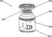
- FIG. 1is a perspective view of a prosthetic device in accordance with an embodiment of the invention
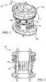
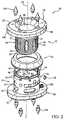
- FIG. 2is an exploded view of the prosthetic device of FIG. 1 ;
- FIG. 3is a cross-sectional view of the prosthetic device of FIG. 1 taken along line 3 - 3 of FIG. 1 ;
- FIG. 4is perspective view of an embodiment of an inner member of the prosthetic device of FIG. 1 ;
- FIG. 5is perspective view of an embodiment of an outer member of the prosthetic device of FIG. 1 ;
- FIG. 6is an end view of the prosthetic device of FIG. 1 ;
- FIG. 7is an elevated side view of one embodiment of a gear member of the prosthetic device of FIG. 1 ;
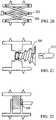
- FIG. 8is an end view of the gear member of FIG. 7 ;
- FIG. 9is a cross-sectional view of the gear member of FIGS. 7 and 8 taken along line 9 - 9 of FIG. 8 ;
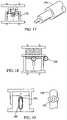
- FIG. 10is a perspective of one embodiment of a tool according to the present invention.
- FIG. 12is a partial cross-sectional view of the combination of FIG. 11 ;
- FIG. 13is a cross-sectional view of another embodiment of an outer member according to the invention.
- FIGS. 14-25depict various alternate embodiments of expandable prosthetic devices according to the present invention.
- FIG. 26is a perspective view of one embodiment of another tool constructed according to the invention.
- FIG. 27is an enlarged view of a portion of the tool of FIG. 26 ;
- FIG. 28is a perspective view of one embodiment of an assembly of the tool of FIG. 26 with one embodiment of an expandable prosthetic device according to the invention
- FIG. 29is an enlarged view of a portion of the assembly of FIG. 28 ;
- FIG. 30is a perspective view of another embodiment of a tool according to the invention.
- FIG. 31is a perspective view of another embodiment of a tool according to the invention.
- FIG. 32is a perspective view of the tool of FIG. 31 shown adjacent a portion of a spine;
- FIG. 33is a perspective view of another embodiment of an expandable prosthetic device according to the invention.
- FIG. 34is a side view of another embodiment of an expandable prosthetic device according to the invention.
- FIG. 35is a partial cross-sectional view of another embodiment of an expandable prosthetic device according to the invention.
- FIG. 36is a partial perspective view of another embodiment of an expandable prosthetic device according to the invention.
- FIG. 37is a partial side view of another embodiment of an expandable prosthetic device according to the invention.
- FIG. 38is a perspective view of another embodiment of an expandable prosthetic device according to the invention.
- FIG. 39is a cross-sectional view of another embodiment of an expandable prosthetic device according to the invention.
- FIG. 40is a cross-sectional view of another embodiment of an expandable prosthetic device according to the invention.
- FIGS. 41-44are partial cross-sectional views of additional embodiments of endplate connection mechanisms for expandable prosthetic devices according to the invention.
- FIG. 45is a perspective view of another embodiment of an expandable prosthetic device according to the invention.
- FIG. 46is an end view of and endplate of another embodiment of an expandable prosthetic device according to the invention.
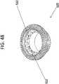
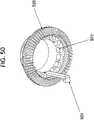
- FIGS. 47-52illustrate the locking assemblies according to the present invention.
- Prosthesis 10generally comprises an inner member 12 which may be telescopingly received within an outer member 14 .
- the prosthesis 10further comprises a gear member 16 generally configured to effect translation of inner member 12 with respect to outer member 14 and cause expansion of prosthesis 10 .
- Inner member 12 , outer member 14 , and gear member 16are centered along a longitudinal axis 18 and define a hollow interior portion which may be filled with bone material, bone growth factors, bone morphogenic proteins, or other materials for encouraging bone growth, blood vessel growth or growth of other tissue through the many apertures in the device.
- members 12 , 14 , and 16are made of a polyether ether ketone (PEEK) plastic material.
- PEEKpolyether ether ketone
- Several known advantages of PEEK plastic materialinclude that it is radiolucent and may be more easily sterilized than other plastics.
- members 12 , 14 , and 16may be made of a biologically inert metal alloy or other suitable materials.
- inner member 12has an endplate 20 at a distal end 22 connected to a generally cylindrical body 24 at a proximal end 26 and generally defines a hollow interior portion extending axially therethrough.
- Body 24 of inner member 12generally comprises a wall 27 with an inner surface 28 and an outer surface 30 and at least part of outer surface 30 includes external threads 32 .
- Outer diameter 34 of body 24is dimensioned to be cooperatively received within outer member 14 .
- Outer member 14has an endplate 40 at a proximal end 42 connected to a generally cylindrical body 44 at a distal end 46 and generally defines a hollow interior portion extending axially therethrough.
- Body 44 of outer member 14generally comprises a wall 47 with an inner surface 48 and an outer surface 50 .
- Inner diameter 52 of body 44is dimensioned to cooperatively receive body 24 of inner member 12 within outer member 14 .
- inner diameter 52 of body 44is greater than outer diameter 34 of body 24 of inner member 12 .
- outer member 14may include one or more openings 53 to permit bone ingrowth.
- a lip 54is formed around the exterior of the distal end 46 of body 44 and is configured to cooperatively fit with a portion of gear member 16 .
- a plurality of relief spaces or slots 56 extending through wall 47are angularly spaced around body 44 adjacent distal end 46 to facilitate a snapping engagement of lip 54 with gear member 16 .
- slots 56allow distal end 46 to deform slightly and contract in the radial direction to accommodate gear member 16 to snap on to lip 54 .
- inner member 12includes a plurality of longitudinal slots 36 extending radially through wall 27 . Slots 36 are angularly spaced around body 24 and extend longitudinally along wall 27 . When inner member 12 is assembled within outer member 14 , slots 36 are configured to engage at least one pin 38 protruding radially inward from the inner surface 48 of outer member 14 to prevent rotational movement of inner member 12 with respect to outer member 14 .
- pin 38may extend into one of slots 36 and may ride within one of the longitudinal slots 36 during expansion of the prosthetic device 10 to prevent rotation of inner member 12 with respect to outer member 14 .
- pin 38may prevent inner member 12 from expanding or translating along axis 18 beyond a predetermined distance when pin 38 bottoms out or contacts the proximal end 39 of the slot in which it is engaged.
- gear member 16comprises a generally hollow body 60 extending from a distal end 61 to a proximal end 63 with a helical thread 62 along at least part of an inner wall 64 and an array of gear teeth 66 along a portion of the exterior wall 68 .
- Gear member 16is generally configured to rotatably connect to distal end 46 of outer member 14 and internal helical thread 62 is configured to engage external threads 32 of inner member 12 to cause translation of inner member 12 with respect to outer member 14 .
- gear member 16includes a cylindrical cutout feature 65 extending around the inner wall 64 to cooperatively receive lip 54 of outer member 14 .
- gear member 16may rotate freely with respect to outer member 14 while being retained from longitudinal and lateral movement.
- the aforementioned snap-on featureallows for the design and manufacture of a relatively thin walled outer member 14 to facilitate the creation of a larger inner diameter of outer gear member 16 and inner member 12 .
- more bone growth stimulating materialmay be packed into the prosthetic device 10 .
- a larger thread size for external thread 32 and internal thread 62may be utilized to provide greater mechanical strength.
- gear teeth 66are positioned at an angle with respect to the proximal end 63 and extend around the entire periphery of a portion of exterior wall 68 to form a general frusto-conical gear teeth surface adjacent the proximal end 63 .
- the outer-most external diameter 67 of gear member 16is sized to be the same as or slightly smaller than the smallest outer diameter of endplates 20 , 40 . In this regard, when prosthetic device 10 is viewed from the end in a plane perpendicular to longitudinal axis 18 , as shown in FIG. 6 , gear member 16 does not protrude radially outward from beyond the perimeter of endplates 20 , 40 .
- the outer-most diameter of gear member 16is substantially the same size as the smallest outer diameter of endplates 20 , 40 .
- gear teeth 66extend a width 69 in a generally radial direction and generally extend radially outward to the outer diameter of gear member 16 .
- teeth 66may be designed to have a width 69 to accommodate the expected gear forces given the particular bevel gear ratio, types of material used, and desired overall inner diameter of prosthetic device 10 .
- teeth 66may be designed to have a width 69 to accommodate the expected gear forces given the particular bevel gear ratio, types of material used, and desired overall inner diameter of prosthetic device 10 .
- the larger the outer diameter to which teeth 66 radially extendthe larger that teeth 66 may be designed while still maintaining the same gear ratio. In this regard, when teeth 66 are made larger, they generally have a better mechanical strength.
- teeth 66is advantageous for embodiments wherein prosthesis 10 is made of PEEK, other plastic, or other non-metallic materials that may have less mechanical strength than, for instance, titanium.
- the outer-most diameter of gear member 16may be as large as the smallest outer diameter of endplates 20 , 40 , and teeth 66 extend radially to the outer-most diameter of gear member 16 , a larger inner diameter of gear member 16 may be manufactured without compromising mechanical gear strength.
- a larger overall inner diameter of prosthetic device 10may be accommodated which allows the packing of more bone material therein and facilitates bone fusion once prosthetic 10 is implanted.
- teeth 66are substantially exposed to the exterior of prosthetic device 10 . Because teeth 66 are exposed around the periphery, less material is needed to cover up the exposed teeth, which generally makes the prosthetic 10 lighter and easier to manufacture than prior art devices that require covering the gear teeth.
- the gear member 16is more easily visible by a surgeon and more readily accessible by a rotation tool than devices that hide or cover gear teeth. As discussed in more detail below, such a feature allows, inter alia, a tool to engage teeth 66 at a multitude of angular positions around the periphery of outer member 14 to provide a surgeon with various surgical options for insertion of prosthetic device 10 .
- the snap-on assembly feature of gear member 16allows for the manufacture of thinner walled parts without sacrificing mechanical strength. As a result, prosthesis 10 is able to have a larger internal diameter which allows more space for bone-packing material.
- prosthesis 10may be expanded by a tool 70 that includes a bevel gear 72 at its distal end.
- Tool 70extends along a tool axis 74 and in operation tool 70 is configured to engage prosthetic device 10 such that tool axis 74 is generally perpendicular to longitudinal axis 18 .
- Bevel gear 72is configured to engage teeth 66 of gear member 16 such that when bevel gear 72 is rotated about the axis of the tool, gear member 16 of prosthetic 10 is rotated about longitudinal axis 18 and inner member 12 translates along longitudinal axis 18 to expand prosthesis 10 .
- tool 70may include a central shaft 76 having a threaded distal tip portion 78 that extends distally beyond bevel gear 72 to facilitate location and mounting of tool 70 with prosthetic 10 .
- Threaded distal tip portion 78may be configured to extend radially through a tool location hole 80 in outer member 14 and threadedly engage a threaded hole 81 located on the inner surface 48 of wall 47 positioned diametrically opposite hole 80 to fix the central shaft 76 of tool 70 to outer member 14 .
- bevel gear 72may rotate with respect to central shaft 76 to effect rotation of gear member 16 and translation of inner member 12 .
- a plurality of mounting features or tool location holes 80 , 82 , 84are provided along the outer surface 50 of outer member 14 .
- Tool location holes 80 , 82 , 84may be spaced around outer surface 50 in a predetermined arrangement to allow insertion of prosthetic device 10 utilizing different surgical approaches.
- holes 80 , 82 , 84may be arranged to permit insertion through a lateral approach, anterolateral approach, or an anterior approach. As shown in FIG.
- tool location hole 80is angularly located or positioned on wall 47 toward the front of prosthetic 10 or toward the short end of end plates 20 , 40 to facilitate insertion of prosthetic device 10 into a patient via an anterior approach.
- Tool location hole 82may be angularly located or positioned on wall 47 to be toward the side of prosthetic 10 or toward the long end of end plates 20 , 40 to facilitate insertion of prosthetic device 10 into a patient via a lateral approach.
- a third tool location hole 84may be angularly located or positioned to be between location holes 80 and 82 to facilitate insertion of prosthetic device 10 through an anterolateral approach.
- a corresponding threaded hole 81 , 83 , 85may be formed on the inner surface 48 of wall 47 and positioned diametrically opposite the corresponding tool location hole to permit the threaded engagement of distal tip portion 78 of tool 70 .
- a locking member 120may be provided to substantially restrict all relative movement between inner member 12 and outer member 14 , when, for example, the desired expansion of the prosthetic device 10 has been obtained.
- a portion of locking membermay protrude radially inward from the outer member 14 to engage the external surface 30 or thread 32 of inner member 12 and lock or fix inner member 12 to outer member 14 by friction and/or deformation of external threads 32 .
- An internal locking screw 121may be provided internal to locking member 120 to translate the locking member radially inward when the screw 121 is rotated.
- Screw 121may be provided with a hexagonal head at its externally exposed end to facilitate engagement with an allen wrench or other tool to rotate screw 121 and drive locking member 120 radially inward to lock inner member 12 in place.
- a plurality of locking members 120 , 122 , 124may be provided spaced around the periphery of outer member 14 such that a surgeon can easily extend the locking member when utilizing any one of the aforementioned tool location holes 80 , 82 , 84 .
- each end plate 20 , 40has a generally oblong or elliptical shape when viewed from the end or perpendicular to the longitudinal axis 18 .
- each end plate 20 , 40generally extends a width distance 90 (large outer diameter) along a long axis 92 in a medial-lateral direction and a length distance 94 (small outer diameter) along a short axis 96 in the anterior posterior direction, wherein width 90 is larger than the length 94 .
- the oblong or elliptical shape of end plates 20 , 40is designed to resemble or mimic the footprint of the vertebral body to which the end plates will engage.
- end plates 20 , 40are configured to engage portions of the vertebrae in a predetermined orientation, namely with long axis 92 extending in a medial-lateral direction, to maximize contact of the superior surface of the end plates 20 , 40 with bone.
- end plates 20 , 40can be varied to accommodate a patient's anatomy.
- end plates 20 , 40may have a width between about 14-32 mm (in the medial-lateral direction) and a length between about 12-25 mm (in the anterior-posterior direction).
- implants 20 , 40have a wedge-shaped profile to accommodate the natural curvature of the spine.
- FIG. 13one embodiment of a wedge shape is shown wherein the end plate 130 has a gradual decrease in height from an anterior side 132 to a posterior side 134 .
- the natural curvature of the lumbar spineis referred to as lordosis.
- the angle 136 formed by the wedgeshould be approximately between 4 degrees and 16 degrees so that the wedge shape is a lordotic shape which mimics the anatomy of the lumbar spine.
- the wedge shape profilemay result from a gradual increase in height from anterior side 132 to posterior side 134 to mimic the natural curvature in other regions of the spine.
- angle 136may be between about ⁇ 4 degrees and ⁇ 16 degrees.
- a plurality of mounting holes 98are spaced around the perimeter of each end plate 20 , 40 for receiving insertable bone engaging members 100 .
- bone engaging members 100comprise conical spikes 102 each having a cylindrical base portion 104 configured to fit within holes 98 , for instance by press-fit.
- differently shaped bone engaging members 100may be used, or in other embodiments no bone engaging members may be used.
- end plates 20 , 40have chamfered edges 106 around the perimeter to facilitate insertion and/or accommodate the shape of the vertebral bodies which they engage.
- the superior or bone engaging surface 108 of endplates 20 , 40may also include numerous types of texturing to provide better initial stability and/or grasping contact between the end plate and the respective vertebrae.
- prosthetic device 10in accordance with the invention may be as follows, although the dimensions of the embodiments shown in the figures are not critical to the invention.
- inner member 12may have a total height 140 of between about 13-68 mm
- outer membermay have a total height 142 of between about 11-64 mm
- prosthetic device 10may be extended to a total prosthetic height of between about 15-130 mm, depending on the configuration and desired application.
- prosthetic device 10may vary to accommodate different applications, different procedures, implantation into different regions of the spine, or size of vertebral body or bodies being replaced or repaired.
- prosthetic device 10may be expandable to a longer distance to replace multiple vertebral bodies.
- end plates 20 , 40can be sized and shaped to accommodate different procedures.
- end plates 20 , 40may be made smaller for smaller statured patients or for smaller regions of the cervical spine.
- FIGS. 14-25various alternate embodiments of expandable prosthetic devices according to the present invention are shown.
- a central gear member 140may be positioned between the inner and outer members to engage teeth 142 to facilitate expansion.
- an oblong cam 160may be used to facilitate expansion.
- an eccentric driver 170may be used to mate with an oblong hole 172 to provide expansion.
- an alternate worm gear 180can be used.
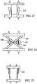
- a slot 190 with a cam lock 192may be used to expand and lock the device at a certain expansion distance. Referring to FIGS.
- a scissor jack 200 and threaded screw 202may be used to facilitate expansion.
- a wedge 204may be used to engage the scissor jack 200 .
- alternate threaded devicesmay be used to expand the prosthetic device.
- a tapered screw 210may be used that may be driven by a driver 212 .
- a simple screw threaded engagement between the inner member and outer membermay used.
- a set screw 220may be used to lock the device at a certain expansion distance. Referring to FIGS.
- the inner and outer membersmay be shaped to ride along an inclined plane or ramp.
- a locking wedge or ring 230may be provided to lock the device at a certain expansion distance.
- rollers 250may be provided to facilitate expansion of the device.
- Tool 260extends along a longitudinal or tool axis 262 and includes a bevel gear 264 adjacent its distal end 266 .
- Tool 260comprises arms 268 extending longitudinally along axis 262 and defining a claw or clamping portion 270 adjacent distal end 266 .
- bevel gear 264is configured to engage teeth 66 of gear member 16 to expand prosthesis 10 .
- clamping portions 270 of arms 268are configured to engage the lateral sides or exterior central portion of prosthesis 10 to clamp and/or hold prosthesis 10 therebetween while allowing bevel gear 264 to rotate and expand prosthesis 10 .
- clamping portions 270may include teeth or bevels 272 configured generally to facilitate or enhance the grip or purchase of a prosthesis between the clamping portions 270 of arms 268 .
- arms 268may be actuated by compressing proximal ends 274 .
- a hinge 282may be provided intermediate the length of arms 268 which causes clamp portions 270 to compress inward when proximal ends 274 of arms 268 are compressed inwards.
- proximal ends 274may be threadedly interconnected and may be actuated by advancing or rotating a screw 276 .
- the threaded portion of screw 276mechanically aids in the physical clamping or holding force applied on prosthesis 10 by clamping portions 270 .
- a surgeon's handsmay be freed to perform other tasks while being assured that a secure hold of prosthesis 10 by tool 260 .
- Bevel gear 264may be rotated by dial 278 positioned adjacent a proximal end of shaft 280 .
- a surgeonmay actuate or expand prosthesis 10 remote from the prosthesis, i.e. outside of a patient's body during implantation.
- centering or positioning pin 284extends distally from bevel gear 264 and is configured and dimensional to engage an opening in prosthesis to locate bevel gear 264 adjacent gear member 16 of prosthetic 10 . Referring to FIGS. 28-29 , perspective views of tool 260 assembled to a prosthetic 10 are shown.
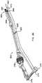
- tool 300is shown that may be used to hold, insert, and/or expand a prosthesis of the invention.
- tool 300is configured to be used with prosthesis 10 utilizing a transforaminal approach.
- tool 300is configured and dimensional to engage or hold prosthesis 10 at an angle with respect to tool axis 302 .
- tool 300extends along a longitudinal or tool axis 302 and generally comprises an angled distal end portion 304 extending at an angle 306 with respect axis 302 .
- angle 306is between about 30 and about 60 degrees.
- angle 306is about 45 degrees.
- Distal tip 308 of end 304may comprise prongs 310 extending distally on either side of bevel gear 312 .
- Prongs 310are configured and dimensioned to engage openings in prosthesis 10 to locate bevel gear 312 adjacent gear member 16 of prosthetic 10 .
- prongs 310may be extendable in the distal direction from portion 304 to hold or grip prosthetic 10 .
- a compressible handle 314may be provided to actuate prongs 310 in an outward or distal direction to contact, engage, or hold prosthesis 10 at a distal end of tool 300 .
- a flexible shaft 316may extend the length of tool 300 from rotation sphere 318 to bevel gear 312 , such that bevel gear 312 may be rotated upon rotation of sphere 318 .
- a surgeonmay actuate or expand a prosthesis 10 remote from the prosthesis or outside the patient's body during implantation. Handle 314 may be released to cause prongs 310 to retract and release prosthesis 10 once the prosthesis is implanted.
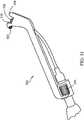
- Tool 320is similar to tool 300 except prongs 310 are not actuatable by a compressible handle, as described above.
- a set screw 322is provided to threadedly engage prosthesis 10 to fixedly hold or secure prosthesis 10 with respect to tool 320 .
- tool 320may also include an alternate rotating mechanism, such as rotating dial 324 , to rotate the bevel gear 326 positioned at the distal tip of the tool.
- rotating dial 324to rotate the bevel gear 326 positioned at the distal tip of the tool.
- tool 320is configured and dimensioned to insert, engage, or hold prosthesis 10 at an angle with respect to the longitudinal axis of the tool and is generally configured to be implanted using a transforaminal approach, as shown in FIG. 32 . Once implanted, a surgeon can loosen screw 322 to release prosthesis 10
- Prosthesis 340is generally similar to prosthesis 10 with the exception that the endplates 342 , 344 are rotatably and pivotably connected to the body 346 of prosthesis 340 .
- endplates 342 , 344are rotatable and/or pivotable about multiple axes.
- endplates 342 , 344are multi-axially connected to body 346 of prosthesis 340 .
- endplates 342 , 344are selectably fixable at any desired pivot angle or rotation position.
- prosthesis 340generally comprises an inner member 348 telescopingly received within an outer member 350 and a gear member 352 generally configured to effect translation of inner member 348 with respect to outer member 350 and cause expansion of prosthesis 340 .
- a first endplate 342is connected to distal end 354 of inner member 348 and second endplate 344 is connected to a proximal end 356 of outer member 350 .
- endplates 342 , 344generally comprise a generally flat outer or bone engaging surface 358 and an opposite connecting or articulating portion 360 .
- Outer surface 358is generally configured and dimensioned to contact or engage a bone surface, such as a portion of a vertebral body.
- articulating portion 360has a generally spherical or ball shaped exterior 362 and is configured to articulate within or engage a correspondingly shaped socket 364 and facilitates rotational and/or pivotal articulation or movement therein.
- socket 364may be defined within a clamping member 366 so that endplates 342 , 344 may be selectably fixed at any position with respect to socket 364 when so desired by a user or surgeon. As seen in FIG.
- clamping member 366generally comprises a C-shaped ring or body 368 with an opening 370 extending through a portion of the perimeter to allow the ring or body 368 to contract along its perimeter and thereby tighten, clamp or otherwise fix the articulating portion 360 of the endplates in position with respect to socket 364 .
- a clamping screw(not shown) may extend across opening 370 and may be rotated to cause clamping member 366 to compress or clamp down on articulating portion 360 .
- endplates 342 , 344facilitates the accommodation of a wide variety of anatomical possibilities when prosthesis 340 is implanted. For example, a surgeon could pivot endplates 342 , 344 to accommodate a wide range of lordotic angles of vertebral bodies.
- an alternative locking mechanismmay be provided to selectably lock endplates 342 , 344 in place.
- endplates 342 , 344may be interconnected to gear member 380 by a cable 382 or the like. As ring gear 380 is rotated, a tension is applied on cables 382 pulling end plates 342 , 344 closer together to bias articulating portion 360 against a contact surface of socket 364 , thereby preventing further actuation of endplates 342 , 344 .
- FIG. 35an alternative embodiment of a fixably actuatable endplate attachment mechanism is shown having an alternate locking mechanism.
- articulating portion 392 of endplate 390comprises a spherical socket portion 394 configured to fit, engage or articulate with respect to a correspondingly shaped ball or spherical portion 396 to facilitate multi-axial rotation and/or pivoting articulation of endplate 390 with respect to spherical portion 396 in much the same manner described above.
- a ramped clip or wedge 398may be inserted into a lateral opening 400 of endplate 390 to effect clamping, locking, or fixation of articulating portion 392 of endplate 390 with respect to spherical portion 396 .
- a collet 402may be interposed between socket portion 394 and spherical portion 396 and when wedge 398 is advanced radially into endplate 390 , collet 402 is compressed downward against socket 394 and spherical portion 396 to prevent further articulation.
- wedge 398has a partial annular, partial ring, or C-shaped body 404 with a ramped profile when viewed from the side.
- an expansion set screw 410may be provided to expand a spherical or ball portion 412 of the ball and socket joint to frictionally engage the socket portion and prevent further rotation between the ball and socket portions of the joint.
- the ball portion 412may include one or more vertical slits, openings or V-shaped grooves 414 or openings to allow ball portion 412 to expand radially outward when screw 410 is rotated.
- a tapered collet 420extends between the ball portion 422 and socket portion 424 and may be advanced or wedged further between the ball and socket portions to bind the joint and prevent rotation.
- the collet 420may be advanced by rotating a cam 426 to advance a collar 428 and engage the collet 420 and force or wedge collet 420 between the ball and socket portions 422 , 424 and thereby lock or angularly fix the endplate with respect to the body portion of the prosthesis.
- Prosthesis 430is generally similar to prosthesis 340 , described above, with the exception that the endplate 432 may be fixed in selected angular positions utilizing a pin and skirt mechanism.
- articulating portion 434 of endplate 432has a generally conical skirt member 436 defining a spherical socket or female portion 438 configured to engage a spherical or ball shaped portion 440 provided adjacent an end of prosthesis 430 and facilitates multi-axial rotational and/or pivotal movement thereabout.
- Skirt 436may comprise a plurality of holes or openings 442 spaced about the perimeter of skirt 436 and extending therethrough to accommodate one or more pins (not shown) to fix or pin skirt 436 and endplate 432 with respect to prosthesis body 444 .
- a plurality of corresponding holes or openingsmay be provided about ball portion 440 to receive one or more pins extending though openings 442 to fix endplate 432 with respect to prosthesis body 444 .
- FIG. 39an alternative embodiment of a prosthesis 450 is shown having an annular endplate 452 with a central opening 454 accommodating a partial spherical or ball shaped articulating portion 456 on the body 458 of prosthesis 450 .
- a set screw 460may be provided to clamp endplate 452 with respect to spherical portion 456 .
- the set screw 460may extend across a radially extending opening 462 in the perimeter of endplate 452 and generally functions similar to a C-clamp as explained above with respect to previously described embodiments.
- FIG. 40an alternative embodiment of a prosthesis 470 is shown having a pivoting or articulating connection similar to a universal joint wherein the endplates 472 , 474 are pivotable about a single axis 476 .
- a set screw or other fixation devicemay be provided in a slotted hinge to facilitate selectable fixation or locking of the endplates at a desired orientation.
- FIGS. 41-44shows various alternative multi-axial coupling mechanisms that may be used to facilitate fixable angulation and/or rotation of endplates 342 , 344 with respect to a body portion of an expandable prosthesis.
- an endplatemay be pivotable about a single axis with respect to the body of a prosthesis.
- captured pivotal connectionsmay be provided to prevent over-rotation of an endplate with respect to the body of a prosthesis.
- locking mechanismssuch as a set screw 480 may be provided to prevent an endplate from rotating too far or over-rotating.
- prosthesis 490may comprise modular insert members 492 having varying angular or wedge shapes.
- modular inserts 492may have varying angles from between about 5 degrees to about 30 degrees.
- an angled insert member 492is interposed into the body portion 494 of prosthesis 490 a variety of angular orientations of endplates 496 , 498 may be obtained.
- a user or surgeon installing the prosthetic devicemay accommodate various lordotic angles. Referring to FIG.
- a plurality of triangular or pie shaped angular inserts 502may be provided to be inserted directly into an endplate 504 to form the outer surface or bone engaging surface of an endplate.
- a plurality angular inserts 502may be provided with various angular shapes as desired.
- a user or surgeonmay fashion an endplate having a desired contour utilizing any combination of modular angular inserts to, for example, accommodate a particular lordotic angle when the prosthesis is inserted.
- FIGS. 47-52show a self locking mechanism of the expandable prosthesis according to one embodiment of the present invention.
- FIG. 47illustrates a prosthesis 510 having an upper and lower endplates 512 , 514 , wherein the upper endplate 512 is attached to an inner member 516 and the lower endplate 514 is attached to an outer member 518 .
- the inner member 516is threaded and translatable along the longitudinal axis.
- a gear member 520is also illustrated having internal threads that are utilized to translate the inner member 516 along the longitudinal axis.
- the gear member 520is more clearly illustrated.
- the gear member 520is provided with a plurality of gear teeth that is adapted to receive the first member of the prosthesis.
- On the inner portion of the gear member 520there is provided a plurality of notches 522 .
- the notches 522are dimensioned and configured to receive a locking member. The locking mechanism of the present invention will be discussed in greater detail with reference to FIGS. 49-51 .
- FIG. 49illustrates a cross-section view of the prosthesis according to particular one embodiment of the present invention. More specifically, flexible member 524 is shown positioned between the outer member and the inner member of the prosthesis. The flexible member 524 is biased so that one end of the flexible member 524 is received within one of the plurality of notices of the gear member, as shown in FIG. 50 . When the flexible member 524 is engaged with one of the notches 522 of the gear member, movement of the gear member 520 is blocked thereby blocking any relative movement between the inner member 516 and the outer member 518 . When an inserter 526 with an insertion point 528 as shown in FIG.
- the gear member 520allows relative movement between the inner member 516 and the outer member 518 .
- the flexible member 524returns to its original position and engages with a notch within the gear member 520 and restricts the gear member 524 from rotating, thereby blocking relative movement between the inner member 516 and outer member 518 .
- FIG. 52illustrates another embodiment of the flexible member 524 according the present invention.
- the member 524is provided with a flexible portion 530 that couples with the angled notches 522 of the gear member 520 .
- the member 524may be used as a ratcheting device or in the alternative, any type of pressure applying device may be applied on the flexible portion 530 to disengage the member 524 from the angled notches 522 .
- any type of locking assembly that restricts the motion of the gear member after the implant is positionedis suitable in the present invention.
- the locking assemblymay utilize clips, springs, and/or any other type of biased members which can fit into the notches of the gear member to restrict motion may be used.
- the notchesmay be of any general shape and size that couple with a portion of the flexible member.
Landscapes
- Health & Medical Sciences (AREA)
- Engineering & Computer Science (AREA)
- Biomedical Technology (AREA)
- Orthopedic Medicine & Surgery (AREA)
- Neurology (AREA)
- Transplantation (AREA)
- Oral & Maxillofacial Surgery (AREA)
- Cardiology (AREA)
- Heart & Thoracic Surgery (AREA)
- Vascular Medicine (AREA)
- Life Sciences & Earth Sciences (AREA)
- Animal Behavior & Ethology (AREA)
- General Health & Medical Sciences (AREA)
- Public Health (AREA)
- Veterinary Medicine (AREA)
- Physical Education & Sports Medicine (AREA)
- Prostheses (AREA)
Abstract
Description
Claims (10)
Priority Applications (3)
| Application Number | Priority Date | Filing Date | Title |
|---|---|---|---|
| US16/400,077US11399951B2 (en) | 2009-01-12 | 2019-05-01 | Expandable vertebral prosthesis |
| US17/815,698US12220324B2 (en) | 2009-01-12 | 2022-07-28 | Expandable vertebral prosthesis |
| US19/027,485US20250161069A1 (en) | 2009-01-12 | 2025-01-17 | Expandable vertebral prosthesis |
Applications Claiming Priority (4)
| Application Number | Priority Date | Filing Date | Title |
|---|---|---|---|
| US12/352,163US8721723B2 (en) | 2009-01-12 | 2009-01-12 | Expandable vertebral prosthesis |
| US14/157,017US9173747B2 (en) | 2009-01-12 | 2014-01-16 | Expandable vertebral prosthesis |
| US14/873,576US10314717B2 (en) | 2009-01-12 | 2015-10-02 | Expandable vertebral prosthesis |
| US16/400,077US11399951B2 (en) | 2009-01-12 | 2019-05-01 | Expandable vertebral prosthesis |
Related Parent Applications (1)
| Application Number | Title | Priority Date | Filing Date |
|---|---|---|---|
| US14/873,576DivisionUS10314717B2 (en) | 2009-01-12 | 2015-10-02 | Expandable vertebral prosthesis |
Related Child Applications (1)
| Application Number | Title | Priority Date | Filing Date |
|---|---|---|---|
| US17/815,698ContinuationUS12220324B2 (en) | 2009-01-12 | 2022-07-28 | Expandable vertebral prosthesis |
Publications (2)
| Publication Number | Publication Date |
|---|---|
| US20190254837A1 US20190254837A1 (en) | 2019-08-22 |
| US11399951B2true US11399951B2 (en) | 2022-08-02 |
Family
ID=42319620
Family Applications (8)
| Application Number | Title | Priority Date | Filing Date |
|---|---|---|---|
| US12/352,163Active2031-12-29US8721723B2 (en) | 2009-01-12 | 2009-01-12 | Expandable vertebral prosthesis |
| US14/157,017Active2029-04-28US9173747B2 (en) | 2009-01-12 | 2014-01-16 | Expandable vertebral prosthesis |
| US14/157,107Active2029-05-01US9180018B2 (en) | 2009-01-12 | 2014-01-16 | Expandable vertebral prosthesis |
| US14/873,576Active2029-05-29US10314717B2 (en) | 2009-01-12 | 2015-10-02 | Expandable vertebral prosthesis |
| US14/876,859Active2029-07-07US9962268B2 (en) | 2009-01-12 | 2015-10-07 | Expandable vertebral prosthesis |
| US16/400,077Active2029-04-13US11399951B2 (en) | 2009-01-12 | 2019-05-01 | Expandable vertebral prosthesis |
| US17/815,698Active2030-01-09US12220324B2 (en) | 2009-01-12 | 2022-07-28 | Expandable vertebral prosthesis |
| US19/027,485PendingUS20250161069A1 (en) | 2009-01-12 | 2025-01-17 | Expandable vertebral prosthesis |
Family Applications Before (5)
| Application Number | Title | Priority Date | Filing Date |
|---|---|---|---|
| US12/352,163Active2031-12-29US8721723B2 (en) | 2009-01-12 | 2009-01-12 | Expandable vertebral prosthesis |
| US14/157,017Active2029-04-28US9173747B2 (en) | 2009-01-12 | 2014-01-16 | Expandable vertebral prosthesis |
| US14/157,107Active2029-05-01US9180018B2 (en) | 2009-01-12 | 2014-01-16 | Expandable vertebral prosthesis |
| US14/873,576Active2029-05-29US10314717B2 (en) | 2009-01-12 | 2015-10-02 | Expandable vertebral prosthesis |
| US14/876,859Active2029-07-07US9962268B2 (en) | 2009-01-12 | 2015-10-07 | Expandable vertebral prosthesis |
Family Applications After (2)
| Application Number | Title | Priority Date | Filing Date |
|---|---|---|---|
| US17/815,698Active2030-01-09US12220324B2 (en) | 2009-01-12 | 2022-07-28 | Expandable vertebral prosthesis |
| US19/027,485PendingUS20250161069A1 (en) | 2009-01-12 | 2025-01-17 | Expandable vertebral prosthesis |
Country Status (1)
| Country | Link |
|---|---|
| US (8) | US8721723B2 (en) |
Families Citing this family (152)
| Publication number | Priority date | Publication date | Assignee | Title |
|---|---|---|---|---|
| FR2897259B1 (en) | 2006-02-15 | 2008-05-09 | Ldr Medical Soc Par Actions Si | INTERSOMATIC TRANSFORAMINAL CAGE WITH INTERBREBAL FUSION GRAFT AND CAGE IMPLANTATION INSTRUMENT |
| FR2824261B1 (en) | 2001-05-04 | 2004-05-28 | Ldr Medical | INTERVERTEBRAL DISC PROSTHESIS AND IMPLEMENTATION METHOD AND TOOLS |
| FR2827156B1 (en) | 2001-07-13 | 2003-11-14 | Ldr Medical | VERTEBRAL CAGE DEVICE WITH MODULAR FASTENING |
| US6793678B2 (en) | 2002-06-27 | 2004-09-21 | Depuy Acromed, Inc. | Prosthetic intervertebral motion disc having dampening |
| FR2846550B1 (en) | 2002-11-05 | 2006-01-13 | Ldr Medical | INTERVERTEBRAL DISC PROSTHESIS |
| AU2004212942A1 (en) | 2003-02-14 | 2004-09-02 | Depuy Spine, Inc. | In-situ formed intervertebral fusion device |
| US20040267367A1 (en) | 2003-06-30 | 2004-12-30 | Depuy Acromed, Inc | Intervertebral implant with conformable endplate |
| FR2865629B1 (en) | 2004-02-04 | 2007-01-26 | Ldr Medical | INTERVERTEBRAL DISC PROSTHESIS |
| EP2113227B1 (en) | 2004-02-04 | 2015-07-29 | LDR Medical | Intervertebral disc prosthesis |
| US8636802B2 (en) | 2004-03-06 | 2014-01-28 | DePuy Synthes Products, LLC | Dynamized interspinal implant |
| FR2869528B1 (en) | 2004-04-28 | 2007-02-02 | Ldr Medical | INTERVERTEBRAL DISC PROSTHESIS |
| FR2871366A1 (en) | 2004-06-09 | 2005-12-16 | Ceravic Soc Par Actions Simpli | PROSTHETIC EXPANSIBLE BONE IMPLANT |
| FR2879436B1 (en) | 2004-12-22 | 2007-03-09 | Ldr Medical | INTERVERTEBRAL DISC PROSTHESIS |
| US9801733B2 (en) | 2005-03-31 | 2017-10-31 | Life Spine, Inc. | Expandable spinal interbody and intravertebral body devices |
| US9848993B2 (en) | 2005-04-12 | 2017-12-26 | Nathan C. Moskowitz | Zero-profile expandable intervertebral spacer devices for distraction and spinal fusion and a universal tool for their placement and expansion |
| FR2891135B1 (en) | 2005-09-23 | 2008-09-12 | Ldr Medical Sarl | INTERVERTEBRAL DISC PROSTHESIS |
| FR2893838B1 (en) | 2005-11-30 | 2008-08-08 | Ldr Medical Soc Par Actions Si | PROSTHESIS OF INTERVERTEBRAL DISC AND INSTRUMENTATION OF INSERTION OF THE PROSTHESIS BETWEEN VERTEBRATES |
| WO2008070863A2 (en) | 2006-12-07 | 2008-06-12 | Interventional Spine, Inc. | Intervertebral implant |
| US8465546B2 (en) | 2007-02-16 | 2013-06-18 | Ldr Medical | Intervertebral disc prosthesis insertion assemblies |
| US8142479B2 (en)* | 2007-05-01 | 2012-03-27 | Spinal Simplicity Llc | Interspinous process implants having deployable engagement arms |
| FR2916956B1 (en) | 2007-06-08 | 2012-12-14 | Ldr Medical | INTERSOMATIC CAGE, INTERVERTEBRAL PROSTHESIS, ANCHORING DEVICE AND IMPLANTATION INSTRUMENTATION |
| US8900307B2 (en) | 2007-06-26 | 2014-12-02 | DePuy Synthes Products, LLC | Highly lordosed fusion cage |
| TWI383772B (en)* | 2007-11-30 | 2013-02-01 | 趙振綱 | Adjustable artificial vertebral body stent |
| EP2237748B1 (en) | 2008-01-17 | 2012-09-05 | Synthes GmbH | An expandable intervertebral implant |
| US8936641B2 (en) | 2008-04-05 | 2015-01-20 | DePuy Synthes Products, LLC | Expandable intervertebral implant |
| US8721723B2 (en) | 2009-01-12 | 2014-05-13 | Globus Medical, Inc. | Expandable vertebral prosthesis |
| US9861399B2 (en) | 2009-03-13 | 2018-01-09 | Spinal Simplicity, Llc | Interspinous process implant having a body with a removable end portion |
| US9757164B2 (en) | 2013-01-07 | 2017-09-12 | Spinal Simplicity Llc | Interspinous process implant having deployable anchor blades |
| US9526620B2 (en) | 2009-03-30 | 2016-12-27 | DePuy Synthes Products, Inc. | Zero profile spinal fusion cage |
| KR101687435B1 (en) | 2009-07-06 | 2016-12-19 | 신세스 게엠바하 | Expandable fixation assemblies |
| CN101627931B (en)* | 2009-08-06 | 2010-12-01 | 雷伟 | A kind of artificial cervical compound joint |
| CN105326585B (en) | 2009-09-17 | 2018-12-11 | Ldr控股公司 | Intervertebral implant with extensible bone anchoring element |
| US9393129B2 (en) | 2009-12-10 | 2016-07-19 | DePuy Synthes Products, Inc. | Bellows-like expandable interbody fusion cage |
| WO2011080535A1 (en) | 2009-12-31 | 2011-07-07 | Lrd Medical | Anchoring device, intervertebral implant and implantation instrument |
| EP2547292B1 (en) | 2010-03-16 | 2019-04-24 | Pinnacle Spine Group, LLC | Ntervertebral implants and graft delivery systems |
| US8870880B2 (en)* | 2010-04-12 | 2014-10-28 | Globus Medical, Inc. | Angling inserter tool for expandable vertebral implant |
| US9579211B2 (en)* | 2010-04-12 | 2017-02-28 | Globus Medical, Inc. | Expandable vertebral implant |
| US8591585B2 (en) | 2010-04-12 | 2013-11-26 | Globus Medical, Inc. | Expandable vertebral implant |
| US9271842B2 (en) | 2010-04-12 | 2016-03-01 | Globus Medical, Inc. | Expandable trial assembly for expandable vertebral implant |
| US8282683B2 (en)* | 2010-04-12 | 2012-10-09 | Globus Medical, Inc. | Expandable vertebral implant |
| US9301850B2 (en)* | 2010-04-12 | 2016-04-05 | Globus Medical, Inc. | Expandable vertebral implant |
| US11426287B2 (en) | 2010-04-12 | 2022-08-30 | Globus Medical Inc. | Expandable vertebral implant |
| US8979860B2 (en) | 2010-06-24 | 2015-03-17 | DePuy Synthes Products. LLC | Enhanced cage insertion device |
| US9907560B2 (en) | 2010-06-24 | 2018-03-06 | DePuy Synthes Products, Inc. | Flexible vertebral body shavers |
| US8623091B2 (en) | 2010-06-29 | 2014-01-07 | DePuy Synthes Products, LLC | Distractible intervertebral implant |
| US9066814B2 (en)* | 2010-08-02 | 2015-06-30 | Ulrich Medical Usa, Inc. | Implant assembly having an angled head |
| US20120078372A1 (en) | 2010-09-23 | 2012-03-29 | Thomas Gamache | Novel implant inserter having a laterally-extending dovetail engagement feature |
| US9402732B2 (en) | 2010-10-11 | 2016-08-02 | DePuy Synthes Products, Inc. | Expandable interspinous process spacer implant |
| US20120179258A1 (en)* | 2010-12-28 | 2012-07-12 | Paul Glazer | Spinal spacer devices, tools, and methods |
| US9283086B2 (en) | 2011-03-03 | 2016-03-15 | Life Spine, Inc. | Expandable corpectomy cage |
| US8518087B2 (en) | 2011-03-10 | 2013-08-27 | Interventional Spine, Inc. | Method and apparatus for minimally invasive insertion of intervertebral implants |
| US8394129B2 (en) | 2011-03-10 | 2013-03-12 | Interventional Spine, Inc. | Method and apparatus for minimally invasive insertion of intervertebral implants |
| US9700425B1 (en) | 2011-03-20 | 2017-07-11 | Nuvasive, Inc. | Vertebral body replacement and insertion methods |
| DE102011002076A1 (en)* | 2011-04-15 | 2012-10-18 | Z.-Medical Gmbh & Co. Kg | Intervertebral implant and device for insertion |
| US9248028B2 (en) | 2011-09-16 | 2016-02-02 | DePuy Synthes Products, Inc. | Removable, bone-securing cover plate for intervertebral fusion cage |
| US9675470B2 (en)* | 2011-10-19 | 2017-06-13 | P&H Medical Products, Llc | Laterally expandable spinal prosthesis |
| US9380932B1 (en) | 2011-11-02 | 2016-07-05 | Pinnacle Spine Group, Llc | Retractor devices for minimally invasive access to the spine |
| US9572678B2 (en)* | 2012-02-07 | 2017-02-21 | Medivest, Llc | Tissue spacer implants, insertion and adjustment tools, and method of use |
| FR2987256B1 (en) | 2012-02-24 | 2014-08-08 | Ldr Medical | ANCHORING DEVICE FOR INTERVERTEBRAL IMPLANT, INTERVERTEBRAL IMPLANT AND IMPLANTATION INSTRUMENTATION |
| EP2838452B1 (en)* | 2012-04-16 | 2019-05-08 | BioSpine, LLC | Multiple spindle adjustable interbody fusion devices |
| CA2873562A1 (en)* | 2012-05-02 | 2013-11-07 | The Board Of Trustees Of The Leland Stanford Junior University | Joint distraction device for arthroscopic surgery |
| US20170258535A1 (en) | 2012-06-21 | 2017-09-14 | Globus Medical, Inc. | Surgical robotic automation with tracking markers |
| US20190038366A1 (en) | 2012-06-21 | 2019-02-07 | Globus Medical, Inc. | Surgical robotic automation with tracking markers |
| EP2877127B1 (en) | 2012-07-26 | 2019-08-21 | Synthes GmbH | Expandable implant |
| US9144503B2 (en)* | 2012-10-12 | 2015-09-29 | Warsaw Orthopedic, Inc. | Expandable spinal implant system and method |
| US9138324B2 (en) | 2013-01-24 | 2015-09-22 | Warsaw Orthopedic, Inc. | Expandable spinal implant system and method |
| US9782265B2 (en)* | 2013-02-15 | 2017-10-10 | Globus Medical, Inc | Articulating and expandable vertebral implant |
| US9717601B2 (en) | 2013-02-28 | 2017-08-01 | DePuy Synthes Products, Inc. | Expandable intervertebral implant, system, kit and method |
| US9522070B2 (en) | 2013-03-07 | 2016-12-20 | Interventional Spine, Inc. | Intervertebral implant |
| US9277928B2 (en) | 2013-03-11 | 2016-03-08 | Interventional Spine, Inc. | Method and apparatus for minimally invasive insertion of intervertebral implants |
| US10154911B2 (en) | 2013-03-13 | 2018-12-18 | Life Spine, Inc. | Expandable implant assembly |
| US12193948B2 (en) | 2013-03-13 | 2025-01-14 | Life Spine, Inc. | Expandable implant assembly |
| US10383741B2 (en) | 2013-03-13 | 2019-08-20 | Life Spine, Inc. | Expandable spinal interbody assembly |
| US11304818B2 (en) | 2013-03-13 | 2022-04-19 | Life Spine, Inc. | Expandable spinal interbody assembly |
| US10426632B2 (en) | 2013-03-13 | 2019-10-01 | Life Spine, Inc. | Expandable spinal interbody assembly |
| WO2014159739A1 (en) | 2013-03-14 | 2014-10-02 | Pinnacle Spine Group, Llc | Interbody implants and graft delivery systems |
| US9993353B2 (en) | 2013-03-14 | 2018-06-12 | DePuy Synthes Products, Inc. | Method and apparatus for minimally invasive insertion of intervertebral implants |
| FR3005569B1 (en) | 2013-05-16 | 2021-09-03 | Ldr Medical | VERTEBRAL IMPLANT, VERTEBRAL IMPLANT FIXATION DEVICE AND IMPLANTATION INSTRUMENTATION |
| AU2014268740B2 (en)* | 2013-05-20 | 2018-04-26 | K2M, Inc. | Adjustable implant and insertion tool |
| DE102013211175A1 (en)* | 2013-06-14 | 2014-12-18 | R + K CAD/CAM Technologie GmbH & Co. KG | Production of semi-finished products for implants based on plastic |
| US9427325B2 (en)* | 2013-07-26 | 2016-08-30 | Warsaw Orthopedic, Inc. | Interbody implant and method |
| US9566167B2 (en) | 2013-08-22 | 2017-02-14 | K2M, Inc. | Expandable spinal implant |
| FR3015221B1 (en) | 2013-12-23 | 2017-09-01 | Vexim | EXPANSIBLE INTRAVERTEBRAL IMPLANT SYSTEM WITH POSTERIOR PEDICULAR FIXATION |
| US9808354B2 (en) | 2014-01-17 | 2017-11-07 | Stryker European Holdings I, Llc | Implant insertion tool |
| FR3016793B1 (en) | 2014-01-30 | 2021-05-07 | Ldr Medical | ANCHORING DEVICE FOR SPINAL IMPLANT, SPINAL IMPLANT AND IMPLANTATION INSTRUMENTATION |
| FR3020756B1 (en) | 2014-05-06 | 2022-03-11 | Ldr Medical | VERTEBRAL IMPLANT, VERTEBRAL IMPLANT FIXATION DEVICE AND IMPLANT INSTRUMENTATION |
| US11452612B2 (en)* | 2014-10-09 | 2022-09-27 | Warsaw Orthopedic, Inc. | Spinal implant system and method |
| US9585762B2 (en) | 2014-10-09 | 2017-03-07 | K2M, Inc. | Expandable spinal interbody spacer and method of use |
| US9974663B2 (en)* | 2014-10-09 | 2018-05-22 | Warsaw Orthopedic, Inc. | Spinal implant system and method |
| WO2016077606A1 (en) | 2014-11-12 | 2016-05-19 | Medivest, Llc | Spinal spacing implant, spinal spacer assembly, expander and insertion instrument, kit and methods of assembly and use |
| US10363142B2 (en) | 2014-12-11 | 2019-07-30 | K2M, Inc. | Expandable spinal implants |
| US9561113B2 (en)* | 2014-12-23 | 2017-02-07 | Globus Medical, Inc. | Vertebral implants and methods for installation thereof |
| US11426290B2 (en) | 2015-03-06 | 2022-08-30 | DePuy Synthes Products, Inc. | Expandable intervertebral implant, system, kit and method |
| US9889018B2 (en) | 2015-03-23 | 2018-02-13 | Musc Foundation For Research Development | Expandable vertebral body replacement device and method |
| US9775719B2 (en) | 2015-03-23 | 2017-10-03 | Musc Foundation For Research Development | Expandable vertebral body replacement device and method |
| US9913727B2 (en) | 2015-07-02 | 2018-03-13 | Medos International Sarl | Expandable implant |
| EP3141222B1 (en)* | 2015-09-08 | 2019-02-06 | Ulrich GmbH & Co. KG | Implant |
| US9883952B2 (en)* | 2015-10-02 | 2018-02-06 | Warsaw Orthopedic, Inc. | Spinal construct and method |
| US10952866B2 (en) | 2015-10-13 | 2021-03-23 | DePuy Synthes Products, Inc. | Intervertebral implant and bone graft inserter |
| US10004608B2 (en) | 2016-02-26 | 2018-06-26 | K2M, Inc. | Insertion instrument for expandable spinal implants |
| US9844446B2 (en) | 2016-05-05 | 2017-12-19 | Globus Medical, Inc. | Expandable vertebral implant |
| US10842651B2 (en) | 2016-06-10 | 2020-11-24 | Globus Medical, Inc. | Vertebral implants and attachment assemblies |
| US11510788B2 (en) | 2016-06-28 | 2022-11-29 | Eit Emerging Implant Technologies Gmbh | Expandable, angularly adjustable intervertebral cages |
| EP3474784A2 (en) | 2016-06-28 | 2019-05-01 | Eit Emerging Implant Technologies GmbH | Expandable and angularly adjustable intervertebral cages with articulating joint |
| LU93170B1 (en) | 2016-08-11 | 2018-03-28 | Ulrich Gmbh & Co Kg | Attachment of tracking elements to surgical instruments |
| US20240390158A1 (en)* | 2016-09-14 | 2024-11-28 | Globus Medical, Inc. | Systems and methods for expandable corpectomy spacer implantation |
| US12161563B2 (en)* | 2016-09-14 | 2024-12-10 | Globus Medical, Inc. | Systems and methods for expandable corpectomy spacer implantation |
| US11596526B2 (en)* | 2016-09-14 | 2023-03-07 | Globus Medical Inc. | Systems and methods for expandable corpectomy spacer implantation |
| US10537436B2 (en) | 2016-11-01 | 2020-01-21 | DePuy Synthes Products, Inc. | Curved expandable cage |
| JP2020500677A (en) | 2016-11-28 | 2020-01-16 | エムユーエスシー ファウンデーション フォー リサーチ ディベロップメントMusc Foundation For Research Development | Telescopic vertebral body replacement device and method |
| US10888433B2 (en) | 2016-12-14 | 2021-01-12 | DePuy Synthes Products, Inc. | Intervertebral implant inserter and related methods |
| EP3614975B1 (en)* | 2017-04-25 | 2024-11-27 | Life Spine, Inc. | Expandable spinal interbody assembly |
| US10758365B2 (en)* | 2017-05-08 | 2020-09-01 | Zavation Medical Products, Llc | Expandable spinal cage assemblies for supporting bone structures |
| US10398563B2 (en) | 2017-05-08 | 2019-09-03 | Medos International Sarl | Expandable cage |
| US11344424B2 (en) | 2017-06-14 | 2022-05-31 | Medos International Sarl | Expandable intervertebral implant and related methods |
| US10940016B2 (en) | 2017-07-05 | 2021-03-09 | Medos International Sarl | Expandable intervertebral fusion cage |
| US11896494B2 (en) | 2017-07-10 | 2024-02-13 | Life Spine, Inc. | Expandable implant assembly |
| US10441430B2 (en) | 2017-07-24 | 2019-10-15 | K2M, Inc. | Expandable spinal implants |
| EP3482694B1 (en) | 2017-11-10 | 2025-07-23 | Globus Medical, Inc. | Surgical robotic system with retractor |
| EP3510927A1 (en) | 2018-01-10 | 2019-07-17 | Globus Medical, Inc. | Surgical robotic systems with target trajectory deviation monitoring |
| EP3517069B1 (en) | 2018-01-29 | 2024-03-06 | Globus Medical, Inc. | Surgical robotic automation with tracking markers |
| EP3566669A1 (en) | 2018-05-10 | 2019-11-13 | Globus Medical, Inc. | Systems and methods related to robotic guidance in surgery |
| JP6979049B2 (en) | 2018-06-07 | 2021-12-08 | グローバス メディカル インコーポレイティッド | Robot systems and related methods that provide co-registration using natural standards |
| JP7082090B2 (en) | 2018-06-27 | 2022-06-07 | グローバス メディカル インコーポレイティッド | How to tune virtual implants and related surgical navigation systems |
| EP3586782A1 (en) | 2018-06-28 | 2020-01-01 | Globus Medical, Inc. | Controlling a surgical robot to avoid robotic arm collision |
| EP3586785B1 (en) | 2018-06-29 | 2024-01-17 | Globus Medical, Inc. | Surgical robotic automation with tracking markers |
| EP3846745B1 (en)* | 2018-09-05 | 2025-06-25 | Warsaw Orthopedic, Inc. | Spinal implant system |
| CN111000632B (en) | 2018-10-08 | 2023-04-18 | 格罗伯斯医疗有限公司 | Surgical robot automation with tracking markers |
| US11446156B2 (en) | 2018-10-25 | 2022-09-20 | Medos International Sarl | Expandable intervertebral implant, inserter instrument, and related methods |
| US11744655B2 (en) | 2018-12-04 | 2023-09-05 | Globus Medical, Inc. | Drill guide fixtures, cranial insertion fixtures, and related methods and robotic systems |
| EP3666212A1 (en) | 2018-12-14 | 2020-06-17 | Globus Medical, Inc. | Surgical robotic automation with tracking markers |
| EP3747389A1 (en) | 2019-06-05 | 2020-12-09 | Globus Medical, Inc. | Surgical robotic automation with tracking markers |
| US11382764B2 (en) | 2019-06-10 | 2022-07-12 | Life Spine, Inc. | Expandable implant assembly with compression features |
| US12042395B2 (en) | 2019-06-11 | 2024-07-23 | Life Spine, Inc. | Expandable implant assembly |
| CN112451097B (en) | 2019-09-06 | 2024-11-12 | 格罗伯斯医疗有限公司 | Surgical Robotic System |
| AU2021226916A1 (en) | 2020-02-24 | 2022-10-06 | Musc Foundation For Research Development | Expandable vertebral body replacement device and method |
| US11426286B2 (en) | 2020-03-06 | 2022-08-30 | Eit Emerging Implant Technologies Gmbh | Expandable intervertebral implant |
| US11857432B2 (en) | 2020-04-13 | 2024-01-02 | Life Spine, Inc. | Expandable implant assembly |
| US11602439B2 (en) | 2020-04-16 | 2023-03-14 | Life Spine, Inc. | Expandable implant assembly |
| US11253216B2 (en) | 2020-04-28 | 2022-02-22 | Globus Medical Inc. | Fixtures for fluoroscopic imaging systems and related navigation systems and methods |
| US12336917B2 (en) | 2020-05-15 | 2025-06-24 | Life Spine, Inc. | Steerable implant assembly |
| US11602440B2 (en) | 2020-06-25 | 2023-03-14 | Life Spine, Inc. | Expandable implant assembly |
| US11554020B2 (en) | 2020-09-08 | 2023-01-17 | Life Spine, Inc. | Expandable implant with pivoting control assembly |
| CN112370221B (en)* | 2020-10-26 | 2022-09-30 | 天衍医疗器材有限公司 | Lumbar vertebra centrum examination mould tool system |
| US11850160B2 (en) | 2021-03-26 | 2023-12-26 | Medos International Sarl | Expandable lordotic intervertebral fusion cage |
| US11752009B2 (en) | 2021-04-06 | 2023-09-12 | Medos International Sarl | Expandable intervertebral fusion cage |
| US12090064B2 (en) | 2022-03-01 | 2024-09-17 | Medos International Sarl | Stabilization members for expandable intervertebral implants, and related systems and methods |
| AU2023385342A1 (en)* | 2022-11-22 | 2025-05-01 | Alphatec Spine, Inc | Vertebral body replacement and insertion device |
| US12133664B2 (en) | 2022-12-13 | 2024-11-05 | Spinal Simplicity, Llc | Medical implant |
| US12427038B2 (en) | 2023-06-27 | 2025-09-30 | Globus Medical Inc. | Expandable intervertebral interbody implants |
| US20250000665A1 (en)* | 2023-06-27 | 2025-01-02 | Globus Medical, Inc. | Expandable intervertebral interbody implants |
| EP4574097A1 (en)* | 2023-12-22 | 2025-06-25 | Globus Medical, Inc. | Expandable intervertebral interbody implants |
Citations (332)
| Publication number | Priority date | Publication date | Assignee | Title |
|---|---|---|---|---|
| US518213A (en) | 1894-04-17 | Insulating-turn buckle | ||
| US2580482A (en) | 1945-07-12 | 1952-01-01 | Louis C Stukenborg | Turnbuckle lock |
| US2694586A (en) | 1951-07-05 | 1954-11-16 | Eugene R Smith | Turnbuckle assembly |
| US2794474A (en) | 1953-05-18 | 1957-06-04 | Louis C Stukenborg | Longitudinally extending key locking means in combination with engaged threaded members |
| US2843408A (en) | 1956-06-27 | 1958-07-15 | Harold V Utterback | Lock for turnbuckles |
| US3486505A (en) | 1967-05-22 | 1969-12-30 | Gordon M Morrison | Orthopedic surgical instrument |
| US3719186A (en) | 1971-04-22 | 1973-03-06 | Univ Alabama In Birmingham | Surgical instrument for placement of bone pins and holes therefor |
| US3741205A (en) | 1971-06-14 | 1973-06-26 | K Markolf | Bone fixation plate |
| US3848601A (en) | 1972-06-14 | 1974-11-19 | G Ma | Method for interbody fusion of the spine |
| US3905047A (en) | 1973-06-27 | 1975-09-16 | Posta Jr John J | Implantable ceramic bone prosthesis |
| US3916907A (en) | 1974-06-21 | 1975-11-04 | Wendell C Peterson | Spreader instrument for use in performing a spinal fusion |
| US4156296A (en) | 1977-04-08 | 1979-05-29 | Bio-Dynamics, Inc. | Great (large) toe prosthesis and method of implanting |
| US4177524A (en) | 1976-05-14 | 1979-12-11 | Pfaudler-Werke A.G. | Medical securement element with abrasive grains on thread surface |
| US4289123A (en) | 1980-03-31 | 1981-09-15 | Dunn Harold K | Orthopedic appliance |
| US4309777A (en) | 1980-11-13 | 1982-01-12 | Patil Arun A | Artificial intervertebral disc |
| US4401112A (en) | 1980-09-15 | 1983-08-30 | Rezaian Seyed M | Spinal fixator |
| US4484570A (en) | 1980-05-28 | 1984-11-27 | Synthes Ltd. | Device comprising an implant and screws for fastening said implant to a bone, and a device for connecting two separated pieces of bone |
| US4501269A (en) | 1981-12-11 | 1985-02-26 | Washington State University Research Foundation, Inc. | Process for fusing bone joints |
| US4512038A (en) | 1979-04-27 | 1985-04-23 | University Of Medicine And Dentistry Of New Jersey | Bio-absorbable composite tissue scaffold |
| US4537185A (en) | 1983-06-10 | 1985-08-27 | Denis P. Stednitz | Cannulated fixation screw |
| US4545374A (en) | 1982-09-03 | 1985-10-08 | Jacobson Robert E | Method and instruments for performing a percutaneous lumbar diskectomy |
| US4553273A (en) | 1983-11-23 | 1985-11-19 | Henry Ford Hospital | Vertebral body prosthesis and spine stabilizing method |
| US4554914A (en) | 1983-10-04 | 1985-11-26 | Kapp John P | Prosthetic vertebral body |
| US4573448A (en) | 1983-10-05 | 1986-03-04 | Pilling Co. | Method for decompressing herniated intervertebral discs |
| US4599086A (en) | 1985-06-07 | 1986-07-08 | Doty James R | Spine stabilization device and method |
| US4611581A (en) | 1983-12-16 | 1986-09-16 | Acromed Corporation | Apparatus for straightening spinal columns |
| US4611582A (en) | 1983-12-27 | 1986-09-16 | Wisconsin Alumni Research Foundation | Vertebral clamp |
| US4636217A (en) | 1985-04-23 | 1987-01-13 | Regents Of The University Of Minnesota | Anterior spinal implant |
| US4645503A (en) | 1985-08-27 | 1987-02-24 | Orthomatrix Inc. | Moldable bone-implant material |
| US4657550A (en) | 1984-12-21 | 1987-04-14 | Daher Youssef H | Buttressing device usable in a vertebral prosthesis |
| US4677972A (en) | 1985-02-07 | 1987-07-07 | Alain Tornier | Coupling assembly for joining an implant tool to a bone implant |
| US4696290A (en) | 1983-12-16 | 1987-09-29 | Acromed Corporation | Apparatus for straightening spinal columns |
| US4743256A (en) | 1985-10-04 | 1988-05-10 | Brantigan John W | Surgical prosthetic implant facilitating vertebral interbody fusion and method |
| US4759766A (en) | 1984-09-04 | 1988-07-26 | Humboldt-Universitaet Zu Berlin | Intervertebral disc endoprosthesis |
| US4772287A (en) | 1987-08-20 | 1988-09-20 | Cedar Surgical, Inc. | Prosthetic disc and method of implanting |
| US4820305A (en) | 1986-11-03 | 1989-04-11 | Harms Juergen | Place holder, in particular for a vertebra body |
| US4834757A (en) | 1987-01-22 | 1989-05-30 | Brantigan John W | Prosthetic implant |
| US4863476A (en) | 1986-08-29 | 1989-09-05 | Shepperd John A N | Spinal implant |
| US4863477A (en) | 1987-05-12 | 1989-09-05 | Monson Gary L | Synthetic intervertebral disc prosthesis |
| US4874389A (en) | 1987-12-07 | 1989-10-17 | Downey Ernest L | Replacement disc |
| US4877020A (en) | 1984-11-30 | 1989-10-31 | Vich Jose M O | Apparatus for bone graft |
| US4880343A (en) | 1987-09-30 | 1989-11-14 | Matsumoto Kokan Co., Ltd. | Lock nut having lock member of shape memory recovery alloy |
| US4892546A (en) | 1987-05-15 | 1990-01-09 | Howmedica Gmbh | Adjustable prosthesis for a joint bone |
| US4903690A (en) | 1988-09-14 | 1990-02-27 | Campbell Clayton J | Spinal orthotic device and method of using same |
| US4911718A (en) | 1988-06-10 | 1990-03-27 | University Of Medicine & Dentistry Of N.J. | Functional and biocompatible intervertebral disc spacer |
| US4927421A (en) | 1989-05-15 | 1990-05-22 | Marlowe Goble E | Process of endosteal fixation of a ligament |
| US4932975A (en) | 1989-10-16 | 1990-06-12 | Vanderbilt University | Vertebral prosthesis |
| US4936848A (en) | 1989-09-22 | 1990-06-26 | Bagby George W | Implant for vertebrae |
| US4945127A (en) | 1987-12-28 | 1990-07-31 | Tonen Sekiyukagaku Kabushiki Kaisha | Polymer composition, its heat-resistant, shape memory formed product and method of producing same |
| US4950269A (en) | 1988-06-13 | 1990-08-21 | Acromed Corporation | Spinal column fixation device |
| US4950258A (en) | 1988-01-28 | 1990-08-21 | Japan Medical Supply Co., Ltd. | Plastic molded articles with shape memory property |
| US4950270A (en) | 1989-02-03 | 1990-08-21 | Boehringer Mannheim Corporation | Cannulated self-tapping bone screw |
| US4961740A (en) | 1988-10-17 | 1990-10-09 | Surgical Dynamics, Inc. | V-thread fusion cage and method of fusing a bone joint |
| US5012247A (en) | 1988-11-21 | 1991-04-30 | Hewlett-Packard Company | Switched-capacitor analog-to-digital converter with autocalibration |
| US5015255A (en) | 1989-05-10 | 1991-05-14 | Spine-Tech, Inc. | Spinal stabilization method |
| US5015247A (en) | 1988-06-13 | 1991-05-14 | Michelson Gary K | Threaded spinal implant |
| US5019108A (en) | 1990-02-02 | 1991-05-28 | Bertin Kim C | Modular implant |
| US5042588A (en) | 1989-11-18 | 1991-08-27 | Jean Walterscheid Gmbh | Lifting strut for a tractor |
| US5055104A (en) | 1989-11-06 | 1991-10-08 | Surgical Dynamics, Inc. | Surgically implanting threaded fusion cages between adjacent low-back vertebrae by an anterior approach |
| US5057109A (en) | 1989-10-16 | 1991-10-15 | Sven Olerud | Fixing instruments for spinal surgery |
| US5059193A (en) | 1989-11-20 | 1991-10-22 | Spine-Tech, Inc. | Expandable spinal implant and surgical method |
| US5062850A (en) | 1990-01-16 | 1991-11-05 | University Of Florida | Axially-fixed vertebral body prosthesis and method of fixation |
| US5064425A (en) | 1986-02-12 | 1991-11-12 | The Institute For Applied Biotechnology | Anchoring member for anchorage in bone tissue |
| US5071437A (en) | 1989-02-15 | 1991-12-10 | Acromed Corporation | Artificial disc |
| US5108395A (en) | 1989-09-18 | 1992-04-28 | Societe De Fabrication De Materiel Orthopedique - Sofamor | Implant for anterior dorsolumbar spinal osteosynthesis, intended for the correction of kyphoses |
| US5123926A (en) | 1991-02-22 | 1992-06-23 | Madhavan Pisharodi | Artificial spinal prosthesis |
| US5139499A (en) | 1989-02-06 | 1992-08-18 | American Cyanamid Company | Screw and driver |
| US5147402A (en) | 1990-12-05 | 1992-09-15 | Sulzer Brothers Limited | Implant for ingrowth of osseous tissue |
| US5147404A (en) | 1987-12-07 | 1992-09-15 | Downey Ernest L | Vertebra prosthesis |
| US5171278A (en) | 1991-02-22 | 1992-12-15 | Madhavan Pisharodi | Middle expandable intervertebral disk implants |
| US5171280A (en) | 1990-04-20 | 1992-12-15 | Sulzer Brothers Limited | Intervertebral prosthesis |
| US5189110A (en) | 1988-12-23 | 1993-02-23 | Asahi Kasei Kogyo Kabushiki Kaisha | Shape memory polymer resin, composition and the shape memorizing molded product thereof |
| US5192327A (en) | 1991-03-22 | 1993-03-09 | Brantigan John W | Surgical prosthetic implant for vertebrae |
| US5192326A (en) | 1990-12-21 | 1993-03-09 | Pfizer Hospital Products Group, Inc. | Hydrogel bead intervertebral disc nucleus |
| US5192237A (en) | 1989-02-13 | 1993-03-09 | Paolo Pegoraro | Aquatic ski with human propulsion generated by deambulatory action |
| US5195541A (en) | 1991-10-18 | 1993-03-23 | Obenchain Theodore G | Method of performing laparoscopic lumbar discectomy |
| US5236460A (en) | 1990-02-12 | 1993-08-17 | Midas Rex Pneumatic Tools, Inc. | Vertebral body prosthesis |
| US5258031A (en) | 1992-01-06 | 1993-11-02 | Danek Medical | Intervertebral disk arthroplasty |
| US5263953A (en) | 1991-12-31 | 1993-11-23 | Spine-Tech, Inc. | Apparatus and system for fusing bone joints |
| US5290312A (en) | 1991-09-03 | 1994-03-01 | Alphatec | Artificial vertebral body |
| US5290289A (en) | 1990-05-22 | 1994-03-01 | Sanders Albert E | Nitinol spinal instrumentation and method for surgically treating scoliosis |
| US5300076A (en) | 1991-10-11 | 1994-04-05 | Societe De Fabrication De Materiel Orthopedique-Sofamore | Percutaneous bone screw for supporting a stereotaxy frame |
| US5306310A (en) | 1991-08-27 | 1994-04-26 | Man Ceramics Gmbh | Vertebral prosthesis |
| US5313962A (en) | 1991-10-18 | 1994-05-24 | Obenchain Theodore G | Method of performing laparoscopic lumbar discectomy |
| US5330535A (en) | 1991-03-07 | 1994-07-19 | Sulzer Brothers Limited | Screw-nut for screwing implants together |
| US5336223A (en) | 1993-02-04 | 1994-08-09 | Rogers Charles L | Telescoping spinal fixator |
| US5354302A (en) | 1992-11-06 | 1994-10-11 | Ko Sung Tao | Medical device and method for facilitating intra-tissue visual observation and manipulation of distensible tissues |
| US5358524A (en) | 1993-02-16 | 1994-10-25 | Wright Medical Technology, Inc. | Adjustable length prosthetic implant |
| US5357983A (en) | 1992-03-17 | 1994-10-25 | Danek Medical, Inc. | Method for subcutaneous suprafascial pedicular internal fixation |
| US5360430A (en) | 1993-07-29 | 1994-11-01 | Lin Chih I | Intervertebral locking device |
| US5364397A (en) | 1993-06-01 | 1994-11-15 | Zimmer, Inc. | Spinal coupler seater with dual jaws and an independent plunger |
| US5382226A (en) | 1993-02-12 | 1995-01-17 | Graham; Richard A. | Inflatable cervical traction and exercising device |
| US5390683A (en) | 1991-02-22 | 1995-02-21 | Pisharodi; Madhavan | Spinal implantation methods utilizing a middle expandable implant |
| US5395317A (en) | 1991-10-30 | 1995-03-07 | Smith & Nephew Dyonics, Inc. | Unilateral biportal percutaneous surgical procedure |
| US5413602A (en) | 1991-09-30 | 1995-05-09 | Howmedica Gmbh | Vertebral body spacer device |
| US5423816A (en) | 1993-07-29 | 1995-06-13 | Lin; Chih I. | Intervertebral locking device |
| US5423817A (en) | 1993-07-29 | 1995-06-13 | Lin; Chih-I | Intervertebral fusing device |
| US5425772A (en) | 1993-09-20 | 1995-06-20 | Brantigan; John W. | Prosthetic implant for intervertebral spinal fusion |
| US5429447A (en) | 1992-08-18 | 1995-07-04 | Trw Inc. | Turnbuckle assembly |
| US5431658A (en) | 1994-02-14 | 1995-07-11 | Moskovich; Ronald | Facilitator for vertebrae grafts and prostheses |
| US5439464A (en) | 1993-03-09 | 1995-08-08 | Shapiro Partners Limited | Method and instruments for performing arthroscopic spinal surgery |
| US5443515A (en) | 1994-01-26 | 1995-08-22 | Implex Corporation | Vertebral body prosthetic implant with slidably positionable stabilizing member |
| US5443514A (en) | 1993-10-01 | 1995-08-22 | Acromed Corporation | Method for using spinal implants |
| US5445639A (en) | 1989-05-10 | 1995-08-29 | Spine-Tech, Inc. | Intervertebral reamer construction |
| US5458641A (en) | 1993-09-08 | 1995-10-17 | Ramirez Jimenez; Juan J. | Vertebral body prosthesis |
| US5458638A (en) | 1989-07-06 | 1995-10-17 | Spine-Tech, Inc. | Non-threaded spinal implant |
| US5458642A (en) | 1994-01-18 | 1995-10-17 | Beer; John C. | Synthetic intervertebral disc |
| US5480442A (en) | 1993-06-24 | 1996-01-02 | Man Ceramics Gmbh | Fixedly adjustable intervertebral prosthesis |
| US5482417A (en) | 1993-10-12 | 1996-01-09 | Kennametal Inc. | Cam and wedge-type self-locking mechanism |
| US5484437A (en) | 1988-06-13 | 1996-01-16 | Michelson; Gary K. | Apparatus and method of inserting spinal implants |
| US5489307A (en) | 1993-02-10 | 1996-02-06 | Spine-Tech, Inc. | Spinal stabilization surgical method |
| US5522899A (en) | 1988-06-28 | 1996-06-04 | Sofamor Danek Properties, Inc. | Artificial spinal fusion implants |
| US5534031A (en) | 1992-01-28 | 1996-07-09 | Asahi Kogaku Kogyo Kabushiki Kaisha | Prosthesis for spanning a space formed upon removal of an intervertebral disk |
| US5533863A (en) | 1993-03-26 | 1996-07-09 | Allied Signal Inc | Self positioning nut |
| US5534028A (en) | 1993-04-20 | 1996-07-09 | Howmedica, Inc. | Hydrogel intervertebral disc nucleus with diminished lateral bulging |
| US5534029A (en) | 1992-12-14 | 1996-07-09 | Yumiko Shima | Articulated vertebral body spacer |
| US5540689A (en) | 1990-05-22 | 1996-07-30 | Sanders; Albert E. | Apparatus for securing a rod adjacent to a bone |
| US5549679A (en) | 1994-05-20 | 1996-08-27 | Kuslich; Stephen D. | Expandable fabric implant for stabilizing the spinal motion segment |
| US5549608A (en) | 1995-07-13 | 1996-08-27 | Fastenetix, L.L.C. | Advanced polyaxial locking screw and coupling element device for use with rod fixation apparatus |
| US5554191A (en) | 1994-01-26 | 1996-09-10 | Biomat | Intersomatic vertebral cage |
| US5562736A (en) | 1994-10-17 | 1996-10-08 | Raymedica, Inc. | Method for surgical implantation of a prosthetic spinal disc nucleus |
| US5571192A (en) | 1994-07-02 | 1996-11-05 | Heinrich Ulrich | Prosthetic vertebral implant |
| US5571109A (en) | 1993-08-26 | 1996-11-05 | Man Ceramics Gmbh | System for the immobilization of vertebrae |
| US5575790A (en) | 1995-03-28 | 1996-11-19 | Rensselaer Polytechnic Institute | Shape memory alloy internal linear actuator for use in orthopedic correction |
| US5591235A (en) | 1995-03-15 | 1997-01-07 | Kuslich; Stephen D. | Spinal fixation device |
| US5603713A (en) | 1991-09-24 | 1997-02-18 | Aust; Gilbert M. | Anterior lumbar/cervical bicortical compression plate |
| US5603722A (en) | 1995-06-06 | 1997-02-18 | Quanam Medical Corporation | Intravascular stent |
| US5607474A (en) | 1992-02-14 | 1997-03-04 | Board Of Regents, University Of Texas System | Multi-phase bioerodible implant/carrier and method of manufacturing and using same |
| US5653763A (en) | 1996-03-29 | 1997-08-05 | Fastenetix, L.L.C. | Intervertebral space shape conforming cage device |
| US5658336A (en) | 1994-03-18 | 1997-08-19 | Pisharodi; Madhavan | Rotating, locking, middle-expanded intervertebral disk stabilizer |
| US5658335A (en) | 1995-03-09 | 1997-08-19 | Cohort Medical Products Group, Inc. | Spinal fixator |
| US5665122A (en) | 1995-01-31 | 1997-09-09 | Kambin; Parviz | Expandable intervertebral cage and surgical method |
| US5674286A (en) | 1991-02-12 | 1997-10-07 | United States Surgical Corporation | Bioabsorbable medical implants |
| US5674295A (en) | 1994-10-17 | 1997-10-07 | Raymedica, Inc. | Prosthetic spinal disc nucleus |
| US5676699A (en) | 1990-09-10 | 1997-10-14 | Laboratorium fur experimentalle Chirurgie, Forschungsinstitut | Bone regeneration membrane |
| US5683465A (en) | 1996-03-18 | 1997-11-04 | Shinn; Gary Lee | Artificial intervertebral disk prosthesis |
| US5693100A (en) | 1991-02-22 | 1997-12-02 | Pisharodi; Madhavan | Middle expandable intervertebral disk implant |
| US5702453A (en) | 1994-12-09 | 1997-12-30 | Sofamor Danek Group | Adjustable vertebral body replacement |
| US5702455A (en) | 1996-07-03 | 1997-12-30 | Saggar; Rahul | Expandable prosthesis for spinal fusion |
| US5702449A (en) | 1995-06-07 | 1997-12-30 | Danek Medical, Inc. | Reinforced porous spinal implants |
| US5713841A (en) | 1993-02-12 | 1998-02-03 | Graham; Richard A. | Inflatable cervical cervico-thoracic thoraco-lumbar and lumbar exercising device |
| US5716410A (en) | 1993-04-30 | 1998-02-10 | Scimed Life Systems, Inc. | Temporary stent and method of use |
| US5716416A (en) | 1996-09-10 | 1998-02-10 | Lin; Chih-I | Artificial intervertebral disk and method for implanting the same |
| US5720746A (en) | 1994-11-16 | 1998-02-24 | Soubeiran; Arnaud Andre | Device for displacing two bodies relative to each other |
| US5723013A (en) | 1995-02-06 | 1998-03-03 | Jbs S.A. | Spacer implant for substituting missing vertebrae |
| US5749916A (en) | 1997-01-21 | 1998-05-12 | Spinal Innovations | Fusion implant |
| US5765957A (en) | 1996-12-16 | 1998-06-16 | The Boeing Company | Lockable turnbuckle assembly |
| US5776197A (en) | 1994-12-09 | 1998-07-07 | Sdgi Holdings, Inc. | Adjustable vertebral body replacement |
| US5782432A (en) | 1995-12-13 | 1998-07-21 | Lockheed Corporation | Apparatus for a variable area nozzle |
| US5800433A (en) | 1996-05-31 | 1998-09-01 | Acromed Corporation | Spinal column retaining apparatus |
| US5824093A (en) | 1994-10-17 | 1998-10-20 | Raymedica, Inc. | Prosthetic spinal disc nucleus |
| US5823699A (en) | 1995-04-06 | 1998-10-20 | A-Dec, Inc. | Post height adjustment for dental equipment |
| US5836948A (en) | 1997-01-02 | 1998-11-17 | Saint Francis Medical Technologies, Llc | Spine distraction implant and method |
| US5843082A (en) | 1996-05-31 | 1998-12-01 | Acromed Corporation | Cervical spine stabilization method and system |
| US5860977A (en) | 1997-01-02 | 1999-01-19 | Saint Francis Medical Technologies, Llc | Spine distraction implant and method |
| US5861035A (en) | 1997-05-23 | 1999-01-19 | Griffith; Donald P. | Modular prosthetic conduit |
| US5863297A (en) | 1995-10-11 | 1999-01-26 | Osteobiologics, Inc. | Moldable, hand-shapable biodegradable implant material |
| US5868745A (en) | 1992-11-12 | 1999-02-09 | Alleyne; Neville | Spinal protection device |
| US5868746A (en) | 1994-03-01 | 1999-02-09 | Biomet, Inc. | Method and apparatus for securing adjacent bone portions |
| US5888224A (en) | 1993-09-21 | 1999-03-30 | Synthesis (U.S.A.) | Implant for intervertebral space |
| US5888220A (en) | 1994-05-06 | 1999-03-30 | Advanced Bio Surfaces, Inc. | Articulating joint repair |
| US5895428A (en) | 1996-11-01 | 1999-04-20 | Berry; Don | Load bearing spinal joint implant |
| US5899904A (en) | 1998-10-19 | 1999-05-04 | Third Milennium Engineering, Llc | Compression locking vertebral body screw, staple, and rod assembly |
| US5899905A (en) | 1998-10-19 | 1999-05-04 | Third Millennium Engineering Llc | Expansion locking vertebral body screw, staple, and rod assembly |
| US5919234A (en) | 1996-08-19 | 1999-07-06 | Macropore, Inc. | Resorbable, macro-porous, non-collapsing and flexible membrane barrier for skeletal repair and regeneration |
| US5954744A (en) | 1995-06-06 | 1999-09-21 | Quanam Medical Corporation | Intravascular stent |
| US5964760A (en) | 1996-10-18 | 1999-10-12 | Spinal Innovations | Spinal implant fixation assembly |
| US5976186A (en) | 1994-09-08 | 1999-11-02 | Stryker Technologies Corporation | Hydrogel intervertebral disc nucleus |
| US5980572A (en) | 1997-04-15 | 1999-11-09 | Asahi Kogaku Kogyo Kabushiki Kaisha | Artificial spines |
| US5980522A (en) | 1994-07-22 | 1999-11-09 | Koros; Tibor | Expandable spinal implants |
| US5984967A (en) | 1995-03-27 | 1999-11-16 | Sdgi Holdings, Inc. | Osteogenic fusion devices |
| US5989290A (en) | 1995-05-24 | 1999-11-23 | Biedermann; Lutz | Height-adjustable artificial vertebral body |
| US5989291A (en) | 1998-02-26 | 1999-11-23 | Third Millennium Engineering, Llc | Intervertebral spacer device |
| US6015436A (en) | 1996-06-07 | 2000-01-18 | Heinrich Ulrich | Implant for filling a space between vertebrae |
| US6017366A (en) | 1997-04-18 | 2000-01-25 | W. L. Gore & Associates, Inc. | Resorbable interposition arthroplasty implant |
| US6017345A (en) | 1997-05-09 | 2000-01-25 | Spinal Innovations, L.L.C. | Spinal fixation plate |
| US6019793A (en) | 1996-10-21 | 2000-02-01 | Synthes | Surgical prosthetic device |
| US6022352A (en) | 1997-03-28 | 2000-02-08 | Biomet, Inc. | Bone fixation screw system |
| US6024764A (en) | 1997-08-19 | 2000-02-15 | Intermedics, Inc. | Apparatus for imparting physician-determined shapes to implantable tubular devices |
| US6039761A (en) | 1997-02-12 | 2000-03-21 | Li Medical Technologies, Inc. | Intervertebral spacer and tool and method for emplacement thereof |
| US6045579A (en) | 1997-05-01 | 2000-04-04 | Spinal Concepts, Inc. | Adjustable height fusion device |
| US6048342A (en) | 1997-01-02 | 2000-04-11 | St. Francis Medical Technologies, Inc. | Spine distraction implant |
| US6068630A (en) | 1997-01-02 | 2000-05-30 | St. Francis Medical Technologies, Inc. | Spine distraction implant |
| US6071982A (en) | 1997-04-18 | 2000-06-06 | Cambridge Scientific, Inc. | Bioerodible polymeric semi-interpenetrating network alloys for surgical plates and bone cements, and method for making same |
| US6086613A (en) | 1997-12-23 | 2000-07-11 | Depuy Acromed, Inc. | Spacer assembly for use in spinal surgeries |
| US6090996A (en) | 1997-08-04 | 2000-07-18 | Collagen Matrix, Inc. | Implant matrix |
| US6093205A (en) | 1997-06-25 | 2000-07-25 | Bridport-Gundry Plc C/O Pearsalls Implants | Surgical implant |
| US6102933A (en) | 1997-02-28 | 2000-08-15 | The Regents Of The University Of California | Release mechanism utilizing shape memory polymer material |
| US6102932A (en) | 1998-12-15 | 2000-08-15 | Micrus Corporation | Intravascular device push wire delivery system |
| US6126689A (en) | 1998-06-15 | 2000-10-03 | Expanding Concepts, L.L.C. | Collapsible and expandable interbody fusion device |
| US6127597A (en) | 1997-03-07 | 2000-10-03 | Discotech N.V. | Systems for percutaneous bone and spinal stabilization, fixation and repair |
| US6132465A (en) | 1998-06-04 | 2000-10-17 | Raymedica, Inc. | Tapered prosthetic spinal disc nucleus |
| US6136031A (en) | 1998-06-17 | 2000-10-24 | Surgical Dynamics, Inc. | Artificial intervertebral disc |
| US6152926A (en) | 1997-01-02 | 2000-11-28 | St. Francis Medical Technologies, Inc. | Spine distraction implant and method |
| US6156842A (en) | 1998-03-11 | 2000-12-05 | The Dow Chemical Company | Structures and fabricated articles having shape memory made from α-olefin/vinyl or vinylidene aromatic and/or hindered aliphatic vinyl or vinylidene interpolymers |
| US6159244A (en) | 1999-07-30 | 2000-12-12 | Suddaby; Loubert | Expandable variable angle intervertebral fusion implant |
| US6160084A (en) | 1998-02-23 | 2000-12-12 | Massachusetts Institute Of Technology | Biodegradable shape memory polymers |
| US6174334B1 (en) | 1998-12-16 | 2001-01-16 | Loubert Suddaby | Expandable intervertebral fusion implant and applicator |
| US6177883B1 (en) | 1998-09-02 | 2001-01-23 | Schlumberger Resource Management Services, Inc. | Utility meter transponder exposed ground level antenna assembly |
| US6176881B1 (en) | 1997-04-15 | 2001-01-23 | Synthes | Telescopic vertebral prosthesis |
| US6179873B1 (en) | 1995-08-11 | 2001-01-30 | Bernhard Zientek | Intervertebral implant, process for widening and instruments for implanting an intervertebral implant |
| US6187048B1 (en) | 1994-05-24 | 2001-02-13 | Surgical Dynamics, Inc. | Intervertebral disc implant |
| US6190413B1 (en) | 1998-04-16 | 2001-02-20 | Ulrich Gmbh & Co. Kg | Vertebral implant |
| US6190414B1 (en) | 1996-10-31 | 2001-02-20 | Surgical Dynamics Inc. | Apparatus for fusion of adjacent bone structures |
| US6193720B1 (en) | 1998-11-30 | 2001-02-27 | Depuy Orthopaedics, Inc. | Cervical spine stabilization method and system |
| US6193757B1 (en) | 1998-10-29 | 2001-02-27 | Sdgi Holdings, Inc. | Expandable intervertebral spacers |
| US6193756B1 (en) | 1997-09-30 | 2001-02-27 | Sulzer Orthopaedie Ag | Tubular support body for bridging two vertebrae |
| US6200322B1 (en) | 1999-08-13 | 2001-03-13 | Sdgi Holdings, Inc. | Minimal exposure posterior spinal interbody instrumentation and technique |
| US6200348B1 (en) | 1998-02-06 | 2001-03-13 | Biedermann, Motech Gmbh | Spacer with adjustable axial length |
| US6206923B1 (en) | 1999-01-08 | 2001-03-27 | Sdgi Holdings, Inc. | Flexible implant using partially demineralized bone |
| US6206883B1 (en) | 1999-03-05 | 2001-03-27 | Stryker Technologies Corporation | Bioabsorbable materials and medical devices made therefrom |
| US6221075B1 (en) | 1998-03-06 | 2001-04-24 | Bionx Implants Oy | Bioabsorbable, deformable fixation plate |
| US6248131B1 (en) | 1994-05-06 | 2001-06-19 | Advanced Bio Surfaces, Inc. | Articulating joint repair |
| US6261289B1 (en) | 1998-10-26 | 2001-07-17 | Mark Levy | Expandable orthopedic device |
| US6264695B1 (en) | 1999-09-30 | 2001-07-24 | Replication Medical, Inc. | Spinal nucleus implant |
| US6332895B1 (en) | 2000-03-08 | 2001-12-25 | Loubert Suddaby | Expandable intervertebral fusion implant having improved stability |
| US6344057B1 (en) | 1994-11-22 | 2002-02-05 | Sdgi Holdings, Inc. | Adjustable vertebral body replacement |
| US6358254B1 (en) | 2000-09-11 | 2002-03-19 | D. Greg Anderson | Method and implant for expanding a spinal canal |
| US6368351B1 (en) | 2001-03-27 | 2002-04-09 | Bradley J. Glenn | Intervertebral space implant for use in spinal fusion procedures |
| US6375682B1 (en) | 2001-08-06 | 2002-04-23 | Lewis W. Fleischmann | Collapsible, rotatable and expandable spinal hydraulic prosthetic device |
| US6402750B1 (en) | 2000-04-04 | 2002-06-11 | Spinlabs, Llc | Devices and methods for the treatment of spinal disorders |
| US6425919B1 (en) | 1999-08-18 | 2002-07-30 | Intrinsic Orthopedics, Inc. | Devices and methods of vertebral disc augmentation |
| US6428544B1 (en) | 2001-07-16 | 2002-08-06 | Third Millennium Engineering, Llc | Insertion tool for use with trial intervertebral distraction spacers |
| US6436140B1 (en) | 1998-08-28 | 2002-08-20 | Sofamor S.N.C. | Expandable interbody fusion cage and method for insertion |
| US6436143B1 (en) | 1999-02-22 | 2002-08-20 | Anthony C. Ross | Method and apparatus for treating intervertebral disks |
| US6436102B1 (en) | 2001-07-16 | 2002-08-20 | Third Millennium Engineering, Llc | Method of distracting vertebral bones |
| US6443989B1 (en) | 2000-12-04 | 2002-09-03 | Roger P. Jackson | Posterior expandable fusion cage |
| US6451057B1 (en) | 2001-10-29 | 2002-09-17 | Chen Po-Quang | Spinal plate element adjusting device having a threaded engagement |
| US6451019B1 (en) | 1998-10-20 | 2002-09-17 | St. Francis Medical Technologies, Inc. | Supplemental spine fixation device and method |
| US6454769B2 (en) | 1997-08-04 | 2002-09-24 | Spinal Concepts, Inc. | System and method for stabilizing the human spine with a bone plate |
| US6454807B1 (en) | 2000-11-30 | 2002-09-24 | Roger P. Jackson | Articulated expandable spinal fusion cage system |
| US6454806B1 (en) | 1999-07-26 | 2002-09-24 | Advanced Prosthetic Technologies, Inc. | Spinal surgical prosthesis |
| US6468310B1 (en) | 2001-07-16 | 2002-10-22 | Third Millennium Engineering, Llc | Intervertebral spacer device having a wave washer force restoring element |
| US6471725B1 (en) | 2001-07-16 | 2002-10-29 | Third Millenium Engineering, Llc | Porous intervertebral distraction spacers |
| US20020161441A1 (en) | 1998-10-15 | 2002-10-31 | Bruno Lang | Telescopic vertebral prosthesis |
| US6482234B1 (en) | 2000-04-26 | 2002-11-19 | Pearl Technology Holdings, Llc | Prosthetic spinal disc |
| US6485517B1 (en) | 1999-05-05 | 2002-11-26 | Gary K. Michelson | Nested interbody spinal fusion implants |
| US6488683B2 (en) | 2000-11-08 | 2002-12-03 | Cleveland Clinic Foundation | Method and apparatus for correcting spinal deformity |
| US6488682B2 (en) | 2000-03-28 | 2002-12-03 | Showa Ika Kohgyo Co., Ltd. | Spinal implant, driver tool and nut guide |
| US6488710B2 (en) | 1999-07-02 | 2002-12-03 | Petrus Besselink | Reinforced expandable cage and method of deploying |
| US6491724B1 (en) | 1999-08-13 | 2002-12-10 | Bret Ferree | Spinal fusion cage with lordosis correction |
| US6500205B1 (en) | 2000-04-19 | 2002-12-31 | Gary K. Michelson | Expandable threaded arcuate interbody spinal fusion implant with cylindrical configuration during insertion |
| US6508839B1 (en) | 1999-08-18 | 2003-01-21 | Intrinsic Orthopedics, Inc. | Devices and methods of vertebral disc augmentation |
| US6514256B2 (en) | 1997-01-02 | 2003-02-04 | St. Francis Medical Technologies, Inc. | Spine distraction implant and method |
| US6520991B2 (en) | 1999-05-11 | 2003-02-18 | Donald R. Huene | Expandable implant for inter-vertebral stabilization, and a method of stabilizing vertebrae |
| US6527806B2 (en) | 2001-07-16 | 2003-03-04 | Third Millennium Engineering, Llc | Intervertebral spacer device having a spiral wave washer force restoring element |
| US20030045877A1 (en) | 2001-08-29 | 2003-03-06 | Chung-Chun Yeh | Device for fixing spinal column under treatment |
| US6551319B2 (en) | 2000-11-08 | 2003-04-22 | The Cleveland Clinic Foundation | Apparatus for implantation into bone |
| US6551320B2 (en) | 2000-11-08 | 2003-04-22 | The Cleveland Clinic Foundation | Method and apparatus for correcting spinal deformity |
| US6558390B2 (en) | 2000-02-16 | 2003-05-06 | Axiamed, Inc. | Methods and apparatus for performing therapeutic procedures in the spine |
| US6562074B2 (en) | 2001-10-17 | 2003-05-13 | Medicinelodge, Inc. | Adjustable bone fusion implant and method |
| US6569203B1 (en) | 1999-09-24 | 2003-05-27 | Waldemar Link (Gmbh & Co.) | Alloplastic replacement for a long bone |
| US6582467B1 (en) | 2000-10-31 | 2003-06-24 | Vertelink Corporation | Expandable fusion cage |
| US6607559B2 (en) | 2001-07-16 | 2003-08-19 | Spine Care, Inc. | Trial intervertebral distraction spacers |
| US6613089B1 (en) | 2000-10-25 | 2003-09-02 | Sdgi Holdings, Inc. | Laterally expanding intervertebral fusion device |
| US20030176925A1 (en) | 2002-03-15 | 2003-09-18 | Francois Paponneau | Vertebral body spacer having variable wedged endplates |
| US6652584B2 (en) | 2000-02-04 | 2003-11-25 | Gary K. Michelson | Expandable threaded arcuate interbody spinal fusion implant with lordotic configuration during insertion |
| US6660038B2 (en) | 2000-03-22 | 2003-12-09 | Synthes (Usa) | Skeletal reconstruction cages |
| US6666891B2 (en) | 2000-11-13 | 2003-12-23 | Frank H. Boehm, Jr. | Device and method for lumbar interbody fusion |
| US6709458B2 (en) | 2000-02-04 | 2004-03-23 | Gary Karlin Michelson | Expandable push-in arcuate interbody spinal fusion implant with tapered configuration during insertion |
| US6712852B1 (en) | 2002-09-30 | 2004-03-30 | Depuy Spine, Inc. | Laminoplasty cage |
| US6716216B1 (en) | 1998-08-14 | 2004-04-06 | Kyphon Inc. | Systems and methods for treating vertebral bodies |
| US6716247B2 (en) | 2000-02-04 | 2004-04-06 | Gary K. Michelson | Expandable push-in interbody spinal fusion implant |
| US6719796B2 (en) | 1999-07-26 | 2004-04-13 | Advanced Prosthetic Technologies, Inc. | Spinal surgical prosthesis |
| US20040073314A1 (en) | 2002-03-21 | 2004-04-15 | White John L. | Vertebral body and disc space replacement devices |
| US6723126B1 (en) | 2002-11-01 | 2004-04-20 | Sdgi Holdings, Inc. | Laterally expandable cage |
| US6733534B2 (en) | 2002-01-29 | 2004-05-11 | Sdgi Holdings, Inc. | System and method for spine spacing |
| US6749614B2 (en) | 2000-06-23 | 2004-06-15 | Vertelink Corporation | Formable orthopedic fixation system with cross linking |
| US6752832B2 (en) | 2000-12-27 | 2004-06-22 | Ulrich Gmbh & Co., Kg | Vertebral implant and setting tool therefor |
| US6758863B2 (en) | 2000-10-25 | 2004-07-06 | Sdgi Holdings, Inc. | Vertically expanding intervertebral body fusion device |
| US6764515B2 (en) | 2001-02-15 | 2004-07-20 | Spinecore, Inc. | Intervertebral spacer device utilizing a spirally slotted belleville washer and a rotational mounting |
| US6764491B2 (en) | 1999-10-21 | 2004-07-20 | Sdgi Holdings, Inc. | Devices and techniques for a posterior lateral disc space approach |
| US6773460B2 (en) | 2000-12-05 | 2004-08-10 | Roger P. Jackson | Anterior variable expandable fusion cage |
| US6776781B1 (en) | 2000-09-28 | 2004-08-17 | Farihan Renno | Spinal-column buttress plate assembly and method for attachment |
| US20050004572A1 (en) | 2002-09-12 | 2005-01-06 | Lutz Biedermann | Space keeper for vertebrae or intervertebral disks |
| US6866682B1 (en) | 1999-09-02 | 2005-03-15 | Stryker Spine | Distractable corpectomy device |
| US6902579B2 (en) | 2000-12-27 | 2005-06-07 | Biedermann Motech Gmbh | Lengthwise adjustable space-maintainer for inserting between two vertebral bodies |
| US6972019B2 (en) | 2001-01-23 | 2005-12-06 | Michelson Gary K | Interbody spinal implant with trailing end adapted to receive bone screws |
| US20060058877A1 (en) | 2002-12-06 | 2006-03-16 | Michael Gutlin | Intervertebral implant |
| US20060100710A1 (en) | 2003-04-28 | 2006-05-11 | Michael Gutlin | Intervertebral implant |
| US7077864B2 (en) | 2002-02-12 | 2006-07-18 | Cross Medical Products, Inc. | Vertebral interbody cage with translatable locking screw |
| US20060200244A1 (en) | 2003-02-05 | 2006-09-07 | Richard Assaker | Vertebral replacement and distraction device for placing said implant |
| US20060241770A1 (en)* | 2005-04-21 | 2006-10-26 | Rhoda William S | Expandable vertebral prosthesis |
| US20060241762A1 (en) | 2003-12-11 | 2006-10-26 | Deltacor Gmbh | Height-adjustable spinal implant and operating instrument for the implant |
| US7135043B2 (en) | 2002-08-20 | 2006-11-14 | Showa Ika Kohgyo Co., Ltd. | Intervertebral cage |
| US20060293755A1 (en) | 2005-05-19 | 2006-12-28 | Aesculap Ag & Co.Kg | Vertebral body replacement implant |
| US20070191954A1 (en) | 2005-04-21 | 2007-08-16 | Noah Hansell | Expandable Vertebral Prosthesis |
| US20070250171A1 (en) | 2006-04-24 | 2007-10-25 | Sdgi Holdings, Inc. | Expandable intervertebral devices and methods of use |
| US20070255415A1 (en) | 2006-05-01 | 2007-11-01 | Sdgi Holdings, Inc. | Expandable intervertebral spacers and methods of use |
| US20080015698A1 (en) | 2002-10-31 | 2008-01-17 | Marino James F | Spinal disc implant |
| US20080027553A1 (en) | 1997-01-02 | 2008-01-31 | Zucherman James F | Spine distraction implant and method |
| US7384431B2 (en) | 2003-03-20 | 2008-06-10 | Warsaw Orthopedic, Inc. | Height adjustable vertebral body and disc space replacement devices |
| US20080183293A1 (en) | 2007-11-12 | 2008-07-31 | John Parry | Orthopaedic Implants and Protheses |
| US20080243254A1 (en) | 2007-03-29 | 2008-10-02 | Butler Michael S | Height adjustable spinal prostheses |
| US20080281424A1 (en) | 2006-11-29 | 2008-11-13 | John Parry | Orthopaedic Implants and Prostheses |
| US7494296B2 (en) | 2004-03-07 | 2009-02-24 | Ragnar Stahle | Adjustment of telescopically movable elements |
| US20090112325A1 (en) | 2007-10-30 | 2009-04-30 | Biospine, Llc | Footplate member and a method for use in a vertebral body replacement device |
| US20090112320A1 (en) | 2007-10-30 | 2009-04-30 | Kilian Kraus | Height-Adjustable Spinal Implant |
| US20090112324A1 (en) | 2007-10-30 | 2009-04-30 | Biospine, Llc | Vertebral body replacement device and method for use to maintain a space between two vertebral bodies within a spine |
| US20090138089A1 (en) | 2007-11-27 | 2009-05-28 | Doubler Robert L | Corpectomy implant |
| US20090164017A1 (en) | 2007-12-19 | 2009-06-25 | Robert Sommerich | Expandable Corpectomy Spinal Fusion Cage |
| US20090182430A1 (en) | 2008-01-16 | 2009-07-16 | Aesculap Implant Systems, Inc. | Dynamic interbody |
| US20090192613A1 (en) | 2008-01-16 | 2009-07-30 | Aesculap Implant Systems, Inc. | Standalone dynamic interbody |
| US20090210061A1 (en) | 2008-02-14 | 2009-08-20 | U. S. Spinal Technologies, L.L.C. | Anterior lumbar interbody fusion cage device and associated method |
| US7588573B2 (en) | 2002-09-23 | 2009-09-15 | Warsaw Orthopedic, Inc. | Expansion tool for adjustable spinal implant |
| US20090234455A1 (en) | 2005-04-12 | 2009-09-17 | Moskowitz Ahmnon D | Bi-directional fixating/locking transvertebral body screw/intervertebral cage stand-alone constructs having a central screw locking lever, and pliers and devices for spinal fusion |
| US7662616B2 (en) | 2006-10-13 | 2010-02-16 | General Atomics | Photosynthetic oil production with high carbon dioxide utilization |
| US20100094424A1 (en) | 2007-03-13 | 2010-04-15 | William Woodburn | Adjustable intervertebral implant |
| US20100106251A1 (en) | 2008-10-24 | 2010-04-29 | Erich Kast | Implant for use between spiral vertebrae |
| US20100145460A1 (en) | 2008-11-07 | 2010-06-10 | Mcdonough William P | Zero-profile interbody spacer and coupled plate assembly |
| US20100179655A1 (en) | 2009-01-12 | 2010-07-15 | Noah Hansell | Expandable Vertebral Prosthesis |
| US7758648B2 (en) | 2006-04-27 | 2010-07-20 | Warsaw Orthopedic, Inc. | Stabilized, adjustable expandable implant and method |
| US7776091B2 (en) | 2004-06-30 | 2010-08-17 | Depuy Spine, Inc. | Adjustable posterior spinal column positioner |
| US20100249934A1 (en) | 2007-01-08 | 2010-09-30 | Warsaw Orthopedic, Inc. | Ratcheting Expandable Corpectomy/Vertebrectomy Cage |
| US7819922B2 (en) | 2003-10-16 | 2010-10-26 | Spinal Generations, Llc | Vertebral prosthesis |
| US20100274357A1 (en) | 2009-04-23 | 2010-10-28 | Warsaw Orthopedic, Inc. | Expandable implant, instrument, and method |
| US20100286787A1 (en) | 2006-04-12 | 2010-11-11 | Spinalmotion, Inc. | Posterior Spinal Device and Method |
| US7846207B2 (en) | 2003-02-06 | 2010-12-07 | Synthes Usa, Llc | Intervertebral implant |
| US20100324686A1 (en) | 2009-06-17 | 2010-12-23 | Gerner Leonie | Implant |
| US20100324687A1 (en) | 2009-06-18 | 2010-12-23 | Warsaw Orthopedic, Inc. | Intervertebral implant with a pivoting end cap |
| US20110015741A1 (en) | 2009-07-16 | 2011-01-20 | Warsaw Orthopedic, Inc. | Spinal implant configured to apply radiation treatment and method |
| US7879096B2 (en) | 2006-04-27 | 2011-02-01 | Warsaw Orthopedic, Inc. | Centrally driven expandable implant |
| US20110035009A1 (en) | 2004-10-01 | 2011-02-10 | Spinal Generations, Llc | Vertebral prosthesis and spinal fixation system |
| US7914581B2 (en) | 2006-04-27 | 2011-03-29 | Warsaw Orthopedic, Inc. | Expandable implant, instrument, and method |
| US20110178598A1 (en) | 2010-01-21 | 2011-07-21 | Rhoda William S | Expandable Vertebral Prosthesis |
| US7985255B2 (en) | 2003-04-21 | 2011-07-26 | Rsb Spine Llc | Implant subsidence control |
| US20110184524A1 (en) | 2008-09-19 | 2011-07-28 | Nelli Wiedenbeck | Implant for insertion between vertebral bodies of the spinal column |
| US20110196493A1 (en) | 2010-02-11 | 2011-08-11 | Luiz Henrique Mattos Pimenta | Cage system to anterior lumbar intervertebral fusion |
| US20110218631A1 (en) | 2008-09-04 | 2011-09-08 | Synthes Usa, Llc | Adjustable intervertebral implant |
| US8034111B2 (en) | 2007-11-30 | 2011-10-11 | Ching-Kong Chao | Adjustable vertebral spacer for vertebral reconstruction |
| US20110251692A1 (en) | 2010-04-12 | 2011-10-13 | Mclaughlin Colm | Expandable Vertebral Implant |
| US20110251691A1 (en) | 2010-04-12 | 2011-10-13 | Mclaughlin Colm | Expandable Vertebral Implant |
Family Cites Families (1)
| Publication number | Priority date | Publication date | Assignee | Title |
|---|---|---|---|---|
| US7530799B2 (en)* | 2004-07-30 | 2009-05-12 | Norris Edward Smith | Long-stroke deep-well pumping unit |
- 2009
- 2009-01-12USUS12/352,163patent/US8721723B2/enactiveActive
- 2014
- 2014-01-16USUS14/157,017patent/US9173747B2/enactiveActive
- 2014-01-16USUS14/157,107patent/US9180018B2/enactiveActive
- 2015
- 2015-10-02USUS14/873,576patent/US10314717B2/enactiveActive
- 2015-10-07USUS14/876,859patent/US9962268B2/enactiveActive
- 2019
- 2019-05-01USUS16/400,077patent/US11399951B2/enactiveActive
- 2022
- 2022-07-28USUS17/815,698patent/US12220324B2/enactiveActive
- 2025
- 2025-01-17USUS19/027,485patent/US20250161069A1/enactivePending
Patent Citations (389)
| Publication number | Priority date | Publication date | Assignee | Title |
|---|---|---|---|---|
| US518213A (en) | 1894-04-17 | Insulating-turn buckle | ||
| US2580482A (en) | 1945-07-12 | 1952-01-01 | Louis C Stukenborg | Turnbuckle lock |
| US2694586A (en) | 1951-07-05 | 1954-11-16 | Eugene R Smith | Turnbuckle assembly |
| US2794474A (en) | 1953-05-18 | 1957-06-04 | Louis C Stukenborg | Longitudinally extending key locking means in combination with engaged threaded members |
| US2843408A (en) | 1956-06-27 | 1958-07-15 | Harold V Utterback | Lock for turnbuckles |
| US3486505A (en) | 1967-05-22 | 1969-12-30 | Gordon M Morrison | Orthopedic surgical instrument |
| US3719186A (en) | 1971-04-22 | 1973-03-06 | Univ Alabama In Birmingham | Surgical instrument for placement of bone pins and holes therefor |
| US3741205A (en) | 1971-06-14 | 1973-06-26 | K Markolf | Bone fixation plate |
| US3848601A (en) | 1972-06-14 | 1974-11-19 | G Ma | Method for interbody fusion of the spine |
| US3905047A (en) | 1973-06-27 | 1975-09-16 | Posta Jr John J | Implantable ceramic bone prosthesis |
| US3916907A (en) | 1974-06-21 | 1975-11-04 | Wendell C Peterson | Spreader instrument for use in performing a spinal fusion |
| US4177524A (en) | 1976-05-14 | 1979-12-11 | Pfaudler-Werke A.G. | Medical securement element with abrasive grains on thread surface |
| US4156296A (en) | 1977-04-08 | 1979-05-29 | Bio-Dynamics, Inc. | Great (large) toe prosthesis and method of implanting |
| US4512038A (en) | 1979-04-27 | 1985-04-23 | University Of Medicine And Dentistry Of New Jersey | Bio-absorbable composite tissue scaffold |
| US4289123A (en) | 1980-03-31 | 1981-09-15 | Dunn Harold K | Orthopedic appliance |
| US4484570A (en) | 1980-05-28 | 1984-11-27 | Synthes Ltd. | Device comprising an implant and screws for fastening said implant to a bone, and a device for connecting two separated pieces of bone |
| US4401112A (en) | 1980-09-15 | 1983-08-30 | Rezaian Seyed M | Spinal fixator |
| US4309777A (en) | 1980-11-13 | 1982-01-12 | Patil Arun A | Artificial intervertebral disc |
| US4501269A (en) | 1981-12-11 | 1985-02-26 | Washington State University Research Foundation, Inc. | Process for fusing bone joints |
| US4545374A (en) | 1982-09-03 | 1985-10-08 | Jacobson Robert E | Method and instruments for performing a percutaneous lumbar diskectomy |
| US4537185A (en) | 1983-06-10 | 1985-08-27 | Denis P. Stednitz | Cannulated fixation screw |
| US4554914A (en) | 1983-10-04 | 1985-11-26 | Kapp John P | Prosthetic vertebral body |
| US4573448A (en) | 1983-10-05 | 1986-03-04 | Pilling Co. | Method for decompressing herniated intervertebral discs |
| US4553273A (en) | 1983-11-23 | 1985-11-19 | Henry Ford Hospital | Vertebral body prosthesis and spine stabilizing method |
| US4611581A (en) | 1983-12-16 | 1986-09-16 | Acromed Corporation | Apparatus for straightening spinal columns |
| US4696290A (en) | 1983-12-16 | 1987-09-29 | Acromed Corporation | Apparatus for straightening spinal columns |
| US4611582A (en) | 1983-12-27 | 1986-09-16 | Wisconsin Alumni Research Foundation | Vertebral clamp |
| US4759766A (en) | 1984-09-04 | 1988-07-26 | Humboldt-Universitaet Zu Berlin | Intervertebral disc endoprosthesis |
| US4877020A (en) | 1984-11-30 | 1989-10-31 | Vich Jose M O | Apparatus for bone graft |
| US4657550A (en) | 1984-12-21 | 1987-04-14 | Daher Youssef H | Buttressing device usable in a vertebral prosthesis |
| US4677972A (en) | 1985-02-07 | 1987-07-07 | Alain Tornier | Coupling assembly for joining an implant tool to a bone implant |
| US4636217A (en) | 1985-04-23 | 1987-01-13 | Regents Of The University Of Minnesota | Anterior spinal implant |
| US4599086A (en) | 1985-06-07 | 1986-07-08 | Doty James R | Spine stabilization device and method |
| US4645503A (en) | 1985-08-27 | 1987-02-24 | Orthomatrix Inc. | Moldable bone-implant material |
| US4743256A (en) | 1985-10-04 | 1988-05-10 | Brantigan John W | Surgical prosthetic implant facilitating vertebral interbody fusion and method |
| US5064425A (en) | 1986-02-12 | 1991-11-12 | The Institute For Applied Biotechnology | Anchoring member for anchorage in bone tissue |
| US4863476A (en) | 1986-08-29 | 1989-09-05 | Shepperd John A N | Spinal implant |
| US4820305A (en) | 1986-11-03 | 1989-04-11 | Harms Juergen | Place holder, in particular for a vertebra body |
| US4878915A (en) | 1987-01-22 | 1989-11-07 | Brantigan John W | Surgical prosthetic implant facilitating vertebral interbody fusion |
| US4834757A (en) | 1987-01-22 | 1989-05-30 | Brantigan John W | Prosthetic implant |
| US4863477A (en) | 1987-05-12 | 1989-09-05 | Monson Gary L | Synthetic intervertebral disc prosthesis |
| US4892546A (en) | 1987-05-15 | 1990-01-09 | Howmedica Gmbh | Adjustable prosthesis for a joint bone |
| US4772287A (en) | 1987-08-20 | 1988-09-20 | Cedar Surgical, Inc. | Prosthetic disc and method of implanting |
| US4880343A (en) | 1987-09-30 | 1989-11-14 | Matsumoto Kokan Co., Ltd. | Lock nut having lock member of shape memory recovery alloy |
| US5147404A (en) | 1987-12-07 | 1992-09-15 | Downey Ernest L | Vertebra prosthesis |
| US4874389A (en) | 1987-12-07 | 1989-10-17 | Downey Ernest L | Replacement disc |
| US4945127A (en) | 1987-12-28 | 1990-07-31 | Tonen Sekiyukagaku Kabushiki Kaisha | Polymer composition, its heat-resistant, shape memory formed product and method of producing same |
| US4950258A (en) | 1988-01-28 | 1990-08-21 | Japan Medical Supply Co., Ltd. | Plastic molded articles with shape memory property |
| US4911718A (en) | 1988-06-10 | 1990-03-27 | University Of Medicine & Dentistry Of N.J. | Functional and biocompatible intervertebral disc spacer |
| US4950269A (en) | 1988-06-13 | 1990-08-21 | Acromed Corporation | Spinal column fixation device |
| US5505732A (en) | 1988-06-13 | 1996-04-09 | Michelson; Gary K. | Apparatus and method of inserting spinal implants |
| US5484437A (en) | 1988-06-13 | 1996-01-16 | Michelson; Gary K. | Apparatus and method of inserting spinal implants |
| US5015247A (en) | 1988-06-13 | 1991-05-14 | Michelson Gary K | Threaded spinal implant |
| US5522899A (en) | 1988-06-28 | 1996-06-04 | Sofamor Danek Properties, Inc. | Artificial spinal fusion implants |
| US4903690A (en) | 1988-09-14 | 1990-02-27 | Campbell Clayton J | Spinal orthotic device and method of using same |
| US4961740B1 (en) | 1988-10-17 | 1997-01-14 | Surgical Dynamics Inc | V-thread fusion cage and method of fusing a bone joint |
| US4961740A (en) | 1988-10-17 | 1990-10-09 | Surgical Dynamics, Inc. | V-thread fusion cage and method of fusing a bone joint |
| US5026373A (en) | 1988-10-17 | 1991-06-25 | Surgical Dynamics, Inc. | Surgical method and apparatus for fusing adjacent bone structures |
| US5012247A (en) | 1988-11-21 | 1991-04-30 | Hewlett-Packard Company | Switched-capacitor analog-to-digital converter with autocalibration |
| US5189110A (en) | 1988-12-23 | 1993-02-23 | Asahi Kasei Kogyo Kabushiki Kaisha | Shape memory polymer resin, composition and the shape memorizing molded product thereof |
| US4950270A (en) | 1989-02-03 | 1990-08-21 | Boehringer Mannheim Corporation | Cannulated self-tapping bone screw |
| US5139499A (en) | 1989-02-06 | 1992-08-18 | American Cyanamid Company | Screw and driver |
| US5192237A (en) | 1989-02-13 | 1993-03-09 | Paolo Pegoraro | Aquatic ski with human propulsion generated by deambulatory action |
| US5071437A (en) | 1989-02-15 | 1991-12-10 | Acromed Corporation | Artificial disc |
| US5015255A (en) | 1989-05-10 | 1991-05-14 | Spine-Tech, Inc. | Spinal stabilization method |
| US5062845A (en) | 1989-05-10 | 1991-11-05 | Spine-Tech, Inc. | Method of making an intervertebral reamer |
| US5445639A (en) | 1989-05-10 | 1995-08-29 | Spine-Tech, Inc. | Intervertebral reamer construction |
| US4927421A (en) | 1989-05-15 | 1990-05-22 | Marlowe Goble E | Process of endosteal fixation of a ligament |
| US5458638A (en) | 1989-07-06 | 1995-10-17 | Spine-Tech, Inc. | Non-threaded spinal implant |
| US5489308A (en) | 1989-07-06 | 1996-02-06 | Spine-Tech, Inc. | Spinal implant |
| US5108395A (en) | 1989-09-18 | 1992-04-28 | Societe De Fabrication De Materiel Orthopedique - Sofamor | Implant for anterior dorsolumbar spinal osteosynthesis, intended for the correction of kyphoses |
| US4936848A (en) | 1989-09-22 | 1990-06-26 | Bagby George W | Implant for vertebrae |
| US5057109A (en) | 1989-10-16 | 1991-10-15 | Sven Olerud | Fixing instruments for spinal surgery |
| US4932975A (en) | 1989-10-16 | 1990-06-12 | Vanderbilt University | Vertebral prosthesis |
| US5055104A (en) | 1989-11-06 | 1991-10-08 | Surgical Dynamics, Inc. | Surgically implanting threaded fusion cages between adjacent low-back vertebrae by an anterior approach |
| US5042588A (en) | 1989-11-18 | 1991-08-27 | Jean Walterscheid Gmbh | Lifting strut for a tractor |
| US5059193A (en) | 1989-11-20 | 1991-10-22 | Spine-Tech, Inc. | Expandable spinal implant and surgical method |
| US5062850A (en) | 1990-01-16 | 1991-11-05 | University Of Florida | Axially-fixed vertebral body prosthesis and method of fixation |
| US5019108A (en) | 1990-02-02 | 1991-05-28 | Bertin Kim C | Modular implant |
| US5236460A (en) | 1990-02-12 | 1993-08-17 | Midas Rex Pneumatic Tools, Inc. | Vertebral body prosthesis |
| US5171280A (en) | 1990-04-20 | 1992-12-15 | Sulzer Brothers Limited | Intervertebral prosthesis |
| US5540689A (en) | 1990-05-22 | 1996-07-30 | Sanders; Albert E. | Apparatus for securing a rod adjacent to a bone |
| US5290289A (en) | 1990-05-22 | 1994-03-01 | Sanders Albert E | Nitinol spinal instrumentation and method for surgically treating scoliosis |
| US5676699A (en) | 1990-09-10 | 1997-10-14 | Laboratorium fur experimentalle Chirurgie, Forschungsinstitut | Bone regeneration membrane |
| US5147402A (en) | 1990-12-05 | 1992-09-15 | Sulzer Brothers Limited | Implant for ingrowth of osseous tissue |
| US5192326A (en) | 1990-12-21 | 1993-03-09 | Pfizer Hospital Products Group, Inc. | Hydrogel bead intervertebral disc nucleus |
| US5674286A (en) | 1991-02-12 | 1997-10-07 | United States Surgical Corporation | Bioabsorbable medical implants |
| US5123926A (en) | 1991-02-22 | 1992-06-23 | Madhavan Pisharodi | Artificial spinal prosthesis |
| US5171278A (en) | 1991-02-22 | 1992-12-15 | Madhavan Pisharodi | Middle expandable intervertebral disk implants |
| US5693100A (en) | 1991-02-22 | 1997-12-02 | Pisharodi; Madhavan | Middle expandable intervertebral disk implant |
| US5390683A (en) | 1991-02-22 | 1995-02-21 | Pisharodi; Madhavan | Spinal implantation methods utilizing a middle expandable implant |
| US5330535A (en) | 1991-03-07 | 1994-07-19 | Sulzer Brothers Limited | Screw-nut for screwing implants together |
| US5192327A (en) | 1991-03-22 | 1993-03-09 | Brantigan John W | Surgical prosthetic implant for vertebrae |
| US5306310A (en) | 1991-08-27 | 1994-04-26 | Man Ceramics Gmbh | Vertebral prosthesis |
| US5290312A (en) | 1991-09-03 | 1994-03-01 | Alphatec | Artificial vertebral body |
| US5603713A (en) | 1991-09-24 | 1997-02-18 | Aust; Gilbert M. | Anterior lumbar/cervical bicortical compression plate |
| US5413602A (en) | 1991-09-30 | 1995-05-09 | Howmedica Gmbh | Vertebral body spacer device |
| US5300076A (en) | 1991-10-11 | 1994-04-05 | Societe De Fabrication De Materiel Orthopedique-Sofamore | Percutaneous bone screw for supporting a stereotaxy frame |
| US5195541A (en) | 1991-10-18 | 1993-03-23 | Obenchain Theodore G | Method of performing laparoscopic lumbar discectomy |
| US5313962A (en) | 1991-10-18 | 1994-05-24 | Obenchain Theodore G | Method of performing laparoscopic lumbar discectomy |
| US5395317A (en) | 1991-10-30 | 1995-03-07 | Smith & Nephew Dyonics, Inc. | Unilateral biportal percutaneous surgical procedure |
| US5263953A (en) | 1991-12-31 | 1993-11-23 | Spine-Tech, Inc. | Apparatus and system for fusing bone joints |
| US5258031A (en) | 1992-01-06 | 1993-11-02 | Danek Medical | Intervertebral disk arthroplasty |
| US5534031A (en) | 1992-01-28 | 1996-07-09 | Asahi Kogaku Kogyo Kabushiki Kaisha | Prosthesis for spanning a space formed upon removal of an intervertebral disk |
| US5607474A (en) | 1992-02-14 | 1997-03-04 | Board Of Regents, University Of Texas System | Multi-phase bioerodible implant/carrier and method of manufacturing and using same |
| US5357983A (en) | 1992-03-17 | 1994-10-25 | Danek Medical, Inc. | Method for subcutaneous suprafascial pedicular internal fixation |
| US5429447A (en) | 1992-08-18 | 1995-07-04 | Trw Inc. | Turnbuckle assembly |
| US5354302A (en) | 1992-11-06 | 1994-10-11 | Ko Sung Tao | Medical device and method for facilitating intra-tissue visual observation and manipulation of distensible tissues |
| US5868745A (en) | 1992-11-12 | 1999-02-09 | Alleyne; Neville | Spinal protection device |
| US5534029A (en) | 1992-12-14 | 1996-07-09 | Yumiko Shima | Articulated vertebral body spacer |
| US5336223A (en) | 1993-02-04 | 1994-08-09 | Rogers Charles L | Telescoping spinal fixator |
| US5489307A (en) | 1993-02-10 | 1996-02-06 | Spine-Tech, Inc. | Spinal stabilization surgical method |
| US5569176A (en) | 1993-02-12 | 1996-10-29 | Graham; Richard A. | Inflatable cervical traction and exercising device |
| US5382226A (en) | 1993-02-12 | 1995-01-17 | Graham; Richard A. | Inflatable cervical traction and exercising device |
| US5713841A (en) | 1993-02-12 | 1998-02-03 | Graham; Richard A. | Inflatable cervical cervico-thoracic thoraco-lumbar and lumbar exercising device |
| US5358524A (en) | 1993-02-16 | 1994-10-25 | Wright Medical Technology, Inc. | Adjustable length prosthetic implant |
| US5439464A (en) | 1993-03-09 | 1995-08-08 | Shapiro Partners Limited | Method and instruments for performing arthroscopic spinal surgery |
| US5533863A (en) | 1993-03-26 | 1996-07-09 | Allied Signal Inc | Self positioning nut |
| US5534028A (en) | 1993-04-20 | 1996-07-09 | Howmedica, Inc. | Hydrogel intervertebral disc nucleus with diminished lateral bulging |
| US5716410A (en) | 1993-04-30 | 1998-02-10 | Scimed Life Systems, Inc. | Temporary stent and method of use |
| US5364397A (en) | 1993-06-01 | 1994-11-15 | Zimmer, Inc. | Spinal coupler seater with dual jaws and an independent plunger |
| US5480442A (en) | 1993-06-24 | 1996-01-02 | Man Ceramics Gmbh | Fixedly adjustable intervertebral prosthesis |
| US5423816A (en) | 1993-07-29 | 1995-06-13 | Lin; Chih I. | Intervertebral locking device |
| US5360430A (en) | 1993-07-29 | 1994-11-01 | Lin Chih I | Intervertebral locking device |
| US5423817A (en) | 1993-07-29 | 1995-06-13 | Lin; Chih-I | Intervertebral fusing device |
| US5571109A (en) | 1993-08-26 | 1996-11-05 | Man Ceramics Gmbh | System for the immobilization of vertebrae |
| US5458641A (en) | 1993-09-08 | 1995-10-17 | Ramirez Jimenez; Juan J. | Vertebral body prosthesis |
| US5425772A (en) | 1993-09-20 | 1995-06-20 | Brantigan; John W. | Prosthetic implant for intervertebral spinal fusion |
| US5888224A (en) | 1993-09-21 | 1999-03-30 | Synthesis (U.S.A.) | Implant for intervertebral space |
| US5443514A (en) | 1993-10-01 | 1995-08-22 | Acromed Corporation | Method for using spinal implants |
| US5482417A (en) | 1993-10-12 | 1996-01-09 | Kennametal Inc. | Cam and wedge-type self-locking mechanism |
| US5458642A (en) | 1994-01-18 | 1995-10-17 | Beer; John C. | Synthetic intervertebral disc |
| US5554191A (en) | 1994-01-26 | 1996-09-10 | Biomat | Intersomatic vertebral cage |
| US5443515A (en) | 1994-01-26 | 1995-08-22 | Implex Corporation | Vertebral body prosthetic implant with slidably positionable stabilizing member |
| US5431658A (en) | 1994-02-14 | 1995-07-11 | Moskovich; Ronald | Facilitator for vertebrae grafts and prostheses |
| US5868746A (en) | 1994-03-01 | 1999-02-09 | Biomet, Inc. | Method and apparatus for securing adjacent bone portions |
| US5658336A (en) | 1994-03-18 | 1997-08-19 | Pisharodi; Madhavan | Rotating, locking, middle-expanded intervertebral disk stabilizer |
| US5888220A (en) | 1994-05-06 | 1999-03-30 | Advanced Bio Surfaces, Inc. | Articulating joint repair |
| US6248131B1 (en) | 1994-05-06 | 2001-06-19 | Advanced Bio Surfaces, Inc. | Articulating joint repair |
| US5549679A (en) | 1994-05-20 | 1996-08-27 | Kuslich; Stephen D. | Expandable fabric implant for stabilizing the spinal motion segment |
| US5571189A (en) | 1994-05-20 | 1996-11-05 | Kuslich; Stephen D. | Expandable fabric implant for stabilizing the spinal motion segment |
| US6187048B1 (en) | 1994-05-24 | 2001-02-13 | Surgical Dynamics, Inc. | Intervertebral disc implant |
| US5571192A (en) | 1994-07-02 | 1996-11-05 | Heinrich Ulrich | Prosthetic vertebral implant |
| US6217579B1 (en) | 1994-07-22 | 2001-04-17 | Tibor Koros | Expandable spinal implants |
| US5980522A (en) | 1994-07-22 | 1999-11-09 | Koros; Tibor | Expandable spinal implants |
| US5976186A (en) | 1994-09-08 | 1999-11-02 | Stryker Technologies Corporation | Hydrogel intervertebral disc nucleus |
| US5674295A (en) | 1994-10-17 | 1997-10-07 | Raymedica, Inc. | Prosthetic spinal disc nucleus |
| US5562736A (en) | 1994-10-17 | 1996-10-08 | Raymedica, Inc. | Method for surgical implantation of a prosthetic spinal disc nucleus |
| US5824093A (en) | 1994-10-17 | 1998-10-20 | Raymedica, Inc. | Prosthetic spinal disc nucleus |
| US5720746A (en) | 1994-11-16 | 1998-02-24 | Soubeiran; Arnaud Andre | Device for displacing two bodies relative to each other |
| US6344057B1 (en) | 1994-11-22 | 2002-02-05 | Sdgi Holdings, Inc. | Adjustable vertebral body replacement |
| US5702453A (en) | 1994-12-09 | 1997-12-30 | Sofamor Danek Group | Adjustable vertebral body replacement |
| US5776197A (en) | 1994-12-09 | 1998-07-07 | Sdgi Holdings, Inc. | Adjustable vertebral body replacement |
| US5776198A (en) | 1994-12-09 | 1998-07-07 | Sdgi Holdings, Inc. | Adjustable vertebral body replacement |
| US5665122A (en) | 1995-01-31 | 1997-09-09 | Kambin; Parviz | Expandable intervertebral cage and surgical method |
| US5723013A (en) | 1995-02-06 | 1998-03-03 | Jbs S.A. | Spacer implant for substituting missing vertebrae |
| US5658335A (en) | 1995-03-09 | 1997-08-19 | Cohort Medical Products Group, Inc. | Spinal fixator |
| US5591235A (en) | 1995-03-15 | 1997-01-07 | Kuslich; Stephen D. | Spinal fixation device |
| US5984967A (en) | 1995-03-27 | 1999-11-16 | Sdgi Holdings, Inc. | Osteogenic fusion devices |
| US5575790A (en) | 1995-03-28 | 1996-11-19 | Rensselaer Polytechnic Institute | Shape memory alloy internal linear actuator for use in orthopedic correction |
| US5823699A (en) | 1995-04-06 | 1998-10-20 | A-Dec, Inc. | Post height adjustment for dental equipment |
| US5989290A (en) | 1995-05-24 | 1999-11-23 | Biedermann; Lutz | Height-adjustable artificial vertebral body |
| US5954744A (en) | 1995-06-06 | 1999-09-21 | Quanam Medical Corporation | Intravascular stent |
| US5603722A (en) | 1995-06-06 | 1997-02-18 | Quanam Medical Corporation | Intravascular stent |
| US5702449A (en) | 1995-06-07 | 1997-12-30 | Danek Medical, Inc. | Reinforced porous spinal implants |
| US5549608A (en) | 1995-07-13 | 1996-08-27 | Fastenetix, L.L.C. | Advanced polyaxial locking screw and coupling element device for use with rod fixation apparatus |
| US6179873B1 (en) | 1995-08-11 | 2001-01-30 | Bernhard Zientek | Intervertebral implant, process for widening and instruments for implanting an intervertebral implant |
| US5863297A (en) | 1995-10-11 | 1999-01-26 | Osteobiologics, Inc. | Moldable, hand-shapable biodegradable implant material |
| US5782432A (en) | 1995-12-13 | 1998-07-21 | Lockheed Corporation | Apparatus for a variable area nozzle |
| US5683465A (en) | 1996-03-18 | 1997-11-04 | Shinn; Gary Lee | Artificial intervertebral disk prosthesis |
| US5653763A (en) | 1996-03-29 | 1997-08-05 | Fastenetix, L.L.C. | Intervertebral space shape conforming cage device |
| US5843082A (en) | 1996-05-31 | 1998-12-01 | Acromed Corporation | Cervical spine stabilization method and system |
| US6036693A (en) | 1996-05-31 | 2000-03-14 | Depuy Orthopaedics, Inc. | Cervical spine stabilization method and system |
| US5800433A (en) | 1996-05-31 | 1998-09-01 | Acromed Corporation | Spinal column retaining apparatus |
| US6214005B1 (en) | 1996-05-31 | 2001-04-10 | Depuy Acromed, Inc. | Spinal column retaining apparatus |
| US6015436A (en) | 1996-06-07 | 2000-01-18 | Heinrich Ulrich | Implant for filling a space between vertebrae |
| US5702455A (en) | 1996-07-03 | 1997-12-30 | Saggar; Rahul | Expandable prosthesis for spinal fusion |
| US5919234A (en) | 1996-08-19 | 1999-07-06 | Macropore, Inc. | Resorbable, macro-porous, non-collapsing and flexible membrane barrier for skeletal repair and regeneration |
| US5716416A (en) | 1996-09-10 | 1998-02-10 | Lin; Chih-I | Artificial intervertebral disk and method for implanting the same |
| US5964760A (en) | 1996-10-18 | 1999-10-12 | Spinal Innovations | Spinal implant fixation assembly |
| US6132432A (en) | 1996-10-18 | 2000-10-17 | Spinal Innovations Llc | Spinal implant fixation assembly |
| US6019793A (en) | 1996-10-21 | 2000-02-01 | Synthes | Surgical prosthetic device |
| US6190414B1 (en) | 1996-10-31 | 2001-02-20 | Surgical Dynamics Inc. | Apparatus for fusion of adjacent bone structures |
| US5895428A (en) | 1996-11-01 | 1999-04-20 | Berry; Don | Load bearing spinal joint implant |
| US5765957A (en) | 1996-12-16 | 1998-06-16 | The Boeing Company | Lockable turnbuckle assembly |
| US6068630A (en) | 1997-01-02 | 2000-05-30 | St. Francis Medical Technologies, Inc. | Spine distraction implant |
| US6699246B2 (en) | 1997-01-02 | 2004-03-02 | St. Francis Medical Technologies, Inc. | Spine distraction implant |
| US6235030B1 (en) | 1997-01-02 | 2001-05-22 | St. Francis Medical Technologies, Inc. | Spine distraction implant |
| US6190387B1 (en) | 1997-01-02 | 2001-02-20 | St. Francis Medical Technologies, Inc. | Spine distraction implant |
| US6514256B2 (en) | 1997-01-02 | 2003-02-04 | St. Francis Medical Technologies, Inc. | Spine distraction implant and method |
| US6500178B2 (en) | 1997-01-02 | 2002-12-31 | St. Francis Medical Technologies, Inc. | Spine distraction implant and method |
| US6332883B1 (en) | 1997-01-02 | 2001-12-25 | St. Francis Medical Technologies, Inc. | Spine distraction implant |
| US5876404A (en) | 1997-01-02 | 1999-03-02 | St. Francis Medical Technologies, Llc | Spine distraction implant and method |
| US6048342A (en) | 1997-01-02 | 2000-04-11 | St. Francis Medical Technologies, Inc. | Spine distraction implant |
| US6238397B1 (en) | 1997-01-02 | 2001-05-29 | St. Francis Technologies, Inc. | Spine distraction implant and method |
| US5836948A (en) | 1997-01-02 | 1998-11-17 | Saint Francis Medical Technologies, Llc | Spine distraction implant and method |
| US6074390A (en) | 1997-01-02 | 2000-06-13 | St. Francis Medical Technologies, Inc. | Spine distraction implant and method |
| US6183471B1 (en) | 1997-01-02 | 2001-02-06 | St. Francis Medical Technologies, Inc. | Spine distraction implant and method |
| US6478796B2 (en) | 1997-01-02 | 2002-11-12 | St. Francis Medical Technologies, Inc. | Spin distraction implant and method |
| US6090112A (en) | 1997-01-02 | 2000-07-18 | St. Francis Medical Technologies, Inc. | Spine distraction implant and method |
| US6280444B1 (en) | 1997-01-02 | 2001-08-28 | St. Francis Technologies, Inc. | Spine distraction implant and method |
| US20080027553A1 (en) | 1997-01-02 | 2008-01-31 | Zucherman James F | Spine distraction implant and method |
| US6451020B1 (en) | 1997-01-02 | 2002-09-17 | St. Francis Medical Technologies, Inc. | Spine distraction implant and method |
| US6699247B2 (en) | 1997-01-02 | 2004-03-02 | St. Francis Medical Technologies, Inc. | Spine distraction implant |
| US5860977A (en) | 1997-01-02 | 1999-01-19 | Saint Francis Medical Technologies, Llc | Spine distraction implant and method |
| US6419676B1 (en) | 1997-01-02 | 2002-07-16 | St. Francis Medical Technologies, Inc. | Spine distraction implant and method |
| US6332882B1 (en) | 1997-01-02 | 2001-12-25 | St. Francis Medical Technologies, Inc. | Spine distraction implant |
| US6419677B2 (en) | 1997-01-02 | 2002-07-16 | St. Francis Medical Technologies, Inc. | Spine distraction implant and method |
| US6149652A (en) | 1997-01-02 | 2000-11-21 | St. Francis Medical Technologies, Inc. | Spine distraction implant and method |
| US6152926A (en) | 1997-01-02 | 2000-11-28 | St. Francis Medical Technologies, Inc. | Spine distraction implant and method |
| US6379355B1 (en) | 1997-01-02 | 2002-04-30 | St. Francis Medical Technologies, Inc. | Spine distraction implant and method |
| US6156038A (en) | 1997-01-02 | 2000-12-05 | St. Francis Medical Technologies, Inc. | Spine distraction implant and method |
| US5749916A (en) | 1997-01-21 | 1998-05-12 | Spinal Innovations | Fusion implant |
| US5976187A (en) | 1997-01-21 | 1999-11-02 | Spinal Innovations, L.L.C. | Fusion implant |
| US6039761A (en) | 1997-02-12 | 2000-03-21 | Li Medical Technologies, Inc. | Intervertebral spacer and tool and method for emplacement thereof |
| US6102933A (en) | 1997-02-28 | 2000-08-15 | The Regents Of The University Of California | Release mechanism utilizing shape memory polymer material |
| US6127597A (en) | 1997-03-07 | 2000-10-03 | Discotech N.V. | Systems for percutaneous bone and spinal stabilization, fixation and repair |
| US6022352A (en) | 1997-03-28 | 2000-02-08 | Biomet, Inc. | Bone fixation screw system |
| US6176881B1 (en) | 1997-04-15 | 2001-01-23 | Synthes | Telescopic vertebral prosthesis |
| US5980572A (en) | 1997-04-15 | 1999-11-09 | Asahi Kogaku Kogyo Kabushiki Kaisha | Artificial spines |
| US6071982A (en) | 1997-04-18 | 2000-06-06 | Cambridge Scientific, Inc. | Bioerodible polymeric semi-interpenetrating network alloys for surgical plates and bone cements, and method for making same |
| US6017366A (en) | 1997-04-18 | 2000-01-25 | W. L. Gore & Associates, Inc. | Resorbable interposition arthroplasty implant |
| US6045579A (en) | 1997-05-01 | 2000-04-04 | Spinal Concepts, Inc. | Adjustable height fusion device |
| US6017345A (en) | 1997-05-09 | 2000-01-25 | Spinal Innovations, L.L.C. | Spinal fixation plate |
| US5861035A (en) | 1997-05-23 | 1999-01-19 | Griffith; Donald P. | Modular prosthetic conduit |
| US6093205A (en) | 1997-06-25 | 2000-07-25 | Bridport-Gundry Plc C/O Pearsalls Implants | Surgical implant |
| US6090996A (en) | 1997-08-04 | 2000-07-18 | Collagen Matrix, Inc. | Implant matrix |
| US6454769B2 (en) | 1997-08-04 | 2002-09-24 | Spinal Concepts, Inc. | System and method for stabilizing the human spine with a bone plate |
| US6024764A (en) | 1997-08-19 | 2000-02-15 | Intermedics, Inc. | Apparatus for imparting physician-determined shapes to implantable tubular devices |
| US6193756B1 (en) | 1997-09-30 | 2001-02-27 | Sulzer Orthopaedie Ag | Tubular support body for bridging two vertebrae |
| US6086613A (en) | 1997-12-23 | 2000-07-11 | Depuy Acromed, Inc. | Spacer assembly for use in spinal surgeries |
| US6200348B1 (en) | 1998-02-06 | 2001-03-13 | Biedermann, Motech Gmbh | Spacer with adjustable axial length |
| US6160084A (en) | 1998-02-23 | 2000-12-12 | Massachusetts Institute Of Technology | Biodegradable shape memory polymers |
| US5989291A (en) | 1998-02-26 | 1999-11-23 | Third Millennium Engineering, Llc | Intervertebral spacer device |
| US6221075B1 (en) | 1998-03-06 | 2001-04-24 | Bionx Implants Oy | Bioabsorbable, deformable fixation plate |
| US6156842A (en) | 1998-03-11 | 2000-12-05 | The Dow Chemical Company | Structures and fabricated articles having shape memory made from α-olefin/vinyl or vinylidene aromatic and/or hindered aliphatic vinyl or vinylidene interpolymers |
| US6190413B1 (en) | 1998-04-16 | 2001-02-20 | Ulrich Gmbh & Co. Kg | Vertebral implant |
| US6132465A (en) | 1998-06-04 | 2000-10-17 | Raymedica, Inc. | Tapered prosthetic spinal disc nucleus |
| US6126689A (en) | 1998-06-15 | 2000-10-03 | Expanding Concepts, L.L.C. | Collapsible and expandable interbody fusion device |
| US6136031A (en) | 1998-06-17 | 2000-10-24 | Surgical Dynamics, Inc. | Artificial intervertebral disc |
| US6409766B1 (en) | 1998-07-30 | 2002-06-25 | Expanding Concepts, Llc | Collapsible and expandable interbody fusion device |
| US6716216B1 (en) | 1998-08-14 | 2004-04-06 | Kyphon Inc. | Systems and methods for treating vertebral bodies |
| US6436140B1 (en) | 1998-08-28 | 2002-08-20 | Sofamor S.N.C. | Expandable interbody fusion cage and method for insertion |
| US6177883B1 (en) | 1998-09-02 | 2001-01-23 | Schlumberger Resource Management Services, Inc. | Utility meter transponder exposed ground level antenna assembly |
| US6524341B2 (en) | 1998-10-15 | 2003-02-25 | Synthes (Usa) | Telescopic vertebral prosthesis |
| US20020161441A1 (en) | 1998-10-15 | 2002-10-31 | Bruno Lang | Telescopic vertebral prosthesis |
| US5899905A (en) | 1998-10-19 | 1999-05-04 | Third Millennium Engineering Llc | Expansion locking vertebral body screw, staple, and rod assembly |
| US5899904A (en) | 1998-10-19 | 1999-05-04 | Third Milennium Engineering, Llc | Compression locking vertebral body screw, staple, and rod assembly |
| US6451019B1 (en) | 1998-10-20 | 2002-09-17 | St. Francis Medical Technologies, Inc. | Supplemental spine fixation device and method |
| US6261289B1 (en) | 1998-10-26 | 2001-07-17 | Mark Levy | Expandable orthopedic device |
| US6395031B1 (en) | 1998-10-29 | 2002-05-28 | Sdgi Holdings, Inc. | Expandable intervertebral spacers |
| US6193757B1 (en) | 1998-10-29 | 2001-02-27 | Sdgi Holdings, Inc. | Expandable intervertebral spacers |
| US6193720B1 (en) | 1998-11-30 | 2001-02-27 | Depuy Orthopaedics, Inc. | Cervical spine stabilization method and system |
| US6102932A (en) | 1998-12-15 | 2000-08-15 | Micrus Corporation | Intravascular device push wire delivery system |
| US6174334B1 (en) | 1998-12-16 | 2001-01-16 | Loubert Suddaby | Expandable intervertebral fusion implant and applicator |
| US6206923B1 (en) | 1999-01-08 | 2001-03-27 | Sdgi Holdings, Inc. | Flexible implant using partially demineralized bone |
| US6436143B1 (en) | 1999-02-22 | 2002-08-20 | Anthony C. Ross | Method and apparatus for treating intervertebral disks |
| US6206883B1 (en) | 1999-03-05 | 2001-03-27 | Stryker Technologies Corporation | Bioabsorbable materials and medical devices made therefrom |
| US6485517B1 (en) | 1999-05-05 | 2002-11-26 | Gary K. Michelson | Nested interbody spinal fusion implants |
| US6520991B2 (en) | 1999-05-11 | 2003-02-18 | Donald R. Huene | Expandable implant for inter-vertebral stabilization, and a method of stabilizing vertebrae |
| US6488710B2 (en) | 1999-07-02 | 2002-12-03 | Petrus Besselink | Reinforced expandable cage and method of deploying |
| US6454806B1 (en) | 1999-07-26 | 2002-09-24 | Advanced Prosthetic Technologies, Inc. | Spinal surgical prosthesis |
| US6719796B2 (en) | 1999-07-26 | 2004-04-13 | Advanced Prosthetic Technologies, Inc. | Spinal surgical prosthesis |
| US6159244A (en) | 1999-07-30 | 2000-12-12 | Suddaby; Loubert | Expandable variable angle intervertebral fusion implant |
| US6491724B1 (en) | 1999-08-13 | 2002-12-10 | Bret Ferree | Spinal fusion cage with lordosis correction |
| US6200322B1 (en) | 1999-08-13 | 2001-03-13 | Sdgi Holdings, Inc. | Minimal exposure posterior spinal interbody instrumentation and technique |
| US6743255B2 (en) | 1999-08-13 | 2004-06-01 | Bret Ferree | Spinal fusion cage with lordosis correction |
| US6482235B1 (en) | 1999-08-18 | 2002-11-19 | Intrinsic Orthopedics, Inc. | Devices and methods of vertebral disc augmentation |
| US6508839B1 (en) | 1999-08-18 | 2003-01-21 | Intrinsic Orthopedics, Inc. | Devices and methods of vertebral disc augmentation |
| US6425919B1 (en) | 1999-08-18 | 2002-07-30 | Intrinsic Orthopedics, Inc. | Devices and methods of vertebral disc augmentation |
| US6866682B1 (en) | 1999-09-02 | 2005-03-15 | Stryker Spine | Distractable corpectomy device |
| US6569203B1 (en) | 1999-09-24 | 2003-05-27 | Waldemar Link (Gmbh & Co.) | Alloplastic replacement for a long bone |
| US6264695B1 (en) | 1999-09-30 | 2001-07-24 | Replication Medical, Inc. | Spinal nucleus implant |
| US6764491B2 (en) | 1999-10-21 | 2004-07-20 | Sdgi Holdings, Inc. | Devices and techniques for a posterior lateral disc space approach |
| US6709458B2 (en) | 2000-02-04 | 2004-03-23 | Gary Karlin Michelson | Expandable push-in arcuate interbody spinal fusion implant with tapered configuration during insertion |
| US6716247B2 (en) | 2000-02-04 | 2004-04-06 | Gary K. Michelson | Expandable push-in interbody spinal fusion implant |
| US6652584B2 (en) | 2000-02-04 | 2003-11-25 | Gary K. Michelson | Expandable threaded arcuate interbody spinal fusion implant with lordotic configuration during insertion |
| US6558390B2 (en) | 2000-02-16 | 2003-05-06 | Axiamed, Inc. | Methods and apparatus for performing therapeutic procedures in the spine |
| US6332895B1 (en) | 2000-03-08 | 2001-12-25 | Loubert Suddaby | Expandable intervertebral fusion implant having improved stability |
| US6660038B2 (en) | 2000-03-22 | 2003-12-09 | Synthes (Usa) | Skeletal reconstruction cages |
| US6488682B2 (en) | 2000-03-28 | 2002-12-03 | Showa Ika Kohgyo Co., Ltd. | Spinal implant, driver tool and nut guide |
| US6402750B1 (en) | 2000-04-04 | 2002-06-11 | Spinlabs, Llc | Devices and methods for the treatment of spinal disorders |
| US6500205B1 (en) | 2000-04-19 | 2002-12-31 | Gary K. Michelson | Expandable threaded arcuate interbody spinal fusion implant with cylindrical configuration during insertion |
| US6482234B1 (en) | 2000-04-26 | 2002-11-19 | Pearl Technology Holdings, Llc | Prosthetic spinal disc |
| US6749614B2 (en) | 2000-06-23 | 2004-06-15 | Vertelink Corporation | Formable orthopedic fixation system with cross linking |
| US6358254B1 (en) | 2000-09-11 | 2002-03-19 | D. Greg Anderson | Method and implant for expanding a spinal canal |
| US6776781B1 (en) | 2000-09-28 | 2004-08-17 | Farihan Renno | Spinal-column buttress plate assembly and method for attachment |
| US6613089B1 (en) | 2000-10-25 | 2003-09-02 | Sdgi Holdings, Inc. | Laterally expanding intervertebral fusion device |
| US6758863B2 (en) | 2000-10-25 | 2004-07-06 | Sdgi Holdings, Inc. | Vertically expanding intervertebral body fusion device |
| US6582467B1 (en) | 2000-10-31 | 2003-06-24 | Vertelink Corporation | Expandable fusion cage |
| US6551320B2 (en) | 2000-11-08 | 2003-04-22 | The Cleveland Clinic Foundation | Method and apparatus for correcting spinal deformity |
| US6551319B2 (en) | 2000-11-08 | 2003-04-22 | The Cleveland Clinic Foundation | Apparatus for implantation into bone |
| US6488683B2 (en) | 2000-11-08 | 2002-12-03 | Cleveland Clinic Foundation | Method and apparatus for correcting spinal deformity |
| US6730126B2 (en) | 2000-11-13 | 2004-05-04 | Frank H. Boehm, Jr. | Device and method for lumbar interbody fusion |
| US6666891B2 (en) | 2000-11-13 | 2003-12-23 | Frank H. Boehm, Jr. | Device and method for lumbar interbody fusion |
| US6454807B1 (en) | 2000-11-30 | 2002-09-24 | Roger P. Jackson | Articulated expandable spinal fusion cage system |
| US6443989B1 (en) | 2000-12-04 | 2002-09-03 | Roger P. Jackson | Posterior expandable fusion cage |
| US6773460B2 (en) | 2000-12-05 | 2004-08-10 | Roger P. Jackson | Anterior variable expandable fusion cage |
| US6902579B2 (en) | 2000-12-27 | 2005-06-07 | Biedermann Motech Gmbh | Lengthwise adjustable space-maintainer for inserting between two vertebral bodies |
| US6752832B2 (en) | 2000-12-27 | 2004-06-22 | Ulrich Gmbh & Co., Kg | Vertebral implant and setting tool therefor |
| US6972019B2 (en) | 2001-01-23 | 2005-12-06 | Michelson Gary K | Interbody spinal implant with trailing end adapted to receive bone screws |
| US7442209B2 (en) | 2001-01-23 | 2008-10-28 | Warsaw Orthopedic, Inc. | Implant with trailing end adapted to receive bone screws |
| US7794502B2 (en) | 2001-01-23 | 2010-09-14 | Warsaw Orthopedic, Inc. | Implant with openings adapted to receive bone screws |
| US6764515B2 (en) | 2001-02-15 | 2004-07-20 | Spinecore, Inc. | Intervertebral spacer device utilizing a spirally slotted belleville washer and a rotational mounting |
| US6368351B1 (en) | 2001-03-27 | 2002-04-09 | Bradley J. Glenn | Intervertebral space implant for use in spinal fusion procedures |
| US6758861B2 (en) | 2001-07-16 | 2004-07-06 | Spinecore, Inc. | Intervertebral spacer device having a wave washer force restoring element |
| US6471725B1 (en) | 2001-07-16 | 2002-10-29 | Third Millenium Engineering, Llc | Porous intervertebral distraction spacers |
| US6468310B1 (en) | 2001-07-16 | 2002-10-22 | Third Millennium Engineering, Llc | Intervertebral spacer device having a wave washer force restoring element |
| US6740119B2 (en) | 2001-07-16 | 2004-05-25 | Spine Cove, Inc. | Method of distracting vertebral bones |
| US6436102B1 (en) | 2001-07-16 | 2002-08-20 | Third Millennium Engineering, Llc | Method of distracting vertebral bones |
| US6428544B1 (en) | 2001-07-16 | 2002-08-06 | Third Millennium Engineering, Llc | Insertion tool for use with trial intervertebral distraction spacers |
| US6607559B2 (en) | 2001-07-16 | 2003-08-19 | Spine Care, Inc. | Trial intervertebral distraction spacers |
| US6527806B2 (en) | 2001-07-16 | 2003-03-04 | Third Millennium Engineering, Llc | Intervertebral spacer device having a spiral wave washer force restoring element |
| US6375682B1 (en) | 2001-08-06 | 2002-04-23 | Lewis W. Fleischmann | Collapsible, rotatable and expandable spinal hydraulic prosthetic device |
| US6730088B2 (en) | 2001-08-29 | 2004-05-04 | Chung-Chun Yeh | Device for fixing spinal column under treatment |
| US20030045877A1 (en) | 2001-08-29 | 2003-03-06 | Chung-Chun Yeh | Device for fixing spinal column under treatment |
| US6562074B2 (en) | 2001-10-17 | 2003-05-13 | Medicinelodge, Inc. | Adjustable bone fusion implant and method |
| US6648917B2 (en) | 2001-10-17 | 2003-11-18 | Medicinelodge, Inc. | Adjustable bone fusion implant and method |
| US6451057B1 (en) | 2001-10-29 | 2002-09-17 | Chen Po-Quang | Spinal plate element adjusting device having a threaded engagement |
| US6733534B2 (en) | 2002-01-29 | 2004-05-11 | Sdgi Holdings, Inc. | System and method for spine spacing |
| US7077864B2 (en) | 2002-02-12 | 2006-07-18 | Cross Medical Products, Inc. | Vertebral interbody cage with translatable locking screw |
| US20030176925A1 (en) | 2002-03-15 | 2003-09-18 | Francois Paponneau | Vertebral body spacer having variable wedged endplates |
| US20040073314A1 (en) | 2002-03-21 | 2004-04-15 | White John L. | Vertebral body and disc space replacement devices |
| US7135043B2 (en) | 2002-08-20 | 2006-11-14 | Showa Ika Kohgyo Co., Ltd. | Intervertebral cage |
| US20050004572A1 (en) | 2002-09-12 | 2005-01-06 | Lutz Biedermann | Space keeper for vertebrae or intervertebral disks |
| US7588573B2 (en) | 2002-09-23 | 2009-09-15 | Warsaw Orthopedic, Inc. | Expansion tool for adjustable spinal implant |
| US6712852B1 (en) | 2002-09-30 | 2004-03-30 | Depuy Spine, Inc. | Laminoplasty cage |
| US20080015698A1 (en) | 2002-10-31 | 2008-01-17 | Marino James F | Spinal disc implant |
| US6953477B2 (en) | 2002-11-01 | 2005-10-11 | Sdgi Holdings, Inc. | Laterally expandable cage |
| US6723126B1 (en) | 2002-11-01 | 2004-04-20 | Sdgi Holdings, Inc. | Laterally expandable cage |
| US7691147B2 (en) | 2002-12-06 | 2010-04-06 | Synthes Usa, Llc | Intervertebral implant |
| US20060058877A1 (en) | 2002-12-06 | 2006-03-16 | Michael Gutlin | Intervertebral implant |
| US20060200244A1 (en) | 2003-02-05 | 2006-09-07 | Richard Assaker | Vertebral replacement and distraction device for placing said implant |
| US7846207B2 (en) | 2003-02-06 | 2010-12-07 | Synthes Usa, Llc | Intervertebral implant |
| US7384431B2 (en) | 2003-03-20 | 2008-06-10 | Warsaw Orthopedic, Inc. | Height adjustable vertebral body and disc space replacement devices |
| US7985255B2 (en) | 2003-04-21 | 2011-07-26 | Rsb Spine Llc | Implant subsidence control |
| US7641693B2 (en) | 2003-04-28 | 2010-01-05 | Synthes Usa, Llc | Intervertebral implant |
| US20060100710A1 (en) | 2003-04-28 | 2006-05-11 | Michael Gutlin | Intervertebral implant |
| US7819922B2 (en) | 2003-10-16 | 2010-10-26 | Spinal Generations, Llc | Vertebral prosthesis |
| US20060241762A1 (en) | 2003-12-11 | 2006-10-26 | Deltacor Gmbh | Height-adjustable spinal implant and operating instrument for the implant |
| US7909870B2 (en) | 2003-12-11 | 2011-03-22 | Tpl - Kilian Kraus | Height-adjustable spinal implant and operating instrument for the implant |
| US7494296B2 (en) | 2004-03-07 | 2009-02-24 | Ragnar Stahle | Adjustment of telescopically movable elements |
| US7776091B2 (en) | 2004-06-30 | 2010-08-17 | Depuy Spine, Inc. | Adjustable posterior spinal column positioner |
| US20110035009A1 (en) | 2004-10-01 | 2011-02-10 | Spinal Generations, Llc | Vertebral prosthesis and spinal fixation system |
| US20090234455A1 (en) | 2005-04-12 | 2009-09-17 | Moskowitz Ahmnon D | Bi-directional fixating/locking transvertebral body screw/intervertebral cage stand-alone constructs having a central screw locking lever, and pliers and devices for spinal fusion |
| US7972363B2 (en) | 2005-04-12 | 2011-07-05 | Moskowitz Ahmnon D | Bi-directional fixating/locking transvertebral body screw/intervertebral cage stand-alone constructs and posterior cervical and lumbar interarticulating joint stapling guns and devices for spinal fusion |
| US7811327B2 (en) | 2005-04-21 | 2010-10-12 | Globus Medical Inc. | Expandable vertebral prosthesis |
| US20070191954A1 (en) | 2005-04-21 | 2007-08-16 | Noah Hansell | Expandable Vertebral Prosthesis |
| US20060241770A1 (en)* | 2005-04-21 | 2006-10-26 | Rhoda William S | Expandable vertebral prosthesis |
| US20100298942A1 (en) | 2005-04-21 | 2010-11-25 | Noah Hansell | Expandable Vertebral Prosthesis |
| US7674296B2 (en) | 2005-04-21 | 2010-03-09 | Globus Medical, Inc. | Expandable vertebral prosthesis |
| US20060293755A1 (en) | 2005-05-19 | 2006-12-28 | Aesculap Ag & Co.Kg | Vertebral body replacement implant |
| US20100286787A1 (en) | 2006-04-12 | 2010-11-11 | Spinalmotion, Inc. | Posterior Spinal Device and Method |
| US20070250171A1 (en) | 2006-04-24 | 2007-10-25 | Sdgi Holdings, Inc. | Expandable intervertebral devices and methods of use |
| US20100280614A1 (en) | 2006-04-27 | 2010-11-04 | Warsaw Orthopedic, Inc. | Stabilized, Adjustable Expandable Implant and Method |
| US20110087328A1 (en) | 2006-04-27 | 2011-04-14 | Warsaw Orthopedic, Inc. | Centrally driven expandable implant and method |
| US7914581B2 (en) | 2006-04-27 | 2011-03-29 | Warsaw Orthopedic, Inc. | Expandable implant, instrument, and method |
| US7758648B2 (en) | 2006-04-27 | 2010-07-20 | Warsaw Orthopedic, Inc. | Stabilized, adjustable expandable implant and method |
| US7879096B2 (en) | 2006-04-27 | 2011-02-01 | Warsaw Orthopedic, Inc. | Centrally driven expandable implant |
| US20070255415A1 (en) | 2006-05-01 | 2007-11-01 | Sdgi Holdings, Inc. | Expandable intervertebral spacers and methods of use |
| US7708779B2 (en) | 2006-05-01 | 2010-05-04 | Warsaw Orthopedic, Inc. | Expandable intervertebral spacers and methods of use |
| US7662616B2 (en) | 2006-10-13 | 2010-02-16 | General Atomics | Photosynthetic oil production with high carbon dioxide utilization |
| US20080281424A1 (en) | 2006-11-29 | 2008-11-13 | John Parry | Orthopaedic Implants and Prostheses |
| US20100249934A1 (en) | 2007-01-08 | 2010-09-30 | Warsaw Orthopedic, Inc. | Ratcheting Expandable Corpectomy/Vertebrectomy Cage |
| US20100094424A1 (en) | 2007-03-13 | 2010-04-15 | William Woodburn | Adjustable intervertebral implant |
| US20080243254A1 (en) | 2007-03-29 | 2008-10-02 | Butler Michael S | Height adjustable spinal prostheses |
| US20090112320A1 (en) | 2007-10-30 | 2009-04-30 | Kilian Kraus | Height-Adjustable Spinal Implant |
| US20090112324A1 (en) | 2007-10-30 | 2009-04-30 | Biospine, Llc | Vertebral body replacement device and method for use to maintain a space between two vertebral bodies within a spine |
| US20090112325A1 (en) | 2007-10-30 | 2009-04-30 | Biospine, Llc | Footplate member and a method for use in a vertebral body replacement device |
| US20080183293A1 (en) | 2007-11-12 | 2008-07-31 | John Parry | Orthopaedic Implants and Protheses |
| US20090138089A1 (en) | 2007-11-27 | 2009-05-28 | Doubler Robert L | Corpectomy implant |
| US8034111B2 (en) | 2007-11-30 | 2011-10-11 | Ching-Kong Chao | Adjustable vertebral spacer for vertebral reconstruction |
| US20090164017A1 (en) | 2007-12-19 | 2009-06-25 | Robert Sommerich | Expandable Corpectomy Spinal Fusion Cage |
| US20090192613A1 (en) | 2008-01-16 | 2009-07-30 | Aesculap Implant Systems, Inc. | Standalone dynamic interbody |
| US20090182430A1 (en) | 2008-01-16 | 2009-07-16 | Aesculap Implant Systems, Inc. | Dynamic interbody |
| US20090210061A1 (en) | 2008-02-14 | 2009-08-20 | U. S. Spinal Technologies, L.L.C. | Anterior lumbar interbody fusion cage device and associated method |
| US20110218631A1 (en) | 2008-09-04 | 2011-09-08 | Synthes Usa, Llc | Adjustable intervertebral implant |
| US20110184524A1 (en) | 2008-09-19 | 2011-07-28 | Nelli Wiedenbeck | Implant for insertion between vertebral bodies of the spinal column |
| US20100106251A1 (en) | 2008-10-24 | 2010-04-29 | Erich Kast | Implant for use between spiral vertebrae |
| US20100145460A1 (en) | 2008-11-07 | 2010-06-10 | Mcdonough William P | Zero-profile interbody spacer and coupled plate assembly |
| US20100179655A1 (en) | 2009-01-12 | 2010-07-15 | Noah Hansell | Expandable Vertebral Prosthesis |
| US20100274357A1 (en) | 2009-04-23 | 2010-10-28 | Warsaw Orthopedic, Inc. | Expandable implant, instrument, and method |
| US20100324686A1 (en) | 2009-06-17 | 2010-12-23 | Gerner Leonie | Implant |
| US20100324687A1 (en) | 2009-06-18 | 2010-12-23 | Warsaw Orthopedic, Inc. | Intervertebral implant with a pivoting end cap |
| US20110015741A1 (en) | 2009-07-16 | 2011-01-20 | Warsaw Orthopedic, Inc. | Spinal implant configured to apply radiation treatment and method |
| US20110178598A1 (en) | 2010-01-21 | 2011-07-21 | Rhoda William S | Expandable Vertebral Prosthesis |
| US20110196493A1 (en) | 2010-02-11 | 2011-08-11 | Luiz Henrique Mattos Pimenta | Cage system to anterior lumbar intervertebral fusion |
| US20110251692A1 (en) | 2010-04-12 | 2011-10-13 | Mclaughlin Colm | Expandable Vertebral Implant |
| US20110251691A1 (en) | 2010-04-12 | 2011-10-13 | Mclaughlin Colm | Expandable Vertebral Implant |
Also Published As
| Publication number | Publication date |
|---|---|
| US20190254837A1 (en) | 2019-08-22 |
| US8721723B2 (en) | 2014-05-13 |
| US20100179655A1 (en) | 2010-07-15 |
| US20220362033A1 (en) | 2022-11-17 |
| US9173747B2 (en) | 2015-11-03 |
| US20160022435A1 (en) | 2016-01-28 |
| US9180018B2 (en) | 2015-11-10 |
| US10314717B2 (en) | 2019-06-11 |
| US12220324B2 (en) | 2025-02-11 |
| US20140142706A1 (en) | 2014-05-22 |
| US9962268B2 (en) | 2018-05-08 |
| US20250161069A1 (en) | 2025-05-22 |
| US20140135934A1 (en) | 2014-05-15 |
| US20160022436A1 (en) | 2016-01-28 |
Similar Documents
| Publication | Publication Date | Title |
|---|---|---|
| US12220324B2 (en) | Expandable vertebral prosthesis | |
| US11291551B2 (en) | Expandable vertebral prosthesis | |
| US9393128B2 (en) | Expandable vertebral prosthesis | |
| US10369002B2 (en) | Expandable vertebral prosthesis | |
| US10500057B2 (en) | Expandable vertebral implant | |
| US20170007423A1 (en) | Expandable vertebral implant |
Legal Events
| Date | Code | Title | Description |
|---|---|---|---|
| AS | Assignment | Owner name:GLOBUS MEDICAL, INC., PENNSYLVANIA Free format text:ASSIGNMENT OF ASSIGNORS INTEREST;ASSIGNORS:HANSELL, NOAH;NIEMIEC, MARCIN;RHODA, WILLIAM S.;REEL/FRAME:049044/0001 Effective date:20090112 | |
| FEPP | Fee payment procedure | Free format text:ENTITY STATUS SET TO UNDISCOUNTED (ORIGINAL EVENT CODE: BIG.); ENTITY STATUS OF PATENT OWNER: LARGE ENTITY | |
| STPP | Information on status: patent application and granting procedure in general | Free format text:NON FINAL ACTION MAILED | |
| STPP | Information on status: patent application and granting procedure in general | Free format text:RESPONSE TO NON-FINAL OFFICE ACTION ENTERED AND FORWARDED TO EXAMINER | |
| STPP | Information on status: patent application and granting procedure in general | Free format text:NOTICE OF ALLOWANCE MAILED -- APPLICATION RECEIVED IN OFFICE OF PUBLICATIONS | |
| STPP | Information on status: patent application and granting procedure in general | Free format text:NOTICE OF ALLOWANCE MAILED -- APPLICATION RECEIVED IN OFFICE OF PUBLICATIONS | |
| STCF | Information on status: patent grant | Free format text:PATENTED CASE |