US11399631B2 - Foldable support and related methods - Google Patents
Foldable support and related methodsDownload PDFInfo
- Publication number
- US11399631B2 US11399631B2US16/768,005US201816768005AUS11399631B2US 11399631 B2US11399631 B2US 11399631B2US 201816768005 AUS201816768005 AUS 201816768005AUS 11399631 B2US11399631 B2US 11399631B2
- Authority
- US
- United States
- Prior art keywords
- support
- user
- locking mechanism
- foldable
- head
- Prior art date
- Legal status (The legal status is an assumption and is not a legal conclusion. Google has not performed a legal analysis and makes no representation as to the accuracy of the status listed.)
- Active, expires
Links
Images


Classifications
- A—HUMAN NECESSITIES
- A47—FURNITURE; DOMESTIC ARTICLES OR APPLIANCES; COFFEE MILLS; SPICE MILLS; SUCTION CLEANERS IN GENERAL
- A47C—CHAIRS; SOFAS; BEDS
- A47C16/00—Stand-alone rests or supports for feet, legs, arms, back or head
- A47C16/02—Footstools; Foot-rests; Leg-rests
- A47C16/025—Footstools; Foot-rests; Leg-rests adjustable, swivelling, rocking
- A—HUMAN NECESSITIES
- A47—FURNITURE; DOMESTIC ARTICLES OR APPLIANCES; COFFEE MILLS; SPICE MILLS; SUCTION CLEANERS IN GENERAL
- A47C—CHAIRS; SOFAS; BEDS
- A47C7/00—Parts, details, or accessories of chairs or stools
- A47C7/36—Supports for the head or the back
- A47C7/38—Supports for the head or the back for the head, e.g. detachable
- A47C7/383—Detachable or loose head- or neck-supports, e.g. horse-shoe shaped
- A—HUMAN NECESSITIES
- A47—FURNITURE; DOMESTIC ARTICLES OR APPLIANCES; COFFEE MILLS; SPICE MILLS; SUCTION CLEANERS IN GENERAL
- A47C—CHAIRS; SOFAS; BEDS
- A47C16/00—Stand-alone rests or supports for feet, legs, arms, back or head
- A—HUMAN NECESSITIES
- A47—FURNITURE; DOMESTIC ARTICLES OR APPLIANCES; COFFEE MILLS; SPICE MILLS; SUCTION CLEANERS IN GENERAL
- A47G—HOUSEHOLD OR TABLE EQUIPMENT
- A47G9/00—Bed-covers; Counterpanes; Travelling rugs; Sleeping rugs; Sleeping bags; Pillows
- A47G9/10—Pillows
- A47G9/1081—Pillows comprising a neck support, e.g. a neck roll
Definitions
- Embodiments of the disclosurerelate generally to bracing and/or support devices or apparatus, specifically foldable bracing and/or support devices or apparatus and to methods of using the foldable bracing and/or support devices.
- Support devicesare often used for supporting a portion of a subject's or user's anatomy while the user is resting.
- pillowsare often used to support a user's head and neck while resting.
- Some examples of pillowsinclude standard pillows that generally provide support for the head and neck in a laying position.
- Other examples of pillowsinclude travel pillows.
- a travel pillowis generally configured to provide support for the head and neck when a user is in a vertical (e.g., upright, sitting) position.
- Some examples of travel pillowsare described in U.S. Pat. Nos. 6,230,349, and 8,239,987. Both of these patents include examples of pillows designed to provide support to a user's head and neck when resting in a vertical position. Some of the common features of these pillows are that they have a general “U”-shape for cradling a user's head and neck. Pillows with these configurations are often used by travelers when sitting in airplanes, buses, cars, etc.
- Support devicesare often large and bulky. Large and bulky support devices can be problematic when traveling or storing the devices. For travelers a large and bulky support device can take up valuable space in luggage, or be cumbersome when boarding a bus or airplane. When not in use large and bulky support devices can take up valuable storage space in homes and offices.
- a supportmay include a first portion and a second portion.
- the first portionmay be configured to support a portion of the user's head.
- the second portionmay be configured to engage with at least one of the user's chest, back, and/or shoulders.
- the first portion and the second portionmay be connected with at least one coupling member.
- the coupling membermay be configured to selectively enable movement of the first portion relative to the second portion.
- the coupling membermay also be configured to apply a force (e.g., a moment) between the first portion and the second portion when the support is in an expanded position to counteract a weight of the user's head engaging with the first portion.
- the above embodimentmay further include wherein the support is configured to compress into a collapsed position.
- One or more of the above embodimentsmay further include wherein the first portion and the second portion are each configured to lie in parallel planes when the support is in the collapsed position.
- One or more of the above embodimentsmay further include the first portion is configured to define an at least partially twisted surface of the first portion when the support is in the expanded position.
- One or more of the above embodimentsmay further include wherein the at least one coupling member is configured to introduce a twist into the first portion to define the at least partially twisted surface of the first portion when the support is in the expanded position.
- One or more of the above embodimentsmay further include a releasable locking connection configured to apply the force in order to secure the first portion relative to the second portion.
- One or more of the above embodimentsmay further include wherein the releasable locking connection further comprises a ratcheting connection.
- the at least one coupling memberis configured to enable movement of the first portion away from the second portion and configured to substantially prevent movement of the first portion back toward the second portion.
- One or more of the above embodimentsmay further include a padded cover surrounding at least a portion of the first portion
- One or more of the above embodimentsmay further include the coupling member comprising at least one hinged connection connecting the first portion comprising a top support with an adjustable shape to the second portion comprising a bottom support and configured to change the adjustable shape of the top support and a locking mechanism configured to lock the top support relative to the bottom support.
- One or more of the above embodimentsmay further include wherein the at least one hinged connection is configured to enable the top support to move relative to the bottom support until the top support is adjacent to the bottom support.
- One or more of the above embodimentsmay further include wherein the top support substantially lies in a plane that is substantially parallel to a plane that the bottom support substantially lies in when the top support is adjacent to the bottom support in a collapsed position.
- One or more of the above embodimentsmay further include wherein the foldable support exhibits a substantially flat orientation when the top support is adjacent to the bottom support.
- the locking mechanismcomprises a releasable locking mechanism, wherein the releasable locking mechanism comprises at least one release configured to disengage the locking mechanism.
- One or more of the above embodimentsmay further include wherein the at least one release is attached to a latching member of the releasable locking mechanism.
- the releasable locking mechanismcomprises at least two releases, wherein a first release is attached to the latching member of the releasable locking mechanism and a second release is attached to a stop of the releasable locking mechanism.
- the locking mechanismcomprises a plurality of stops, wherein the plurality of stops is configured to place the foldable support in a plurality of positions.
- the top support and the bottom supportcomprise an elastomeric polymer.
- a foldable supportmay comprise a top support and a bottom support.
- the top supportmay have an adjustable shape.
- the foldable supportmay include a hinged connection connecting the top support to the bottom support.
- the hinged connectionmay be configured to change the adjustable shape of the top support.
- a locking mechanismmay be configured to lock the top support relative to the bottom support.
- Methods of adjusting a supportmay include supporting a user's head with a head supporting member that has a shape that is at least partially complementary to a lower portion of the user's head.
- the methodmay further include articulating the head supporting member relative to a lower support about at least one hinge assembly and securing the head supporting member in a desired position relative to the lower support with the at least one hinge assembly.
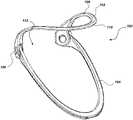
- FIG. 1is a perspective view of a support in expanded position according to an embodiment of the present disclosure
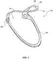
- FIG. 2is a perspective view of a support in an expanded position according to an embodiment of the present disclosure
- FIG. 3is a side view of a support in an expanded position according to an embodiment of the present disclosure
- FIG. 4is a perspective view of a support in a compressed position according to an embodiment of the present disclosure
- FIG. 5is a side view of a support in a compressed position according to an embodiment of the present disclosure
- FIG. 6is a perspective view of a support in a compressed position according to an embodiment of the present disclosure.
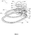
- FIG. 7is an exploded view of a support according to an embodiment of the present disclosure.
- FIG. 8is a perspective view of a support in a compressed position according to an embodiment of the present disclosure.
- FIG. 9is an exploded view of a support according to an embodiment of the present disclosure.
- FIG. 10is a perspective view of a support according to an embodiment of the present disclosure.
- FIG. 11is a perspective view of a support according to an embodiment of the present disclosure.
- FIG. 12is an exploded view of a support according to an embodiment of the present disclosure.
- FIG. 13is a view of a hinge according to an embodiment of the present disclosure.
- FIG. 14is an exploded view of a hinge according to an embodiment of the present discloser.
- FIG. 15is a perspective view of a lower support according to an embodiment of the present disclosure.
- FIG. 16is a perspective view of a support in an expanded position according to an embodiment of the present disclosure.
- FIG. 17is a side view of a user wearing a support in the neck region according to an embodiment of the present disclosure.
- any relational termsuch as “first,” “second,” “top,” “bottom,” etc., is used for clarity and convenience in understanding the disclosure and accompanying drawings and does not connote or depend on any specific preference, orientation, or order, except where the context clearly indicates otherwise. In some embodiments, these and other relational terms may be used in a frame of reference relative to the anatomy of a user sitting or standing in an upright position.
- the term “substantially” in reference to a given parametermeans and includes to a degree that one skilled in the art would understand that the given parameter, property, or condition is met with a small degree of variance, such as within acceptable manufacturing tolerances.
- a parameter that is substantially metmay be at least about 90% met, at least about 95% met, or even at least about 99% met.
- elastomeric polymermeans and includes a polymer capable of recovering its original size and shape after deformation.
- an elastomeric polymeris a polymer having elastic or viscoelastic properties.
- Elastomeric polymersmay also be referred to as “elastomers” in the art.
- Elastomeric polymersinclude, without limitation, homopolymers (polymers having a single chemical unit repeated) and copolymers (polymers having two or more chemical units).
- Embodiments of the present disclosuremay relate to supports for a portion of a user's body (e.g., ergonomic supports, braces, head and/or neck supports, headrests, etc.) that may be folded or collapsed in a way that reduces the amount of space required for storage of the supports.
- the collapsible supportsmay maintain complementary shapes to the appendage or object they are intended to support.
- embodiments of the present disclosuremay relate to an ergonomic support that may be folded to a collapsed position (e.g., a substantially flat position).
- the ergonomic supportmaintains an expanded shape (e.g., an ergonomic shape that is at least partially complementary to a majority of the anatomical features of an intended user, such as, for example, an anatomical shape, a form fitting shape, a cylindrical shape, etc.) when the ergonomic support is expanded and in use.
- the ergonomic supportmay be used to support one or more portions of a user's body, such as, for example, a user's head and/or neck, leg and/or knee, arm and/or elbow, or any other area where a user may need a support or brace.
- the ergonomic supportmay be formed in different sizes and shapes depending on the area being supported and/or the age or size of the user.
- components of the supportmay be designed, configured, and/or sized to fit or to be adjusted to fit a majority of an intended population of users (e.g., a median, a mean, etc., of the intended population).
- Supportsmay be used to support an area while the user is resting to increase comfort, prevent muscle or joint fatigue, support an injured area, or prevent a weak area from becoming injured.
- a head and/or neck supportmay support a user's head when sleeping in an upright position to prevent neck pain and/or fatigue, support an injured (e.g., strained and/or broken neck), or support the neck of an incapacitated user to prevent the neck from becoming injured.
- a knee supportmay support an injured knee, or support a knee following surgery to prevent an injury due to the knee being in a weak state following surgery.
- FIG. 1illustrates an embodiment of a support 100 (e.g., a head and/or neck support) in an expanded position.
- the support 100includes a top support 102 (e.g., upper support, head support, head supporting member, head supporting portion) and a bottom support 104 (e.g., lower support, chest portion of the support, chest engaging member, chest engaging portion).
- the top support 102may be connected to the bottom support 104 with a coupling member, such as, for example, a connection feature (e.g., hinge 106 , pivot, hinged connection, joint, adjustable connection point or feature).
- a connection featuree.g., hinge 106 , pivot, hinged connection, joint, adjustable connection point or feature
- the top support 102 , bottom support 104 , and coupling membermay be unitary (e.g., integrated, undivided, single piece of material, single structure).
- the top support 102may have an ergonomic shape that is at least partially defined in a manner that is complementary to the portion of the user that is to be supported.
- the top support 102may extend from the hinge 106 in a shape that is complementary to and engages with one or more portions of a user's head (e.g., a bottom portion of the user's chin and/or jaw and/or sides portions of the user's head and/or jaw.
- the top support 102may be a frame member (e.g., having a polygonal cross section, a curved and/or elliptical cross section, a rectangular cross section) having a semi-annular shape (e.g., a portion of a ring, a portion of a circle, a portion of a ellipse, a portion of a oval, a horseshoe shape, etc.).
- the top support 102may include side portions 108 rising above a front portion 110 forming a curve when viewed from the side (e.g., along or in the coronal plane).
- the support 100may have an opening 112 in the back of the support 100 to enable the support 100 to be placed around a user's neck.
- the side portions 108 of the top support 102may support the user's head laterally by running along the cheek and/or lower jaw of the user's head while the front portion 110 may be lower than the side portions 108 enabling the bottom of the user's chin and/or jaw to rest on the front portion 110 .
- the shape of the support 100may provide lateral and vertical support to the user's head. The shape of the support 100 may increase the comfort of the support for the user as well.
- the bottom support 104may also have an ergonomic shape.
- the bottom support 104may be a semi-annular frame member (e.g., having a polygonal cross section, a curved, and/or elliptical cross section, a rectangular cross section). When viewed from the side, the bottom support 104 may be curved in a way that is substantially similar and/or complementary to a user's chest.
- the curve in the bottom support 104may be substantially similar to the curve in the top support 102 .
- the bottom support 104may extend a greater distance from the opening 112 in the back of the support 100 than the top support 102 .
- the hinge 106may allow the top support 102 to articulate (e.g., rotate, or pivot) relative to the bottom support 104 .
- the support 100may be placed in a collapsed position by rotating the top support 102 relative to the bottom support 104 until the top support 102 contacts the bottom support 104 .
- the top support 102may be substantially parallel to the bottom support 104 .
- the top support 102may lie in substantially the same plane as the bottom support 104 or may lie in a plane that is adjacent and substantially parallel to a plane in which the bottom support 104 is positioned.
- the hinge 106may enable the top support 102 and the bottom support 104 to move relative to one another, such that an angle between the top support 102 and the bottom support 104 may be adjustable.
- the hinge 106may include a locking mechanism, discussed below in greater detail.
- the locking mechanismmay have at least one locking position. When in the locking position the locking mechanism may substantially inhibit motion of the top support 102 relative to the bottom support 104 .
- the locking mechanismmay include a plurality of locking positions.
- FIG. 2is a perspective view of a support 200 in an expanded position
- FIG. 3is a side view of a support (e.g., the support 200 of FIG. 2 ) in an expanded position
- the support 200may include a top support 202 and a bottom support 204 connected by hinges 206 .
- the top support 202may be formed from a flexible material that may be moved between a substantially planar position (e.g., as shown in FIG. 5 ) and a twisted (e.g., turning, or tortuous expanded position (e.g., as shown in FIG. 2 ).
- the top support 202may have a substantially rectangular cross section with two major planar sides having planar surfaces (e.g., for at least partially engaging portions of the user) and two minor sides extending between the major sides.
- such a twistmay comprise an angular variation of a selected amount of degrees of the major planar sides of the top support 202 (e.g., 5 degrees, 15 degrees, 30 degrees, 45 degrees, 60 degrees, 90 degrees, or more).
- the top support 202 and/or the bottom support 204may have a non-rectangular cross section (e.g., an elliptical cross section, a triangular cross section, a C-channel cross section, etc.)
- the twistmay comprise an angular variation of a selected amount of degrees of at least one plane of the top support and/or bottom support.
- the hinges 206may be substantially vertical (e.g., positioned in a direction transverse to the direction which the top support 202 and/or bottom support 204 extend, positioned in the sagittal plane) when the support 200 is in an expanded position.
- the top support 202may form a semi-annular shape with an opening 212 in the back between the hinges 206 .
- the top support 202may have sides 208 where the planar surface may be set in a plane transverse (e.g., substantially perpendicular) to a plane in which another portion of the top support 202 extends (e.g., a front portion 210 ).
- the planar surface of the top support 202may gradually transition from the transverse plane of the sides 208 to the plane in which a majority of the front portion 210 lies, which may be substantially parallel to a plane in which the top support 202 is positioned in a retracted position (see, e.g., FIG. 5 ).
- the bottom support 204may also be formed from a flexible material that may be moved between a substantially planar position (e.g., as shown in FIG. 5 ) and a twisted, turning, or tortuous expanded position (e.g., as shown in FIG. 2 ).
- the top support 202may have a substantially rectangular cross section with two major planar sides having planar surfaces (e.g., for at least partially engaging portions of a user) and two minor sides extending between the major sides.
- such a twistmay comprise a variation of a selected amount of degrees of the major planar sides of the top support 202 (e.g., 5 degrees, 15 degrees, 30 degrees, 45 degrees, 60 degrees, 90 degrees, or more).
- the bottom support 204may at least partially or substantially extend in a similar manner to the top support 202 with the planar surfaces of the bottom support 204 transitioning from a plane transverse (e.g., substantially perpendicular) to the plane in which another portion of the bottom support 204 (e.g., front portion 214 ) extends to the plane in which a majority of the front portion 214 lies, which may be substantially parallel to a plane in which the bottom support 204 is positioned in a retracted position (see, e.g., FIG. 5 ).
- a plane transversee.g., substantially perpendicular
- the support 200may include support pads 216 extending from the hinges 206 .
- the support pads 216may locate (e.g., secure, center, maintain) the support 200 relative to a user. For example, on a head and/or neck support, the support pads 216 may contact the back of the user's neck securing the support 200 in place with the top support 202 contacting the user's head and the bottom support 204 contacting the user's chest, shoulder(s) and/or back.
- the support pads 216may be pivotally mounted to the hinges 206 . The pivotal support may enable the support pads 216 to conform to the user's anatomy.
- the support pads 216may be removable.
- the support pads 216may have different sizes that may be interchangeable to adjust the support 200 to fit or be customized for different users.
- the support pads 216may be formed from different materials.
- the support pads 216may be interchangeable for different applications.
- a support 200 being used to prevent fatigue while restingmay use support pads 216 with a lower stiffness (e.g., elastic modulus, Young's Modulus) for increased comfort, while a support 200 that may be used to support an injury may require support pads 216 made from a material with a higher stiffness.
- the support pads 216may be interchangeable for support pads 216 of different shapes.
- the support pads 216may be a circular shape, an oblong shape, an oval shape, a crescent shape, etc.
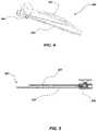
- FIG. 4is a perspective view of a support (e.g., the support 200 of FIGS. 2 and 3 ) in a compressed position
- FIG. 5is a side view of the support in a compressed position.
- the support 200may be configured to collapse into a collapsed (e.g., closed, compressed, passive, storage, retracted) position.
- the top support 202may be substantially parallel to the bottom support 204 .
- the hinge 206may be configured to enable the top support 202 and the bottom support 204 to articulate relative to each other.
- the hinges 206may transition (e.g., substantially 45 to 90 degrees) from a partially or substantially vertical or upright orientation to a substantially horizontal or flat orientation.
- the planar surfaces of the top support 202 and the bottom support 204may also transition such that the entire planar surfaces of the top support 202 and the bottom support 204 form substantially horizontal or flat surfaces.
- the substantially horizontal surfaces of the top support 202 and the bottom support 204may be in contact with or directly adjacent each other in the collapsed position and the support 200 may be substantially flat.
- the hinges 206may be configured to articulate between a horizontal position (e.g., a flat position in a plane substantially parallel to the flat top support 202 and bottom support 204 ) and a vertical or upright position in response to the support 200 moving between a collapsed position and an expanded position.
- a horizontal positione.g., a flat position in a plane substantially parallel to the flat top support 202 and bottom support 204
- a vertical or upright positionin response to the support 200 moving between a collapsed position and an expanded position.
- the hinges 206may introduce a twisting force (e.g., moment, or torque) in the top support 202 and the bottom support 204 .
- the twisting forcemay cause the top support 202 and bottom support 204 to transition from fully horizontal or flat surfaces to ergonomically shaped surfaces.
- the twisting forcemay also introduce additional strength into the support 200 .
- the twisting forcemay increase the moment of inertia (e.g., an area moment of inertia) for at least a portion of the top support 202 and/or the bottom support 204 .
- An increase in the moment of inertia for an itemincreases the amount of force necessary to cause deflection. Therefore, as the moment of inertia for the top support 202 or the bottom support 204 increases the strength of the support also increases.
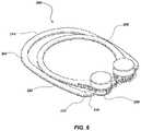
- FIG. 6is a perspective view of a support (e.g., the support 200 of FIGS. 2 through 5 ) in a compressed position.
- the top support 202may have a different shape than the bottom support 204 .
- the different shapesmay react differently to the twisting forces created by the hinges 206 .
- the top support 202may have a substantially elliptical (e.g., circular) shape.
- the bottom support 204may have sides 220 that are substantially straight. The sides 220 may extend between an arch on the front portion 214 of the bottom support 204 and a corner 222 on a back portion 224 of the bottom support 204 .
- the corner 222may be a bend between about a 20° angle and about a 90° angle, such as between about a 45° angle and about a 50° angle, about a 50° angle and about a 55° angle, about a 55° angle and about a 60° angle, about a 60° angle and about a 65° angle, about a 65° angle and about a 70° angle, about a 70° angle and about a 75° angle, about a 75° angle and about an 80° angle, about an 80° angle and about an 85° angle, or about an 85° angle and about a 90° angle.
- the anglemay be between about 70° and 85°, such as between about 75° and 80°, or about 77°.
- the anglemay be selected based on the amount of deflection desired from the twisting forces exerted by the hinges 206 .
- FIG. 8is a perspective view a support 200 ′ in a compressed position.
- the support 200 ′may be similar to and include components of the supports 100 , 200 discussed above.
- one or more of the hinges 206 ′may be positioned such that the axis L 100′ of the hinges 206 ′ is positioned in or substantially parallel to the plane of the top support 202 and the bottom support 204 , when the top support 202 and the bottom support 204 are in a compressed position.
- a majority of the top support 202 , the bottom support 204 , the hinges 206 ′, and axis L 100′ of the hinges 206 ′may lie in or be directly adjacent the same plane.
- the axes L 100′ of the hinges 206 ′may remain substantially stationary with respect to one another as the top portion 202 and the bottom portion 204 articulate.
- the orientation of the hinge 206 ′may create a moment on the top support 202 and the bottom support 204 as the top support 202 and the bottom support 204 move relative to one another into an expanded position.
- the moment created by the hinge 206 ′may cause the top support 202 and the bottom support 204 to form a twisted, turning, or tortuous expanded position similar to that shown in FIGS. 2 and 3 .
- the hinges of the support 200 ′may include a locking mechanism, such as, for example, those discussed herein, in order to fix the support 200 ′ in a selected position (e.g., an expanded position).
- the top support 202 and bottom support 204may be formed from at least partially flexible materials.
- Some materialsmay include composites (e.g., fiberglass, carbon fiber), elastomeric polymers (e.g., polyethylene terephthalate (PETG), PVC), rubber, metals (e.g., sheet steel, aluminum), wood, MDF, and cardboard.
- the materialmay be selected based on its flexibility and fatigue resistance. In some embodiments, the material may be selected to exhibit a selected hardness or durometer (e.g., 60 to 80 shore D, 75 shore D, etc.). Some more flexible materials may allow more articulation while less flexible materials may require more force to create the same amount of articulation.
- More flexible materialsmay provide less support for the support 200 , while less flexible materials may provide more support making the support 200 stronger.
- Some applicationsmay require a more flexible material while other applications may require a stronger material.
- a headrestmay require a more flexible material to provide a comfortable fit to the user's head.
- a headrestmay require a stronger material to withstand jarring forces, such as, for example, on a turbulent flight.
- FIG. 7is an exploded view of a support (e.g., the support 200 of FIGS. 2 through 6 ).
- the hinge 206e.g., hinge assembly
- the pin 230may protrude from a base 232 .
- the pin 230may protrude through a first hole 234 in the bottom support 204 and a second hole 236 in the top support 202 .
- the pin 230may substantially align the first hole 234 and the second hole 236 .
- a retainer 238may attach to the pin 230 on an opposite side of the top support 202 and the bottom support 204 from the base 232 .
- the retainer 238 and the base 232may substantially limit the movement of the top support 202 and the bottom support 204 such that the top support 202 and the bottom support 204 may only move relative to each other in a plane that is perpendicular to an axis L 100 of the pin 230 .
- the axes L 100 of the pins 230 for each hinge 206may be substantially parallel when in the collapsed position.
- the axes L 100 for each pin 230may rotate such that the axes L 100 of each pin 230 are moved from this parallel position (e.g., are no longer parallel in this plane).
- the rotation of each axis L 100may enable the top support 202 to rotate relative to the bottom support 204 due to the retainer 238 and the base 232 limiting the movement of the top support 202 and the bottom support 204 to a plane perpendicular to the axis L 100 .
- the hinge 206 on each side of the top support 202 and the bottom support 204may introduce a twisting force into the top support 202 and the bottom support 204 due to the rotation of the hinge 206 between the planar position shown in FIG. 7 to a transverse position as shown in FIGS. 2 and 3 .
- the pads 216may be connected to a connection point 240 on the end of the pin 230 opposite the base 232 .
- the connection point 240may be a ball joint (e.g., ball and socket, heim joint, rod-end bearing).
- the pads 216may be allowed to pivotally move relative to the pins 230 to conform to the anatomy of the user.
- FIG. 9shows an exploded view of an embodiment of the support 200 of FIGS. 2 through 7 .
- the pin 230 ′may be integral with the pad 216 ′.
- the pin 230 ′may have a retaining lip 239 .
- the pin 230 ′may be split into two separate pieces with a gap 241 between two sides of the pin 230 ′.
- the pin 230 ′may be formed from a resilient material that may allow the two sides of the pin 230 ′ to be compressed together to allow the retaining lip 239 to pass through the holes 234 and 236 in the bottom support 204 and the top support 202 , respectively.
- the two sides of the pin 230 ′may return to a normal configuration.
- the retaining lip 239may contact a bottom surface 237 of the bottom support 204 retaining the pin 230 ′ within the holes 234 and 236 securing the top support 202 to the bottom support 204 and forming the hinge 206 ( FIG. 2 ).
- the retaining lip 239 and the pad 216 ′may substantially limit the movement of the top support 202 and the bottom support 204 such that the top support 202 and the bottom support 204 may only move relative to each other in a plane that is transverse (e.g., perpendicular) to an axis of the pin 230 ′.
- a front surface 242 of the retaining lip 239may include a chamfer.
- the chamfered front surface 242may be configured to compress the two sides of the pin 230 ′ as the pin 230 ′ is inserted into the two holes 234 and 236 .
- FIG. 10illustrates the embodiment of FIG. 9 in a perspective view.
- the pad 216 ′may be formed from a resilient material.
- the pad 216 ′may have a retaining surface 243 and a pad surface 244 .
- the retaining surface 243may contact a top surface of the top support 202 .
- the retaining surface 243may be configured to act opposite the retaining lip 239 ( FIG. 9 ) to limit the movement of the top support 202 and the bottom support 204 relative to one another.
- the pad surface 244may connect to the retaining surface 243 at a point 245 near the opening 212 between the two hinges 206 ( FIG. 2 ).
- the pad surface 244may extend at an angle from the retaining surface 243 . The angle may be between 90° and 10°, such as between about 45° and 25°, or between about 40° and 30°.
- FIG. 11illustrates an embodiment of the support 200 of FIGS. 9 and 10 .
- the pad 216 ′may be a solid part.
- the retaining surface 243 ( FIG. 9 ) and the pad surface 244may be opposing surfaces of the solid pad 216 ′.
- the solid pad 216 ′may be formed in a wedge shape.
- the wedge shapemay be formed with an angle between the retaining surface 243 and the pad surface 244 .
- the anglemay be between 90° and 0°, such as between about 45° and 25°, or between about 40° and 30°.
- the pad surface 244may be a concave surface.
- the pad surface 244may be a convex surface.
- the pad 216 ′may be selected for a shape that is complementary to the user. Different users may require different pad shapes to conform comfortably to the user's anatomy.
- the one or both of the hinges 206may include a locking mechanism 250 .
- the locking mechanism 250may include a stop 252 (e.g., tooth, teeth, cogs, holes, etc.) and a retaining member 254 with a complementary feature to engage with the stop 252 (e.g., tooth, teeth, protrusion, latch, clasp, pin, cog, etc.).
- the locking mechanism 250may lock the support 200 in an expanded position and/or the collapsed position.
- the retaining member 254may contact the stop 252 and substantially inhibit movement of the top support 202 relative to the bottom support 204 (e.g., a protrusion or tooth of the retaining member 254 may engage with one or more teeth of the stop 252 ).
- the stop 252 and retaining member 254may be configured to limit movement between the top support 202 and bottom support 204 in a single direction.
- the stop 252 and the retaining member 254may be configured to selectively enable (e.g., when a selected amount of force is applied) the top support 202 to rotate about the axis L 100 in a direction further expanding the support 200 while preventing the top support 202 from rotating in a direction collapsing the support 200 .
- the stop 252 and the retaining member 254may be configured to selectively enable (e.g., when a selected amount of force is applied) rotation of the top support 202 relative to the bottom support 204 in both directions.
- the locking mechanism 250may consist of high friction coatings such as, abrasive coatings (e.g., metal filings, metal oxides, ceramic materials, etc.), a rubberized coating, or other similar high friction coatings.
- the high friction coatingmay be on surfaces of the top support 202 and bottom support 204 , which are in contact with each other.
- the high friction coatingmay substantially inhibit motion (e.g., until a select amount of force is applied) of the top support 202 relative to the lower support 204 .
- force on the front portion 210 of the top support 202 and front portion 214 of the bottom support 204may increase the friction or reduce the friction inside the hinge 206 , holding the support 200 in the expanded positioned when force is applied by a user during use of the support 200 .
- the top support 202 and the bottom support 204may be configured to increase a pressure between the surfaces of the top support 202 and/or the bottom support 204 , that have the high friction coating, when compressing force is applied to the front portion 210 of the top support 202 and the front portion 214 of the bottom support 204 .
- applying a force to the top support 202 and the bottom support 204 in another waymay decrease the pressure between the surfaces of the top support 202 and/or the bottom support 204 that have the high friction coating to enable collapsing of the support 200 .
- decreasing the pressure between the high friction surfaces of the top support 202 and/or the bottom support 204may decrease the locking force of the locking mechanism 250 substantially releasing the locking mechanism and allowing the top support 202 to move relative to the bottom support 204 .
- the locking mechanism 250may include a dampening mechanism.
- the dampening mechanismmay substantially inhibit movement of the top support 202 relative to the bottom support 204 (e.g., when moving from the expanded position to the collapsed position and/or when moving from the collapsed position to the expanded position).
- a dampening mechanismmay utilize a dampener (e.g., spring, fluid, etc.) to substantially inhibit the movement.
- the dampening mechanismmay be adjustable to provide more or less force to inhibit the movement.
- the locking mechanism 250may include a single stop 252 to lock the support 200 in the expanded position. In other embodiments, the locking mechanism 250 may include more than one stop 252 . In some embodiments, the locking mechanism 250 may include a stop 252 to lock the support 200 in an expanded position and another stop 252 to lock the support 200 in the collapsed position. In some embodiments, the locking mechanism 250 may include a plurality of stops 252 for different expanded positions such that the support 200 may be adjustable to different expanded positions. The number of expanded positions may be defined by the number of stops 252 .
- the locking mechanism 250may include a ratcheting mechanism.
- the ratcheting mechanismmay include a plurality of teeth 252 on at least one of the top support 202 and the bottom support 204 .
- the bottom support 204may include the plurality of teeth 252 for the ratcheting mechanism.
- the top support 202may include a latch 254 (e.g., a complementary tooth).
- the top support 202may include the plurality of teeth 252 and the bottom support 204 may include the latch 254 .
- the latch 254may be biased toward the teeth 252 by a biasing element (e.g., a spring, resilient material, etc.).
- the latch 254may be configured to interact with the plurality of teeth 252 .
- the plurality of teeth 252may be positioned at an angle and configured to have a retaining face 258 and an advancing face 260 .
- the latch 254may contact the retaining face 258 of the plurality of teeth 252 to prevent the top support 202 from rotating about the axis L 100 relative to the bottom support 204 in a direction collapsing the support 200 .
- the latch 254may move along the advancing face 260 of the plurality of teeth 252 allowing the top support 202 to rotate relative to the bottom support 204 in a direction further expanding the support 200 .
- Each tooth of the plurality of teeth 252may define an expanded position of the support 200 .
- the ratcheting mechanismmay include one or more releases 256 , 257 .
- the releases 256 , 257(e.g., one release alone or multiple releases in unison) may be configured to disengage the latch 254 from the plurality of teeth 252 , thereby, enabling the top support 202 to rotate relative to the bottom support 204 in a direction collapsing the support 200 .
- one or both of the releases 256 , 257may move the latch 254 in a direction (e.g., radially outward direction and/or a direction along the axis L 100 ) such that the latch 254 and the plurality of teeth 252 are no longer in contact.
- one or both of the releases 256 , 257may move the latch 254 in a direction along (e.g., parallel to) the axis L 100 to disengage the latch 254 from the plurality of teeth 252 .
- one or both of the releases 256 , 257may move the latch 254 independent of the top support 202 and/or the bottom support 204 .
- the releases 256 , 257may move at least a portion of the support 202 , 204 that includes the latch 254 .
- the first release 256 and the second release 257may work in unison to move the latch 254 relative to the plurality of teeth 252 to disengage the latch 254 and the plurality of teeth 252 .
- a usermay apply a force (e.g., a pinch) to the first release 256 and the second release 257 in order to move the first release 256 toward the second release 257 disengaging the plurality of teeth 252 from the latch 254 .
- opposing forcesmay be applied to the first release 256 and the second release 257 to move both the plurality of teeth 252 and the latch 254 relative to each other. Moving the plurality of teeth 252 and the latch 254 relative to each other may cause the latch 254 and the plurality of teeth 252 to disengage.
- the plurality of teeth 252 in the ratchetmay not be placed at an angle.
- the plurality of teeth 252may have a retaining face 258 on both sides of each tooth.
- the latch 254may prevent the top support 202 from rotating relative to the bottom support 204 in both directions.
- the release 256may need to disengage the latch 254 to rotate the top support 202 in both directions about the axis L 100 relative to the bottom support 204 .
- the locking mechanism 250may include at least two interlocking cogs.
- a stop cog 252may include a plurality of teeth and a latch cog 254 may include a complementary plurality of teeth.
- the plurality of teethmay be configured to stop rotation of the top support 202 relative to the bottom support 204 in both directions.
- the plurality of teethmay be configured to allow rotation of the top support 202 relative to the bottom support 204 in one direction while preventing rotation in the other direction.
- a biasing elemente.g., spring, washer, resilient material
- a release 256may release the biasing element or act against the biasing element moving the latch cog 254 such that the teeth of the latch cog 254 are no longer in contact with the teeth of the stop cog 252 .
- FIG. 12is an exploded view of an embodiment of the support 200 .
- the support 200may include a locking connection 250 .
- the locking connection 250may include a plurality of protrusions (e.g., semispherical bumps 251 ) on at least one of the top support 202 or the bottom support 204 .
- the opposing support 202 or 204may include a complementary feature.
- the bottom support 204may include the plurality of bumps 251 and the top support 202 may include the plurality of complementary recesses.
- the locking connection 250may be configured such that the number of bumps defines the number of possible positions for the support 200 .
- FIG. 13illustrates a close-up view of an embodiment of a joint or hinge 206 for an embodiment of the support 200 .
- the locking connection 250may comprise a plurality of detents 253 on at least one of the top support 202 or the bottom support 204 .
- the opposing supportmay include opposing fingers 255 , which may be configured to act as a latch. The opposing fingers 255 may be inserted into the plurality of detents 253 ; locking the top support 202 relative to the bottom support 204 .
- the bottom support 204may include a plurality of detents 253 and the top support 202 may include at least two opposing fingers 255 (e.g., semispherical protrusions).
- the opposing fingers 255may be complementary to the plurality of detents 253 .
- the plurality of detents 253may be configured to allow the opposing fingers 255 to advance one direction while substantially preventing the opposing fingers 255 from advancing in the opposite direction.
- FIG. 14illustrates a close-up view of an embodiment of a joint or hinge 206 of the support 200 .
- the locking connection 250may include a plurality of holes 252 acting as stops and at least one pin 254 acting as a latch.
- the locking connection 250may include more than one pin 254 , such as two pins, three pins, or four pins.
- the locking connection 250may include the same number of pins 254 as holes 252 .
- the pins 254may have a complementary size and shape to the plurality of holes 252 such that the pins 254 may be inserted into the plurality of holes 252 .
- the latching connection 250may include a release 256 .
- the release 256may include release pins 259 opposing the pins 254 , and a biasing element 261 .
- the biasing element 261may bias the release 256 to the locked position.
- the usermay apply a force on the release 256 against the biasing force of the biasing element 261 .
- the release pins 259may enter the plurality of holes 252 , forcing the pins 254 out of the plurality of holes 252 releasing the latch.
- the release 256may include the same number of release pins 259 as the locking mechanism pins 254 .
- the release 256may mirror the pins 254 , such that the release pins 259 are in substantially the same position as the pins 254 .
- the release 256may include the same number of release pins 259 as the number of the plurality of holes 252 .
- the release 256may remain stationary relative to the holes 252 not rotating with the pins 254 .
- the release pins 259may be a complementary size and shape to the holes 252 .
- the release pins 259may be smaller than the pins 254 such that the release pins 259 may require less force than the pins 254 to insert into the plurality of holes 252 , and to retract from the plurality of holes 252 .
- the locking mechanism 250may also include range of motion stops configured to prevent the support 200 , 200 ′ from over extending or opening in the wrong direction.
- Range of motion stopsmay be an additional stop to the stops 252 of the locking mechanism 250 .
- the range of motion stopsmay be created by contact between the top support 202 and the bottom support 204 .
- the range of motion stopsmay be a physical stop in the hinge 206 that will not allow additional movement beyond the range of motion stop.
- the top support 202 and/or the bottom support 204may have an extruded tab or detent.
- the extruded tabmay contact the detent substantially preventing further movement of the top support and/or bottom support at the range of motion stop.
- the tab and detentmay have additional functions.
- FIG. 9illustrates a first release 256 that may interact with the second release 257 and the retaining member 254 to create two range of motion stops.
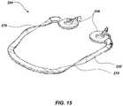
- FIG. 15illustrates an embodiment of the lower support 204 of the support 200 , 200 ′ demonstrated in FIGS. 2 through 10 .
- the lower support 204may include an initial twist 270 in the sides 220 of the lower support 204 .
- the initial twist 270may be present when the support 200 is in the collapsed position.
- the initial twist 270may introduce a twist opposite, the twisting force introduced by the hinge 206 .
- the twisting force introduced by the hinge 206may substantially straighten the sides 220 of the lower support 204 .
- the substantially straight sides 220may conform to the user's chest, shoulders, and/or back for a more comfortable fit.
- FIG. 16is a perspective view of a support in an expanded position (e.g., the support 200 of FIGS. 2 through 7 ).
- the support 200may have covers on at least a portion of one or more of the elements.
- a top cover 262may be attached to the top support 202 .
- a bottom cover 264may be attached to the bottom support 204 .
- a pad cover 266may be attached to the pads 216 .
- the support 200may include the top cover 262 , the bottom cover 264 , and the pad covers 266 . In other embodiments, the support 200 may only include some of the covers.
- the support 200may only include the top cover 262 and the bottom cover 264 , or the top cover 262 and the pad covers 266 , or the bottom cover 264 and the pad covers 266 .
- the covers 262 , 264 , 266may only cover portions of the elements.
- the top cover 262may only cover the side portions 208 of the top support 202 , or the top cover 262 may only cover the front portion 210 of the top support.
- at least two of the coversmay be integrated into a single part.
- the top cover 262 and the pad covers 266may be integrated in to a single part.
- the top cover 262 and the bottom cover 264may be integrated into a single part.
- the top cover 262 , bottom cover 264 , and the pad covers 266may all be integrated into a single part.
- the covers 262 , 264 , 266may be made from cushioning materials (e.g., foam, gel, vinyl, rubber, natural or synthetic fibers).
- the cushioning materialsmay be attached to the support 200 using glue (e.g. hot glue, water-based glue etc.), hook-and-loop adhesives, staples, fabric covers, hook-and-loop fasteners (e.g., VELCRO®), snaps, buttons, etc.
- the covers 262 , 264 , 266may cover only one side of each element of the support.
- the top cover 262may only cover the side of the top support 202 that contacts the user.
- the covers 262 , 264 , 266may envelop each element.
- the bottom cover 264may comprise a sleeve of fabric and the bottom support 204 may be disposed within the bottom cover 264 .
- FIG. 17illustrates an embodiment of the present disclosure being used as a head and/or neck support.
- the planar surfaces of the support 200may substantially follow the contours of the user's body.
- the support 200may be placed around a user's neck.
- the side portions 208 of the top support 202may follow the vertical contours (e.g., along the sagittal and/or coronal plane) of the side of the user's face (e.g., cheek, neck or side of the jaw).
- the planar surfacemay gradually transition following the contour of the jaw line of the user until the front portion 210 passes under the chin of the user as a substantially horizontal surface (e.g., along the transverse plane).
- the planar surface of the bottom support 204may also follow the contours of the user's body.
- the sides 220 of the bottom support 204may extend in a plane substantially parallel to the user's neck and the planar surface of the bottom support 204 may gradually transition to the front portion 214 of the bottom support 204 which may lie in a plane substantially parallel to the user's chest.
- the bottom support sides 220 of the bottom supportmay also lie in a plane substantially parallel to the user's chest along with the front portion 214 to follow the contours of the user's chest.
- the top cover 262 and bottom cover 264may conform to any irregularities in the user's anatomy to provide a tight comfortable fit.
- Embodiment of the disclosuremay comprise supports (e.g., foldable supports) having numerous benefits. For example, large and cumbersome supports are difficult to travel with and may take up valuable space in luggage when traveling and in storage areas when not in use. A support that folds flat may make traveling with a support device less frustrating and storage of the support less difficult. Additionally, a support that is adjustable has several advantages over supports, such as pillows, with minimal adjustment because people are all different shapes and sizes. As a result, a support that works for one user may be too large or too small for another user. A support that can be adjusted may allow multiple different people to comfortably use the same support. The adjustable shape of the support may also increase the comfort for the user using the support, and reduce fatigue on the surrounding joints and muscles when resting on the support.
- supportse.g., foldable supports
Landscapes
- Health & Medical Sciences (AREA)
- General Health & Medical Sciences (AREA)
- Otolaryngology (AREA)
- Pulmonology (AREA)
- Orthopedics, Nursing, And Contraception (AREA)
Abstract
Description
Claims (20)
Priority Applications (1)
| Application Number | Priority Date | Filing Date | Title |
|---|---|---|---|
| US16/768,005US11399631B2 (en) | 2017-12-11 | 2018-11-30 | Foldable support and related methods |
Applications Claiming Priority (3)
| Application Number | Priority Date | Filing Date | Title |
|---|---|---|---|
| US201762597046P | 2017-12-11 | 2017-12-11 | |
| US16/768,005US11399631B2 (en) | 2017-12-11 | 2018-11-30 | Foldable support and related methods |
| PCT/IB2018/059533WO2019116148A1 (en) | 2017-12-11 | 2018-11-30 | Foldable support and related methods |
Publications (2)
| Publication Number | Publication Date |
|---|---|
| US20200359799A1 US20200359799A1 (en) | 2020-11-19 |
| US11399631B2true US11399631B2 (en) | 2022-08-02 |
Family
ID=64901615
Family Applications (1)
| Application Number | Title | Priority Date | Filing Date |
|---|---|---|---|
| US16/768,005Active2039-04-21US11399631B2 (en) | 2017-12-11 | 2018-11-30 | Foldable support and related methods |
Country Status (2)
| Country | Link |
|---|---|
| US (1) | US11399631B2 (en) |
| WO (1) | WO2019116148A1 (en) |
Cited By (2)
| Publication number | Priority date | Publication date | Assignee | Title |
|---|---|---|---|---|
| USD1024338S1 (en)* | 2022-01-18 | 2024-04-23 | Shenzhen Aonuo Medical Technology Co., Ltd. | Cervical vertebra straightener |
| USD1024339S1 (en)* | 2022-01-18 | 2024-04-23 | Shenzhen Aonuo Medical Technology Co., Ltd. | Adjustable cervical spine immobilizer |
Families Citing this family (4)
| Publication number | Priority date | Publication date | Assignee | Title |
|---|---|---|---|---|
| US11399631B2 (en)* | 2017-12-11 | 2022-08-02 | 17B Ehf | Foldable support and related methods |
| CN110638244B (en)* | 2019-11-06 | 2024-05-17 | 广州铧世家具制造有限公司 | Headrest |
| USD1002843S1 (en)* | 2020-08-25 | 2023-10-24 | Jiang Wang | Neck brace |
| USD1002856S1 (en)* | 2020-08-25 | 2023-10-24 | Jiang Wang | Neck brace |
Citations (130)
| Publication number | Priority date | Publication date | Assignee | Title |
|---|---|---|---|---|
| US15581A (en) | 1856-08-19 | slaughter | ||
| US1468072A (en) | 1921-04-14 | 1923-09-18 | Ogle Hubert Millas | Comfort cushion |
| US1587749A (en)* | 1924-07-14 | 1926-06-08 | Albert S Bierly | Propulsive-spring foot support |
| US1787832A (en) | 1929-05-27 | 1931-01-06 | Addie E Mueller | Pillow |
| US2774601A (en) | 1953-06-01 | 1956-12-18 | Frederick G White | Device for use in playing golf |
| US3164151A (en) | 1962-12-14 | 1965-01-05 | Nicoll Esmond D Vere | Inflatable splint |
| US3327330A (en) | 1965-04-12 | 1967-06-27 | Mildred O Mccullough | Comfort pillow |
| US4031578A (en) | 1976-05-20 | 1977-06-28 | Doris Sweeney | Contoured travel pillow |
| US4210317A (en) | 1979-05-01 | 1980-07-01 | Dorothy Sherry | Apparatus for supporting and positioning the arm and shoulder |
| USD256728S (en) | 1978-04-14 | 1980-09-02 | Allen Katherine E | Reversible orthopedic pillow having ear and eye relief areas |
| US4285081A (en) | 1979-10-22 | 1981-08-25 | Price George W E | Device for recumbency of the head and neck |
| USD263625S (en) | 1980-02-13 | 1982-03-30 | McKnight and Bridges Pty. Limited | Inflatable neck support |
| US4345347A (en) | 1980-04-24 | 1982-08-24 | Kantor Philip A | Head and neck support cushions |
| US4887326A (en) | 1988-09-22 | 1989-12-19 | Bax Associates | Suboccipital pillow |
| AU7646691A (en) | 1990-05-09 | 1991-11-14 | Yvonne Macfarlane Van Der Velde | A cushion |
| US5203611A (en)* | 1991-10-21 | 1993-04-20 | Children On The Go, Inc. | Infant bounce and rocking chair |
| US5209521A (en) | 1989-06-26 | 1993-05-11 | Cooper Industries, Inc. | Expanding load shoulder |
| US5313678A (en) | 1993-01-08 | 1994-05-24 | Redewill Frances H | Acoustical pillow |
| US5352173A (en)* | 1993-03-10 | 1994-10-04 | Mclaughlin Gary G | Method for exercising buttock and thigh muscles |
| GB2290705A (en) | 1994-06-29 | 1996-01-10 | Smith Ian Graham Robertson | Neck pillow device |
| USD368527S (en) | 1994-06-22 | 1996-04-02 | Hollister Inc. | Neck brace |
| US5625959A (en) | 1994-03-22 | 1997-05-06 | Dea-Brown & Sharpe S.P.A. | Reconfigurable supporting fixture, particularly for measuring machines, and relative configuration method |
| US5701356A (en) | 1995-12-05 | 1997-12-23 | Hm Electronics | Neck engageable transducer support assembly and method of using same |
| US5785388A (en)* | 1994-10-26 | 1998-07-28 | Curtis; Phillip | Seat belt pillow |
| USD396594S (en) | 1997-09-16 | 1998-08-04 | Lefebvre Peggy A | Travel pillow |
| USD396980S (en) | 1997-06-18 | 1998-08-18 | Louise Novros | Pillow |
| USD404238S (en) | 1997-12-03 | 1999-01-19 | Ed Keilhauer | Travel pillow |
| USD414974S (en) | 1998-07-18 | 1999-10-12 | JEM International Corporation | Face down cushion |
| US5974607A (en) | 1998-12-03 | 1999-11-02 | Vk Industries | Head clip pillow |
| USD416745S (en) | 1999-04-27 | 1999-11-23 | Noyes Linda G | Orthopedic pillow |
| US6010192A (en) | 1998-07-29 | 2000-01-04 | King; Jenny K. | Travel pillow |
| USD419024S (en) | 1999-01-08 | 2000-01-18 | Franzus Company, Inc. | Neck cushion |
| USD420845S (en) | 1999-05-28 | 2000-02-22 | Richard Rumage | Neck support pillow |
| US6106123A (en)* | 1999-10-05 | 2000-08-22 | Mcdonald; Patrick L. | Vision aid for recovering ophthalmic patients |
| US6219865B1 (en) | 1999-04-02 | 2001-04-24 | Carla R. Stokesbary | Head support |
| US6230348B1 (en) | 1999-08-04 | 2001-05-15 | Pano Patrikakis | Neck rest |
| US6230349B1 (en) | 2000-05-03 | 2001-05-15 | Abbye M. Silver | Travel pillow |
| USD443461S1 (en) | 2000-09-22 | 2001-06-12 | Woobie World L.L.C. | Inflatable infant feeding pillow |
| USD444981S1 (en) | 2000-09-22 | 2001-07-17 | Woobie World L.L.C. | Infant feeding pillow |
| USD445624S1 (en) | 2000-04-28 | 2001-07-31 | Taneaki Futagami | Air pillow |
| USD446863S1 (en) | 2001-01-22 | 2001-08-21 | Rosemary Carroll | Combined therapeutic hot and cold compress |
| US20010054837A1 (en) | 1998-08-13 | 2001-12-27 | O'connor Richard W. | Headrest |
| US6408468B1 (en) | 2001-07-19 | 2002-06-25 | Kristen Comfort | Pillow to facilitate hearing |
| US6435617B1 (en) | 2001-03-20 | 2002-08-20 | Mcnair Curtis G. | Vehicle head and neck rest |
| US6447468B1 (en) | 2001-08-08 | 2002-09-10 | James T. Hankins | Portable cervical traction apparatus |
| US20030137178A1 (en) | 2002-01-23 | 2003-07-24 | Craft Raymond E. | Article of furniture having a support member with an adjustable contour |
| AU2003201842A1 (en) | 2002-03-21 | 2003-10-09 | Cole, Sirpa Marjatta Mrs | Portable travel pillow |
| USD481247S1 (en) | 2002-11-01 | 2003-10-28 | Bio-Support Industries Ltd. | Travel pillow |
| US6658681B2 (en) | 2002-04-19 | 2003-12-09 | The First Years, Inc. | Positionable pillow |
| RU34338U1 (en) | 2003-08-28 | 2003-12-10 | Абросимов Максим Владимирович | ORTHOPEDIC PILLOW |
| USD486028S1 (en) | 2001-11-20 | 2004-02-03 | Gwen Cathey | Hairstyle protection pillow |
| US6684431B2 (en)* | 2001-11-05 | 2004-02-03 | Lifegear, Inc.. | Angle-adjustable tabletop personal support apparatus |
| USD501349S1 (en) | 2004-01-15 | 2005-02-01 | Harris Luann M. | Support pillow |
| US6857149B2 (en)* | 2002-03-15 | 2005-02-22 | Todd Damon Hoggatt | Sleep support system |
| KR20050019575A (en) | 2003-08-20 | 2005-03-03 | 이창규 | A cushion pillow |
| KR20050019757A (en) | 2002-06-19 | 2005-03-03 | 에스디지아이 홀딩스 인코포레이티드 | Adjustable surgical guide and method of treating vertebral members |
| USD503062S1 (en) | 2004-01-02 | 2005-03-22 | Jill Nash | Nursing pillow |
| US20050150050A1 (en) | 2004-01-12 | 2005-07-14 | Wolf Jeffery M. | Novelty neck pillow |
| US6926686B2 (en) | 2000-05-17 | 2005-08-09 | Cheatham Consultants International Inc. | Cervical collar |
| US20050229498A1 (en) | 2004-04-16 | 2005-10-20 | Dr. Ing. H.C. F. Porsche | Process for controlling an electrically driver motor vehicle window |
| USD522300S1 (en) | 2004-12-09 | 2006-06-06 | Integral Orthopedics Inc. | Travel pillow |
| US20060138188A1 (en)* | 2004-12-23 | 2006-06-29 | Kramer Robert F | Dual position backpack |
| US7070076B2 (en) | 2001-06-28 | 2006-07-04 | Baby Bjorn Ab | Child-supporting shoulder harness |
| KR200424871Y1 (en) | 2006-06-13 | 2006-08-28 | 이상수 | Car pillows |
| US7175567B2 (en)* | 2003-05-21 | 2007-02-13 | Gymnova Sa | Gymnastics springboard with adjustable elasticity designed for training and competition |
| US20070033737A1 (en) | 2005-08-09 | 2007-02-15 | Florence Melton | Self-adjusting head and neck pillow |
| US7185378B2 (en) | 2002-08-26 | 2007-03-06 | Nathaniel Smith | Adjustable pad/pliable flexible support |
| US20070056107A1 (en) | 2005-09-15 | 2007-03-15 | Gabriel Tyronne G | Headphone pillow |
| US20070067915A1 (en) | 2005-09-29 | 2007-03-29 | Pryor Terry A | Shaped pillow system |
| US7225485B2 (en) | 2004-08-20 | 2007-06-05 | Patricia Binder | Support with buoyancy cushions |
| USD550495S1 (en) | 2006-01-16 | 2007-09-11 | Wesco Company S.A. | Cushion |
| US20070238590A1 (en) | 2006-04-11 | 2007-10-11 | An Tae Jin | Chest expander |
| US20070271703A1 (en) | 2000-10-03 | 2007-11-29 | The Boppy Company | Slipcover and pillow with back rest |
| US20080104764A1 (en) | 2006-11-03 | 2008-05-08 | Chen Tien Shui | Multi-airbag inflatable pillow |
| US20080216244A1 (en) | 2007-03-06 | 2008-09-11 | Kenley B Minton | Sound-insulating sleep pillow |
| US7437788B1 (en) | 2007-01-19 | 2008-10-21 | Holman Elward L | Pillow |
| USD582045S1 (en) | 2007-09-25 | 2008-12-02 | Gene James | Neck pillow |
| US20080301908A1 (en) | 2007-06-11 | 2008-12-11 | Jarllytec Co., Ltd. | Hinge structure with position-locking engagement means |
| USD582713S1 (en) | 2008-02-19 | 2008-12-16 | Baldwin Jeanie D | Head and neck support pillow |
| US20090013471A1 (en) | 2007-07-10 | 2009-01-15 | Biomed Db Design | Pillow to provide direct head, neck, jaw, and chin support, and to relax cervical and shoulder muscles |
| US20090133193A1 (en) | 2007-11-26 | 2009-05-28 | Mary Jane Weise | Buckwheat hull pillow |
| USD597364S1 (en) | 2008-09-26 | 2009-08-04 | Moonlight Pillows, Llc | Crescent-shaped pillow |
| USD607682S1 (en) | 2008-10-30 | 2010-01-12 | Ben Bat Ltd. | Head rest |
| US20100133888A1 (en) | 2008-11-28 | 2010-06-03 | Montuore Robert J | Headrest |
| USD619402S1 (en) | 2010-01-15 | 2010-07-13 | David Bret Sternlight | Travel pillow |
| US7779492B2 (en) | 2008-12-05 | 2010-08-24 | Ingenious Designs Llc | Self-storing combination blanket and neck roll assembly |
| US7788752B2 (en) | 2003-07-01 | 2010-09-07 | The Boppy Company, Llc | Booster accessory for support pillows |
| US7865987B2 (en) | 2007-05-02 | 2011-01-11 | Neck Guard Industries, Llc | Head positioning apparatus |
| US7909406B2 (en) | 2008-11-12 | 2011-03-22 | Samuelsen Leif-Erik A | Resting apparatus |
| USD637440S1 (en) | 2010-06-01 | 2011-05-10 | Paul Richard Mettler | Travel pillow |
| USD637439S1 (en) | 2010-06-01 | 2011-05-10 | Paul Richard Mettler | Pillow |
| US20110113557A1 (en) | 2009-11-17 | 2011-05-19 | Leo Aguilera | Travel head support |
| US20110169316A1 (en)* | 2010-01-11 | 2011-07-14 | Marques Paul Goei | Portable Travel Headrest |
| US20110235832A1 (en) | 2008-09-09 | 2011-09-29 | Luc Riopel | Ambiophonic Headrest |
| WO2011122769A2 (en) | 2010-04-01 | 2011-10-06 | Kim Won Bae | Neck pillow having a hair insertion opening |
| USD647624S1 (en) | 2010-08-06 | 2011-10-25 | Ossur Hf | Cervical collar |
| US20110314609A1 (en) | 2009-02-20 | 2011-12-29 | Comfort Concepts Pty Limited | Pneumatic seat cushion system |
| US20120011655A1 (en) | 2010-07-14 | 2012-01-19 | Rojas Ana C | Contoured Body Support Pillow |
| US20120012431A1 (en)* | 2009-03-28 | 2012-01-19 | Gordon Blackwood Hamilton | Personal seated resting support |
| US20120047656A1 (en)* | 2010-08-24 | 2012-03-01 | Heads Up Group, Inc. | Head Support |
| US8144913B1 (en) | 2007-01-23 | 2012-03-27 | Myles Jr Robert L | Travel pillow with audio system |
| US20120143109A1 (en) | 2010-12-02 | 2012-06-07 | Ronald Louis Krenzel | Selectively Adjustable Arm and Shoulder Support |
| US20120144590A1 (en) | 2010-12-14 | 2012-06-14 | Eric Sharp | Headrest Pillow and Eye Mask Attachment for Neck Pillow |
| US8321977B1 (en) | 2011-10-31 | 2012-12-04 | The Boopy Company, LLC | Feeding pillow with removable support surface |
| US20130125312A1 (en) | 2011-11-22 | 2013-05-23 | Hooshmand Harooni | Combined Travel Neck Pillow With an Attached Hood Assembly |
| US8496582B2 (en) | 2005-04-01 | 2013-07-30 | Thomas R. Winston | Apparatus and method for expanding a chest cavity |
| US8528970B2 (en)* | 2011-01-17 | 2013-09-10 | Mohsen Edalati | Multi-adjustable body-rest apparatus |
| US20130232693A1 (en) | 2012-03-12 | 2013-09-12 | Top Travel Products, LLC | Multi-Position Travel Pillow |
| US20130232696A1 (en) | 2012-03-11 | 2013-09-12 | Henry M. Halimi | Portable personal support |
| US8584285B1 (en) | 2012-11-21 | 2013-11-19 | Ryan Sipherd | Travel pillow with head support contours |
| US8584283B2 (en)* | 2010-05-17 | 2013-11-19 | Robert Mabry | Portable sleeping device |
| US20130345028A1 (en)* | 2011-03-14 | 2013-12-26 | Claude Bes | Fitness device and production method |
| US20150001905A1 (en)* | 2013-06-29 | 2015-01-01 | Kaz Julian Jackow | Portable headrest |
| US8985693B2 (en)* | 2011-11-02 | 2015-03-24 | The Boeing Company | Transport vehicle upright sleep support system |
| US20150082546A1 (en) | 2012-04-12 | 2015-03-26 | Cabeau, Inc. | Travel pillow |
| US9132756B1 (en) | 2013-03-14 | 2015-09-15 | Gill Industries, Inc. | Head restraint assemblies |
| US20150257555A1 (en) | 2014-03-11 | 2015-09-17 | Cabeau, Inc. | Travel Pillow |
| US20150297003A1 (en)* | 2014-01-07 | 2015-10-22 | Erik Ahroon | Headphone case having fixed or inflatable cushion |
| US20170020313A1 (en)* | 2015-07-21 | 2017-01-26 | Steven Sanh | Hands-free holder for electronic devices |
| US20170049655A1 (en)* | 2014-02-14 | 2017-02-23 | Tae-Soo SUNG | Chair having neck exercise support for neck exercise |
| US20170188715A1 (en)* | 2014-04-08 | 2017-07-06 | Hypnap LLC | Bodyrest |
| US20170202378A1 (en) | 2015-06-09 | 2017-07-20 | Hairy Turtle Pty Ltd | Portable cushioned support |
| US9770113B1 (en)* | 2016-03-23 | 2017-09-26 | Andrew Miller | Portable head support |
| US20170340125A1 (en)* | 2016-03-23 | 2017-11-30 | Andrew Miller | Portable head support |
| US20180332968A1 (en)* | 2017-05-12 | 2018-11-22 | Rocking, Inc. | Portable rebounding device |
| US10179261B2 (en)* | 2015-04-03 | 2019-01-15 | Better Standing Company, Inc. | Standing step trainer |
| WO2019116148A1 (en) | 2017-12-11 | 2019-06-20 | 17B Ehf | Foldable support and related methods |
| US10426270B2 (en)* | 2017-02-15 | 2019-10-01 | Michael Beaulieu | Folding chair having sunshade |
| US10646045B2 (en)* | 2014-04-08 | 2020-05-12 | Hypnap LLC | Customizable and stowable bodyrest |
| US10758051B2 (en)* | 2017-07-28 | 2020-09-01 | Inter-Face Medical Llc | Lower back and posture support device |
- 2018
- 2018-11-30USUS16/768,005patent/US11399631B2/enactiveActive
- 2018-11-30WOPCT/IB2018/059533patent/WO2019116148A1/ennot_activeCeased
Patent Citations (145)
| Publication number | Priority date | Publication date | Assignee | Title |
|---|---|---|---|---|
| US15581A (en) | 1856-08-19 | slaughter | ||
| US1468072A (en) | 1921-04-14 | 1923-09-18 | Ogle Hubert Millas | Comfort cushion |
| US1587749A (en)* | 1924-07-14 | 1926-06-08 | Albert S Bierly | Propulsive-spring foot support |
| US1787832A (en) | 1929-05-27 | 1931-01-06 | Addie E Mueller | Pillow |
| US2774601A (en) | 1953-06-01 | 1956-12-18 | Frederick G White | Device for use in playing golf |
| US3164151A (en) | 1962-12-14 | 1965-01-05 | Nicoll Esmond D Vere | Inflatable splint |
| US3327330A (en) | 1965-04-12 | 1967-06-27 | Mildred O Mccullough | Comfort pillow |
| US4031578A (en) | 1976-05-20 | 1977-06-28 | Doris Sweeney | Contoured travel pillow |
| USD256728S (en) | 1978-04-14 | 1980-09-02 | Allen Katherine E | Reversible orthopedic pillow having ear and eye relief areas |
| US4210317A (en) | 1979-05-01 | 1980-07-01 | Dorothy Sherry | Apparatus for supporting and positioning the arm and shoulder |
| US4285081A (en) | 1979-10-22 | 1981-08-25 | Price George W E | Device for recumbency of the head and neck |
| USD263625S (en) | 1980-02-13 | 1982-03-30 | McKnight and Bridges Pty. Limited | Inflatable neck support |
| US4345347A (en) | 1980-04-24 | 1982-08-24 | Kantor Philip A | Head and neck support cushions |
| US4887326A (en) | 1988-09-22 | 1989-12-19 | Bax Associates | Suboccipital pillow |
| US5209521A (en) | 1989-06-26 | 1993-05-11 | Cooper Industries, Inc. | Expanding load shoulder |
| AU7646691A (en) | 1990-05-09 | 1991-11-14 | Yvonne Macfarlane Van Der Velde | A cushion |
| US5203611A (en)* | 1991-10-21 | 1993-04-20 | Children On The Go, Inc. | Infant bounce and rocking chair |
| US5313678A (en) | 1993-01-08 | 1994-05-24 | Redewill Frances H | Acoustical pillow |
| US5352173A (en)* | 1993-03-10 | 1994-10-04 | Mclaughlin Gary G | Method for exercising buttock and thigh muscles |
| US5625959A (en) | 1994-03-22 | 1997-05-06 | Dea-Brown & Sharpe S.P.A. | Reconfigurable supporting fixture, particularly for measuring machines, and relative configuration method |
| USD368527S (en) | 1994-06-22 | 1996-04-02 | Hollister Inc. | Neck brace |
| GB2290705A (en) | 1994-06-29 | 1996-01-10 | Smith Ian Graham Robertson | Neck pillow device |
| US5785388A (en)* | 1994-10-26 | 1998-07-28 | Curtis; Phillip | Seat belt pillow |
| US5701356A (en) | 1995-12-05 | 1997-12-23 | Hm Electronics | Neck engageable transducer support assembly and method of using same |
| USD396980S (en) | 1997-06-18 | 1998-08-18 | Louise Novros | Pillow |
| USD396594S (en) | 1997-09-16 | 1998-08-04 | Lefebvre Peggy A | Travel pillow |
| USD404238S (en) | 1997-12-03 | 1999-01-19 | Ed Keilhauer | Travel pillow |
| USD414974S (en) | 1998-07-18 | 1999-10-12 | JEM International Corporation | Face down cushion |
| US6010192A (en) | 1998-07-29 | 2000-01-04 | King; Jenny K. | Travel pillow |
| US20010054837A1 (en) | 1998-08-13 | 2001-12-27 | O'connor Richard W. | Headrest |
| US20050179300A1 (en) | 1998-08-13 | 2005-08-18 | O'connor Richard W. | Winged headrest with safety features for vehicular use |
| US5974607A (en) | 1998-12-03 | 1999-11-02 | Vk Industries | Head clip pillow |
| USD419024S (en) | 1999-01-08 | 2000-01-18 | Franzus Company, Inc. | Neck cushion |
| US6219865B1 (en) | 1999-04-02 | 2001-04-24 | Carla R. Stokesbary | Head support |
| USD416745S (en) | 1999-04-27 | 1999-11-23 | Noyes Linda G | Orthopedic pillow |
| USD420845S (en) | 1999-05-28 | 2000-02-22 | Richard Rumage | Neck support pillow |
| US6230348B1 (en) | 1999-08-04 | 2001-05-15 | Pano Patrikakis | Neck rest |
| US6106123A (en)* | 1999-10-05 | 2000-08-22 | Mcdonald; Patrick L. | Vision aid for recovering ophthalmic patients |
| USD445624S1 (en) | 2000-04-28 | 2001-07-31 | Taneaki Futagami | Air pillow |
| US6230349B1 (en) | 2000-05-03 | 2001-05-15 | Abbye M. Silver | Travel pillow |
| US6926686B2 (en) | 2000-05-17 | 2005-08-09 | Cheatham Consultants International Inc. | Cervical collar |
| USD444981S1 (en) | 2000-09-22 | 2001-07-17 | Woobie World L.L.C. | Infant feeding pillow |
| USD443461S1 (en) | 2000-09-22 | 2001-06-12 | Woobie World L.L.C. | Inflatable infant feeding pillow |
| US20070271703A1 (en) | 2000-10-03 | 2007-11-29 | The Boppy Company | Slipcover and pillow with back rest |
| USD446863S1 (en) | 2001-01-22 | 2001-08-21 | Rosemary Carroll | Combined therapeutic hot and cold compress |
| US6435617B1 (en) | 2001-03-20 | 2002-08-20 | Mcnair Curtis G. | Vehicle head and neck rest |
| US7070076B2 (en) | 2001-06-28 | 2006-07-04 | Baby Bjorn Ab | Child-supporting shoulder harness |
| US6408468B1 (en) | 2001-07-19 | 2002-06-25 | Kristen Comfort | Pillow to facilitate hearing |
| US6447468B1 (en) | 2001-08-08 | 2002-09-10 | James T. Hankins | Portable cervical traction apparatus |
| US6684431B2 (en)* | 2001-11-05 | 2004-02-03 | Lifegear, Inc.. | Angle-adjustable tabletop personal support apparatus |
| USD486028S1 (en) | 2001-11-20 | 2004-02-03 | Gwen Cathey | Hairstyle protection pillow |
| US20030137178A1 (en) | 2002-01-23 | 2003-07-24 | Craft Raymond E. | Article of furniture having a support member with an adjustable contour |
| US6857149B2 (en)* | 2002-03-15 | 2005-02-22 | Todd Damon Hoggatt | Sleep support system |
| AU2003201842A1 (en) | 2002-03-21 | 2003-10-09 | Cole, Sirpa Marjatta Mrs | Portable travel pillow |
| US6658681B2 (en) | 2002-04-19 | 2003-12-09 | The First Years, Inc. | Positionable pillow |
| KR20050019757A (en) | 2002-06-19 | 2005-03-03 | 에스디지아이 홀딩스 인코포레이티드 | Adjustable surgical guide and method of treating vertebral members |
| US7185378B2 (en) | 2002-08-26 | 2007-03-06 | Nathaniel Smith | Adjustable pad/pliable flexible support |
| USD481247S1 (en) | 2002-11-01 | 2003-10-28 | Bio-Support Industries Ltd. | Travel pillow |
| US7175567B2 (en)* | 2003-05-21 | 2007-02-13 | Gymnova Sa | Gymnastics springboard with adjustable elasticity designed for training and competition |
| US7788752B2 (en) | 2003-07-01 | 2010-09-07 | The Boppy Company, Llc | Booster accessory for support pillows |
| KR20050019575A (en) | 2003-08-20 | 2005-03-03 | 이창규 | A cushion pillow |
| RU34338U1 (en) | 2003-08-28 | 2003-12-10 | Абросимов Максим Владимирович | ORTHOPEDIC PILLOW |
| USD503062S1 (en) | 2004-01-02 | 2005-03-22 | Jill Nash | Nursing pillow |
| USD567562S1 (en) | 2004-01-02 | 2008-04-29 | Jill Nash | Nursing pillow |
| US20050150050A1 (en) | 2004-01-12 | 2005-07-14 | Wolf Jeffery M. | Novelty neck pillow |
| USD501349S1 (en) | 2004-01-15 | 2005-02-01 | Harris Luann M. | Support pillow |
| US20050229498A1 (en) | 2004-04-16 | 2005-10-20 | Dr. Ing. H.C. F. Porsche | Process for controlling an electrically driver motor vehicle window |
| US7225485B2 (en) | 2004-08-20 | 2007-06-05 | Patricia Binder | Support with buoyancy cushions |
| USD522300S1 (en) | 2004-12-09 | 2006-06-06 | Integral Orthopedics Inc. | Travel pillow |
| US20060138188A1 (en)* | 2004-12-23 | 2006-06-29 | Kramer Robert F | Dual position backpack |
| US8496582B2 (en) | 2005-04-01 | 2013-07-30 | Thomas R. Winston | Apparatus and method for expanding a chest cavity |
| US20070033737A1 (en) | 2005-08-09 | 2007-02-15 | Florence Melton | Self-adjusting head and neck pillow |
| US20070056107A1 (en) | 2005-09-15 | 2007-03-15 | Gabriel Tyronne G | Headphone pillow |
| US20070067915A1 (en) | 2005-09-29 | 2007-03-29 | Pryor Terry A | Shaped pillow system |
| USD550495S1 (en) | 2006-01-16 | 2007-09-11 | Wesco Company S.A. | Cushion |
| US20070238590A1 (en) | 2006-04-11 | 2007-10-11 | An Tae Jin | Chest expander |
| US7789815B2 (en) | 2006-04-11 | 2010-09-07 | Tae Jin An | Chest expander |
| KR200424871Y1 (en) | 2006-06-13 | 2006-08-28 | 이상수 | Car pillows |
| US20080104764A1 (en) | 2006-11-03 | 2008-05-08 | Chen Tien Shui | Multi-airbag inflatable pillow |
| US7437788B1 (en) | 2007-01-19 | 2008-10-21 | Holman Elward L | Pillow |
| US8144913B1 (en) | 2007-01-23 | 2012-03-27 | Myles Jr Robert L | Travel pillow with audio system |
| US20080216244A1 (en) | 2007-03-06 | 2008-09-11 | Kenley B Minton | Sound-insulating sleep pillow |
| US7865987B2 (en) | 2007-05-02 | 2011-01-11 | Neck Guard Industries, Llc | Head positioning apparatus |
| US20080301908A1 (en) | 2007-06-11 | 2008-12-11 | Jarllytec Co., Ltd. | Hinge structure with position-locking engagement means |
| US20090013471A1 (en) | 2007-07-10 | 2009-01-15 | Biomed Db Design | Pillow to provide direct head, neck, jaw, and chin support, and to relax cervical and shoulder muscles |
| USD582045S1 (en) | 2007-09-25 | 2008-12-02 | Gene James | Neck pillow |
| US20090133193A1 (en) | 2007-11-26 | 2009-05-28 | Mary Jane Weise | Buckwheat hull pillow |
| USD582713S1 (en) | 2008-02-19 | 2008-12-16 | Baldwin Jeanie D | Head and neck support pillow |
| US20110235832A1 (en) | 2008-09-09 | 2011-09-29 | Luc Riopel | Ambiophonic Headrest |
| USD597364S1 (en) | 2008-09-26 | 2009-08-04 | Moonlight Pillows, Llc | Crescent-shaped pillow |
| USD607682S1 (en) | 2008-10-30 | 2010-01-12 | Ben Bat Ltd. | Head rest |
| US7909406B2 (en) | 2008-11-12 | 2011-03-22 | Samuelsen Leif-Erik A | Resting apparatus |
| US20100133888A1 (en) | 2008-11-28 | 2010-06-03 | Montuore Robert J | Headrest |
| US7779492B2 (en) | 2008-12-05 | 2010-08-24 | Ingenious Designs Llc | Self-storing combination blanket and neck roll assembly |
| US20110314609A1 (en) | 2009-02-20 | 2011-12-29 | Comfort Concepts Pty Limited | Pneumatic seat cushion system |
| US20120012431A1 (en)* | 2009-03-28 | 2012-01-19 | Gordon Blackwood Hamilton | Personal seated resting support |
| US20110113557A1 (en) | 2009-11-17 | 2011-05-19 | Leo Aguilera | Travel head support |
| US8814106B2 (en)* | 2009-11-17 | 2014-08-26 | Leo Aguilera | Travel head support |
| US20110169316A1 (en)* | 2010-01-11 | 2011-07-14 | Marques Paul Goei | Portable Travel Headrest |
| USD619402S1 (en) | 2010-01-15 | 2010-07-13 | David Bret Sternlight | Travel pillow |
| WO2011122769A2 (en) | 2010-04-01 | 2011-10-06 | Kim Won Bae | Neck pillow having a hair insertion opening |
| US8584283B2 (en)* | 2010-05-17 | 2013-11-19 | Robert Mabry | Portable sleeping device |
| USD637439S1 (en) | 2010-06-01 | 2011-05-10 | Paul Richard Mettler | Pillow |
| USD637440S1 (en) | 2010-06-01 | 2011-05-10 | Paul Richard Mettler | Travel pillow |
| US8316488B2 (en) | 2010-07-14 | 2012-11-27 | Ana C. Rojas | Contoured body support pillow |
| US20120011655A1 (en) | 2010-07-14 | 2012-01-19 | Rojas Ana C | Contoured Body Support Pillow |
| USD647624S1 (en) | 2010-08-06 | 2011-10-25 | Ossur Hf | Cervical collar |
| US20120047656A1 (en)* | 2010-08-24 | 2012-03-01 | Heads Up Group, Inc. | Head Support |
| US20120143109A1 (en) | 2010-12-02 | 2012-06-07 | Ronald Louis Krenzel | Selectively Adjustable Arm and Shoulder Support |
| US20120144590A1 (en) | 2010-12-14 | 2012-06-14 | Eric Sharp | Headrest Pillow and Eye Mask Attachment for Neck Pillow |
| US8239987B2 (en) | 2010-12-14 | 2012-08-14 | Eric Sharp | Headrest pillow and eye mask attachment for neck pillow |
| US8528970B2 (en)* | 2011-01-17 | 2013-09-10 | Mohsen Edalati | Multi-adjustable body-rest apparatus |
| US20130345028A1 (en)* | 2011-03-14 | 2013-12-26 | Claude Bes | Fitness device and production method |
| US8321977B1 (en) | 2011-10-31 | 2012-12-04 | The Boopy Company, LLC | Feeding pillow with removable support surface |
| US8985693B2 (en)* | 2011-11-02 | 2015-03-24 | The Boeing Company | Transport vehicle upright sleep support system |
| US20130125312A1 (en) | 2011-11-22 | 2013-05-23 | Hooshmand Harooni | Combined Travel Neck Pillow With an Attached Hood Assembly |
| US20130232696A1 (en) | 2012-03-11 | 2013-09-12 | Henry M. Halimi | Portable personal support |
| US20130232693A1 (en) | 2012-03-12 | 2013-09-12 | Top Travel Products, LLC | Multi-Position Travel Pillow |
| US20150082546A1 (en) | 2012-04-12 | 2015-03-26 | Cabeau, Inc. | Travel pillow |
| US9526360B2 (en) | 2012-04-12 | 2016-12-27 | Cabeau, Inc. | Travel pillow |
| US8584285B1 (en) | 2012-11-21 | 2013-11-19 | Ryan Sipherd | Travel pillow with head support contours |
| US9132756B1 (en) | 2013-03-14 | 2015-09-15 | Gill Industries, Inc. | Head restraint assemblies |
| US20150001905A1 (en)* | 2013-06-29 | 2015-01-01 | Kaz Julian Jackow | Portable headrest |
| US20150297003A1 (en)* | 2014-01-07 | 2015-10-22 | Erik Ahroon | Headphone case having fixed or inflatable cushion |
| US20170049655A1 (en)* | 2014-02-14 | 2017-02-23 | Tae-Soo SUNG | Chair having neck exercise support for neck exercise |
| US20150257555A1 (en) | 2014-03-11 | 2015-09-17 | Cabeau, Inc. | Travel Pillow |
| US10646045B2 (en)* | 2014-04-08 | 2020-05-12 | Hypnap LLC | Customizable and stowable bodyrest |
| US20170188715A1 (en)* | 2014-04-08 | 2017-07-06 | Hypnap LLC | Bodyrest |
| US10179261B2 (en)* | 2015-04-03 | 2019-01-15 | Better Standing Company, Inc. | Standing step trainer |
| US20170202378A1 (en) | 2015-06-09 | 2017-07-20 | Hairy Turtle Pty Ltd | Portable cushioned support |
| US9867486B2 (en)* | 2015-06-09 | 2018-01-16 | Hairy Turtle Pty Ltd | Portable cushioned support |
| US20170020313A1 (en)* | 2015-07-21 | 2017-01-26 | Steven Sanh | Hands-free holder for electronic devices |
| US9770113B1 (en)* | 2016-03-23 | 2017-09-26 | Andrew Miller | Portable head support |
| US20170340125A1 (en)* | 2016-03-23 | 2017-11-30 | Andrew Miller | Portable head support |
| US10383451B2 (en)* | 2016-03-23 | 2019-08-20 | Andrew Miller | Portable head support |
| US20190365110A1 (en)* | 2016-03-23 | 2019-12-05 | Andrew Miller | Portable head support |
| US10980349B2 (en)* | 2016-03-23 | 2021-04-20 | Andrew Miller | Portable head support |
| US20210212472A1 (en)* | 2016-03-23 | 2021-07-15 | Andrew Miller | Portable head support |
| US10426270B2 (en)* | 2017-02-15 | 2019-10-01 | Michael Beaulieu | Folding chair having sunshade |
| US10433643B2 (en)* | 2017-05-12 | 2019-10-08 | Rocking Inc. | Portable rebounding device |
| US20180332968A1 (en)* | 2017-05-12 | 2018-11-22 | Rocking, Inc. | Portable rebounding device |
| US11089875B2 (en)* | 2017-05-12 | 2021-08-17 | Rocking Inc. | Portable rebounding device |
| US10758051B2 (en)* | 2017-07-28 | 2020-09-01 | Inter-Face Medical Llc | Lower back and posture support device |
| WO2019116148A1 (en) | 2017-12-11 | 2019-06-20 | 17B Ehf | Foldable support and related methods |
| US20200359799A1 (en)* | 2017-12-11 | 2020-11-19 | 17B Ehf | Foldable support and related methods |
Non-Patent Citations (2)
| Title |
|---|
| PCT International Patent Application No. PCT/IB2018/059533, International Search Report dated Feb. 21, 2019, 4 pp. |
| PCT International Patent Application No. PCT/IB2018/059533, Written Opinion dated Feb. 21, 2019, 7 pp. |
Cited By (2)
| Publication number | Priority date | Publication date | Assignee | Title |
|---|---|---|---|---|
| USD1024338S1 (en)* | 2022-01-18 | 2024-04-23 | Shenzhen Aonuo Medical Technology Co., Ltd. | Cervical vertebra straightener |
| USD1024339S1 (en)* | 2022-01-18 | 2024-04-23 | Shenzhen Aonuo Medical Technology Co., Ltd. | Adjustable cervical spine immobilizer |
Also Published As
| Publication number | Publication date |
|---|---|
| WO2019116148A1 (en) | 2019-06-20 |
| US20200359799A1 (en) | 2020-11-19 |
Similar Documents
| Publication | Publication Date | Title |
|---|---|---|
| US11399631B2 (en) | Foldable support and related methods | |
| AU2023200091B2 (en) | Portable cushioned support | |
| US9283878B2 (en) | Supporting devices to enhance user comfort in a seated position | |
| US9873361B2 (en) | Supporting devices to enhance user comfort in a seated position | |
| US20140033391A1 (en) | Adaptive arm support systems and methods for use | |
| KR20220023334A (en) | Rotating mechanism, lightweight neck orthosis and its adjustment method | |
| CN101879012B (en) | Protecting device for bend-over sleeping | |
| US20190150619A1 (en) | Lounge chair with ergonomic features | |
| US20060255646A1 (en) | Portable support cushion | |
| US20200093271A1 (en) | Back rest to be used with seat or chair | |
| CN116712236A (en) | Light cervical collar and application | |
| US20130104274A1 (en) | Supporting devices to enhance user comfort in a seated position | |
| US10327941B2 (en) | Cervical neck brace | |
| CN110861068A (en) | Exoskeleton robot | |
| CN210095159U (en) | Chair frame structure with chair back linkage armrest adapting to sitting and lying changes | |
| US20240307241A1 (en) | Leg support apparatus | |
| CN223183218U (en) | Sofa armrest folding mechanism | |
| KR102127371B1 (en) | weight support system with having adjustment of leg length | |
| US20050248188A1 (en) | Infant seat handle with ergonomic extension | |
| CN214157611U (en) | Body rod | |
| JP2017023489A (en) | Upper limb support cushion | |
| CN117101089A (en) | A structure for neck fixation and rehabilitation exercises | |
| WO2023169917A1 (en) | Posture corrector | |
| CN110861069A (en) | Support assembly and exoskeleton robot | |
| US20100179462A1 (en) | Stabilizing Brace For Use By Individuals Having Neuromuscular Disorders |
Legal Events
| Date | Code | Title | Description |
|---|---|---|---|
| FEPP | Fee payment procedure | Free format text:ENTITY STATUS SET TO UNDISCOUNTED (ORIGINAL EVENT CODE: BIG.); ENTITY STATUS OF PATENT OWNER: SMALL ENTITY | |
| STPP | Information on status: patent application and granting procedure in general | Free format text:APPLICATION UNDERGOING PREEXAM PROCESSING | |
| FEPP | Fee payment procedure | Free format text:ENTITY STATUS SET TO SMALL (ORIGINAL EVENT CODE: SMAL); ENTITY STATUS OF PATENT OWNER: SMALL ENTITY | |
| AS | Assignment | Owner name:17B EHF, ICELAND Free format text:ASSIGNMENT OF ASSIGNORS INTEREST;ASSIGNORS:HAFSTEINSSON, HALLGRIMUR SKULI;JONASSON, HAFSTEINN;REEL/FRAME:053376/0296 Effective date:20171210 | |
| STPP | Information on status: patent application and granting procedure in general | Free format text:APPLICATION DISPATCHED FROM PREEXAM, NOT YET DOCKETED | |
| STPP | Information on status: patent application and granting procedure in general | Free format text:DOCKETED NEW CASE - READY FOR EXAMINATION | |
| STPP | Information on status: patent application and granting procedure in general | Free format text:NON FINAL ACTION MAILED | |
| STPP | Information on status: patent application and granting procedure in general | Free format text:RESPONSE TO NON-FINAL OFFICE ACTION ENTERED AND FORWARDED TO EXAMINER | |
| STPP | Information on status: patent application and granting procedure in general | Free format text:NOTICE OF ALLOWANCE MAILED -- APPLICATION RECEIVED IN OFFICE OF PUBLICATIONS | |
| STPP | Information on status: patent application and granting procedure in general | Free format text:AWAITING TC RESP., ISSUE FEE NOT PAID | |
| STPP | Information on status: patent application and granting procedure in general | Free format text:NOTICE OF ALLOWANCE MAILED -- APPLICATION RECEIVED IN OFFICE OF PUBLICATIONS | |
| STCF | Information on status: patent grant | Free format text:PATENTED CASE |