US11396134B2 - Powder distribution for laser sintering systems - Google Patents
Powder distribution for laser sintering systemsDownload PDFInfo
- Publication number
- US11396134B2 US11396134B2US15/265,998US201615265998AUS11396134B2US 11396134 B2US11396134 B2US 11396134B2US 201615265998 AUS201615265998 AUS 201615265998AUS 11396134 B2US11396134 B2US 11396134B2
- Authority
- US
- United States
- Prior art keywords
- powder
- sinterable
- layer
- residual
- laser
- Prior art date
- Legal status (The legal status is an assumption and is not a legal conclusion. Google has not performed a legal analysis and makes no representation as to the accuracy of the status listed.)
- Active, expires
Links
- 239000000843powderSubstances0.000titleclaimsabstractdescription232
- 238000000149argon plasma sinteringMethods0.000titleclaimsabstractdescription54
- 238000009826distributionMethods0.000titleclaimsdescription18
- 238000000034methodMethods0.000claimsabstractdescription51
- 239000010410layerSubstances0.000claimsdescription52
- 239000002356single layerSubstances0.000claimsdescription11
- 238000000151depositionMethods0.000claimsdescription7
- 238000010438heat treatmentMethods0.000claimsdescription6
- 230000008569processEffects0.000abstractdescription18
- 230000006872improvementEffects0.000abstractdescription4
- 238000010410dustingMethods0.000abstractdescription3
- 238000005259measurementMethods0.000description26
- 108010024380dual altered peptide ligandProteins0.000description10
- 238000012986modificationMethods0.000description6
- 230000004048modificationEffects0.000description6
- 239000004482other powderSubstances0.000description6
- 230000008901benefitEffects0.000description5
- 238000001816coolingMethods0.000description5
- 238000004519manufacturing processMethods0.000description5
- 239000000463materialSubstances0.000description5
- IJGRMHOSHXDMSA-UHFFFAOYSA-NAtomic nitrogenChemical compoundN#NIJGRMHOSHXDMSA-UHFFFAOYSA-N0.000description4
- 230000002411adverseEffects0.000description4
- 238000004891communicationMethods0.000description4
- 239000002245particleSubstances0.000description4
- 229920000642polymerPolymers0.000description4
- 238000010420art techniqueMethods0.000description3
- 239000000356contaminantSubstances0.000description3
- 239000000428dustSubstances0.000description3
- 239000000654additiveSubstances0.000description2
- 230000000996additive effectEffects0.000description2
- 230000008859changeEffects0.000description2
- 230000007423decreaseEffects0.000description2
- 239000003517fumeSubstances0.000description2
- 238000002844meltingMethods0.000description2
- 230000008018meltingEffects0.000description2
- 239000002184metalSubstances0.000description2
- 229910052751metalInorganic materials0.000description2
- 229910052757nitrogenInorganic materials0.000description2
- 230000005855radiationEffects0.000description2
- 238000012360testing methodMethods0.000description2
- 238000012546transferMethods0.000description2
- 239000004696Poly ether ether ketoneSubstances0.000description1
- 239000004952PolyamideSubstances0.000description1
- 238000013459approachMethods0.000description1
- JUPQTSLXMOCDHR-UHFFFAOYSA-Nbenzene-1,4-diol;bis(4-fluorophenyl)methanoneChemical compoundOC1=CC=C(O)C=C1.C1=CC(F)=CC=C1C(=O)C1=CC=C(F)C=C1JUPQTSLXMOCDHR-UHFFFAOYSA-N0.000description1
- 230000015556catabolic processEffects0.000description1
- 239000000919ceramicSubstances0.000description1
- 239000003086colorantSubstances0.000description1
- 230000002860competitive effectEffects0.000description1
- 239000002131composite materialSubstances0.000description1
- 238000006731degradation reactionMethods0.000description1
- 238000000280densificationMethods0.000description1
- 230000008021depositionEffects0.000description1
- 230000006866deteriorationEffects0.000description1
- 230000009977dual effectEffects0.000description1
- 238000005516engineering processMethods0.000description1
- 238000001914filtrationMethods0.000description1
- 239000012530fluidSubstances0.000description1
- 239000007789gasSubstances0.000description1
- 150000002739metalsChemical class0.000description1
- 230000003287optical effectEffects0.000description1
- 230000000737periodic effectEffects0.000description1
- 229920002647polyamidePolymers0.000description1
- 229920002530polyetherether ketonePolymers0.000description1
- 238000001556precipitationMethods0.000description1
- 238000002360preparation methodMethods0.000description1
- 238000003892spreadingMethods0.000description1
- 230000007480spreadingEffects0.000description1
- 238000011144upstream manufacturingMethods0.000description1
- 239000002918waste heatSubstances0.000description1
- 239000002699waste materialSubstances0.000description1
Images


Classifications
- B—PERFORMING OPERATIONS; TRANSPORTING
- B29—WORKING OF PLASTICS; WORKING OF SUBSTANCES IN A PLASTIC STATE IN GENERAL
- B29C—SHAPING OR JOINING OF PLASTICS; SHAPING OF MATERIAL IN A PLASTIC STATE, NOT OTHERWISE PROVIDED FOR; AFTER-TREATMENT OF THE SHAPED PRODUCTS, e.g. REPAIRING
- B29C64/00—Additive manufacturing, i.e. manufacturing of three-dimensional [3D] objects by additive deposition, additive agglomeration or additive layering, e.g. by 3D printing, stereolithography or selective laser sintering
- B29C64/30—Auxiliary operations or equipment
- B29C64/357—Recycling
- B—PERFORMING OPERATIONS; TRANSPORTING
- B22—CASTING; POWDER METALLURGY
- B22F—WORKING METALLIC POWDER; MANUFACTURE OF ARTICLES FROM METALLIC POWDER; MAKING METALLIC POWDER; APPARATUS OR DEVICES SPECIALLY ADAPTED FOR METALLIC POWDER
- B22F10/00—Additive manufacturing of workpieces or articles from metallic powder
- B22F10/20—Direct sintering or melting
- B22F10/28—Powder bed fusion, e.g. selective laser melting [SLM] or electron beam melting [EBM]
- B—PERFORMING OPERATIONS; TRANSPORTING
- B22—CASTING; POWDER METALLURGY
- B22F—WORKING METALLIC POWDER; MANUFACTURE OF ARTICLES FROM METALLIC POWDER; MAKING METALLIC POWDER; APPARATUS OR DEVICES SPECIALLY ADAPTED FOR METALLIC POWDER
- B22F12/00—Apparatus or devices specially adapted for additive manufacturing; Auxiliary means for additive manufacturing; Combinations of additive manufacturing apparatus or devices with other processing apparatus or devices
- B22F12/10—Auxiliary heating means
- B22F12/13—Auxiliary heating means to preheat the material
- B—PERFORMING OPERATIONS; TRANSPORTING
- B22—CASTING; POWDER METALLURGY
- B22F—WORKING METALLIC POWDER; MANUFACTURE OF ARTICLES FROM METALLIC POWDER; MAKING METALLIC POWDER; APPARATUS OR DEVICES SPECIALLY ADAPTED FOR METALLIC POWDER
- B22F12/00—Apparatus or devices specially adapted for additive manufacturing; Auxiliary means for additive manufacturing; Combinations of additive manufacturing apparatus or devices with other processing apparatus or devices
- B22F12/50—Means for feeding of material, e.g. heads
- B22F12/52—Hoppers
- B—PERFORMING OPERATIONS; TRANSPORTING
- B22—CASTING; POWDER METALLURGY
- B22F—WORKING METALLIC POWDER; MANUFACTURE OF ARTICLES FROM METALLIC POWDER; MAKING METALLIC POWDER; APPARATUS OR DEVICES SPECIALLY ADAPTED FOR METALLIC POWDER
- B22F12/00—Apparatus or devices specially adapted for additive manufacturing; Auxiliary means for additive manufacturing; Combinations of additive manufacturing apparatus or devices with other processing apparatus or devices
- B22F12/60—Planarisation devices; Compression devices
- B22F12/63—Rollers
- B—PERFORMING OPERATIONS; TRANSPORTING
- B28—WORKING CEMENT, CLAY, OR STONE
- B28B—SHAPING CLAY OR OTHER CERAMIC COMPOSITIONS; SHAPING SLAG; SHAPING MIXTURES CONTAINING CEMENTITIOUS MATERIAL, e.g. PLASTER
- B28B1/00—Producing shaped prefabricated articles from the material
- B28B1/001—Rapid manufacturing of 3D objects by additive depositing, agglomerating or laminating of material
- B—PERFORMING OPERATIONS; TRANSPORTING
- B29—WORKING OF PLASTICS; WORKING OF SUBSTANCES IN A PLASTIC STATE IN GENERAL
- B29C—SHAPING OR JOINING OF PLASTICS; SHAPING OF MATERIAL IN A PLASTIC STATE, NOT OTHERWISE PROVIDED FOR; AFTER-TREATMENT OF THE SHAPED PRODUCTS, e.g. REPAIRING
- B29C64/00—Additive manufacturing, i.e. manufacturing of three-dimensional [3D] objects by additive deposition, additive agglomeration or additive layering, e.g. by 3D printing, stereolithography or selective laser sintering
- B29C64/10—Processes of additive manufacturing
- B29C64/141—Processes of additive manufacturing using only solid materials
- B29C64/153—Processes of additive manufacturing using only solid materials using layers of powder being selectively joined, e.g. by selective laser sintering or melting
- B—PERFORMING OPERATIONS; TRANSPORTING
- B29—WORKING OF PLASTICS; WORKING OF SUBSTANCES IN A PLASTIC STATE IN GENERAL
- B29C—SHAPING OR JOINING OF PLASTICS; SHAPING OF MATERIAL IN A PLASTIC STATE, NOT OTHERWISE PROVIDED FOR; AFTER-TREATMENT OF THE SHAPED PRODUCTS, e.g. REPAIRING
- B29C64/00—Additive manufacturing, i.e. manufacturing of three-dimensional [3D] objects by additive deposition, additive agglomeration or additive layering, e.g. by 3D printing, stereolithography or selective laser sintering
- B29C64/20—Apparatus for additive manufacturing; Details thereof or accessories therefor
- B29C64/205—Means for applying layers
- B—PERFORMING OPERATIONS; TRANSPORTING
- B29—WORKING OF PLASTICS; WORKING OF SUBSTANCES IN A PLASTIC STATE IN GENERAL
- B29C—SHAPING OR JOINING OF PLASTICS; SHAPING OF MATERIAL IN A PLASTIC STATE, NOT OTHERWISE PROVIDED FOR; AFTER-TREATMENT OF THE SHAPED PRODUCTS, e.g. REPAIRING
- B29C64/00—Additive manufacturing, i.e. manufacturing of three-dimensional [3D] objects by additive deposition, additive agglomeration or additive layering, e.g. by 3D printing, stereolithography or selective laser sintering
- B29C64/20—Apparatus for additive manufacturing; Details thereof or accessories therefor
- B29C64/295—Heating elements
- B—PERFORMING OPERATIONS; TRANSPORTING
- B29—WORKING OF PLASTICS; WORKING OF SUBSTANCES IN A PLASTIC STATE IN GENERAL
- B29C—SHAPING OR JOINING OF PLASTICS; SHAPING OF MATERIAL IN A PLASTIC STATE, NOT OTHERWISE PROVIDED FOR; AFTER-TREATMENT OF THE SHAPED PRODUCTS, e.g. REPAIRING
- B29C64/00—Additive manufacturing, i.e. manufacturing of three-dimensional [3D] objects by additive deposition, additive agglomeration or additive layering, e.g. by 3D printing, stereolithography or selective laser sintering
- B29C64/30—Auxiliary operations or equipment
- B29C64/307—Handling of material to be used in additive manufacturing
- B29C64/321—Feeding
- B29C64/329—Feeding using hoppers
- B—PERFORMING OPERATIONS; TRANSPORTING
- B29—WORKING OF PLASTICS; WORKING OF SUBSTANCES IN A PLASTIC STATE IN GENERAL
- B29C—SHAPING OR JOINING OF PLASTICS; SHAPING OF MATERIAL IN A PLASTIC STATE, NOT OTHERWISE PROVIDED FOR; AFTER-TREATMENT OF THE SHAPED PRODUCTS, e.g. REPAIRING
- B29C64/00—Additive manufacturing, i.e. manufacturing of three-dimensional [3D] objects by additive deposition, additive agglomeration or additive layering, e.g. by 3D printing, stereolithography or selective laser sintering
- B29C64/30—Auxiliary operations or equipment
- B29C64/35—Cleaning
- B—PERFORMING OPERATIONS; TRANSPORTING
- B29—WORKING OF PLASTICS; WORKING OF SUBSTANCES IN A PLASTIC STATE IN GENERAL
- B29C—SHAPING OR JOINING OF PLASTICS; SHAPING OF MATERIAL IN A PLASTIC STATE, NOT OTHERWISE PROVIDED FOR; AFTER-TREATMENT OF THE SHAPED PRODUCTS, e.g. REPAIRING
- B29C64/00—Additive manufacturing, i.e. manufacturing of three-dimensional [3D] objects by additive deposition, additive agglomeration or additive layering, e.g. by 3D printing, stereolithography or selective laser sintering
- B29C64/30—Auxiliary operations or equipment
- B29C64/364—Conditioning of environment
- B—PERFORMING OPERATIONS; TRANSPORTING
- B33—ADDITIVE MANUFACTURING TECHNOLOGY
- B33Y—ADDITIVE MANUFACTURING, i.e. MANUFACTURING OF THREE-DIMENSIONAL [3-D] OBJECTS BY ADDITIVE DEPOSITION, ADDITIVE AGGLOMERATION OR ADDITIVE LAYERING, e.g. BY 3-D PRINTING, STEREOLITHOGRAPHY OR SELECTIVE LASER SINTERING
- B33Y10/00—Processes of additive manufacturing
- B—PERFORMING OPERATIONS; TRANSPORTING
- B33—ADDITIVE MANUFACTURING TECHNOLOGY
- B33Y—ADDITIVE MANUFACTURING, i.e. MANUFACTURING OF THREE-DIMENSIONAL [3-D] OBJECTS BY ADDITIVE DEPOSITION, ADDITIVE AGGLOMERATION OR ADDITIVE LAYERING, e.g. BY 3-D PRINTING, STEREOLITHOGRAPHY OR SELECTIVE LASER SINTERING
- B33Y30/00—Apparatus for additive manufacturing; Details thereof or accessories therefor
- B—PERFORMING OPERATIONS; TRANSPORTING
- B22—CASTING; POWDER METALLURGY
- B22F—WORKING METALLIC POWDER; MANUFACTURE OF ARTICLES FROM METALLIC POWDER; MAKING METALLIC POWDER; APPARATUS OR DEVICES SPECIALLY ADAPTED FOR METALLIC POWDER
- B22F10/00—Additive manufacturing of workpieces or articles from metallic powder
- B22F10/10—Formation of a green body
- B—PERFORMING OPERATIONS; TRANSPORTING
- B22—CASTING; POWDER METALLURGY
- B22F—WORKING METALLIC POWDER; MANUFACTURE OF ARTICLES FROM METALLIC POWDER; MAKING METALLIC POWDER; APPARATUS OR DEVICES SPECIALLY ADAPTED FOR METALLIC POWDER
- B22F10/00—Additive manufacturing of workpieces or articles from metallic powder
- B22F10/30—Process control
- B22F10/36—Process control of energy beam parameters
- B—PERFORMING OPERATIONS; TRANSPORTING
- B22—CASTING; POWDER METALLURGY
- B22F—WORKING METALLIC POWDER; MANUFACTURE OF ARTICLES FROM METALLIC POWDER; MAKING METALLIC POWDER; APPARATUS OR DEVICES SPECIALLY ADAPTED FOR METALLIC POWDER
- B22F10/00—Additive manufacturing of workpieces or articles from metallic powder
- B22F10/70—Recycling
- B22F10/73—Recycling of powder
- B—PERFORMING OPERATIONS; TRANSPORTING
- B22—CASTING; POWDER METALLURGY
- B22F—WORKING METALLIC POWDER; MANUFACTURE OF ARTICLES FROM METALLIC POWDER; MAKING METALLIC POWDER; APPARATUS OR DEVICES SPECIALLY ADAPTED FOR METALLIC POWDER
- B22F12/00—Apparatus or devices specially adapted for additive manufacturing; Auxiliary means for additive manufacturing; Combinations of additive manufacturing apparatus or devices with other processing apparatus or devices
- B22F12/20—Cooling means
- B—PERFORMING OPERATIONS; TRANSPORTING
- B22—CASTING; POWDER METALLURGY
- B22F—WORKING METALLIC POWDER; MANUFACTURE OF ARTICLES FROM METALLIC POWDER; MAKING METALLIC POWDER; APPARATUS OR DEVICES SPECIALLY ADAPTED FOR METALLIC POWDER
- B22F3/00—Manufacture of workpieces or articles from metallic powder characterised by the manner of compacting or sintering; Apparatus specially adapted therefor ; Presses and furnaces
- B22F3/004—Filling molds with powder
- B—PERFORMING OPERATIONS; TRANSPORTING
- B29—WORKING OF PLASTICS; WORKING OF SUBSTANCES IN A PLASTIC STATE IN GENERAL
- B29C—SHAPING OR JOINING OF PLASTICS; SHAPING OF MATERIAL IN A PLASTIC STATE, NOT OTHERWISE PROVIDED FOR; AFTER-TREATMENT OF THE SHAPED PRODUCTS, e.g. REPAIRING
- B29C64/00—Additive manufacturing, i.e. manufacturing of three-dimensional [3D] objects by additive deposition, additive agglomeration or additive layering, e.g. by 3D printing, stereolithography or selective laser sintering
- B29C64/10—Processes of additive manufacturing
- B29C64/165—Processes of additive manufacturing using a combination of solid and fluid materials, e.g. a powder selectively bound by a liquid binder, catalyst, inhibitor or energy absorber
- B—PERFORMING OPERATIONS; TRANSPORTING
- B29—WORKING OF PLASTICS; WORKING OF SUBSTANCES IN A PLASTIC STATE IN GENERAL
- B29C—SHAPING OR JOINING OF PLASTICS; SHAPING OF MATERIAL IN A PLASTIC STATE, NOT OTHERWISE PROVIDED FOR; AFTER-TREATMENT OF THE SHAPED PRODUCTS, e.g. REPAIRING
- B29C64/00—Additive manufacturing, i.e. manufacturing of three-dimensional [3D] objects by additive deposition, additive agglomeration or additive layering, e.g. by 3D printing, stereolithography or selective laser sintering
- B29C64/20—Apparatus for additive manufacturing; Details thereof or accessories therefor
- B29C64/205—Means for applying layers
- B29C64/218—Rollers
- B—PERFORMING OPERATIONS; TRANSPORTING
- B29—WORKING OF PLASTICS; WORKING OF SUBSTANCES IN A PLASTIC STATE IN GENERAL
- B29C—SHAPING OR JOINING OF PLASTICS; SHAPING OF MATERIAL IN A PLASTIC STATE, NOT OTHERWISE PROVIDED FOR; AFTER-TREATMENT OF THE SHAPED PRODUCTS, e.g. REPAIRING
- B29C64/00—Additive manufacturing, i.e. manufacturing of three-dimensional [3D] objects by additive deposition, additive agglomeration or additive layering, e.g. by 3D printing, stereolithography or selective laser sintering
- B29C64/20—Apparatus for additive manufacturing; Details thereof or accessories therefor
- B29C64/227—Driving means
- B29C64/236—Driving means for motion in a direction within the plane of a layer
- B—PERFORMING OPERATIONS; TRANSPORTING
- B29—WORKING OF PLASTICS; WORKING OF SUBSTANCES IN A PLASTIC STATE IN GENERAL
- B29C—SHAPING OR JOINING OF PLASTICS; SHAPING OF MATERIAL IN A PLASTIC STATE, NOT OTHERWISE PROVIDED FOR; AFTER-TREATMENT OF THE SHAPED PRODUCTS, e.g. REPAIRING
- B29C64/00—Additive manufacturing, i.e. manufacturing of three-dimensional [3D] objects by additive deposition, additive agglomeration or additive layering, e.g. by 3D printing, stereolithography or selective laser sintering
- B29C64/30—Auxiliary operations or equipment
- B29C64/364—Conditioning of environment
- B29C64/371—Conditioning of environment using an environment other than air, e.g. inert gas
- B—PERFORMING OPERATIONS; TRANSPORTING
- B29—WORKING OF PLASTICS; WORKING OF SUBSTANCES IN A PLASTIC STATE IN GENERAL
- B29K—INDEXING SCHEME ASSOCIATED WITH SUBCLASSES B29B, B29C OR B29D, RELATING TO MOULDING MATERIALS OR TO MATERIALS FOR MOULDS, REINFORCEMENTS, FILLERS OR PREFORMED PARTS, e.g. INSERTS
- B29K2071/00—Use of polyethers, e.g. PEEK, i.e. polyether-etherketone or PEK, i.e. polyetherketone or derivatives thereof, as moulding material
- B—PERFORMING OPERATIONS; TRANSPORTING
- B29—WORKING OF PLASTICS; WORKING OF SUBSTANCES IN A PLASTIC STATE IN GENERAL
- B29K—INDEXING SCHEME ASSOCIATED WITH SUBCLASSES B29B, B29C OR B29D, RELATING TO MOULDING MATERIALS OR TO MATERIALS FOR MOULDS, REINFORCEMENTS, FILLERS OR PREFORMED PARTS, e.g. INSERTS
- B29K2077/00—Use of PA, i.e. polyamides, e.g. polyesteramides or derivatives thereof, as moulding material
- B—PERFORMING OPERATIONS; TRANSPORTING
- B29—WORKING OF PLASTICS; WORKING OF SUBSTANCES IN A PLASTIC STATE IN GENERAL
- B29K—INDEXING SCHEME ASSOCIATED WITH SUBCLASSES B29B, B29C OR B29D, RELATING TO MOULDING MATERIALS OR TO MATERIALS FOR MOULDS, REINFORCEMENTS, FILLERS OR PREFORMED PARTS, e.g. INSERTS
- B29K2105/00—Condition, form or state of moulded material or of the material to be shaped
- B29K2105/25—Solid
- B29K2105/251—Particles, powder or granules
- Y—GENERAL TAGGING OF NEW TECHNOLOGICAL DEVELOPMENTS; GENERAL TAGGING OF CROSS-SECTIONAL TECHNOLOGIES SPANNING OVER SEVERAL SECTIONS OF THE IPC; TECHNICAL SUBJECTS COVERED BY FORMER USPC CROSS-REFERENCE ART COLLECTIONS [XRACs] AND DIGESTS
- Y02—TECHNOLOGIES OR APPLICATIONS FOR MITIGATION OR ADAPTATION AGAINST CLIMATE CHANGE
- Y02P—CLIMATE CHANGE MITIGATION TECHNOLOGIES IN THE PRODUCTION OR PROCESSING OF GOODS
- Y02P10/00—Technologies related to metal processing
- Y02P10/25—Process efficiency
Definitions
- the present inventionis related to laser sintering systems, and more particularly, to laser sintering systems apparatus and methods for improving part quality and reduced disposal of used, unsintered powder.
- Laser sinteringis one form of additive manufacturing that fabricates three-dimensional objects from digital data.
- laser sinteringheats layers of powder, typically a polymer or a metal, with a laser to cause the powder particles to fuse to one another in predetermined patterns to define the cross-sectional layers of the object being fabricated.
- powdertypically a polymer or a metal
- Such techniquesare disclosed in U.S. Pat. Nos. 4,863,538; 5,155,321; 5,252,264; 5,352,405; 6,815,636; 7,569,174; and 7,807,947, the disclosures of which are incorporated by reference herein in their entirety.
- laser attenuationis laser attenuation during the build process whereby the laser power at the image plane (the surface of the sinterable powder being exposed to the laser beam) changes (typically decreases).
- Such change in laser powermay be due to a number of issues and can lead to parts being different colors from the bottom to the top (along the z-axis) or having different mechanical properties along the z-axis.
- One embodiment of the present inventionaddresses the above needs and achieve other advantages that improve the part quality and reduce the need to dispose of sinterable powder.
- One embodiment of the present inventionincludes methods for applying the powder layer to reduce the likelihood of surface features that can lead to reduced part strength or accuracy and that improve the density of the powder in the layer.
- a return powder devicesuch as a piston
- the part bedthe area where the powder is laser sintered
- the return powder deviceis lowered to allow the residual powder to pass beneath the roller and is raised after the roller has passed so that the roller can distribute the residual powder. Any residual powder that remains after the second pass is deposited into a powder return shoot on the side of the part bed.
- Typical laser sintering systemsdo not include laser power measurement devices (measurements are simply done during service by a serviceperson) or the laser power is measure prior to the laser beam entering the build chamber.
- the build chamber of a laser sintering systemis typically very hot and includes fumes and dust that can adversely affect surfaces.
- the present inventionprovides a laser power measurement device that is within the build chamber to determine the laser power delivered to the powder layers in order to adjust or control the scan speed and/or other parameters to ensure that the power being delivered to the sinterable powder is consistent to avoid degradation or other changes in part quality or accuracy.
- the laser power measurement deviceis positioned below the laser window (typically on the ceiling of the build chamber through which the laser enters the build chamber), but above the heaters that heat the sinterable powder (primarily by radiation) so that the device does not block heat delivered to the powder and/or become overheated.
- the laser power measurement devicecomprises a movable mirror that is extended from a position outside the laser scanning area into a position where the laser can be directed to the mirror to direct the laser to the sensing device.
- the mirrorcan be retracted out of the way of the laser.
- the laser power measurementsare taken during the application of a new powder layer so that the build time for the part(s) is not increased.
- the laser power measurement deviceis a sensor on a movable (such as rotatable) arm that may be selectively positioned for the laser to project directly onto it.
- Still further embodiments of the present inventioninclude a chute device for the deposition of powder between the roller and part bed with little or no dust being created.
- the chute device of certain embodimentsis a rigid slot below the hopper that extends to near the surface the powder is being deposited to minimize the distance the powder must fall, thus minimizing the amount of dust created.
- the chute deviceis rotatable so that it does not interfere with the movement of the roller.
- the chuteis also positioned so that it does not block the laser beam from the part bed.
- the chuteincludes heater elements to preheat the powder to be deposited.
- roller heaterpositioned below or proximate the stationary roller position (where the roller is parked during the laser scanning operation) so that the roller surface may be heated to a desired temperature.
- the roller heatermay alternatively comprise a chute heater that pre-heats powder in the chute and also heats the roller surface.
- the rollermay be rotated so that the roller heater evenly heats the surface of the roller to prevent temperature gradients on the roller surface which can lead to undesirable adhesion of powder to some, but not all, surfaces of the roller which results in powder being slung behind the roller which further results in uneven powder surfaces that ultimately result in rough surfaces or other imperfections in the final part.
- Still further embodiments of the present inventioninclude an air scrubber that cleans the air (consisting primarily of nitrogen) within the build chamber.
- the airis cooled through the scrubber to assist with the removal of airborne contaminants by the filter(s).
- the exhaust air of the scrubber that is recirculated back into the build chamberis exhausted into a heater bracket that retains the heaters (that heat the powder by radiation and convection) in order to (i) reheat the relatively cool recirculated air and (ii) cool the heater brackets and heaters so that the heaters are not overheated.
- the heater bracketshave exhaust holes along an outwardly facing surface so that the air is circulated back into the chamber in a way that does not create significant turbulence or other undesirable air flow that could adversely affect the laser sintering process. Therefore, the various embodiments of the present invention provide significant improvements to the laser sintering system and process that result in improved part quality and reduced waste material.
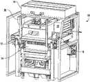
- FIG. 1is a perspective view of a laser sintering system in accordance with one embodiment of the present invention
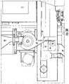
- FIG. 2is a side cross-sectional view of the laser sintering system of FIG. 1 ;
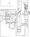
- FIG. 3Ais an enlarged side cross-sectional view of the roller, hopper, chute, roller heater, and other portions of the laser sintering system of FIG. 1 , wherein the chute is in the down position;
- FIG. 3Bis an enlarged side cross-sectional view of the roller, hopper, chute, roller heater, and other portions of the laser sintering system of FIG. 1 , wherein the chute is in the up position;
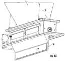
- FIG. 4Ais an enlarged perspective view of the hopper and chute of the embodiment of FIG. 1 , wherein the chute is in the down position;
- FIG. 4Bis an enlarged perspective view of the hopper and chute of the embodiment of FIG. 1 , wherein the chute is in the up position;
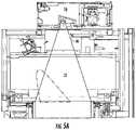
- FIG. 5Ais a side cross sectional view of the upper portion of the laser sintering system of FIG. 1 , showing the laser power measurement device in the retracted position;
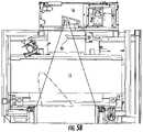
- FIG. 5Bis a side cross-sectional view of the upper portion of the laser sintering system of FIG. 1 , showing the laser power measurement device in the extended position;
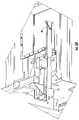
- FIGS. 6A-6Care enlarged perspective views of the laser power measurement device (in the extended position) of a further embodiment of the present invention, wherein the mirror of the laser power measurement device includes a telescoping lube that protrudes into the build chamber through a sealed opening below the laser window (not shown);
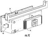
- FIG. 7Ais an enlarged perspective view of a scrubber of the laser sintering system of FIG. 1 showing the internal passages and filters of the scrubber, as well as the check valve on top and blower motor on the side;
- FIG. 7Bis an enlarged side view of the scrubber of FIG. 7A showing the single scrubber inlet and the dual scrubber outlets (each outlet is in fluid communication with one heater bracket);
- FIG. 7Cis an enlarged perspective view of the scrubber of FIG. 7A showing the scrubber inlet and scrubber outlets and the heat sink and fan for cooling of the air to be scrubbed (filtered);
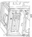
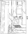
- FIG. 8is an enlarged perspective view of the laser sintering system of FIG. 1 showing the heater brackets (yellow) through which the cooled air from the scrubber outlets is reintroduced into the build chamber in order to heat the air (using the waste Heat of the heaters) and to help cool the heaters; also shown is the piping/duct connecting the scrubber inlet to the opening in the build chamber above the heater brackets;
- FIG. 9is an enlarged perspective view of the laser sintering system of FIG. 1 showing the heaters and heater brackets and the passages on the sides of the heater bracket for the pre-heated air to flow into the build chamber in a direction that does not adversely affect the powder layers;
- FIG. 10is an enlarged perspective view of the laser sintering system of FIG. 1 showing the return powder device in the raised position, wherein the return powder device is on an opposite side of the part bed from the hopper and chute.
- laser sintering systemsin accordance with embodiments of the present invention are illustrated that include many novel upgrades to prior art laser sintering systems that increase part quality and reduce powder disposal.
- These inventionsnot previous known or used in the art provide significant improvement to the part quality by providing consistent energy delivery to the sinterable powder so that the material properties are improved and consistent throughout the part in ail directions (x-axis (side to side in the build chamber), y-axis (front to back in the build chamber), and z-axis (bottom to top in the build chamber)).
- the inventionsin particular those relating to the dual APL, provide powder layers of improved density and with no or minimum peaks, valleys, or voids that provide better flow control of laser sintered particles that enables the creation of more accurate, stronger parts and enables powder to be reused (the powder used in a laser sintering build process but not sintered) for many more build processes, thus significantly reducing the need for virgin powder (new/fresh powder that has not undergone a build process) and the need to dispose of used powder. Therefore, the present inventions significantly reduces the costs associated with laser sintering of parts, which makes parts made by laser sintering more affordable, and ultimately results in laser sintering becoming more competitive against parts made by other additive manufacturing techniques, subtractive manufacturing techniques, and other traditional manufacturing techniques.
- the illustrated embodimentsare designed for polymer systems that use polyamide powders or PEEK powders or other polymer powders; however, other embodiments of the present invention may be used with further materials such as metals, composites, ceramics, and any other powder materials used to form three-dimensional objects from digital data.
- the laser sintering system 10includes a build chamber 12 , a removable part bed cart 14 , and a laser assembly 16 that includes the laser, scanning mirrors and other optics similar to prior art laser sintering systems.
- the laser sintering system 10also includes a control panel 18 or other user interface, such as a touch screen computer or tablet, for the operator to control and/or monitor the laser sintering system.
- FIG. 1also shows portions of the laser sintering system 10 that are not inside the build chamber 12 , such as the powder hopper 20 , from which powder is supplied to the build chamber, and the scrubber 22 that cleans and recirculates the air (primarily nitrogen) in the build chamber.
- FIG. 2is a cross-section of the laser sintering system that illustrates additional features of the system, both inside and outside the build chamber 12 .
- the return powder receptacle 24receives powder that is not used during the dual APL process. Powder (not shown) deposited into the return powder receptacle 24 can be stored for later use in a subsequent build process or recirculated automatically back to the hopper 20 for use in the same or subsequent build process.
- FIG. 2also illustrates components and systems within the build chamber 12 such as the roller 28 , the chute 28 , the image plane 30 where the powder layer is laser sintered (the top layer of the part bed 31 ), and the return powder device 32 (also shown in FIG. 10 ), which in the illustrated embodiment comprises a return powder piston.
- FIG. 2Further embodiments of the present invention comprise alternative return powder devices that transfer a portion of powder from one side of the powder distribution device to the other side of the powder distribution device in preparation for the second pass of the roller or other powder distributing device.
- the laser power measurement device 34is also shown in FIG. 2 and is positioned between (along the x-axis) the laser window 36 and the heaters 38 .
- Dual APLis the process of moving the roller across the part bed 31 two times for each layer of powder distributed on the part bed.
- Prior art systemstypically used a single pass of the roller or other powder distributing device, such as a doctor blade or a doctor blade like structure that holds powder and deposits powder as it moves across the part bed.
- Such systemstypically have hoppers or supply powder pistons on both sides of the part bed, while other prior art systems have a single hopper but deposit powder for a first layer with a first pass and for a second layer with a second pass (by depositing powder atop the roller assembly (or other powder distributing device) and dislodging the powder on the side of the part bed opposite the hopper).
- Still other prior art systemsuse a single pass of the roller or other powder distributing device to apply powder layer in the single pass and then simply return the powder distributing device to its original position without applying a powder layer during the return movement because no powder is provided on the leading edge in the direction of the return.
- the powder densityis significantly improved, as well as quality of the surface of the powder layer applied.
- the density of the powder in the powder layeris important because it has been discovered that the heating and laser sintering of the denser powder is more stable as the fluence (flow) of the temporarily melted material is better controlled during laser sintering.
- the improved density of the layers provided by dual APLenables used powders to be used for many more build processes because even though the powder quality slightly degrades with each build process it undergoes, the used powder still can create parts with satisfactory part quality (for example, surface quality is smooth compared to prior art techniques where reused powder can lead to rough surfaces such as the well-known “orange peel” if too much powder is used too many times) and satisfactory strength. Therefore, the higher density powder layers provided by the dual APL process significantly reduce the amount of used sinterable powder that must be discarded, thus reducing the costs associated with laser sintering while providing parts of better quality and strength.
- the dual APL techniquecomprises the following general steps:
- the dual APLis distinguishable from prior art techniques because it comprises two passes of distributing powder, which is not obvious because two passes requires additional time for each layer, which increases the build time, relative to a prior art single pass system, for each part which reduces the throughput of a laser sintering system if all other parameters are kept constant. Additional information relating to the powder density and part strength is provided in the enclosed documentation.
- certain embodiments of the present inventioncomprise a chute 28 positioned between the hopper 20 and the surface between the roller home position (where the roller is positioned during the laser scanning operation) and the part bed so that a new supply of powder can be deposited in front of the roller before the roller's first pass across the part bed.
- the chute of the illustrated embodimentscomprises a slot extending along the y-axis (front to back of the system) that is rotatable about an axis aligned along the y-axis.
- the chute 28may be rotated automatically or it may be moved by the motion of the roller, such as by contact with at least one pin 40 positioned on the roller assembly 42 that moves the roller 26 .
- the roller 26 or other portion of the roller assembly 42may push the chute from the down position in FIGS. 3A and 4A to the up position in FIGS. 38 and 4B at the beginning of the first pass (first APL) across the part bed, and the pin 40 or other portion of the roller assembly may push the chute back to the down position at the end of the second pass (second APL) across the part bed such that the chute is always in the down position when the roller is in the home position.
- the chutemay be spring loaded or otherwise biased to remain in the up position unless it is held in the down position by the pin 40 or other portion of the roller assembly.
- the chute 28simply serves as a conduit to deposit powder released from the hopper near the roller in a manner that minimizes dusting or other creation of airborne particles.
- the illustrated embodimentis a simple slot, but further embodiments of the present invention include alternative chutes that likewise reduce the dusting, spreading, or other undesirable movement of the deposited powder.
- the chute 28also comprises a chute heater 44 that pre-heats the powder in the chute so that the deposited powder is closer to the temperature the powder must attain when it is spread on the part bed prior to the melting/fusing of the powder particles by the laser. By pre-heating the powder, the build process time may be reduced.
- the chute heater or other heater in the areamay be used to pre-heat the roller.
- the roller heatermay keep the surface temperature of the roller at a desired level so that the roller distributes the powder in the desired manner. While the roller is in the home position during laser sintering of the powder layers, the roller is slowly rotated (slewed) so that the roller surface is evenly heated. Further embodiments of the present invention include alternative roller heaters to heat the surface of the roller.
- FIGS. 5A-6Cillustrate a laser power measurement device that can selectively determine the laser power (and energy) delivered to the layer of sinterable powder. Because the build chamber is hot and includes fumes and gases that may cause surfaces, such as the laser window, to lose transparency, prior art systems have not measured the laser power within the build chamber but have instead measured the laser power prior to (upstream of) the laser beam entering the build chamber or measured the laser power during periodic servicing.
- certain embodiments of the present inventionmeasure the laser power within the build chamber periodically during the build to determine changes in the laser power so that the laser can be adjusted/calibrated to ensure that the powder layers are receiving the desired amounts of energy (such as by changing the laser power or changing the scanning speed that the laser beam is moved across the powder layers).
- the laser power measurement device 43 of the illustrated embodimentsincludes a laser power sensor of a type known in the art and a telescoping mirror 46 that may be selectively positioned in the laser path to reflect the laser beam to the sensor for measurement purposes.
- the mirror 46 in the retracted positionis outside the range of motion of the laser beam so that the laser power measurement device does not block the laser beam from the part bed.
- the mirror 46 in the extended positionis positioned within the range of motion of the laser beam, such as in the center, so that the laser beam may be selectively projected to the sensor within the laser power measurement device 34 .
- FIGS. 6A-6Cillustrate one embodiment of the laser power measurement device 43 in which the mirror 46 is moved by a hollow telescoping shaft that is sealed about its entrance into the build chamber 12 .
- Further embodiments of the present inventioninclude alternative laser power measurement devices for measuring the power of the laser beam within the build chamber.
- the present inventionhas the laser power measurement device positioned above the heaters near the laser window 36 ; however, further embodiments of the present invention include the laser power measurement device at any location in the build chamber where the laser can be in optical communication with the laser power measurement device.
- FIGS. 7A-7Cillustrate a scrubber 22 in accordance with one embodiment, that includes an initial cooling section 48 and a filtration section 50 .
- the scrubber 22includes a scrubber inlet 52 through which air is pulled from the build chamber 12 (such as from/above the heaters 38 and below the laser window 36 ) and two scrubber outlets 54 through which air is expelled back to the build chamber (such as into a heater bracket as described below).
- the cooling section 48is a serpentine passage or other structure that causes the relatively hot air from the build chamber 12 to be cooled, such as with the use of a heat sink and fan assembly 56 in thermal communication with the passages in the cooling section.
- the airis cooled to assist in the precipitation of contaminants from the air.
- the airis then passed through the filter section 50 comprising one or more filters that capture the contaminants from the air passing therethrough.
- the airis circulated through the scrubber 22 by the blower fan 58 rotated by the blower motor 60 .
- FIGS. 8 and 9show the pipe or tubing that connects the build chamber to the scrubber inlet 52 , as well as one of the build chamber inlets 62 for the return of the air from the scrubber.
- the build chamber inlets 62are in flow communication with the respective heater bracket 84 in the build chamber 12 .
- the relatively cool air from the scrubberflows into the heater bracket 64 in order to transfer heat from the heater bracket 64 and the heaters 38 , thereby (i) assisting in the cooling of the heaters, which in some embodiments is desirable to increase the operable life of the heaters and/or to increase the performance of the heaters, and (ii) pre-heating returned scrubbed air.
- the pre-heated airpasses out of the array of holes on the side of each heater bracket 64 .
- the array of holesare sized and positioned to minimize the amount of turbulence or other undesirable air flow within the build chamber (for example, the powder should not be moved by the air in the build chamber).
- the enclosed documentationfurther describes the apparatus and processes of the present invention, as well as test results produced therefrom.
- the chart entitled MP Datashow the significant improvements in mechanical properties relative to prior art techniques.
- the columns of the MP Data chartare for “Recycle Runs” where runs 1 through 4 were conducted without adding any new powder to determine the deterioration in part mechanical properties based upon the lack of new/fresh/virgin powder.
- the Recycle Runswere used to make a plurality of ASTM638 bars for which the mechanical properties of Table 1 were tested for in accordance with industry standard practices known by those of skill in the art.
- the Recycle Runsincluded the respective amounts of fresh (previously unused powder), overflow (powder previously used but retrieved from overflow reservoir and not the part cake), and part cake (powder previously used and retrieved from the part cake).
- the Recycle Runswere conducted with generally consistent build parameters and part parameters, including but not limited to a fill laser power of 60 W, a fill scan count of 1, a fill scan speed of 12 M/sec, an outline laser power of 15 W, an outline fill scan count of 1, a slicer fill scan spacing of 0.2 mm, and a sinter scan of 1.
- a fill laser power of 60 Wa fill scan count of 1, a fill scan speed of 12 M/sec
- an outline laser power of 15 Wan outline fill scan count of 1
- a slicer fill scan spacing of 0.2 mmand a sinter scan of 1.
- Test datasuch as provided in the MP Data chart demonstrate that the embodiments of the present invention can be used to reduce the need for virgin powder and the corresponding need to dispose of used powder.
- the present inventionin various embodiments combines the above apparatus and methods to improve the part quality of laser sintered parts and to improve the useful life of unused laser sinterable powders.
- the present inventionprovides significant technical and financial benefits to users of laser sintering systems that were previously unavailable through prior art technologies.
- the present inventionprovides for the production of three-dimensional objects with improved build and support materials.
Landscapes
- Engineering & Computer Science (AREA)
- Chemical & Material Sciences (AREA)
- Materials Engineering (AREA)
- Manufacturing & Machinery (AREA)
- Mechanical Engineering (AREA)
- Physics & Mathematics (AREA)
- Optics & Photonics (AREA)
- Life Sciences & Earth Sciences (AREA)
- Sustainable Development (AREA)
- Plasma & Fusion (AREA)
- Ceramic Engineering (AREA)
- Health & Medical Sciences (AREA)
- Environmental & Geological Engineering (AREA)
- Toxicology (AREA)
- Powder Metallurgy (AREA)
Abstract
Description
- 1) powder is deposited from the hopper20 (via chute28) to between the
roller 26 and thepart bed 31; - 2) the roller moves across the part bed to distribute the initial layer of powder over the part bed;
- 3) the
return powder device 32 is in a lowered position such that as the roller moves over the return powder device, any powder remaining from the first pass over the part bed is deposited into the gap created by the return powder device, such that the roller moves over the powder above the return powder device; - 4) the return powder device raises so that the powder above the return powder device is between the roller and the part bed;
- 5) the roller moves across the part bed to distribute the remaining powder into any gaps, voids, or other portions missing powder, to level any waves or other raised portions of powder, and to increase the density of the powder layer; and
- 6) the roller is returned to its home position (show in
FIG. 2 ) while the laser scanning step occurs.
- 1) powder is deposited from the hopper20 (via chute28) to between the
| TABLE 1 |
| MP Data |
| Recycle | Recycle | Recycle | Recycle | Recycle | |
| Mechanical Properties | Run 0 | Run 1 | Run 2 | Run 3 | Run 4 |
| Density (LT Front) (g/cc) | 0.975 | 0.971 | 09.67 | ||
| Density (RT Front) (g/cc) | 0.973 | 0.974 | 0.957 | ||
| Density (Middle) (g/cc) | 0.973 | 0.974 | 0.964 | ||
| Density (LT Back) (g/cc) | 0.973 | 0.968 | 0.964 | ||
| Density (RT Back) (g/cc) | 0.971 | 0.974 | 0.957 | ||
| MEAN DENSITY | 0.973 | 0.972 | 0.962 | ||
| Tensile Modulus (X) | 1911 | 1925 | 1798 | ||
| Tensile Modulus (X) | 1887 | 1948 | 1771 | ||
| Tensile Modulus (X) | 1878 | 1938 | 1845 | ||
| Tensile Modulus (X) | 1939 | 1917 | 1801 | ||
| X MEAN MODULUS | 1903.75 | 1932.00 | 1803.75 | ||
| Tensile Modulus (Y) | 1962 | 1855 | 1904 | ||
| Tensile Modulus (Y) | 2012 | 1946 | 1893 | ||
| Tensile Modulus (Y) | 1872 | 1897 | 1945 | ||
| Tensile Modulus (Y) | 1873 | 1861 | 1794 | ||
| Y MEAN MODULUS | 1929.75 | 1889.75 | 1884.00 | ||
| Tensile Modulus (Z) | 1924 | 2003 | 1761 | ||
| Tensile Modulus (Z) | 1934 | 1879 | 2150 | ||
| Tensile Modulus (Z) | 1938 | 2003 | 1863 | ||
| Tensile Modulus (Z) | 1915 | 1856 | 1879 | ||
| Z MEAN MODULUS | 1927.75 | 1935.25 | 1913.25 | ||
| Tensile Strength (X) | 50.4 | 49.5 | 48.9 | ||
| Tensile Strength (X) | 50.3 | 50.0 | 47.4 | ||
| Tensile Strength (X) | 49.7 | 49.7 | 49.4 | ||
| Tensile Strength (X) | 49.4 | 48.8 | 47.8 | ||
| X MEAN STRENGTH | 50.0 | 49.5 | 48.4 | ||
| Tensile Strength (Y) | 50.4 | 48.6 | 48.6 | ||
| Tensile Strength (Y) | 50.6 | 50.2 | 49.4 | ||
| Tensile Strength (Y) | 49.3 | 50.1 | 49.0 | ||
| Tensile Strength (Y) | 49.0 | 48.5 | 47.7 | ||
| Y MEAN STRENGTH | 49.8 | 49.4 | 48.7 | ||
| Tensile Strength (Z) | 49.1 | 47.7 | 46.7 | ||
| Tensile Strength (Z) | 49.8 | 48.2 | 47.6 | ||
| Tensile Strength (Z) | 50.4 | 47.0 | 45.8 | ||
| Tensile Strength (Z) | 48.1 | 48.1 | 46.9 | ||
| Z MEAN STRENGTH | 49.4 | 47.8 | 46.8 | ||
| Elongation at Break (X) | 18.137% | 14.727% | 19.061% | ||
| Elongation at Break (X) | 18.975% | 19.577% | 17.212% | ||
| Elongation at Break (X) | 15.976% | 20.259% | 17.724% | ||
| Elongation at Break (X) | 14.579% | 16.321% | 22.901% | ||
| X MEAN EAB | 16.917% | 17.716% | 19.225% | ||
| Elongation at Break (Y) | 14.991% | 14.734% | 15.401% | ||
| Elongation at Break (Y) | 16.680% | 16.386% | 22.648% | ||
| Elongation at Break (Y) | 13.161% | 19.850% | 24.640% | ||
| Elongation at Break (Y) | 17.391% | 17.899% | 16.648% | ||
| Y MEAN EAB | 15.556% | 17.217% | 19.834% | ||
| Elongation at Break (Z) | 8.324% | 7.075% | 8.899% | ||
| Elongation at Break (Z) | 8.328% | 6.926% | 5.981% | ||
| Elongation at Break (Z) | 9.280% | 5.626% | 5.724% | ||
| Elongation at Break (Z) | 6.944% | 6.297% | 7.321% | ||
| Z MEAN EAB | 8.219% | 6.482% | 6.981% | ||
Claims (14)
Priority Applications (2)
| Application Number | Priority Date | Filing Date | Title |
|---|---|---|---|
| US15/265,998US11396134B2 (en) | 2013-03-15 | 2016-09-15 | Powder distribution for laser sintering systems |
| US17/846,413US12145317B2 (en) | 2013-03-15 | 2022-06-22 | Powder distribution for laser sintering systems |
Applications Claiming Priority (3)
| Application Number | Priority Date | Filing Date | Title |
|---|---|---|---|
| US201361793870P | 2013-03-15 | 2013-03-15 | |
| US14/212,770US20140271326A1 (en) | 2013-03-15 | 2014-03-14 | Powder Distribution for Laser Sintering Systems |
| US15/265,998US11396134B2 (en) | 2013-03-15 | 2016-09-15 | Powder distribution for laser sintering systems |
Related Parent Applications (1)
| Application Number | Title | Priority Date | Filing Date |
|---|---|---|---|
| US14/212,770ContinuationUS20140271326A1 (en) | 2013-03-15 | 2014-03-14 | Powder Distribution for Laser Sintering Systems |
Related Child Applications (1)
| Application Number | Title | Priority Date | Filing Date |
|---|---|---|---|
| US17/846,413ContinuationUS12145317B2 (en) | 2013-03-15 | 2022-06-22 | Powder distribution for laser sintering systems |
Publications (2)
| Publication Number | Publication Date |
|---|---|
| US20170008234A1 US20170008234A1 (en) | 2017-01-12 |
| US11396134B2true US11396134B2 (en) | 2022-07-26 |
Family
ID=50942778
Family Applications (4)
| Application Number | Title | Priority Date | Filing Date |
|---|---|---|---|
| US14/212,865Active2034-09-18US9931785B2 (en) | 2013-03-15 | 2014-03-14 | Chute for laser sintering systems |
| US14/212,770AbandonedUS20140271326A1 (en) | 2013-03-15 | 2014-03-14 | Powder Distribution for Laser Sintering Systems |
| US15/265,998Active2035-01-17US11396134B2 (en) | 2013-03-15 | 2016-09-15 | Powder distribution for laser sintering systems |
| US17/846,413ActiveUS12145317B2 (en) | 2013-03-15 | 2022-06-22 | Powder distribution for laser sintering systems |
Family Applications Before (2)
| Application Number | Title | Priority Date | Filing Date |
|---|---|---|---|
| US14/212,865Active2034-09-18US9931785B2 (en) | 2013-03-15 | 2014-03-14 | Chute for laser sintering systems |
| US14/212,770AbandonedUS20140271326A1 (en) | 2013-03-15 | 2014-03-14 | Powder Distribution for Laser Sintering Systems |
Family Applications After (1)
| Application Number | Title | Priority Date | Filing Date |
|---|---|---|---|
| US17/846,413ActiveUS12145317B2 (en) | 2013-03-15 | 2022-06-22 | Powder distribution for laser sintering systems |
Country Status (5)
| Country | Link |
|---|---|
| US (4) | US9931785B2 (en) |
| EP (4) | EP2969485B1 (en) |
| JP (2) | JP6178492B2 (en) |
| CN (2) | CN105579218B (en) |
| WO (2) | WO2014144319A1 (en) |
Families Citing this family (75)
| Publication number | Priority date | Publication date | Assignee | Title |
|---|---|---|---|---|
| EP2969485B1 (en)* | 2013-03-15 | 2019-06-05 | 3D Systems, Inc. | Chute for laser sintering systems |
| US9486878B2 (en) | 2014-06-20 | 2016-11-08 | Velo3D, Inc. | Apparatuses, systems and methods for three-dimensional printing |
| WO2016102970A1 (en)* | 2014-12-23 | 2016-06-30 | Renishaw Plc | Additive manufacturing apparatus and methods |
| JP6439477B2 (en)* | 2015-02-10 | 2018-12-19 | 株式会社リコー | 3D modeling apparatus, 3D modeling method, program |
| DE102015107178A1 (en)* | 2015-05-07 | 2016-11-10 | Cl Schutzrechtsverwaltungs Gmbh | Device for producing three-dimensional objects by successive solidification of layers and an associated method |
| US10583483B2 (en)* | 2015-10-15 | 2020-03-10 | Arcam Ab | Method and apparatus for producing a three-dimensional article |
| WO2017063829A1 (en)* | 2015-10-15 | 2017-04-20 | Arcam Ab | Method and apparatus for producing three-dimensional articles |
| EP4049772A1 (en) | 2015-10-30 | 2022-08-31 | Seurat Technologies, Inc. | Chamber systems for additive manufacturing |
| US10065270B2 (en) | 2015-11-06 | 2018-09-04 | Velo3D, Inc. | Three-dimensional printing in real time |
| US10286603B2 (en) | 2015-12-10 | 2019-05-14 | Velo3D, Inc. | Skillful three-dimensional printing |
| US20170239719A1 (en) | 2016-02-18 | 2017-08-24 | Velo3D, Inc. | Accurate three-dimensional printing |
| US10589464B2 (en)* | 2016-03-17 | 2020-03-17 | Hewlett-Packard Development Company, L.P. | Spreader roller for additive manufacturing |
| CN109153180A (en)* | 2016-05-12 | 2019-01-04 | 惠普发展公司,有限责任合伙企业 | Post-processing in 3D printing system |
| US11059309B2 (en) | 2016-05-12 | 2021-07-13 | Hewlett-Packard Development Company, L.P. | Calibrating printing stations |
| KR101843493B1 (en) | 2016-06-01 | 2018-03-29 | 한국기계연구원 | 3d printing apparatus comprising measuring member of density of metal powder and 3d printing method using the same |
| GB201610267D0 (en)* | 2016-06-13 | 2016-07-27 | Digital Metal Ab | Slot die manufacturing apparatus and manufacturing method |
| EP3492244A1 (en) | 2016-06-29 | 2019-06-05 | VELO3D, Inc. | Three-dimensional printing system and method for three-dimensional printing |
| US11691343B2 (en) | 2016-06-29 | 2023-07-04 | Velo3D, Inc. | Three-dimensional printing and three-dimensional printers |
| IT201600068832A1 (en)* | 2016-07-01 | 2018-01-01 | 3D4Mec Srl | 3D LASER PRINTER |
| CN109070477B (en) | 2016-07-26 | 2021-04-02 | 惠普发展公司,有限责任合伙企业 | Cooling build materials in 3D printing systems |
| US20180093418A1 (en) | 2016-09-30 | 2018-04-05 | Velo3D, Inc. | Three-dimensional objects and their formation |
| US20180126460A1 (en) | 2016-11-07 | 2018-05-10 | Velo3D, Inc. | Gas flow in three-dimensional printing |
| US20180186082A1 (en) | 2017-01-05 | 2018-07-05 | Velo3D, Inc. | Optics in three-dimensional printing |
| US10549519B2 (en)* | 2017-01-12 | 2020-02-04 | Caterpillar Inc. | Systems and methods for calibrating additive manufacturing operations based on energy density |
| US10919286B2 (en)* | 2017-01-13 | 2021-02-16 | GM Global Technology Operations LLC | Powder bed fusion system with point and area scanning laser beams |
| US10315252B2 (en) | 2017-03-02 | 2019-06-11 | Velo3D, Inc. | Three-dimensional printing of three-dimensional objects |
| JP6880492B2 (en)* | 2017-03-17 | 2021-06-02 | 株式会社リコー | 3D modeling equipment, manufacturing methods and programs for 3D models |
| US10449696B2 (en) | 2017-03-28 | 2019-10-22 | Velo3D, Inc. | Material manipulation in three-dimensional printing |
| WO2018194688A1 (en)* | 2017-04-21 | 2018-10-25 | Hewlett-Packard Development Company, L.P. | Additive manufacturing roller within radiative heat transfer area |
| US10191456B2 (en)* | 2017-05-01 | 2019-01-29 | Desktop Metal, Inc. | Method and system for software defined metallurgy |
| EP3642014A4 (en)* | 2017-07-31 | 2021-03-17 | Hewlett-Packard Development Company, L.P. | Different mixtures of build materials deliverable during a three dimensional print operation |
| EP3661730A4 (en)* | 2017-08-03 | 2021-04-07 | Effusiontech Pty Ltd | A method of 3d printing |
| US20190091765A1 (en)* | 2017-09-28 | 2019-03-28 | 3D Systems, Inc. | High capacity apparatus for layered manufacturing from powdered materials |
| US11351724B2 (en) | 2017-10-03 | 2022-06-07 | General Electric Company | Selective sintering additive manufacturing method |
| US11420384B2 (en) | 2017-10-03 | 2022-08-23 | General Electric Company | Selective curing additive manufacturing method |
| WO2019078809A1 (en) | 2017-10-16 | 2019-04-25 | Hewlett-Packard Development Company, L.P. | Vents for fluid dispensing assemblies |
| US11117324B2 (en) | 2017-10-20 | 2021-09-14 | Formlabs, Inc. | Techniques for integrated preheating and coating of powder material in additive fabrication and related systems and methods |
| US11590691B2 (en) | 2017-11-02 | 2023-02-28 | General Electric Company | Plate-based additive manufacturing apparatus and method |
| US11254052B2 (en) | 2017-11-02 | 2022-02-22 | General Electric Company | Vatless additive manufacturing apparatus and method |
| US10864678B2 (en)* | 2017-11-27 | 2020-12-15 | 3D4Mec Srl | Laser 3D printer |
| US10272525B1 (en) | 2017-12-27 | 2019-04-30 | Velo3D, Inc. | Three-dimensional printing systems and methods of their use |
| US10144176B1 (en) | 2018-01-15 | 2018-12-04 | Velo3D, Inc. | Three-dimensional printing systems and methods of their use |
| WO2019147239A1 (en) | 2018-01-25 | 2019-08-01 | Hewlett-Packard Development Company, L.P. | Build material dispensing device |
| US10821669B2 (en) | 2018-01-26 | 2020-11-03 | General Electric Company | Method for producing a component layer-by-layer |
| US10821668B2 (en) | 2018-01-26 | 2020-11-03 | General Electric Company | Method for producing a component layer-by- layer |
| CN108436085B (en)* | 2018-04-28 | 2024-01-30 | 陕西西北工业技术研究院有限责任公司 | Laser forming bin structure |
| US12121964B2 (en) | 2018-11-07 | 2024-10-22 | James J. Myrick | Processes, compositions and systems for 2D and 3D printing |
| US11724336B2 (en)* | 2019-02-06 | 2023-08-15 | Honeywell Federal Manufacturings Technologies, Llc | Apparatus for a laser welding system |
| US11794412B2 (en) | 2019-02-20 | 2023-10-24 | General Electric Company | Method and apparatus for layer thickness control in additive manufacturing |
| US11498283B2 (en) | 2019-02-20 | 2022-11-15 | General Electric Company | Method and apparatus for build thickness control in additive manufacturing |
| US11179891B2 (en) | 2019-03-15 | 2021-11-23 | General Electric Company | Method and apparatus for additive manufacturing with shared components |
| EP3718746A1 (en)* | 2019-04-02 | 2020-10-07 | Concept Laser GmbH | Apparatus for additively manufacturing three-dimensional objects |
| WO2020222761A1 (en) | 2019-04-29 | 2020-11-05 | Hewlett-Packard Development Company, L.P. | Additive manufacturing spreader with a heater |
| JP6848010B2 (en)* | 2019-06-11 | 2021-03-24 | 株式会社ソディック | Laminated modeling equipment |
| JP2021020319A (en) | 2019-07-24 | 2021-02-18 | 株式会社荏原製作所 | Am equipment |
| CA3148849A1 (en) | 2019-07-26 | 2021-02-04 | Velo3D, Inc. | Quality assurance in formation of three-dimensional objects |
| CN110901049B (en)* | 2019-11-15 | 2020-10-02 | 华中科技大学 | Jet printing equipment suitable for selective melting forming under wide temperature gradient |
| JP6990725B2 (en)* | 2020-01-30 | 2022-01-12 | 株式会社ソディック | Manufacturing method for laminated modeling equipment and 3D modeling |
| US11707883B2 (en) | 2020-11-20 | 2023-07-25 | General Electric Company | Foil interaction device for additive manufacturing |
| US12162074B2 (en) | 2020-11-25 | 2024-12-10 | Lawrence Livermore National Security, Llc | System and method for large-area pulsed laser melting of metallic powder in a laser powder bed fusion application |
| US11865780B2 (en) | 2021-02-26 | 2024-01-09 | General Electric Company | Accumalator assembly for additive manufacturing |
| JP2024518663A (en)* | 2021-05-07 | 2024-05-01 | ニコン エスエルエム ソリューションズ アーゲー | Process chamber for additive manufacturing device and method of operating the process chamber - Patents.com |
| US11951679B2 (en) | 2021-06-16 | 2024-04-09 | General Electric Company | Additive manufacturing system |
| US11731367B2 (en) | 2021-06-23 | 2023-08-22 | General Electric Company | Drive system for additive manufacturing |
| US11958250B2 (en) | 2021-06-24 | 2024-04-16 | General Electric Company | Reclamation system for additive manufacturing |
| US11958249B2 (en) | 2021-06-24 | 2024-04-16 | General Electric Company | Reclamation system for additive manufacturing |
| US11826950B2 (en) | 2021-07-09 | 2023-11-28 | General Electric Company | Resin management system for additive manufacturing |
| US12172379B2 (en) | 2021-08-11 | 2024-12-24 | General Electric Company | Cleaning system for additive manufacturing |
| US12370741B2 (en) | 2021-08-13 | 2025-07-29 | General Electric Company | Material deposition assembly for additive manufacturing |
| US12296535B2 (en) | 2021-08-24 | 2025-05-13 | General Electric Company | Attachment structure for additive manufacturing |
| US11813799B2 (en) | 2021-09-01 | 2023-11-14 | General Electric Company | Control systems and methods for additive manufacturing |
| EP4249216A1 (en) | 2022-03-23 | 2023-09-27 | General Electric Company | Systems and methods for additive manufacturing |
| DE102022111992A1 (en)* | 2022-05-12 | 2023-11-16 | Eos Gmbh Electro Optical Systems | Calibration of an energy beam |
| US12403654B2 (en) | 2022-09-30 | 2025-09-02 | General Electric Company | Systems and methods for additive manufacturing |
| US20240190082A1 (en)* | 2022-12-13 | 2024-06-13 | The Boeing Company | Methods of additively manufacturing a manufactured component, additive manufacturing systems that perform the methods, and storage media that directs additive manufacturing systems to perform the methods |
Citations (154)
| Publication number | Priority date | Publication date | Assignee | Title |
|---|---|---|---|---|
| US4247508A (en) | 1979-12-03 | 1981-01-27 | Hico Western Products Co. | Molding process |
| US4863538A (en) | 1986-10-17 | 1989-09-05 | Board Of Regents, The University Of Texas System | Method and apparatus for producing parts by selective sintering |
| US4944817A (en) | 1986-10-17 | 1990-07-31 | Board Of Regents, The University Of Texas System | Multiple material systems for selective beam sintering |
| US5017753A (en)* | 1986-10-17 | 1991-05-21 | Board Of Regents, The University Of Texas System | Method and apparatus for producing parts by selective sintering |
| US5132143A (en) | 1986-10-17 | 1992-07-21 | Board Of Regents, The University Of Texas System | Method for producing parts |
| US5147587A (en)* | 1986-10-17 | 1992-09-15 | Board Of Regents, The University Of Texas System | Method of producing parts and molds using composite ceramic powders |
| US5182170A (en) | 1989-09-05 | 1993-01-26 | Board Of Regents, The University Of Texas System | Method of producing parts by selective beam interaction of powder with gas phase reactant |
| US5216235A (en) | 1992-04-24 | 1993-06-01 | Amray, Inc. | Opto-mechanical automatic focusing system and method |
| US5252264A (en)* | 1991-11-08 | 1993-10-12 | Dtm Corporation | Apparatus and method for producing parts with multi-directional powder delivery |
| US5354414A (en) | 1988-10-05 | 1994-10-11 | Michael Feygin | Apparatus and method for forming an integral object from laminations |
| WO1995011100A1 (en) | 1993-10-20 | 1995-04-27 | United Technologies Corporation | Temperature-controlled laser sintering |
| DE4400523A1 (en) | 1994-01-11 | 1995-07-13 | Eos Electro Optical Syst | Method and device for producing a three-dimensional object |
| WO1995034468A1 (en) | 1994-06-14 | 1995-12-21 | Soligen, Inc. | Powder handling apparatus for additive fabrication equipment |
| US5534104A (en) | 1992-10-07 | 1996-07-09 | Eos Gmbh Electro Optical Systems | Method and apparatus for production of three-dimensional objects |
| US5536467A (en) | 1993-01-28 | 1996-07-16 | Eos Gmbh Electro Optical Systems | Method and apparatus for producing a three-dimensional object |
| JPH09507882A (en) | 1995-05-09 | 1997-08-12 | イーオーエス ゲゼルシャフト ミット ベシュレンクテル ハフツング イレクトロ オプティカル システムズ | 3D object manufacturing equipment by laser sintering |
| US5658412A (en) | 1993-01-11 | 1997-08-19 | Eos Gmbh Electro Optical Systems | Method and apparatus for producing a three-dimensional object |
| US5665401A (en) | 1995-04-25 | 1997-09-09 | Eos Gmbh Electro Optical Systems | Apparatus for producing an object using stereolithography |
| US5730925A (en) | 1995-04-21 | 1998-03-24 | Eos Gmbh Electro Optical Systems | Method and apparatus for producing a three-dimensional object |
| US5733497A (en) | 1995-03-31 | 1998-03-31 | Dtm Corporation | Selective laser sintering with composite plastic material |
| US5753171A (en) | 1994-05-13 | 1998-05-19 | Eos Gmbh Electro Optical Systems | Method and apparatus for producing a three-dimensional object |
| US5753274A (en) | 1995-03-30 | 1998-05-19 | Eos Gmbh Electronics Optical Systems | Apparatus for producing a three-dimensional object |
| US5786562A (en) | 1993-05-12 | 1998-07-28 | Arcam Limited | Method and device for producing three-dimensional bodies |
| US5817206A (en) | 1996-02-07 | 1998-10-06 | Dtm Corporation | Selective laser sintering of polymer powder of controlled particle size distribution |
| US5832415A (en) | 1994-10-18 | 1998-11-03 | Eos Gmbh Electro Optical Systems | Method and apparatus for calibrating a control apparatus for deflecting a laser beam |
| US5846370A (en) | 1997-03-17 | 1998-12-08 | Delco Electronics Corporation | Rapid prototyping process and apparatus therefor |
| US5876550A (en) | 1988-10-05 | 1999-03-02 | Helisys, Inc. | Laminated object manufacturing apparatus and method |
| US5876767A (en) | 1995-08-16 | 1999-03-02 | Eos Gmbh Electro Optical Systems | Apparatus for layerwise producing an object using laser sintering |
| US5897825A (en) | 1994-10-13 | 1999-04-27 | 3D Systems, Inc. | Method for producing a three-dimensional object |
| US5904890A (en) | 1996-02-20 | 1999-05-18 | Eos Gmbh Electro Optical Systems | Apparatus and method for producing three-dimensional objects |
| US5908569A (en) | 1995-05-09 | 1999-06-01 | Eos Gmbh Electro Optical Systems | Apparatus for producing a three-dimensional object by laser sintering |
| US5934343A (en)* | 1997-03-31 | 1999-08-10 | Therics, Inc | Method for dispensing of powders |
| US6085122A (en) | 1997-05-30 | 2000-07-04 | Dtm Corporation | End-of-vector laser power control in a selective laser sintering system |
| US6136257A (en) | 1998-03-27 | 2000-10-24 | Eos Gmbh Electro Optical Systems | Apparatus and method for producing a three-dimensional object and for applying a layer of a powder material to a surface |
| US6151345A (en) | 1998-07-07 | 2000-11-21 | Dtm Corporation | Laser power control with stretched initial pulses |
| US6155331A (en) | 1994-05-27 | 2000-12-05 | Eos Gmbh Electro Optical Systems | Method for use in casting technology |
| JP2001038812A (en) | 1999-08-03 | 2001-02-13 | Toyota Motor Corp | Powder and particle circulation device in powder and particle additive manufacturing method |
| US6213168B1 (en)* | 1997-03-31 | 2001-04-10 | Therics, Inc. | Apparatus and method for dispensing of powders |
| WO2001081031A1 (en) | 2000-04-27 | 2001-11-01 | Arcam Ab | Device and arrangement for producing a three-dimensional object |
| JP2001334581A (en) | 2000-05-24 | 2001-12-04 | Minolta Co Ltd | 3D modeling equipment |
| US20020090313A1 (en) | 2000-11-27 | 2002-07-11 | Wang Xinhua | Method and apparatus for creating a free-form three-dimensional metal part using high-temperature direct laser melting |
| US6425281B1 (en) | 1999-07-12 | 2002-07-30 | Unit Instruments, Inc. | Pressure insensitive gas control system |
| US20020104973A1 (en) | 2001-02-08 | 2002-08-08 | Kerekes Thomas A. | Surface scanning system for selective deposition modeling |
| US6483596B1 (en) | 1999-04-23 | 2002-11-19 | Eos Gmbh Electro Optical Systems | Method of calibrating an apparatus for producing a three-dimensional object, calibration apparatus and method and apparatus for producing a three-dimensional object |
| US6554600B1 (en) | 1998-10-09 | 2003-04-29 | Eos Gmbh Electro Optical Systems | Device for producing a three-dimensional object, especially a laser sintering machine |
| US6596224B1 (en)* | 1996-05-24 | 2003-07-22 | Massachusetts Institute Of Technology | Jetting layers of powder and the formation of fine powder beds thereby |
| US6600129B2 (en) | 2000-02-19 | 2003-07-29 | Daimlerchrysler Ag | Device and process for sintering a powder with a laser beam |
| JP2003245981A (en) | 2002-02-25 | 2003-09-02 | Matsushita Electric Works Ltd | Method and apparatus for manufacturing three-dimensional shaped object |
| US6617546B2 (en) | 2001-02-22 | 2003-09-09 | Daimlerchrysler Ag | Method and device for selective laser sintering |
| US6672343B1 (en) | 1999-06-21 | 2004-01-06 | Eos Gmbh Optical Systems | Device for supplying powder for a device for producing a three-dimensional object layer by layer |
| US6677554B2 (en) | 2001-07-31 | 2004-01-13 | 3D Systems, Inc. | Selective laser sintering with optimized raster scan direction |
| US6694207B2 (en) | 2001-07-31 | 2004-02-17 | 3D Systems, Inc. | Selective laser sintering with interleaved fill scan |
| US20040061260A1 (en) | 2002-09-30 | 2004-04-01 | Eos Gmbh Electro Optical Systems | Device and method for the manufacturing of three-dimensional objects layer-by-layer |
| WO2004056512A1 (en) | 2002-12-19 | 2004-07-08 | Arcam Ab | Arrangement and method for production of a three dimensional object |
| US20040200816A1 (en)* | 2003-04-09 | 2004-10-14 | 3D Systems, Inc. | Sintering using thermal image feedback |
| US6814926B2 (en) | 2003-03-19 | 2004-11-09 | 3D Systems Inc. | Metal powder composition for laser sintering |
| US6823928B2 (en) | 2002-09-27 | 2004-11-30 | University Of Queensland | Infiltrated aluminum preforms |
| US6824714B1 (en) | 1999-08-20 | 2004-11-30 | Eos Gmbh Electro Optical Systems | Device and method for generative production of a three-dimensional object |
| US6848494B2 (en) | 2002-09-27 | 2005-02-01 | 3D Systems, Inc. | Wetting agent for infiltrated aluminum preforms |
| US6930278B1 (en)* | 2004-08-13 | 2005-08-16 | 3D Systems, Inc. | Continuous calibration of a non-contact thermal sensor for laser sintering |
| US6932935B1 (en) | 1999-08-06 | 2005-08-23 | Eos Gmbh Electro Optical Systems | Method and device for producing a three-dimensional object |
| DE10360094A1 (en) | 2003-12-20 | 2005-09-08 | Concept Laser Gmbh | Construction equipment, useful for layer-wise production by shaped parts from building material, comprises a horizontal displaceable coat and sensor equipment is arranged in the chamber to detect the volume of the building material |
| US20050207931A1 (en) | 2004-03-21 | 2005-09-22 | Toyota Motorsport Gmbh | unknown |
| US20050242473A1 (en) | 2004-04-28 | 2005-11-03 | 3D Systems, Inc. | Uniform thermal distribution imaging |
| US20050263933A1 (en)* | 2004-05-28 | 2005-12-01 | 3D Systems, Inc. | Single side bi-directional feed for laser sintering |
| US20050263934A1 (en)* | 2004-05-28 | 2005-12-01 | 3D Systems, Inc. | Single side feed parked powder wave heating with wave flattener |
| US6997232B2 (en) | 2002-09-27 | 2006-02-14 | University Of Queensland | Infiltrated aluminum preforms |
| US7036550B2 (en) | 2002-09-27 | 2006-05-02 | University Of Queensland | Infiltrated aluminum preforms |
| EP1700686A2 (en) | 2005-03-09 | 2006-09-13 | 3D Systems, Inc. | Laser sintering powder recycle system |
| EP1704989A2 (en) | 2005-03-23 | 2006-09-27 | 3D Systems, Inc. | Apparatus and method for aligning a removable build chamber within a process chamber |
| US20060215246A1 (en)* | 2005-03-22 | 2006-09-28 | 3D Systems, Inc. | Laser scanning and power control in a rapid prototyping system |
| US20060219315A1 (en)* | 2005-03-31 | 2006-10-05 | 3D Systems, Inc. | Pneumatic powder transport system |
| US7153463B2 (en) | 2001-02-07 | 2006-12-26 | Eos Gmbh Electro Optical Systems | Device for treating powder for a device which produces a three-dimensional object device for producing a three-dimensional object and method for the production thereof |
| US20070063372A1 (en)* | 2005-09-19 | 2007-03-22 | Nielsen Jeffrey A | Systems and methods of solid freeform fabrication with interchangeable powder bins |
| EP1771267A1 (en) | 2005-04-12 | 2007-04-11 | EOS GmbH Electro Optical Systems | Device and method for applying layers of a powdery material to a surface |
| US20070087071A1 (en)* | 2005-10-14 | 2007-04-19 | Devos John A | Systems and methods of solid freeform fabrication with translating powder bins |
| US7261542B2 (en) | 2004-03-18 | 2007-08-28 | Desktop Factory, Inc. | Apparatus for three dimensional printing using image layers |
| US7297304B2 (en) | 1999-06-23 | 2007-11-20 | Stratasys, Inc. | High-temperature modeling method |
| US20070267784A1 (en) | 2004-01-23 | 2007-11-22 | Ralph Greiner | Method for the Manufacturing of a Three-Dimensional Object in a Layer-Wise Fashion and Material Systems Suitable Therefor |
| WO2007147221A1 (en) | 2006-06-20 | 2007-12-27 | Katholieke Universiteit Leuven | Procedure and apparatus for in-situ monitoring and feedback control of selective laser powder processing |
| US20080122141A1 (en) | 2006-11-29 | 2008-05-29 | Bryan Bedal | Sinterable Powder |
| US20080190905A1 (en) | 2005-07-01 | 2008-08-14 | Eos Gmbh Electro Optical Systems | Device For Producing a Three-Dimensional Object |
| US7419632B2 (en) | 2002-08-09 | 2008-09-02 | Eos Gmbh Electro Optical Systems | Method and device for the production of a three-dimensional object by means of sintering |
| US20080211132A1 (en)* | 2005-09-05 | 2008-09-04 | Frits Kornelis Feenstra | Apparatus and Method for Building a Three-Dimensional Article |
| US20090025638A1 (en)* | 2005-07-27 | 2009-01-29 | Shofu Inc | Apparatus for Forming Layered Object |
| US20090045553A1 (en) | 2006-05-18 | 2009-02-19 | Eos Gmbh Electro Optical Systems | Device and Method for a Layerwise Manufacturing of a Three-Dimensional Object from a Building Material in Powder Form |
| US20090047165A1 (en) | 2007-05-14 | 2009-02-19 | Eos Gmbh Electro Optical Systems | Metal powder for use in an additive method for the production of three-dimensional objects and method using such metal powder |
| US7521652B2 (en) | 2004-12-07 | 2009-04-21 | 3D Systems, Inc. | Controlled cooling methods and apparatus for laser sintering part-cake |
| US20090152771A1 (en) | 2007-11-27 | 2009-06-18 | Eos Gmbh Electro Optical Systems | Method of manufacturing three-dimensional objects by laser sintering |
| US7569174B2 (en) | 2004-12-07 | 2009-08-04 | 3D Systems, Inc. | Controlled densification of fusible powders in laser sintering |
| US7601422B2 (en) | 2002-12-02 | 2009-10-13 | Eos Gmbh Electro Optical Systems | Rounded-particle plastic powder in particular for application in laser sintering, method for production of such a powder and laser sintering process using such a powder |
| US20090266803A1 (en) | 2006-03-28 | 2009-10-29 | Eos Gmbh Electro Optical Systems | Process Chamber and Method for Processing a Material by a Directed Beam of Electromagnetic Radiation, in Particular for a Laser Sintering Device |
| US7614866B2 (en) | 2007-01-17 | 2009-11-10 | 3D Systems, Inc. | Solid imaging apparatus and method |
| US20090291308A1 (en)* | 2008-05-21 | 2009-11-26 | Eos Gmbh Electro Optical Systems | Method and device of layerwise manufacturing a three-dimensional object of a powdery material |
| US20090295042A1 (en) | 2008-05-20 | 2009-12-03 | Eos Gmbh Electro Optical Systems | Selective sintering of structurally modified polymers |
| US7628600B2 (en) | 2006-11-22 | 2009-12-08 | Eos Gmbh Electro Optical Systems | Device for a layerwise manufacturing of a three-dimensional object |
| US7647107B2 (en) | 2002-10-31 | 2010-01-12 | Medtronic, Inc. | Addressing recurrent atrial fibrillation |
| US7661948B2 (en) | 2006-11-22 | 2010-02-16 | Eos Gmbh Electro Optical Systems | Application device for applying a layer of a building material in powder form in a device for a layerwise manufacturing of a three-dimensional object |
| US7665979B2 (en) | 2002-08-02 | 2010-02-23 | Eos Gmbh Electro Optical Systems | Device and method for the production of three-dimensional objects by means of generative production method |
| US7686005B2 (en) | 2003-01-29 | 2010-03-30 | Adams Joseph S | Combustion-gas-powered paintball marker |
| US7713048B2 (en) | 2006-11-22 | 2010-05-11 | Eos Gmbh Electro Optical Systems | Device for a layerwise manufacturing of a three-dimensional object |
| WO2010061174A2 (en) | 2008-11-27 | 2010-06-03 | University Of Exeter | Manufacturing device and method |
| US20100140550A1 (en) | 2008-11-20 | 2010-06-10 | Eos Gmbh Electro Optical Systems | Method for identifying laser sintering powders |
| US7740683B2 (en) | 2003-09-17 | 2010-06-22 | Eos Gmbh Electro Optical Systems | Powder for manufacturing precious metal products by free forming fabrication and products |
| US20100155985A1 (en) | 2008-12-18 | 2010-06-24 | 3D Systems, Incorporated | Apparatus and Method for Cooling Part Cake in Laser Sintering |
| WO2010095987A1 (en) | 2009-02-18 | 2010-08-26 | Arcam Ab | Apparatus for producing a three-dimensional object |
| US7790096B2 (en) | 2005-03-31 | 2010-09-07 | 3D Systems, Inc. | Thermal management system for a removable build chamber for use with a laser sintering system |
| US7807947B2 (en) | 2005-05-09 | 2010-10-05 | 3D Systems, Inc. | Laser sintering process chamber gas curtain window cleansing in a laser sintering system |
| US20100264302A1 (en) | 2009-04-06 | 2010-10-21 | Eos Gmbh Electro Optical Systems | Method and device for calibrating an irradiation device |
| US20100270713A1 (en) | 2009-04-08 | 2010-10-28 | Eos Gmbh Electro Optical Systems | Method of Manufacturing a Three-Dimensional Object by Use of Synthetic Powder Having Anti-Microbial Properties, and Synthetic Powder Having Anti-Microbial Properties for Such a Method |
| US7837458B2 (en) | 2006-11-22 | 2010-11-23 | Eos Gmbh Electro Optical Systems | Device for a layer-wise manufacturing of a three-dimensional object |
| US7847057B2 (en) | 2007-04-05 | 2010-12-07 | Eos Gmbh Electro Optical Systems | PAEK powder, in particular for the use in a method for a layer-wise manufacturing of a three-dimensional object, as well as method for producing it |
| US7850885B2 (en) | 2005-05-13 | 2010-12-14 | Eos Gmbh Optical Systems | Device and method for manufacturing a three-dimensional object with a heated recoater for a building material in powder form |
| US7891095B2 (en) | 2003-09-17 | 2011-02-22 | Eos Gmbh Electro Optical Systems | Method of producing jewelry and other precious metal products with complex geometries |
| US7931462B2 (en) | 2006-05-18 | 2011-04-26 | Eos Gmbh Electro Optical Systems | Device and method for the manufacturing of a three-dimensional object |
| US7946840B2 (en) | 2006-11-22 | 2011-05-24 | Eos Gmbh Electro Optical Systems | Device and method for a layerwise manufacturing of a three-dimensional object |
| US20110122381A1 (en) | 2009-11-25 | 2011-05-26 | Kevin Hickerson | Imaging Assembly |
| US20110165340A1 (en) | 2010-01-05 | 2011-07-07 | Eos Gmbh Electro Optical Systems | Device for generatively manufacturing a three-dimensional object with continuous heat supply |
| US7976302B2 (en) | 2006-11-22 | 2011-07-12 | Eos Gmbh Electro Optical Systems | Device for a layerwise manufacturing of a three-dimensional object and method for inserting and removing respectively, a container |
| US20110168091A1 (en) | 2010-01-05 | 2011-07-14 | Eos Gmbh Electro Optical Systems | Device of Generatively Manufacturing Three-Dimensional Objects with Insulated Building Field |
| US20110174552A1 (en) | 2010-01-15 | 2011-07-21 | Gulzar Ahmed | Apparatus and Methods for In-Line Weight Checking and Correction |
| US20110221099A1 (en) | 2010-02-23 | 2011-09-15 | Eos Gmbh Electro Optical Systems | Method and device for manufacturing a three-dimensional object that is suitable for application to microtechnology |
| US20110237731A1 (en) | 2010-03-25 | 2011-09-29 | Eos Gmbh Electro Optical Systems | Pa 12 powder for use in a generative layer-wise manufacturing method |
| US8031384B2 (en) | 2006-11-22 | 2011-10-04 | Eos Gmbh Electro Optical Systems | Device for a layerwise manufacturing of a three-dimensional object and method for adjusting an optical system of the same |
| US8032479B2 (en) | 2004-12-09 | 2011-10-04 | Mitsubishi Electric Corporation | String matching system and program therefor |
| US20110278773A1 (en) | 2010-05-12 | 2011-11-17 | Eos Gmbh Electro Optical Systems | Device And Method Of Generatively Manufacturing A Three-Dimensional Object With Working Field Limitation |
| US20110293771A1 (en) | 2010-05-12 | 2011-12-01 | Eos Gmbh Electro Optical Systems | Means For Modifying A Building Space And Device For Manufacturing A Three-Dimensional Object Having Means For Modifying A Building Space |
| US8073315B2 (en) | 2005-05-26 | 2011-12-06 | Eos Gmbh Electro Optical Systems | Radiant heater for heating the building material in a laser sintering device |
| US8075814B2 (en) | 2005-07-21 | 2011-12-13 | Eos Gmbh Electro Optical Systems | Device for layerwise manufacturing of a three-dimensional object |
| US8083513B2 (en) | 2006-11-22 | 2011-12-27 | Eos Gmbh Electro Optical Systems | Apparatus for manufacturing a three-dimensional object layer by layer |
| JP2012501828A (en) | 2008-09-05 | 2012-01-26 | エムティーティー テクノロジーズ リミテッド | Filter assembly |
| US8119053B1 (en) | 2004-03-18 | 2012-02-21 | 3D Systems, Inc. | Apparatus for three dimensional printing using imaged layers |
| US8124192B2 (en) | 2007-06-25 | 2012-02-28 | Eos Gmbh Electro Optical Systems | Layer application device for an electrostatic layer application of a building material in powder form and device and method for manufacturing a three-dimensional object |
| US8137739B2 (en) | 2005-04-06 | 2012-03-20 | Eos Gmbh Electro Optical Systems | Apparatus and method for the manufacture of a three-dimensional object |
| US20120107496A1 (en) | 2010-05-05 | 2012-05-03 | Eos Gmbh Electro Optical Systems | Method of generatively manufacturing a three-dimensional object with broaching elements and method of generating a corresponding data set |
| US20120107438A1 (en) | 2010-10-29 | 2012-05-03 | Eos Gmbh Electro Optical Systems | Device For Processing Powder For A Device For Manufacturing A Three-Dimensional Object And Device For Manufacturing A Three-Dimensional Object |
| US8172562B2 (en) | 2002-08-02 | 2012-05-08 | Eos Gmbh Electro Optical Systems | Device and method for producing a three-dimensional object by means of a generative production method |
| US8186990B2 (en) | 2006-11-22 | 2012-05-29 | Eos Gmbh Electro Optical Systems | Device for a layerwise manufacturing of a three-dimensional object |
| US20120164322A1 (en)* | 2009-07-15 | 2012-06-28 | Phenix Systems | Device for forming thin films and method for using such a device |
| US8260447B2 (en) | 2008-12-02 | 2012-09-04 | Eos Gmbh Electro Optical Systems | Method of providing an identifiable powder amount and method of manufacturing an object |
| US8303886B2 (en) | 2007-12-21 | 2012-11-06 | Eos Gmbh Electro Optical Systems | Method of manufacturing a three-dimensional object |
| US8313087B2 (en) | 2004-03-21 | 2012-11-20 | Eos Gmbh Electro Optical Systems | Powder for rapid prototyping and associated production method |
| US8317508B2 (en) | 2008-10-13 | 2012-11-27 | Eos Gmbh Electro Optical Systems | Frame for a device for manufacturing a three-dimensional object and device for manufacturing a three-dimensional object by such a frame |
| US20130000553A1 (en) | 2009-12-02 | 2013-01-03 | Exone Gmbh | Installation for the layered construction of a shaped body, comprising a coating device cleaner |
| US8366432B2 (en) | 2006-11-22 | 2013-02-05 | Eos Gmbh Electro Optical Systems | Device for a layerwise manufacturing of a three-dimensional object |
| US20130064707A1 (en)* | 2011-09-08 | 2013-03-14 | Sony Corporation | Modeling apparatus, powder removing apparatus, modeling system, and method of manufacturing a model |
| US8414281B2 (en) | 2005-06-27 | 2013-04-09 | Eos Gmbh Electro Optical Systems | Method and device for producing a 3D object by means of a generative 3D-method |
| US8420001B2 (en) | 2008-05-20 | 2013-04-16 | Eos Gmbh Electro Optical Systems | Influencing specific mechanical properties of three-dimensional objects manufactured by a selective sintering by means of electromagnetic radiation from a powder comprising at least one polymer or copolymer |
| US20130171019A1 (en) | 2010-09-03 | 2013-07-04 | Eos Gmbh Electro Optical Systems | Method of manufacturing a three-dimensional object having an internal structure |
| US8501075B2 (en) | 2009-11-25 | 2013-08-06 | Eos Gmbh Electro Optical Systems | Method for manufacturing a three-dimensional object |
| US8525071B2 (en) | 2008-07-03 | 2013-09-03 | Eos Gmbh Electro Optical Systems | Apparatus for manufacturing a three-dimensional object layer by layer |
| US20130330470A1 (en) | 2010-10-08 | 2013-12-12 | Eos Gmbh Electro Optical Systems | Method for coating objects, in particular such objects that have been manufactured by a generative manufacturing method |
| US20140265045A1 (en)* | 2013-03-15 | 2014-09-18 | 3D Systems, Inc. | Chute for Laser Sintering Systems |
| US20140363585A1 (en)* | 2011-12-20 | 2014-12-11 | Compagnie Generale Des Etablissements Michelin | Machine and process for powder-based additive manufacturing |
Family Cites Families (27)
| Publication number | Priority date | Publication date | Assignee | Title |
|---|---|---|---|---|
| US4504064A (en)* | 1982-09-07 | 1985-03-12 | Moore Special Tool Co., Inc. | Laser path seal |
| US5155324A (en)* | 1986-10-17 | 1992-10-13 | Deckard Carl R | Method for selective laser sintering with layerwise cross-scanning |
| US5155321A (en) | 1990-11-09 | 1992-10-13 | Dtm Corporation | Radiant heating apparatus for providing uniform surface temperature useful in selective laser sintering |
| US5594652A (en)* | 1991-01-31 | 1997-01-14 | Texas Instruments Incorporated | Method and apparatus for the computer-controlled manufacture of three-dimensional objects from computer data |
| US6175422B1 (en)* | 1991-01-31 | 2001-01-16 | Texas Instruments Incorporated | Method and apparatus for the computer-controlled manufacture of three-dimensional objects from computer data |
| US5253036A (en)* | 1991-09-06 | 1993-10-12 | Ledalite Architectural Products Inc. | Near-field photometric method and apparatus |
| US5352405A (en) | 1992-12-18 | 1994-10-04 | Dtm Corporation | Thermal control of selective laser sintering via control of the laser scan |
| US6007318A (en)* | 1996-12-20 | 1999-12-28 | Z Corporation | Method and apparatus for prototyping a three-dimensional object |
| US7037382B2 (en)* | 1996-12-20 | 2006-05-02 | Z Corporation | Three-dimensional printer |
| JP3528119B2 (en)* | 1997-10-27 | 2004-05-17 | Ykk株式会社 | How to measure powders |
| US6066285A (en)* | 1997-12-12 | 2000-05-23 | University Of Florida | Solid freeform fabrication using power deposition |
| JP2000117721A (en)* | 1998-10-09 | 2000-04-25 | Matsuoka Concrete Kogyo Kk | Ready mixed concrete charger |
| FR2790418B1 (en)* | 1999-03-01 | 2001-05-11 | Optoform Sarl Procedes De Prot | RAPID PROTOTYPING PROCESS ALLOWING THE USE OF PASTY MATERIALS, AND DEVICE FOR IMPLEMENTING SAME |
| US6902246B2 (en)* | 2001-10-03 | 2005-06-07 | 3D Systems, Inc. | Quantized feed system for solid freeform fabrication |
| DE10216013B4 (en)* | 2002-04-11 | 2006-12-28 | Generis Gmbh | Method and device for applying fluids |
| US6905645B2 (en)* | 2002-07-03 | 2005-06-14 | Therics, Inc. | Apparatus, systems and methods for use in three-dimensional printing |
| KR101537494B1 (en)* | 2006-05-26 | 2015-07-16 | 3디 시스템즈 인코오퍼레이티드 | Apparatus and methods for handling materials in a 3-d printer |
| US20080181977A1 (en)* | 2007-01-17 | 2008-07-31 | Sperry Charles R | Brush assembly for removal of excess uncured build material |
| JP5272519B2 (en)* | 2007-07-17 | 2013-08-28 | セイコーエプソン株式会社 | 3D modeling apparatus and 3D modeling method |
| US7947919B2 (en)* | 2008-03-04 | 2011-05-24 | Universal Laser Systems, Inc. | Laser-based material processing exhaust systems and methods for using such systems |
| US20090283109A1 (en)* | 2008-05-16 | 2009-11-19 | Khalil Moussa | Methods for Cleaning and Curing Solid Freeform Fabrication Parts |
| US20090283119A1 (en)* | 2008-05-16 | 2009-11-19 | Khalil Moussa | Post-Processing System For Solid Freeform Fabrication Parts |
| JP5250338B2 (en)* | 2008-08-22 | 2013-07-31 | パナソニック株式会社 | Manufacturing method of three-dimensional shaped object, manufacturing apparatus thereof, and three-dimensional shaped object |
| JP5774825B2 (en)* | 2010-08-19 | 2015-09-09 | ソニー株式会社 | Three-dimensional modeling apparatus and manufacturing method of modeled object |
| US8603217B2 (en)* | 2011-02-01 | 2013-12-10 | Universal Laser Systems, Inc. | Recirculating filtration systems for material processing systems and associated methods of use and manufacture |
| EP2914433B1 (en)* | 2012-11-05 | 2018-03-28 | Stratasys Ltd. | System and method for direct inkjet printing of 3d objects |
| US9216544B2 (en)* | 2012-12-21 | 2015-12-22 | Stratasys, Inc. | Automated additive manufacturing system for printing three-dimensional parts, printing farm thereof, and method of use thereof |
- 2014
- 2014-03-14EPEP14730240.0Apatent/EP2969485B1/enactiveActive
- 2014-03-14JPJP2016502864Apatent/JP6178492B2/enactiveActive
- 2014-03-14USUS14/212,865patent/US9931785B2/enactiveActive
- 2014-03-14CNCN201480026842.2Apatent/CN105579218B/enactiveActive
- 2014-03-14CNCN201480026835.2Apatent/CN105163930B/enactiveActive
- 2014-03-14WOPCT/US2014/028671patent/WO2014144319A1/enactiveApplication Filing
- 2014-03-14USUS14/212,770patent/US20140271326A1/ennot_activeAbandoned
- 2014-03-14EPEP19172241.2Apatent/EP3556493B1/enactiveActive
- 2014-03-14WOPCT/US2014/028621patent/WO2014165310A2/enactiveApplication Filing
- 2014-03-14JPJP2016502848Apatent/JP6178491B2/enactiveActive
- 2014-03-14EPEP22164716.7Apatent/EP4049832A1/enactivePending
- 2014-03-14EPEP14744210.7Apatent/EP2969486B1/ennot_activeNot-in-force
- 2016
- 2016-09-15USUS15/265,998patent/US11396134B2/enactiveActive
- 2022
- 2022-06-22USUS17/846,413patent/US12145317B2/enactiveActive
Patent Citations (189)
| Publication number | Priority date | Publication date | Assignee | Title |
|---|---|---|---|---|
| US4247508B1 (en) | 1979-12-03 | 1996-10-01 | Dtm Corp | Molding process |
| US4247508A (en) | 1979-12-03 | 1981-01-27 | Hico Western Products Co. | Molding process |
| US5132143A (en) | 1986-10-17 | 1992-07-21 | Board Of Regents, The University Of Texas System | Method for producing parts |
| US5017753A (en)* | 1986-10-17 | 1991-05-21 | Board Of Regents, The University Of Texas System | Method and apparatus for producing parts by selective sintering |
| US4863538A (en) | 1986-10-17 | 1989-09-05 | Board Of Regents, The University Of Texas System | Method and apparatus for producing parts by selective sintering |
| US5147587A (en)* | 1986-10-17 | 1992-09-15 | Board Of Regents, The University Of Texas System | Method of producing parts and molds using composite ceramic powders |
| US4944817A (en) | 1986-10-17 | 1990-07-31 | Board Of Regents, The University Of Texas System | Multiple material systems for selective beam sintering |
| US5354414A (en) | 1988-10-05 | 1994-10-11 | Michael Feygin | Apparatus and method for forming an integral object from laminations |
| US5876550A (en) | 1988-10-05 | 1999-03-02 | Helisys, Inc. | Laminated object manufacturing apparatus and method |
| US5182170A (en) | 1989-09-05 | 1993-01-26 | Board Of Regents, The University Of Texas System | Method of producing parts by selective beam interaction of powder with gas phase reactant |
| US5252264A (en)* | 1991-11-08 | 1993-10-12 | Dtm Corporation | Apparatus and method for producing parts with multi-directional powder delivery |
| US5216235A (en) | 1992-04-24 | 1993-06-01 | Amray, Inc. | Opto-mechanical automatic focusing system and method |
| US5534104A (en) | 1992-10-07 | 1996-07-09 | Eos Gmbh Electro Optical Systems | Method and apparatus for production of three-dimensional objects |
| US5658412A (en) | 1993-01-11 | 1997-08-19 | Eos Gmbh Electro Optical Systems | Method and apparatus for producing a three-dimensional object |
| US5536467A (en) | 1993-01-28 | 1996-07-16 | Eos Gmbh Electro Optical Systems | Method and apparatus for producing a three-dimensional object |
| US5786562A (en) | 1993-05-12 | 1998-07-28 | Arcam Limited | Method and device for producing three-dimensional bodies |
| WO1995011100A1 (en) | 1993-10-20 | 1995-04-27 | United Technologies Corporation | Temperature-controlled laser sintering |
| US5530221A (en) | 1993-10-20 | 1996-06-25 | United Technologies Corporation | Apparatus for temperature controlled laser sintering |
| US5427733A (en) | 1993-10-20 | 1995-06-27 | United Technologies Corporation | Method for performing temperature-controlled laser sintering |
| CN1135732A (en) | 1993-10-20 | 1996-11-13 | 联合技术公司 | temperature controlled laser sintering |
| US5647931A (en) | 1994-01-11 | 1997-07-15 | Eos Gmbh Electro Optical Systems | Method and apparatus for producing a three-dimensional object |
| JPH08502703A (en) | 1994-01-11 | 1996-03-26 | イーオーエス ゲゼルシャフト ミット ベシュレンクテル ハフツング イレクトロ オプティカル システムズ | Method and apparatus for producing three-dimensional object |
| DE4400523A1 (en) | 1994-01-11 | 1995-07-13 | Eos Electro Optical Syst | Method and device for producing a three-dimensional object |
| US5753171A (en) | 1994-05-13 | 1998-05-19 | Eos Gmbh Electro Optical Systems | Method and apparatus for producing a three-dimensional object |
| US6155331A (en) | 1994-05-27 | 2000-12-05 | Eos Gmbh Electro Optical Systems | Method for use in casting technology |
| WO1995034468A1 (en) | 1994-06-14 | 1995-12-21 | Soligen, Inc. | Powder handling apparatus for additive fabrication equipment |
| US5897825A (en) | 1994-10-13 | 1999-04-27 | 3D Systems, Inc. | Method for producing a three-dimensional object |
| US5832415A (en) | 1994-10-18 | 1998-11-03 | Eos Gmbh Electro Optical Systems | Method and apparatus for calibrating a control apparatus for deflecting a laser beam |
| US5753274A (en) | 1995-03-30 | 1998-05-19 | Eos Gmbh Electronics Optical Systems | Apparatus for producing a three-dimensional object |
| US6042774A (en) | 1995-03-30 | 2000-03-28 | Eos Gmbh Electro Optical Systems | Method for producing a three-dimensional object |
| US5733497A (en) | 1995-03-31 | 1998-03-31 | Dtm Corporation | Selective laser sintering with composite plastic material |
| US5730925A (en) | 1995-04-21 | 1998-03-24 | Eos Gmbh Electro Optical Systems | Method and apparatus for producing a three-dimensional object |
| US5665401A (en) | 1995-04-25 | 1997-09-09 | Eos Gmbh Electro Optical Systems | Apparatus for producing an object using stereolithography |
| US5904889A (en) | 1995-04-25 | 1999-05-18 | 3D Systems, Inc. | Apparatus and method for producing an object using stereolithography |
| US5908569A (en) | 1995-05-09 | 1999-06-01 | Eos Gmbh Electro Optical Systems | Apparatus for producing a three-dimensional object by laser sintering |
| JPH09507882A (en) | 1995-05-09 | 1997-08-12 | イーオーエス ゲゼルシャフト ミット ベシュレンクテル ハフツング イレクトロ オプティカル システムズ | 3D object manufacturing equipment by laser sintering |
| US5876767A (en) | 1995-08-16 | 1999-03-02 | Eos Gmbh Electro Optical Systems | Apparatus for layerwise producing an object using laser sintering |
| US5817206A (en) | 1996-02-07 | 1998-10-06 | Dtm Corporation | Selective laser sintering of polymer powder of controlled particle size distribution |
| US5904890A (en) | 1996-02-20 | 1999-05-18 | Eos Gmbh Electro Optical Systems | Apparatus and method for producing three-dimensional objects |
| US6596224B1 (en)* | 1996-05-24 | 2003-07-22 | Massachusetts Institute Of Technology | Jetting layers of powder and the formation of fine powder beds thereby |
| US5846370A (en) | 1997-03-17 | 1998-12-08 | Delco Electronics Corporation | Rapid prototyping process and apparatus therefor |
| US6213168B1 (en)* | 1997-03-31 | 2001-04-10 | Therics, Inc. | Apparatus and method for dispensing of powders |
| US5934343A (en)* | 1997-03-31 | 1999-08-10 | Therics, Inc | Method for dispensing of powders |
| US6085122A (en) | 1997-05-30 | 2000-07-04 | Dtm Corporation | End-of-vector laser power control in a selective laser sintering system |
| US6136257A (en) | 1998-03-27 | 2000-10-24 | Eos Gmbh Electro Optical Systems | Apparatus and method for producing a three-dimensional object and for applying a layer of a powder material to a surface |
| US6151345A (en) | 1998-07-07 | 2000-11-21 | Dtm Corporation | Laser power control with stretched initial pulses |
| US6554600B1 (en) | 1998-10-09 | 2003-04-29 | Eos Gmbh Electro Optical Systems | Device for producing a three-dimensional object, especially a laser sintering machine |
| US6483596B1 (en) | 1999-04-23 | 2002-11-19 | Eos Gmbh Electro Optical Systems | Method of calibrating an apparatus for producing a three-dimensional object, calibration apparatus and method and apparatus for producing a three-dimensional object |
| US6672343B1 (en) | 1999-06-21 | 2004-01-06 | Eos Gmbh Optical Systems | Device for supplying powder for a device for producing a three-dimensional object layer by layer |
| US7297304B2 (en) | 1999-06-23 | 2007-11-20 | Stratasys, Inc. | High-temperature modeling method |
| US6425281B1 (en) | 1999-07-12 | 2002-07-30 | Unit Instruments, Inc. | Pressure insensitive gas control system |
| JP2001038812A (en) | 1999-08-03 | 2001-02-13 | Toyota Motor Corp | Powder and particle circulation device in powder and particle additive manufacturing method |
| US6932935B1 (en) | 1999-08-06 | 2005-08-23 | Eos Gmbh Electro Optical Systems | Method and device for producing a three-dimensional object |
| US6824714B1 (en) | 1999-08-20 | 2004-11-30 | Eos Gmbh Electro Optical Systems | Device and method for generative production of a three-dimensional object |
| US6600129B2 (en) | 2000-02-19 | 2003-07-29 | Daimlerchrysler Ag | Device and process for sintering a powder with a laser beam |
| WO2001081031A1 (en) | 2000-04-27 | 2001-11-01 | Arcam Ab | Device and arrangement for producing a three-dimensional object |
| US20010050448A1 (en) | 2000-05-24 | 2001-12-13 | Minolta Co., Ltd. | Three-dimensional modeling apparatus |
| JP2001334581A (en) | 2000-05-24 | 2001-12-04 | Minolta Co Ltd | 3D modeling equipment |
| US20020090313A1 (en) | 2000-11-27 | 2002-07-11 | Wang Xinhua | Method and apparatus for creating a free-form three-dimensional metal part using high-temperature direct laser melting |
| US7153463B2 (en) | 2001-02-07 | 2006-12-26 | Eos Gmbh Electro Optical Systems | Device for treating powder for a device which produces a three-dimensional object device for producing a three-dimensional object and method for the production thereof |
| US20020104973A1 (en) | 2001-02-08 | 2002-08-08 | Kerekes Thomas A. | Surface scanning system for selective deposition modeling |
| US20030201255A1 (en) | 2001-02-22 | 2003-10-30 | Karsten Manetsberger | Method and device for selective laser sintering |
| US6858816B2 (en) | 2001-02-22 | 2005-02-22 | Daimlerchrysler Ag | Method and device for selective laser sintering |
| US6617546B2 (en) | 2001-02-22 | 2003-09-09 | Daimlerchrysler Ag | Method and device for selective laser sintering |
| US6694207B2 (en) | 2001-07-31 | 2004-02-17 | 3D Systems, Inc. | Selective laser sintering with interleaved fill scan |
| US6677554B2 (en) | 2001-07-31 | 2004-01-13 | 3D Systems, Inc. | Selective laser sintering with optimized raster scan direction |
| JP2003245981A (en) | 2002-02-25 | 2003-09-02 | Matsushita Electric Works Ltd | Method and apparatus for manufacturing three-dimensional shaped object |
| US7665979B2 (en) | 2002-08-02 | 2010-02-23 | Eos Gmbh Electro Optical Systems | Device and method for the production of three-dimensional objects by means of generative production method |
| US8172562B2 (en) | 2002-08-02 | 2012-05-08 | Eos Gmbh Electro Optical Systems | Device and method for producing a three-dimensional object by means of a generative production method |
| US7419632B2 (en) | 2002-08-09 | 2008-09-02 | Eos Gmbh Electro Optical Systems | Method and device for the production of a three-dimensional object by means of sintering |
| US6848494B2 (en) | 2002-09-27 | 2005-02-01 | 3D Systems, Inc. | Wetting agent for infiltrated aluminum preforms |
| US6997232B2 (en) | 2002-09-27 | 2006-02-14 | University Of Queensland | Infiltrated aluminum preforms |
| US6823928B2 (en) | 2002-09-27 | 2004-11-30 | University Of Queensland | Infiltrated aluminum preforms |
| US7036550B2 (en) | 2002-09-27 | 2006-05-02 | University Of Queensland | Infiltrated aluminum preforms |
| US20040061260A1 (en) | 2002-09-30 | 2004-04-01 | Eos Gmbh Electro Optical Systems | Device and method for the manufacturing of three-dimensional objects layer-by-layer |
| US7647107B2 (en) | 2002-10-31 | 2010-01-12 | Medtronic, Inc. | Addressing recurrent atrial fibrillation |
| US20120070666A1 (en) | 2002-12-02 | 2012-03-22 | Eos Gmbh Electro Optical Systems | Rounded-Particle Plastic Powder in Particular for Application in Laser Sintering, Method for Production of Such a Powder and Laser Sintering Process Using Such a Powder |
| US20090321998A1 (en) | 2002-12-02 | 2009-12-31 | Eos Gmbh Electro Optical Systems | Rounded-Particle Plastic Powder in Particular for Application in Laser Sintering, Method for Production of Such a Powder and Laser Sintering Process Using Such a Powder |
| US7601422B2 (en) | 2002-12-02 | 2009-10-13 | Eos Gmbh Electro Optical Systems | Rounded-particle plastic powder in particular for application in laser sintering, method for production of such a powder and laser sintering process using such a powder |
| WO2004056512A1 (en) | 2002-12-19 | 2004-07-08 | Arcam Ab | Arrangement and method for production of a three dimensional object |
| US7686005B2 (en) | 2003-01-29 | 2010-03-30 | Adams Joseph S | Combustion-gas-powered paintball marker |
| US6814926B2 (en) | 2003-03-19 | 2004-11-09 | 3D Systems Inc. | Metal powder composition for laser sintering |
| US6815636B2 (en) | 2003-04-09 | 2004-11-09 | 3D Systems, Inc. | Sintering using thermal image feedback |
| JP2004306612A (en) | 2003-04-09 | 2004-11-04 | Three D Syst Inc | Sintering using thermal image feedback |
| US20040200816A1 (en)* | 2003-04-09 | 2004-10-14 | 3D Systems, Inc. | Sintering using thermal image feedback |
| US7740683B2 (en) | 2003-09-17 | 2010-06-22 | Eos Gmbh Electro Optical Systems | Powder for manufacturing precious metal products by free forming fabrication and products |
| US7891095B2 (en) | 2003-09-17 | 2011-02-22 | Eos Gmbh Electro Optical Systems | Method of producing jewelry and other precious metal products with complex geometries |
| DE10360094A1 (en) | 2003-12-20 | 2005-09-08 | Concept Laser Gmbh | Construction equipment, useful for layer-wise production by shaped parts from building material, comprises a horizontal displaceable coat and sensor equipment is arranged in the chamber to detect the volume of the building material |
| US20070267784A1 (en) | 2004-01-23 | 2007-11-22 | Ralph Greiner | Method for the Manufacturing of a Three-Dimensional Object in a Layer-Wise Fashion and Material Systems Suitable Therefor |
| US7261542B2 (en) | 2004-03-18 | 2007-08-28 | Desktop Factory, Inc. | Apparatus for three dimensional printing using image layers |
| US8119053B1 (en) | 2004-03-18 | 2012-02-21 | 3D Systems, Inc. | Apparatus for three dimensional printing using imaged layers |
| US20080036117A1 (en) | 2004-03-18 | 2008-02-14 | Hickerson Kevin P | Apparatus for three dimensional printing using imaged layers |
| US8313087B2 (en) | 2004-03-21 | 2012-11-20 | Eos Gmbh Electro Optical Systems | Powder for rapid prototyping and associated production method |
| US20050207931A1 (en) | 2004-03-21 | 2005-09-22 | Toyota Motorsport Gmbh | unknown |
| US20080152910A1 (en) | 2004-03-21 | 2008-06-26 | Eos Gmbh Electro Optical Systems | N/a |
| US20050242473A1 (en) | 2004-04-28 | 2005-11-03 | 3D Systems, Inc. | Uniform thermal distribution imaging |
| US20050263934A1 (en)* | 2004-05-28 | 2005-12-01 | 3D Systems, Inc. | Single side feed parked powder wave heating with wave flattener |
| US20050263933A1 (en)* | 2004-05-28 | 2005-12-01 | 3D Systems, Inc. | Single side bi-directional feed for laser sintering |
| US6930278B1 (en)* | 2004-08-13 | 2005-08-16 | 3D Systems, Inc. | Continuous calibration of a non-contact thermal sensor for laser sintering |
| US7569174B2 (en) | 2004-12-07 | 2009-08-04 | 3D Systems, Inc. | Controlled densification of fusible powders in laser sintering |
| US7521652B2 (en) | 2004-12-07 | 2009-04-21 | 3D Systems, Inc. | Controlled cooling methods and apparatus for laser sintering part-cake |
| US8032479B2 (en) | 2004-12-09 | 2011-10-04 | Mitsubishi Electric Corporation | String matching system and program therefor |
| US20060214335A1 (en)* | 2005-03-09 | 2006-09-28 | 3D Systems, Inc. | Laser sintering powder recycle system |
| US7887316B2 (en) | 2005-03-09 | 2011-02-15 | 3D Systems, Inc. | Selective laser sintering powder recycle system |
| JP2006248231A (en) | 2005-03-09 | 2006-09-21 | Three D Syst Inc | Powder recovery system for laser sintering |
| EP1700686A2 (en) | 2005-03-09 | 2006-09-13 | 3D Systems, Inc. | Laser sintering powder recycle system |
| US20060215246A1 (en)* | 2005-03-22 | 2006-09-28 | 3D Systems, Inc. | Laser scanning and power control in a rapid prototyping system |
| US20070057412A1 (en) | 2005-03-23 | 2007-03-15 | 3D Systems, Inc. | Apparatus and method for aligning a removable build chamber within a process chamber |
| US7357629B2 (en) | 2005-03-23 | 2008-04-15 | 3D Systems, Inc. | Apparatus and method for aligning a removable build chamber within a process chamber |
| EP1704989A2 (en) | 2005-03-23 | 2006-09-27 | 3D Systems, Inc. | Apparatus and method for aligning a removable build chamber within a process chamber |
| US7464733B2 (en) | 2005-03-31 | 2008-12-16 | 3D Systems, Inc. | Pneumatic Powder Transport System |
| US7790096B2 (en) | 2005-03-31 | 2010-09-07 | 3D Systems, Inc. | Thermal management system for a removable build chamber for use with a laser sintering system |
| US20060219315A1 (en)* | 2005-03-31 | 2006-10-05 | 3D Systems, Inc. | Pneumatic powder transport system |
| US7296599B2 (en) | 2005-03-31 | 2007-11-20 | 3D Systems, Inc. | Pneumatic powder transport system |
| US8137739B2 (en) | 2005-04-06 | 2012-03-20 | Eos Gmbh Electro Optical Systems | Apparatus and method for the manufacture of a three-dimensional object |
| US7820241B2 (en) | 2005-04-12 | 2010-10-26 | Eos Gmbh Electro Optical Systems | Device and method for applying layers of a powder material onto a surface |
| US20070298182A1 (en) | 2005-04-12 | 2007-12-27 | Hans Perret | Device and Method for Applying Layers of a Powder Material Onto a Surface |
| EP1771267A1 (en) | 2005-04-12 | 2007-04-11 | EOS GmbH Electro Optical Systems | Device and method for applying layers of a powdery material to a surface |
| US7807947B2 (en) | 2005-05-09 | 2010-10-05 | 3D Systems, Inc. | Laser sintering process chamber gas curtain window cleansing in a laser sintering system |
| US7850885B2 (en) | 2005-05-13 | 2010-12-14 | Eos Gmbh Optical Systems | Device and method for manufacturing a three-dimensional object with a heated recoater for a building material in powder form |
| US8073315B2 (en) | 2005-05-26 | 2011-12-06 | Eos Gmbh Electro Optical Systems | Radiant heater for heating the building material in a laser sintering device |
| US8414281B2 (en) | 2005-06-27 | 2013-04-09 | Eos Gmbh Electro Optical Systems | Method and device for producing a 3D object by means of a generative 3D-method |
| US20080190905A1 (en) | 2005-07-01 | 2008-08-14 | Eos Gmbh Electro Optical Systems | Device For Producing a Three-Dimensional Object |
| US20120090734A1 (en) | 2005-07-01 | 2012-04-19 | Eos Gmbh Electro Optical Systems | Device for Producing a Three-Dimensional Object |
| US8075814B2 (en) | 2005-07-21 | 2011-12-13 | Eos Gmbh Electro Optical Systems | Device for layerwise manufacturing of a three-dimensional object |
| US20090025638A1 (en)* | 2005-07-27 | 2009-01-29 | Shofu Inc | Apparatus for Forming Layered Object |
| US20080211132A1 (en)* | 2005-09-05 | 2008-09-04 | Frits Kornelis Feenstra | Apparatus and Method for Building a Three-Dimensional Article |
| US20070063372A1 (en)* | 2005-09-19 | 2007-03-22 | Nielsen Jeffrey A | Systems and methods of solid freeform fabrication with interchangeable powder bins |
| US20070087071A1 (en)* | 2005-10-14 | 2007-04-19 | Devos John A | Systems and methods of solid freeform fabrication with translating powder bins |
| US20090266803A1 (en) | 2006-03-28 | 2009-10-29 | Eos Gmbh Electro Optical Systems | Process Chamber and Method for Processing a Material by a Directed Beam of Electromagnetic Radiation, in Particular for a Laser Sintering Device |
| US20110133367A1 (en) | 2006-05-18 | 2011-06-09 | Eos Gmbh Electro Optical Systems | Device and Method for a Layerwise Manufacturing of a Three-Dimensional Object from a Building Material in Powder Form |
| US7931462B2 (en) | 2006-05-18 | 2011-04-26 | Eos Gmbh Electro Optical Systems | Device and method for the manufacturing of a three-dimensional object |
| US20090045553A1 (en) | 2006-05-18 | 2009-02-19 | Eos Gmbh Electro Optical Systems | Device and Method for a Layerwise Manufacturing of a Three-Dimensional Object from a Building Material in Powder Form |
| WO2007147221A1 (en) | 2006-06-20 | 2007-12-27 | Katholieke Universiteit Leuven | Procedure and apparatus for in-situ monitoring and feedback control of selective laser powder processing |
| US20120267813A1 (en) | 2006-11-22 | 2012-10-25 | Eos Gmbh Electro Optical Systems | Device For A Layerwise Manufacturing Of A Three-Dimensional Object And Method For Supplying A Building Material |
| US8083513B2 (en) | 2006-11-22 | 2011-12-27 | Eos Gmbh Electro Optical Systems | Apparatus for manufacturing a three-dimensional object layer by layer |
| US7837458B2 (en) | 2006-11-22 | 2010-11-23 | Eos Gmbh Electro Optical Systems | Device for a layer-wise manufacturing of a three-dimensional object |
| US8031384B2 (en) | 2006-11-22 | 2011-10-04 | Eos Gmbh Electro Optical Systems | Device for a layerwise manufacturing of a three-dimensional object and method for adjusting an optical system of the same |
| US8366432B2 (en) | 2006-11-22 | 2013-02-05 | Eos Gmbh Electro Optical Systems | Device for a layerwise manufacturing of a three-dimensional object |
| US7946840B2 (en) | 2006-11-22 | 2011-05-24 | Eos Gmbh Electro Optical Systems | Device and method for a layerwise manufacturing of a three-dimensional object |
| US7713048B2 (en) | 2006-11-22 | 2010-05-11 | Eos Gmbh Electro Optical Systems | Device for a layerwise manufacturing of a three-dimensional object |
| US7628600B2 (en) | 2006-11-22 | 2009-12-08 | Eos Gmbh Electro Optical Systems | Device for a layerwise manufacturing of a three-dimensional object |
| US7661948B2 (en) | 2006-11-22 | 2010-02-16 | Eos Gmbh Electro Optical Systems | Application device for applying a layer of a building material in powder form in a device for a layerwise manufacturing of a three-dimensional object |
| US7976302B2 (en) | 2006-11-22 | 2011-07-12 | Eos Gmbh Electro Optical Systems | Device for a layerwise manufacturing of a three-dimensional object and method for inserting and removing respectively, a container |
| US8186990B2 (en) | 2006-11-22 | 2012-05-29 | Eos Gmbh Electro Optical Systems | Device for a layerwise manufacturing of a three-dimensional object |
| US20080122141A1 (en) | 2006-11-29 | 2008-05-29 | Bryan Bedal | Sinterable Powder |
| US7614866B2 (en) | 2007-01-17 | 2009-11-10 | 3D Systems, Inc. | Solid imaging apparatus and method |
| US8299208B2 (en) | 2007-04-05 | 2012-10-30 | Eos Gmbh Electro Optical Systems | PAEK powder, in particular for the use in a method for a layer-wise manufacturing of a three-dimensional object, as well as method for producing it |
| US7847057B2 (en) | 2007-04-05 | 2010-12-07 | Eos Gmbh Electro Optical Systems | PAEK powder, in particular for the use in a method for a layer-wise manufacturing of a three-dimensional object, as well as method for producing it |
| US20090047165A1 (en) | 2007-05-14 | 2009-02-19 | Eos Gmbh Electro Optical Systems | Metal powder for use in an additive method for the production of three-dimensional objects and method using such metal powder |
| US8124192B2 (en) | 2007-06-25 | 2012-02-28 | Eos Gmbh Electro Optical Systems | Layer application device for an electrostatic layer application of a building material in powder form and device and method for manufacturing a three-dimensional object |
| US20090152771A1 (en) | 2007-11-27 | 2009-06-18 | Eos Gmbh Electro Optical Systems | Method of manufacturing three-dimensional objects by laser sintering |
| US8303886B2 (en) | 2007-12-21 | 2012-11-06 | Eos Gmbh Electro Optical Systems | Method of manufacturing a three-dimensional object |
| US8420001B2 (en) | 2008-05-20 | 2013-04-16 | Eos Gmbh Electro Optical Systems | Influencing specific mechanical properties of three-dimensional objects manufactured by a selective sintering by means of electromagnetic radiation from a powder comprising at least one polymer or copolymer |
| US20090295042A1 (en) | 2008-05-20 | 2009-12-03 | Eos Gmbh Electro Optical Systems | Selective sintering of structurally modified polymers |
| US20090291308A1 (en)* | 2008-05-21 | 2009-11-26 | Eos Gmbh Electro Optical Systems | Method and device of layerwise manufacturing a three-dimensional object of a powdery material |
| US8525071B2 (en) | 2008-07-03 | 2013-09-03 | Eos Gmbh Electro Optical Systems | Apparatus for manufacturing a three-dimensional object layer by layer |
| JP2012501828A (en) | 2008-09-05 | 2012-01-26 | エムティーティー テクノロジーズ リミテッド | Filter assembly |
| US8794263B2 (en) | 2008-09-05 | 2014-08-05 | Mtt Technologies Limited | Filter assembly |
| US20140287080A1 (en) | 2008-09-05 | 2014-09-25 | Mtt Technologies Limited | Filter assembly |
| US8317508B2 (en) | 2008-10-13 | 2012-11-27 | Eos Gmbh Electro Optical Systems | Frame for a device for manufacturing a three-dimensional object and device for manufacturing a three-dimensional object by such a frame |
| US20100140550A1 (en) | 2008-11-20 | 2010-06-10 | Eos Gmbh Electro Optical Systems | Method for identifying laser sintering powders |
| WO2010061174A2 (en) | 2008-11-27 | 2010-06-03 | University Of Exeter | Manufacturing device and method |
| US8260447B2 (en) | 2008-12-02 | 2012-09-04 | Eos Gmbh Electro Optical Systems | Method of providing an identifiable powder amount and method of manufacturing an object |
| US20100155985A1 (en) | 2008-12-18 | 2010-06-24 | 3D Systems, Incorporated | Apparatus and Method for Cooling Part Cake in Laser Sintering |
| WO2010095987A1 (en) | 2009-02-18 | 2010-08-26 | Arcam Ab | Apparatus for producing a three-dimensional object |
| US20100264302A1 (en) | 2009-04-06 | 2010-10-21 | Eos Gmbh Electro Optical Systems | Method and device for calibrating an irradiation device |
| US20100270713A1 (en) | 2009-04-08 | 2010-10-28 | Eos Gmbh Electro Optical Systems | Method of Manufacturing a Three-Dimensional Object by Use of Synthetic Powder Having Anti-Microbial Properties, and Synthetic Powder Having Anti-Microbial Properties for Such a Method |
| US20120164322A1 (en)* | 2009-07-15 | 2012-06-28 | Phenix Systems | Device for forming thin films and method for using such a device |
| US20110122381A1 (en) | 2009-11-25 | 2011-05-26 | Kevin Hickerson | Imaging Assembly |
| US8501075B2 (en) | 2009-11-25 | 2013-08-06 | Eos Gmbh Electro Optical Systems | Method for manufacturing a three-dimensional object |
| US20130000553A1 (en) | 2009-12-02 | 2013-01-03 | Exone Gmbh | Installation for the layered construction of a shaped body, comprising a coating device cleaner |
| US20110168091A1 (en) | 2010-01-05 | 2011-07-14 | Eos Gmbh Electro Optical Systems | Device of Generatively Manufacturing Three-Dimensional Objects with Insulated Building Field |
| US20110165340A1 (en) | 2010-01-05 | 2011-07-07 | Eos Gmbh Electro Optical Systems | Device for generatively manufacturing a three-dimensional object with continuous heat supply |
| US20110174552A1 (en) | 2010-01-15 | 2011-07-21 | Gulzar Ahmed | Apparatus and Methods for In-Line Weight Checking and Correction |
| US20110221099A1 (en) | 2010-02-23 | 2011-09-15 | Eos Gmbh Electro Optical Systems | Method and device for manufacturing a three-dimensional object that is suitable for application to microtechnology |
| US20140329953A1 (en) | 2010-03-25 | 2014-11-06 | Eos Gmbh Electro Optical Systems | PA 12 Powder for Use in a Generative Layer-Wise Manufacturing Method |
| US8877874B2 (en) | 2010-03-25 | 2014-11-04 | Eos Gmbh Electro Optical Systems | PA 12 powder for use in a generative layer-wise manufacturing method |
| JP2011202165A (en) | 2010-03-25 | 2011-10-13 | Eos Gmbh Electro Optical Systems | Pa 12 powder optimized for regenerating for use in generative layer-wise manufacturing method |
| US20110237731A1 (en) | 2010-03-25 | 2011-09-29 | Eos Gmbh Electro Optical Systems | Pa 12 powder for use in a generative layer-wise manufacturing method |
| US20120107496A1 (en) | 2010-05-05 | 2012-05-03 | Eos Gmbh Electro Optical Systems | Method of generatively manufacturing a three-dimensional object with broaching elements and method of generating a corresponding data set |
| US20110278773A1 (en) | 2010-05-12 | 2011-11-17 | Eos Gmbh Electro Optical Systems | Device And Method Of Generatively Manufacturing A Three-Dimensional Object With Working Field Limitation |
| US20110293771A1 (en) | 2010-05-12 | 2011-12-01 | Eos Gmbh Electro Optical Systems | Means For Modifying A Building Space And Device For Manufacturing A Three-Dimensional Object Having Means For Modifying A Building Space |
| US20130171019A1 (en) | 2010-09-03 | 2013-07-04 | Eos Gmbh Electro Optical Systems | Method of manufacturing a three-dimensional object having an internal structure |
| US20130330470A1 (en) | 2010-10-08 | 2013-12-12 | Eos Gmbh Electro Optical Systems | Method for coating objects, in particular such objects that have been manufactured by a generative manufacturing method |
| US20120107438A1 (en) | 2010-10-29 | 2012-05-03 | Eos Gmbh Electro Optical Systems | Device For Processing Powder For A Device For Manufacturing A Three-Dimensional Object And Device For Manufacturing A Three-Dimensional Object |
| US20130064707A1 (en)* | 2011-09-08 | 2013-03-14 | Sony Corporation | Modeling apparatus, powder removing apparatus, modeling system, and method of manufacturing a model |
| US20140363585A1 (en)* | 2011-12-20 | 2014-12-11 | Compagnie Generale Des Etablissements Michelin | Machine and process for powder-based additive manufacturing |
| US20140265045A1 (en)* | 2013-03-15 | 2014-09-18 | 3D Systems, Inc. | Chute for Laser Sintering Systems |
Non-Patent Citations (25)
| Title |
|---|
| Chinese Translation of China's First Office Action for Chinese Patent Application No. 201480026842.2 dated Jan. 3, 2017 (15 pages). |
| Chinese Translation of China's Second Office Action for Chinese Patent Application No. 201480026842.2 dated Nov. 9, 2017 (6 pages). |
| English translation of Chinese First Office Action for Chinese Patent Application No. 201480026835.2 dated Jul. 4, 2016 (11 pages). |
| European Examination Report for Application No. EP 05007528.2, dated Dec. 12, 2006 (4 pages). |
| European Examination Report for Application No. EP 05007528.2, dated Nov. 7, 2007 (3 pages). |
| European Examination Report for Application No. EP 05007626.4, dated Aug. 11, 2006 (5 pages). |
| European Extended Search Report for European Patent Application No. 19712241.2 dated Aug. 27, 2019 (9 pages). |
| European Search Report for Application No. EP 05007528.2, Date of Completion of Search Sep. 16, 2005 (3 pages). |
| European Search Report for Application No. EP 05007626.4, Date of Completion of Search Sep. 16, 2005 (3 pages). |
| German Examination Report for Application No. DE 102005015985.0, dated Jan. 31, 2006 (4 pages—no English translation). |
| German Examination Report for Application No. DE 102005015986.0, dated Feb. 2, 2006 (4 pages—no English translation). |
| Japanese Office Action for Application No. JP 2005-155060, dated Jan. 30, 2008 (2 pages). |
| Japanese Office Action for Counterpart Japanese Application No. JP 2005-155059, dated Jan. 22, 2008 (2 pages). |
| Japanese Translation of Japan's First Office Action for Japanese Patent Application No. 2016-502848 dated Aug. 16, 2016 (5 pages). |
| Office Action dated Jan. 7, 2008 in U.S. Appl. No. 10/856,289. |
| Office Action dated Jan. 8, 2008 in U.S. Appl. No. 10/856,303. |
| PCT International Search Report for the International Searching Authority for PCT/US2014/028621 dated Jan. 5, 2015 (8 pages). |
| PCT International Search Report for the International Searching Authority for PCT/US2014/028671 dated Sep. 3, 2014 (6 pages). |
| PCT Partial International Search Report for the International Searching Authority for PCT/US2014/028621 dated Oct. 15, 2014 (6 pages). |
| PCT Preliminary International Search Report for the International Searching Authority for PCT/US2014/028621 dated Sep. 24, 2015 (2 pages). |
| PCT Preliminary International Search Report for the International Searching Authority for PCT/US2014/028671 dated Sep. 24, 2015 (2 pages). |
| PCT Written Opinion for the International Searching Authority for PCT/US2014/028621 dated Sep. 24, 2015 (10 pages). |
| PCT Written Opinion for the International Searching Authority for PCT/US2014/028671 dated Sep. 24, 2015 (8 pages). |
| PCT Written Opinion for the International Searching Authority for PCT/US2014/028671 dated Sep. 3, 2014 (8 pages). |
| PCT Written Report for the International Searching Authority for PCT/US2014/028621 dated Jan. 5, 2015 (10 pages). |
Also Published As
| Publication number | Publication date |
|---|---|
| CN105579218B (en) | 2018-09-18 |
| US12145317B2 (en) | 2024-11-19 |
| EP4049832A1 (en) | 2022-08-31 |
| US20140265045A1 (en) | 2014-09-18 |
| EP3556493A1 (en) | 2019-10-23 |
| JP6178491B2 (en) | 2017-08-09 |
| CN105163930B (en) | 2017-12-12 |
| WO2014144319A1 (en) | 2014-09-18 |
| EP2969485A1 (en) | 2016-01-20 |
| WO2014165310A3 (en) | 2015-02-12 |
| JP2016518264A (en) | 2016-06-23 |
| EP2969486A2 (en) | 2016-01-20 |
| CN105579218A (en) | 2016-05-11 |
| US9931785B2 (en) | 2018-04-03 |
| JP6178492B2 (en) | 2017-08-09 |
| EP2969485B1 (en) | 2019-06-05 |
| JP2016519009A (en) | 2016-06-30 |
| US20140271326A1 (en) | 2014-09-18 |
| WO2014165310A2 (en) | 2014-10-09 |
| US20220324173A1 (en) | 2022-10-13 |
| EP2969486B1 (en) | 2018-05-09 |
| EP3556493B1 (en) | 2022-05-18 |
| US20170008234A1 (en) | 2017-01-12 |
| CN105163930A (en) | 2015-12-16 |
Similar Documents
| Publication | Publication Date | Title |
|---|---|---|
| US12145317B2 (en) | Powder distribution for laser sintering systems | |
| CN111215629B (en) | Apparatus for producing an article by additive manufacturing and method of calibrating an apparatus | |
| JP6875335B2 (en) | Powder floor recorder equipment and how to use it | |
| US20220023952A1 (en) | Method and apparatus for continuously refreshing a recoater blade for additive manufacturing | |
| EP3833192B1 (en) | Additive manufacturing system with gas flow head | |
| US8784721B2 (en) | Method of manufacturing three-dimensional objects by laser sintering | |
| Foster et al. | Optical, layerwise monitoring of powder bed fusion | |
| US20200398482A1 (en) | Methods and apparatus for the manufacture of three-dimensional objects | |
| US11396135B2 (en) | Powder reclamation and cleaning system for an additive manufacturing machine | |
| JP6945470B2 (en) | Manufacturing system of additional model and manufacturing method of additional model | |
| JP2018528879A (en) | Additive manufacturing using preheating | |
| WO2019191607A1 (en) | Powder transer system for additive manufacturing | |
| JP7110487B2 (en) | Powder coating apparatus, method of operating powder coating apparatus, and system for manufacturing three-dimensional workpieces |
Legal Events
| Date | Code | Title | Description |
|---|---|---|---|
| AS | Assignment | Owner name:3D SYSTEMS, INC., SOUTH CAROLINA Free format text:ASSIGNMENT OF ASSIGNORS INTEREST;ASSIGNORS:CULLEN, DAVID H.;HIDALGO, RAFAEL ENRIQUE;REEL/FRAME:039754/0298 Effective date:20140314 | |
| AS | Assignment | Owner name:HSBC BANK USA, NATIONAL ASSOCIATION, AS ADMINISTRA Free format text:SECURITY INTEREST;ASSIGNOR:3D SYSTEMS, INC.;REEL/FRAME:048456/0017 Effective date:20190227 Owner name:HSBC BANK USA, NATIONAL ASSOCIATION, AS ADMINISTRATIVE AGENT, NEW YORK Free format text:SECURITY INTEREST;ASSIGNOR:3D SYSTEMS, INC.;REEL/FRAME:048456/0017 Effective date:20190227 | |
| STPP | Information on status: patent application and granting procedure in general | Free format text:RESPONSE TO NON-FINAL OFFICE ACTION ENTERED AND FORWARDED TO EXAMINER | |
| STPP | Information on status: patent application and granting procedure in general | Free format text:FINAL REJECTION MAILED | |
| STPP | Information on status: patent application and granting procedure in general | Free format text:RESPONSE AFTER FINAL ACTION FORWARDED TO EXAMINER | |
| STPP | Information on status: patent application and granting procedure in general | Free format text:ADVISORY ACTION MAILED | |
| STPP | Information on status: patent application and granting procedure in general | Free format text:DOCKETED NEW CASE - READY FOR EXAMINATION | |
| STPP | Information on status: patent application and granting procedure in general | Free format text:NON FINAL ACTION MAILED | |
| STPP | Information on status: patent application and granting procedure in general | Free format text:FINAL REJECTION MAILED | |
| STPP | Information on status: patent application and granting procedure in general | Free format text:ADVISORY ACTION MAILED | |
| STPP | Information on status: patent application and granting procedure in general | Free format text:NON FINAL ACTION MAILED | |
| AS | Assignment | Owner name:3D SYSTEMS, INC., SOUTH CAROLINA Free format text:RELEASE BY SECURED PARTY;ASSIGNOR:HSBC BANK USA, NATIONAL ASSOCIATION;REEL/FRAME:057651/0374 Effective date:20210824 | |
| STPP | Information on status: patent application and granting procedure in general | Free format text:RESPONSE TO NON-FINAL OFFICE ACTION ENTERED AND FORWARDED TO EXAMINER | |
| STPP | Information on status: patent application and granting procedure in general | Free format text:FINAL REJECTION MAILED | |
| STPP | Information on status: patent application and granting procedure in general | Free format text:RESPONSE AFTER FINAL ACTION FORWARDED TO EXAMINER | |
| STPP | Information on status: patent application and granting procedure in general | Free format text:NOTICE OF ALLOWANCE MAILED -- APPLICATION RECEIVED IN OFFICE OF PUBLICATIONS | |
| STPP | Information on status: patent application and granting procedure in general | Free format text:AWAITING TC RESP., ISSUE FEE NOT PAID | |
| STPP | Information on status: patent application and granting procedure in general | Free format text:PUBLICATIONS -- ISSUE FEE PAYMENT RECEIVED | |
| STCF | Information on status: patent grant | Free format text:PATENTED CASE |