US11395751B2 - Systems and methods for manufacturing a stent frame - Google Patents
Systems and methods for manufacturing a stent frameDownload PDFInfo
- Publication number
- US11395751B2 US11395751B2US15/645,937US201715645937AUS11395751B2US 11395751 B2US11395751 B2US 11395751B2US 201715645937 AUS201715645937 AUS 201715645937AUS 11395751 B2US11395751 B2US 11395751B2
- Authority
- US
- United States
- Prior art keywords
- struts
- support structure
- strut members
- strut
- width
- Prior art date
- Legal status (The legal status is an assumption and is not a legal conclusion. Google has not performed a legal analysis and makes no representation as to the accuracy of the status listed.)
- Active
Links
Images


Classifications
- A—HUMAN NECESSITIES
- A61—MEDICAL OR VETERINARY SCIENCE; HYGIENE
- A61F—FILTERS IMPLANTABLE INTO BLOOD VESSELS; PROSTHESES; DEVICES PROVIDING PATENCY TO, OR PREVENTING COLLAPSING OF, TUBULAR STRUCTURES OF THE BODY, e.g. STENTS; ORTHOPAEDIC, NURSING OR CONTRACEPTIVE DEVICES; FOMENTATION; TREATMENT OR PROTECTION OF EYES OR EARS; BANDAGES, DRESSINGS OR ABSORBENT PADS; FIRST-AID KITS
- A61F2/00—Filters implantable into blood vessels; Prostheses, i.e. artificial substitutes or replacements for parts of the body; Appliances for connecting them with the body; Devices providing patency to, or preventing collapsing of, tubular structures of the body, e.g. stents
- A61F2/02—Prostheses implantable into the body
- A61F2/24—Heart valves ; Vascular valves, e.g. venous valves; Heart implants, e.g. passive devices for improving the function of the native valve or the heart muscle; Transmyocardial revascularisation [TMR] devices; Valves implantable in the body
- A—HUMAN NECESSITIES
- A61—MEDICAL OR VETERINARY SCIENCE; HYGIENE
- A61F—FILTERS IMPLANTABLE INTO BLOOD VESSELS; PROSTHESES; DEVICES PROVIDING PATENCY TO, OR PREVENTING COLLAPSING OF, TUBULAR STRUCTURES OF THE BODY, e.g. STENTS; ORTHOPAEDIC, NURSING OR CONTRACEPTIVE DEVICES; FOMENTATION; TREATMENT OR PROTECTION OF EYES OR EARS; BANDAGES, DRESSINGS OR ABSORBENT PADS; FIRST-AID KITS
- A61F2/00—Filters implantable into blood vessels; Prostheses, i.e. artificial substitutes or replacements for parts of the body; Appliances for connecting them with the body; Devices providing patency to, or preventing collapsing of, tubular structures of the body, e.g. stents
- A61F2/82—Devices providing patency to, or preventing collapsing of, tubular structures of the body, e.g. stents
- A61F2/86—Stents in a form characterised by the wire-like elements; Stents in the form characterised by a net-like or mesh-like structure
- A—HUMAN NECESSITIES
- A61—MEDICAL OR VETERINARY SCIENCE; HYGIENE
- A61F—FILTERS IMPLANTABLE INTO BLOOD VESSELS; PROSTHESES; DEVICES PROVIDING PATENCY TO, OR PREVENTING COLLAPSING OF, TUBULAR STRUCTURES OF THE BODY, e.g. STENTS; ORTHOPAEDIC, NURSING OR CONTRACEPTIVE DEVICES; FOMENTATION; TREATMENT OR PROTECTION OF EYES OR EARS; BANDAGES, DRESSINGS OR ABSORBENT PADS; FIRST-AID KITS
- A61F2/00—Filters implantable into blood vessels; Prostheses, i.e. artificial substitutes or replacements for parts of the body; Appliances for connecting them with the body; Devices providing patency to, or preventing collapsing of, tubular structures of the body, e.g. stents
- A61F2/02—Prostheses implantable into the body
- A61F2/24—Heart valves ; Vascular valves, e.g. venous valves; Heart implants, e.g. passive devices for improving the function of the native valve or the heart muscle; Transmyocardial revascularisation [TMR] devices; Valves implantable in the body
- A61F2/2412—Heart valves ; Vascular valves, e.g. venous valves; Heart implants, e.g. passive devices for improving the function of the native valve or the heart muscle; Transmyocardial revascularisation [TMR] devices; Valves implantable in the body with soft flexible valve members, e.g. tissue valves shaped like natural valves
- A61F2/2415—Manufacturing methods
- A—HUMAN NECESSITIES
- A61—MEDICAL OR VETERINARY SCIENCE; HYGIENE
- A61F—FILTERS IMPLANTABLE INTO BLOOD VESSELS; PROSTHESES; DEVICES PROVIDING PATENCY TO, OR PREVENTING COLLAPSING OF, TUBULAR STRUCTURES OF THE BODY, e.g. STENTS; ORTHOPAEDIC, NURSING OR CONTRACEPTIVE DEVICES; FOMENTATION; TREATMENT OR PROTECTION OF EYES OR EARS; BANDAGES, DRESSINGS OR ABSORBENT PADS; FIRST-AID KITS
- A61F2/00—Filters implantable into blood vessels; Prostheses, i.e. artificial substitutes or replacements for parts of the body; Appliances for connecting them with the body; Devices providing patency to, or preventing collapsing of, tubular structures of the body, e.g. stents
- A61F2/02—Prostheses implantable into the body
- A61F2/24—Heart valves ; Vascular valves, e.g. venous valves; Heart implants, e.g. passive devices for improving the function of the native valve or the heart muscle; Transmyocardial revascularisation [TMR] devices; Valves implantable in the body
- A61F2/2412—Heart valves ; Vascular valves, e.g. venous valves; Heart implants, e.g. passive devices for improving the function of the native valve or the heart muscle; Transmyocardial revascularisation [TMR] devices; Valves implantable in the body with soft flexible valve members, e.g. tissue valves shaped like natural valves
- A61F2/2418—Scaffolds therefor, e.g. support stents
- A—HUMAN NECESSITIES
- A61—MEDICAL OR VETERINARY SCIENCE; HYGIENE
- A61F—FILTERS IMPLANTABLE INTO BLOOD VESSELS; PROSTHESES; DEVICES PROVIDING PATENCY TO, OR PREVENTING COLLAPSING OF, TUBULAR STRUCTURES OF THE BODY, e.g. STENTS; ORTHOPAEDIC, NURSING OR CONTRACEPTIVE DEVICES; FOMENTATION; TREATMENT OR PROTECTION OF EYES OR EARS; BANDAGES, DRESSINGS OR ABSORBENT PADS; FIRST-AID KITS
- A61F2/00—Filters implantable into blood vessels; Prostheses, i.e. artificial substitutes or replacements for parts of the body; Appliances for connecting them with the body; Devices providing patency to, or preventing collapsing of, tubular structures of the body, e.g. stents
- A61F2/02—Prostheses implantable into the body
- A61F2/24—Heart valves ; Vascular valves, e.g. venous valves; Heart implants, e.g. passive devices for improving the function of the native valve or the heart muscle; Transmyocardial revascularisation [TMR] devices; Valves implantable in the body
- A61F2/2427—Devices for manipulating or deploying heart valves during implantation
- A61F2/243—Deployment by mechanical expansion
- A—HUMAN NECESSITIES
- A61—MEDICAL OR VETERINARY SCIENCE; HYGIENE
- A61F—FILTERS IMPLANTABLE INTO BLOOD VESSELS; PROSTHESES; DEVICES PROVIDING PATENCY TO, OR PREVENTING COLLAPSING OF, TUBULAR STRUCTURES OF THE BODY, e.g. STENTS; ORTHOPAEDIC, NURSING OR CONTRACEPTIVE DEVICES; FOMENTATION; TREATMENT OR PROTECTION OF EYES OR EARS; BANDAGES, DRESSINGS OR ABSORBENT PADS; FIRST-AID KITS
- A61F2220/00—Fixations or connections for prostheses classified in groups A61F2/00 - A61F2/26 or A61F2/82 or A61F9/00 or A61F11/00 or subgroups thereof
- A61F2220/0025—Connections or couplings between prosthetic parts, e.g. between modular parts; Connecting elements
- A61F2220/0041—Connections or couplings between prosthetic parts, e.g. between modular parts; Connecting elements using additional screws, bolts, dowels or rivets, e.g. connecting screws
- A—HUMAN NECESSITIES
- A61—MEDICAL OR VETERINARY SCIENCE; HYGIENE
- A61F—FILTERS IMPLANTABLE INTO BLOOD VESSELS; PROSTHESES; DEVICES PROVIDING PATENCY TO, OR PREVENTING COLLAPSING OF, TUBULAR STRUCTURES OF THE BODY, e.g. STENTS; ORTHOPAEDIC, NURSING OR CONTRACEPTIVE DEVICES; FOMENTATION; TREATMENT OR PROTECTION OF EYES OR EARS; BANDAGES, DRESSINGS OR ABSORBENT PADS; FIRST-AID KITS
- A61F2220/00—Fixations or connections for prostheses classified in groups A61F2/00 - A61F2/26 or A61F2/82 or A61F9/00 or A61F11/00 or subgroups thereof
- A61F2220/0025—Connections or couplings between prosthetic parts, e.g. between modular parts; Connecting elements
- A61F2220/0091—Connections or couplings between prosthetic parts, e.g. between modular parts; Connecting elements connected by a hinged linkage mechanism, e.g. of the single-bar or multi-bar linkage type
- A—HUMAN NECESSITIES
- A61—MEDICAL OR VETERINARY SCIENCE; HYGIENE
- A61F—FILTERS IMPLANTABLE INTO BLOOD VESSELS; PROSTHESES; DEVICES PROVIDING PATENCY TO, OR PREVENTING COLLAPSING OF, TUBULAR STRUCTURES OF THE BODY, e.g. STENTS; ORTHOPAEDIC, NURSING OR CONTRACEPTIVE DEVICES; FOMENTATION; TREATMENT OR PROTECTION OF EYES OR EARS; BANDAGES, DRESSINGS OR ABSORBENT PADS; FIRST-AID KITS
- A61F2230/00—Geometry of prostheses classified in groups A61F2/00 - A61F2/26 or A61F2/82 or A61F9/00 or A61F11/00 or subgroups thereof
- A61F2230/0002—Two-dimensional shapes, e.g. cross-sections
- A61F2230/0028—Shapes in the form of latin or greek characters
- A61F2230/0058—X-shaped
- A—HUMAN NECESSITIES
- A61—MEDICAL OR VETERINARY SCIENCE; HYGIENE
- A61F—FILTERS IMPLANTABLE INTO BLOOD VESSELS; PROSTHESES; DEVICES PROVIDING PATENCY TO, OR PREVENTING COLLAPSING OF, TUBULAR STRUCTURES OF THE BODY, e.g. STENTS; ORTHOPAEDIC, NURSING OR CONTRACEPTIVE DEVICES; FOMENTATION; TREATMENT OR PROTECTION OF EYES OR EARS; BANDAGES, DRESSINGS OR ABSORBENT PADS; FIRST-AID KITS
- A61F2240/00—Manufacturing or designing of prostheses classified in groups A61F2/00 - A61F2/26 or A61F2/82 or A61F9/00 or A61F11/00 or subgroups thereof
- A61F2240/001—Designing or manufacturing processes
- A61F2240/005—Templates
- A—HUMAN NECESSITIES
- A61—MEDICAL OR VETERINARY SCIENCE; HYGIENE
- A61F—FILTERS IMPLANTABLE INTO BLOOD VESSELS; PROSTHESES; DEVICES PROVIDING PATENCY TO, OR PREVENTING COLLAPSING OF, TUBULAR STRUCTURES OF THE BODY, e.g. STENTS; ORTHOPAEDIC, NURSING OR CONTRACEPTIVE DEVICES; FOMENTATION; TREATMENT OR PROTECTION OF EYES OR EARS; BANDAGES, DRESSINGS OR ABSORBENT PADS; FIRST-AID KITS
- A61F2250/00—Special features of prostheses classified in groups A61F2/00 - A61F2/26 or A61F2/82 or A61F9/00 or A61F11/00 or subgroups thereof
- A61F2250/0004—Special features of prostheses classified in groups A61F2/00 - A61F2/26 or A61F2/82 or A61F9/00 or A61F11/00 or subgroups thereof adjustable
- A61F2250/001—Special features of prostheses classified in groups A61F2/00 - A61F2/26 or A61F2/82 or A61F9/00 or A61F11/00 or subgroups thereof adjustable for adjusting a diameter
- Y—GENERAL TAGGING OF NEW TECHNOLOGICAL DEVELOPMENTS; GENERAL TAGGING OF CROSS-SECTIONAL TECHNOLOGIES SPANNING OVER SEVERAL SECTIONS OF THE IPC; TECHNICAL SUBJECTS COVERED BY FORMER USPC CROSS-REFERENCE ART COLLECTIONS [XRACs] AND DIGESTS
- Y10—TECHNICAL SUBJECTS COVERED BY FORMER USPC
- Y10T—TECHNICAL SUBJECTS COVERED BY FORMER US CLASSIFICATION
- Y10T29/00—Metal working
- Y10T29/49—Method of mechanical manufacture
- Y10T29/49826—Assembling or joining
- Y10T29/49895—Associating parts by use of aligning means [e.g., use of a drift pin or a "fixture"]
Definitions
- Endoluminal stentscan be implanted in a vessel or tract of a patient to help maintain an open lumen.
- the stentscan also be used as a frame to support a prosthetic device or to deliver a therapeutic agent.
- Stentscan be implanted by either an open operative procedure or a closed operative procedure. When an option exists, the less invasive closed procedure is generally preferred because the stent can be guided through a body lumen, such as the femoral artery, to its desired location.
- Closed procedurestypically use one of two techniques.
- One closed procedureemploys balloon catheterization where an expandable stent encloses an inflatable balloon.
- the stentis implanted by inflating the balloon, which causes the stent to expand.
- the actual positioning of the stentcannot be determined until after the balloon is deflated and, if there is a misplacement of the stent, the process cannot be reversed to reposition the stent.
- the other closed procedureemploys a compressed stent enclosed by a removable sheath.
- a stent made from a shape memory alloy, such as Nitinolis held in a compressed state by a sheath.
- the stentis implanted by withdrawing the sheath, causing the stent to expand to its nominal shape. Again, if there is a misplacement of the stent, the process cannot be reversed to reposition the stent.
- Positioning errorsare particularly dangerous when the stent is used to support a cardiac valve. Serious complications and patient deaths have occurred due to malpositioning of the valve at the implant site in the body, using the available stent-mounted valves. Malpositioning of the valve has resulted in massive paravalvular leakage, device migration, and coronary artery obstruction. The majority of these complications were unavoidable, but detected at the time of the procedure. However, due to inability to reposition or retrieve the device, these problems were impossible to reverse or mitigate during the procedure.
- An endoluminal support structure or stent in accordance with certain embodiments of the inventionsolves certain deficiencies found in the prior art.
- the support structurecan be repositioned within the body lumen or retrieved from the lumen.
- a particular embodiment of the inventionincludes a support apparatus implantable within a biological lumen.
- the support apparatuscan include a plurality of elongated strut members interlinked by a plurality of rotatable joints, wherein the rotatable joints can cooperate with the stent members to adjustably define a shaped structure between a compressed orientation and an expanded orientation.
- the shaped structurecan be one of a cylindrical, a conical, or an hourglass shape.
- a rotatable jointcan form a scissor mechanism with a first strut member and a second strut member.
- the strut memberscan be arranged as a series of linked scissor mechanisms.
- the apparatuscan further include an actuator to urge the rotatable joints within a range of motion.
- the apparatuscan also include a prosthetic valve coupled to the shaped structure.
- the medical stentcan include a plurality of elongated strut members, including a first strut member and a second strut member, and an articulated joint connecting the first strut member and the second strut member.
- the articulated jointcan form a scissor mechanism with the first strut member and the second strut member.
- the articulated jointcan bisect the first strut member and the second strut member.
- the articulated jointcan interconnect a first end of the first strut member with a first end of the second strut member.
- the plurality of strut memberscan be arranged as a series of linked scissor mechanisms.
- the strut memberscan also be non-linear.
- the strut memberscan be arranged to form one of a cylindrical, a conical, or an hourglass shape.
- the stentcan further include an adjustment mechanism to exert a force to urge the strut members about the articulated joint within a range of motion.
- the stentcan include a prosthetic valve coupled to the strut members.
- Specific embodiments of the inventioncan include prosthetic valves that are rotatable or conventional.
- a rotatable prosthetic valvecan include a first structural member coupled to the strut members, a second structural member rotatable relative to the first structural member, and a plurality of pliable valve members connecting the first structural member with the second structural member such that rotation of the second structural member relative to the first structural member can urge the valve members between an open and a closed state.
- the rotation of the second structural membercan be responsive to the natural flow of a biological fluid.
- a conventional prosthetic valvecan include a plurality of pliable valve leaflets having commissures at the intersection of two strut members.
- the prosthetic valvecan further include a skirt material coupled to the strut members.
- a particular advantage of a support structure in accordance with embodiments of the inventionis that it enables a prosthetic valve to be readily retrieved and repositioned in the body. If following deployment, the valve is malpositioned or deemed dysfunctional, the support structure allows the valve to be readily repositioned and re-deployed at a new implant site, or removed from the body entirely. This feature of the device can prevent serious complications and save lives by enabling the repair of mal-positioned devices in the body.
- the methodcomprises placing a plurality of pins through openings in an alignment plate, placing a plurality of eyelets onto the plurality of pins, layering a plurality of strut members each having a plurality of orifices onto the plurality of pins by placing the pins through the orifices, connecting the plurality of strut members into a chain having a first end and a second end by swaging the eyelets, and wrapping the chain into a tubular structure by connecting the first and second ends of the chain.
- the methodfurther comprises placing a plurality of valve leaflets onto the plurality of pins, wherein at least one of the plurality of strut members is layered below each valve leaflet, and at least one of the plurality of strut members is layered above each valve leaflet. In some of these variations, the method further comprises biasing the valve leaflets into a closed configuration after wrapping the chain into a tubular structure, by rotating at least one of the plurality of strut members from a first position to a second position.
- the methodfurther comprises placing a skirt material onto the plurality of pins, wherein at least one of the plurality of strut members is layered below the skirt material, and at least one of the plurality of strut members is layered above the skirt material.
- the methodfurther comprises attaching an actuator to the articulated support structure, wherein the actuator is configured to reversibly and incrementally adjust the articulated support structure between an expanded configuration and a compressed configuration.
- the methodfurther comprises attaching the articulated support structure to a second articulated support structure.
- the methodfurther comprises attaching an actuator to the second articulated support structure, wherein the actuator is configured to reversibly and incrementally adjust the articulated support structure and the second articulated support structure between an expanded configuration and a compressed configuration.
- the methodfurther comprises placing a skirt material onto the plurality of pins, wherein at least one of the plurality of strut members is layered below the skirt material, and at least one of the plurality of strut members is layered above the skirt material.
- the methodfurther comprises attaching the articulated support structure to a second articulated support structure.
- the methodfurther comprises attaching an actuator to the articulated support structure, wherein the actuator is configured to reversibly and incrementally adjust the articulated support structure and the second articulated support structure between an expanded configuration and a compressed configuration.
- the methodmay comprise placing skirt material onto the plurality of pins prior to placement of any strut members.
- the methodmay also comprise tucking the skirt material in between at least two of the plurality of strut members. The tucking may be performed without using any sutures attached to the skirt material, and may comprise using one or more wrapping or folding pin to pierce the skirt material and then pivoting the pin against one strut of the plurality of strut members to wrap the skirt material over the one strut.
- the wrapping or folding pinmay be inserted against an adjacent strut to wrap the skirt material around the strut.
- the wrapping or folding pinmay then be further pushed or inserted temporarily under the strut after wrapping the skirt material over the one strut.
- the skirt materialmay be held against the strut by piercing the skirt material at two different locations with the pin.
- a second strutis then attached to the valve assembly and the wrapping or folding may then be removed from the skirt material.
- the method of fabricating an articulated support structurecomprises interlinking a plurality of strut members into a flattened chain having a first end and a second end, wherein each of the plurality of strut members comprises a plurality of orifices, comprising placing a plurality of alignment guides through at least one orifice of each of the plurality of strut members, wherein each of the plurality of alignment guides is placed through the orifices of at least two strut members, securing the at least two strut members together, removing the plurality of alignment guides from the orifice, and connecting the first end of the flattened chain to the second end of the flattened chain to form a tubular structure.
- the methodfurther comprises securing a valve comprising a plurality of valve leaflets to the support structure, wherein securing the valve to the support structure comprises sandwiching the valve leaflets between the strut members.
- the plurality of strut memberscomprises a plurality of coaptation strut members.
- the methodfurther comprises further comprising rotating the coaptation struts from a first position to a second position to bias the valve toward a closed configuration.
- the methodfurther comprises securing a skirt to the support structure, wherein securing the skirt to the support structure comprises sandwiching the skirt between the strut members.
- the methodfurther comprises interlinking a second plurality of strut members into a second flattened chain having a first end and a second end, wherein each of the second plurality of strut members comprises a plurality of orifices, comprising placing a second plurality of alignment guides through at least one orifice of each of the second plurality of strut members, wherein each of the second plurality of alignment guides is placed through the orifices of at least two strut members of the second plurality of strut members, securing the at least two strut members of the second plurality of strut members together, removing the second plurality of alignment guides from the orifice, and connecting the first end of the second flattened chain to the second end of the second flattened chain to form a second tubular structure, and securing a skirt to the second tubular structure, wherein securing the skirt to the second tubular structure comprises sandwiching the skirt between the strut members.
- the articulated support structurecomprises a plurality of strut members connected by a plurality of articulated joints into a tubular shape, a plurality of valve leaflets forming a valve, wherein each of the plurality of valve leaflets is sandwiched between at least two of the plurality of strut members, and a skirt configured to help seal the valve in the lumen, wherein the skirt is sandwiched between at least two of the plurality of strut members.
- the articulated support structureis reversibly and incrementally adjustable between an expanded configuration and a compressed configuration.
- the articulated support structurefurther comprises an actuator, wherein the actuator is configured to reversibly and incrementally adjust the articulated support structure between an expanded configuration and a compressed configuration. In some variations, the articulated support structure does not comprise any sutures. In some variations, the articulated support structure further comprises a plurality of coaptation struts, wherein the coaptation struts are configured to bias the valve toward a closed configuration.
- an assembly system for an articulated structurecomprising a backing support, the backing support comprising a plurality of backing support strut alignment openings, and a cover plate, the cover support comprising and a plurality of cover support strut alignment openings, wherein the plurality of backing support strut alignment openings are aligned with the plurality of cover support strut alignment openings.
- the backing supportmay further comprise indicia along the plurality of backing support strut alignment openings indicating strut positions.
- the backing supportmay further comprise at least one swaging alignment structure.
- the assembly systemmay further comprise a plurality of alignment pins configured to reside in the plurality of backing support strut alignment openings and the plurality of cover support strut alignment openings.
- the assembly systemmay further comprise a plurality of struts and a plurality of eyelets.
- the assemblymay further comprise a plurality of valve leaflets.
- the assembly systemmay further comprise at least one sealing material. Each of the plurality of sealing material sheets may comprise at least one attaching tab.
- the assemblyfurther comprises a plurality of struts comprising a plurality of primary struts and a plurality of commissure struts.
- the backing supportmay further comprise at least one cover support retaining structure.
- the at least one cover support retaining structuremay comprise a clip.
- At least one of the backing support and the cover supportmay comprise a support alignment structure configured to facilitate alignment of the backing support and the cover support.
- the backing supportmay be a backing plate, and the cover support may be a cover plate.
- the backing supportmay further comprise at least one jig alignment structure.
- the assembly systemmay further comprise a shim or protective insert.
- the protective insertmay comprise a plurality of alignment openings, and/or may comprise base regions and commissure regions.
- the base regionsmay each comprise a triangular shape, and the commissure regions may comprise an elongate shape.
- a medical devicecomprising a first plurality of separate struts in a first tubular scissor linkage configuration, wherein at least one strut of the first plurality of separate struts comprises an integrally formed U-shape or V-shape strut.
- Two or three struts of the first plurality of separate strutsmay comprise once-piece or integrally formed U-shape or V-shape struts.
- the first plurality of separate strutsmay further comprise a plurality of inner struts and a plurality of outer struts configured in the scissor linkage configuration.
- the integrally formed U-shape or V-shape strutmay be attached to one of the first plurality of inner struts and one of the first plurality of outer struts.
- the U-shape or V-shape strutmay comprise an apical opening.
- the U-shape or V-shape strutmay comprise an apical extension the apical opening is located on the apical extension.
- the medical devicemay further comprise a sealing structure, the sealing structure comprising at least one base region and at least one extension region, wherein the at least one extension region is coupled to the at least one strut of the first plurality of separate struts comprising the integrally formed U-shape or V-shape strut.
- the extension regionmay comprise at least one tab configured to wrap around the at least one strut of the first plurality of separate struts comprising the integrally formed U-shape or V-shape strut.
- the at least one tabmay be sutured to the at least one strut of the first plurality of separate struts comprising the integrally formed U-shape or V-shape strut.
- the at least one base regioncomprises may be compressed between two struts of the first plurality of separate struts.
- the medical devicemay further comprise a second plurality of separate struts in a second tubular scissor linkage configuration, wherein the first plurality of separate struts is located in a lumen of the second tubular scissor linkage configuration of the secondary plurality of separate struts.
- the medical devicemay further comprise at least one valve leaflet attached to at least one strut of the first plurality of separate struts comprises an integrally formed U-shape or V-shape strut.
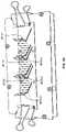
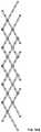
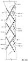
- FIG. 1Ais a perspective view of a particular endoluminal support structure.
- FIG. 1Bis a perspective view of a four strut section of the stent of FIG. 1A .
- FIGS. 1C-1Dare perspective views of the support structure of FIG. 1A .
- FIG. 1Dis a perspective view of the support structure of FIG. 1A in a fully expanded state.
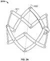
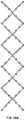
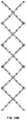
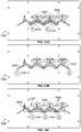
- FIGS. 2A-2Cillustrate perspective views of variations of a particular endoluminal support structure.
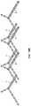
- FIG. 3is a perspective view of the arrangement of strut members in a conical-shaped support structure configuration.
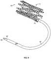
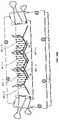
- FIG. 4is a side perspective view of a particular endoluminal support structure.
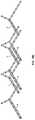
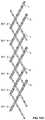
- FIG. 5is a side perspective view of a particular endoluminal support structure with Dacron-sealed struts.
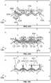
- FIG. 6Ais a perspective view of a particular endoluminal support structure.
- FIG. 6Bis a perspective view of a six strut section of the structure of FIG. 6A .
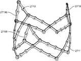
- FIG. 7Ais a perspective view of another embodiment of an endoluminal support structure.
- FIG. 7Bis a perspective view of a variation of the structure of FIG. 7A .
- FIG. 8Ais a perspective view of a linkage of the support structure of FIG. 1A having a particular actuator.
- FIG. 8Bis a perspective view of a linkage of the support structure of FIG. 1A having another particular actuator.
- FIG. 9is a perspective view of a particular support structure and control catheter assembly usable with the actuator of FIGS. 8A and 8B .
- FIG. 10is a side perspective view of the support structure of FIG. 2A having a particular actuator.
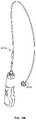
- FIG. 11Ashows a rotary instrument for controlling an actuator from a location remote from the implant site.
- FIG. 11Bshows the rotary instrument of FIG. 11A with an attached catheter, attached to the actuator and support structure of FIG. 10 .
- FIGS. 11C-11Dshow the end of the catheter attached to the actuator and support structure of FIG. 20 in expanded and compressed configurations, respectively.
- FIG. 12is a side view of a control catheter assembly.
- FIG. 13is a perspective view of a tissue valve mounted to the support structure of FIG. 1A .
- FIG. 14is a perspective view of a tissue valve mounted to the structure of FIG. 10A .
- FIG. 15is a schematic illustration of a valve leaflet.
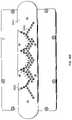
- FIG. 16Ais a top perspective view of a particular alignment plate.
- FIG. 16B-16Wshow steps in a method of fabrication.
- FIG. 16Xis a top perspective view of a particular base frame.
- FIGS. 17A-17Eillustrate configurations of the strut members used in the method of fabrication shown in FIGS. 16B-16W .
- FIGS. 17F-17Gillustrate a side cutaway view and a schematic side view, respectively, of an eyelet used in the method of fabrication before and after swaging, respectively.
- FIG. 18Ais a top perspective view of a particular alignment plate.
- FIG. 18B-18Fillustrate schematic views of steps in a method of fabrication.
- FIG. 19Aillustrates a schematic view of a support structure in a flattened configuration.
- FIGS. 19B-19Fillustrate schematic views of steps in a method of fabrication.
- FIGS. 20A-20Bare top perspective illustrations of methods of fabricating a support structure with a skirt.
- FIGS. 21A and 21Bdepict an embodiment of backing and cover plates configured for assembling a medical device.
- FIG. 21Cdepicts an embodiment of an optional shim or protective insert usable with the backing and cover plates in FIGS. 21A and 21B .
- FIGS. 22A and 22Bdepict an embodiment of a seal material and valve leaflets for a valve of a medical device.
- FIGS. 23A to 23Qare schematic illustrations of another embodiment for manufacturing a medical device.
- Particular embodiments of the inventioninclude endoluminal support structures (stents) and prosthetic valves.
- endoluminal support structures and valve support structurescomprising a plurality of strut members interconnected by articulated joints.
- the support structuresmay have a generally cylindrical or tubular shape and may comprise longitudinal axes.
- the support structures described hereine.g., support structures 10 , 10 ′, 2510 , 2710 , 3910 , 3810 , 4610
- the support structures described hereinmay be incrementally and reversibly expandable and collapsible between an expanded configuration (i.e., having a greater radius orthogonal to the longitudinal axis) and a compressed or collapsed configuration (i.e., having a smaller radius orthogonal to the longitudinal axis).
- the longitudinal distances between two strut membersmay be less in the expanded configuration than in the compressed configuration, while the circumferential distances between two strut members may be greater in the expanded configuration than in the compressed configuration.
- the longitudinal distances between two articulated jointsmay be less in the expanded configuration than in the compressed configuration, while the circumferential distances between two articulated joints may be greater in the expanded configuration than in the compressed configuration.
- the support structuresWhen compressed, the support structures may be at their maximum length and minimum diameter. When expanded, the support structures may be at their minimum length and maximum diameter. The maximum length may be limited by the length of the strut members, while the minimum diameter may be limited by the width of the strut members. In compressed configurations, the support structure may be highly compact. However, they may retain an open lumen through them while in the compressed configurations.
- the strut membersmay be connected such that the support structures may be moved from compressed configurations to expanded configurations, and the reverse, by a number of different force configurations.
- the support structuresmay be moved from an expanded configuration to a compressed configuration by application of radially inward force.
- the radially inward forcemay be applied around the full circumference of the support structure, or it may be applied to fewer discrete points about the circumference of the support structure (e.g., two opposing points about the circumference of the support structure, such as two articulated joints on the same diameter of the support structure).
- the support structuremay be moved from a compressed configuration to an expanded configuration by application of radially outward force.
- the radially outward forcemay be applied around the full circumference of the support structure, or it may be applied to fewer discrete points about the circumference of the support structure (e.g., two opposing points about the circumference of the support structure, such as two articulated joints on the same diameter of the support structure).
- the support structuremay also be moved from an expanded configuration to a compressed configuration by application of longitudinally oriented forces (i.e., force parallel to the longitudinal axis of the support structure) urging two strut members longitudinally away from each other.
- the support structuremay similarly be moved from a compressed configuration to an expanded configuration by application of longitudinally oriented forces urging two strut members longitudinally toward each other.
- the application of longitudinally oriented forces at two pointsmay be sufficient to move the support structure from a compressed configuration to an expanded configuration or from an expanded configuration to a compressed configuration.
- the support structuremay also be moved from an expanded configuration to a compressed configuration by application of circumferentially oriented forces urging two strut members circumferentially toward each other.
- the support structuremay similarly be moved from a compressed configuration to an expanded configuration by application of circumferentially oriented forces urging two strut members circumferentially away from each other.
- the application of circumferentially oriented forces at two pointsmay be sufficient to move the support structure from a compressed configuration to an expanded configuration or from an expanded configuration to a compressed configuration.
- the forces described abovemay be applied by an actuator (such as those described herein), and thus an actuator may be used to move the support structure between compressed and expanded configuration, as described in more detail below.
- the support structuresmay comprise a chain of linkages, which may be configured such that the expansion or compression of any individual linkage, in the manner described above, may cause the other linkages to also expand or compress.
- the support structuresmay be reversibly expanded or compressed by application of force two only two points on the support structure (e.g., force urging two articulated joints apart or towards each other along a longitudinal axis, or force urging two articulated joints apart or towards each other along the circumference of the support structure).
- the articulated joints of the support structures described hereinmay comprise two or more (e.g., three, four, five, six, or more) separate components that may articulate.
- the articulated jointsmay in some variations be rotatable joints, such that the two or more components may rotate in one or more planes relative to each other.
- the rotatable jointsmay be pin joints, such that the two or more components may rotate within a single plane (i.e., single-axis rotation) relative to each other.
- the axes of rotation of the articulated jointsmay be perpendicular to the longitudinal axes of the support structures.
- the articulated jointsmay comprise primary axes of rotation, but may also allow some movement along one or more additional axes (e.g., perpendicular to the primary axis of rotation).
- the support structuresmay comprise longitudinal axes, and the primary axes of rotation of the articulated joints may be perpendicular to the longitudinal axes of the support structures.
- This type of articulationmay be achieved by any number of methods of interconnection between strut members, but in some variations may use fasteners such as rivets, eyelets, capped pins, screws, bolts, ball-in-socket structures, or nails, which may be integrally formed in the struts (such as a peened semi-sphere interacting with an indentation or orifice, or a male-female coupling) or may be a separate structure.
- the fastenersmay be received by orifices spaced along the length of the strut members. The orifices may be countersunk on one side of the strut members to receive the head of a fastener.
- the orificesmay be of uniform diameter and spacing along the strut member, but neither is required.
- the orificesmay provide an additional pathway for tissue growth-over to stabilize and encapsulate the support structure over time.
- FIG. 1Ais a perspective view of a particular endoluminal support structure.
- the support structure 10is a medical stent that includes a plurality of longitudinal strut members 11 interconnected by a plurality of articulated joints 15 .
- the articulated joints 15may allow the interconnected strut members 11 to rotate relative to each other.
- the articulated jointsmay be able to be rotated about an axis of rotation, and/or may be swivelable. As shown, there are eighteen struts 11 .
- the support structure 10may have a generally cylindrical shape, with a longitudinal axis 20 .
- the articulated jointsmay have an axis of rotation perpendicular to the longitudinal axis 20 of the support structure 10 .
- the articulated jointsmay also allow rotation about other axis, while in other variations, the articulated joints may be pin joints allowing rotation about only a single axis perpendicular to the longitudinal axis, as described in more detail above.
- the support structure 10may be incrementally and reversibly expandable and collapsible between an expanded configuration, as shown in FIG. 1D , and a compressed or collapsed configuration, as shown in FIG. 1C , as described in more detail above.
- the strut members 11may be connected such that the support structure 10 may be moved from the compressed configuration to the expanded configuration, and the reverse, by a number of different force configurations, including radially, longitudinally, and circumferentially directed force, as described in more detail above.
- the strut members 11may have a bar shape and may have a front surface 11 f and a back surface 11 b .
- the strut members 11may be interconnected by fasteners 25 , described in more detail above.
- each strut member 11may also include a plurality of orifices 13 spaced along the length of the strut member 11 .
- the orificesmay be countersunk 17 to receive the head of a fastener.
- there are thirteen equally spaced orifices 13 along the length of each strut member 11but more or fewer orifices can be used.
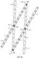
- FIG. 1Bis a perspective view of a four strut section of the stent of FIG. 1A .
- two outer strut members 11 - 1 , 11 - 3overlap two inner strut members 11 - 2 , 11 - 4 , with their back surfaces in communication with each other.
- the first strut member 11 - 1may be rotatably connected to the second strut member 11 - 2 by a middle articulated joint 15 - 1 using a rivet 25 - 1 , which utilizes orifices 13 that bisect the strut members 11 - 1 , 11 - 2 .
- the third strut member 11 - 3may be rotatably connected to bisect the fourth strut member 11 - 4 by a middle articulated joint 15 - 7 using a rivet 25 - 7 .
- the middle articulated joints 15 - 1 , 15 - 7can function as a scissor joint in a scissor linkage or mechanism. As shown, the resulting scissor arms are of equal length.
- the middle articulated joint 15 - 1 , 15 - 7need not bisect the joined strut members, but can instead utilize orifices 13 offset from the longitudinal centers of the strut members resulting in unequal scissor arm lengths.
- the second strut member 11 - 2may be rotatably connected to the third strut member 11 - 3 by a distal anchor articulated joint 15 - 5 , located near the distal ends of the strut members 11 - 2 , 11 - 3 .
- the first strut member 11 - 1may be rotatably connected to the fourth strut member 11 - 4 by a proximal anchor articulated joint 15 - 3 , located near the proximal ends of the strut members 11 - 1 , 11 - 4 .
- the distal and proximal ends of the struts 11can be curved or twisted to provide a flush interface between the joined struts.
- the linkagecan be reversibly expanded and compressed.
- the two strut members 11 - 4 and 11 - 2move to be directly adjacent to each other, and the two strut members 11 - 3 and 11 - 1 move to be directly adjacent to each other, such that center diamond-shaped opening is substantially closed.
- the center diamond-shaped openingis widened.
- FIG. 1Ais a perspective view of a compressed support structure of FIG. 1A .
- the stent 10is at its maximum length and minimum diameter.
- the maximum lengthmay be limited by the length of the strut members, which in a particular embodiment may be 15 mm.
- the minimum diametermay be limited by the width of the strut members, which in a particular embodiment may be about 0.052 inch.
- the support structureis highly compact. However, the support structure may retain an open lumen through it while in the compressed state.
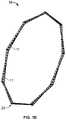
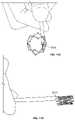
- FIG. 1Dis a perspective view of the support structure of FIG. 1A in a fully expanded state.
- the fully expanded support structure 10forms a ring.
- support structure 10may enter a locked state such that radial inward pressure does not cause the support structure to re-compress and the support structure 10 is in an unstressed state.
- the ring formedcan be used as an annuloplasty ring.
- the compression of the stentmay enable the tissue to cinch.
- the devicecould be used to provide an individualized cinching of the tissue to increase the competency of a heart valve. This could be a useful treatment for mitral valve diseases, such as mitral regurgitation or mitral valve prolapse.
- each strutcan be chosen in accordance with its desired use (e.g., depending on the implant site).
- each strut membermay be about 0.001-0.100 inch thick. More particularly, each strut can be about 0.01 inch thick.
- each strut membermay be about 0.01-0.25 inches wide and about 0.25-3 inches long. More particularly, each strut can be about 0.06 inches wide and about 0.5 inches long.
- the thickness, width, and length of the strutsmay be variable, as described below.
- the strut memberscan however be of different geometries.
- the strutscan be non-flat structures.
- the strutscan include a curvature, such as in a concave or convex manner in relationship to the inner diameter of the stent structure.
- the strutscan also be twisted.
- the nonflatness or flatness of the strutscan be a property of the material from which they are constructed.
- the strutscan exhibit shape-memory or heat-responsive changes in shape to the struts during various states. Such states can be defined by the stent in the compressed or expanded configuration.
- FIG. 1Ashows a serial chain of scissor mechanisms such that there are eighteen struts 11 , but other numbers of struts 11 can be used, including more than eighteen struts or fewer than eighteen struts.
- FIG. 2Ashows a support structure 3010 with a serial chain of scissor mechanisms having twelve struts 3011 .
- the support structure 3010may have a generally cylindrical shape, with a longitudinal axis 3020 .
- the articulated jointsmay have an axis of rotation perpendicular to the longitudinal axis 3020 of the support structure 3010 .
- the articulated jointsmay also allow rotation about other axis, while in other variations, the articulated joints may be pin joints allowing rotation about only a single axis perpendicular to the longitudinal axis, as described in more detail above.
- the support structure 3010may be incrementally and reversibly expandable and collapsible between an expanded configuration and a compressed or collapsed configuration, as described in more detail above.
- the strut members 3011may be connected such that the support structure 3010 may be moved from the compressed configuration to the expanded configuration, and the reverse, by a number of different force configurations, including radially, longitudinally, and circumferentially directed force, as described in more detail above.
- the struts 3011need not have orifices.
- support structures having twelve struts as in FIG. 2Amay have orifices 3013 , as shown in FIG. 2B .
- FIGS. 2A-2Balso show struts 3011 and 3011 ′, respectively, having an inward curvature.
- a support structure having twelve strutsmay have straight struts 3011 ′′.
- Support structures 3010 , 3011 ′, and 3011 ′′can be reversibly expanded, reversibly compressed, fully expanded to form a ring, implanted, used with an actuator and control catheter assembly, and/or used to support a prosthetic valve in the same manner as support structure 10 , described in detail herein.
- FIG. 3is a perspective view of the arrangement of strut members in a conical-shaped support structure configuration.
- the strut members 11may be arranged as shown in FIGS. 1A-1D , except that the middle scissor pivots may not bisect the struts.
- the middle scissor pivotse.g. 15 ′- 1 , 15 ′- 7
- the joined strut memberse.g. 11 ′- 1 , 11 ′- 2 and 11 ′- 3 , 11 ′ 4
- the resulting support structureWhen fully assembled, the resulting support structure may thus conform to a conical shape when expanded.
- the stent 10 ′is shown with a single-threaded actuator rod 32 ′ (described in more detail below), but it is not a required element for this stent embodiment.
- the stent 10 ′can also assume a cone shape in its expanded configuration by imposing a convex or concave curvature to the individual strut members 11 that comprise the stent 10 ′. This could be achieved by using a material with memory, such as shape-memory or temperature sensitive Nitinol.
- a valvecan be orientated in the cone-shaped stent 10 ′ such that the base of the valve was either in the narrower portion of the cone-shaped stent, with the nonbase portion of the valve in the wider portion of the cone.
- the base of the valvecan be located in the widest portion of the stent with the non-base portion of the valve in the less-wide portion of the stent.
- a cone-shaped stent 10 ′ in the bodycan be either towards or away from the stream of blood flow.
- the stentcould be orientated in either direction, in relationship to the axial plane.
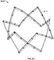
- FIG. 4shows another example of an endoluminal support structure 3810 with a serial chain of scissor mechanisms having twelve strut members 3811 .
- the support structure 3810may have a generally cylindrical shape, with a longitudinal axis 3820 .
- the strut membersmay be interlinked by articulated joints.
- the articulated jointsmay have an axis of rotation perpendicular to the longitudinal axis 3820 of the support structure 3810 .
- the articulated jointsmay also allow rotation about other axis, while in other variations, the articulated joints may be pin joints allowing rotation about only a single axis perpendicular to the longitudinal axis, as described in more detail above.
- the support structure 3810may be incrementally and reversibly expandable and collapsible between an expanded configuration and a compressed or collapsed configuration, as described in more detail above.
- the strut membersmay be connected such that the support structure 3810 may be moved from the compressed configuration to the expanded configuration, and the reverse, by a number of different force configurations, including radially, longitudinally, and circumferentially directed force, as described in more detail above.
- the support structure 3810may comprise a chain of four-bar linkages, each comprising two inner strut members 3811 and two outer strut members 3811 interconnected by fasteners 3825 , as described in more detail above.
- the strut members 3811may have orifices 3813 .
- the first strut member 3811 - 1(an inner strut member) may be rotatably connected to the second strut member 3811 - 2 (an outer strut member) by an articulated joint 3815 - 1 using a rivet 3825 - 1 , which may utilize orifices 3813 located at points spaced apart from the proximal and distal ends of the strut members 3811 - 1 , 3811 - 2 .
- the third strut member 3811 - 3(an inner strut member) may be rotatably connected to the fourth strut member 3811 - 4 (an outer strut member) by an articulated joint 3815 - 7 using a rivet 3825 - 7 , which may utilize orifices 3813 located at points spaced apart from the proximal and distal ends of the strut members 3811 - 3 , 3811 - 4 .
- the articulated joints 3815 - 1 , 3815 - 7may thus function as a scissor joint in a scissor linkage or mechanism. As shown, the resulting scissor arms are of equal length.
- joints 3815 - 1 , 3815 - 7may utilize orifices 3813 offset from the longitudinal centers of the strut members, resulting in unequal scissor arm lengths, or may bisect the joined strut members, resulting in scissor arms of equal lengths.
- the second strut member 3811 - 2may be rotatably connected to the third strut member 3811 - 3 by an articulated joint 3815 - 5 using rivet 3825 - 5 .
- the articulated joint 15 - 5is an anchor joint (i.e., it is located near the distal ends of the strut members 11 - 2 , 11 - 3 )
- the strut members 3811 - 2 , 3811 - 3extend distally beyond the articulated joint 3815 - 5 .
- Strut members 3811 - 2 , 3811 - 3may thus be longer than strut members 3811 - 1 , 3811 - 4 .
- the first strut member 3811 - 1may be rotatably connected to the fourth strut member 3811 - 4 by a proximal anchor articulated joint 3815 - 3 using rivet 3825 - 3 , located near the proximal ends of the strut members 3811 - 1 , 3811 - 4 .
- the strut members 3811may be curved. As a result of these rotatable connections, the linkage can be reversibly expanded and compressed.
- the linkagesmay be combined into a continuous chain to form a support structure.
- three linkagesmay be combined to form support structure 3810 .
- the linkagesmay be combined by connecting strut member 3811 - 1 of one linkage with strut member 3811 - 4 of another linkage at an articulated joint 3815 - 9 using rivet 3825 - 9 ; by connecting strut member 3811 - 2 of one linkage with strut member 3811 - 3 of another linkage at articulated joint 3815 - 11 using rivet 3825 - 11 .
- the continuous chainmay be configured such that the expansion or compression of any individual linkage, in the manner described above, may cause the other linkages to also expand or compress.
- the support structure 3810may be reversibly expanded or compressed by application of force two only two points on the support structure 3810 (e.g., force urging two articulated joints apart or towards each other along a longitudinal axis, or force urging two articulated joints apart or towards each other along the circumference of the support structure).
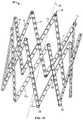
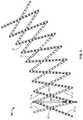
- FIG. 5shows another example of an endoluminal support structure 3910 with a serial chain of scissor mechanisms having twelve struts 3911 .
- the support structure 3910may have a generally cylindrical shape, with a longitudinal axis 3920 .
- the strut membersmay be interlinked by articulated joints.
- the articulated jointsmay have an axis of rotation perpendicular to the longitudinal axis 3920 of the support structure 3910 .
- the articulated jointsmay also allow rotation about other axis, while in other variations, the articulated joints may be pin joints allowing rotation about only a single axis perpendicular to the longitudinal axis, as described in more detail above.
- the support structure 3910may be incrementally and reversibly expandable and collapsible between an expanded configuration and a compressed or collapsed configuration, as described in more detail above.
- the strut members 3911may be connected such that the support structure 3910 may be moved from the compressed configuration to the expanded configuration, and the reverse, by a number of different force configurations, including radially, longitudinally, and circumferentially directed force, as described in more detail above.
- the support structure 3910may comprise a chain of four-bar linkages, each comprising strut members 3911 interconnected by articulated joints 3815 using fasteners 3925 , as described in more detail above.
- the strut membersmay have a coating, described in more detail below.
- the four-bar linkagesmay each comprise two outer strut members ( 3911 - 2 , 3911 - 4 ), and two inner strut members ( 3911 - 1 , 3911 - 3 ), where each of the outer strut members may be connected to two inner strut members and no outer strut members, and each of the inner strut members may be connected to two outer strut members and no inner strut members.
- the four-bar linkagesmay be combined by connecting each of the outer strut members to two more inner strut members, such that each outer strut member is connected to four inner strut members and no outer strut members, and by connected each of the inner strut members to two more outer strut members, such that each inner strut member is connected to four outer strut members and no inner strut members. It should be appreciated that in other variations, the number of connections may be greater, such that each outer strut member may be connected to greater than four inner strut members, and each inner strut member may be connecter to great than four outer strut members.
- first strut member 3911 - 1may be rotatably connected to the second strut member 3911 - 2 by an articulated joint 3915 - 1 using a rivet 3925 - 1 , which may utilize orifices 3913 located at points spaced apart from the proximal and distal ends of the strut members 3911 - 1 , 3911 - 2 .
- the third strut member 3911 - 3may be rotatably connected to the fourth strut member 3911 - 4 by an articulated joint 3915 - 7 using a rivet 3925 - 7 , which may utilize orifices 3913 located at points spaced apart from the proximal and distal ends of the strut members 3911 - 3 , 3911 - 4 .
- the articulated joints 3915 - 1 , 3915 - 7may thus function as a scissor joint in a scissor linkage or mechanism.
- the second strut member 3911 - 2may be rotatably connected to the third strut member 3911 - 3 by an articulated joint 3915 - 5 using a rivet 3925 - 5 , located at points spaced apart from the proximal and distal ends of the strut members 3911 - 2 , 3911 - 3 , but distal to articulated joints 3915 - 1 and 3915 - 7 .
- first strut member 3911 - 1may be rotatably connected to the fourth strut member 3911 - 4 by a proximal anchor articulated joint 3915 - 3 using rivet 3925 - 3 , located near the proximal ends of the strut members 3911 - 1 , 3911 - 4 .
- the strut members 3911may be curved inwardly in a helical fashion. As a result of these rotatable connections, the linkage can be reversibly expanded and compressed. When the linkage is laterally compressed, the two strut members 3911 - 4 and 3911 - 2 move to be closer to each other, and the two strut members 3911 - 3 and 3911 - 1 move to be closer to each other, such that center diamond-shaped opening is substantially closed. When the linkage is laterally expanded, the center diamond-shaped opening is widened. Unlike the strut members of FIGS.
- strut members 3911 - 1 and 3911 - 4may be longer than strut members 3911 - 2 , 3911 - 3 , such that when three four-bar linkages are linked to form support structure 3910 , the ends of strut members 3911 - 1 , 3911 - 4 extend beyond the articulated joints linking the four-bar linkages, as shown in FIG. 5 .
- the linkagesmay be combined into a continuous chain to form a support structure.
- three linkagesmay be combined to form support structure 3910 .
- the linkagesmay be combined by connecting strut member 3911 - 1 of one linkage with strut member 3911 - 4 of another linkage at an articulated joint 3915 - 9 using rivet 3925 - 9 at locations spaced away from the distal end of strut members 3911 - 1 and 3911 - 4 ; by connecting strut member 3911 - 2 of one linkage with strut member 3911 - 3 of another linkage at articulated joint 3915 - 11 using rivet 3925 - 11 at a location at the distal ends of strut members 3911 - 2 and 3911 - 3 ; by connecting strut member 3911 - 3 of one linkage with strut member 3911 - 4 of another linkage at an articulated joint 3915 - 13 using rivet 3925 - 13 at a location at the distal end of strut member 3911
- the continuous chainmay be configured such that the expansion or compression of any individual linkage, in the manner described above, may cause the other linkages to also expand or compress.
- the support structure 3910may be reversibly expanded or compressed by application of force two only two points on the support structure 3910 (e.g., force urging two articulated joints apart or towards each other along a longitudinal axis, or force urging two articulated joints apart or towards each other along the circumference of the support structure).
- each strutcan be chosen in accordance with its desired use (e.g., depending on the implant site).
- each strut membermay be about 0.001-0.100 inches thick. More particularly, each strut may be about 0.01 inches thick. In other variations, some struts may be thinner than other struts, which may provide increased flexibility.
- each strutmay be about 0.01-0.25 inches wide. More particularly, each strut may be about 0.06 inches wide.
- the thickness, width, and length of the strutsmay be variable, as described below.
- each strut membermay be bar shaped.
- the strut memberscan however be of different geometries. For example, instead of a uniform width, a strut can vary in width along its length. Furthermore, an individual strut can have a different width than another strut in the same deployment structure. Similarly, the strut lengths can vary from strut to strut within the same deployment structure. The particular dimensions can be chosen based on the implant site.
- the strutscan be non-flat structures. In particular, the struts can include a curvature, such as in a concave, or convex manner in relationship to the inner diameter of the deployment structure. The struts can also be twisted.
- the nonflatness or flatness of the strutscan be a property of the material from which they are constructed.
- the strutscan exhibit shape-memory or heat-responsive changes in shape to the struts during various states. Such states can be defined by the deployment structure in the compressed or expanded configuration.
- articulated support structuresmay comprise bow struts, as described in PCT/US13/21052, 61/585,165, 61/780,670, which are hereby fully incorporated by reference.
- articulated support structuresmay comprise longer struts with more than one middle articulation and end articulations, as described in PCT/US 13/21052, 61/585,165, 61/780,670.
- articulated support structuresmay comprise radial struts, as described in PCT/US13/21052, 61/585,165, 61/780,670.
- any of the above-described support structuresmay be extended beyond the anchor joints at either of both ends of the stent.
- additional stent lengths and geometriescan be fabricated.
- an hourglass-shaped stentcould be achieved by joining two cone-shaped stents at their narrow ends.
- valve support structuresmay have similar designs and features to the endoluminal support structures described above, but may comprise commissure strut members configured to have attached valve leaflets.
- commissure strut membersmay extend distally beyond the distal ends of the longitudinal strut members, and may be configured to support valve leaflets in a way that allows the leaflets to form a shape suitable for a prosthetic valve.
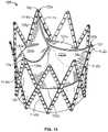
- FIG. 6Ais a perspective view of a support structure to which a tissue valve may be mounted.
- the support structure 2510may have a generally tubular shape comprising a proximal opening 2520 , distal opening 2530 , and a lumen 2540 therebetween.
- the tubular shapemay be shorter and ring like as in the support structure 2510 in FIG. 6A , or in other variations it may be elongate.
- the support structure 2510may have a longitudinal axis 2550 and may comprise a plurality of strut members interlinked by articulated joints.
- the articulated jointsmay have an axis of rotation perpendicular to the longitudinal axis 2550 of the support structure 2510 .
- the articulated jointsmay also allow rotation about other axis, while in other variations, the articulated joints may be pin joints allowing rotation about only a single axis perpendicular to the longitudinal axis, as described in more detail above.
- the support structure 2510may be incrementally and reversibly expandable and collapsible between an expanded configuration and a compressed or collapsed configuration, as described in more detail above.
- the strut membersmay be connected such that the support structure 2510 may be moved from the compressed configuration to the expanded configuration, and the reverse, by a number of different force configurations, including radially, longitudinally, and circumferentially directed force, as described in more detail above.
- the support structure 2510may comprise a plurality of longitudinal strut members 2511 and a plurality of commissure strut members 2519 .
- the longitudinal strut member 2511 and commissure strut members 2519may be interconnected by a plurality articulations comprising pin or articulated joints 2515 .
- the commissure strut members 2519 and their articulationsmay permit regions of the support structure to extend further beyond the structure provided by the longitudinal strut members 2511 , and which may expand and contract along with the configurational changes to the longitudinal strut members 2511 , without generating significantly more resistance or stress in the structure, if any.
- the articulated joints 2515may have an axis of rotation with a radial orientation and which may allow the interconnected strut members 2511 and 2519 to rotate relative to each other.
- One set of articulated joints 2515 connecting longitudinal strut members 2511may be located at the proximal ends of longitudinal strut members 2511 in a plane aligned with the proximal opening 2520 .
- a second set of articulated joints 2511 connecting longitudinal strut members 2511may be located at the distal ends of longitudinal strut members 2511 in a plane aligned with the distal opening 2530 .
- a third set of articulated joints 2515 connecting longitudinal strut members 2511may be located between the proximal opening 2520 and the distal opening 2530 .
- a fourth set of articulated joints 2515 connecting commissure strut members 2519may be located distal to the plane of distal opening 2530 .
- a fifth set of articulated joints 2515 connecting longitudinal strut members 2511 to commissure strut members 2519may be located proximal to the plane of distal opening 2530 between the third set of articulated joints 2515 and the plane of distal opening 2530 .
- each longitudinal strutcan be chosen in accordance with its desired use (e.g., depending on the implant site).
- each longitudinal strut membersmay be about 0.001-0.100 inch thick. More particularly, each strut may be about 0.01 inch thick.
- each longitudinal strut members 2511may be about 0.01-0.25 inches wide. More particularly, each longitudinal strut members 2511 may be about 0.06 inches wide.
- the thickness, width, and length of the longitudinal strut members 2511may be variable, as described below.
- each commissure strut member 2519may be about 0.001-0.100 inches thick. More particularly, each commissure strut member 2519 may be about 0.01 inches thick.
- each commissure strut member 2519may be about 0.01-0.25 inches wide. More particularly, each commissure strut member 2519 may be about 0.06 inches wide.
- the thickness, width, and length of the commissure strut members 2519may be variable, as described below.
- the thickness and/or material of the commissure strut members 2519may be such that the commissure strut members 2519 are more flexible than the longitudinal strut members 2511 , such as by being thinner or by being made of a more flexible material.
- each longitudinal strut member 2511is bar shaped and has a front surface 2511 f and a back surface 2511 b ; and each commissure strut member 2519 is bar shaped and has a front surface 2519 f and a back surface 2519 b .
- the strut memberscan, however, optionally comprise different geometries.
- the longitudinal struts 2511 and commissure struts 2519can be non-flat structures.
- the strutscan include a curvature, such as in a concave or convex manner in relationship to the inner diameter of the support structure 2510 .
- the strutscan also be twisted.
- the nonflatness or flatness of the strutscan be a property of the material from which they are constructed.
- the strutscan exhibit shape-memory or heat responsive changes in shape to the struts during various states. Such states can be defined by the support structure in the compressed or expanded configuration.
- the strutscan also exhibit changes in shape due to stressed on them while implanted. For instance, if used to support a prosthetic valve assembly as described in detail below, the stress on the commissure struts 2519 during the normal cardiac cycle may cause the commissure struts 2519 to permanently or temporarily bend or otherwise change shape.
- commissure strut members 2519are fabricated from biocompatible materials having greater flexibility than the materials from which the longitudinal strut members 2511 are fabricated, if a force including a radially inward component is applied to the commissure strut members, they may flex inward, while the longitudinal strut members 2511 may not substantially deform.
- Each longitudinal strut member 2511may also include a plurality of orifices 2513 spaced along the length of strut members 2511 , as described above. On the front surface 2511 f , orifices may be countersunk to receive the head of a fastener.
- FIG. 6Ashows commissure strut members 2519 as not having orifices 2513 along their lengths. However, in other instances, the commissure strut members 2519 may have orifices 2513 along their lengths. Orifices 2513 on commissure strut members 2519 can similarly be countersunk on front surface 2519 f to receive the head of a fastener. In the support structure of FIG.
- longitudinal strut members 2511 - 1 and 2511 - 4may have thirteen orifices 2513 and longitudinal strut members 2511 - 2 and 2511 - 3 ( FIG. 6B ) may have ten orifices 2513 . There can, however, be more or fewer orifices on longitudinal strut members 2511 .
- the strut members 2511 and 2519may be arranged as a chain of four- and six-bar linkages, and wherein at least some, if not all, of the linkage sets share common struts with adjacent linkages and configuration changes to one linkage will generate complementary changes to the other linkages linked by common struts. Complementary changes, however, are not necessarily limited to linkages or struts with common struts.
- the four-bar linkagesmay have the same configuration as the four strut section of the stent of FIG. 1B , described in detail above.
- FIG. 6Bis a perspective view of a six-bar linkage of the support structure of FIG. 10A .
- two outer strut members 2511 - 1 , 2511 - 3overlap two inner strut members 2511 - 2 , 2511 - 4 , with their back surfaces in communication with each other.
- two commissure strut members-outer commissure strut member 2519 - 1 and inner commissure strut member 2519 - 2can be connected to inner strut member 2511 - 2 and outer strut member 2511 - 3 .
- the strut members 2511 , 2519may be interconnected by fasteners 2525 , as described above, extending through aligned orifices.
- the outer strut member 2511 - 1may be rotatably or swivelably connected to the inner strut member 2511 - 2 by an articulated joint 2515 - 1 using a rivet 2525 - 1 , which utilizes orifices 2913 .
- the articulated joint 2515 - 1may bisect outer strut member 2511 - 1 .
- the articulated joint 2515 - 1may not bisect inner strut member 2511 - 2 , but instead utilize an orifice 2513 that is offset distally from the longitudinal center of inner strut member 2511 - 2 . It should be understood that the articulated joint 2515 - 1 may utilize different orifices 2513 than the ones shown in FIG. 6B .
- the outer strut member 2511 - 3may be rotatably connected to the inner strut member 2511 - 4 by an articulated joint 2515 - 7 using a rivet 2525 - 7 , which utilizes orifices 13 .
- the articulated joint 2515 - 7may bisect inner strut member 2511 - 4 .
- the articulated joint 2525 - 7may not bisect outer strut member 2511 - 3 , but instead utilize an orifice 2513 that is offset distally from the longitudinal center on outer strut member 2511 - 3 . It should be understood that the articulated joint 2515 - 7 may utilize different orifices 2513 than the ones shown in FIG. 6B .
- the outer strut member 2511 - 1may be rotatably connected to the inner strut member 2511 - 4 by a proximal anchor articulated joint 2515 - 3 using rivet 2525 - 3 , located near the proximal ends of the strut members 2511 - 1 , 2511 - 4 .
- the inner strut member 2511 - 2may also be rotatably connected to the commissure strut member 2519 - 1 by an articulated joint 2515 - 9 using a rivet 2525 - 9 , located near the distal end of inner strut member 2511 - 2 and the proximal end of commissure strut member 2519 - 1 .
- outer strut member 2511 - 3may be rotatably connected to the commissure strut member 2519 - 2 by an articulated joint 2515 - 11 using a rivet 2525 - 11 , located near the distal end of outer strut member 2511 - 3 and the proximal end of commissure strut member 2519 - 2 .
- Commissure strut member 2519 - 1may also be rotatably connected to commissure strut member 2519 - 2 by a distal anchor articulated joint 2515 - 13 using rivet 2525 - 13 , located near the distal ends of the commissure strut members 2519 - 1 , 2519 - 2 .
- proximal ends of struts 2511 - 1 , 2511 - 4 and distal ends of commissure struts 2519 - 1 , 2519 - 2may be curved or twisted to provide a flush interface between the joined struts.
- the support structure 2510may be fabricated by linking together a chain of individual six-strut sections ( FIG. 6B ) and four-strut sections ( FIG. 1B ). The chain may then be wrapped or otherwise connected back to itself to join the last section with the first section in the chain. As shown in FIG. 6A , a chain of three six-strut sections and six four-strut sections may be joined, such that every third section is a six-strut section. It should be understood that different numbers of four-strut sections may be linked with the three six-strut sections. In some variations, the support structure may have zero four-strut sections and consist only of six-strut sections. As in the support structure 10 shown in FIG.
- actuating the linkagemay cause the links to be opened or closed, which may result in expanding or compressing the support structure 2510 ( FIG. 6A ).
- the angle between commissure strut members 2519 - 1 , 2519 - 2 at distal anchor articulated joint 2515 - 13may be less than the angle between two longitudinal strut members 2511 at an anchor articulated joint 2515 located near the distal ends of the two longitudinal strut members 2511 .
- Strut members 2511 , 2519may have lengths chosen based on the implant site.
- outer longitudinal strut 2511 - 1 and inner longitudinal strut 2511 - 4may have approximately the same length
- inner longitudinal strut 2511 - 2 and outer longitudinal strut 2511 - 3may have approximately the same length
- commissure struts 2519 - 1 , 2519 - 2may have approximately the same length.
- the length of outer longitudinal strut 2511 - 1 and inner longitudinal strut 2511 - 4may be greater than the length of inner longitudinal strut 2511 - 2 and outer longitudinal strut 2511 - 3 .
- the combined longitudinal length of longitudinal strut member 2511 - 2 and commissure strut member 2519 - 1may be greater than the length of longitudinal strut member 2511 - 1 or longitudinal strut member 2511 - 4 .
- the combined longitudinal length of longitudinal strut member 2511 - 3 and commissure strut member 2519 - 2may be greater than the length of longitudinal strut member 2511 - 1 or longitudinal strut member 2511 - 4 .
- the combined length of longitudinal strut member 2511 - 2 and commissure strut member 2519 - 1may be at least 20% longer than the length of longitudinal strut members 2511 - 1 or 2511 - 4 .
- the combined longitudinal length of longitudinal strut member 2511 - 3 and commissure strut member 2519 - 2may be at least 20% longer than the length of longitudinal strut members 2511 - 1 or 2511 - 4 .
- Distal anchor articulated joint 2515 - 13located near the distal ends of commissure strut members 2519 - 1 and 2519 - 2 may extend beyond the plane of the distal opening 2530 by a longitudinal distance that is at least 20% of the longitudinal distance between the planes of the proximal opening 2520 and distal opening 2530 .
- outer longitudinal strut 2511 - 1 and inner longitudinal strut 2511 - 4may be about 0.250-3.00 inches long; inner longitudinal strut 2511 - 2 and outer longitudinal strut 2511 - 3 may be about 0.1-2.5 inches long; and commissure struts 2519 - 1 , 2519 - 2 may be about 0.1-2.5 inches long. More particularly, outer longitudinal strut 2511 - 1 and inner longitudinal strut 2511 - 4 may be about 0.5 inches long; inner longitudinal strut 2511 - 2 and outer longitudinal strut 2511 - 3 may be about 0.375 inches long; and commissure struts 2519 - 1 , 2519 - 2 may be about 0.2 inches long.
- the diameter of support structure 2510can be chosen based on the implant site. In a particular embodiment for implantation at the mitral valve opening, the diameter may be about 0.5-1.55 inches. More particularly, the diameter may be about 0.8 inches.
- FIG. 7Ais a perspective view of another articulated support structure to which a tissue valve may be able to be mounted.
- the support structuremay have a tubular shape having a proximal opening 2720 , distal opening 2730 , and a lumen 2740 therebetween.
- the tubular shapemay be shorter and ring like as in the support structure 2710 in FIG. 7A , or in other variations it may be elongate.
- the support structure 2710may have a longitudinal axis 2750 and may comprise a plurality of strut members interlinked by articulated joints.
- the articulated jointsmay have an axis of rotation perpendicular to the longitudinal axis 2750 of the support structure 2710 .
- the articulated jointsmay also allow rotation about other axis, while in other variations, the articulated joints may be pin joints allowing rotation about only a single axis perpendicular to the longitudinal axis, as described in more detail above.
- the support structure 2710may be incrementally and reversibly expandable and collapsible between an expanded configuration and a compressed or collapsed configuration, as described in more detail above.
- the strut membersmay be connected such that the support structure 2710 may be moved from the compressed configuration to the expanded configuration, and the reverse, by a number of different force configurations, including radially, longitudinally, and circumferentially directed force, as described in more detail above.
- support structure 2710may include a plurality of longitudinal strut members 2711 and commissure strut members 2719 interconnected by a plurality of articulated joints 2715 . As shown, there are twelve struts 2711 and six struts 2719 .
- the articulated joints 2715may have an axis of rotation with radial orientation, which may allow the interconnected strut members 2711 and 2719 to rotate relative to each other.
- One set of articulated joints 2715 connecting longitudinal strut members 2711may be located at the proximal ends of strut members 2711 in a plane aligned with proximal opening 2720 .
- a second set of articulated joints 2711 connecting longitudinal strut members 2711 to each other and to commissure strut members 2719may be located at the distal ends of longitudinal strut members 2711 and the proximal ends of commissure strut members 2719 and in a plane aligned with the distal opening 2730 .
- a third set of articulated joints 2711 connecting longitudinal strut members 2711may be located between the proximal opening 2720 and distal opening 2730 and proximal to the midpoint between the proximal opening 2720 and distal opening 2730 .
- a fourth set of articulated joints 2711may be located between the proximal opening 2720 and distal opening 2730 and distal to the midpoint between the proximal opening 2720 and distal opening 2730 .
- a fifth set of articulated joints 2711 connecting commissure strut members 2719may be located distal to the plane of distal opening 2730 .
- each longitudinal strutcan be chosen in accordance with its desired use (e.g., depending on the implant site).
- each longitudinal strut member 2711may be about 0.001-0.100 inches thick. More particularly, each longitudinal strut member 2711 may be about 0.01 inches thick. In a particular embodiment, each longitudinal strut member 2711 may be about 0.01-0.25 inches wide. More particularly, each longitudinal strut member 2711 may be about 0.06 inches wide.
- each commissure strut member 3719may be about 0.001-0.100 inch thick. More particularly, each commissure strut member 3719 may be about 0.01 inches thick. In a particular embodiment, each commissure strut member 2719 may be about 0.010-0.250 inches wide.
- each commissure strut member 2719may be about 0.06 inches wide.
- the thickness, width, and length of the commissure strut members 2719may be variable, as described below.
- the thickness and/or material of the commissure strut members 2719may be such that the commissure strut members 2719 are more flexible than the longitudinal strut members 2711 , such as by being thinner or by being made of a more flexible material.
- each longitudinal strut member 2711is bar shaped and has a front surface 2711 f and a back surface 2711 b ; and each commissure strut member 2719 is bar shaped and has a front surface 2719 f and a back surface 2719 b .
- the strut membersmay, however, be of different geometries.
- the longitudinal struts 2711 and commissure struts 2719can be non-flat structures.
- the strutscan include a curvature, such as in a concave or convex manner in relationship to the inner diameter of the support structure 2710 .
- the strutscan also be twisted.
- the nonflatness or flatness of the strutscan be a property of the material from which they are constructed.
- the strutscan exhibit shape-memory or heat responsive changes in shape to the struts during various states. Such states can be defined by the support structure in the compressed or expanded configuration.
- the strutscan also exhibit changes in shape due to stressed on them while implanted. For instance, if used to support a prosthetic valve assembly as described in detail below, the stress on the commissure struts 2719 during the normal cardiac cycle may cause the commissure struts 2719 to permanently or temporarily bend or otherwise change shape.
- commissure strut members 2719are fabricated from biocompatible materials having greater flexibility than the materials from which the longitudinal strut members 2711 are fabricated, if a force including a radially inward component is applied to the commissure strut members 2719 , they may flex inward, while the longitudinal strut members 2711 may not substantially deform.
- Each longitudinal strut member 2711may also include a plurality of orifices 2713 spaced along the length of strut members 2711 , as described above. On the front surface 2711 f , orifices may be countersunk to receive the head of a fastener.
- FIG. 7Ashows commissure strut members 2719 as not having orifices 2713 along their lengths. However, in other instances the commissure strut members 2719 may have orifices 2713 along their lengths, as shown in the variation in FIG. 7B . Orifices 2713 on commissure strut members 2719 may similarly be countersunk on front surface 2719 f to receive the head of a fastener.
- FIG. 7Ashows commissure strut members 2719 as not having orifices 2713 along their lengths. However, in other instances the commissure strut members 2719 may have orifices 2713 along their lengths, as shown in the variation in FIG. 7B . Orifices 2713 on commissure
- longitudinal strut members 2711have five orifices 2713 . There can, however, be more or fewer orifices on longitudinal strut members 2711 .
- longitudinal struts 2711 - 2 , 2711 - 3may have four orifices 2713
- longitudinal struts 2711 - 1 , 2711 - 4may have no orifices.
- longitudinal struts 2711 - 2 , 2711 - 3may have no orifices
- longitudinal struts 2711 - 1 , 2711 - 4may have four orifices 2713 .
- the strut members 2711 and 2719may be arranged as a chain of three six-strut elements. Each six-strut element may contain two outer strut members 2711 - 1 , 2711 - 3 , which overlap two inner strut members 2711 - 2 , 2711 - 4 , with their back surfaces in communication with each other. In addition, each inner and outer strut member may be connected to one of two commissure strut members-outer commissure strut member 2719 - 1 or inner commissure strut member 2719 - 2 .
- the strut members 2711 , 2719may be interconnected by fasteners 2725 , as described in more detail above, extending through aligned orifices.
- the outer strut member 2711 - 1may be rotatably connected to the inner strut member 2711 - 2 by a distal articulated joint 2715 - 2 using rivet 2725 - 2 , located near the distal ends of the strut members 2711 - 1 , 2711 - 2 .
- the outer strut member 2711 - 3may be rotatably connected to the inner strut member 2711 - 4 by a distal articulated joint 2715 - 3 using rivet 2725 - 3 , located near the distal ends of the strut members 2711 - 3 , 2711 - 4 .
- the outer strut member 2711 - 3may also be rotatably connected to the inner strut member 2711 - 2 by an articulated joint 2715 - 1 using a rivet 2725 - 1 , which utilizes orifices 2713 .
- the articulated jointmay be offset distally from the longitudinal center on both outer strut member 2711 - 3 and inner strut member 2711 - 2 . It should be understood that the articulated joint 2715 - 1 may utilize different orifices 2713 than the ones shown in FIG. 7A , including being offset proximally from the longitudinal center.
- the commissure strut member 2719 - 1may be rotatably connected at its proximal end to outer strut member 2711 - 1 and inner strut member 2711 - 2 at articulated joint 2715 - 2 using rivet 2725 - 2 .
- the commissure strut member 2719 - 2may be rotatably connected at its proximal end to outer strut member 2711 - 3 and inner strut member 2711 - 4 at articulated joint 2715 - 3 using rivet 2725 - 3 .
- Commissure strut member 2719 - 1may be rotatably connected to commissure strut member 2719 - 2 by a distal anchor articulated joint 2715 - 4 using rivet 2725 - 4 , located near the distal ends of the commissure strut members 2719 - 1 , 2719 - 2 .
- the support structure 2710may be fabricated by linking together a chain of three six-strut elements, and wherein at least some, if not all, of the linkage sets share common struts with adjacent linkages and configuration changes to one linkage will generate complementary changes to the other linkages linked by common struts.
- Complementary changesare not necessarily limited to linkages or struts with common struts.
- Two such elementsmay be connected by rotatably connecting the outer strut member 2711 - 1 of a first element to the inner strut member 2711 - 2 of a second element by a proximal anchor articulated joint 2715 - 5 using rivet 2725 - 5 , located near the proximal ends of strut member 2711 - 1 of the first element and strut member 2711 - 2 of a second element.
- outer strut member 2711 - 3 of the first elementmay be rotatably connected to the inner strut member 2711 - 4 of the second element by a proximal anchor articulated joint 2715 - 6 using rivet 2725 - 6 , located near the proximal ends of strut member 2711 - 3 of the first element and strut member 2711 - 4 of the second element.
- Outer strut member 2711 - 1 of the first elementmay also be rotatably connected to inner strut member 2711 - 4 of the second element by an articulated joint 2715 - 7 using rivet 2725 - 7 , which utilizes orifices 2713 .
- the articulated jointmay be offset proximally from the longitudinal center on both the outer strut member 2711 - 1 and inner strut member 2711 - 4 . It should be understood that articulated joint 2715 - 7 may utilize different orifices 2713 than the ones shown in FIG. 7A , including being offset distally from the longitudinal center.
- a third elementmay be connected to the second element in the same manner as the second element is connected to the first element. The chain may then be wrapped to join the third element with the first element in the same manner.
- the angles between the commissure strut members 2719 - 1 , 2719 - 2 at distal anchor articulated joint 2715 - 4may be less than the angle between two longitudinal strut members 2711 at other anchor articulated joints 2715 - 2 , 2715 - 3 , 2715 - 5 , and 2715 - 6 .
- the angles between two longitudinal strut members 2711 at anchor articulated joints 2715 - 2 , 2715 - 3 , 2715 - 5 , and 2715 - 6are the same. In other embodiments the angles may be different.
- Strut members 2711 , 2719may have lengths chosen based on the implant site.
- longitudinal strut members 2711may all have approximately the same length, and commissure strut members 2719 may all have approximately the same length.
- the commissure strut members 2719have a shorter length than longitudinal strut members 2719 .
- the commissure strut members 2719may be longer than longitudinal strut members 2719 .
- longitudinal strut members 2711may be about 0.25-3 inches long, and commissure strut members 2719 may be about 0.25-2 inches long. More particularly, longitudinal strut members 2711 may be about 1.75 inches long, and commissure strut members 2719 may be about 1 inch long.
- the proximal ends of longitudinal strut members 2711 and distal ends of commissure strut members 2719can be curved or twisted to provide a flush interface between the joined struts.
- the diameter of support structure 2710can be chosen based on the implant site. In a particular embodiment for implantation at the mitral valve opening, the diameter may be about 0.5-1.5 inches. More particularly, the diameter may be about 0.8 inches. In another embodiment for implantation at the aortic valve opening, the diameter may be larger than the diameter of an embodiment for implantation at the mitral valve opening. More particularly, the diameter may be about 0.5-2.0 inches. In a particular embodiment, the diameter may be about 1 inch. The diameter may be such that the valve is secured in the aortic valve opening by exerting a strong outward radial force against the tissue, forming a friction fit.
- the overall height of the valve support structuremay be less than the overall height of an embodiment for implantation at the mitral valve.
- the height in the expanded configurationmay be about 0.2-2.0 inches. More particularly, the height in the expanded configuration may be about 0.6 inches.
- the support structures described hereinmay have their diameters compressed by utilizing the articulated joints for insertion through a biological lumen, such as an artery, to a selected position.
- the support structurecan then be expanded to secure the support structure at the selected location.
- the selected structurecan be recompressed for removal from the body or for repositioning. Due to the properties of a scissor linkage wrapped into a cylinder, actuators can exert force to expand the stent diameter by either increasing the distance between neighboring scissor joints, and decreasing the distance between the anchor joints.
- the actuatorsmay be attached to the support structures in any suitable manner for reversibly moving the support structures between compressed and expanded configurations.
- the actuatormay be attached so as to apply longitudinally oriented forces urging two strut members longitudinally away or towards each other.
- the actuatormay be attached to two longitudinally adjacent articulated joints; that is, the actuator is attached at two articulated joints located along the same longitudinal axis of the support structure.
- the actuatormay be attached at points along the strut members not at the location of articulated joints. It should be appreciated that the actuator may be configured to apply longitudinally oriented forces urging two strut members longitudinally away or towards each other while being attached at an angle to the longitudinal axis.
- the actuatormay be attached so as to apply circumferentially oriented forces urging two strut members circumferentially away or towards each other.
- the actuatormay be attached to two circumferentially adjacent joints (e.g., at scissor joints between strut members).
- the actuatormay be attached at points along the strut members not at the location of articulated joints. It should be appreciated that the actuator may be configured to apply circumferentially oriented forces urging two strut members circumferentially away or towards each other while being attached at an angle to a circumferential plane through the support structure (e.g. at an angle to a plane orthogonal to the longitudinal axis of the support structure).
- the actuatormay be attached so as to apply radially oriented forces urging two or more points on the support structure away or towards each other. It should also be appreciated that in some variations, the actuator may comprise more than two ends, and may be attached to the support structure at more than two points. It should be appreciated that the actuator may be attached to the outside of the support structure, the inside of the support structure, or it may be attached in the same plane as the strut members.
- the support structures described hereinmay be able to be implanted in a patient during an open operative procedure, a closed procedure may also be desirable.
- the support structuresmay include an actuator to allow a surgeon to expand or compress the support structure from a location remote from the implant site.
- the support structuresmay be implanted through a body lumen, such as the femoral artery, using a tethered endoluminal catheter.
- the actuatorsmay be able to be controlled via a catheter.
- FIG. 8Ais a perspective view of a linkage of the support structure 10 of FIG. 1B having a particular actuator.
- the actuator 30includes a dual-threaded rod 32 positioned on the inside of the support structure 10 .
- the actuator 30can instead be positioned on the outside of the support structure 10 , or within the thickness of the strut members, instead of inside or outside of the stent. Whether positioned on the inside or outside, the actuator 30 may operate in the same way.
- the rodmay include right-hand threads 34 R on its proximal end and left-hand threads 34 L on its distal end.
- the rod 32may be mounted the anchor articulated joints 15 - 3 , 15 - 5 using a pair of threaded low-profile support mounts 35 - 3 , 35 - 5 . Each end of the rod 32 may be terminated by a hex head 37 - 3 , 37 - 5 for receiving a hex driver (not shown). As should be understood, rotating the rod 32 in one direction may urge the anchor fasteners 25 - 3 , 25 - 5 outwardly to compress the linkages while rotating the rod 32 in the opposite direction may urge the anchor fasteners 25 - 3 , 25 - 5 inwardly to expand the linkages.
- FIG. 9is a perspective view of the support structure of FIG. 1A having another particular actuator.
- the actuator 30 ′includes a single-threaded rod 32 ′ positioned on the inside of the support structure 10 ( FIG. 1A ).
- the rod 32 ′may include threads 34 ′ on one of its ends.
- the rod 32 ′may be mounted to low profile anchor articulated joints 15 - 3 , 15 - 5 using a pair of support mounts 35 ′- 3 , 35 ′- 5 , one of which is threaded to mate with the rod threads 34 ′.
- the unthreaded end of the rod 32 ′may include a retaining stop 39 ′ that bears against the support mount 35 ′- 5 to compress the support structure.
- Each end of the rod 32 ′can be terminated by a hex head 37 ′- 3 , 37 ′- 5 for receiving a hex driver (not shown). Again, rotating the rod 32 ′ in one direction may urge the anchor fasteners 25 - 3 , 25 - 5 outwardly to compress the linkages while rotating the rod 32 ′ in the opposite direction may urge the anchor fasteners 25 - 3 , 25 - 5 inwardly to expand the linkages.
- the rod 32 , 32 ′may have a diameter of about 1.0 mm and a thread count of about 240 turns/inch. By employing threads, the rod may be self-locking to maintain the support structure in the desired diameter.
- a ratcheting mechanismcan be incorporated to be utilized during the sliding of one strut relative to the other.
- the stentcould lock at incremental diameters due to the interaction of features that are an integral part of each strut.
- An example of such featureswould be a male component (e.g. bumps) on one strut surface which mates with the female component (e.g.
- Such structurescould be fabricated to have an orientation, such that they incrementally lock the stent in the expanded configuration as the stent is expanded.
- Such a stentcould be expanded using a conventional balloon or other actuator described in this application.
- FIG. 9is a perspective view of a particular support structure and control catheter assembly usable with the actuators of FIGS. 8A-8B .
- the control catheter 40may be dimensioned to be inserted with the support structure through a biological lumen, such as a human artery.
- the control catheter 40includes a flexible drive cable 42 having a driver 44 on its distal end that removably mates with a hex head 37 , 37 ′ of the actuator ( FIGS. 8A-8B ).
- the proximal end of the cable 42can include a hex head 46 .
- the proximal hex head 46 of the cable 42may be rotated by a surgeon, using a thumb wheel or other suitable manipulator (not shown). Rotation of the hex head 46 may be transferred by the cable 42 to the driver head 44 to turn the actuator rod 30 , 30 ′ ( FIGS. 8A-8B ).
- the cable 42may be encased by a flexible outer sheath 48 .
- the distal end of the outer sheath 48may include a lip or protuberance 49 shaped to interface with the support structure 10 .
- the outer sheath lip 49may interact with the support structure 10 to counteract the resulting torque.
- worm gears or a rack and pinion mechanismcan be employed as known in the art.
- One of ordinary skill in the artshould recognize other endoluminal actuation techniques.
- the support structurecan be implanted during an open procedure, which may not require an external actuator.
- FIG. 10shows an actuator similar to the actuator of FIGS. 8A-8B attached to support structure 3010 .
- the actuator 4110may have a rod-like shape.
- the actuatormay be attached to the support structure in any suitable manner for reversibly moving the support structure between compressed and expanded configurations, as described in detail above. As shown in FIG.
- the actuator 4110may comprise a rod having an adjustable length.
- the rodmay comprise two components interconnected by threading (e.g., a microscrew); when two components are rotated relative to each other, the length of the rod may be incrementally and reversibly adjustable between and extended configuration with a longer length and a collapsed configuration with a shorter length. Extending the length of the rod 4110 may cause the joints to which the rod is attached to move longitudinally away from each other, causing the support structure to compress.
- the actuator 4110may be controlled remotely by a surgeon. In some variations, the actuator 4110 may be able to be controlled via a catheter, such as the control catheters described herein.
- FIGS. 11A-11Bshow a rotary instrument 5010 for controlling an actuator, such as the actuators discussed above with respect to FIGS. 8A-18B, 9, and 10 from a location remote from the implant site.
- the rotary instrument 5010may be configured to exert a rotational force. In some variations, the rotary instrument 5010 may be configured to exert bi-directional force, and may have a low RPM.
- the rotary instrument 5010may comprise a control button 5012 that may be used to turn the rotary instrument 5010 on/off and/or to the control the speed and/or direction of the rotation.
- the proximal end 5014 of the rotary instrument 5010may comprise an attachment port for a catheter assembly 5016 .
- the catheter assembly 5016may comprise a flexible catheter having an outer sheath, as shown in FIG. 11B .
- the proximal end 5018 of the cathetermay attach to an actuator, as shown in FIGS. 11C-11D .
- the rotary instrumentmay allow for fine, incremental changes in the size of the support structure. The changes may be reversible, and may allow for continuous auto-locking at each size.
- the support structuresmay be configured to support a prosthetic valve.
- the support structuremay be used in combination with a prosthetic valve, such as for an aortic or mitral valve replacement.
- the support structuresmay support prosthetic valves comprising a plurality of leaflets.
- the leafletsmay be derived from a biocompatible material or materials, which may be either biological or non-biological, or a combination.
- the leafletsmay comprise animal pericardium (e.g. bovine, porcine, equine), human pericardium, chemically treated pericardium, gluteraldehyde-treated pericardium, tissue engineered materials, a scaffold for tissue engineered materials, autologous pericardium, cadaveric pericardium, Nitinol, polymers, plastics, PTFE, or any other material known in the art.
- the valvesmay be configured to be actuated by utilizing the forces exerted by the normal blood flow or pressure changes of the cardiac cycle. More specifically, the heart may eject blood through the fully open valve. Shortly thereafter, the distal or downstream blood pressure may start to rise relative to the proximal pressure across the valve, which may create a backpressure on the valve. In considering the valve as an aortic valve replacement, it may remain closed until the heart enters systole. During systole, as the myocardium forcefully contracts, the blood pressure exerted on the valve's proximal side (the side closest to the heart) may be greater than the pressure on the distal side (downstream) of the closed valve. The valve may passively function to provide unidirectional blood flow.
- the valvesmay comprise three leaflets, which may be attached to the support structure in a triangular configuration.
- This triangular configurationmay simulate the angled attachment of the native leaflet and allow for anatomical draping of the tissue.
- thiscreates an anatomical structure between leaflets, known as the inter-leaflet trigone. Because the anatomical inter-leaflet trigone is believed to offer structural integrity and durability to the native leaflets in humans, it is advantageous to simulate this structure in a prosthetic valve.
- FIG. 13is a perspective view of a tissue valve mounted to the support structure of FIG. 1A .
- a stented valve 120may include a prosthetic tissue valve 121 attached to a support structure 10 , such as that described above.
- the tissue valve 121may include three pliable semi-circular leaflets 121 a , 121 b , 121 c , which can be derived from biocompatible materials as noted above. Adjacent leaflets may be attached in pairs to commissures 123 x , 123 y , 123 z on the support structure 10 . In particular, the commissures 123 x , 123 y , 123 z correspond to spaced-apart distal anchor points 13 x , 13 y , 13 z on the support structure 10 . In an 18-strut stent, the commissures may be attached the structure 10 via corresponding fasteners 25 at every third distal anchor point.
- the leaflet sidesmay be connected to the adjacent diagonal struts. That is, the sides of the first leaflet 121 a may be sutured to the struts 11 -Xa and 11 -Za, respectively; the sides of the second leaflet 121 b may be sutured to the struts 11 -Xb and 11 -Yb, respectively; and the sides of the third leaflet 121 c may be sutured to the struts 11 -Yc and 11 -Zc, respectively. Those sutures may end at the scissor articulated joints on the diagonal struts.
- neighboring struts 11may be attached to one another in a manner that creates multiple arches 128 at the ends of the stent.
- Posts for leaflet attachment, or commissuresmay be formed by attaching a corresponding leaflet to each of the struts that define a suitable arch 128 x , 128 y , 128 z .
- the commissuresmay be formed by three equidistant arches 128 x , 128 y , 128 z in the stent.
- the angled orientation of a strut in relationship to its neighboring strutmay permit the leaflets 121 a , 121 b , 121 c to be attached to the stent in a triangular configuration.
- This triangular configurationsimulates the angled attachment of the native aortic leaflet.
- thiscreates an anatomical structure between leaflets, known as the inter-leaflet trigone. Because the anatomical inter-leaflet trigone is believed to offer structural integrity and durability to the native aortic leaflets in humans, it may be advantageous to simulate this structure in a prosthetic valve.
- One method of attachment of the leaflets to the strutsis to sandwich the leaflet between a multi-ply strut. The multiple layers may then be held together by sutures, or the attachment may be sutureless. Sandwiching the leaflets between the struts may help to dissipate the forces on leaflets and prevent the tearing of sutures through the leaflets. The remaining side of each leaflet 121 a , 121 b , 121 c may be sutured annularly across the intermediate strut members as shown by a leaflet seam.
- FIG. 14is a perspective view of a tissue valve mounted to the support structure of FIG. 6A .
- a stented valve 2800may include a prosthetic tissue valve 121 , as described above, to a support structure 2510 , as described above.
- Adjacent leafletsmay be attached in pairs to commissures 123 x , 123 y , 123 z on support structure 2510 , which correspond to the distal articulated joints 2515 located at the distal ends of commissure strut members 2519 .
- the leaflet sidesmay be connected to the adjacent struts. That is, the sides of the first leaflet 121 a may be sutured to the struts 2511 a - 1 , 2519 a - 1 , 2511 a - 2 , 2519 a - 2 ; the sides of the second leaflet 121 b may be sutured to the struts 2511 b - 1 , 2519 b - 1 , 2511 b - 2 , 2519 b - 2 ; and the sides of the third leaflet 121 c may be sutured to the struts 2511 c - 1 , 2519 c - 1 , 2511 c - 2 , 2519 c - 2 . Those sutures end at the scissor articulated joints 2515 on the longitudinal struts 2511 .
- the angled orientation of a strut in relationship to its neighboring strutmay enable the leaflets 121 a , 121 b , 121 c to be attached to the stent in a triangular configuration, as described in more detail above.
- the tissue valve mounted to support structure shown in FIG. 6Amay also be modified to sandwich the leaflets between multi-ply struts, and to drape the open spaces between the struts with a biocompatible skirt, as described in more detail below.
- the tissue valve 121may be mounted to the support structure 2510 in a secure, sutureless manner.
- Leaflets 121 a , 121 b , 121 ccan be suturelessly attached at the distal tip of commissures 123 x , 123 y , 123 z , and along the distal portion of struts 2511 .
- the leaflets 121 a , 121 b , 121 ccan also be suturelessly attached along struts 2519 .
- leaflet 121 amay be suturelessly attached to the struts 2511 a - 1 , 2511 a - 2 ; the sides of leaflet 121 b may be suturelessly attached to the struts 2511 b - 1 , 2511 b - 2 ; and the sides of leaflet 121 c may be suturelessly attached to the struts 2511 c - 1 , 2511 c - 2 .
- the sides of leaflet 121 acan be suturelessly attached to the struts 2919 a - 1 , 2519 a - 2 ; the sides of leaflet 121 b can be suturelessly attached to the struts 2519 b - 1 , 2519 b - 2 ; and the sides of leaflet 121 c can be suturelessly attached to the struts 2519 c - 1 , 2519 c - 2 .
- the sutureless attachmentsmay be formed by draping the leaflets over the distal tips of commissures 123 x , 123 y , 123 z ; sandwiching the leaflets between struts at articulated joints; or sandwiching the leaflets between multi-ply struts.
- leaflet 121 acan be sandwiched between the commissure strut 2519 c - 1 and commissure strut 2519 a - 2 at the articulated joint at distal tip of commissure 123 z ; sandwiched between commissure strut 2519 a - 2 and longitudinal strut 2511 a - 2 at the connecting articulated joint; sandwiched between longitudinal strut 2511 a - 2 and the rotatably attached longitudinal strut 2511 at the middle articulated joint 2515 ; sandwiched between commissure strut 2519 a - 1 and commissure strut 2519 b - 2 at the articulated joint at distal tip of commissure 123 x ; sandwiched between commissure strut 2519 a - 1 and longitudinal strut 2511 a - 1 at the connecting articulated joint; and sandwiched between longitudinal strut 2511 a - 1 and the rotatably attached longitudinal strut 2511 at the middle articulated joint 2515
- leaflet 121 bcan be sandwiched between the commissure strut 2519 a - 1 and commissure strut 2519 b - 2 at the articulated joint at distal tip of commissure 123 x ; sandwiched between commissure strut 2519 b - 2 and longitudinal strut 2511 b - 2 at the connecting articulated joint; sandwiched between longitudinal strut 2511 b - 2 and the rotatably attached longitudinal strut 2511 at the middle articulated joint 2515 ; sandwiched between commissure strut 2519 b - 1 and commissure strut 2519 c - 2 at the articulated joint at distal tip of commissure 123 y ; sandwiched between commissure strut 2519 b - 1 and longitudinal strut 2511 b - 1 at the connecting articulated joint; and sandwiched between longitudinal strut 2511 b - 1 and the rotatably attached longitudinal strut 2511 at the middle articulated joint 2515 .
- leaflet 121 ccan be sandwiched between the commissure strut 2519 b - 1 and commissure strut 2519 c - 2 at the articulated joint at distal tip of commissure 123 y ; sandwiched between commissure strut 2519 c - 2 and longitudinal strut 2511 c - 2 at the connecting articulated joint; sandwiched between longitudinal strut 2511 c - 2 and the rotatably attached longitudinal strut 2511 at the middle articulated joint 2515 ; sandwiched between commissure strut 2519 c - 1 and commissure strut 2519 a - 2 at the articulated joint at distal tip of commissure 123 z ; sandwiched between commissure strut 2519 c - 1 and longitudinal strut 2511 c - 1 at the connecting articulated joint; and sandwiched between longitudinal strut 2511 c - 1 and the rotatably attached longitudinal strut 2511 at the middle articulated joint 2515 .
- struts 2511 a - 1 , 2511 a - 2 , 2511 a - 3 , 2511 b - 1 , 2511 b - 2 , 2511 b - 3 , 2511 c - 1 , 2511 c - 2 , 2511 c - 3 , 2519 a - 1 , 2519 a - 2 , 2519 a - 3 , 2519 b - 1 , 2519 b - 2 , 2519 b - 3 , 2519 c - 1 , 2519 c - 2 , 2519 c - 3are multi-ply struts, and the leaflets 121 a , 121 b , 121 c are sandwiched between the two or more layers of the struts.
- leaflet 121 amay be sandwiched within the multi-ply strut making up commissure strut 2519 a - 1 and the multi-ply strut making up the distal portion of longitudinal strut 2511 a - 1
- the other side of leaflet 121 amay be sandwiched within the multi-ply strut making up commissure strut 2519 a - 1 and the multi-ply strut making up the distal portion of longitudinal strut 2511 a - 2 .
- leaflet 121 bmay be sandwiched within the multi-ply strut making up commissure strut 2519 b - 1 and the multi-ply strut making up the distal portion of longitudinal strut 2511 b - 1 , and the other side of leaflet 121 b may be sandwiched within the multi-ply strut making up commissure strut 2519 b - 1 and the multi-ply strut making up the distal portion of longitudinal strut 2511 b - 2 .
- leaflet 121 cmay be sandwiched within the multi-ply strut making up commissure strut 2519 c - 1 and the multi-ply strut making up the distal portion of longitudinal strut 2511 c - 1 , and the other side of leaflet 121 c may be sandwiched within the multi-ply strut making up commissure strut 2519 c - 1 and the multi-ply strut making up the distal portion of longitudinal strut 2511 c - 2 .
- the leaflets 121 a , 121 b , 121 cmay comprise a shape as shown in FIG. 15 having a central region 3401 having a semicircular or paraboloid shape, with two rectangular regions extending from each side of the central region 3401 .
- the upper rectangular regions 3403may be sandwiched within multi-ply struts making up commissure struts 2519
- the lower rectangular regions 3405may be sandwiched within multi-ply struts making up longitudinal struts 2511 .
- the outer portions of the regions 3403 , 3405can be removed (e.g. by being cut off), leaving the central region 3401 suturelessly attached to the support structure 2510 .
- tissue valvesmay be mounted to the other support structures described herein (e.g., support structures 10 , 10 ′, 2510 , 2710 , 3910 , 3810 , 4610 ) in the sutureless manner described above.
- the support structures described heremay have skirts.
- the skirtmay function to reduce or eliminate leakage around the valve, or “paravalvular leak,” and in particular, may have increased sealing when greater pressure is applied to the skirt.
- the skirtmay comprise a thin layer of material that lines all or a portion of the structure.
- the materialmay be, but is not limited to, pericardial tissue, polyester, PTFE, or other material or combinations of materials suitable for accepting tissue in growth, including chemically treated materials to promote tissue growth or inhibit infection.
- the remaining open spaces between the struts after attachment of the valve leafletscan be draped by a biocompatible skirt 125 to help seal the valve against the implant site and thus limit paravalvular leakage.
- the skirt 125may be shaped to cover those portions of the stent below and between the valve leaflets.
- the skirt 125 at the base of the valvemay be a thin layer of material that lines the stent wall.
- the skirt layermay be on the inside or the outside of the stent; it may occupy the lower portion of the stent, the upper portion of the stent, or the lower and upper portion of the stent; it may occupy the area between the struts that define the commissure posts; it may be continuous with the leaflet material; it may be sutured to the struts or a multitude of sites; and/or it may be secured to the lower portion of the stent, and pulled or pushed up to cover the outside of the stent during the deployment in the body.
- the above listis not necessarily limiting as those of ordinary skill in the art may recognize alternative draping techniques for specific applications.
- the support structures described herein, including the attachment of valve leaflets and skirts,may be fabricated via a sutureless assembly method. As such, the fabrication method may avoid the labor-intensive manual sewing generally involved in the fabrication of prosthetic valve replacements. However, it should be appreciated that the fabrication method need not be sutureless.
- the assembly methodmay be automated.
- the fabrication methodmay be used to fabricate a support structure (e.g., an endoluminal support structure or a valve support structure) with or without an attached valve and/or skirt.
- the fabrication methodmay be used to separately fabricate a valve support structure with an attached valve and skirt, and an endoluminal support structure with an attached skirt, and then these two support structures may be connected.
- the fabrication methodmay be used to simultaneously fabricate the valve support component and the endoluminal support component.
- the fabrication method described hereincomprises connecting the strut members, and any valve leaflets and/or skirts, in to a flattened chain.
- the flattened chainmay then be shaped into the desired shape (e.g., a cylindrical shape).
- this fabrication methodmay allow the components of the support structure to be arranged in a fixed configuration on a separate support structure before being secured together.
- the flattened chainmay be fabricated by layering the strut members, and any valve leaflets and/or skirts and then securing them together.
- the valve leaflets and/or skirtmay be sandwiched between the strut members, securing them in place without the use of sutures.
- the componentsmay thus be layered in the order in which they will be in the final support structure. In some variations, the components may be layered from the inner-most components to the outer-most components. In other variations, the components may be layered from the outer-most components to the inner-most components.
- the fabrication methodmay use one or more plates and/or alignment guides to assist with alignment of the components.
- one platemay be placed below the components, for the components to rest upon as they are layered.
- This platemay also comprise openings through which alignment guides may be placed, or alternatively, the plate may have permanently attached alignment guides.
- the alignment guidesmay comprise pins, which may be configured to fit through orifices in the strut members, valve leaflets, and skirt material. The strut members, valve leaflets, and skirt material may thus be held in alignment by the alignment guides.
- a second platemay be placed above the components after they are layered. Together, the two plates may allow the components to be removed from the alignment guides after they are layered, while maintaining their configuration, by applying compressive force to hold the components together.
- the componentsmay be secured together by securing elements (e.g., eyelets or rivets).
- the securing elementsmay comprise openings through which the alignment guides may be placed, and the securing elements may be layered with the strut members, valve leaflets, and skirt material between the two plates.
- the securing elementscomprise eyelets or rivets comprising a flange
- the eyelets or rivetsmay be placed on the alignment guides above the first plate and before the bottom-most strut member. The flange may thus be sandwiched between the first plate and the bottom-most strut member.
- the eyelet or rivetmay extend through the other components as they are layered onto the strut member, and the top side of the eyelet or rivet may be swaged after the layering is completed in order to secure the components together.
- the eyelets or rivetsmay be layered after the other components.
- the compressive force from the strut members on the valve leaflet or skirt once the components are secured togethermay hold the valve leaflet or skirt in place without the need for sutures, although in some variations sutures may also be used.
- FIG. 16Ashows a perspective view of an alignment plate 3610 .
- the alignment plate 3610may be configured particularly for the fabrication of the support structure 4610 .
- the alignment plate 3610may comprise an opening 3620 corresponding to the location of each orifice 4613 of the strut members of support structure 4610 when in a flattened configuration.
- the alignment plate 3610may comprise fewer openings, however.
- the alignment plate 3610may comprise openings corresponding to the location of each articulated joint of the support structure 4610 .
- the alignment plate 3610may comprise fewer openings, including no openings.
- the alignment plate 3610may also comprise markings 3625 , which may indicate the locations at which strut members will be placed onto the alignment plate 3610 during the fabrication process, although it should be understood that the markings 3625 are not required.
- Alignment guidesmay be placed through the openings 3620 , as shown in FIG. 16B . As shown there, not all openings 3620 may have pins 3630 placed through them. Instead, the pins 3630 may be placed through openings 3620 on the distal side of the support structure, through the openings 3620 corresponding to the configuration of orifices 4613 of the commissure strut members 4619 of the support structure 4619 and the orifices 4613 of the longitudinal strut members 4611 forming a contiguous line of openings with those of the corresponding to the commissure strut members. In other variations, pins 3630 may be placed into more or all of the openings 3620 of the plate 3610 .
- pins 3630may be placed through each opening 3620 of the plate 3610 corresponding to the location of articulated joints of support structure 4610 .
- a schematic of the flattened chain and openingsis shown in FIG. 16C , with the openings through which pins may be placed shaded.
- pins 3630may be placed into fewer openings 3620 of the plate 3610 , including no openings.
- the alignment guidesmay be attached or integral to the alignment plate.
- the alignment platemay not comprise openings, but may instead comprise alignment guides permanently extending from the same locations at which alignment guides could be placed through openings in the alignment plate described above.
- the alignment plate 3610 with loaded pins 3630may be placed on top of a base frame 3640 and clamped in place, as shown in FIGS. 16D-16F .
- the base frame 3640may comprise a top layer 3640 - 1 and a bottom later 3640 - 2 .
- the base framemay comprise a component or components to help secure the alignment plate in place.
- FIG. 16XSuch a variation of a base frame 3690 is shown in FIG. 16X .
- the base frame 3690may comprise rotating clamps 3695 . The rotating clamps 3695 may be rotated over the alignment plate 3610 once it is placed on the base frame, which may hold the alignment plate 3610 in place.
- Eyelets or rivetsmay then be loaded onto a subset of the pins 3630 .
- the eyelets or rivetsmay be loaded onto the pins 3630 corresponding to locations of the articulated joints of support structure 4610 .
- a side cut-away view of an example of an eyelet 3710is shown in FIG. 17F .
- the eyelets or rivetsmay comprise a larger portion 3712 and a smaller portion 3714 , where the larger portion 3712 of the eyelet or rivet (i.e., the flange) is larger in at least one cross-sectional dimension (i.e., perpendicular to longitudinal axis 3716 ) than the smaller portion 3714 of the eyelets or rivets.
- the eyelet or rivetmay be loaded onto the pins such that the eyelet or rivet flange resides against to the plate 3610 , and the smaller portion 3714 faces upwards, with the longitudinal axis 3716 perpendicular to the alignment plate 3610 .
- the dimensions of the flange 3712may be such that it may not pass through the openings 3620 of the plate 3610 .
- the dimensions of the flange 3712may also be such that it may not pass through the orifices 4613 of the strut members of the support structure 4610 , described in more detail below, while the dimensions of the smaller portion 3717 may be such that it may pass through the orifices 4613 of the strut members of the support structure 4610 .
- the narrower portion of the eyelets or rivetsmay pass through the orifices 4613 , sandwiching the flange between the plate 3610 and the strut members and holding it in a configuration where the longitudinal axis 3716 is perpendicular to the alignment plate 3610 .
- the eyelets or rivetsmay remain sandwiched between the plate 3610 and the strut members after the plates and strut members are removed from the pins 3630 (described below).
- the smaller portion 3714may have a height (i.e., dimension along the longitudinal axis 3716 ) sufficient to pass fully through all of the components layered into the pins 3630 during the fabrication process (e.g., the strut members, skirt material, and valve leaflets, as described below) when the flange is sandwiched as described, such that the smaller portion 3714 may be swaged after the components are layered. It should be appreciated that in some variations, an eyelet or rivet may not be placed at each location corresponding to an articulating joint of the support structure.
- no eyelet or rivetmay be placed at articulated joints at which the support structure may be intended to be connected to another support structure (e.g., at articulated joints at which support structure 4610 is intended to be connected to an endoluminal support structure, such as support structure 3810 or 3910 ).
- a subset of the longitudinal strut members 4611may then be placed on the pins 3630 , as shown in FIG. 16G .
- This subsetmay correspond to the outermost set of strut members of support structure 4610 .
- a schematic of the flattened chain and openingsis shown in FIG. 16H , with the strut members placed onto the shaded areas. The numbers indicate the order in which the strut members may be placed onto the pins.
- the longitudinal strut members 4611may be mounted on the pins 3630 by placing the pins 3630 through orifices 4613 of the longitudinal strut members 4611 .
- the smaller portion 3714 of the eyeletsmay fit through the orifices 4613 , while the wider diameter portion of the eyelets may not.
- the subset of the longitudinal strut members 4611 mounted on the pins 3630may comprise six longitudinal strut members 4611 .
- the longitudinal strut members mounted on the pins 3630 in this stepmay all be parallel to each other and may not overlap with each other.
- the longitudinal strut members 4611 first mounted on the pins 3630may comprise the three outer longitudinal strut members 4611 - 2 and the three outer longitudinal strut members 4611 - 4 .
- the three outer longitudinal strut members 4611 - 4may be first placed on the pins 3630 . While the variation shown in FIG.
- 16Hindicates that the three outer longitudinal strut members 4611 - 4 may be placed in order from left to right, in other variations, they may be placed in any other order, such as but not limited to right to left.
- the outer longitudinal strut members 4611 - 2may then be placed onto the pins 3630 . While the variation shown in FIG. 16H indicates that the three outer longitudinal strut members 4611 - 4 may be placed in order from left to right, in other variations, they may be placed in any other order, such as but not limited to right to left.
- the outer longitudinal strut members 4611 - 2may be placed onto the pins 3630 in a double layer (i.e., a pair of struts sitting on top of each other), as opposed to the single layer of outer longitudinal strut members 4611 - 4 .
- the double layermay provide greater flexibility to these areas of the support structure, allowing the support structure to flex to mimic a PERIMOUNT open surgical valve.
- a pinmay be placed through each orifice 4613 of the longitudinal strut members 4611 - 2 and 4611 - 4 .
- a pinmay be placed through fewer than each orifice of the longitudinal strut members.
- the longitudinal strut members 4611 - 4may have a thickness of 0.008, and the longitudinal strut members 4611 - 2 may individually have a thickness of 0.005.
- One configuration of longitudinal strut members 4611 - 4is shown in more detail in FIG. 17B .
- One configuration of longitudinal strut members 4611 - 2is shown in more detail in FIG. 17C .
- the commissure strut members 4619may then be placed on the pins 3630 , as shown in FIG. 161 .
- a schematic of the flattened chain and openingsis shown in FIG. 16J , with the strut members placed onto the shaded areas.
- the numbersindicate the order in which the strut members may be placed onto the pins. More specifically, the three commissure strut members 4619 - 2 may be first placed on the pins 3630 , which may be done from left to right as indicated. The three commissure strut members 4619 - 1 may then be placed on the pins 3630 , which also may be done from left to right.
- both sets of the commissure strut members 4619may be placed onto the pins in other orders, such as but not limited to right to left.
- a pinmay be placed through each orifice 4613 of the commissure strut members 4619 .
- a pinmay be placed through fewer than each orifice of the longitudinal strut members.
- All of the commissure strut members 4619may have a thickness of 0.005 and may be placed onto the pins 3630 in a single layer.
- One configuration of the commissure strut members 4619is shown in more detail in FIG. 17D .
- the remaining longitudinal strut members 4611 of the support structure 4610may then be placed on the pins 3630 , as shown in FIG. 16K .
- a schematic of the flattened chain and openingsis shown in FIG. 16L , with the strut members placed onto the shaded areas. The numbers indicate the order in which the strut members may be placed onto the pins.
- These remaining longitudinal strut members 4611may comprise six parallel longitudinal strut members 4611 —more specifically, three inner longitudinal strut members 4611 - 1 and three inner longitudinal strut members 4611 - 3 .
- the three inner longitudinal strut members 4611 - 1may be first placed on the pins 3630 . While the variation shown in FIG.
- 16Lindicates that the three inner longitudinal strut members 4611 - 1 may be placed in order from left to right, in other variations, they may be placed in any other order, such as but not limited to right to left.
- the three inner longitudinal strut members 4611 - 3may then be placed into the pins 3630 . While the variation shown in FIG. 16L indicates that the three inner longitudinal strut members 4611 - 3 may be placed in order from left to right, in other variations, they may be placed in any other order, such as but not limited to right to left.
- the three inner longitudinal strut members 4611 - 3may be placed onto the pins 3630 in a double layer (i.e., a pair of struts sitting on top of each other), as opposed to the single layer of outer longitudinal strut members 4611 - 1 .
- the double layermay provide greater flexibility to these areas of the support structure, allowing the support structure to flex to mimic a PERIMOUNT open surgical valve.
- a pinmay not be placed through each orifice of the inner longitudinal strut members 4611 - 1 , 4611 - 3 .
- a pinmay only be placed through the distal-most orifice 4613 of each inner longitudinal strut member 4611 - 1 , 4611 - 3 , at the location corresponding to the articulated joints 4615 - 2 and 4615 - 3 .
- the longitudinal strut members 4611 - 1may have a thickness of 0.008, and the longitudinal strut members 4611 - 3 may have a thickness of 0.005.
- One configuration of the longitudinal strut members 4611 - 1is shown in more detail in FIG. 17B .
- One configuration of the longitudinal strut members 4611 - 3is shown in more detail in FIG. 17C .
- the skirt material 3670may then be placed over the pins 3630 , as shown in FIG. 16M .
- the skirt material 3670may comprise Dacron.
- the skirt material 3670Before being lowered onto the pins 3630 , the skirt material 3670 may be stretched taut using an embroidery-hoop like device 3680 that may sandwich the skirt material 3670 between two hoops while being placed over the pins 3630 .
- the fibersmay be oriented diagonally relative to the horizontal plane of the frame (i.e., along the bias). Orienting the skirt material in this way may allow the material to stretch to accommodate the adjustable diameter of the assembled support structure.
- the pins 3630may fit through the natural openings between the woven fibers.
- the skirt materialmay comprise openings configured to receive the pins 3630 through them.
- the pins 3630may be configured to pierce or cut the skirt material (e.g., by comprising a sharpened or pointed end) in order to allow the pins 3630 to be placed through the skirt material.
- valve leaflets 4621 a , 4621 b , 4621 cmay then be placed onto the pins 3630 , as shown in FIG. 16O .
- the valve leafletsmay comprise a substantially rounded triangular shape, as shown.
- the valve leafletsmay comprise tabs 4623 on either side to assist with placement of the leaflets onto the pins.
- the valve leaflets 4621may comprise openings 4626 configured to receive the pins 3630 through them.
- valve leaflets 4621may not comprise openings, but the pins 3630 may be configured to pierce or cut the valve leaflets 4621 (e.g., by comprising a sharpened or pointed end) in order to allow the pins 3630 to be placed through the valve leaflets 4621 . Once placed onto the pins 3630 , the valve leaflets may sit flat against the skirt material, as shown in FIG. 16O .
- More strut membersmay then be placed on the pins 3630 over the valve leaflets.
- the strut membersmay be placed in locations corresponding to the edges of the valve leaflets 4621 , which may also correspond to the locations of the commissure strut members and a subset of longitudinal strut members of support structure 4610 .
- the strut membersmay thus sandwich the edges of the valve leaflets between them and the previously placed strut members (with the skirt material intervening).
- a schematic of the flattened chain and openingsis shown in FIG. 16P , with the strut members placed onto the shaded areas.
- the numbersindicate the order in which the strut members may be placed onto the pins.
- three strut members corresponding to the location of commissure strut members 4619 - 2may first be placed on the pins 3630 .
- the three outer longitudinal strut members 4619 - 2may be placed in order from left to right, in other variations, they may be placed in any other order, such as but not limited to right to left.
- Three strut members corresponding to commissure strut members 4619 - 1may then be placed onto the pins 3630 , which may also be done from left to right, or in other variations may be done in other orders, such as but not limited to right to left.
- Three strut members corresponding to outer longitudinal strut members 4611 - 4may then be placed onto the pins 3630 , which may also be done from left to right, or in other variations may be done in other order, such as but not limited to right to left.
- Three strut members corresponding to inner longitudinal strut members 4611 - 1may then be placed onto the pins 3630 in a single layer, which may also be done from left to right, or in other variations may be done in other order, such as but not limited to right to left.
- a pinmay be placed through each orifice 4613 of the struts corresponding to the longitudinal strut members 4611 and commissure strut members 4619 .
- a pinmay be placed through fewer than each orifice of the longitudinal strut members. These struts may have a thickness of 0.005.
- FIG. 17DOne configuration of the strut members corresponding to commissure strut members 4619 - 1 , 4619 - 2 is shown in more detail in FIG. 17D .
- Coaptation strut members 4651may then be placed on the pins 3630 , as shown in FIG. 16Q .
- a schematic of the flattened chain and openingsis shown in FIG. 16R , with the strut members placed onto the shaded areas. The numbers indicate the order in which the strut members may be placed onto the pins. It should be noted that the skirt material and valve leaflets are not shown in FIG. 16Q in order to reveal the underlying strut members.
- the three coaptation strut members 4651 - 2may be first placed on the pins 3630 , which may be done from left to right as indicated.
- Three coaptation strut members 4651 - 1may then be placed on the pins 3630 , which also may be done from left to right.
- the coaptation strut members 4651may have a thickness of 0.005 and may be placed in a single layer.
- the coaptation strut members 4651may comprise a wire, which in some variations may comprise a shape memory material, such as Nitinol.
- One configuration of the coaptation strut members 4651 - 1 , 4651 - 2is shown in more detail in FIG. 17E .
- the coaptation strut members 4651may have other configurations; for example, they may have a longer length, which may allow them to follow the entire length of the valve leaflet when the coaptation strut members 4651 are rotated over the leaflets, as described in more detail below.
- the coaptation strut members 4651may comprise a single element or multiple elements.
- One configuration of the coaptation strut members 4651 - 1 , 4651 - 2is shown in more detail in FIG. 17E .
- a pinmay be placed only through one orifice 4613 of each of the coaptation strut members 4651 ; this may allow the coaptation strut members 4651 to be rotated during the fabrication process, as described in more detail below. More specifically, each pair of coaptation strut members 4651 - 1 , 4651 - 2 may be placed over the pin corresponding to the location of the articulated joint 4615 - 4 of support structure 4610 .
- a cover plate 3650may then be placed over the pins 3630 , as shown in FIGS. 16S-16T .
- the cover platemay but need not comprise openings 3660 corresponding to the location of each orifice 4613 of the strut members of support structure 4610 . It should be appreciated that the cover plate may comprise fewer openings; for example, the cover plate may comprise openings only corresponding to the placement of pins 3630 , as described above, or openings only corresponding to the placement of eyelets or rivets, as described above.
- each pin 3630may go through an opening 3660 of the cover plate 3650 in variations having an opening corresponding to each pin.
- the openings 3660 of the cover plate 3650may be larger than the openings 3620 of the alignment plate to allow access for a swaging tool, as described in more detail below.
- the alignment plate 3610 and the cover plate 3650 , and the eyelets, strut members, skirt material, and valve leaflets located in between the two plates,may then be removed from the base frame 3640 by sliding them up and off of the pins 3630 , as shown in FIG. 16U .
- Compressive forcemay be applied to the alignment plate 3610 and the cover plate 3650 while removing them from the pins 3630 , which may hold the eyelets, strut members, skirt material, and valve leaflets in place as and after they are removed from the pins 3630 .
- the eyeletsmay then be swaged.
- the swagingmay be done using a manual swaging tool.
- a benchtop swaging instrumentmay be used.
- the openings 3660 in the cover plate 3650may be large enough to allow the swaging tool to access each eyelet.
- FIG. 17Gillustrates a side view of an eyelet after being swaged. As shown, after being swaged, the end of the smaller portion 3714 may be bent outward. After being bent outward, at least one dimension of the smaller portion 3714 of the eyelet or rivet may be large enough that it may not pass through the openings 4613 of the strut members of the support structure 4610 .
- the layered strut members, valve leaflets, and skirt materialmay thus be held between the flange 3712 of the eyelet and the outwardly bent end of the smaller portion 3714 , securing them together.
- the dimensions of the smaller portion 3714 of the eyelet or rivet once bent outwardlymay be small enough to fit through the openings 3660 of the cover plate 3650 , such that the cover plate 3650 may be removed from the layered components after swaging.
- the alignment plate 3610 and cover plate 3650may be removed.
- the flattened chainmay then be shaped into the final shape of the support structure 4610 , i.e., into a tubular shape.
- the ends of the flattened chainmay be interlinked to hold the flattened chain into the final shape, e.g., by securing the ends together with eyelets, which may then be swaged.
- the coaptation strut members 4651may then be moved from their initial position, as shown in FIG. 16Q , into a final position, shown in FIG. 16V .
- the coaptation strut members 4651may extend in part distally to the articulated joint 4615 - 4 .
- the coaptation strut member 4651may extend in part proximally to the articulated joint 4615 - 4 .
- the coaptation strut members 4651may be rotated proximally and away from each other about the articulated joint 4615 - 4 to be moved from the initial position to the final position.
- the coaptation strut members 4651As the coaptation strut members 4651 are rotated proximally and away from each other, they may come into contact with the valve leaflets 4621 a , 4621 b , 4621 c and may bend the outer distal ends of each leaflet proximally, biasing each valve leaflet 4621 , 4621 b , 4621 c into a closed position, as shown in FIG. 16V .
- the free ends of the coaptation strut membersmay then be secured to the underlying commissure struts by eyelets.
- the eyeletsmay be swaged using a hand tool. This may sandwich the valve material between the commissure strut members 4619 and the coaptation strut members 4651 biased in the closed position.
- the free ends of the coaptation strut membersneed not be secured to the underlying commissure strut members by eyelets.
- the free ends of the coaptation strut membersmay be held in place via other methods, such as but not limited to friction.
- the excess skirt material 3670(i.e., the skirt material extending distally to the support structure 4610 ) may then be trimmed off, resulting in the support structure with valve and skirt shown in FIG. 16W .
- each group of strut members placed onto the pins 3630may be placed onto the pins from right to left.
- a similar methodmay also be used to fabricate an endoluminal support structure, such as the support structure 3910 of FIG. 5 .
- the valve support structure fabricated abovemay be connected to the endoluminal support structure, as described in more detail below.
- the endoluminal support structuremay be fabricated with a skirt by sandwiching the skirt material between two sets of strut members.
- the two sets of strut membersmay be the same, while in other variations, the two sets of strut members may be different.
- the support structure 3910may be fabricated using an alignment plate 4410 such as the one shown in FIG. 18A .
- the alignment plate 4410may comprise an opening 4420 corresponding to the location of each orifice 3913 of the strut members of support structure 3910 when in a flattened configuration. In other variations, the alignment plate 4410 may comprise fewer openings, however. For example, the alignment plate 4410 may comprise openings corresponding to the location of each articulated joint of the support structure 3910 . In other variations, the alignment plate 4410 may comprise fewer openings, including no openings.
- the alignment plate 4410may also comprise markings 4425 , which may indicate the locations at which strut members will be placed onto the alignment plate 4410 during the fabrication process, although it should be understood that the markings 4425 are not required.
- Alignment guidesmay be placed through the openings 4420 . Not all openings 4420 may have pins placed through them. Instead, the pins may be placed through openings 4420 through the openings 4420 corresponding to the configuration of articulated joints of the support structure 3910 . In other variations, pins may be placed into more or all of the openings 4420 of the plate 4410 . For example, pins may be placed through each opening 4420 of the plate 4410 . A schematic of the flattened chain and openings is shown in FIG. 18B , with the openings through which pins may be placed shaded. In other variations, pins may be placed into fewer openings 4420 of the plate 4410 , including no openings.
- the alignment guidesmay be attached or integral to the alignment plate.
- the alignment platemay not comprise openings, but may instead comprise alignment guides permanently extending from the same locations at which alignment guides could be placed through openings in the alignment plate described above.
- the alignment plate 4410 with loaded pinsmay be placed on top of a base frame and clamped in place as described above with respect to the valve support structure above.
- the same or a different base platemay be used for alignment plate 4410 .
- Eyelets or rivetsmay then be loaded onto the pins.
- the pin locationsinclude ones that do not correspond to articulated joints of the support structure 3910
- the eyelets or rivetsmay be loaded only onto pins corresponding to articulated joints of the support structure 3910 .
- the eyeletsmay be the same or have similar features as described above with respect to FIGS. 17F-17G .
- an eyelet or rivetmay not be placed at each location corresponding to an articulating joint of the support structure. For example, no eyelet or rivet may be placed at articulated joints at which the support structure may be intended to be connected to another support structure (e.g., at articulated joints at which support structure 3910 is intended to be connected to valve support structure 4610 ).
- a subset of the strut members 3911may then be placed on the pins. This subset may correspond to the outermost set of strut members of support structure 3910 .
- a schematic of the flattened chain and openingsis shown in FIG. 18C , with the strut members placed onto the shaded areas. The numbers 1 through 6 indicate the order in which the strut members may be placed onto the pins.
- the strut members 3911may be mounted on the pins by placing the pins through orifices 3913 of the strut members 3911 . The smaller portion of the eyelets may fit through the orifices 3913 , while the wider diameter portion of the eyelets may not.
- the subset of the longitudinal strut members 3911 mounted on the pinsmay comprise the three strut members 3911 - 2 and the three strut members 3911 - 4 , as described in more detail with respect to FIG. 5 .
- the strut members mounted on the pins in this stepmay all be parallel to each other and may not overlap with each other. While the variation shown in FIG. 18C indicates that the strut members may be placed in order from left to right, in other variations, they may be placed in any other order, such as but not limited to right to left. In so placing the strut members 3911 on the pins as described, a pin may be placed through each orifice 3913 of the strut members 3911 . In other variations a pin may be placed through fewer than each orifice of the longitudinal strut members.
- the remaining strut members 3911 of the support structure 3910may then be placed on the pins.
- a schematic of the flattened chain and openingsis shown in FIG. 18D , with the strut members placed onto the shaded areas.
- the numbers 1 through 6indicate the order in which the strut members may be placed onto the pins.
- These remaining strut members 3911may comprise six parallel strut members 3911 —more specifically, the six innermost strut members of support structure 3910 . This may include the three strut members 3911 - 1 and three strut members 3911 - 3 . While the variation shown in FIG.
- the strut membersmay be placed in order from left to right, in other variations, they may be placed in any other order, such as but not limited to right to left. In so placing the strut members 3911 on the pins as described, a pin may be placed through each orifice 3913 of the strut members 3911 .
- Skirt materialmay then be placed over the pins.
- the skirt materialmay comprise Dacron. Before being lowered onto the pins, the skirt material may be stretched taut using an embroidery-hoop like device that may sandwich the skirt material between two hoops while being placed over the pins, as described in more detail above with respect to FIG. 16M .
- the pinsmay fit through the natural openings between the woven fibers.
- the skirt materialmay comprise openings configured to receive the pins through them.
- the pinsmay be configured to pierce or cut the skirt material (e.g., by comprising a sharpened or pointed end) in order to allow the pins to be placed through the skirt material.
- More strut membersmay then be placed on the pins over the skirt material.
- the strut membersmay sandwich the skirt material between them and the previously placed strut members.
- These strut membersmay in some variations be at the same locations as the strut members located below the skirt material, but in other variations may be located at other locations.
- the strut membersmay be placed in a particular order over the skirt material. For example, in some variations, six strut members may be placed over the skirt material at locations that correspond to a subset of the locations of the strut members located below the skirt material. A schematic of this example is shown in FIG.
- FIG. 18Ewith three strut members corresponding to the locations of strut members 3911 - 3 first placed onto the pins, shown by the shaded areas. A second group of three strut member corresponding to the locations of strut members 3911 - 4 may then be placed onto the pins, as indicated in FIG. 36F .
- the numbers 1 through 3indicate the order in which the strut members may be placed onto the pins. While the variation shown in FIG. 18E-18F indicates that the strut members may be placed in order from left to right, in other variations, they may be placed in any other order, such as but not limited to right to left. It should also be appreciated that the skirt material may be sandwiched between the strut members shown in FIGS.
- the strut members placed over the skirt materialmay comprise strut members corresponding to strut members 3911 - 1 and 3911 - 2 of support structure 3910 .
- a cover platemay then be placed over the pins.
- the cover platemay but need not comprise openings corresponding to the location of each orifice 3913 of the strut members of support structure 3910 . It should be appreciated that the cover plate may comprise fewer openings; for example, the cover plate may comprise openings only corresponding to the placement of pins, as described above, or openings only corresponding to the placement of eyelets or rivets, as described above.
- each pinOnce placed over the pins, each pin may go through an opening of the cover plate in variations having an opening corresponding to each pin.
- the openings of the cover platemay be larger than the openings of the alignment plate to allow access for a swaging tool, as described in more detail below.
- the alignment plate 4410 and the cover plate, and the eyelets, strut members, and skirt material located in between the two platesmay then be removed from the base frame by sliding them up and off of the pins. Compressive force may be applied to the alignment plate 4410 and the cover plate while removing them from the pins, which may hold the eyelets, strut members, skirt material, and valve leaflets in place as and after they are removed from the pins.
- the eyeletsmay then be swaged, as described in more detail with respect to support structure 3610 above. After the eyelets or rivets are swaged to hold the layered strut members and skirt material together, the alignment plate 4410 and cover plate may be removed.
- the flattened chainmay then be shaped into the final shape of the support structure 3910 , i.e., into a tubular shape.
- the ends of the flattened chainmay be interlinked to hold the flattened chain into the final shape, e.g., by securing the ends together with eyelets, which may then be swaged.
- an actuatormay in some instances be attached to the support structure, in the manner described in more detail above. In other variations, an actuator may be attached to the flattened chain before it is shaped into the final shape.
- each group of strut members placed onto the pinsmay be placed onto the pins from right to left.
- valve support structure fabricated abovemay be connected to the endoluminal support structure. It should also be appreciated that in some variations of the methods described herein, the valve support structure and endoluminal support structure may be fabricated simultaneously—that is, as a single flattened chain, which may then be rolled into a tubular structure. It should also be appreciated that the support structures described herein may be fabricated in a similar method using three-dimensional printing. In some variations, three-dimensional printing may be used to print the flattened chain of components described herein, either from outermost to innermost, or from innermost to outermost, and then the chain may be shaped into a tubular structure.
- three-dimensional printingmay be used to print the strut members of the flattened chain, while the skirt and/or valve leaflets may be added separately during the printing process. In yet other variations, three-dimensional printing may be used to print the device in its final tubular form.
- Similar methodsmay be used to fabricate other support structures.
- a similar fabrication methodmay be used to fabricate a support structure such as the one shown schematically in a flattened configuration FIG. 19A .
- a similar alignment platemay be used, but the openings and markings may correspond to those shown in FIG. 19A . That is, the alignment plate may comprise an opening corresponding to the location of each orifice of the strut members of support structure when in a flattened configuration. In other variations, the alignment plate may comprise fewer openings, however.
- the alignment platemay comprise openings corresponding to the location of each articulated joint of the support structure. In other variations, the alignment plate may comprise fewer openings, including no openings. It should be understood that the markings on the alignment plate are not required.
- Alignment guidesmay be placed through the openings. Not all openings may have pins placed through them. Instead, the pins may be placed through openings through the openings corresponding to the configuration of articulated joints of the support structure. In other variations, pins may be placed into more or all of the openings of the alignment plate. For example, pins may be placed through each opening of the alignment plate. A schematic of the flattened chain and openings is shown in FIG. 19B , with the openings through which pins may be placed shaded. In other variations, pins may be placed into fewer openings of the alignment plate, including no openings. It should also be appreciated that in some variations, the alignment guides may be attached or integral to the alignment plate. For example, the alignment plate may not comprise openings, but may instead comprise alignment guides permanently extending from the same locations at which alignment guides could be placed through openings in the alignment plate described above.
- the alignment plate with loaded pinsmay be placed on top of a base frame and clamped in place as described in more detail above with respect to the valve support structure 4610 .
- Eyelets or rivetsmay then be loaded onto the pins.
- the pin locationsinclude ones that do not correspond to articulated joints of the support structure
- the eyelets or rivetsmay be loaded only onto pins corresponding to articulated joints of the support structure.
- the eyeletsmay be the same or have similar features as described above with respect to FIGS. 17F-17G . It should be appreciated that in some variations, an eyelet or rivet may not be placed at each location corresponding to an articulating joint of the support structure. For example, no eyelet or rivet may be placed at articulated joints at which the support structure may be intended to be connected to another support structure.
- a subset of the strut membersmay then be placed on the pins. This subset may correspond to the outermost set of strut members of support structure.
- a schematic of the flattened chain and openingsis shown in FIG. 19C , with the strut members placed onto the shaded areas.
- the numbers 1 through 5indicate the order in which the strut members may be placed onto the pins.
- the strut membersmay be mounted on the pins by placing the pins through orifices of the strut members. The smaller portion of the eyelets may fit through the orifices, while the wider diameter portion of the eyelets may not.
- the subset of the longitudinal strut members mounted on the pinsmay comprise the five outermost strut members.
- the strut members mounted on the pins in this stepmay all be parallel to each other and may not overlap with each other. While the variation shown in FIG. 19C indicates that the strut members may be placed in order from left to right, in other variations, they may be placed in any other order, such as but not limited to right to left. In so placing the strut members on the pins as described, a pin may be placed through each orifice of the strut members, or a pin may be placed through fewer (e.g., two) orifices of each strut member.
- a second subset of the strut members of the support structuremay then be placed on the pins.
- a schematic of the flattened chain and openingsis shown in FIG. 19D , with the strut members placed onto the shaded areas.
- the numbers 1 through 5indicate the order in which the strut members may be placed onto the pins.
- These strut membersmay comprise five parallel strut members. While the variation shown in FIG. 19D indicates that the strut members may be placed in order from left to right, in other variations, they may be placed in any other order, such as but not limited to right to left. In so placing the strut members on the pins as described, a pin may be placed through each orifice of the strut members, or a pin may be placed through fewer (e.g., two) orifices of each strut member.
- a third subset of the strut members of the support structuremay then be placed on the pins.
- a schematic of the flattened chain and openingsis shown in FIG. 19E , with the strut members placed onto the shaded areas.
- the numbers 1 through 5indicate the order in which the strut members may be placed onto the pins.
- These strut membersmay comprise five parallel strut members. While the variation shown in FIG. 19E indicates that the strut members may be placed in order from left to right, in other variations, they may be placed in any other order, such as but not limited to right to left. In so placing the strut members on the pins as described, a pin may be placed through each orifice of the strut members, or a pin may be placed through fewer (e.g., two) orifices of each strut member.
- a fourth subset of the strut members of the support structuremay then be placed on the pins.
- a schematic of the flattened chain and openingsis shown in FIG. 19F , with the strut members placed onto the shaded areas.
- the numbers 1 through 5indicate the order in which the strut members may be placed onto the pins.
- These strut membersmay comprise five parallel strut members, and may comprise the innermost strut members. While the variation shown in FIG. 19F indicates that the strut members may be placed in order from left to right, in other variations, they may be placed in any other order, such as but not limited to right to left. In so placing the strut members on the pins as described, a pin may be placed through each orifice of the strut members, or a pin may be placed through fewer (e.g., two) orifices of each strut member.
- a cover platemay then be placed over the pins.
- the cover platemay but need not comprise openings corresponding to the location of each orifice of the strut members of support structure. It should be appreciated that the cover plate may comprise fewer openings; for example, the cover plate may comprise openings only corresponding to the placement of pins, as described above, or openings only corresponding to the placement of eyelets or rivets, as described above.
- each pinOnce placed over the pins, each pin may go through an opening of the cover plate in variations having an opening corresponding to each pin.
- the openings of the cover platemay be larger than the openings of the alignment plate to allow access for a swaging tool, as described in more detail below.
- the alignment plate and the cover plate, and the eyelets and strut members located in between the two platesmay then be removed from the base frame by sliding them up and off of the pins. Compressive force may be applied to the alignment plate and the cover plate while removing them from the pins, which may hold the eyelets and strut members.
- the eyeletsmay then be swaged, as described in more detail with respect to support structure 3610 above. After the eyelets or rivets are swaged to hold the layered strut members and skirt material together, the alignment plate and cover plate may be removed.
- the flattened chainmay then be shaped into the final shape of the support structure, i.e., into a tubular shape.
- the ends of the flattened chainmay be interlinked to hold the flattened chain into the final shape, e.g., by securing the ends together with eyelets, which may then be swaged.
- an actuatormay in some instances be attached to the support structure, in the manner described in more detail above. In other variations, an actuator may be attached to the flattened chain before it is shaped into the final shape.
- the method of fabricationmay be performed in the reverse order. It should also be appreciated that certain steps may be performed in different orders; for example, each group of strut members placed onto the pins may be placed onto the pins from right to left. It should also be appreciated that the method of fabrication may comprise the addition of skirt material and/or valve leaflets, which may be attached by being sandwiched between strut members, in a manner similar to that described above. It should also be appreciated that the support structure described herein may be fabricated in a similar method using three-dimensional printing. In some variations, three-dimensional printing may be used to print the flattened chain of components described herein, either from outermost to innermost, or from innermost to outermost, and then the chain may be shaped into a tubular structure.
- three-dimensional printingmay be used to print the strut members of the flattened chain, while the skirt and/or valve leaflets may be added separately during the printing process. In yet other variations, three-dimensional printing may be used to print the device in its final tubular form.
- the support structures described hereinmay be fabricated using variations of the methods described above.
- the support structure 4610may also be fabricated by connecting the strut members into a flattened chain by layering the strut members and then securing them together. This may be facilitated using alignment guides. More specifically, the strut members may be connected by placing the appropriate orifices 4613 of the strut members onto alignment guides in an appropriate order. In one variation, the strut members may be placed onto the alignment guides in an order from outer-most to inner-most: the outer layer of longitudinal strut members (e.g.
- 4611 - 1 , 4611 - 3may first be placed onto the alignment guides through orifices 4613 ; the inner layer of longitudinal strut members (e.g. 4611 - 2 , 4611 - 4 ) may then be placed onto the alignment guides through orifices 4613 ; then the outer commissure strut members (first the outer second commissure strut members 4619 y - 1 , then the outer first commissure strut member 4619 x - 1 , in variations in which the commissure strut members comprise inner and outer components) may be placed onto the alignment guides through orifices 4613 ; and then the inner commissure strut members (first the inner second commissure strut member 4619 y - 2 ; then the inner first commissure strut member 4619 x - 2 ) may be placed onto the alignment guides through orifices 4613 .
- the inner commissure strut membersfirst the inner second commissure strut member 4619 y - 2 ; then the inner first commis
- the strut membersmay also be placed onto the alignment guides in an order from inner-most to outer-most: the inner commissure strut members (first the inner first commissure strut member 4619 x - 2 , then inner second commissure strut members 4619 y - 2 ) may be placed onto the alignment guides through orifices 4613 ; then the outer commissure strut members (first the outer first commissure strut member 4619 x - 1 , then the outer second commissure strut member 4619 y - 1 ) may be placed onto the alignment guides through orifices 4613 ; then the inner layer of longitudinal strut members (e.g.
- 4611 - 2 , 4611 - 4may then be placed onto the alignment guides through orifices 4613 ; and then the outer layer of longitudinal strut members (e.g. 4611 - 1 , 4611 - 3 ) may first be placed onto the alignment guides through orifices 4613 . It should be appreciated that these strut members may be placed onto the alignment guides in other orders to the extent that the strut members are not placed onto the same alignment guides.
- the alignment guidesmay comprise elongated pins configured to fit through orifices of the strut members.
- the alignment guidesmay be arranged in a desired orientation by placement on or through an alignment plate, which may comprise markings or openings to assist in alignment of the alignment guides.
- the alignment platemay comprise an opening corresponding to the location of each orifice 4613 of the strut members of support structure 4610 .
- the alignment guidesmay be placed through each opening that corresponds to the location of an articulated Joint 4615 of support structure 4610 .
- the alignment platemay comprise an opening corresponding to the location of each articulated joint 4615 .
- the alignment guidesmay be placed through each opening of the alignment plate.
- the alignment guides throughout the methods of fabrication described hereinmay have any suitable design for holding the strut members in place relative to each other.
- the alignment guidesmay comprise rails that may fit around one or more edges of the strut members, or the alignment guides may comprise recesses into which the strut members may fit.
- the strut membersmay be held together via rivets.
- the rivetsmay be placed onto the alignment guides before the strut members are placed onto the alignment guides.
- the eyelets or rivetsmay comprise a larger portion and a smaller portion, where the larger portion of the eyelets or rivets (i.e., the flange) is larger in at least one cross-sectional dimension than the smaller portion of the eyelets.
- the eyelet or rivetmay be loaded onto the alignment guides such that the eyelet or rivet flange resides against to the alignment plate.
- the dimensions of the flange of the eyelets or rivetsmay be such that it may not pass through the openings of the alignment plate.
- the dimensions of the flange of the eyelets or rivetsmay also be such that it may not pass through the orifices 4613 of the strut members of the support structure 4610 , while the dimensions of the smaller portion of the eyelets or rivets may be such that it may pass through the orifices 4613 of the strut members of the support structure 4610 .
- the narrower portion of the eyelets or rivetsmay pass through the orifices 4613 , sandwiching the flange between the alignment plate and the strut members.
- the narrower portion of the eyelets or rivetsmay have a height sufficient to pass fully through all of the elements layered into the alignment guides during the fabrication process when the flange is sandwiched as described, such that the end of the eyelet or rivet may be swaged.
- the rivetsmay be swaged to secure the strut members together.
- the rivets and strut membersmay be removed from the alignment guides in order to swage the rivets.
- a hand toolmay be used to swage the rivets.
- the rivetsmay be swaged in an automated manner using XY frame machines.
- the componentsmay be held in place during swaging by pressing the layered components between the alignment plate and a cover plate.
- the cover platemay comprise openings that may be configured to correspond to the location of the rivets, to allow access for swaging.
- the flattened chainmay be shaped into the desired continuous support structure 4610 , and the two ends of the flattened chain may be secured together via rivets.
- the flattened chainmay be shaped into the desired shape by wrapping the flattened chain around a cylindrical mold.
- the tissue valve 4621may be mounted in a secure, sutureless manner using a similar method of fabrication.
- the tissue valvemay be suturelessly attached to the support structure 4610 as part of the fabrication process described above using alignment guide by sandwiching the leaflets between the inner and outer longitudinal strut members and commissure strut members.
- the leafletsmay comprise pre-cut openings configured to receive the alignment guides (e.g., elongated pins).
- the alignment guidesmay be configured to pierce or cut the leaflets (e.g., by comprising a sharpened or pointed end) in order to allow the leaflets to be placed over the alignment guides.
- the leafletsmay be placed onto the alignment guides between strut members, such that when the strut members are fixed together with rivets, as described above, the leaflets are as a result fixed between the strut members.
- Coaptation strutsmay also be attached using the alignment guides. After the flattened chain is wrapped into the continuous support structure 4610 , the coaptation struts 4651 may be rotated proximally from their fabrication position to their biasing position, and the proximal ends may be attached to the commissure struts 4651 to sandwich the leaflets of valve 4621 between the coaptation struts 4651 and commissure strut members 4619 .
- a skirt 4210may be attached to the support structure 3810 using a fabrication method similar to that described above with respect to FIGS. 18A-18R .
- the support structure 3810 with an attached skirt 4210may be fabricated by connecting strut members into a flattened chain by layering the strut members and skirt and then securing them together. As described above with respect to support structure 4610 , this may be facilitated using alignment guides. More specifically, to fabricate the structure 3810 with skirt 4210 , the strut members may be placed onto the alignment guides in an order from outer-most to inner-most. As shown in FIG.
- the strut members 3811 making up support structure 3810may first be placed onto the alignment guides through orifices 3813 .
- the outer strut members 3811(the set of three outer strut members 3811 - 2 (not shown) and three outer strut members 3811 - 4 ) may first be placed onto the alignment guides through orifices 3813 at the locations of the articulated joints 3815 ( 3815 - 1 , 3815 - 5 , 3815 - 11 and 3815 - 3 , 3815 - 7 , 3715 - 9 , respectively).
- the inner strut members 3811(the set of three inner strut members 3811 - 1 and three inner strut members 3811 - 3 (not shown)) may then be placed onto the alignment guides through orifices 3813 at the locations of the articulated joints 3815 ( 3815 - 1 , 3815 - 3 , 3815 - 9 and 3815 - 5 , 3815 - 7 , 3815 - 11 , respectively).
- the skirt materialmay then be placed above the strut members 3811 .
- the skirt materialmay comprise openings configured to receive the alignment guides through them.
- the alignmentsmay be configured to pierce or cut the skirt material (e.g., by comprising a sharpened or pointed end) in order to allow the alignment guides to be placed through the skirt material.
- An outer layer of strut members 4311may then be layered on top of the skirt material, as shown in FIG. 20A .
- the strut members 4311may comprise six struts 4311 having orifices 4313 : three inner strut members 4311 - 1 and three outer strut member 4311 - 2 .
- the three outer strut members 4311 - 2may first be placed onto the alignment guides through orifices 4313 ; the three inner strut members 4311 - 1 may then be placed onto the alignment guides through orifices 4313 .
- the placement of the alignment guides through the inner and outer strut members 4311may be such that each strut is placed over two alignment guides; one at a location corresponding to articulated joint 4315 - 1 spaced apart from its ends (which may or may not be a midpoint of the strut member 4311 ), and one at a location corresponding to articulated joint 4315 - 2 at an end of the strut member (in the view shown in FIG. 20A , the right-most end).
- Each of these alignment guidesmay go through the orifices 4313 of one inner strut member 4311 - 1 and one outer strut member 4311 - 2 .
- the strut membersmay also be placed onto the alignment guides in an order from inner-most to outermost.
- the strut members 4311may first be placed onto the alignment guides as described above, but with the three inner strut members 4311 - 1 may first be placed onto the alignment guides, and the three outer strut members 4311 - 2 then be placed onto the alignments guides.
- the skirt materialmay then be placed above the strut members 4311 and onto the alignment guides, in a manner similar to that described above.
- the strut members 3811 of support structure 3810may then be placed onto the alignment guides, with inner strut members 3811 - 1 , 3811 - 3 being placed first onto the alignment guides, and then outer strut members 3811 - 2 , 3811 - 2 being placed onto the alignment guides.
- the alignment guidesmay comprise elongated pins configured to fit through the orifices of the strut members.
- the alignment guidesmay be arranged in a desired orientation by placement on or through an alignment plate, which may comprise markings or openings to assist in alignment of the alignment guides.
- the alignment platemay comprise an opening corresponding to the location of each orifice 3813 and 4313 of the strut members 3811 and 4311 , and the alignment guides may be placed through each opening corresponding to the location of an articulated joint 3815 or 4315 .
- the alignment platemay comprise an opening 3620 corresponding to the location of each desired articulated joint 3815 and 4315 .
- the alignment guidesmay be placed through each opening of the alignment plate. It should be recognized that the alignment guides placed through orifices 4313 of the strut members 4311 need not be the same alignment guides placed through orifices 3813 of strut members 3811 of support structure 3810 .
- the strut members 4311may have other numbers and configurations. In some variations, the strut members 4311 may have the same number and configuration as strut members 3811 making up support structure 3810 . Furthermore, a similar method of fabrication may be used for attaching a skirt to other support structures of combination structures. In general, the skirt may be attached to a support structure by sandwiching the skirt between the strut members of two support structures. These two support structures may be the same, or the two support structures may be different (as in the example above with strut members 3811 and 4311 ).
- FIG. 20Billustrates another example in which the skirt 4320 is sandwiched between two sets of strut members 3911 both configured to make up a support structure 3910 when connected into a continuous support structure.
- the strut membersmay be connected into a flattened chain by layering the strut members and the skirt and then securing them together, which may be facilitated using alignment guides. More specifically, to fabricate the structure 3910 with skirt 4220 , the strut members may be placed onto the alignment guides in an order from outer-most to inner-most. The strut members 3911 making up support structure 3910 may first be placed onto the alignment guides through orifices 3913 .
- the outer strut members 3911(the set of three outer strut members 3911 - 2 and three outer strut members 3911 - 4 ) may first be placed onto the alignment guides through orifices 3913 at the locations of the articulated joints 3915 ( 3915 - 1 , 3915 - 5 , 3915 - 11 , 3915 - 15 and 3915 - 3 , 3915 - 7 , 3915 - 9 , 3915 - 13 respectively).
- the inner strut members 3911(the set of three inner strut members 3911 - 1 and three inner strut members 3911 - 3 ) may then be placed onto the alignment guides through orifices 3913 at the locations of the articulated joints 3915 ( 3915 - 1 , 3915 - 3 , 3915 - 9 , 2915 - 15 and 3915 - 5 , 3915 - 7 , 3915 - 11 , 3915 - 13 respectively).
- the skirt materialmay then be placed above the strut members 3811 .
- the skirt materialmay comprise openings configured to receive the alignment guides through them.
- the alignmentsmay be configured to pierce or cut the skirt material (e.g., by comprising a sharpened or pointed end) in order to allow the alignment guides to be placed through the skirt material.
- An outer layer of strut members 3911may then be layered on top of the skirt material, as shown in FIG. 20B .
- the inner strut members 3911may first be placed onto the alignment guides through orifices 3913 at the locations of the articulated joints 3915 ( 3915 - 1 , 3915 - 3 , 3915 - 9 , 2915 - 15 and 3915 - 5 , 3915 - 7 , 3915 - 11 , 3915 - 13 respectively).
- the outer strut members 3911(the set of three outer strut members 3911 - 2 and three outer strut members 3911 - 4 ) may then be placed onto the alignment guides through orifices 3913 at the locations of the articulated joints 3915 ( 3915 - 1 , 3915 - 5 , 3915 - 11 , 3915 - 15 and 3915 - 3 , 3915 - 7 , 3915 - 9 , 3915 - 13 respectively).
- the alignment guidesmay comprise elongated pins configured to fit through the orifices of the strut members.
- the alignment guidesmay be arranged in a desired orientation by placement on or through an alignment plate.
- An example of an alignment plate 4410is shown in FIG. 18A , which may comprise markings 4440 and openings 4420 to assist in alignment of the alignment guides.
- the alignment plate 4410may comprise an opening 4420 corresponding to the location of each orifice 3913 of the strut members 3911 , and the alignment guides may be placed through each opening corresponding to the location of an articulated joint 3915 .
- the alignment platemay comprise an opening corresponding to the location of each desired articulated joint 3815 and 4315 .
- the alignment guidesmay be placed through each opening of the alignment plate. It should be recognized that the alignment guides placed through orifices 4313 of the strut members 4311 need not be the same alignment guides placed through orifices 3813 of strut members 3811 of support structure 3810 .
- the strut members discussed with respect to FIGS. 20A and 20Bmay be held together via rivets.
- the rivetsmay be placed onto the alignment guides before the strut members are placed onto the alignment guides.
- the rivetsmay be swaged to secure the strut members together.
- a hand toolmay be used to swage the rivets.
- the rivetsmay be swaged in an automated manner using XY frame machines.
- the alignment guidesmay then be removed from the orifices.
- the componentsmay be held in place during swaging by pressing the layered components between the alignment plate and a cover plate.
- the cover platemay comprise openings that may be configured to correspond to the location of the rivets, to allow access for swaging.
- the flattened chainmay be shaped into a continuous support structure, and the two ends of the flattened chain may be secured together via rivets.
- the flattened chainmay be shaped into the desired shape by wrapping the flattened chain around a cylindrical mold.
- FIGS. 23A to 23Qschematically depicts another assembly process for an articulated stent structure.
- the assembly processutilizes an assembly system comprising a backing plate or support 5002 and a cover plate or support 5004 , depicted in FIGS. 21A and 21B , respectively, along with alignment pins (for clarity, not shown in the pin openings 5006 of the backing plate 5002 ), which are used to facilitate alignment of the various stent components during the manufacturing process.
- the stent structurecomprises an optional sealing material 5008 , shown in FIG. 22A , and optional valve leaflets 5010 , shown in FIG.
- optional indicia or template markings 5020may be provided on the backing plate 5002 to facilitate proper placement of the struts, and in some variations the markings may have a shape like the struts to be placed into the backing plate 5002 .
- the backing plate 5002is placed onto a jig or other structure configured to removably retain the backing plate 5002 , but in other embodiments the backing plate may be integrally formed with a jig or other assembly structure. Pins are then placed through the pin openings 5006 of the backing plate 5002 .
- a seal material 5008is placed onto the backing plate 5002 through the pins.
- placement of the seal material 5008may be optionally performed using a support structure 5012 coupled to the top surface of the seal material, as shown in FIG. 23A .
- the support structure 5010may comprise preformed openings 5014 for the pins, which may facilitate piercing of the seal material 5008 by the pins, in embodiments where the seal material 5008 does not have preformed pin openings.
- the support structure 5012may be removed, leaving behind the seal material 5008 , as shown in FIG. 23B .
- eyelets 5016are then place onto each pin, the head or wider portion facing downward, against the seal material 5008 . These may be performed by machine, or may be performed by hand. Forceps or other hand tools may be used for eyelet placement.
- the eyelets 5016may be placed in any order, but in some variations, may be placed in an ordered fashion from a first side to a second side, such as from position 1 to 41 , as shown in FIG. 23C .
- the number of eyelets in any one embodimentmay be different, but in some variations, the number of eyelets may be in the range of 35 to 45, or 30 to 50, or 20 to 40, or 15 to 50, or 20 to 60, for example.
- the first side to the second sidemay be from left-to-right, right-to-left, top-to-bottom or bottom-to-top, for example.
- FIG. 23Ddepicts the placement of the lower struts.
- the lower struts 5018 at positions 1 and 2are placed first, followed by the lower struts 5020 .
- This arrangementachieves an overlap of the outer lower struts 5018 with inner lower struts 5020 , as well as an inner and outer strut configuration, which may achieve a smaller collapsed profile and ease of expansion and reduction of the stent structure.
- strut positioning onto the backing plateis performed in a left to right manner, but in other examples may be performed in a right to left manner, or some other manner.
- a consistent assembly directionmay or may not reduce assembly errors during the manufacturing process.
- the end struts 5022are placed onto backing plate 5002 .
- one or more of the strut positionsmay comprise two bars at the same location, whether for reinforcement or other purpose.
- the strut location at position 1may comprise two struts 5018 at the same location, while the strut location at position 2 may comprise a single strut 5018 .
- the first set of upper struts 5024are then placed onto the backing plate 5002 , starting from position 1 to 2 to 3 .
- optional commissure strutsare also provided, such that the upper struts 5022 comprise an enlarged end 5026 which should be oriented superiorly during placement.
- each of the strutsmay or may not involve a particular orientation.
- one of the upper struts 5024overlaps with one of the end struts, and each of the upper struts 5024 overlaps with one or two lower struts, but not with each other.
- the second set of upper struts 5028are then placed, starting from position 1 to 2 to 3 , from left to right, with the enlarged end 5030 oriented superiorly during placement.
- Each of the second set of upper struts 5030overlap one or more lower struts, but not with each other.
- the first side or set of commissure struts 5032are placed onto the backing plate 5002 .
- the first set of commissure struts 5032are the right side struts at the commissures, as viewed during assembly, and may be assembled in order from positions 1 to 2 to 3 , from left to right.
- Each of the first set of commissure strutsoverlaps with an upper strut at this juncture in the assembly process.
- the second side or set of commissure struts 5034are placed onto the backing plate 5002 .
- the second set of commissure struts 5034are the left side struts at the commissures, as viewed during assembly, and may be assembled in order from positions 1 to 2 to 3 , from left to right.
- Each of the second set of commissure struts 5034overlaps with a corresponding commissure strut from the first set, and also an upper strut.
- each commissurecomprising a two part stent
- a single piece wishbone or inverted U-shape commissure strutmay be used instead, as in some designs, no movement between the two attached commissure struts occurs, or is otherwise required.
- the seal material 5008may be optionally manipulated so that the seal material 5008 may be folded back or tucked in between struts, without using sutures.
- folding pins 5036are initially positioned with their heads 5042 in the superior position pushed against the seal material 5008 close to the upper edge 5038 of the seal material 5008 , between the eyelets 5040 the upper struts 5022 .
- the pins 5036are pushed just enough to contact the struts 5024 .
- the pins 5036are then pivoted or levered in an inferior direction until the heads 5042 of the pins 5036 are almost contacting the backing plate 5002 .
- pins 5036are then pushed under struts 5024 and through the seal material 5008 so that the strut 5024 is generally located about the middle of the pin 5036 , as shown in FIG. 23J .
- four pins 5036are used along on of the struts 5024 , but in other embodiments one, two, three, five, six, seven, eight, nine, or ten or more pins may be used long a strut.
- FIG. 23Kdepicts all the pins 5036 after pivoting or levering along all of the upper struts 5024 and 5028 .
- valve leaflets 5010are then placed on the backing plate 5002 , from positions 1 to 2 to 3 , left to right, aligned with the pins corresponding to the commissure struts 5032 , 5034 and upper struts 5024 and 5028 , shown in earlier figures but covered up by the leaflets in FIG. 23L .
- the leaflet materialis maintained in a wet state, and may be wetted during assembly to resist or avoid desiccation.
- a third set of commissure struts or posts 5046are then positioned onto the backing plate 5002 using pins, onto the valve leaflets 5010 , from positions 1 to 2 to 3 , left to right.
- thisis followed by a fourth set of commissure struts or posts 5048 that are placed onto the backing plate 5002 using pins onto the valve leaflets 5010 , from positions 1 to 2 to 3 , left to right.
- a portion of each valve leaflet 5042is sandwiched between, or otherwise secured tot eh commissure struts 5032 , 5034 , 5046 and 5048 .
- a first set of curved struts 5050are then positioned onto the backing plate 5002 against the leaflets 5010 , from positions 1 to 3 to 4 , left to right.
- the folding pins 5036are removed, prior to the placement of the next curved strut 5050 , as indicated by removal steps 2 to 4 to 6 .
- Thisis followed by the placement of another set of curved struts 5052 onto the leaflets 5010 and the backing plate 5002 , from positions 1 to 3 to 4 , left to right, as shown in FIG. 23P , which also involve the removal of folding pins 5036 after each strut placement.
- These curved struts 5050 , 5052are pushed sufficiently such that the struts 5050 , 5052 may contact the eyelets (not shown in FIG. 230 or 23P ).
- the cover plate 5004 or clamping plateis then placed on top of all the components, sandwiching the components between the backing plate 5002 and the cover plate 5004 , as shown in FIG. 23Q .
- Retaining clips 5056 or clampsmay be attached to attachment sites 5054 on the backing plate, to keep the components and the cover plate 5004 together, so that the backing plate 5002 , components and cover plate 5004 may be optionally removed as a single composite structure to a swaging machine.
- the clips 5056may be rotatable to facilitate clamping or removal of the cover plate 5004 from the backing plate 5002 .
- the backing plate 5002 and the cover plate 5004may also optionally comprise alignment openings or structures which may form a complementary interfit between the two plates 5002 , 5004 or permit a post or pin to be used to maintain or facilitate plate alignment.
- the backing platecomprises cover plate opening 5058 which are configured to align with backing plate openings 5060 on the cover plate 5004 via post or pins inserted therethrough.
- the cover platemay optionally comprise leaflet openings 5064 .
- the leaflet openings 5064permit viewing of the leaflet to confirm the positioning of the leaflets during clamping, or to confirm that damage to the leaflets has not occurring during clamping or swaging.
- the swaging toolmay be integrated into a jig, such that a cover plate is not needed and swaging may be directly performed on the components, without a cover plate.
- Each of the eyeletsare then swaged, either with the pins in place or with the pins removed before swaging.
- the eyelet swagingmay be performed in a single step for each eyelet, or may comprise two or more steps for each eyelet, where the swaging tool acts only on one side of the eyelet at a time.
- the eyeletsmay be swaged serially or simultaneously in parallel.
- additional sutures or eyeletsmay be placed at the commissure struts, upper struts or lower struts, to further attach either the valve leaflets or the sealing material to the assembly.
- an additional eyeletmay be swaged at each commissure edge of each valve leaflet to further attach the leaflets to the commissure struts.
- the assembled layered valve assemblyis removed from the backing plate, and the side ends of the layered valve assembly are attached to circularize the layered valve assembly into a tubular or ring-like structure. If a shim was used, the shim may be removed from the assembly before circularization is performed. Because the shim was located between the seal material and the eyelets, the shim may be removed once the pins are removed.
- the sealing materialmay be pre-attached to the support structure, by a mechanical or an adhesive mechanism.
- the support layermay comprise a metal or hard plastic.
- the sealing materialmay be pierced by the alignment pins during assembly, but in other variations, the sealing material may comprise pre-formed openings configured to receive the alignment pins.
- the valve leaflets 5010 depicted in FIG. 22Bmay optionally comprise pre-formed pin openings 5044 .
- a protective insert or shim 5066may be optionally placed on top of the lower portion of the sealing material 5008 , after the sealing material 5008 is placed onto the backing plate 5002 and before any struts are placed.
- the shim 5066may aid in protecting the sealing material 5008 during the assembly and or swaging procedure, and may be removed prior to tubularization of the device.
- the shim 5066may comprise triangular base regions 5068 and elongate commissure regions 5070 .
- the shim 5066may comprise pin apertures 5072 to facilitate or maintain desired positioning of the shim 5066 on the backing plate 5002 via the alignment pins.
- the apertures 5072 of the shim 5088correspond to the openings 5006 on the backing plate 5002 for the upper struts of the device, but in other embodiments, the shim apertures may correspond to other openings 5006 on the backing plate, or other alignment openings independent of the strut alignment openings.
- the shimmay comprise a metal or plastic material, or other material.
- the seal material 5008is further attached to stent assembly by wrapping its upper tabs 5078 and its lower tabs 5080 around the commissure struts.
- the wrappingmay go from the outer surface of the commissure struts, to the inner surface, and then back to the outer surface, depending upon the length of the tabs.
- the sealing materialprovides sufficient coverage such that there is no exposed stent on the outer perimeter of the stent assembly.
- the seal material 5008may then be secured to the commissure struts using sutures and the eyelets of the commissure struts, or by adhesive or tissue welding, or other known attachment modalities.
- a single tabmay be provided to each side of the commissure extension 5076 of the sealing material, or the single tab may be provided to just one side of the commissure extension, like a flag and pole configuration.
- the tabsmay comprise a trapezoidal or half-trapezoidal shape, with a wider base and a narrower distal end.
- the base 5074 of the sealing material 5008is attached to the lower struts of the valve or stent assembly, but in other variations, the base 5074 remains unattached, even where the commissure extensions are attached to the commissure struts. In some variations, the base 5074 are left unattached to permit expansion of the stent assembly, without the base 5074 constraining expansion due to attachment to the stent assembly. In some further variations, the valve assembly is then placed and secured to a second stent assembly, e.g. one configured for aortic or mitral valve placement, and then the base 5074 of the sealing material 5008 is then attached to the second stent assembly. Examples of combination or composite valve structures are described in U.S. Pub. 2014/0277563, which is hereby incorporated by reference in its entirety.
- the devicemay allow the user to advert the serious complications that can occur during percutaneous heart valve implantation. Because the device may be configured to be retrievable and re-positionable during implantation into the body, the surgeon may be able to avoid serious complications due to valve mal-positioning or migration during implantation. Examples of these complications include occlusion of the coronary arteries, massive paravalvular leakage, or arrhythmias.
- the devicemay also decrease vascular access complications because of the device's narrow insertion profile.
- the device's profilemay be low, in part, due to its unique geometry, which may allow neighboring struts in the stent to overlap during stent compression.
- the device's low profilemay be further augmented by eliminating the necessity for a balloon or a sheath. In some embodiments, however, the device may be placed within a sheath during insertion.
- the device's narrow profileoffers the advantage of widening the vascular access route options in patients. For instance, the device may enable the delivery of the prosthetic valve through an artery in the leg in a patient whom would have previously been committed to a more invasive approach through the chest wall. The device may therefore decrease complications associated with the use of large profile devices in patients with poor vascular access.
- the tissue valve embodimentscan offer improved durability by allowing for attachment of the leaflets to flexible commissural posts.
- the flexible postsmay allow dissipation of the stress and strain imposed on the leaflet by the cardiac cycle.
- the use of multi-ply strutsmay enable the leaflets to be sandwiched in between the struts, which may re-enforce the leaflet attachments and prevents tearing of sutures and provide a significantly simplified approach for leaflet attachment.
- the valvemay further assume a desirable leaflet morphology, which may further reduce the stress and strain on leaflets.
- the angled leaflet attachment to the stentmay be similar to the native human aortic valve's inter-leaflet trigone pattern. These properties may significantly improve the longevity of percutaneous heart valve replacement therapies.
- the support structurein comparison to Nitinol frames, the support structure may have more forceful expansion and higher hoop strength, and may be more fatigue resistant while collapsing more easily. Moreover, it may not require cooling or warning to cause
- the devicecould reduce or eliminate arrhythmia complications due to the incremental expansion or compression of the stent.
- the stentcan employ a screw mechanism for deployment, which enables the stent to self-lock or un-lock at all radii. This may enable more controlled deployment and the potential for individualizing the expansion or compression of the device in each patient. Because the expansion or compression of the device may be configured to be reversible at any stage during the procedure, the surgeon may be able to easily reverse the expansion of the device to relieve an arrhythmia. In addition, if an arrhythmia is detected during implantation, the device may be able to be repositioned to further eliminate the problem.
- the devicemay reduce or eliminate paravalvular leak due to the device's ability to be accurately positioned, and re-positioned, if necessary. That may considerably decrease the occurrence and severity of paravalvular leaks.
- the devicemay also reduce or eliminate paravalvular leak due to the ability to retain a dynamic seal.
- the devicemay eliminate balloon-related complications.
- the screw mechanism of deploymentexploits the mechanical advantage of a screw. This may provide for forceful dilation of the stent.
- the lever arms created by the pivoting of the struts in the scissor linkage of the stentmay transmit a further expansion force to the stent.
- the stentmay be expanded without the need for a balloon.
- the devicemay have the ability to be forcefully dilated, which may reduce or eliminate the need for pre- or post-ballooning during the implantation procedure in patients.
- the devicemay have more predictable and precise positioning in the body because the difference between the height of the stent in the compressed and expanded position may be small. This “reduced foreshortening” may help the surgeon to position the device in the desirable location in the body. The ability to re-position the device in the body may further confer the ability to precisely position the device in each individual.
- the devicemay enable a wider population of patients to be treated by a less invasive means for valve replacement.
- the devicemay enable patients with co-morbidities, who are not candidates for open chest surgical valve replacement, to be offered a treatment option.
- the device's ability to assume a narrow profilemay also enable patients who were previously denied treatment due to poor vascular access (e.g. tortuous, calcified, or small arteries), to be offered a treatment option.
- the durability of the valvemay expand the use of less-invasive procedures to the population of otherwise healthy patients, who would otherwise be candidates for open chest surgical valve replacement.
- the devicecan also provide a less invasive treatment to patients with degenerative prosthesis from a prior implant, by providing for a “valve-in-valve” procedure.
- the devicecould be accurately positioned inside the failing valve, without removing the patient's degenerative prosthesis. It could help the patient by providing a functional valve replacement, without a “re-do” operation and its associated risks.
Landscapes
- Health & Medical Sciences (AREA)
- Engineering & Computer Science (AREA)
- Biomedical Technology (AREA)
- Cardiology (AREA)
- Heart & Thoracic Surgery (AREA)
- Transplantation (AREA)
- Oral & Maxillofacial Surgery (AREA)
- Vascular Medicine (AREA)
- Life Sciences & Earth Sciences (AREA)
- Animal Behavior & Ethology (AREA)
- General Health & Medical Sciences (AREA)
- Public Health (AREA)
- Veterinary Medicine (AREA)
- Manufacturing & Machinery (AREA)
- Prostheses (AREA)
Abstract
Description
Claims (19)
Priority Applications (3)
| Application Number | Priority Date | Filing Date | Title |
|---|---|---|---|
| US15/645,937US11395751B2 (en) | 2013-11-11 | 2017-07-10 | Systems and methods for manufacturing a stent frame |
| US17/874,077US12268620B2 (en) | 2013-11-11 | 2022-07-26 | Systems and methods for manufacturing a stent frame |
| US19/072,155US20250268735A1 (en) | 2013-11-11 | 2025-03-06 | Systems and methods for manufacturing a stent frame |
Applications Claiming Priority (3)
| Application Number | Priority Date | Filing Date | Title |
|---|---|---|---|
| US201361902726P | 2013-11-11 | 2013-11-11 | |
| US14/538,705US9700442B2 (en) | 2013-11-11 | 2014-11-11 | Methods for manufacturing a stent frame |
| US15/645,937US11395751B2 (en) | 2013-11-11 | 2017-07-10 | Systems and methods for manufacturing a stent frame |
Related Parent Applications (1)
| Application Number | Title | Priority Date | Filing Date |
|---|---|---|---|
| US14/538,705ContinuationUS9700442B2 (en) | 2013-11-11 | 2014-11-11 | Methods for manufacturing a stent frame |
Related Child Applications (1)
| Application Number | Title | Priority Date | Filing Date |
|---|---|---|---|
| US17/874,077ContinuationUS12268620B2 (en) | 2013-11-11 | 2022-07-26 | Systems and methods for manufacturing a stent frame |
Publications (2)
| Publication Number | Publication Date |
|---|---|
| US20170360585A1 US20170360585A1 (en) | 2017-12-21 |
| US11395751B2true US11395751B2 (en) | 2022-07-26 |
Family
ID=53042255
Family Applications (4)
| Application Number | Title | Priority Date | Filing Date |
|---|---|---|---|
| US14/538,705Active2035-09-18US9700442B2 (en) | 2013-11-11 | 2014-11-11 | Methods for manufacturing a stent frame |
| US15/645,937ActiveUS11395751B2 (en) | 2013-11-11 | 2017-07-10 | Systems and methods for manufacturing a stent frame |
| US17/874,077ActiveUS12268620B2 (en) | 2013-11-11 | 2022-07-26 | Systems and methods for manufacturing a stent frame |
| US19/072,155PendingUS20250268735A1 (en) | 2013-11-11 | 2025-03-06 | Systems and methods for manufacturing a stent frame |
Family Applications Before (1)
| Application Number | Title | Priority Date | Filing Date |
|---|---|---|---|
| US14/538,705Active2035-09-18US9700442B2 (en) | 2013-11-11 | 2014-11-11 | Methods for manufacturing a stent frame |
Family Applications After (2)
| Application Number | Title | Priority Date | Filing Date |
|---|---|---|---|
| US17/874,077ActiveUS12268620B2 (en) | 2013-11-11 | 2022-07-26 | Systems and methods for manufacturing a stent frame |
| US19/072,155PendingUS20250268735A1 (en) | 2013-11-11 | 2025-03-06 | Systems and methods for manufacturing a stent frame |
Country Status (7)
| Country | Link |
|---|---|
| US (4) | US9700442B2 (en) |
| EP (2) | EP3848004A1 (en) |
| CN (3) | CN111419472B (en) |
| CA (1) | CA2934975A1 (en) |
| CR (1) | CR20160240A (en) |
| SG (1) | SG10201804045TA (en) |
| WO (1) | WO2015070249A1 (en) |
Families Citing this family (132)
| Publication number | Priority date | Publication date | Assignee | Title |
|---|---|---|---|---|
| JP5219518B2 (en) | 2004-12-09 | 2013-06-26 | ザ ファウンドリー, エルエルシー | Aortic valve repair |
| US9585743B2 (en) | 2006-07-31 | 2017-03-07 | Edwards Lifesciences Cardiaq Llc | Surgical implant devices and methods for their manufacture and use |
| ES2781686T3 (en) | 2007-12-14 | 2020-09-04 | Edwards Lifesciences Corp | Leaflet Junction Frame for a Prosthetic Valve |
| PL4223257T3 (en) | 2008-06-06 | 2024-09-23 | Edwards Lifesciences Corporation | LOW-PROFILE TRANSCATHETIC HEART VALVE |
| US8795354B2 (en) | 2010-03-05 | 2014-08-05 | Edwards Lifesciences Corporation | Low-profile heart valve and delivery system |
| US8579964B2 (en) | 2010-05-05 | 2013-11-12 | Neovasc Inc. | Transcatheter mitral valve prosthesis |
| DK4233795T3 (en) | 2010-10-05 | 2024-08-26 | Edwards Lifesciences Corp | Prosthetic heart valve |
| CA2822381C (en) | 2010-12-23 | 2019-04-02 | Foundry Newco Xii, Inc. | System for mitral valve repair and replacement |
| US9155619B2 (en) | 2011-02-25 | 2015-10-13 | Edwards Lifesciences Corporation | Prosthetic heart valve delivery apparatus |
| US9554897B2 (en) | 2011-04-28 | 2017-01-31 | Neovasc Tiara Inc. | Methods and apparatus for engaging a valve prosthesis with tissue |
| US9308087B2 (en) | 2011-04-28 | 2016-04-12 | Neovasc Tiara Inc. | Sequentially deployed transcatheter mitral valve prosthesis |
| JP5872692B2 (en) | 2011-06-21 | 2016-03-01 | トゥエルヴ, インコーポレイテッド | Artificial therapy device |
| US11202704B2 (en) | 2011-10-19 | 2021-12-21 | Twelve, Inc. | Prosthetic heart valve devices, prosthetic mitral valves and associated systems and methods |
| US9655722B2 (en) | 2011-10-19 | 2017-05-23 | Twelve, Inc. | Prosthetic heart valve devices, prosthetic mitral valves and associated systems and methods |
| JP6133309B2 (en) | 2011-10-19 | 2017-05-24 | トゥエルヴ, インコーポレイテッド | Prosthetic heart valve device |
| US9039757B2 (en) | 2011-10-19 | 2015-05-26 | Twelve, Inc. | Prosthetic heart valve devices, prosthetic mitral valves and associated systems and methods |
| EA201400478A1 (en) | 2011-10-19 | 2014-10-30 | Твелв, Инк. | DEVICES, SYSTEMS AND METHODS OF PROTESIZING THE HEART VALVE |
| US12364596B2 (en) | 2011-10-21 | 2025-07-22 | Edwards Lifesciences Cardiaq Llc | Actively controllable stent, stent graft, heart valve and method of controlling same |
| US9579198B2 (en) | 2012-03-01 | 2017-02-28 | Twelve, Inc. | Hydraulic delivery systems for prosthetic heart valve devices and associated methods |
| US9345573B2 (en) | 2012-05-30 | 2016-05-24 | Neovasc Tiara Inc. | Methods and apparatus for loading a prosthesis onto a delivery system |
| US9572665B2 (en) | 2013-04-04 | 2017-02-21 | Neovasc Tiara Inc. | Methods and apparatus for delivering a prosthetic valve to a beating heart |
| AU2014268631B2 (en) | 2013-05-20 | 2019-08-01 | Twelve, Inc. | Implantable heart valve devices, mitral valve repair devices and associated systems and methods |
| US8870948B1 (en) | 2013-07-17 | 2014-10-28 | Cephea Valve Technologies, Inc. | System and method for cardiac valve repair and replacement |
| CA3199859A1 (en) | 2013-08-12 | 2015-02-19 | Mitral Valve Technologies Sarl | Apparatus and methods for implanting a replacement heart valve |
| CR20160240A (en) | 2013-11-11 | 2016-08-04 | Edwards Lifesciences Cardiaq Llc | SYSTEMS AND METHODS FOR THE MANUFACTURE OF THE FRAME OF A CANNULA |
| US10098734B2 (en) | 2013-12-05 | 2018-10-16 | Edwards Lifesciences Corporation | Prosthetic heart valve and delivery apparatus |
| US10016272B2 (en) | 2014-09-12 | 2018-07-10 | Mitral Valve Technologies Sarl | Mitral repair and replacement devices and methods |
| WO2016093877A1 (en) | 2014-12-09 | 2016-06-16 | Cephea Valve Technologies, Inc. | Replacement cardiac valves and methods of use and manufacture |
| CN104799975B (en)* | 2015-04-20 | 2017-05-24 | 杭州嘉和众邦生物科技有限公司 | Artificial bioprosthetic heart valve and production method thereof |
| WO2018136959A1 (en) | 2017-01-23 | 2018-07-26 | Cephea Valve Technologies, Inc. | Replacement mitral valves |
| AU2016262564B2 (en) | 2015-05-14 | 2020-11-05 | Cephea Valve Technologies, Inc. | Replacement mitral valves |
| EP3294220B1 (en) | 2015-05-14 | 2023-12-06 | Cephea Valve Technologies, Inc. | Cardiac valve delivery devices and systems |
| US10603195B1 (en) | 2015-05-20 | 2020-03-31 | Paul Sherburne | Radial expansion and contraction features of medical devices |
| CA2990872C (en) | 2015-06-22 | 2022-03-22 | Edwards Lifescience Cardiaq Llc | Actively controllable heart valve implant and methods of controlling same |
| US10238490B2 (en) | 2015-08-21 | 2019-03-26 | Twelve, Inc. | Implant heart valve devices, mitral valve repair devices and associated systems and methods |
| CA3007660A1 (en) | 2015-12-15 | 2017-06-22 | Neovasc Tiara Inc. | Transseptal delivery system |
| US10433952B2 (en) | 2016-01-29 | 2019-10-08 | Neovasc Tiara Inc. | Prosthetic valve for avoiding obstruction of outflow |
| CN108882980B (en) | 2016-03-24 | 2020-12-08 | 爱德华兹生命科学公司 | Delivery system for prosthetic heart valve |
| WO2017189276A1 (en) | 2016-04-29 | 2017-11-02 | Medtronic Vascular Inc. | Prosthetic heart valve devices with tethered anchors and associated systems and methods |
| WO2017218877A1 (en) | 2016-06-17 | 2017-12-21 | Cephea Valve Technologies, Inc. | Cardiac valve delivery devices and systems |
| GB201611910D0 (en)* | 2016-07-08 | 2016-08-24 | Valtech Cardio Ltd | Adjustable annuloplasty device with alternating peaks and troughs |
| GB201616777D0 (en) | 2016-10-03 | 2016-11-16 | Univ Southampton | A frame for an implantable medical device and a method of manufacturing a frame for an implantable medical device |
| US10463484B2 (en) | 2016-11-17 | 2019-11-05 | Edwards Lifesciences Corporation | Prosthetic heart valve having leaflet inflow below frame |
| US10973631B2 (en) | 2016-11-17 | 2021-04-13 | Edwards Lifesciences Corporation | Crimping accessory device for a prosthetic valve |
| CA3042588A1 (en) | 2016-11-21 | 2018-05-24 | Neovasc Tiara Inc. | Methods and systems for rapid retraction of a transcatheter heart valve delivery system |
| US10603165B2 (en) | 2016-12-06 | 2020-03-31 | Edwards Lifesciences Corporation | Mechanically expanding heart valve and delivery apparatus therefor |
| USD854172S1 (en)* | 2016-12-31 | 2019-07-16 | Woori Material Inc. | Cast |
| AU2018203053B2 (en) | 2017-01-23 | 2020-03-05 | Cephea Valve Technologies, Inc. | Replacement mitral valves |
| US11013600B2 (en) | 2017-01-23 | 2021-05-25 | Edwards Lifesciences Corporation | Covered prosthetic heart valve |
| US11654023B2 (en) | 2017-01-23 | 2023-05-23 | Edwards Lifesciences Corporation | Covered prosthetic heart valve |
| US11185406B2 (en) | 2017-01-23 | 2021-11-30 | Edwards Lifesciences Corporation | Covered prosthetic heart valve |
| US10624738B2 (en) | 2017-02-23 | 2020-04-21 | Edwards Lifesciences Corporation | Heart valve manufacturing devices and methods |
| US10702378B2 (en) | 2017-04-18 | 2020-07-07 | Twelve, Inc. | Prosthetic heart valve device and associated systems and methods |
| US10575950B2 (en) | 2017-04-18 | 2020-03-03 | Twelve, Inc. | Hydraulic systems for delivering prosthetic heart valve devices and associated methods |
| US10433961B2 (en) | 2017-04-18 | 2019-10-08 | Twelve, Inc. | Delivery systems with tethers for prosthetic heart valve devices and associated methods |
| US10792151B2 (en) | 2017-05-11 | 2020-10-06 | Twelve, Inc. | Delivery systems for delivering prosthetic heart valve devices and associated methods |
| CN114631913A (en) | 2017-05-22 | 2022-06-17 | 爱德华兹生命科学公司 | Valve anchor and installation method |
| US12064341B2 (en) | 2017-05-31 | 2024-08-20 | Edwards Lifesciences Corporation | Sealing member for prosthetic heart valve |
| US10646338B2 (en) | 2017-06-02 | 2020-05-12 | Twelve, Inc. | Delivery systems with telescoping capsules for deploying prosthetic heart valve devices and associated methods |
| US10869759B2 (en)* | 2017-06-05 | 2020-12-22 | Edwards Lifesciences Corporation | Mechanically expandable heart valve |
| US11026785B2 (en) | 2017-06-05 | 2021-06-08 | Edwards Lifesciences Corporation | Mechanically expandable heart valve |
| US10709591B2 (en) | 2017-06-06 | 2020-07-14 | Twelve, Inc. | Crimping device and method for loading stents and prosthetic heart valves |
| CN109199658B (en)* | 2017-07-03 | 2024-03-29 | 深圳市科奕顿生物医疗科技有限公司 | Self-expanding type lumen stent and manufacturing method thereof |
| US10786352B2 (en) | 2017-07-06 | 2020-09-29 | Twelve, Inc. | Prosthetic heart valve devices and associated systems and methods |
| US10729541B2 (en) | 2017-07-06 | 2020-08-04 | Twelve, Inc. | Prosthetic heart valve devices and associated systems and methods |
| US10918473B2 (en) | 2017-07-18 | 2021-02-16 | Edwards Lifesciences Corporation | Transcatheter heart valve storage container and crimping mechanism |
| WO2019032992A2 (en) | 2017-08-11 | 2019-02-14 | Edwards Lifesciences Corportion | Sealing element for prosthetic heart valve |
| US11083575B2 (en) | 2017-08-14 | 2021-08-10 | Edwards Lifesciences Corporation | Heart valve frame design with non-uniform struts |
| US10932903B2 (en) | 2017-08-15 | 2021-03-02 | Edwards Lifesciences Corporation | Skirt assembly for implantable prosthetic valve |
| US10898319B2 (en) | 2017-08-17 | 2021-01-26 | Edwards Lifesciences Corporation | Sealing member for prosthetic heart valve |
| US10973628B2 (en) | 2017-08-18 | 2021-04-13 | Edwards Lifesciences Corporation | Pericardial sealing member for prosthetic heart valve |
| US10722353B2 (en) | 2017-08-21 | 2020-07-28 | Edwards Lifesciences Corporation | Sealing member for prosthetic heart valve |
| CA3073834A1 (en) | 2017-08-25 | 2019-02-28 | Neovasc Tiara Inc. | Sequentially deployed transcatheter mitral valve prosthesis |
| US10973629B2 (en) | 2017-09-06 | 2021-04-13 | Edwards Lifesciences Corporation | Sealing member for prosthetic heart valve |
| US11147667B2 (en) | 2017-09-08 | 2021-10-19 | Edwards Lifesciences Corporation | Sealing member for prosthetic heart valve |
| US10912664B2 (en)* | 2017-11-21 | 2021-02-09 | Cook Medical Technologies, LLC | Stent with induction responsive muscles that facilitate implantation adjustments |
| US10368976B2 (en)* | 2018-01-03 | 2019-08-06 | Allium Medical Solutions Ltd. | Implantable anchoring device and methods of use |
| IL275709B2 (en) | 2018-01-12 | 2025-06-01 | Edwards Lifesciences Corp | Automatic heart valve suturing |
| US11071626B2 (en)* | 2018-03-16 | 2021-07-27 | W. L. Gore & Associates, Inc. | Diametric expansion features for prosthetic valves |
| US11318011B2 (en)* | 2018-04-27 | 2022-05-03 | Edwards Lifesciences Corporation | Mechanically expandable heart valve with leaflet clamps |
| WO2019246268A1 (en)* | 2018-06-20 | 2019-12-26 | W. L. Gore & Associates, Inc. | Support structure for an implantable device with enhanced compressive stiffness region(s) |
| CN118065060A (en) | 2018-08-22 | 2024-05-24 | 爱德华兹生命科学公司 | Automated heart valve manufacturing apparatus and method |
| US12161551B2 (en) | 2018-08-30 | 2024-12-10 | Edwards Lifesciences Corporation | Systems and methods for sizing and implanting prosthetic heart valves |
| KR20210082188A (en)* | 2018-10-19 | 2021-07-02 | 에드워즈 라이프사이언시스 코포레이션 | Artificial heart valve with non-cylindrical frame |
| US12310847B2 (en)* | 2018-10-19 | 2025-05-27 | Edwards Lifesciences Corporation | Prosthetic heart valve having non-cylindrical frame |
| JP7395598B2 (en) | 2018-10-30 | 2023-12-11 | エドワーズ ライフサイエンシーズ コーポレイション | Monitoring valve diameter and force of prosthetic valves |
| WO2020092248A1 (en) | 2018-10-30 | 2020-05-07 | Edwards Lifesciences Corporation | Prosthetic valve delivery assembly |
| CN113271890B (en) | 2018-11-08 | 2024-08-30 | 内奥瓦斯克迪亚拉公司 | Ventricular deployment of transcatheter mitral valve prosthesis |
| EP4397278A3 (en)* | 2018-11-14 | 2024-09-11 | Edwards Lifesciences Corporation | Prosthetic heart valve having commissure support element |
| WO2020117887A1 (en) | 2018-12-06 | 2020-06-11 | Edwards Lifesciences Corporation | Mechanically expandable prosthetic heart valve and delivery apparatus |
| SG11202107448UA (en) | 2019-01-16 | 2021-08-30 | Edwards Lifesciences Corp | Apparatus and method for monitoring valve expansion |
| WO2020150378A1 (en) | 2019-01-17 | 2020-07-23 | Edwards Lifesciences Corporation | Frame for prosthetic heart valve |
| CN111467098B (en)* | 2019-01-23 | 2024-11-26 | 江苏启灏医疗科技有限公司 | A sinus stent and a manufacturing device and method thereof |
| CN119857008A (en) | 2019-01-28 | 2025-04-22 | 爱德华兹生命科学公司 | Prosthetic valve |
| WO2020167531A1 (en) | 2019-02-13 | 2020-08-20 | Edwards Lifesciences Corporation | Heart valve frame design with non-uniform struts |
| JP7541023B2 (en) | 2019-03-04 | 2024-08-27 | エドワーズ ライフサイエンシーズ コーポレイション | Commissure attachment for artificial valves |
| CA3132873A1 (en) | 2019-03-08 | 2020-09-17 | Neovasc Tiara Inc. | Retrievable prosthesis delivery system |
| JP7520034B2 (en) | 2019-03-26 | 2024-07-22 | エドワーズ ライフサイエンシーズ コーポレイション | Artificial Heart Valves |
| CA3135753C (en) | 2019-04-01 | 2023-10-24 | Neovasc Tiara Inc. | Controllably deployable prosthetic valve |
| US11491006B2 (en) | 2019-04-10 | 2022-11-08 | Neovasc Tiara Inc. | Prosthetic valve with natural blood flow |
| EP4467102A1 (en) | 2019-04-11 | 2024-11-27 | Edwards Lifesciences Corporation | Method of assembling a prosthetic heart valve |
| US11779742B2 (en) | 2019-05-20 | 2023-10-10 | Neovasc Tiara Inc. | Introducer with hemostasis mechanism |
| JP7520897B2 (en) | 2019-06-20 | 2024-07-23 | ニオバスク ティアラ インコーポレイテッド | Thin prosthetic mitral valve |
| WO2021003167A1 (en) | 2019-07-02 | 2021-01-07 | Edwards Lifesciences Corporation | Prosthetic heart valve and delivery apparatus therefor |
| CA3141139A1 (en) | 2019-07-03 | 2021-01-07 | Edwards Lifesciences Corporation | Force limiting mechanism for prosthetic heart valve delivery apparatus |
| EP3999000A1 (en) | 2019-07-19 | 2022-05-25 | Edwards Lifesciences Corporation | Crimping devices for prosthetic heart valves |
| EP4003230B1 (en)* | 2019-07-31 | 2024-12-04 | St. Jude Medical, Cardiology Division, Inc. | Alternate stent caf design for tavr |
| WO2021025979A1 (en) | 2019-08-02 | 2021-02-11 | Edwards Lifesciences Corporation | Rotary application of fibrous material to medical devices |
| JP7506098B2 (en) | 2019-08-13 | 2024-06-25 | エドワーズ ライフサイエンシーズ コーポレイション | Prosthetic heart valve having at least two types of struts |
| EP4481098A3 (en) | 2019-08-19 | 2025-03-19 | Edwards Lifesciences Corporation | Heart valve manufacturing devices and methods |
| CN215960461U (en) | 2019-10-30 | 2022-03-08 | 爱德华兹生命科学公司 | Implantable prosthetic device, assembly including the same, and expansion and locking mechanism therein |
| WO2021086611A1 (en) | 2019-10-31 | 2021-05-06 | Edwards Lifesciences Corporation | Expandable transition element for a transcatheter delivery device |
| JP7704689B2 (en) | 2019-12-06 | 2025-07-08 | エドワーズ ライフサイエンシーズ コーポレイション | Delivery device and method for implanting a prosthetic heart valve - Patents.com |
| EP4061283B1 (en)* | 2020-01-10 | 2024-12-04 | Edwards Lifesciences Corporation | Assembly methods for a prosthetic heart valve leaflet |
| CA3166717A1 (en) | 2020-01-13 | 2021-07-22 | Edwards Lifesciences Corporation | Handle locking mechanisms for a transcatheter delivery system |
| EP4461267A3 (en)* | 2020-01-14 | 2025-02-19 | Edwards Lifesciences Corporation | Expansion and locking mechanism for mechanically expandable valves |
| CN114080201A (en) | 2020-02-18 | 2022-02-22 | 爱德华兹生命科学公司 | Device for monitoring valve dilation |
| CN115426980A (en) | 2020-03-03 | 2022-12-02 | 爱德华兹生命科学公司 | Prosthetic heart valve leaflet commissure assemblies and methods |
| JP7741083B2 (en) | 2020-03-06 | 2025-09-17 | エドワーズ ライフサイエンシーズ コーポレイション | Delivery device having a nose cone with a ball joint |
| CN113993484A (en) | 2020-03-16 | 2022-01-28 | 爱德华兹生命科学公司 | Delivery apparatus and method for implanting a prosthetic heart valve |
| WO2021221748A1 (en) | 2020-04-28 | 2021-11-04 | Edwards Lifesciences Corporation | Silk-based electrospun materials for implant systems and devices |
| EP4157151A1 (en) | 2020-05-29 | 2023-04-05 | Edwards Lifesciences Corporation | Delivery apparatus and methods for implanting prosthetic heart valves |
| KR20230021701A (en) | 2020-06-09 | 2023-02-14 | 에드워즈 라이프사이언시스 코포레이션 | Automated sewing and thread management |
| EP4167911B1 (en) | 2020-06-18 | 2024-10-30 | Edwards Lifesciences Corporation | Crimping methods |
| CN115835837A (en)* | 2020-07-10 | 2023-03-21 | 爱德华兹生命科学公司 | Prosthetic heart valve with expansion and locking assembly |
| EP4181831A1 (en) | 2020-08-18 | 2023-05-24 | Edwards Lifesciences Corporation | Prosthetic heart valve including an expansion and locking mechanism transitionable between locked and unlocked states |
| US11724588B2 (en)* | 2020-09-22 | 2023-08-15 | GM Global Technology Operations LLC | Additive manufactured grille and method |
| EP4281014A1 (en) | 2021-01-20 | 2023-11-29 | Edwards Lifesciences Corporation | Connecting skirt for attaching a leaflet to a frame of a prosthetic heart valve |
| KR20230160297A (en) | 2021-03-23 | 2023-11-23 | 에드워즈 라이프사이언시스 코포레이션 | Artificial heart valve with elongated sealing member |
| WO2023137024A1 (en)* | 2022-01-17 | 2023-07-20 | Edwards Lifesciences Corporation | Mechanical wave sensor for detecting detachment of prosthetic valve actuator |
| JP2025509442A (en)* | 2022-03-10 | 2025-04-11 | エドワーズ ライフサイエンシーズ コーポレイション | Actuation mechanism for artificial heart valves |
| WO2024229278A1 (en) | 2023-05-03 | 2024-11-07 | Edwards Lifesciences Corporation | Automated knot tying for heart valves |
Citations (265)
| Publication number | Priority date | Publication date | Assignee | Title |
|---|---|---|---|---|
| US3409013A (en) | 1965-08-23 | 1968-11-05 | Berry Henry | Instrument for inserting artificial heart valves |
| US3548417A (en) | 1967-09-05 | 1970-12-22 | Ronnie G Kischer | Heart valve having a flexible wall which rotates between open and closed positions |
| US3587115A (en) | 1966-05-04 | 1971-06-28 | Donald P Shiley | Prosthetic sutureless heart valves and implant tools therefor |
| US3657744A (en) | 1970-05-08 | 1972-04-25 | Univ Minnesota | Method for fixing prosthetic implants in a living body |
| US3671979A (en) | 1969-09-23 | 1972-06-27 | Univ Utah | Catheter mounted artificial heart valve for implanting in close proximity to a defective natural heart valve |
| US3714671A (en) | 1970-11-30 | 1973-02-06 | Cutter Lab | Tissue-type heart valve with a graft support ring or stent |
| DE2246526A1 (en) | 1971-09-24 | 1973-03-29 | Smiths Industries Ltd | MEDICAL AND / OR SURGICAL EQUIPMENT |
| US3755823A (en) | 1971-04-23 | 1973-09-04 | Hancock Laboratories Inc | Flexible stent for heart valve |
| US4035849A (en) | 1975-11-17 | 1977-07-19 | William W. Angell | Heart valve stent and process for preparing a stented heart valve prosthesis |
| US4056854A (en) | 1976-09-28 | 1977-11-08 | The United States Of America As Represented By The Department Of Health, Education And Welfare | Aortic heart valve catheter |
| US4106129A (en) | 1976-01-09 | 1978-08-15 | American Hospital Supply Corporation | Supported bioprosthetic heart valve with compliant orifice ring |
| US4222126A (en) | 1978-12-14 | 1980-09-16 | The United States Of America As Represented By The Secretary Of The Department Of Health, Education & Welfare | Unitized three leaflet heart valve |
| GB2056023A (en) | 1979-08-06 | 1981-03-11 | Ross D N Bodnar E | Stent for a cardiac valve |
| US4265694A (en) | 1978-12-14 | 1981-05-05 | The United States Of America As Represented By The Department Of Health, Education And Welfare | Method of making unitized three leaflet heart valve |
| US4297749A (en) | 1977-04-25 | 1981-11-03 | Albany International Corp. | Heart valve prosthesis |
| US4339831A (en) | 1981-03-27 | 1982-07-20 | Medtronic, Inc. | Dynamic annulus heart valve and reconstruction ring |
| US4345340A (en) | 1981-05-07 | 1982-08-24 | Vascor, Inc. | Stent for mitral/tricuspid heart valve |
| US4373216A (en) | 1980-10-27 | 1983-02-15 | Hemex, Inc. | Heart valves having edge-guided occluders |
| US4406022A (en) | 1981-11-16 | 1983-09-27 | Kathryn Roy | Prosthetic valve means for cardiovascular surgery |
| EP0103546A1 (en) | 1982-08-09 | 1984-03-21 | Domenico Iorio | Surgical instrument for implanting prosthetic heart valves or the like |
| US4441216A (en) | 1980-11-03 | 1984-04-10 | Shiley, Inc. | Tissue heart valve and stent |
| US4470157A (en) | 1981-04-27 | 1984-09-11 | Love Jack W | Tricuspid prosthetic tissue heart valve |
| US4535483A (en) | 1983-01-17 | 1985-08-20 | Hemex, Inc. | Suture rings for heart valves |
| US4574803A (en) | 1979-01-19 | 1986-03-11 | Karl Storz | Tissue cutter |
| US4592340A (en) | 1984-05-02 | 1986-06-03 | Boyles Paul W | Artificial catheter means |
| US4605407A (en) | 1983-01-11 | 1986-08-12 | The University Of Sheffield | Heart valve replacements |
| US4612011A (en) | 1983-07-22 | 1986-09-16 | Hans Kautzky | Central occluder semi-biological heart valve |
| SU1271508A1 (en) | 1984-11-29 | 1986-11-23 | Горьковский государственный медицинский институт им.С.М.Кирова | Artificial heart valve |
| US4643732A (en) | 1984-11-17 | 1987-02-17 | Beiersdorf Aktiengesellschaft | Heart valve prosthesis |
| US4655771A (en) | 1982-04-30 | 1987-04-07 | Shepherd Patents S.A. | Prosthesis comprising an expansible or contractile tubular body |
| US4692164A (en) | 1986-03-06 | 1987-09-08 | Moskovskoe Vysshee Tekhnicheskoe Uchilische, Imeni N.E. Baumana | Bioprosthetic heart valve, methods and device for preparation thereof |
| US4733665A (en) | 1985-11-07 | 1988-03-29 | Expandable Grafts Partnership | Expandable intraluminal graft, and method and apparatus for implanting an expandable intraluminal graft |
| US4759758A (en) | 1984-12-07 | 1988-07-26 | Shlomo Gabbay | Prosthetic heart valve |
| US4762128A (en) | 1986-12-09 | 1988-08-09 | Advanced Surgical Intervention, Inc. | Method and apparatus for treating hypertrophy of the prostate gland |
| US4777951A (en) | 1986-09-19 | 1988-10-18 | Mansfield Scientific, Inc. | Procedure and catheter instrument for treating patients for aortic stenosis |
| US4787901A (en) | 1984-07-17 | 1988-11-29 | Doguhan Baykut | Two-way acting valve and cardiac valve prosthesis |
| US4787899A (en) | 1983-12-09 | 1988-11-29 | Lazarus Harrison M | Intraluminal graft device, system and method |
| US4796629A (en) | 1987-06-03 | 1989-01-10 | Joseph Grayzel | Stiffened dilation balloon catheter device |
| US4820299A (en) | 1985-09-23 | 1989-04-11 | Avions Marcel Dassault-Breguet Aviation | Prosthetic cardiac valve |
| US4829990A (en) | 1987-06-25 | 1989-05-16 | Thueroff Joachim | Implantable hydraulic penile erector |
| US4851001A (en) | 1987-09-17 | 1989-07-25 | Taheri Syde A | Prosthetic valve for a blood vein and an associated method of implantation of the valve |
| US4856516A (en) | 1989-01-09 | 1989-08-15 | Cordis Corporation | Endovascular stent apparatus and method |
| US4878906A (en) | 1986-03-25 | 1989-11-07 | Servetus Partnership | Endoprosthesis for repairing a damaged vessel |
| US4878495A (en) | 1987-05-15 | 1989-11-07 | Joseph Grayzel | Valvuloplasty device with satellite expansion means |
| US4883458A (en) | 1987-02-24 | 1989-11-28 | Surgical Systems & Instruments, Inc. | Atherectomy system and method of using the same |
| US4922905A (en) | 1985-11-30 | 1990-05-08 | Strecker Ernst P | Dilatation catheter |
| US4966604A (en) | 1989-01-23 | 1990-10-30 | Interventional Technologies Inc. | Expandable atherectomy cutter with flexibly bowed blades |
| US4979939A (en) | 1984-05-14 | 1990-12-25 | Surgical Systems & Instruments, Inc. | Atherectomy system with a guide wire |
| US4986830A (en) | 1989-09-22 | 1991-01-22 | Schneider (U.S.A.) Inc. | Valvuloplasty catheter with balloon which remains stable during inflation |
| US4994077A (en) | 1989-04-21 | 1991-02-19 | Dobben Richard L | Artificial heart valve for implantation in a blood vessel |
| US5007896A (en) | 1988-12-19 | 1991-04-16 | Surgical Systems & Instruments, Inc. | Rotary-catheter for atherectomy |
| US5026366A (en) | 1984-03-01 | 1991-06-25 | Cardiovascular Laser Systems, Inc. | Angioplasty catheter and method of use thereof |
| US5032128A (en) | 1988-07-07 | 1991-07-16 | Medtronic, Inc. | Heart valve prosthesis |
| US5037434A (en) | 1990-04-11 | 1991-08-06 | Carbomedics, Inc. | Bioprosthetic heart valve with elastic commissures |
| US5047041A (en) | 1989-08-22 | 1991-09-10 | Samuels Peter B | Surgical apparatus for the excision of vein valves in situ |
| US5059177A (en) | 1990-04-19 | 1991-10-22 | Cordis Corporation | Triple lumen balloon catheter |
| WO1991017720A1 (en) | 1990-05-18 | 1991-11-28 | Henning Rud Andersen | A valve prosthesis for implantation in the body and a catheter for implantating such valve prosthesis |
| US5080668A (en) | 1988-11-29 | 1992-01-14 | Biotronik Mess- und Therapiegerate GmbH & Co. KG Ingenieurburo Berlin | Cardiac valve prosthesis |
| US5085635A (en) | 1990-05-18 | 1992-02-04 | Cragg Andrew H | Valved-tip angiographic catheter |
| US5089015A (en) | 1989-11-28 | 1992-02-18 | Promedica International | Method for implanting unstented xenografts and allografts |
| US5152771A (en) | 1990-12-31 | 1992-10-06 | The Board Of Supervisors Of Louisiana State University | Valve cutter for arterial by-pass surgery |
| WO1992017118A1 (en) | 1991-04-04 | 1992-10-15 | Shturman Cardiology Systems, Inc. | Method and apparatus for in vivo heart valve decalcification |
| US5163953A (en) | 1992-02-10 | 1992-11-17 | Vince Dennis J | Toroidal artificial heart valve stent |
| US5167628A (en) | 1991-05-02 | 1992-12-01 | Boyles Paul W | Aortic balloon catheter assembly for indirect infusion of the coronary arteries |
| WO1993001768A1 (en) | 1991-07-16 | 1993-02-04 | Stevens John H | Endovascular aortic valve replacement |
| US5192297A (en) | 1991-12-31 | 1993-03-09 | Medtronic, Inc. | Apparatus and method for placement and implantation of a stent |
| US5266073A (en) | 1987-12-08 | 1993-11-30 | Wall W Henry | Angioplasty stent |
| US5282847A (en) | 1991-02-28 | 1994-02-01 | Medtronic, Inc. | Prosthetic vascular grafts with a pleated structure |
| US5332402A (en) | 1992-05-12 | 1994-07-26 | Teitelbaum George P | Percutaneously-inserted cardiac valve |
| US5360444A (en) | 1991-03-19 | 1994-11-01 | Kenji Kusuhara | Occluder supporter and a method of attachment thereof |
| US5397351A (en) | 1991-05-13 | 1995-03-14 | Pavcnik; Dusan | Prosthetic valve for percutaneous insertion |
| US5411552A (en) | 1990-05-18 | 1995-05-02 | Andersen; Henning R. | Valve prothesis for implantation in the body and a catheter for implanting such valve prothesis |
| US5411055A (en) | 1992-11-24 | 1995-05-02 | Mannesmann Aktiengesellschaft | Flow limiting throttle element |
| US5480424A (en) | 1993-11-01 | 1996-01-02 | Cox; James L. | Heart valve replacement using flexible tubes |
| US5500014A (en) | 1989-05-31 | 1996-03-19 | Baxter International Inc. | Biological valvular prothesis |
| US5545209A (en) | 1993-09-30 | 1996-08-13 | Texas Petrodet, Inc. | Controlled deployment of a medical device |
| US5549665A (en) | 1993-06-18 | 1996-08-27 | London Health Association | Bioprostethic valve |
| US5554185A (en) | 1994-07-18 | 1996-09-10 | Block; Peter C. | Inflatable prosthetic cardiovascular valve for percutaneous transluminal implantation of same |
| US5558644A (en) | 1991-07-16 | 1996-09-24 | Heartport, Inc. | Retrograde delivery catheter and method for inducing cardioplegic arrest |
| US5571175A (en) | 1995-06-07 | 1996-11-05 | St. Jude Medical, Inc. | Suture guard for prosthetic heart valve |
| US5584803A (en) | 1991-07-16 | 1996-12-17 | Heartport, Inc. | System for cardiac procedures |
| US5591195A (en) | 1995-10-30 | 1997-01-07 | Taheri; Syde | Apparatus and method for engrafting a blood vessel |
| US5591185A (en) | 1989-12-14 | 1997-01-07 | Corneal Contouring Development L.L.C. | Method and apparatus for reprofiling or smoothing the anterior or stromal cornea by scraping |
| US5609626A (en) | 1989-05-31 | 1997-03-11 | Baxter International Inc. | Stent devices and support/restrictor assemblies for use in conjunction with prosthetic vascular grafts |
| DE19532846A1 (en) | 1995-09-06 | 1997-03-13 | Georg Dr Berg | Valve for use in heart |
| US5628792A (en) | 1992-03-13 | 1997-05-13 | Jcl Technic Ab | Cardiac valve with recessed valve flap hinges |
| US5639274A (en) | 1995-06-02 | 1997-06-17 | Fischell; Robert E. | Integrated catheter system for balloon angioplasty and stent delivery |
| DE19546692A1 (en) | 1995-12-14 | 1997-06-19 | Figulla Hans Reiner Prof Dr Me | Self-expandable heart valve bio-prosthesis or synthetic polyurethane valve |
| WO1997024080A1 (en) | 1995-12-28 | 1997-07-10 | Cogent | Kit for surgical treatment of intracorporal lumens |
| US5665115A (en) | 1992-02-21 | 1997-09-09 | Boston Scientific Technology, Inc. | Intraluminal stent |
| US5667523A (en)* | 1995-04-28 | 1997-09-16 | Impra, Inc. | Dual supported intraluminal graft |
| US5716417A (en) | 1995-06-07 | 1998-02-10 | St. Jude Medical, Inc. | Integral supporting structure for bioprosthetic heart valve |
| US5728068A (en) | 1994-06-14 | 1998-03-17 | Cordis Corporation | Multi-purpose balloon catheter |
| US5749890A (en) | 1996-12-03 | 1998-05-12 | Shaknovich; Alexander | Method and system for stent placement in ostial lesions |
| US5756476A (en) | 1992-01-14 | 1998-05-26 | The United States Of America As Represented By The Department Of Health And Human Services | Inhibition of cell proliferation using antisense oligonucleotides |
| US5769812A (en) | 1991-07-16 | 1998-06-23 | Heartport, Inc. | System for cardiac procedures |
| EP0850607A1 (en) | 1996-12-31 | 1998-07-01 | Cordis Corporation | Valve prosthesis for implantation in body channels |
| US5800508A (en) | 1994-02-09 | 1998-09-01 | Boston Scientific Technology, Inc. | Bifurcated endoluminal prosthesis |
| US5855602A (en) | 1996-09-09 | 1999-01-05 | Shelhigh, Inc. | Heart valve prosthesis |
| US5855597A (en) | 1997-05-07 | 1999-01-05 | Iowa-India Investments Co. Limited | Stent valve and stent graft for percutaneous surgery |
| US5855601A (en) | 1996-06-21 | 1999-01-05 | The Trustees Of Columbia University In The City Of New York | Artificial heart valve and method and device for implanting the same |
| US5871536A (en)* | 1993-11-08 | 1999-02-16 | Lazarus; Harrison M. | Intraluminal vascular graft and method |
| WO1999030646A1 (en) | 1997-12-17 | 1999-06-24 | St. Jude Medical, Inc. | Prosthetic heart valve stent utilizing mounting clips |
| WO1999033414A1 (en) | 1997-12-29 | 1999-07-08 | Ivan Vesely | System for minimally invasive insertion of a bioprosthetic heart valve |
| US5925063A (en) | 1997-09-26 | 1999-07-20 | Khosravi; Farhad | Coiled sheet valve, filter or occlusive device and methods of use |
| WO1999040964A1 (en) | 1998-02-16 | 1999-08-19 | Medicorp S.A. | Angioplasty and stent delivery catheter |
| WO1999047075A1 (en) | 1998-03-17 | 1999-09-23 | Medicorp S.A. | Reversible-action endoprosthesis delivery device |
| US5957949A (en) | 1997-05-01 | 1999-09-28 | World Medical Manufacturing Corp. | Percutaneous placement valve stent |
| US6027525A (en) | 1996-05-23 | 2000-02-22 | Samsung Electronics., Ltd. | Flexible self-expandable stent and method for making the same |
| WO2000018333A1 (en) | 1998-09-28 | 2000-04-06 | Autogenics | Heart valve having tissue retention with anchors and an outer sheath |
| DE19857887A1 (en) | 1998-12-15 | 2000-07-06 | Fraunhofer Ges Forschung | Anchoring support for a heart valve prosthesis comprises a single-piece component which is formed of rod shaped elements made of a memory metal, and has at least in part a lattice structure |
| FR2788217A1 (en) | 1999-01-12 | 2000-07-13 | Brice Letac | PROSTHETIC VALVE IMPLANTABLE BY CATHETERISM, OR SURGICAL |
| WO2000047139A1 (en) | 1999-02-10 | 2000-08-17 | Heartport, Inc. | Methods and devices for implanting cardiac valves |
| DE19907646A1 (en) | 1999-02-23 | 2000-08-24 | Georg Berg | Valve for blood vessels uses flap holders and counterpart holders on stent to latch together in place and all channeled for guide wire. |
| US6132473A (en) | 1997-05-02 | 2000-10-17 | St. Jude Medical, Inc. | Differential treatment of prosthetic devices |
| EP1057460A1 (en) | 1999-06-01 | 2000-12-06 | Numed, Inc. | Replacement valve assembly and method of implanting same |
| US6171335B1 (en) | 1997-01-24 | 2001-01-09 | Aortech Europe Limited | Heart valve prosthesis |
| US6174327B1 (en) | 1998-02-27 | 2001-01-16 | Scimed Life Systems, Inc. | Stent deployment apparatus and method |
| US6210408B1 (en) | 1999-02-24 | 2001-04-03 | Scimed Life Systems, Inc. | Guide wire system for RF recanalization of vascular blockages |
| EP1088529A2 (en) | 1999-09-30 | 2001-04-04 | SORIN BIOMEDICA CARDIO S.p.A. | A device for cardiac valve replacement or repair operations |
| US6217585B1 (en) | 1996-08-16 | 2001-04-17 | Converge Medical, Inc. | Mechanical stent and graft delivery system |
| US6231602B1 (en) | 1999-04-16 | 2001-05-15 | Edwards Lifesciences Corporation | Aortic annuloplasty ring |
| WO2001035878A2 (en) | 1999-11-18 | 2001-05-25 | Thermamed Gmbh | Medical warming device |
| US6245102B1 (en) | 1997-05-07 | 2001-06-12 | Iowa-India Investments Company Ltd. | Stent, stent graft and stent valve |
| WO2001049213A2 (en) | 1999-12-31 | 2001-07-12 | Advanced Bio Prosthetic Surfaces, Ltd. | Endoluminal cardiac and venous valve prostheses and methods of manufacture and delivery thereof |
| WO2001054625A1 (en) | 2000-01-31 | 2001-08-02 | Cook Biotech Incorporated | Stent valves and uses of same |
| WO2001054624A1 (en) | 2000-01-27 | 2001-08-02 | 3F Therapeutics, Inc. | Prosthetic heart valve |
| US20010012960A1 (en) | 1999-01-07 | 2001-08-09 | International Business Machines Corporation | Method and tooling for forming a stent and stent so formed |
| WO2001062189A1 (en) | 2000-02-28 | 2001-08-30 | Fraunhofer-Gesellschaft zur Förderung der angewandten Forschung e.V. | Device for fastening and anchoring cardiac valve prostheses |
| WO2001064137A1 (en) | 2000-02-28 | 2001-09-07 | Fraunhofer-Gesellschaft zur Förderung der angewandten Forschung e.V. | Anchoring system for implantable heart valve prostheses |
| US6299637B1 (en) | 1999-08-20 | 2001-10-09 | Samuel M. Shaolian | Transluminally implantable venous valve |
| WO2001076510A2 (en) | 2000-04-06 | 2001-10-18 | Edwards Lifesciences Corporation | Minimally-invasive heart valves and methods of use |
| US6350277B1 (en) | 1999-01-15 | 2002-02-26 | Scimed Life Systems, Inc. | Stents with temporary retaining bands |
| US20020026094A1 (en) | 1993-02-22 | 2002-02-28 | Roth Alex T. | Devices for less-invasive intracardiac interventions |
| US6352547B1 (en) | 1999-09-22 | 2002-03-05 | Scimed Life Systems, Inc. | Stent crimping system |
| US20020032481A1 (en) | 2000-09-12 | 2002-03-14 | Shlomo Gabbay | Heart valve prosthesis and sutureless implantation of a heart valve prosthesis |
| WO2002022054A1 (en) | 2000-09-12 | 2002-03-21 | Gabbay S | Valvular prosthesis and method of using same |
| DE10049813C1 (en) | 2000-10-09 | 2002-04-18 | Universitaetsklinikum Freiburg | Instrument for the local removal of built-up matter at an aortic valve, in a human or animal heart, is a hollow catheter with a cutting unit at the far end within a closure cap for minimum invasion |
| DE10049812A1 (en) | 2000-10-09 | 2002-04-18 | Universitaetsklinikum Freiburg | Blood-filter consists of two filter screens placed on connecting axis with facing concave sides and operated by catheter |
| DE10049814A1 (en) | 2000-10-09 | 2002-04-18 | Universitaetsklinikum Freiburg | Operating framework has anchoring elements attaching it to vessel's inner wall, is coiled or folded into cylindrical, and has connecting or contact structure. |
| DE10049815A1 (en) | 2000-10-09 | 2002-04-25 | Universitaetsklinikum Freiburg | Aortic valve removal system uses hollow catheter flexibly conforming to aortic arch and fluid tightly fitted to sharp-edged sleeve with projecting spiral element. |
| FR2815844A1 (en) | 2000-10-31 | 2002-05-03 | Jacques Seguin | TUBULAR SUPPORT FOR SETTING UP, BY PERCUTANEOUS, OF A REPLACEMENT HEART VALVE |
| WO2002041789A2 (en) | 2000-11-21 | 2002-05-30 | Rex Medical, L.P. | Percutaneous aortic valve |
| WO2002043620A1 (en) | 2000-12-01 | 2002-06-06 | Prodesco, Inc. | Endovascular valve |
| WO2002047575A2 (en) | 2000-12-15 | 2002-06-20 | Angiomed Gmbh & Co. Medizintechnik Kg | Stent with valve |
| WO2002049540A2 (en) | 2000-12-21 | 2002-06-27 | The Cleveland Clinic Foundation | Bioprosthetic cardiovascular valve system |
| US6440764B1 (en) | 2000-11-22 | 2002-08-27 | Agere Systems Guardian Corp. | Enhancement of carrier concentration in As-containing contact layers |
| US20020138135A1 (en) | 2001-03-21 | 2002-09-26 | Duerig Thomas W. | Stent-based venous valves |
| US6461382B1 (en) | 2000-09-22 | 2002-10-08 | Edwards Lifesciences Corporation | Flexible heart valve having moveable commissures |
| US6468660B2 (en) | 2000-12-29 | 2002-10-22 | St. Jude Medical, Inc. | Biocompatible adhesives |
| US6482228B1 (en) | 2000-11-14 | 2002-11-19 | Troy R. Norred | Percutaneous aortic valve replacement |
| US20020173842A1 (en) | 2001-05-17 | 2002-11-21 | Buchanan Eric S. | Prosthetic heart valve with slit stent |
| US6488704B1 (en) | 2001-05-07 | 2002-12-03 | Biomed Solutions, Llc | Implantable particle measuring apparatus |
| US20030040791A1 (en)* | 2001-08-22 | 2003-02-27 | Oktay Hasan Semih | Flexible MEMS actuated controlled expansion stent |
| US6527979B2 (en) | 1999-08-27 | 2003-03-04 | Corazon Technologies, Inc. | Catheter systems and methods for their use in the treatment of calcified vascular occlusions |
| US20030050694A1 (en) | 2001-09-13 | 2003-03-13 | Jibin Yang | Methods and apparatuses for deploying minimally-invasive heart valves |
| US20030100939A1 (en) | 2001-11-23 | 2003-05-29 | Mindguard Ltd. | Expandable delivery appliance particularly for delivering intravascular devices |
| WO2003047468A1 (en) | 2001-10-11 | 2003-06-12 | Percutaneous Valve Technologies | Implantable prosthetic valve |
| US6605112B1 (en) | 1996-12-18 | 2003-08-12 | Venpro Corporation | Device for regulating the flow of blood through the blood system |
| US20030158597A1 (en) | 1993-08-05 | 2003-08-21 | Quiachon Dinah B. | Multicapsule intraluminal grafting system and method |
| US20030191524A1 (en)* | 2000-12-28 | 2003-10-09 | James Hong | Hybrid stent |
| US20030212454A1 (en) | 2002-05-08 | 2003-11-13 | Scott Michael J. | Compressed tissue for heart valve leaflets |
| US6689123B2 (en) | 1998-12-22 | 2004-02-10 | Medinol Ltd. | Apparatus and method for securing a stent on a balloon |
| US6716244B2 (en) | 2000-12-20 | 2004-04-06 | Carbomedics, Inc. | Sewing cuff assembly for heart valves |
| US6733525B2 (en) | 2001-03-23 | 2004-05-11 | Edwards Lifesciences Corporation | Rolled minimally-invasive heart valves and methods of use |
| US6769161B2 (en) | 1997-10-16 | 2004-08-03 | Scimed Life Systems, Inc. | Radial stent crimper |
| US6783542B2 (en) | 2001-02-22 | 2004-08-31 | Scimed Life Systems, Inc | Crimpable balloon/stent protector |
| US20040186563A1 (en) | 2003-03-18 | 2004-09-23 | Lobbi Mario M. | Minimally-invasive heart valve with cusp positioners |
| US6830584B1 (en) | 1999-11-17 | 2004-12-14 | Jacques Seguin | Device for replacing a cardiac valve by percutaneous route |
| US20040260389A1 (en) | 2003-04-24 | 2004-12-23 | Cook Incorporated | Artificial valve prosthesis with improved flow dynamics |
| US20050075728A1 (en) | 2003-10-06 | 2005-04-07 | Nguyen Tuoc Tan | Minimally invasive valve replacement system |
| US6878162B2 (en) | 2002-08-30 | 2005-04-12 | Edwards Lifesciences Ag | Helical stent having improved flexibility and expandability |
| WO2005034812A1 (en) | 2003-10-02 | 2005-04-21 | Edwards Lifesciences Corporation | Implantable prosthetic valve with non-laminar flow |
| US20050188525A1 (en) | 2004-02-26 | 2005-09-01 | Scimed Life Systems, Inc. | Crimper |
| EP1570809A1 (en) | 2004-03-03 | 2005-09-07 | Sorin Biomedica Cardio S.R.L. | "Cardiac-valve prosthesis" |
| US20050203614A1 (en) | 2004-02-27 | 2005-09-15 | Cardiacmd, Inc. | Prosthetic heart valves, scaffolding structures, and systems and methods for implantation of same |
| US20050234546A1 (en) | 2004-02-05 | 2005-10-20 | Alan Nugent | Transcatheter delivery of a replacement heart valve |
| US20060004469A1 (en) | 2004-06-16 | 2006-01-05 | Justin Sokel | Tissue prosthesis processing technology |
| US20060025857A1 (en) | 2004-04-23 | 2006-02-02 | Bjarne Bergheim | Implantable prosthetic valve |
| WO2006014233A2 (en) | 2004-07-02 | 2006-02-09 | Xtent, Inc. | Apparatus and methods for positioning prostheses for deployment from a catheter |
| US20060058872A1 (en) | 2003-12-23 | 2006-03-16 | Amr Salahieh | Methods and apparatus for endovascular heart valve replacement comprising tissue grasping elements |
| US7018406B2 (en) | 1999-11-17 | 2006-03-28 | Corevalve Sa | Prosthetic valve for transluminal delivery |
| WO2006034008A2 (en) | 2004-09-17 | 2006-03-30 | Acclarent, Inc. | Apparatus and methods for dilating and modifying ostia of paranasal sinuses and other intranasal or paranasal structures |
| US20060111772A1 (en)* | 2002-08-06 | 2006-05-25 | Icon Medical Corp. | Stent with micro-latching hinge joints |
| US20060149350A1 (en) | 2003-06-05 | 2006-07-06 | Flowmedica, Inc. | Systems and methods for performing bi-lateral interventions or diagnosis in branched body lumens |
| US20060183383A1 (en) | 2005-02-15 | 2006-08-17 | Boston Scientific Scimed, Inc. | Protective sheet loader |
| US7096554B2 (en) | 2003-04-04 | 2006-08-29 | Boston Scientific Scimed, Inc. | Protective loading of stents |
| US20060229719A1 (en) | 2005-04-06 | 2006-10-12 | Salvador Marquez | Highly flexible heart valve connecting band |
| WO2006111391A1 (en) | 2005-04-21 | 2006-10-26 | Edwards Lifesciences Ag | A blood flow controlling apparatus |
| US20060259137A1 (en) | 2003-10-06 | 2006-11-16 | Jason Artof | Minimally invasive valve replacement system |
| WO2006127089A1 (en) | 2005-05-25 | 2006-11-30 | Boston Scientific Limited | Method and apparatus for reducing a stent |
| WO2006138173A2 (en) | 2005-06-13 | 2006-12-28 | Edwards Lifesciences Corporation | Heart valve delivery system |
| US20070010877A1 (en) | 2003-12-23 | 2007-01-11 | Amr Salahieh | Methods and Apparatus for Endovascularly Replacing a Heart Valve |
| US20070010876A1 (en) | 2003-12-23 | 2007-01-11 | Amr Salahieh | Externally Expandable Heart Valve Anchor and Method |
| WO2007047488A2 (en) | 2005-10-18 | 2007-04-26 | Edwards Lifesciences Corporation | Heart valve delivery system with valve catheter |
| US20070112422A1 (en) | 2005-11-16 | 2007-05-17 | Mark Dehdashtian | Transapical heart valve delivery system and method |
| US7225518B2 (en) | 2004-02-23 | 2007-06-05 | Boston Scientific Scimed, Inc. | Apparatus for crimping a stent assembly |
| WO2007067942A1 (en) | 2005-12-07 | 2007-06-14 | Arbor Surgical Technologies, Inc. | Connection systems for two piece prosthetic heart valve assemblies |
| EP1796597A2 (en) | 2004-09-14 | 2007-06-20 | Edwards Lifesciences AG | Device and method for treatment of heart valve regurgitation |
| US20070162102A1 (en) | 2006-01-11 | 2007-07-12 | Medtronic, Inc. | Sterile cover for compressible stents used in percutaneous device delivery systems |
| WO2007097983A2 (en) | 2006-02-14 | 2007-08-30 | Sadra Medical, Inc. | Systems and methods for delivering a medical implant |
| US20070203576A1 (en) | 2005-06-03 | 2007-08-30 | Arbor Surgical Technologies, Inc. | Apparatus and methods for making leaflets and valve prostheses including such leaflets |
| US20070203575A1 (en) | 2006-02-27 | 2007-08-30 | Cardiacmd, Inc., A California Corporation | Methods and devices for delivery of prosthetic heart valves and other prosthetics |
| US20070213813A1 (en) | 2005-12-22 | 2007-09-13 | Symetis Sa | Stent-valves for valve replacement and associated methods and systems for surgery |
| US7276078B2 (en) | 2004-06-30 | 2007-10-02 | Edwards Lifesciences Pvt | Paravalvular leak detection, sealing, and prevention |
| US20070233228A1 (en) | 2006-03-28 | 2007-10-04 | Medtronic, Inc. | Prosthetic cardiac valve formed from pericardium material and methods of making same |
| US20070260305A1 (en) | 2006-04-29 | 2007-11-08 | Drews Michael J | Guide shields for multiple component prosthetic heart valve assemblies and apparatus and methods for using them |
| US20070265700A1 (en) | 2005-10-26 | 2007-11-15 | Eliasen Kenneth A | Safety for Mitral Valve Plug |
| WO2008005405A2 (en) | 2006-06-28 | 2008-01-10 | Lemaitre Vascular, Inc. | Non-occluding dilation device |
| US7318278B2 (en) | 2002-09-20 | 2008-01-15 | Edwards Lifesciences Corporation | Method of manufacture of a heart valve support frame |
| WO2008015257A2 (en) | 2006-08-02 | 2008-02-07 | Syntach Ag | Luminal implant with large expansion ratio |
| WO2008035337A2 (en) | 2006-09-19 | 2008-03-27 | Ventor Technologies, Ltd. | Fixation member for valve |
| US20080114442A1 (en) | 2006-11-14 | 2008-05-15 | Medtronic Vascular, Inc. | Delivery System for Stent-Graft With Anchoring Pins |
| US7374571B2 (en) | 2001-03-23 | 2008-05-20 | Edwards Lifesciences Corporation | Rolled minimally-invasive heart valves and methods of manufacture |
| US20080154355A1 (en) | 2006-12-22 | 2008-06-26 | Netanel Benichou | Implantable prosthetic valve assembly and method of making the same |
| US20080183271A1 (en) | 2007-01-31 | 2008-07-31 | Abbott Laboratories | Compliant crimping sheath |
| WO2008091515A2 (en) | 2007-01-19 | 2008-07-31 | Medtronic, Inc. | Stented heart valve devices and methods for atrioventricular valve replacement |
| US20080275537A1 (en) | 2007-05-04 | 2008-11-06 | Limon Timothy A | Stents with High Radial Strength and Methods of Manufacturing Same |
| WO2008147964A1 (en) | 2007-05-25 | 2008-12-04 | Medical Entrepreneurs Ii, Inc. | Prosthetic heart valve |
| US7462191B2 (en) | 2004-06-30 | 2008-12-09 | Edwards Lifesciences Pvt, Inc. | Device and method for assisting in the implantation of a prosthetic valve |
| WO2008150529A1 (en) | 2007-06-04 | 2008-12-11 | St. Jude Medical, Inc. | Prosthetic heart valves |
| WO2009033469A1 (en) | 2007-09-13 | 2009-03-19 | Georg Lutter | Heart valve stent |
| US20090125118A1 (en) | 2006-11-15 | 2009-05-14 | Victoria Gong | Patterned mold for medical device |
| US20090132035A1 (en)* | 2004-02-27 | 2009-05-21 | Roth Alex T | Prosthetic Heart Valves, Support Structures and Systems and Methods for Implanting the Same |
| US20090157175A1 (en) | 2007-12-14 | 2009-06-18 | Edwards Lifesciences Corporation | Leaflet attachment frame for a prosthetic valve |
| US7563280B2 (en) | 1999-04-28 | 2009-07-21 | St. Jude Medical, Inc. | Efficient implantation of heart valve prostheses |
| US20090276040A1 (en) | 2008-05-01 | 2009-11-05 | Edwards Lifesciences Corporation | Device and method for replacing mitral valve |
| US20090281619A1 (en) | 2008-05-09 | 2009-11-12 | Edwards Lifesciences Corporation | Low Profile Delivery System for Transcatheter Heart Valve |
| US20090299452A1 (en) | 2008-05-30 | 2009-12-03 | Boston Scientific Scimed, Inc. | Devices and methods for abluminally coating medical devices |
| US20090319037A1 (en) | 2008-06-20 | 2009-12-24 | Edwards Lifesciences Corporation | Retaining mechanisms for prosthetic valves |
| WO2010011699A2 (en)* | 2008-07-21 | 2010-01-28 | White Jennifer K | Repositionable endoluminal support structure and its applications |
| US20100049313A1 (en) | 2008-08-22 | 2010-02-25 | Edwards Lifesciences Corporation | Prosthetic heart valve and delivery apparatus |
| US20100168844A1 (en) | 2007-01-26 | 2010-07-01 | 3F Therapeutics, Inc. | Methods and systems for reducing paravalvular leakage in heart valves |
| US20100204781A1 (en) | 2007-08-24 | 2010-08-12 | Alkhatib Yousef F | Prosthetic aortic heart valves |
| US7785366B2 (en) | 2005-10-26 | 2010-08-31 | Maurer Christopher W | Mitral spacer |
| WO2010121076A2 (en) | 2009-04-15 | 2010-10-21 | Cardiaq Valve Technologies, Inc. | Vascular implant and delivery system |
| US20110015729A1 (en) | 2009-07-14 | 2011-01-20 | Edwards Lifesciences Corporation | Transapical delivery system for heart valves |
| US7959672B2 (en) | 2003-12-23 | 2011-06-14 | Sadra Medical | Replacement valve and anchor |
| US7993394B2 (en) | 2008-06-06 | 2011-08-09 | Ilia Hariton | Low profile transcatheter heart valve |
| US20110230956A1 (en)* | 2008-07-21 | 2011-09-22 | White Jennifer K | Repositionable endoluminal support structure and its applications |
| US8029556B2 (en) | 2006-10-04 | 2011-10-04 | Edwards Lifesciences Corporation | Method and apparatus for reshaping a ventricle |
| US20120123529A1 (en) | 2010-10-05 | 2012-05-17 | Edwards Lifesciences Corporation | Prosthetic heart valve |
| US20120259409A1 (en) | 2005-05-13 | 2012-10-11 | Medtronic Corevalve, Inc. | Heart Valve Prosthesis and Methods of Manufacture and Use |
| US20130023985A1 (en) | 2011-01-28 | 2013-01-24 | Middle Peak Medical, Inc. | Device, system, and method for transcatheter treatment of valve regurgitation |
| US20130046373A1 (en)* | 2010-06-24 | 2013-02-21 | Syntheon Cardiology, Llc | Actively Controllable Stent, Stent Graft, Heart Valve and Method of Controlling Same |
| US8449606B2 (en) | 2005-10-26 | 2013-05-28 | Cardiosolutions, Inc. | Balloon mitral spacer |
| WO2013106585A1 (en) | 2012-01-10 | 2013-07-18 | White Jennifer K | Articulated support structure with secondary strut features |
| US20130190857A1 (en) | 2011-09-09 | 2013-07-25 | Endoluminal Sciences Pty Ltd. | Means for controlled sealing of endovascular devices |
| US20130274873A1 (en) | 2012-03-22 | 2013-10-17 | Symetis Sa | Transcatheter Stent-Valves and Methods, Systems and Devices for Addressing Para-Valve Leakage |
| US20130317598A1 (en) | 2005-05-24 | 2013-11-28 | Edwards Lifesciences Corporation | Rapid deployment prosthetic heart valves |
| US20130331929A1 (en) | 2011-09-09 | 2013-12-12 | Endoluminal Sciences Pty Ltd. | Means for Controlled Sealing of Endovascular Devices |
| US8652203B2 (en) | 2010-09-23 | 2014-02-18 | Cardiaq Valve Technologies, Inc. | Replacement heart valves, delivery devices and methods |
| US8747463B2 (en) | 2003-08-22 | 2014-06-10 | Medtronic, Inc. | Methods of using a prosthesis fixturing device |
| US20140194981A1 (en) | 2013-01-10 | 2014-07-10 | Medtronic CV Luxembourg S.a.r.l. | Anti-Paravalvular Leakage Components for a Transcatheter Valve Prosthesis |
| US20140200661A1 (en) | 2010-09-10 | 2014-07-17 | Edwards Lifesciences Corporation | Rapidly deployable surgical heart valves |
| US20140209238A1 (en) | 2011-05-20 | 2014-07-31 | Edwards Lifesciences Corporation | Methods of making encapsulated heart valves |
| US20140277417A1 (en) | 2013-03-14 | 2014-09-18 | St. Jude Medical, Cardiology Division, Inc. | Cuff configurations for prosthetic heart valve |
| US20140277419A1 (en) | 2013-03-12 | 2014-09-18 | Medtronic, Inc. | Anti-Paravalvular Leakage Component for a Transcatheter Valve Prosthesis |
| US20140277563A1 (en)* | 2013-03-13 | 2014-09-18 | Jenesis Surgical, Llc | Articulated commissure valve stents and methods |
| US20140277424A1 (en) | 2013-03-12 | 2014-09-18 | St. Jude Medical, Cardiology Division, Inc. | Paravalvular leak protection |
| US20140330372A1 (en) | 2013-05-03 | 2014-11-06 | Medtronic, Inc. | Medical Devices for Implanting in a Valve and Associated Methods |
| US20140343671A1 (en) | 2011-07-15 | 2014-11-20 | Edwards Lifesciences Corporation | Perivalvular sealing for transcatheter heart valve |
| US20140350667A1 (en) | 2008-07-15 | 2014-11-27 | St. Jude Medical, Inc. | Collapsible and re-expandable prosthetic heart valve cuff designs and complementary technological applications |
| US20150073545A1 (en) | 2013-09-12 | 2015-03-12 | St. Jude Medical, Cardiology Division, Inc. | Stent designs for prosthetic heart valves |
| US10973629B2 (en)* | 2017-09-06 | 2021-04-13 | Edwards Lifesciences Corporation | Sealing member for prosthetic heart valve |
Family Cites Families (124)
| Publication number | Priority date | Publication date | Assignee | Title |
|---|---|---|---|---|
| USRE30912E (en) | 1968-09-16 | 1982-04-27 | Hancock Laboratories, Inc. | Stent for heart valve |
| JPS5262850A (en) | 1975-11-17 | 1977-05-24 | Iga Kousan Kk | Extendable structure |
| US4289123A (en) | 1980-03-31 | 1981-09-15 | Dunn Harold K | Orthopedic appliance |
| JPS598499U (en) | 1982-07-07 | 1984-01-19 | 四国化成工業株式会社 | telescopic door |
| US5122154A (en) | 1990-08-15 | 1992-06-16 | Rhodes Valentine J | Endovascular bypass graft |
| US5171278A (en) | 1991-02-22 | 1992-12-15 | Madhavan Pisharodi | Middle expandable intervertebral disk implants |
| JPH05317204A (en) | 1992-05-22 | 1993-12-03 | Bridgestone Corp | Copying device for wall surface ascending/descending device |
| DE69308568T2 (en) | 1992-08-06 | 1997-10-02 | Cook William Europ | PROSTHESIS FOR SUPPORTING A BLOOD VESSEL OR A LUMEN OF A CAVE ORGAN |
| JP2571928Y2 (en) | 1993-06-15 | 1998-05-20 | 株式会社豊田自動織機製作所 | Forklift pusher device |
| US6051020A (en) | 1994-02-09 | 2000-04-18 | Boston Scientific Technology, Inc. | Bifurcated endoluminal prosthesis |
| US5503497A (en) | 1994-09-19 | 1996-04-02 | Op-D-Op, Inc. | Ratchet link |
| RU2157146C2 (en) | 1995-06-13 | 2000-10-10 | ВИЛЬЯМ КУК Европа, A/S | Device for performing implantation in blood vessels and hollow organs |
| US6261318B1 (en) | 1995-07-25 | 2001-07-17 | Medstent Inc. | Expandable stent |
| IL123039A (en) | 1995-07-25 | 2002-02-10 | Medstent Inc | Expandible stent |
| US5735842A (en) | 1995-09-11 | 1998-04-07 | St. Jude Medical, Inc. | Low profile manipulators for heart valve prostheses |
| US5593417A (en) | 1995-11-27 | 1997-01-14 | Rhodes; Valentine J. | Intravascular stent with secure mounting means |
| CA2199890C (en) | 1996-03-26 | 2002-02-05 | Leonard Pinchuk | Stents and stent-grafts having enhanced hoop strength and methods of making the same |
| US5827321A (en) | 1997-02-07 | 1998-10-27 | Cornerstone Devices, Inc. | Non-Foreshortening intraluminal prosthesis |
| US5928281A (en)* | 1997-03-27 | 1999-07-27 | Baxter International Inc. | Tissue heart valves |
| US5938697A (en) | 1998-03-04 | 1999-08-17 | Scimed Life Systems, Inc. | Stent having variable properties |
| US6036706A (en) | 1998-03-13 | 2000-03-14 | Cardiothoracic Systems, Inc. | Vascular clamp and method for using the same |
| US6626938B1 (en) | 2000-11-16 | 2003-09-30 | Cordis Corporation | Stent graft having a pleated graft member |
| US7452371B2 (en) | 1999-06-02 | 2008-11-18 | Cook Incorporated | Implantable vascular device |
| US6183517B1 (en) | 1998-12-16 | 2001-02-06 | Loubert Suddaby | Expandable intervertebral fusion implant and applicator |
| WO2000042950A2 (en) | 1999-01-26 | 2000-07-27 | Edwards Lifesciences Corporation | Flexible heart valve |
| US6896690B1 (en) | 2000-01-27 | 2005-05-24 | Viacor, Inc. | Cardiac valve procedure methods and devices |
| US6666885B2 (en) | 1999-04-16 | 2003-12-23 | Carbomedics Inc. | Heart valve leaflet |
| US6245101B1 (en) | 1999-05-03 | 2001-06-12 | William J. Drasler | Intravascular hinge stent |
| US7628803B2 (en) | 2001-02-05 | 2009-12-08 | Cook Incorporated | Implantable vascular device |
| DE19951475A1 (en) | 1999-10-26 | 2001-05-10 | Biotronik Mess & Therapieg | Stent |
| US6689150B1 (en) | 1999-10-27 | 2004-02-10 | Atritech, Inc. | Filter apparatus for ostium of left atrial appendage |
| US6872226B2 (en) | 2001-01-29 | 2005-03-29 | 3F Therapeutics, Inc. | Method of cutting material for use in implantable medical device |
| US6348061B1 (en) | 2000-02-22 | 2002-02-19 | Powermed, Inc. | Vessel and lumen expander attachment for use with an electromechanical driver device |
| US6560844B1 (en)* | 2000-02-24 | 2003-05-13 | Honeywell International Inc. | Alignment plate with matched thermal coefficient of expansion |
| JP3071573U (en) | 2000-03-07 | 2000-09-14 | 直樹 杉山 | Containers and components using bags of a wide range of sizes |
| DE10047614C2 (en) | 2000-09-26 | 2003-03-27 | Generis Gmbh | Device for building up models in layers |
| US6685737B1 (en) | 2000-10-31 | 2004-02-03 | Advanced Cardiovascular Systems, Inc. | Endoluminal stent cross section for optimum biocompatibility |
| WO2002054989A2 (en) | 2001-01-15 | 2002-07-18 | Terumo Corp | Stent |
| EP1245203B1 (en) | 2001-03-30 | 2006-03-08 | Terumo Kabushiki Kaisha | Stent |
| WO2002087474A1 (en) | 2001-05-01 | 2002-11-07 | Imperial Medical Devices Limited | Valve prosthesis |
| US7056338B2 (en) | 2003-03-28 | 2006-06-06 | Conor Medsystems, Inc. | Therapeutic agent delivery device with controlled therapeutic agent release rates |
| GB0206061D0 (en) | 2002-03-14 | 2002-04-24 | Angiomed Ag | Metal structure compatible with MRI imaging, and method of manufacturing such a structure |
| AU2003256499A1 (en) | 2002-07-11 | 2004-02-02 | Setagon, Inc. | Expandable body having deployable microstructures and related methods |
| US20040024452A1 (en) | 2002-08-02 | 2004-02-05 | Kruse Steven D. | Valved prostheses with preformed tissue leaflets |
| US7041132B2 (en) | 2002-08-16 | 2006-05-09 | 3F Therapeutics, Inc, | Percutaneously delivered heart valve and delivery means thereof |
| US6875231B2 (en)* | 2002-09-11 | 2005-04-05 | 3F Therapeutics, Inc. | Percutaneously deliverable heart valve |
| US7316710B1 (en) | 2002-12-30 | 2008-01-08 | Advanced Cardiovascular Systems, Inc. | Flexible stent |
| US7458985B2 (en) | 2003-01-27 | 2008-12-02 | Frank Madda | Spiral stent assembly |
| US7571133B2 (en) | 2003-03-10 | 2009-08-04 | Chicago Mercantile Exchange, Inc. | Derivatives trading methods that use a variable order price and a hedge transaction |
| US7438721B2 (en) | 2003-04-25 | 2008-10-21 | Medtronic Vascular, Inc. | Universal modular stent graft assembly to accommodate flow to collateral branches |
| US7007396B2 (en) | 2003-05-29 | 2006-03-07 | Plc Medical Systems, Inc. | Replacement heart valve sizing device |
| US7491227B2 (en) | 2003-06-16 | 2009-02-17 | Boston Scientific Scimed, Inc. | Coiled-sheet stent with flexible mesh design |
| US7959665B2 (en) | 2003-07-31 | 2011-06-14 | Abbott Cardiovascular Systems Inc. | Intravascular stent with inverted end rings |
| US9579194B2 (en) | 2003-10-06 | 2017-02-28 | Medtronic ATS Medical, Inc. | Anchoring structure with concave landing zone |
| JP2007512919A (en) | 2003-12-04 | 2007-05-24 | ザ ブリガム アンド ウィメンズ ホスピタル インコーポレイテッド | Aortic annuloplasty ring |
| US7186265B2 (en) | 2003-12-10 | 2007-03-06 | Medtronic, Inc. | Prosthetic cardiac valves and systems and methods for implanting thereof |
| US8603160B2 (en) | 2003-12-23 | 2013-12-10 | Sadra Medical, Inc. | Method of using a retrievable heart valve anchor with a sheath |
| US7445631B2 (en) | 2003-12-23 | 2008-11-04 | Sadra Medical, Inc. | Methods and apparatus for endovascularly replacing a patient's heart valve |
| US7780725B2 (en) | 2004-06-16 | 2010-08-24 | Sadra Medical, Inc. | Everting heart valve |
| US7329279B2 (en) | 2003-12-23 | 2008-02-12 | Sadra Medical, Inc. | Methods and apparatus for endovascularly replacing a patient's heart valve |
| US8840663B2 (en) | 2003-12-23 | 2014-09-23 | Sadra Medical, Inc. | Repositionable heart valve method |
| US7381219B2 (en) | 2003-12-23 | 2008-06-03 | Sadra Medical, Inc. | Low profile heart valve and delivery system |
| US7479158B2 (en) | 2004-02-20 | 2009-01-20 | Boston Scientific Scimed, Inc. | Stent with nested flexible connectors for flexibility and crimpability |
| JP2007535342A (en) | 2004-03-11 | 2007-12-06 | パーキュテイニアス カルディオバスキュラー ソリューションズ ピー・ティー・ワイ リミテッド | Percutaneous prosthetic heart valve |
| EP1737391A2 (en) | 2004-04-13 | 2007-01-03 | Cook Incorporated | Implantable frame with variable compliance |
| AU2004324043A1 (en) | 2004-10-02 | 2006-04-20 | Christoph Hans Huber | Methods and devices for repair or replacement of heart valves or adjacent tissue without the need for full cardiopulmonary support |
| JP4888914B2 (en) | 2004-12-08 | 2012-02-29 | イノベーショナル・ホールディングス・エルエルシー | Expandable medical device with different hinge performance |
| US7758640B2 (en) | 2004-12-16 | 2010-07-20 | Valvexchange Inc. | Cardiovascular valve assembly |
| GB0508094D0 (en) | 2005-04-22 | 2005-06-01 | Lenighan Peter | Improvements to showers and baths |
| WO2006116761A2 (en) | 2005-04-27 | 2006-11-02 | Stout Medical Group, L.P. | Expandable support device and methods of use |
| US7404823B2 (en) | 2005-10-31 | 2008-07-29 | Boston Scientific Scimed, Inc. | Stent configurations |
| US8219229B2 (en) | 2006-03-02 | 2012-07-10 | Edwards Lifesciences Corporation | Virtual heart valve |
| US8828077B2 (en) | 2006-03-15 | 2014-09-09 | Medinol Ltd. | Flat process of preparing drug eluting stents |
| US7591848B2 (en) | 2006-04-06 | 2009-09-22 | Medtronic Vascular, Inc. | Riveted stent valve for percutaneous use |
| US8500799B2 (en) | 2006-06-20 | 2013-08-06 | Cardiacmd, Inc. | Prosthetic heart valves, support structures and systems and methods for implanting same |
| US20080004696A1 (en) | 2006-06-29 | 2008-01-03 | Valvexchange Inc. | Cardiovascular valve assembly with resizable docking station |
| US20080021546A1 (en) | 2006-07-18 | 2008-01-24 | Tim Patz | System for deploying balloon-expandable heart valves |
| JP2008029506A (en) | 2006-07-27 | 2008-02-14 | Toshin Partners Co Ltd | Carrying bag for refuge |
| US20100087918A1 (en) | 2006-10-23 | 2010-04-08 | Ivan Vesely | Cardiovascular valve and assembly |
| US8460369B2 (en) | 2007-01-18 | 2013-06-11 | Valvexchange Inc. | Tools for removal and installation of exchangeable cardiovascular valves |
| US7704275B2 (en) | 2007-01-26 | 2010-04-27 | Reva Medical, Inc. | Circumferentially nested expandable device |
| US20080208327A1 (en) | 2007-02-27 | 2008-08-28 | Rowe Stanton J | Method and apparatus for replacing a prosthetic valve |
| US7896915B2 (en) | 2007-04-13 | 2011-03-01 | Jenavalve Technology, Inc. | Medical device for treating a heart valve insufficiency |
| US8388673B2 (en) | 2008-05-02 | 2013-03-05 | Abbott Cardiovascular Systems Inc. | Polymeric stent |
| US9814611B2 (en)* | 2007-07-31 | 2017-11-14 | Edwards Lifesciences Cardiaq Llc | Actively controllable stent, stent graft, heart valve and method of controlling same |
| CA2696055C (en) | 2007-08-21 | 2013-12-10 | Valvexchange Inc. | Method and apparatus for prosthetic valve removal |
| US8066755B2 (en) | 2007-09-26 | 2011-11-29 | Trivascular, Inc. | System and method of pivoted stent deployment |
| EP3443938B1 (en)* | 2007-09-26 | 2024-01-24 | St. Jude Medical, LLC | Collapsible prosthetic heart valves |
| EP2679198B1 (en) | 2007-10-25 | 2021-03-24 | Symetis SA | Valved-stents and systems for delivery thereof |
| WO2009061389A2 (en) | 2007-11-05 | 2009-05-14 | St. Jude Medical, Inc. | Collapsible/expandable prosthetic heart valves with non-expanding stent posts and retrieval features |
| EP2211773A4 (en) | 2007-11-30 | 2015-07-29 | Reva Medical Inc | Axially-radially nested expandable device |
| WO2009091965A1 (en) | 2008-01-18 | 2009-07-23 | Med Institute, Inc. | Intravascular device attachment system having tubular expandable body |
| CA2714062A1 (en) | 2008-01-24 | 2009-07-30 | Medtronic, Inc. | Stents for prosthetic heart valves |
| US8313525B2 (en) | 2008-03-18 | 2012-11-20 | Medtronic Ventor Technologies, Ltd. | Valve suturing and implantation procedures |
| AU2009236062A1 (en) | 2008-04-18 | 2009-10-22 | Cook Medical Technologies Llc | Branched vessel prosthesis |
| EP2119417B2 (en) | 2008-05-16 | 2020-04-29 | Sorin Group Italia S.r.l. | Atraumatic prosthetic heart valve prosthesis |
| CN102292053A (en) | 2008-09-29 | 2011-12-21 | 卡迪尔克阀门技术公司 | Heart valve |
| EP3613383B1 (en) | 2008-11-21 | 2023-08-30 | Percutaneous Cardiovascular Solutions Pty Limited | Heart valve prosthesis |
| US8075611B2 (en) | 2009-06-02 | 2011-12-13 | Medtronic, Inc. | Stented prosthetic heart valves |
| US8348998B2 (en) | 2009-06-26 | 2013-01-08 | Edwards Lifesciences Corporation | Unitary quick connect prosthetic heart valve and deployment system and methods |
| US8449599B2 (en) | 2009-12-04 | 2013-05-28 | Edwards Lifesciences Corporation | Prosthetic valve for replacing mitral valve |
| US8795354B2 (en) | 2010-03-05 | 2014-08-05 | Edwards Lifesciences Corporation | Low-profile heart valve and delivery system |
| WO2011120050A1 (en)* | 2010-03-26 | 2011-09-29 | Thubrikar Aortic Valve, Inc. | Valve component, frame component and prosthetic valve device including the same for implantation in a body lumen |
| AU2011300644B2 (en)* | 2010-09-10 | 2015-08-20 | Symetis Sa | Valve replacement devices and a system comprising the valve replacement device and a delivery device therefor |
| EP2618783A2 (en)* | 2010-09-23 | 2013-07-31 | Colibri Heart Valve LLC | Percutaneously deliverable heart or blood vessel valve with frame having abluminally situated tissue membrane |
| US8845720B2 (en)* | 2010-09-27 | 2014-09-30 | Edwards Lifesciences Corporation | Prosthetic heart valve frame with flexible commissures |
| US8568475B2 (en) | 2010-10-05 | 2013-10-29 | Edwards Lifesciences Corporation | Spiraled commissure attachment for prosthetic valve |
| US9717593B2 (en)* | 2011-02-01 | 2017-08-01 | St. Jude Medical, Cardiology Division, Inc. | Leaflet suturing to commissure points for prosthetic heart valve |
| US8726483B2 (en) | 2011-07-29 | 2014-05-20 | Abbott Cardiovascular Systems Inc. | Methods for uniform crimping and deployment of a polymer scaffold |
| US9827093B2 (en) | 2011-10-21 | 2017-11-28 | Edwards Lifesciences Cardiaq Llc | Actively controllable stent, stent graft, heart valve and method of controlling same |
| CN104114127B (en) | 2011-12-09 | 2017-09-05 | 爱德华兹生命科学公司 | Prosthetic heart valve with improved commissural support |
| EP3424469A1 (en)* | 2012-02-22 | 2019-01-09 | Syntheon TAVR, LLC | Actively controllable stent, stent graft and heart valve |
| US20140005776A1 (en)* | 2012-06-29 | 2014-01-02 | St. Jude Medical, Cardiology Division, Inc. | Leaflet attachment for function in various shapes and sizes |
| US9439763B2 (en) | 2013-02-04 | 2016-09-13 | Edwards Lifesciences Corporation | Prosthetic valve for replacing mitral valve |
| US9232994B2 (en)* | 2013-03-15 | 2016-01-12 | Medtronic Vascular Galway Limited | Stented prosthetic heart valve and methods for making |
| EP2999436B1 (en) | 2013-05-20 | 2018-08-29 | Edwards Lifesciences Corporation | Prosthetic heart valve delivery apparatus |
| CR20160240A (en) | 2013-11-11 | 2016-08-04 | Edwards Lifesciences Cardiaq Llc | SYSTEMS AND METHODS FOR THE MANUFACTURE OF THE FRAME OF A CANNULA |
| US10098734B2 (en) | 2013-12-05 | 2018-10-16 | Edwards Lifesciences Corporation | Prosthetic heart valve and delivery apparatus |
| US9974650B2 (en) | 2015-07-14 | 2018-05-22 | Edwards Lifesciences Corporation | Prosthetic heart valve |
| US11096781B2 (en) | 2016-08-01 | 2021-08-24 | Edwards Lifesciences Corporation | Prosthetic heart valve |
| US10603165B2 (en) | 2016-12-06 | 2020-03-31 | Edwards Lifesciences Corporation | Mechanically expanding heart valve and delivery apparatus therefor |
| US11135056B2 (en) | 2017-05-15 | 2021-10-05 | Edwards Lifesciences Corporation | Devices and methods of commissure formation for prosthetic heart valve |
| US10869759B2 (en) | 2017-06-05 | 2020-12-22 | Edwards Lifesciences Corporation | Mechanically expandable heart valve |
| PL3644904T3 (en) | 2017-06-30 | 2025-06-30 | Ohio State Innovation Foundation | Prosthetic heart valve with tri-leaflet design for use in percutaneous valve replacement procedures |
- 2014
- 2014-11-11CRCR20160240Apatent/CR20160240A/enunknown
- 2014-11-11CACA2934975Apatent/CA2934975A1/ennot_activeAbandoned
- 2014-11-11EPEP21160080.4Apatent/EP3848004A1/enactivePending
- 2014-11-11WOPCT/US2014/065089patent/WO2015070249A1/enactiveApplication Filing
- 2014-11-11CNCN201911407696.9Apatent/CN111419472B/enactiveActive
- 2014-11-11USUS14/538,705patent/US9700442B2/enactiveActive
- 2014-11-11SGSG10201804045TApatent/SG10201804045TA/enunknown
- 2014-11-11CNCN201480072646.9Apatent/CN106456320B/enactiveActive
- 2014-11-11EPEP14859360.1Apatent/EP3068346B1/enactiveActive
- 2014-11-11CNCN202211630430.2Apatent/CN116158889A/enactivePending
- 2017
- 2017-07-10USUS15/645,937patent/US11395751B2/enactiveActive
- 2022
- 2022-07-26USUS17/874,077patent/US12268620B2/enactiveActive
- 2025
- 2025-03-06USUS19/072,155patent/US20250268735A1/enactivePending
Patent Citations (325)
| Publication number | Priority date | Publication date | Assignee | Title |
|---|---|---|---|---|
| US3409013A (en) | 1965-08-23 | 1968-11-05 | Berry Henry | Instrument for inserting artificial heart valves |
| US3587115A (en) | 1966-05-04 | 1971-06-28 | Donald P Shiley | Prosthetic sutureless heart valves and implant tools therefor |
| US3548417A (en) | 1967-09-05 | 1970-12-22 | Ronnie G Kischer | Heart valve having a flexible wall which rotates between open and closed positions |
| US3671979A (en) | 1969-09-23 | 1972-06-27 | Univ Utah | Catheter mounted artificial heart valve for implanting in close proximity to a defective natural heart valve |
| US3657744A (en) | 1970-05-08 | 1972-04-25 | Univ Minnesota | Method for fixing prosthetic implants in a living body |
| US3714671A (en) | 1970-11-30 | 1973-02-06 | Cutter Lab | Tissue-type heart valve with a graft support ring or stent |
| US3755823A (en) | 1971-04-23 | 1973-09-04 | Hancock Laboratories Inc | Flexible stent for heart valve |
| DE2246526A1 (en) | 1971-09-24 | 1973-03-29 | Smiths Industries Ltd | MEDICAL AND / OR SURGICAL EQUIPMENT |
| US4035849A (en) | 1975-11-17 | 1977-07-19 | William W. Angell | Heart valve stent and process for preparing a stented heart valve prosthesis |
| US4106129A (en) | 1976-01-09 | 1978-08-15 | American Hospital Supply Corporation | Supported bioprosthetic heart valve with compliant orifice ring |
| US4056854A (en) | 1976-09-28 | 1977-11-08 | The United States Of America As Represented By The Department Of Health, Education And Welfare | Aortic heart valve catheter |
| US4297749A (en) | 1977-04-25 | 1981-11-03 | Albany International Corp. | Heart valve prosthesis |
| US4222126A (en) | 1978-12-14 | 1980-09-16 | The United States Of America As Represented By The Secretary Of The Department Of Health, Education & Welfare | Unitized three leaflet heart valve |
| US4265694A (en) | 1978-12-14 | 1981-05-05 | The United States Of America As Represented By The Department Of Health, Education And Welfare | Method of making unitized three leaflet heart valve |
| US4574803A (en) | 1979-01-19 | 1986-03-11 | Karl Storz | Tissue cutter |
| GB2056023A (en) | 1979-08-06 | 1981-03-11 | Ross D N Bodnar E | Stent for a cardiac valve |
| US4343048A (en) | 1979-08-06 | 1982-08-10 | Ross Donald N | Stent for a cardiac valve |
| US4373216A (en) | 1980-10-27 | 1983-02-15 | Hemex, Inc. | Heart valves having edge-guided occluders |
| US4441216A (en) | 1980-11-03 | 1984-04-10 | Shiley, Inc. | Tissue heart valve and stent |
| US4339831A (en) | 1981-03-27 | 1982-07-20 | Medtronic, Inc. | Dynamic annulus heart valve and reconstruction ring |
| US4470157A (en) | 1981-04-27 | 1984-09-11 | Love Jack W | Tricuspid prosthetic tissue heart valve |
| US4345340A (en) | 1981-05-07 | 1982-08-24 | Vascor, Inc. | Stent for mitral/tricuspid heart valve |
| US4406022A (en) | 1981-11-16 | 1983-09-27 | Kathryn Roy | Prosthetic valve means for cardiovascular surgery |
| US4655771A (en) | 1982-04-30 | 1987-04-07 | Shepherd Patents S.A. | Prosthesis comprising an expansible or contractile tubular body |
| US4655771B1 (en) | 1982-04-30 | 1996-09-10 | Medinvent Ams Sa | Prosthesis comprising an expansible or contractile tubular body |
| EP0103546A1 (en) | 1982-08-09 | 1984-03-21 | Domenico Iorio | Surgical instrument for implanting prosthetic heart valves or the like |
| US4605407A (en) | 1983-01-11 | 1986-08-12 | The University Of Sheffield | Heart valve replacements |
| US4535483A (en) | 1983-01-17 | 1985-08-20 | Hemex, Inc. | Suture rings for heart valves |
| US4612011A (en) | 1983-07-22 | 1986-09-16 | Hans Kautzky | Central occluder semi-biological heart valve |
| US4787899A (en) | 1983-12-09 | 1988-11-29 | Lazarus Harrison M | Intraluminal graft device, system and method |
| US5026366A (en) | 1984-03-01 | 1991-06-25 | Cardiovascular Laser Systems, Inc. | Angioplasty catheter and method of use thereof |
| US4592340A (en) | 1984-05-02 | 1986-06-03 | Boyles Paul W | Artificial catheter means |
| US4979939A (en) | 1984-05-14 | 1990-12-25 | Surgical Systems & Instruments, Inc. | Atherectomy system with a guide wire |
| US4787901A (en) | 1984-07-17 | 1988-11-29 | Doguhan Baykut | Two-way acting valve and cardiac valve prosthesis |
| US4643732A (en) | 1984-11-17 | 1987-02-17 | Beiersdorf Aktiengesellschaft | Heart valve prosthesis |
| SU1271508A1 (en) | 1984-11-29 | 1986-11-23 | Горьковский государственный медицинский институт им.С.М.Кирова | Artificial heart valve |
| US4759758A (en) | 1984-12-07 | 1988-07-26 | Shlomo Gabbay | Prosthetic heart valve |
| US4820299A (en) | 1985-09-23 | 1989-04-11 | Avions Marcel Dassault-Breguet Aviation | Prosthetic cardiac valve |
| US4733665C2 (en) | 1985-11-07 | 2002-01-29 | Expandable Grafts Partnership | Expandable intraluminal graft and method and apparatus for implanting an expandable intraluminal graft |
| US4733665A (en) | 1985-11-07 | 1988-03-29 | Expandable Grafts Partnership | Expandable intraluminal graft, and method and apparatus for implanting an expandable intraluminal graft |
| US4733665B1 (en) | 1985-11-07 | 1994-01-11 | Expandable Grafts Partnership | Expandable intraluminal graft,and method and apparatus for implanting an expandable intraluminal graft |
| US4922905A (en) | 1985-11-30 | 1990-05-08 | Strecker Ernst P | Dilatation catheter |
| US4692164A (en) | 1986-03-06 | 1987-09-08 | Moskovskoe Vysshee Tekhnicheskoe Uchilische, Imeni N.E. Baumana | Bioprosthetic heart valve, methods and device for preparation thereof |
| US4878906A (en) | 1986-03-25 | 1989-11-07 | Servetus Partnership | Endoprosthesis for repairing a damaged vessel |
| US4777951A (en) | 1986-09-19 | 1988-10-18 | Mansfield Scientific, Inc. | Procedure and catheter instrument for treating patients for aortic stenosis |
| US4762128A (en) | 1986-12-09 | 1988-08-09 | Advanced Surgical Intervention, Inc. | Method and apparatus for treating hypertrophy of the prostate gland |
| US4883458A (en) | 1987-02-24 | 1989-11-28 | Surgical Systems & Instruments, Inc. | Atherectomy system and method of using the same |
| US4878495A (en) | 1987-05-15 | 1989-11-07 | Joseph Grayzel | Valvuloplasty device with satellite expansion means |
| US4796629A (en) | 1987-06-03 | 1989-01-10 | Joseph Grayzel | Stiffened dilation balloon catheter device |
| US4829990A (en) | 1987-06-25 | 1989-05-16 | Thueroff Joachim | Implantable hydraulic penile erector |
| US4851001A (en) | 1987-09-17 | 1989-07-25 | Taheri Syde A | Prosthetic valve for a blood vein and an associated method of implantation of the valve |
| US5266073A (en) | 1987-12-08 | 1993-11-30 | Wall W Henry | Angioplasty stent |
| US5032128A (en) | 1988-07-07 | 1991-07-16 | Medtronic, Inc. | Heart valve prosthesis |
| US5080668A (en) | 1988-11-29 | 1992-01-14 | Biotronik Mess- und Therapiegerate GmbH & Co. KG Ingenieurburo Berlin | Cardiac valve prosthesis |
| US5007896A (en) | 1988-12-19 | 1991-04-16 | Surgical Systems & Instruments, Inc. | Rotary-catheter for atherectomy |
| US4856516A (en) | 1989-01-09 | 1989-08-15 | Cordis Corporation | Endovascular stent apparatus and method |
| US4966604A (en) | 1989-01-23 | 1990-10-30 | Interventional Technologies Inc. | Expandable atherectomy cutter with flexibly bowed blades |
| US4994077A (en) | 1989-04-21 | 1991-02-19 | Dobben Richard L | Artificial heart valve for implantation in a blood vessel |
| US5500014A (en) | 1989-05-31 | 1996-03-19 | Baxter International Inc. | Biological valvular prothesis |
| US5609626A (en) | 1989-05-31 | 1997-03-11 | Baxter International Inc. | Stent devices and support/restrictor assemblies for use in conjunction with prosthetic vascular grafts |
| US5047041A (en) | 1989-08-22 | 1991-09-10 | Samuels Peter B | Surgical apparatus for the excision of vein valves in situ |
| US4986830A (en) | 1989-09-22 | 1991-01-22 | Schneider (U.S.A.) Inc. | Valvuloplasty catheter with balloon which remains stable during inflation |
| US5089015A (en) | 1989-11-28 | 1992-02-18 | Promedica International | Method for implanting unstented xenografts and allografts |
| US5591185A (en) | 1989-12-14 | 1997-01-07 | Corneal Contouring Development L.L.C. | Method and apparatus for reprofiling or smoothing the anterior or stromal cornea by scraping |
| US5037434A (en) | 1990-04-11 | 1991-08-06 | Carbomedics, Inc. | Bioprosthetic heart valve with elastic commissures |
| US5059177A (en) | 1990-04-19 | 1991-10-22 | Cordis Corporation | Triple lumen balloon catheter |
| US5085635A (en) | 1990-05-18 | 1992-02-04 | Cragg Andrew H | Valved-tip angiographic catheter |
| US6168614B1 (en) | 1990-05-18 | 2001-01-02 | Heartport, Inc. | Valve prosthesis for implantation in the body |
| US5840081A (en) | 1990-05-18 | 1998-11-24 | Andersen; Henning Rud | System and method for implanting cardiac valves |
| EP0592410A1 (en) | 1990-05-18 | 1994-04-20 | Henning Rud Andersen | A valve prosthesis for implantation in the body and a catheter for implantating such valve prosthesis. |
| US6582462B1 (en) | 1990-05-18 | 2003-06-24 | Heartport, Inc. | Valve prosthesis for implantation in the body and a catheter for implanting such valve prosthesis |
| US5411552A (en) | 1990-05-18 | 1995-05-02 | Andersen; Henning R. | Valve prothesis for implantation in the body and a catheter for implanting such valve prothesis |
| WO1991017720A1 (en) | 1990-05-18 | 1991-11-28 | Henning Rud Andersen | A valve prosthesis for implantation in the body and a catheter for implantating such valve prosthesis |
| US7618446B2 (en) | 1990-05-18 | 2009-11-17 | Edwards Lifesciences Ag | Valve prosthesis for implantation in the body and a catheter for implanting such valve prosthesis |
| US5152771A (en) | 1990-12-31 | 1992-10-06 | The Board Of Supervisors Of Louisiana State University | Valve cutter for arterial by-pass surgery |
| US5282847A (en) | 1991-02-28 | 1994-02-01 | Medtronic, Inc. | Prosthetic vascular grafts with a pleated structure |
| US5607464A (en) | 1991-02-28 | 1997-03-04 | Medtronic, Inc. | Prosthetic vascular graft with a pleated structure |
| US5360444A (en) | 1991-03-19 | 1994-11-01 | Kenji Kusuhara | Occluder supporter and a method of attachment thereof |
| US5295958A (en) | 1991-04-04 | 1994-03-22 | Shturman Cardiology Systems, Inc. | Method and apparatus for in vivo heart valve decalcification |
| US5443446A (en) | 1991-04-04 | 1995-08-22 | Shturman Cardiology Systems, Inc. | Method and apparatus for in vivo heart valve decalcification |
| WO1992017118A1 (en) | 1991-04-04 | 1992-10-15 | Shturman Cardiology Systems, Inc. | Method and apparatus for in vivo heart valve decalcification |
| US5167628A (en) | 1991-05-02 | 1992-12-01 | Boyles Paul W | Aortic balloon catheter assembly for indirect infusion of the coronary arteries |
| US5397351A (en) | 1991-05-13 | 1995-03-14 | Pavcnik; Dusan | Prosthetic valve for percutaneous insertion |
| US5558644A (en) | 1991-07-16 | 1996-09-24 | Heartport, Inc. | Retrograde delivery catheter and method for inducing cardioplegic arrest |
| WO1993001768A1 (en) | 1991-07-16 | 1993-02-04 | Stevens John H | Endovascular aortic valve replacement |
| US5545214A (en) | 1991-07-16 | 1996-08-13 | Heartport, Inc. | Endovascular aortic valve replacement |
| EP0597967A1 (en) | 1991-07-16 | 1994-05-25 | Heartport, Inc. | Endovascular aortic valve replacement |
| US5769812A (en) | 1991-07-16 | 1998-06-23 | Heartport, Inc. | System for cardiac procedures |
| US5584803A (en) | 1991-07-16 | 1996-12-17 | Heartport, Inc. | System for cardiac procedures |
| US5370685A (en) | 1991-07-16 | 1994-12-06 | Stanford Surgical Technologies, Inc. | Endovascular aortic valve replacement |
| US5192297A (en) | 1991-12-31 | 1993-03-09 | Medtronic, Inc. | Apparatus and method for placement and implantation of a stent |
| US5756476A (en) | 1992-01-14 | 1998-05-26 | The United States Of America As Represented By The Department Of Health And Human Services | Inhibition of cell proliferation using antisense oligonucleotides |
| US5163953A (en) | 1992-02-10 | 1992-11-17 | Vince Dennis J | Toroidal artificial heart valve stent |
| US5665115A (en) | 1992-02-21 | 1997-09-09 | Boston Scientific Technology, Inc. | Intraluminal stent |
| US5628792A (en) | 1992-03-13 | 1997-05-13 | Jcl Technic Ab | Cardiac valve with recessed valve flap hinges |
| US5332402A (en) | 1992-05-12 | 1994-07-26 | Teitelbaum George P | Percutaneously-inserted cardiac valve |
| US5411055A (en) | 1992-11-24 | 1995-05-02 | Mannesmann Aktiengesellschaft | Flow limiting throttle element |
| US20020026094A1 (en) | 1993-02-22 | 2002-02-28 | Roth Alex T. | Devices for less-invasive intracardiac interventions |
| US5549665A (en) | 1993-06-18 | 1996-08-27 | London Health Association | Bioprostethic valve |
| US20030158597A1 (en) | 1993-08-05 | 2003-08-21 | Quiachon Dinah B. | Multicapsule intraluminal grafting system and method |
| US5545209A (en) | 1993-09-30 | 1996-08-13 | Texas Petrodet, Inc. | Controlled deployment of a medical device |
| US5480424A (en) | 1993-11-01 | 1996-01-02 | Cox; James L. | Heart valve replacement using flexible tubes |
| US5871536A (en)* | 1993-11-08 | 1999-02-16 | Lazarus; Harrison M. | Intraluminal vascular graft and method |
| US6302906B1 (en) | 1994-02-09 | 2001-10-16 | Boston Scientific Technology, Inc. | System for delivering a prosthesis |
| US5800508A (en) | 1994-02-09 | 1998-09-01 | Boston Scientific Technology, Inc. | Bifurcated endoluminal prosthesis |
| US5728068A (en) | 1994-06-14 | 1998-03-17 | Cordis Corporation | Multi-purpose balloon catheter |
| US5554185A (en) | 1994-07-18 | 1996-09-10 | Block; Peter C. | Inflatable prosthetic cardiovascular valve for percutaneous transluminal implantation of same |
| US5667523A (en)* | 1995-04-28 | 1997-09-16 | Impra, Inc. | Dual supported intraluminal graft |
| US5639274A (en) | 1995-06-02 | 1997-06-17 | Fischell; Robert E. | Integrated catheter system for balloon angioplasty and stent delivery |
| US5716417A (en) | 1995-06-07 | 1998-02-10 | St. Jude Medical, Inc. | Integral supporting structure for bioprosthetic heart valve |
| US5571175A (en) | 1995-06-07 | 1996-11-05 | St. Jude Medical, Inc. | Suture guard for prosthetic heart valve |
| DE19532846A1 (en) | 1995-09-06 | 1997-03-13 | Georg Dr Berg | Valve for use in heart |
| US5591195A (en) | 1995-10-30 | 1997-01-07 | Taheri; Syde | Apparatus and method for engrafting a blood vessel |
| DE19546692A1 (en) | 1995-12-14 | 1997-06-19 | Figulla Hans Reiner Prof Dr Me | Self-expandable heart valve bio-prosthesis or synthetic polyurethane valve |
| WO1997024080A1 (en) | 1995-12-28 | 1997-07-10 | Cogent | Kit for surgical treatment of intracorporal lumens |
| US6027525A (en) | 1996-05-23 | 2000-02-22 | Samsung Electronics., Ltd. | Flexible self-expandable stent and method for making the same |
| US5855601A (en) | 1996-06-21 | 1999-01-05 | The Trustees Of Columbia University In The City Of New York | Artificial heart valve and method and device for implanting the same |
| US6217585B1 (en) | 1996-08-16 | 2001-04-17 | Converge Medical, Inc. | Mechanical stent and graft delivery system |
| US5855602A (en) | 1996-09-09 | 1999-01-05 | Shelhigh, Inc. | Heart valve prosthesis |
| US5749890A (en) | 1996-12-03 | 1998-05-12 | Shaknovich; Alexander | Method and system for stent placement in ostial lesions |
| US6605112B1 (en) | 1996-12-18 | 2003-08-12 | Venpro Corporation | Device for regulating the flow of blood through the blood system |
| US6908481B2 (en) | 1996-12-31 | 2005-06-21 | Edwards Lifesciences Pvt, Inc. | Value prosthesis for implantation in body channels |
| EP0850607A1 (en) | 1996-12-31 | 1998-07-01 | Cordis Corporation | Valve prosthesis for implantation in body channels |
| US7585321B2 (en) | 1996-12-31 | 2009-09-08 | Edwards Lifesciences Pvt, Inc. | Methods of implanting a prosthetic heart valve within a native heart valve |
| WO1998029057A1 (en) | 1996-12-31 | 1998-07-09 | Cordis Corporation | Valve prosthesis for implantation in body channels |
| US6171335B1 (en) | 1997-01-24 | 2001-01-09 | Aortech Europe Limited | Heart valve prosthesis |
| US5957949A (en) | 1997-05-01 | 1999-09-28 | World Medical Manufacturing Corp. | Percutaneous placement valve stent |
| US6132473A (en) | 1997-05-02 | 2000-10-17 | St. Jude Medical, Inc. | Differential treatment of prosthetic devices |
| US5855597A (en) | 1997-05-07 | 1999-01-05 | Iowa-India Investments Co. Limited | Stent valve and stent graft for percutaneous surgery |
| US6245102B1 (en) | 1997-05-07 | 2001-06-12 | Iowa-India Investments Company Ltd. | Stent, stent graft and stent valve |
| US6221091B1 (en) | 1997-09-26 | 2001-04-24 | Incept Llc | Coiled sheet valve, filter or occlusive device and methods of use |
| US5925063A (en) | 1997-09-26 | 1999-07-20 | Khosravi; Farhad | Coiled sheet valve, filter or occlusive device and methods of use |
| US6769161B2 (en) | 1997-10-16 | 2004-08-03 | Scimed Life Systems, Inc. | Radial stent crimper |
| WO1999030646A1 (en) | 1997-12-17 | 1999-06-24 | St. Jude Medical, Inc. | Prosthetic heart valve stent utilizing mounting clips |
| WO1999033414A1 (en) | 1997-12-29 | 1999-07-08 | Ivan Vesely | System for minimally invasive insertion of a bioprosthetic heart valve |
| US6530952B2 (en)* | 1997-12-29 | 2003-03-11 | The Cleveland Clinic Foundation | Bioprosthetic cardiovascular valve system |
| US6569196B1 (en) | 1997-12-29 | 2003-05-27 | The Cleveland Clinic Foundation | System for minimally invasive insertion of a bioprosthetic heart valve |
| WO1999040964A1 (en) | 1998-02-16 | 1999-08-19 | Medicorp S.A. | Angioplasty and stent delivery catheter |
| US6174327B1 (en) | 1998-02-27 | 2001-01-16 | Scimed Life Systems, Inc. | Stent deployment apparatus and method |
| WO1999047075A1 (en) | 1998-03-17 | 1999-09-23 | Medicorp S.A. | Reversible-action endoprosthesis delivery device |
| WO2000018333A1 (en) | 1998-09-28 | 2000-04-06 | Autogenics | Heart valve having tissue retention with anchors and an outer sheath |
| DE19857887A1 (en) | 1998-12-15 | 2000-07-06 | Fraunhofer Ges Forschung | Anchoring support for a heart valve prosthesis comprises a single-piece component which is formed of rod shaped elements made of a memory metal, and has at least in part a lattice structure |
| US6689123B2 (en) | 1998-12-22 | 2004-02-10 | Medinol Ltd. | Apparatus and method for securing a stent on a balloon |
| US20010012960A1 (en) | 1999-01-07 | 2001-08-09 | International Business Machines Corporation | Method and tooling for forming a stent and stent so formed |
| FR2788217A1 (en) | 1999-01-12 | 2000-07-13 | Brice Letac | PROSTHETIC VALVE IMPLANTABLE BY CATHETERISM, OR SURGICAL |
| WO2000041652A1 (en) | 1999-01-12 | 2000-07-20 | Brice Letac | Prosthetic heart valve implantable by catheter insertion or surgically |
| US6350277B1 (en) | 1999-01-15 | 2002-02-26 | Scimed Life Systems, Inc. | Stents with temporary retaining bands |
| WO2000047139A1 (en) | 1999-02-10 | 2000-08-17 | Heartport, Inc. | Methods and devices for implanting cardiac valves |
| US6425916B1 (en) | 1999-02-10 | 2002-07-30 | Michi E. Garrison | Methods and devices for implanting cardiac valves |
| DE19907646A1 (en) | 1999-02-23 | 2000-08-24 | Georg Berg | Valve for blood vessels uses flap holders and counterpart holders on stent to latch together in place and all channeled for guide wire. |
| US6210408B1 (en) | 1999-02-24 | 2001-04-03 | Scimed Life Systems, Inc. | Guide wire system for RF recanalization of vascular blockages |
| US6231602B1 (en) | 1999-04-16 | 2001-05-15 | Edwards Lifesciences Corporation | Aortic annuloplasty ring |
| US7563280B2 (en) | 1999-04-28 | 2009-07-21 | St. Jude Medical, Inc. | Efficient implantation of heart valve prostheses |
| EP1057460A1 (en) | 1999-06-01 | 2000-12-06 | Numed, Inc. | Replacement valve assembly and method of implanting same |
| US6299637B1 (en) | 1999-08-20 | 2001-10-09 | Samuel M. Shaolian | Transluminally implantable venous valve |
| US6527979B2 (en) | 1999-08-27 | 2003-03-04 | Corazon Technologies, Inc. | Catheter systems and methods for their use in the treatment of calcified vascular occlusions |
| US6352547B1 (en) | 1999-09-22 | 2002-03-05 | Scimed Life Systems, Inc. | Stent crimping system |
| EP1088529A2 (en) | 1999-09-30 | 2001-04-04 | SORIN BIOMEDICA CARDIO S.p.A. | A device for cardiac valve replacement or repair operations |
| US6830584B1 (en) | 1999-11-17 | 2004-12-14 | Jacques Seguin | Device for replacing a cardiac valve by percutaneous route |
| US7018406B2 (en) | 1999-11-17 | 2006-03-28 | Corevalve Sa | Prosthetic valve for transluminal delivery |
| WO2001035878A2 (en) | 1999-11-18 | 2001-05-25 | Thermamed Gmbh | Medical warming device |
| US6458153B1 (en) | 1999-12-31 | 2002-10-01 | Abps Venture One, Ltd. | Endoluminal cardiac and venous valve prostheses and methods of manufacture and delivery thereof |
| WO2001049213A2 (en) | 1999-12-31 | 2001-07-12 | Advanced Bio Prosthetic Surfaces, Ltd. | Endoluminal cardiac and venous valve prostheses and methods of manufacture and delivery thereof |
| US6652578B2 (en) | 1999-12-31 | 2003-11-25 | Abps Venture One, Ltd. | Endoluminal cardiac and venous valve prostheses and methods of manufacture and delivery thereof |
| US7018408B2 (en) | 1999-12-31 | 2006-03-28 | Abps Venture One, Ltd. | Endoluminal cardiac and venous valve prostheses and methods of manufacture and delivery thereof |
| US20010021872A1 (en) | 1999-12-31 | 2001-09-13 | Bailey Steven R. | Endoluminal cardiac and venous valve prostheses and methods of manufacture and delivery thereof |
| US20080125853A1 (en) | 1999-12-31 | 2008-05-29 | Abps Venture One, Ltd. | Endoluminal cardiac and venous valve prostheses and methods of manufacture and delivery thereof |
| WO2001054624A1 (en) | 2000-01-27 | 2001-08-02 | 3F Therapeutics, Inc. | Prosthetic heart valve |
| WO2001054625A1 (en) | 2000-01-31 | 2001-08-02 | Cook Biotech Incorporated | Stent valves and uses of same |
| US20050096736A1 (en) | 2000-01-31 | 2005-05-05 | Osse Francisco J. | Percutaneous heart valve devices |
| WO2001064137A1 (en) | 2000-02-28 | 2001-09-07 | Fraunhofer-Gesellschaft zur Förderung der angewandten Forschung e.V. | Anchoring system for implantable heart valve prostheses |
| WO2001062189A1 (en) | 2000-02-28 | 2001-08-30 | Fraunhofer-Gesellschaft zur Förderung der angewandten Forschung e.V. | Device for fastening and anchoring cardiac valve prostheses |
| WO2001076510A2 (en) | 2000-04-06 | 2001-10-18 | Edwards Lifesciences Corporation | Minimally-invasive heart valves and methods of use |
| US6454799B1 (en) | 2000-04-06 | 2002-09-24 | Edwards Lifesciences Corporation | Minimally-invasive heart valves and methods of use |
| US6767362B2 (en) | 2000-04-06 | 2004-07-27 | Edwards Lifesciences Corporation | Minimally-invasive heart valves and methods of use |
| US20040186565A1 (en) | 2000-04-06 | 2004-09-23 | Stefan Schreck | Minimally-invasive heart valves with wireforms |
| US20020032481A1 (en) | 2000-09-12 | 2002-03-14 | Shlomo Gabbay | Heart valve prosthesis and sutureless implantation of a heart valve prosthesis |
| WO2002022054A1 (en) | 2000-09-12 | 2002-03-21 | Gabbay S | Valvular prosthesis and method of using same |
| US6461382B1 (en) | 2000-09-22 | 2002-10-08 | Edwards Lifesciences Corporation | Flexible heart valve having moveable commissures |
| DE10049815A1 (en) | 2000-10-09 | 2002-04-25 | Universitaetsklinikum Freiburg | Aortic valve removal system uses hollow catheter flexibly conforming to aortic arch and fluid tightly fitted to sharp-edged sleeve with projecting spiral element. |
| DE10049814A1 (en) | 2000-10-09 | 2002-04-18 | Universitaetsklinikum Freiburg | Operating framework has anchoring elements attaching it to vessel's inner wall, is coiled or folded into cylindrical, and has connecting or contact structure. |
| DE10049812A1 (en) | 2000-10-09 | 2002-04-18 | Universitaetsklinikum Freiburg | Blood-filter consists of two filter screens placed on connecting axis with facing concave sides and operated by catheter |
| DE10049813C1 (en) | 2000-10-09 | 2002-04-18 | Universitaetsklinikum Freiburg | Instrument for the local removal of built-up matter at an aortic valve, in a human or animal heart, is a hollow catheter with a cutting unit at the far end within a closure cap for minimum invasion |
| WO2002036048A1 (en) | 2000-10-31 | 2002-05-10 | Jacques Seguin | Tubular support for setting, by percutaneous route, a substitution cusp |
| FR2815844A1 (en) | 2000-10-31 | 2002-05-03 | Jacques Seguin | TUBULAR SUPPORT FOR SETTING UP, BY PERCUTANEOUS, OF A REPLACEMENT HEART VALVE |
| US6482228B1 (en) | 2000-11-14 | 2002-11-19 | Troy R. Norred | Percutaneous aortic valve replacement |
| WO2002041789A2 (en) | 2000-11-21 | 2002-05-30 | Rex Medical, L.P. | Percutaneous aortic valve |
| US6440764B1 (en) | 2000-11-22 | 2002-08-27 | Agere Systems Guardian Corp. | Enhancement of carrier concentration in As-containing contact layers |
| WO2002043620A1 (en) | 2000-12-01 | 2002-06-06 | Prodesco, Inc. | Endovascular valve |
| WO2002047575A2 (en) | 2000-12-15 | 2002-06-20 | Angiomed Gmbh & Co. Medizintechnik Kg | Stent with valve |
| US6716244B2 (en) | 2000-12-20 | 2004-04-06 | Carbomedics, Inc. | Sewing cuff assembly for heart valves |
| WO2002049540A2 (en) | 2000-12-21 | 2002-06-27 | The Cleveland Clinic Foundation | Bioprosthetic cardiovascular valve system |
| US20030191524A1 (en)* | 2000-12-28 | 2003-10-09 | James Hong | Hybrid stent |
| US6468660B2 (en) | 2000-12-29 | 2002-10-22 | St. Jude Medical, Inc. | Biocompatible adhesives |
| US6783542B2 (en) | 2001-02-22 | 2004-08-31 | Scimed Life Systems, Inc | Crimpable balloon/stent protector |
| US20020138135A1 (en) | 2001-03-21 | 2002-09-26 | Duerig Thomas W. | Stent-based venous valves |
| US6733525B2 (en) | 2001-03-23 | 2004-05-11 | Edwards Lifesciences Corporation | Rolled minimally-invasive heart valves and methods of use |
| US7276084B2 (en) | 2001-03-23 | 2007-10-02 | Edwards Lifesciences Corporation | Rolled minimally invasive heart valves |
| US7374571B2 (en) | 2001-03-23 | 2008-05-20 | Edwards Lifesciences Corporation | Rolled minimally-invasive heart valves and methods of manufacture |
| US6488704B1 (en) | 2001-05-07 | 2002-12-03 | Biomed Solutions, Llc | Implantable particle measuring apparatus |
| US20020173842A1 (en) | 2001-05-17 | 2002-11-21 | Buchanan Eric S. | Prosthetic heart valve with slit stent |
| US6936067B2 (en) | 2001-05-17 | 2005-08-30 | St. Jude Medical Inc. | Prosthetic heart valve with slit stent |
| US20030040791A1 (en)* | 2001-08-22 | 2003-02-27 | Oktay Hasan Semih | Flexible MEMS actuated controlled expansion stent |
| US20030050694A1 (en) | 2001-09-13 | 2003-03-13 | Jibin Yang | Methods and apparatuses for deploying minimally-invasive heart valves |
| US20040039436A1 (en) | 2001-10-11 | 2004-02-26 | Benjamin Spenser | Implantable prosthetic valve |
| US6893460B2 (en) | 2001-10-11 | 2005-05-17 | Percutaneous Valve Technologies Inc. | Implantable prosthetic valve |
| WO2003047468A1 (en) | 2001-10-11 | 2003-06-12 | Percutaneous Valve Technologies | Implantable prosthetic valve |
| US7510575B2 (en) | 2001-10-11 | 2009-03-31 | Edwards Lifesciences Corporation | Implantable prosthetic valve |
| US7393360B2 (en) | 2001-10-11 | 2008-07-01 | Edwards Lifesciences Pvt, Inc. | Implantable prosthetic valve |
| US6730118B2 (en) | 2001-10-11 | 2004-05-04 | Percutaneous Valve Technologies, Inc. | Implantable prosthetic valve |
| US20030100939A1 (en) | 2001-11-23 | 2003-05-29 | Mindguard Ltd. | Expandable delivery appliance particularly for delivering intravascular devices |
| US20030212454A1 (en) | 2002-05-08 | 2003-11-13 | Scott Michael J. | Compressed tissue for heart valve leaflets |
| US20060111772A1 (en)* | 2002-08-06 | 2006-05-25 | Icon Medical Corp. | Stent with micro-latching hinge joints |
| US6878162B2 (en) | 2002-08-30 | 2005-04-12 | Edwards Lifesciences Ag | Helical stent having improved flexibility and expandability |
| US7318278B2 (en) | 2002-09-20 | 2008-01-15 | Edwards Lifesciences Corporation | Method of manufacture of a heart valve support frame |
| US20040186563A1 (en) | 2003-03-18 | 2004-09-23 | Lobbi Mario M. | Minimally-invasive heart valve with cusp positioners |
| US7096554B2 (en) | 2003-04-04 | 2006-08-29 | Boston Scientific Scimed, Inc. | Protective loading of stents |
| US20040260389A1 (en) | 2003-04-24 | 2004-12-23 | Cook Incorporated | Artificial valve prosthesis with improved flow dynamics |
| US7618447B2 (en) | 2003-04-24 | 2009-11-17 | Cook Incorporated | Artificial valve prosthesis with improved flow dynamics |
| US20060149350A1 (en) | 2003-06-05 | 2006-07-06 | Flowmedica, Inc. | Systems and methods for performing bi-lateral interventions or diagnosis in branched body lumens |
| US8747463B2 (en) | 2003-08-22 | 2014-06-10 | Medtronic, Inc. | Methods of using a prosthesis fixturing device |
| WO2005034812A1 (en) | 2003-10-02 | 2005-04-21 | Edwards Lifesciences Corporation | Implantable prosthetic valve with non-laminar flow |
| US20050075728A1 (en) | 2003-10-06 | 2005-04-07 | Nguyen Tuoc Tan | Minimally invasive valve replacement system |
| US20060259137A1 (en) | 2003-10-06 | 2006-11-16 | Jason Artof | Minimally invasive valve replacement system |
| US7959672B2 (en) | 2003-12-23 | 2011-06-14 | Sadra Medical | Replacement valve and anchor |
| US20060058872A1 (en) | 2003-12-23 | 2006-03-16 | Amr Salahieh | Methods and apparatus for endovascular heart valve replacement comprising tissue grasping elements |
| US20070203503A1 (en) | 2003-12-23 | 2007-08-30 | Amr Salahieh | Systems and methods for delivering a medical implant |
| US20070010877A1 (en) | 2003-12-23 | 2007-01-11 | Amr Salahieh | Methods and Apparatus for Endovascularly Replacing a Heart Valve |
| US20070010876A1 (en) | 2003-12-23 | 2007-01-11 | Amr Salahieh | Externally Expandable Heart Valve Anchor and Method |
| US20050234546A1 (en) | 2004-02-05 | 2005-10-20 | Alan Nugent | Transcatheter delivery of a replacement heart valve |
| US7225518B2 (en) | 2004-02-23 | 2007-06-05 | Boston Scientific Scimed, Inc. | Apparatus for crimping a stent assembly |
| US20050188525A1 (en) | 2004-02-26 | 2005-09-01 | Scimed Life Systems, Inc. | Crimper |
| WO2005084595A1 (en) | 2004-02-27 | 2005-09-15 | Cardiacmd, Inc. | Prosthetic heart valve delivery systems and methods |
| US20050203617A1 (en) | 2004-02-27 | 2005-09-15 | Cardiacmd, Inc. | Prosthetic heart valves, scaffolding structures, and systems and methods for implantation of same |
| US20090132035A1 (en)* | 2004-02-27 | 2009-05-21 | Roth Alex T | Prosthetic Heart Valves, Support Structures and Systems and Methods for Implanting the Same |
| US20050203614A1 (en) | 2004-02-27 | 2005-09-15 | Cardiacmd, Inc. | Prosthetic heart valves, scaffolding structures, and systems and methods for implantation of same |
| EP1570809A1 (en) | 2004-03-03 | 2005-09-07 | Sorin Biomedica Cardio S.R.L. | "Cardiac-valve prosthesis" |
| US20060025857A1 (en) | 2004-04-23 | 2006-02-02 | Bjarne Bergheim | Implantable prosthetic valve |
| US20060004469A1 (en) | 2004-06-16 | 2006-01-05 | Justin Sokel | Tissue prosthesis processing technology |
| US7462191B2 (en) | 2004-06-30 | 2008-12-09 | Edwards Lifesciences Pvt, Inc. | Device and method for assisting in the implantation of a prosthetic valve |
| US7276078B2 (en) | 2004-06-30 | 2007-10-02 | Edwards Lifesciences Pvt | Paravalvular leak detection, sealing, and prevention |
| WO2006014233A2 (en) | 2004-07-02 | 2006-02-09 | Xtent, Inc. | Apparatus and methods for positioning prostheses for deployment from a catheter |
| EP1796597A2 (en) | 2004-09-14 | 2007-06-20 | Edwards Lifesciences AG | Device and method for treatment of heart valve regurgitation |
| US20100198347A1 (en) | 2004-09-14 | 2010-08-05 | Edwards Lifesciences Ag | Device and method for treatment of heart valve regurgitation |
| WO2006034008A2 (en) | 2004-09-17 | 2006-03-30 | Acclarent, Inc. | Apparatus and methods for dilating and modifying ostia of paranasal sinuses and other intranasal or paranasal structures |
| US20060183383A1 (en) | 2005-02-15 | 2006-08-17 | Boston Scientific Scimed, Inc. | Protective sheet loader |
| US20060229719A1 (en) | 2005-04-06 | 2006-10-12 | Salvador Marquez | Highly flexible heart valve connecting band |
| WO2006111391A1 (en) | 2005-04-21 | 2006-10-26 | Edwards Lifesciences Ag | A blood flow controlling apparatus |
| US20120259409A1 (en) | 2005-05-13 | 2012-10-11 | Medtronic Corevalve, Inc. | Heart Valve Prosthesis and Methods of Manufacture and Use |
| US20130317598A1 (en) | 2005-05-24 | 2013-11-28 | Edwards Lifesciences Corporation | Rapid deployment prosthetic heart valves |
| WO2006127089A1 (en) | 2005-05-25 | 2006-11-30 | Boston Scientific Limited | Method and apparatus for reducing a stent |
| US20070203576A1 (en) | 2005-06-03 | 2007-08-30 | Arbor Surgical Technologies, Inc. | Apparatus and methods for making leaflets and valve prostheses including such leaflets |
| US20070005131A1 (en) | 2005-06-13 | 2007-01-04 | Taylor David M | Heart valve delivery system |
| WO2006138173A3 (en) | 2005-06-13 | 2007-03-08 | Edwards Lifesciences Corp | Heart valve delivery system |
| WO2006138173A2 (en) | 2005-06-13 | 2006-12-28 | Edwards Lifesciences Corporation | Heart valve delivery system |
| US8167932B2 (en) | 2005-10-18 | 2012-05-01 | Edwards Lifesciences Corporation | Heart valve delivery system with valve catheter |
| WO2007047488A2 (en) | 2005-10-18 | 2007-04-26 | Edwards Lifesciences Corporation | Heart valve delivery system with valve catheter |
| US20070265700A1 (en) | 2005-10-26 | 2007-11-15 | Eliasen Kenneth A | Safety for Mitral Valve Plug |
| US7785366B2 (en) | 2005-10-26 | 2010-08-31 | Maurer Christopher W | Mitral spacer |
| US8449606B2 (en) | 2005-10-26 | 2013-05-28 | Cardiosolutions, Inc. | Balloon mitral spacer |
| US20070112422A1 (en) | 2005-11-16 | 2007-05-17 | Mark Dehdashtian | Transapical heart valve delivery system and method |
| WO2007067942A1 (en) | 2005-12-07 | 2007-06-14 | Arbor Surgical Technologies, Inc. | Connection systems for two piece prosthetic heart valve assemblies |
| US20070213813A1 (en) | 2005-12-22 | 2007-09-13 | Symetis Sa | Stent-valves for valve replacement and associated methods and systems for surgery |
| US9078781B2 (en) | 2006-01-11 | 2015-07-14 | Medtronic, Inc. | Sterile cover for compressible stents used in percutaneous device delivery systems |
| US20070162102A1 (en) | 2006-01-11 | 2007-07-12 | Medtronic, Inc. | Sterile cover for compressible stents used in percutaneous device delivery systems |
| WO2007097983A2 (en) | 2006-02-14 | 2007-08-30 | Sadra Medical, Inc. | Systems and methods for delivering a medical implant |
| US20070203575A1 (en) | 2006-02-27 | 2007-08-30 | Cardiacmd, Inc., A California Corporation | Methods and devices for delivery of prosthetic heart valves and other prosthetics |
| US20070233228A1 (en) | 2006-03-28 | 2007-10-04 | Medtronic, Inc. | Prosthetic cardiac valve formed from pericardium material and methods of making same |
| US20070260305A1 (en) | 2006-04-29 | 2007-11-08 | Drews Michael J | Guide shields for multiple component prosthetic heart valve assemblies and apparatus and methods for using them |
| WO2008005405A2 (en) | 2006-06-28 | 2008-01-10 | Lemaitre Vascular, Inc. | Non-occluding dilation device |
| WO2008015257A2 (en) | 2006-08-02 | 2008-02-07 | Syntach Ag | Luminal implant with large expansion ratio |
| WO2008035337A2 (en) | 2006-09-19 | 2008-03-27 | Ventor Technologies, Ltd. | Fixation member for valve |
| US8029556B2 (en) | 2006-10-04 | 2011-10-04 | Edwards Lifesciences Corporation | Method and apparatus for reshaping a ventricle |
| US7655034B2 (en) | 2006-11-14 | 2010-02-02 | Medtronic Vascular, Inc. | Stent-graft with anchoring pins |
| US20080114442A1 (en) | 2006-11-14 | 2008-05-15 | Medtronic Vascular, Inc. | Delivery System for Stent-Graft With Anchoring Pins |
| US20090125118A1 (en) | 2006-11-15 | 2009-05-14 | Victoria Gong | Patterned mold for medical device |
| US20080154355A1 (en) | 2006-12-22 | 2008-06-26 | Netanel Benichou | Implantable prosthetic valve assembly and method of making the same |
| WO2008091515A2 (en) | 2007-01-19 | 2008-07-31 | Medtronic, Inc. | Stented heart valve devices and methods for atrioventricular valve replacement |
| US20100168844A1 (en) | 2007-01-26 | 2010-07-01 | 3F Therapeutics, Inc. | Methods and systems for reducing paravalvular leakage in heart valves |
| US20080183271A1 (en) | 2007-01-31 | 2008-07-31 | Abbott Laboratories | Compliant crimping sheath |
| US20080275537A1 (en) | 2007-05-04 | 2008-11-06 | Limon Timothy A | Stents with High Radial Strength and Methods of Manufacturing Same |
| WO2008147964A1 (en) | 2007-05-25 | 2008-12-04 | Medical Entrepreneurs Ii, Inc. | Prosthetic heart valve |
| WO2008150529A1 (en) | 2007-06-04 | 2008-12-11 | St. Jude Medical, Inc. | Prosthetic heart valves |
| US20150073546A1 (en) | 2007-06-04 | 2015-03-12 | St. Jude Medical, Inc. | Prosthetic heart valves |
| US20100204781A1 (en) | 2007-08-24 | 2010-08-12 | Alkhatib Yousef F | Prosthetic aortic heart valves |
| WO2009033469A1 (en) | 2007-09-13 | 2009-03-19 | Georg Lutter | Heart valve stent |
| US20090157175A1 (en) | 2007-12-14 | 2009-06-18 | Edwards Lifesciences Corporation | Leaflet attachment frame for a prosthetic valve |
| US20090276040A1 (en) | 2008-05-01 | 2009-11-05 | Edwards Lifesciences Corporation | Device and method for replacing mitral valve |
| US20090281619A1 (en) | 2008-05-09 | 2009-11-12 | Edwards Lifesciences Corporation | Low Profile Delivery System for Transcatheter Heart Valve |
| US20090299452A1 (en) | 2008-05-30 | 2009-12-03 | Boston Scientific Scimed, Inc. | Devices and methods for abluminally coating medical devices |
| US8291570B2 (en) | 2008-05-30 | 2012-10-23 | Boston Scientific Scimed, Inc. | Methods for abluminally coating medical devices |
| US7993394B2 (en) | 2008-06-06 | 2011-08-09 | Ilia Hariton | Low profile transcatheter heart valve |
| US20130310926A1 (en) | 2008-06-06 | 2013-11-21 | Edwards Lifesciences Corporation | Low profile transcatheter heart valve |
| US20110319991A1 (en) | 2008-06-06 | 2011-12-29 | Edwards Lifesciences Corporation | Low Profile Transcatheter Heart Valve |
| US8454685B2 (en) | 2008-06-06 | 2013-06-04 | Edwards Lifesciences Corporation | Low profile transcatheter heart valve |
| US20090319037A1 (en) | 2008-06-20 | 2009-12-24 | Edwards Lifesciences Corporation | Retaining mechanisms for prosthetic valves |
| US20140350667A1 (en) | 2008-07-15 | 2014-11-27 | St. Jude Medical, Inc. | Collapsible and re-expandable prosthetic heart valve cuff designs and complementary technological applications |
| WO2010011699A2 (en)* | 2008-07-21 | 2010-01-28 | White Jennifer K | Repositionable endoluminal support structure and its applications |
| US20200170812A1 (en)* | 2008-07-21 | 2020-06-04 | Edwards Lifesciences Cardiaq Llc | Repositionable endoluminal support structure and its applications |
| US20110230956A1 (en)* | 2008-07-21 | 2011-09-22 | White Jennifer K | Repositionable endoluminal support structure and its applications |
| US20100049313A1 (en) | 2008-08-22 | 2010-02-25 | Edwards Lifesciences Corporation | Prosthetic heart valve and delivery apparatus |
| WO2010121076A2 (en) | 2009-04-15 | 2010-10-21 | Cardiaq Valve Technologies, Inc. | Vascular implant and delivery system |
| US20110015729A1 (en) | 2009-07-14 | 2011-01-20 | Edwards Lifesciences Corporation | Transapical delivery system for heart valves |
| US20130046373A1 (en)* | 2010-06-24 | 2013-02-21 | Syntheon Cardiology, Llc | Actively Controllable Stent, Stent Graft, Heart Valve and Method of Controlling Same |
| US20140200661A1 (en) | 2010-09-10 | 2014-07-17 | Edwards Lifesciences Corporation | Rapidly deployable surgical heart valves |
| US8652203B2 (en) | 2010-09-23 | 2014-02-18 | Cardiaq Valve Technologies, Inc. | Replacement heart valves, delivery devices and methods |
| US20120123529A1 (en) | 2010-10-05 | 2012-05-17 | Edwards Lifesciences Corporation | Prosthetic heart valve |
| US20130023985A1 (en) | 2011-01-28 | 2013-01-24 | Middle Peak Medical, Inc. | Device, system, and method for transcatheter treatment of valve regurgitation |
| US20140209238A1 (en) | 2011-05-20 | 2014-07-31 | Edwards Lifesciences Corporation | Methods of making encapsulated heart valves |
| US20140343671A1 (en) | 2011-07-15 | 2014-11-20 | Edwards Lifesciences Corporation | Perivalvular sealing for transcatheter heart valve |
| US20130190857A1 (en) | 2011-09-09 | 2013-07-25 | Endoluminal Sciences Pty Ltd. | Means for controlled sealing of endovascular devices |
| US20130331929A1 (en) | 2011-09-09 | 2013-12-12 | Endoluminal Sciences Pty Ltd. | Means for Controlled Sealing of Endovascular Devices |
| WO2013059776A1 (en) | 2011-10-21 | 2013-04-25 | Syntheon Cardiology, Llc | Actively controllable stent, stent graft, heart valve and method of controlling same |
| WO2013106585A1 (en) | 2012-01-10 | 2013-07-18 | White Jennifer K | Articulated support structure with secondary strut features |
| US20130274873A1 (en) | 2012-03-22 | 2013-10-17 | Symetis Sa | Transcatheter Stent-Valves and Methods, Systems and Devices for Addressing Para-Valve Leakage |
| US20140194981A1 (en) | 2013-01-10 | 2014-07-10 | Medtronic CV Luxembourg S.a.r.l. | Anti-Paravalvular Leakage Components for a Transcatheter Valve Prosthesis |
| US20140277424A1 (en) | 2013-03-12 | 2014-09-18 | St. Jude Medical, Cardiology Division, Inc. | Paravalvular leak protection |
| US20140277419A1 (en) | 2013-03-12 | 2014-09-18 | Medtronic, Inc. | Anti-Paravalvular Leakage Component for a Transcatheter Valve Prosthesis |
| US20140277563A1 (en)* | 2013-03-13 | 2014-09-18 | Jenesis Surgical, Llc | Articulated commissure valve stents and methods |
| US11179254B2 (en)* | 2013-03-13 | 2021-11-23 | Edwards Lifesciences Cardiaq Llc | Articulated commissure valve stents and methods |
| US20220071784A1 (en)* | 2013-03-13 | 2022-03-10 | Edwards Lifesciences Cardiaq Llc | Articulated commissure valve stents and methods |
| US20140277417A1 (en) | 2013-03-14 | 2014-09-18 | St. Jude Medical, Cardiology Division, Inc. | Cuff configurations for prosthetic heart valve |
| US20140330372A1 (en) | 2013-05-03 | 2014-11-06 | Medtronic, Inc. | Medical Devices for Implanting in a Valve and Associated Methods |
| US20150073545A1 (en) | 2013-09-12 | 2015-03-12 | St. Jude Medical, Cardiology Division, Inc. | Stent designs for prosthetic heart valves |
| US10973629B2 (en)* | 2017-09-06 | 2021-04-13 | Edwards Lifesciences Corporation | Sealing member for prosthetic heart valve |
Non-Patent Citations (9)
| Title |
|---|
| Al-Khaja et al., "Eleven Years' Experience with Carpentier-Edwards Prosthetic Valves in Relation to Survival and Complications," European Journal of Cardiothoracic Surgery, vol. 3, pp. 305-311. Jul. 1989. |
| Andersen et al.,"Transluminal implantation of artificial heart valves. Description of a new expandable aortic valve and initial results with implantation by catheter technique in closed chest pigs," European Heart Journal 13(5): 704-708, May 1992. |
| Andersen, "History of percutaneous aortic valve prosthesis," Herz Kardiovaskulare Erkrankungen 34(5): 343-346, Aug. 2009. |
| Bailey, "Percutaneous Expandable Prosthetic Valves," Textbook of Interventional Cardiology, vol. 2, 2nd. Ed., pp. 1268-1276. 1994. |
| Pavcnik et al., "Development and initial experimental evaluation of a prosthetic aortic valve for transcatheter placement. Work in progress," Radiology 183(1):151-154, Apr. 1992. |
| Ross, "Aortic valve surgery," Annals of the Royal College of Surgeons of England 39(3): 192-197, Sep. 1966. |
| Sabbah et al., "Mechanical Feature in the Degeneration of Porcine Bioprosthetic Valves: An Overview," Journal of Cardiac Surgery, vol. 4, No. 4, pp. 302-309. Dec. 1989. |
| Uchida et al., "Modifications of Gianturco Expandable Wire Stents," American Journal of Roentgenology vol. 150, pp. 1185-1187. May 1988. |
| Wheatley et al., "Valve Prostheses." Rob & Smith's Operative Surgery, pp. 415-424, 1986. |
Also Published As
| Publication number | Publication date |
|---|---|
| CA2934975A1 (en) | 2015-05-14 |
| CN106456320B (en) | 2020-01-21 |
| SG10201804045TA (en) | 2018-06-28 |
| EP3068346A4 (en) | 2017-07-12 |
| US20250268735A1 (en) | 2025-08-28 |
| US20150135506A1 (en) | 2015-05-21 |
| US20170360585A1 (en) | 2017-12-21 |
| EP3068346B1 (en) | 2021-03-03 |
| CN116158889A (en) | 2023-05-26 |
| CN111419472A (en) | 2020-07-17 |
| CN106456320A (en) | 2017-02-22 |
| US20220354673A1 (en) | 2022-11-10 |
| US9700442B2 (en) | 2017-07-11 |
| EP3848004A1 (en) | 2021-07-14 |
| WO2015070249A1 (en) | 2015-05-14 |
| CR20160240A (en) | 2016-08-04 |
| CN111419472B (en) | 2023-01-10 |
| US12268620B2 (en) | 2025-04-08 |
| EP3068346A1 (en) | 2016-09-21 |
Similar Documents
| Publication | Publication Date | Title |
|---|---|---|
| US20220354673A1 (en) | Systems and methods for manufacturing a stent frame | |
| US20240091005A1 (en) | Repositionable endoluminal support structure and its applications | |
| US10154916B2 (en) | Articulated commissure valve stents and methods | |
| JP6250553B2 (en) | Articulated support structure using second strut features |
Legal Events
| Date | Code | Title | Description |
|---|---|---|---|
| AS | Assignment | Owner name:JENESIS SURGICAL, LLC, RHODE ISLAND Free format text:ASSIGNMENT OF ASSIGNORS INTEREST;ASSIGNOR:WHITE, JENNIFER K.;REEL/FRAME:043565/0395 Effective date:20150512 | |
| AS | Assignment | Owner name:EDWARDS LIFESCIENCES CARDIAQ LLC, CALIFORNIA Free format text:ASSIGNMENT OF ASSIGNORS INTEREST;ASSIGNOR:JENESIS SURGICAL, LLC;REEL/FRAME:043573/0142 Effective date:20160421 | |
| STPP | Information on status: patent application and granting procedure in general | Free format text:NON FINAL ACTION MAILED | |
| STPP | Information on status: patent application and granting procedure in general | Free format text:RESPONSE TO NON-FINAL OFFICE ACTION ENTERED AND FORWARDED TO EXAMINER | |
| STPP | Information on status: patent application and granting procedure in general | Free format text:FINAL REJECTION MAILED | |
| STPP | Information on status: patent application and granting procedure in general | Free format text:ADVISORY ACTION MAILED | |
| STPP | Information on status: patent application and granting procedure in general | Free format text:DOCKETED NEW CASE - READY FOR EXAMINATION | |
| STPP | Information on status: patent application and granting procedure in general | Free format text:RESPONSE TO NON-FINAL OFFICE ACTION ENTERED AND FORWARDED TO EXAMINER | |
| STPP | Information on status: patent application and granting procedure in general | Free format text:FINAL REJECTION MAILED | |
| STPP | Information on status: patent application and granting procedure in general | Free format text:DOCKETED NEW CASE - READY FOR EXAMINATION | |
| STPP | Information on status: patent application and granting procedure in general | Free format text:NON FINAL ACTION MAILED | |
| STPP | Information on status: patent application and granting procedure in general | Free format text:RESPONSE TO NON-FINAL OFFICE ACTION ENTERED AND FORWARDED TO EXAMINER | |
| STPP | Information on status: patent application and granting procedure in general | Free format text:FINAL REJECTION MAILED | |
| STPP | Information on status: patent application and granting procedure in general | Free format text:ADVISORY ACTION MAILED | |
| STPP | Information on status: patent application and granting procedure in general | Free format text:NOTICE OF ALLOWANCE MAILED -- APPLICATION RECEIVED IN OFFICE OF PUBLICATIONS | |
| STPP | Information on status: patent application and granting procedure in general | Free format text:PUBLICATIONS -- ISSUE FEE PAYMENT VERIFIED | |
| STCF | Information on status: patent grant | Free format text:PATENTED CASE |