US11395747B2 - Joint or segmental bone implant for deformity correction - Google Patents
Joint or segmental bone implant for deformity correctionDownload PDFInfo
- Publication number
- US11395747B2 US11395747B2US16/102,107US201816102107AUS11395747B2US 11395747 B2US11395747 B2US 11395747B2US 201816102107 AUS201816102107 AUS 201816102107AUS 11395747 B2US11395747 B2US 11395747B2
- Authority
- US
- United States
- Prior art keywords
- component
- talus
- tibia
- implant
- bone
- Prior art date
- Legal status (The legal status is an assumption and is not a legal conclusion. Google has not performed a legal analysis and makes no representation as to the accuracy of the status listed.)
- Active, expires
Links
Images


Classifications
- A—HUMAN NECESSITIES
- A61—MEDICAL OR VETERINARY SCIENCE; HYGIENE
- A61F—FILTERS IMPLANTABLE INTO BLOOD VESSELS; PROSTHESES; DEVICES PROVIDING PATENCY TO, OR PREVENTING COLLAPSING OF, TUBULAR STRUCTURES OF THE BODY, e.g. STENTS; ORTHOPAEDIC, NURSING OR CONTRACEPTIVE DEVICES; FOMENTATION; TREATMENT OR PROTECTION OF EYES OR EARS; BANDAGES, DRESSINGS OR ABSORBENT PADS; FIRST-AID KITS
- A61F2/00—Filters implantable into blood vessels; Prostheses, i.e. artificial substitutes or replacements for parts of the body; Appliances for connecting them with the body; Devices providing patency to, or preventing collapsing of, tubular structures of the body, e.g. stents
- A61F2/02—Prostheses implantable into the body
- A61F2/30—Joints
- A61F2/46—Special tools for implanting artificial joints
- A61F2/4603—Special tools for implanting artificial joints for insertion or extraction of endoprosthetic joints or of accessories thereof
- A61F2/4606—Special tools for implanting artificial joints for insertion or extraction of endoprosthetic joints or of accessories thereof of wrists or ankles; of hands, e.g. fingers; of feet, e.g. toes
- A—HUMAN NECESSITIES
- A61—MEDICAL OR VETERINARY SCIENCE; HYGIENE
- A61F—FILTERS IMPLANTABLE INTO BLOOD VESSELS; PROSTHESES; DEVICES PROVIDING PATENCY TO, OR PREVENTING COLLAPSING OF, TUBULAR STRUCTURES OF THE BODY, e.g. STENTS; ORTHOPAEDIC, NURSING OR CONTRACEPTIVE DEVICES; FOMENTATION; TREATMENT OR PROTECTION OF EYES OR EARS; BANDAGES, DRESSINGS OR ABSORBENT PADS; FIRST-AID KITS
- A61F2/00—Filters implantable into blood vessels; Prostheses, i.e. artificial substitutes or replacements for parts of the body; Appliances for connecting them with the body; Devices providing patency to, or preventing collapsing of, tubular structures of the body, e.g. stents
- A61F2/02—Prostheses implantable into the body
- A61F2/30—Joints
- A61F2/42—Joints for wrists or ankles; for hands, e.g. fingers; for feet, e.g. toes
- A61F2/4202—Joints for wrists or ankles; for hands, e.g. fingers; for feet, e.g. toes for ankles
- A—HUMAN NECESSITIES
- A61—MEDICAL OR VETERINARY SCIENCE; HYGIENE
- A61B—DIAGNOSIS; SURGERY; IDENTIFICATION
- A61B17/00—Surgical instruments, devices or methods
- A61B17/56—Surgical instruments or methods for treatment of bones or joints; Devices specially adapted therefor
- A61B17/58—Surgical instruments or methods for treatment of bones or joints; Devices specially adapted therefor for osteosynthesis, e.g. bone plates, screws or setting implements
- A61B17/68—Internal fixation devices, including fasteners and spinal fixators, even if a part thereof projects from the skin
- A61B17/72—Intramedullary devices, e.g. pins or nails
- A61B17/7291—Intramedullary devices, e.g. pins or nails for small bones, e.g. in the foot, ankle, hand or wrist
- A—HUMAN NECESSITIES
- A61—MEDICAL OR VETERINARY SCIENCE; HYGIENE
- A61B—DIAGNOSIS; SURGERY; IDENTIFICATION
- A61B17/00—Surgical instruments, devices or methods
- A61B17/56—Surgical instruments or methods for treatment of bones or joints; Devices specially adapted therefor
- A61B2017/564—Methods for bone or joint treatment
- A—HUMAN NECESSITIES
- A61—MEDICAL OR VETERINARY SCIENCE; HYGIENE
- A61F—FILTERS IMPLANTABLE INTO BLOOD VESSELS; PROSTHESES; DEVICES PROVIDING PATENCY TO, OR PREVENTING COLLAPSING OF, TUBULAR STRUCTURES OF THE BODY, e.g. STENTS; ORTHOPAEDIC, NURSING OR CONTRACEPTIVE DEVICES; FOMENTATION; TREATMENT OR PROTECTION OF EYES OR EARS; BANDAGES, DRESSINGS OR ABSORBENT PADS; FIRST-AID KITS
- A61F2/00—Filters implantable into blood vessels; Prostheses, i.e. artificial substitutes or replacements for parts of the body; Appliances for connecting them with the body; Devices providing patency to, or preventing collapsing of, tubular structures of the body, e.g. stents
- A61F2/0077—Special surfaces of prostheses, e.g. for improving ingrowth
- A—HUMAN NECESSITIES
- A61—MEDICAL OR VETERINARY SCIENCE; HYGIENE
- A61F—FILTERS IMPLANTABLE INTO BLOOD VESSELS; PROSTHESES; DEVICES PROVIDING PATENCY TO, OR PREVENTING COLLAPSING OF, TUBULAR STRUCTURES OF THE BODY, e.g. STENTS; ORTHOPAEDIC, NURSING OR CONTRACEPTIVE DEVICES; FOMENTATION; TREATMENT OR PROTECTION OF EYES OR EARS; BANDAGES, DRESSINGS OR ABSORBENT PADS; FIRST-AID KITS
- A61F2/00—Filters implantable into blood vessels; Prostheses, i.e. artificial substitutes or replacements for parts of the body; Appliances for connecting them with the body; Devices providing patency to, or preventing collapsing of, tubular structures of the body, e.g. stents
- A61F2/02—Prostheses implantable into the body
- A61F2/30—Joints
- A61F2002/30001—Additional features of subject-matter classified in A61F2/28, A61F2/30 and subgroups thereof
- A61F2002/30108—Shapes
- A61F2002/30199—Three-dimensional shapes
- A61F2002/30242—Three-dimensional shapes spherical
- A—HUMAN NECESSITIES
- A61—MEDICAL OR VETERINARY SCIENCE; HYGIENE
- A61F—FILTERS IMPLANTABLE INTO BLOOD VESSELS; PROSTHESES; DEVICES PROVIDING PATENCY TO, OR PREVENTING COLLAPSING OF, TUBULAR STRUCTURES OF THE BODY, e.g. STENTS; ORTHOPAEDIC, NURSING OR CONTRACEPTIVE DEVICES; FOMENTATION; TREATMENT OR PROTECTION OF EYES OR EARS; BANDAGES, DRESSINGS OR ABSORBENT PADS; FIRST-AID KITS
- A61F2/00—Filters implantable into blood vessels; Prostheses, i.e. artificial substitutes or replacements for parts of the body; Appliances for connecting them with the body; Devices providing patency to, or preventing collapsing of, tubular structures of the body, e.g. stents
- A61F2/02—Prostheses implantable into the body
- A61F2/30—Joints
- A61F2002/30001—Additional features of subject-matter classified in A61F2/28, A61F2/30 and subgroups thereof
- A61F2002/30108—Shapes
- A61F2002/30199—Three-dimensional shapes
- A61F2002/3028—Three-dimensional shapes polyhedral different from parallelepipedal and pyramidal
- A—HUMAN NECESSITIES
- A61—MEDICAL OR VETERINARY SCIENCE; HYGIENE
- A61F—FILTERS IMPLANTABLE INTO BLOOD VESSELS; PROSTHESES; DEVICES PROVIDING PATENCY TO, OR PREVENTING COLLAPSING OF, TUBULAR STRUCTURES OF THE BODY, e.g. STENTS; ORTHOPAEDIC, NURSING OR CONTRACEPTIVE DEVICES; FOMENTATION; TREATMENT OR PROTECTION OF EYES OR EARS; BANDAGES, DRESSINGS OR ABSORBENT PADS; FIRST-AID KITS
- A61F2/00—Filters implantable into blood vessels; Prostheses, i.e. artificial substitutes or replacements for parts of the body; Appliances for connecting them with the body; Devices providing patency to, or preventing collapsing of, tubular structures of the body, e.g. stents
- A61F2/02—Prostheses implantable into the body
- A61F2/30—Joints
- A61F2002/30001—Additional features of subject-matter classified in A61F2/28, A61F2/30 and subgroups thereof
- A61F2002/30316—The prosthesis having different structural features at different locations within the same prosthesis; Connections between prosthetic parts; Special structural features of bone or joint prostheses not otherwise provided for
- A61F2002/30329—Connections or couplings between prosthetic parts, e.g. between modular parts; Connecting elements
- A61F2002/30476—Connections or couplings between prosthetic parts, e.g. between modular parts; Connecting elements locked by an additional locking mechanism
- A61F2002/30517—Connections or couplings between prosthetic parts, e.g. between modular parts; Connecting elements locked by an additional locking mechanism using a locking plate
- A—HUMAN NECESSITIES
- A61—MEDICAL OR VETERINARY SCIENCE; HYGIENE
- A61F—FILTERS IMPLANTABLE INTO BLOOD VESSELS; PROSTHESES; DEVICES PROVIDING PATENCY TO, OR PREVENTING COLLAPSING OF, TUBULAR STRUCTURES OF THE BODY, e.g. STENTS; ORTHOPAEDIC, NURSING OR CONTRACEPTIVE DEVICES; FOMENTATION; TREATMENT OR PROTECTION OF EYES OR EARS; BANDAGES, DRESSINGS OR ABSORBENT PADS; FIRST-AID KITS
- A61F2/00—Filters implantable into blood vessels; Prostheses, i.e. artificial substitutes or replacements for parts of the body; Appliances for connecting them with the body; Devices providing patency to, or preventing collapsing of, tubular structures of the body, e.g. stents
- A61F2/02—Prostheses implantable into the body
- A61F2/30—Joints
- A61F2002/30001—Additional features of subject-matter classified in A61F2/28, A61F2/30 and subgroups thereof
- A61F2002/30316—The prosthesis having different structural features at different locations within the same prosthesis; Connections between prosthetic parts; Special structural features of bone or joint prostheses not otherwise provided for
- A61F2002/30535—Special structural features of bone or joint prostheses not otherwise provided for
- A61F2002/30593—Special structural features of bone or joint prostheses not otherwise provided for hollow
- A—HUMAN NECESSITIES
- A61—MEDICAL OR VETERINARY SCIENCE; HYGIENE
- A61F—FILTERS IMPLANTABLE INTO BLOOD VESSELS; PROSTHESES; DEVICES PROVIDING PATENCY TO, OR PREVENTING COLLAPSING OF, TUBULAR STRUCTURES OF THE BODY, e.g. STENTS; ORTHOPAEDIC, NURSING OR CONTRACEPTIVE DEVICES; FOMENTATION; TREATMENT OR PROTECTION OF EYES OR EARS; BANDAGES, DRESSINGS OR ABSORBENT PADS; FIRST-AID KITS
- A61F2/00—Filters implantable into blood vessels; Prostheses, i.e. artificial substitutes or replacements for parts of the body; Appliances for connecting them with the body; Devices providing patency to, or preventing collapsing of, tubular structures of the body, e.g. stents
- A61F2/02—Prostheses implantable into the body
- A61F2/30—Joints
- A61F2002/30001—Additional features of subject-matter classified in A61F2/28, A61F2/30 and subgroups thereof
- A61F2002/30316—The prosthesis having different structural features at different locations within the same prosthesis; Connections between prosthetic parts; Special structural features of bone or joint prostheses not otherwise provided for
- A61F2002/30535—Special structural features of bone or joint prostheses not otherwise provided for
- A61F2002/30604—Special structural features of bone or joint prostheses not otherwise provided for modular
- A—HUMAN NECESSITIES
- A61—MEDICAL OR VETERINARY SCIENCE; HYGIENE
- A61F—FILTERS IMPLANTABLE INTO BLOOD VESSELS; PROSTHESES; DEVICES PROVIDING PATENCY TO, OR PREVENTING COLLAPSING OF, TUBULAR STRUCTURES OF THE BODY, e.g. STENTS; ORTHOPAEDIC, NURSING OR CONTRACEPTIVE DEVICES; FOMENTATION; TREATMENT OR PROTECTION OF EYES OR EARS; BANDAGES, DRESSINGS OR ABSORBENT PADS; FIRST-AID KITS
- A61F2/00—Filters implantable into blood vessels; Prostheses, i.e. artificial substitutes or replacements for parts of the body; Appliances for connecting them with the body; Devices providing patency to, or preventing collapsing of, tubular structures of the body, e.g. stents
- A61F2/02—Prostheses implantable into the body
- A61F2/30—Joints
- A61F2/42—Joints for wrists or ankles; for hands, e.g. fingers; for feet, e.g. toes
- A61F2/4202—Joints for wrists or ankles; for hands, e.g. fingers; for feet, e.g. toes for ankles
- A61F2002/4205—Tibial components
- A—HUMAN NECESSITIES
- A61—MEDICAL OR VETERINARY SCIENCE; HYGIENE
- A61F—FILTERS IMPLANTABLE INTO BLOOD VESSELS; PROSTHESES; DEVICES PROVIDING PATENCY TO, OR PREVENTING COLLAPSING OF, TUBULAR STRUCTURES OF THE BODY, e.g. STENTS; ORTHOPAEDIC, NURSING OR CONTRACEPTIVE DEVICES; FOMENTATION; TREATMENT OR PROTECTION OF EYES OR EARS; BANDAGES, DRESSINGS OR ABSORBENT PADS; FIRST-AID KITS
- A61F2/00—Filters implantable into blood vessels; Prostheses, i.e. artificial substitutes or replacements for parts of the body; Appliances for connecting them with the body; Devices providing patency to, or preventing collapsing of, tubular structures of the body, e.g. stents
- A61F2/02—Prostheses implantable into the body
- A61F2/30—Joints
- A61F2/42—Joints for wrists or ankles; for hands, e.g. fingers; for feet, e.g. toes
- A61F2/4202—Joints for wrists or ankles; for hands, e.g. fingers; for feet, e.g. toes for ankles
- A61F2002/4207—Talar components
- A—HUMAN NECESSITIES
- A61—MEDICAL OR VETERINARY SCIENCE; HYGIENE
- A61F—FILTERS IMPLANTABLE INTO BLOOD VESSELS; PROSTHESES; DEVICES PROVIDING PATENCY TO, OR PREVENTING COLLAPSING OF, TUBULAR STRUCTURES OF THE BODY, e.g. STENTS; ORTHOPAEDIC, NURSING OR CONTRACEPTIVE DEVICES; FOMENTATION; TREATMENT OR PROTECTION OF EYES OR EARS; BANDAGES, DRESSINGS OR ABSORBENT PADS; FIRST-AID KITS
- A61F2/00—Filters implantable into blood vessels; Prostheses, i.e. artificial substitutes or replacements for parts of the body; Appliances for connecting them with the body; Devices providing patency to, or preventing collapsing of, tubular structures of the body, e.g. stents
- A61F2/02—Prostheses implantable into the body
- A61F2/30—Joints
- A61F2/42—Joints for wrists or ankles; for hands, e.g. fingers; for feet, e.g. toes
- A61F2/4202—Joints for wrists or ankles; for hands, e.g. fingers; for feet, e.g. toes for ankles
- A61F2002/4212—Tarsal bones
- A61F2002/4215—Lateral row of tarsal bones
- A61F2002/4217—Calcaneum or calcaneus or heel bone
- A—HUMAN NECESSITIES
- A61—MEDICAL OR VETERINARY SCIENCE; HYGIENE
- A61F—FILTERS IMPLANTABLE INTO BLOOD VESSELS; PROSTHESES; DEVICES PROVIDING PATENCY TO, OR PREVENTING COLLAPSING OF, TUBULAR STRUCTURES OF THE BODY, e.g. STENTS; ORTHOPAEDIC, NURSING OR CONTRACEPTIVE DEVICES; FOMENTATION; TREATMENT OR PROTECTION OF EYES OR EARS; BANDAGES, DRESSINGS OR ABSORBENT PADS; FIRST-AID KITS
- A61F2250/00—Special features of prostheses classified in groups A61F2/00 - A61F2/26 or A61F2/82 or A61F9/00 or A61F11/00 or subgroups thereof
- A61F2250/0014—Special features of prostheses classified in groups A61F2/00 - A61F2/26 or A61F2/82 or A61F9/00 or A61F11/00 or subgroups thereof having different values of a given property or geometrical feature, e.g. mechanical property or material property, at different locations within the same prosthesis
- A61F2250/0023—Special features of prostheses classified in groups A61F2/00 - A61F2/26 or A61F2/82 or A61F9/00 or A61F11/00 or subgroups thereof having different values of a given property or geometrical feature, e.g. mechanical property or material property, at different locations within the same prosthesis differing in porosity
- A61F2250/0024—Special features of prostheses classified in groups A61F2/00 - A61F2/26 or A61F2/82 or A61F9/00 or A61F11/00 or subgroups thereof having different values of a given property or geometrical feature, e.g. mechanical property or material property, at different locations within the same prosthesis differing in porosity made from both porous and non-porous parts, e.g. adjacent parts
Definitions
- a medical implantis described and, more particularly, a medical implant for use in joint or segmental bone defects for deformity correction with or without obtaining arthrodesis.
- Implantsmay be used in humans or animals to support or secure one or more bones. Once implanted, the implant may provide support between the bones and bone growth may take place around and through the implant to at least partially fuse the bones for long-term support.
- An implantfor use in an ankle joint between reconditioned end surfaces established on a distal end of an upper tibia bone and an opposing lower talus bone.
- the implantcomprises a substantially porous rigid component adapted to be anchored against the upper tibia reconditioned end surface and the lower talus reconditioned end surface.
- the componentdefining an opening therethrough.
- An intramedullary nailis configured to pass through the opening in the component when the nail is driven through the talus and into the tibia.
- a method of securing an ankle jointcomprises the steps of reconditioning end surfaces on a distal end of an upper tibia bone and an opposing lower talus bone of the ankle joint.
- a substantially porous rigid componentis positioned against the upper tibia reconditioned end surface and the lower talus reconditioned end surface.
- the componentdefining an opening therethrough.
- An intramedullary nailconfigured to be driven through the through the talus and the opening in the component and into the tibia.
- FIG. 1is a top plan view of an embodiment of a joint or segmental bone implant.
- FIG. 2is a top perspective view of the bone implant as shown in FIG. 1 .
- FIG. 3is a perspective view of the bone implant as shown in FIG. 1 receiving a portion of an intramedullary nail.
- FIG. 4is a perspective view of the bone implant as shown in FIG. 1 positioned in a foot and ankle joint.
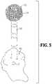
- FIG. 5is an exploded perspective view of the bone implant and the foot and ankle joint as shown in FIG. 4 .
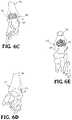
- FIG. 6Ais a side elevation view of the bone implant as shown in FIG. 1 positioned in a foot and ankle joint.
- FIG. 6Bis an opposite side elevation view of the bone implant positioned in a foot and ankle joint as shown in FIG. 6A .
- FIG. 6Cis a rear perspective view of the bone implant positioned in a foot and ankle joint as shown in FIG. 6A .
- FIG. 6Dis a front perspective view of the bone implant shown in phantom positioned in a foot and ankle joint as shown in FIG. 6A .
- FIG. 6Eis a top perspective view of the bone implant positioned in a foot and ankle joint as shown in FIG. 6A .
- FIG. 7Ais a side elevation view of the bone implant as shown in FIG. 1 positioned in a foot and ankle joint and a portion of an intramedullary nail shown in phantom.
- FIG. 7Bis a rear perspective view of the bone implant positioned in a foot and ankle joint as shown in FIG. 7A .
- FIG. 7Cis an opposite side elevation view of the bone implant positioned in a foot and ankle joint as shown in FIG. 7A .
- FIG. 7Dis a top plan view of the bone implant positioned in a foot and ankle joint as shown in FIG. 7A .
- FIG. 7Eis an up-close view of the bone implant positioned in a foot and ankle joint as shown in FIG. 7A .
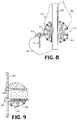
- FIG. 8is a perspective view of another embodiment of a bone implant positioned in a foot and ankle joint and including a fixation device.
- FIG. 9is an elevation view of a third embodiment of a bone implant having a planar surface to accommodate a plate or other device.
- FIG. 10is an elevation view of a fourth embodiment of a bone implant positioned in a foot and ankle joint.
- FIG. 11is a perspective view of fifth embodiment of a bone implant for use in a foot and ankle joint.
- FIG. 12is a perspective view of a sixth embodiment of a bone implant for use in a foot and ankle joint.
- FIG. 13is schematic elevation view of the third embodiment of the bone implant as shown in FIG. 9 between two portions of bone.
- FIG. 14is schematic elevation view of a seventh embodiment of a bone implant shown between two portions of bone.
- the implant 20comprises a porous web structure 22 configured to interface with human bone tissue.
- the web structure 22extends throughout the implant 20 to provide support.
- the web structure 22disperses the stress of compressive forces throughout implant 20 , wherein the implant 20 is supported against tensile, compressive, and shear forces.
- the web structure 22can be further employed to receive and distribute throughout the implant 20 loading forces of the surrounding tissue.
- the web structure 22may also reinforce the implant 20 along multiple planes.
- the web structure 22is formed with interconnected triangular-shaped building blocks.
- the resultis a web structure 22 formed from a pattern of triangularly-shaped geometrical building blocks.
- the triangularly-shaped building blocksmay form tetrahedrons that may also be used as building blocks. Other patterns from the triangles are also contemplated.
- Each tetrahedronmay include four triangular faces in which three of the four triangles meet at each vertex. At least two of the plurality of tetrahedrons are coupled together via one or more common components connecting two respective vertices on each of the two tetrahedrons such that two tetrahedrons share a common unit to form a hexahedron.
- the porous web structure 22is configured to form a substantially spherical structure as shown in FIGS. 1 and 2 .
- the implant 20can have a diameter of at least about 38 mm to about 40 mm.
- the design of the implant 20may be sized appropriately to meet specified dimensions of the implantation site.
- multiple implants of different sizesmay be constructed and delivered in a kit.
- a medical health professionalmay choose an implant (e.g., according to a needed size) during surgery.
- various shapes of web structuresare contemplated.
- a portion of the spherical implantmay be removed to form an implant having a planar side ( FIG. 9 ).
- the implant 54may be egg-shaped.
- the implant 20may be formed from a biocompatible material such as a titanium alloy (e.g., y-titanium aluminides), cobalt, chromium, stainless steel, polyetheretherketone (PEEK), ceramics, or other suitable material.
- the implant 20may be made through a rapid prototyping process (e.g., electron beam melting (EBM) process).
- EBMelectron beam melting
- Other processesare also possible, such as injection molding, casting, sintering, selective laser sintering (SLS), direct metal laser sintering (DMLS), etc).
- SLSmay include laser-sintering of high-performance polymers such as that provided by EOS of North America, Inc., headquartered in Novi, Mich., U.S.A.
- High-performance polymersmay include various forms of PEEK (e.g., HP3 having a tensile strength of up to about 95 mega Pascal (MPa) and a Young's modulus of up to about 4400 MPa and continuous operating temperature between about 180° C. (356° F.) and 260° C. (500° F.)).
- Other materialsmay include PA 12 and PA 11 provided by EOS of North America, Inc. Multiple parts may be cast or injection molded and joined together (e.g., through welding, melting, etc.).
- individual components 24 forming the implant 20may be generated separately (e.g., by casting, injection molding, etc.) and welded together to form the implant 20 .
- the porous web structure 22may be made according to the disclosure of International Application No. PCT/US2012/045717, filed Jul. 6, 2012, and published Jan. 10, 2013, as International Publication No. WO 2013/006778, the contents of which are hereby incorporated by reference in their entirety.
- the web structure 22 of the implant 50may be formed from a generally porous material having random openings 45 .
- the implant 20 , 50may include a top face 26 and an opposed bottom face 28 wherein at least a portion of the top face 26 and the bottom face 28 are generally parallel to one another.
- the top and bottom faces 26 , 28are configured to be disposed in contact, or near contact, of an adjacent bony structure for contacting the bony structure during use to adhere or couple with the adjacent structure when implanted.
- the implant 20 , 50is intended to sandwich between two adjacent bony structures interfacing with bone structure of a foot and ankle joint 34 .
- the top contact face 26may couple to a portion of the first bony structure disposed above implant 20 and the bottom contact face 28 may couple to the second bony structure disposed below implant 20 .
- the web structure 22defines openings configured to define open volume to enable bone growth through the openings of the web structure 22 , thereby enhancing coupling of the implant 20 to the adjacent bony structure. At least a portion of the web structure 22 is in contact, or near contact, with the adjacent bony structure, thereby enabling bone growth to extend into or through at least a portion of open volume of the web structure 22 such that the bone growth interlocks with the web structure 22 of the implant 20 .
- the interlocking of the bone growth and the web structure 22may rigidly fix the implant 20 in a fixed location relative to the bony structure.
- a web structure 22may define an open space for bone growth therethrough, thereby enabling bone through growth to interlock the bone structure and the web structure 22 with one another to couple the implant 20 to the bony structure at or near the contact surface.
- Such interlocking bone through growthmay inhibit movement between the implant 20 and the bony structure, which could otherwise lead to loosening, migration, subsidence, or dislodging of the implant 20 from the intended position.
- the web structure 22 of the implant 20may also provide surface area for bone graft fusion.
- the voids in the web structure 22 of the implant 20may be filled with, or surfaces of the web structure 22 may be coated with, bone grafting material, a biologic, growth factor or the like.
- the web structure 22 extending throughout the implant 20may add additional surface area on the surface of the components 24 to fuse to the bone graft material and prevent the bone graft material from loosening or migrating from the implant 20 .
- the web structure 22may also support and facilitate bone in-growth. For example, adjacent bone in an ankle joint may grow over at least a portion of the components 24 of the implant 22 .
- the bone growth and engagement between the bone growth and the implant 20may further stabilize the implant.
- the surfaces of the implant 20may be formed with a rough surface to assist in bone in-growth adhesion.
- At least a portion of the open volume of the web structure 22 of the implant 20may be filled with bone growth material.
- cancellous bonemay be packed into the openings internally of the implant 20 .
- at least a portion of the surfaces of implant 20may be coated or treated with a material intend to promote bone growth or bone adhesion or an antimicrobial agent to prevent infections.
- the surface of the web structure 22may be coated with a biologic or a bone growth factor.
- the biologic or growth factormay be physically secured to the web structure 22 in a central portion of the implant 20 provided there is the physical attachment of the biologic or growth factor.
- the biologicmay include a coating, such as hydroxyapatite, bone morphaginic protein (BMP), insulin-like growth factors I and II, transforming growth factor-beta, acidic and basic fibroblast growth factor, platelet-derived growth factor, or similar bone growth stimulant that facilitates good biological fixation between the bone growth and a surface of the implant 20 .
- the bone growth factormay include a naturally occurring substance capable of stimulating cellular growth, proliferation and cellular differentiation (e.g., a protein or steroid hormone).
- the center portion of the spherical web structure 22defines a cylindrical passage 30 .
- the central passage 30is configured to receive an intramedullary nail extending therethrough ( FIG. 3 ).
- the planar or aspherical portion of the implant 24accommodates a plate 42 or the like to facilitate attaching the combined porous web structure 22 and the plate 42 to bone using screws 48 .
- one or more structuresmay be disposed on or extend from a surface (e.g., an interface plate) of the implant that is intended to contact, and at least partially adhere to, the bony structure during use.
- a methodincludes the steps of providing an opening in a foot or ankle 34 of a human, and installing into the opening the implant 20 , 44 , 50 , 54 .
- the implant locationis first prepared, including surgical dissection for forming an opening proximate the foot or ankle 34 to the level of proposed implantation.
- a bone bedcan be prepared from the adjacent bony structure either by using a spherical reaming device or using a saw and osteotomes.
- the bone bedmay be formed in either a joint or within a single bone.
- Bone graft materialmay be packed in the bone bed or within the porous web structure 22 of the implant 20 .
- the implant 20is then inserted into the bone bed.
- the implant 20may be incorporated into the end surfaces established between an upper tibia bone 36 and an opposite and lower talus bone 38 .
- the shape of at least a portion of the implant 20allows the bone or the joint surface on either side of the implant 20 to be placed in a preferred position, for example, to correct a deformity.
- FIGS. 6A-6Eshow the implant 20 disposed in respective openings of the foot and ankle bones.
- inserting the implant 20includes positioning the implant 20 adjacent the boney structure, aligning the web structure 22 with a complementary portion of the boney structure, or advancing a contact surface toward the boney structure such that at least the web structure 22 is in contact or near contact with the boney structure.
- the implant 20may be advanced until the contact surface is in contact or near contact with the boney structure, such that at least portion or substantially all of the web structure 22 is disposed in the boney structure.
- the implant 20then may, or may not be, fixed in place.
- an intramedullary nail 32is inserted into the heel and through the passage 30 in the web structure 22 of the implant 20 .
- the nail 32is driven into the end of the tibia 36 for fusing the foot and ankle joint 34 ( FIGS. 7A-7E ).
- a tab 40 integral with the web structure 22may be included on the implant 20 .
- the tab 40may be secured to adjacent bone with staples, screws, plates, or other means of fixation.
- FIG. 11shows openings in the intramedullary nail 32 for receiving at least one screw passing through another part of the foot and ankle joint.
- FIGS. 13 and 14schematically show the implants 44 , 54 having an aspherical side and an egg-shape implant contacting adjacent bony structure 56 .
- the implants 44 , 54are intended to be disposed between the adjacent bony structures interfacing with bone structure of a foot and ankle joint.
- the top of the implants 44 , 54may couple to a portion of the first bony structure 56 disposed above the implants and the bottom contact faces 28 may couple to the second bony structure disposed below implants 44 , 54 .
- the access point to the implant sitemay be closed using sutures or other closure devices.
- a nail and a screwmay not be structural equivalents in that a nail employs a cylindrical surface to secure wooden parts together, whereas a screw employs a helical surface, in the environment of fastening wooden parts, a nail and a screw may be equivalent structures.
Landscapes
- Health & Medical Sciences (AREA)
- Orthopedic Medicine & Surgery (AREA)
- Life Sciences & Earth Sciences (AREA)
- Surgery (AREA)
- General Health & Medical Sciences (AREA)
- Veterinary Medicine (AREA)
- Engineering & Computer Science (AREA)
- Biomedical Technology (AREA)
- Heart & Thoracic Surgery (AREA)
- Public Health (AREA)
- Animal Behavior & Ethology (AREA)
- Transplantation (AREA)
- Molecular Biology (AREA)
- Medical Informatics (AREA)
- Nuclear Medicine, Radiotherapy & Molecular Imaging (AREA)
- Neurology (AREA)
- Cardiology (AREA)
- Oral & Maxillofacial Surgery (AREA)
- Vascular Medicine (AREA)
- Physical Education & Sports Medicine (AREA)
- Prostheses (AREA)
- Surgical Instruments (AREA)
Abstract
Description
Claims (13)
Priority Applications (1)
| Application Number | Priority Date | Filing Date | Title |
|---|---|---|---|
| US16/102,107US11395747B2 (en) | 2015-05-22 | 2018-08-13 | Joint or segmental bone implant for deformity correction |
Applications Claiming Priority (3)
| Application Number | Priority Date | Filing Date | Title |
|---|---|---|---|
| US201562165376P | 2015-05-22 | 2015-05-22 | |
| US15/162,525US10045854B2 (en) | 2015-05-22 | 2016-05-23 | Joint or segmental bone implant for deformity correction |
| US16/102,107US11395747B2 (en) | 2015-05-22 | 2018-08-13 | Joint or segmental bone implant for deformity correction |
Related Parent Applications (1)
| Application Number | Title | Priority Date | Filing Date |
|---|---|---|---|
| US15/162,525ContinuationUS10045854B2 (en) | 2015-05-22 | 2016-05-23 | Joint or segmental bone implant for deformity correction |
Publications (2)
| Publication Number | Publication Date |
|---|---|
| US20180360611A1 US20180360611A1 (en) | 2018-12-20 |
| US11395747B2true US11395747B2 (en) | 2022-07-26 |
Family
ID=56131615
Family Applications (5)
| Application Number | Title | Priority Date | Filing Date |
|---|---|---|---|
| US15/162,525ActiveUS10045854B2 (en) | 2015-05-22 | 2016-05-23 | Joint or segmental bone implant for deformity correction |
| US15/447,227ActiveUS10517737B2 (en) | 2015-05-22 | 2017-03-02 | Joint or segmental bone implant for deformity correction |
| US16/102,107Active2038-08-19US11395747B2 (en) | 2015-05-22 | 2018-08-13 | Joint or segmental bone implant for deformity correction |
| US16/729,739Active2038-03-13US11759332B2 (en) | 2015-05-22 | 2019-12-30 | Joint or segmental bone implant for deformity correction |
| US18/233,598PendingUS20230380987A1 (en) | 2015-05-22 | 2023-08-14 | Joint Or Segmental Bone Implant For Deformity Correction |
Family Applications Before (2)
| Application Number | Title | Priority Date | Filing Date |
|---|---|---|---|
| US15/162,525ActiveUS10045854B2 (en) | 2015-05-22 | 2016-05-23 | Joint or segmental bone implant for deformity correction |
| US15/447,227ActiveUS10517737B2 (en) | 2015-05-22 | 2017-03-02 | Joint or segmental bone implant for deformity correction |
Family Applications After (2)
| Application Number | Title | Priority Date | Filing Date |
|---|---|---|---|
| US16/729,739Active2038-03-13US11759332B2 (en) | 2015-05-22 | 2019-12-30 | Joint or segmental bone implant for deformity correction |
| US18/233,598PendingUS20230380987A1 (en) | 2015-05-22 | 2023-08-14 | Joint Or Segmental Bone Implant For Deformity Correction |
Country Status (7)
| Country | Link |
|---|---|
| US (5) | US10045854B2 (en) |
| EP (1) | EP3297553B1 (en) |
| JP (1) | JP2018519134A (en) |
| CN (1) | CN107835669A (en) |
| AU (1) | AU2016267051A1 (en) |
| CA (1) | CA2986752A1 (en) |
| WO (1) | WO2016191393A1 (en) |
Families Citing this family (17)
| Publication number | Priority date | Publication date | Assignee | Title |
|---|---|---|---|---|
| US8728387B2 (en) | 2005-12-06 | 2014-05-20 | Howmedica Osteonics Corp. | Laser-produced porous surface |
| US12279964B2 (en) | 2008-12-18 | 2025-04-22 | 4Web, Llc | Implants having bone growth promoting agents and methods of using such implants to repair bone structures |
| US12115071B2 (en) | 2012-09-25 | 2024-10-15 | 4Web, Llc | Programmable intramedullary implants and methods of using programmable intramedullary implants to repair bone structures |
| WO2015017074A1 (en)* | 2013-07-02 | 2015-02-05 | Cmarr Enterprises | Curved tibiotalar fusion nail and method of use |
| US10610368B2 (en) | 2018-05-26 | 2020-04-07 | Acumed Llc | Ankle fusion system with expandable spacer |
| AU2016267051A1 (en) | 2015-05-22 | 2017-12-14 | Stryker European Operations Limited | Joint or segmental bone implant for deformity correction |
| US11547456B2 (en)* | 2017-01-12 | 2023-01-10 | Dt Medtech, Llc | Internal ankle fixation systems, foot securement and jig devices, and related methods |
| AU2018225123C1 (en)* | 2017-02-21 | 2020-03-19 | Biomet Manufacturing, Llc | Implants for bridging osseous defects |
| AU2017418982B2 (en) | 2017-06-13 | 2020-03-12 | Wright Medical Technology, Inc. | Calcaneal prosthesis |
| US20190167433A1 (en)* | 2017-12-04 | 2019-06-06 | Duke University | Orthopedic implant for sustained drug release |
| CA3086594A1 (en)* | 2017-12-22 | 2019-06-27 | Pure Technologies Ltd. | Surround for pipeline inspection equipment |
| US11147679B2 (en)* | 2018-02-05 | 2021-10-19 | Paragon Advanced Technologies, Inc. | Bone fixation device |
| US11517438B2 (en)* | 2019-09-25 | 2022-12-06 | Depuy Ireland Unlimited Company | Three-dimensional porous structures for bone ingrowth and methods for producing |
| CA3159552A1 (en) | 2019-10-30 | 2021-05-06 | 4Web, Inc. | Programmable intramedullary implants and methods of using programmable intramedullary implants to repair bone structures |
| WO2021097438A1 (en) | 2019-11-15 | 2021-05-20 | 4Web, Inc. | Piezoelectric coated implants and methods of using piezoelectric coated implants to repair bone structures |
| EP4178496A4 (en) | 2020-07-08 | 2024-08-14 | 4Web, Inc. | Implants having bone growth promoting agents contained within biodegradable materials |
| AU2022323511A1 (en)* | 2021-08-02 | 2024-03-21 | Paragon 28, Inc. | Implants, instruments, systems, and methods of using |
Citations (86)
| Publication number | Priority date | Publication date | Assignee | Title |
|---|---|---|---|---|
| GB190118231A (en) | 1901-09-12 | 1901-11-30 | Samuel Adams White | An Improved Dish for use in Dressing Boots and Shoes |
| FR373990A (en) | 1906-04-29 | 1907-05-31 | Edwin Trueman | Device for braking or locking the wheels of wagons, mine tanks, etc. |
| GB595628A (en) | 1944-06-28 | 1947-12-11 | George Samuel Adams | Improvements in clothes drying and airing devices |
| GB972282A (en) | 1959-10-06 | 1964-10-14 | Samuel Adams | Device for production of electrons for high frequency purposes |
| US4820305A (en) | 1986-11-03 | 1989-04-11 | Harms Juergen | Place holder, in particular for a vertebra body |
| US4936848A (en) | 1989-09-22 | 1990-06-26 | Bagby George W | Implant for vertebrae |
| US5281226A (en) | 1989-03-31 | 1994-01-25 | Davydov Anatoly B | Missing portion of a tubular bone |
| US5609367A (en) | 1995-12-01 | 1997-03-11 | Alliedsignal Inc. | Adjustable three-point restraint seat belt system for children and adults |
| US5702451A (en) | 1995-02-14 | 1997-12-30 | Biedermann; Lutz | Space holder, in particular for a vertebra or an intervertebral disk |
| US6086613A (en) | 1997-12-23 | 2000-07-11 | Depuy Acromed, Inc. | Spacer assembly for use in spinal surgeries |
| US6193755B1 (en) | 1996-09-26 | 2001-02-27 | Howmedica Gmbh | Spinal cage assembly |
| US6193756B1 (en) | 1997-09-30 | 2001-02-27 | Sulzer Orthopaedie Ag | Tubular support body for bridging two vertebrae |
| US6200348B1 (en) | 1998-02-06 | 2001-03-13 | Biedermann, Motech Gmbh | Spacer with adjustable axial length |
| US6206924B1 (en) | 1999-10-20 | 2001-03-27 | Interpore Cross Internat | Three-dimensional geometric bio-compatible porous engineered structure for use as a bone mass replacement or fusion augmentation device |
| US6579293B1 (en) | 2000-08-02 | 2003-06-17 | Rama E. Chandran | Intramedullary rod with interlocking oblique screw for tibio-calcaneal arthrodesis |
| US6585770B1 (en) | 1997-06-02 | 2003-07-01 | Sdgi Holdings, Inc. | Devices for supporting bony structures |
| US6663669B1 (en) | 1999-10-22 | 2003-12-16 | Mark A Reiley | Ankle replacement system |
| US6673116B2 (en)* | 1999-10-22 | 2004-01-06 | Mark A. Reiley | Intramedullary guidance systems and methods for installing ankle replacement prostheses |
| US6706924B2 (en) | 2000-12-22 | 2004-03-16 | Bayer Aktiengesellschaft | Process for the production of 1,5-naphthalenediamine |
| WO2004110309A2 (en) | 2003-06-11 | 2004-12-23 | Case Western Reserve University | Computer-aided-design of skeletal implants |
| US20050015154A1 (en) | 2003-06-25 | 2005-01-20 | Baylor College Of Medicine Office Of Technology Administration | Tissue integration design for seamless implant fixation |
| US6902581B2 (en) | 2000-10-24 | 2005-06-07 | Kowmedica Osteonics Corp. | Apparatus for fusing adjacent bone structure |
| WO2005051233A2 (en) | 2003-11-21 | 2005-06-09 | William Marsh Rice University | Computer-aided tissue engineering of a biological body |
| US6931812B1 (en) | 2000-12-22 | 2005-08-23 | Stephen Leon Lipscomb | Web structure and method for making the same |
| US20060147332A1 (en) | 2004-12-30 | 2006-07-06 | Howmedica Osteonics Corp. | Laser-produced porous structure |
| US7087200B2 (en) | 2001-06-22 | 2006-08-08 | The Regents Of The University Of Michigan | Controlled local/global and micro/macro-porous 3D plastic, polymer and ceramic/cement composite scaffold fabrication and applications thereof |
| EP1800627A2 (en) | 2005-12-23 | 2007-06-27 | BIEDERMANN MOTECH GmbH | Multi-walled placeholder |
| US7244273B2 (en) | 1999-12-17 | 2007-07-17 | Cartificial A/S | Prosthetic device |
| WO2008022206A2 (en) | 2006-08-15 | 2008-02-21 | Motionback Llc | Spinal implant |
| CN201164511Y (en) | 2008-03-03 | 2008-12-17 | 曼德卡姆有限公司 | Artificial hip joint acetabulum outer lining |
| CN201200499Y (en) | 2008-05-19 | 2009-03-04 | 曼德卡姆有限公司 | Latticed metal orthopedic implant |
| US20100174377A1 (en) | 2007-06-07 | 2010-07-08 | Smith & Nephew, Inc. | Reticulated particle porous coating for medical implant use |
| US7855062B2 (en) | 2005-12-14 | 2010-12-21 | The Invention Science Fund I, Llc | Bone cell delivery device |
| US20110125284A1 (en) | 2008-05-28 | 2011-05-26 | University Of Bath | Improvements in or Relating to Joints and/or Implants |
| US20110172826A1 (en) | 2005-12-14 | 2011-07-14 | Amodei Dario G | Device including altered microorganisms, and methods and systems of use |
| WO2011082905A1 (en) | 2009-12-14 | 2011-07-14 | Fraunhofer-Gesellschaft zur Förderung der angewandten Forschung e.V. | Open-cell titanium metal foams and method for producing same |
| US20110200478A1 (en) | 2010-02-14 | 2011-08-18 | Romain Louis Billiet | Inorganic structures with controlled open cell porosity and articles made therefrom |
| WO2011123110A1 (en) | 2010-03-30 | 2011-10-06 | Daniel Sunho Oh | Method of preparing ceramic/polymer composite scaffolds with bioactive molecules for hard tissue regeneration |
| US8062365B2 (en) | 2003-08-04 | 2011-11-22 | Warsaw Orthopedic, Inc. | Bone supporting devices with bio-absorbable end members |
| US20110313532A1 (en) | 2010-06-18 | 2011-12-22 | Jessee Hunt | Bone implant interface system and method |
| US8114647B2 (en) | 2005-12-14 | 2012-02-14 | The Invention Science Fund I, Llc | Blood brain barrier device |
| US8278094B2 (en) | 2005-12-14 | 2012-10-02 | The Invention Science Fund I, Llc | Bone semi-permeable device |
| US8292967B2 (en) | 2005-04-21 | 2012-10-23 | Biomet Manufacturing Corp. | Method and apparatus for use of porous implants |
| WO2013006778A2 (en) | 2011-07-07 | 2013-01-10 | 4-Web, Inc. | Foot and ankle implant system and method |
| US8354258B2 (en) | 2005-12-14 | 2013-01-15 | The Invention Science Fund I, Llc | Diatom device |
| US20130030529A1 (en) | 2011-07-29 | 2013-01-31 | Jessee Hunt | Implant interface system and method |
| US8367384B2 (en) | 2005-12-14 | 2013-02-05 | The Invention Science Fund I, Llc | Bone semi-permeable device |
| US20130090739A1 (en) | 2011-09-27 | 2013-04-11 | Linares Medical Devices, Llc | Implantable ankle joint assembly with spherical inter-support |
| US8430950B2 (en) | 2008-03-05 | 2013-04-30 | Thyssenkrupp Uhde Gmbh | Device for removing fine-grained or dust-like solids from a container |
| US8430930B2 (en) | 2008-12-18 | 2013-04-30 | 4-Web, Inc. | Truss implant |
| US20130123935A1 (en) | 2011-11-03 | 2013-05-16 | Jessee Hunt | Method of length preservation during bone repair |
| US8485820B1 (en) | 2011-12-22 | 2013-07-16 | Mohamed Ikbal Ali | Devices and methods for enhancing bone growth |
| US8492143B2 (en) | 2005-12-14 | 2013-07-23 | The Invention Science Fund I, Llc | Bone delivery device |
| WO2013119907A1 (en) | 2012-02-08 | 2013-08-15 | 4-Web, Inc. | Prosthetic implant for ball and socket joints and method of use |
| US20130218278A1 (en) | 2012-02-21 | 2013-08-22 | Steve Wolfe | Device and method for performing spinal interbody fusion |
| US8532806B1 (en) | 2010-06-07 | 2013-09-10 | Marcos V. Masson | Process for manufacture of joint implants |
| USRE44501E1 (en) | 2005-02-18 | 2013-09-17 | Smith & Nephew, Inc. | Hindfoot nail |
| US8545572B2 (en) | 2011-01-21 | 2013-10-01 | Trilliant Surgical, Ltd. | Subtalar implant |
| US8682619B2 (en) | 2005-12-14 | 2014-03-25 | The Invention Science Fund I, Llc | Device including altered microorganisms, and methods and systems of use |
| US8709089B2 (en) | 2002-10-07 | 2014-04-29 | Conformis, Inc. | Minimally invasive joint implant with 3-dimensional geometry matching the articular surfaces |
| US20140121776A1 (en) | 2012-09-25 | 2014-05-01 | 4Web, Inc. | Programmable implants and methods of using programmable implants to repair bone structures |
| US8734823B2 (en) | 2005-12-14 | 2014-05-27 | The Invention Science Fund I, Llc | Device including altered microorganisms, and methods and systems of use |
| US8808303B2 (en) | 2009-02-24 | 2014-08-19 | Microport Orthopedics Holdings Inc. | Orthopedic surgical guide |
| US20140277576A1 (en) | 2013-03-14 | 2014-09-18 | Ethicon, Inc. | Randomly Uniform Three Dimensional Tissue Scaffold of Absorbable and Non-Absorbable Materials |
| US20140277575A1 (en) | 2013-03-14 | 2014-09-18 | Ethicon, Inc. | Randomly Uniform Three Dimensional Tissue Scaffold of Absorbable and Non-Absorbable Materials |
| US20140288650A1 (en) | 2013-03-15 | 2014-09-25 | 4Web, Inc. | Motion preservation implant and methods |
| US20140288649A1 (en) | 2013-03-15 | 2014-09-25 | 4Web, Inc. | Traumatic bone fracture repair systems and methods |
| US8906022B2 (en) | 2010-03-08 | 2014-12-09 | Conventus Orthopaedics, Inc. | Apparatus and methods for securing a bone implant |
| US9005944B2 (en) | 2005-12-14 | 2015-04-14 | The Invention Science Fund I, Llc | Bone cell delivery device |
| US9020788B2 (en) | 1997-01-08 | 2015-04-28 | Conformis, Inc. | Patient-adapted and improved articular implants, designs and related guide tools |
| US9066764B2 (en) | 2007-10-16 | 2015-06-30 | Campbell Clinic, P.C. | Long bone fixation system and methods |
| US20150258735A1 (en) | 2002-11-08 | 2015-09-17 | Howmedica Osteonics Corp. | Laser-produced porous surface |
| US20160089245A1 (en) | 2014-09-29 | 2016-03-31 | Biomet C.V. | Implants for fixation of the distal tibia |
| US9364896B2 (en) | 2012-02-07 | 2016-06-14 | Medical Modeling Inc. | Fabrication of hybrid solid-porous medical implantable devices with electron beam melting technology |
| US20160338842A1 (en) | 2015-05-22 | 2016-11-24 | Surgical Alternatives | Joint or segmental bone implant for deformity correction |
| US9636276B2 (en) | 2001-12-06 | 2017-05-02 | Sanofi-Aventis Deutschland Gmbh | Medicament cartridge assembly |
| US9724203B2 (en) | 2013-03-15 | 2017-08-08 | Smed-Ta/Td, Llc | Porous tissue ingrowth structure |
| US20170319349A1 (en) | 2016-05-03 | 2017-11-09 | Additive Orthopaedics, LLC | Bone fixation device and method of use |
| US20170360488A1 (en) | 2016-06-03 | 2017-12-21 | Additive Orthopaedics, LLC | Bone fixation devices |
| US20180028242A1 (en) | 2016-07-29 | 2018-02-01 | Additive Orthopaedics, LLC | Bone fixation device and method of use |
| US9890827B2 (en) | 2007-05-10 | 2018-02-13 | Hrl Laboratories, Llc | Energy absorbing truss structures for mitigation of injuries from blasts and impacts |
| JP2018051913A (en) | 2016-09-28 | 2018-04-05 | ブラザー工業株式会社 | Printer |
| US10064726B1 (en) | 2017-04-18 | 2018-09-04 | Warsaw Orthopedic, Inc. | 3D printing of mesh implants for bone delivery |
| US10070962B1 (en) | 2015-02-13 | 2018-09-11 | Nextstep Arthropedix, LLC | Medical implants having desired surface features and methods of manufacturing |
| US10166033B2 (en) | 2014-09-18 | 2019-01-01 | Si-Bone Inc. | Implants for bone fixation or fusion |
| US10182832B1 (en) | 2017-08-24 | 2019-01-22 | Limacorporate S.P.A. | Ankle arthroplasty systems and methods |
Family Cites Families (8)
| Publication number | Priority date | Publication date | Assignee | Title |
|---|---|---|---|---|
| WO1999033641A1 (en) | 1997-12-24 | 1999-07-08 | Molecular Geodesics, Inc. | Foam scaffold materials |
| CN101917915B (en)* | 2007-11-26 | 2014-08-06 | 比德尔曼技术有限责任两合公司 | Nails and Osseosynthesis Kits for Heels |
| US9011503B2 (en)* | 2009-07-14 | 2015-04-21 | Neil Duggal | Joint arthrodesis and arthroplasty |
| US9161796B2 (en)* | 2010-12-18 | 2015-10-20 | The Brigham And Women's Hospital, Inc. | Medical devices for use during ankle fusion surgery |
| US9220518B2 (en)* | 2012-05-08 | 2015-12-29 | Zimmer, Inc. | Porous spacers, instruments, and methods for foot and ankle fusion |
| US9125695B2 (en)* | 2012-10-18 | 2015-09-08 | Bespa, Inc. | Ankle fusion nail apparatus and method |
| CN102940542B (en)* | 2012-10-23 | 2015-05-20 | 华中科技大学 | Artificial limb ankle joint with four passive degrees of freedom |
| CN203001181U (en)* | 2012-11-14 | 2013-06-19 | 黄国富 | Buffer type artificial ankle joint |
- 2016
- 2016-05-23AUAU2016267051Apatent/AU2016267051A1/ennot_activeAbandoned
- 2016-05-23WOPCT/US2016/033835patent/WO2016191393A1/ennot_activeCeased
- 2016-05-23CACA2986752Apatent/CA2986752A1/ennot_activeAbandoned
- 2016-05-23USUS15/162,525patent/US10045854B2/enactiveActive
- 2016-05-23CNCN201680040821.5Apatent/CN107835669A/enactivePending
- 2016-05-23JPJP2018512843Apatent/JP2018519134A/enactivePending
- 2016-05-23EPEP16729417.2Apatent/EP3297553B1/enactiveActive
- 2017
- 2017-03-02USUS15/447,227patent/US10517737B2/enactiveActive
- 2018
- 2018-08-13USUS16/102,107patent/US11395747B2/enactiveActive
- 2019
- 2019-12-30USUS16/729,739patent/US11759332B2/enactiveActive
- 2023
- 2023-08-14USUS18/233,598patent/US20230380987A1/enactivePending
Patent Citations (133)
| Publication number | Priority date | Publication date | Assignee | Title |
|---|---|---|---|---|
| GB190118231A (en) | 1901-09-12 | 1901-11-30 | Samuel Adams White | An Improved Dish for use in Dressing Boots and Shoes |
| FR373990A (en) | 1906-04-29 | 1907-05-31 | Edwin Trueman | Device for braking or locking the wheels of wagons, mine tanks, etc. |
| GB595628A (en) | 1944-06-28 | 1947-12-11 | George Samuel Adams | Improvements in clothes drying and airing devices |
| GB972282A (en) | 1959-10-06 | 1964-10-14 | Samuel Adams | Device for production of electrons for high frequency purposes |
| US4820305A (en) | 1986-11-03 | 1989-04-11 | Harms Juergen | Place holder, in particular for a vertebra body |
| US5281226A (en) | 1989-03-31 | 1994-01-25 | Davydov Anatoly B | Missing portion of a tubular bone |
| US4936848A (en) | 1989-09-22 | 1990-06-26 | Bagby George W | Implant for vertebrae |
| US5702451A (en) | 1995-02-14 | 1997-12-30 | Biedermann; Lutz | Space holder, in particular for a vertebra or an intervertebral disk |
| US5609367A (en) | 1995-12-01 | 1997-03-11 | Alliedsignal Inc. | Adjustable three-point restraint seat belt system for children and adults |
| US6193755B1 (en) | 1996-09-26 | 2001-02-27 | Howmedica Gmbh | Spinal cage assembly |
| US9020788B2 (en) | 1997-01-08 | 2015-04-28 | Conformis, Inc. | Patient-adapted and improved articular implants, designs and related guide tools |
| US6585770B1 (en) | 1997-06-02 | 2003-07-01 | Sdgi Holdings, Inc. | Devices for supporting bony structures |
| US6193756B1 (en) | 1997-09-30 | 2001-02-27 | Sulzer Orthopaedie Ag | Tubular support body for bridging two vertebrae |
| US6086613A (en) | 1997-12-23 | 2000-07-11 | Depuy Acromed, Inc. | Spacer assembly for use in spinal surgeries |
| US6200348B1 (en) | 1998-02-06 | 2001-03-13 | Biedermann, Motech Gmbh | Spacer with adjustable axial length |
| US6206924B1 (en) | 1999-10-20 | 2001-03-27 | Interpore Cross Internat | Three-dimensional geometric bio-compatible porous engineered structure for use as a bone mass replacement or fusion augmentation device |
| US6663669B1 (en) | 1999-10-22 | 2003-12-16 | Mark A Reiley | Ankle replacement system |
| US6673116B2 (en)* | 1999-10-22 | 2004-01-06 | Mark A. Reiley | Intramedullary guidance systems and methods for installing ankle replacement prostheses |
| US7314488B2 (en) | 1999-10-22 | 2008-01-01 | Inbone Technologies, Inc. | Intramedullary guidance systems and methods for installing ankle replacement prostheses |
| US7717920B2 (en) | 1999-10-22 | 2010-05-18 | Inbone Technologies, Inc. | Ankle replacement prostheses |
| US8808389B2 (en) | 1999-10-22 | 2014-08-19 | Inbone Technologies, Inc. | Ankle replacement system |
| US7641697B2 (en) | 1999-10-22 | 2010-01-05 | Inbone Technologies, Inc. | Systems and methods for installing ankle replacement prostheses |
| US7244273B2 (en) | 1999-12-17 | 2007-07-17 | Cartificial A/S | Prosthetic device |
| US6579293B1 (en) | 2000-08-02 | 2003-06-17 | Rama E. Chandran | Intramedullary rod with interlocking oblique screw for tibio-calcaneal arthrodesis |
| US6902581B2 (en) | 2000-10-24 | 2005-06-07 | Kowmedica Osteonics Corp. | Apparatus for fusing adjacent bone structure |
| US6931812B1 (en) | 2000-12-22 | 2005-08-23 | Stephen Leon Lipscomb | Web structure and method for making the same |
| US6706924B2 (en) | 2000-12-22 | 2004-03-16 | Bayer Aktiengesellschaft | Process for the production of 1,5-naphthalenediamine |
| US7087200B2 (en) | 2001-06-22 | 2006-08-08 | The Regents Of The University Of Michigan | Controlled local/global and micro/macro-porous 3D plastic, polymer and ceramic/cement composite scaffold fabrication and applications thereof |
| US9636276B2 (en) | 2001-12-06 | 2017-05-02 | Sanofi-Aventis Deutschland Gmbh | Medicament cartridge assembly |
| US8709089B2 (en) | 2002-10-07 | 2014-04-29 | Conformis, Inc. | Minimally invasive joint implant with 3-dimensional geometry matching the articular surfaces |
| US20150258735A1 (en) | 2002-11-08 | 2015-09-17 | Howmedica Osteonics Corp. | Laser-produced porous surface |
| WO2004110309A2 (en) | 2003-06-11 | 2004-12-23 | Case Western Reserve University | Computer-aided-design of skeletal implants |
| US20050015154A1 (en) | 2003-06-25 | 2005-01-20 | Baylor College Of Medicine Office Of Technology Administration | Tissue integration design for seamless implant fixation |
| US9364330B2 (en) | 2003-06-25 | 2016-06-14 | Biedermann Technologies Gmbh & Co. Kg | Tissue integration design for seamless implant fixation |
| US10213309B2 (en) | 2003-06-25 | 2019-02-26 | Biedermann Technologies Gmbh & Co. Kg | Tissue integration design for seamless implant fixation |
| US8062365B2 (en) | 2003-08-04 | 2011-11-22 | Warsaw Orthopedic, Inc. | Bone supporting devices with bio-absorbable end members |
| WO2005051233A2 (en) | 2003-11-21 | 2005-06-09 | William Marsh Rice University | Computer-aided tissue engineering of a biological body |
| US20060147332A1 (en) | 2004-12-30 | 2006-07-06 | Howmedica Osteonics Corp. | Laser-produced porous structure |
| US9456901B2 (en) | 2004-12-30 | 2016-10-04 | Howmedica Osteonics Corp. | Laser-produced porous structure |
| USRE44501E1 (en) | 2005-02-18 | 2013-09-17 | Smith & Nephew, Inc. | Hindfoot nail |
| US8292967B2 (en) | 2005-04-21 | 2012-10-23 | Biomet Manufacturing Corp. | Method and apparatus for use of porous implants |
| US20110172826A1 (en) | 2005-12-14 | 2011-07-14 | Amodei Dario G | Device including altered microorganisms, and methods and systems of use |
| US8999711B2 (en) | 2005-12-14 | 2015-04-07 | The Invention Science Fund I, Llc | Bone delivery device |
| US8114647B2 (en) | 2005-12-14 | 2012-02-14 | The Invention Science Fund I, Llc | Blood brain barrier device |
| US8278094B2 (en) | 2005-12-14 | 2012-10-02 | The Invention Science Fund I, Llc | Bone semi-permeable device |
| US8975074B2 (en) | 2005-12-14 | 2015-03-10 | The Invention Science Fund I, Llc | Bone semi-permeable device |
| US9061075B2 (en) | 2005-12-14 | 2015-06-23 | The Invention Science Fund I, Llc | Bone delivery device |
| US8354258B2 (en) | 2005-12-14 | 2013-01-15 | The Invention Science Fund I, Llc | Diatom device |
| US8734823B2 (en) | 2005-12-14 | 2014-05-27 | The Invention Science Fund I, Llc | Device including altered microorganisms, and methods and systems of use |
| US8367384B2 (en) | 2005-12-14 | 2013-02-05 | The Invention Science Fund I, Llc | Bone semi-permeable device |
| US20150064146A1 (en) | 2005-12-14 | 2015-03-05 | Searete Llc | Blood Brain Barrier Device |
| US20130101637A1 (en) | 2005-12-14 | 2013-04-25 | Searete Llc | Bone Semi-Permeable Device |
| US8682619B2 (en) | 2005-12-14 | 2014-03-25 | The Invention Science Fund I, Llc | Device including altered microorganisms, and methods and systems of use |
| US9005943B2 (en) | 2005-12-14 | 2015-04-14 | The Invention Science Fund I, Llc | Bone cell delivery device |
| US7855062B2 (en) | 2005-12-14 | 2010-12-21 | The Invention Science Fund I, Llc | Bone cell delivery device |
| US8900865B2 (en) | 2005-12-14 | 2014-12-02 | The Invention Science Fund I, Llc | Blood brain barrier device |
| US9023630B2 (en) | 2005-12-14 | 2015-05-05 | The Invention Science Fund I, Llc | Bone cell delivery device |
| US8492143B2 (en) | 2005-12-14 | 2013-07-23 | The Invention Science Fund I, Llc | Bone delivery device |
| US9005944B2 (en) | 2005-12-14 | 2015-04-14 | The Invention Science Fund I, Llc | Bone cell delivery device |
| EP1800627A2 (en) | 2005-12-23 | 2007-06-27 | BIEDERMANN MOTECH GmbH | Multi-walled placeholder |
| US10130485B2 (en) | 2005-12-23 | 2018-11-20 | Biedermann Technologies Gmbh & Co. Kg | Multi-walled placeholder |
| US9814595B2 (en) | 2005-12-23 | 2017-11-14 | Biedermann Technologies Gmbh & Co. Kg. | Multi-walled placeholder |
| WO2008022206A2 (en) | 2006-08-15 | 2008-02-21 | Motionback Llc | Spinal implant |
| US9890827B2 (en) | 2007-05-10 | 2018-02-13 | Hrl Laboratories, Llc | Energy absorbing truss structures for mitigation of injuries from blasts and impacts |
| US20100174377A1 (en) | 2007-06-07 | 2010-07-08 | Smith & Nephew, Inc. | Reticulated particle porous coating for medical implant use |
| US9066764B2 (en) | 2007-10-16 | 2015-06-30 | Campbell Clinic, P.C. | Long bone fixation system and methods |
| CN201164511Y (en) | 2008-03-03 | 2008-12-17 | 曼德卡姆有限公司 | Artificial hip joint acetabulum outer lining |
| US8430950B2 (en) | 2008-03-05 | 2013-04-30 | Thyssenkrupp Uhde Gmbh | Device for removing fine-grained or dust-like solids from a container |
| CN201200499Y (en) | 2008-05-19 | 2009-03-04 | 曼德卡姆有限公司 | Latticed metal orthopedic implant |
| US20110125284A1 (en) | 2008-05-28 | 2011-05-26 | University Of Bath | Improvements in or Relating to Joints and/or Implants |
| US20170216035A1 (en) | 2008-12-18 | 2017-08-03 | 4Web, Inc. | System and method of length preservation during bone repair |
| US20150282946A1 (en) | 2008-12-18 | 2015-10-08 | 4Web, Inc. | Implant device having curved or arced struts |
| US9421108B2 (en) | 2008-12-18 | 2016-08-23 | 4Web, Inc. | Implant system and method |
| US9545317B2 (en) | 2008-12-18 | 2017-01-17 | 4Web, Inc. | Implant interface system and device |
| US8430930B2 (en) | 2008-12-18 | 2013-04-30 | 4-Web, Inc. | Truss implant |
| US20180085230A1 (en) | 2008-12-18 | 2018-03-29 | 4Web, Inc. | Implant device allowing motion preservation |
| US9999516B2 (en) | 2008-12-18 | 2018-06-19 | 4Web, Inc. | Implant device having a non-planar surface |
| US8808303B2 (en) | 2009-02-24 | 2014-08-19 | Microport Orthopedics Holdings Inc. | Orthopedic surgical guide |
| US9642632B2 (en) | 2009-02-24 | 2017-05-09 | Microport Orthopedics Holdings Inc. | Orthopedic surgical guide |
| US10039557B2 (en) | 2009-02-24 | 2018-08-07 | Micorport Orthopedics Holdings, Inc. | Orthopedic surgical guide |
| WO2011082905A1 (en) | 2009-12-14 | 2011-07-14 | Fraunhofer-Gesellschaft zur Förderung der angewandten Forschung e.V. | Open-cell titanium metal foams and method for producing same |
| US20110200478A1 (en) | 2010-02-14 | 2011-08-18 | Romain Louis Billiet | Inorganic structures with controlled open cell porosity and articles made therefrom |
| US20180199972A1 (en) | 2010-03-08 | 2018-07-19 | Conventus Orthopaedics, Inc. | Apparatus and methods for securing a bone implant |
| US8906022B2 (en) | 2010-03-08 | 2014-12-09 | Conventus Orthopaedics, Inc. | Apparatus and methods for securing a bone implant |
| US9993277B2 (en) | 2010-03-08 | 2018-06-12 | Conventus Orthopaedics, Inc. | Apparatus and methods for securing a bone implant |
| WO2011123110A1 (en) | 2010-03-30 | 2011-10-06 | Daniel Sunho Oh | Method of preparing ceramic/polymer composite scaffolds with bioactive molecules for hard tissue regeneration |
| US8532806B1 (en) | 2010-06-07 | 2013-09-10 | Marcos V. Masson | Process for manufacture of joint implants |
| US20110313532A1 (en) | 2010-06-18 | 2011-12-22 | Jessee Hunt | Bone implant interface system and method |
| US20130158672A1 (en) | 2010-06-18 | 2013-06-20 | 4-Web, Inc. | Bone implant interface system and method |
| US8545572B2 (en) | 2011-01-21 | 2013-10-01 | Trilliant Surgical, Ltd. | Subtalar implant |
| WO2013006778A2 (en) | 2011-07-07 | 2013-01-10 | 4-Web, Inc. | Foot and ankle implant system and method |
| US20130030529A1 (en) | 2011-07-29 | 2013-01-31 | Jessee Hunt | Implant interface system and method |
| US20130090739A1 (en) | 2011-09-27 | 2013-04-11 | Linares Medical Devices, Llc | Implantable ankle joint assembly with spherical inter-support |
| US20130123935A1 (en) | 2011-11-03 | 2013-05-16 | Jessee Hunt | Method of length preservation during bone repair |
| US8485820B1 (en) | 2011-12-22 | 2013-07-16 | Mohamed Ikbal Ali | Devices and methods for enhancing bone growth |
| US9364896B2 (en) | 2012-02-07 | 2016-06-14 | Medical Modeling Inc. | Fabrication of hybrid solid-porous medical implantable devices with electron beam melting technology |
| US20170319344A1 (en) | 2012-02-08 | 2017-11-09 | 4Web, Inc. | Prosthetic implant for ball and socket joints and method of use |
| WO2013119907A1 (en) | 2012-02-08 | 2013-08-15 | 4-Web, Inc. | Prosthetic implant for ball and socket joints and method of use |
| US20130218278A1 (en) | 2012-02-21 | 2013-08-22 | Steve Wolfe | Device and method for performing spinal interbody fusion |
| US9757235B2 (en) | 2012-09-25 | 2017-09-12 | 4Web, Inc. | Spinal programmable implant |
| US9572669B2 (en) | 2012-09-25 | 2017-02-21 | 4-Web, Inc. | Programmable implant having an angled exterior surface |
| US20190060077A1 (en) | 2012-09-25 | 2019-02-28 | 4Web | Programmable implant |
| US9549823B2 (en) | 2012-09-25 | 2017-01-24 | 4-Web, Inc. | Programmable implant having curved or arced struts |
| US9987137B2 (en) | 2012-09-25 | 2018-06-05 | 4Web, Inc. | Programmable implant having curved or arced struts |
| US9271845B2 (en) | 2012-09-25 | 2016-03-01 | 4Web | Programmable implants and methods of using programmable implants to repair bone structures |
| US20140121776A1 (en) | 2012-09-25 | 2014-05-01 | 4Web, Inc. | Programmable implants and methods of using programmable implants to repair bone structures |
| US20160287388A1 (en) | 2012-09-25 | 2016-10-06 | 4Web, Inc. | Programmable implant having struts with different physical properties |
| US20140277575A1 (en) | 2013-03-14 | 2014-09-18 | Ethicon, Inc. | Randomly Uniform Three Dimensional Tissue Scaffold of Absorbable and Non-Absorbable Materials |
| US20140277576A1 (en) | 2013-03-14 | 2014-09-18 | Ethicon, Inc. | Randomly Uniform Three Dimensional Tissue Scaffold of Absorbable and Non-Absorbable Materials |
| US9724203B2 (en) | 2013-03-15 | 2017-08-08 | Smed-Ta/Td, Llc | Porous tissue ingrowth structure |
| US9636226B2 (en) | 2013-03-15 | 2017-05-02 | 4Web, Inc. | Traumatic bone fracture repair systems and methods |
| US20180064540A1 (en) | 2013-03-15 | 2018-03-08 | 4Web, Inc. | Motion preservation implant and methods |
| US20140288650A1 (en) | 2013-03-15 | 2014-09-25 | 4Web, Inc. | Motion preservation implant and methods |
| US20140288649A1 (en) | 2013-03-15 | 2014-09-25 | 4Web, Inc. | Traumatic bone fracture repair systems and methods |
| US10166033B2 (en) | 2014-09-18 | 2019-01-01 | Si-Bone Inc. | Implants for bone fixation or fusion |
| US20160089245A1 (en) | 2014-09-29 | 2016-03-31 | Biomet C.V. | Implants for fixation of the distal tibia |
| US10070962B1 (en) | 2015-02-13 | 2018-09-11 | Nextstep Arthropedix, LLC | Medical implants having desired surface features and methods of manufacturing |
| US10098746B1 (en) | 2015-02-13 | 2018-10-16 | Nextstep Arthropedix, LLC | Medical implants having desired surface features and methods of manufacturing |
| US20160338842A1 (en) | 2015-05-22 | 2016-11-24 | Surgical Alternatives | Joint or segmental bone implant for deformity correction |
| US20180360611A1 (en) | 2015-05-22 | 2018-12-20 | Ebm Fusion Solutions, Llc | Joint or segmental bone implant for deformity correction |
| EP3297553A1 (en) | 2015-05-22 | 2018-03-28 | EBM Fusion Solutions, LLC | Joint or segmental bone implant for deformity correction |
| CN107835669A (en) | 2015-05-22 | 2018-03-23 | Ebm融合解决方案有限责任公司 | Joint or section bone implant for malformation correction |
| US20170172752A1 (en) | 2015-05-22 | 2017-06-22 | Surgical Alternatives | Joint or segmental bone implant for deformity correction |
| US10045854B2 (en) | 2015-05-22 | 2018-08-14 | Ebm Fusion Solutions, Llc | Joint or segmental bone implant for deformity correction |
| WO2016191393A1 (en) | 2015-05-22 | 2016-12-01 | Surgical Alternatives | Joint or segmental bone implant for deformity correction |
| CA2986752A1 (en) | 2015-05-22 | 2016-12-01 | Ebm Fusion Solutions, Llc | Joint or segmental bone implant for deformity correction |
| AU2016267051A1 (en) | 2015-05-22 | 2017-12-14 | Stryker European Operations Limited | Joint or segmental bone implant for deformity correction |
| US20170319349A1 (en) | 2016-05-03 | 2017-11-09 | Additive Orthopaedics, LLC | Bone fixation device and method of use |
| US20170360488A1 (en) | 2016-06-03 | 2017-12-21 | Additive Orthopaedics, LLC | Bone fixation devices |
| US20180028242A1 (en) | 2016-07-29 | 2018-02-01 | Additive Orthopaedics, LLC | Bone fixation device and method of use |
| JP2018051913A (en) | 2016-09-28 | 2018-04-05 | ブラザー工業株式会社 | Printer |
| US10064726B1 (en) | 2017-04-18 | 2018-09-04 | Warsaw Orthopedic, Inc. | 3D printing of mesh implants for bone delivery |
| US10182832B1 (en) | 2017-08-24 | 2019-01-22 | Limacorporate S.P.A. | Ankle arthroplasty systems and methods |
Non-Patent Citations (15)
| Title |
|---|
| Adams, Samuel; Advisory Action for U.S. Appl. No. 15/447,227, filed Mar. 2, 2017, dated Aug. 13, 2018, 3 pgs. |
| Adams, Samuel; Applicant Initiated Interview Summary for U.S. Appl. No. 15/162,525, filed May 23, 2016, dated Jun. 22, 2018, 3 pgs. |
| Adams, Samuel; Applicant Initiated Interview Summary for U.S. Appl. No. 15/447,227, filed Mar. 2, 2017, dated Nov. 13, 2017, 3 pgs. |
| Adams, Samuel; Final Office Action for U.S. Appl. No. 15/447,227, filed Mar. 2, 2017, dated Jan. 25, 2019, 8 pgs. |
| Adams, Samuel; International Preliminary Repod on Patentability for serial No. PCT/US2016/033835, filed on May 23, 2016, dated Dec. 7, 2017, 8 pgs. |
| Adams, Samuel; Issue Notification for U.S. Appl. No. 15/162,525, filed May 23, 2016, dated Jul. 25, 2018, 1 pg. |
| Adams, Samuel; Notice of Allowance for U.S. Appl. No. 15/162,525, filed May 23, 2016, dated Mar. 22, 2018, 7 pgs. |
| Adams, Samuel; Requirement for Restriction/Election for U.S. Appl. No. 15/447,227, filed Mar. 2, 2017, dated Apr. 3, 2017, 9 pgs. |
| Rasmussen et al., "Implantable Medical Devices With Friction Enhancing Needle Protrusions, and Methods for Making Same Using Additive Manufacturing Techniques", U.S. Appl. No. 13/530,048, filed Jun. 21, 2012. |
| Surgical Alternatives, International Patent Application No. PCT/US2016/033835, International Search Report and Written Opinion, Aug. 26, 2016. |
| Thimmesch, D., 3D Printed Bone Implant Saves a Virginia Woman's Injured Leg, 3D Printing/Health 3D Printing, Dec. 10, 2014, WRAL.com. |
| U.S. Appl. No. 15/162,525, Office Action, dated Aug. 10, 2017. |
| U.S. Appl. No. 15/162,525, Restriction Requirement, dated Apr. 3, 2017. |
| U.S. Appl. No. 15/447,227, Final Office Action, dated Feb. 23, 2018. |
| U.S. Appl. No. 15/447,227, Office Action, dated Aug. 11, 2017. |
Also Published As
| Publication number | Publication date |
|---|---|
| CA2986752A1 (en) | 2016-12-01 |
| US20160338842A1 (en) | 2016-11-24 |
| JP2018519134A (en) | 2018-07-19 |
| EP3297553B1 (en) | 2020-10-14 |
| US10045854B2 (en) | 2018-08-14 |
| US20170172752A1 (en) | 2017-06-22 |
| WO2016191393A1 (en) | 2016-12-01 |
| AU2016267051A1 (en) | 2017-12-14 |
| EP3297553A1 (en) | 2018-03-28 |
| CN107835669A (en) | 2018-03-23 |
| US20200129303A1 (en) | 2020-04-30 |
| US20180360611A1 (en) | 2018-12-20 |
| US11759332B2 (en) | 2023-09-19 |
| US20230380987A1 (en) | 2023-11-30 |
| US10517737B2 (en) | 2019-12-31 |
Similar Documents
| Publication | Publication Date | Title |
|---|---|---|
| US11395747B2 (en) | Joint or segmental bone implant for deformity correction | |
| US11833052B2 (en) | Tissue integration design for seamless implant fixation | |
| JP5885355B2 (en) | Implant components and methods | |
| JP5737791B2 (en) | Device to be implanted in human or animal tissue and method for embedding and assembling the device | |
| JP2022000292A (en) | Implant with multi-layer bone interfacing lattice | |
| CA2911880C (en) | Traumatic bone fracture repair systems and methods | |
| US8292967B2 (en) | Method and apparatus for use of porous implants | |
| JP2021013756A (en) | Facet joint implant | |
| US20070185582A1 (en) | Methods and Devices for Resurfacing the Wrist Joint | |
| JP2013524981A (en) | Prosthesis | |
| AU2004275762A1 (en) | Reinforced fusion implant |
Legal Events
| Date | Code | Title | Description |
|---|---|---|---|
| FEPP | Fee payment procedure | Free format text:ENTITY STATUS SET TO UNDISCOUNTED (ORIGINAL EVENT CODE: BIG.); ENTITY STATUS OF PATENT OWNER: LARGE ENTITY | |
| FEPP | Fee payment procedure | Free format text:ENTITY STATUS SET TO SMALL (ORIGINAL EVENT CODE: SMAL); ENTITY STATUS OF PATENT OWNER: LARGE ENTITY | |
| STPP | Information on status: patent application and granting procedure in general | Free format text:DOCKETED NEW CASE - READY FOR EXAMINATION | |
| AS | Assignment | Owner name:STRYKER EUROPEAN OPERATIONS LIMITED, IRELAND Free format text:ASSIGNMENT OF ASSIGNORS INTEREST;ASSIGNOR:EBM FUSION SOLUTIONS, LLC;REEL/FRAME:049568/0560 Effective date:20190611 | |
| AS | Assignment | Owner name:EBM FUSION SOLUTIONS, LLC, NORTH CAROLINA Free format text:ASSIGNMENT OF ASSIGNORS INTEREST;ASSIGNOR:ADAMS, SAMUEL;REEL/FRAME:049779/0097 Effective date:20171106 | |
| STPP | Information on status: patent application and granting procedure in general | Free format text:NON FINAL ACTION MAILED | |
| STPP | Information on status: patent application and granting procedure in general | Free format text:RESPONSE TO NON-FINAL OFFICE ACTION ENTERED AND FORWARDED TO EXAMINER | |
| STPP | Information on status: patent application and granting procedure in general | Free format text:FINAL REJECTION MAILED | |
| STPP | Information on status: patent application and granting procedure in general | Free format text:RESPONSE AFTER FINAL ACTION FORWARDED TO EXAMINER | |
| STPP | Information on status: patent application and granting procedure in general | Free format text:NOTICE OF ALLOWANCE MAILED -- APPLICATION RECEIVED IN OFFICE OF PUBLICATIONS | |
| STPP | Information on status: patent application and granting procedure in general | Free format text:PUBLICATIONS -- ISSUE FEE PAYMENT RECEIVED | |
| FEPP | Fee payment procedure | Free format text:ENTITY STATUS SET TO UNDISCOUNTED (ORIGINAL EVENT CODE: BIG.); ENTITY STATUS OF PATENT OWNER: LARGE ENTITY | |
| STCF | Information on status: patent grant | Free format text:PATENTED CASE |