US11395436B2 - Modular telecommunications patch panel system - Google Patents
Modular telecommunications patch panel systemDownload PDFInfo
- Publication number
- US11395436B2 US11395436B2US17/062,111US202017062111AUS11395436B2US 11395436 B2US11395436 B2US 11395436B2US 202017062111 AUS202017062111 AUS 202017062111AUS 11395436 B2US11395436 B2US 11395436B2
- Authority
- US
- United States
- Prior art keywords
- telecommunications
- module
- panel frame
- panel
- modular
- Prior art date
- Legal status (The legal status is an assumption and is not a legal conclusion. Google has not performed a legal analysis and makes no representation as to the accuracy of the status listed.)
- Active
Links
- 239000000463materialSubstances0.000claimsdescription3
- 238000004891communicationMethods0.000description2
- 239000000835fiberSubstances0.000description2
- 238000003780insertionMethods0.000description2
- 230000037431insertionEffects0.000description2
- 230000003287optical effectEffects0.000description2
- 238000010276constructionMethods0.000description1
- 210000005069earsAnatomy0.000description1
- 238000009434installationMethods0.000description1
- 238000004519manufacturing processMethods0.000description1
- 238000000034methodMethods0.000description1
- 230000008520organizationEffects0.000description1
Images


Classifications
- H—ELECTRICITY
- H01—ELECTRIC ELEMENTS
- H01R—ELECTRICALLY-CONDUCTIVE CONNECTIONS; STRUCTURAL ASSOCIATIONS OF A PLURALITY OF MUTUALLY-INSULATED ELECTRICAL CONNECTING ELEMENTS; COUPLING DEVICES; CURRENT COLLECTORS
- H01R13/00—Details of coupling devices of the kinds covered by groups H01R12/70 or H01R24/00 - H01R33/00
- H01R13/46—Bases; Cases
- H01R13/502—Bases; Cases composed of different pieces
- H—ELECTRICITY
- H05—ELECTRIC TECHNIQUES NOT OTHERWISE PROVIDED FOR
- H05K—PRINTED CIRCUITS; CASINGS OR CONSTRUCTIONAL DETAILS OF ELECTRIC APPARATUS; MANUFACTURE OF ASSEMBLAGES OF ELECTRICAL COMPONENTS
- H05K7/00—Constructional details common to different types of electric apparatus
- H05K7/18—Construction of rack or frame
- H05K7/186—Construction of rack or frame for supporting telecommunication equipment
- H—ELECTRICITY
- H04—ELECTRIC COMMUNICATION TECHNIQUE
- H04Q—SELECTING
- H04Q1/00—Details of selecting apparatus or arrangements
- H04Q1/02—Constructional details
- H04Q1/13—Patch panels for monitoring, interconnecting or testing circuits, e.g. patch bay, patch field or jack field; Patching modules
- H—ELECTRICITY
- H01—ELECTRIC ELEMENTS
- H01R—ELECTRICALLY-CONDUCTIVE CONNECTIONS; STRUCTURAL ASSOCIATIONS OF A PLURALITY OF MUTUALLY-INSULATED ELECTRICAL CONNECTING ELEMENTS; COUPLING DEVICES; CURRENT COLLECTORS
- H01R13/00—Details of coupling devices of the kinds covered by groups H01R12/70 or H01R24/00 - H01R33/00
- H01R13/46—Bases; Cases
- H01R13/514—Bases; Cases composed as a modular blocks or assembly, i.e. composed of co-operating parts provided with contact members or holding contact members between them
- H—ELECTRICITY
- H01—ELECTRIC ELEMENTS
- H01R—ELECTRICALLY-CONDUCTIVE CONNECTIONS; STRUCTURAL ASSOCIATIONS OF A PLURALITY OF MUTUALLY-INSULATED ELECTRICAL CONNECTING ELEMENTS; COUPLING DEVICES; CURRENT COLLECTORS
- H01R13/00—Details of coupling devices of the kinds covered by groups H01R12/70 or H01R24/00 - H01R33/00
- H01R13/73—Means for mounting coupling parts to apparatus or structures, e.g. to a wall
- H01R13/74—Means for mounting coupling parts in openings of a panel
- H01R13/741—Means for mounting coupling parts in openings of a panel using snap fastening means
- H01R13/745—Means for mounting coupling parts in openings of a panel using snap fastening means separate from the housing
- H—ELECTRICITY
- H01—ELECTRIC ELEMENTS
- H01R—ELECTRICALLY-CONDUCTIVE CONNECTIONS; STRUCTURAL ASSOCIATIONS OF A PLURALITY OF MUTUALLY-INSULATED ELECTRICAL CONNECTING ELEMENTS; COUPLING DEVICES; CURRENT COLLECTORS
- H01R24/00—Two-part coupling devices, or either of their cooperating parts, characterised by their overall structure
- H01R24/60—Contacts spaced along planar side wall transverse to longitudinal axis of engagement
- H01R24/62—Sliding engagements with one side only, e.g. modular jack coupling devices
- H01R24/64—Sliding engagements with one side only, e.g. modular jack coupling devices for high frequency, e.g. RJ 45
- H—ELECTRICITY
- H04—ELECTRIC COMMUNICATION TECHNIQUE
- H04Q—SELECTING
- H04Q1/00—Details of selecting apparatus or arrangements
- H04Q1/02—Constructional details
- H04Q1/025—Cabinets
Definitions
- Patch panelsare commonly used to enable inter-connection or cross-connection between telecommunications equipment.
- a typical patch panelincludes a cable termination interface (e.g., optical adapters, electrical jacks, etc.) to connect one or more patch cables to respective connector elements.
- cable termination interfacee.g., optical adapters, electrical jacks, etc.
- patch panelscan include fixtures to facilitate cable management and organization. Patch panels that provide more effective and/or efficient methods for cable termination and management are desired.
- a modular telecommunications patch panel systemcan include a panel frame extending between a first end and a second end and extending between a front side and a rear side, the panel frame defining a module opening extending between the front and rear sides, and can include a telecommunications module removably received within the panel frame module opening, the telecommunications module including either an aperture for receiving a telecommunications component or including a telecommunications component.
- the panel frame and telecommunications moduleare configured such that the telecommunications module can be received into and removed out of the module opening from either the front side of the panel frame or the rear side of the panel frame.
- the telecommunications moduleis secured to the panel frame with a snap-fit type connection.
- the telecommunications moduleincludes a plurality of apertures configured for receiving a plurality of telecommunications components configured as RJ-type jacks.
- the telecommunications modulehouses a plurality of telecommunications components configured as RJ-type jacks.
- the telecommunications module apertureincludes a plurality of apertures configured for receiving RJ-type jacks.
- the telecommunications modulehouses a plurality of RJ-type jacks.
- the telecommunications moduleincludes a first part of a first connection arrangement at each of first and second sides of the telecommunications module, and wherein the panel frame aperture has a pair of sidewalls with each defining a second part of the first connection arrangement interconnecting with the first part of the first connection arrangement.
- the telecommunications moduledefines a first part of a second connection arrangement at each of top and bottom sides of the telecommunications module, and wherein the panel frame aperture has a top wall and a bottom wall with each defining a second part of the second connection arrangement interconnecting with the first part of the second connection arrangement.
- the second part of the first connection arrangementacts as a stop member for the telecommunications module when the telecommunications module is inserted from the rear side of the panel frame
- the second part of the second communication arrangementacts as a stop member for the telecommunications module when the telecommunications module is inserted from the front side of the panel frame
- the panel framedefines a 1 U rack height. In some examples, the panel frame defines a greater than 1 U rack height.
- the panel frameis unitarily constructed as a single component.
- the panel frameis formed from a polymeric material.
- the module openingincludes at least four module openings.
- a modular telecommunications panelcan include a panel frame defining a module opening extending between the front and rear sides, the panel frame including mounting locations for mounting the panel frame to a chassis and can include a telecommunications module removably received within the module opening from either the front side of the panel frame or the rear side of the panel frame.
- the telecommunications moduleis secured to the panel frame with a snap-fit type connection.
- the telecommunications module apertureincludes a plurality of apertures configured for receiving RJ-type jacks.
- the telecommunications modulehouses a plurality of RJ-type jacks.
- the telecommunications moduleincludes a first part of a first connection arrangement at each of first and second sides of the telecommunications module, and wherein the panel frame aperture has a pair of sidewalls with each defining a second part of the first connection arrangement interconnecting with the first part of the first connection arrangement.
- the telecommunications moduledefines a first part of a second connection arrangement at each of top and bottom sides of the telecommunications module, and wherein the panel frame aperture has a top wall and a bottom wall with each defining a second part of the second connection arrangement interconnecting with the first part of the second connection arrangement.
- the second part of the first connection arrangementacts as a stop member for the telecommunications module when the telecommunications module is inserted from the rear side of the panel frame
- the second part of the second communication arrangementacts as a stop member for the telecommunications module when the telecommunications module is inserted from the front side of the panel frame
- the panel framedefines a 1 U rack height.
- the panel frameis unitarily constructed as a single component.
- the panel frameis formed from a polymeric material.
- the module openingincludes at least four module openings.
- a telecommunications module receivable into a module opening in a panel frame through front and rear sides of the panel framecan include a main body extending between first and second ends, top and bottom sides, and front and rear sides, the main body either including an aperture for receiving a telecommunications component or including a telecommunications component, and can include a pair of deflectable latch arms located proximate the first and second ends of the main body, the pair of deflectable latch arms being integrally formed with the main body.
- the apertureincludes a plurality of apertures configured for receiving RJ-type jacks.
- the telecommunications modulehouses a plurality of RJ-type jacks.
- the moduleis sized to fit within a panel frame defining a 1 U rack height.
- the apertureincludes at least six apertures.
- inventive aspectscan relate to individual features and combinations of features. It is to be understood that both the foregoing general description and the following detailed description are exemplary and explanatory only and are not restrictive of the broad inventive concepts upon which the embodiments disclosed herein are based.
- FIG. 1is a front perspective view of an example modular telecommunications patch panel system having features in accordance with the principles of the present disclosure.
- FIG. 2is a rear perspective view of the example modular telecommunications patch panel system shown in FIG. 1 .
- FIG. 3is a rear perspective view of a portion of the example modular telecommunications patch panel system shown in FIG. 1 .
- FIG. 4is a rear cross-sectional perspective view of a portion of the example modular telecommunications patch panel system shown in FIG. 1 .
- FIG. 5is atop cross-sectional view of a portion of the example modular telecommunications patch panel system shown in FIG. 1 .
- FIG. 6is an exploded front perspective view of the example modular telecommunications patch panel system shown in FIG. 1 .
- FIG. 7is a front perspective view of a pair of panel frames of the example modular telecommunications patch panel system shown in FIG. 1 .
- FIG. 8is a front perspective view of a single module opening of the panel frames shown in FIG. 7 .
- FIG. 9is a rear perspective view of the single module opening shown in FIG. 8 .
- FIG. 10is a front view of the single module opening shown in FIG. 8 .
- FIG. 11is a rear view of the single module opening shown in FIG. 8 .
- FIG. 12is a top cross-sectional view of the single module opening shown in FIG. 8 .
- FIG. 13is a side cross-sectional view of the single module opening shown in FIG. 8 .
- FIG. 14is a front perspective view of a first telecommunications module of the example modular telecommunications patch panel system shown in FIG. 1 .
- FIG. 15is a rear view of the telecommunications module shown in FIG. 14 .
- FIG. 16is a front view of the telecommunications module shown in FIG. 14 .
- FIG. 17is a rear view of the telecommunications module shown in FIG. 14 .
- FIG. 18is a top view of the telecommunications module shown in FIG. 14 .
- FIG. 19is a side view of the telecommunications module shown in FIG. 14 .
- FIG. 20is a front perspective view of a second telecommunications module of the example modular telecommunications patch panel system shown in FIG. 1 .
- FIG. 21is a rear view of the telecommunications module shown in FIG. 20 .
- FIG. 22is a front view of the telecommunications module shown in FIG. 20 .
- FIG. 23is a rear view of the telecommunications module shown in FIG. 21 .
- FIG. 24is a top view of the telecommunications module shown in FIG. 22 .
- FIG. 25is a side view of the telecommunications module shown in FIG. 23 .
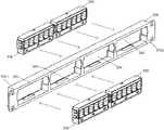
- FIG. 26is an perspective view of a plurality of the first telecommunications modules and a panel frame shown in FIG. 1 , with two of the modules aligned for insertion into module openings of the panel frame through the front side of the panel frame and with two of the modules aligned for insertion into the module openings of the panel frame through the rear side of the panel frame.
- FIGS. 1 to 6a modular telecommunications patch panel system 100 is shown and described.
- the components of the patch panel system 100can be arranged to provide different panel configurations.
- FIGS. 1 and 2show four different configurations 100 a to 100 d with two different panel frame styles and two different telecommunications module styles.
- a liner or straight panel frame 102 ais provided for panel systems 100 a and 100 c .
- a v-shaped panel frame 102 ais provided.
- the panel frames 102 a , 102 bare collectively referred to as panel frame 102 when describing common features.
- Panel systems 110 a , 110 bare also shown as including telecommunications modules 200 received into module openings 104 of the panel frames 102 a , 102 b .
- the modules 200define apertures 200 a configured for receiving separate telecommunications components, for example, individual RJ-type jacks.
- six apertures 200 a for receiving RJ-type jacksare provided within each module 200 , however more or fewer apertures 200 a could be provided.
- the module 200could be configured with apertures 200 a for receiving other types of telecommunications components, such as fiber optic connectors.
- Panel systems 100 c , 110 dare also shown as including telecommunications modules 300 received into module openings 104 of the panel frames 102 a , 102 b .
- the modules 300are provided with telecommunications components 302 instead of apertures 200 a for receiving telecommunications components.
- the telecommunications modules 300house a plurality of telecommunications components 302 , for example RJ-type jacks. In the example presented, six RJ-type jacks are provided within each module 300 , however more or fewer jacks could be provided.
- the module 300could be configured to house other types of telecommunications components, such as fiber optic connectors.
- each panel frame 102can be configured to include fewer or more openings to support a different number of modules 200 , 300 .
- each panel frame 102can be defined as extending between a first end 102 c and a second end 102 d , extending between a top side 102 e and a bottom side 102 f , and extending between a front side 102 g and a rear side 102 h .
- each of the panel frames 102is provided with a pair of mounting ears 102 i defining openings 102 j for receiving fasteners, such that the panel frames 102 can be mounted to a chassis.
- the panel frames 102define a 1 U rack height.
- the panel frames 102could be configured to define a different rack height, for example a 2 U, 3 U, 4 U or greater rack height defining singular or multiple rows of openings 104 .
- each frame opening 104is defined by a pair of sidewalls 104 a , 104 b , a top wall 104 c , and a bottom wall 104 d .
- a deflectable latch 104 eis provided at each of the top and bottom walls 104 c , 104 d , with each deflectable latch 104 e including a deflectable arm 104 f and a latch member 104 g .
- the latch member 104 gengages with a catch surface of one of the modules 200 , 300 to aid in retaining the module 200 , 300 within the opening 104 .
- a recess 104 his provided such that the deflectable latch 104 e can deflect into the recess 104 h without increasing the overall height of the panel frame 102 during installation of a module 200 , 300 .
- each of the sidewalls 104 a , 104 bdefines a recess 104 i with a catch surfaces or protrusion 104 j extending therefrom proximate the front side 102 g of the panel 102 .
- the recesses 104 i and catch surfaces 104 jinteract with a deflectable latch 202 h of the modules 200 , 300 to aid in retaining the module 200 , 300 within the opening 104 , as most easily viewed at FIGS. 3 to 5 .
- the catch surfaces 104 jdefine a further recess 104 k such that a tool, such as a screwdriver, can extend through the recess 104 k to disengage the module deflectable latch 202 h from the catch surfaces 104 j .
- the sidewalls 104 h , 104 bare provided with a narrowed portion 104 k that partially defines the recesses 104 k and that has a beveled end 104 m such that the module deflectable latch is more easily guided in to the recess 104 k.
- the module 200has a main body 202 that extends between a first end 202 a and a second end 202 b , extending between a top side 202 c and a bottom side 202 d , and extending between a front side 202 e and a rear side 202 f.
- the module 200also defines a plurality of apertures 200 a extending between the front and rear sides 202 e , 202 f .
- the apertures 200 aare configured to hold one or more types of cable termination interfaces, such as electrical jacks. In other implementations, however, the apertures 200 a could hold optical adapters or other media interfaces.
- module 200defines 6 apertures 200 a in a single row array. However, more or fewer apertures 200 a may be provided.
- the apertures 200 acan also be provided in more than one row, such as two rows.
- Apertures 200 acan be sized to fit any of a plurality of types of jacks, for example RJ-type telecommunications jacks.
- the apertures 200 amay be sized to receive jacks of the type shown and described in PCT International Patent Application Publication WO 2019/094560, published on May 16, 2019 and PCT PCT International Patent Application Publication WO 2016/156644, filed on Mar. 26, 2016, the entireties of which are incorporated by reference herein.
- each of the deflectable latches 202 hincludes a deflectable arm 202 i and a latch member 202 j .
- the latch member 202 jengages with the catch surfaces 104 j of the panel frame 102 to aid in retaining the module 200 within the opening 104 , as most easily viewed at FIGS. 3 to 5 .
- the deflectable latches 202 hcan also include ramped surfaces 202 k and 202 m for aiding in guiding the deflectable latches into and out of the openings 104 of the panel frame 102 .
- the ramped surface 202 mcan act as a surface against which a tool can act to disengage the deflectable latch 202 h from the catch surface 104 j.
- the module 200is also shown as being provided with catch surfaces 202 n proximate the rear side 202 j of the module 200 for catching the deflectable latches 104 e of the frame 102 .
- the catch surfaces 202 n , 202 pcoincide with the edge of the rear side 202 f of the main body 202 .
- the module 200is also provided with a pair of recesses 202 q , 202 r on the top and bottom sides 202 c , 202 d to enable a tool, such as a screwdriver, to extend through the recesses 202 m , 202 n to disengage the panel frame deflectable latches 104 e from the catch surfaces 202 k.
- the module 300is shown in further detail.
- the module 300differs from module 200 in that, as stated previously, telecommunications components 302 (e.g. RJ-type jacks mounted to a common printed circuit board) are provided instead of apertures 200 a .
- the module 300has cooperating housing parts 300 a , 300 b that together form the main body 302 of the module 300 .
- the main body 302extends between a first end 302 a and a second end 302 b , extending between a top side 302 c and a bottom side 302 d , and extending between a front side 302 e and a rear side 302 f .
- the module 300is provided with deflectable latches 302 h that are the same as the deflectable latches 202 h associated with the module 200 . Accordingly, the features of the deflectable latches 302 h need not be further discussed as the above-provided description for deflectable latches 202 h is applicable to deflectable latches 302 h , the main body 302 also defines catch surfaces 302 n , 302 p in the same general configuration as shown and described for the catch surfaces 202 n , 202 p for the module 200 .
- the module 300is provided with members 302 q , 302 r which can be used as a surface against which a tool can act to disengage the deflectable latches 104 e from the catch surfaces 302 n , 302 p.
- the modules 200 , 300can be installed from the front side 102 e of the panel frame 102 or from the rear side 102 g of the panel frame 102 .
- the latch members 104 gact as a stop surface against the catch surfaces 202 n , 302 n , 202 p , 302 p of the modules 200 , 300 .
- the deflectable latches 202 h , 302 hsnap out such that the latch members 202 j abut the catch surfaces 104 j of the panel frame 102 .
- the opposite actionoccurs in which the catch surfaces 104 j of the panel frame 102 act as a stop surface against the latch members 202 j , 302 j of the deflectable latches 202 h , 302 h , wherein as abutment of these surfaces occur, the deflectable latches 104 e snap out such that the latch members 104 g abut the catch surfaces 202 n , 302 n .
- the fully snapped-in configuration achievable from either front entry or rear entrycan be seen most easily at FIGS. 3 to 5 .
Landscapes
- Engineering & Computer Science (AREA)
- Computer Networks & Wireless Communication (AREA)
- Microelectronics & Electronic Packaging (AREA)
- Structure Of Telephone Exchanges (AREA)
- Casings For Electric Apparatus (AREA)
Abstract
Description
Claims (20)
Applications Claiming Priority (2)
| Application Number | Priority Date | Filing Date | Title |
|---|---|---|---|
| CN201910956073.0ACN112652913A (en) | 2019-10-10 | 2019-10-10 | Modular telecommunications panel system and telecommunications module |
| CN201910956073.0 | 2019-10-10 |
Publications (2)
| Publication Number | Publication Date |
|---|---|
| US20210112678A1 US20210112678A1 (en) | 2021-04-15 |
| US11395436B2true US11395436B2 (en) | 2022-07-19 |
Family
ID=75342591
Family Applications (1)
| Application Number | Title | Priority Date | Filing Date |
|---|---|---|---|
| US17/062,111ActiveUS11395436B2 (en) | 2019-10-10 | 2020-10-02 | Modular telecommunications patch panel system |
Country Status (2)
| Country | Link |
|---|---|
| US (1) | US11395436B2 (en) |
| CN (1) | CN112652913A (en) |
Families Citing this family (1)
| Publication number | Priority date | Publication date | Assignee | Title |
|---|---|---|---|---|
| CN112652897A (en) | 2019-10-10 | 2021-04-13 | 康普技术有限责任公司 | Modular telecommunications panel and modular telecommunications system |
Citations (49)
| Publication number | Priority date | Publication date | Assignee | Title |
|---|---|---|---|---|
| US5836786A (en)* | 1996-05-21 | 1998-11-17 | The Whitaker Corporation | Patch panel having snap together construction |
| WO1999019944A1 (en) | 1997-10-09 | 1999-04-22 | Stewart Connector Systems | High frequency bi-level offset multi-port jack |
| US6015307A (en) | 1998-10-21 | 2000-01-18 | Chiu; Pen-Fu | Electric outlet with rotary socket bodies |
| US6504726B1 (en)* | 2001-11-16 | 2003-01-07 | Adc Telecommunications, Inc. | Telecommunications patch panel |
| US20030022552A1 (en)* | 2001-07-26 | 2003-01-30 | Barker Jed M. | Angled patch panel with cable support bar for network cable racks |
| US6537106B1 (en)* | 1998-06-05 | 2003-03-25 | Adc Telecommunications, Inc. | Telecommunications patch panel with angled connector modules |
| US20050159036A1 (en) | 2003-11-24 | 2005-07-21 | Caveney Jack E. | Communications patch panel systems and methods |
| US7094095B1 (en)* | 2005-02-25 | 2006-08-22 | Panduit Corp. | Stair-stepped angled patch panel |
| US7112090B2 (en)* | 2003-05-14 | 2006-09-26 | Panduit Corp. | High density keystone jack patch panel |
| US7220145B2 (en) | 2004-04-14 | 2007-05-22 | Tyco Electronics Corporation | Patch panel system |
| US20070184712A1 (en)* | 2006-02-03 | 2007-08-09 | Ortronics, Inc. | Arcuate patch panel assembly |
| US20080009183A1 (en)* | 2006-07-06 | 2008-01-10 | Ching-Li Wu | High density module connector |
| US7335056B1 (en)* | 2006-10-19 | 2008-02-26 | Adc Telecommunications, Inc. | RJ to RJ swing panel |
| US20080090461A1 (en)* | 2006-10-16 | 2008-04-17 | Tyco Electronics Corporation | Interface module |
| US20080096438A1 (en)* | 2006-10-19 | 2008-04-24 | Clark Gordon P | Rotatable connector modules with inverted jacks |
| US20080100069A1 (en) | 2006-06-23 | 2008-05-01 | Morris Stephen J | Latch and handle arrangement for a telecommunications panel |
| US7367850B1 (en)* | 2007-02-20 | 2008-05-06 | Telebox Industries Corp. | Bidirectional communication module jack assembly |
| US20080115956A1 (en)* | 2006-11-20 | 2008-05-22 | Panduit Corp. | Angled Patch Panel Cover Plate |
| US20080303392A1 (en)* | 2007-06-07 | 2008-12-11 | Tyco Electronics Corporation | Cable support bracket for an electrical component |
| US20090034226A1 (en)* | 2007-08-02 | 2009-02-05 | Stephen Scott Herndon | Module assembly having interface module and insertable modular jack |
| US20090068881A1 (en)* | 2007-09-06 | 2009-03-12 | Adc Gmbh | Telecommunication patch panel |
| US20090232455A1 (en)* | 2008-03-04 | 2009-09-17 | Ponharith Pon Nhep | Multi-port adapter block |
| US20090243757A1 (en) | 2008-03-25 | 2009-10-01 | Hon Hai Precision Ind. Co., Ltd. | Modular jack having an improved magnetic module |
| US20090274422A1 (en) | 2008-04-30 | 2009-11-05 | Henry Randall R | Connector assembly having a light pipe assembly |
| US7628644B1 (en) | 2009-01-29 | 2009-12-08 | Commscope, Inc. Of North Carolina | Angled patch panel with removable forwardly-extending display |
| US20100216335A1 (en) | 2009-02-24 | 2010-08-26 | Terry Cobb | Communications Patching Devices that Include Integrated Electronic Static Discharge Circuits and Related Methods |
| US20100227500A1 (en)* | 2009-03-03 | 2010-09-09 | Yi-Teh Shih | Double hooked reverse mountable module and panel with opening for multiple modules mounting |
| US20100255716A1 (en) | 2009-04-02 | 2010-10-07 | The Siemon Company | Telecommunications Patch Panel |
| US7854624B1 (en) | 2009-07-23 | 2010-12-21 | Tyco Electronics Corporation | Panel assembly for a connectivity management system |
| US7874865B2 (en) | 2008-06-20 | 2011-01-25 | Tyco Electronics Corporation | Electrical connector with a compliant cable strain relief element |
| US7909622B2 (en) | 2009-02-27 | 2011-03-22 | Tyco Electronics Corporation | Shielded cassette for a cable interconnect system |
| US7914324B2 (en)* | 2009-02-27 | 2011-03-29 | Tyco Electronics Corporation | Cassette for use within a connectivity management system |
| US20110115494A1 (en) | 2009-10-19 | 2011-05-19 | Adc Telecommunications | Managed electrical connectivity systems |
| US20120226807A1 (en) | 2009-10-07 | 2012-09-06 | Molex Incorporated | System for and method of network asset identification |
| US20120244752A1 (en) | 2011-03-22 | 2012-09-27 | Panduit Corp. | Communication Connector |
| US20130217249A1 (en) | 2008-11-12 | 2013-08-22 | Panduit Corp. | Patch Cord Insertion Detection and Light Illumination Capabilities |
| US20140080354A1 (en) | 2008-11-12 | 2014-03-20 | Panduit Corp. | Intelligent Patching System |
| US8834199B2 (en)* | 2011-04-11 | 2014-09-16 | Hsing Chau Industrial Co., Ltd. | Tilted module for assembling network distribution device |
| US20160021779A1 (en)* | 2014-07-16 | 2016-01-21 | Knubox, Llc | Unified Network Connection Device |
| US20160080836A1 (en)* | 2013-04-30 | 2016-03-17 | Te Connectivity Amp España, S.L.U. | Patch panel system and jack module attachment thereto |
| WO2016156644A1 (en) | 2015-03-27 | 2016-10-06 | De Dios Martín Longinos | A connector assembly with a connector, a latch member and a panel |
| US20170229825A1 (en) | 2014-08-06 | 2017-08-10 | Molex, Llc | Patch panel frame for circuit board module |
| US20170235076A1 (en) | 2012-09-21 | 2017-08-17 | Commscope Technologies Llc | Slidable fiber optic connection module with cable slack management |
| WO2018034870A1 (en) | 2016-08-15 | 2018-02-22 | Commscope Technologies Llc | Connector assembly with grounding |
| WO2018236875A1 (en) | 2017-06-19 | 2018-12-27 | Commscope Technologies Llc | HIGH DENSITY DIAL FOR CONNECTION BOARD |
| WO2019094560A1 (en) | 2017-11-10 | 2019-05-16 | Commscope Technologies Llc | Telecommunications panel with grounding wire |
| WO2019094558A1 (en) | 2017-11-10 | 2019-05-16 | Commscope Technologies Llc | Telecommunications panel with patching device installation features |
| US10585256B1 (en)* | 2019-03-29 | 2020-03-10 | Corning Research & Development Corporation | Terminal of an optical fiber network having a bypass module |
| US20210112316A1 (en) | 2019-10-10 | 2021-04-15 | Commscope Technologies Llc | Modular telecommunications patch panel |
- 2019
- 2019-10-10CNCN201910956073.0Apatent/CN112652913A/enactivePending
- 2020
- 2020-10-02USUS17/062,111patent/US11395436B2/enactiveActive
Patent Citations (63)
| Publication number | Priority date | Publication date | Assignee | Title |
|---|---|---|---|---|
| US5836786A (en)* | 1996-05-21 | 1998-11-17 | The Whitaker Corporation | Patch panel having snap together construction |
| WO1999019944A1 (en) | 1997-10-09 | 1999-04-22 | Stewart Connector Systems | High frequency bi-level offset multi-port jack |
| US20060228940A1 (en)* | 1998-06-05 | 2006-10-12 | Adc Telecommunications, Inc. | Telecommunications patch panel with angled connector modules |
| US6537106B1 (en)* | 1998-06-05 | 2003-03-25 | Adc Telecommunications, Inc. | Telecommunications patch panel with angled connector modules |
| US20030129871A1 (en)* | 1998-06-05 | 2003-07-10 | Adc Telecommunications, Inc. | Telecommunications patch panel with angled connector modules |
| US20050191901A1 (en)* | 1998-06-05 | 2005-09-01 | Adc Telecommunications, Inc. | Telecommunications patch panel with angled connector modules |
| US20060025011A1 (en)* | 1998-06-05 | 2006-02-02 | Adc Telecommunications, Inc. | Telecommunications patch panel with angled connector modules |
| US7544090B2 (en)* | 1998-06-05 | 2009-06-09 | Adc Telecommunications, Inc. | Telecommunications patch panel with angled connector modules |
| US7534135B2 (en)* | 1998-06-05 | 2009-05-19 | Adc Telecommunications, Inc. | Telecommunications patch panel with angled connector modules |
| US9356384B2 (en)* | 1998-06-05 | 2016-05-31 | Commscope Technologies Llc | Telecommunications patch panel with angled connector modules |
| US6015307A (en) | 1998-10-21 | 2000-01-18 | Chiu; Pen-Fu | Electric outlet with rotary socket bodies |
| US6866541B2 (en) | 2001-07-26 | 2005-03-15 | Panduit Corp. | Angled patch panel with cable support bar for network cable racks |
| US20030022552A1 (en)* | 2001-07-26 | 2003-01-30 | Barker Jed M. | Angled patch panel with cable support bar for network cable racks |
| US6504726B1 (en)* | 2001-11-16 | 2003-01-07 | Adc Telecommunications, Inc. | Telecommunications patch panel |
| US7112090B2 (en)* | 2003-05-14 | 2006-09-26 | Panduit Corp. | High density keystone jack patch panel |
| US7207846B2 (en) | 2003-11-24 | 2007-04-24 | Panduit Corp. | Patch panel with a motherboard for connecting communication jacks |
| US20050159036A1 (en) | 2003-11-24 | 2005-07-21 | Caveney Jack E. | Communications patch panel systems and methods |
| US7220145B2 (en) | 2004-04-14 | 2007-05-22 | Tyco Electronics Corporation | Patch panel system |
| US7094095B1 (en)* | 2005-02-25 | 2006-08-22 | Panduit Corp. | Stair-stepped angled patch panel |
| US20070184712A1 (en)* | 2006-02-03 | 2007-08-09 | Ortronics, Inc. | Arcuate patch panel assembly |
| US20080100069A1 (en) | 2006-06-23 | 2008-05-01 | Morris Stephen J | Latch and handle arrangement for a telecommunications panel |
| US20080009183A1 (en)* | 2006-07-06 | 2008-01-10 | Ching-Li Wu | High density module connector |
| US20080090461A1 (en)* | 2006-10-16 | 2008-04-17 | Tyco Electronics Corporation | Interface module |
| US20080096438A1 (en)* | 2006-10-19 | 2008-04-24 | Clark Gordon P | Rotatable connector modules with inverted jacks |
| US7335056B1 (en)* | 2006-10-19 | 2008-02-26 | Adc Telecommunications, Inc. | RJ to RJ swing panel |
| US20080115956A1 (en)* | 2006-11-20 | 2008-05-22 | Panduit Corp. | Angled Patch Panel Cover Plate |
| US7367850B1 (en)* | 2007-02-20 | 2008-05-06 | Telebox Industries Corp. | Bidirectional communication module jack assembly |
| US20080303392A1 (en)* | 2007-06-07 | 2008-12-11 | Tyco Electronics Corporation | Cable support bracket for an electrical component |
| US20090034226A1 (en)* | 2007-08-02 | 2009-02-05 | Stephen Scott Herndon | Module assembly having interface module and insertable modular jack |
| US20090068881A1 (en)* | 2007-09-06 | 2009-03-12 | Adc Gmbh | Telecommunication patch panel |
| US7901236B2 (en)* | 2007-09-06 | 2011-03-08 | Adc Gmbh | Telecommunication patch panel |
| US20090232455A1 (en)* | 2008-03-04 | 2009-09-17 | Ponharith Pon Nhep | Multi-port adapter block |
| US20090243757A1 (en) | 2008-03-25 | 2009-10-01 | Hon Hai Precision Ind. Co., Ltd. | Modular jack having an improved magnetic module |
| US20090274422A1 (en) | 2008-04-30 | 2009-11-05 | Henry Randall R | Connector assembly having a light pipe assembly |
| US7874865B2 (en) | 2008-06-20 | 2011-01-25 | Tyco Electronics Corporation | Electrical connector with a compliant cable strain relief element |
| US20140080354A1 (en) | 2008-11-12 | 2014-03-20 | Panduit Corp. | Intelligent Patching System |
| US20130217249A1 (en) | 2008-11-12 | 2013-08-22 | Panduit Corp. | Patch Cord Insertion Detection and Light Illumination Capabilities |
| US7628644B1 (en) | 2009-01-29 | 2009-12-08 | Commscope, Inc. Of North Carolina | Angled patch panel with removable forwardly-extending display |
| US20100216335A1 (en) | 2009-02-24 | 2010-08-26 | Terry Cobb | Communications Patching Devices that Include Integrated Electronic Static Discharge Circuits and Related Methods |
| US7909622B2 (en) | 2009-02-27 | 2011-03-22 | Tyco Electronics Corporation | Shielded cassette for a cable interconnect system |
| US7914324B2 (en)* | 2009-02-27 | 2011-03-29 | Tyco Electronics Corporation | Cassette for use within a connectivity management system |
| US20100227500A1 (en)* | 2009-03-03 | 2010-09-09 | Yi-Teh Shih | Double hooked reverse mountable module and panel with opening for multiple modules mounting |
| US20100255716A1 (en) | 2009-04-02 | 2010-10-07 | The Siemon Company | Telecommunications Patch Panel |
| US7854624B1 (en) | 2009-07-23 | 2010-12-21 | Tyco Electronics Corporation | Panel assembly for a connectivity management system |
| US20120226807A1 (en) | 2009-10-07 | 2012-09-06 | Molex Incorporated | System for and method of network asset identification |
| US20110115494A1 (en) | 2009-10-19 | 2011-05-19 | Adc Telecommunications | Managed electrical connectivity systems |
| US20170302040A1 (en) | 2009-10-19 | 2017-10-19 | Commscope Technologies Llc | Managed electrical connectivity systems |
| US20120244752A1 (en) | 2011-03-22 | 2012-09-27 | Panduit Corp. | Communication Connector |
| US8834199B2 (en)* | 2011-04-11 | 2014-09-16 | Hsing Chau Industrial Co., Ltd. | Tilted module for assembling network distribution device |
| US20170235076A1 (en) | 2012-09-21 | 2017-08-17 | Commscope Technologies Llc | Slidable fiber optic connection module with cable slack management |
| US20160080836A1 (en)* | 2013-04-30 | 2016-03-17 | Te Connectivity Amp España, S.L.U. | Patch panel system and jack module attachment thereto |
| US20160021779A1 (en)* | 2014-07-16 | 2016-01-21 | Knubox, Llc | Unified Network Connection Device |
| US20170229825A1 (en) | 2014-08-06 | 2017-08-10 | Molex, Llc | Patch panel frame for circuit board module |
| WO2016156644A1 (en) | 2015-03-27 | 2016-10-06 | De Dios Martín Longinos | A connector assembly with a connector, a latch member and a panel |
| US20180287312A1 (en)* | 2015-03-27 | 2018-10-04 | CommScope Connectivity Spain, S.L. | Latch for telecommunications connector |
| WO2018034870A1 (en) | 2016-08-15 | 2018-02-22 | Commscope Technologies Llc | Connector assembly with grounding |
| WO2018236875A1 (en) | 2017-06-19 | 2018-12-27 | Commscope Technologies Llc | HIGH DENSITY DIAL FOR CONNECTION BOARD |
| WO2019094560A1 (en) | 2017-11-10 | 2019-05-16 | Commscope Technologies Llc | Telecommunications panel with grounding wire |
| WO2019094558A1 (en) | 2017-11-10 | 2019-05-16 | Commscope Technologies Llc | Telecommunications panel with patching device installation features |
| US20200351573A1 (en)* | 2017-11-10 | 2020-11-05 | Commscope Technologies Llc | Telecommunications panel with grounding wire |
| US20210185417A1 (en)* | 2017-11-10 | 2021-06-17 | Commscope Technologies Llc | Telecommunications panel with patching device installation features |
| US10585256B1 (en)* | 2019-03-29 | 2020-03-10 | Corning Research & Development Corporation | Terminal of an optical fiber network having a bypass module |
| US20210112316A1 (en) | 2019-10-10 | 2021-04-15 | Commscope Technologies Llc | Modular telecommunications patch panel |
Non-Patent Citations (2)
| Title |
|---|
| "Mini-Com All Metal Shielded Modular Patch Panels, Installation Instructions", Panduit, 2 pages (2010). |
| "Mini-Com® All Metal Shielded Modular Patch Panels, Installation Instructions, Specification Sheet", Panduit, 3 pages (2016). |
Also Published As
| Publication number | Publication date |
|---|---|
| US20210112678A1 (en) | 2021-04-15 |
| CN112652913A (en) | 2021-04-13 |
Similar Documents
| Publication | Publication Date | Title |
|---|---|---|
| EP3881113B1 (en) | Fiber optic connector parking device | |
| US11838700B2 (en) | High density bezel for patch panel | |
| US8824850B2 (en) | Insect-infestation prevention device for a telecommunications equipment housing | |
| US9846291B2 (en) | Modularly mountable cable management systems and associated methods | |
| US8428418B2 (en) | Fiber optic adapter plate and cassette | |
| US8195022B2 (en) | Fiber optic adapter cassette and panel | |
| US8600208B2 (en) | Fiber optic telecommunications module | |
| US5724467A (en) | Adapter to secure fiber optic connectors within a telecommuniations box | |
| US7070459B2 (en) | Non-orthogonal cable management system | |
| US8059931B2 (en) | Fiber optic monitoring patch panel providing readily accessible monitoring ports | |
| US7357673B2 (en) | Shielded cage assembly for electrical connectors | |
| US8179684B2 (en) | Sliding adapter panel with living hinge and forward/rearward locking | |
| KR101076985B1 (en) | Patch panel for mounting on a wall or in a subrack | |
| US6866541B2 (en) | Angled patch panel with cable support bar for network cable racks | |
| US20140241689A1 (en) | Ganged fiber optic connector adapter modules and assemblies having reinforcement members and staggered fiber optic connector adapter ports | |
| US11870229B2 (en) | Connection interface | |
| AU2014215062A1 (en) | Optical assemblies with managed connectivity | |
| US11477545B2 (en) | Modular telecommunications patch panel | |
| US11395436B2 (en) | Modular telecommunications patch panel system | |
| EP4266103A2 (en) | Fiber optic connector assembly | |
| WO2025029530A1 (en) | Double plate for mounting fiber optic adapters |
Legal Events
| Date | Code | Title | Description |
|---|---|---|---|
| FEPP | Fee payment procedure | Free format text:ENTITY STATUS SET TO UNDISCOUNTED (ORIGINAL EVENT CODE: BIG.); ENTITY STATUS OF PATENT OWNER: LARGE ENTITY | |
| STPP | Information on status: patent application and granting procedure in general | Free format text:DOCKETED NEW CASE - READY FOR EXAMINATION | |
| STPP | Information on status: patent application and granting procedure in general | Free format text:NON FINAL ACTION MAILED | |
| AS | Assignment | Owner name:JPMORGAN CHASE BANK, N.A., NEW YORK Free format text:ABL SECURITY AGREEMENT;ASSIGNORS:ARRIS ENTERPRISES LLC;COMMSCOPE TECHNOLOGIES LLC;COMMSCOPE, INC. OF NORTH CAROLINA;REEL/FRAME:058843/0712 Effective date:20211112 Owner name:JPMORGAN CHASE BANK, N.A., NEW YORK Free format text:TERM LOAN SECURITY AGREEMENT;ASSIGNORS:ARRIS ENTERPRISES LLC;COMMSCOPE TECHNOLOGIES LLC;COMMSCOPE, INC. OF NORTH CAROLINA;REEL/FRAME:058875/0449 Effective date:20211112 | |
| AS | Assignment | Owner name:WILMINGTON TRUST, DELAWARE Free format text:SECURITY INTEREST;ASSIGNORS:ARRIS SOLUTIONS, INC.;ARRIS ENTERPRISES LLC;COMMSCOPE TECHNOLOGIES LLC;AND OTHERS;REEL/FRAME:060752/0001 Effective date:20211115 | |
| STPP | Information on status: patent application and granting procedure in general | Free format text:RESPONSE TO NON-FINAL OFFICE ACTION ENTERED AND FORWARDED TO EXAMINER | |
| STPP | Information on status: patent application and granting procedure in general | Free format text:FINAL REJECTION MAILED | |
| STPP | Information on status: patent application and granting procedure in general | Free format text:DOCKETED NEW CASE - READY FOR EXAMINATION | |
| STPP | Information on status: patent application and granting procedure in general | Free format text:NOTICE OF ALLOWANCE MAILED -- APPLICATION RECEIVED IN OFFICE OF PUBLICATIONS | |
| AS | Assignment | Owner name:COMMSCOPE TECHNOLOGIES LLC, NORTH CAROLINA Free format text:ASSIGNMENT OF ASSIGNORS INTEREST;ASSIGNORS:LIU, ZHIHUI;WANG, JING;THIJS, DANNY GHISLAIN;AND OTHERS;SIGNING DATES FROM 20220601 TO 20220602;REEL/FRAME:060105/0520 | |
| STPP | Information on status: patent application and granting procedure in general | Free format text:PUBLICATIONS -- ISSUE FEE PAYMENT RECEIVED | |
| STCF | Information on status: patent grant | Free format text:PATENTED CASE | |
| AS | Assignment | Owner name:APOLLO ADMINISTRATIVE AGENCY LLC, NEW YORK Free format text:SECURITY INTEREST;ASSIGNORS:ARRIS ENTERPRISES LLC;COMMSCOPE TECHNOLOGIES LLC;COMMSCOPE INC., OF NORTH CAROLINA;AND OTHERS;REEL/FRAME:069889/0114 Effective date:20241217 | |
| AS | Assignment | Owner name:COMMSCOPE TECHNOLOGIES LLC, NORTH CAROLINA Free format text:RELEASE OF SECURITY INTEREST AT REEL/FRAME 058875/0449;ASSIGNOR:JPMORGAN CHASE BANK, N.A., AS COLLATERAL AGENT;REEL/FRAME:069743/0057 Effective date:20241217 Owner name:COMMSCOPE, INC. OF NORTH CAROLINA, NORTH CAROLINA Free format text:RELEASE OF SECURITY INTEREST AT REEL/FRAME 058875/0449;ASSIGNOR:JPMORGAN CHASE BANK, N.A., AS COLLATERAL AGENT;REEL/FRAME:069743/0057 Effective date:20241217 Owner name:ARRIS ENTERPRISES LLC (F/K/A ARRIS ENTERPRISES, INC.), NORTH CAROLINA Free format text:RELEASE OF SECURITY INTEREST AT REEL/FRAME 058875/0449;ASSIGNOR:JPMORGAN CHASE BANK, N.A., AS COLLATERAL AGENT;REEL/FRAME:069743/0057 Effective date:20241217 |