US11394180B2 - Replacement panels for electrical distribution cabinets for the monitoring of targeted components and connections - Google Patents
Replacement panels for electrical distribution cabinets for the monitoring of targeted components and connectionsDownload PDFInfo
- Publication number
- US11394180B2 US11394180B2US16/066,271US201716066271AUS11394180B2US 11394180 B2US11394180 B2US 11394180B2US 201716066271 AUS201716066271 AUS 201716066271AUS 11394180 B2US11394180 B2US 11394180B2
- Authority
- US
- United States
- Prior art keywords
- panel
- electrical components
- viewing
- information
- electrical
- Prior art date
- Legal status (The legal status is an assumption and is not a legal conclusion. Google has not performed a legal analysis and makes no representation as to the accuracy of the status listed.)
- Active, expires
Links
Images


Classifications
- H—ELECTRICITY
- H02—GENERATION; CONVERSION OR DISTRIBUTION OF ELECTRIC POWER
- H02B—BOARDS, SUBSTATIONS OR SWITCHING ARRANGEMENTS FOR THE SUPPLY OR DISTRIBUTION OF ELECTRIC POWER
- H02B1/00—Frameworks, boards, panels, desks, casings; Details of substations or switching arrangements
- H02B1/26—Casings; Parts thereof or accessories therefor
- H02B1/30—Cabinet-type casings; Parts thereof or accessories therefor
- H02B1/306—Accessories, e.g. windows
- G—PHYSICS
- G06—COMPUTING OR CALCULATING; COUNTING
- G06F—ELECTRIC DIGITAL DATA PROCESSING
- G06F1/00—Details not covered by groups G06F3/00 - G06F13/00 and G06F21/00
- G06F1/16—Constructional details or arrangements
- G06F1/18—Packaging or power distribution
- G06F1/181—Enclosures
- G—PHYSICS
- G06—COMPUTING OR CALCULATING; COUNTING
- G06K—GRAPHICAL DATA READING; PRESENTATION OF DATA; RECORD CARRIERS; HANDLING RECORD CARRIERS
- G06K19/00—Record carriers for use with machines and with at least a part designed to carry digital markings
- G06K19/06—Record carriers for use with machines and with at least a part designed to carry digital markings characterised by the kind of the digital marking, e.g. shape, nature, code
- G06K19/067—Record carriers with conductive marks, printed circuits or semiconductor circuit elements, e.g. credit or identity cards also with resonating or responding marks without active components
- G06K19/07—Record carriers with conductive marks, printed circuits or semiconductor circuit elements, e.g. credit or identity cards also with resonating or responding marks without active components with integrated circuit chips
- G06K19/077—Constructional details, e.g. mounting of circuits in the carrier
- G06K19/07749—Constructional details, e.g. mounting of circuits in the carrier the record carrier being capable of non-contact communication, e.g. constructional details of the antenna of a non-contact smart card
- G06K19/07758—Constructional details, e.g. mounting of circuits in the carrier the record carrier being capable of non-contact communication, e.g. constructional details of the antenna of a non-contact smart card arrangements for adhering the record carrier to further objects or living beings, functioning as an identification tag
- H05K5/0021—
- H—ELECTRICITY
- H05—ELECTRIC TECHNIQUES NOT OTHERWISE PROVIDED FOR
- H05K—PRINTED CIRCUITS; CASINGS OR CONSTRUCTIONAL DETAILS OF ELECTRIC APPARATUS; MANUFACTURE OF ASSEMBLAGES OF ELECTRICAL COMPONENTS
- H05K5/00—Casings, cabinets or drawers for electric apparatus
- H05K5/30—Side-by-side or stacked arrangements
Definitions
- the presently disclosed inventionrelates in general to the field of cabinets for electrical distribution equipment, and in particular to: an IR/UV-permitting panel for replacing filler or blanking plates for cabinets that enclose electrical components of power distribution systems; data acquisition and management systems and devices utilizing NFC tags for the monitoring of electrical components in electrical distribution equipment cabinets; and, methods for monitoring electrical components and connections located within targeted areas in electrical distribution equipment cabinets via IR/UV-permitting panels and NFC tags.
- One drawback with certain implementations of monitoring electrical componentsis the limited accessibility of components' electrical connections within a cabinet. Due to the location of electrical connections within a housing, a proper inspection may not be physically possible. For example, an infrared camera may not be able to capture accurate temperature measurements if the targeted connection is obstructed by other electrical or structural components.
- Embodiments of the presently disclosed inventionmay enable electrical components and connections to be monitored within an enclosure via a panel that is transparent to at least one of infrared (IR) radiation, ultraviolet (UV) radiation, or visible light.
- IRinfrared
- UVultraviolet
- Such an IR/UV-permitting panelmay be located adjacent to the targeted area, which may be within close proximity to the monitored electrical components/connections.
- the IR/UV-permitting panelmay be interchangeable with filler or blanking panels that are located adjacent to the targeted area.
- a preexisting blanking panelmay be altered or adapted to include an IR/UV-permitting viewing window assembly.
- NFC tagsmay enable data acquisition and management systems for the monitoring of electrical components in electrical distribution equipment cabinets. Such NFC tags may be utilized in connection with IR/UV-permitting panels.
- the NFC tagsmay receive, store and transmit information concerning the electrical components in electrical distribution equipment cabinets, such as the components' specifications, temperature operating ranges, maintenance history, the last time that they were checked, and additional data concerning the infrared and visual inspection of the components/connections.
- a viewing window assemblymay comprise a viewing panel that may be adapted to permit the monitoring of electrical components located within an electrical distribution equipment cabinet.
- the viewing window assemblymay further comprise a retaining mechanism that may be adapted to mount the viewing panel to an opening of the electrical distribution equipment cabinet.
- the openingmay be adapted for a removable blanking panel.
- the viewing window assemblymay have the same dimensions as the removable blanking panel.
- the viewing panelmay be transparent to infrared radiation.
- the viewing panelmay be transparent to ultraviolet radiation.
- the viewing panelmay be transparent to visible light.
- the retaining mechanismmay comprise a tool-less mounting mechanism, such a latch, clip, notch, slot, or snap.
- the retaining mechanism for the viewing window assemblymay be based on a retaining mechanism for the removable blanking panel.
- the viewing window assemblymay further comprise a Near Field Communication (NFC) tag that may be adapted to permit the monitoring of the electrical components located within the electrical distribution equipment cabinet.
- NFC tagmay be mounted to the viewing panel.
- the NFC tagmay be adapted to receive, store and transmit information related to the electrical components in the electrical distribution equipment cabinet.
- the informationmay include specification information for the electrical components, temperature operating-range information for the electrical components, maintenance information for the electrical components, repair information for the electrical components, access log information for the electrical components, infrared-inspection information for the electrical components, or visual-inspection information for the electrical components.
- the methodmay comprise removing a blanking panel from the electrical distribution equipment cabinet.
- the blanking panelmay be adapted to cover an opening of the electrical distribution equipment cabinet.
- the methodmay also comprise mounting a viewing window assembly to the opening of the electrical distribution equipment cabinet.
- the viewing window assemblymay comprise a viewing panel that is adapted to permit the monitoring of the electrical components located within the electrical distribution equipment cabinet.
- the viewing window assemblymay further comprise a retaining mechanism that is adapted to mount the viewing panel to the opening of the electrical distribution equipment cabinet.
- the methodmay further comprise monitoring, via a detection device, the electrical components located within the electrical distribution equipment cabinet.
- the detection devicemay be an infrared camera. In some embodiments, the detection device may be an ultraviolet camera.
- the methodmay comprise altering a portion of the blanking panel.
- the altered panelmay comprise a viewing pane, and the viewing panel may comprise the viewing pane.
- the viewing panelmay comprise a polymeric material that is transparent to infrared radiation.
- the viewing panelmay comprise a polymeric material that is transparent to ultraviolet radiation.
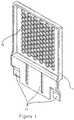
- FIG. 1is a diagram illustrating a perspective view of an IR/UV-permitting panel having multiple rows of ports, in accordance with certain embodiments of the invention.
- FIG. 2is a diagram illustrating a rear view of an IR/UV-permitting panel having multiple rows of ports, in accordance with certain embodiments of the invention.
- FIG. 3is a diagram illustrating a front view of an IR/UV-permitting panel having multiple rows of ports, in accordance with certain embodiments of the invention.
- FIG. 4is a diagram illustrating a top view of an IR/UV-permitting panel having multiple rows of ports, in accordance with certain embodiments of the invention.
- FIG. 5is a diagram illustrating a bottom view of an IR/UV-permitting panel having multiple rows of ports, in accordance with certain embodiments of the invention.
- FIG. 6is a diagram illustrating an exploded view of the front side of an IR/UV-permitting panel displaying a second grill, in accordance with certain embodiments of the invention.
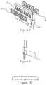
- FIGS. 7A and 7Bare diagrams illustrating perspective views of an IR/UV-permitting panel having one row of ports, in accordance with certain embodiments of the invention.
- FIG. 8is a diagram illustrating an exploded view of an IR/UV-permitting panel having one row of ports displaying a first grill and a second grill, in accordance with certain embodiments of the invention.
- FIG. 9is a diagram illustrating a side view of an IR/UV-permitting panel having one row of ports, in accordance with certain embodiments of the invention.
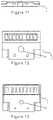
- FIG. 10is a diagram illustrating a top view of an IR/UV-permitting panel having one row of ports, in accordance with certain embodiments of the invention.
- FIG. 11is a diagram illustrating a bottom view of an IR/UV-permitting panel having one row of ports, in accordance with certain embodiments of the invention.
- FIG. 12is a diagram illustrating a front view of an IR/UV-permitting panel having one row of ports, in accordance with certain embodiments of the invention.
- FIG. 13is a diagram illustrating a rear view of an IR/UV-permitting panel having one row of ports, in accordance with certain embodiments of the invention.
- FIGS. 14 and 15are diagrams illustrating an IR/UV-permitting panel adjacent to circuit breakers and blanking panels, in accordance with certain embodiments of the invention.
- FIG. 16is an infrared image illustrating temperature measurements via an IR/UV-permitting panel adjacent to electrical components and their connections within a targeted area of a power cabinet, in accordance with certain embodiments of the invention.
- FIG. 17is a perspective view of a power cabinet, as depicted in FIG. 2 of U.S. Patent Publication No. US 2014/0160686 that was previously incorporated by reference above in Paragraph [0003] of this disclosure.
- FIG. 18is flow chart illustrating steps of a method for the monitoring of electrical components within an electrical distribution equipment cabinet, in accordance with certain embodiments of the invention.
- the presently disclosed inventionmay be embodied in various forms, including a device, a system, or a method for monitoring of electrical components in electrical distribution equipment cabinets.
- the embodimentsmay allow for the mounting of an IR/UV-permitting panel 1 .
- the panel 1may be transparent to at least one of infrared (IR) radiation, ultraviolet (UV) radiation, or visible light.
- the panelmay comprise polymeric material that is opaque but transparent to infrared radiation or ultraviolet radiation.
- Embodimentsmay comprise an IR/UV-permitting viewing window assembly or device 2 , for replacing a filler or blanking panel 3 for cabinets 4 that enclose electrical components/equipment 5 of power distribution systems 6 .
- An IR/UV-permitting viewing window assembly 2may comprise an IR/UV-permitting panel 1 .
- a benefitmay include the inspection of electrical components 5 , such as circuit breakers 7 , which may be located in the proximity of the replaced blanking panel 3 .
- the circuit breakers 7 , and/or its connection 8 to other electrical components 5 located within a power cabinet 4may not be readily accessible for inspection.
- the removal of a solid blanking panel 3would permit access to a targeted area 9 , which may include a circuit breaker 7 and/or its electrical connection 8 . It may be extremely hazardous to permit uncontrolled or unauthorized access to the circuit breaker's connection 8 and other electrical components 5 located within a power cabinet 4 .
- a blanking panel 3 for power cabinets 4may be intended to isolate the electrical components 5 from the ambient environment for the protection of the electrical components 5 and for general safety considerations, which may include those regulated by Occupational Safety and Health Administration (OSHA).
- OSHAOccupational Safety and Health Administration
- an advantage of the presently disclosed inventionmay include the limited inspection of a known targeted area 9 that does not require the removal of an entire side of the housing 10 of a cabinet 4 . Rather than alter the housing 10 , a blanking panel 3 located in the proximity of the targeted area 9 may be removed to gain access to the electrical components 5 equipment for the purpose of infrared inspections or temperature measurement. It is known that infrared/ultraviolet cameras or detection devices 11 may be used to monitor electrical components 5 for observing their installation and operation.
- an IR/UV-permitting viewing window assembly 2may comprise an IR/UV-permitting panel 1 and a retaining mechanism 12 .
- Embodiments of an IR/UV-permitting viewing window assembly 2may have the same shape and dimensions as the replaced blanking panel 3 .
- the retaining mechanism 12 for the IR/UV-permitting panel 1may also emulate the retaining mechanism 12 of the replaced blanking panel 3 .
- the retaining mechanism 12may comprise any means for mounting a panel 1 to a rack or housing 10 of a cabinet 4 .
- the retaining mechanism 12may permit tool-less mounting so that the blanking plate 3 may be removed, and the IR/UV-permitting panel 1 may be mounted, by hand without the use of any tools.
- the retaining mechanism 12may comprise a latch, clip, notch, slot, snap or any other means for securing covering such as a panel, whether by fastening, turning, twisting, pushing, pulling, pinching, sliding, leaning, leveraging, or pressing.
- the retaining mechanism 12may comprise an adhesive or screws. Such adhesive or screws of the replaced blanking panel 3 may be removed before mounting the IR/UV-permitting panel 1 . An adhesive or screws may be used to retain the IR/UV-permitting panel 1 .
- a viewing window assembly 2may be mounted within an aperture 13 created in a removed blanking panel 3 .
- the assembly 2may be supported directly within the aperture 13 by the cabinet 4 .
- the viewing window assembly 2may be supported in a frame (not shown) adapted to the aperture 13 .
- the viewing window assembly 2may comprise a viewing pane 14 that may be mounted to the frame.
- the removed blanking panel 3may be altered by eliminating a solid portion of the panel 3 and mounting the viewing pane 14 directly to the panel 3 .
- holesmay be drilled into the solid portion of the panel 3 in order to make a viewing pane 14 .
- the altered or modified panel 3may be mounted or reinserted over the aperture 13 .
- the viewing pane 14may be formed from an infrared and/or ultraviolet transmitting material.
- the pane 14may have two generally opposed surfaces.
- the viewing window assembly 2may comprise a protective grill 15 lying against one of the opposed surfaces and providing mechanical protection and support to the pane.
- the grill 15may have an array of holes or ports 16 formed therethrough that permit infrared inspection through the pane 14 from the outside of the housing 10 of the cabinet 4 when the modified blanking panel 3 is reinserted.
- a protective grill 15is not included.
- one of the opposed surfaces of the pane 14may be located toward the interior of the housing 10 , and the other surface may be located toward the exterior of the housing 10 .
- the protective grill 15may be provided on either of those opposed faces depending on the conditions inside and outside the housing 10 .
- a second grill 15may be included on the other surface of the pane 14 , so that the pane 14 is equipped to resist adverse conditions that prevail in the interior and the exterior of the housing 10 .
- Alignment meansmay be provided on the first and second grills 15 so that the ports 16 of the first grill 15 align with the ports 16 of the second grill 15 .
- first and second grills 15may take various forms, including a notch formed in identical places on the periphery of the first and second grills 15 that engage a protuberance provided on the panel 3 or frame, if present.
- the first and second grills 15could be provided with complementary formations arranged to ensure the ports 16 align when the formations co-operate with one another.
- an arrangement the ports 16may be all of an equal size and shape.
- each hole or port 16may be a regular polygon in shape with sides of equal length.
- An array of ports 16 of such a shapemay be uniform in appearance and in infrared transmissivity.
- the characteristics of the grill(s) 15such as the shape of the ports 16 , the dimensions of the ports 16 , and the spacing between the ports 16 , may be important in certain applications because they are related to the strength of the assembly and the transmission of electromagnetic radiation therethrough.
- there may be an optimum size port 16 and size spacing depending on the application of the viewing window assembly 2because some applications may require extra strength and others extra transmission quality.
- all of the ports 16may be the same size and shape, in accordance with some embodiments.
- the ports 16are a shape that tessellate, such that two adjacent ports 16 are spaced apart by a narrow strip. This arrangement enables all strips between adjacent ports 16 to have a uniform thickness which provides uniformity in strength and transmission over the entire array.
- the ports 16could be a combination of different shapes that tessellate, for example octagons and squares, or may be similar tessellating shapes such as hexagons, squares or triangles. In some embodiments, all of the ports 16 may be hexagonal because this may provide a good balance between strength and transmission, regardless of the orientation of an infrared imaging camera 11 .
- FIGS. 1-6illustrate various views of an embodiment of an IR/UV-permitting panel 1 having multiple rows of ports 16 .
- FIGS. 7-13illustrate various views of an embodiment of an IR/UV-permitting panel 1 having one row of ports 16 .
- FIGS. 14-15are diagrams illustrating an IR/UV-permitting panel 1 adjacent to circuit breakers 7 and blanking panels 3 .
- FIG. 16is an infrared image illustrating temperature measurements via an IR/UV-permitting panel 1 .
- the IR/UV-permitting panel 1allows the transmission of the electromagnetic spectral range of the radiation dispensed from the adjacent electrical components 5 and their connections 8 within a targeted area 9 of a cabinet 4 to pass through the panel 1 so that the radiation can be imaged or otherwise monitored by an appropriate camera or detection device 11 .
- a device 11may enable the identification of specific areas of the electrical equipment or components 5 that are failing or that are achieving temperatures that are hotter or cooler than their specified operating range.
- Such a monitoring processallows the inspector of such electrical equipment and components 5 to readily identify and resolve any potential problems before they occur, as well as to troubleshoot any existing problems.
- the pane 14may be made of a material which enables electromagnetic radiation in the infrared and/or ultraviolet range to pass therethrough.
- the pane 14is made from an infrared and/or ultraviolet transmitting polymer which is not water soluble.
- the material from which the pane 14 is madeis an infrared and/or ultraviolet transmitting crystal such as calcium fluoride (CaF 2 ).
- the size of ports 16may be a critical feature in accordance with some embodiments. For example, the ports 16 may need to be small enough to retard the propagation of fire and impede the passage of fingers due to safety concerns while still permitting the infrared inspection through the pane 14 .
- the grill 15may be made from any one material or combination of materials that exhibit sufficient structural strength to provide sufficient mechanical protection and support to the pane 14 .
- the framework of each grill 15may be made of aluminum or other non-ferrous metals. Such a framework may be coated with plastics.
- IR/UV-permitting viewing window assemblies 2 for monitoring general or large areas within electrical distribution equipment cabinets 4are described by the present inventor in the following patent and publications: U.S. Pat. No. 8,164,827; No. 2010/0014152; and, No. 2015/0131177. These patents and publications are incorporated herein by reference.
- the IR/UV-permitting panel 1 for monitoring electrical components/equipment 5 and/or their connections 8 within a targeted area 9 of a cabinet 4may be expandable to fit openings of various sizes in the cabinet 4 .
- one portion of an IR/UV-permitting panel 1may be adapted to slide over another portion of the panel 1 .
- an adjustable panel 1may replace blanking panels 3 of varying sizes and dimensions.
- a IR/UV-permitting panel 1may be adapted to be expandable to two predetermined lengths for installations that have two types of blanking panels 3 that correspond to two types of circuit breakers 5 for certain power cabinets 4 .
- a substantial portion of an IR/UV-permitting panel 1may be formed of IR/UV-permitting materials.
- an objective of the presently disclosed device, system and methodmay be the enablement of data acquisition and management systems for the monitoring of electrical components 5 in electrical distribution equipment cabinets 4 .
- RFIDradio-frequency identification
- NFCNear field communication
- NFC technologysuch as an NFC tag, has been described in U.S. Pat. No. 9,032,211. These patents and publications are incorporated herein by reference.
- NFC technologymay be utilized to enable communication between the electrical components 5 with monitoring devices, such as an appropriate camera or detection device 11 .
- a NFC tag 17may be utilized in connection with a panel 1 or an IR/UV-permitting viewing window assembly 2 .
- the NFC tags 17may be programmed with information concerning the electrical components 5 in electrical distribution equipment cabinets 4 , such as the specifications of the components 5 , temperature operating ranges, maintenance history, the last time that the components 5 were checked, and additional data concerning the infrared and visual inspection of the components/connections 5 .
- the NFC tag 17may be mounted on the inside of the IR/UV-permitting panel 1 in order to prevent tampering and contamination.
- the NFC tag 17may be embedded within the IR/UV-permitting panel 1 in accordance with certain embodiments of the invention.
- the NFC tag 17may be located under a label on the plane 1 .
- the NFC tags 17may be a standalone component, in accordance with certain embodiments.
- FIG. 18illustrates the steps of a method for the monitoring of electrical components within an electrical distribution equipment cabinet, in accordance with certain embodiments of the invention.
- stepsmay include the following: Removing a blanking panel from an electrical distribution equipment cabinet, wherein the blanking panel is adapted to cover an opening of the electrical distribution equipment cabinet [step 1801 ]; Altering a portion of the blanking panel, wherein the altered panel comprises a viewing pane of the viewing window assembly [step 1802 ]; Mounting the viewing window assembly to the opening of the electrical distribution equipment cabinet, wherein the viewing window assembly has a retaining mechanism adapted to mount the viewing panel to the opening of the electrical distribution equipment cabinet [step 1803 ]; and, Monitoring the electrical components located within the electrical distribution equipment cabinet [step 1804 ]. While some reordering or other groupings are specifically mentioned, others will be apparent to those of ordinary skill in the art and so do not present an exhaustive list of alternatives. Moreover, it should be recognized that the stages could be implemented in hardware, firmware, software or any combination thereof.
Landscapes
- Engineering & Computer Science (AREA)
- Theoretical Computer Science (AREA)
- Power Engineering (AREA)
- Computer Hardware Design (AREA)
- Physics & Mathematics (AREA)
- General Physics & Mathematics (AREA)
- Microelectronics & Electronic Packaging (AREA)
- Human Computer Interaction (AREA)
- General Engineering & Computer Science (AREA)
- Casings For Electric Apparatus (AREA)
- Photometry And Measurement Of Optical Pulse Characteristics (AREA)
- Cooling Or The Like Of Electrical Apparatus (AREA)
- Radiation Pyrometers (AREA)
Abstract
Description
Claims (16)
Priority Applications (1)
| Application Number | Priority Date | Filing Date | Title |
|---|---|---|---|
| US16/066,271US11394180B2 (en) | 2016-01-08 | 2017-01-06 | Replacement panels for electrical distribution cabinets for the monitoring of targeted components and connections |
Applications Claiming Priority (3)
| Application Number | Priority Date | Filing Date | Title |
|---|---|---|---|
| US201662276480P | 2016-01-08 | 2016-01-08 | |
| PCT/US2017/012461WO2017120425A1 (en) | 2016-01-08 | 2017-01-06 | Replacement panels for electrical distribution cabinets for the monitoring of targeted components and connections |
| US16/066,271US11394180B2 (en) | 2016-01-08 | 2017-01-06 | Replacement panels for electrical distribution cabinets for the monitoring of targeted components and connections |
Related Parent Applications (1)
| Application Number | Title | Priority Date | Filing Date |
|---|---|---|---|
| PCT/US2017/012461A-371-Of-InternationalWO2017120425A1 (en) | 2016-01-08 | 2017-01-06 | Replacement panels for electrical distribution cabinets for the monitoring of targeted components and connections |
Related Child Applications (1)
| Application Number | Title | Priority Date | Filing Date |
|---|---|---|---|
| US17/866,909ContinuationUS11728627B2 (en) | 2016-01-08 | 2022-07-18 | Replacement panels for electrical distribution cabinets for the monitoring of targeted components and connections |
Publications (2)
| Publication Number | Publication Date |
|---|---|
| US20190173267A1 US20190173267A1 (en) | 2019-06-06 |
| US11394180B2true US11394180B2 (en) | 2022-07-19 |
Family
ID=59274438
Family Applications (4)
| Application Number | Title | Priority Date | Filing Date |
|---|---|---|---|
| US16/066,271Active2038-08-04US11394180B2 (en) | 2016-01-08 | 2017-01-06 | Replacement panels for electrical distribution cabinets for the monitoring of targeted components and connections |
| US17/866,909ActiveUS11728627B2 (en) | 2016-01-08 | 2022-07-18 | Replacement panels for electrical distribution cabinets for the monitoring of targeted components and connections |
| US18/233,720ActiveUS12068587B2 (en) | 2016-01-08 | 2023-08-14 | Replacement panels for electrical distribution cabinets for the monitoring of targeted components and connections |
| US18/808,808PendingUS20240413617A1 (en) | 2016-01-08 | 2024-08-19 | Replacement panels for electrical distribution cabinets for the monitoring of targeted components and connections |
Family Applications After (3)
| Application Number | Title | Priority Date | Filing Date |
|---|---|---|---|
| US17/866,909ActiveUS11728627B2 (en) | 2016-01-08 | 2022-07-18 | Replacement panels for electrical distribution cabinets for the monitoring of targeted components and connections |
| US18/233,720ActiveUS12068587B2 (en) | 2016-01-08 | 2023-08-14 | Replacement panels for electrical distribution cabinets for the monitoring of targeted components and connections |
| US18/808,808PendingUS20240413617A1 (en) | 2016-01-08 | 2024-08-19 | Replacement panels for electrical distribution cabinets for the monitoring of targeted components and connections |
Country Status (2)
| Country | Link |
|---|---|
| US (4) | US11394180B2 (en) |
| WO (1) | WO2017120425A1 (en) |
Cited By (1)
| Publication number | Priority date | Publication date | Assignee | Title |
|---|---|---|---|---|
| US11728627B2 (en) | 2016-01-08 | 2023-08-15 | IRISS Holdings, Inc. | Replacement panels for electrical distribution cabinets for the monitoring of targeted components and connections |
Families Citing this family (2)
| Publication number | Priority date | Publication date | Assignee | Title |
|---|---|---|---|---|
| SE2051189A1 (en)* | 2020-10-13 | 2022-04-12 | Stora Enso Oyj | RFID reader antenna for use in an intelligent cabinet |
| CN117374769B (en)* | 2023-09-20 | 2024-09-17 | 河南宇和电气有限公司 | Intelligent box-type substation based on artificial intelligent algorithm load prediction and self-adjustment |
Citations (56)
| Publication number | Priority date | Publication date | Assignee | Title |
|---|---|---|---|---|
| US1642698A (en) | 1921-05-14 | 1927-09-20 | George F Rohn Electric Company | Power cabinet |
| US3404316A (en) | 1967-06-23 | 1968-10-01 | Gen Electric | Circuit breaker segrgation system |
| US6247353B1 (en) | 1998-05-04 | 2001-06-19 | Csi Technology, Inc. | Digital ultrasonic monitoring system and method |
| US20020153338A1 (en) | 2001-04-19 | 2002-10-24 | David Orr | Blank panel for rack units |
| US20030020027A1 (en) | 2001-07-25 | 2003-01-30 | Nordson Corporation | Apparatus for infrared reduction in ultraviolet radiation generators |
| US6547348B2 (en)* | 2000-12-22 | 2003-04-15 | General Electric Company | Interlocking trim plates |
| US6616005B1 (en)* | 2000-08-28 | 2003-09-09 | Hubbell Incorporated | Modular faceplate assembly for an electrical box |
| US20040120109A1 (en) | 2002-10-07 | 2004-06-24 | Kennedy Robert A. | Front-accessible communications port for enclosed electrical equipment |
| US6798587B2 (en) | 2002-03-08 | 2004-09-28 | Mikron Infrared, Inc. | Thermal imaging combination and method |
| US20060141921A1 (en)* | 2004-12-29 | 2006-06-29 | Turek James R | Air distribution arrangement for rack-mounted equipment |
| US7079334B2 (en) | 2003-02-04 | 2006-07-18 | Holliday Graham R | Infrared sight glass for aftermarket fitment |
| US7209042B2 (en) | 2004-12-20 | 2007-04-24 | Temptime Corporation | RFID tag with visual environmental condition monitor |
| US7295133B1 (en) | 2004-12-30 | 2007-11-13 | Hendrix Wire & Cable, Inc. | Electrical circuit monitoring device |
| US7336153B2 (en) | 2005-06-30 | 2008-02-26 | Hewlett-Packard Development Company, L.P. | Wireless temperature monitoring for an electronics system |
| US7432818B2 (en) | 2006-04-26 | 2008-10-07 | Xerox Corporation | Printing apparatus including components equipped with RFID wear monitoring devices |
| CN201213200Y (en) | 2008-06-27 | 2009-03-25 | 陕西虹光机电制造有限公司 | Infrared temperature measuring window for high-voltage switch cabinet |
| US20090178991A1 (en)* | 2004-10-15 | 2009-07-16 | American Power Conversion Corporation | Blanking panel for equipment rack or enclosure |
| US20100000953A1 (en) | 2008-07-07 | 2010-01-07 | Electrorack Products Company | Modular blocking panel systems for racks and cabinets |
| US20100014152A1 (en) | 2007-03-20 | 2010-01-21 | Martin Robinson | Infrared window assembly with internal and external cover |
| US20100107496A1 (en)* | 2008-11-05 | 2010-05-06 | Powersmiths International Corp. | Rotatable inspection port |
| US20100201230A1 (en) | 2009-02-02 | 2010-08-12 | Schweitzer Iii Edmund O | Electric power system control system with selective enclosure |
| US20110073726A1 (en)* | 2009-09-29 | 2011-03-31 | American Power Conversion Corporation | Tool-less installation system and method of u-mounted devices |
| US20110083824A1 (en) | 2009-06-03 | 2011-04-14 | Bripco Bvba | Data Centre |
| US8023818B2 (en) | 2008-07-24 | 2011-09-20 | Fluke Corporation | Articulating infrared window |
| US20120049706A1 (en) | 2010-08-31 | 2012-03-01 | Eaton Corporation | Air Flow Management Enclosure |
| CN202171504U (en) | 2011-05-04 | 2012-03-21 | 北京玻璃研究院 | Enclosed electrical cabinet infrared window |
| WO2012037575A1 (en) | 2010-09-17 | 2012-03-22 | Exiscan, Llc | Inspection window |
| US20120075070A1 (en) | 2010-09-27 | 2012-03-29 | General Electric Company | Real time measurement of rotor surface |
| US20120091090A1 (en)* | 2010-10-15 | 2012-04-19 | Ortronics, Inc. | Filler Panel For Equipment Racks and Enclosures |
| US8164827B2 (en)* | 2007-03-20 | 2012-04-24 | Martin Robinson | Infrared window assembly |
| US8258928B2 (en) | 2008-05-22 | 2012-09-04 | National Taiwan University Of Science And Technology | RFID system and RFID tag thereof |
| WO2013021182A1 (en) | 2011-08-05 | 2013-02-14 | Bripco Bvba | Data centre |
| CN202856180U (en) | 2012-10-29 | 2013-04-03 | 山东电力集团公司德州供电公司 | Composite infrared temperature measurement window |
| US8421629B2 (en) | 2009-03-13 | 2013-04-16 | William N. Carr | System for power control and memory access of hybrid RFID tags |
| US20130117995A1 (en)* | 2011-11-11 | 2013-05-16 | Thomas & Betts International, Inc. | Infrared scanning port |
| US20130176678A1 (en) | 2012-01-09 | 2013-07-11 | Joseph Kyle Campbell | Rack level hot aisle containment system |
| US8500271B2 (en) | 2003-10-09 | 2013-08-06 | Ipventure, Inc. | Eyewear supporting after-market electrical components |
| US20140144858A1 (en) | 2011-08-24 | 2014-05-29 | Fujitsu Limited | Casing mounting rail, blank plate, and rack mount system |
| US20140160686A1 (en) | 2012-12-07 | 2014-06-12 | Stored Energy Systems, a Limited Liability Company | Cabinet-based dc power systems |
| US20140170971A1 (en)* | 2012-12-19 | 2014-06-19 | Eaton Corporation | System and method for providing information to and/or obtaining information from a component of an electrical distribution system |
| US20140218817A1 (en) | 2013-02-05 | 2014-08-07 | Fluke Corporation | Viewing window assembly for single-sided installation |
| CN203800406U (en) | 2014-03-31 | 2014-08-27 | 淮安红相光电科技有限公司 | Explosion-proof infrared observation window |
| CN204088925U (en) | 2014-10-31 | 2015-01-07 | 秦皇岛本征晶体科技有限公司 | A kind of infrared observation window |
| US8931952B2 (en) | 2012-04-27 | 2015-01-13 | Par Technology Corporation | Temperature monitoring device for workflow monitoring system |
| US20150060382A1 (en) | 2013-09-05 | 2015-03-05 | International Business Machines Corporation | Adjustable Blanking Panel for Datacentre Racks |
| USD727326S1 (en) | 2011-11-11 | 2015-04-21 | Thomas & Betts International, Llc | Infrared scanning port assembly |
| WO2015057504A1 (en) | 2013-10-14 | 2015-04-23 | Eaton Corporation | Apparatus and methods for monitoring electrical interconnections using rfid devices |
| WO2015065376A1 (en) | 2012-10-30 | 2015-05-07 | Rohrer Timothy | Inspection window |
| US9032211B2 (en) | 2008-07-09 | 2015-05-12 | Samsung Electronics Co., Ltd. | Near field communication (NFC) device and method for selectively securing records in a near field communication data exchange format (NDEF) message |
| US20150131177A1 (en)* | 2013-11-08 | 2015-05-14 | Martin Robinson | Bus duct with a curved viewing window assembly |
| US20150154433A1 (en) | 2013-09-27 | 2015-06-04 | Integro Llc | Rfid molded connector tracking system and method |
| US20150177072A1 (en) | 2013-12-20 | 2015-06-25 | Aktiebolaget Skf | Infrared temperature magnet with rfid antenna |
| US20150233999A1 (en) | 2014-02-17 | 2015-08-20 | Scadata, Inc. | Monitoring system for electrical equipment failure and method |
| CN204651701U (en) | 2015-06-05 | 2015-09-16 | 国网天津市电力公司 | Infrared temperature measurement window |
| US9154712B2 (en) | 2011-12-19 | 2015-10-06 | Harrison Goddard Foote | Thermal window with transmitter |
| US20150334355A1 (en) | 2012-12-27 | 2015-11-19 | Schneider Electric It Corporation | System for asset management |
Family Cites Families (4)
| Publication number | Priority date | Publication date | Assignee | Title |
|---|---|---|---|---|
| US8548334B2 (en)* | 2006-12-06 | 2013-10-01 | Mohammad Mazed | Dynamic intelligent bidirectional optical access communication system with object/intelligent appliance-to-object/intelligent appliance interaction |
| GB2485398A (en)* | 2010-11-15 | 2012-05-16 | Lmr Technologies Ltd | Movable shutter for permitting access to the interior of a cabinet |
| US11394180B2 (en) | 2016-01-08 | 2022-07-19 | IRISS Holdings, Inc. | Replacement panels for electrical distribution cabinets for the monitoring of targeted components and connections |
| CN111095010B (en) | 2017-04-25 | 2022-06-14 | 伊利斯控股公司 | Panel for auditorially monitoring electrical components and detecting electrical faults |
- 2017
- 2017-01-06USUS16/066,271patent/US11394180B2/enactiveActive
- 2017-01-06WOPCT/US2017/012461patent/WO2017120425A1/ennot_activeCeased
- 2022
- 2022-07-18USUS17/866,909patent/US11728627B2/enactiveActive
- 2023
- 2023-08-14USUS18/233,720patent/US12068587B2/enactiveActive
- 2024
- 2024-08-19USUS18/808,808patent/US20240413617A1/enactivePending
Patent Citations (62)
| Publication number | Priority date | Publication date | Assignee | Title |
|---|---|---|---|---|
| US1642698A (en) | 1921-05-14 | 1927-09-20 | George F Rohn Electric Company | Power cabinet |
| US3404316A (en) | 1967-06-23 | 1968-10-01 | Gen Electric | Circuit breaker segrgation system |
| US6247353B1 (en) | 1998-05-04 | 2001-06-19 | Csi Technology, Inc. | Digital ultrasonic monitoring system and method |
| US6616005B1 (en)* | 2000-08-28 | 2003-09-09 | Hubbell Incorporated | Modular faceplate assembly for an electrical box |
| US6547348B2 (en)* | 2000-12-22 | 2003-04-15 | General Electric Company | Interlocking trim plates |
| US20020153338A1 (en) | 2001-04-19 | 2002-10-24 | David Orr | Blank panel for rack units |
| US6758353B2 (en) | 2001-04-19 | 2004-07-06 | David Orr | Blank panel for rack units |
| US20030020027A1 (en) | 2001-07-25 | 2003-01-30 | Nordson Corporation | Apparatus for infrared reduction in ultraviolet radiation generators |
| US6798587B2 (en) | 2002-03-08 | 2004-09-28 | Mikron Infrared, Inc. | Thermal imaging combination and method |
| US20040120109A1 (en) | 2002-10-07 | 2004-06-24 | Kennedy Robert A. | Front-accessible communications port for enclosed electrical equipment |
| US7079334B2 (en) | 2003-02-04 | 2006-07-18 | Holliday Graham R | Infrared sight glass for aftermarket fitment |
| US8500271B2 (en) | 2003-10-09 | 2013-08-06 | Ipventure, Inc. | Eyewear supporting after-market electrical components |
| US8052231B2 (en) | 2004-10-15 | 2011-11-08 | American Power Conversion Corporation | Blanking panel for equipment rack or enclosure |
| US20090178991A1 (en)* | 2004-10-15 | 2009-07-16 | American Power Conversion Corporation | Blanking panel for equipment rack or enclosure |
| US7209042B2 (en) | 2004-12-20 | 2007-04-24 | Temptime Corporation | RFID tag with visual environmental condition monitor |
| US20060141921A1 (en)* | 2004-12-29 | 2006-06-29 | Turek James R | Air distribution arrangement for rack-mounted equipment |
| US7295133B1 (en) | 2004-12-30 | 2007-11-13 | Hendrix Wire & Cable, Inc. | Electrical circuit monitoring device |
| US7336153B2 (en) | 2005-06-30 | 2008-02-26 | Hewlett-Packard Development Company, L.P. | Wireless temperature monitoring for an electronics system |
| US7432818B2 (en) | 2006-04-26 | 2008-10-07 | Xerox Corporation | Printing apparatus including components equipped with RFID wear monitoring devices |
| US8400708B2 (en) | 2007-03-20 | 2013-03-19 | Martin Robinson | Infrared window assembly with internal and external cover |
| US20100014152A1 (en) | 2007-03-20 | 2010-01-21 | Martin Robinson | Infrared window assembly with internal and external cover |
| US8164827B2 (en)* | 2007-03-20 | 2012-04-24 | Martin Robinson | Infrared window assembly |
| US8258928B2 (en) | 2008-05-22 | 2012-09-04 | National Taiwan University Of Science And Technology | RFID system and RFID tag thereof |
| CN201213200Y (en) | 2008-06-27 | 2009-03-25 | 陕西虹光机电制造有限公司 | Infrared temperature measuring window for high-voltage switch cabinet |
| US20100000953A1 (en) | 2008-07-07 | 2010-01-07 | Electrorack Products Company | Modular blocking panel systems for racks and cabinets |
| US9032211B2 (en) | 2008-07-09 | 2015-05-12 | Samsung Electronics Co., Ltd. | Near field communication (NFC) device and method for selectively securing records in a near field communication data exchange format (NDEF) message |
| US8023818B2 (en) | 2008-07-24 | 2011-09-20 | Fluke Corporation | Articulating infrared window |
| US20100107496A1 (en)* | 2008-11-05 | 2010-05-06 | Powersmiths International Corp. | Rotatable inspection port |
| US8407938B2 (en) | 2008-11-05 | 2013-04-02 | Powersmiths International Corp. | Rotatable inspection port |
| US20100201230A1 (en) | 2009-02-02 | 2010-08-12 | Schweitzer Iii Edmund O | Electric power system control system with selective enclosure |
| US8421629B2 (en) | 2009-03-13 | 2013-04-16 | William N. Carr | System for power control and memory access of hybrid RFID tags |
| US20110083824A1 (en) | 2009-06-03 | 2011-04-14 | Bripco Bvba | Data Centre |
| US20110073726A1 (en)* | 2009-09-29 | 2011-03-31 | American Power Conversion Corporation | Tool-less installation system and method of u-mounted devices |
| US20120049706A1 (en) | 2010-08-31 | 2012-03-01 | Eaton Corporation | Air Flow Management Enclosure |
| WO2012037575A1 (en) | 2010-09-17 | 2012-03-22 | Exiscan, Llc | Inspection window |
| US20120075070A1 (en) | 2010-09-27 | 2012-03-29 | General Electric Company | Real time measurement of rotor surface |
| US20120091090A1 (en)* | 2010-10-15 | 2012-04-19 | Ortronics, Inc. | Filler Panel For Equipment Racks and Enclosures |
| CN202171504U (en) | 2011-05-04 | 2012-03-21 | 北京玻璃研究院 | Enclosed electrical cabinet infrared window |
| WO2013021182A1 (en) | 2011-08-05 | 2013-02-14 | Bripco Bvba | Data centre |
| US20140144858A1 (en) | 2011-08-24 | 2014-05-29 | Fujitsu Limited | Casing mounting rail, blank plate, and rack mount system |
| US9044832B2 (en)* | 2011-11-11 | 2015-06-02 | Thomas & Betts International, Llc | Infrared scanning port |
| US20130117995A1 (en)* | 2011-11-11 | 2013-05-16 | Thomas & Betts International, Inc. | Infrared scanning port |
| USD727326S1 (en) | 2011-11-11 | 2015-04-21 | Thomas & Betts International, Llc | Infrared scanning port assembly |
| US20150230354A1 (en)* | 2011-11-11 | 2015-08-13 | Thomas & Betts International, Llc | Infrared scanning port |
| US9154712B2 (en) | 2011-12-19 | 2015-10-06 | Harrison Goddard Foote | Thermal window with transmitter |
| US20130176678A1 (en) | 2012-01-09 | 2013-07-11 | Joseph Kyle Campbell | Rack level hot aisle containment system |
| US8931952B2 (en) | 2012-04-27 | 2015-01-13 | Par Technology Corporation | Temperature monitoring device for workflow monitoring system |
| CN202856180U (en) | 2012-10-29 | 2013-04-03 | 山东电力集团公司德州供电公司 | Composite infrared temperature measurement window |
| WO2015065376A1 (en) | 2012-10-30 | 2015-05-07 | Rohrer Timothy | Inspection window |
| US20140160686A1 (en) | 2012-12-07 | 2014-06-12 | Stored Energy Systems, a Limited Liability Company | Cabinet-based dc power systems |
| US20140170971A1 (en)* | 2012-12-19 | 2014-06-19 | Eaton Corporation | System and method for providing information to and/or obtaining information from a component of an electrical distribution system |
| US20150334355A1 (en) | 2012-12-27 | 2015-11-19 | Schneider Electric It Corporation | System for asset management |
| US20140218817A1 (en) | 2013-02-05 | 2014-08-07 | Fluke Corporation | Viewing window assembly for single-sided installation |
| US20150060382A1 (en) | 2013-09-05 | 2015-03-05 | International Business Machines Corporation | Adjustable Blanking Panel for Datacentre Racks |
| US20150154433A1 (en) | 2013-09-27 | 2015-06-04 | Integro Llc | Rfid molded connector tracking system and method |
| WO2015057504A1 (en) | 2013-10-14 | 2015-04-23 | Eaton Corporation | Apparatus and methods for monitoring electrical interconnections using rfid devices |
| US20150131177A1 (en)* | 2013-11-08 | 2015-05-14 | Martin Robinson | Bus duct with a curved viewing window assembly |
| US20150177072A1 (en) | 2013-12-20 | 2015-06-25 | Aktiebolaget Skf | Infrared temperature magnet with rfid antenna |
| US20150233999A1 (en) | 2014-02-17 | 2015-08-20 | Scadata, Inc. | Monitoring system for electrical equipment failure and method |
| CN203800406U (en) | 2014-03-31 | 2014-08-27 | 淮安红相光电科技有限公司 | Explosion-proof infrared observation window |
| CN204088925U (en) | 2014-10-31 | 2015-01-07 | 秦皇岛本征晶体科技有限公司 | A kind of infrared observation window |
| CN204651701U (en) | 2015-06-05 | 2015-09-16 | 国网天津市电力公司 | Infrared temperature measurement window |
Non-Patent Citations (6)
| Title |
|---|
| D.G. Watters, et al., "Design and Performance of Wireless Sensors For Structural Health Monitoring," Menlo Park, CA, dated Aug. 18, 2003, 8 pages. |
| Fluke, "Fluke CV401 ClirVu® 95 mm (4 in) Infrared Window," U.S., obtained from the Internet on Nov. 3, 2015, at URL: http://en-us.fluke.com/products/ir-windows/fluke-cv401.html, 3 pages. |
| International Search Report and Written Opinion for Application No. PCT/US18/29050 dated Aug. 3, 20148, 12 pages. |
| International Search Report and Written Opinion for Application No. PCT/US2017/012461 dated Mar. 17, 2017, 10 pages. |
| Startech, "Vented Blank Panel for Server Racks—1U," Startech.com, obtained from the Internet on Nov. 4, 2015 at URL: http://www.startech.com/Server-Management/Racks/1u-vented-rack-panel˜RKPNLTL1UV, 3 pages. |
| Startech, "Vented Blank Panel with Hinge for Server Racks—6U," Startech.com, obtained from the Internet on Nov. 4, 2015 at URL: <http://www.startech.com/Server-Management/Racks/6u-hinged-vented-blanking-panel˜R...>, 3 pages. |
Cited By (2)
| Publication number | Priority date | Publication date | Assignee | Title |
|---|---|---|---|---|
| US11728627B2 (en) | 2016-01-08 | 2023-08-15 | IRISS Holdings, Inc. | Replacement panels for electrical distribution cabinets for the monitoring of targeted components and connections |
| US12068587B2 (en) | 2016-01-08 | 2024-08-20 | IRISS Holdings, Inc. | Replacement panels for electrical distribution cabinets for the monitoring of targeted components and connections |
Also Published As
| Publication number | Publication date |
|---|---|
| WO2017120425A1 (en) | 2017-07-13 |
| US12068587B2 (en) | 2024-08-20 |
| US20190173267A1 (en) | 2019-06-06 |
| US20240014638A1 (en) | 2024-01-11 |
| US20240413617A1 (en) | 2024-12-12 |
| US11728627B2 (en) | 2023-08-15 |
| US20220416521A1 (en) | 2022-12-29 |
Similar Documents
| Publication | Publication Date | Title |
|---|---|---|
| US11728627B2 (en) | Replacement panels for electrical distribution cabinets for the monitoring of targeted components and connections | |
| CA3039715C (en) | Smart locker system | |
| US10968681B2 (en) | Smart locker system | |
| US9207904B2 (en) | Multi-panel display with hot swappable display panels and methods of servicing thereof | |
| US6867701B2 (en) | Computer-server rack enclosure fault light diagnostic system | |
| EP2602803B1 (en) | Infrared scanning port | |
| CA2882998C (en) | Systems and methods for computer equipment management | |
| EP3509407B1 (en) | Rack pdu bracket with rotation function | |
| US20210258543A1 (en) | System and Methods for Computerized Health and Safety Assessments | |
| US9926725B2 (en) | Lockable cover assembly | |
| CN109470296B (en) | Detection system and detection method for distribution network switch cabinet | |
| US20250290802A1 (en) | Thermal Infrared Sensor That Can Be Fixed Onto Infrared Windows | |
| CN212137816U (en) | A device for visual management of secondary equipment in substations | |
| EP3461243B1 (en) | Asset tag holder mechanism to improve accessibility | |
| CN210819455U (en) | Safety tool cabinet | |
| EP4471384A1 (en) | Apparatus for monitoring properties of or in electrical installations, holder therefor, and gateway-device for such apparatus, electrical installation having such apparatus and gateway-device, and corresponding methods of installing and operating | |
| Glavaš et al. | Infrared thermography as evaluation method of a faulty status of a LED LCD TV | |
| CN205176200U (en) | On -vehicle inspection system of distribution network | |
| CN216123081U (en) | Embedded computer monitoring equipment | |
| CN220476058U (en) | Data information monitoring equipment based on artificial intelligence | |
| CN213069909U (en) | Online intelligent fault monitoring lane controller | |
| CN213755507U (en) | Computer network cabinet that detects warning | |
| CN113873202A (en) | Device and method for monitoring closed space | |
| Wallis | WORLD-FIRST TECHNOLOGY FOR DETECTING CORONA DISCHARGE ON HIGH-VOLTAGE POWERLINES | |
| CN206709287U (en) | A kind of electronic information Intelligentized machine room |
Legal Events
| Date | Code | Title | Description |
|---|---|---|---|
| FEPP | Fee payment procedure | Free format text:ENTITY STATUS SET TO UNDISCOUNTED (ORIGINAL EVENT CODE: BIG.); ENTITY STATUS OF PATENT OWNER: SMALL ENTITY | |
| AS | Assignment | Owner name:IRISS, INC., FLORIDA Free format text:ASSIGNMENT OF ASSIGNORS INTEREST;ASSIGNOR:ROBINSON, MARTIN;REEL/FRAME:047832/0577 Effective date:20181218 | |
| AS | Assignment | Owner name:IRISS HOLDINGS, INC., FLORIDA Free format text:ASSIGNMENT OF ASSIGNORS INTEREST;ASSIGNOR:IRISS, INC.;REEL/FRAME:048237/0116 Effective date:20190116 | |
| FEPP | Fee payment procedure | Free format text:ENTITY STATUS SET TO SMALL (ORIGINAL EVENT CODE: SMAL); ENTITY STATUS OF PATENT OWNER: SMALL ENTITY | |
| STPP | Information on status: patent application and granting procedure in general | Free format text:NON FINAL ACTION MAILED | |
| STPP | Information on status: patent application and granting procedure in general | Free format text:RESPONSE TO NON-FINAL OFFICE ACTION ENTERED AND FORWARDED TO EXAMINER | |
| STPP | Information on status: patent application and granting procedure in general | Free format text:FINAL REJECTION MAILED | |
| STPP | Information on status: patent application and granting procedure in general | Free format text:RESPONSE AFTER FINAL ACTION FORWARDED TO EXAMINER | |
| STPP | Information on status: patent application and granting procedure in general | Free format text:ADVISORY ACTION MAILED | |
| STCV | Information on status: appeal procedure | Free format text:NOTICE OF APPEAL FILED | |
| STPP | Information on status: patent application and granting procedure in general | Free format text:RESPONSE TO NON-FINAL OFFICE ACTION ENTERED AND FORWARDED TO EXAMINER | |
| STPP | Information on status: patent application and granting procedure in general | Free format text:NON FINAL ACTION MAILED | |
| STPP | Information on status: patent application and granting procedure in general | Free format text:RESPONSE TO NON-FINAL OFFICE ACTION ENTERED AND FORWARDED TO EXAMINER | |
| STPP | Information on status: patent application and granting procedure in general | Free format text:FINAL REJECTION MAILED | |
| STPP | Information on status: patent application and granting procedure in general | Free format text:DOCKETED NEW CASE - READY FOR EXAMINATION | |
| STPP | Information on status: patent application and granting procedure in general | Free format text:NOTICE OF ALLOWANCE MAILED -- APPLICATION RECEIVED IN OFFICE OF PUBLICATIONS | |
| STPP | Information on status: patent application and granting procedure in general | Free format text:PUBLICATIONS -- ISSUE FEE PAYMENT VERIFIED | |
| STCF | Information on status: patent grant | Free format text:PATENTED CASE |