US11394157B2 - Active cover plates - Google Patents
Active cover platesDownload PDFInfo
- Publication number
- US11394157B2 US11394157B2US16/538,722US201916538722AUS11394157B2US 11394157 B2US11394157 B2US 11394157B2US 201916538722 AUS201916538722 AUS 201916538722AUS 11394157 B2US11394157 B2US 11394157B2
- Authority
- US
- United States
- Prior art keywords
- contact
- cover plate
- active cover
- prong
- light
- Prior art date
- Legal status (The legal status is an assumption and is not a legal conclusion. Google has not performed a legal analysis and makes no representation as to the accuracy of the status listed.)
- Active, expires
Links
Images


Classifications
- H—ELECTRICITY
- H01—ELECTRIC ELEMENTS
- H01R—ELECTRICALLY-CONDUCTIVE CONNECTIONS; STRUCTURAL ASSOCIATIONS OF A PLURALITY OF MUTUALLY-INSULATED ELECTRICAL CONNECTING ELEMENTS; COUPLING DEVICES; CURRENT COLLECTORS
- H01R13/00—Details of coupling devices of the kinds covered by groups H01R12/70 or H01R24/00 - H01R33/00
- H01R13/66—Structural association with built-in electrical component
- H01R13/665—Structural association with built-in electrical component with built-in electronic circuit
- H01R13/6675—Structural association with built-in electrical component with built-in electronic circuit with built-in power supply
- G—PHYSICS
- G05—CONTROLLING; REGULATING
- G05F—SYSTEMS FOR REGULATING ELECTRIC OR MAGNETIC VARIABLES
- G05F3/00—Non-retroactive systems for regulating electric variables by using an uncontrolled element, or an uncontrolled combination of elements, such element or such combination having self-regulating properties
- G05F3/02—Regulating voltage or current
- H—ELECTRICITY
- H02—GENERATION; CONVERSION OR DISTRIBUTION OF ELECTRIC POWER
- H02G—INSTALLATION OF ELECTRIC CABLES OR LINES, OR OF COMBINED OPTICAL AND ELECTRIC CABLES OR LINES
- H02G3/00—Installations of electric cables or lines or protective tubing therefor in or on buildings, equivalent structures or vehicles
- H02G3/02—Details
- H02G3/08—Distribution boxes; Connection or junction boxes
- H02G3/14—Fastening of cover or lid to box
- H—ELECTRICITY
- H05—ELECTRIC TECHNIQUES NOT OTHERWISE PROVIDED FOR
- H05K—PRINTED CIRCUITS; CASINGS OR CONSTRUCTIONAL DETAILS OF ELECTRIC APPARATUS; MANUFACTURE OF ASSEMBLAGES OF ELECTRICAL COMPONENTS
- H05K5/00—Casings, cabinets or drawers for electric apparatus
- H05K5/02—Details
- H05K5/03—Covers
- H—ELECTRICITY
- H01—ELECTRIC ELEMENTS
- H01R—ELECTRICALLY-CONDUCTIVE CONNECTIONS; STRUCTURAL ASSOCIATIONS OF A PLURALITY OF MUTUALLY-INSULATED ELECTRICAL CONNECTING ELEMENTS; COUPLING DEVICES; CURRENT COLLECTORS
- H01R13/00—Details of coupling devices of the kinds covered by groups H01R12/70 or H01R24/00 - H01R33/00
- H01R13/02—Contact members
- H01R13/26—Pin or blade contacts for sliding co-operation on one side only
- H—ELECTRICITY
- H01—ELECTRIC ELEMENTS
- H01R—ELECTRICALLY-CONDUCTIVE CONNECTIONS; STRUCTURAL ASSOCIATIONS OF A PLURALITY OF MUTUALLY-INSULATED ELECTRICAL CONNECTING ELEMENTS; COUPLING DEVICES; CURRENT COLLECTORS
- H01R2103/00—Two poles
- H—ELECTRICITY
- H01—ELECTRIC ELEMENTS
- H01R—ELECTRICALLY-CONDUCTIVE CONNECTIONS; STRUCTURAL ASSOCIATIONS OF A PLURALITY OF MUTUALLY-INSULATED ELECTRICAL CONNECTING ELEMENTS; COUPLING DEVICES; CURRENT COLLECTORS
- H01R24/00—Two-part coupling devices, or either of their cooperating parts, characterised by their overall structure
- H01R24/76—Two-part coupling devices, or either of their cooperating parts, characterised by their overall structure with sockets, clips or analogous contacts and secured to apparatus or structure, e.g. to a wall
- H01R24/78—Two-part coupling devices, or either of their cooperating parts, characterised by their overall structure with sockets, clips or analogous contacts and secured to apparatus or structure, e.g. to a wall with additional earth or shield contacts
Definitions
- Modern buildingsinclude wiring to deliver electrical power to lights, outlets, and other devices.
- the electrical wiringtypically terminates in an electrical box in a wall, ceiling, floor or the box may be connected to another structural element. Connections are made to the wiring in the electrical box.
- electrical wiringmay be connected to outlets and switches by stab-in connectors or with screw terminals on the sides of the outlet/switch body. After installation, a wall plate is placed over the outlet/switch body to cover the opening to the box while allowing access to the outlet receptacles and/or access to manually manipulate the switch(s).
- FIGS. 1A-1Care drawings of GFCI outlet installations, according to one example of principles described herein.
- FIGS. 2A-2Kare diagrams and images of an illustrative GFCI active cover plate and various prongs for use with the active cover plate, according to one example of principles described herein.
- FIG. 3A-3Care illustrations of a GFCI active cover plate installed over a GFCI outlet, according to one example of principles described herein.
- FIGS. 4A-4Dare diagrams showing installation of a GFCI active cover plate over a GFCI outlet, according to one embodiment of principles described herein.
- FIGS. 5A-5Ishow various illustrative GFCI prongs for a GFCI active cover plate, according to one example of principles described herein.
- FIGS. 6A-6Iare diagrams of illustrative GFCI prongs with adjustable contact positions, according to one example of principles described herein.
- FIGS. 7A-7Dare diagrams of illustrative GFCI prongs with adjustable contact positions, according to one example of principles described herein.
- FIGS. 8A-8Eare examples of illustrative GFCI prongs with dual contacts for a GFCI active cover plate, according to one example of principles described herein.
- FIGS. 9A-9Care examples of illustrative dual GFCI prongs for a GFCI active cover plate, according to one example of principles described herein.
- FIGS. 10A-10Gshow various illustrative examples of prongs for a GFCI active cover plate, according to one example of principles described herein.
- FIGS. 11A-11Hshow various illustrative examples of prongs for active cover plates, according to one example of principles described herein.
- FIG. 12shows an illustrative method for insertion of a prong of an active cover plate to touch an electrical terminal of an electrical receptacle, according to one embodiment of principles described herein.
- FIGS. 13A and 13Bshow one illustrative embodiment for insulating the inboard side of prongs, according to one example of principles described herein.
- FIGS. 14A and 14Bshow various illustrative examples of prongs and insulation/support structures for active cover plates, according to one example of principles described herein.
- FIGS. 15A-15Eshow an illustrative example of a prong for active cover plates, according to one example of principles described herein.
- FIGS. 16A-16Eshow various illustrative examples of stiffening member/resilient insert for prongs on active cover plates, according to one example of principles described herein.
- FIGS. 17A and 17Bshow prongs that are hinged to reduce shipping and packaging volume, according to one embodiment of principles described herein.
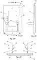
- FIGS. 1A-1Cshow various views of ground fault circuit interrupter (GFCI) outlets 10 .
- GFCI outlets 10are designed to quickly and automatically disconnect a circuit when they detect that the electric current is not balanced between the energized (line) conductor(s) and the return (neutral) conductor. Under normal circumstances, these two wires are expected to carry matching currents, and any difference may indicate that a short circuit or other electrical anomaly is present, such as leakage.
- the hot and neutral wiresmay be on opposite sides of the GFCI outlet.
- Leakagemay indicate a shock hazard (or shock in progress) which is a potential danger to a person.
- Current leakagemay result in harm or death due to electric shock, especially if the leaking electric current passes through the torso of a human.
- a current of around 30 mA (0.030 amperes)may be sufficient to cause cardiac arrest or serious harm if it persists for more than a fraction of a second.
- GFCI outlets 10are designed to disconnect the conducting wires 12 quickly enough to prevent serious injury from such shocks.
- the buttons 14 a , 14 b on the face of the GFCI outlet 10are “test” and “reset” buttons.
- the test button 14 amay cause a small amount of power to be sent to ground or a neutral wire, simulating a short.
- the GFCIshould disconnect (“trip”) and power to the outlet 10 should be disconnected.
- the “reset” button 14 amay be depressed to reset the GFCI configuration and reenergize the outlet 10 .
- the buttons 14 a , 14 bare shown in FIG. 1A .
- the reset button 14 bis the larger button and the test button 14 a is the smaller button.
- Other GFCI outlets 10may have different configurations. GFCI outlets 10 may also be known as “residual current devices”; ground fault interrupters “GFI”; and more sophisticated versions may include arc fault circuit interrupters (“AFCI,” “AFCI/GFCI” or “AF/GF”).
- FIG. 1Bshows a GFCI outlet 10 installed in a wall with a tile wall covering 16 .
- GFCI outlets 10may be wider (e.g., have wider shoulders 18 ) than standard outlets because of the additional circuitry and electrical components that they contain. Consequently, there may be a relatively small gap 20 between the sides of the outlet 10 and the sides of the electrical/receptacle box 22 in which the outlet 10 is installed. This can have significant consequences for active cover plates that use prongs to contact screw terminals 24 of GFCI outlets 10 .
- the prongsshould fit in the open space 20 between the GFCI outlet 10 and the box 22 in order to reach the screw terminals 24 on the sides of the GFCI outlet 10 .
- the smaller the space 20the thinner the prongs must be to fit.
- FIG. 1Cshows a side view of a GFCI outlet 10 installed in a receptacle box 22 .
- One side of the receptacle box 22has been cut away to allow for a clear view into the box 22 and behind the GFCI outlet 10 .
- the screw terminals 24are not located in the same position as a standard outlet.
- the screw terminals 24are farther back and recessed into the body of the outlet 10 (i.e., there is a greater distance 26 between the front of the outlet 10 and the screw terminals 24 ).
- the designersrecessed the screw terminals 24 to allow wires to make connections without causing the GFCI outlet width to increase beyond its already significant size.
- GFCI outlets 10typically include four screw terminals 24 , two on each side.
- a first set of opposing screw terminals 24 bmay be designated as “line” terminals.
- the house wiring 12 that supplies power to the outlet 10may be connected there, with the hot line connected to one terminal and the neutral line connected to the other terminal.
- a second set of opposing screw terminals 24 amay also be located on the body of a GFCI outlet 10 .
- This other set of screw terminals 24 amay be designated as the “load” screw terminals 24 .
- These load screw terminals 24 amay not be used when the GFCI outlet 10 is used by itself.
- additional outletsmay be connected to the GFCI outlet 10 (“daisy chained”) using the load screw terminals 24 a .
- These additional “daisy chained” outletsmay be standard outlets, but because they are connected to power through the GFCI outlet 10 they may also be protected from ground faults by the GFCI outlet 10 .
- an active cover plate designed for GFCI outlets 10may be connected to either the line or load terminals 24 . If the active cover plate is connected to the line terminals 24 b (the other line terminal may be on the opposite side of the GFCI outlet), it will be powered regardless of the operation of the GFCI outlet 10 . For example, if the GFCI were to detect a fault and trip, the active cover plate may remain on and functioning. The active cover plate may have its own internal current-limiting safeguards. Conversely, if the active cover plate were connected to the load terminals 24 a (the other load screw terminal may be on the opposite side of the GFCI outlet 10 ), it may act like any other circuit that is connected through the GFCI outlet 10 and have additional protection against ground faults.
- the wires 12there can be a large number of wires 12 packed behind a GFCI outlet 10 . Because the body of the GFCI outlet 10 may be larger than the bodies of standard outlets, the wires 12 may be more tightly packed behind it. In some embodiments, the prongs of the active cover plate may have specific features that are designed to avoid contacting the wires 12 behind the GFCI outlet 10 .
- the wires 12may prevent the active cover plate/functional wall plate from installing because the prongs jam into the wires 12 .
- the prongsmay be lifted off the screw terminals 24 as they encounter wires 12 .
- the setback distance 26 from the outlet mount to the screw terminal 24is also designated in the figure. The setback distance 26 may change between various models of GFCI outlets 10 and can place additional compatibility requirements on prongs that are designed for use with a wide range of GFCI outlets 10 .
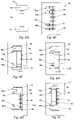
- FIGS. 2A, 2B, and 2Cshow one example of an illustrative coordinate system that can be used to define directions for the active cover plate.
- FIG. 2Dshows additional nomenclature that defines the direction “outboard” as being away from the centerline of the active cover plate and “inboard” as being toward the centerline of the cover plate.
- FIG. 2Ashows a front view of one embodiment of a GFCI active cover plate 28 (e.g., an active cover plate 28 suitable for use with one or more GFCI outlets 10 ).
- the GFCI active cover plate 28may have a number of apertures 30 , including one or more screw apertures 30 a and one or more aperture(s) 30 b through which a GFCI outlet 10 and/or buttons 14 (e.g. FIG. 1A ) thereof may be accessed.
- FIGS. 2B and 2Care front and rear perspective views, respectively, that show prongs 32 extending rearward (in the transverse direction) from a front plate 34 of an active cover plate 28 .
- the front plate 34includes a front surface 31 and a back surface 33 .
- a base of the prongs 32may be sandwiched between a back plate 36 on an active cover plate 28 and a front plate 34 thereof.
- the back plate 36 and/or front plate 34may include a number of additional features, including additional posts 38 that can be used to secure the back plate 36 to the front plate 34 and/or to secure different prongs 32 for connection to ordinary outlets.
- FIG. 2Dshows a rear view of the GFCI active cover plate 28 with the prongs 32 extending rearward from the rear surface 33 of the front plate 34 .
- the prongs 32may be secured to the front plate 34 in a variety of ways.
- the base of the prongs 32may fit over one or more of the posts 38 and may be sandwiched between the front plate 34 and the backplate 36 .
- the prongs 32are lower on the front plate 34 for the GFCI active cover plate 28 than on a standard outlet active cover plate because of the lower placement of the screw terminals 24 on the GFCI outlet 10 .
- the two opposing prongs 32may contact either the load or the line screw terminals 24 of a GFCI outlet 10 , depending on the configuration of the specific GFCI outlet 10 and installation orientation of the active cover plate 28 with respect to the GFCI outlet 10 . As discussed above, if the prongs 32 contact the line screw terminals 24 , an active cover plate 28 may draw electrical power from the house wiring 12 and may operate regardless of whether the GFCI outlet 10 is tripped. If the prongs 32 contact the load screw terminals 24 , an active cover plate 28 may not have power when the GFCI outlet 10 is tripped.
- FIG. 2Eshows a side view of an active cover plate 28 .
- the structure of the GFCI prongs 32shows that the prongs may be generally straight and extend from the front plate 34 in a perpendicular manner.
- the prongs 32may have a variety of other configurations.
- the prongs 32may extend from the front plate 34 at any angle, including angles that bring the tips of the prongs 32 toward each other.
- FIG. 2Fshows a bottom view of an active cover plate 28 and prongs 32 that extend rearward off the front plate 34 .
- the prongs 32may include back element(s) 40 , a main ramp 42 at the terminal end of the prongs 32 , and front element(s) 44 .
- the back element(s) 40 and front element(s)may be insulative components.
- a free/terminal end of a resilient contactnear the base of a prong 32
- the terminal end of the resilient contactmay slide between these two insulative components 40 , 44 to facilitate the compression of the contact as the corresponding prong 32 is inserted in the gap 20 between the edge of the GFCI outlet 10 and the outlet box 22 and its subsequent re-expansion to contact the screw 24 .
- each of the prongs 32may include a resilient contact 46 (in this illustrative embodiment the resilient contact can be described as a resilient bowed contact) and an auxiliary spring 48 (e.g. a cantilevered spring) beneath the resilient contact 46 .
- the resilient contact 46may compress during insertion of the prongs 32 between the body of the GFCI outlet 10 and sides of the electrical receptacle box 22 . This results in a prong 32 that can pass through very thin/narrow openings/gaps. The contact 46 then expands/rebounds when the prong 32 reaches the recessed area containing the screw terminals 24 or other area with greater width.
- the spring 48may assist the contact 46 in expanding by providing additional force on the rear of the resilient contact 46 . This may assist in bringing the contact 46 inward, increasing the width of the prong 32 , and makes an electrical connection between the contact 46 and the screw terminal 24 .
- the spring 48may or may not be present in a particular design. In general, the contact 46 may contain sufficient resilient force to rebound after compression.
- FIGS. 2G, 2H, and 2Ishow one embodiment of a metal clip 50 that can be incorporated into a prong 32 and may be configured to provide resilience, electrical conductivity, and a contact 46 for a prong 32 .
- FIG. 2Gis a side view of the metal clip 50 , showing the base 52 , upright 54 , and resilient contact 46 .
- the spring 48is also shown.
- FIG. 2Hshows a perspective view of the metal clip 50 .
- the base 52 of the metal clip 50has apertures 56 that are configured to fit over posts 38 that extend from the rear of the front plate 34 .
- the metal clip 50may also include a number of other features. For example, there may be another cutout or aperture 67 .
- the resilient contact 46may extend over this aperture 67 with a first fixed end 59 ( FIG. 2I ) on one side of the aperture and a second free end 60 on the other side of the aperture.
- the aperture 67may be generally rectangular and pass entirely through the upright.
- This aperture 67may be behind the resilient contact 46 .
- This aperture 67may have a first short side, a second short side, and a first long side and a second long side.
- the first fixed end 59may be proximate to the first short side of the aperture and the free end 60 may be proximate to the second short side.
- the base 52may also be secured by sandwiching it between the front plate 34 and the back plate 36 .
- the upright portion 54is configured to support the prong 32 and resiliently flex when forces are applied to the prong.
- the flexure in the upright 54may be configured to allow the prongs 32 to bend outward when placed over an electrical receptacle 10 that is wider than spacing between the two opposing resilient contacts 46 .
- the flexure and resiliency in the upright 54then urges the prong 32 inward so that the contact 46 is brought into electrical and mechanical contact with the screw terminal 24 of the GFCI outlet receptacle 10 .
- the upright 54may or may not be metal or conductive. In some embodiments, the upright may be formed from plastic or other material.
- the contact 46 of the metal clip 50may be formed by bending an extension 58 from the top of the upright 54 into a desired shape.
- an extension 58is bent near its base and the extension 58 curves to form the rounded resilient contact 46 and place the end 60 of the extension 58 against a lower portion upright 54 .
- the end 60can be configured to slide back and forth against the upright 54 as the curvature of the contact 46 changes, thereby increasing/decreasing the overall width of the prong 32 .
- the prong 32may be connected to the back surface 33 of the front plate 34 at a location outboard of the outlet aperture 30 and extend rearward away from the back surface 33 of the front plate 34 in the transverse direction.
- the prong 32may include an upright 54 extending rearward away from the back surface 33 of the front plate 34 in the transverse direction and a resilient contact 46 located on an inboard side of the upright 54 .
- FIG. 2Ishows an insulating back element 40 and an insulating front element 44 over a metal clip 50 .
- the outboard/back element 40covers the rear of the metal clip 50 and the top curve of the resilient contact 46 .
- the front element 44covers the bottom/end 60 of the extension 58 and has two posts 62 that extend through corresponding apertures 64 in the upright 54 and apertures in the back element 40 . These posts 62 may be compressed to secure the back and front elements 40 , 44 in place on the metal clip 50 .
- the rear element 40may also be secured by having shoulders 66 on the metal clip 50 slide into slots in the rear element 40 .
- the rear element 40includes a ramp 42 . Both the front and rear elements in this example may be insulating.
- a resilient contact 46may include a first end 59 , second end 60 , and middle portion 47 .
- the first end 59 and second end 60may contact the upright 54 while the middle portion 47 extends inboard and away from the upright 54 .
- One of more of the ends 59 , 60may be free to move with respect to the upright 54 .
- the first end 59is connected to the upright 54 and the second end 60 is free to move with respect to the upright 54 .
- the prongsmay have other configurations, with both ends of the contact being free to move or the end of the contact extending farthest away from the base of the prong may be free to move instead of the end closer to the base.
- the prong 32may further include a front element 44 covering at least a portion of the inboard side of the upright 54 .
- the second end 60 of the contact 46may be captured between the front element 44 and the inboard side of the upright 54 such that the second end 60 has a greater freedom of motion in the transverse direction than in the lateral direction or the longitudinal direction.
- the examples discussed aboveare only illustrative.
- the principles describedmay take a variety of different forms and be combined with other principles or features described herein.
- the prongs 32 and/or metal clips 50 described in FIGS. 2J and 2Kmay have different geometric implementations than other prongs than incorporate the principles described herein.
- the prongs 32are not limited to any specific embodiment shown, but can have a wide range of implementations of the principles described.
- prongs 32 extending rearward from the front plate 34 of an active cover plate 28may have various lengths or contact configurations to contact a wider range of GFCI outlets 10 .
- One approach to contacting screw terminals 24 with different setback distances 26is to make prongs 32 with two different heights 68 .
- FIG. 2Jshows a shorter GFCI prong 32 .
- FIG. 2Kshows a longer GFCI prong 32 .
- cantilever springs 48that extend from an upper portion of an upright 54 rather than from a lower portion of an upright 54 as shown in FIGS. 2B, 2C, 2F, and 2G-2I .
- FIGS. 2J and 2Kalso show the resilient contacts 46 , the uprights 54 , the insulation including the front element(s) 44 and rear/back element 40 with terminal ramps 42 .
- the bases 52may include a number of features to retain the prong on the face plate and to make an electrical connection with circuitry that is included in the active cover plate.
- conductive materialmay connect the resilient contact to the electronic circuitry.
- wiresmay connect to the base of the prong and then to a circuit board sandwiched between the front plate and back plate.
- the prongs, circuitry and the method of connecting the circuitry to the prongsmay vary in other embodiments.
- the prongmay have an integral extension of metal that connects to the circuit.
- the resilient contactmay be conductive while other elements, such as the upright 54 may not be conductive.
- a wire or other conductive elementmay connect directly to the contact and the circuit.
- the circuitrymay include a light source such as LEDs.
- FIG. 3Ashows a rear view of a GFCI outlet 10 with an active cover plate 28 installed over the GFCI outlet 10 .
- FIG. 3Bshows a front view of the GFCI outlet 10 with the active cover plate 28 installed.
- FIG. 3Cis a rear perspective view that shows a prong 32 extending along the side of the GFCI outlet 10 , which enables a corresponding resilient contact 46 to extend into recesses 53 and contact an inset screw terminal 24 .
- an active cover plate 28may include at least one prong 32 configured to contact a screw terminal 24 of an electrical receptacle 10 such as a GFCI outlet or other receptacle.
- This prong 32may include a front element 44 that may serve as insulator and/or bottom cover on the inboard side of prong 32 and back element 40 on the outboard side of the upright 54 .
- the back elementmay have a number of functions including insulation, structural support, or other functions.
- the prong 32also may include a resilient contact 46 (e.g. a bowed or resilient contact) extending beyond the front element 44 (e.g. bottom cover) to make contact with the screw terminal 24 of an electrical receptacle 10 .
- the active cover plate 28may include a circuit and an electrical connection between the at least one prong 32 and the circuit, wherein the at least one prong 32 may supply the circuit with electrical power from the screw terminal 24 .
- the resilient contact 46may compress under a normal or lateral force of less than ten newtons to less than one quarter of its uncompressed height.
- the resilient contact 46may also be secured between the front element 44 (e.g. insulating and/or bottom cover) and the back element 40 (e.g. insulating cover). Additionally or alternatively, the resilient contact 46 may be configured to compress to less than half of its uncompressed height.
- the resilient contact 46may be configured to be compressed to less than half of its uncompressed height under manual pressure during installation of the active cover plate 28 over an electrical receptacle 10 .
- the resilient contact 46may be configured to rebound to at least 80% of its original height after being compress to half of its uncompressed height.
- FIGS. 4A-4Dare diagrams that show various illustrative stages of an installation and removal of an active cover plate 28 over a GFCI outlet 10 .
- the active cover plate 28 with its prongs 32 extending rearwardhas been placed over the GFCI outlet 10 so that there is one prong 32 on either side of the GFCI outlet 10 .
- the prongs 32 in this exampleare secured between the front plate 34 and back plate 36 with posts 38 extending through the base of the prongs 32 .
- Electrical power to the GFCI outlet 10is supplied through wires 12 that are connected by screw terminals 24 .
- the width 70 of the prong 32exceeds the width 72 of the narrow gap 20 between the body of the GFCI outlet 10 and the electrical box 22 .
- a shoulder 18 on the GFCI outlet 10protrudes to create the narrowest portion of the gap 20 .
- the prong 32must compress to pass through the gap 20 .
- the prong 32may flex or contract to pass through the gap 20 .
- the prongs 32also include a main ramp 42 that is configured to engage with the body of the GFCI outlet 10 and guide the prongs 32 around the GFCI outlet 10 .
- the ramp 42may be configured to engage with the electrical box 22 and have an incline in the other direction.
- the prongs 32 in FIGS. 2J and 2Khave ramps that are inclined in the opposite direction of those shown in FIGS. 4A-4D .
- FIG. 4Bshows the active cover plate 28 being installed over the GFCI outlet 10 and the prongs 32 compressing to enter the narrow gap 20 .
- the free end 60 of the contact 46extends into the cavity 74 , FIG. 4A and allows the face/profile of the contact 46 to straighten, thereby narrowing the overall width 70 of the prong 32 .
- the auxiliary spring 48also bends, thereby allowing the overall width 70 of the prong 32 to narrow.
- the back of the prong 32is in contact with the inner wall of the electrical box 22 .
- the main ramp 42is in contact with the inner wall of the electrical box 22 as well.
- FIG. 4Cshows the active cover plate 28 in place over the GFCI outlet 10 and the free end 60 of the contact 46 retracting out of the cavity 74 and the contact 46 rebounding/recovering its width 70 after passing through the gap 20 to contact the screw terminal 24 .
- the auxiliary spring 48may provide some portion of the recovery force to assist the contact 46 in recovering.
- the GFCI prongs 32that do not include the auxiliary spring 48 or the auxiliary spring 48 may have a different geometry.
- the auxiliary spring 48may be a cantilever spring as shown in FIG. 4C or may have a different geometry as shown in FIG. 4D .
- the prong 32may also have a variety of other auxiliary spring 48 types, sizes, and/or geometries that assist with rebound of the contact 46 .
- a compression springmay be under the contact 46 or may otherwise support the contact 46 .
- the front of the prong 32may be in contact with the screw terminal 24 and at least a portion of the outboard side of the prong may be in contact with the inner wall of the box 22 .
- the ramp 42 and/or other portions of the prongmay be in contact with the electrical box 22 .
- FIG. 4Dshows removal of the active cover plate 28 from the GFCI outlet 10 .
- friction between the contact 46 and the shoulder 18 of the GFCI outlet 10may tend to prevent contact 46 from being withdrawn. In some embodiments, this may tend to pull the terminal end 60 of the contact 46 out of the cavity 74 and to bunch up the contact 46 rather than having it collapse and narrow to pass through the gap 20 .
- the free end 60 of the contact 46may be captured in the cavity 74 to prevent the end 60 of the contact 46 from being pulled from the cavity 74 during removal of the active cover plate 28 . This concept is described in greater detail in FIGS. 5G-5I and associated text.
- the auxiliary spring 48may have an additional purpose in that it may prevent the contact 46 from bunching up as the active cover plate is withdrawn.
- a first end 59 of the resilient contact 46may be secured with respect to the rear element 40 (e.g. insulating cover) and a second end 60 of the resilient contact 46 may be configured to slide with respect to the rear element 40 .
- the second end 60 of the resilient contact 46may be configured to slide between the rear element 40 and the front element 44 .
- the second end 60 of the resilient contact 46may be configured to slide into a slot between the rear element 40 and the front element 44 when the contact 46 is compressed and to retract at least partway out of the slot when the contact 46 relaxes (see e.g. FIG. 4C ).
- the prong 32may include an additional spring 48 configured to provide a restoring force to the resilient contact 46 to restore the height of the resilient contact 46 after compression.
- the spring 48may be a cantilever spring 48 or other appropriate spring 48 configured to press against an underside of the resilient contact 46 .
- FIG. 5Ais a front view of a prong 32 showing the base 52 , a bottom cover 44 , a contact 46 , a rear element 40 , which acts as an insulating cover, extending upward from the base 52 and supporting the contact 46 and main ramp 42 extending from or as part of the rear element 40 .
- FIG. 5Bis a top view of the prong 32 with the contact 46 extending/bowing outward from the insulating cover 40 .
- the base 52is shown with securing elements formed therein.
- the securing elementsare apertures 56 that are configured to accept mounting posts such as mounting posts 38 shown in FIGS. 2D-2F .
- FIG. 5Cshows a bottom view of the prong 32 with the contact 46 , bottom/front cover 44 and base 52 .
- the contact 46may compress by sliding one end 60 further into the bottom cover 44 . This allows the ends of the contact 46 to move away from each other and for the contact 46 to collapse or flatten.
- the auxiliary spring 48may assist the contact 46 in resiliently springing back to contact the often recessed screw terminal 24 .
- FIG. 5Dshows a side view of a prong 32 that includes spring 48 , contact 46 and base 52 .
- the base 52 , spring 48 and contact 46may all be stamped/formed from the same piece of resilient sheet metal.
- the bottom/terminal end 60 of the contact 46may slide in a pocket, space, and/or cavity in the front element 44 . This allows the bowed contact to compress to have a flatter profile.
- the front element 44may be connected to the rear element 40 in this example by two joining posts 62 . However, this and other connections could be made in a variety of different ways.
- FIG. 5Eshows a rear view of the illustrative prong 32 .
- FIG. 5Fshows a perspective view of a prong 32 .
- FIGS. 5G-5Ishow a prong 32 that includes end-capture of the contact 46 .
- FIG. 5Gshows a front view of the prong 32 with the front element 44 partially cut away to show the end 60 of the contact 46 captured within the cavity 74 .
- FIG. 5Hshows that during compression, the end 60 of the contact 46 extends further into the cavity 74 and during expansion of the contact 46 (i.e. retraction of the prong) the end 60 (e.g. a retention feature 76 of the end 60 ) contacts a blocking feature 78 to prevent the end 60 of the contact 46 from leaving the cavity 74 .
- Figure SIshows that during expansion or retraction of the prong 32 the blocking feature 78 contacts the retention feature 76 and prevents the end 60 of the contact 46 from leaving or being pulled out of the cavity 74 .
- the GFCI outlet 10may be installed upside down or right side up. If the screw terminals 24 are symmetrical, then the same prong 32 in the same position would contact the screw terminals 24 in both orientations. However, if the screw terminals 24 were not symmetrical about a midpoint of the outlet 10 , then the prong 32 may not be able to contact the screw terminal 24 in one of the configurations.
- the GFCI outlets 10may have screw terminals 24 at a range of depths. Some screw terminals 24 may be a shorter distance from the face of the outlet 10 , while others may be a greater distance from the face of the outlet 10 . Additionally, sometimes a GFCI cover plate is installed so that the front surface of the GFCI outlet 10 is flush with the front surface of the cover plate. In other situations, the GFCI outlet 10 may extend as much as a 1 ⁇ 4 of an inch beyond the front surface of the active cover plate 28 . This means that there may be variation of as much as a quarter inch in the depth or location of the screw terminal 24 with respect to the active cover plate 28 based solely on the way the GFCI outlet 10 is installed.
- FIGS. 6A-6Iare diagrams showing prongs 32 with contacts 46 that can be moved to better contact screw terminals 24 with varying depths.
- FIG. 6Ashows a prong 32 with a contact 46 in a lower position. The contact 46 is touching some part of a screw terminal 24 (in this case a screw head of a GFCI outlet 10 , although it could be touching any other electrified surface of any type of electrical receptacle).
- FIG. 6Cshows that the contact 46 can be moved from one position 80 (for shallow terminals) to another position 82 (for deeper terminals).
- FIG. 6Cshows the contact 46 in a position 82 suitable for contacting a recessed screw terminal 24 while avoiding a shoulder 18 of the GFCI outlet 10 .
- the prong 32may be configured in a variety of ways to allow the contact 46 to be moved from one position 80 to another position 82 .
- the contact 46may be a separate piece and “float” while still remaining captured.
- the contact 46may be formed from metal and move up and down/in and out in a conductive track in the face of the prong 32 . This may allow for motion of the contact 46 while still maintaining electrical conductivity between the contact 46 and other conductors in the prong 32 .
- FIGS. 6D-6Ishow one embodiment of a mechanism that may allow a position of a contact 46 on the face 84 of a prong 32 to be adjusted.
- FIG. 6Dshows an illustrative contact 46 and a prong face 84 that allow for the contact 46 to be moved and “locked” into place.
- the contact 46may include a convex contact portion 86 , an upper base 88 and a lower base 90 .
- the contact 46may be formed in a variety of ways and from a variety of materials.
- the contact 46may be formed from a conductive sheet and stamped into the desired shape/geometry.
- FIG. 6Eshows a face 84 of a prong 32 that includes an outer layer 92 with an aperture 94 .
- the aperture 94may include four slots 96 a , 96 b , 96 c , 96 d spaced along one side 98 , two upper slots 96 a , 96 c with the same spacing as the upper and lower bases 88 , 90 of the contact 46 and two lower slots 96 b , 96 d , also with the same spacing as the upper and lower bases 88 , 90 of the contact 46 .
- the aperture 94may be backed by an inner layer 100 .
- the outer layer 92 (e.g., front insulation element 44 ) and inner layer 100may be formed from a variety of materials including conductive and nonconductive materials. In one example, both the outer and inner layers 92 , 100 are formed from conductive metal. In other embodiments the outer layer 92 is an insulator and the inner layer 100 is a conductor.
- FIG. 6Fshows the contact 46 in place in the face 84 of the prong 32 , with the upper and lower bases 88 , 90 sandwiched between the inner and outer layers 100 , 92 and the convex contact portion 86 extending away from the face 84 of the prong 32 (toward the viewer).
- the contact 46By moving the contact 46 down and to the left into the lower set of slots 96 b , 96 d , the contact 46 may be secured in a lower position 80 , with the slots 96 b , 96 d preventing the contact 46 from moving vertically.
- the upper and lower bases 88 , 90may be sandwiched between the inner and outer layers 100 , 92 and are in electrical contact with at least one of the layers 92 , 100 that is conductive. This allows for an electrical path from the contact 46 through the prong 32 .
- FIG. 6Gshows the contact 46 locked into position in the two lower slots 96 b , 96 d . However, the contact 46 may still be able to compress because one or more of the ends may be able to slide (e.g. in the slots 96 b , 96 d ) to flatten an arch formed by the convex contact portion 86 . Conversely, if the contact 46 is moved up and to the left as shown in FIG. 6H , the contact 46 may be locked or secured in an upper position 82 in the face 84 of the prong 32 as shown in FIG. 6I .
- FIGS. 7A-7Dshow another illustrative embodiment of a prong 32 with a movable contact 46 .
- FIG. 7Ais a side view of the prong 32 , showing the base 52 of the prong 32 , an upright 54 extending at an angle from the base 52 and a ramp 42 at the distal end of the upright 54 .
- a movable contact 46extends from the inboard face 84 of the prong 32 .
- FIG. 7Bis a front view (of the inboard side of the prong 32 ) that shows the resilient contact 46 and the upright 54 at least partially covered by insulative material 40 , 44 .
- FIG. 7Cis an upper perspective view of the prong 32 and FIG. 7D is a lower perspective view of the prong 32 .
- the contact 46has a lower base 90 and upper base 88 that are captured between an outer layer 92 (e.g., front insulation 44 ) and an upright 54 .
- the lower base 90may slide vertically within a lower aperture 102 or slot 102 in the outer layer 92 .
- the upper base 88may also slide within an upper aperture 104 in the outer layer 92 .
- the upper aperture 104 in the outer layer 92may have a number of locking features 106 a , 106 b that are configured to secure the upper base 88 in at least two vertical positions.
- the bottom base 90may be free to slide within the lower aperture 102 to allow the contact 46 to compress/flex to pass through restricted locations such as narrow gaps 20 between GFCI outlets 10 and electrical boxes 22 .
- the upper base 88has a tooth 108 that selectively engages the locking features 106 a , 106 b of the upper aperture 104 in the outer layer 92 . Accordingly, the tooth 108 may engage or reside within an upper locking feature 106 a when the corresponding contact 46 is in a more distal position with respect to the base 52 and may engage or reside within a lower locking feature 106 b when the corresponding contact 46 is in a more proximal position with respect to the base 52 .
- FIGS. 8A-8Eshow several illustrative examples of prongs 32 that have multiple contacts 46 a , 46 b to accommodate a wider range of variations in GFCI outlets 10 .
- FIG. 8Ais a side view of a prong 32 that includes an insulating rear element 40 , a base 52 , a front element 44 , and two resilient contacts 46 (e.g., a first contact 46 a and a second contact 46 b ).
- the first and second resilient contacts 46 a , 46 bare bowed contact that slide in cavities 74 in the lower cover/front element 44 .
- FIG. 8Bthere are a number of shapes that the contacts 46 may have.
- the contacts 46 a , 46 bare more rounded and protrude farther than the contacts 46 a , 46 b in FIG. 8A .
- FIG. 8Cshows a front view of a prong 32 , with the first contact 46 a offset laterally and vertically from the second contact 46 b .
- FIG. 8Dshows a side view of a GFCI outlet 10 with an obstruction 110 above the screw.
- a single contact 46may encounter an obstruction 110 and be lifted away from the screw terminal 24 .
- the first contact 46 amay independently contact the obstruction 110 while the second contact 46 b may contact the screw terminal 24 .
- the second contact 46 bmay engage with the shoulder 18 while the first contact 46 a may engage with a recessed screw 24 .
- first and second contacts 46 b , 46 aas shown in FIGS. 8A-8E or dual contacts 46 a , 46 b corresponding to dual prongs 32 a , 32 b as shown in FIGS. 9A-9C ).
- the first and second resilient contacts 46 a , 46 bmay be vertically and laterally offset in the prong 32 (see e.g. FIGS. 8A-8E ). In other examples, the first and second resilient contacts 46 a , 46 b may only be laterally offset in the prong 32 (see e.g. FIGS. 9A-9C and associated text).
- the first and second resilient contacts 46 a , 46 bmay be only vertically offset in the prong 32 , but not laterally offset.
- the first and second resilient contacts 46 a , 46 bmay be able to compress independently.
- one of the resilient contacts 46 a , 46 bmay be configured to compress or reform dependent on the compression of the other contact 46 b , 46 a.
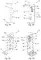
- FIGS. 9A-9Cshow an alternative configuration with double prongs 32 a , 32 b .
- FIG. 9Ashows a metal clip 50 suitable for use with double prongs 32 a , 32 b .
- the metal clip 50may begin as stamped or otherwise cutout sheet metal that has not yet been bent or formed.
- the metal clip 50may include a base 52 with apertures 56 to both receive mounting post 38 and apertures 64 through which the joining posts 62 can pass to secure insulating elements 40 , 44 .
- Extensions 58are formed to make the contacts 46 a and 46 b and their free ends 60 .
- the portions that form the upright 54 and cantilevered sprint 48are also labeled.
- FIG. 9Bshows double prongs 32 a , 32 b forming part of an active cover plate 28 that is installed over a GFCI outlet 10 .
- the active cover plate 28 with double prongs 32 a , 32 bis installed over a GFCI outlet 10 with the GFCI outlet 10 in a “right side up” orientation.
- the active cover plate 28is shown without the back plate 36 , circuitry, or other prongs 32 (prongs 32 for engaging the other side of the GFCI outlet 10 ).
- the first contact 46 a of the double prongs 32 a , 32 bis contacting the screw terminal 24 , while the second contact 46 b is not contacting the screw terminal.
- FIG. 9Cshows an active cover plate 28 with double prongs 32 a , 32 b installed over a GFCI outlet 10 with the GFCI outlet 10 in an “upside down” orientation.
- the GFCI outlet 10is not symmetrical. Consequently, the second bowed contact 46 b makes contact with the screw terminal 24 instead of the first bowed contact 46 a .
- the double prongsmay increase the compatibility of the active cover plate 28 with a wider variety of outlets and outlet configurations.
- an active cover plateincludes at least one prong configured to contact a screw terminal of an electrical receptacle.
- the prongmay include front electrical insulation on a first side of the prong, rear insulation on a second side of the prong; and a compressible contact extending beyond the front insulation to make contact with the screw terminal of an electrical receptacle.
- the active cover platemay also include a circuit and an electrical connection between at least one prong and the circuit. At least one prong may supply the circuit with electrical power from the screw terminal(s).
- the compressible contactmay be secured between the front insulation and the rear insulation and a free end of the compressible contact may be configured to move with respect to the front and/or rear insulation.
- the free end of the compressible contactmay be configured to move in a cavity between the front insulation and rear insulation.
- a first end of the compressible contactis secured with respect to the rear insulation and a second end of the compressible contact is configured to slide with respect to the rear and/or front insulation.
- the second free end of the compressiblemay be configured to slide into a slot or cavity between the rear insulation and the front insulation when the contact is compressed and to retract at least partway out of the slot or cavity when the contact relaxes.
- the prongmay include additional contacts.
- the prongmay include two or more compressible contacts that are horizontally or laterally offset from one another on the prong. These two or more compressible contacts may compress independently.
- the contacts on the prongmay not be compressible and there may be multiple contacts present on a single prong.
- an active cover platemay include at least one prong extending rearward from the face plate.
- the prongmay include multiple electrically conductive contacts. These contacts may be connected to each other using one or more fuse elements.
- an active cover platemay include a face plate, at least one prong extending rearward from the face plate.
- the prongmay include an electrically conductive contact that includes a dielectric substrate with a plurality of electrically conductive patches supported by the dielectric substrate and connected to one another by one or more fuse elements.
- FIGS. 10A-10Gshow various examples of principles or features that may be applied to prongs 32 for GFCI outlets 10 or other situations where prongs 32 need to pass through narrow openings and then expand to make electrical contact with elements beyond the narrow opening.
- FIG. 10Ashows a resilient conductive plastic or metal prong 32 that may or may not be paired with an insulator (in this case a separate insulating wall 112 ) on the outboard side of the prong 32 .
- the conductive prong 32may have a fairly narrow profile and be flexible enough to compress to pass through a narrow opening.
- FIG. 10Bshows a flexible prong 32 with a rear element/insulator 40 coupled to its outboard side.
- the flexible prong 32may be formed by dual injection molding. First a conductive plastic may be injected to form the base 52 , upright 54 and contact portions 46 . The insulating plastic 40 on the upper and outboard sides of the conductive plastic could then be formed. Additionally or alternatively, the conductive plastic could be partially or completely replaced with flexible metal.
- FIGS. 10C and 10Dshow a prong 32 that has an internal structure that expands after the active cover plate 28 is installed.
- the prong 32may include a base element 114 that is compressed as the active cover plate 28 is installed over the electrical receptacle 10 . As the base element 114 is compressed, it may expand, broaden, alter the shape, or the like of a distal end of the prong 32 so that the prong 32 is brought into contact with the screw terminal 24 .
- the front plate 34 and back plate 36are shown in each of the embodiments.
- FIG. 10Eshows a prong with a spring or resilient joint 116 between the base 52 the upright 54 .
- the spring or resilient joint 116may urge the upright portion 54 of the prong 32 in an inboard direction 118 (toward the screw terminal 24 of an outlet 10 ).
- the profile of the upright 54may be relatively narrow so that the prong 32 can extend into the narrow openings. After passing through the narrow opening the spring or resilient joint 116 may urge the contact 46 to the screw terminal 24 .
- the conductivity of the prong 32may be maintained through the spring or resilient joint 116 .
- FIG. 10Fshows a prong 32 that includes an upright 54 that may or may not be conductive and an electrical contact 46 located on an upper/distal portion of the prong 32 .
- the upright 54may or may not be flexible and/or resilient.
- the upright 54may be made of a plastic material that may or may not be resilient or provide spring force.
- a conductor 120may be connected to the contact 46 and pass into the internal space (e.g., to an electrical circuit) of the active cover plate 28 .
- FIG. 10Gshows one embodiment where the electrical contact 46 is a magnet that is attached to a flexible upright 54 .
- the flexible upright 54may be made of any material and have any of a number of different geometries.
- the flexible upright 54has a bending moment (stiffness, resistance to bending) that is small in one direction and significantly greater in another direction.
- the magnetmay be on the end of a sheet that can easily bend toward or away from the screw terminal 24 , thereby allowing the magnetic force between the magnet and the screw terminal 24 to bring the magnet into contact with the screw terminal 24 .
- the upright 54may be more rigid to allow the magnet and corresponding prong 32 to be more accurately or easily maneuvered into position.
- the upright 54may be relatively rigid for motion that is in and out of the page. This would allow the upright 54 to support the weight of the magnet during installation of the active cover plate 28 over a wall mounted GFCI outlet 10 .
- FIGS. 11A-11Fare various illustrative embodiments of prongs 32 for active cover plates 28 .
- FIGS. 11A and 11Bshow a prong 32 that includes an upright, conductive element 54 and a rear insulating element 40 that includes slots 122 or slits 122 to increase its flexibility.
- the upright, conductive element 54may be any of a number of different elements, including conductive plastic or metal. It may be resilient and may or may not have its inboard side partially covered by insulation. It may have any shape that is appropriate.
- the slots 122allow the thickness of the insulation 40 to be maintained while increasing the flexibility of the prong 32 overall.
- FIGS. 11C and 11Dshow prongs 32 comprising a number of joints 124 and stiffer segments 126 that work together to increase the flexibility and resilience of the prong 32 .
- This embodiment and the following embodimentincludes a base 52 and a segmented upright 54 .
- FIG. 11Cshows the prong 32 in its rest position with the contact 46 extending inward/inboard. During insertion or the application of forces that tend to straighten the prong 32 , it straightens and elongates using the flexure provided by the joints 124 . When the force(s) are removed, the prong 32 may return to its rest position to urge or initiate contact with the screw terminal 24 of the GFCI outlet 10 .
- 11E and 11Fshow an illustrative embodiment with different joints 124 .
- the term “free end”means free to move in at least one translational direction.
- the insulated end 60 of the contact 46is a free end because it can extend or move in the transverse direction as shown in FIGS. 11A and 11B .
- the prongs 32 shown in FIG. 11C-11Fcan extend or move in the transverse direction when forces are applied (compare for example FIGS. 11C and 11E with FIGS. 11D and 11F ).
- the illustrative prongs 32 shown in FIGS. 2A-2Khave a contact 46 with a free end 60 (see e.g. FIG.
- the free end 60 of the contact 46may be on the far end of the contact 46 (relative to the base 52 of the prong 32 ) as shown in FIGS. 11G and 11H . Additionally or alternatively, the free end 60 may be on the near side of the contact 46 (relative to the base 52 of the prong 32 ) as shown in FIGS. 2A-2K . Further, both ends of the contact 46 may have limited freedom as shown in FIG. 6D-6I .
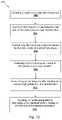
- FIG. 12shows an illustrative method 200 for insertion of a prong of an active cover plate to touch an electrical terminal of an electrical receptacle.
- the methodincludes obtaining an active cover plate with a first prong (step 202 ).
- the active cover platemay include a front plate and a first prong extending away from a backside of the front plate.
- the first prongis inserted into a first gap between a first side of an electrical receptacle and a first wall of an electrical box in which the electrical receptacle is installed (step 204 ).
- the methodmay also include contacting, by the first prong during the inserting, the first side and first wall simultaneously (step 206 ).
- the first prongdeflects to a reduced width (step 208 ).
- the first prongmay rebound to a second width greater than the reduced width (step 210 ).
- the first prongmay touch a first electrical terminal located on the first side of the electrical receptacle (step 212 ).
- the first prongmay further comprise a first electrical contact, where the touching may include physical contact between the first electrical contact and the first electrical terminal.
- the active cover platemay further comprise electronic circuitry connected to the front plate and conductive material extending to connect the first electrical contact to the electronic circuitry.
- the active cover platemay include a second prong with a second electrical contact.
- the insertingfurther comprises inserting the second prong into a second gap between a second side of the electrical receptacle and a second wall of the electrical box.
- the contactingmay further include contacting, by the second prong during the inserting, the second side and the second wall simultaneously.
- the deflectingmay further comprise deflecting by the second prong as a result of the contacting to the reduced width.
- the touchingmay further comprise touching, by the second prong after the rebounding, a second electrical terminal located on the second side of the electrical receptacle.
- FIGS. 13A and 13Bshow rear perspective views of an illustrative two-prong active cover plate ( 1300 ) for use with a decor light switch.
- the principles described hereinhave wide applicability and can be used with a variety of different active cover plate and electrical receptacle designs.
- the active cover plate ( 1300 )has a large aperture ( 1307 ) in the face plate ( 1305 ) to accommodate the rocker on the face of a rocker light switch.
- the two prongs ( 1315 )are connected to the face plate ( 1305 ) and are configured to contact side screw terminals of a décor light switch. However, they will also contact screw terminals on many three-way and four-way light switches. But because there are only two prongs instead of three, four or more, complete electrical contact with all the screw terminals of three and four-way switches is not made.
- the two prongsextend rearward from the face plate and include both front and back insulation.
- the front insulationmay be configured to insulate against electrical contact with the metal yoke of light switches and the rear insulation may be configured to insulate against electrical contact with electrical conductors in the electrical box.
- the prongs ( 1315 )also include a number of ramps surrounding the contact. As discussed previously, the ramps may allow the active cover plate ( 1300 ) to be installed more easily.
- the side rampsallow for vertical motion of the active cover plate ( 1300 ) to align the prongs ( 1315 ) with the screw terminals and the aperture in the face plate ( 1305 ) with the light switch toggle and/or rocker.
- the prongs ( 1315 )can be inserted on the appropriate side of the light switch and then the active cover plate ( 1300 ) moved into place to align the aperture ( 1307 ) in the face plate ( 1305 ) of the cover plate with the toggle or rocker of the light switch.
- FIGS. 13A and 13Bshow various rear perspective views of an active cover plate ( 1300 ) that uses a protrusion ( 1317 ) molded into a rear surface of the face plate ( 1305 ) to insulate and/or support prongs ( 1315 ).
- the prong hood/insulation ( 1310 )may leave a gap between the bottom of the insulation and the face plate. Consequently, this may leave some portion of the conductive material exposed. Additional insulation can be formed on the face plate. This is accomplished by molding a protrusion ( 1317 ) into the face plate ( 1305 ).
- the protrusion ( 1317 )extends upward/rearward to insulate a gap ( 1316 ) the otherwise exposed portion of the electrical conductor.
- the protrusion ( 1317 )is an integrally molded feature in the face plate ( 1305 ) and the prongs ( 1315 ) fit onto the face plate ( 1305 ) such that the prongs ( 1315 ) are insulated on their inboard side by the protrusion ( 1317 ).
- the active cover platehas front insulation that includes a protrusion on the face plate extending rearward to cover at least a portion of the inboard side of the prong.
- the protrusion on the face platemay cover a conductive metal portion of the prong.
- the conductive metal portion of the prongmay include a formed metal sheet where the protrusion on the face plate may at least partially covers an inboard side of the bend of the formed metal sheet.
- FIGS. 14A and 14Bshow an alternative embodiment of an active cover plate with spring clips that extract power from screw terminals on the sides of outlet or switch bodies.
- FIG. 14Ashows a rear perspective view of an active cover plate ( 1400 ) that includes a face plate ( 1402 ), a sandwich or back plate ( 1408 ) with two integral “U” channels ( 1404 ) and spring clips ( 1406 ).
- This viewillustrates that the U channel/rear insulation ( 1404 ) surrounds the rear and sides of the spring clips ( 1406 ) and prevents accidental contact with the spring clips ( 1406 ).
- the spring clips ( 1406 ) and rear insulation ( 1404 )may have any of a variety of configurations and geometries, including those shown in other documents that are incorporated by reference.
- the insulation of the rear and/or sides of the prongmay take a variety of configurations, including a three-dimensional shape such as the “U” channel described above, a two dimensional shape, such as a wall (see e.g. 61/720,131, FIGS. 1B, 9E, 10B, 18, 39), a shape that the conductive elements fit or slide into (see e.g. 61/720,131, FIGS. 9C, 24, 42C; present disclosure, FIGS. 5A-5I, 15A-15E), or other appropriate geometry.
- the rear insulationmay be an integral feature of the back plate or may be separate element.
- FIG. 14Bis a perspective view of the spring clip ( 1406 ).
- the spring clip ( 1406 )includes a convex base curve, a concave mid curve, angled wings, an angled end portion, and a folded end. As discussed above, the angled end portion directs the spring clip ( 1406 ) outward as the active cover plate ( 1400 ) is initially brought into contact with the outlet or switch body. Folding the end of the spring clip ( 1406 ) creates a smooth end shape that is configured not to gouge or snag on surrounding materials.
- the structure of the spring clipis designed to allow for large amounts of flexibility without permanent deformation.
- the spring clipcan be formed from a variety of different materials including copper, copper alloys, beryllium copper alloys, spring steels, beryllium alloys and other metal alloys.
- the spring clipsare designed to make electrical contact with screw terminals on the sides of the outlet body.
- the screw terminalsmay have a variety of different widths, depending on the width of the outlet body and whether the screws are screwed out of the body or into the body. In one design, for small amounts of deformation, the spring clips primarily move outward by cantilever bending with most of the rotation occurring in and around the base curve.
- the back portions of the spring clipcan begin to contact the inner wall of the rear insulation. This changes the bending locations within the spring clips and prevents the base curve from being plastically deformed.
- the back portions that may contact the rear insulationinclude the back portion of the mid curve and the folded end of the prong. These portions are designed to slide within the rear insulation during deformation.
- the rounded back portion of the mid curve and folded endboth present smooth rounded surfaces that will slide easily in the rear insulation without becoming caught.
- the springbecomes much stiffer when the back of the mid curve and folded end contact the back of the rear insulation.
- the bendingthen occurs in different areas than the base curve. For example, a significant amount of the additional bending may occur in regions that are immediately above and below the angled wings.
- the U channelprovides a number of benefits as it interacts with the spring clip. It shields the screw terminal from accidental contact with exterior devices or components.
- the rear insulationalso prevents undesirable plastic bending of the spring clip by supporting the spring clip. For example, when folded end of the spring clip is between the side walls of the rear insulation, lateral forces (for example forces exerted on the spring clip during vertical motion relative to the outlet body) may not bend the spring clip to the side because the spring clip will contact the side walls of the rear insulation.
- Embodiments that use the U channel or other similar insulating shielding or tabmay not require insulation placed directly on the spring clip.
- the spring clipdoes not have any insulating coating because it is protected and insulated from the surroundings by the rear insulation.
- the rear insulationmay be used in conjunction with an insulated spring clip or front insulation.
- the concepts described abovecan be broadly applied to prongs with a variety of geometries. For example, the concept of using rear insulation surrounding the prong on two or more sides can be applied with a wide range of prong and insulation geometries. This may accomplish a variety of purposes, including protecting and insulating the prong.
- FIG. 15Ashows a front perspective view of the conductive spring clip element ( 1500 ).
- the elementincludes a contact ( 1505 ) designed to make contact with a side screw terminal, a base ( 1515 ), and a curved flexure/flexible conductive element ( 1510 ) connecting the contact ( 1505 ) to the base ( 1515 ).
- FIG. 15Bshows a side view of the conductive spring clip element ( 1500 ), with the contact ( 1505 ), curved flexure/flexible conductive element ( 1510 ), and base ( 1515 ).
- the curved flexure ( 1510 )includes an elbow curve ( 1512 ) and a base curve ( 1516 ). The combination of these two curves may be configured to allow the element to bend around shoulders of light switches or outlet bodies.
- the base ( 1515 )in this example shows a wire retention feature ( 1520 ).
- FIG. 15Cshows a rear perspective view of the spring clip element ( 1500 ).
- This viewshows barbed retention features ( 1525 ) along the sides of the contact ( 1505 ).
- the contact ( 1505 ) in this exampleis stamped out of the same piece of metal and is concave on the back side of the conductive element and convex on the front/inboard side (the side facing the screw terminal).
- the curved flexure ( 1510 )also may include features to retain the insulating element. In this example, there is a hole ( 1530 ) through the curved flexure that allows a front portion and a rear portion of the insulating element to be connected together.
- the base ( 1515 )may include wire retention features ( 1520 ) as discussed above and other retention features ( 1535 ) that assist in securing the base to the face plate.
- the other retention features ( 1535 )may include apertures configured to accept posts extending from the face plate.
- FIG. 15Dshows various views of spring clips for use in guidelights for light switches.
- FIG. 15Dis an exploded assembly view of one example of a spring clip.
- the spring clipsinclude an insulating portion or hood ( 1540 ).
- the hood in this exampleis formed from a single piece of electrical insulating material and includes an upper portion ( 1590 ), a rear insulating portion ( 1555 ), and a front insulating portion ( 1570 ).
- the upper portion ( 1590 )includes a main ramp ( 1545 ), and two side ramps ( 1550 ). It also includes a cavity ( 1562 ) to receive the contact ( 1505 ).
- the barbed features ( 1525 )are designed to secure the insulating element over the conductive element. For example, the conductive element may slide into slots in the cavity ( 1562 ). The barbed features ( 1525 ) may engage with the sides of the slots to secure the insulating element over the conductive element.
- the rear insulating portion ( 1555 )is directly connected to the upper portion ( 1590 ).
- the rear insulating portion ( 1555 )is connected to the front insulating portion ( 1570 ) by a flexible portion ( 1565 ).
- the flexible portion ( 1565 )may be a joint or a living hinge.
- the rear insulating portion ( 1555 )includes an aperture ( 1530 ) that is configured to receive a post ( 1575 ) on the front insulating portion ( 1570 ).
- the front insulating portion ( 1570 )is folded upward as shown by the curved arrow.
- the cavity ( 1562 ) in the upper portion ( 1590 ) of the hoodslips ( 1540 ) over the contact ( 1505 ) and the barbs ( 1525 ) engage with the sides and/or slots in the cavity ( 1562 ) to secure the hood onto the conductive element ( 1500 ).
- the front insulating portion ( 1570 )is then rotated about the joint/flexible portion ( 1565 ) until the post ( 1575 ) fits through the aperture ( 1530 ) in the conductive portion/curved flexure ( 1510 ) and through the aperture ( 1572 ) in the rear insulating portion ( 1555 ).
- the post ( 1575 )is then secured in place.
- the post ( 1575 )may be pressed so that it expands to fill the apertures ( 1530 ) and secure the front insulating portion ( 1570 ) to the rear insulating portion ( 1555 ) and additionally secure the hood ( 1540 ) to the flexible element ( 1500 ).
- a variety of configurationscould be used to apply the principles described.
- the front insulation, and the rear insulationmay be secured in a variety of ways including an interference fit, sonic welding, or other appropriate joining technique.
- FIG. 15Eshows a perspective view of a spring clip ( 1585 ).
- the hood ( 1540 )is installed over the flexible conductive element ( 1500 ) by sliding the contact ( 1505 ) into the cavity ( 1562 ) and the barbs ( 1525 ) into slots on either side of the cavity. This positions the ramps ( 1550 , 1545 ) to facilitate during the installation of the active cover plate such that the contact ( 1505 ) moves into place over the screw terminal.
- the front insulating portion ( 1570 )covers the front of the flexible conductive portion ( 1510 ) and the rear insulating portion ( 1555 ) covers the rear of the flexible conductive portion.
- the front insulation ( 1570 )may include a number of additional components such the protrusions from the face plate as discussed above.
- FIGS. 16A-16Eare diagrams describing various resilient support ( 1612 , 1614 , 1616 ) that can be used to prevent or mitigate permanent deformation of plastic or other materials used to support electrical contacts.
- FIGS. 16A and 16Bshow a prong or clip ( 1600 ) for an active cover plate with a plastic support structure that includes a base ( 1608 ), a curve ( 1610 ), and an upright ( 1606 ).
- a contact ( 1602 )is mounted on the upright ( 1606 ) and the conductor ( 1604 ) is electrically connected to the contact ( 1602 ).
- FIG. 16Ashows the prong ( 1600 ) in its neutral position. In one example shown in FIG.
- the prong ( 1600 )when the prong ( 1600 ) comes into contact with a screw terminal or other part of an electrical receptacle, the prong ( 1600 ) is bent backwards. This bending can occur anywhere along the upright ( 1606 ) but, as illustrated in FIG. 16B , the flexure may primarily occur in the curve ( 1610 ). Because the support structure is plastic or other deformable material, it will deform over time and assume a position that is closer to the deflected position than the neutral position. This may be undesirable because it reduces the normal force between the contact and the screw terminal. Further, if the active cover plate is ever removed from that receptacle to a different receptacle, the deformed prongs may not even contact the electrical receptacle.
- the prongcould be deformed.
- the prongmay be deformed during packaging, handling or installation.
- a resilient support/insertcan improve the prong resiliency and robustness and assist in returning the prong to a desired configuration.
- FIGS. 16C, 16D and 16Eshow various resilient supports ( 1612 , 1614 , 1616 ) that may prevent or mitigate deformation over time.
- the internal resilient supportscan be deflected without significant plastic deformation and consequently tend to return the prong to its original neutral position.
- These resilient supportsmay be internal or external to the support structure.
- FIG. 16Cshows an example of a prong ( 1600 ) that includes an internal resilient support ( 1612 ) that is not electrically connected to the contact ( 1602 ).
- the resilient support or stiffening membermay be embedded or sandwiched into the upright.
- the resilient support ( 1614 )may be a strip or sheet of metal or other material as shown in FIG.
- resilient support/insert1616
- resilient supportscould be shaped in any of a variety of ways to secure them to a base/back plate/front plate and to support the prong upright in returning a position that is closer to a neutral or other desired position.
- an active cover platemay include a face plate, an electrical load and at least one clip extending rearward from the face plate.
- the clipmay include a contact, an upright mechanically supporting the contact, where the contact may be joined to the main upright and passes through the main upright and a rear insulator covers a rear side of the contact and an electrical connection between the clip and the electrical load.
- the clipmay further comprise a stiffening member disposed between the main upright portion and the rear insulator.
- the stiffening membermay be formed from a resilient metal such as a resilient wire or resilient strip.
- the stiffening membermay be a resilient metal that follows the contours of the main upright and moves with the main upright.
- the stiffening membermay include any or all of the following: a base portion, a bent portion, an upright portion and a head portion. The head portion may be narrower than the base portion and the bent portion.
- the active cover platemay include a face plate, an electrical load and at least one clip extending rearward from the face plate.
- the clipmay include a mechanical support and a contact supported by the mechanical support.
- the mechanical supportmay be formed from a plastic material that may be permanently deformed.
- the clipmay further comprise a stiffening member joined to the mechanical support that provides additional resilient force to return the mechanical support to a neutral position.
- the stiffening membermay be formed from a resilient metal such as a resilient wire or resilient strip and may be encapsulated, sandwiched, or otherwise joined to the mechanical support. The stiffening member may or may not be connected to the contact.
- FIGS. 17A and 17Bshow various cross sectional diagrams of an active cover plate that includes vertically adjustable spring clips with hinge joints.
- the hinge jointsallow the spring clips to be packaged and shipped flat. This can provide a number of advantages including lowering the cost of shipping, decreasing the size and weight of packaging, and protecting the spring clips from damage.
- FIG. 17Ashows a cross sectional view of an active cover plate ( 1700 ) that has two hinged spring clips ( 1715 , 1720 ) that are folded down for shipping or storage.
- the active cover plate ( 1700 )includes a face plate ( 1705 ) and hinges ( 1710 , 1725 ).
- the spring clips ( 1715 , 1720 )can be brought into the upright position so that they extend rearward from the face plate as shown in FIG. 17B .
- the hingesare designed to be conductive throughout their range of motion. In other examples, the hinges may only be conductive in their raised position. Alternatively, the hinges may not be conductive. In this case the contact and the moving part of the spring clip may be connected to circuitry in the active cover plate by a flexible wire or make an electrical contact in their upright position. In one implementation, the spring clips lock into their upright position. In this example, a latching mechanism ( 1712 , FIG. 17B ) engages with the spring clip when the spring clips are raised. The latching mechanism holds the spring clip in the upright position and prevents the hinge joint from rotating after the latch engages with the spring clip. In other implementations, the spring clips may be held in their raised position by pressure from the contact on the outlet/switch body.
- the latching mechanism ( 1712 )may include a ramp and a slot. When the spring clip is raised, it engages with the ramp on the latching mechanism and then clicks into the slot. This secures the spring clip ( 1720 ) in the desired upright position.
- hingesthat allow the spring clips to lay flat and be raised, there are a variety of other mechanisms that could be used, including flexures, joints, or other suitable rotational mechanisms.
- an active cover platemay include a face plate and a prong extending from the face plate.
- the prongmay include an upright comprising at least one aperture and a resilient contact comprising a fixed end and a free end.
- the upright shown in FIG. 2Hshows a number of apertures ( 56 , 64 ) and an aperture ( 67 ) behind the resilient contact ( 46 ).
- the uprightmay be wider than the resilient contact, where the resilient contact may be disposed on an inboard side of the upright; and where the fixed end of the resilient contact may be secured to the upright and at least a portion of the resilient contact extends over the aperture in the upright.
- the active cover platemay include a resilient contact with a middle portion between the fixed end and the free end, where at least a part of the middle portion may extend over the aperture in the upright.
- the prongmay also include a base extending at an angle from the upright with the base comprising a wire connection feature.
- the basemay be generally parallel to the plane of a back surface of the face plate.
- the upright, resilient contact, and basemay be formed from a single piece of sheet metal.
- the metalmay be formed using stamping processes.
- the active cover platemay further comprise a circuit and a wire, where the wire may form a connection to the base to make an electrical connection between the circuit and the prong.
- the aperturemay be generally rectangular aperture through the upright and may include a first short side, a second short side, a first long side and a second long side.
- the first end of the resilient contactmay be connected to the upright proximate to a first short side of the aperture and may extend over the aperture with a free end of the resilient contact more proximate to the second short side than the first short side of the rectangular aperture.
- the active cover platemay also include electrical insulation and the upright may include at least one additional aperture and the upright may be at least partially secured to the electrical insulation using at least one additional aperture. For example, a portion of the electrical insulation may extend through an additional aperture in the upright.
- the uprightmay include edges that engage with the electrical insulation to at least partially secure the upright to the electrical insulation.
- the uprightmay include shoulders proximal to the face plate that are wider than portions of the upright that are more distal from the face plate.
- the resilient contactmay include a first resilient contact and the prong may include a second aperture and a second resilient contact extending over the second aperture.
- the second resilient contactmay be longitudinally spaced from the first resilient contact.
- the active cover platemay also include a rear insulator that includes a wall outboard from the upright, where an outboard surface of the upright and the inboard surface of the outboard wall may be substantially flat, parallel, contiguous and fixed relative to each other.
- the active cover platemay extend in longitudinal, lateral, and transverse directions that are orthogonal to one another.
- the active cover platemay include a front plate comprising a front surface, a back surface, and an electrical receptacle aperture.
- the electrical receptacle aperturemay extend through the front plate in the transverse direction.
- the prongmay be connecting to the back surface of the front plate at a location outboard of the electrical receptacle aperture.
- the prongmay extend rearward away from the back surface of the front plate in the transverse direction.
- a back platemay include a protrusion extending from a back surface of the back plate in the transverse direction and the protrusion may include an outboard wall and lateral walls joined to opposite edges of the outboard wall.
- the protrusionmay be an integrally molded feature of the back plate and the outboard wall and lateral walls may define a partially enclosed volume.
- the protrusionmay include insulation that covers at least a portion of an outboard side of the prong.
- the outboard and lateral walls of the protrusionmay form a U channel with the prong at least partially disposed within an interior volume enclosed by the U channel. Lateral compression of the prong may bring the prong into contact with the protrusion. For example, the lateral compression of the prong may bring the prong into direct contact with the inner side of the outboard wall of the protrusion.
- the prongmay include a cantilever comprising a fixed end connected to a support and a free end, where the free end of the prong may be configured to contact the inner side of the outboard wall of the protrusion when the cantilever is deformed.
- the contactmay also increase bending stiffness of the prong between the free end of the cantilever when the prong contacts the inner wall of the protrusion.
- the contact between the free end of the cantilever and inner wall of the protrusionmay change the bending behavior of the cantilever or resilient strip.
- the fixed endmay be fixed with respect to the protrusion.
- the protrusionmay include at least one partially open face on its inboard side, where the prong may extend from and may compress into the partially open face.
- the protrusionmay also include an open top side that is in a transverse direction opposite the face plate.
- the back plate and protrusionmay be connected to the face plate by posts molded into the surface of the face plate and the posts may pass through corresponding apertures in the back plate.
- a wall-plate systemmay extend in longitudinal, lateral, and transverse directions that are orthogonal to one another and the wall-plate system may include a front plate comprising a front surface, a back surface.
- the front platemay include an electrical receptacle aperture that extends through the front plate in the transverse direction.
- the wall-plate systemmay further comprise a first prong connecting to the back surface of the front plate at a location outboard of the electrical receptacle aperture.
- the first prongmay extend rearward away from the back surface of the front plate in the transverse direction.
- the first prongmay include a first upright extending rearward away from the back surface of the front plate in the transverse direction and a first insulating back element.
- the first insulating back elementmay cover an outboard side of the first upright and left and right edges of the upright.
- the first insulating back elementmay be secured to the upright through at least one aperture in the upright.
- the first resilient contactmay be located on an inboard side of the first upright and the first resilient contact may include a first end, second end, and middle portion; and where the first end of the first resilient contact may be fixed with respect to the first upright.
- a second prongmay connect to the back surface of the front plate at a location outboard of the outlet aperture.
- the second prongmay extend rearward away from the back surface of the front plate in the transverse direction.
- Theremay be a second insulating back element that may cover an outboard side of the second upright and left and right edges of the upright.
- the second insulating back elementmay be secured to the upright through at least one aperture in the upright.
- the second resilient contactmay be located on an inboard side of the second upright and may include a first end, second end, and middle portion; and where the first end of the second resilient contact may be fixed with respect to the second upright.
- the second prongmay connect to the back surface of the front plate at a location outboard of the outlet aperture.
- the second prongmay be opposite the first prong across the electrical receptacle aperture.
- the wall plate systemmay include the first and second prongs each with two resilient contacts. The two resilient contacts may be spaced such that a first resilient contact on each of the first and second prongs contacts a first screw terminal of an electrical receptacle when the wall plate system is fastened over the electrical receptacle in a first orientation and the second resilient contact on each of the first and second prongs contacts the first screw terminal when the wall plate system is fastened over the electrical receptacle in a second orientation.
- the two resilient contacts on each of the first and second prongsmay be spaced such that the wall plate is configured to receive power when the wall plate system is placed over an electrical receptacle in at least two different orientations.
- the two resilient contactsare longitudinally offset from each other and are configured to compress independently, where there may be a gap between the two resilient contacts that is greater than longitudinal width of the resilient contacts.
- an active cover platemay include a face plate with an aperture and a prong extending from the face plate.
- the prongmay include rear insulation and front insulation.
- the rear insulation and front insulationmay define an opening with an electrical contact extending through the opening.
- the rear insulationmay include at least three sides define an interior space.
- the prongmay include an upright and the rear insulation may cover at least three sides of the upright.
- the rear insulationmay cover at least a portion of the back of the upright, at least a portion of the sides of the upright, and at least a portion of the front of the upright.
- the active cover platemay include a hinged connection between the face plate and the prong.
- the prong and hinged connectionmay be configured to allow the prong to rotate toward the plane of the face plate for shipping and rotate away from the plate of the face plate for installation.
- the prongmay also include a resilient insert that may include resilient metal that is not electrically connected to the contact.
- the front insulation and rear insulationmay be joined in a variety of ways including being joined by posts passing through a conductor supporting the electrical contact.
- the electrical contactmay include a bowed contact extending through the opening with a terminal end of the bowed contact extending into a cavity in prong. The terminal end of the bowed contact may be configured to move farther into the cavity when the bowed contact is compressed.
- the prongmay further comprise an upright wherein a first end of the bowed contact is connected to the upright and a second end of the bowed contact is not connected to the upright and is free to move with respect to the upright.
- the active cover plate of claim 1wherein the prong comprises a first electrical contact and a second electrical contact, wherein the first contact and second contact are transversely or longitudinally offset from each other.
- the first contact and second contactmay include a first bowed contact and a second bowed contact.
- the prongmay include one support supporting both the first contact and second contact.
- the supportincludes a conductive base and wherein the first contact and second contact are electrically connected to each other by circuitry or electrically connected by the conductive base.
- the front insulation and rear insulationmay interface to form the opening.
- active cover platesthat are configured to interface with an electrical receptacle that include principles described herein may include a face plate comprising an aperture, at least one prong extending from the face plate and configured to make electrical contact with an electrified terminal of an electrical receptacle.
- the prongmay include a conductor that may include an upright and a contact and insulation that may include at least three solid sides and an open side. The three solid sides may cover at least a portion of the at least three sides of the upright and the contact may extend out of the open side.
- the active cover platemay also include a back plate that may be joined to the face plate and at least a portion of the insulation may be an integrally formed element of the back plate.
- the insulationmay include rear insulation and front insulation wherein the front insulation may include a protrusion on the face plate extending rearward to cover at least a portion of the inboard side of the conductor.
- the conductormay include a formed metal sheet with a base connected to and in plane with the face plate, a bend, and the upright.
- the contactmay be connected to and extend from the upright.
- the protrusion on the face platemay at least partially cover an inboard side of the bend of the formed metal sheet.
- the insulationmay substantially cover four sides of the upright and/or the insulation may substantially covers an outboard side, a left side, a right side and at least a portion of an inboard side of the upright.
- the insulationmay include a slot and the upright may engage with the slot to secure the contact with respect to the insulation.
- an active cover plate configure to interface with an electrical receptaclemay include a face plate comprising an aperture configured to accept an electrical receptacle and at least one prong extending from the face plate.
- the prongmay include insulation that includes a cavity and an electrical conductor that may include a support at least partially disposed in the cavity, and a contact where at least a portion of the contact may extend from the support through an opening in the insulation.
- the contact and the supportmay be formed from a single piece of sheet metal.
- the openingmay include an aperture in a side of the cavity and at least a portion of the support may be secured in the cavity. Additionally or alternatively, at least a portion of the contact may extend from the support through an opening in the cavity.
- the insulationmay include front and rear insulation wherein the front and rear insulation interface to form the cavity.
- at least a portion of the supportmay be disposed in and secured in the cavity.
- the contactmay include a first end secured to the support, a middle portion extending from the opening in the insulation, and an opposite free end extending into the cavity and configured to move within the cavity.
- the contactmay include a bowed contact with one end secured to the support and an opposite end of the bowed contact extending into the cavity. The opposite end of the bowed contact may be configured to extend deeper into the cavity when the bowed contact is compressed and to retract when the contact relaxes.
- the insulationmay include a slot and wherein the support is configured to engage with the slot.
- the contactmay include a bowed contact and the support may be secured in a slot in the insulation and the bowed contact may extend from the support and may terminate in a free end that may be captured in the cavity and is may be configured to move within the cavity.
- active cover platesmay be used as glass break detectors.
- the active cover platesmay include microphones. Glass breaking has an identifiable sound that could be detected by these microphones.
- the active cover plate or a device in communication with the active cover platecould filter the sounds detected by the microphone to determine if the signals indicate that glass is breaking. If the microphones in the active cover plates indicate that glass is breaking, an alarm can be sounded and the room where the breaking glass was detected can be indicated. Appropriate action and notifications can then be taken to secure the room or building.
- the active cover platescould be used to direct individuals during an emergency situation. For example, during a fire, individuals can become easily confused when trying to exit a building.
- the outletsare ideally situated, not only to detect fires, but to give visual or audio instructions about what actions should be taken. For example, a mother could record a message for a child's bedroom that would be played for the child through the outlet cover... “Robby, the fire alarms are going off. Shut your door. Go to the window and wait, I′ll come and get you if I can.” If the outlets detect rising temperatures near the bedroom, the message could change, “Open the window, push out the screen and climb onto the roof.” Thus, very individualized instruction could be given based on location and situation.
- the active cover platescould be used to show an individual the way out of the fire or other emergency situation.
- the lights on the active cover platein addition to providing emergency lighting, could have a visual or audio indicator of the action the individual should take.
- One or more LEDs on the active cover platescould blink green, indicating that the area near the cover plate is safe and an exit is near by. Yellow blinking could indicate a region that the user should move out of, while red blinking indicates that the region near the active cover plate is unsafe. For example, if a glass break sensor in an active cover plate in the living room has been triggered, the active cover plates throughout the house could guide the owners away from the living room and the potential intruder.
- the active cover plates on wall outletscould be particularly valuable because they are close to the ground where the smoke and heat are less. Individuals who are exiting the house from a fire are advised to crawl on the floor to avoid smoke inhalation.
- the wall outletsare typically located about a foot from the floor and are ideally situated to provide lighting and direction for a person crawling out of a burning or smoke filled building.
- an active cover platemay be an active cover plate with rear illumination. Active cover plates can extract power from outlet and switch bodies to provide illumination in a variety of ways. In one example, the active cover plate illuminates an image from the rear. When the image is illuminated, image becomes visible to the occupants of the room.
Landscapes
- Engineering & Computer Science (AREA)
- Microelectronics & Electronic Packaging (AREA)
- Physics & Mathematics (AREA)
- Electromagnetism (AREA)
- General Physics & Mathematics (AREA)
- Radar, Positioning & Navigation (AREA)
- Automation & Control Theory (AREA)
- Architecture (AREA)
- Civil Engineering (AREA)
- Structural Engineering (AREA)
- Connector Housings Or Holding Contact Members (AREA)
Abstract
Description
Claims (17)
Priority Applications (5)
| Application Number | Priority Date | Filing Date | Title |
|---|---|---|---|
| US16/538,722US11394157B2 (en) | 2011-08-01 | 2019-08-12 | Active cover plates |
| US16/989,817US11664631B2 (en) | 2011-08-01 | 2020-08-10 | Environment sensing active units |
| US29/778,909USD939932S1 (en) | 2014-11-20 | 2021-04-15 | Wall plate |
| US17/868,595US11888301B2 (en) | 2011-08-01 | 2022-07-19 | Active cover plates |
| US18/203,610US20230420891A1 (en) | 2011-08-01 | 2023-05-30 | Environment Sensing Active Units |
Applications Claiming Priority (53)
| Application Number | Priority Date | Filing Date | Title |
|---|---|---|---|
| US201161574344P | 2011-08-01 | 2011-08-01 | |
| US13/461,915US8912442B2 (en) | 2011-08-01 | 2012-05-02 | Active cover plate |
| US201261720131P | 2012-10-30 | 2012-10-30 | |
| US201361778386P | 2013-03-12 | 2013-03-12 | |
| US201361836972P | 2013-06-19 | 2013-06-19 | |
| US14/066,621US9035180B2 (en) | 2011-08-01 | 2013-10-29 | Active cover plates |
| US14/066,637US9035181B2 (en) | 2011-08-01 | 2013-10-29 | Modified electrical devices |
| US201361906651P | 2013-11-20 | 2013-11-20 | |
| US201462027784P | 2014-07-23 | 2014-07-23 | |
| US201462081539P | 2014-11-18 | 2014-11-18 | |
| US14/549,143US9362728B2 (en) | 2011-08-01 | 2014-11-20 | Active cover plates |
| US29/522,404USD781241S1 (en) | 2014-11-20 | 2015-03-30 | USB cover plate |
| US29/522,406USD810697S1 (en) | 2014-11-20 | 2015-03-30 | USB cover plate |
| US14/678,746US9768562B2 (en) | 2011-08-01 | 2015-04-03 | Modified electrical devices |
| US29/551,208USD809899S1 (en) | 2016-01-11 | 2016-01-11 | Illuminated light switch plate |
| US201662279831P | 2016-01-18 | 2016-01-18 | |
| US15/145,749US9787025B2 (en) | 2011-08-01 | 2016-05-03 | Active cover plates |
| US15/406,404US9742111B2 (en) | 2011-08-01 | 2017-01-13 | Active cover plates |
| US15/409,508US9807829B2 (en) | 2016-01-18 | 2017-01-18 | Voltage isolating current control circuits |
| US15/428,099US9832841B2 (en) | 2016-01-18 | 2017-02-08 | Wall-plate-switch system and method |
| US29/594,002USD832223S1 (en) | 2012-05-02 | 2017-02-14 | Active wall plate |
| US29/594,003USD913963S1 (en) | 2012-05-02 | 2017-02-14 | Active wall plate |
| US29/594,007USD832224S1 (en) | 2012-05-02 | 2017-02-14 | Active wall plate |
| US29594005 | 2017-02-14 | ||
| US201762460094P | 2017-02-17 | 2017-02-17 | |
| US29/598,255USD819426S1 (en) | 2013-10-29 | 2017-03-23 | Lighted wall plate |
| US29/599,679USD845108S1 (en) | 2017-04-05 | 2017-04-05 | Safety wall plate |
| US15/481,280US9882318B2 (en) | 2011-08-01 | 2017-04-06 | Active cover plates |
| US15/481,318US9882361B2 (en) | 2011-08-01 | 2017-04-06 | Active cover plates |
| US15/486,277US9899814B2 (en) | 2011-08-01 | 2017-04-12 | Active cover plates |
| US15/486,273US9871324B2 (en) | 2011-08-01 | 2017-04-12 | Active cover plates |
| US15/486,280US9917430B2 (en) | 2011-08-01 | 2017-04-12 | Active cover plates |
| US15/496,872US10291007B2 (en) | 2012-10-30 | 2017-04-25 | Active cover plates |
| US29/608,299USD849511S1 (en) | 2017-06-20 | 2017-06-20 | Light switch cover plate |
| US29/608,300USD849512S1 (en) | 2017-06-20 | 2017-06-20 | Light switch cover plate |
| US29/608,301USD849513S1 (en) | 2017-06-20 | 2017-06-20 | Light switch cover plate |
| US29/608,295USD842076S1 (en) | 2017-06-20 | 2017-06-20 | Light switch cover plate |
| US29/608,296USD877599S1 (en) | 2017-06-20 | 2017-06-20 | Light switch cover plate |
| US29/608,294USD842075S1 (en) | 2017-06-20 | 2017-06-20 | Light switch cover plate |
| US29/608,297USD849510S1 (en) | 2017-06-20 | 2017-06-20 | Light switch cover plate |
| US29/608,292USD847608S1 (en) | 2017-06-20 | 2017-06-20 | Light switch cover plate |
| US201762522691P | 2017-06-21 | 2017-06-21 | |
| US201762536452P | 2017-07-24 | 2017-07-24 | |
| US15/708,082US10644461B2 (en) | 2011-08-01 | 2017-09-18 | Modified electrical devices |
| US201762579033P | 2017-10-30 | 2017-10-30 | |
| US29/629,812USD887819S1 (en) | 2013-10-29 | 2017-12-15 | Lighted wall plate |
| US15/870,832US10109945B2 (en) | 2017-02-17 | 2018-01-12 | Active cover plates |
| US15/920,047US10404045B2 (en) | 2011-08-01 | 2018-03-13 | Active cover plates |
| US16/166,965US11158982B2 (en) | 2011-08-01 | 2018-10-22 | Active cover plates |
| US29676104 | 2019-01-08 | ||
| US29/676,102USD881137S1 (en) | 2014-11-20 | 2019-01-08 | USB wall plate |
| US16/244,819US10381788B2 (en) | 2011-08-01 | 2019-01-10 | Active cover plates |
| US16/538,722US11394157B2 (en) | 2011-08-01 | 2019-08-12 | Active cover plates |
Related Parent Applications (2)
| Application Number | Title | Priority Date | Filing Date |
|---|---|---|---|
| US29/676,102ContinuationUSD881137S1 (en) | 2011-08-01 | 2019-01-08 | USB wall plate |
| US16/244,819ContinuationUS10381788B2 (en) | 2011-08-01 | 2019-01-10 | Active cover plates |
Related Child Applications (4)
| Application Number | Title | Priority Date | Filing Date |
|---|---|---|---|
| US29/629,812Continuation-In-PartUSD887819S1 (en) | 2011-08-01 | 2017-12-15 | Lighted wall plate |
| US16/989,817Continuation-In-PartUS11664631B2 (en) | 2011-08-01 | 2020-08-10 | Environment sensing active units |
| US29/778,909ContinuationUSD939932S1 (en) | 2014-11-20 | 2021-04-15 | Wall plate |
| US17/868,595ContinuationUS11888301B2 (en) | 2011-08-01 | 2022-07-19 | Active cover plates |
Publications (2)
| Publication Number | Publication Date |
|---|---|
| US20200036141A1 US20200036141A1 (en) | 2020-01-30 |
| US11394157B2true US11394157B2 (en) | 2022-07-19 |
Family
ID=66432535
Family Applications (2)
| Application Number | Title | Priority Date | Filing Date |
|---|---|---|---|
| US16/244,819ActiveUS10381788B2 (en) | 2011-08-01 | 2019-01-10 | Active cover plates |
| US16/538,722Active2033-02-21US11394157B2 (en) | 2011-08-01 | 2019-08-12 | Active cover plates |
Family Applications Before (1)
| Application Number | Title | Priority Date | Filing Date |
|---|---|---|---|
| US16/244,819ActiveUS10381788B2 (en) | 2011-08-01 | 2019-01-10 | Active cover plates |
Country Status (1)
| Country | Link |
|---|---|
| US (2) | US10381788B2 (en) |
Cited By (9)
| Publication number | Priority date | Publication date | Assignee | Title |
|---|---|---|---|---|
| US20200412070A1 (en)* | 2011-08-01 | 2020-12-31 | Snaprays, Llc Dba Snappower | Environment Sensing Active Units |
| US20210359477A1 (en)* | 2017-02-17 | 2021-11-18 | Snaprays, Llc Dba Snappower | Active cover plates |
| US11949183B1 (en) | 2019-06-04 | 2024-04-02 | Titan3 Technology LLC | Powered wall plate with keyed interface |
| US12095249B1 (en) | 2021-02-05 | 2024-09-17 | Titan3 Technology LLC | Powered wall plate with adjustable plug prongs |
| US12142880B2 (en) | 2011-08-01 | 2024-11-12 | Snaprays, Llc | Active cover plates |
| US12308581B1 (en) | 2017-05-07 | 2025-05-20 | Titan3 Technology LLC | Powered wall plate with plug prongs |
| US12327956B1 (en) | 2022-02-01 | 2025-06-10 | Titan3 Technology LLC | Two-part powered electrical wall plate |
| US12335593B2 (en) | 2020-12-30 | 2025-06-17 | Titan3 Technology LLC | Electrical receptacle with built-in camera |
| US12418711B1 (en) | 2019-04-23 | 2025-09-16 | Titan3 Technology LLC | Electrical wall plate with movably positionable camera |
Families Citing this family (27)
| Publication number | Priority date | Publication date | Assignee | Title |
|---|---|---|---|---|
| US10381788B2 (en)* | 2011-08-01 | 2019-08-13 | Snaprays Llc | Active cover plates |
| US11888301B2 (en) | 2011-08-01 | 2024-01-30 | Snaprays, Llc | Active cover plates |
| US11158982B2 (en)* | 2011-08-01 | 2021-10-26 | Snaprays Llc | Active cover plates |
| US10996645B1 (en) | 2017-04-01 | 2021-05-04 | Smart Power Partners LLC | Modular power adapters and methods of implementing modular power adapters |
| US10530597B1 (en) | 2017-04-01 | 2020-01-07 | Smart Power Partners LLC | System for controlling a plurality of power switches configured to apply power to devices |
| US12027968B2 (en) | 2017-04-01 | 2024-07-02 | John J. King | Power adapters and methods of implementing a power adapter |
| US12093004B1 (en) | 2017-04-01 | 2024-09-17 | Smart Power Partners LLC | In-wall power adapter and method of implementing an in-wall power adapter |
| US12100919B2 (en) | 2017-09-21 | 2024-09-24 | O'Reilly Winship, LLC | Rechargeable USB electrical outlet with integrated lighting with connectivity |
| US11489298B2 (en) | 2017-09-21 | 2022-11-01 | O'Reilly Winship, LLC | Electrical outlet cover with integrated lighting with connectivity |
| US12322910B2 (en) | 2017-09-21 | 2025-06-03 | O'Reilly Winship, LLC | Electrical outlet cover with integrated lighting with connectivity |
| US10665996B2 (en) | 2017-09-21 | 2020-05-26 | O'Reilly Winship, LLC | Rechargeable USB electrical outlet with integrated lighting |
| US11043801B2 (en)* | 2018-10-09 | 2021-06-22 | Ford Global Technologies, Llc | Hybrid vehicle with electrical power outlet |
| US11059474B2 (en) | 2018-10-09 | 2021-07-13 | Ford Global Technologies, Llc | Hybrid vehicle with electrical power outlet |
| US20200227902A1 (en)* | 2019-01-11 | 2020-07-16 | Alltrade Tools Llc | Direct coverplate |
| US11264769B1 (en) | 2019-06-30 | 2022-03-01 | Smart Power Partners LLC | Power adapter having contact elements in a recess and method of controlling a power adapter |
| US10917956B1 (en) | 2019-06-30 | 2021-02-09 | Smart Power Partners LLC | Control attachment configured to provide power to a load and method of configuring a control attachment |
| US11043768B1 (en) | 2019-06-30 | 2021-06-22 | Smart Power Partners LLC | Power adapter configured to provide power to a load and method of implementing a power adapter |
| US11201444B1 (en) | 2019-06-30 | 2021-12-14 | Smart Power Partners LLC | Power adapter having contact elements in a recess and method of controlling a power adapter |
| US11219108B1 (en) | 2019-06-30 | 2022-01-04 | Smart Power Partners LLC | Power adapter arrangement and method of implementing a power adapter arrangement |
| US12164350B1 (en) | 2019-06-30 | 2024-12-10 | Smart Power Partners LLC | Power adapter configured to provide power to a load |
| US10965068B1 (en) | 2019-06-30 | 2021-03-30 | Smart Power Partners LLC | In-wall power adapter having an outlet and method of controlling an in-wall power adapter |
| US11231730B1 (en) | 2019-06-30 | 2022-01-25 | Smart Power Power LLC | Control attachment for a power adapter configured to control power applied to a load |
| US10938168B2 (en) | 2019-06-30 | 2021-03-02 | Smart Power Partners LLC | In-wall power adapter and method of controlling the application of power to a load |
| US12066848B1 (en) | 2019-06-30 | 2024-08-20 | Smart Power Partners LLC | In-wall power adaper adapted to receive a control attachment and method of implementing a power adapter |
| US12045071B1 (en) | 2019-06-30 | 2024-07-23 | Smart Power Partners LLC | In-wall power adapter having an outlet |
| US11614210B2 (en) | 2020-05-11 | 2023-03-28 | James McGovern | Residential emergency lighting system |
| US12160074B2 (en) | 2021-11-03 | 2024-12-03 | Smart Power Partners LLC | In-wall power adapter having a switch and a recess adapted to receive a control module |
Citations (294)
| Publication number | Priority date | Publication date | Assignee | Title |
|---|---|---|---|---|
| US1938309A (en) | 1930-12-20 | 1933-12-05 | Emrys M Williams | Electrical outlet or switch |
| US2015698A (en) | 1933-12-07 | 1935-10-01 | Tiffany Technical Corp | Safety switch plate |
| US2045199A (en) | 1931-10-23 | 1936-06-23 | Circle F Mfg Co | Indicating wall socket |
| US2134695A (en) | 1936-04-25 | 1938-11-01 | Morris L Bigman | Illuminating attachment for switch devices |
| US2193740A (en) | 1938-09-06 | 1940-03-12 | John M Reed | Illuminated wall switch plate |
| US2227549A (en) | 1939-05-23 | 1941-01-07 | Fred L Mcneill | Illuminated receptacle |
| US2385620A (en) | 1944-06-01 | 1945-09-25 | Fleckenstein Andrew | Electric outlet accessory fixture |
| US2428167A (en) | 1946-04-30 | 1947-09-30 | Fuse Indicator Corp | Illuminated escutcheon for electrical outlets |
| US2515820A (en) | 1945-10-15 | 1950-07-18 | George P R Clark | Luminous display unit |
| US2575820A (en) | 1944-10-10 | 1951-11-20 | Fuse Indicator Corp | Illuminated cover plate for electrical outlets |
| US2580056A (en) | 1945-02-19 | 1951-12-25 | Jr Thomas L Wheeler | Electrically lighted wall switch plate |
| US2749381A (en) | 1952-06-26 | 1956-06-05 | Jr Robert E Farish | Safety protective device |
| US2880285A (en) | 1955-09-22 | 1959-03-31 | Hilda S Robison | Electric switches |
| US2908743A (en) | 1956-11-30 | 1959-10-13 | Robert T Premoshis | Electrical outlet |
| US2934590A (en) | 1958-08-29 | 1960-04-26 | Harry B Thompson | Electric outlet receptacle |
| US3120414A (en) | 1961-02-17 | 1964-02-04 | Jr Robert E Farish | Safety protective device |
| US3168612A (en) | 1962-10-10 | 1965-02-02 | Carling Electric Inc | Mounting adapters for switch cases |
| US3200221A (en) | 1961-12-22 | 1965-08-10 | Albert D Traher | Fuse device for cover plates of plug-in electrical receptacles |
| US3225265A (en) | 1961-09-08 | 1965-12-21 | K & M Electronics Company | Remote control electrical switch and radio frequency actuating system therefor |
| US3307030A (en) | 1964-06-15 | 1967-02-28 | Francisco Arthur De | Plug-in electroluminescent device |
| US3522595A (en) | 1967-03-27 | 1970-08-04 | Donald A White | Self-contained fire detecting and warning apparatus |
| US3588489A (en) | 1968-04-04 | 1971-06-28 | Sierra Electric Inc | Illuminated electrical device |
| US3680237A (en) | 1971-04-30 | 1972-08-01 | John Gerard Finnerty Sr | Outdoor illuminated signs |
| US3739226A (en) | 1971-09-08 | 1973-06-12 | W Seiter | Emergency light unit for mounting to an electrical wall outlet |
| US3859454A (en) | 1973-09-13 | 1975-01-07 | Production Products Inc | Cover plate |
| US3879101A (en) | 1973-12-04 | 1975-04-22 | George T Mckissic | Electric Plug-In Module |
| US4000405A (en) | 1975-08-28 | 1976-12-28 | Product Concepts, Inc. | Electrical adaptor and night light |
| US4038582A (en) | 1975-08-28 | 1977-07-26 | Product Concepts, Inc. | Internally illuminated switch plate |
| US4117258A (en) | 1976-05-21 | 1978-09-26 | Benjamin Shanker | Modular electric light switch assembly |
| US4255780A (en) | 1979-06-14 | 1981-03-10 | Sakellaris Peter C | Illumination assembly for use with electrical terminal units |
| US4282591A (en) | 1979-03-22 | 1981-08-04 | Andreuccetti Ilio A | Light control and indicating device |
| US4494815A (en) | 1982-11-19 | 1985-01-22 | At&T Technologies, Inc. | Self-aligning cover for modular tricoupler |
| US4514789A (en) | 1984-03-07 | 1985-04-30 | Jester Michael H | Illuminated light switch plate with LED and oscillator circuit |
| US4522455A (en) | 1983-10-11 | 1985-06-11 | Johnson Richard H | Modular electrified cover plate |
| US4534486A (en) | 1984-03-29 | 1985-08-13 | Eidson Lawrence E | Cover plate fastening device |
| US4546419A (en) | 1984-11-05 | 1985-10-08 | Johnson Kelli J | Wall receptacle recessed box contained light intensity on/off controlled night light system |
| US4611264A (en) | 1983-05-04 | 1986-09-09 | Bradley Morgan B | Combination switch light and rechargeable flashlight |
| US4616285A (en) | 1984-05-14 | 1986-10-07 | Sackett Robert L | Safety and selective use switch for a power outlet |
| US4617613A (en) | 1985-01-22 | 1986-10-14 | Rice Keith Q | Illuminated electrical outlet cover plate |
| US4636914A (en) | 1984-11-28 | 1987-01-13 | Ave S.P.A. | Outlet box with removable self-contained device |
| US4710858A (en) | 1987-01-20 | 1987-12-01 | Hout James E Van | Panel displays, framed lighted switch actuators therefor |
| US4755913A (en) | 1987-11-09 | 1988-07-05 | Sleveland Kenley R | Light emitting diode assembly installed on the back of an electrical switch wall plate to indicate, in the dark, the location of the switch, or to indicate at any time an electrical circuit is carrying current |
| US4774641A (en) | 1987-03-06 | 1988-09-27 | Rice Keith Q | Illuminated electric outlet cover plate |
| US5009618A (en) | 1986-10-17 | 1991-04-23 | Ohio Associated Enterprises, Inc. | Method and apparatus for making electrical connecting device |
| US5016398A (en) | 1989-06-06 | 1991-05-21 | Akio Fukunaga | Wire stripping apparatus |
| US5096439A (en) | 1991-08-28 | 1992-03-17 | At&T Bell Laboratories | Wall plate having jack-release slots |
| US5153816A (en) | 1991-04-25 | 1992-10-06 | Lightolier Incorporated | Face plate with decorator insert |
| USD330267S (en) | 1990-08-21 | 1992-10-13 | Hendrix Joseph L | Combined night light and electrical outlet cover plate |
| GB2255242A (en) | 1991-04-27 | 1992-10-28 | Graham Wild | Emergency lighting system |
| US5186682A (en) | 1990-10-09 | 1993-02-16 | Zexel Corporation | Air conditioning system for vehicles |
| US5248919A (en) | 1992-03-31 | 1993-09-28 | Lutron Electronics Co., Inc. | Lighting control device |
| US5290175A (en) | 1990-01-19 | 1994-03-01 | Leviton Manufacturing Co., Inc. | Modular higher density communications coupling system |
| US5365154A (en) | 1991-07-12 | 1994-11-15 | North Coast Electronics, Inc. | Appliance control system and method |
| US5384428A (en) | 1992-12-22 | 1995-01-24 | Pacusma Co. Ltd. | Receptacle wall plate with built-in protection circuitry |
| US5406439A (en) | 1993-03-05 | 1995-04-11 | Molex Incorporated | Feedback of relay status |
| KR950015932A (en) | 1993-11-25 | 1995-06-17 | 배순훈 | Voltage switching device |
| US5473517A (en) | 1995-01-23 | 1995-12-05 | Blackman; Stephen E. | Emergency safety light |
| US5481442A (en) | 1994-05-16 | 1996-01-02 | Paige Innovations Inc. | Night light cover plate assembly for electric wall outlet |
| USD366339S (en) | 1994-03-28 | 1996-01-16 | Travis Waller | Combined electrical switch and battery powered night light |
| US5485356A (en) | 1994-11-14 | 1996-01-16 | Nguyen; Duc H. | Receptacle power indicator |
| US5544025A (en) | 1994-06-02 | 1996-08-06 | Standard Enterprises, Inc. | Outlet cover plate incorporating a nightlight |
| US5584725A (en) | 1994-09-29 | 1996-12-17 | Hon Hai Precision Ind. Co., Ltd. | Retention post for use with connector having elongated housing |
| US5622424A (en) | 1996-01-23 | 1997-04-22 | Brady; Floyd W. | Decorative night light with replaceable photo holder |
| US5650771A (en) | 1995-04-25 | 1997-07-22 | Lee; Chung-Cheng | Electrical socket with monitoring unit for monitoring operating conditions |
| US5660459A (en) | 1996-04-19 | 1997-08-26 | E-Lite Technologies, Inc. | Illuminated assembly for a switch/outlet |
| US5670776A (en) | 1995-01-06 | 1997-09-23 | Rothbaum; Wayne P. | Electroluminescent wall plate and switch |
| US5683166A (en) | 1996-05-06 | 1997-11-04 | Lutzker; Robert S. | electroluminescent wall plate |
| USD395314S (en) | 1996-05-07 | 1998-06-16 | Sega Enterprises, Ltd. | Modem for video game machine |
| US5816682A (en) | 1996-08-09 | 1998-10-06 | Austin Innovations, Incorporated | Electrical receptacle faceplate with built-in nightlight |
| USD399825S (en) | 1997-04-16 | 1998-10-20 | Recoton Corporation | Surge protector |
| US5833350A (en) | 1997-04-25 | 1998-11-10 | Electro Static Solutions, Llc | Switch cover plate providing automatic emergency lighting |
| USD401566S (en) | 1996-05-23 | 1998-11-24 | The Siemon Company | Cable management enclosure |
| USD407072S (en) | 1997-12-24 | 1999-03-23 | I.C. Innovations, Inc. | Light switch plate with digital thermometer |
| US5914826A (en) | 1996-07-24 | 1999-06-22 | Logic Laboratories, Inc. | Light switch cover plate with audio recording and playback feature |
| US6010228A (en) | 1997-11-13 | 2000-01-04 | Stephen E. Blackman | Wireless emergency safety light with sensing means for conventional light switch or plug receptacle |
| US6023021A (en) | 1999-01-15 | 2000-02-08 | Pass & Seymour, Inc. | Reinforced thermoplastic elastomer wall plate with captive screw |
| US6026605A (en) | 1998-10-28 | 2000-02-22 | Tippett; Nancy J. | Switch plate picture frame assembly |
| US6051787A (en) | 1996-05-02 | 2000-04-18 | Rintz; William J. | Light switch cover |
| USD427086S (en) | 1999-03-22 | 2000-06-27 | I.C. Innovations, Inc. | Light switch plate with digital thermometer |
| US6087588A (en) | 1998-02-17 | 2000-07-11 | Technical Systems Corp. | Active cover plate for an electrical outlet |
| US6089893A (en) | 1998-01-21 | 2000-07-18 | Leviton Manufacturing Co., Inc. | Illuminated electrical receptacle employing electroluminescent lamp member |
| USD429829S (en) | 1999-07-23 | 2000-08-22 | American Tack & Hardware Co., Inc. | Combined night light and outlet cover with safety panel cover |
| US6120320A (en) | 1998-07-31 | 2000-09-19 | Veiga; William | GFI adapter |
| US6183101B1 (en) | 1995-02-03 | 2001-02-06 | Tseng-Lu Chien | Cover arrangement including an electro-luminescent element |
| USD443500S1 (en) | 1999-11-16 | 2001-06-12 | Pacsuma Company, Ltd. | Wall plate |
| US6310291B1 (en) | 2000-02-10 | 2001-10-30 | Emett Clough | Utility lock-out apparatus |
| US20010046130A1 (en) | 2000-01-31 | 2001-11-29 | Vern Cunningham | Frame assembly and light for an electrical wall conduit |
| US6341981B1 (en) | 2000-01-05 | 2002-01-29 | Michael P. Gorman | Safety electrical outlet and switch system |
| US6355885B1 (en) | 1996-05-02 | 2002-03-12 | William J. Rintz | Sub frame assembly for light switch assembly |
| US6390647B1 (en) | 1997-12-31 | 2002-05-21 | Louisa Shaefer | Night light |
| US6395981B1 (en) | 2001-04-02 | 2002-05-28 | Oem Systems Company, Inc. | Multiple gang junction box assembly with electrical arcing isolation between compartments |
| US20020086567A1 (en) | 2000-05-08 | 2002-07-04 | Cash Ronald G. | Smart modular receptacle and system |
| US6423900B1 (en) | 1998-02-17 | 2002-07-23 | Technical Systems Corp. | Active cover plate for an electrical outlet |
| US20020118498A1 (en) | 2001-02-26 | 2002-08-29 | Nordling Norvin L. | Homeowner method of conversion electrical outlets to GFI outlets |
| US20020131262A1 (en) | 1999-10-28 | 2002-09-19 | Amburgey James D. | Surface mounted night light and socket assembly |
| US6457843B1 (en) | 2001-03-09 | 2002-10-01 | Billie-Jo M. Kester | Outlet covering system |
| US20030013503A1 (en) | 2001-07-16 | 2003-01-16 | Royal Thoughts, L.L.C. | Intercom module for a wireless system |
| US6518724B2 (en) | 2000-08-02 | 2003-02-11 | Simple Devices | Wall switch device and power outlet device |
| US6547411B1 (en) | 2001-11-16 | 2003-04-15 | Timothy J. Dornbusch | Illuminated outlet |
| USD473528S1 (en) | 2002-03-15 | 2003-04-22 | Industrias Sica S.A.I.C. | Cover and decorative frame for electric switch |
| US20030092297A1 (en) | 2001-11-12 | 2003-05-15 | Royal Appliance Mfg. Co. | Convenience light with supplemental electrical outlet |
| US6578980B1 (en) | 2002-03-25 | 2003-06-17 | Jen-Fu Chen | Socket device and switch device with luminescent device |
| US20030124022A1 (en) | 2001-12-27 | 2003-07-03 | Chris Georges | Aroma dispensing wall plate |
| US6608253B1 (en) | 1996-05-02 | 2003-08-19 | William J. Rintz | Light switch assembly |
| US6642452B2 (en) | 2001-08-31 | 2003-11-04 | Iplate Technologies, Inc. | Lighted switch or outlet plate with labeling designation |
| KR200332123Y1 (en) | 2003-07-08 | 2003-11-05 | (주)다산방재산업 | An exit light |
| JP2004064136A (en) | 2002-07-24 | 2004-02-26 | Asahi Kasei Corp | Power line information outlet and power line network |
| US6765149B1 (en) | 2003-09-26 | 2004-07-20 | Fa Chai Ku | Wall box having light device |
| US20040142601A1 (en) | 2002-10-29 | 2004-07-22 | Luu Daniel V. H. | Adapter wall plate assembly with integrated electrical function |
| US6774328B2 (en) | 2002-05-10 | 2004-08-10 | Lutron Electronics Co., Inc. | Dimmer having a thermally insulated faceplate fastener |
| US6805469B1 (en) | 2003-05-03 | 2004-10-19 | R A Barton | Concealed safety lighting device |
| US6808283B2 (en) | 2001-05-16 | 2004-10-26 | Frank Wen-Chung Tsao | Sensitive lighting fixture for construction junction box |
| US20040218379A1 (en) | 2003-05-03 | 2004-11-04 | Mr. Robert Barton | Concealed Safety Lighting Device |
| US20040247300A1 (en) | 2002-08-30 | 2004-12-09 | He Mengtao Pete | Vaporizer features |
| USD500743S1 (en) | 2003-12-02 | 2005-01-11 | Pass & Seymour, Inc. | Electrical device |
| US20050012633A1 (en) | 2003-07-11 | 2005-01-20 | Heung-Sik Yoon | Emergency lighting fixture in switch cover |
| US6867370B2 (en) | 2000-06-08 | 2005-03-15 | Carlo Compagnone, Jr. | Temporary protective cover for an electrical box |
| US6891284B2 (en) | 2003-04-18 | 2005-05-10 | David A Tilley | Electronic timer with photosensor |
| US20050117343A1 (en) | 2003-11-13 | 2005-06-02 | Richard Leifer | Night light |
| US6943296B2 (en) | 2003-12-03 | 2005-09-13 | Bellsouth Intellectual Property Corp. | USB wall plate |
| US20050264383A1 (en) | 2004-05-21 | 2005-12-01 | Shanghai Ele Mfg. Co. Ltd. | Ground-fault circuit interrupter with reverse wiring protection |
| US6974910B2 (en) | 2003-11-26 | 2005-12-13 | Pass & Seymour, Inc. | Screwless faceplate components and assembly |
| US6993417B2 (en) | 2001-09-10 | 2006-01-31 | Osann Jr Robert | System for energy sensing analysis and feedback |
| US6993289B2 (en) | 2000-08-02 | 2006-01-31 | Simple Devices | System including a wall switch device and a system including a power outlet device and methods for using the same |
| US7011422B2 (en) | 2002-10-16 | 2006-03-14 | Robertson Jonas J | Illuminated power strip and electrical outlet |
| US7019212B1 (en) | 2003-08-04 | 2006-03-28 | Rouhollah Esmailzadeh | Cover plate arrangement |
| US20060065510A1 (en) | 2004-09-03 | 2006-03-30 | Kiko Frederick J | Universal control apparatus and methods |
| US20060072302A1 (en) | 2004-10-01 | 2006-04-06 | Chien Tseng L | Electro-luminescent (EL) illuminated wall plate device with push-tighten frame means |
| US20060077684A1 (en) | 2004-10-12 | 2006-04-13 | Yuen Se K | LED wall plate night light |
| US7036948B1 (en) | 2003-08-11 | 2006-05-02 | Bryan Wyatt | Illuminated electrical outlet and light switch |
| US7064498B2 (en) | 1997-08-26 | 2006-06-20 | Color Kinetics Incorporated | Light-emitting diode based products |
| US20060161270A1 (en) | 2004-10-14 | 2006-07-20 | Lagotek Corporation | Distributed wireless home and commercial electrical automation systems |
| US20060170380A1 (en) | 2003-10-14 | 2006-08-03 | Cyberlux Corporation | Apparatus and methods for providing emergency safety lighting |
| US20060262462A1 (en) | 2003-05-03 | 2006-11-23 | Robert Barton | Concealed Safety Lighting and Alerting System |
| US20060267788A1 (en) | 2005-01-21 | 2006-11-30 | Delany George B | Method and apparatus for illuminating a wall plate |
| USD542627S1 (en) | 2003-11-26 | 2007-05-15 | Pass & Seymour, Inc. | Electrical device faceplate |
| US20070120978A1 (en) | 2004-07-02 | 2007-05-31 | Cellular Security And Surveillance Inc. | Intelligent Sensory Platform for Wireless Two-Way Sensory Surveillance |
| US7247793B2 (en) | 2005-02-04 | 2007-07-24 | Honeywell International Inc. | Wall plate adapter for coupling home network control signals to AC power wiring |
| US20070193866A1 (en) | 2006-01-18 | 2007-08-23 | John Eder | Lampholder |
| DE202006006354U1 (en) | 2006-04-20 | 2007-08-30 | Merten Gmbh & Co. Kg | Electrical installation device |
| US20070206375A1 (en) | 2000-04-24 | 2007-09-06 | Color Kinetics Incorporated | Light emitting diode based products |
| US7270436B2 (en) | 2002-02-07 | 2007-09-18 | Michael Jasper | Backlighting for electrical cover plates |
| US7273983B1 (en) | 1996-05-02 | 2007-09-25 | Rintz William J | Light switch assembly |
| US20070227867A1 (en) | 2006-04-03 | 2007-10-04 | Hsiu-Ling Yang | Integrating structure of switch plates |
| US20070291469A1 (en) | 2006-06-15 | 2007-12-20 | Wen-Pin Chen | Switch panel assembly with a light-guiding rod |
| USD561559S1 (en) | 2006-07-12 | 2008-02-12 | Liberty Hardware Mfg. Corp. | Wall plate |
| USD561558S1 (en) | 2006-07-11 | 2008-02-12 | Liberty Hardware Mfg. Corp. | Wall plate |
| US20080043471A1 (en) | 2006-08-21 | 2008-02-21 | Musgrove Bryan H | Motion activated night light with extended battery life |
| US20080073117A1 (en) | 2006-09-26 | 2008-03-27 | Donald Lowell Misener | Configurable safety light receptacle |
| US7360912B1 (en) | 2003-12-02 | 2008-04-22 | Pass & Seymour, Inc. | Electrical device with lamp module |
| USD567633S1 (en) | 2007-09-06 | 2008-04-29 | Gerry Anderson | Electric outlet cover plate |
| KR20080047328A (en) | 2008-03-13 | 2008-05-28 | 지에스건설 주식회사 | Concrete cement hardening retardant composition and concrete cement hardening retardation method using the same |
| USD573005S1 (en) | 2006-09-01 | 2008-07-15 | Huadao Huang | Screwless wall plate |
| US20080169176A1 (en) | 2007-01-11 | 2008-07-17 | Hsiu-Ling Yang | Push-button switch structure with illumination function |
| USD576566S1 (en) | 2007-07-18 | 2008-09-09 | Leviton Manufacturing Co., Inc. | Dimmer switch |
| US7429118B1 (en) | 2007-04-06 | 2008-09-30 | Nathan Borowiak | Light way |
| USD577985S1 (en) | 2001-10-10 | 2008-10-07 | Cheetah Usa Corp. | Switch cover plate |
| US20080266080A1 (en) | 2007-04-30 | 2008-10-30 | Wing Fai Leung | Wireless communication system |
| US20080266121A1 (en) | 2005-12-14 | 2008-10-30 | Ellul Enterprises, Inc. | Emergency notification and directional signaling apparatus |
| EP1481192B1 (en) | 2002-02-15 | 2009-01-07 | Jenesis International, Inc. | Marker lights for wireless doorbell transmitters and similar devices |
| US20090009353A1 (en) | 2007-05-24 | 2009-01-08 | Optimal Innovations Inc. | Utility outlets having dynamically changing emergency evacuation routing |
| US20090052162A1 (en) | 2007-08-20 | 2009-02-26 | Leviton Manufacturing Company Inc. | Combination device including a guide light and an electrical component |
| US20090058193A1 (en) | 2007-08-31 | 2009-03-05 | Square D Company | Wall switch for lighting load management system for lighting systems having multiple power circuits |
| US7506990B2 (en) | 2006-01-21 | 2009-03-24 | Nite Ize, Inc. | Switchplate area light |
| US20090103329A1 (en) | 2007-10-22 | 2009-04-23 | Ching-Huei Wu | Combination of electrical socket and night lamp |
| US7547131B2 (en) | 2005-08-10 | 2009-06-16 | Michael Joseph Faunce | Illuminated electrical box cover plate |
| US20090153438A1 (en) | 2007-12-13 | 2009-06-18 | Miller Michael E | Electronic device, display and touch-sensitive user interface |
| JP2009158448A (en) | 2007-12-26 | 2009-07-16 | Shakubai Tei | Outlet for saving power of electric product |
| US20090180280A1 (en) | 2008-01-11 | 2009-07-16 | Hadden David M | Multi-action, battery-powered, trigger-activated lighting system |
| US7576285B1 (en) | 2007-02-13 | 2009-08-18 | Pass & Seymour, Inc. | Modular wall plate for ganging commercial dimmers |
| US7581844B1 (en) | 2008-03-24 | 2009-09-01 | Hsiu-Ling Yang | Switch cover plate with lighting mechanism |
| US20090225480A1 (en) | 2005-10-05 | 2009-09-10 | Michael Baxter | Electrical Safety Outlet |
| CN201311835Y (en) | 2008-10-17 | 2009-09-16 | 广州骏发电气有限公司 | Dry-type transformer with tapping gear protective device |
| KR20090098056A (en) | 2008-03-13 | 2009-09-17 | 한동희 | Protective sheet separator of polarizing film |
| USD603984S1 (en) | 2008-05-16 | 2009-11-10 | Leviton Manufacturing Co., Inc. | Nightlight for an electrical device |
| US20090284384A1 (en) | 2003-05-03 | 2009-11-19 | Barton Robert A | Unobtrusive Power Failure Lighting System |
| US20090284385A1 (en) | 2008-05-15 | 2009-11-19 | Lex Products Corp. | Apparatus and method of illuminating indicator lights |
| KR20090121424A (en) | 2008-05-22 | 2009-11-26 | 김동룡 | Wall-mounted outlet for blocking standby power |
| USD606029S1 (en) | 2008-11-04 | 2009-12-15 | Leviton Manufacturing Co., Inc. | Dimmer switch |
| US20090322159A1 (en) | 2008-06-27 | 2009-12-31 | Igo, Inc. | Load condition controlled wall plate outlet system |
| EP2149744A1 (en) | 2008-07-31 | 2010-02-03 | Humankind Limited | Safety lighting |
| US20100033951A1 (en) | 2001-07-23 | 2010-02-11 | Chris Luginbuhl | Electrical cover plate with visual enhancement |
| US20100033950A1 (en) | 2008-08-06 | 2010-02-11 | Becky Farrell | Switchplate with nightlight |
| US7703934B2 (en) | 2006-08-01 | 2010-04-27 | Hunter Fan Company | Power outage light socket device |
| KR100955064B1 (en) | 2009-10-15 | 2010-04-28 | (주)삼우전기컨설턴트 | Electric shock prevent socket |
| US7745750B2 (en) | 2006-03-17 | 2010-06-29 | Lutron Electronics Co., Inc. | Dimmer switch having an illuminated button and slider slot |
| EP2211210A1 (en) | 2006-03-17 | 2010-07-28 | Lutron Electronics Co., Inc. | A light pipe structure for conducting light |
| US7821160B1 (en) | 2010-01-05 | 2010-10-26 | Inncom International Inc. | Modular wall box system |
| US7850322B2 (en) | 2006-01-21 | 2010-12-14 | Nite Ize, Inc. | Switch plate area light |
| US20100327766A1 (en) | 2006-03-28 | 2010-12-30 | Recker Michael V | Wireless emergency lighting system |
| US20110050171A1 (en) | 2009-09-02 | 2011-03-03 | Modu Ltd. | Battery charger with sensor-activated light source |
| US20110056720A1 (en) | 2009-09-04 | 2011-03-10 | Davidson Gordon R | Wall plate devices and systems |
| US7918667B1 (en) | 2010-03-10 | 2011-04-05 | Henry Hyunbo Shim | Electrical wall outlet with LED indicator |
| US20110082599A1 (en) | 2009-10-06 | 2011-04-07 | Makarand Shinde | Optimizing Utility Usage by Smart Monitoring |
| CN201829750U (en) | 2010-09-25 | 2011-05-11 | 郑洋 | Multi-functional socket |
| US7946871B1 (en) | 2010-03-11 | 2011-05-24 | Alltop Electronics (Suzhou) Co., Ltd | Electrical connector and electrical connector assembly having structures for preventing arc-discharge |
| US20110182012A1 (en) | 2008-07-23 | 2011-07-28 | Hilton Paul C M | Providing Additional Electrical Functionality To A Node |
| US7990252B2 (en) | 2007-09-19 | 2011-08-02 | Barton Robert A | Safety system and method for conventional lighting fixtures |
| US8003886B1 (en) | 1996-05-02 | 2011-08-23 | Rintz William J | Light switch assembly |
| US20110210833A1 (en) | 2003-08-21 | 2011-09-01 | Mcneely Craig A | Combined power and data cord and receptacle |
| US20110228552A1 (en) | 2010-03-17 | 2011-09-22 | Leviton Manufacturing Company, Inc. | Faceplate guidelight system |
| US8063303B1 (en) | 2008-05-05 | 2011-11-22 | McBain Enterprises, LLC | Safety electrical outlet cover |
| USD650112S1 (en) | 2011-04-18 | 2011-12-06 | Cooper Technologies Company | Wall pack light fixture |
| WO2012006812A1 (en) | 2010-07-15 | 2012-01-19 | 北京翠祥电器元件有限公司 | Miniature moulded case circuit breaker |
| AU2010100520B4 (en) | 2010-05-28 | 2012-02-16 | Peeler, Andrew Charles Mr | Light Alright |
| JP4884043B2 (en) | 2006-03-17 | 2012-02-22 | 株式会社Lixilニッタン | Earthquake safety light |
| WO2012033746A2 (en) | 2010-09-07 | 2012-03-15 | Venmill Industries, Inc. | Illuminable wall socket plates and systems and methods thereof |
| US20120068613A1 (en) | 2010-09-15 | 2012-03-22 | Veneto Dominic M | Motion detector night light for toilet bowl |
| US20120068612A1 (en) | 2010-09-16 | 2012-03-22 | Cordell Eldred Ebeling | Receptacle cover |
| US20120156937A1 (en) | 2010-10-21 | 2012-06-21 | Alon Almouli | Electric connector with a linearly and circularly displaceable plug |
| US20120182172A1 (en) | 2011-01-14 | 2012-07-19 | Shopper Scientist, Llc | Detecting Shopper Presence in a Shopping Environment Based on Shopper Emanated Wireless Signals |
| US20120215470A1 (en) | 2011-02-22 | 2012-08-23 | Yael Maguire | Ac plug receptacle with non-contact power meter and radio telemetry |
| CA2732657A1 (en) | 2011-02-25 | 2012-08-25 | Jeremy C. Smith | Illuminated cover plates with finger-like contactors for outlets and light switches |
| USD666471S1 (en) | 2010-10-14 | 2012-09-04 | Peckham Albert E | Electrical outlet plate |
| US8304652B2 (en) | 1995-09-07 | 2012-11-06 | McBain Enterprises, LLC | Illuminated electrical fixture face plate and safety cover |
| US20120316808A1 (en) | 2008-02-01 | 2012-12-13 | Energyhub | System and method for home energy monitor and control |
| WO2013019394A1 (en) | 2011-08-01 | 2013-02-07 | Snaprays, Llc | Active cover plates |
| US20130063848A1 (en) | 2011-09-08 | 2013-03-14 | Activefireprevention, Llc | Safety shut-off device and method of use |
| GB2494896A (en) | 2011-09-22 | 2013-03-27 | Thomas Mason | Device for retaining and charging rechargeable batteries incorporated into a pattress or wall/junction box. |
| US20130076242A1 (en) | 2011-09-23 | 2013-03-28 | Gregory Moreland | Automatic Backup Lighting System |
| US8444309B2 (en) | 2010-08-13 | 2013-05-21 | Leviton Manufacturing Company, Inc. | Wiring device with illumination |
| US8456131B2 (en) | 2010-07-07 | 2013-06-04 | Hans Bukow | Smart wall plate |
| US8511866B1 (en) | 2010-12-09 | 2013-08-20 | Moises Mendez | Backup lighting system |
| CN203202882U (en) | 2013-01-30 | 2013-09-18 | 河北亮维智能光电技术有限公司 | LED floor lamp |
| US8564279B2 (en) | 2008-05-08 | 2013-10-22 | Outsmart Power Systems, Llc | Device and method for measuring current and power in a plug or receptacle |
| CN203277863U (en) | 2013-06-08 | 2013-11-06 | 上海电机学院 | A night-use automatic lighting socket |
| CN103398330A (en) | 2013-08-05 | 2013-11-20 | 孙瑞玺 | Small night light capable of being automatically closed and starting sound control in timing mode |
| CN203322962U (en) | 2013-05-30 | 2013-12-04 | 汤剑刚 | Novel sensing little night light |
| CN203463952U (en) | 2013-08-05 | 2014-03-05 | 冯浩松 | Night lamp |
| TWI434004B (en) | 2010-12-16 | 2014-04-11 | Geee Creations Inc | Multi-purpose lighting device |
| CN203562615U (en) | 2013-11-27 | 2014-04-23 | 戴寿朋 | Power socket cover with emergency lighting |
| US8714803B2 (en) | 2007-04-25 | 2014-05-06 | Hyu Wan Park | Lighting device using light guide plate |
| WO2014070863A1 (en) | 2012-10-30 | 2014-05-08 | Snaprays Llc | Active cover plates |
| US20140139119A1 (en) | 2012-11-19 | 2014-05-22 | Pass & Symour, Inc. | Removable night light |
| CN203932546U (en) | 2014-05-15 | 2014-11-05 | 杨子涛 | Wall switch socket with smart light-sensing LED night light device |
| USD719699S1 (en) | 2013-07-19 | 2014-12-16 | Cooper Technologies Company | Luminaire with horizontal light fixtures |
| CN204062517U (en) | 2014-08-20 | 2014-12-31 | 尤振飞 | A kind of Multifunctional tent lamp |
| USD721043S1 (en) | 2012-11-14 | 2015-01-13 | Eric Tonnesen | Electrical outlet cover |
| CN104613338A (en) | 2014-12-19 | 2015-05-13 | 厦门少坤智能科技有限公司 | Infrared sensing lamp bulb with adjustable mode |
| US9035180B2 (en) | 2011-08-01 | 2015-05-19 | Snaprays Llc | Active cover plates |
| US9035181B2 (en) | 2011-08-01 | 2015-05-19 | Snaprays Llc | Modified electrical devices |
| US9124105B2 (en) | 2010-12-07 | 2015-09-01 | Bryce Robert Gunderman | Wireless charging shelf |
| WO2015127579A1 (en) | 2014-02-25 | 2015-09-03 | 东莞市洁都电子科技有限公司 | Emergency induction socket panel safelight |
| US9196998B1 (en) | 2013-03-15 | 2015-11-24 | Sam Billington | Electrical outlet cover |
| US9206969B2 (en) | 2010-03-02 | 2015-12-08 | Glenn Bushee | Long life compact lighting system |
| US9208965B2 (en) | 2013-08-06 | 2015-12-08 | Centralite Systems, Inc. | Switch cover and control for controllable lamp |
| CN105156980A (en) | 2015-10-08 | 2015-12-16 | 苏州汉克山姆照明科技有限公司 | Intelligent sleep lamp |
| CN105156977A (en) | 2015-10-08 | 2015-12-16 | 苏州汉克山姆照明科技有限公司 | Sound-control sleep lamp |
| US20150371534A1 (en) | 2014-06-24 | 2015-12-24 | Lutron Electronics Co., Inc. | Battery-powered retrofit remote control device |
| US20150380984A1 (en) | 2014-06-25 | 2015-12-31 | Raymond J. Lewis | Emergency lighting system |
| CA2902518A1 (en) | 2014-08-28 | 2016-02-28 | Ase Smart Energy Inc. | Integrated cover plate and sensor system |
| US9362728B2 (en) | 2011-08-01 | 2016-06-07 | SnapPower | Active cover plates |
| US9520671B2 (en) | 2006-09-26 | 2016-12-13 | Calm Technologies Inc. | Configurable safety light receptacle |
| US9564725B1 (en) | 2015-08-31 | 2017-02-07 | J Moss | Pluggable electrical receptacle and universal wall box and methods of use thereof |
| US9633584B2 (en) | 2011-07-05 | 2017-04-25 | Jeffrey L. Underwood | Electrical outlet cover plate with signage feature |
| US20170214188A1 (en) | 2011-08-01 | 2017-07-27 | Snaprays Llc | Active cover plates |
| US20170214201A1 (en) | 2016-01-21 | 2017-07-27 | Paul John Armstrong | Wall plate |
| US9732921B2 (en) | 2013-06-05 | 2017-08-15 | Tseng-Lu Chien | Multiple functions wall cover plate has built-in USB and light means |
| US9742111B2 (en) | 2011-08-01 | 2017-08-22 | Snaprays Llc | Active cover plates |
| ES2631183A1 (en) | 2016-02-26 | 2017-08-29 | Antonio SAN JUAN CAMBRA | Dual connector and dual wall plug suitable for its connection to electrical networks and domestic fiber optic communications networks (Machine-translation by Google Translate, not legally binding) |
| US20170264059A1 (en) | 2016-03-13 | 2017-09-14 | Scott E. Cote | Powered wall plate system for an electrical outlet |
| US9807829B2 (en) | 2016-01-18 | 2017-10-31 | Snaprays Llc | Voltage isolating current control circuits |
| US20170331231A1 (en) | 2014-11-12 | 2017-11-16 | Winon Holding Company Limited | Multifunctional Wall Socket |
| US9832841B2 (en) | 2016-01-18 | 2017-11-28 | Snap Rays LLC | Wall-plate-switch system and method |
| US9871324B2 (en) | 2011-08-01 | 2018-01-16 | Snap Rays LLC | Active cover plates |
| US9882361B2 (en) | 2011-08-01 | 2018-01-30 | Snaprays Llc | Active cover plates |
| CN206988969U (en) | 2017-07-12 | 2018-02-09 | 赵丹 | A kind of bedside lamp to conduce to sleep |
| US9899814B2 (en) | 2011-08-01 | 2018-02-20 | Snaprays Llc | Active cover plates |
| US9917430B2 (en) | 2011-08-01 | 2018-03-13 | Snap Rays | Active cover plates |
| US9935440B1 (en) | 2017-02-28 | 2018-04-03 | Nanoport Technology Inc. | Powered wall mount for a portable electronic device |
| CN207230276U (en) | 2017-05-05 | 2018-04-13 | 陈毅平 | A kind of illuminator with prompt facility |
| USD819426S1 (en) | 2013-10-29 | 2018-06-05 | Snaprays, Llc | Lighted wall plate |
| US10085332B2 (en) | 2006-03-28 | 2018-09-25 | A9.Com, Inc. | Motion sensitive communication device for controlling lighting |
| US10109945B2 (en) | 2017-02-17 | 2018-10-23 | Snaprays, Llc | Active cover plates |
| CN207999686U (en) | 2018-04-12 | 2018-10-23 | 慈溪市校杰电器有限公司 | A kind of desk lamp of automatic regulating lightness |
| US10139790B2 (en) | 2015-06-10 | 2018-11-27 | Vivint, Inc. | Powered faceplate integration |
| GB2563290A (en) | 2017-06-11 | 2018-12-12 | Paul John Maxwell King | Socket with integrated emergency lighting |
| US20180375313A1 (en) | 2017-06-26 | 2018-12-27 | Swidget Corp. | Configurable Electrical Receptacles |
| US10285241B2 (en) | 2011-10-06 | 2019-05-07 | A9.Com, Inc. | Wireless lighting device with charging port |
| US10373773B2 (en)* | 2017-02-17 | 2019-08-06 | Snaprays Llc | Active cover plates |
| US10381789B2 (en)* | 2011-08-01 | 2019-08-13 | Snaprays Llc | Active cover plates |
| US10381788B2 (en)* | 2011-08-01 | 2019-08-13 | Snaprays Llc | Active cover plates |
| US10601244B2 (en) | 2006-03-28 | 2020-03-24 | A9.Com, Inc. | Emergency lighting device with remote lighting |
| US10701786B2 (en) | 2012-06-19 | 2020-06-30 | A9.Com, Inc. | Beaconing wireless transmitter for coordinated lighting system control |
| US20200227902A1 (en) | 2019-01-11 | 2020-07-16 | Alltrade Tools Llc | Direct coverplate |
| US10833460B2 (en) | 2017-09-21 | 2020-11-10 | O'Reilly Winship, LLC | Electrical outlet cover with integrated lighting |
| US10965068B1 (en) | 2019-06-30 | 2021-03-30 | Smart Power Partners LLC | In-wall power adapter having an outlet and method of controlling an in-wall power adapter |
| US10996645B1 (en) | 2017-04-01 | 2021-05-04 | Smart Power Partners LLC | Modular power adapters and methods of implementing modular power adapters |
| US11011867B1 (en) | 2016-07-27 | 2021-05-18 | Ibo Partners, Llc | Outlet cover assembly with electrical connection |
| USD920079S1 (en) | 2019-06-28 | 2021-05-25 | Daniel Rego | Active cover plate |
| CN213453014U (en) | 2020-09-30 | 2021-06-15 | 浙江倬屹科技有限公司 | Multifunctional household emergency lamp |
| US11158982B2 (en)* | 2011-08-01 | 2021-10-26 | Snaprays Llc | Active cover plates |
| US11189948B1 (en) | 2019-06-30 | 2021-11-30 | Smart Power Partners LLC | Power adapter and method of implementing a power adapter to provide power to a load |
| US11201444B1 (en) | 2019-06-30 | 2021-12-14 | Smart Power Partners LLC | Power adapter having contact elements in a recess and method of controlling a power adapter |
- 2019
- 2019-01-10USUS16/244,819patent/US10381788B2/enactiveActive
- 2019-08-12USUS16/538,722patent/US11394157B2/enactiveActive
Patent Citations (321)
| Publication number | Priority date | Publication date | Assignee | Title |
|---|---|---|---|---|
| US1938309A (en) | 1930-12-20 | 1933-12-05 | Emrys M Williams | Electrical outlet or switch |
| US2045199A (en) | 1931-10-23 | 1936-06-23 | Circle F Mfg Co | Indicating wall socket |
| US2015698A (en) | 1933-12-07 | 1935-10-01 | Tiffany Technical Corp | Safety switch plate |
| US2134695A (en) | 1936-04-25 | 1938-11-01 | Morris L Bigman | Illuminating attachment for switch devices |
| US2193740A (en) | 1938-09-06 | 1940-03-12 | John M Reed | Illuminated wall switch plate |
| US2227549A (en) | 1939-05-23 | 1941-01-07 | Fred L Mcneill | Illuminated receptacle |
| US2385620A (en) | 1944-06-01 | 1945-09-25 | Fleckenstein Andrew | Electric outlet accessory fixture |
| US2575820A (en) | 1944-10-10 | 1951-11-20 | Fuse Indicator Corp | Illuminated cover plate for electrical outlets |
| US2580056A (en) | 1945-02-19 | 1951-12-25 | Jr Thomas L Wheeler | Electrically lighted wall switch plate |
| US2515820A (en) | 1945-10-15 | 1950-07-18 | George P R Clark | Luminous display unit |
| US2428167A (en) | 1946-04-30 | 1947-09-30 | Fuse Indicator Corp | Illuminated escutcheon for electrical outlets |
| US2749381A (en) | 1952-06-26 | 1956-06-05 | Jr Robert E Farish | Safety protective device |
| US2880285A (en) | 1955-09-22 | 1959-03-31 | Hilda S Robison | Electric switches |
| US2908743A (en) | 1956-11-30 | 1959-10-13 | Robert T Premoshis | Electrical outlet |
| US2934590A (en) | 1958-08-29 | 1960-04-26 | Harry B Thompson | Electric outlet receptacle |
| US3120414A (en) | 1961-02-17 | 1964-02-04 | Jr Robert E Farish | Safety protective device |
| US3225265A (en) | 1961-09-08 | 1965-12-21 | K & M Electronics Company | Remote control electrical switch and radio frequency actuating system therefor |
| US3200221A (en) | 1961-12-22 | 1965-08-10 | Albert D Traher | Fuse device for cover plates of plug-in electrical receptacles |
| US3168612A (en) | 1962-10-10 | 1965-02-02 | Carling Electric Inc | Mounting adapters for switch cases |
| US3307030A (en) | 1964-06-15 | 1967-02-28 | Francisco Arthur De | Plug-in electroluminescent device |
| US3522595A (en) | 1967-03-27 | 1970-08-04 | Donald A White | Self-contained fire detecting and warning apparatus |
| US3588489A (en) | 1968-04-04 | 1971-06-28 | Sierra Electric Inc | Illuminated electrical device |
| US3680237A (en) | 1971-04-30 | 1972-08-01 | John Gerard Finnerty Sr | Outdoor illuminated signs |
| US3739226A (en) | 1971-09-08 | 1973-06-12 | W Seiter | Emergency light unit for mounting to an electrical wall outlet |
| US3859454A (en) | 1973-09-13 | 1975-01-07 | Production Products Inc | Cover plate |
| US3879101A (en) | 1973-12-04 | 1975-04-22 | George T Mckissic | Electric Plug-In Module |
| US4000405A (en) | 1975-08-28 | 1976-12-28 | Product Concepts, Inc. | Electrical adaptor and night light |
| US4038582A (en) | 1975-08-28 | 1977-07-26 | Product Concepts, Inc. | Internally illuminated switch plate |
| US4117258A (en) | 1976-05-21 | 1978-09-26 | Benjamin Shanker | Modular electric light switch assembly |
| US4282591A (en) | 1979-03-22 | 1981-08-04 | Andreuccetti Ilio A | Light control and indicating device |
| US4255780A (en) | 1979-06-14 | 1981-03-10 | Sakellaris Peter C | Illumination assembly for use with electrical terminal units |
| US4494815A (en) | 1982-11-19 | 1985-01-22 | At&T Technologies, Inc. | Self-aligning cover for modular tricoupler |
| US4611264A (en) | 1983-05-04 | 1986-09-09 | Bradley Morgan B | Combination switch light and rechargeable flashlight |
| US4522455A (en) | 1983-10-11 | 1985-06-11 | Johnson Richard H | Modular electrified cover plate |
| US4514789A (en) | 1984-03-07 | 1985-04-30 | Jester Michael H | Illuminated light switch plate with LED and oscillator circuit |
| US4534486A (en) | 1984-03-29 | 1985-08-13 | Eidson Lawrence E | Cover plate fastening device |
| US4616285A (en) | 1984-05-14 | 1986-10-07 | Sackett Robert L | Safety and selective use switch for a power outlet |
| US4546419A (en) | 1984-11-05 | 1985-10-08 | Johnson Kelli J | Wall receptacle recessed box contained light intensity on/off controlled night light system |
| US4636914A (en) | 1984-11-28 | 1987-01-13 | Ave S.P.A. | Outlet box with removable self-contained device |
| US4617613A (en) | 1985-01-22 | 1986-10-14 | Rice Keith Q | Illuminated electrical outlet cover plate |
| US5009618A (en) | 1986-10-17 | 1991-04-23 | Ohio Associated Enterprises, Inc. | Method and apparatus for making electrical connecting device |
| US4710858A (en) | 1987-01-20 | 1987-12-01 | Hout James E Van | Panel displays, framed lighted switch actuators therefor |
| US4774641A (en) | 1987-03-06 | 1988-09-27 | Rice Keith Q | Illuminated electric outlet cover plate |
| US4755913A (en) | 1987-11-09 | 1988-07-05 | Sleveland Kenley R | Light emitting diode assembly installed on the back of an electrical switch wall plate to indicate, in the dark, the location of the switch, or to indicate at any time an electrical circuit is carrying current |
| US5016398A (en) | 1989-06-06 | 1991-05-21 | Akio Fukunaga | Wire stripping apparatus |
| US5290175A (en) | 1990-01-19 | 1994-03-01 | Leviton Manufacturing Co., Inc. | Modular higher density communications coupling system |
| USD330267S (en) | 1990-08-21 | 1992-10-13 | Hendrix Joseph L | Combined night light and electrical outlet cover plate |
| US5186682A (en) | 1990-10-09 | 1993-02-16 | Zexel Corporation | Air conditioning system for vehicles |
| US5153816A (en) | 1991-04-25 | 1992-10-06 | Lightolier Incorporated | Face plate with decorator insert |
| GB2255242A (en) | 1991-04-27 | 1992-10-28 | Graham Wild | Emergency lighting system |
| US5365154A (en) | 1991-07-12 | 1994-11-15 | North Coast Electronics, Inc. | Appliance control system and method |
| US5096439A (en) | 1991-08-28 | 1992-03-17 | At&T Bell Laboratories | Wall plate having jack-release slots |
| US5248919A (en) | 1992-03-31 | 1993-09-28 | Lutron Electronics Co., Inc. | Lighting control device |
| US5384428A (en) | 1992-12-22 | 1995-01-24 | Pacusma Co. Ltd. | Receptacle wall plate with built-in protection circuitry |
| US5406439A (en) | 1993-03-05 | 1995-04-11 | Molex Incorporated | Feedback of relay status |
| KR950015932A (en) | 1993-11-25 | 1995-06-17 | 배순훈 | Voltage switching device |
| USD366339S (en) | 1994-03-28 | 1996-01-16 | Travis Waller | Combined electrical switch and battery powered night light |
| US5481442A (en) | 1994-05-16 | 1996-01-02 | Paige Innovations Inc. | Night light cover plate assembly for electric wall outlet |
| US5544025A (en) | 1994-06-02 | 1996-08-06 | Standard Enterprises, Inc. | Outlet cover plate incorporating a nightlight |
| US5584725A (en) | 1994-09-29 | 1996-12-17 | Hon Hai Precision Ind. Co., Ltd. | Retention post for use with connector having elongated housing |
| US5485356A (en) | 1994-11-14 | 1996-01-16 | Nguyen; Duc H. | Receptacle power indicator |
| US5670776A (en) | 1995-01-06 | 1997-09-23 | Rothbaum; Wayne P. | Electroluminescent wall plate and switch |
| US5473517A (en) | 1995-01-23 | 1995-12-05 | Blackman; Stephen E. | Emergency safety light |
| US6183101B1 (en) | 1995-02-03 | 2001-02-06 | Tseng-Lu Chien | Cover arrangement including an electro-luminescent element |
| US5650771A (en) | 1995-04-25 | 1997-07-22 | Lee; Chung-Cheng | Electrical socket with monitoring unit for monitoring operating conditions |
| US8304652B2 (en) | 1995-09-07 | 2012-11-06 | McBain Enterprises, LLC | Illuminated electrical fixture face plate and safety cover |
| US5622424A (en) | 1996-01-23 | 1997-04-22 | Brady; Floyd W. | Decorative night light with replaceable photo holder |
| US5660459A (en) | 1996-04-19 | 1997-08-26 | E-Lite Technologies, Inc. | Illuminated assembly for a switch/outlet |
| US7009111B1 (en) | 1996-05-02 | 2006-03-07 | Rintz William J | Light switch assembly |
| US7273983B1 (en) | 1996-05-02 | 2007-09-25 | Rintz William J | Light switch assembly |
| US6608253B1 (en) | 1996-05-02 | 2003-08-19 | William J. Rintz | Light switch assembly |
| US8003886B1 (en) | 1996-05-02 | 2011-08-23 | Rintz William J | Light switch assembly |
| US6051787A (en) | 1996-05-02 | 2000-04-18 | Rintz; William J. | Light switch cover |
| US6355885B1 (en) | 1996-05-02 | 2002-03-12 | William J. Rintz | Sub frame assembly for light switch assembly |
| US5683166A (en) | 1996-05-06 | 1997-11-04 | Lutzker; Robert S. | electroluminescent wall plate |
| USD395314S (en) | 1996-05-07 | 1998-06-16 | Sega Enterprises, Ltd. | Modem for video game machine |
| USD401566S (en) | 1996-05-23 | 1998-11-24 | The Siemon Company | Cable management enclosure |
| US5914826A (en) | 1996-07-24 | 1999-06-22 | Logic Laboratories, Inc. | Light switch cover plate with audio recording and playback feature |
| US5816682A (en) | 1996-08-09 | 1998-10-06 | Austin Innovations, Incorporated | Electrical receptacle faceplate with built-in nightlight |
| USD399825S (en) | 1997-04-16 | 1998-10-20 | Recoton Corporation | Surge protector |
| US6000807A (en) | 1997-04-25 | 1999-12-14 | Moreland; Gregory B. | Switch cover plate providing automatic emergency lighting |
| US5833350A (en) | 1997-04-25 | 1998-11-10 | Electro Static Solutions, Llc | Switch cover plate providing automatic emergency lighting |
| US7064498B2 (en) | 1997-08-26 | 2006-06-20 | Color Kinetics Incorporated | Light-emitting diode based products |
| US6010228A (en) | 1997-11-13 | 2000-01-04 | Stephen E. Blackman | Wireless emergency safety light with sensing means for conventional light switch or plug receptacle |
| USD407072S (en) | 1997-12-24 | 1999-03-23 | I.C. Innovations, Inc. | Light switch plate with digital thermometer |
| US6390647B1 (en) | 1997-12-31 | 2002-05-21 | Louisa Shaefer | Night light |
| US6089893A (en) | 1998-01-21 | 2000-07-18 | Leviton Manufacturing Co., Inc. | Illuminated electrical receptacle employing electroluminescent lamp member |
| US6087588A (en) | 1998-02-17 | 2000-07-11 | Technical Systems Corp. | Active cover plate for an electrical outlet |
| US6423900B1 (en) | 1998-02-17 | 2002-07-23 | Technical Systems Corp. | Active cover plate for an electrical outlet |
| US6120320A (en) | 1998-07-31 | 2000-09-19 | Veiga; William | GFI adapter |
| US6026605A (en) | 1998-10-28 | 2000-02-22 | Tippett; Nancy J. | Switch plate picture frame assembly |
| US6023021A (en) | 1999-01-15 | 2000-02-08 | Pass & Seymour, Inc. | Reinforced thermoplastic elastomer wall plate with captive screw |
| USD427086S (en) | 1999-03-22 | 2000-06-27 | I.C. Innovations, Inc. | Light switch plate with digital thermometer |
| USD429829S (en) | 1999-07-23 | 2000-08-22 | American Tack & Hardware Co., Inc. | Combined night light and outlet cover with safety panel cover |
| US20020131262A1 (en) | 1999-10-28 | 2002-09-19 | Amburgey James D. | Surface mounted night light and socket assembly |
| USD456239S1 (en) | 1999-11-16 | 2002-04-30 | Pacusma Company, Ltd. | Wall plate |
| USD464865S1 (en) | 1999-11-16 | 2002-10-29 | Pacusma Company, Ltd. | Wall plate having an electroluminescent night light |
| USD443500S1 (en) | 1999-11-16 | 2001-06-12 | Pacsuma Company, Ltd. | Wall plate |
| US6341981B1 (en) | 2000-01-05 | 2002-01-29 | Michael P. Gorman | Safety electrical outlet and switch system |
| US20010046130A1 (en) | 2000-01-31 | 2001-11-29 | Vern Cunningham | Frame assembly and light for an electrical wall conduit |
| US6883927B2 (en) | 2000-01-31 | 2005-04-26 | Cube Investments Limited | Frame assembly and light for an electrical wall conduit |
| US6310291B1 (en) | 2000-02-10 | 2001-10-30 | Emett Clough | Utility lock-out apparatus |
| US20070206375A1 (en) | 2000-04-24 | 2007-09-06 | Color Kinetics Incorporated | Light emitting diode based products |
| US20020086567A1 (en) | 2000-05-08 | 2002-07-04 | Cash Ronald G. | Smart modular receptacle and system |
| US6867370B2 (en) | 2000-06-08 | 2005-03-15 | Carlo Compagnone, Jr. | Temporary protective cover for an electrical box |
| US6993289B2 (en) | 2000-08-02 | 2006-01-31 | Simple Devices | System including a wall switch device and a system including a power outlet device and methods for using the same |
| US6518724B2 (en) | 2000-08-02 | 2003-02-11 | Simple Devices | Wall switch device and power outlet device |
| US20020118498A1 (en) | 2001-02-26 | 2002-08-29 | Nordling Norvin L. | Homeowner method of conversion electrical outlets to GFI outlets |
| US6457843B1 (en) | 2001-03-09 | 2002-10-01 | Billie-Jo M. Kester | Outlet covering system |
| US6395981B1 (en) | 2001-04-02 | 2002-05-28 | Oem Systems Company, Inc. | Multiple gang junction box assembly with electrical arcing isolation between compartments |
| US6808283B2 (en) | 2001-05-16 | 2004-10-26 | Frank Wen-Chung Tsao | Sensitive lighting fixture for construction junction box |
| US20030013503A1 (en) | 2001-07-16 | 2003-01-16 | Royal Thoughts, L.L.C. | Intercom module for a wireless system |
| US20100033951A1 (en) | 2001-07-23 | 2010-02-11 | Chris Luginbuhl | Electrical cover plate with visual enhancement |
| US6642452B2 (en) | 2001-08-31 | 2003-11-04 | Iplate Technologies, Inc. | Lighted switch or outlet plate with labeling designation |
| US6993417B2 (en) | 2001-09-10 | 2006-01-31 | Osann Jr Robert | System for energy sensing analysis and feedback |
| USD577985S1 (en) | 2001-10-10 | 2008-10-07 | Cheetah Usa Corp. | Switch cover plate |
| US20030092297A1 (en) | 2001-11-12 | 2003-05-15 | Royal Appliance Mfg. Co. | Convenience light with supplemental electrical outlet |
| US6547411B1 (en) | 2001-11-16 | 2003-04-15 | Timothy J. Dornbusch | Illuminated outlet |
| US20030124022A1 (en) | 2001-12-27 | 2003-07-03 | Chris Georges | Aroma dispensing wall plate |
| US7270436B2 (en) | 2002-02-07 | 2007-09-18 | Michael Jasper | Backlighting for electrical cover plates |
| EP1481192B1 (en) | 2002-02-15 | 2009-01-07 | Jenesis International, Inc. | Marker lights for wireless doorbell transmitters and similar devices |
| USD473528S1 (en) | 2002-03-15 | 2003-04-22 | Industrias Sica S.A.I.C. | Cover and decorative frame for electric switch |
| US6578980B1 (en) | 2002-03-25 | 2003-06-17 | Jen-Fu Chen | Socket device and switch device with luminescent device |
| US6774328B2 (en) | 2002-05-10 | 2004-08-10 | Lutron Electronics Co., Inc. | Dimmer having a thermally insulated faceplate fastener |
| JP2004064136A (en) | 2002-07-24 | 2004-02-26 | Asahi Kasei Corp | Power line information outlet and power line network |
| US20040247300A1 (en) | 2002-08-30 | 2004-12-09 | He Mengtao Pete | Vaporizer features |
| US7011422B2 (en) | 2002-10-16 | 2006-03-14 | Robertson Jonas J | Illuminated power strip and electrical outlet |
| US20040142601A1 (en) | 2002-10-29 | 2004-07-22 | Luu Daniel V. H. | Adapter wall plate assembly with integrated electrical function |
| US6891284B2 (en) | 2003-04-18 | 2005-05-10 | David A Tilley | Electronic timer with photosensor |
| US20040218379A1 (en) | 2003-05-03 | 2004-11-04 | Mr. Robert Barton | Concealed Safety Lighting Device |
| US6805469B1 (en) | 2003-05-03 | 2004-10-19 | R A Barton | Concealed safety lighting device |
| US20090284384A1 (en) | 2003-05-03 | 2009-11-19 | Barton Robert A | Unobtrusive Power Failure Lighting System |
| US20060262462A1 (en) | 2003-05-03 | 2006-11-23 | Robert Barton | Concealed Safety Lighting and Alerting System |
| US7118235B2 (en) | 2003-05-03 | 2006-10-10 | Robert A Barton | Concealed safety lighting device |
| KR200332123Y1 (en) | 2003-07-08 | 2003-11-05 | (주)다산방재산업 | An exit light |
| US20050012633A1 (en) | 2003-07-11 | 2005-01-20 | Heung-Sik Yoon | Emergency lighting fixture in switch cover |
| KR100527369B1 (en) | 2003-07-11 | 2005-11-09 | 윤흥식 | an emergency lightening struture of swith cover |
| US7019212B1 (en) | 2003-08-04 | 2006-03-28 | Rouhollah Esmailzadeh | Cover plate arrangement |
| US7036948B1 (en) | 2003-08-11 | 2006-05-02 | Bryan Wyatt | Illuminated electrical outlet and light switch |
| US20110210833A1 (en) | 2003-08-21 | 2011-09-01 | Mcneely Craig A | Combined power and data cord and receptacle |
| US6765149B1 (en) | 2003-09-26 | 2004-07-20 | Fa Chai Ku | Wall box having light device |
| US20060170380A1 (en) | 2003-10-14 | 2006-08-03 | Cyberlux Corporation | Apparatus and methods for providing emergency safety lighting |
| US20050117343A1 (en) | 2003-11-13 | 2005-06-02 | Richard Leifer | Night light |
| US6974910B2 (en) | 2003-11-26 | 2005-12-13 | Pass & Seymour, Inc. | Screwless faceplate components and assembly |
| USD542627S1 (en) | 2003-11-26 | 2007-05-15 | Pass & Seymour, Inc. | Electrical device faceplate |
| US7360912B1 (en) | 2003-12-02 | 2008-04-22 | Pass & Seymour, Inc. | Electrical device with lamp module |
| USD500743S1 (en) | 2003-12-02 | 2005-01-11 | Pass & Seymour, Inc. | Electrical device |
| US6943296B2 (en) | 2003-12-03 | 2005-09-13 | Bellsouth Intellectual Property Corp. | USB wall plate |
| US20050264383A1 (en) | 2004-05-21 | 2005-12-01 | Shanghai Ele Mfg. Co. Ltd. | Ground-fault circuit interrupter with reverse wiring protection |
| US20070120978A1 (en) | 2004-07-02 | 2007-05-31 | Cellular Security And Surveillance Inc. | Intelligent Sensory Platform for Wireless Two-Way Sensory Surveillance |
| US20060065510A1 (en) | 2004-09-03 | 2006-03-30 | Kiko Frederick J | Universal control apparatus and methods |
| US7318653B2 (en) | 2004-10-01 | 2008-01-15 | Tseng-Lu Chien | Multiple function wall cover plate |
| US20060072302A1 (en) | 2004-10-01 | 2006-04-06 | Chien Tseng L | Electro-luminescent (EL) illuminated wall plate device with push-tighten frame means |
| US20060077684A1 (en) | 2004-10-12 | 2006-04-13 | Yuen Se K | LED wall plate night light |
| US20060161270A1 (en) | 2004-10-14 | 2006-07-20 | Lagotek Corporation | Distributed wireless home and commercial electrical automation systems |
| US20120008307A1 (en) | 2005-01-21 | 2012-01-12 | aaa Foray, Inc. | Method and apparatus for illuminating a wall plate |
| US20060267788A1 (en) | 2005-01-21 | 2006-11-30 | Delany George B | Method and apparatus for illuminating a wall plate |
| US7247793B2 (en) | 2005-02-04 | 2007-07-24 | Honeywell International Inc. | Wall plate adapter for coupling home network control signals to AC power wiring |
| US7547131B2 (en) | 2005-08-10 | 2009-06-16 | Michael Joseph Faunce | Illuminated electrical box cover plate |
| US20090225480A1 (en) | 2005-10-05 | 2009-09-10 | Michael Baxter | Electrical Safety Outlet |
| US20080266121A1 (en) | 2005-12-14 | 2008-10-30 | Ellul Enterprises, Inc. | Emergency notification and directional signaling apparatus |
| US20070193866A1 (en) | 2006-01-18 | 2007-08-23 | John Eder | Lampholder |
| US7506990B2 (en) | 2006-01-21 | 2009-03-24 | Nite Ize, Inc. | Switchplate area light |
| US7850322B2 (en) | 2006-01-21 | 2010-12-14 | Nite Ize, Inc. | Switch plate area light |
| JP4884043B2 (en) | 2006-03-17 | 2012-02-22 | 株式会社Lixilニッタン | Earthquake safety light |
| US7745750B2 (en) | 2006-03-17 | 2010-06-29 | Lutron Electronics Co., Inc. | Dimmer switch having an illuminated button and slider slot |
| EP2211210A1 (en) | 2006-03-17 | 2010-07-28 | Lutron Electronics Co., Inc. | A light pipe structure for conducting light |
| US10085332B2 (en) | 2006-03-28 | 2018-09-25 | A9.Com, Inc. | Motion sensitive communication device for controlling lighting |
| US20100327766A1 (en) | 2006-03-28 | 2010-12-30 | Recker Michael V | Wireless emergency lighting system |
| US10601244B2 (en) | 2006-03-28 | 2020-03-24 | A9.Com, Inc. | Emergency lighting device with remote lighting |
| US20070227867A1 (en) | 2006-04-03 | 2007-10-04 | Hsiu-Ling Yang | Integrating structure of switch plates |
| DE202006006354U1 (en) | 2006-04-20 | 2007-08-30 | Merten Gmbh & Co. Kg | Electrical installation device |
| WO2007122141A1 (en) | 2006-04-20 | 2007-11-01 | Merten Gmbh & Co. Kg | Electrical installation device |
| US20070291469A1 (en) | 2006-06-15 | 2007-12-20 | Wen-Pin Chen | Switch panel assembly with a light-guiding rod |
| USD561558S1 (en) | 2006-07-11 | 2008-02-12 | Liberty Hardware Mfg. Corp. | Wall plate |
| USD561559S1 (en) | 2006-07-12 | 2008-02-12 | Liberty Hardware Mfg. Corp. | Wall plate |
| US7703934B2 (en) | 2006-08-01 | 2010-04-27 | Hunter Fan Company | Power outage light socket device |
| US20080043471A1 (en) | 2006-08-21 | 2008-02-21 | Musgrove Bryan H | Motion activated night light with extended battery life |
| USD573005S1 (en) | 2006-09-01 | 2008-07-15 | Huadao Huang | Screwless wall plate |
| US9520671B2 (en) | 2006-09-26 | 2016-12-13 | Calm Technologies Inc. | Configurable safety light receptacle |
| US20080073117A1 (en) | 2006-09-26 | 2008-03-27 | Donald Lowell Misener | Configurable safety light receptacle |
| US20080169176A1 (en) | 2007-01-11 | 2008-07-17 | Hsiu-Ling Yang | Push-button switch structure with illumination function |
| US7576285B1 (en) | 2007-02-13 | 2009-08-18 | Pass & Seymour, Inc. | Modular wall plate for ganging commercial dimmers |
| US7429118B1 (en) | 2007-04-06 | 2008-09-30 | Nathan Borowiak | Light way |
| US8714803B2 (en) | 2007-04-25 | 2014-05-06 | Hyu Wan Park | Lighting device using light guide plate |
| US20080266080A1 (en) | 2007-04-30 | 2008-10-30 | Wing Fai Leung | Wireless communication system |
| US20090009353A1 (en) | 2007-05-24 | 2009-01-08 | Optimal Innovations Inc. | Utility outlets having dynamically changing emergency evacuation routing |
| USD576566S1 (en) | 2007-07-18 | 2008-09-09 | Leviton Manufacturing Co., Inc. | Dimmer switch |
| US20090052162A1 (en) | 2007-08-20 | 2009-02-26 | Leviton Manufacturing Company Inc. | Combination device including a guide light and an electrical component |
| US20090058193A1 (en) | 2007-08-31 | 2009-03-05 | Square D Company | Wall switch for lighting load management system for lighting systems having multiple power circuits |
| USD567633S1 (en) | 2007-09-06 | 2008-04-29 | Gerry Anderson | Electric outlet cover plate |
| US7990252B2 (en) | 2007-09-19 | 2011-08-02 | Barton Robert A | Safety system and method for conventional lighting fixtures |
| US20090103329A1 (en) | 2007-10-22 | 2009-04-23 | Ching-Huei Wu | Combination of electrical socket and night lamp |
| US20090153438A1 (en) | 2007-12-13 | 2009-06-18 | Miller Michael E | Electronic device, display and touch-sensitive user interface |
| JP2009158448A (en) | 2007-12-26 | 2009-07-16 | Shakubai Tei | Outlet for saving power of electric product |
| US20090180280A1 (en) | 2008-01-11 | 2009-07-16 | Hadden David M | Multi-action, battery-powered, trigger-activated lighting system |
| US20120316808A1 (en) | 2008-02-01 | 2012-12-13 | Energyhub | System and method for home energy monitor and control |
| KR20080047328A (en) | 2008-03-13 | 2008-05-28 | 지에스건설 주식회사 | Concrete cement hardening retardant composition and concrete cement hardening retardation method using the same |
| KR20090098056A (en) | 2008-03-13 | 2009-09-17 | 한동희 | Protective sheet separator of polarizing film |
| US7581844B1 (en) | 2008-03-24 | 2009-09-01 | Hsiu-Ling Yang | Switch cover plate with lighting mechanism |
| US8063303B1 (en) | 2008-05-05 | 2011-11-22 | McBain Enterprises, LLC | Safety electrical outlet cover |
| US8564279B2 (en) | 2008-05-08 | 2013-10-22 | Outsmart Power Systems, Llc | Device and method for measuring current and power in a plug or receptacle |
| US20090284385A1 (en) | 2008-05-15 | 2009-11-19 | Lex Products Corp. | Apparatus and method of illuminating indicator lights |
| USD603984S1 (en) | 2008-05-16 | 2009-11-10 | Leviton Manufacturing Co., Inc. | Nightlight for an electrical device |
| KR20090121424A (en) | 2008-05-22 | 2009-11-26 | 김동룡 | Wall-mounted outlet for blocking standby power |
| US20090322159A1 (en) | 2008-06-27 | 2009-12-31 | Igo, Inc. | Load condition controlled wall plate outlet system |
| US20110182012A1 (en) | 2008-07-23 | 2011-07-28 | Hilton Paul C M | Providing Additional Electrical Functionality To A Node |
| US8797723B2 (en) | 2008-07-23 | 2014-08-05 | Outsmart Power Systems, Llc | Providing additional electrical functionality to a node |
| EP2149744A1 (en) | 2008-07-31 | 2010-02-03 | Humankind Limited | Safety lighting |
| US20100033950A1 (en) | 2008-08-06 | 2010-02-11 | Becky Farrell | Switchplate with nightlight |
| CN201311835Y (en) | 2008-10-17 | 2009-09-16 | 广州骏发电气有限公司 | Dry-type transformer with tapping gear protective device |
| USD606029S1 (en) | 2008-11-04 | 2009-12-15 | Leviton Manufacturing Co., Inc. | Dimmer switch |
| US20110050171A1 (en) | 2009-09-02 | 2011-03-03 | Modu Ltd. | Battery charger with sensor-activated light source |
| US8697991B2 (en) | 2009-09-04 | 2014-04-15 | Gordon R. Davidson | Wall plate devices and systems |
| US20110056720A1 (en) | 2009-09-04 | 2011-03-10 | Davidson Gordon R | Wall plate devices and systems |
| US8148637B2 (en) | 2009-09-04 | 2012-04-03 | SlapPlates LLC | Wall plate devices and systems |
| US20110082599A1 (en) | 2009-10-06 | 2011-04-07 | Makarand Shinde | Optimizing Utility Usage by Smart Monitoring |
| KR100955064B1 (en) | 2009-10-15 | 2010-04-28 | (주)삼우전기컨설턴트 | Electric shock prevent socket |
| US7821160B1 (en) | 2010-01-05 | 2010-10-26 | Inncom International Inc. | Modular wall box system |
| US9206969B2 (en) | 2010-03-02 | 2015-12-08 | Glenn Bushee | Long life compact lighting system |
| US7918667B1 (en) | 2010-03-10 | 2011-04-05 | Henry Hyunbo Shim | Electrical wall outlet with LED indicator |
| US7946871B1 (en) | 2010-03-11 | 2011-05-24 | Alltop Electronics (Suzhou) Co., Ltd | Electrical connector and electrical connector assembly having structures for preventing arc-discharge |
| US8393747B2 (en) | 2010-03-17 | 2013-03-12 | Leviton Manufacturing Company, Inc. | Faceplate guidelight system |
| US20110228552A1 (en) | 2010-03-17 | 2011-09-22 | Leviton Manufacturing Company, Inc. | Faceplate guidelight system |
| AU2010100520B4 (en) | 2010-05-28 | 2012-02-16 | Peeler, Andrew Charles Mr | Light Alright |
| US8456131B2 (en) | 2010-07-07 | 2013-06-04 | Hans Bukow | Smart wall plate |
| WO2012006812A1 (en) | 2010-07-15 | 2012-01-19 | 北京翠祥电器元件有限公司 | Miniature moulded case circuit breaker |
| US8444309B2 (en) | 2010-08-13 | 2013-05-21 | Leviton Manufacturing Company, Inc. | Wiring device with illumination |
| US20130221868A1 (en) | 2010-09-07 | 2013-08-29 | Venmill Industries, Inc. | Illuminable Wall Socket Plates and Systems and Methods Thereof |
| US9755374B2 (en) | 2010-09-07 | 2017-09-05 | Snaprays, Llc | Wall socket plates and signal boosters and systems and methods thereof |
| US9774154B2 (en) | 2010-09-07 | 2017-09-26 | Snaprays, Llc | Wall socket plates with at least a third receptacle and systems and methods thereof |
| US20170018890A1 (en) | 2010-09-07 | 2017-01-19 | Venmill Industries Incorporated | Wall Socket Plates and Signal Boosters and Systems and Methods Thereof |
| WO2012033746A2 (en) | 2010-09-07 | 2012-03-15 | Venmill Industries, Inc. | Illuminable wall socket plates and systems and methods thereof |
| US20180048099A1 (en) | 2010-09-07 | 2018-02-15 | Snaprays Llc Dba Snappower | Illuminable wall socket plates |
| US9482426B2 (en) | 2010-09-07 | 2016-11-01 | Venmill Industries, Inc. | Illuminable wall socket plates and systems and methods thereof |
| US20170018897A1 (en) | 2010-09-07 | 2017-01-19 | Venmill Industries Incorporated | Wall Socket Plates with at Least a Third Receptacle and Systems and Methods Thereof |
| US20120068613A1 (en) | 2010-09-15 | 2012-03-22 | Veneto Dominic M | Motion detector night light for toilet bowl |
| US20120068612A1 (en) | 2010-09-16 | 2012-03-22 | Cordell Eldred Ebeling | Receptacle cover |
| US9464795B2 (en) | 2010-09-16 | 2016-10-11 | Cordell Eldred Ebeling | Receptacle cover |
| US8668347B2 (en) | 2010-09-16 | 2014-03-11 | Cordell Eldred Ebeling | Receptacle cover |
| CN201829750U (en) | 2010-09-25 | 2011-05-11 | 郑洋 | Multi-functional socket |
| USD666471S1 (en) | 2010-10-14 | 2012-09-04 | Peckham Albert E | Electrical outlet plate |
| US20120156937A1 (en) | 2010-10-21 | 2012-06-21 | Alon Almouli | Electric connector with a linearly and circularly displaceable plug |
| US9124105B2 (en) | 2010-12-07 | 2015-09-01 | Bryce Robert Gunderman | Wireless charging shelf |
| US8511866B1 (en) | 2010-12-09 | 2013-08-20 | Moises Mendez | Backup lighting system |
| TWI434004B (en) | 2010-12-16 | 2014-04-11 | Geee Creations Inc | Multi-purpose lighting device |
| US20120182172A1 (en) | 2011-01-14 | 2012-07-19 | Shopper Scientist, Llc | Detecting Shopper Presence in a Shopping Environment Based on Shopper Emanated Wireless Signals |
| US20120215470A1 (en) | 2011-02-22 | 2012-08-23 | Yael Maguire | Ac plug receptacle with non-contact power meter and radio telemetry |
| CA2732657A1 (en) | 2011-02-25 | 2012-08-25 | Jeremy C. Smith | Illuminated cover plates with finger-like contactors for outlets and light switches |
| USD650112S1 (en) | 2011-04-18 | 2011-12-06 | Cooper Technologies Company | Wall pack light fixture |
| US9633584B2 (en) | 2011-07-05 | 2017-04-25 | Jeffrey L. Underwood | Electrical outlet cover plate with signage feature |
| US8912442B2 (en) | 2011-08-01 | 2014-12-16 | SnapPower | Active cover plate |
| US10381788B2 (en)* | 2011-08-01 | 2019-08-13 | Snaprays Llc | Active cover plates |
| US9917430B2 (en) | 2011-08-01 | 2018-03-13 | Snap Rays | Active cover plates |
| WO2013019394A1 (en) | 2011-08-01 | 2013-02-07 | Snaprays, Llc | Active cover plates |
| US9882318B2 (en) | 2011-08-01 | 2018-01-30 | Snaprays Llc | Active cover plates |
| US9035180B2 (en) | 2011-08-01 | 2015-05-19 | Snaprays Llc | Active cover plates |
| US9035181B2 (en) | 2011-08-01 | 2015-05-19 | Snaprays Llc | Modified electrical devices |
| US9882361B2 (en) | 2011-08-01 | 2018-01-30 | Snaprays Llc | Active cover plates |
| US9362728B2 (en) | 2011-08-01 | 2016-06-07 | SnapPower | Active cover plates |
| US9871324B2 (en) | 2011-08-01 | 2018-01-16 | Snap Rays LLC | Active cover plates |
| US10381789B2 (en)* | 2011-08-01 | 2019-08-13 | Snaprays Llc | Active cover plates |
| US9899814B2 (en) | 2011-08-01 | 2018-02-20 | Snaprays Llc | Active cover plates |
| US9768562B2 (en) | 2011-08-01 | 2017-09-19 | Snap Rays LLC | Modified electrical devices |
| US11158982B2 (en)* | 2011-08-01 | 2021-10-26 | Snaprays Llc | Active cover plates |
| US9742111B2 (en) | 2011-08-01 | 2017-08-22 | Snaprays Llc | Active cover plates |
| US20170214188A1 (en) | 2011-08-01 | 2017-07-27 | Snaprays Llc | Active cover plates |
| US20130063848A1 (en) | 2011-09-08 | 2013-03-14 | Activefireprevention, Llc | Safety shut-off device and method of use |
| GB2494896A (en) | 2011-09-22 | 2013-03-27 | Thomas Mason | Device for retaining and charging rechargeable batteries incorporated into a pattress or wall/junction box. |
| US20130076242A1 (en) | 2011-09-23 | 2013-03-28 | Gregory Moreland | Automatic Backup Lighting System |
| US10285241B2 (en) | 2011-10-06 | 2019-05-07 | A9.Com, Inc. | Wireless lighting device with charging port |
| US10701786B2 (en) | 2012-06-19 | 2020-06-30 | A9.Com, Inc. | Beaconing wireless transmitter for coordinated lighting system control |
| WO2014070863A1 (en) | 2012-10-30 | 2014-05-08 | Snaprays Llc | Active cover plates |
| USD721043S1 (en) | 2012-11-14 | 2015-01-13 | Eric Tonnesen | Electrical outlet cover |
| US20140139119A1 (en) | 2012-11-19 | 2014-05-22 | Pass & Symour, Inc. | Removable night light |
| CN203202882U (en) | 2013-01-30 | 2013-09-18 | 河北亮维智能光电技术有限公司 | LED floor lamp |
| US9196998B1 (en) | 2013-03-15 | 2015-11-24 | Sam Billington | Electrical outlet cover |
| CN203322962U (en) | 2013-05-30 | 2013-12-04 | 汤剑刚 | Novel sensing little night light |
| US9732921B2 (en) | 2013-06-05 | 2017-08-15 | Tseng-Lu Chien | Multiple functions wall cover plate has built-in USB and light means |
| CN203277863U (en) | 2013-06-08 | 2013-11-06 | 上海电机学院 | A night-use automatic lighting socket |
| USD719699S1 (en) | 2013-07-19 | 2014-12-16 | Cooper Technologies Company | Luminaire with horizontal light fixtures |
| CN203463952U (en) | 2013-08-05 | 2014-03-05 | 冯浩松 | Night lamp |
| CN103398330A (en) | 2013-08-05 | 2013-11-20 | 孙瑞玺 | Small night light capable of being automatically closed and starting sound control in timing mode |
| US9208965B2 (en) | 2013-08-06 | 2015-12-08 | Centralite Systems, Inc. | Switch cover and control for controllable lamp |
| USD819426S1 (en) | 2013-10-29 | 2018-06-05 | Snaprays, Llc | Lighted wall plate |
| WO2015078079A1 (en) | 2013-11-27 | 2015-06-04 | 李俊育 | Power socket cover with emergency light |
| CN203562615U (en) | 2013-11-27 | 2014-04-23 | 戴寿朋 | Power socket cover with emergency lighting |
| WO2015127579A1 (en) | 2014-02-25 | 2015-09-03 | 东莞市洁都电子科技有限公司 | Emergency induction socket panel safelight |
| CN203932546U (en) | 2014-05-15 | 2014-11-05 | 杨子涛 | Wall switch socket with smart light-sensing LED night light device |
| US20150371534A1 (en) | 2014-06-24 | 2015-12-24 | Lutron Electronics Co., Inc. | Battery-powered retrofit remote control device |
| US20150380984A1 (en) | 2014-06-25 | 2015-12-31 | Raymond J. Lewis | Emergency lighting system |
| CN204062517U (en) | 2014-08-20 | 2014-12-31 | 尤振飞 | A kind of Multifunctional tent lamp |
| CA2902518A1 (en) | 2014-08-28 | 2016-02-28 | Ase Smart Energy Inc. | Integrated cover plate and sensor system |
| US20170331231A1 (en) | 2014-11-12 | 2017-11-16 | Winon Holding Company Limited | Multifunctional Wall Socket |
| CN104613338A (en) | 2014-12-19 | 2015-05-13 | 厦门少坤智能科技有限公司 | Infrared sensing lamp bulb with adjustable mode |
| US10139790B2 (en) | 2015-06-10 | 2018-11-27 | Vivint, Inc. | Powered faceplate integration |
| US9564725B1 (en) | 2015-08-31 | 2017-02-07 | J Moss | Pluggable electrical receptacle and universal wall box and methods of use thereof |
| CN105156977A (en) | 2015-10-08 | 2015-12-16 | 苏州汉克山姆照明科技有限公司 | Sound-control sleep lamp |
| CN105156980A (en) | 2015-10-08 | 2015-12-16 | 苏州汉克山姆照明科技有限公司 | Intelligent sleep lamp |
| US9807829B2 (en) | 2016-01-18 | 2017-10-31 | Snaprays Llc | Voltage isolating current control circuits |
| US9832841B2 (en) | 2016-01-18 | 2017-11-28 | Snap Rays LLC | Wall-plate-switch system and method |
| US20170214201A1 (en) | 2016-01-21 | 2017-07-27 | Paul John Armstrong | Wall plate |
| ES2631183A1 (en) | 2016-02-26 | 2017-08-29 | Antonio SAN JUAN CAMBRA | Dual connector and dual wall plug suitable for its connection to electrical networks and domestic fiber optic communications networks (Machine-translation by Google Translate, not legally binding) |
| US20170264059A1 (en) | 2016-03-13 | 2017-09-14 | Scott E. Cote | Powered wall plate system for an electrical outlet |
| US11011867B1 (en) | 2016-07-27 | 2021-05-18 | Ibo Partners, Llc | Outlet cover assembly with electrical connection |
| US10109945B2 (en) | 2017-02-17 | 2018-10-23 | Snaprays, Llc | Active cover plates |
| US10373773B2 (en)* | 2017-02-17 | 2019-08-06 | Snaprays Llc | Active cover plates |
| US9935440B1 (en) | 2017-02-28 | 2018-04-03 | Nanoport Technology Inc. | Powered wall mount for a portable electronic device |
| US10996645B1 (en) | 2017-04-01 | 2021-05-04 | Smart Power Partners LLC | Modular power adapters and methods of implementing modular power adapters |
| CN207230276U (en) | 2017-05-05 | 2018-04-13 | 陈毅平 | A kind of illuminator with prompt facility |
| GB2563290A (en) | 2017-06-11 | 2018-12-12 | Paul John Maxwell King | Socket with integrated emergency lighting |
| US20180375313A1 (en) | 2017-06-26 | 2018-12-27 | Swidget Corp. | Configurable Electrical Receptacles |
| CN206988969U (en) | 2017-07-12 | 2018-02-09 | 赵丹 | A kind of bedside lamp to conduce to sleep |
| US10833460B2 (en) | 2017-09-21 | 2020-11-10 | O'Reilly Winship, LLC | Electrical outlet cover with integrated lighting |
| CN207999686U (en) | 2018-04-12 | 2018-10-23 | 慈溪市校杰电器有限公司 | A kind of desk lamp of automatic regulating lightness |
| US20200227902A1 (en) | 2019-01-11 | 2020-07-16 | Alltrade Tools Llc | Direct coverplate |
| USD920079S1 (en) | 2019-06-28 | 2021-05-25 | Daniel Rego | Active cover plate |
| US10965068B1 (en) | 2019-06-30 | 2021-03-30 | Smart Power Partners LLC | In-wall power adapter having an outlet and method of controlling an in-wall power adapter |
| US11189948B1 (en) | 2019-06-30 | 2021-11-30 | Smart Power Partners LLC | Power adapter and method of implementing a power adapter to provide power to a load |
| US11201444B1 (en) | 2019-06-30 | 2021-12-14 | Smart Power Partners LLC | Power adapter having contact elements in a recess and method of controlling a power adapter |
| CN213453014U (en) | 2020-09-30 | 2021-06-15 | 浙江倬屹科技有限公司 | Multifunctional household emergency lamp |
Non-Patent Citations (25)
| Title |
|---|
| Initial Expert Report of Michael Thuma. |
| International Preliminary Report on Patentability for PCT/US2011/050524, pp. 1-4, dated Mar. 13, 2013. |
| International Search Report for PCT/US2011/050524, pp. 1-3, dated Mar. 28, 2012. |
| Office Action dated Feb. 23, 2018 for U.S. Re-exam Application No. 90/014,022. |
| Office Action dated Jan. 26, 2018 for U.S. Re-exam 90/014,022. |
| Office Action dated Sep. 20, 2018 for U.S. Appl. No. 15/920,047. |
| Ontel answer and Affirmative Defenses to Plaintiff's Second Amended Complaint, U.S. District Court filing, Jun. 5, 2017. |
| Ontel Defendants LPR 2.2(b) Initial Disclosures, U.S. District Court filing, Jul. 14, 2017. |
| Ontel Defendants LPR 2.4 Preliminary Non-Infringement and Invalidity Contentions, Aug. 8, 2017. |
| Ontel Defendants Memorandum in Opposition to Plaintiff's Motion for Leave to File a Second Amended Complaint, U.S. District Court filing, Apr. 11, 2017. |
| Permaglo Night Light, www.costco.ca, accessed Mar. 21, 2017, pp. 1-4. |
| PermaGLO Safety Lighting Products, www.permaglo.com, accessed Mar. 21, 2017, 1 page. |
| Plate Pals Wallplate Thermometers, http://www.platepals.com/home.html. Last visited Apr. 12, 2017. ,2006. |
| Request for Ex Parte Reexamination for U.S. Pat. No. 8,912,442, May 19, 2015. |
| Request for Ex Parte Reexamination for U.S. Pat. No. 9,035,180, May 19, 2015. |
| Respondent Alltrade Tools LLC's Notice of Prior Art. |
| Respondent Alltrade Tools LLC's Second Supplemental Invalidity Contentions. |
| Respondent Alltrade Tools LLC's Supplemental Invalidity Contentions. |
| Respondent Enstant Technology Co., Ltd,'s Response to Compainant Snaprays, LLC's Invalidity Contentions Interrogatories. |
| Respondent Enstant Technology Co., Ltd. and Vistek Technology Co., Lts.'s Notice of Prior Art. |
| Respondent Ontel Products Corporation's Notice of Prior Art. |
| TekSkCo Technical Systems Company—Plug into The Future, at least as early as Jul. 16, 2009. |
| U.S. Appl. No. 61/380,561 made publicly accessible with U.S. Patent Application Publication No. 2013/0221868, onAug. 29, 2013, pp. 1-19. |
| UL warns of night light with unauthorized UL Mark, Product Safety Alert, Jul. 13, 2009, pp. 1-2, Electrical Safety Authority. |
| Written Opinion of the International Searching Authority for PCT/US2011/050524, pp. 1-3, dated Mar. 7, 2013. |
Cited By (12)
| Publication number | Priority date | Publication date | Assignee | Title |
|---|---|---|---|---|
| US20200412070A1 (en)* | 2011-08-01 | 2020-12-31 | Snaprays, Llc Dba Snappower | Environment Sensing Active Units |
| US11664631B2 (en)* | 2011-08-01 | 2023-05-30 | Snaprays, Llc | Environment sensing active units |
| US12142880B2 (en) | 2011-08-01 | 2024-11-12 | Snaprays, Llc | Active cover plates |
| US20210359477A1 (en)* | 2017-02-17 | 2021-11-18 | Snaprays, Llc Dba Snappower | Active cover plates |
| US12021335B2 (en)* | 2017-02-17 | 2024-06-25 | Snaprays, Llc | Active cover plates |
| US12308581B1 (en) | 2017-05-07 | 2025-05-20 | Titan3 Technology LLC | Powered wall plate with plug prongs |
| US12418711B1 (en) | 2019-04-23 | 2025-09-16 | Titan3 Technology LLC | Electrical wall plate with movably positionable camera |
| US11949183B1 (en) | 2019-06-04 | 2024-04-02 | Titan3 Technology LLC | Powered wall plate with keyed interface |
| US12230909B1 (en) | 2019-06-04 | 2025-02-18 | Titan3 Technology LLC | Powered wall plate with keyed interface |
| US12335593B2 (en) | 2020-12-30 | 2025-06-17 | Titan3 Technology LLC | Electrical receptacle with built-in camera |
| US12095249B1 (en) | 2021-02-05 | 2024-09-17 | Titan3 Technology LLC | Powered wall plate with adjustable plug prongs |
| US12327956B1 (en) | 2022-02-01 | 2025-06-10 | Titan3 Technology LLC | Two-part powered electrical wall plate |
Also Published As
| Publication number | Publication date |
|---|---|
| US20190148891A1 (en) | 2019-05-16 |
| US20200036141A1 (en) | 2020-01-30 |
| US10381788B2 (en) | 2019-08-13 |
Similar Documents
| Publication | Publication Date | Title |
|---|---|---|
| US11394157B2 (en) | Active cover plates | |
| US10381789B2 (en) | Active cover plates | |
| US10109945B2 (en) | Active cover plates | |
| US10373773B2 (en) | Active cover plates | |
| US9742111B2 (en) | Active cover plates | |
| US7544071B2 (en) | Electrical power distribution apparatus | |
| US9917430B2 (en) | Active cover plates | |
| US7636050B2 (en) | Systems and methods for detecting a patch cord end connection | |
| US9419361B2 (en) | Electrical connector with pivot block for terminating an electrical wire | |
| CN104283065B (en) | The attachment device of electric connector and booster | |
| US20170222414A1 (en) | Active cover plates | |
| CA2890156C (en) | Active cover plates | |
| US20150075836A1 (en) | Active Cover Plates | |
| MXPA02008035A (en) | Safety receptacle with jacketed internal switches. | |
| JP5337565B2 (en) | Ground wire relay terminal block and distribution board equipped with the same | |
| US11888301B2 (en) | Active cover plates | |
| US20240291211A1 (en) | Active Cover Plates | |
| CA2993230A1 (en) | Active cover plates | |
| US12021335B2 (en) | Active cover plates | |
| KR200167818Y1 (en) | United line consent | |
| TWM405102U (en) | Power socket with switch | |
| HK1094377B (en) | Electrical power distribution apparatus |
Legal Events
| Date | Code | Title | Description |
|---|---|---|---|
| FEPP | Fee payment procedure | Free format text:ENTITY STATUS SET TO UNDISCOUNTED (ORIGINAL EVENT CODE: BIG.); ENTITY STATUS OF PATENT OWNER: SMALL ENTITY | |
| FEPP | Fee payment procedure | Free format text:ENTITY STATUS SET TO SMALL (ORIGINAL EVENT CODE: SMAL); ENTITY STATUS OF PATENT OWNER: SMALL ENTITY | |
| AS | Assignment | Owner name:SNAPRAYS, LLC DBA SNAPPOWER, UTAH Free format text:ASSIGNMENT OF ASSIGNORS INTEREST;ASSIGNOR:KNIGHT, DARREN C.;REEL/FRAME:051471/0392 Effective date:20191025 | |
| STPP | Information on status: patent application and granting procedure in general | Free format text:DOCKETED NEW CASE - READY FOR EXAMINATION | |
| AS | Assignment | Owner name:SNAPRAYS, LLC, DBA SNAPPOWER, UTAH Free format text:ASSIGNMENT OF ASSIGNORS INTEREST;ASSIGNOR:JOHNSON, MARTIN;REEL/FRAME:051633/0992 Effective date:20191030 | |
| AS | Assignment | Owner name:SNAPRAYS, LLC, DBA SNAPPOWER, UTAH Free format text:ASSIGNMENT OF ASSIGNORS INTEREST;ASSIGNOR:SMITH, JEREMY C.;REEL/FRAME:051772/0486 Effective date:20200127 Owner name:SNAPRAYS, LLC DBA SNAPPOWER, UTAH Free format text:ASSIGNMENT OF ASSIGNORS INTEREST;ASSIGNOR:ROBINSON, R. CAMDEN;REEL/FRAME:051772/0305 Effective date:20191023 | |
| STPP | Information on status: patent application and granting procedure in general | Free format text:NOTICE OF ALLOWANCE MAILED -- APPLICATION RECEIVED IN OFFICE OF PUBLICATIONS | |
| STPP | Information on status: patent application and granting procedure in general | Free format text:NOTICE OF ALLOWANCE MAILED -- APPLICATION RECEIVED IN OFFICE OF PUBLICATIONS | |
| STPP | Information on status: patent application and granting procedure in general | Free format text:AWAITING TC RESP., ISSUE FEE NOT PAID | |
| STPP | Information on status: patent application and granting procedure in general | Free format text:NOTICE OF ALLOWANCE MAILED -- APPLICATION RECEIVED IN OFFICE OF PUBLICATIONS | |
| STPP | Information on status: patent application and granting procedure in general | Free format text:PUBLICATIONS -- ISSUE FEE PAYMENT VERIFIED | |
| STCF | Information on status: patent grant | Free format text:PATENTED CASE |