US11392860B2 - Systems and methods for contactless communication mechanisms for cards and mobile devices - Google Patents
Systems and methods for contactless communication mechanisms for cards and mobile devicesDownload PDFInfo
- Publication number
- US11392860B2 US11392860B2US13/468,625US201213468625AUS11392860B2US 11392860 B2US11392860 B2US 11392860B2US 201213468625 AUS201213468625 AUS 201213468625AUS 11392860 B2US11392860 B2US 11392860B2
- Authority
- US
- United States
- Prior art keywords
- rfid
- data
- card
- processor
- chip
- Prior art date
- Legal status (The legal status is an assumption and is not a legal conclusion. Google has not performed a legal analysis and makes no representation as to the accuracy of the status listed.)
- Active, expires
Links
Images


Classifications
- G—PHYSICS
- G06—COMPUTING OR CALCULATING; COUNTING
- G06Q—INFORMATION AND COMMUNICATION TECHNOLOGY [ICT] SPECIALLY ADAPTED FOR ADMINISTRATIVE, COMMERCIAL, FINANCIAL, MANAGERIAL OR SUPERVISORY PURPOSES; SYSTEMS OR METHODS SPECIALLY ADAPTED FOR ADMINISTRATIVE, COMMERCIAL, FINANCIAL, MANAGERIAL OR SUPERVISORY PURPOSES, NOT OTHERWISE PROVIDED FOR
- G06Q10/00—Administration; Management
- G—PHYSICS
- G06—COMPUTING OR CALCULATING; COUNTING
- G06Q—INFORMATION AND COMMUNICATION TECHNOLOGY [ICT] SPECIALLY ADAPTED FOR ADMINISTRATIVE, COMMERCIAL, FINANCIAL, MANAGERIAL OR SUPERVISORY PURPOSES; SYSTEMS OR METHODS SPECIALLY ADAPTED FOR ADMINISTRATIVE, COMMERCIAL, FINANCIAL, MANAGERIAL OR SUPERVISORY PURPOSES, NOT OTHERWISE PROVIDED FOR
- G06Q20/00—Payment architectures, schemes or protocols
- G06Q20/22—Payment schemes or models
- G06Q20/223—Payment schemes or models based on the use of peer-to-peer networks
- G—PHYSICS
- G06—COMPUTING OR CALCULATING; COUNTING
- G06Q—INFORMATION AND COMMUNICATION TECHNOLOGY [ICT] SPECIALLY ADAPTED FOR ADMINISTRATIVE, COMMERCIAL, FINANCIAL, MANAGERIAL OR SUPERVISORY PURPOSES; SYSTEMS OR METHODS SPECIALLY ADAPTED FOR ADMINISTRATIVE, COMMERCIAL, FINANCIAL, MANAGERIAL OR SUPERVISORY PURPOSES, NOT OTHERWISE PROVIDED FOR
- G06Q20/00—Payment architectures, schemes or protocols
- G06Q20/30—Payment architectures, schemes or protocols characterised by the use of specific devices or networks
- G06Q20/32—Payment architectures, schemes or protocols characterised by the use of specific devices or networks using wireless devices
- G06Q20/322—Aspects of commerce using mobile devices [M-devices]
- G—PHYSICS
- G06—COMPUTING OR CALCULATING; COUNTING
- G06Q—INFORMATION AND COMMUNICATION TECHNOLOGY [ICT] SPECIALLY ADAPTED FOR ADMINISTRATIVE, COMMERCIAL, FINANCIAL, MANAGERIAL OR SUPERVISORY PURPOSES; SYSTEMS OR METHODS SPECIALLY ADAPTED FOR ADMINISTRATIVE, COMMERCIAL, FINANCIAL, MANAGERIAL OR SUPERVISORY PURPOSES, NOT OTHERWISE PROVIDED FOR
- G06Q20/00—Payment architectures, schemes or protocols
- G06Q20/30—Payment architectures, schemes or protocols characterised by the use of specific devices or networks
- G06Q20/32—Payment architectures, schemes or protocols characterised by the use of specific devices or networks using wireless devices
- G06Q20/327—Short range or proximity payments by means of M-devices
- G06Q20/3278—RFID or NFC payments by means of M-devices
- G—PHYSICS
- G06—COMPUTING OR CALCULATING; COUNTING
- G06Q—INFORMATION AND COMMUNICATION TECHNOLOGY [ICT] SPECIALLY ADAPTED FOR ADMINISTRATIVE, COMMERCIAL, FINANCIAL, MANAGERIAL OR SUPERVISORY PURPOSES; SYSTEMS OR METHODS SPECIALLY ADAPTED FOR ADMINISTRATIVE, COMMERCIAL, FINANCIAL, MANAGERIAL OR SUPERVISORY PURPOSES, NOT OTHERWISE PROVIDED FOR
- G06Q20/00—Payment architectures, schemes or protocols
- G06Q20/30—Payment architectures, schemes or protocols characterised by the use of specific devices or networks
- G06Q20/34—Payment architectures, schemes or protocols characterised by the use of specific devices or networks using cards, e.g. integrated circuit [IC] cards or magnetic cards
- G06Q20/352—Contactless payments by cards
- G—PHYSICS
- G06—COMPUTING OR CALCULATING; COUNTING
- G06Q—INFORMATION AND COMMUNICATION TECHNOLOGY [ICT] SPECIALLY ADAPTED FOR ADMINISTRATIVE, COMMERCIAL, FINANCIAL, MANAGERIAL OR SUPERVISORY PURPOSES; SYSTEMS OR METHODS SPECIALLY ADAPTED FOR ADMINISTRATIVE, COMMERCIAL, FINANCIAL, MANAGERIAL OR SUPERVISORY PURPOSES, NOT OTHERWISE PROVIDED FOR
- G06Q20/00—Payment architectures, schemes or protocols
- G06Q20/38—Payment protocols; Details thereof
- G06Q20/385—Payment protocols; Details thereof using an alias or single-use codes
- G—PHYSICS
- G06—COMPUTING OR CALCULATING; COUNTING
- G06Q—INFORMATION AND COMMUNICATION TECHNOLOGY [ICT] SPECIALLY ADAPTED FOR ADMINISTRATIVE, COMMERCIAL, FINANCIAL, MANAGERIAL OR SUPERVISORY PURPOSES; SYSTEMS OR METHODS SPECIALLY ADAPTED FOR ADMINISTRATIVE, COMMERCIAL, FINANCIAL, MANAGERIAL OR SUPERVISORY PURPOSES, NOT OTHERWISE PROVIDED FOR
- G06Q40/00—Finance; Insurance; Tax strategies; Processing of corporate or income taxes
Definitions
- This inventionrelates to cards, mobile devices and related systems.
- a cardmay include a dynamic magnetic communications device, which may take the form of a magnetic encoder or a magnetic emulator.
- a magnetic encodermay be utilized to modify information that is located on a magnetic medium, such that a magnetic stripe reader may then be utilized to read the modified magnetic information from the magnetic medium.
- a magnetic emulatormay be provided to generate electromagnetic fields that directly communicate data to a read-head of a magnetic stripe reader.
- a magnetic emulatormay communicate data serially to a read-head of the magnetic stripe reader.
- a magnetic emulatorfor example, may communicate data in parallel to a read-head of the magnetic stripe reader.
- All, or substantially all, of the front surface, as well as the rear surface, of a cardmay be implemented as a display (e.g., bi-stable, non bi-stable, LCD, or electrochromic display). Electrodes of a display may be coupled to one or more touch sensors, such that a display may be sensitive to touch (e.g., using a finger or a pointing device) and may be further sensitive to a location of the touch. The display may be sensitive, for example, to objects that come within a proximity of the display without actually touching the display.
- a dynamic magnetic stripe communications devicemay be implemented on a multiple layer board (e.g., a two-layer flexible printed circuit board).
- a coil for each track of information that is to be communicated by the dynamic magnetic stripe communications devicemay then be provided by including wire segments on each layer and interconnecting the wire segments through layer interconnections to create a coil.
- a dynamic magnetic stripe communications devicemay include two coils such that two tracks of information may be communicated to two different read-heads included in a read-head housing of a magnetic stripe reader.
- a dynamic magnetic communications devicemay include, for example, three coils such that three tracks of information may be communicated to three different read-heads included in a read-head housing of a magnetic stripe reader.
- Input and/or output devicesmay be included on a card, for example, to facilitate data exchange with the card.
- an integrated circuitIC
- Such a chipe.g., an EMV chip
- a chip readere.g., an EMV chip reader
- a contactless devicee.g., one or more RFID antennas and one or more associated RFID chips
- RFID devicesmay be included in a card, for example, to exchange information with an RFID device.
- One or more detectorsmay be provided in a card, for example, to sense the presence of an external object, such as a person or device, which in turn, may trigger the initiation of a communication sequence with the external object.
- the sensed presence of the external objectmay then be communicated to a processor of the card, which in turn may direct the exchange of information between a card and the external object.
- timing aspects of the information exchange between an external object and the various I/O devices provided on a cardmay also be determined by circuitry (e.g., a processor) provided on a card.
- the sensed presence of the external object or devicemay include the type of object or device that is detected and, therefore, may then determine the type of communication that is to be used with the detected object or device.
- a detected objectmay include a determination that the object is a read-head housing of a magnetic stripe reader.
- Such an identifying detectionmay activate a dynamic magnetic stripe communications device so that information may be communicated to the read-head of the magnetic stripe reader.
- Informationmay be communicated by a dynamic magnetic stripe communications device, for example, by re-writing magnetic information on a magnetic medium that is able to be read by a magnetic stripe reader or electromagnetically communicating data to the magnetic stripe reader.
- a detected objectmay include a determination that the object is an RFID enabled device.
- Such an identifying detectionmay cause RFID data to be communicated by a processor of a card to an RFID chip of a card.
- the RFID datamay be temporarily contained within the RFID chip until the RFID data is communicated to a detected RFID device by an RFID antenna on the card.
- the RFID datamay, for example, be erased from the RFID chip after being communicated to the RFID device.
- a cardmay, for example, be an assembly of multiple printed circuit boards, electronics, one or more RFID antennas, and one or more associated RFID chips.
- An RFID antennamay, for example, be fabricated on one printed circuit board and an associated RFID chip may, for example, be attached to a separate printed circuit board. Communications (e.g., RFID data transfer between the RFID chip and the RFID antenna) may, for example, be transferred between separate printed circuit boards via conductive paths established between the separate printed circuit boards.
- An RFID antenna and an associated RFID chipmay, for example, reside on the same printed circuit board so as to reduce a number of conductive traces that may be required between separate printed circuit boards.
- a card assemblymay, for example, be laminated such that all printed circuit boards, electronic circuitry and components are covered in a polymer.
- an electronics packagemay be provided between two layers of polymer and a liquid polymer may be introduced between these layers and hardened to form a card.
- a laminated card assemblymay, for example, be devoid of electrical contacts on either surface of the laminated card.
- a laminated card assemblymay, for example, provide electrical contacts (e.g., EMV chip contacts) on one or more surfaces of a laminated card assembly.
- a mobile devicesuch as a laptop computer, a mobile telephonic device (e.g., a cellular phone), a PDA, an MP3 player, or a positioning device (e.g., a GPS) may include one or more RFID antennas and associated RFID chips. Accordingly, for example, any mobile device may establish an RFID communication channel with any other RFID enabled device (e.g., an RFID enabled card).
- a computing devicesuch as a desktop computer, may be an RFID enabled device. Accordingly, for example, any RFID enabled device (e.g., an RFID enabled card or an RFID enabled mobile device) may establish an RFID communication channel with any RFID enabled computing device.
- FIG. 1is an illustration of cards constructed in accordance with the principles of the present invention
- FIG. 2is an illustration of a network topology constructed in accordance with the principles of the present invention
- FIG. 3is an illustration of mobile devices constructed in accordance with the principles of the present invention.
- FIG. 4is an illustration of a card constructed in accordance with the principles of the present invention.
- FIG. 5is an illustration of a card constructed in accordance with the principles of the present invention.
- FIG. 6is an illustration of a card constructed in accordance with the principles of the present invention.
- FIG. 7is an illustration of a card constructed in accordance with the principles of the present invention.
- FIG. 8is an illustration of a card constructed in accordance with the principles of the present invention.
- FIG. 9is an illustration of a card constructed in accordance with the principles of the present invention.
- FIG. 10is an illustration of a system constructed in accordance with the principles of the present invention.
- FIG. 11is an illustration of a system constructed in accordance with the principles of the present invention.
- FIG. 12is an illustration of process flow charts constructed in accordance with the principles of the present invention.
- FIG. 1shows card 100 that may include, for example, a dynamic number that may be entirely, or partially, displayed using a display (e.g., display 106 ).
- a dynamic numbermay include a permanent portion such as, for example, permanent portion 104 and a dynamic portion such as, for example, dynamic portion 106 .
- Card 100may include a dynamic number having permanent portion 104 and permanent portion 104 may be incorporated on card 100 so as to be visible to an observer of card 100 .
- labeling techniquessuch as printing, embossing, laser etching, etc., may be utilized to visibly implement permanent portion 104 .
- Card 100may include a second dynamic number that may be entirely, or partially, displayed via a second display (e.g., display 108 ).
- Display 108may be utilized, for example, to display a dynamic code such as a dynamic security code.
- Card 100may also include third display 122 that may be used to display graphical information, such as logos and barcodes.
- Third display 122may also be utilized to display multiple rows and/or columns of textual and/or graphical information.
- any one or more of displays 106 , 108 , and/or 122may be implemented as a bi-stable display.
- information provided on displays 106 , 108 , and/or 122may be stable in at least two different states (e.g., a powered-on state and a powered-off state).
- Any one or more of displays 106 , 108 , and/or 122may be implemented as a non-bi-stable display.
- the displayis stable in response to operational power that is applied to the non-bi-stable display.
- Other display types, such as LCD or electro-chromicmay be provided as well.
- Permanent information 120may be included within card 100 , which may include user specific information, such as the cardholder's name or username.
- Permanent information 120may, for example, include information that is specific to card 100 (e.g., a card issue date and/or a card expiration date).
- Information 120may represent, for example, information that includes information that is both specific to the cardholder as well as information that is specific to card 100 .
- Card 100may accept user input data via any one or more data input devices, such as buttons 110 - 118 .
- Buttons 110 - 118may be included to accept data entry through mechanical distortion, contact, or proximity.
- Buttons 110 - 118may be responsive to, for example, induced changes and/or deviations in light intensity, pressure magnitude, or electric and/or magnetic field strength.
- Such information exchangemay then be determined and processed by a processor of card 100 as data input.
- An RFID chipmay, for example, include memory that may be populated with data to be communicated via RFID antenna 124 when one or more buttons 110 - 118 are pressed.
- RFID datamay be loaded into an RFID chip memory and once an RFID communication channel is formed (e.g., once card 100 is brought within an RFID communication distance of an RFID enabled device) the data in RFID chip memory may be communicated via an RFID communication channel using RFID antenna 124 . Once RFID data is communicated, or after a configurable delay period, the RFID chip memory may be erased.
- FIG. 1shows architecture 150 , which may include one or more processors 154 .
- processors 154may be configured to utilize external memory 152 , internal memory of processor 154 , internal memory of RFID chip 162 , or a combination of external memory 152 , internal memory of RFID chip 162 , and internal memory of processor 154 for dynamically storing information, such as executable machine language, related dynamic machine data, RFID data and user input data values.
- One or more of the components shown in architecture 150may be configured to transmit information to processor 154 and/or may be configured to receive information as transmitted by processor 154 .
- one or more displays 156may be coupled to receive data from processor 154 .
- the data received from processor 154may include, for example, at least a portion of dynamic numbers and/or dynamic codes.
- the data to be displayed on the displaymay be displayed on one or more displays 156 .
- One or more displays 156may be, for example, touch sensitive and/or proximity sensitive. For example, objects such as fingers, pointing devices, etc., may be brought into contact with displays 156 , or in proximity to displays 156 . Detection of object proximity or object contact with displays 156 may be effective to perform any type of function (e.g., transmit data to processor 154 ). Displays 156 may have multiple locations that are able to be determined as being touched, or determined as being in proximity to an object.
- a cardmay, for example, be a self-contained device that derives its own operational power from one or more batteries 158 .
- one or more batteries 158may be included, for example, to provide operational power for a period of time (e.g., approximately 2-4 years).
- One or more batteries 158may be included, for example, as rechargeable batteries.
- Input and/or output devicesmay be implemented on architecture 150 .
- integrated circuit (IC) chip 160e.g., an EMV chip
- ICintegrated circuit
- chip readere.g., an EMV chip reader
- Other input and/or output devicesmay be included on architecture 150 , for example, to provide any number of input and/or output capabilities within architecture 150 .
- other input and/or output devicesmay include an audio device capable of receiving and/or transmitting audible information.
- Other input and/or output devicesmay include a device that exchanges analog and/or digital data using a visible data carrier.
- other input and/or output devicesmay include a device that is sensitive to a non-visible data carrier, such as an infrared data carrier or electromagnetic data carrier.
- a dynamic magnetic stripe communications devicemay be included within architecture 150 to communicate information to, for example, a read-head of a magnetic stripe reader via, for example, electromagnetic signals.
- electromagnetic field generators 170 - 174may be included to communicate one or more tracks of electromagnetic data to read-heads of a magnetic stripe reader.
- Electromagnetic field generators 170 - 174may include, for example, a series of electromagnetic elements, where each electromagnetic element may be implemented as a coil wrapped around one or more materials (e.g., a magnetic material and/or a non-magnetic material). Additional materials may be placed outside the coil (e.g., a magnetic material and/or a non-magnetic material).
- Electrical excitation by processor 154 of one or more coils of one or more electromagnetic elements via, for example, driving circuitry 164may be effective to generate electromagnetic fields from one or more electromagnetic elements.
- One or more electromagnetic field generators 170 - 174may be utilized to communicate electromagnetic information to, for example, one or more read-heads of a magnetic stripe reader.
- Timing aspects of information exchange between architecture 150 and the various I/O devices implemented on architecture 150may be determined by processor 154 .
- Detector 166may be utilized, for example, to sense the proximity and/or actual contact, of an external device, which in turn, may trigger the initiation of a communication sequence.
- the sensed presence and/or touch of the external devicemay then be communicated to a controller (e.g., processor 154 ), which in turn may direct the exchange of information with the external device.
- the sensed presence and/or touch of the external devicemay be effective to, for example, determine the type of device or object detected.
- the detectionmay include the detection of, for example, a read-head of a magnetic stripe reader.
- processor 154may activate one or more electromagnetic field generators 170 - 174 to initiate a communications sequence with, for example, one or more read-heads of a magnetic stripe reader.
- the timing relationships associated with communications between one or more electromagnetic field generators 170 - 174 and one or more read-heads of a magnetic stripe readermay be provided through use of the detection of the magnetic stripe reader.
- processor 154may provide user-specific and/or card-specific information through utilization of any one or more of buttons 110 - 118 , RFID chip 162 , RFID antenna 168 , IC chip 160 , electromagnetic field generators 170 - 174 , and any other input and/or output device.
- RFID antenna 168may, for example, be brought within a communication distance of an RFID enabled device which may be generating a carrier field (e.g., an RF field). In so doing, RFID antenna 168 may collect energy from the RF field which may then be detected by RFID chip 162 .
- RFID chip 162may, for example, communicate a presence of an RFID communication device to processor 152 .
- Processor 152may, in turn, populate a memory of RFID chip 162 with user-specific and/or card-specific information (e.g., a payment account number, cardholder name, and a dynamic security code) that may then be communicated to the RFID enabled device via RFID antenna 168 .
- user-specific and/or card-specific informatione.g., a payment account number, cardholder name, and a dynamic security code
- RFID antenna 168may be configured to receive data from an RFID device (e.g., an RFID tag). Accordingly, for example, RFID chip 162 may interrogate the capabilities of an RFID device and may receive data from the RFID device upon a determination that the RFID device may communicate data.
- RFID antenna 168may, for example, be provided as two or more RFID antennas that may be used to enhance RFID data communication and/or reception with an RFID enabled device.
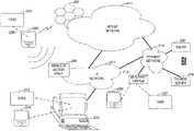
- FIG. 2shows network topology 200 that may include, for example, mobile device 202 (e.g., a mobile telephonic device, a PDA, an electronic tablet, a laptop, a GPS unit, or an MP3 player).
- Mobile device 202may, for example, include a contactless interface that may initiate, sustain, and/or terminate communication channel 226 between card 204 and mobile device 202 .
- Card 204 and mobile device 202may communicate via channel 226 via a contactless communication medium (e.g., an RF medium).
- a contactless communication mediume.g., an RF medium
- Mobile device 202may provide one or more transceivers that may communicate with one or more wired networks (e.g., IP network 212 and/or payment network 214 ) and/or one or more wireless networks (e.g., mobile network 210 ).
- Mobile device 202may, for example, communicate with a cellular station over a wireless radio interface (e.g., a GSM air interface) that may be used by mobile device 202 to communicate information (e.g., voice and data) to cellular network access infrastructure 206 (e.g., one or more GSM base transceiver stations, base station controllers, and mobile switching centers).
- cellular network access infrastructure 206may utilize any multiple access architecture, such as for example, a code-division multiple access architecture and/or a time-division multiple access architecture.
- Mobile device 202may, for example, communicate with wireless access point 208 over a wireless interface (e.g., a Bluetooth interface or a Wi-Fi interface). Accordingly, for example, mobile device 202 may access one or more wired networks (e.g., IP network 212 and/or payment network 214 ) and/or one or more wireless networks (e.g., mobile network 210 ) without the need to first gain access to cellular network access infrastructure 206 .
- a wireless interfacee.g., a Bluetooth interface or a Wi-Fi interface
- wired networkse.g., IP network 212 and/or payment network 214
- wireless networkse.g., mobile network 210
- Card 204may, for example, be a powered card or a non-powered card (e.g., a powered payment card or a non-powered payment card). Accordingly, for example, payment information (e.g., a payment account number and a card expiration date) may be communicated from card 204 to mobile device 202 in support of a financial transaction being conducted by mobile device 202 . In so doing, for example, items for purchase on IP network 212 (e.g., the internet) may be accessed by a browser of mobile device 202 via an access point (e.g., wireless access point 208 or cellular network access infrastructure 206 ). Mobile device 202 may, for example, complete a purchase transaction by first obtaining required payment information from card 204 and then communicating such payment information to network entities (e.g., payment server 216 and/or issuer 220 ).
- network entitiese.g., payment server 216 and/or issuer 220 .
- Payment server 216may, for example, contact issuer 220 via a network (e.g., payment network 214 ) with payment information received from mobile device 202 for authorization of a purchase. Once authorized, payment transaction information may be recorded onto a receipt that may be delivered to mobile device 202 via any one or more delivery options (e.g., via a short messaging service of mobile network 210 or an email delivery service of IP network 212 ). Mobile device 202 may allow a user to associate purchase categories (e.g., groceries, auto repair, or entertainment) to purchases transacted by the mobile device so that the user may receive a more detailed accounting of his or her expenditures on his or her receipt.
- purchase categoriese.g., groceries, auto repair, or entertainment
- a payment receiptmay, for example, be provided to mobile device 202 as a proof-of-purchase object (e.g., a barcode) that may be provided to a display of mobile device 202 and read by other computing equipment (e.g., a barcode scanner) for proof-of-purchase confirmation.
- a proof-of-purchase objecte.g., a barcode
- other computing equipmente.g., a barcode scanner
- a devicemay, for example, include a contactless communication device (e.g., an RFID device) that may initiate, sustain, and/or terminate a contactless communication channel (e.g., an RFID communications channel) with merchant terminal 218 .
- a contactless communication devicee.g., an RFID device
- card 222 and/or mobile device 228may communicate payment information to merchant terminal 218 to complete a financial transaction.
- mobile device 228 and/or card 222may first receive a request from a user to communicate payment information to merchant terminal 218 .
- a user of card 222may press a button on card 222 that may cause payment information to be transferred to a memory of a processor (e.g., an RFID chip).
- An associated RFID antennamay, for example, sense the presence of merchant terminal 218 by detecting an RF carrier field that may be generated by an RFID device of merchant terminal 218 . Once the presence of merchant terminal 218 is sensed, payment information may be transferred from an RFID chip of card 222 to an RFID antenna of card 222 to communicate the payment information via an RFID communication channel to merchant terminal 218 to complete a financial transaction.
- card 222may be a non-powered card (e.g., a non-powered payment card). Accordingly, for example, card 222 may include an RFID chip and associated RFID antenna that may be brought within proximity to merchant terminal 218 . An RFID antenna of card 222 may sense an RF carrier field generated by merchant terminal 218 and may derive operational power from the RF carrier field. The operational power may, for example, be collected by an RFID antenna of card 222 and provided to an associated RFID chip of card 222 in order to energize the RFID chip of card 222 . Once energized, an RFID chip of card 222 may modulate an RF carrier field generated by merchant terminal 218 to, for example, communicate payment information from card 222 to merchant terminal 218 to complete a purchase transaction.
- a non-powered carde.g., a non-powered payment card.
- card 222may include an RFID chip and associated RFID antenna that may be brought within proximity to merchant terminal 218 .
- An RFID antenna of card 222may sense an RF carrier field generated by merchant terminal 218 and
- Any computing devicemay, for example, provide contactless communication electronics (e.g., an RFID reader) that may communicate with a contactless communication device (e.g., card 232 and/or mobile device 234 ).
- a contactless communication devicee.g., card 232 and/or mobile device 234
- any information that may be communicated by card 232e.g., payment information
- computing device 230e.g., received via an RFID communication channel established between card 232 and computing device 230
- a network entitye.g., issuer 220 and/or payment server 216
- any RFID informationmay be exchanged between computing device 230 and an RFID enabled device (e.g., card 232 and/or mobile device 234 ).
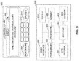
- FIG. 3shows mobile device 300 .
- Mobile device 300may be any mobile device, such as a mobile telephonic device (e.g., cell phone), a PDA, an electronic tablet, an MP3 player, or a locating device (e.g., a GPS device). Accordingly, mobile device 300 may be operated in a mobile environment while a user of mobile device 300 goes about his or her daily activities (e.g., driving, shopping, walking, dining, and exercising). In addition, for example, mobile device 300 may perform multiple functions simultaneously (e.g., a person may carry on a conversation while at the same time browsing and purchasing products on the Internet).
- Mobile device 300may include audio processing devices (e.g., microphone 308 and speaker 310 ). Accordingly, for example, mobile device 300 may receive voice commands from a user via microphone 308 and may process such commands to perform a function. For example, a user may place mobile device 300 into a desired operational mode by speaking a command into microphone 308 that is associated with the desired operational mode. In so doing, for example, mobile device 300 may engage in hands-free operation by receiving voice commands via microphone 308 and performing functions associated with the received voice commands.
- audio processing devicese.g., microphone 308 and speaker 310 . Accordingly, for example, mobile device 300 may receive voice commands from a user via microphone 308 and may process such commands to perform a function. For example, a user may place mobile device 300 into a desired operational mode by speaking a command into microphone 308 that is associated with the desired operational mode. In so doing, for example, mobile device 300 may engage in hands-free operation by receiving voice commands via microphone 308 and performing functions associated with the received voice commands.
- Mobile device 300may receive data input via microphone 308 .
- a voice-band modemmay generate signals in a voice-band frequency range that may be received by microphone 308 .
- a processor of mobile device 300may interpret the received audible information as data signals and may process the data signals as, for example, data values and/or control data input.
- Mobile device 300may include camera 302 .
- Camera 302may capture one or more frames of video data and store the video data within a memory of mobile device 300 .
- a processor of mobile device 300may receive one or more frames of video information via camera 302 and may process the video information as data values and/or control data input.
- mobile device 300may receive optical information that is sensed by camera 302 during a series of one or more video capture events that produce one or more frames of video information.
- the one or more frames of video informationmay contain one or more data elements (e.g., pixels) having properties (e.g., color, intensity, or contrast) that may be interpreted by a processor of mobile device 300 as data values and/or control data.
- Mobile device 300may include manual input interface 312 .
- Manual input interface 312may, for example, include keys and/or buttons that may be sensitive to manual input, such as a touch or an application of pressure. Accordingly, for example, a user of mobile device 300 may enter information into mobile device 300 via manual interface 312 to cause a processor of mobile device 300 to enter a particular mode of operation.
- Manual interface 312may, for example, be used for data entry (e.g., dialing a phone number or entering data as may be requested by mobile device 300 ) during a particular mode of operation of mobile device 300 .
- Mobile device 300may include display 304 .
- Display 304may provide visible information that may be utilized by a user during interaction with mobile device 300 .
- a portion or all of display 304may be touch sensitive such that objects making contact with display 304 or objects coming within a proximity of display 304 may be detected by a processor of mobile device 300 .
- RFID operations graphical user interface 306may be provided by display 304 so that graphical information may be displayed to solicit and/or receive data entry from a user.
- touch-sensitive graphical user interface devicessuch as radio buttons, textual input boxes, virtual buttons, pull-down menus, and navigational tools may be used for data entry to initiate, change, and/or support functions performed by mobile device 300 .
- FIG. 3shows architecture 350 .
- User interface 352may, for example, be included within architecture 350 to allow user interaction with architecture 350 .
- a dedicated key pad or keyboardmay be included within user interface 352 to allow alphanumeric data entry into architecture 350 .
- Display 354may, for example, be touch-sensitive. Accordingly, for example, display 354 may be utilized for alphanumeric data entry using virtual buttons that may be rendered onto touch-sensitive portions of display 354 . In so doing, for example, touching virtual buttons that may be associated with alphabetic and numeric characters of display 354 may be detected by processor 358 as alphanumeric data entry.
- Alphanumeric entry boxesmay, for example, be rendered onto display 354 .
- a usermay, for example, activate a cursor within such an alphanumeric entry box by touching an area within the alphanumeric entry box.
- a usermay utilize user interface 352 and/or a virtual keypad rendered onto display 354 to select alphanumeric characters to be placed within the alphanumeric entry box in accordance with a character position identified by an activated cursor within the alphanumeric entry box.
- processor 358may receive alphanumeric characters as typed into a alphanumeric entry box of display 354 and may use such alphanumeric characters as data input.
- Display 354may, for example, provide data output from architecture 350 .
- display 354may communicate data using a series of light pulses.
- processor 358may cause one or more portions of display 354 to produce light pulses having varying characteristics (e.g., duration, intensity, and frequency) that may communicate information via such light pulses.
- a device that may be sensitive to light pulsesmay receive information communicated by display 354 via light pulses having varying characteristics.
- Display 354may, for example, communicate data using visual information that may be substantially static (e.g., a barcode).
- Transceiver 356may communicate information to and/or may receive information from one or more devices. Transceiver 356 may, for example, communicate via a wireless interface with one or more cellular stations of a mobile network. Accordingly, for example, transceiver 356 may allow a mobile device (e.g., mobile device 300 of FIG. 3 ) to establish a communications channel with an associated cellular station. In so doing, for example, a mobile device (e.g., mobile device 300 of FIG. 3 ) may exchange information (e.g., voice, text, data, or multimedia) with one or more terrestrial networks (e.g., the internet or a payment network) via an associated cellular station. As per another example, transceiver 356 may exchange information with one or more other mobile devices via one or more associated cellular stations.
- a mobile devicee.g., mobile device 300 of FIG. 3
- informatione.g., voice, text, data, or multimedia
- terrestrial networkse.g., the internet or a payment network
- Transceiver 356may, for example, communicate via a wireless interface with one or more mobile devices directly. Accordingly, for example, transceiver 356 may communicate with another mobile device without first accessing a mobile network via a cellular station of the mobile network. As per another example, transceiver 356 may, for example, communicate via a wireless interface with one or more network devices (e.g., a wireless access point) directly. Accordingly, for example, a mobile device (e.g., mobile device 300 of FIG. 3 ) may directly connect to a wired and/or a wireless network via any one or more wireless standards (e.g., Bluetooth or Wi-Fi) to exchange information with other devices that may be connected to the wired and/or wireless network. In so doing, for example, a wired and/or wireless network may be accessed by a mobile device without first accessing a mobile network via a cellular station of a mobile network.
- wireless standardse.g., Bluetooth or Wi-Fi
- Architecture 350may include RFID chip 364 , RFID antenna 362 , and optional RFID antenna 366 which may combine to communicate with an RFID enabled device via an RFID communication channel. Accordingly, for example, architecture 350 may be compatible with any RFID device, such as for example, an RFID enabled card, an RFID reader, and an RFID enabled computing device (e.g., an RFID enabled desktop computer). RFID antenna 366 may, for example, be provided to enhance RFID data communication and/or reception.
- RFID antenna 362 and/or RFID antenna 366may, for example, establish an RF carrier field that may be modulated by an RFID device (e.g., an RFID tag of a non-powered payment card).
- an RFID tag of a non-powered payment cardmay derive operational power from an RF field provided by RFID antenna 362 and/or RFID antenna 366 and may communicate information (e.g., one, two, and/or three tracks of magnetic stripe data) to RFID antenna 362 and/or RFID antenna 366 by modulating the RF field produced by RFID antenna 362 and/or RFID antenna 366 .
- a powered cardmay, for example, communicate with RFID antenna 362 and/or RFID antenna 366 .
- a powered cardmay, for example, include a processor, a battery, a memory, a wireless communications device (e.g., a powered RFID device) and other electronics (e.g., buttons) that may allow a user to interact with the powered card to perform one or more functions. Accordingly, for example, a powered card may be used to communicate specific information to RFID antenna 362 and/or RFID antenna 366 by selective interaction with the buttons of the powered card.
- a powered cardmay be used to interactively communicate magnetic stripe information (e.g., one, two, and/or three tracks of magnetic stripe data) to RFID antenna 362 and/or RFID antenna 366 by sending a signal to a processor of a powered card (e.g., by pressing a button on the powered card) to initiate such communications.
- magnetic stripe informatione.g., one, two, and/or three tracks of magnetic stripe data
- RFID antenna 362 and/or RFID antenna 366by sending a signal to a processor of a powered card (e.g., by pressing a button on the powered card) to initiate such communications.
- RFID chip 364may, for example, receive RFID data from processor 358 and may store such RFID data temporarily. Accordingly, for example, once an RFID communication channel is formed with an RFID enabled device, RFID data contained within RFID chip 364 may be communicated to the RFID enabled device via RFID antenna 362 and/or RFID antenna 366 .
- RFID antennas 362 and 366may, for example, communicate the same RFID data to an RFID enabled device.
- RFID antennas 362 and 366may, for example, communicate different RFID data sets to an RFID enabled device and the differences between the RFID data sets communicated may provide multiple other channels of data that may be communicated (e.g., an amplitude difference between RFID data sets may be an RFID data channel and a phase difference between RFID data sets may be an additional RFID data channel).
- Architecture 350may include memory 360 and/or processor 358 may include internal memory. Accordingly, for example, application code may be stored within memory 360 and/or processor 358 and executed by processor 358 in support of functions performed by architecture 350 . For example, an application (e.g., a graphical user interface) may be executed by processor 358 and displayed onto display 354 , which may be used to interact with a user of a mobile device (e.g., mobile device 300 of FIG. 3 ). Persons skilled in the art will appreciate that executable application code may be communicated to architecture 350 via any one or more interfaces of architecture 350 (e.g., user interface 352 , display 354 , transceiver 356 , and/or RFID antennas 362 and/or 366 ).
- interfaces of architecture 350e.g., user interface 352 , display 354 , transceiver 356 , and/or RFID antennas 362 and/or 366 .
- Application datamay be temporarily stored within RFID chip 364 and communicated by RFID antenna 362 and/or RFID antenna 366 during operation.
- payment datamay be temporarily communicated to RFID chip 364 by processor 358 during a financial transaction being conducted via an RFID communication channel between a mobile device (e.g., mobile device 300 of FIG. 3 ) and another RFID device (e.g., a merchant terminal).
- processor 358may cause the payment data stored within RFID chip 364 to be erased so as to reduce an ability of an RFID skimmer to access data from RFID chip 364 .
- FIG. 4shows card 400 , which may be a powered card and may include, for example, board 402 , board 404 , dynamic magnetic communications device 406 , RFID chip 418 , board 408 , battery 414 , conductive leads 420 - 426 and RFID antenna 416 .
- Additional circuitrymay be provided on board 402 , which may include, for example, processor 430 , an EMV chip, a display, a display driver, driver circuitry for dynamic magnetic stripe communications device 406 , light emitting diodes, light sensors, infrared sensors and transmitters, capacitive sensing contacts, and a user interface (e.g., one or more buttons).
- All boards, circuitry, and other components of card 400may be laminated to form card assembly 410 .
- a laminationmay, for example, be implemented using a series of lamination process steps, such that an electronics package containing boards 402 , 404 , and/or 408 and associated electronics may be encapsulated by an injection molding process (e.g., a reaction injection molding process), whereby a silicon-based material or a polyurethane-based material may be injected and cured (e.g., using temperature and/or chemical reaction) to form the electronics package.
- the electronics packagemay then be sandwiched between layers of laminate (e.g., layers of polymer laminate).
- both surfaces of card assembly 410may be formed by a layer of laminate such that no electrical contacts exist on either surface of card assembly 410 .
- a surface of card assembly 410may be formed by a layer of laminate such that electrical contacts may exist on a surface of card assembly 410 to provide connectivity from a surface of card assembly 410 to a processor (e.g., an EMV chip) of card 400 .
- RFID antenna 416may, for example, be formed using an additive technique, whereby patterns of a conductive element (e.g., copper) may be applied to a PCB substrate (e.g., applied to either side of board 408 ) according to a patterning mask definition layer.
- RFID antenna 416may, for example, be formed using a subtractive technique whereby patterns of a conductive element (e.g., copper) may be removed from a pre-plated PCB substrate (e.g., removed from either side of board 408 ) according to an etching mask definition layer.
- Other non-PCB fabrication techniquesmay be used to implement RFID antenna 416 as may be required by a particular application.
- Conductive leads 420 and 422may, for example, provide electrical conductivity between board 408 and board 402 . Accordingly, for example, RFID data signals received by RFID antenna 416 may be communicated to RFID chip 418 via conductive leads 420 and 422 . RFID data signals to be communicated by RFID antenna 416 (e.g., RFID data signals provided to RFID chip 418 via processor 430 ) may, for example, be received from RFID chip 418 via conductive leads 420 and 422 .
- Conductive leads 424 and 426may, for example, provide electrical conductivity between board 408 and board 402 so that operational power may be provided to the active electrical components that may exist on board 402 from battery 414 .
- Conductive leads 420 - 426may use conductive adhesive, soldering paste, or any other type of conductive applications to provide electrical conductivity between boards 408 and 402 .
- FIG. 5shows card 500 , which may be a powered card and may include, for example, board 502 , board 504 , dynamic magnetic communications device 506 , RFID chip 518 , board 508 , battery 514 , conductive leads 520 - 526 and RFID antenna 516 .
- Additional circuitrymay be provided on board 502 , which may include, for example, processor 530 , an EMV chip, a display, a display driver, driver circuitry for dynamic magnetic stripe communications device 506 , light emitting diodes, light sensors, infrared sensors and transmitters, capacitive sensing contacts, and a user interface (e.g., one or more buttons).
- All boards, circuitry, and other components of card 500may, for example, be encapsulated by an injection molding process and sandwiched between two layers of laminate to form card assembly 510 having no exposed contacts.
- a surface of card assembly 510may be formed by a layer of laminate such that electrical contacts may exist on a surface of card assembly 510 to provide connectivity from a surface of card assembly 510 to a processor (e.g., an EMV chip) of card 500 .
- RFID antenna 516may, for example, be formed using additive and/or subtractive techniques to define patterns of a conductive element (e.g., copper) to form RFID antenna 516 (e.g., on either side of board 504 ).
- Conductive leads 520 and 522may, for example, provide electrical conductivity between board 504 and board 502 . Accordingly, for example, RFID data signals received by RFID antenna 516 may be communicated to RFID chip 518 via conductive leads 520 and 522 .
- RFID data signals to be communicated by RFID antenna 516(e.g., as may be provided to RFID chip 518 by processor 530 ) may be received from RFID chip 518 via conductive leads 520 and 522 .
- Conductive leads 524 and 526may, for example, provide electrical conductivity between board 508 and board 502 so that operational power may be provided to the active electrical components that may exist on board 502 from battery 514 .
- FIG. 6shows card 600 , which may be a powered card and may include, for example, board 602 , board 604 , dynamic magnetic communications device 606 , RFID chip 618 , board 608 , battery 614 , conductive leads 622 - 626 and RFID antenna 616 .
- Additional circuitrymay be provided on board 602 , which may include, for example, processor 630 , an EMV chip, a display, a display driver, driver circuitry for dynamic magnetic stripe communications device 606 , light emitting diodes, light sensors, infrared sensors and transmitters, capacitive sensing contacts, and a user interface (e.g., one or more buttons).
- All boards, circuitry, and other components of card 600may, for example, be encapsulated by an injection molding process and sandwiched between two layers of laminate to form card assembly 610 having no exposed contacts.
- a surface of card assembly 610may be formed by a layer of laminate such that electrical contacts may exist on a surface of card assembly 610 to provide connectivity from a surface of card assembly 610 to a processor (e.g., an EMV chip) of card 600 .
- RFID antenna 616may, for example, be formed using additive and/or subtractive techniques to define patterns of a conductive element (e.g., copper) to form RFID antenna 616 (e.g., on either side of board 604 ).
- One or more conductive leads 622may, for example, provide electrical conductivity between RFID chip 618 of board 604 and processor 630 of board 602 . Accordingly, for example, while data exchanged between RFID chip 618 and RFID antenna 616 may remain on board 604 , one or more conduction paths 622 may be provided so that data that is to be communicated by RFID antenna 616 may first be communicated to RFID chip 618 by processor 630 that may exist, for example, on board 602 .
- Conductive leads 624 and 626may, for example, provide electrical conductivity between board 608 and board 602 so that operational power may be provided to the active electrical components that may exist on boards 602 and 604 from battery 614 .
- FIG. 7shows card 700 , which may be a powered card and may include, for example, board 702 , board 704 , dynamic magnetic communications device 706 , RFID chip 718 , board 708 , battery 714 , conductive leads 724 - 726 and RFID antenna 716 .
- Additional circuitrymay be provided on board 702 , which may include, for example, processor 730 , an EMV chip, a display, a display driver, driver circuitry for dynamic magnetic stripe communications device 706 , light emitting diodes, light sensors, infrared sensors and transmitters, capacitive sensing contacts, and a user interface (e.g., one or more buttons).
- All boards, circuitry, and other components of card 700may, for example, be encapsulated by an injection molding process and sandwiched between two layers of laminate to form card assembly 710 having no exposed contacts.
- a surface of card assembly 710may be formed by a layer of laminate such that electrical contacts may exist on a surface of card assembly 710 to provide connectivity from a surface of card assembly 710 to a processor (e.g., an EMV chip) of card 700 .
- RFID antenna 716may, for example, be formed using additive and/or subtractive techniques to define patterns of a conductive element (e.g., copper) to form RFID antenna 716 (e.g., on a top side of board 702 ). Accordingly, for example, RFID antenna 716 may be applied to board 702 at a location proximate to a location of board 704 . In so doing, for example, RFID antenna 716 may be applied to board 702 below a location where board 704 attaches to board 702 and conduction paths may be extended to RFID chip 718 from RFID antenna 716 (e.g., via conductive traces on board 702 ).
- a conductive elemente.g., copper
- Conductive leads 724 and 726may, for example, provide electrical conductivity between board 708 and board 702 so that operational power may be provided to the active electrical components that may exist on board 702 from battery 714 .
- RFID antenna 716may be placed anywhere on any board (e.g., around a perimeter of board 702 ) so as to maximize an effectiveness of RFID antenna 716 .
- processorsEMV chips, display drivers, dynamic magnetic stripe communications device drivers, RFID chips, and associated circuitry may be combined into one or more application specific integrated circuits (ASIC).
- ASICapplication specific integrated circuits
- a core processormay interoperate with an ASIC that combines the functionalities of an RFID chip, a dynamic magnetic stripe communications device driver, and a display driver.
- a core processor, RFID chip, a dynamic magnetic stripe communications device driver, a display driver and associated electronicsmay be consolidated into a single ASIC.
- a core processor and an RFID chipmay be provided as discrete components that may interoperate with an ASIC that may be dedicated to dynamic magnetic stripe communications device driver functions and another ASIC that may be dedicated to display driver functions.
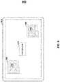
- FIG. 8shows card 800 , which may include multiple RFID antennas (e.g., RFID antennas 802 - 804 ) and associated RFID chips (e.g., RFID chips 806 - 808 ). Additional circuitry may be provided on card 800 , which may include, for example, a processor, an EMV chip, a display, a display driver, driver circuitry for a dynamic magnetic stripe communications device, light emitting diodes, light sensors, infrared sensors and transmitters, capacitive sensing contacts, and a user interface (e.g., one or more buttons). All boards, circuitry, and other components of card 800 may, for example, be encapsulated by an injection molding process and sandwiched between two layers of laminate to form card assembly 812 having no exposed contacts.
- All boards, circuitry, and other components of card 800may, for example, be encapsulated by an injection molding process and sandwiched between two layers of laminate to form card assembly 812 having no exposed contacts.
- a surface of card assembly 812may be formed by a layer of laminate such that electrical contacts may exist on a surface of card assembly 812 to provide connectivity from a surface of card assembly 812 to a processor (e.g., an EMV chip) of card 800 .
- a processore.g., an EMV chip
- Processor 810may, for example, provide data to RFID chips 806 and/or 808 that may be communicated by RFID antenna 802 and/or RFID antenna 804 , respectively.
- Processor 810may, for example, receive data from RFID chips 806 and/or 808 that may be received by RFID antenna 802 and/or RFID antenna 804 , respectively.
- Card 800may, for example, be placed within a communication distance of one or more RFID devices (e.g., one or more RFID enabled merchant terminals) in order to conduct a purchase transaction. Accordingly, for example, processor 810 may communicate track 1 and track 2 magnetic stripe data to the RFID enabled merchant terminal via RFID chip 806 and associated RFID antenna 802 . Alternately, for example, processor 810 may communicate track 1 and track 2 magnetic stripe data to the RFID enabled merchant terminal via RFID chip 808 and associated RFID antenna 804 .
- RFID devicese.g., one or more RFID enabled merchant terminals
- processor 810may utilize both RFID antennas 802 and 804 and associated RFID chips 806 and 808 , respectively, to increase communication efficiency. Accordingly, for example, processor 810 may communicate track 1 magnetic stripe data to RFID chip 806 and track 2 magnetic stripe data to RFID chip 808 , so that track 1 magnetic stripe data may be communicated to an RFID enabled merchant terminal via RFID antenna 802 and track 2 magnetic stripe data may be communicated to an RFID enabled merchant terminal via RFID antenna 804 . In so doing, for example, two tracks of magnetic stripe data may be communicated in half the time.
- RFID data communicated to RFID chips 806 and 808 by processor 810may be communicated in a fashion such that multiple channels of information may be communicated in addition to the first and second channels of information communicated by RFID chips 806 and 808 .
- phase, frequency, and/or amplitude differences between data communicated by RFID chip 806 /RFID antenna 802 and data communicated by RFID chip 808 /RFID antenna 804may be used to communicate multiple channels of information.
- a first set of informationmay be communicated by RFID chip 806 /RFID antenna 802
- a second set of informationmay be communicated by RFID chip 808 /RFID antenna 804
- a third set of informationmay be communicated as an amplitude difference between each data element of the first and second information sets.
- a fourth set of informationmay be communicated, for example, as a phase difference between each data element of the first and second data sets.
- a fifth set of informationmay be communicated, for example, as a rate of change of the phase difference (e.g., frequency difference) between each data element of the first and second information sets.
- any number of channels of informationmay be communicated by a pair of RFID communicators when differences between RFID data sets communicated by each RFID communicator are exploited as data channels.
- a pair of RFID communicatorsmay, for example, be used to increase accuracy of RFID data communicated.
- the same RFID datamay be communicated by RFID chip 806 /RFID antenna 802 as is communicated by RFID chip 808 /RFID antenna 804 so as to increase a probability that an RFID reader may receive RFID data that was intended to be communicated.
- an RFID readerthat may be spatially oriented such that data reception quality from a first RFID communicator is diminished in relation to a data reception quality from a second RFID communicator, may nevertheless receive a complete set of RFID data due to the redundant RFID communication configuration.
- An RFID readermay, for example, employ collision avoidance algorithms, so that communications received from a first RFID communicator do not trump communications received from a second RFID communicator. Accordingly, for example, processor 810 of card 800 may communicate to such an RFID reader that dual RFID communicators may be present within card 800 . In so doing, for example, the RFID reader may activate its collision avoidance algorithm to accept RFID communications from both RFID communicators (e.g., RFID chip 806 /RFID antenna 802 and RFID chip 808 /RFID antenna 804 ) simultaneously.
- RFID communicatorse.g., RFID chip 806 /RFID antenna 802 and RFID chip 808 /RFID antenna 804
- RFID datamay, for example, be received by RFID chip 806 /RFID antenna 802 and RFID chip 808 /RFID antenna 804 .
- card 800may be an RFID reader that may utilize a pair of RFID readers (e.g., a first RFID reader is provided by RFID chip 806 /RFID antenna 802 and a second RFID reader is provided by RFID chip 808 /RFID antenna 804 ).
- processor 810may impose an RFID communication protocol that accepts RFID data form each RFID reader simultaneously.
- FIG. 9shows card 900 that may include, for example, configuration 902 .
- Configuration 902may include, for example, button 904 , button 908 , display 906 and display 910 .
- Button 904may be associated with display 906 .
- Button 904may be pressed to utilize the option described by display 906 .
- Button 908may be associated with display 910 .
- Button 908may be pressed to utilize the option described by display 910 .
- a cardmay include additional buttons or displays or may not include the number of buttons or displays of card 900 .
- a cardmay include only a single button (e.g., button 904 ).
- a user of card 900may, for example, select options 906 or 910 when card 900 is to be used (e.g., when card 900 is to be utilized at a point-of-sale terminal to complete a purchase transaction). Accordingly, for example, a user of card 900 may press button 904 to select option 906 if the user wishes to exchange RFID data between card 900 and an RFID device. Alternately, for example, a user of card 900 may press button 908 to select option 910 if the user wishes to communication information to a magnetic stripe reader.
- a usermay, for example, press button 908 to prepare card 900 for communications with a magnetic stripe reader.
- a processor of card 900may initiate a mode of operation upon activation of option 910 , whereby the processor searches for the presence of a read-head housing of a magnetic stripe reader.
- option 910Once option 910 is activated, a user may bring card 900 within a communication distance of a magnetic stripe reader (e.g., the user may swipe card 900 through a magnetic stripe reader).
- the processormay communicate one, two, and/or three tracks of magnetic stripe data to a read-head of the detected magnetic stripe reader via dynamic magnetic stripe communications device 914 .
- a usermay press button 904 to prepare card 900 for communication with an RFID device.
- a processor of card 900may initiate a mode of operation upon activation of option 906 , whereby a processor of card 900 provides magnetic stripe information (e.g., one, two, and/or three tracks of magnetic stripe data) to an RFID chip of card 900 .
- a usermay bring card 900 within a communication distance of an RFID reader (e.g., the user may wave card 900 within an RFID communication distance of an RFID reader) and an RFID communication sequence between card 900 and an RFID reader may be completed where RFID data may be provided to RFID antenna 912 from an RFID chip on card 900 and communicated from RFID antenna 912 to the RFID reader.
- a processor of card 900may activate passive RFID communications or active RFID communications using RFID antenna 912 and an associated RFID chip. Passive RFID communications, for example, may require little or no energy to be expended by card 900 . Instead, RFID antenna 912 may collect energy from an RFID reader when a user of card 900 brings card 900 within a communication distance of the RFID reader. The energy collected by RFID antenna 912 may, for example, provide power to an RFID chip of card 900 . In so doing, for example, an RFID chip of card 900 may communicate with a processor of card 900 , so that the processor may populate a memory of the RFID chip with information (e.g., payment information) that may be needed to complete a transaction (e.g., a purchase transaction). Once populated with information, the RFID chip of card 900 may communicate the information to RFID antenna 912 , which may then communicate the information to the RFID reader.
- informatione.g., payment information
- Active RFID communications from card 900may, for example, utilize battery power from within card 900 . Accordingly, for example, once card 900 is brought within a communication distance of an RFID reader, RFID antenna 912 may detect the RFID reader and may wake an RFID chip from a low-power state. In so doing, for example, an RFID antenna 912 may detect energy from an RFID reader and an RFID chip of card 900 may utilize battery power of card 900 to receive information from a processor of card 900 and to provide the received information to RFID antenna 912 for subsequent communication to an RFID reader.
- Card 900may, for example, operate as an RFID reader, such that when brought within a communication distance of another RFID device, an RFID chip of card 900 may interrogate the RFID device to determine whether the RFID device is to receive information from card 900 (e.g., the RFID device is operating as an RFID reader) or whether the RFID device is to communicate information to card 900 (e.g., the RFID device is operating as an RFID tag). Accordingly, for example, an RFID chip of card 900 may interrogate the RFID device to determine that the RFID device is an RFID tag an that RFID data may be communicated from the RFID device to an RFID chip of card 900 .
- an RFID chip of card 900may receive information, such as executable machine code, payment information, or any other type of information that may be required by card 900 to operate as intended and may forward such information to a processor of card 900 to be stored within a memory of card 900 .
- an RFID chip of card 900may receive personalization information (e.g., cardholder information and cardholder account information) to prepare card 900 for use as a payment card.
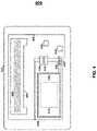
- FIG. 10shows system 1000 , which may include card 1002 and one or more RFID devices (e.g., mobile devices 1004 and 1006 ).
- Card 1002may, for example, communicate with multiple RFID devices simultaneously.
- a user of card 1002may, for example, enable RFID communications with card 1002 by pressing one of buttons 1012 or 1014 .
- payment informatione.g., payment account number and cardholder name
- Data indicative of which button was pushede.g., discretionary data indicative of either credit button 1012 or debit button 1014
- card 1002may provide two RFID communication devices that may detect an RF carrier field that may be generated by each of mobile devices 1004 and 1006 .
- Users of mobile devices 1004 and 1006may, for example, be husband and wife who may wish to store payment information associated with card 1002 on respective memory locations of mobile devices 1004 and 1004 so that such payment information may be used to complete purchase transactions using mobile devices 1004 and 1006 .
- a first RFID communication device of card 1002may establish RFID communication channel 1010 with an RFID reader of mobile device 1004 and a second RFID communication device of card 1002 may establish communication channel 1008 with an RFID reader of mobile device 1006 .
- the first and second RFID communication devices of card 1002may communicate payment information temporarily stored within an RFID chip of each respective RFID communication device of card 1002 .
- mobile devices 1004 and 1006may store payment information communicated via RFID communication channels 1010 and 1008 , respectively, within respective memory locations of mobile devices 1004 and 1006 .
- Mobile devices 1004 and 1006may later recall such payment information from their respective memory locations, communicate the stored payment information via channels 1016 and 1018 , respectively, of payment network 1020 , and complete payment transactions with network entity 1022 using payment information received from card 1002 .
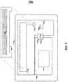
- FIG. 11shows system 1100 , which may include mobile device 1102 , a stationary device (e.g., desktop computer 1104 ), payment network 1106 , and network entity 1108 .
- An applicatione.g., RFID operations GUI 1112
- Such an RF devicemay, for example, include any device (e.g., desktop computer 1104 ) that may be RFID equipped.
- An RFID antenna and associated RFID chipmay, for example, exist within desktop computer 1104 such that when mobile device 1102 is brought within an RFID communication distance of desktop computer 1104 , an RFID antenna of mobile device 1102 may detect its presence, report the same to an RFID chip within mobile device 1102 , which may then be reported to a processor of mobile device 1102 and reported to a user of mobile device 1102 via GUI 1112 .
- GUI 1112may, for example, ask the user of mobile device 1102 whether he or she wishes to allow an RFID connection between mobile device 1102 and desktop computer 1104 .
- the usermay indicate his or her wish via radio buttons 1114 and may also indicate whether information (e.g., payment information) stored within a memory of mobile device 1102 is to be communicated to desktop computer 1104 via an RFID communication channel previously authorized by the user of mobile device 1102 (e.g., by selecting one of radio buttons 1116 ). If so, then such information may be communicated to desktop computer 1104 by mobile device 1102 and stored within a memory of desktop computer 1104 .
- informatione.g., payment information
- payment information communicated by mobile device 1102 to desktop computer 1104may subsequently be communicated by desktop computer 1104 via communication channel 1110 of payment network 1106 to complete a purchase transaction (e.g., an online purchase of items contained within a shopping cart generated by an internet browser of desktop computer 1104 ) via network entity 1108 .
- a purchase transactione.g., an online purchase of items contained within a shopping cart generated by an internet browser of desktop computer 1104
- network entity 1108e.g., an online purchase of items contained within a shopping cart generated by an internet browser of desktop computer 1104
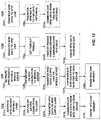
- Step 1211 of sequence 1210may, for example, include activating an RFID search within a card.
- a user interfacee.g., one or more buttons
- a user interfacee.g., one or more buttons
- an RFID devicemay be detected by the card and an RFID connection may be established between the card and the RFID device.
- RFID datamay, for example, be transferred to an RFID chip on the card (e.g., as in step 1213 ) and the RFID data contained within an RFID chip on the card may, for example, be communicated via an RFID antenna on the card to the RFID device (e.g., as in step 1214 ). Once RFID data is communicated, RFID data contained within an RFID chip on the card may be erased so as to reduce a likelihood of skimming RFID data from the RFID chip on the card.
- Step 1221 of sequence 1220may, for example, include activating an RFID search within a mobile device.
- a user interfacee.g., a GUI executing on a processor of the mobile device
- a communication feature on the mobile devicewhereby interfacing with the GUI may activate an RFID communication channel between a detected RFID device and the mobile device (e.g., as in step 1222 ).
- RFID datamay, for example, be transferred to an RFID chip on the mobile device and the RFID data contained within an RFID chip on the mobile device may, for example, be communicated via an RFID antenna on the mobile device to the RFID device (e.g., as in step 1224 ).
- RFID data contained within an RFID chip on the mobile devicemay be erased so as to reduce a likelihood of skimming RFID data from the RFID chip on the mobile device.
- Step 1231 of sequence 1230may, for example, include transferring RFID data from a core processor to an RFID chip on a card or a mobile device in preparation for communicating the RFID data via an RFID antenna on the card or the mobile device. If a timeout period that may be set in step 1232 expires before the RFID data is communicated by the card or mobile device (e.g., as in step 1233 ), then RFID data previously transferred to the RFID chip may be erased from the RFID chip by the core processor.
- Step 1241 of sequence 1240may, for example, include transferring RFID data from a core processor to an RFID chip on a card or a mobile device in preparation for communicating the RFID data via two RFID antennas on the card or the mobile device.
- the same datamay be transferred to both RFID antennas.
- different datamay be transferred each RFID antenna.
- both RFID antennasmay communicate data to an RFID reader.
- the same datamay be communicated by both RFID antennas so as to increase a reliability of data communication.
- different datamay be communicated by each RFID antenna in order to increase an efficiency of data communication.
- different datamay be communicated by each RFID antenna, where differences (e.g., phase, frequency, and/or amplitude) may be used to communicate multiple other data channels.
Landscapes
- Business, Economics & Management (AREA)
- Engineering & Computer Science (AREA)
- Physics & Mathematics (AREA)
- Accounting & Taxation (AREA)
- Theoretical Computer Science (AREA)
- General Physics & Mathematics (AREA)
- General Business, Economics & Management (AREA)
- Strategic Management (AREA)
- Computer Networks & Wireless Communication (AREA)
- Marketing (AREA)
- Finance (AREA)
- Economics (AREA)
- Tourism & Hospitality (AREA)
- Quality & Reliability (AREA)
- Operations Research (AREA)
- Human Resources & Organizations (AREA)
- Entrepreneurship & Innovation (AREA)
- Development Economics (AREA)
- Technology Law (AREA)
- Microelectronics & Electronic Packaging (AREA)
- Telephone Function (AREA)
Abstract
Description
Claims (20)
Priority Applications (2)
| Application Number | Priority Date | Filing Date | Title |
|---|---|---|---|
| US13/468,625US11392860B2 (en) | 2011-05-10 | 2012-05-10 | Systems and methods for contactless communication mechanisms for cards and mobile devices |
| US17/837,791US20220327435A1 (en) | 2011-05-10 | 2022-06-10 | Systems and methods for contactless communication mechanisms for cards and mobile devices |
Applications Claiming Priority (5)
| Application Number | Priority Date | Filing Date | Title |
|---|---|---|---|
| US201161585566P | 2011-05-10 | 2011-05-10 | |
| US201161484576P | 2011-05-10 | 2011-05-10 | |
| US201161484547P | 2011-05-10 | 2011-05-10 | |
| US201161484588P | 2011-05-10 | 2011-05-10 | |
| US13/468,625US11392860B2 (en) | 2011-05-10 | 2012-05-10 | Systems and methods for contactless communication mechanisms for cards and mobile devices |
Related Child Applications (1)
| Application Number | Title | Priority Date | Filing Date |
|---|---|---|---|
| US17/837,791ContinuationUS20220327435A1 (en) | 2011-05-10 | 2022-06-10 | Systems and methods for contactless communication mechanisms for cards and mobile devices |
Publications (2)
| Publication Number | Publication Date |
|---|---|
| US20120286936A1 US20120286936A1 (en) | 2012-11-15 |
| US11392860B2true US11392860B2 (en) | 2022-07-19 |
Family
ID=82385742
Family Applications (1)
| Application Number | Title | Priority Date | Filing Date |
|---|---|---|---|
| US13/468,625Active2033-10-15US11392860B2 (en) | 2011-05-10 | 2012-05-10 | Systems and methods for contactless communication mechanisms for cards and mobile devices |
Country Status (1)
| Country | Link |
|---|---|
| US (1) | US11392860B2 (en) |
Cited By (1)
| Publication number | Priority date | Publication date | Assignee | Title |
|---|---|---|---|---|
| WO2023034642A1 (en) | 2021-09-06 | 2023-03-09 | Metaland Llc | Encapsulating a metal inlay with thermosetting resin and method for making a metal transaction card |
Families Citing this family (42)
| Publication number | Priority date | Publication date | Assignee | Title |
|---|---|---|---|---|
| US20090159682A1 (en) | 2007-12-24 | 2009-06-25 | Dynamics Inc. | Cards and devices with multi-function magnetic emulators and methods for using same |
| US8511574B1 (en) | 2009-08-17 | 2013-08-20 | Dynamics Inc. | Advanced loyalty applications for powered cards and devices |
| US8348172B1 (en) | 2010-03-02 | 2013-01-08 | Dynamics Inc. | Systems and methods for detection mechanisms for magnetic cards and devices |
| US9836680B1 (en) | 2011-03-03 | 2017-12-05 | Dynamics Inc. | Systems and methods for advanced communication mechanisms for magnetic cards and devices |
| EP3869443A1 (en) | 2011-05-10 | 2021-08-25 | Dynamics Inc. | Systems, devices, and methods for mobile payment acceptance, mobile authorizations, mobile wallets, and contactless communication mechanisms |
| US8628022B1 (en) | 2011-05-23 | 2014-01-14 | Dynamics Inc. | Systems and methods for sensor mechanisms for magnetic cards and devices |
| US11207794B1 (en) | 2011-09-20 | 2021-12-28 | Dynamics Inc. | Systems and methods for trimming powered cards and devices |
| US11551046B1 (en) | 2011-10-19 | 2023-01-10 | Dynamics Inc. | Stacked dynamic magnetic stripe commmunications device for magnetic cards and devices |
| US11409971B1 (en) | 2011-10-23 | 2022-08-09 | Dynamics Inc. | Programming and test modes for powered cards and devices |
| US9619741B1 (en) | 2011-11-21 | 2017-04-11 | Dynamics Inc. | Systems and methods for synchronization mechanisms for magnetic cards and devices |
| US9710745B1 (en) | 2012-02-09 | 2017-07-18 | Dynamics Inc. | Systems and methods for automated assembly of dynamic magnetic stripe communications devices |
| US11961147B1 (en) | 2012-04-15 | 2024-04-16 | K. Shane Cupp | Cards, devices, systems, and methods for financial management services |
| US11418483B1 (en) | 2012-04-19 | 2022-08-16 | Dynamics Inc. | Cards, devices, systems, and methods for zone-based network management |
| US9033218B1 (en) | 2012-05-15 | 2015-05-19 | Dynamics Inc. | Cards, devices, systems, methods and dynamic security codes |
| US12373820B1 (en) | 2012-08-27 | 2025-07-29 | Dynamics Inc. | Cards, devices, systems, and methods for a featured application management system |
| US12380474B1 (en) | 2012-08-30 | 2025-08-05 | Dynamics Inc. | Cards, devices, systems, and methods for a ratings management system |
| US11126997B1 (en) | 2012-10-02 | 2021-09-21 | Dynamics Inc. | Cards, devices, systems, and methods for a fulfillment system |
| US9092712B2 (en)* | 2012-11-02 | 2015-07-28 | Flextronics Ap, Llc | Embedded high frequency RFID |
| US9659246B1 (en) | 2012-11-05 | 2017-05-23 | Dynamics Inc. | Dynamic magnetic stripe communications device with beveled magnetic material for magnetic cards and devices |
| US9010644B1 (en) | 2012-11-30 | 2015-04-21 | Dynamics Inc. | Dynamic magnetic stripe communications device with stepped magnetic material for magnetic cards and devices |
| US10949627B2 (en) | 2012-12-20 | 2021-03-16 | Dynamics Inc. | Systems and methods for non-time smearing detection mechanisms for magnetic cards and devices |
| US9776071B2 (en) | 2013-05-09 | 2017-10-03 | Mattel, Inc. | Resonant coils for use with games and toys |
| US9053405B1 (en) | 2013-08-27 | 2015-06-09 | Flextronics Ap, Llc | Printed RFID circuit |
| US9560746B1 (en) | 2014-01-24 | 2017-01-31 | Multek Technologies, Ltd. | Stress relief for rigid components on flexible circuits |
| US10108891B1 (en) | 2014-03-21 | 2018-10-23 | Dynamics Inc. | Exchange coupled amorphous ribbons for electronic stripes |
| JP6151214B2 (en)* | 2014-04-28 | 2017-06-21 | 株式会社東芝 | Electronics |
| US10025963B2 (en)* | 2014-06-30 | 2018-07-17 | Symbol Technologies, Llc | System for, and method of, detecting the presence of a mobile communication device in proximity to an imaging reader and for automatically configuring the reader to read an electronic code displayed on the device upon such detection |
| US9679152B1 (en) | 2014-07-24 | 2017-06-13 | Wells Fargo Bank, N.A. | Augmented reality security access |
| US9477852B1 (en) | 2014-07-24 | 2016-10-25 | Wells Fargo Bank, N.A. | Augmented reality numberless transaction card |
| DE102014015275A1 (en)* | 2014-10-16 | 2016-04-21 | Giesecke & Devrient Gmbh | Data carrier with flat light source |
| US9965911B2 (en) | 2015-12-07 | 2018-05-08 | Capital One Services, Llc | Electronic access control system |
| CN105740939B (en)* | 2016-02-04 | 2019-06-11 | 中国计量学院 | An RFID tag integrated in PCBA |
| US10032049B2 (en) | 2016-02-23 | 2018-07-24 | Dynamics Inc. | Magnetic cards and devices for motorized readers |
| US9760773B1 (en)* | 2016-06-01 | 2017-09-12 | Wu-Hsu Lin | Smart card with a retina identifying module |
| US20180039876A1 (en)* | 2016-08-08 | 2018-02-08 | Ellipse World S.A. | Prepaid, Debit and Credit Card Security Code Generation System |
| US10235674B2 (en) | 2016-08-08 | 2019-03-19 | Ellipse World, Inc. | Method for a prepaid, debit and credit card security code generation system |
| US20180039986A1 (en)* | 2016-08-08 | 2018-02-08 | Ellipse World S.A. | Method for a Prepaid, Debit and Credit Card Security Code Generation System |
| US10032169B2 (en) | 2016-08-08 | 2018-07-24 | Ellipse World, Inc. | Prepaid, debit and credit card security code generation system |
| US10339530B1 (en) | 2019-02-21 | 2019-07-02 | Capital One Services, Llc | Touch authentication of multiple users or operating modes for a transaction card |
| US11416844B1 (en) | 2019-08-28 | 2022-08-16 | United Services Automobile Association (Usaa) | RFID-enabled payment authentication |
| JP7620407B2 (en)* | 2020-09-18 | 2025-01-23 | キヤノン株式会社 | Information processing device, information processing method, and program |
| US20230214628A1 (en)* | 2021-12-30 | 2023-07-06 | C2P Group Corp. | Four-cornered wireless information card |
Citations (73)
| Publication number | Priority date | Publication date | Assignee | Title |
|---|---|---|---|---|
| US5960344A (en)* | 1993-12-20 | 1999-09-28 | Norand Corporation | Local area network having multiple channel wireless access |
| US20050207624A1 (en)* | 2004-03-22 | 2005-09-22 | Ehlers Gerald L | Personal authentication device |
| US20060109119A1 (en)* | 2004-11-19 | 2006-05-25 | Jeremy Burr | RFID tag in a printed circuit board |
| US20070125866A1 (en)* | 2004-02-20 | 2007-06-07 | Hirotaka Nishizawa | Ic card and a method of manufacturing the same |
| US20070273519A1 (en)* | 2005-01-19 | 2007-11-29 | Brother Kogyo Kabushiki Kaisha | System For Managing Information Of A RFID Tag, Appratus For Communicating With A RFID Tag, Reader For Communicating With A RFID Tag, Cartridge For Including At Least A RFID Tag, And RFID Tag |
| US20080029607A1 (en) | 2005-05-09 | 2008-02-07 | Mullen Jeffrey D | Dynamic credit card with magnetic stripe and embedded encoder and methods for using the same to provide a copy-proof credit card |
| US20080035738A1 (en) | 2005-05-09 | 2008-02-14 | Mullen Jeffrey D | Dynamic credit card with magnetic stripe and embedded encoder and methods for using the same to provide a copy-proof credit card |
| US20080072423A1 (en)* | 2006-09-26 | 2008-03-27 | Advanced Microelectronic And Automation Technology Ltd. | Secure high frequency / ultra high frequency inlay, and method and apparatus for making the inlay |
| US20080074269A1 (en)* | 2006-09-21 | 2008-03-27 | Zih Corp. | Rfid system and associated antenna-coupler |
| US20080094220A1 (en)* | 2006-10-19 | 2008-04-24 | Joseph Foley | Methods and Systems for Improving RFID Security |
| US7432816B1 (en)* | 2005-10-13 | 2008-10-07 | Hewlett-Packard Development Company, L.P. | Printed circuit board with RFID antenna |
| US20080309463A1 (en)* | 2005-12-21 | 2008-12-18 | Koninklijke Philips Electronics, N.V. | Collaborating Rfid Devices |
| US20080308641A1 (en)* | 2007-04-10 | 2008-12-18 | Advanced Microelectronic And Automation Technology Ltd. | Smart card with switchable matching antenna |
| US20090159688A1 (en) | 2007-12-24 | 2009-06-25 | Dynamics Inc. | Payment cards and devices with displays, chips, rfids, magnetic emulators, magnetic decoders, and other components |
| US20100123583A1 (en)* | 2008-11-18 | 2010-05-20 | The Boeing Company | Rfid-based corrosion and moisture detection |
| US20100123561A1 (en)* | 2008-11-19 | 2010-05-20 | Samsung Electronics Co., Ltd. | Radio frequency identification apparatus with a plurality of radio frequency identification schemes |
| US20100207737A1 (en)* | 2007-10-12 | 2010-08-19 | Electronics And Telecommunications Research Institute | Tdma control method used by rfid reader via mobile phone base station and mobile rfid reader |
| US20100223479A1 (en)* | 2007-10-29 | 2010-09-02 | Bundesdruckerei Gmbh | Method for Protection of A Chip Card From Unauthorized Use, Chip Card and Chip Card Terminal |
| USD643063S1 (en) | 2010-07-09 | 2011-08-09 | Dynamics Inc. | Interactive electronic card with display |
| US20110284632A1 (en) | 2010-05-18 | 2011-11-24 | Mullen Jeffrey D | Systems and methods for cards and devices operable to communicate to touch sensitive displays |
| US8066191B1 (en) | 2009-04-06 | 2011-11-29 | Dynamics Inc. | Cards and assemblies with user interfaces |
| USD651237S1 (en) | 2010-07-09 | 2011-12-27 | Dynamics Inc. | Interactive electronic card with display |
| USD651238S1 (en) | 2010-07-09 | 2011-12-27 | Dynamics Inc. | Interactive electronic card with display |
| USD651644S1 (en) | 2010-07-09 | 2012-01-03 | Dynamics Inc. | Interactive electronic card with display |
| USD652076S1 (en) | 2010-07-09 | 2012-01-10 | Dynamics Inc. | Multiple button interactive electronic card with display |
| USD652075S1 (en) | 2010-07-02 | 2012-01-10 | Dynamics Inc. | Multiple button interactive electronic card |
| USD652450S1 (en) | 2010-07-09 | 2012-01-17 | Dynamics Inc. | Multiple button interactive electronic card |
| USD652448S1 (en) | 2010-07-02 | 2012-01-17 | Dynamics Inc. | Multiple button interactive electronic card |
| USD652449S1 (en) | 2010-07-02 | 2012-01-17 | Dynamics Inc. | Multiple button interactive electronic card |
| USD652867S1 (en) | 2010-07-02 | 2012-01-24 | Dynamics Inc. | Multiple button interactive electronic card |
| USD653288S1 (en) | 2010-07-09 | 2012-01-31 | Dynamics Inc. | Multiple button interactive electronic card |
| US20120028702A1 (en) | 2010-07-29 | 2012-02-02 | Mullen Jeffrey D | Payment cards, devices, systems, and methods for providing game actions with payment data |
| US20120037709A1 (en) | 2010-02-16 | 2012-02-16 | Cloutier Bruce S | Systems and methods for drive circuits for dynamic magnetic stripe communications devices |
| US20120197708A1 (en) | 2011-01-31 | 2012-08-02 | Mullen Jeffrey D | Systems and methods for social networking mechanisms for powered cards and devices |
| USD665022S1 (en) | 2010-07-09 | 2012-08-07 | Dynamics Inc. | Multiple button interactive electronic card with light source |
| USD665447S1 (en) | 2010-07-09 | 2012-08-14 | Dynamics Inc. | Multiple button interactive electronic card with light source and display |
| US20120209744A1 (en) | 2011-02-16 | 2012-08-16 | Mullen Jeffrey D | Systems and methods for information exchange mechanisms for powered cards and devices |
| USD666241S1 (en) | 2010-07-09 | 2012-08-28 | Dynamics Inc. | Multiple button interactive electronic card with light source |
| US20120218083A1 (en)* | 2008-03-06 | 2012-08-30 | Round Rock Research, Llc | Methods and apparatuses to secure data transmission in rfid systems |
| US20120254037A1 (en) | 2011-04-04 | 2012-10-04 | Mullen Jeffrey D | Cards, devices, systems, and methods for payment functionality selection |
| USD670759S1 (en) | 2010-07-02 | 2012-11-13 | Dynamics Inc. | Multiple button interactive electronic card with light sources |
| US20120286928A1 (en) | 2011-05-10 | 2012-11-15 | Mullen Jeffrey D | Systems and methods for mobile authorizations |
| US8322623B1 (en) | 2010-07-26 | 2012-12-04 | Dynamics Inc. | Systems and methods for advanced card printing |
| USD672389S1 (en) | 2010-07-02 | 2012-12-11 | Dynamics Inc. | Multiple button interactive electronic card with light sources |
| US8348172B1 (en) | 2010-03-02 | 2013-01-08 | Dynamics Inc. | Systems and methods for detection mechanisms for magnetic cards and devices |
| USD674013S1 (en) | 2010-07-02 | 2013-01-08 | Dynamics Inc. | Multiple button interactive electronic card with light sources |
| US8390456B2 (en)* | 2008-12-03 | 2013-03-05 | Tego Inc. | RFID tag facility with access to external devices |
| US8393546B1 (en) | 2009-10-25 | 2013-03-12 | Dynamics Inc. | Games, prizes, and entertainment for powered cards and devices |
| US8393545B1 (en) | 2009-06-23 | 2013-03-12 | Dynamics Inc. | Cards deployed with inactivated products for activation |
| US8485446B1 (en) | 2011-03-28 | 2013-07-16 | Dynamics Inc. | Shielded magnetic stripe for magnetic cards and devices |
| USD687094S1 (en) | 2010-07-02 | 2013-07-30 | Dynamics Inc. | Multiple button interactive electronic card with light sources |
| US8511574B1 (en) | 2009-08-17 | 2013-08-20 | Dynamics Inc. | Advanced loyalty applications for powered cards and devices |
| US8523059B1 (en) | 2009-10-20 | 2013-09-03 | Dynamics Inc. | Advanced payment options for powered cards and devices |
| US8561894B1 (en) | 2010-10-20 | 2013-10-22 | Dynamics Inc. | Powered cards and devices designed, programmed, and deployed from a kiosk |
| US8567679B1 (en) | 2011-01-23 | 2013-10-29 | Dynamics Inc. | Cards and devices with embedded holograms |
| US8579203B1 (en)* | 2008-12-19 | 2013-11-12 | Dynamics Inc. | Electronic magnetic recorded media emulators in magnetic card devices |
| US8585850B2 (en)* | 2000-01-24 | 2013-11-19 | Nextreme, Llc | Thermoformed platform having a communications device |
| US8622309B1 (en) | 2009-04-06 | 2014-01-07 | Dynamics Inc. | Payment cards and devices with budgets, parental controls, and virtual accounts |
| US8727219B1 (en) | 2009-10-12 | 2014-05-20 | Dynamics Inc. | Magnetic stripe track signal having multiple communications channels |
| US8820638B1 (en)* | 2007-07-27 | 2014-09-02 | United Services Automobile Association (Usaa) | System and methods related to an available balance debit/credit card |
| US8931703B1 (en) | 2009-03-16 | 2015-01-13 | Dynamics Inc. | Payment cards and devices for displaying barcodes |
| US9053398B1 (en) | 2010-08-12 | 2015-06-09 | Dynamics Inc. | Passive detection mechanisms for magnetic cards and devices |
| US9306666B1 (en) | 2009-10-08 | 2016-04-05 | Dynamics Inc. | Programming protocols for powered cards and devices |
| US9329619B1 (en) | 2009-04-06 | 2016-05-03 | Dynamics Inc. | Cards with power management |
| US9646240B1 (en) | 2010-11-05 | 2017-05-09 | Dynamics Inc. | Locking features for powered cards and devices |
| USD792513S1 (en) | 2010-07-09 | 2017-07-18 | Dynamics Inc. | Display with font |
| USD792512S1 (en) | 2010-07-09 | 2017-07-18 | Dynamics Inc. | Display with font |
| USD792511S1 (en) | 2010-07-09 | 2017-07-18 | Dynamics Inc. | Display with font |
| US9836680B1 (en) | 2011-03-03 | 2017-12-05 | Dynamics Inc. | Systems and methods for advanced communication mechanisms for magnetic cards and devices |
| US10022884B1 (en) | 2010-10-15 | 2018-07-17 | Dynamics Inc. | Systems and methods for alignment techniques for magnetic cards and devices |
| US10055614B1 (en) | 2010-08-12 | 2018-08-21 | Dynamics Inc. | Systems and methods for advanced detection mechanisms for magnetic cards and devices |
| US10095970B1 (en) | 2011-01-31 | 2018-10-09 | Dynamics Inc. | Cards including anti-skimming devices |
| US10693263B1 (en) | 2010-03-16 | 2020-06-23 | Dynamics Inc. | Systems and methods for audio connectors for powered cards and devices |
- 2012
- 2012-05-10USUS13/468,625patent/US11392860B2/enactiveActive
Patent Citations (239)
| Publication number | Priority date | Publication date | Assignee | Title |
|---|---|---|---|---|
| US5960344A (en)* | 1993-12-20 | 1999-09-28 | Norand Corporation | Local area network having multiple channel wireless access |
| US8585850B2 (en)* | 2000-01-24 | 2013-11-19 | Nextreme, Llc | Thermoformed platform having a communications device |
| US20070125866A1 (en)* | 2004-02-20 | 2007-06-07 | Hirotaka Nishizawa | Ic card and a method of manufacturing the same |
| US20050207624A1 (en)* | 2004-03-22 | 2005-09-22 | Ehlers Gerald L | Personal authentication device |
| US20060109119A1 (en)* | 2004-11-19 | 2006-05-25 | Jeremy Burr | RFID tag in a printed circuit board |
| US20070273519A1 (en)* | 2005-01-19 | 2007-11-29 | Brother Kogyo Kabushiki Kaisha | System For Managing Information Of A RFID Tag, Appratus For Communicating With A RFID Tag, Reader For Communicating With A RFID Tag, Cartridge For Including At Least A RFID Tag, And RFID Tag |
| US20080302869A1 (en) | 2005-05-09 | 2008-12-11 | Mullen Jeffrey D | Dynamic credit card with magnetic stripe and embedded encoder and methods for using the same to provide a copy-proof credit card |
| US20110276424A1 (en) | 2005-05-09 | 2011-11-10 | Mullen Jeffrey D | Dynamic credit card with magnetic stripe and embedded encoder and methods for using the same to provide a copy-proof credit card |
| US20080054068A1 (en) | 2005-05-09 | 2008-03-06 | Mullen Jeffrey D | Dynamic credit card with magnetic stripe and embedded encoder and methods for using the same to provide a copy-proof credit card |
| US20080054079A1 (en) | 2005-05-09 | 2008-03-06 | Mullen Jeffrey D | Dynamic credit card with magnetic stripe and embedded encoder and methods for using the same to provide a copy-proof credit card |
| US20080065555A1 (en) | 2005-05-09 | 2008-03-13 | Mullen Jeffrey D | Dynamic credit card with magnetic stripe and embedded encoder and methods for using the same to provide a copy-proof credit card |
| US7793851B2 (en) | 2005-05-09 | 2010-09-14 | Dynamics Inc. | Dynamic credit card with magnetic stripe and embedded encoder and methods for using the same to provide a copy-proof credit card |
| US7828220B2 (en) | 2005-05-09 | 2010-11-09 | Dynamics Inc. | Dynamic credit card with magnetic stripe and embedded encoder and methods for using the same to provide a copy-proof credit card |
| US7931195B2 (en) | 2005-05-09 | 2011-04-26 | Dynamics Inc. | Dynamic credit card with magnetic stripe and embedded encoder and methods for using the same to provide a copy-proof credit card |
| US7954705B2 (en) | 2005-05-09 | 2011-06-07 | Dynamics Inc. | Dynamic credit card with magnetic stripe and embedded encoder and methods for using the same to provide a copy-proof credit card |
| US20080302876A1 (en) | 2005-05-09 | 2008-12-11 | Mullen Jeffrey D | Dynamic credit card with magnetic stripe and embedded encoder and methods for using the same to provide a copy-proof credit card |
| US20090308921A1 (en) | 2005-05-09 | 2009-12-17 | Mullen Jeffrey D | Dynamic credit card with magnetic stripe and embedded encoder and methods for using the same to provide a copy-proof credit card |
| US20080054081A1 (en) | 2005-05-09 | 2008-03-06 | Mullen Jeffrey D | Dynamic credit card with magnetic stripe and embedded encoder and methods for using the same to provide a copy-proof credit card |
| US20110272478A1 (en) | 2005-05-09 | 2011-11-10 | Mullen Jeffrey D | Dynamic credit card with magnetic stripe and embedded encoder and methods for using the same to provide a copy-proof credit card |
| US20080035738A1 (en) | 2005-05-09 | 2008-02-14 | Mullen Jeffrey D | Dynamic credit card with magnetic stripe and embedded encoder and methods for using the same to provide a copy-proof credit card |
| US20110276425A1 (en) | 2005-05-09 | 2011-11-10 | Mullen Jeffrey D | Dynamic credit card with magnetic stripe and embedded encoder and methods for using the same to provide a copy-proof credit card |
| US20080029607A1 (en) | 2005-05-09 | 2008-02-07 | Mullen Jeffrey D | Dynamic credit card with magnetic stripe and embedded encoder and methods for using the same to provide a copy-proof credit card |
| US20110272471A1 (en) | 2005-05-09 | 2011-11-10 | Mullen Jeffrey D | Dynamic credit card with magnetic stripe and embedded encoder and methods for using the same to provide a copy-proof credit card |
| US7432816B1 (en)* | 2005-10-13 | 2008-10-07 | Hewlett-Packard Development Company, L.P. | Printed circuit board with RFID antenna |
| US20080309463A1 (en)* | 2005-12-21 | 2008-12-18 | Koninklijke Philips Electronics, N.V. | Collaborating Rfid Devices |
| US20080074269A1 (en)* | 2006-09-21 | 2008-03-27 | Zih Corp. | Rfid system and associated antenna-coupler |
| US20080072423A1 (en)* | 2006-09-26 | 2008-03-27 | Advanced Microelectronic And Automation Technology Ltd. | Secure high frequency / ultra high frequency inlay, and method and apparatus for making the inlay |
| US20080094220A1 (en)* | 2006-10-19 | 2008-04-24 | Joseph Foley | Methods and Systems for Improving RFID Security |
| US20080308641A1 (en)* | 2007-04-10 | 2008-12-18 | Advanced Microelectronic And Automation Technology Ltd. | Smart card with switchable matching antenna |
| US8820638B1 (en)* | 2007-07-27 | 2014-09-02 | United Services Automobile Association (Usaa) | System and methods related to an available balance debit/credit card |
| US20100207737A1 (en)* | 2007-10-12 | 2010-08-19 | Electronics And Telecommunications Research Institute | Tdma control method used by rfid reader via mobile phone base station and mobile rfid reader |
| US20100223479A1 (en)* | 2007-10-29 | 2010-09-02 | Bundesdruckerei Gmbh | Method for Protection of A Chip Card From Unauthorized Use, Chip Card and Chip Card Terminal |
| US9384438B2 (en) | 2007-12-24 | 2016-07-05 | Dynamics, Inc. | Cards with serial magnetic emulators |
| US20160342878A1 (en) | 2007-12-24 | 2016-11-24 | Dynamics Inc. | Cards and devices with multifunction magnetic emulators and methods for using same |
| US20090159698A1 (en) | 2007-12-24 | 2009-06-25 | Dymanics Inc. | Payment cards and devices with gift card, global integration, and magnetic stripe reader communication functionality |
| US20090159681A1 (en) | 2007-12-24 | 2009-06-25 | Dynamics, Inc. | Cards and devices with magnetic emulators and magnetic reader read-head detectors |
| US20090159706A1 (en) | 2007-12-24 | 2009-06-25 | Dynamics Inc. | Payment cards and devices with displays, chips, rfids, magentic emulators, magentic decoders, and other components |
| US20090159699A1 (en) | 2007-12-24 | 2009-06-25 | Dynamics Inc. | Payment cards and devices operable to receive point-of-sale actions before point-of-sale and forward actions at point-of-sale |
| US20090159712A1 (en) | 2007-12-24 | 2009-06-25 | Dynamics Inc. | Payment cards and devices with displays, chips, rfids, magnetic emulators, magentic decoders, and other components |
| US20090159668A1 (en) | 2007-12-24 | 2009-06-25 | Dynamics Inc. | Cards and devices with multifunction magnetic emulators and methods for using same |
| US20090159673A1 (en) | 2007-12-24 | 2009-06-25 | Dynamics Inc. | Systems and methods for programmable payment cards and devices with loyalty-based payment applications |
| US20090159670A1 (en) | 2007-12-24 | 2009-06-25 | Dynamics Inc. | Cards and devices with multifunction magnetic emulators and methods for using the same |
| US20090159703A1 (en) | 2007-12-24 | 2009-06-25 | Dynamics Inc. | Credit, security, debit cards and the like with buttons |
| US20090159709A1 (en) | 2007-12-24 | 2009-06-25 | Dynamics Inc. | Advanced dynamic credit cards |
| US20090159707A1 (en) | 2007-12-24 | 2009-06-25 | Dynamics Inc. | Systems and methods for programmable payment cards and devices with loyalty-based payment applications |
| US20090159672A1 (en) | 2007-12-24 | 2009-06-25 | Dynamics Inc. | Cards with serial magnetic emulators |
| US20090159696A1 (en) | 2007-12-24 | 2009-06-25 | Dynamics Inc. | Advanced dynamic credit cards |
| US20090159710A1 (en) | 2007-12-24 | 2009-06-25 | Dynamics Inc. | Cards and devices with magnetic emulators and magnetic reader read-head detectors |
| US20090159711A1 (en) | 2007-12-24 | 2009-06-25 | Dynamics Inc. | Cards and devices with magnetic emulators with zoning control and advanced interiors |
| US20090159690A1 (en) | 2007-12-24 | 2009-06-25 | Dynamics Inc. | Payment cards and devices with gift card, global integration, and magnetic stripe reader communication functionality |
| US20090159701A1 (en) | 2007-12-24 | 2009-06-25 | Dynamics Inc. | Payment cards and devices with enhanced magnetic emulators |
| US20090159669A1 (en) | 2007-12-24 | 2009-06-25 | Dynamics Inc. | Cards with serial magnetic emulators |
| US11062195B2 (en) | 2007-12-24 | 2021-07-13 | Dynamics Inc. | Cards and devices with multifunction magnetic emulators and methods for using same |
| US10997489B2 (en) | 2007-12-24 | 2021-05-04 | Dynamics Inc. | Cards and devices with multifunction magnetic emulators and methods for using same |
| US20090159708A1 (en) | 2007-12-24 | 2009-06-25 | Dynamics Inc. | Payment cards and devices with enhanced magnetic emulators |
| US7784687B2 (en) | 2007-12-24 | 2010-08-31 | Dynamics Inc. | Payment cards and devices with displays, chips, RFIDS, magnetic emulators, magnetic decoders, and other components |
| US20090159680A1 (en) | 2007-12-24 | 2009-06-25 | Dynamics Inc. | Credit, security, debit cards and the like with buttons |
| US20090160617A1 (en)* | 2007-12-24 | 2009-06-25 | Dynamics Inc. | Credit, security, debit cards and the like with buttons |
| US20090159704A1 (en) | 2007-12-24 | 2009-06-25 | Dynamics Inc. | Cards and devices with magnetic emulators and magnetic read-head detectors |
| US20090159663A1 (en) | 2007-12-24 | 2009-06-25 | Dynamics Inc. | Payment cards and devices operable to receive point-of-sale actions before point-of-sale and forward actions at point-of-sale |
| US20090159667A1 (en) | 2007-12-24 | 2009-06-25 | Dynamics, Inc. | Cards with serial magnetic emulators |
| US10579920B2 (en) | 2007-12-24 | 2020-03-03 | Dynamics Inc. | Systems and methods for programmable payment cards and devices with loyalty-based payment applications |
| US8011577B2 (en) | 2007-12-24 | 2011-09-06 | Dynamics Inc. | Payment cards and devices with gift card, global integration, and magnetic stripe reader communication functionality |
| US8020775B2 (en) | 2007-12-24 | 2011-09-20 | Dynamics Inc. | Payment cards and devices with enhanced magnetic emulators |
| US20090159713A1 (en) | 2007-12-24 | 2009-06-25 | Dynamics Inc. | Payment cards and devices with enhanced magnetic emulators |
| US20090159702A1 (en) | 2007-12-24 | 2009-06-25 | Dynamics Inc. | Advanced dynamic credit cards |
| US20110272479A1 (en) | 2007-12-24 | 2011-11-10 | Mullen Jeffrey D | Advanced dynamic credit cards |
| US20110276416A1 (en) | 2007-12-24 | 2011-11-10 | Mullen Jeffrey D | Payment cards and devices operable to receive point-of-sale actions before point-of-sale and forward actions at point-of-sale |
| US20110272473A1 (en) | 2007-12-24 | 2011-11-10 | Mullen Jeffrey D | Cards with serial magnetic emulators |
| US20110272484A1 (en) | 2007-12-24 | 2011-11-10 | Mullen Jeffrey D | Payment cards and devices with displays, chips, rfids, magnetic emulators, magentic decoders, and other components |
| US20110272474A1 (en) | 2007-12-24 | 2011-11-10 | Mullen Jeffrey D | Credit, security, debit cards and the like with buttons |
| US20110272477A1 (en) | 2007-12-24 | 2011-11-10 | Mullen Jeffrey D | Payment cards and devices with displays, chips, rfids, magnetic emulators, magentic decoders, and other components |
| US20110272482A1 (en) | 2007-12-24 | 2011-11-10 | Mullen Jeffrey D | Cards and devices with multifunction magnetic emulators and methods for using same |
| US20110276381A1 (en) | 2007-12-24 | 2011-11-10 | Mullen Jeffrey D | Systems and methods for programmable payment cards and devices with loyalty-based payment applications |
| US20110272475A1 (en) | 2007-12-24 | 2011-11-10 | Mullen Jeffrey D | Cards and devices with multifunction magnetic emulators and methods for using same |
| US20110272465A1 (en) | 2007-12-24 | 2011-11-10 | Mullen Jeffrey D | Cards and devices with magnetic emulators and magnetic reader read-head detectors |
| US20110272476A1 (en) | 2007-12-24 | 2011-11-10 | Mullen Jeffrey D | Cards and devices with magnetic emulators with zoning control and advanced interiors |
| US20110276436A1 (en) | 2007-12-24 | 2011-11-10 | Mullen Jeffrey D | Payment cards and devices with gift card, global integration, and magnetic stripe reader communication functionality |
| US20110272472A1 (en) | 2007-12-24 | 2011-11-10 | Mullen Jeffrey D | Advanced dynamic credit cards |
| US20110276437A1 (en) | 2007-12-24 | 2011-11-10 | Mullen Jeffrey D | Payment cards and devices with gift card, global integration, and magnetic stripe reader communication functionality |
| US20110272480A1 (en) | 2007-12-24 | 2011-11-10 | Mullen Jeffrey D | Cards with serial magnetic emulators |
| US20110272467A1 (en) | 2007-12-24 | 2011-11-10 | Mullen Jeffrey D | Payment cards and devices with enhanced magnetic emulators |
| US20110276380A1 (en) | 2007-12-24 | 2011-11-10 | Mullen Jeffrey D | Systems and methods for programmable payment cards and devices with loyalty-based payment applications |
| US20110272466A1 (en) | 2007-12-24 | 2011-11-10 | Mullen Jeffrey D | Payment cards and devices with enhanced magnetic emulators |
| US20110272481A1 (en) | 2007-12-24 | 2011-11-10 | Mullen Jeffrey D | Credit, security, debit cards and the like with buttons |
| US20090159671A1 (en) | 2007-12-24 | 2009-06-25 | Dynamics Inc. | Cards and devices with magnetic emulators with zoning control and advanced interiors |
| US20090159697A1 (en) | 2007-12-24 | 2009-06-25 | Dynamics, Inc. | Cards and devices with magnetic emulators with zoning control and advanced interiors |
| US20110272483A1 (en) | 2007-12-24 | 2011-11-10 | Mullen Jeffrey D | Cards and devices with magnetic emulators with zoning control and advanced interiors |
| US20110278364A1 (en) | 2007-12-24 | 2011-11-17 | Mullen Jeffrey D | Cards and devices with magnetic emulators and magnetic reader read-head detectors |
| US20110282753A1 (en) | 2007-12-24 | 2011-11-17 | Mullen Jeffrey D | Payment cards and devices operable to receive point-of-sale actions before point-of-sale and forward actions at point-of-sale |
| US10496918B2 (en) | 2007-12-24 | 2019-12-03 | Dynamics Inc. | Cards and devices with multifunction magnetic emulators and methods for using the same |
| US20190340484A1 (en) | 2007-12-24 | 2019-11-07 | Dynamics Inc. | Payment cards and devices with displays, chips, rfids, magnetic emulators, magnetic encoders, and other components |
| US10467521B2 (en) | 2007-12-24 | 2019-11-05 | Dynamics Inc. | Payment cards and devices with gift card, global integration, and magnetic stripe reader communication functionality |
| US8074877B2 (en) | 2007-12-24 | 2011-12-13 | Dynamics Inc. | Systems and methods for programmable payment cards and devices with loyalty-based payment applications |
| US10430704B2 (en) | 2007-12-24 | 2019-10-01 | Dynamics Inc. | Payment cards and devices with displays, chips, RFIDs, magnetic emulators, magnetic encoders, and other components |
| US20190197387A1 (en) | 2007-12-24 | 2019-06-27 | Dynamics Inc. | Cards and devices with magnetic emulators with zoning control and advanced interiors |
| US10325199B2 (en) | 2007-12-24 | 2019-06-18 | Dynamics Inc. | Payment cards and devices with displays, chips, RFIDs, magnetic emulators, magentic decoders, and other components |
| US10255545B2 (en) | 2007-12-24 | 2019-04-09 | Dynamics Inc. | Cards and devices with multifunction magnetic emulators and methods for using same |
| US10223631B2 (en) | 2007-12-24 | 2019-03-05 | Dynamics Inc. | Cards and devices with multifunction magnetic emulators and methods for using same |
| US20190065928A1 (en) | 2007-12-24 | 2019-02-28 | Dynamics Inc. | Cards and devices with multifunction magnetic emulators and methods for using the same |
| US10198687B2 (en) | 2007-12-24 | 2019-02-05 | Dynamics Inc. | Cards and devices with multifunction magnetic emulators and methods for using same |
| US10169692B2 (en) | 2007-12-24 | 2019-01-01 | Dynamics Inc. | Credit, security, debit cards and the like with buttons |
| US10095974B1 (en) | 2007-12-24 | 2018-10-09 | Dynamics Inc. | Payment cards and devices with displays, chips, RFIDs, magnetic emulators, magnetic encoders, and other components |
| US10032100B2 (en) | 2007-12-24 | 2018-07-24 | Dynamics Inc. | Cards and devices with multifunction magnetic emulators and methods for using same |
| US9805297B2 (en) | 2007-12-24 | 2017-10-31 | Dynamics Inc. | Systems and methods for programmable payment cards and devices with loyalty-based payment applications |
| US20170300796A1 (en) | 2007-12-24 | 2017-10-19 | Dynamics Inc. | Payment cards and devices with displays, chips, rfids, magnetic emulators, magnetic encoders, and other components |
| US20170286817A1 (en) | 2007-12-24 | 2017-10-05 | Dynamics Inc. | Cards and devices with magnetic emulators with zoning control and advanced interiors |
| US9727813B2 (en) | 2007-12-24 | 2017-08-08 | Dynamics Inc. | Credit, security, debit cards and the like with buttons |
| US9704088B2 (en) | 2007-12-24 | 2017-07-11 | Dynamics Inc. | Cards and devices with multifunction magnetic emulators and methods for using same |
| US9704089B2 (en) | 2007-12-24 | 2017-07-11 | Dynamics Inc. | Systems and methods for programmable payment cards and devices with loyalty-based payment applications |
| US9697454B2 (en) | 2007-12-24 | 2017-07-04 | Dynamics Inc. | Payment cards and devices with displays, chips, RFIDs, magnetic emulators, magnetic encoders, and other components |
| US9684861B2 (en) | 2007-12-24 | 2017-06-20 | Dynamics Inc. | Payment cards and devices with displays, chips, RFIDs, magnetic emulators, magnetic decoders, and other components |
| US9639796B2 (en) | 2007-12-24 | 2017-05-02 | Dynamics Inc. | Cards and devices with magnetic emulators with zoning control and advanced interiors |
| US9547816B2 (en) | 2007-12-24 | 2017-01-17 | Dynamics Inc. | Cards and devices with multifunction magnetic emulators and methods for using same |
| US20090159689A1 (en) | 2007-12-24 | 2009-06-25 | Dynamics Inc. | Payment cards and devices with gift card, global integration, and magnetic stripe reader communication functionality |
| US8286876B2 (en) | 2007-12-24 | 2012-10-16 | Dynamics Inc. | Cards and devices with magnetic emulators and magnetic reader read-head detectors |
| US8302872B2 (en) | 2007-12-24 | 2012-11-06 | Dynamics Inc. | Advanced dynamic credit cards |
| US20160342879A1 (en) | 2007-12-24 | 2016-11-24 | Dynamics Inc. | Cards and devices with multifunction magnetic emulators and methods for using same |
| US20120286037A1 (en) | 2007-12-24 | 2012-11-15 | Mullen Jeffrey D | Cards and devices with multifunction magnetic emulators and methods for using same |
| US20160342880A1 (en) | 2007-12-24 | 2016-11-24 | Dynamics Inc. | Cards and devices with multifunction magnetic emulators and methods for using same |
| US20160342877A1 (en) | 2007-12-24 | 2016-11-24 | Dynamics Inc. | Cards and devices with multifunction magnetic emulators and methods for using same |
| US20160342876A1 (en) | 2007-12-24 | 2016-11-24 | Dynamics Inc. | Cards and devices with multifunction magnetic emulators and methods for using same |
| US20120318871A1 (en) | 2007-12-24 | 2012-12-20 | Mullen Jeffrey D | Cards and devices with magnetic emulators and magnetic reader read-head detectors |
| US20160335529A1 (en) | 2007-12-24 | 2016-11-17 | Dynamics Inc. | Cards and devices with multifunction magnetic emulators and methods for using same |
| US20160307085A1 (en) | 2007-12-24 | 2016-10-20 | Dynamics Inc. | Cards and devices with multifunction magnetic emulators and methods for using same |
| US20160283837A1 (en) | 2007-12-24 | 2016-09-29 | Dynamics Inc. | Cards with serial magnetic emulators |
| US20130020396A1 (en) | 2007-12-24 | 2013-01-24 | Mullen Jeffrey D | Cards and devices with multifunction magnetic emulators and methods for using same |
| US8382000B2 (en) | 2007-12-24 | 2013-02-26 | Dynamics Inc. | Payment cards and devices with enhanced magnetic emulators |
| US20160239735A1 (en) | 2007-12-24 | 2016-08-18 | Dynamics Inc. | Cards and devices with multifunction magnetic emulators and methods for using same |
| US20090159688A1 (en) | 2007-12-24 | 2009-06-25 | Dynamics Inc. | Payment cards and devices with displays, chips, rfids, magnetic emulators, magnetic decoders, and other components |
| US20160180209A1 (en) | 2007-12-24 | 2016-06-23 | Dynamics Inc. | Payment cards and devices with displays, chips, rfids, magnetic emulators, magnetic encoders, and other components |
| US8413892B2 (en) | 2007-12-24 | 2013-04-09 | Dynamics Inc. | Payment cards and devices with displays, chips, RFIDs, magnetic emulators, magnetic encoders, and other components |
| US8424773B2 (en) | 2007-12-24 | 2013-04-23 | Dynamics Inc. | Payment cards and devices with enhanced magnetic emulators |
| US8459548B2 (en) | 2007-12-24 | 2013-06-11 | Dynamics Inc. | Payment cards and devices with gift card, global integration, and magnetic stripe reader communication functionality |
| US9361569B2 (en) | 2007-12-24 | 2016-06-07 | Dynamics, Inc. | Cards with serial magnetic emulators |
| US8485437B2 (en) | 2007-12-24 | 2013-07-16 | Dynamics Inc. | Systems and methods for programmable payment cards and devices with loyalty-based payment applications |
| US20150186766A1 (en) | 2007-12-24 | 2015-07-02 | Dynamics Inc. | Systems and methods for programmable payment cards and devices with loyalty-based payment applications |
| US9010630B2 (en) | 2007-12-24 | 2015-04-21 | Dynamics Inc. | Systems and methods for programmable payment cards and devices with loyalty-based payment applications |
| US8517276B2 (en) | 2007-12-24 | 2013-08-27 | Dynamics Inc. | Cards and devices with multifunction magnetic emulators and methods for using same |
| US9004368B2 (en) | 2007-12-24 | 2015-04-14 | Dynamics Inc. | Payment cards and devices with enhanced magnetic emulators |
| US8973824B2 (en) | 2007-12-24 | 2015-03-10 | Dynamics Inc. | Cards and devices with magnetic emulators with zoning control and advanced interiors |
| US20130282575A1 (en) | 2007-12-24 | 2013-10-24 | Jeffrey D. Mullen | Systems and methods for programmable payment cards and devices with loyalty-based payment applications |
| US20130282573A1 (en) | 2007-12-24 | 2013-10-24 | Jeffrey D. Mullen | Payment cards and devices with gift card, global integration, and magnetic stripe reader communication functionality |
| US8881989B2 (en) | 2007-12-24 | 2014-11-11 | Dynamics Inc. | Cards and devices with magnetic emulators with zoning control and advanced interiors |
| US8875999B2 (en) | 2007-12-24 | 2014-11-04 | Dynamics Inc. | Payment cards and devices with gift card, global integration, and magnetic stripe reader communication functionality |
| US20090159705A1 (en) | 2007-12-24 | 2009-06-25 | Dynamics Inc. | Payment cards and devices operable to receive point-of-sale actions before point-of-sale and forward actions at point-of-sale |
| US20090159682A1 (en) | 2007-12-24 | 2009-06-25 | Dynamics Inc. | Cards and devices with multi-function magnetic emulators and methods for using same |
| US8733638B2 (en) | 2007-12-24 | 2014-05-27 | Dynamics Inc. | Payment cards and devices with displays, chips, RFIDs, magnetic emulators, magentic decoders, and other components |
| US8668143B2 (en) | 2007-12-24 | 2014-03-11 | Dynamics Inc. | Payment cards and devices with gift card, global integration, and magnetic stripe reader communication functionality |
| US8608083B2 (en) | 2007-12-24 | 2013-12-17 | Dynamics Inc. | Cards and devices with magnetic emulators with zoning control and advanced interiors |
| US20120218083A1 (en)* | 2008-03-06 | 2012-08-30 | Round Rock Research, Llc | Methods and apparatuses to secure data transmission in rfid systems |
| US20100123583A1 (en)* | 2008-11-18 | 2010-05-20 | The Boeing Company | Rfid-based corrosion and moisture detection |
| US20100123561A1 (en)* | 2008-11-19 | 2010-05-20 | Samsung Electronics Co., Ltd. | Radio frequency identification apparatus with a plurality of radio frequency identification schemes |
| US8390456B2 (en)* | 2008-12-03 | 2013-03-05 | Tego Inc. | RFID tag facility with access to external devices |
| US8579203B1 (en)* | 2008-12-19 | 2013-11-12 | Dynamics Inc. | Electronic magnetic recorded media emulators in magnetic card devices |
| US8931703B1 (en) | 2009-03-16 | 2015-01-13 | Dynamics Inc. | Payment cards and devices for displaying barcodes |
| US8282007B1 (en) | 2009-04-06 | 2012-10-09 | Dynamics Inc. | Laminated cards with manual input interfaces |
| US9329619B1 (en) | 2009-04-06 | 2016-05-03 | Dynamics Inc. | Cards with power management |
| US8066191B1 (en) | 2009-04-06 | 2011-11-29 | Dynamics Inc. | Cards and assemblies with user interfaces |
| US8757499B2 (en) | 2009-04-06 | 2014-06-24 | Dynamics Inc. | Laminated cards with manual input interfaces |
| US20190042903A1 (en) | 2009-04-06 | 2019-02-07 | Dynamics Inc. | Cards and assemblies with user interfaces |
| US9928456B1 (en) | 2009-04-06 | 2018-03-27 | Dynamics Inc. | Cards and assemblies with user interfaces |
| US8590796B1 (en) | 2009-04-06 | 2013-11-26 | Dynamics Inc. | Cards having dynamic magnetic stripe communication devices fabricated from multiple boards |
| US8172148B1 (en) | 2009-04-06 | 2012-05-08 | Dynamics Inc. | Cards and assemblies with user interfaces |
| US10948964B1 (en) | 2009-04-06 | 2021-03-16 | Dynamics Inc. | Cards with power management |
| US10176419B1 (en) | 2009-04-06 | 2019-01-08 | Dynamics Inc. | Cards and assemblies with user interfaces |
| US20120326013A1 (en) | 2009-04-06 | 2012-12-27 | Cloutier Bruce S | Laminated cards with manual input interfaces |
| US8622309B1 (en) | 2009-04-06 | 2014-01-07 | Dynamics Inc. | Payment cards and devices with budgets, parental controls, and virtual accounts |
| US9064255B1 (en) | 2009-06-23 | 2015-06-23 | Dynamics Inc. | Cards deployed with inactivated products for activation |
| US8393545B1 (en) | 2009-06-23 | 2013-03-12 | Dynamics Inc. | Cards deployed with inactivated products for activation |
| US8757483B1 (en) | 2009-06-23 | 2014-06-24 | Dynamics Inc. | Cards deployed with inactivated products for activation |
| US9953255B1 (en) | 2009-08-17 | 2018-04-24 | Dynamics Inc. | Advanced loyalty applications for powered cards and devices |
| US8511574B1 (en) | 2009-08-17 | 2013-08-20 | Dynamics Inc. | Advanced loyalty applications for powered cards and devices |
| US9852368B1 (en) | 2009-08-17 | 2017-12-26 | Dynamics Inc. | Advanced loyalty applications for powered cards and devices |
| US9306666B1 (en) | 2009-10-08 | 2016-04-05 | Dynamics Inc. | Programming protocols for powered cards and devices |
| US8727219B1 (en) | 2009-10-12 | 2014-05-20 | Dynamics Inc. | Magnetic stripe track signal having multiple communications channels |
| US9292843B1 (en) | 2009-10-20 | 2016-03-22 | Dynamics Inc. | Advanced payment options for powered cards and devices |
| US8523059B1 (en) | 2009-10-20 | 2013-09-03 | Dynamics Inc. | Advanced payment options for powered cards and devices |
| US10181097B1 (en) | 2009-10-20 | 2019-01-15 | Dynamics Inc. | Advanced payment options for powered cards and devices |
| US8814050B1 (en) | 2009-10-20 | 2014-08-26 | Dynamics Inc. | Advanced payment options for powered cards and devices |
| US8393546B1 (en) | 2009-10-25 | 2013-03-12 | Dynamics Inc. | Games, prizes, and entertainment for powered cards and devices |
| US9652436B1 (en) | 2009-10-25 | 2017-05-16 | Dynamics Inc. | Games, prizes, and entertainment for powered cards and devices |
| US20120037709A1 (en) | 2010-02-16 | 2012-02-16 | Cloutier Bruce S | Systems and methods for drive circuits for dynamic magnetic stripe communications devices |
| US9875437B2 (en) | 2010-02-16 | 2018-01-23 | Dynamics Inc. | Systems and methods for drive circuits for dynamic magnetic stripe communications devices |
| US20180053079A1 (en) | 2010-02-16 | 2018-02-22 | Dynamics Inc. | Systems and methods for drive circuits for dynamic magnetic stripe communications devices |
| US8602312B2 (en) | 2010-02-16 | 2013-12-10 | Dynamics Inc. | Systems and methods for drive circuits for dynamic magnetic stripe communications devices |
| US9373069B2 (en) | 2010-02-16 | 2016-06-21 | Dynamics Inc. | Systems and methods for drive circuits for dynamic magnetic stripe communications devices |
| US20160162713A1 (en) | 2010-02-16 | 2016-06-09 | Dynamics Inc. | Systems and methods for drive circuits for dynamic magnetic stripe communications devices |
| US20140054384A1 (en) | 2010-02-16 | 2014-02-27 | Dynamics Inc. | Systems and methods for drive circuits for dynamic magnetic stripe communications devices |
| US8746579B1 (en) | 2010-03-02 | 2014-06-10 | Dynamics Inc. | Systems and methods for detection mechanisms for magnetic cards and devices |
| US8348172B1 (en) | 2010-03-02 | 2013-01-08 | Dynamics Inc. | Systems and methods for detection mechanisms for magnetic cards and devices |
| US8573503B1 (en) | 2010-03-02 | 2013-11-05 | Dynamics Inc. | Systems and methods for detection mechanisms for magnetic cards and devices |
| US10482363B1 (en) | 2010-03-02 | 2019-11-19 | Dynamics Inc. | Systems and methods for detection mechanisms for magnetic cards and devices |
| US10693263B1 (en) | 2010-03-16 | 2020-06-23 | Dynamics Inc. | Systems and methods for audio connectors for powered cards and devices |
| US10504105B2 (en) | 2010-05-18 | 2019-12-10 | Dynamics Inc. | Systems and methods for cards and devices operable to communicate to touch sensitive displays |
| US20200082383A1 (en) | 2010-05-18 | 2020-03-12 | Dynamics Inc. | Systems and methods for cards and devices operable to communicate to touch sensitive displays |
| US20110284632A1 (en) | 2010-05-18 | 2011-11-24 | Mullen Jeffrey D | Systems and methods for cards and devices operable to communicate to touch sensitive displays |
| US20110284640A1 (en) | 2010-05-18 | 2011-11-24 | Mullen Jeffrey D | Systems and methods for cards and devices operable to communicate via light pulsing |
| USD652449S1 (en) | 2010-07-02 | 2012-01-17 | Dynamics Inc. | Multiple button interactive electronic card |
| USD652867S1 (en) | 2010-07-02 | 2012-01-24 | Dynamics Inc. | Multiple button interactive electronic card |
| USD687094S1 (en) | 2010-07-02 | 2013-07-30 | Dynamics Inc. | Multiple button interactive electronic card with light sources |
| USD670759S1 (en) | 2010-07-02 | 2012-11-13 | Dynamics Inc. | Multiple button interactive electronic card with light sources |
| USD652075S1 (en) | 2010-07-02 | 2012-01-10 | Dynamics Inc. | Multiple button interactive electronic card |
| USD674013S1 (en) | 2010-07-02 | 2013-01-08 | Dynamics Inc. | Multiple button interactive electronic card with light sources |
| USD672389S1 (en) | 2010-07-02 | 2012-12-11 | Dynamics Inc. | Multiple button interactive electronic card with light sources |
| USD652448S1 (en) | 2010-07-02 | 2012-01-17 | Dynamics Inc. | Multiple button interactive electronic card |
| USD653288S1 (en) | 2010-07-09 | 2012-01-31 | Dynamics Inc. | Multiple button interactive electronic card |
| USD665022S1 (en) | 2010-07-09 | 2012-08-07 | Dynamics Inc. | Multiple button interactive electronic card with light source |
| USD651237S1 (en) | 2010-07-09 | 2011-12-27 | Dynamics Inc. | Interactive electronic card with display |
| USD665447S1 (en) | 2010-07-09 | 2012-08-14 | Dynamics Inc. | Multiple button interactive electronic card with light source and display |
| USD651238S1 (en) | 2010-07-09 | 2011-12-27 | Dynamics Inc. | Interactive electronic card with display |
| USD651644S1 (en) | 2010-07-09 | 2012-01-03 | Dynamics Inc. | Interactive electronic card with display |
| USD792513S1 (en) | 2010-07-09 | 2017-07-18 | Dynamics Inc. | Display with font |
| USD652076S1 (en) | 2010-07-09 | 2012-01-10 | Dynamics Inc. | Multiple button interactive electronic card with display |
| USD792512S1 (en) | 2010-07-09 | 2017-07-18 | Dynamics Inc. | Display with font |
| USD643063S1 (en) | 2010-07-09 | 2011-08-09 | Dynamics Inc. | Interactive electronic card with display |
| USD666241S1 (en) | 2010-07-09 | 2012-08-28 | Dynamics Inc. | Multiple button interactive electronic card with light source |
| USD652450S1 (en) | 2010-07-09 | 2012-01-17 | Dynamics Inc. | Multiple button interactive electronic card |
| USD792511S1 (en) | 2010-07-09 | 2017-07-18 | Dynamics Inc. | Display with font |
| US8322623B1 (en) | 2010-07-26 | 2012-12-04 | Dynamics Inc. | Systems and methods for advanced card printing |
| US20120028702A1 (en) | 2010-07-29 | 2012-02-02 | Mullen Jeffrey D | Payment cards, devices, systems, and methods for providing game actions with payment data |
| US9053398B1 (en) | 2010-08-12 | 2015-06-09 | Dynamics Inc. | Passive detection mechanisms for magnetic cards and devices |
| US10055614B1 (en) | 2010-08-12 | 2018-08-21 | Dynamics Inc. | Systems and methods for advanced detection mechanisms for magnetic cards and devices |
| US10022884B1 (en) | 2010-10-15 | 2018-07-17 | Dynamics Inc. | Systems and methods for alignment techniques for magnetic cards and devices |
| US8561894B1 (en) | 2010-10-20 | 2013-10-22 | Dynamics Inc. | Powered cards and devices designed, programmed, and deployed from a kiosk |
| US9646240B1 (en) | 2010-11-05 | 2017-05-09 | Dynamics Inc. | Locking features for powered cards and devices |
| US8567679B1 (en) | 2011-01-23 | 2013-10-29 | Dynamics Inc. | Cards and devices with embedded holograms |
| US8944333B1 (en) | 2011-01-23 | 2015-02-03 | Dynamics Inc. | Cards and devices with embedded holograms |
| US9721201B1 (en) | 2011-01-23 | 2017-08-01 | Dynamics Inc. | Cards and devices with embedded holograms |
| US10176423B1 (en) | 2011-01-23 | 2019-01-08 | Dynamics Inc. | Cards and devices with embedded holograms |
| US20120197708A1 (en) | 2011-01-31 | 2012-08-02 | Mullen Jeffrey D | Systems and methods for social networking mechanisms for powered cards and devices |
| US10095970B1 (en) | 2011-01-31 | 2018-10-09 | Dynamics Inc. | Cards including anti-skimming devices |
| US20180060881A1 (en) | 2011-02-16 | 2018-03-01 | Dynamics Inc. | Systems and methods for information exchange mechanisms for powered cards and devices |
| US20120209744A1 (en) | 2011-02-16 | 2012-08-16 | Mullen Jeffrey D | Systems and methods for information exchange mechanisms for powered cards and devices |
| US9818125B2 (en) | 2011-02-16 | 2017-11-14 | Dynamics Inc. | Systems and methods for information exchange mechanisms for powered cards and devices |
| US9836680B1 (en) | 2011-03-03 | 2017-12-05 | Dynamics Inc. | Systems and methods for advanced communication mechanisms for magnetic cards and devices |
| US8485446B1 (en) | 2011-03-28 | 2013-07-16 | Dynamics Inc. | Shielded magnetic stripe for magnetic cards and devices |
| US20120254037A1 (en) | 2011-04-04 | 2012-10-04 | Mullen Jeffrey D | Cards, devices, systems, and methods for payment functionality selection |
| US20120286928A1 (en) | 2011-05-10 | 2012-11-15 | Mullen Jeffrey D | Systems and methods for mobile authorizations |
Cited By (1)
| Publication number | Priority date | Publication date | Assignee | Title |
|---|---|---|---|---|
| WO2023034642A1 (en) | 2021-09-06 | 2023-03-09 | Metaland Llc | Encapsulating a metal inlay with thermosetting resin and method for making a metal transaction card |
Also Published As
| Publication number | Publication date |
|---|---|
| US20120286936A1 (en) | 2012-11-15 |
Similar Documents
| Publication | Publication Date | Title |
|---|---|---|
| US20220327435A1 (en) | Systems and methods for contactless communication mechanisms for cards and mobile devices | |
| US11392860B2 (en) | Systems and methods for contactless communication mechanisms for cards and mobile devices | |
| US20210216842A1 (en) | Switch card or device and system with multiple secure elements | |
| US20250148252A1 (en) | Systems and methods for anti-skimming rfid topologies | |
| US20200082383A1 (en) | Systems and methods for cards and devices operable to communicate to touch sensitive displays | |
| US11847518B2 (en) | Systems and methods for constructing programmable credential and security cards | |
| US20240121299A1 (en) | Systems and methods for constructing programmable credential and security cards | |
| US9292845B2 (en) | Automated opening of electronic wallet function in mobile device | |
| US20180068300A1 (en) | Integrated point of sale (pos) mobile device and methods of manufacture | |
| US20110202417A1 (en) | Integrated system and method for enabling mobile commerce transactions using active posters and contactless identity modules | |
| US20120187184A1 (en) | Method and Apparatus for Communicating Information with a Personal Electronic Device via NFC and Light-Simulated Bar Codes | |
| US10375217B2 (en) | Plastic metal hybrid house of a sale-integrated transaction mobile device | |
| KR20180021249A (en) | Providing haptic effects to users in a short range wireless system | |
| CN103020697A (en) | Smart card and communication method thereof | |
| CA2773760C (en) | Payment processing system including mobile wireless communications device to send a payment confirmation to a transaction terminal and associated methods | |
| US9858519B2 (en) | Multi-magnetic card and method for manufacturing magnetic cell | |
| AU2021201441A1 (en) | Systems, devices, and methods for mobile payment acceptance, mobile authorizations, mobile wallets, and contactless communication mechanisms | |
| AU2012253439A1 (en) | Systems, devices, and methods for mobile payment acceptance, mobile authorizations, mobile wallets, and contactless communication mechanisms |
Legal Events
| Date | Code | Title | Description |
|---|---|---|---|
| AS | Assignment | Owner name:DYNAMICS INC., PENNSYLVANIA Free format text:ASSIGNMENT OF ASSIGNORS INTEREST;ASSIGNOR:WALLACE, MICHAEL T.;REEL/FRAME:028190/0133 Effective date:20120510 | |
| AS | Assignment | Owner name:DYNAMICS INC., PENNSYLVANIA Free format text:ASSIGNMENT OF ASSIGNORS INTEREST;ASSIGNORS:MULLEN, JEFFREY D.;RIGATTI, CHRISTOPHER J.;SIGNING DATES FROM 20120517 TO 20120522;REEL/FRAME:028346/0848 | |
| STPP | Information on status: patent application and granting procedure in general | Free format text:NON FINAL ACTION MAILED | |
| STPP | Information on status: patent application and granting procedure in general | Free format text:RESPONSE TO NON-FINAL OFFICE ACTION ENTERED AND FORWARDED TO EXAMINER | |
| STPP | Information on status: patent application and granting procedure in general | Free format text:FINAL REJECTION MAILED | |
| STPP | Information on status: patent application and granting procedure in general | Free format text:DOCKETED NEW CASE - READY FOR EXAMINATION | |
| STPP | Information on status: patent application and granting procedure in general | Free format text:NOTICE OF ALLOWANCE MAILED -- APPLICATION RECEIVED IN OFFICE OF PUBLICATIONS | |
| STPP | Information on status: patent application and granting procedure in general | Free format text:NOTICE OF ALLOWANCE MAILED -- APPLICATION RECEIVED IN OFFICE OF PUBLICATIONS | |
| STPP | Information on status: patent application and granting procedure in general | Free format text:DOCKETED NEW CASE - READY FOR EXAMINATION | |
| STPP | Information on status: patent application and granting procedure in general | Free format text:NOTICE OF ALLOWANCE MAILED -- APPLICATION RECEIVED IN OFFICE OF PUBLICATIONS | |
| STPP | Information on status: patent application and granting procedure in general | Free format text:PUBLICATIONS -- ISSUE FEE PAYMENT VERIFIED | |
| STCF | Information on status: patent grant | Free format text:PATENTED CASE |