US11392190B2 - System and method for utilizing a tablet kickstand to power up an information handling system - Google Patents
System and method for utilizing a tablet kickstand to power up an information handling systemDownload PDFInfo
- Publication number
- US11392190B2 US11392190B2US16/802,861US202016802861AUS11392190B2US 11392190 B2US11392190 B2US 11392190B2US 202016802861 AUS202016802861 AUS 202016802861AUS 11392190 B2US11392190 B2US 11392190B2
- Authority
- US
- United States
- Prior art keywords
- keyboard
- kickstand
- signal
- information handling
- sensor
- Prior art date
- Legal status (The legal status is an assumption and is not a legal conclusion. Google has not performed a legal analysis and makes no representation as to the accuracy of the status listed.)
- Active, expires
Links
Images


Classifications
- G—PHYSICS
- G06—COMPUTING OR CALCULATING; COUNTING
- G06F—ELECTRIC DIGITAL DATA PROCESSING
- G06F1/00—Details not covered by groups G06F3/00 - G06F13/00 and G06F21/00
- G06F1/16—Constructional details or arrangements
- G06F1/1613—Constructional details or arrangements for portable computers
- G06F1/1633—Constructional details or arrangements of portable computers not specific to the type of enclosures covered by groups G06F1/1615 - G06F1/1626
- G06F1/1662—Details related to the integrated keyboard
- G06F1/1667—Arrangements for adjusting the tilt angle of the integrated keyboard independently from the main body
- G—PHYSICS
- G06—COMPUTING OR CALCULATING; COUNTING
- G06F—ELECTRIC DIGITAL DATA PROCESSING
- G06F1/00—Details not covered by groups G06F3/00 - G06F13/00 and G06F21/00
- G06F1/26—Power supply means, e.g. regulation thereof
- G06F1/32—Means for saving power
- G06F1/3203—Power management, i.e. event-based initiation of a power-saving mode
- G—PHYSICS
- G06—COMPUTING OR CALCULATING; COUNTING
- G06F—ELECTRIC DIGITAL DATA PROCESSING
- G06F1/00—Details not covered by groups G06F3/00 - G06F13/00 and G06F21/00
- G06F1/16—Constructional details or arrangements
- G06F1/1613—Constructional details or arrangements for portable computers
- G06F1/1633—Constructional details or arrangements of portable computers not specific to the type of enclosures covered by groups G06F1/1615 - G06F1/1626
- G06F1/1656—Details related to functional adaptations of the enclosure, e.g. to provide protection against EMI, shock, water, or to host detachable peripherals like a mouse or removable expansions units like PCMCIA cards, or to provide access to internal components for maintenance or to removable storage supports like CDs or DVDs, or to mechanically mount accessories
- G06F1/166—Details related to functional adaptations of the enclosure, e.g. to provide protection against EMI, shock, water, or to host detachable peripherals like a mouse or removable expansions units like PCMCIA cards, or to provide access to internal components for maintenance or to removable storage supports like CDs or DVDs, or to mechanically mount accessories related to integrated arrangements for adjusting the position of the main body with respect to the supporting surface, e.g. legs for adjusting the tilt angle
- G—PHYSICS
- G06—COMPUTING OR CALCULATING; COUNTING
- G06F—ELECTRIC DIGITAL DATA PROCESSING
- G06F1/00—Details not covered by groups G06F3/00 - G06F13/00 and G06F21/00
- G06F1/16—Constructional details or arrangements
- G06F1/1613—Constructional details or arrangements for portable computers
- G06F1/1633—Constructional details or arrangements of portable computers not specific to the type of enclosures covered by groups G06F1/1615 - G06F1/1626
- G06F1/1662—Details related to the integrated keyboard
- G06F1/1666—Arrangements for reducing the size of the integrated keyboard for transport, e.g. foldable keyboards, keyboards with collapsible keys
- G—PHYSICS
- G06—COMPUTING OR CALCULATING; COUNTING
- G06F—ELECTRIC DIGITAL DATA PROCESSING
- G06F1/00—Details not covered by groups G06F3/00 - G06F13/00 and G06F21/00
- G06F1/16—Constructional details or arrangements
- G06F1/1613—Constructional details or arrangements for portable computers
- G06F1/1633—Constructional details or arrangements of portable computers not specific to the type of enclosures covered by groups G06F1/1615 - G06F1/1626
- G06F1/1675—Miscellaneous details related to the relative movement between the different enclosures or enclosure parts
- G06F1/1677—Miscellaneous details related to the relative movement between the different enclosures or enclosure parts for detecting open or closed state or particular intermediate positions assumed by movable parts of the enclosure, e.g. detection of display lid position with respect to main body in a laptop, detection of opening of the cover of battery compartment
- G—PHYSICS
- G06—COMPUTING OR CALCULATING; COUNTING
- G06F—ELECTRIC DIGITAL DATA PROCESSING
- G06F1/00—Details not covered by groups G06F3/00 - G06F13/00 and G06F21/00
- G06F1/16—Constructional details or arrangements
- G06F1/1613—Constructional details or arrangements for portable computers
- G06F1/1633—Constructional details or arrangements of portable computers not specific to the type of enclosures covered by groups G06F1/1615 - G06F1/1626
- G06F1/1675—Miscellaneous details related to the relative movement between the different enclosures or enclosure parts
- G06F1/1679—Miscellaneous details related to the relative movement between the different enclosures or enclosure parts for locking or maintaining the movable parts of the enclosure in a fixed position, e.g. latching mechanism at the edge of the display in a laptop or for the screen protective cover of a PDA
- G—PHYSICS
- G06—COMPUTING OR CALCULATING; COUNTING
- G06F—ELECTRIC DIGITAL DATA PROCESSING
- G06F1/00—Details not covered by groups G06F3/00 - G06F13/00 and G06F21/00
- G06F1/26—Power supply means, e.g. regulation thereof
- G06F1/32—Means for saving power
- G06F1/3203—Power management, i.e. event-based initiation of a power-saving mode
- G06F1/3206—Monitoring of events, devices or parameters that trigger a change in power modality
- G—PHYSICS
- G06—COMPUTING OR CALCULATING; COUNTING
- G06F—ELECTRIC DIGITAL DATA PROCESSING
- G06F1/00—Details not covered by groups G06F3/00 - G06F13/00 and G06F21/00
- G06F1/26—Power supply means, e.g. regulation thereof
Definitions
- This disclosurerelates generally to information handling systems and, more particularly, to systems and methods for changing an operational state of a portable information handling system based on a position of a kickstand.
- An information handling systemgenerally processes, compiles, stores, and/or communicates information or data for business, personal, or other purposes thereby allowing users to take advantage of the value of the information.
- information handling systemsmay also vary regarding what information is handled, how the information is handled, how much information is processed, stored, or communicated, and how quickly and efficiently the information may be processed, stored, or communicated.
- the variations in information handling systemsallow for information handling systems to be general or configured for a specific user or specific use such as financial transaction processing, airline reservations, enterprise data storage, or global communications.
- information handling systemsmay include a variety of hardware and software components that may be configured to process, store, and communicate information and may include one or more computer systems, data storage systems, and networking systems.
- Portable information handling systemsprovide the functionality of an information handling system in compact devices such as notebook computers, tablet computers and 2-in-1 tablet-laptop combination computers.
- Portable information handling systemsmay be coupled to a constant power source or a battery power source.
- Portable information handling systemsmay operate in a working state (also referred to as active system power state (S0)) or may power down to one or more sleep states (also referred to as system power states S1-S4) and a shutdown state (also referred to as system power state S5) to conserve power or for other reasons.
- a portable information handling systemcomprises a chassis with a detachable keyboard, a kickstand and a power control system for determining whether to change an operational state of the portable information handling system based on the position of the kickstand and the keyboard.
- the portable information handling systemmay be operating as a tablet. If the kickstand is opened when the portable information handling system is operating as a tablet, the power control system powers up the portable information handling system to the active system power state (S0).
- the portable information handling systemmay be operating as a tablet or a laptop. If the kickstand is opened when the keyboard is attached, the power control system determines if the keyboard is opened. If the keyboard is opened, the power control system powers up the portable information handling system to the active system power state (S0). If the keyboard is closed, the power control system may determine an accidental opening has occurred and maintain the portable information handling system in its present system power state. If the user closes the keyboard while the kickstand is opened, the portable information handling system transitions to an inactive system power state (S1-S4).
- FIG. 1is a block diagram of selected elements of an embodiment of a portable information handling system with a power control system for determining a system power state for the portable information handling system based on a keyboard and a kickstand;
- FIG. 2is a perspective view of a chassis of a portable information handling system utilizing a kickstand sensor and a keyboard sensor for determining a system power state for the portable information handling system of FIG. 1 ;
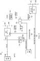
- FIG. 3is a circuit diagram depicting a power control system for determining a system power state for the portable information handling system of FIG. 1 ;
- FIG. 4is a table depicting system power state changes for various configurations of a keyboard and a kickstand in the portable information handling system of FIG. 1 ;
- FIG. 5is a flow diagram depicting a method for determining a system power state for the portable information handling system of FIG. 1 .
- a hyphenated form of a reference numeralrefers to a specific instance of an element and the un-hyphenated form of the reference numeral refers to the collective or generic element.
- widget “ 72 - 1 ”refers to an instance of a widget class, which may be referred to collectively as widgets “ 72 ” and any one of which may be referred to generically as a widget “ 72 .”
- a portable information handling systemmay include a chassis containing an instrumentality or aggregate of instrumentalities operable to compute, classify, process, transmit, receive, retrieve, originate, switch, store, display, manifest, detect, record, reproduce, handle, or utilize various forms of information, intelligence, or data for business, scientific, control, entertainment, or other purposes.
- a portable information handling systemmay be a laptop, a tablet, a 2-in-1, or another portable device and may vary in size, shape, performance, functionality, and price.
- the portable information handling systemincludes one or more processing resources such as a central processing unit (CPU) or hardware or software control logic.
- Additional components of the portable information handling systemmay include one or more storage devices, one or more communications ports for communicating with external devices as well as various input and output (I/O) devices, such as a keyboard, a mouse, and a video display.
- the portable information handling systemmay also include one or more buses operable to transmit communication between the various hardware components.
- FIGS. 1-5wherein like numbers are used to indicate like and corresponding parts.
- FIG. 1illustrates a block diagram depicting selected elements of an embodiment of portable information handling system 100 .
- portable information handling system 100may represent a portable computing device, such as a 2-in-1 tablet device operated by a user.
- components of information handling system 100may include, but are not limited to, processor subsystem 120 , which may comprise one or more processors, and system bus 121 that communicatively couples various system components to processor subsystem 120 including, for example, a memory subsystem 130 , an I/O subsystem 140 , local storage resource 150 , a network interface 160 and a power control system 170 comprising an embedded controller 172 , a kickstand sensor 174 and a keyboard sensor 176 .
- processor subsystem 120may comprise one or more processors
- system bus 121that communicatively couples various system components to processor subsystem 120 including, for example, a memory subsystem 130 , an I/O subsystem 140 , local storage resource 150 , a network interface 160 and a power control system 170 comprising an embedded controller 172 , a kickstand sensor 174 and a keyboard sensor 176 .
- Processor subsystem 120may comprise a system, device, or apparatus operable to interpret and/or execute program instructions and/or process data, and may include a microprocessor, microcontroller, digital signal processor (DSP), application specific integrated circuit (ASIC), or another digital or analog circuitry configured to interpret and/or execute program instructions and/or process data.
- processor subsystem 120may interpret and/or execute program instructions and/or process data stored locally (e.g., in memory subsystem 130 ).
- System bus 121may represent a variety of suitable types of bus structures, e.g., a memory bus, a peripheral bus, or a local bus using various bus architectures in selected embodiments.
- bus architecturesmay include, but are not limited to, Micro Channel Architecture (MCA) bus, Industry Standard Architecture (ISA) bus, Enhanced ISA (EISA) bus, Peripheral Component Interconnect (PCI) bus, PCI-Express bus, HyperTransport (HT) bus, and Video Electronics Standards Association (VESA) local bus.
- MCAMicro Channel Architecture
- ISAIndustry Standard Architecture
- EISAEnhanced ISA
- PCIPeripheral Component Interconnect
- PCI-ExpressPCI-Express
- HTHyperTransport
- VESAVideo Electronics Standards Association
- I/O subsystem 140may comprise a system, device, or apparatus generally operable to receive and transmit data to or from or within information handling system 100 .
- I/O subsystem 140may represent, for example, a variety of communication interfaces, graphics interfaces, video interfaces, user input interfaces, and peripheral interfaces.
- I/O subsystem 140may be used to support various peripheral devices, such as a touch panel, a display adapter, a keyboard, an accelerometer, a touch pad, a gyroscope, or a camera, among other examples.
- I/O subsystem 140may support so-called ‘plug and play’ connectivity to external devices, in which an external device (e.g., a keyboard) may be added or removed while portable information handling system 100 is operating.
- local storage resource 150may comprise computer-readable media (e.g., hard disk drive, floppy disk drive, CD-ROM, and other type of rotating storage media, flash memory, EEPROM, or another type of solid state storage media) and may be generally operable to store instructions and data, and to permit access to stored instructions and data on demand.
- computer-readable mediamay include an instrumentality or aggregation of instrumentalities that may retain data and/or instructions for a period of time.
- Computer-readable mediamay include, without limitation, storage media such as a direct access storage device (e.g., a hard disk drive or floppy disk), a sequential access storage device (e.g., a tape disk drive), compact disk, CD-ROM, DVD, random access memory (RAM), read-only memory (ROM), electrically erasable programmable read-only memory (EEPROM), and/or flash memory (SSD); as well as communications media such wires, optical fibers, microwaves, radio waves, and other electromagnetic and/or optical carriers; and/or any combination of the foregoing.
- storage mediasuch as a direct access storage device (e.g., a hard disk drive or floppy disk), a sequential access storage device (e.g., a tape disk drive), compact disk, CD-ROM, DVD, random access memory (RAM), read-only memory (ROM), electrically erasable programmable read-only memory (EEPROM), and/or flash memory (SSD); as well as communications media such wires, optical fibers, microwaves, radio
- network interface 160may be a suitable system, apparatus, or device operable to serve as an interface between information handling system 100 and a network (not shown).
- Network interface 160may enable information handling system 100 to communicate over the network using a suitable transmission protocol and/or standard, including, but not limited to, transmission protocols and/or standards enumerated below with respect to the discussion of the network.
- network interface 160may be communicatively coupled via the network to a network storage resource (not shown).
- the network coupled to network interface 160may be implemented as, or may be a part of, a storage area network (SAN), personal area network (PAN), local area network (LAN), a metropolitan area network (MAN), a wide area network (WAN), a wireless local area network (WLAN), a virtual private network (VPN), an intranet, the Internet or another appropriate architecture or system that facilitates the communication of signals, data and/or messages (generally referred to as data).
- SANstorage area network
- PANpersonal area network
- LANlocal area network
- MANmetropolitan area network
- WANwide area network
- WLANwireless local area network
- VPNvirtual private network
- intranetthe Internet or another appropriate architecture or system that facilitates the communication of signals, data and/or messages (generally referred to as data).
- the network coupled to network interface 160may transmit data using a desired storage and/or communication protocol, including, but not limited to, Fibre Channel, Frame Relay, Asynchronous Transfer Mode (ATM), Internet protocol (IP), other packet-based protocol, small computer system interface (SCSI), Internet SCSI (iSCSI), Serial Attached SCSI (SAS) or another transport that operates with the SCSI protocol, advanced technology attachment (ATA), serial ATA (SATA), advanced technology attachment packet interface (ATAPI), serial storage architecture (SSA), integrated drive electronics (IDE), and/or any combination thereof.
- ATMAsynchronous Transfer Mode
- IPInternet protocol
- SCSIInternet SCSI
- iSCSIInternet SCSI
- SASSerial Attached SCSI
- ATAadvanced technology attachment
- SATAserial ATA
- ATAPIadvanced technology attachment packet interface
- SSAserial storage architecture
- IDEintegrated drive electronics
- power control system 170may include embedded controller (EC) 172 configured to communicate with kickstand sensor 174 , keyboard sensor 176 , battery 180 and processor subsystem 120 to facilitate portable information handling system 100 changing its operational state on based on a position of a keyboard and a kickstand while preventing accidental powering on of portable information handling system 100 .
- ECembedded controller
- components of portable information handling system 100 described abovemay be configured in a portable device 200 which allows a user to utilize the functionality of information handling system 100 in a laptop configuration (shown) or a tablet configuration (not shown).
- Portable device 200comprises chassis 202 and keyboard 212 , which may be detached from chassis 202 or attached to chassis 202 and closed or opened.
- Chassis 202contains components of portable information handling system 100 and display 204 for displaying information to a user.
- Display 204may have touch screen functionality to allow a user to enter information and interact with portable information handling system 100 .
- Keyboard 212may be detachably and hingedly coupled to chassis 202 .
- a usermay detach keyboard 212 from chassis 202 and portable information handling system 100 may operate in a tablet configuration, in which display 204 contains touch screen functionality for receiving information and instructions from the user.
- Keyboard 212may be formed as part of a lid, wherein a user may attach keyboard 212 to chassis 202 to protect display 204 when transporting and storing portable device 200 .
- Keyboard 212facilitates portable information handling system 100 operating in either a tablet or laptop configuration, in which display 204 contains touch screen functionality for receiving information and instructions from the user and keyboard 212 contains functionality for receiving information and instructions from the user.
- keyboard 212may be attached to chassis 202 and rotated to an angle to allow the user to operate portable information handling system 100 in a tablet configuration or a laptop configuration.
- Portable device 200comprises kickstand 208 hingedly coupled to chassis 202 . As depicted in FIG. 2 , kickstand 208 may be opened to support chassis 202 in an upright orientation. Kickstand 208 may also be closed.
- Portable device 200comprises kickstand sensor 174 for detecting when kickstand 208 is closed or opened.
- kickstand sensor 174comprises a switch, wherein the switch is in a first position when kickstand 208 is closed and the switch is in a second position when kickstand 208 is opened.
- Portable device 200may include keyboard sensor 176 for determining when keyboard 212 is opened or closed.
- keyboard sensor 176may be a Hall effect sensor and keyboard 212 comprises magnet 214 .
- Keyboard sensor 176 based on a Hall effect sensormay determine whether keyboard 212 is opened or closed based on a magnetic field strength associated with magnet 214 and may further determine whether keyboard 212 is opening or closing based on whether the magnetic field strength is decreasing or increasing.
- a signal from keyboard sensor 176may indicate that keyboard 212 is slightly ajar but not opened enough to allow a user to utilize keyboard 212 or portable information handling system 100 .
- components of a power control system 170may be configured for powering up or powering down portable information handling system 100 based on signals received from kickstand sensor 174 and keyboard sensor 176 .
- power control system 170may include embedded controller (EC) 172 , which may include a second processor included within portable information handling system 100 for certain management tasks, including supporting communication and providing various functionality with respect to determining when to power up or power down portable information handling system 100 .
- EC 172may have access to memory storing instructions executable to determine when to power up or power down portable information handling system 100 , discussed below in more detail.
- Embedded controller 172may execute firmware, which may represent one or more input/output interfaces or signals that embedded controller 172 can use to communicate with other elements of portable information handling system 100 .
- EC 172may receive a signal to power up portable information handling system 100 .
- a signalmay be received from a power button activated by a user wanting portable information handling system 100 to power up.
- a signalmay be received from kickstand sensor 174 and/or keyboard sensor 176 indicating a user is opening kickstand 208 and/or keyboard 212 because the user wants to use portable information handling system 100 . If signals are received from each of kickstand sensor 174 and keyboard sensor 176 , the sequence in which the signals are received may indicate whether the user is configuring portable device 200 to operate portable information handling system 100 as a laptop or a tablet.
- Power control system 170may determine when to power on portable information handling system 100 based on the position of kickstand 208 and keyboard 212 .
- FIG. 3depicts a block diagram of one embodiment of system 300 for determining when to power up portable information handling system 100 based on the configuration of kickstand 208 and keyboard 212 .
- system 300comprises embedded controller (EC) 172 , kickstand sensor 174 and keyboard sensor 176 , and further comprises platform controller hub (PCH) 310 and electronic circuits 302 and 312 , all coupled to battery 180 for receiving power.
- ECembedded controller
- PCHplatform controller hub
- kickstand sensor 174is communicatively coupled to electronic circuit 302 , EC 172 and PCH 310 .
- kickstand sensor 174comprises a switch integrated into a hinge, wherein opening or closing kickstand 208 causes kickstand sensor 174 to send a signal.
- Kickstand sensor 174may be configured to send a signal whenever kickstand 208 is opened or closed.
- electronic circuit 302may be communicatively coupled to kickstand sensor 174 such that a signal sent by kickstand sensor 174 is received by electronic circuit 302 .
- electronic circuit 302may be a one-shot integrated circuit (IC) with an external resistance 304 and an external capacitance 306 .
- ICintegrated circuit
- the signal sent by kickstand sensor 174triggers electronic circuit 302 to generate pulse 308 having an output voltage (e.g., 3V) for a length of time.
- Electronic circuit 302is communicatively coupled to EC 172 such that pulse 308 is transmitted to EC 172 .
- EC 172is communicatively coupled to electronic circuit 302 for receiving pulse 308 , is communicatively coupled to kickstand sensor 174 for receiving a signal indicating kickstand 208 is opened and is communicatively coupled to keyboard sensor 176 for receiving signals indicating keyboard 212 is opened or closed.
- EC 172is configured to receive a signal from kickstand sensor 174 and send a signal to battery electronic circuit 312 .
- Electronic circuit 312is communicatively coupled to EC 172 and may receive a signal from EC 172 .
- battery electronic circuit 312may be a one-shot integrated circuit (IC) with an external resistance 314 and an external capacitance 316 .
- ICintegrated circuit
- battery electronic circuit 312when EC 172 sends a signal to battery electronic circuit 312 , battery electronic circuit 312 is triggered to generate an output voltage (e.g., 3V) for a length of time for waking battery 180 from an advanced storage mode.
- battery 180may be a low-dropout (LDO) battery.
- LDOlow-dropout
- keyboard sensor 176may send a signal to EC 172 indicating keyboard 212 is opened.
- EC 172may be further configured to determine, based on the signal received from kickstand sensor 174 indicating kickstand 208 is opened and the signal received from keyboard sensor 176 indicating keyboard 212 is opened, whether a user is wanting to use portable information handling system 100 .
- EC 172may be configured to send a signal to PCH 310 to power up portable information handling system 100 .
- Platform controller hub (PCH) 310is communicatively coupled to kickstand sensor 174 and EC 172 and may be communicatively coupled to other components of portable information handling system 100 , such as processor subsystem 120 depicted in FIG. 1 to power up portable information handling system 100 .
- FIG. 4depicts a table 400 of a plurality of scenarios 402 - 1 to 402 - 8 , in which each scenario comprises an operation sequence 404 associated with portable device 200 and the resulting system power state changes 406 to portable information handling system 100 .
- portable information handling system 100may transition from one of several system power states including modern standby (MS), hibernation (S4) and complete shutdown (S5) to system power state (S0) (an active or working state).
- MSstandby
- S4hibernation
- S5system power state
- a first scenario 402 - 1in an operation sequence 404 in which portable device 200 is configured with keyboard 212 detached from chassis 202 , if kickstand 208 is closed, no system power state changes occur in portable information handling system 100 .
- keyboard 212is detached from chassis 202 and portable information handling system 100 is operating in the active system power state (S0), is operating in modern standby (MS) mode, is hibernating (S4) or shut down (S5) and kickstand 208 is closed, portable information handling system 100 remains in the active system power state (S0), in modern standby (MS), in hibernation (S4) or shut down (S5).
- a second configuration 402 - 2in an operation sequence 404 in which portable device 200 is configured with keyboard 212 detached from chassis 202 , if kickstand 208 is opened, power control system 300 may initiate changes to the system power state of portable information handling system 100 .
- portable information handling system 100is operating in the active system power state (S0) and kickstand 208 is opened, portable information handling system 100 continues to function as a tablet and a user is able to orient portable device 200 in an upright configuration.
- MSmodern standby
- S4hibernating
- S5completely shut down
- kickstand 208power control system 300 may power up portable information handling system 100 to the active system power state (S0).
- power control system 300may be configured to maintain portable information handling system 100 in its present system power state (S0, MS, S4 or S5), regardless of whether kickstand 208 is opened or closed.
- a fifth configuration 402 - 5in an operation sequence 404 in which keyboard 212 is attached to chassis 202 and opened, if kickstand 208 is closed, no changes are made to the system power state of portable information handling system 100 .
- portable information handling system 100is operating in the active system power state (S0), in modern standby (MS), hibernating (S4) or shut down (S5) and kickstand 208 is closed, portable information handling system 100 continues to operate in the active system power state (S0), in modern standby (MS), in hibernation (S4) or shut down (S5).
- system 300may initiate changes to the system power state of portable information handling system 100 . If portable information handling system 100 is operating in the active system power state (S0), in modern standby (MS) mode, in hibernation (S4) or shut down (S5) and the kickstand is opened, power control system 300 may power up portable information handling system 100 to the active system power state (S0).
- a seventh configuration 402 - 7in an operation sequence 404 in which keyboard 212 is attached to chassis 202 and kickstand 208 is closed, if keyboard 212 is opened, system 300 may initiate changes to the system power state of portable information handling system 100 . If portable information handling system 100 is operating in the active system power state (S0) with kickstand 208 opened and keyboard 212 is then opened, portable information handling system 100 continues to operate in the active system power state (S0).
- power control system 300may power up portable information handling system 100 to the active system power state (S0), but if portable information handling system 100 is hibernating (S4) or is completely shut down (S5) and keyboard 212 is opened, portable information handling system 100 remains in hibernation (S4) or shut down (S5).
- system 300may initiate changes to the system power state of portable information handling system 100 . If portable information handling system 100 is operating in the active system power state (S0) with kickstand 208 opened and keyboard 212 is opened, portable information handling system 100 remains in the active system power state (S0) and a user is able to orient portable device 200 in an upright configuration.
- power control system 300may power up portable information handling system 100 to the active system power state (S0).
- embodimentsmay allow BIOS option 408 in which power control system 170 may be enabled or disabled.
- FIG. 5depicts a flow diagram, illustrating method 500 for determining whether to power up portable information handling system 100 based on one or more of a position of kickstand 208 and keyboard 212 .
- the methodstarts at step 502 , when power control system 300 determines if kickstand 208 is opened.
- determining if kickstand 208 is openedcomprises kickstand sensor 174 sending a signal to EC 172 .
- step 504power control system 300 does not initiate changes to the system power state of portable information handling system 100 and portable information handling system 100 remains powered off.
- a signal and a pulsemay be sent to EC 172 .
- an electronic circuit 302such as a one-shot IC may send a signal to EC 172 and may also send a pulse for supplying a voltage for a predetermined length of time to EC 172 .
- EC 172may send a signal to PCH 310 to start to boot or wake up portable device 200 .
- EC 172may send a signal to wake up only certain components and not power up all of portable information handling system 100 .
- EC 172may send a signal to components necessary to determine a configuration of portable device 200 .
- components that started to wake upmay return to an inactive state.
- EC 172may send a signal to wake a battery from an advanced storage mode.
- EC 172may send a signal to battery electronic circuit 312 to generate a pulse for supplying a voltage for a predetermined length of time to battery 180 to wake battery 180 from an advanced storage mode.
- Battery 180may wake to a system power state for a predetermined length of time that allows battery 180 to supply power to components of power control system 300 .
- the batterymay begin issuing power.
- battery 180may issue or supply power to some components of portable information handling system 100 such as EC 172 and keyboard sensor 176 .
- EC 172may determine if keyboard 212 is closed. In some embodiments, EC 172 receives power from battery 180 and communicates with keyboard sensor 176 to determine if keyboard 212 is closed.
- power control system 300may keep portable information handling system 100 in a present system power state, including modern standby (MS), hibernation (S4) or shut down (S5). In some embodiments, when the time period associated with pulse 308 ends, EC 172 returns to an inactive state.
- MSstandby
- S4hibernation
- S5shut down
- keyboard sensor 176comprises keyboard sensor 176 and magnet 214 and EC 172 may determine if a magnetic field strength associated with magnet 214 is decreasing or below a threshold value. In some embodiments, EC 172 may determine keyboard 212 is detached from chassis 202 .
- power control system 300may keep portable information handling system 100 in a present system power state, including modern standby (MS), hibernation (S4) or shut down (S5).
- EC 172may have sent a signal to wake battery 180 from an advanced storage mode. The signal may have included a time period for battery 180 to supply power to one or more components of power control system 300 , wherein at the expiration of the time period, battery 180 returns to the advanced storage mode.
- method 500ends at step 518 when power control system 300 powers up portable information handling system 100 from modern standby (MS), hibernation (S4) or complete shutdown (S5) to the active system power state (S0).
- EC 172communicates a signal to platform controller hub (PCH) 310 to power up portable information handling system 100 from modern standby (MS), hibernation (S4) or complete shutdown (S5) to active system power state (S0).
- PCHplatform controller hub
Landscapes
- Engineering & Computer Science (AREA)
- Theoretical Computer Science (AREA)
- Computer Hardware Design (AREA)
- General Engineering & Computer Science (AREA)
- Physics & Mathematics (AREA)
- General Physics & Mathematics (AREA)
- Human Computer Interaction (AREA)
- Power Sources (AREA)
Abstract
Description
Claims (18)
Priority Applications (1)
| Application Number | Priority Date | Filing Date | Title |
|---|---|---|---|
| US16/802,861US11392190B2 (en) | 2020-02-27 | 2020-02-27 | System and method for utilizing a tablet kickstand to power up an information handling system |
Applications Claiming Priority (1)
| Application Number | Priority Date | Filing Date | Title |
|---|---|---|---|
| US16/802,861US11392190B2 (en) | 2020-02-27 | 2020-02-27 | System and method for utilizing a tablet kickstand to power up an information handling system |
Publications (2)
| Publication Number | Publication Date |
|---|---|
| US20210271304A1 US20210271304A1 (en) | 2021-09-02 |
| US11392190B2true US11392190B2 (en) | 2022-07-19 |
Family
ID=77463749
Family Applications (1)
| Application Number | Title | Priority Date | Filing Date |
|---|---|---|---|
| US16/802,861Active2041-01-16US11392190B2 (en) | 2020-02-27 | 2020-02-27 | System and method for utilizing a tablet kickstand to power up an information handling system |
Country Status (1)
| Country | Link |
|---|---|
| US (1) | US11392190B2 (en) |
Cited By (4)
| Publication number | Priority date | Publication date | Assignee | Title |
|---|---|---|---|---|
| US20230108323A1 (en)* | 2021-10-01 | 2023-04-06 | Lenovo (Singapore) Pte. Ltd | Foldable device |
| US12260018B2 (en) | 2020-10-20 | 2025-03-25 | Adeia Guides Inc. | Methods and systems of extended reality environment interaction based on eye motions |
| US12373029B2 (en) | 2020-10-20 | 2025-07-29 | Adeia Guides Inc. | Methods and systems of extended reality environment interaction based on eye motions |
| US12436609B2 (en) | 2020-10-20 | 2025-10-07 | Adeia Guides Inc. | Methods and systems of extended reality environment interaction based on eye motions |
Families Citing this family (5)
| Publication number | Priority date | Publication date | Assignee | Title |
|---|---|---|---|---|
| US11392190B2 (en)* | 2020-02-27 | 2022-07-19 | Dell Products L.P. | System and method for utilizing a tablet kickstand to power up an information handling system |
| US20230259190A1 (en)* | 2020-07-31 | 2023-08-17 | Hewlett-Packard Development Company, L.P. | S5 power state control action |
| US12164363B2 (en) | 2020-07-31 | 2024-12-10 | Hewlett-Packard Development Company, L.P. | Operational change control action |
| US11815962B2 (en)* | 2022-03-08 | 2023-11-14 | Dell Products L.P. | Configuring an information handling system (IHS) using a kickstand |
| US20250093939A1 (en)* | 2023-09-14 | 2025-03-20 | Microchip Technology Incorporated | Method and Apparatus for Controlling Battery Storage Mode |
Citations (20)
| Publication number | Priority date | Publication date | Assignee | Title |
|---|---|---|---|---|
| US5077551A (en)* | 1988-11-30 | 1991-12-31 | Kabushiki Kaisha Toshiba | Display panel open/closed detection mechanism, and portable electronic apparatus using the same |
| US20030011972A1 (en)* | 2001-07-13 | 2003-01-16 | Koo Ja-Goun | Control of LCD display backlight by actuation of a latch in a notebook computer |
| US20050038982A1 (en)* | 2003-08-11 | 2005-02-17 | Lg Electronics Inc. | Convertible computer |
| US20050062715A1 (en)* | 2003-09-19 | 2005-03-24 | Kabushiki Kaisha Toshiba | Information processing apparatus having function of changing orientation of screen image |
| US20060139326A1 (en)* | 2004-12-02 | 2006-06-29 | Lenovo (Singapore) Pte. Ltd. | Managing laptop power based on display angle |
| US20060238439A1 (en)* | 2005-04-22 | 2006-10-26 | Microsoft Corporation | State-based auxiliary display operation |
| US20100331063A1 (en)* | 2009-06-30 | 2010-12-30 | Nokia Corporation | Method and apparatus for a sliding display |
| US20110161710A1 (en)* | 2009-12-31 | 2011-06-30 | Compal Electronics, Inc. | Laptop computer and hinge module with angle detector thereof |
| US20110179864A1 (en)* | 2010-01-27 | 2011-07-28 | Stmicroelectronics, Inc. | Dual accelerometer detector for clamshell devices |
| US20120001943A1 (en)* | 2010-07-02 | 2012-01-05 | Fujitsu Limited | Electronic device, computer-readable medium storing control program, and control method |
| US20120278638A1 (en)* | 2011-04-28 | 2012-11-01 | Hon Hai Precision Industry Co., Ltd. | Electronic device and control method |
| US20130106704A1 (en)* | 2011-10-26 | 2013-05-02 | Yael Vidal | Laptop computer |
| US20130232353A1 (en)* | 2012-03-02 | 2013-09-05 | Jim Tom Belesiu | Mobile Device Power State |
| US20140043259A1 (en)* | 2012-08-08 | 2014-02-13 | Samsung Electronics Co., Ltd. | Electronic apparatus and method of control thereof |
| US20140146446A1 (en)* | 2012-11-27 | 2014-05-29 | Kabushiki Kaisha Toshiba | Electronic Device |
| US20140293534A1 (en)* | 2013-03-28 | 2014-10-02 | Microsoft Corporation | Hinge Mechanism for Rotatable Component Attachment |
| US20150097788A1 (en)* | 2013-10-03 | 2015-04-09 | Acer Incorporated | Methods for controlling a touch panel and portable computers using the same |
| US20170010636A1 (en)* | 2014-03-28 | 2017-01-12 | Intel Corporation | Rotation sensor device |
| US20200081518A1 (en)* | 2017-04-04 | 2020-03-12 | Hewlett-Packard Development Company, L.P. | Electronic device control based on rotation angle of display units |
| US20210271304A1 (en)* | 2020-02-27 | 2021-09-02 | Dell Products L.P. | System and method for utilizing a tablet kickstand to power up an information handling system |
- 2020
- 2020-02-27USUS16/802,861patent/US11392190B2/enactiveActive
Patent Citations (20)
| Publication number | Priority date | Publication date | Assignee | Title |
|---|---|---|---|---|
| US5077551A (en)* | 1988-11-30 | 1991-12-31 | Kabushiki Kaisha Toshiba | Display panel open/closed detection mechanism, and portable electronic apparatus using the same |
| US20030011972A1 (en)* | 2001-07-13 | 2003-01-16 | Koo Ja-Goun | Control of LCD display backlight by actuation of a latch in a notebook computer |
| US20050038982A1 (en)* | 2003-08-11 | 2005-02-17 | Lg Electronics Inc. | Convertible computer |
| US20050062715A1 (en)* | 2003-09-19 | 2005-03-24 | Kabushiki Kaisha Toshiba | Information processing apparatus having function of changing orientation of screen image |
| US20060139326A1 (en)* | 2004-12-02 | 2006-06-29 | Lenovo (Singapore) Pte. Ltd. | Managing laptop power based on display angle |
| US20060238439A1 (en)* | 2005-04-22 | 2006-10-26 | Microsoft Corporation | State-based auxiliary display operation |
| US20100331063A1 (en)* | 2009-06-30 | 2010-12-30 | Nokia Corporation | Method and apparatus for a sliding display |
| US20110161710A1 (en)* | 2009-12-31 | 2011-06-30 | Compal Electronics, Inc. | Laptop computer and hinge module with angle detector thereof |
| US20110179864A1 (en)* | 2010-01-27 | 2011-07-28 | Stmicroelectronics, Inc. | Dual accelerometer detector for clamshell devices |
| US20120001943A1 (en)* | 2010-07-02 | 2012-01-05 | Fujitsu Limited | Electronic device, computer-readable medium storing control program, and control method |
| US20120278638A1 (en)* | 2011-04-28 | 2012-11-01 | Hon Hai Precision Industry Co., Ltd. | Electronic device and control method |
| US20130106704A1 (en)* | 2011-10-26 | 2013-05-02 | Yael Vidal | Laptop computer |
| US20130232353A1 (en)* | 2012-03-02 | 2013-09-05 | Jim Tom Belesiu | Mobile Device Power State |
| US20140043259A1 (en)* | 2012-08-08 | 2014-02-13 | Samsung Electronics Co., Ltd. | Electronic apparatus and method of control thereof |
| US20140146446A1 (en)* | 2012-11-27 | 2014-05-29 | Kabushiki Kaisha Toshiba | Electronic Device |
| US20140293534A1 (en)* | 2013-03-28 | 2014-10-02 | Microsoft Corporation | Hinge Mechanism for Rotatable Component Attachment |
| US20150097788A1 (en)* | 2013-10-03 | 2015-04-09 | Acer Incorporated | Methods for controlling a touch panel and portable computers using the same |
| US20170010636A1 (en)* | 2014-03-28 | 2017-01-12 | Intel Corporation | Rotation sensor device |
| US20200081518A1 (en)* | 2017-04-04 | 2020-03-12 | Hewlett-Packard Development Company, L.P. | Electronic device control based on rotation angle of display units |
| US20210271304A1 (en)* | 2020-02-27 | 2021-09-02 | Dell Products L.P. | System and method for utilizing a tablet kickstand to power up an information handling system |
Cited By (5)
| Publication number | Priority date | Publication date | Assignee | Title |
|---|---|---|---|---|
| US12260018B2 (en) | 2020-10-20 | 2025-03-25 | Adeia Guides Inc. | Methods and systems of extended reality environment interaction based on eye motions |
| US12373029B2 (en) | 2020-10-20 | 2025-07-29 | Adeia Guides Inc. | Methods and systems of extended reality environment interaction based on eye motions |
| US12436609B2 (en) | 2020-10-20 | 2025-10-07 | Adeia Guides Inc. | Methods and systems of extended reality environment interaction based on eye motions |
| US20230108323A1 (en)* | 2021-10-01 | 2023-04-06 | Lenovo (Singapore) Pte. Ltd | Foldable device |
| US11762418B2 (en)* | 2021-10-01 | 2023-09-19 | Lenovo (Singapore) Pte. Ltd | Foldable device |
Also Published As
| Publication number | Publication date |
|---|---|
| US20210271304A1 (en) | 2021-09-02 |
Similar Documents
| Publication | Publication Date | Title |
|---|---|---|
| US11392190B2 (en) | System and method for utilizing a tablet kickstand to power up an information handling system | |
| CN104798410B (en) | Tap-to-wake and tap-to-login near field communication (NFC) devices | |
| US11275592B2 (en) | System and method of providing updates | |
| US8601252B2 (en) | Method and system for automatically restarting an information handling system to restore system configuration after disorderly shutdown indicated by setting a latch | |
| JP6758365B2 (en) | Electronics, control methods, and programs | |
| US10712805B2 (en) | System and method of thermal management of information handling systems | |
| US11017823B1 (en) | System and method for dynamic adjustment of SSD critical temperature threshold based on memory size | |
| US9880858B2 (en) | Systems and methods for reducing BIOS reboots | |
| US10666078B2 (en) | System and method of managing battery systems | |
| US11226862B1 (en) | System and method for baseboard management controller boot first resiliency | |
| US10739843B2 (en) | System and method of monitoring device states | |
| US9652251B2 (en) | Pre-boot diagnostic display | |
| CN101620463A (en) | Information processing apparatus and wake-up control method | |
| US9710286B2 (en) | Enhanced wakeup mode | |
| JP4846862B2 (en) | Information processing apparatus and power saving control method | |
| US11163354B2 (en) | Information processing apparatus, and control method | |
| US12130676B2 (en) | Method of fan control in an information handling system using a pseudo temperature sensor | |
| US11663106B2 (en) | Systems and methods for mitigating failure to enter standby mode | |
| US11334141B2 (en) | System and method for dynamic power control based on a cache size in volatile memory | |
| KR102233299B1 (en) | Electronic device having a controller to enter a low power mode | |
| US20190050330A1 (en) | System and Method of Managing a Memory Medium | |
| US10678321B2 (en) | Systems and methods for reduced boot power consumption using early BIOS controlled CPU P-states to enhance power budgeting and allocation | |
| US10996727B2 (en) | System and method of managing power in information handling system | |
| US20240427607A1 (en) | Managing power-on at an information handling system | |
| KR102417186B1 (en) | Method for operating a notebook computer |
Legal Events
| Date | Code | Title | Description |
|---|---|---|---|
| AS | Assignment | Owner name:DELL PRODUCTS L.P., TEXAS Free format text:ASSIGNMENT OF ASSIGNORS INTEREST;ASSIGNORS:CHANG, YAOTSUNG;LIN, CHIH-LANG;LIU, LI CHUNG;SIGNING DATES FROM 20200224 TO 20200227;REEL/FRAME:051948/0333 | |
| FEPP | Fee payment procedure | Free format text:ENTITY STATUS SET TO UNDISCOUNTED (ORIGINAL EVENT CODE: BIG.); ENTITY STATUS OF PATENT OWNER: LARGE ENTITY | |
| AS | Assignment | Owner name:THE BANK OF NEW YORK MELLON TRUST COMPANY, N.A., TEXAS Free format text:SECURITY AGREEMENT;ASSIGNORS:CREDANT TECHNOLOGIES INC.;DELL INTERNATIONAL L.L.C.;DELL MARKETING L.P.;AND OTHERS;REEL/FRAME:053546/0001 Effective date:20200409 | |
| AS | Assignment | Owner name:CREDIT SUISSE AG, CAYMAN ISLANDS BRANCH, NORTH CAROLINA Free format text:SECURITY AGREEMENT;ASSIGNORS:DELL PRODUCTS L.P.;EMC IP HOLDING COMPANY LLC;REEL/FRAME:052771/0906 Effective date:20200528 | |
| AS | Assignment | Owner name:THE BANK OF NEW YORK MELLON TRUST COMPANY, N.A., AS COLLATERAL AGENT, TEXAS Free format text:SECURITY INTEREST;ASSIGNORS:DELL PRODUCTS L.P.;EMC CORPORATION;EMC IP HOLDING COMPANY LLC;REEL/FRAME:053311/0169 Effective date:20200603 Owner name:THE BANK OF NEW YORK MELLON TRUST COMPANY, N.A., AS COLLATERAL AGENT, TEXAS Free format text:SECURITY INTEREST;ASSIGNORS:DELL PRODUCTS L.P.;EMC IP HOLDING COMPANY LLC;REEL/FRAME:052852/0022 Effective date:20200603 Owner name:THE BANK OF NEW YORK MELLON TRUST COMPANY, N.A., AS COLLATERAL AGENT, TEXAS Free format text:SECURITY INTEREST;ASSIGNORS:DELL PRODUCTS L.P.;EMC IP HOLDING COMPANY LLC;REEL/FRAME:052851/0917 Effective date:20200603 Owner name:THE BANK OF NEW YORK MELLON TRUST COMPANY, N.A., AS COLLATERAL AGENT, TEXAS Free format text:SECURITY INTEREST;ASSIGNORS:DELL PRODUCTS L.P.;EMC IP HOLDING COMPANY LLC;THE BANK OF NEW YORK MELLON TRUST COMPANY, N.A., AS COLLATERAL AGENT;REEL/FRAME:052851/0081 Effective date:20200603 | |
| STPP | Information on status: patent application and granting procedure in general | Free format text:DOCKETED NEW CASE - READY FOR EXAMINATION | |
| AS | Assignment | Owner name:EMC IP HOLDING COMPANY LLC, TEXAS Free format text:RELEASE OF SECURITY INTEREST AT REEL 052771 FRAME 0906;ASSIGNOR:CREDIT SUISSE AG, CAYMAN ISLANDS BRANCH;REEL/FRAME:058001/0298 Effective date:20211101 Owner name:DELL PRODUCTS L.P., TEXAS Free format text:RELEASE OF SECURITY INTEREST AT REEL 052771 FRAME 0906;ASSIGNOR:CREDIT SUISSE AG, CAYMAN ISLANDS BRANCH;REEL/FRAME:058001/0298 Effective date:20211101 | |
| STPP | Information on status: patent application and granting procedure in general | Free format text:NOTICE OF ALLOWANCE MAILED -- APPLICATION RECEIVED IN OFFICE OF PUBLICATIONS | |
| STPP | Information on status: patent application and granting procedure in general | Free format text:PUBLICATIONS -- ISSUE FEE PAYMENT VERIFIED | |
| AS | Assignment | Owner name:EMC IP HOLDING COMPANY LLC, TEXAS Free format text:RELEASE OF SECURITY INTEREST IN PATENTS PREVIOUSLY RECORDED AT REEL/FRAME (053311/0169);ASSIGNOR:THE BANK OF NEW YORK MELLON TRUST COMPANY, N.A., AS NOTES COLLATERAL AGENT;REEL/FRAME:060438/0742 Effective date:20220329 Owner name:EMC CORPORATION, MASSACHUSETTS Free format text:RELEASE OF SECURITY INTEREST IN PATENTS PREVIOUSLY RECORDED AT REEL/FRAME (053311/0169);ASSIGNOR:THE BANK OF NEW YORK MELLON TRUST COMPANY, N.A., AS NOTES COLLATERAL AGENT;REEL/FRAME:060438/0742 Effective date:20220329 Owner name:DELL PRODUCTS L.P., TEXAS Free format text:RELEASE OF SECURITY INTEREST IN PATENTS PREVIOUSLY RECORDED AT REEL/FRAME (053311/0169);ASSIGNOR:THE BANK OF NEW YORK MELLON TRUST COMPANY, N.A., AS NOTES COLLATERAL AGENT;REEL/FRAME:060438/0742 Effective date:20220329 Owner name:EMC IP HOLDING COMPANY LLC, TEXAS Free format text:RELEASE OF SECURITY INTEREST IN PATENTS PREVIOUSLY RECORDED AT REEL/FRAME (052851/0917);ASSIGNOR:THE BANK OF NEW YORK MELLON TRUST COMPANY, N.A., AS NOTES COLLATERAL AGENT;REEL/FRAME:060436/0509 Effective date:20220329 Owner name:DELL PRODUCTS L.P., TEXAS Free format text:RELEASE OF SECURITY INTEREST IN PATENTS PREVIOUSLY RECORDED AT REEL/FRAME (052851/0917);ASSIGNOR:THE BANK OF NEW YORK MELLON TRUST COMPANY, N.A., AS NOTES COLLATERAL AGENT;REEL/FRAME:060436/0509 Effective date:20220329 Owner name:EMC IP HOLDING COMPANY LLC, TEXAS Free format text:RELEASE OF SECURITY INTEREST IN PATENTS PREVIOUSLY RECORDED AT REEL/FRAME (052851/0081);ASSIGNOR:THE BANK OF NEW YORK MELLON TRUST COMPANY, N.A., AS NOTES COLLATERAL AGENT;REEL/FRAME:060436/0441 Effective date:20220329 Owner name:DELL PRODUCTS L.P., TEXAS Free format text:RELEASE OF SECURITY INTEREST IN PATENTS PREVIOUSLY RECORDED AT REEL/FRAME (052851/0081);ASSIGNOR:THE BANK OF NEW YORK MELLON TRUST COMPANY, N.A., AS NOTES COLLATERAL AGENT;REEL/FRAME:060436/0441 Effective date:20220329 Owner name:EMC IP HOLDING COMPANY LLC, TEXAS Free format text:RELEASE OF SECURITY INTEREST IN PATENTS PREVIOUSLY RECORDED AT REEL/FRAME (052852/0022);ASSIGNOR:THE BANK OF NEW YORK MELLON TRUST COMPANY, N.A., AS NOTES COLLATERAL AGENT;REEL/FRAME:060436/0582 Effective date:20220329 Owner name:DELL PRODUCTS L.P., TEXAS Free format text:RELEASE OF SECURITY INTEREST IN PATENTS PREVIOUSLY RECORDED AT REEL/FRAME (052852/0022);ASSIGNOR:THE BANK OF NEW YORK MELLON TRUST COMPANY, N.A., AS NOTES COLLATERAL AGENT;REEL/FRAME:060436/0582 Effective date:20220329 Owner name:DELL MARKETING L.P. (ON BEHALF OF ITSELF AND AS SUCCESSOR-IN-INTEREST TO CREDANT TECHNOLOGIES, INC.), TEXAS Free format text:RELEASE OF SECURITY INTEREST IN PATENTS PREVIOUSLY RECORDED AT REEL/FRAME (053546/0001);ASSIGNOR:THE BANK OF NEW YORK MELLON TRUST COMPANY, N.A., AS NOTES COLLATERAL AGENT;REEL/FRAME:071642/0001 Effective date:20220329 Owner name:DELL INTERNATIONAL L.L.C., TEXAS Free format text:RELEASE OF SECURITY INTEREST IN PATENTS PREVIOUSLY RECORDED AT REEL/FRAME (053546/0001);ASSIGNOR:THE BANK OF NEW YORK MELLON TRUST COMPANY, N.A., AS NOTES COLLATERAL AGENT;REEL/FRAME:071642/0001 Effective date:20220329 Owner name:DELL PRODUCTS L.P., TEXAS Free format text:RELEASE OF SECURITY INTEREST IN PATENTS PREVIOUSLY RECORDED AT REEL/FRAME (053546/0001);ASSIGNOR:THE BANK OF NEW YORK MELLON TRUST COMPANY, N.A., AS NOTES COLLATERAL AGENT;REEL/FRAME:071642/0001 Effective date:20220329 Owner name:DELL USA L.P., TEXAS Free format text:RELEASE OF SECURITY INTEREST IN PATENTS PREVIOUSLY RECORDED AT REEL/FRAME (053546/0001);ASSIGNOR:THE BANK OF NEW YORK MELLON TRUST COMPANY, N.A., AS NOTES COLLATERAL AGENT;REEL/FRAME:071642/0001 Effective date:20220329 Owner name:EMC CORPORATION, MASSACHUSETTS Free format text:RELEASE OF SECURITY INTEREST IN PATENTS PREVIOUSLY RECORDED AT REEL/FRAME (053546/0001);ASSIGNOR:THE BANK OF NEW YORK MELLON TRUST COMPANY, N.A., AS NOTES COLLATERAL AGENT;REEL/FRAME:071642/0001 Effective date:20220329 Owner name:DELL MARKETING CORPORATION (SUCCESSOR-IN-INTEREST TO FORCE10 NETWORKS, INC. AND WYSE TECHNOLOGY L.L.C.), TEXAS Free format text:RELEASE OF SECURITY INTEREST IN PATENTS PREVIOUSLY RECORDED AT REEL/FRAME (053546/0001);ASSIGNOR:THE BANK OF NEW YORK MELLON TRUST COMPANY, N.A., AS NOTES COLLATERAL AGENT;REEL/FRAME:071642/0001 Effective date:20220329 Owner name:EMC IP HOLDING COMPANY LLC, TEXAS Free format text:RELEASE OF SECURITY INTEREST IN PATENTS PREVIOUSLY RECORDED AT REEL/FRAME (053546/0001);ASSIGNOR:THE BANK OF NEW YORK MELLON TRUST COMPANY, N.A., AS NOTES COLLATERAL AGENT;REEL/FRAME:071642/0001 Effective date:20220329 | |
| STCF | Information on status: patent grant | Free format text:PATENTED CASE |