US11391539B2 - Holster - Google Patents
HolsterDownload PDFInfo
- Publication number
- US11391539B2 US11391539B2US16/596,408US201916596408AUS11391539B2US 11391539 B2US11391539 B2US 11391539B2US 201916596408 AUS201916596408 AUS 201916596408AUS 11391539 B2US11391539 B2US 11391539B2
- Authority
- US
- United States
- Prior art keywords
- holster
- accessory
- handgun
- spring member
- blocking
- Prior art date
- Legal status (The legal status is an assumption and is not a legal conclusion. Google has not performed a legal analysis and makes no representation as to the accuracy of the status listed.)
- Active
Links
Images


Classifications
- F—MECHANICAL ENGINEERING; LIGHTING; HEATING; WEAPONS; BLASTING
- F41—WEAPONS
- F41C—SMALLARMS, e.g. PISTOLS, RIFLES; ACCESSORIES THEREFOR
- F41C33/00—Means for wearing or carrying smallarms
- F41C33/02—Holsters, i.e. cases for pistols having means for being carried or worn, e.g. at the belt or under the arm
- F41C33/0254—Holsters, i.e. cases for pistols having means for being carried or worn, e.g. at the belt or under the arm with accommodation for auxiliary devices mounted on the small arm, e.g. telescopic sights, flashlights or laser-devices
- F—MECHANICAL ENGINEERING; LIGHTING; HEATING; WEAPONS; BLASTING
- F41—WEAPONS
- F41C—SMALLARMS, e.g. PISTOLS, RIFLES; ACCESSORIES THEREFOR
- F41C33/00—Means for wearing or carrying smallarms
- F41C33/02—Holsters, i.e. cases for pistols having means for being carried or worn, e.g. at the belt or under the arm
- F41C33/0245—Skeleton-holsters, e.g. contacting only a minimal part of the small arm, e.g. contacting the muzzle, ejection port, chamber, trigger guard or hammer
- F—MECHANICAL ENGINEERING; LIGHTING; HEATING; WEAPONS; BLASTING
- F41—WEAPONS
- F41C—SMALLARMS, e.g. PISTOLS, RIFLES; ACCESSORIES THEREFOR
- F41C33/00—Means for wearing or carrying smallarms
- F41C33/02—Holsters, i.e. cases for pistols having means for being carried or worn, e.g. at the belt or under the arm
- F41C33/0263—Holsters, i.e. cases for pistols having means for being carried or worn, e.g. at the belt or under the arm having a locking system for preventing unauthorized or accidental removal of the small arm from the holster
- F—MECHANICAL ENGINEERING; LIGHTING; HEATING; WEAPONS; BLASTING
- F41—WEAPONS
- F41G—WEAPON SIGHTS; AIMING
- F41G11/00—Details of sighting or aiming apparatus; Accessories
- F41G11/001—Means for mounting tubular or beam shaped sighting or aiming devices on firearms
- F41G11/003—Mountings with a dove tail element, e.g. "Picatinny rail systems"
Definitions
- Weapon-mounted firearm accessorieshave become an important tool for military, police, naval, and civilian firearm users.
- Examples of popular firearm accessoriesinclude targeting devices, such as LASER sighting devices, and target illuminators, such as flashlights.
- Many handgun designsincorporate mounting rails for supporting these accessories. Using an accessory rail interface, a given accessory may be mounted to a variety of firearms or firearms platforms. Likewise, if a particular firearm includes a rail interface, a variety of accessories may be interchangeably mounted to the firearm. The interchangeability of accessories is of particular importance to military and law enforcement personnel attached to special operations units, as this allows a single firearm to be reconfigured to meet certain mission specific needs.
- handgun-mounted light or flashlighttypically attached to a mounting rail located forward of the trigger guard and are centered along the bore axis of the handgun.
- a weapon-mounted flashlightis useful to light both the surrounding environment as well as possible assailants using only a single hand. This frees the other hand to call the police or fend off an attacker, or alternatively allows a user to keep both hands on the gun for a more secure grip.
- Handgun-mounted lasersmay similarly be attached to an accessory rail parallel to the bore axis of a handgun.
- a weapon-mounted laser sighting systemhas several advantages. First, a laser can aid in shooting accuracy and speed, particularly in high pressure situations. Further, lasers can aid in shooting at night or indoors in poorly lit environments. Lasers can also be used to safely practice trigger control. Finally, lasers may work as an intimidating deterrent for would-be assailants.
- holster systemcomprises a holster and an accessory configured to be fixed to a mounting rail of a handgun.
- the accessoryhaving a lower downwardly facing surface and a pair of upwardly facing shoulders with lands positioned adjacent grooves of the mounting rail.
- the holsterhaving a holster body having a pair of opposing wall portions defining an interior or cavity. Each wall portion having an inwardly projecting rib dividing the interior of the holster body into an upper first cavity portion and a lower second cavity portion, the second cavity configured as a form fitting accessory pocket.
- the first cavity portiondimensioned to universally receive slides and the body of various handgun makes and models in a spaced relationship from two sides and the top of the firearm.
- the holster bodyconfigured such that the second cavity portion receives the accessory so that a conforming engagement is formed between the accessory and the holster body.
- a stop surface fixed with respect to, or part of the holster bodyengages a forward facing surface of the accessory upon insertion of the handgun with accessory into the holster body thereby providing a seating position of the handgun and accessory in the holster body whereby the accessory and thus the handgun is constrained forwardly, upwardly, downwardly, to the port side, and to the starboard side.
- a retention mechanismmay be supported by the wall of the holster body.
- the retention mechanismhaving a blocking portion movable between a blocking position and a non-blocking position so that the retention mechanism either prevents or allows the accessory attached to the handgun from being withdrawn from the interior of the holster body thus retaining the handgun in the holster.
- the blocking portionmay be on a spring member biased to a blocking position and positioned to engage and block a rearward facing surface of the accessory.
- a sliding memberconfigured as a flat thin bar or elongate thin plate on the port side of the holster has a thumb receiving portion and a cam surface configured as a ramp that engages cam follower surfaces on the spring member to move the spring member and blocking portion to the non-blocking position.
- a cam surfacemay alternatively engage a cam follower surface on the blocking portion.
- the blocking portionmay also be urged to and/or locked in the blocking position when the handgun is pulled rearwardly, that is, in an outward or removal direction with respect to the holster. This may preclude the depression of the thumb receiving portion when the handgun is being pulled and at least inhibits the removal of the handgun from the holster when being so pulled rearwardly.
- a feature of embodimentsis a handgun withdrawal inhibitor device that is effective to lock the release actuation mechanism in the blocking position upon a force urging the handgun rearwardly when the release actuation mechanism has not been manually actuated.
- this featureis accomplished with a blocking member that is movable forwardly and rearwardly and that has a locking portion that engages a fixed surface to immobilize the blocking member when the firearm and/or accessory pushes the locking portion rearwardly before the locking portion has been moved out of the way of the firearm and/or accessory.
- the locking portionmay be a ramped surface or a recess on the blocking portion.
- the locking portionmay be displaced from the blocking portion, for example disposed on the spring member to which the blocking portion is attached.
- the blocking membermay engage conventional retention features on the holstered handgun such as the ejection port or trigger guard rather than an accessory.
- a depressing of the thumb release portion when the handgun is being pulled rearwardlywill cause a bowing of the elongate spring member without causing movement of the blocking portion from the blocking position to the non-blocking position.
- a feature and advantage of embodimentsis the locking out of the release actuation mechanism where the handgun has been rearwardly displaced from a seating position before the release actuation mechanism is actuated.
- thumb actuating release actuation mechanismis biased, such as by a spring, to a preactuation position and is automatically reset after withdrawal of the handgun.
- the handguncan be reholstered without manual reset of the retention mechanism or the release actuation mechanism.
- the accessoryhas a width less than or equal to the maximum width of the handgun. In an embodiment, the accessory has a height less than or equal to the height of the trigger guard of the handgun.
- a feature and advantage of embodimentsinclude providing a universal holster system that allows a single holster to be utilized with various makes and models of handgun.
- a weapon mounted accessorysuch as a camera and/or a light, is used as the sole or primary interface with the holster.
- the holsterpartially encloses the handgun while leaving a predetermined clearance around the handgun.
- the clearance around the handgunallows a single holster system to be utilized with various makes and models of handguns.
- a feature and advantage of embodimentsinvolves reducing or eliminating wear and tear on handgun surface finishes due to the fact that the holster cavity leaves clearance around the handgun.
- a feature and advantage of embodimentsis a thumb-actuated release actuation mechanism that selectively releases the retention mechanism when the user wishes to draw his or her weapon.
- the release actuation mechanismincludes an elongate substantially flat plate sliding member and a blocking portion with cooperating sloped surfaces configured to cause deflection of the blocking portion when a thumb receiving portion on the sliding member is pressed downward.
- a feature and advantage of embodimentsis a thin, thumb-actuated release actuation mechanism that fits between the holster and a mounting plate defining one or more slots for receiving belts, straps, and the like.
- a feature and advantage of embodimentsis that the actuation receiving portion is in a position that is not readily accessible or visible to potential attackers.
- a feature and advantage of embodimentsis a thin, thumb-actuated release actuation mechanism configured such that pressing downward on a thumb receiving portion moves a blocking portion from a blocking position in which the blocking portion prevents the accessory from being withdrawn from the first cavity defined by the holster body to a non-blocking position in which the retention mechanism allows the accessory to be withdrawn from the first cavity.
- a feature and advantage of embodimentsis a holster with a capture mechanism with an elongate sliding planar bar extending from the thumb push button to the end of the bar with no motion transfer mechanisms or bends in the bar. Pressure from the thumb actuation is efficiently transferred to the cam surface to deflect the spring member and blocking portion. An integral cam surface positioned on the middle of the bar deflects the spring member for releasing the handgun.
- the holstercaptures the accessory when the handgun with accessory in inserted into the holster to capture the accessory and handgun, the holster and accessory engagement constraining all freedom of motion of the accessory except freedom of motion in the insertion and withdrawal direction along a forward rearward axis of the handgun.
- the holsterfurther providing a stop portion whereby the accessory seats in the slot and abuts the stop portion, the only freedom of motion of the accessory with respect to the holster is a linear withdrawal motion.
- a spring memberconfigured as a leaf spring, is deflected by the accessory upon insertion of the handgun as it is seated; when the handgun is seated in the holster, a blocking portion of the spring member blocks the handgun from withdrawal there restricting any movement of the handgun with respect to the holster.
- a slot defined by the holster structurecaptures the accessory when the handgun with accessory in inserted into the holster to capture the accessory and constrain all freedom of motion of the accessory and attached handgun.
- the slot defined by holster structureto engage a combination of corners and surfaces of the accessory to limit any freedom of motion of the accessory.
- the holsteris form fit to the accessory to capture and constrains the holster accessory combination by exclusively or primarily capturing the accessory.
- the holster structure defining the slotmay be part of side wall portions of the holster, with the side wall portions joined and unitary at the top and bottom of the holster thereby providing the sufficient strength and structural stability to the slot defined by the side wall portions to secure the holster accessory combination in the holster.
- An advantage and feature of embodimentsis an holster system having an accessory that is attachable to a multiplicity of different shaped handguns at the respective rails of the handguns, the accessory form fit to a holster, the holster not form fit to the multiplicity of different shaped handguns, and the holster being sized sufficient to have clearances with the multiplicity of different sized handguns whereby each of the handguns with the accessory attached receives and secures each handgun therein.
- an accessory clamped to the handgun railhas a singular function of interfacing with the holster while maintaining a reduced profile.
- the “interface-only” accessoryhas the interface features of other accessories (e.g., camera, flashlight and/or laser that clamps to a rail but is of reduced size and/or weight.
- a holster that accommodates a specific flashlight designcan accommodate the interface-only accessory attached to a handgun with an additional insert adaptor that seats into and is fixed within the accessory pocket of the holster body.
- the lower downwardly facing surface of the interface-only accessoryslidingly engages the insert adaptor upon insertion and withdrawal of the handgun and seats on the insert adaptor when the firearm is fully holstered.
- the holster bodycan be configured for the interface only accessory whereby the adaptor is not needed.
- the secondary pocket for the accessorywill be reduced in size with pocket defined as extending from the bottom inside upwardly facing surface of the pocket to the inwardly projecting ribs that engage an upwardly facing surface of the clamp portion of the interface only accessory.
- the height of the pocketcorresponding to the height of the accessory and in embodiments will be less than one half the height of the trigger guard. In embodiments, the height of the pocket will be less than 0.5 inches.
- a feature and advantage of embodimentsis automatic retention of the accessory (and therefore the handgun) upon insertion of the handgun/accessory combination into the holster.
- the systemincludes a blocking portion with a protrusion that engages a surface of the accessory. The protrusion extends through an aperture defined by the wall of the holster.
- the blocking portionincludes a rearwardly facing face with a sloped surface configured to cause deflection of a cantilevered portion of the blocking portion member upon insertion of the handgun/accessory combination into the holster.
- a feature and advantage of embodimentsis a locking action which resists or prevents actuation of the release actuation mechanism while rearward forces are being applied to the handgun; for example, when an attacker is attempting to draw the user's weapon or when the user is running and jostling the holster and firearm.
- the blocking member of the systeminclude a rearward facing ramp oriented such that the ramp engages a portion of the holster body at the aperture when the blocking portion is forced rearwardly such as when the handgun is pulled without the blocking member being moved out of position.
- the ramp engaging surface of the holster bodyapplies a reaction force to the distal ramp.
- the reaction forcehas a lateral force component securing the blocking portion in the blocking position such that depression of the thumb receiving portion is resisted or prevented.
- the spring member and blocking portionmay be attached to the holster body with some minimal forward backward movement, with respect to the holster body for example, less than 0.25 inches. In other embodiments the forward backward movement may be less than 0.125 inches.
- the blocking portionmay be slidably moveable on the spring member. The blocking portion may be biased toward a non-locking position.
- a feature and advantage of embodimentsinvolves providing a holster that is capable of receiving handguns of various makes and models without requiring a user to make adjustments to the holster.
- the holsterhas sufficient clearance around each handgun to provide a multi-handgun fit. For example, a user can switch handguns in the middle of a three gun competition without removing the holster from his or her body so long as a predetermined accessory for which the holster is configured to receive and retain is attached to each handgun on the handgun rail.
- a feature and advantage of embodimentsinvolves providing a holster capable of receiving a first handgun with a slide portion having a first shape and a second handgun with a slide portion having a second shape that is different from the first shape so long as the first and second handguns have an accessory with predetermined form that conforms to an accessory pocket in the holster.
- a feature and advantage of embodimentsis that the release actuation mechanism is actuated by the user's thumb rather than the user's index finger and that the actuation portion is narrow having the height and width of the elongate sliding member.
- a feature and advantage of embodimentsis that certain retention mechanism components are housed in a cavity defined by the elongate sliding member that actuates the retention mechanism and a wall portion of the holster.
- the elongate spring member with the blocking portion and the spring that biases the elongate sliding memberare in said cavity.
- the cavitymay be open downwardly to allow debris to exit the cavity.
- the elongate sliding memberis secured in a recess defined by a pair of guides or tracks extending forwardly and backwardly on the wall portion and is retained in position by a mounting plate or belt attachment member.
- a holster systemis configured for receiving and releasably retaining differently configured handguns, each of the differently configured handguns having a mounting rail positioned below barrels of the differently configured handgun.
- the holster systemcomprises an accessory configured to be fixed to the mounting rail of the differently configured handguns.
- the accessoryhas a body with an upper clamp sized to grip the mounting rail, the upper clamp having a pair of shoulders, and each shoulder having an upwardly facing surface.
- the bodyfurther having a lower most downwardly facing surface below the shoulders.
- the holster systemfurther including a holster body having a forward end and a rearward end, the holster body comprising a pair of opposing side wall portions 120 , 122 defining a cavity with an open rearward end.
- the holster bodyhaving a handgun receiving and withdrawal axis extending forwardly and rearwardly.
- the holster bodyfurther having a pair of opposing ribs projecting inwardly from each of the opposing side wall portions.
- the ribsextending forwardly and rearwardly and defining a lower accessory receiving pocket in the cavity.
- the lower accessory receiving pocketbeing sized for a conforming fit with the accessory including engagement of the holster body with the pair of shoulders with the pair of ribs.
- the holster systemfurther including a cover attached to one of the opposing sidewall portions, the cover defining a chamber having an opening that is covered by the one of the opposing sidewall portions.
- the holster systemfurther including a retention mechanism supported by the wall of the holster body.
- the retention mechanismcomprising an elongate spring member disposed inside the chamber defined by the cover.
- the elongate spring memberextending rearwardly and having a blocking portion at the rearward end of the elongate spring member.
- the blocking portionswingable in a direction transverse to the handgun receiving and withdrawal axis between a blocking position and a non-blocking position with respect to the accessory such that when the accessory is mounted on one of the differently configured handguns the accessory and handgun attached thereto is retained in the accessory receiving pocket when the blocking portion is in the blocking position and the accessory and handgun attached thereto may be withdrawn from accessory receiving pocket when the blocking portion is in the non-blocking position.
- the blocking portionbeing biased toward the blocking position and engageable with the accessory at one of the pair of shoulders of the accessory.
- the spring member and blocking portionbeing movable rearwardly with respect to the holster body when a holstered accessory and handgun attached thereto is moved rearwardly in a withdrawal motion with respect to the holster body and the blocking portion is in the blocking position whereby a rearward face of the blocking portion engages a portion of the holster body to at least inhibit the blocking portion from moving to the non-blocking position thereby retaining the handgun in the holster.
- the retention mechanism of the holster systemfurther comprises a thumb actuated release actuation mechanism including an elongate sliding member extending along an exterior surface of one of the side wall portions.
- the elongate memberhaving opposing ends with a thumb receiving portion at a rearward end thereof and having a protrusion that engages structure on the spring member positioned intermediate a forward end and the rearward end.
- the protrusion and structureare configured to produce cantilevered bending of the spring member when the elongate member is slid forwardly and the blocking member is unconstrained thereby moving the blocking member in a direction outwardly with respect to the holster body from the blocking position to the non-blocking position.
- elongate sliding memberengages the spring member forwardly of the blocking portion and when the handgun is moved rearwardly in a withdrawal motion with respect to the holster body and the blocking portion is in the blocking position depressing of the thumb receiving portion causes a bowing of the spring member while retaining the blocking portion in the blocking position.
- a holster systemis configured for receiving a handgun having a forward rail below the barrel with an accessory secured thereto.
- the holster systemcomprising a holster body having a pair of opposing side wall portions defining an interior with an upper first cavity portion and a lower second cavity portion.
- the first cavity portionis sized to receive a slide of the handgun and the second cavity portion is dimensioned to form fit the particular form of the accessory secured to the mounting rail of the handgun.
- each of the first and second cavitiesare open at a rearward end for receiving and withdrawing the handgun and attached accessory in a forward and rearward direction.
- the holster systemfurther including a cover attached to one of the opposing sidewall portions.
- the coverdefining a chamber having an opening that is covered by the one of the opposing sidewall portions.
- the holster systemfurther including a retention mechanism supported by the wall of the holster body.
- the retention mechanismcomprising a spring member disposed inside the chamber defined by the cover.
- the spring memberbeing secured with respect to the one of the opposing sidewall portions at a first end thereof and the spring member extending rearwardly along an exterior surface of the one of the opposing sidewall portions.
- the second end of the spring memberbeing fixed to a blocking portion.
- the blocking portionbeing positioned at a aperture in the one of the opposing sidewall portions and movable between a blocking position and a non-blocking position with respect to the accessory when the accessory is in the second cavity portion.
- the retention mechanismfurther comprising an elongate sliding member extending along an exterior surface of the one of the side wall portions and slidable therealong.
- a first portion of the elongate memberextending into the chamber defined by the cover.
- the first portion of the elongate memberbeing sandwiched between the cover and the one of the side wall portions.
- the elongate memberhaving opposing ends with a thumb receiving portion at a rearward end thereof and a protrusion that engages structure on the spring member positioned intermediate a forward end and the rearward end.
- the protrusion and structureproducing cantilevered bending of the spring member when the elongate member is slid forwardly thereby moving the blocking member in a direction outwardly with respect to the holster body from the blocking position to the non-blocking position.
- a holster systemis configured for receiving and releasably retaining differently configured handguns, each of the differently configured handgun having a mounting rail positioned below a barrel of the differently configured handgun with a predetermined accessory attached to the rail.
- the accessoryhaving a vertical distance from the bottom surface of the accessory to the top surface of a pair of clamp portions.
- the holster systemcomprising a holster body having a forward end and a rearward end.
- the holster bodycomprising a pair of opposing side wall portions defining an interior with an open rearward end.
- the holster bodyhaving a handgun receiving and withdrawal axis extending forwardly and rearwardly.
- the holster bodyfurther having a pair of opposing ribs extending linearly forwardly and backwardly and projecting inwardly from each of the opposing side wall portions.
- the ribsbeing spaced from an upwardly facing bottom surface of the holster body a distance substantially equal to the vertical distance so that the pair of opposing side walls and the ribs defining a lower accessory receiving pocket in the interior.
- the holster systemfurther comprising a cover attached to one of the opposing sidewall portions.
- the coverdefining a chamber having an opening that is covered by the one of the opposing sidewall portions.
- the holster systemfurther comprising a retention mechanism supported by the wall of the holster body.
- the retention mechanismcomprising an elongate spring member connecting to a blocking portion.
- the elongate spring memberbeing disposed in the chamber defined by the cover.
- the blocking portionmovable in a direction transverse to the handgun receiving and withdrawal axis between a blocking position and a non-blocking position with respect to the accessory such that when the accessory is mounted on one of the differently configured handguns the accessory and handgun attached thereto is retained in the accessory receiving pocket when the blocking portion is in the blocking position and the accessory and handgun attached thereto may be withdrawn from accessory receiving pocket when the blocking portion is in the non-blocking position, the blocking portion biased toward the blocking position.
- the retention mechanismfurther comprising a thumb actuated release actuation mechanism.
- the thumb actuated release actuation mechanismcomprising an elongate member extending into the chamber defined by the cover.
- the elongate memberbeing slidably supported by the cover and the one of the opposing sidewall portions.
- the elongate memberhaving opposing ends with a thumb receiving portion at a rearward end thereof and having a protrusion that engages structure on the spring member positioned intermediate a forward end and the rearward end.
- the protrusion and the structureproducing cantilevered bending of the spring member when the elongate member is slid forwardly thereby moving the blocking member in a direction outwardly with respect to the holster body from the blocking position to the non-blocking position.
- a holster systemcomprises a holster and an accessory configured to be fixed to a mounting rail of a handgun.
- the accessoryincludes an activator switch carried by a housing of the accessory.
- the activator switchhas a projecting portion biased into a projecting position, the projecting portion being movable out of the projecting position and into a depressed position.
- the activator switchis operatively connected to a camera so that the camera is activated when the projecting portion is in the projecting position and is deactivated when the projecting portion is in the depressed position.
- a surface of the holster bodyholds the projecting portion in the depressed position while the accessory is in a cavity defined by the holster body.
- the cameramay be mounted in various locations. Examples of camera mounting locations include locations on the body of a person, locations on the holster, and locations on the handgun.
- the cameramay be automatically activated upon withdrawal of the gun from the holster regardless of the location of the camera.
- the accessorymay comprise a camera and the system may include a retention mechanism having a blocking portion movable between a blocking position and a non-blocking position so that the retention mechanism either prevents or allows the accessory attached to the handgun from being withdrawn from the interior of the holster body thus retaining the handgun in the holster.
- “Portion” when used hereinmay refer to a discrete component or an integral part of a component that includes other portions.
- “blocking portion”may be a separately formed component that is then subsequently attached to another component, such as a spring member. Or it may be the end of a single molded component that has the blocking function and a spring function.
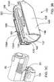
- FIG. 1is a perspective view showing a universal holster system in accordance with the detailed description.
- FIG. 2Ais a port side view showing the holster shown in FIG. 1 .
- FIG. 2Bis a perspective cross-sectional view further illustrating the holster shown in FIG. 2A .
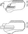
- FIG. 2Cis a perspective view showing a portion of an accessory fixed to a mounting rail of a handgun.
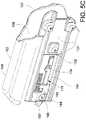
- FIG. 3Ais a port side view showing the holster shown in FIG. 1 .
- FIG. 3Bis a perspective cross-sectional view further illustrating the holster shown in FIG. 3A .
- FIG. 3Cis a perspective view showing a portion of an accessory fixed to a mounting rail of a handgun.
- FIG. 4is a perspective view showing a portion of an accessory fixed to a mounting rail of a handgun and how it is received into a slot or pocket of a holster.
- FIG. 5Ais an exploded perspective view of an assembly including a holster and a retention mechanism viewed from the port side.
- FIG. 5Bis an exploded perspective view of the assembly of FIG. 5A view from the starboard side.
- FIG. 5Cis a perspective view of the holster body with the plate and elongate sliding member removed.
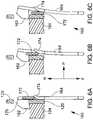
- FIG. 6A , FIG. 6B and FIG. 6Care a sequence of stylized front plan views illustrating the operation of a retention mechanism in accordance with the detailed description.
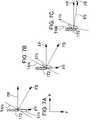
- FIG. 7A , FIG. 7B and FIG. 7Care a sequence of diagrams illustrating the forces acting on the ramp portion of the elongate spring member shown in FIG. 6 .
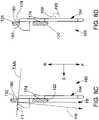
- FIG. 8A and FIG. 8Bare stylized front plan views showing an elongate spring member of a retention mechanism in accordance with the detailed description.
- FIG. 8Cis a diagram illustrating forces applied to the blocking portion 162 under circumstances such as the ones illustrate in FIG. 8B providing actuation lockout.
- FIG. 8Dillustrates alternative actuation lockout configurations of the elongate spring member.
- FIG. 9A , FIG. 9B and FIG. 9Care a series of stylized front plan views illustrating a sequence of events occurring as an accessory attached to a handgun is inserted into a cavity defined by the wall of a holster.
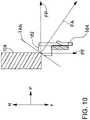
- FIG. 10is a diagram illustrating forces applied to the blocking portion of a retention mechanism during a sequence of events such as the events illustrated in FIG. 9 .
- FIG. 11is an exploded perspective view showing a universal holster system in accordance with the detailed description.
- FIG. 12is a cross-sectional view further illustrating the holster system shown in FIG. 11 .
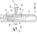
- FIG. 13is an exploded plan view illustrating a dummy accessory configured to be fixed to a mounting rail of a handgun.
- FIG. 14is a prior art copy of Military Standard MIL-STD-1913 (AR) of mounting rails.
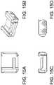
- FIGS. 15A through 15Gare several views showing an additional embodiment of a dummy accessory in accordance with the detailed description.
- FIGS. 16A and 16Bare exploded perspective views depicting an additional embodiment of a holster assembly in accordance with the detailed description.
- FIG. 16Cis a perspective view showing the holster assembly of FIGS. 16A and 16B in a partially assembled state.
- FIG. 17Ais a port side elevation view of a holster.
- FIG. 17Bis a port side perspective view of the holster of FIG. 17A .
- FIG. 17Cis a starboard side elevation view of the holster of FIG. 17A .
- FIG. 17Dis a starboard side perspective view of the holster of FIG. 17A .
- FIG. 17Eis a top view of the holster of FIG. 17A .
- FIG. 17Fis a bottom view of the holster of FIG. 17A .
- FIGS. 18A-18Bare stylized front plan views showing a spring member of a retention mechanism in accordance with the detailed description.
- FIGS. 19A and 19Bare exploded perspective views depicting an additional embodiment of a holster assembly in accordance with the detailed description.
- FIG. 19Cis a perspective view showing the holster assembly of FIGS. 19A and 19B in a partially assembled state.
- FIG. 20Ais a partially exploded perspective view further illustrating the holster assembly shown in FIGS. 19A, 19B and 19C .
- FIG. 20Bis a perspective view showing a sliding member of a retention mechanism in accordance with the detailed description. The sliding member of FIG. 20B is also visible in the partially exploded perspective view of FIG. 20A .
- FIG. 21Ais a partially exploded perspective view further illustrating the holster assembly shown in FIGS. 20A, 20B and 20C .
- FIG. 21Bis a perspective view showing a sliding member of a retention mechanism in accordance with the detailed description.
- FIGS. 22A and 22Bare diagrams showing a beam B in a relaxed state and in a bowed state, respectively.
- FIGS. 23A and 23Bare diagrams showing a beam C in a relaxed state and in a cantilevered bending, respectively.
- FIGS. 24 through 24Fare perspective views showing the holster assembly.
- FIG. 1is a perspective view showing a holster system 100 in accordance with this detailed description.
- the holster system 100 of FIG. 1comprises a holster 102 and an accessory 104 configured to be fixed to a mounting rail 22 of a handgun 20 .
- the mounting railmay conform to Military Standard MIL-STD-1913 (AR) as shown in FIG. 14 .
- the systemmay include the handgun 20 .
- the accessory 104may comprise various types of accessories without deviating from the spirit and scope of this detailed description. Examples of accessories that may be suitable in some applications include cameras, targeting devices, such as LASER sighting devices, and target illuminators, such as flashlights, and non-active mounting adaptors.
- FIG. 1is a perspective view showing a holster system 100 in accordance with this detailed description.
- the holster system 100 of FIG. 1comprises a holster 102 and an accessory 104 configured to be fixed to a mounting rail 22 of a handgun 20 .
- the mounting railmay conform
- accessory 104comprises a light source.
- a feature and advantage of embodiments of the holster system 100includes providing a universal holster system that allows a single holster to be utilized with various makes and models of handgun.
- a predetermined weapon mounted accessorysuch as a light
- the holsterpartially encloses the handgun while leaving a predetermined clearance around the handgun. The clearance around the handgun allows a single holster system to be utilized with various makes and models of handgun as long as the handgun has the predetermined accessory.
- the holster 102has a holster body 148 having a wall 106 defining an interior or cavity 108 .
- the wall 106 of the holster body 148includes a port side wall portion 120 and a starboard side wall portion 122 .
- a mounting plate 50is fixed to the port wall portion 120 of the holster 102 .
- the mounting plate 50defines a plurality of slots that may receive a belt, straps, and/or other retaining means.
- the holster system 100 of FIG. 1includes a retention mechanism that is capable of selectively allowing and preventing withdrawal of the handgun 20 from the holster 102 .
- the retention mechanismincludes an elongate sliding member 166 having a thumb receiving portion 168 .
- the sliding member 166extends between the mounting plate 50 and the port side wall portion 120 of the holster in the embodiment of FIG. 1 .
- the sliding member 166is slidingly supported by a port side wall portion 120 of the holster 102 .
- the state of the retention mechanismmay be changed by applying a forward force to the thumb receiving portion 168 of the sliding member 166 .
- orientationsare keyed from the handgun in a normal firing position and are applicable to the holster throughout this application.
- An upward direction U and a downward or lower direction Dare illustrated using arrows labeled “U” and “D,” respectively.
- a forward direction F and a rearward direction Rare illustrated using arrows labeled “F” and “R,” respectively, in FIG. 1 .
- a starboard direction S and a port direction Pare illustrated using arrows labeled “S” and “P,” respectively.
- direction-indicating termsare used herein as a convenient way to discuss the objects shown in the figures. It will be appreciated that many direction indicating terms are related to the instant orientation of the object being described. It will also be appreciated that the objects described herein may assume various orientations without deviating from the spirit and scope of this detailed description. Accordingly, direction-indicating terms such as “upwardly,” “downwardly,” “forwardly,” “backwardly,” “portly,” and “starboardly,” should not be interpreted to limit the scope of the invention recited in the attached claims.
- FIG. 2Ais a port side view showing the holster 102 shown in FIG. 1 .
- FIG. 2Bis a perspective cross-sectional view further illustrating the holster shown in FIG. 2A .
- the cross-sectional view of FIG. 2Bwas created by cutting holster 102 along section line B-B shown in FIG. 2A .
- FIG. 2Cis a perspective view showing a portion of an accessory 104 fixed to a mounting rail 22 of a handgun 20 .
- the holster 102has a holster body 148 with a wall 106 defining a cavity 108 .
- the wall 106 of the holster body 148includes a port wall portion 120 and a starboard wall portion 122 .
- Each wall portionhas an inwardly projecting track or rib 124 , 124 dividing the cavity 108 into an upper first cavity portion 130 and a lower second cavity portion 132 configured as a conforming pocket.
- the rib extending inwardly from the port wall portionis shown in FIG. 2 .
- a starboard rib 124can be seen extending inwardly from the starboard wall portion 122 .
- the starboard rib 124is stippled with a pattern of dots in FIG. 2B .
- the first cavity portion 130is dimensioned to receive a slide portion of the handgun 20 and the second cavity portion 132 is dimensioned to receive the accessory 104 .
- the holster body 148is configured such that a conforming engagement is formed between the accessory 104 and the holster body 148 when the accessory 104 is received in the second cavity portion 132 .
- the first cavity portion 130is dimensioned to be oversized to receive various handgun makes and models in a spaced relationship from three sides thereof.
- a starboard ledge 126 Bcan be seen extending inwardly from the starboard wall portion 122 .
- the starboard ledge 126 Bis shaded with a pattern of dots in FIG. 2B .
- the starboard ledge 126 Aincludes a starboard side stop surface 128 B that engages the accessory 104 upon insertion of the handgun 20 with the accessory 104 into the holster body 148 .
- the holster body 148also includes a port ledge that is not visible in FIG. 2 .
- the port ledgeextends inwardly from the port wall portion 120 .
- the port ledgeincludes a port side stop surface.
- a retention mechanism 160is capable of selectively preventing and allowing movement of the accessory 104 in the rearward direction. A portion of the retention mechanism 160 is visible in FIG. 2B . In the embodiment of FIG. 2 , the retention mechanism 160 is supported by the port wall portion 120 of the holster body 148 .
- the retention mechanism 160 of FIG. 2Acomprises a retention or blocking portion 162 movable between a retention or blocking position and a non-blocking position so that the retention mechanism 160 either prevents or allows withdrawal of the accessory 104 attached to the handgun 20 defined by the holster body 148 thus retaining the handgun 20 in the holster 102 .
- the blocking portion 162can be seen extending through an aperture 170 defined by the port wall portion 120 .
- the blocking portion 162is on a spring member biased to a retention position.
- the blocking portion 162is positioned to engage an upward facing surface of the accessory 104 .
- a sliding member 166 on the port side of the holster 102engages the spring member for selectively deflecting the spring member to move the blocking portion 162 to the non-blocking position.
- FIG. 3Ais a starboard side view showing the holster 102 shown in FIG. 1 .
- FIG. 3Bis a perspective cross-sectional view further illustrating the holster shown in FIG. 3A .
- the cross-sectional view of FIG. 3Bwas created by cutting holster 102 along section line B-B shown in FIG. 3A .
- FIG. 3Cis a perspective view showing a portion of an accessory 104 fixed to a mounting rail 22 of a handgun 20 .
- FIG. 3A , FIG. 3B and FIG. 3Cmay be collectively referred to as FIG. 3 .
- the holster 102has a holster body 148 with a wall 106 defining a cavity 108 .
- the wall 106 of the holster body 148includes a port wall portion 120 and a starboard wall portion 122 .
- Each wall portionhas an inwardly projecting rib dividing the cavity 108 into an upper first cavity portion 130 and a lower second cavity portion 132 .
- the rib extending inwardly from the starboard wall portion 122is not visible in FIG. 3 .
- a port rib 124can be seen extending inwardly from the port wall portion 120 .
- the port rib 124is shaded with a pattern of dots in FIG. 3B .
- the first cavity portion 130is dimensioned to receive a slide portion of the handgun 20 and the second cavity portion 132 is dimensioned to receive the accessory 104 .
- the holster body 148is configured such that a conforming engagement is formed between the accessory 104 and the holster body 148 when the accessory 104 is received in the second cavity portion 132 .
- the first cavity portion 130is dimensioned to receive various handgun makes and models in a spaced relationship from three sides thereof.
- a port ledge 126 Acan be seen extending inwardly from the port wall portion 120 .
- the port ledge 126 Ais shaded with a pattern of dots in FIG. 3B .
- the port ledge 126 Aincludes a port side stop surface 128 A that engages the accessory 104 upon insertion of the handgun 20 and the accessory 104 mounted thereto into the holster body 148 .
- the holster body 148also includes a starboard ledge that is not visible in FIG. 3 .
- the starboard ledgeextends inwardly from the starboard wall portion 122 .
- the starboard ledgeincludes a starboard side stop surface.
- a retention mechanism 160is capable of selectively preventing and allowing movement of the accessory 104 in the rearward direction. A portion of the retention mechanism 160 is visible in FIG. 3B . In the embodiment of FIG. 3 , the retention mechanism 160 is supported by the port wall portion 120 of the holster body 148 .
- the retention mechanism 160 of FIG. 3comprises a blocking portion 162 movable between a blocking position and a non-blocking position so that the retention mechanism 160 either prevents or allows the accessory 104 attached to the handgun 20 from being withdrawn from the second cavity portion 132 defined by the holster body 148 thus retaining the handgun 20 in the holster 102 .
- the blocking portion 162can be seen extending through an aperture 170 defined by the port wall portion 120 .
- the blocking portion 162is on a spring member biased to a retention position.
- the blocking portion 162is positioned to engage an upward facing surface of the accessory 104 .
- a sliding member 166 on the port side of the holster 102engages the spring member for selectively deflecting the spring member to move the blocking portion 162 to the non-blocking position.
- FIG. 4is a perspective view showing a portion of an accessory 104 fixed to a mounting rail 22 of a handgun 20 by way of clamp portions 141 .
- the accessory 104has a transverse cross-sectional shape 134 that is filled with a pattern of x-shaped marks in FIG. 4 .
- the transverse cross-sectional shape 134 of the accessory 104has a first fillet 136 and a second fillet 138 and a lower most downwardly facing surface 139 .
- the first fillet 136 of the cross-sectional shape 134corresponds to a first convex surface 140 of the accessory 104 .
- the second fillet 138 of the cross-sectional shape 134corresponds to a second convex surface 142 of the accessory 104 .
- the transverse cross-sectional shape 134 of the accessory 104also has a first corner 144 and a second corner 146 .
- the first corner 144 and the second corner 146each have a convex outer surface.
- first corner 144has a radius of curvature that is smaller than the radius of curvature of first fillet 136 .
- second corner 146has a radius of curvature that is smaller than the radius of curvature of second fillet 138 .
- FIG. 4illustrates the accessory and where it interfaces with a portion of the holster 102 .
- the holster 102has a holster body 148 with a wall 106 defining a cavity 108 .
- the wall 106 of the holster body 148comprises a port wall portion 120 and a starboard wall portion 122 .
- a port rib 124can be seen extending into the cavity 108 from the port wall portion 120 .
- a starboard rib 124is shown extending into the cavity 108 from the starboard wall portion 122 .
- the cutting plane used to create the section view of FIG. 4passes through both the port rib 124 and the starboard rib 124 .
- the port rib 124defines a first groove 150 and the starboard rib 124 defines a second groove 152 .
- the first groove 150is defined by a concave surface of the starboard rib 124 .
- the second groove 152is defined by a concave surface of the port rib 124 .
- the port rib 124 and the starboard rib 124divide the cavity 108 of the holster into a first cavity portion 130 and a second cavity portion 132 .
- the second cavity portion 132is partially defined by a first concave surface 154 of the wall 106 and a second concave surface 156 of the wall 106 .
- the transverse cross-sectional shape 134 of the accessory 104is shown disposed in the second cavity portion 132 of FIG. 4 .
- the transverse cross-sectional shape 134is represented by a pattern of x-shaped marks in FIG. 4 .
- the first concave surface 154 of the wall 106is configured to mate with the first convex surface 140 of the accessory 104 and the second concave surface 156 of the wall is configured to mate with the second convex surface 142 of the accessory 104 when the accessory is received in the second cavity portion 132 .
- the first groove 150is configured to receive the first corner 144 of the accessory 104 and the second groove 152 is configured to receive the second corner 146 of the accessory 104 when the accessory 104 is received in the second cavity portion 132 .
- a holster assembly 182 including a holster 102 with a retention mechanism 160is depicted.
- the holster 102having the holster body 148 with a port wall portion 120 and an opposite starboard wall portion 122 .
- the walls of the holster bodydefining the cavity 108 .
- the retention mechanism 160primarily comprises a spring member 164 and elongate sliding member 166 .
- the sliding memberis illustrated with a planar exterior surface 173 that may be flush with or recessed from the outer surfaces of the guides.
- the spring member 164has a forward end 176 , a protrusion with a ramp 174 and a blocking portion 162 . In the embodiment of FIGS.
- the spring member 164is in a relaxed state with no external forces acting on it.
- a holding memberconfigured as a bracket 184 holds one end of the spring member 164 against the port wall portion 120 so that the spring member 164 may be deflected in a cantilevered fashion.
- the spring membercan be preloaded when attached to the side wall portion so that the blocking portion exerts some pressure against the wall portion at or proximate the aperture.
- a blocking portion 162is disposed at an end of the elongate spring member opposite the bracket 184 . When the assembly 182 is in an assembled state, the blocking portion 162 extends through an aperture 170 defined by the port wall portion 120 .
- the bracket 184is fixed to the port wall portion 120 using a screw 186 .
- the bracket or holding member 184defines a slot 185 from which the spring member 164 extends.
- the spring member 164may be movable forwardly and backwardly in the slot with the movement being limited by the tab 189 in the recess 190 of the bracket 184 with stop surfaces 191 and 192 .
- An elongate sliding member 166slidingly engages the port wall portion 120 of the holster body 148 on guides 187 that define a forward and backward extending recess or slot 194 that receives the sliding member. Ribs 195 on the bracket cooperate with grooves 196 , 197 on the inside surface 198 of the elongate sliding member.
- a coil spring 188extends between sliding member 166 and the bracket 184 when the assembly 182 is in an assembled state. The coil spring 188 is positioned to bias the sliding member 166 in a rearward direction.
- the springmay be anchored at other locations, for example, the tab 176 or a suitably positioned protrusion on the side wall portion, not shown.
- assembly 182includes a mounting plate 50 .
- the mounting plate 50When the assembly 182 is in an assembled state the mounting plate 50 is fixed to the port wall portion 120 of the holster 102 .
- the sliding member 166extends between mounting plate 50 and the port wall portion 120 of the holster body 148 when the assembly 182 is in an assembled state.
- the mounting plate 50defines a plurality of slots that may receive a belt, straps, and/or other retaining means.
- the retention mechanism 160comprises a blocking portion 162 that is movable between a blocking position and a non-blocking position, and the elongate sliding member 166 including a cam portion 172 .
- a cross-sectional depiction of the cam-portion 172is included in FIG. 6A-6C .
- FIG. 6Ashows the blocking portion 162 disposed in the blocking position with the blocking portion 162 extending through an aperture 170 defined by the port wall portion 120 .
- the blocking portion 162can be seen contacting a rearwardly facing surface of the accessory 104 in FIG. 6A .
- the accessory 104is prevented from moving in a rearward direction R.
- the retention mechanism 160comprises spring member 164 having a forward end 176 with a tab 189 , a protrusion 175 with a ramp 174 and a blocking portion 162 .
- the spring member 164is in a normal state with no external forces acting on it. It may have a pretension, on attachment, inwardly so that the blocking member is well set in the aperture.
- the surface of the cam portion 172is shown making initial contact with the surface of the ramp portion 174 .
- the spring member 164may be deflected in a cantilevered fashion by moving the cam portion 172 in a downward direction D.
- FIG. 6Billustrates the blocking portion 162 and the cam portion 172 .
- the ramp portion 174 and the cam portion 172are shaped and dimensioned such that forces applied to the ramp portion 174 by the cam portion 172 will cause the blocking portion 162 to move in a port direction P as the cam portion 172 is moved in a forward direction F.
- the cam portion 172has been moved in a downward direction relative to the position of the cam portion 172 shown in FIG. 6A .
- FIG. 6Cshows the blocking portion 162 disposed in the non-blocking position.
- the cam portion 172has moved further in the forward direction relative to the position of the cam portion 172 shown in FIG. 6B .
- the cam portion 172slides along the surface of the ramp portion 174 as the cam portion 172 moves in the forward direction.
- the blocking portion 172has moved in the port direction P a sufficient distance to reach the non-blocking position.
- the accessory 104is free to move in the rearward direction R.
- FIGS. 7A-7Care a sequence of diagrams illustrating the forces acting on the ramp portion 174 of the spring member 164 shown in FIGS. 6A-6C .
- Each of these FIGS.include a cross-sectional depiction of the cam portion 172 shown in FIG. 6 .
- the ramp portion 174is also shown in in each of these FIGS.
- FIGS. 7A-7Ca surface of the cam portion 172 is shown contacting a surface of the ramp portion 174 at a point of tangency.
- a tangent line TANis shown extending through the point of tangency in FIG. 7 .
- the surface of the cam portion 172acts on the surface of the ramp portion 174 with a slider force FS.
- the slider force FSmay be resolved into a forwardly force component FF and a portward force component FP.
- a forward direction F and a port direction Pare illustrated using arrows labeled “F” and “P,” respectively.
- the portward force component FPacts to deflect the spring member of the spring member 164 in a cantilevered fashion.
- the surface of the cam portion 172makes initial contact with the surface of the ramp portion 174 and begins to act on the ramp portion 174 with slider force FS.
- the cam portion 172has moved in the forward direction D relative to the position of the cam portion 172 shown in FIG. 7A . As illustrated in the figures, the cam portion 172 slides along the surface of the ramp portion 174 as the cam portion 172 moves in the forward direction.
- the portward force component FPacts to deflect the spring member of the spring member 164 in a cantilevered fashion as the cam portion 172 slides along the surface of the ramp portion 174 .
- the cam portion 172has moved further in the forward direction F relative to the position of the cam portion 172 shown in FIG. 7B .
- FIG. 7CBy comparing FIG. 7C with FIG. 7B , it will be appreciated that the cam portion 172 slides along the surface of the ramp portion 174 as the cam portion 172 moves in the downward direction.
- the portward force component FPacts to deflect the spring member of the spring member 164 in a cantilevered fashion as the cam portion 172 slides along the surface of the ramp portion 174 .
- FIGS. 8A-8Bare stylized front plan views showing a spring member 164 of a retention mechanism 160 in accordance with this detailed description.
- the spring member 164includes a blocking portion 162 that is movable between a blocking position and a non-blocking position.
- the blocking portion 162is disposed in the blocking position and has a rearward facing face 177 and a forward facing face 178 .
- the blocking portion 162extends through an aperture 170 defined by the port wall portion 120 when the blocking portion 162 is disposed in the blocking position.
- the blocking portion 162can be seen contacting a rearwardly facing surface of the accessory 104 in FIG. 8A .
- the accessory 104is prevented from moving in a rearward direction R.
- FIGS. 8A-8Ba rearward direction R, a forward direction F, and a starboard direction S are illustrated using arrows labeled R, F and S, respectively.
- a rearwardly directed force RFhas been applied to the accessory 104 . This may occur, for example, when an assailant is attempting to pull a police officer's handgun out of its holster or when the police officer is running.
- the application of the upwardly directed pulling force RF to the accessory 104has caused the spring member 164 to move in the upward direction U so that an rearward surface 180 of the spring member 164 is contacting an edge surface of the port wall portion 120 that defines the aperture 170 .
- the edge surface of the port wall portion 120provides a reaction force that stops the movement of the spring member 164 .
- the rearward surface 180 of the spring member 164is sloped so that the reaction force provided by the edge surface of the port wall portion 120 will have a starboardly directed component.
- the rearward surface 180 of the spring member 164is oriented such that the starboardly directed component of the reaction force provided by the edge surface of the port wall portion 120 resists or prevents release of the retention mechanism 160 while rearward or pulling forces are being applied to the handgun.
- FIG. 8Cis a diagram illustrating forces applied to the blocking portion 162 under circumstances such as the ones illustrate in FIG. 8B .
- the components of a reaction force FR provided by the edge surface of the port wall portion 120are illustrated in arrows in FIG. 8C .
- the edge surface of the port wall portion 120is shown contacting the rearward surface 180 of the spring member 164 at a point of tangency.
- a tangent line TANis shown extending through the point of tangency in FIG. 8C .
- the reaction force FR provided by the edge surface of the port wall portion 120may be resolved into a downward force component FD and a starboard force component FT.
- the surface 180 of the spring member 164is sloped so that the reaction force FR provided by the edge surface of the port wall portion 120 will has a starboardly directed component, such a starboard force component FT shown in FIG. 8C .
- the rearward surface 180 of the spring member 164is a locking surface that is oriented such that the starboardly directed component of the reaction force provided by the edge surface of the port wall portion 120 urges the blocking portion to the blocking position.
- the spring member 164is part of the retention mechanism 160 having a locked state and an unlocked state.
- the blocking portion 162is disposed in the blocking position when the retention mechanism 160 is in the locked state.
- starboard force component FThas a direction causing blocking portion 162 to resist movement of blocking portion 162 from the blocking position to the non-blocking position.
- blocking portion rearward facing face 178has a recess 179 and a tab 183 to more positively lock out the release actuation mechanism when the firearm is urged rearwardly.
- These locking featuresmay be displaced from the blocking portion, for example on an intermediate portion of the spring member, by way, for example, with a hook portion 193 integral with the spring member that engages a tab 199 that is fixed with respect to the holster body when the spring member moves forwardly.
- FIGS. 9A-9Care a series of stylized front plan views illustrating a sequence of events occurring as an accessory 104 attached to a handgun (not shown in FIG. 9 ) is inserted into a cavity defined in part by a port wall portion 120 of a holster.
- the retention mechanism 160also includes the accessory 104 and a spring member 164 .
- a feature and advantage of the retention mechanism 160is automatic retention of the accessory 104 (and therefore the handgun) upon insertion of the handgun/accessory combination into a holster.
- the retention mechanism 160includes a spring member 164 with a blocking portion 162 that engages a surface of the accessory 104 .
- the blocking portion 162includes a sloped or ramp surface 181 configured to cause deflection of the spring member 164 upon insertion of the handgun/accessory combination into the holster.
- the blocking portion 162can be seen extending through an aperture 170 defined by the port wall portion 120 .
- FIG. 9Aa downward facing surface or corner of the accessory 104 is shown making initial contact with a sloped surface of the blocking portion 162 as the accessory 104 is inserted into the cavity defined in part by a port wall 120 of a holster.
- the spring member 164is in a normal state.
- the spring member 164may be deflected in a cantilevered fashion by moving the accessory 104 in a forward direction D.
- the forward directionis illustrated with an arrow labeled “F” in FIG. 9 .
- a rearward direction R and a port direction Pare illustrated using arrows labeled “R” and “P,” respectively.
- the accessory 104acts on the sloped surface of the blocking portion 162 to urge the blocking portion 162 in the port direction.
- FIG. 9Billustrates the position of the blocking portion 162 after the accessory 104 has moved further in the downward direction relative to the position of the accessory 104 shown in FIG. 9A .
- FIG. 9Bit will be appreciated that movement of the accessory 104 in the downward direction has caused deflection of the spring member 164 .
- the blocking portion 162can be seen contacting a side surface of accessory 104 in FIG. 9B .
- FIG. 9Cis a stylized front plan view showing the blocking portion 162 disposed in the blocking position.
- the blocking portion 162extends through an aperture 170 defined by the port wall portion 120 when the blocking portion 162 is disposed in the blocking position.
- the blocking portion 162can be seen contacting an upwardly facing surface of the accessory 104 in FIG. 9C .
- the accessory 104is prevented from moving in the rearward direction R.
- FIG. 10is a diagram illustrating forces applied to the blocking portion 162 during a sequence of events such as the events illustrated in FIGS. 9A-9C .
- the accessory 104is shown contacting the sloped surface of the blocking portion 162 at a point of tangency.
- a tangent line TANis shown extending through the point of tangency in FIG. 10 .
- An accessory force FA applied to the sloped surface of the blocking portion 162is illustrated using an arrow in FIG. 10 .
- the accessory force FAmay be resolved into a downward force component FD and a port force component FP.
- FIG. 10the accessory force FA may be resolved into a downward force component FD and a port force component FP.
- the port force component FPacts to deflect the spring member of the spring member 164 in a cantilevered fashion as a downward facing surface of the accessory 104 slides along the sloped surface of the blocking portion 162 .
- the blocking portion 162moves in a portward direction as the spring member of the spring member 164 is deflected.
- a universal holster system 200comprises a holster 202 and an interface only dummy accessory 298 configured to be fixed to a mounting rail 22 of a handgun 20 .
- the “dummy” accessorymay be nonfunctional, other than being an interface-only accessory.
- a feature and advantage of embodiments of the holster system 200includes providing a universal holster system that allows a single holster to be utilized with various makes and models of handgun with minimal size and weight accessory.
- dummy accessory 298is used as the sole or primary interface with the holster.
- the holsterpartially encloses the handgun while leaving a predetermined clearance around the handgun. The clearance around the handgun allows a single holster system to be utilized with various makes and models of handgun.
- the dummy accessorymay interface with the ribs of the holster body at the accessory's shoulders at the clamp portions as described in the embodiments associated with FIGS. 1-4 .
- the holster 202 of the holster system 200has a holster body 248 having a wall 206 defining a cavity 208 .
- the holster system 200also includes an adaptor 292 that is configured to be received in the cavity 208 defined by the wall 206 of the holster body 248 .
- the adaptor 292defines a pocket 290 that is dimensioned to receive the dummy accessory 298 by the bottom facing surface 302 engaging the upwardly facing surface 303 of the adaptor 292 .
- the dummy accessory 298includes a main portion 294 and a cap 296 .
- the cap 296may be fixed to the main portion 294 using a plurality of screws.
- the mounting rail 22 of the handgun 20may be clamped between the cap 296 and the main portion of the dummy accessory 298 .
- the adaptor 292is disposed inside the cavity 208 defined by the wall 206 of the holster body 248 .
- the adaptor 292may be fixed to the wall 206 of the holster body 248 , for example, with one or more screws.
- a portion of a handgun 20 with a dummy accessory 298 fixed theretohas been inserted into the cavity 208 defined by the wall 206 of the holster body 248 .
- the dummy accessory 298can be seen resting in the pocket 290 defined by the adaptor 292 .
- FIG. 13is an exploded plan view illustrating a dummy accessory 298 configured to be fixed to a mounting rail 22 of a handgun 20 .
- the dummy accessory 298includes a main portion 294 and a cap 296 .
- the accessoryhas two clamp portions 306 , 308 with one clamp portion 306 integral with the body 309 of the accessory and the other clamp portion 308 movable and tightenable with respect to the body 309 .
- the cap 296may be fixed to the main portion 294 using a plurality of screws 311 .
- the mounting rail 22 of the handgun 20may be clamped between the cap 296 and body portion of the dummy accessory 298 .
- the accessory 104 , 309has a maximum width, taken in a port-starboard direction of W 1 .
- the maximum width of the handgunis illustrated as dimension W 2 .
- the dimension of W 2is greater than W 1 .
- the handgunhas a maximum slide width of dimension W 3 and the maximum width of the dimension W 1 of the accessory is no more than 20% greater than the maximum width dimension of the slide.
- the accessoryhas a maximum height dimension H 1
- the slidehas a maximum height dimension H 2
- H 1is 30% or less than H 2 .
- H 1is 40% or less of H 2 .
- H 1is 25% or less of H 2 .
- the handgun trigger guardhas a maximum height dimension of H 3 and H 1 is 30% or less of H 3 . In other embodiments H 1 is 40% or less of H 3 .
- FIG. 15A through FIG. 15Gan additional embodiment of a dummy accessory is depicted.
- FIG. 15A through FIG. 15Gmay be collectively referred to as FIG. 15 .
- the dummy accessory of FIG. 15may form part of universal holster system in accordance with this detailed description.
- the universal holster systemmay include the dummy accessory and a holster having a retention mechanism.
- the dummy accessory of FIG. 15is configured to be fixed to a mounting rail of a handgun.
- the dummy accessory of FIG. 15may be nonfunctional, other than being an interface-only accessory.
- FIG. 15Ais a top view of the accessory.
- FIG. 15Bis a perspective view of the accessory.
- FIG. 15Cis a front side view of the accessory.
- FIG. 15Dis a port side view of the accessory.
- FIG. 15Eis a rear side view of the accessory.
- FIG. 15Fis a starboard side view of the accessory.
- FIG. 15Gis a bottom view of the accessory.
- the holster assembly 382may be used with a handgun while an interface only dummy accessory, such as the dummy accessory shown in FIG. 15A through FIG. 15G is fixed to a mounting rail of the handgun.
- the holster assembly 382includes a holster 302 and a retention mechanism 360 .
- the holster 302has a holster body 348 with a port wall portion 320 and an opposite starboard wall portion 322 .
- the walls of the holster body 348define a cavity 308 .
- the retention mechanism 360primarily comprises a spring member 364 and elongate sliding member 366 .
- the spring member 364has a forward end 376 , a protrusion with a ramp 374 , a blocking portion 362 , and a tab 389 .
- the spring member 364is in a relaxed state with no external forces acting on it.
- a forward portion of the spring member 364is held between the port wall portion 320 and the elongate sliding member 366 so that the spring member 364 may be deflected in a cantilevered fashion.
- the spring member 364can be preloaded when attached to the side wall portion so that the blocking portion exerts some pressure against the wall portion at or proximate the aperture.
- a blocking portion 362is disposed at an end of the elongate spring member opposite the forward end 376 . When the assembly 382 is in an assembled state, the blocking portion 362 extends through an aperture 370 defined by the port wall portion 320 .
- the port wall portion 320defines a slot 385 from which the spring member 364 extends.
- the spring member 364may be movable forwardly and backwardly in the slot 385 with the movement being limited by the tab 389 which is disposed between a first stop surface of a first stop member 391 and a second stop surface of a second stop member 392 .
- An elongate sliding member 366slidingly engages the port wall portion 320 of the holster body 348 on guides 387 that define a forward and backward extending recess or slot 394 that receives the sliding member.
- Ribs 395 on the port wall portion 320cooperate with grooves 396 , 397 on the inside surface 398 of the elongate sliding member 366 .
- a coil spring 388extends between sliding member 366 and a spring pocket defined by the port wall portion 320 when the assembly 382 is in an assembled state.
- the coil spring 388is positioned to bias the sliding member 366 in a rearward direction.
- assembly 382includes a mounting plate 50 .
- the mounting plate 50When the assembly 382 is in an assembled state the mounting plate 50 is fixed to the port wall portion 320 of the holster 302 .
- the sliding member 366extends between mounting plate 50 and the port wall portion 320 of the holster body 348 when the assembly 382 is in an assembled state.
- the mounting plate 50defines a plurality of slots that may receive a belt, straps, and/or other retaining means.
- FIG. 17A through FIG. 17Fan additional embodiment of a holster is depicted.
- FIG. 17A through FIG. 17Fmay be collectively referred to as FIG. 17 .
- the holster of FIG. 17may form part of universal holster system in accordance with this detailed description.
- the universal holster systemmay include a dummy accessory and a holster having a retention mechanism.
- the dummy accessorymay be configured to be fixed to a mounting rail of a handgun.
- the dummy accessorymay be nonfunctional, other than being an interface-only accessory.
- a feature and advantage of embodiments of a holster system in accordance with this detailed descriptionincludes providing a universal holster system that allows a single holster to be utilized with various makes and models of handgun with an accessory having minimal size and weight.
- the dummy accessoryis used as the sole or primary interface with the holster.
- the holsterpartially encloses the handgun while leaving a predetermined clearance around the handgun. The clearance around the handgun allows a single holster system to be utilized with various makes and models of handgun.
- FIG. 17Ais a port side elevation view of a holster.
- FIG. 17Bis a port side perspective view of the holster of FIG. 17A .
- FIG. 17Cis a starboard side elevation view of the holster of FIG. 17A .
- FIG. 17Dis a starboard side perspective view of the holster of FIG. 17A .
- FIG. 17Eis a top view of the holster of FIG. 17A .
- FIG. 17Fis a bottom view of the holster of FIG. 17A .
- FIGS. 18A-18Bare stylized front plan views showing a spring member 564 of a retention mechanism 560 in accordance with this detailed description.
- FIG. 18A and FIG. 18Bmay be collectively referred to as FIG. 18 .
- the spring member 564includes a blocking portion 562 that is normally movable between a blocking position and a non-blocking position.
- the blocking portion 562is disposed in the blocking position and has a rearward facing face 577 and a forward facing face 578 .
- the blocking portion 562extends through an aperture 570 defined by the port wall portion 520 when the blocking portion 562 is disposed in the blocking position.
- the blocking portion 562can be seen contacting a rearwardly facing surface of the accessory 504 in FIG. 18A .
- the accessory 504is prevented from moving in a rearward direction R.
- a rearward direction R, a forward direction F, and a starboard direction Sare illustrated using arrows labeled R, F and S, respectively.
- a rearwardly directed force RFhas been applied to the accessory 504 . This may occur, for example, when an assailant is attempting to pull a police officer's handgun out of its holster.
- the application of the upwardly directed pulling force RF to the accessory 504is causing a rearward facing surface 577 of the spring member 564 to contact an edge surface of the port wall portion 520 that defines the aperture 570 .
- the edge surface of the port wall portion 520provides a reaction force that stops the movement of the spring member 564 .
- the rearward facing surface 577 of the spring member 564is sloped so that the reaction force provided by the edge surface of the port wall portion 520 will have a starboardly directed component.
- the rearward facing surface 577 of the spring member 564is oriented such that the starboardly directed component of the reaction force provided by the edge surface of the port wall portion 520 resists or prevents release of the retention mechanism 560 while rearward or pulling forces are being applied to the handgun (and thus the accessory 504 ).
- the spring member 564 of FIG. 18is part of a retention mechanism 560 .
- the retention mechanism 560also comprises a sliding member including a cam portion 572 .
- a cross-sectional depiction of the cam portion 572is included in FIG. 18A and FIG. 18B .
- FIG. 18Athe surface of the cam portion 572 is shown making contact with the surface of the ramp portion 574 of the spring member 564 .
- the spring member 564may be deflected in a cantilevered fashion by moving the cam portion 572 in a forward direction F.
- FIG. 18In the embodiment of FIG.
- the rearward facing surface 577 of the spring member 564is oriented such that the starboardly directed component of the reaction force provided by the edge surface of the port wall portion 520 resists or prevents release of the retention mechanism 560 while rearward or pulling forces (such as force RF) are being applied to the handgun (and thus the accessory 504 ).
- the blocking portion 562 and the cam portion 572can be seen in both FIG. 18A and FIG. 18B .
- FIG. 18B and FIG. 18Ait will be appreciated that the blocking portion 562 has moved in the port direction P the cam portion 572 has been moved in a downward direction relative to the position of the cam portion 572 shown in FIG. 18A .
- the forces applied to the ramp portion 574 by the cam portion 572have not caused the blocking portion 562 to move in a port direction P as the cam portion 572 is moved in a forward direction F. Instead, the forces applied to the ramp portion 574 by the cam portion 572 as the cam portion 572 is moved in the forward direction F have caused the spring member 564 to deflect or bow.
- the spring member 564is dimensioned and configured so that forces applied to the ramp portion 574 by the cam portion 572 as the cam portion 572 is moved in the forward direction F cause the spring member 564 to deflect or bow rather than bending in a cantilevered fashion while rearward or pulling forces are being applied to the handgun (and thus the accessory 504 ).
- the rearward facing surface 577 of the spring member 564is oriented such that the starboardly directed component of the reaction force provided by the edge surface of the port wall portion 520 prevents the blocking member 562 from being moved in a port direction P.
- the spring member 564deflects or bows rather than bending in a cantilevered fashion that moves the blocking member 562 in a port direction. The fact that moving the sliding member in the forward direction fails to unlock the handgun may confuse an assailant who is attempting to pull a police officer's handgun out of its holster.
- FIGS. 19A, 19B, and 19Ca holster assembly 582 including a holster 502 with a retention mechanism 560 is depicted.
- FIGS. 19A, 19B, and 19Cmay be collectively referred to as FIG. 19 .
- the holster 502has a holster body 548 with a port wall portion 520 and an opposite starboard wall portion 522 .
- the walls of the holster bodydefine a cavity 508 .
- the retention mechanism 560primarily comprises a spring member 564 and elongate sliding member 566 .
- the spring member 564has a forward end 576 , a protrusion with a ramp 574 and a blocking portion 562 .
- FIG. 19A, 19B, and 19Cmay be collectively referred to as FIG. 19 .
- the holster 502has a holster body 548 with a port wall portion 520 and an opposite starboard wall portion 522 .
- the spring member 564is in a relaxed state with no external forces acting on it.
- a cover 555holds one end of the spring member 564 against the port wall portion 520 so that the spring member 564 may be deflected in a cantilevered fashion.
- a blocking portion 562is disposed at an end of the elongate spring member opposite the forward end 576 .
- the blocking portion 562extends through an aperture 570 defined by the port wall portion 520 .
- the cover 555is fixed to the port wall portion 520 using a first screw 586 A and a second screw 586 B.
- Theort wall portion 520includes a plurality of protrusions 512 A, 512 B, 512 C, and 512 D that define a slot 585 from which the spring member 564 extends.
- the cover 555defines a chamber 514 . When the assembly 582 of FIG. 19 is in an assembled state, the cover 555 is fixed to the port wall portion 520 .
- the chamber 514 defined by the cover 555has an opening that is covered by the port wall portion when the assembly 582 of FIG. 19 is in an assembled state
- the cover 555may be fixed to the port wall portion 520 , for example, using the first screw 586 A and the second screw 586 B.
- the retention mechanism 560is supported by the wall of the holster body 548 when the holster assembly 582 is in an assembled state.
- the elongate spring member 564 of the retention mechanism 560is disposed in the chamber 514 defined by the cover 555 when the holster assembly 582 is in an assembled state.
- the elongate spring member 564is secured with respect to the port sidewall portion 520 at a first end thereof when the holster assembly 582 is in an assembled state.
- the second end of the elongate spring member 564fixed to a blocking portion 562 .
- the blocking portionis positioned at an aperture 570 in the port sidewall portion 520 and is movable between a blocking position and a non-blocking position with respect to the port side wall portion 520 .
- the retention mechanism 560further comprises an elongate sliding member 566 extending along an exterior surface of the port sidewall portion 520 and slidable therealong when the holster assembly 582 is in an assembled state.
- a first portion of the elongate sliding member 566extends into the cavity defined by the cover 555 when the holster assembly 582 is in an assembled state.
- the first portion of the elongate sliding member 566is sandwiched between the cover 555 and the port side wall portion 580 when the holster assembly 582 is in an assembled state.
- a coil spring 588is positioned between the sliding member 566 and the port wall portion 520 when the holster assembly 582 is in an assembled state.
- the coil spring 588is positioned to bias the sliding member 566 in a rearward direction.
- assembly 582includes a mounting plate 50 .
- the cover 555is disposed between the mounting plate 50 and the port wall portion 520 of the holster body 548 when the assembly 582 is in an assembled state.
- the sliding member 566extends between cover 555 and the port wall portion 520 of the holster body 548 when the assembly 582 is in an assembled state.
- the sliding member 566extends between mounting plate 50 and the port wall portion 520 of the holster body 548 when the assembly 582 is in an assembled state.
- the mounting plate 50defines a plurality of slots that may receive a belt, straps, and/or other retaining means.
- FIG. 20Ais a partially exploded perspective view further illustrating the holster assembly 582 shown in FIGS. 19A, 19B and 19C .
- FIG. 20Bis a perspective view showing a sliding member 566 of a retention mechanism 560 in accordance with the detailed description. The sliding member 566 of FIG. 20B is also visible in the partially exploded perspective view of FIG. 20A .
- FIG. 20A and FIG. 20Bmay be collectively referred to as FIG. 20 .
- the holster assembly 582comprises a holster 502 having a holster body 548 with a port wall portion 520 and an opposite starboard wall portion 522 .
- the walls of the holster body 548define a cavity 508 .
- the cover 555When the assembly 582 of FIG. 20 is in an assembled state, the cover 555 is fixed to the port wall portion 520 .
- the cover 555defines a chamber 514 .
- the chamber 514 defined by the cover 555has an opening that is covered by the port wall portion 520 when the assembly 582 of FIG. 20 is in an assembled state
- the cover 555may be fixed to the port wall portion 520 , for example, using a first screw 586 A and a second screw 586 B.
- a retention mechanism 560is supported by the wall of the holster body 548 when the holster assembly 582 is in an assembled state.
- the retention mechanism 560comprises an elongate spring member 564 that is disposed in the chamber 514 defined by the cover 555 . The spring member is secured with respect to the one of the port sidewall portion 520 at a first end thereof when the holster assembly 582 is in an assembled state.
- the retention mechanism 560primarily comprises a spring member 564 and elongate sliding member 566 .
- the spring member 564has a forward end 576 , a protrusion with a ramp 574 and a blocking portion 562 .
- the spring member 564is in a relaxed state with no external forces acting on it.
- the cover 555holds one end of the spring member 564 against the port wall portion 520 so that the spring member 564 may be deflected in a cantilevered fashion.
- a blocking portion 562is disposed at an end of the elongate spring member 564 opposite the forward end 576 .
- the blocking portion 562extends through an aperture 570 defined by the port wall portion 520 .
- the cover 555is fixed to the port wall portion 520 using a first screw 586 A and a second screw 586 B.
- the elongate spring member 564extends rearwardly along an exterior surface of the port sidewall portion 520 when the holster assembly 582 is in an assembled state.
- the second end of the spring member 564fixed to the blocking portion 562 .
- the blocking portion 562is movable between a blocking position and a non-blocking position with respect to the port side wall portion 520 .
- the retention mechanism 560further comprises an elongate sliding member 566 extending along an exterior surface of the port sidewall portion 520 and slidable therealong when the holster assembly 582 is in an assembled state. A first portion of the elongate sliding member 566 extends into the cavity defined by the cover 555 when the holster assembly 582 is in an assembled state.
- the first portion of the elongate sliding member 566is sandwiched between the cover 555 and the port side wall portion 580 when the holster assembly 582 is in an assembled state.
- a coil spring 588is positioned between the sliding member 566 and the port wall portion 520 when the holster assembly 582 is in an assembled state.
- the coil spring 588is positioned to bias the sliding member 566 in a rearward direction.
- assembly 582includes a mounting plate 50 .
- the cover 555is disposed between the mounting plate 50 and the port wall portion 520 of the holster body 548 when the assembly 582 is in an assembled state.
- the sliding member 566extends between cover 555 and the port wall portion 520 of the holster body 548 when the assembly 582 is in an assembled state.
- the sliding member 566extends between mounting plate 50 and the port wall portion 520 of the holster body 548 when the assembly 582 is in an assembled state.
- the mounting plate 50defines a plurality of slots that may receive a belt, straps, and/or other retaining means.
- FIG. 21Ais a partially exploded perspective view further illustrating the holster assembly 582 shown in FIGS. 19A, 19B and 19C .
- FIG. 21Bis a perspective view showing a sliding member 566 of a retention mechanism 560 in accordance with the detailed description. The sliding member 566 of FIG. 21B is also visible in the partially exploded perspective view of FIG. 21A .
- FIG. 21A and FIG. 21Bmay be collectively referred to as FIG. 21 .
- the holster assembly 582comprises a holster 502 having a holster body 548 with a port wall portion 520 and an opposite starboard wall portion 522 .
- the walls of the holster body 548define a cavity 508 .
- the cover 555When the assembly 582 of FIG. 21 is in an assembled state, the cover 555 is fixed to the port wall portion 520 .
- the cover 555defines a chamber 514 .
- the chamber 514 defined by the cover 555has an opening that is covered by the port wall portion 520 when the assembly 582 of FIG. 21 is in an assembled state
- the cover 555may be fixed to the port wall portion 520 , for example, using a first screw 586 A and a second screw 586 B.
- a retention mechanism 560is supported by the wall of the holster body 548 when the holster assembly 582 is in an assembled state.
- the retention mechanism 560comprises an elongate spring member 564 that is disposed in the chamber 514 defined by the cover 555 . The spring member is secured with respect to the one of the port sidewall portion 520 at a first end thereof when the holster assembly 582 is in an assembled state.
- the retention mechanism 560primarily comprises a spring member 564 and elongate sliding member 566 .
- the spring member 564has a forward end 576 , a protrusion with a ramp 574 and a blocking portion 562 .
- the spring member 564is in a relaxed state with no external forces acting on it.
- the cover 555holds one end of the spring member 564 against the port wall portion 520 so that the spring member 564 may be deflected in a cantilevered fashion.
- a blocking portion 562is disposed at an end of the elongate spring member 564 opposite the forward end 576 .
- the blocking portion 562extends through an aperture 570 defined by the port wall portion 520 .
- the cover 555is fixed to the port wall portion 520 using a first screw 586 A and a second screw 586 B.
- the elongate spring member 564extends rearwardly along an exterior surface of the port sidewall portion 520 when the holster assembly 582 is in an assembled state.
- the second end of the spring member 564fixed to the blocking portion 562 .
- the blocking portion 562is movable between a blocking position and a non-blocking position with respect to the port side wall portion 520 .
- the retention mechanism 560further comprises an elongate sliding member 566 extending along an exterior surface of the port sidewall portion 520 and slidable therealong when the holster assembly 582 is in an assembled state. A first portion of the elongate sliding member 566 extends into the cavity defined by the cover 555 when the holster assembly 582 is in an assembled state.
- the first portion of the elongate sliding member 566is sandwiched between the cover 555 and the port side wall portion 580 when the holster assembly 582 is in an assembled state.
- a coil spring 588is positioned between the sliding member 566 and the port wall portion 520 when the holster assembly 582 is in an assembled state.
- the coil spring 588is positioned to bias the sliding member 566 in a rearward direction.
- assembly 582includes a mounting plate 50 .
- the cover 555is disposed between the mounting plate 50 and the port wall portion 520 of the holster body 548 when the assembly 582 is in an assembled state.
- the sliding member 566extends between cover 555 and the port wall portion 520 of the holster body 548 when the assembly 582 is in an assembled state.
- the sliding member 566extends between mounting plate 50 and the port wall portion 520 of the holster body 548 when the assembly 582 is in an assembled state.
- the mounting plate 50defines a plurality of slots that may receive a belt, straps, and/or other retaining means.
- FIGS. 22A and 22Bare diagrams showing a beam B.
- the beam Bis in a relaxed state with no external forces acting on it other than its own weight and forces from supports that are bearing the weight of the beam B.
- beam Bis bowing to the application of a force BFF.
- FIGS. 23A and 23Bare diagrams showing a beam C.
- the beam Cis in a relaxed state with no external forces acting on it other than its own weight and forces from a support that is bearing the weight of the beam C.
- beam Cis exhibiting cantilevered bending to the application of a cantilevered bending force CBF.
- FIGS. 24 through 24Fare perspective views showing the holster assembly 582 described above. Forward and starboard facing sides of the holster assembly 582 are visible in FIG. 24 . Forward and portward facing sides of the holster assembly 582 are visible in FIG. 24 . Rearward and portward facing sides of the holster assembly 582 are visible in FIG. 24C . Rearward and starboard facing sides of the holster assembly 582 are visible in FIG. 24D . Upward and portward facing sides of the holster assembly 582 are visible in FIG. 24E . Downward and starbard facing sides of the holster assembly 582 are visible in FIG. 24F .
- a holster assembly 582 including a holster 502 with a retention mechanism 560is depicted.
- a holster assembly 582is configured for receiving and releasably retaining differently configured handguns, each of the differently configured handguns having a mounting rail positioned below barrels of the differently configured handgun.
- the holster assembly 582comprises an accessory configured to be fixed to the mounting rail of the differently configured handguns.
- the accessoryhas a body with an upper clamp sized to grip the mounting rail, the upper clamp having a pair of shoulders, and each shoulder having an upwardly facing surface. The body further having a lower most downwardly facing surface below the shoulders.
- the holster assembly 582further including a holster body 548 having a forward end and a rearward end, the holster body 548 comprising a pair of opposing side wall portions 520 , 522 defining a cavity 508 with an open rearward end.
- the holster body 548having a handgun receiving and withdrawal axis extending forwardly and rearwardly.
- the holster body 548further having a pair of opposing ribs projecting inwardly from each of the opposing side wall portions 520 , 522 .
- the ribsextending forwardly and rearwardly and defining a lower accessory receiving pocket in the cavity 508 .
- the lower accessory receiving pocketbeing sized for a conforming fit with the accessory including engagement of the holster body 548 with the pair of shoulders with the pair of ribs.
- the holster assembly 582further including a cover 555 attached to one of the opposing side wall portions 520 , 522 , the cover 555 defining a chamber 514 having an opening that is covered by the one of the opposing side wall portions 520 , 522 .
- the holster assembly 582further including a retention mechanism 560 supported by the wall of the holster body 548 .
- the retention mechanism 560comprising an elongate spring member 564 disposed inside the chamber 514 defined by the cover 555 .
- the elongate spring member 564extending rearwardly and having a blocking portion 562 at the rearward end of the elongate spring member 564 .
- the blocking portion 562swingable in a direction transverse to the handgun receiving and withdrawal axis between a blocking position and a non-blocking position with respect to the accessory such that when the accessory is mounted on one of the differently configured handguns the accessory and handgun attached thereto is retained in the accessory receiving pocket when the blocking portion 562 is in the blocking position and the accessory and handgun attached thereto may be withdrawn from accessory receiving pocket when the blocking portion 562 is in the non-blocking position.
- the blocking portion 562being biased toward the blocking position and engageable with the accessory at one of the pair of shoulders of the accessory.
- the elongate spring member 564 and blocking portion 562being movable rearwardly with respect to the holster body 548 when a holstered accessory and handgun attached thereto is moved rearwardly in a withdrawal motion with respect to the holster body 548 and the blocking portion 562 is in the blocking position whereby a rearward face of the blocking portion 562 engages a portion of the holster body 548 to at least inhibit the blocking portion 562 from moving to the non-blocking position thereby retaining the handgun in the holster.
- the retention mechanism 560 of the holster assembly 582further comprises a thumb actuated release actuation mechanism including an elongate sliding member 566 extending along an exterior surface of one of the side wall portions.
- the elongate memberhaving opposing ends with a thumb receiving portion at a rearward end thereof and having a protrusion that engages structure on the elongate spring member 564 positioned intermediate a forward end and the rearward end.
- the protrusion and structureare configured to produce cantilevered bending of the elongate spring member 564 when the elongate member is slid forwardly and the blocking member is unconstrained thereby moving the blocking member in a direction outwardly with respect to the holster body 548 from the blocking position to the non-blocking position.
- elongate sliding member 566engages the elongate spring member 564 forwardly of the blocking portion 562 and when the handgun is moved rearwardly in a withdrawal motion with respect to the holster body 548 and the blocking portion 562 is in the blocking position depressing of the thumb receiving portion causes a bowing of the elongate spring member 564 while retaining the blocking portion 562 in the blocking position.
- the holster assembly 582is configured for receiving a handgun having a forward rail below the barrel with an accessory secured thereto.
- the holster assembly 582comprising a holster body 548 having a pair of opposing side wall portions 520 , 522 defining an interior with an upper first cavity portion and a lower second cavity portion.
- the first cavity portionis sized to receive a slide of the handgun and the second cavity portion is dimensioned to form fit the particular form of the accessory secured to the mounting rail of the handgun.
- each of the first and second cavitiesare open at a rearward end for receiving and withdrawing the handgun and attached accessory in a forward and rearward direction.
- the holster assembly 582further including a cover 555 attached to one of the opposing side wall portions 520 , 522 .
- the cover 555defining a chamber 514 having an opening that is covered by the one of the opposing side wall portions 520 , 522 .
- the holster assembly 582further including a retention mechanism 560 supported by the wall of the holster body 548 .
- the retention mechanism 560comprising an elongate spring member 564 disposed inside the chamber 514 defined by the cover 555 .
- the elongate spring member 564being secured with respect to the one of the opposing side wall portions 520 , 522 at a first end thereof and the elongate spring member 564 extending rearwardly along an exterior surface of the one of the opposing side wall portions 520 , 522 .
- the second end of the elongate spring member 564being fixed to a blocking portion 562 .
- the blocking portion 562being positioned at a aperture in the one of the opposing side wall portions 520 , 522 and movable between a blocking position and a non-blocking position with respect to the accessory when the accessory is in the second cavity portion.
- the retention mechanism 560further comprising an elongate sliding member 566 extending along an exterior surface of the one of the side wall portions and slidable therealong. A first portion of the elongate member extending into the chamber 514 defined by the cover 555 . The first portion of the elongate member being sandwiched between the cover 555 and the one of the side wall portions.
- the elongate memberhaving opposing ends with a thumb receiving portion at a rearward end thereof and a protrusion that engages structure on the elongate spring member 564 positioned intermediate a forward end and the rearward end.
- the protrusion and structureproducing cantilevered bending of the elongate spring member 564 when the elongate member is slid forwardly thereby moving the blocking member in a direction outwardly with respect to the holster body 548 from the blocking position to the non-blocking position.
- the holster assembly 582is configured for receiving and releasably retaining differently configured handguns, each of the differently configured handgun having a mounting rail positioned below a barrel of the differently configured handgun with a predetermined accessory attached to the rail.
- the accessoryhaving a vertical distance from the bottom surface of the accessory to the top surface of a pair of clamp portions.
- the holster assembly 582comprising a holster body 548 having a forward end and a rearward end.
- the holster body 548comprising a pair of opposing side wall portions 520 , 522 defining an interior with an open rearward end.
- the holster body 548having a handgun receiving and withdrawal axis extending forwardly and rearwardly.
- the holster body 548further having a pair of opposing ribs extending linearly forwardly and backwardly and projecting inwardly from each of the opposing side wall portions 520 , 522 .
- the ribsbeing spaced from an upwardly facing bottom surface of the holster body 548 a distance substantially equal to the vertical distance so that the pair of opposing side walls and the ribs defining a lower accessory receiving pocket in the interior.
- the holster assembly 582further comprising a cover 555 attached to one of the opposing side wall portions 520 , 522 .
- the cover 555defining a chamber 514 having an opening that is covered by the one of the opposing side wall portions 520 , 522 .
- the holster assembly 582further comprising a retention mechanism 560 supported by the wall of the holster body 548 .
- the retention mechanism 560comprising an elongate spring member 564 connecting to a blocking portion 562 .
- the elongate spring member 564being disposed in the chamber 514 defined by the cover 555 .
- the blocking portion 562movable in a direction transverse to the handgun receiving and withdrawal axis between a blocking position and a non-blocking position with respect to the accessory such that when the accessory is mounted on one of the differently configured handguns the accessory and handgun attached thereto is retained in the accessory receiving pocket when the blocking portion 562 is in the blocking position and the accessory and handgun attached thereto may be withdrawn from accessory receiving pocket when the blocking portion 562 is in the non-blocking position, the blocking portion 562 biased toward the blocking position.
- the retention mechanism 560further comprising a thumb actuated release actuation mechanism.
- the thumb actuated release actuation mechanismcomprising an elongate member extending into the chamber 514 defined by the cover 555 .
- the elongate memberbeing slidably supported by the cover 555 and the one of the opposing side wall portions 520 , 522 .
- the elongate memberhaving opposing ends with a thumb receiving portion at a rearward end thereof and having a protrusion that engages structure on the elongate spring member 564 positioned intermediate a forward end and the rearward end.
- the protrusion and the structureproducing cantilevered bending of the elongate spring member 564 when the elongate member is slid forwardly thereby moving the blocking member in a direction outwardly with respect to the holster body 548 from the blocking position to the non-blocking position.
- the holster body and other parts of the holster systemmay be formed of injection molded polymers or composite construction. Generally the holster body and other parts of the holster system will be rigid materials with some resilience. Polyamides (e.g., nylon), polyethylenes, polyurethanes, and epoxies, may be suitable for example; such may be reinforced with glass, carbon or other fiber materials. Other materials may also be suitable, for example, some components could be formed from a metallic material or a composite construction-polymer and metal.
Landscapes
- Engineering & Computer Science (AREA)
- General Engineering & Computer Science (AREA)
- Physics & Mathematics (AREA)
- Optics & Photonics (AREA)
- Purses, Travelling Bags, Baskets, Or Suitcases (AREA)
- Workshop Equipment, Work Benches, Supports,Or Storage Means (AREA)
Abstract
Description
Claims (18)
Priority Applications (1)
| Application Number | Priority Date | Filing Date | Title |
|---|---|---|---|
| US16/596,408US11391539B2 (en) | 2016-03-22 | 2019-10-08 | Holster |
Applications Claiming Priority (5)
| Application Number | Priority Date | Filing Date | Title |
|---|---|---|---|
| US15/077,583US9777986B1 (en) | 2016-03-22 | 2016-03-22 | Holster |
| US201662355115P | 2016-06-27 | 2016-06-27 | |
| PCT/US2017/023631WO2017165547A1 (en) | 2016-03-22 | 2017-03-22 | Holster |
| US201816087532A | 2018-09-21 | 2018-09-21 | |
| US16/596,408US11391539B2 (en) | 2016-03-22 | 2019-10-08 | Holster |
Related Parent Applications (2)
| Application Number | Title | Priority Date | Filing Date |
|---|---|---|---|
| PCT/US2017/023631ContinuationWO2017165547A1 (en) | 2016-03-22 | 2017-03-22 | Holster |
| US16/087,532ContinuationUS10436550B2 (en) | 2016-03-22 | 2017-03-22 | Holster |
Publications (2)
| Publication Number | Publication Date |
|---|---|
| US20200158466A1 US20200158466A1 (en) | 2020-05-21 |
| US11391539B2true US11391539B2 (en) | 2022-07-19 |
Family
ID=59900224
Family Applications (2)
| Application Number | Title | Priority Date | Filing Date |
|---|---|---|---|
| US16/087,532ActiveUS10436550B2 (en) | 2016-03-22 | 2017-03-22 | Holster |
| US16/596,408ActiveUS11391539B2 (en) | 2016-03-22 | 2019-10-08 | Holster |
Family Applications Before (1)
| Application Number | Title | Priority Date | Filing Date |
|---|---|---|---|
| US16/087,532ActiveUS10436550B2 (en) | 2016-03-22 | 2017-03-22 | Holster |
Country Status (6)
| Country | Link |
|---|---|
| US (2) | US10436550B2 (en) |
| EP (1) | EP3433563B1 (en) |
| CN (1) | CN109313000B (en) |
| AU (2) | AU2017238200A1 (en) |
| CA (1) | CA3018746C (en) |
| WO (1) | WO2017165547A1 (en) |
Families Citing this family (11)
| Publication number | Priority date | Publication date | Assignee | Title |
|---|---|---|---|---|
| US10415927B1 (en) | 2017-04-17 | 2019-09-17 | Vista Outdoor Operations Llc | Ambidextrous holster convertible between an IWB use configuration and an OWB use configuration |
| USD885754S1 (en)* | 2017-06-08 | 2020-06-02 | Jean Song | Pocket holster |
| US11098978B2 (en)* | 2018-09-14 | 2021-08-24 | John N. Rassias | Safety holster |
| US11585634B2 (en)* | 2019-01-21 | 2023-02-21 | Evike.Com Inc. | Devices for carrying firearms and related methods |
| USD1009205S1 (en)* | 2019-11-04 | 2023-12-26 | Vara Corporation | Universal insert base for firearm locking devices and mounts |
| JP7522441B2 (en) | 2020-08-19 | 2024-07-25 | 株式会社オペレーション・トレーニング・サービス | Adapter for storing a gun and holster having the adapter |
| USD1004953S1 (en) | 2021-02-23 | 2023-11-21 | Concealment Express, LLC | Angled belt loop clip |
| USD1022471S1 (en) | 2021-02-23 | 2024-04-16 | Concealment Express, LLC | Horizontal magazine belt clip |
| USD1000108S1 (en) | 2021-02-23 | 2023-10-03 | Concealment Express, LLC | Backer with triangle pattern |
| USD999519S1 (en) | 2021-06-17 | 2023-09-26 | Concealment Express, LLC | Holster with accessory receiving holes |
| US12092427B2 (en)* | 2022-10-31 | 2024-09-17 | Double-Alpha Academy B.V. | Customizable locking and quick release mechanism and kit for handgun holsters |
Citations (197)
| Publication number | Priority date | Publication date | Assignee | Title |
|---|---|---|---|---|
| US1046912A (en) | 1912-04-27 | 1912-12-10 | George M Wanee | Gun-holder. |
| US1113530A (en) | 1914-03-16 | 1914-10-13 | Francis H Audley | Gun-holster. |
| US1148935A (en) | 1915-02-20 | 1915-08-03 | Delbert H Snavely | Holster. |
| US1421578A (en) | 1921-03-25 | 1922-07-04 | Schussler Joseph | Safety revolver holster |
| US1635984A (en) | 1925-02-07 | 1927-07-19 | William S Swift | Revolver holster |
| US1641439A (en) | 1925-08-07 | 1927-09-06 | John B Jovino | Safety holster |
| US1750139A (en) | 1928-02-15 | 1930-03-11 | William S Swift | Revolver holster |
| US1851352A (en) | 1930-05-21 | 1932-03-29 | H & D Folsom Arms Co | Pistol holster |
| US1951865A (en) | 1931-10-22 | 1934-03-20 | H & D Folsom Arms Company | Quick release pistol holster |
| US2051844A (en) | 1935-01-15 | 1936-08-25 | Samuel G Green | Pistol holster |
| US2088811A (en) | 1936-03-16 | 1937-08-03 | Clifford A Ray | Revolver holster |
| US2109734A (en) | 1936-10-14 | 1938-03-01 | Preneta Joseph | Gun holster |
| US2349376A (en) | 1942-03-13 | 1944-05-23 | Frederick A Ray | Safety latch for pistol holsters |
| US2443397A (en) | 1945-06-06 | 1948-06-15 | William J Myres | Natural draw holster |
| US2551913A (en) | 1948-11-23 | 1951-05-08 | Keyston Bros | Retainer latch for pistol holsters |
| US2577869A (en) | 1949-10-24 | 1951-12-11 | Sumner W Adams | Pistol holster |
| US2893615A (en) | 1957-05-23 | 1959-07-07 | John R Couper | Pistol holster |
| US3289903A (en) | 1965-12-23 | 1966-12-06 | Peter J Taormina | Safety gun holster |
| US3419728A (en) | 1965-08-10 | 1968-12-31 | Curtis L. Wilson | Weapon holster |
| US3420420A (en) | 1967-05-31 | 1969-01-07 | Bucheimer Clark Leather Goods | Holster for revolver |
| US3550821A (en) | 1969-05-21 | 1970-12-29 | Andrew G Daigle | Side arm belt support |
| US3550822A (en) | 1968-12-26 | 1970-12-29 | James A Lloyd | Hand gun holster |
| US3669325A (en) | 1971-04-26 | 1972-06-13 | Ben R Furman | Quick draw holster |
| US3718240A (en) | 1971-10-28 | 1973-02-27 | P Rose | Holster with pistol retaining mechanism |
| US3777952A (en) | 1972-01-03 | 1973-12-11 | Seventrees Ltd | Secure holster for revolvers |
| US3804306A (en) | 1972-06-08 | 1974-04-16 | S Azurin | Automatic pistol holster |
| US3828990A (en) | 1972-12-27 | 1974-08-13 | A Baldocchi | Holster for pistols |
| US3866811A (en) | 1973-04-16 | 1975-02-18 | Robert L Hamby | Holster safety clasp |
| US3904091A (en) | 1974-09-13 | 1975-09-09 | H Jack Jones | Sidearm holsters |
| US3910469A (en) | 1974-03-05 | 1975-10-07 | Archie Baldocchi | Holster for hand guns |
| USRE30139E (en) | 1974-09-13 | 1979-11-06 | Wilma Catherine Jones | Sidearm holsters |
| US4277007A (en) | 1979-02-12 | 1981-07-07 | Bianchi Leather Products, Inc. | Front opening holster for pistols |
| US4846384A (en) | 1988-07-25 | 1989-07-11 | Gould & Goodrich Leather, Inc. | Holster for automatic pistol |
| US5018654A (en) | 1989-06-12 | 1991-05-28 | Safariland Ltd., Inc. | Handgun holster with trigger guard restraint |
| US5048735A (en) | 1989-12-06 | 1991-09-17 | Mccormick Michael L | Firearm holster locking apparatus and method |
| US5082318A (en) | 1990-10-26 | 1992-01-21 | The United States Of America As Represented By The Secretary Of The Navy | Girth hitching mechanism |
| US5094376A (en) | 1991-05-08 | 1992-03-10 | Alan Baruch | Holster for an automatic weapon with internal retention |
| US5100036A (en) | 1991-03-06 | 1992-03-31 | Safariland, Ltd., Inc. | Handgun holster with trigger guard restraint |
| US5127566A (en) | 1989-10-11 | 1992-07-07 | Strong Holster Co. | Security holster thumb-break |
| US5129562A (en) | 1990-11-01 | 1992-07-14 | Bianchi International, Inc. | Trigger guard retainer |
| US5199620A (en) | 1989-10-11 | 1993-04-06 | Strong Holster Company | Security holster thumb-break |
| US5215238A (en)* | 1991-05-08 | 1993-06-01 | Alan Baruch | Holster for a weapon with laser light |
| US5282559A (en) | 1992-03-24 | 1994-02-01 | Michaels Of Oregon Co. | Holster with frame |
| US5284281A (en) | 1991-10-04 | 1994-02-08 | Nichols Richard E D | Holster with trigger guard gripping device |
| US5322200A (en) | 1993-04-12 | 1994-06-21 | Blanchard Keith R | Storage holster |
| US5358160A (en) | 1993-06-04 | 1994-10-25 | Bianchi John E | Pistol carrying device and retention system |
| US5372288A (en) | 1994-01-05 | 1994-12-13 | Safariland Ltd., Inc. | Adjustable handgun holster |
| US5395021A (en) | 1993-11-02 | 1995-03-07 | Brown; Alvah B. | Handgun holster and retention block therefor |
| US5419474A (en) | 1993-10-15 | 1995-05-30 | Michaels Of Oregon Co. | Handgun holster with internal retention device |
| US5421497A (en) | 1993-08-26 | 1995-06-06 | Gilmore; W. Riley | Variable position handgun holster |
| US5449103A (en) | 1994-10-31 | 1995-09-12 | Tilley; Michael A. | Security holster |
| US5458266A (en) | 1993-07-29 | 1995-10-17 | Giat Industries | Portable weapon carrying system |
| US5467909A (en) | 1993-06-08 | 1995-11-21 | Resca; Franco | Firearm holding device |
| US5501381A (en) | 1994-01-05 | 1996-03-26 | Safariland Ltd., Inc. | Handgun holster |
| US5501380A (en) | 1994-12-12 | 1996-03-26 | Wu; Kuang-Li | Safety holster for handgun |
| US5509591A (en) | 1992-01-09 | 1996-04-23 | Carver; John W. | Holster |
| US5513785A (en) | 1994-03-21 | 1996-05-07 | Campagna, Jr.; Gerald P. | Gun retention system |
| US5518155A (en) | 1994-10-11 | 1996-05-21 | Gallagher; Richard N. | Holster lock |
| US5570830A (en) | 1993-01-27 | 1996-11-05 | R.E.D. Nichols & Associates, Inc. | Holster and method of manufacture |
| US5573157A (en) | 1994-06-13 | 1996-11-12 | Mauriello; Gerald | Security means for a pistol holster |
| US5598958A (en) | 1994-09-12 | 1997-02-04 | Ryan, Iii; Willis N. | Competition holsters |
| US5611164A (en) | 1995-06-05 | 1997-03-18 | Rassias; John N. | Security and deployment assembly |
| US5622295A (en) | 1994-01-28 | 1997-04-22 | Hellweg; Albert W. | Holster for handguns or the like |
| US5749507A (en) | 1997-02-28 | 1998-05-12 | Wood; Lonnie | Concealed weapon holder |
| US5758448A (en) | 1997-01-02 | 1998-06-02 | Laser Devices, Inc. | Laser system mounting device |
| US5779114A (en) | 1996-07-19 | 1998-07-14 | Owens; William Rex | Safety holster |
| US5810222A (en) | 1996-09-27 | 1998-09-22 | Shoemaker; Randy R. | Holster with handgun detent means |
| US5810221A (en) | 1997-01-21 | 1998-09-22 | Bianchi International | Handgun holster having a trigger guard retainer latch |
| US5855305A (en) | 1996-10-01 | 1999-01-05 | Nichols; Richard E. D. | Holster with trigger guard retention device |
| ZA986778B (en) | 1997-07-29 | 1999-02-02 | Franco Resca | A lockable holster |
| US5916087A (en) | 1996-07-19 | 1999-06-29 | Owens; William | Safety device for firearms |
| US5918784A (en)* | 1997-11-25 | 1999-07-06 | Serpa; Michael Lawrence | Quick-release handgun holster |
| US5927578A (en) | 1998-05-28 | 1999-07-27 | Colt's Manufacturing Company, Inc. | Firearm with trigger lock guard |
| US5931358A (en) | 1997-11-17 | 1999-08-03 | Safariland Ltd, Inc. | Adjustable holster |
| US5944239A (en) | 1997-08-11 | 1999-08-31 | Safariland Ltd., Inc. | Forward biased handgun holster with lock |
| US5961013A (en) | 1998-09-04 | 1999-10-05 | Don Hume Leathergoods, Inc. | Security Holster |
| US6085951A (en) | 1997-07-09 | 2000-07-11 | Bianchi International | Secondary latching device for holsters |
| US6112962A (en)* | 1995-07-26 | 2000-09-05 | Laser Products Ltd. | Hand weapon holstering systems |
| US6149042A (en) | 1996-11-04 | 2000-11-21 | Rassias; John N. | Security and deployment system |
| US6189751B1 (en) | 1999-09-30 | 2001-02-20 | Exquisite Plastic Model Co., Ltd. | Holster with tilting forward unlocking mechanism |
| US6230946B1 (en) | 2000-01-03 | 2001-05-15 | Albert W. Vor Keller | Safety holster for preventing access to a firearm by unauthorized users |
| US6267279B1 (en)* | 1995-07-26 | 2001-07-31 | Laser Products Ltd. | Hand weapon holstering systems |
| US6276581B1 (en) | 1999-07-20 | 2001-08-21 | Gaston Glock | Holster for a firearm |
| US6320975B1 (en) | 1999-04-22 | 2001-11-20 | Thomas Vieweg | Firearm holster lock with fingerprint identification means |
| US6349496B1 (en) | 1999-08-31 | 2002-02-26 | George Joseph Neely | Safety locking device for a firearm |
| US6389726B1 (en) | 2000-10-05 | 2002-05-21 | James K. Bentley | Gun lock assembly |
| US6398089B1 (en) | 1999-04-29 | 2002-06-04 | Fobus International Ltd. | Holster for a hand gun and a magazine |
| US6415541B1 (en) | 1997-10-03 | 2002-07-09 | John N. Rassias | Security and deployment assembly |
| US6467660B2 (en) | 2001-01-26 | 2002-10-22 | Safariland Ltd., Inc. | Automatic locking holster |
| US20020153396A1 (en) | 2000-11-09 | 2002-10-24 | French John M. | Handgun holster |
| US20020178963A1 (en) | 2001-05-29 | 2002-12-05 | Olin Corporation, A Corporation Of The State Of Virginia | Dual core ammunition |
| US6533149B2 (en) | 2000-01-03 | 2003-03-18 | Al Vor Keller | Safety holster for preventing access to a firearm by unauthorized users |
| US6547111B2 (en)* | 2000-08-04 | 2003-04-15 | Michaels Of Oregon Co. | Handgun holster with internal retention device |
| US6585209B1 (en) | 2001-05-21 | 2003-07-01 | Ronald C. Mattingly | Storage bracket for firearms |
| US6588635B2 (en) | 2000-01-03 | 2003-07-08 | Safety First Devices, Inc. | Safety holster for preventing access to a firearm by unauthorized users |
| US6604657B2 (en) | 2000-01-13 | 2003-08-12 | Benyamin Yirmiyahu | Holster security device |
| US6616020B1 (en) | 1997-03-13 | 2003-09-09 | Peter Spielberger | Holster for handguns |
| US6634527B2 (en) | 2002-01-25 | 2003-10-21 | Chin-Sheng Liu | Carrying device of a pistol |
| US6732891B2 (en) | 2001-08-30 | 2004-05-11 | Locklear, Iii Burney | Secure, quick-release handgun holster |
| US6752300B2 (en) | 2002-06-06 | 2004-06-22 | Fobus International Ltd. | Holster for a handgun |
| US6755331B2 (en) | 2000-01-12 | 2004-06-29 | John N. Rassias | Locking action holster |
| US6769582B1 (en) | 2001-07-25 | 2004-08-03 | Bianchi International | Secondary vertical latching lever and secondary horizontal latching lever holsters |
| US6769581B2 (en) | 2001-01-26 | 2004-08-03 | Safariland Ltd., Inc. | Automatic locking holster |
| US6799392B2 (en) | 2000-05-17 | 2004-10-05 | Milec Jiri | Safety lock against an undesired pulling of a short firearm out of its scabbard |
| US20040195282A1 (en) | 2001-07-25 | 2004-10-07 | Beletsky Robert J. | Secondary vertical latching lever and secondary horizontal latching lever holsters |
| US6854626B2 (en) | 2001-05-16 | 2005-02-15 | Chien-Chen Liao | Protective pistol holster with safety device |
| USD501991S1 (en) | 2004-02-09 | 2005-02-22 | Blackhawk Industries Product Group Unlimited Llc | Rigid holster |
| US6886725B2 (en) | 2001-03-23 | 2005-05-03 | Iron Sheath Llc | Gun holster |
| US6918519B2 (en) | 2000-01-03 | 2005-07-19 | Safety First Devices, Incorporated | Securing mechanisms for preventing access to a firearm by unauthorized users, and safety housing for use therewith |
| US20050205621A1 (en) | 2004-03-11 | 2005-09-22 | Michaels Of Oregon Co. | Holster with accessory holder |
| US20050205624A1 (en) | 2004-03-11 | 2005-09-22 | Michaels Of Oregon Co. | Finger-actuated handgun retention device for holster |
| US6948644B1 (en) | 2001-08-13 | 2005-09-27 | Bianchi International | Movable welt holster |
| USD512561S1 (en) | 2004-02-09 | 2005-12-13 | Blackhawk Industries Product Group Unlimited Llc | Rigid holster |
| US20050279789A1 (en) | 2004-02-11 | 2005-12-22 | Tactical Design Labs | Tactical holster |
| US20060156525A1 (en) | 2004-10-01 | 2006-07-20 | Taylor Jenkins | Holster manufacturing system and method of making |
| US20060157520A1 (en) | 2005-01-20 | 2006-07-20 | Clifton Norman E Jr | Handgun locking device and holster |
| US7082426B2 (en) | 1993-06-18 | 2006-07-25 | Cnet Networks, Inc. | Content aggregation method and apparatus for an on-line product catalog |
| US20060175366A1 (en) | 2003-08-28 | 2006-08-10 | Artradex Sprl. | Security and retention device for a handgun |
| US7117625B2 (en)* | 2004-05-11 | 2006-10-10 | Dov Pikielny | Holster with accessories mounting rail |
| US20060226185A1 (en) | 2005-04-07 | 2006-10-12 | Fobus International Lltd. | Holster for a handgun |
| US7140523B2 (en) | 2001-03-23 | 2006-11-28 | Tactical Design Labs | Gun holster |
| FR2893404A1 (en) | 2005-11-15 | 2007-05-18 | Gi Professional Soc Par Action | HANDGUN CASE, SUCH AS FOR EXAMPLE A GUN OR A REVOLVER |
| US20070181619A1 (en) | 2006-02-09 | 2007-08-09 | Todd Seyfert | Modular holster for handguns and the like |
| US7258259B1 (en) | 2002-08-09 | 2007-08-21 | William Rex Owens | Molded semi-universal holster |
| US20080110947A1 (en) | 2006-11-15 | 2008-05-15 | Dov Pikielny | Holster with internal guides |
| US20080121670A1 (en) | 2006-10-27 | 2008-05-29 | Buress Steve M | Weapon Holster System |
| US20080179360A1 (en) | 2006-10-23 | 2008-07-31 | Lowe Michael V | Top lock security holster ii |
| US20080179359A1 (en) | 2006-08-22 | 2008-07-31 | Gregory Aberle | Top Lock Security Holster |
| EP1975542A2 (en) | 2007-03-26 | 2008-10-01 | Miroslav Benes | Handgun holster |
| US7434712B2 (en)* | 2004-07-09 | 2008-10-14 | Blackhawk Industries Product Group Unlimited Llc | Hooded holster |
| US7461765B2 (en)* | 2003-08-07 | 2008-12-09 | Michaels Of Oregon Co. | Security hood for handgun holsters and the like |
| US20090001117A1 (en) | 2006-02-07 | 2009-01-01 | Rassias John N | Lockable Holster With Multi-Directionally Adjustable Hip Mount |
| US7530456B1 (en) | 2007-10-29 | 2009-05-12 | Steady Flying Enterprise Co., Ltd. | Safety enhanced pistol holder |
| US7543404B2 (en) | 2002-12-30 | 2009-06-09 | Valeriy Adamovich Kovalchuk | Method for loading a pistol and a holster |
| US7562797B2 (en) | 2005-02-11 | 2009-07-21 | Tactical Design Labs, Inc. | Left handed holster linkage |
| US7584875B2 (en) | 2003-06-25 | 2009-09-08 | Tactical Design Labs, Inc. | Gun holster |
| US7591402B2 (en) | 2002-01-29 | 2009-09-22 | Rassias John N | High security holster assembly and enclosure system |
| US20090321480A1 (en) | 2008-06-30 | 2009-12-31 | Kincaid Robert A | Retention holster having an extended pivot guard |
| US7644845B2 (en)* | 2004-02-11 | 2010-01-12 | Michael Lowe | Security holster for pistols with attached utility device |
| WO2010064268A1 (en) | 2008-12-05 | 2010-06-10 | Radar Leather Division S.R.L. | Holster with quick unlocking of weapon extraction |
| US7735255B1 (en)* | 2006-11-16 | 2010-06-15 | Blackhawk Industries Product Group Unlimited Llc | Offset accessory mount |
| US7762018B1 (en) | 2007-02-09 | 2010-07-27 | Magpul Industries Corp. | Modular gunstock |
| US7819294B2 (en) | 2003-06-25 | 2010-10-26 | Tactical Design Labs, Inc. | Gun holster |
| US20100276464A1 (en) | 2007-10-18 | 2010-11-04 | Robert Hirt | Holster apparatus for use with firearms |
| US7841497B1 (en)* | 2005-01-06 | 2010-11-30 | Blackhawk Industries Product Group Unlimited Llc | Holster retention system |
| US7850053B2 (en) | 2003-09-09 | 2010-12-14 | Rassias John N | Security holster with locking lever |
| US20110011904A1 (en) | 2009-07-17 | 2011-01-20 | Howard Schultz | Locking holster with thumb drive |
| US7934333B1 (en) | 2004-05-21 | 2011-05-03 | Michael Tuz | Pistol concealment device |
| US20110101063A1 (en) | 2009-10-30 | 2011-05-05 | Nisim Zusman | Holster and locking device |
| US7937880B1 (en)* | 2006-09-15 | 2011-05-10 | Hal Fidlow | Camera integrated firearm system and method |
| US7950553B2 (en) | 2005-05-06 | 2011-05-31 | Rassias John N | Automatically locking high security holster |
| US20110163138A1 (en) | 2008-09-12 | 2011-07-07 | Holster Tech Finland Oy | Holster for keeping a pistol |
| US20110174850A1 (en) | 2010-01-20 | 2011-07-21 | Safariland, Llc | Holster assembly for a revolver and related locking device |
| US20110174849A1 (en) | 2010-01-18 | 2011-07-21 | Safariland, Llc | Locking device safety mechanism and related holster assembly |
| US8052018B2 (en) | 2008-05-27 | 2011-11-08 | Gallagher Richard N | Gun holster with articulating spine |
| US8132355B1 (en)* | 2006-11-16 | 2012-03-13 | Alliant Techsystems Inc. | Offset accessory mount and mounting system |
| US8141758B2 (en) | 2005-05-13 | 2012-03-27 | Peter Spielberger | Holster for small arms |
| US20120097718A1 (en) | 2010-10-26 | 2012-04-26 | John Baumann | Holster |
| US8177108B1 (en)* | 2004-07-09 | 2012-05-15 | Alliant Techsystems Inc. | Hooded holster |
| US8235263B1 (en)* | 2006-02-08 | 2012-08-07 | Alliant Techsystems Inc. | Retention holster having a guard and guard release |
| US8251266B2 (en) | 2007-10-09 | 2012-08-28 | Alliant Techsystems Inc. | Rotatable accessory attachment platform |
| US8281512B2 (en) | 2010-11-23 | 2012-10-09 | David Lara | System and method for carrying firearms |
| US8302827B1 (en) | 2008-04-03 | 2012-11-06 | Cole Tod L | One sided holster |
| US8371487B1 (en) | 2009-04-30 | 2013-02-12 | Rhino Holsters Inc. | Handgun holster |
| WO2013071402A1 (en) | 2011-11-14 | 2013-05-23 | Evgeny Abushaev | Safety holster locking mechanism and mounts |
| US8474670B1 (en)* | 2005-01-06 | 2013-07-02 | Alliant Techsystems Inc. | Holster retention system |
| USRE44428E1 (en) | 1997-03-13 | 2013-08-13 | Peter Spielberger | Holster for handguns |
| US20130240582A1 (en) | 2010-12-08 | 2013-09-19 | Holster Tech Finland Oy | Holster |
| US8544706B2 (en)* | 2010-01-15 | 2013-10-01 | Lineweight Llc | Handgun holster |
| US20130299543A1 (en) | 2012-05-11 | 2013-11-14 | Surefire, Llc | Quick draw gun holster |
| US8602275B1 (en) | 2011-06-28 | 2013-12-10 | Here Be Dragons, Llc | Quick release device for holster |
| US8646665B2 (en) | 2009-01-06 | 2014-02-11 | Evgeny ABUSHAEV | Self-loading holster for semi-automatic or automatic pistols |
| US20140048572A1 (en)* | 2012-08-17 | 2014-02-20 | Alliant Techsystems Inc. | Holster |
| US20140109345A1 (en) | 2012-01-12 | 2014-04-24 | Toby J. Melville | Equipment retention system |
| US8720753B2 (en) | 2009-01-15 | 2014-05-13 | Miroslav Bene{hacek over (s)} | Handgun holster |
| US8720755B2 (en)* | 2009-11-09 | 2014-05-13 | Alliant Techsystems Inc. | Lockable holster retention system |
| US8720754B2 (en) | 2010-01-18 | 2014-05-13 | Saul Kirsch | Locking and quick release mechanism for handgun holsters |
| US8783532B2 (en) | 2010-01-13 | 2014-07-22 | Alliant Techsystems Inc. | Multi-disk accessory attachment platform |
| EP2757271A2 (en) | 2013-01-22 | 2014-07-23 | Steven Tiller | A clip |
| US8807404B1 (en) | 2013-01-09 | 2014-08-19 | Here Be Dragons, Llc | Holster retention device |
| US8851344B2 (en) | 2012-05-17 | 2014-10-07 | Gunhide Properties, Llc | Holster |
| US8870042B2 (en) | 2008-12-29 | 2014-10-28 | Norman E. Clifton | Holster assembly and related methods |
| USD723796S1 (en) | 2014-04-25 | 2015-03-10 | Franco Resco | Holster |
| US9016533B2 (en) | 2013-03-14 | 2015-04-28 | Relativity Engineering, Llc | Weapon safety device |
| US9022262B2 (en) | 2011-05-10 | 2015-05-05 | Radar Leather Division, S.R.L. | Handgun holster having a safety lock for engagement with the spent casing ejection port of the handgun |
| US9057580B2 (en)* | 2012-05-11 | 2015-06-16 | Surefire, Llc | Quick draw gun holster with interactive accessory device |
| US9057579B2 (en)* | 2012-05-11 | 2015-06-16 | Surefire, Llc | Quick draw gun holster |
| US20150184978A1 (en) | 2013-12-27 | 2015-07-02 | Laser Aiming Systems Corporation | Gun holster and electronic accessory |
| US9086254B1 (en) | 2013-10-18 | 2015-07-21 | William Joseph Plappert | Modular handgun holster |
| US9109855B1 (en) | 2014-04-18 | 2015-08-18 | Bravo Company USA, Inc. | Modular buttstock assembly |
| USD740021S1 (en) | 2014-03-03 | 2015-10-06 | Sagi Faifer | Holster for a gun |
| US9175925B2 (en) | 2011-05-10 | 2015-11-03 | Radar Leather Division, S.R.L. | Handgun holster provided with a shutter safety lock |
| US9228802B2 (en) | 2013-04-15 | 2016-01-05 | Augusto Ribas-Servicos, Part. E Empreendimentos Ltda. | Universal holster assembly |
| US20170003101A1 (en)* | 2015-07-02 | 2017-01-05 | Safety Trace, LLC | Firearm Monitoring and Tracking System |
| US9777986B1 (en)* | 2016-03-22 | 2017-10-03 | Vista Outdoor Operations Llc | Holster |
| US10024615B1 (en) | 2017-01-16 | 2018-07-17 | Vara Corporation | Firearm locking device |
| US10900744B1 (en)* | 2019-01-18 | 2021-01-26 | Vista Outdoor Operations Llc | Holster |
Family Cites Families (9)
| Publication number | Priority date | Publication date | Assignee | Title |
|---|---|---|---|---|
| US3942692A (en)* | 1974-03-22 | 1976-03-09 | Chica Quentin J | Spring-release safety holster |
| US3955724A (en)* | 1974-12-05 | 1976-05-11 | Safariland Ltd. Inc. | Holster |
| US4225067A (en)* | 1979-02-12 | 1980-09-30 | Bianchi Leather Products, Inc. | Holster with controllable resistance to draw |
| US4463884A (en)* | 1983-09-19 | 1984-08-07 | Parlante Henry J | Security Holster for revolver-pistol |
| US4886197A (en)* | 1988-05-27 | 1989-12-12 | Bowles Dale D | Anti-theft holster |
| US5209383A (en)* | 1992-02-20 | 1993-05-11 | Thundercloud Corporation | Weapon holsters having one-piece construction |
| US6371341B1 (en)* | 2000-05-01 | 2002-04-16 | Safariland Ltd., Inc. | Releasable block for rotating hood holster |
| AT515299B1 (en)* | 2014-08-28 | 2015-08-15 | Spielberger Peter | Combat field lighting module, short weapon with a battlefield lighting module and holster for a short weapon with battlefield lighting module |
| CN205014895U (en)* | 2015-09-09 | 2016-02-03 | 梁国栋 | Safety gun sleeve |
- 2017
- 2017-03-22CACA3018746Apatent/CA3018746C/enactiveActive
- 2017-03-22USUS16/087,532patent/US10436550B2/enactiveActive
- 2017-03-22AUAU2017238200Apatent/AU2017238200A1/ennot_activeAbandoned
- 2017-03-22CNCN201780031724.4Apatent/CN109313000B/enactiveActive
- 2017-03-22WOPCT/US2017/023631patent/WO2017165547A1/ennot_activeCeased
- 2017-03-22EPEP17771080.3Apatent/EP3433563B1/enactiveActive
- 2019
- 2019-10-08USUS16/596,408patent/US11391539B2/enactiveActive
- 2020
- 2020-02-06AUAU2020200856Apatent/AU2020200856A1/ennot_activeAbandoned
Patent Citations (223)
| Publication number | Priority date | Publication date | Assignee | Title |
|---|---|---|---|---|
| US1046912A (en) | 1912-04-27 | 1912-12-10 | George M Wanee | Gun-holder. |
| US1113530A (en) | 1914-03-16 | 1914-10-13 | Francis H Audley | Gun-holster. |
| US1148935A (en) | 1915-02-20 | 1915-08-03 | Delbert H Snavely | Holster. |
| US1421578A (en) | 1921-03-25 | 1922-07-04 | Schussler Joseph | Safety revolver holster |
| US1635984A (en) | 1925-02-07 | 1927-07-19 | William S Swift | Revolver holster |
| US1641439A (en) | 1925-08-07 | 1927-09-06 | John B Jovino | Safety holster |
| US1750139A (en) | 1928-02-15 | 1930-03-11 | William S Swift | Revolver holster |
| US1851352A (en) | 1930-05-21 | 1932-03-29 | H & D Folsom Arms Co | Pistol holster |
| US1951865A (en) | 1931-10-22 | 1934-03-20 | H & D Folsom Arms Company | Quick release pistol holster |
| US2051844A (en) | 1935-01-15 | 1936-08-25 | Samuel G Green | Pistol holster |
| US2088811A (en) | 1936-03-16 | 1937-08-03 | Clifford A Ray | Revolver holster |
| US2109734A (en) | 1936-10-14 | 1938-03-01 | Preneta Joseph | Gun holster |
| US2349376A (en) | 1942-03-13 | 1944-05-23 | Frederick A Ray | Safety latch for pistol holsters |
| US2443397A (en) | 1945-06-06 | 1948-06-15 | William J Myres | Natural draw holster |
| US2551913A (en) | 1948-11-23 | 1951-05-08 | Keyston Bros | Retainer latch for pistol holsters |
| US2577869A (en) | 1949-10-24 | 1951-12-11 | Sumner W Adams | Pistol holster |
| US2893615A (en) | 1957-05-23 | 1959-07-07 | John R Couper | Pistol holster |
| US3419728A (en) | 1965-08-10 | 1968-12-31 | Curtis L. Wilson | Weapon holster |
| US3289903A (en) | 1965-12-23 | 1966-12-06 | Peter J Taormina | Safety gun holster |
| US3420420A (en) | 1967-05-31 | 1969-01-07 | Bucheimer Clark Leather Goods | Holster for revolver |
| US3550822A (en) | 1968-12-26 | 1970-12-29 | James A Lloyd | Hand gun holster |
| US3550821A (en) | 1969-05-21 | 1970-12-29 | Andrew G Daigle | Side arm belt support |
| US3669325A (en) | 1971-04-26 | 1972-06-13 | Ben R Furman | Quick draw holster |
| US3718240A (en) | 1971-10-28 | 1973-02-27 | P Rose | Holster with pistol retaining mechanism |
| US3777952A (en) | 1972-01-03 | 1973-12-11 | Seventrees Ltd | Secure holster for revolvers |
| US3804306A (en) | 1972-06-08 | 1974-04-16 | S Azurin | Automatic pistol holster |
| US3828990A (en) | 1972-12-27 | 1974-08-13 | A Baldocchi | Holster for pistols |
| US3866811A (en) | 1973-04-16 | 1975-02-18 | Robert L Hamby | Holster safety clasp |
| US3910469A (en) | 1974-03-05 | 1975-10-07 | Archie Baldocchi | Holster for hand guns |
| USRE30139E (en) | 1974-09-13 | 1979-11-06 | Wilma Catherine Jones | Sidearm holsters |
| US3904091A (en) | 1974-09-13 | 1975-09-09 | H Jack Jones | Sidearm holsters |
| US4277007A (en) | 1979-02-12 | 1981-07-07 | Bianchi Leather Products, Inc. | Front opening holster for pistols |
| US4846384A (en) | 1988-07-25 | 1989-07-11 | Gould & Goodrich Leather, Inc. | Holster for automatic pistol |
| US5018654A (en) | 1989-06-12 | 1991-05-28 | Safariland Ltd., Inc. | Handgun holster with trigger guard restraint |
| US5127566A (en) | 1989-10-11 | 1992-07-07 | Strong Holster Co. | Security holster thumb-break |
| US5199620A (en) | 1989-10-11 | 1993-04-06 | Strong Holster Company | Security holster thumb-break |
| US5048735A (en) | 1989-12-06 | 1991-09-17 | Mccormick Michael L | Firearm holster locking apparatus and method |
| US5082318A (en) | 1990-10-26 | 1992-01-21 | The United States Of America As Represented By The Secretary Of The Navy | Girth hitching mechanism |
| US5129562A (en) | 1990-11-01 | 1992-07-14 | Bianchi International, Inc. | Trigger guard retainer |
| US5275317A (en) | 1991-03-06 | 1994-01-04 | Safariland, Ltd., Inc. | Handgun holster with a lockable trigger guard restraint |
| US5100036A (en) | 1991-03-06 | 1992-03-31 | Safariland, Ltd., Inc. | Handgun holster with trigger guard restraint |
| US5215238A (en)* | 1991-05-08 | 1993-06-01 | Alan Baruch | Holster for a weapon with laser light |
| US5094376A (en) | 1991-05-08 | 1992-03-10 | Alan Baruch | Holster for an automatic weapon with internal retention |
| US5284281A (en) | 1991-10-04 | 1994-02-08 | Nichols Richard E D | Holster with trigger guard gripping device |
| US5509591A (en) | 1992-01-09 | 1996-04-23 | Carver; John W. | Holster |
| US5282559A (en) | 1992-03-24 | 1994-02-01 | Michaels Of Oregon Co. | Holster with frame |
| US5570830A (en) | 1993-01-27 | 1996-11-05 | R.E.D. Nichols & Associates, Inc. | Holster and method of manufacture |
| US5322200A (en) | 1993-04-12 | 1994-06-21 | Blanchard Keith R | Storage holster |
| US5358160A (en) | 1993-06-04 | 1994-10-25 | Bianchi John E | Pistol carrying device and retention system |
| US5467909A (en) | 1993-06-08 | 1995-11-21 | Resca; Franco | Firearm holding device |
| US7082426B2 (en) | 1993-06-18 | 2006-07-25 | Cnet Networks, Inc. | Content aggregation method and apparatus for an on-line product catalog |
| US5458266A (en) | 1993-07-29 | 1995-10-17 | Giat Industries | Portable weapon carrying system |
| US5421497A (en) | 1993-08-26 | 1995-06-06 | Gilmore; W. Riley | Variable position handgun holster |
| US5551611A (en) | 1993-08-26 | 1996-09-03 | Gilmore; W. Riley | Variable position handgun holster |
| US5419474A (en) | 1993-10-15 | 1995-05-30 | Michaels Of Oregon Co. | Handgun holster with internal retention device |
| US5395021A (en) | 1993-11-02 | 1995-03-07 | Brown; Alvah B. | Handgun holster and retention block therefor |
| US5501381A (en) | 1994-01-05 | 1996-03-26 | Safariland Ltd., Inc. | Handgun holster |
| US5372288A (en) | 1994-01-05 | 1994-12-13 | Safariland Ltd., Inc. | Adjustable handgun holster |
| US5622295A (en) | 1994-01-28 | 1997-04-22 | Hellweg; Albert W. | Holster for handguns or the like |
| US5513785A (en) | 1994-03-21 | 1996-05-07 | Campagna, Jr.; Gerald P. | Gun retention system |
| US5573157A (en) | 1994-06-13 | 1996-11-12 | Mauriello; Gerald | Security means for a pistol holster |
| US5598958A (en) | 1994-09-12 | 1997-02-04 | Ryan, Iii; Willis N. | Competition holsters |
| US5518155A (en) | 1994-10-11 | 1996-05-21 | Gallagher; Richard N. | Holster lock |
| US5449103A (en) | 1994-10-31 | 1995-09-12 | Tilley; Michael A. | Security holster |
| US5501380A (en) | 1994-12-12 | 1996-03-26 | Wu; Kuang-Li | Safety holster for handgun |
| US5768816A (en) | 1995-06-05 | 1998-06-23 | Rassias; John N. | Security and deployment assembly |
| US5611164A (en) | 1995-06-05 | 1997-03-18 | Rassias; John N. | Security and deployment assembly |
| US6267279B1 (en)* | 1995-07-26 | 2001-07-31 | Laser Products Ltd. | Hand weapon holstering systems |
| US6112962A (en)* | 1995-07-26 | 2000-09-05 | Laser Products Ltd. | Hand weapon holstering systems |
| US6523374B1 (en) | 1996-07-19 | 2003-02-25 | William Owens | Safety device for firearms |
| US5916087A (en) | 1996-07-19 | 1999-06-29 | Owens; William | Safety device for firearms |
| US5779114A (en) | 1996-07-19 | 1998-07-14 | Owens; William Rex | Safety holster |
| US5810222A (en) | 1996-09-27 | 1998-09-22 | Shoemaker; Randy R. | Holster with handgun detent means |
| US5855305A (en) | 1996-10-01 | 1999-01-05 | Nichols; Richard E. D. | Holster with trigger guard retention device |
| US6149042A (en) | 1996-11-04 | 2000-11-21 | Rassias; John N. | Security and deployment system |
| US5758448A (en) | 1997-01-02 | 1998-06-02 | Laser Devices, Inc. | Laser system mounting device |
| US5810221A (en) | 1997-01-21 | 1998-09-22 | Bianchi International | Handgun holster having a trigger guard retainer latch |
| US5749507A (en) | 1997-02-28 | 1998-05-12 | Wood; Lonnie | Concealed weapon holder |
| US5806739A (en) | 1997-02-28 | 1998-09-15 | M.C.Q., Inc. | Concealed weapon holder |
| US20040050887A1 (en) | 1997-03-13 | 2004-03-18 | Peter Spielberger | Holster for handguns |
| US7556181B2 (en)* | 1997-03-13 | 2009-07-07 | Peter Spielberger | Holster for handguns |
| US6616020B1 (en) | 1997-03-13 | 2003-09-09 | Peter Spielberger | Holster for handguns |
| USRE44428E1 (en) | 1997-03-13 | 2013-08-13 | Peter Spielberger | Holster for handguns |
| US6085951A (en) | 1997-07-09 | 2000-07-11 | Bianchi International | Secondary latching device for holsters |
| ZA986778B (en) | 1997-07-29 | 1999-02-02 | Franco Resca | A lockable holster |
| US5944239A (en) | 1997-08-11 | 1999-08-31 | Safariland Ltd., Inc. | Forward biased handgun holster with lock |
| US6415541B1 (en) | 1997-10-03 | 2002-07-09 | John N. Rassias | Security and deployment assembly |
| US5931358A (en) | 1997-11-17 | 1999-08-03 | Safariland Ltd, Inc. | Adjustable holster |
| US5918784A (en)* | 1997-11-25 | 1999-07-06 | Serpa; Michael Lawrence | Quick-release handgun holster |
| US5927578A (en) | 1998-05-28 | 1999-07-27 | Colt's Manufacturing Company, Inc. | Firearm with trigger lock guard |
| US5961013A (en) | 1998-09-04 | 1999-10-05 | Don Hume Leathergoods, Inc. | Security Holster |
| US6320975B1 (en) | 1999-04-22 | 2001-11-20 | Thomas Vieweg | Firearm holster lock with fingerprint identification means |
| US6398089B1 (en) | 1999-04-29 | 2002-06-04 | Fobus International Ltd. | Holster for a hand gun and a magazine |
| US6276581B1 (en) | 1999-07-20 | 2001-08-21 | Gaston Glock | Holster for a firearm |
| US6349496B1 (en) | 1999-08-31 | 2002-02-26 | George Joseph Neely | Safety locking device for a firearm |
| US6189751B1 (en) | 1999-09-30 | 2001-02-20 | Exquisite Plastic Model Co., Ltd. | Holster with tilting forward unlocking mechanism |
| US6533149B2 (en) | 2000-01-03 | 2003-03-18 | Al Vor Keller | Safety holster for preventing access to a firearm by unauthorized users |
| US7200965B2 (en) | 2000-01-03 | 2007-04-10 | Vor Keller Albert W | Securing mechanisms for preventing access to a firearm by unauthorized users, and safety housings for use therewith |
| US6588635B2 (en) | 2000-01-03 | 2003-07-08 | Safety First Devices, Inc. | Safety holster for preventing access to a firearm by unauthorized users |
| US6230946B1 (en) | 2000-01-03 | 2001-05-15 | Albert W. Vor Keller | Safety holster for preventing access to a firearm by unauthorized users |
| US6918519B2 (en) | 2000-01-03 | 2005-07-19 | Safety First Devices, Incorporated | Securing mechanisms for preventing access to a firearm by unauthorized users, and safety housing for use therewith |
| US6755331B2 (en) | 2000-01-12 | 2004-06-29 | John N. Rassias | Locking action holster |
| US6604657B2 (en) | 2000-01-13 | 2003-08-12 | Benyamin Yirmiyahu | Holster security device |
| US6799392B2 (en) | 2000-05-17 | 2004-10-05 | Milec Jiri | Safety lock against an undesired pulling of a short firearm out of its scabbard |
| US6547111B2 (en)* | 2000-08-04 | 2003-04-15 | Michaels Of Oregon Co. | Handgun holster with internal retention device |
| US6389726B1 (en) | 2000-10-05 | 2002-05-21 | James K. Bentley | Gun lock assembly |
| US20020153396A1 (en) | 2000-11-09 | 2002-10-24 | French John M. | Handgun holster |
| US6641009B2 (en)* | 2000-11-09 | 2003-11-04 | Michaels Of Oregon Co. | Handgun holster |
| US6769581B2 (en) | 2001-01-26 | 2004-08-03 | Safariland Ltd., Inc. | Automatic locking holster |
| US6467660B2 (en) | 2001-01-26 | 2002-10-22 | Safariland Ltd., Inc. | Automatic locking holster |
| US7140523B2 (en) | 2001-03-23 | 2006-11-28 | Tactical Design Labs | Gun holster |
| US8096453B2 (en) | 2001-03-23 | 2012-01-17 | Tactical Design Labs | Gun holster |
| US6886725B2 (en) | 2001-03-23 | 2005-05-03 | Iron Sheath Llc | Gun holster |
| US6854626B2 (en) | 2001-05-16 | 2005-02-15 | Chien-Chen Liao | Protective pistol holster with safety device |
| US6585209B1 (en) | 2001-05-21 | 2003-07-01 | Ronald C. Mattingly | Storage bracket for firearms |
| US20020178963A1 (en) | 2001-05-29 | 2002-12-05 | Olin Corporation, A Corporation Of The State Of Virginia | Dual core ammunition |
| US6769582B1 (en) | 2001-07-25 | 2004-08-03 | Bianchi International | Secondary vertical latching lever and secondary horizontal latching lever holsters |
| US20040195282A1 (en) | 2001-07-25 | 2004-10-07 | Beletsky Robert J. | Secondary vertical latching lever and secondary horizontal latching lever holsters |
| US6948644B1 (en) | 2001-08-13 | 2005-09-27 | Bianchi International | Movable welt holster |
| US6732891B2 (en) | 2001-08-30 | 2004-05-11 | Locklear, Iii Burney | Secure, quick-release handgun holster |
| US6634527B2 (en) | 2002-01-25 | 2003-10-21 | Chin-Sheng Liu | Carrying device of a pistol |
| US7591402B2 (en) | 2002-01-29 | 2009-09-22 | Rassias John N | High security holster assembly and enclosure system |
| US6752300B2 (en) | 2002-06-06 | 2004-06-22 | Fobus International Ltd. | Holster for a handgun |
| US7258259B1 (en) | 2002-08-09 | 2007-08-21 | William Rex Owens | Molded semi-universal holster |
| US7543404B2 (en) | 2002-12-30 | 2009-06-09 | Valeriy Adamovich Kovalchuk | Method for loading a pistol and a holster |
| US7819294B2 (en) | 2003-06-25 | 2010-10-26 | Tactical Design Labs, Inc. | Gun holster |
| US7584875B2 (en) | 2003-06-25 | 2009-09-08 | Tactical Design Labs, Inc. | Gun holster |
| US7461765B2 (en)* | 2003-08-07 | 2008-12-09 | Michaels Of Oregon Co. | Security hood for handgun holsters and the like |
| US20060175366A1 (en) | 2003-08-28 | 2006-08-10 | Artradex Sprl. | Security and retention device for a handgun |
| US7850053B2 (en) | 2003-09-09 | 2010-12-14 | Rassias John N | Security holster with locking lever |
| USD512561S1 (en) | 2004-02-09 | 2005-12-13 | Blackhawk Industries Product Group Unlimited Llc | Rigid holster |
| USD501991S1 (en) | 2004-02-09 | 2005-02-22 | Blackhawk Industries Product Group Unlimited Llc | Rigid holster |
| US20050279789A1 (en) | 2004-02-11 | 2005-12-22 | Tactical Design Labs | Tactical holster |
| US7644845B2 (en)* | 2004-02-11 | 2010-01-12 | Michael Lowe | Security holster for pistols with attached utility device |
| US20050205624A1 (en) | 2004-03-11 | 2005-09-22 | Michaels Of Oregon Co. | Finger-actuated handgun retention device for holster |
| US20050205621A1 (en) | 2004-03-11 | 2005-09-22 | Michaels Of Oregon Co. | Holster with accessory holder |
| US7117625B2 (en)* | 2004-05-11 | 2006-10-10 | Dov Pikielny | Holster with accessories mounting rail |
| US7934333B1 (en) | 2004-05-21 | 2011-05-03 | Michael Tuz | Pistol concealment device |
| US8517235B1 (en) | 2004-07-09 | 2013-08-27 | Alliant Techsystems Inc. | Holster with hood assembly |
| US8177108B1 (en)* | 2004-07-09 | 2012-05-15 | Alliant Techsystems Inc. | Hooded holster |
| US7434712B2 (en)* | 2004-07-09 | 2008-10-14 | Blackhawk Industries Product Group Unlimited Llc | Hooded holster |
| US20060156525A1 (en) | 2004-10-01 | 2006-07-20 | Taylor Jenkins | Holster manufacturing system and method of making |
| US8474670B1 (en)* | 2005-01-06 | 2013-07-02 | Alliant Techsystems Inc. | Holster retention system |
| US7841497B1 (en)* | 2005-01-06 | 2010-11-30 | Blackhawk Industries Product Group Unlimited Llc | Holster retention system |
| US20060157520A1 (en) | 2005-01-20 | 2006-07-20 | Clifton Norman E Jr | Handgun locking device and holster |
| US7694860B2 (en)* | 2005-01-20 | 2010-04-13 | Safariland Ltd, Inc. | Handgun locking device and holster |
| US7562797B2 (en) | 2005-02-11 | 2009-07-21 | Tactical Design Labs, Inc. | Left handed holster linkage |
| US20060226185A1 (en) | 2005-04-07 | 2006-10-12 | Fobus International Lltd. | Holster for a handgun |
| US7950553B2 (en) | 2005-05-06 | 2011-05-31 | Rassias John N | Automatically locking high security holster |
| US8141758B2 (en) | 2005-05-13 | 2012-03-27 | Peter Spielberger | Holster for small arms |
| FR2893404A1 (en) | 2005-11-15 | 2007-05-18 | Gi Professional Soc Par Action | HANDGUN CASE, SUCH AS FOR EXAMPLE A GUN OR A REVOLVER |
| US8215525B2 (en) | 2006-02-07 | 2012-07-10 | Rassias John N | Lockable holster with multi-directionally adjustable hip mount |
| US20090001117A1 (en) | 2006-02-07 | 2009-01-01 | Rassias John N | Lockable Holster With Multi-Directionally Adjustable Hip Mount |
| US8235263B1 (en)* | 2006-02-08 | 2012-08-07 | Alliant Techsystems Inc. | Retention holster having a guard and guard release |
| US20070181619A1 (en) | 2006-02-09 | 2007-08-09 | Todd Seyfert | Modular holster for handguns and the like |
| US20080179359A1 (en) | 2006-08-22 | 2008-07-31 | Gregory Aberle | Top Lock Security Holster |
| US7937880B1 (en)* | 2006-09-15 | 2011-05-10 | Hal Fidlow | Camera integrated firearm system and method |
| US20080179360A1 (en) | 2006-10-23 | 2008-07-31 | Lowe Michael V | Top lock security holster ii |
| US20080121670A1 (en) | 2006-10-27 | 2008-05-29 | Buress Steve M | Weapon Holster System |
| US20080110947A1 (en) | 2006-11-15 | 2008-05-15 | Dov Pikielny | Holster with internal guides |
| US8714423B1 (en)* | 2006-11-16 | 2014-05-06 | Alliant Techsystems Inc. | Retention holster for a firearm having an offset mounted accessory |
| US7735255B1 (en)* | 2006-11-16 | 2010-06-15 | Blackhawk Industries Product Group Unlimited Llc | Offset accessory mount |
| US7954971B1 (en)* | 2006-11-16 | 2011-06-07 | Blackhawk Industries Product Group Unlimited Llc | Offset mountable light accessory |
| US8132355B1 (en)* | 2006-11-16 | 2012-03-13 | Alliant Techsystems Inc. | Offset accessory mount and mounting system |
| US7762018B1 (en) | 2007-02-09 | 2010-07-27 | Magpul Industries Corp. | Modular gunstock |
| US7922050B2 (en) | 2007-03-26 | 2011-04-12 | Bene Hacek Over S Miroslav | Handgun holster |
| EP1975542A2 (en) | 2007-03-26 | 2008-10-01 | Miroslav Benes | Handgun holster |
| US8251266B2 (en) | 2007-10-09 | 2012-08-28 | Alliant Techsystems Inc. | Rotatable accessory attachment platform |
| US20100276464A1 (en) | 2007-10-18 | 2010-11-04 | Robert Hirt | Holster apparatus for use with firearms |
| US7530456B1 (en) | 2007-10-29 | 2009-05-12 | Steady Flying Enterprise Co., Ltd. | Safety enhanced pistol holder |
| US8302827B1 (en) | 2008-04-03 | 2012-11-06 | Cole Tod L | One sided holster |
| US8052018B2 (en) | 2008-05-27 | 2011-11-08 | Gallagher Richard N | Gun holster with articulating spine |
| US20090321480A1 (en) | 2008-06-30 | 2009-12-31 | Kincaid Robert A | Retention holster having an extended pivot guard |
| US8602276B2 (en) | 2008-09-12 | 2013-12-10 | Holster Tech Finland Oy | Holster for keeping a pistol |
| US20110163138A1 (en) | 2008-09-12 | 2011-07-07 | Holster Tech Finland Oy | Holster for keeping a pistol |
| WO2010064268A1 (en) | 2008-12-05 | 2010-06-10 | Radar Leather Division S.R.L. | Holster with quick unlocking of weapon extraction |
| US8870042B2 (en) | 2008-12-29 | 2014-10-28 | Norman E. Clifton | Holster assembly and related methods |
| US8646665B2 (en) | 2009-01-06 | 2014-02-11 | Evgeny ABUSHAEV | Self-loading holster for semi-automatic or automatic pistols |
| US8720753B2 (en) | 2009-01-15 | 2014-05-13 | Miroslav Bene{hacek over (s)} | Handgun holster |
| US8371487B1 (en) | 2009-04-30 | 2013-02-12 | Rhino Holsters Inc. | Handgun holster |
| US20110011904A1 (en) | 2009-07-17 | 2011-01-20 | Howard Schultz | Locking holster with thumb drive |
| US8631981B2 (en) | 2009-10-30 | 2014-01-21 | Nisim Zusman | Holster and locking device |
| US20110101063A1 (en) | 2009-10-30 | 2011-05-05 | Nisim Zusman | Holster and locking device |
| US8720755B2 (en)* | 2009-11-09 | 2014-05-13 | Alliant Techsystems Inc. | Lockable holster retention system |
| US8783532B2 (en) | 2010-01-13 | 2014-07-22 | Alliant Techsystems Inc. | Multi-disk accessory attachment platform |
| US8544706B2 (en)* | 2010-01-15 | 2013-10-01 | Lineweight Llc | Handgun holster |
| US8910839B2 (en) | 2010-01-18 | 2014-12-16 | Safariland, Llc | Locking device safety mechanism and related holster assembly |
| US8720754B2 (en) | 2010-01-18 | 2014-05-13 | Saul Kirsch | Locking and quick release mechanism for handgun holsters |
| US20110174849A1 (en) | 2010-01-18 | 2011-07-21 | Safariland, Llc | Locking device safety mechanism and related holster assembly |
| US20110174850A1 (en) | 2010-01-20 | 2011-07-21 | Safariland, Llc | Holster assembly for a revolver and related locking device |
| US8925773B2 (en) | 2010-01-20 | 2015-01-06 | Salariland, LLC | Holster assembly for a revolver and related locking device |
| US8690032B2 (en)* | 2010-10-26 | 2014-04-08 | Helgen Industries Inc. | Holster |
| US20120097718A1 (en) | 2010-10-26 | 2012-04-26 | John Baumann | Holster |
| US8281512B2 (en) | 2010-11-23 | 2012-10-09 | David Lara | System and method for carrying firearms |
| US20130240582A1 (en) | 2010-12-08 | 2013-09-19 | Holster Tech Finland Oy | Holster |
| US9022262B2 (en) | 2011-05-10 | 2015-05-05 | Radar Leather Division, S.R.L. | Handgun holster having a safety lock for engagement with the spent casing ejection port of the handgun |
| US9175925B2 (en) | 2011-05-10 | 2015-11-03 | Radar Leather Division, S.R.L. | Handgun holster provided with a shutter safety lock |
| US8602275B1 (en) | 2011-06-28 | 2013-12-10 | Here Be Dragons, Llc | Quick release device for holster |
| US20150285587A1 (en) | 2011-11-14 | 2015-10-08 | Abushaev, Evgeny | Safety holster locking mechanism and mounts |
| WO2013071402A1 (en) | 2011-11-14 | 2013-05-23 | Evgeny Abushaev | Safety holster locking mechanism and mounts |
| US20140109345A1 (en) | 2012-01-12 | 2014-04-24 | Toby J. Melville | Equipment retention system |
| US9057579B2 (en)* | 2012-05-11 | 2015-06-16 | Surefire, Llc | Quick draw gun holster |
| US20130299543A1 (en) | 2012-05-11 | 2013-11-14 | Surefire, Llc | Quick draw gun holster |
| US9057580B2 (en)* | 2012-05-11 | 2015-06-16 | Surefire, Llc | Quick draw gun holster with interactive accessory device |
| US8985412B2 (en)* | 2012-05-11 | 2015-03-24 | Surefire, Llc | Quick draw gun holster |
| US8851344B2 (en) | 2012-05-17 | 2014-10-07 | Gunhide Properties, Llc | Holster |
| WO2014028876A1 (en) | 2012-08-17 | 2014-02-20 | Alliant Techsystems Inc. | Holster |
| US20160069639A1 (en) | 2012-08-17 | 2016-03-10 | Vista Outdoor Operations Llc | Holster |
| US20140048572A1 (en)* | 2012-08-17 | 2014-02-20 | Alliant Techsystems Inc. | Holster |
| US9134093B2 (en)* | 2012-08-17 | 2015-09-15 | Vista Outdoor Operations Llc | Holster |
| US8807404B1 (en) | 2013-01-09 | 2014-08-19 | Here Be Dragons, Llc | Holster retention device |
| EP2757271A2 (en) | 2013-01-22 | 2014-07-23 | Steven Tiller | A clip |
| US9016533B2 (en) | 2013-03-14 | 2015-04-28 | Relativity Engineering, Llc | Weapon safety device |
| US9228802B2 (en) | 2013-04-15 | 2016-01-05 | Augusto Ribas-Servicos, Part. E Empreendimentos Ltda. | Universal holster assembly |
| US9086254B1 (en) | 2013-10-18 | 2015-07-21 | William Joseph Plappert | Modular handgun holster |
| US20150184978A1 (en) | 2013-12-27 | 2015-07-02 | Laser Aiming Systems Corporation | Gun holster and electronic accessory |
| USD740021S1 (en) | 2014-03-03 | 2015-10-06 | Sagi Faifer | Holster for a gun |
| US9109855B1 (en) | 2014-04-18 | 2015-08-18 | Bravo Company USA, Inc. | Modular buttstock assembly |
| USD723796S1 (en) | 2014-04-25 | 2015-03-10 | Franco Resco | Holster |
| US20170003101A1 (en)* | 2015-07-02 | 2017-01-05 | Safety Trace, LLC | Firearm Monitoring and Tracking System |
| US9777986B1 (en)* | 2016-03-22 | 2017-10-03 | Vista Outdoor Operations Llc | Holster |
| US10024615B1 (en) | 2017-01-16 | 2018-07-17 | Vara Corporation | Firearm locking device |
| US10900744B1 (en)* | 2019-01-18 | 2021-01-26 | Vista Outdoor Operations Llc | Holster |
Non-Patent Citations (5)
| Title |
|---|
| European Patent Office, Search Opinion of Application No. 10828676.6, dated Feb. 16, 2015 3 pages. |
| European Patent Office, Supplementary Search Report of Application No. 10828676.6, dated Feb. 16, 2015 2 pages. |
| PCT International Preliminary Report on Patentability for International Application No. PCT/US2010/002935 dated May 15, 2012 5 pages. |
| PCT International Search Report for International Application No. PCT/US2010/002935 dated Jan. 7, 2011, 2 pages. |
| Written Opinion of the International Searching Authority for International Application No. PCT/US2010/002935 dated Jan. 7, 2011, 4 pages. |
Also Published As
| Publication number | Publication date |
|---|---|
| US20200158466A1 (en) | 2020-05-21 |
| EP3433563A1 (en) | 2019-01-30 |
| EP3433563A4 (en) | 2019-11-13 |
| CN109313000A (en) | 2019-02-05 |
| EP3433563B1 (en) | 2022-11-30 |
| AU2020200856A1 (en) | 2020-02-27 |
| US20190212096A1 (en) | 2019-07-11 |
| WO2017165547A1 (en) | 2017-09-28 |
| US10436550B2 (en) | 2019-10-08 |
| CA3018746C (en) | 2020-10-13 |
| AU2017238200A1 (en) | 2018-10-04 |
| CA3018746A1 (en) | 2017-09-28 |
| CN109313000B (en) | 2021-07-30 |
Similar Documents
| Publication | Publication Date | Title |
|---|---|---|
| US10254078B2 (en) | Holster | |
| US11391539B2 (en) | Holster | |
| US11555667B2 (en) | Holster system with removable sight cover | |
| US20190056195A1 (en) | Equipment retention system | |
| EP2847536B1 (en) | Quick draw gun holster with interactive accessory device | |
| US8215525B2 (en) | Lockable holster with multi-directionally adjustable hip mount | |
| US8690032B2 (en) | Holster | |
| US6574901B1 (en) | Auxiliary device for a weapon and attachment thereof | |
| US9057579B2 (en) | Quick draw gun holster | |
| US8646665B2 (en) | Self-loading holster for semi-automatic or automatic pistols | |
| US10794648B2 (en) | Magazine release and holding apparatus for use with firearms | |
| RU2004126241A (en) | HANDLE ASSEMBLY AND ENHANCED SECURITY COVER SYSTEM | |
| US20200232755A1 (en) | Holster and holster spacer | |
| US12140405B2 (en) | Device for attaching a sight to a handgun | |
| US20070170215A1 (en) | Rapid deployable weapon retention system for tactical holsters | |
| EP0840878B1 (en) | Hand weapon holstering systems | |
| US20250060192A1 (en) | Holster | |
| WO2025037282A1 (en) | Holster | |
| HK1127117A (en) | Lockable holster with multi-directionally adjustable hip mount |
Legal Events
| Date | Code | Title | Description |
|---|---|---|---|
| FEPP | Fee payment procedure | Free format text:ENTITY STATUS SET TO UNDISCOUNTED (ORIGINAL EVENT CODE: BIG.); ENTITY STATUS OF PATENT OWNER: LARGE ENTITY | |
| STPP | Information on status: patent application and granting procedure in general | Free format text:NON FINAL ACTION MAILED | |
| STPP | Information on status: patent application and granting procedure in general | Free format text:RESPONSE TO NON-FINAL OFFICE ACTION ENTERED AND FORWARDED TO EXAMINER | |
| STPP | Information on status: patent application and granting procedure in general | Free format text:NON FINAL ACTION MAILED | |
| AS | Assignment | Owner name:CAPITAL ONE, NATIONAL ASSOCIATION, AS ADMINISTRATIVE AGENT, MARYLAND Free format text:ABL INTELLECTUAL PROPERTY SECURITY AGREEMENT;ASSIGNORS:AMMUNITION OPERATIONS LLC;BEE STINGER, LLC;BELL SPORTS, INC.;AND OTHERS;REEL/FRAME:056033/0349 Effective date:20210331 | |
| STPP | Information on status: patent application and granting procedure in general | Free format text:RESPONSE TO NON-FINAL OFFICE ACTION ENTERED AND FORWARDED TO EXAMINER | |
| STPP | Information on status: patent application and granting procedure in general | Free format text:FINAL REJECTION MAILED | |
| STPP | Information on status: patent application and granting procedure in general | Free format text:DOCKETED NEW CASE - READY FOR EXAMINATION | |
| STPP | Information on status: patent application and granting procedure in general | Free format text:NOTICE OF ALLOWANCE MAILED -- APPLICATION RECEIVED IN OFFICE OF PUBLICATIONS | |
| AS | Assignment | Owner name:VISTA OUTDOOR OPERATIONS LLC, MINNESOTA Free format text:ASSIGNMENT OF ASSIGNORS INTEREST;ASSIGNORS:LANCE, TROY E.;YARBROUGH, LIAM;KINCAID, ROBERT;AND OTHERS;SIGNING DATES FROM 20190515 TO 20190523;REEL/FRAME:060258/0216 | |
| STPP | Information on status: patent application and granting procedure in general | Free format text:PUBLICATIONS -- ISSUE FEE PAYMENT VERIFIED | |
| STCF | Information on status: patent grant | Free format text:PATENTED CASE | |
| AS | Assignment | Owner name:JPMORGAN CHASE BANK, N.A., AS THE ADMINISTRATIVE AGENT, ILLINOIS Free format text:SECURITY INTEREST;ASSIGNORS:AMMUNITION OPERATIONS LLC;BEE STINGER, LLC;BELL SPORTS, INC.;AND OTHERS;REEL/FRAME:061521/0747 Effective date:20220805 | |
| AS | Assignment | Owner name:SIMMS FISHING PRODUCTS LLC, MONTANA Free format text:TERMINATION AND RELEASE OF TERM LOAN INTELLECTUAL PROPERTY SECURITY AGREEMENT;ASSIGNOR:JPMORGAN CHASE BANK, N.A., AS ADMINISTRATIVE AGENT;REEL/FRAME:066959/0001 Effective date:20240306 Owner name:FOX HEAD, INC., CALIFORNIA Free format text:TERMINATION AND RELEASE OF TERM LOAN INTELLECTUAL PROPERTY SECURITY AGREEMENT;ASSIGNOR:JPMORGAN CHASE BANK, N.A., AS ADMINISTRATIVE AGENT;REEL/FRAME:066959/0001 Effective date:20240306 Owner name:WAWGD NEWCO, LLC, CALIFORNIA Free format text:TERMINATION AND RELEASE OF TERM LOAN INTELLECTUAL PROPERTY SECURITY AGREEMENT;ASSIGNOR:JPMORGAN CHASE BANK, N.A., AS ADMINISTRATIVE AGENT;REEL/FRAME:066959/0001 Effective date:20240306 Owner name:VISTA OUTDOOR OPERATIONS LLC, MINNESOTA Free format text:TERMINATION AND RELEASE OF TERM LOAN INTELLECTUAL PROPERTY SECURITY AGREEMENT;ASSIGNOR:JPMORGAN CHASE BANK, N.A., AS ADMINISTRATIVE AGENT;REEL/FRAME:066959/0001 Effective date:20240306 Owner name:STONE GLACIER, INC., MONTANA Free format text:TERMINATION AND RELEASE OF TERM LOAN INTELLECTUAL PROPERTY SECURITY AGREEMENT;ASSIGNOR:JPMORGAN CHASE BANK, N.A., AS ADMINISTRATIVE AGENT;REEL/FRAME:066959/0001 Effective date:20240306 Owner name:MILLETT INDUSTRIES, INC., KANSAS Free format text:TERMINATION AND RELEASE OF TERM LOAN INTELLECTUAL PROPERTY SECURITY AGREEMENT;ASSIGNOR:JPMORGAN CHASE BANK, N.A., AS ADMINISTRATIVE AGENT;REEL/FRAME:066959/0001 Effective date:20240306 Owner name:MICHAELS OF OREGON CO., KANSAS Free format text:TERMINATION AND RELEASE OF TERM LOAN INTELLECTUAL PROPERTY SECURITY AGREEMENT;ASSIGNOR:JPMORGAN CHASE BANK, N.A., AS ADMINISTRATIVE AGENT;REEL/FRAME:066959/0001 Effective date:20240306 Owner name:LOGAN OUTDOOR PRODUCTS, LLC, UTAH Free format text:TERMINATION AND RELEASE OF TERM LOAN INTELLECTUAL PROPERTY SECURITY AGREEMENT;ASSIGNOR:JPMORGAN CHASE BANK, N.A., AS ADMINISTRATIVE AGENT;REEL/FRAME:066959/0001 Effective date:20240306 Owner name:GOLD TIP, LLC, MISSISSIPPI Free format text:TERMINATION AND RELEASE OF TERM LOAN INTELLECTUAL PROPERTY SECURITY AGREEMENT;ASSIGNOR:JPMORGAN CHASE BANK, N.A., AS ADMINISTRATIVE AGENT;REEL/FRAME:066959/0001 Effective date:20240306 Owner name:FEDERAL CARTRIDGE COMPANY, MINNESOTA Free format text:TERMINATION AND RELEASE OF TERM LOAN INTELLECTUAL PROPERTY SECURITY AGREEMENT;ASSIGNOR:JPMORGAN CHASE BANK, N.A., AS ADMINISTRATIVE AGENT;REEL/FRAME:066959/0001 Effective date:20240306 Owner name:EAGLE INDUSTRIES UNLIMITED, INC., VIRGINIA Free format text:TERMINATION AND RELEASE OF TERM LOAN INTELLECTUAL PROPERTY SECURITY AGREEMENT;ASSIGNOR:JPMORGAN CHASE BANK, N.A., AS ADMINISTRATIVE AGENT;REEL/FRAME:066959/0001 Effective date:20240306 Owner name:CAMELBAK PRODUCTS, LLC, CALIFORNIA Free format text:TERMINATION AND RELEASE OF TERM LOAN INTELLECTUAL PROPERTY SECURITY AGREEMENT;ASSIGNOR:JPMORGAN CHASE BANK, N.A., AS ADMINISTRATIVE AGENT;REEL/FRAME:066959/0001 Effective date:20240306 Owner name:C PREME LIMITED LLC, CALIFORNIA Free format text:TERMINATION AND RELEASE OF TERM LOAN INTELLECTUAL PROPERTY SECURITY AGREEMENT;ASSIGNOR:JPMORGAN CHASE BANK, N.A., AS ADMINISTRATIVE AGENT;REEL/FRAME:066959/0001 Effective date:20240306 Owner name:BUSHNELL INC., KANSAS Free format text:TERMINATION AND RELEASE OF TERM LOAN INTELLECTUAL PROPERTY SECURITY AGREEMENT;ASSIGNOR:JPMORGAN CHASE BANK, N.A., AS ADMINISTRATIVE AGENT;REEL/FRAME:066959/0001 Effective date:20240306 Owner name:BUSHNELL HOLDINGS, INC., KANSAS Free format text:TERMINATION AND RELEASE OF TERM LOAN INTELLECTUAL PROPERTY SECURITY AGREEMENT;ASSIGNOR:JPMORGAN CHASE BANK, N.A., AS ADMINISTRATIVE AGENT;REEL/FRAME:066959/0001 Effective date:20240306 Owner name:BELL SPORTS, INC., CALIFORNIA Free format text:TERMINATION AND RELEASE OF TERM LOAN INTELLECTUAL PROPERTY SECURITY AGREEMENT;ASSIGNOR:JPMORGAN CHASE BANK, N.A., AS ADMINISTRATIVE AGENT;REEL/FRAME:066959/0001 Effective date:20240306 Owner name:AMMUNITION OPERATIONS LLC, MINNESOTA Free format text:TERMINATION AND RELEASE OF TERM LOAN INTELLECTUAL PROPERTY SECURITY AGREEMENT;ASSIGNOR:JPMORGAN CHASE BANK, N.A., AS ADMINISTRATIVE AGENT;REEL/FRAME:066959/0001 Effective date:20240306 | |
| AS | Assignment | Owner name:REVELYST OPERATIONS LLC, MINNESOTA Free format text:ASSIGNMENT OF ASSIGNORS INTEREST;ASSIGNOR:VISTA OUTDOOR OPERATIONS LLC;REEL/FRAME:069272/0579 Effective date:20241021 | |
| AS | Assignment | Owner name:VISTA OUTDOOR OPERATIONS LLC, MINNESOTA Free format text:RELEASE BY SECURED PARTY;ASSIGNOR:CAPITAL ONE, NATIONAL ASSOCIATION;REEL/FRAME:069460/0001 Effective date:20241127 Owner name:STONEY POINT PRODUCTS, INC., MONTANA Free format text:RELEASE BY SECURED PARTY;ASSIGNOR:CAPITAL ONE, NATIONAL ASSOCIATION;REEL/FRAME:069460/0001 Effective date:20241127 Owner name:MILLETT INDUSTRIES, INC., MONTANA Free format text:RELEASE BY SECURED PARTY;ASSIGNOR:CAPITAL ONE, NATIONAL ASSOCIATION;REEL/FRAME:069460/0001 Effective date:20241127 Owner name:MICHAELS OF OREGON CO., MONTANA Free format text:RELEASE BY SECURED PARTY;ASSIGNOR:CAPITAL ONE, NATIONAL ASSOCIATION;REEL/FRAME:069460/0001 Effective date:20241127 Owner name:LOGAN OUTDOOR PRODUCTS, LLC, UTAH Free format text:RELEASE BY SECURED PARTY;ASSIGNOR:CAPITAL ONE, NATIONAL ASSOCIATION;REEL/FRAME:069460/0001 Effective date:20241127 Owner name:GOLD TIP, LLC, MONTANA Free format text:RELEASE BY SECURED PARTY;ASSIGNOR:CAPITAL ONE, NATIONAL ASSOCIATION;REEL/FRAME:069460/0001 Effective date:20241127 Owner name:FEDERAL CARTRIDGE COMPANY, MINNESOTA Free format text:RELEASE BY SECURED PARTY;ASSIGNOR:CAPITAL ONE, NATIONAL ASSOCIATION;REEL/FRAME:069460/0001 Effective date:20241127 Owner name:EAGLE INDUSTRIES UNLIMITED, INC., VIRGINIA Free format text:RELEASE BY SECURED PARTY;ASSIGNOR:CAPITAL ONE, NATIONAL ASSOCIATION;REEL/FRAME:069460/0001 Effective date:20241127 Owner name:CAMELBAK PRODUCTS, LLC, CALIFORNIA Free format text:RELEASE BY SECURED PARTY;ASSIGNOR:CAPITAL ONE, NATIONAL ASSOCIATION;REEL/FRAME:069460/0001 Effective date:20241127 Owner name:C PREME LIMITED LLC, CALIFORNIA Free format text:RELEASE BY SECURED PARTY;ASSIGNOR:CAPITAL ONE, NATIONAL ASSOCIATION;REEL/FRAME:069460/0001 Effective date:20241127 Owner name:BUSHNELL HOLDINGS, INC., MONTANA Free format text:RELEASE BY SECURED PARTY;ASSIGNOR:CAPITAL ONE, NATIONAL ASSOCIATION;REEL/FRAME:069460/0001 Effective date:20241127 Owner name:BUSHNELL INC., MONTANA Free format text:RELEASE BY SECURED PARTY;ASSIGNOR:CAPITAL ONE, NATIONAL ASSOCIATION;REEL/FRAME:069460/0001 Effective date:20241127 Owner name:BELL SPORTS, INC., CALIFORNIA Free format text:RELEASE BY SECURED PARTY;ASSIGNOR:CAPITAL ONE, NATIONAL ASSOCIATION;REEL/FRAME:069460/0001 Effective date:20241127 Owner name:BEE STINGER, LLC, MONTANA Free format text:RELEASE BY SECURED PARTY;ASSIGNOR:CAPITAL ONE, NATIONAL ASSOCIATION;REEL/FRAME:069460/0001 Effective date:20241127 Owner name:AMMUNITION OPERATIONS LLC, MINNESOTA Free format text:RELEASE BY SECURED PARTY;ASSIGNOR:CAPITAL ONE, NATIONAL ASSOCIATION;REEL/FRAME:069460/0001 Effective date:20241127 | |
| AS | Assignment | Owner name:FORTRESS CREDIT CORP., AS COLLATERAL AGENT, NEW YORK Free format text:SECURITY INTEREST;ASSIGNORS:BELL SPORTS, INC.;BUSHNELL HOLDINGS, INC.;BUSHNELL INC.;AND OTHERS;REEL/FRAME:069817/0586 Effective date:20250103 | |
| AS | Assignment | Owner name:CAPITAL ONE, NATIONAL ASSOCIATION, AS THE ADMINISTRATIVE AGENT, CONNECTICUT Free format text:SECURITY INTEREST;ASSIGNORS:BELL SPORTS, INC.;BUSHNELL HOLDINGS, INC.;BUSHNELL INC.;AND OTHERS;REEL/FRAME:072238/0250 Effective date:20250103 |