US11391523B2 - Asymmetric application of cooling features for a cast plate heat exchanger - Google Patents
Asymmetric application of cooling features for a cast plate heat exchangerDownload PDFInfo
- Publication number
- US11391523B2 US11391523B2US16/276,801US201916276801AUS11391523B2US 11391523 B2US11391523 B2US 11391523B2US 201916276801 AUS201916276801 AUS 201916276801AUS 11391523 B2US11391523 B2US 11391523B2
- Authority
- US
- United States
- Prior art keywords
- augmentation features
- group
- heat exchanger
- plate heat
- density
- Prior art date
- Legal status (The legal status is an assumption and is not a legal conclusion. Google has not performed a legal analysis and makes no representation as to the accuracy of the status listed.)
- Active
Links
- 238000001816coolingMethods0.000titleclaimsdescription15
- 230000003416augmentationEffects0.000claimsabstractdescription144
- 238000004891communicationMethods0.000claimsdescription6
- NJPPVKZQTLUDBO-UHFFFAOYSA-NnovaluronChemical compoundC1=C(Cl)C(OC(F)(F)C(OC(F)(F)F)F)=CC=C1NC(=O)NC(=O)C1=C(F)C=CC=C1FNJPPVKZQTLUDBO-UHFFFAOYSA-N0.000claimsdescription2
- 230000008646thermal stressEffects0.000abstractdescription3
- 230000035882stressEffects0.000description26
- 239000000463materialSubstances0.000description4
- 230000004048modificationEffects0.000description2
- 238000012986modificationMethods0.000description2
- 230000003750conditioning effectEffects0.000description1
- 238000007373indentationMethods0.000description1
- 238000004519manufacturing processMethods0.000description1
- 239000007769metal materialSubstances0.000description1
- 238000000034methodMethods0.000description1
- 230000001141propulsive effectEffects0.000description1
Images


Classifications
- F—MECHANICAL ENGINEERING; LIGHTING; HEATING; WEAPONS; BLASTING
- F28—HEAT EXCHANGE IN GENERAL
- F28F—DETAILS OF HEAT-EXCHANGE AND HEAT-TRANSFER APPARATUS, OF GENERAL APPLICATION
- F28F3/00—Plate-like or laminated elements; Assemblies of plate-like or laminated elements
- F28F3/08—Elements constructed for building-up into stacks, e.g. capable of being taken apart for cleaning
- F—MECHANICAL ENGINEERING; LIGHTING; HEATING; WEAPONS; BLASTING
- F28—HEAT EXCHANGE IN GENERAL
- F28F—DETAILS OF HEAT-EXCHANGE AND HEAT-TRANSFER APPARATUS, OF GENERAL APPLICATION
- F28F1/00—Tubular elements; Assemblies of tubular elements
- F28F1/02—Tubular elements of cross-section which is non-circular
- F28F1/022—Tubular elements of cross-section which is non-circular with multiple channels
- F—MECHANICAL ENGINEERING; LIGHTING; HEATING; WEAPONS; BLASTING
- F28—HEAT EXCHANGE IN GENERAL
- F28F—DETAILS OF HEAT-EXCHANGE AND HEAT-TRANSFER APPARATUS, OF GENERAL APPLICATION
- F28F1/00—Tubular elements; Assemblies of tubular elements
- F28F1/10—Tubular elements and assemblies thereof with means for increasing heat-transfer area, e.g. with fins, with projections, with recesses
- F28F1/42—Tubular elements and assemblies thereof with means for increasing heat-transfer area, e.g. with fins, with projections, with recesses the means being both outside and inside the tubular element
- F28F1/422—Tubular elements and assemblies thereof with means for increasing heat-transfer area, e.g. with fins, with projections, with recesses the means being both outside and inside the tubular element with outside means integral with the tubular element and inside means integral with the tubular element
- F—MECHANICAL ENGINEERING; LIGHTING; HEATING; WEAPONS; BLASTING
- F28—HEAT EXCHANGE IN GENERAL
- F28F—DETAILS OF HEAT-EXCHANGE AND HEAT-TRANSFER APPARATUS, OF GENERAL APPLICATION
- F28F3/00—Plate-like or laminated elements; Assemblies of plate-like or laminated elements
- F28F3/02—Elements or assemblies thereof with means for increasing heat-transfer area, e.g. with fins, with recesses, with corrugations
- F28F3/025—Elements or assemblies thereof with means for increasing heat-transfer area, e.g. with fins, with recesses, with corrugations the means being corrugated, plate-like elements
- F28F3/027—Elements or assemblies thereof with means for increasing heat-transfer area, e.g. with fins, with recesses, with corrugations the means being corrugated, plate-like elements with openings, e.g. louvered corrugated fins; Assemblies of corrugated strips
- F—MECHANICAL ENGINEERING; LIGHTING; HEATING; WEAPONS; BLASTING
- F28—HEAT EXCHANGE IN GENERAL
- F28F—DETAILS OF HEAT-EXCHANGE AND HEAT-TRANSFER APPARATUS, OF GENERAL APPLICATION
- F28F3/00—Plate-like or laminated elements; Assemblies of plate-like or laminated elements
- F28F3/02—Elements or assemblies thereof with means for increasing heat-transfer area, e.g. with fins, with recesses, with corrugations
- F28F3/04—Elements or assemblies thereof with means for increasing heat-transfer area, e.g. with fins, with recesses, with corrugations the means being integral with the element
- F28F3/048—Elements or assemblies thereof with means for increasing heat-transfer area, e.g. with fins, with recesses, with corrugations the means being integral with the element in the form of ribs integral with the element or local variations in thickness of the element, e.g. grooves, microchannels
- F—MECHANICAL ENGINEERING; LIGHTING; HEATING; WEAPONS; BLASTING
- F28—HEAT EXCHANGE IN GENERAL
- F28F—DETAILS OF HEAT-EXCHANGE AND HEAT-TRANSFER APPARATUS, OF GENERAL APPLICATION
- F28F2215/00—Fins
- F—MECHANICAL ENGINEERING; LIGHTING; HEATING; WEAPONS; BLASTING
- F28—HEAT EXCHANGE IN GENERAL
- F28F—DETAILS OF HEAT-EXCHANGE AND HEAT-TRANSFER APPARATUS, OF GENERAL APPLICATION
- F28F2215/00—Fins
- F28F2215/10—Secondary fins, e.g. projections or recesses on main fins
Definitions
- a plate fin heat exchangerincludes adjacent flow paths that transfer heat from a hot flow to a cooling flow.
- the flow pathsare defined by a combination of plates and fins that are arranged to transfer heat from one flow to another flow.
- the plates and finsare created from sheet metal material brazed together to define the different flow paths.
- Thermal gradients present in the sheet materialcreate stresses that can be very high in certain locations. The stresses are typically largest in one corner where the hot side flow first meets the coldest portion of the cooling flow. In an opposite corner where the coldest hot side flow meets the hottest cold side flow the temperature difference is much less resulting in unbalanced stresses across the heat exchanger structure. Increasing temperatures and pressures can result in stresses on the structure that can exceed material and assembly capabilities.
- Turbine engine manufacturesutilize heat exchangers throughout the engine to cool and condition airflow for cooling and other operational needs. Improvements to turbine engines have enabled increases in operational temperatures and pressures. The increases in temperatures and pressures improve engine efficiency but also increase demands on all engine components including heat exchangers.
- Turbine engine manufacturerscontinue to seek further improvements to engine performance including improvements to thermal, transfer and propulsive efficiencies.
- a cast plate heat exchangerin a featured embodiment, includes a first surface including a first surface inlet end and a first group of augmentation features defining a first average density of augmentation features across the first surface.
- a second surfaceis in heat transfer communication with the first surface.
- the second surfaceincludes a second surfaces inlet end and a second group of augmentation features defining a second average density of augmentation features across the second surface.
- a total augmentation feature density ratiois defined from the first average density of augmentation features to the second average density of augmentation features.
- a first regionis shared by both the first surface and the second surface and covers at least a portion of the first surface inlet end.
- the first regionincludes a first region augmentation feature density ratio that is less than the total augmentation feature density ratio.
- the first regioncovers at least a portion of the second surface inlet end.
- the first regionextends a length not more than 10% of a total length between the first surface inlet end and a first surface outlet end.
- the first region augmentation feature density ratiois up to 20% less than the total augmentation feature density ratio.
- the first region augmentation feature density ratiois up to 15% less than the total augmentation feature density ratio.
- the density of augmentation features in the second groupis up to 225% greater than a density of augmentation features in the first group within the first region.
- the density of augmentation features in the second groupis up to 200% greater than a density of augmentation features in the first group within the first region.
- the first group of augmentation features and the second group of augmentation featuresinclude at least one of a trip strip, a depression and a pedestal integrally formed as part of one of the first surface and the second surface.
- the first group of augmentation features and the second group of augmentation featuresinclude augmentation features that are the same.
- the first group of augmentation features and the second group of augmentation featuresinclude differently shaped augmentation features.
- the second surfaceincludes an outer surface exposed to a cooling flow and the first surface comprises an inner surface exposed to a hot flow.
- the first regionis disposed adjacent a joint between the cast plate heat exchanger and a manifold.
- the first regionis disposed adjacent a joint between the cast plate heat exchanger and another structure.
- the outer surfaceis disposed between fins.
- the inner surfaceincludes internal walls separating a plurality of passages for the hot flow.
- a cast plate heat exchangerin another featured embodiment, includes a plate portion including outer surfaces, a leading edge, a trailing edge, and internal passages in heat transfer communication with the outer surfaces.
- a first group of augmentation features on walls of the internal passagesis disposed between an inlet side and an outlet side.
- the first group of augmentation featuresdefines a first average density of augmentation features.
- a second group of augmentation featuresis on the outer surfaces.
- the second group of augmentation featuresdefine a second average density of augmentation features.
- a total augmentation feature density ratiois defined from the first average density of augmentation features to the second average density of augmentation features.
- a first region shared by both the first group and the second groupincludes a first region augmentation feature density ratio that is less than the total augmentation feature density ratio.
- the plate portionincludes a total length between the inlet side and the outlet side and a length of the first region is no more than 10% of the total length from the inlet side.
- fin portionsextend from the outer surfaces and the second group of augmentation features are disposed between the fin portions.
- the first region augmentation feature densityis up to 20% less than the total augmentation feature density ratio.
- the second average density of augmentation featuresis up to 225% greater than the first average density of augmentation features within the first region.
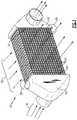
- FIG. 1is a perspective view of an example heat exchanger assembly.
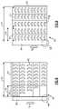
- FIG. 2is an exploded view of another example heat exchanger assembly.
- FIG. 3is a perspective view of a portion of the example heat exchanger assembly.
- FIG. 4is a schematic cross-section along a longitudinal plane of a portion of an example plate.
- FIG. 5is another schematic cross-section of the example plate.
- FIG. 6is a schematic view of augmentation features arranged in internal passages of the example plate.
- FIG. 7is a schematic view of augmentation features arranged on an outer surface of the example plate.
- FIG. 8is another schematic view of augmentation features arranged within internal passages of the example plate.
- FIG. 9is another schematic view of augmentation features arranged on the outer surface of the example plate.
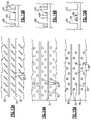
- FIG. 10Ais a top view of example augmentation features within an internal passage.
- FIG. 10Bis a side view of augmentation features within an internal passage.
- FIG. 11Ais a top view of another augmentation feature within the internal passage.
- FIG. 11Bis a cross-sectional view of the augmentation features shown in FIG. 11A within the internal passage.
- FIG. 12Ais top view of yet another augmentation feature within the internal passage.
- FIG. 12Bis a cross-sectional view of the augmentation features within the internal passage shown in FIG. 12A .
- FIG. 13Ais a top view of augmentation features on an outer surface.
- FIG. 13Bis a side view of the augmentation features shown in FIG. 13A .
- FIG. 14Ais a top view of another example group of augmentation features on the outer surface.
- FIG. 14Bis a side view of the augmentation features shown in FIG. 14A .
- FIG. 15Ais top view of yet another group of augmentation features on the outer surface.
- FIG. 15Bis a side view of the augmentation features shown in FIG. 15A .
- an example heat exchangeris schematically shown and indicated at 10 and includes a plurality of plates 12 disposed between an inlet manifold 14 and an outlet manifold 16 .
- Each of the plates 12include internal passages for hot airflow 18 and external surfaces exposed to a cooling airflow 20 .
- the plates 12are one single unitary part that is either cast or formed using other manufacturing techniques that provide a one piece part.
- the plates 12are secured to the inlet manifold 14 at a first joint 22 and to the outlet manifold 16 at a second joint 24 .
- the joints 22 and 24are exposed to differences in temperature between the cooling airflow 20 and the hot airflow 18 .
- a high temperature gradient area schematically shown at 26is located at a position where the coolest of the cooling airflow 20 meets the hottest of the hot flow 18 .
- a thermal gradient between cooling airflow 20 and hot airflow within the plates 12is at its greatest.
- an opposite corner 25 wherein the hottest of the cooling airflow 20 and the coolest of the hot flow 18 meetgenerates the smallest thermal gradient.
- the difference in thermal gradients within the areas 26 and 25can create stresses within the joints 22 and 24 .
- another heat exchanger assembly 28is schematically shown and includes a plurality of plates 34 attached to an inlet manifold 30 at a first joint 36 .
- the plates 34are also attached to an outlet manifold 32 at an outlet joint 40 .
- Each of the joints 36 and 40encounter mechanical stresses caused by uneven thermal gradients within each of the plate structure 34 caused by the differences in temperature between the cooling airflow 20 and the hot airflow 18 .
- a high stress area indicated at 44along with lower stresses throughout other areas create mechanical stresses that are most evident in the joints 36 and 40 .
- Each of the disclosed example plates 34include features to reduce the thermal gradients relative to the high stress locations to reduce mechanical stresses. It should be appreciated that although joints are shown and described by way of example that other high stress locations and interfaces are within the contemplation of this disclosure.
- each of the example plates 12 , 34include inner passages 46 with inner surfaces that are disposed in heat transfer communication with adjacent outer surfaces.
- heat transfer communicationis used to describe opposing surfaces of a common wall, or adjacent wall through which thermal energy is transferred.
- each of the plates 12 , 34the inner passages 46 are separated from the outer surface 48 by a common wall.
- the inner surfaces defined by the passages 46are exposed to hot flow 18 and the outer surface 48 is exposed to cooling airflow 20 .
- each of the outer surface 48 and the passages 46include heat augmentation features 50 .
- the augmentation features 50improve thermal transfer between the hot and cold flows by providing additional surface area and by tailoring flow properties to further enhance thermal transfer.
- the augmentation features 50are arranged in a density for a defined area to tailor thermal transfer to minimize mechanical stresses. Variation of heat augmentation density between augmentation features 50 on the outer surface 48 and the passages 46 enable tailoring of thermal transfer and thereby enable adjustment of thermal gradients to reduce stresses on a joint such as the joint schematically indicated at 56 .
- the example disclosed plates 12 , 34include groups of augmentation features 50 that are proportionally arranged to reduce thermal gradients relative to mechanical interfaces such as the example joint 56 .
- the internal passages 46are schematically illustrated in FIG. 6 and include a group of augmentation features 50 that improve the transfer of thermal energy from the hot airflow 18 through the passage walls into the outer surface 48 .
- Both the internal passages 46 and outer surface 48are shown adjacent to a joint 56 .
- the example joint 56is an interface that includes mechanical stresses that are greatest in the region 58 . Stresses in the joint 56 increase in a direction indicated by arrow 75 toward the region 58 .
- the example plates 12 , 34include a disclosed relative arrangement of augmentation features to provide more uniform thermal gradients that reduce stresses in the joint 56 .
- a joint 56is illustrated schematically by way of example, any interface subject to mechanical stress would benefit from the features described in this disclosure.
- the example plates 12 , 34include a length 52 that begins at the joint 56 and extends the entire length of the passages 46 .
- a first region 55is disposed within a length 54 from the joint 56 and a second region 57 is disposed at the end of the first region 55 to the end of the plate 12 , 34 .
- the first region 55is disposed within the length 54 that is no more than 10% of the total length 52 .
- the first region 55is within the length 54 that is no more than 7% of the total length.
- the number of augmentation features 50 within the passages 46is different than the number of augmentation features 50 within the same first region 55 on the outer surface 48 . It should be understood, that variation in the number of augmentation features is discloses by way of example, but any difference in number, structure, shape of the augmentation features that changes the thermal transfer capability through the adjoining wall could be utilized and is within the contemplation of this disclosure.
- the outer surface 48includes a second group 67 of augmentation features 50 that includes an equal number of augmentation features 50 disposed at a uniform density along the entire length 52 to define a second average density of augmentation features.
- the passage 46includes a first group 65 of augmentation features 50 that define a first average density of augmentation features for all the augmentation features across the length 52 .
- the first average density of augmentation features and the second average density of augmentation featuresare related according to a total augmentation feature density ratio that relates augmentation features in the first and second groups to each other.
- the passage 46does not include any augmentation features within the first region 55 . Accordingly, a ratio of the first group of augmentation features to the second group of augmentation features within the first region is different than for than the total augmentation feature density of augmentation features. In one disclosed embodiment, a first region augmentation feature density ratio is less than the total augmentation feature density ratio.
- a density of augmentation features 50 disposed on the outer surface 48 relative to a density of augmentation features within the passage 46differs to vary the differing densities of heat augmentation features within the passage 46 and the outer surface 48 reduces thermal stresses in the blade and the joint.
- the first region augmentation feature density ratiois up to 20% less than the total augmentation feature density ratio.
- the reduced density ratiois provided by reducing the group of first augmentation features provided in the passage 46 as compared to the group of second augmentation features 50 provided on the outer surface 48 .
- the first region augmentation feature density ratiois up to 15% less than the total augmentation feature density ratio.
- the density of augmentation features 50 in the first group 65 within the passage 46is reduced as compared to the second group 67 provided on the outer surface 48 within the first region 55 .
- the disclosed examplesinclude a reduction in augmentation features in the first group within the passage 46
- the different ratiosmay also be provided by increasing the number of augmentation features within the second group on the outer surface and is within the scope and contemplation of this disclosure.
- the density of augmentation features 50 within the second group 67 disposed on the outer surfaces 48is up to 225% greater than the first group 65 provided in the first passage 46 . In another disclosed example embodiment, the density of augmentation features 50 within the second group 67 is up to 200% greater than the first group 65 in the passages 46 .
- the differing density of augmentation features 50enables tailoring of thermal transfer to reduce stresses within the interface provided by the joint 56 .
- FIGS. 8 and 9another example plate 12 , 34 is schematically shown to illustrate another example relative orientation between augmentation features 50 within the passages 46 and the outer surface within the first region 54 .
- the density of augmentation features 50 within the passage 46is increased in a direction away from the high stress area indicated at 58 .
- the density of augmentation features 50 provided on the outer surface 48remain the same.
- Increasing the density of augmentation features 50 in a direction away from the highest stress region 58 within the passages 46provides desired reduction in thermal gradients that matches stresses within the joint 56 .
- Arrow 75indicates a direction of increasing stress in the joint 56 .
- the density of augmentation features 50 within the passages 46is increased in a direction opposite the increasing stress indicated by arrow 75 .
- the reduced number of augmentation features 50reduce the thermal transfer in that region to provide a more uniform thermal gradient across the plate 12 , 34 .
- an example passage 46including a plurality of trip strips 60 .
- the trip strips 60extend from top and bottom walls 62 of the passage 64 .
- the trip strips 60are integrally formed into the walls 62 to both increase surface area and tailor flow properties of the hot flow 18 to increase thermal transfer.
- FIGS. 11A and 11Banother passage 66 is schematically shown and includes augmentation features in the form of pedestals 70 that extend from walls 62 of the passage 66 .
- augmentation features formed as indentations or dimples 72are provided along the walls 62 of the passage 68 .
- the dimples 72provide additional surface area along enable the flow to be modified to improve thermal transfer.
- an example outer surface 74is shown and includes fins 80 and trip strips 82 between the fins 80 .
- the trip strips 82extend from the outer surface 74 and provide additional surface area for thermal transfer.
- the example trip strips 82are shown as simple angled walls that can direct flow against the fins 80 to provide additional thermal transfer.
- FIGS. 14A and 14Banother outer surface 76 is illustrated with pedestals 84 disposed between the fins 80 .
- the pedestals 84extend upward between the fins to enable tailoring of thermal transfer and cooling airflow 20 properties.
- yet another example outer surface 78is disclosed including dimples 86 disposed between the fins 80 .
- the dimples 86provide for flow conditioning of cooling airflow between the fins 80 as well as improved thermal transfer properties.
- the example disclosed augmentation featuresformed as integral portions of surfaces of each of the plates on both the inner and outer surfaces in a targeted manner to tailor thermal gradients to reduce thermal stresses relative to interfaces and joints.
Landscapes
- Engineering & Computer Science (AREA)
- Physics & Mathematics (AREA)
- Thermal Sciences (AREA)
- Mechanical Engineering (AREA)
- General Engineering & Computer Science (AREA)
- Geometry (AREA)
- Heat-Exchange Devices With Radiators And Conduit Assemblies (AREA)
Abstract
Description
Claims (16)
Priority Applications (2)
| Application Number | Priority Date | Filing Date | Title |
|---|---|---|---|
| US16/276,801US11391523B2 (en) | 2018-03-23 | 2019-02-15 | Asymmetric application of cooling features for a cast plate heat exchanger |
| EP19164136.4AEP3553449B1 (en) | 2018-03-23 | 2019-03-20 | Asymmetric application of cooling features for a cast plate heat exchanger |
Applications Claiming Priority (2)
| Application Number | Priority Date | Filing Date | Title |
|---|---|---|---|
| US201862647116P | 2018-03-23 | 2018-03-23 | |
| US16/276,801US11391523B2 (en) | 2018-03-23 | 2019-02-15 | Asymmetric application of cooling features for a cast plate heat exchanger |
Publications (2)
| Publication Number | Publication Date |
|---|---|
| US20190293367A1 US20190293367A1 (en) | 2019-09-26 |
| US11391523B2true US11391523B2 (en) | 2022-07-19 |
Family
ID=65894884
Family Applications (1)
| Application Number | Title | Priority Date | Filing Date |
|---|---|---|---|
| US16/276,801ActiveUS11391523B2 (en) | 2018-03-23 | 2019-02-15 | Asymmetric application of cooling features for a cast plate heat exchanger |
Country Status (2)
| Country | Link |
|---|---|
| US (1) | US11391523B2 (en) |
| EP (1) | EP3553449B1 (en) |
Cited By (2)
| Publication number | Priority date | Publication date | Assignee | Title |
|---|---|---|---|---|
| US20220003165A1 (en)* | 2020-06-25 | 2022-01-06 | Turbine Aeronautics IP Pty Ltd | Heat exchanger |
| US12372313B2 (en) | 2022-12-15 | 2025-07-29 | Rtx Corporation | Variable passages to optimize delta p and heat transfer along flow path |
Families Citing this family (1)
| Publication number | Priority date | Publication date | Assignee | Title |
|---|---|---|---|---|
| US11391523B2 (en)* | 2018-03-23 | 2022-07-19 | Raytheon Technologies Corporation | Asymmetric application of cooling features for a cast plate heat exchanger |
Citations (123)
| Publication number | Priority date | Publication date | Assignee | Title |
|---|---|---|---|---|
| US813918A (en)* | 1899-12-29 | 1906-02-27 | Albert Schmitz | Tubes, single or compound, with longitudinal ribs. |
| US1343352A (en)* | 1918-02-19 | 1920-06-15 | Costelloe Clinton | Automobile-radiator |
| US1365438A (en)* | 1920-10-21 | 1921-01-11 | Cecil F Adamson | Automobile-crank-case pan |
| US1376882A (en)* | 1919-10-14 | 1921-05-03 | Motor Radiator & Mfg Corp | Radiator |
| US1519673A (en)* | 1921-08-01 | 1924-12-16 | Doble Lab | Heater |
| US1777782A (en)* | 1929-02-11 | 1930-10-07 | Bundy Tubing Co | Externally and internally finned tube and method therefor |
| US1935332A (en)* | 1932-09-13 | 1933-11-14 | Bundy Tubing Co | Heat transfer device |
| US2362571A (en)* | 1942-09-02 | 1944-11-14 | Henry J De N Mccollum | Heater |
| US2389166A (en)* | 1942-01-20 | 1945-11-20 | Jay J Seaver | Flue insert for regenerative furnaces and the like |
| US2405722A (en)* | 1943-02-27 | 1946-08-13 | Charles J Villier | Heat exchange structure |
| US2414557A (en)* | 1944-03-02 | 1947-01-21 | Sears Roebuck & Co | Sidearm circulating water heater |
| US2432308A (en)* | 1943-12-29 | 1947-12-09 | Harold J Goodyer | Conduit having annular ribs, a sump, and sediment directing means |
| US2467668A (en)* | 1947-10-30 | 1949-04-19 | Chase Brass & Copper Co | Mandrel for expanding internallyfinned tubes |
| US2577188A (en)* | 1948-04-01 | 1951-12-04 | Michael F Hall | Composite oil pan for engines |
| US2703921A (en)* | 1949-04-14 | 1955-03-15 | Brown Fintube Co | Method of making internally finned tubes |
| US2717320A (en)* | 1952-03-10 | 1955-09-06 | Reliance Electric & Eng Co | Heat exchanger |
| US2895508A (en)* | 1955-11-23 | 1959-07-21 | Patterson Kelley Company Inc | Heat exchange conduit |
| US2905447A (en)* | 1956-05-04 | 1959-09-22 | Huet Andre | Tubular heat-exchanger |
| US2929408A (en)* | 1955-04-27 | 1960-03-22 | Acme Ind Inc | Fin construction |
| US2930405A (en)* | 1955-05-31 | 1960-03-29 | Brown Fintube Co | Tube with internal fins and method of making same |
| US3002729A (en)* | 1955-06-20 | 1961-10-03 | Brown Fintube Co | Tube with external fins |
| US3136037A (en)* | 1955-10-31 | 1964-06-09 | Olin Mathieson | Method of constructing finned heat exchangers from bonded metal sheets |
| US3267564A (en)* | 1964-04-23 | 1966-08-23 | Calumet & Hecla | Method of producing duplex internally finned tube unit |
| US3301319A (en)* | 1965-03-23 | 1967-01-31 | High Vacuum Equipment Corp | Thermal shroud |
| US3705617A (en)* | 1970-11-05 | 1972-12-12 | Badger Co | Sublimation apparatus and method |
| US3817354A (en)* | 1972-06-01 | 1974-06-18 | Gear Co M W | Oil pan for tractors |
| US3908603A (en)* | 1973-06-21 | 1975-09-30 | Beondu Ag | Boiler and elements therefor |
| US3993126A (en)* | 1973-07-27 | 1976-11-23 | Delanair Limited | Heat exchanger |
| US4022272A (en)* | 1975-11-14 | 1977-05-10 | Chester O. Houston, Jr. | Transmission fluid heat radiator |
| US4022162A (en)* | 1975-11-21 | 1977-05-10 | Societe Generale De Fonderie | Boiler having a separable furnace and heat exchanger |
| US4157698A (en)* | 1976-10-09 | 1979-06-12 | Hans Viessmann | Water heating boiler |
| US4169431A (en)* | 1976-10-09 | 1979-10-02 | Hans Viessmann | Boiler |
| US4282833A (en)* | 1978-05-23 | 1981-08-11 | Metaalgieterij G. Giesen, B.V. | Hot-water boiler, for instance a central heating boiler, and a metal casting therefor |
| US4296539A (en)* | 1978-01-27 | 1981-10-27 | Kobe Steel, Limited | Heat transfer tubing for natural gas evaporator |
| US4306619A (en)* | 1979-04-09 | 1981-12-22 | Trojani Benito L | Tube provided with inner fins and outer fins or pins, particularly for heat exchangers, and method therefor |
| US4345644A (en)* | 1980-11-03 | 1982-08-24 | Dankowski Detlef B | Oil cooler |
| US4356794A (en)* | 1979-10-25 | 1982-11-02 | Tricentrol Benelux B.V. | Hot water boiler |
| US4470455A (en)* | 1978-06-19 | 1984-09-11 | General Motors Corporation | Plate type heat exchanger tube pass |
| JPS60238684A (en) | 1984-05-11 | 1985-11-27 | Mitsubishi Electric Corp | Heat exchanger |
| US4653572A (en)* | 1986-03-11 | 1987-03-31 | Air Products And Chemicals, Inc. | Dual-zone boiling process |
| US4657074A (en)* | 1985-02-27 | 1987-04-14 | Diesel Kiki Co., Ltd. | Heat exchanger for combustion heater |
| US4696342A (en)* | 1985-06-28 | 1987-09-29 | Nippondenso Co., Ltd. | Plate-type heat exchanger |
| EP0248222A2 (en) | 1986-05-06 | 1987-12-09 | Norsk Hydro A/S | Cooling tubes, and process and device for their manufacture |
| US4751964A (en)* | 1985-07-19 | 1988-06-21 | Feg Fegyver-Es Gazkeszulekgyar | Heat exchanger, mainly for use with gas heated devices |
| US4778002A (en)* | 1985-09-14 | 1988-10-18 | Norsk Hydro A.S | Fluid cooler |
| US4782892A (en)* | 1983-08-26 | 1988-11-08 | Oestbo Karl | Heat exchanger |
| US4886018A (en)* | 1985-12-23 | 1989-12-12 | Paolo Ferroli | Boiler element |
| US4898261A (en)* | 1989-04-10 | 1990-02-06 | Brunswick Corporation | Water cooled plastic oil pan |
| US5855240A (en)* | 1998-06-03 | 1999-01-05 | Ford Motor Company | Automotive heat exchanger |
| US5937817A (en)* | 1998-06-23 | 1999-08-17 | Harley-Davidson Motor Company | Dry sump oil cooling system |
| US6047769A (en)* | 1997-07-17 | 2000-04-11 | Denso Corporation | Heat exchanger constructed by plural heat conductive plates |
| US6070657A (en)* | 1994-03-24 | 2000-06-06 | Hoval Interliz Ag | Heat exchanger tube for heating boilers |
| US6157778A (en)* | 1995-11-30 | 2000-12-05 | Komatsu Ltd. | Multi-temperature control system and fluid temperature control device applicable to the same system |
| US6187185B1 (en)* | 2000-01-11 | 2001-02-13 | Dana Corporation | Filter arrangement for liquids |
| US6202736B1 (en)* | 1999-08-19 | 2001-03-20 | Verlyn R. Fast | Vehicle transmission fluid cooler |
| US6286465B1 (en)* | 2000-04-28 | 2001-09-11 | Aos Holding Company | Water heater flue system |
| US6289982B1 (en)* | 1998-12-30 | 2001-09-18 | Valeo Climatisation | Heat exchanger, heating and/or air conditioning apparatus and vehicle including such a heat exchanger |
| US6318455B1 (en)* | 1999-07-14 | 2001-11-20 | Mitsubishi Heavy Industries, Ltd. | Heat exchanger |
| US6321792B1 (en)* | 1998-06-08 | 2001-11-27 | Norsk Hydro Asa | Flow conduit and means for enlarging the surface thereof to provide cooling, and a fuel pipe, and a method for the manufacture thereof |
| US20020029871A1 (en)* | 2000-05-23 | 2002-03-14 | Josef Kern | Heat exchanger block |
| US6438936B1 (en)* | 2000-05-16 | 2002-08-27 | Elliott Energy Systems, Inc. | Recuperator for use with turbine/turbo-alternator |
| US20030033990A1 (en)* | 1999-12-21 | 2003-02-20 | Keita Inoue | Fire-resistant structural body supporting metal bar for protection of water pipe |
| US20030159806A1 (en)* | 2002-02-28 | 2003-08-28 | Sehmbey Maninder Singh | Flat-plate heat-pipe with lanced-offset fin wick |
| US6691831B1 (en)* | 1999-09-29 | 2004-02-17 | Fuji Jukogyo Kabushiki Kaisha | Splashing oil lubrication type internal combustion engine |
| US20040099712A1 (en) | 2002-11-27 | 2004-05-27 | Tonkovich Anna Lee | Microchannel apparatus, methods of making microchannel apparatus, and processes of conducting unit operations |
| US20050120715A1 (en)* | 1997-12-23 | 2005-06-09 | Christion School Of Technology Charitable Foundation Trust | Heat energy recapture and recycle and its new applications |
| US6938685B2 (en)* | 2001-05-11 | 2005-09-06 | Behr Gmbh & Co. | Heat exchanger |
| US7044210B2 (en)* | 2002-05-10 | 2006-05-16 | Usui Kokusai Sangyo Kaisha, Ltd. | Heat transfer pipe and heat exchange incorporating such heat transfer pipe |
| US7148452B2 (en)* | 2001-04-03 | 2006-12-12 | Emerson Electric Co. | Heat sink for printed circuit board components |
| US20080149313A1 (en)* | 2006-12-20 | 2008-06-26 | Victor Blakemore Slaughter | Method of making a heat exchanger |
| US20090218086A1 (en)* | 2007-06-26 | 2009-09-03 | Aerojet-General Corporation | Heat exchanger for a rocket engine |
| US7588074B1 (en)* | 2004-12-21 | 2009-09-15 | Robert Alvin White | In the rate of energy transfer across boundaries |
| US7637337B2 (en)* | 2007-04-19 | 2009-12-29 | Ford Global Technologies, Llc | Transmission oil pan |
| US20100162967A1 (en)* | 2007-04-16 | 2010-07-01 | Stephen Taylor | Heat exchanger |
| US20100242863A1 (en)* | 2007-10-25 | 2010-09-30 | Bekaert Combustion Technology B.V. | Metallic porous body incorporated by casting into a heat exchanger |
| US20110108253A1 (en)* | 2008-07-03 | 2011-05-12 | Peter Jan Cool | Heat Exchanger |
| US20120090563A1 (en)* | 2009-06-23 | 2012-04-19 | Bekaert Combustion Technology B.V. | Core box with air vents integrated in pins |
| US8235098B2 (en)* | 2008-01-24 | 2012-08-07 | Honeywell International Inc. | Heat exchanger flat tube with oblique elongate dimples |
| US20140096938A1 (en)* | 2012-10-04 | 2014-04-10 | Tokaiseiki Co., Ltd. | Heat dissipation device |
| US20140110085A1 (en)* | 2012-10-23 | 2014-04-24 | Dejatech Ges B.V. | Heat exchanger and method for manufacturing such |
| US20140116664A1 (en) | 2012-10-31 | 2014-05-01 | The Boeing Company | Cross-Flow Heat Exchanger Having Graduated Fin Density |
| US8770269B2 (en)* | 2010-06-11 | 2014-07-08 | Hs Marston Aerospace Ltd. | Three phase fin surface cooler |
| US20140260218A1 (en)* | 2013-03-12 | 2014-09-18 | Dejatech Ges B.V. | Combined heat and power (chp) system |
| US8939683B1 (en)* | 2004-12-21 | 2015-01-27 | Robert Alvin White | Inverse square tool form |
| US20150050520A1 (en)* | 2011-12-02 | 2015-02-19 | Uacj Corporation | Aluminum alloy material, aluminum alloy structure, and manufacturing method for same |
| US20150121701A1 (en)* | 2009-10-03 | 2015-05-07 | Wolverine Tube, Inc. | Cold Plate with Pins |
| US9077056B2 (en)* | 2007-12-11 | 2015-07-07 | Battery Patent Trust | Device for housing electrochemical cells |
| US20160069622A1 (en)* | 2013-04-23 | 2016-03-10 | Alexiou & Tryde Holding Aps | Heat Sink Having a Cooling Structure with Decreasing Structure Density |
| US20160110881A1 (en) | 2014-10-20 | 2016-04-21 | Sesame Enable Ltd | Motion tracking device control systems and methods |
| US20160230595A1 (en) | 2015-02-06 | 2016-08-11 | United Technologies Corporation | Heat exchanger system with spatially varied additively manufactured heat transfer surfaces |
| US9437905B2 (en)* | 2014-02-25 | 2016-09-06 | Ford Global Technologies, Llc | Traction battery thermal plate manifold |
| US20170152751A1 (en) | 2015-12-01 | 2017-06-01 | United Technologies Corporation | Cooling passages for a gas path component of a gas turbine engine |
| US9745069B2 (en)* | 2013-01-21 | 2017-08-29 | Hamilton Sundstrand Corporation | Air-liquid heat exchanger assembly having a bypass valve |
| US9777963B2 (en)* | 2014-06-30 | 2017-10-03 | General Electric Company | Method and system for radial tubular heat exchangers |
| US20170333941A1 (en) | 2014-10-28 | 2017-11-23 | President And Fellows Of Harvard College | High energy efficiency phase change device using convex surface features |
| US20170343301A1 (en)* | 2016-05-25 | 2017-11-30 | Nova Chemicals (International) S.A. | Furnace coil modified fins |
| US9835380B2 (en)* | 2015-03-13 | 2017-12-05 | General Electric Company | Tube in cross-flow conduit heat exchanger |
| US20180045472A1 (en)* | 2016-08-15 | 2018-02-15 | Hs Marston Aerospace Limited | Heat exchanger device |
| US20180073813A1 (en)* | 2016-09-12 | 2018-03-15 | Hamilton Sundstrand Corporation | Counter-flow ceramic heat exchanger assembly and method |
| US10006369B2 (en)* | 2014-06-30 | 2018-06-26 | General Electric Company | Method and system for radial tubular duct heat exchangers |
| US20180209635A1 (en)* | 2015-08-04 | 2018-07-26 | Philips Lightng Holding B.V. | Heat sink lighting device and method for manufacturing a heat sink |
| US20180299210A1 (en)* | 2015-10-08 | 2018-10-18 | Linde Aktiengesellschaft | Fin for a plate heat exchanger and method for producing same |
| US20180340743A1 (en)* | 2010-05-04 | 2018-11-29 | Fractal Heatsink Technologies LLC | Fractal heat transfer device |
| US20180372416A1 (en)* | 2017-06-26 | 2018-12-27 | United Technologies Corporation | Manufacturing a heat exchanger using a material buildup process |
| US10175003B2 (en)* | 2017-02-28 | 2019-01-08 | General Electric Company | Additively manufactured heat exchanger |
| US20190021186A1 (en)* | 2017-07-17 | 2019-01-17 | Fractal Heatsink Technologies, LLC | Multi-fractal heatsink system and method |
| US10184702B2 (en)* | 2013-07-31 | 2019-01-22 | Sortech Ag | Adsorption module |
| US20190036301A1 (en)* | 2017-07-26 | 2019-01-31 | The Boeing Company | Methods and apparatus to thermally manage heat sources using eutectic thermal control |
| US10316750B2 (en)* | 2014-02-21 | 2019-06-11 | Rolls-Royce North American Technologies, Inc. | Single phase micro/mini channel heat exchangers for gas turbine intercooling |
| US10378835B2 (en)* | 2016-03-25 | 2019-08-13 | Unison Industries, Llc | Heat exchanger with non-orthogonal perforations |
| US20190277579A1 (en)* | 2018-03-07 | 2019-09-12 | United Technologies Corporation | High temperature plate fin heat exchanger |
| US20190277571A1 (en)* | 2018-03-07 | 2019-09-12 | United Technologies Corporation | Ganged plate stack in cast plate fin heat exchanger |
| US20190277580A1 (en)* | 2018-03-07 | 2019-09-12 | United Technologies Corporation | Segmented fins for a cast heat exchanger |
| US20190293367A1 (en)* | 2018-03-23 | 2019-09-26 | United Technologies Corporation | Asymmetric application of cooling features for a cast plate heat exchanger |
| US20190293365A1 (en)* | 2018-03-23 | 2019-09-26 | United Technologies Corporation | Cast plate heat exchanger and method of making using directional solidification |
| US20190293366A1 (en)* | 2018-03-23 | 2019-09-26 | United Technologies Corporation | Shaped leading edge of cast plate fin heat exchanger |
| US10520261B2 (en)* | 2012-09-25 | 2019-12-31 | Mahle International Gmbh | Flat pipe |
| US20200025467A1 (en)* | 2018-03-23 | 2020-01-23 | United Technologies Corporation | Stackable core system for producing cast plate heat exchanger |
| US10578374B2 (en)* | 2016-08-31 | 2020-03-03 | Brazeway, Inc. | Fin enhancements for low Reynolds number airflow |
| US10605543B2 (en)* | 2014-05-12 | 2020-03-31 | Fraunhofer Gesellschaft zur Förderung der angewandten Forschung e.V. | Heat transfer device having channels |
| US10612414B2 (en)* | 2016-08-22 | 2020-04-07 | United Technologies Corporation | Panel based heat exchanger |
| US10690420B2 (en)* | 2015-08-25 | 2020-06-23 | Danfoss Micro Channel Heat Exchanger (Jiaxing) Co., Ltd. | Heat exchange tube for heat exchanger, heat exchanger and assembly method thereof |
| EP3889533A1 (en)* | 2018-04-19 | 2021-10-06 | Raytheon Technologies Corporation | Mixing between flow channels of cast plate heat exchanger |
- 2019
- 2019-02-15USUS16/276,801patent/US11391523B2/enactiveActive
- 2019-03-20EPEP19164136.4Apatent/EP3553449B1/enactiveActive
Patent Citations (132)
| Publication number | Priority date | Publication date | Assignee | Title |
|---|---|---|---|---|
| US813918A (en)* | 1899-12-29 | 1906-02-27 | Albert Schmitz | Tubes, single or compound, with longitudinal ribs. |
| US1343352A (en)* | 1918-02-19 | 1920-06-15 | Costelloe Clinton | Automobile-radiator |
| US1376882A (en)* | 1919-10-14 | 1921-05-03 | Motor Radiator & Mfg Corp | Radiator |
| US1365438A (en)* | 1920-10-21 | 1921-01-11 | Cecil F Adamson | Automobile-crank-case pan |
| US1519673A (en)* | 1921-08-01 | 1924-12-16 | Doble Lab | Heater |
| US1777782A (en)* | 1929-02-11 | 1930-10-07 | Bundy Tubing Co | Externally and internally finned tube and method therefor |
| US1935332A (en)* | 1932-09-13 | 1933-11-14 | Bundy Tubing Co | Heat transfer device |
| US2389166A (en)* | 1942-01-20 | 1945-11-20 | Jay J Seaver | Flue insert for regenerative furnaces and the like |
| US2362571A (en)* | 1942-09-02 | 1944-11-14 | Henry J De N Mccollum | Heater |
| US2405722A (en)* | 1943-02-27 | 1946-08-13 | Charles J Villier | Heat exchange structure |
| US2432308A (en)* | 1943-12-29 | 1947-12-09 | Harold J Goodyer | Conduit having annular ribs, a sump, and sediment directing means |
| US2414557A (en)* | 1944-03-02 | 1947-01-21 | Sears Roebuck & Co | Sidearm circulating water heater |
| US2467668A (en)* | 1947-10-30 | 1949-04-19 | Chase Brass & Copper Co | Mandrel for expanding internallyfinned tubes |
| US2577188A (en)* | 1948-04-01 | 1951-12-04 | Michael F Hall | Composite oil pan for engines |
| US2703921A (en)* | 1949-04-14 | 1955-03-15 | Brown Fintube Co | Method of making internally finned tubes |
| US2717320A (en)* | 1952-03-10 | 1955-09-06 | Reliance Electric & Eng Co | Heat exchanger |
| US2929408A (en)* | 1955-04-27 | 1960-03-22 | Acme Ind Inc | Fin construction |
| US2930405A (en)* | 1955-05-31 | 1960-03-29 | Brown Fintube Co | Tube with internal fins and method of making same |
| US3002729A (en)* | 1955-06-20 | 1961-10-03 | Brown Fintube Co | Tube with external fins |
| US3136037A (en)* | 1955-10-31 | 1964-06-09 | Olin Mathieson | Method of constructing finned heat exchangers from bonded metal sheets |
| US2895508A (en)* | 1955-11-23 | 1959-07-21 | Patterson Kelley Company Inc | Heat exchange conduit |
| US2905447A (en)* | 1956-05-04 | 1959-09-22 | Huet Andre | Tubular heat-exchanger |
| US3267564A (en)* | 1964-04-23 | 1966-08-23 | Calumet & Hecla | Method of producing duplex internally finned tube unit |
| US3301319A (en)* | 1965-03-23 | 1967-01-31 | High Vacuum Equipment Corp | Thermal shroud |
| US3705617A (en)* | 1970-11-05 | 1972-12-12 | Badger Co | Sublimation apparatus and method |
| US3817354A (en)* | 1972-06-01 | 1974-06-18 | Gear Co M W | Oil pan for tractors |
| US3908603A (en)* | 1973-06-21 | 1975-09-30 | Beondu Ag | Boiler and elements therefor |
| US3993126A (en)* | 1973-07-27 | 1976-11-23 | Delanair Limited | Heat exchanger |
| US4022272A (en)* | 1975-11-14 | 1977-05-10 | Chester O. Houston, Jr. | Transmission fluid heat radiator |
| US4022162A (en)* | 1975-11-21 | 1977-05-10 | Societe Generale De Fonderie | Boiler having a separable furnace and heat exchanger |
| US4157698A (en)* | 1976-10-09 | 1979-06-12 | Hans Viessmann | Water heating boiler |
| US4169431A (en)* | 1976-10-09 | 1979-10-02 | Hans Viessmann | Boiler |
| US4296539A (en)* | 1978-01-27 | 1981-10-27 | Kobe Steel, Limited | Heat transfer tubing for natural gas evaporator |
| US4282833A (en)* | 1978-05-23 | 1981-08-11 | Metaalgieterij G. Giesen, B.V. | Hot-water boiler, for instance a central heating boiler, and a metal casting therefor |
| US4470455A (en)* | 1978-06-19 | 1984-09-11 | General Motors Corporation | Plate type heat exchanger tube pass |
| US4306619A (en)* | 1979-04-09 | 1981-12-22 | Trojani Benito L | Tube provided with inner fins and outer fins or pins, particularly for heat exchangers, and method therefor |
| US4356794A (en)* | 1979-10-25 | 1982-11-02 | Tricentrol Benelux B.V. | Hot water boiler |
| US4345644A (en)* | 1980-11-03 | 1982-08-24 | Dankowski Detlef B | Oil cooler |
| US4782892A (en)* | 1983-08-26 | 1988-11-08 | Oestbo Karl | Heat exchanger |
| JPS60238684A (en) | 1984-05-11 | 1985-11-27 | Mitsubishi Electric Corp | Heat exchanger |
| US4657074A (en)* | 1985-02-27 | 1987-04-14 | Diesel Kiki Co., Ltd. | Heat exchanger for combustion heater |
| US4696342A (en)* | 1985-06-28 | 1987-09-29 | Nippondenso Co., Ltd. | Plate-type heat exchanger |
| US4751964A (en)* | 1985-07-19 | 1988-06-21 | Feg Fegyver-Es Gazkeszulekgyar | Heat exchanger, mainly for use with gas heated devices |
| US4778002A (en)* | 1985-09-14 | 1988-10-18 | Norsk Hydro A.S | Fluid cooler |
| US4821797A (en)* | 1985-09-14 | 1989-04-18 | Norsk Hydro A.S. | Fluid cooler |
| US4886018A (en)* | 1985-12-23 | 1989-12-12 | Paolo Ferroli | Boiler element |
| US4653572A (en)* | 1986-03-11 | 1987-03-31 | Air Products And Chemicals, Inc. | Dual-zone boiling process |
| EP0248222A2 (en) | 1986-05-06 | 1987-12-09 | Norsk Hydro A/S | Cooling tubes, and process and device for their manufacture |
| US4898261A (en)* | 1989-04-10 | 1990-02-06 | Brunswick Corporation | Water cooled plastic oil pan |
| US6070657A (en)* | 1994-03-24 | 2000-06-06 | Hoval Interliz Ag | Heat exchanger tube for heating boilers |
| US6157778A (en)* | 1995-11-30 | 2000-12-05 | Komatsu Ltd. | Multi-temperature control system and fluid temperature control device applicable to the same system |
| US6047769A (en)* | 1997-07-17 | 2000-04-11 | Denso Corporation | Heat exchanger constructed by plural heat conductive plates |
| US20050120715A1 (en)* | 1997-12-23 | 2005-06-09 | Christion School Of Technology Charitable Foundation Trust | Heat energy recapture and recycle and its new applications |
| US5855240A (en)* | 1998-06-03 | 1999-01-05 | Ford Motor Company | Automotive heat exchanger |
| US6321792B1 (en)* | 1998-06-08 | 2001-11-27 | Norsk Hydro Asa | Flow conduit and means for enlarging the surface thereof to provide cooling, and a fuel pipe, and a method for the manufacture thereof |
| US5937817A (en)* | 1998-06-23 | 1999-08-17 | Harley-Davidson Motor Company | Dry sump oil cooling system |
| US6289982B1 (en)* | 1998-12-30 | 2001-09-18 | Valeo Climatisation | Heat exchanger, heating and/or air conditioning apparatus and vehicle including such a heat exchanger |
| US6318455B1 (en)* | 1999-07-14 | 2001-11-20 | Mitsubishi Heavy Industries, Ltd. | Heat exchanger |
| US6202736B1 (en)* | 1999-08-19 | 2001-03-20 | Verlyn R. Fast | Vehicle transmission fluid cooler |
| US6691831B1 (en)* | 1999-09-29 | 2004-02-17 | Fuji Jukogyo Kabushiki Kaisha | Splashing oil lubrication type internal combustion engine |
| US20030033990A1 (en)* | 1999-12-21 | 2003-02-20 | Keita Inoue | Fire-resistant structural body supporting metal bar for protection of water pipe |
| US6187185B1 (en)* | 2000-01-11 | 2001-02-13 | Dana Corporation | Filter arrangement for liquids |
| US6286465B1 (en)* | 2000-04-28 | 2001-09-11 | Aos Holding Company | Water heater flue system |
| US6438936B1 (en)* | 2000-05-16 | 2002-08-27 | Elliott Energy Systems, Inc. | Recuperator for use with turbine/turbo-alternator |
| US20020029871A1 (en)* | 2000-05-23 | 2002-03-14 | Josef Kern | Heat exchanger block |
| US7148452B2 (en)* | 2001-04-03 | 2006-12-12 | Emerson Electric Co. | Heat sink for printed circuit board components |
| US6938685B2 (en)* | 2001-05-11 | 2005-09-06 | Behr Gmbh & Co. | Heat exchanger |
| US20030159806A1 (en)* | 2002-02-28 | 2003-08-28 | Sehmbey Maninder Singh | Flat-plate heat-pipe with lanced-offset fin wick |
| US7044210B2 (en)* | 2002-05-10 | 2006-05-16 | Usui Kokusai Sangyo Kaisha, Ltd. | Heat transfer pipe and heat exchange incorporating such heat transfer pipe |
| US20040099712A1 (en) | 2002-11-27 | 2004-05-27 | Tonkovich Anna Lee | Microchannel apparatus, methods of making microchannel apparatus, and processes of conducting unit operations |
| US8939683B1 (en)* | 2004-12-21 | 2015-01-27 | Robert Alvin White | Inverse square tool form |
| US7588074B1 (en)* | 2004-12-21 | 2009-09-15 | Robert Alvin White | In the rate of energy transfer across boundaries |
| US20080149313A1 (en)* | 2006-12-20 | 2008-06-26 | Victor Blakemore Slaughter | Method of making a heat exchanger |
| US20100162967A1 (en)* | 2007-04-16 | 2010-07-01 | Stephen Taylor | Heat exchanger |
| US7637337B2 (en)* | 2007-04-19 | 2009-12-29 | Ford Global Technologies, Llc | Transmission oil pan |
| US20090218086A1 (en)* | 2007-06-26 | 2009-09-03 | Aerojet-General Corporation | Heat exchanger for a rocket engine |
| US20100242863A1 (en)* | 2007-10-25 | 2010-09-30 | Bekaert Combustion Technology B.V. | Metallic porous body incorporated by casting into a heat exchanger |
| US9077056B2 (en)* | 2007-12-11 | 2015-07-07 | Battery Patent Trust | Device for housing electrochemical cells |
| US8235098B2 (en)* | 2008-01-24 | 2012-08-07 | Honeywell International Inc. | Heat exchanger flat tube with oblique elongate dimples |
| US20110108253A1 (en)* | 2008-07-03 | 2011-05-12 | Peter Jan Cool | Heat Exchanger |
| US8757103B2 (en)* | 2008-07-03 | 2014-06-24 | Inter-Gas Heating Assets B.V. | Heat exchanger |
| US20120090563A1 (en)* | 2009-06-23 | 2012-04-19 | Bekaert Combustion Technology B.V. | Core box with air vents integrated in pins |
| US20150121701A1 (en)* | 2009-10-03 | 2015-05-07 | Wolverine Tube, Inc. | Cold Plate with Pins |
| US20180340743A1 (en)* | 2010-05-04 | 2018-11-29 | Fractal Heatsink Technologies LLC | Fractal heat transfer device |
| US8770269B2 (en)* | 2010-06-11 | 2014-07-08 | Hs Marston Aerospace Ltd. | Three phase fin surface cooler |
| US20150050520A1 (en)* | 2011-12-02 | 2015-02-19 | Uacj Corporation | Aluminum alloy material, aluminum alloy structure, and manufacturing method for same |
| US20170137919A1 (en)* | 2011-12-02 | 2017-05-18 | Uacj Corporation | Aluminum alloy material, aluminum alloy structure, and manufacturing method for same |
| US10520261B2 (en)* | 2012-09-25 | 2019-12-31 | Mahle International Gmbh | Flat pipe |
| US20140096938A1 (en)* | 2012-10-04 | 2014-04-10 | Tokaiseiki Co., Ltd. | Heat dissipation device |
| US20140110085A1 (en)* | 2012-10-23 | 2014-04-24 | Dejatech Ges B.V. | Heat exchanger and method for manufacturing such |
| US20140116664A1 (en) | 2012-10-31 | 2014-05-01 | The Boeing Company | Cross-Flow Heat Exchanger Having Graduated Fin Density |
| US9377250B2 (en) | 2012-10-31 | 2016-06-28 | The Boeing Company | Cross-flow heat exchanger having graduated fin density |
| US9745069B2 (en)* | 2013-01-21 | 2017-08-29 | Hamilton Sundstrand Corporation | Air-liquid heat exchanger assembly having a bypass valve |
| US20140260218A1 (en)* | 2013-03-12 | 2014-09-18 | Dejatech Ges B.V. | Combined heat and power (chp) system |
| US20160069622A1 (en)* | 2013-04-23 | 2016-03-10 | Alexiou & Tryde Holding Aps | Heat Sink Having a Cooling Structure with Decreasing Structure Density |
| US10184702B2 (en)* | 2013-07-31 | 2019-01-22 | Sortech Ag | Adsorption module |
| US10316750B2 (en)* | 2014-02-21 | 2019-06-11 | Rolls-Royce North American Technologies, Inc. | Single phase micro/mini channel heat exchangers for gas turbine intercooling |
| US9437905B2 (en)* | 2014-02-25 | 2016-09-06 | Ford Global Technologies, Llc | Traction battery thermal plate manifold |
| US10605543B2 (en)* | 2014-05-12 | 2020-03-31 | Fraunhofer Gesellschaft zur Förderung der angewandten Forschung e.V. | Heat transfer device having channels |
| US10006369B2 (en)* | 2014-06-30 | 2018-06-26 | General Electric Company | Method and system for radial tubular duct heat exchangers |
| US9777963B2 (en)* | 2014-06-30 | 2017-10-03 | General Electric Company | Method and system for radial tubular heat exchangers |
| US20160110881A1 (en) | 2014-10-20 | 2016-04-21 | Sesame Enable Ltd | Motion tracking device control systems and methods |
| US20170333941A1 (en) | 2014-10-28 | 2017-11-23 | President And Fellows Of Harvard College | High energy efficiency phase change device using convex surface features |
| US10907500B2 (en)* | 2015-02-06 | 2021-02-02 | Raytheon Technologies Corporation | Heat exchanger system with spatially varied additively manufactured heat transfer surfaces |
| US20160230595A1 (en) | 2015-02-06 | 2016-08-11 | United Technologies Corporation | Heat exchanger system with spatially varied additively manufactured heat transfer surfaces |
| US9835380B2 (en)* | 2015-03-13 | 2017-12-05 | General Electric Company | Tube in cross-flow conduit heat exchanger |
| US20180209635A1 (en)* | 2015-08-04 | 2018-07-26 | Philips Lightng Holding B.V. | Heat sink lighting device and method for manufacturing a heat sink |
| US10690420B2 (en)* | 2015-08-25 | 2020-06-23 | Danfoss Micro Channel Heat Exchanger (Jiaxing) Co., Ltd. | Heat exchange tube for heat exchanger, heat exchanger and assembly method thereof |
| US20180299210A1 (en)* | 2015-10-08 | 2018-10-18 | Linde Aktiengesellschaft | Fin for a plate heat exchanger and method for producing same |
| US20170152751A1 (en) | 2015-12-01 | 2017-06-01 | United Technologies Corporation | Cooling passages for a gas path component of a gas turbine engine |
| US10378835B2 (en)* | 2016-03-25 | 2019-08-13 | Unison Industries, Llc | Heat exchanger with non-orthogonal perforations |
| US20170343301A1 (en)* | 2016-05-25 | 2017-11-30 | Nova Chemicals (International) S.A. | Furnace coil modified fins |
| US20180045472A1 (en)* | 2016-08-15 | 2018-02-15 | Hs Marston Aerospace Limited | Heat exchanger device |
| US10612414B2 (en)* | 2016-08-22 | 2020-04-07 | United Technologies Corporation | Panel based heat exchanger |
| US10578374B2 (en)* | 2016-08-31 | 2020-03-03 | Brazeway, Inc. | Fin enhancements for low Reynolds number airflow |
| US20180073813A1 (en)* | 2016-09-12 | 2018-03-15 | Hamilton Sundstrand Corporation | Counter-flow ceramic heat exchanger assembly and method |
| US10830540B2 (en)* | 2017-02-28 | 2020-11-10 | General Electric Company | Additively manufactured heat exchanger |
| US10175003B2 (en)* | 2017-02-28 | 2019-01-08 | General Electric Company | Additively manufactured heat exchanger |
| US10502502B2 (en)* | 2017-02-28 | 2019-12-10 | General Electric Company | Additively manufactured heat exchanger |
| US10823511B2 (en)* | 2017-06-26 | 2020-11-03 | Raytheon Technologies Corporation | Manufacturing a heat exchanger using a material buildup process |
| US20180372416A1 (en)* | 2017-06-26 | 2018-12-27 | United Technologies Corporation | Manufacturing a heat exchanger using a material buildup process |
| US20190021186A1 (en)* | 2017-07-17 | 2019-01-17 | Fractal Heatsink Technologies, LLC | Multi-fractal heatsink system and method |
| US20190036301A1 (en)* | 2017-07-26 | 2019-01-31 | The Boeing Company | Methods and apparatus to thermally manage heat sources using eutectic thermal control |
| US20190277579A1 (en)* | 2018-03-07 | 2019-09-12 | United Technologies Corporation | High temperature plate fin heat exchanger |
| US20190277571A1 (en)* | 2018-03-07 | 2019-09-12 | United Technologies Corporation | Ganged plate stack in cast plate fin heat exchanger |
| US20190277580A1 (en)* | 2018-03-07 | 2019-09-12 | United Technologies Corporation | Segmented fins for a cast heat exchanger |
| US20190293367A1 (en)* | 2018-03-23 | 2019-09-26 | United Technologies Corporation | Asymmetric application of cooling features for a cast plate heat exchanger |
| US20190293366A1 (en)* | 2018-03-23 | 2019-09-26 | United Technologies Corporation | Shaped leading edge of cast plate fin heat exchanger |
| US20200025467A1 (en)* | 2018-03-23 | 2020-01-23 | United Technologies Corporation | Stackable core system for producing cast plate heat exchanger |
| US20190293365A1 (en)* | 2018-03-23 | 2019-09-26 | United Technologies Corporation | Cast plate heat exchanger and method of making using directional solidification |
| EP3889533A1 (en)* | 2018-04-19 | 2021-10-06 | Raytheon Technologies Corporation | Mixing between flow channels of cast plate heat exchanger |
| US11209224B2 (en)* | 2018-04-19 | 2021-12-28 | Raytheon Technologies Corporation | Mixing between flow channels of cast plate heat exchanger |
Non-Patent Citations (1)
| Title |
|---|
| European Search Report for EP Application No. 19164136.4 dated Sep. 17, 2019. |
Cited By (3)
| Publication number | Priority date | Publication date | Assignee | Title |
|---|---|---|---|---|
| US20220003165A1 (en)* | 2020-06-25 | 2022-01-06 | Turbine Aeronautics IP Pty Ltd | Heat exchanger |
| US11639828B2 (en)* | 2020-06-25 | 2023-05-02 | Turbine Aeronautics IP Pty Ltd | Heat exchanger |
| US12372313B2 (en) | 2022-12-15 | 2025-07-29 | Rtx Corporation | Variable passages to optimize delta p and heat transfer along flow path |
Also Published As
| Publication number | Publication date |
|---|---|
| US20190293367A1 (en) | 2019-09-26 |
| EP3553449A1 (en) | 2019-10-16 |
| EP3553449B1 (en) | 2021-05-12 |
Similar Documents
| Publication | Publication Date | Title |
|---|---|---|
| EP3553447B1 (en) | Heat augmentation features in a cast heat exchanger | |
| US11079181B2 (en) | Cast plate heat exchanger with tapered walls | |
| US10962306B2 (en) | Shaped leading edge of cast plate fin heat exchanger | |
| EP3499170B1 (en) | Heat exchanger inlet | |
| US20190277579A1 (en) | High temperature plate fin heat exchanger | |
| EP3537085B1 (en) | Ganged plate stack in cast plate fin heat exchanger | |
| US20170167805A1 (en) | Heat exchanger designs using variable geometries and configurations | |
| US11391523B2 (en) | Asymmetric application of cooling features for a cast plate heat exchanger | |
| US20240060728A1 (en) | Cast plate heat exchanger and method of making using directional solidification | |
| US20140027102A1 (en) | Air-cooled engine surface cooler | |
| US8292578B2 (en) | Material having internal cooling passage and method for cooling material having internal cooling passage | |
| EP3537084B1 (en) | Segmented fins for a cast heat exchanger | |
| KR20140118878A (en) | Air to air heat exchanger | |
| GB2100807A (en) | Turbine blade for gas turbine engines | |
| EP3553448B1 (en) | Secondarily applied cold side features for cast heat exchanger | |
| EP3889533B1 (en) | Mixing between flow channels of cast plate heat exchanger | |
| US12372313B2 (en) | Variable passages to optimize delta p and heat transfer along flow path | |
| US12292244B2 (en) | Additively manufactured heat exchanger layer | |
| JP6756314B2 (en) | Heat exchanger | |
| GB2496852A (en) | Heat exchanger with tapered fins for a gas turbine |
Legal Events
| Date | Code | Title | Description |
|---|---|---|---|
| FEPP | Fee payment procedure | Free format text:ENTITY STATUS SET TO UNDISCOUNTED (ORIGINAL EVENT CODE: BIG.); ENTITY STATUS OF PATENT OWNER: LARGE ENTITY | |
| STPP | Information on status: patent application and granting procedure in general | Free format text:DOCKETED NEW CASE - READY FOR EXAMINATION | |
| AS | Assignment | Owner name:RAYTHEON TECHNOLOGIES CORPORATION, MASSACHUSETTS Free format text:CHANGE OF NAME;ASSIGNOR:UNITED TECHNOLOGIES CORPORATION;REEL/FRAME:054062/0001 Effective date:20200403 | |
| STPP | Information on status: patent application and granting procedure in general | Free format text:RESPONSE TO NON-FINAL OFFICE ACTION ENTERED AND FORWARDED TO EXAMINER | |
| AS | Assignment | Owner name:RAYTHEON TECHNOLOGIES CORPORATION, CONNECTICUT Free format text:CORRECTIVE ASSIGNMENT TO CORRECT THE AND REMOVE PATENT APPLICATION NUMBER 11886281 AND ADD PATENT APPLICATION NUMBER 14846874. TO CORRECT THE RECEIVING PARTY ADDRESS PREVIOUSLY RECORDED AT REEL: 054062 FRAME: 0001. ASSIGNOR(S) HEREBY CONFIRMS THE CHANGE OF ADDRESS;ASSIGNOR:UNITED TECHNOLOGIES CORPORATION;REEL/FRAME:055659/0001 Effective date:20200403 | |
| STPP | Information on status: patent application and granting procedure in general | Free format text:NON FINAL ACTION MAILED | |
| STPP | Information on status: patent application and granting procedure in general | Free format text:RESPONSE TO NON-FINAL OFFICE ACTION ENTERED AND FORWARDED TO EXAMINER | |
| STPP | Information on status: patent application and granting procedure in general | Free format text:FINAL REJECTION MAILED | |
| STPP | Information on status: patent application and granting procedure in general | Free format text:ADVISORY ACTION MAILED | |
| STPP | Information on status: patent application and granting procedure in general | Free format text:DOCKETED NEW CASE - READY FOR EXAMINATION | |
| STPP | Information on status: patent application and granting procedure in general | Free format text:NOTICE OF ALLOWANCE MAILED -- APPLICATION RECEIVED IN OFFICE OF PUBLICATIONS | |
| STPP | Information on status: patent application and granting procedure in general | Free format text:PUBLICATIONS -- ISSUE FEE PAYMENT VERIFIED | |
| STCF | Information on status: patent grant | Free format text:PATENTED CASE | |
| AS | Assignment | Owner name:RTX CORPORATION, CONNECTICUT Free format text:CHANGE OF NAME;ASSIGNOR:RAYTHEON TECHNOLOGIES CORPORATION;REEL/FRAME:064714/0001 Effective date:20230714 |