US11389641B2 - Modular flying lead cable and methods for use with heart pump controllers - Google Patents
Modular flying lead cable and methods for use with heart pump controllersDownload PDFInfo
- Publication number
- US11389641B2 US11389641B2US16/359,925US201916359925AUS11389641B2US 11389641 B2US11389641 B2US 11389641B2US 201916359925 AUS201916359925 AUS 201916359925AUS 11389641 B2US11389641 B2US 11389641B2
- Authority
- US
- United States
- Prior art keywords
- driveline
- external
- assembly
- connector
- distal
- Prior art date
- Legal status (The legal status is an assumption and is not a legal conclusion. Google has not performed a legal analysis and makes no representation as to the accuracy of the status listed.)
- Active, expires
Links
Images


Classifications
- A—HUMAN NECESSITIES
- A61—MEDICAL OR VETERINARY SCIENCE; HYGIENE
- A61M—DEVICES FOR INTRODUCING MEDIA INTO, OR ONTO, THE BODY; DEVICES FOR TRANSDUCING BODY MEDIA OR FOR TAKING MEDIA FROM THE BODY; DEVICES FOR PRODUCING OR ENDING SLEEP OR STUPOR
- A61M60/00—Blood pumps; Devices for mechanical circulatory actuation; Balloon pumps for circulatory assistance
- A61M60/80—Constructional details other than related to driving
- A61M60/855—Constructional details other than related to driving of implantable pumps or pumping devices
- A61M60/871—Energy supply devices; Converters therefor
- A—HUMAN NECESSITIES
- A61—MEDICAL OR VETERINARY SCIENCE; HYGIENE
- A61N—ELECTROTHERAPY; MAGNETOTHERAPY; RADIATION THERAPY; ULTRASOUND THERAPY
- A61N1/00—Electrotherapy; Circuits therefor
- A61N1/18—Applying electric currents by contact electrodes
- A61N1/32—Applying electric currents by contact electrodes alternating or intermittent currents
- A61N1/36—Applying electric currents by contact electrodes alternating or intermittent currents for stimulation
- A61N1/372—Arrangements in connection with the implantation of stimulators
- A61N1/378—Electrical supply
- A61N1/3787—Electrical supply from an external energy source
- A—HUMAN NECESSITIES
- A61—MEDICAL OR VETERINARY SCIENCE; HYGIENE
- A61M—DEVICES FOR INTRODUCING MEDIA INTO, OR ONTO, THE BODY; DEVICES FOR TRANSDUCING BODY MEDIA OR FOR TAKING MEDIA FROM THE BODY; DEVICES FOR PRODUCING OR ENDING SLEEP OR STUPOR
- A61M60/00—Blood pumps; Devices for mechanical circulatory actuation; Balloon pumps for circulatory assistance
- A61M60/10—Location thereof with respect to the patient's body
- A61M60/122—Implantable pumps or pumping devices, i.e. the blood being pumped inside the patient's body
- A61M60/126—Implantable pumps or pumping devices, i.e. the blood being pumped inside the patient's body implantable via, into, inside, in line, branching on, or around a blood vessel
- A61M60/148—Implantable pumps or pumping devices, i.e. the blood being pumped inside the patient's body implantable via, into, inside, in line, branching on, or around a blood vessel in line with a blood vessel using resection or like techniques, e.g. permanent endovascular heart assist devices
- A—HUMAN NECESSITIES
- A61—MEDICAL OR VETERINARY SCIENCE; HYGIENE
- A61M—DEVICES FOR INTRODUCING MEDIA INTO, OR ONTO, THE BODY; DEVICES FOR TRANSDUCING BODY MEDIA OR FOR TAKING MEDIA FROM THE BODY; DEVICES FOR PRODUCING OR ENDING SLEEP OR STUPOR
- A61M60/00—Blood pumps; Devices for mechanical circulatory actuation; Balloon pumps for circulatory assistance
- A61M60/10—Location thereof with respect to the patient's body
- A61M60/122—Implantable pumps or pumping devices, i.e. the blood being pumped inside the patient's body
- A61M60/165—Implantable pumps or pumping devices, i.e. the blood being pumped inside the patient's body implantable in, on, or around the heart
- A61M60/178—Implantable pumps or pumping devices, i.e. the blood being pumped inside the patient's body implantable in, on, or around the heart drawing blood from a ventricle and returning the blood to the arterial system via a cannula external to the ventricle, e.g. left or right ventricular assist devices
- A—HUMAN NECESSITIES
- A61—MEDICAL OR VETERINARY SCIENCE; HYGIENE
- A61M—DEVICES FOR INTRODUCING MEDIA INTO, OR ONTO, THE BODY; DEVICES FOR TRANSDUCING BODY MEDIA OR FOR TAKING MEDIA FROM THE BODY; DEVICES FOR PRODUCING OR ENDING SLEEP OR STUPOR
- A61M60/00—Blood pumps; Devices for mechanical circulatory actuation; Balloon pumps for circulatory assistance
- A61M60/50—Details relating to control
- A61M60/585—User interfaces
- A—HUMAN NECESSITIES
- A61—MEDICAL OR VETERINARY SCIENCE; HYGIENE
- A61M—DEVICES FOR INTRODUCING MEDIA INTO, OR ONTO, THE BODY; DEVICES FOR TRANSDUCING BODY MEDIA OR FOR TAKING MEDIA FROM THE BODY; DEVICES FOR PRODUCING OR ENDING SLEEP OR STUPOR
- A61M60/00—Blood pumps; Devices for mechanical circulatory actuation; Balloon pumps for circulatory assistance
- A61M60/80—Constructional details other than related to driving
- A61M60/855—Constructional details other than related to driving of implantable pumps or pumping devices
- A61M60/857—Implantable blood tubes
- A—HUMAN NECESSITIES
- A61—MEDICAL OR VETERINARY SCIENCE; HYGIENE
- A61M—DEVICES FOR INTRODUCING MEDIA INTO, OR ONTO, THE BODY; DEVICES FOR TRANSDUCING BODY MEDIA OR FOR TAKING MEDIA FROM THE BODY; DEVICES FOR PRODUCING OR ENDING SLEEP OR STUPOR
- A61M60/00—Blood pumps; Devices for mechanical circulatory actuation; Balloon pumps for circulatory assistance
- A61M60/80—Constructional details other than related to driving
- A61M60/855—Constructional details other than related to driving of implantable pumps or pumping devices
- A61M60/871—Energy supply devices; Converters therefor
- A61M60/878—Electrical connections within the patient's body
- A—HUMAN NECESSITIES
- A61—MEDICAL OR VETERINARY SCIENCE; HYGIENE
- A61M—DEVICES FOR INTRODUCING MEDIA INTO, OR ONTO, THE BODY; DEVICES FOR TRANSDUCING BODY MEDIA OR FOR TAKING MEDIA FROM THE BODY; DEVICES FOR PRODUCING OR ENDING SLEEP OR STUPOR
- A61M60/00—Blood pumps; Devices for mechanical circulatory actuation; Balloon pumps for circulatory assistance
- A61M60/80—Constructional details other than related to driving
- A61M60/855—Constructional details other than related to driving of implantable pumps or pumping devices
- A61M60/871—Energy supply devices; Converters therefor
- A61M60/88—Percutaneous cables
- A—HUMAN NECESSITIES
- A61—MEDICAL OR VETERINARY SCIENCE; HYGIENE
- A61M—DEVICES FOR INTRODUCING MEDIA INTO, OR ONTO, THE BODY; DEVICES FOR TRANSDUCING BODY MEDIA OR FOR TAKING MEDIA FROM THE BODY; DEVICES FOR PRODUCING OR ENDING SLEEP OR STUPOR
- A61M60/00—Blood pumps; Devices for mechanical circulatory actuation; Balloon pumps for circulatory assistance
- A61M60/50—Details relating to control
- A—HUMAN NECESSITIES
- A61—MEDICAL OR VETERINARY SCIENCE; HYGIENE
- A61N—ELECTROTHERAPY; MAGNETOTHERAPY; RADIATION THERAPY; ULTRASOUND THERAPY
- A61N1/00—Electrotherapy; Circuits therefor
- A61N1/18—Applying electric currents by contact electrodes
- A61N1/32—Applying electric currents by contact electrodes alternating or intermittent currents
- A61N1/36—Applying electric currents by contact electrodes alternating or intermittent currents for stimulation
- A61N1/362—Heart stimulators
- A61N1/3627—Heart stimulators for treating a mechanical deficiency of the heart, e.g. congestive heart failure or cardiomyopathy
- A—HUMAN NECESSITIES
- A61—MEDICAL OR VETERINARY SCIENCE; HYGIENE
- A61N—ELECTROTHERAPY; MAGNETOTHERAPY; RADIATION THERAPY; ULTRASOUND THERAPY
- A61N1/00—Electrotherapy; Circuits therefor
- A61N1/18—Applying electric currents by contact electrodes
- A61N1/32—Applying electric currents by contact electrodes alternating or intermittent currents
- A61N1/36—Applying electric currents by contact electrodes alternating or intermittent currents for stimulation
- A61N1/372—Arrangements in connection with the implantation of stimulators
- A61N1/375—Constructional arrangements, e.g. casings
- A61N1/3752—Details of casing-lead connections
Definitions
- Ventricular assist devicesknown as VADs, often include an implantable blood pump and are used for both short-term (i.e., days, months) and long-term applications (i.e., years or a lifetime) where a patient's heart is incapable of providing adequate circulation, commonly referred to as heart failure or congestive heart failure.
- heart failurecongestive heart failure
- Heart Associationmore than five million Americans are living with heart failure, with about 670,000 new cases diagnosed every year. People with heart failure often have shortness of breath and fatigue. Years of living with blocked arteries and/or high blood pressure can leave a heart too weak to pump enough blood to the body. As symptoms worsen, advanced heart failure develops.
- a patient suffering from heart failuremay use a VAD while awaiting a heart transplant or as a long term therapy.
- a patientmay also use a VAD while recovering from heart surgery.
- a VADcan supplement a weak heart (i.e., partial support) or can effectively replace the natural heart's function.
- an external controller assembly for an implanted medical deviceincludes an external controller and an external driveline assembly connected to, and extending from, the external controller.
- the external driveline assemblyincludes an external driveline distal connector and an external driveline cable extending between the external controller and the external driveline distal connector.
- the external driveline distal connectoris adapted so that a patient in which the medical device is implanted can (a) connect the external controller assembly to a distal driveline assembly that is connected to the implanted medical device, and (b) disconnect the external controller assembly from the distal driveline assembly.
- the external driveline cablehas a length and flexibility that enables the patient to position and orient the external driveline distal connector to more easily align and connect the external driveline distal connector with a distal driveline proximal connector of the distal driveline assembly.
- the length and flexibility of the external driveline cableenables the patient to position and orient the external driveline distal connector to more easily disconnect the external driveline distal connector from the distal driveline proximal connector.
- the external driveline assemblyenables the patient to position and orient the external driveline distal connector to directly observe the angular orientation of the external driveline distal connector relative to an insertion axis of the external driveline distal connector.
- the external driveline assemblyenables the patient to hold the external driveline distal connector in one hand and hold the distal driveline proximal connector in the other hand in positions and orientations that best enable the patient to make the connection or the disconnection.
- the external driveline assemblyenables the patient to position the external driveline distal connector and the distal driveline proximal connector out in front of the patient while the external controller is disposed in a holder attached to a support belt worn by the patient, thereby enabling the patient to directly observe the connection and disconnection and apply sufficient force to make the connection or the disconnection.
- a blood circulation assist systemincludes an implantable blood pump, an external controller, a distal driveline assembly, and an external driveline assembly. Power to operate the implantable blood pump is supplied to the implantable blood pump via the external controller.
- the external controllerincludes an external controller display viewable by a patient in which the implantable blood pump is implanted.
- the distal driveline assemblyincludes a percutaneous cable connected to the implantable blood pump and a distal driveline proximal connector electrically coupled with the percutaneous cable.
- the percutaneous cablehas a skin-interface segment adapted to extend through a skin of the patient.
- the external driveline assemblyincludes an external driveline cable and an external driveline distal connector. The external driveline cable is connected to the external driveline distal connector and the external controller.
- the external driveline cableaccommodates positioning of the external driveline distal connector, by the patient, for simultaneous viewing of the external driveline distal connector and the external controller display by the patient.
- the external driveline distal connectoris adapted to be connected to the distal driveline proximal connector by the patient.
- the external driveline distal connectoris adapted to be disconnected from the distal driveline proximal connector by the patient.
- the external driveline cablehas a length and a flexibility that enables the patient to position and/or orient the external driveline distal connector to facilitate connection, by the patient, of the external driveline distal connector to the distal driveline proximal connector and disconnection, by the patient, of the external driveline distal connector from the distal driveline proximal connector.
- the external driveline cablehas a length and a flexibility to accommodate the positioning of the external driveline distal connector, by the patient, for simultaneous viewing of the external driveline distal connector and the external controller display by the patient.
- the length of the external driveline cableis from 5 inches to 9 inches.
- the external driveline assemblyis connected to the external controller so as to prevent disconnection of the external driveline assembly from the external controller without the use of a tool.
- the external controllerincludes an external driveline connection port
- the external driveline assemblyincludes an external driveline proximal connector by which the external driveline cable is connected to the external driveline connection port
- the external controllerincludes an external driveline latching mechanism that prevents the patient from disconnecting the external driveline proximal connector from the external driveline connection port without the use of a tool (e.g., a key, a specialized tool).
- the external controller and the external driveline assemblyare adapted to detect whether the external driveline assembly is connected to the distal driveline assembly.
- the external driveline assemblyincludes a first connection lead and a second connection lead
- the second connection leadis electrically connected to the first connection lead while the external driveline distal connector is connected to the distal driveline proximal connector
- the second connection leadis electrically disconnected from the first connection lead while the external driveline distal connector is not connected to the distal driveline proximal connector
- the external controllerdetects whether the external driveline distal connector is connected to the distal driveline proximal connector by detecting whether the second connection lead is electrically connected to the first connection lead.
- the distal driveline assemblyincludes a percutaneous driveline assembly and an intermediate driveline assembly.
- the intermediate driveline assemblycan include the distal driveline proximal connector, an intermediate driveline cable, and an intermediate driveline distal connector.
- the intermediate driveline cableconnects the distal driveline proximal connector to the intermediate driveline distal connector.
- the percutaneous driveline assemblycan include a percutaneous driveline proximal connector and the percutaneous cable. The percutaneous driveline proximal connector is connectable to the intermediate driveline distal connector.
- the percutaneous driveline proximal connector and the intermediate driveline distal connectorare adapted to be connected so that the patient cannot disconnect the intermediate driveline distal connector and the percutaneous driveline proximal connector by hand.
- the blood circulation assist systemincludes an intermediate driveline latching mechanism that prevents disconnection of the percutaneous driveline proximal connector and the intermediate driveline distal connector without the use of a tool, which in some embodiments is a specialized tool.
- the distal driveline assemblyhas a flexibility and an exterior length from the skin-interface segment to the distal driveline proximal connector that accommodates positioning of the distal driveline proximal connector, by the patient, between the external controller display and an eye of the patient.
- the exterior length of the distal driveline assemblyis from 3 inches to 7 inches.
- a method of connecting an external controller to a blood pump implanted in a patientincludes connecting a distal end of a percutaneous driveline assembly to the blood pump.
- the percutaneous driveline assemblyincludes a percutaneous driveline cable and a percutaneous driveline proximal connector.
- the percutaneous driveline cableextends between the blood pump and the percutaneous driveline proximal connector.
- the percutaneous driveline cablehas a skin-interface segment that extends through a skin of the patient.
- the methodfurther includes connecting an intermediate driveline assembly to the percutaneous driveline assembly by connecting an intermediate driveline distal connector of the intermediate driveline assembly to the percutaneous driveline proximal connector.
- the intermediate driveline assemblyincludes an intermediate driveline proximal connector and an intermediate driveline cable connecting the intermediate driveline distal connector and the intermediate driveline proximal connector.
- the methodfurther includes connecting an external controller assembly to the intermediate driveline assembly.
- the external controller assemblyincludes an external driveline assembly and an external controller via which power is supplied to the blood pump.
- the external driveline assemblyincludes an external driveline cable and an external driveline distal connector.
- the external driveline cableconnects the external driveline distal connector with the external controller.
- the external controllerincludes an external controller display viewable by the patient. The external driveline cable accommodates positioning of the external driveline distal connector, by the patient, for simultaneous viewing of the external driveline distal connector and the external controller display by the patient.
- the external driveline assemblyis secured to the external controller and/or the intermediate driveline assembly is secured to the percutaneous driveline assembly so as to prevent disconnection without the use of a tool (e.g., a key, a specialized tool).
- the methodfurther includes securing the intermediate driveline distal connector to the percutaneous driveline proximal connector so as to prevent the patient from disconnecting the intermediate driveline distal connector from the percutaneous driveline proximal connector without the use of a tool, which in some embodiments is a specialized tool.
- the methodfurther includes: (a) connecting the external driveline assembly to the external controller by connecting an external driveline proximal connector of the external driveline assembly to an external driveline connection port of the external controller, and (b) securing the external driveline proximal connector to the external driveline connection port so as to prevent the patient from disconnecting the external driveline proximal connector from the external driveline connection port without the use of a tool (e.g., a key, a specialized tool).
- a toole.g., a key, a specialized tool
- the external driveline cablehas a length and a flexibility that enables the patient to position and/or orient the external driveline distal connector to facilitate connection, by the patient, of the external driveline distal connector to the intermediate driveline proximal connector and disconnection, by the patient, of the external driveline distal connector from the intermediate driveline proximal connector.
- the external driveline cablehas a length and a flexibility to accommodate the positioning of the external driveline distal connector, by the patient, for simultaneous viewing of the external driveline distal connector and the external controller display by the patient.
- the length of the external driveline cableis from 5 inches to 9 inches.
- an external controller assembly for an implanted blood pump assemblyincludes an external controller and an external driveline assembly. Power can be supplied to the implantable blood pump via the external controller.
- the external controllerincludes an external controller display viewable by the patient.
- the external driveline assemblyincludes an external driveline cable and an external driveline distal connector.
- the external driveline cableis connected to the external driveline distal connector and the external controller.
- the external driveline cableaccommodates positioning of the external driveline distal connector, by the patient, for simultaneous viewing of the external driveline distal connector and the external controller display by the patient.
- the external driveline distal connectoris adapted to be connected to a distal driveline proximal connector of a distal driveline assembly by the patient.
- the external driveline distal connectoris adapted to be disconnected from the distal driveline proximal connector by the patient.
- the external driveline cablehas a length and a flexibility to accommodate the positioning of the external driveline distal connector, by the patient, for simultaneous viewing of the external driveline distal connector and the external controller display by the patient.
- the length of the external driveline cableis from 5 inches to 9 inches.
- the external drivelineis connected to the external controller so as to prevent disconnection of the external driveline from the external controller without the use of a tool.
- the external controllerincludes an external driveline connection port
- the external driveline assemblyincludes an external driveline proximal connector by which the external driveline cable is connected to the external driveline connection port
- the external controllerincludes an external driveline latching mechanism that prevents the patient from disconnecting the external driveline proximal connector from the external driveline connection port without the use of a tool (e.g., a key, a specialized tool).
- the external controller and the external driveline assemblyare adapted to detect whether the external driveline assembly is connected to the distal driveline assembly.
- the external driveline assemblyincludes a first connection lead and a second connection lead
- the second connection leadis electrically connected to the first connection lead while the external driveline distal connector is connected to the distal driveline proximal connector
- the second connection leadis electrically disconnected from the first connection lead while the external driveline distal connector is not connected to the distal driveline proximal connector
- the external controllerdetects whether the external driveline distal connector is connected to the distal driveline proximal connector by detecting whether the second connection lead is electrically connected to the first connection lead.
- FIG. 1illustrates a blood circulation assist system that includes an external controller assembly including an external controller and an external driveline assembly connected to, and extending from, the external controller, in accordance with many embodiments.
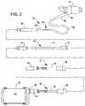
- FIG. 2is an exploded view illustrating driveline assemblies of the blood circulation assist system of FIG. 1 .
- FIG. 3is an exploded view illustrating connection of the external controller assembly with a distal driveline assembly in the blood circulation assist system of FIG. 1 .
- FIG. 4is a simplified block diagram of a method of connecting an external controller to a blood pump implanted in a patient, in accordance with many embodiments.
- FIG. 5shows an embodiment of a patient-operable connection assembly for connecting an external controller to a blood pump implanted in a patient and disconnecting the external controller to the blood pump.
- FIG. 6shows another embodiment of a patient-operable connection assembly for connecting an external controller to a blood pump implanted in a patient and disconnecting the external controller to the blood pump.
- FIG. 7shows another embodiment of a patient-operable connection assembly for connecting an external controller to a blood pump implanted in a patient and disconnecting the external controller to the blood pump.
- FIG. 8shows another embodiment of a patient-operable connection assembly for connecting an external controller to a blood pump implanted in a patient and disconnecting the external controller to the blood pump.
- FIG. 9shows another embodiment of a patient-operable connection assembly for connecting an external controller to a blood pump implanted in a patient and disconnecting the external controller to the blood pump.
- Embodiments described hereinare directed to improving the ability of a patient to reliably and effectively connect an external controller to a driveline assembly connected to an implanted medical device (e.g., an implanted blood pump).
- an implanted medical devicee.g., an implanted blood pump
- some existing external controllersare difficult to connect to a driveline assembly connected to an implanted medical device.
- some existing external controllershave a display and a connection port for the driveline assembly that is positioned and oriented so the patient cannot simultaneously view the display and the connection port, thereby preventing the patient from monitoring the display while viewing the connection port.
- connection portcontributes to poor ergonomics when attempting to align a proximal connector of the driveline assembly with the connection port during connection of the driveline assembly to the external controller.
- a relatively high connection forcemay be required to connect the proximal connector of the driveline assembly to the connection port of the external controller.
- Embodiments described hereininclude and/or employ an external controller assembly that includes an external controller and an external driveline assembly connected to, and extending from, the external controller.
- the external driveline assemblyincludes an external driveline distal connector and an external driveline cable by which the external driveline distal connector is connected to the external controller and by which the external driveline distal connector is disposed at a distance from the external controller.
- the external driveline assemblymoves the patient interaction area away from the external controller. Moving the patient interaction area away from the external controller enables the patient to connect the external driveline distal connector to the proximal connector of the driveline assembly while simultaneously observing the connection and directly monitoring a display of the external controller for a displayed indication that the connection is complete.
- the external driveline assemblyallows the patient to comfortably grasp the external driveline distal connector in one hand and the proximal connector of the driveline assembly in the other hand while making the connection between the external driveline distal connector and the proximal connector of the distal driveline assembly.
- connection of the external driveline distal connector and the proximal connector of the distal driveline assemblycan be made using a suitable insertion force that can be generated by most patients.
- the external driveline assemblyis compatible with existing external controllers.
- the external driveline assemblyis pseudo-permanently attached to a connection port of the external controller.
- the connection of the external driveline assembly to the connection port of the external controllercan be made during manufacture of the external controller assembly and/or by a trained technician.
- FIG. 1illustrates a blood circulation assist system 10 being used by a patient 12 , in accordance with many embodiments.
- the blood circulation assist system 10includes an implantable blood pump 14 , a blood flow conduit 16 , a percutaneous driveline assembly 18 , an intermediate driveline assembly 20 , an external driveline assembly 22 , an external controller 24 , a first battery 26 , a first battery cable 28 , a second battery 30 , a second battery cable 32 , and a support harness 34 .
- the support harness 34has receptacles that hold the first battery 26 and the second battery 30 .
- the external controller 24is mountable to the support harness 34 to hold the external controller 24 in a suitable position and orientation relative to the patient 12 , such as the position and orientation of the external controller 24 relative to the patient 12 illustrated in FIG. 1 .
- the blood pump 14is powered via electrical power supplied by the first battery 26 via the first battery cable 28 and/or by the second battery 30 via the second battery cable 32 . Electrical power supplied by the first battery 26 and/or the second battery 30 is transmitted, via the external controller 24 , over the external driveline assembly 22 , the intermediate driveline assembly 20 , and the percutaneous driveline assembly 18 to the blood pump 14 .
- the blood pump 14is a left ventricle assist device (LVAD) that pumps blood from the left ventricle of the patient 12 to the aorta of the patient 12 via the blood flow conduit 16 .
- LVADleft ventricle assist device
- the external driveline assembly 22can be used in connection with any suitable implanted medical device.
- the blood pump 14is a left ventricle assist device (LVAD) that pumps blood from the left ventricle of the patient 12 to the aorta of the patient 12 via the blood flow conduit 16 .
- the external driveline assembly 22is connectable, by the patient 12 , to the intermediate driveline assembly 20 via a patient-operable connection assembly 64 .
- the external driveline assembly 22can be disconnected, by the patient 12 , from the intermediate driveline assembly 20 via the patient-operable connection assembly 64 .
- FIG. 2is an exploded view illustrating connection of the external controller 24 to the blood pump 14 via the combination of the percutaneous driveline assembly 18 , the intermediate driveline assembly 20 , and the external driveline assembly 22 .
- the external driveline assembly 22includes an external driveline distal connector 36 , an external driveline cable 38 , and an external driveline proximal connector 40 .
- the intermediate driveline assembly 20includes an intermediate driveline distal connector 42 , an intermediate driveline cable 44 , and an intermediate driveline proximal connector 46 .
- the percutaneous driveline assembly 18includes a percutaneous driveline distal connector 48 , a percutaneous driveline cable 50 , and a percutaneous driveline proximal connector 52 .
- the percutaneous driveline cable 50includes a skin-interface portion 54 .
- the external controller 24includes an external driveline connection port 56 .
- the blood pump 14includes a percutaneous driveline connector 58 .
- the external driveline assembly 22is connectable to the external controller 24 via insertion of the external driveline proximal connector 40 into the external driveline connection port 56 .
- the external driveline assembly 22is connectable to the intermediate driveline assembly 20 via connection of the external driveline distal connector 36 and the intermediate driveline proximal connector 46 .
- the intermediate driveline assembly 20is connectable to the percutaneous driveline assembly 18 via connection of the intermediate driveline distal connector 42 and the percutaneous driveline proximal connector 52 .
- the percutaneous driveline assembly 18is connected to the blood pump 14 via connection of the percutaneous driveline distal connector 48 and the percutaneous driveline connector 58 .
- the external controller 24includes an external driveline latch mechanism that can be reconfigured between a connection configuration that accommodates connection of the external driveline proximal connector 40 to the external driveline connection port 56 and a retention configuration that blocks disconnection of the external driveline proximal connector 40 from the external driveline connection port 56 .
- reconfiguration of the external driveline latch mechanism between the connection configuration and the retention configurationrequires the use of a tool (e.g., a key, a specialized tool).
- the external driveline latch mechanismcan include a key-operated locking mechanism operable to lock the external driveline latch mechanism in the retention configuration and requiring the use of a key to reconfigure the external driveline latch mechanism from the retention configuration to the connection configuration.
- reconfiguration of the external driveline latch mechanism between the connection configuration and the retention configurationdoes not require the use of a tool (e.g., a key, a specialized tool).
- the connection between the intermediate driveline assembly 20 and the percutaneous driveline assembly 18prevents disconnection of the intermediate driveline distal connector 42 and the percutaneous driveline proximal connector 52 without the use of a tool (e.g., a specialized tool not typically possessed by the patient).
- a toole.g., a specialized tool not typically possessed by the patient.
- the connection between the intermediate driveline distal connector 42 and the percutaneous driveline proximal connector 52can be secured via a retainer ring that prevents disconnection without removal of the retainer ring via the use of a retainer ring plier.
- the connection between the intermediate driveline assembly 20 and the percutaneous driveline assembly 18accommodates disconnection of the intermediate driveline distal connector 42 and the percutaneous driveline proximal connector 52 without the use of a tool.
- FIG. 3is an exploded view illustrating the external controller 24 , the external driveline assembly 22 , and the intermediate driveline assembly 20 .
- the external driveline assembly 22can be connected to the intermediate driveline assembly 20 and disconnected from the intermediate driveline assembly 20 by the patient without the use of a tool.
- the external driveline distal connector 36is configured as a female connector assembly and the intermediate driveline proximal connector 46 is configured as a male assembly that is inserted into the external driveline distal connector 36 by the patient.
- the external driveline distal connector 36includes a rotatable retention collar 60 that the patient can rotate, by hand without the use of a tool, between a connection orientation in which the retention collar 60 accommodates insertion of the intermediate driveline proximal connector 46 into the external driveline distal connector 36 and a retention orientation in which the retention collar 60 blocks disconnection of the intermediate driveline proximal connector 46 from the external driveline distal connector 36 .
- the retention collar 60is rotatable by the patient through less than a full revolution (e.g., by a quarter turn, by a half turn) between the retention orientation and the connection orientation.
- the external controller 24 and the external driveline assembly 22are adapted to detect whether the external driveline assembly 22 is connected to the intermediate driveline assembly 20 and display an indication on the external controller display 62 indicative of whether the external driveline assembly 22 is connected to the intermediate driveline assembly 20 .
- the external driveline assembly 22includes a first connection lead and a second connection lead. The second connection lead is electrically connected to the first connection lead while the external driveline distal connector 36 is connected to the distal driveline proximal connector 46 . The second connection lead is electrically disconnected from the first connection lead while the external driveline distal connector 36 is not connected to the distal driveline proximal connector 46 .
- the external controller 24detects whether the external driveline distal connector 36 is connected to the distal driveline proximal connector 46 by detecting whether the second connection lead is electrically connected to the first connection lead. In many embodiments, the external controller 24 displays an indicator 63 on the external controller display 62 indicative of whether the external driveline distal connector 36 is connected to the distal driveline proximal connector 46 . The displayed indicator 63 provides feedback to the patient as to whether the external driveline distal connector 36 is connected to the distal driveline proximal connector 46 .
- the external driveline cable 38has a length and a flexibility that enables the patient to position and/or orient the external driveline distal connector 36 to facilitate connection, by the patient, of the external driveline distal connector 36 to the intermediate driveline proximal connector 46 and disconnection, by the patient, of the external driveline distal connector 36 from the intermediate driveline proximal connector 46 .
- the external driveline cable 38has a length and a flexibility to accommodate the positioning of the external driveline distal connector 38 , by the patient, for simultaneous viewing of the external driveline distal connector 36 and an external controller display 62 by the patient.
- the length of the external driveline cable 38 and/or the overall length of the external driveline assembly 22is from 5 inches to 9 inches.
- FIG. 4is a simplified block diagram of a method 100 of connecting an external controller to a blood pump implanted in a patient, in accordance with many embodiments. While the method 100 is described herein with reference to the blood circulation assist system 10 , the method 100 can be practiced with respect to connecting any suitable external controller to any suitable medical device implanted in a patient.
- the method 100includes connecting a distal end of the percutaneous driveline assembly 18 to an implantable blood pump (act 102 ).
- the percutaneous driveline distal connector 48is connected to the percutaneous driveline connector 58 .
- the method 100further includes securing the connection between the percutaneous driveline distal connector 48 and the percutaneous driveline connector 58 so as to prevent inadvertent disconnection thereof.
- a suitable latching mechanismcan be employed and reconfigured from a connection configuration accommodating the connection of the percutaneous driveline distal connector 48 to the percutaneous driveline connector 58 to a retention configuration that blocks disconnection of the percutaneous driveline distal connector 48 from the percutaneous driveline connector 58 .
- the method 100further includes implanting a distal portion of the percutaneous driveline assembly 18 within the patient so that the skin-interface portion 54 of the percutaneous driveline cable 50 extends through an aperture through the skin of the patient with the skin-interface portion 54 interfacing with an edge of the skin at the aperture and the remaining proximal portion being disposed exterior to the patient.
- the method 100further includes connecting the intermediate driveline assembly 20 to the percutaneous driveline assembly 18 by connecting the intermediate driveline distal connector 42 to the percutaneous driveline proximal connector 52 (act 104 ).
- the method 100further includes securing the connection between the intermediate driveline distal connector 42 and the percutaneous driveline proximal connector 52 so as to prevent disconnection by the patient without the use of a specialized tool.
- the connection between the intermediate driveline distal connector 42 and the percutaneous driveline proximal connector 52can be secured by installing a retainer ring using a retainer ring plier so as to engage a respective retainer groove in each of the intermediate driveline distal connector 42 and the percutaneous driveline proximal connector 52 .
- the method 100further includes connecting an external controller assembly to the intermediate driveline assembly 20 (act 106 ).
- the external controller assemblyincludes the external driveline assembly 22 and the external controller 24 .
- the external driveline assembly 22is connected to the intermediate driveline assembly 20 by connecting the external driveline distal connector 36 to the intermediate driveline proximal connector 40 .
- the connection between the external driveline distal connector 36 and the intermediate driveline proximal connector 40is patient-operable to accommodate connection and disconnection thereof, by the patient, to enable the patient to replace the external controller assembly with a replacement external controller assembly.
- the method 100further includes: (a) connecting the external driveline assembly 22 to the external controller 24 by connecting the external driveline proximal connector 40 to the external controller driveline connection port 56 , and (b) securing the external driveline proximal connector 40 to the external controller driveline connection port 56 so as to prevent the patient from disconnecting the external driveline proximal connector 40 from the external controller driveline connection port 56 without the use of a key or a specialized tool.
- the external driveline assembly 22is integrally attached to the external controller 24 so that the external controller 24 does not include the external controller driveline connection port 56 and the external driveline assembly 22 does not include the external driveline proximal connector 40 .
- the external driveline cable 38has a length and a flexibility that enables the patient to position and/or orient the external driveline distal connector 36 to facilitate connection, by the patient, of the external driveline distal connector 36 to the intermediate driveline proximal connector 46 and disconnection, by the patient, of the external driveline distal connector 36 from the intermediate driveline proximal connector 46 .
- the external driveline cable 38has a length and a flexibility to accommodate the positioning of the external driveline distal connector 36 , by the patient, for simultaneous viewing of the external driveline distal connector 36 and the external controller display 62 by the patient.
- the length of the external driveline cable 38is from 5 inches to 9 inches.
- FIG. 5shows a patient-operable connection assembly 110 that can be employed in the patient-operable connection assembly 64 shown in FIG. 1 .
- the connection assembly 110includes a male connector component 112 and a female connector assembly 114 .
- the female connector assembly 114has a receptacle 118 and a latching mechanism 120 .
- the male connector component 112has an end portion 116 that has a retention groove 122 .
- the end portion 116has one or more alignment features that engage complementarily-shaped alignment features of the female connector assembly 114 to ensure alignment with electrical contacts supported by the male connector component 112 with electrical contacts supported by the female connector assembly 114 .
- the end portion 116is adapted to be inserted into the receptacle 118 and retained in the receptacle 118 via engagement between the latching mechanism 120 and the retention groove 122 .
- the latching mechanism 120is spring-biased towards a retention configuration in which the latching mechanism 120 is configured to retain the end portion 116 in the receptacle 118 via engagement with the retention groove 122 .
- insertion of the end portion 116 into the receptacle 118induces a reconfiguration cycle in which interaction between the end portion 116 and the latching mechanism 120 causes the latching mechanism 120 to reconfigure so as to accommodate full insertion of the end portion 116 into the receptacle 118 to a depth where the retention groove 122 is positioned to be engaged by the latching mechanism 120 .
- the latching mechanism 120self-reconfigures back to the retention configuration, thereby engaging the retention groove 122 to prevent inadvertent decoupling of the male connector component 112 and the female connector assembly 114 .
- the latching mechanism 120can be manually reconfigured by the patient from the retention configuration to a release configuration in which the male connector component 112 can be decoupled from the female connector assembly 114 .
- the patientcan push or pull on the latching mechanism 120 to reconfigure the latching mechanism 120 from the retention configuration to the release configuration to enable the patient to decouple the male connector component 112 from the female connector assembly 114 .
- the male connector component 112can be included in the intermediate driveline proximal connector 46 .
- the female connector assembly 114can be included in the external driveline distal connector 36 .
- FIG. 6shows a patient-operable connection assembly 130 that can be employed in the patient-operable connection assembly 64 shown in FIG. 1 .
- the connection assembly 130includes a male connector component 132 and a female connector assembly 134 .
- the female connector assembly 114includes a base member 136 and latching members 138 that are pivotally mounted to the base member 136 .
- the base member 136defines a receptacle 140 .
- the male connector component 132has an end portion 142 .
- the end portion 142has one or more alignment features that engage complementarily-shaped alignment features of the base member 136 to ensure alignment with electrical contacts supported by the male connector component 132 with electrical contacts supported by the female connector assembly 134 .
- the end portion 142is adapted to be inserted into the receptacle 140 and retained in the receptacle 140 via coupling of the latching members 138 with the male connector component 132 .
- the male connector component 132includes coupling features to which the latching members 138 can be selectively coupled with by the patient and decoupled from by the patient.
- the male connector component 132can be included in the intermediate driveline proximal connector 46 .
- the female connector assembly 134can be included in the external driveline distal connector 36 .
- FIG. 7shows a patient-operable connection assembly 150 that can be employed in the patient-operable connection assembly 64 shown in FIG. 1 .
- the connection assembly 150includes a first connector component 152 and a second connector component 154 .
- the first connector component 152has retention features 158 , 160 .
- the second connector component 154has retention features 162 , 164 .
- Each of the retention features 158defines a slot 166 shaped to accommodate and engage a respective retention feature 164 when the connection assembly 150 is in a coupled configuration.
- each of the retention features 162defines a slot 166 shaped to accommodate and engage a respective retention feature 160 when the connection assembly 150 is in the coupled configuration.
- connection assembly 150is connectable by the patient via relative translation between the first connector component 152 and the second connector component 154 along a connection axis 156 to bring the first connector component 152 and the second connector component 154 into engagement in an intermediate configuration, followed by relative rotation between the first connector component 152 and the second connector component 154 around the connection axis 156 from the intermediate configuration into the coupled configuration.
- the connection assembly 150can be disconnected by the patient via relative rotation between the first connector component 152 and the second connector component 154 around the connection axis 156 from the coupled configuration to the intermediate configuration, followed by relative translation between the first connector component 152 and the second connector component 154 along a connection axis 156 to separate the first connector component 152 and the second connector component 154 .
- connection assembly 150includes a patient-operable retention mechanism that prevents relative rotation between the first connector component 152 and the second connector component 154 in the coupled configuration of the connection assembly 150 absent reconfiguration of the retention mechanism by the patient into a release configuration that accommodates relative rotation between the first connector component 152 and the second connector component 154 .
- the first connector component 152can be included in the intermediate driveline proximal connector 46 .
- the second connector component 154can be included in the external driveline distal connector 36 .
- FIG. 8shows a patient-operable connection assembly 170 that can be employed in the patient-operable connection assembly 64 shown in FIG. 1 .
- the connection assembly 170includes a male connector component 172 and a female connector assembly 174 .
- the female connector assembly 174has a receptacle 176 and a translatable latching member 178 .
- the male connector component 172has an end portion 180 .
- the end portion 180has one or more alignment features that engage complementarily-shaped alignment features of the female connector assembly 174 to ensure alignment with electrical contacts supported by the male connector component 172 with electrical contacts supported by the female connector assembly 174 .
- the end portion 180is adapted to be inserted into the receptacle 176 and retained in the receptacle 176 via engagement with the latching member 178 .
- the latching member 178is spring-biased towards a retention configuration in which the female connector assembly 174 is configured to retain the end portion 180 in the receptacle 176 .
- insertion of the end portion 180 into the receptacle 176induces a reconfiguration cycle in which interaction between the end portion 180 and the latching member 178 causes the latching member 178 to translate so as to accommodate full insertion of the end portion 180 into the receptacle 176 .
- the latching member 178translates back to the retention configuration, thereby engaging the end portion 180 to prevent inadvertent decoupling of the male connector component 172 and the female connector assembly 174 .
- the latching member 178can be manually translated by the patient from the retention configuration to a release configuration in which the male connector component 172 can be decoupled from the female connector assembly 174 .
- the patientcan translate the latching member 178 to reconfigure the female connector assembly 174 from the retention configuration to the release configuration to enable the patient to decouple the male connector component 172 from the female connector assembly 174 .
- the male connector component 172can be included in the intermediate driveline proximal connector 46 .
- the female connector assembly 174can be included in the external driveline distal connector 36 .
- FIG. 9shows a patient-operable connection assembly 190 that can be employed in the patient-operable connection assembly 64 shown in FIG. 1 .
- the connection assembly 190includes a male connector component 192 and a female connector assembly 194 .
- the female connector assembly 194has a latching mechanism that includes a patient-operable release button 196 that can be pressed by the patient to enable decoupling of the male connector component 192 from the female connector assembly 194 .
- the connection assembly 190is configured similar to the connection assembly 110 with respect to the ability of the latching mechanism to accommodate insertion of the male connector component 192 into the female connector assembly 194 and have the latching mechanism automatically reconfigure into the retention configuration upon full insertion of the male connector component 192 into the female connector assembly 194 .
- the release button 196is recessed relative to the surrounding adjacent exterior surface of the female connector assembly 194 to prevent inadvertent pressing of the release button 196 .
- the male connector component 192can be included in the intermediate driveline proximal connector 46 .
- the female connector assembly 194can be included in the external driveline distal connector 36 .
Landscapes
- Health & Medical Sciences (AREA)
- Engineering & Computer Science (AREA)
- Heart & Thoracic Surgery (AREA)
- Cardiology (AREA)
- Veterinary Medicine (AREA)
- Life Sciences & Earth Sciences (AREA)
- Animal Behavior & Ethology (AREA)
- General Health & Medical Sciences (AREA)
- Public Health (AREA)
- Biomedical Technology (AREA)
- Mechanical Engineering (AREA)
- Anesthesiology (AREA)
- Hematology (AREA)
- Vascular Medicine (AREA)
- Human Computer Interaction (AREA)
- Radiology & Medical Imaging (AREA)
- Nuclear Medicine, Radiotherapy & Molecular Imaging (AREA)
- Infusion, Injection, And Reservoir Apparatuses (AREA)
- External Artificial Organs (AREA)
Abstract
Description
Claims (20)
Priority Applications (3)
| Application Number | Priority Date | Filing Date | Title |
|---|---|---|---|
| US16/359,925US11389641B2 (en) | 2018-03-21 | 2019-03-20 | Modular flying lead cable and methods for use with heart pump controllers |
| US17/837,750US11944834B2 (en) | 2018-03-21 | 2022-06-10 | Modular flying lead cable and methods for use with heart pump controllers |
| US18/596,185US20240269474A1 (en) | 2018-03-21 | 2024-03-05 | Modular Flying Lead Cable and Methods for Use With Heart Pump Controllers |
Applications Claiming Priority (2)
| Application Number | Priority Date | Filing Date | Title |
|---|---|---|---|
| US201862646174P | 2018-03-21 | 2018-03-21 | |
| US16/359,925US11389641B2 (en) | 2018-03-21 | 2019-03-20 | Modular flying lead cable and methods for use with heart pump controllers |
Related Child Applications (1)
| Application Number | Title | Priority Date | Filing Date |
|---|---|---|---|
| US17/837,750ContinuationUS11944834B2 (en) | 2018-03-21 | 2022-06-10 | Modular flying lead cable and methods for use with heart pump controllers |
Publications (2)
| Publication Number | Publication Date |
|---|---|
| US20190290820A1 US20190290820A1 (en) | 2019-09-26 |
| US11389641B2true US11389641B2 (en) | 2022-07-19 |
Family
ID=67983985
Family Applications (3)
| Application Number | Title | Priority Date | Filing Date |
|---|---|---|---|
| US16/359,925Active2039-06-26US11389641B2 (en) | 2018-03-21 | 2019-03-20 | Modular flying lead cable and methods for use with heart pump controllers |
| US17/837,750ActiveUS11944834B2 (en) | 2018-03-21 | 2022-06-10 | Modular flying lead cable and methods for use with heart pump controllers |
| US18/596,185PendingUS20240269474A1 (en) | 2018-03-21 | 2024-03-05 | Modular Flying Lead Cable and Methods for Use With Heart Pump Controllers |
Family Applications After (2)
| Application Number | Title | Priority Date | Filing Date |
|---|---|---|---|
| US17/837,750ActiveUS11944834B2 (en) | 2018-03-21 | 2022-06-10 | Modular flying lead cable and methods for use with heart pump controllers |
| US18/596,185PendingUS20240269474A1 (en) | 2018-03-21 | 2024-03-05 | Modular Flying Lead Cable and Methods for Use With Heart Pump Controllers |
Country Status (1)
| Country | Link |
|---|---|
| US (3) | US11389641B2 (en) |
Cited By (29)
| Publication number | Priority date | Publication date | Assignee | Title |
|---|---|---|---|---|
| US20220362562A1 (en)* | 2018-03-21 | 2022-11-17 | Tc1 Llc | Modular Flying Lead Cable and Methods for Use With Heart Pump Controllers |
| US11754075B2 (en) | 2018-07-10 | 2023-09-12 | Kardion Gmbh | Impeller for an implantable, vascular support system |
| US11804767B2 (en) | 2018-01-24 | 2023-10-31 | Kardion Gmbh | Magnetic coupling element with a magnetic bearing function |
| US11944805B2 (en) | 2020-01-31 | 2024-04-02 | Kardion Gmbh | Pump for delivering a fluid and method of manufacturing a pump |
| US11996699B2 (en) | 2018-05-02 | 2024-05-28 | Kardion Gmbh | Receiving unit, transmission unit, power transmission system and method for wireless power transmission |
| US12005248B2 (en) | 2018-05-16 | 2024-06-11 | Kardion Gmbh | Rotor bearing system |
| US12064615B2 (en) | 2018-05-30 | 2024-08-20 | Kardion Gmbh | Axial-flow pump for a ventricular assist device and method for producing an axial-flow pump for a ventricular assist device |
| US12076549B2 (en) | 2018-07-20 | 2024-09-03 | Kardion Gmbh | Feed line for a pump unit of a cardiac assistance system, cardiac assistance system and method for producing a feed line for a pump unit of a cardiac assistance system |
| US12107474B2 (en) | 2018-05-16 | 2024-10-01 | Kardion Gmbh | End-face rotating joint for transmitting torques |
| US12102835B2 (en) | 2018-05-02 | 2024-10-01 | Kardion Gmbh | Transmission unit comprising a transmission coil and a temperature sensor |
| US12144976B2 (en) | 2018-06-21 | 2024-11-19 | Kardion Gmbh | Method and device for detecting a wear condition of a ventricular assist device and for operating same, and ventricular assist device |
| US12150647B2 (en) | 2016-06-06 | 2024-11-26 | Kardion Gmbh | Method for punching a lumen and implanting an implant device |
| US12178554B2 (en) | 2018-06-06 | 2024-12-31 | Kardion Gmbh | Systems and methods for determining a viscosity of a fluid |
| US12194287B2 (en) | 2018-05-30 | 2025-01-14 | Kardion Gmbh | Method of manufacturing electrical conductor tracks in a region of an intravascular blood pump |
| US12201823B2 (en) | 2018-05-30 | 2025-01-21 | Kardion Gmbh | Line device for conducting a blood flow for a heart support system, heart support system, and method for producing a line device |
| US12201821B2 (en) | 2018-06-06 | 2025-01-21 | Kardion Gmbh | Method for determining a flow rate of a fluid flowing through an implanted vascular support system, and implantable vascular support system |
| US12222267B2 (en) | 2018-06-06 | 2025-02-11 | Kardion Gmbh | Analysis device and method for analyzing a viscosity of a fluid |
| US12230868B2 (en) | 2018-05-02 | 2025-02-18 | Kardion Gmbh | Device for inductive energy transfer into a human body, for example, and use of said device |
| US12233250B2 (en) | 2018-05-02 | 2025-02-25 | Kardion Gmbh | Device for inductive energy transmission into a human body and use thereof |
| US12257424B2 (en) | 2018-06-06 | 2025-03-25 | Kardion Gmbh | Implantable ventricular assist system and method for operating same |
| US12263333B2 (en) | 2018-06-21 | 2025-04-01 | Kardion Gmbh | Stator vane device for guiding the flow of a fluid flowing out of an outlet opening of a ventricular assist device, ventricular assist device with stator vane device, method for operating a stator vane device and manufacturing method |
| US12311160B2 (en) | 2018-06-06 | 2025-05-27 | Kardion Gmbh | Method and system for determining the speed of sound in a fluid in the region of a cardiac support system |
| US12310708B2 (en) | 2018-06-06 | 2025-05-27 | Kardion Gmbh | Systems and methods for determining a flow speed of a fluid flowing through a cardiac assist device |
| US12324906B2 (en) | 2018-06-06 | 2025-06-10 | Kardion Gmbh | Systems and methods for determining a total blood volume flow in a cardiac support system and vascular support system |
| US12377256B2 (en) | 2018-06-06 | 2025-08-05 | Kardion Gmbh | Cardiac support system flow measurement using pressure sensors |
| US12383727B2 (en) | 2018-05-30 | 2025-08-12 | Kardion Gmbh | Motor housing module for a heart support system, and heart support system and method for mounting a heart support system |
| US12390633B2 (en) | 2018-08-07 | 2025-08-19 | Kardion Gmbh | Bearing device for a heart support system, and method for rinsing a space in a bearing device for a heart support system |
| US12400788B2 (en) | 2020-11-05 | 2025-08-26 | Kardion Gmbh | Device for inductive energy transmission in a human body and use of the device |
| US12403296B2 (en) | 2018-05-30 | 2025-09-02 | Kardion Gmbh | Apparatus for anchoring a ventricular assist system in a blood vessel, operating method, production method for producing an apparatus and ventricular assist system |
Families Citing this family (3)
| Publication number | Priority date | Publication date | Assignee | Title |
|---|---|---|---|---|
| US10737007B2 (en)* | 2017-04-28 | 2020-08-11 | Tc1 Llc | Patient adapter for driveline cable and methods |
| US12102816B2 (en)* | 2018-08-24 | 2024-10-01 | Sun Medical Technology Research Corporation | Conduit forming unit and tube joint |
| CN118750759A (en)* | 2024-07-08 | 2024-10-11 | 首都医科大学附属北京安贞医院 | Cable assembly for left ventricular assist system and left ventricular assist system |
Citations (98)
| Publication number | Priority date | Publication date | Assignee | Title |
|---|---|---|---|---|
| US3882861A (en) | 1973-09-24 | 1975-05-13 | Vital Assists | Auxiliary control for a blood pump |
| US4521871A (en) | 1982-04-12 | 1985-06-04 | Allen-Bradley Company | Programmable controller with back-up capability |
| US5046965A (en) | 1990-05-04 | 1991-09-10 | Utah Medical Products, Inc. | Disposable electrical connector for fetal scalp electrode |
| US5695474A (en) | 1995-09-18 | 1997-12-09 | Becton Dickinson And Company | Needle shield with collapsible cover |
| US5853394A (en)* | 1994-05-09 | 1998-12-29 | Tolkoff; Marc Joshua | Catheter |
| US5888242A (en) | 1996-11-01 | 1999-03-30 | Nimbus, Inc. | Speed control system for implanted blood pumps |
| US5904646A (en)* | 1997-09-08 | 1999-05-18 | Jarvik; Robert | Infection resistant power cable system for medically implanted electric motors |
| US5935105A (en) | 1991-11-15 | 1999-08-10 | Deka Products Limited Partnership | Intravenous-line air-elimination system |
| US5991595A (en) | 1997-03-21 | 1999-11-23 | Educational Testing Service | Computerized system for scoring constructed responses and methods for training, monitoring, and evaluating human rater's scoring of constructed responses |
| US6004269A (en)* | 1993-07-01 | 1999-12-21 | Boston Scientific Corporation | Catheters for imaging, sensing electrical potentials, and ablating tissue |
| US6071093A (en) | 1996-10-18 | 2000-06-06 | Abiomed, Inc. | Bearingless blood pump and electronic drive system |
| US6116862A (en) | 1996-06-25 | 2000-09-12 | Medos Medizintechnik Gmbh | Blood pump |
| US6123726A (en)* | 1997-07-25 | 2000-09-26 | Seiko Epson Corporation | Portable drive system for artificial heart |
| US6146179A (en) | 1998-12-09 | 2000-11-14 | International Business Machines Corporation | Auto unlatching connector tab |
| US6183412B1 (en) | 1997-10-02 | 2001-02-06 | Micromed Technology, Inc. | Implantable pump system |
| US6234772B1 (en) | 1999-04-28 | 2001-05-22 | Kriton Medical, Inc. | Rotary blood pump |
| US6264635B1 (en) | 1998-12-03 | 2001-07-24 | Kriton Medical, Inc. | Active magnetic bearing system for blood pump |
| US6305962B1 (en) | 1999-02-16 | 2001-10-23 | Nimbus, Incorporated | Inline cable connector |
| US20020007198A1 (en) | 2000-04-25 | 2002-01-17 | Haupert David J. | Interface devices for instruments in communication with implantable medical devices |
| US6494736B2 (en) | 2000-03-14 | 2002-12-17 | International Business Machines Corporation | Connector for a battery charger |
| US6508756B1 (en)* | 1995-06-13 | 2003-01-21 | Abiomed, Inc. | Passive cardiac assistance device |
| US6592620B1 (en) | 1998-10-05 | 2003-07-15 | Kriton Medical, Inc. | Power system for an implantable heart pump |
| US6688861B2 (en) | 1996-02-20 | 2004-02-10 | Heartware, Inc. | Sealless rotary blood pump |
| US20050055038A1 (en)* | 2002-09-09 | 2005-03-10 | Brian Kelleher | Device and method for endoluminal therapy |
| US20050069426A1 (en)* | 2002-03-26 | 2005-03-31 | Christopher Mason | Devices for use in medicine |
| US20050071001A1 (en) | 2003-09-30 | 2005-03-31 | Robert Jarvik | Artificial heart power and control system |
| WO2006055745A2 (en) | 2004-11-16 | 2006-05-26 | Micromed Cardivascular, Inc. | Remote data monitor for heart pump system |
| US20060226423A1 (en)* | 2005-04-11 | 2006-10-12 | Seiko Epson Corporation | Electro-optical device, manufacturing method thereof, and electronic apparatus |
| US20070078293A1 (en) | 2005-10-05 | 2007-04-05 | Shambaugh Charles R Jr | Impeller for a rotary ventricular assist device |
| US20070142696A1 (en) | 2005-12-08 | 2007-06-21 | Ventrassist Pty Ltd | Implantable medical devices |
| US20070208290A1 (en)* | 2006-03-06 | 2007-09-06 | Robert Pecor | Quick priming connectors for blood circuit |
| US20080021394A1 (en) | 2006-01-13 | 2008-01-24 | Larose Jeffrey A | Stabilizing drive for contactless rotary blood pump impeller |
| US7340304B2 (en) | 2002-03-15 | 2008-03-04 | Biomed Soutions, Llc | Biothermal power source for implantable devices |
| US7425142B1 (en) | 2007-03-16 | 2008-09-16 | Ad-Tech Medical Instrument Corp. | Electrical connector for an in-body multi-contact medical electrode device |
| US20090118827A1 (en) | 2003-06-12 | 2009-05-07 | Terumo Kabushiki Kaisha | Artificial heart pump system and its control apparatus |
| US20090203957A1 (en) | 2008-02-08 | 2009-08-13 | Larose Jeffrey A | Ventricular assist device for intraventricular placement |
| US7658613B1 (en) | 2007-01-16 | 2010-02-09 | Griffin Technology Inc | Magnetic connector |
| US7699586B2 (en) | 2004-12-03 | 2010-04-20 | Heartware, Inc. | Wide blade, axial flow pump |
| US7771221B1 (en)* | 2009-09-27 | 2010-08-10 | Blackwell Donald A | Environmental protective covering for electrical power connectors |
| WO2010122139A1 (en) | 2009-04-23 | 2010-10-28 | Centre Hospitalier Universitaire De Rouen | Electrical connection system between an electrical power supply device and an implanted medical device |
| US20100305692A1 (en)* | 2009-05-27 | 2010-12-02 | Thomas Douglas C | Monitoring of redundant conductors |
| US20110071336A1 (en)* | 2009-09-21 | 2011-03-24 | Barry Yomtov | Hard-wired implanted controller system |
| US7961156B2 (en) | 2003-07-29 | 2011-06-14 | Sorin Group Deutschland Gmbh | Display and control device for medical equipment |
| US20110160516A1 (en) | 2009-12-30 | 2011-06-30 | Thoratec Corporation | Mobility-Enhancing Blood Pump System |
| WO2011081626A1 (en) | 2009-12-30 | 2011-07-07 | Thoratec Corporation | Mobility-enhancing blood pump system |
| US20110196189A1 (en)* | 2010-02-09 | 2011-08-11 | Myocardiocare, Inc. | Extra-cardiac differential ventricular actuation by inertial and baric partitioning |
| US20110218383A1 (en) | 2010-03-05 | 2011-09-08 | Minnetronix Inc. | Portable controller and power source for mechanical circulation support systems |
| US8029441B2 (en) | 2006-02-28 | 2011-10-04 | Abbott Diabetes Care Inc. | Analyte sensor transmitter unit configuration for a data monitoring and management system |
| US20110270331A1 (en)* | 2010-04-02 | 2011-11-03 | Sunshine Heart Company Pty Ltd | Combination heart assist systems, methods, and devices |
| US20120046514A1 (en) | 2010-08-20 | 2012-02-23 | Kevin Bourque | Implantable blood pump |
| US8152493B2 (en) | 2007-04-30 | 2012-04-10 | Hearthware Inc. | Centrifugal rotary blood pump with impeller having a hydrodynamic thrust bearing surface |
| US8157720B2 (en) | 2006-01-27 | 2012-04-17 | Circulite, Inc. | Heart assist system |
| US20120095281A1 (en) | 2010-10-13 | 2012-04-19 | Reichenbach Steven H | Pumping blood |
| US8186665B2 (en) | 2008-12-24 | 2012-05-29 | Ricoh Company, Limited | Locking device of paper feed tray and image forming apparatus |
| US20120149229A1 (en)* | 2010-12-08 | 2012-06-14 | Keith Hamilton Kearsley | Modular driveline |
| US20120183261A1 (en) | 2010-11-12 | 2012-07-19 | Research In Motion Limited | Magnetically coupled connector for electrical and optical data circuits |
| US8323174B2 (en) | 2010-10-22 | 2012-12-04 | Nupulse, Inc. | Skin interface for ventricular assist device |
| US8344847B2 (en) | 2009-07-09 | 2013-01-01 | Medtronic Minimed, Inc. | Coordination of control commands in a medical device system having at least one therapy delivery device and at least one wireless controller device |
| US8348678B2 (en) | 2010-01-11 | 2013-01-08 | Automotive Industrial Marketing Corp. | Magnetic cable connector systems |
| US20130096364A1 (en) | 2011-10-13 | 2013-04-18 | Steven H. Reichenbach | Pump and method for mixed flow blood pumping |
| US20130121821A1 (en) | 2010-07-12 | 2013-05-16 | Terumo Kabushiki Kaisha | Centrifugal pump apparatus |
| US20130127253A1 (en) | 2011-11-21 | 2013-05-23 | Joseph Stark | Transcutaneous power transmission utilizing non-planar resonators |
| US8449444B2 (en) | 2009-02-27 | 2013-05-28 | Thoratec Corporation | Blood flow meter |
| US20130170970A1 (en) | 2010-09-14 | 2013-07-04 | Terumo Kabushiki Kaisha | Centrifugal pump apparatus |
| US8500620B2 (en)* | 2006-01-30 | 2013-08-06 | National Cheng Kung University | Ventricular assist device |
| US8506471B2 (en) | 2010-09-24 | 2013-08-13 | Thoratec Corporation | Generating artificial pulse |
| US20130225909A1 (en) | 2012-02-27 | 2013-08-29 | Terumo Kabushiki Kaisha | Quick-Connect Outflow Tube for Ventricular Assist Device |
| US20130310631A1 (en)* | 2012-05-17 | 2013-11-21 | Eric Lee | Touch screen interface and infrared communication system integrated into a battery |
| US20130314047A1 (en) | 2012-05-24 | 2013-11-28 | Heartware, Inc. | Low-power battery pack with safety system |
| US8597350B2 (en) | 2010-12-09 | 2013-12-03 | Heartware, Inc. | Controller and power source for implantable blood pump |
| US8639348B2 (en) | 2012-06-29 | 2014-01-28 | Zoll Medical Corporation | Providing life support |
| US8652024B1 (en)* | 2013-01-23 | 2014-02-18 | Thoratec Corporation | Sterilizable cable system for implantable blood pump |
| US8657733B2 (en) | 2005-11-04 | 2014-02-25 | Thoratec Corporation | Control systems for rotary blood pumps |
| US8684763B2 (en) | 2011-06-21 | 2014-04-01 | Adc Telecommunications, Inc. | Connector with slideable retention feature and patch cord having the same |
| US20140094645A1 (en)* | 2012-05-22 | 2014-04-03 | Sunshine Heart Company Pty Ltd | Methods, Systems, and Devices Relating to a Removable Percutaneous Interface Line |
| US20140188148A1 (en)* | 2012-12-27 | 2014-07-03 | Pieter W.C.J. le Blanc | Surgical tunneler |
| WO2014107424A2 (en) | 2013-01-04 | 2014-07-10 | Heartware, Inc. | Controller and power source for implantable blood pump |
| US20140194670A1 (en)* | 2013-01-08 | 2014-07-10 | Stephen Manuel Wildhirt | Implanting cardiac devices |
| US20140243970A1 (en) | 2013-02-25 | 2014-08-28 | Thoratec Corporation | Programming of backup control unit for cardiac assist system |
| US20140309733A1 (en) | 2010-06-07 | 2014-10-16 | Thoratec Corporation | Bi-Ventricular Percutaneous Cable |
| US8894561B2 (en) | 2012-03-05 | 2014-11-25 | Thoratec Corporation | Modular implantable medical pump |
| WO2015017770A1 (en) | 2013-08-02 | 2015-02-05 | Circulite, Inc. | Implantable system with secure remote control |
| US8971958B2 (en) | 2005-04-11 | 2015-03-03 | Roche Diagnostics International Ag | Web-enabled portable medical device |
| US20150290377A1 (en)* | 2014-04-15 | 2015-10-15 | Thoratec Corporation | Protective cap for driveline cable connector |
| US20160064117A1 (en)* | 2014-09-03 | 2016-03-03 | Thoratec Corporation | Triple helix driveline cable and methods of assembly and use |
| US20160095968A1 (en) | 2014-10-01 | 2016-04-07 | Heartware, Inc. | Back Up Controller System With Updating |
| US20160181730A1 (en)* | 2014-10-06 | 2016-06-23 | Thoratec Corporation | Multiaxial connector for implantable devices |
| US20160175502A1 (en)* | 2014-12-17 | 2016-06-23 | Heartware, Inc. | Implantable connector |
| WO2017087380A1 (en) | 2015-11-20 | 2017-05-26 | Tc1 Llc | System architecture that allows patient replacement of vad controller/interface module without disconnection of old module |
| US20170173238A1 (en)* | 2015-12-21 | 2017-06-22 | Heartware, Inc. | Implantable mechanical circulatory support devices |
| US20170324185A1 (en)* | 2016-05-06 | 2017-11-09 | Tc1 Llc | Compliant implantable connector and methods of use and manufacture |
| US20170354772A1 (en)* | 2016-06-13 | 2017-12-14 | Heartware, Inc. | Detachable percutaneous connector |
| US20180001007A1 (en)* | 2016-07-01 | 2018-01-04 | John Stratton | Ventricular assist device driveline protector |
| US20180055983A1 (en)* | 2016-08-26 | 2018-03-01 | Tc1 Llc | Prosthetic rib with integrated percutaneous connector for ventricular assist devices |
| US20180250459A1 (en) | 2015-11-20 | 2018-09-06 | Tc1 Llc | Energy management of blood pump controllers |
| US20180256801A1 (en) | 2015-11-20 | 2018-09-13 | Tc1 Llc | Connectors and cables for use with ventricle assist systems |
| US20180256800A1 (en) | 2015-11-20 | 2018-09-13 | Tc1 Llc | Blood pump controllers having daisy-chained batteries |
| US10124101B2 (en) | 2016-07-27 | 2018-11-13 | Tc1 Llc | Fluid resistant locking electrical connector for ventricular assist devices |
Family Cites Families (4)
| Publication number | Priority date | Publication date | Assignee | Title |
|---|---|---|---|---|
| US9724508B2 (en)* | 2009-03-09 | 2017-08-08 | Boston Scientific Neuromodulation Corporation | Electronic identification of external cables for external medical devices |
| WO2015160993A1 (en)* | 2014-04-15 | 2015-10-22 | Thoratec Corporation | Methods and systems for providing battery feedback to patient |
| US11389641B2 (en)* | 2018-03-21 | 2022-07-19 | Tc1 Llc | Modular flying lead cable and methods for use with heart pump controllers |
| EP3787707B1 (en) | 2018-04-30 | 2023-12-27 | Tc1 Llc | Improved blood pump connectors |
- 2019
- 2019-03-20USUS16/359,925patent/US11389641B2/enactiveActive
- 2022
- 2022-06-10USUS17/837,750patent/US11944834B2/enactiveActive
- 2024
- 2024-03-05USUS18/596,185patent/US20240269474A1/enactivePending
Patent Citations (117)
| Publication number | Priority date | Publication date | Assignee | Title |
|---|---|---|---|---|
| US3882861A (en) | 1973-09-24 | 1975-05-13 | Vital Assists | Auxiliary control for a blood pump |
| US4521871A (en) | 1982-04-12 | 1985-06-04 | Allen-Bradley Company | Programmable controller with back-up capability |
| US5046965A (en) | 1990-05-04 | 1991-09-10 | Utah Medical Products, Inc. | Disposable electrical connector for fetal scalp electrode |
| US5935105A (en) | 1991-11-15 | 1999-08-10 | Deka Products Limited Partnership | Intravenous-line air-elimination system |
| US6004269A (en)* | 1993-07-01 | 1999-12-21 | Boston Scientific Corporation | Catheters for imaging, sensing electrical potentials, and ablating tissue |
| US5853394A (en)* | 1994-05-09 | 1998-12-29 | Tolkoff; Marc Joshua | Catheter |
| US6508756B1 (en)* | 1995-06-13 | 2003-01-21 | Abiomed, Inc. | Passive cardiac assistance device |
| US5695474A (en) | 1995-09-18 | 1997-12-09 | Becton Dickinson And Company | Needle shield with collapsible cover |
| US6688861B2 (en) | 1996-02-20 | 2004-02-10 | Heartware, Inc. | Sealless rotary blood pump |
| US6116862A (en) | 1996-06-25 | 2000-09-12 | Medos Medizintechnik Gmbh | Blood pump |
| US6071093A (en) | 1996-10-18 | 2000-06-06 | Abiomed, Inc. | Bearingless blood pump and electronic drive system |
| US5888242A (en) | 1996-11-01 | 1999-03-30 | Nimbus, Inc. | Speed control system for implanted blood pumps |
| US5991595A (en) | 1997-03-21 | 1999-11-23 | Educational Testing Service | Computerized system for scoring constructed responses and methods for training, monitoring, and evaluating human rater's scoring of constructed responses |
| US6123726A (en)* | 1997-07-25 | 2000-09-26 | Seiko Epson Corporation | Portable drive system for artificial heart |
| US5904646A (en)* | 1997-09-08 | 1999-05-18 | Jarvik; Robert | Infection resistant power cable system for medically implanted electric motors |
| US6183412B1 (en) | 1997-10-02 | 2001-02-06 | Micromed Technology, Inc. | Implantable pump system |
| US6592620B1 (en) | 1998-10-05 | 2003-07-15 | Kriton Medical, Inc. | Power system for an implantable heart pump |
| US6264635B1 (en) | 1998-12-03 | 2001-07-24 | Kriton Medical, Inc. | Active magnetic bearing system for blood pump |
| US6146179A (en) | 1998-12-09 | 2000-11-14 | International Business Machines Corporation | Auto unlatching connector tab |
| US6305962B1 (en) | 1999-02-16 | 2001-10-23 | Nimbus, Incorporated | Inline cable connector |
| US6234772B1 (en) | 1999-04-28 | 2001-05-22 | Kriton Medical, Inc. | Rotary blood pump |
| US6494736B2 (en) | 2000-03-14 | 2002-12-17 | International Business Machines Corporation | Connector for a battery charger |
| US20020007198A1 (en) | 2000-04-25 | 2002-01-17 | Haupert David J. | Interface devices for instruments in communication with implantable medical devices |
| US7340304B2 (en) | 2002-03-15 | 2008-03-04 | Biomed Soutions, Llc | Biothermal power source for implantable devices |
| US20050069426A1 (en)* | 2002-03-26 | 2005-03-31 | Christopher Mason | Devices for use in medicine |
| US20050055038A1 (en)* | 2002-09-09 | 2005-03-10 | Brian Kelleher | Device and method for endoluminal therapy |
| US20090118827A1 (en) | 2003-06-12 | 2009-05-07 | Terumo Kabushiki Kaisha | Artificial heart pump system and its control apparatus |
| US7961156B2 (en) | 2003-07-29 | 2011-06-14 | Sorin Group Deutschland Gmbh | Display and control device for medical equipment |
| US20050071001A1 (en) | 2003-09-30 | 2005-03-31 | Robert Jarvik | Artificial heart power and control system |
| WO2006055745A2 (en) | 2004-11-16 | 2006-05-26 | Micromed Cardivascular, Inc. | Remote data monitor for heart pump system |
| EP1812094A2 (en) | 2004-11-16 | 2007-08-01 | Micromed Cardiovascular, Inc. | Remote data monitor for heart pump system |
| US8668473B2 (en) | 2004-12-03 | 2014-03-11 | Heartware, Inc. | Axial flow pump with multi-grooved rotor |
| US7699586B2 (en) | 2004-12-03 | 2010-04-20 | Heartware, Inc. | Wide blade, axial flow pump |
| US8007254B2 (en) | 2004-12-03 | 2011-08-30 | Heartware, Inc. | Axial flow pump with multi-grooved rotor |
| US20060226423A1 (en)* | 2005-04-11 | 2006-10-12 | Seiko Epson Corporation | Electro-optical device, manufacturing method thereof, and electronic apparatus |
| US8971958B2 (en) | 2005-04-11 | 2015-03-03 | Roche Diagnostics International Ag | Web-enabled portable medical device |
| US20070078293A1 (en) | 2005-10-05 | 2007-04-05 | Shambaugh Charles R Jr | Impeller for a rotary ventricular assist device |
| US8657733B2 (en) | 2005-11-04 | 2014-02-25 | Thoratec Corporation | Control systems for rotary blood pumps |
| US20070142696A1 (en) | 2005-12-08 | 2007-06-21 | Ventrassist Pty Ltd | Implantable medical devices |
| US20080021394A1 (en) | 2006-01-13 | 2008-01-24 | Larose Jeffrey A | Stabilizing drive for contactless rotary blood pump impeller |
| US7997854B2 (en) | 2006-01-13 | 2011-08-16 | Heartware, Inc. | Shrouded thrust bearings |
| US7976271B2 (en) | 2006-01-13 | 2011-07-12 | Heartware, Inc. | Stabilizing drive for contactless rotary blood pump impeller |
| US20120172657A1 (en) | 2006-01-27 | 2012-07-05 | Circulite, Inc. | Heart assist system |
| US8157720B2 (en) | 2006-01-27 | 2012-04-17 | Circulite, Inc. | Heart assist system |
| US8500620B2 (en)* | 2006-01-30 | 2013-08-06 | National Cheng Kung University | Ventricular assist device |
| US8029441B2 (en) | 2006-02-28 | 2011-10-04 | Abbott Diabetes Care Inc. | Analyte sensor transmitter unit configuration for a data monitoring and management system |
| US20070208290A1 (en)* | 2006-03-06 | 2007-09-06 | Robert Pecor | Quick priming connectors for blood circuit |
| US7658613B1 (en) | 2007-01-16 | 2010-02-09 | Griffin Technology Inc | Magnetic connector |
| US7425142B1 (en) | 2007-03-16 | 2008-09-16 | Ad-Tech Medical Instrument Corp. | Electrical connector for an in-body multi-contact medical electrode device |
| US8152493B2 (en) | 2007-04-30 | 2012-04-10 | Hearthware Inc. | Centrifugal rotary blood pump with impeller having a hydrodynamic thrust bearing surface |
| US20090203957A1 (en) | 2008-02-08 | 2009-08-13 | Larose Jeffrey A | Ventricular assist device for intraventricular placement |
| US8186665B2 (en) | 2008-12-24 | 2012-05-29 | Ricoh Company, Limited | Locking device of paper feed tray and image forming apparatus |
| US8449444B2 (en) | 2009-02-27 | 2013-05-28 | Thoratec Corporation | Blood flow meter |
| US20120028490A1 (en)* | 2009-04-23 | 2012-02-02 | Pierre-Yves Litzler | Electrical connection system between an electrical power supply device and an implanted medical device |
| WO2010122139A1 (en) | 2009-04-23 | 2010-10-28 | Centre Hospitalier Universitaire De Rouen | Electrical connection system between an electrical power supply device and an implanted medical device |
| US20100305692A1 (en)* | 2009-05-27 | 2010-12-02 | Thomas Douglas C | Monitoring of redundant conductors |
| US8344847B2 (en) | 2009-07-09 | 2013-01-01 | Medtronic Minimed, Inc. | Coordination of control commands in a medical device system having at least one therapy delivery device and at least one wireless controller device |
| US20110071336A1 (en)* | 2009-09-21 | 2011-03-24 | Barry Yomtov | Hard-wired implanted controller system |
| US8628460B2 (en) | 2009-09-21 | 2014-01-14 | Heartware, Inc. | Hard-wired implanted controller system |
| US7771221B1 (en)* | 2009-09-27 | 2010-08-10 | Blackwell Donald A | Environmental protective covering for electrical power connectors |
| US20110160516A1 (en) | 2009-12-30 | 2011-06-30 | Thoratec Corporation | Mobility-Enhancing Blood Pump System |
| US20140073838A1 (en) | 2009-12-30 | 2014-03-13 | Thoratec Corporation | Mobility-Enhancing Blood Pump System |
| US8562508B2 (en) | 2009-12-30 | 2013-10-22 | Thoratec Corporation | Mobility-enhancing blood pump system |
| WO2011081626A1 (en) | 2009-12-30 | 2011-07-07 | Thoratec Corporation | Mobility-enhancing blood pump system |
| US8348678B2 (en) | 2010-01-11 | 2013-01-08 | Automotive Industrial Marketing Corp. | Magnetic cable connector systems |
| US20110196189A1 (en)* | 2010-02-09 | 2011-08-11 | Myocardiocare, Inc. | Extra-cardiac differential ventricular actuation by inertial and baric partitioning |
| US20110218383A1 (en) | 2010-03-05 | 2011-09-08 | Minnetronix Inc. | Portable controller and power source for mechanical circulation support systems |
| US20110270331A1 (en)* | 2010-04-02 | 2011-11-03 | Sunshine Heart Company Pty Ltd | Combination heart assist systems, methods, and devices |
| US20140309733A1 (en) | 2010-06-07 | 2014-10-16 | Thoratec Corporation | Bi-Ventricular Percutaneous Cable |
| US20130121821A1 (en) | 2010-07-12 | 2013-05-16 | Terumo Kabushiki Kaisha | Centrifugal pump apparatus |
| US20120046514A1 (en) | 2010-08-20 | 2012-02-23 | Kevin Bourque | Implantable blood pump |
| US20130170970A1 (en) | 2010-09-14 | 2013-07-04 | Terumo Kabushiki Kaisha | Centrifugal pump apparatus |
| US8506471B2 (en) | 2010-09-24 | 2013-08-13 | Thoratec Corporation | Generating artificial pulse |
| US20120095281A1 (en) | 2010-10-13 | 2012-04-19 | Reichenbach Steven H | Pumping blood |
| US8323174B2 (en) | 2010-10-22 | 2012-12-04 | Nupulse, Inc. | Skin interface for ventricular assist device |
| US20120183261A1 (en) | 2010-11-12 | 2012-07-19 | Research In Motion Limited | Magnetically coupled connector for electrical and optical data circuits |
| US9452249B2 (en) | 2010-12-08 | 2016-09-27 | Thoratec Corporation | Modular driveline |
| US20120149229A1 (en)* | 2010-12-08 | 2012-06-14 | Keith Hamilton Kearsley | Modular driveline |
| US20150031937A1 (en)* | 2010-12-08 | 2015-01-29 | Thoratec Corporation | Modular Driveline |
| US8794989B2 (en) | 2010-12-08 | 2014-08-05 | Thoratec Corporation | Modular driveline |
| US8597350B2 (en) | 2010-12-09 | 2013-12-03 | Heartware, Inc. | Controller and power source for implantable blood pump |
| US8684763B2 (en) | 2011-06-21 | 2014-04-01 | Adc Telecommunications, Inc. | Connector with slideable retention feature and patch cord having the same |
| US20130096364A1 (en) | 2011-10-13 | 2013-04-18 | Steven H. Reichenbach | Pump and method for mixed flow blood pumping |
| US20130127253A1 (en) | 2011-11-21 | 2013-05-23 | Joseph Stark | Transcutaneous power transmission utilizing non-planar resonators |
| US20130225909A1 (en) | 2012-02-27 | 2013-08-29 | Terumo Kabushiki Kaisha | Quick-Connect Outflow Tube for Ventricular Assist Device |
| US8894561B2 (en) | 2012-03-05 | 2014-11-25 | Thoratec Corporation | Modular implantable medical pump |
| US20130310631A1 (en)* | 2012-05-17 | 2013-11-21 | Eric Lee | Touch screen interface and infrared communication system integrated into a battery |
| US20140094645A1 (en)* | 2012-05-22 | 2014-04-03 | Sunshine Heart Company Pty Ltd | Methods, Systems, and Devices Relating to a Removable Percutaneous Interface Line |
| US20130314047A1 (en) | 2012-05-24 | 2013-11-28 | Heartware, Inc. | Low-power battery pack with safety system |
| US8639348B2 (en) | 2012-06-29 | 2014-01-28 | Zoll Medical Corporation | Providing life support |
| US20140188148A1 (en)* | 2012-12-27 | 2014-07-03 | Pieter W.C.J. le Blanc | Surgical tunneler |
| US20150367047A1 (en)* | 2013-01-04 | 2015-12-24 | Heartware, Inc. | Controller and power source for implantable blood pump |
| WO2014107424A2 (en) | 2013-01-04 | 2014-07-10 | Heartware, Inc. | Controller and power source for implantable blood pump |
| US20140194985A1 (en) | 2013-01-04 | 2014-07-10 | Heartware, Inc. | Controller and power source for implantable blood pump |
| US20140194670A1 (en)* | 2013-01-08 | 2014-07-10 | Stephen Manuel Wildhirt | Implanting cardiac devices |
| US8652024B1 (en)* | 2013-01-23 | 2014-02-18 | Thoratec Corporation | Sterilizable cable system for implantable blood pump |
| US20140243970A1 (en) | 2013-02-25 | 2014-08-28 | Thoratec Corporation | Programming of backup control unit for cardiac assist system |
| WO2015017770A1 (en) | 2013-08-02 | 2015-02-05 | Circulite, Inc. | Implantable system with secure remote control |
| US9302035B2 (en) | 2013-08-02 | 2016-04-05 | Circulite, Inc. | Implantable blood flow system with secure remote control |
| US20150038771A1 (en) | 2013-08-02 | 2015-02-05 | Circulite, Inc. | Implantable system with secure remote control |
| US20150290377A1 (en)* | 2014-04-15 | 2015-10-15 | Thoratec Corporation | Protective cap for driveline cable connector |
| US20160064117A1 (en)* | 2014-09-03 | 2016-03-03 | Thoratec Corporation | Triple helix driveline cable and methods of assembly and use |
| US20160095968A1 (en) | 2014-10-01 | 2016-04-07 | Heartware, Inc. | Back Up Controller System With Updating |
| US20160181730A1 (en)* | 2014-10-06 | 2016-06-23 | Thoratec Corporation | Multiaxial connector for implantable devices |
| US20160175502A1 (en)* | 2014-12-17 | 2016-06-23 | Heartware, Inc. | Implantable connector |
| US20180250459A1 (en) | 2015-11-20 | 2018-09-06 | Tc1 Llc | Energy management of blood pump controllers |
| WO2017087380A1 (en) | 2015-11-20 | 2017-05-26 | Tc1 Llc | System architecture that allows patient replacement of vad controller/interface module without disconnection of old module |
| US20180256800A1 (en) | 2015-11-20 | 2018-09-13 | Tc1 Llc | Blood pump controllers having daisy-chained batteries |
| US20180256796A1 (en) | 2015-11-20 | 2018-09-13 | Tc1 Llc | System architecture that allows patient replacement of vad controller/interface module without disconnection of old module |
| US20180256801A1 (en) | 2015-11-20 | 2018-09-13 | Tc1 Llc | Connectors and cables for use with ventricle assist systems |
| US20170173238A1 (en)* | 2015-12-21 | 2017-06-22 | Heartware, Inc. | Implantable mechanical circulatory support devices |
| US20170324185A1 (en)* | 2016-05-06 | 2017-11-09 | Tc1 Llc | Compliant implantable connector and methods of use and manufacture |
| US9985374B2 (en) | 2016-05-06 | 2018-05-29 | Tc1 Llc | Compliant implantable connector and methods of use and manufacture |
| US20170354772A1 (en)* | 2016-06-13 | 2017-12-14 | Heartware, Inc. | Detachable percutaneous connector |
| US20180001007A1 (en)* | 2016-07-01 | 2018-01-04 | John Stratton | Ventricular assist device driveline protector |
| US10124101B2 (en) | 2016-07-27 | 2018-11-13 | Tc1 Llc | Fluid resistant locking electrical connector for ventricular assist devices |
| US20180055983A1 (en)* | 2016-08-26 | 2018-03-01 | Tc1 Llc | Prosthetic rib with integrated percutaneous connector for ventricular assist devices |
Non-Patent Citations (3)
| Title |
|---|
| Di Paola et al., "Improved Blood Pump Connectors", U.S. Appl. No. 16/395,134, filed Apr. 25, 2019, Unpublished, 94 pages. |
| Heartmate II, "The HeartMate II System", HeartMate II, Left Ventricular Assist System, Retrieved from Internet: http://heartmateii.com/heartmate-ii-system.aspx, Jul. 16, 2015, 2 pages. |
| My Lvad, "Berlin Heart Incor", Retrieved from Internet:http://www.mylvad.com/content/berlin-heart-incor, Jul. 16, 2015, 3 pages. |
Cited By (30)
| Publication number | Priority date | Publication date | Assignee | Title |
|---|---|---|---|---|
| US12150647B2 (en) | 2016-06-06 | 2024-11-26 | Kardion Gmbh | Method for punching a lumen and implanting an implant device |
| US11804767B2 (en) | 2018-01-24 | 2023-10-31 | Kardion Gmbh | Magnetic coupling element with a magnetic bearing function |
| US11944834B2 (en)* | 2018-03-21 | 2024-04-02 | Tc1 Llc | Modular flying lead cable and methods for use with heart pump controllers |
| US20220362562A1 (en)* | 2018-03-21 | 2022-11-17 | Tc1 Llc | Modular Flying Lead Cable and Methods for Use With Heart Pump Controllers |
| US12102835B2 (en) | 2018-05-02 | 2024-10-01 | Kardion Gmbh | Transmission unit comprising a transmission coil and a temperature sensor |
| US12233250B2 (en) | 2018-05-02 | 2025-02-25 | Kardion Gmbh | Device for inductive energy transmission into a human body and use thereof |
| US12230868B2 (en) | 2018-05-02 | 2025-02-18 | Kardion Gmbh | Device for inductive energy transfer into a human body, for example, and use of said device |
| US11996699B2 (en) | 2018-05-02 | 2024-05-28 | Kardion Gmbh | Receiving unit, transmission unit, power transmission system and method for wireless power transmission |
| US12005248B2 (en) | 2018-05-16 | 2024-06-11 | Kardion Gmbh | Rotor bearing system |
| US12107474B2 (en) | 2018-05-16 | 2024-10-01 | Kardion Gmbh | End-face rotating joint for transmitting torques |
| US12194287B2 (en) | 2018-05-30 | 2025-01-14 | Kardion Gmbh | Method of manufacturing electrical conductor tracks in a region of an intravascular blood pump |
| US12201823B2 (en) | 2018-05-30 | 2025-01-21 | Kardion Gmbh | Line device for conducting a blood flow for a heart support system, heart support system, and method for producing a line device |
| US12403296B2 (en) | 2018-05-30 | 2025-09-02 | Kardion Gmbh | Apparatus for anchoring a ventricular assist system in a blood vessel, operating method, production method for producing an apparatus and ventricular assist system |
| US12383727B2 (en) | 2018-05-30 | 2025-08-12 | Kardion Gmbh | Motor housing module for a heart support system, and heart support system and method for mounting a heart support system |
| US12064615B2 (en) | 2018-05-30 | 2024-08-20 | Kardion Gmbh | Axial-flow pump for a ventricular assist device and method for producing an axial-flow pump for a ventricular assist device |
| US12310708B2 (en) | 2018-06-06 | 2025-05-27 | Kardion Gmbh | Systems and methods for determining a flow speed of a fluid flowing through a cardiac assist device |
| US12377256B2 (en) | 2018-06-06 | 2025-08-05 | Kardion Gmbh | Cardiac support system flow measurement using pressure sensors |
| US12222267B2 (en) | 2018-06-06 | 2025-02-11 | Kardion Gmbh | Analysis device and method for analyzing a viscosity of a fluid |
| US12178554B2 (en) | 2018-06-06 | 2024-12-31 | Kardion Gmbh | Systems and methods for determining a viscosity of a fluid |
| US12201821B2 (en) | 2018-06-06 | 2025-01-21 | Kardion Gmbh | Method for determining a flow rate of a fluid flowing through an implanted vascular support system, and implantable vascular support system |
| US12257424B2 (en) | 2018-06-06 | 2025-03-25 | Kardion Gmbh | Implantable ventricular assist system and method for operating same |
| US12324906B2 (en) | 2018-06-06 | 2025-06-10 | Kardion Gmbh | Systems and methods for determining a total blood volume flow in a cardiac support system and vascular support system |
| US12311160B2 (en) | 2018-06-06 | 2025-05-27 | Kardion Gmbh | Method and system for determining the speed of sound in a fluid in the region of a cardiac support system |
| US12144976B2 (en) | 2018-06-21 | 2024-11-19 | Kardion Gmbh | Method and device for detecting a wear condition of a ventricular assist device and for operating same, and ventricular assist device |
| US12263333B2 (en) | 2018-06-21 | 2025-04-01 | Kardion Gmbh | Stator vane device for guiding the flow of a fluid flowing out of an outlet opening of a ventricular assist device, ventricular assist device with stator vane device, method for operating a stator vane device and manufacturing method |
| US11754075B2 (en) | 2018-07-10 | 2023-09-12 | Kardion Gmbh | Impeller for an implantable, vascular support system |
| US12076549B2 (en) | 2018-07-20 | 2024-09-03 | Kardion Gmbh | Feed line for a pump unit of a cardiac assistance system, cardiac assistance system and method for producing a feed line for a pump unit of a cardiac assistance system |
| US12390633B2 (en) | 2018-08-07 | 2025-08-19 | Kardion Gmbh | Bearing device for a heart support system, and method for rinsing a space in a bearing device for a heart support system |
| US11944805B2 (en) | 2020-01-31 | 2024-04-02 | Kardion Gmbh | Pump for delivering a fluid and method of manufacturing a pump |
| US12400788B2 (en) | 2020-11-05 | 2025-08-26 | Kardion Gmbh | Device for inductive energy transmission in a human body and use of the device |
Also Published As
| Publication number | Publication date |
|---|---|
| US20220362562A1 (en) | 2022-11-17 |
| US20240269474A1 (en) | 2024-08-15 |
| US20190290820A1 (en) | 2019-09-26 |
| US11944834B2 (en) | 2024-04-02 |
Similar Documents
| Publication | Publication Date | Title |
|---|---|---|
| US11944834B2 (en) | Modular flying lead cable and methods for use with heart pump controllers | |
| US10953145B2 (en) | Driveline connectors and methods for use with heart pump controllers | |
| US10124101B2 (en) | Fluid resistant locking electrical connector for ventricular assist devices | |
| US12097363B2 (en) | Connectors and cables for use with ventricle assist systems | |
| EP3503940B1 (en) | Prosthetic rib with integrated percutaneous connector for ventricular assist devices | |
| US12021329B2 (en) | Blood pump connectors | |
| KR20150079667A (en) | Implantable connector assembly and method of communicating an element to an implantable device | |
| US20180311427A1 (en) | Patient adapter for driveline cable and methods | |
| JPH05507342A (en) | catheter attachment device | |
| US20210361932A1 (en) | Systems and methods for blood pump connectors | |
| CN118076408A (en) | Separate connector | |
| US20160287770A1 (en) | Implantable connector assembly and method of communicating an element to an implantable device | |
| WO2025128353A1 (en) | Low-profile electrical connectors for recharging of an implanted medical system |
Legal Events
| Date | Code | Title | Description |
|---|---|---|---|
| FEPP | Fee payment procedure | Free format text:ENTITY STATUS SET TO UNDISCOUNTED (ORIGINAL EVENT CODE: BIG.); ENTITY STATUS OF PATENT OWNER: LARGE ENTITY | |
| STPP | Information on status: patent application and granting procedure in general | Free format text:DOCKETED NEW CASE - READY FOR EXAMINATION | |
| AS | Assignment | Owner name:TC1 LLC, MINNESOTA Free format text:ASSIGNMENT OF ASSIGNORS INTEREST;ASSIGNORS:NGUYEN, JOHN;FRANCO, FABIAN;DI PAOLA, JOHN MARK;AND OTHERS;SIGNING DATES FROM 20180619 TO 20180622;REEL/FRAME:053203/0079 | |
| AS | Assignment | Owner name:THORATEC CORPORATION, CALIFORNIA Free format text:EMPLOYEE CONFIDENTIAL INFORMATION AND INVENTIONS AGREEMENT;ASSIGNOR:HOARAU, CARINE;REEL/FRAME:053609/0112 Effective date:20080421 Owner name:THORATEC LLC, CALIFORNIA Free format text:CONVERSION / CHANGE OF NAME;ASSIGNOR:THORATEC CORPORATION;REEL/FRAME:053609/0180 Effective date:20151112 Owner name:TC1 LLC, MINNESOTA Free format text:CONFIRMATORY ASSIGNMENT;ASSIGNOR:THORATEC LLC;REEL/FRAME:053609/0231 Effective date:20200818 | |
| STPP | Information on status: patent application and granting procedure in general | Free format text:FINAL REJECTION MAILED | |
| STPP | Information on status: patent application and granting procedure in general | Free format text:DOCKETED NEW CASE - READY FOR EXAMINATION | |
| STPP | Information on status: patent application and granting procedure in general | Free format text:NON FINAL ACTION MAILED | |
| STPP | Information on status: patent application and granting procedure in general | Free format text:RESPONSE TO NON-FINAL OFFICE ACTION ENTERED AND FORWARDED TO EXAMINER | |
| STPP | Information on status: patent application and granting procedure in general | Free format text:NOTICE OF ALLOWANCE MAILED -- APPLICATION RECEIVED IN OFFICE OF PUBLICATIONS | |
| STPP | Information on status: patent application and granting procedure in general | Free format text:PUBLICATIONS -- ISSUE FEE PAYMENT VERIFIED | |
| STCF | Information on status: patent grant | Free format text:PATENTED CASE |