US11389357B2 - Energy storage device management for a patient support apparatus - Google Patents
Energy storage device management for a patient support apparatusDownload PDFInfo
- Publication number
- US11389357B2 US11389357B2US16/168,144US201816168144AUS11389357B2US 11389357 B2US11389357 B2US 11389357B2US 201816168144 AUS201816168144 AUS 201816168144AUS 11389357 B2US11389357 B2US 11389357B2
- Authority
- US
- United States
- Prior art keywords
- esd
- patient support
- support apparatus
- unit
- replacement
- Prior art date
- Legal status (The legal status is an assumption and is not a legal conclusion. Google has not performed a legal analysis and makes no representation as to the accuracy of the status listed.)
- Active, expires
Links
Images


Classifications
- A—HUMAN NECESSITIES
- A61—MEDICAL OR VETERINARY SCIENCE; HYGIENE
- A61G—TRANSPORT, PERSONAL CONVEYANCES, OR ACCOMMODATION SPECIALLY ADAPTED FOR PATIENTS OR DISABLED PERSONS; OPERATING TABLES OR CHAIRS; CHAIRS FOR DENTISTRY; FUNERAL DEVICES
- A61G7/00—Beds specially adapted for nursing; Devices for lifting patients or disabled persons
- A61G7/08—Apparatus for transporting beds
- A—HUMAN NECESSITIES
- A61—MEDICAL OR VETERINARY SCIENCE; HYGIENE
- A61G—TRANSPORT, PERSONAL CONVEYANCES, OR ACCOMMODATION SPECIALLY ADAPTED FOR PATIENTS OR DISABLED PERSONS; OPERATING TABLES OR CHAIRS; CHAIRS FOR DENTISTRY; FUNERAL DEVICES
- A61G7/00—Beds specially adapted for nursing; Devices for lifting patients or disabled persons
- A61G7/002—Beds specially adapted for nursing; Devices for lifting patients or disabled persons having adjustable mattress frame
- A61G7/018—Control or drive mechanisms
- A—HUMAN NECESSITIES
- A61—MEDICAL OR VETERINARY SCIENCE; HYGIENE
- A61G—TRANSPORT, PERSONAL CONVEYANCES, OR ACCOMMODATION SPECIALLY ADAPTED FOR PATIENTS OR DISABLED PERSONS; OPERATING TABLES OR CHAIRS; CHAIRS FOR DENTISTRY; FUNERAL DEVICES
- A61G1/00—Stretchers
- A61G1/02—Stretchers with wheels
- A61G1/0275—Stretchers with wheels having driven wheels, e.g. motorised
- A—HUMAN NECESSITIES
- A61—MEDICAL OR VETERINARY SCIENCE; HYGIENE
- A61G—TRANSPORT, PERSONAL CONVEYANCES, OR ACCOMMODATION SPECIALLY ADAPTED FOR PATIENTS OR DISABLED PERSONS; OPERATING TABLES OR CHAIRS; CHAIRS FOR DENTISTRY; FUNERAL DEVICES
- A61G5/00—Chairs or personal conveyances specially adapted for patients or disabled persons, e.g. wheelchairs
- A61G5/04—Chairs or personal conveyances specially adapted for patients or disabled persons, e.g. wheelchairs motor-driven
- A61G5/047—Chairs or personal conveyances specially adapted for patients or disabled persons, e.g. wheelchairs motor-driven by a modular detachable drive system
- A—HUMAN NECESSITIES
- A61—MEDICAL OR VETERINARY SCIENCE; HYGIENE
- A61G—TRANSPORT, PERSONAL CONVEYANCES, OR ACCOMMODATION SPECIALLY ADAPTED FOR PATIENTS OR DISABLED PERSONS; OPERATING TABLES OR CHAIRS; CHAIRS FOR DENTISTRY; FUNERAL DEVICES
- A61G7/00—Beds specially adapted for nursing; Devices for lifting patients or disabled persons
- A61G7/05—Parts, details or accessories of beds
- B—PERFORMING OPERATIONS; TRANSPORTING
- B25—HAND TOOLS; PORTABLE POWER-DRIVEN TOOLS; MANIPULATORS
- B25J—MANIPULATORS; CHAMBERS PROVIDED WITH MANIPULATION DEVICES
- B25J11/00—Manipulators not otherwise provided for
- B25J11/008—Manipulators for service tasks
- B25J11/009—Nursing, e.g. carrying sick persons, pushing wheelchairs, distributing drugs
- H02J7/0021—
- H—ELECTRICITY
- H02—GENERATION; CONVERSION OR DISTRIBUTION OF ELECTRIC POWER
- H02J—CIRCUIT ARRANGEMENTS OR SYSTEMS FOR SUPPLYING OR DISTRIBUTING ELECTRIC POWER; SYSTEMS FOR STORING ELECTRIC ENERGY
- H02J7/00—Circuit arrangements for charging or depolarising batteries or for supplying loads from batteries
- H02J7/34—Parallel operation in networks using both storage and other DC sources, e.g. providing buffering
- H02J7/345—Parallel operation in networks using both storage and other DC sources, e.g. providing buffering using capacitors as storage or buffering devices
Definitions
- Patient support apparatusessuch as hospital beds, stretchers, cots, wheelchairs, and chairs are routinely used by operators to move patients from one location to another.
- Conventional patient support apparatusescomprise a base and a patient support surface upon which the patient is supported. Wheels are coupled to the base to enable transport over floor surfaces.
- Patient careincreasingly demands more and more attention from caregivers. Any activities that distract the caregiver from the patient are undesirable.
- One such distracting activityis attending to the battery of the patient support apparatus.
- primary batteriesrequire frequent replacement.
- Rechargeable batteriesare often low-density and require high maintenance.
- caregiversoften must manually plug a power cord of the patient support apparatus to an electrical outlet (or station) for charging the battery.
- the power cordis burdensome to manage, thereby consuming more time of the caregiver.
- the patient support apparatusis generally not available for use when the power cord is plugged into the electrical outlet to charge the battery.
- conventional energy systems for patient support apparatusesare undesirable for at least these reasons.
- a patient support apparatus with features designed to overcome one or more of the aforementioned challengesis desired.
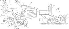
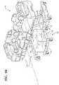
- FIG. 1is perspective view of a patient support apparatus comprising swappable energy storage devices, according to one embodiment.
- FIG. 2is a block diagram of an electrical distribution system and electrical components of the patient support apparatus according to one embodiment.
- FIG. 3is a cross-sectional view of the energy storage device disposed relative to a receptacle of the patient support apparatus and further showing components or systems that are coupled to the receptacle.
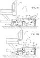
- FIGS. 4A-4Care cross-sectional views progressively showing interaction between an interface of the energy storage device and an interface of a swapping unit that is configured to remove or install the energy storage device, according to one embodiment.
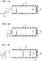
- FIGS. 5A-5Care cross-sectional views progressively showing interaction between the interface of the energy storage device and the interface of the swapping unit, according to another embodiment.
- FIGS. 6A-6Care cross-sectional views progressively showing interaction between the interface of the energy storage device and the interface of the swapping unit, according to yet another embodiment.
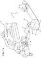
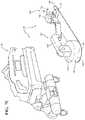
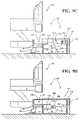
- FIGS. 7A-7Dare perspective views, partially in phantom, progressively showing interaction between the swapping unit and the patient support apparatus, wherein the swapping unit is embodied as a robotic device.
- FIGS. 8A-8Care perspective views, partially in phantom, progressively showing interaction between the swapping unit and the patient support apparatus, wherein the swapping unit is embodied as a mobile conveyor unit.
- FIGS. 9A-9Gare elevation views, partially in phantom, progressively showing interaction between the swapping unit and the patient support apparatus, wherein the swapping unit is embodied as a robotic docking system.
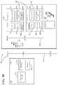
- FIG. 10is a block diagram of a network system wherein communication is handled between the patient support apparatus, the swapping unit, mobile display devices, and a remote server.
- FIG. 11is a sample screen shot of a graphical user interface provided on a display for conveying information between the patient support apparatus and the swapping unit.
- a patient support apparatus 30is shown for moving a patient from one location to another.
- the patient support apparatus 30 illustrated in FIG. 1is a hospital bed. In other embodiments, however, the patient support apparatus 30 may be a stretcher, cot, wheelchair, chair, or similar apparatus.
- a support structure 32provides support for the patient during movement of the patient support apparatus 30 .
- the support structure 32 illustrated in FIG. 1comprises a base 34 and an intermediate frame 36 .
- the intermediate frame 36is spaced above the base 34 .
- the support structure 32also comprises a patient support deck 38 disposed on the intermediate frame 36 .
- the patient support deck 38may comprise several sections, some of which are pivotable relative to the intermediate frame 36 , such as a head section, a seat section, a thigh section, and a foot section.
- the patient support deck 38provides a patient support surface 42 upon which the patient is supported.
- the patient support surface 42is supported by the base 34 .
- a mattress 40is disposed on the patient support deck 38 .
- the mattress 40comprises a direct patient support surface 43 upon which the patient is supported.
- the base 34 , intermediate frame 36 , patient support deck 38 , and patient support surfaces 42 , 43each have a head end and a foot end corresponding to the designated placement of the patient's head and feet on the patient support apparatus 30 .
- the construction of the support structure 32may take on any suitable design, and is not limited to that specifically set forth above or shown in FIG. 1 .
- a first side rail 44is positioned at a right head end of the intermediate frame 36 .
- a second side rail 46is positioned at a right foot end of the intermediate frame 36 .
- a third side rail 48is positioned at a left head end of the intermediate frame 36 .
- a fourth side rail 50is positioned at a left foot end of the intermediate frame 36 . If the patient support apparatus 30 is a stretcher or a cot, there may be fewer side rails.
- the side rails 44 , 46 , 48 , 50are movable between a raised position in which they block ingress and egress into and out of the patient support apparatus 30 , one or more intermediate positions, and a lowered position in which they are not an obstacle to enable such ingress and egress.
- the patient support apparatus 30may not include any side rails.
- a headboard 52 and a footboard 54are coupled to the intermediate frame 36 .
- the headboard 52 and footboard 54may be coupled to other locations on the patient support apparatus 30 , such as the base 34 .
- the patient support apparatus 30does not include the headboard 52 or the footboard 54 .
- Operator (human control) interfaces 56such as handles, are shown integrated into the footboard 54 and side rails 44 , 46 , 48 , 50 to facilitate movement of the patient support apparatus 30 over the floor surfaces. Additional operator interfaces 56 may be integrated into the headboard 52 and/or other components of the patient support apparatus 30 . The operator interfaces 56 are graspable by the operator to manipulate the patient support apparatus 30 for movement.
- the operator interface 56may comprise one or more handles coupled to the intermediate frame 36 .
- the operator interface 56may simply be a surface on the patient support apparatus 30 upon which the operator locally applies force to cause movement of the patient support apparatus 30 in one or more directions, also referred to as a push location. This may comprise one or more surfaces on the intermediate frame 36 or base 34 .
- the operator interface 56may comprise separate handles for each hand of the operator.
- the operator interface 56may comprise two handles.
- Other forms of the operator interface 56are also contemplated.
- One or more caster assemblies 58are coupled to the base 34 to facilitate transport over floor surfaces.
- four caster assemblies 58 a - 58 dare arranged in each of four quadrants of the base 34 adjacent to corners of the base 34 .
- the caster assemblies 58 a - 58 dare able to rotate and swivel relative to the support structure 32 during transport.
- the caster assemblies 58may be non-steerable, steerable, non-powered, powered (driven), or any combinations thereof.
- the caster assemblies 58may have any suitable shape or configuration other than those shown in the Figures.
- the patient support apparatus 30may comprise any suitable number of caster assemblies 58 , such as two or six, etc.
- the caster assemblies 58may have any suitable configuration and arrangement depending on the specific type of patient support apparatus 30 .
- the patient support apparatus 30may comprise two front non-driven caster assemblies 58 and two rear driven caster assemblies 58 .
- auxiliary wheels 66(powered or non-powered), which may be movable between stowed positions and deployed positions, may be coupled to the support structure 32 .
- auxiliary wheels 66when these auxiliary wheels 66 are located between the caster assemblies 58 and contact the floor surface in the deployed position, they cause two of the caster assemblies 58 to be lifted off the floor surface thereby shortening a wheel base of the patient support apparatus 30 .
- Such auxiliary wheels 66may also be arranged substantially in a center of the base 34 .
- the patient support apparatus 30comprises a controller 68 in communication with and for controlling any suitable components of the patient support apparatus 30 , such as the electrical or electromechanical components described herein.
- the controller 68may comprise any suitable signal processing means, computer executable instructions or software modules stored in non-transitory memory wherein the executable instructions or modules may be executed by a processor, or the like. Additionally, or alternatively, the controller 68 may comprise a microcontroller, a processor, one or more integrated circuits, logic parts, and the like for enabling the same.
- the controller 68may have any suitable configuration for enabling performance of various tasks related to operation of the patient support apparatus 30 , such as those described below.
- the controller 68may be located at any suitable location of the patient support apparatus 30 .
- the patient support apparatus 30comprises one or more electrical devices 70 .
- the electrical device 70is a device that is actively energized and consumes energy.
- the electrical device 70is connected to an energy storage device (ESD) 72 , which stores such energy for consumption.
- ESDenergy storage device
- the patient transport apparatus 30may comprise any suitable number of powered devices 70 . Examples of the powered devices 70 are shown in the block diagram of FIG. 2 .
- the electrical device 70may be an actuator 74 , such as a motor, for moving the patient support deck 38 in different positions and/or for lifting the intermediate frame 36 .
- the actuator 74may also be coupled to one or more of the wheels 58 , 66 for steering or drive purposes. Additionally, the actuator 74 may be provided for a “pre-swivel” mechanism or a “steer-lock” mechanism.
- the electrical device 70is an electronic scale 76 for detecting patient weight and/or patient presence.
- the electrical device 70may be a user interface (UI) device 78 provided for communicating with the operator and/or accepting user input to enable the operator to control aspects of the patient transport apparatus 30 .
- the user interface device 78may comprise a digital display (e.g., backlit display), buttons, touch-screens, voice activation, or combinations thereof.
- the user interface device 78may be mounted to the headboard 52 , footboard 54 , side rails 44 , 46 , 48 , 50 , or any other suitable location on the patient transport apparatus 30 .
- the user interface device 78may also be removably attached to or located remotely from the patient transport apparatus 30 .
- the user interface device 78may have any other suitable configuration for communicating with the operator and/or accepting user input to enable the operator to control aspects of the patient transport apparatus 30 .
- the electrical device 70is a communication unit or device 80 for enabling communication with other components of the patient transport apparatus 30 and/or to enable the patient transport apparatus 30 to communicate with external communication sources.
- the communication device 80may be wireless or wired. Examples of such communication devices 80 include, but are not limited to, transmitters, mobile RF communication devices, receivers, transponders, transceivers, near-field communication devices, antennae, low power IEEE 802.15.1 enabled devices, infrared devices, wireless access points, Wi-Fi devices or modules, and the like.
- the communication device 80may have any other suitable configuration for implementing those functions described herein, and those not specifically recited herein.
- the electrical device 70may be any electronic sensor 82 employed by the patient transport apparatus 30 , including, but not limited to, force sensors (e.g., sensors for any of the headboard 52 , footboard 54 , and/or side rails 44 , 46 , 48 , 50 ), steering sensors, brake sensors, speed sensors, position sensors, electronic accelerometers, electronic gyroscopic sensors, potentiometers, strain gauges, capacitive sensors, piezoresistive sensors, proximity sensors (e.g., Hall effect sensors), piezoelectric sensors, GPS sensors, IR sensors, RF sensors, electromagnetic sensors, and combinations thereof.
- the electrical device 70may be the controller 68 itself.
- the patient support apparatus 30comprises an electrical distribution system 84 providing a medium to distribute power to any of the electrical devices 70 .
- the electrical distribution system 84comprises circuits, wires, fuses, switches, relays, electrical connectors, electrical terminals, junction boxes, circuit boards, and the like, which enable such power distribution and control thereof.
- the electrical distribution system 84may be routed throughout various components of the patient support apparatus 30 , such as the support structure, 32 , base 34 , intermediate frame 36 , and/or patient support deck 38 .
- the electrical distribution system 84may have any configuration desired for adequately distributing power, or enabling control of power delivery, to any of the electrical devices 70 .
- the ESD 72is coupled to the electrical distribution system 84 .
- the stored energy in the ESD 72is distributed to any of the electrical devices 70 through the electrical distribution system 84 .
- the ESD 72exhibits a high or ultra-high energy density.
- Energy densityis the amount of energy stored in per unit volume of the ESD 72 . In one example, the energy density is in a range between 1-30 MJ/L.
- the ESD 72may be specifically configured for use with a wireless power transfer (WPT) systems employed by the patient support apparatus 30 .
- WPTwireless power transfer
- a peak power drawis taken into account wherein the WPT system would require peak current draw above a certain current threshold, e.g., above 10 Amps.
- High-density ESDs 72such as the supercapacitors, are capable of storing power for such peak current draw required by the WPT system.
- the high-density ESD 72can deliver large amounts of power quickly and efficiently with little loss of energy during transfer.
- the high-density ESD 72exhibits a long life allowing for hundreds of thousand charging and discharge cycles.
- the high-density ESD 72reduces the overall power transfer required under wireless device use to less than one amp and reduces the need for larger and more expensive battery components and circuitry. Furthermore, the overall energy delivery system of the patient support apparatus 30 is reduced in physical size and the overall cost of the energy delivery system is reduced. Additionally, the ESD 72 often obtains charge originally from the electrical system of the facility in which the patient support apparatus 30 is located. By utilizing such high-density ESDs 72 , the overall facility power consumed by the patient support apparatuses 30 in the facility is reduced, in turn, allowing the electrical system of the facility to be less burdened.
- the ESD 72may be designed electrochemically or chemically.
- the ESD 72is a battery.
- the batterymay be a Lithium-ion battery.
- the Lithium-ion batterymay be one or more of a Lithium Cobalt Oxide, Lithium Manganese Oxide, Lithium Iron Phosphate, Lithium Nickel Manganese Cobalt Oxide, Lithium Nickel Cobalt Aluminum Oxide, and Lithium Titanate battery.
- the ESD 72is a Lithium battery, a Lead-acid battery, or a Nickel-metal hydride battery.
- the ESD 72is not a battery, but rather a supercapacitor.
- the supercapacitormay be electrical or electrostatically based, such as an electric double-layer capacitor (EDLC).
- EDLCelectric double-layer capacitor
- the supercapacitoris a pseudo-capacitor or a hybrid capacitor.
- the patient support apparatus 30may comprise any number of ESDs 72 of the same type.
- a second ESD 86which is of a different type as compared with the first ESD 72 .
- the second ESD 86is coupled to the electrical distribution system 84 .
- the stored energy in the second ESD 72may also be distributed to any of the electrical devices 70 through the electrical distribution system 84 . Additional techniques involving management of the first and second ESDs 72 , 86 are provided below.
- the controller 68may be coupled to the electrical distribution system 84 for controlling power distribution operations.
- the electrical distribution system 84may comprise one or more control blocks 88 a - 88 b for controlling power distribution. Any of the control blocks 88 a - 88 b described herein may be disposed on a device separate from the controller 68 or may be integrated within the controller 68 itself. In either scenario, the controller 68 can provide selective control over the control blocks 88 a - 88 b , for purposes such as enabling or disabling power distribution through certain pathways.
- the control blocks 88 a - 88 bmay comprise any suitable switches (e.g., transistors), integrated circuits, and other electrical components for enabling power distribution control. Additionally, or alternatively, the control block 100 may be a software block or module.
- control block 88 ais disposed between the controller 68 and an input side of the ESDs 72 , 86 to selectively activate and/or deactivate the ESDs 72 , 86 , or control charging to the same.
- Control block 88 bis disposed between an output side of each of the ESDs 72 , 86 and one or more of the electrical devices 70 to control distributed power output to the electrical devices 70 individually.
- the power distribution system 84 and control blocks 88 a , 88 bmay have any configuration other than that shown in FIG. 2 , or described above.
- the patient support apparatus 30provides means for enabling swapping or easy replacement of the ESD 72 or any number of ESDs 72 . Such swapping may be needed to replace the ESD 72 when the ESD is low on charge or life. Swapping may also be useful to maintain the overall charge level among a plurality of ESDs 72 above a certain threshold.
- the ESD 72is provided on the patient support apparatus 30 in a plug-and-play manner.
- the patient support apparatus 30comprises one or more receptacles 100 being configured to house one or more ESDs 72 .
- the patient support apparatus 30comprises two receptacles 100 for respectively housing two ESDs.
- any number of receptacles 100may be used for housing any number of ESDs 72 .
- one receptacle 100may house a plurality of ESDs 72 .
- the receptacle 100is coupled to any suitable location on the patient support apparatus 30 that enables the ESD 72 to be readily accessible.
- the receptacle 100is coupled to the support structure 32 , and more specifically, the base 34 .
- the receptacle 100may be coupled to any of the headboard 52 , footboard 54 , and Side rails 44 , 46 , 48 , 50 .
- the receptacle 100may be disposed on, or integrated in, any of the components of the patient support apparatus 30 , such as those described.
- FIG. 3a cross-sectional view of the ESD 72 and the receptacle 100 are shown.
- the ESD 72comprises a casing 102 for housing components and/or materials of the ESD 72 that are designed to store energy.
- the receptacle 100defines a slot 104 that receives the ESD 72 , and more specifically, the casing 102 .
- the ESD 72is shown as being partially slid into the slot 104 .
- the slot 104may be any suitable size for receiving the casing 102 .
- the slot 104conforms to the casing 102 such that ESD 72 is secured from movement when installed in the receptacle 100 .
- the slot 104is defined such that the casing 102 substantially occupies the slot 102 when the receptacle 100 receives the ESD 72 .
- the casing 102may occupy a portion of the slot 102 such that other portions of the casing 102 are outside of the receptacle 100 .
- the ESD 72comprises electrical contacts 106 for enabling charging or discharging of energy from the ESD 72 .
- Two electrical contacts 106are shown in this example. However, any number of electrical contacts 106 may be utilized depending on the configuration of the ESD 72 and/or the number of ESDs 72 housed by a single receptacle 100 . Furthermore, the electrical contacts 106 may be any suitable shape or configuration depending on the type of the ESD 72 , and the like.
- the receptacle 100has electrical contacts 108 configured to interface with the electrical contacts 106 of the ESD 72 .
- the electrical contacts 106 , 108couple when the receptacle 100 receives the ESD 72 .
- the electrical contacts 108 of the receptacle 100conform to the electrical contacts 106 of the ESD 72 .
- the electrical contacts 108 of the receptacle 100define openings for receiving the electrical contacts 106 projecting from the casing 102 of the ESD 72 .
- one or more electrical contacts 108 of the receptacle 100comprise a biasing member for establishing contact with the electrical contacts 106 of the ESD 72 .
- Two electrical contacts 108 of the receptacle 100are shown in this example. However, any number of electrical contacts 108 may be utilized and such electrical contacts 108 may be of any suitable shape or type.
- the electrical contacts 108 of the receptacle 100are coupled to the electrical distribution system 84 of the patient support apparatus 30 . As such, when the ESD 72 is fully engaged with the receptacle 100 , and the electrical contacts 106 , 108 interface with one another, the ESD 72 becomes coupled to the electrical distribution system 84 . From here, the ESD 72 can be discharged through the receptacle 100 to power the one or more electrical devices 70 through the electrical distribution system 84 . Additionally or alternatively, the ESD 72 can be charged through the receptacle 100 to increase energy stored therein.
- the controller 68may be coupled to the electrical contacts 108 of the receptacle 100 for actively controlling operation of the ESD 72 when installed in the receptacle 100 .
- the controller 68may selectively disconnect the electrical contacts 108 of the receptacle 100 from the electrical distribution system 84 using switches 110 to prevent the ESD 72 from powering the one or more electrical devices 70 , and vice-versa
- the ESD 72comprises a first interface 112 configured to allow easy handling of the ESD 72 .
- the first interface 112is configured to be physically engaged for removal of the ESD 72 from the receptacle 100 and/and for insertion of the ESD 72 into the receptacle 100 .
- the first interface 112is coupled to the casing 102 and may be mechanically attached to the casing 102 or integrated with the casing 102 .
- the first interface 112is configured to structurally support the weight of the ESD 72 when the ESD 72 is physically engaged by the first interface 112 .
- the first interface 112is embodied as a handle. Other examples of the first interface 112 are described below.
- the first interface 112located in any suitable location on the ESD 72 depending on the shape of the ESD 72 and/or the shape of the receptacle 100 .
- the first interface 112is located such that when the ESD 72 is disposed in the receptacle 100 , the first interface 112 remains exposed to allow accessibility for physically engagement.
- the first interface 112may have any other suitable configuration for enabling swapping of the ESD 72 to and/or from the patient support apparatus 30 .
- any number of first interfaces 112may be utilized for the ESD 72 , and may be of a common or different configuration from one another.
- the patient support apparatus 30may utilize an ESD 72 b that was initially located remote from the patient support apparatus 30 and later provided on the patient support apparatus 30 to supplement and/or to replace existing ESDs 72 .
- ESDs 72 b of this natureare referred to as replacements ESDs 72 b below.
- the replacements ESD 72 bmay be the same or different type as existing ESDs 72 a on the patient support apparatus 30 .
- any of the existing ESDs 72 a on the patient support apparatus 30may have formally been a replacement ESD 72 b , i.e., before being installed on the patient support apparatus 30 . Any of the features, structure, and/or functions of the ESD 72 a may be applied fully to any replacement ESD 72 b described herein.
- a system 120includes the patient support apparatus 30 in conjunction with a unit 122 that is independent from the patient support apparatus 30 .
- the unit 122is configured to interact autonomously with the patient support apparatus 30 .
- the unit 122is configured to autonomously remove the ESD 72 a from the patient support apparatus 30 and/or to autonomously place the replacement ESD 72 b on to the patient support apparatus 30 .
- the unit 122may also be understood as a swapping unit or an ESD swapper.
- the autonomous nature of the unit 122may be understood as being fully or semi-autonomous.
- the caregiverneed not perform any preliminary tasks to enable the unit 122 to perform autonomous swapping.
- the unit 122is configured to approach the patient support apparatus 30 autonomously and perform autonomous swapping, even if, for example, the caregiver is not near the patient support apparatus 30 .
- the caregivermay need to perform some preliminary tasks to enable the unit 122 to perform autonomous swapping.
- such preliminary tasksmay include activating the unit 122 , signaling to the unit 122 that swapping is desired, and/or moving the patient support apparatus 30 to a location suitable for the unit 122 to perform autonomous swapping.
- the unit 122removes the ESD 72 a from the patient support apparatus 30 and/or to places the replacement ESD 72 b on to the patient support apparatus 30 .
- the unit 122may be of various configurations.
- the unit 122comprises a robotic device 124 that is stationary and autonomously configured to remove the ESD 72 a and/or to place the replacement ESD 72 b .
- the unit 122comprises a mobile device 126 autonomously configured to approach the patient support apparatus 30 to remove the ESD 72 a and/or to place the replacement ESD 72 b .
- the unit 122comprises a docking system 128 configured to enable docking between the patient support apparatus 30 and the unit 122 for autonomously removal of the ESD 72 a and/or placement the replacement ESD 72 b .
- the unit 122may comprise any combination of the embodiments described herein. Furthermore, the unit 122 may comprise embodiments for autonomously removing the ESD 72 a from the patient support apparatus 30 and/or for autonomously placing the replacement ESD 72 b on to the patient support apparatus 30 other than those described herein.
- the unit 122is configured to physically engage the ESD 72 to enable autonomous removal or installing of the same.
- the unit 122may physically engage the casing 102 of the ESD 72 without regard to the first interface 112 .
- the unit 122may slide a mechanism below, or around, the ESD 72 for sliding the ESD 72 into and out of the patient support apparatus 30 .
- the unit 122may engage the ESD 72 by physically engaging the first interface 112 of the ESD 72 .
- the unit 122may comprise a second interface 130 configured to physically engage the first interface 112 .
- the first and second interfaces 112 , 130may be mechanical interfaces that are configured to mechanically interlock.
- the first and second interfaces 112 , 130may be magnetic, electromagnetic, or the like.
- the second interface 130is embodied as a static mechanical member.
- the static mechanical memberis a hooking plate.
- the first interface 112 in this examplecomprises an opposing mechanical member, such as an opposing plate, which is capable of being engaged by the hooking plate.
- the unit 122autonomously moves the hooking plate towards the first interface 112 of the ESD 72 disposed in the receptacle 100 .
- the unit 122orients the hooking plate at a level that would enable the hooking plate to avoid collision with the first interface 112 .
- the unit 122autonomously moves the hooking plate behind the first interface 112 and elevates the hooking plate such that the hooking plate contacts and interlocks with the first interface 112 .
- the unit 122in FIG. 4C , autonomously pulls the hooking plate such that the hooking plate applies force to the first interface 112 to pull the ESD 72 from the receptacle 100 .
- FIGS. 4A-4Cshow autonomous removal of the ESD 72 from the patient support apparatus 30 .
- FIGS. 4A-4Cwhen viewed in reverse order and with reverse directionality, can be understood to show autonomous installation of the ESD 72 on to the patient support apparatus 30 .
- the second interface 130is embodied as a gripping device.
- the gripping deviceis a mechanically movable device that is configured to move between a gripped and an un-gripped positon.
- the gripping devicemay be actuated mechanically and/or electrically.
- the gripping deviceis provided on the robotic device 124 of the embodiment of FIG. 7 .
- the first interface 112 in this examplecomprises one or more protrusions integrally formed in the casing 102 , which are capable of being engaged by the gripping device.
- protrusionsmay or may not be specifically designed for gripping by the gripping device.
- protrusionsmay exist for purposes such as casing 102 aesthetic design, enabling proper installation of the ESD 72 in the receptacle 100 , and/or for securing the ESD 72 in the receptacle 100 .
- the unit 122autonomously moves the gripping device towards the first interface 112 of the ESD 72 disposed in the receptacle 100 .
- the unit 122orients the gripping device to align the gripping device with the protrusions.
- the unit 122autonomously moves the gripping device past the protrusions in the un-gripped position. Once in this position, the unit 122 , in FIG. 5C , autonomously closes the gripping device to the gripped position such that the gripping device contacts and interlocks with the protrusions.
- the unit 122autonomously pulls the gripping device such that the gripping device applies force to the protrusions to pull the ESD 72 from the receptacle 100 .
- the first interface 112may embody protrusions of any configuration other than that shown in FIG. 5 . Additionally or alternatively, the first interface 112 may define openings or notches to enable physical engagement the second interface 130 .
- the second interface 130may embody gripping devices other than those shown in FIG. 5 .
- such gripping devicesmay be an adjustable strap device, a robotic hand, or the like.
- FIGS. 5A-5Cshow autonomous removal of the ESD 72 from the patient support apparatus 30 . However, FIGS. 5A-5C , when viewed in reverse order and with reverse directionality, can be understood to show autonomous installation of the ESD 72 on to the patient support apparatus 30 .
- the second interface 130is embodied as a connector.
- the connectoris configured to mechanically connect to the first interface 112 .
- the connector in FIG. 6is a threaded female connector (e.g., nut) that is driven, mechanically and/or electrically, by the unit 122 .
- the first interface 112 in this examplecomprises a threaded male connector (e.g., bolt) conforming to the female connector.
- the connectorsmay be of opposite configuration from that shown in FIG. 6 .
- one of the first and second interfaces 112 , 130may comprise a connector, while the other does not. Additionally, the connectors may take any form other than that shown in FIG. 6 .
- the unit 122autonomously moves the female connector towards the first interface 112 of the ESD 72 disposed in the receptacle 100 .
- the unit 122orients the female connector to align the female connector with the male connector.
- the unit 122autonomously moves the female connector such that it contacts the male connector. Once in this position, the unit 122 autonomously rotates the female connector such that threads of the connectors engage one another to interlock the female connector to the ESD 72 . Once this interlock is made, the unit 122 autonomously pulls the female connector such that the female connector applies force to the male connector to pull the ESD 72 from the receptacle 100 .
- FIGS. 6A-6Cshow autonomous removal of the ESD 72 from the patient support apparatus 30 .
- FIGS. 6A-6Cwhen viewed in reverse order and with reverse directionality, can be understood to show autonomous installation of the ESD 72 on to the patient support apparatus 30 .
- the second interface 130 of the unit 122may physically engage the first interface 112 of the ESD 72 according to examples other than those shown in FIGS. 4-6 .
- different ESDs 72may comprise different types of first interfaces 112 .
- any given ESD 72may comprise any combination of first interfaces 112 , which may be common or different from one another.
- the unit 122may be configured to interchange second interfaces 130 upon detection of the first interface 112 provided on the ESD 72 .
- the unit 122comprises a controller 132 in communication with and for controlling any suitable components of the unit 122 , such as the electrical or electromechanical components described herein.
- the controller 132may comprise any suitable signal processing means, computer executable instructions or software modules stored in non-transitory memory wherein the executable instructions or modules may be executed by a processor, or the like. Additionally, or alternatively, the controller 132 may comprise a microcontroller, a processor, one or more integrated circuits, logic parts, and the like for enabling the same.
- the controller 132may have any suitable configuration for enabling performance of various tasks related to operation of the unit 122 such as those described below.
- the controller 132may be located at any suitable location of the unit 122 . Additional functionality of the controller 132 will be understood from the various embodiments described herein.
- the unit 122may also comprise and/or interact with a charging station 134 .
- the charging station 134is configured to charge replacement ESDs 72 b .
- the charging station 134may be coupled to the controller 132 such that the controller 132 can monitor and control charge delivered to the replacements ESDs 72 b .
- the charging station 134may be integrated with the unit 122 or coupled thereto. In other embodiments, the charging station 134 is remote from the unit 122 , but the unit 122 may be configured to autonomously locate and deposit and/or remove ESDs to/from the charging station 134 .
- the charging station 134may be coupled to a wall or a floor surface of the facility and many charging stations 134 may be located throughout the facility.
- the charging station 134comprises a receptacle 136 for housing the replacement ESD 72 b .
- the unit 122is configured to autonomously place the ESDs 72 a into the receptacle and/or to autonomously remove the replacement ESD 72 b from the receptacle.
- the receptacle 136 of the charging station 134comprises electrical contacts 138 coupled to a power source.
- the electrical contacts 138 of the charging station 134interface with the electrical contacts 106 of the replacement ESD 72 b to enable the power source to electrically charge the same.
- the receptacle 136 of the charging station 134may have a configuration or functionality according to any of the configurations or functionally of the receptacle 100 of the patient support apparatus 30 .
- the configurations of receptacle 100apply fully to receptacle 136 , and therefore, are not repeated herein for simplicity.
- the unit 122is the robotic device 124 .
- the robotic device 124 in FIG. 7comprises a base 140 , a robotic arm 142 that moves relative to the base 140 , and the charging station 134 .
- the first interface 130is coupled to a distal end of the robotic arm 142 .
- the robotic arm 142may comprise any suitable number of joints and/or links, with motors, to enable the robotic arm 142 to move in any number of degrees of freedom, such as six degrees or freedom, or more.
- the controller 132 of the unit 122is in the base 140 of the robotic device 124 .
- the robotic device 124 in this exampleis stationary. However, the robotic device 124 alternatively may be mobile.
- the unit 122may be coupled to, or may include, a tracking system 144 that is configured to track the position and orientation of the patient support apparatus 30 relative to the unit 122 .
- the tracking system 144is coupled to the base 124 of the robotic device 124 .
- Such tracking systems 144may include a camera, optical tracking elements, Hall Effect sensors, ultrasonic detection elements, electromagnetic elements, or the like.
- the tracking system 144may alternatively track the positon and orientation of the ESDs 72 .
- the patient support apparatus 30may also be configured with elements that facilitate tracking by the tracking system 144 . Such elements may include trackers, sensors, markers, and the like.
- the controller 132may communicate with the tracking system 144 to coordinate autonomous motion of the unit 122 relative to the patient support apparatus 30 .
- the robotic device 124 in FIG. 7may iteratively move the arm 142 relative to the ESD 72 .
- the tracking system 144may have configurations other than those described herein and as shown in the Figures. It should be appreciated that the unit 122 may be autonomously operational without use of the tracking system 144 .
- the robotic device 124detects presence of the patient support apparatus 30 using the tracking system 132 .
- the controller 132processes tracking data from the tracking system 132 and commands motion of the robotic arm 142 relative to the patient support apparatus 30 .
- the unit 122may also receive status information over a network about the ESDs 72 a of the patient support apparatus 30 , for purposes of determining, for example, which ESD 72 a in the receptacle 100 requires replacement.
- network communication schemesare described in detail below.
- the second interface 130 of the robotic device 124physically engages the first interface 112 of the ESD 72 a , according to any of the techniques described herein. Meanwhile, the replacement ESD 72 b is being charged on the charging station 136 coupled to the robotic device 124 such that the replacement ESD 72 b is charged at a sufficiently high enough level before installation on the patient support apparatus 30 .
- the robotics device 124autonomously actuates one or motors of the links of the robotic arm 142 to pull the ESD 72 a from the receptacle 100 .
- Physical engagement between the interfaces 112 , 130supports the ESD 72 a weight load.
- the robotic device 124actuates the robotic arm 142 to autonomously move the ESD 72 a towards the charging station 134 .
- the controller 132may process data to determine which receptacles 136 of the charging station 134 are vacant or occupied by replacement ESDs 72 b .
- the robotic device 124recognizes that the receptacle 136 on the right of the charging station 134 is vacant, and hence, autonomously places the ESD 72 a that was taken from the patient support apparatus 30 in the receptacle 136 of the charging station 134 .
- the electrical contacts 106 of the ESD 72 binterface with the electrical contacts 138 of the charging station 134 to charge the ESD 72 b.
- the robotic device 124uses the second interface 130 to engage the replacement ESD 72 b that was on the charging station 134 .
- the robotic arm 142is actuated to autonomously move the replacement ESD 72 b into the receptacle 100 of the patient support apparatus 30 that previously housed ESD 72 a .
- the robotic device 124disengages the replacement ESD 72 b such that the patient support apparatus 30 is free to move disconnected from the robotic device 124 .
- the robotic device 124 , charging station 134 , and tracking system 144may have configurations other than those shown in FIG. 7 . Furthermore, the robotic device 124 may perform other autonomous tasks relating to swapping of the ESD 72 other than those tasks shown in FIG. 7 . For example, the robotic device 124 may be configured to engage the patient support apparatus 30 to position and/or orient the patient support apparatus 30 to allow unobscured access to the ESDs 72 by the robotic arm 142 .
- the unit 122is embodied as mobile cart or unit 126 .
- the mobile unit 126comprises one or more wheels 150 that are autonomously steered and driven to move the mobile unit 126 towards the patient support apparatus 30 .
- the mobile unit 126 in FIG. 8Ais configured to receive tracking information about the patient support apparatus 30 and to autonomously approach the patient support apparatus 30 .
- Tracking informationmay be provided by the tracking system 144 , which in this example, is a camera unit 144 disposed on the mobile unit 126 , and/or by communication of tracking data over a network. Examples of such networks and communication schemes are described below.
- the mobile unit 126is shown having the replacement ESD 72 b disposed in the receptacle 136 , which also provides the charging station 134 .
- the charging station 134is also mobile such that the mobile unit 126 can charge the replacement ESD 72 b while moving.
- the replacement ESD 72 bis disposed on a conveyor device 152 , which is configured to slide ESDs 72 in and out of the receptacle 136 .
- the first and second interfaces 112 , 130may or may not be utilized in addition to the conveyor device 152 .
- devices and techniques for moving the ESDs 72 other than the conveyor device 152may be utilized.
- the receptacle 100 of the patient support apparatus 30has one vacancy for placement of the replacement ESD 72 b .
- the other ESD 72 a in the receptacle 100is low on energy and should be removed.
- situations for the ESDs 72 other than those shown in the Figuresmay be fully addressed by the techniques described herein.
- the mobile unit 126autonomously moves adjacent to the patient support apparatus 30 , and more specifically, the receptacle 100 .
- the mobile unit 126aligns the replacement ESD 72 b with the vacancy in the receptacle 100 on the patient support apparatus 30 .
- the conveyor device 152slides the replacement ESD 72 b into the receptacle 100 so that the replacement ESD 72 b can connect to the electrical distribution system 84 of the patient support apparatus 30 .
- the conveyor device 152may comprise supplemental components, such as an extendable member for sliding underneath the ESD 72 when the ESD 72 is partially disposed outside of the receptacle 136 .
- the mobile unit 126uses the same conveyor device 152 or an adjacent conveyor device to remove the ESD 72 a that was on the patient support apparatus 30 .
- the mobile unit 126may align the second conveyor device 152 with the ESD 72 a and slide the extendable member underneath the ESD 72 a to slide the ESD 72 a out of the receptacle 100 .
- the conveyor device 152slides the ESD 72 a into the receptacle 136 until the ESD 72 a couples to the charging station 134 for charging.
- the mobile unit 126may have configurations other than those shown in FIG. 8 .
- mobility in the unit 122may be provided with any of the embodiments described herein or shown in the Figures.
- the unit 122comprises a docking system 128 configured to enable docking between the patient support apparatus 30 and the unit 122 for autonomously removal of the ESD 72 a and/or placement the replacement ESD 72 b .
- the docking system 128 in this exampleis stationary, but may be mobile in other configurations.
- the docking system 128comprises the charging station 134 disposed in a housing 160 .
- a docking feature 162enables the patient support apparatus 30 to be captured by the docking station 128 .
- the docking feature 162may be integrated with or attached to the docking system 128 or may be separated therefrom.
- the docking feature 162may be a passive object or an actively energized device. As shown in FIG. 9A , the docking feature 162 comprises a wedge that is disposed on the floor surface, over which one or more wheels 58 , 66 of the patient support apparatus 30 roll over.
- the docking system 128further comprises a machine 164 for physically moving the ESDs 72 .
- the machine 164 in this embodimentcomprises a rail unit 166 , which moves along or by guide tracks 168 .
- the guide track 168may be fixed to the housing 160 and/or or coupled to the rail unit 166 such that the rail unit 166 is moved through extension of the guide track 168 .
- the rail unit 166 and/or the guide tracks 168may comprise motors to enable such movement.
- the second interface 130is coupled to the rail unit 166 .
- the docking system 128 in this exampleis semi-autonomous, thereby requiring the caregiver to dock the patient support apparatus 30 before autonomous management of the ESDs 72 is carried out.
- the patient support apparatus 30is moved towards the docking system 128 for ESD 72 management.
- the patient support apparatus 30comprises the receptacle 100 facing the docking system 128 . Any designed orientation of the docking system 128 relative to the receptacle 100 , and vice-versa, is contemplated.
- the patient support apparatus 30comprises the ESD 72 a , which in this example, requires replacement.
- the replacement ESD 72 bis being charged on the charging system 134 .
- the wheel 58 of the patient support apparatus 30rolls over the wedge 162 causing the patient support apparatus 30 to be pushed towards the docking system 128 due to the decline of the wedge 162 .
- the wedge 162may be spaced from the docking system 128 according to a predetermined distance to enable such docking.
- the receptacle 100 of the patient support apparatus 30is disposed adjacent to an opening in the housing 160 of the docking system 128 .
- the rail unit 166moves with the horizontal guide track 168 towards the opening in the housing 160 .
- the second interface 130 on the rail unit 166engages the first unit 112 of the ESD 72 a within the receptacle 100 .
- the rail unit 166is moved with the horizontal guide track 168 in the opposite direction thereby removing the ESD 72 a from the receptacle 100 .
- the rail unit 166moves the ESD 72 a using physical engagement from the interfaces 112 , 130 to prepare positioning of the ESD 72 a into the charging station 134 .
- the charging station 134comprises one vacancy for receiving the ESD 72 a.
- the rail unit 166is moved down the vertical guide track 168 to align the ESD 72 a to the charging station 134 . Once aligned, the rail unit 166 is moved horizontally with the horizontal guide track 168 to push the ESD 72 a into the charging station 134 .
- the docking system 128moves the rail unit 166 down with the vertical guide track 168 to physically engage the replacement ESD 72 b . In so doing, the rail unit 166 removes the replacement ESD 72 b from the charging station 134 using physical connection of the interfaces 112 , 130 .
- the rail unit 166along with the replacement ESD 72 b , are moved up with the vertical guide track 168 to align the replacement ESD 72 b with the opening in the housing 160 , which remains aligned with the receptacle 100 of the patient support apparatus 30 .
- the rail unit 166moves with the horizontal guide track 168 to force the replacement ESD 72 b through the opening of the housing 160 and fully into the receptacle 100 .
- the docking system 128disengages the interfaces 112 , 130 so that the patient support apparatus 30 is free to be undocked.
- the docking system 128may have configurations other than those shown in FIG. 9 . Furthermore, docking capabilities in the unit 122 may be provided with any of the embodiments described herein or shown in the Figures.
- FIGS. 2, 10 and 11components, systems, and techniques are provided which facilitate communication between the patient support apparatus 30 and the unit 122 , the caregiver and the patient support apparatus 30 , and the caregiver and the unit 122 .
- FIG. 10illustrates a block diagram of one embodiment of a communication system 200 .
- the communication system 200comprises a plurality of the patient transport apparatuses 30 , which are configured to be located in the facility 22 .
- the patient transport apparatuses 30are equipped with sensors 82 , such as those described herein, which are configured to produce readings about behavior of the patient transport apparatuses 30 in the facility, and the like.
- the patient transport apparatus 30transmits the readings using the communication device 80 .
- FIG. 10further illustrates a sample block diagram of the unit 122 .
- the unit 122may be equipped with sensors 202 , such as those any of those described herein with reference to the patient support apparatus 30 , which are configured to produce readings about behavior of the unit 122 in the facility, and the like.
- the unit 122may comprise a display device 204 , having any suitable embodiment, such as those described with reference to the display device 78 of the patient support apparatus 30 .
- the unit 122transmits the readings using a communication device 206 that may be of any suitable configurations, such as the configurations of the communication device 80 of the patient support apparatus 30 , as described herein.
- a mobile computing device 208 that is independent of the patient support apparatus 30may be provided.
- the mobile computing device 208may convey information about the patient support apparatus 30 and/or the unit 122 .
- the mobile computing device 208may be carried by an individual in the facility who may interacts with the patient support apparatus 30 and/or the unit 122 . Examples of such individuals include, but are not limited to, caregivers, other healthcare personnel, facility maintenance personnel, patients, and the like.
- the mobile computing device 208may be any suitable device, such as a tablet or smart phone, etc.
- the mobile computing device 208may have access to a map of the facility through an updatable software application. Additionally, application programming interfaces (APIs) may be utilized to retrieve map information.
- the mobile computing device 208may be equipped with its own display device, sensors, and communication unit, which may be like those described herein.
- a server 210is configured to receive the readings of the sensors 82 , 202 over one or more networks 212 a , 212 b .
- the server 210is configured to analyze the readings, and to respond to any of the communication units 80 , 206 .
- the server 210may receive readings from sensors 82 of the patient support apparatus 30 and, in response, communicate information to the unit 122 , to the mobile computing device 208 , or any combination thereof.
- the server 210may be configured to analyze the readings using a navigation module 214 and receive readings and/or transit information and/or using a communication module 216 .
- the navigation module 214is provided for location services for the patient support apparatus 30 , the unit 122 , and/or the mobile computing device 208 .
- the navigation module 214may include sub-modules, such as an analysis sub-module configured to analyze the readings from the sensors 82 , 202 , a map module configured to determine a map of the facility and to determine the position and/or orientation of the patient support apparatus 30 , the unit 122 , and/or the mobile computing device 208 relative to the facility map.
- Access points 218are configured to be disposed throughout the facility and are configured to receive the readings from the patient transport apparatus 30 , the unit 112 , and/or the mobile computing device 208 , e.g., over the network 212 a , and to send the readings to the server 210 , e.g., over the network 212 b .
- the communication system 200may have configurations or functionality other than that described herein.
- a non-transitory computer-readable medium 220 a - 220 c , or memory,may be provided on the patient support apparatus 30 , the unit 122 , the mobile computing device 208 , and/or the server 210 .
- the memory 220may store instructions, which implement a software program.
- the software programmay exist on the memory 220 of any one or more of the patient support apparatus 30 , the unit 122 , the mobile computing device 208 , and/or the server 210 .
- the software programcomprises instructions, which when executed by one or more processors, are configured to provide information presentable on one of the display devices 78 , 204 relating to interaction between the patient support apparatus 30 and the unit 122 .
- the software programmay be configured to track a location of the patient support apparatus 30 and a location of the unit 122 in the facility, e.g., using the communication system 200 .
- the software programenhances the ESD 72 swapping techniques described above.
- the software programgives the user of the patient support apparatus 30 sophisticated insight into information relating to the ESD 72 , and swapping thereof, that would otherwise be unavailable to or unobtainable by the user.
- GUIgraphical user interface
- FIG. 11One example of a graphical user interface (GUI) 230 produced by the software program is shown in FIG. 11 .
- the GUI 230is provided on the display device of the mobile computing device 208 .
- any of the other display devices 78 , 204may be used instead.
- a map 232 of the facilityis provided showing respective positions of the patient support apparatus 30 and the unit 122 relative to each other on the map 232 . This helps to show the user where the nearest unit 122 is relative to the location of the patient support apparatus 30 .
- the software programis configured to display a notification 234 regarding a status of the ESD 72 a used by the patient support apparatus 30 .
- the notification 234may convey information indicative of needed removal of the ESD 72 a and/or needed placement of the replacement ESD 72 b using the unit 122 .
- the notification 234conveys a remaining charge of the ESD 72 a used by the patient support apparatus 30 , which in this example is 4 minutes. This enables the user to understand precisely how long the patient support apparatus 30 can use the ESD 72 a before losing operation of electrical sub-systems, or power, in general. Such information further provides the user with an understanding of how much time remains to find the nearest unit 122 before losing power.
- the notification 234may also display a proximity between the patient support apparatus 30 and the unit 122 according to time and/or distance. For example, as shown in FIG. 11 , the GUI 230 displays the distance to the unit 122 being 300 feet and the time to the unit 122 being 2 minutes.
- the navigation module 214 in the server 210may compute such information using sensor data about the speed of the patient support apparatus 30 and/or unit 122 , if mobile, as well as any historical data relating to the same. Such information also enhances the user experience by conveying to the user how far the nearest unit 122 is to the patient support apparatus 30 .
- the software programmay further enable the GUI 230 to display navigation information to help the patient support apparatus 30 reach the unit 122 .
- the GUI 230may display a projected and optimized route 238 on the map 232 that the patient support apparatus 30 should travel to reach the unit 122 in the projected time.
- the GUI 230may also display directions 240 specifically computed to help the patient support apparatus 30 follow the route 238 .
- the directions 240convey that the patient support apparatus 30 should turn right after 200 feet in order to approach the nearest unit 122 .
- the navigation module 214 in the server 210may compute such information using location data about the patient support apparatus 30 and/or unit 122 , as well as any historical data relating to the same.
- the software programmay also convey information relating to actions performed by the unit 122 relative to the patient support apparatus 30 .
- the GUI 230may display a notification conveying any one or more of the following: removal of the ESD 72 a by the unit 122 , installation of the replacement ESD 72 b by the unit 122 , a docking or communication linking status between the patient support apparatus 30 and the unit 122 , and the like.
- the software programmay convey information relating to the unit 122 other than those described herein.
- the server 210may enable the software program to provide notifications to the display devices 78 , 204 regarding service notifications for any of the ESDs 72 , 86 .
- the server 210may be provided with predictive maintenance algorithms that can keep track of usage, and anticipated service life of any of the ESDs 72 , 86 .
- the notificationscan be triggered in response to the ESD 72 being swapped a specific number of times, for instance, or based on the overall time the ESD 72 has been utilized during its lifetime.
- the ESDs 72may be equipped with sensors or communication devices for sending data for service or tracking purposes. Such data may be sent using the communication device 80 of the patient support apparatus 30 , for example.
- the status of the ESDs 72can be communicated to the server 210 such that the server 210 can keep a running log of the usage and location of the ESDs 72 .
- the software programnotifies the user about the quantity of available ESDs 72 .
- the notificationmay convey how many replacement ESDs 72 b are available at each unit 122 .
- the notificationconveys where in the facility ESDs 72 are in low or high supply. For example, when in short supply in a region of the facility, the notification can be sent to promote the user to utilize certain units 122 in that region of the facility and to let the unit 122 retrieve ESDs 72 from the patient support apparatus 30 to increase supply in the region.
- Service related featuresmay be provided by the server 210 and/or software program other than those described herein.
- the patient support apparatus 30may comprise techniques for controlling the first ESD 72 and/or second ESD 86 .
- control block 88 aimplements a constant charging circuit.
- the charging circuitregulates charging of the ESD 72 .
- This circuitprevents the electrical distribution system 84 , or any of the electrical devices 70 , from drawing excessive current or voltage from the facility power supply when the patient support apparatus 30 , is first turned on. This helps prevent the high-density ESD 72 from overheating.
- the charging circuitregulates charge provided to the ESDs 72 such that the provided current or voltage is relatively uniform.
- the circuitmay comprise an integrated circuit that varies voltage applied to the ESD 72 to maintain a constant current flow.
- the circuitmay comprise a step down transformer with a rectifier to provide the DC voltage to charge the ESDs 72 .
- Other charging control schemessuch as trickle charging, pulsed charging, and other slow or fast charging schemes may be utilized.
- charge supplied to, and/or charge supplied from the ESD 72 and second ESD 86is regulated by the controller 68 in tandem.
- the second ESD 86is of a different type as compared with the first ESD 72 .
- the term “second”is used to describe the second ESD 86
- the second ESD 86may be the primary energy supply for the patient transport apparatus 30 while the ESD 72 is a back-up energy supply.
- the ESD 72may be the primary energy supply while the second ESD 86 is a back-up supply of energy.
- the patient support apparatusmay be desirable for the patient support apparatus to rely on both the ESD 72 and the second ESD 86 for power, in some examples. However, it may also be desirable to rely only on one of the ESD 72 and second ESD 86 for power, and not both at the same time.
- the controller 68may include an ESD module 300 , as shown in FIG. 2 .
- the ESD module 300is configured to analyze the states of the ESD 72 and the second ESD 86 .
- the ESD module 300may use control blocks 88 a , 88 b for managing energy among the ESD 72 and the second ESD 86 .
- the energy ESD module 300is configured to selectively determine whether to charge the ESD 72 or second ESD 86 . Additionally, or alternatively, the ESD module 300 is configured to determine whether to release energy from the ESD 72 or second ESD 86 .
- the ESD module 300may make such determinations depending a plurality of factors, such as a measured self-discharge of the ESD 72 or second ESD 86 , the inherent charging/discharging properties of the high-density ESD 72 as compared with the second ESD 86 , a storage capacity of the ESD 72 or second ESD 86 , a current charge level of the ESD 72 or second ESD 86 , and the like.
- Another factor used in determinations made by the ESD module 300may include characteristics of the power demanded by the electrical devices 70 , as determined by the controller 68 .
- the ESD module 300may tap energy from the high-density ESD 72 to satisfy a sudden spike in demanded power, knowing that the charge level of the ESD 72 would otherwise be lost from inherent self-discharge. Any other factors may be utilized in making such energy management determinations.
- the controller 68can selectively disconnect one of the ESDs 72 , 86 from the electrical distribution system 84 , using, for example, the control block 88 a .
- the controller 68can selectively connect, or otherwise confirm connection of, the other one of the ESDs 72 , 86 to the electrical distribution system 84 to power the one or more electrical devices 70 instead of the disconnected ESD 72 , 86 .
- Control schemes for managing the ESDs 72 , 86may have configurations other than those shown and described herein.
Landscapes
- Health & Medical Sciences (AREA)
- General Health & Medical Sciences (AREA)
- Life Sciences & Earth Sciences (AREA)
- Animal Behavior & Ethology (AREA)
- Public Health (AREA)
- Veterinary Medicine (AREA)
- Nursing (AREA)
- Engineering & Computer Science (AREA)
- Robotics (AREA)
- Mechanical Engineering (AREA)
- Accommodation For Nursing Or Treatment Tables (AREA)
- Apparatus For Radiation Diagnosis (AREA)
Abstract
Description
Claims (19)
Priority Applications (3)
| Application Number | Priority Date | Filing Date | Title |
|---|---|---|---|
| US16/168,144US11389357B2 (en) | 2017-10-24 | 2018-10-23 | Energy storage device management for a patient support apparatus |
| US17/836,125US12029695B2 (en) | 2017-10-24 | 2022-06-09 | Energy storage device management for a patient support apparatus |
| US18/732,754US12350213B2 (en) | 2017-10-24 | 2024-06-04 | Energy storage device management for a patient support apparatus |
Applications Claiming Priority (2)
| Application Number | Priority Date | Filing Date | Title |
|---|---|---|---|
| US201762576318P | 2017-10-24 | 2017-10-24 | |
| US16/168,144US11389357B2 (en) | 2017-10-24 | 2018-10-23 | Energy storage device management for a patient support apparatus |
Related Child Applications (1)
| Application Number | Title | Priority Date | Filing Date |
|---|---|---|---|
| US17/836,125ContinuationUS12029695B2 (en) | 2017-10-24 | 2022-06-09 | Energy storage device management for a patient support apparatus |
Publications (2)
| Publication Number | Publication Date |
|---|---|
| US20190117487A1 US20190117487A1 (en) | 2019-04-25 |
| US11389357B2true US11389357B2 (en) | 2022-07-19 |
Family
ID=66169084
Family Applications (3)
| Application Number | Title | Priority Date | Filing Date |
|---|---|---|---|
| US16/168,144Active2040-10-14US11389357B2 (en) | 2017-10-24 | 2018-10-23 | Energy storage device management for a patient support apparatus |
| US17/836,125Active2039-01-05US12029695B2 (en) | 2017-10-24 | 2022-06-09 | Energy storage device management for a patient support apparatus |
| US18/732,754ActiveUS12350213B2 (en) | 2017-10-24 | 2024-06-04 | Energy storage device management for a patient support apparatus |
Family Applications After (2)
| Application Number | Title | Priority Date | Filing Date |
|---|---|---|---|
| US17/836,125Active2039-01-05US12029695B2 (en) | 2017-10-24 | 2022-06-09 | Energy storage device management for a patient support apparatus |
| US18/732,754ActiveUS12350213B2 (en) | 2017-10-24 | 2024-06-04 | Energy storage device management for a patient support apparatus |
Country Status (1)
| Country | Link |
|---|---|
| US (3) | US11389357B2 (en) |
Cited By (1)
| Publication number | Priority date | Publication date | Assignee | Title |
|---|---|---|---|---|
| US20220296445A1 (en)* | 2017-10-24 | 2022-09-22 | Stryker Corporation | Energy Storage Device Management For A Patient Support Apparatus |
Families Citing this family (3)
| Publication number | Priority date | Publication date | Assignee | Title |
|---|---|---|---|---|
| DE102020215206A1 (en) | 2020-12-02 | 2022-06-02 | Kuka Deutschland Gmbh | Coupling device, system with an autonomous vehicle and a patient transport device, and method for operating such a system |
| CN113415624B (en)* | 2021-07-21 | 2023-08-18 | 路宸(上海)医疗科技有限公司 | Telescopic claw of medical sickbed transportation robot |
| US12300838B2 (en) | 2021-11-09 | 2025-05-13 | Stryker Corporation | Patient support apparatus with battery retention system |
Citations (295)
| Publication number | Priority date | Publication date | Assignee | Title |
|---|---|---|---|---|
| US3644945A (en) | 1969-12-31 | 1972-02-29 | Goodman Brothers Mfg Co | Adjustable hospital beds |
| US3743905A (en) | 1969-12-31 | 1973-07-03 | D Kilpatrick | Adjustable hospital beds |
| US3763979A (en) | 1969-12-31 | 1973-10-09 | Goodman Bros Mfg Co | Adjustable hospital beds |
| US4095822A (en) | 1975-09-25 | 1978-06-20 | Frank Warburton Thornhill | Suspension means |
| WO1989003665A1 (en) | 1983-01-21 | 1989-05-05 | Jose Alexander Marchosky | System for volumetric interstitial conductive hyperthermia |
| US4944056A (en) | 1988-09-28 | 1990-07-31 | The Research Foundation Of State University Of Ny | Method and apparatus for transporting a disabled person |
| WO1991000054A1 (en) | 1989-06-29 | 1991-01-10 | Nettelhorst Herwig F V | Sensor for mechanical forces generated by the animal or human body |
| US5164623A (en) | 1989-09-01 | 1992-11-17 | Shkondin Vasily V | Independent-drive wheel for a wheel-mounted vehicle |
| EP0315210B1 (en) | 1987-11-05 | 1994-07-27 | Jecheskel Davidovitch | Computerized electrical vehicle |
| WO1994028560A1 (en) | 1993-05-21 | 1994-12-08 | Era Patents Limited | Power coupling |
| WO1996020754A1 (en) | 1995-01-04 | 1996-07-11 | Plexus, Inc. | Implantable stimulator with replenishable, high value capacitive power source and method therefor |
| CA2187727A1 (en) | 1995-10-13 | 1997-04-14 | Thomas Wick | Apparatus for charging batteries of electric vehicles |
| US5697110A (en) | 1995-12-01 | 1997-12-16 | Patient Easy Care Products, Inc. | Control panel for a patient transporter |
| US5708993A (en) | 1995-12-01 | 1998-01-20 | Patient Easy Care Products, Inc. | Patient transporter and method of using it |
| US5806110A (en) | 1994-07-11 | 1998-09-15 | Kunz; Richard Don | Handicap bath assist device |
| US5806111A (en) | 1996-04-12 | 1998-09-15 | Hill-Rom, Inc. | Stretcher controls |
| US5821728A (en) | 1996-07-22 | 1998-10-13 | Schwind; John P. | Armature induction charging of moving electric vehicle batteries |
| US5991665A (en) | 1997-09-18 | 1999-11-23 | Sulzer Intermedics Inc. | Self-cooling transcutaneous energy transfer system for battery powered implantable device |
| US6460828B1 (en) | 1999-04-01 | 2002-10-08 | Demag Cranes & Components Gmbh | Brake, in particular for a drive of a hoist |
| US6532607B1 (en) | 2001-09-28 | 2003-03-18 | Arlan Dean Heil | Body lift |
| US20030079923A1 (en) | 2001-10-26 | 2003-05-01 | Daniel Johnson | Hospital bed power-assist |
| US20040083394A1 (en) | 2002-02-22 | 2004-04-29 | Gavin Brebner | Dynamic user authentication |
| WO2004038890A1 (en) | 2002-10-24 | 2004-05-06 | Draeger Medical Systems, Inc. | Electrically isolated power and data coupling system suitable for portable equipment |
| US6802385B2 (en) | 2002-05-16 | 2004-10-12 | Wavecrest Laboratories, Llc | Electrically powered vehicles having motor and power supply contained within wheels |
| US6838174B2 (en) | 2000-10-12 | 2005-01-04 | Nissan Electric Co., Ltd. | Object being in contact with human skin when used |
| WO2005016216A2 (en) | 2003-08-04 | 2005-02-24 | Non-Invasive Monitoring Systems, Inc. | Reciprocating movement platform for the external addition of pulses to the fluid channels of a subject |
| US6896468B2 (en)* | 2002-02-19 | 2005-05-24 | Tennant Company | Battery interchange system for battery powered floor maintenance equipment |
| US20050155149A1 (en) | 2002-05-17 | 2005-07-21 | Pedersen Flemming B. | Device and bed for turning horizontally lying persons |
| WO2005077102A2 (en) | 2004-02-11 | 2005-08-25 | The Braun Corporation | Capacitance threshold sensor for a wheelchair lift or ramp |
| US20050212478A1 (en)* | 2004-03-25 | 2005-09-29 | Funai Electric Co., Ltd. | Station for self-propelled robot |
| US6966083B1 (en) | 2004-12-15 | 2005-11-22 | Shao-Szu Cheng | Magnetic levitation bed |
| US7010369B2 (en) | 1997-11-07 | 2006-03-07 | Hill-Rom Services, Inc. | Medical equipment controller |
| US20060059623A1 (en) | 2004-07-02 | 2006-03-23 | Karmer Duwayne E Jr | Bariatric transport with improved maneuverability |
| US20060108977A1 (en) | 2004-11-25 | 2006-05-25 | Robert Kagermeier | Charging apparatus for charging a wireless operating element of a medical device |
| US20060249320A1 (en) | 2005-03-18 | 2006-11-09 | Carter Scott J | Power generation systems and methods for wheeled objects |
| US7154397B2 (en) | 2001-08-03 | 2006-12-26 | Hill Rom Services, Inc. | Patient point-of-care computer system |
| WO2007064609A1 (en) | 2005-12-02 | 2007-06-07 | Medtronic, Inc. | Passive charge of implantable medical device utilizing external power source and method |
| WO2007063500A2 (en) | 2005-12-02 | 2007-06-07 | Koninklijke Philips Electronics N.V. | Coupling system |
| US7256705B2 (en) | 2003-03-14 | 2007-08-14 | Siemens Aktiengesellschaft | Technical device and associated remote control |
| US20070211866A1 (en) | 2006-02-22 | 2007-09-13 | Federal Signal Corporation | Public safety warning network |
| US20070219950A1 (en) | 2002-02-25 | 2007-09-20 | Crawford C S L | Systems and methods for controlling access within a system of networked and non-networked processor-based systems |
| WO2007118221A2 (en) | 2006-04-06 | 2007-10-18 | Douglas Yazzie | System and method for communicating and transferring data between a vehicle and mobile communication points |
| WO2007136733A2 (en) | 2006-05-19 | 2007-11-29 | Mark Elliot Pomper | Mobile radiation therapy |
| US20070299473A1 (en) | 2003-06-11 | 2007-12-27 | Matos Jeffrey A | System for cardiac resuscitation |
| WO2008003027A2 (en) | 2006-06-28 | 2008-01-03 | Stryker Corporation | Patient support |
| US7321811B1 (en) | 2006-09-14 | 2008-01-22 | Rawls-Meehan Martin B | Methods and systems of adjustable bed position control |
| US20080041282A1 (en) | 2004-08-12 | 2008-02-21 | Goschy Patrick E | Modular multi-wall tray retrofitable to a wheelchair |
| WO2008036087A1 (en) | 2006-09-20 | 2008-03-27 | Gatekeeper Systems, Inc. | Systems and methods for power storage and management from intermittent power sources |
| US20080086817A1 (en) | 2002-09-10 | 2008-04-17 | Zucker Stefanie A | Pediatric emergency transport device |
| WO2008050260A1 (en) | 2006-10-26 | 2008-05-02 | Philips Intellectual Property & Standards Gmbh | Inductive power system and method of operation |
| WO2008050292A2 (en) | 2006-10-26 | 2008-05-02 | Koninklijke Philips Electronics N.V. | Floor covering and inductive power system |
| WO2008055664A2 (en) | 2006-11-07 | 2008-05-15 | Schleifring Und Apparatebau Gmbh | Inductive rotary joint |
| US7398571B2 (en) | 2004-09-24 | 2008-07-15 | Stryker Corporation | Ambulance cot and hydraulic elevating mechanism therefor |
| US20080295595A1 (en) | 2007-05-31 | 2008-12-04 | Twill Tech, Inc. | Dynamically balanced in-line wheel vehicle |
| WO2009009296A2 (en) | 2007-07-11 | 2009-01-15 | Stryker Corporation | Powered patient support and fastening system with inductive based power system |
| AU2008316723A1 (en) | 2007-10-26 | 2009-04-30 | Hill-Rom Services, Inc. | System and method for collection and communication of data from multiple patient care devices |
| WO2009055432A2 (en) | 2007-10-22 | 2009-04-30 | Rawls-Meehan Martin B | Adjustable bed position control |
| WO2009055203A1 (en) | 2007-10-26 | 2009-04-30 | Medtronic, Inc. | Method and apparatus for dynamic adjustment of recharge parameters |
| US7528521B2 (en) | 2005-07-20 | 2009-05-05 | Yamaha Hatsudoki Kabushiki Kaisha | Rotary electric machine and electric wheelchair mounted with rotary electric machine |
| WO2009120970A2 (en) | 2008-03-27 | 2009-10-01 | Rawls-Meehan Martin B | Adjustable bed frame |
| WO2009123780A1 (en) | 2008-04-02 | 2009-10-08 | Medtronic, Inc. | Holster for charging pectorally-implanted medical devices |
| WO2009135081A2 (en) | 2008-04-30 | 2009-11-05 | Board Of Regents, The University Of Texas System | Integrated patient bed system |
| US20100045146A1 (en) | 2007-02-19 | 2010-02-25 | Thorley Industries, Llc | Power Generation System for a Stroller |
| WO2010027282A2 (en) | 2008-09-05 | 2010-03-11 | Fisher & Paykel Healthcare Limited | Contactless power transfer in a system for providing respiratory gases to a user for therapeutic purposes |
| WO2010036980A1 (en) | 2008-09-27 | 2010-04-01 | Witricity Corporation | Wireless energy transfer systems |
| WO2010059097A1 (en) | 2008-11-21 | 2010-05-27 | Milux Holding S.A. | System, method and apparatus f or supplying energy to an implantable medical device |
| WO2010059096A1 (en) | 2008-11-21 | 2010-05-27 | Milux Holding S.A. | System for supplying energy |
| US7725968B2 (en) | 2004-09-24 | 2010-06-01 | Stryker Corporation | Ambulance cot with retractable head section and control system therefor |
| US20100162488A1 (en)* | 2008-10-29 | 2010-07-01 | Oncolog Medical Qa Ab | Patient handling system |
| WO2010093997A1 (en) | 2009-02-13 | 2010-08-19 | Witricity Corporation | Wireless energy transfer in lossy environments |
| US20100277121A1 (en) | 2008-09-27 | 2010-11-04 | Hall Katherine L | Wireless energy transfer between a source and a vehicle |
| US7868740B2 (en) | 2007-08-29 | 2011-01-11 | Hill-Rom Services, Inc. | Association of support surfaces and beds |
| US20110011878A1 (en) | 2009-07-14 | 2011-01-20 | Georgia-Pacific Consumer Products Lp | Dispensing mechanism for flexible sheets |
| US20110030142A1 (en)* | 2009-08-05 | 2011-02-10 | Deepak | Patient care and transport assembly |
| US20110043049A1 (en) | 2008-09-27 | 2011-02-24 | Aristeidis Karalis | Wireless energy transfer with high-q resonators using field shaping to improve k |
| US20110117529A1 (en) | 2009-11-13 | 2011-05-19 | David Barash | CPR Competition System |
| US20110162067A1 (en) | 2009-12-17 | 2011-06-30 | Shuart Laird H | Cognitive-based loon process for computing device |
| WO2011096111A1 (en) | 2010-02-05 | 2011-08-11 | パラマウントベッド株式会社 | Cordless power supply apparatus for medical or nursing-care equipment within a room |
| US8000800B2 (en) | 2002-05-23 | 2011-08-16 | Limited Company Tm | Contactless charging system for an artificial organ, a storage device and a feeding device for use with this system |
| US20110208074A1 (en) | 2010-02-25 | 2011-08-25 | Pamela Ann Anderson | Digital EKG machine & portable wireless printer |
| US8006332B2 (en) | 2005-12-19 | 2011-08-30 | Stryker Corporation | Hospital bed |
| WO2011113070A1 (en) | 2010-03-07 | 2011-09-15 | Centauri Medical, INC. | Systems, devices and methods for preventing, detecting, and treating pressure-induced ischemia, pressure ulcers, and other conditions |
| US20110247137A1 (en) | 2010-04-09 | 2011-10-13 | Fred Herman | Siderail Accessory Module |
| US20110247134A1 (en) | 2010-04-09 | 2011-10-13 | Howell Charles A | Siderail accessory module |
| US8063785B2 (en) | 2008-09-10 | 2011-11-22 | Alcor Scientific, Inc. a Rhode Island corporation | Head gatch alarm system |
| US20110298420A1 (en) | 2003-10-02 | 2011-12-08 | Medtronic, Inc. | Inductively rechargeable external energy source, charger and system for a transcutaneous inductive charger for an implantable medical device |
| WO2011156768A2 (en) | 2010-06-11 | 2011-12-15 | Mojo Mobility, Inc. | System for wireless power transfer that supports interoperability, and multi-pole magnets for use therewith |
| US8121856B2 (en) | 2005-06-28 | 2012-02-21 | Hill-Rom Services, Inc. | Remote access to healthcare device diagnostic information |
| US8125318B2 (en) | 2004-09-10 | 2012-02-28 | Hill-Rom Services, Inc. | Wireless control system for a patient-support apparatus |
| US8143846B2 (en) | 2010-04-09 | 2012-03-27 | Hill-Rom Services, Inc. | Siderail accessory charging system |
| US20120086284A1 (en) | 2008-09-27 | 2012-04-12 | Capanella Andrew J | Wireless transmission of solar generated power |
| US20120091949A1 (en) | 2008-09-27 | 2012-04-19 | Campanella Andrew J | Wireless energy transfer for energizing power tools |
| US20120091820A1 (en) | 2008-09-27 | 2012-04-19 | Campanella Andrew J | Wireless power transfer within a circuit breaker |
| US20120091819A1 (en) | 2008-09-27 | 2012-04-19 | Konrad Kulikowski | Computer that wirelessly powers accessories |
| US20120091796A1 (en) | 2008-09-27 | 2012-04-19 | Kesler Morris P | Wireless powered projector |
| US20120091797A1 (en) | 2008-09-27 | 2012-04-19 | Kesler Morris P | Energized tabletop |
| US20120091794A1 (en) | 2008-09-27 | 2012-04-19 | Campanella Andrew J | Wirelessly powered laptop and desktop environment |
| US20120110824A1 (en) | 2010-11-05 | 2012-05-10 | Smith Bret W | Medical Device Packaging With Window For Insertion Of Reusable Component |
| US20120112538A1 (en) | 2008-09-27 | 2012-05-10 | Kesler Morris P | Wireless energy transfer for vehicle applications |
| US20120112536A1 (en) | 2008-09-27 | 2012-05-10 | Aristeidis Karalis | Wireless energy transfer for vehicles |
| US20120112691A1 (en) | 2008-09-27 | 2012-05-10 | Kurs Andre B | Wireless energy transfer for vehicles |
| US20120117730A1 (en) | 2006-06-28 | 2012-05-17 | Stryker Corporation | Patient support with wireless data and/or energy transfer |
| US20120119569A1 (en) | 2008-09-27 | 2012-05-17 | Aristeidis Karalis | Multi-resonator wireless energy transfer inside vehicles |
| US20120123242A1 (en) | 2008-10-27 | 2012-05-17 | Physio-Control, Inc. | External medical device reacting to warning from other medical device about impending independent administration of treatment |
| US20120119698A1 (en) | 2008-09-27 | 2012-05-17 | Aristeidis Karalis | Wireless energy transfer for vehicles |
| US20120139355A1 (en) | 2008-09-27 | 2012-06-07 | Ganem Steven J | Wireless energy transfer for medical applications |
| WO2012087807A2 (en) | 2010-12-20 | 2012-06-28 | Abiomed, Inc. | Transcutaneous energy transfer system with multiple secondary coils |
| WO2012100219A1 (en) | 2011-01-20 | 2012-07-26 | Zoll Medical Corporation | Systems and methods for collection, organization and display of ems information |
| US20120228952A1 (en) | 2008-09-27 | 2012-09-13 | Hall Katherine L | Tunable wireless energy transfer for appliances |
| WO2012122002A1 (en) | 2011-03-04 | 2012-09-13 | Stryker Corporation | Sensing system for patient supports |
| US20120235504A1 (en) | 2008-09-27 | 2012-09-20 | Kesler Morris P | Tunable wireless energy transfer for sensors |
| US20120235502A1 (en) | 2008-09-27 | 2012-09-20 | Kesler Morris P | Multi-resonator wireless energy transfer for implanted medical devices |
| US20120235566A1 (en) | 2008-09-27 | 2012-09-20 | Aristeidis Karalis | Tunable wireless energy transfer for lighting applications |
| US20120235501A1 (en) | 2008-09-27 | 2012-09-20 | Kesler Morris P | Multi-resonator wireless energy transfer for medical applications |
| US20120242159A1 (en) | 2008-09-27 | 2012-09-27 | Herbert Toby Lou | Multi-resonator wireless energy transfer for appliances |
| US20120248981A1 (en) | 2008-09-27 | 2012-10-04 | Aristeidis Karalis | Multi-resonator wireless energy transfer for lighting |
| US20120248886A1 (en) | 2008-09-27 | 2012-10-04 | Kesler Morris P | Multi-resonator wireless energy transfer to mobile devices |
| WO2012135118A1 (en) | 2011-03-25 | 2012-10-04 | Stryker Corporation | Computer support station |
| US20120248888A1 (en) | 2008-09-27 | 2012-10-04 | Kesler Morris P | Wireless energy transfer with resonator arrays for medical applications |
| US20120248887A1 (en) | 2008-09-27 | 2012-10-04 | Kesler Morris P | Multi-resonator wireless energy transfer for sensors |
| US8295940B2 (en) | 2004-12-17 | 2012-10-23 | De Puy Products, Inc. | System for recharging medical instruments |
| US8304935B2 (en) | 2008-09-27 | 2012-11-06 | Witricity Corporation | Wireless energy transfer using field shaping to reduce loss |
| US8324759B2 (en) | 2008-09-27 | 2012-12-04 | Witricity Corporation | Wireless energy transfer using magnetic materials to shape field and reduce loss |
| US20120312196A1 (en) | 2011-06-08 | 2012-12-13 | Newkirk David C | Overbed table with wireless power transfer |
| WO2012170278A2 (en) | 2011-06-06 | 2012-12-13 | Witricity Corporation | Wireless energy transfer for implantable devices |
| US8344860B2 (en) | 2004-08-02 | 2013-01-01 | Hill-Rom Services, Inc. | Patient support apparatus alert system |
| WO2013006845A2 (en) | 2011-07-07 | 2013-01-10 | Leib Roger Kenneth | Chair, frame and lifting garment useful for patients |
| WO2013009881A2 (en) | 2011-07-11 | 2013-01-17 | Vascor, Inc. | Transcutaneous power transmission and communication for implanted heart assist and other devices |
| US8400104B2 (en) | 2010-04-06 | 2013-03-19 | L & P Property Management Company | Gangable inductive battery charger |
| US8400017B2 (en) | 2008-09-27 | 2013-03-19 | Witricity Corporation | Wireless energy transfer for computer peripheral applications |
| WO2013044165A2 (en) | 2011-09-23 | 2013-03-28 | Orthosensor | Device and method for enabling an orthopedic tool for parameter measurement |
| US8410636B2 (en) | 2008-09-27 | 2013-04-02 | Witricity Corporation | Low AC resistance conductor designs |
| WO2013050699A1 (en) | 2011-10-03 | 2013-04-11 | Commissariat A L'energie Atomique Et Aux Energies Alternatives | System for transferring energy by electromagnetic coupling |
| WO2013049979A1 (en) | 2011-10-04 | 2013-04-11 | Lee Siu Lun | Electric wheelchair |
| WO2013062809A2 (en) | 2011-10-28 | 2013-05-02 | Medtronic, Inc. | Removable heat management for recharge coils |
| US20130106347A1 (en) | 2011-10-28 | 2013-05-02 | Medtronic, Inc. | Heat management for recharge coils for implantable medical devices |
| US20130109973A1 (en) | 2007-10-19 | 2013-05-02 | Panasonic Corporation | Ultrasonic probe, charger, ultrasonic diagnostic apparatus and ultrasonic diagnostic system |
| US8441154B2 (en) | 2008-09-27 | 2013-05-14 | Witricity Corporation | Multi-resonator wireless energy transfer for exterior lighting |
| US8439416B2 (en) | 2007-07-11 | 2013-05-14 | Stryker Corporation | Ambulance cot and loading and unloading system |
| US8447366B2 (en) | 2008-05-30 | 2013-05-21 | T-Mobile Usa, Inc. | Charging station for mobile devices that allows access to device services |
| WO2013074452A2 (en) | 2011-11-14 | 2013-05-23 | Stryker Corporation | Medical equipment with antimicrobial components and/or system |
| WO2013072306A1 (en) | 2011-11-15 | 2013-05-23 | Peugeot Citroen Automobiles Sa | Motor vehicle configured to accept and to charge an electrically powered means of locomotion being transported by said vehicle |
| WO2013078092A1 (en) | 2011-11-21 | 2013-05-30 | Thoratec Corporation | Transcutaneous power transmission utilizing non-planar resonators |
| US8461722B2 (en) | 2008-09-27 | 2013-06-11 | Witricity Corporation | Wireless energy transfer using conducting surfaces to shape field and improve K |
| US8461721B2 (en) | 2008-09-27 | 2013-06-11 | Witricity Corporation | Wireless energy transfer using object positioning for low loss |
| US8461720B2 (en) | 2008-09-27 | 2013-06-11 | Witricity Corporation | Wireless energy transfer using conducting surfaces to shape fields and reduce loss |
| US8466583B2 (en) | 2008-09-27 | 2013-06-18 | Witricity Corporation | Tunable wireless energy transfer for outdoor lighting applications |
| US8471410B2 (en) | 2008-09-27 | 2013-06-25 | Witricity Corporation | Wireless energy transfer over distance using field shaping to improve the coupling factor |
| US8476788B2 (en) | 2008-09-27 | 2013-07-02 | Witricity Corporation | Wireless energy transfer with high-Q resonators using field shaping to improve K |
| US8482158B2 (en) | 2008-09-27 | 2013-07-09 | Witricity Corporation | Wireless energy transfer using variable size resonators and system monitoring |
| US8487480B1 (en) | 2008-09-27 | 2013-07-16 | Witricity Corporation | Wireless energy transfer resonator kit |
| US8497601B2 (en) | 2008-09-27 | 2013-07-30 | Witricity Corporation | Wireless energy transfer converters |
| WO2013112782A2 (en) | 2012-01-27 | 2013-08-01 | Medtronic, Inc. | Adaptive rate recharging system |
| US8499384B2 (en) | 2011-03-17 | 2013-08-06 | Hill-Rom Services, Inc. | Pendant assembly with removable tether |
| WO2013123119A1 (en) | 2012-02-15 | 2013-08-22 | Stryker Corporation | Patient support apparatus and controls therefor |
| WO2013131078A1 (en) | 2012-03-02 | 2013-09-06 | Stryker Corporation | Patient support |
| WO2013142840A1 (en) | 2012-03-23 | 2013-09-26 | Witricity Corporation | Integrated repeaters for cell phone applications |
| US8551163B2 (en) | 2010-10-07 | 2013-10-08 | Everheart Systems Inc. | Cardiac support systems and methods for chronic use |
| WO2013156907A2 (en) | 2012-04-18 | 2013-10-24 | Enhanced Surface Dynamics, Inc. | Methods, circuits, apparatuses and assemblies for providing a mattress or body portion support cushion with a sensor layer |
| WO2013158675A1 (en) | 2012-04-16 | 2013-10-24 | Cega Innovations, Llc | System and method for transferring patients |
| US8569914B2 (en) | 2008-09-27 | 2013-10-29 | Witricity Corporation | Wireless energy transfer using object positioning for improved k |
| US8587155B2 (en) | 2008-09-27 | 2013-11-19 | Witricity Corporation | Wireless energy transfer using repeater resonators |
| US8587153B2 (en) | 2008-09-27 | 2013-11-19 | Witricity Corporation | Wireless energy transfer using high Q resonators for lighting applications |
| US8604917B2 (en) | 2004-08-02 | 2013-12-10 | Hill-Rom Services, Inc. | Hospital bed having user input to enable and suspend remote monitoring of alert conditions |
| US20140004814A1 (en) | 2012-06-29 | 2014-01-02 | Zoll Medical Corporation | Rescue services activation |
| US8626249B2 (en) | 2008-08-12 | 2014-01-07 | T-Mobile Usa, Inc. | Charging station that operates as an intermediary device between mobile devices and other devices |
| US8629578B2 (en) | 2008-09-27 | 2014-01-14 | Witricity Corporation | Wireless energy transfer systems |
| US8634981B1 (en) | 2012-09-28 | 2014-01-21 | Elwha Llc | Automated systems, devices, and methods for transporting and supporting patients |
| WO2014014581A2 (en) | 2012-07-19 | 2014-01-23 | Boston Scientific Neuromodulation Corporation | Self-affixing external charging system for an implantable medical device |
| US20140031883A1 (en) | 2012-07-26 | 2014-01-30 | Zoll Medical Corporation | Automated external defibrillator configuration |
| US20140045367A1 (en) | 2012-08-07 | 2014-02-13 | Hill-Rom Services, Inc. | Battery systems for person support apparatus |
| US20140057235A1 (en) | 2010-10-05 | 2014-02-27 | Scientific Pathways International, Llc | System, components and methodologies for training and testing on cardiac compressions |
| US8669676B2 (en) | 2008-09-27 | 2014-03-11 | Witricity Corporation | Wireless energy transfer across variable distances using field shaping with magnetic materials to improve the coupling factor |
| WO2014043659A1 (en) | 2012-09-17 | 2014-03-20 | Stryker Corporation | Communication systems for patient support apparatuses |
| WO2014046844A1 (en) | 2012-09-18 | 2014-03-27 | Stryker Corporation | Powered patient support apparatus |
| US8686598B2 (en) | 2008-09-27 | 2014-04-01 | Witricity Corporation | Wireless energy transfer for supplying power and heat to a device |
| WO2014052148A2 (en) | 2012-09-28 | 2014-04-03 | Elwha Llc | Automated systems, devices, and methods for transporting and supporting patients including multi-floor operation |
| US8692410B2 (en) | 2008-09-27 | 2014-04-08 | Witricity Corporation | Wireless energy transfer with frequency hopping |
| US8723366B2 (en) | 2008-09-27 | 2014-05-13 | Witricity Corporation | Wireless energy transfer resonator enclosures |
| US8729737B2 (en) | 2008-09-27 | 2014-05-20 | Witricity Corporation | Wireless energy transfer using repeater resonators |
| US20140139405A1 (en) | 2012-11-14 | 2014-05-22 | Hill-Rom Services, Inc. | Augmented reality system in the patient care environment |
| WO2014078667A1 (en) | 2012-11-16 | 2014-05-22 | Hill-Rom Services, Inc. | Person support apparatuses having exercise therapy features |
| WO2014097055A1 (en) | 2012-12-17 | 2014-06-26 | Koninklijke Philips N.V. | Multi function docking module for a pressure support therapy system |
| US8772973B2 (en) | 2008-09-27 | 2014-07-08 | Witricity Corporation | Integrated resonator-shield structures |
| WO2014113164A1 (en) | 2013-01-18 | 2014-07-24 | Fxi, Inc. | Body support system with pressure redistribution and internal air flow guide(s) |
| US8799011B2 (en) | 2010-02-19 | 2014-08-05 | Hill-Rom Services, Inc. | Patient room and bed management apparatus and system |
| US20140259414A1 (en) | 2013-03-15 | 2014-09-18 | Stryker Corporation | Patient support apparatus with remote communications |
| WO2014151577A1 (en) | 2013-03-15 | 2014-09-25 | Stryker Corporation | Patient support apparatus with patient information sensors |
| WO2014150970A1 (en) | 2013-03-15 | 2014-09-25 | Stryker Corporation | Patient support apparatus with remote communications |
| US8847548B2 (en) | 2008-09-27 | 2014-09-30 | Witricity Corporation | Wireless energy transfer for implantable devices |
| WO2014164248A1 (en) | 2013-03-11 | 2014-10-09 | Hill-Rom Services, Inc. | Wireless bed power |
| CN104097531A (en) | 2013-04-11 | 2014-10-15 | 陈辉 | Highway for long-distance traveling of electric car |
| US20140312706A1 (en) | 2008-09-27 | 2014-10-23 | Witricity Corporation | Temperature compensation in a wireless transfer system |
| US20140327320A1 (en) | 2013-05-01 | 2014-11-06 | Witricity Corporation | Wireless energy transfer |
| US8901778B2 (en) | 2008-09-27 | 2014-12-02 | Witricity Corporation | Wireless energy transfer with variable size resonators for implanted medical devices |
| US8901779B2 (en) | 2008-09-27 | 2014-12-02 | Witricity Corporation | Wireless energy transfer with resonator arrays for medical applications |
| US8907531B2 (en) | 2008-09-27 | 2014-12-09 | Witricity Corporation | Wireless energy transfer with variable size resonators for medical applications |
| US8912687B2 (en) | 2008-09-27 | 2014-12-16 | Witricity Corporation | Secure wireless energy transfer for vehicle applications |
| US8928276B2 (en) | 2008-09-27 | 2015-01-06 | Witricity Corporation | Integrated repeaters for cell phone applications |
| US8933594B2 (en) | 2008-09-27 | 2015-01-13 | Witricity Corporation | Wireless energy transfer for vehicles |
| WO2015010702A1 (en) | 2013-07-22 | 2015-01-29 | Linak A/S | Actuator system |
| US8946938B2 (en) | 2008-09-27 | 2015-02-03 | Witricity Corporation | Safety systems for wireless energy transfer in vehicle applications |
| US8963488B2 (en) | 2008-09-27 | 2015-02-24 | Witricity Corporation | Position insensitive wireless charging |
| US20150075575A1 (en) | 2012-08-17 | 2015-03-19 | Robert J. Karlovich | Mobility Assistance Device |
| US20150107020A1 (en) | 2013-10-21 | 2015-04-23 | Liko Research & Development Ab | Sling bar or lift strap connector having an integrated scale with tilt compensation |
| US20150128353A1 (en) | 2012-09-10 | 2015-05-14 | Boyd Thomas Kildey | Sleep monitoring system and method |
| US20150135436A1 (en) | 2007-04-13 | 2015-05-21 | Stryker Corporation | Patient support with universal energy supply system |
| US9038218B1 (en) | 2014-01-15 | 2015-05-26 | Hill-Rom Services, Inc. | Person support apparatuses with selectively coupled foot sections |
| US9044365B2 (en) | 2006-09-14 | 2015-06-02 | Ascion, Llc | Mattress support facility with retaining brackets |
| US9059599B2 (en) | 2012-04-20 | 2015-06-16 | Korea Electronics Technology Institute | Method and system for multi wireless charging |
| WO2015106239A1 (en) | 2014-01-13 | 2015-07-16 | Cega Innovations, Llc | Systems, methods and transfer sheets for transferring patients |
| US20150207351A1 (en) | 2012-07-09 | 2015-07-23 | Google Inc. | Mobile charging device for a mobile device |
| US9089462B1 (en) | 2012-07-05 | 2015-07-28 | Stryker Corporation | Pressure ulcer management pad |
| US9093853B2 (en) | 2008-09-27 | 2015-07-28 | Witricity Corporation | Flexible resonator attachment |
| US9106203B2 (en) | 2008-09-27 | 2015-08-11 | Witricity Corporation | Secure wireless energy transfer in medical applications |
| US9105959B2 (en) | 2008-09-27 | 2015-08-11 | Witricity Corporation | Resonator enclosure |
| US9101521B2 (en) | 2012-04-16 | 2015-08-11 | Cega Innovations, Llc | Systems, methods and transfer sheets for transferring patients |
| US9107783B2 (en) | 2009-10-12 | 2015-08-18 | Stryker Corporation | Patient handling device |
| US9114050B2 (en) | 2012-04-16 | 2015-08-25 | Cega Innovations, Llc | Systems and methods for transferring patients |
| US20150255994A1 (en) | 2009-09-25 | 2015-09-10 | Witricity Corporation | Safety systems for wireless energy transfer in vehicle applications |
| US20150251322A1 (en) | 2014-03-05 | 2015-09-10 | BlueSky Designs, Inc. | Mounting and positioning apparatus for increased user independence |
| US20150252940A1 (en) | 2014-03-05 | 2015-09-10 | BlueSky Designs, Inc. | Mounting and positioning apparatus for increased user independence |
| US9132051B2 (en) | 2014-01-15 | 2015-09-15 | Hill-Rom Services, Inc. | Person support apparatuses with exercise functionalities |
| US9139310B1 (en)* | 2014-08-08 | 2015-09-22 | SZ DJI Technology Co., Ltd | Systems and methods for UAV battery exchange |
| WO2015148578A2 (en) | 2014-03-24 | 2015-10-01 | Alghazi Ahmad Alsayed M | Multi-functional smart mobility aid devices and methods of use |
| US9160203B2 (en) | 2008-09-27 | 2015-10-13 | Witricity Corporation | Wireless powered television |
| US20150297439A1 (en) | 2013-08-08 | 2015-10-22 | Robert J. Karlovich | Mobility Assistance Device |
| US9173793B2 (en) | 2006-09-14 | 2015-11-03 | Ascion, Llc | Adjustable bed frame with mattress retaining brackets |
| US9184595B2 (en) | 2008-09-27 | 2015-11-10 | Witricity Corporation | Wireless energy transfer in lossy environments |
| US9182750B2 (en) | 2006-09-14 | 2015-11-10 | Martin B. Rawls-Meehan | System and method of a bed with a safety stop |
| US20150335506A9 (en) | 2012-09-10 | 2015-11-26 | Boyd Thomas Kildey | Sleep Cycle Bed |
| US20150351981A1 (en) | 2014-06-10 | 2015-12-10 | The Board Of Trustees Of The University Of Alabama | Patient monitoring systems and methods |
| US20150351982A1 (en) | 2014-06-05 | 2015-12-10 | Matthew W. Krenik | Automated bed and method of operation thereof |
| US20150357831A1 (en) | 2008-09-27 | 2015-12-10 | Witricity Corporation | Wireless power system for an electronic display with associated impedance matching network |
| US20150360708A1 (en)* | 2014-06-16 | 2015-12-17 | Pamela Benton | Shopping cart system |
| US20150362333A1 (en) | 2014-06-11 | 2015-12-17 | Enovate Medical, Llc | Asset management for physical assets |
| WO2015191819A1 (en) | 2014-06-11 | 2015-12-17 | Gentherm Incorporated | Office climate control system and method |
| US9218454B2 (en) | 2009-03-04 | 2015-12-22 | Masimo Corporation | Medical monitoring system |
| US20160000622A1 (en) | 2006-09-14 | 2016-01-07 | Ascion, Llc | Drive arm for adjustable bed frame |
| US9246336B2 (en) | 2008-09-27 | 2016-01-26 | Witricity Corporation | Resonator optimizations for wireless energy transfer |
| US20160043571A1 (en) | 2008-09-27 | 2016-02-11 | Witricity Corporation | Resonator enclosure |
| US20160052139A1 (en) | 2014-08-21 | 2016-02-25 | Elwha Llc | Systems, devices, and methods including a wheelchair-assist robot |
| US20160052137A1 (en) | 2014-08-21 | 2016-02-25 | Elwha Llc | Systems, devices, and methods including a wheelchair-assist robot |
| US20160052129A1 (en) | 2014-08-25 | 2016-02-25 | Paul Ekas | Link structure and assembly including cable guide system for robotic mechanical manipulator structure |
| US20160052138A1 (en) | 2014-08-21 | 2016-02-25 | Elwha Llc | Systems, devices, and methods including a wheelchair-assist robot |
| US9281701B2 (en) | 2012-11-16 | 2016-03-08 | Ati Technologies Ulc | Wireless power transfer device for charging mobile/portable devices |
| US20160075177A1 (en) | 2014-04-04 | 2016-03-17 | Superpedestrian, Inc. | User interface for a motorized wheel |
| US9295849B2 (en) | 2012-07-27 | 2016-03-29 | Zoll Medical Corporation | Medical equipment messaging |
| US20160089283A1 (en) | 2012-09-18 | 2016-03-31 | Stryker Corporation | Patient Support Apparatus |
| US9306322B2 (en) | 2012-08-23 | 2016-04-05 | Stryker Corporation | Patient support apparatus connectors |
| US20160120722A1 (en) | 2012-12-03 | 2016-05-05 | Peter A. Mueller | Lift |
| US20160120740A1 (en) | 2006-09-14 | 2016-05-05 | Martin B. Rawls-Meehan | System and method of an adjustable bed with a vibration motor |
| US9333136B2 (en) | 2013-02-28 | 2016-05-10 | Hill-Rom Services, Inc. | Sensors in a mattress cover |
| US20160149425A1 (en) | 2014-11-24 | 2016-05-26 | Powergene Technology Co., Ltd., Taiwan Branch | Charging connector of mobile power pack |
| WO2016090384A2 (en) | 2014-12-05 | 2016-06-09 | Egg Medical, Inc. | A multimodality medical procedure mattress-based device |
| US9364625B2 (en) | 2010-04-08 | 2016-06-14 | Zoll Medical Corporation | Wireless ventilator reporting |
| US20160175602A1 (en) | 2012-05-08 | 2016-06-23 | Physio-Control, Inc. | Defibrillator network system |
| US9375374B2 (en) | 2010-04-09 | 2016-06-28 | Hill-Rom Services, Inc. | Siderail power communication interface |
| US9397518B1 (en) | 2013-02-22 | 2016-07-19 | Daniel Theobald | Wirelessly transferring energy to a mobile device |
| US20160211695A1 (en) | 2015-01-20 | 2016-07-21 | David Singer | Medical computer cart |
| US9425640B2 (en) | 2013-09-26 | 2016-08-23 | The Charles Stark Draper Laboratory, Inc. | System and method of inductive charging and localization through using multiple primary inductive coils to detect the induced voltage of a secondary inductive coil |
| US20160242681A1 (en) | 2010-04-22 | 2016-08-25 | Leaf Healthcare, Inc. | Pressure Ulcer Detection Methods, Devices and Techniques |
| US20160242558A1 (en) | 2009-02-09 | 2016-08-25 | Ascion, Llc | Leg assembly |
| US20160256080A1 (en) | 2010-04-22 | 2016-09-08 | Leaf Healthcare, Inc. | Systems, Devices and Methods for the Prevention and Treatment of Pressure Ulcers, Bed Exits, Falls, and Other Conditions |
| US20160275776A1 (en) | 2010-04-22 | 2016-09-22 | Leaf Healthcare, Inc. | Systems, Devices and Methods for the Prevention and Treatment of Pressure Ulcers, Bed Exits, Falls, and Other Conditions |
| US9463126B2 (en) | 2014-03-11 | 2016-10-11 | Hill-Rom Services, Inc. | Caregiver universal remote cart for patient bed control |
| WO2016167594A1 (en) | 2015-04-15 | 2016-10-20 | Samsung Electronics Co., Ltd. | Electronic device and method for performing hybrid communication with external electronic device |
| WO2016179562A1 (en) | 2015-05-06 | 2016-11-10 | Oribs Robotics, Inc. | Convertible telepresence robot |
| US20160338891A1 (en) | 2015-05-22 | 2016-11-24 | Hill-Rom Services, Inc. | In-bed patient identity verification and data collection |
| US20160367415A1 (en)* | 2015-06-22 | 2016-12-22 | Stryker Corporation | Patient support apparatuses with navigation and guidance systems |
| US9527699B2 (en) | 2009-03-06 | 2016-12-27 | Liko Research & Development Ab | Lift control systems for lifting devices and lifting devices comprising the same |
| US20160374884A1 (en) | 2014-11-11 | 2016-12-29 | Ferno-Washington, Inc. | Powered ambulance cot with an automated cot control system |
| US9537344B2 (en) | 2013-02-21 | 2017-01-03 | Cyberonics, Inc. | Phase change material as a dynamic heat sink for trancutaneous energy transmission systems |
| US20170015376A1 (en)* | 2014-03-06 | 2017-01-19 | Myd"L" | Assembly for Giving Self-Service Access to at Least One Wheelchair for a Person of Reduced Mobility |
| US20170020440A1 (en) | 2015-07-24 | 2017-01-26 | Johnson & Johnson Vision Care, Inc. | Biomedical devices for biometric based information communication and sleep monitoring |
| US20170027789A1 (en) | 2015-07-28 | 2017-02-02 | Stryker Corporation | Person support apparatus barrier |
| US20170047762A1 (en) | 2015-08-12 | 2017-02-16 | Nuheart As | Apparatus for contactless power transfer in implantable devices |
| WO2017025735A1 (en) | 2015-08-07 | 2017-02-16 | Aergo Ltd | Support system and method |
| US20170053736A9 (en) | 2008-09-27 | 2017-02-23 | Witricity Corporation | Wireless energy transfer converters |
| US20170063143A1 (en) | 2015-08-31 | 2017-03-02 | Thoratec Corporation | Wireless energy transfer system and wearables |
| US20170055887A1 (en) | 2015-08-31 | 2017-03-02 | Masimo Corporation | Wireless patient monitoring systems and methods |
| WO2017040317A1 (en) | 2015-08-28 | 2017-03-09 | Thoratec Corporation | Blood pump controllers and methods of use for improved energy efficiency |
| US9601270B2 (en) | 2008-09-27 | 2017-03-21 | Witricity Corporation | Low AC resistance conductor designs |
| US20170098044A1 (en) | 2015-10-06 | 2017-04-06 | Convergence Systems Limited | Medical pad and a wetness reporting system with such a medical pad |
| US20170119607A1 (en) | 2015-10-28 | 2017-05-04 | Stryker Corporation | Systems And Methods For Facilitating Movement Of A Patient Transport Apparatus |
| US20170158329A1 (en)* | 2014-09-03 | 2017-06-08 | SZ DJI Technology Co., Ltd. | Uav, method and system for cleaning a wall body |
| US20170259811A1 (en)* | 2016-02-23 | 2017-09-14 | Deka Products Limited Partnership | Mobility Device |
| US20170281440A1 (en) | 2016-03-30 | 2017-10-05 | Stryker Corporation | Patient support apparatuses with drive systems |
| US20170337797A1 (en)* | 2016-05-19 | 2017-11-23 | Aaron McClellan | Hospital bed having modular power/data hub |
| US20170340498A1 (en)* | 2016-05-26 | 2017-11-30 | Stryker Corporation | Patient Support Systems And Methods For Docking, Transporting, Sterilizing, And Storing Patient Support Decks |
| US20180056985A1 (en)* | 2016-02-23 | 2018-03-01 | Deka Products Limited Partnership | Mobility Device |
| US20180228676A1 (en)* | 2017-02-16 | 2018-08-16 | Jonathan W. Merdek | Illumination system for medical patient transport stretchers |
| US20190046373A1 (en)* | 2016-02-23 | 2019-02-14 | Stewart M. Coulter | Mobility device |
| US20190123587A1 (en)* | 2017-10-24 | 2019-04-25 | Stryker Corporation | Techniques For Power Transfer Through Wheels Of A Patient Support Apparatus |
| US20190231160A1 (en)* | 2018-01-31 | 2019-08-01 | Lite-On Electronics (Guangzhou) Limited | Cleaning robot system and operating method thereof |
Family Cites Families (2)
| Publication number | Priority date | Publication date | Assignee | Title |
|---|---|---|---|---|
| US8572778B2 (en)* | 2007-03-30 | 2013-11-05 | Hill-Rom Services, Inc. | User interface for hospital bed |
| US11389357B2 (en)* | 2017-10-24 | 2022-07-19 | Stryker Corporation | Energy storage device management for a patient support apparatus |
- 2018
- 2018-10-23USUS16/168,144patent/US11389357B2/enactiveActive
- 2022
- 2022-06-09USUS17/836,125patent/US12029695B2/enactiveActive
- 2024
- 2024-06-04USUS18/732,754patent/US12350213B2/enactiveActive
Patent Citations (474)
| Publication number | Priority date | Publication date | Assignee | Title |
|---|---|---|---|---|
| US3644945A (en) | 1969-12-31 | 1972-02-29 | Goodman Brothers Mfg Co | Adjustable hospital beds |
| US3743905A (en) | 1969-12-31 | 1973-07-03 | D Kilpatrick | Adjustable hospital beds |
| US3763979A (en) | 1969-12-31 | 1973-10-09 | Goodman Bros Mfg Co | Adjustable hospital beds |
| US4095822A (en) | 1975-09-25 | 1978-06-20 | Frank Warburton Thornhill | Suspension means |
| US4961422A (en) | 1983-01-21 | 1990-10-09 | Marchosky J Alexander | Method and apparatus for volumetric interstitial conductive hyperthermia |
| US5197466A (en) | 1983-01-21 | 1993-03-30 | Med Institute Inc. | Method and apparatus for volumetric interstitial conductive hyperthermia |
| WO1989003665A1 (en) | 1983-01-21 | 1989-05-05 | Jose Alexander Marchosky | System for volumetric interstitial conductive hyperthermia |
| EP0315210B1 (en) | 1987-11-05 | 1994-07-27 | Jecheskel Davidovitch | Computerized electrical vehicle |
| US4944056A (en) | 1988-09-28 | 1990-07-31 | The Research Foundation Of State University Of Ny | Method and apparatus for transporting a disabled person |
| WO1991000054A1 (en) | 1989-06-29 | 1991-01-10 | Nettelhorst Herwig F V | Sensor for mechanical forces generated by the animal or human body |
| US5164623A (en) | 1989-09-01 | 1992-11-17 | Shkondin Vasily V | Independent-drive wheel for a wheel-mounted vehicle |
| EP0700574B1 (en) | 1993-05-21 | 1997-07-30 | Era Patents Limited | Power coupling |
| WO1994028560A1 (en) | 1993-05-21 | 1994-12-08 | Era Patents Limited | Power coupling |
| US5806110A (en) | 1994-07-11 | 1998-09-15 | Kunz; Richard Don | Handicap bath assist device |
| US5591217A (en) | 1995-01-04 | 1997-01-07 | Plexus, Inc. | Implantable stimulator with replenishable, high value capacitive power source and method therefor |
| US5769877A (en) | 1995-01-04 | 1998-06-23 | Plexus, Inc. | High value capacitive, replenishable power source |
| US5807397A (en) | 1995-01-04 | 1998-09-15 | Plexus, Inc. | Implantable stimulator with replenishable, high value capacitive power source and method therefor |
| WO1996020754A1 (en) | 1995-01-04 | 1996-07-11 | Plexus, Inc. | Implantable stimulator with replenishable, high value capacitive power source and method therefor |
| CA2187727A1 (en) | 1995-10-13 | 1997-04-14 | Thomas Wick | Apparatus for charging batteries of electric vehicles |
| US5697110A (en) | 1995-12-01 | 1997-12-16 | Patient Easy Care Products, Inc. | Control panel for a patient transporter |
| US5708993A (en) | 1995-12-01 | 1998-01-20 | Patient Easy Care Products, Inc. | Patient transporter and method of using it |
| US5806111A (en) | 1996-04-12 | 1998-09-15 | Hill-Rom, Inc. | Stretcher controls |
| US5821728A (en) | 1996-07-22 | 1998-10-13 | Schwind; John P. | Armature induction charging of moving electric vehicle batteries |
| US5991665A (en) | 1997-09-18 | 1999-11-23 | Sulzer Intermedics Inc. | Self-cooling transcutaneous energy transfer system for battery powered implantable device |
| US7010369B2 (en) | 1997-11-07 | 2006-03-07 | Hill-Rom Services, Inc. | Medical equipment controller |
| US6460828B1 (en) | 1999-04-01 | 2002-10-08 | Demag Cranes & Components Gmbh | Brake, in particular for a drive of a hoist |
| US6838174B2 (en) | 2000-10-12 | 2005-01-04 | Nissan Electric Co., Ltd. | Object being in contact with human skin when used |
| US9286441B2 (en) | 2001-08-03 | 2016-03-15 | Hill-Rom Services, Inc. | Hospital bed computer system having direct caregiver messaging |
| US8334779B2 (en) | 2001-08-03 | 2012-12-18 | Hill-Rom Services, Inc. | Touch screen control of a hospital bed |
| US20140195057A1 (en) | 2001-08-03 | 2014-07-10 | Hill-Rom Services, Inc. | Hospital bed computer system having direct caregiver messaging |
| US20160117450A1 (en) | 2001-08-03 | 2016-04-28 | Hill-Rom Services, Inc. | Hospital bed computer system having emr charting capability |
| US7154397B2 (en) | 2001-08-03 | 2006-12-26 | Hill Rom Services, Inc. | Patient point-of-care computer system |
| US8674839B2 (en) | 2001-08-03 | 2014-03-18 | Hill-Rom Services, Inc. | Hospital bed computer system for control of patient room environment |
| US7679520B2 (en) | 2001-08-03 | 2010-03-16 | Hill-Rom Services, Inc. | Patient point-of-care computer system |
| US7911349B2 (en) | 2001-08-03 | 2011-03-22 | Hill-Rom Services, Inc. | Hospital bed computer system |
| US8368545B2 (en) | 2001-08-03 | 2013-02-05 | Hill-Rom Services, Inc. | Hospital bed computer system with pharmacy interaction |
| US6532607B1 (en) | 2001-09-28 | 2003-03-18 | Arlan Dean Heil | Body lift |
| US6871714B2 (en) | 2001-10-26 | 2005-03-29 | Daniel Johnson | Hospital bed power-assist |
| US20030079923A1 (en) | 2001-10-26 | 2003-05-01 | Daniel Johnson | Hospital bed power-assist |
| US6896468B2 (en)* | 2002-02-19 | 2005-05-24 | Tennant Company | Battery interchange system for battery powered floor maintenance equipment |
| US20040083394A1 (en) | 2002-02-22 | 2004-04-29 | Gavin Brebner | Dynamic user authentication |
| US20070219950A1 (en) | 2002-02-25 | 2007-09-20 | Crawford C S L | Systems and methods for controlling access within a system of networked and non-networked processor-based systems |
| US6802385B2 (en) | 2002-05-16 | 2004-10-12 | Wavecrest Laboratories, Llc | Electrically powered vehicles having motor and power supply contained within wheels |
| US20050155149A1 (en) | 2002-05-17 | 2005-07-21 | Pedersen Flemming B. | Device and bed for turning horizontally lying persons |
| US8000800B2 (en) | 2002-05-23 | 2011-08-16 | Limited Company Tm | Contactless charging system for an artificial organ, a storage device and a feeding device for use with this system |
| US6870475B2 (en) | 2002-07-08 | 2005-03-22 | Draeger Medical Systems Inc. | Electrically isolated power and data coupling system suitable for portable and other equipment |
| US20120084920A1 (en) | 2002-09-10 | 2012-04-12 | Zucker Stefanie A | Pediatric emergency transport device |
| US20080086817A1 (en) | 2002-09-10 | 2008-04-17 | Zucker Stefanie A | Pediatric emergency transport device |
| WO2004038890A1 (en) | 2002-10-24 | 2004-05-06 | Draeger Medical Systems, Inc. | Electrically isolated power and data coupling system suitable for portable equipment |
| US7256705B2 (en) | 2003-03-14 | 2007-08-14 | Siemens Aktiengesellschaft | Technical device and associated remote control |
| US20070299473A1 (en) | 2003-06-11 | 2007-12-27 | Matos Jeffrey A | System for cardiac resuscitation |
| WO2005016216A2 (en) | 2003-08-04 | 2005-02-24 | Non-Invasive Monitoring Systems, Inc. | Reciprocating movement platform for the external addition of pulses to the fluid channels of a subject |
| US7404221B2 (en) | 2003-08-04 | 2008-07-29 | Non-Invasive Monitoring Systems, Inc. | Reciprocating movement platform for the external addition of pulses to the fluid channels of a subject |
| US20110298420A1 (en) | 2003-10-02 | 2011-12-08 | Medtronic, Inc. | Inductively rechargeable external energy source, charger and system for a transcutaneous inductive charger for an implantable medical device |
| US9108063B2 (en) | 2003-10-02 | 2015-08-18 | Medtronic, Inc. | Inductively rechargeable external energy source, charger, system and method for a transcutaneous inductive charger for an implantable medical device |
| US8554322B2 (en) | 2003-10-02 | 2013-10-08 | Medtronic, Inc. | Inductively rechargeable external energy source, charger, system and method for a transcutaneous inductive charger for an implantable medical device |
| US9463324B2 (en) | 2003-10-02 | 2016-10-11 | Medtronic, Inc. | Inductively rechargeable external energy source, charger, system and method for a transcutaneous inductive charger for an implantable medical device |
| US8725262B2 (en) | 2003-10-02 | 2014-05-13 | Medtronic, Inc. | Inductively rechargeable external energy source, charger, system and method for a transcutaneous inductive charger for an implantable medical device |
| US20170065766A1 (en) | 2003-10-02 | 2017-03-09 | Medtronic, Inc. | Inductively rechargeable external energy source, charger, system and method for a transcutaneous inductive charger for an implantable medical device |
| WO2005077102A2 (en) | 2004-02-11 | 2005-08-25 | The Braun Corporation | Capacitance threshold sensor for a wheelchair lift or ramp |
| US20050212478A1 (en)* | 2004-03-25 | 2005-09-29 | Funai Electric Co., Ltd. | Station for self-propelled robot |
| US20060059623A1 (en) | 2004-07-02 | 2006-03-23 | Karmer Duwayne E Jr | Bariatric transport with improved maneuverability |
| US8866598B2 (en) | 2004-08-02 | 2014-10-21 | Hill-Rom Services, Inc. | Healthcare communication system with whiteboard |
| US8344860B2 (en) | 2004-08-02 | 2013-01-01 | Hill-Rom Services, Inc. | Patient support apparatus alert system |
| US8917166B2 (en) | 2004-08-02 | 2014-12-23 | Hill-Rom Services, Inc. | Hospital bed networking system and method |
| US20170035370A1 (en) | 2004-08-02 | 2017-02-09 | Hill-Rom Services, Infc. | Bed alarm communication system |
| US20170035295A1 (en) | 2004-08-02 | 2017-02-09 | Hill-Rom Services, Inc. | Network connectivity unit for hospital bed |
| US9050031B2 (en) | 2004-08-02 | 2015-06-09 | Hill-Rom Services, Inc. | Healthcare communication system having configurable alarm rules |
| US9336672B2 (en) | 2004-08-02 | 2016-05-10 | Hill-Rom Services, Inc. | Healthcare communication system for programming bed alarms |
| US8536990B2 (en) | 2004-08-02 | 2013-09-17 | Hill-Rom Services, Inc. | Hospital bed with nurse call system interface unit |
| US9513899B2 (en) | 2004-08-02 | 2016-12-06 | Hill-Rom Services, Inc. | System wide firmware updates to networked hospital beds |
| US9517034B2 (en) | 2004-08-02 | 2016-12-13 | Hill-Rom Services, Inc. | Healthcare communication system for programming bed alarms |
| US8604917B2 (en) | 2004-08-02 | 2013-12-10 | Hill-Rom Services, Inc. | Hospital bed having user input to enable and suspend remote monitoring of alert conditions |
| US20080041282A1 (en) | 2004-08-12 | 2008-02-21 | Goschy Patrick E | Modular multi-wall tray retrofitable to a wheelchair |
| US8125318B2 (en) | 2004-09-10 | 2012-02-28 | Hill-Rom Services, Inc. | Wireless control system for a patient-support apparatus |
| US8056950B2 (en) | 2004-09-24 | 2011-11-15 | Stryker Corporation | In-ambulance cot shut-off device |
| US7398571B2 (en) | 2004-09-24 | 2008-07-15 | Stryker Corporation | Ambulance cot and hydraulic elevating mechanism therefor |
| US7725968B2 (en) | 2004-09-24 | 2010-06-01 | Stryker Corporation | Ambulance cot with retractable head section and control system therefor |
| US20060108977A1 (en) | 2004-11-25 | 2006-05-25 | Robert Kagermeier | Charging apparatus for charging a wireless operating element of a medical device |
| US6966083B1 (en) | 2004-12-15 | 2005-11-22 | Shao-Szu Cheng | Magnetic levitation bed |
| US8295940B2 (en) | 2004-12-17 | 2012-10-23 | De Puy Products, Inc. | System for recharging medical instruments |
| US20060249320A1 (en) | 2005-03-18 | 2006-11-09 | Carter Scott J | Power generation systems and methods for wheeled objects |
| US8121856B2 (en) | 2005-06-28 | 2012-02-21 | Hill-Rom Services, Inc. | Remote access to healthcare device diagnostic information |
| US7528521B2 (en) | 2005-07-20 | 2009-05-05 | Yamaha Hatsudoki Kabushiki Kaisha | Rotary electric machine and electric wheelchair mounted with rotary electric machine |
| US7825544B2 (en) | 2005-12-02 | 2010-11-02 | Koninklijke Philips Electronics N.V. | Coupling system |
| WO2007064609A1 (en) | 2005-12-02 | 2007-06-07 | Medtronic, Inc. | Passive charge of implantable medical device utilizing external power source and method |
| US7650192B2 (en) | 2005-12-02 | 2010-01-19 | Medtronic, Inc. | Passive charge of implantable medical device utilizing external power source and method |
| WO2007063500A2 (en) | 2005-12-02 | 2007-06-07 | Koninklijke Philips Electronics N.V. | Coupling system |
| US8285388B2 (en) | 2005-12-02 | 2012-10-09 | Medtronic, Inc. | Passive charge of implantable medical device utilizing external power source and method |
| US8006332B2 (en) | 2005-12-19 | 2011-08-30 | Stryker Corporation | Hospital bed |
| US20070211866A1 (en) | 2006-02-22 | 2007-09-13 | Federal Signal Corporation | Public safety warning network |
| WO2007118221A2 (en) | 2006-04-06 | 2007-10-18 | Douglas Yazzie | System and method for communicating and transferring data between a vehicle and mobile communication points |
| US8177274B2 (en) | 2006-05-19 | 2012-05-15 | Breya, Llc. | Mobile radiation therapy |
| WO2007136733A2 (en) | 2006-05-19 | 2007-11-29 | Mark Elliot Pomper | Mobile radiation therapy |
| US7530616B2 (en) | 2006-05-19 | 2009-05-12 | Breya, Llc. | Mobile radiation therapy |
| US20120069961A1 (en) | 2006-05-19 | 2012-03-22 | Mark Elliot Pomper | Mobile radiation therapy |
| US20160158083A1 (en) | 2006-06-28 | 2016-06-09 | Stryker Corporation | Patient support with energy transfer |
| US20120117730A1 (en) | 2006-06-28 | 2012-05-17 | Stryker Corporation | Patient support with wireless data and/or energy transfer |
| US20150115638A1 (en) | 2006-06-28 | 2015-04-30 | Stryker Corporation | Patient support with energy transfer |
| US8864205B2 (en) | 2006-06-28 | 2014-10-21 | Stryker Corporation | Patient support with wireless data and/or energy transfer |
| WO2008003027A2 (en) | 2006-06-28 | 2008-01-03 | Stryker Corporation | Patient support |
| US9289336B2 (en) | 2006-06-28 | 2016-03-22 | Stryker Corporation | Patient support with energy transfer |
| US8056163B2 (en) | 2006-06-28 | 2011-11-15 | Stryker Corporation | Patient support |
| US20120110738A1 (en) | 2006-08-29 | 2012-05-10 | Rawls-Meehan Martin B | Adjustable bed with an actuator safety slot |
| US9161633B2 (en) | 2006-08-29 | 2015-10-20 | Martin B. Rawls-Meehan | System of memory positions for an adjustable bed |
| US9314105B2 (en) | 2006-08-29 | 2016-04-19 | Martin B Ralws-Meehan | Methods and systems of an adjustable bed |
| US9149126B2 (en) | 2006-08-29 | 2015-10-06 | Martin B Rawls-Meehan | Methods and systems of an adjustable bed |
| US9526346B2 (en) | 2006-09-14 | 2016-12-27 | Ascion, Llc | Adjustable mattress support facility |
| US9526665B2 (en) | 2006-09-14 | 2016-12-27 | Ascion, Llc | Deck-on-deck adjustable bed frame |
| US8046117B2 (en) | 2006-09-14 | 2011-10-25 | Martin B Rawls-Meehan | Wireless control of an adjustable bed |
| US8046115B2 (en) | 2006-09-14 | 2011-10-25 | Martin B Rawls-Meehan | Common control of an adjustable bed and a second system using stored preferences |
| US8046116B2 (en) | 2006-09-14 | 2011-10-25 | Martin B Rawls-Meehan | Controlling an adjustable bed and a second system with a modular controller |
| US8375488B2 (en) | 2006-09-14 | 2013-02-19 | Martin B. Rawls-Meehan | Adjustable bed frame |
| US8032263B2 (en) | 2006-09-14 | 2011-10-04 | Martin B Rawls-Meehan | Methods and systems of an adjustable bed |
| US9433546B2 (en) | 2006-09-14 | 2016-09-06 | Ascion, Llc | Dual motion deck-on-deck bed frame |
| US8869328B2 (en) | 2006-09-14 | 2014-10-28 | Martin B Rawls-Meehan | System of two-way communication in an adjustable bed with memory |
| US8069512B2 (en) | 2006-09-14 | 2011-12-06 | Martin B Rawls-Meehan | Adjustable bed frame |
| US20130191992A1 (en) | 2006-09-14 | 2013-08-01 | Martin B. Rawls-Meehan | Adjustable bed frame with mattress bracket |
| US8078336B2 (en) | 2006-09-14 | 2011-12-13 | Martin B Rawls-Meehan | Two-way communication between a bed facility controller and a remote control for the bed facility |
| US8078337B2 (en) | 2006-09-14 | 2011-12-13 | Martin B Rawls-Meehan | Control of an adjustable bed through a network |
| US9237814B2 (en) | 2006-09-14 | 2016-01-19 | Martin B. Rawls-Meehan | Feedback loop in control of an adjustable bed including a memory |
| US20090121660A1 (en) | 2006-09-14 | 2009-05-14 | Rawls-Meehan Martin B | Controlling adjustable bed features with a hand-held remote control |
| US9173794B2 (en) | 2006-09-14 | 2015-11-03 | Ascion, Llc | Deck-on-deck adjustable bed frame |
| US20160000622A1 (en) | 2006-09-14 | 2016-01-07 | Ascion, Llc | Drive arm for adjustable bed frame |
| US8909378B2 (en) | 2006-09-14 | 2014-12-09 | Martin B Rawls-Meehan | Adjustable bed position control |
| US20120057685A1 (en) | 2006-09-14 | 2012-03-08 | Rawls-Meehan Martin B | Control of an adjustable bed through a network |
| US20120056729A1 (en) | 2006-09-14 | 2012-03-08 | Rawls-Meehan Martin B | Two-way communication between a bed facility controller and a remote control for the bed facility |
| US8019486B2 (en) | 2006-09-14 | 2011-09-13 | Martin B Rawls-Meehan | Voice command control of adjustable bed functions |
| US7465280B2 (en) | 2006-09-14 | 2008-12-16 | Rawls-Meehan Martin B | Methods and systems of mounting a vibration motor to an adjustable bed |
| US8565934B2 (en) | 2006-09-14 | 2013-10-22 | Martin B Rawls-Meehan | Touch screen control of an adjustable bed |
| US9182750B2 (en) | 2006-09-14 | 2015-11-10 | Martin B. Rawls-Meehan | System and method of a bed with a safety stop |
| US7321811B1 (en) | 2006-09-14 | 2008-01-22 | Rawls-Meehan Martin B | Methods and systems of adjustable bed position control |
| US9451833B2 (en) | 2006-09-14 | 2016-09-27 | Ascion, Llc | Leg assembly for a support frame |
| US9044366B2 (en) | 2006-09-14 | 2015-06-02 | Ascion, Llc | Adjustable mattress support facility |
| US9044365B2 (en) | 2006-09-14 | 2015-06-02 | Ascion, Llc | Mattress support facility with retaining brackets |
| US9173793B2 (en) | 2006-09-14 | 2015-11-03 | Ascion, Llc | Adjustable bed frame with mattress retaining brackets |
| US20150130586A1 (en) | 2006-09-14 | 2015-05-14 | Martin B. Rawls-Meehan | Adjustable bed position control |
| US20160120740A1 (en) | 2006-09-14 | 2016-05-05 | Martin B. Rawls-Meehan | System and method of an adjustable bed with a vibration motor |
| WO2008036087A1 (en) | 2006-09-20 | 2008-03-27 | Gatekeeper Systems, Inc. | Systems and methods for power storage and management from intermittent power sources |
| WO2008050260A1 (en) | 2006-10-26 | 2008-05-02 | Philips Intellectual Property & Standards Gmbh | Inductive power system and method of operation |
| WO2008050292A2 (en) | 2006-10-26 | 2008-05-02 | Koninklijke Philips Electronics N.V. | Floor covering and inductive power system |
| US20100328044A1 (en) | 2006-10-26 | 2010-12-30 | Koninklijke Philips Electronics N.V. | Inductive power system and method of operation |
| US20100314946A1 (en) | 2006-10-26 | 2010-12-16 | Koninklijke Philips Electronics N.V. | Floor covering and inductive power system |
| WO2008055664A2 (en) | 2006-11-07 | 2008-05-15 | Schleifring Und Apparatebau Gmbh | Inductive rotary joint |
| US8129865B2 (en) | 2006-11-07 | 2012-03-06 | Schleifring Und Apparatebau Gmbh | Inductive systems for non-contact transmission of electrical energy |
| US20100045146A1 (en) | 2007-02-19 | 2010-02-25 | Thorley Industries, Llc | Power Generation System for a Stroller |
| US20150135436A1 (en) | 2007-04-13 | 2015-05-21 | Stryker Corporation | Patient support with universal energy supply system |
| US20080295595A1 (en) | 2007-05-31 | 2008-12-04 | Twill Tech, Inc. | Dynamically balanced in-line wheel vehicle |
| WO2008150448A1 (en) | 2007-05-31 | 2008-12-11 | Twill Tech., Inc. | Dynamically balanced in-line wheel vehicle |
| WO2009009296A2 (en) | 2007-07-11 | 2009-01-15 | Stryker Corporation | Powered patient support and fastening system with inductive based power system |
| US8439416B2 (en) | 2007-07-11 | 2013-05-14 | Stryker Corporation | Ambulance cot and loading and unloading system |
| WO2009009296A3 (en) | 2007-07-11 | 2009-03-12 | Stryker Corp | Powered patient support and fastening system with inductive based power system |
| US7887113B2 (en) | 2007-07-11 | 2011-02-15 | Stryker Corporation | Powered patient support and fastening system with inductive based power system |
| US20170011181A1 (en) | 2007-08-29 | 2017-01-12 | Hill-Rom Services, Inc. | Wireless bed locating system |
| US8031057B2 (en) | 2007-08-29 | 2011-10-04 | Hill-Rom Services, Inc. | Association of support surfaces and beds |
| US7868740B2 (en) | 2007-08-29 | 2011-01-11 | Hill-Rom Services, Inc. | Association of support surfaces and beds |
| US9465915B2 (en) | 2007-08-29 | 2016-10-11 | Hill-Rom Services, Inc. | Association of support surfaces and beds |
| US8604916B2 (en) | 2007-08-29 | 2013-12-10 | Hill-Rom Services, Inc. | Association of support surfaces and beds |
| US8641629B2 (en) | 2007-10-19 | 2014-02-04 | Panasonic Corporation | Ultrasonic probe, charger, ultrasonic diagnostic apparatus and ultrasonic diagnostic system |
| US20130109973A1 (en) | 2007-10-19 | 2013-05-02 | Panasonic Corporation | Ultrasonic probe, charger, ultrasonic diagnostic apparatus and ultrasonic diagnostic system |
| WO2009055432A2 (en) | 2007-10-22 | 2009-04-30 | Rawls-Meehan Martin B | Adjustable bed position control |
| US9734293B2 (en) | 2007-10-26 | 2017-08-15 | Hill-Rom Services, Inc. | System and method for association of patient care devices to a patient |
| AU2008316723A1 (en) | 2007-10-26 | 2009-04-30 | Hill-Rom Services, Inc. | System and method for collection and communication of data from multiple patient care devices |
| WO2009055203A1 (en) | 2007-10-26 | 2009-04-30 | Medtronic, Inc. | Method and apparatus for dynamic adjustment of recharge parameters |
| US8362742B2 (en) | 2007-10-26 | 2013-01-29 | Medtronic, Inc. | Method and apparatus for dynamic adjustment of recharge parameters |
| WO2009120970A2 (en) | 2008-03-27 | 2009-10-01 | Rawls-Meehan Martin B | Adjustable bed frame |
| WO2009123780A1 (en) | 2008-04-02 | 2009-10-08 | Medtronic, Inc. | Holster for charging pectorally-implanted medical devices |
| US20140090173A1 (en) | 2008-04-30 | 2014-04-03 | Board Of Regents, The University Of Texas System | Integrated patient bed system |
| WO2009135081A2 (en) | 2008-04-30 | 2009-11-05 | Board Of Regents, The University Of Texas System | Integrated patient bed system |
| US8606344B2 (en) | 2008-04-30 | 2013-12-10 | Board Of Regents, The University Of Texas System | Integrated patient bed system |
| US8447366B2 (en) | 2008-05-30 | 2013-05-21 | T-Mobile Usa, Inc. | Charging station for mobile devices that allows access to device services |
| US8626249B2 (en) | 2008-08-12 | 2014-01-07 | T-Mobile Usa, Inc. | Charging station that operates as an intermediary device between mobile devices and other devices |
| WO2010027282A2 (en) | 2008-09-05 | 2010-03-11 | Fisher & Paykel Healthcare Limited | Contactless power transfer in a system for providing respiratory gases to a user for therapeutic purposes |
| US8063785B2 (en) | 2008-09-10 | 2011-11-22 | Alcor Scientific, Inc. a Rhode Island corporation | Head gatch alarm system |
| US8946938B2 (en) | 2008-09-27 | 2015-02-03 | Witricity Corporation | Safety systems for wireless energy transfer in vehicle applications |
| US20140312707A1 (en) | 2008-09-27 | 2014-10-23 | Witricity Corporation | Wireless energy transfer resonator enclosures |
| US8400017B2 (en) | 2008-09-27 | 2013-03-19 | Witricity Corporation | Wireless energy transfer for computer peripheral applications |
| WO2010036980A1 (en) | 2008-09-27 | 2010-04-01 | Witricity Corporation | Wireless energy transfer systems |
| US8410636B2 (en) | 2008-09-27 | 2013-04-02 | Witricity Corporation | Low AC resistance conductor designs |
| US20150123484A1 (en) | 2008-09-27 | 2015-05-07 | Witricity Corporation | Wireless energy transfer systems |
| US20120091797A1 (en) | 2008-09-27 | 2012-04-19 | Kesler Morris P | Energized tabletop |
| US20120112538A1 (en) | 2008-09-27 | 2012-05-10 | Kesler Morris P | Wireless energy transfer for vehicle applications |
| US20120091796A1 (en) | 2008-09-27 | 2012-04-19 | Kesler Morris P | Wireless powered projector |
| US20100277121A1 (en) | 2008-09-27 | 2010-11-04 | Hall Katherine L | Wireless energy transfer between a source and a vehicle |
| US9369182B2 (en) | 2008-09-27 | 2016-06-14 | Witricity Corporation | Wireless energy transfer using variable size resonators and system monitoring |
| US8441154B2 (en) | 2008-09-27 | 2013-05-14 | Witricity Corporation | Multi-resonator wireless energy transfer for exterior lighting |
| US20150088129A1 (en) | 2008-09-27 | 2015-03-26 | Witricity Corporation | Wireless Energy Transfer for Medical Applications |
| US20160043571A1 (en) | 2008-09-27 | 2016-02-11 | Witricity Corporation | Resonator enclosure |
| US20160028243A1 (en) | 2008-09-27 | 2016-01-28 | Witricity Corporation | Flexible resonator attachment |
| US9246336B2 (en) | 2008-09-27 | 2016-01-26 | Witricity Corporation | Resonator optimizations for wireless energy transfer |
| US20120091819A1 (en) | 2008-09-27 | 2012-04-19 | Konrad Kulikowski | Computer that wirelessly powers accessories |
| US20120091820A1 (en) | 2008-09-27 | 2012-04-19 | Campanella Andrew J | Wireless power transfer within a circuit breaker |
| US8461722B2 (en) | 2008-09-27 | 2013-06-11 | Witricity Corporation | Wireless energy transfer using conducting surfaces to shape field and improve K |
| US8461719B2 (en) | 2008-09-27 | 2013-06-11 | Witricity Corporation | Wireless energy transfer systems |
| US8461721B2 (en) | 2008-09-27 | 2013-06-11 | Witricity Corporation | Wireless energy transfer using object positioning for low loss |
| US8461720B2 (en) | 2008-09-27 | 2013-06-11 | Witricity Corporation | Wireless energy transfer using conducting surfaces to shape fields and reduce loss |
| US8466583B2 (en) | 2008-09-27 | 2013-06-18 | Witricity Corporation | Tunable wireless energy transfer for outdoor lighting applications |
| US8471410B2 (en) | 2008-09-27 | 2013-06-25 | Witricity Corporation | Wireless energy transfer over distance using field shaping to improve the coupling factor |
| US8476788B2 (en) | 2008-09-27 | 2013-07-02 | Witricity Corporation | Wireless energy transfer with high-Q resonators using field shaping to improve K |
| US8482158B2 (en) | 2008-09-27 | 2013-07-09 | Witricity Corporation | Wireless energy transfer using variable size resonators and system monitoring |
| US8487480B1 (en) | 2008-09-27 | 2013-07-16 | Witricity Corporation | Wireless energy transfer resonator kit |
| US8497601B2 (en) | 2008-09-27 | 2013-07-30 | Witricity Corporation | Wireless energy transfer converters |
| US20150069831A1 (en) | 2008-09-27 | 2015-03-12 | Witricity Corporation | Secure Wireless Energy Transfer For Vehicle Applications |
| US20110043049A1 (en) | 2008-09-27 | 2011-02-24 | Aristeidis Karalis | Wireless energy transfer with high-q resonators using field shaping to improve k |
| US8963488B2 (en) | 2008-09-27 | 2015-02-24 | Witricity Corporation | Position insensitive wireless charging |
| US9444520B2 (en) | 2008-09-27 | 2016-09-13 | Witricity Corporation | Wireless energy transfer converters |
| US20120112536A1 (en) | 2008-09-27 | 2012-05-10 | Aristeidis Karalis | Wireless energy transfer for vehicles |
| US8324759B2 (en) | 2008-09-27 | 2012-12-04 | Witricity Corporation | Wireless energy transfer using magnetic materials to shape field and reduce loss |
| US20150357831A1 (en) | 2008-09-27 | 2015-12-10 | Witricity Corporation | Wireless power system for an electronic display with associated impedance matching network |
| US20120112691A1 (en) | 2008-09-27 | 2012-05-10 | Kurs Andre B | Wireless energy transfer for vehicles |
| US8304935B2 (en) | 2008-09-27 | 2012-11-06 | Witricity Corporation | Wireless energy transfer using field shaping to reduce loss |
| US20120248887A1 (en) | 2008-09-27 | 2012-10-04 | Kesler Morris P | Multi-resonator wireless energy transfer for sensors |
| US8937408B2 (en) | 2008-09-27 | 2015-01-20 | Witricity Corporation | Wireless energy transfer for medical applications |
| US8933594B2 (en) | 2008-09-27 | 2015-01-13 | Witricity Corporation | Wireless energy transfer for vehicles |
| US8569914B2 (en) | 2008-09-27 | 2013-10-29 | Witricity Corporation | Wireless energy transfer using object positioning for improved k |
| US8587155B2 (en) | 2008-09-27 | 2013-11-19 | Witricity Corporation | Wireless energy transfer using repeater resonators |
| US8587153B2 (en) | 2008-09-27 | 2013-11-19 | Witricity Corporation | Wireless energy transfer using high Q resonators for lighting applications |
| US20120248888A1 (en) | 2008-09-27 | 2012-10-04 | Kesler Morris P | Wireless energy transfer with resonator arrays for medical applications |
| US8928276B2 (en) | 2008-09-27 | 2015-01-06 | Witricity Corporation | Integrated repeaters for cell phone applications |
| US20120248886A1 (en) | 2008-09-27 | 2012-10-04 | Kesler Morris P | Multi-resonator wireless energy transfer to mobile devices |
| US8618696B2 (en) | 2008-09-27 | 2013-12-31 | Witricity Corporation | Wireless energy transfer systems |
| US9184595B2 (en) | 2008-09-27 | 2015-11-10 | Witricity Corporation | Wireless energy transfer in lossy environments |
| US20120248981A1 (en) | 2008-09-27 | 2012-10-04 | Aristeidis Karalis | Multi-resonator wireless energy transfer for lighting |
| US8629578B2 (en) | 2008-09-27 | 2014-01-14 | Witricity Corporation | Wireless energy transfer systems |
| US20120119569A1 (en) | 2008-09-27 | 2012-05-17 | Aristeidis Karalis | Multi-resonator wireless energy transfer inside vehicles |
| US8035255B2 (en) | 2008-09-27 | 2011-10-11 | Witricity Corporation | Wireless energy transfer using planar capacitively loaded conducting loop resonators |
| US20160301253A1 (en) | 2008-09-27 | 2016-10-13 | Witricity Corporation | Wireless energy transfer in lossy environments |
| US20120242159A1 (en) | 2008-09-27 | 2012-09-27 | Herbert Toby Lou | Multi-resonator wireless energy transfer for appliances |
| US8912687B2 (en) | 2008-09-27 | 2014-12-16 | Witricity Corporation | Secure wireless energy transfer for vehicle applications |
| US9496719B2 (en) | 2008-09-27 | 2016-11-15 | Witricity Corporation | Wireless energy transfer for implantable devices |
| US9160203B2 (en) | 2008-09-27 | 2015-10-13 | Witricity Corporation | Wireless powered television |
| US8669676B2 (en) | 2008-09-27 | 2014-03-11 | Witricity Corporation | Wireless energy transfer across variable distances using field shaping with magnetic materials to improve the coupling factor |
| US20120235501A1 (en) | 2008-09-27 | 2012-09-20 | Kesler Morris P | Multi-resonator wireless energy transfer for medical applications |
| US8907531B2 (en) | 2008-09-27 | 2014-12-09 | Witricity Corporation | Wireless energy transfer with variable size resonators for medical applications |
| US20160336812A1 (en) | 2008-09-27 | 2016-11-17 | Witricity Corporation | Wireless powered television |
| US8686598B2 (en) | 2008-09-27 | 2014-04-01 | Witricity Corporation | Wireless energy transfer for supplying power and heat to a device |
| US20120235566A1 (en) | 2008-09-27 | 2012-09-20 | Aristeidis Karalis | Tunable wireless energy transfer for lighting applications |
| US9515494B2 (en) | 2008-09-27 | 2016-12-06 | Witricity Corporation | Wireless power system including impedance matching network |
| US20120235502A1 (en) | 2008-09-27 | 2012-09-20 | Kesler Morris P | Multi-resonator wireless energy transfer for implanted medical devices |
| US8692410B2 (en) | 2008-09-27 | 2014-04-08 | Witricity Corporation | Wireless energy transfer with frequency hopping |
| US8716903B2 (en) | 2008-09-27 | 2014-05-06 | Witricity Corporation | Low AC resistance conductor designs |
| US20120235504A1 (en) | 2008-09-27 | 2012-09-20 | Kesler Morris P | Tunable wireless energy transfer for sensors |
| US8723366B2 (en) | 2008-09-27 | 2014-05-13 | Witricity Corporation | Wireless energy transfer resonator enclosures |
| US8729737B2 (en) | 2008-09-27 | 2014-05-20 | Witricity Corporation | Wireless energy transfer using repeater resonators |
| US9515495B2 (en) | 2008-09-27 | 2016-12-06 | Witricity Corporation | Wireless energy transfer in lossy environments |
| US8901779B2 (en) | 2008-09-27 | 2014-12-02 | Witricity Corporation | Wireless energy transfer with resonator arrays for medical applications |
| US9601270B2 (en) | 2008-09-27 | 2017-03-21 | Witricity Corporation | Low AC resistance conductor designs |
| US9601261B2 (en) | 2008-09-27 | 2017-03-21 | Witricity Corporation | Wireless energy transfer using repeater resonators |
| US8901778B2 (en) | 2008-09-27 | 2014-12-02 | Witricity Corporation | Wireless energy transfer with variable size resonators for implanted medical devices |
| US8772973B2 (en) | 2008-09-27 | 2014-07-08 | Witricity Corporation | Integrated resonator-shield structures |
| US20120228952A1 (en) | 2008-09-27 | 2012-09-13 | Hall Katherine L | Tunable wireless energy transfer for appliances |
| US20160362015A1 (en) | 2008-09-27 | 2016-12-15 | Witricity Corporation | Wireless powered television |
| US9596005B2 (en) | 2008-09-27 | 2017-03-14 | Witricity Corporation | Wireless energy transfer using variable size resonators and systems monitoring |
| US20120091949A1 (en) | 2008-09-27 | 2012-04-19 | Campanella Andrew J | Wireless energy transfer for energizing power tools |
| US8106539B2 (en) | 2008-09-27 | 2012-01-31 | Witricity Corporation | Wireless energy transfer for refrigerator application |
| US20170062124A9 (en) | 2008-09-27 | 2017-03-02 | Witricity Corporation | Wireless energy transfer converters |
| US9584189B2 (en) | 2008-09-27 | 2017-02-28 | Witricity Corporation | Wireless energy transfer using variable size resonators and system monitoring |
| US20120086284A1 (en) | 2008-09-27 | 2012-04-12 | Capanella Andrew J | Wireless transmission of solar generated power |
| US8847548B2 (en) | 2008-09-27 | 2014-09-30 | Witricity Corporation | Wireless energy transfer for implantable devices |
| US20170053737A1 (en) | 2008-09-27 | 2017-02-23 | Witricity Corporation | Integrated resonator-shield structures |
| US9093853B2 (en) | 2008-09-27 | 2015-07-28 | Witricity Corporation | Flexible resonator attachment |
| US20170054319A1 (en) | 2008-09-27 | 2017-02-23 | Witricity Corporation | Wireless Energy Transfer For Implantable Devices |
| US9105959B2 (en) | 2008-09-27 | 2015-08-11 | Witricity Corporation | Resonator enclosure |
| US20120139355A1 (en) | 2008-09-27 | 2012-06-07 | Ganem Steven J | Wireless energy transfer for medical applications |
| US20140312706A1 (en) | 2008-09-27 | 2014-10-23 | Witricity Corporation | Temperature compensation in a wireless transfer system |
| US20120091794A1 (en) | 2008-09-27 | 2012-04-19 | Campanella Andrew J | Wirelessly powered laptop and desktop environment |
| US20120119698A1 (en) | 2008-09-27 | 2012-05-17 | Aristeidis Karalis | Wireless energy transfer for vehicles |
| US20170053736A9 (en) | 2008-09-27 | 2017-02-23 | Witricity Corporation | Wireless energy transfer converters |
| US9106203B2 (en) | 2008-09-27 | 2015-08-11 | Witricity Corporation | Secure wireless energy transfer in medical applications |
| US9577436B2 (en) | 2008-09-27 | 2017-02-21 | Witricity Corporation | Wireless energy transfer for implantable devices |
| US20120123242A1 (en) | 2008-10-27 | 2012-05-17 | Physio-Control, Inc. | External medical device reacting to warning from other medical device about impending independent administration of treatment |
| US20100162488A1 (en)* | 2008-10-29 | 2010-07-01 | Oncolog Medical Qa Ab | Patient handling system |
| WO2010059097A1 (en) | 2008-11-21 | 2010-05-27 | Milux Holding S.A. | System, method and apparatus f or supplying energy to an implantable medical device |
| WO2010059096A1 (en) | 2008-11-21 | 2010-05-27 | Milux Holding S.A. | System for supplying energy |
| US20110278948A1 (en) | 2008-11-21 | 2011-11-17 | Milux Holdings SA | System for supplying energy |
| US8862241B2 (en) | 2008-11-21 | 2014-10-14 | Peter Forsell | System for supplying energy to an implantable medical device |
| US20160242558A1 (en) | 2009-02-09 | 2016-08-25 | Ascion, Llc | Leg assembly |
| WO2010093997A1 (en) | 2009-02-13 | 2010-08-19 | Witricity Corporation | Wireless energy transfer in lossy environments |
| US9218454B2 (en) | 2009-03-04 | 2015-12-22 | Masimo Corporation | Medical monitoring system |
| US9527699B2 (en) | 2009-03-06 | 2016-12-27 | Liko Research & Development Ab | Lift control systems for lifting devices and lifting devices comprising the same |
| US20110011878A1 (en) | 2009-07-14 | 2011-01-20 | Georgia-Pacific Consumer Products Lp | Dispensing mechanism for flexible sheets |
| US20110030142A1 (en)* | 2009-08-05 | 2011-02-10 | Deepak | Patient care and transport assembly |
| US20150255994A1 (en) | 2009-09-25 | 2015-09-10 | Witricity Corporation | Safety systems for wireless energy transfer in vehicle applications |
| US9456939B2 (en) | 2009-10-02 | 2016-10-04 | Stryker Corporation | Ambulance cot and loading and unloading system |
| US8973963B2 (en) | 2009-10-02 | 2015-03-10 | Stryker Corporation | Ambulance cot and loading and unloading system |
| US20150297427A1 (en) | 2009-10-02 | 2015-10-22 | Clifford Edwin Lambarth | Ambulance cot and loading and unloading system |
| US9107783B2 (en) | 2009-10-12 | 2015-08-18 | Stryker Corporation | Patient handling device |
| US20110117529A1 (en) | 2009-11-13 | 2011-05-19 | David Barash | CPR Competition System |
| US20110162067A1 (en) | 2009-12-17 | 2011-06-30 | Shuart Laird H | Cognitive-based loon process for computing device |
| WO2011096111A1 (en) | 2010-02-05 | 2011-08-11 | パラマウントベッド株式会社 | Cordless power supply apparatus for medical or nursing-care equipment within a room |
| US8799011B2 (en) | 2010-02-19 | 2014-08-05 | Hill-Rom Services, Inc. | Patient room and bed management apparatus and system |
| US20140343968A1 (en) | 2010-02-19 | 2014-11-20 | Hill-Rom Services, Inc. | Patient Room and Bed Management Apparatus and System |
| US20110208074A1 (en) | 2010-02-25 | 2011-08-25 | Pamela Ann Anderson | Digital EKG machine & portable wireless printer |
| WO2011113070A1 (en) | 2010-03-07 | 2011-09-15 | Centauri Medical, INC. | Systems, devices and methods for preventing, detecting, and treating pressure-induced ischemia, pressure ulcers, and other conditions |
| US8400104B2 (en) | 2010-04-06 | 2013-03-19 | L & P Property Management Company | Gangable inductive battery charger |
| US9364625B2 (en) | 2010-04-08 | 2016-06-14 | Zoll Medical Corporation | Wireless ventilator reporting |
| US20110247134A1 (en) | 2010-04-09 | 2011-10-13 | Howell Charles A | Siderail accessory module |
| US20110247137A1 (en) | 2010-04-09 | 2011-10-13 | Fred Herman | Siderail Accessory Module |
| US9375374B2 (en) | 2010-04-09 | 2016-06-28 | Hill-Rom Services, Inc. | Siderail power communication interface |
| US8143846B2 (en) | 2010-04-09 | 2012-03-27 | Hill-Rom Services, Inc. | Siderail accessory charging system |
| US20160275776A1 (en) | 2010-04-22 | 2016-09-22 | Leaf Healthcare, Inc. | Systems, Devices and Methods for the Prevention and Treatment of Pressure Ulcers, Bed Exits, Falls, and Other Conditions |
| US20160256080A1 (en) | 2010-04-22 | 2016-09-08 | Leaf Healthcare, Inc. | Systems, Devices and Methods for the Prevention and Treatment of Pressure Ulcers, Bed Exits, Falls, and Other Conditions |
| US20160242681A1 (en) | 2010-04-22 | 2016-08-25 | Leaf Healthcare, Inc. | Pressure Ulcer Detection Methods, Devices and Techniques |
| US8896264B2 (en) | 2010-06-11 | 2014-11-25 | Mojo Mobility, Inc. | Inductive charging with support for multiple charging protocols |
| US20150130412A1 (en) | 2010-06-11 | 2015-05-14 | Mojo Mobility, Inc. | Intelligent initiation of inductive charging process |
| WO2011156768A2 (en) | 2010-06-11 | 2011-12-15 | Mojo Mobility, Inc. | System for wireless power transfer that supports interoperability, and multi-pole magnets for use therewith |
| US8901881B2 (en) | 2010-06-11 | 2014-12-02 | Mojo Mobility, Inc. | Intelligent initiation of inductive charging process |
| US8890470B2 (en) | 2010-06-11 | 2014-11-18 | Mojo Mobility, Inc. | System for wireless power transfer that supports interoperability, and multi-pole magnets for use therewith |
| US20140057235A1 (en) | 2010-10-05 | 2014-02-27 | Scientific Pathways International, Llc | System, components and methodologies for training and testing on cardiac compressions |
| US8551163B2 (en) | 2010-10-07 | 2013-10-08 | Everheart Systems Inc. | Cardiac support systems and methods for chronic use |
| US20160193397A9 (en) | 2010-10-07 | 2016-07-07 | Everheart Systems Inc. | Cardiac support systems and methods for chronic use |
| US20120110824A1 (en) | 2010-11-05 | 2012-05-10 | Smith Bret W | Medical Device Packaging With Window For Insertion Of Reusable Component |
| WO2012087807A2 (en) | 2010-12-20 | 2012-06-28 | Abiomed, Inc. | Transcutaneous energy transfer system with multiple secondary coils |
| US9002469B2 (en) | 2010-12-20 | 2015-04-07 | Abiomed, Inc. | Transcutaneous energy transfer system with multiple secondary coils |
| WO2012100219A1 (en) | 2011-01-20 | 2012-07-26 | Zoll Medical Corporation | Systems and methods for collection, organization and display of ems information |
| US20140039351A1 (en) | 2011-03-04 | 2014-02-06 | Stryker Corporation | Sensing system for patient supports |
| WO2012122002A1 (en) | 2011-03-04 | 2012-09-13 | Stryker Corporation | Sensing system for patient supports |
| US8499384B2 (en) | 2011-03-17 | 2013-08-06 | Hill-Rom Services, Inc. | Pendant assembly with removable tether |
| US20160128468A1 (en) | 2011-03-25 | 2016-05-12 | Patrick Lafleche | Computer support station |
| WO2012135118A1 (en) | 2011-03-25 | 2012-10-04 | Stryker Corporation | Computer support station |
| WO2012170278A2 (en) | 2011-06-06 | 2012-12-13 | Witricity Corporation | Wireless energy transfer for implantable devices |
| US20120312196A1 (en) | 2011-06-08 | 2012-12-13 | Newkirk David C | Overbed table with wireless power transfer |
| US9492339B2 (en) | 2011-07-07 | 2016-11-15 | Develop, Llc | Chair, frame and lifting garment useful for patients |
| WO2013006845A2 (en) | 2011-07-07 | 2013-01-10 | Leib Roger Kenneth | Chair, frame and lifting garment useful for patients |
| US9308303B2 (en) | 2011-07-11 | 2016-04-12 | Vascor, Inc. | Transcutaneous power transmission and communication for implanted heart assist and other devices |
| US8764621B2 (en) | 2011-07-11 | 2014-07-01 | Vascor, Inc. | Transcutaneous power transmission and communication for implanted heart assist and other devices |
| WO2013009881A2 (en) | 2011-07-11 | 2013-01-17 | Vascor, Inc. | Transcutaneous power transmission and communication for implanted heart assist and other devices |
| WO2013044165A2 (en) | 2011-09-23 | 2013-03-28 | Orthosensor | Device and method for enabling an orthopedic tool for parameter measurement |
| WO2013044165A3 (en) | 2011-09-23 | 2013-05-23 | Orthosensor | Device and method for enabling an orthopedic tool for parameter measurement |
| US20140285016A1 (en) | 2011-10-03 | 2014-09-25 | Commissariat A L'energie Atomique Et Aux Energies Alternatives | System for transferring energy by electromagnetic coupling |
| US9768645B2 (en) | 2011-10-03 | 2017-09-19 | Commissariat à l'énergie atomique et aux énergies alternatives | System for transferring energy by electromagnetic coupling |
| WO2013050699A1 (en) | 2011-10-03 | 2013-04-11 | Commissariat A L'energie Atomique Et Aux Energies Alternatives | System for transferring energy by electromagnetic coupling |
| WO2013049979A1 (en) | 2011-10-04 | 2013-04-11 | Lee Siu Lun | Electric wheelchair |
| US9278036B2 (en) | 2011-10-04 | 2016-03-08 | Siu Lun Lee | Electric wheelchair |
| US20130106347A1 (en) | 2011-10-28 | 2013-05-02 | Medtronic, Inc. | Heat management for recharge coils for implantable medical devices |
| US8887619B2 (en) | 2011-10-28 | 2014-11-18 | Medtronic, Inc. | Removable heat management for recharge coils |
| WO2013062809A2 (en) | 2011-10-28 | 2013-05-02 | Medtronic, Inc. | Removable heat management for recharge coils |
| US9560787B2 (en) | 2011-10-28 | 2017-01-31 | Medtronic, Inc. | Removable heat management for recharge coils |
| WO2013062808A1 (en) | 2011-10-28 | 2013-05-02 | Medtronic, Inc. | Heat management for recharge coils for implantable medical devices |
| WO2013074452A2 (en) | 2011-11-14 | 2013-05-23 | Stryker Corporation | Medical equipment with antimicrobial components and/or system |
| US9615983B2 (en) | 2011-11-14 | 2017-04-11 | Stryker Corporation | Medical equipment with antimicrobial components and/or system |
| WO2013072306A1 (en) | 2011-11-15 | 2013-05-23 | Peugeot Citroen Automobiles Sa | Motor vehicle configured to accept and to charge an electrically powered means of locomotion being transported by said vehicle |
| US9079043B2 (en) | 2011-11-21 | 2015-07-14 | Thoratec Corporation | Transcutaneous power transmission utilizing non-planar resonators |
| US20160067396A1 (en) | 2011-11-21 | 2016-03-10 | Thoratec Corporation | Transcutaneous power transmission utilizing non-planar resonators |
| WO2013078092A1 (en) | 2011-11-21 | 2013-05-30 | Thoratec Corporation | Transcutaneous power transmission utilizing non-planar resonators |
| US9270134B2 (en) | 2012-01-27 | 2016-02-23 | Medtronic, Inc. | Adaptive rate recharging system |
| WO2013112782A2 (en) | 2012-01-27 | 2013-08-01 | Medtronic, Inc. | Adaptive rate recharging system |
| WO2013123119A1 (en) | 2012-02-15 | 2013-08-22 | Stryker Corporation | Patient support apparatus and controls therefor |
| US8984685B2 (en) | 2012-02-15 | 2015-03-24 | Stryker Corporation | Patient support apparatus and controls therefor |
| WO2013131078A1 (en) | 2012-03-02 | 2013-09-06 | Stryker Corporation | Patient support |
| US9381125B2 (en) | 2012-03-02 | 2016-07-05 | Stryker Corporation | Patient support |
| WO2013142840A1 (en) | 2012-03-23 | 2013-09-26 | Witricity Corporation | Integrated repeaters for cell phone applications |
| US9427367B2 (en) | 2012-04-16 | 2016-08-30 | Cega Innovations, Llc | System and method for transferring patients |
| US9101521B2 (en) | 2012-04-16 | 2015-08-11 | Cega Innovations, Llc | Systems, methods and transfer sheets for transferring patients |
| US9114050B2 (en) | 2012-04-16 | 2015-08-25 | Cega Innovations, Llc | Systems and methods for transferring patients |
| US8782826B2 (en) | 2012-04-16 | 2014-07-22 | Cega Innovations, Llc | System and method for transferring patients |
| WO2013158675A1 (en) | 2012-04-16 | 2013-10-24 | Cega Innovations, Llc | System and method for transferring patients |
| WO2013156907A2 (en) | 2012-04-18 | 2013-10-24 | Enhanced Surface Dynamics, Inc. | Methods, circuits, apparatuses and assemblies for providing a mattress or body portion support cushion with a sensor layer |
| US20150128354A1 (en) | 2012-04-18 | 2015-05-14 | Enhanced Surface Dynamics, Inc. | Methods, circuits, apparatuses and assemblies for providing a mattress or body portion support cushion with a sensor layer |
| US9059599B2 (en) | 2012-04-20 | 2015-06-16 | Korea Electronics Technology Institute | Method and system for multi wireless charging |
| US20160175602A1 (en) | 2012-05-08 | 2016-06-23 | Physio-Control, Inc. | Defibrillator network system |
| US20140004814A1 (en) | 2012-06-29 | 2014-01-02 | Zoll Medical Corporation | Rescue services activation |
| US9089462B1 (en) | 2012-07-05 | 2015-07-28 | Stryker Corporation | Pressure ulcer management pad |
| US20150207351A1 (en) | 2012-07-09 | 2015-07-23 | Google Inc. | Mobile charging device for a mobile device |
| WO2014014581A2 (en) | 2012-07-19 | 2014-01-23 | Boston Scientific Neuromodulation Corporation | Self-affixing external charging system for an implantable medical device |
| US8886333B2 (en) | 2012-07-19 | 2014-11-11 | Boston Scientific Neuromodulation Corporation | Self-affixing external charging system for an implantable medical device |
| US9407110B2 (en) | 2012-07-19 | 2016-08-02 | Boston Scientific Neuromodulation Corporation | Self-affixing external charging system for an implantable medical device |
| US20140031883A1 (en) | 2012-07-26 | 2014-01-30 | Zoll Medical Corporation | Automated external defibrillator configuration |
| US9295849B2 (en) | 2012-07-27 | 2016-03-29 | Zoll Medical Corporation | Medical equipment messaging |
| US20140045367A1 (en) | 2012-08-07 | 2014-02-13 | Hill-Rom Services, Inc. | Battery systems for person support apparatus |
| US20150075575A1 (en) | 2012-08-17 | 2015-03-19 | Robert J. Karlovich | Mobility Assistance Device |
| US9306322B2 (en) | 2012-08-23 | 2016-04-05 | Stryker Corporation | Patient support apparatus connectors |
| US20150128353A1 (en) | 2012-09-10 | 2015-05-14 | Boyd Thomas Kildey | Sleep monitoring system and method |
| US20150335506A9 (en) | 2012-09-10 | 2015-11-26 | Boyd Thomas Kildey | Sleep Cycle Bed |
| WO2014043659A1 (en) | 2012-09-17 | 2014-03-20 | Stryker Corporation | Communication systems for patient support apparatuses |
| US9259369B2 (en) | 2012-09-18 | 2016-02-16 | Stryker Corporation | Powered patient support apparatus |
| US20160089283A1 (en) | 2012-09-18 | 2016-03-31 | Stryker Corporation | Patient Support Apparatus |
| US20160136018A1 (en) | 2012-09-18 | 2016-05-19 | Stryker Corporation | Powered patient support apparatus |
| WO2014046844A1 (en) | 2012-09-18 | 2014-03-27 | Stryker Corporation | Powered patient support apparatus |
| US10004651B2 (en) | 2012-09-18 | 2018-06-26 | Stryker Corporation | Patient support apparatus |
| WO2014052147A2 (en) | 2012-09-28 | 2014-04-03 | Elwha Llc | Automated systems, devices, and methods for transporting and supporting patients |
| US9125779B2 (en) | 2012-09-28 | 2015-09-08 | Elwha Llc | Automated systems, devices, and methods for transporting and supporting patients |
| US9233039B2 (en) | 2012-09-28 | 2016-01-12 | Elwha Llc | Automated systems, devices, and methods for transporting and supporting patients |
| US8634981B1 (en) | 2012-09-28 | 2014-01-21 | Elwha Llc | Automated systems, devices, and methods for transporting and supporting patients |
| WO2014052148A2 (en) | 2012-09-28 | 2014-04-03 | Elwha Llc | Automated systems, devices, and methods for transporting and supporting patients including multi-floor operation |
| US9220651B2 (en) | 2012-09-28 | 2015-12-29 | Elwha Llc | Automated systems, devices, and methods for transporting and supporting patients |
| US8886383B2 (en) | 2012-09-28 | 2014-11-11 | Elwha Llc | Automated systems, devices, and methods for transporting and supporting patients |
| US9052718B2 (en) | 2012-09-28 | 2015-06-09 | Elwha Llc | Automated systems, devices, and methods for transporting and supporting patients |
| US20150342806A1 (en) | 2012-09-28 | 2015-12-03 | Elwha Llc | Automated systems, devices, and methods for transporting and supporting patients |
| US20160070267A1 (en) | 2012-09-28 | 2016-03-10 | Elwha Llc | Automated systems, devices, and methods for transporting and supporting patients |
| US9241858B2 (en) | 2012-09-28 | 2016-01-26 | Elwha Llc | Automated systems, devices, and methods for transporting and supporting patients |
| US20140145915A1 (en) | 2012-11-14 | 2014-05-29 | Hill-Rom Services, Inc. | Augmented reality system in the patient care environment |
| US20140139405A1 (en) | 2012-11-14 | 2014-05-22 | Hill-Rom Services, Inc. | Augmented reality system in the patient care environment |
| US20150290061A1 (en) | 2012-11-16 | 2015-10-15 | Hill-Rom Services, Inc. | Person support apparatuses having exercise therapy features |
| US9281701B2 (en) | 2012-11-16 | 2016-03-08 | Ati Technologies Ulc | Wireless power transfer device for charging mobile/portable devices |
| WO2014078667A1 (en) | 2012-11-16 | 2014-05-22 | Hill-Rom Services, Inc. | Person support apparatuses having exercise therapy features |
| US20160120722A1 (en) | 2012-12-03 | 2016-05-05 | Peter A. Mueller | Lift |
| US20150296550A1 (en) | 2012-12-17 | 2015-10-15 | Koninklijke Philips N.V. | Multi function docking module for a pressure support therapy system |
| WO2014097055A1 (en) | 2012-12-17 | 2014-06-26 | Koninklijke Philips N.V. | Multi function docking module for a pressure support therapy system |
| WO2014113164A1 (en) | 2013-01-18 | 2014-07-24 | Fxi, Inc. | Body support system with pressure redistribution and internal air flow guide(s) |
| US9392875B2 (en) | 2013-01-18 | 2016-07-19 | Fxi, Inc. | Body support system with combination of pressure redistribution and internal air flow guide(s) for withdrawing heat and moisture away from body reclining on support surface of body support system |
| US9537344B2 (en) | 2013-02-21 | 2017-01-03 | Cyberonics, Inc. | Phase change material as a dynamic heat sink for trancutaneous energy transmission systems |
| US9397518B1 (en) | 2013-02-22 | 2016-07-19 | Daniel Theobald | Wirelessly transferring energy to a mobile device |
| US9333136B2 (en) | 2013-02-28 | 2016-05-10 | Hill-Rom Services, Inc. | Sensors in a mattress cover |
| WO2014164248A1 (en) | 2013-03-11 | 2014-10-09 | Hill-Rom Services, Inc. | Wireless bed power |
| US20160013837A1 (en)* | 2013-03-11 | 2016-01-14 | Hill-Rom Services, Inc | Wireless bed power |
| US20140259414A1 (en) | 2013-03-15 | 2014-09-18 | Stryker Corporation | Patient support apparatus with remote communications |
| US20160213537A1 (en) | 2013-03-15 | 2016-07-28 | Stryker Corporation | Patient support apparatus with remote communications |
| WO2014151577A1 (en) | 2013-03-15 | 2014-09-25 | Stryker Corporation | Patient support apparatus with patient information sensors |
| US20160022218A1 (en) | 2013-03-15 | 2016-01-28 | Stryker Corporation | Patient support apparatus with patient information sensors |
| WO2014150970A1 (en) | 2013-03-15 | 2014-09-25 | Stryker Corporation | Patient support apparatus with remote communications |
| CN104097531A (en) | 2013-04-11 | 2014-10-15 | 陈辉 | Highway for long-distance traveling of electric car |
| US20140327320A1 (en) | 2013-05-01 | 2014-11-06 | Witricity Corporation | Wireless energy transfer |
| WO2015010702A1 (en) | 2013-07-22 | 2015-01-29 | Linak A/S | Actuator system |
| US20150297439A1 (en) | 2013-08-08 | 2015-10-22 | Robert J. Karlovich | Mobility Assistance Device |
| US9425640B2 (en) | 2013-09-26 | 2016-08-23 | The Charles Stark Draper Laboratory, Inc. | System and method of inductive charging and localization through using multiple primary inductive coils to detect the induced voltage of a secondary inductive coil |
| US20150107020A1 (en) | 2013-10-21 | 2015-04-23 | Liko Research & Development Ab | Sling bar or lift strap connector having an integrated scale with tilt compensation |
| WO2015106239A1 (en) | 2014-01-13 | 2015-07-16 | Cega Innovations, Llc | Systems, methods and transfer sheets for transferring patients |
| US20150216749A1 (en) | 2014-01-15 | 2015-08-06 | Hill-Rom Services, Inc. | Person Support Apparatuses With Selectively Coupled Foot Sections |
| WO2015108653A1 (en) | 2014-01-15 | 2015-07-23 | Hill-Rom Services, Inc. | Person support apparatuses with selectively coupled foot sections |
| US9132051B2 (en) | 2014-01-15 | 2015-09-15 | Hill-Rom Services, Inc. | Person support apparatuses with exercise functionalities |
| US9038218B1 (en) | 2014-01-15 | 2015-05-26 | Hill-Rom Services, Inc. | Person support apparatuses with selectively coupled foot sections |
| US20150251322A1 (en) | 2014-03-05 | 2015-09-10 | BlueSky Designs, Inc. | Mounting and positioning apparatus for increased user independence |
| US20150252940A1 (en) | 2014-03-05 | 2015-09-10 | BlueSky Designs, Inc. | Mounting and positioning apparatus for increased user independence |
| US20170015376A1 (en)* | 2014-03-06 | 2017-01-19 | Myd"L" | Assembly for Giving Self-Service Access to at Least One Wheelchair for a Person of Reduced Mobility |
| US9463126B2 (en) | 2014-03-11 | 2016-10-11 | Hill-Rom Services, Inc. | Caregiver universal remote cart for patient bed control |
| US20160367420A1 (en) | 2014-03-11 | 2016-12-22 | Hill-Rom Services, Inc. | Patient bed having software download capability |
| WO2015148578A2 (en) | 2014-03-24 | 2015-10-01 | Alghazi Ahmad Alsayed M | Multi-functional smart mobility aid devices and methods of use |
| US20160075177A1 (en) | 2014-04-04 | 2016-03-17 | Superpedestrian, Inc. | User interface for a motorized wheel |
| US20150351982A1 (en) | 2014-06-05 | 2015-12-10 | Matthew W. Krenik | Automated bed and method of operation thereof |
| US20150351981A1 (en) | 2014-06-10 | 2015-12-10 | The Board Of Trustees Of The University Of Alabama | Patient monitoring systems and methods |
| WO2015191819A1 (en) | 2014-06-11 | 2015-12-17 | Gentherm Incorporated | Office climate control system and method |
| US20150362333A1 (en) | 2014-06-11 | 2015-12-17 | Enovate Medical, Llc | Asset management for physical assets |
| US20150365138A1 (en) | 2014-06-11 | 2015-12-17 | Enovate Medical, Llc | Interference Detection for a Wireless Transfer Station |
| US20150360708A1 (en)* | 2014-06-16 | 2015-12-17 | Pamela Benton | Shopping cart system |
| US9139310B1 (en)* | 2014-08-08 | 2015-09-22 | SZ DJI Technology Co., Ltd | Systems and methods for UAV battery exchange |
| US20160052139A1 (en) | 2014-08-21 | 2016-02-25 | Elwha Llc | Systems, devices, and methods including a wheelchair-assist robot |
| US9314928B2 (en) | 2014-08-21 | 2016-04-19 | Elwha Llc | Systems, devices, and methods including a wheelchair-assist robot |
| US9314929B2 (en) | 2014-08-21 | 2016-04-19 | Elwha Llc | Systems, devices, and methods including a wheelchair-assist robot |
| US20160052138A1 (en) | 2014-08-21 | 2016-02-25 | Elwha Llc | Systems, devices, and methods including a wheelchair-assist robot |
| US20160052137A1 (en) | 2014-08-21 | 2016-02-25 | Elwha Llc | Systems, devices, and methods including a wheelchair-assist robot |
| US20160199983A1 (en) | 2014-08-21 | 2016-07-14 | Elwha Llc | Systems, devices, and methods including a wheelchair-assist robot |
| US20160052129A1 (en) | 2014-08-25 | 2016-02-25 | Paul Ekas | Link structure and assembly including cable guide system for robotic mechanical manipulator structure |
| US20170158329A1 (en)* | 2014-09-03 | 2017-06-08 | SZ DJI Technology Co., Ltd. | Uav, method and system for cleaning a wall body |
| US20160374884A1 (en) | 2014-11-11 | 2016-12-29 | Ferno-Washington, Inc. | Powered ambulance cot with an automated cot control system |
| US20160149425A1 (en) | 2014-11-24 | 2016-05-26 | Powergene Technology Co., Ltd., Taiwan Branch | Charging connector of mobile power pack |
| WO2016090384A2 (en) | 2014-12-05 | 2016-06-09 | Egg Medical, Inc. | A multimodality medical procedure mattress-based device |
| US20160158082A1 (en) | 2014-12-05 | 2016-06-09 | Egg Medical, Inc. | Multimodality Medical Procedure Mattress-Based Device |
| US20160211695A1 (en) | 2015-01-20 | 2016-07-21 | David Singer | Medical computer cart |
| US20160306762A1 (en) | 2015-04-15 | 2016-10-20 | Samsung Electronics Co., Ltd. | Electronic device and method for performing hybrid communication with external electronic device |
| WO2016167594A1 (en) | 2015-04-15 | 2016-10-20 | Samsung Electronics Co., Ltd. | Electronic device and method for performing hybrid communication with external electronic device |
| WO2016179562A1 (en) | 2015-05-06 | 2016-11-10 | Oribs Robotics, Inc. | Convertible telepresence robot |
| US20160330402A1 (en)* | 2015-05-06 | 2016-11-10 | Orbis Robotics, Inc. | Convertible Telepresence Robot |
| US20160338891A1 (en) | 2015-05-22 | 2016-11-24 | Hill-Rom Services, Inc. | In-bed patient identity verification and data collection |
| US20160367415A1 (en)* | 2015-06-22 | 2016-12-22 | Stryker Corporation | Patient support apparatuses with navigation and guidance systems |
| US20170020440A1 (en) | 2015-07-24 | 2017-01-26 | Johnson & Johnson Vision Care, Inc. | Biomedical devices for biometric based information communication and sleep monitoring |
| US20170027789A1 (en) | 2015-07-28 | 2017-02-02 | Stryker Corporation | Person support apparatus barrier |
| WO2017025735A1 (en) | 2015-08-07 | 2017-02-16 | Aergo Ltd | Support system and method |
| US20170047762A1 (en) | 2015-08-12 | 2017-02-16 | Nuheart As | Apparatus for contactless power transfer in implantable devices |
| WO2017040317A1 (en) | 2015-08-28 | 2017-03-09 | Thoratec Corporation | Blood pump controllers and methods of use for improved energy efficiency |
| US20170055882A1 (en) | 2015-08-31 | 2017-03-02 | Masimo Corporation | Systems and methods for patient fall detection |
| US20170055887A1 (en) | 2015-08-31 | 2017-03-02 | Masimo Corporation | Wireless patient monitoring systems and methods |
| US20170063143A1 (en) | 2015-08-31 | 2017-03-02 | Thoratec Corporation | Wireless energy transfer system and wearables |
| US20170098044A1 (en) | 2015-10-06 | 2017-04-06 | Convergence Systems Limited | Medical pad and a wetness reporting system with such a medical pad |
| US20170119607A1 (en) | 2015-10-28 | 2017-05-04 | Stryker Corporation | Systems And Methods For Facilitating Movement Of A Patient Transport Apparatus |
| US20170259811A1 (en)* | 2016-02-23 | 2017-09-14 | Deka Products Limited Partnership | Mobility Device |
| US20180056985A1 (en)* | 2016-02-23 | 2018-03-01 | Deka Products Limited Partnership | Mobility Device |
| US20190046373A1 (en)* | 2016-02-23 | 2019-02-14 | Stewart M. Coulter | Mobility device |
| US20170281440A1 (en) | 2016-03-30 | 2017-10-05 | Stryker Corporation | Patient support apparatuses with drive systems |
| US20170337797A1 (en)* | 2016-05-19 | 2017-11-23 | Aaron McClellan | Hospital bed having modular power/data hub |
| US20170340498A1 (en)* | 2016-05-26 | 2017-11-30 | Stryker Corporation | Patient Support Systems And Methods For Docking, Transporting, Sterilizing, And Storing Patient Support Decks |
| US20180228676A1 (en)* | 2017-02-16 | 2018-08-16 | Jonathan W. Merdek | Illumination system for medical patient transport stretchers |
| US20190123587A1 (en)* | 2017-10-24 | 2019-04-25 | Stryker Corporation | Techniques For Power Transfer Through Wheels Of A Patient Support Apparatus |
| US20190231160A1 (en)* | 2018-01-31 | 2019-08-01 | Lite-On Electronics (Guangzhou) Limited | Cleaning robot system and operating method thereof |
Non-Patent Citations (14)
| Title |
|---|
| Colson Group USA, "EZ Wheel Brochure", 2017, 4 pages. |
| Daily Mail Reporter, "Move over Fred Flintstone: The human-powered car that can reach speeds of up to 60mph", http://www.dailymail.co.uk/motoring/article-1304120/The-human-powered-car-reach-speeds-60mph.html, Aug. 19, 2010, 5 Pages. |
| English language abstract and machine-assisted English translation for CN 104097531 extracted from espacenet.com database on Jan. 10, 2019, 6 pages. |
| English language abstract and machine-assisted English translation for WO 2013/072306 extracted from espacenet.com database on Jan. 10, 2019, 14 pages. |
| English language abstract and machine-assisted English translation for WO 91/00054 extracted from espacenet.com database on Jan. 14, 2019, 11 pages. |
| English language abstract for WO 2008/055664 extracted from espacenet.com database on Jan. 14, 2019, 2 pages. |
| English language abstract for WO 2011/096111 and machine-assisted English translation for CN 102812617, an equivalent of WO 2011/096111, extracted from espacenet.com database on Jan. 10, 2019, 22 pages. |
| English language abstract for WO 2013/049979 extracted from espacenet.com database on Jan. 10, 2019, 1 page. |
| English language abstract for WO 2013/050699 extracted from espacenet.com database on Jan. 14, 2019, 1 page. |
| English language abstract not found for AU 2008316723; however, see English language equivalent U.S. Pat. No. 9,734,293. Original document extracted from espacenet.com databasse on Jan. 10, 2019, 1 page. |
| EZ-Wheel, "La Premiere Roue Electrique Autonome-Integrant Moteur and Batteries Brochure", http://www.ez-wheel.com, 2017, 8 pages. |
| Stryker SA, "Prime TC Transport Chair Brochure", 2013, 8 pages. |
| U.S. Appl. No. 16/168,089, filed Oct. 23, 2018. |
| YOUTUBE "Tesla Charging Snake Video", Aug. 6, 2015, https://www.youtube.com/watch?v=ut3sELMOyTM, 3 pages. |
Cited By (3)
| Publication number | Priority date | Publication date | Assignee | Title |
|---|---|---|---|---|
| US20220296445A1 (en)* | 2017-10-24 | 2022-09-22 | Stryker Corporation | Energy Storage Device Management For A Patient Support Apparatus |
| US12029695B2 (en)* | 2017-10-24 | 2024-07-09 | Stryker Corporation | Energy storage device management for a patient support apparatus |
| US12350213B2 (en) | 2017-10-24 | 2025-07-08 | Stryker Corporation | Energy storage device management for a patient support apparatus |
Also Published As
| Publication number | Publication date |
|---|---|
| US20220296445A1 (en) | 2022-09-22 |
| US20240315901A1 (en) | 2024-09-26 |
| US12350213B2 (en) | 2025-07-08 |
| US12029695B2 (en) | 2024-07-09 |
| US20190117487A1 (en) | 2019-04-25 |
Similar Documents
| Publication | Publication Date | Title |
|---|---|---|
| US12350213B2 (en) | Energy storage device management for a patient support apparatus | |
| US20250001981A1 (en) | Systems and Methods for Automated In-Situ Swapping of Batteries for Electric Vehicles | |
| US12062927B2 (en) | Power transfer system with patient support apparatus and power transfer device to transfer power to the patient support apparatus | |
| US11641135B2 (en) | Techniques for power transfer through wheels of a patient support apparatus | |
| JP5351221B2 (en) | Robotic transfer device and system | |
| US9821959B2 (en) | Robot for transporting storage bins | |
| CN103220977B (en) | Mobile X-ray Device | |
| US11806295B2 (en) | Patient support apparatus with portable charging device | |
| US10588584B2 (en) | Mobile C-arm X-ray apparatus | |
| WO2014164248A1 (en) | Wireless bed power | |
| CN109157361B (en) | Multifunctional medical nursing vehicle and application thereof | |
| US20240294220A1 (en) | Systems, devices, and methods for a mobile robot system | |
| WO2022155268A1 (en) | Swappable battery system for battery powered vehicles | |
| KR20160106098A (en) | Robot for transporting storage bins | |
| JP3309864B2 (en) | Battery charger for mobile vehicles | |
| CN219322109U (en) | Mobile power supply system for supplying power to medical equipment | |
| EP2741445A1 (en) | Ethernet Based Power Supply for Hospital Bed | |
| WO2025042820A2 (en) | Interchangeable battery system |
Legal Events
| Date | Code | Title | Description |
|---|---|---|---|
| FEPP | Fee payment procedure | Free format text:ENTITY STATUS SET TO UNDISCOUNTED (ORIGINAL EVENT CODE: BIG.); ENTITY STATUS OF PATENT OWNER: LARGE ENTITY | |
| STPP | Information on status: patent application and granting procedure in general | Free format text:DOCKETED NEW CASE - READY FOR EXAMINATION | |
| AS | Assignment | Owner name:STRYKER CORPORATION, MICHIGAN Free format text:ASSIGNMENT OF ASSIGNORS INTEREST;ASSIGNORS:FURMAN, AARON D.;CHEN, MING;TITOV, ALEXEY;AND OTHERS;SIGNING DATES FROM 20190308 TO 20190327;REEL/FRAME:048935/0553 | |
| STPP | Information on status: patent application and granting procedure in general | Free format text:NON FINAL ACTION MAILED | |
| STPP | Information on status: patent application and granting procedure in general | Free format text:RESPONSE TO NON-FINAL OFFICE ACTION ENTERED AND FORWARDED TO EXAMINER | |
| STPP | Information on status: patent application and granting procedure in general | Free format text:NOTICE OF ALLOWANCE MAILED -- APPLICATION RECEIVED IN OFFICE OF PUBLICATIONS | |
| AS | Assignment | Owner name:STRYKER CORPORATION, MICHIGAN Free format text:ASSIGNMENT OF ASSIGNORS INTEREST;ASSIGNOR:PATMORE, KEVIN M.;REEL/FRAME:060147/0348 Effective date:20220419 | |
| STPP | Information on status: patent application and granting procedure in general | Free format text:PUBLICATIONS -- ISSUE FEE PAYMENT VERIFIED | |
| STCF | Information on status: patent grant | Free format text:PATENTED CASE | |
| AS | Assignment | Owner name:STRYKER CORPORATION, MICHIGAN Free format text:CHANGE OF ADDRESS;ASSIGNOR:STRYKER CORPORATION;REEL/FRAME:069737/0184 Effective date:20241217 |