US11389272B2 - Orthodonitic appliance with precision cutout - Google Patents
Orthodonitic appliance with precision cutoutDownload PDFInfo
- Publication number
- US11389272B2 US11389272B2US16/148,740US201816148740AUS11389272B2US 11389272 B2US11389272 B2US 11389272B2US 201816148740 AUS201816148740 AUS 201816148740AUS 11389272 B2US11389272 B2US 11389272B2
- Authority
- US
- United States
- Prior art keywords
- tooth
- cutout
- orthodontic
- patient
- elastic band
- Prior art date
- Legal status (The legal status is an assumption and is not a legal conclusion. Google has not performed a legal analysis and makes no representation as to the accuracy of the status listed.)
- Active, expires
Links
Images


Classifications
- A—HUMAN NECESSITIES
- A61—MEDICAL OR VETERINARY SCIENCE; HYGIENE
- A61C—DENTISTRY; APPARATUS OR METHODS FOR ORAL OR DENTAL HYGIENE
- A61C7/00—Orthodontics, i.e. obtaining or maintaining the desired position of teeth, e.g. by straightening, evening, regulating, separating, or by correcting malocclusions
- A61C7/002—Orthodontic computer assisted systems
- A—HUMAN NECESSITIES
- A61—MEDICAL OR VETERINARY SCIENCE; HYGIENE
- A61C—DENTISTRY; APPARATUS OR METHODS FOR ORAL OR DENTAL HYGIENE
- A61C19/00—Dental auxiliary appliances
- A61C19/04—Measuring instruments specially adapted for dentistry
- A61C19/05—Measuring instruments specially adapted for dentistry for determining occlusion
- A—HUMAN NECESSITIES
- A61—MEDICAL OR VETERINARY SCIENCE; HYGIENE
- A61C—DENTISTRY; APPARATUS OR METHODS FOR ORAL OR DENTAL HYGIENE
- A61C7/00—Orthodontics, i.e. obtaining or maintaining the desired position of teeth, e.g. by straightening, evening, regulating, separating, or by correcting malocclusions
- A61C7/08—Mouthpiece-type retainers or positioners, e.g. for both the lower and upper arch
- A—HUMAN NECESSITIES
- A61—MEDICAL OR VETERINARY SCIENCE; HYGIENE
- A61C—DENTISTRY; APPARATUS OR METHODS FOR ORAL OR DENTAL HYGIENE
- A61C7/00—Orthodontics, i.e. obtaining or maintaining the desired position of teeth, e.g. by straightening, evening, regulating, separating, or by correcting malocclusions
- A61C7/36—Devices acting between upper and lower teeth
- A—HUMAN NECESSITIES
- A61—MEDICAL OR VETERINARY SCIENCE; HYGIENE
- A61C—DENTISTRY; APPARATUS OR METHODS FOR ORAL OR DENTAL HYGIENE
- A61C7/00—Orthodontics, i.e. obtaining or maintaining the desired position of teeth, e.g. by straightening, evening, regulating, separating, or by correcting malocclusions
- A61C7/002—Orthodontic computer assisted systems
- A61C2007/004—Automatic construction of a set of axes for a tooth or a plurality of teeth
- B—PERFORMING OPERATIONS; TRANSPORTING
- B33—ADDITIVE MANUFACTURING TECHNOLOGY
- B33Y—ADDITIVE MANUFACTURING, i.e. MANUFACTURING OF THREE-DIMENSIONAL [3-D] OBJECTS BY ADDITIVE DEPOSITION, ADDITIVE AGGLOMERATION OR ADDITIVE LAYERING, e.g. BY 3-D PRINTING, STEREOLITHOGRAPHY OR SELECTIVE LASER SINTERING
- B33Y80/00—Products made by additive manufacturing
Definitions
- the present inventiongenerally relates to the field of orthodontics, and more particularly to the design of dental positioning appliances precisely configured to interface with an orthodontic elastic member.
- An objective of orthodonticsis to move a patient's teeth to positions where function and/or aesthetics are optimized.
- appliancessuch as braces are applied to a patient's teeth by a treating practitioner and the set of braces exerts continual force on the teeth and gradually urges them toward their intended positions. Over time and with a series of clinical visits and adjustments to the braces, the practitioner adjusts the appliances to move the teeth toward their final destination.
- the Invisalign® Systemincludes designing and/or fabricating multiple, and sometimes all, of the aligners to be worn by the patient before the aligners are administered to the patient and used to reposition the teeth (e.g., at the outset of treatment). Often, designing and planning a customized treatment for a patient makes use of computer-based 3-dimensional planning/design tools, such as TreatTM software from Align Technology, Inc.
- TreatTM softwarefrom Align Technology, Inc.
- the design of the alignerscan rely on computer modeling of a series of planned successive tooth arrangements, and the individual aligners are designed to be worn over the teeth and elastically reposition the teeth to each of the planned tooth arrangements.
- bracketsare bonded to teeth in the upper and lower jaws and an orthodontic elastic member is used to couple the brackets to generate the tension force.
- Generating such a tension force in conjunction with recently developed orthodontic approachescan be challenging.
- shell alignersare often designed to match the geometry of a patient's teeth, thereby leaving little room for bonding such brackets to a patient's teeth.
- shell alignersthat can be used in conjunction with an orthodontic elastic member to, for example, bring a patient's teeth into a desired occlusion.
- the present disclosureprovides orthodontic positioning appliances for use with an orthodontic elastic band, and related systems and methods.
- the disclosed methods and systemsinclude methods and systems for designing a patient removable orthodontic positioning device for use with an orthodontic elastic band.
- the orthodontic positioning deviceincludes a first patient removable orthodontic tooth positioning appliance having teeth receiving cavities shaped to receive and apply a resilient positioning force to a patient's teeth provided in one of an upper jaw and a lower jaw.
- the first applianceincludes a hook configured to receive an orthodontic elastic band.
- the orthodontic positioning devicealso includes a second patient removable orthodontic tooth positioning appliance having teeth receiving cavities shaped to receive and apply a resilient positioning force to a patient's teeth provided in the other of the upper jaw and the lower jaw.
- the second applianceincludes a cutout operable to expose an orthodontic elastic band receiving member.
- FIG. 1illustrates a jaw and an incremental positioning appliance for the jaw, in accordance to an embodiment.
- FIG. 2illustrates a jaw including an elastic band receiving member.
- FIG. 3illustrates an elastic band receiving member according to one embodiment.
- FIG. 4Aillustrates a patient-removable tooth positioning appliance including a cutout.
- FIG. 4Billustrates a patient-removable tooth positioning appliance including a hook.
- FIG. 5Ais an isometric view of an orthodontic positioning device according to an embodiment.
- FIG. 5Bis a side view of the orthodontic positioning device of FIG. 5A .
- FIG. 6is a simplified block diagram illustrating a method for treating dental malocclusions.
- FIG. 7is a simplified block diagram illustrating a method for detecting dental malocclusions.
- FIG. 8Ashows a tooth arrangement with a Class II type malocclusion (distocclusion).
- FIG. 8Bshows a tooth arrangement with a Class I type malocclusion (neutrocclusion).
- FIG. 8Cshows a tooth arrangement with a Class III type malocclusion (mesiocclusion).
- FIG. 9Ais a top view of a tooth arrangement including a tangent line.
- FIG. 9Bshows a plane that is tangential to a point on a tooth of the upper jaw.
- FIG. 9Cshows a plane that is tangential to a point on a tooth of the lower jaw.
- FIG. 9Dshows the tangent lines (i.e., intersection lines) for each of the upper and lower jaws drawn on a common Cartesian coordinate system.
- FIG. 9Eshows the average line of tangent lines.
- FIG. 9Fshows a measurement plane formed using an average line.
- FIG. 9Gshows a measurement plane disposed proximate to the upper jaw and lower jaw when the patient's mouth is closed.
- FIG. 9Hshows a plane represented as a two-dimensional Cartesian coordinate system.
- FIG. 10is a simplified block diagram illustrating a method for designing a patient removable orthodontic tooth positioning appliance including a cutout.
- FIG. 11Ashows a simplified digital representation of a patient's tooth having an elastic band receiving member disposed thereon.
- FIG. 11Bshows a simplified digital representation of a patient's tooth and an elastic band receiving member with overlaid placement guidelines.
- FIG. 11Cshows a simplified digital representation of a patient's tooth and an elastic band receiving member with cutout line.
- FIG. 11Dshows a simplified digital representation of a patient's tooth and an elastic band receiving member with a cutout line and overlaid constraint lines.
- FIG. 11Eshows a simplified digital representation of a patient's tooth and an elastic band receiving member with a cutout line having user-manipulable nodes.
- FIG. 11Fshows a simplified digital representation of a patient's tooth and an elastic band receiving member with a manipulated cutout line.
- FIG. 11Gis a simplified representation of an orthodontic tooth positioning appliance disposed over a tooth having an elastic band receiving member disposed thereon.
- FIG. 12is a simplified block diagram illustrating a method for designing a patient removable orthodontic tooth positioning appliance including a hook.
- FIG. 13Ashows a simplified digital representation of a patient's tooth having a cutout line for a hook disposed thereon.
- FIG. 13Bshows a simplified digital representation of a patient's tooth having a cutout line disposed in a first orientation.
- FIG. 13Cshows a simplified digital representation of a patient's tooth and geometrical information for a cutout line.
- FIG. 13Dshows a simplified digital representation of a patient's tooth and a hook cutout line having user-manipulable nodes.
- FIG. 13Eshows a simplified digital representation of a patient's tooth and a manipulated hook cutout line according to a first embodiment.
- FIG. 13Fshows a simplified digital representation of a patient's tooth and a manipulated hook cutout line according to a second embodiment.
- FIG. 13Gshows a simplified digital representation of a patient's tooth and an extended cutout line according to a first embodiment.
- FIG. 13Hshows a simplified digital representation of a patient's tooth and an extended cutout line according to a second embodiment.
- FIG. 13Iis a simplified representation of an orthodontic tooth positioning appliance disposed over a tooth having a hook formed therein.
- FIG. 14is a side view of patient's mouth including a tooth positioning device requiring a hook.
- FIG. 15Ashows a magnified portion of FIG. 14 without a tooth positioning appliance on the teeth of the patient's upper jaw and including a hook orientation guideline.
- FIG. 15Bshows a magnified portion of FIG. 14 without a tooth positioning appliance on the teeth of the patient's upper jaw and including a hook cutout line.
- FIG. 15Cshows a magnified portion of FIG. 14 where a tooth positioning appliance on the teeth of the patient's upper jaw includes a hook.
- FIG. 16illustrates a method for fabricating a tooth positioning device in accordance with a first embodiment.
- FIG. 17illustrates a method for fabricating a tooth positioning device in accordance with a second embodiment.
- FIG. 18is a simplified block diagram of a data processing system embodying embodiments of the present invention.
- Orthodontic positioning appliancesare provided that can be used in conjunction with one or more orthodontic elastic members, as well as related methods and systems.
- orthodontic treatmentit may be necessary to apply forces to a tooth to generate movement of the tooth to, for example, bring the patient's teeth into a better occlusion in a mesial or distal direction.
- the presently disclosed appliances, methods, and systemsprovide means by which such forces can be applied during orthodontic treatment where appliances having teeth receiving cavities are used, such as preformed appliances/aligners available from Align Technology, Inc., Santa Clara, Calif., under the trade name Invisalign® System, and where a patient has an elastic band receiving member (e.g., an orthodontic button or a bracket with a hook) affixed to one or more of their teeth.
- an elastic band receiving membere.g., an orthodontic button or a bracket with a hook
- orthodontic positioning appliancesmay include a first appliance for coupling to a patient's teeth in one jaw (e.g., the upper jaw), and a second appliance for coupling to patient's teeth in another jaw (e.g., the lower jaw).
- the patientmay have an elastic band receiving member (e.g., an orthodontic button) affixed to one of their teeth, such as a molar in the lower jaw.
- the second appliancemay then be designed and fabricated to include a cutout operable to expose the elastic band receiving member or otherwise prevent physical and/or functional interference with the elastic band receiving member.
- the first appliancemay include a cutout defining a hook, such as a hook provided on an incisor of a tooth in the lower jaw.
- an elastic bandmay be attached to the hook of the first appliance and the elastic band receiving member affixed to the molar, thereby advantageously using existing orthodontic elements (such as the orthodontic button) and new appliances, as well as advantageously using the new appliances to apply forces via both their teeth receiving cavities and via the existing orthodontic elements.
- existing orthodontic elementssuch as the orthodontic button
- Embodimentsalso include methods for designing patient removable orthodontic tooth positioning appliances including cutouts.
- computer-based 3-dimensional planning/design toolssuch as TreatTM software from Align Technology, Inc.
- TreatTM softwarefrom Align Technology, Inc.
- a digital representation of a patient's tooth or teethmay initially be received.
- a treating practitionermay then select a digital representation of the elastic band receiving member, and place the digital representation of the elastic band receiving member on the digital representation of the patients tooth.
- the digital representation of the elastic band receiving membermay initially be provided in a default location defined by the computer-based planning/design tools, and may subsequently be modified by the treating practitioner.
- conditionsmay be imposed to restrict a location of the digital representation of the elastic band receiving member.
- the computer-based planning/design toolsmay define a cutout line.
- the cutout linemay subsequently be used to cut the tooth positioning appliance such that the appliance does not interfere with the elastic band receiving member when disposed on the patient's teeth.
- the cutout linemay have be optimally shaped so as to minimize the amount of material removed from the tooth positioning appliance.
- the cutout linemay be user-manipulable such that the treating practitioner may redefine a location and/or shape of the cutout line.
- Embodimentsalso include methods for designing patient removable orthodontic tooth positioning appliances including hooks.
- computer-based 3-dimensional planning/design toolsmay be used to design and fabricate a tooth positioning appliance including a hook operable to couple to an elastic band.
- a digital representation of a patient's tooth or teethmay initially be received.
- a treating practitionermay then generate a hook cutout line extending from the gingival line of a tooth.
- the hook cutout linemay initially be provided in a default location defined by the computer-based planning/design tools, and may subsequently be modified by the treating practitioner.
- conditionsmay be imposed to restrict a location of the hook cutout line. Once the hook cutout line is provided on the digital representation of the patients tooth, the computer-based planning/design tools may extend the hook cutout line.
- the extended hook cutout linemay subsequently be used to cut the tooth positioning appliance such that the appliance is operable to receive an elastic band when disposed on the patient's teeth.
- the hook cutout linemay have be optimally shaped so as to extend in a direction toward a center of an elastic band receiving member affixed to a patient's tooth.
- the hook cutout linemay be user-manipulable such that the treating practitioner may redefine a location and/or shape of the cutout line.
- a method of detecting a malocclusion of a patient's teethmay detect various types of malocclusion, such as Class I type malocclusion (neutrocclusion), Class II type malocclusion (distocclusion), and/or Class III type malocclusion (mesiocclusion).
- the computer-based planning/design toolsmay receive a digital representation of the patient's teeth in both the upper jaw and the lower jaw. The digital representations of the teeth in the jaws may be aligned in accordance with the patient's natural occlusion.
- Points on corresponding teeth in the upper and lower jawsmay be identified, a distance there between measured. Based on the measured distance, a type of malocclusion (such as distocclusion or mesiocclusion) may be determined.
- a type of malocclusionsuch as distocclusion or mesiocclusion
- FIG. 1provides an appropriate starting point in a detailed discussion of various embodiments of the present invention with respect to tooth repositioning appliances designed to apply repositioning forces to teeth.
- a tooth repositioning appliance 10can be worn by a patient in order to achieve an incremental repositioning of individual teeth in the jaw 11 .
- the appliancecan include a shell (e.g., a polymeric shell) having teeth-receiving cavities that receive and resiliently reposition the teeth.
- a polymeric appliancecan be formed from a thin sheet of suitable elastomeric polymeric material, such as a 0.03 inch thermal forming dental material by Tru-Tain Plastics, Rochester, Minn.
- An appliancecan fit over all teeth present in an upper or lower jaw, or less than all of the teeth. In some cases, only certain teeth received by an appliance will be repositioned by the appliance while other teeth can provide a base or anchor region for holding the appliance in place as it applies force against the tooth or teeth targeted for repositioning. In some cases, many or most, and even all, of the teeth will be repositioned at some point during treatment. Teeth that are moved can also serve as a base or anchor for holding the appliance as it is worn by the patient. Typically, no wires or other means will be provided for holding an appliance in place over the teeth.
- An appliancecan be designed and/or provided as part of a set or plurality of appliances.
- each appliancemay be configured so a tooth-receiving cavity has a geometry corresponding to an intermediate or final tooth arrangement intended for the appliance.
- the patient's teethcan be progressively repositioned from an initial tooth arrangement to a target tooth arrangement by placing a series of incremental position adjustment appliances over the patient's teeth.
- a target tooth arrangementcan be a planned final tooth arrangement selected for the patient's teeth at the end of all planned orthodontic treatment.
- a target arrangementcan be one of many intermediate arrangements for the patient's teeth during the course of orthodontic treatment, which may include where surgery is recommended, where inter-proximal reduction (IPR) is appropriate, where a progress check is scheduled, where anchor placement is best, where palatal expansion is desirable, etc.
- IPRinter-proximal reduction
- a target tooth arrangementcan be any planned resulting arrangement for the patient's teeth that follows one or more incremental repositioning stages.
- an initial tooth arrangementcan be any initial arrangement for the patient's teeth that is followed by one or more incremental repositioning stages.
- the adjustment appliancescan be generated all at the same stage or in sets or batches, e.g., at the beginning of a stage of the treatment, and the patient wears each appliance until the pressure of each appliance on the teeth can no longer be felt or has resulted in the maximum amount of expressed tooth movement for that given stage.
- a plurality of different appliancese.g., set
- the appliancesare generally not affixed to the teeth and the patient may place and replace the appliances at any time during the procedure (e.g., patient-removable appliances).
- the final appliance or several appliances in the seriesmay have a geometry or geometries selected to overcorrect the tooth arrangement, i.e., have a geometry which would (if fully achieved) move individual teeth beyond the tooth arrangement which has been selected as the “final.”
- Such over-correctionmay be desirable in order to offset potential relapse after the repositioning method has been terminated, i.e., to permit movement of individual teeth back toward their pre-corrected positions.
- Over-correctionmay also be beneficial to speed the rate of correction, i.e., by having an appliance with a geometry that is positioned beyond a desired intermediate or final position, the individual teeth will be shifted toward the position at a greater rate. In such cases, the use of an appliance can be terminated before the teeth reach the positions defined by the appliance.
- patient-removable tooth positioning applianceswith orthodontic members that are affixed to a surface (e.g., a lingual or buccal surface) of a patient's teeth.
- a surfacee.g., a lingual or buccal surface
- patient-removable tooth positioning applianceswith an orthodontic member that is operable to receive an elastic band, such as an orthodontic button.
- the patient-removable tooth positioning appliancesmay then be coupleable to the elastic band so that tooth repositioning forces may be applied by the elastic band between the orthodontic button and the patient-removable tooth positioning appliances.
- FIG. 2illustrates a jaw 11 including an elastic band receiving member 12 .
- Elastic band receiving member 12may be any orthodontic appliance affixed to a patient's tooth operable to receive a force generating element such as an elastic band.
- the elastic bandmay wrap around at least a portion of elastic band receiving member 12 and, when in tension, apply a force to the tooth which elastic band receiving member 12 is affixed to and/or the jaw which the tooth is a part of.
- elastic band receiving member 12may be attached to any suitable surface of any suitable tooth of any suitable jaw.
- elastic band receiving member 12may be attached to a tooth surface including a facial surface, lingual surface, palatal surface, etc., may be attached to a tooth including a wisdom tooth, a molar, a bicuspid, etc., and may be attached to a tooth in either the upper or lower jaw of the patient.
- elastic band receiving member 12may be an orthodontic button.
- elastic band receiving member 12may assume any suitable shape for attaching to a surface of a patient's tooth and receiving a force generating element such as an elastic band.
- Elastic band receiving member 12may be operable not only to receive a force generating element such as an elastic band, but may also be operable to perform one or more additional functions.
- elastic band receiving member 12may be an orthodontic bracket including a hook, accordingly being operable to both receive an orthodontic wire and an orthodontic elastic band.
- elastic band receiving member 12may be a temporary anchorage device (TAD) provided in the patient's mouth at a location other than an exposed surface of the patient's teeth.
- elastic band receiving member 12may be a retraction screw inserted through the gingival tissue and embedded into a bone of the patient's mouth.
- the TADmay be embedded into any suitable bone at any suitable location in the patient's mouth.
- the TADmay be embedded into bone at a location between the second premolar and the first molar, or between the first and second molars.
- the TADmay be embedded into bone from any suitable surface of the mouth, including either buccal or lingual facing bone surfaces.
- FIG. 3illustrates an elastic band receiving member 12 according to one embodiment.
- elastic band receiving member 12is an orthodontic button.
- Elastic band receiving member 12includes a base 14 for bonding elastic band receiving member 12 to a patient's tooth.
- the surface of base 14 to be bonded to the patient's toothmay have any suitable shape.
- the shape shown in FIG. 3is circular, however the shape may alternatively be oval, square, rectangular, polygonal, or any other suitable shape for bonding to a surface of a patient's tooth.
- Elastic band receiving memberalso includes a band-receiving portion 16 .
- Band-receiving portion 16extends from base 14 and is shaped to receive a force generating element such as an elastic band.
- Band-receiving portion 16may have any suitable shape for receiving the force generating element, such as hook-shaped, mushroom-shaped, shaped to include a ball provided on an end surface of a column, etc.
- a patient-removable orthodontic tooth positioning appliancesuch that the tooth positioning appliance does not interfere with elastic band receiving member 12 .
- the patient-removable orthodontic tooth positioning appliancebe operable to apply tooth positioning or re-positioning forces by way of its tooth receiving cavities, but also elastic band receiving member 12 may be engaged to also apply tooth/jaw positioning or re-positioning forces.
- an additional elastic band receiving memberdisposed on a tooth in a jaw opposite the jaw which elastic band receiving member 12 is located.
- the additional elastic band receiving membermay need to be provided in an undesirable location, such as on a facial surface of a canine tooth. Accordingly, it may instead be desirable to use a patient-removable orthodontic tooth positioning appliance rather than an additional elastic band receiving member to engage the elastic band.
- a patient-removable orthodontic tooth positioning appliance provided for one jawmay be adapted to receive the elastic band (e.g., the appliance may include a hook), while a patient-removable orthodontic tooth positioning appliance provided for the other jaw (such as the lower jaw) may be adapted to avoid interference with an elastic band receiving member disposed on a tooth (e.g., a button on a tooth of the lower jaw).
- the pair of patient-removable orthodontic tooth positioning appliancesmay then be operable to apply tooth positioning or repositioning forces in accordance with their tooth receiving cavities, and may be operable to allow an orthodontic elastic band to be coupled between a hook of one appliance and a button disposed on a tooth so as to provide further tooth/jaw positioning/repositioning forces.
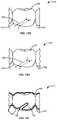
- FIG. 4Aillustrates a patient-removable tooth positioning appliance 20 similar to appliance 10 discussed with reference to FIG. 1 .
- tooth positioning appliance 20includes a cutout 22 .
- Cutout 22is shaped to avoid physical and/or functional interference with an elastic band receiving member such as elastic band receiving member 12 discussed with reference to FIG. 2 and FIG. 3 .
- cutout 22may have a parabolic or otherwise curved shape, where cutout 22 protrudes into a gingival-facing surface of tooth positioning appliance 20 a distance at least halfway between the gingival line (of a patient's tooth when tooth positioning appliance 20 is attached to the teeth) and an occlusal surface of the tooth.
- cutout 22While shown as being adjacent to a buccal surface of a tooth in the lower jaw (when tooth positioning appliance 20 is attached to the teeth), cutout 22 , similar to elastic band receiving member 12 , may be provided on any suitable surface of any suitable tooth receiving cavity of a patient-removable tooth positioning appliance 20 designed for any suitable jaw.
- cutout 22is provided for a tooth surface on which an elastic band receiving member 12 is disposed for a given treatment period.
- cutout 22may provide for a tooth surface on which an elastic band receiving member 12 is not disposed for a given treatment period.
- elastic band receiving member 12may be planned to be used in a future treatment period, or may have previously been used during a past treatment period.
- FIG. 4Billustrates a patient-removable tooth positioning appliance 25 similar to appliance 10 discussed with reference to FIG. 1 .
- tooth positioning appliance 20includes a hook 26 , where hook is operable to receive an elastic band.
- hook 26is formed by cutting out a portion of tooth positioning appliance 25 and protruding along a gingival-facing surface of tooth positioning appliance 25 .
- hook 26may have any suitable shape for receiving an elastic band, including any of those discussed in U.S. patent application Ser. No. 12/722,130, entitled “REINFORCED ALIGNER HOOKS”, which is commonly assigned and incorporated by reference herein in its entirety for all purposes.
- hook 26While shown as being adjacent to a facial surface of a tooth in the upper jaw (when tooth positioning appliance 25 is attached to the teeth), hook 26 , similar to cutout 22 discussed with reference to FIG. 4A , may be provided on any suitable surface of any suitable tooth receiving cavity of a patient-removable tooth positioning appliance 20 designed for any suitable jaw. In some embodiments, hook 26 is provided on the same tooth surface (although for a different tooth) for which cutout 22 is provided. However, in other embodiments, hook 26 may provide for a tooth surface different than that which cutout 22 is provided.
- a patient-removable tooth positioning appliance having cutout 22may be provided for disposal on a patient's teeth at the same time at which a patient-removable tooth positioning appliance having hook 26 may be provided for disposal on the patient's teeth.
- Cutout 22 and hook 26may be provided for different teeth on different jaws so that coupling of an orthodontic elastic band may operate to apply tooth/jaw repositioning forces sufficient to treat tooth malocclusions such as distocclusion or mesiocclusion.
- cutout 22may be provided for disposal over a posterior tooth in one jaw, while hook 26 may be provided for disposal over an anterior tooth in another jaw. In this fashion, an orthodontic elastic band may operate to apply tooth/jaw repositioning forces that tend to move one or more teeth or the jaw in a mesial or distal direction.
- the present inventioncan include an orthodontic treatment system including one or more sets of aligners utilizing elastics.
- An exemplary set of alignersis described with reference to FIGS. 5A and 5B , where the set includes a first aligner for a first dental arch of a patient and a second aligner for a second dental arch of the patient.
- One aligner of the setmay include a hook adapted to receive an elastic, and the other aligner can include a receiving member or cutout to accommodate a receiving member.
- the aligners of the setcan be configured to accommodate an elastic coupling the hook and receiving member.
- a treatment systemcan include one or more sets of aligners according to systems described herein.
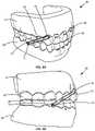
- FIG. 5Ais an isometric view of an orthodontic positioning device 30 according to an embodiment.
- Orthodontic positioning device 30includes a first patient removable orthodontic tooth positioning appliance 25 having teeth receiving cavities shaped to receive and apply a resilient positioning force to a patient's teeth provided in an upper jaw 32 of the patient. Tooth positioning appliance 25 includes hook 26 adapted to receive elastic band 33 .
- Orthodontic positioning device 30also includes a second patient removable orthodontic tooth positioning appliance 20 having teeth receiving cavities shaped to receive and apply a resilient positioning force to a patient's teeth provided in a lower jaw 34 of the patient. Tooth positioning appliance 20 includes cutout 22 shaped to avoid physical and/or functional interference with elastic band receiving member 12 .
- Orthodontic positioning device 30may also include elastic band 33 and/or elastic band receiving member 12 .
- hook 26is disposed over a facial surface of the patient's canine tooth provided on the right side of the upper jaw
- cutout 22is disposed over elastic band receiving member 12 that is coupled to a facial surface of the patient's first molar provided on the right side of the lower jaw.
- hook 26 and cutout 22may be provided over any suitable teeth.
- elastic band 33is coupled between hook 26 and elastic band receiving member 12 and may be operable to apply a tooth/jaw positioning/repositioning forces in the mesial or distal directions.
- FIG. 5Bis a side view of the orthodontic positioning device of FIG. 5A .
- cutout 22may be shaped to avoid physical and/or functional interference with elastic band receiving member 12 .
- hook 26may be shaped to follow a contour of the patient's teeth and/or may have a facial surface that is substantially parallel with and/or does not extend (in a facial direction) past other portions of the tooth receiving cavity in which hook 26 is provided. In other words, with reference to the orientation shown in FIG. 5B , hook 26 does not protrude horizontally in a direction away from other portions of patient-removable tooth positioning appliance 25 , thereby reducing undesirable contact or interference with the tissue on an inner surface of a patient's mouth.
- dental malocclusionsmay be detected using digital representations (such as 3-dimensional models) of a patient's tooth arrangement, including digital representations of teeth in the patient's upper jaw, and digital representations of teeth in the patient's lower jaw.
- digital representationssuch as 3-dimensional models
- computer-based 3-dimensional planning/design toolssuch as TreatTM software from Align Technology, Inc.
- TreatTM softwarefrom Align Technology, Inc.
- the cutoutsmay be designed by digitally simulating the placement of elastic band receiving members such as orthodontic buttons and defining appliance cutout lines around portions of the buttons so that a resulting tooth positioning appliance does not interfere with the actual button attached to the patient's tooth.
- the hookmay be designed by digitally placing, sizing, and orienting a hook, where an orientation of the hook may be optimized based on a location of a cutout in another tooth positioning appliance or a location of a corresponding elastic band receiving member.
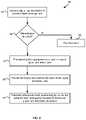
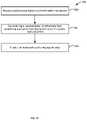
- FIG. 6is a simplified block diagram illustrating a method 40 for treating dental malocclusions.
- digital representations of a patient's teeth arrangementare received.
- the digital representationsmay include a 3-D model of the patient's teeth including tooth crowns provided in the upper and/or lower jaws, where the digital representations of the teeth may be segmented or unsegmented.
- the digital representationsmay also include gingiva and/or other dental features provided in proximity to the patient's teeth.
- the digital representationsmay be received in any suitable manner.
- the patient's teethmay be scanned using one or more imaging devices suitable to generate 3-D models of the teeth.
- the digital representationsmay be manipulated to represent the teeth in an arrangement other than a current teeth arrangement of the patient.
- the digital representationsmay be manipulated to represent the patient's teeth in a desired intermediate or final position.
- the digital representations of the patient's teeth provided in the upper and lower jawsmay be used.
- Malocclusionmay be a Class I type malocclusion, i.e., neutrocclusion, whereby the buccal teeth have a correct mesiodistal relationship with respect to one another, but other teeth may have other types of positioning problems such as overcrowding.
- Malocclusionmay be a Class II type malocclusion, i.e., distocclusion, whereby the lower teeth are in a distal position compared to the upper teeth.
- malocclusionmay be a Class III type malocclusion, i.e., mesiocclusion, in which the lower teeth are positioned mesially compared to the upper teeth.
- a digital representation of an orthodontic buttonmay be placed on a digital representation of a tooth of one of the upper and lower jaws.
- the digital representation of the orthodontic buttonmay be, for example, a digital representation of the previously discussed elastic band receiving member 12 .
- the orthodontic buttonmay be placed on any suitable surface of any suitable tooth of any suitable jaw. In one embodiment, the digital representation of the orthodontic button is placed on the same tooth and in the same orientation and position which elastic band receiving member 12 is provided.
- a hook placementmay be provided for a tooth of one of the upper and lower jaws.
- the hook placementmay be defined with reference to a digital representation of a patient's tooth, and may itself define a shape of a hook to be subsequently formed in a tooth positioning appliance.
- the hook placementmay define a shape of the previously discussed hook 26 .
- the hook placementbe defined for any suitable surface of any suitable tooth of any suitable jaw.
- an orthodontic positioning deviceis fabricated for the patient's teeth arrangement based on the digital representation of the orthodontic button and the hook placement.
- the orthodontic positioning devicemay include a first patient removable orthodontic tooth positioning appliance such as patient removable orthodontic tooth positioning appliance 20 discussed with reference to FIG. 5A , and may include a second patient removable orthodontic tooth positioning appliance such as patient removable orthodontic tooth positioning appliance 25 discussed with reference to FIG. 5B .
- the digital representation of the orthodontic buttonmay be used to form cutout 22 so that patient removable orthodontic tooth positioning appliance 20 does not interfere with elastic band receiving member 12 .
- the hook placementmay be used to form hook 26 .
- method 40may be implemented by any suitable electronic computing device, server, or system.
- a system that may be used in accordance with one embodimentis discussed later with reference to FIG. 18 .
- the specific operations illustrated in FIG. 6provide a particular method of treating dental malocclusions, according to certain embodiments of the present invention.
- Other sequences of operationsmay also be performed according to alternative embodiments.
- alternative embodiments of the present inventionmay perform the operations outlined above in a different order.
- the individual operations illustrated in FIG. 6may include multiple sub-operations that may be performed in various sequences as appropriate to the individual operations.
- additional operationsmay be added or existing operations removed depending on the particular applications.
- One of ordinary skill in the artwould recognize and appreciate many variations, modifications, and alternatives.
- a type of malocclusion of the patient's teethmay be detected using any one of numerous techniques such as that discussed with reference to operation 44 of FIG. 6 .
- digital representations of the patient's teethboth upper and lower jaw
- the teeth in the upper and lower jawsmay be aligned in accordance with the patient's natural occlusion.
- Corresponding points on corresponding teeth in the upper and lower jawsmay then be identified. For example, center points of facial surfaces of left canine teeth in the upper and lower jaws may be identified. A distance may then be calculated using these points, and based on the distance, a type of malocclusion detected.
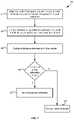
- FIG. 7is a simplified block diagram illustrating a method 60 for detecting dental malocclusions.
- the operations depicted and discussed with reference to method 60may correspond to the malocclusion detection operation 44 discussed with reference to FIG. 6 .
- a digital representation of a patient's teeth arrangementmay initially be acquired, as discussed with reference to operation 42 of FIG. 6 .
- the teeth in the patient's upper jaware aligned with the teeth in the patient's lower jaw in accordance with the patient's natural occlusion.
- the digital representation of the teeth in the patient's upper jawmay be aligned with the digital representation of the teeth in the patient's lower jaw. Any one of a variety of techniques may be used to performing such a digital alignment.
- the patient's teethmay scanned while they are in occlusion, and the subsequent image used as the image representing the aligned teeth.
- the patient's teethmay be scanned while they are in occlusion, and subsequently used to align 3-D models of the patient's teeth using surface matching techniques or other suitable image matching techniques.
- corresponding points on corresponding teeth in both an upper dental arch and a lower dental archare identified.
- the teeth chosenmay be any suitable teeth in the upper and lower dental arches.
- the canine tooth on the right side of an upper jawmay be chosen, as well as the canine tooth on the right side of the lower jaw.
- other corresponding teethmay be chosen, such as incisors, premolars, or molars, on any suitable side, including the left or right side of the jaws.
- a common pointmay be identified at any suitable location on the teeth.
- the common pointmay be a center of the facial surface of the tooth crowns.
- the common pointmay be at location on the facial surface of the teeth other than the center, such as a location near the gingival or near the occlusal surface of the teeth.
- the common pointmay be at features of the teeth provided at locations other than the facial surface, and may include, for example, cusps, ridges, grooves, or other features that are common between the identified teeth.
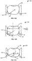
- FIGS. 8A to 8Care simplified images of teeth arrangements having different malocclusion types that may aid in the discussion of methods for detecting dental malocclusions.
- FIG. 8Ashows a tooth arrangement 70 including an upper jaw 71 and lower jaw 72 .
- First point 73is identified on the center of a facial surface of the right-side canine tooth in the upper jaw.
- Second point 74is identified on the center of a facial surface of the right-side canine tooth in the lower jaw.
- a distance between the identified pointsis calculated.
- the distancemay be calculated in one or more of a variety of fashions.
- a linemay be drawn between the identified points, where the distance is calculated as the length of the line.
- linesmay be drawn in parallel with one another from each identified point to a single plane. A distance along one axis of that plane, where the axis is arranged in the mesial/distal direction, may then be measured between the intersection points of the drawn lines and the plane. For instance, with reference to FIG. 8A and considering the orientation of the tooth arrangement 70 as illustrated, parallel lines 76 and 77 may be drawn extending from points 73 and 74 .
- Lines 76 and 77may be drawn in a direction perpendicular to the occlusal plane and terminate at a line extending in the mesial/distal direction. The distance may then be measured as the distance between the intersection points, i.e., between points A and B shown in FIG. 8A .
- FIG. 9Ais a top view of a tooth arrangement 80 including a tangent line 82 .
- Tangent line 82is representative of a tangent direction, and in this embodiment is calculated as the average direction between lines which are tangent to each of a tooth in the upper jaw and the lower jaw in the mesial-distal direction.
- the teethare canines of the upper and lower jaws.
- tangential planesmay be generated for points on each of a pair of corresponding teeth in the upper and lower jaws and subsequently used to determine tangent line 82 .
- FIG. 9Bshows a plane 83 that is tangential to a point 83 A on a tooth of the upper jaw 84 .
- point 83 Ais provided at the center of the facial surface of the canine tooth, although point 83 A may be provided at any suitable location of any suitable tooth.
- Plane 83may be graphically provided in a three-dimensional Cartesian coordinate system 85 , in which the origin of the coordinate system 85 (i.e., the (0,0,0) point) is disposed at point 83 A.
- the Y-axisis provided in the mesial-distal direction of the jaw
- the X-axisis provided perpendicular to the Y-axis and in the occlusal plane
- the Z-axisextends perpendicular to the XY-plane and in the sagittal plane.
- an angle Rmay be formed between the Y-axis and the intersection line of plane 83 and the XY-plane. This intersection line may be considered as a line that is tangent to a point on a tooth of the upper jaw in the mesial-distal direction.
- FIG. 9Cshows a plane 86 that is tangential to a point 86 A on a tooth of the lower jaw 87 .
- point 86 Ais provided at the center of the facial surface of the canine tooth, although point 86 A may be provided at any suitable point and tooth that corresponds to the point and tooth chosen for the upper jaw.
- plane 86may be graphically provided in a three-dimensional Cartesian coordinate system 88 , but in this case the origin of the coordinate system 88 is disposed at point 86 A, and an angle S is formed between the Y-axis and the intersection line of plane 86 and the XY-plane. This intersection line may be considered as a line that is tangent to a point on a tooth of the lower jaw in the mesial-distal direction.
- FIG. 9Dshows the tangent lines (i.e., intersection lines) for each of the upper and lower jaws drawn on a common Cartesian coordinate system.
- Intersection line 83 Ais the line representing the intersection line of plane 83 and the XY-plane
- intersection line 86 Ais the line representing the intersection line of plane 86 and the XY-plane.
- FIG. 9Eshows the average line 89 of the tangent lines. The average line 89 is determined by drawing a line at an angle T from the Y-axis, where the angle T is equal to the average of angle R and angle S.
- a measurement planemay then be generated using the average direction line determined from the tangent lines.
- FIG. 9Fshows a measurement plane 89 A formed using average line 89 .
- measurement plane 89 Aextends in the Z-plane and passes through average line 89 .
- the measurement planemay represent a plane that is the average of tangential planes 83 and 86 , where the average is the average of the direction that each of tangential planes 83 and 86 are arranged in the mesial-distal direction.
- FIG. 9Gshows measurement plane 89 A disposed proximate to upper jaw 84 and lower jaw 87 when the patient's mouth is closed. Measurement plane 89 A may be arranged between points 83 A and 86 A, or at any other suitable location. Points 83 A and 86 A may then be projected onto plane 89 A.
- FIG. 9Hshows plane 89 A represented as a two-dimensional Cartesian coordinate system 91 . The X-axis is in the mesial-distal direction and the Y-axis is perpendicular to the X-axis.
- Point 83 Ais projected onto plane 89 A as point 83 AA
- point 86 Ais projected onto plane 89 A as point 86 AA.
- a distance U between points 83 AA and 86 AA along the X-axismay then be determined and subsequently used for determining whether patient has a malocclusion and, in some cases, the type of malocclusion.
- the allowable rangemay be any suitable range for defining a malocclusion, and may include different ranges for identifying different types of malocclusions as well as different severity levels of the malocclusions.
- the distance between points A and Bmay be less than ⁇ 6 mm, and thus it may be determined that the patient has a Class III type malocclusion (distocclusion).
- disocclusiona Class III type malocclusion
- a Class III type malocclusionmay be identified if the distance between points A and B is less than ⁇ 5 mm, ⁇ 5.5 mm, ⁇ 6.5 mm, ⁇ 7 mm, or is less than a value in the range ⁇ 5 mm to ⁇ 7 mm.
- the distance between points A and Bmay be between ⁇ 6 mm and 0 mm, and thus it may be determined that the patient has a Class I type malocclusion (neutrocclusion).
- a Class I type malocclusionneutralization
- One of ordinary skill in the artwould recognize that this range is merely exemplary, and other ranges suitable for identifying a Class I type malocclusion may be used.
- a Class I type malocclusionmay be identified if the distance between points A and B is greater than ⁇ 5 mm, ⁇ 5.5 mm, ⁇ 6.5 mm, ⁇ 7 mm, or a value in the range ⁇ 5 mm to ⁇ 7 mm, and less than ⁇ 1 mm, ⁇ 0.5 mm, 0.5 mm, 1 mm, or a value in the range ⁇ 1 mm to 1 mm.
- the distance between points A and Bmay be greater than 0 mm, and thus it may be determined that the patient has a Class III type malocclusion (mesiocclusion).
- a Class III type malocclusionmay be identified if the distance between points A and B is greater than ⁇ 1 mm, ⁇ 0.5 mm, ⁇ 0.5 mm, 1 mm, or a value in the range ⁇ 1 mm to 1 mm.
- determining that no malocclusion is detectedit may be determined that no specific types of malocclusion is detected. For example, in operation 66 , it may be determined whether the distance between points A and B is between ⁇ 6 mm and 0 mm. In this case, it may be determined that no malocclusion is detected in that neither distocclusion nor mesiocclusion are detected. If it is determined that the distance between points A and B is either less than ⁇ 7 mm or greater than 0 mm, a malocclusion (i.e., distocclusion or mesiocclusion) may be detected.
- a malocclusioni.e., distocclusion or mesiocclusion
- method 60may be implemented by any suitable electronic computing device, server, or system.
- a system that may be used in accordance with one embodimentis discussed later with reference to FIG. 18 .
- the specific operations illustrated in FIG. 7provide a particular method of detecting dental malocclusions, according to certain embodiments of the present invention. Other sequences of operations may also be performed according to alternative embodiments. For example, alternative embodiments of the present invention may perform the operations outlined above in a different order.
- the individual operations illustrated in FIG. 7may include multiple sub-operations that may be performed in various sequences as appropriate to the individual operations.
- additional operationsmay be added or existing operations removed depending on the particular applications.
- One of ordinary skill in the artwould recognize and appreciate many variations, modifications, and alternatives.
- methods for designing patient removable orthodontic tooth positioning appliancesmay be provided, and in some cases may be provided as part of an overall orthodontic treatment method such as that discussed with reference to FIG. 6 .
- computer-based 3-dimensional planning/design toolssuch as TreatTM software from Align Technology, Inc., may be used to design and subsequently fabricate tooth positioning appliances.
- the 3-dimensional planning/design toolmay be used to place a digital representation of an elastic band receiving member (such as an orthodontic button) on a digital representation of a patient's tooth.
- the 3-dimensional planning/design toolmay generate a cutout line.
- the cutout linemay subsequently be used to assist in fabricating the tooth positioning appliance, in that it may define a line for cutting the appliance such that the appliance does not interfere with the elastic band receiving member when the appliance is disposed over the patient's teeth.
- FIG. 10is a simplified block diagram illustrating a method 90 for designing a patient removable orthodontic tooth positioning appliance including a cutout.
- the operations depicted and discussed with reference to method 90may correspond to the provision for a button placement of operation 48 discussed with reference to FIG. 6 .
- a digital representation of a patient's teeth arrangementmay initially be acquired, as discussed with reference to operation 42 of FIG. 6 .
- a user selection to add an elastic band receiving membere.g., an orthodontic button
- geometry information describing the geometries of one or more orthodontic elastic band receiving membersmay be stored in the computer-based planning/design tool, and the user may use a graphical user interface (GUI) to select one of the elastic band receiving members and its corresponding geometry.
- GUIgraphical user interface
- the usermay be able to modify properties of the elastic band receiving member, such as size, shape, etc.
- the usermay be able to upload to the computer-based planning/design tool geometry information describing the geometry of a custom elastic band receiving member, and subsequently use the custom elastic band receiving member for designing the tooth positioning appliance.
- computer-based planning/design toolIn receiving the user selection to add an elastic band receiving member to a tooth, computer-based planning/design tool also receives a user selection of a particular tooth and tooth surface. For example, the user may select a molar, a premolar, an incisor, or any other suitable tooth. In some embodiments, computer-based planning/design tool may provide a default tooth surface. For example, in response to the user selecting a particular tooth, the elastic band receiving member may be added to a facial surface of the selected tooth. In one embodiment, the user may select the tooth surface on which the elastic band receiving member is to be added, such as a facial surface, a lingual surface, or any other suitable surface.
- FIG. 11Ashows a simplified digital representation 100 of a patient's tooth 102 having an elastic band receiving member 104 disposed thereon.
- Digital representation 100may include teeth other than tooth 102 , or may include only tooth 102 . Further, digital representation 100 may include other dental features as well, such as gingiva 106 .
- digital representation 100in response to receiving a user selection add an elastic band receiving member to a tooth, digital representation 100 may be displayed to the user, where tooth 102 represents the user-selected tooth and elastic band receiving member 104 represents the user-selected elastic band receiving member.
- the elastic band receiving memberis positioned on the tooth in a default position.
- the computer-based planning/design toolmay place the elastic band receiving member in any suitable location on the surface of the tooth such that the elastic band receiving member may function as intended. In some embodiments, this may include positioning the elastic band receiving member a distance away from various dental features, such as the gingival line, the occlusal surface, the distal surface, the mesial surface, etc. In one embodiment, this may include positioning the elastic band receiving member in a center of the tooth surface.
- FIG. 11Bshows a simplified digital representation 110 of a patient's tooth 102 and an elastic band receiving member 104 with overlaid placement guidelines, where the placement guidelines may be used to determine the default location.
- the computer-based planning/design toolmay determine a width W of tooth 102 , and use W to identify a centerline C (e.g., by dividing W in half).
- Elastic band receiving member 104may then be centered about centerline C.
- a distance D between gingival line 108 and an edge of elastic band receiving member 104may be defined.
- Dmay be 0.5 mm, 1.0 mm, 1.5 mm, in the range of 0.5 to 1.5 mm, less than 0.5 mm, or greater than 1.5 mm.
- Dmay be measured from the intersection point of centerline C and gingival line 108 , and may always be greater than 0 mm.
- computer-based planning/design toolmay ensure one or more of a variety of placement conditions are satisfied. For example, computer-based planning/design tool may ensure that elastic band receiving member 104 does not contact the gingival line, does not overlap with other teeth, is placed entirely on a single surface of a tooth, etc.
- the elastic band receiving membermay be repositioned on the tooth in response to a user input.
- the usermay change a position, orientation, or the like of the elastic band receiving member. For example, the user may rotate the elastic band receiving member, move the elastic band receiving member horizontally or vertically, etc.
- computer-based planning/design toolmay prevent the user from violating one or more of the placement conditions. In other embodiments, computer-based planning/design tool may allow the user to violate or otherwise override one or more of the placement conditions.
- a cutout lineis generated, where the cutout line extends between a first point on a gingival line of the tooth and a second point on the gingival line of the tooth.
- FIG. 11Cshows a simplified digital representation 120 of a patient's tooth 102 and an elastic band receiving member 104 with cutout line 112 .
- Cutout line 112extends between a first point F located on gingival line 108 and a second point G located on gingival line 108 .
- Cutout line 112may be subsequently used to define a line for cutting a tooth positioning appliance, and specifically for cutting a portion of a tooth positioning appliance that will be disposed over a patient's tooth having an elastic band receiving member attached thereto.
- cutout line 112may be any suitable line that, when subsequently used to cut a tooth positioning appliance, results in a tooth positioning appliance that does not interfere with an elastic band receiving member disposed on a patient's tooth.
- cutout line 112may be displayed by computer-based planning/design tool, while in other embodiments cutout line 112 may not be displayed.
- cutout line 112may be recalculated in response to a repositioning of elastic band receiving member 104 .
- cutout line 112may be optimized by the computer-based planning/design tool. For example, cutout line 112 may be calculated as the shortest line that extends from the gingival line on one side of elastic band receiving member 104 to the gingival line on the opposite side of elastic band receiving member 104 while passing between elastic band receiving member 104 and an occlusal surface of tooth 102 and not contacting elastic band receiving member 104 .
- cutout line 112may be shaped to conform to at least a portion of the shape of elastic band receiving member 104 .
- elastic band receiving member 104is circular, and cutout line 112 includes a portion extending between elastic band receiving member 104 and the occlusal surface of the tooth that has a similar radius as the radius of elastic band receiving member 104 .
- a distance Hmay be defined between an edge of elastic band receiving member 104 and a portion of cutout line 112 .
- Distance Hmay be any suitable distance greater than 0 mm, such as 0.5 mm, 1.0 mm, 1.5 mm, in a range from 0.5 mm to 1.5 mm, less than 0.5 mm, or greater than 1.5 mm.
- a location of points F and G on gingival line 108may be constrained.
- FIG. 11Dshows a simplified digital representation 130 of a patient's tooth 102 and an elastic band receiving member 104 with a cutout line and overlaid constraint lines W, X, Y, and Z. Constraint lines W and Z may pass through gingival line 108 at opposite edge of tooth 102 , while constraint lines X and Y may pass through gingival line 108 at opposite edges of elastic band receiving member 104 .
- point Fmay be limited to a location on gingival line 108 between constraint lines W and X
- point Gmay be limited to a location on gingival line 108 between constraint lines Y and Z.
- points F and Gmay be limited to a location that is at least a certain distance away from one or more of constraint lines W, X, Y, and Z.
- point Fmay be limited to a location that is at least 1 mm away from constraint line W.
- cutout line 112may be required to not intersect with itself.
- elastic band receiving member 104may be limited to an area between gingival line 108 and cutout line 112 .
- surfaces of tooth 102may not be manipulable.
- the cutout lineis rearranged in response to a user input.
- a position, length, shape and/or orientation of the cutout linemay be rearranged as desired in accordance with a user input.
- computer-based planning/design toolmay initially generate a cutout line based on a shape and position of an elastic band receiving member and one or more constraints, and may then subsequently allow a treating practitioner to alter the default cutout line as desired.
- nodesmay facilitate the rearrangement of the cutout line.
- FIG. 11Eshows a simplified digital representation 140 of a patient's tooth 102 and an elastic band receiving member 104 with a cutout line having user-manipulable nodes 114 - 118 .
- One or more user-manipulable nodesmay be provided, where the nodes operate to segment the cutout line into a plurality of connected lines having shapes that are user-manipulable. In this embodiment, five nodes are shown.
- a usermay reposition a node such as node 116 , whereby repositioning the node may result in the lines to adjacent nodes (e.g., the cutout line between nodes 115 and 116 , and the cutout line between nodes 116 and 117 ) being adjusted.
- FIG. 11Fshows a simplified digital representation 150 of a patient's tooth 102 and an elastic band receiving member 104 with a manipulated cutout line 112 . In this case, nodes 115 and 117 have been repositioned to a location closer to gingival line 108 .
- FIG. 11Gis a simplified representation 160 of an orthodontic tooth positioning appliance 122 disposed over a tooth 102 having an elastic band receiving member 104 attached thereto.
- Orthodontic tooth positioning appliance 122includes a cutout 124 , where cutout 124 has a shape defined by the generated cutout line.
- cutout 124has a shape defined by cutout line 112 discussed with reference to FIGS. 11C, 11D, and 11E . Accordingly, it may be recognized that cutout line 112 and subsequently cutout 124 may define a gingival-facing surface of orthodontic tooth positioning appliance 122 .
- method 90may be implemented by any suitable electronic computing device, server, or system.
- a system that may be used in accordance with one embodimentis discussed later with reference to FIG. 18 .
- the specific operations illustrated in FIG. 10 and also discussed with reference to FIGS. 11A to 11Gprovide a particular method of designing a patient removable orthodontic tooth positioning appliance, according to certain embodiments of the present invention.
- Other sequences of operationsmay also be performed according to alternative embodiments.
- alternative embodiments of the present inventionmay perform the operations outlined above in a different order.
- the individual operations illustrated in FIG. 10 and also discussed with reference to FIGS. 11A to 11Gmay include multiple sub-operations that may be performed in various sequences as appropriate to the individual operations.
- additional operationsmay be added or existing operations removed depending on the particular applications.
- One of ordinary skill in the artwould recognize and appreciate many variations, modifications, and alternatives.
- computer-based planning/design toolmay generate a cutout line for defining a hook to be fabricated in the orthodontic tooth positioning appliance. This may include receiving user inputs for identifying a tooth and tooth surface to place the hook, as well as user inputs for reshaping a default cutout line.
- FIG. 12is a simplified block diagram illustrating a method 170 for designing a patient removable orthodontic tooth positioning appliance including a hook.
- the operations depicted and discussed with reference to method 170may correspond to the provision for a hook placement of operation 50 discussed with reference to FIG. 6 .
- a digital representation of a patient's teeth arrangementmay initially be acquired, as discussed with reference to operation 42 of FIG. 6 .
- a user selection to add a hooke.g., a portion of a patient-removable tooth positioning appliance operable to receive an elastic band
- Operation 172may be similar to operation 92 discussed with reference to FIG. 10 , but in this case the user selection is to add a hook rather than an elastic band receiving member. Accordingly, the user may select a particular tooth and tooth surface to add a hook.
- FIG. 13Ashows a simplified digital representation 180 of a patient's tooth 102 having a cutout line 182 for a hook disposed thereon.
- Digital representation 180may include teeth other than tooth 102 , or may include only tooth 102 . Further, digital representation 180 may include other dental features as well, such as gingiva 106 .
- digital representation 180in response to receiving a user selection add a hook to a tooth, digital representation 180 may be displayed to the user, where tooth 102 represents the user-selected tooth and cutout line 182 represents a portion of a cutout line that may be used to define a hook in a fabricated tooth positioning appliance. Cutout line 182 extends between point H located on gingival line 108 and point I which is located on a surface of tooth 102 but not on gingival line 108 .
- the cutout linemay be positioned in a default location.
- computer-based planning/design toolmay orient the cutout line in any direction on the surface of the tooth such that a resulting hook may function as intended.
- FIG. 13Bshows a simplified digital representation 190 of a patient's tooth 102 having a cutout line 182 disposed in a first orientation.
- cutout line 182may be said to point in a distal direction, in which case a resulting hook formed in an orthodontic positioning appliance may have an opening facing the distal direction.
- the cutout linemay alternatively be pointed in a mesial direction.
- default hook orientationsmay be associated with each tooth.
- default hook orientationsmay be orientations in the distal direction.
- default hook orientationsmay be orientations in the mesial direction.
- a location of the hookmay be determined. For example, with reference to FIG. 13B , computer-based planning/design tool may determine the width of tooth 102 and centerline C. Computer-based planning/design tool may then identify a portion 184 of gingival line 108 on which an end point of cutout line 182 may be located. In one embodiment, portion 184 of gingival line 108 may be located between centerline C and an edge of tooth 102 . In response to determining a distal-oriented hook, computer-based planning/design tool may locate an end of cutout line 182 somewhere along (e.g., at the center of) portion 184 of gingival line 108 .
- geometry information describing the geometry of the hookmay be stored in the computer-based planning/design tool and provide a default location and orientation of the hook cutout.
- FIG. 13Cshows a simplified digital representation 200 of a patient's tooth 102 and geometrical information for a cutout line 182 .
- the geometrical informationincludes a slit offset L, a hook width M, a hook length N, and a hook angle O.
- Default values for the geometrical informationmay be stored by computer-based planning/design tool and used to provide a default size and orientation of the hook cutout.
- Lmay be 0.5 mm, 0.75 mm, 1 mm, in the range from 0.5 mm to 1 mm, less than 0.5 mm, or greater than 1 mm.
- Mmay be 1 mm, 2 mm, 3 mm, in a range from 1 mm to 3 mm, less than 1 mm or greater than 3 mm.
- Nmay be 1 mm, 2 mm, 3 mm, in a range from 1 mm to 3 mm, less than 1 mm or greater than 3 mm.
- Omay be 30 degrees, 45 degrees, 60 degrees, in a range from 30 degrees to 60 degrees, less than 30 degrees or greater than 60 degrees.
- computer-based planning/design toolmay ensure one or more of a variety of placement conditions are satisfied. For example, computer-based planning/design tool may ensure that hook cutout 182 is oriented in a particular direction based on the type of tooth it is disposed over, does not extend to an occlusal surface of the tooth, does not extend to gingival line 182 , does not intersect with itself, etc.
- the hook cutout linemay be rearranged in response to a user input.
- the usermay change a position, orientation, or the like of the hook cutout line.
- the usermay change one or more of slit offset L, hook width M, hook length N, hook angle O, and a location of point H ( FIGS. 13B and 13C ).
- computer-based planning/design toolmay prevent the user from violating one or more of the placement conditions.
- computer-based planning/design toolmay allow the user to violate or otherwise override one or more of the placement conditions.
- nodesmay facilitate the rearrangement of the hook cutout line.
- FIG. 13Dshows a simplified digital representation 210 of a patient's tooth 102 and a hook cutout line 182 having user-manipulable nodes 183 - 185 .
- User-manipulable nodes 183 - 185may be similar to user-manipulable nodes 114 - 118 discussed with reference to FIG. 11E .
- a usermay use user-manipulable nodes 183 - 185 to modify a shape of hook cutout line 182 .
- FIG. 13Eshows a simplified digital representation 220 of a patient's tooth 102 and a manipulated hook cutout line 182 according to a first embodiment.
- FIG. 13Fshows a simplified digital representation 230 of a patient's tooth 102 and a manipulated hook cutout line 182 according to a second embodiment.
- hook cutout line 182has been linearly shifted to a location closer to an edge of tooth 102 .
- the hook cutout linemay be extended from the point on the tooth outside the gingival line to a second point on the gingival line of the tooth.
- the entire hookmay be defined.
- FIG. 13Gshows a simplified digital representation 240 of a patient's tooth 102 and an extended cutout line 182 according to a first embodiment.
- Extended cutout line 182includes an extension from point I to a point K on gingival line 108 . In this case, the extension passes through an additional point J.
- the extension from point I to point Kmay have any suitable shape and length.
- the extensionincludes a first portion extending between points I and J and a second portion extending between points J and K. Further, the second portion extending between points J and K is in parallel with the portion extending between points H and I, and is provided at a distance from the portion extending between points H and I based on slit offset L ( FIG. 13C ).
- the portion extending from point I to point Jis linear. However, this portion may assume one or more curves.
- FIG. 13Hshows a simplified digital representation 250 of a patient's tooth 102 and an extended cutout line 182 according to a second embodiment. In this case, the portion extending between points I and J is a curved line rather than a straight line.
- FIG. 13Iis a simplified representation 260 of an orthodontic tooth positioning appliance 122 disposed over a tooth 102 and having a hook formed therein.
- Orthodontic tooth positioning appliance 122includes a cutout 186 , where cutout 186 has a shape defined by the extended hook cutout line.
- cutout 186has a shape defined by extended cutout line 182 discussed with reference to FIG. 13H . Accordingly, it may be recognized that cutout line 182 may define a surface of orthodontic tooth positioning appliance 122 operable to receive an elastic band.
- method 170may be implemented by any suitable electronic computing device, server, or system.
- a system that may be used in accordance with one embodimentis discussed later with reference to FIG. 18 .
- the specific operations illustrated in FIG. 12 and also discussed with reference to FIGS. 13A to 13Iprovide a particular method of designing a patient removable orthodontic tooth positioning appliance, according to certain embodiments of the present invention.
- Other sequences of operationsmay also be performed according to alternative embodiments.
- alternative embodiments of the present inventionmay perform the operations outlined above in a different order.
- the individual operations illustrated in FIG. 12 and also discussed with reference to FIGS. 13A to 13Imay include multiple sub-operations that may be performed in various sequences as appropriate to the individual operations.
- additional operationsmay be added or existing operations removed depending on the particular applications.
- One of ordinary skill in the artwould recognize and appreciate many variations, modifications, and alternatives.
- an orientation of a hook cutout linemay be optimized based on a location of an elastic band receiving member.
- the location of the elastic band receiving membermay be identified by an actual elastic band receiving member (such as elastic band receiving member 12 of FIG. 2 ) or a digital representation of the elastic band receiving member on a tooth (such as elastic band receiving member 104 of FIGS. 11A to 11F ).
- the location of the elastic band receiving membermay be identified by an actual cutout from a tooth positioning appliance (such as cutout 124 of FIG. 11G ) or a digital representation of the cutout (such as cutout line 112 of FIGS. 11C to 11F ).
- the orientationmay be determined so that an elastic band can be functionally disposed over the elastic band receiving member and the hook and, in some embodiments, may be determined as part of operation 174 or operation 176 discussed with reference to FIG. 12 .
- FIG. 14is a side view of patient's mouth 270 including a tooth positioning device requiring a hook.
- the tooth positioning deviceincludes a first tooth positioning appliance 272 for disposal on teeth of the patient's upper jaw, and a second tooth positioning appliance 274 for disposal on teeth of the patient's lower jaw.
- second tooth positioning appliance 274includes a cutout 276 to prevent interference with an elastic band receiving member 278 disposed on a tooth of the patient's lower jaw. Accordingly, it may be desirable to provide a hook on first tooth positioning appliance 272 so that an elastic band may be used with the hook and elastic band receiving member 278 .
- FIG. 15Ashows a magnified portion Q of FIG. 14 without a tooth positioning appliance on the teeth of the patient's upper jaw and including a hook orientation guideline 282 .
- the computer-based planning/design toolcalculates hook orientation guideline 282 as a line extending between a tooth having an elastic band receiving member 278 and a tooth intended to have a hook disposed there over when the patient's mouth is closed. Hook orientation guidelines may then be used to cut a hook into a tooth positioning appliance to be disposed on the tooth of the patient's upper jaw.
- hook orientation guideline 282passes through a center of elastic band receiving member 278 .
- hook orientation guideline 282need not pass through the exact center of elastic band receiving member 278 , but rather could pass through an area in the proximity of elastic band receiving member 278 , such as an area defined by tooth surface 284 . Further, this point may be calculated using one or more of elastic band receiving member 278 and cutout 276 .
- hook orientation guideline 282passes through a point P located on the gingival line of the tooth over which a hook is to be provided.
- point Pmay be the same as point H ( FIGS. 13A to 13I ).
- a usermay select tooth 285 to dispose a hook over.
- computer-based planning/design toolmay determine the orientation (mesial/distal) of the hook cutout line, and a location of point P.
- Computer-based planning/design toolmay then subsequently generate hook orientation guideline 282 to pass through point P.
- Hook orientation guideline 282may be used to determine an angle O ( FIG. 13C ) of a hook cutout line.
- FIG. 15Bshows a magnified portion Q of FIG. 14 without a tooth positioning appliance on the teeth of the patient's upper jaw and including a hook cutout line 286 .
- Hook cutout line 286extends from point P in a direction along hook orientation guideline 282 toward elastic band receiving member 278 .
- Hook cutout line 286may then be used to fabricate a tooth positioning appliance having a hook oriented in a direction of elastic band receiving member 278 .
- FIG. 15Cshows a magnified portion Q of FIG. 14 where a tooth positioning appliance 272 on the teeth of the patient's upper jaw includes a hook 288 .
- a shape of hook 288is at least partially defined by cutout 289 , where cutout 289 has a shape which extends in a substantially linear direction toward elastic band receiving member 278 when the patient's teeth are in occlusion.
- one or more a variety of techniquesmay be used to fabricate an orthodontic tooth positioning device such as orthodontic positioning device 30 discussed with reference to FIGS. 5A and 5B .
- a mold of a patient's teethmay be acquired and subsequently used to create tooth positioning appliances such as tooth positioning appliance 10 discussed with reference to FIG. 1 .
- the tooth positioning appliancemay then be trimmed using cutout lines, where the cutout lines may define gingival-facing surfaces of the tooth positioning appliance and, when used, prevent interference with an elastic band receiving member (such as an orthodontic button) and/or make the tooth positioning appliance operable to receive an elastic band (e.g., by providing a hook in the appliance).
- a digital representation of the tooth positioning appliancemay be generated, and gingival-facing surfaces of the appliance may be digitally defined using one or more cutout lines.
- a tooth positioning appliancemay then be directly fabricated using the digital representation of the tooth positioning appliance.
- FIG. 16illustrates a method 310 for fabricating a tooth positioning device in accordance with a first embodiment. It should be appreciated that method 310 can be practiced in a variety of ways. For example, method 310 can be computer implemented and employ three-dimensional modeling representations and techniques.
- a mold of a patient's teeth in their upper and lower jawsis built.
- the moldmay be built using any one of a number of known techniques.
- the moldmay be built from a digital representation of the patient's dentition, via the use of dental trays and molding material, or using any other suitable technique.
- the moldmay include structures corresponding to orthodontic fixtures affixed to the patient's teeth, such as elastic band receiving members.
- a sheet of materialis provided over the mold.
- the materialmay be any suitable material for forming tooth positioning appliances.
- suitable polymer materialincluding an elastomeric polymeric material such as Tru-Tain 0.03 in. thermal forming dental material manufactured by Tru-Tain Plastics of Rochester, Minn., and/or a thermoplastic polyurethane material such as Estane manufactured by Lubrizol of Wickliffe, Ohio, and/or a polycarbonate material such as Lexan manufactured by Saudi Basic Industries Corp. of Riyadh, Saudi Arabia, and/or a polyester or copolyester material such as Eastar manufactured by Eastman Corp. of Kingsport, Tenn., and/or a thermoplastic polyolefin material such as Engage manufactured by The Dow Chemical Co. of Midland, Mich.
- portions of the materialmay assume the shape of the mold.
- the mold and materialmay be provided in a vacuum chamber, whereby application of a vacuum may cause the material to form to the shape of the mold.
- shaped portions of materialare removed from the sheet.
- the shaped portionsare those portions that were shaped by providing the sheet of material over the mold.
- the shaped portionsmay be removed using any known techniques, whereby the shaped portions are roughly cut from the sheet.
- the shaped portionsare trimmed using a button cutout line and/or a hook cutout line.
- the shaped portionsmay be trimmed using cutout line 112 discussed with reference to FIGS. 11C to 11F , and/or using cutout line 182 discussed with reference to FIGS. 13A to 13H , and/or using cutout line 286 discussed with reference to FIG. 15B .
- the shaped portionsmay also be trimmed using a gingival line such as gingival line 108 discussed with reference to FIGS. 11B to 11F and FIGS. 13A to 13H .
- a gingival-facing surface of the trimmed shaped portionsmay follow the contours of a patient's gingival line and include cutouts for preventing interference with elastic band receiving members and/or cutouts for defining hooks in the trimmed shaped portions.
- a digital representation of trimming instructionsmay be received, where the trimming instructions include at least one of the button cutout line and the hook cutout line.
- the shaped portionsmay be arranged over a mold shaped to receive the positioning appliance.
- a cutting elementsuch as a disk saw may then be applied along a direction normal to a buccal surface or a labial surface of the teeth receiving cavities. While cutting, the cutting element may be retracted from the mold if the cutting element contacts a surface of the mold.
- FIG. 17illustrates a method 320 for fabricating a tooth positioning device in accordance with a second embodiment. It should be appreciated that method 320 can be practiced in a variety of ways. For example, method 320 can be computer implemented and employ three-dimensional modeling representations and techniques.
- a digital representation of a patient's teethis received.
- the received digital representationincludes a digital representation of one or more orthodontic fixtures such as an elastic band receiving member affixed to a tooth.
- the received digital representationis modified to add or remove the digital representation(s) of orthodontic fixture(s).
- the digital representationmay be originally generated in any known fashion. For example, the digital representation may be originally generated by scanning the patient's.
- the teethmay be in a current arrangement in a different arrangement. For example, the teeth may be provided in or re-arranged to an intermediate or final position.
- a digital representation of one or more orthodontic tooth positioning appliancesis generated, where the appliances include a button cutout line and/or a hook cutout line.
- the button cutout linemay correspond cutout line 112 discussed with reference to FIGS. 11C to 11F .
- the hook cutout linemay correspond to cutout line 182 discussed with reference to FIGS. 13A to 13H and/or cutout line 286 discussed with reference to FIG. 15B .
- the digital representation of the appliancesmay also include a gingival cutout line, where the gingival cutout line may correspond to gingival line 108 discussed with reference to FIGS. 11B to 11F and/or gingival line discussed with reference to FIGS. 13A to 13H .
- the button cutout line and hook cutout linemay be generated using one or more of the methods and techniques previously discussed, and may or may not be displayed to the user. For example, in generating the button cutout line, a digital representation of an elastic band receiving member may first be generated and placed on a tooth, and the button cutout line subsequently formed partially around the elastic band receiving member.
- the orthodontic tooth positioning appliancesare directly fabricated.
- Various known manufacturing processescan be used to directly fabricate the orthodontic tooth positioning appliances using the digital representation generated in operation 324 .
- the orthodontic tooth positioning appliancesmay be formed by a stereo-lithography fabrication machine, where resin is selectively hardened in the shape of the tracking template.
- a digital representation of trimming instructionsmay be received, where the trimming instructions include at least one of the button cutout line and the hook cutout line.
- methods 310 and 320may be implemented by any suitable electronic computing device, server, or system.
- a system that may be used in accordance with one embodimentis discussed later with reference to FIG. 18 .
- the specific operations illustrated in FIGS. 16 and 17provide particular methods of fabricating a tooth positioning device, according to certain embodiments of the present invention. Other sequences of operations may also be performed according to alternative embodiments. For example, alternative embodiments of the present invention may perform the operations outlined above in a different order.
- the individual operations illustrated in FIGS. 16 and 17may include multiple sub-operations that may be performed in various sequences as appropriate to the individual operations.
- additional operationsmay be added or existing operations removed depending on the particular applications.
- One of ordinary skill in the artwould recognize and appreciate many variations, modifications, and alternatives.
- FIG. 18is a simplified block diagram of a data processing system 400 embodying embodiments of the present invention.
- Data processing system 400typically includes at least one processor 402 which communicates with a number of peripheral devices via a bus subsystem 404 .
- peripheral devicestypically include a storage subsystem 406 (memory subsystem 408 and file storage subsystem 410 ), a set of user interface input and output devices 412 , and an interface to outside networks 414 , including the public switched telephone network.
- This interfaceis shown schematically as “Modems and Network Interface” block 414 , and is coupled to corresponding interface devices in other data processing systems via a communication network interface 416 .
- Data processing system 400could be a terminal or a low-end personal computer or a high-end personal computer, workstation, or mainframe.
- the user interface input devicestypically include a keyboard and may further include a pointing device and a scanner.
- the pointing devicemay be an indirect pointing device such as a mouse, trackball, touchpad, or graphics tablet, or a direct pointing device such as a touch screen incorporated into the display.
- Other types of user interface input devices, such as voice recognition systems,are also possible.
- User interface output devicestypically include a printer and a display subsystem, which includes a display controller and a display device coupled to the controller.
- the display devicemay be a cathode ray tube (CRT), a flat-panel device such as a liquid crystal display (LCD), or a projection device.
- the display subsystemmay also provide non-visual display such as audio output.
- Storage subsystem 406maintains the basic programming and data constructs that provide the functionality of embodiments of the present invention.
- Software modules used to implement the methods discussed aboveare typically stored in storage subsystem 406 .
- Storage subsystem 406typically comprises memory subsystem 408 and file storage subsystem 410 .
- Memory subsystem 408typically includes a number of memories including a main random access memory (RAM) 418 for storage of instructions and data during program execution and a read only memory (ROM) 420 in which fixed instructions are stored.
- RAMmain random access memory
- ROMread only memory
- the ROMwould include portions of the operating system; in the case of IBM-compatible personal computers, this would include the BIOS (basic input/output system).
- File storage subsystem 410provides persistent (non-volatile) storage for program and data files, and typically includes at least one hard disk drive and at least one disk drive (with associated removable media). There may also be other devices such as a CD-ROM drive and optical drives (all with their associated removable media). Additionally, the system may include drives of the type with removable media cartridges.
- the removable media cartridgesmay, for example be hard disk cartridges, such as those marketed by Syquest and others, and flexible disk cartridges, such as those marketed by Iomega.
- One or more of the drivesmay be located at a remote location, such as in a server on a local area network or at a site on the Internet's World Wide Web.
- bus subsystemis used generically so as to include any mechanism for letting the various components and subsystems communicate with each other as intended.
- the other componentsneed not be at the same physical location.
- portions of the file storage systemcould be connected via various local-area or wide-area network media, including telephone lines.
- the input devices and displayneed not be at the same location as the processor, although it is anticipated that the present invention will most often be implemented in the context of PCs and workstations.
- Bus subsystem 404is shown schematically as a single bus, but a typical system has a number of buses such as a local bus and one or more expansion buses (e.g., ADB, SCSI, ISA, EISA, MCA, NuBus, or PCI), as well as serial and parallel ports. Network connections are usually established through a device such as a network adapter on one of these expansion buses or a modem on a serial port.
- the client computermay be a desktop system or a portable system.
- Scanner 422is responsible for scanning impressions or casts of the patient's teeth obtained either from the patient or from an orthodontist and providing the scanned digital data set information to data processing system 400 for further processing.
- canner 422may operate to directly scan a patient's teeth and, in some cases, orthodontic fixtures such as elastic band receiving members affixed to the patient's teeth.
- scanner 422may be located at a remote location and communicate scanned digital data set information to data processing system 400 via network interface 416 .
- Fabrication machine 424may fabricate patient-removable orthodontic appliances based on tooth arrangement information received from data processing system 400 . According to some embodiments, fabrication machine 424 may fabricate the patient-removable orthodontic appliances based on a tooth arrangement and, in some cases, information received from data processing system 400 . In a distributed environment, fabrication machine 424 may be located at a remote location and receive data set information from data processing system 400 via network interface 416 .
- kitsmay contain one or more of a patient-removable orthodontic appliance or plurality (e.g., set) of patient-removable orthodontic appliances (including pairs of appliances for simultaneously use with upper and lower jaws where one of the appliances includes a hook and the other appliance includes a cutout for preventing interference with an elastic band receiving member affixed to a patient's tooth).
- a tooth-receiving cavity of a patient-removable orthodontic appliancecan be treated or altered, e.g., by chemical means, so as to affect a property of the appliance.
- a kitcan be configured for delivery to an intended recipient (e.g., patient, practitioner, etc.) directly or indirectly.
- a kitcan include an object or component provided separated from an appliance, but which is meant to be coupled with another component.
- the kitmay also include elastic band receiving members and/or elastic bands.
- the software components or functions described in this applicationmay be implemented as software code to be executed by one or more processors using any suitable computer language such as, for example, Java, C++ or Perl using, for example, conventional or object-oriented techniques.
- the software codemay be stored as a series of instructions, or commands on a computer-readable medium, such as a random access memory (RAM), a read-only memory (ROM), a magnetic medium such as a hard-drive or a floppy disk, or an optical medium such as a CD-ROM. Any such computer-readable medium may also reside on or within a single computational apparatus, and may be present on or within different computational apparatuses within a system or network.
- the present inventioncan be implemented in the form of control logic in software or hardware or a combination of both.
- the control logicmay be stored in an information storage medium as a plurality of instructions adapted to direct an information processing device to perform a set of steps disclosed in embodiments of the present invention. Based on the disclosure and teachings provided herein, a person of ordinary skill in the art will appreciate other ways and/or methods to implement the present invention.
Landscapes
- Health & Medical Sciences (AREA)
- Life Sciences & Earth Sciences (AREA)
- General Health & Medical Sciences (AREA)
- Epidemiology (AREA)
- Dentistry (AREA)
- Animal Behavior & Ethology (AREA)
- Oral & Maxillofacial Surgery (AREA)
- Public Health (AREA)
- Veterinary Medicine (AREA)
- Engineering & Computer Science (AREA)
- General Engineering & Computer Science (AREA)
- Biomedical Technology (AREA)
- Biophysics (AREA)
- Dental Tools And Instruments Or Auxiliary Dental Instruments (AREA)
Abstract
Description
Claims (18)
Priority Applications (3)
| Application Number | Priority Date | Filing Date | Title |
|---|---|---|---|
| US16/148,740US11389272B2 (en) | 2011-10-10 | 2018-10-01 | Orthodonitic appliance with precision cutout |
| US17/833,532US12329598B2 (en) | 2011-10-10 | 2022-06-06 | Devices and methods for dental appliances with cutouts |
| US19/233,957US20250302589A1 (en) | 2011-10-10 | 2025-06-10 | Systems of orthodontic appliances with precision cuts |
Applications Claiming Priority (4)
| Application Number | Priority Date | Filing Date | Title |
|---|---|---|---|
| US13/270,171US8641414B2 (en) | 2011-10-10 | 2011-10-10 | Automatic placement of precision cuts |
| US14/148,453US9433477B2 (en) | 2011-10-10 | 2014-01-06 | Automatic placement of precision cuts |
| US15/219,779US10136964B2 (en) | 2011-10-10 | 2016-07-26 | Automatic placement of precision cuts |
| US16/148,740US11389272B2 (en) | 2011-10-10 | 2018-10-01 | Orthodonitic appliance with precision cutout |
Related Parent Applications (1)
| Application Number | Title | Priority Date | Filing Date |
|---|---|---|---|
| US15/219,779DivisionUS10136964B2 (en) | 2011-10-10 | 2016-07-26 | Automatic placement of precision cuts |
Related Child Applications (1)
| Application Number | Title | Priority Date | Filing Date |
|---|---|---|---|
| US17/833,532ContinuationUS12329598B2 (en) | 2011-10-10 | 2022-06-06 | Devices and methods for dental appliances with cutouts |
Publications (2)
| Publication Number | Publication Date |
|---|---|
| US20190167384A1 US20190167384A1 (en) | 2019-06-06 |
| US11389272B2true US11389272B2 (en) | 2022-07-19 |
Family
ID=48042303
Family Applications (6)
| Application Number | Title | Priority Date | Filing Date |
|---|---|---|---|
| US13/270,171Active2031-10-22US8641414B2 (en) | 2011-10-10 | 2011-10-10 | Automatic placement of precision cuts |
| US14/148,453Active2032-11-14US9433477B2 (en) | 2011-10-10 | 2014-01-06 | Automatic placement of precision cuts |
| US15/219,779Active2032-06-29US10136964B2 (en) | 2011-10-10 | 2016-07-26 | Automatic placement of precision cuts |
| US16/148,740Active2033-07-04US11389272B2 (en) | 2011-10-10 | 2018-10-01 | Orthodonitic appliance with precision cutout |
| US17/833,532Active2032-12-10US12329598B2 (en) | 2011-10-10 | 2022-06-06 | Devices and methods for dental appliances with cutouts |
| US19/233,957PendingUS20250302589A1 (en) | 2011-10-10 | 2025-06-10 | Systems of orthodontic appliances with precision cuts |
Family Applications Before (3)
| Application Number | Title | Priority Date | Filing Date |
|---|---|---|---|
| US13/270,171Active2031-10-22US8641414B2 (en) | 2011-10-10 | 2011-10-10 | Automatic placement of precision cuts |
| US14/148,453Active2032-11-14US9433477B2 (en) | 2011-10-10 | 2014-01-06 | Automatic placement of precision cuts |
| US15/219,779Active2032-06-29US10136964B2 (en) | 2011-10-10 | 2016-07-26 | Automatic placement of precision cuts |
Family Applications After (2)
| Application Number | Title | Priority Date | Filing Date |
|---|---|---|---|
| US17/833,532Active2032-12-10US12329598B2 (en) | 2011-10-10 | 2022-06-06 | Devices and methods for dental appliances with cutouts |
| US19/233,957PendingUS20250302589A1 (en) | 2011-10-10 | 2025-06-10 | Systems of orthodontic appliances with precision cuts |
Country Status (1)
| Country | Link |
|---|---|
| US (6) | US8641414B2 (en) |
Families Citing this family (205)
| Publication number | Priority date | Publication date | Assignee | Title |
|---|---|---|---|---|
| US9326831B2 (en) | 2006-10-20 | 2016-05-03 | Align Technology, Inc. | System and method for positioning three-dimensional brackets on teeth |
| US8899977B2 (en) | 2008-01-29 | 2014-12-02 | Align Technology, Inc. | Orthodontic repositioning appliances having improved geometry, methods and systems |
| US9119691B2 (en) | 2008-05-23 | 2015-09-01 | Align Technology, Inc. | Orthodontic tooth movement device, systems and methods |
| US8172569B2 (en) | 2008-06-12 | 2012-05-08 | Align Technology, Inc. | Dental appliance |
| US20100129763A1 (en) | 2008-11-24 | 2010-05-27 | Align Technology, Inc. | Sequential sports guard |
| US10199311B2 (en) | 2009-01-29 | 2019-02-05 | Semiconductor Components Industries, Llc | Leadless semiconductor packages, leadframes therefor, and methods of making |
| US8292617B2 (en) | 2009-03-19 | 2012-10-23 | Align Technology, Inc. | Dental wire attachment |
| US8765031B2 (en) | 2009-08-13 | 2014-07-01 | Align Technology, Inc. | Method of forming a dental appliance |
| CN102054091A (en)* | 2009-11-09 | 2011-05-11 | 无锡时代天使医疗器械科技有限公司 | Method for manufacturing dental instrument for correcting the position of teeth |
| US8708697B2 (en) | 2009-12-08 | 2014-04-29 | Align Technology, Inc. | Tactile objects for orthodontics, systems and methods |
| US20110269092A1 (en) | 2010-04-30 | 2011-11-03 | Align Technology, Inc. | Reinforced aligner hooks |
| US9241774B2 (en) | 2010-04-30 | 2016-01-26 | Align Technology, Inc. | Patterned dental positioning appliance |
| US8641414B2 (en) | 2011-10-10 | 2014-02-04 | Align Technology, Inc. | Automatic placement of precision cuts |
| US10011050B2 (en) | 2011-10-12 | 2018-07-03 | Ormco Corporation | Fabrication of an orthodontic aligner from a negative mold designed by a computational device |
| CN103142317A (en)* | 2011-10-12 | 2013-06-12 | 奥姆科公司 | Direct manufacture of orthodontic aligner |
| US9013714B2 (en)* | 2011-12-06 | 2015-04-21 | The Procter & Gamble Company | Method of analyzing video or image data of an absorbent article |
| US9375300B2 (en) | 2012-02-02 | 2016-06-28 | Align Technology, Inc. | Identifying forces on a tooth |
| US9433476B2 (en)* | 2012-03-01 | 2016-09-06 | Align Technology, Inc. | Interproximal reduction planning |
| US9220580B2 (en) | 2012-03-01 | 2015-12-29 | Align Technology, Inc. | Determining a dental treatment difficulty |
| EP2845171B1 (en)* | 2012-05-02 | 2020-08-19 | Cogent Design, Inc. dba Tops Software | Systems and methods for consolidated management and distribution of orthodontic care data, including an interactive three-dimensional tooth chart model |
| US9655691B2 (en) | 2012-05-14 | 2017-05-23 | Align Technology, Inc. | Multilayer dental appliances and related methods and systems |
| US9414897B2 (en) | 2012-05-22 | 2016-08-16 | Align Technology, Inc. | Adjustment of tooth position in a virtual dental model |
| US20140067334A1 (en) | 2012-09-06 | 2014-03-06 | Align Technology Inc. | Method and a system usable in creating a subsequent dental appliance |
| ES2874777T3 (en) | 2012-10-30 | 2021-11-05 | Univ Southern California | Non-slip snap-in archwire orthodontic appliance |
| US9539066B2 (en)* | 2013-05-10 | 2017-01-10 | Todd Evan Dickerson | Orthodontic appliance |
| US9675427B2 (en)* | 2013-06-07 | 2017-06-13 | Align Technology, Inc. | Adjusting a tooth position |
| US10555792B2 (en)* | 2014-01-31 | 2020-02-11 | Align Technology, Inc. | Direct fabrication of orthodontic appliances with elastics |
| US10758323B2 (en) | 2014-01-31 | 2020-09-01 | Align Technology, Inc. | Orthodontic appliances with elastics |
| US9844424B2 (en) | 2014-02-21 | 2017-12-19 | Align Technology, Inc. | Dental appliance with repositioning jaw elements |
| US10537406B2 (en) | 2014-02-21 | 2020-01-21 | Align Technology, Inc. | Dental appliance with repositioning jaw elements |
| CN106413623B (en) | 2014-03-21 | 2020-07-03 | 阿莱恩技术有限公司 | Segmented orthodontic appliance with elastomer |
| CN111631832B (en) | 2014-06-20 | 2022-02-25 | 阿莱恩技术有限公司 | Orthotic with elastic layer |
| CN116077212A (en) | 2014-06-20 | 2023-05-09 | 阿莱恩技术有限公司 | Elastic piece covered orthodontic appliance |
| WO2016004415A1 (en)* | 2014-07-02 | 2016-01-07 | Selane Products, Inc. | Sleep apnea oral appliance for use during orthodontic treatment |
| US10772506B2 (en) | 2014-07-07 | 2020-09-15 | Align Technology, Inc. | Apparatus for dental confocal imaging |
| US9675430B2 (en) | 2014-08-15 | 2017-06-13 | Align Technology, Inc. | Confocal imaging apparatus with curved focal surface |
| US9700385B2 (en) | 2014-08-22 | 2017-07-11 | Alitn Technology, Inc. | Attachment structure |
| US9993317B2 (en)* | 2014-09-08 | 2018-06-12 | Kottemann Orthodontics Pllc | Class II malocclusion correction appliance for removable aligners |
| US9610141B2 (en) | 2014-09-19 | 2017-04-04 | Align Technology, Inc. | Arch expanding appliance |
| US10449016B2 (en) | 2014-09-19 | 2019-10-22 | Align Technology, Inc. | Arch adjustment appliance |
| CN104287846A (en)* | 2014-10-13 | 2015-01-21 | 肖家良 | Tooth gap closure device |
| US10111730B2 (en) | 2014-11-12 | 2018-10-30 | Align Technology, Inc. | Orthodontic aligner with isolated segments |
| US9744001B2 (en) | 2014-11-13 | 2017-08-29 | Align Technology, Inc. | Dental appliance with cavity for an unerupted or erupting tooth |
| EP3232980B1 (en) | 2014-12-16 | 2020-08-05 | Selane Products, Inc. | Adjustable sleep apnea oral appliance |
| US11980523B2 (en) | 2015-01-05 | 2024-05-14 | Align Technology, Inc. | Method to modify aligner by modifying tooth position |
| US10517701B2 (en) | 2015-01-13 | 2019-12-31 | Align Technology, Inc. | Mandibular advancement and retraction via bone anchoring devices |
| US10537463B2 (en) | 2015-01-13 | 2020-01-21 | Align Technology, Inc. | Systems and methods for positioning a patient's mandible in response to sleep apnea status |
| US10588776B2 (en) | 2015-01-13 | 2020-03-17 | Align Technology, Inc. | Systems, methods, and devices for applying distributed forces for mandibular advancement |
| US10504386B2 (en) | 2015-01-27 | 2019-12-10 | Align Technology, Inc. | Training method and system for oral-cavity-imaging-and-modeling equipment |
| JP6855380B2 (en) | 2015-02-23 | 2021-04-07 | アライン テクノロジー, インコーポレイテッドAlign Technology,Inc. | Early stage clear liner stage to solve the delay problem in treatment |
| WO2016135549A1 (en) | 2015-02-23 | 2016-09-01 | Align Technology, Inc. | Method to manufacture aligner by modifying tooth position |
| KR101592421B1 (en)* | 2015-05-12 | 2016-02-05 | 남경수 | Orthodontic appliance |
| US10213277B2 (en) | 2015-06-09 | 2019-02-26 | Align Technology, Inc. | Dental appliance binding structure |
| US11963842B2 (en) | 2015-07-07 | 2024-04-23 | Align Technology, Inc. | Appliances for intraoral delivery of agents |
| WO2017007964A1 (en) | 2015-07-07 | 2017-01-12 | Align Technology, Inc. | Orthodontic appliances with variable properties and integrally formed components |
| US20170007359A1 (en)* | 2015-07-07 | 2017-01-12 | Align Technology, Inc. | Direct fabrication of orthodontic appliances with variable properties |
| US10492888B2 (en) | 2015-07-07 | 2019-12-03 | Align Technology, Inc. | Dental materials using thermoset polymers |
| US11642194B2 (en) | 2015-07-07 | 2023-05-09 | Align Technology, Inc. | Multi-material aligners |
| US11576750B2 (en) | 2015-07-07 | 2023-02-14 | Align Technology, Inc. | Direct fabrication of aligners for arch expansion |
| US10248883B2 (en) | 2015-08-20 | 2019-04-02 | Align Technology, Inc. | Photograph-based assessment of dental treatments and procedures |
| US11298210B2 (en) | 2015-10-09 | 2022-04-12 | John H. Khouri | Orthodontic assembly |
| US11931222B2 (en) | 2015-11-12 | 2024-03-19 | Align Technology, Inc. | Dental attachment formation structures |
| US11554000B2 (en) | 2015-11-12 | 2023-01-17 | Align Technology, Inc. | Dental attachment formation structure |
| US11103330B2 (en) | 2015-12-09 | 2021-08-31 | Align Technology, Inc. | Dental attachment placement structure |
| US11596502B2 (en) | 2015-12-09 | 2023-03-07 | Align Technology, Inc. | Dental attachment placement structure |
| US10045835B2 (en) | 2016-02-17 | 2018-08-14 | Align Technology, Inc. | Variable direction tooth attachments |
| US10842594B2 (en)* | 2016-05-24 | 2020-11-24 | Clearcorrect Operating, Llc | Virtual modeling of gingiva adaptations to progressive orthodontic correction and associated methodology of appliance manufacture |
| US10507080B2 (en)* | 2016-06-10 | 2019-12-17 | Anthony M Gadbois | Orthodontic anchor system |
| US10383705B2 (en) | 2016-06-17 | 2019-08-20 | Align Technology, Inc. | Orthodontic appliance performance monitor |
| WO2017218947A1 (en) | 2016-06-17 | 2017-12-21 | Align Technology, Inc. | Intraoral appliances with sensing |
| US10881487B2 (en)* | 2016-06-30 | 2021-01-05 | Align Technology, Inc. | Insertable and prefabricated attachments for an oral appliance |
| US10507087B2 (en) | 2016-07-27 | 2019-12-17 | Align Technology, Inc. | Methods and apparatuses for forming a three-dimensional volumetric model of a subject's teeth |
| CA3030676A1 (en) | 2016-07-27 | 2018-02-01 | Align Technology, Inc. | Intraoral scanner with dental diagnostics capabilities |
| CN106137415B (en)* | 2016-08-11 | 2018-12-18 | 佛山市第一人民医院 | It is a kind of to rescue the invisible orthotic device without bracket dashed forward before jawbone |
| CN117257492A (en) | 2016-11-04 | 2023-12-22 | 阿莱恩技术有限公司 | Method and apparatus for dental imaging |
| WO2018102588A1 (en) | 2016-12-02 | 2018-06-07 | Swift Health Systems Inc. | Indirect orthodontic bonding systems and methods for bracket placement |
| EP3547952B1 (en) | 2016-12-02 | 2020-11-04 | Align Technology, Inc. | Palatal expander |
| AU2017366755B2 (en) | 2016-12-02 | 2022-07-28 | Align Technology, Inc. | Methods and apparatuses for customizing rapid palatal expanders using digital models |
| WO2018102770A1 (en) | 2016-12-02 | 2018-06-07 | Align Technology, Inc. | Force control, stop mechanism, regulating structure of removable arch adjustment appliance |
| US11026831B2 (en) | 2016-12-02 | 2021-06-08 | Align Technology, Inc. | Dental appliance features for speech enhancement |
| US10548700B2 (en) | 2016-12-16 | 2020-02-04 | Align Technology, Inc. | Dental appliance etch template |
| WO2018118769A1 (en) | 2016-12-19 | 2018-06-28 | Align Technology, Inc. | Aligners with enhanced gable bends |
| US10456043B2 (en) | 2017-01-12 | 2019-10-29 | Align Technology, Inc. | Compact confocal dental scanning apparatus |
| ES2966191T3 (en) | 2017-01-31 | 2024-04-18 | Swift Health Systems Inc | Hybrid Orthodontic Arch Wires |
| US10779718B2 (en) | 2017-02-13 | 2020-09-22 | Align Technology, Inc. | Cheek retractor and mobile device holder |
| EP4512364A3 (en)* | 2017-03-02 | 2025-08-13 | Bay Materials, LLC | Dental appliance with differential properties |
| JP7223704B2 (en) | 2017-03-15 | 2023-02-16 | スリーエム イノベイティブ プロパティズ カンパニー | Method of operating dental instruments and automatic manufacturing system for dental instruments |
| WO2018183358A1 (en) | 2017-03-27 | 2018-10-04 | Align Technology, Inc. | Apparatuses and methods assisting in dental therapies |
| US10613515B2 (en) | 2017-03-31 | 2020-04-07 | Align Technology, Inc. | Orthodontic appliances including at least partially un-erupted teeth and method of forming them |
| EP4282376A3 (en) | 2017-04-21 | 2024-01-24 | Swift Health Systems Inc. | Indirect bonding tray having several handles |
| DE102017209403A1 (en)* | 2017-06-02 | 2018-12-06 | Sirona Dental Systems Gmbh | Manufacturing method for a dental aid made of a thermoplastic film or sheet |
| US11045283B2 (en) | 2017-06-09 | 2021-06-29 | Align Technology, Inc. | Palatal expander with skeletal anchorage devices |
| CN116942335A (en) | 2017-06-16 | 2023-10-27 | 阿莱恩技术有限公司 | Automatic detection of tooth type and eruption status |
| MY193867A (en)* | 2017-06-20 | 2022-10-29 | Betaline Orthodontics Pty Ltd | Orthodontic appliance |
| US10636522B2 (en) | 2017-06-21 | 2020-04-28 | SmileDirectClub LLC | Arrangements for intraoral scanning |
| US11253409B2 (en) | 2017-06-21 | 2022-02-22 | Sdc U.S. Smilepay Spv | Systems and methods for mobile dentition scanning |
| US20180368954A1 (en)* | 2017-06-21 | 2018-12-27 | SmileDirectClub LLC | Dental impression kit and methods therefor |
| US20180368941A1 (en) | 2017-06-21 | 2018-12-27 | SmileDirectClub LLC | Dental impression kit and methods therefor |
| US11337778B2 (en) | 2017-06-21 | 2022-05-24 | Sdc U.S. Smilepay Spv | Distributed system for fabricating dental aligners |
| DE102017113833A1 (en)* | 2017-06-22 | 2018-12-27 | Konrad Hofmann | Occlusal splint assembly with fixation band |
| US10639134B2 (en) | 2017-06-26 | 2020-05-05 | Align Technology, Inc. | Biosensor performance indicator for intraoral appliances |
| US10885521B2 (en) | 2017-07-17 | 2021-01-05 | Align Technology, Inc. | Method and apparatuses for interactive ordering of dental aligners |
| CN111107806B (en) | 2017-07-21 | 2022-04-19 | 阿莱恩技术有限公司 | Jaw profile anchoring |
| US11547534B2 (en)* | 2017-07-26 | 2023-01-10 | Spartan Orthodontics Inc. | Orthodontic lip advancer |
| EP4278957A3 (en) | 2017-07-27 | 2024-01-24 | Align Technology, Inc. | System and methods for processing an orthodontic aligner by means of an optical coherence tomography |
| US11331166B2 (en)* | 2017-07-27 | 2022-05-17 | Align Technology, Inc. | Surgical stabilizer aligner |
| CN110996842B (en) | 2017-07-27 | 2022-10-14 | 阿莱恩技术有限公司 | Tooth Staining, Transparency and Glazing |
| US12274597B2 (en)* | 2017-08-11 | 2025-04-15 | Align Technology, Inc. | Dental attachment template tray systems |
| US11116605B2 (en) | 2017-08-15 | 2021-09-14 | Align Technology, Inc. | Buccal corridor assessment and computation |
| US11123156B2 (en) | 2017-08-17 | 2021-09-21 | Align Technology, Inc. | Dental appliance compliance monitoring |
| EP3687439B1 (en) | 2017-09-29 | 2024-05-15 | Align Technology, Inc. | Cellular architecture for controlled focal stiffness across intraoral appliances |
| US12171575B2 (en) | 2017-10-04 | 2024-12-24 | Align Technology, Inc. | Intraoral systems and methods for sampling soft-tissue |
| US10813720B2 (en) | 2017-10-05 | 2020-10-27 | Align Technology, Inc. | Interproximal reduction templates |
| CN111182848B (en)* | 2017-10-06 | 2022-04-26 | 3M创新有限公司 | Removable dental appliance including a positioning member |
| EP4585184A3 (en) | 2017-10-06 | 2025-08-27 | Solventum Intellectual Properties Company | Removable dental appliance including spring member and computer method of designing said appliance |
| CN111565668B (en) | 2017-10-27 | 2022-06-07 | 阿莱恩技术有限公司 | Substitute occlusion adjusting structure |
| CN111295153B (en) | 2017-10-31 | 2023-06-16 | 阿莱恩技术有限公司 | Dental appliance with selective bite loading and controlled tip staggering |
| WO2019089782A1 (en)* | 2017-11-01 | 2019-05-09 | Align Technology, Inc. | Systems and methods for correcting malocclusions of teeth |
| CN119235481A (en) | 2017-11-01 | 2025-01-03 | 阿莱恩技术有限公司 | Automatic treatment planning |
| US11534974B2 (en) | 2017-11-17 | 2022-12-27 | Align Technology, Inc. | Customized fabrication of orthodontic retainers based on patient anatomy |
| US11219506B2 (en) | 2017-11-30 | 2022-01-11 | Align Technology, Inc. | Sensors for monitoring oral appliances |
| US11432908B2 (en) | 2017-12-15 | 2022-09-06 | Align Technology, Inc. | Closed loop adaptive orthodontic treatment methods and apparatuses |
| US10980613B2 (en) | 2017-12-29 | 2021-04-20 | Align Technology, Inc. | Augmented reality enhancements for dental practitioners |
| WO2019138141A1 (en)* | 2018-01-09 | 2019-07-18 | Juan Carlos Diaz Rendon | Orthodontic device |
| US10813727B2 (en) | 2018-01-26 | 2020-10-27 | Align Technology, Inc. | Diagnostic intraoral tracking |
| US10413386B2 (en) | 2018-01-31 | 2019-09-17 | Won Moon | Hybrid orthodontic appliance |
| US10485635B2 (en) | 2018-01-31 | 2019-11-26 | Won Moon | Orthodontic appliance |
| US20190231481A1 (en)* | 2018-01-31 | 2019-08-01 | Won Moon | Elastic orthodontic appliance |
| US11564778B2 (en)* | 2018-03-07 | 2023-01-31 | TH!NK Innovations, LLC | Orthodontic elastic attachments for use with dental aligners |
| US20190282334A1 (en)* | 2018-03-16 | 2019-09-19 | Arix Cnc Machines Co., Ltd. | Invisible plastic teeth brace for orthodontics |
| US11937991B2 (en) | 2018-03-27 | 2024-03-26 | Align Technology, Inc. | Dental attachment placement structure |
| EP3773320B1 (en) | 2018-04-11 | 2024-05-15 | Align Technology, Inc. | Releasable palatal expanders |
| CA3098622A1 (en) | 2018-05-04 | 2019-11-07 | Align Technology, Inc. | Polymerizable monomers and method of polymerizing the same |
| WO2019213585A1 (en) | 2018-05-04 | 2019-11-07 | Align Technology, Inc. | Curable composition for use in a high temperature lithography-based photopolymerization process and method of producing crosslinked polymers therefrom |
| US11504214B2 (en) | 2018-05-11 | 2022-11-22 | Align Technology, Inc. | Devices, systems, and computer-implemented methods for dental attachment templates |
| US10217237B1 (en) | 2018-06-21 | 2019-02-26 | 3D Med Ag | Systems and methods for forming a desired bend angle in an orthodontic appliance |
| US11701203B2 (en)* | 2018-06-29 | 2023-07-18 | Align Technology, Inc. | Dental appliance hook placement and visualization |
| CN110811897B (en)* | 2018-08-13 | 2021-09-14 | 叶轩 | Method for generating virtual gingiva based on tooth model feature points |
| US10251729B1 (en) | 2018-08-31 | 2019-04-09 | 3D Med Ag | Intra-oral device |
| US11318667B2 (en) | 2018-09-14 | 2022-05-03 | Align Technology, Inc. | Hybrid 3D printing with photo-curable materials |
| US10935958B2 (en)* | 2018-10-23 | 2021-03-02 | Ormco Corporation | Systems and methods for designing and manufacturing an orthodontic appliance |
| US12153398B2 (en) | 2018-10-23 | 2024-11-26 | Ormco Corporation | Systems and methods for designing and manufacturing an orthodontic appliance |
| US10315353B1 (en) | 2018-11-13 | 2019-06-11 | SmileDirectClub LLC | Systems and methods for thermoforming dental aligners |
| US11395719B2 (en)* | 2018-11-26 | 2022-07-26 | Anthony T Suriano | Unimpeded distalizing jig |
| TR201818074A2 (en)* | 2018-11-28 | 2019-02-21 | Mustafa Oezcan | A METHOD AND APPARATUS FOR ORTHODONTIC TREATMENT WITH TRANSPARENT CORRECTORS |
| US11007042B2 (en) | 2019-02-06 | 2021-05-18 | Sdc U.S. Smilepay Spv | Systems and methods for marking models for dental aligner fabrication |
| US10482192B1 (en) | 2019-02-12 | 2019-11-19 | SmileDirectClub LLC | Systems and methods for selecting and marking a location on a dental aligner |
| US11771527B2 (en) | 2019-02-20 | 2023-10-03 | Sdc U.S. Smilepay Spv | Limited wear aligner and treatment methods |
| EP3930622A4 (en) | 2019-03-01 | 2022-11-16 | Swift Health Systems Inc. | INDIRECT BOND TRAYS WITH BISSTURBO AND ORTHODONTIC AID INTEGRATION |
| US11273009B2 (en) | 2019-03-05 | 2022-03-15 | Sdc U.S. Smilepay Spv | Systems and methods for trimming dental aligners |
| US10925691B2 (en) | 2019-03-05 | 2021-02-23 | Sdc U.S. Smilepay Spv | Systems and methods for trimming dental aligners |
| US10466676B1 (en)* | 2019-04-08 | 2019-11-05 | SmileDirectClub LLC | Systems and methods for shearing adjustment of a dental aligner cutting tool |
| US11602414B2 (en) | 2019-06-11 | 2023-03-14 | Align Technology, Inc. | Aligner material, cleanliness, and quality detection via aligner case |
| CN110141381B (en)* | 2019-06-24 | 2020-08-21 | 四川大学 | Correction method and correction device for pushing molar teeth far away for invisible correction |
| EP4031063A1 (en) | 2019-09-16 | 2022-07-27 | Align Technology, Inc. | Durable ornamental indicia carrier |
| CN110584805B (en) | 2019-09-20 | 2022-06-14 | 正雅齿科科技(上海)有限公司 | A treatment system for concave jaw deformity and its design method |
| WO2021087158A1 (en) | 2019-10-31 | 2021-05-06 | Swift Health Systems Inc. | Indirect orthodontic bonding systems and methods |
| US10717208B1 (en) | 2019-12-04 | 2020-07-21 | Oxilio Ltd | Methods and systems for thermoforming orthodontic aligners |
| US10631956B1 (en) | 2019-12-04 | 2020-04-28 | Oxilio Ltd | Methods and systems for making an orthodontic aligner having fixing blocks |
| US10631954B1 (en) | 2019-12-04 | 2020-04-28 | Oxilio Ltd | Systems and methods for determining orthodontic treatments |
| US10695146B1 (en) | 2019-12-04 | 2020-06-30 | Oxilio Ltd | Systems and methods for determining orthodontic treatments |
| US11273008B2 (en) | 2019-12-04 | 2022-03-15 | Oxilio Ltd | Systems and methods for generating 3D-representation of tooth-specific appliance |
| US10726949B1 (en) | 2019-12-05 | 2020-07-28 | Oxilio Ltd | Systems and methods for generating 3D-representation of tooth-specific platform for dental appliance |
| CN114786616B (en) | 2019-12-09 | 2025-02-18 | 阿莱恩技术有限公司 | Bite block design for lateral locking |
| US11723748B2 (en) | 2019-12-23 | 2023-08-15 | Align Technology, Inc. | 2D-to-3D tooth reconstruction, optimization, and positioning frameworks using a differentiable renderer |
| US11622836B2 (en) | 2019-12-31 | 2023-04-11 | Align Technology, Inc. | Aligner stage analysis to obtain mechanical interactions of aligners and teeth for treatment planning |
| US12226280B2 (en) | 2020-01-21 | 2025-02-18 | Align Technology, Inc. | Direct fabrication of orthodontic appliances with 4D printing |
| US10751149B1 (en) | 2020-02-18 | 2020-08-25 | Oxilio Ltd | Method of determining deformation of gingiva |
| US20210259809A1 (en) | 2020-02-24 | 2021-08-26 | Align Technology, Inc. | Flexible 3d printed orthodontic device |
| US11851510B2 (en) | 2020-03-02 | 2023-12-26 | Align Technology, Inc. | Low viscosity photo-curable resins for the direct fabrication of orthodontic appliances |
| WO2021183925A1 (en) | 2020-03-13 | 2021-09-16 | Align Technology, Inc. | Weak covalent crosslinks in thermoset materials for increased toughness |
| US10898298B1 (en) | 2020-04-08 | 2021-01-26 | Oxilio Ltd | Systems and methods for determining orthodontic treatment |
| US10856954B1 (en) | 2020-05-19 | 2020-12-08 | Oxilio Ltd | Systems and methods for determining tooth center of resistance |
| US12090025B2 (en) | 2020-06-11 | 2024-09-17 | Swift Health Systems Inc. | Orthodontic appliance with non-sliding archform |
| US10950061B1 (en) | 2020-07-23 | 2021-03-16 | Oxilio Ltd | Systems and methods for planning an orthodontic treatment |
| US11026767B1 (en) | 2020-07-23 | 2021-06-08 | Oxilio Ltd | Systems and methods for planning an orthodontic treatment |
| US10945812B1 (en) | 2020-07-24 | 2021-03-16 | Oxilio Ltd | Systems and methods for planning an orthodontic treatment |
| WO2022027071A1 (en) | 2020-07-31 | 2022-02-03 | Align Technology, Inc. | Direct fabrication of mixed metal and polymer orthodontic devices |
| CN112022382B (en)* | 2020-08-17 | 2021-12-14 | 苏州瀚华智造智能技术有限公司 | Automatic cutting method and device for tooth socket |
| US11661468B2 (en) | 2020-08-27 | 2023-05-30 | Align Technology, Inc. | Additive manufacturing using variable temperature-controlled resins |
| US20220061957A1 (en)* | 2020-08-31 | 2022-03-03 | James R. Glidewell Dental Ceramics, Inc. | Automatic bite setting |
| EP4188274A1 (en) | 2020-08-31 | 2023-06-07 | Align Technology, Inc. | 3d printed composites from phase separated materials |
| US10993782B1 (en) | 2020-09-08 | 2021-05-04 | Oxilio Ltd | Systems and methods for determining a tooth trajectory |
| USD958170S1 (en) | 2020-09-08 | 2022-07-19 | Arkimos Ltd | Display screen or portion thereof with graphical user interface |
| EP4225204B1 (en) | 2020-10-09 | 2024-12-25 | Align Technology, Inc. | Multiple material dental apparatuses and techniques for making the same |
| US11969311B2 (en) | 2020-12-14 | 2024-04-30 | Align Technology, Inc. | Replacement attachment system |
| US11058515B1 (en) | 2021-01-06 | 2021-07-13 | Arkimos Ltd. | Systems and methods for forming dental appliances |
| US11055850B1 (en) | 2021-01-06 | 2021-07-06 | Oxilio Ltd | Systems and methods for tooth segmentation |
| US11197744B1 (en) | 2021-01-06 | 2021-12-14 | Arkimos Ltd | Method and system for generating interdental filler models |
| US11116606B1 (en) | 2021-01-06 | 2021-09-14 | Arkimos Ltd. | Systems and methods for determining a jaw curve |
| US11166787B1 (en) | 2021-01-06 | 2021-11-09 | Arkimos Ltd | Orthodontic attachment systems and methods |
| US11191618B1 (en) | 2021-01-06 | 2021-12-07 | Arkimos Ltd | Systems and methods for forming a dental appliance |
| CN112754692B (en)* | 2021-01-07 | 2022-05-10 | 北京缔佳医疗器械有限公司 | Preparation method of invisible appliance, invisible appliance and application |
| EP4304519A4 (en) | 2021-03-12 | 2025-01-15 | Swift Health Systems Inc. | INDIRECT ORTHODONTIC BONDING SYSTEMS AND METHODS |
| WO2022226424A1 (en) | 2021-04-23 | 2022-10-27 | Align Technology, Inc. | Photopolymerizable block polymers and methods of producing and using the same |
| US20220370171A1 (en)* | 2021-05-18 | 2022-11-24 | 1092228 B.C. Ltd. | Orthodontic appliance with aligner and attachment |
| CN117545799A (en) | 2021-06-24 | 2024-02-09 | 阿莱恩技术有限公司 | Recovery of monomer and oligomer components from polymer materials |
| WO2023033869A1 (en) | 2021-09-03 | 2023-03-09 | Swift Health Systems Inc. | Orthodontic appliance with non-sliding archform |
| EP4395688A4 (en) | 2021-09-03 | 2025-07-02 | Swift Health Systems Inc | Method for administering adhesive for bonding orthodontic brackets |
| CN113749797B (en)* | 2021-09-09 | 2023-06-23 | 浙江工业大学 | Invisible aligner with non-uniform thickness and design method thereof |
| USD1043994S1 (en) | 2022-01-06 | 2024-09-24 | Swift Health Systems Inc. | Archwire |
| US11517400B1 (en) | 2022-04-14 | 2022-12-06 | Oxilio Ltd | Systems and methods for determining a position for an orthodontic attachment |
| US11897205B2 (en) | 2022-06-02 | 2024-02-13 | Sdc U.S. Smilepay Spv | Laser-based support structure removal |
| WO2024052788A1 (en)* | 2022-09-05 | 2024-03-14 | Biosaf In S.R.L. | Dental aligner and relevant dental aligner system |
| USD1035006S1 (en) | 2022-09-12 | 2024-07-09 | Align Technology, Inc. | Dental aligner storage case |
Citations (156)
| Publication number | Priority date | Publication date | Assignee | Title |
|---|---|---|---|---|
| US2467432A (en) | 1943-07-23 | 1949-04-19 | Harold D Kesling | Method of making orthodontic appliances and of positioning teeth |
| US3407500A (en) | 1966-05-06 | 1968-10-29 | Peter C. Kesling | Tooth positioner |
| US3600808A (en) | 1970-01-22 | 1971-08-24 | James Jackson Reeve | Anterior root-torquing auxiliary wire |
| US3660900A (en) | 1969-11-10 | 1972-05-09 | Lawrence F Andrews | Method and apparatus for improved orthodontic bracket and arch wire technique |
| US3683502A (en) | 1970-09-14 | 1972-08-15 | Melvin Wallshein | Orthodontic systems |
| US3738005A (en) | 1972-03-22 | 1973-06-12 | M Cohen | Method and apparatus for applying orthodontic brackets and the like |
| US3860803A (en) | 1970-08-24 | 1975-01-14 | Diecomp Inc | Automatic method and apparatus for fabricating progressive dies |
| US3916526A (en) | 1973-05-10 | 1975-11-04 | Fred Frank Schudy | Method and apparatus for orthodontic treatment |
| US3922786A (en) | 1974-01-30 | 1975-12-02 | Joseph L Lavin | Method and apparatus for forming and fitting orthodontic appliances |
| US3950851A (en) | 1975-03-05 | 1976-04-20 | Bergersen Earl Olaf | Orthodontic positioner and method for improving retention of tooth alignment therewith |
| US3983628A (en) | 1975-01-24 | 1976-10-05 | Raul Acevedo | Dental articulator, new bite registration guide, and diagnostic procedure associated with stereodont orthodontic study model |
| US4014096A (en) | 1975-03-25 | 1977-03-29 | Dellinger Eugene L | Method and apparatus for orthodontic treatment |
| DE2749802A1 (en) | 1976-11-05 | 1978-05-11 | Suyehiro Hito | DENTAL TREATMENT DEVICE AND ITS MANUFACTURING PROCESS |
| US4195046A (en) | 1978-05-04 | 1980-03-25 | Kesling Peter C | Method for molding air holes into a tooth positioning and retaining appliance |
| US4253828A (en) | 1979-04-09 | 1981-03-03 | Coles Donna C | Orthodontic appliance |
| US4324547A (en) | 1978-09-16 | 1982-04-13 | Vishay Intertechnology, Inc. | Dentistry technique |
| US4324546A (en) | 1979-09-12 | 1982-04-13 | Paul Heitlinger | Method for the manufacture of dentures and device for carrying out the method |
| US4348178A (en) | 1977-01-03 | 1982-09-07 | Kurz Craven H | Vibrational orthodontic appliance |
| EP0091876A1 (en) | 1982-04-14 | 1983-10-19 | Duret, François | Device for taking impressions by optical means, particularly for the automatic shaping of dental prostheses |
| US4478580A (en) | 1982-02-05 | 1984-10-23 | Barrut Luc P | Process and apparatus for treating teeth |
| US4500294A (en) | 1983-10-03 | 1985-02-19 | Epic International Corporation | Method and device for detecting dental cavities |
| US4505672A (en) | 1983-11-14 | 1985-03-19 | Kurz Craven H | Two-piece gnathologic orthodontic positioner |
| US4526540A (en) | 1983-12-19 | 1985-07-02 | Dellinger Eugene L | Orthodontic apparatus and method for treating malocclusion |
| US4575805A (en) | 1980-12-24 | 1986-03-11 | Moermann Werner H | Method and apparatus for the fabrication of custom-shaped implants |
| US4575330A (en) | 1984-08-08 | 1986-03-11 | Uvp, Inc. | Apparatus for production of three-dimensional objects by stereolithography |
| US4591341A (en) | 1984-10-03 | 1986-05-27 | Andrews Lawrence F | Orthodontic positioner and method of manufacturing same |
| US4609349A (en) | 1984-09-24 | 1986-09-02 | Cain Steve B | Active removable orthodontic appliance and method of straightening teeth |
| US4656860A (en) | 1984-04-19 | 1987-04-14 | Wolfgang Orthuber | Dental apparatus for bending and twisting wire pieces |
| US4663720A (en) | 1984-02-21 | 1987-05-05 | Francois Duret | Method of and apparatus for making a prosthesis, especially a dental prosthesis |
| US4664626A (en) | 1985-03-19 | 1987-05-12 | Kesling Peter C | System for automatically preventing overtipping and/or overuprighting in the begg technique |
| US4676747A (en) | 1986-08-06 | 1987-06-30 | Tp Orthodontics, Inc. | Torquing auxiliary |
| US4755139A (en) | 1987-01-29 | 1988-07-05 | Great Lakes Orthodontics, Ltd. | Orthodontic anchor appliance and method for teeth positioning and method of constructing the appliance |
| US4763791A (en) | 1985-06-06 | 1988-08-16 | Excel Dental Studios, Inc. | Dental impression supply kit |
| US4793803A (en) | 1987-10-08 | 1988-12-27 | Martz Martin G | Removable tooth positioning appliance and method |
| US4798534A (en) | 1984-08-03 | 1989-01-17 | Great Lakes Orthodontic Laboratories Inc. | Method of making a dental appliance |
| EP0299490A2 (en) | 1987-07-16 | 1989-01-18 | Hans Dr. Steinbichler | Method for producing dental prosthesis |
| US4836778A (en) | 1987-05-26 | 1989-06-06 | Vexcel Corporation | Mandibular motion monitoring system |
| US4837732A (en) | 1986-06-24 | 1989-06-06 | Marco Brandestini | Method and apparatus for the three-dimensional registration and display of prepared teeth |
| US4850864A (en) | 1987-03-30 | 1989-07-25 | Diamond Michael K | Bracket placing instrument |
| US4850865A (en) | 1987-04-30 | 1989-07-25 | Napolitano John R | Orthodontic method and apparatus |
| US4856991A (en) | 1987-05-05 | 1989-08-15 | Great Lakes Orthodontics, Ltd. | Orthodontic finishing positioner and method of construction |
| US4877398A (en) | 1987-04-16 | 1989-10-31 | Tp Orthodontics, Inc. | Bracket for permitting tipping and limiting uprighting |
| US4880380A (en) | 1987-10-13 | 1989-11-14 | Martz Martin G | Orthodonture appliance which may be manually installed and removed by the patient |
| US4889238A (en) | 1989-04-03 | 1989-12-26 | The Procter & Gamble Company | Medicament package for increasing compliance with complex therapeutic regimens |
| US4890608A (en) | 1985-06-20 | 1990-01-02 | E. R. Squibb And Sons, Inc. | Attachment assembly for use on the human skin |
| US4935635A (en) | 1988-12-09 | 1990-06-19 | Harra Dale G O | System for measuring objects in three dimensions |
| US4936862A (en) | 1986-05-30 | 1990-06-26 | Walker Peter S | Method of designing and manufacturing a human joint prosthesis |
| US4937928A (en) | 1987-10-07 | 1990-07-03 | Elephant Edelmetaal B.V. | Method of making a dental crown for a dental preparation by means of a CAD-CAM system |
| EP0376873A2 (en) | 1988-12-30 | 1990-07-04 | Aaron Shafir | Apparatus for digitizing the contour of a dental surface, particularly useful for preparing a dental crown |
| US4941826A (en) | 1988-06-09 | 1990-07-17 | William Loran | Apparatus for indirect dental machining |
| WO1990008512A1 (en) | 1989-01-24 | 1990-08-09 | Dolphin Imaging Systems Inc. | A method of producing an orthodontic bracket |
| US4975052A (en) | 1989-04-18 | 1990-12-04 | William Spencer | Orthodontic appliance for reducing tooth rotation |
| US4983334A (en) | 1986-08-28 | 1991-01-08 | Loren S. Adell | Method of making an orthodontic appliance |
| FR2652256A1 (en) | 1989-09-26 | 1991-03-29 | Jourda Gerard | DEVICE FOR ESTABLISHING THE TRACE OF A REMOVABLE PARTIAL DENTAL PLATE. |
| US5017133A (en) | 1989-06-20 | 1991-05-21 | Gac International, Inc. | Orthodontic archwire |
| US5027281A (en) | 1989-06-09 | 1991-06-25 | Regents Of The University Of Minnesota | Method and apparatus for scanning and recording of coordinates describing three dimensional objects of complex and unique geometry |
| US5055039A (en) | 1988-10-06 | 1991-10-08 | Great Lakes Orthodontics, Ltd. | Orthodontic positioner and methods of making and using same |
| JPH0428359A (en) | 1990-05-24 | 1992-01-30 | Mitsubishi Petrochem Co Ltd | Manufacturing method for orthodontic mouthpieces |
| US5100316A (en) | 1988-09-26 | 1992-03-31 | Wildman Alexander J | Orthodontic archwire shaping method |
| US5121333A (en) | 1989-06-09 | 1992-06-09 | Regents Of The University Of Minnesota | Method and apparatus for manipulating computer-based representations of objects of complex and unique geometry |
| EP0490848A2 (en) | 1990-12-12 | 1992-06-17 | Nobelpharma AB | A procedure and apparatus for producing individually designed, three-dimensional bodies usable as tooth replacements, prostheses, etc. |
| US5125832A (en) | 1986-06-26 | 1992-06-30 | Tp Orthodontics, Inc. | Bracket for permitting tipping and limiting uprighting |
| US5128870A (en) | 1989-06-09 | 1992-07-07 | Regents Of The University Of Minnesota | Automated high-precision fabrication of objects of complex and unique geometry |
| US5130064A (en) | 1988-04-18 | 1992-07-14 | 3D Systems, Inc. | Method of making a three dimensional object by stereolithography |
| US5131843A (en) | 1991-05-06 | 1992-07-21 | Ormco Corporation | Orthodontic archwire |
| US5131844A (en) | 1991-04-08 | 1992-07-21 | Foster-Miller, Inc. | Contact digitizer, particularly for dental applications |
| US5139419A (en) | 1990-01-19 | 1992-08-18 | Ormco Corporation | Method of forming an orthodontic brace |
| US5145364A (en) | 1991-05-15 | 1992-09-08 | M-B Orthodontics, Inc. | Removable orthodontic appliance |
| US5176517A (en) | 1991-10-24 | 1993-01-05 | Tru-Tain, Inc. | Dental undercut application device and method of use |
| US5184306A (en) | 1989-06-09 | 1993-02-02 | Regents Of The University Of Minnesota | Automated high-precision fabrication of objects of complex and unique geometry |
| US5186623A (en) | 1987-05-05 | 1993-02-16 | Great Lakes Orthodontics, Ltd. | Orthodontic finishing positioner and method of construction |
| EP0541500A1 (en) | 1991-11-01 | 1993-05-12 | Nobelpharma AB | Scanning device |
| US5257203A (en) | 1989-06-09 | 1993-10-26 | Regents Of The University Of Minnesota | Method and apparatus for manipulating computer-based representations of objects of complex and unique geometry |
| US5273429A (en) | 1992-04-03 | 1993-12-28 | Foster-Miller, Inc. | Method and apparatus for modeling a dental prosthesis |
| US5278756A (en) | 1989-01-24 | 1994-01-11 | Dolphin Imaging Systems | Method and apparatus for generating cephalometric images |
| WO1994010935A1 (en) | 1992-11-09 | 1994-05-26 | Ormco Corporation | Custom orthodontic appliance forming method and apparatus |
| US5328362A (en) | 1992-03-11 | 1994-07-12 | Watson Sherman L | Soft resilient interocclusal dental appliance, method of forming same and composition for same |
| US5338198A (en) | 1993-11-22 | 1994-08-16 | Dacim Laboratory Inc. | Dental modeling simulator |
| US5340309A (en) | 1990-09-06 | 1994-08-23 | Robertson James G | Apparatus and method for recording jaw motion |
| US5342202A (en) | 1992-07-06 | 1994-08-30 | Deshayes Marie Josephe | Method for modelling cranio-facial architecture |
| US5368478A (en) | 1990-01-19 | 1994-11-29 | Ormco Corporation | Method for forming jigs for custom placement of orthodontic appliances on teeth |
| US5382164A (en) | 1993-07-27 | 1995-01-17 | Stern; Sylvan S. | Method for making dental restorations and the dental restoration made thereby |
| US5395238A (en) | 1990-01-19 | 1995-03-07 | Ormco Corporation | Method of forming orthodontic brace |
| US5431562A (en) | 1990-01-19 | 1995-07-11 | Ormco Corporation | Method and apparatus for designing and forming a custom orthodontic appliance and for the straightening of teeth therewith |
| US5440326A (en) | 1990-03-21 | 1995-08-08 | Gyration, Inc. | Gyroscopic pointer |
| US5447432A (en) | 1990-01-19 | 1995-09-05 | Ormco Corporation | Custom orthodontic archwire forming method and apparatus |
| US5452219A (en) | 1990-06-11 | 1995-09-19 | Dentsply Research & Development Corp. | Method of making a tooth mold |
| US5454717A (en) | 1990-01-19 | 1995-10-03 | Ormco Corporation | Custom orthodontic brackets and bracket forming method and apparatus |
| US5456600A (en) | 1992-11-09 | 1995-10-10 | Ormco Corporation | Coordinated orthodontic archwires and method of making same |
| US5474448A (en) | 1990-01-19 | 1995-12-12 | Ormco Corporation | Low profile orthodontic appliance |
| US5528735A (en) | 1993-03-23 | 1996-06-18 | Silicon Graphics Inc. | Method and apparatus for displaying data within a three-dimensional information landscape |
| US5533895A (en) | 1990-01-19 | 1996-07-09 | Ormco Corporation | Orthodontic appliance and group standardized brackets therefor and methods of making, assembling and using appliance to straighten teeth |
| US5542842A (en) | 1992-11-09 | 1996-08-06 | Ormco Corporation | Bracket placement jig assembly and method of placing orthodontic brackets on teeth therewith |
| US5549476A (en) | 1995-03-27 | 1996-08-27 | Stern; Sylvan S. | Method for making dental restorations and the dental restoration made thereby |
| US5562448A (en) | 1990-04-10 | 1996-10-08 | Mushabac; David R. | Method for facilitating dental diagnosis and treatment |
| US5587912A (en) | 1993-07-12 | 1996-12-24 | Nobelpharma Ab | Computer aided processing of three-dimensional object and apparatus therefor |
| US5605459A (en) | 1995-04-14 | 1997-02-25 | Unisn Incorporated | Method of and apparatus for making a dental set-up model |
| US5607305A (en) | 1993-07-12 | 1997-03-04 | Nobelpharma Ab | Process and device for production of three-dimensional dental bodies |
| US5614075A (en) | 1993-10-01 | 1997-03-25 | Andre Sr.; Larry E. | Method of incremental object fabrication |
| US5621648A (en) | 1994-08-02 | 1997-04-15 | Crump; Craig D. | Apparatus and method for creating three-dimensional modeling data from an object |
| US5645420A (en) | 1993-07-12 | 1997-07-08 | Ortho-Tain, Inc. | Multi-racial preformed orthodontic treatment applicance |
| US5645421A (en) | 1995-04-28 | 1997-07-08 | Great Lakes Orthodontics Ltd. | Orthodontic appliance debonder |
| US5655653A (en) | 1995-07-11 | 1997-08-12 | Minnesota Mining And Manufacturing Company | Pouch for orthodontic appliance |
| US5683244A (en) | 1995-07-10 | 1997-11-04 | Truax; Lloyd H. | Dental appliance to correct malocclusion |
| US5692894A (en) | 1996-04-08 | 1997-12-02 | Raintree Essix, Inc. | Thermoformed plastic dental retainer and method of construction |
| US5725378A (en) | 1996-08-16 | 1998-03-10 | Wang; Hong-Chi | Artificial tooth assembly |
| US5725376A (en) | 1996-02-27 | 1998-03-10 | Poirier; Michel | Methods for manufacturing a dental implant drill guide and a dental implant superstructure |
| US5740267A (en) | 1992-05-29 | 1998-04-14 | Echerer; Scott J. | Radiographic image enhancement comparison and storage requirement reduction system |
| US5742700A (en) | 1995-08-10 | 1998-04-21 | Logicon, Inc. | Quantitative dental caries detection system and method |
| WO1998032394A1 (en) | 1997-01-28 | 1998-07-30 | Bruce Willard Hultgren | Dental scanning method and apparatus |
| US5799100A (en) | 1996-06-03 | 1998-08-25 | University Of South Florida | Computer-assisted method and apparatus for analysis of x-ray images using wavelet transforms |
| US5800174A (en) | 1994-02-18 | 1998-09-01 | Nobel Biocare Ab | Method using an articulator and computer to represent an individual's bite |
| WO1998044865A1 (en) | 1997-04-10 | 1998-10-15 | Nobel Biocare Ab (Publ) | Arrangement and system for production of dental products and transmission of information |
| US5823778A (en) | 1996-06-14 | 1998-10-20 | The United States Of America As Represented By The Secretary Of The Air Force | Imaging method for fabricating dental devices |
| US5848115A (en) | 1997-05-02 | 1998-12-08 | General Electric Company | Computed tomography metrology |
| WO1998058596A1 (en) | 1997-06-20 | 1998-12-30 | Align Technology, Inc. | Method and system for incrementally moving teeth |
| US5857853A (en) | 1993-07-26 | 1999-01-12 | Nobel Biocare Ab | Method of manufacturing a prosthesis to be fixed to implants in the jawbone of a patient, and a system for manufacturing such prostheses |
| US5866058A (en) | 1997-05-29 | 1999-02-02 | Stratasys Inc. | Method for rapid prototyping of solid models |
| US5880961A (en) | 1994-08-02 | 1999-03-09 | Crump; Craig D. | Appararus and method for creating three-dimensional modeling data from an object |
| US5879158A (en) | 1997-05-20 | 1999-03-09 | Doyle; Walter A. | Orthodontic bracketing system and method therefor |
| US5934288A (en) | 1998-04-23 | 1999-08-10 | General Electric Company | Method and apparatus for displaying 3D ultrasound data using three modes of operation |
| US5957686A (en) | 1997-04-29 | 1999-09-28 | Anthony; Wayne L. | Incisor block |
| US5964587A (en) | 1998-09-16 | 1999-10-12 | Sato; Mikio | Bite control point and a method to form a projection on tooth surface |
| US5971754A (en) | 1998-07-30 | 1999-10-26 | Sondhi; Anoop | Indirect bonding method and adhesive for orthodontic treatment |
| US6044309A (en) | 1996-11-07 | 2000-03-28 | Kabushiki Kaisha F A Labo | Three-dimensional machining method and recording medium stored with a three-dimensional machining control program |
| US6049743A (en) | 1996-09-06 | 2000-04-11 | Technology Research Association Of Medical And Welfare Appartus | Method of designing dental prosthesis model and computer program product therefor |
| US6068482A (en) | 1996-10-04 | 2000-05-30 | Snow; Michael Desmond | Method for creation and utilization of individualized 3-dimensional teeth models |
| US6099314A (en) | 1995-07-21 | 2000-08-08 | Cadent Ltd. | Method and system for acquiring three-dimensional teeth image |
| US6123544A (en) | 1998-12-18 | 2000-09-26 | 3M Innovative Properties Company | Method and apparatus for precise bond placement of orthodontic appliances |
| US6152731A (en) | 1997-09-22 | 2000-11-28 | 3M Innovative Properties Company | Methods for use in dental articulation |
| EP0774933B1 (en) | 1993-05-27 | 2000-12-06 | Sandvik Aktiebolag | Method of manufacturing ceramic tooth restorations |
| US6183248B1 (en) | 1998-11-30 | 2001-02-06 | Muhammad Chishti | System and method for releasing tooth positioning appliances |
| US6190165B1 (en) | 1999-03-23 | 2001-02-20 | Ormco Corporation | Plastic orthodontic appliance having mechanical bonding base and method of making same |
| EP0731673B1 (en) | 1994-10-04 | 2001-05-30 | Nobel Biocare AB (reg. no. 556002-0231) | Method and device for a product intended to be introduced into the human body. |
| US6309215B1 (en) | 1997-06-20 | 2001-10-30 | Align Technology Inc. | Attachment devices and method for a dental applicance |
| US6315553B1 (en) | 1999-11-30 | 2001-11-13 | Orametrix, Inc. | Method and apparatus for site treatment of an orthodontic patient |
| US6350120B1 (en) | 1999-11-30 | 2002-02-26 | Orametrix, Inc. | Method and apparatus for designing an orthodontic apparatus to provide tooth movement |
| US6382975B1 (en) | 1997-02-26 | 2002-05-07 | Technique D'usinage Sinlab Inc. | Manufacturing a dental implant drill guide and a dental implant superstructure |
| US6402707B1 (en) | 2000-06-28 | 2002-06-11 | Denupp Corporation Bvi | Method and system for real time intra-orally acquiring and registering three-dimensional measurements and images of intra-oral objects and features |
| US6450807B1 (en) | 1997-06-20 | 2002-09-17 | Align Technology, Inc. | System and method for positioning teeth |
| US6482298B1 (en) | 2000-09-27 | 2002-11-19 | International Business Machines Corporation | Apparatus for electroplating alloy films |
| US20020192617A1 (en)* | 2000-04-25 | 2002-12-19 | Align Technology, Inc. | Embedded features and methods of a dental appliance |
| US20030009252A1 (en) | 2000-02-17 | 2003-01-09 | Align Technology, Inc. | Efficient data representation of teeth model |
| US6524101B1 (en) | 2000-04-25 | 2003-02-25 | Align Technology, Inc. | System and methods for varying elastic modulus appliances |
| US6554611B2 (en) | 1997-06-20 | 2003-04-29 | Align Technology, Inc. | Method and system for incrementally moving teeth |
| US6572372B1 (en) | 2000-04-25 | 2003-06-03 | Align Technology, Inc. | Embedded features and methods of a dental appliance |
| US20030139834A1 (en) | 2000-02-17 | 2003-07-24 | Align Technology, Inc. | Efficient data representation of teeth model |
| US20030198911A1 (en) | 2002-04-18 | 2003-10-23 | Align Technology, Inc. A Delaware Corporation | Systems and methods for improved engagement between aligners and teeth |
| US20030224311A1 (en) | 2002-05-31 | 2003-12-04 | Cronauer Edward A. | Orthodontic appliance with embedded wire for moving teeth and method |
| US6705863B2 (en) | 1997-06-20 | 2004-03-16 | Align Technology, Inc. | Attachment devices and methods for a dental appliance |
| US6932598B1 (en) | 2002-01-11 | 2005-08-23 | Ross W. Anderson | Device and method of molar distalization and mandibular protraction |
| US6935858B2 (en) | 2002-11-19 | 2005-08-30 | 3M Innovative Properties Company | Elastomeric force module for orthodontic treatment |
| US20050233276A1 (en) | 2004-04-15 | 2005-10-20 | Avi Kopelman | Dental targetting device and method |
| US20060188834A1 (en) | 2005-02-18 | 2006-08-24 | Hilliard Jack K | Method for creating features in orthodontic aligners |
| US20130089828A1 (en) | 2011-10-10 | 2013-04-11 | Align Technology, Inc. | Automatic placement of precision cuts |
| US9675427B2 (en) | 2013-06-07 | 2017-06-13 | Align Technology, Inc. | Adjusting a tooth position |
Family Cites Families (155)
| Publication number | Priority date | Publication date | Assignee | Title |
|---|---|---|---|---|
| JPS5333131A (en) | 1976-09-09 | 1978-03-28 | Asahi Optical Co Ltd | Small wide angle photographic lens |
| JPS573259Y2 (en) | 1976-10-21 | 1982-01-21 | ||
| JPS5954962A (en) | 1982-09-22 | 1984-03-29 | Fuji Photo Film Co Ltd | Multilayer assay material |
| US5674067A (en)* | 1995-06-07 | 1997-10-07 | Masel; Richard I. | Flavored orthodontic elastic band and method of treating orthodontic patient |
| US5820368A (en) | 1995-10-23 | 1998-10-13 | Wolk; Roger S. | Disposable applicator for forming and retaining an orthodontic attachment |
| US6471511B1 (en) | 1997-06-20 | 2002-10-29 | Align Technology, Inc. | Defining tooth-moving appliances computationally |
| US11026768B2 (en) | 1998-10-08 | 2021-06-08 | Align Technology, Inc. | Dental appliance reinforcement |
| US7121825B2 (en) | 1998-11-30 | 2006-10-17 | Align Technology, Inc. | Tooth positioning appliances and systems |
| US6318994B1 (en) | 1999-05-13 | 2001-11-20 | Align Technology, Inc | Tooth path treatment plan |
| US6454565B2 (en) | 2000-04-25 | 2002-09-24 | Align Technology, Inc. | Systems and methods for varying elastic modulus appliances |
| US6947038B1 (en) | 2000-04-27 | 2005-09-20 | Align Technology, Inc. | Systems and methods for generating an appliance with tie points |
| US6386864B1 (en) | 2000-06-30 | 2002-05-14 | Align Technology, Inc. | Stress indicators for tooth positioning appliances |
| US7878801B2 (en) | 2000-09-21 | 2011-02-01 | Align Technology, Inc. | Systems and methods for dental appliance compliance indication |
| US6607382B1 (en) | 2000-09-21 | 2003-08-19 | Align Technology, Inc. | Methods and systems for concurrent tooth repositioning and substance delivery |
| US7553157B2 (en) | 2004-09-24 | 2009-06-30 | Align Technology, Inc. | Systems and methods for dental appliance compliance indication |
| US6783604B2 (en) | 2001-09-28 | 2004-08-31 | Align Technology, Inc. | System and method for cleaning aligners |
| US8771149B2 (en) | 2001-10-01 | 2014-07-08 | The Nemours Foundation | Compliance monitor and method for a medical device |
| US7771195B2 (en) | 2001-10-29 | 2010-08-10 | Align Technology, Inc. | Polar attachment devices and method for a dental appliance |
| AU2003222430A1 (en) | 2002-05-02 | 2003-11-17 | Cadent Ltd. | Appliance for positioning orthodontic components |
| US7074039B2 (en) | 2002-05-02 | 2006-07-11 | Cadent Ltd. | Method and system for assessing the outcome of an orthodontic treatment |
| US7160107B2 (en) | 2002-05-02 | 2007-01-09 | Cadent Ltd. | Method and system for assessing the outcome of an orthodontic treatment |
| US6814574B2 (en) | 2002-11-06 | 2004-11-09 | Align Technology, Inc. | Dental pliers for forming and removing bumps on appliances |
| US20050014105A1 (en) | 2002-11-06 | 2005-01-20 | Amir Abolfathi | Dental pliers for forming and removing bumps on appliances |
| US7600999B2 (en) | 2003-02-26 | 2009-10-13 | Align Technology, Inc. | Systems and methods for fabricating a dental template |
| US20040166462A1 (en) | 2003-02-26 | 2004-08-26 | Align Technology, Inc. | Systems and methods for fabricating a dental template |
| US7658610B2 (en) | 2003-02-26 | 2010-02-09 | Align Technology, Inc. | Systems and methods for fabricating a dental template with a 3-D object placement |
| US20040166463A1 (en) | 2003-02-26 | 2004-08-26 | Align Technology, Inc. | Systems and methods for combination treatments of dental patients |
| JP4106658B2 (en) | 2003-06-07 | 2008-06-25 | 株式会社奥田製作所 | Furniture fall prevention device |
| US7192273B2 (en) | 2003-08-07 | 2007-03-20 | Mcsurdy Jr David W | System and method for palatal expansion |
| US7354270B2 (en) | 2003-12-22 | 2008-04-08 | Align Technology, Inc. | Surgical dental appliance |
| US20050186524A1 (en) | 2004-02-24 | 2005-08-25 | Align Technology, Inc. | Arch expander |
| US20050244768A1 (en) | 2004-04-28 | 2005-11-03 | Eldad Taub | Device and method for applying an abutment force between dental appliance and teeth |
| US20060019218A1 (en) | 2004-07-20 | 2006-01-26 | Kuo Eric E | Combined interproximal reduction (IPR) disc/measurement tool |
| US8899976B2 (en) | 2004-09-24 | 2014-12-02 | Align Technology, Inc. | Release agent receptacle |
| US20060078841A1 (en) | 2004-10-12 | 2006-04-13 | Desimone Joseph M | Orthodontic appliances and materials for making same |
| US20060199142A1 (en) | 2005-03-07 | 2006-09-07 | Liu Frank Z | Dental aligner for providing accurate dental treatment |
| US20060115785A1 (en) | 2004-11-30 | 2006-06-01 | Chunhua Li | Systems and methods for intra-oral drug delivery |
| US7766658B2 (en) | 2004-11-30 | 2010-08-03 | Align Technology, Inc. | Systems and methods for intra-oral diagnosis |
| US20060115782A1 (en) | 2004-11-30 | 2006-06-01 | Chunhua Li | Systems and methods for coating a dental appliance |
| US7947508B2 (en) | 2004-11-30 | 2011-05-24 | Align Technology, Inc. | Systems and methods for intra-oral diagnosis |
| US7448514B2 (en) | 2005-02-03 | 2008-11-11 | Align Technology, Inc. | Storage system for dental devices |
| US20060234179A1 (en) | 2005-04-15 | 2006-10-19 | Huafeng Wen | Dental aligner devices having snap-on connectors |
| US8684729B2 (en) | 2005-03-07 | 2014-04-01 | Align Technology, Inc. | Disposable dental aligner |
| US8337199B2 (en) | 2005-03-07 | 2012-12-25 | Align Technology, Inc. | Fluid permeable dental aligner |
| US9326831B2 (en) | 2006-10-20 | 2016-05-03 | Align Technology, Inc. | System and method for positioning three-dimensional brackets on teeth |
| US20080118882A1 (en) | 2006-11-17 | 2008-05-22 | Li-Hung Su | Moisture resistant pressure sensitive adhesives for orthodontic applications |
| US20080160473A1 (en) | 2006-12-28 | 2008-07-03 | Chunhua Li | Dental aligner seating and removal tool and method of use |
| US8562337B2 (en) | 2007-03-19 | 2013-10-22 | Align Technology, Inc. | Active attachments for interacting with a polymeric shell dental appliance |
| US20080286717A1 (en) | 2007-05-18 | 2008-11-20 | Mark Sherwood | Dental impression tray with contoured occlusal surface |
| US20080286716A1 (en) | 2007-05-18 | 2008-11-20 | Mark Sherwood | Dental tray with anterior torque reducing handle |
| US7878805B2 (en) | 2007-05-25 | 2011-02-01 | Align Technology, Inc. | Tabbed dental appliance |
| US7883334B2 (en) | 2007-06-01 | 2011-02-08 | Align Technology, Inc. | Method and system for providing alternating use orthodontic aligners |
| US7543511B2 (en) | 2007-07-27 | 2009-06-09 | Align Technology Inc. | Concurrently measuring a force exerted upon each of a plurality of teeth |
| US7481121B1 (en) | 2007-07-27 | 2009-01-27 | Align Technology, Inc. | Orthodontic force measurement system |
| US7871269B2 (en) | 2007-10-04 | 2011-01-18 | Align Technology, Inc. | Injection impression tray |
| US7914283B2 (en) | 2007-12-06 | 2011-03-29 | Align Technology, Inc. | Activatable dental appliance |
| US8899977B2 (en) | 2008-01-29 | 2014-12-02 | Align Technology, Inc. | Orthodontic repositioning appliances having improved geometry, methods and systems |
| US8758009B2 (en) | 2008-03-25 | 2014-06-24 | Align Technology, Inc. | Restorative dental appliances |
| US20090280450A1 (en) | 2008-05-09 | 2009-11-12 | Eric Kuo | Pre-formed hard-shell attachment devices for dental appliances |
| US9119691B2 (en) | 2008-05-23 | 2015-09-01 | Align Technology, Inc. | Orthodontic tooth movement device, systems and methods |
| US8172569B2 (en) | 2008-06-12 | 2012-05-08 | Align Technology, Inc. | Dental appliance |
| US20100055635A1 (en) | 2008-09-02 | 2010-03-04 | Align Technology, Inc. | Shape engineered aligner - auto shaping |
| US8517726B2 (en) | 2008-09-12 | 2013-08-27 | Align Technology, Inc. | Dental appliance with resilient portion |
| US8152518B2 (en) | 2008-10-08 | 2012-04-10 | Align Technology, Inc. | Dental positioning appliance having metallic portion |
| CA2740808C (en) | 2008-11-20 | 2016-04-05 | Align Technology, Inc. | Orthodontic systems and methods including parametric attachments |
| US8936463B2 (en) | 2008-11-24 | 2015-01-20 | Align Technology, Inc. | Dental appliance with simulated teeth and method for making |
| US20100129763A1 (en) | 2008-11-24 | 2010-05-27 | Align Technology, Inc. | Sequential sports guard |
| US8235715B2 (en) | 2008-12-18 | 2012-08-07 | Align Technology, Inc. | UV and chemical cure blocking dental template |
| US8401686B2 (en) | 2008-12-18 | 2013-03-19 | Align Technology, Inc. | Reduced registration bonding template |
| US8936464B2 (en) | 2009-02-24 | 2015-01-20 | Cadent Ltd. | Method, system and model for indirect bonding |
| US8292617B2 (en) | 2009-03-19 | 2012-10-23 | Align Technology, Inc. | Dental wire attachment |
| US8708697B2 (en) | 2009-12-08 | 2014-04-29 | Align Technology, Inc. | Tactile objects for orthodontics, systems and methods |
| US20110269092A1 (en) | 2010-04-30 | 2011-11-03 | Align Technology, Inc. | Reinforced aligner hooks |
| US9241774B2 (en) | 2010-04-30 | 2016-01-26 | Align Technology, Inc. | Patterned dental positioning appliance |
| US9022781B2 (en) | 2012-02-15 | 2015-05-05 | Align Technology, Inc. | Orthodontic appliances that accommodate incremental and continuous tooth movement, systems and methods |
| US9433476B2 (en) | 2012-03-01 | 2016-09-06 | Align Technology, Inc. | Interproximal reduction planning |
| US9655691B2 (en) | 2012-05-14 | 2017-05-23 | Align Technology, Inc. | Multilayer dental appliances and related methods and systems |
| US20140067334A1 (en) | 2012-09-06 | 2014-03-06 | Align Technology Inc. | Method and a system usable in creating a subsequent dental appliance |
| US10758323B2 (en) | 2014-01-31 | 2020-09-01 | Align Technology, Inc. | Orthodontic appliances with elastics |
| US10555792B2 (en) | 2014-01-31 | 2020-02-11 | Align Technology, Inc. | Direct fabrication of orthodontic appliances with elastics |
| US9844424B2 (en) | 2014-02-21 | 2017-12-19 | Align Technology, Inc. | Dental appliance with repositioning jaw elements |
| US10537406B2 (en) | 2014-02-21 | 2020-01-21 | Align Technology, Inc. | Dental appliance with repositioning jaw elements |
| US10299894B2 (en) | 2014-02-21 | 2019-05-28 | Align Technology, Inc. | Treatment plan specific bite adjustment structures |
| CN106413623B (en) | 2014-03-21 | 2020-07-03 | 阿莱恩技术有限公司 | Segmented orthodontic appliance with elastomer |
| CN111631832B (en) | 2014-06-20 | 2022-02-25 | 阿莱恩技术有限公司 | Orthotic with elastic layer |
| CN116077212A (en) | 2014-06-20 | 2023-05-09 | 阿莱恩技术有限公司 | Elastic piece covered orthodontic appliance |
| US9700385B2 (en) | 2014-08-22 | 2017-07-11 | Alitn Technology, Inc. | Attachment structure |
| US9610141B2 (en) | 2014-09-19 | 2017-04-04 | Align Technology, Inc. | Arch expanding appliance |
| US10449016B2 (en) | 2014-09-19 | 2019-10-22 | Align Technology, Inc. | Arch adjustment appliance |
| US10111730B2 (en) | 2014-11-12 | 2018-10-30 | Align Technology, Inc. | Orthodontic aligner with isolated segments |
| US9744001B2 (en) | 2014-11-13 | 2017-08-29 | Align Technology, Inc. | Dental appliance with cavity for an unerupted or erupting tooth |
| US11980523B2 (en) | 2015-01-05 | 2024-05-14 | Align Technology, Inc. | Method to modify aligner by modifying tooth position |
| US10588776B2 (en) | 2015-01-13 | 2020-03-17 | Align Technology, Inc. | Systems, methods, and devices for applying distributed forces for mandibular advancement |
| US10537463B2 (en) | 2015-01-13 | 2020-01-21 | Align Technology, Inc. | Systems and methods for positioning a patient's mandible in response to sleep apnea status |
| US10517701B2 (en) | 2015-01-13 | 2019-12-31 | Align Technology, Inc. | Mandibular advancement and retraction via bone anchoring devices |
| WO2016135549A1 (en) | 2015-02-23 | 2016-09-01 | Align Technology, Inc. | Method to manufacture aligner by modifying tooth position |
| JP6855380B2 (en) | 2015-02-23 | 2021-04-07 | アライン テクノロジー, インコーポレイテッドAlign Technology,Inc. | Early stage clear liner stage to solve the delay problem in treatment |
| US10213277B2 (en) | 2015-06-09 | 2019-02-26 | Align Technology, Inc. | Dental appliance binding structure |
| US10201409B2 (en) | 2015-07-07 | 2019-02-12 | Align Technology, Inc. | Dental appliance having ornamental design |
| US10743964B2 (en) | 2015-07-07 | 2020-08-18 | Align Technology, Inc. | Dual aligner assembly |
| US11642194B2 (en) | 2015-07-07 | 2023-05-09 | Align Technology, Inc. | Multi-material aligners |
| US11576750B2 (en) | 2015-07-07 | 2023-02-14 | Align Technology, Inc. | Direct fabrication of aligners for arch expansion |
| US11045282B2 (en) | 2015-07-07 | 2021-06-29 | Align Technology, Inc. | Direct fabrication of aligners with interproximal force coupling |
| US20170007359A1 (en) | 2015-07-07 | 2017-01-12 | Align Technology, Inc. | Direct fabrication of orthodontic appliances with variable properties |
| US10492888B2 (en) | 2015-07-07 | 2019-12-03 | Align Technology, Inc. | Dental materials using thermoset polymers |
| US11931222B2 (en) | 2015-11-12 | 2024-03-19 | Align Technology, Inc. | Dental attachment formation structures |
| US11554000B2 (en) | 2015-11-12 | 2023-01-17 | Align Technology, Inc. | Dental attachment formation structure |
| US11103330B2 (en) | 2015-12-09 | 2021-08-31 | Align Technology, Inc. | Dental attachment placement structure |
| US11596502B2 (en) | 2015-12-09 | 2023-03-07 | Align Technology, Inc. | Dental attachment placement structure |
| US10045835B2 (en) | 2016-02-17 | 2018-08-14 | Align Technology, Inc. | Variable direction tooth attachments |
| US10383705B2 (en) | 2016-06-17 | 2019-08-20 | Align Technology, Inc. | Orthodontic appliance performance monitor |
| WO2017218947A1 (en) | 2016-06-17 | 2017-12-21 | Align Technology, Inc. | Intraoral appliances with sensing |
| US10881487B2 (en) | 2016-06-30 | 2021-01-05 | Align Technology, Inc. | Insertable and prefabricated attachments for an oral appliance |
| EP3503837B1 (en) | 2016-08-24 | 2023-06-07 | Align Technology, Inc. | Method to visualize and manufacture aligner by modifying tooth position |
| US10150244B2 (en) | 2016-10-20 | 2018-12-11 | Align Technology, Inc. | Dental appliances with shaped material components |
| US11026831B2 (en) | 2016-12-02 | 2021-06-08 | Align Technology, Inc. | Dental appliance features for speech enhancement |
| AU2017366755B2 (en) | 2016-12-02 | 2022-07-28 | Align Technology, Inc. | Methods and apparatuses for customizing rapid palatal expanders using digital models |
| WO2018102770A1 (en) | 2016-12-02 | 2018-06-07 | Align Technology, Inc. | Force control, stop mechanism, regulating structure of removable arch adjustment appliance |
| EP3547952B1 (en) | 2016-12-02 | 2020-11-04 | Align Technology, Inc. | Palatal expander |
| US10548700B2 (en) | 2016-12-16 | 2020-02-04 | Align Technology, Inc. | Dental appliance etch template |
| WO2018118769A1 (en) | 2016-12-19 | 2018-06-28 | Align Technology, Inc. | Aligners with enhanced gable bends |
| US10613515B2 (en) | 2017-03-31 | 2020-04-07 | Align Technology, Inc. | Orthodontic appliances including at least partially un-erupted teeth and method of forming them |
| US11045283B2 (en) | 2017-06-09 | 2021-06-29 | Align Technology, Inc. | Palatal expander with skeletal anchorage devices |
| CN116942335A (en) | 2017-06-16 | 2023-10-27 | 阿莱恩技术有限公司 | Automatic detection of tooth type and eruption status |
| US10639134B2 (en) | 2017-06-26 | 2020-05-05 | Align Technology, Inc. | Biosensor performance indicator for intraoral appliances |
| CN120477970A (en) | 2017-06-30 | 2025-08-15 | 阿莱恩技术有限公司 | Computer-implemented method and system for designing and/or manufacturing an orthodontic appliance for treating or preventing temporomandibular joint dysfunction |
| US11793606B2 (en) | 2017-06-30 | 2023-10-24 | Align Technology, Inc. | Devices, systems, and methods for dental arch expansion |
| USD865180S1 (en) | 2017-07-17 | 2019-10-29 | Align Technology, Inc. | Dental aligner case |
| CN111107806B (en) | 2017-07-21 | 2022-04-19 | 阿莱恩技术有限公司 | Jaw profile anchoring |
| US11331166B2 (en) | 2017-07-27 | 2022-05-17 | Align Technology, Inc. | Surgical stabilizer aligner |
| US12274597B2 (en) | 2017-08-11 | 2025-04-15 | Align Technology, Inc. | Dental attachment template tray systems |
| US11123156B2 (en) | 2017-08-17 | 2021-09-21 | Align Technology, Inc. | Dental appliance compliance monitoring |
| EP3687439B1 (en) | 2017-09-29 | 2024-05-15 | Align Technology, Inc. | Cellular architecture for controlled focal stiffness across intraoral appliances |
| US12171575B2 (en) | 2017-10-04 | 2024-12-24 | Align Technology, Inc. | Intraoral systems and methods for sampling soft-tissue |
| US10813720B2 (en) | 2017-10-05 | 2020-10-27 | Align Technology, Inc. | Interproximal reduction templates |
| CN111565668B (en) | 2017-10-27 | 2022-06-07 | 阿莱恩技术有限公司 | Substitute occlusion adjusting structure |
| CN111295153B (en) | 2017-10-31 | 2023-06-16 | 阿莱恩技术有限公司 | Dental appliance with selective bite loading and controlled tip staggering |
| WO2019089782A1 (en) | 2017-11-01 | 2019-05-09 | Align Technology, Inc. | Systems and methods for correcting malocclusions of teeth |
| US11534974B2 (en) | 2017-11-17 | 2022-12-27 | Align Technology, Inc. | Customized fabrication of orthodontic retainers based on patient anatomy |
| US11219506B2 (en) | 2017-11-30 | 2022-01-11 | Align Technology, Inc. | Sensors for monitoring oral appliances |
| US11937991B2 (en) | 2018-03-27 | 2024-03-26 | Align Technology, Inc. | Dental attachment placement structure |
| EP3773320B1 (en) | 2018-04-11 | 2024-05-15 | Align Technology, Inc. | Releasable palatal expanders |
| WO2019213585A1 (en) | 2018-05-04 | 2019-11-07 | Align Technology, Inc. | Curable composition for use in a high temperature lithography-based photopolymerization process and method of producing crosslinked polymers therefrom |
| CA3098622A1 (en) | 2018-05-04 | 2019-11-07 | Align Technology, Inc. | Polymerizable monomers and method of polymerizing the same |
| US11504214B2 (en) | 2018-05-11 | 2022-11-22 | Align Technology, Inc. | Devices, systems, and computer-implemented methods for dental attachment templates |
| US11701203B2 (en) | 2018-06-29 | 2023-07-18 | Align Technology, Inc. | Dental appliance hook placement and visualization |
| US11318667B2 (en) | 2018-09-14 | 2022-05-03 | Align Technology, Inc. | Hybrid 3D printing with photo-curable materials |
| US11278375B2 (en) | 2018-09-27 | 2022-03-22 | Align Technology, Inc. | Aligner damage prediction and mitigation |
| US12144704B2 (en) | 2018-11-21 | 2024-11-19 | Align Technology, Inc. | Energy-delivering orthodontic aligner systems |
| CN212661979U (en) | 2018-12-12 | 2021-03-09 | 阿莱恩技术有限公司 | Tooth attachment placing structure |
| CN113795218B (en) | 2019-01-03 | 2023-07-04 | 阿莱恩技术有限公司 | Automatic appliance design using robust parameter optimization method |
| US11779243B2 (en) | 2019-01-07 | 2023-10-10 | Align Technology, Inc. | Customized aligner change indicator |
| US11602414B2 (en) | 2019-06-11 | 2023-03-14 | Align Technology, Inc. | Aligner material, cleanliness, and quality detection via aligner case |
| EP4031063A1 (en) | 2019-09-16 | 2022-07-27 | Align Technology, Inc. | Durable ornamental indicia carrier |
| US12215223B2 (en) | 2019-10-31 | 2025-02-04 | Align Technology, Inc. | Crystallizable resins |
- 2011
- 2011-10-10USUS13/270,171patent/US8641414B2/enactiveActive
- 2014
- 2014-01-06USUS14/148,453patent/US9433477B2/enactiveActive
- 2016
- 2016-07-26USUS15/219,779patent/US10136964B2/enactiveActive
- 2018
- 2018-10-01USUS16/148,740patent/US11389272B2/enactiveActive
- 2022
- 2022-06-06USUS17/833,532patent/US12329598B2/enactiveActive
- 2025
- 2025-06-10USUS19/233,957patent/US20250302589A1/enactivePending
Patent Citations (202)
| Publication number | Priority date | Publication date | Assignee | Title |
|---|---|---|---|---|
| US2467432A (en) | 1943-07-23 | 1949-04-19 | Harold D Kesling | Method of making orthodontic appliances and of positioning teeth |
| US3407500A (en) | 1966-05-06 | 1968-10-29 | Peter C. Kesling | Tooth positioner |
| US3660900A (en) | 1969-11-10 | 1972-05-09 | Lawrence F Andrews | Method and apparatus for improved orthodontic bracket and arch wire technique |
| US3600808A (en) | 1970-01-22 | 1971-08-24 | James Jackson Reeve | Anterior root-torquing auxiliary wire |
| US3860803A (en) | 1970-08-24 | 1975-01-14 | Diecomp Inc | Automatic method and apparatus for fabricating progressive dies |
| US3683502A (en) | 1970-09-14 | 1972-08-15 | Melvin Wallshein | Orthodontic systems |
| US3738005A (en) | 1972-03-22 | 1973-06-12 | M Cohen | Method and apparatus for applying orthodontic brackets and the like |
| US3916526A (en) | 1973-05-10 | 1975-11-04 | Fred Frank Schudy | Method and apparatus for orthodontic treatment |
| US3922786A (en) | 1974-01-30 | 1975-12-02 | Joseph L Lavin | Method and apparatus for forming and fitting orthodontic appliances |
| US3983628A (en) | 1975-01-24 | 1976-10-05 | Raul Acevedo | Dental articulator, new bite registration guide, and diagnostic procedure associated with stereodont orthodontic study model |
| US3950851A (en) | 1975-03-05 | 1976-04-20 | Bergersen Earl Olaf | Orthodontic positioner and method for improving retention of tooth alignment therewith |
| US4014096A (en) | 1975-03-25 | 1977-03-29 | Dellinger Eugene L | Method and apparatus for orthodontic treatment |
| AU517102B2 (en) | 1976-11-05 | 1981-07-09 | Suyehiro, Hito | Orthodontic treating device j |
| DE2749802A1 (en) | 1976-11-05 | 1978-05-11 | Suyehiro Hito | DENTAL TREATMENT DEVICE AND ITS MANUFACTURING PROCESS |
| FR2369828A1 (en) | 1976-11-05 | 1978-06-02 | Suyehiro Hito | ORTHODONTIC TREATMENT DEVICE AND MANUFACTURING METHOD |
| AU3031677A (en) | 1976-11-05 | 1979-05-10 | Suyehiro, Hito | Orthodontic treating device j |
| GB1550777A (en) | 1976-11-05 | 1979-08-22 | Suyehiro H | Orthodontic treating device and method of manufacturing same |
| ES463897A1 (en) | 1976-11-05 | 1980-01-01 | Hito Suyehiro D | Orthodontic treating device and method of manufacturing same |
| US4504225A (en) | 1976-11-05 | 1985-03-12 | Osamu Yoshii | Orthodontic treating device and method of manufacturing same |
| US4505673A (en) | 1976-11-05 | 1985-03-19 | Hito Suyehiro | Orthodontic treating device and method of manufacturing same |
| JPS5358191A (en) | 1976-11-05 | 1978-05-25 | Osamu Yoshii | Method of producing dental correction treating instrument using silicon resin material |
| CA1121955A (en) | 1976-11-05 | 1982-04-20 | Osamu Yoshii | Orthodontic treating device and method of manufacturing same |
| US4348178A (en) | 1977-01-03 | 1982-09-07 | Kurz Craven H | Vibrational orthodontic appliance |
| US4195046A (en) | 1978-05-04 | 1980-03-25 | Kesling Peter C | Method for molding air holes into a tooth positioning and retaining appliance |
| US4324547A (en) | 1978-09-16 | 1982-04-13 | Vishay Intertechnology, Inc. | Dentistry technique |
| US4253828A (en) | 1979-04-09 | 1981-03-03 | Coles Donna C | Orthodontic appliance |
| US4324546A (en) | 1979-09-12 | 1982-04-13 | Paul Heitlinger | Method for the manufacture of dentures and device for carrying out the method |
| US4575805A (en) | 1980-12-24 | 1986-03-11 | Moermann Werner H | Method and apparatus for the fabrication of custom-shaped implants |
| US4478580A (en) | 1982-02-05 | 1984-10-23 | Barrut Luc P | Process and apparatus for treating teeth |
| EP0091876A1 (en) | 1982-04-14 | 1983-10-19 | Duret, François | Device for taking impressions by optical means, particularly for the automatic shaping of dental prostheses |
| US4611288A (en) | 1982-04-14 | 1986-09-09 | Francois Duret | Apparatus for taking odontological or medical impressions |
| US4742464A (en) | 1983-04-14 | 1988-05-03 | Francois Duret | Method of making a prosthesis, especially a dental prosthesis |
| US4500294A (en) | 1983-10-03 | 1985-02-19 | Epic International Corporation | Method and device for detecting dental cavities |
| US4505672A (en) | 1983-11-14 | 1985-03-19 | Kurz Craven H | Two-piece gnathologic orthodontic positioner |
| US4526540A (en) | 1983-12-19 | 1985-07-02 | Dellinger Eugene L | Orthodontic apparatus and method for treating malocclusion |
| US4663720A (en) | 1984-02-21 | 1987-05-05 | Francois Duret | Method of and apparatus for making a prosthesis, especially a dental prosthesis |
| US4656860A (en) | 1984-04-19 | 1987-04-14 | Wolfgang Orthuber | Dental apparatus for bending and twisting wire pieces |
| US4798534A (en) | 1984-08-03 | 1989-01-17 | Great Lakes Orthodontic Laboratories Inc. | Method of making a dental appliance |
| US4575330A (en) | 1984-08-08 | 1986-03-11 | Uvp, Inc. | Apparatus for production of three-dimensional objects by stereolithography |
| US4575330B1 (en) | 1984-08-08 | 1989-12-19 | ||
| US4609349A (en) | 1984-09-24 | 1986-09-02 | Cain Steve B | Active removable orthodontic appliance and method of straightening teeth |
| US4591341A (en) | 1984-10-03 | 1986-05-27 | Andrews Lawrence F | Orthodontic positioner and method of manufacturing same |
| US4664626A (en) | 1985-03-19 | 1987-05-12 | Kesling Peter C | System for automatically preventing overtipping and/or overuprighting in the begg technique |
| US4763791A (en) | 1985-06-06 | 1988-08-16 | Excel Dental Studios, Inc. | Dental impression supply kit |
| US4890608A (en) | 1985-06-20 | 1990-01-02 | E. R. Squibb And Sons, Inc. | Attachment assembly for use on the human skin |
| US4936862A (en) | 1986-05-30 | 1990-06-26 | Walker Peter S | Method of designing and manufacturing a human joint prosthesis |
| US4837732A (en) | 1986-06-24 | 1989-06-06 | Marco Brandestini | Method and apparatus for the three-dimensional registration and display of prepared teeth |
| US5125832A (en) | 1986-06-26 | 1992-06-30 | Tp Orthodontics, Inc. | Bracket for permitting tipping and limiting uprighting |
| US4676747A (en) | 1986-08-06 | 1987-06-30 | Tp Orthodontics, Inc. | Torquing auxiliary |
| US4983334A (en) | 1986-08-28 | 1991-01-08 | Loren S. Adell | Method of making an orthodontic appliance |
| US4755139A (en) | 1987-01-29 | 1988-07-05 | Great Lakes Orthodontics, Ltd. | Orthodontic anchor appliance and method for teeth positioning and method of constructing the appliance |
| US4850864A (en) | 1987-03-30 | 1989-07-25 | Diamond Michael K | Bracket placing instrument |
| US4877398A (en) | 1987-04-16 | 1989-10-31 | Tp Orthodontics, Inc. | Bracket for permitting tipping and limiting uprighting |
| US4850865A (en) | 1987-04-30 | 1989-07-25 | Napolitano John R | Orthodontic method and apparatus |
| US5035613A (en) | 1987-05-05 | 1991-07-30 | Great Lakes Orthodontics, Ltd. | Orthodontic finishing positioner and method of construction |
| US4856991A (en) | 1987-05-05 | 1989-08-15 | Great Lakes Orthodontics, Ltd. | Orthodontic finishing positioner and method of construction |
| US5059118A (en) | 1987-05-05 | 1991-10-22 | Great Lakes Orthodontics, Ltd. | Orthodontic finishing positioner and method of construction |
| US5186623A (en) | 1987-05-05 | 1993-02-16 | Great Lakes Orthodontics, Ltd. | Orthodontic finishing positioner and method of construction |
| US4836778A (en) | 1987-05-26 | 1989-06-06 | Vexcel Corporation | Mandibular motion monitoring system |
| US4964770A (en) | 1987-07-16 | 1990-10-23 | Hans Steinbichler | Process of making artificial teeth |
| EP0299490A2 (en) | 1987-07-16 | 1989-01-18 | Hans Dr. Steinbichler | Method for producing dental prosthesis |
| US4937928A (en) | 1987-10-07 | 1990-07-03 | Elephant Edelmetaal B.V. | Method of making a dental crown for a dental preparation by means of a CAD-CAM system |
| US4793803A (en) | 1987-10-08 | 1988-12-27 | Martz Martin G | Removable tooth positioning appliance and method |
| US4880380A (en) | 1987-10-13 | 1989-11-14 | Martz Martin G | Orthodonture appliance which may be manually installed and removed by the patient |
| US5130064A (en) | 1988-04-18 | 1992-07-14 | 3D Systems, Inc. | Method of making a three dimensional object by stereolithography |
| US4941826A (en) | 1988-06-09 | 1990-07-17 | William Loran | Apparatus for indirect dental machining |
| US5100316A (en) | 1988-09-26 | 1992-03-31 | Wildman Alexander J | Orthodontic archwire shaping method |
| US5055039A (en) | 1988-10-06 | 1991-10-08 | Great Lakes Orthodontics, Ltd. | Orthodontic positioner and methods of making and using same |
| US4935635A (en) | 1988-12-09 | 1990-06-19 | Harra Dale G O | System for measuring objects in three dimensions |
| EP0376873A2 (en) | 1988-12-30 | 1990-07-04 | Aaron Shafir | Apparatus for digitizing the contour of a dental surface, particularly useful for preparing a dental crown |
| USRE35169E (en) | 1989-01-24 | 1996-03-05 | Ormco Corporation | Method for determining orthodontic bracket placement |
| WO1990008512A1 (en) | 1989-01-24 | 1990-08-09 | Dolphin Imaging Systems Inc. | A method of producing an orthodontic bracket |
| US5278756A (en) | 1989-01-24 | 1994-01-11 | Dolphin Imaging Systems | Method and apparatus for generating cephalometric images |
| US5011405A (en) | 1989-01-24 | 1991-04-30 | Dolphin Imaging Systems | Method for determining orthodontic bracket placement |
| US4889238A (en) | 1989-04-03 | 1989-12-26 | The Procter & Gamble Company | Medicament package for increasing compliance with complex therapeutic regimens |
| US4975052A (en) | 1989-04-18 | 1990-12-04 | William Spencer | Orthodontic appliance for reducing tooth rotation |
| US5121333A (en) | 1989-06-09 | 1992-06-09 | Regents Of The University Of Minnesota | Method and apparatus for manipulating computer-based representations of objects of complex and unique geometry |
| US5027281A (en) | 1989-06-09 | 1991-06-25 | Regents Of The University Of Minnesota | Method and apparatus for scanning and recording of coordinates describing three dimensional objects of complex and unique geometry |
| US5128870A (en) | 1989-06-09 | 1992-07-07 | Regents Of The University Of Minnesota | Automated high-precision fabrication of objects of complex and unique geometry |
| US5257203A (en) | 1989-06-09 | 1993-10-26 | Regents Of The University Of Minnesota | Method and apparatus for manipulating computer-based representations of objects of complex and unique geometry |
| US5184306A (en) | 1989-06-09 | 1993-02-02 | Regents Of The University Of Minnesota | Automated high-precision fabrication of objects of complex and unique geometry |
| US5017133A (en) | 1989-06-20 | 1991-05-21 | Gac International, Inc. | Orthodontic archwire |
| FR2652256A1 (en) | 1989-09-26 | 1991-03-29 | Jourda Gerard | DEVICE FOR ESTABLISHING THE TRACE OF A REMOVABLE PARTIAL DENTAL PLATE. |
| WO1991004713A1 (en) | 1989-09-26 | 1991-04-18 | Jourda Gerard | Device for tracing a removable partial dental plate |
| US5431562A (en) | 1990-01-19 | 1995-07-11 | Ormco Corporation | Method and apparatus for designing and forming a custom orthodontic appliance and for the straightening of teeth therewith |
| US5474448A (en) | 1990-01-19 | 1995-12-12 | Ormco Corporation | Low profile orthodontic appliance |
| US5454717A (en) | 1990-01-19 | 1995-10-03 | Ormco Corporation | Custom orthodontic brackets and bracket forming method and apparatus |
| US5139419A (en) | 1990-01-19 | 1992-08-18 | Ormco Corporation | Method of forming an orthodontic brace |
| US5447432A (en) | 1990-01-19 | 1995-09-05 | Ormco Corporation | Custom orthodontic archwire forming method and apparatus |
| US5395238A (en) | 1990-01-19 | 1995-03-07 | Ormco Corporation | Method of forming orthodontic brace |
| US5518397A (en) | 1990-01-19 | 1996-05-21 | Ormco Corporation | Method of forming an orthodontic brace |
| US5368478A (en) | 1990-01-19 | 1994-11-29 | Ormco Corporation | Method for forming jigs for custom placement of orthodontic appliances on teeth |
| US5533895A (en) | 1990-01-19 | 1996-07-09 | Ormco Corporation | Orthodontic appliance and group standardized brackets therefor and methods of making, assembling and using appliance to straighten teeth |
| US5440326A (en) | 1990-03-21 | 1995-08-08 | Gyration, Inc. | Gyroscopic pointer |
| US5562448A (en) | 1990-04-10 | 1996-10-08 | Mushabac; David R. | Method for facilitating dental diagnosis and treatment |
| JPH0428359A (en) | 1990-05-24 | 1992-01-30 | Mitsubishi Petrochem Co Ltd | Manufacturing method for orthodontic mouthpieces |
| US5452219A (en) | 1990-06-11 | 1995-09-19 | Dentsply Research & Development Corp. | Method of making a tooth mold |
| US5340309A (en) | 1990-09-06 | 1994-08-23 | Robertson James G | Apparatus and method for recording jaw motion |
| EP0490848A2 (en) | 1990-12-12 | 1992-06-17 | Nobelpharma AB | A procedure and apparatus for producing individually designed, three-dimensional bodies usable as tooth replacements, prostheses, etc. |
| US5440496A (en) | 1990-12-12 | 1995-08-08 | Nobelpharma Ab | Procedure and apparatus for producing individually designed, three-dimensional bodies usable as tooth replacements, prostheses, etc. |
| US5131844A (en) | 1991-04-08 | 1992-07-21 | Foster-Miller, Inc. | Contact digitizer, particularly for dental applications |
| US5131843A (en) | 1991-05-06 | 1992-07-21 | Ormco Corporation | Orthodontic archwire |
| US5145364A (en) | 1991-05-15 | 1992-09-08 | M-B Orthodontics, Inc. | Removable orthodontic appliance |
| US5176517A (en) | 1991-10-24 | 1993-01-05 | Tru-Tain, Inc. | Dental undercut application device and method of use |
| EP0541500A1 (en) | 1991-11-01 | 1993-05-12 | Nobelpharma AB | Scanning device |
| US5328362A (en) | 1992-03-11 | 1994-07-12 | Watson Sherman L | Soft resilient interocclusal dental appliance, method of forming same and composition for same |
| US5273429A (en) | 1992-04-03 | 1993-12-28 | Foster-Miller, Inc. | Method and apparatus for modeling a dental prosthesis |
| US5740267A (en) | 1992-05-29 | 1998-04-14 | Echerer; Scott J. | Radiographic image enhancement comparison and storage requirement reduction system |
| US5342202A (en) | 1992-07-06 | 1994-08-30 | Deshayes Marie Josephe | Method for modelling cranio-facial architecture |
| US6015289A (en) | 1992-11-09 | 2000-01-18 | Ormco Corporation | Custom orthodontic appliance forming method and apparatus |
| EP0667753B1 (en) | 1992-11-09 | 2000-01-19 | Ormco Corporation | Custom orthodontic appliance forming method and apparatus |
| WO1994010935A1 (en) | 1992-11-09 | 1994-05-26 | Ormco Corporation | Custom orthodontic appliance forming method and apparatus |
| US5542842A (en) | 1992-11-09 | 1996-08-06 | Ormco Corporation | Bracket placement jig assembly and method of placing orthodontic brackets on teeth therewith |
| US20020006597A1 (en) | 1992-11-09 | 2002-01-17 | Ormco Corporation | Custom orthodontic appliance forming method and apparatus |
| AU5598894A (en) | 1992-11-09 | 1994-06-08 | Ormco Corporation | Custom orthodontic appliance forming method and apparatus |
| US5456600A (en) | 1992-11-09 | 1995-10-10 | Ormco Corporation | Coordinated orthodontic archwires and method of making same |
| US5683243A (en) | 1992-11-09 | 1997-11-04 | Ormco Corporation | Custom orthodontic appliance forming apparatus |
| US6244861B1 (en) | 1992-11-09 | 2001-06-12 | Ormco Corporation | Custom orthodontic appliance forming method and apparatus |
| DE69327661T2 (en) | 1992-11-09 | 2000-07-20 | Ormco Corp., Glendora | METHOD AND DEVICE FOR MANUFACTURING INDIVIDUALLY ADAPTED ORTHODONTIC DEVICES |
| JPH08508174A (en) | 1992-11-09 | 1996-09-03 | オルムコ コーポレイション | Custom orthodontic appliance forming method and apparatus |
| US5528735A (en) | 1993-03-23 | 1996-06-18 | Silicon Graphics Inc. | Method and apparatus for displaying data within a three-dimensional information landscape |
| EP0774933B1 (en) | 1993-05-27 | 2000-12-06 | Sandvik Aktiebolag | Method of manufacturing ceramic tooth restorations |
| US5645420A (en) | 1993-07-12 | 1997-07-08 | Ortho-Tain, Inc. | Multi-racial preformed orthodontic treatment applicance |
| US5607305A (en) | 1993-07-12 | 1997-03-04 | Nobelpharma Ab | Process and device for production of three-dimensional dental bodies |
| US5587912A (en) | 1993-07-12 | 1996-12-24 | Nobelpharma Ab | Computer aided processing of three-dimensional object and apparatus therefor |
| US5880962A (en) | 1993-07-12 | 1999-03-09 | Nobel Biocare Ab | Computer aided processing of three-dimensional object and apparatus thereof |
| US5733126A (en) | 1993-07-12 | 1998-03-31 | Nobel Biocare Ab | Process and device for production of three-dimensional bodies |
| US5857853A (en) | 1993-07-26 | 1999-01-12 | Nobel Biocare Ab | Method of manufacturing a prosthesis to be fixed to implants in the jawbone of a patient, and a system for manufacturing such prostheses |
| US5382164A (en) | 1993-07-27 | 1995-01-17 | Stern; Sylvan S. | Method for making dental restorations and the dental restoration made thereby |
| US5614075A (en) | 1993-10-01 | 1997-03-25 | Andre Sr.; Larry E. | Method of incremental object fabrication |
| US5338198A (en) | 1993-11-22 | 1994-08-16 | Dacim Laboratory Inc. | Dental modeling simulator |
| US6062861A (en) | 1994-02-18 | 2000-05-16 | Nobelpharma Ab | Method and arrangement using an articulator and computer equipment |
| US5800174A (en) | 1994-02-18 | 1998-09-01 | Nobel Biocare Ab | Method using an articulator and computer to represent an individual's bite |
| US5880961A (en) | 1994-08-02 | 1999-03-09 | Crump; Craig D. | Appararus and method for creating three-dimensional modeling data from an object |
| US5621648A (en) | 1994-08-02 | 1997-04-15 | Crump; Craig D. | Apparatus and method for creating three-dimensional modeling data from an object |
| EP0731673B1 (en) | 1994-10-04 | 2001-05-30 | Nobel Biocare AB (reg. no. 556002-0231) | Method and device for a product intended to be introduced into the human body. |
| US5549476A (en) | 1995-03-27 | 1996-08-27 | Stern; Sylvan S. | Method for making dental restorations and the dental restoration made thereby |
| US5605459A (en) | 1995-04-14 | 1997-02-25 | Unisn Incorporated | Method of and apparatus for making a dental set-up model |
| US5645421A (en) | 1995-04-28 | 1997-07-08 | Great Lakes Orthodontics Ltd. | Orthodontic appliance debonder |
| US5683244A (en) | 1995-07-10 | 1997-11-04 | Truax; Lloyd H. | Dental appliance to correct malocclusion |
| US5655653A (en) | 1995-07-11 | 1997-08-12 | Minnesota Mining And Manufacturing Company | Pouch for orthodontic appliance |
| US6099314A (en) | 1995-07-21 | 2000-08-08 | Cadent Ltd. | Method and system for acquiring three-dimensional teeth image |
| US5742700A (en) | 1995-08-10 | 1998-04-21 | Logicon, Inc. | Quantitative dental caries detection system and method |
| US5725376A (en) | 1996-02-27 | 1998-03-10 | Poirier; Michel | Methods for manufacturing a dental implant drill guide and a dental implant superstructure |
| US5692894A (en) | 1996-04-08 | 1997-12-02 | Raintree Essix, Inc. | Thermoformed plastic dental retainer and method of construction |
| US5799100A (en) | 1996-06-03 | 1998-08-25 | University Of South Florida | Computer-assisted method and apparatus for analysis of x-ray images using wavelet transforms |
| US5823778A (en) | 1996-06-14 | 1998-10-20 | The United States Of America As Represented By The Secretary Of The Air Force | Imaging method for fabricating dental devices |
| US5725378A (en) | 1996-08-16 | 1998-03-10 | Wang; Hong-Chi | Artificial tooth assembly |
| US6049743A (en) | 1996-09-06 | 2000-04-11 | Technology Research Association Of Medical And Welfare Appartus | Method of designing dental prosthesis model and computer program product therefor |
| US6068482A (en) | 1996-10-04 | 2000-05-30 | Snow; Michael Desmond | Method for creation and utilization of individualized 3-dimensional teeth models |
| US6044309A (en) | 1996-11-07 | 2000-03-28 | Kabushiki Kaisha F A Labo | Three-dimensional machining method and recording medium stored with a three-dimensional machining control program |
| WO1998032394A1 (en) | 1997-01-28 | 1998-07-30 | Bruce Willard Hultgren | Dental scanning method and apparatus |
| US6217334B1 (en) | 1997-01-28 | 2001-04-17 | Iris Development Corporation | Dental scanning method and apparatus |
| US6382975B1 (en) | 1997-02-26 | 2002-05-07 | Technique D'usinage Sinlab Inc. | Manufacturing a dental implant drill guide and a dental implant superstructure |
| WO1998044865A1 (en) | 1997-04-10 | 1998-10-15 | Nobel Biocare Ab (Publ) | Arrangement and system for production of dental products and transmission of information |
| US5957686A (en) | 1997-04-29 | 1999-09-28 | Anthony; Wayne L. | Incisor block |
| US5848115A (en) | 1997-05-02 | 1998-12-08 | General Electric Company | Computed tomography metrology |
| US5879158A (en) | 1997-05-20 | 1999-03-09 | Doyle; Walter A. | Orthodontic bracketing system and method therefor |
| US5866058A (en) | 1997-05-29 | 1999-02-02 | Stratasys Inc. | Method for rapid prototyping of solid models |
| WO1998058596A1 (en) | 1997-06-20 | 1998-12-30 | Align Technology, Inc. | Method and system for incrementally moving teeth |
| US6450807B1 (en) | 1997-06-20 | 2002-09-17 | Align Technology, Inc. | System and method for positioning teeth |
| US6398548B1 (en) | 1997-06-20 | 2002-06-04 | Align Technology, Inc. | Method and system for incrementally moving teeth |
| US6554611B2 (en) | 1997-06-20 | 2003-04-29 | Align Technology, Inc. | Method and system for incrementally moving teeth |
| US6217325B1 (en) | 1997-06-20 | 2001-04-17 | Align Technology, Inc. | Method and system for incrementally moving teeth |
| US6722880B2 (en) | 1997-06-20 | 2004-04-20 | Align Technology, Inc. | Method and system for incrementally moving teeth |
| US5975893A (en) | 1997-06-20 | 1999-11-02 | Align Technology, Inc. | Method and system for incrementally moving teeth |
| US6629840B2 (en) | 1997-06-20 | 2003-10-07 | Align Technology, Inc. | Method and system for incrementally moving teeth |
| US6309215B1 (en) | 1997-06-20 | 2001-10-30 | Align Technology Inc. | Attachment devices and method for a dental applicance |
| US6705863B2 (en) | 1997-06-20 | 2004-03-16 | Align Technology, Inc. | Attachment devices and methods for a dental appliance |
| US6322359B1 (en) | 1997-09-22 | 2001-11-27 | 3M Innovative Properties Company | Method for use in dental articulation |
| US6152731A (en) | 1997-09-22 | 2000-11-28 | 3M Innovative Properties Company | Methods for use in dental articulation |
| US5934288A (en) | 1998-04-23 | 1999-08-10 | General Electric Company | Method and apparatus for displaying 3D ultrasound data using three modes of operation |
| US5971754A (en) | 1998-07-30 | 1999-10-26 | Sondhi; Anoop | Indirect bonding method and adhesive for orthodontic treatment |
| US5964587A (en) | 1998-09-16 | 1999-10-12 | Sato; Mikio | Bite control point and a method to form a projection on tooth surface |
| US6183248B1 (en) | 1998-11-30 | 2001-02-06 | Muhammad Chishti | System and method for releasing tooth positioning appliances |
| US6123544A (en) | 1998-12-18 | 2000-09-26 | 3M Innovative Properties Company | Method and apparatus for precise bond placement of orthodontic appliances |
| US6190165B1 (en) | 1999-03-23 | 2001-02-20 | Ormco Corporation | Plastic orthodontic appliance having mechanical bonding base and method of making same |
| US6315553B1 (en) | 1999-11-30 | 2001-11-13 | Orametrix, Inc. | Method and apparatus for site treatment of an orthodontic patient |
| US6350120B1 (en) | 1999-11-30 | 2002-02-26 | Orametrix, Inc. | Method and apparatus for designing an orthodontic apparatus to provide tooth movement |
| US20050055118A1 (en) | 2000-02-17 | 2005-03-10 | Align Technology, Inc. | Efficient data representation of teeth model |
| US20030009252A1 (en) | 2000-02-17 | 2003-01-09 | Align Technology, Inc. | Efficient data representation of teeth model |
| US20040128010A1 (en) | 2000-02-17 | 2004-07-01 | Align Technology, Inc. | Efficient data representation of teeth model |
| US20030139834A1 (en) | 2000-02-17 | 2003-07-24 | Align Technology, Inc. | Efficient data representation of teeth model |
| US20080020337A1 (en) | 2000-04-25 | 2008-01-24 | Align Technology, Inc. | Embedded features and methods of a dental appliance |
| US20030190576A1 (en) | 2000-04-25 | 2003-10-09 | Align Technology, Inc. A Delaware Corporation | Embedded features and methods of a dental appliance |
| US6572372B1 (en) | 2000-04-25 | 2003-06-03 | Align Technology, Inc. | Embedded features and methods of a dental appliance |
| US6524101B1 (en) | 2000-04-25 | 2003-02-25 | Align Technology, Inc. | System and methods for varying elastic modulus appliances |
| US20020192617A1 (en)* | 2000-04-25 | 2002-12-19 | Align Technology, Inc. | Embedded features and methods of a dental appliance |
| US6402707B1 (en) | 2000-06-28 | 2002-06-11 | Denupp Corporation Bvi | Method and system for real time intra-orally acquiring and registering three-dimensional measurements and images of intra-oral objects and features |
| US6482298B1 (en) | 2000-09-27 | 2002-11-19 | International Business Machines Corporation | Apparatus for electroplating alloy films |
| US6932598B1 (en) | 2002-01-11 | 2005-08-23 | Ross W. Anderson | Device and method of molar distalization and mandibular protraction |
| US20030198911A1 (en) | 2002-04-18 | 2003-10-23 | Align Technology, Inc. A Delaware Corporation | Systems and methods for improved engagement between aligners and teeth |
| US20030224311A1 (en) | 2002-05-31 | 2003-12-04 | Cronauer Edward A. | Orthodontic appliance with embedded wire for moving teeth and method |
| US6935858B2 (en) | 2002-11-19 | 2005-08-30 | 3M Innovative Properties Company | Elastomeric force module for orthodontic treatment |
| US20050233276A1 (en) | 2004-04-15 | 2005-10-20 | Avi Kopelman | Dental targetting device and method |
| US20060188834A1 (en) | 2005-02-18 | 2006-08-24 | Hilliard Jack K | Method for creating features in orthodontic aligners |
| US20130089828A1 (en) | 2011-10-10 | 2013-04-11 | Align Technology, Inc. | Automatic placement of precision cuts |
| US8641414B2 (en) | 2011-10-10 | 2014-02-04 | Align Technology, Inc. | Automatic placement of precision cuts |
| US20140120490A1 (en) | 2011-10-10 | 2014-05-01 | Align Technology, Inc. | Automatic placement of precision cuts |
| US9433477B2 (en) | 2011-10-10 | 2016-09-06 | Align Technology, Inc. | Automatic placement of precision cuts |
| US10136964B2 (en) | 2011-10-10 | 2018-11-27 | Align Technology, Inc. | Automatic placement of precision cuts |
| US9675427B2 (en) | 2013-06-07 | 2017-06-13 | Align Technology, Inc. | Adjusting a tooth position |
Non-Patent Citations (154)
| Title |
|---|
| AADR. American Association for Dental Research, Summary of Activities, Mar. 20-23, 1980, Los Angeles, CA, p. 195. |
| Alcaniz, et al, "An Advanced System for the Simulation and Planning of Orthodontic Treatments," Karl Heinz Hohne and Ron Kikinis (eds.), Visualization in Biomedical Computing, 4th Intl. Conf., VBC '96, Hamburg, Germany, Sep. 22-25, 1996, Springer-Verlag, pp. 511-520. |
| Alexander et al., "The DigiGraph Work Station Part 2 Clinical Management," JCO, pp. 402-407 (Jul. 1990). |
| Altschuler et al., "Analysis of 3-D Data for Comparative 3-D Serial Growth Pattern Studies of Oral-Facial Structures," IADR Abstracts, Program and Abstracts of Papers, 57th General Session, IADR Annual Session, Mar. 29, 1979-Apr. 1, 1979, New Orleans Marriot, Journal of Dental Research, vol. 58, Jan. 1979, Special Issue A, p. 221. |
| Altschuler et al., "Laser Electro-Optic System for Rapid Three-Dimensional (3D) Topographic Mapping of Surfaces," Optical Engineering, 20(6):953-961 (1981). |
| Altschuler et al., "Measuring Surfaces Space-Coded by a Laser-Projected Dot Matrix," SPIE Imaging Applications for Automated Industrial Inspection and Assembly, vol. 182, p. 187-191 (1979). |
| Altschuler, "3D Mapping of Maxillo-Facial Prosthesis," AADR Abstract #607, 2 pages total, (1980). |
| Andersson et al., "Clinical Results with Titanium Crowns Fabricated with Machine Duplication and Spark Erosion," Acta. Odontol. Scand., 47:279-286 (1989). |
| Andrews, The Six Keys to Optimal Occlusion Straight Wire, Chapter 3, pp. 13-24 (1989). |
| Bartels, et al., An Introduction to Splines for Use in Computer Graphics and Geometric Modeling, Morgan Kaufmann Publishers, pp. 422-425 (1987). |
| Baumrind et al., "A Stereophotogrammetric System for the Detection of Prosthesis Loosening in Total Hip Arthroplasty," NATO Symposium on Applications of Human Biostereometrics, Jul. 9-13, 1978, SPIE, vol. 166, pp. 112-123. |
| Baumrind et al., "Mapping the Skull in 3-D," reprinted from J. Calif. Dent. Assoc., 48(2), 11 pages total, (1972 Fall Issue). |
| Baumrind, "A System for Craniofacial Mapping Through the Integration of Data from Stereo X-Ray Films and Stereo Photographs," an invited paper submitted to the 1975 American Society of Photogram Symposium on Close-Range Photogram Systems, University of III., Aug. 26-30, 1975, pp. 142-166. |
| Baumrind, "Integrated Three-Dimensional Craniofacial Mapping: Background, Principles, and Perspectives," Semin. in Orthod., 7(4):223-232 (Dec. 2001). |
| Begole et al., "A Computer System for the Analysis of Dental Casts," The Angle Orthod., 51(3):253-259 (Jul. 1981). |
| Bernard et al.,"Computerized Diagnosis in Orthodontics for Epidemiological Studies: A Progress Report," Abstract, J. Dental Res. Special Issue, vol. 67, p. 169, paper presented at International Association for Dental Research 66th General Session, Mar. 9-13, 1988, Montreal, Canada. |
| Bhatia et al., "A Computer-Aided Design for Orthognathic Surgery," Br. J. Oral Maxillofac. Surg., 22:237-253 (1984). |
| Biggerstaff et al., "Computerized Analysis of Occlusion in the Postcanine Dentition," Am. J. Orthod., 61(3): 245-254 (Mar. 1972). |
| Biggerstaff, "Computerized Diagnostic Setups and Simulations," Angle Orthod., 40(1):28-36 (Jan. 1970). |
| Biostar Opeation & Training Manual. Great Lakes Orthodontics, Ltd. 199 Fire Tower Drive, Tonawanda, New York. 14150-5890, 20 pages total (1990). |
| Blu, et al., "Linear interpolation revitalized", IEEE Trans. Image Proc., 13(5):710-719 (May 2004. |
| Bourke, "Coordinate System Transformation," (Jun. 1996), p. 1, retrieved from the Internet Nov. 5, 2004, URL< http://astronomy.swin.edu.au/—pbourke/prolection/coords>. |
| Boyd et al., "Three Dimensional Diagnosis and Orthodontic Treatment of Complex Malocclusions With the Invisalipn Appliance," Semin. Orthod., 7(4):274-293 (Dec. 2001). |
| Brandestini et al., "Computer Machined Ceramic Inlays: In Vitro Marginal Adaptation," J. Dent. Res. Special Issue, Abstract 305, vol. 64, p. 208 (1985). |
| Brook et al., "An Image Analysis System for the Determination of Tooth Dimensions from Study Casts: Comparison with Manual Measurements of Mesio-distal Diameter," J. Dent. Res., 65(3):428-431 (Mar. 1986). |
| Burstone (interview), "Dr. Charles J. Burstone on The Uses of the Computer in Orthodontic Practice (Part 1)," J. Clin. Orthod., 13(7):442-453 (Jul. 1979). |
| Burstone (interview), "Dr. Charles J. Burstone on The Uses of the Computer in Orthodontic Practice (Part 2)," J. Clin. Orthod., 13(8):539-551 (Aug. 1979). |
| Burstone et al., Precision Adjustment of the Transpalatal Lingual Arch: Computer Arch Form IN Predetermination, Am, Journal of Orthodontics, vol. 79, No. 2 (Feb. 1981), pp. 115-133. |
| Cardinal Industrial Finishes, Powder Coatings information posted at< http://www.cardinalpaint.com> on Aug. 25, 2000, 2 pages. |
| Carnaghan, "An Alternative to Holograms for the Portrayal of Human Teeth," 4th Int'l. Conf. on Holographic Systems, Components and Applications, Sep. 15, 1993, pp. 228-231. |
| Chaconas et al., "The DigiGraph Work Station, Part 1, Basic Concepts," JCO, pp. 360-367 (Jun. 1990). |
| Chafetz et al., "Subsidence of the Femoral Prosthesis, A Stereophotogrammetric Evaluation," Clin. Orthop. Relat. Res., No. 201, pp. 60-67 (Dec. 1985). |
| Chiappone, (1980). Constructing the Gnathologic Setup and Positioner, J. Clin. Orthod, vol. 14, pp. 121-133. |
| Cottingham, (1969). Gnathologic Clear Plastic Positioner, Am. J. Orthod, vol. 55, pp. 23-31. |
| Crawford, "CAD/CAM in the Dental Office: Does It Work?", Canadian Dental Journal, vol. 57, No. 2, pp. 121-123 (Feb. 1991). |
| Crawford, "Computers in Dentistry: Part 1 CAD/CAM: The Computer Moves Chairside," Part 2 F. Duret—A Man with a Vision,"Part 3 The Computer Gives New Vision—Literally," Part 4 Bytes 'N Bites—The Computer Moves from the Front Desk to the Operatory, Canadian Dental Journal, vol. 54 (9), pp. 661-666 (1988). |
| Crooks, "CAD/CAM Comes to USC," USC Dentistry, pp. 14-17 (Spring 1990). |
| Cureton, Correcting Malaligned Mandibular Incisors with Removable Retainers, J. Clin. Orthod, vol. 30, No. 7 (1996) pp. 390-395. |
| Curry et al., "Integrated Three-Dimensional Craniofacial Mapping at the Craniofacial Research Instrumentation Laboratory/University of the Pacific," Semin. Orthod., 7(4):258-265 (Dec. 2001). |
| Cutting et a/., "Three-Dimensional Computer-Assisted Design of Craniofacial Surgical Procedures: Optimization and Interaction with Cephalometric and CT-Based Models," Plast. 77(6):877-885 (Jun. 1986). |
| DCS Dental AG, "The CAD/CAM ‘DCS Titan System’ for Production of Crowns/Bridges," DSC Production AG, pp. 1-7 (Jan. 1992. |
| Definition for gingiva. Dictionary.com p. 1-3. Retrieved from the internet Nov. 5, 2004< http://reference.com/search/search?q=gingiva>. |
| Defranco et al., "Three-Dimensional Large Displacement Analysis of Orthodontic Appliances," J. Biomechanics, 9:793-801 (1976). |
| Dental Institute University of Zurich Switzerland, Program for International Symposium JD on Computer Restorations: State of the Art of the CEREC-Method, May 1991, 2 pages total. |
| Dentrac Corporation, Dentrac document, pp. 4-13 (1992). |
| Dent-X posted on Sep. 24, 1998 at< http://www.dent-x.com/DentSim.htm>, 6 pages. |
| Doyle, "Digital Dentistry," Computer Graphics World, pp. 50-52, 54 (Oct. 2000). |
| DuraClearTM product information, Allesee Orthodontic Appliances-Pro Lab, 1 page (1997). |
| Duret et al, "CAD-CAM in Dentistry," J. Am. Dent. Assoc. 117:715-720 (Nov. 1988). |
| Duret et al., "CAD/CAM Imaging in Dentistry," Curr. Opin. Dent., 1:150-154 (1991). |
| Duret, "The Dental CAD/CAM, General Description of the Project," Hennson International Product Brochure, 18 pages total, Jan. 1986. |
| Duret,"Vers Une Prosthese Informatisee," (English translation attached), Tonus, vol. 75, pp. 55-57 (Nov. 15, 1985). |
| Economides, "The Microcomputer in the Orthodontic Office," JCO, pp. 767-772 (Nov. 1979). |
| Elsasser, Some Observations on the History and Uses of the Kesling Positioner, Am. J. Orthod. (1950) 36:368-374. |
| English translation of Japanese Laid-Open Publication No. 63-11148 to inventor T. Ozukuri (Laid-Open on Jan. 18, 1998) pp. 1-7. |
| Felton et al., "A Computerized Analysis of the Shape and Stability of Mandibular Arch Form," Am. J. Orthod. Dentofacial Orthop., 92(6):478-483 (Dec. 1987). |
| Friede et al., "Accuracy of Cephalometric Prediction in Orthognathic Surgery," Abstract of Papers, J. Dent. Res., 70:754-760 (1987). |
| Futterling et a/., "Automated Finite Element Modeling of a Human Mandible with Dental Implants," JS WSCG '98-Conference Program, retrieved from the Internet:< http://wscg.zcu.cz/wscg98/papers98/Strasser 98.pdf>, 8 pages. |
| Gao et al., "3-D element Generation for Multi-Connected Complex Dental and Mandibular Structure," Proc. Intl Workshop on Medical Imaging and Augmented Reality, pp. 267-271 (Jun. 12, 2001). |
| Gim-Alldent Deutschland, "Das DUX System: Die Technik," 2 pages total (2002). |
| Gottleib et al., "JCO Interviews Dr. James A. McNamura, Jr., on the Frankel Appliance: Part 2: Clinical 1-1 Management,"J. Clin. Orthod., 16(6):390-407 (Jun. 1982). |
| Grayson, "New Methods for Three Dimensional Analysis of Craniofacial Deformity, Symposium: JW Computerized Facial Imaging in Oral and Maxiiofacial Surgery," AAOMS, 3 pages total, (Sep. 13, 1990). |
| Guess et al., "Computer Treatment Estimates in Orthodontics and Orthognathic Surgery," JCO, pp. 262-28 (Apr. 1989). |
| Heaven et a/., "Computer-Based Image Analysis of Artificial Root Surface Caries," Abstracts of Papers, J. Dent. Res., 70:528 (Apr. 17-21, 1991). |
| Highbeam Research, "Simulating Stress Put on Jaw," Tooling & Production [online], Nov. 1996, n pp. 1-2, retrieved from the Internet on Nov. 5, 2004, URL http://static.highbeam.com/t/toolingampproduction/november011996/simulatingstressputonfa...>. |
| Hikage, "Integrated Orthodontic Management System for Virtual Three-Dimensional Computer Graphic Simulation and Optical Video Image Database for Diagnosis and Treatment Planning", Journal of Japan KA Orthodontic Society, Feb. 1987, English translation, pp. 1-38, Japanese version, 46(2), pp. 248-269 (60 pages total). |
| Hoffmann, et al., "Role of Cephalometry for Planning of Jaw Orthopedics and Jaw Surgery Procedures," (Article Summary in English, article in German), Informatbnen, pp. 375-396 (Mar. 1991). |
| Hojjatie et al., "Three-Dimensional Finite Element Analysis of Glass-Ceramic Dental Crowns," J. Biomech., 23(11):1157-1166 (1990). |
| Huckins, "CAD-CAM Generated Mandibular Model Prototype from MRI Data," AAOMS, p. 96 (1999). |
| Important Tip About Wearing the Red White & Blue Active Clear Retainer System, Allesee Orthodontic Appliances-Pro Lab, 1 page 1998). |
| JCO Interviews, Craig Andreiko , DDS, MS on the Elan and Orthos Systems, JCO, pp. 459-468 (Aug. 1994). |
| JCO Interviews, Dr. Homer W. Phillips on Computers in Orthodontic Practice, Part 2, JCO. 1997; 1983:819-831. |
| Jerrold, "The Problem, Electronic Data Transmission and the Law," AJO-DO, pp. 478-479 (Apr. 1988). |
| Jones et al., "An Assessment of the Fit of a Parabolic Curve to Pre- and Post-Treatment Dental Arches," Br. J. Orthod., 16:85-93 (1989). |
| JP Faber et al., "Computerized Interactive Orthodontic Treatment Planning," Am. J. Orthod., 73(1):36-46 (Jan. 1978). |
| Kamada et.al., Case Reports on Tooth Positioners Using LTV Vinyl Silicone Rubber, J. Nihon University School of Dentistry (1984) 26(1): 11-29. |
| Kamada et.al., Construction of Tooth Positioners with LTV Vinyl Silicone Rubber and Some Case KJ Reports, J. Nihon University School of Dentistry (1982) 24(1):1-27. |
| Kanazawa et al., "Three-Dimensional Measurements of the Occlusal Surfaces of Upper Molars in a Dutch Population," J. Dent Res., 63(11):1298-1301 (Nov. 1984). |
| Kesling et al., The Philosophy of the Tooth Positioning Appliance, American Journal of Orthodontics and Oral surgery. 1945; 31:297-304. |
| Kesling, Coordinating the Predetermined Pattern and Tooth Positioner with Conventional Treatment, KN Am. J. Orthod. Oral Surg. (1946) 32:285-293. |
| Kleeman et al., The Speed Positioner, J. Clin. Orthod. (1996) 30:673-680. |
| Kochanek, "Interpolating Splines with Local Tension, Continuity and Bias Control," Computer Graphics, ri 18(3):33-41 (Jul. 1984). KM Oral Surgery (1945) 31 :297-30. |
| Kunii et al., "Articulation Simulation for an Intelligent Dental Care System," Displays 15:181-188 (1994). |
| Kuroda et al., Three-Dimensional Dental Cast Analyzing System Using Laser Scanning, Am. J. Orthod. Dentofac. Orthop. (1996) 110:365-369. |
| Laurendeau, et al., "A Computer-Vision Technique for the Acquisition and Processing of 3-D Profiles of 7 KR Dental Imprints: An Application in Orthodontics," IEEE Transactions on Medical Imaging, 10(3):453-461 (Sep. 1991. |
| Leinfelder, et al., "A New Method for Generating Ceramic Restorations: a CAD-CAM System," J. Am. 1-1 Dent. Assoc., 118(6):703-707 (Jun. 1989). |
| Manetti, et al., "Computer-Aided Cefalometry and New Mechanics in Orthodontics," (Article Summary in English, article in German), Fortschr Kieferorthop. 44, 370-376 (Nr. 5), 1983. |
| McCann, "Inside the ADA," J. Amer. Dent. Assoc., 118:286-294 (Mar. 1989). |
| McNamara et al., "Invisible Retainers," J. Cfin. Orthod., pp. 570-578 (Aug. 1985). |
| McNamara et al., Orthodontic and Orthopedic Treatment in the Mixed Dentition, Needham Press, pp. 347-353 (Jan. 1993). |
| Moermann et al., "Computer Machined Adhesive Porcelain Inlays: Margin Adaptation after Fatigue Stress," IADR Abstract 339, J. Dent. Res., 66(a):763 (1987). |
| Moles, "Correcting Mild Malalignments—As Easy as One, Two, Three," AOA/Pro Corner, vol. 11, No. 1, 2 pages (2002). |
| Mormann et al., "Marginale Adaptation von adhasuven Porzellaninlays in vitro," Separatdruck aus: Schweiz. Mschr. Zahnmed. 95: 1118-1129, 1985. |
| Nahoum, "The Vacuum Formed Dental Contour Appliance," N. Y. State Dent. J., 30(9):385-390 (Nov. 1964). |
| Nash, "CEREC CAD/CAM Inlays: Aesthetics and Durability in a Single Appointment," Dent. Today, 9(8):20, 22-23 (Oct. 1990). |
| Nishiyama et al., "A New Construction of Tooth Repositioner by LTV Vinyl Silicone Rubber," J. Nihon Univ. Sch. Dent., 19(2):93-102 (1977). |
| Paul et al., "Digital Documentation of Individual Human Jaw and Tooth Forms for Applications in Orthodontics, Oral Surgery and Forensic Medicine" Proc. of the 24th Annual Conf. of the IEEE Industrial Electronics Society (IECON '98), Sept. 4, 1998, pp. 2415-2418. |
| Pinkham, "Foolish Concept Propels Technology," Dentist, 3 pages total, Jan./Feb. 1989. |
| Pinkham, "Inventor's CAD/CAM May Transform Dentistry," Dentist, 3 pages total, Sep. 1990. |
| Ponitz, "Invisible Retainers," Am. J. Orthod., 59(3):266-272 (Mar. 1971). |
| PROCERA Research Projects, "Procera Research Projects 1993—Abstract Collection," pp. 3-7; 28 (1993). |
| Proffit et al., Contemporary Orthodontics, (Second Ed.), Chapter 15, Mosby Inc., pp. 470-533 (Oct. 1993. |
| Raintree Essix & ARS Materials, Inc., Raintree Essix, Technical Magazine Table of contents and Essix Appliances,< http:// www.essix.com/magazine/defaulthtml> Aug. 13, 1997. |
| Redmond et al., "Clinical Implications of Digital Orthodontics," Am. J. Orthod. Dentofacial Orthop., 117(2):240-242 (2000). |
| Rekow et al., "CAD/CAM for Dental Restorations—Some of the Curious Challenges," IEEE Trans. Biomed. Eng., 38(4):314-318 (Apr. 1991). |
| Rekow et al., "Comparison of Three Data Acquisition Techniques for 3-D Tooth Surface Mapping," Annual International Conference of the IEEE Engineering in Medicine and Biology Society, 13(1):344-345 1991. |
| Rekow, "A Review of the Developments in Dental CAD/CAM Systems," (contains references to Japanese efforts and content of the papers of particular interest to the clinician are indicated with a one line summary of their content in the bibliography), Curr. Opin. Dent., 2:25-33 (Jun. 1992). |
| Rekow, "CAD/CAM in Dentistry: A Historical Perspective and View of the Future," J. Can. Dent. Assoc., 58(4):283, 287-288 (Apr. 1992). |
| Rekow, "Computer-Aided Design and Manufacturing in Dentistry: A Review of the State of the Art," J. Prosthet. Dent., 58(4):512-516 (Oct. 1987). |
| Rekow, "Dental CAD-CAM Systems: What is the State of the Art?", J. Amer. Dent. Assoc., 122:43-48 1991. |
| Rekow, "Feasibility of an Automated System for Production of Dental Restorations, Ph.D. Thesis," Univ. of Minnesota, 244 pages total, Nov. 1988. |
| Richmond et al., "The Development of a 3D Cast Analysis System," Br. J. Orthod., 13(1):53-54 (Jan. 1986). |
| Richmond et al., "The Development of the PAR Index (Peer Assessment Rating): Reliability and Validity," Eur. J. Orthod., 14:125-139 (1992). |
| Richmond, "Recording the Dental Cast in Three Dimensions," Am. J. Orthod. Dentofacial Orthop., 92(3):199-206 (Sep. 1987). |
| Rudge, "Dental Arch Analysis: Arch Form, A Review of the Literature," Eur. J. Orthod., 3(4):279-284 1981. |
| Sakuda et al., "Integrated Information-Processing System in Clinical Orthodontics: An Approach with Use of a Computer Network System," Am. J. Orthod. Dentofacial Orthop., 101(3): 210-220 (Mar. 1992). |
| Schellhas et al., "Three-Dimensional Computed Tomography in Maxillofacial Surgical Planning," Arch. Otolamp!. Head Neck Sur9., 114:438-442 (Apr. 1988). |
| Schroeder et al., Eds. The Visual Toolkit, Prentice Hall PTR, New Jersey (1998) Chapters 6, 8 & 9, (pp. 153-210, 309-354, and 355-428, respectively. |
| Shilliday, (1971). Minimizing finishing problems with the mini-positioner, Am. J. Orthod. 59:596-599. |
| Siemens, "CEREC—Computer-Reconstruction," High Tech in der Zahnmedizin, 14 pages total (2004). |
| Sinclair, "The Readers' Corner," J. Clin. Orthod., 26(6):369-372 (Jun. 1992). |
| Sirona Dental Systems GmbH, CEREC 3D, Manuel utiiisateur, Version 2.0X (in French), 2003,114 pages total. |
| Stoll et al., "Computer-aided Technologies in Dentistry," (article summary in English, article in German), Dtsch Zahna'rztl Z 45, pp. 314-322 (1990). |
| Sturman, "Interactive Keyframe Animation of 3-D Articulated Models," Proceedings Graphics Interface '84, May-Jun. 1984, pp. 35-40. |
| The Choice is Clear: Red, White & Blue . . . The Simple, Affordable, No-Braces Treatment, Allesee HI Orthodontic Appliances-Pro Lab product information for doctors. http://ormco.com/aoa/appliancesservices/RWB/doctorhtml>, 5 pages (May 19, 2003). |
| The Choice is Clear: Red, White & Blue . . . The Simple, Affordable, No-Braces Treatment, Allesee HJ Orthodontic Appliances-Pro Lab product information for patients,< http://ormco.com/aoa/appliancesservices/RWB/patients.html>, 2 pages (May 19, 2003). |
| The Choice is Clear: Red, White & Blue . . . The Simple, Affordable, No-Braces Treatment, Allesee Orthodontic Appliances-Pro Lab product information, 6 pages (2003). |
| The Red, White & Blue Way to Improve Your Smile!Allesee Orthodontic Appliances-Pro Lab product information for patients, 2 pages 1992. |
| Truax L., "Truax Clasp-Less(TM) Appliance System," Funct. Orthod., 9(5):22-4, 26-8 (Sep.-Oct. 1992). |
| Tru-Tain Orthodontic & Dental Supplies, Product Brochure, Rochester, Minnesota 55902, 16 pages total (1996). |
| U.S. Appl. No. 60/050,342, filed Jun. 20, 1997, 41 pages total. |
| U.S. Department of Commerce, National Technical Information Service, "Automated Crown Replication Using Solid Photography SM," Solid Photography Inc., Melville NY, Oct. 1977, 20 pages total. |
| U.S. Department of Commerce, National Technical Information Service, "Holodontography: An Introduction to Dental Laser Holography," School of Aerospace Medicine Brooks AFB Tex, Mar. 1973, 37 pages total. |
| Van Der Linden et al., "Three-Dimensional Analysis of Dental Casts by Means of the Optocom," J. Dent. Res., p. 1100 (Jul.-Aug. 1972). |
| Van Der Linden, "A New Method to Determine Tooth Positions and Dental Arch Dimensions," J. Dent. Res., 51(4):1104 (Jul.-Aug. 1972). |
| Van Der Zel, "Ceramic-Fused-to-Metal Restorations with a New CAD/CAM System," Quintessence Int., 24(11):769-778 (1993. |
| Varady et al., "Reverse Engineering of Geometric Models—An Introduction," Computer-Aided Design, 29(4):255-268,1997. |
| Verstreken et al., "An Image-Guided Planning System for Endosseous Oral Implants," IEEE Trans. Med. Imaging, 17(5):842-852 (Oct. 1998). |
| Warunek et al., Physical and Mechanical Properties of Elastomers in Orthodonic Positioners, Am J. Orthod. Dentofac. Orthop, vol. 95, No. 5, (May 1989) pp. 399-400. |
| Warunek et.al., Clinical Use of Silicone Elastomer Applicances, JCO (1989) XXIII(10):694-700. |
| Wells, Application of the Positioner Appliance in Orthodontic Treatment, Am. J. Orthodont. (1970) 58:351-366. |
| Williams, "Dentistry and CAD/CAM: Another French Revolution," J. Dent. Practice Admin., pp. 2-5 (Jan./Mar. 1987). |
| Williams, "The Switzerland and Minnesota Developments in CAD/CAM," J. Dent. Practice Admin., pp. 50-55 (Apr./Jun. 1987. |
| Wishan, "New Advances in Personal Computer Applications for Cephalometric Analysis, Growth Prediction, Surgical Treatment Planning and Imaging Processing," Symposium: Computerized Facial Imaging in Oral and Maxilofacial Surgery Presented on Sep. 13, 1990. |
| WSCG'98—Conference Program, "The Sixth International Conference in Central Europe on Computer Graphics and Visualization '98," Feb. 9-13, 1998, pp. 1-7, retrieved from the Internet on Nov. 5, 2004, URL<http://wscg.zcu.cz/wscg98/wscg98.h>. |
| Xia et al., "Three-Dimensional Virtual-Reality Surgical Planning and Soft-Tissue Prediction for Orthognathic Surgery," IEEE Trans. Inf. Technol. Biomed., 5(2):97-107 (Jun. 2001). |
| Yamamoto et al., "Optical Measurement of Dental Cast Profile and Application to Analysis of Three-Dimensional Tooth Movement in Orthodontics," Front. Med. Biol. Eng., 1(2):119-130 (1988). |
| Yamamoto et al., "Three-Dimensional Measurement of Dental Cast Profiles and Its Applications to Orthodontics," Conf. Proc. IEEE Eng. Med. Biol. Soc., 12(5):2051-2053 (1990). |
| Yamany et al., "A System for Human Jaw Modeling Using Intra-Oral Images," Proc. of the 20th Annual Conf. of the IEEE Engineering in Medicine and Biology Society, Nov. 1, 1998, vol. 2, pp. 563-566. |
| Yoshii, "Research on a New Orthodontic Appliance: The Dynamic Positioner (D.P.); I. The D.P. Concept and Implementation of Transparent Silicone Resin (Orthocon)," Nippon Dental Review, 452:61-74 (Jun. 1980). |
| Yoshii, "Research on a New Orthodontic Appliance: The Dynamic Positioner (D.P.); II. The D.P. Manufacturing Procedure and Clinical Applications," Nippon Dental Review, 454:107-130 (Aug. 1980). |
| Yoshii, "Research on a New Orthodontic Appliance: The Dynamic Positioner (D.P.); III. The General Concept of the D.P. Method and Its Therapeutic Effect, Part 1, Dental and Functional Reversed Occlusion Case Reports," Nippon Dental Review, 457:146-164 (Nov. 1980). |
| Yoshii, "Research on a New Orthodontic Appliance: The Dynamic Positioner (D.P.); III.—The General Concept of the D.P. Method and Its Therapeutic Effect, Part 2. Skeletal Reversed Occlusion Case Reports," Nippon Dental Review, 458:112-129 (Dec. 1980). |
| You May Be a Candidate for This Invisible No-Braces Treatment, Allesee Orthodontic Appliances-Pro Lab product information for patients, 2 pages (2002). |
Also Published As
| Publication number | Publication date |
|---|---|
| US20140120490A1 (en) | 2014-05-01 |
| US8641414B2 (en) | 2014-02-04 |
| US10136964B2 (en) | 2018-11-27 |
| US20160331492A1 (en) | 2016-11-17 |
| US20220296341A1 (en) | 2022-09-22 |
| US20130089828A1 (en) | 2013-04-11 |
| US20190167384A1 (en) | 2019-06-06 |
| US12329598B2 (en) | 2025-06-17 |
| US9433477B2 (en) | 2016-09-06 |
| US20250302589A1 (en) | 2025-10-02 |
Similar Documents
| Publication | Publication Date | Title |
|---|---|---|
| US12329598B2 (en) | Devices and methods for dental appliances with cutouts | |
| US12181857B2 (en) | Systems and methods for tracking teeth movement during orthodontic treatment | |
| US11890160B2 (en) | Protruding aligner hooks | |
| US11266484B2 (en) | Dental appliance with simulated teeth and method for making | |
| JP3620048B2 (en) | Method and system for incremental tooth movement | |
| US20020064746A1 (en) | Tooth path treatment plan | |
| JP2004536662A (en) | Method and apparatus for selecting a prescription for an orthodontic brace |
Legal Events
| Date | Code | Title | Description |
|---|---|---|---|
| FEPP | Fee payment procedure | Free format text:ENTITY STATUS SET TO UNDISCOUNTED (ORIGINAL EVENT CODE: BIG.); ENTITY STATUS OF PATENT OWNER: LARGE ENTITY | |
| STPP | Information on status: patent application and granting procedure in general | Free format text:DOCKETED NEW CASE - READY FOR EXAMINATION | |
| STPP | Information on status: patent application and granting procedure in general | Free format text:NON FINAL ACTION MAILED | |
| STPP | Information on status: patent application and granting procedure in general | Free format text:RESPONSE TO NON-FINAL OFFICE ACTION ENTERED AND FORWARDED TO EXAMINER | |
| AS | Assignment | Owner name:ALIGN TECHNOLOGY, INC., CALIFORNIA Free format text:ASSIGNMENT OF ASSIGNORS INTEREST;ASSIGNORS:BOROVINSKIH, ARTEM;TEREKHOV, ANTON;STERENTAL, RENE;AND OTHERS;SIGNING DATES FROM 20111109 TO 20120113;REEL/FRAME:055813/0540 | |
| STPP | Information on status: patent application and granting procedure in general | Free format text:NON FINAL ACTION MAILED | |
| STPP | Information on status: patent application and granting procedure in general | Free format text:RESPONSE TO NON-FINAL OFFICE ACTION ENTERED AND FORWARDED TO EXAMINER | |
| STPP | Information on status: patent application and granting procedure in general | Free format text:FINAL REJECTION MAILED | |
| STPP | Information on status: patent application and granting procedure in general | Free format text:NOTICE OF ALLOWANCE MAILED -- APPLICATION RECEIVED IN OFFICE OF PUBLICATIONS | |
| STPP | Information on status: patent application and granting procedure in general | Free format text:AWAITING TC RESP, ISSUE FEE PAYMENT RECEIVED | |
| STPP | Information on status: patent application and granting procedure in general | Free format text:AWAITING TC RESP, ISSUE FEE PAYMENT VERIFIED | |
| STPP | Information on status: patent application and granting procedure in general | Free format text:PUBLICATIONS -- ISSUE FEE PAYMENT VERIFIED | |
| STCF | Information on status: patent grant | Free format text:PATENTED CASE | |
| AS | Assignment | Owner name:ALIGN TECHNOLOGY, INC., CALIFORNIA Free format text:ASSIGNMENT OF ASSIGNORS INTEREST;ASSIGNOR:ALIGN TECHNOLOGY RESEARCH AND DEVELOPMENT, INC.,;REEL/FRAME:061418/0680 Effective date:20220921 |