US11382543B2 - Tubing system for use in a blood sampling-blood pressure monitoring system - Google Patents
Tubing system for use in a blood sampling-blood pressure monitoring systemDownload PDFInfo
- Publication number
- US11382543B2 US11382543B2US16/422,493US201916422493AUS11382543B2US 11382543 B2US11382543 B2US 11382543B2US 201916422493 AUS201916422493 AUS 201916422493AUS 11382543 B2US11382543 B2US 11382543B2
- Authority
- US
- United States
- Prior art keywords
- tubing sections
- rigid
- blood pressure
- flexible
- blood
- Prior art date
- Legal status (The legal status is an assumption and is not a legal conclusion. Google has not performed a legal analysis and makes no representation as to the accuracy of the status listed.)
- Active, expires
Links
Images


Classifications
- A—HUMAN NECESSITIES
- A61—MEDICAL OR VETERINARY SCIENCE; HYGIENE
- A61B—DIAGNOSIS; SURGERY; IDENTIFICATION
- A61B5/00—Measuring for diagnostic purposes; Identification of persons
- A61B5/15—Devices for taking samples of blood
- A61B5/150992—Blood sampling from a fluid line external to a patient, such as a catheter line, combined with an infusion line; Blood sampling from indwelling needle sets, e.g. sealable ports, luer couplings or valves
- A—HUMAN NECESSITIES
- A61—MEDICAL OR VETERINARY SCIENCE; HYGIENE
- A61B—DIAGNOSIS; SURGERY; IDENTIFICATION
- A61B5/00—Measuring for diagnostic purposes; Identification of persons
- A61B5/02—Detecting, measuring or recording for evaluating the cardiovascular system, e.g. pulse, heart rate, blood pressure or blood flow
- A61B5/021—Measuring pressure in heart or blood vessels
- A61B5/0215—Measuring pressure in heart or blood vessels by means inserted into the body
- A—HUMAN NECESSITIES
- A61—MEDICAL OR VETERINARY SCIENCE; HYGIENE
- A61B—DIAGNOSIS; SURGERY; IDENTIFICATION
- A61B5/00—Measuring for diagnostic purposes; Identification of persons
- A61B5/15—Devices for taking samples of blood
- A61B5/150007—Details
- A61B5/150015—Source of blood
- A61B5/15003—Source of blood for venous or arterial blood
- A—HUMAN NECESSITIES
- A61—MEDICAL OR VETERINARY SCIENCE; HYGIENE
- A61B—DIAGNOSIS; SURGERY; IDENTIFICATION
- A61B5/00—Measuring for diagnostic purposes; Identification of persons
- A61B5/68—Arrangements of detecting, measuring or recording means, e.g. sensors, in relation to patient
- A61B5/6846—Arrangements of detecting, measuring or recording means, e.g. sensors, in relation to patient specially adapted to be brought in contact with an internal body part, i.e. invasive
- A61B5/6847—Arrangements of detecting, measuring or recording means, e.g. sensors, in relation to patient specially adapted to be brought in contact with an internal body part, i.e. invasive mounted on an invasive device
- A61B5/6866—Extracorporeal blood circuits, e.g. dialysis circuits
- A—HUMAN NECESSITIES
- A61—MEDICAL OR VETERINARY SCIENCE; HYGIENE
- A61M—DEVICES FOR INTRODUCING MEDIA INTO, OR ONTO, THE BODY; DEVICES FOR TRANSDUCING BODY MEDIA OR FOR TAKING MEDIA FROM THE BODY; DEVICES FOR PRODUCING OR ENDING SLEEP OR STUPOR
- A61M39/00—Tubes, tube connectors, tube couplings, valves, access sites or the like, specially adapted for medical use
- A61M39/08—Tubes; Storage means specially adapted therefor
- A—HUMAN NECESSITIES
- A61—MEDICAL OR VETERINARY SCIENCE; HYGIENE
- A61B—DIAGNOSIS; SURGERY; IDENTIFICATION
- A61B5/00—Measuring for diagnostic purposes; Identification of persons
- A61B5/02—Detecting, measuring or recording for evaluating the cardiovascular system, e.g. pulse, heart rate, blood pressure or blood flow
- A61B5/021—Measuring pressure in heart or blood vessels
- A61B5/022—Measuring pressure in heart or blood vessels by applying pressure to close blood vessels, e.g. against the skin; Ophthalmodynamometers
- A—HUMAN NECESSITIES
- A61—MEDICAL OR VETERINARY SCIENCE; HYGIENE
- A61B—DIAGNOSIS; SURGERY; IDENTIFICATION
- A61B5/00—Measuring for diagnostic purposes; Identification of persons
- A61B5/15—Devices for taking samples of blood
- A61B5/150007—Details
- A61B5/150206—Construction or design features not otherwise provided for; manufacturing or production; packages; sterilisation of piercing element, piercing device or sampling device
- A61B5/150221—Valves
- A—HUMAN NECESSITIES
- A61—MEDICAL OR VETERINARY SCIENCE; HYGIENE
- A61B—DIAGNOSIS; SURGERY; IDENTIFICATION
- A61B5/00—Measuring for diagnostic purposes; Identification of persons
- A61B5/15—Devices for taking samples of blood
- A61B5/150007—Details
- A61B5/150351—Caps, stoppers or lids for sealing or closing a blood collection vessel or container, e.g. a test-tube or syringe barrel
- A—HUMAN NECESSITIES
- A61—MEDICAL OR VETERINARY SCIENCE; HYGIENE
- A61B—DIAGNOSIS; SURGERY; IDENTIFICATION
- A61B5/00—Measuring for diagnostic purposes; Identification of persons
- A61B5/15—Devices for taking samples of blood
- A61B5/150007—Details
- A61B5/150374—Details of piercing elements or protective means for preventing accidental injuries by such piercing elements
- A61B5/150381—Design of piercing elements
- A61B5/150389—Hollow piercing elements, e.g. canulas, needles, for piercing the skin
- A—HUMAN NECESSITIES
- A61—MEDICAL OR VETERINARY SCIENCE; HYGIENE
- A61B—DIAGNOSIS; SURGERY; IDENTIFICATION
- A61B5/00—Measuring for diagnostic purposes; Identification of persons
- A61B5/15—Devices for taking samples of blood
- A61B5/150007—Details
- A61B5/150374—Details of piercing elements or protective means for preventing accidental injuries by such piercing elements
- A61B5/150534—Design of protective means for piercing elements for preventing accidental needle sticks, e.g. shields, caps, protectors, axially extensible sleeves, pivotable protective sleeves
- A61B5/150572—Pierceable protectors, e.g. shields, caps, sleeves or films, e.g. for hygienic purposes
- A—HUMAN NECESSITIES
- A61—MEDICAL OR VETERINARY SCIENCE; HYGIENE
- A61B—DIAGNOSIS; SURGERY; IDENTIFICATION
- A61B5/00—Measuring for diagnostic purposes; Identification of persons
- A61B5/15—Devices for taking samples of blood
- A61B5/153—Devices specially adapted for taking samples of venous or arterial blood, e.g. with syringes
Definitions
- the present inventionrelates to a tubing system, and, in particular, to a tubing system for use in a blood sampling-blood pressure measurement system.
- One way to obtain a blood sampleis to draw the blood from a catheter that is already inserted in the patient, either in a central venous line, such as one placed in the right atrium, or in an arterial line.
- a central venous linesuch as one placed in the right atrium
- existing access sites for arterial or venous or pressure monitoring linesare used to take periodic blood samples from the patient.
- Conventional mechanisms for drawing blood from the lines used for infusion or pressure monitoringutilize a plurality of stopcock mechanisms that preclude flow from the infusion fluid supply or from the pressure column drip supply, while allowing blood to flow from the patient into a collecting syringe connected to a proximal port formed in one of the stopcocks.
- a first sample of fluidgenerally about 5 ml in volume for intensive care environments was withdrawn into the sampling syringe and discarded.
- This first samplepotentially included some of the infusion fluid and thus would be an unreliable blood chemistry measurement sample.
- the second samplewas pure blood from the artery or vein.
- VAMPVenous Arterial blood Management Protection
- the VAMP systemconveniently utilizes a reservoir with one-handed operability, and includes a line from the patient into and out of the reservoir and to a proximal source of flushing fluid and a pressure transducer.
- a pressure transducerin the line proximal to the reservoir senses fluid pressure within the line and conveys the signal to a monitor.
- One exemplary pressure transduceris a Disposable Pressure Transducer (DPT).
- the nurse or clinicianwithdraws an amount of fluid into the reservoir chamber and distal line sufficient to pull pure blood past one or more fluid sampling sites. After full retraction of the plunger, the stopcock valve closes off the reservoir from the patient and a sample of blood is taken at one or more of the sampling sites. Subsequently, the clinician manipulates the stopcock valve so that the volume within the reservoir can be re-infused back into the patient by depressing the plunger, and the flushing drip and pressure monitoring resumes.
- Tubes that are currently utilized in blood pressure monitoring systemsare typically soft (for compliance) and long in length. Unfortunately, this soft and long tubing configuration attenuates the signal from the patient to the pressure transducer which reduces the accuracy of the blood pressure measurement.
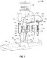
- FIG. 1is a diagram illustrating an example blood sampling-blood pressure monitoring system as may be set up in a hospital room and connected to a patient with flexible and rigid tubing sections, according to embodiments of the invention.
- FIG. 2is a diagram particularly illustrating the combination of flexible and rigid tubing sections, according to embodiments of the invention.
- FIG. 3is another diagram illustrating the combination of flexible and rigid tubing sections, according to embodiments of the invention.
- FIG. 1illustrates an example blood sampling system 120 in an example blood sampling-blood pressure monitoring system 100 as may be set up in a hospital room and connected to a patient 110 .
- the blood sampling system 120comprises a conduit line having a distal segment 122 toward the patient 110 and a proximal segment 124 .
- the distal segment 122may terminate in a male luer connector 126 for attaching to a female luer connector (not shown) of an injection site, or other conduit leading to the patient 110 .
- a reservoir 130connects to the conduit line via a multi-port control valve 132 interposed between the distal segment 122 and the proximal segment 124 .
- the multi-port control valve 132externally resembles a stopcock and controls fluid flow between the conduit line and the reservoir 130 .
- the proximal segment 124extends from the multi-port control valve 132 and terminates in a female luer connector 134 attached to a stopcock 136 of a pressure transducer 138 (e.g., a disposable pressure transducer (DPT)).
- a pressure transducer 138e.g., a disposable pressure transducer (DPT)
- the reservoir 130 and pressure transducer 138removably mount to a bracket 140 which, in turn, may be secured to a conventional pole support 142 with the reservoir 130 in a vertical orientation.
- the blood sampling system 120forms a portion of the blood sampling-blood pressure monitoring system 100
- the pressure transducer 138may be a DPT.
- any type of pressure monitoring devicemay be utilized.
- a fluid sampling site 161 that includes a Z-shaped flow passage adjacent a pre-slit septummay be utilized to sample blood.
- the septumpreferably comprises an elastomeric disc which accepts a blunt cannula and reseals after each sample is drawn, reducing the potential for contamination and eliminating the danger of needle sticks.
- any type of fluid sampling sitemay be utilized.
- the blood sampling reservoir 130may include a syringe-type variable volume chamber 162 , though other reservoirs that have constant volume chambers or other receptacles for receiving fluid may be used.
- the reservoir 130is of a type that includes a channel through the variable volume chamber 162 for passage of flushing fluid therethrough.
- a clinicianmay rotate a valve handle of the multi-port control valve 132 to select a mode of operation (e.g., a monitoring mode, a drawing/re-infusing mode, a sampling mode, or a flushing/priming mode).
- a mode of operatione.g., a monitoring mode, a drawing/re-infusing mode, a sampling mode, or a flushing/priming mode.
- the pressure transducer 138may continuously or periodically sense pressure within the sampling line to measure the patient's blood pressure and forwards the signal to the display monitor 160 .
- the plunger 164 of the reservoir 130may draw a fluid sample into the chamber 162 of the reservoir 130 to draw blood from the patient 110 past the sampling site 161 .
- the clinicianmay take a sample of undiluted blood from the sampling site 161 .
- the clinicianmay depress the plunger 164 to re-infuse blood and fluid from the reservoir 130 and tubes back to the patient 110 .
- the reservoir 130 , sample sites 161 , and tubescan be flushed, cleared, and de-bubbled such that portions of the blood sampling-blood pressure monitoring system 100 may be cleared for operation.
- a supply of flush solution 144connects to a flush port 146 of the transducer 138 via tubing 148 and can be flushed through the reservoir 130 , sample sites 161 , and tubes for flushing and clearing.
- a reduced pressureis created within the variable volume chamber 162 by withdrawing the plunger 164 such that a fluid sample from the distal segment 122 is drawn into the chamber 162 .
- the chamber 162may have a sufficient volume, e.g., 12 ml, to draw blood from the patient 110 past the sampling site 161 .
- the cliniciancan then take a sample of undiluted blood from the sampling site 161 .
- the blood and other fluids drawn into the reservoir 130 during the sampling operationmay be re-infused by depressing the plunger 164 .
- the pressure transducer 138may include a flow restrictor or flow control means to prevent flushed solution from going proximally through the sensor rather than back to the patient 110 .
- the stopcock 136may be used to close off the fluid path through the pressure transducer 138 prior to re-infusing the reservoir clearance volume.
- the entire sampling system 120is thus closed as the “priming” volume that ensures a pure sample of blood reaches the sampling site 161 remains within the sampling system 120 and is re-infused into the patient.
- the reservoir 130 , sample sites 161 , and tubescan be flushed, cleared, and de-bubbled such that portions of the blood sampling-blood pressure monitoring system 100 may be cleared for operation, as previously described.
- the blood sampling-blood pressure monitoring system 100may include: a control valve 132 , a blood pressure transducer 138 , a reservoir 130 with a plunger 164 , a sampling site 161 , and a blood pressure transducer 138 for measuring the blood pressure of the patient 110 , which may be displayed on the display monitor 160 .
- a tubemay be connected from the patient 110 to the sampling sight 161 , from the sampling sight 161 to the control valve 132 , and from the control valve 132 to the pressure transducer 138 , etc.
- control valve 132may be a multi-port control valve that is described in detail in pending U.S. patent application Ser. No. 15/801,009, entitled “Multi-Port Control Valve for use in a Blood Sampling, Blood Pressure Measurement Systems”, hereby incorporated by reference, or may be any suitable control valve presently utilized in blood sampling-blood pressure monitoring systems.
- tubing between the patient 110 and the blood pressure transducer 138may include flexible tubing sections interlinked with ridged tubing sections.
- a plurality of flexible tubing sections 125may be interlinked with rigid tubing sections 123 .
- the plurality of rigid tubing sections 123 and the plurality of flexible tubing sections 125may be interlinked with one another between the patient 110 and the blood pressure transducer 138 for the blood pressure measurement of the patient 110 by the blood pressure transducer 138 to improve the signal quality for blood pressure measurement, as will be described.
- the blood pressure measurementmay be displayed on the patient monitor 160 .
- the plurality of rigid tubing sections 123 and the flexible tubing sections 125are interlinked with one another, one after another, between the patient 110 and the sampling site 161 . It should be noted that, in this way, the pressure signal measured by the blood pressure transducer 138 at the back end is improved while allowing for an increase in the working length of system, as well as, maintaining the flexibility of the tubing from the pressure transducer 138 and the patient 110 (via the flexible tubing sections 125 ).
- the rigid tubing sections 123may be longer than the flexible tubing sections 125 .
- the flexible tubing sections 125may be standardized tubing typically utilized in blood sampling-blood pressure monitoring systems.
- the standardized flexible tubing 125may be a polyvinyl chloride (PVC).
- PVCpolyvinyl chloride
- the rigid tubing sections 123may be utilized as replacement parts for the typical standardized flexible tubing sections to improve the pressure signal for blood pressure measurement by the pressure transducer 138 , as previously described.
- the flexible tubing sections 125may have a relatively low tensile modulus and may be relatively flexible whereas the rigid tubing sections 123 may have a significantly higher tensile modulus than the flexible tubing sections 125 and may be relatively rigid.
- the flexible tubing sections 125may be relatively flexible and may include one or more of the following material components: a flexible polymer, a flexible plastic, or a flexible polyvinyl chloride (PVC).
- the rigid tubing sections 123may be relatively rigid and may include one or more of the following material components: a rigid polymer, a rigid plastic, a rigid polyvinyl chloride (PVC), a metal, a glass, metallic wires, metallic braids, aramid fibers, glass fibers, plastic fibers, or any suitable stiffer material.
- rigid tubing sections 123may be added in-line with standardized tubing 125 of an existing of blood sampling-blood pressure monitoring system 100 . This may increase the working length of the tubing while maintaining the pressure signal fidelity to meet required performance specifications for blood pressure monitoring by the pressure transducer 138 for blood pressure monitoring systems. In particular, when rigid tubing sections 123 are utilized to replace parts of existing tubing, the pressure signal for blood pressure monitoring as measured by the pressure transducer 138 may be improved thereby increasing blood pressure monitoring accuracy.
- the longer sections of rigid tubing 123may be joined together with shorter sections of existing (e.g., currently used) standard flexible tubing 125 , forming a chain of sections of longer rigid tubing 123 and short sections of compliant tubing (e.g., standardized flexible tubing 125 ), forming a chain of longer sections of rigid tubing and short sections of compliant tubing to provide a rigid portion of tubing (e.g., ideal for pressure monitoring) while allowing the flexibility of the line (e.g., joined by the short compliant tubing 125 ).
- the series of rigid tubing sections 123provide optimal conditions (e.g., high fidelity at the rigid sections) to improve the accuracy of blood pressure monitoring by the pressure transducer 138 .
- FIG. 3illustrates that the longer rigid tubing sections 123 may have a relatively high tensile modulus (TM) whereas the shorter flexible tubing sections 125 may have a relatively low tensile modulus (TM). Therefore, as has been previously described, the standardized tubing sections 125 may have a relatively low tensile modulus and be flexible tubing (e.g., a flexible PVC) and the rigid tubing sections 123 may have a significantly higher tensile modulus and be rigid (e.g., a rigid PVC).
- TMtensile modulus
- TMtensile modulus
- the flexible tubing sections 125may be relatively flexible and may include one or more of the following material components: a flexible polymer, a flexible plastic, or a flexible polyvinyl chloride (PVC).
- the rigid tubing sections 123may be relatively rigid and may include one or more of the following material components: a rigid polymer, a rigid plastic, a rigid polyvinyl chloride (PVC), a metal, a glass, metallic wires, metallic braids, aramid fibers, glass fibers, plastic fibers, or any suitable stiffer material. It should be appreciated that any suitable material may be used for flexible or rigid tubing that has an appropriate tensile modulus (TM).
- TMtensile modulus
- modes of operatione.g., a monitoring mode, a drawing/re-infusing mode, a sampling mode, or a flushing/priming mode
Landscapes
- Health & Medical Sciences (AREA)
- Life Sciences & Earth Sciences (AREA)
- Engineering & Computer Science (AREA)
- Heart & Thoracic Surgery (AREA)
- Biomedical Technology (AREA)
- Veterinary Medicine (AREA)
- Public Health (AREA)
- General Health & Medical Sciences (AREA)
- Animal Behavior & Ethology (AREA)
- Molecular Biology (AREA)
- Hematology (AREA)
- Medical Informatics (AREA)
- Biophysics (AREA)
- Surgery (AREA)
- Physics & Mathematics (AREA)
- Pathology (AREA)
- Cardiology (AREA)
- Manufacturing & Machinery (AREA)
- Vascular Medicine (AREA)
- Pulmonology (AREA)
- Anesthesiology (AREA)
- Physiology (AREA)
- External Artificial Organs (AREA)
- Measuring Pulse, Heart Rate, Blood Pressure Or Blood Flow (AREA)
- Measurement Of The Respiration, Hearing Ability, Form, And Blood Characteristics Of Living Organisms (AREA)
Abstract
Description
Claims (15)
Priority Applications (6)
| Application Number | Priority Date | Filing Date | Title |
|---|---|---|---|
| US16/422,493US11382543B2 (en) | 2018-06-11 | 2019-05-24 | Tubing system for use in a blood sampling-blood pressure monitoring system |
| JP2020568678AJP2021529012A (en) | 2018-06-11 | 2019-06-07 | Blood collection-tube material system for use in blood pressure monitoring systems |
| EP19733332.1AEP3801260B1 (en) | 2018-06-11 | 2019-06-07 | Tubing system for use in a blood sampling-blood pressure monitoring system |
| PCT/US2019/035948WO2019241051A1 (en) | 2018-06-11 | 2019-06-07 | Tubing system for use in a blood sampling-blood pressure monitoring system |
| CN201980038614.XACN112236080B (en) | 2018-06-11 | 2019-06-07 | Tube system for blood sampling-blood pressure monitoring system |
| US17/860,026US12121354B2 (en) | 2018-06-11 | 2022-07-07 | Tubing system for use in a blood sampling-blood pressure monitoring system |
Applications Claiming Priority (2)
| Application Number | Priority Date | Filing Date | Title |
|---|---|---|---|
| US201862683102P | 2018-06-11 | 2018-06-11 | |
| US16/422,493US11382543B2 (en) | 2018-06-11 | 2019-05-24 | Tubing system for use in a blood sampling-blood pressure monitoring system |
Related Child Applications (1)
| Application Number | Title | Priority Date | Filing Date |
|---|---|---|---|
| US17/860,026ContinuationUS12121354B2 (en) | 2018-06-11 | 2022-07-07 | Tubing system for use in a blood sampling-blood pressure monitoring system |
Publications (2)
| Publication Number | Publication Date |
|---|---|
| US20190374147A1 US20190374147A1 (en) | 2019-12-12 |
| US11382543B2true US11382543B2 (en) | 2022-07-12 |
Family
ID=68765351
Family Applications (2)
| Application Number | Title | Priority Date | Filing Date |
|---|---|---|---|
| US16/422,493Active2040-02-21US11382543B2 (en) | 2018-06-11 | 2019-05-24 | Tubing system for use in a blood sampling-blood pressure monitoring system |
| US17/860,026Active2039-11-14US12121354B2 (en) | 2018-06-11 | 2022-07-07 | Tubing system for use in a blood sampling-blood pressure monitoring system |
Family Applications After (1)
| Application Number | Title | Priority Date | Filing Date |
|---|---|---|---|
| US17/860,026Active2039-11-14US12121354B2 (en) | 2018-06-11 | 2022-07-07 | Tubing system for use in a blood sampling-blood pressure monitoring system |
Country Status (5)
| Country | Link |
|---|---|
| US (2) | US11382543B2 (en) |
| EP (1) | EP3801260B1 (en) |
| JP (1) | JP2021529012A (en) |
| CN (1) | CN112236080B (en) |
| WO (1) | WO2019241051A1 (en) |
Families Citing this family (4)
| Publication number | Priority date | Publication date | Assignee | Title |
|---|---|---|---|---|
| CN109964223B (en)* | 2017-10-23 | 2020-11-13 | 腾讯科技(深圳)有限公司 | Session information processing method and device, storage medium |
| US11266336B2 (en)* | 2018-06-11 | 2022-03-08 | Edwards Lifesciences Corporation | Attachment mechanism to attach a component to a particular location on a tube in a blood sampling-blood pressure monitoring system |
| US11382543B2 (en)* | 2018-06-11 | 2022-07-12 | Edwards Lifesciences Corporation | Tubing system for use in a blood sampling-blood pressure monitoring system |
| CN114028647A (en)* | 2021-12-01 | 2022-02-11 | 广州中医药大学第一附属医院 | A kind of multifunctional physiological saline bag inflation pressure pump and inflation method |
Citations (41)
| Publication number | Priority date | Publication date | Assignee | Title |
|---|---|---|---|---|
| US2804075A (en) | 1955-11-14 | 1957-08-27 | Ruth O Borden | Non-clogging surgical aspirator |
| US2830361A (en) | 1955-02-21 | 1958-04-15 | Charles H Bruner | Means for sleeving flexible tubing on rigid tubes |
| US4246899A (en)* | 1978-10-23 | 1981-01-27 | Loseff Herbert S | Drainage system for a collection of body fluids |
| US4250872A (en) | 1978-05-25 | 1981-02-17 | Yehuda Tamari | Blood pulsating and/or pumping device |
| US4662404A (en)* | 1981-05-15 | 1987-05-05 | Leveen Harry H | Flexible tubing |
| US5222949A (en)* | 1991-07-23 | 1993-06-29 | Intermed, Inc. | Flexible, noncollapsible catheter tube with hard and soft regions |
| US5361756A (en) | 1993-05-07 | 1994-11-08 | Constance M. Cernosek | Guide and containment member for leads from operating room monitoring units |
| CA2073402C (en) | 1991-07-11 | 1999-01-12 | William H. Tuggle, Jr. | Rigid/flexible tube |
| DE19949590A1 (en) | 1998-10-14 | 2000-06-21 | Cardiothoracic Sys Inc | Cannula comprising flexible and inflexible tube sections with joints, use in various surgical procedures, e.g. Cardiopulmonary Bypass (CPB) |
| US6240231B1 (en) | 1997-12-22 | 2001-05-29 | Micrus Corporation | Variable stiffness fiber optic shaft |
| US6652508B2 (en) | 2001-11-09 | 2003-11-25 | Scimed Life Systems, Inc. | Intravascular microcatheter having hypotube proximal shaft with transition |
| US6817983B1 (en) | 2002-09-19 | 2004-11-16 | Millar Instruments, Inc. | External fluid-filled catheter pressure transducer |
| US20060189926A1 (en)* | 2005-02-14 | 2006-08-24 | Hall W D | Apparatus and methods for analyzing body fluid samples |
| US20060188407A1 (en)* | 2005-02-14 | 2006-08-24 | Gable Jennifer H | Fluid handling cassette having a spectroscopic sample cell |
| US20070142729A1 (en)* | 2005-12-15 | 2007-06-21 | Up Management Gmbh & Co Med-Systems Kg | Blood vessel catheter and injection system for carrying out a blood pressure measurement of a patient |
| US20070179407A1 (en)* | 2005-09-13 | 2007-08-02 | Mark Gordon | Closed blood sampling system with isolated pressure monitoring |
| US7300534B2 (en) | 2002-01-15 | 2007-11-27 | Boston Scientific Scimed, Inc. | Bonds between metals and polymers for medical devices |
| US20080275354A1 (en)* | 2007-04-11 | 2008-11-06 | Naveen Thuramalla | System and method for diverting flow to facilitate measurement of system parameters |
| US20090124964A1 (en)* | 2003-12-05 | 2009-05-14 | Dexcom, Inc. | Integrated device for continuous in vivo analyte detection and simultaneous control of an infusion device |
| US20090156975A1 (en)* | 2007-11-30 | 2009-06-18 | Mark Ries Robinson | Robust System and Methods for Blood Access |
| US20090156922A1 (en)* | 2005-02-01 | 2009-06-18 | Daniel Goldberger | Blood monitoring system |
| US20100240964A1 (en)* | 2005-02-14 | 2010-09-23 | Sterling Bernhard B | System and method for determining a treatment dose for a patient |
| DE102009037045A1 (en) | 2009-08-13 | 2011-02-17 | Olympus Winter & Ibe Gmbh | Tubular shaft of a surgical instrument |
| US20110313318A1 (en)* | 2010-06-17 | 2011-12-22 | Optiscan Biomedical Corporation | Systems and methods to reduce fluid contamination |
| US20120050994A1 (en) | 2010-08-27 | 2012-03-01 | International Business Machines Corporation | Flexible-to-rigid tubing |
| US20120065482A1 (en)* | 2005-04-08 | 2012-03-15 | Mark Ries Robinson | Determination of blood pump system performance and sample dilution using a property of fluid being transported |
| US20120123298A1 (en)* | 2009-06-03 | 2012-05-17 | Yair Mendels | Apparatus and method of fluid aspiration |
| US20130180339A1 (en)* | 2010-09-23 | 2013-07-18 | Nxstage Medical, Inc. | Pressure sensing methods, devices, and systems |
| US20140031788A1 (en)* | 2012-07-24 | 2014-01-30 | An-Min Jason Sung | Rigid reinforcing exoskeletal sleeve for delivery of flowable biocompatible materials |
| US20140236120A1 (en)* | 2013-02-19 | 2014-08-21 | Leo Lee Tsai | Adjustable stiffness catheter |
| US20140276117A1 (en) | 2013-03-15 | 2014-09-18 | Volcano Corporation | Intravascular Devices, Systems, and Methods |
| US20150119663A1 (en)* | 2009-07-20 | 2015-04-30 | Optiscan Biomedical Corporation | Fluid analysis system |
| US20170020427A1 (en)* | 2015-07-24 | 2017-01-26 | Calliope Solutions, Inc. | Blood sample optimization system and blood contaminant sequestration device and method |
| US20170027458A1 (en)* | 2011-10-28 | 2017-02-02 | Three Rivers Cardiovascular Systems Inc. | System and apparatus comprising a multi-sensor catheter for right heart and pulmonary artery catheterization |
| US20170056032A1 (en) | 2015-08-28 | 2017-03-02 | Incuvate, Llc | Aspiration monitoring system and method |
| US9669187B2 (en) | 2013-07-12 | 2017-06-06 | Curan Medical B.V. | Male urinary catheter package |
| US20170296112A1 (en)* | 2009-07-20 | 2017-10-19 | Optiscan Biomedical Corporation | Fluid analysis system |
| US20180271425A1 (en)* | 2017-02-10 | 2018-09-27 | Kurin, Inc. | Blood contaminant sequestration device with one-way air valve and air-permeable blood barrier with closure mechanism |
| US20180306831A1 (en)* | 2017-04-21 | 2018-10-25 | 2Pi-Sigma Corporation | Automated medical sample collection and testing |
| US20190021674A1 (en)* | 2017-01-23 | 2019-01-24 | Hdl Therapeutics, Inc. | Methods for Treating Cholesterol-Related Diseases |
| US20190374147A1 (en)* | 2018-06-11 | 2019-12-12 | Edwards Lifesciences Corporation | Tubing system for use in a blood sampling-blood pressure monitoring system |
Family Cites Families (10)
| Publication number | Priority date | Publication date | Assignee | Title |
|---|---|---|---|---|
| CA1275373C (en)* | 1987-04-21 | 1990-10-23 | The Regents Of The University Of Minnesota | Apparatus and method for rapid infusion of circulatory supportive fluids |
| US5048537A (en)* | 1990-05-15 | 1991-09-17 | Medex, Inc. | Method and apparatus for sampling blood |
| US5772608A (en)* | 1994-12-28 | 1998-06-30 | The Research Foundation Of State University Of New York | System for sampling arterial blood from a patient |
| TW556558U (en)* | 2002-05-02 | 2003-10-01 | Ru-Ping Lee | Device for draining body fluids |
| WO2004064896A2 (en)* | 2003-01-14 | 2004-08-05 | Medtronic, Inc. | An extracorporeal blood circuit with active air removal |
| US20100168535A1 (en)* | 2006-04-12 | 2010-07-01 | Mark Ries Robinson | Methods and apparatuses related to blood analyte measurement system |
| US20080200837A1 (en)* | 2007-02-15 | 2008-08-21 | Frazier John A | Disposable, closed blood sampling system for use in medical conduit line |
| EP2106821B1 (en)* | 2008-03-31 | 2019-04-17 | Dentsply IH AB | Catheter assembly comprising a tubular member having pleated regions, and methods of activating and manufacturing the same |
| JP2011072562A (en)* | 2009-09-30 | 2011-04-14 | Terumo Corp | Catheter |
| WO2017127625A1 (en)* | 2016-01-22 | 2017-07-27 | Baxter International Inc. | Sterile solutions product bag |
- 2019
- 2019-05-24USUS16/422,493patent/US11382543B2/enactiveActive
- 2019-06-07JPJP2020568678Apatent/JP2021529012A/enactivePending
- 2019-06-07CNCN201980038614.XApatent/CN112236080B/enactiveActive
- 2019-06-07EPEP19733332.1Apatent/EP3801260B1/enactiveActive
- 2019-06-07WOPCT/US2019/035948patent/WO2019241051A1/ennot_activeCeased
- 2022
- 2022-07-07USUS17/860,026patent/US12121354B2/enactiveActive
Patent Citations (42)
| Publication number | Priority date | Publication date | Assignee | Title |
|---|---|---|---|---|
| US2830361A (en) | 1955-02-21 | 1958-04-15 | Charles H Bruner | Means for sleeving flexible tubing on rigid tubes |
| US2804075A (en) | 1955-11-14 | 1957-08-27 | Ruth O Borden | Non-clogging surgical aspirator |
| US4250872A (en) | 1978-05-25 | 1981-02-17 | Yehuda Tamari | Blood pulsating and/or pumping device |
| US4246899A (en)* | 1978-10-23 | 1981-01-27 | Loseff Herbert S | Drainage system for a collection of body fluids |
| US4662404A (en)* | 1981-05-15 | 1987-05-05 | Leveen Harry H | Flexible tubing |
| CA2073402C (en) | 1991-07-11 | 1999-01-12 | William H. Tuggle, Jr. | Rigid/flexible tube |
| US5222949A (en)* | 1991-07-23 | 1993-06-29 | Intermed, Inc. | Flexible, noncollapsible catheter tube with hard and soft regions |
| US5334171A (en) | 1991-07-23 | 1994-08-02 | Intermed, Inc. | Flexible, noncollapsible catheter tube with hard and soft regions |
| US5361756A (en) | 1993-05-07 | 1994-11-08 | Constance M. Cernosek | Guide and containment member for leads from operating room monitoring units |
| US6240231B1 (en) | 1997-12-22 | 2001-05-29 | Micrus Corporation | Variable stiffness fiber optic shaft |
| DE19949590A1 (en) | 1998-10-14 | 2000-06-21 | Cardiothoracic Sys Inc | Cannula comprising flexible and inflexible tube sections with joints, use in various surgical procedures, e.g. Cardiopulmonary Bypass (CPB) |
| US6652508B2 (en) | 2001-11-09 | 2003-11-25 | Scimed Life Systems, Inc. | Intravascular microcatheter having hypotube proximal shaft with transition |
| US7300534B2 (en) | 2002-01-15 | 2007-11-27 | Boston Scientific Scimed, Inc. | Bonds between metals and polymers for medical devices |
| US6817983B1 (en) | 2002-09-19 | 2004-11-16 | Millar Instruments, Inc. | External fluid-filled catheter pressure transducer |
| US20090124964A1 (en)* | 2003-12-05 | 2009-05-14 | Dexcom, Inc. | Integrated device for continuous in vivo analyte detection and simultaneous control of an infusion device |
| US20090156922A1 (en)* | 2005-02-01 | 2009-06-18 | Daniel Goldberger | Blood monitoring system |
| US20060189926A1 (en)* | 2005-02-14 | 2006-08-24 | Hall W D | Apparatus and methods for analyzing body fluid samples |
| US20060188407A1 (en)* | 2005-02-14 | 2006-08-24 | Gable Jennifer H | Fluid handling cassette having a spectroscopic sample cell |
| US20100240964A1 (en)* | 2005-02-14 | 2010-09-23 | Sterling Bernhard B | System and method for determining a treatment dose for a patient |
| US20120065482A1 (en)* | 2005-04-08 | 2012-03-15 | Mark Ries Robinson | Determination of blood pump system performance and sample dilution using a property of fluid being transported |
| US20070179407A1 (en)* | 2005-09-13 | 2007-08-02 | Mark Gordon | Closed blood sampling system with isolated pressure monitoring |
| US20070142729A1 (en)* | 2005-12-15 | 2007-06-21 | Up Management Gmbh & Co Med-Systems Kg | Blood vessel catheter and injection system for carrying out a blood pressure measurement of a patient |
| US20080275354A1 (en)* | 2007-04-11 | 2008-11-06 | Naveen Thuramalla | System and method for diverting flow to facilitate measurement of system parameters |
| US20090156975A1 (en)* | 2007-11-30 | 2009-06-18 | Mark Ries Robinson | Robust System and Methods for Blood Access |
| US20120123298A1 (en)* | 2009-06-03 | 2012-05-17 | Yair Mendels | Apparatus and method of fluid aspiration |
| US20150119663A1 (en)* | 2009-07-20 | 2015-04-30 | Optiscan Biomedical Corporation | Fluid analysis system |
| US20170296112A1 (en)* | 2009-07-20 | 2017-10-19 | Optiscan Biomedical Corporation | Fluid analysis system |
| DE102009037045A1 (en) | 2009-08-13 | 2011-02-17 | Olympus Winter & Ibe Gmbh | Tubular shaft of a surgical instrument |
| US20110313318A1 (en)* | 2010-06-17 | 2011-12-22 | Optiscan Biomedical Corporation | Systems and methods to reduce fluid contamination |
| US20120050994A1 (en) | 2010-08-27 | 2012-03-01 | International Business Machines Corporation | Flexible-to-rigid tubing |
| US20130180339A1 (en)* | 2010-09-23 | 2013-07-18 | Nxstage Medical, Inc. | Pressure sensing methods, devices, and systems |
| US20170027458A1 (en)* | 2011-10-28 | 2017-02-02 | Three Rivers Cardiovascular Systems Inc. | System and apparatus comprising a multi-sensor catheter for right heart and pulmonary artery catheterization |
| US20140031788A1 (en)* | 2012-07-24 | 2014-01-30 | An-Min Jason Sung | Rigid reinforcing exoskeletal sleeve for delivery of flowable biocompatible materials |
| US20140236120A1 (en)* | 2013-02-19 | 2014-08-21 | Leo Lee Tsai | Adjustable stiffness catheter |
| US20140276117A1 (en) | 2013-03-15 | 2014-09-18 | Volcano Corporation | Intravascular Devices, Systems, and Methods |
| US9669187B2 (en) | 2013-07-12 | 2017-06-06 | Curan Medical B.V. | Male urinary catheter package |
| US20170020427A1 (en)* | 2015-07-24 | 2017-01-26 | Calliope Solutions, Inc. | Blood sample optimization system and blood contaminant sequestration device and method |
| US20170056032A1 (en) | 2015-08-28 | 2017-03-02 | Incuvate, Llc | Aspiration monitoring system and method |
| US20190021674A1 (en)* | 2017-01-23 | 2019-01-24 | Hdl Therapeutics, Inc. | Methods for Treating Cholesterol-Related Diseases |
| US20180271425A1 (en)* | 2017-02-10 | 2018-09-27 | Kurin, Inc. | Blood contaminant sequestration device with one-way air valve and air-permeable blood barrier with closure mechanism |
| US20180306831A1 (en)* | 2017-04-21 | 2018-10-25 | 2Pi-Sigma Corporation | Automated medical sample collection and testing |
| US20190374147A1 (en)* | 2018-06-11 | 2019-12-12 | Edwards Lifesciences Corporation | Tubing system for use in a blood sampling-blood pressure monitoring system |
Non-Patent Citations (1)
| Title |
|---|
| Joseph, Dr. Tinku, "Arterial Lines," Published on Jun. 10, 2016. |
Also Published As
| Publication number | Publication date |
|---|---|
| US20190374147A1 (en) | 2019-12-12 |
| CN112236080A (en) | 2021-01-15 |
| EP3801260B1 (en) | 2021-11-10 |
| JP2021529012A (en) | 2021-10-28 |
| CN112236080B (en) | 2024-08-02 |
| US12121354B2 (en) | 2024-10-22 |
| WO2019241051A1 (en) | 2019-12-19 |
| US20220338771A1 (en) | 2022-10-27 |
| EP3801260A1 (en) | 2021-04-14 |
Similar Documents
| Publication | Publication Date | Title |
|---|---|---|
| US12121354B2 (en) | Tubing system for use in a blood sampling-blood pressure monitoring system | |
| US11969247B2 (en) | Extension housing a probe or intravenous catheter | |
| US4468224A (en) | System and method for catheter placement in blood vessels of a human patient | |
| CN102596023B (en) | Systems, methods and devices for facilitating access to an anatomical site or environment | |
| JP5415073B2 (en) | Closed blood sampling system with isolated pressure monitoring | |
| US10694986B2 (en) | Bracket for mounting a multi-port control valve and a reservoir to a sensor holder for use in a blood sampling-blood pressure monitoring system | |
| US20080200837A1 (en) | Disposable, closed blood sampling system for use in medical conduit line | |
| US20190133460A1 (en) | Blood pressure monitoring system with isolation | |
| US20110184266A1 (en) | Blood glucose monitoring system | |
| CN216366262U (en) | Catheter system | |
| US20230256200A1 (en) | Vascular Access Blood Draw Device with Integrated Point-of-Care Small Volume Blood Collection Device | |
| US20230255529A1 (en) | Point of Care Collection and Transfer Device with Luer Lock Access Device and Syringe Compatibility | |
| US11266336B2 (en) | Attachment mechanism to attach a component to a particular location on a tube in a blood sampling-blood pressure monitoring system | |
| US10595761B2 (en) | Adapter for use with a multi-port control valve used in blood sampling, blood pressure measurement systems | |
| CN221865663U (en) | Patency Indicators and Arterial Lines |
Legal Events
| Date | Code | Title | Description |
|---|---|---|---|
| AS | Assignment | Owner name:EDWARDS LIFESCIENCES CORPORATION, CALIFORNIA Free format text:ASSIGNMENT OF ASSIGNORS INTEREST;ASSIGNOR:HOAN, ANDREW NGUYEN;REEL/FRAME:049280/0676 Effective date:20180801 | |
| FEPP | Fee payment procedure | Free format text:ENTITY STATUS SET TO UNDISCOUNTED (ORIGINAL EVENT CODE: BIG.); ENTITY STATUS OF PATENT OWNER: LARGE ENTITY | |
| STPP | Information on status: patent application and granting procedure in general | Free format text:DOCKETED NEW CASE - READY FOR EXAMINATION | |
| STPP | Information on status: patent application and granting procedure in general | Free format text:NON FINAL ACTION MAILED | |
| STPP | Information on status: patent application and granting procedure in general | Free format text:RESPONSE TO NON-FINAL OFFICE ACTION ENTERED AND FORWARDED TO EXAMINER | |
| STPP | Information on status: patent application and granting procedure in general | Free format text:FINAL REJECTION MAILED | |
| STPP | Information on status: patent application and granting procedure in general | Free format text:RESPONSE AFTER FINAL ACTION FORWARDED TO EXAMINER | |
| STPP | Information on status: patent application and granting procedure in general | Free format text:NOTICE OF ALLOWANCE MAILED -- APPLICATION RECEIVED IN OFFICE OF PUBLICATIONS | |
| STCF | Information on status: patent grant | Free format text:PATENTED CASE | |
| AS | Assignment | Owner name:BD SWITZERLAND SARL, SWITZERLAND Free format text:ASSIGNMENT OF ASSIGNORS INTEREST;ASSIGNORS:EDWARDS LIFESCIENCES CORPORATION;EDWARDS LIFESCIENCES LLC;EDWARDS LIFESCIENCES SARL;AND OTHERS;REEL/FRAME:070634/0001 Effective date:20240903 Owner name:BECTON, DICKINSON AND COMPANY, NEW JERSEY Free format text:ASSIGNMENT OF ASSIGNORS INTEREST;ASSIGNOR:BD SWITZERLAND SARL;REEL/FRAME:070179/0813 Effective date:20241021 |