US11378997B2 - Variable phase and frequency pulse-width modulation technique - Google Patents
Variable phase and frequency pulse-width modulation techniqueDownload PDFInfo
- Publication number
- US11378997B2 US11378997B2US16/600,496US201916600496AUS11378997B2US 11378997 B2US11378997 B2US 11378997B2US 201916600496 AUS201916600496 AUS 201916600496AUS 11378997 B2US11378997 B2US 11378997B2
- Authority
- US
- United States
- Prior art keywords
- frequency
- intervals
- base frequency
- phase
- phase angle
- Prior art date
- Legal status (The legal status is an assumption and is not a legal conclusion. Google has not performed a legal analysis and makes no representation as to the accuracy of the status listed.)
- Active, expires
Links
Images


Classifications
- G—PHYSICS
- G06—COMPUTING OR CALCULATING; COUNTING
- G06F—ELECTRIC DIGITAL DATA PROCESSING
- G06F1/00—Details not covered by groups G06F3/00 - G06F13/00 and G06F21/00
- G06F1/02—Digital function generators
- G06F1/025—Digital function generators for functions having two-valued amplitude, e.g. Walsh functions
- H—ELECTRICITY
- H03—ELECTRONIC CIRCUITRY
- H03K—PULSE TECHNIQUE
- H03K11/00—Transforming types of modulations, e.g. position-modulated pulses into duration-modulated pulses
- G—PHYSICS
- G06—COMPUTING OR CALCULATING; COUNTING
- G06F—ELECTRIC DIGITAL DATA PROCESSING
- G06F17/00—Digital computing or data processing equipment or methods, specially adapted for specific functions
- G06F17/10—Complex mathematical operations
- G06F17/17—Function evaluation by approximation methods, e.g. inter- or extrapolation, smoothing, least mean square method
Definitions
- the present disclosurerelates generally to reconstructing digital signals by specified amplitude and phase via inducing frequency shifts away from a base frequency implied by phase changes.
- Phased array systemsrely on the production of an exact carrier frequency to function. To simplify systems, it is often assumed that the carrier frequency is emitted during all relevant times so that the system can be treated as time invariant. This time invariance is necessary for the input signals to the array element transducers to be treated as complex values.
- the solution presented hereinuses the specified amplitude and phase to reconstruct a digital signal that explicitly induces the frequency shifts away from the base frequency implied by phase changes. Shifting the carrier frequency of a digitally controlled phased array while preserving the timing of the individual phase pulses enables more efficient driving of the phased array system when the phase of the drive signals change dynamically in time.
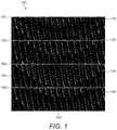
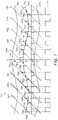
- FIG. 1shows an output from a quickly-moving focus point using a standard approach.
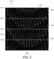
- FIG. 2shows an output similar to FIG. 1 but from a quickly-moving focus point using a novel approach.
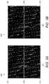
- FIGS. 3A and 3Bare closeups of FIGS. 1 and 2 , respectively.
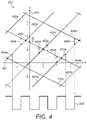
- FIG. 4shows geometric behavior of a system having 3/2 of a base frequency.
- FIG. 5shows geometric behavior of a system having exactly the base frequency.
- FIG. 6shows geometric behavior of a system having a slowly increasing phase relative to the base frequency.
- FIG. 7shows geometric behavior of a system having an arbitrary function of phase angle relative to the base frequency.
- FIG. 8shows geometric construction of proof of the correct behavior for the case of increased frequency.
- FIG. 9shows geometric construction of proof of the correct behavior for the case of decreased frequency.
- Carrier frequencyis defined herein as the consequential instantaneous frequency of the output digital signal pulses.
- Base frequencyis defined herein as the center frequency that is described by an unmoving or constant phase signal. It is known that any phase change in the signal also constitutes a frequency shift. In this case that is realized by the carrier frequency shifting away from the base frequency.
- the input data to the methodis considered to be the phase and duty cycle of a pulse-width modulation. This is measured with respect to a steady reference signal that is a fixed source at the base frequency.
- FIG. 1shows an output from a quickly-moving focus point using a standard approach.
- the drive of each transducer in a square 16 ⁇ 16 element phased arrayis represented by a column of black and white data.
- Horizontal gray barsrepresent the start of each period of the base frequency and the rows are each tick of the clock on which a binary digit that describes the transducer state must be output.
- Each square of black or white datadescribes the binary state of the electrical input signal and thus transducer element at that tick through time.
- Each carrier frequency periodis generated independently at the base frequency with the correct phase and duty cycle that corresponds to the amplitude.
- FIG. 1is a visualization 100 of the digital pulse-width modulated output from the standard technique when the focus for the array is moving quickly.
- the input to each transduceris arranged horizontally 160 , with time 150 moving from the bottom to the top of the diagram.
- the base frequency periodsare delineated 161 , 162 , 163 , 164 , showing where one period ends and the next begins. Erroneously repeating pulses 110 , 120 , 130 , 140 can be seen that are indicative of a frequency shift from the base frequency, here to a lower carrier frequency.
- the standard techniquerequires that each base frequency period contains at least one pulse region 110 , 120 , 130 , 140 .
- the new algorithmwhose output is shown in FIG. 2 , allows the carrier frequency to shift away from the base frequency while preserving the timing and phase accuracy of the amplitude generating pulses.
- the input to each transduceris arranged horizontally 260 , with time 250 moving from the bottom of the top of the diagram.
- the base frequency periodsare delineated 261 , 262 , 263 , 264 , showing where one period ends and the next begins.
- the double pulses 210 , 220 , 230 , 240are no longer a problem. While the phases agree exactly with the standard approach at the start of each base frequency period, the number of pulse regions per base frequency period is now on average less than one.
- FIG. 3Ais a detail 300 of the upper left corner of FIG. 1 .
- FIG. 3Bis a detail 350 of the upper left corner of FIG. 2 .
- the pulse intended to be produced at the base frequency in the old techniquehas instead produced a double pulse 310 due to the moving phase shift.
- the realityis that not only is the double pulse incorrect, its frequency content is disruptive to the behavior of the system. This is because the temporal distance between the two pulses implies very high frequency content that is near neither the base nor the intended carrier frequency.
- a single pulse 360has been produced at a lower frequency that corresponds to the corrected position across both base frequency periods (between 261 and 262 and between 262 and 263 ).
- the single pulse 360further has been elongated in time to factor in the change in the number of discrete ticks that a given duty cycle percentage implies. This is shown by its occupation of more pulse elements (white squares) than the equivalent pulses in 310 .
- the hardware-efficient method of generating the up-sampling of the phase represented as the evaluation of high-order polynomial interpolantis also novel.
- the aimis to produce a PWM output that respects and correctly interprets changes in frequency while also preserving absolute phase and phase changes. Without loss of generality, this technique may be also restated with phase delays that produces a “sign flip” in angle from the technique described.
- the moving phase anglemay be considered as an equivalent formulations for a phase-frequency modulated wave:
- Describing the phase delay ⁇ ′(t)may be achieved by interpolating phase offsets generated in subsequent base frequency steps by a polynomial, since it is beneficial for the frequency to be defined and continuous on the endpoints.
- the frequencyis defined as:
- ⁇ ′(0) and ⁇ ′(1)can be achieved using backwards differences, thus limiting the number of samples required in the future direction and reducing latency. This also reduces the total number of immediately available samples required from four to three precomputed samples of the phase angle and duty cycle of the intended signal.
- ⁇ ′( t )( ⁇ ⁇ 1 +2 ⁇ 0 ⁇ 1 ) t 3 +(2 ⁇ ⁇ 1 ⁇ 4 ⁇ 0 +2 ⁇ 1 ) t 2 +( ⁇ 0 ⁇ 1 ⁇ 1 ) t+ ⁇ 0 , which is repeated for every interval.
- phasemay be also represented by a lower degree polynomial. Although this would imply sacrificing some of the continuity conditions, the reasonable approach is to produce discontinuities in frequency anyway (but importantly, phase continuity is preserved as only the time derivatives of the phase are discontinuous). Even with frequency discontinuities, the technique using this interpolant enjoys a significant accuracy improvement over the standard technique.
- is computed. If it is smaller than a given value representing an amplitude, then the point in time is within the pulse, in the high region of the digital signal. Otherwise, the point in time is outside the pulse and in the low region of the digital signal.
- FIGS. 4 through 7geometrically demonstrate how testing that this value is less than ⁇ ′(t)/2 generates the appropriate pulse.
- FIG. 4shows the geometrical behavior 400 for the edge case of 3/2 of the base frequency.
- ⁇is ⁇ (t)
- the y-axis 410represents normalized angle (in revolutions) ⁇
- the x-axis 420represents normalized time (in base frequency periods) t.
- This FIG. 4is a geometric interpretation of the PWM generation when applied to a slowly decreasing phase (with derivative ⁇ 1 ⁇ 2, negative slope down and to the right), relative to the base frequency represented by the diagonal phase lines 440 a , 440 b , 440 c.
- the distance between the two sets of repeating curvescrosses the threshold where it is less than ⁇ /2 (defined as half the duty cycle quantity) distance in a number of places 450 a , 450 b , 450 c , 450 d , 450 e , 450 f , 450 g , 450 h that repeat in time.
- ⁇ /2defined as half the duty cycle quantity
- the interpolated phase curves ( ⁇ ′(t))that represent the desired behavior that are an addition to this signal in phase 440 a , 440 b , 440 c . Where the two curves “match” in phase closely enough (less than ⁇ /2), these regions represent the pulse parts of the pulse signals 430 .
- the dashed vertical lines projected from the ⁇ /2 distance factors 450 a , 450 b , 450 c , 450 d , 450 e , 450 f , 450 g , 450 hshow the places on the PWM signal 430 where the binary state is changed inducing pulse edges due to the ⁇ /2 distance factor being reached.
- FIG. 5shows the geometrical behavior 500 for exactly the base frequency.
- ⁇is ⁇ (t)
- the y-axis 510represents normalized angle (in revolutions) ⁇
- the x-axis 520represents normalized time (in base frequency periods) t.
- Shownis a geometric interpretation of the PWM generation when applied to a flat constant phase angle ⁇ ′(t) (horizontal lines with derivative zero in time) that does not change relative to the base frequency represented by the diagonal phase lines 540 a , 540 b , 540 c.
- the distance ⁇ /2 550 a , 550 b , 550 c , 550 d , 550 e , 550 fagain represents the transition points between the two states in the pulse signal.
- the two curvescross over exactly once per base frequency period because the interpolated phase curve is horizontal and represents a constant phase angle.
- the dashed linesshow the pulse edges in the pulsed signal.
- the final digital signal 530that is to drive the element made up of all of the points where the two sets of curves are again less than ⁇ /2 distance apart.
- FIG. 6shows the geometrical behavior 600 for the edge case of 1 ⁇ 2 the base frequency.
- ⁇is ⁇ (t)
- the y-axis 610represents normalized angle (in revolutions) ⁇
- the x-axis 620represents normalized time (in base frequency periods) t.
- the distance ⁇ /2 650 a , 650 bagain represents the transition points between the two states in the pulse signal.
- the final digital signal 630that is to drive the element made up of all of the points where the two sets of curves are again less than ⁇ /2 distance apart.
- FIG. 7shows the geometrical behavior 700 as to how an example interpolated function where the gradient and thus frequency changes significantly over time fits into this geometric description.
- ⁇is ⁇ (t)
- the y-axis 710represents normalized angle (in revolutions) ⁇
- the x-axis 720represents normalized time (in base frequency periods) t.
- Shown is a geometric interpretation of the PWM generation when applied to a more arbitrarily defined function of phase angle, relative to the base frequency represented by the diagonal phase lines ⁇ ′(t) or ⁇⁇ t 740 a , 740 b , 740 c , 740 d , 740 e , 740 f , 740 g , 740 h , 740 j , 740 k .
- the wavy horizontal lines 745 a , 745 b , 745 care the interpolated phase lines ⁇ ′(t) in this example.
- the variation in the derivative of ⁇ ′(t)moves between positive derivative that generates longer pulses at a lower frequency and negative derivative that generates shorter pulses at a higher frequency. This is due to the crossings between y-axis distances smaller than ⁇ /2 and larger than ⁇ /2 changing their relative distance apart.
- the final digital signal 730that is to drive the element, wherein pulse edges are induced when the signal y-axis distance crosses the ⁇ /2 threshold.
- FIG. 8shows the geometric construction 800 of the proof of the correct behavior for the case of increased frequency.
- the y-axis 810represents normalized angle (in revolutions) 0 and the x-axis 820 represents normalized time (in base frequency periods) t.
- the distance ⁇ /2 844again represents the state change in the transducer drive signal. But in this situation the curve ⁇ ′(t) is assumed to have negative derivative
- FIG. 8demonstrates that the half pulse width is appropriately scaled in this situation for the frequency multiplier
- FIG. 9shows the geometric construction 900 of the proof of the correct behavior for the case of decreased frequency.
- the y-axis 910represents normalized angle (in revolutions) ⁇ and the x-axis 920 represents normalized time (in base frequency periods) t.
- the distance ⁇ /2 944again represents the state change in the transducer drive signal. But in this situation the curve ⁇ ′(t) is assumed to have positive derivative
- the angle ⁇ 940can be found using a similar construction as before as:
- ⁇ ′ ⁇ ( t ) 2p 2 - x
- ⁇ xp 2 ⁇ ⁇ d ⁇ ⁇ ⁇ ′ ⁇ ( t ) dt ⁇
- ⁇ ⁇ ′ ⁇ ( t ) 2p 2 - p 2 ⁇ ⁇ d ⁇ ⁇ ⁇ ′ ⁇ ( t ) dt ⁇
- ⁇ ⁇ ′ ⁇ ( t ) 2p 2 ⁇ ( 1 - ⁇ d ⁇ ⁇ ⁇ ′ ⁇ ( t ) dt ⁇ )
- ⁇ p 2⁇ ′ ⁇ ( t ) / 2 1 - ⁇ d ⁇ ⁇ ⁇ ′ ⁇ ( t ) dt ⁇ , which is the definition of the appropriate pulse width change due to the frequency shift when
- FIG. 9demonstrates that the half pulse width is appropriately scaled in this situation for the frequency multiplier
- Each spline intervalcounts k discrete sub-interval steps from 0 to 2 INT_BITS ⁇ 1. By incrementing each counter, it can compute the terms corresponding to the powers of k. By reinterpreting powers of k as fractions, powers of t are computed. This occurs by first establishing a per spline-curve constant, for instance taking the constant b.
- ⁇ ( f+bO ( t )) 02 INT_BITS f
- ⁇ ( f+bO ( t )) k⁇ ( f+bO ( t )) k-1 +b
- next counter(proportional to b multiplied by a quadratic order term in t) is defined by the “triangular” numbers as:
- ⁇ bO ⁇ ( t 2 ) 00
- ⁇ ⁇ bO ⁇ ( t 2 ) k⁇ bO ⁇ ( t 2 ) k - 1 + ⁇ bO ⁇ ( t ) k
- ⁇ 2 ⁇ ( ⁇ bO ⁇ ( t 2 ) k ) - ( ⁇ bO ⁇ ( t ) k )2 2 ⁇ INT BITS ⁇ bt 2 .
- the linear partmust be subtracted beforehand due to the difference in the power-of-two. This then yields the quadratic term in t, bt 2 , when adjusted to represent a fraction.
- ⁇ bO ⁇ ( t 3 ) 00
- ⁇ ⁇ bO ⁇ ( t 3 ) k⁇ bO ⁇ ( t 3 ) k - 1 + ⁇ O ⁇ ( t 2 ) k
- ⁇ bO ⁇ ( t 3 ) - 10
- ⁇ 6 ⁇ ( ⁇ bO ⁇ ( t 3 ) k - 1 ) + ⁇ bO ⁇ ( t )2 3 ⁇ INT_BITS ⁇ bt 3 ,
- simple countersmay be used to generate splines consisting of arbitrarily high-order polynomials.
- the incremented countersserve to increment the time variable t forward, and in so doing, generate the next discrete time slice of the intended signal.
- ⁇ ′(t)the duty cycle to achieve the required output power at the base frequency
- ⁇ ′(t)the instantaneous phase offset with respect to the base frequency
- phase and amplitude samplesspaced by power-of-two counts of the base frequency period and not just splitting the base frequency period into 2 INT_BITS discrete steps. This could be used in some embodiments to provide a lower bandwidth interface, both in data usage and in frequency range about the base frequency that are addressable.
- the phase and amplitude samplesmay be increased in some embodiments to have a power-of-two samples in every base frequency period to provide additional frequency bandwidth about the carrier instead.
- the spline interpolant intervalmust be reduced to cover only a power-of-two with a negative exponent (fractional) part of the base frequency period. This may involve decreasing the number of bits of precision produced by the interpolant or increasing the number of bits of precision of the timer counter.
- the addition of these extra data pointseffectively makes the spline interval 0 ⁇ t ⁇ 2 ⁇ N . This increases the accessible range of frequencies as the maximum angular movement of the additional phase, a radians, is now confined to 2 ⁇ N fraction of base frequency period. This increases the maximum possible frequency shift achievable.
- phased locked loopsWith traditional techniques such as frequency multipliers, dividers and phased locked loops (PLLs), it is difficult to make small or dynamic changes to the carrier frequency. As the dynamic control of a phased array requires exact phase information this implies that a digital approach, if the hardware is sufficiently capable, will be more suitable than an analog solution for prescribing precise behavior. Thus, its behavior is deterministic, easy to model and predictable compared to a system which uses analog infrastructure to achieve this level of synchronization due to delays and instabilities among other problems. As the system explicitly evaluates the phase function, the transducer impulse response can be predicted and taken into account by modeling the frequency content of the output signal.
- the technique described hereinby adding an accumulator onto the phase angle input into the signal generator described produces a frequency shift that may be easily controlled without affecting the relative phases in an unknown way. In the case of environmental changes, it may be that the frequency requires such small changes to keep the wavelength constant. The remainder of the system may then continue to work in units of wavelength with the guarantee that this is compensated for by the driving system at the end of the pipeline.
- the accumulator that adds onto the phase for all of the transducersis incremented or decremented using a value that is derived from one or more sensors, such as (for example) temperature, humidity and altitude/density sensors.
- a systemcomprising a digital or analog electrical signal driven by a real-time progressive polynomial spline evaluation that achieves an up-sampling by a power-of-two factor using a linear combination of counters.
- a systemcomprising a digital or analog electrical signal whose instantaneous phase angle is substantially calculated by a real-time progressive polynomial spline evaluation that achieves an up-sampling by a power-of-two factor using a linear combination of counters.
- a systemcomprising a digital electrical signal whose state is calculated by comparing the difference between the current position in the base frequency cycle and the instantaneous phase angle to the proportion of cycle duty that would be present at the base frequency.
Landscapes
- Engineering & Computer Science (AREA)
- Physics & Mathematics (AREA)
- Theoretical Computer Science (AREA)
- General Physics & Mathematics (AREA)
- Data Mining & Analysis (AREA)
- Pure & Applied Mathematics (AREA)
- Mathematical Optimization (AREA)
- Mathematical Analysis (AREA)
- Mathematical Physics (AREA)
- General Engineering & Computer Science (AREA)
- Computational Mathematics (AREA)
- Algebra (AREA)
- Databases & Information Systems (AREA)
- Software Systems (AREA)
- Radar Systems Or Details Thereof (AREA)
- Transmission And Conversion Of Sensor Element Output (AREA)
Abstract
Description
where θ′(t) is a time-dependent function of phase and Ω′(t) is a time-dependent function of frequency. It can be seen that dθ′(t)/dt is a measure of deviation of the carrier frequency from the base frequency. This can be simplified by normalizing both angle and ω (divide through by the base frequency and 2π radians, θ now being measured in revolutions), yielding ω=1.
where the first time derivatives of phase angle also contribute to the instantaneous carrier frequency and thus form two derivative constraints:
The two endpoints of the interval in angle also have further constraints:
θ′(0)=θ0,
θ′(1)=θ1,
which together with the constraints on carrier frequency make four in total. This necessitates a cubic polynomial interpolation for this level of continuity. As shown, defining ω′(0) and ω′(1) can be achieved using backwards differences, thus limiting the number of samples required in the future direction and reducing latency. This also reduces the total number of immediately available samples required from four to three precomputed samples of the phase angle and duty cycle of the intended signal.
θ′(t)=(−θ−1+2θ0−θ1)t3+(2θ−1−4θ0+2θ1)t2+(θ0−1−1)t+θ0,
which is repeated for every interval.
θ′(t)=(θ1−θ0)t+θ0.
Δ′(t)=(Δ1−Δ0)t+Δ0.
Defining the output signal going into the element as a digital approximation to:
so a time-varying θ phase offset with respect to the base frequency may also be viewed as a deviation from the base signal frequency co, effectively dθ′(t)/dt. To search for the locations of the pulses, zeroes (also multiples of 2π) of the angle input to the cosine function must be found. These correspond to peaks in the wave and high points in the digital signal. To achieve this, both angle and ω are normalized (divide through by the frequency and 2π radians, all θ now being measured in revolutions), yielding ω=1. Therefore, the condition being searched for is:
ωt-θ′(t)=t−θ′(t)=0.
This describes the center of the pulse at each step.
resulting in a higher frequency. The more negative the derivative
the higher the frequency and the larger the distance X should be.
and since
which is the definition of the appropriate pulse-width change due to the frequency shift when
when the y-axis distance Δ/2 is used as the criterion for the pulse edges. This is exactly the frequency multiplier required.
resulting in a lower frequency. The more positive the derivative
the lower the frequency and the larger the distance X should be.
and since
which is the definition of the appropriate pulse width change due to the frequency shift when
when the y-axis distance Δ/2 is used as the criterion for the pulse edges. This is exactly the frequency multiplier required.
|t−θ′(t)|<Δ′(t)/2,
is guaranteed to produce the best approximation of the pulse, it is imperative that the progressive evaluation of the polynomial interpolant be achieved with an efficient hardware algorithm.
∝bO(t)0=0,
∝bO(t)k=∝bO(t)k-1+b,
∝bO(t)k=bk=2INT_BITSbt.
∝(f+bO(t))0=2INT_BITSf,
∝(f+bO(t))k=∝(f+bO(t))k-1+b,
∝(f+bO(t))k=2INT_BITSf+bk=2INT_BITS(bt+f).
The linear part must be subtracted beforehand due to the difference in the power-of-two. This then yields the quadratic term in t, bt2, when adjusted to represent a fraction.
θ′(t)=(−θ−1+2θ0−θ1)t3+(2θ−1−4θ0+2θ1)t2+(θ0−θ−1)t+θ0,
and the duty cycle interpolant:
Δ′(t)=(Δ1−Δ0)t+Δ0,
the counters required are then:
Acounter:=∝(Δ0+(Δ1−Δ0)O(t)),
Bcounter:=∝((θ−1−2θ0+θ1)O(t)),
Ccounter:=∝((θ−1−2θ0+θ1)O(t2)),
Dcounter:=∝((θ−1−2θ0+θ1)O(t3)),
Ecounter:=∝((θ0+(θ0−θ−1)O(t)).
which are trivially added together and subtracted to produce the Boolean condition that drives the output signal.
Claims (12)
Priority Applications (2)
| Application Number | Priority Date | Filing Date | Title |
|---|---|---|---|
| US16/600,496US11378997B2 (en) | 2018-10-12 | 2019-10-12 | Variable phase and frequency pulse-width modulation technique |
| US17/805,860US20220300028A1 (en) | 2018-10-12 | 2022-06-07 | Variable Phase and Frequency Pulse-Width Modulation Technique |
Applications Claiming Priority (2)
| Application Number | Priority Date | Filing Date | Title |
|---|---|---|---|
| US201862744656P | 2018-10-12 | 2018-10-12 | |
| US16/600,496US11378997B2 (en) | 2018-10-12 | 2019-10-12 | Variable phase and frequency pulse-width modulation technique |
Related Child Applications (1)
| Application Number | Title | Priority Date | Filing Date |
|---|---|---|---|
| US17/805,860DivisionUS20220300028A1 (en) | 2018-10-12 | 2022-06-07 | Variable Phase and Frequency Pulse-Width Modulation Technique |
Publications (2)
| Publication Number | Publication Date |
|---|---|
| US20200117229A1 US20200117229A1 (en) | 2020-04-16 |
| US11378997B2true US11378997B2 (en) | 2022-07-05 |
Family
ID=68296529
Family Applications (2)
| Application Number | Title | Priority Date | Filing Date |
|---|---|---|---|
| US16/600,496Active2040-01-01US11378997B2 (en) | 2018-10-12 | 2019-10-12 | Variable phase and frequency pulse-width modulation technique |
| US17/805,860PendingUS20220300028A1 (en) | 2018-10-12 | 2022-06-07 | Variable Phase and Frequency Pulse-Width Modulation Technique |
Family Applications After (1)
| Application Number | Title | Priority Date | Filing Date |
|---|---|---|---|
| US17/805,860PendingUS20220300028A1 (en) | 2018-10-12 | 2022-06-07 | Variable Phase and Frequency Pulse-Width Modulation Technique |
Country Status (11)
| Country | Link |
|---|---|
| US (2) | US11378997B2 (en) |
| EP (1) | EP3864752A1 (en) |
| JP (1) | JP2022504521A (en) |
| KR (2) | KR20210068564A (en) |
| CN (1) | CN112889219A (en) |
| AU (1) | AU2019357130B2 (en) |
| CA (1) | CA3114280C (en) |
| IL (1) | IL282266A (en) |
| SG (1) | SG11202103480SA (en) |
| WO (1) | WO2020074928A1 (en) |
| ZA (1) | ZA202102059B (en) |
Families Citing this family (20)
| Publication number | Priority date | Publication date | Assignee | Title |
|---|---|---|---|---|
| GB2513884B (en) | 2013-05-08 | 2015-06-17 | Univ Bristol | Method and apparatus for producing an acoustic field |
| GB2530036A (en) | 2014-09-09 | 2016-03-16 | Ultrahaptics Ltd | Method and apparatus for modulating haptic feedback |
| CA2976312C (en) | 2015-02-20 | 2023-06-13 | Ultrahaptics Ip Limited | Perceptions in a haptic system |
| CN107534810B (en) | 2015-02-20 | 2019-12-20 | 超级触觉资讯处理有限公司 | Method for providing improved haptic feedback |
| US10818162B2 (en) | 2015-07-16 | 2020-10-27 | Ultrahaptics Ip Ltd | Calibration techniques in haptic systems |
| US10268275B2 (en) | 2016-08-03 | 2019-04-23 | Ultrahaptics Ip Ltd | Three-dimensional perceptions in haptic systems |
| US10943578B2 (en) | 2016-12-13 | 2021-03-09 | Ultrahaptics Ip Ltd | Driving techniques for phased-array systems |
| US11531395B2 (en) | 2017-11-26 | 2022-12-20 | Ultrahaptics Ip Ltd | Haptic effects from focused acoustic fields |
| EP3729417B1 (en) | 2017-12-22 | 2025-09-10 | Ultrahaptics Ip Ltd | Tracking in haptic systems |
| EP3729418B1 (en) | 2017-12-22 | 2024-11-20 | Ultrahaptics Ip Ltd | Minimizing unwanted responses in haptic systems |
| CA3098642C (en) | 2018-05-02 | 2022-04-19 | Ultrahaptics Ip Ltd | Blocking plate structure for improved acoustic transmission efficiency |
| US11098951B2 (en) | 2018-09-09 | 2021-08-24 | Ultrahaptics Ip Ltd | Ultrasonic-assisted liquid manipulation |
| US12373033B2 (en) | 2019-01-04 | 2025-07-29 | Ultrahaptics Ip Ltd | Mid-air haptic textures |
| EP3906462B1 (en) | 2019-01-04 | 2025-06-18 | Ultrahaptics IP Ltd | Mid-air haptic textures |
| US11842517B2 (en) | 2019-04-12 | 2023-12-12 | Ultrahaptics Ip Ltd | Using iterative 3D-model fitting for domain adaptation of a hand-pose-estimation neural network |
| US11374586B2 (en) | 2019-10-13 | 2022-06-28 | Ultraleap Limited | Reducing harmonic distortion by dithering |
| US11553295B2 (en) | 2019-10-13 | 2023-01-10 | Ultraleap Limited | Dynamic capping with virtual microphones |
| US11715453B2 (en) | 2019-12-25 | 2023-08-01 | Ultraleap Limited | Acoustic transducer structures |
| US11816267B2 (en) | 2020-06-23 | 2023-11-14 | Ultraleap Limited | Features of airborne ultrasonic fields |
| US11886639B2 (en) | 2020-09-17 | 2024-01-30 | Ultraleap Limited | Ultrahapticons |
Citations (230)
| Publication number | Priority date | Publication date | Assignee | Title |
|---|---|---|---|---|
| US4218921A (en) | 1979-07-13 | 1980-08-26 | The United States Of America As Represented By The Administrator Of The National Aeronautics And Space Administration | Method and apparatus for shaping and enhancing acoustical levitation forces |
| US4771205A (en) | 1983-08-31 | 1988-09-13 | U.S. Philips Corporation | Ultrasound transducer |
| EP0309003A2 (en) | 1984-02-15 | 1989-03-29 | Trw Inc. | Surface acoustic wave spectrum analyzer |
| US4881212A (en) | 1986-04-25 | 1989-11-14 | Yokogawa Medical Systems, Limited | Ultrasonic transducer |
| WO1991018486A1 (en) | 1990-05-14 | 1991-11-28 | Commonwealth Scientific And Industrial Research Organisation | A coupling device |
| US5226000A (en) | 1988-11-08 | 1993-07-06 | Wadia Digital Corporation | Method and system for time domain interpolation of digital audio signals |
| US5243344A (en)* | 1991-05-30 | 1993-09-07 | Koulopoulos Michael A | Digital-to-analog converter--preamplifier apparatus |
| US5329682A (en) | 1991-02-07 | 1994-07-19 | Siemens Aktiengesellschaft | Method for the production of ultrasound transformers |
| US5422431A (en) | 1992-02-27 | 1995-06-06 | Yamaha Corporation | Electronic musical tone synthesizing apparatus generating tones with variable decay rates |
| US5426388A (en) | 1994-02-15 | 1995-06-20 | The Babcock & Wilcox Company | Remote tone burst electromagnetic acoustic transducer pulser |
| US5477736A (en) | 1994-03-14 | 1995-12-26 | General Electric Company | Ultrasonic transducer with lens having electrorheological fluid therein for dynamically focusing and steering ultrasound energy |
| US5511296A (en) | 1994-04-08 | 1996-04-30 | Hewlett Packard Company | Method for making integrated matching layer for ultrasonic transducers |
| WO1996039754A1 (en) | 1995-06-05 | 1996-12-12 | Christian Constantinov | Ultrasonic sound system and method for producing virtual sound |
| US5859915A (en) | 1997-04-30 | 1999-01-12 | American Technology Corporation | Lighted enhanced bullhorn |
| US6029518A (en) | 1997-09-17 | 2000-02-29 | The United States Of America As Represented By The Administrator Of The National Aeronautics And Space Administration | Manipulation of liquids using phased array generation of acoustic radiation pressure |
| US6193936B1 (en) | 1998-11-09 | 2001-02-27 | Nanogram Corporation | Reactant delivery apparatuses |
| US20010033124A1 (en) | 2000-03-28 | 2001-10-25 | Norris Elwood G. | Horn array emitter |
| US20020149570A1 (en) | 2001-01-18 | 2002-10-17 | Knowles Terence J. | Acoustic wave touch actuated switch with feedback |
| US6503204B1 (en) | 2000-03-31 | 2003-01-07 | Acuson Corporation | Two-dimensional ultrasonic transducer array having transducer elements in a non-rectangular or hexagonal grid for medical diagnostic ultrasonic imaging and ultrasound imaging system using same |
| US20030024317A1 (en) | 2001-07-31 | 2003-02-06 | Miller David G. | Ultrasonic transducer wafer having variable acoustic impedance |
| CA2470115A1 (en) | 2001-12-13 | 2003-06-19 | The University Of Wyoming Research Corporation Doing Business As Western Research Institute | Volatile organic compound sensor system |
| US20030144032A1 (en) | 2000-05-25 | 2003-07-31 | Christopher Brunner | Beam forming method |
| US20030182647A1 (en) | 2002-03-19 | 2003-09-25 | Radeskog Mattias Dan | Automatic interactive component placement for electronics-CAD software through the use of force simulations |
| US6647359B1 (en) | 1999-07-16 | 2003-11-11 | Interval Research Corporation | System and method for synthesizing music by scanning real or simulated vibrating object |
| US20040014434A1 (en) | 2000-10-16 | 2004-01-22 | Martin Haardt | Beam-shaping method |
| US20040052387A1 (en) | 2002-07-02 | 2004-03-18 | American Technology Corporation. | Piezoelectric film emitter configuration |
| US20040091119A1 (en) | 2002-11-08 | 2004-05-13 | Ramani Duraiswami | Method for measurement of head related transfer functions |
| US6771294B1 (en) | 1999-12-29 | 2004-08-03 | Petri Pulli | User interface |
| US6772490B2 (en) | 1999-07-23 | 2004-08-10 | Measurement Specialties, Inc. | Method of forming a resonance transducer |
| US6800987B2 (en) | 2002-01-22 | 2004-10-05 | Measurement Specialties, Inc. | Protective housing for ultrasonic transducer apparatus |
| US20040210158A1 (en) | 2000-12-28 | 2004-10-21 | Z-Tech (Canada) Inc. | Electrical impedance method and apparatus for detecting and diagnosing diseases |
| US20040226378A1 (en) | 2003-05-16 | 2004-11-18 | Denso Corporation | Ultrasonic sensor |
| US20040264707A1 (en) | 2001-08-31 | 2004-12-30 | Jun Yang | Steering of directional sound beams |
| WO2005017965A2 (en) | 2003-08-06 | 2005-02-24 | Measurement Specialities, Inc. | Ultrasonic air transducer arrays using polymer piezoelectric films and impedance matching structures for ultrasonic polymer transducer arrays |
| US20050052714A1 (en) | 2003-07-24 | 2005-03-10 | Zebra Imaging, Inc. | Enhanced environment visualization using holographic stereograms |
| US20050056851A1 (en) | 2003-09-11 | 2005-03-17 | Infineon Technologies Ag | Optoelectronic component and optoelectronic arrangement with an optoelectronic component |
| US20050212760A1 (en) | 2004-03-23 | 2005-09-29 | Marvit David L | Gesture based user interface supporting preexisting symbols |
| US20050267695A1 (en) | 2004-03-29 | 2005-12-01 | Peter German | Systems and methods to determine elastic properties of materials |
| US20060085049A1 (en) | 2004-10-20 | 2006-04-20 | Nervonix, Inc. | Active electrode, bio-impedance based, tissue discrimination system and methods of use |
| US20060091301A1 (en) | 2004-10-29 | 2006-05-04 | Silicon Light Machines Corporation | Two-dimensional motion sensor |
| US20060090955A1 (en) | 2004-11-04 | 2006-05-04 | George Cardas | Microphone diaphragms defined by logarithmic curves and microphones for use therewith |
| US20060164428A1 (en) | 2005-01-26 | 2006-07-27 | Pixar | Method of creating and evaluating bandlimited noise for computer graphics |
| US7109789B2 (en) | 2002-01-18 | 2006-09-19 | American Technology Corporation | Modulator—amplifier |
| US20070036492A1 (en) | 2005-08-15 | 2007-02-15 | Lee Yee C | System and method for fiber optics based direct view giant screen flat panel display |
| US7182726B2 (en) | 2001-06-13 | 2007-02-27 | Williams John I | Brachytherapy device and method |
| US20070094317A1 (en)* | 2005-10-25 | 2007-04-26 | Broadcom Corporation | Method and system for B-spline interpolation of a one-dimensional signal using a fractional interpolation ratio |
| US7225404B1 (en) | 1996-04-04 | 2007-05-29 | Massachusetts Institute Of Technology | Method and apparatus for determining forces to be applied to a user through a haptic interface |
| US20070177681A1 (en) | 2003-12-27 | 2007-08-02 | In-Kyeong Choi | Mimo-ofdm system using eigenbeamforming method |
| US20070263741A1 (en) | 2001-02-28 | 2007-11-15 | Erving Richard H | Efficient reduced complexity windowed optimal time domain equalizer for discrete multitone-based DSL modems |
| WO2007144801A2 (en) | 2006-06-14 | 2007-12-21 | Koninklijke Philips Electronics N. V. | Device for transdermal drug delivery and method of operating such a device |
| EP1875081A1 (en) | 2005-04-22 | 2008-01-09 | The Technology Partnership Public Limited Company | Pump |
| US20080012647A1 (en) | 2006-06-30 | 2008-01-17 | Texas Instruments Incorporated | All-Digital Phase-Locked Loop for a Digital Pulse-Width Modulator |
| US7345600B1 (en) | 2005-03-09 | 2008-03-18 | Texas Instruments Incorporated | Asynchronous sampling rate converter |
| JP2008074075A (en) | 2006-09-25 | 2008-04-03 | Canon Inc | Image forming apparatus and control method thereof |
| US20080084789A1 (en) | 2004-05-17 | 2008-04-10 | Epos Technologies Limited | Acoustic Robust Synchronization Signaling for Acoustic Positioning System |
| EP1911530A1 (en) | 2006-10-09 | 2008-04-16 | Baumer Electric AG | Ultrasound converter with acoustic impedance adjustment |
| US20080130906A1 (en) | 2006-11-20 | 2008-06-05 | Personics Holdings Inc. | Methods and Devices for Hearing Damage Notification and Intervention II |
| US20080273723A1 (en) | 2007-05-04 | 2008-11-06 | Klaus Hartung | System and method for directionally radiating sound |
| US20080300055A1 (en) | 2007-05-29 | 2008-12-04 | Lutnick Howard W | Game with hand motion control |
| US20090093724A1 (en) | 2007-02-21 | 2009-04-09 | Super Sonic Imagine | Method for optimising the focussing of waves through an aberration-inducing element |
| US20090116660A1 (en) | 2005-02-09 | 2009-05-07 | American Technology Corporation | In-Band Parametric Sound Generation System |
| WO2009071746A1 (en) | 2007-12-05 | 2009-06-11 | Valtion Teknillinen Tutkimuskeskus | Device for measuring pressure, variation in acoustic pressure, a magnetic field, acceleration, vibration, or the composition of a gas |
| US7577260B1 (en) | 1999-09-29 | 2009-08-18 | Cambridge Mechatronics Limited | Method and apparatus to direct sound |
| WO2009112866A1 (en) | 2008-03-14 | 2009-09-17 | The Technology Partnership Plc | Pump |
| US20090232684A1 (en) | 2007-10-16 | 2009-09-17 | Murata Manufacturing Co., Ltd. | Piezoelectric micro-blower |
| US20090251421A1 (en) | 2008-04-08 | 2009-10-08 | Sony Ericsson Mobile Communications Ab | Method and apparatus for tactile perception of digital images |
| US20090319065A1 (en) | 2008-06-19 | 2009-12-24 | Texas Instruments Incorporated | Efficient Asynchronous Sample Rate Conversion |
| WO2010003836A1 (en) | 2008-07-08 | 2010-01-14 | Brüel & Kjær Sound & Vibration Measurement A/S | Method for reconstructing an acoustic field |
| US20100013613A1 (en) | 2008-07-08 | 2010-01-21 | Jonathan Samuel Weston | Haptic feedback projection system |
| US20100030076A1 (en) | 2006-08-01 | 2010-02-04 | Kobi Vortman | Systems and Methods for Simultaneously Treating Multiple Target Sites |
| US20100044120A1 (en) | 2006-05-01 | 2010-02-25 | Ident Technology Ag | Input device |
| US20100066512A1 (en) | 2001-10-09 | 2010-03-18 | Immersion Corporation | Haptic Feedback Sensations Based on Audio Output From Computer Devices |
| GB2464117A (en) | 2008-10-03 | 2010-04-07 | New Transducers Ltd | A touch sensitive device |
| US20100085168A1 (en) | 2007-02-02 | 2010-04-08 | Kyung Ki-Uk | Tactile stimulation device and apparatus using the same |
| US20100103246A1 (en) | 2007-04-10 | 2010-04-29 | Seereal Technologies S.A. | Holographic Projection System with Optical Wave Tracking and with Means for Correcting the Holographic Reconstruction |
| US20100109481A1 (en) | 2008-10-30 | 2010-05-06 | Avago Technologies, Ltd. | Multi-aperture acoustic horn |
| JP2010109579A (en) | 2008-10-29 | 2010-05-13 | Nippon Telegr & Teleph Corp <Ntt> | Sound output element array and sound output method |
| US20100199232A1 (en) | 2009-02-03 | 2010-08-05 | Massachusetts Institute Of Technology | Wearable Gestural Interface |
| US20100231508A1 (en) | 2009-03-12 | 2010-09-16 | Immersion Corporation | Systems and Methods for Using Multiple Actuators to Realize Textures |
| US20100262008A1 (en) | 2007-12-13 | 2010-10-14 | Koninklijke Philips Electronics N.V. | Robotic ultrasound system with microadjustment and positioning control using feedback responsive to acquired image data |
| US20100302015A1 (en) | 2009-05-29 | 2010-12-02 | Microsoft Corporation | Systems and methods for immersive interaction with virtual objects |
| WO2010139916A1 (en) | 2009-06-03 | 2010-12-09 | The Technology Partnership Plc | Fluid disc pump |
| US20100321216A1 (en) | 2009-06-19 | 2010-12-23 | Conexant Systems, Inc. | Systems and Methods for Variable Rate Conversion |
| EP2271129A1 (en) | 2009-07-02 | 2011-01-05 | Nxp B.V. | Transducer with resonant cavity |
| US20110006888A1 (en) | 2009-07-10 | 2011-01-13 | Samsung Electronics Co., Ltd. | Method and apparatus for generating vibrations in portable terminals |
| US20110010958A1 (en) | 2009-07-16 | 2011-01-20 | Wayne Clark | Quiet hair dryer |
| US20110051554A1 (en) | 2007-11-12 | 2011-03-03 | Super Sonic Imagine | Insonification device that includes a three-dimensional network of emitters arranged in at least two concentric spirals, which are designed to generate a beam of high-intensity focussed waves |
| US20110066032A1 (en) | 2009-08-26 | 2011-03-17 | Shuki Vitek | Asymmetric ultrasound phased-array transducer |
| US8000481B2 (en) | 2005-10-12 | 2011-08-16 | Yamaha Corporation | Speaker array and microphone array |
| US20110199342A1 (en) | 2010-02-16 | 2011-08-18 | Harry Vartanian | Apparatus and method for providing elevated, indented or texturized sensations to an object near a display device or input detection using ultrasound |
| JP2011172074A (en) | 2010-02-19 | 2011-09-01 | Nippon Telegr & Teleph Corp <Ntt> | Local reproduction apparatus and method, and program |
| WO2011132012A1 (en) | 2010-04-20 | 2011-10-27 | Nokia Corporation | An apparatus and associated methods |
| US20110310028A1 (en) | 2010-06-21 | 2011-12-22 | Sony Ericsson Mobile Communications Ab | Active Acoustic Touch Location for Electronic Devices |
| WO2012023864A1 (en) | 2010-08-20 | 2012-02-23 | Industrial Research Limited | Surround sound system |
| JP2012048378A (en) | 2010-08-25 | 2012-03-08 | Denso Corp | Tactile presentation device |
| US20120057733A1 (en) | 2009-04-28 | 2012-03-08 | Keiko Morii | Hearing aid device and hearing aid method |
| US20120063628A1 (en) | 2010-09-14 | 2012-03-15 | Frank Rizzello | Sound reproduction systems and method for arranging transducers therein |
| US20120066280A1 (en) | 2010-09-10 | 2012-03-15 | Ryo Tsutsui | Asynchronous Sample Rate Conversion Using A Polynomial Interpolator With Minimax Stopband Attenuation |
| KR20120065779A (en) | 2010-12-13 | 2012-06-21 | 가천대학교 산학협력단 | Graphic haptic electronic board and method for transferring the visual image information into the haptic information for visually impaired people |
| CN102591512A (en) | 2011-01-07 | 2012-07-18 | 马克西姆综合产品公司 | Contact feedback system and method for providing haptic feedback |
| WO2012104648A1 (en) | 2011-02-03 | 2012-08-09 | The Technology Partnership Plc | Pump |
| US20120223880A1 (en) | 2012-02-15 | 2012-09-06 | Immersion Corporation | Method and apparatus for producing a dynamic haptic effect |
| US20120229401A1 (en) | 2012-05-16 | 2012-09-13 | Immersion Corporation | System and method for display of multiple data channels on a single haptic display |
| US20120229400A1 (en) | 2012-02-15 | 2012-09-13 | Immersion Corporation | Interactivity model for shared feedback on mobile devices |
| US8269168B1 (en) | 2007-04-30 | 2012-09-18 | Physical Logic Ag | Meta materials integration, detection and spectral analysis |
| US20120236689A1 (en) | 2009-11-11 | 2012-09-20 | Btech Acoustics Llc | Acoustic transducers for underwater navigation and communication |
| US20120243374A1 (en) | 2009-09-23 | 2012-09-27 | Elliptic Laboratories As | Acoustic motion determination |
| US20120249409A1 (en) | 2011-03-31 | 2012-10-04 | Nokia Corporation | Method and apparatus for providing user interfaces |
| US20120249474A1 (en) | 2011-04-01 | 2012-10-04 | Analog Devices, Inc. | Proximity and force detection for haptic effect generation |
| US20120299853A1 (en) | 2011-05-26 | 2012-11-29 | Sumit Dagar | Haptic interface |
| US20120307649A1 (en) | 2010-02-12 | 2012-12-06 | Pantech Co., Ltd. | Channel status information feedback apparatus and method for same, base station, and transmission method of said base station |
| US20120315605A1 (en) | 2011-06-08 | 2012-12-13 | Jin-Soo Cho | System and method for providing learning information for visually impaired people based on haptic electronic board |
| US20130035582A1 (en) | 2009-12-28 | 2013-02-07 | Koninklijke Philips Electronics N.V. | High intensity focused ultrasound transducer optimization |
| US20130079621A1 (en) | 2010-05-05 | 2013-03-28 | Technion Research & Development Foundation Ltd. | Method and system of operating a multi focused acoustic wave source |
| US20130094678A1 (en) | 2009-12-11 | 2013-04-18 | Rick Scholte | Acoustic transducer assembly |
| US20130101141A1 (en) | 2011-10-19 | 2013-04-25 | Wave Sciences Corporation | Directional audio array apparatus and system |
| US20130100008A1 (en) | 2011-10-19 | 2013-04-25 | Stefan J. Marti | Haptic Response Module |
| KR20130055972A (en) | 2011-11-21 | 2013-05-29 | 알피니언메디칼시스템 주식회사 | Transducer for hifu |
| US20130173658A1 (en) | 2011-12-29 | 2013-07-04 | Mighty Cast, Inc. | Interactive base and token capable of communicating with computing device |
| WO2013179179A2 (en) | 2012-05-31 | 2013-12-05 | Koninklijke Philips N.V. | Ultrasound transducer assembly and method for driving an ultrasound transducer head |
| US8607922B1 (en) | 2010-09-10 | 2013-12-17 | Harman International Industries, Inc. | High frequency horn having a tuned resonant cavity |
| US20140027201A1 (en) | 2011-01-31 | 2014-01-30 | Wayne State University | Acoustic metamaterials |
| US20140104274A1 (en) | 2012-10-17 | 2014-04-17 | Microsoft Corporation | Grasping virtual objects in augmented reality |
| CN103797379A (en) | 2011-09-22 | 2014-05-14 | 皇家飞利浦有限公司 | Ultrasound measurement assembly for multidirectional measurement |
| US20140139071A1 (en) | 2011-08-03 | 2014-05-22 | Murata Manufacturing Co., Ltd. | Ultrasonic transducer |
| US20140168091A1 (en) | 2012-12-13 | 2014-06-19 | Immersion Corporation | System and method for identifying users and selecting a haptic response |
| US20140204002A1 (en) | 2013-01-21 | 2014-07-24 | Rotem Bennet | Virtual interaction with image projection |
| CN103984414A (en) | 2014-05-16 | 2014-08-13 | 北京智谷睿拓技术服务有限公司 | Method and equipment for producing touch feedback |
| US8833510B2 (en) | 2011-05-05 | 2014-09-16 | Massachusetts Institute Of Technology | Phononic metamaterials for vibration isolation and focusing of elastic waves |
| US20140269208A1 (en) | 2013-03-15 | 2014-09-18 | Elwha LLC, a limited liability company of the State of Delaware | Portable electronic device directed audio targeted user system and method |
| US20140265572A1 (en) | 2013-03-15 | 2014-09-18 | Fujifilm Sonosite, Inc. | Low noise power sources for portable electronic systems |
| US20140269207A1 (en) | 2013-03-15 | 2014-09-18 | Elwha Llc | Portable Electronic Device Directed Audio Targeted User System and Method |
| US8884927B1 (en) | 2013-06-27 | 2014-11-11 | Elwha Llc | Tactile feedback generated by phase conjugation of ultrasound surface acoustic waves |
| GB2513884A (en) | 2013-05-08 | 2014-11-12 | Univ Bristol | Method and apparatus for producing an acoustic field |
| US20150005039A1 (en) | 2013-06-29 | 2015-01-01 | Min Liu | System and method for adaptive haptic effects |
| US20150002477A1 (en) | 2013-06-27 | 2015-01-01 | Elwha LLC, a limited company of the State of Delaware | Tactile feedback generated by non-linear interaction of surface acoustic waves |
| US20150007025A1 (en) | 2013-07-01 | 2015-01-01 | Nokia Corporation | Apparatus |
| US20150006645A1 (en) | 2013-06-28 | 2015-01-01 | Jerry Oh | Social sharing of video clips |
| US20150013023A1 (en) | 2011-10-28 | 2015-01-08 | Regeneron Pharmaceuticals, Inc. | Humanized il-6 and il-6 receptor |
| WO2015006467A1 (en) | 2013-07-09 | 2015-01-15 | Coactive Drive Corporation | Synchronized array of vibration actuators in an integrated module |
| JP2015035657A (en) | 2013-08-07 | 2015-02-19 | 株式会社豊田中央研究所 | Notification device and input device |
| US20150066445A1 (en) | 2013-08-27 | 2015-03-05 | Halliburton Energy Services, Inc. | Generating a smooth grid for simulating fluid flow in a well system environment |
| US20150070147A1 (en) | 2013-09-06 | 2015-03-12 | Immersion Corporation | Systems and Methods for Generating Haptic Effects Associated With an Envelope in Audio Signals |
| US20150070245A1 (en) | 2012-03-16 | 2015-03-12 | City University Of Hong Kong | Coil-based artificial atom for metamaterials, metamaterial comprising the artificial atom, and device comprising the metamaterial |
| US20150081110A1 (en) | 2005-06-27 | 2015-03-19 | Coative Drive Corporation | Synchronized array of vibration actuators in a network topology |
| US20150078136A1 (en) | 2013-09-13 | 2015-03-19 | Mitsubishi Heavy Industries, Ltd. | Conformable Transducer With Self Position Sensing |
| WO2015039622A1 (en) | 2013-09-19 | 2015-03-26 | The Hong Kong University Of Science And Technology | Active control of membrane-type acoustic metamaterial |
| US20150110310A1 (en) | 2013-10-17 | 2015-04-23 | Oticon A/S | Method for reproducing an acoustical sound field |
| US20150130323A1 (en) | 2012-05-18 | 2015-05-14 | Nvf Tech Ltd | Panel For Use in Vibratory Panel Device |
| US20150168205A1 (en) | 2013-12-16 | 2015-06-18 | Lifescan, Inc. | Devices, systems and methods to determine area sensor |
| US20150192995A1 (en) | 2014-01-07 | 2015-07-09 | University Of Bristol | Method and apparatus for providing tactile sensations |
| US20150220199A1 (en) | 2011-04-26 | 2015-08-06 | The Regents Of The University Of California | Systems and devices for recording and reproducing senses |
| US20150226831A1 (en) | 2014-02-13 | 2015-08-13 | Honda Motor Co., Ltd. | Sound processing apparatus and sound processing method |
| US20150226537A1 (en) | 2012-08-29 | 2015-08-13 | Agfa Healthcare Nv | System and method for optical coherence tomography and positioning element |
| WO2015127335A2 (en) | 2014-02-23 | 2015-08-27 | Qualcomm Incorporated | Ultrasonic authenticating button |
| US20150248787A1 (en) | 2013-07-12 | 2015-09-03 | Magic Leap, Inc. | Method and system for retrieving data in response to user input |
| US20150258431A1 (en) | 2014-03-14 | 2015-09-17 | Sony Computer Entertainment Inc. | Gaming device with rotatably placed cameras |
| US20150277610A1 (en) | 2014-03-27 | 2015-10-01 | Industry-Academic Cooperation Foundation, Yonsei University | Apparatus and method for providing three-dimensional air-touch feedback |
| US20150304789A1 (en) | 2012-11-18 | 2015-10-22 | Noveto Systems Ltd. | Method and system for generation of sound fields |
| US20150323667A1 (en) | 2014-05-12 | 2015-11-12 | Chirp Microsystems | Time of flight range finding with an adaptive transmit pulse and adaptive receiver processing |
| US20150331576A1 (en) | 2014-05-14 | 2015-11-19 | Purdue Research Foundation | Manipulating virtual environment using non-instrumented physical object |
| US20150332075A1 (en) | 2014-05-15 | 2015-11-19 | Fedex Corporate Services, Inc. | Wearable devices for courier processing and methods of use thereof |
| US9208664B1 (en) | 2013-03-11 | 2015-12-08 | Amazon Technologies, Inc. | Adjusting structural characteristics of a device |
| WO2016007920A1 (en) | 2014-07-11 | 2016-01-14 | New York University | Three dimensional tactile feedback system |
| US20160019879A1 (en) | 2013-03-13 | 2016-01-21 | Bae Systems Plc | Metamaterial |
| US20160019762A1 (en) | 2014-07-15 | 2016-01-21 | Immersion Corporation | Systems and methods to generate haptic feedback for skin-mediated interactions |
| KR20160008280A (en) | 2014-07-14 | 2016-01-22 | 한국기계연구원 | Air-coupled ultrasonic transducer using metamaterials |
| US20160026253A1 (en) | 2014-03-11 | 2016-01-28 | Magic Leap, Inc. | Methods and systems for creating virtual and augmented reality |
| US20160044417A1 (en) | 2014-08-05 | 2016-02-11 | The Boeing Company | Apparatus and method for an active and programmable acoustic metamaterial |
| US9267735B2 (en) | 2011-03-24 | 2016-02-23 | Twinbird Corporation | Dryer |
| GB2530036A (en) | 2014-09-09 | 2016-03-16 | Ultrahaptics Ltd | Method and apparatus for modulating haptic feedback |
| JP2016035646A (en) | 2014-08-01 | 2016-03-17 | 株式会社デンソー | Tactile device, and tactile display including the same |
| US20160138986A1 (en) | 2013-06-12 | 2016-05-19 | Atlas Copco Industrial Technique Ab | A method of measuring elongation of a fastener with ultrasound, performed by a power tool, and a power tool |
| WO2016095033A1 (en) | 2014-12-17 | 2016-06-23 | Igt Canada Solutions Ulc | Contactless tactile feedback on gaming terminal with 3d display |
| WO2016099279A1 (en) | 2014-12-19 | 2016-06-23 | Umc Utrecht Holding B.V. | High intensity focused ultrasound apparatus |
| US20160175709A1 (en) | 2014-12-17 | 2016-06-23 | Fayez Idris | Contactless tactile feedback on gaming terminal with 3d display |
| US20160189702A1 (en) | 2014-12-24 | 2016-06-30 | United Technology Corporation | Acoustic metamaterial gate |
| US9421291B2 (en) | 2011-05-12 | 2016-08-23 | Fifth Third Bank | Hand dryer with sanitizing ionization assembly |
| US20160246374A1 (en) | 2015-02-20 | 2016-08-25 | Ultrahaptics Limited | Perceptions in a Haptic System |
| US20160249150A1 (en) | 2015-02-20 | 2016-08-25 | Ultrahaptics Limited | Algorithm Improvements in a Haptic System |
| US20160242724A1 (en) | 2013-11-04 | 2016-08-25 | Surgivisio | Method for reconstructing a 3d image from 2d x-ray images |
| WO2016137675A1 (en) | 2015-02-27 | 2016-09-01 | Microsoft Technology Licensing, Llc | Molding and anchoring physically constrained virtual environments to real-world environments |
| US20160291716A1 (en) | 2013-03-11 | 2016-10-06 | The Regents Of The University Of California | In-air ultrasonic rangefinding and angle estimation |
| WO2016162058A1 (en) | 2015-04-08 | 2016-10-13 | Huawei Technologies Co., Ltd. | Apparatus and method for driving an array of loudspeakers |
| US20160306423A1 (en) | 2015-04-17 | 2016-10-20 | Apple Inc. | Contracting and Elongating Materials for Providing Input and Output for an Electronic Device |
| US20160339132A1 (en) | 2015-05-24 | 2016-11-24 | LivOnyx Inc. | Systems and methods for sanitizing surfaces |
| US20160374562A1 (en) | 2013-03-15 | 2016-12-29 | LX Medical, Inc. | Tissue imaging and image guidance in luminal anatomic structures and body cavities |
| US20170002839A1 (en) | 2013-12-13 | 2017-01-05 | The Technology Partnership Plc | Acoustic-resonance fluid pump |
| US20170004819A1 (en) | 2015-06-30 | 2017-01-05 | Pixie Dust Technologies, Inc. | System and method for manipulating objects in a computational acoustic-potential field |
| US20170018171A1 (en) | 2015-07-16 | 2017-01-19 | Thomas Andrew Carter | Calibration Techniques in Haptic Systems |
| US20170052148A1 (en) | 2015-08-17 | 2017-02-23 | Texas Instruments Incorporated | Methods and apparatus to measure and analyze vibration signatures |
| US20170123487A1 (en) | 2015-10-30 | 2017-05-04 | Ostendo Technologies, Inc. | System and methods for on-body gestural interfaces and projection displays |
| US20170140552A1 (en) | 2014-06-25 | 2017-05-18 | Korea Advanced Institute Of Science And Technology | Apparatus and method for estimating hand position utilizing head mounted color depth camera, and bare hand interaction system using same |
| US20170144190A1 (en) | 2014-06-17 | 2017-05-25 | Pixie Dust Technologies, Inc. | Low-noise ultrasonic wave focusing apparatus |
| US20170181725A1 (en) | 2015-12-25 | 2017-06-29 | General Electric Company | Joint ultrasound imaging system and method |
| US20170193823A1 (en) | 2016-01-06 | 2017-07-06 | Honda Motor Co., Ltd. | System for indicating vehicle presence and method thereof |
| US20170193768A1 (en) | 2016-01-05 | 2017-07-06 | Ultrahaptics Ip Ltd | Calibration and Detection Techniques in Haptic Systems |
| US20170211022A1 (en) | 2012-06-08 | 2017-07-27 | Alm Holding Company | Biodiesel emulsion for cleaning bituminous coated equipment |
| EP3207817A1 (en) | 2016-02-17 | 2017-08-23 | Koninklijke Philips N.V. | Ultrasound hair drying and styling |
| WO2017172006A1 (en) | 2016-03-29 | 2017-10-05 | Intel Corporation | System to provide tactile feedback during non-contact interaction |
| CN107340871A (en) | 2017-07-25 | 2017-11-10 | 深识全球创新科技(北京)有限公司 | The devices and methods therefor and purposes of integrated gesture identification and ultrasonic wave touch feedback |
| US9816757B1 (en) | 2012-02-01 | 2017-11-14 | Revive Electronics, LLC | Methods and apparatuses for drying electronic devices |
| US20170336860A1 (en) | 2016-05-20 | 2017-11-23 | Disney Enterprises, Inc. | System for providing multi-directional and multi-person walking in virtual reality environments |
| US9863699B2 (en) | 2014-06-09 | 2018-01-09 | Terumo Bct, Inc. | Lyophilization |
| US20180039333A1 (en) | 2016-08-03 | 2018-02-08 | Ultrahaptics Ip Ltd | Three-Dimensional Perceptions in Haptic Systems |
| US20180074580A1 (en) | 2016-09-15 | 2018-03-15 | International Business Machines Corporation | Interaction with holographic image notification |
| US20180081439A1 (en) | 2015-04-14 | 2018-03-22 | John James Daniels | Wearable Electronic, Multi-Sensory, Human/Machine, Human/Human Interfaces |
| US20180139557A1 (en) | 2016-04-04 | 2018-05-17 | Pixie Dust Technologies, Inc. | System and method for generating spatial sound using ultrasound |
| US20180146306A1 (en) | 2016-11-18 | 2018-05-24 | Stages Pcs, Llc | Audio Analysis and Processing System |
| US20180151035A1 (en) | 2016-11-29 | 2018-05-31 | Immersion Corporation | Targeted haptic projection |
| US20180166063A1 (en) | 2016-12-13 | 2018-06-14 | Ultrahaptics Ip Ltd | Driving Techniques for Phased-Array Systems |
| US20180190007A1 (en) | 2017-01-04 | 2018-07-05 | Nvidia Corporation | Stereoscopic rendering using raymarching and a virtual view broadcaster for such rendering |
| US20180309515A1 (en) | 2015-08-03 | 2018-10-25 | Phase Sensitive Innovations, Inc. | Distributed array for direction and frequency finding |
| US20180304310A1 (en) | 2017-04-24 | 2018-10-25 | Ultrahaptics Ip Ltd | Interference Reduction Techniques in Haptic Systems |
| US20180310111A1 (en) | 2017-04-24 | 2018-10-25 | Ultrahaptics Ip Ltd | Algorithm Enhancements for Haptic-Based Phased-Array Systems |
| US10140776B2 (en) | 2016-06-13 | 2018-11-27 | Microsoft Technology Licensing, Llc | Altering properties of rendered objects via control points |
| US10146353B1 (en) | 2011-08-05 | 2018-12-04 | P4tents1, LLC | Touch screen system, method, and computer program product |
| US20180350339A1 (en) | 2017-05-31 | 2018-12-06 | Nxp B.V. | Acoustic processor |
| US20190038496A1 (en) | 2017-08-02 | 2019-02-07 | Immersion Corporation | Haptic implants |
| US20190091565A1 (en) | 2017-09-28 | 2019-03-28 | Igt | Interacting with three-dimensional game elements using gaze detection |
| US20190175077A1 (en) | 2016-08-15 | 2019-06-13 | Georgia Tech Research Corporation | Electronic Device and Method of Controlling Same |
| US20190187244A1 (en) | 2017-12-06 | 2019-06-20 | Invensense, Inc. | Three dimensional object-localization and tracking using ultrasonic pulses with synchronized inertial position determination |
| US20190197842A1 (en) | 2017-12-22 | 2019-06-27 | Ultrahaptics Limited | Minimizing Unwanted Responses in Haptic Systems |
| US20190197840A1 (en) | 2017-04-24 | 2019-06-27 | Ultrahaptics Ip Ltd | Grouping and Optimization of Phased Ultrasonic Transducers for Multi-Field Solutions |
| US20190196578A1 (en) | 2017-12-22 | 2019-06-27 | Ultrahaptics Limited | Tracking in Haptic Systems |
| US20190235628A1 (en) | 2018-01-26 | 2019-08-01 | Immersion Corporation | Method and device for performing actuator control based on an actuator model |
| US10469973B2 (en) | 2017-04-28 | 2019-11-05 | Bose Corporation | Speaker array systems |
| US10510357B2 (en)* | 2014-06-27 | 2019-12-17 | Orange | Resampling of an audio signal by interpolation for low-delay encoding/decoding |
| US10523159B2 (en) | 2018-05-11 | 2019-12-31 | Nanosemi, Inc. | Digital compensator for a non-linear system |
| US20200080776A1 (en) | 2018-09-09 | 2020-03-12 | Ultrahaptics Limited | Ultrasonic-Assisted Liquid Manipulation |
Family Cites Families (6)
| Publication number | Priority date | Publication date | Assignee | Title |
|---|---|---|---|---|
| US3745408A (en)* | 1969-02-20 | 1973-07-10 | Ampex | Intelligence transducing beam modulation method and apparatus |
| US3866133A (en)* | 1974-03-07 | 1975-02-11 | Rockwell International Corp | Digital frequency-phase discriminator circuit |
| AU2003253991A1 (en)* | 2002-07-19 | 2004-02-09 | Celerity Group, Inc. | Methods and apparatus for pressure compensation in a mass flow controller |
| US7342525B2 (en)* | 2005-12-23 | 2008-03-11 | Cirrus Logic, Inc. | Sample rate conversion combined with DSM |
| CN109412276B (en)* | 2017-08-15 | 2022-08-12 | 泰达电子股份有限公司 | Control circuit and control method suitable for wireless power transmission device |
| US10693454B2 (en)* | 2018-05-24 | 2020-06-23 | Infineon Technologies Austria Ag | Signals for the control of power devices |
- 2019
- 2019-10-12USUS16/600,496patent/US11378997B2/enactiveActive
- 2019-10-14WOPCT/GB2019/052916patent/WO2020074928A1/ennot_activeCeased
- 2019-10-14KRKR1020217013876Apatent/KR20210068564A/ennot_activeCeased
- 2019-10-14EPEP19790754.6Apatent/EP3864752A1/enactivePending
- 2019-10-14KRKR1020247039827Apatent/KR20240171192A/enactivePending
- 2019-10-14CNCN201980067262.0Apatent/CN112889219A/enactivePending
- 2019-10-14CACA3114280Apatent/CA3114280C/enactiveActive
- 2019-10-14SGSG11202103480SApatent/SG11202103480SA/enunknown
- 2019-10-14AUAU2019357130Apatent/AU2019357130B2/enactiveActive
- 2019-10-14JPJP2021519573Apatent/JP2022504521A/enactivePending
- 2021
- 2021-03-26ZAZA2021/02059Apatent/ZA202102059B/enunknown
- 2021-04-12ILIL282266Apatent/IL282266A/enunknown
- 2022
- 2022-06-07USUS17/805,860patent/US20220300028A1/enactivePending
Patent Citations (261)
| Publication number | Priority date | Publication date | Assignee | Title |
|---|---|---|---|---|
| US4218921A (en) | 1979-07-13 | 1980-08-26 | The United States Of America As Represented By The Administrator Of The National Aeronautics And Space Administration | Method and apparatus for shaping and enhancing acoustical levitation forces |
| US4771205A (en) | 1983-08-31 | 1988-09-13 | U.S. Philips Corporation | Ultrasound transducer |
| EP0309003A2 (en) | 1984-02-15 | 1989-03-29 | Trw Inc. | Surface acoustic wave spectrum analyzer |
| US4881212A (en) | 1986-04-25 | 1989-11-14 | Yokogawa Medical Systems, Limited | Ultrasonic transducer |
| US5226000A (en) | 1988-11-08 | 1993-07-06 | Wadia Digital Corporation | Method and system for time domain interpolation of digital audio signals |
| WO1991018486A1 (en) | 1990-05-14 | 1991-11-28 | Commonwealth Scientific And Industrial Research Organisation | A coupling device |
| US5329682A (en) | 1991-02-07 | 1994-07-19 | Siemens Aktiengesellschaft | Method for the production of ultrasound transformers |
| US5243344A (en)* | 1991-05-30 | 1993-09-07 | Koulopoulos Michael A | Digital-to-analog converter--preamplifier apparatus |
| US5422431A (en) | 1992-02-27 | 1995-06-06 | Yamaha Corporation | Electronic musical tone synthesizing apparatus generating tones with variable decay rates |
| US5426388A (en) | 1994-02-15 | 1995-06-20 | The Babcock & Wilcox Company | Remote tone burst electromagnetic acoustic transducer pulser |
| US5477736A (en) | 1994-03-14 | 1995-12-26 | General Electric Company | Ultrasonic transducer with lens having electrorheological fluid therein for dynamically focusing and steering ultrasound energy |
| US5511296A (en) | 1994-04-08 | 1996-04-30 | Hewlett Packard Company | Method for making integrated matching layer for ultrasonic transducers |
| WO1996039754A1 (en) | 1995-06-05 | 1996-12-12 | Christian Constantinov | Ultrasonic sound system and method for producing virtual sound |
| US7225404B1 (en) | 1996-04-04 | 2007-05-29 | Massachusetts Institute Of Technology | Method and apparatus for determining forces to be applied to a user through a haptic interface |
| US5859915A (en) | 1997-04-30 | 1999-01-12 | American Technology Corporation | Lighted enhanced bullhorn |
| US6029518A (en) | 1997-09-17 | 2000-02-29 | The United States Of America As Represented By The Administrator Of The National Aeronautics And Space Administration | Manipulation of liquids using phased array generation of acoustic radiation pressure |
| US6193936B1 (en) | 1998-11-09 | 2001-02-27 | Nanogram Corporation | Reactant delivery apparatuses |
| US6647359B1 (en) | 1999-07-16 | 2003-11-11 | Interval Research Corporation | System and method for synthesizing music by scanning real or simulated vibrating object |
| US6772490B2 (en) | 1999-07-23 | 2004-08-10 | Measurement Specialties, Inc. | Method of forming a resonance transducer |
| US7577260B1 (en) | 1999-09-29 | 2009-08-18 | Cambridge Mechatronics Limited | Method and apparatus to direct sound |
| US6771294B1 (en) | 1999-12-29 | 2004-08-03 | Petri Pulli | User interface |
| US20010033124A1 (en) | 2000-03-28 | 2001-10-25 | Norris Elwood G. | Horn array emitter |
| US6503204B1 (en) | 2000-03-31 | 2003-01-07 | Acuson Corporation | Two-dimensional ultrasonic transducer array having transducer elements in a non-rectangular or hexagonal grid for medical diagnostic ultrasonic imaging and ultrasound imaging system using same |
| US20030144032A1 (en) | 2000-05-25 | 2003-07-31 | Christopher Brunner | Beam forming method |
| US20040014434A1 (en) | 2000-10-16 | 2004-01-22 | Martin Haardt | Beam-shaping method |
| US20040210158A1 (en) | 2000-12-28 | 2004-10-21 | Z-Tech (Canada) Inc. | Electrical impedance method and apparatus for detecting and diagnosing diseases |
| US20020149570A1 (en) | 2001-01-18 | 2002-10-17 | Knowles Terence J. | Acoustic wave touch actuated switch with feedback |
| US20070263741A1 (en) | 2001-02-28 | 2007-11-15 | Erving Richard H | Efficient reduced complexity windowed optimal time domain equalizer for discrete multitone-based DSL modems |
| US7182726B2 (en) | 2001-06-13 | 2007-02-27 | Williams John I | Brachytherapy device and method |
| US20030024317A1 (en) | 2001-07-31 | 2003-02-06 | Miller David G. | Ultrasonic transducer wafer having variable acoustic impedance |
| US20040264707A1 (en) | 2001-08-31 | 2004-12-30 | Jun Yang | Steering of directional sound beams |
| US20100066512A1 (en) | 2001-10-09 | 2010-03-18 | Immersion Corporation | Haptic Feedback Sensations Based on Audio Output From Computer Devices |
| US20040005715A1 (en) | 2001-12-13 | 2004-01-08 | The University Of Wyoming Research Corporation D/B/A Western Research Institute | Volatile organic compound sensor system |
| US7487662B2 (en) | 2001-12-13 | 2009-02-10 | The University Of Wyoming Research Corporation | Volatile organic compound sensor system |
| WO2003050511A1 (en) | 2001-12-13 | 2003-06-19 | The University Of Wyoming Research Corporation Doing Business As Western Research Institute | Volatile organic compound sensor system |
| USRE42192E1 (en) | 2001-12-13 | 2011-03-01 | The University Of Wyoming Research Corporation | Volatile organic compound sensor system |
| EP1461598B1 (en) | 2001-12-13 | 2014-04-02 | UNIVERSITY OF WYOMING RESEARCH CORPORATION, doing business as, WESTERN RESEARCH INSTITUTE | Volatile organic compound sensor system |
| CA2470115A1 (en) | 2001-12-13 | 2003-06-19 | The University Of Wyoming Research Corporation Doing Business As Western Research Institute | Volatile organic compound sensor system |
| US7109789B2 (en) | 2002-01-18 | 2006-09-19 | American Technology Corporation | Modulator—amplifier |
| US6800987B2 (en) | 2002-01-22 | 2004-10-05 | Measurement Specialties, Inc. | Protective housing for ultrasonic transducer apparatus |
| US20030182647A1 (en) | 2002-03-19 | 2003-09-25 | Radeskog Mattias Dan | Automatic interactive component placement for electronics-CAD software through the use of force simulations |
| US20040052387A1 (en) | 2002-07-02 | 2004-03-18 | American Technology Corporation. | Piezoelectric film emitter configuration |
| US20040091119A1 (en) | 2002-11-08 | 2004-05-13 | Ramani Duraiswami | Method for measurement of head related transfer functions |
| US20040226378A1 (en) | 2003-05-16 | 2004-11-18 | Denso Corporation | Ultrasonic sensor |
| US20050052714A1 (en) | 2003-07-24 | 2005-03-10 | Zebra Imaging, Inc. | Enhanced environment visualization using holographic stereograms |
| WO2005017965A2 (en) | 2003-08-06 | 2005-02-24 | Measurement Specialities, Inc. | Ultrasonic air transducer arrays using polymer piezoelectric films and impedance matching structures for ultrasonic polymer transducer arrays |
| US20050056851A1 (en) | 2003-09-11 | 2005-03-17 | Infineon Technologies Ag | Optoelectronic component and optoelectronic arrangement with an optoelectronic component |
| US20070177681A1 (en) | 2003-12-27 | 2007-08-02 | In-Kyeong Choi | Mimo-ofdm system using eigenbeamforming method |
| US20050212760A1 (en) | 2004-03-23 | 2005-09-29 | Marvit David L | Gesture based user interface supporting preexisting symbols |
| US7966134B2 (en) | 2004-03-29 | 2011-06-21 | Peter Thomas German | Systems and methods to determine elastic properties of materials |
| US7107159B2 (en) | 2004-03-29 | 2006-09-12 | Peter Thomas German | Systems and methods to determine elastic properties of materials |
| US20050267695A1 (en) | 2004-03-29 | 2005-12-01 | Peter German | Systems and methods to determine elastic properties of materials |
| US20080084789A1 (en) | 2004-05-17 | 2008-04-10 | Epos Technologies Limited | Acoustic Robust Synchronization Signaling for Acoustic Positioning System |
| US20060085049A1 (en) | 2004-10-20 | 2006-04-20 | Nervonix, Inc. | Active electrode, bio-impedance based, tissue discrimination system and methods of use |
| US20060091301A1 (en) | 2004-10-29 | 2006-05-04 | Silicon Light Machines Corporation | Two-dimensional motion sensor |
| US20060090955A1 (en) | 2004-11-04 | 2006-05-04 | George Cardas | Microphone diaphragms defined by logarithmic curves and microphones for use therewith |
| US7692661B2 (en) | 2005-01-26 | 2010-04-06 | Pixar | Method of creating and evaluating bandlimited noise for computer graphics |
| US20060164428A1 (en) | 2005-01-26 | 2006-07-27 | Pixar | Method of creating and evaluating bandlimited noise for computer graphics |
| US20090116660A1 (en) | 2005-02-09 | 2009-05-07 | American Technology Corporation | In-Band Parametric Sound Generation System |
| US7345600B1 (en) | 2005-03-09 | 2008-03-18 | Texas Instruments Incorporated | Asynchronous sampling rate converter |
| US8123502B2 (en) | 2005-04-22 | 2012-02-28 | The Technology Partnership Plc | Acoustic pump utilizing radial pressure oscillations |
| EP1875081A1 (en) | 2005-04-22 | 2008-01-09 | The Technology Partnership Public Limited Company | Pump |
| US20150081110A1 (en) | 2005-06-27 | 2015-03-19 | Coative Drive Corporation | Synchronized array of vibration actuators in a network topology |
| US20070036492A1 (en) | 2005-08-15 | 2007-02-15 | Lee Yee C | System and method for fiber optics based direct view giant screen flat panel display |
| US8000481B2 (en) | 2005-10-12 | 2011-08-16 | Yamaha Corporation | Speaker array and microphone array |
| US20070094317A1 (en)* | 2005-10-25 | 2007-04-26 | Broadcom Corporation | Method and system for B-spline interpolation of a one-dimensional signal using a fractional interpolation ratio |
| US20100044120A1 (en) | 2006-05-01 | 2010-02-25 | Ident Technology Ag | Input device |
| WO2007144801A2 (en) | 2006-06-14 | 2007-12-21 | Koninklijke Philips Electronics N. V. | Device for transdermal drug delivery and method of operating such a device |
| US20080012647A1 (en) | 2006-06-30 | 2008-01-17 | Texas Instruments Incorporated | All-Digital Phase-Locked Loop for a Digital Pulse-Width Modulator |
| US20100030076A1 (en) | 2006-08-01 | 2010-02-04 | Kobi Vortman | Systems and Methods for Simultaneously Treating Multiple Target Sites |
| JP2008074075A (en) | 2006-09-25 | 2008-04-03 | Canon Inc | Image forming apparatus and control method thereof |
| EP1911530A1 (en) | 2006-10-09 | 2008-04-16 | Baumer Electric AG | Ultrasound converter with acoustic impedance adjustment |
| US20080130906A1 (en) | 2006-11-20 | 2008-06-05 | Personics Holdings Inc. | Methods and Devices for Hearing Damage Notification and Intervention II |
| US20100085168A1 (en) | 2007-02-02 | 2010-04-08 | Kyung Ki-Uk | Tactile stimulation device and apparatus using the same |
| US20090093724A1 (en) | 2007-02-21 | 2009-04-09 | Super Sonic Imagine | Method for optimising the focussing of waves through an aberration-inducing element |
| US20100103246A1 (en) | 2007-04-10 | 2010-04-29 | Seereal Technologies S.A. | Holographic Projection System with Optical Wave Tracking and with Means for Correcting the Holographic Reconstruction |
| US8269168B1 (en) | 2007-04-30 | 2012-09-18 | Physical Logic Ag | Meta materials integration, detection and spectral analysis |
| US20080273723A1 (en) | 2007-05-04 | 2008-11-06 | Klaus Hartung | System and method for directionally radiating sound |
| US20080300055A1 (en) | 2007-05-29 | 2008-12-04 | Lutnick Howard W | Game with hand motion control |
| US20090232684A1 (en) | 2007-10-16 | 2009-09-17 | Murata Manufacturing Co., Ltd. | Piezoelectric micro-blower |
| US20110051554A1 (en) | 2007-11-12 | 2011-03-03 | Super Sonic Imagine | Insonification device that includes a three-dimensional network of emitters arranged in at least two concentric spirals, which are designed to generate a beam of high-intensity focussed waves |
| WO2009071746A1 (en) | 2007-12-05 | 2009-06-11 | Valtion Teknillinen Tutkimuskeskus | Device for measuring pressure, variation in acoustic pressure, a magnetic field, acceleration, vibration, or the composition of a gas |
| US20100262008A1 (en) | 2007-12-13 | 2010-10-14 | Koninklijke Philips Electronics N.V. | Robotic ultrasound system with microadjustment and positioning control using feedback responsive to acquired image data |
| WO2009112866A1 (en) | 2008-03-14 | 2009-09-17 | The Technology Partnership Plc | Pump |
| CN101986787A (en) | 2008-03-14 | 2011-03-16 | 技术合伙公司 | Pump |
| US20090251421A1 (en) | 2008-04-08 | 2009-10-08 | Sony Ericsson Mobile Communications Ab | Method and apparatus for tactile perception of digital images |
| US20090319065A1 (en) | 2008-06-19 | 2009-12-24 | Texas Instruments Incorporated | Efficient Asynchronous Sample Rate Conversion |
| US8369973B2 (en) | 2008-06-19 | 2013-02-05 | Texas Instruments Incorporated | Efficient asynchronous sample rate conversion |
| US20100013613A1 (en) | 2008-07-08 | 2010-01-21 | Jonathan Samuel Weston | Haptic feedback projection system |
| WO2010003836A1 (en) | 2008-07-08 | 2010-01-14 | Brüel & Kjær Sound & Vibration Measurement A/S | Method for reconstructing an acoustic field |
| GB2464117A (en) | 2008-10-03 | 2010-04-07 | New Transducers Ltd | A touch sensitive device |
| JP2010109579A (en) | 2008-10-29 | 2010-05-13 | Nippon Telegr & Teleph Corp <Ntt> | Sound output element array and sound output method |
| US20100109481A1 (en) | 2008-10-30 | 2010-05-06 | Avago Technologies, Ltd. | Multi-aperture acoustic horn |
| US20100199232A1 (en) | 2009-02-03 | 2010-08-05 | Massachusetts Institute Of Technology | Wearable Gestural Interface |
| US20100231508A1 (en) | 2009-03-12 | 2010-09-16 | Immersion Corporation | Systems and Methods for Using Multiple Actuators to Realize Textures |
| US20120057733A1 (en) | 2009-04-28 | 2012-03-08 | Keiko Morii | Hearing aid device and hearing aid method |
| US20100302015A1 (en) | 2009-05-29 | 2010-12-02 | Microsoft Corporation | Systems and methods for immersive interaction with virtual objects |
| CN102459900A (en) | 2009-06-03 | 2012-05-16 | 技术合伙公司 | Fluid disc pump |
| WO2010139916A1 (en) | 2009-06-03 | 2010-12-09 | The Technology Partnership Plc | Fluid disc pump |
| US20100321216A1 (en) | 2009-06-19 | 2010-12-23 | Conexant Systems, Inc. | Systems and Methods for Variable Rate Conversion |
| EP2271129A1 (en) | 2009-07-02 | 2011-01-05 | Nxp B.V. | Transducer with resonant cavity |
| US20110006888A1 (en) | 2009-07-10 | 2011-01-13 | Samsung Electronics Co., Ltd. | Method and apparatus for generating vibrations in portable terminals |
| US20110010958A1 (en) | 2009-07-16 | 2011-01-20 | Wayne Clark | Quiet hair dryer |
| US20110066032A1 (en) | 2009-08-26 | 2011-03-17 | Shuki Vitek | Asymmetric ultrasound phased-array transducer |
| US20120243374A1 (en) | 2009-09-23 | 2012-09-27 | Elliptic Laboratories As | Acoustic motion determination |
| US20120236689A1 (en) | 2009-11-11 | 2012-09-20 | Btech Acoustics Llc | Acoustic transducers for underwater navigation and communication |
| US20130094678A1 (en) | 2009-12-11 | 2013-04-18 | Rick Scholte | Acoustic transducer assembly |
| US20130035582A1 (en) | 2009-12-28 | 2013-02-07 | Koninklijke Philips Electronics N.V. | High intensity focused ultrasound transducer optimization |
| US20180361174A1 (en) | 2009-12-28 | 2018-12-20 | Profound Medical Inc. | High Intensity Focused Ultrasound Transducer Optimization |
| US20120307649A1 (en) | 2010-02-12 | 2012-12-06 | Pantech Co., Ltd. | Channel status information feedback apparatus and method for same, base station, and transmission method of said base station |
| US20110199342A1 (en) | 2010-02-16 | 2011-08-18 | Harry Vartanian | Apparatus and method for providing elevated, indented or texturized sensations to an object near a display device or input detection using ultrasound |
| JP2011172074A (en) | 2010-02-19 | 2011-09-01 | Nippon Telegr & Teleph Corp <Ntt> | Local reproduction apparatus and method, and program |
| WO2011132012A1 (en) | 2010-04-20 | 2011-10-27 | Nokia Corporation | An apparatus and associated methods |
| US20130079621A1 (en) | 2010-05-05 | 2013-03-28 | Technion Research & Development Foundation Ltd. | Method and system of operating a multi focused acoustic wave source |
| US20110310028A1 (en) | 2010-06-21 | 2011-12-22 | Sony Ericsson Mobile Communications Ab | Active Acoustic Touch Location for Electronic Devices |
| WO2012023864A1 (en) | 2010-08-20 | 2012-02-23 | Industrial Research Limited | Surround sound system |
| JP2012048378A (en) | 2010-08-25 | 2012-03-08 | Denso Corp | Tactile presentation device |
| US8607922B1 (en) | 2010-09-10 | 2013-12-17 | Harman International Industries, Inc. | High frequency horn having a tuned resonant cavity |
| US20120066280A1 (en) | 2010-09-10 | 2012-03-15 | Ryo Tsutsui | Asynchronous Sample Rate Conversion Using A Polynomial Interpolator With Minimax Stopband Attenuation |
| US20120063628A1 (en) | 2010-09-14 | 2012-03-15 | Frank Rizzello | Sound reproduction systems and method for arranging transducers therein |
| KR20120065779A (en) | 2010-12-13 | 2012-06-21 | 가천대학교 산학협력단 | Graphic haptic electronic board and method for transferring the visual image information into the haptic information for visually impaired people |
| CN102591512A (en) | 2011-01-07 | 2012-07-18 | 马克西姆综合产品公司 | Contact feedback system and method for providing haptic feedback |
| US20140027201A1 (en) | 2011-01-31 | 2014-01-30 | Wayne State University | Acoustic metamaterials |
| WO2012104648A1 (en) | 2011-02-03 | 2012-08-09 | The Technology Partnership Plc | Pump |
| US9267735B2 (en) | 2011-03-24 | 2016-02-23 | Twinbird Corporation | Dryer |
| US20120249409A1 (en) | 2011-03-31 | 2012-10-04 | Nokia Corporation | Method and apparatus for providing user interfaces |
| US20120249474A1 (en) | 2011-04-01 | 2012-10-04 | Analog Devices, Inc. | Proximity and force detection for haptic effect generation |
| US20150220199A1 (en) | 2011-04-26 | 2015-08-06 | The Regents Of The University Of California | Systems and devices for recording and reproducing senses |
| US8833510B2 (en) | 2011-05-05 | 2014-09-16 | Massachusetts Institute Of Technology | Phononic metamaterials for vibration isolation and focusing of elastic waves |
| US9421291B2 (en) | 2011-05-12 | 2016-08-23 | Fifth Third Bank | Hand dryer with sanitizing ionization assembly |
| US20120299853A1 (en) | 2011-05-26 | 2012-11-29 | Sumit Dagar | Haptic interface |
| US20120315605A1 (en) | 2011-06-08 | 2012-12-13 | Jin-Soo Cho | System and method for providing learning information for visually impaired people based on haptic electronic board |
| US9662680B2 (en) | 2011-08-03 | 2017-05-30 | Murata Manufacturing Co., Ltd. | Ultrasonic transducer |
| US20140139071A1 (en) | 2011-08-03 | 2014-05-22 | Murata Manufacturing Co., Ltd. | Ultrasonic transducer |
| US10146353B1 (en) | 2011-08-05 | 2018-12-04 | P4tents1, LLC | Touch screen system, method, and computer program product |
| CN103797379A (en) | 2011-09-22 | 2014-05-14 | 皇家飞利浦有限公司 | Ultrasound measurement assembly for multidirectional measurement |
| US20130100008A1 (en) | 2011-10-19 | 2013-04-25 | Stefan J. Marti | Haptic Response Module |
| US20130101141A1 (en) | 2011-10-19 | 2013-04-25 | Wave Sciences Corporation | Directional audio array apparatus and system |
| US20150013023A1 (en) | 2011-10-28 | 2015-01-08 | Regeneron Pharmaceuticals, Inc. | Humanized il-6 and il-6 receptor |
| KR20130055972A (en) | 2011-11-21 | 2013-05-29 | 알피니언메디칼시스템 주식회사 | Transducer for hifu |
| US20130173658A1 (en) | 2011-12-29 | 2013-07-04 | Mighty Cast, Inc. | Interactive base and token capable of communicating with computing device |
| US9816757B1 (en) | 2012-02-01 | 2017-11-14 | Revive Electronics, LLC | Methods and apparatuses for drying electronic devices |
| US20120229400A1 (en) | 2012-02-15 | 2012-09-13 | Immersion Corporation | Interactivity model for shared feedback on mobile devices |
| US20120223880A1 (en) | 2012-02-15 | 2012-09-06 | Immersion Corporation | Method and apparatus for producing a dynamic haptic effect |
| US8279193B1 (en) | 2012-02-15 | 2012-10-02 | Immersion Corporation | Interactivity model for shared feedback on mobile devices |
| US20150070245A1 (en) | 2012-03-16 | 2015-03-12 | City University Of Hong Kong | Coil-based artificial atom for metamaterials, metamaterial comprising the artificial atom, and device comprising the metamaterial |
| US20120229401A1 (en) | 2012-05-16 | 2012-09-13 | Immersion Corporation | System and method for display of multiple data channels on a single haptic display |
| US20150130323A1 (en) | 2012-05-18 | 2015-05-14 | Nvf Tech Ltd | Panel For Use in Vibratory Panel Device |
| WO2013179179A2 (en) | 2012-05-31 | 2013-12-05 | Koninklijke Philips N.V. | Ultrasound transducer assembly and method for driving an ultrasound transducer head |
| US20170211022A1 (en) | 2012-06-08 | 2017-07-27 | Alm Holding Company | Biodiesel emulsion for cleaning bituminous coated equipment |
| US20150226537A1 (en) | 2012-08-29 | 2015-08-13 | Agfa Healthcare Nv | System and method for optical coherence tomography and positioning element |
| US20140104274A1 (en) | 2012-10-17 | 2014-04-17 | Microsoft Corporation | Grasping virtual objects in augmented reality |
| US20150304789A1 (en) | 2012-11-18 | 2015-10-22 | Noveto Systems Ltd. | Method and system for generation of sound fields |
| US20140168091A1 (en) | 2012-12-13 | 2014-06-19 | Immersion Corporation | System and method for identifying users and selecting a haptic response |
| US20140204002A1 (en) | 2013-01-21 | 2014-07-24 | Rotem Bennet | Virtual interaction with image projection |
| US20160291716A1 (en) | 2013-03-11 | 2016-10-06 | The Regents Of The University Of California | In-air ultrasonic rangefinding and angle estimation |
| US9208664B1 (en) | 2013-03-11 | 2015-12-08 | Amazon Technologies, Inc. | Adjusting structural characteristics of a device |
| US20160019879A1 (en) | 2013-03-13 | 2016-01-21 | Bae Systems Plc | Metamaterial |
| US20160374562A1 (en) | 2013-03-15 | 2016-12-29 | LX Medical, Inc. | Tissue imaging and image guidance in luminal anatomic structures and body cavities |
| US20140269208A1 (en) | 2013-03-15 | 2014-09-18 | Elwha LLC, a limited liability company of the State of Delaware | Portable electronic device directed audio targeted user system and method |
| US20140265572A1 (en) | 2013-03-15 | 2014-09-18 | Fujifilm Sonosite, Inc. | Low noise power sources for portable electronic systems |
| US20140269207A1 (en) | 2013-03-15 | 2014-09-18 | Elwha Llc | Portable Electronic Device Directed Audio Targeted User System and Method |
| WO2014181084A1 (en) | 2013-05-08 | 2014-11-13 | The University Of Bristol | Method and apparatus for producing an acoustic field |
| GB2513884A (en) | 2013-05-08 | 2014-11-12 | Univ Bristol | Method and apparatus for producing an acoustic field |
| US20160124080A1 (en) | 2013-05-08 | 2016-05-05 | Ultrahaptics Limited | Method and apparatus for producing an acoustic field |
| US9977120B2 (en) | 2013-05-08 | 2018-05-22 | Ultrahaptics Ip Ltd | Method and apparatus for producing an acoustic field |
| US20160138986A1 (en) | 2013-06-12 | 2016-05-19 | Atlas Copco Industrial Technique Ab | A method of measuring elongation of a fastener with ultrasound, performed by a power tool, and a power tool |
| US20150002477A1 (en) | 2013-06-27 | 2015-01-01 | Elwha LLC, a limited company of the State of Delaware | Tactile feedback generated by non-linear interaction of surface acoustic waves |
| US8884927B1 (en) | 2013-06-27 | 2014-11-11 | Elwha Llc | Tactile feedback generated by phase conjugation of ultrasound surface acoustic waves |
| US20150006645A1 (en) | 2013-06-28 | 2015-01-01 | Jerry Oh | Social sharing of video clips |
| US20150005039A1 (en) | 2013-06-29 | 2015-01-01 | Min Liu | System and method for adaptive haptic effects |
| US20150007025A1 (en) | 2013-07-01 | 2015-01-01 | Nokia Corporation | Apparatus |
| WO2015006467A1 (en) | 2013-07-09 | 2015-01-15 | Coactive Drive Corporation | Synchronized array of vibration actuators in an integrated module |
| US20150248787A1 (en) | 2013-07-12 | 2015-09-03 | Magic Leap, Inc. | Method and system for retrieving data in response to user input |
| JP2015035657A (en) | 2013-08-07 | 2015-02-19 | 株式会社豊田中央研究所 | Notification device and input device |
| US20150066445A1 (en) | 2013-08-27 | 2015-03-05 | Halliburton Energy Services, Inc. | Generating a smooth grid for simulating fluid flow in a well system environment |
| US20150070147A1 (en) | 2013-09-06 | 2015-03-12 | Immersion Corporation | Systems and Methods for Generating Haptic Effects Associated With an Envelope in Audio Signals |
| US20150078136A1 (en) | 2013-09-13 | 2015-03-19 | Mitsubishi Heavy Industries, Ltd. | Conformable Transducer With Self Position Sensing |
| WO2015039622A1 (en) | 2013-09-19 | 2015-03-26 | The Hong Kong University Of Science And Technology | Active control of membrane-type acoustic metamaterial |
| US20150110310A1 (en) | 2013-10-17 | 2015-04-23 | Oticon A/S | Method for reproducing an acoustical sound field |
| US20160242724A1 (en) | 2013-11-04 | 2016-08-25 | Surgivisio | Method for reconstructing a 3d image from 2d x-ray images |
| US20170002839A1 (en) | 2013-12-13 | 2017-01-05 | The Technology Partnership Plc | Acoustic-resonance fluid pump |
| US20150168205A1 (en) | 2013-12-16 | 2015-06-18 | Lifescan, Inc. | Devices, systems and methods to determine area sensor |
| US9898089B2 (en) | 2014-01-07 | 2018-02-20 | Ultrahaptics Ip Ltd | Method and apparatus for providing tactile sensations |
| US9612658B2 (en) | 2014-01-07 | 2017-04-04 | Ultrahaptics Ip Ltd | Method and apparatus for providing tactile sensations |
| US20150192995A1 (en) | 2014-01-07 | 2015-07-09 | University Of Bristol | Method and apparatus for providing tactile sensations |
| US20150226831A1 (en) | 2014-02-13 | 2015-08-13 | Honda Motor Co., Ltd. | Sound processing apparatus and sound processing method |
| US9945818B2 (en) | 2014-02-23 | 2018-04-17 | Qualcomm Incorporated | Ultrasonic authenticating button |
| WO2015127335A2 (en) | 2014-02-23 | 2015-08-27 | Qualcomm Incorporated | Ultrasonic authenticating button |
| US20160026253A1 (en) | 2014-03-11 | 2016-01-28 | Magic Leap, Inc. | Methods and systems for creating virtual and augmented reality |
| US20150258431A1 (en) | 2014-03-14 | 2015-09-17 | Sony Computer Entertainment Inc. | Gaming device with rotatably placed cameras |
| US20150277610A1 (en) | 2014-03-27 | 2015-10-01 | Industry-Academic Cooperation Foundation, Yonsei University | Apparatus and method for providing three-dimensional air-touch feedback |
| US20150323667A1 (en) | 2014-05-12 | 2015-11-12 | Chirp Microsystems | Time of flight range finding with an adaptive transmit pulse and adaptive receiver processing |
| US20150331576A1 (en) | 2014-05-14 | 2015-11-19 | Purdue Research Foundation | Manipulating virtual environment using non-instrumented physical object |
| US20150332075A1 (en) | 2014-05-15 | 2015-11-19 | Fedex Corporate Services, Inc. | Wearable devices for courier processing and methods of use thereof |
| CN103984414A (en) | 2014-05-16 | 2014-08-13 | 北京智谷睿拓技术服务有限公司 | Method and equipment for producing touch feedback |
| US9863699B2 (en) | 2014-06-09 | 2018-01-09 | Terumo Bct, Inc. | Lyophilization |
| US10569300B2 (en) | 2014-06-17 | 2020-02-25 | Pixie Dust Technologies, Inc. | Low-noise ultrasonic wave focusing apparatus |
| US20170144190A1 (en) | 2014-06-17 | 2017-05-25 | Pixie Dust Technologies, Inc. | Low-noise ultrasonic wave focusing apparatus |
| US20170140552A1 (en) | 2014-06-25 | 2017-05-18 | Korea Advanced Institute Of Science And Technology | Apparatus and method for estimating hand position utilizing head mounted color depth camera, and bare hand interaction system using same |
| US10510357B2 (en)* | 2014-06-27 | 2019-12-17 | Orange | Resampling of an audio signal by interpolation for low-delay encoding/decoding |
| US10133353B2 (en) | 2014-07-11 | 2018-11-20 | New York University | Three dimensional tactile feedback system |
| WO2016007920A1 (en) | 2014-07-11 | 2016-01-14 | New York University | Three dimensional tactile feedback system |
| US20170123499A1 (en) | 2014-07-11 | 2017-05-04 | New York University | Three dimensional tactile feedback system |
| KR20160008280A (en) | 2014-07-14 | 2016-01-22 | 한국기계연구원 | Air-coupled ultrasonic transducer using metamaterials |
| US20160019762A1 (en) | 2014-07-15 | 2016-01-21 | Immersion Corporation | Systems and methods to generate haptic feedback for skin-mediated interactions |
| JP2016035646A (en) | 2014-08-01 | 2016-03-17 | 株式会社デンソー | Tactile device, and tactile display including the same |
| US20160044417A1 (en) | 2014-08-05 | 2016-02-11 | The Boeing Company | Apparatus and method for an active and programmable acoustic metamaterial |
| GB2530036A (en) | 2014-09-09 | 2016-03-16 | Ultrahaptics Ltd | Method and apparatus for modulating haptic feedback |
| US20160320843A1 (en) | 2014-09-09 | 2016-11-03 | Ultrahaptics Limited | Method and Apparatus for Modulating Haptic Feedback |
| WO2016095033A1 (en) | 2014-12-17 | 2016-06-23 | Igt Canada Solutions Ulc | Contactless tactile feedback on gaming terminal with 3d display |
| US20160175709A1 (en) | 2014-12-17 | 2016-06-23 | Fayez Idris | Contactless tactile feedback on gaming terminal with 3d display |
| US20160175701A1 (en) | 2014-12-17 | 2016-06-23 | Gtech Canada Ulc | Contactless tactile feedback on gaming terminal with 3d display |
| WO2016099279A1 (en) | 2014-12-19 | 2016-06-23 | Umc Utrecht Holding B.V. | High intensity focused ultrasound apparatus |
| US20160189702A1 (en) | 2014-12-24 | 2016-06-30 | United Technology Corporation | Acoustic metamaterial gate |
| US10101814B2 (en) | 2015-02-20 | 2018-10-16 | Ultrahaptics Ip Ltd. | Perceptions in a haptic system |
| WO2016132144A1 (en) | 2015-02-20 | 2016-08-25 | Ultrahaptics Ip Limited | Perceptions in a haptic system |
| US10101811B2 (en) | 2015-02-20 | 2018-10-16 | Ultrahaptics Ip Ltd. | Algorithm improvements in a haptic system |
| US20160249150A1 (en) | 2015-02-20 | 2016-08-25 | Ultrahaptics Limited | Algorithm Improvements in a Haptic System |
| US20160246374A1 (en) | 2015-02-20 | 2016-08-25 | Ultrahaptics Limited | Perceptions in a Haptic System |
| US9841819B2 (en) | 2015-02-20 | 2017-12-12 | Ultrahaptics Ip Ltd | Perceptions in a haptic system |
| WO2016137675A1 (en) | 2015-02-27 | 2016-09-01 | Microsoft Technology Licensing, Llc | Molding and anchoring physically constrained virtual environments to real-world environments |
| WO2016162058A1 (en) | 2015-04-08 | 2016-10-13 | Huawei Technologies Co., Ltd. | Apparatus and method for driving an array of loudspeakers |
| US20180081439A1 (en) | 2015-04-14 | 2018-03-22 | John James Daniels | Wearable Electronic, Multi-Sensory, Human/Machine, Human/Human Interfaces |
| US20160306423A1 (en) | 2015-04-17 | 2016-10-20 | Apple Inc. | Contracting and Elongating Materials for Providing Input and Output for an Electronic Device |
| US20160339132A1 (en) | 2015-05-24 | 2016-11-24 | LivOnyx Inc. | Systems and methods for sanitizing surfaces |
| US20170004819A1 (en) | 2015-06-30 | 2017-01-05 | Pixie Dust Technologies, Inc. | System and method for manipulating objects in a computational acoustic-potential field |
| US20170018171A1 (en) | 2015-07-16 | 2017-01-19 | Thomas Andrew Carter | Calibration Techniques in Haptic Systems |
| US20180309515A1 (en) | 2015-08-03 | 2018-10-25 | Phase Sensitive Innovations, Inc. | Distributed array for direction and frequency finding |
| US20170052148A1 (en) | 2015-08-17 | 2017-02-23 | Texas Instruments Incorporated | Methods and apparatus to measure and analyze vibration signatures |
| US20170123487A1 (en) | 2015-10-30 | 2017-05-04 | Ostendo Technologies, Inc. | System and methods for on-body gestural interfaces and projection displays |
| US20170181725A1 (en) | 2015-12-25 | 2017-06-29 | General Electric Company | Joint ultrasound imaging system and method |
| US20170193768A1 (en) | 2016-01-05 | 2017-07-06 | Ultrahaptics Ip Ltd | Calibration and Detection Techniques in Haptic Systems |
| US20170193823A1 (en) | 2016-01-06 | 2017-07-06 | Honda Motor Co., Ltd. | System for indicating vehicle presence and method thereof |
| EP3207817A1 (en) | 2016-02-17 | 2017-08-23 | Koninklijke Philips N.V. | Ultrasound hair drying and styling |
| WO2017172006A1 (en) | 2016-03-29 | 2017-10-05 | Intel Corporation | System to provide tactile feedback during non-contact interaction |
| US20180139557A1 (en) | 2016-04-04 | 2018-05-17 | Pixie Dust Technologies, Inc. | System and method for generating spatial sound using ultrasound |
| US20170336860A1 (en) | 2016-05-20 | 2017-11-23 | Disney Enterprises, Inc. | System for providing multi-directional and multi-person walking in virtual reality environments |
| US10140776B2 (en) | 2016-06-13 | 2018-11-27 | Microsoft Technology Licensing, Llc | Altering properties of rendered objects via control points |
| US20180039333A1 (en) | 2016-08-03 | 2018-02-08 | Ultrahaptics Ip Ltd | Three-Dimensional Perceptions in Haptic Systems |
| US20190175077A1 (en) | 2016-08-15 | 2019-06-13 | Georgia Tech Research Corporation | Electronic Device and Method of Controlling Same |
| US20180074580A1 (en) | 2016-09-15 | 2018-03-15 | International Business Machines Corporation | Interaction with holographic image notification |
| US20180146306A1 (en) | 2016-11-18 | 2018-05-24 | Stages Pcs, Llc | Audio Analysis and Processing System |
| US20180151035A1 (en) | 2016-11-29 | 2018-05-31 | Immersion Corporation | Targeted haptic projection |
| US20180166063A1 (en) | 2016-12-13 | 2018-06-14 | Ultrahaptics Ip Ltd | Driving Techniques for Phased-Array Systems |
| US20180190007A1 (en) | 2017-01-04 | 2018-07-05 | Nvidia Corporation | Stereoscopic rendering using raymarching and a virtual view broadcaster for such rendering |
| US20190197840A1 (en) | 2017-04-24 | 2019-06-27 | Ultrahaptics Ip Ltd | Grouping and Optimization of Phased Ultrasonic Transducers for Multi-Field Solutions |
| US20180310111A1 (en) | 2017-04-24 | 2018-10-25 | Ultrahaptics Ip Ltd | Algorithm Enhancements for Haptic-Based Phased-Array Systems |
| US20180304310A1 (en) | 2017-04-24 | 2018-10-25 | Ultrahaptics Ip Ltd | Interference Reduction Techniques in Haptic Systems |
| US10469973B2 (en) | 2017-04-28 | 2019-11-05 | Bose Corporation | Speaker array systems |
| US20180350339A1 (en) | 2017-05-31 | 2018-12-06 | Nxp B.V. | Acoustic processor |
| CN107340871A (en) | 2017-07-25 | 2017-11-10 | 深识全球创新科技(北京)有限公司 | The devices and methods therefor and purposes of integrated gesture identification and ultrasonic wave touch feedback |
| US20190038496A1 (en) | 2017-08-02 | 2019-02-07 | Immersion Corporation | Haptic implants |
| US20190091565A1 (en) | 2017-09-28 | 2019-03-28 | Igt | Interacting with three-dimensional game elements using gaze detection |
| US20190187244A1 (en) | 2017-12-06 | 2019-06-20 | Invensense, Inc. | Three dimensional object-localization and tracking using ultrasonic pulses with synchronized inertial position determination |
| US20190197842A1 (en) | 2017-12-22 | 2019-06-27 | Ultrahaptics Limited | Minimizing Unwanted Responses in Haptic Systems |
| US20190196578A1 (en) | 2017-12-22 | 2019-06-27 | Ultrahaptics Limited | Tracking in Haptic Systems |
| US20190235628A1 (en) | 2018-01-26 | 2019-08-01 | Immersion Corporation | Method and device for performing actuator control based on an actuator model |
| US10523159B2 (en) | 2018-05-11 | 2019-12-31 | Nanosemi, Inc. | Digital compensator for a non-linear system |
| US20200080776A1 (en) | 2018-09-09 | 2020-03-12 | Ultrahaptics Limited | Ultrasonic-Assisted Liquid Manipulation |
| WO2020049321A2 (en) | 2018-09-09 | 2020-03-12 | Ultrahaptics Ip Ltd | Ultrasonic assisted liquid manipulation |
Non-Patent Citations (245)
| Title |
|---|
| "Welcome to Project Soli" video, https://atap.google.eom/#project-soli Accessed Nov. 30, 2018, 2 pages. |
| A. B. Vallbo, Receptive field characteristics of tactile units with myelinated afferents in hairy skin of human subjects, Journal of Physiology (1995), 483.3, pp. 783-795. |
| A. Sand, Head-Mounted Display with Mid-Air Tactile Feedback, Proceedings of the 21st ACM Symposium on Virtual Reality Software and Technology, Nov. 13-15, 2015 (8 pages). |
| Alexander, J. et al. (2011), Adding Haptic Feedback to Mobile TV (6 pages). |
| Amanda Zimmerman, The gentle touch receptors of mammalian skin, Science, Nov. 21, 2014, vol. 346 Issue 6212, p. 950. |
| Anonymous: "How does Ultrahaptics technology work?—Ultrahaptics Developer Information", Jul. 31, 2018 (Jul. 31, 2018), XP055839320, Retrieved from the Internet: URL:https://developer.ultrahaptics.com/knowledgebase/haptics-overview/ [retrieved on Sep. 8, 2021]. |
| Aoki et al., Sound location of stero reproduction with parametric loudspeakers, Applied Acoustics 73 (2012) 1289-1295 (7 pages). |
| Ashish Shrivastava et al., Learning from Simulated and Unsupervised Images through Adversarial Training, Jul. 19, 2017, pp. 1-16. |
| Bajard et al., BKM: A New Hardware Algorithm for Complex Elementary Functions, 8092 IEEE Transactions on Computers 43 (1994) (9 pages). |
| Bajard et al., Evaluation of Complex Elementary Functions / A New Version of BKM, SPIE Conference on Advanced Signal Processing, Jul. 1999 (8 pages). |
| Benjamin Long et al, "Rendering volumetric haptic shapes in mid-air using ultrasound", ACM Transactions On Graphics (TOG), ACM, US, (Nov. 19, 2014), vol. 33, No. 6, ISSN 0730-0301, pp. 1-10. |
| Bortoff et al., Pseudolinearization of the Acrobot using Spline Functions, IEEE Proceedings of the 31st Conference on Decision and Control, Sep. 10, 1992 (6 pages). |
| Boźena Smagowska & Malgorzata Pawlaczyk-Łuszczyńska (2013) Effects of Ultrasonic Noise on the Human Body—A Bibliographic Review, International Journal of Occupational Safety and Ergonomics, 19:2, 195-202. |
| Brian Kappus and Ben Long, Spatiotemporal Modulation for Mid-Air Haptic Feedback from an Ultrasonic Phased Array, ICSV25, Hiroshima, Jul. 8-12, 2018, 6 pages. |
| Canada Application 2,909,804 Office Action dated Oct. 18, 2019, 4 pages. |
| Casper et al., Realtime Control of Multiple-focus Phased Array Heating Patterns Based on Noninvasive Ultrasound Thermography, IEEE Trans Biomed Eng. Jan. 2012; 59(1): 95-105. |
| Christoper M. Bishop, Pattern Recognition and Machine Learning, pp. 1-758. |
| Colgan, A., "How Does the Leap Motion Controller Work?" Leap Motion, Aug. 9, 2014, 10 pages. |
| Corrected Notice of Allowability dated Aug. 9, 2021 for U.S. Appl. No. 15/396,851 (pp. 1-6). |
| Corrected Notice of Allowability dated Jan. 14, 2021 for U.S. Appl. No. 15/897,804 (pp. 1-2). |
| Corrected Notice of Allowability dated Jun. 21, 2019 for U.S. Appl. No. 15/966,213 (2 pages). |
| Corrected Notice of Allowability dated Nov. 24, 2021 for U.S. Appl. No. 16/600,500 (pp. 1-5). |
| Corrected Notice of Allowability dated Oct. 31, 2019 for U.S. Appl. No. 15/623,516 (pp. 1-2). |
| Damn Geeky, "Virtual projection keyboard technology with haptic feedback on palm of your hand," May 30, 2013, 4 pages. |
| David Joseph Tan et al., Fits like a Glove: Rapid and Reliable Hand Shape Personalization, 2016 IEEE Conference on Computer Vision and Pattern Recognition, pp. 5610-5619. |
| Definition of "Interferometry" according to Wikipedia, 25 pages., Retrieved Nov. 2018. |
| Definition of "Multilateration" according to Wikipedia, 7 pages., Retrieved Nov. 2018. |
| Definition of "Trilateration" according to Wikipedia, 2 pages., Retrieved Nov. 2018. |
| Diederik P. Kingma et al., Adam: A Method for Stochastic Optimization, Jan. 30, 2017, pp. 1-15. |
| E. Bok, Metasurface for Water-to-Air Sound Transmission, Physical Review Letters 120, 044302 (2018) (6 pages). |
| E.S. Ebbini et al. (1991), A spherical-section ultrasound phased array applicator for deep localized hyperthermia, Biomedical Engineering, IEEE Transactions on (vol. 38 Issue: 7), pp. 634-643. |
| EPO 21186570.4 Extended Search Report dated Oct. 29, 2021. |
| EPO Application 18 725 358.8 Examination Report dated Sep. 22, 2021. |
| EPO Examination Search Report 17 702 910.5 (dated Jun. 23, 2021). |
| EPO Office Action for EP16708440.9 dated Sep. 12, 2018 (7 pages). |
| EPSRC Grant summary EP/J004448/1 (2011) (1 page). |
| Eric Tzeng et al., Adversarial Discriminative Domain Adaptation, Feb. 17, 2017, pp. 1-10. |
| European Office Action for Application No. EP16750992.6, dated Oct. 2, 2019, 3 pages. |
| Ex Parte Quayle Action dated Dec. 28, 2018 for U.S. Appl. No. 15/966,213 (pp. 1-7). |
| Extended European Search Report for Application No. EP19169929.7, dated Aug. 6, 2019, 7 pages. |
| Freeman et al., Tactile Feedback for Above-Device Gesture Interfaces: Adding Touch to Touchless Interactions ICMI'14, Nov. 12-16, 2014, Istanbul, Turkey (8 pages). |
| Gavrilov L R et al. (2000) "A theoretical assessment of the relative performance of spherical phased arrays for ultrasound surgery" Ultrasonics, Ferroelectrics, and Frequency Control, IEEE Transactions on (vol. 47, Issue: 1), pp. 125-139. |
| Gavrilov, L.R. (2008) "The Possibility of Generating Focal Regions of Complex Configurations in Application to the Problems of Stimulation of Human Receptor Structures by Focused Ultrasound" Acoustical Physics, vol. 54, No. 2, pp. 269-278. |
| Georgiou et al., Haptic In-Vehicle Gesture Controls, Adjunct Proceedings of the 9th International ACM Conference on Automotive User Interfaces and Interactive Vehicular Applications (AutomotiveUI '17), Sep. 24-27, 2017 (6 pages). |
| GitHub—danfis/libccd: Library for collision detection between two convex shapes, Mar. 26, 2020, pp. 1-6. |
| GitHub—IntelRealSense/hand_tracking_samples: researc codebase for depth-based hand pose estimation using dynamics based tracking and CNNs, Mar. 26, 2020, 3 pages. |
| Gokturk, et al., "A Time-of-Flight Depth Sensor-System Description, Issues and Solutions," Published in: 2004 Conference on Computer Vision and Pattern Recognition Workshop, Date of Conference: Jun. 27-Jul. 2, 2004, 9 pages. |
| Hasegawa, K. and Shinoda, H. (2013) "Aerial Display of Vibrotactile Sensation with High Spatial-Temporal Resolution using Large Aperture Airbourne Ultrasound Phased Array", University of Tokyo (6 pages). |
| Henrik Bruus, Acoustofluidics 2: Perturbation theory and ultrasound resonance modes, Lab Chip, 2012, 12, 20-28. |
| Hilleges et al. Interactions in the air: adding further depth to interactive tabletops, UIST '09: Proceedings of the 22nd annual ACM symposium on User interface software and technologyOct. 2009 pp. 139-148. |
| Hoshi et al.,Tactile Presentation by Airborne Ultrasonic Oscillator Array, Proceedings of Robotics and Mechatronics Lecture 2009, Japan Society of Mechanical Engineers; May 24, 2009 (5 pages). |
| Hoshi T et al., "Noncontact Tactile Display Based on Radiation Pressure of Airborne Ultrasound", IEEE Transactions on Haptics, IEEE, USA, (Jul. 1, 2010), vol. 3, No. 3, ISSN 1939-1412, pp. 155-165. |
| Hoshi, T., Development of Aerial-Input and Aerial-Tactile-Feedback System, IEEE World Haptics Conference 2011, p. 569-573. |
| Hoshi, T., Handwriting Transmission System Using Noncontact Tactile Display, IEEE Haptics Symposium 2012 pp. 399-401. |
| Hoshi, T., Non-contact Tactile Sensation Synthesized by Ultrasound Transducers, Third Joint Euro haptics Conference and Symposium on Haptic Interfaces for Virtual Environment and Teleoperator Systems 2009 (5 pages). |
| Hoshi, T., Touchable Holography, Siggraph 2009, New Orleans, Louisiana, Aug. 3-7, 2009. (1 page). |
| Hua J, Qin H., Haptics-based dynamic implicit solid modeling, IEEE Trans Vis Comput Graph. Sep.-Oct. 2004;10(5):574-86. |
| Hyunjae Gil, Whiskers: Exploring the Use of Ultrasonic Haptic Cues on the Face, CHI 2018, Apr. 21-26, 2018, Montreal, QC, Canada. |
| Iddan, et al., "3D Imaging in the Studio (And Elsewhwere . . ." Apr. 2001, 3DV systems Ltd., Yokneam, Isreal, www.3dvsystems.com.il, 9 pages. |
| Imaginary Phone: Learning Imaginary Interfaces by Transferring Spatial Memory From a Familiar Device Sean Gustafson, Christian Holz and Patrick Baudisch. UIST 2011. (10 pages). |
| India Morrison, The skin as a social organ, Exp Brain Res (2010) 204:305-314. |
| International Preliminary Report on Patentability and Written Opinion issued in corresponding PCT/US2017/035009, dated Dec. 4, 2018, 8 pages. |
| International Preliminary Report on Patentability for Application No. PCT/EP2017/069569 dated Feb. 5, 2019, 11 pages. |
| International Search Report and Written Opinion for App. No. PCT/GB2021/051590, dated Nov. 11, 2021, 20 pages. |
| International Search Report and Written Opinion for Application No. PCT/GB2018/053738, dated Apr. 11, 2019, 14 pages. |
| International Search Report and Written Opinion for Application No. PCT/GB2018/053739, dated Jun. 4, 2019, 16 pages. |
| International Search Report and Written Opinion for Application No. PCT/GB2019/050969, dated Jun. 13, 2019, 15 pages. |
| International Search Report and Written Opinion for Application No. PCT/GB2019/051223, dated Aug. 8, 2019, 15 pages. |
| International Search Report and Written Opinion for Application No. PCT/GB2019/052510, dated Jan. 14, 2020, 25 pages. |
| ISR & WO for PCT/GB2020/052545 (dated Jan. 27, 2021) 14 pages. |
| ISR and WO for PCT/GB2020/050013 (dated Jul. 13, 2020) (20 pages). |
| ISR and WO for PCT/GB2020/050926 (dated Jun. 2, 2020) (16 pages). |
| ISR and WO for PCT/GB2020/052544 (dated Dec. 18, 2020) (14 pages). |
| ISR and WO for PCT/GB2020/052545 (dated Jan. 27, 2021) (14 pages). |
| ISR and WO for PCT/GB2020/052829 (dated Feb. 1, 2021) (15 pages). |
| ISR for PCT/GB2020/052546 (dated Feb. 23, 2021) (14 pages). |
| ISR for PCT/GB2020/053373 (dated Mar. 26, 2021) (16 pages). |
| Iwamoto et al. (2008), Non-contact Method for Producing Tactile Sensation Using Airborne Ultrasound, EuroHaptics, pp. 504-513. |
| Iwamoto et al., Airborne Ultrasound Tactile Display: Supplement, The University of Tokyo 2008 (2 pages). |
| Iwamoto T et al, "Two-dimensional Scanning Tactile Display using Ultrasound Radiation Pressure", Haptic Interfaces for Virtual Environment and Teleoperator Systems, 20 06 14th Symposium on Alexandria, VA, USA Mar. 25-26, 2006, Piscataway, NJ, USA,IEEE, (Mar. 25, 2006), ISBN 978-1-4244-0226-7, pp. 57-61. |
| Jager et al., "Air-Coupled 40-KHZ Ultrasonic 2D-Phased Array Based on a 3D-Printed Waveguide Structure", 2017 IEEE, 4 pages. |
| Japanese Office Action (with English language translation) for Application No. 2017-514569, dated Mar. 31, 3019, 10 pages. |
| JonasChatel-Goldman, Touch increases autonomic coupling between romantic partners, Frontiers in Behavioral Neuroscience Mar. 2014, vol. 8, Article 95. |
| Jonathan Taylor et al., Articulated Distance Fields for Ultra-Fast Tracking of Hands Interacting, ACM Transactions on Graphics, vol. 36, No. 4, Article 244, Publication Date: Nov. 2017, pp. 1-12. |
| Jonathan Taylor et al., Efficient and Precise Interactive Hand Tracking Through Joint, Continuous Optimization of Pose and Correspondences, Siggraph '16 Technical Paper, Jul. 24-28, 2016, Anaheim, CA, ISBN: 978-1-4503-4279-87/16/07, pp. 1-12. |
| Jonathan Tompson et al., Real-Time Continuous Pose Recovery of Human Hands Using Convolutional Networks, ACM Trans. Graph. 33, 5, Article 169, pp. 1-10. |
| K. Jia, Dynamic properties of micro-particles in ultrasonic transportation using phase-controlled standing waves, J. Applied Physics 116, n. 16 (2014) (12 pages). |
| Kai Tsumoto, Presentation of Tactile Pleasantness Using Airborne Ultrasound, 2021 IEEE World Haptics Conference (WHC) Jul. 6-9, 2021. Montreal, Canada. |
| Kaiming He et al., Deep Residual Learning for Image Recognition, http://image-net.org/challenges/LSVRC/2015/ and http://mscoco.org/dataset/#detections-challenge2015, Dec. 10, 2015, pp. 1-12. |
| Kamakura, T. and Aoki, K. (2006) "A Highly Directional Audio System using a Parametric Array in Air" WESPAC IX 2006 (8 pages). |
| Keisuke Hasegawa, Electronically steerable ultrasound-driven long narrow airstream, Applied Physics Letters 111, 064104 (2017). |
| Keisuke Hasegawa, Midair Ultrasound Fragrance Rendering, IEEE Transactions on Visualization and Computer Graphics, vol. 24, No. 4, Apr. 2018 1477. |
| Keisuke Hasegawa,,Curved acceleration path of ultrasound-driven airflow, J. Appl. Phys. 125, 054902 (2019). |
| Kolb, et al., "Time-of-Flight Cameras in Computer Graphics," Computer Graphics forum, vol. 29 (2010), No. 1, pp. 141-159. |
| Konstantinos Bousmalis et al., Domain Separation Networks, 29th Conference on Neural Information Processing Sysgtems (NIPS 2016), Barcelona, Spain. Aug. 22, 2016, pp. 1-15. |
| Krim, et al., "Two Decades of Array Signal Processing Research—The Parametric Approach", IEEE Signal Processing Magazine, Jul. 1996, pp. 67-94. |
| Lang, Robert, "3D Time-of-Flight Distance Measurement with Custom Solid-State Image Sensors in CMOS/CCD—Technology", A dissertation submitted to Department of EE and CS at Univ. of Siegen, dated Jun. 28, 2000, 223 pages. |
| Large et al.,Feel the noise: Mid-air ultrasound haptics as a novel human-vehicle interaction paradigm, Applied Ergonomics (2019) (10 pages). |
| Li, Larry, "Time-of-Flight Camera—An Introduction," Texas Instruments, Technical White Paper, SLOA190B—Jan. 2014 Revised May 2014, 10 pages. |
| Light, E.D., Progress in Two Dimensional Arrays for Real Time Volumetric Imaging, 1998 (17 pages). |
| Line S Loken, Coding of pleasant touch by unmyelinated afferents in humans, Nature Neuroscience vol. 12 [ No. 5 [ May 2009 547. |
| M. Barmatz et al, "Acoustic radiation potential on a sphere in plane, cylindrical, and spherical standing wave fields", The Journal of the Acoustical Society of America, New York, NY, US, (Mar. 1, 1985), vol. 77, No. 3, pp. 928-945, XP055389249. |
| M. BARMATZ, P. COLLAS: "Acoustic radiation potential on a sphere in plane, cylindrical, and spherical standing wave fields", THE JOURNAL OF THE ACOUSTICAL SOCIETY OF AMERICA, AMERICAN INSTITUTE OF PHYSICS, 2 HUNTINGTON QUADRANGLE, MELVILLE, NY 11747, vol. 77, no. 3, 1 March 1985 (1985-03-01), 2 Huntington Quadrangle, Melville, NY 11747, pages 928 - 945, XP055389249, ISSN: 0001-4966, DOI: 10.1121/1.392061 |
| M. Toda, New Type of Matching Layer for Air-Coupled Ultrasonic Transducers, IEEE Transactions on Ultrasonics, Ferroelecthcs, and Frequency Control, vol. 49, No. 7, Jul. 2002 (8 pages). |
| Mahdi Rad et al., Feature Mapping for Learning Fast and Accurate 3D Pose Inference from Synthetic Images, Mar. 26, 2018, pp. 1-14. |
| Marco A B Andrade et al, "Matrix method for acoustic levitation simulation", IEEE Transactions on Ultrasonics, Ferroelectrics and Frequency Control, IEEE, US, (Aug. 1, 2011), vol. 58, No. 8, ISSN 0885-3010, pp. 1674-1683. |
| Mariana von Mohr, The soothing function of touch: affective touch reduces feelings of social exclusion, Scientific Reports, 7: 13516, Oct. 18, 2017. |
| Marin, About LibHand, LibHand—A Hand Articulation Library, www.libhand.org/index.html, Mar. 26, 2020, pp. 1-2; www.libhand.org/download.html, 1 page; www.libhand.org/examples.html, pp. 1-2. |
| Markus Oberweger et al., DeepPrior++: Improving Fast and Accurate 3D Hand Pose Estimation, Aug. 28, 2017, pp. 1-10. |
| Markus Oberweger et al., Hands Deep in Deep Learning for Hand Pose Estimation, Dec. 2, 2016, pp. 1-10. |
| Marshall, M ., Carter, T., Alexander, J., & Subramanian, S. (2012). Ultratangibles: creating movable tangible objects on interactive tables. In Proceedings of the 2012 ACM annual conference on Human Factors in Computing Systems, (pp. 2185-2188). |
| Marzo et al., Holographic acoustic elements for manipulation of levitated objects, Nature Communications DOI: I0.1038/ncomms9661 (2015) (7 pages). |
| Meijster, A., et al., "A General Algorithm for Computing Distance Transforms in Linear Time," Mathematical Morphology and its Applications to Image and Signal Processing, 2002, pp. 331-340. |
| Mingzhu Lu et al. (2006) Design and experiment of 256-element ultrasound phased array for noninvasive focused ultrasound surgery, Ultrasonics, vol. 44, Supplement, Dec. 22, 2006, pp. e325-e330. |
| Mitsuru Nakajima, Remotely Displaying Cooling Sensation via Ultrasound-Driven Air Flow, Haptics Symposium 2018, San Francisco, USA p. 340. |
| Mohamed Yacine Tsalamlal, Affective Communication through Air Jet Stimulation: Evidence from Event-Related Potentials, International Journal of Human-Computer Interaction 2018. |
| Mueller, GANerated Hands for Real-Time 3D Hand Tracking from Monocular RGB, Eye in-Painting with Exemplar Generative Adverserial Networks, pp. 49-59 (Jun. 1, 2018). |
| Nina Gaissert, Christian Wallraven, and Heinrich H. Bulthoff, "Visual and Haptic Perceptual Spaces Show High Similarity in Humans", published to Journal of Vision in 2010, available at http://www.journalofvision.org/content/10/11/2 and retrieved on Apr. 22, 2020 (Year: 2010), 20 pages. |
| Notice of Allowance dated Apr. 20, 2021 for U.S. Appl. No. 16/563,608 (pp. 1-5). |
| Notice of Allowance dated Apr. 22, 2020 for U.S. Appl. No. 15/671,107 (pp. 1-5). |
| Notice of Allowance dated Dec. 19, 2018 for U.S. Appl. No. 15/665,629 (pp. 1-9). |
| Notice of Allowance dated Dec. 21, 2018 for U.S. Appl. No. 15/983,864 (pp. 1-7). |
| Notice of Allowance dated Feb. 10, 2020, for U.S. Appl. No. 16/160,862 (pp. 1-9). |
| Notice of Allowance dated Feb. 7, 2019 for U.S. Appl. No. 15/851,214 (pp. 1-7). |
| Notice of Allowance dated Jul. 22, 2021 for U.S. Appl. No. 16/600,500 (pp. 1-9). |
| Notice of Allowance dated Jul. 31, 2019 for U.S. Appl. No. 15/851,214 (pp. 1-9). |
| Notice of Allowance dated Jul. 31, 2019 for U.S. Appl. No. 16/296,127 (pp. 1-9). |
| Notice of Allowance dated Jun. 10, 2021 for U.S. Appl. No. 17/092,333 (pp. 1-9). |
| Notice of Allowance dated Jun. 17, 2020 for U.S. Appl. No. 15/210,661 (pp. 1-9). |
| Notice of Allowance dated Jun. 25, 2021 for U.S. Appl. No. 15/396,851 (pp. 1-10). |
| Notice of Allowance dated May 30, 2019 for U.S. Appl. No. 15/966,213 (pp. 1-9). |
| Notice of Allowance dated Nov. 5, 2021 for U.S. Appl. No. 16/899,720 (pp. 1-9). |
| Notice of Allowance dated Oct. 1, 2020 for U.S. Appl. No. 15/897,804 (pp. 1-9). |
| Notice of Allowance dated Oct. 16, 2020 for U.S. Appl. No. 16/159,695 (pp. 1-7). |
| Notice of Allowance dated Oct. 30, 2020 for U.S. Appl. No. 15/839,184 (pp. 1-9). |
| Notice of Allowance dated Oct. 6, 2020 for U.S. Appl. No. 16/699,629 (pp. 1-8). |
| Notice of Allowance dated Sep. 30, 2020 for U.S. Appl. No. 16/401,148 (pp. 1-10). |
| Notice of Allowance in U.S. Appl. No. 15/210,661 dated Jun. 17, 2020 (22 pages). |
| Obrist et al., Emotions Mediated Through Mid-Air Haptics, CHI 2015, Apr. 18-23, 2015, Seoul, Republic of Korea. (10 pages). |
| Obrist et al., Talking about Tactile Experiences, CHI 2013, Apr. 27-May 2, 2013 (10 pages). |
| Office Action (Non-Final Rejection) dated Dec. 20, 2021 for U.S. Appl. No. 17/195,795 (pp. 1-7). |
| Office Action (Notice of Allowance and Fees Due (PTOL-85)) dated Dec. 14, 2021 for U.S. Appl. No. 17/170,841 (pp. 1-8). |
| Office Action dated Apr. 16, 2020 for U.S. Appl. No. 15/839,184 (pp. 1-8). |
| Office Action dated Apr. 17, 2020 for U.S. Appl. No. 16/401,148 (pp. 1-15). |
| Office Action dated Apr. 18, 2019 for U.S. Appl. No. 16/296,127 (pags 1-6). |
| Office Action dated Apr. 28, 2020 for U.S. Appl. No. 15/396,851 (pp. 1-12). |
| Office Action dated Apr. 29, 2020 for U.S. Appl. No. 16/374,301 (pp. 1-18). |
| Office Action dated Apr. 4, 2019 for U.S. Appl. No. 15/897,804 (pp. 1-10). |
| Office Action dated Apr. 8, 2020, for U.S. Appl. No. 16/198,959 (pp. 1-17). |
| Office Action dated Aug. 10, 2021 for U.S. Appl. No. 16/564,016 (pp. 1-14). |
| Office Action dated Aug. 19, 2021 for U.S. Appl. No. 17/170,841 (pp. 1-9). |
| Office Action dated Aug. 22, 2019 for U.S. Appl. No. 16/160,862 (pp. 1-5). |
| Office Action dated Aug. 9, 2021 for U.S. Appl. No. 17/068,825 (pp. 1-9). |
| Office Action dated Dec. 11, 2019 for U.S. Appl. No. 15/959,266 (pp. 1-15). |
| Office Action dated Dec. 7, 2020 for U.S. Appl. No. 16/563,608 (pp. 1-8). |
| Office Action dated Feb. 20, 2019 for U.S. Appl. No. 15/623,516 (pp. 1-8). |
| Office Action dated Feb. 25, 2020 for U.S. Appl. No. 15/960,113 (pp. 1-7). |
| Office Action dated Feb. 7, 2020 for U.S. Appl. No. 16/159,695 (pp. 1-8). |
| Office Action dated Jan. 10, 2020 for U.S. Appl. No. 16/228,767 (pp. 1-6). |
| Office Action dated Jan. 29, 2020 for U.S. Appl. No. 16/198,959 (p. 1-6). |
| Office Action dated Jul. 10, 2019 for U.S. Appl. No. 15/210,661 (pp. 1-12). |
| Office Action dated Jul. 26, 2019 for U.S. Appl. No. 16/159,695 (pp. 1-8). |
| Office Action dated Jul. 9, 2020 for U.S. Appl. No. 16/228,760 (pp. 1-17). |
| Office Action dated Jun. 19, 2020 for U.S. Appl. No. 16/699,629 (pp. 1-12). |
| Office Action dated Jun. 25, 2020 for U.S. Appl. No. 16/228,767 (pp. 1-27). |
| Office Action dated Jun. 25, 2021 for U.S. Appl. No. 16/899,720 (pp. 1-5). |
| Office Action dated Mar. 11, 2021 for U.S. Appl. No. 16/228,767 (pp. 1-23). |
| Office Action dated Mar. 20, 2020 for U.S. Appl. No. 15/210,661 (pp. 1-10). |
| Office Action dated Mar. 31, 2021 for U.S. Appl. No. 16/228,760 (pp. 1-21). |
| Office Action dated May 13, 2021 for U.S. Appl. No. 16/600,500 (pp. 1-9). |
| Office Action dated May 14, 2021 for U.S. Appl. No. 16/198,959 (pp. 1-6). |
| Office Action dated May 16, 2019 for U.S. Appl. No. 15/396,851 (pp. 1-7). |
| Office Action dated May 18, 2020 for U.S. Appl. No. 15/960,113 (pp. 1-21). |
| Office Action dated Oct. 17, 2019 for U.S. Appl. No. 15/897,804 (pp. 1-10). |
| Office Action dated Oct. 29, 2021 for U.S. Appl. No. 16/198,959 (pp. 1-7). |
| Office Action dated Oct. 31, 2019 for U.S. Appl. No. 15/671,107 (pp. 1-6). |
| Office Action dated Oct. 7, 2019 for U.S. Appl. No. 15/396,851 (pp. 1-9). |
| Office Action dated Sep. 18, 2020 for U.S. Appl. No. 15/396,851 (pp. 1-14). |
| Office Action dated Sep. 21, 2020 for U.S. Appl. No. 16/198,959 (pp. 1-17). |
| Office Action dated Sep. 24, 2021 for U.S. Appl. No. 17/080,840 (pp. 1-9). |
| OGRECave/ogre—GitHub: ogre/Samples/Media/materials at 7de80a7483f20b50f2b10d7ac6de9d9c6c87d364, Mar. 26, 2020, 1 page. |
| Optimal regularisation for acoustic source reconstruction by inverse methods, Y. Kim, P.A. Nelson, Institute of Sound and Vibration Research, University of Southampton, Southampton, SO17 1BJ, UK; 25 pages. |
| Oscar Martínez-Graullera et al, "2D array design based on Fermat spiral for ultrasound imaging", Ultrasonics, (Feb. 1, 2010), vol. 50, No. 2, ISSN 0041-624X, pp. 280-289, XP055210119. |
| OSCAR MARTÍNEZ-GRAULLERA, CARLOS J. MARTÍN, GREGORIO GODOY, LUIS G. ULLATE: "2D array design based on Fermat spiral for ultrasound imaging", ULTRASONICS, ELSEVIER, vol. 50, no. 2, 1 February 2010 (2010-02-01), pages 280 - 289, XP055210119, ISSN: 0041624X, DOI: 10.1016/j.ultras.2009.09.010 |
| Partial International Search Report for Application No. PCT/GB2018/053735, dated Apr. 12, 2019, 14 pages. |
| Partial ISR for Application No. PCT/GB2020/050013 dated May 19, 2020 (16 pages). |
| PCT Partial International Search Report for Application No. PCT/GB2018/053404 dated Feb. 25, 2019, 13 pages. |
| Péter Tamás Kovács et al, "Tangible Holographic 3D Objects with Virtual Touch", Interactive Tabletops & Surfaces, ACM, 2 Penn Plaza, Suite 701 New York NY 10121-0701 USA, (Nov. 15, 2015), ISBN 978-1-4503-3899-8, pp. 319-324. |
| Phys.org, Touchable Hologram Becomes Reality, Aug. 6, 2009, by Lisa Zyga (2 pages). |
| Pompei, F.J. (2002), "Sound from Ultrasound: The Parametric Array as an Audible Sound Source", Massachusetts Institute of Technology (132 pages). |
| Rocchesso et al.,Accessing and Selecting Menu Items by In-Air Touch, ACM CHItaly'19, Sep. 23-25, 2019, Padova, Italy (9 pages). |
| Rochelle Ackerley, Human C-Tactile Afferents Are Tuned to the Temperature of a Skin-Stroking Caress, J. Neurosci., Feb. 19, 2014, 34(8):2879-2883. |
| Ryoko Takahashi, Tactile Stimulation by Repetitive Lateral Movement of Midair Ultrasound Focus, Journal of Latex Class Files, vol. 14, No. 8, Aug. 2015. |
| Schmidt, Ralph, "Multiple Emitter Location and Signal Parameter Estimation" IEEE Transactions of Antenna and Propagation, vol. AP-34, No. 3, Mar. 1986, pp. 276-280. |
| Sean Gustafson et al., "Imaginary Phone", Proceedings of the 24th Annual ACM Symposium on User Interface Software and Techology: Oct. 16-19, 2011, Santa Barbara, CA, USA, ACM, New York, NY, Oct. 16, 2011, pp. 283-292, XP058006125, DOI: 10.1145/2047196.2047233, ISBN: 978-1-4503-0716-1. |
| Search report and Written Opinion of ISA for PCT/GB2015/050417 dated Jul. 8, 2016 (20 pages). |
| Search report and Written Opinion of ISA for PCT/GB2015/050421 dated Jul. 8, 2016 (15 pages). |
| Search report and Written Opinion of ISA for PCT/GB2017/050012 dated Jun. 8, 2017. (18 pages). |
| Search Report by EPO for EP 17748466 dated Jan. 13, 2021 (16 pages). |
| Search Report for GB1308274.8 dated Nov. 11, 2013. (2 pages). |
| Search Report for GB1415923.0 dated Mar. 11, 2015. (1 page). |
| Search Report for PCT/GB/2017/053729 dated Mar. 15, 2018 (16 pages). |
| Search Report for PCT/GB/2017/053880 dated Mar. 21, 2018. (13 pages). |
| Search report for PCT/GB2014/051319 dated Dec. 8, 2014 (4 pages). |
| Search report for PCT/GB2015/052507 dated Mar. 11, 2020 (19 pages). |
| Search report for PCT/GB2015/052578 dated Oct. 26, 2015 (12 pages). |
| Search report for PCT/GB2015/052916 dated Feb. 26, 2020 (18 pages). |
| Search Report for PCT/GB2017/052332 dated Oct. 10, 2017 (12 pages). |
| Search report for PCT/GB2018/051061 dated Sep. 26, 2018 (17 pages). |
| Search report for PCT/US2018/028966 dated Jul. 13, 2018 (43 pages). |
| Sergey Ioffe et al., Batch Normalization: Accelerating Deep Network Training by Reducing Internal Covariat Shift, Mar. 2, 2015, pp. 1-11. |
| Seungryul, Pushing the Envelope for RGB-based Dense 3D Hand Pose Estimation for RGB-based Desne 3D Hand Pose Estimation via Neural Rendering, arXiv:1904.04196v2 [cs.CV] Apr. 9, 2019 (5 pages). |
| Shakeri, G., Williamson, J. H. and Brewster, S. (2018) May the Force Be with You: Ultrasound Haptic Feedback for Mid-Air Gesture Interaction in Cars. In: 10th International ACM Conference on Automotive User Interfaces and Interactive Vehicular Applications (AutomotiveUI 2018) (11 pages). |
| Shanxin Yuan et al., BigHand2.2M Bechmark: Hand Pose Dataset and State of the Art Analysis, Dec. 9, 2017, pp. 1-9. |
| Shome Subhra Das, Detectioin of Self Intersection in Synthetic Hand Pose Generators, 2017 Fifteenth IAPR International Conference on Machine Vision Applications (MVA), Nagoya University, Nagoya, Japan, May 8-12, 2017, pp. 354-357. |
| Sixth Sense webpage, http://www.pranavmistry.com/projects/sixthsense/ Accessed Nov. 30, 2018, 7 pages. |
| Stan Melax et al., Dynamics Based 3D Skeletal Hand Tracking, May 22, 2017, pp. 1-8. |
| Stanley J. Bolanowski, Hairy Skin: Psychophysical Channels and Their Physiological Substrates, Somatosensory and Motor Research, vol. 11. No. 3, 1994, pp. 279-290. |
| Stefan G. Lechner, Hairy Sensation, Physiology 28: 142-150, 2013. |
| Steve Guest et al., "Audiotactile interactions in roughness perception", Exp. Brain Res (2002) 146:161-171, DOI 10.1007/s00221-002-1164-z, Accepted: May 16, 2002/Published online: Jul. 26, 2002, Springer-Verlag 2002, (11 pages). |
| Supplemental Notice of Allowability dated Jul. 28, 2021 for U.S. Appl. No. 16/563,608 (pp. 1-2). |
| Supplemental Notice of Allowability dated Jul. 28, 2021 for U.S. Appl. No. 17/092,333 (pp. 1-2). |
| Sylvia Gebhardt, Ultrasonic Transducer Arrays for Particle Manipulation (date unknown) (2 pages). |
| Takaaki Kamigaki, Noncontact Thermal and Vibrotactile Display Using Focused Airborne Ultrasound, EuroHaptics 2020, LNCS 12272, pp. 271-278, 2020. |
| Takahashi Dean: "Ultrahaptics shows off sense of touch in virtual reality", Dec. 10, 2016 (Dec. 10, 2016), XP055556416, Retrieved from the Internet: URL: https://venturebeat.com/2016/12/10/ultrahaptics-shows-off-sense-of-touch-in-virt ual-reality/ [retrieved on Feb. 13, 2019] 4 pages. |
| Takahashi et al., "Noncontact Tactile Display Based on Radiation Pressure of Airborne Ultrasound" IEEE Transactions on Haptics vol. 3, No. 3 p. 165 (2010). |
| Takahashi, M. et al., Large Aperture Airborne Ultrasound Tactile Display Using Distributed Array Units, SICE Annual Conference 2010 p. 359-62. |
| Teixeira, et al., "A brief introduction to Microsoft's Kinect Sensor," Kinect, 26 pages., retrieved Nov. 2018. |
| Toby Sharp et al., Accurate, Robust, and Flexible Real-time Hand Tracking, CHI '15, Apr. 18-23, 2015, Seoul, Republic of Korea, ACM 978-1-4503-3145-06/15/04, pp. 1-10. |
| Tom Carter et al, "UltraHaptics: Multi-Point Mid-Air Haptic Feedback for Touch Surfaces", Proceedings of the 26th Annual ACM Symposium on User Interface Software and Technology, UIST '13, New York, New York, USA, (Jan. 1, 2013), ISBN 978-1-45-032268-3, pp. 505-514. |
| Tom Nelligan and Dan Kass, Intro to Ultrasonic Phased Array (date unknown) (8 pages). |
| Tomoo Kamakura, Acoustic streaming induced in focused Gaussian beams, J. Acoust. Soc. Am. 97 (5), Pt. 1, May 1995 p. 2740. |
| Uta Sailer, How Sensory and Affective Attributes Describe Touch Targeting C-Tactile Fibers, Experimental Psychology (2020), 67(4), 224-236. |
| Vincent Lepetit et al., Model Based Augmentation and Testing of an Annotated Hand Pose Dataset, ResearchGate, https://www.researchgate.net/publication/307910344, Sep. 2016, 13 pages. |
| Wang et al., Device-Free Gesture Tracking Using Acoustic Signals, ACM MobiCom '16, pp. 82-94 (13 pages). |
| Wilson et al., Perception of Ultrasonic Haptic Feedback on the Hand: Localisation and Apparent Motion, CHI 2014, Apr. 26-May 1, 2014, Toronto, Ontario, Canada. (10 pages). |
| Wooh et al., "Optimum beam steering of linear phased arays," Wave Motion 29 (1999) pp. 245-265, 21 pages. |
| Xin Cheng et al, "Computation of the acoustic radiation force on a sphere based on the 3-D FDTD method", Piezoelectricity, Acoustic Waves and Device Applications (SPAWDA), 2010 Symposium on, IEEE, (Dec. 10, 2010), ISBN 978-1-4244-9822-2, pp. 236-239. |
| Xu Hongyi et al, "6-DoF Haptic Rendering Using Continuous Collision Detection between Points and Signed Distance Fields", IEEE Transactions on Haptics, IEEE, USA, vol. 10, No. 2, ISSN 1939-1412, (Sep. 27, 2016), pp. 151-161, (Jun. 16, 2017). |
| Yang Ling et al, "Phase-coded approach for controllable generation of acoustical vortices", Journal of Applied Physics, American Institute of Physics, US, vol. 113, No. 15, ISSN 0021-8979, (Apr. 21, 2013), pp. 154904-154904. |
| Yarin Gal et al., Dropout as a Bayesian Approximation: Representing Model Uncertainty in Deep Learning, Oct. 4, 2016, pp. 1-12, Proceedings of the 33rd International Conference on Machine Learning, New York, NY, USA, 2016, JMLR: W&CP vol. 48. |
| Yaroslav Ganin et al., Domain-Adversarial Training of Neural Networks, Journal of Machine Learning Research 17 (2016) 1-35, submitted May 2015; published Apr. 2016. |
| Yaroslav Ganin et al., Unsupervised Domain Adaptataion by Backpropagation, Skolkovo Institute of Science and Technology (Skoltech), Moscow Region, Russia, Proceedings of the 32nd International Conference on Machine Learning, Lille, France, 2015, JMLR: W&CP vol. 37, copyright 2015 by the author(s), 11 pages. |
| Yoshino, K. and Shinoda, H. (2013), "Visio Acoustic Screen for Contactless Touch Interface with Tactile Sensation", University of Tokyo (5 pages). |
| Zeng, Wejun, "Microsoft Kinect Sensor and Its Effect," IEEE Multimedia, Apr.-Jun. 2012, 7 pages. |
Also Published As
| Publication number | Publication date |
|---|---|
| CA3114280C (en) | 2024-03-05 |
| KR20210068564A (en) | 2021-06-09 |
| ZA202102059B (en) | 2022-06-29 |
| US20200117229A1 (en) | 2020-04-16 |
| CA3114280A1 (en) | 2020-04-16 |
| AU2019357130B2 (en) | 2023-10-19 |
| AU2019357130A1 (en) | 2021-05-06 |
| CN112889219A (en) | 2021-06-01 |
| SG11202103480SA (en) | 2021-05-28 |
| JP2022504521A (en) | 2022-01-13 |
| IL282266A (en) | 2021-05-31 |
| WO2020074928A1 (en) | 2020-04-16 |
| US20220300028A1 (en) | 2022-09-22 |
| EP3864752A1 (en) | 2021-08-18 |
| KR20240171192A (en) | 2024-12-06 |
Similar Documents
| Publication | Publication Date | Title |
|---|---|---|
| US11378997B2 (en) | Variable phase and frequency pulse-width modulation technique | |
| US12191875B2 (en) | Reducing harmonic distortion by dithering | |
| US7196658B2 (en) | Waveform generation method, waveform generation program, waveform generation circuit and radar device | |
| US5627500A (en) | Phase modulator having individually placed edges | |
| EP0712211B1 (en) | Phase modulation having individual placed edges | |
| Leitner et al. | Design techniques for direct digital synthesis circuits with improved frequency accuracy over wide frequency ranges | |
| US7103622B1 (en) | Direct digital synthesizer with output signal jitter reduction | |
| CN104124966B (en) | A kind of Direct frequency synthesizer method for producing linear FM signal | |
| US8751552B2 (en) | System and method of generating complex waveforms | |
| HK40069921B (en) | Reducing harmonic distortion by dithering | |
| HK40069921A (en) | Reducing harmonic distortion by dithering | |
| US20240162908A1 (en) | Phase-locked loop, radar system and method for randomizing initial phases of fmcw signals | |
| JP2795443B2 (en) | Processing method of position detection signal | |
| US20040257123A1 (en) | Method of generating complex waveforms and modulating signals | |
| Peng et al. | Instantaneous frequency distribution for pulse-output DDS | |
| Cox Jr et al. | ANew High-Speed General Purpose I/O With Real-Time Computing Capability | |
| JP2004153813A (en) | Pulse generating device, pulse generating method, control program, and storage medium | |
| JPS60223216A (en) | Linear display signal generator |
Legal Events
| Date | Code | Title | Description |
|---|---|---|---|
| FEPP | Fee payment procedure | Free format text:ENTITY STATUS SET TO UNDISCOUNTED (ORIGINAL EVENT CODE: BIG.); ENTITY STATUS OF PATENT OWNER: LARGE ENTITY | |
| AS | Assignment | Owner name:ULTRAHAPTICS IP LTD, UNITED KINGDOM Free format text:ASSIGNMENT OF ASSIGNORS INTEREST;ASSIGNORS:LONG, BENJAMIN JOHN OLIVER;JIBRY, RAFEL;SIGNING DATES FROM 20191021 TO 20191022;REEL/FRAME:050796/0124 | |
| AS | Assignment | Owner name:ULTRALEAP LIMITED, UNITED KINGDOM Free format text:CHANGE OF NAME;ASSIGNOR:ULTRAHAPTICS LIMITED;REEL/FRAME:051474/0209 Effective date:20190918 | |
| AS | Assignment | Owner name:ULTRAHAPTICS IP LTD, UNITED KINGDOM Free format text:NUNC PRO TUNC ASSIGNMENT;ASSIGNOR:ULTRALEAP LIMITED;REEL/FRAME:051586/0157 Effective date:20200122 | |
| AS | Assignment | Owner name:ULTRAHAPTICS LIMITED, UNITED KINGDOM Free format text:NUNC PRO TUNC ASSIGNMENT;ASSIGNORS:LONG, BENJAMIN JOHN OLIVER;JIBRY, RAFEL;SIGNING DATES FROM 20200306 TO 20200309;REEL/FRAME:052172/0517 | |
| STPP | Information on status: patent application and granting procedure in general | Free format text:NON FINAL ACTION MAILED | |
| STPP | Information on status: patent application and granting procedure in general | Free format text:RESPONSE TO NON-FINAL OFFICE ACTION ENTERED AND FORWARDED TO EXAMINER | |
| STPP | Information on status: patent application and granting procedure in general | Free format text:NON FINAL ACTION MAILED | |
| STPP | Information on status: patent application and granting procedure in general | Free format text:NOTICE OF ALLOWANCE MAILED -- APPLICATION RECEIVED IN OFFICE OF PUBLICATIONS | |
| STPP | Information on status: patent application and granting procedure in general | Free format text:PUBLICATIONS -- ISSUE FEE PAYMENT VERIFIED | |
| STCF | Information on status: patent grant | Free format text:PATENTED CASE |