US11378811B2 - Optical assembly with curved reflective polarizer for head mounted display - Google Patents
Optical assembly with curved reflective polarizer for head mounted displayDownload PDFInfo
- Publication number
- US11378811B2 US11378811B2US16/434,982US201916434982AUS11378811B2US 11378811 B2US11378811 B2US 11378811B2US 201916434982 AUS201916434982 AUS 201916434982AUS 11378811 B2US11378811 B2US 11378811B2
- Authority
- US
- United States
- Prior art keywords
- optical element
- refractive
- curvature
- display
- disposed
- Prior art date
- Legal status (The legal status is an assumption and is not a legal conclusion. Google has not performed a legal analysis and makes no representation as to the accuracy of the status listed.)
- Active, expires
Links
- 230000003287optical effectEffects0.000titleclaimsabstractdescription104
- 230000010287polarizationEffects0.000claimsdescription13
- 210000001747pupilAnatomy0.000claimsdescription8
- 230000002123temporal effectEffects0.000claimsdescription2
- 239000000463materialSubstances0.000description11
- 230000015654memoryEffects0.000description9
- 230000000712assemblyEffects0.000description6
- 238000000429assemblyMethods0.000description6
- 239000004926polymethyl methacrylateSubstances0.000description4
- 230000000694effectsEffects0.000description3
- 239000004973liquid crystal related substanceSubstances0.000description3
- 238000000034methodMethods0.000description3
- 239000004033plasticSubstances0.000description3
- 229920003023plasticPolymers0.000description3
- NIXOWILDQLNWCW-UHFFFAOYSA-Nacrylic acid groupChemical groupC(C=C)(=O)ONIXOWILDQLNWCW-UHFFFAOYSA-N0.000description2
- 238000005516engineering processMethods0.000description2
- 239000004744fabricSubstances0.000description2
- 239000011521glassSubstances0.000description2
- 210000003128headAnatomy0.000description2
- 239000012528membraneSubstances0.000description2
- 238000012986modificationMethods0.000description2
- 230000004048modificationEffects0.000description2
- 230000001902propagating effectEffects0.000description2
- XUIMIQQOPSSXEZ-UHFFFAOYSA-NSiliconChemical compound[Si]XUIMIQQOPSSXEZ-UHFFFAOYSA-N0.000description1
- 238000003491arrayMethods0.000description1
- 230000003190augmentative effectEffects0.000description1
- 230000005540biological transmissionEffects0.000description1
- 238000013500data storageMethods0.000description1
- 230000006870functionEffects0.000description1
- 238000001746injection mouldingMethods0.000description1
- 238000004519manufacturing processMethods0.000description1
- 239000011368organic materialSubstances0.000description1
- 235000012771pancakesNutrition0.000description1
- 229920000642polymerPolymers0.000description1
- 239000002096quantum dotSubstances0.000description1
- 239000010453quartzSubstances0.000description1
- 230000035945sensitivityEffects0.000description1
- 229910052710siliconInorganic materials0.000description1
- 239000010703siliconSubstances0.000description1
- VYPSYNLAJGMNEJ-UHFFFAOYSA-Nsilicon dioxideInorganic materialsO=[Si]=OVYPSYNLAJGMNEJ-UHFFFAOYSA-N0.000description1
Images


Classifications
- G—PHYSICS
- G02—OPTICS
- G02B—OPTICAL ELEMENTS, SYSTEMS OR APPARATUS
- G02B17/00—Systems with reflecting surfaces, with or without refracting elements
- G02B17/08—Catadioptric systems
- G02B17/0804—Catadioptric systems using two curved mirrors
- G—PHYSICS
- G02—OPTICS
- G02B—OPTICAL ELEMENTS, SYSTEMS OR APPARATUS
- G02B27/00—Optical systems or apparatus not provided for by any of the groups G02B1/00 - G02B26/00, G02B30/00
- G02B27/28—Optical systems or apparatus not provided for by any of the groups G02B1/00 - G02B26/00, G02B30/00 for polarising
- G02B27/286—Optical systems or apparatus not provided for by any of the groups G02B1/00 - G02B26/00, G02B30/00 for polarising for controlling or changing the state of polarisation, e.g. transforming one polarisation state into another
- G—PHYSICS
- G02—OPTICS
- G02B—OPTICAL ELEMENTS, SYSTEMS OR APPARATUS
- G02B17/00—Systems with reflecting surfaces, with or without refracting elements
- G02B17/08—Catadioptric systems
- G02B17/0856—Catadioptric systems comprising a refractive element with a reflective surface, the reflection taking place inside the element, e.g. Mangin mirrors
- G—PHYSICS
- G02—OPTICS
- G02B—OPTICAL ELEMENTS, SYSTEMS OR APPARATUS
- G02B27/00—Optical systems or apparatus not provided for by any of the groups G02B1/00 - G02B26/00, G02B30/00
- G02B27/01—Head-up displays
- G02B27/017—Head mounted
- G02B27/0172—Head mounted characterised by optical features
- G—PHYSICS
- G02—OPTICS
- G02B—OPTICAL ELEMENTS, SYSTEMS OR APPARATUS
- G02B27/00—Optical systems or apparatus not provided for by any of the groups G02B1/00 - G02B26/00, G02B30/00
- G02B27/28—Optical systems or apparatus not provided for by any of the groups G02B1/00 - G02B26/00, G02B30/00 for polarising
- G—PHYSICS
- G02—OPTICS
- G02B—OPTICAL ELEMENTS, SYSTEMS OR APPARATUS
- G02B5/00—Optical elements other than lenses
- G02B5/30—Polarising elements
- G02B5/3025—Polarisers, i.e. arrangements capable of producing a definite output polarisation state from an unpolarised input state
- G—PHYSICS
- G02—OPTICS
- G02B—OPTICAL ELEMENTS, SYSTEMS OR APPARATUS
- G02B5/00—Optical elements other than lenses
- G02B5/30—Polarising elements
- G02B5/3083—Birefringent or phase retarding elements
- G—PHYSICS
- G02—OPTICS
- G02B—OPTICAL ELEMENTS, SYSTEMS OR APPARATUS
- G02B25/00—Eyepieces; Magnifying glasses
- G02B25/001—Eyepieces
Definitions
- This disclosurerelates generally to optics, and in particular to optical assemblies for Head Mounted Displays.
- An optical assemblycan be included in a head mounted display (HMD) in order to focus image light emitted from a display to an eye of a user that wears the HMD. Improvements to the optical assembly that provide an enhanced user experience are desirable.
- HMDhead mounted display
- FIG. 1illustrates an example optical system that includes a display and a lens assembly including a first optical element and a second optical element, in accordance with an embodiment of the disclosure.
- FIG. 2illustrates an example optical system that includes a display and a lens assembly including a first optical element and a second optical element, in accordance with an embodiment of the disclosure.
- FIG. 3illustrates an example optical path for display light propagating through optical elements, in accordance with an embodiment of the disclosure.
- FIG. 4illustrates an example head mounted display (HMD) that may include optical assemblies of the disclosure, in accordance with an embodiment of the disclosure.
- HMDhead mounted display
- FIG. 5illustrates an optical system that includes example optical paths of display light, in accordance with an embodiment of the disclosure.
- the optical assemblies that are described in this disclosureutilize a partially reflective layer on a first optical element reflecting display light to a curved reflective polarizer on a second optical element.
- the disclosed optical assemblymay be utilized to focus image light for an eye of a user of a head mounted display (HMD) and correct for field curvature.
- HMDhead mounted display
- FIG. 1illustrates an example optical system 100 that includes a display 105 and a lens assembly 101 including a first optical element 110 and a second optical element 140 , in accordance with an embodiment of the disclosure.
- Optical system 100may be utilized in an HMD.
- FIG. 1includes an optional optical element 109 disposed between the first optical element 110 and display 105 .
- Optional optical element 109may be configured to receive display light 107 and generate circularly polarized light 161 .
- Optional optical element 109may include a quarter-waveplate configured to shift the polarization axis of incident light display light 107 by ⁇ /4 (45 degrees) so that display light 161 has a circular polarization orientation.
- Optional optical element 109may also include a linear polarizer if display light 107 is not already have a linear polarization orientation.
- display layers included in display 105generate circularly polarized light an optional optical element 109 is not included in example optical system 100 .
- Lens assembly 101is configured to focus display light 107 to an eyebox area 150 for an eye 102 of a user wearing an HMD.
- Display 105may include a liquid crystal display (LCD), an organic light emitting diode (OLED) display, micro-LED display, quantum dot display, pico-projector, or liquid crystal on silicon (LCOS) display.
- Optical element 110includes a refractive optical element having a first side 113 and a second side 115 that is flat.
- the refractive optical elementmay be made of refractive material 114 .
- Refractive material 114may include, plastic, glass, poly-methyl methacrylate (PMMA), or other acrylic.
- a partially reflective layer 111is disposed on first side 113 .
- partially reflective layer 111is a mirrored surface configured to transmit approximately 50% of incident light and reflect approximately 50% of incident light.
- first side 113has a curvature to provide optical power.
- Quarter-waveplate (QWP) 120is also included in first optical element 110 , in the illustrated embodiment.
- QWP 120may be laminated to the flat second side 115 with an index matching bonding material matched to material 114 , in some embodiments.
- QWP 120is configured to shift the polarization axis of incident light by ⁇ /4 (45 degrees). Therefore, incident linearly polarized light may be converted to circularly polarized light by QWP 120 . Likewise, incident circularly polarized light may be converted to linearly polarized light by QWP 120 .
- QWP 120may be made of birefringent materials such as quartz, organic material sheets, or liquid crystal, for example.
- QWP 120is designed to be a so called “zero order waveplate” so that the retardance imparted by the QWP 120 remains close to a quarter of a wave independent of the wavelength and angle of incidence of incoming light.
- Second optical element 140is spaced a gap distance 130 from first optical element 110 .
- Second optical element 140includes a second refractive optical element having a lensing curvature 143 .
- the second refractive optical elementincludes a refractive material 141 .
- Refractive material 141may include, plastic, glass, poly-methyl methacrylate (PMMA), or other acrylic.
- a curved reflective polarizer 147is disposed on the lensing curvature 143 , in the illustrated embodiment of FIG. 1 .
- Curved reflective polarizer 147is configured to reflect a first orientation of linearly polarized light and to pass (transmit) a second orientation of linearly polarized light that is orthogonal to the first orientation of linearly polarized light.
- curved reflective polarizer 147may be configured to reflect p-polarized light and to transmit s-polarized light.
- curved reflective polarizer 147is configured to reflect s-polarized light and transmit p-polarized light.
- reflective polarizer layersthat selectively reflect light based on polarization
- flat film-type reflective polarizerscan be curved into shape to fit onto lenses. These reflective polarizers can be either wire-grid type, or multi-layer polymer type.
- Lensing curvature 145is disposed opposite of lensing curvature 143 .
- the curved reflective polarizer 147is disposed on lensing curvature 145 instead of lensing curvature 143 .
- FIG. 2illustrates an example optical system 200 that includes display 105 and a lens assembly 201 including first optical element 110 and a second optical element 240 , in accordance with an embodiment of the disclosure.
- surface 245is flat rather than having a curvature 145 , as in FIG. 2 .
- Surface 245is disposed opposite of lensing curvature 143 .
- FIG. 3illustrates an example optical path for display light propagating through optical elements of example optical assemblies, in accordance with an embodiment of the disclosure.
- Optical system 300includes display 305 , waveplate surface 309 , partially reflective layer 311 , waveplate surface 330 , and a curved reflective polarizer surface 347 .
- Display 305may have the properties of display 105 .
- Waveplate surface 309may be a quarter-waveplate.
- Partially reflective layer 311may be an example of partially reflective layer 111
- waveplate surface 330may be an example of QWP 120
- reflective polarizer surface 347may be an example of curved reflective polarizer 147 disposed on a curvature of the second optical element 140 / 240 .
- Display 305emits display light 307 .
- Display light 307may be linearly polarized.
- Display light 307is rotated 45 degrees ( ⁇ /4) by waveplate surface 309 to generate circularly polarized light 310 .
- Waveplate surface 309may be included in optional optical element 109 , for example.
- a portion (not illustrated) of the circularly polarized light 310is reflected by partially reflective layer 311 .
- the remaining (not reflected) portion of display light 310is transmitted by partially reflective layer 311 as light 315 , which encounters waveplate surface 330 .
- Waveplate surface 330may rotate the circularly polarized light 315 45 degrees ( ⁇ /4) to generate linearly polarized display light 320 .
- Linearly polarized display light 320may be p-polarized light and curved reflective polarizer surface 347 may be configured to reflect p-polarized light and transmit s-polarized light, for example.
- Linearly polarized display light 320is reflected by curved reflective polarizer surface 347 as reflected linearly polarized light 325 .
- Reflected linearly polarized light 325retains the polarization orientation of linearly polarized display light 320 .
- Linearly polarized light 325may be rotated 45 degrees by waveplate surface 330 to generate circularly polarized light 327 .
- a portion (not illustrated) of circularly polarized light 327is transmitted by partially reflective layer 311 .
- the remaining portion of circularly polarized light 327(not transmitted through layer 311 ) is reflected as circularly polarized light 335 .
- circularly polarized light 327is left-hand circularly polarized light, circularly polarized light 335 will have a right-hand circularly polarized light orientation. If circularly polarized light 327 is right-hand circularly polarized light, circularly polarized light 335 will have a left-hand circularly polarized light orientation.
- the curvature that partially reflective layer 311 is disposed onmay impart optical power (in reflection) to assist in focusing the display light.
- Circularly polarized light 335is rotated 45 degrees by waveplate surface 330 to generate orthogonal linearly polarized light 340 .
- Orthogonal linearly polarized light 340has an orientation that is orthogonal to linearly polarized light 320 .
- orthogonal linearly polarized light 340is transmitted (passed) by curved reflective polarizer surface 347 as light 345 rather than reflected.
- orthogonal linearly polarized light 340is s-polarized light.
- Light 345is focused/directed to eyebox area 150 and eye 102 by optical power provided by curvatures 143 and/or 145 formed in refractive material 141 .
- curved reflective polarizer 147disposed on a curvature such as curvature 143 or 145 in the second optical element 140 / 240 may assist in correcting for field curvature and improving pupil swim.
- Curvatures 143 and 145may be relatively shallow curvatures. Changes in the location of the eye within an eyebox area may result in distortion in the content being presented to the user. This undesirable effect is referred to as “pupil swim.”
- Providing a curved reflective polarizer (e.g. curved reflective polarizer 147 ) opposite a partially reflective layer (e.g. partially reflective layer 111 ) in a pancake lens configurationmay reduce pupil swim significantly in the context of an HMD.
- IPDinterpupillary distance
- vertical disparityif optical system is canted
- providing a partially reflective layer 111allows for improved manufacturability of lens assemblies of the disclosure that include QWP 120 since waveplate surfaces are generally manufactured as flat elements that could be laminated to a flat surface 115 .
- a center-to-edge thickness ratio of optical elements 110 , 140 , and/or 240are less than four to one for injection molding fabrication purposes.
- the sag to diameter ratio of the curved reflective polarizer 147is less than 0.1.
- the radius of curvature 113 that the partially reflective layer 111 is disposed on and the radius of curvature that curved reflective polarizer 147 is disposed onhave the same sign such that in reflection, curvature 113 is concave and focuses/converges rays while the curvature that the curved reflective polarizer 147 is disposed on is convex and diverges rays.
- the total track of the disclosed optical assembliesis less than 23 mm (first lens vertex to display).
- the field curvature of the systemis less than 1 diopter for the full field.
- Pupil swim in display spacemay be less than 10 display pixel pitch for all gaze angles.
- pupil swimmay be less than 30 arcmin for all gaze angles.
- FIG. 4illustrates an example head mounted display (HMD) 400 that may include systems 100 / 200 / 300 , in accordance with an embodiment of the disclosure.
- Example head mounted display (HMD) 400includes a top structure 441 , a rear securing structure 443 , and a side structure 442 attached with a viewing structure 440 having a front rigid body 444 .
- the illustrated HMD 400is configured to be worn on a head of a user of the HMD.
- top structure 441includes a fabric strap that may include elastic.
- Side structure 442 and rear securing structure 443may include a fabric as well as rigid structures (e.g. plastics) for securing the HMD to the head of the user.
- HMD 400may optionally include earpiece(s) 420 configured to deliver audio to the ear(s) of a wearer of HMD 400 .
- viewing structure 440includes an interface membrane 418 for contacting a face of a wearer of HMD 400 .
- Interface membrane 418may function to block out some or all ambient light from reaching the eyes of the wearer of HMD 400 .
- Example HMD 400also includes a chassis for supporting hardware of the viewing structure 440 of HMD 400 .
- Hardware of viewing structure 440may include any of processing logic, wired and/or wireless data interface for sending and receiving data, graphic processors, and one or more memories for storing data and computer-executable instructions.
- viewing structure 440may be configured to receive wired power.
- viewing structure 440is configured to be powered by one or more batteries.
- viewing structure 440may be configured to receive wired data including video data.
- viewing structure 440is configured to receive wireless data including video data.
- Viewing structure 440may include a display for directing image light to a wearer of HMD 400 .
- the displaymay include the properties of displays 105 / 305 .
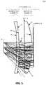
- FIG. 5illustrates an optical system 500 that includes example optical paths of display light that are focused to the eyebox 150 via lens assembly 101 , in accordance with an embodiment of the disclosure.
- Example rays 591 of FIG. 5illustrate that display light emitted from display 105 pass through partially reflective layer 111 and QWP 120 before being reflected by curved reflective polarizer 147 through QWP back to partially reflective layer 111 .
- the display light reflected by partially reflective layer 111passes through QWP 120 , curved reflective polarizer 147 , and the refractive material of second optical element 140 before encountering eyebox area 150 .
- these types of optical systemscan work for a range of display panel sizes between 1.4′′ and 2.5′′ diagonal, for a VR field of view of at least 85 degrees along the horizontal side (nasal to temporal). If the panel size is much smaller than 1.4′′ diagonal, performance may degrade, and the optical system may not be able to support a large enough eye-box and/or field of view. If the panel size is much bigger than 2.5′′ diagonal, a flat reflective polarizer layer may suffice to provide satisfactory performance.
- processing logicin this disclosure may include one or more processors, microprocessors, multi-core processors, Application-specific integrated circuits (ASIC), and/or Field Programmable Gate Arrays (FPGAs) to execute operations disclosed herein.
- memoriesare integrated into the processing logic to store instructions to execute operations and/or store data.
- Processing logicmay also include analog or digital circuitry to perform the operations in accordance with embodiments of the disclosure.
- a “memory” or “memories” described in this disclosuremay include one or more volatile or non-volatile memory architectures.
- the “memory” or “memories”may be removable and non-removable media implemented in any method or technology for storage of information such as computer-readable instructions, data structures, program modules, or other data.
- Example memory technologiesmay include RAM, ROM, EEPROM, flash memory, CD-ROM, digital versatile disks (DVD), high-definition multimedia/data storage disks, or other optical storage, magnetic cassettes, magnetic tape, magnetic disk storage or other magnetic storage devices, or any other non-transmission medium that can be used to store information for access by a computing device.
- a computing devicemay include a desktop computer, a laptop computer, a tablet, a phablet, a smartphone, a feature phone, a server computer, or otherwise.
- a server computermay be located remotely in a data center or be stored locally.
- Embodiments of the inventionmay include or be implemented in conjunction with an artificial reality system.
- Artificial realityis a form of reality that has been adjusted in some manner before presentation to a user, which may include, e.g., a virtual reality (VR), an augmented reality (AR), a mixed reality (MR), a hybrid reality, or some combination and/or derivatives thereof.
- Artificial reality contentmay include completely generated content or generated content combined with captured (e.g., real-world) content.
- the artificial reality contentmay include video, audio, haptic feedback, or some combination thereof, and any of which may be presented in a single channel or in multiple channels (such as stereo video that produces a three-dimensional effect to the viewer).
- artificial realitymay also be associated with applications, products, accessories, services, or some combination thereof, that are used to, e.g., create content in an artificial reality and/or are otherwise used in (e.g., perform activities in) an artificial reality.
- the artificial reality system that provides the artificial reality contentmay be implemented on various platforms, including a head-mounted display (HMD) connected to a host computer system, a standalone HMD, a mobile device or computing system, or any other hardware platform capable of providing artificial reality content to one or more viewers.
- HMDhead-mounted display
Landscapes
- Physics & Mathematics (AREA)
- General Physics & Mathematics (AREA)
- Optics & Photonics (AREA)
Abstract
Description
Claims (18)
Priority Applications (4)
| Application Number | Priority Date | Filing Date | Title |
|---|---|---|---|
| US16/434,982US11378811B2 (en) | 2018-06-18 | 2019-06-07 | Optical assembly with curved reflective polarizer for head mounted display |
| CN201980035615.9ACN112352184B (en) | 2018-06-18 | 2019-08-12 | Optical assembly with curved reflective polarizer for head-mounted display |
| EP19759053.2AEP3794394A1 (en) | 2018-06-18 | 2019-08-12 | Optical assembly with curved reflective polarizer for head mounted display |
| PCT/IB2019/056840WO2019244141A1 (en) | 2018-06-18 | 2019-08-12 | Optical assembly with curved reflective polarizer for head mounted display |
Applications Claiming Priority (2)
| Application Number | Priority Date | Filing Date | Title |
|---|---|---|---|
| US201862686601P | 2018-06-18 | 2018-06-18 | |
| US16/434,982US11378811B2 (en) | 2018-06-18 | 2019-06-07 | Optical assembly with curved reflective polarizer for head mounted display |
Publications (2)
| Publication Number | Publication Date |
|---|---|
| US20190384070A1 US20190384070A1 (en) | 2019-12-19 |
| US11378811B2true US11378811B2 (en) | 2022-07-05 |
Family
ID=68839866
Family Applications (1)
| Application Number | Title | Priority Date | Filing Date |
|---|---|---|---|
| US16/434,982Active2040-02-22US11378811B2 (en) | 2018-06-18 | 2019-06-07 | Optical assembly with curved reflective polarizer for head mounted display |
Country Status (4)
| Country | Link |
|---|---|
| US (1) | US11378811B2 (en) |
| EP (1) | EP3794394A1 (en) |
| CN (1) | CN112352184B (en) |
| WO (1) | WO2019244141A1 (en) |
Cited By (5)
| Publication number | Priority date | Publication date | Assignee | Title |
|---|---|---|---|---|
| US11619808B1 (en)* | 2018-11-28 | 2023-04-04 | Meta Platforms Technologies, Llc | Display and optical assembly with color-selective effective focal length |
| US20230341697A1 (en)* | 2022-04-21 | 2023-10-26 | Newmax Technology Co., Ltd. | Optical lens assembly and head-mounted electronic device |
| TWI838140B (en)* | 2023-02-24 | 2024-04-01 | 新鉅科技股份有限公司 | Optical lens assembly and head-mounted electronic device |
| TWI890104B (en)* | 2023-07-27 | 2025-07-11 | 大陸商業成光電(深圳)有限公司 | Head-mounted display device and zoomable curved optical device thereof |
| US12399360B1 (en) | 2018-11-01 | 2025-08-26 | Meta Platforms Technologies, Llc | Enabling eye tracking in pancake lens optics |
Families Citing this family (26)
| Publication number | Priority date | Publication date | Assignee | Title |
|---|---|---|---|---|
| US11054622B1 (en)* | 2017-11-20 | 2021-07-06 | Facebook Technologies, Llc | Folded viewing optics with an optical retarder on a simple surface |
| CN112585511A (en)* | 2018-08-14 | 2021-03-30 | 3M创新有限公司 | Optical system |
| US11022784B1 (en) | 2018-08-17 | 2021-06-01 | Facebook Technologies, Llc | Use of folded optics to reduce volume in a virtual-reality system |
| US10861240B1 (en)* | 2018-09-26 | 2020-12-08 | Facebook Technologies, Llc | Virtual pupil camera in head mounted display |
| JP7414561B2 (en)* | 2020-01-31 | 2024-01-16 | キヤノン株式会社 | Image observation device |
| CN114868052B (en)* | 2020-02-06 | 2024-12-03 | 威尔乌集团 | Polarization compensation of wire grid polarizers for head mounted display systems |
| US11656500B2 (en) | 2020-06-10 | 2023-05-23 | Meta Platforms Technologies, Llc | Switchable multilayer cholesteric liquid crystal reflective polarizer |
| JP7480013B2 (en)* | 2020-10-12 | 2024-05-09 | 株式会社ジャパンディスプレイ | Display device |
| JP7500386B2 (en)* | 2020-10-12 | 2024-06-17 | 株式会社ジャパンディスプレイ | Display device |
| CN114690415A (en)* | 2020-12-29 | 2022-07-01 | 华为技术有限公司 | Optical module and electronic equipment |
| CN114690414B (en)* | 2020-12-30 | 2025-09-02 | 舜宇光学(浙江)研究院有限公司 | Waveguide-based augmented reality device and method |
| CN117120906A (en)* | 2021-03-30 | 2023-11-24 | 3M创新有限公司 | Optical lens assembly with wide field of view |
| CN113219666A (en)* | 2021-04-30 | 2021-08-06 | 歌尔股份有限公司 | Optical module and head-mounted display device |
| CN113359303B (en)* | 2021-06-28 | 2023-01-24 | 歌尔光学科技有限公司 | Imaging modules and head-mounted display devices |
| CN115576103A (en)* | 2021-07-02 | 2023-01-06 | 广州视享科技有限公司 | Diopter-adjustable optical device and virtual reality display equipment |
| US20230093721A1 (en)* | 2021-09-23 | 2023-03-23 | Valve Corporation | Head-mounted display system with compact optics |
| CN116027551A (en)* | 2021-10-26 | 2023-04-28 | 广州视源电子科技股份有限公司 | Short-focus folding optical system and virtual reality display device |
| TWI805207B (en)* | 2022-01-27 | 2023-06-11 | 國立陽明交通大學 | Pancake lens assembly |
| CN114660803B (en)* | 2022-03-07 | 2024-05-31 | 玩出梦想(上海)科技有限公司 | An under-screen eye tracking system |
| CN114895469B (en)* | 2022-05-19 | 2023-07-25 | 歌尔光学科技有限公司 | Optical modules and head-mounted display devices |
| CN115509022B (en)* | 2022-08-17 | 2024-10-18 | 业成光电(深圳)有限公司 | Folding lens system and method of manufacturing the same |
| TW202409638A (en)* | 2022-08-19 | 2024-03-01 | 大根光學工業股份有限公司 | Optical system and head-mounted device |
| EP4350420A4 (en)* | 2022-08-24 | 2024-11-06 | Samsung Electronics Co., Ltd. | Lens assembly including light-emitting element disposed on first lens, and wearable electronic device including same |
| CN118778241A (en)* | 2023-04-04 | 2024-10-15 | 浙江舜宇光学有限公司 | Visual lens |
| CN117055218A (en)* | 2023-07-27 | 2023-11-14 | 业成科技(成都)有限公司 | Head-mounted display device and zoom type optical device thereof |
| US12436725B2 (en) | 2023-10-25 | 2025-10-07 | Samsung Electronics Co., Ltd. | Display device and electronic device including same |
Citations (6)
| Publication number | Priority date | Publication date | Assignee | Title |
|---|---|---|---|---|
| US5644436A (en) | 1994-03-18 | 1997-07-01 | Olympus Optical Co., Ltd. | Concentric optical system |
| WO2001002893A1 (en) | 1999-07-02 | 2001-01-11 | Koninklijke Philips Electronics N.V. | Head-mounted display |
| US20180039052A1 (en) | 2016-08-02 | 2018-02-08 | Apple Inc. | Optical System for Head-Mounted Display |
| US20180059296A1 (en) | 2015-09-03 | 2018-03-01 | 3M Innovative Properties Company | Head-mounted display |
| US20180239146A1 (en) | 2017-02-23 | 2018-08-23 | Google Llc | Compact eye tracking using folded display optics |
| WO2018211405A2 (en)* | 2017-05-16 | 2018-11-22 | 3M Innovative Properties Company | Optical system |
Family Cites Families (2)
| Publication number | Priority date | Publication date | Assignee | Title |
|---|---|---|---|---|
| US10025060B2 (en)* | 2015-12-08 | 2018-07-17 | Oculus Vr, Llc | Focus adjusting virtual reality headset |
| US10277893B1 (en)* | 2017-06-22 | 2019-04-30 | Facebook Technologies, Llc | Characterization of optical distortion in a head mounted display |
- 2019
- 2019-06-07USUS16/434,982patent/US11378811B2/enactiveActive
- 2019-08-12CNCN201980035615.9Apatent/CN112352184B/ennot_activeExpired - Fee Related
- 2019-08-12WOPCT/IB2019/056840patent/WO2019244141A1/ennot_activeCeased
- 2019-08-12EPEP19759053.2Apatent/EP3794394A1/enactivePending
Patent Citations (8)
| Publication number | Priority date | Publication date | Assignee | Title |
|---|---|---|---|---|
| US5644436A (en) | 1994-03-18 | 1997-07-01 | Olympus Optical Co., Ltd. | Concentric optical system |
| WO2001002893A1 (en) | 1999-07-02 | 2001-01-11 | Koninklijke Philips Electronics N.V. | Head-mounted display |
| US20180059296A1 (en) | 2015-09-03 | 2018-03-01 | 3M Innovative Properties Company | Head-mounted display |
| US9952371B2 (en) | 2015-09-03 | 2018-04-24 | 3M Innovative Properties Company | Convex multilayer reflective polarizer |
| US20180039052A1 (en) | 2016-08-02 | 2018-02-08 | Apple Inc. | Optical System for Head-Mounted Display |
| US20180239146A1 (en) | 2017-02-23 | 2018-08-23 | Google Llc | Compact eye tracking using folded display optics |
| WO2018211405A2 (en)* | 2017-05-16 | 2018-11-22 | 3M Innovative Properties Company | Optical system |
| US20200081234A1 (en)* | 2017-05-16 | 2020-03-12 | 3M Innovative Properties Company | Optical system |
Non-Patent Citations (5)
| Title |
|---|
| Dereniak et al., Geometrical and Trigonometric Optics, Chapter 11, 38 pages, published 2008 (Year: 2008).* |
| First Office Action dated Jan. 25, 2022 for Chinese Patent Application No. 201980035615.9, filed Aug. 12, 2019, 22 pages. |
| International Preliminary Report on Patentability for International Application No. PCT/IB2019/056840, dated Dec. 30, 2020, 9 Pages. |
| International Searching Authority, Patent Cooperation Treaty, European Application No. PCT/IB2019/056840, dated Nov. 15, 2019, 7 pages. |
| Patent Cooperation Treaty, International Search Report, European Application No. PCT/IB2019/056840, dated Nov. 15, 2019, 3 pages. |
Cited By (5)
| Publication number | Priority date | Publication date | Assignee | Title |
|---|---|---|---|---|
| US12399360B1 (en) | 2018-11-01 | 2025-08-26 | Meta Platforms Technologies, Llc | Enabling eye tracking in pancake lens optics |
| US11619808B1 (en)* | 2018-11-28 | 2023-04-04 | Meta Platforms Technologies, Llc | Display and optical assembly with color-selective effective focal length |
| US20230341697A1 (en)* | 2022-04-21 | 2023-10-26 | Newmax Technology Co., Ltd. | Optical lens assembly and head-mounted electronic device |
| TWI838140B (en)* | 2023-02-24 | 2024-04-01 | 新鉅科技股份有限公司 | Optical lens assembly and head-mounted electronic device |
| TWI890104B (en)* | 2023-07-27 | 2025-07-11 | 大陸商業成光電(深圳)有限公司 | Head-mounted display device and zoomable curved optical device thereof |
Also Published As
| Publication number | Publication date |
|---|---|
| US20190384070A1 (en) | 2019-12-19 |
| CN112352184A (en) | 2021-02-09 |
| CN112352184B (en) | 2022-12-27 |
| EP3794394A1 (en) | 2021-03-24 |
| WO2019244141A1 (en) | 2019-12-26 |
Similar Documents
| Publication | Publication Date | Title |
|---|---|---|
| US11378811B2 (en) | Optical assembly with curved reflective polarizer for head mounted display | |
| US10670861B2 (en) | Optical assembly with waveplate configuration for ghost image reduction | |
| US12140741B2 (en) | Optical system for head-mounted display | |
| US9897811B2 (en) | Curved eyepiece with color correction for head wearable display | |
| US8760765B2 (en) | Optical beam tilt for offset head mounted display | |
| CN110268301B (en) | Optical system for head-mounted display | |
| US8767305B2 (en) | Method and apparatus for a near-to-eye display | |
| US8867139B2 (en) | Dual axis internal optical beam tilt for eyepiece of an HMD | |
| US9915823B1 (en) | Lightguide optical combiner for head wearable display | |
| US9389422B1 (en) | Eyepiece for head wearable display using partial and total internal reflections | |
| US11604351B1 (en) | Field bias optical element for digital projector | |
| US11703709B1 (en) | Optical element with linear polarizer | |
| US20240045128A1 (en) | Lens Assembly Including Wave Plate | |
| TW202505260A (en) | Head-mounted display device and zoomable curved optical device thereof |
Legal Events
| Date | Code | Title | Description |
|---|---|---|---|
| FEPP | Fee payment procedure | Free format text:ENTITY STATUS SET TO UNDISCOUNTED (ORIGINAL EVENT CODE: BIG.); ENTITY STATUS OF PATENT OWNER: LARGE ENTITY | |
| STPP | Information on status: patent application and granting procedure in general | Free format text:DOCKETED NEW CASE - READY FOR EXAMINATION | |
| AS | Assignment | Owner name:FACEBOOK TECHNOLOGIES, LLC, CALIFORNIA Free format text:ASSIGNMENT OF ASSIGNORS INTEREST;ASSIGNORS:GENG, YING;GOLLIER, JACQUES;SULAI, YUSUFU NJONI BAMAXAM;AND OTHERS;SIGNING DATES FROM 20191108 TO 20191206;REEL/FRAME:051318/0290 | |
| STPP | Information on status: patent application and granting procedure in general | Free format text:NON FINAL ACTION MAILED | |
| STPP | Information on status: patent application and granting procedure in general | Free format text:RESPONSE TO NON-FINAL OFFICE ACTION ENTERED AND FORWARDED TO EXAMINER | |
| STPP | Information on status: patent application and granting procedure in general | Free format text:FINAL REJECTION MAILED | |
| STPP | Information on status: patent application and granting procedure in general | Free format text:DOCKETED NEW CASE - READY FOR EXAMINATION | |
| STPP | Information on status: patent application and granting procedure in general | Free format text:NOTICE OF ALLOWANCE MAILED -- APPLICATION RECEIVED IN OFFICE OF PUBLICATIONS | |
| STPP | Information on status: patent application and granting procedure in general | Free format text:AWAITING TC RESP., ISSUE FEE NOT PAID | |
| STPP | Information on status: patent application and granting procedure in general | Free format text:NOTICE OF ALLOWANCE MAILED -- APPLICATION RECEIVED IN OFFICE OF PUBLICATIONS | |
| STCB | Information on status: application discontinuation | Free format text:ABANDONED -- FAILURE TO PAY ISSUE FEE | |
| AS | Assignment | Owner name:META PLATFORMS TECHNOLOGIES, LLC, CALIFORNIA Free format text:CHANGE OF NAME;ASSIGNOR:FACEBOOK TECHNOLOGIES, LLC;REEL/FRAME:060246/0845 Effective date:20220318 | |
| STPP | Information on status: patent application and granting procedure in general | Free format text:PUBLICATIONS -- ISSUE FEE PAYMENT VERIFIED | |
| STCF | Information on status: patent grant | Free format text:PATENTED CASE |