US11376409B2 - Hub component for vented connector - Google Patents
Hub component for vented connectorDownload PDFInfo
- Publication number
- US11376409B2 US11376409B2US16/132,331US201816132331AUS11376409B2US 11376409 B2US11376409 B2US 11376409B2US 201816132331 AUS201816132331 AUS 201816132331AUS 11376409 B2US11376409 B2US 11376409B2
- Authority
- US
- United States
- Prior art keywords
- fingers
- component
- hub
- receiver
- connector
- Prior art date
- Legal status (The legal status is an assumption and is not a legal conclusion. Google has not performed a legal analysis and makes no representation as to the accuracy of the status listed.)
- Active, expires
Links
- CURLTUGMZLYLDI-UHFFFAOYSA-NCarbon dioxideChemical compoundO=C=OCURLTUGMZLYLDI-UHFFFAOYSA-N0.000claimsabstractdescription17
- 229910002092carbon dioxideInorganic materials0.000claimsabstractdescription11
- 239000001569carbon dioxideSubstances0.000claimsabstractdescription11
- 230000008878couplingEffects0.000claimsdescription63
- 238000010168coupling processMethods0.000claimsdescription63
- 238000005859coupling reactionMethods0.000claimsdescription63
- 239000012530fluidSubstances0.000claimsdescription18
- 230000002496gastric effectEffects0.000claimsdescription7
- 238000012546transferMethods0.000claimsdescription4
- 239000007793ph indicatorSubstances0.000claimsdescription3
- 235000016709nutritionNutrition0.000claimsdescription2
- 238000004891communicationMethods0.000description5
- 238000000926separation methodMethods0.000description4
- 230000000295complement effectEffects0.000description3
- 238000013461designMethods0.000description2
- 238000013022ventingMethods0.000description2
- 238000007792additionMethods0.000description1
- 239000000853adhesiveSubstances0.000description1
- 230000001070adhesive effectEffects0.000description1
- 230000006837decompressionEffects0.000description1
- 238000012217deletionMethods0.000description1
- 230000037430deletionEffects0.000description1
- 238000006073displacement reactionMethods0.000description1
- 210000003736gastrointestinal contentAnatomy0.000description1
- 230000005484gravityEffects0.000description1
- 230000002452interceptive effectEffects0.000description1
- 230000001788irregularEffects0.000description1
- 238000005259measurementMethods0.000description1
- 238000000034methodMethods0.000description1
- 238000012986modificationMethods0.000description1
- 230000004048modificationEffects0.000description1
- 230000037361pathwayEffects0.000description1
- 230000002572peristaltic effectEffects0.000description1
- 230000002265preventionEffects0.000description1
- 238000009423ventilationMethods0.000description1
Images


Classifications
- A—HUMAN NECESSITIES
- A61—MEDICAL OR VETERINARY SCIENCE; HYGIENE
- A61J—CONTAINERS SPECIALLY ADAPTED FOR MEDICAL OR PHARMACEUTICAL PURPOSES; DEVICES OR METHODS SPECIALLY ADAPTED FOR BRINGING PHARMACEUTICAL PRODUCTS INTO PARTICULAR PHYSICAL OR ADMINISTERING FORMS; DEVICES FOR ADMINISTERING FOOD OR MEDICINES ORALLY; BABY COMFORTERS; DEVICES FOR RECEIVING SPITTLE
- A61J15/00—Feeding-tubes for therapeutic purposes
- A61J15/0026—Parts, details or accessories for feeding-tubes
- A61J15/0096—Provisions for venting
- A—HUMAN NECESSITIES
- A61—MEDICAL OR VETERINARY SCIENCE; HYGIENE
- A61M—DEVICES FOR INTRODUCING MEDIA INTO, OR ONTO, THE BODY; DEVICES FOR TRANSDUCING BODY MEDIA OR FOR TAKING MEDIA FROM THE BODY; DEVICES FOR PRODUCING OR ENDING SLEEP OR STUPOR
- A61M39/00—Tubes, tube connectors, tube couplings, valves, access sites or the like, specially adapted for medical use
- A61M39/10—Tube connectors; Tube couplings
- A—HUMAN NECESSITIES
- A61—MEDICAL OR VETERINARY SCIENCE; HYGIENE
- A61J—CONTAINERS SPECIALLY ADAPTED FOR MEDICAL OR PHARMACEUTICAL PURPOSES; DEVICES OR METHODS SPECIALLY ADAPTED FOR BRINGING PHARMACEUTICAL PRODUCTS INTO PARTICULAR PHYSICAL OR ADMINISTERING FORMS; DEVICES FOR ADMINISTERING FOOD OR MEDICINES ORALLY; BABY COMFORTERS; DEVICES FOR RECEIVING SPITTLE
- A61J1/00—Containers specially adapted for medical or pharmaceutical purposes
- A61J1/14—Details; Accessories therefor
- A61J1/20—Arrangements for transferring or mixing fluids, e.g. from vial to syringe
- A61J1/2003—Accessories used in combination with means for transfer or mixing of fluids, e.g. for activating fluid flow, separating fluids, filtering fluid or venting
- A61J1/2048—Connecting means
- A61J1/2055—Connecting means having gripping means
- A—HUMAN NECESSITIES
- A61—MEDICAL OR VETERINARY SCIENCE; HYGIENE
- A61J—CONTAINERS SPECIALLY ADAPTED FOR MEDICAL OR PHARMACEUTICAL PURPOSES; DEVICES OR METHODS SPECIALLY ADAPTED FOR BRINGING PHARMACEUTICAL PRODUCTS INTO PARTICULAR PHYSICAL OR ADMINISTERING FORMS; DEVICES FOR ADMINISTERING FOOD OR MEDICINES ORALLY; BABY COMFORTERS; DEVICES FOR RECEIVING SPITTLE
- A61J1/00—Containers specially adapted for medical or pharmaceutical purposes
- A61J1/14—Details; Accessories therefor
- A61J1/20—Arrangements for transferring or mixing fluids, e.g. from vial to syringe
- A61J1/2003—Accessories used in combination with means for transfer or mixing of fluids, e.g. for activating fluid flow, separating fluids, filtering fluid or venting
- A61J1/2068—Venting means
- A61J1/2075—Venting means for external venting
- A—HUMAN NECESSITIES
- A61—MEDICAL OR VETERINARY SCIENCE; HYGIENE
- A61J—CONTAINERS SPECIALLY ADAPTED FOR MEDICAL OR PHARMACEUTICAL PURPOSES; DEVICES OR METHODS SPECIALLY ADAPTED FOR BRINGING PHARMACEUTICAL PRODUCTS INTO PARTICULAR PHYSICAL OR ADMINISTERING FORMS; DEVICES FOR ADMINISTERING FOOD OR MEDICINES ORALLY; BABY COMFORTERS; DEVICES FOR RECEIVING SPITTLE
- A61J1/00—Containers specially adapted for medical or pharmaceutical purposes
- A61J1/14—Details; Accessories therefor
- A61J1/20—Arrangements for transferring or mixing fluids, e.g. from vial to syringe
- A61J1/2096—Combination of a vial and a syringe for transferring or mixing their contents
- A—HUMAN NECESSITIES
- A61—MEDICAL OR VETERINARY SCIENCE; HYGIENE
- A61J—CONTAINERS SPECIALLY ADAPTED FOR MEDICAL OR PHARMACEUTICAL PURPOSES; DEVICES OR METHODS SPECIALLY ADAPTED FOR BRINGING PHARMACEUTICAL PRODUCTS INTO PARTICULAR PHYSICAL OR ADMINISTERING FORMS; DEVICES FOR ADMINISTERING FOOD OR MEDICINES ORALLY; BABY COMFORTERS; DEVICES FOR RECEIVING SPITTLE
- A61J15/00—Feeding-tubes for therapeutic purposes
- A61J15/0026—Parts, details or accessories for feeding-tubes
- A61J15/008—Sensor means, e.g. for sensing reflux, acidity or pressure
- A61J15/0084—Sensor means, e.g. for sensing reflux, acidity or pressure for sensing parameters related to the patient
- A—HUMAN NECESSITIES
- A61—MEDICAL OR VETERINARY SCIENCE; HYGIENE
- A61M—DEVICES FOR INTRODUCING MEDIA INTO, OR ONTO, THE BODY; DEVICES FOR TRANSDUCING BODY MEDIA OR FOR TAKING MEDIA FROM THE BODY; DEVICES FOR PRODUCING OR ENDING SLEEP OR STUPOR
- A61M39/00—Tubes, tube connectors, tube couplings, valves, access sites or the like, specially adapted for medical use
- A61M39/10—Tube connectors; Tube couplings
- A61M39/1011—Locking means for securing connection; Additional tamper safeties
- A—HUMAN NECESSITIES
- A61—MEDICAL OR VETERINARY SCIENCE; HYGIENE
- A61M—DEVICES FOR INTRODUCING MEDIA INTO, OR ONTO, THE BODY; DEVICES FOR TRANSDUCING BODY MEDIA OR FOR TAKING MEDIA FROM THE BODY; DEVICES FOR PRODUCING OR ENDING SLEEP OR STUPOR
- A61M39/00—Tubes, tube connectors, tube couplings, valves, access sites or the like, specially adapted for medical use
- A61M39/20—Closure caps or plugs for connectors or open ends of tubes
- A—HUMAN NECESSITIES
- A61—MEDICAL OR VETERINARY SCIENCE; HYGIENE
- A61J—CONTAINERS SPECIALLY ADAPTED FOR MEDICAL OR PHARMACEUTICAL PURPOSES; DEVICES OR METHODS SPECIALLY ADAPTED FOR BRINGING PHARMACEUTICAL PRODUCTS INTO PARTICULAR PHYSICAL OR ADMINISTERING FORMS; DEVICES FOR ADMINISTERING FOOD OR MEDICINES ORALLY; BABY COMFORTERS; DEVICES FOR RECEIVING SPITTLE
- A61J1/00—Containers specially adapted for medical or pharmaceutical purposes
- A61J1/14—Details; Accessories therefor
- A61J1/1412—Containers with closing means, e.g. caps
- A61J1/1425—Snap-fit type
- A—HUMAN NECESSITIES
- A61—MEDICAL OR VETERINARY SCIENCE; HYGIENE
- A61J—CONTAINERS SPECIALLY ADAPTED FOR MEDICAL OR PHARMACEUTICAL PURPOSES; DEVICES OR METHODS SPECIALLY ADAPTED FOR BRINGING PHARMACEUTICAL PRODUCTS INTO PARTICULAR PHYSICAL OR ADMINISTERING FORMS; DEVICES FOR ADMINISTERING FOOD OR MEDICINES ORALLY; BABY COMFORTERS; DEVICES FOR RECEIVING SPITTLE
- A61J1/00—Containers specially adapted for medical or pharmaceutical purposes
- A61J1/14—Details; Accessories therefor
- A61J1/1475—Inlet or outlet ports
- A61J1/1481—Inlet or outlet ports with connection retaining means, e.g. thread or snap-fit
- A—HUMAN NECESSITIES
- A61—MEDICAL OR VETERINARY SCIENCE; HYGIENE
- A61J—CONTAINERS SPECIALLY ADAPTED FOR MEDICAL OR PHARMACEUTICAL PURPOSES; DEVICES OR METHODS SPECIALLY ADAPTED FOR BRINGING PHARMACEUTICAL PRODUCTS INTO PARTICULAR PHYSICAL OR ADMINISTERING FORMS; DEVICES FOR ADMINISTERING FOOD OR MEDICINES ORALLY; BABY COMFORTERS; DEVICES FOR RECEIVING SPITTLE
- A61J2200/00—General characteristics or adaptations
- A61J2200/70—Device provided with specific sensor or indicating means
- A—HUMAN NECESSITIES
- A61—MEDICAL OR VETERINARY SCIENCE; HYGIENE
- A61M—DEVICES FOR INTRODUCING MEDIA INTO, OR ONTO, THE BODY; DEVICES FOR TRANSDUCING BODY MEDIA OR FOR TAKING MEDIA FROM THE BODY; DEVICES FOR PRODUCING OR ENDING SLEEP OR STUPOR
- A61M39/00—Tubes, tube connectors, tube couplings, valves, access sites or the like, specially adapted for medical use
- A61M39/10—Tube connectors; Tube couplings
- A61M2039/1027—Quick-acting type connectors
- A—HUMAN NECESSITIES
- A61—MEDICAL OR VETERINARY SCIENCE; HYGIENE
- A61M—DEVICES FOR INTRODUCING MEDIA INTO, OR ONTO, THE BODY; DEVICES FOR TRANSDUCING BODY MEDIA OR FOR TAKING MEDIA FROM THE BODY; DEVICES FOR PRODUCING OR ENDING SLEEP OR STUPOR
- A61M39/00—Tubes, tube connectors, tube couplings, valves, access sites or the like, specially adapted for medical use
- A61M39/10—Tube connectors; Tube couplings
- A61M2039/1033—Swivel nut connectors, e.g. threaded connectors, bayonet-connectors
- A—HUMAN NECESSITIES
- A61—MEDICAL OR VETERINARY SCIENCE; HYGIENE
- A61M—DEVICES FOR INTRODUCING MEDIA INTO, OR ONTO, THE BODY; DEVICES FOR TRANSDUCING BODY MEDIA OR FOR TAKING MEDIA FROM THE BODY; DEVICES FOR PRODUCING OR ENDING SLEEP OR STUPOR
- A61M39/00—Tubes, tube connectors, tube couplings, valves, access sites or the like, specially adapted for medical use
- A61M39/20—Closure caps or plugs for connectors or open ends of tubes
- A61M2039/205—Closure caps or plugs for connectors or open ends of tubes comprising air venting means
- A—HUMAN NECESSITIES
- A61—MEDICAL OR VETERINARY SCIENCE; HYGIENE
- A61M—DEVICES FOR INTRODUCING MEDIA INTO, OR ONTO, THE BODY; DEVICES FOR TRANSDUCING BODY MEDIA OR FOR TAKING MEDIA FROM THE BODY; DEVICES FOR PRODUCING OR ENDING SLEEP OR STUPOR
- A61M2202/00—Special media to be introduced, removed or treated
- A61M2202/04—Liquids
- A61M2202/0468—Liquids non-physiological
- A61M2202/0482—Enteral feeding product
- A—HUMAN NECESSITIES
- A61—MEDICAL OR VETERINARY SCIENCE; HYGIENE
- A61M—DEVICES FOR INTRODUCING MEDIA INTO, OR ONTO, THE BODY; DEVICES FOR TRANSDUCING BODY MEDIA OR FOR TAKING MEDIA FROM THE BODY; DEVICES FOR PRODUCING OR ENDING SLEEP OR STUPOR
- A61M2230/00—Measuring parameters of the user
- A61M2230/20—Blood composition characteristics
- A61M2230/208—Blood composition characteristics pH-value
- A—HUMAN NECESSITIES
- A61—MEDICAL OR VETERINARY SCIENCE; HYGIENE
- A61M—DEVICES FOR INTRODUCING MEDIA INTO, OR ONTO, THE BODY; DEVICES FOR TRANSDUCING BODY MEDIA OR FOR TAKING MEDIA FROM THE BODY; DEVICES FOR PRODUCING OR ENDING SLEEP OR STUPOR
- A61M2230/00—Measuring parameters of the user
- A61M2230/40—Respiratory characteristics
- A61M2230/43—Composition of exhalation
- A61M2230/432—Composition of exhalation partial CO2 pressure (P-CO2)
Definitions
- the present inventionrelates generally to medical devices, and more particularly to connectors and couplings and other components for vessels for fluids in the medical field.
- the present inventionrelates to a hub component for connection with a vented connector.
- the inventionrelates to a hub component including a generally elongate body, a coupling portion formed at the first end, one or more elongate fingers formed at the second end, and a receiver defined within a portion of the body between the first and second ends.
- the elongate bodyhas a first end and a second end defining a length therebetween, and a lumen extending through the body from the first end to the second end.
- an outer surface of the one or more fingersinclude at least one engagement member formed thereon.
- the receiveris configured for coupling complementary engagement with a connector-receiving portion of a connector.
- the connector-receiving portionincludes a male hub.
- the male hubincludes a male ISO 80369-3 compatible coupling and the receiver includes a female ISO 80369-3 compatible coupling.
- the connector-receiving portionfurther includes an outer cylindrical collar surrounding the male hub and defines an annular space therebetween, the outer cylindrical collar having an endwall defining one or more vents, wherein the one or more fingers are configured for extension through the one or more vents when the receiver is connected with the male hub.
- an outer surface of the one or more fingersinclude an engagement member configured for engagement with the endwall of the collar when the male hub is connected with the receiver of the elongate body.
- the one or more fingersinclude a pair of opposing fingers defining a pair of elongate channels therebetween.
- the one or more fingersinclude a circular array of four space-apart fingers, wherein at least one of the four fingers comprises an engagement member extending from an outer surface thereof.
- a first pair of fingers and a second pair of fingersincluding at least one engagement member formed on an outer surface thereof at a first height and the second pair of fingers comprising at least one engagement member formed on an outer surface thereof at a second height, wherein the first height is not identical to the second height.
- the length of the elongate bodyis between about 5-200 millimeters.
- the hub componentfurther includes a lumen extension tip formed with the receiver.
- the coupling portionis configured for connection with a sensor or detector.
- the sensor or detectorcan be a carbon dioxide detector, a pH indicator or other sensor or detector so as to ensure proper gastric placement of a feeding tube.
- the inventionin another aspect, relates to a component for coupling engagement with a vented connector.
- the vented connectorincludes a body having a lumen extending therethrough and defining a vessel-attaching portion and a component-attaching portion, the component-attaching portion including a cylindrical collar surrounding the body and having an endwall having one or more vents.
- the componentincludes a cylindrical body, a coupling portion defined at the first end, at least one clip defined at the second end, and a receiver formed within the cylindrical body between the first and second ends.
- the at least one clipis configured for passing through the one or more vents so as to permit the body of component-attaching portion to engage with the receiver.
- the cylindrical bodyextends from a first end to a generally opposite second end, and a lumen extends through the body from the first end to the second end.
- the body of the component-attaching portioncomprises a male hub, the male hub being formatted to be compatible with the ISO 80369-3 design standard, and wherein the receiver is formatted to be compatible with the ISO 80369-3 design standard so as to provide complementary interengagement between the component and the vented connector.
- an outer surface of the at least one clipcomprises an engagement member having an engagement surface, the engagement surface configured for interfering with the endwall of the cylindrical collar when the receiver is connected with the body of the component-attaching portion.
- the second end of the cylindrical bodyincludes at least two fingers, wherein one of the at least two fingers includes an engagement member formed on an outer surface thereof and positioned at a first height and wherein the other of the at least two fingers includes an engagement member formed on an outer surface thereof and positioned at a second height.
- the componentcan be configured for connecting with the vented connector in either of a vented configuration or a sealed configuration, wherein in the vented configuration the engagement member positioned at the first height is engaged with the endwall so as to provide at least some space between in inner surface of the receiver and an outer surface of the body of the vented connector, and wherein in the sealed configuration the engagement member positioned at the second height is engaged with the endwall so as to provide a sealed, interference fit between the inner surface of the receiver and an outer surface of the body of the vented connector.
- the inventionin yet another aspect, relates to a component for coupling engagement with nutritional or medicinal fluid transfer systems or components.
- the componentincludes an elongate body extending between a first end and a second end and defining a lumen extending therethrough.
- the first endincludes a coupling portion and the second end includes one or more fingers.
- a receiveris formed in the elongate body between the first and second ends, wherein the receiver includes an inner surface for compatible engagement with a male hub.
- the coupling portion of the second endis configured for coupling engagement with another medical device, component, vessel, detector or sensor.
- the detectoris capable of determining the presence of carbon dioxide and/or measuring the acidity of a fluid.
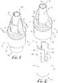
- FIG. 1shows a perspective view of a hub component according to an example embodiment of the present invention, the hub component connected with a known vented connector for medical fluid vessels.
- FIG. 2shows a perspective assembly view of the hub component of FIG. 1 , wherein the hub component and the vented connector are disassembled and spaced apart from each other.
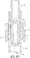
- FIG. 3shows a cross-sectional view of the disassembled hub component and vented connector of FIG. 2 .
- FIG. 4shows a cross-sectional view of the hub component connected with the vented connector of FIG. 1 taken along line 4 - 4 .
- FIG. 5shows a perspective view of a hub component according to another example embodiment of the present invention.
- FIG. 6shows a perspective view of a hub component according to another example embodiment of the present invention, showing the hub component connected with a known vented connector for medical fluid vessels.
- FIG. 7shows a perspective view of a hub component connected with a vented connector according to another example embodiment of the present invention.
- FIG. 8shows a perspective assembly view of the hub component and vented connector of FIG. 7 , wherein the hub component and vented connector are spaced apart and disconnected from each other.
- FIG. 9shows a cross-sectional assembly view of a hub component and a vented connector according to another example embodiment of the present invention.
- FIG. 10shows a cross-sectional view of the hub component and vented connector of FIG. 9 connected together.
- FIG. 11shows a perspective view of a hub component according to another example embodiment of the present invention, the hub component being tethered to a vented connector and wherein a closure is further tethered to the vented connector.
- FIGS. 1-2show a hub connector or component 10 according to an example embodiment of the present invention.
- the component 10is configured for connecting with a connector 60 .
- the connector 60comprises a vessel-attaching portion 61 defining a rear end 63 , a coupling-attaching portion 62 defining a front end 64 , and a central member or conduit 70 defining a lumen 72 extending longitudinally therethrough from end to end.
- the vessel-attaching portion 61attaches to (e.g., receives and secures) the vessel and secures it in place with a good seal by conventional structures such as crimps or adhesives so that the vessel extends longitudinally from the rear end.
- the vesselis generally a tube, though the term “vessel” is intended to be broadly construed to include any carrier or container for a fluid as well as any fluid-delivery device, and as such in other embodiments the vessel is a catheter, hose, feeding tube, bottle, bag, syringe, pump, or the like.
- the vessel-attaching portion 61defines a receiver or connecting portion 76 (that is configured for receiving a feeding tube or the like).
- the connecting portion 76can be configured as desired, for example, such that a vessel can be permanently coupled therewith.
- the vesselcan optionally be removably coupled therewith.
- the component 10 of the present inventionis configured for connection with the coupling-attaching portion 62 of the connector 60 .
- the coupling-attaching portion 62comprises a male hub 74 (comprising the lumen 72 extending therethrough), and a cylindrical collar 80 extending around the entirety thereof and comprising threads 82 formed on an inside or interior surface thereof.
- the connector 60is vented to provide for fluid drainage and airflow ventilation.
- an endwall 81 of the cylindrical collar 80 of the connector 60comprises at least one vent opening 84 (e.g., two, as depicted) providing fluid communication between an annular space defined generally near the coupling-attaching portion (e.g., between an interior surface of the collar 80 and an outer surface of the male hub 74 ) and external to the annular space.
- U.S. Published Patent Application US 2016/0067471, Ser. No. 14/844,956is incorporated herein by reference in its entirety and discloses a vented connector comprising a vessel-attaching portion defining a rear end, a coupling-attaching portion defining a front end, a lumen extending longitudinally therethrough from end to end, and at least one vent opening.
- two connecting portions 86fix together the conduit 70 (and male hub 74 ) with the cylindrical collar 80 so as to axially align the conduit 70 with the cylindrical collar 80 .
- the component 10is configured for engagement with the coupling-attaching portion 62 of the connector 60 .
- the component 10is configured for providing an interference fit with the male hub 74 .
- the component 10comprises a generally cylindrical body 16 extending between a first end 12 and a second end 14 (defining a length L therebetween), and defines a lumen 18 extending entirely through the body 16 from end to end.
- the second end 14comprises at least one elongate member or finger 20 and the first end 12 comprises a coupling 50 (as will be described below).
- FIG. 1depicted in FIG.
- the length L of the component 10is between about 12-35 millimeters, for example, between about 20-30 millimeters according to one example embodiment, and for example, between about 23-26 millimeters according to another example embodiment. In alternate example embodiments, the length L can be chosen as desired, for example, between about 5-200 millimeters.
- the second end of the cylindrical body 16comprises a pair of opposing radial clips or fingers 20 comprising a slot or channel 22 defined between the sides of the fingers 20 .
- the fingers 20are configured for passing through a pair of vents 84 formed in the endwall 81 of the coupling-attaching portion 62 of the connector 60 , for example, wherein one or more outer protrusions or engagement members 30 pass beyond the endwall 81 so as to provide engagement with the same.
- the fingers 20are generally sized and shaped to extend through the pair of vents 84 , for example, which are generally in the form of curved slots.
- the pair of fingers 20comprise a cross-section that is shaped to pass through the curved slots.
- the fingerscan comprise a desired cross-section, and for example, the cross-section of the fingers can be sized and shaped to generally fit within the shape of the vents 84 , for example, in the case that the vents are generally curved or sized and shaped as desired, or for example, wherein one or more vents are shaped to be cylindrical, oval, linear and/or non-linear channels, irregular, or otherwise shaped as desired.
- the channels 22 that are defined between the fingers 20are preferably sized and shaped so as to receive the connecting portions 86 when the fingers 20 extend through the vents 84 .
- the channels 22are generally linear and rectangular in shape, and comprising a curved or radiused lower portion.
- the channels 22can preferably be shaped and sized as desired, for example, such that they are capable of receiving the connecting portions 86 .
- the channelscan be generally non-linear or substantially helical so as to define one or more helical fingers.
- the fingers and the channelsare generally helical.
- an external surface 24 of the fingers 20comprise the engagement members 30 defined thereon, which are generally sized and shaped to permit the assembly and engagement thereof, however, disconnecting the component 10 from the connector 60 is generally prevented until manipulation of the fingers 20 .
- pressing inwardly on the fingers 20disengages the engagement members 30 from the endwall 81 such that the fingers 20 (and engagement members 30 extending therefrom) are provided with sufficient clearance to pass through the vents 84 , thereby permitting disconnection of the component 10 from the connector 60 .
- a lower engagement surface 31 of the engagement members 30engages with the endwall 81 of the connector-attaching portion 60 while a receiver 40 within the body 16 of the component 10 provides for an interference fit with the male hub 74 of the connector-attaching portion 62 .
- the lower engagement surface 31 of the engagement members 30extends outwardly from an exterior surface 24 of the fingers 20 by about 0.22 millimeters.
- the outer surface 24 of the fingers 20is spaced apart from an outer wall of the vents 84 by about 0.125 millimeters, for example, such that about 0.1 millimeters of interference is defined between the engagement surface 31 and the endwall 81 .
- an inner surface 26 of the fingers 20are generally spaced about 0.61 millimeters from an outer surface of the body 70 .
- the fingerscomprise about 0.61 millimeters of allowable deflection or displacement so as to allow disengagement of the engagement surface 31 and the endwall 81 to permit full separation of the component 10 from the connector 60 .
- the extension of the engagement surface, the interference with the endwall 81 , spacing relative to the vent wall and the bodycan preferably be configured as desired, for example, to comprise more or less extension, interference, spacing, etc.
- the engagement surface 31 and the endwall 81can comprise between about 0.05-5 millimeters of interference when fully assembled.
- the engagement members 30 and the endwall 81can be configured for providing a permanent connection, for example, such that the component 10 and connector 60 are prevented from separation after being connected together.
- the fingers 20each comprise a pair of spaced-apart engagement members comprising the engagement surface 31 .
- the engagement members 30are generally ramped or wedge-shaped, or for example, oriented to project from the outer surface 24 to define the lower engagement surface and an angled surface extending from the engagement surface 31 and back into the outer surface 24 .
- the engagement members 30can be in the form of one or more protrusions, projections, outwardly-extending members(s), nubs, teeth, or other members or engagement couplings that are configured for coupling engagement with the endwall 81 of the connector.
- the connector 60can comprise one or more projections and the engagement members can be in the form of one or more recesses or otherwise receivers for engagement with the projections of the connector 60 .
- one or more complementary interengagement features, male/female couplings, protrusions, receivers, stop surfaces, or other engagement featurescan be provided for providing engagement of the fingers 20 with the connector 60 , for example, the fingers with the vents 84 .
- the fingers 20are free from engagement members 30 .
- the connector-attaching portion 62 and at least the receiver 40 of the component 10are formatted to be ISO 80369-3 compatible, or for example, where the male hub 74 comprises a non-luer ENFit male compatible coupling and the receiver 40 comprises a female ENFit compatible coupling.
- the connector-attaching portion 62 and the male hub 74can be formatted as desired.
- the body 16comprises an inner surface 26 defined along the fingers 20 , and an inner surface 42 is defined along an interior of the receiver 40 .
- the male hub 74sealingly engages with the receiver 40 such that a friction-fit connection is provided therebetween.
- the inner surface 42 of the receiver 40is dimensioned to comprise a first diameter a second diameter X 2 that is spaced a distance from the first diameter X 1 , and a third diameter X 3 that is defining the opening size of the lumen 18 .
- the first diameter X 1is about 5.6 millimeters
- the second diameter X 2is about 5.4 millimeters
- the third diameter X 3is about 3.2 millimeters
- the first diameter X 1can be between about 2-10 millimeters
- the second diameter X 2can be between about 2-10 millimeters
- the third diametercan be between about 2-10 millimeters.
- the first diameter X 1is about 5.625 millimeters.
- the first, second and third diameters X 1 , X 2 and X 3can preferably be sized as desired.
- the receiver 40is configured to provide an interference fit with the male hub 74 of the connector-attaching portion 62 .
- the receiver 40can be configured for providing a clearance fit with the male hub 74 such that a minimal amount of interference is provided therebetween.
- a minimal seal or substantially no seal at allis provided therebetween.
- the coupling portion 50 of the first end 12 of the component 10can be configured for coupling engagement with a plurality of components, or for example, can be configured for housing one or more components and for allowing fluid communication with the one or more components with the lumen 18 (and lumen 72 of the male hub 74 when coupled thereto).
- one or more componentscan be housed within a portion of the component 10 (and in fluid communication with the lumen 18 ) while still providing a coupling portion 50 , or for example, comprising a connector or other coupling member for receiving one or more other components, connectors, vessels, or other components as desired.
- the second end 12 of the component 10is configured for compatible engagement with a sensor or measuring device, for example, a carbon dioxide (CO 2 ) sensor or detector.
- a sensor or measuring devicefor example, a carbon dioxide (CO 2 ) sensor or detector.
- CO 2carbon dioxide
- the receiver 40is coupled with the male hub 74 and the coupling portion 50 receives a CO 2 detector, for example, by engaging an inner and/or outer surface 52 , 54 thereof, or for example, by otherwise coupling with the first end 12 of the component 10 .
- the coupling portion 50comprises a receiver 51 defining the inner surface 52 , and the outer surface 54 is generally provided on an exterior portion thereof.
- the outer surface 54 of the first enddefines a diameter D of about 8.4 millimeters,
- the diameter Dcan be between about 0.25 millimeters to about 35 millimeters, or for example, the diameter D can be chosen as desired.
- the CO 2 detector(or a portion thereof) can be coupled (and sealingly engaged) with the inner surface 52 , the outer surface 54 , an end surface between the inner and outer surfaces 52 , 54 , or can otherwise be sealingly engaged therewith.
- the first end 12 (and coupling portion 50 ) of the component 10can be a vessel, a vessel from a tube set from a gravity fed bag, a vessel from a tube set connecting to a syringe, a vessel from a tube set connected to a peristaltic pump, a male ISO 80369-3 compatible connector (e.g., generally similar to male hub 74 ), a bifurcated med port connector (ISO 80369-3), a male slip fit ISO 80369-3 compatible connector, a funnel connector, a small vessel for residual collection, a port and/or reservoir for venting (gastric decompression), and/or any other desirable connector or coupling including Luer, non-luer, Nutrisafe 2, reverse Luer, neuraxial, ISO 80369-3 female compatible connector, etc.
- a male ISO 80369-3 compatible connectore.g., generally similar to male hub 74
- ISO 80369-3bifurcated med port connector
- the first end 12 of the component 10can be configured for coupling to other feeding systems, couplings or other available enteral feeding components or connectors.
- the coupling portion 50can be configured for coupling engagement with one or more sensors, couplings, connectors, vessels, measurement devices, other feeding systems, couplings or other available enteral feeding components or connectors.
- a CO 2 detectoris configured for engagement with the coupling portion 50 to ensure proper gastric placement.
- the coupling portion 50comprises two or more couplings, for example, such that one or more sensors and/or detectors or other components can be in fluid communication with the lumen 18 (and lumen 72 of the connector 60 ) while permitting fluid transfer through the lumen 18 (and lumen 72 ) to one of the other couplings.
- the coupling portion 50comprises a connector or other coupling member for connection with a feeding tube set or other fluid delivery conduit or device, and a separate coupling portion is provided at the first end 12 for connecting with a sensor or detector.
- the componentcomprises a pH indicator or strip housed therein, and which is in fluid communication with the lumen of the component 10 and connector 60 , for example, such that fluids present within the lumen communicate with the strip.
- the pH stripcan be utilized to indicate the pH level of a patient's stomach contents, and thus, provide an indication of proper gastric placement of the feeding tube or vessel.
- FIG. 5shows a hub component 100 according to another example embodiment of the present invention.
- the component 100is generally similar to the component 10 as described above, for example, comprising a body 116 extending between a first end 112 and a second end 114 , at least one finger 120 at the second end 114 , and a coupling portion 150 at the first end 112 .
- the second end 114comprises four fingers 120 having a curved or radial cross-section for passing through the vents 84 , for example, wherein each of the four fingers 120 each comprise engagement members 130 (defining engagement surfaces 131 ) for independently providing engagement with the endwall 81 of the connector.
- the fingers 120are generally spaced apart to define a circular or radial-like array wherein channels 122 are defined therebetween. In example embodiments, two of the channels 122 are sized for receiving the connecting members 86 of the connector 60 . In example embodiments, to disconnect and fully separate the component 100 from the connector 60 , all four of the fingers 120 are displaced or flexed inwardly to disengage the engagement surfaces 31 from the endwall 81 .
- FIG. 6shows a component 200 connected with the connector 60 according to another example embodiment.
- the component 200is generally similar to the component 100 as described above.
- the componentcomprises a first pair of fingers 220 and a second pair of fingers 221 .
- the fingers 220comprise engagement members 230 protruding therefrom and positioned at a first height
- the fingers 221comprise engagement members 230 positioned at a second height.
- the height difference of the engagement members 230preferably allows for varying level of engagement with the connector. For example, as depicted in FIG.
- the engagement members 230 of the second pair of fingers 221are engaged with the endwall 81 whereby the receiver (not shown) is provided with an interference fit with the male hub 74 of the connector.
- at least some separation of the receiver and male hubcan be provided by disengaging the engagement members of the fingers 221 so that the engagement members 230 of the fingers 220 engage the endwall 81 .
- the engagement of the component 200 with the connector 60can vary.
- the engagement members 230 of the fingers 220when the engagement members 230 of the fingers 220 are engaged with the endwall 81 , at least some spacing is provided between the receiver and male hub (e.g., permitting at least some venting). However, when the engagement members 230 of the fingers 221 are engaged with the endwall 81 , the receiver and the male hub are substantially engaged to provide a sealed; interference fit.
- the component 100can be at least partially separated from the connector until the engagement members 230 of the first set of fingers 220 engage with the endwall 81 , thereby providing at least some clearance between the interior surface of the receiver of the component and an outer surface of the male hub, thereby providing a vented connection.
- the hub componentcan be configured for removable engagement with the connector-attaching portion of the vented connector, for example, in either a vented configuration or an interference or sealed configuration depending on which of the fingers 220 , 221 are engaged with the endwall 81 of the connector 60 .
- FIGS. 7-8shows a hub component 300 for compatible engagement with a vented connector 160 according to another example embodiment of the present invention.
- the component 300 and connector 160are preferably removably engageable with each other, for example, similar to a bayonet fitting.
- the component 300is generally similar to the components as described above and comprises a second end comprising a pair of opposing fingers 320 comprising engagement members 330 protruding outwardly therefrom, and wherein a channel 322 is defined between the fingers 320 .
- the connector 160is generally similar to the connector 60 as described above, however, a channeled engagement track or pathway is provided with the connector 160 so as to permit a rotational/clipped engagement with the fingers 320 of the component 300 , for example, which is generally similar to a bayonet fitting.
- the collar 180comprises the endwall 181 (as described above) and comprises an elongate entrance channel 182 a , a radial track 182 b extending from the channel 182 a , and a coupling recess or catch 182 c defined at an end of the radial track 182 b .
- the component 300is connected with the connector 160 by moving the fingers through the vents 184 (with the engagement members 330 aligned with the channel 182 a ), and rotating the component 300 such that the engagement surface 231 of the engagement member 230 rides along the radial track 182 b until the engagement member 330 is fitted within the catch 182 c .
- the component 300is engaged with the connector 160 (and with the receiver providing an interference fit with the male hub).
- the fingers 320are pressed or deflected inwardly (see arrow of FIG. 7 ) until the engagement members 330 are free from engagement with the catch 182 c , and then the component 300 is rotated such that the engagement surface 331 rides along the radial track 182 b until reaching the channel 182 a .
- the engagement members 330are then free to pass through the channel 182 a thereby permitting full separation of the component 300 from the connector 160 .
- the channel 182 acan extend entirely along an internal portion of the collar 180 , for example, wherein at least a portion of the threads defined on an internal portion of the collar can be slotted or comprise a groove or recess.
- FIGS. 9-10show a hub component 400 according to another example embodiment of the present invention.
- the component 400is generally similar to the component 10 as described above.
- the receiver 440further comprises a dosing control coupling or lumen extension tip 480 projecting in a direction generally opposite the coupling portion 450 .
- an annular space 444is defined between an inner surface 442 of the receiver an outer or external surface of the lumen extension tip 480 .
- FIG. 11shows a connector assembly 500 comprising a vented connector 502 , a hub component 504 , and a closure or cap 506 .
- the component 504 and the cap 506are connected to the connector 502 by a tether or connecting member 510 .
- a user or cliniciancan readily access either of the component 504 or the cap 506 as desired.
- one or more additional components, connectors or other closurescan be tethered to the connector 502 as desired.
- the hub component 504can be connected with the connector 502 , and then the cap 506 can be connected to the coupling portion of the component 504 , for example, to provide a closure or seal at the coupling portion.
- a cliniciancan sealingly engage the hub component to the connector and sealingly engage a CO 2 detector to the second end of the hub component to ensure proper gastric placement of the tube or vessel extending from the connector.
- the hub componentcan be coupled with the connector in the vented configuration, for example, such that air or gasses are permitted to pass through the vessel, through the lumen of the male coupling, and through the at least partially spaced-apart or offset surfaces of the hub component and male coupling while keeping the male coupling (and lumen thereof) substantially covered and clean or sanitary.
- the one or more fingersdo not comprise any ribs or surface features, and thus rely on a friction fit with the male coupling of the vented connector.
- one or more ribs or surface features of the one or more fingerscan be configured to provide for a substantially permanent connection, for example, to be used in applications where tamper evidence or re-use prevention is desirable.
Landscapes
- Health & Medical Sciences (AREA)
- Life Sciences & Earth Sciences (AREA)
- Animal Behavior & Ethology (AREA)
- General Health & Medical Sciences (AREA)
- Public Health (AREA)
- Veterinary Medicine (AREA)
- Heart & Thoracic Surgery (AREA)
- Pharmacology & Pharmacy (AREA)
- Engineering & Computer Science (AREA)
- Anesthesiology (AREA)
- Biomedical Technology (AREA)
- Hematology (AREA)
- Pulmonology (AREA)
- Physics & Mathematics (AREA)
- Fluid Mechanics (AREA)
- Infusion, Injection, And Reservoir Apparatuses (AREA)
Abstract
Description
Claims (14)
Priority Applications (3)
| Application Number | Priority Date | Filing Date | Title |
|---|---|---|---|
| US16/132,331US11376409B2 (en) | 2014-09-08 | 2018-09-14 | Hub component for vented connector |
| US17/826,508US12337134B2 (en) | 2014-09-08 | 2022-05-27 | Hub component for vented connector |
| US19/029,500US20250170383A1 (en) | 2014-09-08 | 2025-01-17 | Hub component for vented connector |
Applications Claiming Priority (5)
| Application Number | Priority Date | Filing Date | Title |
|---|---|---|---|
| US201462047389P | 2014-09-08 | 2014-09-08 | |
| US201562192614P | 2015-07-15 | 2015-07-15 | |
| US14/844,956US10668263B2 (en) | 2014-09-08 | 2015-09-03 | Vented connector for medical fluid vessels |
| US201762559006P | 2017-09-15 | 2017-09-15 | |
| US16/132,331US11376409B2 (en) | 2014-09-08 | 2018-09-14 | Hub component for vented connector |
Related Parent Applications (1)
| Application Number | Title | Priority Date | Filing Date |
|---|---|---|---|
| US14/844,956Continuation-In-PartUS10668263B2 (en) | 2014-09-08 | 2015-09-03 | Vented connector for medical fluid vessels |
Related Child Applications (1)
| Application Number | Title | Priority Date | Filing Date |
|---|---|---|---|
| US17/826,508DivisionUS12337134B2 (en) | 2014-09-08 | 2022-05-27 | Hub component for vented connector |
Publications (2)
| Publication Number | Publication Date |
|---|---|
| US20190030312A1 US20190030312A1 (en) | 2019-01-31 |
| US11376409B2true US11376409B2 (en) | 2022-07-05 |
Family
ID=65138523
Family Applications (3)
| Application Number | Title | Priority Date | Filing Date |
|---|---|---|---|
| US16/132,331Active2035-11-02US11376409B2 (en) | 2014-09-08 | 2018-09-14 | Hub component for vented connector |
| US17/826,508Active2036-07-08US12337134B2 (en) | 2014-09-08 | 2022-05-27 | Hub component for vented connector |
| US19/029,500PendingUS20250170383A1 (en) | 2014-09-08 | 2025-01-17 | Hub component for vented connector |
Family Applications After (2)
| Application Number | Title | Priority Date | Filing Date |
|---|---|---|---|
| US17/826,508Active2036-07-08US12337134B2 (en) | 2014-09-08 | 2022-05-27 | Hub component for vented connector |
| US19/029,500PendingUS20250170383A1 (en) | 2014-09-08 | 2025-01-17 | Hub component for vented connector |
Country Status (1)
| Country | Link |
|---|---|
| US (3) | US11376409B2 (en) |
Cited By (1)
| Publication number | Priority date | Publication date | Assignee | Title |
|---|---|---|---|---|
| USD996613S1 (en)* | 2018-08-31 | 2023-08-22 | Carefusion 303, Inc. | Intravenous priming cap |
Families Citing this family (8)
| Publication number | Priority date | Publication date | Assignee | Title |
|---|---|---|---|---|
| USD747471S1 (en)* | 2012-08-10 | 2016-01-12 | Fisher & Paykel Healthcare Limited | Connector |
| KR101862929B1 (en)* | 2016-09-23 | 2018-05-31 | 사회복지법인 삼성생명공익재단 | The guider for separating tube |
| US11147956B2 (en)* | 2018-06-21 | 2021-10-19 | Becton, Dickinson And Company | Enteral syringe with vented collar |
| US12220544B2 (en) | 2020-07-31 | 2025-02-11 | Avent, Inc. | Airway detection using ultrasound |
| US12036063B2 (en) | 2020-07-31 | 2024-07-16 | Avent, Inc. | Airway detection using acoustic signals |
| JP7724123B2 (en)* | 2020-10-22 | 2025-08-15 | 株式会社ジェイ・エム・エス | Male connector cover |
| WO2022085594A1 (en)* | 2020-10-22 | 2022-04-28 | 株式会社ジェイ・エム・エス | Cover for male connector |
| USD999369S1 (en)* | 2021-06-09 | 2023-09-19 | Zevex, Inc. | In-line occluder |
Citations (20)
| Publication number | Priority date | Publication date | Assignee | Title |
|---|---|---|---|---|
| US4214586A (en) | 1978-11-30 | 1980-07-29 | Ethicon, Inc. | Anastomotic coupling device |
| EP0453264A1 (en) | 1990-04-17 | 1991-10-23 | Lynn, Lawrence A. | Medical connector |
| US5782808A (en)* | 1994-02-14 | 1998-07-21 | Fresenius Usa, Inc. | Antibacterial medical tubing connector |
| US5830195A (en)* | 1994-02-17 | 1998-11-03 | Clinical Product Development Limited | Couplings for medical cannulae |
| WO1999064103A1 (en) | 1998-06-08 | 1999-12-16 | Qd Enterprises, Llc | Safety indexed medical connectors |
| US6183465B1 (en) | 1999-09-01 | 2001-02-06 | Sherwood Services, Ag | Adapter for a feeding system |
| US20050261664A1 (en)* | 2004-03-18 | 2005-11-24 | Rome Guy T | Multifunction adaptor for an open-ended catheter |
| WO2006052655A2 (en) | 2004-11-05 | 2006-05-18 | Icu Medical, Inc. | Soft-grip medical connector |
| US7080672B2 (en)* | 2002-08-22 | 2006-07-25 | Sherwood Services Ag | Sliding seal adapter for a feeding system |
| US20110144481A1 (en)* | 2008-08-28 | 2011-06-16 | Koninklijke Philips Electronics N.V. | A device, apparatus and method for obtaining physiological signals by way of a feeding tube |
| US20110270230A1 (en)* | 2010-04-29 | 2011-11-03 | Medtronic, Inc. | Catheter connectors and systems, and methods of using same |
| US20120022457A1 (en) | 2010-07-23 | 2012-01-26 | Medela Holding Ag | Enteral Feeding Connector and Assembly |
| US8652104B2 (en) | 2010-06-25 | 2014-02-18 | Smiths Medical Asd, Inc. | Catheter assembly with seal member |
| US20140276652A1 (en) | 2013-03-15 | 2014-09-18 | Cook Medical Technologies Llc | Catheter attachment mechanism |
| US8852168B2 (en) | 2005-06-20 | 2014-10-07 | C. R. Bard, Inc. | Connection system for multi-lumen catheter |
| US8915883B2 (en) | 2008-05-28 | 2014-12-23 | Poly Medicure Ltd. | Catheter introducer |
| US20150297839A1 (en) | 2014-04-21 | 2015-10-22 | Becton Dickinson and Company Limited | System for Closed Transfer of Fluids and Membrane Arrangements for Use Thereof |
| US20160089528A1 (en) | 2014-09-25 | 2016-03-31 | Covidien Lp | Enteral feeding connector |
| US20160206516A1 (en)* | 2013-09-06 | 2016-07-21 | Jms Co., Ltd. | Double male connector |
| US20180071169A1 (en) | 2015-03-24 | 2018-03-15 | Neomed, Inc. | Oral administration coupler for back-of-mouth delivery |
Family Cites Families (69)
| Publication number | Priority date | Publication date | Assignee | Title |
|---|---|---|---|---|
| US2872060A (en) | 1955-11-08 | 1959-02-03 | Brune Herbert | Hollow stopper for bottles, tubes or the like, or artificial material, preferably polyethylene |
| US3057502A (en) | 1957-04-24 | 1962-10-09 | Permuta Closures Ltd | Stoppers |
| US3307552A (en) | 1963-03-25 | 1967-03-07 | Lillian T Strawn | Catheter plug and shield device |
| US3339772A (en) | 1964-11-16 | 1967-09-05 | Formold Plastics Inc | Container cap |
| FR2115111B1 (en) | 1970-11-26 | 1975-09-26 | Bouchage Mecanique | |
| US4230231A (en) | 1979-04-16 | 1980-10-28 | Coulter Electronics, Inc. | Closure cap |
| US4237935A (en) | 1978-12-14 | 1980-12-09 | Eaton Corporation | Hydraulic pressure relief valve and fluid isolator |
| US4349024A (en) | 1981-04-01 | 1982-09-14 | Ralston Jr Philip G | Multiple adapter device for interconnecting tubing of different sizes |
| US4416273A (en) | 1981-06-15 | 1983-11-22 | Grimes Jerry L | Connector valve assembly for endotracheal tubes |
| US4417890A (en) | 1981-08-17 | 1983-11-29 | Baxter Travenol Laboratories, Inc. | Antibacterial closure |
| US4597758A (en) | 1982-09-21 | 1986-07-01 | Baxter Travenol Laboratories, Inc. | Sealing closure for a Luer fitting in open communication with a pressurized liquid supply |
| US4573602A (en) | 1984-07-10 | 1986-03-04 | Goldberg James R | Molded safety closure device and method for making same |
| US4904238A (en) | 1987-12-21 | 1990-02-27 | Alcon Laboratories, Inc. | Irrigation/aspiration handpiece |
| US4963132A (en) | 1988-11-11 | 1990-10-16 | Gibson Roger M | Capped fluidic connector |
| US4994068A (en) | 1989-11-24 | 1991-02-19 | Unidex, Inc. | Combination sterile pad support and lancet containing lancet disposal element |
| US5184742A (en) | 1990-06-18 | 1993-02-09 | Boc Health Care, Inc. | Deadender cap for luer fitting |
| US5385372A (en) | 1993-01-08 | 1995-01-31 | Utterberg; David S. | Luer connector with integral closure |
| US5401255A (en) | 1993-07-20 | 1995-03-28 | Baxter International Inc. | Multi-functional valve with unitary valving member and improved safety |
| US5591344A (en) | 1995-02-13 | 1997-01-07 | Aksys, Ltd. | Hot water disinfection of dialysis machines, including the extracorporeal circuit thereof |
| JPH0977105A (en) | 1995-09-06 | 1997-03-25 | Sanshu:Kk | Closure construction for opening of bottle |
| WO1997022535A1 (en) | 1995-12-15 | 1997-06-26 | Medisystems Technology Corporation | Medical connector with integral closure |
| US5813554A (en) | 1996-09-13 | 1998-09-29 | Diseno Industrial Mago, S.L. | Annular lock |
| US6883778B1 (en) | 1996-11-18 | 2005-04-26 | Nypro Inc. | Apparatus for reducing fluid drawback through a medical valve |
| US5951519A (en) | 1997-04-25 | 1999-09-14 | Dsu Medical Corporation | Aseptic female connector |
| FR2784033B1 (en) | 1998-10-01 | 2000-12-22 | Marc Brunel | SINGLE USE INJECTION DEVICE FOR PRE-FILLED |
| CA2345439C (en) | 1998-10-29 | 2005-08-09 | Minimed, Inc. | Compact pump drive system |
| US20020173748A1 (en) | 1998-10-29 | 2002-11-21 | Mcconnell Susan | Reservoir connector |
| US6595971B1 (en) | 1999-07-28 | 2003-07-22 | Zassi Medical Evolutions, Inc. | Ostomy irrigation system |
| USD463546S1 (en) | 1999-10-14 | 2002-09-24 | Becton Dickinson And Company | Drug container holder |
| US6808521B1 (en) | 1999-11-18 | 2004-10-26 | Kimberly-Clark Worldwide, Inc. | Enteral feeding adapter |
| US6632199B1 (en) | 2000-05-23 | 2003-10-14 | Becton Dickinson And Company | Syringe assembly including plastic tip cap |
| US7077829B2 (en) | 2001-01-09 | 2006-07-18 | Rex Medical, L.P. | Dialysis catheter |
| US6745998B2 (en) | 2001-08-10 | 2004-06-08 | Alaris Medical Systems, Inc. | Valved male luer |
| GB2379253B (en) | 2001-09-04 | 2005-09-14 | Clinical Product Dev Ltd | Couplings for medical fluid delivery systems |
| JP4287273B2 (en) | 2001-09-24 | 2009-07-01 | アプライド メディカル リソーシーズ コーポレイション | Bladeless obturator |
| USD473646S1 (en) | 2001-12-21 | 2003-04-22 | Microsurgical Technology, Inc. | Irrigation/aspiration instrument connector |
| GB0229870D0 (en) | 2002-12-21 | 2003-01-29 | Intersurgical Ltd | Improvements relating to closure devices |
| US8932264B2 (en) | 2003-08-11 | 2015-01-13 | Becton, Dickinson And Company | Medication delivery pen assembly with needle locking safety shield |
| US20050124935A1 (en) | 2003-12-05 | 2005-06-09 | Kimberly-Clark Worldwide, Inc. | Venting adapter for feeding device |
| WO2006013796A1 (en) | 2004-08-04 | 2006-02-09 | Olympus Corporation | Plug body for endoscope |
| US20060060202A1 (en) | 2004-09-21 | 2006-03-23 | Flynn Daniel P | Gastric tube placement indicator |
| US9895526B2 (en) | 2006-03-08 | 2018-02-20 | Ivaxis, Llc | Anti-contamination cover for fluid connections |
| DE102006041414A1 (en) | 2006-09-04 | 2008-03-06 | Fresenius Kabi Deutschland Gmbh | Multipurpose connector for enteral application |
| US20080103486A1 (en) | 2006-10-26 | 2008-05-01 | Troy Jean-Luc Owens | SafeFeed Adapter |
| US8066670B2 (en) | 2006-11-06 | 2011-11-29 | Becton, Dickinson And Company | Vascular access device septum venting |
| US20080128646A1 (en) | 2006-12-05 | 2008-06-05 | Humitek, Inc. | Splines and caps for fluid ports |
| US8523831B2 (en) | 2009-10-30 | 2013-09-03 | Catheter Connections, Inc. | Disinfecting caps having sealing features and related systems and methods |
| US8523830B2 (en) | 2007-01-16 | 2013-09-03 | Catheter Connections | Disinfecting caps for medical female luer connectors |
| US20080183153A1 (en) | 2007-01-31 | 2008-07-31 | Benlan, Inc. | Enteral Feeding Tube Connector |
| GB2453361A (en) | 2007-10-04 | 2009-04-08 | Smith & Nephew | A cap member for sealing an open orifice |
| US20090182309A1 (en) | 2008-01-11 | 2009-07-16 | Dartmouth-Hitchcock Clinic | Medical fluid coupling port with guide for reduction of contamination |
| DE102009016373A1 (en) | 2009-04-07 | 2010-10-21 | V. KRÜTTEN MEDIZINISCHE EINMALGERÄTE GmbH | Connector for the probe tube of an enteral feeding tube and assembly of an enteral feeding tube and an enteral transfer system |
| DE202009005077U1 (en) | 2009-07-28 | 2010-12-23 | Fa. Hans Jürgen Hopf | Connection system for fluid connections |
| US20110240162A1 (en) | 2010-04-06 | 2011-10-06 | Zeyfang Rederick W | Vented end cap for medical tube |
| WO2011156521A2 (en) | 2010-06-08 | 2011-12-15 | Dotted Intellectual Property, Llc | Connector assembly |
| USD665497S1 (en) | 2010-07-28 | 2012-08-14 | Owen Mumford Limited | Torque limiting needle cap |
| ES2682651T3 (en)* | 2010-08-10 | 2018-09-21 | Medical Components, Inc. | Clamp Clamp Lock |
| US8491535B2 (en) | 2011-04-28 | 2013-07-23 | Becton, Dickinson And Company | Safety pen needle assembly |
| US9867975B2 (en) | 2011-05-23 | 2018-01-16 | Excelsior Medical Corporation | Antiseptic line cap |
| US20120323221A1 (en) | 2011-06-20 | 2012-12-20 | Med-Systems, Inc. | Adapter Cap and Nasal Washing System Using the Cap |
| EP2583715A1 (en) | 2011-10-19 | 2013-04-24 | Unomedical A/S | Infusion tube system and method for manufacture |
| USD737436S1 (en) | 2012-02-13 | 2015-08-25 | Medimop Medical Projects Ltd. | Liquid drug reconstitution assembly |
| US9308362B2 (en) | 2013-03-12 | 2016-04-12 | Carefusion 303, Inc. | Male luer with fluid path and vent path seals |
| US9814871B2 (en) | 2013-03-15 | 2017-11-14 | Bayer Healthcare Llc | Connector assembly for syringe system |
| EP2826508A1 (en) | 2013-07-18 | 2015-01-21 | Becton Dickinson France | A tip cap and an injection device having a distal tip sealed by a tip cap |
| USD736906S1 (en) | 2014-01-28 | 2015-08-18 | Joseph P. Schultz | Nasal-irrigation cap |
| EP3191166B1 (en) | 2014-09-08 | 2019-11-20 | Neomed, Inc. | Vented connector for medical fluid vessels |
| US9604046B2 (en) | 2014-11-03 | 2017-03-28 | Nordson Corporation | Protective caps for use with medical fluid fittings, and related methods |
| AU2016294538B2 (en) | 2015-07-14 | 2020-04-02 | Neomed, Inc. | Dosing control coupling for enteral fluid transfer |
- 2018
- 2018-09-14USUS16/132,331patent/US11376409B2/enactiveActive
- 2022
- 2022-05-27USUS17/826,508patent/US12337134B2/enactiveActive
- 2025
- 2025-01-17USUS19/029,500patent/US20250170383A1/enactivePending
Patent Citations (23)
| Publication number | Priority date | Publication date | Assignee | Title |
|---|---|---|---|---|
| US4214586A (en) | 1978-11-30 | 1980-07-29 | Ethicon, Inc. | Anastomotic coupling device |
| EP0453264A1 (en) | 1990-04-17 | 1991-10-23 | Lynn, Lawrence A. | Medical connector |
| US5782808A (en)* | 1994-02-14 | 1998-07-21 | Fresenius Usa, Inc. | Antibacterial medical tubing connector |
| US5830195A (en)* | 1994-02-17 | 1998-11-03 | Clinical Product Development Limited | Couplings for medical cannulae |
| WO1999064103A1 (en) | 1998-06-08 | 1999-12-16 | Qd Enterprises, Llc | Safety indexed medical connectors |
| US6183465B1 (en) | 1999-09-01 | 2001-02-06 | Sherwood Services, Ag | Adapter for a feeding system |
| US7080672B2 (en)* | 2002-08-22 | 2006-07-25 | Sherwood Services Ag | Sliding seal adapter for a feeding system |
| US20050261664A1 (en)* | 2004-03-18 | 2005-11-24 | Rome Guy T | Multifunction adaptor for an open-ended catheter |
| US7578803B2 (en)* | 2004-03-18 | 2009-08-25 | C. R. Bard, Inc. | Multifunction adaptor for an open-ended catheter |
| WO2006052655A2 (en) | 2004-11-05 | 2006-05-18 | Icu Medical, Inc. | Soft-grip medical connector |
| US8852168B2 (en) | 2005-06-20 | 2014-10-07 | C. R. Bard, Inc. | Connection system for multi-lumen catheter |
| US8915883B2 (en) | 2008-05-28 | 2014-12-23 | Poly Medicure Ltd. | Catheter introducer |
| US20110144481A1 (en)* | 2008-08-28 | 2011-06-16 | Koninklijke Philips Electronics N.V. | A device, apparatus and method for obtaining physiological signals by way of a feeding tube |
| US20110270230A1 (en)* | 2010-04-29 | 2011-11-03 | Medtronic, Inc. | Catheter connectors and systems, and methods of using same |
| US8652104B2 (en) | 2010-06-25 | 2014-02-18 | Smiths Medical Asd, Inc. | Catheter assembly with seal member |
| US9399116B2 (en) | 2010-06-25 | 2016-07-26 | Smiths Medical Asd, Inc. | Method of making catheter assembly with seal member |
| US20160296724A1 (en) | 2010-06-25 | 2016-10-13 | Smiths Medical Asd, Inc. | Method of making catheter assembly with seal member |
| US20120022457A1 (en) | 2010-07-23 | 2012-01-26 | Medela Holding Ag | Enteral Feeding Connector and Assembly |
| US20140276652A1 (en) | 2013-03-15 | 2014-09-18 | Cook Medical Technologies Llc | Catheter attachment mechanism |
| US20160206516A1 (en)* | 2013-09-06 | 2016-07-21 | Jms Co., Ltd. | Double male connector |
| US20150297839A1 (en) | 2014-04-21 | 2015-10-22 | Becton Dickinson and Company Limited | System for Closed Transfer of Fluids and Membrane Arrangements for Use Thereof |
| US20160089528A1 (en) | 2014-09-25 | 2016-03-31 | Covidien Lp | Enteral feeding connector |
| US20180071169A1 (en) | 2015-03-24 | 2018-03-15 | Neomed, Inc. | Oral administration coupler for back-of-mouth delivery |
Non-Patent Citations (1)
| Title |
|---|
| International Application No. PCT/US2018/051248, International Search Report and Written Opinion dated Mar. 13, 2019, 11 pages. |
Cited By (1)
| Publication number | Priority date | Publication date | Assignee | Title |
|---|---|---|---|---|
| USD996613S1 (en)* | 2018-08-31 | 2023-08-22 | Carefusion 303, Inc. | Intravenous priming cap |
Also Published As
| Publication number | Publication date |
|---|---|
| US12337134B2 (en) | 2025-06-24 |
| US20190030312A1 (en) | 2019-01-31 |
| US20250170383A1 (en) | 2025-05-29 |
| US20220280766A1 (en) | 2022-09-08 |
Similar Documents
| Publication | Publication Date | Title |
|---|---|---|
| US12337134B2 (en) | Hub component for vented connector | |
| US11986617B2 (en) | Vented connector for medical fluid vessels | |
| US20240374479A1 (en) | Adapter assembly for enteral feeding | |
| US10773067B2 (en) | Enteral connectors having coupling features | |
| CA2563620C (en) | Dual purpose adapter | |
| US10004889B2 (en) | Enteral feeding connector and assembly | |
| AU2009202621B2 (en) | Discriminating oral tip adaptor | |
| CA2704900C (en) | Female adaptor for feeding line | |
| CA2988747C (en) | Enteral feeding syringe assembly | |
| US20250161653A1 (en) | Vented connector for medical fluid vessels and tapered plug | |
| AU2018347862A1 (en) | Hub component for vented connector |
Legal Events
| Date | Code | Title | Description |
|---|---|---|---|
| FEPP | Fee payment procedure | Free format text:ENTITY STATUS SET TO UNDISCOUNTED (ORIGINAL EVENT CODE: BIG.); ENTITY STATUS OF PATENT OWNER: LARGE ENTITY | |
| FEPP | Fee payment procedure | Free format text:ENTITY STATUS SET TO SMALL (ORIGINAL EVENT CODE: SMAL); ENTITY STATUS OF PATENT OWNER: LARGE ENTITY | |
| STPP | Information on status: patent application and granting procedure in general | Free format text:DOCKETED NEW CASE - READY FOR EXAMINATION | |
| AS | Assignment | Owner name:CITIBANK, N.A., NEW YORK Free format text:SECURITY INTEREST;ASSIGNOR:NEOMED, INC.;REEL/FRAME:050320/0673 Effective date:20190830 | |
| STPP | Information on status: patent application and granting procedure in general | Free format text:NON FINAL ACTION MAILED | |
| AS | Assignment | Owner name:NEOMED, INC., GEORGIA Free format text:ASSIGNMENT OF ASSIGNORS INTEREST;ASSIGNORS:DAVIS, BENJAMIN M.;DOORNBOS, DAVID A.;REEL/FRAME:052685/0058 Effective date:20200403 | |
| STPP | Information on status: patent application and granting procedure in general | Free format text:RESPONSE TO NON-FINAL OFFICE ACTION ENTERED AND FORWARDED TO EXAMINER | |
| STPP | Information on status: patent application and granting procedure in general | Free format text:RESPONSE TO NON-FINAL OFFICE ACTION ENTERED AND FORWARDED TO EXAMINER | |
| STPP | Information on status: patent application and granting procedure in general | Free format text:FINAL REJECTION MAILED | |
| STPP | Information on status: patent application and granting procedure in general | Free format text:RESPONSE AFTER FINAL ACTION FORWARDED TO EXAMINER | |
| STPP | Information on status: patent application and granting procedure in general | Free format text:ADVISORY ACTION MAILED | |
| FEPP | Fee payment procedure | Free format text:ENTITY STATUS SET TO UNDISCOUNTED (ORIGINAL EVENT CODE: BIG.); ENTITY STATUS OF PATENT OWNER: LARGE ENTITY | |
| STPP | Information on status: patent application and granting procedure in general | Free format text:DOCKETED NEW CASE - READY FOR EXAMINATION | |
| STPP | Information on status: patent application and granting procedure in general | Free format text:NON FINAL ACTION MAILED | |
| STPP | Information on status: patent application and granting procedure in general | Free format text:RESPONSE TO NON-FINAL OFFICE ACTION ENTERED AND FORWARDED TO EXAMINER | |
| STPP | Information on status: patent application and granting procedure in general | Free format text:FINAL REJECTION MAILED | |
| AS | Assignment | Owner name:AVENT, INC., GEORGIA Free format text:ASSIGNMENT OF ASSIGNORS INTEREST;ASSIGNOR:NEOMED, INC.;REEL/FRAME:059087/0935 Effective date:20200801 | |
| STPP | Information on status: patent application and granting procedure in general | Free format text:NOTICE OF ALLOWANCE MAILED -- APPLICATION RECEIVED IN OFFICE OF PUBLICATIONS | |
| STPP | Information on status: patent application and granting procedure in general | Free format text:PUBLICATIONS -- ISSUE FEE PAYMENT VERIFIED | |
| STCF | Information on status: patent grant | Free format text:PATENTED CASE | |
| AS | Assignment | Owner name:JPMORGAN CHASE BANK, N.A., AS ADMINISTRATIVE AGENT, ILLINOIS Free format text:SECURITY INTEREST;ASSIGNOR:AVENT, INC.;REEL/FRAME:060441/0445 Effective date:20220624 | |
| AS | Assignment | Owner name:AVANOS MEDICAL SALES, LLC, GEORGIA Free format text:RELEASE BY SECURED PARTY;ASSIGNOR:CITIBANK, N.A.;REEL/FRAME:060557/0062 Effective date:20220624 Owner name:AVENT, INC., GEORGIA Free format text:RELEASE BY SECURED PARTY;ASSIGNOR:CITIBANK, N.A.;REEL/FRAME:060557/0062 Effective date:20220624 |