US11375133B2 - Automatic exposure module for an image acquisition system - Google Patents
Automatic exposure module for an image acquisition systemDownload PDFInfo
- Publication number
- US11375133B2 US11375133B2US16/915,987US202016915987AUS11375133B2US 11375133 B2US11375133 B2US 11375133B2US 202016915987 AUS202016915987 AUS 202016915987AUS 11375133 B2US11375133 B2US 11375133B2
- Authority
- US
- United States
- Prior art keywords
- image
- determining
- subject
- light condition
- determined
- Prior art date
- Legal status (The legal status is an assumption and is not a legal conclusion. Google has not performed a legal analysis and makes no representation as to the accuracy of the status listed.)
- Active
Links
Images


Classifications
- G—PHYSICS
- G01—MEASURING; TESTING
- G01S—RADIO DIRECTION-FINDING; RADIO NAVIGATION; DETERMINING DISTANCE OR VELOCITY BY USE OF RADIO WAVES; LOCATING OR PRESENCE-DETECTING BY USE OF THE REFLECTION OR RERADIATION OF RADIO WAVES; ANALOGOUS ARRANGEMENTS USING OTHER WAVES
- G01S11/00—Systems for determining distance or velocity not using reflection or reradiation
- G01S11/12—Systems for determining distance or velocity not using reflection or reradiation using electromagnetic waves other than radio waves
- H—ELECTRICITY
- H04—ELECTRIC COMMUNICATION TECHNIQUE
- H04N—PICTORIAL COMMUNICATION, e.g. TELEVISION
- H04N23/00—Cameras or camera modules comprising electronic image sensors; Control thereof
- H04N23/70—Circuitry for compensating brightness variation in the scene
- H04N23/73—Circuitry for compensating brightness variation in the scene by influencing the exposure time
- H04N5/2353—
- G—PHYSICS
- G01—MEASURING; TESTING
- G01S—RADIO DIRECTION-FINDING; RADIO NAVIGATION; DETERMINING DISTANCE OR VELOCITY BY USE OF RADIO WAVES; LOCATING OR PRESENCE-DETECTING BY USE OF THE REFLECTION OR RERADIATION OF RADIO WAVES; ANALOGOUS ARRANGEMENTS USING OTHER WAVES
- G01S3/00—Direction-finders for determining the direction from which infrasonic, sonic, ultrasonic, or electromagnetic waves, or particle emission, not having a directional significance, are being received
- G—PHYSICS
- G06—COMPUTING OR CALCULATING; COUNTING
- G06V—IMAGE OR VIDEO RECOGNITION OR UNDERSTANDING
- G06V40/00—Recognition of biometric, human-related or animal-related patterns in image or video data
- G06V40/10—Human or animal bodies, e.g. vehicle occupants or pedestrians; Body parts, e.g. hands
- G06V40/18—Eye characteristics, e.g. of the iris
- G06V40/19—Sensors therefor
- H—ELECTRICITY
- H04—ELECTRIC COMMUNICATION TECHNIQUE
- H04N—PICTORIAL COMMUNICATION, e.g. TELEVISION
- H04N23/00—Cameras or camera modules comprising electronic image sensors; Control thereof
- H04N23/60—Control of cameras or camera modules
- H04N23/61—Control of cameras or camera modules based on recognised objects
- H04N23/611—Control of cameras or camera modules based on recognised objects where the recognised objects include parts of the human body
- H—ELECTRICITY
- H04—ELECTRIC COMMUNICATION TECHNIQUE
- H04N—PICTORIAL COMMUNICATION, e.g. TELEVISION
- H04N23/00—Cameras or camera modules comprising electronic image sensors; Control thereof
- H04N23/70—Circuitry for compensating brightness variation in the scene
- H04N23/72—Combination of two or more compensation controls
- H—ELECTRICITY
- H04—ELECTRIC COMMUNICATION TECHNIQUE
- H04N—PICTORIAL COMMUNICATION, e.g. TELEVISION
- H04N23/00—Cameras or camera modules comprising electronic image sensors; Control thereof
- H04N23/70—Circuitry for compensating brightness variation in the scene
- H04N23/74—Circuitry for compensating brightness variation in the scene by influencing the scene brightness using illuminating means
- H—ELECTRICITY
- H04—ELECTRIC COMMUNICATION TECHNIQUE
- H04N—PICTORIAL COMMUNICATION, e.g. TELEVISION
- H04N23/00—Cameras or camera modules comprising electronic image sensors; Control thereof
- H04N23/70—Circuitry for compensating brightness variation in the scene
- H04N23/76—Circuitry for compensating brightness variation in the scene by influencing the image signals
- H04N5/23219—
- H04N5/2352—
- H04N5/2354—
- H04N5/243—
- G—PHYSICS
- G08—SIGNALLING
- G08B—SIGNALLING OR CALLING SYSTEMS; ORDER TELEGRAPHS; ALARM SYSTEMS
- G08B13/00—Burglar, theft or intruder alarms
- G08B13/18—Actuation by interference with heat, light, or radiation of shorter wavelength; Actuation by intruding sources of heat, light, or radiation of shorter wavelength
- G08B13/189—Actuation by interference with heat, light, or radiation of shorter wavelength; Actuation by intruding sources of heat, light, or radiation of shorter wavelength using passive radiation detection systems
- G08B13/194—Actuation by interference with heat, light, or radiation of shorter wavelength; Actuation by intruding sources of heat, light, or radiation of shorter wavelength using passive radiation detection systems using image scanning and comparing systems
- G08B13/196—Actuation by interference with heat, light, or radiation of shorter wavelength; Actuation by intruding sources of heat, light, or radiation of shorter wavelength using passive radiation detection systems using image scanning and comparing systems using television cameras
- G08B13/19602—Image analysis to detect motion of the intruder, e.g. by frame subtraction
- G08B13/19604—Image analysis to detect motion of the intruder, e.g. by frame subtraction involving reference image or background adaptation with time to compensate for changing conditions, e.g. reference image update on detection of light level change
- G—PHYSICS
- G08—SIGNALLING
- G08B—SIGNALLING OR CALLING SYSTEMS; ORDER TELEGRAPHS; ALARM SYSTEMS
- G08B13/00—Burglar, theft or intruder alarms
- G08B13/18—Actuation by interference with heat, light, or radiation of shorter wavelength; Actuation by intruding sources of heat, light, or radiation of shorter wavelength
- G08B13/189—Actuation by interference with heat, light, or radiation of shorter wavelength; Actuation by intruding sources of heat, light, or radiation of shorter wavelength using passive radiation detection systems
- G08B13/194—Actuation by interference with heat, light, or radiation of shorter wavelength; Actuation by intruding sources of heat, light, or radiation of shorter wavelength using passive radiation detection systems using image scanning and comparing systems
- G08B13/196—Actuation by interference with heat, light, or radiation of shorter wavelength; Actuation by intruding sources of heat, light, or radiation of shorter wavelength using passive radiation detection systems using image scanning and comparing systems using television cameras
- G08B13/19602—Image analysis to detect motion of the intruder, e.g. by frame subtraction
- G08B13/1961—Movement detection not involving frame subtraction, e.g. motion detection on the basis of luminance changes in the image
Definitions
- the present inventionrelates to an automatic exposure (AE) module for an image acquisition system and a method of operating an automatic exposure module.
- AEautomatic exposure
- Automatic exposureinvolves the setting of image exposure time as well as image sensor gain in an image acquisition system.
- an image of an iris regionis typically acquired using infra-red (IR) illumination to bring out the main features of a subject's underlying iris pattern.
- Iris segmentationis performed on the detected region of the image in order to define an iris segment, and then feature extraction is performed on the iris segment.
- the extracted featurescan be used to generate an iris code for the subject of the acquired image and this can be used in conjunction with stored iris code(s) to identify, recognize or authenticate the subject of the image.
- an automatic exposure methodaccording to claim 1 .
- an image acquisition system and a computer program productaccording to claims 13 and 14 respectively.
- Embodiments of the present inventionprovide automatic exposure which is fast and may only require a single acquired frame in order to determine the required exposure and gain values for acquiring an image to be used for iris recognition.
- the automatic exposure methodis based on acquiring an image in a semi-controlled environment.
- the image acquisition systemcomprises an infra-red (IR) illumination source for illuminating a subject
- the image acquisition systemcomprises at least an image sensor and a filter arranged to allow the passage therethrough of selected IR wavelengths (corresponding to the wavelengths emitted by the illumination source) towards the image sensor.
- IRinfra-red
- the image acquisition settingscan be adjusted based on the distance between the subject and the image acquisition system.
- a limited set of look-up tablescan be maintained, each one associated with a corresponding possible light condition and storing image acquisition settings for the image acquisition system which are associated to corresponding distance values between the subject and the image acquisition system.
- a calculated distance during the image acquisition between the subject and the image acquisition systemcan be used as an index for selecting corresponding image acquisition settings from the look-up table corresponding to a determined light condition.
- the distance-based AE methodcan adjust image acquisition settings of the during the image acquisition system quickly. Indeed, once the look-up tables are filled and maintained, the method may only require a single image acquisition, a discrimination between a limited number of light conditions, and a measurement of the distance between the subject and the image acquisition system to determine the required image acquisition settings.
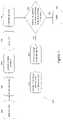
- FIG. 1illustrates a method according to an embodiment of the present invention
- FIG. 2illustrates portions of three exemplary look-up tables usable in the method illustrated in FIG. 1 ;
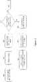
- FIG. 3illustrates an exemplary method for light condition classification, which can be used during the execution of the method illustrated in FIG. 1 ;
- FIG. 4illustrates an exemplary acquired image containing region of interests which can be detected during the execution of the method illustrated in FIG. 3 ;
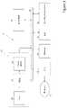
- FIG. 5illustrates an image acquisition system for iris recognition according to an embodiment of the present invention.
- FIGS. 1 and 5there are shown respectively an AE method 100 according to an embodiment of the present invention and an image acquisition system 10 for iris recognition including an AE module 28 which operates according to the method 100 .
- the system 10which may comprise for example, a camera, a smartphone, a tablet or the like, comprises a central processing unit (CPU) 24 which typically runs operating system software as well as general purpose application software, for example, camera applications, browser, messaging, e-mail or other apps.
- the operating systemmay be set so that a user must authenticate themselves to unlock the system and to gain access to applications installed on the system; or individual applications running on the system may require a user to authenticate themselves before they gain access to sensitive information.
- the system 10comprises at least one IR illumination source 16 capable of acquiring an image, such as a facial image of a predetermined subject to be recognized and authenticated by the system 10 .
- the IR illumination source 16which can for example be a NIR LED, is configured to illuminate a subject with IR light, preferably NIR light (that is light of approximately 700-1000 nm in wavelength).
- IR lightpreferably NIR light (that is light of approximately 700-1000 nm in wavelength).
- One suitable LEDcomprises an 810 nm SFH 4780S LED from OSRAM.
- more than one illumination source or a tunable illumination sourcemay be employed to emit IR light at different wavelengths.
- the system 10further comprises a camera module 15 having at least a lens assembly 12 , an image sensor 14 , and a filter 13 .
- the lens assembly 12is configured for focusing IR light reflected from the subject illuminated by the IR illumination source 16 onto the sensor 14 .
- the filter 13is arranged to allow the passage therethrough towards the sensor 14 of selected IR wavelengths (corresponding to the wavelengths emitted by the IR illumination source 16 ).
- a first exemplary lens assembly 12is disclosed in PCT/EP2016/052395 (Ref: FN-452), the disclosure of which is incorporated herein by reference, which comprises a collecting lens surface with an optical axis and which is arranged to focus IR light received from a given object distance on the image sensor surface.
- the lens assemblyincludes at least a first reflective surface for reflecting collected light along an axis transverse to the optical axis, so that a length of the optical system along the optical axis is reduced by comparison to a focal length of the lens assembly.
- a second exemplary lens assembly 12is disclosed in PCT/EP2016/060941 (Ref: FN-466), the disclosure of which is incorporated herein by reference, which comprises a cluster of at least two lenses arranged in front of the image sensor with each lens' optical axis in parallel spaced apart relationship. Each lens has a fixed focus and a different aperture to provide a respective angular field of view. The lens with the closest focus has the smallest aperture and the lens with the farthest focus has the largest aperture, so that iris images can be acquired from subjects at distances from between about 200 mm to 500 mm from an acquisition device.
- a third exemplary lens assembly 12is disclosed in U.S. patent application Ser. No. 15/186,283 filed 17 Jun. 2016 (Ref: FN-477), the disclosure of which is incorporated herein by reference, which comprises an image sensor comprising an array of pixels including pixels sensitive to NIR wavelengths; at least one NIR light source capable of selectively emitting light with different discrete NIR wavelengths; and a processor, operably connected to the image sensor and the at least one NIR light source, to acquire image information from the sensor under illumination at one of the different discrete NIR wavelengths.
- a lens assemblycomprises a plurality of lens elements with a total track length no more than 4.7 mm, each lens element comprising a material with a refractive index inversely proportional to wavelength.
- the different discrete NIR wavelengthsare matched with the refractive index of the material for the lens elements to balance axial image shift induced by a change in object distance with axial image shift due to change in illumination wavelength.
- images acquired from the image sensor 14are written into memory 22 as required either by applications being executed by the CPU 24 or other dedicated processing blocks which have access to the image sensor 14 and/or memory 22 across the system bus 26 .
- the system 10further comprises a dedicated face/eye/iris detector 18 for identifying a face region within an acquired image, and within a given face region, one or more eye regions and iris regions within those eye regions.
- This functionalitycould equally be implemented in software executed by the CPU 24 .
- Face detection in real-timehas become a standard feature of most digital imaging devices and there are many techniques for identifying such regions within an acquired image, for example, as disclosed in WO2008/018887 (Reference: FN-143), the disclosure of which is incorporated herein by reference.
- most cameras and smartphonesalso support the real-time detection of various facial features and can identify specific patterns such as ‘eye-blink’ and ‘smile’ so that for example, the timing of main image acquisition can be adjusted to ensure subjects within a scene are in-focus, not blinking or are smiling such as disclosed in WO2007/106117 (Reference: FN-149), the disclosure of which is incorporated herein by reference.
- detecting and tracking face regions and eye regions within those face regionsimposes no additional overhead and so this information is available continuously for a stream of images being acquired by the system 10 .
- the iris regionsare extracted from the identified eye regions and a more detailed analysis may be performed to confirm if a valid iris pattern is detectable.
- J. Daugman, “New methods in iris recognition,” IEEE Trans. Syst. Man. Cybern. B. Cybern., vol. 37, pp. 1167-1175, 2007discloses a range of additional refinements which can be utilized to determine the exact shape of iris and the eye-pupil. It is also common practice to transform the iris from a polar to rectangular co-ordinate system, although this is not necessary.
- Iris regions identified within an acquired imagecan be used as an input for a biometric authentication unit (BAU) 20 .
- the BAU 20is configured for analyzing the received iris regions in order to detect whether they belong to a predetermined subject.
- the BAU 20is preferably configured to compare the received one or more iris regions with reference iris region(s) associated to the predetermined subject, which can be stored in memory 22 , within secure memory in the BAU 20 or in any location accessible to the BAU 20 .
- An exemplary way for performing iris code extraction and comparison between iris regionsis disclosed in WO2011/124512 (Reference: FN-458), the disclosure of which is incorporated herein by reference, and this involves a comparison between two image templates using a master mask to select corresponding codes from the templates.
- the master maskexcludes blocks from the matching process and/or weights blocks according to their known or expected reliability.
- the system 10uses active NIR illumination provided by the source 16 and the filter 13 , three main light conditions are considered for the operation of the system 10 , namely an indoor condition, an outdoor overcast (cloudy) condition, and an outdoor sunny condition.
- the method 100 provided by an AE module 28 for the camera module 15 of the system 10comprises a prerequisite step 101 of maintaining three pre-generated look-up tables (LUTs) 200 , 201 , 202 , which are associated, respectively, with the indoor condition, the outdoor overcast condition and the outdoor sunny condition, FIG. 2 .
- LUTslook-up tables
- each one of the LUTs 200 , 201 , 202stores image acquisition settings for the camera module 15 .
- each one of the LUTs 200 , 201 , 202comprises:
- the method 100comprises acquiring a raw image of a subject from the camera module 15 (step 102 ), and determining which of the indoor, outdoor overcast, and outdoor sunny conditions occurred during the acquisition of the raw image, based on the raw image itself (step 103 ).
- an exemplary method to make the determination at step 103comprises detecting eye regions within the acquired raw image (step 300 ), and selecting iris regions 350 based on the eye detection (step 301 ).
- the median value of the pixels in each selected iris regionis calculated (step 302 ), and the maximum of the two calculated median values is compared with a threshold to determine whether the outdoor sunny condition occurred in acquiring the raw image (step 303 ). For example, if the determined maximum median value is greater than the threshold, the raw image is considered to have been captured in the outdoor sunny condition.
- the threshold used in the determination at step 303can be set using Decision Trees on a pre-captured training database.
- An exemplary threshold value in a range from 0 to a maximum brightness of 255can be 79.
- step 303If the determination at step 303 is positive, the process stops.
- the processcontinues by determining regions of interest (ROIs) within the acquired raw image, other than the previously detected iris regions (step 304 ).
- ROIsregions of interest
- the ROIs 351correspond for example to the cheek regions 351 of the subject i.e. rectangular regions disposed below (in an upright face image) the eye regions.
- the average pixel values of the ROIs 351are calculated and summed (step 305 ).
- the sum resultis compared with a threshold to determine whether the indoor condition or the outdoor overcast condition occurred during the acquisition of the raw image (step 306 ).
- the raw imageis assumed to have been captured in the indoor condition. If the sum exceeds the threshold, the raw image is assumed to have been captured in the outdoor overcast condition.
- the threshold used in the determination at step 306can be set using Decision Trees on a pre-captured training database. For example, assuming that both eyes are visible, the threshold value can be 262 in a range from 0 to a maximum brightness of 510.
- An assumption for the process illustrated in FIG. 3is that both eyes are visible and detectable in the raw image.
- a similar methodcan also be used to determine the light condition occurred during image acquisition, but using only one iris region for the determination at step 303 and/or only one ROI 351 for the determination at step 304 .
- Such a methodcan be applied for example when only one eye region is detectable in the raw image.
- determining the light condition which pertained during the acquisition of the raw imagecan comprise checking for a presence of shadows in the areas around the eyes, such as disclosed in PCT Application No. PCT/EP2017/058106 (Ref: FN-491-PCT), the disclosure of which is incorporated herein by reference. If shadows are detected, it could be assumed that the raw image has been captured outdoors, in strong sunlight. Other indicators could also be used, such as checking the time of day—it is unlikely that images being acquired between 9 pm and 6 am are being acquired in strong sunlight, or checking device location. For example, GPS coordinates can indicate if a device is located outside in bright conditions or inside under artificially lit conditions. Other indicators include testing whether the image processing device is connected to or detects a WiFi signal—if not there is a good chance the device is outdoors.
- the LUT 200 , 201 , 202is selected which corresponds to the determined light condition (step 104 ).
- the method 100further comprises calculating a distance between the subject and the camera module 15 during the acquisition of the raw image (step 105 ).
- Distancecan be determined directly if the image acquisition system includes a distance measurement device, for example a laser, although this may not be desirable when an image acquisition system is directed towards a user's eyes.
- a distance measurement devicefor example a laser
- the distance to the subjectcan be calculated from the raw image itself using anthropometric information such as an assumed centre-to-centre pupil distance of about 65 mm as disclosed in PCT Application No. PCT/EP2015/076881 (Ref: FN-399-PCT).
- the distancecan be calculated from a depth map generated by using stereo information from both the NIR camera module 15 and a second RGB front facing camera module, typically incorporated in a smartphone for enabling video conferencing or calling.
- the determination at step 106can comprise determining if at least one of the determined light condition and the calculated distance are different than a predetermined light condition and a predetermined distance.
- default exposure time and gain valuescan be set for a specific distance and light condition. For example, it has been statistically determined that iris recognition is most likely performed indoor with the camera module 15 held at a distance of about 30 cm from the subject under recognition. For this reason, the default exposure time and gain values correspond to the values stored in the LUT 200 and associated to a distance value of 30 cm. Once the raw image is acquired, if a light condition other than indoor is determined and/or the calculated distance is different than 30 cm, a new exposure time and/or gain values may be required.
- the auto-setting method 100stops (step 107 ) and the raw image can be used for iris recognition processing.
- the raw imagecan be sent to the detector 18 or, if iris regions have been already detected and stored at step 102 for determining the light condition, such regions can be directly provided to the BAU 20 .
- the method 100proceeds with a step 208 of retrieving an exposure time value 207 and a gain value 206 which correspond to the calculated distance from the LUT selected at step 104 .
- the measured distanceis used as an index to access the selected LUT and to retrieve therefrom the pair of new exposure time and gain values that are required for the calculated distance, at the determined light condition.
- either the entry for the closest stored distancecan be used and/or interpolation and/or extrapolation from entries within the selected LUT can be employed.
- a new imageis then acquired from the camera module 15 using the selected exposure time and gain values (step 109 ).
- the above method 100can be repeated using the new acquired image as a raw image.
- the LUTs 200 , 201 , 202 used in the method 100are filled with data worked out experimentally.
- suitable exposure time and gain values 206 , 207 associated to corresponding distance values 205are chosen based on image quality scores (contrast) which are suitable for the specific iris recognition module implemented by the system 10 .
- the exposure time and gain valuesare chosen in such a way that in each LUT 200 , 201 , 202 the product of exposure time and gain increases, with distance.
- exposure valuesare increased first until a maximum value is reached. After reaching this maximum value, the gain needs to be increased.
- the maximum valueis set at 12 ms, since for greater exposure time values there is a risk of having geometrical distortions due to hand motion of the subject.
- the gainit is kept low while the exposure time is below the maximum value. This in order to minimize the sensor noise in the acquired image. For example, until the exposure time values reach the maximum value, the gain can be kept at a constant low value or can slowly increase.
- gainincreases at discrete intervals, so it will be seen that when gain changes from 2-3 or 1-2 in tables 200 and 201 respectively, the exposure time needs to be curtailed to provide a relatively smooth progression of exposure.
- the exposure time and gain values of the LUT table 200are higher than the exposure time and gain values of the LUT 201 at the same corresponding distance values, and the exposure time and gain values of the LUT 202 are higher than the exposure time and gain values of the LUT 202 at the same corresponding distance values. This is because with more light, less exposure time and gain are need to reach the desired image quality score.
- the functionality of the module 28could equally be implemented in software executed by the CPU 24 .
- the AE module 28could form a component of a dedicated camera module 15 .
- the LUTs 200 , 201 , 202can be stored in the memory 22 or in any other memory of the system 10 or accessibly by the system 10 .
- the Face/Eye/Iris detector 18can be used for the execution of the method illustrated in FIG. 3 , in order to detect the iris regions 350 and other ROIs 351 used for discriminating between the light conditions.
Landscapes
- Engineering & Computer Science (AREA)
- Multimedia (AREA)
- Signal Processing (AREA)
- Physics & Mathematics (AREA)
- General Physics & Mathematics (AREA)
- Radar, Positioning & Navigation (AREA)
- Remote Sensing (AREA)
- Health & Medical Sciences (AREA)
- General Health & Medical Sciences (AREA)
- Ophthalmology & Optometry (AREA)
- Human Computer Interaction (AREA)
- Theoretical Computer Science (AREA)
- Electromagnetism (AREA)
- Studio Devices (AREA)
- Measurement Of The Respiration, Hearing Ability, Form, And Blood Characteristics Of Living Organisms (AREA)
Abstract
Description
- a set of
distance values 205 between a subject under recognition and thecamera module 15 of thesystem 10; and - a pair of gain and exposure time values206,207 for the
sensor 14 which are associated with eachdistance value 205.
- a set of
Claims (20)
Priority Applications (1)
| Application Number | Priority Date | Filing Date | Title |
|---|---|---|---|
| US16/915,987US11375133B2 (en) | 2017-05-31 | 2020-06-29 | Automatic exposure module for an image acquisition system |
Applications Claiming Priority (2)
| Application Number | Priority Date | Filing Date | Title |
|---|---|---|---|
| US15/609,314US10701277B2 (en) | 2017-05-31 | 2017-05-31 | Automatic exposure module for an image acquisition system |
| US16/915,987US11375133B2 (en) | 2017-05-31 | 2020-06-29 | Automatic exposure module for an image acquisition system |
Related Parent Applications (1)
| Application Number | Title | Priority Date | Filing Date |
|---|---|---|---|
| US15/609,314ContinuationUS10701277B2 (en) | 2017-05-31 | 2017-05-31 | Automatic exposure module for an image acquisition system |
Publications (2)
| Publication Number | Publication Date |
|---|---|
| US20200404149A1 US20200404149A1 (en) | 2020-12-24 |
| US11375133B2true US11375133B2 (en) | 2022-06-28 |
Family
ID=64460743
Family Applications (2)
| Application Number | Title | Priority Date | Filing Date |
|---|---|---|---|
| US15/609,314ActiveUS10701277B2 (en) | 2017-05-31 | 2017-05-31 | Automatic exposure module for an image acquisition system |
| US16/915,987ActiveUS11375133B2 (en) | 2017-05-31 | 2020-06-29 | Automatic exposure module for an image acquisition system |
Family Applications Before (1)
| Application Number | Title | Priority Date | Filing Date |
|---|---|---|---|
| US15/609,314ActiveUS10701277B2 (en) | 2017-05-31 | 2017-05-31 | Automatic exposure module for an image acquisition system |
Country Status (1)
| Country | Link |
|---|---|
| US (2) | US10701277B2 (en) |
Families Citing this family (5)
| Publication number | Priority date | Publication date | Assignee | Title |
|---|---|---|---|---|
| JP7260990B2 (en)* | 2018-10-26 | 2023-04-19 | キヤノン株式会社 | Imaging device and imaging system |
| US11627262B2 (en)* | 2019-11-04 | 2023-04-11 | Fotonation Limited | Handheld computing device |
| CN111741230B (en)* | 2019-11-21 | 2021-06-29 | 天津九安医疗电子股份有限公司 | Camera head |
| CN115767253B (en)* | 2022-11-22 | 2025-01-28 | 广东亿嘉和科技有限公司 | A method and device for adaptively adjusting camera exposure parameters and marker recognition thresholds |
| CN116074616B (en)* | 2023-04-06 | 2023-06-20 | 上海知率智能科技有限公司 | Container image acquisition system |
Citations (39)
| Publication number | Priority date | Publication date | Assignee | Title |
|---|---|---|---|---|
| US2195748A (en)* | 1933-12-09 | 1940-04-02 | Leber Alois | Optical exposure meter |
| US4241456A (en)* | 1978-08-30 | 1980-12-23 | Hitachi, Ltd. | Remote-controlled receiver |
| US4547057A (en)* | 1982-12-29 | 1985-10-15 | Canon Kabushiki Kaisha | Flash photographic apparatus |
| US4801964A (en)* | 1988-01-13 | 1989-01-31 | Eastman Kodak Company | Fill flash control system for cameras |
| US5159381A (en)* | 1990-05-23 | 1992-10-27 | Polaroid Corporation | Electronic flash control circuit |
| US20020034067A1 (en)* | 2000-09-19 | 2002-03-21 | Massaro Michael J. | Electronic display for store shelves |
| US6389232B2 (en)* | 1994-06-09 | 2002-05-14 | Fuji Photo Film Co., Ltd. | Method and apparatus for controlling exposure of camera |
| US6525763B1 (en)* | 1995-04-10 | 2003-02-25 | Minolta Co., Ltd. | Film image reading device and method with focus adjustment |
| US6564014B1 (en)* | 1999-09-24 | 2003-05-13 | Nikon Corporation | Flash control device |
| US20030136832A1 (en)* | 2000-09-19 | 2003-07-24 | Massaro Michael J. | Display system for store shelves |
| US6724419B1 (en)* | 1999-08-13 | 2004-04-20 | Universal Imaging Corporation | System and method for acquiring images at maximum acquisition rate while asynchronously sequencing microscope devices |
| US6734894B1 (en)* | 1998-02-18 | 2004-05-11 | Fuji Photo Optical Co., Ltd. | Electronic-endoscope light quantity controlling apparatus |
| US20040195774A1 (en)* | 2001-08-14 | 2004-10-07 | Segan Marc H. | Amusement device with a moving target and a clock |
| US20070049159A1 (en)* | 2005-08-26 | 2007-03-01 | Kulis Richard W Ii | Illuminable propeller assembly for model vehicle |
| US20070103890A1 (en)* | 2004-04-01 | 2007-05-10 | Sondra Morehead | Illluminated collar |
| US20070164115A1 (en)* | 2006-01-17 | 2007-07-19 | Symboltechnologies, Inc. | Automatic exposure system for imaging-based bar code reader |
| WO2007106117A2 (en) | 2006-02-24 | 2007-09-20 | Fotonation Vision Limited | Method and apparatus for selective rejection of digital images |
| US20070228755A1 (en)* | 2006-03-17 | 2007-10-04 | Julio Alvarado | Vehicle observation apparatus |
| US7295765B1 (en)* | 1995-05-16 | 2007-11-13 | Olympus Corporation | Digital image recording and reproducing apparatus having formats corresponding to pixel configurations |
| WO2008018887A1 (en) | 2006-08-11 | 2008-02-14 | Fotonation Vision Limited | Real-time face tracking in a digital image acquisition device |
| US7489333B2 (en)* | 2003-06-20 | 2009-02-10 | Canon Kabushiki Kaisha | Ophthalmologic image pickup apparatus |
| WO2011124512A2 (en) | 2010-04-09 | 2011-10-13 | Donald Martin Monro | Image template masking |
| US8045002B2 (en)* | 2005-07-29 | 2011-10-25 | Mitutoyo Corporation | Systems and methods for controlling strobe illumination |
| US8488958B2 (en) | 2010-05-25 | 2013-07-16 | Apple Inc. | Scene adaptive auto exposure |
| US20150294128A1 (en)* | 2012-12-27 | 2015-10-15 | Optoelectronics Co., Ltd. | Optical information reading device |
| US20160125178A1 (en)* | 2014-10-30 | 2016-05-05 | Delta ID Inc. | Systems And Methods For Spoof Detection In Iris Based Biometric Systems |
| WO2016091545A1 (en) | 2014-12-09 | 2016-06-16 | Fotonation Limited | Image processing method |
| WO2016134942A1 (en) | 2015-02-27 | 2016-09-01 | Fotonation Limited | An optical system for an image acquisition device |
| WO2016177914A1 (en) | 2015-12-09 | 2016-11-10 | Fotonation Limited | Image acquisition system |
| US20160378266A1 (en)* | 2015-06-25 | 2016-12-29 | Wistron Corporation | Optical touch apparatus and width detecting method thereof |
| US20170045617A1 (en)* | 2014-05-02 | 2017-02-16 | Fujifilm Corporation | Distance measurement device, distance measurement method, and distance measurement program |
| US20170061210A1 (en)* | 2015-08-26 | 2017-03-02 | Intel Corporation | Infrared lamp control for use with iris recognition authentication |
| US20170131088A1 (en)* | 2014-08-05 | 2017-05-11 | Fujifilm Corporation | Distance measurement device, distance measurement method, and distance measurement program |
| WO2017144733A1 (en) | 2016-06-24 | 2017-08-31 | Fotonation Limited | Image processing method and system for iris recognition |
| US20170277950A1 (en)* | 2014-09-02 | 2017-09-28 | Samsung Electronics Co., Ltd. | Method for recognizing iris and electronic device therefor |
| US20170289421A1 (en)* | 2016-03-29 | 2017-10-05 | Symbol Technologies, Llc | Imaging module and reader for, and method of, expeditiously setting imaging parameters of imagers for imaging targets to be read over a range of working distances |
| US20170366761A1 (en) | 2016-06-17 | 2017-12-21 | Fotonation Limited | Iris image acquisition system |
| US20180189547A1 (en)* | 2016-12-30 | 2018-07-05 | Intel Corporation | Biometric identification system |
| US20190313009A1 (en)* | 2018-04-05 | 2019-10-10 | Motorola Mobility Llc | Electronic Device with Image Capture Command Source Identification and Corresponding Methods |
- 2017
- 2017-05-31USUS15/609,314patent/US10701277B2/enactiveActive
- 2020
- 2020-06-29USUS16/915,987patent/US11375133B2/enactiveActive
Patent Citations (39)
| Publication number | Priority date | Publication date | Assignee | Title |
|---|---|---|---|---|
| US2195748A (en)* | 1933-12-09 | 1940-04-02 | Leber Alois | Optical exposure meter |
| US4241456A (en)* | 1978-08-30 | 1980-12-23 | Hitachi, Ltd. | Remote-controlled receiver |
| US4547057A (en)* | 1982-12-29 | 1985-10-15 | Canon Kabushiki Kaisha | Flash photographic apparatus |
| US4801964A (en)* | 1988-01-13 | 1989-01-31 | Eastman Kodak Company | Fill flash control system for cameras |
| US5159381A (en)* | 1990-05-23 | 1992-10-27 | Polaroid Corporation | Electronic flash control circuit |
| US6389232B2 (en)* | 1994-06-09 | 2002-05-14 | Fuji Photo Film Co., Ltd. | Method and apparatus for controlling exposure of camera |
| US6525763B1 (en)* | 1995-04-10 | 2003-02-25 | Minolta Co., Ltd. | Film image reading device and method with focus adjustment |
| US7295765B1 (en)* | 1995-05-16 | 2007-11-13 | Olympus Corporation | Digital image recording and reproducing apparatus having formats corresponding to pixel configurations |
| US6734894B1 (en)* | 1998-02-18 | 2004-05-11 | Fuji Photo Optical Co., Ltd. | Electronic-endoscope light quantity controlling apparatus |
| US6724419B1 (en)* | 1999-08-13 | 2004-04-20 | Universal Imaging Corporation | System and method for acquiring images at maximum acquisition rate while asynchronously sequencing microscope devices |
| US6564014B1 (en)* | 1999-09-24 | 2003-05-13 | Nikon Corporation | Flash control device |
| US20030136832A1 (en)* | 2000-09-19 | 2003-07-24 | Massaro Michael J. | Display system for store shelves |
| US20020034067A1 (en)* | 2000-09-19 | 2002-03-21 | Massaro Michael J. | Electronic display for store shelves |
| US20040195774A1 (en)* | 2001-08-14 | 2004-10-07 | Segan Marc H. | Amusement device with a moving target and a clock |
| US7489333B2 (en)* | 2003-06-20 | 2009-02-10 | Canon Kabushiki Kaisha | Ophthalmologic image pickup apparatus |
| US20070103890A1 (en)* | 2004-04-01 | 2007-05-10 | Sondra Morehead | Illluminated collar |
| US8045002B2 (en)* | 2005-07-29 | 2011-10-25 | Mitutoyo Corporation | Systems and methods for controlling strobe illumination |
| US20070049159A1 (en)* | 2005-08-26 | 2007-03-01 | Kulis Richard W Ii | Illuminable propeller assembly for model vehicle |
| US20070164115A1 (en)* | 2006-01-17 | 2007-07-19 | Symboltechnologies, Inc. | Automatic exposure system for imaging-based bar code reader |
| WO2007106117A2 (en) | 2006-02-24 | 2007-09-20 | Fotonation Vision Limited | Method and apparatus for selective rejection of digital images |
| US20070228755A1 (en)* | 2006-03-17 | 2007-10-04 | Julio Alvarado | Vehicle observation apparatus |
| WO2008018887A1 (en) | 2006-08-11 | 2008-02-14 | Fotonation Vision Limited | Real-time face tracking in a digital image acquisition device |
| WO2011124512A2 (en) | 2010-04-09 | 2011-10-13 | Donald Martin Monro | Image template masking |
| US8488958B2 (en) | 2010-05-25 | 2013-07-16 | Apple Inc. | Scene adaptive auto exposure |
| US20150294128A1 (en)* | 2012-12-27 | 2015-10-15 | Optoelectronics Co., Ltd. | Optical information reading device |
| US20170045617A1 (en)* | 2014-05-02 | 2017-02-16 | Fujifilm Corporation | Distance measurement device, distance measurement method, and distance measurement program |
| US20170131088A1 (en)* | 2014-08-05 | 2017-05-11 | Fujifilm Corporation | Distance measurement device, distance measurement method, and distance measurement program |
| US20170277950A1 (en)* | 2014-09-02 | 2017-09-28 | Samsung Electronics Co., Ltd. | Method for recognizing iris and electronic device therefor |
| US20160125178A1 (en)* | 2014-10-30 | 2016-05-05 | Delta ID Inc. | Systems And Methods For Spoof Detection In Iris Based Biometric Systems |
| WO2016091545A1 (en) | 2014-12-09 | 2016-06-16 | Fotonation Limited | Image processing method |
| WO2016134942A1 (en) | 2015-02-27 | 2016-09-01 | Fotonation Limited | An optical system for an image acquisition device |
| US20160378266A1 (en)* | 2015-06-25 | 2016-12-29 | Wistron Corporation | Optical touch apparatus and width detecting method thereof |
| US20170061210A1 (en)* | 2015-08-26 | 2017-03-02 | Intel Corporation | Infrared lamp control for use with iris recognition authentication |
| WO2016177914A1 (en) | 2015-12-09 | 2016-11-10 | Fotonation Limited | Image acquisition system |
| US20170289421A1 (en)* | 2016-03-29 | 2017-10-05 | Symbol Technologies, Llc | Imaging module and reader for, and method of, expeditiously setting imaging parameters of imagers for imaging targets to be read over a range of working distances |
| US20170366761A1 (en) | 2016-06-17 | 2017-12-21 | Fotonation Limited | Iris image acquisition system |
| WO2017144733A1 (en) | 2016-06-24 | 2017-08-31 | Fotonation Limited | Image processing method and system for iris recognition |
| US20180189547A1 (en)* | 2016-12-30 | 2018-07-05 | Intel Corporation | Biometric identification system |
| US20190313009A1 (en)* | 2018-04-05 | 2019-10-10 | Motorola Mobility Llc | Electronic Device with Image Capture Command Source Identification and Corresponding Methods |
Non-Patent Citations (2)
| Title |
|---|
| J. Daugman, "New methods in iris recognition," IEEE Trans. Syst. Man. Cybern. B. Cybern., vol. 37, No. 5, Oct. 2007. pp. 1167-1175. |
| Office action for U.S. Appl. No. 15/609,314, dated Jul. 15, 2019, Andorko, "Automatic exposure module for an image acquisition system", 11 pages. |
Also Published As
| Publication number | Publication date |
|---|---|
| US20180352131A1 (en) | 2018-12-06 |
| US20200404149A1 (en) | 2020-12-24 |
| US10701277B2 (en) | 2020-06-30 |
Similar Documents
| Publication | Publication Date | Title |
|---|---|---|
| US11375133B2 (en) | Automatic exposure module for an image acquisition system | |
| US10891479B2 (en) | Image processing method and system for iris recognition | |
| US20180018516A1 (en) | Method and apparatus for iris recognition | |
| EP3440593B1 (en) | Method and apparatus for iris recognition | |
| US11243607B2 (en) | Method and system for glint/reflection identification | |
| JPWO2019163065A1 (en) | Spoofing detection device, spoofing detection method, and program | |
| CN113557519A (en) | Information processing apparatus, information processing system, information processing method, and recording medium | |
| US11163994B2 (en) | Method and device for determining iris recognition image, terminal apparatus, and storage medium | |
| US9349071B2 (en) | Device for detecting pupil taking account of illuminance and method thereof | |
| US20200187774A1 (en) | Method and system for controlling illuminators | |
| US10288879B1 (en) | Method and system for glint/reflection identification | |
| US20190087657A1 (en) | Binding of selfie face image to iris images for biometric identity enrollment | |
| CN108009534B (en) | Biopsy method based on pupil gray scale | |
| CN111160299A (en) | Living body identification method and device | |
| JP2020140637A (en) | Pupil detector | |
| US11156831B2 (en) | Eye-tracking system and method for pupil detection, associated systems and computer programs | |
| US12307819B2 (en) | Identification model generation apparatus, identification apparatus, identification model generation method, identification method, and storage medium | |
| EP3801196B1 (en) | Method and system for glint/reflection identification | |
| JP3848953B2 (en) | Living body eye determination method and living body eye determination device | |
| CN113011222A (en) | Living body detection system and method and electronic equipment | |
| JP4527088B2 (en) | Living body eye determination method and living body eye determination device | |
| SE2030271A1 (en) | Eye tracking system | |
| JP2021048441A (en) | Imaging control unit and imaging control method | |
| US12424025B2 (en) | Personal authentication apparatus and control method | |
| CN119310751A (en) | System and method for adaptive control of smart glasses combined with the Internet of Things |
Legal Events
| Date | Code | Title | Description |
|---|---|---|---|
| FEPP | Fee payment procedure | Free format text:ENTITY STATUS SET TO UNDISCOUNTED (ORIGINAL EVENT CODE: BIG.); ENTITY STATUS OF PATENT OWNER: LARGE ENTITY | |
| AS | Assignment | Owner name:FOTONATION LIMITED, IRELAND Free format text:ASSIGNMENT OF ASSIGNORS INTEREST;ASSIGNOR:ANDORKO, ISTVAN;REEL/FRAME:053759/0469 Effective date:20170526 | |
| STPP | Information on status: patent application and granting procedure in general | Free format text:DOCKETED NEW CASE - READY FOR EXAMINATION | |
| STPP | Information on status: patent application and granting procedure in general | Free format text:NON FINAL ACTION MAILED | |
| STPP | Information on status: patent application and granting procedure in general | Free format text:RESPONSE TO NON-FINAL OFFICE ACTION ENTERED AND FORWARDED TO EXAMINER | |
| STPP | Information on status: patent application and granting procedure in general | Free format text:FINAL REJECTION MAILED | |
| STPP | Information on status: patent application and granting procedure in general | Free format text:NOTICE OF ALLOWANCE MAILED -- APPLICATION RECEIVED IN OFFICE OF PUBLICATIONS | |
| STPP | Information on status: patent application and granting procedure in general | Free format text:PUBLICATIONS -- ISSUE FEE PAYMENT RECEIVED | |
| STPP | Information on status: patent application and granting procedure in general | Free format text:PUBLICATIONS -- ISSUE FEE PAYMENT VERIFIED | |
| STCF | Information on status: patent grant | Free format text:PATENTED CASE | |
| AS | Assignment | Owner name:TOBII TECHNOLOGY LIMITED, IRELAND Free format text:CHANGE OF NAME;ASSIGNOR:FOTONATION LIMITED;REEL/FRAME:070238/0774 Effective date:20240820 | |
| AS | Assignment | Owner name:TOBII TECHNOLOGIES LIMITED, IRELAND Free format text:CHANGE OF NAME;ASSIGNOR:FOTONATION LIMITED;REEL/FRAME:070682/0207 Effective date:20240820 | |
| AS | Assignment | Owner name:BANK OF AMERICA, N.A., AS COLLATERAL AGENT, ILLINOIS Free format text:SECURITY INTEREST;ASSIGNORS:ADEIA INC. (F/K/A XPERI HOLDING CORPORATION);ADEIA HOLDINGS INC.;ADEIA MEDIA HOLDINGS INC.;AND OTHERS;REEL/FRAME:071454/0343 Effective date:20250527 | |
| AS | Assignment | Owner name:ADEIA MEDIA HOLDINGS LLC, CALIFORNIA Free format text:ASSIGNMENT OF ASSIGNORS INTEREST;ASSIGNOR:TOBII TECHNOLOGIES LTD;REEL/FRAME:071572/0855 Effective date:20250318 Owner name:ADEIA MEDIA HOLDINGS INC., CALIFORNIA Free format text:CONVERSION;ASSIGNOR:ADEIA MEDIA HOLDINGS LLC;REEL/FRAME:071577/0875 Effective date:20250408 |