US11375125B2 - Electronic device - Google Patents
Electronic deviceDownload PDFInfo
- Publication number
- US11375125B2 US11375125B2US16/872,400US202016872400AUS11375125B2US 11375125 B2US11375125 B2US 11375125B2US 202016872400 AUS202016872400 AUS 202016872400AUS 11375125 B2US11375125 B2US 11375125B2
- Authority
- US
- United States
- Prior art keywords
- image capture
- capture device
- motor
- processor
- image
- Prior art date
- Legal status (The legal status is an assumption and is not a legal conclusion. Google has not performed a legal analysis and makes no representation as to the accuracy of the status listed.)
- Active
Links
Images


Classifications
- H04N5/23299—
- H—ELECTRICITY
- H04—ELECTRIC COMMUNICATION TECHNIQUE
- H04M—TELEPHONIC COMMUNICATION
- H04M1/00—Substation equipment, e.g. for use by subscribers
- H04M1/72—Mobile telephones; Cordless telephones, i.e. devices for establishing wireless links to base stations without route selection
- H04M1/724—User interfaces specially adapted for cordless or mobile telephones
- H04M1/72403—User interfaces specially adapted for cordless or mobile telephones with means for local support of applications that increase the functionality
- H—ELECTRICITY
- H04—ELECTRIC COMMUNICATION TECHNIQUE
- H04N—PICTORIAL COMMUNICATION, e.g. TELEVISION
- H04N23/00—Cameras or camera modules comprising electronic image sensors; Control thereof
- H04N23/60—Control of cameras or camera modules
- H04N23/695—Control of camera direction for changing a field of view, e.g. pan, tilt or based on tracking of objects
- H—ELECTRICITY
- H04—ELECTRIC COMMUNICATION TECHNIQUE
- H04N—PICTORIAL COMMUNICATION, e.g. TELEVISION
- H04N23/00—Cameras or camera modules comprising electronic image sensors; Control thereof
- H04N23/50—Constructional details
- H04N23/51—Housings
- H—ELECTRICITY
- H04—ELECTRIC COMMUNICATION TECHNIQUE
- H04N—PICTORIAL COMMUNICATION, e.g. TELEVISION
- H04N23/00—Cameras or camera modules comprising electronic image sensors; Control thereof
- H04N23/50—Constructional details
- H04N23/53—Constructional details of electronic viewfinders, e.g. rotatable or detachable
- H—ELECTRICITY
- H04—ELECTRIC COMMUNICATION TECHNIQUE
- H04N—PICTORIAL COMMUNICATION, e.g. TELEVISION
- H04N23/00—Cameras or camera modules comprising electronic image sensors; Control thereof
- H04N23/50—Constructional details
- H04N23/54—Mounting of pick-up tubes, electronic image sensors, deviation or focusing coils
- H—ELECTRICITY
- H04—ELECTRIC COMMUNICATION TECHNIQUE
- H04N—PICTORIAL COMMUNICATION, e.g. TELEVISION
- H04N23/00—Cameras or camera modules comprising electronic image sensors; Control thereof
- H04N23/57—Mechanical or electrical details of cameras or camera modules specially adapted for being embedded in other devices
- H—ELECTRICITY
- H04—ELECTRIC COMMUNICATION TECHNIQUE
- H04N—PICTORIAL COMMUNICATION, e.g. TELEVISION
- H04N23/00—Cameras or camera modules comprising electronic image sensors; Control thereof
- H04N23/60—Control of cameras or camera modules
- H04N23/63—Control of cameras or camera modules by using electronic viewfinders
- H04N23/633—Control of cameras or camera modules by using electronic viewfinders for displaying additional information relating to control or operation of the camera
- H04N23/634—Warning indications
- H—ELECTRICITY
- H04—ELECTRIC COMMUNICATION TECHNIQUE
- H04N—PICTORIAL COMMUNICATION, e.g. TELEVISION
- H04N23/00—Cameras or camera modules comprising electronic image sensors; Control thereof
- H04N23/60—Control of cameras or camera modules
- H04N23/698—Control of cameras or camera modules for achieving an enlarged field of view, e.g. panoramic image capture
- H04N5/22525—
- H04N5/2253—
- H04N5/23238—
- H04N5/232941—
- H—ELECTRICITY
- H04—ELECTRIC COMMUNICATION TECHNIQUE
- H04M—TELEPHONIC COMMUNICATION
- H04M1/00—Substation equipment, e.g. for use by subscribers
- H04M1/02—Constructional features of telephone sets
- H04M1/0202—Portable telephone sets, e.g. cordless phones, mobile phones or bar type handsets
- H04M1/026—Details of the structure or mounting of specific components
- H04M1/0264—Details of the structure or mounting of specific components for a camera module assembly
- H—ELECTRICITY
- H04—ELECTRIC COMMUNICATION TECHNIQUE
- H04M—TELEPHONIC COMMUNICATION
- H04M2250/00—Details of telephonic subscriber devices
- H04M2250/52—Details of telephonic subscriber devices including functional features of a camera
- H—ELECTRICITY
- H04—ELECTRIC COMMUNICATION TECHNIQUE
- H04N—PICTORIAL COMMUNICATION, e.g. TELEVISION
- H04N7/00—Television systems
- H04N7/14—Systems for two-way working
- H04N7/141—Systems for two-way working between two video terminals, e.g. videophone
- H04N7/142—Constructional details of the terminal equipment, e.g. arrangements of the camera and the display
- H04N2007/145—Handheld terminals
Definitions
- the inventionrelates to an electronic device with an image capture device.
- the different operation method of the componentsare correspondingly introduced. For example, when a camera unit is no longer located at back of a smart phone, new operation scenarios for the camera unit is required for users to operate the various novel components more efficiently and conveniently.
- the disclosureprovides an electronic device which reduces mis-operation and improves the user experience.
- an electronic deviceincludes: a body; an image capture device, rotatably disposed on the body, for capturing an image; a display, disposed on a first side of the body; a motor, electrically connected to the image capture device, for driving the image capture device to rotate with a flip angle and to locate at a first position, a second position, or a position between the first position and the second position; at least two sensors, respectively disposed on the image capture device and the body, for sensing the flip angle of the image capture device; and a processor, electrically connected to the image capture device, the display, the motor and the at least two sensors, and configured to control the motor.
- the electronic devicereduces mis-operation situation and improves the user experience.
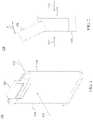
- FIG. 1is a schematic diagram of an electronic device according to an embodiment.
- FIG. 2is a schematic diagram of an electronic device according to an embodiment.
- FIG. 3is a functional block diagram of an electronic device according to an embodiment.
- FIG. 4is a schematic diagram of a panorama image mode according to an embodiment.
- FIG. 5is a schematic image of a panoramic image according to an embodiment.
- An electronic device 100includes a body 110 , an image capture device 120 , a display 130 , a motor 140 , a processor 150 , and a sensor 160 .
- the processor 150is electrically connected to the image capture device 120 , the display 130 , the motor 140 and at least two sensors 160 .
- the body 110includes a first side 112 and a second side 114 opposite with each other.
- the image capture device 120is rotatably disposed on the body 110 for capturing images.
- the display 130is disposed on the first side 112 of the body 110 .
- the display 130is configured to display the image generated by the image capture device 120 .
- the motor 140is electrically connected to the image capture device 120 to drive the image capture device 120 to rotate with a flip angle ⁇ .
- the processor 150is configured to control the motor 140 .
- the two sensors 160are respectively disposed on the body 110 and the image capture device 120 to obtain the flip angle ⁇ of the image capture device 120 .
- the electronic device 100is a smart phone.
- the image capture device 120has a camera lens on a smart phone, and the display 130 is a mobile phone screen located on the front of the body 110 .
- the display 130is LCD, LED, OLED, AMOLED or IPS, etc. which is not limited herein.
- the motor 140is a U-shaped motor, and the sensor 160 is a hall sensor, a distance sensor (P sensor), a gravity sensor (G sensor), or a gyroscope sensor (Gyro Sensor), which is not limited herein.
- the image capture device 120is a camera module with single lens or dual lens or multi lens, which is not limited herein.
- the image capture device 120when the motor 140 drives the image capture device 120 to rotate with a flip angle ⁇ , the image capture device 120 is positioned at a first position (such as a front lens position), at a second position (such as a rear lens position) or a position between the first position and the second position. In an embodiment, when the image capture device 120 is located at the second position (the rear lens position), the image capture device 120 is located at the second side 114 of the body 110 . When the image capture device 120 is rotated 180° relative to the body 110 , the image capture device 120 is located at the first position (the front lens position), and at this time, the image capture device 120 and the display 130 face the same direction.
- a first positionsuch as a front lens position
- a second positionsuch as a rear lens position
- the image capture device 120when the image capture device 120 is located at the second side 114 of the body 110 .
- the image capture device 120is rotated 180° relative to the body 110 , the image capture device 120 is located at the first position (the
- the processor 150transmits a first motor control signal to the motor 140 to control the motor 140 to maintain the image capture device 120 at the front lens position for a preset time.
- the processor 150determines whether the image capture device 120 needs to be used or not. When the processor 150 determines that the image capture device 120 needs to be used, the processor 150 transmits the first motor control signal to control the motor 140 to maintain the image capture device 120 at the front lens position. When the processor 150 determines that the image capture device 120 is not needed to be used, the processor 150 transmits a second motor control signal to the motor 140 to control the motor 140 to rotate the image capture device 120 to the rear lens position (the second position).
- the electronic device 100already has an application using camera functions, such as the front lens function, and meanwhile another application is turned on, the processor 150 first receives a command to turn off the camera function. At this time, the processor 150 controls the motor 140 to maintain the image capture device 120 at the front lens position for a preset time without flipping back to the rear lens position. In this preset time, the processor 150 determines whether the other application needs to use the camera function or not. When the processor 150 determines that the application needs to use the camera function, the processor 150 transmits the first motor control signal to control the motor 140 to maintain the image capture device 120 at the front lens position. When the processor 150 determines that another application does not need to use the camera function, the processor 150 transmits the second motor control signal to control the motor 140 to rotate the image capture device 120 from the front lens position to the rear lens position.
- the processor 150when the processor 150 receives a video notification and does not receive a video confirmation signal, the processor 150 controls the motor 140 not to rotate the image capture device 120 .
- the processor 150when it receives the video notification of the application but does not receive a user confirmation to perform the video function, the electronic device 100 does not flip the image capture device 120 , which avoids reducing the service life of the image capture device 120 due to flipping the image capture device 120 too frequently.
- the electronic device 100when the display 130 is awakened, the electronic device 100 does not perform the face recognition function immediately. Until the display 130 is awakened and the processor 150 receives a specific control signal, the motor 140 is controlled to rotate the image capture device 120 to the front lens position according to the specific control signal to perform the face recognition function. In an embodiment, when the electronic device 100 receives the notification from the application and wakes up the display 130 , it does not perform the face recognition function.
- the processor 150controls the motor 140 to rotate the image capture device 120 to the front lens position according to the specific control signal to perform the face recognition function, which avoids frequently flipping the image capture device 120 due to waking up the display 130 .
- the touch operationis continuous taps on the display 130 or a finger sliding a certain distance or along a path on the display 130 .
- the electronic device 100further includes a physical button 170 , and the physical button 170 is electrically connected to the processor 150 .
- the processor 150receives an adjustment signal from the physical button 170 and controls the motor 140 according to the adjustment signal to adjust the flip angle ⁇ of the image capture device 120 relative to the body 110 , which makes the image capture device 120 at the front lens position, the rear lens position, or the rest of the required flip angle ⁇ .
- the physical button 170includes a volume up key and a volume down key.
- the processor 150controls the motor 140 to flip the image capture device 120 toward the front lens position according to the adjustment signal received from the volume up key.
- the processor 150controls the motor 140 to flip the image capture device 120 towards the rear lens position according to the adjustment signal received from the volume down key.
- the processor 150when the processor 150 repeatedly receives at least one of an enable image capture function command or a switch lens command over a reference times within a specific time, the processor 150 controls the motor 140 to stop rotating the image capture device 120 for a stop time, and controls the display 130 to display a warning message. For example, when the enable image capture function command or the switch lens command is received more than 3 times in 2 seconds, the electronic device 100 stops rotating the image capture device 120 for a stop time and controls the display 130 to display the warning message to inform the user that the lens cannot be switched at this time and please perform the lens switching function after a period of time.
- the processor 150 in the electronic device 100controls the motor 140 to rotate the image capture device 120 to capture a plurality of panoramic segmented images 200 a ⁇ 200 n , and splices the panoramic segmented images 200 a ⁇ 200 n together to form a panoramic image 200 .
- a flipping angle range of the image capture device 120is 0° ⁇ 180°, and in the process of the image capture device 120 flipping from 0° to 180°, the image capture device 120 captures multiple panoramic segmented images 200 a ⁇ 200 n .
- the number of the panoramic segmented images 200 a ⁇ 200 ncan be different according to the actual operation.
- the panoramic image 200includes the panoramic segmented image 200 a , the panoramic segmented image 200 b , and the panoramic segmented image 200 c , and the number of the panoramic segmented images is not limited thereto.
- the processor 150Before splicing multiple the panoramic segmented images, the processor 150 confirms the flipping angle range of the image capture device 120 , and then estimates a maximum splicing length of the panoramic image according to the flipping angle range. In one embodiment, when the electronic device 100 is operated in the panorama image mode, the processor 150 splices the panoramic segmented images captured by the image capture device 120 while the image capture device 120 captures the panoramic segmented images. When the total length of the panoramic segmented images that are spliced reaches the maximum splicing length of the panoramic image, the processor 150 stops the panorama image mode after a wait time. The wait time is not fixed and is changeable according to the flipping angle range of the image capture device 120 and the rotation performance of the motor 140 .
- the processor 150estimates an estimated total flipping time (such as 10.5 seconds) required by the motor 140 to turn the image capture device 120 from 0° to 180°, and the time taken by the motor 140 to actually turn the image capture device 120 from 0° to 180° is an actual total flipping time (for example, 9 seconds).
- the processor 150waits for 1.5 seconds (that is, the wait time is 1.5 seconds) and then stops the panorama image mode, that is, the wait time is the absolute value of the difference between the estimated total flipping time and the actual total flipping time.
- the estimated total flipping timeis the average of the total length of time required for the motor 140 of the same type to rotate the image capture device 120 from 0° to 180° plus the length of the buffer time.
- the flipping angle range of the image capture device 120is 0° ⁇ 180°.
- the processor 150stops the panorama image mode.
- the processor 150stops the panorama image mode when the flip angle of the image capture device 120 reaches the upper limit of the flipping angle range, even if the total length of the spliced panoramic segmented images at that time did not reach the maximum splicing length of the panoramic image.
- the motor 140uses a low constant speed rotation method to flip the image capture device 120 at a constant speed.
- the image capture device 120continuously captures the panoramic segmented images while flipping, and then the processor 150 splices the panoramic segmented images captured by the ArcSoft Library algorithm.
- the processor 150determines that the image content difference between the adjacent panoramic segmented images is greater than an error condition. In an embodiment, when the difference in colors, objects, or scenes in the adjacent panoramic segmented images is greater than the error condition, the processor 150 stops the panorama image mode. For example, the image content of the panoramic segmented image 200 b deviates from the image centerline, causing the image content of the panoramic segmented image 200 b to be too different from the image content of the panoramic segmented image 200 a . Therefore, the processor 150 stops the panorama image mode in advance.
- the electronic device of the embodimentsdetermines whether to rotate the image capture device according to different usage scenarios, so as to prevent the service life of the image capture device reduces due to frequent rotation.
- the image capture devicerotates only when it is determined that the image capture device needs to be used, which greatly reduces the mis-operation situation and improves the user experience.
Landscapes
- Engineering & Computer Science (AREA)
- Signal Processing (AREA)
- Multimedia (AREA)
- Human Computer Interaction (AREA)
- Computer Networks & Wireless Communication (AREA)
- Studio Devices (AREA)
Abstract
Description
Claims (13)
Priority Applications (1)
| Application Number | Priority Date | Filing Date | Title |
|---|---|---|---|
| US16/872,400US11375125B2 (en) | 2019-05-15 | 2020-05-12 | Electronic device |
Applications Claiming Priority (4)
| Application Number | Priority Date | Filing Date | Title |
|---|---|---|---|
| US201962848074P | 2019-05-15 | 2019-05-15 | |
| TW108136446 | 2019-10-08 | ||
| TW108136446ATWI708986B (en) | 2019-05-15 | 2019-10-08 | Electronic device |
| US16/872,400US11375125B2 (en) | 2019-05-15 | 2020-05-12 | Electronic device |
Publications (2)
| Publication Number | Publication Date |
|---|---|
| US20200366850A1 US20200366850A1 (en) | 2020-11-19 |
| US11375125B2true US11375125B2 (en) | 2022-06-28 |
Family
ID=73231380
Family Applications (1)
| Application Number | Title | Priority Date | Filing Date |
|---|---|---|---|
| US16/872,400ActiveUS11375125B2 (en) | 2019-05-15 | 2020-05-12 | Electronic device |
Country Status (1)
| Country | Link |
|---|---|
| US (1) | US11375125B2 (en) |
Cited By (1)
| Publication number | Priority date | Publication date | Assignee | Title |
|---|---|---|---|---|
| US20230379586A1 (en)* | 2022-05-20 | 2023-11-23 | Tdk Taiwan Corp. | Optical system |
Citations (54)
| Publication number | Priority date | Publication date | Assignee | Title |
|---|---|---|---|---|
| US20030220145A1 (en)* | 2002-05-22 | 2003-11-27 | Erickson Craig S. | Digital camera and networking accessories for a portable video game device |
| US20050024500A1 (en) | 2003-07-31 | 2005-02-03 | Kyocera Corporation | Camera device, electronic device, and image processing method for same |
| US20050110874A1 (en) | 2003-11-25 | 2005-05-26 | Lg Electronics Inc. | Recording audio and video in a mobile communication terminal |
| CN1633136A (en) | 2004-12-29 | 2005-06-29 | 海信集团有限公司 | Mobile phone with automatic image switching |
| US6933981B1 (en) | 1999-06-25 | 2005-08-23 | Kabushiki Kaisha Toshiba | Electronic apparatus and electronic system provided with the same |
| US20050270385A1 (en)* | 2004-05-19 | 2005-12-08 | Hiroyuki Shioya | Image pickup apparatus and image pickup method |
| US20070041058A1 (en)* | 2005-08-22 | 2007-02-22 | Israel Disatnik | Device and a method for identifying movement patterns |
| CN1979322A (en) | 2005-12-02 | 2007-06-13 | 上海乐金广电电子有限公司 | Camera image regulation system using acceleration sensor and method therefor |
| US20070132835A1 (en)* | 2001-06-12 | 2007-06-14 | Kang Jae S | Portable phone with camera |
| CN101634871A (en) | 2008-07-23 | 2010-01-27 | 华硕电脑股份有限公司 | portable electronic device |
| US7672118B2 (en) | 2007-06-25 | 2010-03-02 | Kabushiki Kaisha Toshiba | Electronic apparatus |
| US7782375B2 (en) | 2004-09-23 | 2010-08-24 | Agere Systems Inc. | Mobile communication device having panoramic imagemaking capability |
| US8010154B2 (en) | 2004-04-15 | 2011-08-30 | Agere Systems Inc. | Retractable rotatable camera module for mobile communication device and method of operation thereof |
| CN102170493A (en) | 2011-02-12 | 2011-08-31 | 惠州Tcl移动通信有限公司 | Mobile phone as well as method and device for controlling video calls of mobile phone |
| TWM417729U (en) | 2011-04-11 | 2011-12-01 | Dxg Technology Corp | Hand-held electronic device |
| US20120123733A1 (en)* | 2010-11-11 | 2012-05-17 | National Chiao Tung University | Method system and computer readable media for human movement recognition |
| CN102572031A (en) | 2012-01-09 | 2012-07-11 | 华为终端有限公司 | Rotatable terminal |
| TWM436853U (en) | 2012-04-24 | 2012-09-01 | Abunno Technology Co Ltd | Spherical lens holder |
| US20140118562A1 (en)* | 2012-11-01 | 2014-05-01 | Microsoft Corporation | Video data |
| CN103873652A (en) | 2012-12-12 | 2014-06-18 | 腾讯科技(深圳)有限公司 | Incoming call information display method and device thereof |
| US20140320604A1 (en)* | 2013-04-24 | 2014-10-30 | Nvidia Corporation | Reusing a standalone camera as part of a three-dimensional (3d) camera in a data processing device |
| US20140354779A1 (en) | 2013-05-31 | 2014-12-04 | Samsung Electronics Co., Ltd. | Electronic device for collaboration photographing and method of controlling the same |
| CN104255015A (en) | 2013-04-09 | 2014-12-31 | 华为技术有限公司 | Mobile electronic device with a rotatable camera |
| CN104301609A (en) | 2014-09-26 | 2015-01-21 | 深圳市欧珀通信软件有限公司 | A camera rotation control method applied to a mobile terminal and the mobile terminal |
| CN104469165A (en) | 2014-12-23 | 2015-03-25 | 广东欧珀移动通信有限公司 | Mobile terminal and method for detecting camera rotation state |
| CN204425471U (en) | 2014-12-08 | 2015-06-24 | 路宽 | Mobile terminal and Full-automatic turn-over type camera assembly |
| US20150189175A1 (en)* | 2013-12-31 | 2015-07-02 | Futurewei Technologies Inc. | Automatic rotatable camera for panorama taking in mobile terminals |
| CN104954676A (en) | 2014-06-16 | 2015-09-30 | 广东欧珀移动通信有限公司 | Method for controlling camera to automatically rotate and electronic equipment |
| CN104954675A (en) | 2014-06-13 | 2015-09-30 | 广东欧珀移动通信有限公司 | Method for detecting rotation angle of mobile terminal and camera thereof |
| US20150370226A1 (en) | 2014-06-19 | 2015-12-24 | Samsung Electronics Co., Ltd. | Electronic apparatus and method of managing function in electronic apparatus |
| CN105827847A (en) | 2016-04-08 | 2016-08-03 | 广东欧珀移动通信有限公司 | Fall protection method of mobile terminal, and mobile terminal |
| TW201631954A (en) | 2015-02-26 | 2016-09-01 | 宏達國際電子股份有限公司 | Camera device, manipulation method and non-transitory computer readable storage medium |
| CN105955779A (en) | 2016-05-03 | 2016-09-21 | 深圳Tcl数字技术有限公司 | Process closing method and device |
| US20160314818A1 (en)* | 2015-04-23 | 2016-10-27 | Adidas Ag | Method and device for associating frames in a video of an activity of a person with an event |
| TW201702808A (en) | 2015-05-30 | 2017-01-16 | 群邁通訊股份有限公司 | Portable electronic device and method for controlling the camera of the portable electronic device |
| US20170026575A1 (en)* | 2015-03-27 | 2017-01-26 | Aerial Sphere, Llc | Aerial image capturing system |
| US20170156662A1 (en)* | 2014-07-17 | 2017-06-08 | Elwha Llc | Monitoring body movement or condition according to motion regimen with conformal electronics |
| CN107333055A (en) | 2017-06-12 | 2017-11-07 | 美的集团股份有限公司 | Control method, control device, Intelligent mirror and computer-readable recording medium |
| CN107509038A (en) | 2017-10-16 | 2017-12-22 | 维沃移动通信有限公司 | A kind of image pickup method and mobile terminal |
| CN107671862A (en) | 2017-11-17 | 2018-02-09 | 珠海市微半导体有限公司 | The detection method and processing method that robot is stuck |
| CN107819907A (en) | 2017-11-14 | 2018-03-20 | 维沃移动通信有限公司 | A kind of camera control method and mobile terminal |
| CN107872582A (en) | 2017-11-20 | 2018-04-03 | 上海理工大学 | Anti-drop self-protection device and method for mobile phone |
| US20180128883A1 (en)* | 2015-07-03 | 2018-05-10 | TE Connectivity Sensors Germany GmbH | Electrical Structural Member and Production Method for Producing Such an Electrical Structural Member |
| CN207530941U (en) | 2017-11-13 | 2018-06-22 | 郑宇杰 | Image tracking device |
| CN108495039A (en) | 2015-05-19 | 2018-09-04 | 广东欧珀移动通信有限公司 | A kind of camera angle correcting method and terminal |
| CN108509782A (en) | 2018-03-29 | 2018-09-07 | 维沃移动通信有限公司 | A kind of recognition of face control method and mobile terminal |
| CN108566510A (en) | 2018-01-31 | 2018-09-21 | 努比亚技术有限公司 | Flexible screen control method, mobile terminal and readable storage medium storing program for executing |
| CN108683795A (en) | 2018-03-30 | 2018-10-19 | 中兴通讯股份有限公司 | Mobile terminal and its control method and computer readable storage medium |
| CN108989660A (en) | 2018-06-08 | 2018-12-11 | Oppo广东移动通信有限公司 | Control method of sliding assembly, control assembly, electronic device and storage medium |
| CN109167894A (en) | 2018-06-15 | 2019-01-08 | Oppo广东移动通信有限公司 | Camera control method and device, mobile terminal and storage medium |
| CN109388925A (en) | 2017-08-03 | 2019-02-26 | 上海聚虹光电科技有限公司 | A kind of mobile device wakes up and unlocking method |
| CN109639965A (en) | 2018-12-10 | 2019-04-16 | 维沃移动通信有限公司 | Starting method, terminal and the computer readable storage medium of camera |
| US20200341515A1 (en)* | 2019-04-29 | 2020-10-29 | MLY Technix Corp. | Advanced Laptop Hardware and Software Architecture |
| US10915163B2 (en)* | 2018-01-02 | 2021-02-09 | Compal Electronics, Inc. | Electronic device, hinge assembly and augmented reality interaction process for electronic device |
- 2020
- 2020-05-12USUS16/872,400patent/US11375125B2/enactiveActive
Patent Citations (60)
| Publication number | Priority date | Publication date | Assignee | Title |
|---|---|---|---|---|
| US6933981B1 (en) | 1999-06-25 | 2005-08-23 | Kabushiki Kaisha Toshiba | Electronic apparatus and electronic system provided with the same |
| US7627342B2 (en) | 2001-06-12 | 2009-12-01 | Lg Electronics Inc. | Portable phone with camera |
| US20070132835A1 (en)* | 2001-06-12 | 2007-06-14 | Kang Jae S | Portable phone with camera |
| US20030220145A1 (en)* | 2002-05-22 | 2003-11-27 | Erickson Craig S. | Digital camera and networking accessories for a portable video game device |
| US20050024500A1 (en) | 2003-07-31 | 2005-02-03 | Kyocera Corporation | Camera device, electronic device, and image processing method for same |
| US20050110874A1 (en) | 2003-11-25 | 2005-05-26 | Lg Electronics Inc. | Recording audio and video in a mobile communication terminal |
| US8010154B2 (en) | 2004-04-15 | 2011-08-30 | Agere Systems Inc. | Retractable rotatable camera module for mobile communication device and method of operation thereof |
| US20050270385A1 (en)* | 2004-05-19 | 2005-12-08 | Hiroyuki Shioya | Image pickup apparatus and image pickup method |
| US7782375B2 (en) | 2004-09-23 | 2010-08-24 | Agere Systems Inc. | Mobile communication device having panoramic imagemaking capability |
| CN1633136A (en) | 2004-12-29 | 2005-06-29 | 海信集团有限公司 | Mobile phone with automatic image switching |
| US20070041058A1 (en)* | 2005-08-22 | 2007-02-22 | Israel Disatnik | Device and a method for identifying movement patterns |
| CN1979322A (en) | 2005-12-02 | 2007-06-13 | 上海乐金广电电子有限公司 | Camera image regulation system using acceleration sensor and method therefor |
| US7672118B2 (en) | 2007-06-25 | 2010-03-02 | Kabushiki Kaisha Toshiba | Electronic apparatus |
| CN101634871A (en) | 2008-07-23 | 2010-01-27 | 华硕电脑股份有限公司 | portable electronic device |
| US20120123733A1 (en)* | 2010-11-11 | 2012-05-17 | National Chiao Tung University | Method system and computer readable media for human movement recognition |
| CN102170493A (en) | 2011-02-12 | 2011-08-31 | 惠州Tcl移动通信有限公司 | Mobile phone as well as method and device for controlling video calls of mobile phone |
| TWM417729U (en) | 2011-04-11 | 2011-12-01 | Dxg Technology Corp | Hand-held electronic device |
| CN102572031A (en) | 2012-01-09 | 2012-07-11 | 华为终端有限公司 | Rotatable terminal |
| CN102572031B (en) | 2012-01-09 | 2014-12-24 | 华为终端有限公司 | Rotatable terminal |
| TWM436853U (en) | 2012-04-24 | 2012-09-01 | Abunno Technology Co Ltd | Spherical lens holder |
| US20140118562A1 (en)* | 2012-11-01 | 2014-05-01 | Microsoft Corporation | Video data |
| CN103873652A (en) | 2012-12-12 | 2014-06-18 | 腾讯科技(深圳)有限公司 | Incoming call information display method and device thereof |
| CN103873652B (en) | 2012-12-12 | 2019-03-26 | 腾讯科技(深圳)有限公司 | Incoming call information methods of exhibiting and device |
| CN104255015A (en) | 2013-04-09 | 2014-12-31 | 华为技术有限公司 | Mobile electronic device with a rotatable camera |
| US20140320604A1 (en)* | 2013-04-24 | 2014-10-30 | Nvidia Corporation | Reusing a standalone camera as part of a three-dimensional (3d) camera in a data processing device |
| US20140354779A1 (en) | 2013-05-31 | 2014-12-04 | Samsung Electronics Co., Ltd. | Electronic device for collaboration photographing and method of controlling the same |
| US20150189175A1 (en)* | 2013-12-31 | 2015-07-02 | Futurewei Technologies Inc. | Automatic rotatable camera for panorama taking in mobile terminals |
| CN104954675A (en) | 2014-06-13 | 2015-09-30 | 广东欧珀移动通信有限公司 | Method for detecting rotation angle of mobile terminal and camera thereof |
| CN104954676A (en) | 2014-06-16 | 2015-09-30 | 广东欧珀移动通信有限公司 | Method for controlling camera to automatically rotate and electronic equipment |
| CN104954676B (en) | 2014-06-16 | 2018-03-02 | 广东欧珀移动通信有限公司 | Method for controlling automatic rotation of camera and electronic equipment |
| US20150370226A1 (en) | 2014-06-19 | 2015-12-24 | Samsung Electronics Co., Ltd. | Electronic apparatus and method of managing function in electronic apparatus |
| US20170156662A1 (en)* | 2014-07-17 | 2017-06-08 | Elwha Llc | Monitoring body movement or condition according to motion regimen with conformal electronics |
| CN104301609B (en) | 2014-09-26 | 2018-09-11 | 广东欧珀移动通信有限公司 | A kind of camera method of controlling rotation and mobile terminal applied to mobile terminal |
| CN104301609A (en) | 2014-09-26 | 2015-01-21 | 深圳市欧珀通信软件有限公司 | A camera rotation control method applied to a mobile terminal and the mobile terminal |
| CN204425471U (en) | 2014-12-08 | 2015-06-24 | 路宽 | Mobile terminal and Full-automatic turn-over type camera assembly |
| CN104469165A (en) | 2014-12-23 | 2015-03-25 | 广东欧珀移动通信有限公司 | Mobile terminal and method for detecting camera rotation state |
| US10291847B2 (en) | 2015-02-26 | 2019-05-14 | Htc Corporation | Portable device and manipulation method |
| TW201631954A (en) | 2015-02-26 | 2016-09-01 | 宏達國際電子股份有限公司 | Camera device, manipulation method and non-transitory computer readable storage medium |
| US20170026575A1 (en)* | 2015-03-27 | 2017-01-26 | Aerial Sphere, Llc | Aerial image capturing system |
| US20160314818A1 (en)* | 2015-04-23 | 2016-10-27 | Adidas Ag | Method and device for associating frames in a video of an activity of a person with an event |
| CN108495039A (en) | 2015-05-19 | 2018-09-04 | 广东欧珀移动通信有限公司 | A kind of camera angle correcting method and terminal |
| TW201702808A (en) | 2015-05-30 | 2017-01-16 | 群邁通訊股份有限公司 | Portable electronic device and method for controlling the camera of the portable electronic device |
| US20180128883A1 (en)* | 2015-07-03 | 2018-05-10 | TE Connectivity Sensors Germany GmbH | Electrical Structural Member and Production Method for Producing Such an Electrical Structural Member |
| CN105827847A (en) | 2016-04-08 | 2016-08-03 | 广东欧珀移动通信有限公司 | Fall protection method of mobile terminal, and mobile terminal |
| CN105955779A (en) | 2016-05-03 | 2016-09-21 | 深圳Tcl数字技术有限公司 | Process closing method and device |
| CN107333055A (en) | 2017-06-12 | 2017-11-07 | 美的集团股份有限公司 | Control method, control device, Intelligent mirror and computer-readable recording medium |
| CN109388925A (en) | 2017-08-03 | 2019-02-26 | 上海聚虹光电科技有限公司 | A kind of mobile device wakes up and unlocking method |
| CN107509038A (en) | 2017-10-16 | 2017-12-22 | 维沃移动通信有限公司 | A kind of image pickup method and mobile terminal |
| CN207530941U (en) | 2017-11-13 | 2018-06-22 | 郑宇杰 | Image tracking device |
| CN107819907A (en) | 2017-11-14 | 2018-03-20 | 维沃移动通信有限公司 | A kind of camera control method and mobile terminal |
| CN107671862A (en) | 2017-11-17 | 2018-02-09 | 珠海市微半导体有限公司 | The detection method and processing method that robot is stuck |
| CN107872582A (en) | 2017-11-20 | 2018-04-03 | 上海理工大学 | Anti-drop self-protection device and method for mobile phone |
| US10915163B2 (en)* | 2018-01-02 | 2021-02-09 | Compal Electronics, Inc. | Electronic device, hinge assembly and augmented reality interaction process for electronic device |
| CN108566510A (en) | 2018-01-31 | 2018-09-21 | 努比亚技术有限公司 | Flexible screen control method, mobile terminal and readable storage medium storing program for executing |
| CN108509782A (en) | 2018-03-29 | 2018-09-07 | 维沃移动通信有限公司 | A kind of recognition of face control method and mobile terminal |
| CN108683795A (en) | 2018-03-30 | 2018-10-19 | 中兴通讯股份有限公司 | Mobile terminal and its control method and computer readable storage medium |
| CN108989660A (en) | 2018-06-08 | 2018-12-11 | Oppo广东移动通信有限公司 | Control method of sliding assembly, control assembly, electronic device and storage medium |
| CN109167894A (en) | 2018-06-15 | 2019-01-08 | Oppo广东移动通信有限公司 | Camera control method and device, mobile terminal and storage medium |
| CN109639965A (en) | 2018-12-10 | 2019-04-16 | 维沃移动通信有限公司 | Starting method, terminal and the computer readable storage medium of camera |
| US20200341515A1 (en)* | 2019-04-29 | 2020-10-29 | MLY Technix Corp. | Advanced Laptop Hardware and Software Architecture |
Cited By (1)
| Publication number | Priority date | Publication date | Assignee | Title |
|---|---|---|---|---|
| US20230379586A1 (en)* | 2022-05-20 | 2023-11-23 | Tdk Taiwan Corp. | Optical system |
Also Published As
| Publication number | Publication date |
|---|---|
| US20200366850A1 (en) | 2020-11-19 |
Similar Documents
| Publication | Publication Date | Title |
|---|---|---|
| EP3539280B1 (en) | Mobile terminal | |
| US10136069B2 (en) | Apparatus and method for positioning image area using image sensor location | |
| EP3404508B1 (en) | Terminal control method and terminal | |
| US9678703B2 (en) | Information processing method and electronic device thereof | |
| US8152308B2 (en) | Mobile terminal having projector and method of controlling display unit in the mobile terminal | |
| US20190327354A1 (en) | Mobile terminal | |
| US20180324351A1 (en) | Control device, control method, and program | |
| US9952708B2 (en) | Electronic device and control method for the same | |
| CN104581033A (en) | Control method and control system for monitoring camera | |
| CN112689094B (en) | Camera anti-shake prompting method and device and electronic equipment | |
| KR101340794B1 (en) | Portable terminal and method for driving the same | |
| CN107277363A (en) | Image processing method, image processing apparatus and electronic equipment | |
| KR20130093962A (en) | The apparatus and method for reducing power consumption and user convenience in hand-held device display using face recognition | |
| US11375125B2 (en) | Electronic device | |
| US20110098024A1 (en) | Mobile communication terminal and method of automatically executing an application in accordance with the change of an axis of a display in the mobile communication terminal | |
| US9756251B2 (en) | Digital device and method of controlling therefor | |
| CN112637495B (en) | Shooting method, shooting device, electronic equipment and readable storage medium | |
| CN111953866B (en) | Electronic device | |
| CN112291471B (en) | Shooting control method, shooting control device, electronic device and readable storage medium | |
| US12390927B2 (en) | Control method, gimbal, mobile platform system, and computer-readable storage medium | |
| US10911593B2 (en) | Electronic device having a rotatable camera module | |
| US9516204B2 (en) | Electronic device and information processing method | |
| CN108924289B (en) | Control method, device, electronic device and storage medium for sliding mechanism | |
| JP2019015752A (en) | Display control device, control method and program | |
| CN108874272A (en) | Brightness display control method, computer readable storage medium and the intelligent terminal of intelligent terminal |
Legal Events
| Date | Code | Title | Description |
|---|---|---|---|
| AS | Assignment | Owner name:ASUSTEK COMPUTER INC., TAIWAN Free format text:ASSIGNMENT OF ASSIGNORS INTEREST;ASSIGNORS:WU, I-HSI;HSU, JEN-PANG;CHANG, KAI-SHUN;REEL/FRAME:052632/0256 Effective date:20200508 | |
| FEPP | Fee payment procedure | Free format text:ENTITY STATUS SET TO UNDISCOUNTED (ORIGINAL EVENT CODE: BIG.); ENTITY STATUS OF PATENT OWNER: LARGE ENTITY | |
| STPP | Information on status: patent application and granting procedure in general | Free format text:NON FINAL ACTION MAILED | |
| STPP | Information on status: patent application and granting procedure in general | Free format text:RESPONSE TO NON-FINAL OFFICE ACTION ENTERED AND FORWARDED TO EXAMINER | |
| STPP | Information on status: patent application and granting procedure in general | Free format text:FINAL REJECTION MAILED | |
| STPP | Information on status: patent application and granting procedure in general | Free format text:DOCKETED NEW CASE - READY FOR EXAMINATION | |
| STPP | Information on status: patent application and granting procedure in general | Free format text:NON FINAL ACTION MAILED | |
| STPP | Information on status: patent application and granting procedure in general | Free format text:RESPONSE TO NON-FINAL OFFICE ACTION ENTERED AND FORWARDED TO EXAMINER | |
| STPP | Information on status: patent application and granting procedure in general | Free format text:FINAL REJECTION MAILED | |
| STPP | Information on status: patent application and granting procedure in general | Free format text:NOTICE OF ALLOWANCE MAILED -- APPLICATION RECEIVED IN OFFICE OF PUBLICATIONS | |
| STPP | Information on status: patent application and granting procedure in general | Free format text:PUBLICATIONS -- ISSUE FEE PAYMENT RECEIVED | |
| STPP | Information on status: patent application and granting procedure in general | Free format text:PUBLICATIONS -- ISSUE FEE PAYMENT VERIFIED | |
| STCF | Information on status: patent grant | Free format text:PATENTED CASE | |
| MAFP | Maintenance fee payment | Free format text:PAYMENT OF MAINTENANCE FEE, 4TH YEAR, LARGE ENTITY (ORIGINAL EVENT CODE: M1551); ENTITY STATUS OF PATENT OWNER: LARGE ENTITY Year of fee payment:4 |