US11374794B2 - Transitive routing in public cloud - Google Patents
Transitive routing in public cloudDownload PDFInfo
- Publication number
- US11374794B2 US11374794B2US16/112,597US201816112597AUS11374794B2US 11374794 B2US11374794 B2US 11374794B2US 201816112597 AUS201816112597 AUS 201816112597AUS 11374794 B2US11374794 B2US 11374794B2
- Authority
- US
- United States
- Prior art keywords
- vpc
- data message
- logical
- network
- mfe
- Prior art date
- Legal status (The legal status is an assumption and is not a legal conclusion. Google has not performed a legal analysis and makes no representation as to the accuracy of the status listed.)
- Active, expires
Links
Images


Classifications
- H—ELECTRICITY
- H04—ELECTRIC COMMUNICATION TECHNIQUE
- H04L—TRANSMISSION OF DIGITAL INFORMATION, e.g. TELEGRAPHIC COMMUNICATION
- H04L12/00—Data switching networks
- H04L12/66—Arrangements for connecting between networks having differing types of switching systems, e.g. gateways
- H—ELECTRICITY
- H04—ELECTRIC COMMUNICATION TECHNIQUE
- H04L—TRANSMISSION OF DIGITAL INFORMATION, e.g. TELEGRAPHIC COMMUNICATION
- H04L12/00—Data switching networks
- H04L12/28—Data switching networks characterised by path configuration, e.g. LAN [Local Area Networks] or WAN [Wide Area Networks]
- H04L12/46—Interconnection of networks
- H04L12/4633—Interconnection of networks using encapsulation techniques, e.g. tunneling
- H—ELECTRICITY
- H04—ELECTRIC COMMUNICATION TECHNIQUE
- H04L—TRANSMISSION OF DIGITAL INFORMATION, e.g. TELEGRAPHIC COMMUNICATION
- H04L45/00—Routing or path finding of packets in data switching networks
- H04L45/64—Routing or path finding of packets in data switching networks using an overlay routing layer
- H—ELECTRICITY
- H04—ELECTRIC COMMUNICATION TECHNIQUE
- H04L—TRANSMISSION OF DIGITAL INFORMATION, e.g. TELEGRAPHIC COMMUNICATION
- H04L45/00—Routing or path finding of packets in data switching networks
- H04L45/72—Routing based on the source address
- H—ELECTRICITY
- H04—ELECTRIC COMMUNICATION TECHNIQUE
- H04L—TRANSMISSION OF DIGITAL INFORMATION, e.g. TELEGRAPHIC COMMUNICATION
- H04L45/00—Routing or path finding of packets in data switching networks
- H04L45/74—Address processing for routing
- H—ELECTRICITY
- H04—ELECTRIC COMMUNICATION TECHNIQUE
- H04L—TRANSMISSION OF DIGITAL INFORMATION, e.g. TELEGRAPHIC COMMUNICATION
- H04L67/00—Network arrangements or protocols for supporting network services or applications
- H04L67/01—Protocols
- H04L67/10—Protocols in which an application is distributed across nodes in the network
- H—ELECTRICITY
- H04—ELECTRIC COMMUNICATION TECHNIQUE
- H04L—TRANSMISSION OF DIGITAL INFORMATION, e.g. TELEGRAPHIC COMMUNICATION
- H04L45/00—Routing or path finding of packets in data switching networks
- H04L45/302—Route determination based on requested QoS
- H04L45/306—Route determination based on the nature of the carried application
Definitions
- VPCsvirtual private clouds
- VPCsvirtual private clouds
- Some cloud providersdo not allow for transitive routing using the cloud-provided network making it difficult to route traffic requiring a service provided at a service VPC to the service VPC as part of a route from a source VPC to a destination VPC.
- some services provided by a cloud providerrely on the use of the cloud-provider assigned addresses and don't integrate well with compute nodes assigned addresses in an overlay logical network.
- Some embodimentsprovide a centralized overlay-network cloud gateway and a set of centralized services in a transit virtual cloud network (VCN) connected to multiple other compute VCNs hosting compute nodes (VMs, containers, etc.) that are part of (belong to) the overlay network.
- the centralized overlay-network cloud gateway executing in the transit VCNin some embodiments, is used in place of multiple overlay-network cloud gateways executing in multiple non-transit VCNs to reduce the cost and management overhead.
- the centralized overlay-network cloud gatewayprovides connectivity between compute nodes of the overlay network (e.g., a logical network spanning multiple VCNs) and compute nodes in external networks.
- the centralized overlay-network cloud gatewayalso provides services for data messages it processes.
- the servicesare provided by some combination of the cloud gateway and third party services accessed through or by the gateway.
- Some embodimentsuse the centralized overlay-network cloud gateway to provide transitive routing (e.g., routing through a transit VPC) in the absence of direct peering between source and destination VPCs.
- the cloud gatewayin some embodiments, is accessed from each VPC through a peering relationship established between the transit VPC and the VPC.
- a managed forwarding element (MFE)implementing a logical routing element (LRE) that connects the logical switching elements of the logical network to a centralized logical routing element implemented by the cloud gateway performs a set of forwarding operations to direct a data message to the transit VPC.
- the overlay networkuses the same subnetting and default gateway address for each compute node as the cloud provider network provided by the virtual private cloud provider. Using the same address space as the cloud provider network allows seamless integration of services provided by the cloud provider network and with the novel method of forwarding data messages disclosed herein also allows seamless integration with services provided by an overlay network.
- some embodimentsprovide a method and arbiter module (e.g., as part of a managed forwarding element implementing a hybrid switching element that provides logical forwarding for both the overlay and cloud provider networks) for determining the proper method for forwarding data messages sent by the compute nodes.
- the arbiter moduledetermines whether a destination compute node is in a same or different VPC from the source compute node. When source and destination compute nodes are on a same VPC, the default behavior is to route using the cloud provider infrastructure.
- a usercan override this default behavior and use the overlay network (i.e., tunneling to the cloud gateway in the transit VPC) if a centralized service is to be provided by a service engine in a transit VPC.
- the default behavioris to route the data message using the overlay network (i.e., the cloud gateway in the transit VPC).
- the methodallows an administrator to override the default behavior for data messages (1) that do not need a service provided by a service engine in the transit VPC and (2) for which a peering (e.g., a tunnel provided by the cloud provider infrastructure) exists between a source VC and a destination VPC.
- the default behavior for data messages between compute nodes in VPCs connected by a cloud provider tunnelis to route the data message using the overlay logical network and the centralized overlay-network cloud gateway.
- a cloud provider tunnele.g., peered VPCs
- an administratorconfigures a policy-based routing (PBR) rule in an arbiter module of an MFE that directs the MFE to forward the data message using the peering between the VPCs. If no PBR rule or other method is used to override the default behavior, data messages for which a service provided in the transit VPC is required are routed using the overlay network based on a routing table of a distributed router implementation.
- PBRpolicy-based routing
- the routing decisionsare configured by a PBR implementation that determines a next hop based on a policy that can be defined by characteristics of a data message or data message flow in addition to the destination address (e.g., a five-tuple specifying a source IP address/port number and destination IP address/port number as well as a protocol).
- a policycan be defined by characteristics of a data message or data message flow in addition to the destination address (e.g., a five-tuple specifying a source IP address/port number and destination IP address/port number as well as a protocol).
- the default behavior for data messages between compute nodes in VPCs connected by a cloud provider tunnelis to route the data message using the cloud provider tunnel.
- data messages for which a service provided in the transit VPC is requiredare routed using the overlay network by having an administrator remove routes to the destination compute node (e.g., the route associated with the IP address or subnet of the destination compute node) from a routing table of a distributed router implementation.
- the routing decisionsare configured by a policy-based routing implementation that determines a next hop based on a policy that can be defined by characteristics of a data message or data message flow in addition to the destination address (e.g., a five-tuple specifying a source and destination IP and MAC address as well as a port or protocol).
- a policycan be defined by characteristics of a data message or data message flow in addition to the destination address (e.g., a five-tuple specifying a source and destination IP and MAC address as well as a port or protocol).
- FIG. 1conceptually illustrates a logical topology of some embodiments, as an administrator might input the topology into the management plane.
- FIG. 2illustrates an embodiment using a centralized transit VPC providing access to external network for compute nodes executing in a compute VPC.
- FIG. 3illustrates an embodiment using a centralized transit VPC providing both transitive routing and access to external network for compute nodes executing in any of a plurality of compute VPCs.
- FIG. 4illustrates a system that is mostly identical to the system of FIG. 3 but with an additional peering relationship indicated by a connection existing between VPCs.
- FIG. 5conceptually illustrates a process performed by a managed forwarding element (MFE) to intelligently forward a data message received from a compute node using one of the overlay or cloud provider network.
- MFEmanaged forwarding element
- FIG. 6illustrates a set of possible data message paths and headers that are used in some embodiments for intra-VPC traffic.
- FIG. 7illustrates a set of inter-VPC data message traffic in a system of some embodiments.
- FIG. 8conceptually illustrates a process used in some embodiments to configure an MFE to implement the process of FIG. 5 .
- FIG. 9conceptually illustrates a computer system with which some embodiments of the invention are implemented.
- Some embodimentsprovide a centralized overlay-network cloud gateway and a set of centralized services in a transit virtual cloud network (VCN) connected to multiple other compute VCNs hosting compute nodes (VMs, containers, etc.) that are part of (belong to) the overlay network.
- the centralized overlay-network cloud gateway executing in the transit VCNin some embodiments, is used in place of multiple overlay-network cloud gateways executing in multiple non-transit VCNs to reduce the cost and management overhead.
- the centralized overlay-network cloud gatewayprovides connectivity between compute nodes of the overlay network (e.g., a logical network spanning multiple VCNs) and compute nodes in external networks.
- the centralized overlay-network cloud gatewayalso provides services for data messages it processes.
- the servicesare provided by some combination of the cloud gateway and third party services accessed through or by the gateway.
- a logical network as used in this applicationrefers to a particular logical abstraction of a network.
- the logical abstractionincludes logical counterparts to network elements of a physical network such as forwarding elements (e.g., switches, hubs, routers, bridges, etc.), load balancers, and firewalls.
- the logical forwarding elementse.g., a logical switch or logical router
- MFEse.g., physical or virtual/software switches, or routers
- a particular host machinemay host data compute nodes (DCNs) (e.g., containers or virtual machines (VMs)) connected to multiple different logical networks and the set of MFEs implements all the logical networks to which the DCNs logically connect.
- DCNsdata compute nodes
- MFEsvirtual machines
- the DCNsare hosted by a cloud provider (e.g., Amazon Web Services (AWS) or Microsoft Azure (Azure)) that provides VCNs (e.g., virtual private clouds (VPCs) for AWS or virtual networks (VNets) for Azure) for at least one tenant.
- VCNse.g., virtual private clouds (VPCs) for AWS or virtual networks (VNets) for Azure
- VCNsvirtual private clouds
- VNetsvirtual networks
- a cloud providerprovides VCNs for multiple tenants with a set of tenants having multiple VCNs.
- a private range of IP addressesis specified (e.g. a range of IPv4 and/or IPv6 addresses) for communication within the VCN.
- Communication between compute nodes within a VCNuses the public cloud provider infrastructure and stay within the VCN at the level of the logical specification of the VCN. If a peering relationship is established between VCNs, the private IP addresses of a destination compute node in a different VCN can be used in sending a data message and the data message will not need to be processed by an internet gateway provided by the cloud provider. Instead, in some embodiments, the data message is forwarded using the same methodology as used for intra-VCN traffic.
- peeringis implemented by the cloud provider by modifying the configuration of an underlay routing element (e.g., by adding routing entries, modifying security rules, etc.) such that compute nodes in peered VCNs communicate as if they are in a same VCN.
- the underlay routing elementsenforce this by preventing direct communication between the compute nodes in the two unpeered VCNs (e.g., using security rules for preventing the private IP addresses of one VCN from communicating with the private IP addresses of the other VCN).
- peeringis not transitive and compute nodes in two VCNs peered with a common VCN (but not with each other) cannot communicate using the private IP addresses of the unpeered VCNs.
- inter-VCN traffictraverses specific interfaces of the cloud provider underlay (e.g., gateway forwarding elements). That is, in such embodiments, these specific interfaces in the source and/or destination VCNs enforce the peering relationships through a set of routing tables and/or security rules. In such embodiments, the routing tables and security rules of each interface are modified to allow traffic that arrives at the cloud-provider gateway devices destined for a peered VCN to be forwarded to the cloud-provider gateway device of the peered VCN. Without peering, in such embodiments, the cloud-provider gateway devices would not forward traffic to the cloud-provider gateway device of an unpeered VCN.
- gateway forwarding elementse.g., gateway forwarding elements
- a range of unique public IP addressescan additionally be specified in order to allow communications with an external network such as the internet through an internet gateway provided by the cloud provider.
- Communication between compute nodes in unpeered VCNsuses the internet gateway provided by the cloud provider and a public IP address associated with the public IP address of the unpeered VCN.
- each VCN for a particular tenanthas a different range of private IP addresses specified.
- a VCNin some embodiments, spans multiple physical datacenters and is further broken up into availability zones that each span separate sets of physical datacenters such that no datacenter supports more than one availability zone.
- a logical topologymay be stretched across these datacenters.
- Some embodimentsconfine the VMs attached to a given logical switch to one physical datacenter, while other embodiments allow for even a single logical switch to be stretched across multiple datacenters (e.g., a set of datacenters supporting an availability zone).
- FIG. 1conceptually illustrates a logical topology 100 of some embodiments, as an administrator might input the topology into the management plane.
- the logical topology input into the management planeis implemented in the VCN.
- the logical topology 100includes a logical router 105 and four logical switches 110 - 125 . Two virtual machines are attached to each logical switch, and the logical router 105 includes an uplink port to an external network. In this case, only one tier of logical router is shown in the logical network, although some embodiments could also include multiple tiers of logical routers.
- the management plane of some embodimentsmight define several logical routing components (e.g., a distributed router and one or more centralized service routers) for the logical router 105 .
- logical routing componentse.g., a distributed router and one or more centralized service routers
- the multiple tiers of logical routers and creation of multiple routing components for a logical routerare described in further detail in U.S. Pat. No. 9,787,605, which is incorporated herein by reference. However, a short summary of logical routing components and possible implementations are provided below.
- a logical routerin some embodiments, comprises multiple logical routing components including a distributed logical router, a transit logical switch and a centralized (service) router.
- a distributed logical routeris implemented by a set of local MFEs (e.g., a local MFE executing in each VCN, or by each MFE implementing a logical switching element of the logical network).
- the distributed logical routerperforms routing for data message and can determine a logical switch to which the data message should be forwarded.
- a transit logical switchis a logical switching element that is used only by the logical routing element to connect the distributed logical routing component to a centralized (service) logical routing component of the logical routing element.
- Both local and centralized MFEsimplement distributed logical router components and transit logical switch components, while centralized MFEs implement the centralized (service) logical router.
- the centralized logical routerserves as a gateway to external networks for compute nodes in a tenant logical network.
- the logical switches 110 - 125 attached to the logical router 105are each assigned a subnet, in some embodiments, and thus the workload VMs created to attach to a particular logical switch should be assigned IP addresses in the appropriate subnet.
- the logical topologyis defined for both the overlay network and the VCN implementation such that the IP addresses (subnets and individual DCN IP addresses) assigned by the VCN can be, and are, used by the overlay logical switches and routers to allow the applications to continue operating with the IP addresses from the cloud provider, thereby facilitating easy seamless integration with other services provided by the cloud provider, such as storage or load balancing services.
- thisis accomplished by determining the cloud-provider assigned addresses using APIs provided by the cloud provider (i.e., the provider of the VCN) and using them for the overlay network as well (e.g., assigning the IP address assigned to a VM by the cloud provider to the tunnel endpoint created for the MFE operating on the VM).
- the IP address of the VM with regard to the cloud provideris different than the IP address of the logical port mapped to that VM, as the IP address facing the cloud provider network is that of the tunnel endpoint created for the MFE operating on the VM.
- the logical switch 110in some embodiments is assigned the subnet 192.168.1.0/24 in the overlay while being assigned 10.1.0.0/24 by the cloud provider.
- two VMsare shown attached to the logical switch 110 .
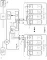
- FIG. 2illustrates an embodiment in AWS using a centralized transit VPC 205 providing access to external network 260 for compute nodes (e.g., VMs 230 ) executing in a compute VPC 210 .
- FIG. 2illustrates an example of four VMs 230 attached to the two of the four logical switches 110 and 120 , as implemented within a single compute VPC 210 of a single public cloud provider along with a transit VPC 205 implementing a cloud gateway 201 , a set of service compute nodes (SVMs 202 A-M), and cloud provider interne gateway 203 .
- FIG. 1illustrates an embodiment in AWS using a centralized transit VPC 205 providing access to external network 260 for compute nodes (e.g., VMs 230 ) executing in a compute VPC 210 .
- FIG. 2illustrates an example of four VMs 230 attached to the two of the four logical switches 110 and 120 , as implemented within a single compute VPC 210 of a
- each logical switchis contained within a single VPC (e.g., all of the VMs attached to a logical switch 110 and 120 are instantiated in the same VPC), with multiple logical switches instantiated in VPC 210 .
- VPC 210is assigned a subnet 10.1.0.0/16, which may be a public or private subnet depending on how the administrator has configured the VPC on the public cloud.
- the MFEsare all operating in a hybrid mode that allows the VM IP address (e.g., MFE tunnel endpoint IP address) to be the same as the workload application IP address (i.e., the IP address associated with the logical switch port).
- An MFE operating in a hybrid modedetermines whether to forward data messages sent by the workload application through the logical network (overlaid on the cloud provider network) or directly through the cloud provider network.
- each of the VMsis assigned a different workload IP (e.g., 10.1.0.2, 10.1.0.3, etc.) in the IP subnet assigned to the logical switch (e.g., 10.1.0.0/24) to which it connects, the IP subnet of the logical switch being an IP subnet of the subnet assigned to the VPC in which it is implemented (e.g., 10.1.0.0/16).
- IP addressese.g., 10.1.0.2, 10.1.0.3, etc.
- the logical switche.g.0.0/24
- the IP subnet of the logical switchbeing an IP subnet of the subnet assigned to the VPC in which it is implemented (e.g., 10.1.0.0/16).
- IP addressesin some embodiments, are identical to the IP addresses assigned to the VM (or the virtual extensible local area network tunnel endpoint (VTEP) of the MFE operating on the VM) by the cloud provider. Forwarding operations performed by an MFE implementing a hybrid logical switch for such embodiments are discussed in more
- each of the VMsis assigned a different workload IP in a subnet of the logical network that is not the same as the logical switch subnet assigned by the cloud provider (e.g., the 192.168.1.0/24 subnet instead of the 10.1.1.0/24 subnet).
- this different workload IP addresswill be the source IP used in the header of that packet.
- the MFEs operating on these VMshave VTEPs with different IP addresses on the VPC subnets (10.1.0.2, 10.1.0.3, 10.10.0.2, 10.10.0.3, etc.). The packets that exit the VM will thus be encapsulated using this VTEP IP address as the source IP address (after logical processing is performed by the MFE in the source VM), in order to be sent to other destinations in the VPC.
- the figurealso illustrates tunnels between these four MFEs and a cloud gateway 201 in the transit VPC 205 .
- the tunnelsin some embodiments use a peering relationship between compute VPC 210 and transit VPC 205 illustrated as network connection 250 .
- the cloud gateway 201provides connectivity for the overlay logical network to external network 260 and on-premises datacenter 270 . As shown, the cloud gateway 201 connects to external network 260 through internet gateway 203 .
- Internet gateway 203is provided, in some embodiments, by the cloud provider as part of the deployment of transit VPC 205 .
- the tunnels connecting the MFEs to the cloud gateway 201pass through the underlying network of the public cloud provider (referred to herein as the “underlay”).
- tunnelsare created (through the underlay network) between each pair of the MFEs operating on the VMs 230 .
- the data messagepasses through additional managed forwarding elements in one of the compute VPC and the transit VPC or in both the compute and transit VPC between the illustrated MFE and the cloud gateway.
- the intermediate MFEsimplement additional intermediary logical forwarding elements.
- the cloud gateway 201can also send packets to (and receive packets from) destinations within an on-premises private datacenter 270 .
- the cloud gateway 201encapsulates the packets using its VTEP IP, so that the destination will identify the incoming packet as a logical network packet.
- the packetsare sent via a VPN tunnel 204 in some embodiments.
- the components of the cloud gateway device 201are not shown but are discussed in more detail in U.S. Patent publication number 2018/0062923 which is incorporated herein by reference.
- Cloud gateway 201is a gateway compute node (e.g., a virtual machine) that provides access to external networks (e.g. forwards north-south traffic) to compute nodes inside the logical network.
- cloud gateway 201also provides services to north-south traffic received at cloud gateway 201 .
- Services provided at the cloud gateway 201include, in some embodiments, any one or more of a firewall service, a load balancing service, a network address translation service, intrusion detection, VPN, audit logging, service chaining (sending data messages to third-party service appliances (e.g., SVMs 202 ) for various middlebox processing).
- the services provided to traffic received at cloud gateway 201are provided by forwarding the traffic to a service compute node such as one of SVMs 202 A-M executing in the Transit VPC 205 .
- SVMs 202 A-Min some embodiments, provide a set of logical network services and a set of third party services. Having a centralized cloud gateway allows third-party appliances for north-south logical network traffic to also be centralized to the transit VPC in some embodiments leading to further cost and management overhead reductions.
- FIG. 3illustrates an embodiment using a centralized transit VPC 305 providing both transitive routing (i.e., routing from a first VPC to a second VPC through a third transit VPC) and access to external network 260 for compute nodes (e.g., VMs 230 ) executing in any of compute VPCs 310 A-N.
- FIG. 3illustrates an embodiment using a centralized transit VPC 305 providing both transitive routing (i.e., routing from a first VPC to a second VPC through a third transit VPC) and access to external network 260 for compute nodes (e.g., VMs 230 ) executing in any of compute VPCs 310 A-N.
- FIG. 3illustrates an embodiment using a centralized transit VPC 305 providing both transitive routing (i.e., routing from a first VPC to a second VPC through a third transit VPC) and access to external network 260 for compute nodes (e.g., VMs 230 )
- FIG. 3illustrates an example of eight VMs 330 attached to the four logical switches 110 - 125 , as implemented within a plurality of compute VPCs 310 A-N (specifically shown implemented in VPCs 310 A and 310 N) of a single public cloud provider along with a transit VPC 305 implementing a cloud gateway 301 , and a set of service compute nodes (SVMs 302 A-M), cloud provider internet gateway 303 .
- FIG. 3also illustrates an external network 360 , an on-premises datacenter 370 (e.g., a datacenter run by the owner of the VMs 330 ) and a VPN tunnel 304 connecting the transit VPC 305 to the on-premises datacenter 370 .
- an on-premises datacenter 370e.g., a datacenter run by the owner of the VMs 330
- VPN tunnel 304connecting the transit VPC 305 to the on-premises datacenter 370 .
- each logical switchspans a single VPC (e.g., all of the VMs attached to a logical switch 110 - 125 are instantiated in the same VPC), with VMs attached to multiple logical switches instantiated in each VPC.
- logical switchesspan multiple VPCs as described in U.S. Patent publication number 2018/0062923.
- VPC 310 Ais assigned a subnet 10.1.0.0/16
- VPC 310 Bis assigned a subnet 10.10.0.0/16, either of which may be a public or private subnet depending on how the administrator has configured the VPC on the public cloud.
- the MFEsare all operating in a hybrid mode that allows the VM IP address (e.g., MFE tunnel endpoint IP address) to be the same as the workload application IP address (i.e., the IP address associated with the logical switch port).
- An MFE operating in a hybrid modedetermines whether to forward data messages sent by the workload application through the logical network (overlaid on the cloud provider network) or directly through the cloud provider network.
- each of the VMsis assigned a different workload IP (e.g., 10.1.0.2, 10.10.0.3, etc.) in the IP subnet assigned to the logical switch (e.g., 10.1.0.0/24, 10.10.0.0/24, etc.) to which it connects.
- the IP subnet of the logical switchis an IP subnet of the subnet assigned to the VPC in which it is implemented (e.g., 10.1.0.0/16 or 10.10.0.0/16).
- These IP addressesare identical to the IP addresses assigned to the VM (or the VTEP of the MFE operating on the VM) by the cloud provider. Forwarding operations performed by an MFE implementing a hybrid logical switch for such embodiments are discussed in more detail below.
- each of the VMsis assigned a different workload IP in a subnet of the logical network that is not the same as the logical switch subnet assigned by the cloud provider (e.g., the 192.168.1.0/24 subnet instead of the 10.1.1.0/24 subnet).
- this different workload IP addresswill be the source IP used in the header of that packet.
- the MFEs operating on these VMshave VTEPs with different IP addresses on the VPC subnets (10.1.0.2, 10.1.0.3, 10.10.0.2, 10.10.0.3, etc.). The packets that exit the VM will thus be encapsulated using this VTEP IP address as the source IP address (after logical processing is performed by the MFE in the source VM), in order to be sent to other destinations in the VPC.
- the figurealso illustrates tunnels between these eight MFEs and a cloud gateway 301 in the transit VPC 305 .
- the tunnelsin some embodiments use a peering relationship between compute VPCs 310 A-N and transit VPC 305 illustrated as network connections 350 .
- These tunnelspass through the underlying network of the public cloud provider (referred to herein as the “underlay”).
- underlaythe public cloud provider
- tunnelsare created (through the underlay network) between each pair of the MFEs operating on the VMs 330 .
- tunnels between the MFEs 340 and the cloud gateway 301are used to forward traffic between compute nodes (e.g., VMs, containers, etc.) that are implemented by different VPCs if, for example, there is no peering between the source and destination VPCs or a centralized service provided by or through the cloud gateway 301 is required for the traffic.
- compute nodese.g., VMs, containers, etc.
- the cloud gateway 301can also send packets to (and receive packets from) destinations within an on-premises private datacenter 370 .
- the cloud gateway 301encapsulates the packets using its VTEP IP, so that the destination will identify the incoming packet as a logical network packet.
- the packetsare sent via a VPN tunnel 304 in some embodiments.
- the gateway's connection to external networksis not shown, and is discussed in more detail in U.S. Patent publication number 2018/0062923 which is incorporated herein by reference.
- Cloud gateway 301is a gateway compute node (e.g., a virtual machine) that provides access to external networks (e.g. forwards north-south traffic) to compute nodes inside the logical network.
- cloud gateway 301also provides services to traffic (both north-south and east-west) received at cloud gateway 301 .
- Services provided at the cloud gateway 301include, in some embodiments, any one or more of logical routing, a firewall service, a load balancing service, a network address translation service, intrusion detection, VPN, audit logging, service chaining (sending data messages to third-party service appliances (e.g., SVMs 302 ) for various middlebox processing).
- the services provided to traffic received at cloud gateway 301is provided by forwarding the traffic to a service compute node such as one of SVMs 302 A-M executing in the Transit VPC 305 .
- SVMs 302 A-Min some embodiments, provide a set of logical network services and a set of third party services. Having a centralized cloud gateway allows third-party appliances for north-south and east-west logical network traffic to also be centralized to the transit VPC in some embodiments leading to further cost and management overhead reductions.
- a cloud gatewayas a cluster of two or more cloud gateway devices in active-active or active-standby mode in a single transit VPC.
- Still other embodimentsimplement a cluster of two or more transit VPCs each hosting a cloud gateway device that are configured in one of active-active or active-standby configuration.
- Cloud gateways (or transit VPCs) in active-active modeare each addressable by compute nodes in the logical network and are load balanced in some embodiments or are addressed by a same multicast address.
- MFEsare configured as described in relation to FIG.
- stateful processingis maintained by an assignment of specific flows to specific cloud gateway devices/transit VPCs based on a sharding (e.g., based on source or destination IP address) or hashing (e.g., based on a hash of an n-tuple that defines a flow).
- a single cloud gateway device/transit VPCacts as the cloud gateway/transit VPC with additional devices or VPCs in the cluster providing redundancy in case the active device/transit VPC fails.
- FIG. 4illustrates a system 400 that is mostly identical to the system 300 of FIG. 3 but with an additional peering relationship indicated by connection 450 existing between VPCs 310 A and 310 N.
- system 400in addition to being able to forward data messages between VPCs 310 A and 310 N through transit VPC 305 (and cloud gateway 301 ), data messages can also be forwarded using the peering relationship.
- FIG. 5conceptually illustrates a process for making use of existing peering and intra-VPC connectivity along with the centralized cloud gateway device.
- FIG. 5conceptually illustrates a process performed by a managed forwarding element (MFE) to intelligently forward a data message received from a compute node using one of the overlay or cloud provider network.
- the processbegins (at 510 ) by receiving a data message from a compute node (e.g., a virtual machine or container) destined for another compute node. Different data messages are destined for different compute nodes in different virtual private clouds and require different services.
- the cloud providerprovides some services while other services are provided by an element of the overlay network.
- the services provided by the cloud providerare of a same type (e.g., firewall, load balancing, WAN optimization, etc.) as those provided by the elements of the overlay network.
- the MFEUpon receiving the data message, the MFE performs (at 520 ) ingress processing.
- the ingress processingincludes a distributed firewall operation.
- the MFEconsults an arbiter to determine (at 530 ) whether the data message requires processing by a cloud gateway executing in the transit VPC.
- the arbiteris part of the MFE. The determination, in some embodiments, is based on whether the destination of the data message is in a same VPC as the source of the data message, whether any centralized services are required for the data message, and whether a peering exists between the source and destination VPCs.
- the policyin some embodiments, is specified in terms of a tuple associated with data messages (e.g., a five-tuple specifying source and destination IP address, source and destination port and protocol).
- the determination that a data message requires a centralized serviceis made implicitly based on a lack of a routing entry for the destination IP address after having the routing table processed to remove routes to addresses that are not available from the VPC or that require routing through the cloud gateway in the transit VPC (as discussed in relation to FIG. 8 ).
- the determination whether a peering exists between a source and destination VPCis based on whether or not a route for the destination IP address in a destination VPC exists in a routing table of the source VPC (or MFE implementing a logical router of the overlay network).
- information regarding whether a peering between a source VPC and a destination VPC existsis provided by a user (e.g., a system administrator) and is pushed to the MFEs executing at the different VPCs.
- the MFEor separate managed switching and routing elements as discussed below
- arbiter moduleperforms logical switching and routing operations associated with logical switching and routing elements of the overlay network (e.g. a tenant logical network).
- Logical switching operationsinclude, in some embodiments, identifying an egress logical port of the logical switching element that receives the data message from a source compute node and logically forwarding the data message to the egress logical port connected to a logical routing element.
- the logical routing operationsinclude implementing a distributed logical router to identify a logical port of the logical routing element associated with the destination address of the data message.
- the distributed logical routeris configured, in some embodiments, to cause data messages that (1) require a service provided at the overlay cloud gateway or (2) that are destined for VPC for which no peering relationship exists from a source VPC to be routed to the cloud gateway. In some embodiments, this is equivalent to the distributed logical routing element determining that the data message should be forwarded to a centralized service routing element implemented by the overlay cloud gateway.
- a data messagerequires processing by an overlay cloud gateway (e.g., a device implementing a logical router to provide access to external network for compute nodes in the overlay network), in some embodiments, if the data message (1) requires a centralized service provided by the cloud gateway (whether source and destination VPCs are the same or different) or (2) is destined to a VPC that is not peered to the source VPC.
- an overlay cloud gatewaye.g., a device implementing a logical router to provide access to external network for compute nodes in the overlay network
- a data messagedoes not require processing by the overlay cloud gateway if (1) the data message is destined to a compute node in the same VPC and does not require a centralized service provided by the cloud gateway or (2) the data message is destined to a compute node on a VPC that is peered with the VPC of the source compute node and the data message does not require a centralized service.
- the processencapsulates (at 530 ) the data message with a header that directs the packet to a tunnel endpoint of the cloud gateway.
- the tunnel endpointis a Virtual Extensible Local Area Network (VXLAN) Tunnel Endpoint (VTEP).
- VXLANVirtual Extensible Local Area Network
- VTEPVirtual Extensible Local Area Network Tunnel Endpoint
- the encapsulationin some embodiments, is a generic network virtualization encapsulation (GENEVE) header.
- the processforwards the data message to the destination.
- the data messageis forwarded to a forwarding element of the cloud provider and the process ends.
- the cloud-provider forwarding elementin some embodiments provides a further encapsulation to traverse the physical network on which the virtual private cloud is implemented.
- data messages encapsulated to be forwarded to the cloud gatewayare received at the cloud gateway which then decapsulates the data message, provides any required services, and forwards the data message to the destination compute node.
- the forwarded data messagedoes not require encapsulation to be forwarded from the cloud gateway to the destination compute node.
- FIG. 6illustrates a set of possible data message paths and headers that are used in some embodiments for intra-VPC traffic.
- FIG. 6depicts system 600 which is a reduced view of system 300 that includes a physical cloud host machine 680 including a public cloud forwarding element (PCFE) 690 on which VM 1 executes and does not show tunneling relationships between MFEs 340 and cloud gateway 301 . Similar public cloud host machines 680 on which other VMs execute are not shown.
- FIG. 6illustrates a data message being directed from an application executing on VM 1 to VM 6 .
- PCFEpublic cloud forwarding element
- VM 1belongs to the 10.1.0.0/24 subnet of a first logical switch and VM belongs to the 10.1.1.0/24 subnet of a second logical switch, both logical switches implemented in VPC 310 A with assigned IP subnet 10.1.0.0/16.
- first and second paths from VM 1 to VM 6are depicted.
- the beginning of each pathbegins with a data message (labeled ‘ 1 ’) that is sent from the workload application using the source and destination IP addresses that are equivalent in the overlay network and the cloud provider network.
- the overlay network addresseswould appear in the header of the data message from the workload application.
- the containersends data message ‘ 1 ’ to an MFE (e.g. an OVS) using the IP addresses assigned by the overlay network.
- MFEe.g. an OVS
- MFE 340determines whether the data message requires forwarding to the cloud gateway 301 (e.g., based on PBR, or lack of routing entry for the destination switch subnet as described above). If MFE 340 determines that the data message should be forwarded directly to the destination (i.e., VM 6 ) the MFE forwards the data message to the PCFE that is provided by the cloud provider and implements the provider logical network on the underlay network infrastructure. The data message is forwarded without encapsulation by the MFE as data message ‘ 2 ’ and the PCFE encapsulates the data message as data message ‘ 3 ’ to traverse the underlay network to reach the public cloud host machine (not shown) hosting the destination compute node (i.e., VM 6 ).
- the MFEFor intra-VPC traffic that the MFE determines requires forwarding to the cloud gateway 301 based on a need for a particular service provided by the cloud gateway 301 , the MFE encapsulates the data message (as data message ‘ 4 ’) with the IP address of the cloud gateway (e.g., 10.12.0.1) which is accessible based on the peering 350 between compute VPC 310 A and transit VPC 305 .
- the address of the cloud gateway 301in this case, is both the overlay and cloud provider address, but in embodiments in which they are not the same, the MFE uses the VTEP address of the MFE to which the cloud gateway 301 attaches in the encapsulation.
- Data message ‘ 4 ’is received by PCFE 690 and, similarly to data message ‘ 3 ’, is encapsulated as data message ‘ 5 ’ to traverse the underlay network to arrive at cloud gateway 301 .
- the structure of the data messages ‘ 1 ’ through ‘ 5 ’is shown on the right hand side of FIG. 6 .
- the cloud gateway 301receives data message ‘ 5 ’ it provides the service (e.g., firewall, NAT, load balancing, etc.) to/for the data message.
- providing the serviceincludes forwarding the data message as data message ‘ 6 ’ to a service compute node (i.e., SVM 302 A) that is one of a logical network service appliance or a third-party service appliance in some embodiments. Forwarding the data message to the service appliance uses the overlay encapsulation in some embodiments, while in other embodiments, the service appliance is addressed using the cloud provider logical network address. After the service is performed/provided, the service appliance returns data message ‘ 7 ’ to the cloud gateway 301 for forwarding to the destination as data message ‘ 8 ’.
- a service compute nodei.e., SVM 302 A
- Data message ‘ 8 ’ in some embodimentsis sent without an overlay encapsulation based on the peering relationship between transit VPC 305 and compute VPC 310 A that allows addressing compute nodes in other VPCs directly.
- a PCFE executing on the host machine on which the cloud gateway operateswill encapsulate the data message as in data messages ‘ 3 ’ and ‘ 5 ’ whether the data message is sent by the cloud gateway 301 encapsulated or unencapsulated.
- data messages ‘ 6 ’ and ‘ 7 ’are not sent as the service is provided by the cloud gateway itself.
- FIG. 7illustrates a set of inter-VPC data message traffic in a system 700 .
- System 700depicts three compute VPCs 710 A, B, and N with respective IP subnets (e.g., CIDR blocks) 10.1.0.0/16, 10.8.0.0/16, and 10.10.0.0/16, and including VMs 1 , 4 , and 8 with respective IP addresses 10.1.0.2, 10.8.0.3, and 10.10.1.3 (VMs 1 , 4 , and 8 logically connected as in FIG. 1 ).
- Each of VMs 1 , 4 , and 8operate in a public cloud host machine that includes a PCFE as in FIG. 6 which are not shown for clarity.
- Three basic inter-VPC traffic patternsare depicted in FIG.
- Data message ‘ 1 ’ of FIG. 7depicts a first data message that has been determined to require a service provided by or through cloud gateway 701 .
- Data message ‘ 1 ’is sent from an application or container on VM 1 addressed to an IP address in another VPC.
- the MFEencapsulates the data message as in data message ‘ 4 ’ of FIG.
- Data messages ‘ 2 a ’ through ‘ 2 m ’represent a set of data messages to implement service chaining of multiple services provided by cloud gateway 701 .
- the service chainin some embodiments, is in addition to services provided by the cloud gateway.
- no services provided by the service appliances 702are necessary and the traffic goes directly from data message ‘ 1 ’ to data message ‘ 2 n ’ or ‘ 3 ’.
- data messages sent from cloud gateway 701 to VMs in compute VPCscan be sent using overlay encapsulation or the cloud provider network.
- Data message ‘ 4 ’is a data message sent from a VM in a first compute VPC 710 A to a second compute VPC 710 B for which a peering exists.
- MFE 740receives a data message from an application or container on VM 1 and determines that the data message does not require routing through the transit VPC 705 and that a peering relationship exists between the current compute VPC and the destination compute VPC. Based on the determination, data message ‘ 4 ’ is sent to the PCFE (not shown) using the cloud provider addresses (e.g., as for data message ‘ 2 ’ of FIG. 6 ) for the PCFE to encapsulate using the underlay network IP addresses and headers.
- FIG. 8conceptually illustrates a process 800 used in some embodiments to configure an MFE to implement the process of FIG. 5 .
- the process 800receives (at 810 ) configuration data.
- the configuration dataincludes a list of directly available endpoint addresses.
- the directly available addressesare specified for a particular VPC.
- a listspecifies addresses directly available for multiple VPCs at the same time.
- the listmay be arranged as a list of addresses and the VPC for which they are directly available.
- Directly available addresses for a particular VPCinclude addresses available on VPCs peered to the particular VPC and addresses available through a cloud-provider virtual private network (VPN).
- VPNvirtual private network
- Configuration dataincludes an identification of (1) peered VPCs and (2) VPNs that exist between VPCs.
- the configuration datais received by a network controller from a user (e.g., a system administrator).
- An identification of peered VPCs and existing VPNs in some embodimentsare retrieved automatically using application programming interfaces (APIs) provided by the cloud provider.
- Configuration dataspecifies a preferred method of communication between specific compute nodes or types of compute nodes (e.g., web servers to app servers, app servers to database servers, etc.) or a priority of methods of communication (e.g., preferring VPC peering using the provider network over VPN traffic) for compute nodes that are connected in multiple ways.
- the processpushes (at 820 ) configuration data to compute nodes in the overlay network.
- the configuration data pushed to the compute nodesis the configuration data received by the controller.
- the controllerconverts the received configuration data into compute-node- or VPC-specific data that reflects the portion of the configuration data that is relevant to the compute node or to the VPC in which the compute node executes (e.g., that the VPC is peered with 2 additional VPCs).
- the controllercommunicates the configuration information to a local agent of the compute node to be configured. This configuration data, in some embodiments, is in addition to other sets of configuration data for constructing/populating routing tables of the different MFEs.
- the compute nodereceives (at 830 ) the configuration data.
- the compute nodeoperates an MFE of the overlay network.
- the MFEexecutes in a virtual machine along with a set of applications or containers for which the MFE provides forwarding services.
- the MFEis an open vSwitch (OVS) and the configuration data is received as a set of forwarding entries for an open vSwitch (OVS).
- the configurationincludes a set of routing entries reflecting the existence of peering relationships between VPCs, the existence of VPNs, or specific flows that should be directed to a cloud gateway in a transit VPC.
- the configuration datain such embodiments includes configuration data for each managed switching and routing element separately to implement the desired logical switching and routing elements, respectively, of the overlay network (e.g., a tenant logical network).
- the compute nodeonly executes a managed switching element with a managed routing element executing on a separate compute node.
- Some embodimentsplace the routing entries in a routing table of a Tier-1 or Tier-0 distributed router implemented by the MFE or managed routing element.
- the logical network implementing Tier-1 and Tier-0 logical routersis described in U.S. Pat. No. 9,787,605 which is hereby incorporated by reference.
- the compute nodeconverts the configuration data into forwarding data (e.g., entries in a routing table, flow entries for the OVS).
- Some embodimentsreceive the configuration data as (1) policy based routing data that defines policies based on data message or flow characteristics (e.g., a five-tuple, or other header values) and (2) private routing table data that is used (i) to direct an MFE to use the private routing table when the characteristics of a data message match and (ii) to generate and populate the private routing table, respectively.
- policy based routing datathat defines policies based on data message or flow characteristics (e.g., a five-tuple, or other header values)
- private routing table datathat is used (i) to direct an MFE to use the private routing table when the characteristics of a data message match and (ii) to generate and populate the private routing table, respectively.
- the processconfigures (at 840 ) the MFE to implement the forwarding decisions based on the received configuration data.
- configuring the MFEincludes updating a routing table of the MFE (or managed routing element) with routes based on the configuration data.
- Routing table entries of the updated routing tablemay include routing entries to forward traffic (1) using the cloud provider network (e.g., sending the traffic without encapsulation by the MFE) to a destination compute node, (2) encapsulated by the MFE to use a direct tunnel between source and destination compute nodes (e.g., between MFEs to which the source and destination compute nodes connect), or (3) encapsulated to use a tunnel to a cloud gateway (e.g., a cloud gateway in a transit VPC) for the cloud gateway to forward to the destination compute node.
- configuring the MFEincludes updating flow entries of the OVS to forward traffic in any of the ways outlined above for the routing entries. The MFE is now configured and the process ends.
- Computer readable storage mediumalso referred to as computer readable medium.
- processing unit(s)e.g., one or more processors, cores of processors, or other processing units
- processing unit(s)e.g., one or more processors, cores of processors, or other processing units
- Examples of computer readable mediainclude, but are not limited to, CD-ROMs, flash drives, RAM chips, hard drives, EPROMs, etc.
- the computer readable mediadoes not include carrier waves and electronic signals passing wirelessly or over wired connections.
- the term “software”is meant to include firmware residing in read-only memory or applications stored in magnetic storage, which can be read into memory for processing by a processor.
- multiple software inventionscan be implemented as sub-parts of a larger program while remaining distinct software inventions.
- multiple software inventionscan also be implemented as separate programs.
- any combination of separate programs that together implement a software invention described hereis within the scope of the invention.
- the software programswhen installed to operate on one or more electronic systems, define one or more specific machine implementations that execute and perform the operations of the software programs.
- FIG. 9conceptually illustrates a computer system 900 with which some embodiments of the invention are implemented.
- the computer system 900can be used to implement any of the above-described hosts, controllers, and managers. As such, it can be used to execute any of the above described processes.
- This computer systemincludes various types of non-transitory machine readable media and interfaces for various other types of machine readable media.
- Computer system 900includes a bus 9105 , processing unit(s) 910 , a system memory 925 , a read-only memory 930 , a permanent storage device 935 , input devices 940 , and output devices 945 .
- the bus 905collectively represents all system, peripheral, and chipset buses that communicatively connect the numerous internal devices of the computer system 900 .
- the bus 905communicatively connects the processing unit(s) 910 with the read-only memory 930 , the system memory 925 , and the permanent storage device 935 .
- the processing unit(s) 910retrieve instructions to execute and data to process in order to execute the processes of the invention.
- the processing unit(s)may be a single processor or a multi-core processor in different embodiments.
- the read-only-memory (ROM) 930stores static data and instructions that are needed by the processing unit(s) 910 and other modules of the computer system.
- the permanent storage device 935is a read-and-write memory device. This device is a non-volatile memory unit that stores instructions and data even when the computer system 900 is off. Some embodiments of the invention use a mass-storage device (such as a magnetic or optical disk and its corresponding disk drive) as the permanent storage device 935 .
- the system memory 925is a read-and-write memory device. However, unlike storage device 935 , the system memory is a volatile read-and-write memory, such a random access memory.
- the system memorystores some of the instructions and data that the processor needs at runtime.
- the invention's processesare stored in the system memory 925 , the permanent storage device 935 , and/or the read-only memory 930 . From these various memory units, the processing unit(s) 910 retrieve instructions to execute and data to process in order to execute the processes of some embodiments.
- the bus 905also connects to the input and output devices 940 and 945 .
- the input devicesenable the user to communicate information and select commands to the computer system.
- the input devices 940include alphanumeric keyboards and pointing devices (also called “cursor control devices”).
- the output devices 945display images generated by the computer system.
- the output devicesinclude printers and display devices, such as cathode ray tubes (CRT) or liquid crystal displays (LCD). Some embodiments include devices such as a touchscreen that function as both input and output devices.
- bus 905also couples computer system 900 to a network 965 through a network adapter (not shown).
- the computercan be a part of a network of computers (such as a local area network (“LAN”), a wide area network (“WAN”), or an Intranet, or a network of networks, such as the Internet. Any or all components of computer system 900 may be used in conjunction with the invention.
- Some embodimentsinclude electronic components, such as microprocessors, storage and memory that store computer program instructions in a machine-readable or computer-readable medium (alternatively referred to as computer-readable storage media, machine-readable media, or machine-readable storage media).
- computer-readable mediainclude RAM, ROM, read-only compact discs (CD-ROM), recordable compact discs (CD-R), rewritable compact discs (CD-RW), read-only digital versatile discs (e.g., DVD-ROM, dual-layer DVD-ROM), a variety of recordable/rewritable DVDs (e.g., DVD-RAM, DVD-RW, DVD+RW, etc.), flash memory (e.g., SD cards, mini-SD cards, micro-SD cards, etc.), magnetic and/or solid state hard drives, read-only and recordable Blu-Ray® discs, ultra-density optical discs, any other optical or magnetic media, and floppy disks.
- CD-ROMcompact discs
- CD-Rrecordable compact
- the computer-readable mediamay store a computer program that is executable by at least one processing unit and includes sets of instructions for performing various operations.
- Examples of computer programs or computer codeinclude machine code, such as is produced by a compiler, and files including higher-level code that are executed by a computer, an electronic component, or a microprocessor using an interpreter.
- ASICsapplication specific integrated circuits
- FPGAsfield programmable gate arrays
- integrated circuitsexecute instructions that are stored on the circuit itself.
- the terms “computer”, “server”, “processor”, and “memory”all refer to electronic or other technological devices. These terms exclude people or groups of people.
- display or displayingmeans displaying on an electronic device.
- the terms “computer readable medium,” “computer readable media,” and “machine readable medium”are entirely restricted to tangible, physical objects that store information in a form that is readable by a computer. These terms exclude any wireless signals, wired download signals, and any other ephemeral or transitory signals.
Landscapes
- Engineering & Computer Science (AREA)
- Computer Networks & Wireless Communication (AREA)
- Signal Processing (AREA)
- Data Exchanges In Wide-Area Networks (AREA)
Abstract
Description
Claims (18)
Priority Applications (7)
| Application Number | Priority Date | Filing Date | Title |
|---|---|---|---|
| US16/112,597US11374794B2 (en) | 2018-08-24 | 2018-08-24 | Transitive routing in public cloud |
| EP19762271.5AEP3815311B1 (en) | 2018-08-24 | 2019-08-14 | Intelligent use of peering in public cloud |
| PCT/US2019/046570WO2020041074A1 (en) | 2018-08-24 | 2019-08-14 | Intelligent use of peering in public cloud |
| EP23188797.7AEP4243367A3 (en) | 2018-08-24 | 2019-08-14 | Intelligent use of peering in public cloud |
| CN202211668939.6ACN116032836B (en) | 2018-08-24 | 2019-08-14 | Using peering intelligently in public clouds |
| CN201980055833.9ACN112640369B (en) | 2018-08-24 | 2019-08-14 | Method, apparatus, and machine-readable medium for intelligently using peers in a public cloud |
| US17/849,669US12074731B2 (en) | 2018-08-24 | 2022-06-26 | Transitive routing in public cloud |
Applications Claiming Priority (1)
| Application Number | Priority Date | Filing Date | Title |
|---|---|---|---|
| US16/112,597US11374794B2 (en) | 2018-08-24 | 2018-08-24 | Transitive routing in public cloud |
Related Child Applications (1)
| Application Number | Title | Priority Date | Filing Date |
|---|---|---|---|
| US17/849,669ContinuationUS12074731B2 (en) | 2018-08-24 | 2022-06-26 | Transitive routing in public cloud |
Publications (2)
| Publication Number | Publication Date |
|---|---|
| US20200067733A1 US20200067733A1 (en) | 2020-02-27 |
| US11374794B2true US11374794B2 (en) | 2022-06-28 |
Family
ID=69586660
Family Applications (2)
| Application Number | Title | Priority Date | Filing Date |
|---|---|---|---|
| US16/112,597Active2040-01-21US11374794B2 (en) | 2018-08-24 | 2018-08-24 | Transitive routing in public cloud |
| US17/849,669ActiveUS12074731B2 (en) | 2018-08-24 | 2022-06-26 | Transitive routing in public cloud |
Family Applications After (1)
| Application Number | Title | Priority Date | Filing Date |
|---|---|---|---|
| US17/849,669ActiveUS12074731B2 (en) | 2018-08-24 | 2022-06-26 | Transitive routing in public cloud |
Country Status (1)
| Country | Link |
|---|---|
| US (2) | US11374794B2 (en) |
Cited By (5)
| Publication number | Priority date | Publication date | Assignee | Title |
|---|---|---|---|---|
| US20210105208A1 (en)* | 2017-08-27 | 2021-04-08 | Nicira, Inc. | Performing in-line service in public cloud |
| US20220337545A1 (en)* | 2019-05-10 | 2022-10-20 | Huawei Technologies Co., Ltd. | Virtual private cloud communication and configuration method, and related apparatus |
| US20220337506A1 (en)* | 2020-01-07 | 2022-10-20 | Huawei Cloud Computing Technologies Co., Ltd. | Method for multi-cloud interconnection and device |
| US11792138B2 (en) | 2016-08-27 | 2023-10-17 | Nicira, Inc. | Centralized processing of north-south traffic for logical network in public cloud |
| US12074731B2 (en) | 2018-08-24 | 2024-08-27 | VMware LLC | Transitive routing in public cloud |
Families Citing this family (24)
| Publication number | Priority date | Publication date | Assignee | Title |
|---|---|---|---|---|
| US10341371B2 (en) | 2016-08-31 | 2019-07-02 | Nicira, Inc. | Identifying and handling threats to data compute nodes in public cloud |
| US10567482B2 (en) | 2017-08-24 | 2020-02-18 | Nicira, Inc. | Accessing endpoints in logical networks and public cloud service providers native networks using a single network interface and a single routing table |
| US10862753B2 (en) | 2017-12-04 | 2020-12-08 | Nicira, Inc. | High availability for stateful services in public cloud logical networks |
| US11343229B2 (en) | 2018-06-28 | 2022-05-24 | Vmware, Inc. | Managed forwarding element detecting invalid packet addresses |
| US11196591B2 (en) | 2018-08-24 | 2021-12-07 | Vmware, Inc. | Centralized overlay gateway in public cloud |
| US11388227B1 (en)* | 2020-02-27 | 2022-07-12 | Aviatrix Systems, Inc. | Multi-cloud active mesh network system and method |
| US11652736B2 (en)* | 2020-06-30 | 2023-05-16 | Amazon Technologies, Inc. | Transmitting network traffic to a pool of redundant network appliances |
| US11616755B2 (en) | 2020-07-16 | 2023-03-28 | Vmware, Inc. | Facilitating distributed SNAT service |
| US11611613B2 (en) | 2020-07-24 | 2023-03-21 | Vmware, Inc. | Policy-based forwarding to a load balancer of a load balancing cluster |
| US11902050B2 (en)* | 2020-07-28 | 2024-02-13 | VMware LLC | Method for providing distributed gateway service at host computer |
| US11843539B1 (en)* | 2020-08-24 | 2023-12-12 | Aviatrix Systems, Inc. | Systems and methods for load balancing network traffic at firewalls deployed in a cloud computing environment |
| US11595307B1 (en) | 2020-09-25 | 2023-02-28 | Amazon Technologies, Inc. | Customized tuple definition for hashing at a network appliance routing service |
| US12182599B2 (en)* | 2020-12-22 | 2024-12-31 | Oracle International Corporation | Mechanism to implement VCN network virtualization in a rack-based switch |
| US12309066B1 (en)* | 2021-02-22 | 2025-05-20 | Aviatrix Systems, Inc. | System and method for increased throughput and scalability |
| US11722409B2 (en)* | 2021-05-03 | 2023-08-08 | Vmware, Inc. | Inter-tunneling endpoint (inter-TEP) overlay forwarding |
| CN117178259B (en)* | 2021-05-24 | 2024-12-03 | 威睿有限责任公司 | Allocating additional bandwidth to resources in a data center through deployment of dedicated gateways |
| US11956123B1 (en)* | 2021-09-29 | 2024-04-09 | Cisco Technology, Inc. | Monitoring interface configurations for network devices in fabrics |
| EP4473403A1 (en) | 2022-02-02 | 2024-12-11 | Oracle International Corporation | Multi-cloud control plane architecture |
| WO2023150531A1 (en) | 2022-02-02 | 2023-08-10 | Oracle International Corporation | Cloud-link adaptor of a multi-cloud infrastructure |
| JP2025506395A (en) | 2022-02-02 | 2025-03-11 | オラクル・インターナショナル・コーポレイション | Multicloud Control Plane Network Adapter Architecture |
| CN115051948B (en)* | 2022-05-19 | 2023-10-13 | 天翼云科技有限公司 | VPC distributed network element data transmission method and device and electronic equipment |
| US11831498B1 (en)* | 2022-05-23 | 2023-11-28 | Cisco Technology, Inc. | Integrating an existing cloud network into a target environment |
| CN120035958A (en) | 2022-10-14 | 2025-05-23 | 甲骨文国际公司 | Identity management in multi-cloud infrastructure |
| WO2025117319A1 (en)* | 2023-11-30 | 2025-06-05 | Oracle International Corporation | Subscription to a service provided by a first cloud service provider via a second cloud service provider |
Citations (198)
| Publication number | Priority date | Publication date | Assignee | Title |
|---|---|---|---|---|
| US6108300A (en) | 1997-05-02 | 2000-08-22 | Cisco Technology, Inc | Method and apparatus for transparently providing a failover network device |
| US20020062217A1 (en) | 1996-11-01 | 2002-05-23 | Junichi Fujimori | System and method for preventing unauthorized data copying using communication network |
| US20020199007A1 (en) | 2001-06-12 | 2002-12-26 | Tom Clayton | Virtual private network software system |
| US6832238B1 (en) | 2000-05-24 | 2004-12-14 | Sun Microsystems, Inc. | Local transaction management |
| CN1792062A (en) | 2003-02-07 | 2006-06-21 | 移动365 | Intermediary network system and method |
| US7107360B1 (en) | 2001-07-24 | 2006-09-12 | Cisco Technology, Inc. | Network address translation in a gateway |
| EP1742430A1 (en) | 2005-07-07 | 2007-01-10 | Solace Systems, Inc | Router redundancy in data communication networks |
| US20070186281A1 (en) | 2006-01-06 | 2007-08-09 | Mcalister Donald K | Securing network traffic using distributed key generation and dissemination over secure tunnels |
| US20070226795A1 (en) | 2006-02-09 | 2007-09-27 | Texas Instruments Incorporated | Virtual cores and hardware-supported hypervisor integrated circuits, systems, methods and processes of manufacture |
| US20070256073A1 (en) | 2006-03-14 | 2007-11-01 | University Of Utah Research Foundation | Extendable framework for distributed applications and data |
| US7360245B1 (en) | 2001-07-18 | 2008-04-15 | Novell, Inc. | Method and system for filtering spoofed packets in a network |
| US20080104692A1 (en) | 2006-09-29 | 2008-05-01 | Mcalister Donald | Virtual security interface |
| US7423962B2 (en) | 2002-06-28 | 2008-09-09 | Nokia Corporation | Redundancy and load balancing in a telecommunication unit and system |
| US20080225888A1 (en) | 2007-03-14 | 2008-09-18 | Vamsidhar Valluri | Optimizing return traffic paths using network address translation |
| US7523485B1 (en) | 2003-05-21 | 2009-04-21 | Foundry Networks, Inc. | System and method for source IP anti-spoofing security |
| US20100037311A1 (en) | 2006-11-20 | 2010-02-11 | Liwen He | Secure network architecture |
| US20100112974A1 (en) | 2008-11-05 | 2010-05-06 | Aakash Sahai | Reducing receiver power dissipation |
| CN101764752A (en) | 2009-12-25 | 2010-06-30 | 杭州华三通信技术有限公司 | Method and system for managing remote concentrated image |
| US20100318609A1 (en) | 2009-06-15 | 2010-12-16 | Microsoft Corporation | Bridging enterprise networks into cloud |
| US20110075674A1 (en) | 2009-09-30 | 2011-03-31 | Alcatel-Lucent Usa Inc. | Scalable architecture for enterprise extension in a cloud topology |
| US7953895B1 (en) | 2007-03-07 | 2011-05-31 | Juniper Networks, Inc. | Application identification |
| CN102255934A (en) | 2010-05-20 | 2011-11-23 | 中兴通讯股份有限公司 | Cloud service publishing method, cloud service publishing interface message packet and cloud service broker |
| US20110317703A1 (en) | 2010-06-29 | 2011-12-29 | Futurewei Technologies, Inc. | Asymmetric Network Address Encapsulation |
| US20120082063A1 (en) | 2010-09-30 | 2012-04-05 | Nec Corporation | Quarantine device, quarantine method, and computer-readable storage medium |
| US8264947B1 (en) | 2005-06-15 | 2012-09-11 | Barclays Capital, Inc. | Fault tolerant wireless access system and method |
| US20120250682A1 (en) | 2011-03-30 | 2012-10-04 | Amazon Technologies, Inc. | Frameworks and interfaces for offload device-based packet processing |
| US8296434B1 (en) | 2009-05-28 | 2012-10-23 | Amazon Technologies, Inc. | Providing dynamically scaling computing load balancing |
| US20130044641A1 (en) | 2011-08-17 | 2013-02-21 | Teemu Koponen | Federating interconnection switching element network to two or more levels |
| US20130044636A1 (en) | 2011-08-17 | 2013-02-21 | Teemu Koponen | Distributed logical l3 routing |
| US20130058208A1 (en) | 2010-07-06 | 2013-03-07 | Benjamin L. Pfaff | Fault tolerant managed switching element architecture |
| US20130058335A1 (en) | 2010-07-06 | 2013-03-07 | Teemu Koponen | Packet processing for logical datapath sets |
| CN103036919A (en) | 2011-09-30 | 2013-04-10 | 上海贝尔股份有限公司 | Method and device for achieving migration of virtual machine in virtual private cloud (VPC) |
| US8432791B1 (en) | 2005-07-29 | 2013-04-30 | F5 Networks, Inc. | Network route injections |
| US20130125230A1 (en) | 2011-11-15 | 2013-05-16 | Nicira, Inc. | Firewalls in logical networks |
| US20130152076A1 (en) | 2011-12-07 | 2013-06-13 | Cisco Technology, Inc. | Network Access Control Policy for Virtual Machine Migration |
| US20130198740A1 (en) | 2012-01-30 | 2013-08-01 | International Business Machines Corporation | Integrated virtual infrastructure system |
| US8514868B2 (en) | 2008-06-19 | 2013-08-20 | Servicemesh, Inc. | Cloud computing gateway, cloud computing hypervisor, and methods for implementing same |
| US20130263118A1 (en) | 2012-03-29 | 2013-10-03 | International Business Machines Corporation | Emulating a data center network on a single physical host with support for virtual machine mobility |
| US20130287026A1 (en) | 2012-04-13 | 2013-10-31 | Nicira Inc. | Extension of logical networks across layer 3 virtual private networks |
| US20130297768A1 (en) | 2012-05-01 | 2013-11-07 | Cisco Technology, Inc. | Method and apparatus for providing tenant information for network flows |
| US20130304903A1 (en) | 2012-05-09 | 2013-11-14 | Rackspace Us, Inc. | Market-Based Virtual Machine Allocation |
| US20130318219A1 (en) | 2012-05-23 | 2013-11-28 | Brocade Communications Systems, Inc | Layer-3 overlay gateways |
| US20130346585A1 (en) | 2011-03-18 | 2013-12-26 | Nec Corporation | Network system, and policy route setting method |
| US20140010239A1 (en) | 2011-03-16 | 2014-01-09 | Huawei Technologies, Co., Ltd. | Media gateway device and method for forwarding data frames |
| US20140052877A1 (en) | 2012-08-16 | 2014-02-20 | Wenbo Mao | Method and apparatus for tenant programmable logical network for multi-tenancy cloud datacenters |
| US20140108665A1 (en) | 2012-10-16 | 2014-04-17 | Citrix Systems, Inc. | Systems and methods for bridging between public and private clouds through multilevel api integration |
| JP2014075731A (en) | 2012-10-05 | 2014-04-24 | Hitachi Solutions Ltd | Intercloud communication-setting system |
| US8719590B1 (en) | 2012-06-18 | 2014-05-06 | Emc Corporation | Secure processing in multi-tenant cloud infrastructure |
| US20140143853A1 (en) | 2011-07-11 | 2014-05-22 | Nec Corporation | Network quarantine system, network quarantine method and program therefor |
| US20140156818A1 (en) | 2012-12-03 | 2014-06-05 | Cutting Edge Consulting Associates, Inc. | Systems and methods for protecting an identity in network communications |
| US20140192804A1 (en) | 2013-01-09 | 2014-07-10 | Dell Products L.P. | Systems and methods for providing multicast routing in an overlay network |
| US20140226820A1 (en) | 2013-02-12 | 2014-08-14 | Vmware, Inc. | Infrastructure level lan security |
| US20140245420A1 (en) | 2013-02-28 | 2014-08-28 | Microsoft Corporation | Web ticket based upon a symmetric key usable for user authentication |
| US20140241247A1 (en) | 2011-08-29 | 2014-08-28 | Telefonaktiebolaget L M Ericsson (Publ) | Implementing a 3g packet core in a cloud computer with openflow data and control planes |
| US20140280961A1 (en) | 2013-03-15 | 2014-09-18 | Frank Martinez | System and method for a cloud computing abstraction with multi-tier deployment policy |
| US20140317677A1 (en) | 2013-04-19 | 2014-10-23 | Vmware, Inc. | Framework for coordination between endpoint security and network security services |
| US20140334495A1 (en) | 2013-05-07 | 2014-11-13 | Equinix, Inc. | Direct Connect Virtual Private Interface for a One to Many Connection with Multiple Virtual Private Clouds |
| US20140337500A1 (en) | 2013-02-26 | 2014-11-13 | Zentera Systems, Inc. | Secure cloud fabric to connect subnets in different network domains |
| US8902743B2 (en) | 2010-06-28 | 2014-12-02 | Microsoft Corporation | Distributed and scalable network address translation |
| US20140376560A1 (en) | 2013-06-24 | 2014-12-25 | Microsoft Corporation | Logical switch |
| US20150009995A1 (en) | 2013-07-08 | 2015-01-08 | Nicira, Inc. | Encapsulating Data Packets Using an Adaptive Tunnelling Protocol |
| US20150016460A1 (en) | 2013-07-09 | 2015-01-15 | Nicira, Inc. | Using Headerspace Analysis to Identify Flow Entry Reachability |
| US20150016286A1 (en) | 2013-07-12 | 2015-01-15 | Nicira, Inc. | Tracing Network Packets by a Cluster of Network Controllers |
| US20150043383A1 (en) | 2013-08-07 | 2015-02-12 | Telefonaktiebolaget L M Ericsson (Publ) | Automatic establishment of redundant paths with cautious restoration in a packet network |
| US8958293B1 (en) | 2011-12-06 | 2015-02-17 | Google Inc. | Transparent load-balancing for cloud computing services |
| US20150052522A1 (en) | 2013-08-14 | 2015-02-19 | Nicira, Inc. | Generation of DHCP Configuration Files |
| US20150052525A1 (en) | 2013-08-13 | 2015-02-19 | Vmware, Inc. | Virtual private networks distributed across multiple cloud-computing facilities |
| US20150063364A1 (en) | 2013-09-04 | 2015-03-05 | Nicira, Inc. | Multiple Active L3 Gateways for Logical Networks |
| US20150063360A1 (en) | 2013-09-04 | 2015-03-05 | Nicira, Inc. | High Availability L3 Gateways for Logical Networks |
| US20150085870A1 (en) | 2013-09-25 | 2015-03-26 | Cisco Technology, Inc. | Co-operative load sharing and redundancy in distributed service chains in a network environment |
| US20150096011A1 (en) | 2013-10-01 | 2015-04-02 | Racemi, Inc. | Migration of complex applications within a hybrid cloud environment |
| US20150098465A1 (en) | 2013-10-07 | 2015-04-09 | Level 3 Communications, Llc | Redirecting Network Traffic Based on Content |
| US20150106804A1 (en) | 2013-10-13 | 2015-04-16 | Nicira, Inc. | Logical Router |
| US20150103838A1 (en) | 2013-10-13 | 2015-04-16 | Nicira, Inc. | Asymmetric connection with external networks |
| US20150124645A1 (en) | 2013-11-05 | 2015-05-07 | Cisco Technology, Inc. | Provisioning services in legacy mode in a data center network |
| US20150128245A1 (en) | 2013-11-07 | 2015-05-07 | International Business Machines Corporation | Management of addresses in virtual machines |
| WO2015068255A1 (en) | 2013-11-08 | 2015-05-14 | 株式会社 日立製作所 | Network system, communication control device, and communication method |
| US20150139238A1 (en) | 2013-11-18 | 2015-05-21 | Telefonaktiebolaget L M Ericsson (Publ) | Multi-tenant isolation in a cloud environment using software defined networking |
| US20150138973A1 (en) | 2013-11-15 | 2015-05-21 | Cisco Technology, Inc. | Shortening of service paths in service chains in a communications network |
| US20150163137A1 (en) | 2013-12-09 | 2015-06-11 | International Business Machines Corporation | Overlay capabilities exchange using dcbx |
| US20150163192A1 (en) | 2013-12-05 | 2015-06-11 | Cisco Technology, Inc. | Detection of a Misconfigured Duplicate IP Address in a Distributed Data Center Network Fabric |
| US20150163145A1 (en) | 2013-12-09 | 2015-06-11 | Nicira, Inc. | Reporting elephant flows to a network controller |
| US20150172075A1 (en) | 2013-12-12 | 2015-06-18 | International Business Machines Corporation | Managing data flows in overlay networks |
| US20150172331A1 (en) | 2013-12-16 | 2015-06-18 | Vmware, Inc. | Mapping virtual machines from a private network to a multi-tenant public datacenter |
| US9137209B1 (en) | 2008-12-10 | 2015-09-15 | Amazon Technologies, Inc. | Providing local secure network access to remote services |
| US20150263992A1 (en) | 2014-03-14 | 2015-09-17 | International Business Machines Corporation | Determining virtual adapter access controls in a computing environment |
| US20150263946A1 (en) | 2014-03-14 | 2015-09-17 | Nicira, Inc. | Route advertisement by managed gateways |
| US20150263983A1 (en) | 2013-12-30 | 2015-09-17 | Stratus Technologies Bermuda Ltd. | System and Method for Allocating Resources and Managing a Cloud Based Computer System |
| US20150264077A1 (en) | 2014-03-13 | 2015-09-17 | International Business Machines Corporation | Computer Implemented Techniques for Detecting, Investigating and Remediating Security Violations to IT Infrastructure |
| US20150263899A1 (en) | 2014-03-14 | 2015-09-17 | Nicira, Inc. | Managed gateways peering with external router to attract ingress packets |
| WO2015142404A1 (en) | 2014-03-21 | 2015-09-24 | Nicira, Inc. | Dynamic routing for logical routers |
| US20150271303A1 (en) | 2014-03-21 | 2015-09-24 | Nicira, Inc. | Multiple levels of logical routers |
| US20150281098A1 (en) | 2014-03-31 | 2015-10-01 | Nicira, Inc. | Flow Cache Hierarchy |
| US20150281274A1 (en) | 2014-03-31 | 2015-10-01 | Nicira, Inc. | Auto detecting legitimate ip addresses using spoofguard agents |
| US20150295800A1 (en) | 2014-04-10 | 2015-10-15 | International Business Machines Corporation | Always-On Monitoring in the Cloud |
| US20150295731A1 (en) | 2014-04-15 | 2015-10-15 | Cisco Technology, Inc. | Programmable infrastructure gateway for enabling hybrid cloud services in a network environment |
| US20150304117A1 (en) | 2014-04-17 | 2015-10-22 | Cisco Technology, Inc. | Automatic fabric multicast group selection in a dynamic fabric automation network architecture |
| US20150326469A1 (en) | 2014-05-09 | 2015-11-12 | Telefonaktiebolaget L M Ericsson (Publ) | Oam aided explicit path report via igp |
| CN105099953A (en) | 2014-04-28 | 2015-11-25 | 华为技术有限公司 | Cloud data center virtual network isolation method and device |
| US20150339136A1 (en) | 2014-05-20 | 2015-11-26 | Amazon Technologies, Inc. | Low latency connections to workspaces in a cloud computing environment |
| US20150350101A1 (en) | 2014-05-30 | 2015-12-03 | Vmware, Inc. | Customized configuration of cloud-based applications prior to deployment |
| US20150350059A1 (en) | 2014-05-27 | 2015-12-03 | Telefonaktiebolaget L M Ericsson (Publ) | Enhanced procedure to compute lfas with igp max metric |
| US20150373012A1 (en) | 2014-06-19 | 2015-12-24 | Microsoft Corporation | Integrated APIs and UIs for Consuming Services across Different Distributed Networks |
| US20150381493A1 (en) | 2014-06-30 | 2015-12-31 | Juniper Networks, Inc. | Service chaining across multiple networks |
| US20160014023A1 (en) | 2014-07-11 | 2016-01-14 | Telefonaktiebolaget L M Ericsson (Publ) | Forwarding table performance control in sdn |
| US9244669B2 (en) | 2014-06-26 | 2016-01-26 | Vmware, Inc. | Deploying an application across multiple deployment environments |
| US20160055019A1 (en) | 2014-08-22 | 2016-02-25 | Vmware, Inc. | Method and system for migrating virtual machines in virtual infrastructure |
| US20160072888A1 (en) | 2014-09-10 | 2016-03-10 | Panzura, Inc. | Sending interim notifications for namespace operations for a distributed filesystem |
| US20160094661A1 (en) | 2014-09-30 | 2016-03-31 | Nicira, Inc. | Sticky Service Sessions in a Datacenter |
| US20160094364A1 (en) | 2014-09-30 | 2016-03-31 | Nicira, Inc. | Virtual Distributed Bridging |
| US20160105488A1 (en) | 2014-10-13 | 2016-04-14 | Vmware, Inc. | Cross-cloud object mapping for hybrid clouds |
| US20160124742A1 (en) | 2014-10-30 | 2016-05-05 | Equinix, Inc. | Microservice-based application development framework |
| US20160134418A1 (en) | 2013-06-26 | 2016-05-12 | Nokia Technologies Oy | Methods and Apparatus for Generating Keys in Device-to-Device Communications |
| US9356866B1 (en) | 2014-01-10 | 2016-05-31 | Juniper Networks, Inc. | Receive packet steering for virtual networks |
| US20160182567A1 (en) | 2014-12-23 | 2016-06-23 | Intel Corporation | Techniques to Deliver Security and Network Policies to a Virtual Network Function |
| US20160191304A1 (en) | 2014-12-31 | 2016-06-30 | Red Hat Israel, Ltd. | Layer 3 high availability router |
| US20160198003A1 (en) | 2015-01-02 | 2016-07-07 | Siegfried Luft | Architecture and method for sharing dedicated public cloud connectivity |
| US20160226967A1 (en) | 2015-01-30 | 2016-08-04 | Nicira, Inc. | Edge datapath using inter-process transport for tenant logical networks |
| US9413730B1 (en) | 2014-06-04 | 2016-08-09 | Skyhigh Networks, Inc. | Encryption in the cloud using enterprise managed keys |
| US20160274926A1 (en) | 2015-03-16 | 2016-09-22 | Oracle International Corporation | Virtual machine (vm) migration from switched fabric based computing system to external systems |
| WO2016159113A1 (en) | 2015-03-31 | 2016-10-06 | 日本電気株式会社 | Control device, control method, and program |
| US20160308762A1 (en) | 2015-04-17 | 2016-10-20 | Equinix, Inc. | Cloud-based services exchange |
| US9485149B1 (en) | 2004-01-06 | 2016-11-01 | Juniper Networks, Inc. | Routing device having multiple logical routers |
| US20160337329A1 (en) | 2015-05-11 | 2016-11-17 | Kapil Sood | Technologies for secure bootstrapping of virtual network functions |
| US20160352747A1 (en) | 2015-05-29 | 2016-12-01 | Oracle International Corporation | System and method providing automatic pushdown hierarchical filters |
| US20160352623A1 (en) | 2015-06-01 | 2016-12-01 | Telefonaktiebolaget L M Ericsson (Publ) | Method for multi-chassis redundancy using anycast and gtp teid |
| US20160352682A1 (en) | 2015-05-29 | 2016-12-01 | Cisco Technology, Inc. | Default gateway extension |
| US9519782B2 (en) | 2012-02-24 | 2016-12-13 | Fireeye, Inc. | Detecting malicious network content |
| US20160364575A1 (en) | 2014-09-06 | 2016-12-15 | Airwatch Llc | Document state interface |
| US20160380973A1 (en) | 2015-06-29 | 2016-12-29 | Cisco Technology, Inc. | Virtual routing and forwarding (vrf) for asymmetrical virtual service provider (vsp) tunnels |
| US20170006053A1 (en) | 2015-06-30 | 2017-01-05 | Microsoft Technology Licensing Llc | Automatically preventing and remediating network abuse |
| US20170005923A1 (en) | 2015-06-30 | 2017-01-05 | Vmware, Inc. | Dynamic virtual machine network policy for ingress optimization |
| US20170034129A1 (en) | 2015-07-31 | 2017-02-02 | Nicira, Inc. | Distributed tunneling for vpn |
| US20170034198A1 (en) | 2011-09-14 | 2017-02-02 | Architecture Technology Corporation | Fight-through nodes for survivable computer network |
| US20170060628A1 (en) | 2015-08-28 | 2017-03-02 | Vmware, Inc. | Virtual machine migration within a hybrid cloud system |
| US9590904B2 (en) | 2014-12-10 | 2017-03-07 | Vmware, Inc. | Fast software L2 switching using a caching technique |
| US20170078248A1 (en) | 2015-09-10 | 2017-03-16 | International Business Machines Corporation | Interconnecting external networks with overlay networks in a shared computing environment |
| US20170093646A1 (en) | 2015-09-30 | 2017-03-30 | Nicira, Inc. | Preventing Concurrent Distribution of Network Data to a Hardware Switch by Multiple Controllers |
| US20170091717A1 (en) | 2015-09-25 | 2017-03-30 | Yahoo! Inc. | Auto extraction of tasks from unstructured communications such as emails and messages |
| US20170091458A1 (en) | 2015-09-30 | 2017-03-30 | Nvidia Corporation | Secure reconfiguration of hardware device operating features |
| US20170099188A1 (en)* | 2015-10-06 | 2017-04-06 | Cisco Technology, Inc. | Policy-driven switch overlay bypass in a hybrid cloud network environment |
| US20170097841A1 (en) | 2015-10-06 | 2017-04-06 | Cisco Technology, Inc. | Performance-based public cloud selection for a hybrid cloud environment |
| US20170104365A1 (en) | 2014-03-27 | 2017-04-13 | Schneider Electric It Corporation | Bi-directional dc-dc converter |
| US20170111230A1 (en) | 2015-10-20 | 2017-04-20 | Vss Monitoring, Inc. | Hybrid control/data plane for packet brokering orchestration |
| US20170118115A1 (en) | 2014-06-17 | 2017-04-27 | Nec Corporation | Switching device, computer system, method, and program |
| US20170126552A1 (en) | 2015-10-31 | 2017-05-04 | Nicira, Inc. | Distributed Database Structure for Logical and Physical Network Data |
| US20170149582A1 (en) | 2015-11-20 | 2017-05-25 | Oracle International Corporation | Redirecting packets for egress from an autonomous system using tenant specific routing and forwarding tables |
| US20170163599A1 (en) | 2015-12-02 | 2017-06-08 | Nicira, Inc. | Grouping tunnel endpoints of a bridge cluster |
| US20170163442A1 (en) | 2015-12-02 | 2017-06-08 | Nicira, Inc. | Distribution of tunnel endpoint mapping information |
| US9699070B2 (en) | 2013-10-04 | 2017-07-04 | Nicira, Inc. | Database protocol for exchanging forwarding state with hardware switches |
| US20170195217A1 (en) | 2015-12-30 | 2017-07-06 | Akamai Technologies, Inc. | Distributed quality-of-service (QoS) in an overlay network using capacity enforcement |
| US20170222928A1 (en) | 2016-01-28 | 2017-08-03 | Oracle International Corporation | System and method for using subnet prefix values in global route header (grh) for linear forwarding table (lft) lookup in a high performance computing environment |
| US20170223518A1 (en) | 2016-01-29 | 2017-08-03 | Aruba Networks, Inc. | Waking network access devices based on requests for association |
| US20170279826A1 (en) | 2016-03-22 | 2017-09-28 | Symantec Corporation | Protecting dynamic and short-lived virtual machine instances in cloud environments |
| US20170289060A1 (en) | 2016-04-04 | 2017-10-05 | At&T Intellectual Property I, L.P. | Model driven process for automated deployment of domain 2.0 virtualized services and applications on cloud infrastructure |
| US20170302529A1 (en) | 2014-12-19 | 2017-10-19 | Hewlett Packard Enterprise Development Lp | Multicast advertisement message for a network switch in a storage area network |
| US20170310580A1 (en) | 2016-04-21 | 2017-10-26 | Metaswitch Networks Ltd. | Address sharing |
| US20170317972A1 (en) | 2016-04-30 | 2017-11-02 | Nicira, Inc. | Method of translating a logical switch into a set of network addresses |
| US20170324848A1 (en) | 2016-01-28 | 2017-11-09 | Oracle International Corporation | System and method for supporting shared multicast local identifiers (mild) ranges in a high performance computing environment |
| US20170331746A1 (en) | 2014-10-24 | 2017-11-16 | Telefonaktiebolaget Lm Ericsson (Publ) | Multicast traffic management in an overlay network |
| US9832118B1 (en) | 2014-11-14 | 2017-11-28 | Amazon Technologies, Inc. | Linking resource instances to virtual networks in provider network environments |
| US20170359304A1 (en) | 2013-01-22 | 2017-12-14 | International Business Machines Corporation | Address management in an overlay network environment |
| US20180006943A1 (en) | 2016-06-29 | 2018-01-04 | Nicira, Inc. | Installation of Routing Tables for Logical Router in Route Server Mode |
| US20180007002A1 (en)* | 2016-06-30 | 2018-01-04 | Sophos Limited | Elastic outbound gateway |
| US20180013791A1 (en) | 2016-07-11 | 2018-01-11 | Stripe Inc. | Methods and systems for providing configuration management for computing environments |
| US9871720B1 (en) | 2014-03-18 | 2018-01-16 | Amazon Technologies, Inc. | Using packet duplication with encapsulation in a packet-switched network to increase reliability |
| US20180026944A1 (en) | 2016-07-21 | 2018-01-25 | AT&T Global Network Services (U.K.) B.V. | Assessing risk associated with firewall rules |
| US20180026873A1 (en) | 2016-07-21 | 2018-01-25 | Alibaba Group Holding Limited | Express route transmissions between virtual machines and cloud service computing devices |
| US20180027012A1 (en) | 2016-07-20 | 2018-01-25 | Cisco Technology, Inc. | Technologies for preventing man-in-the-middle attacks in software defined networks |
| US20180027079A1 (en) | 2016-07-19 | 2018-01-25 | Telefonaktiebolaget Lm Ericsson (Publ) | Communication stack optimized per application without virtual machine overhead |
| US20180053001A1 (en) | 2016-08-16 | 2018-02-22 | International Business Machines Corporation | Security fix of a container in a virtual machine environment |
| US20180062881A1 (en) | 2016-08-27 | 2018-03-01 | Ganesan Chandrashekhar | Logical Network Domains Stretched Between Public and Private Datacenters |
| US20180062923A1 (en) | 2016-08-31 | 2018-03-01 | Nicira, Inc. | Use of Public Cloud Inventory Tags to Configure Data Compute Node for Logical Network |
| WO2018044341A1 (en) | 2016-08-27 | 2018-03-08 | Nicira, Inc. | Extension of network control system into public cloud |
| US20180115586A1 (en) | 2016-10-24 | 2018-04-26 | Nubeva, Inc. | Seamless Service Updates for Cloud-Based Security Services |
| US20180139123A1 (en) | 2015-06-12 | 2018-05-17 | Telefonaktiebolaget Lm Ericsson (Publ) | Multipath forwarding in an overlay network |
| US20180197122A1 (en) | 2012-02-29 | 2018-07-12 | Amazon Technologies, Inc. | Portable network interfaces for authentication and license enforcement |
| US20180336158A1 (en) | 2017-05-16 | 2018-11-22 | Dell Products L.P. | Systems and methods for data transfer with coherent and non-coherent bus topologies and attached external memory |
| US20190037033A1 (en) | 2017-07-27 | 2019-01-31 | Cisco Technology, Inc. | Integrating service appliances without source network address translation in networks with logical overlays |
| US20190068500A1 (en)* | 2017-08-27 | 2019-02-28 | Nicira, Inc. | Performing in-line service in public cloud |
| US20190068689A1 (en) | 2017-08-24 | 2019-02-28 | Nicira, Inc. | Accessing endpoints in logical networks and public cloud service providers native networks using a single network interface and a single routing table |
| US20190068493A1 (en) | 2017-08-24 | 2019-02-28 | Nicira, Inc. | Packet communication between logical networks and public cloud service providers native networks using a single network interface and a single routing table |
| WO2019040720A1 (en) | 2017-08-24 | 2019-02-28 | Nicira, Inc. | Accessing endpoints in logical networks and public cloud service providers native networks using a single network interface and a single routing table |
| US10228959B1 (en) | 2011-06-02 | 2019-03-12 | Google Llc | Virtual network for virtual machine communication and migration |
| US20190097838A1 (en) | 2017-09-26 | 2019-03-28 | Oracle International Corporation | Virtual interface system and method for multi-tenant cloud networking |
| US20190173780A1 (en) | 2017-12-04 | 2019-06-06 | Nicira, Inc. | Failover of centralized routers in public cloud logical networks |
| US20190173757A1 (en) | 2017-12-04 | 2019-06-06 | Nicira, Inc. | High availability for stateful services in public cloud logical networks |
| WO2019112704A1 (en) | 2017-12-04 | 2019-06-13 | Nicira, Inc. | High availability for stateful services in public cloud logical networks |
| US10326744B1 (en) | 2016-03-21 | 2019-06-18 | EMC IP Holding Company LLC | Security layer for containers in multi-tenant environments |
| US10348767B1 (en)* | 2013-02-26 | 2019-07-09 | Zentera Systems, Inc. | Cloud over IP session layer network |
| US10491466B1 (en) | 2018-08-24 | 2019-11-26 | Vmware, Inc. | Intelligent use of peering in public cloud |
| US20200007497A1 (en)* | 2018-06-28 | 2020-01-02 | Vmware, Inc. | Managed forwarding element detecting invalid packet addresses |
| US20200028758A1 (en)* | 2018-07-17 | 2020-01-23 | Cisco Technology, Inc. | Multi-cloud connectivity using srv6 and bgp |
| WO2020041074A1 (en) | 2018-08-24 | 2020-02-27 | Vmware, Inc. | Intelligent use of peering in public cloud |
| US20200067734A1 (en) | 2018-08-24 | 2020-02-27 | Vmware, Inc. | Centralized overlay gateway in public cloud |
| US10673952B1 (en)* | 2014-11-10 | 2020-06-02 | Turbonomic, Inc. | Systems, apparatus, and methods for managing computer workload availability and performance |
| US10764331B2 (en) | 2006-03-31 | 2020-09-01 | Amazon Technologies, Inc. | Network-accessible service for managing communications for computing node groups using rules |
| US20200351254A1 (en)* | 2017-05-31 | 2020-11-05 | Microsoft Technology Licensing, Llc | Distributed ipsec gateway |
Family Cites Families (29)
| Publication number | Priority date | Publication date | Assignee | Title |
|---|---|---|---|---|
| JP4713499B2 (en) | 2004-01-08 | 2011-06-29 | エスケーテレコム株式会社 | Mobile communication system and handover method for packet data service in a mobile communication network in which asynchronous and synchronous networks coexist |
| CN102726007B (en) | 2009-04-01 | 2015-04-08 | Nicira股份有限公司 | Method and apparatus for implementing and managing virtual switches |
| US8532108B2 (en) | 2009-09-30 | 2013-09-10 | Alcatel Lucent | Layer 2 seamless site extension of enterprises in cloud computing |
| US8861368B2 (en) | 2009-11-19 | 2014-10-14 | Qualcomm Incorporated | Method and apparatus for handling stale PDN context |
| US9122538B2 (en) | 2010-02-22 | 2015-09-01 | Virtustream, Inc. | Methods and apparatus related to management of unit-based virtual resources within a data center environment |
| US8738745B1 (en) | 2010-03-31 | 2014-05-27 | Amazon Technologies, Inc. | Managing use of intermediate destination hardware devices for provided computer networks |
| US8661120B2 (en) | 2010-09-21 | 2014-02-25 | Amazon Technologies, Inc. | Methods and systems for dynamically managing requests for computing capacity |
| US9135037B1 (en) | 2011-01-13 | 2015-09-15 | Google Inc. | Virtual network protocol |
| US20130036213A1 (en) | 2011-08-02 | 2013-02-07 | Masum Hasan | Virtual private clouds |
| US8521905B2 (en) | 2011-12-22 | 2013-08-27 | Telefonaktiebolaget L M Ericsson (Publ) | System for flexible and extensible flow processing in software-defined networks |
| US9106508B2 (en) | 2012-04-30 | 2015-08-11 | International Business Machines Corporation | Providing services to virtual overlay network traffic |
| US8831000B2 (en) | 2012-10-10 | 2014-09-09 | Telefonaktiebolaget L M Ericsson (Publ) | IP multicast service join process for MPLS-based virtual private cloud networking |
| US9392050B2 (en) | 2013-03-15 | 2016-07-12 | Cisco Technology, Inc. | Automatic configuration of external services based upon network activity |
| US10361918B2 (en) | 2013-03-19 | 2019-07-23 | Yale University | Managing network forwarding configurations using algorithmic policies |
| CN104104534A (en) | 2013-04-12 | 2014-10-15 | 中兴通讯股份有限公司 | Realization method of virtual network (VN) management and virtual network management system |
| US9432215B2 (en) | 2013-05-21 | 2016-08-30 | Nicira, Inc. | Hierarchical network managers |
| US20150098455A1 (en) | 2013-10-09 | 2015-04-09 | Darren William Fritsch | WiFi Enabled Wide Area Automation System |
| KR20150079236A (en)* | 2013-12-31 | 2015-07-08 | 한국전자통신연구원 | Virtual private network gateway and method for secure communication thereof |
| US9794186B2 (en) | 2014-03-27 | 2017-10-17 | Nicira, Inc. | Distributed network address translation for efficient cloud service access |
| CN103957270B (en) | 2014-05-12 | 2017-04-19 | 武大吉奥信息技术有限公司 | Cloud atomic unit delivery and deployment method and device |
| WO2016076900A1 (en) | 2014-11-14 | 2016-05-19 | Nicira, Inc. | Stateful services on stateless clustered edge |
| US20160321664A1 (en)* | 2015-04-28 | 2016-11-03 | Ronald R. Erickson | System and method for secure transactions using images |
| US20170195253A1 (en) | 2015-12-31 | 2017-07-06 | Fortinet, Inc. | Flexible pipeline architecture for multi-table flow processing |
| US10367655B2 (en) | 2016-01-25 | 2019-07-30 | Alibaba Group Holding Limited | Network system and method for connecting a private network with a virtual private network |
| US10348556B2 (en)* | 2016-06-02 | 2019-07-09 | Alibaba Group Holding Limited | Method and network infrastructure for a direct public traffic connection within a datacenter |
| CN106789367A (en) | 2017-02-23 | 2017-05-31 | 郑州云海信息技术有限公司 | The construction method and device of a kind of network system |
| CN107733704B (en) | 2017-09-29 | 2021-02-26 | 中国石油化工股份有限公司 | Virtualization and container technology-based cloud exploration and development system and method |
| CN107959689B (en) | 2018-01-10 | 2020-09-25 | 北京工业大学 | A cloud platform tenant network isolation test method |
| US11374794B2 (en) | 2018-08-24 | 2022-06-28 | Vmware, Inc. | Transitive routing in public cloud |
- 2018
- 2018-08-24USUS16/112,597patent/US11374794B2/enactiveActive
- 2022
- 2022-06-26USUS17/849,669patent/US12074731B2/enactiveActive
Patent Citations (244)
| Publication number | Priority date | Publication date | Assignee | Title |
|---|---|---|---|---|
| US20020062217A1 (en) | 1996-11-01 | 2002-05-23 | Junichi Fujimori | System and method for preventing unauthorized data copying using communication network |
| US6108300A (en) | 1997-05-02 | 2000-08-22 | Cisco Technology, Inc | Method and apparatus for transparently providing a failover network device |
| US6832238B1 (en) | 2000-05-24 | 2004-12-14 | Sun Microsystems, Inc. | Local transaction management |
| US20020199007A1 (en) | 2001-06-12 | 2002-12-26 | Tom Clayton | Virtual private network software system |
| US7360245B1 (en) | 2001-07-18 | 2008-04-15 | Novell, Inc. | Method and system for filtering spoofed packets in a network |
| US7107360B1 (en) | 2001-07-24 | 2006-09-12 | Cisco Technology, Inc. | Network address translation in a gateway |
| US7423962B2 (en) | 2002-06-28 | 2008-09-09 | Nokia Corporation | Redundancy and load balancing in a telecommunication unit and system |
| CN1792062A (en) | 2003-02-07 | 2006-06-21 | 移动365 | Intermediary network system and method |
| US20090254973A1 (en) | 2003-05-21 | 2009-10-08 | Foundry Networks, Inc. | System and method for source ip anti-spoofing security |
| US7523485B1 (en) | 2003-05-21 | 2009-04-21 | Foundry Networks, Inc. | System and method for source IP anti-spoofing security |
| US9485149B1 (en) | 2004-01-06 | 2016-11-01 | Juniper Networks, Inc. | Routing device having multiple logical routers |
| US8264947B1 (en) | 2005-06-15 | 2012-09-11 | Barclays Capital, Inc. | Fault tolerant wireless access system and method |
| EP1742430A1 (en) | 2005-07-07 | 2007-01-10 | Solace Systems, Inc | Router redundancy in data communication networks |
| US8432791B1 (en) | 2005-07-29 | 2013-04-30 | F5 Networks, Inc. | Network route injections |
| US20070186281A1 (en) | 2006-01-06 | 2007-08-09 | Mcalister Donald K | Securing network traffic using distributed key generation and dissemination over secure tunnels |
| US20070226795A1 (en) | 2006-02-09 | 2007-09-27 | Texas Instruments Incorporated | Virtual cores and hardware-supported hypervisor integrated circuits, systems, methods and processes of manufacture |
| US20070256073A1 (en) | 2006-03-14 | 2007-11-01 | University Of Utah Research Foundation | Extendable framework for distributed applications and data |
| US10764331B2 (en) | 2006-03-31 | 2020-09-01 | Amazon Technologies, Inc. | Network-accessible service for managing communications for computing node groups using rules |
| US20080104692A1 (en) | 2006-09-29 | 2008-05-01 | Mcalister Donald | Virtual security interface |
| US20100037311A1 (en) | 2006-11-20 | 2010-02-11 | Liwen He | Secure network architecture |
| US7953895B1 (en) | 2007-03-07 | 2011-05-31 | Juniper Networks, Inc. | Application identification |
| US20080225888A1 (en) | 2007-03-14 | 2008-09-18 | Vamsidhar Valluri | Optimizing return traffic paths using network address translation |
| US8514868B2 (en) | 2008-06-19 | 2013-08-20 | Servicemesh, Inc. | Cloud computing gateway, cloud computing hypervisor, and methods for implementing same |
| US20100112974A1 (en) | 2008-11-05 | 2010-05-06 | Aakash Sahai | Reducing receiver power dissipation |
| JP2015165700A (en) | 2008-12-10 | 2015-09-17 | アマゾン テクノロジーズ インコーポレイテッド | How to provide local secure network access to remote services |
| US9137209B1 (en) | 2008-12-10 | 2015-09-15 | Amazon Technologies, Inc. | Providing local secure network access to remote services |
| US8296434B1 (en) | 2009-05-28 | 2012-10-23 | Amazon Technologies, Inc. | Providing dynamically scaling computing load balancing |
| US20100318609A1 (en) | 2009-06-15 | 2010-12-16 | Microsoft Corporation | Bridging enterprise networks into cloud |
| US20110075674A1 (en) | 2009-09-30 | 2011-03-31 | Alcatel-Lucent Usa Inc. | Scalable architecture for enterprise extension in a cloud topology |
| CN102577270A (en) | 2009-09-30 | 2012-07-11 | 阿尔卡特朗讯公司 | Scalable architecture for enterprise extension in a cloud topology |
| CN101764752A (en) | 2009-12-25 | 2010-06-30 | 杭州华三通信技术有限公司 | Method and system for managing remote concentrated image |
| US20130060928A1 (en) | 2010-05-20 | 2013-03-07 | Weixiang Shao | Cloud Service Publishing Method, Cloud Service Publishing Interface Message Packet and Cloud Service Broker |
| CN102255934A (en) | 2010-05-20 | 2011-11-23 | 中兴通讯股份有限公司 | Cloud service publishing method, cloud service publishing interface message packet and cloud service broker |
| US8902743B2 (en) | 2010-06-28 | 2014-12-02 | Microsoft Corporation | Distributed and scalable network address translation |
| US20110317703A1 (en) | 2010-06-29 | 2011-12-29 | Futurewei Technologies, Inc. | Asymmetric Network Address Encapsulation |
| US20130058335A1 (en) | 2010-07-06 | 2013-03-07 | Teemu Koponen | Packet processing for logical datapath sets |
| US20130058208A1 (en) | 2010-07-06 | 2013-03-07 | Benjamin L. Pfaff | Fault tolerant managed switching element architecture |
| US20120082063A1 (en) | 2010-09-30 | 2012-04-05 | Nec Corporation | Quarantine device, quarantine method, and computer-readable storage medium |
| US20140010239A1 (en) | 2011-03-16 | 2014-01-09 | Huawei Technologies, Co., Ltd. | Media gateway device and method for forwarding data frames |
| US20130346585A1 (en) | 2011-03-18 | 2013-12-26 | Nec Corporation | Network system, and policy route setting method |
| US20120250682A1 (en) | 2011-03-30 | 2012-10-04 | Amazon Technologies, Inc. | Frameworks and interfaces for offload device-based packet processing |
| US10228959B1 (en) | 2011-06-02 | 2019-03-12 | Google Llc | Virtual network for virtual machine communication and migration |
| US20140143853A1 (en) | 2011-07-11 | 2014-05-22 | Nec Corporation | Network quarantine system, network quarantine method and program therefor |
| US20130044763A1 (en) | 2011-08-17 | 2013-02-21 | Teemu Koponen | Packet processing in federated network |
| US20130044641A1 (en) | 2011-08-17 | 2013-02-21 | Teemu Koponen | Federating interconnection switching element network to two or more levels |
| US20130044636A1 (en) | 2011-08-17 | 2013-02-21 | Teemu Koponen | Distributed logical l3 routing |
| US20140241247A1 (en) | 2011-08-29 | 2014-08-28 | Telefonaktiebolaget L M Ericsson (Publ) | Implementing a 3g packet core in a cloud computer with openflow data and control planes |
| US20170034198A1 (en) | 2011-09-14 | 2017-02-02 | Architecture Technology Corporation | Fight-through nodes for survivable computer network |
| CN103036919A (en) | 2011-09-30 | 2013-04-10 | 上海贝尔股份有限公司 | Method and device for achieving migration of virtual machine in virtual private cloud (VPC) |
| CN103036919B (en) | 2011-09-30 | 2015-12-09 | 上海贝尔股份有限公司 | For realizing the method and apparatus of the migration of virtual machine in virtual privately owned cloud |
| US20130125230A1 (en) | 2011-11-15 | 2013-05-16 | Nicira, Inc. | Firewalls in logical networks |
| US8958293B1 (en) | 2011-12-06 | 2015-02-17 | Google Inc. | Transparent load-balancing for cloud computing services |
| US20130152076A1 (en) | 2011-12-07 | 2013-06-13 | Cisco Technology, Inc. | Network Access Control Policy for Virtual Machine Migration |
| US20130198740A1 (en) | 2012-01-30 | 2013-08-01 | International Business Machines Corporation | Integrated virtual infrastructure system |
| US9519782B2 (en) | 2012-02-24 | 2016-12-13 | Fireeye, Inc. | Detecting malicious network content |
| US20180197122A1 (en) | 2012-02-29 | 2018-07-12 | Amazon Technologies, Inc. | Portable network interfaces for authentication and license enforcement |
| US20130263118A1 (en) | 2012-03-29 | 2013-10-03 | International Business Machines Corporation | Emulating a data center network on a single physical host with support for virtual machine mobility |
| US20130287026A1 (en) | 2012-04-13 | 2013-10-31 | Nicira Inc. | Extension of logical networks across layer 3 virtual private networks |
| US20160212049A1 (en) | 2012-04-13 | 2016-07-21 | Nicira, Inc. | Extension of Logical Networks Across Layer 3 Virtual Private Networks |
| US20130297768A1 (en) | 2012-05-01 | 2013-11-07 | Cisco Technology, Inc. | Method and apparatus for providing tenant information for network flows |
| US20130304903A1 (en) | 2012-05-09 | 2013-11-14 | Rackspace Us, Inc. | Market-Based Virtual Machine Allocation |
| US20130318219A1 (en) | 2012-05-23 | 2013-11-28 | Brocade Communications Systems, Inc | Layer-3 overlay gateways |
| US8719590B1 (en) | 2012-06-18 | 2014-05-06 | Emc Corporation | Secure processing in multi-tenant cloud infrastructure |
| US20140052877A1 (en) | 2012-08-16 | 2014-02-20 | Wenbo Mao | Method and apparatus for tenant programmable logical network for multi-tenancy cloud datacenters |
| JP2014075731A (en) | 2012-10-05 | 2014-04-24 | Hitachi Solutions Ltd | Intercloud communication-setting system |
| US20140108665A1 (en) | 2012-10-16 | 2014-04-17 | Citrix Systems, Inc. | Systems and methods for bridging between public and private clouds through multilevel api integration |
| US20140156818A1 (en) | 2012-12-03 | 2014-06-05 | Cutting Edge Consulting Associates, Inc. | Systems and methods for protecting an identity in network communications |
| US20140192804A1 (en) | 2013-01-09 | 2014-07-10 | Dell Products L.P. | Systems and methods for providing multicast routing in an overlay network |
| US20170359304A1 (en) | 2013-01-22 | 2017-12-14 | International Business Machines Corporation | Address management in an overlay network environment |
| US20140226820A1 (en) | 2013-02-12 | 2014-08-14 | Vmware, Inc. | Infrastructure level lan security |
| US20140337500A1 (en) | 2013-02-26 | 2014-11-13 | Zentera Systems, Inc. | Secure cloud fabric to connect subnets in different network domains |
| US10348767B1 (en)* | 2013-02-26 | 2019-07-09 | Zentera Systems, Inc. | Cloud over IP session layer network |
| US20140245420A1 (en) | 2013-02-28 | 2014-08-28 | Microsoft Corporation | Web ticket based upon a symmetric key usable for user authentication |
| US20140280961A1 (en) | 2013-03-15 | 2014-09-18 | Frank Martinez | System and method for a cloud computing abstraction with multi-tier deployment policy |
| US20140317677A1 (en) | 2013-04-19 | 2014-10-23 | Vmware, Inc. | Framework for coordination between endpoint security and network security services |
| CN105379227A (en) | 2013-05-07 | 2016-03-02 | 环球互连及数据中心公司 | A direct connect virtual private interface for a one to many connection with multiple virtual private clouds |
| US20140334495A1 (en) | 2013-05-07 | 2014-11-13 | Equinix, Inc. | Direct Connect Virtual Private Interface for a One to Many Connection with Multiple Virtual Private Clouds |
| US20140376560A1 (en) | 2013-06-24 | 2014-12-25 | Microsoft Corporation | Logical switch |
| US20160134418A1 (en) | 2013-06-26 | 2016-05-12 | Nokia Technologies Oy | Methods and Apparatus for Generating Keys in Device-to-Device Communications |
| US20150009995A1 (en) | 2013-07-08 | 2015-01-08 | Nicira, Inc. | Encapsulating Data Packets Using an Adaptive Tunnelling Protocol |
| US20150016460A1 (en) | 2013-07-09 | 2015-01-15 | Nicira, Inc. | Using Headerspace Analysis to Identify Flow Entry Reachability |
| US20150016286A1 (en) | 2013-07-12 | 2015-01-15 | Nicira, Inc. | Tracing Network Packets by a Cluster of Network Controllers |
| US20150043383A1 (en) | 2013-08-07 | 2015-02-12 | Telefonaktiebolaget L M Ericsson (Publ) | Automatic establishment of redundant paths with cautious restoration in a packet network |
| US20150052525A1 (en) | 2013-08-13 | 2015-02-19 | Vmware, Inc. | Virtual private networks distributed across multiple cloud-computing facilities |
| US20150052522A1 (en) | 2013-08-14 | 2015-02-19 | Nicira, Inc. | Generation of DHCP Configuration Files |
| US20150063360A1 (en) | 2013-09-04 | 2015-03-05 | Nicira, Inc. | High Availability L3 Gateways for Logical Networks |
| US20170142012A1 (en) | 2013-09-04 | 2017-05-18 | Nicira, Inc. | Multiple Active L3 Gateways for Logical Networks |
| US20150063364A1 (en) | 2013-09-04 | 2015-03-05 | Nicira, Inc. | Multiple Active L3 Gateways for Logical Networks |
| US20150085870A1 (en) | 2013-09-25 | 2015-03-26 | Cisco Technology, Inc. | Co-operative load sharing and redundancy in distributed service chains in a network environment |
| US20150096011A1 (en) | 2013-10-01 | 2015-04-02 | Racemi, Inc. | Migration of complex applications within a hybrid cloud environment |
| US9699070B2 (en) | 2013-10-04 | 2017-07-04 | Nicira, Inc. | Database protocol for exchanging forwarding state with hardware switches |
| US20150098465A1 (en) | 2013-10-07 | 2015-04-09 | Level 3 Communications, Llc | Redirecting Network Traffic Based on Content |
| US20150106804A1 (en) | 2013-10-13 | 2015-04-16 | Nicira, Inc. | Logical Router |
| US20150103838A1 (en) | 2013-10-13 | 2015-04-16 | Nicira, Inc. | Asymmetric connection with external networks |
| US20150124645A1 (en) | 2013-11-05 | 2015-05-07 | Cisco Technology, Inc. | Provisioning services in legacy mode in a data center network |
| US20150128245A1 (en) | 2013-11-07 | 2015-05-07 | International Business Machines Corporation | Management of addresses in virtual machines |
| WO2015068255A1 (en) | 2013-11-08 | 2015-05-14 | 株式会社 日立製作所 | Network system, communication control device, and communication method |
| US20150138973A1 (en) | 2013-11-15 | 2015-05-21 | Cisco Technology, Inc. | Shortening of service paths in service chains in a communications network |
| US20150139238A1 (en) | 2013-11-18 | 2015-05-21 | Telefonaktiebolaget L M Ericsson (Publ) | Multi-tenant isolation in a cloud environment using software defined networking |
| US20150163192A1 (en) | 2013-12-05 | 2015-06-11 | Cisco Technology, Inc. | Detection of a Misconfigured Duplicate IP Address in a Distributed Data Center Network Fabric |
| US20150163145A1 (en) | 2013-12-09 | 2015-06-11 | Nicira, Inc. | Reporting elephant flows to a network controller |
| US20150163137A1 (en) | 2013-12-09 | 2015-06-11 | International Business Machines Corporation | Overlay capabilities exchange using dcbx |
| US20150172075A1 (en) | 2013-12-12 | 2015-06-18 | International Business Machines Corporation | Managing data flows in overlay networks |
| US20150172183A1 (en) | 2013-12-12 | 2015-06-18 | International Business Machines Corporation | Managing data flows in overlay networks |
| US20150172331A1 (en) | 2013-12-16 | 2015-06-18 | Vmware, Inc. | Mapping virtual machines from a private network to a multi-tenant public datacenter |
| US20150263983A1 (en) | 2013-12-30 | 2015-09-17 | Stratus Technologies Bermuda Ltd. | System and Method for Allocating Resources and Managing a Cloud Based Computer System |
| US9356866B1 (en) | 2014-01-10 | 2016-05-31 | Juniper Networks, Inc. | Receive packet steering for virtual networks |
| US20150264077A1 (en) | 2014-03-13 | 2015-09-17 | International Business Machines Corporation | Computer Implemented Techniques for Detecting, Investigating and Remediating Security Violations to IT Infrastructure |
| US20150263899A1 (en) | 2014-03-14 | 2015-09-17 | Nicira, Inc. | Managed gateways peering with external router to attract ingress packets |
| US20150263946A1 (en) | 2014-03-14 | 2015-09-17 | Nicira, Inc. | Route advertisement by managed gateways |
| US20150263992A1 (en) | 2014-03-14 | 2015-09-17 | International Business Machines Corporation | Determining virtual adapter access controls in a computing environment |
| US9871720B1 (en) | 2014-03-18 | 2018-01-16 | Amazon Technologies, Inc. | Using packet duplication with encapsulation in a packet-switched network to increase reliability |
| CN106165358A (en) | 2014-03-21 | 2016-11-23 | Nicira股份有限公司 | Dynamic Routing for Logical Routers |
| US20170230241A1 (en) | 2014-03-21 | 2017-08-10 | Nicira, Inc. | Multiple levels of logical routers |
| US20150271303A1 (en) | 2014-03-21 | 2015-09-24 | Nicira, Inc. | Multiple levels of logical routers |
| WO2015142404A1 (en) | 2014-03-21 | 2015-09-24 | Nicira, Inc. | Dynamic routing for logical routers |
| US20170104365A1 (en) | 2014-03-27 | 2017-04-13 | Schneider Electric It Corporation | Bi-directional dc-dc converter |
| US20150281274A1 (en) | 2014-03-31 | 2015-10-01 | Nicira, Inc. | Auto detecting legitimate ip addresses using spoofguard agents |
| US20150281098A1 (en) | 2014-03-31 | 2015-10-01 | Nicira, Inc. | Flow Cache Hierarchy |
| US20150295800A1 (en) | 2014-04-10 | 2015-10-15 | International Business Machines Corporation | Always-On Monitoring in the Cloud |
| US20150295731A1 (en) | 2014-04-15 | 2015-10-15 | Cisco Technology, Inc. | Programmable infrastructure gateway for enabling hybrid cloud services in a network environment |
| US20150304117A1 (en) | 2014-04-17 | 2015-10-22 | Cisco Technology, Inc. | Automatic fabric multicast group selection in a dynamic fabric automation network architecture |
| CN105099953A (en) | 2014-04-28 | 2015-11-25 | 华为技术有限公司 | Cloud data center virtual network isolation method and device |
| US20150326469A1 (en) | 2014-05-09 | 2015-11-12 | Telefonaktiebolaget L M Ericsson (Publ) | Oam aided explicit path report via igp |
| US20150339136A1 (en) | 2014-05-20 | 2015-11-26 | Amazon Technologies, Inc. | Low latency connections to workspaces in a cloud computing environment |
| US20150350059A1 (en) | 2014-05-27 | 2015-12-03 | Telefonaktiebolaget L M Ericsson (Publ) | Enhanced procedure to compute lfas with igp max metric |
| US20150350101A1 (en) | 2014-05-30 | 2015-12-03 | Vmware, Inc. | Customized configuration of cloud-based applications prior to deployment |
| US9413730B1 (en) | 2014-06-04 | 2016-08-09 | Skyhigh Networks, Inc. | Encryption in the cloud using enterprise managed keys |
| US20170118115A1 (en) | 2014-06-17 | 2017-04-27 | Nec Corporation | Switching device, computer system, method, and program |
| US20150373012A1 (en) | 2014-06-19 | 2015-12-24 | Microsoft Corporation | Integrated APIs and UIs for Consuming Services across Different Distributed Networks |
| US9244669B2 (en) | 2014-06-26 | 2016-01-26 | Vmware, Inc. | Deploying an application across multiple deployment environments |
| US20150381493A1 (en) | 2014-06-30 | 2015-12-31 | Juniper Networks, Inc. | Service chaining across multiple networks |
| US20160014023A1 (en) | 2014-07-11 | 2016-01-14 | Telefonaktiebolaget L M Ericsson (Publ) | Forwarding table performance control in sdn |
| US20160055019A1 (en) | 2014-08-22 | 2016-02-25 | Vmware, Inc. | Method and system for migrating virtual machines in virtual infrastructure |
| US20160364575A1 (en) | 2014-09-06 | 2016-12-15 | Airwatch Llc | Document state interface |
| US20160072888A1 (en) | 2014-09-10 | 2016-03-10 | Panzura, Inc. | Sending interim notifications for namespace operations for a distributed filesystem |
| US20160094661A1 (en) | 2014-09-30 | 2016-03-31 | Nicira, Inc. | Sticky Service Sessions in a Datacenter |
| US20160094364A1 (en) | 2014-09-30 | 2016-03-31 | Nicira, Inc. | Virtual Distributed Bridging |
| US20160105488A1 (en) | 2014-10-13 | 2016-04-14 | Vmware, Inc. | Cross-cloud object mapping for hybrid clouds |
| US20170331746A1 (en) | 2014-10-24 | 2017-11-16 | Telefonaktiebolaget Lm Ericsson (Publ) | Multicast traffic management in an overlay network |
| US20160124742A1 (en) | 2014-10-30 | 2016-05-05 | Equinix, Inc. | Microservice-based application development framework |
| US10673952B1 (en)* | 2014-11-10 | 2020-06-02 | Turbonomic, Inc. | Systems, apparatus, and methods for managing computer workload availability and performance |
| US9832118B1 (en) | 2014-11-14 | 2017-11-28 | Amazon Technologies, Inc. | Linking resource instances to virtual networks in provider network environments |
| US9590904B2 (en) | 2014-12-10 | 2017-03-07 | Vmware, Inc. | Fast software L2 switching using a caching technique |
| US20170302529A1 (en) | 2014-12-19 | 2017-10-19 | Hewlett Packard Enterprise Development Lp | Multicast advertisement message for a network switch in a storage area network |
| US20160182567A1 (en) | 2014-12-23 | 2016-06-23 | Intel Corporation | Techniques to Deliver Security and Network Policies to a Virtual Network Function |
| US20160191304A1 (en) | 2014-12-31 | 2016-06-30 | Red Hat Israel, Ltd. | Layer 3 high availability router |
| US20160198003A1 (en) | 2015-01-02 | 2016-07-07 | Siegfried Luft | Architecture and method for sharing dedicated public cloud connectivity |
| US20160226967A1 (en) | 2015-01-30 | 2016-08-04 | Nicira, Inc. | Edge datapath using inter-process transport for tenant logical networks |
| CN107210959A (en) | 2015-01-30 | 2017-09-26 | Nicira股份有限公司 | Logical router with multiple routing components |
| US20160274926A1 (en) | 2015-03-16 | 2016-09-22 | Oracle International Corporation | Virtual machine (vm) migration from switched fabric based computing system to external systems |
| WO2016159113A1 (en) | 2015-03-31 | 2016-10-06 | 日本電気株式会社 | Control device, control method, and program |
| US20180077048A1 (en) | 2015-03-31 | 2018-03-15 | Nec Corporation | Controller, control method and program |
| CN107534603A (en) | 2015-03-31 | 2018-01-02 | 日本电气株式会社 | Controller, control method and program |
| US20160308762A1 (en) | 2015-04-17 | 2016-10-20 | Equinix, Inc. | Cloud-based services exchange |
| US20160337329A1 (en) | 2015-05-11 | 2016-11-17 | Kapil Sood | Technologies for secure bootstrapping of virtual network functions |
| US20160352747A1 (en) | 2015-05-29 | 2016-12-01 | Oracle International Corporation | System and method providing automatic pushdown hierarchical filters |
| US20160352682A1 (en) | 2015-05-29 | 2016-12-01 | Cisco Technology, Inc. | Default gateway extension |
| US20160352623A1 (en) | 2015-06-01 | 2016-12-01 | Telefonaktiebolaget L M Ericsson (Publ) | Method for multi-chassis redundancy using anycast and gtp teid |
| US20180139123A1 (en) | 2015-06-12 | 2018-05-17 | Telefonaktiebolaget Lm Ericsson (Publ) | Multipath forwarding in an overlay network |
| US20160380973A1 (en) | 2015-06-29 | 2016-12-29 | Cisco Technology, Inc. | Virtual routing and forwarding (vrf) for asymmetrical virtual service provider (vsp) tunnels |
| US20170006053A1 (en) | 2015-06-30 | 2017-01-05 | Microsoft Technology Licensing Llc | Automatically preventing and remediating network abuse |
| US20170005923A1 (en) | 2015-06-30 | 2017-01-05 | Vmware, Inc. | Dynamic virtual machine network policy for ingress optimization |
| US20170034129A1 (en) | 2015-07-31 | 2017-02-02 | Nicira, Inc. | Distributed tunneling for vpn |
| US20170060628A1 (en) | 2015-08-28 | 2017-03-02 | Vmware, Inc. | Virtual machine migration within a hybrid cloud system |
| US20170078248A1 (en) | 2015-09-10 | 2017-03-16 | International Business Machines Corporation | Interconnecting external networks with overlay networks in a shared computing environment |
| US20180083923A1 (en) | 2015-09-10 | 2018-03-22 | International Business Machines Corporation | Interconnecting external networks with overlay networks in a shared computing environment |
| US20170091717A1 (en) | 2015-09-25 | 2017-03-30 | Yahoo! Inc. | Auto extraction of tasks from unstructured communications such as emails and messages |
| US20170093646A1 (en) | 2015-09-30 | 2017-03-30 | Nicira, Inc. | Preventing Concurrent Distribution of Network Data to a Hardware Switch by Multiple Controllers |
| US20170091458A1 (en) | 2015-09-30 | 2017-03-30 | Nvidia Corporation | Secure reconfiguration of hardware device operating features |
| US20170097841A1 (en) | 2015-10-06 | 2017-04-06 | Cisco Technology, Inc. | Performance-based public cloud selection for a hybrid cloud environment |
| US20170099188A1 (en)* | 2015-10-06 | 2017-04-06 | Cisco Technology, Inc. | Policy-driven switch overlay bypass in a hybrid cloud network environment |
| US20170111230A1 (en) | 2015-10-20 | 2017-04-20 | Vss Monitoring, Inc. | Hybrid control/data plane for packet brokering orchestration |
| US20170126552A1 (en) | 2015-10-31 | 2017-05-04 | Nicira, Inc. | Distributed Database Structure for Logical and Physical Network Data |
| US20170149582A1 (en) | 2015-11-20 | 2017-05-25 | Oracle International Corporation | Redirecting packets for egress from an autonomous system using tenant specific routing and forwarding tables |
| US20170163599A1 (en) | 2015-12-02 | 2017-06-08 | Nicira, Inc. | Grouping tunnel endpoints of a bridge cluster |
| US20170163442A1 (en) | 2015-12-02 | 2017-06-08 | Nicira, Inc. | Distribution of tunnel endpoint mapping information |
| US20170195217A1 (en) | 2015-12-30 | 2017-07-06 | Akamai Technologies, Inc. | Distributed quality-of-service (QoS) in an overlay network using capacity enforcement |
| US20170324848A1 (en) | 2016-01-28 | 2017-11-09 | Oracle International Corporation | System and method for supporting shared multicast local identifiers (mild) ranges in a high performance computing environment |
| US20170222928A1 (en) | 2016-01-28 | 2017-08-03 | Oracle International Corporation | System and method for using subnet prefix values in global route header (grh) for linear forwarding table (lft) lookup in a high performance computing environment |
| US20170223518A1 (en) | 2016-01-29 | 2017-08-03 | Aruba Networks, Inc. | Waking network access devices based on requests for association |
| US10326744B1 (en) | 2016-03-21 | 2019-06-18 | EMC IP Holding Company LLC | Security layer for containers in multi-tenant environments |
| US20170279826A1 (en) | 2016-03-22 | 2017-09-28 | Symantec Corporation | Protecting dynamic and short-lived virtual machine instances in cloud environments |
| US20170289060A1 (en) | 2016-04-04 | 2017-10-05 | At&T Intellectual Property I, L.P. | Model driven process for automated deployment of domain 2.0 virtualized services and applications on cloud infrastructure |
| US20170310580A1 (en) | 2016-04-21 | 2017-10-26 | Metaswitch Networks Ltd. | Address sharing |
| US20170317972A1 (en) | 2016-04-30 | 2017-11-02 | Nicira, Inc. | Method of translating a logical switch into a set of network addresses |
| US20180006943A1 (en) | 2016-06-29 | 2018-01-04 | Nicira, Inc. | Installation of Routing Tables for Logical Router in Route Server Mode |
| US20180007002A1 (en)* | 2016-06-30 | 2018-01-04 | Sophos Limited | Elastic outbound gateway |
| US20180013791A1 (en) | 2016-07-11 | 2018-01-11 | Stripe Inc. | Methods and systems for providing configuration management for computing environments |
| US20180027079A1 (en) | 2016-07-19 | 2018-01-25 | Telefonaktiebolaget Lm Ericsson (Publ) | Communication stack optimized per application without virtual machine overhead |
| US20180027012A1 (en) | 2016-07-20 | 2018-01-25 | Cisco Technology, Inc. | Technologies for preventing man-in-the-middle attacks in software defined networks |
| US20180026873A1 (en) | 2016-07-21 | 2018-01-25 | Alibaba Group Holding Limited | Express route transmissions between virtual machines and cloud service computing devices |
| US20180026944A1 (en) | 2016-07-21 | 2018-01-25 | AT&T Global Network Services (U.K.) B.V. | Assessing risk associated with firewall rules |
| US20180053001A1 (en) | 2016-08-16 | 2018-02-22 | International Business Machines Corporation | Security fix of a container in a virtual machine environment |
| US20180062933A1 (en) | 2016-08-27 | 2018-03-01 | Nicira, Inc. | Managed forwarding element executing in public cloud data compute node with different internal and external network addresses |
| WO2018044341A1 (en) | 2016-08-27 | 2018-03-08 | Nicira, Inc. | Extension of network control system into public cloud |
| US20180063036A1 (en) | 2016-08-27 | 2018-03-01 | Ganesan Chandrashekhar | Distributed Processing of North-South Traffic for Logical Network in Public Cloud |
| US10397136B2 (en) | 2016-08-27 | 2019-08-27 | Nicira, Inc. | Managed forwarding element executing in separate namespace of public cloud data compute node than workload application |
| US10367757B2 (en) | 2016-08-27 | 2019-07-30 | Nicira, Inc. | Extension of network control system into public cloud |
| US20180062880A1 (en) | 2016-08-27 | 2018-03-01 | Jia Yu | Centralized Processing of North-South Traffic for Logical Network in Public Cloud |
| US20180062917A1 (en) | 2016-08-27 | 2018-03-01 | Nicira, Inc. | Extension of network control system into public cloud |
| US10135675B2 (en) | 2016-08-27 | 2018-11-20 | Nicira, Inc. | Centralized processing of north-south traffic for logical network in public cloud |
| US20180063193A1 (en) | 2016-08-27 | 2018-03-01 | Ganesan Chandrashekhar | Distributed Network Encryption for Logical Network Implemented in Public Cloud |
| US10193749B2 (en) | 2016-08-27 | 2019-01-29 | Nicira, Inc. | Managed forwarding element executing in public cloud data compute node without overlay network |
| US20180063087A1 (en) | 2016-08-27 | 2018-03-01 | Nicira, Inc. | Managed forwarding element executing in separate namespace of public cloud data compute node than workload application |
| US20210258268A1 (en) | 2016-08-27 | 2021-08-19 | Nicira, Inc. | Centralized processing of north-south traffic for logical network in public cloud |
| US11018993B2 (en) | 2016-08-27 | 2021-05-25 | Nicira, Inc. | Distributed network encryption for logical network implemented in public cloud |
| US10484302B2 (en) | 2016-08-27 | 2019-11-19 | Nicira, Inc. | Managed forwarding element executing in public cloud data compute node with different internal and external network addresses |
| US10924431B2 (en) | 2016-08-27 | 2021-02-16 | Nicira, Inc. | Distributed processing of north-south traffic for logical network in public cloud |
| US20180062881A1 (en) | 2016-08-27 | 2018-03-01 | Ganesan Chandrashekhar | Logical Network Domains Stretched Between Public and Private Datacenters |
| US20180063086A1 (en) | 2016-08-27 | 2018-03-01 | Nicira, Inc. | Managed forwarding element executing in public cloud data compute node without overlay network |
| US10812413B2 (en) | 2016-08-27 | 2020-10-20 | Nicira, Inc. | Logical network domains stretched between public and private datacenters |
| US10805330B2 (en) | 2016-08-31 | 2020-10-13 | Nicira, Inc. | Identifying and handling threats to data compute nodes in public cloud |
| US10333959B2 (en) | 2016-08-31 | 2019-06-25 | Nicira, Inc. | Use of public cloud inventory tags to configure data compute node for logical network |
| US10341371B2 (en) | 2016-08-31 | 2019-07-02 | Nicira, Inc. | Identifying and handling threats to data compute nodes in public cloud |
| US20180062923A1 (en) | 2016-08-31 | 2018-03-01 | Nicira, Inc. | Use of Public Cloud Inventory Tags to Configure Data Compute Node for Logical Network |
| US20180063176A1 (en) | 2016-08-31 | 2018-03-01 | Nicira, Inc. | Identifying and Handling Threats to Data Compute Nodes in Public Cloud |
| US20190306185A1 (en)* | 2016-08-31 | 2019-10-03 | Nicira, Inc. | Identifying and handling threats to data compute nodes in public cloud |
| US20180115586A1 (en) | 2016-10-24 | 2018-04-26 | Nubeva, Inc. | Seamless Service Updates for Cloud-Based Security Services |
| US20180336158A1 (en) | 2017-05-16 | 2018-11-22 | Dell Products L.P. | Systems and methods for data transfer with coherent and non-coherent bus topologies and attached external memory |
| US20200351254A1 (en)* | 2017-05-31 | 2020-11-05 | Microsoft Technology Licensing, Llc | Distributed ipsec gateway |
| US20190037033A1 (en) | 2017-07-27 | 2019-01-31 | Cisco Technology, Inc. | Integrating service appliances without source network address translation in networks with logical overlays |
| US20190068493A1 (en) | 2017-08-24 | 2019-02-28 | Nicira, Inc. | Packet communication between logical networks and public cloud service providers native networks using a single network interface and a single routing table |
| US20200177670A1 (en)* | 2017-08-24 | 2020-06-04 | Nicira, Inc. | Accessing endpoints in logical networks and public cloud service providers native networks using a single network interface and a single routing table |
| US20190068689A1 (en) | 2017-08-24 | 2019-02-28 | Nicira, Inc. | Accessing endpoints in logical networks and public cloud service providers native networks using a single network interface and a single routing table |
| WO2019040720A1 (en) | 2017-08-24 | 2019-02-28 | Nicira, Inc. | Accessing endpoints in logical networks and public cloud service providers native networks using a single network interface and a single routing table |
| US10491516B2 (en) | 2017-08-24 | 2019-11-26 | Nicira, Inc. | Packet communication between logical networks and public cloud service providers native networks using a single network interface and a single routing table |
| US10567482B2 (en) | 2017-08-24 | 2020-02-18 | Nicira, Inc. | Accessing endpoints in logical networks and public cloud service providers native networks using a single network interface and a single routing table |
| US10778579B2 (en) | 2017-08-27 | 2020-09-15 | Nicira, Inc. | Performing in-line service in public cloud |
| US20190068500A1 (en)* | 2017-08-27 | 2019-02-28 | Nicira, Inc. | Performing in-line service in public cloud |
| US20210105208A1 (en) | 2017-08-27 | 2021-04-08 | Nicira, Inc. | Performing in-line service in public cloud |
| WO2019046071A1 (en) | 2017-08-27 | 2019-03-07 | Nicira, Inc. | Performing in-line service in public cloud |
| US20190097838A1 (en) | 2017-09-26 | 2019-03-28 | Oracle International Corporation | Virtual interface system and method for multi-tenant cloud networking |
| US20190173780A1 (en) | 2017-12-04 | 2019-06-06 | Nicira, Inc. | Failover of centralized routers in public cloud logical networks |
| US20190173757A1 (en) | 2017-12-04 | 2019-06-06 | Nicira, Inc. | High availability for stateful services in public cloud logical networks |
| WO2019112704A1 (en) | 2017-12-04 | 2019-06-13 | Nicira, Inc. | High availability for stateful services in public cloud logical networks |
| US10601705B2 (en) | 2017-12-04 | 2020-03-24 | Nicira, Inc. | Failover of centralized routers in public cloud logical networks |
| US10862753B2 (en) | 2017-12-04 | 2020-12-08 | Nicira, Inc. | High availability for stateful services in public cloud logical networks |
| WO2020005540A1 (en) | 2018-06-28 | 2020-01-02 | Vmware, Inc. | Managed forwarding element detecting invalid packet addresses |
| US20200007497A1 (en)* | 2018-06-28 | 2020-01-02 | Vmware, Inc. | Managed forwarding element detecting invalid packet addresses |
| US20200028758A1 (en)* | 2018-07-17 | 2020-01-23 | Cisco Technology, Inc. | Multi-cloud connectivity using srv6 and bgp |
| US20200067734A1 (en) | 2018-08-24 | 2020-02-27 | Vmware, Inc. | Centralized overlay gateway in public cloud |
| US10491466B1 (en) | 2018-08-24 | 2019-11-26 | Vmware, Inc. | Intelligent use of peering in public cloud |
| WO2020041074A1 (en) | 2018-08-24 | 2020-02-27 | Vmware, Inc. | Intelligent use of peering in public cloud |
Non-Patent Citations (26)
| Title |
|---|
| Author Unknown, "Network Controller," Dec. 16, 2014, 4 pages, available at: https://web.archive.org/web/20150414112014/https://technet.microsoft.com/en-us/library/dn859239.aspx. |
| Black, David, et al., "An Architecture for Data Center Network Virtualization Overlays (NV03) [draft-ietf-nvo3-arch-08]," Sep. 20, 2016, 34 pages, IETF. |
| Church, Mark, "Docker Reference Architecture: Designing Scalable, Portable Docker Container Networks," Article ID: KB000801, Jun. 20, 2017, 36 pages, retrieved from https://success.docker.com/article/networking. |
| Fernando, Rex, et al., "Service Chaining using Virtual Networks with BGP," Internet Engineering Task Force, IETF, Jul. 7, 2015, 32 pages, Internet Society (ISOC), Geneva, Switzerland, available at https://tools.ietf.org/html/draft-fm-bess-service-chaining-01. |
| Firestone, Daniel, "VFP: A Virtual Switch Platform for Host SDN in the Public Cloud," 14th USENIX Symposium on Networked Systems Design and Implementation, Mar. 27-29, 2017, 15 pages, USENIX, Boston, MA, USA. |
| Koponen, Teemu, et al., "Network Virtualization in Multi-tenant Datacenters," Proceedings of the 11th USENIX Symposium on Networked Systems Design and Implementation (NSDI'14), Apr. 2-4, 2014, 15 pages, Seattle, WA, USA. |
| Lasserre, Marc, et al., "Framework for Data Center (DC) Network Virtualization," RFC 7365, Oct. 2014, 26 pages, IETF. |
| Le Bigot, Jean-Tiare, "Introduction to Linux Namespaces—Part 5: NET," Jan. 19, 2014, 6 pages, retrieved from https://blog.yadutaf.fr/2014/01/19/introduction-to-linux-namespaces-part-5-net. |
| Lee, Wonhyuk, et al., "Micro-Datacenter Management Architecture for Mobile Wellness Information," 2014 International Conference on IT Convergence and Security, Oct. 28-30, 2014, 4 pages, IEEE, Beijing, China. |
| Ling, Lu, et al., "Hybrid Cloud Solution Based on SDN Architecture," Collection of Cloud Computing Industry Application Cases, Dec. 31, 2016, 20 pages, Issue 2, China Academic Journal Publishing House. [English translation of document generated from www.onlinedoctranslator.com]. |
| Merkel, Dirk, "Docker: Lightweight Linux Containers for Consistent Development and Deployment," Linux Journal, May 19, 2014, 16 pages, vol. 2014-Issue 239, Belltown Media, Houston, USA. |
| Non-Published commonly Owned U.S. Appl. No. 15/831,369, filed Dec. 4, 2017, 47 pages, Nicira Inc. |
| Non-Published commonly Owned U.S. Appl. No. 15/831,372, filed Dec. 4, 2017, 47 pages, Nicira Inc. |
| Non-Published commonly Owned U.S. Appl. No. 16/022,657, filed Jun. 28, 2018, 28 pages, VMware, Inc. |
| Non-Published commonly Owned U.S. Appl. No. 16/112,599, filed Aug. 24, 2018, 38 pages, VMware, Inc. |
| Non-Published commonly Owned U.S. Appl. No. 16/112,602, filed Aug. 24, 2018, 38 pages, VMware, Inc. |
| Non-Published commonly Owned U.S. Appl. No. 16/447,872, filed Jun. 20, 2019, 124 pages, Nicira, Inc. |
| Non-Published commonly owned U.S. Appl. No. 16/785,620, filed Feb. 9, 2020, 52 pages, Nicira Inc. |
| Non-Published commonly Owned U.S. Appl. No. 17/020,713, filed Sep. 14, 2020, 30 pages, Nicira, Inc. |
| Non-Published commonly owned U.S. Appl. No. 17/114,322, filed Dec. 7, 2020, 50 pages, Nicira Inc. |
| Singla, Ankur, et al., "Architecture Documentation: OpenContrail Architecture Document," Jan. 24, 2015, 42 pages, OpenContrail. |
| Suen, Chun-Hui, et al., "Efficient Migration of Virtual Machines between Public and Private Cloud," 2011 IEEE Third International Conference on Cloud Computing Technology and Science, Nov. 29-Dec. 1, 2011, 5 pages, IEEE, Athens, Greece. |
| Sunliang, Huang, "Future SDN-based Data Center Network," Nov. 15, 2013, 5 pages, ZTE Corporation, available at http://wwwen.zte.com.cn/endata/magazine/ztetechnologies/2013/no6/articles/201311/t20131115_412737.html. |
| Wenjie, Zhu (Jerry), "Next Generation Service Overlay Networks," IEEE P1903 NGSON (3GPP Draft), Aug. 22, 2014, 24 pages, IEEE. |
| Zhang, Zhe, et al., "Lark: Bringing Network Awareness to High Throughput Computing," 15th IEEE/ACM International Symposium on Cluster, Cloud and Grid Computing, May 4-7, 2015, 10 pages, IEEE, Shenzhen, China. |
| Zheng, Guo, et al., "Study and Development of Private Cloud," Scientific View, Sep. 30, 2016, 2 pages. [English translation of abstract generated from Google Translate]. |
Cited By (7)
| Publication number | Priority date | Publication date | Assignee | Title |
|---|---|---|---|---|
| US11792138B2 (en) | 2016-08-27 | 2023-10-17 | Nicira, Inc. | Centralized processing of north-south traffic for logical network in public cloud |
| US20210105208A1 (en)* | 2017-08-27 | 2021-04-08 | Nicira, Inc. | Performing in-line service in public cloud |
| US11695697B2 (en)* | 2017-08-27 | 2023-07-04 | Nicira, Inc. | Performing in-line service in public cloud |
| US12074731B2 (en) | 2018-08-24 | 2024-08-27 | VMware LLC | Transitive routing in public cloud |
| US20220337545A1 (en)* | 2019-05-10 | 2022-10-20 | Huawei Technologies Co., Ltd. | Virtual private cloud communication and configuration method, and related apparatus |
| US20220337506A1 (en)* | 2020-01-07 | 2022-10-20 | Huawei Cloud Computing Technologies Co., Ltd. | Method for multi-cloud interconnection and device |
| US11750496B2 (en)* | 2020-01-07 | 2023-09-05 | Huawei Cloud Computing Technologies Co., Ltd. | Method for multi-cloud interconnection and device |
Also Published As
| Publication number | Publication date |
|---|---|
| US20200067733A1 (en) | 2020-02-27 |
| US12074731B2 (en) | 2024-08-27 |
| US20220329461A1 (en) | 2022-10-13 |
Similar Documents
| Publication | Publication Date | Title |
|---|---|---|
| US12074731B2 (en) | Transitive routing in public cloud | |
| US11196591B2 (en) | Centralized overlay gateway in public cloud | |
| EP3815311B1 (en) | Intelligent use of peering in public cloud | |
| US10491466B1 (en) | Intelligent use of peering in public cloud | |
| US11736394B2 (en) | Address resolution using multiple designated instances of a logical router | |
| US11368431B2 (en) | Implementing logical network security on a hardware switch | |
| US11902050B2 (en) | Method for providing distributed gateway service at host computer | |
| US11451413B2 (en) | Method for advertising availability of distributed gateway service and machines at host computer | |
| US10805212B2 (en) | Static route configuration for logical router | |
| US10944673B2 (en) | Redirection of data messages at logical network gateway | |
| US10601700B2 (en) | Authorization for advertised routes among logical routers | |
| US20230179475A1 (en) | Common connection tracker across multiple logical switches | |
| EP3629529B1 (en) | Ingress ecmp in virtual distributed routing environment | |
| US11159343B2 (en) | Configuring traffic optimization using distributed edge services | |
| US10938594B1 (en) | Transparent demilitarized zone providing stateful service between physical and logical networks | |
| US20220038379A1 (en) | Route advertisement to support distributed gateway services architecture | |
| US11909558B2 (en) | Port mapping for bonded interfaces of ECMP group |
Legal Events
| Date | Code | Title | Description |
|---|---|---|---|
| FEPP | Fee payment procedure | Free format text:ENTITY STATUS SET TO UNDISCOUNTED (ORIGINAL EVENT CODE: BIG.); ENTITY STATUS OF PATENT OWNER: LARGE ENTITY | |
| AS | Assignment | Owner name:VMWARE, INC., CALIFORNIA Free format text:ASSIGNMENT OF ASSIGNORS INTEREST;ASSIGNORS:HIRA, MUKESH;WANG, SU;JAIN, RAHUL;AND OTHERS;SIGNING DATES FROM 20190130 TO 20190522;REEL/FRAME:049937/0461 | |
| STPP | Information on status: patent application and granting procedure in general | Free format text:NON FINAL ACTION MAILED | |
| STPP | Information on status: patent application and granting procedure in general | Free format text:FINAL REJECTION MAILED | |
| STPP | Information on status: patent application and granting procedure in general | Free format text:RESPONSE AFTER FINAL ACTION FORWARDED TO EXAMINER | |
| STPP | Information on status: patent application and granting procedure in general | Free format text:NON FINAL ACTION MAILED | |
| STPP | Information on status: patent application and granting procedure in general | Free format text:RESPONSE TO NON-FINAL OFFICE ACTION ENTERED AND FORWARDED TO EXAMINER | |
| STPP | Information on status: patent application and granting procedure in general | Free format text:FINAL REJECTION MAILED | |
| STPP | Information on status: patent application and granting procedure in general | Free format text:NOTICE OF ALLOWANCE MAILED -- APPLICATION RECEIVED IN OFFICE OF PUBLICATIONS | |
| STPP | Information on status: patent application and granting procedure in general | Free format text:AWAITING TC RESP, ISSUE FEE PAYMENT VERIFIED | |
| STPP | Information on status: patent application and granting procedure in general | Free format text:PUBLICATIONS -- ISSUE FEE PAYMENT VERIFIED | |
| STCF | Information on status: patent grant | Free format text:PATENTED CASE | |
| AS | Assignment | Owner name:VMWARE LLC, CALIFORNIA Free format text:CHANGE OF NAME;ASSIGNOR:VMWARE, INC.;REEL/FRAME:067022/0870 Effective date:20231122 | |
| AS | Assignment | Owner name:VMWARE LLC, CALIFORNIA Free format text:CHANGE OF NAME;ASSIGNOR:VMWARE, INC.;REEL/FRAME:067102/0395 Effective date:20231121 |