US11373818B2 - Tough device - Google Patents
Tough deviceDownload PDFInfo
- Publication number
- US11373818B2 US11373818B2US16/783,175US202016783175AUS11373818B2US 11373818 B2US11373818 B2US 11373818B2US 202016783175 AUS202016783175 AUS 202016783175AUS 11373818 B2US11373818 B2US 11373818B2
- Authority
- US
- United States
- Prior art keywords
- layer
- bracket
- touch device
- cover plate
- thickness
- Prior art date
- Legal status (The legal status is an assumption and is not a legal conclusion. Google has not performed a legal analysis and makes no representation as to the accuracy of the status listed.)
- Active
Links
Images


Classifications
- G—PHYSICS
- G06—COMPUTING OR CALCULATING; COUNTING
- G06F—ELECTRIC DIGITAL DATA PROCESSING
- G06F3/00—Input arrangements for transferring data to be processed into a form capable of being handled by the computer; Output arrangements for transferring data from processing unit to output unit, e.g. interface arrangements
- G06F3/01—Input arrangements or combined input and output arrangements for interaction between user and computer
- G06F3/03—Arrangements for converting the position or the displacement of a member into a coded form
- G06F3/033—Pointing devices displaced or positioned by the user, e.g. mice, trackballs, pens or joysticks; Accessories therefor
- G06F3/0354—Pointing devices displaced or positioned by the user, e.g. mice, trackballs, pens or joysticks; Accessories therefor with detection of 2D relative movements between the device, or an operating part thereof, and a plane or surface, e.g. 2D mice, trackballs, pens or pucks
- G06F3/03547—Touch pads, in which fingers can move on a surface
- H—ELECTRICITY
- H01—ELECTRIC ELEMENTS
- H01H—ELECTRIC SWITCHES; RELAYS; SELECTORS; EMERGENCY PROTECTIVE DEVICES
- H01H13/00—Switches having rectilinearly-movable operating part or parts adapted for pushing or pulling in one direction only, e.g. push-button switch
- H01H13/02—Details
- H01H13/12—Movable parts; Contacts mounted thereon
- H01H13/14—Operating parts, e.g. push-button
- G—PHYSICS
- G05—CONTROLLING; REGULATING
- G05G—CONTROL DEVICES OR SYSTEMS INSOFAR AS CHARACTERISED BY MECHANICAL FEATURES ONLY
- G05G1/00—Controlling members, e.g. knobs or handles; Assemblies or arrangements thereof; Indicating position of controlling members
- G05G1/08—Controlling members for hand actuation by rotary movement, e.g. hand wheels
- G05G1/10—Details, e.g. of discs, knobs, wheels or handles
- G—PHYSICS
- G06—COMPUTING OR CALCULATING; COUNTING
- G06F—ELECTRIC DIGITAL DATA PROCESSING
- G06F1/00—Details not covered by groups G06F3/00 - G06F13/00 and G06F21/00
- G06F1/16—Constructional details or arrangements
- G06F1/1613—Constructional details or arrangements for portable computers
- G06F1/1633—Constructional details or arrangements of portable computers not specific to the type of enclosures covered by groups G06F1/1615 - G06F1/1626
- G06F1/1656—Details related to functional adaptations of the enclosure, e.g. to provide protection against EMI, shock, water, or to host detachable peripherals like a mouse or removable expansions units like PCMCIA cards, or to provide access to internal components for maintenance or to removable storage supports like CDs or DVDs, or to mechanically mount accessories
- G—PHYSICS
- G06—COMPUTING OR CALCULATING; COUNTING
- G06F—ELECTRIC DIGITAL DATA PROCESSING
- G06F1/00—Details not covered by groups G06F3/00 - G06F13/00 and G06F21/00
- G06F1/16—Constructional details or arrangements
- G06F1/1613—Constructional details or arrangements for portable computers
- G06F1/1633—Constructional details or arrangements of portable computers not specific to the type of enclosures covered by groups G06F1/1615 - G06F1/1626
- G06F1/1662—Details related to the integrated keyboard
- G06F1/1664—Arrangements for ergonomically adjusting the disposition of keys of the integrated keyboard
- G—PHYSICS
- G06—COMPUTING OR CALCULATING; COUNTING
- G06F—ELECTRIC DIGITAL DATA PROCESSING
- G06F1/00—Details not covered by groups G06F3/00 - G06F13/00 and G06F21/00
- G06F1/16—Constructional details or arrangements
- G06F1/1613—Constructional details or arrangements for portable computers
- G06F1/1633—Constructional details or arrangements of portable computers not specific to the type of enclosures covered by groups G06F1/1615 - G06F1/1626
- G06F1/1684—Constructional details or arrangements related to integrated I/O peripherals not covered by groups G06F1/1635 - G06F1/1675
- G06F1/169—Constructional details or arrangements related to integrated I/O peripherals not covered by groups G06F1/1635 - G06F1/1675 the I/O peripheral being an integrated pointing device, e.g. trackball in the palm rest area, mini-joystick integrated between keyboard keys, touch pads or touch stripes
- G—PHYSICS
- G06—COMPUTING OR CALCULATING; COUNTING
- G06F—ELECTRIC DIGITAL DATA PROCESSING
- G06F3/00—Input arrangements for transferring data to be processed into a form capable of being handled by the computer; Output arrangements for transferring data from processing unit to output unit, e.g. interface arrangements
- G06F3/01—Input arrangements or combined input and output arrangements for interaction between user and computer
- G06F3/03—Arrangements for converting the position or the displacement of a member into a coded form
- G06F3/033—Pointing devices displaced or positioned by the user, e.g. mice, trackballs, pens or joysticks; Accessories therefor
- G06F3/0354—Pointing devices displaced or positioned by the user, e.g. mice, trackballs, pens or joysticks; Accessories therefor with detection of 2D relative movements between the device, or an operating part thereof, and a plane or surface, e.g. 2D mice, trackballs, pens or pucks
- G06F3/03543—Mice or pucks
- G—PHYSICS
- G06—COMPUTING OR CALCULATING; COUNTING
- G06F—ELECTRIC DIGITAL DATA PROCESSING
- G06F3/00—Input arrangements for transferring data to be processed into a form capable of being handled by the computer; Output arrangements for transferring data from processing unit to output unit, e.g. interface arrangements
- G06F3/01—Input arrangements or combined input and output arrangements for interaction between user and computer
- G06F3/03—Arrangements for converting the position or the displacement of a member into a coded form
- G06F3/033—Pointing devices displaced or positioned by the user, e.g. mice, trackballs, pens or joysticks; Accessories therefor
- G06F3/0362—Pointing devices displaced or positioned by the user, e.g. mice, trackballs, pens or joysticks; Accessories therefor with detection of 1D translations or rotations of an operating part of the device, e.g. scroll wheels, sliders, knobs, rollers or belts
- G—PHYSICS
- G06—COMPUTING OR CALCULATING; COUNTING
- G06F—ELECTRIC DIGITAL DATA PROCESSING
- G06F3/00—Input arrangements for transferring data to be processed into a form capable of being handled by the computer; Output arrangements for transferring data from processing unit to output unit, e.g. interface arrangements
- G06F3/01—Input arrangements or combined input and output arrangements for interaction between user and computer
- G06F3/03—Arrangements for converting the position or the displacement of a member into a coded form
- G06F3/041—Digitisers, e.g. for touch screens or touch pads, characterised by the transducing means
- H—ELECTRICITY
- H01—ELECTRIC ELEMENTS
- H01H—ELECTRIC SWITCHES; RELAYS; SELECTORS; EMERGENCY PROTECTIVE DEVICES
- H01H13/00—Switches having rectilinearly-movable operating part or parts adapted for pushing or pulling in one direction only, e.g. push-button switch
- H01H13/70—Switches having rectilinearly-movable operating part or parts adapted for pushing or pulling in one direction only, e.g. push-button switch having a plurality of operating members associated with different sets of contacts, e.g. keyboard
- H01H13/702—Switches having rectilinearly-movable operating part or parts adapted for pushing or pulling in one direction only, e.g. push-button switch having a plurality of operating members associated with different sets of contacts, e.g. keyboard with contacts carried by or formed from layers in a multilayer structure, e.g. membrane switches
- H01H13/705—Switches having rectilinearly-movable operating part or parts adapted for pushing or pulling in one direction only, e.g. push-button switch having a plurality of operating members associated with different sets of contacts, e.g. keyboard with contacts carried by or formed from layers in a multilayer structure, e.g. membrane switches characterised by construction, mounting or arrangement of operating parts, e.g. push-buttons or keys
- H—ELECTRICITY
- H01—ELECTRIC ELEMENTS
- H01H—ELECTRIC SWITCHES; RELAYS; SELECTORS; EMERGENCY PROTECTIVE DEVICES
- H01H13/00—Switches having rectilinearly-movable operating part or parts adapted for pushing or pulling in one direction only, e.g. push-button switch
- H01H13/70—Switches having rectilinearly-movable operating part or parts adapted for pushing or pulling in one direction only, e.g. push-button switch having a plurality of operating members associated with different sets of contacts, e.g. keyboard
- H01H13/83—Switches having rectilinearly-movable operating part or parts adapted for pushing or pulling in one direction only, e.g. push-button switch having a plurality of operating members associated with different sets of contacts, e.g. keyboard characterised by legends, e.g. Braille, liquid crystal displays, light emitting or optical elements
- H—ELECTRICITY
- H01—ELECTRIC ELEMENTS
- H01H—ELECTRIC SWITCHES; RELAYS; SELECTORS; EMERGENCY PROTECTIVE DEVICES
- H01H3/00—Mechanisms for operating contacts
- H01H3/02—Operating parts, i.e. for operating driving mechanism by a mechanical force external to the switch
- H01H3/12—Push-buttons
- H01H3/122—Push-buttons with enlarged actuating area, e.g. of the elongated bar-type; Stabilising means therefor
- H01H3/125—Push-buttons with enlarged actuating area, e.g. of the elongated bar-type; Stabilising means therefor using a scissor mechanism as stabiliser
- G—PHYSICS
- G06—COMPUTING OR CALCULATING; COUNTING
- G06F—ELECTRIC DIGITAL DATA PROCESSING
- G06F1/00—Details not covered by groups G06F3/00 - G06F13/00 and G06F21/00
- G06F1/16—Constructional details or arrangements
- G06F1/1613—Constructional details or arrangements for portable computers
- G06F1/1615—Constructional details or arrangements for portable computers with several enclosures having relative motions, each enclosure supporting at least one I/O or computing function
- G06F1/1616—Constructional details or arrangements for portable computers with several enclosures having relative motions, each enclosure supporting at least one I/O or computing function with folding flat displays, e.g. laptop computers or notebooks having a clamshell configuration, with body parts pivoting to an open position around an axis parallel to the plane they define in closed position
- G—PHYSICS
- G06—COMPUTING OR CALCULATING; COUNTING
- G06F—ELECTRIC DIGITAL DATA PROCESSING
- G06F2203/00—Indexing scheme relating to G06F3/00 - G06F3/048
- G06F2203/041—Indexing scheme relating to G06F3/041 - G06F3/045
- G06F2203/04103—Manufacturing, i.e. details related to manufacturing processes specially suited for touch sensitive devices
- H—ELECTRICITY
- H01—ELECTRIC ELEMENTS
- H01H—ELECTRIC SWITCHES; RELAYS; SELECTORS; EMERGENCY PROTECTIVE DEVICES
- H01H2217/00—Facilitation of operation; Human engineering
- H01H2217/01—Off centre actuation
- H—ELECTRICITY
- H01—ELECTRIC ELEMENTS
- H01H—ELECTRIC SWITCHES; RELAYS; SELECTORS; EMERGENCY PROTECTIVE DEVICES
- H01H2219/00—Legends
- H01H2219/028—Printed information
- H01H2219/03—Printed information in transparent keyboard
- H—ELECTRICITY
- H01—ELECTRIC ELEMENTS
- H01H—ELECTRIC SWITCHES; RELAYS; SELECTORS; EMERGENCY PROTECTIVE DEVICES
- H01H2219/00—Legends
- H01H2219/036—Light emitting elements
- H—ELECTRICITY
- H01—ELECTRIC ELEMENTS
- H01H—ELECTRIC SWITCHES; RELAYS; SELECTORS; EMERGENCY PROTECTIVE DEVICES
- H01H2221/00—Actuators
- H01H2221/07—Actuators transparent
Definitions
- the present inventionrelates to a touch device, and more particularly to a touch device for reducing noise.
- Portable electronic devicessuch as notebook computers, smart phones or tablet computers are convenient to carry and can process, receive and transmit information in real time, and thus, are widely accepted by consumers and become the mainstream in the current electronic consumer market.
- the notebook computerin terms of controlling the position of a cursor on a display screen, the notebook computer can further utilize a touch device integrated on a casing to achieve a similar function of controlling cursor to move or click on the display screen through the mouse.
- the present inventionis directed to a touch device capable of reducing noise generated when pressed.
- the touch device of the present inventionincludes a cover plate, a circuit board, a bracket, and a noise reduction layer group.
- the circuit boardis fixed below the cover plate.
- the circuit boardis provided with a trigger zone located on a bottom surface, and includes an elastic sheet located in the trigger zone.
- the bracketis disposed below the circuit board.
- the noise reduction layer groupis disposed between the bracket and the elastic sheet.
- the noise reduction layer groupincludes a soft layer and a hard layer which are stacked, the soft layer facing the elastic sheet, and the hard layer facing the bracket.
- the Shore hardness C of the soft layeris between 50 degrees and 60 degrees, and the Shore hardness C of the hard layer is between 70 degrees and 80 degrees.
- the difference between the Shore hardness C of the hard layer and the Shore hardness C of the soft layeris between 10 degrees and 20 degrees.
- the bracketis provided with a hole at a part corresponding to the elastic sheet.
- the thickness of the hard layeris between 0.2 mm and 0.3 mm
- the thickness of the soft layeris between 0.1 mm and 0.2 mm.
- a ratio of the thickness of the hard layer to the thickness of the soft layeris between 2 and 3.
- the diameter of the holeis smaller than the diameter of the elastic sheet.
- the bracketis provided with no hole at a part corresponding to the elastic sheet.
- the thickness of the hard layeris between 0.2 mm and 0.3 mm
- the thickness of the soft layeris between 0.3 mm and 0.5 mm.
- a ratio of the thickness of the hard layer to the thickness of the soft layeris between 0.6 and 0.8.
- the touch device of the present inventionincludes the noise reduction layer group disposed between the bracket and the elastic sheet, which absorbs the force of the elastic sheet impacting the bracket to reduce the noise generated when the elastic sheet impacts the bracket.
- FIG. 1Ais an exploded schematic view of a touch device according to an embodiment of the present invention.
- FIG. 1Bis an exploded schematic view of the touch device of FIG. 1 from another viewing angle.
- FIG. 2is an assembled view of the touch device of FIG. 1B .
- FIG. 3is a cross-sectional schematic view of the touch device of FIG. 2 taken along line A-A.
- FIG. 4 and FIG. 5are cross-sectional schematic views of multiple touch devices according to other embodiments of the present invention.
- FIG. 1Ais an exploded schematic view of a touch device according to an embodiment of the present invention.
- FIG. 1Bis an exploded schematic view of the touch device of FIG. 1 from another viewing angle.
- the touch device 100 of the present embodimentincludes a cover plate 110 , a circuit board 120 , a bracket 130 , and a noise reduction layer group 140 .
- the touch device 100is adapted to be disposed in a notebook computer (not shown). However, in other embodiments, the touch device 100 is also disposed on a tablet computer or the like, and is not limited thereto.
- FIG. 1Bis a viewing angle after the touch device 100 of FIG. 1A is turned by 180 degrees to more clearly illustrate other components of the touch device 100 .
- the circuit board 120is fixed below the cover plate 110 .
- the bracket 130is disposed below the circuit board 120 .
- the circuit board 120is provided with a trigger zone 121 located on a bottom surface B, and includes an elastic sheet 122 and a circuit switch 123 ( FIG. 3 ) located in the trigger zone 121 .
- the noise reduction layer group 140is disposed between the bracket 130 and the elastic sheet 122 .
- the elastic sheet 122is in a dome shape ( FIG. 3 ), but is not limited thereto.
- the elastic sheet 122is a metal elastic diaphragm, but the form of the elastic sheet 122 is not limited thereto.
- the material of the bracket 130 of the present embodimentis metal, for example, stainless steel (SUS304), but the material of the bracket 130 is not limited thereto.
- the bracket 130is provided with a first side 131 and a second side 132 opposite to each other.
- the cover plate 110is pivotally connected to the first side 131 of the bracket 130 .
- the circuit board 120is fixed to the first side 131 of the bracket 130 by an elevating member 150 of the touch device 100 .
- the elevating member 150is, for example, bonded to the circuit board 120 and the bracket 130 by an adhesive, but in other embodiments, the manner in which the elevating member 150 is bonded to the circuit board 120 and the bracket 130 is not limited thereto.
- the elevating member 150is located on the first side 131 , and used for providing a fulcrum or a rotating shaft when the second side 132 is pressed, so that the second side 132 is slightly rotated relative to the elevating member 150 .
- the elevating member 150is, for example, a hinge or a pivot, but in other embodiments, is not limited thereto.
- the cover plate 110includes a glass plate and a touch line (not shown) disposed on the glass plate, but is not limited thereto.
- a usercontrols the movement of a cursor by sliding a finger on the cover plate 110 , and makes the cover plate 110 press against the elastic sheet 122 and trigger the circuit switch 123 by pressing the cover plate 110 to achieve the function of controlling the cursor to click on a display screen of a notebook computer (not shown).
- the cover plateis pivotally connected to the first side of the bracket, when the user presses the second side of the cover plate, the second side of the cover plate moves downward to press against the elastic sheet, and the elastic sheet impacts the bracket to produce a sound.
- the noise reduction layer group 140contacts the second side 132 of the bracket 130 and is located between the elastic sheet 122 and the bracket 130 to reduce noise generated during impact. The noise reduction layer group 140 will be described in more detail below.
- FIG. 2is an assembled view of the touch device of FIG. 1B .
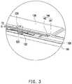
- FIG. 3is a cross-sectional schematic view of the touch device of FIG. 2 taken along line A-A.
- the noise reduction layer group 140 of the present embodimentincludes a soft layer 141 and a hard layer 142 which are stacked. The hardness of the soft layer 141 and the hardness of the hard layer 142 are respectively smaller than the hardness of the bracket 130 .
- the soft layer 141faces the elastic sheet 122
- the hard layer 142faces the bracket 130 .
- the soft layer 141includes a foam sheet, a polyurethane sheet, a rubber sheet or a silicone rubber sheet, and the hard layer 142 includes a Teflon or a Mylar sheet, but the materials of the soft layer 141 and the hard layer 142 are not limited thereto.
- the noise reduction layer group 140 of the present embodimentserves as a buffer assembly of the elastic sheet 122 by the combination of the soft layer 141 and the hard layer 142 , so that the elastic sheet 122 does not directly impact the bracket 130 when pressed.
- the noise reduction layer group 140 of the present embodimentabsorbs the force when the elastic sheet 122 is pressed down by the soft layer 141 , thereby reducing the force of the elastic sheet 122 impacting the bracket 130 , so as to reduce the noise generated when the elastic sheet 122 is pressed down.
- the noise reduction layer group 140 of the present embodimentprovides sufficient hardness by the hard layer 142 , so that the user's force used to press the touch device 100 is not completely absorbed by the soft layer 141 , and the elastic sheet 122 is still deformed by compression to trigger the circuit switch 123 .
- the soft layer 141 and the hard layer 142are bonded to each other by an adhesive.
- the manner in which the soft layer 141 and the hard layer 142 are bondedis not limited thereto.
- the soft layer 141 and the hard layer 142are also integrated, for example, composed of a composite material.
- the soft layer 141 and the hard layer 142are also made by plastic injection molding, and are not limited to the above.
- the Shore hardness C of the soft layer 141is between 50 degrees and 60 degrees, and the Shore hardness C of the hard layer 142 is between 70 degrees and 80 degrees.
- the difference between the Shore hardness C of the hard layer 142 and the Shore hardness C of the soft layer 141 of the present embodimentis between 10 degrees and 20 degrees.
- the noise reduction layer group 140is only provided with a single layer structure, and has the hardness smaller than the hardness of the bracket 130 , but is not limited to the above.
- the noise reduction layer group 140includes only the soft layer 141 .
- the soft layer 141also provides the buffer required when the elastic sheet 122 is pressed down.
- the elastic sheet 122When the elastic sheet 122 is pressed down, the elastic sheet 122 does not directly impact the bracket 130 , but the impact force of the elastic sheet 122 is absorbed by the soft layer 141 , thereby reducing the noise generated when the elastic sheet 122 is pressed down.
- the noise reduction layer group 140includes only the hard layer 142 . Since the hard layer 142 is disposed between the elastic sheet 122 and the bracket 130 , when the elastic sheet 122 is pressed down, the elastic sheet 122 does not directly impact the bracket 130 , but the impact force of the elastic sheet 122 is absorbed by the hard layer 142 , thereby reducing the noise generated when the elastic sheet 122 is pressed down.
- the bracket 130is provided with a hole 133 at a part corresponding to the elastic sheet 122 , and the hole 133 provides a space in which the noise reduction layer group 140 retreats, so that the noise reduction layer group 140 has a better buffer effect. That is, the design of the hole 133 disposed in the bracket 130 further reduces the force of the elastic sheet 122 impacting the bracket 130 .
- the diameter of the hole 133is between 2 mm and 4 mm. However, in other embodiments, as long as the diameter of the hole 133 is smaller than the diameter of the elastic sheet 122 , it is within the protection scope of the present invention.
- the thickness T 2 of the hard layer 142is between 0.2 mm and 0.3 mm, and the thickness T 1 of the soft layer 141 is between 0.1 mm and 0.2 mm.
- the hard layer 142is thicker than the soft layer 141 .
- a ratio of the thickness T 2 of the hard layer 142 to the thickness T 1 of the soft layer 141is between 2 and 3 to achieve moderate noise reduction and buffer effects.
- the soft layer 141doesn't absorb the force when the elastic sheet 122 is pressed down, so that it is easy to produce permanent deformation of the hard layer 142 at the part near the hole 133 and cause unexpected influence on the pressing stroke of the cover plate 110 and the pressing feeling of the cover plate 110 .
- the hard layer 142is too thick (not within the above ratio range)
- the hard layer 142does not retreat to the space provided by the hole 133 , so that the hard layer 142 is not effectively deformed at the part near the hole 133 and doesn't achieve the shock absorbing effect, and the noise suppressing effect is not good.
- the hard layer 142is too thin (not within the above ratio range)
- the hard layer 142does not provide the force for pressing against the soft layer 141 (the hard layer 142 is too thin and not hard enough, and is equivalent to a too thick soft layer 141 when being placed together with the soft layer 141 ), so that the user must use larger force to press the cover plate 110 , resulting in excessive pressing load on the cover plate 110 and excessive pressing stroke of the cover plate 110 , causing poor user experience.
- the thickness T 2 of the hard layer 142 and the thickness T 1 of the soft layer 141are adjusted according to different loads or acoustic specifications, and are not limited to the above.
- FIG. 4 and FIG. 5are cross-sectional schematic views of multiple touch devices according to other embodiments of the present invention.
- a bracket 130 A of the present embodimentis slightly different from the bracket 130 of FIG. 3 in that in the present embodiment, the hole 133 A does not run through the bracket 130 A.
- the hole 133 Aalso provides a space in which a noise reduction layer group 140 A retreats, so that the noise reduction layer group 140 A has a good buffer effect.
- the thickness T 1 ′ of a soft layer 141 Ais larger than the thickness T 1 of the soft layer 141 of FIG.
- the thickness of the soft layer 141 Amay be the same as the thickness T 1 of the soft layer 141 of FIG. 3 , and the thickness of the soft layer 141 A is not limited to the above.
- a bracket 130 B of the present embodimentis slightly different from the bracket 130 A of FIG. 3 in that in the present embodiment, the bracket 130 B is provided with no hole 133 at the part corresponding to the elastic sheet 122 .
- the thickness T 2 ′′ of a hard layer 142 Bis between 0.2 mm and 0.3 mm
- the thickness T 1 ′′ of a soft layer 141 Bis between 0.3 mm and 0.5 mm.
- a ratio of the thickness T 2 ′′ of the hard layer 142 B to the thickness T 1 ′′ of the soft layer 141 Bis between 0.6 and 0.8 to achieve moderate noise reduction and buffer effects.
- the reason for this designis that if the soft layer 141 B is too thick (not within the above ratio range), the user must use larger force to press the cover plate 110 , resulting in excessive pressing load on the cover plate 110 . Furthermore, since the amount of compression of the soft layer 141 is large, the pressing stroke of the cover plate 110 is too large, resulting in poor user experience. Conversely, if the soft layer 141 B is too thin (not within the above ratio range), the shock absorbing effect of the soft layer 141 B is not good, and the noise suppressing effect of the noise reduction layer group 140 B is not good.
- the shock absorbing effectis not good, so that the noise suppressing effect of the noise reduction layer group is not good (the same as the case that the soft layer 141 B is too thin).
- the hard layer 142 Bis too thin (not within the above ratio range)
- the hard layer 142 Bdoes not provide the force for pressing against the soft layer 141 B (the hard layer 142 B is too thin and not be hard enough, and is equivalent to a too thick soft layer 141 B when being placed together with the soft layer 141 B), so that the user must use larger force to press the cover plate 110 , resulting in excessive pressing load on the cover plate 110 and excessive pressing stroke of the cover plate 110 , causing poor user experience.
- the thickness T 1 ′′ of the soft layer 141 Bis larger than the thickness T 1 ′ of the soft layer 141 B of FIG. 3 and the thickness T 1 ′ of the soft layer 141 A of FIG. 4 to absorb the impact force of the elastic sheet 122 , so that the noise reduction layer group 140 B provides buffer and noise reduction effects close to the noise reduction layer group 140 and the noise reduction layer group 140 A.
- the thickness of the soft layer 141 Bmay be the same as the thickness T 1 of the soft layer 141 of FIG. 3 or the same as the thickness T 1 ′ of the soft layer 141 A of FIG. 4 , and the thickness of the soft layer 141 B is not limited to the above.
- the touch device of the present inventionincludes the noise reduction layer group. Since the noise reduction layer group is disposed between the bracket and the elastic sheet, when the elastic sheet is pressed down, the noise reduction layer group provides buffer for the elastic sheet to reduce the force of the elastic sheet impacting the bracket, thereby reducing the noise generated when the elastic sheet is pressed down.
- the bracketis provided with the hole at a part corresponding to the elastic sheet, and when the elastic sheet is pressed down, a portion of the noise reduction layer group falls into the hole.
Landscapes
- Engineering & Computer Science (AREA)
- Theoretical Computer Science (AREA)
- General Engineering & Computer Science (AREA)
- Physics & Mathematics (AREA)
- General Physics & Mathematics (AREA)
- Computer Hardware Design (AREA)
- Human Computer Interaction (AREA)
- Automation & Control Theory (AREA)
- Mathematical Physics (AREA)
- Position Input By Displaying (AREA)
- Push-Button Switches (AREA)
- Input From Keyboards Or The Like (AREA)
- Manufacture Of Switches (AREA)
Abstract
Description
Claims (12)
Priority Applications (1)
| Application Number | Priority Date | Filing Date | Title |
|---|---|---|---|
| US16/783,175US11373818B2 (en) | 2019-02-21 | 2020-02-06 | Tough device |
Applications Claiming Priority (4)
| Application Number | Priority Date | Filing Date | Title |
|---|---|---|---|
| US201962808818P | 2019-02-21 | 2019-02-21 | |
| CN201910720624.3 | 2019-08-06 | ||
| CN201910720624.3ACN110471565A (en) | 2019-02-21 | 2019-08-06 | Touch device |
| US16/783,175US11373818B2 (en) | 2019-02-21 | 2020-02-06 | Tough device |
Publications (2)
| Publication Number | Publication Date |
|---|---|
| US20200272259A1 US20200272259A1 (en) | 2020-08-27 |
| US11373818B2true US11373818B2 (en) | 2022-06-28 |
Family
ID=68439894
Family Applications (7)
| Application Number | Title | Priority Date | Filing Date |
|---|---|---|---|
| US16/782,022ActiveUS11049672B2 (en) | 2019-02-21 | 2020-02-04 | Touch control device |
| US16/783,175ActiveUS11373818B2 (en) | 2019-02-21 | 2020-02-06 | Tough device |
| US16/785,626ActiveUS10978260B2 (en) | 2019-02-21 | 2020-02-09 | Base plate, key assembly, illuminated key input device and manufacturing method of base plate |
| US16/794,108ActiveUS11393644B2 (en) | 2019-02-21 | 2020-02-18 | Input device |
| US16/794,254ActiveUS11133135B2 (en) | 2019-02-21 | 2020-02-19 | Input device |
| US17/102,320AbandonedUS20210074492A1 (en) | 2019-02-21 | 2020-11-23 | Base plate and key assembly |
| US17/745,889ActiveUS11640882B2 (en) | 2019-02-21 | 2022-05-17 | Input device |
Family Applications Before (1)
| Application Number | Title | Priority Date | Filing Date |
|---|---|---|---|
| US16/782,022ActiveUS11049672B2 (en) | 2019-02-21 | 2020-02-04 | Touch control device |
Family Applications After (5)
| Application Number | Title | Priority Date | Filing Date |
|---|---|---|---|
| US16/785,626ActiveUS10978260B2 (en) | 2019-02-21 | 2020-02-09 | Base plate, key assembly, illuminated key input device and manufacturing method of base plate |
| US16/794,108ActiveUS11393644B2 (en) | 2019-02-21 | 2020-02-18 | Input device |
| US16/794,254ActiveUS11133135B2 (en) | 2019-02-21 | 2020-02-19 | Input device |
| US17/102,320AbandonedUS20210074492A1 (en) | 2019-02-21 | 2020-11-23 | Base plate and key assembly |
| US17/745,889ActiveUS11640882B2 (en) | 2019-02-21 | 2022-05-17 | Input device |
Country Status (2)
| Country | Link |
|---|---|
| US (7) | US11049672B2 (en) |
| CN (7) | CN110471561B (en) |
Families Citing this family (21)
| Publication number | Priority date | Publication date | Assignee | Title |
|---|---|---|---|---|
| US10884519B2 (en)* | 2017-03-16 | 2021-01-05 | Lite-On Electronics (Guangzhou) Limited | Scroll wheel module |
| FR3072849A1 (en)* | 2017-10-24 | 2019-04-26 | Orange | PROTECTIVE DEVICE FOR ELECTRONIC EQUIPMENT |
| CN110471561B (en)* | 2019-02-21 | 2024-01-23 | 光宝电子(广州)有限公司 | Touch control device |
| TWI696094B (en)* | 2019-06-19 | 2020-06-11 | 群光電子股份有限公司 | Keyboard device |
| CN111834155B (en)* | 2020-01-02 | 2023-02-21 | 光宝电子(广州)有限公司 | Frame structure and keyboard device |
| US11424090B2 (en)* | 2020-03-31 | 2022-08-23 | Darfon Electronics Corp. | Keyswitch support connection structure and keyswitch structure therewith |
| TWI759945B (en)* | 2020-03-31 | 2022-04-01 | 達方電子股份有限公司 | Keyswitch support connection structure and keyswitch structure therewith |
| CN113921315A (en)* | 2020-07-10 | 2022-01-11 | 致伸科技股份有限公司 | Keyboard device and key structure thereof |
| TWI733516B (en)* | 2020-07-10 | 2021-07-11 | 致伸科技股份有限公司 | Keyboard devic and key structure |
| TWI830014B (en)* | 2021-03-30 | 2024-01-21 | 達方電子股份有限公司 | Backlight module and luminous keyboard including the same |
| TWM614779U (en)* | 2021-04-06 | 2021-07-21 | 精元電腦股份有限公司 | Omnidirectional touchpad pressing device |
| TWI786614B (en)* | 2021-04-28 | 2022-12-11 | 達方電子股份有限公司 | Keyswitch with preferred supporting strength and related keyboard and related base manufacturing method |
| US20250291434A1 (en)* | 2022-05-12 | 2025-09-18 | Voyetra Turtle Beach, Inc. | Mouse button structure and mouse device having the same |
| US12416982B2 (en) | 2023-06-27 | 2025-09-16 | Dell Products L.P. | Low acoustic magnetic mouse scroll wheel |
| US11983336B1 (en) | 2023-06-27 | 2024-05-14 | Dell Products L.P. | Magnetic toggle ejector |
| US12282610B2 (en) | 2023-06-27 | 2025-04-22 | Dell Products L.P. | Low acoustic keyboard with audio dampener and liquid drain |
| US11983332B1 (en)* | 2023-06-27 | 2024-05-14 | Dell Products L.P. | Low acoustic keyboard key |
| US12236017B2 (en) | 2023-06-27 | 2025-02-25 | Dell Products L.P. | Low acoustic keyboard cushioned stabilized key |
| US12032750B1 (en) | 2023-06-27 | 2024-07-09 | Dell Products L.P. | Low acoustic magnetic keyboard key |
| US20250173007A1 (en)* | 2023-11-27 | 2025-05-29 | Lite-On Technology Corporation | Touch device and input device |
| TWI886741B (en)* | 2024-01-09 | 2025-06-11 | 精元電腦股份有限公司 | Global Touch Panel Device |
Citations (6)
| Publication number | Priority date | Publication date | Assignee | Title |
|---|---|---|---|---|
| US20050181843A1 (en)* | 2004-02-18 | 2005-08-18 | Nec Corporation | Portable telephone and method of manufacturing the same |
| US20080257707A1 (en)* | 2007-04-23 | 2008-10-23 | Kabushiki Kaisha Tokai Rika Denki Seisakusho | Touch sensor switch |
| US20090255755A1 (en)* | 2008-04-09 | 2009-10-15 | Toyota Boshoku Kabushiki Kaisha | Soundproofing material |
| US20130257712A1 (en)* | 2012-03-30 | 2013-10-03 | Kabushiki Kaisha Toshiba | Electronic device |
| US20140071654A1 (en)* | 2012-09-11 | 2014-03-13 | Logitech Europe S.A. | Protective Cover for a Tablet Computer |
| US20170262111A1 (en)* | 2016-03-10 | 2017-09-14 | Boe Technology Group Co., Ltd. | Touch control elastic structure, pressure detection method and display device |
Family Cites Families (47)
| Publication number | Priority date | Publication date | Assignee | Title |
|---|---|---|---|---|
| DE3041859A1 (en)* | 1980-11-06 | 1982-06-03 | Preh Elektro Feinmechanik | KEYBOARD |
| US5201824A (en)* | 1989-10-06 | 1993-04-13 | Alps Electric Co., Ltd. | Push button switch |
| US5710397A (en)* | 1995-08-04 | 1998-01-20 | Acer Peripherals, Inc. | Switch actuator for membrane switch |
| GB9519557D0 (en)* | 1995-09-26 | 1995-11-29 | Psion Plc | Key assembly |
| US6330991B1 (en)* | 1997-06-23 | 2001-12-18 | Micron Technology, Inc. | Apparatus for mounting an element |
| US6344643B1 (en)* | 1999-10-20 | 2002-02-05 | Dexin Corporation | Encoder wheel module and circuit board arrangement for an optical mouse with scrolling function |
| US6204462B1 (en)* | 2000-03-28 | 2001-03-20 | Silitek Corporation | Stable keyswitch |
| US8446366B2 (en)* | 2005-12-23 | 2013-05-21 | Logitech Europe S.A. | Multi-function roller apparatus and method for a control device |
| CN101686595B (en)* | 2008-09-25 | 2014-11-05 | 鸿富锦精密工业(深圳)有限公司 | Electronic device and conducting strip thereof |
| DE202008014509U1 (en)* | 2008-10-31 | 2009-02-19 | Zippy Technology Corp., Hsin-Tien | Evenly lit keyboard device |
| US20120092263A1 (en)* | 2009-10-15 | 2012-04-19 | Pacinian Corporation | Haptic keyboard featuring a satisfying tactile keypress experience |
| CN102044362A (en)* | 2009-10-23 | 2011-05-04 | 鸿富锦精密工业(深圳)有限公司 | Power button module and electronic device using same |
| TWI410182B (en)* | 2010-06-08 | 2013-09-21 | Inventec Corp | Anti-esd elastic plate and device |
| CN102375477A (en)* | 2010-08-11 | 2012-03-14 | 英业达股份有限公司 | Touchpad Module and Electronics |
| CN102446015A (en)* | 2010-09-30 | 2012-05-09 | 英业达股份有限公司 | Touch device and electronic device using same |
| JP2013020604A (en)* | 2011-06-17 | 2013-01-31 | Sony Corp | Operation accepting apparatus |
| CN102929413A (en)* | 2011-08-12 | 2013-02-13 | 致伸科技股份有限公司 | Roller module applied to input device |
| CN202258947U (en)* | 2011-10-08 | 2012-05-30 | 群光电子股份有限公司 | Luminous keyboard device |
| JP2013182424A (en)* | 2012-03-01 | 2013-09-12 | Alps Electric Co Ltd | Input device |
| CN202502927U (en)* | 2012-03-08 | 2012-10-24 | 纬创资通股份有限公司 | Key module and electronic device with key module |
| CN103455173A (en)* | 2012-06-04 | 2013-12-18 | 致伸科技股份有限公司 | Wheeled mouse |
| TWI479299B (en)* | 2012-11-13 | 2015-04-01 | Wistron Corp | Touch pad and portable electronic device thereof |
| TW201501155A (en)* | 2013-06-28 | 2015-01-01 | Giga Byte Tech Co Ltd | Keycap, key structure and keyboard having the same |
| TWI511173B (en)* | 2014-04-15 | 2015-12-01 | Wistron Corp | Keyswitch mechanism and related electronic device |
| US9779894B2 (en)* | 2014-09-05 | 2017-10-03 | Apple Inc. | Button features of an electronic device |
| TWI597751B (en)* | 2015-03-27 | 2017-09-01 | 達方電子股份有限公司 | Key switch |
| CN104882318B (en)* | 2015-05-20 | 2017-08-25 | 苏州达方电子有限公司 | Press-key structure |
| CN108139819B (en)* | 2015-10-28 | 2021-06-01 | 阿尔卑斯阿尔派株式会社 | operating device |
| CN205194586U (en)* | 2015-11-20 | 2016-04-27 | 比亚迪股份有限公司 | Button resets and notebook computer thereof |
| CN205900399U (en)* | 2016-06-22 | 2017-01-18 | 李荣书 | Cushioned Durable Keyboard Key Structure |
| CN105938772B (en)* | 2016-06-22 | 2018-05-25 | 苏州达方电子有限公司 | Button |
| CN108281316A (en)* | 2017-01-06 | 2018-07-13 | 致伸科技股份有限公司 | Keyboard with a keyboard body |
| CN108628472B (en)* | 2017-03-16 | 2021-06-15 | 光宝电子(广州)有限公司 | Roller module |
| CN108628479B (en)* | 2017-03-22 | 2020-08-14 | 致伸科技股份有限公司 | Mouse roller structure |
| US10373779B2 (en)* | 2017-06-01 | 2019-08-06 | Darfon Electronics Corp. | Key switch with noise reduction capability and assembly method thereof |
| CN107134387A (en)* | 2017-06-13 | 2017-09-05 | 苏州达方电子有限公司 | A kind of keyboard |
| TWM551337U (en)* | 2017-06-16 | 2017-11-01 | 群光電子股份有限公司 | Keyswitch device and hook bracket |
| CN207281658U (en)* | 2017-09-29 | 2018-04-27 | 惠州比亚迪电子有限公司 | Touch pad key device and laptop |
| CN107946114B (en)* | 2017-10-27 | 2019-12-31 | 苏州达方电子有限公司 | key structure |
| CN108493014A (en)* | 2018-01-26 | 2018-09-04 | 苏州达方电子有限公司 | Press-key structure |
| CN108172440A (en)* | 2018-02-08 | 2018-06-15 | 江苏传艺科技股份有限公司 | Novel keyboard structure |
| CN108052236A (en)* | 2018-02-05 | 2018-05-18 | 精元电脑股份有限公司 | Has the Trackpad of decrease of noise functions |
| CN208208625U (en)* | 2018-06-06 | 2018-12-07 | 群光电子(苏州)有限公司 | Key device |
| CN109243894A (en)* | 2018-08-30 | 2019-01-18 | 苏州达方电子有限公司 | Key and keyboard |
| TWI696096B (en)* | 2018-10-26 | 2020-06-11 | 致伸科技股份有限公司 | Roller module |
| CN111383857A (en)* | 2018-12-28 | 2020-07-07 | 富泰华工业(深圳)有限公司 | Noise reduction device, key device with noise reduction device, electronic device |
| CN110471561B (en)* | 2019-02-21 | 2024-01-23 | 光宝电子(广州)有限公司 | Touch control device |
- 2019
- 2019-07-30CNCN201910692182.6Apatent/CN110471561B/enactiveActive
- 2019-08-06CNCN201910720624.3Apatent/CN110471565A/enactivePending
- 2019-09-11CNCN201921508997.6Upatent/CN210272144U/enactiveActive
- 2019-09-11CNCN201910858013.5Apatent/CN110444431A/enactivePending
- 2019-12-27CNCN201911372934.7Apatent/CN111029196B/enactiveActive
- 2020
- 2020-01-06CNCN202010008614.XApatent/CN111176472B/enactiveActive
- 2020-01-08CNCN202020034005.7Upatent/CN210897094U/enactiveActive
- 2020-02-04USUS16/782,022patent/US11049672B2/enactiveActive
- 2020-02-06USUS16/783,175patent/US11373818B2/enactiveActive
- 2020-02-09USUS16/785,626patent/US10978260B2/enactiveActive
- 2020-02-18USUS16/794,108patent/US11393644B2/enactiveActive
- 2020-02-19USUS16/794,254patent/US11133135B2/enactiveActive
- 2020-11-23USUS17/102,320patent/US20210074492A1/ennot_activeAbandoned
- 2022
- 2022-05-17USUS17/745,889patent/US11640882B2/enactiveActive
Patent Citations (6)
| Publication number | Priority date | Publication date | Assignee | Title |
|---|---|---|---|---|
| US20050181843A1 (en)* | 2004-02-18 | 2005-08-18 | Nec Corporation | Portable telephone and method of manufacturing the same |
| US20080257707A1 (en)* | 2007-04-23 | 2008-10-23 | Kabushiki Kaisha Tokai Rika Denki Seisakusho | Touch sensor switch |
| US20090255755A1 (en)* | 2008-04-09 | 2009-10-15 | Toyota Boshoku Kabushiki Kaisha | Soundproofing material |
| US20130257712A1 (en)* | 2012-03-30 | 2013-10-03 | Kabushiki Kaisha Toshiba | Electronic device |
| US20140071654A1 (en)* | 2012-09-11 | 2014-03-13 | Logitech Europe S.A. | Protective Cover for a Tablet Computer |
| US20170262111A1 (en)* | 2016-03-10 | 2017-09-14 | Boe Technology Group Co., Ltd. | Touch control elastic structure, pressure detection method and display device |
Also Published As
| Publication number | Publication date |
|---|---|
| CN111029196B (en) | 2022-06-07 |
| CN111176472B (en) | 2024-02-06 |
| CN111176472A (en) | 2020-05-19 |
| CN111029196A (en) | 2020-04-17 |
| CN110444431A (en) | 2019-11-12 |
| CN110471561B (en) | 2024-01-23 |
| US11393644B2 (en) | 2022-07-19 |
| CN210272144U (en) | 2020-04-07 |
| CN210897094U (en) | 2020-06-30 |
| US20210074492A1 (en) | 2021-03-11 |
| US20200273641A1 (en) | 2020-08-27 |
| US20200272206A1 (en) | 2020-08-27 |
| US20200272248A1 (en) | 2020-08-27 |
| US10978260B2 (en) | 2021-04-13 |
| CN110471565A (en) | 2019-11-19 |
| US11049672B2 (en) | 2021-06-29 |
| US11640882B2 (en) | 2023-05-02 |
| US20200273642A1 (en) | 2020-08-27 |
| US11133135B2 (en) | 2021-09-28 |
| US20220277908A1 (en) | 2022-09-01 |
| US20200272259A1 (en) | 2020-08-27 |
| CN110471561A (en) | 2019-11-19 |
Similar Documents
| Publication | Publication Date | Title |
|---|---|---|
| US11373818B2 (en) | Tough device | |
| US9360950B2 (en) | Key control device for click pad | |
| US20080174942A1 (en) | Handheld Electronic Device | |
| US11402931B1 (en) | Touchpad module and computing device using same | |
| KR20110054378A (en) | Touch panel device | |
| US20210151267A1 (en) | Touch pad structure | |
| CN1932711B (en) | Multidirectional key | |
| US20200333917A1 (en) | Touch device and input module | |
| US20190385800A1 (en) | Touch module | |
| US20070013682A1 (en) | Electronic device with rotary knob | |
| US9153396B2 (en) | Keyboard module and electronic device having the same | |
| CN108404403A (en) | A kind of operation handle and terminal device | |
| US10410805B1 (en) | Key structure | |
| TW202240348A (en) | Touchpad device | |
| CN202142433U (en) | Thin key structure and portable electronic device | |
| US12293030B2 (en) | Touchpad device | |
| US7085130B2 (en) | Electronic device and button structure | |
| TWI830136B (en) | Touchpad device | |
| CN104994299A (en) | Portable electronic device with photographing function | |
| US11435839B2 (en) | Touch pad module | |
| TW201430888A (en) | Electronic device | |
| US11093009B2 (en) | Movalbe input device in a computer casing | |
| CN110609624A (en) | Touch control module | |
| CN101872693B (en) | Keypress structure, keyboard and input device | |
| CN112637384A (en) | Electronic equipment |
Legal Events
| Date | Code | Title | Description |
|---|---|---|---|
| FEPP | Fee payment procedure | Free format text:ENTITY STATUS SET TO UNDISCOUNTED (ORIGINAL EVENT CODE: BIG.); ENTITY STATUS OF PATENT OWNER: LARGE ENTITY | |
| AS | Assignment | Owner name:LITE-ON ELECTRONICS (GUANGZHOU) LIMITED, CHINA Free format text:ASSIGNMENT OF ASSIGNORS INTEREST;ASSIGNOR:LU, CHENG-AN;REEL/FRAME:051790/0356 Effective date:20200205 Owner name:LITE-ON TECHNOLOGY CORPORATION, TAIWAN Free format text:ASSIGNMENT OF ASSIGNORS INTEREST;ASSIGNOR:LU, CHENG-AN;REEL/FRAME:051790/0356 Effective date:20200205 | |
| STPP | Information on status: patent application and granting procedure in general | Free format text:NON FINAL ACTION MAILED | |
| STPP | Information on status: patent application and granting procedure in general | Free format text:RESPONSE TO NON-FINAL OFFICE ACTION ENTERED AND FORWARDED TO EXAMINER | |
| STPP | Information on status: patent application and granting procedure in general | Free format text:FINAL REJECTION MAILED | |
| STPP | Information on status: patent application and granting procedure in general | Free format text:DOCKETED NEW CASE - READY FOR EXAMINATION | |
| STPP | Information on status: patent application and granting procedure in general | Free format text:NOTICE OF ALLOWANCE MAILED -- APPLICATION RECEIVED IN OFFICE OF PUBLICATIONS | |
| STPP | Information on status: patent application and granting procedure in general | Free format text:PUBLICATIONS -- ISSUE FEE PAYMENT VERIFIED | |
| STCF | Information on status: patent grant | Free format text:PATENTED CASE |