US11373502B2 - Vehicle alert apparatus - Google Patents
Vehicle alert apparatusDownload PDFInfo
- Publication number
- US11373502B2 US11373502B2US16/941,430US202016941430AUS11373502B2US 11373502 B2US11373502 B2US 11373502B2US 202016941430 AUS202016941430 AUS 202016941430AUS 11373502 B2US11373502 B2US 11373502B2
- Authority
- US
- United States
- Prior art keywords
- alert
- driver
- drowse
- vehicle speed
- inattentiveness
- Prior art date
- Legal status (The legal status is an assumption and is not a legal conclusion. Google has not performed a legal analysis and makes no representation as to the accuracy of the status listed.)
- Active
Links
- 238000001514detection methodMethods0.000claimsabstractdescription71
- 230000008859changeEffects0.000claimsdescription5
- 238000000034methodMethods0.000description68
- 230000008569processEffects0.000description68
- 208000028752abnormal postureDiseases0.000description17
- 230000006870functionEffects0.000description8
- 238000010586diagramMethods0.000description6
- 230000002265preventionEffects0.000description4
- 210000000744eyelidAnatomy0.000description3
- 210000003128headAnatomy0.000description3
- 206010039203Road traffic accidentDiseases0.000description2
- 208000032140SleepinessDiseases0.000description2
- 206010041349SomnolenceDiseases0.000description2
- 230000008901benefitEffects0.000description2
- 230000000052comparative effectEffects0.000description2
- 230000000694effectsEffects0.000description2
- 230000037321sleepinessEffects0.000description2
- 230000002159abnormal effectEffects0.000description1
- 244000145845chatteringSpecies0.000description1
- 238000004891communicationMethods0.000description1
- 238000005516engineering processMethods0.000description1
- 230000008921facial expressionEffects0.000description1
- 238000004519manufacturing processMethods0.000description1
- 230000004048modificationEffects0.000description1
- 238000012986modificationMethods0.000description1
- 230000002093peripheral effectEffects0.000description1
- 230000009467reductionEffects0.000description1
- 230000004044responseEffects0.000description1
Images


Classifications
- G—PHYSICS
- G08—SIGNALLING
- G08B—SIGNALLING OR CALLING SYSTEMS; ORDER TELEGRAPHS; ALARM SYSTEMS
- G08B21/00—Alarms responsive to a single specified undesired or abnormal condition and not otherwise provided for
- G08B21/02—Alarms for ensuring the safety of persons
- G08B21/06—Alarms for ensuring the safety of persons indicating a condition of sleep, e.g. anti-dozing alarms
- B—PERFORMING OPERATIONS; TRANSPORTING
- B60—VEHICLES IN GENERAL
- B60K—ARRANGEMENT OR MOUNTING OF PROPULSION UNITS OR OF TRANSMISSIONS IN VEHICLES; ARRANGEMENT OR MOUNTING OF PLURAL DIVERSE PRIME-MOVERS IN VEHICLES; AUXILIARY DRIVES FOR VEHICLES; INSTRUMENTATION OR DASHBOARDS FOR VEHICLES; ARRANGEMENTS IN CONNECTION WITH COOLING, AIR INTAKE, GAS EXHAUST OR FUEL SUPPLY OF PROPULSION UNITS IN VEHICLES
- B60K28/00—Safety devices for propulsion-unit control, specially adapted for, or arranged in, vehicles, e.g. preventing fuel supply or ignition in the event of potentially dangerous conditions
- B60K28/02—Safety devices for propulsion-unit control, specially adapted for, or arranged in, vehicles, e.g. preventing fuel supply or ignition in the event of potentially dangerous conditions responsive to conditions relating to the driver
- B60K28/06—Safety devices for propulsion-unit control, specially adapted for, or arranged in, vehicles, e.g. preventing fuel supply or ignition in the event of potentially dangerous conditions responsive to conditions relating to the driver responsive to incapacity of driver
- B60K28/066—Safety devices for propulsion-unit control, specially adapted for, or arranged in, vehicles, e.g. preventing fuel supply or ignition in the event of potentially dangerous conditions responsive to conditions relating to the driver responsive to incapacity of driver actuating a signalling device
- B—PERFORMING OPERATIONS; TRANSPORTING
- B60—VEHICLES IN GENERAL
- B60W—CONJOINT CONTROL OF VEHICLE SUB-UNITS OF DIFFERENT TYPE OR DIFFERENT FUNCTION; CONTROL SYSTEMS SPECIALLY ADAPTED FOR HYBRID VEHICLES; ROAD VEHICLE DRIVE CONTROL SYSTEMS FOR PURPOSES NOT RELATED TO THE CONTROL OF A PARTICULAR SUB-UNIT
- B60W40/00—Estimation or calculation of non-directly measurable driving parameters for road vehicle drive control systems not related to the control of a particular sub unit, e.g. by using mathematical models
- B60W40/08—Estimation or calculation of non-directly measurable driving parameters for road vehicle drive control systems not related to the control of a particular sub unit, e.g. by using mathematical models related to drivers or passengers
- B60W40/09—Driving style or behaviour
- B—PERFORMING OPERATIONS; TRANSPORTING
- B60—VEHICLES IN GENERAL
- B60W—CONJOINT CONTROL OF VEHICLE SUB-UNITS OF DIFFERENT TYPE OR DIFFERENT FUNCTION; CONTROL SYSTEMS SPECIALLY ADAPTED FOR HYBRID VEHICLES; ROAD VEHICLE DRIVE CONTROL SYSTEMS FOR PURPOSES NOT RELATED TO THE CONTROL OF A PARTICULAR SUB-UNIT
- B60W40/00—Estimation or calculation of non-directly measurable driving parameters for road vehicle drive control systems not related to the control of a particular sub unit, e.g. by using mathematical models
- B60W40/10—Estimation or calculation of non-directly measurable driving parameters for road vehicle drive control systems not related to the control of a particular sub unit, e.g. by using mathematical models related to vehicle motion
- B60W40/105—Speed
- B—PERFORMING OPERATIONS; TRANSPORTING
- B60—VEHICLES IN GENERAL
- B60W—CONJOINT CONTROL OF VEHICLE SUB-UNITS OF DIFFERENT TYPE OR DIFFERENT FUNCTION; CONTROL SYSTEMS SPECIALLY ADAPTED FOR HYBRID VEHICLES; ROAD VEHICLE DRIVE CONTROL SYSTEMS FOR PURPOSES NOT RELATED TO THE CONTROL OF A PARTICULAR SUB-UNIT
- B60W50/00—Details of control systems for road vehicle drive control not related to the control of a particular sub-unit, e.g. process diagnostic or vehicle driver interfaces
- B60W50/08—Interaction between the driver and the control system
- B60W50/14—Means for informing the driver, warning the driver or prompting a driver intervention
- G—PHYSICS
- G08—SIGNALLING
- G08G—TRAFFIC CONTROL SYSTEMS
- G08G1/00—Traffic control systems for road vehicles
- G08G1/16—Anti-collision systems
- B—PERFORMING OPERATIONS; TRANSPORTING
- B60—VEHICLES IN GENERAL
- B60W—CONJOINT CONTROL OF VEHICLE SUB-UNITS OF DIFFERENT TYPE OR DIFFERENT FUNCTION; CONTROL SYSTEMS SPECIALLY ADAPTED FOR HYBRID VEHICLES; ROAD VEHICLE DRIVE CONTROL SYSTEMS FOR PURPOSES NOT RELATED TO THE CONTROL OF A PARTICULAR SUB-UNIT
- B60W40/00—Estimation or calculation of non-directly measurable driving parameters for road vehicle drive control systems not related to the control of a particular sub unit, e.g. by using mathematical models
- B60W40/08—Estimation or calculation of non-directly measurable driving parameters for road vehicle drive control systems not related to the control of a particular sub unit, e.g. by using mathematical models related to drivers or passengers
- B60W2040/0818—Inactivity or incapacity of driver
- B60W2040/0827—Inactivity or incapacity of driver due to sleepiness
- B—PERFORMING OPERATIONS; TRANSPORTING
- B60—VEHICLES IN GENERAL
- B60W—CONJOINT CONTROL OF VEHICLE SUB-UNITS OF DIFFERENT TYPE OR DIFFERENT FUNCTION; CONTROL SYSTEMS SPECIALLY ADAPTED FOR HYBRID VEHICLES; ROAD VEHICLE DRIVE CONTROL SYSTEMS FOR PURPOSES NOT RELATED TO THE CONTROL OF A PARTICULAR SUB-UNIT
- B60W50/00—Details of control systems for road vehicle drive control not related to the control of a particular sub-unit, e.g. process diagnostic or vehicle driver interfaces
- B60W50/08—Interaction between the driver and the control system
- B60W50/14—Means for informing the driver, warning the driver or prompting a driver intervention
- B60W2050/143—Alarm means
- B—PERFORMING OPERATIONS; TRANSPORTING
- B60—VEHICLES IN GENERAL
- B60W—CONJOINT CONTROL OF VEHICLE SUB-UNITS OF DIFFERENT TYPE OR DIFFERENT FUNCTION; CONTROL SYSTEMS SPECIALLY ADAPTED FOR HYBRID VEHICLES; ROAD VEHICLE DRIVE CONTROL SYSTEMS FOR PURPOSES NOT RELATED TO THE CONTROL OF A PARTICULAR SUB-UNIT
- B60W2520/00—Input parameters relating to overall vehicle dynamics
- B60W2520/10—Longitudinal speed
- B—PERFORMING OPERATIONS; TRANSPORTING
- B60—VEHICLES IN GENERAL
- B60W—CONJOINT CONTROL OF VEHICLE SUB-UNITS OF DIFFERENT TYPE OR DIFFERENT FUNCTION; CONTROL SYSTEMS SPECIALLY ADAPTED FOR HYBRID VEHICLES; ROAD VEHICLE DRIVE CONTROL SYSTEMS FOR PURPOSES NOT RELATED TO THE CONTROL OF A PARTICULAR SUB-UNIT
- B60W2540/00—Input parameters relating to occupants
- B60W2540/229—Attention level, e.g. attentive to driving, reading or sleeping
- B—PERFORMING OPERATIONS; TRANSPORTING
- B60—VEHICLES IN GENERAL
- B60W—CONJOINT CONTROL OF VEHICLE SUB-UNITS OF DIFFERENT TYPE OR DIFFERENT FUNCTION; CONTROL SYSTEMS SPECIALLY ADAPTED FOR HYBRID VEHICLES; ROAD VEHICLE DRIVE CONTROL SYSTEMS FOR PURPOSES NOT RELATED TO THE CONTROL OF A PARTICULAR SUB-UNIT
- B60W2540/00—Input parameters relating to occupants
- B60W2540/26—Incapacity
Definitions
- the present disclosurerelates to a vehicle alert apparatus.
- Traffic accidents caused by sleepiness or inattentiveness of a driverare a social problem. Detecting a state of the sleepiness or the inattentiveness and alerting the driver can contribute to reduction in the traffic accidents. On the other hand, there is a trade-off relation between an alert frequency and troublesomeness of the driver. In a case where the alert is unnecessary, when the driver is alerted, the driver feels very troublesome with the alert.
- a vehicle alert apparatusmay include: a drowse detector that may detect drowse of a driver; an inattention detector that may detect inattention of the driver; a vehicle speed detector that may detect the vehicle speed; a notification portion that may execute alert for the driver; and an alert controller that may control the alert executed by the notification portion based on a detection result of the drowse of the driver, a detection result of the inattention of the driver, or a detection result of the vehicle speed.
- FIG. 1is a block diagram showing an electrical configuration of a vehicle alert apparatus according to a first embodiment
- FIG. 2is a diagram (part 1 ) illustrating a control of determining a vehicle speed
- FIG. 3is a diagram (part 2 ) illustrating the control of determining the vehicle speed
- FIG. 4is a diagram showing a table of an alert on-off relation when a speed range of the vehicle speed is in a state of V ⁇ 0;
- FIG. 5is a diagram showing a table of the alert on-off relation when the speed range of the vehicle speed is in a state of 0 ⁇ V ⁇ Vth;
- FIG. 6is a diagram showing a table of the alert on-off relation when the speed range of the vehicle speed is in a state of Vth ⁇ V;
- FIG. 7is a flowchart showing a main control of an alert control
- FIG. 8is a flowchart showing a first alert control
- FIG. 9is a flowchart showing a second alert control
- FIG. 10is a flowchart showing a third alert control
- FIG. 11is a flowchart showing a second alert control according to a second embodiment.
- FIG. 12is a flowchart showing a third alert control.
- an apparatusdetects that the driver falls asleep (drowses) and does not execute the alert for the drowse when there is no problem even in a case where the driver drowses.
- the apparatusexecutes determination based on three vehicle signals from a vehicle wheel speed sensor, a gear sensor, and a side brake sensor.
- the apparatus described abovecan only alert the driver to the drowse and does not alert the driver when the driver looks aside.
- an apparatusdetects that the driver drowses or looks aside and alerts the driver.
- the apparatus described aboveexecutes the alert even while the vehicle stops or the vehicle moves at a very low speed for searching a parking position or the like in a parking lot. Therefore, the drive may feel troublesome with the alert.
- One example of the present disclosureprovides a vehicle alert apparatus capable of alerting a driver when the driver drowses and also preventing a situation where the driver feels troublesome with the alert as much as possible.
- a vehicle alert apparatusincludes: a drowse detector that detects drowse of a driver; an inattention detector that detects inattention of the driver; a vehicle speed detector that detects the vehicle speed; a notification portion that executes alert for the driver; and an alert controller that controls the alert executed by the notification portion based on a detection result of the drowse of the driver, a detection result of the inattention of the driver, or a detection result of the vehicle speed.
- the alert controllercontrols the alert in accordance with a determination level for the detection result of the vehicle speed.
- the determination levelis sectioned by a threshold value of the vehicle speed.
- the alert controllercauses the notification portion to execute the alert when the drowse of the driver is detected, and causes the notification portion not to execute the alert even when the inattentive of the driver is detected.
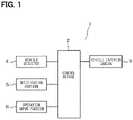
- a vehicle alert apparatus 1 of the present embodimentincludes a control device 2 , a vehicle interior camera 3 , a vehicle speed detector 4 , a notification portion 5 , and an operation input portion 6 , as shown in FIG. 1 .
- the control device 2controls the entire of the vehicle alert apparatus 1 , and has functions of inputting data of an image captured by the vehicle interior camera 3 , inputting a vehicle speed signal detected by the vehicle speed detector 4 , inputting an operation signal input by the operation input portion 6 , and driving and controlling the notification portion 5 .
- the control device 2has each function as a drowse detector, an inattentiveness detector, and an alert controller.
- the vehicle interior camera 3serially captures the periphery of a driver face, and transmits the captured image data to the control device 2 .
- the control device 2detects, for example, an opening degree of a driver eyelid, a driver face direction, a driver line-of-sight direction, a driver head position, or the like.
- the control device 2has a function of estimating a driver state, that is, a function as DSM (Driver Status Monitor) based on data of each detection result described above.
- DSMDriver Status Monitor
- the control device 2has a function of determining, as a driver state, a driver unsafe state such as, for example, the drowse, the inattentiveness, or an unsafe posture, that is, an abnormal posture.
- a driver unsafe statesuch as, for example, the drowse, the inattentiveness, or an unsafe posture, that is, an abnormal posture.
- the control device 2determines whether the driver is in a drowse state based on the opening degree of the driver eyelid, that is, a relative value to the opening degree average of an individual eyelid, a facial expression of the driver face, or the like. It is preferable to appropriately use a determination control of the well-known technology for this drowse determination control.
- the control device 2determines the driver face direction, the driver line-of-sight direction, and these duration. Specifically, the driver executes the inattentive driving when a state where the driver face direction and the driver line-of-sight direction are lateral directions inclined at, for example, 30 degrees or more with respect to the front continues for two seconds or more, for example.
- the driver inattentivenessis determined, the determination is executed based on the driver face direction and the driver line-of-sight direction. Alternatively, the determination may be executed based on the driver face direction, or the determination may be executed based on the driver line-of-sight direction.
- the control device 2has the function of determining, for example, the abnormal posture, that is, the unsafe posture as the driver state.
- the control device 2determines that the driver posture is the abnormal posture when a state where the driver head position is outside a preset abnormal posture determination area, that is, an area indicating a normal position of the head position continues for a set time, for example, two seconds or more.
- the vehicle speed detector 4detects a vehicle speed based on a vehicle speed pulse output from a vehicle speed sensor of the vehicle or a GPS signal output from a GPS (Global Positioning System) receiver, and transmits the detected vehicle speed signal to the control device 2 .
- GPSGlobal Positioning System
- the notification portion 5includes a speaker, a sound output device that outputs an alert sound or the like from this speaker, a voice output device that outputs the voice such as an alert message from this speaker, a display mounted on an instrument panel, and a display control device that displays the alert message or the like on this display.
- the operation input portion 6includes a touch panel placed in a screen of the display, a mechanical switch placed on a peripheral of the display, a remote controller, or the like.
- the control device 2executes control to alert or not the driver to the drowse or the inattentiveness in accordance with the vehicle speed. Therefore, it is necessary that the control device 2 accurately determines whether a vehicle speed V exceeds a preset threshold value Vth, for example, 10 km/h, specifically, the speed range of the vehicle speed Vth is any one of ranges of 0 ⁇ V ⁇ Vth, Vth ⁇ V, or V ⁇ 0, and prevents an erroneous detection.
- a preset threshold value Vthfor example, 10 km/h
- the speed range of the vehicle speed Vthis any one of ranges of 0 ⁇ V ⁇ Vth, Vth ⁇ V, or V ⁇ 0, and prevents an erroneous detection.
- the control device 2executes the following control in order to prevent the erroneous detection of the vehicle speed. For example, as shown in FIG. 2 , when the vehicle speed is detected 10 times every 100 ms, that is, 1 s and when most of the ten vehicle speed detection values are in a range close to 0, for example, a range between 5 km/h and Vth, it is determined that the speed range is a range of 0 ⁇ V ⁇ Vth. That is, the detection value that exceeds the Vth and is in accordance with a small number of detection times or the detection value that is lower than 5 km/h and is in accordance with a small number of detection times is ignored as noise.
- the speed rangeis a range of Vth ⁇ V. That is, the detection value that is in accordance with a small number of detection times and is equal to or lower than the Vth is ignored as the noise.
- Vis nearly equal to 0 (V ⁇ 0)
- V ⁇ 0V ⁇ 0
- the speed rangeis a range of That is, the detection value that is in accordance with a small number of detection times and equal to or higher than 5 km/h is ignored as the noise.
- the vehicle speedis detected 10 times every 100 ms, that is, 1 s and when the number of detection times of the vehicle detection values with V ⁇ 0, that is, the detection values lower than 5 km/h among the ten vehicle speed detection values is, for example, two, when the number of detection times of the vehicle speed detection values in the range of 0 ⁇ V ⁇ Vth are, for example, 3 and when the number of detection times of the vehicle speed detection values in the range of Vth ⁇ V are, for example, 5, the speed range of Vth ⁇ V in accordance with the highest number of detection times of the vehicle detection values is determined as the vehicle speed.
- the erroneous detection prevention control of the vehicle speed described aboveis executed by the control device 2 .
- the erroneous detection prevention controlmay be executed by the vehicle speed detector 4 or the like.
- the vehicle speedis detected 10 times every 100 ms.
- the vehicle speedmay be detected 10 times every 1 s, that is, detected for 10 seconds.
- a detection timing of the vehicle speed, the number of detection times or the detection time, or the likemay be appropriately changeable.
- a chattering prevention functionmay be provided, that is, the speed range of the vehicle speed detected once may be ignored, for example.
- a driver, a user, a traveling manager, or the likecan change the threshold value Vth of the vehicle to a value larger than 10 km/h or a value smaller than 10 km/h by, for example, operating the operation input portion 6 .
- the change operation of the threshold value Vthmay be preferably executed at the end of driving or the like.
- an erroneous alert of the drowse alert and the inattentiveness alert of the driver based on an image recognition process resultmay occur. Therefore, by adding a vehicle speed determination condition, the occurrence of the erroneous alert is suppressed as much as possible. That is, the control of whether to alert is executed based on the detection result of the driver drowse, the detection result of the driver inattentiveness, or the detection result of the vehicle speed. Specifically, the vehicle speed V is divided into three speed ranges of V ⁇ 0, 0 ⁇ V ⁇ Vth, and Vth ⁇ V. Thereby, the condition for executing the drowse alert or the inattentiveness alert is set.
- the alertis executed in regardless of whether the driver is drowsing or whether the driver is looking aside.
- the alertis executed in regardless of whether the driver is looking aside.
- the alertis executed in regardless of whether the driver is looking aside. That is, in the case of the speed range, when the driver is looking aside without drowsing, the alert is not executed.
- the speed rangeis the speed range of Vth ⁇ V, as shown in a table of FIG. 6
- the alertis executed in regardless of whether the driver is looking aside.
- the alertis executed.
- the alertis not executed. That is, in the case of the speed range, when the driver is looking aside without drowsing, the alert is executed.
- FIGS. 7 to 10show contents of the control device 2 .
- the control device 2receives a vehicle speed detection signal from the vehicle speed detector 4 , executes the erroneous detection prevention control described above based on the received vehicle speed detection signal, and determines in which of the three speed ranges the vehicle speed V is, that is, acquires the vehicle speed.
- the control device 2receives the image data from the vehicle interior camera 3 , and executes the image recognition process on the received image data. Thereby, the control device 2 determines the driver state, specifically, whether the driver is drowsing and whether the driver is looking aside, and stores the determination result in the memory inside the control device 2 . This image process of the driver corresponds to a driver state determination control.
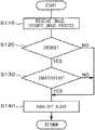
- the processshifts to a step S 20 , and it is determined whether the speed range of the vehicle speed V is the range of V ⁇ 0.
- the processshifts to a step S 50 and a first alert control is executed. This first alert control is described later.
- the processshifts to a step S 30 .
- step S 30it is determined whether the speed range of the vehicle speed V is the range of 0 ⁇ V ⁇ Vth.
- the processshifts to a step S 60 and a second alert control is executed. This second alert control is described later.
- the processshifts to a step S 40 .
- step S 40it is determined whether the speed range of the vehicle speed V is the range of Vth ⁇ V.
- the processshifts to a step S 70 and a third alert control is executed. This third alert control is described later.
- step S 40 described abovewhen the speed range is not the range of Vth ⁇ V (NO), the process returns to the step S 10 and the processes described above are repeatedly executed.
- the control of FIG. 7that is, the vehicle speed determination control is repeatedly executed at a predetermined cycle.
- a step S 110 of FIG. 8the control device 2 receives the image data from the vehicle interior camera 3 , and executes the image process on the received image data. Thereby, the control device 2 determines the driver state, specifically, whether the driver is drowsing and whether the driver is looking aside, and stores the determination result in the memory inside the control device 2 .
- This image process of the driverthat is, the driver state determination control has been already executed in the step S 10 of FIG. 7 . Therefore, the process of the step S 110 may be omitted.
- the image process in the step S 10 of FIG. 7may be omitted.
- the processshifts to a step S 120 , and it is determined whether the driver is drowsing.
- the processshifts to a step S 130 and it is determined whether the driver is looking aside.
- the processshifts to a step S 140 and the alert of the drowse and the inattentiveness is turned off, that is, the alert is not executed. Thereby, the first alert control ends, and the process returns to the main control of FIG. 7 .
- step S 120when the driver is not drowsing (NO), the process shifts to a step S 140 .
- the alert of the drowse and the inattentivenessis turned off, and the first alert control ends.
- step S 130when the driver is not looking aside (NO), the process shifts to the step S 140 .
- the alert of the drowse and the inattentivenessis turned off, and the first alert control ends.
- the alertis not executed in regardless of whether the driver is drowsing and whether the driver is looking aside. Therefore, in the processes of the steps S 110 to S 130 may be omitted and the process of only the step S 140 may be executed.
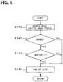
- the control device 2receives the image data from the vehicle interior camera 3 , and executes the image process on the received image data. Thereby, the control device 2 determines the driver state, specifically, whether the driver is drowsing and whether the driver is looking aside, and stores the determination result in the memory inside the control device 2 .
- This image process of the driverthat is, the driver state determination control has been already executed in the step S 10 of FIG. 7 . Therefore, the process of the step S 210 may be omitted.
- the image process in the step S 10 of FIG. 7may be omitted.
- the processshifts to a step S 220 , and it is determined whether the driver is drowsing.
- the processshifts to a step S 230 and the alert of the drowse and the inattentiveness is turned on, that is, the alert is executed.
- the control device 2causes the speaker to output an alert sound for alerting the driver to the drowse, the alert voice for alerting the driver to the drowse, or the like, or displays the alert message for alerting the driver to the drowse on the display.
- step S 220when the driver is not drowsing (NO), the process shifts to a step 240 and it is determined whether the driver is looking aside.
- the processshifts to a step S 250 and the alert of the drowse and the inattentiveness is turned off, that is, the alert is not executed. Thereby, the second alert control ends, and the process returns to the main control of FIG. 7 .
- step S 240when the driver is not looking aside (NO), also in this case, the process shifts to the step S 250 .
- the alert of the drowse and the inattentivenessis turned off, and the second alert control ends.
- the process of the step S 240may be omitted.
- the process of the step S 250may be executed.
- the control device 2receives the image data from the vehicle interior camera 3 , and executes the image process on the received image data. Thereby, the control device 2 determines the driver state, specifically, whether the driver is drowsing and whether the driver is looking aside, and stores the determination result in the memory inside the control device 2 .
- This image process of the driverthat is, the driver state determination control has been already executed in the step S 10 of FIG. 7 . Therefore, the process of the step S 310 can be omitted.
- the image process in the step S 10 of FIG. 7may be omitted.
- the processshifts to a step S 320 , and it is determined whether the driver is drowsing.
- the processshifts to a step S 330 and the alert of the drowse and the inattentiveness is turned on, that is, the alert is executed.
- the control device 2causes the speaker to output the alert sound for alerting the driver to the drowse, the alert voice for alerting the driver to the drowse, or the like, or displays the alert message for alerting the driver to the drowse on the display.
- the third alert controlends, and the process returns to third main control of FIG. 7 .
- step S 320when the driver is not drowsing (NO), the process shifts to a step 340 and it is determined whether the driver is looking aside.
- the processshifts to a step S 330 and the alert of the drowse and the inattentiveness is turned on, that is, the alert is executed. Thereby, the third alert control ends, and the process returns to third main control of FIG. 7 .
- step S 340when the driver is not looking aside (NO), also in this case, the process shifts to the step S 350 .
- the alert of the drowse and the inattentivenessis turned off, that is, the alert is not executed. Thereby, the third alert control ends, and the process returns to third main control of FIG. 7 .
- each control of FIGS. 8, 9, and 10that is, the driver state determination control is repeatedly executed at a predetermined cycle.
- the vehicle speed determination control of FIG. 7 and each driver state determination control of FIGS. 8, 9, and 10are repeatedly executed in synchronization.
- the vehicle speed determination controlis executed first. Thereafter, the driver state determination control, that is, the determination control for the drowse, the inattentiveness of the driver, or the like is executed.
- the driver state determination controlmay be executed first, and thereafter the vehicle speed determination control may be executed. Even such a configuration can provide the similar operation effect.
- the notification portionexecutes the alert.
- the alert execution by the notification portionis controlled based on the detection result of the driver drowse, the detection result of the driver inattentiveness, or the detection result of the vehicle speed. According to this configuration, it may be possible to execute the alert when the driver drowses or looks aside. Further, it may be possible not to execute the alert when the alert is unnecessary. Therefore, it may be possible to prevent the situation where the driver feels troublesome with the alert as much as possible.
- the threshold value Vthis changeable. Therefore, the determination level of whether to execute the alert can be customized so as to match the sense of the driver, that is, the user. Thereby, the erroneous alert is reduced, and it may be possible to reduce the troublesomeness of the driver. Accordingly, it may be possible to improve the usability as compared with the conventional configuration.
- the alertin the case where the vehicle speed is equal to or lower than the threshold value Vth, when the drowse of the driver is detected, the alert is executed. Even when the inattentiveness of the driver is detected, the alert is not executed. According to this configuration, when the vehicle is moving at an extremely low speed in order to search a parking position or the like in a parking lot, the alert is not executed. Therefore, it may be possible to prevent the driver from feeling troublesome with the alert.
- the alertin the case where the vehicle speed is higher than the threshold value Vth, when the drowse of the driver is detected or the inattentiveness of the driver is detected, the alert is executed.
- the alertin a case where the vehicle is traveling at the normal vehicle speed, when the drowse or the inattentiveness is detected, the alert is executed. Therefore, it may be possible to prevent the drowse driving or the inattentiveness driving.
- the alertin the case where the vehicle speed is 0 or close to 0, even when the drowse of the driver is detected, the alert is not executed. Therefore, in the case where the vehicle speed is 0 or close to 0, the alert of the drowse or the inattentiveness is not executed. Thereby, it may be possible to prevent the driver from feeling troublesome with the alert.
- FIG. 11 and FIG. 12show a second embodiment.
- a configuration identical to that according to the first embodimentis denoted by an identical reference sign.
- an abnormal posture of the driveris detected and the alert is executed.
- the second alert control of the step S 60 in the first embodiment, that is, the flowchart of FIG. 9 and the third alert control of the step S 70 , that is, the flowchart of FIG. 10are changed as described below.
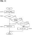
- a second alert control of the second embodimentwill be described with reference to FIG. 11 .
- Each process of steps S 210 , S 220 , and S 230 in FIG. 11is executed similarly to the first embodiment.
- the processshifts to a step S 235 and it is determined whether the driver posture is the abnormal posture.
- a detection process of the driver abnormal postureis executed in the image process of the step S 210 or the step S 10 in FIG. 7 , that is, the driver state determination control.
- the detection resultis stored in the memory inside the control device 2 .
- step S 235when the driver posture is the abnormal posture (YES), the process shifts to the step S 230 and the alert is turned on, that is, the alert of the drowse, the inattentive, and the abnormal posture is executed.
- the driver posturewhen the driver posture is the abnormal posture (NO), the process shifts to the step S 240 and it is determined whether the driver is looking aside.
- Each process of the steps S 240 and S 250is executed similarly to the first embodiment.
- step S 320when the driver is not drowsing (NO), the process shifts to the step S 335 and it is determined whether the driver posture is the abnormal posture.
- a detection process of the driver abnormal postureis executed in the image process of the step S 310 or the step S 10 in FIG. 7 , that is, the driver state determination control. The detection result is stored in the memory inside the control device 2 .
- step S 335when the driver posture is the abnormal posture (YES), the process shifts to the step S 330 and the alert is turned on, that is, the alert of the drowse, the inattentive, and the abnormal posture is executed.
- the driver posturewhen the driver posture is the abnormal posture (NO), the process shifts to the step S 340 and it is determined whether the driver is looking aside.
- Each process of the steps S 340 and S 350is executed similarly to the first embodiment.
- Configurations according to the second embodiment other than those described aboveare similar to corresponding configurations according to the first embodiment. Accordingly, the second embodiment can provide the operation effect similar to the first embodiment.
- the abnormal posture of the driveris detected. Therefore, when the driver posture is abnormal, it may be possible to alert the driver to the abnormal posture. It may be possible to encourage the driver to take a correct posture.
- the initial value of the threshold value Vththat is, a default is set to 10 km/h. However, it may be set to a different speed.
- the threshold value Vthcan be changed by the user, the traveling manager, or the like. However, it is not limited to this.
- the threshold value Vthmay be changed as follows.
- the driverinputs information regarding the troublesomeness with the alert and the threshold value Vth is adjusted each driver based on the input information regarding the troublesomeness. Specifically, when the driving of the vehicle ends and the driver gets off the vehicle, for example, a message of “Is the frequency of the alert troublesome?” is displayed on the screen of the display.
- the threshold value Vthis changed in accordance with the selection result. Thereby, the threshold value Vth is reflected in the alert process at the next driving.
- the control device 2holds the threshold value Vth at the current value, and uses the same threshold value Vth for the alert process at the next driving.
- the threshold value Vthis changed to a small value and thereby the detection of the drowse or the like is eased.
- the changed threshold value Vthis stored in the memory inside the control device 2 , for example, a non-volatile memory. Thereby, at the next driving, the changed threshold value Vth is read at the starting of the detection control, and used for the detection control.
- the control device 2 and the operation input portion 6have a function as a threshold value change portion.
- Each of the embodiments described abovemay include a configuration of receiving a feedback of whether the alert frequency or the like is appropriate from the driver after the driving of the vehicle ends.
- the alertmatches the user sense. Therefore, it is preferable that the threshold value Vth is not changed, and is maintained.
- the alertcannot be turned off and the alert can be continued. However, when the vehicle is not on the road, the alert can be turned off.
Landscapes
- Engineering & Computer Science (AREA)
- Automation & Control Theory (AREA)
- Transportation (AREA)
- Mechanical Engineering (AREA)
- Physics & Mathematics (AREA)
- Mathematical Physics (AREA)
- General Physics & Mathematics (AREA)
- Human Computer Interaction (AREA)
- Business, Economics & Management (AREA)
- Emergency Management (AREA)
- Chemical & Material Sciences (AREA)
- Combustion & Propulsion (AREA)
- Traffic Control Systems (AREA)
- Emergency Alarm Devices (AREA)
Abstract
Description
Claims (7)
Applications Claiming Priority (4)
| Application Number | Priority Date | Filing Date | Title |
|---|---|---|---|
| JPJP2018-014957 | 2018-01-31 | ||
| JP2018-014957 | 2018-01-31 | ||
| JP2018014957AJP6977589B2 (en) | 2018-01-31 | 2018-01-31 | Vehicle alarm device |
| PCT/JP2018/046563WO2019150808A1 (en) | 2018-01-31 | 2018-12-18 | Warning device for vehicle |
Related Parent Applications (1)
| Application Number | Title | Priority Date | Filing Date |
|---|---|---|---|
| PCT/JP2018/046563ContinuationWO2019150808A1 (en) | 2018-01-31 | 2018-12-18 | Warning device for vehicle |
Publications (2)
| Publication Number | Publication Date |
|---|---|
| US20200365003A1 US20200365003A1 (en) | 2020-11-19 |
| US11373502B2true US11373502B2 (en) | 2022-06-28 |
Family
ID=67479797
Family Applications (1)
| Application Number | Title | Priority Date | Filing Date |
|---|---|---|---|
| US16/941,430ActiveUS11373502B2 (en) | 2018-01-31 | 2020-07-28 | Vehicle alert apparatus |
Country Status (5)
| Country | Link |
|---|---|
| US (1) | US11373502B2 (en) |
| JP (1) | JP6977589B2 (en) |
| CN (1) | CN111656422B (en) |
| DE (1) | DE112018006987T5 (en) |
| WO (1) | WO2019150808A1 (en) |
Families Citing this family (6)
| Publication number | Priority date | Publication date | Assignee | Title |
|---|---|---|---|---|
| JP7259957B2 (en)* | 2019-06-11 | 2023-04-18 | 日本電気株式会社 | Judgment system, processing method, program |
| JP2022089223A (en)* | 2020-12-04 | 2022-06-16 | ダイハツ工業株式会社 | Doze detection system |
| CN112669583B (en) | 2020-12-31 | 2022-11-04 | 上海商汤临港智能科技有限公司 | Alarm threshold adjusting method and device, electronic equipment and storage medium |
| CN114013446A (en)* | 2021-11-19 | 2022-02-08 | 安徽江淮汽车集团股份有限公司 | Automobile with driver vital sign monitoring system |
| JP2024031625A (en) | 2022-08-26 | 2024-03-07 | トヨタ自動車株式会社 | Notification device, notification method, and notification computer program |
| DE102022211268A1 (en) | 2022-10-24 | 2024-04-25 | Volkswagen Aktiengesellschaft | Method for detecting an ergonomic position of a person in a motor vehicle by means of an assistance system of the motor vehicle, computer program product and assistance system |
Citations (58)
| Publication number | Priority date | Publication date | Assignee | Title |
|---|---|---|---|---|
| JPH08290726A (en) | 1995-04-21 | 1996-11-05 | Mitsubishi Electric Corp | Dozing alarm device |
| US5815070A (en)* | 1995-08-01 | 1998-09-29 | Honda Giken Kogyo Kabushiki Kaisha | Driving state-monitoring apparatus for automotive vehicles |
| US5821860A (en)* | 1996-05-20 | 1998-10-13 | Honda Giken Kogyo Kabushiki Kaisha | Driving condition-monitoring apparatus for automotive vehicles |
| US20010037171A1 (en)* | 2000-04-28 | 2001-11-01 | Toyota Jidosha Kabushiki Kaisha | Vehicular deceleration control apparatus, and braking system control method |
| US20020101354A1 (en)* | 2000-08-23 | 2002-08-01 | Banas Patrick A. | Method to alert drowsy driver |
| US20020105438A1 (en)* | 2000-11-22 | 2002-08-08 | Fred Forbes | Vehicular black box monitoring system |
| US20030105578A1 (en)* | 2001-11-30 | 2003-06-05 | Hitachi, Ltd. | Traffic environment recognition method and system for carrying out the same |
| JP2003226227A (en) | 2002-02-06 | 2003-08-12 | Denso Corp | Room monitor device, room monitor control device and vehicle robber specifying system |
| US20030151516A1 (en)* | 2002-01-18 | 2003-08-14 | Basir Otman Adam | Drowsiness detection system |
| US20040201481A1 (en)* | 2003-03-20 | 2004-10-14 | Takeshi Yoshinori | Vehicle tiredness alleviating system |
| US20050065711A1 (en)* | 2003-04-07 | 2005-03-24 | Darwin Dahlgren | Centralized facility and intelligent on-board vehicle platform for collecting, analyzing and distributing information relating to transportation infrastructure and conditions |
| US20050219058A1 (en)* | 2003-05-16 | 2005-10-06 | Fujitsu Limited | Alarm system, alarm control apparatus and alarm control program |
| US20060142968A1 (en)* | 2004-12-29 | 2006-06-29 | Samsung Electronics Co., Ltd. | Home control system using galvanic skin response and heart rate and method thereof |
| JP2006268189A (en) | 2005-03-22 | 2006-10-05 | Nissan Motor Co Ltd | Visual behavior determination device |
| US7184873B1 (en)* | 2006-05-05 | 2007-02-27 | Stanox Technologies Inc. | Vehicle speed limiting device |
| US20070080816A1 (en)* | 2005-10-12 | 2007-04-12 | Haque M A | Vigilance monitoring technique for vehicle operators |
| US20070168128A1 (en)* | 2004-01-28 | 2007-07-19 | Setsuo Tokoro | Running support system for vehicle |
| JP2007226666A (en) | 2006-02-24 | 2007-09-06 | Aisin Aw Co Ltd | Driving support method and driving support device |
| US20070265777A1 (en)* | 2006-05-15 | 2007-11-15 | Kohsuke Munakata | On-Vehicle Road Configuration Identifying Device |
| JP2008097445A (en)* | 2006-10-13 | 2008-04-24 | Toyota Motor Corp | In-vehicle warning device |
| US20090115589A1 (en)* | 2003-11-26 | 2009-05-07 | Arnim Lars Galley | Method and Computer Program for Identification of Inattentiveness by the Driver of a Vehicle |
| US20090132143A1 (en)* | 2005-07-28 | 2009-05-21 | Advics Co., Ltd. | Parking Support Control Apparatus and Parking Support Control System |
| JP2009116394A (en)* | 2007-11-01 | 2009-05-28 | Mazda Motor Corp | Alarm device for vehicle |
| US20090318776A1 (en)* | 2006-11-07 | 2009-12-24 | Aisin Seiki Kabushiki Kaisha | Physical condition management system |
| US20100007480A1 (en) | 2006-10-13 | 2010-01-14 | Shigeyasu Uozumi | On-board warning apparatus and warning method |
| US20100049068A1 (en)* | 2008-08-22 | 2010-02-25 | Yoshitaka Fuwamoto | In-vehicle electrocardiograph device and vehicle |
| US20100094103A1 (en)* | 2003-02-28 | 2010-04-15 | Consolidated Research Of Richmond, Inc | Automated treatment system for sleep |
| US7710249B2 (en)* | 2005-08-02 | 2010-05-04 | Delphi Technologies, Inc. | Method of controlling a driver assistance system and an associated apparatus |
| US20100188233A1 (en)* | 2007-07-05 | 2010-07-29 | Svenska Utvecklings Entreprenoren Susen Ab | Device for waking up a driver and an operator |
| US20100207751A1 (en)* | 2009-02-13 | 2010-08-19 | Follmer Todd W | System and method for viewing and correcting data in a street mapping database |
| US20100217099A1 (en)* | 2009-02-25 | 2010-08-26 | Leboeuf Steven Francis | Methods and Apparatus for Assessing Physiological Conditions |
| US20110105925A1 (en)* | 2008-07-04 | 2011-05-05 | Toyota Jidosha Kabushiki Kaisha | Drowsiness detector |
| US20110144515A1 (en)* | 2008-02-15 | 2011-06-16 | Georgia Tech Research Corporation | Systems and methods for providing environment monitoring |
| US20110163863A1 (en)* | 2008-04-04 | 2011-07-07 | Lonnie Chatmon | Driver's Alert System |
| US8041493B2 (en)* | 2007-04-25 | 2011-10-18 | Nissan Motor Co., Ltd. | Cruise control device and method for controlling the running of a vehicle |
| US20120025993A1 (en)* | 2009-04-23 | 2012-02-02 | Toyota Jidosha Kabushiki Kaisha | Device responding to improper drive |
| US20120133515A1 (en)* | 2009-06-30 | 2012-05-31 | Asp Technology Aps | Pause adviser system and use thereof |
| US20120253628A1 (en)* | 2011-03-29 | 2012-10-04 | Fuji Jukogyo Kabushiki Kaisha | Driving support apparatus for vehicle |
| US20130113910A1 (en)* | 2011-11-07 | 2013-05-09 | Kia Motors Corporation | Driving assistant system and method having warning function for risk level |
| US20130144470A1 (en)* | 2011-11-16 | 2013-06-06 | Flextronics Ap, Llc | Vehicle climate control |
| US8618952B2 (en)* | 2011-01-21 | 2013-12-31 | Honda Motor Co., Ltd. | Method of intersection identification for collision warning system |
| US8742936B2 (en)* | 2005-06-09 | 2014-06-03 | Daimler Ag | Method and control device for recognising inattentiveness according to at least one parameter which is specific to a driver |
| US20140309881A1 (en)* | 2011-02-18 | 2014-10-16 | Honda Motor Co., Ltd. | System and method for responding to driver behavior |
| US20150029014A1 (en)* | 2012-02-01 | 2015-01-29 | Fico Mirrors, S.A. | Method and system for inferring the behavior or state of the driver of a vehicle, use of the method and computer program for carrying out the method |
| US9315194B2 (en)* | 2012-03-28 | 2016-04-19 | Toyota Jidosha Kabushiki Kaisha | Low-level consciousness determination system |
| US20160196098A1 (en)* | 2015-01-02 | 2016-07-07 | Harman Becker Automotive Systems Gmbh | Method and system for controlling a human-machine interface having at least two displays |
| JP3207515U (en) | 2016-08-12 | 2016-11-17 | 田中 久生 | Dozing detection device in a vehicle |
| US20170106858A1 (en)* | 2015-10-19 | 2017-04-20 | Leauto Intelligent Technology (BEIJING) Co., Ltd. | Driver fatigue alert method and system for vehicle |
| US20170183006A1 (en)* | 2015-12-28 | 2017-06-29 | Firstenergy Ventures Corp. | Vehicle speed control system |
| JP2017151606A (en) | 2016-02-23 | 2017-08-31 | 株式会社デンソー | Inattentiveness/overlooking reminding system and computer program |
| JP2017208007A (en) | 2016-05-20 | 2017-11-24 | 株式会社デンソー | Face orientation estimation device and face orientation estimation method |
| US20180061232A1 (en)* | 2016-08-29 | 2018-03-01 | Allstate Insurance Company | Electrical Data Processing System for Determining Status of Traffic Device and Vehicle Movement |
| US20180057015A1 (en)* | 2015-03-14 | 2018-03-01 | Audi Ag | Method for Operating a Motor Vehicle and Associated Motor Vehicle |
| US9937923B2 (en)* | 2016-01-30 | 2018-04-10 | Bendix Commercial Vehicle Systems Llc | System and method for providing a speed warning and speed control |
| US20180105180A1 (en)* | 2011-02-18 | 2018-04-19 | Honda Motor Co., Ltd. | Coordinated vehicle response system and method for driver behavior |
| US20180357894A1 (en)* | 2017-06-13 | 2018-12-13 | Volvo Car Corporation | Method for providing drowsiness alerts in vehicles |
| US20180365986A1 (en)* | 2017-06-14 | 2018-12-20 | Delphi Technologies, Inc. | Driver fatigue warning system |
| US10272926B2 (en)* | 2016-10-04 | 2019-04-30 | Toyota Jidosha Kabushiki Kaisha | Vehicle traveling control apparatus |
Family Cites Families (5)
| Publication number | Priority date | Publication date | Assignee | Title |
|---|---|---|---|---|
| JP5088669B2 (en)* | 2007-03-23 | 2012-12-05 | 株式会社デンソー | Vehicle periphery monitoring device |
| JP4372804B2 (en)* | 2007-05-09 | 2009-11-25 | トヨタ自動車株式会社 | Image processing device |
| JP5003705B2 (en)* | 2009-03-23 | 2012-08-15 | 株式会社豊田中央研究所 | Open / closed eye state determination device, front lateral state determination device, and program |
| JP6428513B2 (en)* | 2015-07-07 | 2018-11-28 | 日本ポリエチレン株式会社 | Method for measuring the density of polyethylene resin |
| CN106205052A (en)* | 2016-07-21 | 2016-12-07 | 上海仰笑信息科技有限公司 | A kind of driving recording method for early warning |
- 2018
- 2018-01-31JPJP2018014957Apatent/JP6977589B2/enactiveActive
- 2018-12-18CNCN201880087824.3Apatent/CN111656422B/enactiveActive
- 2018-12-18WOPCT/JP2018/046563patent/WO2019150808A1/ennot_activeCeased
- 2018-12-18DEDE112018006987.7Tpatent/DE112018006987T5/enactiveGranted
- 2020
- 2020-07-28USUS16/941,430patent/US11373502B2/enactiveActive
Patent Citations (59)
| Publication number | Priority date | Publication date | Assignee | Title |
|---|---|---|---|---|
| JPH08290726A (en) | 1995-04-21 | 1996-11-05 | Mitsubishi Electric Corp | Dozing alarm device |
| US5815070A (en)* | 1995-08-01 | 1998-09-29 | Honda Giken Kogyo Kabushiki Kaisha | Driving state-monitoring apparatus for automotive vehicles |
| US5821860A (en)* | 1996-05-20 | 1998-10-13 | Honda Giken Kogyo Kabushiki Kaisha | Driving condition-monitoring apparatus for automotive vehicles |
| US20010037171A1 (en)* | 2000-04-28 | 2001-11-01 | Toyota Jidosha Kabushiki Kaisha | Vehicular deceleration control apparatus, and braking system control method |
| US20020101354A1 (en)* | 2000-08-23 | 2002-08-01 | Banas Patrick A. | Method to alert drowsy driver |
| US20020105438A1 (en)* | 2000-11-22 | 2002-08-08 | Fred Forbes | Vehicular black box monitoring system |
| US20030105578A1 (en)* | 2001-11-30 | 2003-06-05 | Hitachi, Ltd. | Traffic environment recognition method and system for carrying out the same |
| US20030151516A1 (en)* | 2002-01-18 | 2003-08-14 | Basir Otman Adam | Drowsiness detection system |
| JP2003226227A (en) | 2002-02-06 | 2003-08-12 | Denso Corp | Room monitor device, room monitor control device and vehicle robber specifying system |
| US20100094103A1 (en)* | 2003-02-28 | 2010-04-15 | Consolidated Research Of Richmond, Inc | Automated treatment system for sleep |
| US20040201481A1 (en)* | 2003-03-20 | 2004-10-14 | Takeshi Yoshinori | Vehicle tiredness alleviating system |
| US20050065711A1 (en)* | 2003-04-07 | 2005-03-24 | Darwin Dahlgren | Centralized facility and intelligent on-board vehicle platform for collecting, analyzing and distributing information relating to transportation infrastructure and conditions |
| US20050219058A1 (en)* | 2003-05-16 | 2005-10-06 | Fujitsu Limited | Alarm system, alarm control apparatus and alarm control program |
| US20090115589A1 (en)* | 2003-11-26 | 2009-05-07 | Arnim Lars Galley | Method and Computer Program for Identification of Inattentiveness by the Driver of a Vehicle |
| US20070168128A1 (en)* | 2004-01-28 | 2007-07-19 | Setsuo Tokoro | Running support system for vehicle |
| US20060142968A1 (en)* | 2004-12-29 | 2006-06-29 | Samsung Electronics Co., Ltd. | Home control system using galvanic skin response and heart rate and method thereof |
| JP2006268189A (en) | 2005-03-22 | 2006-10-05 | Nissan Motor Co Ltd | Visual behavior determination device |
| US8742936B2 (en)* | 2005-06-09 | 2014-06-03 | Daimler Ag | Method and control device for recognising inattentiveness according to at least one parameter which is specific to a driver |
| US20090132143A1 (en)* | 2005-07-28 | 2009-05-21 | Advics Co., Ltd. | Parking Support Control Apparatus and Parking Support Control System |
| US7710249B2 (en)* | 2005-08-02 | 2010-05-04 | Delphi Technologies, Inc. | Method of controlling a driver assistance system and an associated apparatus |
| US20070080816A1 (en)* | 2005-10-12 | 2007-04-12 | Haque M A | Vigilance monitoring technique for vehicle operators |
| JP2007226666A (en) | 2006-02-24 | 2007-09-06 | Aisin Aw Co Ltd | Driving support method and driving support device |
| US7184873B1 (en)* | 2006-05-05 | 2007-02-27 | Stanox Technologies Inc. | Vehicle speed limiting device |
| US20070265777A1 (en)* | 2006-05-15 | 2007-11-15 | Kohsuke Munakata | On-Vehicle Road Configuration Identifying Device |
| JP2008097445A (en)* | 2006-10-13 | 2008-04-24 | Toyota Motor Corp | In-vehicle warning device |
| US20100007480A1 (en) | 2006-10-13 | 2010-01-14 | Shigeyasu Uozumi | On-board warning apparatus and warning method |
| US20090318776A1 (en)* | 2006-11-07 | 2009-12-24 | Aisin Seiki Kabushiki Kaisha | Physical condition management system |
| US8041493B2 (en)* | 2007-04-25 | 2011-10-18 | Nissan Motor Co., Ltd. | Cruise control device and method for controlling the running of a vehicle |
| US20100188233A1 (en)* | 2007-07-05 | 2010-07-29 | Svenska Utvecklings Entreprenoren Susen Ab | Device for waking up a driver and an operator |
| JP2009116394A (en)* | 2007-11-01 | 2009-05-28 | Mazda Motor Corp | Alarm device for vehicle |
| US20110144515A1 (en)* | 2008-02-15 | 2011-06-16 | Georgia Tech Research Corporation | Systems and methods for providing environment monitoring |
| US20110163863A1 (en)* | 2008-04-04 | 2011-07-07 | Lonnie Chatmon | Driver's Alert System |
| US20110105925A1 (en)* | 2008-07-04 | 2011-05-05 | Toyota Jidosha Kabushiki Kaisha | Drowsiness detector |
| US20100049068A1 (en)* | 2008-08-22 | 2010-02-25 | Yoshitaka Fuwamoto | In-vehicle electrocardiograph device and vehicle |
| US20100207751A1 (en)* | 2009-02-13 | 2010-08-19 | Follmer Todd W | System and method for viewing and correcting data in a street mapping database |
| US20100217099A1 (en)* | 2009-02-25 | 2010-08-26 | Leboeuf Steven Francis | Methods and Apparatus for Assessing Physiological Conditions |
| US20120025993A1 (en)* | 2009-04-23 | 2012-02-02 | Toyota Jidosha Kabushiki Kaisha | Device responding to improper drive |
| US20120133515A1 (en)* | 2009-06-30 | 2012-05-31 | Asp Technology Aps | Pause adviser system and use thereof |
| US8618952B2 (en)* | 2011-01-21 | 2013-12-31 | Honda Motor Co., Ltd. | Method of intersection identification for collision warning system |
| US20140309881A1 (en)* | 2011-02-18 | 2014-10-16 | Honda Motor Co., Ltd. | System and method for responding to driver behavior |
| US20180105180A1 (en)* | 2011-02-18 | 2018-04-19 | Honda Motor Co., Ltd. | Coordinated vehicle response system and method for driver behavior |
| US20120253628A1 (en)* | 2011-03-29 | 2012-10-04 | Fuji Jukogyo Kabushiki Kaisha | Driving support apparatus for vehicle |
| US8983750B2 (en)* | 2011-03-29 | 2015-03-17 | Fuji Jukogyo Kabushiki Kaisha | Driving support apparatus for vehicle |
| US20130113910A1 (en)* | 2011-11-07 | 2013-05-09 | Kia Motors Corporation | Driving assistant system and method having warning function for risk level |
| US20130144470A1 (en)* | 2011-11-16 | 2013-06-06 | Flextronics Ap, Llc | Vehicle climate control |
| US20150029014A1 (en)* | 2012-02-01 | 2015-01-29 | Fico Mirrors, S.A. | Method and system for inferring the behavior or state of the driver of a vehicle, use of the method and computer program for carrying out the method |
| US9315194B2 (en)* | 2012-03-28 | 2016-04-19 | Toyota Jidosha Kabushiki Kaisha | Low-level consciousness determination system |
| US20160196098A1 (en)* | 2015-01-02 | 2016-07-07 | Harman Becker Automotive Systems Gmbh | Method and system for controlling a human-machine interface having at least two displays |
| US20180057015A1 (en)* | 2015-03-14 | 2018-03-01 | Audi Ag | Method for Operating a Motor Vehicle and Associated Motor Vehicle |
| US20170106858A1 (en)* | 2015-10-19 | 2017-04-20 | Leauto Intelligent Technology (BEIJING) Co., Ltd. | Driver fatigue alert method and system for vehicle |
| US20170183006A1 (en)* | 2015-12-28 | 2017-06-29 | Firstenergy Ventures Corp. | Vehicle speed control system |
| US9937923B2 (en)* | 2016-01-30 | 2018-04-10 | Bendix Commercial Vehicle Systems Llc | System and method for providing a speed warning and speed control |
| JP2017151606A (en) | 2016-02-23 | 2017-08-31 | 株式会社デンソー | Inattentiveness/overlooking reminding system and computer program |
| JP2017208007A (en) | 2016-05-20 | 2017-11-24 | 株式会社デンソー | Face orientation estimation device and face orientation estimation method |
| JP3207515U (en) | 2016-08-12 | 2016-11-17 | 田中 久生 | Dozing detection device in a vehicle |
| US20180061232A1 (en)* | 2016-08-29 | 2018-03-01 | Allstate Insurance Company | Electrical Data Processing System for Determining Status of Traffic Device and Vehicle Movement |
| US10272926B2 (en)* | 2016-10-04 | 2019-04-30 | Toyota Jidosha Kabushiki Kaisha | Vehicle traveling control apparatus |
| US20180357894A1 (en)* | 2017-06-13 | 2018-12-13 | Volvo Car Corporation | Method for providing drowsiness alerts in vehicles |
| US20180365986A1 (en)* | 2017-06-14 | 2018-12-20 | Delphi Technologies, Inc. | Driver fatigue warning system |
Non-Patent Citations (21)
| Title |
|---|
| Ahir et al., Driver Inattention Monitoring System A Review (Year: 2019).* |
| Bartra et al., A feasability study of drowsiness detection using driving behaviour parameters (Year: 2012).* |
| Bergasa et al., DriveSafe An app for alerting inattentive drivers and scoring driving behaviors (Year: 2018).* |
| Calinescu et al., Maintaining driver attentiveness in shared-control autonomous driving (Year: 2021).* |
| Chang et al., Vision-based onboard unit for inattentive driving warning and car-following control (Year: 2010).* |
| Dong et al., Driver Inattention Monitoring System for Intelligent Vehicles A Review (Year: 2011).* |
| Ed-Doughmi et al., Real-Time System for Driver Fatigue Detection Based on a Recurrent Neuronal Network (Year: 2020).* |
| Galarza et al., Real Time Driver Drowsiness Detection Based on Driver's Face Image Behavior Using a System of Human Computer Interaction Implemented in a Smartphone (Year: 2018).* |
| Hitendra Garg, Drowsiness Detection of a Driver using Conventional Computer Vision Application (Year: 2020).* |
| Jain et al., Neural Network Based Driver Warning System (Year: 2020).* |
| Kang et al., Various Approaches for Driver and Driving Behavior Monitoring A Review (Year: 2013).* |
| Lindow et al., AI-Based Driving Data Analysis for Behavior Recognition in Vehicle Cabin (Year: 2020).* |
| Maiti et al., An innovative prototype to prevent accidents using eye blink sensors and accelerometer ADXL330 (Year: 2015).* |
| Naz et al., Intelligent driver safety system using fatigue detection (Year: 2017).* |
| Nguyen et al., Eye tracking system to detect driver drowsiness (Year: 2015).* |
| Nishigaki et al., Driver attention level estimation using driver model identification (Year: 2019).* |
| Ou et al., Driver Behavior Monitoring Using Tools of Deep Learning and Fuzzy Inferencing (Year: 2018).* |
| Ovcharova et al., Effectiveness of forward collision warnings for different driver attention states (Year: 2012).* |
| Rusmin et al., Design and implementation of driver drowsiness detection system on digitalized driver system (Year: 2013).* |
| Sahayadhas et al., Detecting Driver Drowsiness Based on Sensors A Review (Year: 2012).* |
| Santos et al., Evaluating the Effect of Audio Feedback on the Behavior of Automotive Fatigue and Distraction Detection System Users (Year: 2019).* |
Also Published As
| Publication number | Publication date |
|---|---|
| JP2019133402A (en) | 2019-08-08 |
| DE112018006987T5 (en) | 2020-10-08 |
| CN111656422A (en) | 2020-09-11 |
| JP6977589B2 (en) | 2021-12-08 |
| CN111656422B (en) | 2022-06-14 |
| WO2019150808A1 (en) | 2019-08-08 |
| US20200365003A1 (en) | 2020-11-19 |
Similar Documents
| Publication | Publication Date | Title |
|---|---|---|
| US11373502B2 (en) | Vehicle alert apparatus | |
| US20200216095A1 (en) | Vehicle driving assistance apparatus | |
| US9650056B2 (en) | Method for controlling a driver assistance system | |
| US20170043715A1 (en) | Alerting device | |
| US12307791B2 (en) | Method for determining a drowsiness level of a motor vehicle driver | |
| US10882536B2 (en) | Autonomous driving control apparatus and method for notifying departure of front vehicle | |
| WO2018070064A1 (en) | Driving mode switching control device, method, and program | |
| JP5011827B2 (en) | Notification control device and notification information transmission device | |
| JP2019159711A (en) | Arousal maintenance device | |
| US20130194099A1 (en) | Driving assistance apparatus | |
| KR20210113070A (en) | Attention-based notifications | |
| JP4770946B2 (en) | In-vehicle display system | |
| JP2012038138A (en) | Display device for vehicle | |
| JP2006098359A (en) | Obstacle detector | |
| JP6512174B2 (en) | In-vehicle warning system | |
| WO2016120994A1 (en) | Driving information presentation system | |
| US10719724B2 (en) | Safety system for an automobile | |
| JP2007264883A (en) | Arousal level information output device for vehicle | |
| US9821660B2 (en) | Display system | |
| US9815371B2 (en) | Information providing apparatus for vehicle | |
| JP2021131596A (en) | Warning controller | |
| US20220161803A1 (en) | Vehicle and Control Method Thereof | |
| WO2020079755A1 (en) | Information providing device and information providing method | |
| JP2018151818A (en) | Failure determination apparatus, method and program | |
| KR20050045472A (en) | System for warning drowsy driving |
Legal Events
| Date | Code | Title | Description |
|---|---|---|---|
| FEPP | Fee payment procedure | Free format text:ENTITY STATUS SET TO UNDISCOUNTED (ORIGINAL EVENT CODE: BIG.); ENTITY STATUS OF PATENT OWNER: LARGE ENTITY | |
| AS | Assignment | Owner name:DENSO CORPORATION, JAPAN Free format text:ASSIGNMENT OF ASSIGNORS INTEREST;ASSIGNOR:NORO, TETSUSHI;REEL/FRAME:053534/0180 Effective date:20200720 | |
| STPP | Information on status: patent application and granting procedure in general | Free format text:DOCKETED NEW CASE - READY FOR EXAMINATION | |
| STPP | Information on status: patent application and granting procedure in general | Free format text:NON FINAL ACTION MAILED | |
| STPP | Information on status: patent application and granting procedure in general | Free format text:RESPONSE TO NON-FINAL OFFICE ACTION ENTERED AND FORWARDED TO EXAMINER | |
| STPP | Information on status: patent application and granting procedure in general | Free format text:FINAL REJECTION MAILED | |
| STPP | Information on status: patent application and granting procedure in general | Free format text:ADVISORY ACTION MAILED | |
| STPP | Information on status: patent application and granting procedure in general | Free format text:DOCKETED NEW CASE - READY FOR EXAMINATION | |
| STPP | Information on status: patent application and granting procedure in general | Free format text:NON FINAL ACTION MAILED | |
| STPP | Information on status: patent application and granting procedure in general | Free format text:NOTICE OF ALLOWANCE MAILED -- APPLICATION RECEIVED IN OFFICE OF PUBLICATIONS | |
| STPP | Information on status: patent application and granting procedure in general | Free format text:PUBLICATIONS -- ISSUE FEE PAYMENT RECEIVED | |
| STPP | Information on status: patent application and granting procedure in general | Free format text:PUBLICATIONS -- ISSUE FEE PAYMENT VERIFIED | |
| STCF | Information on status: patent grant | Free format text:PATENTED CASE |