US11371899B2 - Measuring element with an extended permeation resistant layer - Google Patents
Measuring element with an extended permeation resistant layerDownload PDFInfo
- Publication number
- US11371899B2 US11371899B2US16/616,736US201916616736AUS11371899B2US 11371899 B2US11371899 B2US 11371899B2US 201916616736 AUS201916616736 AUS 201916616736AUS 11371899 B2US11371899 B2US 11371899B2
- Authority
- US
- United States
- Prior art keywords
- diaphragm
- base body
- measuring element
- resistant layer
- permeation resistant
- Prior art date
- Legal status (The legal status is an assumption and is not a legal conclusion. Google has not performed a legal analysis and makes no representation as to the accuracy of the status listed.)
- Active, expires
Links
- 238000003466weldingMethods0.000claimsdescription31
- 239000012530fluidSubstances0.000claimsdescription19
- 238000005259measurementMethods0.000claimsdescription14
- 238000000034methodMethods0.000claimsdescription11
- 238000004519manufacturing processMethods0.000claimsdescription7
- 239000011248coating agentSubstances0.000claimsdescription4
- 238000000576coating methodMethods0.000claimsdescription4
- 238000007789sealingMethods0.000claims2
- 239000002609mediumSubstances0.000description24
- UFHFLCQGNIYNRP-UHFFFAOYSA-NHydrogenChemical compound[H][H]UFHFLCQGNIYNRP-UHFFFAOYSA-N0.000description12
- 239000001257hydrogenSubstances0.000description12
- 229910052739hydrogenInorganic materials0.000description12
- 239000000463materialSubstances0.000description5
- 239000000243solutionSubstances0.000description4
- PCHJSUWPFVWCPO-UHFFFAOYSA-NgoldChemical compound[Au]PCHJSUWPFVWCPO-UHFFFAOYSA-N0.000description3
- 239000010931goldSubstances0.000description3
- 229910052737goldInorganic materials0.000description3
- 239000002245particleSubstances0.000description3
- 239000012466permeateSubstances0.000description3
- 230000000694effectsEffects0.000description2
- 239000007788liquidSubstances0.000description2
- 238000012423maintenanceMethods0.000description2
- 238000012986modificationMethods0.000description2
- 230000004048modificationEffects0.000description2
- 238000004886process controlMethods0.000description2
- 239000000047productSubstances0.000description2
- 239000007320rich mediumSubstances0.000description2
- 239000007787solidSubstances0.000description2
- 239000000126substanceSubstances0.000description2
- 229910000831SteelInorganic materials0.000description1
- 230000005540biological transmissionEffects0.000description1
- 230000000903blocking effectEffects0.000description1
- 238000009530blood pressure measurementMethods0.000description1
- 239000004568cementSubstances0.000description1
- 239000003818cinderSubstances0.000description1
- 239000003245coalSubstances0.000description1
- 238000010276constructionMethods0.000description1
- 238000013461designMethods0.000description1
- 238000006073displacement reactionMethods0.000description1
- 238000009713electroplatingMethods0.000description1
- 238000000605extractionMethods0.000description1
- 239000011261inert gasSubstances0.000description1
- 238000002347injectionMethods0.000description1
- 239000007924injectionSubstances0.000description1
- 238000012544monitoring processMethods0.000description1
- 238000007747platingMethods0.000description1
- 238000004321preservationMethods0.000description1
- 238000012545processingMethods0.000description1
- 229910001220stainless steelInorganic materials0.000description1
- 239000010935stainless steelSubstances0.000description1
- 239000010959steelSubstances0.000description1
- 238000012360testing methodMethods0.000description1
- WFKWXMTUELFFGS-UHFFFAOYSA-NtungstenChemical compound[W]WFKWXMTUELFFGS-UHFFFAOYSA-N0.000description1
- 229910052721tungstenInorganic materials0.000description1
- 239000010937tungstenSubstances0.000description1
Images


Classifications
- G—PHYSICS
- G01—MEASURING; TESTING
- G01L—MEASURING FORCE, STRESS, TORQUE, WORK, MECHANICAL POWER, MECHANICAL EFFICIENCY, OR FLUID PRESSURE
- G01L19/00—Details of, or accessories for, apparatus for measuring steady or quasi-steady pressure of a fluent medium insofar as such details or accessories are not special to particular types of pressure gauges
- G01L19/0007—Fluidic connecting means
- G01L19/0046—Fluidic connecting means using isolation membranes
- G—PHYSICS
- G01—MEASURING; TESTING
- G01L—MEASURING FORCE, STRESS, TORQUE, WORK, MECHANICAL POWER, MECHANICAL EFFICIENCY, OR FLUID PRESSURE
- G01L13/00—Devices or apparatus for measuring differences of two or more fluid pressure values
- G01L13/02—Devices or apparatus for measuring differences of two or more fluid pressure values using elastically-deformable members or pistons as sensing elements
- G01L13/025—Devices or apparatus for measuring differences of two or more fluid pressure values using elastically-deformable members or pistons as sensing elements using diaphragms
- B—PERFORMING OPERATIONS; TRANSPORTING
- B23—MACHINE TOOLS; METAL-WORKING NOT OTHERWISE PROVIDED FOR
- B23K—SOLDERING OR UNSOLDERING; WELDING; CLADDING OR PLATING BY SOLDERING OR WELDING; CUTTING BY APPLYING HEAT LOCALLY, e.g. FLAME CUTTING; WORKING BY LASER BEAM
- B23K11/00—Resistance welding; Severing by resistance heating
- B23K11/08—Seam welding not restricted to one of the preceding subgroups
- B23K11/093—Seam welding not restricted to one of the preceding subgroups for curved planar seams
- G—PHYSICS
- G01—MEASURING; TESTING
- G01L—MEASURING FORCE, STRESS, TORQUE, WORK, MECHANICAL POWER, MECHANICAL EFFICIENCY, OR FLUID PRESSURE
- G01L19/00—Details of, or accessories for, apparatus for measuring steady or quasi-steady pressure of a fluent medium insofar as such details or accessories are not special to particular types of pressure gauges
- G01L19/06—Means for preventing overload or deleterious influence of the measured medium on the measuring device or vice versa
- G01L19/0627—Protection against aggressive medium in general
- G01L19/0645—Protection against aggressive medium in general using isolation membranes, specially adapted for protection
- G—PHYSICS
- G01—MEASURING; TESTING
- G01L—MEASURING FORCE, STRESS, TORQUE, WORK, MECHANICAL POWER, MECHANICAL EFFICIENCY, OR FLUID PRESSURE
- G01L19/00—Details of, or accessories for, apparatus for measuring steady or quasi-steady pressure of a fluent medium insofar as such details or accessories are not special to particular types of pressure gauges
- G01L19/06—Means for preventing overload or deleterious influence of the measured medium on the measuring device or vice versa
- G01L19/0672—Leakage or rupture protection or detection
Definitions
- the present disclosurerelates to a measuring element and a measuring device comprising the same.
- a process mediumor a medium to be measured
- relevant measurement parametersfor example, pressure, differential pressure, liquid level
- remote transmission measuring devicesfor example, remote transmitters
- the measuring elementmay include a base body and a diaphragm.
- a sealed cavityis defined between the diaphragm and the base body. The sealed cavity can be filled with working fluid.
- pressure measurement or monitoring of the medium to be measuredmay be performed by changes in fluid pressure on both sides of the diaphragm.
- the medium to be measuredis a hydrogen-rich medium
- the hydrogen in the medium to be measuredmay pass through the diaphragm and enter into the sealed cavity to aggregate and cause a pressure deviation, which leading to an inaccurate measurement accuracy of the measuring device, and in serious cases, the diaphragm may be inflated or even broken.
- a measuring elementincludes: a base body; a diaphragm fixedly connected to the base body, with a sealed cavity being defined between the diaphragm and the base body; and a permeation resistant layer arranged on an inner side surface, facing the sealed cavity, of the diaphragm, and extended continuously on the inner side surface of the diaphragm at least beyond a connection region of the diaphragm with the base body.
- the diaphragmis fixedly connected to the base body by resistance seam welding.
- the diaphragmis connected to the base body by TIG welding (Tungsten Inert Gas Welding) and resistance seam welding, and a welding region for the resistance seam welding is radially located at an inner side of a welding region for the TIG welding.
- TIG weldingTungsten Inert Gas Welding
- resistance seam weldinga welding region for the resistance seam welding is radially located at an inner side of a welding region for the TIG welding.
- the permeation resistant layeris extended over the entire inner side surface of the diaphragm.
- a coating thickness of the permeation resistant layer on the diaphragmis less than or equal to 10 ⁇ m.
- the diaphragmis formed with one or more annular folds.
- the base bodyis provided with a recess at a portion corresponding to the diaphragm.
- the base bodyis provided with a fluid channel for filling the sealed cavity with a fluid.
- the permeation resistant layeris a gold-plated layer formed on the inner side surface of the diaphragm.
- a measuring deviceis provided according to another aspect of the present disclosure, which includes the measuring element described above.
- substancesfor example, hydrogen
- a permeation resistance layerfor example, the gold-plated layer
- the permeation resistance layersince the permeation resistance layer is designed to face the inner side of the sealed cavity, the permeation resistance layer does not directly come into contact with the medium to be measured, and cannot be scratched by particles in the medium to be measured, which improving the wear resistance ability of a product. Under the premise of ensuring welding strength and quality, a design with zero hydrogen permeation paths is realized, which improving the service life of the product.
- an one-side integral or partial permeation resistance layercan be directly arranged on the sealed diaphragm before the diaphragm is connected to the base body.
- the permeation resistance layermay cover only the diaphragm, material costs can be greatly reduced.
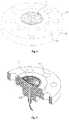
- FIG. 1is a perspective schematic view of a measuring element according to an embodiment of the present disclosure
- FIG. 2is a sectional view of the measuring element of FIG. 1 ;
- FIG. 3is a schematic cross-sectional view of the measuring element of FIG. 1 ;
- FIG. 4is a partial sectional view of the measuring element according to an embodiment of the present disclosure.
- FIG. 5is an EDX microscopic observation image of a partial section of the measuring element according to an embodiment of the present disclosure.
- FIG. 6is a schematic structural view of a measuring device according to an embodiment of the present disclosure.
- a measuring element and a measuring devicewill be described by, for example, a remote measuring device for measuring a pressure or pressure difference of a medium to be measured.
- a remote measuring devicefor measuring a pressure or pressure difference of a medium to be measured.
- the present disclosureis not limited to the structures and applications described in the following preferred embodiments, and can be applied to any feasible structure or application, for example, measuring viscosity liquid level, etc. Also, the present disclosure is not limited to the remote measuring devices, and can be applied to any feasible devices or means.
- the remote measuring devicegenerally includes the measuring element at the medium to be measured.
- a measuring elementmay be provided with a sealed cavity defined by a diaphragm and a base body.
- the sealed cavitymay be filled with a fluid (or referred to as a working fluid) for measurement.
- the remote measuring devicemay further include a sensing assembly located at a distance from the measuring element, during the measurement, the measuring element comes into contact with the medium to be measured and transmits the sensed pressure to the sensing assembly, which converting a physical quantity measured by the measuring element to an digital quantity actually required.
- the side of the diaphragm facing away from the sealed cavity(referred to herein as an outer side) and the side facing the sealed cavity (similarly, referred to as an inner side) are subjected to the pressure from the medium to be measured and the pressure of the working fluid within the sealed cavity respectively.
- the diaphragmtransmits the pressure from the measuring medium to the working fluid, which then transmits the sensed pressure to a sensing element for associated processing.
- the measuring device according to the present disclosuremay include a measuring element as described in detail below (as indicated by M in FIG. 6 ).
- FIG. 1shows a perspective schematic view of the measuring element in accordance with an embodiment of the present disclosure.
- the measuring element according to the present disclosuremay include the base body 1 and the diaphragm 2 which are made of steel.
- the diaphragm 2may be a substantially circular sheet member.
- the diaphragm 2may be fixedly connected to the base body 1 by the periphery of the diaphragm 2 , so that a sealed cavity 3 (see FIG. 3 ) is defined between the diaphragm 2 and the base body 1 .
- a working fluidmay be accommodated in the sealed cavity 3 .
- the sealed cavity 3may be filled with oil.
- the outer side surface 22 of the diaphragm 2may be displaced by the pressure of the measuring medium, and the displacement can be transmitted to the sensing element through the working fluid within the sealed cavity, which providing the pressure parameters required for a process control.
- the diaphragm 2may be provided with one or more annular folds 23 , allowing the diaphragm 2 to be properly deformed or partially displaced.
- one or more depressionsmay be provided on the diaphragm 2 if the diaphragm 2 has sufficient thickness.
- the fold and the depressions on the diaphragm 2are not limited to being annular.
- the base body 1may be provided with a recess 15 at a portion corresponding to the diaphragm 2 so as to form the sealed cavity 3 through the base body 1 and the diaphragm 2 .
- the base body 1can be further connected to the sensing assembly at a distal end. As shown in FIGS. 1 to 3 , the base body 1 may have a flange portion 11 , on which a through hole 12 through which a connecting member (such as a connecting bolt) passes may be provided. A fluid channel 13 may also be provided on the base body 1 . The working fluid may be injected into the sealed cavity 3 through the fluid channel 13 before the measuring element is applied, and the fluid channel 13 is closed after the injection is completed.
- a connecting membersuch as a connecting bolt
- the diaphragm 2may be appropriately deformed or displaced based on the pressure of the measuring medium the diaphragm 2 feels, so that the parameters extraction or measurement can be performed.
- the inventorhas found that since the diaphragm 2 is usually thin, a part of the elements or components (for example, hydrogen) in the medium to be measured can easily permeate through the diaphragm 2 into the sealed cavity 3 , and thus may be dissolved in the working fluid. Moreover, since the space of the sealed cavity 3 is relatively small and closed, the permeation of hydrogen may affect the pressure in the sealed cavity 3 and even cause the diaphragm 2 to bulge or rupture, which affecting the accuracy of the measurement and even causing damage to the measuring element.
- the elements or componentsfor example, hydrogen
- a permeation resistant layermay be arranged on the diaphragm 2 , thus blocking a permeate path through the diaphragm.
- a gold-plated layermay be provided to prevent hydrogen in the medium to be measured from permeating into the sealed cavity.
- the gold-plated layeris described as an example of the permeation resistant layer.
- other permeation resistant materialsother than gold may be used to achieve the object of preventing permeation depending on the actual application.
- the gold-plated layeris provided on the outer side surface 22 of the diaphragm 2 , considering that there may be a large amount of solid particles (such as pulp, crushed stones, cinders and the like) contained in some of the mediums to be measured, which will scratch the gold-plated layer on the diaphragm 2 . Since the diaphragm 2 is usually thin and the gold-plated layer is soft, the gold-plated layer is easily worn. As such, the gold-plated layer will lose its intended effect, resulting in a reduction in the wear resistance ability and service life of the measuring element (and even the measuring device) and a reduction in measurement accuracy.
- solid particlessuch as pulp, crushed stones, cinders and the like
- the gold-plated layer 4may be provided on the inner side surface 21 of the diaphragm 2 facing the sealed cavity 3 . In this way, the gold-plated layer 4 is not in contact with the medium to be measured and thus is not affected by the solid particles in the medium to be measured.
- the gold-plated layer 4may extend continuously between the inner side surface 21 of the diaphragm 2 and the corresponding portion of the base body 1 (in other words, an outer diameter of the gold-plated layer should be at least equal to or larger than the outer diameter of the connection region of the diaphragm 2 and the base body 1 ) at least beyond the connection region of the diaphragm 2 with the base body 1 , to prevent a hydrogen permeation path from being caused in the connection region between the diaphragm 2 and the base body 1 .
- the gold-plated layer 4may cover the entire inner side surface 21 of the diaphragm 2 in its entirety.
- the periphery of the diaphragm 2may be fixedly connected to the base body 1 by means of resistance seam welding (or other means that does not cause damage to the gold-plated layer in the connection region between the diaphragm 2 and the base body 1 ).
- FIG. 5shows an EDX microscopic view image of a partial section of the measuring element according to an embodiment of the present disclosure.
- the hydrogen permeation path of the sealed cavitymay be completely blocked, which improving the accuracy of measurement.
- the extended area of the permeation resistance layercovers at least the portion of the inner side surface 21 of the diaphragm 2 which is located in the sealed cavity 3 and in the connection region between the diaphragm 2 and the base body 1 , the components and elements in the medium to be measured on the outer side of the diaphragm 2 cannot permeate into the sealed cavity 3 through the diaphragm 2 . Therefore, the accuracy of the measurement may be improved. Furthermore, since the gold-plated layer is located on the inner side surface 21 of the diaphragm 2 , which is not affected by the medium to be measured, which improving the wear resistance ability and the service life of the measuring element.
- the sealed diaphragm 2can be directly integrally gold-plated at one side or partially gold-plated before assembly, the safe transportation and the low inventory may be achieved, and a lot of transportation and maintenance costs can be saved.
- the permeation resistance layercan cover the diaphragm only, the material cost may be greatly reduced as compared with the previously mentioned solution that the gold-plated layer is gold-plated on the outer side of the diaphragm 2 .
- the periphery of the diaphragm 2may be fixed to the base body 1 by TIG welding (as indicated by B in FIG. 4 ) or other fixed connection ways, and then the diaphragm 2 is further connected to the base body 1 (as shown by the C region in FIG. 4 ) by resistance seam welding or other feasible connection ways.
- TIG weldingas indicated by B in FIG. 4
- resistance seam weldingor other feasible connection ways.
- the welding region of the resistance seam weldingis located radially inward of the welding region of the TIG welding.
- the coverage of the gold-plated layer 4 on the inner side surface 21 of the diaphragm 2may extend beyond the welding region of the resistance seam welding only.
- the gold-plated layer 4may be provided on the inner side surface 21 of the diaphragm 2 by a usual process such as an electroplating process or vacuum plating.
- the thickness of the gold-plated layer 4is preferably such that the measurement accuracy is not affected, for example, the thickness of the gold-plated layer may be 10 ⁇ m or less, for example, the thickness of the gold-plated layer may be 5 ⁇ m.
- the measuring element and the measuring device according to the present disclosurealso have the advantages in measuring accuracy and cost etc., in terms of a technical solution that a problem caused by applying a gold-plated layer on the outer side surface 22 of the diaphragm 2 is solved by the way of increasing the thickness of the coating.
- the diaphragm 2can be made of a material that is the same as or different from that of the base body 1 .
- the diaphragm 2 and the base body 1may both be made of a stainless steel material.
- the measuring element and the measuring device according to the present disclosureimprove the accuracy of the measurement, increase the service life of the parts, and reduce manufacturing and maintenance costs.
Landscapes
- Physics & Mathematics (AREA)
- General Physics & Mathematics (AREA)
- Engineering & Computer Science (AREA)
- Mechanical Engineering (AREA)
- Measuring Fluid Pressure (AREA)
Abstract
Description
Claims (20)
Applications Claiming Priority (5)
| Application Number | Priority Date | Filing Date | Title |
|---|---|---|---|
| CN201810475248.1ACN110501033A (en) | 2018-05-17 | 2018-05-17 | Measuring element and measuring device including such measuring element |
| CN201810475248.1 | 2018-05-17 | ||
| CN201820741719.4UCN208140155U (en) | 2018-05-17 | 2018-05-17 | Measuring cell and measuring device including such measuring cell |
| CN201820741719.4 | 2018-05-17 | ||
| PCT/US2019/032824WO2019222598A1 (en) | 2018-05-17 | 2019-05-17 | Measuring element and measuring device comprising the same |
Publications (2)
| Publication Number | Publication Date |
|---|---|
| US20200333204A1 US20200333204A1 (en) | 2020-10-22 |
| US11371899B2true US11371899B2 (en) | 2022-06-28 |
Family
ID=66691065
Family Applications (1)
| Application Number | Title | Priority Date | Filing Date |
|---|---|---|---|
| US16/616,736Active2039-11-28US11371899B2 (en) | 2018-05-17 | 2019-05-17 | Measuring element with an extended permeation resistant layer |
Country Status (5)
| Country | Link |
|---|---|
| US (1) | US11371899B2 (en) |
| EP (1) | EP3769063B1 (en) |
| JP (1) | JP2021517969A (en) |
| CA (1) | CA3099745A1 (en) |
| WO (1) | WO2019222598A1 (en) |
Families Citing this family (2)
| Publication number | Priority date | Publication date | Assignee | Title |
|---|---|---|---|---|
| JP7192839B2 (en)* | 2020-10-08 | 2022-12-20 | 横河電機株式会社 | Diaphragm seal and its maintenance method |
| DE102021102046A1 (en)* | 2021-01-29 | 2022-08-04 | Infineon Technologies Ag | MEDIA-RESISTANT PRESSURE SENSOR FOR LARGE PRESSURE RANGES |
Citations (127)
| Publication number | Priority date | Publication date | Assignee | Title |
|---|---|---|---|---|
| US4089036A (en) | 1974-04-04 | 1978-05-09 | Rosemount Inc. | Capacitive load cell |
| US4184376A (en) | 1978-12-13 | 1980-01-22 | Donaldson Company, Inc. | Pressure sensitive indicating device |
| US4370890A (en) | 1980-10-06 | 1983-02-01 | Rosemount Inc. | Capacitive pressure transducer with isolated sensing diaphragm |
| US4389895A (en) | 1981-07-27 | 1983-06-28 | Rosemount Inc. | Capacitance pressure sensor |
| US4565096A (en) | 1983-12-09 | 1986-01-21 | Rosemount Inc. | Pressure transducer |
| US4572000A (en) | 1983-12-09 | 1986-02-25 | Rosemount Inc. | Pressure sensor with a substantially flat overpressure stop for the measuring diaphragm |
| US4611492A (en) | 1984-05-03 | 1986-09-16 | Rosemount Inc. | Membrane type non-intrusive ice detector |
| US4612812A (en) | 1985-08-15 | 1986-09-23 | Rosemount Inc. | Stress reducing stop for unstretched pressure sensing diaphragm |
| US4638830A (en) | 1985-09-27 | 1987-01-27 | Rosemount Inc. | High sensitivity magnetic actuator |
| US4653523A (en) | 1985-09-25 | 1987-03-31 | Rosemount Inc. | Pneumatic amplifier with negative feedback for current to pressure transducer |
| US4730496A (en) | 1986-06-23 | 1988-03-15 | Rosemount Inc. | Capacitance pressure sensor |
| US4773269A (en) | 1986-07-28 | 1988-09-27 | Rosemount Inc. | Media isolated differential pressure sensors |
| US4777826A (en) | 1985-06-20 | 1988-10-18 | Rosemount Inc. | Twin film strain gauge system |
| US4790192A (en) | 1987-09-24 | 1988-12-13 | Rosemount Inc. | Silicon side by side coplanar pressure sensors |
| US4798089A (en) | 1987-03-12 | 1989-01-17 | Rosemount Inc. | Isolator apparatus |
| US4800758A (en) | 1986-06-23 | 1989-01-31 | Rosemount Inc. | Pressure transducer with stress isolation for hard mounting |
| US4833920A (en) | 1986-06-30 | 1989-05-30 | Rosemount Inc. | Differential pressure sensor |
| US4833922A (en) | 1987-06-01 | 1989-05-30 | Rosemount Inc. | Modular transmitter |
| US4869282A (en) | 1988-12-09 | 1989-09-26 | Rosemount Inc. | Micromachined valve with polyimide film diaphragm |
| US4905575A (en) | 1988-10-20 | 1990-03-06 | Rosemount Inc. | Solid state differential pressure sensor with overpressure stop and free edge construction |
| US4926695A (en) | 1987-09-15 | 1990-05-22 | Rosemount Inc. | Rocking beam vortex sensor |
| US4950499A (en)* | 1987-01-27 | 1990-08-21 | The Foxboro Company | Method of making a compliant fluid-impermeable element |
| US4970898A (en) | 1989-09-20 | 1990-11-20 | Rosemount Inc. | Pressure transmitter with flame isolating plug |
| JPH0344646A (en) | 1989-07-12 | 1991-02-26 | Sharp Corp | Formation of resist pattern |
| US5095755A (en) | 1990-11-01 | 1992-03-17 | Rosemount Inc. | Isolator for pressure transmitter |
| US5157972A (en) | 1991-03-29 | 1992-10-27 | Rosemount Inc. | Pressure sensor with high modules support |
| US5184514A (en) | 1991-07-12 | 1993-02-09 | Rosemount Inc. | Corrosion resistant isolator |
| US5230248A (en) | 1991-07-12 | 1993-07-27 | Rosemount Inc. | Corrosion resistant isolator |
| US5287746A (en) | 1992-04-14 | 1994-02-22 | Rosemount Inc. | Modular transmitter with flame arresting header |
| US5333504A (en) | 1992-09-01 | 1994-08-02 | Rosemount Inc. | High overpressure low range pressure sensor |
| US5343762A (en) | 1992-10-05 | 1994-09-06 | Rosemount Inc. | Vortex flowmeter |
| US5483834A (en) | 1993-09-20 | 1996-01-16 | Rosemount Inc. | Suspended diaphragm pressure sensor |
| US5495768A (en) | 1993-04-23 | 1996-03-05 | Rosemount Inc. | Pressure isolator assembly for sanitary processing |
| US5515732A (en) | 1992-09-01 | 1996-05-14 | Rosemount Inc. | Capacitive pressure sensor and reference with stress isolating pedestal |
| US5524492A (en) | 1993-09-24 | 1996-06-11 | Rosemount Inc. | Pressure transmitter isolation diaphragm |
| US5578760A (en)* | 1994-03-17 | 1996-11-26 | Yamatake-Honeywell Co., Ltd. | Seal diaphragm structure for pressure measuring device |
| US5731522A (en) | 1997-03-14 | 1998-03-24 | Rosemount Inc. | Transmitter with isolation assembly for pressure sensor |
| US5760310A (en) | 1994-11-30 | 1998-06-02 | Rosemount Inc. | Transmitter with fill fluid loss detection |
| US5922965A (en) | 1998-04-28 | 1999-07-13 | Rosemount Inc. | Pressure sensor and transmitter having a weld ring with a rolling hinge point |
| US6003219A (en) | 1998-04-24 | 1999-12-21 | Rosemount Inc. | Method of making a pressure transmitter having pressure sensor having cohered surfaces |
| JPH11351991A (en) | 1998-06-08 | 1999-12-24 | Yokogawa Electric Corp | Differential pressure measuring device |
| US6030709A (en)* | 1996-04-12 | 2000-02-29 | Grundfos A/S | Electronic component |
| US6038961A (en) | 1998-03-02 | 2000-03-21 | Rosemount Inc. | Flush mount remote seal |
| US6120033A (en) | 1998-06-17 | 2000-09-19 | Rosemount Inc. | Process diaphragm seal |
| JP2001208629A (en) | 2000-01-31 | 2001-08-03 | Yokogawa Electric Corp | Differential pressure measuring device |
| US6295875B1 (en) | 1999-05-14 | 2001-10-02 | Rosemount Inc. | Process pressure measurement devices with improved error compensation |
| US6425290B2 (en) | 2000-02-11 | 2002-07-30 | Rosemount Inc. | Oil-less differential pressure sensor |
| US6484585B1 (en) | 1995-02-28 | 2002-11-26 | Rosemount Inc. | Pressure sensor for a pressure transmitter |
| US6505516B1 (en) | 2000-01-06 | 2003-01-14 | Rosemount Inc. | Capacitive pressure sensing with moving dielectric |
| US6516672B2 (en) | 2001-05-21 | 2003-02-11 | Rosemount Inc. | Sigma-delta analog to digital converter for capacitive pressure sensor and process transmitter |
| US6568278B2 (en) | 2000-10-24 | 2003-05-27 | Rosemount Inc. | Process connection for in-line pressure transmitter |
| US6647794B1 (en) | 2002-05-06 | 2003-11-18 | Rosemount Inc. | Absolute pressure sensor |
| US6662662B1 (en) | 2000-05-04 | 2003-12-16 | Rosemount, Inc. | Pressure transmitter with improved isolator system |
| US6675655B2 (en) | 2002-03-21 | 2004-01-13 | Rosemount Inc. | Pressure transmitter with process coupling |
| US6782754B1 (en) | 2000-07-07 | 2004-08-31 | Rosemount, Inc. | Pressure transmitter for clean environments |
| US6843133B2 (en) | 2002-06-18 | 2005-01-18 | Rosemount, Inc. | Capacitive pressure transmitter |
| US7036381B2 (en) | 2004-06-25 | 2006-05-02 | Rosemount Inc. | High temperature pressure transmitter assembly |
| US7096738B2 (en) | 2004-03-18 | 2006-08-29 | Rosemount Inc. | In-line annular seal-based pressure device |
| US7115118B2 (en) | 2002-04-08 | 2006-10-03 | Rosemount Inc. | Implantable pressure-activated micro-valve |
| US7117745B2 (en) | 2004-02-09 | 2006-10-10 | Rosemount Inc. | Process seal for process control transmitter |
| US7255012B2 (en) | 2004-12-01 | 2007-08-14 | Rosemount Inc. | Process fluid flow device with variable orifice |
| US7258021B2 (en) | 2004-06-25 | 2007-08-21 | Rosemount Inc. | Process transmitter isolation assembly |
| US7295131B2 (en) | 2005-01-07 | 2007-11-13 | Rosemount Inc. | Diagnostic system for detecting rupture or thinning of diaphragms |
| US7308830B2 (en) | 2006-01-26 | 2007-12-18 | Rosemount Inc. | Pressure sensor fault detection |
| US7334484B2 (en) | 2005-05-27 | 2008-02-26 | Rosemount Inc. | Line pressure measurement using differential pressure sensor |
| US7373831B2 (en) | 2004-06-25 | 2008-05-20 | Rosemount Inc. | High temperature pressure transmitter assembly |
| US7377174B2 (en) | 2004-03-18 | 2008-05-27 | Rosemount Inc. | Capillary weld extension with thermal isolation |
| US7415886B2 (en) | 2005-12-20 | 2008-08-26 | Rosemount Inc. | Pressure sensor with deflectable diaphragm |
| US7437938B2 (en) | 2007-03-21 | 2008-10-21 | Rosemount Inc. | Sensor with composite diaphragm containing carbon nanotubes or semiconducting nanowires |
| US7448275B1 (en) | 2007-09-12 | 2008-11-11 | Rosemount Inc. | Bi-planar process fluid pressure measurement system |
| US7454975B2 (en) | 2007-04-06 | 2008-11-25 | Rosemount Inc. | Expansion chamber for use with a pressure transmitter |
| US7484416B1 (en) | 2007-10-15 | 2009-02-03 | Rosemount Inc. | Process control transmitter with vibration sensor |
| US7503220B2 (en) | 2006-04-25 | 2009-03-17 | Rosemount Inc. | Pressure sensor using near net shape sintered ceramics |
| CN101413839A (en) | 2008-11-25 | 2009-04-22 | 沈阳市传感技术研究所 | Anti-corrosion diaphragm for sensor and preparing method thereof |
| US7591184B2 (en) | 2007-03-16 | 2009-09-22 | Rosemount Inc. | Industrial pressure sensor having enhanced dielectric fill fluid |
| US7624642B2 (en) | 2007-09-20 | 2009-12-01 | Rosemount Inc. | Differential pressure sensor isolation in a process fluid pressure transmitter |
| US20100064816A1 (en) | 2008-09-17 | 2010-03-18 | Dario Filippi | Diaphragm structure and method of manufacturing a diaphragm structure |
| US7779698B2 (en) | 2007-11-08 | 2010-08-24 | Rosemount Inc. | Pressure sensor |
| US7819014B1 (en) | 2009-04-23 | 2010-10-26 | Rosemount Inc. | Capacitive gage pressure sensor with vacuum dielectric |
| US7882736B2 (en) | 2007-11-12 | 2011-02-08 | Rosemount Inc. | Level measurement using a process vessel cage |
| DE102010018377A1 (en) | 2010-04-26 | 2011-04-28 | Labom Meß- und Regeltechnik GmbH | Functional component such as pressure transmitter for measure technical application on corrosive measuring media, comprises a base body and a metal film made of a metallic corrosion resistant special material |
| US8042401B2 (en) | 2008-06-12 | 2011-10-25 | Rosemount, Inc. | Isolation system for process pressure measurement |
| US8079269B2 (en) | 2007-05-16 | 2011-12-20 | Rosemount Inc. | Electrostatic pressure sensor with porous dielectric diaphragm |
| CN102575966A (en) | 2009-09-30 | 2012-07-11 | 米其林技术公司 | Sealed pressure measuring member |
| US8234927B2 (en) | 2010-06-08 | 2012-08-07 | Rosemount Inc. | Differential pressure sensor with line pressure measurement |
| US8429978B2 (en) | 2010-03-30 | 2013-04-30 | Rosemount Inc. | Resonant frequency based pressure sensor |
| US8448519B2 (en) | 2010-10-05 | 2013-05-28 | Rosemount Inc. | Industrial process transmitter with high static pressure isolation diaphragm coupling |
| CN103196623A (en) | 2013-04-26 | 2013-07-10 | 陈君杰 | Medium isolation pressure sensor based on back metalization process |
| US8596141B2 (en) | 2009-12-24 | 2013-12-03 | Rosemount Inc. | Vortex flow meter with vortex oscillation sensor plate |
| US20130320662A1 (en) | 2012-05-30 | 2013-12-05 | Daniel A. Norberg | Process fluid pressure measurement system with improved coupling |
| JP2013257225A (en) | 2012-06-13 | 2013-12-26 | Yokogawa Electric Corp | Pressure transmitter |
| US8776608B2 (en) | 2011-10-31 | 2014-07-15 | Rosemount Inc. | Coplanar process fluid pressure sensor module |
| US8813572B2 (en) | 2011-12-06 | 2014-08-26 | Rosemount Inc. | Ferrofluid modified fill fluid for pressure transmitters |
| US8915140B2 (en) | 2011-04-08 | 2014-12-23 | Rosemount Inc. | Corrosion resistant isolator assembly for process devices |
| US9010191B2 (en) | 2011-12-22 | 2015-04-21 | Rosemount Inc. | Pressure sensor module for sub-sea applications |
| US9038476B2 (en) | 2012-09-27 | 2015-05-26 | Rosemount Inc. | Pressure transmitter with fill tube |
| US9057659B2 (en) | 2012-05-22 | 2015-06-16 | Rosemount Inc. | Pressure transmitter with hydrogen getter |
| CN204556155U (en) | 2014-09-30 | 2015-08-12 | 罗斯蒙特公司 | For the remote seal assemblies of process transmitter |
| US20150228365A1 (en) | 2014-02-13 | 2015-08-13 | Hitachi, Ltd. | Instrumentation equipment for nuclear power plant |
| CN105203252A (en) | 2014-06-30 | 2015-12-30 | 罗斯蒙特公司 | Process pressure transmitter with seals coated with diamond-like carbon |
| US9234776B2 (en) | 2013-09-26 | 2016-01-12 | Rosemount Inc. | Multivariable process fluid transmitter for high pressure applications |
| US9274018B2 (en) | 2012-09-28 | 2016-03-01 | Rosemount Inc. | Remote seal process pressure measuring system |
| US9316553B2 (en) | 2014-03-26 | 2016-04-19 | Rosemount Inc. | Span line pressure effect compensation for diaphragm pressure sensor |
| RU2585641C2 (en) | 2014-09-02 | 2016-05-27 | Открытое акционерное общество "Казанский химический научно-исследовательский институт" | Antistatic coating of rubber-fabric protective materials |
| US9389106B2 (en) | 2012-03-06 | 2016-07-12 | Rosemount Inc. | Remote seal pressure measurement system for subsea use |
| US9459170B2 (en) | 2013-09-26 | 2016-10-04 | Rosemount Inc. | Process fluid pressure sensing assembly for pressure transmitters subjected to high working pressure |
| CN106062526A (en) | 2014-02-28 | 2016-10-26 | 恩德莱斯和豪瑟尔两合公司 | Differential pressure measuring pickup |
| CN106053948A (en) | 2016-06-01 | 2016-10-26 | 苏州迈奇杰智能技术有限公司 | Resistance detection and analysis system with visible light communication automatic alarming function |
| US9513183B2 (en) | 2014-06-30 | 2016-12-06 | Rosemount Inc. | Process isolation diaphragm assembly for metal process seal |
| CN106289634A (en) | 2016-08-23 | 2017-01-04 | 太仓市威士达电子有限公司 | A kind of metal shell for pressure sensor package combines |
| US9562819B2 (en) | 2015-06-30 | 2017-02-07 | Rosemount Inc | Polymeric remote seal system for single-use containers |
| US20170113917A1 (en)* | 2015-10-23 | 2017-04-27 | Mitsubishi Electric Corporation | Semiconductor pressure sensor |
| US9689769B2 (en) | 2013-07-19 | 2017-06-27 | Rosemount Inc. | Pressure transmitter having an isolation assembly with a two-piece isolator plug |
| US9719872B2 (en) | 2015-09-29 | 2017-08-01 | Rosemount Inc. | High over-pressure capable silicon die pressure sensor with extended pressure signal output |
| US9857259B2 (en) | 2014-09-30 | 2018-01-02 | Rosemount Inc. | Differential pressure sensor with high pressure capabilities |
| US9909909B2 (en) | 2016-03-16 | 2018-03-06 | Rosemount Inc. | Flow measurement system for single-use containers |
| WO2018058487A1 (en) | 2016-09-30 | 2018-04-05 | Rosemount Inc. | Process pressure transmitter with polymer seal |
| US10048152B2 (en) | 2015-09-30 | 2018-08-14 | Rosemount Inc. | Pressure transmitter with overpressure protection |
| US10060813B2 (en) | 2015-09-29 | 2018-08-28 | Rosemount Inc. | High over-pressure capable silicon die pressure sensor |
| US10060814B2 (en) | 2016-03-15 | 2018-08-28 | Rosemount Inc. | Fluid filled elongate pressure sensor |
| US10156491B2 (en) | 2014-04-25 | 2018-12-18 | Rosemount Inc. | Corrosion resistant pressure module for process fluid pressure transmitter |
| US10203258B2 (en) | 2016-09-26 | 2019-02-12 | Rosemount Inc. | Pressure sensor diaphragm with overpressure protection |
| US20190259779A1 (en)* | 2016-12-26 | 2019-08-22 | Murata Manufacturing Co., Ltd. | Electronic device and method of manufacturing the same |
| US10584309B2 (en) | 2017-02-06 | 2020-03-10 | Rosemount Inc. | Pressure transducer for single-use containers |
| US10598559B2 (en) | 2017-06-29 | 2020-03-24 | Rosemount Inc. | Pressure sensor assembly |
| US10627302B2 (en) | 2017-06-16 | 2020-04-21 | Rosemount Inc. | Pressure sensor module for high working pressure applications |
| US10816424B2 (en) | 2018-09-21 | 2020-10-27 | Rosemount Inc. | Remote seal diaphragm system |
Family Cites Families (3)
| Publication number | Priority date | Publication date | Assignee | Title |
|---|---|---|---|---|
| JPH0344646U (en)* | 1989-09-11 | 1991-04-25 | ||
| JP5831065B2 (en)* | 2011-09-13 | 2015-12-09 | 横河電機株式会社 | Differential pressure / pressure gauge |
| JP2015172542A (en)* | 2014-03-12 | 2015-10-01 | 株式会社日立ハイテクソリューションズ | Pressure transmission device |
- 2019
- 2019-05-17JPJP2020555817Apatent/JP2021517969A/enactivePending
- 2019-05-17WOPCT/US2019/032824patent/WO2019222598A1/ennot_activeCeased
- 2019-05-17EPEP19728282.5Apatent/EP3769063B1/enactiveActive
- 2019-05-17CACA3099745Apatent/CA3099745A1/enactivePending
- 2019-05-17USUS16/616,736patent/US11371899B2/enactiveActive
Patent Citations (153)
| Publication number | Priority date | Publication date | Assignee | Title |
|---|---|---|---|---|
| US4089036A (en) | 1974-04-04 | 1978-05-09 | Rosemount Inc. | Capacitive load cell |
| US4184376A (en) | 1978-12-13 | 1980-01-22 | Donaldson Company, Inc. | Pressure sensitive indicating device |
| SU991959A3 (en) | 1978-12-13 | 1983-01-23 | Дональдсон Компани,Инк (Фирма) | Pressure indicator |
| US4370890A (en) | 1980-10-06 | 1983-02-01 | Rosemount Inc. | Capacitive pressure transducer with isolated sensing diaphragm |
| US4389895A (en) | 1981-07-27 | 1983-06-28 | Rosemount Inc. | Capacitance pressure sensor |
| US4565096A (en) | 1983-12-09 | 1986-01-21 | Rosemount Inc. | Pressure transducer |
| US4572000A (en) | 1983-12-09 | 1986-02-25 | Rosemount Inc. | Pressure sensor with a substantially flat overpressure stop for the measuring diaphragm |
| US4611492A (en) | 1984-05-03 | 1986-09-16 | Rosemount Inc. | Membrane type non-intrusive ice detector |
| US4777826A (en) | 1985-06-20 | 1988-10-18 | Rosemount Inc. | Twin film strain gauge system |
| US4612812A (en) | 1985-08-15 | 1986-09-23 | Rosemount Inc. | Stress reducing stop for unstretched pressure sensing diaphragm |
| US4653523A (en) | 1985-09-25 | 1987-03-31 | Rosemount Inc. | Pneumatic amplifier with negative feedback for current to pressure transducer |
| US4638830A (en) | 1985-09-27 | 1987-01-27 | Rosemount Inc. | High sensitivity magnetic actuator |
| US4730496A (en) | 1986-06-23 | 1988-03-15 | Rosemount Inc. | Capacitance pressure sensor |
| US4800758A (en) | 1986-06-23 | 1989-01-31 | Rosemount Inc. | Pressure transducer with stress isolation for hard mounting |
| US4833920A (en) | 1986-06-30 | 1989-05-30 | Rosemount Inc. | Differential pressure sensor |
| US4773269A (en) | 1986-07-28 | 1988-09-27 | Rosemount Inc. | Media isolated differential pressure sensors |
| US4950499A (en)* | 1987-01-27 | 1990-08-21 | The Foxboro Company | Method of making a compliant fluid-impermeable element |
| US4798089A (en) | 1987-03-12 | 1989-01-17 | Rosemount Inc. | Isolator apparatus |
| US4833922A (en) | 1987-06-01 | 1989-05-30 | Rosemount Inc. | Modular transmitter |
| US4926695A (en) | 1987-09-15 | 1990-05-22 | Rosemount Inc. | Rocking beam vortex sensor |
| US4790192A (en) | 1987-09-24 | 1988-12-13 | Rosemount Inc. | Silicon side by side coplanar pressure sensors |
| US4905575A (en) | 1988-10-20 | 1990-03-06 | Rosemount Inc. | Solid state differential pressure sensor with overpressure stop and free edge construction |
| US4869282A (en) | 1988-12-09 | 1989-09-26 | Rosemount Inc. | Micromachined valve with polyimide film diaphragm |
| JPH0344646A (en) | 1989-07-12 | 1991-02-26 | Sharp Corp | Formation of resist pattern |
| US4970898A (en) | 1989-09-20 | 1990-11-20 | Rosemount Inc. | Pressure transmitter with flame isolating plug |
| US5095755A (en) | 1990-11-01 | 1992-03-17 | Rosemount Inc. | Isolator for pressure transmitter |
| US5157972A (en) | 1991-03-29 | 1992-10-27 | Rosemount Inc. | Pressure sensor with high modules support |
| US5184514A (en) | 1991-07-12 | 1993-02-09 | Rosemount Inc. | Corrosion resistant isolator |
| US5230248A (en) | 1991-07-12 | 1993-07-27 | Rosemount Inc. | Corrosion resistant isolator |
| US5287746A (en) | 1992-04-14 | 1994-02-22 | Rosemount Inc. | Modular transmitter with flame arresting header |
| US5333504A (en) | 1992-09-01 | 1994-08-02 | Rosemount Inc. | High overpressure low range pressure sensor |
| US5515732A (en) | 1992-09-01 | 1996-05-14 | Rosemount Inc. | Capacitive pressure sensor and reference with stress isolating pedestal |
| US5695590A (en) | 1992-09-01 | 1997-12-09 | Rosemount Inc. | Anodic bonding method for making pressure sensor |
| US5343762A (en) | 1992-10-05 | 1994-09-06 | Rosemount Inc. | Vortex flowmeter |
| US5396810A (en) | 1992-10-05 | 1995-03-14 | Rosemount Inc. | Vortex flowmeter |
| US5495768A (en) | 1993-04-23 | 1996-03-05 | Rosemount Inc. | Pressure isolator assembly for sanitary processing |
| US5483834A (en) | 1993-09-20 | 1996-01-16 | Rosemount Inc. | Suspended diaphragm pressure sensor |
| US5524492A (en) | 1993-09-24 | 1996-06-11 | Rosemount Inc. | Pressure transmitter isolation diaphragm |
| US5578760A (en)* | 1994-03-17 | 1996-11-26 | Yamatake-Honeywell Co., Ltd. | Seal diaphragm structure for pressure measuring device |
| US5760310A (en) | 1994-11-30 | 1998-06-02 | Rosemount Inc. | Transmitter with fill fluid loss detection |
| US6484585B1 (en) | 1995-02-28 | 2002-11-26 | Rosemount Inc. | Pressure sensor for a pressure transmitter |
| US6030709A (en)* | 1996-04-12 | 2000-02-29 | Grundfos A/S | Electronic component |
| US5731522A (en) | 1997-03-14 | 1998-03-24 | Rosemount Inc. | Transmitter with isolation assembly for pressure sensor |
| US6038961A (en) | 1998-03-02 | 2000-03-21 | Rosemount Inc. | Flush mount remote seal |
| US6003219A (en) | 1998-04-24 | 1999-12-21 | Rosemount Inc. | Method of making a pressure transmitter having pressure sensor having cohered surfaces |
| US5922965A (en) | 1998-04-28 | 1999-07-13 | Rosemount Inc. | Pressure sensor and transmitter having a weld ring with a rolling hinge point |
| US6055863A (en) | 1998-04-28 | 2000-05-02 | Rosemount Inc. | Pressure sensor and transmitter having a weld ring with a rolling hinge point |
| JPH11351991A (en) | 1998-06-08 | 1999-12-24 | Yokogawa Electric Corp | Differential pressure measuring device |
| US6120033A (en) | 1998-06-17 | 2000-09-19 | Rosemount Inc. | Process diaphragm seal |
| EP0965829B1 (en) | 1998-06-17 | 2004-08-25 | Rosemount Inc. | Isolation diaphragm mounting |
| US6295875B1 (en) | 1999-05-14 | 2001-10-02 | Rosemount Inc. | Process pressure measurement devices with improved error compensation |
| US6505516B1 (en) | 2000-01-06 | 2003-01-14 | Rosemount Inc. | Capacitive pressure sensing with moving dielectric |
| JP2001208629A (en) | 2000-01-31 | 2001-08-03 | Yokogawa Electric Corp | Differential pressure measuring device |
| US6425290B2 (en) | 2000-02-11 | 2002-07-30 | Rosemount Inc. | Oil-less differential pressure sensor |
| US6612174B2 (en) | 2000-02-11 | 2003-09-02 | Rosemount Inc. | Optical pressure sensor |
| US6662662B1 (en) | 2000-05-04 | 2003-12-16 | Rosemount, Inc. | Pressure transmitter with improved isolator system |
| US6782754B1 (en) | 2000-07-07 | 2004-08-31 | Rosemount, Inc. | Pressure transmitter for clean environments |
| US6568278B2 (en) | 2000-10-24 | 2003-05-27 | Rosemount Inc. | Process connection for in-line pressure transmitter |
| US6516672B2 (en) | 2001-05-21 | 2003-02-11 | Rosemount Inc. | Sigma-delta analog to digital converter for capacitive pressure sensor and process transmitter |
| US6675655B2 (en) | 2002-03-21 | 2004-01-13 | Rosemount Inc. | Pressure transmitter with process coupling |
| US7115118B2 (en) | 2002-04-08 | 2006-10-03 | Rosemount Inc. | Implantable pressure-activated micro-valve |
| US6647794B1 (en) | 2002-05-06 | 2003-11-18 | Rosemount Inc. | Absolute pressure sensor |
| US7124641B2 (en) | 2002-06-18 | 2006-10-24 | Rosemount Inc. | Capacitive pressure transmitter |
| US6843133B2 (en) | 2002-06-18 | 2005-01-18 | Rosemount, Inc. | Capacitive pressure transmitter |
| US7117745B2 (en) | 2004-02-09 | 2006-10-10 | Rosemount Inc. | Process seal for process control transmitter |
| US7096738B2 (en) | 2004-03-18 | 2006-08-29 | Rosemount Inc. | In-line annular seal-based pressure device |
| US7377174B2 (en) | 2004-03-18 | 2008-05-27 | Rosemount Inc. | Capillary weld extension with thermal isolation |
| US7373831B2 (en) | 2004-06-25 | 2008-05-20 | Rosemount Inc. | High temperature pressure transmitter assembly |
| US7258021B2 (en) | 2004-06-25 | 2007-08-21 | Rosemount Inc. | Process transmitter isolation assembly |
| US7036381B2 (en) | 2004-06-25 | 2006-05-02 | Rosemount Inc. | High temperature pressure transmitter assembly |
| US7255012B2 (en) | 2004-12-01 | 2007-08-14 | Rosemount Inc. | Process fluid flow device with variable orifice |
| US7295131B2 (en) | 2005-01-07 | 2007-11-13 | Rosemount Inc. | Diagnostic system for detecting rupture or thinning of diaphragms |
| US7334484B2 (en) | 2005-05-27 | 2008-02-26 | Rosemount Inc. | Line pressure measurement using differential pressure sensor |
| US7415886B2 (en) | 2005-12-20 | 2008-08-26 | Rosemount Inc. | Pressure sensor with deflectable diaphragm |
| US7308830B2 (en) | 2006-01-26 | 2007-12-18 | Rosemount Inc. | Pressure sensor fault detection |
| US7503220B2 (en) | 2006-04-25 | 2009-03-17 | Rosemount Inc. | Pressure sensor using near net shape sintered ceramics |
| US7591184B2 (en) | 2007-03-16 | 2009-09-22 | Rosemount Inc. | Industrial pressure sensor having enhanced dielectric fill fluid |
| US7437938B2 (en) | 2007-03-21 | 2008-10-21 | Rosemount Inc. | Sensor with composite diaphragm containing carbon nanotubes or semiconducting nanowires |
| US7454975B2 (en) | 2007-04-06 | 2008-11-25 | Rosemount Inc. | Expansion chamber for use with a pressure transmitter |
| US8079269B2 (en) | 2007-05-16 | 2011-12-20 | Rosemount Inc. | Electrostatic pressure sensor with porous dielectric diaphragm |
| US7448275B1 (en) | 2007-09-12 | 2008-11-11 | Rosemount Inc. | Bi-planar process fluid pressure measurement system |
| US7624642B2 (en) | 2007-09-20 | 2009-12-01 | Rosemount Inc. | Differential pressure sensor isolation in a process fluid pressure transmitter |
| US7484416B1 (en) | 2007-10-15 | 2009-02-03 | Rosemount Inc. | Process control transmitter with vibration sensor |
| US7779698B2 (en) | 2007-11-08 | 2010-08-24 | Rosemount Inc. | Pressure sensor |
| US7882736B2 (en) | 2007-11-12 | 2011-02-08 | Rosemount Inc. | Level measurement using a process vessel cage |
| US8042401B2 (en) | 2008-06-12 | 2011-10-25 | Rosemount, Inc. | Isolation system for process pressure measurement |
| US20100064816A1 (en) | 2008-09-17 | 2010-03-18 | Dario Filippi | Diaphragm structure and method of manufacturing a diaphragm structure |
| US7814798B2 (en) | 2008-09-17 | 2010-10-19 | P I Components Corporation | Diaphragm structure and method of manufacturing a diaphragm structure |
| CN102159928A (en) | 2008-09-17 | 2011-08-17 | 匹艾器件有限公司 | Diaphragm structure and method of manufacturing diaphragm structure |
| CN101413839A (en) | 2008-11-25 | 2009-04-22 | 沈阳市传感技术研究所 | Anti-corrosion diaphragm for sensor and preparing method thereof |
| US7819014B1 (en) | 2009-04-23 | 2010-10-26 | Rosemount Inc. | Capacitive gage pressure sensor with vacuum dielectric |
| US20170003188A1 (en) | 2009-09-30 | 2017-01-05 | Compagnie Generale Des Etablissements Michelin | Sealed pressure-measuring member |
| US9476789B2 (en) | 2009-09-30 | 2016-10-25 | Compagnie Generale Des Etablissements Michelin | Sealed pressure-measuring member |
| US20120239313A1 (en) | 2009-09-30 | 2012-09-20 | Michelin Recherche Et Technique S.A. | Sealed pressure-measuring member |
| CN102575966A (en) | 2009-09-30 | 2012-07-11 | 米其林技术公司 | Sealed pressure measuring member |
| US8596141B2 (en) | 2009-12-24 | 2013-12-03 | Rosemount Inc. | Vortex flow meter with vortex oscillation sensor plate |
| US8429978B2 (en) | 2010-03-30 | 2013-04-30 | Rosemount Inc. | Resonant frequency based pressure sensor |
| DE102010018377A1 (en) | 2010-04-26 | 2011-04-28 | Labom Meß- und Regeltechnik GmbH | Functional component such as pressure transmitter for measure technical application on corrosive measuring media, comprises a base body and a metal film made of a metallic corrosion resistant special material |
| US8234927B2 (en) | 2010-06-08 | 2012-08-07 | Rosemount Inc. | Differential pressure sensor with line pressure measurement |
| US8448519B2 (en) | 2010-10-05 | 2013-05-28 | Rosemount Inc. | Industrial process transmitter with high static pressure isolation diaphragm coupling |
| US8915140B2 (en) | 2011-04-08 | 2014-12-23 | Rosemount Inc. | Corrosion resistant isolator assembly for process devices |
| US9752945B2 (en) | 2011-10-31 | 2017-09-05 | Rosemount Inc. | Coplanar process fluid pressure sensor module |
| US8776608B2 (en) | 2011-10-31 | 2014-07-15 | Rosemount Inc. | Coplanar process fluid pressure sensor module |
| US8813572B2 (en) | 2011-12-06 | 2014-08-26 | Rosemount Inc. | Ferrofluid modified fill fluid for pressure transmitters |
| US9010191B2 (en) | 2011-12-22 | 2015-04-21 | Rosemount Inc. | Pressure sensor module for sub-sea applications |
| US9389106B2 (en) | 2012-03-06 | 2016-07-12 | Rosemount Inc. | Remote seal pressure measurement system for subsea use |
| US9057659B2 (en) | 2012-05-22 | 2015-06-16 | Rosemount Inc. | Pressure transmitter with hydrogen getter |
| US20130320662A1 (en) | 2012-05-30 | 2013-12-05 | Daniel A. Norberg | Process fluid pressure measurement system with improved coupling |
| CN103454031A (en) | 2012-05-30 | 2013-12-18 | 罗斯蒙德公司 | Process fluid pressure measurement system with improved coupling |
| US8720277B2 (en) | 2012-05-30 | 2014-05-13 | Rosemount Inc. | Process fluid pressure measurement system with improved coupling |
| JP2013257225A (en) | 2012-06-13 | 2013-12-26 | Yokogawa Electric Corp | Pressure transmitter |
| US9038476B2 (en) | 2012-09-27 | 2015-05-26 | Rosemount Inc. | Pressure transmitter with fill tube |
| US9274018B2 (en) | 2012-09-28 | 2016-03-01 | Rosemount Inc. | Remote seal process pressure measuring system |
| CN103196623A (en) | 2013-04-26 | 2013-07-10 | 陈君杰 | Medium isolation pressure sensor based on back metalization process |
| US9689769B2 (en) | 2013-07-19 | 2017-06-27 | Rosemount Inc. | Pressure transmitter having an isolation assembly with a two-piece isolator plug |
| US9234776B2 (en) | 2013-09-26 | 2016-01-12 | Rosemount Inc. | Multivariable process fluid transmitter for high pressure applications |
| US9459170B2 (en) | 2013-09-26 | 2016-10-04 | Rosemount Inc. | Process fluid pressure sensing assembly for pressure transmitters subjected to high working pressure |
| US20150228365A1 (en) | 2014-02-13 | 2015-08-13 | Hitachi, Ltd. | Instrumentation equipment for nuclear power plant |
| US10067023B2 (en) | 2014-02-28 | 2018-09-04 | Endress+Hauser Se+Co.Kg | Differential pressure measuring pickup |
| US20170010169A1 (en) | 2014-02-28 | 2017-01-12 | Endress+Hauser Gmbh+Co. Kg | Differential Pressure Measuring Pickup |
| CN106062526A (en) | 2014-02-28 | 2016-10-26 | 恩德莱斯和豪瑟尔两合公司 | Differential pressure measuring pickup |
| US9316553B2 (en) | 2014-03-26 | 2016-04-19 | Rosemount Inc. | Span line pressure effect compensation for diaphragm pressure sensor |
| US10156491B2 (en) | 2014-04-25 | 2018-12-18 | Rosemount Inc. | Corrosion resistant pressure module for process fluid pressure transmitter |
| US20150377730A1 (en) | 2014-06-30 | 2015-12-31 | Rosemount Inc. | Process pressure transmitter with seal having diamond like carbon coating |
| US9513183B2 (en) | 2014-06-30 | 2016-12-06 | Rosemount Inc. | Process isolation diaphragm assembly for metal process seal |
| US10514311B2 (en) | 2014-06-30 | 2019-12-24 | Rosemount Inc. | Process pressure transmitter with seal having diamond like carbon coating |
| CN105203252A (en) | 2014-06-30 | 2015-12-30 | 罗斯蒙特公司 | Process pressure transmitter with seals coated with diamond-like carbon |
| RU2585641C2 (en) | 2014-09-02 | 2016-05-27 | Открытое акционерное общество "Казанский химический научно-исследовательский институт" | Antistatic coating of rubber-fabric protective materials |
| US20200284681A1 (en) | 2014-09-30 | 2020-09-10 | Rosemount Inc. | Fill fluid thermal management |
| CN204556155U (en) | 2014-09-30 | 2015-08-12 | 罗斯蒙特公司 | For the remote seal assemblies of process transmitter |
| US20160091383A1 (en) | 2014-09-30 | 2016-03-31 | Rosemount Inc. | Fill fluid thermal management |
| US9772246B2 (en) | 2014-09-30 | 2017-09-26 | Rosemount Inc. | Fill fluid thermal management |
| US20170356820A1 (en) | 2014-09-30 | 2017-12-14 | Rosemount Inc. | Fill fluid thermal management |
| US9857259B2 (en) | 2014-09-30 | 2018-01-02 | Rosemount Inc. | Differential pressure sensor with high pressure capabilities |
| US9562819B2 (en) | 2015-06-30 | 2017-02-07 | Rosemount Inc | Polymeric remote seal system for single-use containers |
| US10060813B2 (en) | 2015-09-29 | 2018-08-28 | Rosemount Inc. | High over-pressure capable silicon die pressure sensor |
| US9719872B2 (en) | 2015-09-29 | 2017-08-01 | Rosemount Inc. | High over-pressure capable silicon die pressure sensor with extended pressure signal output |
| US10048152B2 (en) | 2015-09-30 | 2018-08-14 | Rosemount Inc. | Pressure transmitter with overpressure protection |
| US20170113917A1 (en)* | 2015-10-23 | 2017-04-27 | Mitsubishi Electric Corporation | Semiconductor pressure sensor |
| US10060814B2 (en) | 2016-03-15 | 2018-08-28 | Rosemount Inc. | Fluid filled elongate pressure sensor |
| US9909909B2 (en) | 2016-03-16 | 2018-03-06 | Rosemount Inc. | Flow measurement system for single-use containers |
| CN106053948A (en) | 2016-06-01 | 2016-10-26 | 苏州迈奇杰智能技术有限公司 | Resistance detection and analysis system with visible light communication automatic alarming function |
| CN106289634A (en) | 2016-08-23 | 2017-01-04 | 太仓市威士达电子有限公司 | A kind of metal shell for pressure sensor package combines |
| US10203258B2 (en) | 2016-09-26 | 2019-02-12 | Rosemount Inc. | Pressure sensor diaphragm with overpressure protection |
| WO2018058487A1 (en) | 2016-09-30 | 2018-04-05 | Rosemount Inc. | Process pressure transmitter with polymer seal |
| CA3035111A1 (en) | 2016-09-30 | 2018-04-05 | Rosemount Inc. | Process pressure transmitter with polymer seal |
| US20180245998A1 (en) | 2016-09-30 | 2018-08-30 | Rosemount Inc. | Process pressure transmitter with polymer seal |
| US10378984B2 (en) | 2016-09-30 | 2019-08-13 | Rosemount Inc. | Process pressure transmitter with polymer seal |
| US20190259779A1 (en)* | 2016-12-26 | 2019-08-22 | Murata Manufacturing Co., Ltd. | Electronic device and method of manufacturing the same |
| US10584309B2 (en) | 2017-02-06 | 2020-03-10 | Rosemount Inc. | Pressure transducer for single-use containers |
| US10627302B2 (en) | 2017-06-16 | 2020-04-21 | Rosemount Inc. | Pressure sensor module for high working pressure applications |
| US10598559B2 (en) | 2017-06-29 | 2020-03-24 | Rosemount Inc. | Pressure sensor assembly |
| US10816424B2 (en) | 2018-09-21 | 2020-10-27 | Rosemount Inc. | Remote seal diaphragm system |
Non-Patent Citations (9)
| Title |
|---|
| Communication Pursuant to Rules 161(1) and 162 EPC from European Application No. 19728282.5, dated Nov. 3, 2020. |
| Final Office Action from Japanese Application No. 2020-555817, dated Feb. 2, 2022. |
| Notification of Transmittal of the International Search Report and the Written Opinion of the International Searching Authority from International Application No. PCT/US2019/032824, dated Aug. 30, 2019. |
| Office Action from Canadian Application No. 3,099,745, dated Nov. 18, 2021. |
| Office Action from Chinese Application No. 201980003676.7, dated Apr. 1, 2021. |
| Office Action, including Search Report, from Chinese Patent Application No. 201980003676.7, dated Aug. 23, 2021. |
| Office Action, including Search Report, from Japanese Patent Application No. 2020-555817, dated Sep. 22, 2021. |
| Office Action, including Search Report, from Russian Patent Application No. 2020141418, dated May 11, 2021. |
| Third Office Action, including Search Report, from Chinese Patent Application No. 201980003676.7, dated Dec. 31, 2021. |
Also Published As
| Publication number | Publication date |
|---|---|
| EP3769063B1 (en) | 2023-01-04 |
| US20200333204A1 (en) | 2020-10-22 |
| WO2019222598A1 (en) | 2019-11-21 |
| CA3099745A1 (en) | 2019-11-21 |
| EP3769063A1 (en) | 2021-01-27 |
| JP2021517969A (en) | 2021-07-29 |
Similar Documents
| Publication | Publication Date | Title |
|---|---|---|
| US11371899B2 (en) | Measuring element with an extended permeation resistant layer | |
| US7004470B2 (en) | Device for a pipe flange seal | |
| US8608014B2 (en) | Cylindrical pressure vessel having a defined leakage path | |
| US9103739B2 (en) | Seal for pressure transmitter for use in industrial process | |
| US10605683B2 (en) | Pressure sensor arrangement having rotating articulation including strain gauges | |
| CN108413152A (en) | A kind of axial seal component | |
| JP2020134420A (en) | Differential pressure detector | |
| CN108443511A (en) | A kind of adjustable axial sealer of sealed pressure | |
| US12085465B2 (en) | Diaphragm seal with integral flushing ring | |
| CN111492217B (en) | Measuring element and measuring device including such measuring element | |
| RU2773417C1 (en) | Measuring element and measuring apparatus containing said element | |
| US12247891B2 (en) | Temperature isolator systems and methods for the assembly thereof | |
| JPH11351991A (en) | Differential pressure measuring device | |
| CN208140155U (en) | Measuring cell and measuring device including such measuring cell | |
| CN203051801U (en) | Top open emptying valve | |
| CN112964419B (en) | Measuring element and measuring device comprising the same | |
| CN211740475U (en) | Measuring element and measuring device including the same | |
| US20230287977A1 (en) | Seal part | |
| CN111157166B (en) | Liquid chromatography pump pressure measuring device and pump head | |
| JP2014095558A (en) | Connection component, and differential pressure/pressure transmitter | |
| DE102020133407A1 (en) | Pressure sensor for determining a relative pressure | |
| CN102032357A (en) | Non-leakage fully-lined ball valve | |
| JP2017102043A (en) | Pressure sensor | |
| NO333390B1 (en) | Device for packing for source components | |
| CN117030127B (en) | A zirconium composite plate weld leak detection structure |
Legal Events
| Date | Code | Title | Description |
|---|---|---|---|
| AS | Assignment | Owner name:ROSEMOUNT INC., MINNESOTA Free format text:ASSIGNMENT OF ASSIGNORS INTEREST;ASSIGNORS:CHEN, FANG;LI, BAOGANG;FADELL, PAUL;REEL/FRAME:051105/0230 Effective date:20190517 | |
| FEPP | Fee payment procedure | Free format text:ENTITY STATUS SET TO UNDISCOUNTED (ORIGINAL EVENT CODE: BIG.); ENTITY STATUS OF PATENT OWNER: LARGE ENTITY | |
| FEPP | Fee payment procedure | Free format text:PETITION RELATED TO MAINTENANCE FEES GRANTED (ORIGINAL EVENT CODE: PTGR); ENTITY STATUS OF PATENT OWNER: LARGE ENTITY | |
| STPP | Information on status: patent application and granting procedure in general | Free format text:APPLICATION DISPATCHED FROM PREEXAM, NOT YET DOCKETED | |
| STPP | Information on status: patent application and granting procedure in general | Free format text:DOCKETED NEW CASE - READY FOR EXAMINATION | |
| STPP | Information on status: patent application and granting procedure in general | Free format text:NON FINAL ACTION MAILED | |
| STPP | Information on status: patent application and granting procedure in general | Free format text:RESPONSE TO NON-FINAL OFFICE ACTION ENTERED AND FORWARDED TO EXAMINER | |
| STPP | Information on status: patent application and granting procedure in general | Free format text:NOTICE OF ALLOWANCE MAILED -- APPLICATION RECEIVED IN OFFICE OF PUBLICATIONS | |
| STPP | Information on status: patent application and granting procedure in general | Free format text:AWAITING TC RESP., ISSUE FEE NOT PAID | |
| STPP | Information on status: patent application and granting procedure in general | Free format text:NOTICE OF ALLOWANCE MAILED -- APPLICATION RECEIVED IN OFFICE OF PUBLICATIONS | |
| STPP | Information on status: patent application and granting procedure in general | Free format text:PUBLICATIONS -- ISSUE FEE PAYMENT VERIFIED | |
| STCF | Information on status: patent grant | Free format text:PATENTED CASE |