US11370428B2 - Vehicle speed limiter - Google Patents
Vehicle speed limiterDownload PDFInfo
- Publication number
- US11370428B2 US11370428B2US16/670,453US201916670453AUS11370428B2US 11370428 B2US11370428 B2US 11370428B2US 201916670453 AUS201916670453 AUS 201916670453AUS 11370428 B2US11370428 B2US 11370428B2
- Authority
- US
- United States
- Prior art keywords
- vehicle
- speed
- limiting factor
- location
- information
- Prior art date
- Legal status (The legal status is an assumption and is not a legal conclusion. Google has not performed a legal analysis and makes no representation as to the accuracy of the status listed.)
- Active, expires
Links
- 238000000034methodMethods0.000claimsabstractdescription35
- 230000008859changeEffects0.000claimsabstractdescription25
- 238000004891communicationMethods0.000description37
- 238000005516engineering processMethods0.000description11
- 230000005540biological transmissionEffects0.000description9
- 230000002093peripheral effectEffects0.000description4
- 230000002547anomalous effectEffects0.000description3
- 230000006870functionEffects0.000description3
- 230000008901benefitEffects0.000description2
- 230000001413cellular effectEffects0.000description2
- 238000010276constructionMethods0.000description2
- 238000013480data collectionMethods0.000description2
- 238000012986modificationMethods0.000description2
- 230000004048modificationEffects0.000description2
- 238000012544monitoring processMethods0.000description2
- 230000003287optical effectEffects0.000description2
- 230000000737periodic effectEffects0.000description2
- 240000007320Pinus strobusSpecies0.000description1
- 238000013459approachMethods0.000description1
- 230000000994depressogenic effectEffects0.000description1
- 239000000446fuelSubstances0.000description1
- 239000004973liquid crystal related substanceSubstances0.000description1
- 238000012423maintenanceMethods0.000description1
- 230000008569processEffects0.000description1
- 230000004044responseEffects0.000description1
- 239000011435rockSubstances0.000description1
- 239000007787solidSubstances0.000description1
- 210000003813thumbAnatomy0.000description1
Images


Classifications
- B—PERFORMING OPERATIONS; TRANSPORTING
- B60—VEHICLES IN GENERAL
- B60W—CONJOINT CONTROL OF VEHICLE SUB-UNITS OF DIFFERENT TYPE OR DIFFERENT FUNCTION; CONTROL SYSTEMS SPECIALLY ADAPTED FOR HYBRID VEHICLES; ROAD VEHICLE DRIVE CONTROL SYSTEMS FOR PURPOSES NOT RELATED TO THE CONTROL OF A PARTICULAR SUB-UNIT
- B60W30/00—Purposes of road vehicle drive control systems not related to the control of a particular sub-unit, e.g. of systems using conjoint control of vehicle sub-units
- B60W30/14—Adaptive cruise control
- B60W30/143—Speed control
- B60W30/146—Speed limiting
- B—PERFORMING OPERATIONS; TRANSPORTING
- B60—VEHICLES IN GENERAL
- B60W—CONJOINT CONTROL OF VEHICLE SUB-UNITS OF DIFFERENT TYPE OR DIFFERENT FUNCTION; CONTROL SYSTEMS SPECIALLY ADAPTED FOR HYBRID VEHICLES; ROAD VEHICLE DRIVE CONTROL SYSTEMS FOR PURPOSES NOT RELATED TO THE CONTROL OF A PARTICULAR SUB-UNIT
- B60W50/00—Details of control systems for road vehicle drive control not related to the control of a particular sub-unit, e.g. process diagnostic or vehicle driver interfaces
- B60W2050/0062—Adapting control system settings
- B60W2050/0075—Automatic parameter input, automatic initialising or calibrating means
- B—PERFORMING OPERATIONS; TRANSPORTING
- B60—VEHICLES IN GENERAL
- B60W—CONJOINT CONTROL OF VEHICLE SUB-UNITS OF DIFFERENT TYPE OR DIFFERENT FUNCTION; CONTROL SYSTEMS SPECIALLY ADAPTED FOR HYBRID VEHICLES; ROAD VEHICLE DRIVE CONTROL SYSTEMS FOR PURPOSES NOT RELATED TO THE CONTROL OF A PARTICULAR SUB-UNIT
- B60W2530/00—Input parameters relating to vehicle conditions or values, not covered by groups B60W2510/00 or B60W2520/00
- B60W2530/10—Weight
- B—PERFORMING OPERATIONS; TRANSPORTING
- B60—VEHICLES IN GENERAL
- B60W—CONJOINT CONTROL OF VEHICLE SUB-UNITS OF DIFFERENT TYPE OR DIFFERENT FUNCTION; CONTROL SYSTEMS SPECIALLY ADAPTED FOR HYBRID VEHICLES; ROAD VEHICLE DRIVE CONTROL SYSTEMS FOR PURPOSES NOT RELATED TO THE CONTROL OF A PARTICULAR SUB-UNIT
- B60W2540/00—Input parameters relating to occupants
- B60W2540/043—Identity of occupants
- B—PERFORMING OPERATIONS; TRANSPORTING
- B60—VEHICLES IN GENERAL
- B60W—CONJOINT CONTROL OF VEHICLE SUB-UNITS OF DIFFERENT TYPE OR DIFFERENT FUNCTION; CONTROL SYSTEMS SPECIALLY ADAPTED FOR HYBRID VEHICLES; ROAD VEHICLE DRIVE CONTROL SYSTEMS FOR PURPOSES NOT RELATED TO THE CONTROL OF A PARTICULAR SUB-UNIT
- B60W2552/00—Input parameters relating to infrastructure
- B—PERFORMING OPERATIONS; TRANSPORTING
- B60—VEHICLES IN GENERAL
- B60W—CONJOINT CONTROL OF VEHICLE SUB-UNITS OF DIFFERENT TYPE OR DIFFERENT FUNCTION; CONTROL SYSTEMS SPECIALLY ADAPTED FOR HYBRID VEHICLES; ROAD VEHICLE DRIVE CONTROL SYSTEMS FOR PURPOSES NOT RELATED TO THE CONTROL OF A PARTICULAR SUB-UNIT
- B60W2554/00—Input parameters relating to objects
- B60W2554/40—Dynamic objects, e.g. animals, windblown objects
- B60W2554/402—Type
- B—PERFORMING OPERATIONS; TRANSPORTING
- B60—VEHICLES IN GENERAL
- B60W—CONJOINT CONTROL OF VEHICLE SUB-UNITS OF DIFFERENT TYPE OR DIFFERENT FUNCTION; CONTROL SYSTEMS SPECIALLY ADAPTED FOR HYBRID VEHICLES; ROAD VEHICLE DRIVE CONTROL SYSTEMS FOR PURPOSES NOT RELATED TO THE CONTROL OF A PARTICULAR SUB-UNIT
- B60W2554/00—Input parameters relating to objects
- B60W2554/40—Dynamic objects, e.g. animals, windblown objects
- B60W2554/404—Characteristics
- B60W2554/4041—Position
- B—PERFORMING OPERATIONS; TRANSPORTING
- B60—VEHICLES IN GENERAL
- B60W—CONJOINT CONTROL OF VEHICLE SUB-UNITS OF DIFFERENT TYPE OR DIFFERENT FUNCTION; CONTROL SYSTEMS SPECIALLY ADAPTED FOR HYBRID VEHICLES; ROAD VEHICLE DRIVE CONTROL SYSTEMS FOR PURPOSES NOT RELATED TO THE CONTROL OF A PARTICULAR SUB-UNIT
- B60W2554/00—Input parameters relating to objects
- B60W2554/40—Dynamic objects, e.g. animals, windblown objects
- B60W2554/406—Traffic density
- B—PERFORMING OPERATIONS; TRANSPORTING
- B60—VEHICLES IN GENERAL
- B60W—CONJOINT CONTROL OF VEHICLE SUB-UNITS OF DIFFERENT TYPE OR DIFFERENT FUNCTION; CONTROL SYSTEMS SPECIALLY ADAPTED FOR HYBRID VEHICLES; ROAD VEHICLE DRIVE CONTROL SYSTEMS FOR PURPOSES NOT RELATED TO THE CONTROL OF A PARTICULAR SUB-UNIT
- B60W2555/00—Input parameters relating to exterior conditions, not covered by groups B60W2552/00, B60W2554/00
- B60W2555/20—Ambient conditions, e.g. wind or rain
- B—PERFORMING OPERATIONS; TRANSPORTING
- B60—VEHICLES IN GENERAL
- B60W—CONJOINT CONTROL OF VEHICLE SUB-UNITS OF DIFFERENT TYPE OR DIFFERENT FUNCTION; CONTROL SYSTEMS SPECIALLY ADAPTED FOR HYBRID VEHICLES; ROAD VEHICLE DRIVE CONTROL SYSTEMS FOR PURPOSES NOT RELATED TO THE CONTROL OF A PARTICULAR SUB-UNIT
- B60W2555/00—Input parameters relating to exterior conditions, not covered by groups B60W2552/00, B60W2554/00
- B60W2555/60—Traffic rules, e.g. speed limits or right of way
- B—PERFORMING OPERATIONS; TRANSPORTING
- B60—VEHICLES IN GENERAL
- B60W—CONJOINT CONTROL OF VEHICLE SUB-UNITS OF DIFFERENT TYPE OR DIFFERENT FUNCTION; CONTROL SYSTEMS SPECIALLY ADAPTED FOR HYBRID VEHICLES; ROAD VEHICLE DRIVE CONTROL SYSTEMS FOR PURPOSES NOT RELATED TO THE CONTROL OF A PARTICULAR SUB-UNIT
- B60W2556/00—Input parameters relating to data
- B60W2556/45—External transmission of data to or from the vehicle
- B60W2556/50—External transmission of data to or from the vehicle of positioning data, e.g. GPS [Global Positioning System] data
- B—PERFORMING OPERATIONS; TRANSPORTING
- B60—VEHICLES IN GENERAL
- B60W—CONJOINT CONTROL OF VEHICLE SUB-UNITS OF DIFFERENT TYPE OR DIFFERENT FUNCTION; CONTROL SYSTEMS SPECIALLY ADAPTED FOR HYBRID VEHICLES; ROAD VEHICLE DRIVE CONTROL SYSTEMS FOR PURPOSES NOT RELATED TO THE CONTROL OF A PARTICULAR SUB-UNIT
- B60W2556/00—Input parameters relating to data
- B60W2556/45—External transmission of data to or from the vehicle
- B60W2556/55—External transmission of data to or from the vehicle using telemetry
- B—PERFORMING OPERATIONS; TRANSPORTING
- B60—VEHICLES IN GENERAL
- B60W—CONJOINT CONTROL OF VEHICLE SUB-UNITS OF DIFFERENT TYPE OR DIFFERENT FUNCTION; CONTROL SYSTEMS SPECIALLY ADAPTED FOR HYBRID VEHICLES; ROAD VEHICLE DRIVE CONTROL SYSTEMS FOR PURPOSES NOT RELATED TO THE CONTROL OF A PARTICULAR SUB-UNIT
- B60W2720/00—Output or target parameters relating to overall vehicle dynamics
- B60W2720/10—Longitudinal speed
- B—PERFORMING OPERATIONS; TRANSPORTING
- B60—VEHICLES IN GENERAL
- B60W—CONJOINT CONTROL OF VEHICLE SUB-UNITS OF DIFFERENT TYPE OR DIFFERENT FUNCTION; CONTROL SYSTEMS SPECIALLY ADAPTED FOR HYBRID VEHICLES; ROAD VEHICLE DRIVE CONTROL SYSTEMS FOR PURPOSES NOT RELATED TO THE CONTROL OF A PARTICULAR SUB-UNIT
- B60W2756/00—Output or target parameters relating to data
- B60W2756/10—Involving external transmission of data to or from the vehicle
Definitions
- the present inventionis generally directed to systems and methods for controlling a vehicle. More specifically, the present invention limits the maximum speed of a vehicle.
- the speed of a vehicle controlled or monitored by an apparatusare implemented in vehicles that are driven by a person. In other instances, such as the instance of a driverless vehicle, the speed of a vehicle is controlled automatically by one or more computing devices.
- the presently claimed inventionrelates to an apparatus, a method, and a non-transitory computer readable storage medium for controlling the maximum speed of a vehicle.
- a method of the presently claimed inventionmay receive information that identifies a first location along a route that is being traversed by a vehicle, where that first location may have been identified by a global positioning system at a vehicle and where the information that identifies the first location was transmitted from an electronic device at the vehicle.
- the method of the presently claimed inventionmay identify a first maximum speed that corresponds to the route, a first speed limiting factor, and a characteristic of the vehicle.
- Next informationmay be transmitted to the electronic device at the vehicle that identifies a first maximum speed.
- the electronic device at the vehiclemay limit a maximum speed of the vehicle to the first maximum speed as the vehicle proceeds along the route. Then information relating to a second maximum speed that corresponds to a second position along the route may be identified and be transmitted to the electronic device at the vehicle.
- the second maximum speedmay also correspond to a second speed limiting factor, and the characteristic.
- the electronic device at the vehiclemay then limit the maximum speed of the vehicle to the second maximum speed at the position that corresponds to the second position along the route.
- a processor executing instructions out of a memorymay also receive information that identifies a first location along a route that is being traversed by a vehicle, where that first location may have been identified by a global positioning system at a vehicle and where the information that identifies the first location was transmitted from an electronic device at the vehicle.
- the method of the presently claimed inventionmay identify a first maximum speed that corresponds to the route, a first speed limiting factor, and a characteristic of the vehicle.
- Next informationmay be transmitted to the electronic device at the vehicle that identifies a first maximum speed.
- the electronic device at the vehiclemay limit a maximum speed of the vehicle to the first maximum speed as the vehicle proceeds along the route. Then information relating to a second maximum speed that corresponds to second position along the route may be identified and be transmitted to the electronic device at the vehicle.
- the second maximum speedmay also correspond to a second speed limiting factor, and the characteristic.
- the electronic device at the vehiclemay then limit the maximum speed of the vehicle to the second maximum speed at the position that corresponds to the second position along the route.
- An apparatus of the presently claimed inventionmay include a memory, a processor, and a network interface where the network interface may receive data from an electronic device at a vehicle over a network interface.
- the received informationmay include a first position of a vehicle traveling along a route.
- the first position of the vehiclemay be identified by a GPS system at the vehicle.
- a first maximum speed of the vehiclemay be limited to a first maximum speed that relates to a first speed limiting factor and to a characteristic.
- the processor executing instructions out of the memorymay also identify a second speed limiting factor that corresponds to a second position along the route.
- Information for controlling the maximum speedmay then be transmitted to an electronic device at the vehicle such that the maximum speed of the vehicle may be limited to a second maximum speed at the position that corresponds to the second position along the route.
- FIG. 1illustrates an exemplary sub-system that may be implemented in a vehicle for controlling the speed of the vehicle.
- FIG. 2illustrates an exemplary system consistent with the present disclosure that may be used for controlling a vehicle.
- FIG. 3illustrates an exemplary route along which a vehicle is traveling.
- FIG. 4illustrates an exemplary method consistent with the present disclosure.
- FIG. 6illustrates an exemplary computing system that may be used to implement all or a portion of a device for use with the present technology.
- the present disclosureis directed to systems and method for controlling the maximum speed of a vehicle as that vehicle travels along a route of travel.
- a route of travelcorresponds to one or more particular roadways along which a vehicle travels.
- the present disclosureis not limited to vehicles traveling along a roadway, however, as the maximum speed of a vehicle may be limited when that vehicle is moving in a parking lot or when traveling off of an official roadway.
- Apparatus and methods consistent with the present disclosuremay receive location information from an electronic device that is located at a vehicle and may provide information to the electronic device at that controls the maximum speed of the vehicle as speed limits change along the route.
- FIG. 1illustrates an exemplary sub-system that may be implemented in a vehicle for controlling the speed of the vehicle.
- the sub-system 100 of FIG. 1includes a vehicle accelerator (i.e. a throttle or gas pedal) 110 , a controller 120 , a vehicle electronic control unit (ECU) 130 , a global positioning system (GPS) module 140 , and a communication module 150 .
- a vehicle acceleratori.e. a throttle or gas pedal
- ECUvehicle electronic control unit
- GPSglobal positioning system
- a communication module 150When a driver depresses accelerator 110 , a measure relating to how much the accelerator is depressed may be sensed by controller 120 .
- the measure of accelerator depressionmay correspond to an angle like ⁇ of FIG. 1 .
- ⁇may correspond to a measure of resistance when accelerator 110 is coupled to a rheostat (not depicted).
- GPS module 140may receive satellite information via antenna 145 and communicate that information to controller 120 .
- GPS module 140may provide information (such as longitude and latitude data) that identifies a current location of the vehicle to controller 120 .
- Controller 120may then transmit that location information via communication module 150 and communication antenna 155 to an external computing device.
- Communication module 150may be implemented via any type of communication technology, including yet not limited to wireless cellular (2G, 3G, 4G, or other) communications, radio communications, or other communication technology standard in the art.
- the information provided to an external computing device via communication module 150 and antenna 155may be pushed (i.e. proactively sent to) to the external computing device or be pulled by the external computing device (i.e. sent in response to a ping or to a message that was sent from the external computing device).
- the information sent to the external computing devicemay also include a GPS location that corresponds to a speed limit or to a replacement maximum speed of particular locations.
- Informationmay also be received from an external computing device via antenna 155 and communication module 150 that may identify a speed limit along a roadway or a replacement maximum speed.
- the information received from the external apparatusmay be passed to controller 120 where controller 120 may compare current GPS location information with the received maximum speed information as controller 120 controls the maximum speed of the vehicle as the vehicle travels down a roadway.
- controller 120may provide information to ECU 130 that limits the maximum speed of the vehicle, where ECU 130 controls the speed of the vehicle using vehicle control outputs 135 .
- vehicle control outputs 135may be coupled to an engine, electric motor, or other apparatus that may limit the speed of the vehicle.
- controller 120can limit the speed of the vehicle by directly providing speed control to an engine, an electric motor, or other apparatus. Controller 120 may, thus, bypass ECU 130 when limiting the speed of the vehicle.
- the maximum speed of a vehiclemay be limited by controller 120 intercepting accelerator position and by providing substituted accelerator position data to ECU 130 , the present disclosure is not limited to this technique.
- the speed of a vehiclemay be controlled via other means, including, yet not limited to: applying controlled braking or dynamic braking (electronic vehicles), by controlling the pulse with of a pulse width modulation signal that provides power to electrical motors, by controlling fuel as it is delivered to an engine, or by other means.
- FIG. 2illustrates an exemplary system consistent with the present disclosure that may be used for controlling a vehicle.
- the system 200 of FIG. 2may include sub-system 205 that resides within a vehicle.
- sub-system 205 of FIG. 2includes accelerator 210 .
- the position of accelerator 210may correspond to the angle 4 ) where a measure of resistance may be provided to controller 220 .
- Controller 220 of FIG. 2is located between accelerator 210 electronic control unit (ECU) 230 , where controller 220 may intercept accelerator position information before it can reach ECU 230 . Because of this, controller 220 may provide “controlled” accelerator position information to ECU 230 when limiting the maximum speed of a vehicle.
- ECUelectronice control unit
- Controller 220may receive location information from GPS unit 240 and may provide that location information to an external computing device via communication module 250 and communication antenna 255 .
- FIG. 2also includes wireless signal 260 that communicates information to external server 270 .
- External server 270may periodically ping a vehicle control sub-system of a vehicle for location information. In such instances, server 270 may send a communication that requests (i.e. that “pings”) that vehicle control sub-system 205 send location information to the server 270 .
- Server 270may also send some or all of this information received from vehicle control sub-system 205 to speed data provider 280 for analysis. Note that server 270 may ping vehicle control subsystem 205 periodically (i.e. every 10 seconds, for example).
- Server 270may receive GPS data from sub-system 205 via wireless signal 260 , and server 270 may communicate this GPS data to speed data provider 280 .
- Speed data provider 280may also receive data from one or more other sources 290 .
- speed data provider 280may track a route along which a vehicle is traveling.
- Speed data provider 280may then provide information to server 270 that relates to the route along which the vehicle is traveling.
- the information provided by the speed data provider 280may include information that identifies: a speed limit at a location, a maximum speed setting that corresponds to the location, or may include other information that is pertinent to limiting the maximum speed of the vehicle as it travels along the route.
- Server 270may also forward the information provided by speed data provider 280 to sub-system 205 such that controller 220 may control the maximum speed of the vehicle according to the information provided by speed data provider 280 .
- Speed data provider 280may retrieve or be provided data from other data sources 290 when preparing information to send to server 270 .
- Sources of this other datainclude, yet are not limited to electronic devices that are directly connected to roadway infrastructure (such as signal lights) and services that post roadway information.
- These other data sources 290 of FIG. 2may be a system that collects information related to a roadway or be a system that provides weather information regarding an area around the roadway.
- data collected from other sources 290may include information relating to an accident, information related to road hazards, or information related to weather conditions.
- server 270 or speed data provider 280may provide information relating to real-time information that limits the speed of the vehicle along a roadway based on current road conditions.
- server 270 or speed data provider 280identifies that it is raining along a certain section of roadway where a vehicle is traveling, information may be sent to communication module 250 such that controller 220 may limit the speed of the vehicle to 45 MPH, for example. In yet other instances, the speed of a vehicle may be limited to speeds stored in memory at sub-system 205 .
- While datamay be transmitted from a vehicle control sub-system periodically, data may also be transmitted from a vehicle control sub-system whenever the vehicle control sub-system has detected a change in the route being driven.
- a change in routemay, for example, be identified when a vehicle turns more than a threshold number of degrees off a particular route. Alternatively or additionally, a change of route may be identified when a vehicle turns onto another roadway.
- datamay be transmitted from a vehicle when an anomalous condition has been observed.
- datamay be transmitted from a vehicle when an event is detected. For example, when a vehicle stops moving or when the vehicle is involved in an accident a vehicle control sub-system may send a message to an external electronic device.
- server 270 or speed data provider 280may also use timing information when the speed of a vehicle is controlled.
- controller 220may transmit a relative or absolute time via communication module 250 , antenna 255 , and signal 260 when location information is transmitted from sub-system 205 to server 270 , and server 270 may also transmit this time based information when vehicle location information is transmitted to speed data provider 280 .
- speed data provider 280could calculate or identify measures of vehicle speed by evaluating relative changes in vehicle location and changes in time between different relative locations.
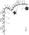
- FIG. 3illustrates an exemplary route along which a vehicle is traveling.
- Route 310 of FIG. 3may be a particular road, such as U.S. Interstate Highway 50 .
- FIG. 3includes numerous points from which data may be received from a vehicle control sub-system. The data received from these numerous data points are illustrated as data received point 1 (DR 1 ) through DR 17 along route 310 .
- DR 1data received point 1
- DR 17data received point 1
- the arrows in route 310indicate a direction of travel of a vehicle that is being tracked and controlled by systems and methods consistent with the present disclosure.
- FIG. 3also includes several different speed limit indicators SL 65 320 , SL 55 330 , SL 35 340 , and SL 65 360 .
- Each of these speed limit indicatorsmay identify a speed limit associated with route 310 as those speed limits change along route 310 from DR 1 through DR 17 .
- a servermay receive information, such as GPS location information, from a vehicle according to a sample rate or after an interval of time. For example, a server may receive information from the vehicle every 10 seconds. In such an instance, each of the respective locations associated with DR 1 , DR 2 , DR 3 , . . . , DR 17 may be acquired as a vehicle moves along route 310 .
- a distance between each respective data received points DR 1 through DR 17is indicative of changes in vehicle speed as the vehicle drives along route 310 .
- larger distances between respective data received pointsare associated with higher vehicle speeds and smaller distances between relative data received points are associated with slower vehicle speeds.
- distances between each respective data received point between data received points DR 6 and DR 14are closer together than distances between each respective data received point between data received points DR 1 and DR 6 .
- the vehicle traveling along route 310 of FIG. 3was moving at slower speeds between data received points DR 6 and DR 14 as compared to speeds that the vehicle was moving between data received points DR 1 and DR 6 .
- datamay be transmitted from a vehicle control sub-system periodically
- datamay also be transmitted from a vehicle control sub-system whenever the vehicle control sub-system has detected a change in the route being driven.
- datamay be transmitted from a vehicle when an anomalous condition has been observed.
- datamay be transmitted from a vehicle when an event is detected. For example, when a vehicle stops moving or when the vehicle is involved in an accident a vehicle control sub-system may send a message to an external electronic device.
- FIG. 3also includes command points 325 , 335 , 345 , 355 , and 365 .
- These command pointsmay correspond to locations where a vehicle was located at when it received updated information from a server, such as server 270 of FIG. 3 .
- these command pointsmay correspond to GPS coordinates identified in transmissions that were received before the vehicle has reached the GPS coordinates associated with command points 325 , 335 , 345 , 355 , and 365 .
- a controller of a vehicle control sub-systemafter receiving information regarding a command point, may cause the maximum speed associated with a vehicle to be changed such that the vehicles maximum speed does not exceed a posted speed limit at all or by more than a threshold amount.
- command points 325 , 335 , 345 , 355 , and 365may vary based on one or more characteristics that may be associated with a vehicle, with facts relating to a roadway/direction of travel, with driver facts (such as an experience level), with a time of day/night, or with current weather conditions.
- Exemplary characteristics that may be associated with a vehicleinclude a vehicle weight or vehicle type.
- Facts relating to the roadwaymay identify the location of an accident, may indicate a road hazard, or may identify that road congestion will likely increase in an area near a ball park when a ball game is ending.
- Weather conditions that may affect the controlled speed of a vehicleinclude indications of poor weather (i.e. foggy, rainy, snowy, sunny, or windy conditions) or may relate to the fact that the Sun is likely shining in the driver's eyes at a particular location at a particular time.
- FIG. 3includes a star ALT 350 that identifies a location that may be associated with something that may affect a roadway.
- Information relating to location ALT 350may have been reported to a vehicle control sub-system of a vehicle indirectly.
- an external computing devicecould have provided information regarding the location of ALT 350 to the vehicle control sub-system 205 of FIG. 2 based on information that the external computing device received from other information sources.
- FIG. 3also includes beacon BCN 370 that may transmit information to data collection systems.
- beacon BCN 370may transmit signals directly to vehicle control sub-systems consistent with the present disclosure.
- information from beacon BCN 370is received by a data collection system, that information may be provided to the vehicle control sub-systems of various vehicles indirectly.
- a signal from beacon BCN 370may be received by ground based infrastructure receiving devices, where information relating to BCN 370 may be forwarded to a speed data provider that in turn forwards that information to a server that wirelessly transmits control information to one or more vehicle control sub-systems consistent with the present disclosure.
- beacon BCN 370may be located within a service vehicle or with an emergency vehicle. Examples of service and emergency vehicles include maintenance vehicles, police cars, ambulances, and fire engines.
- beaconssuch as BCN 370
- BCN 370may only broadcast a beacon signal when a service or emergency vehicle stops or slows along a roadway. For example, a beacon may begin transmitting when a service vehicle slows down below a threshold speed when traveling along a roadway.
- a speed data provider and a servermay track both service vehicles and other vehicles, where information collected by the speed data provider or server may be used to limit the speed of these other vehicles as they approach a location where a service vehicle has stopped.
- a beaconmay be coupled to speed controlled vehicles either directly via a transmission from the beacon that is received by a speed control sub-assembly or be coupled indirectly via one or more other electronic devices.
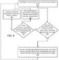
- FIG. 4illustrates an exemplary method consistent with the present disclosure.
- FIG. 4begins with a first step 410 where a current speed limit that is associated with a current location and a route is identified.
- This first speed limitfor example, may be associated with a roadway, such as route 310 of FIG. 3 .
- step 420 of FIG. 4identifies whether the speed limit changes at a future location along a route that is within a threshold distance from the vehicle.
- step 430a message may be transmitted to the vehicle.
- information in the message sent to the vehiclemay cause a maximum speed associated with the vehicle to be changed before the vehicle reaches the future location where the speed limit actually does change.
- a maximum speed setting of the vehiclemay be changed hundreds or thousands of feet before a projected future location where the speed limit changes. Since a heavy vehicle, like a semi-truck has more inertia than a small vehicle, such as a compact car, it may take longer for the heavy vehicle to slow down as compared to the smaller vehicle.
- information included in a message sent to a vehicle control devicemay be tailored to a type of vehicle, where maximum speeds of different vehicle types are associated with different speed offsets.
- the information sent to a semi-truckmay cause the semi-truck to begin slowing from 65 miles per hour (MPH) to 45 MPH some 3000 feet (i.e. a 3000 foot offset) before the semi-truck reaches the point where the speed limit changes from 65 MPH to 45 MPH.
- the information sent to the vehiclemay cause the compact car to begin slowing from 65 MPH to 45 MPH 2000 feet (i.e. a 2000 foot offset) before the compact car reaches the point where the speed limit changes from 65 MPH to 45 MPH.
- the information sent to a particular vehiclemay correspond to the type, weight, or size of the particular vehicle being controlled.
- the information sent to the vehicle in step 430may include a GPS location that is some distance before the actual location where the speed limit changes.
- This information sent to the vehiclemay include a new maximum speed and may include the actual GPS location where the speed limit actually changes.
- the transmissionmay include information relating to the speed limit change where information in that transmission causes the vehicle to slow down immediately upon receiving a new maximum speed, this may occur at a distance that is well before the location where the speed limit actually changes. Because of this, embodiments of the present disclosure may control the maximum speed of a vehicle such that the vehicle never exceeds a speed limit associated with a roadway.
- the speed of a vehiclemay be controlled by systems and methods of the present disclosure according to one or more profiles that may be associated with a vehicle or a driver.
- the 3000 foot offset discussed above relating to a semi-truck reducing speed from 65 MPH to 45 MPHmay correspond to a speed or velocity change profile.
- Such a profilemay correspond to different distances for different amounts of speed or velocity changes.
- the semi-truckmay be commanded to change a maximum speed 2000 feet before a speed limit changes from 65 MPH to 55 MPH and that same semi-truck may be commanded to change a maximum speed 1000 feet before a speed limit changes from 40 MPH to 35 MPH.
- velocity or speed profiles associated with the present disclosuremay correspond to allowing the speed or velocity of a vehicle to reduce according to a target rate of speed or velocity decrease, such that the vehicle slows down gradually.
- the information transmitted to the vehicle in step 420may also include a maximum speed that is associated with particular weather conditions or times of day/night. For example, when it is raining, instead of transmitting information relating to actual speed limits of a roadway, the maximum speeds transmitted to the vehicle may be reduced. For example, when a speed limit of a particular portion of roadway is 65 MPH, a maximum speed of 45 MPH may be sent to a vehicle instead of a maximum speed of 65 MPH because it is raining.
- Weather conditionsmay also be used to change speed offset distances.
- the maximum speed settingmay be changed 3500 feet before the speed limit change when it is raining.
- a certain locationmay be associated with a maximum speed of 65 MPH during the day and that same location may be associated with a maximum speed of 60 MPH during the night.
- Step 420When determination step 420 identifies that the speed limit does not change at a projected future location within a threshold distance along the route, program flow moves from step 420 to step 440 .
- Step 440then identifies if there is a reason to provide a maximum speed to a vehicle based on an anomaly along the roadway, when yes, program flow moves to step 460 where a new maximum speed is transmitted to the vehicle based on the anomaly.
- the information transmitted to the vehiclemay cause the vehicle to slow down before an actual location where the anomaly is located.
- a vehicle speed limiting system consistent with the present disclosuremay be aware of an intended route and speed limits or speed limiting road conditions associated with that route before a vehicle has traveled along that route.
- information about a routemay be sent for storage in a memory at a vehicle speed limiting system.
- This information stored in the memorymay include route geometric information and may include numerous points where a maximum speed setting of the vehicle may change.
- a computer that controls the vehicles speedmay compare position data (such as GPS data) with the speed related data stored in the memory when that computer controls or limits the speed of the vehicle.
- the speed of a vehiclemay be limited along an entire route based on information previously stored in the memory.
- vehicle control systems consistent with the present disclosuremay be pre-initialized with route information such that the vehicle control system may limit the velocity of the vehicle even without receiving transmissions from external electronic devices as the vehicle travels along that route.
- the speed of a vehiclemay be limited when the vehicle travels along a route that the vehicle speed limiting system has not been pre-initialized to traverse.
- the vehicle control systemmay be configured to receive information from an external computing device less frequently. For example, rather than continuously receiving information from an external computer every 30 seconds, route speed information may be received once every several minutes or when the vehicle reaches certain geo-locations.
- route speed informationmay be received once every several minutes or when the vehicle reaches certain geo-locations.
- a vehicle control systemreceives route information infrequently, that control system may receive information relating to a series of points along a route.
- a server that sends speed limiting information to a vehicle control systemmay be configured to send information to the vehicle control system in bursts. These bursts of information may include multiple geo-locations where the maximum speed of the vehicle changes along the route.
- the vehicle control systemmay limit the speed of the vehicle based on location information and based on route information stored in memory at the vehicle control system.
- that vehicle control systemmay be provided with information regarding a plurality of future geo-locations where speed limits change in a just in time fashion.
- the vehicle control systemmay be provided with geometric information relating to points that the vehicle has not yet reached.
- the vehicle control systemmay send transmissions to a server that informs the server to send an additional burst of information to the vehicle control system.
- bursts of informationmay be sent to the vehicle control system by the server when according to a protocol at the server.
- the bursts of information sent from the servermay include route geometric information that spans several minutes of vehicle travel time.
- the information sent to the vehicle control system by the servermay be based on the current position of the vehicle or be based on a current or projected speed of the vehicle as the vehicle travels along a route or heading.
- the server and the vehicle control systemmay communicate when a communication protocol is configured. In such instances, how frequently the server communicates with the vehicle control system may be limited based on actions performed by the server, be based on actions performed by the vehicle control system, or be limited based on an agreement between the server and the vehicle control system.
- the servermay simply set a communication protocol at the vehicle control system via a transmission.
- the vehicle control systemmay request that the server use a communication protocol that limits how frequently communications are performed based on protocols supported by both the server and the vehicle control system.
- how frequently communications are performedmay be set based on limitations of the vehicle control system that are provided to the server, or be based on wireless communication capabilities associated with certain particular sets of geo-locations along a route.
- communication protocolsmay be used to change how frequently communications are sent between a server and a vehicle control system dynamically as a vehicle travels along a route.
- Anomalies that may cause a new maximum speed to be transmitted to the vehicleinclude, yet are not limited to: the location of a service or emergency vehicle, the location of a beacon, the location of a reported incident, or a “location of observations” made by systems and methods of the present disclosure.
- An example of a “location of observations” made by systems and methods of the present disclosureinclude, identifying that the speeds associated with various other vehicles traveling along the route have slowed to a speed that is less than the speed limit at a particular location.
- the particular locationmay be associated with an unknown or unreported hazard.
- an obstructionsuch as a rock, a ladder, or a piece of furniture
- systems and methods associated with the present disclosuremay include various different vehicles where each vehicle includes a vehicle control sub-system, external computing devices consistent with the present disclosure may send information to vehicles that have not yet reached a location that is associated with anomalistic vehicle speed changes.
- Vehicle control systems consistent with the present disclosuremay also include an interface where a driver may initiate a transmission that informs external computing devices that an obstacle is in the roadway at a particular location. For example, after a driver has encountered an obstacle in the roadway, the driver could press a button or simply speak a word (i.e. “obstacle”) to their vehicle control system, and the vehicle control system could send a message relating to the obstacle to an external computing system. After the external computing system receives the message regarding that obstacle, it could send messages regarding that obstacle to other vehicles traveling along that route before those other vehicles reached the obstacle.
- Another type of anomaly associated with a vehiclemay include a driver pressing a button or by speaking a word that overrides a current maximum speed setting at a vehicle control sub-system. In such instances spoken words may be interpreted by a voice recognition system at the vehicle or at an external electronic device.
- step 440When determination step 440 identifies that there is no reason to provide the vehicle a maximum speed based on an anomaly, program flow moves from step 440 to step 450 where a maximum speed that is associated with the current location and with a characteristic may be sent to the vehicle in step 450 of FIG. 4 .
- the maximum speed sent to the vehiclemay be simply the speed limit associated with the location.
- the maximum speed provided to the vehiclemay be offset from an actual speed limit by a certain margin or percentage of the speed limit. In such instances, the maximum speed provided to a vehicle may be slightly above or below the actual speed limit. For example when the speed limit is really 65 MPH, a maximum speed sent to the vehicle may be 69 MPH. In yet another example, all compatible vehicles traveling along a particular route may be provided a maximum speed of 15 MPH when a particular route is associated with snowy or icy conditions.
- a characteristic associated with a vehicle and a maximum speedmay relate to an experience level of a driver. For example, when a novice driver drives a heavy vehicle, that vehicles speed may be limited to 25 MPH even when a speed limit associated with a roadway where the vehicle is driving is 40 MPH. In such instances, different maximum speeds can be provided to the same vehicle based on an experience level of low, medium, and high, where each experience level is associated with different maximum speeds based on one or more sets of rules.
- FIG. 4proceeds back to step 410 where the current speed of the current location of the route is identified again.
- FIG. 5illustrates a second exemplary method consistent with the present disclosure.
- FIG. 5begins with a first step 510 where a first speed limiting factor is identified. This first speed limiting factor may be associated with a first location and with a route.
- the speed limiting factor identified in step 510may be a speed limit associated with the first location or may be a factor relating to a fact or a circumstance along the route that the vehicle is traveling.
- the first speed limiting factormay have been identified after an external computer that is associated with controlling the maximum speed of the vehicle has received a GPS location of the vehicle.
- a control sub-system at the vehiclemay have identified the vehicle's GPS location and transmitted that location to a server or to a speed data provider like the server 270 and speed data provider 280 of FIG. 2 .
- Facts and circumstances identified in step 510may relate to a vehicle type, the weight of the vehicle, the experience level of the driver of the vehicle, the time or day/night, or whether the Sun is shining in the eyes of the driver.
- Other facts that may be relevant to controlling the speed of a vehiclemay relate to current weather conditions, the location of a service or emergency vehicle, the location of a beacon, or may relate to a particular type of zone (i.e. a construction zone, a school zone, or hospital zone) of travel.
- Step 510the method of FIG. 5 moves from step 510 to step 520 where information regarding a second location of the vehicle traveling along the route may be received.
- Step 520may be a step where an external computing device receives a second GPS location of the vehicle as it travels down the roadway.
- a second speed limiting factor that corresponds to the second location along the routemay be identified.
- the speed limiting factor of step 530may be associated with be a speed limit associated with a current location or may be a factor relating a fact or a circumstance that may affect the roadway.
- facts or circumstances identified in step 530may relate to a type of a vehicle, the weight of the vehicle, the experience level of a driver of the vehicle, the time or day/night, whether the Sun is shining in the eyes of the driver, facts relating to current weather conditions, the location of an service vehicle or an emergency vehicle, the location of a beacon, or may relate a particular type of zone (i.e. a construction zone, a school zone, or hospital zone) that the vehicle is approaching.
- step 540may transmit a maximum speed that is associated with the second location and with the second speed limiting factor to the vehicle control system.
- information transmitted in step 540may include information transmitted to a vehicle as discussed in respect to steps 430 , 450 , or 460 of FIG. 4 .
- information transmitted to a vehiclemay relate to controlling the maximum speed of a vehicle based on various factors, characteristics, anomalies, or road conditions.
- factors, characteristics, anomalies, or road condition informationmay relate to a vehicle type, a vehicle weight, driver experience level, weather conditions, times of day/night, and may include information that causes the speed of a vehicle to change a maximum speed before the vehicle reaches a particular location.
- FIG. 6illustrates an exemplary computing system that may be used to implement all or a portion of a device for use with the present technology.
- the computing system 600 of FIG. 6includes one or more processors 610 and memory 620 .
- Main memory 620stores, in part, instructions and data for execution by processor 610 .
- Main memory 620can store the executable code when in operation.
- the system 600 of FIG. 6further includes a mass storage device 630 , portable storage medium drive(s) 640 , a GPS system 645 , output devices 650 , user input devices 660 , a graphics display 670 , peripheral devices 680 , and a wireless communication system 685 .
- the components shown in FIG. 6are depicted as being connected via a single bus 690 . However, the components may be connected through one or more data transport means.
- processor unit 610 and main memory 620may be connected via a local microprocessor bus, and the mass storage device 630 , peripheral device(s) 680 , portable storage device 640 , and display system 670 may be connected via one or more input/output (I/O) buses.
- Mass storage device 630which may be implemented with a magnetic disk drive, solid state drives, an optical disk drive or other devices, may be a non-volatile storage device for storing data and instructions for use by processor unit 610 .
- Mass storage device 630can store the system software for implementing embodiments of the present invention for purposes of loading that software into main memory 620 .
- Portable storage device 640operates in conjunction with a portable non-volatile storage medium, such as a FLASH thumb drive, compact disk or Digital video disc, to input and output data and code to and from the computer system 600 of FIG. 4 .
- the system software for implementing embodiments of the present inventionmay be stored on such a portable medium and input to the computer system 600 via the portable storage device 640 .
- Input devices 660provide a portion of a user interface.
- Input devices 660may include an alpha-numeric keypad, such as a keyboard, for inputting alpha-numeric and other information, or a pointing device, such as a mouse, a trackball, stylus, or cursor direction keys.
- the system 600 as shown in FIG. 6includes output devices 650 . Examples of suitable output devices include speakers, printers, network interfaces, and monitors.
- Display system 670may include a liquid crystal display (LCD) or other suitable display device.
- Display system 670receives textual and graphical information, and processes the information for output to the display device.
- LCDliquid crystal display
- Peripherals 680may include any type of computer support device to add additional functionality to the computer system.
- peripheral device(s) 680may include a modem or a router.
- GPS system 645may include an antenna (not illustrated in FIG. 6 ) that receives global positioning information from one or more satellites such that a location associated with a current location of computer system 600 may be identified and provided to processor 610 via bus 690 .
- FIG. 6also includes a wireless communication system 685 that may include an antenna (not illustrated in FIG. 6 ).
- Wireless communication system 685may be configured to receive or transmit information via any standard wireless communication technology standard in the art. As such, wireless communication system 685 may receive or transmit information according to a wireless (2G, 3G, 4G, blue-tooth, 802.11, light strobes, or other) cellular or device to device standard, or may use radio or optical communication technologies.
- Wireless communication systemmay be configured to receive signals directly from pieces of infrastructure along a roadway (such as a signal light or roadway sensors), may be configured to receive signals associated with an emergency band, or may be configured to receive beacons that may be located at a service or emergency vehicle.
- Computer systems of the present disclosuremay also include multiple wireless communication systems like communication system 685 .
- the components contained in the computer system 600 of FIG. 6are those typically found in computer systems that may be suitable for use with embodiments of the present invention and are intended to represent a broad category of such computer components that are well known in the art.
- the computer system 600 of FIG. 6can be a personal computer, hand held computing device, telephone, mobile computing device, workstation, server, minicomputer, mainframe computer, or any other computing device.
- the computercan also include different bus configurations, networked platforms, multi-processor platforms, etc.
- Various operating systemscan be used including Unix, Linux, Windows, Macintosh OS, Android, and other suitable operating systems.
Landscapes
- Engineering & Computer Science (AREA)
- Automation & Control Theory (AREA)
- Transportation (AREA)
- Mechanical Engineering (AREA)
- Traffic Control Systems (AREA)
- Radar, Positioning & Navigation (AREA)
- Remote Sensing (AREA)
- Computer Networks & Wireless Communication (AREA)
- Physics & Mathematics (AREA)
- General Physics & Mathematics (AREA)
- Control Of Driving Devices And Active Controlling Of Vehicle (AREA)
Abstract
Description
Claims (21)
Priority Applications (3)
| Application Number | Priority Date | Filing Date | Title |
|---|---|---|---|
| US16/670,453US11370428B2 (en) | 2017-02-24 | 2019-10-31 | Vehicle speed limiter |
| US17/850,205US11772650B2 (en) | 2017-02-24 | 2022-06-27 | Vehicle operation characteristic control |
| US18/241,506US20240043001A1 (en) | 2017-02-24 | 2023-09-01 | Vehicle operation characteristic control |
Applications Claiming Priority (3)
| Application Number | Priority Date | Filing Date | Title |
|---|---|---|---|
| US15/442,438US10029685B1 (en) | 2017-02-24 | 2017-02-24 | Vehicle speed limiter |
| US16/043,559US10464561B2 (en) | 2017-02-24 | 2018-07-24 | Vehicle speed limiter |
| US16/670,453US11370428B2 (en) | 2017-02-24 | 2019-10-31 | Vehicle speed limiter |
Related Parent Applications (1)
| Application Number | Title | Priority Date | Filing Date |
|---|---|---|---|
| US16/043,559ContinuationUS10464561B2 (en) | 2017-02-24 | 2018-07-24 | Vehicle speed limiter |
Related Child Applications (1)
| Application Number | Title | Priority Date | Filing Date |
|---|---|---|---|
| US17/850,205ContinuationUS11772650B2 (en) | 2017-02-24 | 2022-06-27 | Vehicle operation characteristic control |
Publications (2)
| Publication Number | Publication Date |
|---|---|
| US20200062253A1 US20200062253A1 (en) | 2020-02-27 |
| US11370428B2true US11370428B2 (en) | 2022-06-28 |
Family
ID=62874171
Family Applications (5)
| Application Number | Title | Priority Date | Filing Date |
|---|---|---|---|
| US15/442,438Active2037-03-05US10029685B1 (en) | 2017-02-24 | 2017-02-24 | Vehicle speed limiter |
| US16/043,559ActiveUS10464561B2 (en) | 2017-02-24 | 2018-07-24 | Vehicle speed limiter |
| US16/670,453Active2037-06-08US11370428B2 (en) | 2017-02-24 | 2019-10-31 | Vehicle speed limiter |
| US17/850,205ActiveUS11772650B2 (en) | 2017-02-24 | 2022-06-27 | Vehicle operation characteristic control |
| US18/241,506AbandonedUS20240043001A1 (en) | 2017-02-24 | 2023-09-01 | Vehicle operation characteristic control |
Family Applications Before (2)
| Application Number | Title | Priority Date | Filing Date |
|---|---|---|---|
| US15/442,438Active2037-03-05US10029685B1 (en) | 2017-02-24 | 2017-02-24 | Vehicle speed limiter |
| US16/043,559ActiveUS10464561B2 (en) | 2017-02-24 | 2018-07-24 | Vehicle speed limiter |
Family Applications After (2)
| Application Number | Title | Priority Date | Filing Date |
|---|---|---|---|
| US17/850,205ActiveUS11772650B2 (en) | 2017-02-24 | 2022-06-27 | Vehicle operation characteristic control |
| US18/241,506AbandonedUS20240043001A1 (en) | 2017-02-24 | 2023-09-01 | Vehicle operation characteristic control |
Country Status (1)
| Country | Link |
|---|---|
| US (5) | US10029685B1 (en) |
Cited By (1)
| Publication number | Priority date | Publication date | Assignee | Title |
|---|---|---|---|---|
| US20220396265A1 (en)* | 2017-02-24 | 2022-12-15 | Speedgauge, Inc. | Vehicle operation characteristic control |
Families Citing this family (22)
| Publication number | Priority date | Publication date | Assignee | Title |
|---|---|---|---|---|
| US11836802B2 (en)* | 2014-04-15 | 2023-12-05 | Speedgauge, Inc. | Vehicle operation analytics, feedback, and enhancement |
| DE102015012552B3 (en)* | 2015-09-25 | 2017-01-12 | Audi Ag | Method for operating a start-stop system and motor vehicle |
| US10551842B2 (en)* | 2017-06-19 | 2020-02-04 | Hitachi, Ltd. | Real-time vehicle state trajectory prediction for vehicle energy management and autonomous drive |
| GB2567154B (en)* | 2017-10-02 | 2020-03-04 | Jaguar Land Rover Ltd | Method and apparatus for assisting in the maintenance of a vehicle speed within a speed range, and a vehicle comprising such an apparatus |
| US10594991B1 (en) | 2018-01-09 | 2020-03-17 | Wm Intellectual Property Holdings, Llc | System and method for managing service and non-service related activities associated with a waste collection, disposal and/or recycling vehicle |
| FR3077382B1 (en)* | 2018-01-30 | 2020-02-21 | Transdev Group | ELECTRONIC METHOD AND DEVICE FOR CONTROLLING THE SPEED OF AN AUTONOMOUS VEHICLE, COMPUTER PROGRAM, AUTONOMOUS VEHICLE AND ASSOCIATED MONITORING PLATFORM |
| US11699309B2 (en) | 2019-03-04 | 2023-07-11 | Speedgauge, Inc. | Dynamic driver and vehicle analytics based on vehicle tracking and driving statistics |
| US11475416B1 (en) | 2019-08-23 | 2022-10-18 | Wm Intellectual Property Holdings Llc | System and method for auditing the fill status of a customer waste container by a waste services provider during performance of a waste service activity |
| US10683017B1 (en) | 2020-02-21 | 2020-06-16 | Smartdrive Systems, Inc. | Systems and methods for managing speed thresholds for vehicles |
| US10684390B1 (en) | 2020-02-21 | 2020-06-16 | Smartdrive Systems, Inc. | Systems and methods for detecting a sitting duck scenario |
| US20220049967A1 (en)* | 2020-08-13 | 2022-02-17 | Honda Motor Co., Ltd. | Promoting rider safety in shared mobility space |
| US11386362B1 (en) | 2020-12-16 | 2022-07-12 | Wm Intellectual Property Holdings, L.L.C. | System and method for optimizing waste / recycling collection and delivery routes for service vehicles |
| US12361432B1 (en) | 2021-03-09 | 2025-07-15 | Wm Intellectual Property Holdings, L.L.C. | System and method for customer and/or container discovery based on GPS drive path analysis for a waste / recycling service vehicle |
| US11373536B1 (en) | 2021-03-09 | 2022-06-28 | Wm Intellectual Property Holdings, L.L.C. | System and method for customer and/or container discovery based on GPS drive path and parcel data analysis for a waste / recycling service vehicle |
| US11488118B1 (en) | 2021-03-16 | 2022-11-01 | Wm Intellectual Property Holdings, L.L.C. | System and method for auditing overages and contamination for a customer waste container by a waste services provider during performance of a waste service activity |
| KR20230173724A (en)* | 2021-04-27 | 2023-12-27 | 모셔널 에이디 엘엘씨 | Improving ride comfort in various traffic scenarios for autonomous vehicles |
| US11878689B2 (en)* | 2021-06-11 | 2024-01-23 | Ford Global Technologies, Llc | Vehicle reverse drive mode |
| DE102021003870B4 (en)* | 2021-07-27 | 2023-05-04 | Mercedes-Benz Group AG | Method for checking a specified speed limit for vehicles on a roadway and method for supporting a driver |
| US12332073B1 (en) | 2021-11-02 | 2025-06-17 | Wm Intellectual Property Holdings, L.L.C. | System and method for efficient customer and container on-property service based on collection of off-street data for a waste / recycling service vehicle |
| US11977381B1 (en) | 2022-04-01 | 2024-05-07 | Wm Intellectual Property Holdings, L.L.C. | System and method for autonomous waste collection by a waste services provider during performance of a waste service activity |
| US12337859B2 (en) | 2022-12-21 | 2025-06-24 | Toyota Motor Engineering & Manufacturing North America, Inc. | Personalized speed limiter |
| FR3157587A1 (en)* | 2023-12-21 | 2025-06-27 | Ampere Sas | Method of updating, by a management system on board a vehicle, regulatory speed limits |
Citations (43)
| Publication number | Priority date | Publication date | Assignee | Title |
|---|---|---|---|---|
| US3655962A (en) | 1969-04-01 | 1972-04-11 | Melpar Inc | Digital automatic speed control for railway vehicles |
| US5485161A (en) | 1994-11-21 | 1996-01-16 | Trimble Navigation Limited | Vehicle speed control based on GPS/MAP matching of posted speeds |
| US5995895A (en) | 1997-07-15 | 1999-11-30 | Case Corporation | Control of vehicular systems in response to anticipated conditions predicted using predetermined geo-referenced maps |
| US6246948B1 (en) | 1998-12-10 | 2001-06-12 | Ericsson Inc. | Wireless intelligent vehicle speed control or monitoring system and method |
| US6265989B1 (en) | 2000-06-17 | 2001-07-24 | Richard Taylor | GPS enabled speeding detector |
| US7272469B2 (en) | 2004-03-03 | 2007-09-18 | Magtec Products Inc. | Immobilizer system for vehicles |
| US20080009965A1 (en) | 2006-07-05 | 2008-01-10 | Battelle Energy Alliance, Llc | Autonomous Navigation System and Method |
| US20080154629A1 (en) | 1997-10-22 | 2008-06-26 | Intelligent Technologies International, Inc. | Vehicle Speed Control Method and Arrangement |
| US20080167767A1 (en)* | 2006-03-20 | 2008-07-10 | Brooks James D | Method and Computer Software Code for Determining When to Permit a Speed Control System to Control a Powered System |
| US7739036B2 (en) | 2005-08-26 | 2010-06-15 | Gm Global Technology Operations, Inc. | Speed limit advisor |
| US20100204896A1 (en) | 2009-02-06 | 2010-08-12 | Gm Global Technology Operations, Inc. | Cruise control systems and methods with adaptive speed adjustment rates |
| US7859392B2 (en) | 2006-05-22 | 2010-12-28 | Iwi, Inc. | System and method for monitoring and updating speed-by-street data |
| US20100332114A1 (en) | 2007-07-09 | 2010-12-30 | Ju Han Jung | Navigation system and method for guiding speed limiting information by block |
| US20110050459A1 (en)* | 2009-08-28 | 2011-03-03 | Alcatel-Lucent Usa Inc. | System and method to enhance safety and legal compliance by location analysis |
| US7957882B2 (en) | 2006-03-10 | 2011-06-07 | Magtec Products, Inc. | Onboard controller system |
| US20110307155A1 (en)* | 2009-02-24 | 2011-12-15 | Simard Christian | Method and system for limiting a dynamic parameter of a vehicle |
| US20120083947A1 (en) | 2009-03-05 | 2012-04-05 | Massachusetts Institute Of Technology | Integrated framework for vehicle operator assistance based on a trajectory and threat assessment |
| US20120089312A1 (en) | 2009-06-10 | 2012-04-12 | Oskar Johansson | Method and module for determining of velocity reference values for a vehicle control system |
| US8188887B2 (en) | 2009-02-13 | 2012-05-29 | Inthinc Technology Solutions, Inc. | System and method for alerting drivers to road conditions |
| US8204646B2 (en) | 2006-03-10 | 2012-06-19 | Magtec Products, Inc. | Onboard controller system |
| US20130141249A1 (en)* | 2011-12-02 | 2013-06-06 | Procongps, Inc. | Geospatial data based assessment of driver behavior |
| US8630795B2 (en) | 1999-03-11 | 2014-01-14 | American Vehicular Sciences Llc | Vehicle speed control method and arrangement |
| US8712650B2 (en) | 2005-11-17 | 2014-04-29 | Invent.Ly, Llc | Power management systems and designs |
| US8751133B2 (en) | 2011-02-17 | 2014-06-10 | 7980302 Canada Inc. | Speed limiter system and method for a vehicle |
| US20140222272A1 (en) | 2011-07-19 | 2014-08-07 | Continental Teves Ag & Co. Ohg | Method for improving the driving stability |
| US20140277835A1 (en) | 2013-03-13 | 2014-09-18 | Ford Global Technologies, Llc | Route navigation with optimal speed profile |
| US20140330503A1 (en) | 2011-12-22 | 2014-11-06 | Scania Cv Ab | Module and method pertaining to mode choice when determining reference values |
| US20140350821A1 (en) | 2011-12-22 | 2014-11-27 | Scania Cv Ab | Method and module for controlling a vehicle's speed based on rules and/or costs |
| US9002613B2 (en) | 2010-06-07 | 2015-04-07 | Ford Global Technologies, Llc | System and method for vehicle speed monitoring using historical speed data |
| US20150127239A1 (en)* | 2013-11-01 | 2015-05-07 | Intelligent Technologies International, Inc. | Mapping techniques using probe vehicles |
| US20150197248A1 (en) | 1997-10-22 | 2015-07-16 | American Vehicular Sciences Llc | Vehicle speed control method and arrangement |
| US20150197247A1 (en) | 2014-01-14 | 2015-07-16 | Honda Motor Co., Ltd. | Managing vehicle velocity |
| US20150211871A1 (en)* | 2014-01-28 | 2015-07-30 | Research & Business Foundation Sungkyunkwan University | Vehicle navigation apparatus and method of determining trajectory of vehicle |
| US20150355637A1 (en)* | 2014-06-10 | 2015-12-10 | Magtec Products, Inc. | Remote speed management system for vehicles |
| US20160129914A1 (en)* | 2005-06-01 | 2016-05-12 | Allstate Insurance Company | Motor Vehicle Operating Data Collection and Analysis |
| US20170061798A1 (en)* | 2014-08-19 | 2017-03-02 | Here Global B.V. | Optimal Warning Distance |
| US20170106855A1 (en)* | 2015-10-20 | 2017-04-20 | Ford Global Technologies, Llc | Systems and methods for abrupt road change assist and active suspension control |
| US20170248118A1 (en) | 2016-02-26 | 2017-08-31 | Henry Ivers | Novel Applications of the New Wind Power Formula, Novel Movements of Sails, and Novel Sail Turbines, plus Novel Propulsion Systems |
| US9798324B2 (en) | 2014-07-18 | 2017-10-24 | Helico Aerospace Industries Sia | Autonomous vehicle operation |
| US20180025632A1 (en)* | 2014-12-15 | 2018-01-25 | Intelligent Technologies International, Inc. | Mapping Techniques Using Probe Vehicles |
| US20180065481A1 (en)* | 2016-04-19 | 2018-03-08 | Magtec Products, Inc. | Throttle control system and method |
| US9925987B1 (en)* | 2015-12-11 | 2018-03-27 | Lytx, Inc. | Driving abnormality detection |
| US10029685B1 (en) | 2017-02-24 | 2018-07-24 | Speedgauge, Inc. | Vehicle speed limiter |
Family Cites Families (17)
| Publication number | Priority date | Publication date | Assignee | Title |
|---|---|---|---|---|
| US7042347B2 (en)* | 2001-06-19 | 2006-05-09 | Cherouny Peter H | Electronic programmable speed limiter |
| JP2003153341A (en)* | 2001-11-12 | 2003-05-23 | Denso Corp | In-vehicle communication terminal, server, and method of registering in-vehicle communication terminal in server |
| JP4019787B2 (en)* | 2002-01-17 | 2007-12-12 | 日産自動車株式会社 | Vehicle information communication system and vehicle information communication device |
| US7797108B2 (en)* | 2006-10-19 | 2010-09-14 | Gm Global Technology Operations, Inc. | Collision avoidance system and method of aiding rearward vehicular motion |
| US8352111B2 (en)* | 2009-04-06 | 2013-01-08 | GM Global Technology Operations LLC | Platoon vehicle management |
| EP2962064B1 (en)* | 2013-02-26 | 2018-04-04 | Polaris Industries Inc. | Recreational vehicle interactive telemetry, mapping, and trip planning system |
| US10037689B2 (en)* | 2015-03-24 | 2018-07-31 | Donald Warren Taylor | Apparatus and system to manage monitored vehicular flow rate |
| US9834098B2 (en)* | 2014-01-30 | 2017-12-05 | General Electric Company | Vehicle propulsion system with multi-channel DC bus and method of manufacturing same |
| US9272621B2 (en)* | 2014-04-24 | 2016-03-01 | Cummins Inc. | Systems and methods for vehicle speed management |
| US10599155B1 (en)* | 2014-05-20 | 2020-03-24 | State Farm Mutual Automobile Insurance Company | Autonomous vehicle operation feature monitoring and evaluation of effectiveness |
| US9997077B2 (en)* | 2014-09-04 | 2018-06-12 | Honda Motor Co., Ltd. | Vehicle operation assistance |
| US10157423B1 (en)* | 2014-11-13 | 2018-12-18 | State Farm Mutual Automobile Insurance Company | Autonomous vehicle operating style and mode monitoring |
| DE102015200025A1 (en)* | 2015-01-05 | 2016-07-07 | Robert Bosch Gmbh | Driver assistance system and method for assisted driving of a vehicle |
| JP6417995B2 (en)* | 2015-02-09 | 2018-11-07 | 株式会社デンソー | Vehicle speed management device and vehicle speed management method |
| US10081357B2 (en)* | 2016-06-23 | 2018-09-25 | Honda Motor Co., Ltd. | Vehicular communications network and methods of use and manufacture thereof |
| US10640117B2 (en)* | 2016-08-17 | 2020-05-05 | Allstate Insurance Company | Driving cues and coaching |
| US11046242B2 (en)* | 2017-02-09 | 2021-06-29 | Ford Global Technologies, Llc | Display for rear lamp of a vehicle |
- 2017
- 2017-02-24USUS15/442,438patent/US10029685B1/enactiveActive
- 2018
- 2018-07-24USUS16/043,559patent/US10464561B2/enactiveActive
- 2019
- 2019-10-31USUS16/670,453patent/US11370428B2/enactiveActive
- 2022
- 2022-06-27USUS17/850,205patent/US11772650B2/enactiveActive
- 2023
- 2023-09-01USUS18/241,506patent/US20240043001A1/ennot_activeAbandoned
Patent Citations (53)
| Publication number | Priority date | Publication date | Assignee | Title |
|---|---|---|---|---|
| US3655962A (en) | 1969-04-01 | 1972-04-11 | Melpar Inc | Digital automatic speed control for railway vehicles |
| US5485161A (en) | 1994-11-21 | 1996-01-16 | Trimble Navigation Limited | Vehicle speed control based on GPS/MAP matching of posted speeds |
| US5995895A (en) | 1997-07-15 | 1999-11-30 | Case Corporation | Control of vehicular systems in response to anticipated conditions predicted using predetermined geo-referenced maps |
| US20080154629A1 (en) | 1997-10-22 | 2008-06-26 | Intelligent Technologies International, Inc. | Vehicle Speed Control Method and Arrangement |
| US20150197248A1 (en) | 1997-10-22 | 2015-07-16 | American Vehicular Sciences Llc | Vehicle speed control method and arrangement |
| US6246948B1 (en) | 1998-12-10 | 2001-06-12 | Ericsson Inc. | Wireless intelligent vehicle speed control or monitoring system and method |
| US8630795B2 (en) | 1999-03-11 | 2014-01-14 | American Vehicular Sciences Llc | Vehicle speed control method and arrangement |
| US6265989B1 (en) | 2000-06-17 | 2001-07-24 | Richard Taylor | GPS enabled speeding detector |
| US7272469B2 (en) | 2004-03-03 | 2007-09-18 | Magtec Products Inc. | Immobilizer system for vehicles |
| US20160129914A1 (en)* | 2005-06-01 | 2016-05-12 | Allstate Insurance Company | Motor Vehicle Operating Data Collection and Analysis |
| US7739036B2 (en) | 2005-08-26 | 2010-06-15 | Gm Global Technology Operations, Inc. | Speed limit advisor |
| US8712650B2 (en) | 2005-11-17 | 2014-04-29 | Invent.Ly, Llc | Power management systems and designs |
| US7957882B2 (en) | 2006-03-10 | 2011-06-07 | Magtec Products, Inc. | Onboard controller system |
| US8204646B2 (en) | 2006-03-10 | 2012-06-19 | Magtec Products, Inc. | Onboard controller system |
| US8290680B2 (en) | 2006-03-10 | 2012-10-16 | Magtec Products, Inc. | Onboard controller system |
| US20080167767A1 (en)* | 2006-03-20 | 2008-07-10 | Brooks James D | Method and Computer Software Code for Determining When to Permit a Speed Control System to Control a Powered System |
| US20110267205A1 (en) | 2006-05-22 | 2011-11-03 | Mcclellan Scott | System and Method for Monitoring and Updating Speed-By-Street Data |
| US8890717B2 (en) | 2006-05-22 | 2014-11-18 | Inthinc Technology Solutions, Inc. | System and method for monitoring and updating speed-by-street data |
| US7859392B2 (en) | 2006-05-22 | 2010-12-28 | Iwi, Inc. | System and method for monitoring and updating speed-by-street data |
| US20080009965A1 (en) | 2006-07-05 | 2008-01-10 | Battelle Energy Alliance, Llc | Autonomous Navigation System and Method |
| US7587260B2 (en) | 2006-07-05 | 2009-09-08 | Battelle Energy Alliance, Llc | Autonomous navigation system and method |
| US20100332114A1 (en) | 2007-07-09 | 2010-12-30 | Ju Han Jung | Navigation system and method for guiding speed limiting information by block |
| US8315775B2 (en) | 2009-02-06 | 2012-11-20 | GM Global Technology Operations LLC | Cruise control systems and methods with adaptive speed adjustment rates |
| US20100204896A1 (en) | 2009-02-06 | 2010-08-12 | Gm Global Technology Operations, Inc. | Cruise control systems and methods with adaptive speed adjustment rates |
| US8188887B2 (en) | 2009-02-13 | 2012-05-29 | Inthinc Technology Solutions, Inc. | System and method for alerting drivers to road conditions |
| US20110307155A1 (en)* | 2009-02-24 | 2011-12-15 | Simard Christian | Method and system for limiting a dynamic parameter of a vehicle |
| US20120083947A1 (en) | 2009-03-05 | 2012-04-05 | Massachusetts Institute Of Technology | Integrated framework for vehicle operator assistance based on a trajectory and threat assessment |
| US8620557B2 (en) | 2009-06-10 | 2013-12-31 | Scania Cv Ab | Method and module for determining of velocity reference values for a vehicle control system |
| US20120089312A1 (en) | 2009-06-10 | 2012-04-12 | Oskar Johansson | Method and module for determining of velocity reference values for a vehicle control system |
| US20110050459A1 (en)* | 2009-08-28 | 2011-03-03 | Alcatel-Lucent Usa Inc. | System and method to enhance safety and legal compliance by location analysis |
| US9002613B2 (en) | 2010-06-07 | 2015-04-07 | Ford Global Technologies, Llc | System and method for vehicle speed monitoring using historical speed data |
| US8751133B2 (en) | 2011-02-17 | 2014-06-10 | 7980302 Canada Inc. | Speed limiter system and method for a vehicle |
| US20140222272A1 (en) | 2011-07-19 | 2014-08-07 | Continental Teves Ag & Co. Ohg | Method for improving the driving stability |
| US9409554B2 (en) | 2011-07-19 | 2016-08-09 | Continental Teves Ag & Co. Ohg | Method for improving the driving stability |
| US20130302757A1 (en)* | 2011-12-02 | 2013-11-14 | Richard Frank Pearlman | Geospatial data based assessment of driver behavior |
| US20130141249A1 (en)* | 2011-12-02 | 2013-06-06 | Procongps, Inc. | Geospatial data based assessment of driver behavior |
| US20140350821A1 (en) | 2011-12-22 | 2014-11-27 | Scania Cv Ab | Method and module for controlling a vehicle's speed based on rules and/or costs |
| US20140330503A1 (en) | 2011-12-22 | 2014-11-06 | Scania Cv Ab | Module and method pertaining to mode choice when determining reference values |
| US20140277835A1 (en) | 2013-03-13 | 2014-09-18 | Ford Global Technologies, Llc | Route navigation with optimal speed profile |
| US20150127239A1 (en)* | 2013-11-01 | 2015-05-07 | Intelligent Technologies International, Inc. | Mapping techniques using probe vehicles |
| US20150197247A1 (en) | 2014-01-14 | 2015-07-16 | Honda Motor Co., Ltd. | Managing vehicle velocity |
| US20150211871A1 (en)* | 2014-01-28 | 2015-07-30 | Research & Business Foundation Sungkyunkwan University | Vehicle navigation apparatus and method of determining trajectory of vehicle |
| US20150355637A1 (en)* | 2014-06-10 | 2015-12-10 | Magtec Products, Inc. | Remote speed management system for vehicles |
| US9798324B2 (en) | 2014-07-18 | 2017-10-24 | Helico Aerospace Industries Sia | Autonomous vehicle operation |
| US20170061798A1 (en)* | 2014-08-19 | 2017-03-02 | Here Global B.V. | Optimal Warning Distance |
| US20180025632A1 (en)* | 2014-12-15 | 2018-01-25 | Intelligent Technologies International, Inc. | Mapping Techniques Using Probe Vehicles |
| US20170106855A1 (en)* | 2015-10-20 | 2017-04-20 | Ford Global Technologies, Llc | Systems and methods for abrupt road change assist and active suspension control |
| US9925987B1 (en)* | 2015-12-11 | 2018-03-27 | Lytx, Inc. | Driving abnormality detection |
| US20170248118A1 (en) | 2016-02-26 | 2017-08-31 | Henry Ivers | Novel Applications of the New Wind Power Formula, Novel Movements of Sails, and Novel Sail Turbines, plus Novel Propulsion Systems |
| US20180065481A1 (en)* | 2016-04-19 | 2018-03-08 | Magtec Products, Inc. | Throttle control system and method |
| US10029685B1 (en) | 2017-02-24 | 2018-07-24 | Speedgauge, Inc. | Vehicle speed limiter |
| US20180326984A1 (en) | 2017-02-24 | 2018-11-15 | Speedgauge, Inc. | Vehicle speed limiter |
| US10464561B2 (en) | 2017-02-24 | 2019-11-05 | Speedgauge, Inc. | Vehicle speed limiter |
Non-Patent Citations (23)
| Title |
|---|
| "Automotive FMCW Radar Development and Verification Methods" By Machado, Sanoal and Mancheno, Santiago; Master's thesis in Embedded Electronic System Design, University of Gothenburg, Sweden (Year: 2018).* |
| A Simulation System for Vehicle Safety Operating Speed on the Freeway; Gongliang Jiang;Zhihong Wang; 2010 Ninth International Symposium on Distributed Computing and Applications to Business, Engineering and Science; Year: 2010; IEEE Conference Paper ; (Year: 2010).* |
| Abdelsalam et al., Mohamed; "IoV Road Safety: Vehicle Speeding Limiting System", 2019 International Conference on Communications, Signal Processing, and their Applications (ICCSPA); IEEE Conference Paper (Year: 2019). |
| Adaptive advisory speed limit dissemination using vehicular communication; Ali Jalooli;Mohammad Reza Jabbarpour;Hossein MalakootiKhah;Erfan Shaghaghi;Alireza Marefat;Rafidah Md Noor; 2014 IEEE Asia Pacific Conference on Wireless and Mobile ; IEEE Conference Paper (Year: 2014).* |
| Agarwal, Yash et al.; "Turning Conventional Vehicles in Secured Areas Into Connected Vechiles for Safety Applications", 2016 IEEE Information Technology, Networking, Electronic and Automation Control Conference, pp. 538-542, IEEE Conferences, Year: 2016. |
| Chen, Baiyu et al.; "Cyber-Physical System Enabled Nearby Traffic Flow Modelling for Autonomous Vehicles", 2017 IEEE 36th International Performance Computing and Communications Conference (IPCCC); pp. 1-6 IEEE Conferences, Year: 2017. |
| Coifman, B.; "Analytical Tools for Loop Detectors and Traffic Monitoring Systems", Proceedings of the 2007 IEEE Intelligent Transportation Systems Conference; Year: 2007; pp. 1086-1091. |
| E. Bogale, X. Wang and L. B. Le, "Adaptive Channel Prediction, Beamforming and Scheduling Design for 5G V2I Network: Analytical and Machine Learning Approaches," in IEEE Transactions on Vehicular Technology, vol. 69, No. 5, pp. 5055-5067, May 2020, doi: 10.1109/TVT.2020.2975818.(Year: 2020).* |
| FPGA-based embedded speed limit enforcement system on freeway;Jian-qun Fu;Zhong-ke Shi; 2010 3rd International Conference on Advanced Computer Theory and Engineering(ICACTE); vol. 6; IEEE Conference Paper; (Year: 2010).* |
| Gallen, Romain; "Supporting Drivers in Keeping Safe Speed in Adverse Weather Conditions by Mitigating the Risk Level", IEEE Transactions on Intelligent Transportation Systems Year: 2013, vol. 14, Issue: 4; pp. 1558-1571. |
| Hao, Peng; "Modal Activity-Based Stochastic Model for Estimating Vehicle Trajectories from Sparse Mobile Sensor Data", IEEE Transactions on Intelligent Transportation Systems, vol. 18, No. 3, pp. 701-711. Mar. 2017. |
| IoV Road Safety: Vehicle Speed Limiting System; Mohamed Abdelsalam;Talal Bonny; 2019 International Conference on Communications, Signal Processing, and their Applications (ICCSPA); IEEE Conference Paper; (Year: 2019).* |
| Jalooli et al., Ali; "Adaptive Advisory Speed Limit Dissemination Using Vehicular Communication", IEEE Asia Pacific Conference on Wireless and Mobile; IEEE Conf, paper. (year: 2014). |
| Jiang et al., Gongliang; "A Simulation System for Vehicle Safety Operating Speed on the Freeway", 2010 Ninth International Symposium on Distributed Computing and Applications to Business, Engineering and Science, IEEE Conference paper (year: 2010). |
| Jian-Qun et al., Fu; "FPGA-Based Embedded Speed Limit Enforcement System on Freeway", 2010 3rd International Conference on Advanced Computer Theory and Engineering (ICACTE); vol. 6; IEEE Conference paper (Year: 2019). |
| N. Aphrodis et al. "Design, Control and Validation of a PV System Based on Supervisory Control and Data Acquisition (SCADA) Viewer in Smartgrids," 2019 5th Inter Conf on Control, Automation and Robotics (ICCAR), 2019, pp. 23-28, (Year: 2019).* |
| New Consistency Model Based on Inertial Operating Speed Profiles for Road Safety Evaluation , by David Llopis-Castelló et al., Journal of Transportation Engineering, Part A: Systems / vol. 144 Issue 4—Apr. 2018 (year: 2018).* |
| Schommer, Alana; "Breakthrough Truck Speed Limiter Adjusts To Local Posted Speed Limits", SafeSpeed, MAGTEC, Sep. 23, 2016. |
| Speed profile variation as a surrogate measure of road safety based on GPS-equipped vehicle data, by Saroch Boonsiripant, a Dissertation in Partial Fulfillment of the Requirements for the Degree Doctor of Philosophy in Civil Engineering, Gorgia Institute of Technology (year: 2009).* |
| Tangent-to-Curve Transition on Two-Lane Rural Roads Based on Continuous Speed Profiles , by Garcia et al., Journal of Transportation Engineering, vol. 139 Issue 11—Nov. 2013 (year: 2013).* |
| U.S. Appl. No. 16/043,559 Office Action dated Feb. 8, 2019. |
| Wahlsrom et al., Johan; "Map-Aided Dead-Reckoning Using Only Measurements of Speed", IEEE Transactions on Intelligent Vehicles, vol. 1, Issue 3, pp. 244-253. |
| Z. Li, I. V. Kolmanovsky, E. M. Atkins, J. Lu, D. P. Filevand Y. Bai, "Road Disturbance Estimation and Cloud-Aided Comfort-Based Route Planning," in IEEE Transactions on Cybernetics, vol. 47, No. 11, pp. 3879-3891, Nov. 2017, doi: 10.1109/TCYB.2016.2587673 (year: 2017).* |
Cited By (2)
| Publication number | Priority date | Publication date | Assignee | Title |
|---|---|---|---|---|
| US20220396265A1 (en)* | 2017-02-24 | 2022-12-15 | Speedgauge, Inc. | Vehicle operation characteristic control |
| US11772650B2 (en)* | 2017-02-24 | 2023-10-03 | Speedgauge, Inc. | Vehicle operation characteristic control |
Also Published As
| Publication number | Publication date |
|---|---|
| US10464561B2 (en) | 2019-11-05 |
| US10029685B1 (en) | 2018-07-24 |
| US11772650B2 (en) | 2023-10-03 |
| US20220396265A1 (en) | 2022-12-15 |
| US20200062253A1 (en) | 2020-02-27 |
| US20240043001A1 (en) | 2024-02-08 |
| US20180326984A1 (en) | 2018-11-15 |
Similar Documents
| Publication | Publication Date | Title |
|---|---|---|
| US11772650B2 (en) | Vehicle operation characteristic control | |
| US12260756B2 (en) | Emergency vehicle detection and avoidance systems for autonomous vehicles | |
| US9272711B1 (en) | Congestion-friendly adaptive cruise control | |
| US11161503B2 (en) | Vehicular communications network and methods of use and manufacture thereof | |
| US12043268B2 (en) | Vehicle driver performance based on contextual changes and driver response | |
| US11269352B2 (en) | System for building a vehicle-to-cloud real-time traffic map for autonomous driving vehicles (ADVS) | |
| US11069229B2 (en) | Probe based variable speed sign value | |
| US9560490B2 (en) | Method and system for determining road conditions based on driver data | |
| US9959763B2 (en) | System and method for coordinating V2X and standard vehicles | |
| JP4814378B2 (en) | Wireless communication to adjust the speed of transport | |
| CN101727753B (en) | Configurable vehicular time to stop warning system | |
| US11645915B2 (en) | Method of determining vehicle accident, server device for performing the same, and vehicle electronic device and operation method thereof | |
| CN103562039A (en) | Driver interaction pertaining to economical cruise control device | |
| KR102402171B1 (en) | Method and system for detecting slip accident using mobile device | |
| WO2021065626A1 (en) | Traffic control system, traffic control method, and control device | |
| US20230012196A1 (en) | Operating embedded traffic light system for autonomous vehicles | |
| US11285941B2 (en) | Electronic device for vehicle and operating method thereof | |
| US20190061755A1 (en) | Inhibiting highway assist mode | |
| CN115140100A (en) | Automatic driving control method, device, vehicle, storage medium and chip |
Legal Events
| Date | Code | Title | Description |
|---|---|---|---|
| AS | Assignment | Owner name:SPEEDGAUGE, INC., CALIFORNIA Free format text:ASSIGNMENT OF ASSIGNORS INTEREST;ASSIGNORS:HUBBARD, JONATHAN;KANTARJIEV, CHRISTOPHER A.;REEL/FRAME:050883/0156 Effective date:20170322 | |
| FEPP | Fee payment procedure | Free format text:ENTITY STATUS SET TO UNDISCOUNTED (ORIGINAL EVENT CODE: BIG.); ENTITY STATUS OF PATENT OWNER: SMALL ENTITY | |
| FEPP | Fee payment procedure | Free format text:ENTITY STATUS SET TO SMALL (ORIGINAL EVENT CODE: SMAL); ENTITY STATUS OF PATENT OWNER: SMALL ENTITY | |
| STPP | Information on status: patent application and granting procedure in general | Free format text:APPLICATION DISPATCHED FROM PREEXAM, NOT YET DOCKETED | |
| STPP | Information on status: patent application and granting procedure in general | Free format text:DOCKETED NEW CASE - READY FOR EXAMINATION | |
| STPP | Information on status: patent application and granting procedure in general | Free format text:NON FINAL ACTION MAILED | |
| STPP | Information on status: patent application and granting procedure in general | Free format text:RESPONSE TO NON-FINAL OFFICE ACTION ENTERED AND FORWARDED TO EXAMINER | |
| STPP | Information on status: patent application and granting procedure in general | Free format text:FINAL REJECTION MAILED | |
| STPP | Information on status: patent application and granting procedure in general | Free format text:AWAITING TC RESP., ISSUE FEE NOT PAID | |
| STPP | Information on status: patent application and granting procedure in general | Free format text:NOTICE OF ALLOWANCE MAILED -- APPLICATION RECEIVED IN OFFICE OF PUBLICATIONS | |
| STPP | Information on status: patent application and granting procedure in general | Free format text:PUBLICATIONS -- ISSUE FEE PAYMENT VERIFIED | |
| STCF | Information on status: patent grant | Free format text:PATENTED CASE | |
| AS | Assignment | Owner name:WESTERN ALLIANCE BANK, CALIFORNIA Free format text:SECURITY INTEREST;ASSIGNOR:SPEEDGAUGE, INC.;REEL/FRAME:064394/0939 Effective date:20190703 |