US11370266B2 - Hybrid utility vehicle - Google Patents
Hybrid utility vehicleDownload PDFInfo
- Publication number
- US11370266B2 US11370266B2US16/414,217US201916414217AUS11370266B2US 11370266 B2US11370266 B2US 11370266B2US 201916414217 AUS201916414217 AUS 201916414217AUS 11370266 B2US11370266 B2US 11370266B2
- Authority
- US
- United States
- Prior art keywords
- cooling
- assembly
- voltage
- hybrid vehicle
- vehicle
- Prior art date
- Legal status (The legal status is an assumption and is not a legal conclusion. Google has not performed a legal analysis and makes no representation as to the accuracy of the status listed.)
- Active, expires
Links
Images


Classifications
- B—PERFORMING OPERATIONS; TRANSPORTING
- B60—VEHICLES IN GENERAL
- B60K—ARRANGEMENT OR MOUNTING OF PROPULSION UNITS OR OF TRANSMISSIONS IN VEHICLES; ARRANGEMENT OR MOUNTING OF PLURAL DIVERSE PRIME-MOVERS IN VEHICLES; AUXILIARY DRIVES FOR VEHICLES; INSTRUMENTATION OR DASHBOARDS FOR VEHICLES; ARRANGEMENTS IN CONNECTION WITH COOLING, AIR INTAKE, GAS EXHAUST OR FUEL SUPPLY OF PROPULSION UNITS IN VEHICLES
- B60K11/00—Arrangement in connection with cooling of propulsion units
- B—PERFORMING OPERATIONS; TRANSPORTING
- B60—VEHICLES IN GENERAL
- B60H—ARRANGEMENTS OF HEATING, COOLING, VENTILATING OR OTHER AIR-TREATING DEVICES SPECIALLY ADAPTED FOR PASSENGER OR GOODS SPACES OF VEHICLES
- B60H1/00—Heating, cooling or ventilating [HVAC] devices
- B60H1/00357—Air-conditioning arrangements specially adapted for particular vehicles
- B60H1/00385—Air-conditioning arrangements specially adapted for particular vehicles for vehicles having an electrical drive, e.g. hybrid or fuel cell
- B60H1/004—Air-conditioning arrangements specially adapted for particular vehicles for vehicles having an electrical drive, e.g. hybrid or fuel cell for vehicles having a combustion engine and electric drive means, e.g. hybrid electric vehicles
- B—PERFORMING OPERATIONS; TRANSPORTING
- B60—VEHICLES IN GENERAL
- B60H—ARRANGEMENTS OF HEATING, COOLING, VENTILATING OR OTHER AIR-TREATING DEVICES SPECIALLY ADAPTED FOR PASSENGER OR GOODS SPACES OF VEHICLES
- B60H1/00—Heating, cooling or ventilating [HVAC] devices
- B60H1/00271—HVAC devices specially adapted for particular vehicle parts or components and being connected to the vehicle HVAC unit
- B60H1/00278—HVAC devices specially adapted for particular vehicle parts or components and being connected to the vehicle HVAC unit for the battery
- B—PERFORMING OPERATIONS; TRANSPORTING
- B60—VEHICLES IN GENERAL
- B60H—ARRANGEMENTS OF HEATING, COOLING, VENTILATING OR OTHER AIR-TREATING DEVICES SPECIALLY ADAPTED FOR PASSENGER OR GOODS SPACES OF VEHICLES
- B60H1/00—Heating, cooling or ventilating [HVAC] devices
- B60H1/00642—Control systems or circuits; Control members or indication devices for heating, cooling or ventilating devices
- B60H1/00814—Control systems or circuits characterised by their output, for controlling particular components of the heating, cooling or ventilating installation
- B60H1/00878—Control systems or circuits characterised by their output, for controlling particular components of the heating, cooling or ventilating installation the components being temperature regulating devices
- B—PERFORMING OPERATIONS; TRANSPORTING
- B60—VEHICLES IN GENERAL
- B60K—ARRANGEMENT OR MOUNTING OF PROPULSION UNITS OR OF TRANSMISSIONS IN VEHICLES; ARRANGEMENT OR MOUNTING OF PLURAL DIVERSE PRIME-MOVERS IN VEHICLES; AUXILIARY DRIVES FOR VEHICLES; INSTRUMENTATION OR DASHBOARDS FOR VEHICLES; ARRANGEMENTS IN CONNECTION WITH COOLING, AIR INTAKE, GAS EXHAUST OR FUEL SUPPLY OF PROPULSION UNITS IN VEHICLES
- B60K11/00—Arrangement in connection with cooling of propulsion units
- B60K11/02—Arrangement in connection with cooling of propulsion units with liquid cooling
- B—PERFORMING OPERATIONS; TRANSPORTING
- B60—VEHICLES IN GENERAL
- B60K—ARRANGEMENT OR MOUNTING OF PROPULSION UNITS OR OF TRANSMISSIONS IN VEHICLES; ARRANGEMENT OR MOUNTING OF PLURAL DIVERSE PRIME-MOVERS IN VEHICLES; AUXILIARY DRIVES FOR VEHICLES; INSTRUMENTATION OR DASHBOARDS FOR VEHICLES; ARRANGEMENTS IN CONNECTION WITH COOLING, AIR INTAKE, GAS EXHAUST OR FUEL SUPPLY OF PROPULSION UNITS IN VEHICLES
- B60K11/00—Arrangement in connection with cooling of propulsion units
- B60K11/06—Arrangement in connection with cooling of propulsion units with air cooling
- B—PERFORMING OPERATIONS; TRANSPORTING
- B60—VEHICLES IN GENERAL
- B60H—ARRANGEMENTS OF HEATING, COOLING, VENTILATING OR OTHER AIR-TREATING DEVICES SPECIALLY ADAPTED FOR PASSENGER OR GOODS SPACES OF VEHICLES
- B60H1/00—Heating, cooling or ventilating [HVAC] devices
- B60H1/00642—Control systems or circuits; Control members or indication devices for heating, cooling or ventilating devices
- B60H1/00814—Control systems or circuits characterised by their output, for controlling particular components of the heating, cooling or ventilating installation
- B60H1/00878—Control systems or circuits characterised by their output, for controlling particular components of the heating, cooling or ventilating installation the components being temperature regulating devices
- B60H2001/00928—Control systems or circuits characterised by their output, for controlling particular components of the heating, cooling or ventilating installation the components being temperature regulating devices comprising a secondary circuit
- B—PERFORMING OPERATIONS; TRANSPORTING
- B60—VEHICLES IN GENERAL
- B60K—ARRANGEMENT OR MOUNTING OF PROPULSION UNITS OR OF TRANSMISSIONS IN VEHICLES; ARRANGEMENT OR MOUNTING OF PLURAL DIVERSE PRIME-MOVERS IN VEHICLES; AUXILIARY DRIVES FOR VEHICLES; INSTRUMENTATION OR DASHBOARDS FOR VEHICLES; ARRANGEMENTS IN CONNECTION WITH COOLING, AIR INTAKE, GAS EXHAUST OR FUEL SUPPLY OF PROPULSION UNITS IN VEHICLES
- B60K1/00—Arrangement or mounting of electrical propulsion units
- B60K2001/003—Arrangement or mounting of electrical propulsion units with means for cooling the electrical propulsion units
- B60K2001/005—Arrangement or mounting of electrical propulsion units with means for cooling the electrical propulsion units the electric storage means
- B—PERFORMING OPERATIONS; TRANSPORTING
- B60—VEHICLES IN GENERAL
- B60Y—INDEXING SCHEME RELATING TO ASPECTS CROSS-CUTTING VEHICLE TECHNOLOGY
- B60Y2200/00—Type of vehicle
- B60Y2200/90—Vehicles comprising electric prime movers
- B60Y2200/92—Hybrid vehicles
Definitions
- the present applicationrelates to a utility vehicle and, more particularly, a hybrid utility vehicle.
- Electric vehiclesare known to have at least one battery pack which may be operably coupled to an electric motor for charging the battery pack and/or for driving the wheels of the vehicle.
- a hybrid vehiclealso includes an engine. The hybrid vehicle, therefore, has to ensure that both the engine, electric motor, and battery packs are sufficiently cooled. Additionally, because the vehicle must have sufficient space for supporting the battery packs, any accessories or cargo to be carried on the vehicle may be positioned at alternative locations thereon.
- a cooling assembly for a hybrid vehiclecomprises a first cooling system configured to cool an engine and a second cooling system separate from the first cooling system and configured to cool a plurality of electrical components.
- the second cooling systemis configured with a first method of cooling at least a first electrical component and is configured with a second method of cooling at least a second electrical component.
- the first method of coolingis different from the second method of cooling.
- a hybrid vehiclecomprises a plurality of ground-engaging members; a frame assembly supported by the plurality of ground-engaging members; an operator area supported by the frame assembly and including an operator seat and a front passenger seat; an engine operably coupled to the plurality of ground-engaging members; and an electrical assembly operably coupled to at least one of the engine and the plurality of ground-engaging members.
- the electrical assemblyincludes at least one high-voltage component and at least one low-voltage component.
- the vehiclealso comprises a cooling assembly including a first cooling system fluidly coupled to the engine and a second cooling system fluidly coupled to the electrical assembly.
- the second cooling systemincludes an air intake on a lateral side of the hybrid vehicle and the at least one low-voltage component is positioned adjacent the air intake.
- the second cooling systemsis configured to receive ambient air through the air intake and flow the ambient air across the low-voltage and high-voltage components
- FIG. 1Ais a front left perspective view of a hybrid utility vehicle of the present disclosure
- FIG. 1Bis a rear right perspective of the vehicle of FIG. 1A ;
- FIG. 2is a schematic view of a drivetrain assembly of the vehicle of FIG. 1A ;
- FIG. 3is a rear elevational view of an operator area of the vehicle of FIG. 1A ;
- FIG. 4is a logic diagram of a portion of the powertrain assembly and/or electrical assembly of the hybrid utility vehicle of FIG. 1A illustrating a transition from a stealth mode to a hybrid mode of operation;
- FIG. 5Ais a front left perspective view of a cooling assembly and housing for electrical components of the vehicle
- FIG. 5Bis a front right perspective view of the cooling assembly and housing of FIG. 5A ;
- FIG. 6is a top view of the cooling assembly and indicating air flow therethrough
- FIG. 7is a front right perspective view of the cooling assembly of FIG. 5A with the housing removed;
- FIG. 8is a rear left perspective view of the cooling assembly of FIG. 7 ;
- FIG. 9is a rear left perspective view of a plurality of cooling plates and a water pump of the cooling assembly of FIG. 7 ;
- FIG. 10Ais a front exploded view of low- and high-voltage electrical components, a cooling plate, and a frame assembly;
- FIG. 10Bis a rear exploded view of the low- and high-voltage electrical components, a cooling plate, and a frame assembly of FIG. 10A ;
- FIG. 11is a logic diagram for operation of the cooling assembly of FIG. 7 ;
- FIG. 12is a front left perspective view of a portion of a frame assembly of the vehicle of FIG. 1A and an accessory mounting assembly;
- FIG. 13is an exploded view of the accessory mounting assembly of FIG. 12 ;
- FIG. 14is a cross-sectional view of the accessory mounting assembly of FIG. 12 , taken along line 14 - 14 of FIG. 12 ;
- FIG. 15is a front left perspective view of a spare tire holder of the vehicle of FIG. 1A ;
- FIG. 16is an exploded view of the spare tire holder of FIG. 15 ;
- FIG. 17is a rear left perspective view of a frame assembly of the spare tire holder of FIG. 15 ;
- FIG. 18is a front left perspective view of the frame assembly of the spare tire holder of FIG. 17 .
- ground-engaging membersincluding front ground-engaging members 12 and rear ground-engaging members 14 , a powertrain assembly 16 , a frame assembly 20 , a plurality of body panels 22 coupled to frame assembly 20 , a front suspension assembly 24 , a rear suspension assembly 26 , and a rear cargo area 28 .
- one or more ground engaging members 12 , 14may be replaced with tracks, such as the PROSPECTOR II tracks available from Polaris Industries, Inc. located at 2100 Highway 55 in Medina, Minn. 55340, or non-pneumatic tires.
- Vehicle 10may be referred to as a utility vehicle (“UV”), an all-terrain vehicle (“ATV”), or a side-by-side vehicle (“SxS”) and is configured for travel over various terrains or surfaces. More particularly, vehicle 10 may be configured for military, industrial, agricultural, or recreational applications.
- UVutility vehicle
- ATVall-terrain vehicle
- SxSside-by-side vehicle
- vehicle 10includes an operator area 30 supported by frame assembly 20 , and which includes seating for at least an operator and a passenger.
- vehicle 10includes an operator seat 32 and a front passenger seat 34 in a side-by-side arrangement.
- Operator seat 32includes a seat bottom, illustratively a bucket seat, and a seat back.
- front passenger seat 34includes a seat bottom, illustratively a bucket seat, and a seat back.
- cargo area 28may be configured support additional passengers and/or cargo items.
- Frame assembly 20 of vehicle 10is supported by ground engaging members 12 , 14 .
- Frame assembly 20includes a lower frame assembly 20 a and an upper frame assembly 20 b .
- Lower frame assembly 20 aincludes a front frame portion 36 and a rear frame portion 38 .
- Upper frame assembly 20 bis coupled to lower frame assembly 20 a and cooperates with operator area 30 to define a cab of vehicle 10 .
- Powertrain assembly 16is operably supported on frame assembly 20 and is drivingly connected to one or more of ground engaging members 12 , 14 .
- powertrain assembly 16may include an engine 40 and a transmission 42 .
- transmission 42may include a continuously variable transmission (“CVT”) 42 a and/or a shiftable transmission 42 b .
- Engine 40may be a fuel-burning internal combustion engine, however, any engine assembly may be contemplated, such as hybrid, fuel cell, or electric engines or units.
- powertrain assembly 16includes a turbocharger (not shown) and engine 40 is a diesel internal combustion engine. Additional details of CVT 42 a may be disclosed in U.S. patent application Ser. No. 14/475,385, filed Sep. 2, 2014; U.S. patent application Ser. No. 15/388,106, filed Dec. 22, 2016; and U.S. patent application Ser. No. 16/357,695, filed Mar. 19, 2019, the complete disclosures of which are expressly incorporated by reference herein.
- Powertrain assembly 16also includes a driveline 44 comprised of at least a front differential 46 , a rear differential 48 , and a drive shaft 49 extending therebetween.
- Front differential 46is operably coupled to front ground-engaging members 12 and rear differential 48 is operably coupled to rear ground-engaging members 14 .
- powertrain assembly 16includes at least one electric motor/generator 50 and includes or is operably coupled to at least one battery pack 54 .
- powertrain assembly 16also includes at least one traction motor 52 .
- engine 40may be operably coupled to transmission 42 , motor/generator 50 , and/or battery pack(s) 54 in at least one operating or drive mode of vehicle 10 .
- engine 40may be operably coupled to driveline 44 through transmission 42 .
- motor/generator 50is operably coupled to battery pack(s) 54 , transmission 42 , driveline 44 , and/or traction motor 52 .
- traction motor 52is operably coupled to battery pack 54 , motor/generator 50 , and/or driveline 44 . Additional details of powertrain assembly and the various operating or drive modes of vehicle 10 are disclosed in U.S. Pat. No. 10,118,477, filed Jun. 5, 2017, and issued Nov. 6, 2018, the complete disclosure of which is expressly incorporated by reference herein.
- Operator area 30includes a plurality of operator inputs, such as a steering input 56 (e.g., a steering wheel), at least one display or gauge 58 which may be configured to transmit information to and from the operator, and a plurality of input members 59 (e.g., buttons, levers, switches, etc.) configured to allow the operator to change operating modes, conditions, parameters, etc. of vehicle 10 and/or change any other input, system, or component on vehicle 10 .
- Display 58 and input members 59are supported on an upper portion or member 62 of a dashboard assembly 60 .
- Dashboard assembly 60also may include a lower portion or member 64 thereof which extends below upper portion 62 .
- Lower portion 64may be integrally formed with upper portion 62 or may be removably coupled thereto with fasteners.
- lower portion 64 of dashboard assembly 60may support an input console 66 which includes a plurality of input members 68 (e.g., levers, buttons, switches, etc.).
- Input console 66includes a support panel 70 which is angled towards operator seat 32 .
- support panel 70may include an integral mounting bracket 72 or may be removably coupled thereto.
- Mounting bracket 72includes a first leg 74 which extends outwardly from lower portion 64 of dashboard assembly 60 towards a left side of vehicle 10 and includes a second leg 76 which extends outwardly from lower portion 64 towards a right side of vehicle 10 .
- First and second legs 74 , 76may be integral with each other or may be removably coupled to each other.
- first and second legs 74 , 76angles support panel 70 towards the operator seated on operator seat 32 .
- any of input members 68 on support panel 70are positioned toward the operator and are in close proximity to the operator for easy accessibility during operation of vehicle 10 , thereby allowing the operator to keep his/her eyes on the road and not lean forward when accessing input console 66 .
- Certain input members 68may define drive mode controls, including a hybrid mode and a powertrain mode for stealth and/or hybrid operation. More particularly, an input member 68 a may actuate the hybrid mode which includes a combination of engine 40 and motor/generator 50 for operation of vehicle 10 , whereas the stealth mode, actuated by an input member 68 b , allows vehicle 10 to operate in an electric mode using only motor/generator 50 . In this way, vehicle 10 operates quietly and without the sound of engine 40 when in the stealth mode. More particularly, with respect to operation in the stealth mode, and as disclosed in FIG.
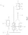
- powertrain assembly 16 and/or electrical assembly 100includes a hybrid control unit (“HCU”) 300 , an engine control unit (“ECU”) 302 , and an engine starter 304 .
- HCU 300receives inputs related to the state of a key/start switch 306 , the engagement or disengagement of the hybrid mode via input member 68 b , and/or the engagement of disengagement of a brake pedal 308 .
- HCU 300is configured to prevent unintentional engine starting and noises associated therewith when in the stealth mode.
- a locking featurethat prevents the hybrid mode from being engaged, thereby preventing the sound of the engine 40 or other components of powertrain assembly 16 from being actuated and exposing vehicle 10 to detection that would otherwise not be possible in the stealth mode.
- an override featurewould have to be engaged in which the operator may be required to confirm his/her intent to exit or disengage the stealth mode or may be required to enter a code, pin, or other input when disengaging the stealth mode.
- engine starter 304is not connected to key/start switch 306 and, rather, all key/start switch states are wired to HCU 300 , including the engine start position.
- the operatorengages input member 68 a to select the hybrid mode, engages brake pedal 308 , and turns key/start switch 306 to the engine start position.
- the operatorkeeps his/her foot on brake pedal 308 until engine 40 cranks and fully starts.
- HCU 300controls ECU 302 over CANbus communication and engine starter 304 is controlled by ECU 302 .
- the hybrid modemay allow the operator to choose a Hybrid Max Performance mode or a Hybrid State-of-Charge (“SOC”) mode.
- Hybrid Max Performance modeboth engine 40 and traction motor 52 will provide maximum assistance during acceleration and driving while minimal power from motor/generator 50 is diverted to charge the traction batteries of vehicle 10 .
- SOC modemaximum power is diverted to charge batteries 54 and minimal or no power is provided to traction motor 52 .
- the intent of the Hybrid SOC modeis to allow the operator to recharge batteries 54 as quickly as possible during operation of vehicle 10 .
- certain displays, such as display 58may include an input to actuate a Blackout mode where all visible lighting on vehicle 10 is disabled for night operations of vehicle 10 .
- Input console 66also may include certain input members 68 which define a push-button selection for the gear position in an intuitive pattern from the top-left to the bottom-right: Park, Reverse, Neutral, Low, and High.
- an input member 68 cmay correspond to Park
- an input member 68 dmay correspond to Reverse
- an input member 68 emay correspond to Drive with input members 68 g and 68 h indicating High and Low, respectively.
- input console 66displays the currently-selected gear and the currently-active gear on the same display.
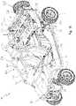
- cooling assembly 80for vehicle 10 is shown.
- Engine 40 and other mechanical components of powertrain assembly 16may be cooled by a separate cooling system which is not shown.
- cooling assembly 80 of FIGS. 5A-11is configured to cool various components of an electrical system 100 of vehicle 10 .
- cooling assembly 80is configured to cool battery pack 54 , electrical wires or conduits 102 , various electrical circuits or connections 104 , and other electrical components.
- Illustrative cooling assembly 80is a water-cooled system, however, cooling assembly 80 may be cooled by any other mechanism, liquid, fluid, etc.
- a housing 82 for portions of cooling assembly 80 and electrical assembly 100is comprised of at least an upper cover 84 , opposing lateral side covers 86 , and at least one front cover 88 removably coupled together with removable fasteners or permanently joined together, for example with welds.
- a recess 89is defined along a portion of front cover 88 to allow various components of vehicle 10 , such as drive shaft 49 or other components of powertrain assembly 16 to be positioned within a portion of housing 82 .
- Right side cover 86may include at least one grouping openings and corresponding louvers 90 configured to direct air within housing 82 and left side cover 86 includes a grouping of openings and corresponding louvers 91 which expel air from housing 82 .
- front cover 88may include at least one grouping of openings and louvers 92 configured to direct air within housing 82 .
- the openings and louvers 90 , 92define air intake locations of housing 82 and cooling assembly 80 and openings and louvers 92 define an air outlet of housing 82 . More particularly, and as shown best in FIG. 6 , ambient air A is configured to flow into housing 82 through the air intake on right side cover 86 and through the air intake on front cover 88 .
- louvers 90 , 92directs air A laterally through housing 82 such that air A flows from the right side of housing 82 toward the left side of housing 82 . In this way, cool, ambient air A flows into housing 82 and flows across battery pack 54 and any other electrical components within housing 82 to cool such components through convection. After flowing through housing 82 , air A, which has been warmed by the electrical components within housing 82 , flows out of housing 82 through openings and louvers 91 on left side cover 86 .
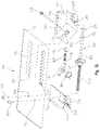
- cooling assembly 80includes a frame 110 , a heat exchanger or radiator 112 , a fan 114 fluidly coupled to heat exchanger 112 , a plurality of cooling plates 116 , 118 supported by frame 110 , an electric water pump 120 , and various cooling conduits, such as conduit 117 ( FIG. 7 ) configured to flow cooling water between motor/generator 50 ( FIG. 2 ) and heat exchanger 112 and conduit 119 ( FIG. 7 ) configured to flow cooling water between traction motor 52 and heat exchanger 112 .
- Frame 110 of cooling assembly 80is supported by lower frame assembly 20 a of vehicle 10 ( FIG. 1A ) and, illustratively, as shown in FIG.
- Heat exchanger 112is coupled to frame 110 along the left side of vehicle 10 and is positioned intermediate side cover 86 and fan 114 .
- Fan 114is configured to pull ambient air A from right side cover 86 and front cover 88 through and across housing 82 such that warm air A flows outside of vehicle 10 through heat exchanger 112 and left side cover 86 .
- Heat exchanger 112is fluidly coupled to cooling plates 116 , 118 through pump 120 . More particularly, and as shown best in FIG. 9 , pump 120 flows cooling water from heat exchanger 112 into a first conduit 121 to flow the water into first cooling plate 116 through a second conduit 122 . The cooling water circulates through first cooling plate 116 and flows from first cooling plate to second cooling plate 118 through a third conduit 124 . From second cooling plate 118 , the water may flow through a fourth conduit 126 which is fluidly coupled to conduit(s) 117 and/or 119 for flowing cooling water to motor/generator 50 and/or traction motor 52 . It may be appreciated that the water flowing through first and second cooling plates 116 , 118 , motor/generator 50 , and/or traction motor 52 is heated and, therefore, ultimately flows back into heat exchanger 112 to be cooled therein.
- frame 110also may support various components of electrical assembly 100 for providing cooling thereto. More particularly, a charger 128 of electrical assembly 100 is positioned on frame 110 adjacent a first surface 132 of first cooling plate 116 .
- Charger 128may include a heat sink, defined by a plurality of cooling fins 130 , positioned laterally outward thereof such that charger 128 is positioned laterally intermediate cooling fins 130 and first cooling plate 116 . It may be appreciated that charger 128 is positioned generally below an access plate or cover 85 of housing 82 , as shown in FIG. 5A , such that charger 128 is easily accessible for repairs or replacement.
- an access plate or cover 87is positioned on a forward end of housing 82 to also provide access to various components of electrical assembly 100 , such as charger 128 , switches, a manual shift for traction motor 52 ( FIG. 2 ), etc.
- a first motor controller 136illustratively a generator control unit (“GCU”) for motor/generator 50 , may be positioned adjacent a second surface 134 of first cooling plate 116 . More particularly, and still referring to FIGS. 7-10B , motor controller 136 is part of electrical assembly 100 and is supported on frame 110 on an opposing side of first cooling plate 116 from charger 128 . In this way, first cooling plate 116 is positioned laterally intermediate charger 128 and first motor controller 136 and, as such, first cooling plate 116 is able cool both first motor controller 136 and charger 128 .
- GCUgenerator control unit
- first cooling plate 116is configured to cool multiple components of electrical assembly 100 by positioning electrical components on both sides of first cooling plate 116 .
- first motor controller 136 and charger 128do not operate at the same time and, therefore, first cooling plate 116 is only needed to cool either first motor controller 136 or charger 128 at any given time. More particularly, the same cooling plate 116 for charger 128 and first motor controller 136 can be optimally used because both charger 128 and first motor controller 136 do not operate and produce heat at the same time, but rather, charger 128 is used for charging batteries 54 from an external AC source, whereas first motor controller 136 is used to charge batteries 54 when vehicle 10 is in operation or in a stationary power mode.
- frame 110To support first cooling plate 116 , charger 128 , and first motor controller 136 on vehicle 10 , frame 110 includes a side portion 140 comprised of at least longitudinally-extending members 142 , upstanding members 144 , mounting members 146 , a front cross-member 148 , a rear cross-member 150 , and a mounting rack 152 .
- mounting rack 152is configured to support various components of electrical assembly 100 , such as a generator.
- upstanding members 144are coupled to front cross-member 148 and are configured to support second cooling plate 118 thereon.
- Longitudinally-extending member 142is coupled to a support plate 154 with removable fasteners (not shown).
- Support plate 154is configured to support charger 128 on a first side thereof and support first cooling plate 116 and first motor controller 136 on a second side thereof.
- first motor controller 136is removably coupled to first cooling plate 116 instead of support plate 154 , however, in alternative embodiments, first motor controller 136 may be coupled to support plate 154 or any portion of frame 110 .
- Charger 128is coupled to longitudinally-extending member 142 with a mounting bracket 129 , as shown in FIG. 7 .
- electrical assembly 100also includes a second motor controller 137 , illustratively a traction control unit (“TCU”) for traction motor 52 , positioned rearward of second cooling plate 118 .
- Second motor controller 137is positioned generally perpendicularly to first motor controller 136 . While second motor controller 137 is removably coupled to second cooling plate 118 , second motor controller 137 also may be coupled to any portion of frame 110 , such as front cross-member 148 and/or upstanding members 144 .
- At least charger 128 , first motor controller 136 , and second motor controller 137define a high-voltage system, circuit, or portion of electrical assembly 100 , which is generally positioned on a left side of vehicle 10 and is generally rearward of operator seat 32 .
- electrical assembly 100also includes a low-voltage system, circuit, or portion, which is generally positioned on a right side of vehicle 10 and is generally rearward of front passenger seat 34 .
- the low-voltage systemincludes fuses, inverters, batteries 54 , and other low-voltage components. It may be appreciated that at least one DC-DC converter is included with electrical assembly 100 to convert high voltage to low voltage.
- the low-voltage systemincludes components which generate and/or transmit voltages lower than that of the high-voltage components, the low-voltage system of electrical assembly 100 may not generate as much heat as the high-voltage system. As such, it is sufficient to cool and maintain the temperature of the low-voltage system through natural convection cooling using ambient air A. Conversely, because the high-voltage system includes components which generate and/or transmit voltages higher than that of the low-voltage system, the high-voltage system of electrical assembly 100 generates more heat than the low-voltage system and may require an enhanced cooling system, such as the liquid-cooling system of cooling assembly 80 .
- the low-voltage components cooled through convectionmay be cooled at different (e.g., lower) rate of cooling than the high-voltage components cooled through liquid cooling.
- the components of the high-voltage systemare positioned within the air flow path of the ambient air A for cooling the low-voltage system, so the high-voltage system is cooled through both the liquid cooling assembly 80 and through convection with ambient air A. More particularly, the components of the low-voltage system are positioned adjacent to the openings and louvers 90 , 92 such that they are close to the intake of ambient air A for efficient cooling.
- Fan 114draws air into housing 82 at the right side of vehicle 10 such that the ambient air A is pulled across the low-voltage components.
- the ambient air Aflows through housing 82 and towards radiator 112 , the ambient air A also passes over the high-voltage components after flowing past the low-voltage components because the high-voltage components are positioned downstream of the low-voltage components.
- components of vehicle 10are strategically positioned rearward of seats 32 , 34 such that the ambient air A can be used to facilitate cooling of both the low- and high-voltage components.
- cooling assembly 80also is configured to cool the low-voltage components using the liquid cooling system thereof.
- cooling assembly 80may be configured to insert the low-voltage components into the liquid cooling system through fluid conduits and other components coupled to heat exchanger 112 .
- HCU 300receives a plurality of inputs from various components of vehicle 10 , such as inputs related to the state or status of the ignition key/switch 306 , the state of charger 128 , the state of hybrid mode input 68 b , the state of the blackout mode input on display 58 ( FIG. 3 ), the temperature of charger 128 , the temperature of second motor controller 137 , the temperature of first motor controller 136 , the temperature of traction motor 52 , the temperature of motor/generator 50 , the temperature of batteries 54 , and/or the temperature of the DC-DC converter(s).
- various components of vehicle 10such as inputs related to the state or status of the ignition key/switch 306 , the state of charger 128 , the state of hybrid mode input 68 b , the state of the blackout mode input on display 58 ( FIG. 3 ), the temperature of charger 128 , the temperature of second motor controller 137 , the temperature of first motor controller 136 , the temperature of traction motor 52 , the
- HCU 300determines if pump 120 of the liquid cooling system and/or fan 114 should be activated. If pump 120 and/or fan 114 are activated, pump 120 and/or fan 114 continue to be active before and/or after a component is needed in order to keep the component temperatures low and allow for maximizing the performance of the liquid cooling system.
- the key stateis used to determine if vehicle 10 is in the “Key OFF” charging position or “Key ON” charging position.
- the liquid cooling systemmay be active for any component in cooling assembly 80 .
- pump 120is turned on first and, only if additional cooling is required, will fan 114 then be turned on also.
- fan 114can be calibrated to turn off by a switch or automatically turned off by HCU 300 .
- connection assembly 260allows for external systems or packages to be connected to electrical assembly 100 .
- connection assembly 260defines an autonomous ready connection assembly configured to quickly and easily plug into an autonomous operation controller, wiring harness, or other such component. More particularly, connection assembly 260 includes adapters or plug connectors 262 configured to receive mating or complementary plugs or adapters of an autonomous operation controller, wiring assembly, or the like.
- Connectors 262are electrically coupled to wires or conduits 264 which extend along the outer surface of housing 82 and are electrically coupled to components of electrical assembly 100 within housing 82 through a connector 266 on front cover 88 .
- connection assembly 260allows the operator to merely plug in an autonomous operation controller through connectors 262 to quickly connect such a controller to other components of electrical assembly 100 without the need to rewire or reconfigure portions of electrical assembly 100 .
- connector assembly 260includes the SMET required IOP signals which allows autonomy packages to be simply connected to electrical assembly 100 through connectors 262 .
- vehicle 10When vehicle 10 operates with an autonomous package, vehicle 10 has the ability for “Follow Me” modes, waypoint navigation, and drive-by-remote options, such as remote driving with a camera.
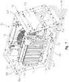
- vehicle 10also is configured to support a plurality of accessories or cargo thereon. While many accessories and cargo may be supported in rear cargo area 28 ( FIGS. 1A and 1B ), upper frame assembly 20 b also may be configured to support one or more accessories, vehicle components, and/or cargo.
- vehicle 10includes a first portion 160 of upper frame assembly 20 b positioned generally over operator seat 32 and front passenger seat 34 and a second portion 162 of upper frame assembly 20 b positioned generally over a portion of rear cargo area 28 and is rearward of first portion 160 of upper frame assembly 20 b ( FIGS. 1A and 1B ). At least first portion 160 of upper frame assembly 20 b is configured to support an accessory or cargo rack assembly 170 .
- rack assembly 170is supported on longitudinally-extending members 164 , a front cross-member 166 , and a rear cross-member 168 .
- members 164 , 166 , 168have a circular cross-section, however, it is envisioned that rectangular or other cross-sectional profiles may be used.
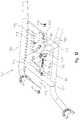
- Rack assembly 170includes an accessory plate 172 , a first or forward coupler 174 , a second or rearward coupler 176 , and a tension assembly 178 .
- First and second couplers 174 , 176each include a groove or recessed portion 175 , 177 which are configured to receive a portion of cross-members 166 , 168 , respectively. It may be appreciated that recessed portions 175 , 177 can receive cross-members of any shape and merely need to attach to generally parallel cross-members.
- Tension assembly 178allows rack assembly 170 to be adjustably positioned between cross-members 166 , 168 .
- Tension assembly 178includes a shaft 180 having a threaded portion 180 a and a non-threaded portion 180 b , a tension coupler, illustratively a knob 182 , a lever arm 184 , a tension member 186 for lever arm 184 , a spring 188 , and a stop member 190 .
- knob 182may be a worm gear with a knob, an over-center cam latch or mechanism, or any other similar device or mechanism.
- Tension assembly 178is removably coupled to accessory plate 172 with removable fasteners 192 and rails 194 .
- first coupler 174has a fixed position on accessory plate 172 while second coupler 176 is configured to move relative to accessory plate 172 .
- rails 194are coupled to a lower surface of accessory plate 172 with adhesive, mechanical fasteners, or the like, or may be integrally formed with accessory plate 172 .
- Rails 194are configured to receive second coupler 176 .
- second coupler 176includes shoulders 200 which are received within a sliding surface or groove 202 of rails 194 and are configured to retain second coupler 176 between rails 194 .
- Shoulders 200are configured to slide or translate along the length of rails 194 to allow for movement of second coupler 176 , as disclosed further herein.
- First coupler 174 of rack assembly 170includes a first mounting member 204 configured to receive a portion of shaft 180 . More particularly, first mounting member 204 includes an opening or through hole 206 configured to receive threaded portion 180 a of shaft 180 . The inner surface of through hole 206 is threaded such that threaded portion 180 a of shaft 180 is threadedly coupled therein. Non-threaded portion 180 b of shaft 180 is received within a second mounting member 208 of second coupler 176 . Second mounting member 208 also includes an opening or through hole 210 configured to receive non-threaded portion 180 b .
- non-threaded portion 180 bincludes a first spacer 212 and a second spacer 214 which are configured to flank and abut second mounting member 208 when the distal end of shaft 180 is positioned within through hole 210 .
- spacers 212 , 214fix the position of the distal end of shaft 180 with respect to second coupler 176 .
- first and second couplers 174 , 176may be adjusted. More particularly, tension coupler 182 can be rotated along threaded portion 180 a of shaft 180 to adjust the position of threaded portion 180 a within first mounting member 204 . As threaded portion 180 a moves within first mounting member 204 , second coupler 176 may be moved along rails 194 to move closer to or further from first coupler 174 , depending on the distance between first and second cross-members 166 , 168 and to allow rack assembly 170 to be coupled to first portion 160 of upper frame assembly 20 b after assembly of vehicle 10 .
- Tension assembly 178is configured to maintain the distance between first and second couplers 174 , 176 once rack assembly 170 is coupled to upper frame assembly 20 b .
- lever arm 184is received within an opening 216 of second coupler 176 and is secured therein with a removable fastener 218 .
- Lever arm 184includes a pin 219 which is received within spring 188 and is configured to contact stop member 190 when spring 188 is fully compressed. Stop member 190 contacts or abuts rear cross-member 168 as lever arm 184 and spring 188 push against stop member 190 .
- Tension member 186provides a pre-loaded tension or resistance on lever arm 184 .
- second coupler 176may be initially moved along rails 194 towards first coupler 174 to decrease the space between couplers 174 , 176 . This allows rack assembly 170 to be positioned over cross-members 166 , 168 of upper frame assembly 20 b and first and second couplers 174 , 176 to be positioned between cross-members 166 , 168 . Once recessed portions 175 , 177 of first and second couplers 174 , 176 are generally aligned with cross-members 166 , 168 , respectively, tension assembly 178 may be engaged to secure rack assembly 170 to upper frame assembly 20 b .
- tension coupler 182may be rotated to move threaded portion 180 a within first mounting member 204 . Because non-threaded portion 180 b is fixed to second coupler 176 , the movement of shaft 180 relative to first mounting member 204 increases the distance between first and second couplers 174 , 176 such that second coupler 176 moves rearwardly to engage rear cross-member 168 . Once second coupler 176 is engaged with rear cross-member 168 , tension coupler 182 may be rotated slightly more such that stop member 190 contacts rear cross-member 168 . Continued rotation of tension coupler 182 results in spring 188 being compressed at stop member 190 and tension member 186 engaging lever arm 184 . In this way, pressure is applied via tension assembly 178 to maintain the position of second coupler 176 on rear cross-member 168 in order to securely couple rack assembly 170 to upper frame assembly 20 b.
- rack assembly 170is configured to support a plurality of cargo items, such as spare tires, fire extinguishers, fuel can holders, ammunition holders, a jack for vehicle 10 , tool boxes or holders, storage boxes, additional cargo to be transported by the vehicle, vehicle accessories, vehicle components, such as cameras, sensor equipment, body panels of vehicle 10 , and any other item.
- rack assembly 170is configured to support a plurality of heavy objects and is configured to do so because tension assembly 178 holds rack assembly 170 on upper frame assembly 20 b in tension. It may be appreciated that the disclosure of rack assembly 170 herein illustrates that rack assembly 170 is coupled to upper frame assembly 20 b without any tools.
- vehicle 10is configured to support additional cargo thereon.
- vehicle 10may include a cargo support assembly 220 , which as shown, may hold a spare tire 222 thereon.
- Spare tire 222includes a tire 223 a supported on a wheel hub 223 b .
- cargo support assembly 220is coupled to wheel hub 223 b to secure spare tire 222 to vehicle 10 and, more particularly, to a tail gate 224 of vehicle 10 . In this way, cargo support assembly 220 is positioned at rear cargo area 28 .
- Cargo support assembly 220includes a mounting surface 236 coupled to a frame member 238 .
- Frame member 258includes upstanding portions 239 a and a base portion 239 b .
- upstanding portions 239 a and base portion 239 bare integrally formed together.
- Mounting surface 236is coupled to frame member 238 with removable fasteners 240 .
- Mounting surface 236includes an attachment member 242 coupled thereto with fasteners 244 .
- Attachment member 242has a generally L-shaped configuration and is configured to hook over the top of tail gate 224 when cargo support assembly 220 is positioned thereon. More particularly, attachment member 242 is configured to attach to an upper rail 226 of tail gate 224 .
- Mounting surface 236also includes mounting anchors 252 which are coupled thereto with fasteners 254 .
- Mounting anchors 252extend forwardly from mounting surface 236 and are received over complementary mounting anchors 234 on a lower rail 228 of tail gate 224 .
- Mounting anchors 234are supported on lower rail 228 with mounts 232 .
- Mounts 232may be integrally formed with lower rail 228 or may be removably or permanently coupled thereto with fasteners, welds, adhesive, or any other attachment mechanism or material. In this way, cargo support assembly 220 is removably coupled to tail gate 224 with attachment member 242 and mounting anchors 252 .
- mounting anchors 234 and 252may be configured as Lock & Ride® anchors available from Polaris Industries Inc.
- Cargo support assembly 220is configured to support at least spare tire 222 on vehicle 10 on the opposite side of mounting surface 236 from mounting anchors 252 . More particularly, a rear-facing side of mounting surface 236 includes a threaded T-handle 250 configured to threadedly couple with wheel hub 223 b of spare tire 222 . T-handle 250 is coupled to mounting surface 236 with fasteners 248 . As such, vehicle 10 is configured to support a plurality of cargo options at multiple locations of vehicle 10 .
Landscapes
- Engineering & Computer Science (AREA)
- Mechanical Engineering (AREA)
- Chemical & Material Sciences (AREA)
- Combustion & Propulsion (AREA)
- Physics & Mathematics (AREA)
- Thermal Sciences (AREA)
- Transportation (AREA)
- Life Sciences & Earth Sciences (AREA)
- Sustainable Development (AREA)
- Sustainable Energy (AREA)
- Electric Propulsion And Braking For Vehicles (AREA)
- Cooling, Air Intake And Gas Exhaust, And Fuel Tank Arrangements In Propulsion Units (AREA)
- Arrangement Or Mounting Of Propulsion Units For Vehicles (AREA)
- Polymers With Sulfur, Phosphorus Or Metals In The Main Chain (AREA)
Abstract
Description
Claims (19)
Priority Applications (11)
| Application Number | Priority Date | Filing Date | Title |
|---|---|---|---|
| US16/414,217US11370266B2 (en) | 2019-05-16 | 2019-05-16 | Hybrid utility vehicle |
| PCT/US2020/032342WO2020231922A1 (en) | 2019-05-16 | 2020-05-11 | Hybrid utility vehicle |
| EP20728867.1AEP3969311B1 (en) | 2019-05-16 | 2020-05-11 | Cooling assembly for a hybrid vehicle and a hybrid vehicle |
| CA3135122ACA3135122A1 (en) | 2019-05-16 | 2020-05-11 | Hybrid utility vehicle |
| DK20728867.1TDK3969311T3 (en) | 2019-05-16 | 2020-05-11 | Cooling unit for a hybrid vehicle and a hybrid vehicle |
| AU2020275400AAU2020275400B2 (en) | 2019-05-16 | 2020-05-11 | Hybrid utility vehicle |
| IL286596AIL286596A (en) | 2019-05-16 | 2021-09-22 | Hybrid utility vehicle |
| US17/838,903US12194808B2 (en) | 2019-05-16 | 2022-06-13 | Hybrid utility vehicle |
| US18/212,970US12311728B2 (en) | 2019-05-16 | 2023-06-22 | Hybrid utility vehicle |
| AU2023219900AAU2023219900A1 (en) | 2019-05-16 | 2023-08-24 | Hybrid utility vehicle |
| AU2023237145AAU2023237145B2 (en) | 2019-05-16 | 2023-09-28 | Hybrid utility vehicle |
Applications Claiming Priority (1)
| Application Number | Priority Date | Filing Date | Title |
|---|---|---|---|
| US16/414,217US11370266B2 (en) | 2019-05-16 | 2019-05-16 | Hybrid utility vehicle |
Related Child Applications (1)
| Application Number | Title | Priority Date | Filing Date |
|---|---|---|---|
| US17/838,903ContinuationUS12194808B2 (en) | 2019-05-16 | 2022-06-13 | Hybrid utility vehicle |
Publications (2)
| Publication Number | Publication Date |
|---|---|
| US20200361273A1 US20200361273A1 (en) | 2020-11-19 |
| US11370266B2true US11370266B2 (en) | 2022-06-28 |
Family
ID=70861562
Family Applications (3)
| Application Number | Title | Priority Date | Filing Date |
|---|---|---|---|
| US16/414,217Active2039-06-13US11370266B2 (en) | 2019-05-16 | 2019-05-16 | Hybrid utility vehicle |
| US17/838,903Active2039-10-03US12194808B2 (en) | 2019-05-16 | 2022-06-13 | Hybrid utility vehicle |
| US18/212,970Active2039-05-28US12311728B2 (en) | 2019-05-16 | 2023-06-22 | Hybrid utility vehicle |
Family Applications After (2)
| Application Number | Title | Priority Date | Filing Date |
|---|---|---|---|
| US17/838,903Active2039-10-03US12194808B2 (en) | 2019-05-16 | 2022-06-13 | Hybrid utility vehicle |
| US18/212,970Active2039-05-28US12311728B2 (en) | 2019-05-16 | 2023-06-22 | Hybrid utility vehicle |
Country Status (7)
| Country | Link |
|---|---|
| US (3) | US11370266B2 (en) |
| EP (1) | EP3969311B1 (en) |
| AU (3) | AU2020275400B2 (en) |
| CA (1) | CA3135122A1 (en) |
| DK (1) | DK3969311T3 (en) |
| IL (1) | IL286596A (en) |
| WO (1) | WO2020231922A1 (en) |
Cited By (7)
| Publication number | Priority date | Publication date | Assignee | Title |
|---|---|---|---|---|
| US20220266908A1 (en)* | 2020-11-18 | 2022-08-25 | Arctic Cat Inc. | Off-road vehicle |
| US20230313872A1 (en)* | 2022-04-04 | 2023-10-05 | Polaris Industries Inc. | Continuously variable transmission |
| US20230415558A1 (en)* | 2020-05-15 | 2023-12-28 | Polaris Industries Inc. | Off-road vehicle |
| USD1036314S1 (en)* | 2021-01-08 | 2024-07-23 | Polaris Industries Inc. | Upper frame for an off-road vehicle |
| US12194954B2 (en) | 2023-03-17 | 2025-01-14 | Polaris Industries Inc. | Integrated seat belt energy management loop |
| US12384464B2 (en) | 2020-05-15 | 2025-08-12 | Polaris Industries Inc. | Off-road vehicle |
| US12415394B2 (en) | 2019-04-30 | 2025-09-16 | Polaris Industries, Inc. | Vehicle |
Families Citing this family (8)
| Publication number | Priority date | Publication date | Assignee | Title |
|---|---|---|---|---|
| US11370266B2 (en) | 2019-05-16 | 2022-06-28 | Polaris Industries Inc. | Hybrid utility vehicle |
| US11987196B2 (en)* | 2019-11-26 | 2024-05-21 | Robby Gordon | Roll cage center supports |
| US11945388B2 (en)* | 2019-11-26 | 2024-04-02 | Robby Gordon | Roll cage chassis spine |
| US12005849B2 (en)* | 2019-11-26 | 2024-06-11 | Robby Gordon | Roll cage chassis structural spine |
| US11987288B2 (en) | 2020-03-27 | 2024-05-21 | Polaris Industries Inc. | Utility vehicle |
| US11858586B2 (en)* | 2020-11-23 | 2024-01-02 | Zeger Van Thuyl | Motorcycle conversion kit |
| KR20220088969A (en)* | 2020-12-21 | 2022-06-28 | 현대자동차주식회사 | Cooling assembly of hydrogen electric truck |
| US12214844B2 (en)* | 2021-02-09 | 2025-02-04 | Barnabas LeBlanc | Endless track conveyance machines having a torque assist system for enhancing performance and a battery temperature assist |
Citations (395)
| Publication number | Priority date | Publication date | Assignee | Title |
|---|---|---|---|---|
| US1138122A (en) | 1914-12-19 | 1915-05-04 | Fred A Lambert | Electric motor-vehicle. |
| US1551594A (en) | 1922-10-27 | 1925-09-01 | Walter Maurice | Electric motor vehicle |
| US1989585A (en) | 1933-05-08 | 1935-01-29 | Chester S Bigelow | Oil warmer and cooler |
| US2623612A (en) | 1949-10-07 | 1952-12-30 | Graf & Stift Automobilfabrik A | Internal combustion engine with lubricating oil cooler |
| US3294190A (en) | 1964-11-05 | 1966-12-27 | Suvor Tosun | Wheel drive and suspension arrangement for transport vehicle |
| US3523592A (en) | 1968-07-26 | 1970-08-11 | Kohler Co | Engine lubrication system |
| US3694661A (en) | 1968-10-18 | 1972-09-26 | Hitachi Ltd | Ac generator directly coupled to an internal combustion engine |
| US3708028A (en) | 1970-12-21 | 1973-01-02 | Boyertown Auto Body Works | Electrically driven vehicles |
| US3874472A (en) | 1974-01-25 | 1975-04-01 | West Virginia High Bird Corp | Battery powered vehicle drive |
| US4010725A (en) | 1974-11-14 | 1977-03-08 | White Cygnal G | Self-contained engine warmer |
| US4022272A (en) | 1975-11-14 | 1977-05-10 | Chester O. Houston, Jr. | Transmission fluid heat radiator |
| US4042054A (en) | 1975-12-18 | 1977-08-16 | Ward Eugene T | Vehicle and battery pack |
| US4150655A (en) | 1976-10-13 | 1979-04-24 | Fiat Societa Per Azioni | Lubricating oil sump for internal combustion engines |
| US4254843A (en) | 1979-07-20 | 1981-03-10 | Han Joon H | Electrically powered vehicle |
| US4337406A (en) | 1978-05-27 | 1982-06-29 | Robert Bosch Gmbh | Bearing-less remotely journalled dynamo electric machine, particularly alternator for combination with a gas turbine |
| US4388583A (en) | 1981-03-06 | 1983-06-14 | Outboard Marine Corporation | Battery charger with transducer for controlling charge rate |
| JPS58126434A (en) | 1982-01-23 | 1983-07-27 | Nissan Motor Co Ltd | Smoothing device of torque in internal-combustion engine |
| US4405028A (en) | 1981-06-18 | 1983-09-20 | Price Cosby G | Drive system for electric vehicles |
| US4404936A (en) | 1980-04-30 | 1983-09-20 | Mitsubishi Jukogyo Kabushiki Kaisha | Breather device for overhead valve engines |
| US4405029A (en) | 1980-01-02 | 1983-09-20 | Hunt Hugh S | Hybrid vehicles |
| JPS5939933A (en) | 1982-08-27 | 1984-03-05 | Yamaha Motor Co Ltd | portable power generator |
| US4434934A (en) | 1981-06-15 | 1984-03-06 | Klockner-Humboldt-Deutz Ag | System for heating the operators cabin of a machine powered by an internal combustion engine |
| US4470389A (en) | 1982-02-08 | 1984-09-11 | Kawasaki Jukogyo Kabushiki Kaisha | Breather-lubricator system for engines |
| JPS60209616A (en) | 1984-04-02 | 1985-10-22 | Fuji Heavy Ind Ltd | Lubricating apparatus for ohc engine |
| JPS61135910A (en) | 1984-12-04 | 1986-06-23 | Fuji Heavy Ind Ltd | Lubricant oil cooling device for engine |
| US4602694A (en) | 1984-07-30 | 1986-07-29 | William Weldin | Motor generator electric automotive vehicle |
| US4638172A (en) | 1984-11-27 | 1987-01-20 | Williams George A | Combination, a model vehicle engine and a direct-current generator |
| US4685430A (en) | 1985-03-20 | 1987-08-11 | Valeo | Motor vehicle exhaust gas heat exchanger for heating engine coolant and lubricating oil |
| US4688529A (en) | 1985-07-10 | 1987-08-25 | Kawasaki Jukogyo Kabushiki Kaisha | Lubricating system for horizontal cylinder overhead valve engine |
| US4697660A (en) | 1985-10-31 | 1987-10-06 | Wu C H | Vehicle with multiple power source |
| US4779905A (en) | 1986-08-25 | 1988-10-25 | Kubato Ltd. | Forcedly air-cooled engine generator of vertical shaft type |
| DE3825349A1 (en) | 1987-08-06 | 1989-02-23 | Velasco Sesena D Lor Fernandez | Portable, variable radio-frequency generator |
| US4898261A (en) | 1989-04-10 | 1990-02-06 | Brunswick Corporation | Water cooled plastic oil pan |
| US5018490A (en) | 1989-04-28 | 1991-05-28 | J. Eberspacher | Heating system, in particular for motor vehicles, with an internal combustion engine and a heater |
| US5036939A (en) | 1987-08-28 | 1991-08-06 | Polaris Industries L.P. | Multiple axle drive vehicle with overrunning roller clutch hubs |
| US5148883A (en) | 1989-12-27 | 1992-09-22 | Aisin Aw Co., Ltd. | Regenerative braking electric vehicle with four motors |
| EP0511654A2 (en) | 1991-04-30 | 1992-11-04 | Toyota Jidosha Kabushiki Kaisha | Drive apparatus for hybrid vehicle |
| US5212431A (en) | 1990-05-23 | 1993-05-18 | Nissan Motor Co., Ltd. | Electric vehicle |
| US5251721A (en) | 1992-04-21 | 1993-10-12 | Richard Ortenheim | Semi-hybrid electric automobile |
| US5251588A (en) | 1991-11-15 | 1993-10-12 | Toyota Jidosha Kabushiki Kaisha | Controller for hybrid vehicle drive system |
| US5255733A (en) | 1992-08-10 | 1993-10-26 | Ford Motor Company | Hybird vehicle cooling system |
| US5264764A (en) | 1992-12-21 | 1993-11-23 | Ford Motor Company | Method for controlling the operation of a range extender for a hybrid electric vehicle |
| US5341280A (en) | 1991-09-27 | 1994-08-23 | Electric Power Research Institute | Contactless coaxial winding transformer power transfer system |
| US5359247A (en) | 1992-04-27 | 1994-10-25 | Sundstrand Corporation | Cooling arrangement and method for offset gearbox |
| US5382833A (en) | 1991-03-01 | 1995-01-17 | Kaethe Hagemeier | Current generator with core cooling |
| US5407130A (en) | 1993-07-20 | 1995-04-18 | Honda Giken Kogyo Kabushiki Kaisha | Motor vehicle heat storage device with coolant bypass |
| US5408965A (en) | 1993-10-04 | 1995-04-25 | Ford Motor Company | Internal combustion engine oil pan with oil cooler |
| US5422822A (en) | 1991-06-20 | 1995-06-06 | Honda Giken Kogyo Kabushiki Kaisha | Apparatus for detecting remanent stored energy in storage battery and apparatus for warning of reduction in remanent stored energy in storage battery |
| US5461568A (en) | 1992-05-20 | 1995-10-24 | Nissan Motor Co., Ltd. | Torque split control apparatus |
| DE4427322A1 (en) | 1994-08-02 | 1996-02-15 | Wolfgang Hill | Electricity generation set for series hybrid vehicle and stationary thermal plant |
| US5528148A (en) | 1988-07-13 | 1996-06-18 | Electronic Development, Inc. | Battery monitoring and deceleration dependent fuel-saving charging system |
| US5531285A (en)* | 1991-08-01 | 1996-07-02 | Wavedriver Limited | Vehicle cooling system |
| US5546901A (en) | 1995-06-30 | 1996-08-20 | Briggs & Stratton Corporation | Engine housing for an engine-device assembly |
| US5549153A (en) | 1992-11-13 | 1996-08-27 | Behr Gmbh & Co. | Device for cooling drive components and heating a passenger compartment of an electric vehicle |
| US5550445A (en) | 1993-09-24 | 1996-08-27 | Toyota Jidosha Kabushiki Kaisha | Generator controller and controlling method for hybrid vehicle |
| US5558057A (en) | 1991-12-02 | 1996-09-24 | Ryobi Outdoor Products | Operator carried power tool having a four-cycle engine |
| US5586613A (en) | 1993-04-22 | 1996-12-24 | The Texas A&M University System | Electrically peaking hybrid system and method |
| US5614809A (en) | 1994-08-22 | 1997-03-25 | Honda Giken Kogyo Kabushiki Kaisha | Electric generation control system for hybrid vehicle |
| JPH0995149A (en) | 1995-09-29 | 1997-04-08 | Fuji Heavy Ind Ltd | Driving device of hybrid car |
| US5621304A (en) | 1994-08-22 | 1997-04-15 | Honda Giken Kogyo Kabushiki Kaisha | Electric generation control system for hybrid vehicle |
| US5625558A (en) | 1990-11-29 | 1997-04-29 | Mitsubishi Jidosha Kogyo Kabushiki Kaisha | Drive-by-wire vehicle engine output control system |
| US5647534A (en) | 1994-09-22 | 1997-07-15 | Mercedes-Benz Ag | Device for heating an interior of an electric vehicle |
| US5673668A (en) | 1996-08-05 | 1997-10-07 | Ford Global Technologies, Inc. | Method and apparatus for electronic throttle monitoring |
| DE4447138A1 (en) | 1994-12-29 | 1997-12-11 | Karl Heinz | Arrangement for hybrid drive of vehicle esp. automobile |
| US5788597A (en) | 1994-12-23 | 1998-08-04 | Mercedes-Benz Ag | Process and apparatus for braking a hybrid-drive motor vehicle |
| EP0856427A1 (en) | 1996-07-30 | 1998-08-05 | Denso Corporation | Hybrid car controller |
| US5804935A (en) | 1997-02-06 | 1998-09-08 | Radev; Vladimir | Drive system for electric vehicles |
| US5860403A (en) | 1996-10-09 | 1999-01-19 | Honda Giken Kogyo Kagushiki Kaisha | System for producing lubricating oil mist in engine |
| US5867009A (en) | 1995-04-28 | 1999-02-02 | Honda Giken Kogyo Kabushiki Kaisha | Control system for electric power generating apparatus on hybrid vehicle |
| DE19735021A1 (en) | 1997-08-13 | 1999-02-18 | Volkswagen Ag | Automobile hybrid drive unit |
| EP0898352A1 (en) | 1997-08-22 | 1999-02-24 | Ecomag S.A. | Generator-set |
| US5883496A (en) | 1996-05-08 | 1999-03-16 | Toyota Jidosha Kabushiki Kaisha | Electric vehicle power supply |
| US5947075A (en) | 1995-12-15 | 1999-09-07 | Honda Giken Kogyo Kabushiki Kaisha | Lubricating system in a 4-cycle engine |
| US5960901A (en) | 1997-09-04 | 1999-10-05 | Corbin Pacific, Inc. | Battery-powered vehicle |
| US5960764A (en) | 1997-03-03 | 1999-10-05 | Kioritz Corporation | Four-stroke internal combustion engine |
| US5971290A (en) | 1997-04-30 | 1999-10-26 | Honda Giken Kogyo Kabushiki Kaisha | Heat exchange system for electric vehicle |
| US6019183A (en) | 1997-11-18 | 2000-02-01 | Honda Giken Kogyo Kabushiki Kaisha | Hybrid vehicle |
| US6030316A (en) | 1998-10-29 | 2000-02-29 | Mitsubishi Denki Kabushiki Kaisha | Drive by wire fail safe control to fix the vehicle speed at a preset speed |
| US6047678A (en) | 1996-03-08 | 2000-04-11 | Ryobi North America, Inc. | Multi-position operator-carried four-cycle engine |
| US6114784A (en) | 1998-06-22 | 2000-09-05 | Nissan Motor Co., Ltd. | Motor with cooling structure |
| US6119636A (en) | 1999-06-11 | 2000-09-19 | Fan; Guo Xiang | Portable generator |
| CN1268997A (en) | 1997-07-08 | 2000-10-04 | 赖哈特研究及发展有限公司 | Improvements in and relating to internal combustion engine |
| GB2349483A (en) | 1999-04-28 | 2000-11-01 | Rover Group | An engine-driven generator assembly |
| US6152098A (en) | 1998-01-14 | 2000-11-28 | Andreas Stihl Ag & Co. | Internal combustion engine for a portable handheld work apparatus |
| US6178947B1 (en) | 1998-08-28 | 2001-01-30 | Unisia Jecs Corporation | Control apparatus for internal combustion engine with electronically-controlled throttle system |
| US6184603B1 (en) | 1999-03-29 | 2001-02-06 | Unisia Jecs Corporation | Motor/generator unit applicable to automotive vehicle |
| US6198183B1 (en) | 1998-04-18 | 2001-03-06 | Daimlerchrysler Ag | Integrated electric drive unit including an electric motor and an electronic control and monitoring module |
| US6196168B1 (en) | 1996-09-17 | 2001-03-06 | Modine Manufacturing Company | Device and method for cooling and preheating |
| US6209518B1 (en) | 1998-08-05 | 2001-04-03 | Unisia Jecs Corporation | Method and apparatus for fail safe control of an electronically controlled throttle valve of an internal combustion engine |
| US6213079B1 (en) | 1998-06-03 | 2001-04-10 | Fuji Robin Kabushiki Kaisha | Lubricating apparatus for four-cycle engines |
| US6217758B1 (en) | 1999-08-06 | 2001-04-17 | Dana Corporation | Oil sump arrangement with integral filter and heat exchanger |
| US20010011051A1 (en) | 2000-01-27 | 2001-08-02 | Toyota Jidosha Kabushiki Kaisha | Shift control apparatus for continuously variable transmission of motor vehicle |
| US6276331B1 (en) | 1998-08-05 | 2001-08-21 | Unisia Jecs Corporation | Method and apparatus for fail-safe controlling internal combustion engine with electronic controlled throttle system |
| US20010020554A1 (en) | 2000-02-24 | 2001-09-13 | Takashi Yanase | Regeneration control device of hybrid electric vehicle |
| US20010043808A1 (en) | 2000-05-19 | 2001-11-22 | Ken Matsunaga | Heating apparatus for vehicle cabin |
| US6333620B1 (en) | 2000-09-15 | 2001-12-25 | Transportation Techniques Llc | Method and apparatus for adaptively controlling a state of charge of a battery array of a series type hybrid electric vehicle |
| US6332504B1 (en) | 1997-04-04 | 2001-12-25 | Graham John Adds | Electric vehicles |
| US6334364B1 (en) | 1998-09-16 | 2002-01-01 | Honda Giken Kogyo Kabushiki Kaisha | Torque sensor unit for regulating axial movement and axial load |
| US20020011100A1 (en) | 2000-03-03 | 2002-01-31 | Pursifull Ross Dykstra | High-resolution electronic throttle position system |
| US6353786B1 (en) | 1998-06-30 | 2002-03-05 | Nissan Diesel Co., Ltd. | Braking device for an electrically-powered car that uses a load of an electrical motor as a braking force |
| US6359344B1 (en) | 2000-09-12 | 2002-03-19 | Lincoln Global, Inc. | Electric generating domestic implement |
| US6362602B1 (en) | 2001-05-03 | 2002-03-26 | Ford Global Technologies, Inc. | Strategy to control battery state of charge based on vehicle velocity |
| US6371878B1 (en) | 2000-08-22 | 2002-04-16 | New Venture Gear, Inc. | Electric continuously variable transmission |
| US20020043413A1 (en)* | 2000-10-13 | 2002-04-18 | Honda Giken Kogyo Kabushiki Kaisha | Vehicle battery cooling apparatus |
| EP1205331A2 (en) | 2000-11-14 | 2002-05-15 | Nissan Motor Company, Limited | Driving force control apparatus |
| US6397795B2 (en) | 2000-06-23 | 2002-06-04 | Nicholas S. Hare | Engine with dry sump lubrication, separated scavenging and charging air flows and variable exhaust port timing |
| US20020074177A1 (en) | 1999-02-24 | 2002-06-20 | Paolo Pasquini | Power plant for electric earth-moving and agricultural vehicles with four-wheel drive |
| US20020094908A1 (en) | 2001-01-16 | 2002-07-18 | Nissan Motor Co., Ltd. | Four-wheel drive hybrid vehicle |
| US6427797B1 (en) | 2001-02-07 | 2002-08-06 | Hui-Lung Chang | Transmission structure of gearbox of electrically actuated car |
| US6467286B2 (en)* | 2000-12-20 | 2002-10-22 | Honda Giken Kogyo Kabushiki Kaisha | Cooling apparatus of hybrid vehicle, including serially-connected cooling systems for electric devices which have different heat resisting allowable temperatures |
| US6488108B1 (en) | 1999-11-06 | 2002-12-03 | Daimlerchrysler Ag | Drive unit for a motor vehicle |
| US20020179354A1 (en) | 2000-05-02 | 2002-12-05 | Sail D. White Enterprises, Inc. | Extended range electric vehicle |
| US6504259B1 (en) | 1999-08-16 | 2003-01-07 | Honda Giken Kogyo Kabushiki Kaisha | Engine automatic start stop control apparatus |
| US6510829B2 (en) | 2000-03-21 | 2003-01-28 | Honda Giken Kogyo Kabushiki Kaisha | Handheld type four-cycle engine |
| US6513492B1 (en) | 2001-07-31 | 2003-02-04 | General Motors Corporation | Limited acceleration mode for electronic throttle control |
| US6520133B1 (en) | 1998-08-11 | 2003-02-18 | Wenko Ag Burgdorf | Reciprocating engine with rocker-arm valve control |
| US20030034187A1 (en) | 2001-08-10 | 2003-02-20 | Aisin Aw Co., Ltd. | Electric vehicle drive control apparatus, electric vehicle drive control method, and program thereof |
| USRE38012E1 (en) | 1998-10-09 | 2003-03-04 | Hilliard Corporation | Bi-directional overrunning clutch |
| US6528918B2 (en) | 2000-01-05 | 2003-03-04 | Mannesman Sachs Ag | Drive system |
| US20030070849A1 (en) | 2001-10-17 | 2003-04-17 | Whittaker Clark Thomas | Auxiliary power unit for vehicles |
| US6557515B2 (en) | 2000-05-23 | 2003-05-06 | Fuji Jukogyo Kabushiki Kaisha | Structure for lubricating valve-operating device of OHC engine and cover member for OHC engine |
| US6561315B2 (en) | 2000-05-23 | 2003-05-13 | Fuji Jukogyo Kabushiki Kaisha | Lubricating system for OHC engine |
| US20030104900A1 (en) | 2001-11-30 | 2003-06-05 | Honda Giken Kogyo Kabushiki Kaisha | Automotive internal combustion engine control system |
| US6591896B1 (en) | 2002-05-23 | 2003-07-15 | Dennis Hansen | Method and system for providing a transmission fluid heat exchanger in-line with respect to an engine cooling system |
| US20030162631A1 (en) | 2002-02-27 | 2003-08-28 | Williams Cameron P. | Hybrid vehicle system |
| US6622804B2 (en) | 2001-01-19 | 2003-09-23 | Transportation Techniques, Llc. | Hybrid electric vehicle and method of selectively operating the hybrid electric vehicle |
| US6640766B2 (en) | 2001-02-16 | 2003-11-04 | Fuji Jukogyo Kabushiki Kaisha | Bearing case for engine |
| US6661108B1 (en) | 1998-12-18 | 2003-12-09 | Nissan Diesel Co., Ltd. | Hybrid drive device |
| US20030226653A1 (en) | 2002-06-10 | 2003-12-11 | Honda Giken Kogyo Kabushiki Kaisha | Structure for cooling high-voltage built-in units in hybrid vehicle |
| US20040002808A1 (en) | 2002-06-26 | 2004-01-01 | Mitsubishi Denki Kabushiki Kaisha | Vehicle engine control device |
| US6675562B2 (en) | 2002-02-19 | 2004-01-13 | Robert C. Lawrence | Portable modular implement system |
| EP1382475A1 (en) | 2002-07-19 | 2004-01-21 | Toyota Jidosha Kabushiki Kaisha | Hybrid vehicle and method in which the engine is preheated before start |
| US20040031451A1 (en) | 2002-07-09 | 2004-02-19 | Friedrich Atschreiter | Method and apparatus for regulating the operating temperature of an internal combustion engine |
| US6702052B1 (en) | 1999-09-22 | 2004-03-09 | Honda Giken Kogyo Kabushiki Kaisha | Control apparatus for hybrid vehicles |
| US20040063535A1 (en) | 2000-10-10 | 2004-04-01 | Shigeru Ibaraki | Hybrid vehicle |
| US20040079569A1 (en) | 2002-10-28 | 2004-04-29 | Suzuki Motor Corporation | Apparatus for attaching electrical components to a vehicle |
| US20040130224A1 (en) | 2002-11-28 | 2004-07-08 | Seiichi Mogi | Motor drive unit |
| US20040134698A1 (en) | 2002-12-26 | 2004-07-15 | Fujitsu Limited | Drive control apparatus for hybrid vehicle |
| US6769391B1 (en) | 2003-04-11 | 2004-08-03 | Eci Engine Co., Ltd. | Four-stroke engine with an oil spray generating assembly for lubrication |
| WO2004067361A1 (en) | 2003-01-28 | 2004-08-12 | Club Car, Inc. | Housing for vehicle power systems |
| US6777846B2 (en) | 2001-04-16 | 2004-08-17 | Briggs & Stratton Corporation | Vehicle including a three-phase generator |
| US20040159183A1 (en) | 1999-04-21 | 2004-08-19 | Hitachi Ltd. | Power transmission system of an automobile |
| US20040168455A1 (en) | 2002-11-05 | 2004-09-02 | Hiroki Nakamura | Vehicle air conditioner with regenerative electric power |
| US6786187B2 (en) | 2000-05-29 | 2004-09-07 | Kioritz Corporation | Internal combustion engine |
| US20040177827A1 (en) | 2003-03-13 | 2004-09-16 | Shore Line Industries, Inc. | Integral baffle and lubricant cooler |
| WO2004085194A1 (en) | 2003-03-25 | 2004-10-07 | Jung Hun Choi | An electric automobile |
| US6809429B1 (en) | 1998-04-21 | 2004-10-26 | The Regents Of The University Of California | Control method and apparatus for internal combustion engine electric hybrid vehicles |
| US6810977B2 (en) | 2000-10-16 | 2004-11-02 | Toyota Jidosha Kabushiki Kaisha | Hybrid vehicle and method in which the engine is preheated before start |
| US20040226761A1 (en) | 2003-05-13 | 2004-11-18 | Aisin Aw. Co., Ltd. | Drive system including electric power devices |
| US6822353B2 (en) | 2001-12-27 | 2004-11-23 | Aisin Aw Co., Ltd. | Cooling apparatus for electric motor control unit |
| US6820583B2 (en) | 2001-12-01 | 2004-11-23 | Dr. Ing. H.C.F. Porsche Aktiengesellschaft | Internal combustion engine |
| US6825573B2 (en) | 2001-04-13 | 2004-11-30 | Fuji Jukogyo Kabushiki Kaisha | Engine generator |
| US6837325B2 (en) | 2002-06-11 | 2005-01-04 | Japan Science And Technology Corporation | Body construction of electric car |
| US20050055140A1 (en) | 2003-09-10 | 2005-03-10 | Ford Motor Company | Method for controlling activation of a power source of a hybrid electric vehicle |
| US20050052080A1 (en) | 2002-07-31 | 2005-03-10 | Maslov Boris A. | Adaptive electric car |
| US20050079953A1 (en) | 2002-07-27 | 2005-04-14 | Zieles Michael D. | Throttle control and failure accommodation |
| US6886531B1 (en) | 2004-06-02 | 2005-05-03 | Mitsubishi Denki Kabushiki Kaisha | Control apparatus for an internal combustion engine |
| JP2005130629A (en) | 2003-10-24 | 2005-05-19 | Toyota Motor Corp | Automobile |
| US20050107200A1 (en) | 2003-11-14 | 2005-05-19 | Nobushi Yamazaki | Torque transmission apparatus and case structure |
| US6899162B2 (en)* | 2001-07-20 | 2005-05-31 | Robert Bosch Gmbh | Device for cooling and heating a motor vehicle |
| US20050115748A1 (en) | 2003-11-28 | 2005-06-02 | Lanier Theodore D. | All-wheel drive electric vehicle |
| US6909200B2 (en) | 2002-02-28 | 2005-06-21 | Azure Dynamics Inc. | Methods of supplying energy to an energy bus in a hybrid electric vehicle, and apparatuses, media and signals for the same |
| US6915770B2 (en) | 2003-10-27 | 2005-07-12 | Chi-Fang Lu | Lubricating oil supplying structure of an engine |
| US6930405B2 (en) | 2002-10-15 | 2005-08-16 | Nissan Motor Co., Ltd. | Vehicle control apparatus |
| US6935297B2 (en) | 2002-07-24 | 2005-08-30 | Honda Giken Kogyo Kabushiki Kaisha | Lubricating system for 4-cycle engine |
| US6954045B2 (en) | 2002-11-29 | 2005-10-11 | Honda Motor Co. | Driving force control system for hybrid vehicle |
| JP2005299469A (en) | 2004-04-09 | 2005-10-27 | Toyota Motor Corp | Hybrid vehicle warm-up control device |
| US6966803B2 (en) | 2003-07-18 | 2005-11-22 | Honda Motor Co., Ltd. | Control apparatus for hybrid vehicle |
| US20050279539A1 (en) | 2003-09-10 | 2005-12-22 | National Chung-Hsing University | Electrical wheelchair with an electrical seat-rotating device |
| US20060027618A1 (en) | 2002-02-20 | 2006-02-09 | Let's Go Aero, Inc. | Electrical generator carrier system |
| US7004134B2 (en) | 2003-02-17 | 2006-02-28 | Fuji Jukogyo Kabushiki Kaisha | Engine generator |
| US20060066106A1 (en) | 2004-09-30 | 2006-03-30 | Jihui Yang | Auxiliary electrical power generation |
| US20060073929A1 (en) | 2001-04-24 | 2006-04-06 | Porter Fred C | Four-wheel drive hybrid vehicle |
| US20060080986A1 (en)* | 2004-10-18 | 2006-04-20 | Denso Corporation | Battery cooling device for vehicle use |
| US7036616B1 (en) | 1995-01-17 | 2006-05-02 | Electrion, Inc. | Hydrogen-electric hybrid vehicle construction |
| US20060112695A1 (en) | 2003-01-17 | 2006-06-01 | Achim Neubauer | Motor vehicle comprising an internal combustion engine and an auxiliary power unit |
| US7055454B1 (en) | 2004-07-13 | 2006-06-06 | Polaris Industries Inc. | Vehicle expansion retainer |
| US20060130888A1 (en) | 2004-12-22 | 2006-06-22 | Denso Corporation | Thermoelectric generator |
| US7073482B2 (en) | 2000-11-30 | 2006-07-11 | Roland Kirchberger | Four-cycle internal combustion engine |
| US20060162973A1 (en) | 2000-04-14 | 2006-07-27 | Airtrax Corporation | Hybrid power supply module |
| US20060169507A1 (en)* | 2005-02-02 | 2006-08-03 | Denso Corporation | Cooling structure of heat generating member |
| DE102005003077A1 (en) | 2005-01-22 | 2006-08-10 | Audi Ag | Drive unit for motor vehicle has rotor of electric machine provided with rotational axis offset to side with regard to rotational axis of crankshaft and is connected to crankshaft via gearwheel stage |
| US7100562B2 (en) | 2004-03-04 | 2006-09-05 | Honda Motor Co., Ltd. | Multicylinder internal combustion engine |
| US7104242B2 (en) | 2003-10-08 | 2006-09-12 | Honda Motor Co., Ltd. | Internal combustion engine including splash-resistant oil storage structure |
| US7108091B2 (en) | 2002-12-02 | 2006-09-19 | Yamaha Hatsudoki Kabushiki Kaisha | Small vehicle with fuel cell that has elements cooled by ventilation system |
| US7114585B2 (en) | 1998-09-09 | 2006-10-03 | Luk Lamellen Und Kupplungsbau Beteiligungs Kg | Power train for use in motor vehicles and the like |
| US20060231304A1 (en) | 1998-09-14 | 2006-10-19 | Paice Llc | Hybrid vehicles |
| US7134517B1 (en) | 2003-02-10 | 2006-11-14 | Kaiser Clements J | Dual electric motor four wheel drive personnel carrier |
| US7165522B2 (en) | 2002-10-29 | 2007-01-23 | Bayerische Motoren Werke Aktiengesellschaft | Cylinder head of an internal combustion engine having a camshaft bearing rail |
| US20070027609A1 (en) | 2005-07-28 | 2007-02-01 | Mitsubishi Denki Kabushiki Kaisha | Sensor abnormality detecting method and electronic throttle control apparatus |
| US20070050095A1 (en) | 2005-09-01 | 2007-03-01 | Polaris Industries Inc. | Controller area network based self-configuring vehicle management system and method |
| JP2007064080A (en) | 2005-08-30 | 2007-03-15 | Honda Motor Co Ltd | Internal combustion engine |
| US7191855B2 (en) | 2004-04-07 | 2007-03-20 | Vasilantone Michael M | Rotary engine with improved hybrid features |
| US20070080006A1 (en) | 2003-11-10 | 2007-04-12 | Koichi Yamaguchi | Hybrid vehicle |
| US7204219B2 (en) | 2003-08-18 | 2007-04-17 | Yamaha Hatsudoki Kabushiki Kaisha | Valve operating mechanism with roller rocker arm, 4-cycle engine, and motorcycle having 4-cycle engine mounted thereon |
| US7208847B2 (en) | 2004-05-07 | 2007-04-24 | Denso Corporation | Vehicular electric power generating system |
| GB2431704A (en) | 2005-10-26 | 2007-05-02 | Cooper Cameron Corp | Removable hirth coupling |
| US7216943B2 (en) | 2003-11-12 | 2007-05-15 | Honda Motor Co., Ltd. | Hybrid vehicle |
| US20070114080A1 (en) | 2003-02-10 | 2007-05-24 | Kaiser Clenemts J | Dual electric motor four wheel drive personnel carrier |
| US20070114081A1 (en) | 2005-10-26 | 2007-05-24 | Aisin Aw Co., Ltd. | Electric vehicle drive control device and control method therefor |
| US7224132B2 (en) | 2004-01-22 | 2007-05-29 | Wavecrest Laboratories, Llc. | Portable range extender operable in automatic and manual modes |
| US20070144800A1 (en) | 2005-11-30 | 2007-06-28 | Stone Kevin T | System and method for braking resistor supplemental heating |
| US7243632B2 (en) | 2003-08-29 | 2007-07-17 | Hu Ji-Rong | Small four-stroke gasoline engine with oil mist lubrication |
| US7258183B2 (en) | 2003-09-24 | 2007-08-21 | Ford Global Technologies, Llc | Stabilized electric distribution system for use with a vehicle having electric assist |
| US20070193793A1 (en) | 2006-02-22 | 2007-08-23 | Andrew Burrows | Hybrid Motor Vehicle Driveline |
| JP2007278228A (en) | 2006-04-10 | 2007-10-25 | Toyota Motor Corp | Internal combustion engine |
| US7287508B2 (en) | 2005-08-03 | 2007-10-30 | Etg Limited | Engine lubrication method |
| US20070251742A1 (en) | 2006-05-01 | 2007-11-01 | Adams Herbert L Iii | Vehicle with hybrid power train providing part-time all-wheel drive |
| US20070259747A1 (en) | 2006-05-05 | 2007-11-08 | Thomas Steven G | Speed reduction gear train with planetary differential for electric motor axle drive |
| US20080022981A1 (en) | 2006-03-30 | 2008-01-31 | Honda Motor Co., Ltd. | Breather structure for internal combustion engine |
| US7325526B2 (en) | 2003-11-21 | 2008-02-05 | Husqvarna Outdoor Products Inc. | Four-stroke engine system |
| US20080060866A1 (en) | 2006-09-11 | 2008-03-13 | Worman William E | Live twist beam axle assembly |
| KR20080028174A (en) | 2006-09-26 | 2008-03-31 | 한라공조주식회사 | Heating device for vehicles |
| US20080083392A1 (en) | 2005-08-03 | 2008-04-10 | Etg Limited | Engine lubrication method |
| US20080121443A1 (en) | 2004-10-28 | 2008-05-29 | Textron Inc. | Ac drive system for electrically operated vehicle |
| US7380621B2 (en) | 2003-12-26 | 2008-06-03 | Toyota Jidosha Kabushiki Kaisha | Hybrid system |
| US7389837B2 (en) | 2003-10-20 | 2008-06-24 | General Motors Corporation | Electric power control system for a hybrid vehicle |
| US20080157592A1 (en) | 2006-12-29 | 2008-07-03 | Bax Randall L | Electric power generation system with current-controlled power boost |
| US7395804B2 (en) | 2006-04-25 | 2008-07-08 | Honda Motor Co., Ltd. | Lubrication structure of engine |
| US20080178830A1 (en) | 2007-01-25 | 2008-07-31 | Richard Sposato | Motor oil heating system, product and method |
| US20080184978A1 (en) | 2007-02-05 | 2008-08-07 | Toyota Jidosha Kabushiki Kaisha | Driving force control apparatus for vehicle |
| US20080185199A1 (en) | 2007-02-07 | 2008-08-07 | Toyota Jidosha Kabushiki Kaisha | Vehicle and control method thereof, power output apparatus and control method thereof, and driving system and control method thereof |
| US20080202483A1 (en) | 2004-08-17 | 2008-08-28 | Briggs And Stratton Corporation | Reduced-emission single cylinder engine |
| US7424926B2 (en) | 2003-02-04 | 2008-09-16 | Toyota Jidosha Kabushiki Kaisha | Vehicular battery mounting structure |
| WO2008115463A1 (en) | 2007-03-16 | 2008-09-25 | Polaris Industries Inc. | Vehicle |
| US20080236920A1 (en) | 2007-03-27 | 2008-10-02 | Swindell Edward Leroy | All-electric motor car |
| US20080257625A1 (en) | 2007-04-19 | 2008-10-23 | Antonio Stranges | Transmission oil pan |
| US20080271937A1 (en) | 2007-05-01 | 2008-11-06 | Ford Global Technologies, Llc | System and method for powering a power consuming vehicle accessory during an off state of the vehicle |
| US7449793B2 (en) | 2004-02-18 | 2008-11-11 | Bluwav Systems, Llc | Portable range extender with autonomous control of starting and stopping operations |
| US7451808B2 (en) | 2004-09-17 | 2008-11-18 | Behr Gmbh & Co. | Exchanging device for motor vehicles |
| US20080299448A1 (en) | 2006-11-20 | 2008-12-04 | Derrick Scott Buck | Battery unit with temperature control device |
| DE102007024126A1 (en) | 2007-05-24 | 2008-12-04 | Zf Friedrichshafen Ag | Hybrid drive system for a vehicle |
| US20080308334A1 (en) | 2007-03-16 | 2008-12-18 | Leonard Joshua J | Vehicle with space utilization |
| US20090000849A1 (en) | 2007-03-16 | 2009-01-01 | Leonard Joshua J | Method and apparatus related to transportability of a vehicle |
| US7472766B2 (en) | 2004-11-12 | 2009-01-06 | Honda Motor Co., Ltd. | Regeneration control system |
| US20090014246A1 (en) | 2007-07-14 | 2009-01-15 | Szu Liang Lin | Lubrication system for four-stroke engine |
| US20090015023A1 (en) | 2007-07-13 | 2009-01-15 | Dr. Ing. H.C.F. Porsche Aktiengesellschaft | Method for Controlling a Drivetrain and Drivetrain |
| US20090014223A1 (en) | 2007-07-09 | 2009-01-15 | Jones Robert M | Differential for a lightweight vehicle |
| GB2452062A (en) | 2007-08-23 | 2009-02-25 | Ford Global Tech Llc | A Hybrid Electric Motor Vehicle |
| US20090054190A1 (en) | 2007-08-24 | 2009-02-26 | Hyundai Motor Company | Power transmission device for hybrid vehicle |
| US7497285B1 (en) | 2007-11-15 | 2009-03-03 | Vladimir Radev | Hybrid electric vehicle |
| US7497286B2 (en) | 2005-07-29 | 2009-03-03 | Borgwarner Inc. | Auxiliary electric drive assembly |
| US20090065279A1 (en) | 2007-09-10 | 2009-03-12 | Kubota Corporation | Drive Train for Work Vehicle |
| US20090064642A1 (en) | 2005-06-23 | 2009-03-12 | Yoshikazu Sato | Gas-liquid separation device of engine |
| US20090071739A1 (en) | 2007-03-16 | 2009-03-19 | Leonard Joshua J | Utility vehicle having modular components |
| CN201211849Y (en) | 2008-06-04 | 2009-03-25 | 江西江铃汽车集团实业有限公司 | Driving mechanism of four-wheel drive electric motor vehicle |
| US20090079384A1 (en) | 2007-09-24 | 2009-03-26 | Harris Scott C | Charging Control in an Electric Vehicle |
| US20090090573A1 (en) | 2007-10-03 | 2009-04-09 | Boone Daniel J | Hybrid electric vehicle and towable trailer that uses renewable solid fuel |
| US20090091101A1 (en) | 2007-03-16 | 2009-04-09 | Leonard Joshua J | Vehicle |
| US20090091137A1 (en) | 2005-06-23 | 2009-04-09 | Honda Motor Co., Ltd. | Generator-equipped engine and method for assembling same |
| GB2454349A (en) | 2007-10-30 | 2009-05-06 | Ford Global Tech Llc | Heating hybrid vehicle engine oil |
| WO2009059407A1 (en) | 2007-11-06 | 2009-05-14 | Xylodyne Corporation | Range extender for electric vehicle |
| US20090121518A1 (en) | 2007-03-16 | 2009-05-14 | Leonard Joshua J | Vehicle with space utilization |
| JP2009101723A (en) | 2007-10-19 | 2009-05-14 | Ntn Corp | Oil supply device for driving force transmitting device of hybrid vehicle |
| US7537070B2 (en) | 2004-06-22 | 2009-05-26 | Bluwav Systems Llc | Autonomous portable range extender |
| US20090143929A1 (en) | 2007-06-15 | 2009-06-04 | Tesla Motors, Inc. | Multi-mode charging system for an electric vehicle |
| US20090179509A1 (en) | 2005-07-13 | 2009-07-16 | Oliver Gerundt | Method for influencing the temparture of an electromechanical component and device for carring out the method |
| US20090183938A1 (en) | 2008-01-22 | 2009-07-23 | Steven Cover | Utility vehicle |
| JP2009173147A (en) | 2008-01-24 | 2009-08-06 | Nissan Motor Co Ltd | VEHICLE ELECTRIC SYSTEM CONTROL DEVICE AND CONTROL METHOD |
| US7572201B2 (en) | 2005-10-20 | 2009-08-11 | Ford Global Technologies, Llc | Electric hybrid powertrain system |
| JP2009220765A (en) | 2008-03-18 | 2009-10-01 | Toyota Motor Corp | Control device for hybrid vehicle |
| US20090256415A1 (en) | 2006-06-26 | 2009-10-15 | Michelin Recherche Et Technique S.A. | Redundant hardware architecture for the low-voltage power supply stage of the braking system of a vehicle in which each of the wheels are connected to at least one rotary electrical machine |
| JP2009281330A (en) | 2008-05-23 | 2009-12-03 | Toyota Motor Corp | Hybrid vehicle |
| US20090302590A1 (en) | 2008-06-06 | 2009-12-10 | Kevin Van Bronkhorst | Vehicle |
| US20090301830A1 (en) | 2008-06-06 | 2009-12-10 | Kinsman Anthony J | Suspension systems for a vehicle |
| US20090314462A1 (en) | 2008-06-20 | 2009-12-24 | Mohamed Yahia | System For The Heating, Ventilation, and/or Air Conditioning Of A Vehicle, Comprising At Least One Heat Exchanger Through Which A Heat-Transfer Fluid Flows |
| US20090321156A1 (en) | 2008-06-25 | 2009-12-31 | Ford Global Technologies, Llc | Hybrid automotive powertrain system and method of operating same |
| US7641584B1 (en) | 2007-02-21 | 2010-01-05 | Belloso Gregorio M | Vehicle with primary cruiser engine and auxiliary accelerator engine |
| US7647994B1 (en) | 2006-10-10 | 2010-01-19 | Belloso Gregorio M | Hybrid vehicle having an electric generator engine and an auxiliary accelerator engine |
| EP2145808A1 (en) | 2007-05-15 | 2010-01-20 | Toyota Jidosha Kabushiki Kaisha | Vehicle and its control method |
| US20100012412A1 (en) | 2008-07-16 | 2010-01-21 | Polaris Industries Inc. | Floorboard for a vehicle |
| US20100019722A1 (en) | 2008-07-22 | 2010-01-28 | Sanchez david m | Self-Charging Electric Vehicles (SC-EV) Regeneration Component |
| WO2010015784A1 (en) | 2008-08-08 | 2010-02-11 | Thierry Zerbato | Hybrid drive intended for a vehicle |
| US20100060015A1 (en) | 2008-09-11 | 2010-03-11 | Buker Guy T | Portable generator having a detachable panel |
| US20100065344A1 (en) | 2008-09-12 | 2010-03-18 | Collings Iii John K | Self Propelled Electric Vehicle Recharging Trailer |
| JP2010064744A (en) | 2009-12-14 | 2010-03-25 | Honda Motor Co Ltd | Control device of hybrid vehicle |
| US20100090797A1 (en) | 2008-10-10 | 2010-04-15 | Polaris Industries Inc. | Vehicle security system |
| US20100090657A1 (en) | 2007-04-24 | 2010-04-15 | Andras Fazakas | Circuit arrangement for the parallel operation of battery chargers |
| US7699737B2 (en) | 2008-02-05 | 2010-04-20 | Ford Global Technologies, Llc | Electric axle drive unit |
| US20100096199A1 (en) | 2008-10-21 | 2010-04-22 | Maurice Raynor | Self, ceaselessly repeating electrical system |
| CN101701547A (en) | 2009-10-12 | 2010-05-05 | 力帆实业(集团)股份有限公司 | Extended range electric car on-board generator |
| US7715968B2 (en) | 2004-03-31 | 2010-05-11 | Honda Motor Co., Ltd. | Control method for four-wheel drive vehicle |
| US20100121512A1 (en) | 2008-11-07 | 2010-05-13 | Toyota Jidosha Kabushiki Kaisha | Hybrid vehicle and control method thereof |
| CN101708694A (en) | 2009-12-16 | 2010-05-19 | 奇瑞汽车股份有限公司 | Control system of mileage increaser of electric vehicle and control method thereof |
| US20100131134A1 (en) | 2008-11-24 | 2010-05-27 | Wallace David L | Self Sustaining Electric Engine Enhancement (SSEEE) |
| US20100147606A1 (en) | 2008-12-11 | 2010-06-17 | Fev Motorentechnik Gmbh | Electric vehicle with increased range |
| US7740092B2 (en) | 2005-09-23 | 2010-06-22 | Afs Trinity Power Corporation | Method and apparatus for power electronics and control of plug-in hybrid propulsion with fast energy storage |
| US20100155170A1 (en) | 2008-12-22 | 2010-06-24 | Melvin Timothy F | Vehicle |
| US7747363B1 (en) | 2009-02-26 | 2010-06-29 | Tesla Motors, Inc. | Traction control system for an electric vehicle |
| US20100162989A1 (en) | 2007-05-18 | 2010-07-01 | Jan Aamand | Lubricating apparatus and method for dosing cylinder lubrication oil |
| JP2010155570A (en) | 2008-12-29 | 2010-07-15 | Toyota Motor Corp | Drive system for electric vehicle |
| WO2010081979A1 (en) | 2009-01-16 | 2010-07-22 | Renault Sas | Range extender arrangement for an electric motor vehicle |
| US7762366B2 (en) | 2008-02-05 | 2010-07-27 | Ford Global Technologies, Llc | Axle drive unit for a hybrid electric vehicle |
| FR2941424A1 (en) | 2009-01-28 | 2010-07-30 | Renault Sas | SYSTEM AND METHOD FOR MANAGING AN EXTENDER OF AUTONOMY OF AN ELECTRIC VEHICLE |
| US7769505B2 (en) | 2007-05-03 | 2010-08-03 | Gm Global Technology Operations, Inc. | Method of operating a plug-in hybrid electric vehicle |
| US20100193269A1 (en) | 2007-07-06 | 2010-08-05 | Dr. Ing. H.C.F. Porsche Aktiengesellschaft | Hybrid vehicle |
| US20100211242A1 (en) | 2007-09-26 | 2010-08-19 | Kurt Russell Kelty | Operation of a range extended electric vehicle |
| US7780562B2 (en) | 2006-01-09 | 2010-08-24 | General Electric Company | Hybrid vehicle and method of assembling same |
| US7832514B2 (en) | 2008-02-05 | 2010-11-16 | Ford Global Technologies, Llc | Axle drive unit for a hybrid electric vehicle |
| US7832513B2 (en) | 2006-07-14 | 2010-11-16 | Gm Global Technology Operations, Inc. | Vehicular electrical system and control method therefor |
| US7834582B2 (en) | 2006-05-11 | 2010-11-16 | Gm Global Technology Operations, Inc. | Method and apparatus for controlling vehicle battery charging |
| US20100300646A1 (en)* | 2008-03-05 | 2010-12-02 | Calsonic Kansei Corporation | Vehicle battery cooling device |
| US20100314182A1 (en) | 2009-06-15 | 2010-12-16 | Polaris Industries Inc. | Electric vehicle |
| US20100320959A1 (en) | 2009-06-23 | 2010-12-23 | Tomberlin Michael D | Expanded range electric vehicle with off-grid battery charger |
| EP2266855A1 (en) | 2009-06-16 | 2010-12-29 | Thierry Zerbato | Basically electric hybrid drivetrain for a vehicle |
| US7871348B2 (en) | 2008-01-21 | 2011-01-18 | Ford Global Technologies, Llc | Vehicle hybrid powertrain system and method of operating same |
| US20110011665A1 (en)* | 2009-07-16 | 2011-01-20 | Agco Corporation | Agricultural vehicle emission aftertreatment device utilizing heat exchanger ventilation |
| US7884574B2 (en) | 2006-02-23 | 2011-02-08 | Toyota Jidosha Kabushiki Kaisha | Hybrid vehicle and control method therefor |
| US20110036658A1 (en) | 2006-10-13 | 2011-02-17 | Codrin-Gruie Cantemir | power train, vehicle and methods |
| US20110048821A1 (en) | 2010-09-02 | 2011-03-03 | Everette Energy, LLC | Electric vehicle with switched reluctance motor power plant |
| US20110061961A1 (en) | 2009-09-11 | 2011-03-17 | Changwen Liu | Four-wheel drive electric vehicles |
| WO2011035056A2 (en) | 2009-09-16 | 2011-03-24 | Swissauto Powersports Llc | Electric vehicle and on-board battery charging apparatus therefore |
| US7913782B1 (en) | 2007-08-17 | 2011-03-29 | Polaris Industries Inc. | Pull behind unit for use with a self-propelled unit |
| US20110079454A1 (en) | 2009-10-07 | 2011-04-07 | Gm Global Technology Operations, Inc. | Hybrid vehicle configuration and method of reconfiguring non-hybrid vehicle architecture as hybrid vehicle architecture |
| US7921945B2 (en) | 2006-02-21 | 2011-04-12 | Clean Emissions Technologies, Inc. | Vehicular switching, including switching traction modes and shifting gears while in electric traction mode |
| US20110094225A1 (en) | 2009-10-28 | 2011-04-28 | Dr. Ing. H.C. F. Porsche Aktiengesellschaft | Internal combustion engine |
| US20110139521A1 (en) | 2009-12-15 | 2011-06-16 | Toyota Jidosha Kabushiki Kaisha | Charging cable-housing device and vehicle |
| US20110148184A1 (en) | 2009-12-18 | 2011-06-23 | Hitachi Automotive Systems, Ltd. | Braking control apparatus for electric vehicle |
| US20110174561A1 (en) | 2010-01-21 | 2011-07-21 | ePower Engine Systems, L.L.C. | Hydrocarbon Fueled-Electric Series Hybrid Propulsion Systems |
| US7994745B2 (en) | 2007-08-06 | 2011-08-09 | Honda Motor Co., Ltd. | Power supply device for vehicles |
| US7992662B2 (en) | 2006-01-18 | 2011-08-09 | General Electric Company | Vehicle and method of assembling same |
| US20110200860A1 (en)* | 2010-02-18 | 2011-08-18 | Denso International America, Inc. | Battery cooling with mist evaporation and condensation |
| US8007401B2 (en) | 2007-05-02 | 2011-08-30 | Nissan Motor Co., Ltd. | Hybrid vehicle drive control apparatus and method |
| US8011461B2 (en) | 2008-02-14 | 2011-09-06 | Illinois Institute Of Technology | Hybrid electric conversion kit for rear-wheel drive, all wheel drive, and four wheel drive vehicles |
| US20110226539A1 (en) | 2010-03-16 | 2011-09-22 | Huss Michael A | Vehicle with removable auxiliary power system |
| US8033954B2 (en) | 2007-04-18 | 2011-10-11 | GM Global Technology Operations LLC | Hybrid powertrain with reversing engine and method of control |
| US8035247B2 (en) | 2007-07-18 | 2011-10-11 | Toyota Jidosha Kabushiki Kaisha | Power supply device for vehicle |
| US8038573B2 (en) | 2008-04-17 | 2011-10-18 | Bayerische Motoren Werke Aktiengesellschaft | Power development for rapid start in full-hybrid drives with optimized traction control |
| US8039976B2 (en) | 2006-09-20 | 2011-10-18 | Toyota Jidosha Kabushiki Kaisha | Power supply control apparatus and method for hybrid vehicle |
| US8042993B2 (en) | 2007-12-21 | 2011-10-25 | GM Global Technology Operations LLC | Air-cooled power electronics service algorithm |
| US8050851B2 (en) | 2008-02-13 | 2011-11-01 | Toyota Jidosha Kabushiki Kaisha | Power output apparatus, vehicle equipped with power output apparatus, driving system, and control method of power output apparatus |
| US8047451B2 (en) | 2004-04-16 | 2011-11-01 | Mcnaughton Incorporated | Windshield heat and clean |
| US20110276241A1 (en) | 2009-01-08 | 2011-11-10 | Toyota Jidosha Kabushiki Kaisha | Control apparatus for power transmitting system of four-wheel-drive vehicle |
| US8074753B2 (en) | 2005-10-26 | 2011-12-13 | Toyota Jidosha Kabushiki Kaisha | Drive device of vehicle |
| US8075436B2 (en) | 2006-12-16 | 2011-12-13 | Zf Friedrichshafen, Ag | Hybrid drive train of a motor vehicle |
| DE102011102265A1 (en) | 2011-05-23 | 2012-04-12 | Daimler Ag | Arrangement for power train on structure, particularly vehicle body of motor vehicle, comprises electric machine, which is arranged in vehicle longitudinal direction behind rear axle of motor vehicle |
| WO2012066226A1 (en) | 2010-11-19 | 2012-05-24 | Peugeot Citroen Automobiles Sa | Device and method for controlling the temperature of a traction battery of a vehicle |
| US20120125022A1 (en) | 2009-07-31 | 2012-05-24 | Carrier Corporation | Cooling system |
| US8215427B2 (en)* | 2005-09-13 | 2012-07-10 | Renault S.A.S. | Method for controlling a vehicle drive train comprising two cooling circuits |
| US20120209463A1 (en) | 2011-02-15 | 2012-08-16 | GM Global Technology Operations LLC | Method for operating a hybrid vehicle |
| US20120215392A1 (en) | 2009-12-11 | 2012-08-23 | Toyota Jidosha Kabushiki Kaisha | Vehicle and control method thereof |
| US20120241129A1 (en)* | 2009-09-25 | 2012-09-27 | Michael Kohl | System for a motor vehicle for heating and/or cooling a battery and a motor vehicle interior |
| WO2012138991A2 (en) | 2011-04-08 | 2012-10-11 | Polaris Industries Inc. | Electric vehicle with range extender |
| US20130006458A1 (en) | 2011-06-30 | 2013-01-03 | GM Global Technology Operations LLC | System and method for operating a hybrid vehicle |
| US8353265B2 (en) | 2008-09-12 | 2013-01-15 | Ford Global Technologies, Llc | Efficient vehicle component heating |
| US8356472B2 (en) | 2007-11-05 | 2013-01-22 | Mitsubishi Fuso Truck And Bus Corporation | Exhaust purification device for hybrid electric vehicle |
| US8386109B2 (en) | 2010-12-02 | 2013-02-26 | Jaguar Cars Limited | Hybrid electric vehicle and method of control |
| US20130048396A1 (en)* | 2011-08-29 | 2013-02-28 | Deere And Company | Trapezoidal cooling package |
| US8393551B2 (en)* | 2008-07-18 | 2013-03-12 | GM Global Technology Operations LLC | Coolant systems for electric and hybrid-electric vehicles |
| EP2567846A2 (en) | 2011-09-08 | 2013-03-13 | Kanzaki Kokyukoki Mfg. Co., Ltd. | Hybrid working vehicle |
| US8567540B2 (en) | 2008-01-25 | 2013-10-29 | Ford Global Technologies, Llc | Drive unit for an electric hybrid vehicle |
| US8597145B2 (en) | 2011-03-17 | 2013-12-03 | American Axle & Manufacturing, Inc. | Torque transfer unit with integrated electric drive motor |
| US8662239B2 (en) | 2011-12-28 | 2014-03-04 | Kawasaki Jukogyo Kabushiki Kaisha | Series-hybrid vehicle |
| US8701523B2 (en) | 2007-10-24 | 2014-04-22 | Polaris Sales Europe Sarl | Coupling device for a hybrid power train that operates in at least two, electrical/combustion-electrical modes, intended for a vehicle |
| US20140144719A1 (en) | 2011-07-08 | 2014-05-29 | Consortium De Recherche Brp - Universite De Sherbrook S.E.N.C. | Electric off-road wheeled vehicle |
| US8742701B2 (en)* | 2010-12-20 | 2014-06-03 | Cummins Inc. | System, method, and apparatus for integrated hybrid power system thermal management |
| US8851153B2 (en)* | 2011-07-27 | 2014-10-07 | Hyundai Motor Company | System and method for managing waste heat of electric vehicle |
| US8878469B2 (en) | 2011-11-14 | 2014-11-04 | Polaris Sales Europe Sarl | Process for electrical assistance to the braking of a vehicle and associated motor system |
| US20140335995A1 (en) | 2013-05-08 | 2014-11-13 | GM Global Technology Operations LLC | Hybrid powertrain and modular rear drive unit for same |
| US8936120B2 (en) | 2011-12-29 | 2015-01-20 | Kawasaki Jukogyo Kabushiki Kaisha | Utility vehicle having a front electric motor |
| US8958965B2 (en) | 2007-09-13 | 2015-02-17 | Ford Global Technologies Llc | System and method for managing a powertrain in a vehicle |
| US8991283B2 (en) | 2010-07-09 | 2015-03-31 | Dr. Ing. H.C. F. Porsche Aktiengesellschaft | Drive system for a motor vehicle and motor vehicle having such a drive system |
| WO2015052808A1 (en) | 2013-10-10 | 2015-04-16 | 日産自動車株式会社 | Control device for four-wheel drive electric vehicle |
| US9038754B2 (en) | 2011-12-30 | 2015-05-26 | Kawasaki Jukogyo Kabushiki Kaisha | Hybrid vehicle |
| US9096207B2 (en)* | 2010-12-31 | 2015-08-04 | Cummins Inc. | Hybrid vehicle powertrain cooling system |
| US20150224867A1 (en) | 2012-08-27 | 2015-08-13 | Gkn Driveline International Gmbh | Vehicle electric and mechanical drive train |
| US9108615B2 (en) | 2013-09-19 | 2015-08-18 | Borgwarner Inc. | Multimode clutch for a parallel hybrid vehicle |
| US9145136B2 (en) | 2012-03-26 | 2015-09-29 | Mcmaster University | Powertrain system for hybrid vehicles having compound and split modes of operation |
| US9187083B2 (en) | 2009-09-16 | 2015-11-17 | Polaris Industries Inc. | System and method for charging an on-board battery of an electric vehicle |
| JP2016002772A (en) | 2014-06-13 | 2016-01-12 | 三菱自動車工業株式会社 | Electric vehicle |
| CN105517670A (en) | 2014-03-31 | 2016-04-20 | 铃木株式会社 | Hybrid four-wheel-drive vehicle |
| US20160129803A1 (en) | 2013-06-27 | 2016-05-12 | Jaguar Land Rover Limited | Improvements relating to range prediction electric vehicles |
| US20160185216A1 (en) | 2013-08-19 | 2016-06-30 | Jaguar Land Rover Limited | Driveline and method of controlling a driveline |
| US20160207418A1 (en) | 2015-01-21 | 2016-07-21 | Polaris Industries Inc. | Electric vehicle |
| US20160355086A1 (en) | 2014-02-27 | 2016-12-08 | Nissan Motor Co., Ltd. | Clutch control device for 4-wheel drive vehicle |
| US9598067B2 (en) | 2012-08-24 | 2017-03-21 | Eaton Corporation | Control strategy for AWD connection and disconnection |
| US20170120899A1 (en) | 2015-11-04 | 2017-05-04 | Kanzaki Kokyukoki Mfg. Co., Ltd. | Transaxle and motor unit for hybrid vehicle |
| US9643490B2 (en) | 2012-02-02 | 2017-05-09 | Gkn Driveline International Gmbh | Drive assembly with electric machine and motor vehicle having such a drive assembly |
| USD786133S1 (en) | 2015-07-31 | 2017-05-09 | Polaris Industries Inc. | Vehicle |
| US9650032B2 (en) | 2015-02-17 | 2017-05-16 | Oshkosh Corporation | Multi-mode electromechanical variable transmission |
| US20170166052A1 (en) | 2014-02-28 | 2017-06-15 | Nissan Motor Co., Ltd. | Clutch control device for 4-wheel drive vehicle |
| US9695932B2 (en) | 2013-12-18 | 2017-07-04 | Hyundai Motor Company | Power transmission apparatus for vehicle |
| US9718355B2 (en) | 2011-04-28 | 2017-08-01 | Jaguar Land Rover Limited | Vehicle and method of controlling a vehicle |
| US20170232866A1 (en) | 2016-02-12 | 2017-08-17 | Honda Motor Co., Ltd. | Vehicle |
| US9738272B2 (en) | 2013-03-14 | 2017-08-22 | Allison Transmission, Inc. | System and method for engine driveline disconnect during regeneration in hybrid vehicles |
| US9776625B2 (en) | 2014-04-22 | 2017-10-03 | Panasonic Intellectual Property Management Co., Ltd. | Vehicle drive device |
| US20170355259A1 (en) | 2016-06-14 | 2017-12-14 | Polaris Industries Inc. | Hybrid utility vehicle |
| US20180154765A1 (en) | 2016-12-05 | 2018-06-07 | Kubota Corporation | Work Vehicle |
| WO2018121985A1 (en) | 2016-12-26 | 2018-07-05 | Renault S.A.S | Method for operating a cooling system for a hybrid electric vehicle comprising a liquid coolant transfer circuit |
| US10046617B2 (en)* | 2013-02-01 | 2018-08-14 | Ford Global Technologies, Llc | Electric vehicle multi-loop thermal management system |
| US20180251019A1 (en) | 2015-11-04 | 2018-09-06 | Eaton Corporation | Transmission system for commercial vehicle powertrain electrification |
| US20180252315A1 (en) | 2017-03-02 | 2018-09-06 | Toyota Motor Engineering & Manufacturing North America, Inc. | Downsized cvt oil pump achieved by slip device |
| SE540917C2 (en) | 2015-09-15 | 2018-12-18 | Scania Cv Ab | A cooling arrangement for an electric power unit in a vehicle |
| WO2019039990A1 (en) | 2017-08-25 | 2019-02-28 | Scania Cv Ab | A cooling arrangement for a hybrid vehicle comprising an electric drive unit, a combustion engine and a whr system |
| US20190275885A1 (en) | 2010-04-06 | 2019-09-12 | Polaris Industries Inc. | Vehicle |
Family Cites Families (24)
| Publication number | Priority date | Publication date | Assignee | Title |
|---|---|---|---|---|
| FR1394719A (en) | 1963-04-08 | 1965-04-09 | Motobecane Ateliers | Vehicle with folding roof |
| US3284129A (en) | 1963-10-09 | 1966-11-08 | Motobecane Ateliers | Collapsible vehicle |
| CH482621A (en)* | 1967-11-16 | 1969-12-15 | Ciniglio Ignace | Unwinding device for yarns, in particular for shrunk yarns |
| US6682436B2 (en)* | 1993-11-30 | 2004-01-27 | Toray Industries Inc. | Shock absorbing tube |
| ZA978309B (en) | 1996-09-17 | 1998-09-03 | Raceco International Inc | Space frame for vehicle |
| US5842732A (en) | 1996-11-27 | 1998-12-01 | Daggett, Deceased; Bill E. | Riding lawn mower canopy |
| JP3296328B2 (en)* | 1999-05-11 | 2002-06-24 | 株式会社豊田自動織機 | Fiber reinforced plastic pipe |
| US6293616B1 (en) | 2000-01-10 | 2001-09-25 | Ford Global Technologies, Inc. | Modular rail for roof and windshield |
| US6557922B1 (en) | 2000-02-18 | 2003-05-06 | Edward S. Hommel | Foldable top |
| JP3422316B2 (en)* | 2000-07-28 | 2003-06-30 | 株式会社豊田自動織機 | Propeller shaft and manufacturing method thereof |
| US7874605B2 (en) | 2008-01-22 | 2011-01-25 | Yamaha Hatsudoki Kabushiki Kaisha | Utility vehicle |
| US20100029450A1 (en)* | 2008-08-01 | 2010-02-04 | Bobby Earl Ward | Crunch ball rotator tension bar exerciser |
| DE102010017784B4 (en) | 2010-07-07 | 2013-08-08 | Krauss-Maffei Wegmann Gmbh & Co. Kg | A rollover protection military vehicle and method for reducing the vehicle height of a military vehicle |
| US8464827B2 (en) | 2010-12-28 | 2013-06-18 | Kawasaki Jukogyo Kabushiki Kaisha | Utility vehicle |
| US8998253B2 (en) | 2012-03-30 | 2015-04-07 | Polaris Industries Inc. | Folding cab frame |
| US9592782B2 (en) | 2012-09-20 | 2017-03-14 | Polaris Industries Inc. | Vehicle |
| WO2015071904A1 (en) | 2013-11-14 | 2015-05-21 | Ido Off Road Center Ltd. | Foldable cage for land vehicles |
| US9725940B2 (en)* | 2014-07-24 | 2017-08-08 | Michael Lambright | Door hinge closing mechanism |
| US9884647B2 (en) | 2015-12-10 | 2018-02-06 | Polaris Industries Inc. | Utility vehicle |
| JP7107756B2 (en) | 2018-06-05 | 2022-07-27 | ポリプラ・エボニック株式会社 | Sheet and sheet manufacturing method |
| US11370266B2 (en) | 2019-05-16 | 2022-06-28 | Polaris Industries Inc. | Hybrid utility vehicle |
| US11987288B2 (en) | 2020-03-27 | 2024-05-21 | Polaris Industries Inc. | Utility vehicle |
| KR20230065820A (en) | 2021-11-05 | 2023-05-12 | 현대자동차주식회사 | Roof Device for Vehicle and Control Method Thereof |
| JP2025039933A (en) | 2023-09-07 | 2025-03-24 | 株式会社三共 | Gaming Machines |
- 2019
- 2019-05-16USUS16/414,217patent/US11370266B2/enactiveActive
- 2020
- 2020-05-11WOPCT/US2020/032342patent/WO2020231922A1/ennot_activeCeased
- 2020-05-11EPEP20728867.1Apatent/EP3969311B1/enactiveActive
- 2020-05-11AUAU2020275400Apatent/AU2020275400B2/enactiveActive
- 2020-05-11DKDK20728867.1Tpatent/DK3969311T3/enactive
- 2020-05-11CACA3135122Apatent/CA3135122A1/enactivePending
- 2021
- 2021-09-22ILIL286596Apatent/IL286596A/enunknown
- 2022
- 2022-06-13USUS17/838,903patent/US12194808B2/enactiveActive
- 2023
- 2023-06-22USUS18/212,970patent/US12311728B2/enactiveActive
- 2023-08-24AUAU2023219900Apatent/AU2023219900A1/ennot_activeWithdrawn
- 2023-09-28AUAU2023237145Apatent/AU2023237145B2/enactiveActive
Patent Citations (460)
| Publication number | Priority date | Publication date | Assignee | Title |
|---|---|---|---|---|
| US1138122A (en) | 1914-12-19 | 1915-05-04 | Fred A Lambert | Electric motor-vehicle. |
| US1551594A (en) | 1922-10-27 | 1925-09-01 | Walter Maurice | Electric motor vehicle |
| US1989585A (en) | 1933-05-08 | 1935-01-29 | Chester S Bigelow | Oil warmer and cooler |
| US2623612A (en) | 1949-10-07 | 1952-12-30 | Graf & Stift Automobilfabrik A | Internal combustion engine with lubricating oil cooler |
| US3294190A (en) | 1964-11-05 | 1966-12-27 | Suvor Tosun | Wheel drive and suspension arrangement for transport vehicle |
| US3523592A (en) | 1968-07-26 | 1970-08-11 | Kohler Co | Engine lubrication system |
| US3694661A (en) | 1968-10-18 | 1972-09-26 | Hitachi Ltd | Ac generator directly coupled to an internal combustion engine |
| US3708028A (en) | 1970-12-21 | 1973-01-02 | Boyertown Auto Body Works | Electrically driven vehicles |
| US3874472A (en) | 1974-01-25 | 1975-04-01 | West Virginia High Bird Corp | Battery powered vehicle drive |
| US4010725A (en) | 1974-11-14 | 1977-03-08 | White Cygnal G | Self-contained engine warmer |
| US4022272A (en) | 1975-11-14 | 1977-05-10 | Chester O. Houston, Jr. | Transmission fluid heat radiator |
| US4042054A (en) | 1975-12-18 | 1977-08-16 | Ward Eugene T | Vehicle and battery pack |
| US4150655A (en) | 1976-10-13 | 1979-04-24 | Fiat Societa Per Azioni | Lubricating oil sump for internal combustion engines |
| US4337406A (en) | 1978-05-27 | 1982-06-29 | Robert Bosch Gmbh | Bearing-less remotely journalled dynamo electric machine, particularly alternator for combination with a gas turbine |
| US4254843A (en) | 1979-07-20 | 1981-03-10 | Han Joon H | Electrically powered vehicle |
| US4405029A (en) | 1980-01-02 | 1983-09-20 | Hunt Hugh S | Hybrid vehicles |
| US4404936A (en) | 1980-04-30 | 1983-09-20 | Mitsubishi Jukogyo Kabushiki Kaisha | Breather device for overhead valve engines |
| US4388583A (en) | 1981-03-06 | 1983-06-14 | Outboard Marine Corporation | Battery charger with transducer for controlling charge rate |
| US4434934A (en) | 1981-06-15 | 1984-03-06 | Klockner-Humboldt-Deutz Ag | System for heating the operators cabin of a machine powered by an internal combustion engine |
| US4405028A (en) | 1981-06-18 | 1983-09-20 | Price Cosby G | Drive system for electric vehicles |
| JPS58126434A (en) | 1982-01-23 | 1983-07-27 | Nissan Motor Co Ltd | Smoothing device of torque in internal-combustion engine |
| US4470389A (en) | 1982-02-08 | 1984-09-11 | Kawasaki Jukogyo Kabushiki Kaisha | Breather-lubricator system for engines |
| JPS5939933A (en) | 1982-08-27 | 1984-03-05 | Yamaha Motor Co Ltd | portable power generator |
| JPS60209616A (en) | 1984-04-02 | 1985-10-22 | Fuji Heavy Ind Ltd | Lubricating apparatus for ohc engine |
| US4602694A (en) | 1984-07-30 | 1986-07-29 | William Weldin | Motor generator electric automotive vehicle |
| US4638172A (en) | 1984-11-27 | 1987-01-20 | Williams George A | Combination, a model vehicle engine and a direct-current generator |
| JPS61135910A (en) | 1984-12-04 | 1986-06-23 | Fuji Heavy Ind Ltd | Lubricant oil cooling device for engine |
| US4685430A (en) | 1985-03-20 | 1987-08-11 | Valeo | Motor vehicle exhaust gas heat exchanger for heating engine coolant and lubricating oil |
| US4688529A (en) | 1985-07-10 | 1987-08-25 | Kawasaki Jukogyo Kabushiki Kaisha | Lubricating system for horizontal cylinder overhead valve engine |
| US4688529B1 (en) | 1985-07-10 | 1991-10-15 | Kawasaki Heavy Ind Ltd | |
| US4697660A (en) | 1985-10-31 | 1987-10-06 | Wu C H | Vehicle with multiple power source |
| US4779905A (en) | 1986-08-25 | 1988-10-25 | Kubato Ltd. | Forcedly air-cooled engine generator of vertical shaft type |
| DE3825349A1 (en) | 1987-08-06 | 1989-02-23 | Velasco Sesena D Lor Fernandez | Portable, variable radio-frequency generator |
| US5036939A (en) | 1987-08-28 | 1991-08-06 | Polaris Industries L.P. | Multiple axle drive vehicle with overrunning roller clutch hubs |
| US5528148A (en) | 1988-07-13 | 1996-06-18 | Electronic Development, Inc. | Battery monitoring and deceleration dependent fuel-saving charging system |
| US4898261A (en) | 1989-04-10 | 1990-02-06 | Brunswick Corporation | Water cooled plastic oil pan |
| US5018490A (en) | 1989-04-28 | 1991-05-28 | J. Eberspacher | Heating system, in particular for motor vehicles, with an internal combustion engine and a heater |
| US5148883A (en) | 1989-12-27 | 1992-09-22 | Aisin Aw Co., Ltd. | Regenerative braking electric vehicle with four motors |
| US5212431A (en) | 1990-05-23 | 1993-05-18 | Nissan Motor Co., Ltd. | Electric vehicle |
| US5625558A (en) | 1990-11-29 | 1997-04-29 | Mitsubishi Jidosha Kogyo Kabushiki Kaisha | Drive-by-wire vehicle engine output control system |
| US5382833A (en) | 1991-03-01 | 1995-01-17 | Kaethe Hagemeier | Current generator with core cooling |
| EP0511654A2 (en) | 1991-04-30 | 1992-11-04 | Toyota Jidosha Kabushiki Kaisha | Drive apparatus for hybrid vehicle |
| US5422822A (en) | 1991-06-20 | 1995-06-06 | Honda Giken Kogyo Kabushiki Kaisha | Apparatus for detecting remanent stored energy in storage battery and apparatus for warning of reduction in remanent stored energy in storage battery |
| US5531285A (en)* | 1991-08-01 | 1996-07-02 | Wavedriver Limited | Vehicle cooling system |
| US5341280A (en) | 1991-09-27 | 1994-08-23 | Electric Power Research Institute | Contactless coaxial winding transformer power transfer system |
| US5251588A (en) | 1991-11-15 | 1993-10-12 | Toyota Jidosha Kabushiki Kaisha | Controller for hybrid vehicle drive system |
| US5950590A (en) | 1991-12-02 | 1999-09-14 | Ryobi Outdoor Products, Inc. | Operator carried power tool having a four-cycle engine and an engine lubrication method |
| US5738062A (en) | 1991-12-02 | 1998-04-14 | Ryobi Outdoor Products, Inc. | Operator carried power tool having a four-cycle engine |
| US6227160B1 (en) | 1991-12-02 | 2001-05-08 | Mtd Southwest, Inc. | Operator carried power tool having a four-cycle engine and engine lubrication method |
| US5558057A (en) | 1991-12-02 | 1996-09-24 | Ryobi Outdoor Products | Operator carried power tool having a four-cycle engine |
| US5251721A (en) | 1992-04-21 | 1993-10-12 | Richard Ortenheim | Semi-hybrid electric automobile |
| US5359247A (en) | 1992-04-27 | 1994-10-25 | Sundstrand Corporation | Cooling arrangement and method for offset gearbox |
| US5461568A (en) | 1992-05-20 | 1995-10-24 | Nissan Motor Co., Ltd. | Torque split control apparatus |
| US5255733A (en) | 1992-08-10 | 1993-10-26 | Ford Motor Company | Hybird vehicle cooling system |
| US5549153A (en) | 1992-11-13 | 1996-08-27 | Behr Gmbh & Co. | Device for cooling drive components and heating a passenger compartment of an electric vehicle |
| US5264764A (en) | 1992-12-21 | 1993-11-23 | Ford Motor Company | Method for controlling the operation of a range extender for a hybrid electric vehicle |
| US5586613A (en) | 1993-04-22 | 1996-12-24 | The Texas A&M University System | Electrically peaking hybrid system and method |
| US5407130A (en) | 1993-07-20 | 1995-04-18 | Honda Giken Kogyo Kabushiki Kaisha | Motor vehicle heat storage device with coolant bypass |
| US5550445A (en) | 1993-09-24 | 1996-08-27 | Toyota Jidosha Kabushiki Kaisha | Generator controller and controlling method for hybrid vehicle |
| US5408965A (en) | 1993-10-04 | 1995-04-25 | Ford Motor Company | Internal combustion engine oil pan with oil cooler |
| DE4427322A1 (en) | 1994-08-02 | 1996-02-15 | Wolfgang Hill | Electricity generation set for series hybrid vehicle and stationary thermal plant |
| US5621304A (en) | 1994-08-22 | 1997-04-15 | Honda Giken Kogyo Kabushiki Kaisha | Electric generation control system for hybrid vehicle |
| US5614809A (en) | 1994-08-22 | 1997-03-25 | Honda Giken Kogyo Kabushiki Kaisha | Electric generation control system for hybrid vehicle |
| US5647534A (en) | 1994-09-22 | 1997-07-15 | Mercedes-Benz Ag | Device for heating an interior of an electric vehicle |
| US5788597A (en) | 1994-12-23 | 1998-08-04 | Mercedes-Benz Ag | Process and apparatus for braking a hybrid-drive motor vehicle |
| DE4447138A1 (en) | 1994-12-29 | 1997-12-11 | Karl Heinz | Arrangement for hybrid drive of vehicle esp. automobile |
| US7036616B1 (en) | 1995-01-17 | 2006-05-02 | Electrion, Inc. | Hydrogen-electric hybrid vehicle construction |
| US5867009A (en) | 1995-04-28 | 1999-02-02 | Honda Giken Kogyo Kabushiki Kaisha | Control system for electric power generating apparatus on hybrid vehicle |
| US5546901A (en) | 1995-06-30 | 1996-08-20 | Briggs & Stratton Corporation | Engine housing for an engine-device assembly |
| US6041877A (en) | 1995-09-29 | 2000-03-28 | Fuji Jukogyo Kabushiki Kaisha | Drive unit for hybrid vehicle |
| JPH0995149A (en) | 1995-09-29 | 1997-04-08 | Fuji Heavy Ind Ltd | Driving device of hybrid car |
| US5947075A (en) | 1995-12-15 | 1999-09-07 | Honda Giken Kogyo Kabushiki Kaisha | Lubricating system in a 4-cycle engine |
| US6216660B1 (en) | 1995-12-15 | 2001-04-17 | Honda Giken Kogyo Kabushiki Kaisha | Lubricating system in a 4-cycle engine |
| US6213081B1 (en) | 1995-12-15 | 2001-04-10 | Honda Giken Kogyo Kabushiki Kaisha | Lubricating system in a 4-cycle engine |
| US6394061B2 (en) | 1995-12-15 | 2002-05-28 | Honda Giken Kogyo Kabushiki Kaisha | Lubricating system in a 4-cycle engine |
| US6047678A (en) | 1996-03-08 | 2000-04-11 | Ryobi North America, Inc. | Multi-position operator-carried four-cycle engine |
| US5883496A (en) | 1996-05-08 | 1999-03-16 | Toyota Jidosha Kabushiki Kaisha | Electric vehicle power supply |
| EP0856427A1 (en) | 1996-07-30 | 1998-08-05 | Denso Corporation | Hybrid car controller |
| US5673668A (en) | 1996-08-05 | 1997-10-07 | Ford Global Technologies, Inc. | Method and apparatus for electronic throttle monitoring |
| US6196168B1 (en) | 1996-09-17 | 2001-03-06 | Modine Manufacturing Company | Device and method for cooling and preheating |
| US5860403A (en) | 1996-10-09 | 1999-01-19 | Honda Giken Kogyo Kagushiki Kaisha | System for producing lubricating oil mist in engine |
| US5804935A (en) | 1997-02-06 | 1998-09-08 | Radev; Vladimir | Drive system for electric vehicles |
| US5960764A (en) | 1997-03-03 | 1999-10-05 | Kioritz Corporation | Four-stroke internal combustion engine |
| US6332504B1 (en) | 1997-04-04 | 2001-12-25 | Graham John Adds | Electric vehicles |
| US5971290A (en) | 1997-04-30 | 1999-10-26 | Honda Giken Kogyo Kabushiki Kaisha | Heat exchange system for electric vehicle |
| CN1268997A (en) | 1997-07-08 | 2000-10-04 | 赖哈特研究及发展有限公司 | Improvements in and relating to internal combustion engine |
| DE19735021A1 (en) | 1997-08-13 | 1999-02-18 | Volkswagen Ag | Automobile hybrid drive unit |
| EP0898352A1 (en) | 1997-08-22 | 1999-02-24 | Ecomag S.A. | Generator-set |
| US5960901A (en) | 1997-09-04 | 1999-10-05 | Corbin Pacific, Inc. | Battery-powered vehicle |
| US6019183A (en) | 1997-11-18 | 2000-02-01 | Honda Giken Kogyo Kabushiki Kaisha | Hybrid vehicle |
| US6152098A (en) | 1998-01-14 | 2000-11-28 | Andreas Stihl Ag & Co. | Internal combustion engine for a portable handheld work apparatus |
| US6198183B1 (en) | 1998-04-18 | 2001-03-06 | Daimlerchrysler Ag | Integrated electric drive unit including an electric motor and an electronic control and monitoring module |
| US6809429B1 (en) | 1998-04-21 | 2004-10-26 | The Regents Of The University Of California | Control method and apparatus for internal combustion engine electric hybrid vehicles |
| US6213079B1 (en) | 1998-06-03 | 2001-04-10 | Fuji Robin Kabushiki Kaisha | Lubricating apparatus for four-cycle engines |
| US6114784A (en) | 1998-06-22 | 2000-09-05 | Nissan Motor Co., Ltd. | Motor with cooling structure |
| US6353786B1 (en) | 1998-06-30 | 2002-03-05 | Nissan Diesel Co., Ltd. | Braking device for an electrically-powered car that uses a load of an electrical motor as a braking force |
| US6209518B1 (en) | 1998-08-05 | 2001-04-03 | Unisia Jecs Corporation | Method and apparatus for fail safe control of an electronically controlled throttle valve of an internal combustion engine |
| US6276331B1 (en) | 1998-08-05 | 2001-08-21 | Unisia Jecs Corporation | Method and apparatus for fail-safe controlling internal combustion engine with electronic controlled throttle system |
| US20010039938A1 (en) | 1998-08-05 | 2001-11-15 | Unisia Jecs Corporation | Method and apparatus for fail-safe controlling internal combustion engine with electronic controlled throttle system |
| US6520133B1 (en) | 1998-08-11 | 2003-02-18 | Wenko Ag Burgdorf | Reciprocating engine with rocker-arm valve control |
| US6178947B1 (en) | 1998-08-28 | 2001-01-30 | Unisia Jecs Corporation | Control apparatus for internal combustion engine with electronically-controlled throttle system |
| US7114585B2 (en) | 1998-09-09 | 2006-10-03 | Luk Lamellen Und Kupplungsbau Beteiligungs Kg | Power train for use in motor vehicles and the like |
| US20060231304A1 (en) | 1998-09-14 | 2006-10-19 | Paice Llc | Hybrid vehicles |
| US7455134B2 (en) | 1998-09-14 | 2008-11-25 | Paice Llc | Hybrid vehicles |
| US20090177345A1 (en) | 1998-09-14 | 2009-07-09 | Paice Llc | Hybrid vehicles |
| US6334364B1 (en) | 1998-09-16 | 2002-01-01 | Honda Giken Kogyo Kabushiki Kaisha | Torque sensor unit for regulating axial movement and axial load |
| USRE38012E1 (en) | 1998-10-09 | 2003-03-04 | Hilliard Corporation | Bi-directional overrunning clutch |
| US6030316A (en) | 1998-10-29 | 2000-02-29 | Mitsubishi Denki Kabushiki Kaisha | Drive by wire fail safe control to fix the vehicle speed at a preset speed |
| US6661108B1 (en) | 1998-12-18 | 2003-12-09 | Nissan Diesel Co., Ltd. | Hybrid drive device |
| US20020074177A1 (en) | 1999-02-24 | 2002-06-20 | Paolo Pasquini | Power plant for electric earth-moving and agricultural vehicles with four-wheel drive |
| US6615946B2 (en) | 1999-02-24 | 2003-09-09 | Vf Venieri S.P.A. | Power plant for electric earth-moving and agricultural vehicles with four-wheel drive |
| US6184603B1 (en) | 1999-03-29 | 2001-02-06 | Unisia Jecs Corporation | Motor/generator unit applicable to automotive vehicle |
| US20040159183A1 (en) | 1999-04-21 | 2004-08-19 | Hitachi Ltd. | Power transmission system of an automobile |
| GB2349483A (en) | 1999-04-28 | 2000-11-01 | Rover Group | An engine-driven generator assembly |
| US6119636A (en) | 1999-06-11 | 2000-09-19 | Fan; Guo Xiang | Portable generator |
| US6217758B1 (en) | 1999-08-06 | 2001-04-17 | Dana Corporation | Oil sump arrangement with integral filter and heat exchanger |
| US6504259B1 (en) | 1999-08-16 | 2003-01-07 | Honda Giken Kogyo Kabushiki Kaisha | Engine automatic start stop control apparatus |
| US6702052B1 (en) | 1999-09-22 | 2004-03-09 | Honda Giken Kogyo Kabushiki Kaisha | Control apparatus for hybrid vehicles |
| US6488108B1 (en) | 1999-11-06 | 2002-12-03 | Daimlerchrysler Ag | Drive unit for a motor vehicle |
| US6528918B2 (en) | 2000-01-05 | 2003-03-04 | Mannesman Sachs Ag | Drive system |
| US20010011051A1 (en) | 2000-01-27 | 2001-08-02 | Toyota Jidosha Kabushiki Kaisha | Shift control apparatus for continuously variable transmission of motor vehicle |
| US20010020554A1 (en) | 2000-02-24 | 2001-09-13 | Takashi Yanase | Regeneration control device of hybrid electric vehicle |
| US20020011100A1 (en) | 2000-03-03 | 2002-01-31 | Pursifull Ross Dykstra | High-resolution electronic throttle position system |
| US6510829B2 (en) | 2000-03-21 | 2003-01-28 | Honda Giken Kogyo Kabushiki Kaisha | Handheld type four-cycle engine |
| US20060162973A1 (en) | 2000-04-14 | 2006-07-27 | Airtrax Corporation | Hybrid power supply module |
| US20020179354A1 (en) | 2000-05-02 | 2002-12-05 | Sail D. White Enterprises, Inc. | Extended range electric vehicle |
| US20010043808A1 (en) | 2000-05-19 | 2001-11-22 | Ken Matsunaga | Heating apparatus for vehicle cabin |
| US6557515B2 (en) | 2000-05-23 | 2003-05-06 | Fuji Jukogyo Kabushiki Kaisha | Structure for lubricating valve-operating device of OHC engine and cover member for OHC engine |
| US6561315B2 (en) | 2000-05-23 | 2003-05-13 | Fuji Jukogyo Kabushiki Kaisha | Lubricating system for OHC engine |
| US6786187B2 (en) | 2000-05-29 | 2004-09-07 | Kioritz Corporation | Internal combustion engine |
| US6397795B2 (en) | 2000-06-23 | 2002-06-04 | Nicholas S. Hare | Engine with dry sump lubrication, separated scavenging and charging air flows and variable exhaust port timing |
| US6371878B1 (en) | 2000-08-22 | 2002-04-16 | New Venture Gear, Inc. | Electric continuously variable transmission |
| US6359344B1 (en) | 2000-09-12 | 2002-03-19 | Lincoln Global, Inc. | Electric generating domestic implement |
| US6333620B1 (en) | 2000-09-15 | 2001-12-25 | Transportation Techniques Llc | Method and apparatus for adaptively controlling a state of charge of a battery array of a series type hybrid electric vehicle |
| US20040063535A1 (en) | 2000-10-10 | 2004-04-01 | Shigeru Ibaraki | Hybrid vehicle |
| US20020043413A1 (en)* | 2000-10-13 | 2002-04-18 | Honda Giken Kogyo Kabushiki Kaisha | Vehicle battery cooling apparatus |
| US6810977B2 (en) | 2000-10-16 | 2004-11-02 | Toyota Jidosha Kabushiki Kaisha | Hybrid vehicle and method in which the engine is preheated before start |
| EP1205331A2 (en) | 2000-11-14 | 2002-05-15 | Nissan Motor Company, Limited | Driving force control apparatus |
| US7073482B2 (en) | 2000-11-30 | 2006-07-11 | Roland Kirchberger | Four-cycle internal combustion engine |
| US6467286B2 (en)* | 2000-12-20 | 2002-10-22 | Honda Giken Kogyo Kabushiki Kaisha | Cooling apparatus of hybrid vehicle, including serially-connected cooling systems for electric devices which have different heat resisting allowable temperatures |
| US20020094908A1 (en) | 2001-01-16 | 2002-07-18 | Nissan Motor Co., Ltd. | Four-wheel drive hybrid vehicle |
| US7017542B2 (en) | 2001-01-19 | 2006-03-28 | Transportation Techniques, Llc | Hybrid electric vehicle and method of selectively operating the hybrid electric vehicle |
| US6622804B2 (en) | 2001-01-19 | 2003-09-23 | Transportation Techniques, Llc. | Hybrid electric vehicle and method of selectively operating the hybrid electric vehicle |
| US6427797B1 (en) | 2001-02-07 | 2002-08-06 | Hui-Lung Chang | Transmission structure of gearbox of electrically actuated car |
| US20020104704A1 (en) | 2001-02-07 | 2002-08-08 | Hui-Lung Chang | Transmission structrue of gearbox of electrically actuated car |
| US6640766B2 (en) | 2001-02-16 | 2003-11-04 | Fuji Jukogyo Kabushiki Kaisha | Bearing case for engine |
| US6825573B2 (en) | 2001-04-13 | 2004-11-30 | Fuji Jukogyo Kabushiki Kaisha | Engine generator |
| US6777846B2 (en) | 2001-04-16 | 2004-08-17 | Briggs & Stratton Corporation | Vehicle including a three-phase generator |
| US20060073929A1 (en) | 2001-04-24 | 2006-04-06 | Porter Fred C | Four-wheel drive hybrid vehicle |
| US6362602B1 (en) | 2001-05-03 | 2002-03-26 | Ford Global Technologies, Inc. | Strategy to control battery state of charge based on vehicle velocity |
| US6899162B2 (en)* | 2001-07-20 | 2005-05-31 | Robert Bosch Gmbh | Device for cooling and heating a motor vehicle |
| US6513492B1 (en) | 2001-07-31 | 2003-02-04 | General Motors Corporation | Limited acceleration mode for electronic throttle control |
| US20030034187A1 (en) | 2001-08-10 | 2003-02-20 | Aisin Aw Co., Ltd. | Electric vehicle drive control apparatus, electric vehicle drive control method, and program thereof |
| US20030070849A1 (en) | 2001-10-17 | 2003-04-17 | Whittaker Clark Thomas | Auxiliary power unit for vehicles |
| US20030104900A1 (en) | 2001-11-30 | 2003-06-05 | Honda Giken Kogyo Kabushiki Kaisha | Automotive internal combustion engine control system |
| US6820583B2 (en) | 2001-12-01 | 2004-11-23 | Dr. Ing. H.C.F. Porsche Aktiengesellschaft | Internal combustion engine |
| US6822353B2 (en) | 2001-12-27 | 2004-11-23 | Aisin Aw Co., Ltd. | Cooling apparatus for electric motor control unit |
| US6675562B2 (en) | 2002-02-19 | 2004-01-13 | Robert C. Lawrence | Portable modular implement system |
| US20060027618A1 (en) | 2002-02-20 | 2006-02-09 | Let's Go Aero, Inc. | Electrical generator carrier system |
| US20030162631A1 (en) | 2002-02-27 | 2003-08-28 | Williams Cameron P. | Hybrid vehicle system |
| US6909200B2 (en) | 2002-02-28 | 2005-06-21 | Azure Dynamics Inc. | Methods of supplying energy to an energy bus in a hybrid electric vehicle, and apparatuses, media and signals for the same |
| US6591896B1 (en) | 2002-05-23 | 2003-07-15 | Dennis Hansen | Method and system for providing a transmission fluid heat exchanger in-line with respect to an engine cooling system |
| US20030226653A1 (en) | 2002-06-10 | 2003-12-11 | Honda Giken Kogyo Kabushiki Kaisha | Structure for cooling high-voltage built-in units in hybrid vehicle |
| US6837325B2 (en) | 2002-06-11 | 2005-01-04 | Japan Science And Technology Corporation | Body construction of electric car |
| US20040002808A1 (en) | 2002-06-26 | 2004-01-01 | Mitsubishi Denki Kabushiki Kaisha | Vehicle engine control device |
| US20040031451A1 (en) | 2002-07-09 | 2004-02-19 | Friedrich Atschreiter | Method and apparatus for regulating the operating temperature of an internal combustion engine |
| EP1382475A1 (en) | 2002-07-19 | 2004-01-21 | Toyota Jidosha Kabushiki Kaisha | Hybrid vehicle and method in which the engine is preheated before start |
| US6935297B2 (en) | 2002-07-24 | 2005-08-30 | Honda Giken Kogyo Kabushiki Kaisha | Lubricating system for 4-cycle engine |
| US20050079953A1 (en) | 2002-07-27 | 2005-04-14 | Zieles Michael D. | Throttle control and failure accommodation |
| US20050052080A1 (en) | 2002-07-31 | 2005-03-10 | Maslov Boris A. | Adaptive electric car |
| US6930405B2 (en) | 2002-10-15 | 2005-08-16 | Nissan Motor Co., Ltd. | Vehicle control apparatus |
| US20040079569A1 (en) | 2002-10-28 | 2004-04-29 | Suzuki Motor Corporation | Apparatus for attaching electrical components to a vehicle |
| US7165522B2 (en) | 2002-10-29 | 2007-01-23 | Bayerische Motoren Werke Aktiengesellschaft | Cylinder head of an internal combustion engine having a camshaft bearing rail |
| US20040168455A1 (en) | 2002-11-05 | 2004-09-02 | Hiroki Nakamura | Vehicle air conditioner with regenerative electric power |
| US20040130224A1 (en) | 2002-11-28 | 2004-07-08 | Seiichi Mogi | Motor drive unit |
| US6954045B2 (en) | 2002-11-29 | 2005-10-11 | Honda Motor Co. | Driving force control system for hybrid vehicle |
| US7108091B2 (en) | 2002-12-02 | 2006-09-19 | Yamaha Hatsudoki Kabushiki Kaisha | Small vehicle with fuel cell that has elements cooled by ventilation system |
| US20040134698A1 (en) | 2002-12-26 | 2004-07-15 | Fujitsu Limited | Drive control apparatus for hybrid vehicle |
| US20060112695A1 (en) | 2003-01-17 | 2006-06-01 | Achim Neubauer | Motor vehicle comprising an internal combustion engine and an auxiliary power unit |
| US7775311B1 (en) | 2003-01-28 | 2010-08-17 | Club Car, Inc. | Housing for vehicle power systems |
| WO2004067361A1 (en) | 2003-01-28 | 2004-08-12 | Club Car, Inc. | Housing for vehicle power systems |
| US7424926B2 (en) | 2003-02-04 | 2008-09-16 | Toyota Jidosha Kabushiki Kaisha | Vehicular battery mounting structure |
| US7134517B1 (en) | 2003-02-10 | 2006-11-14 | Kaiser Clements J | Dual electric motor four wheel drive personnel carrier |
| US20070114080A1 (en) | 2003-02-10 | 2007-05-24 | Kaiser Clenemts J | Dual electric motor four wheel drive personnel carrier |
| US7004134B2 (en) | 2003-02-17 | 2006-02-28 | Fuji Jukogyo Kabushiki Kaisha | Engine generator |
| US20040177827A1 (en) | 2003-03-13 | 2004-09-16 | Shore Line Industries, Inc. | Integral baffle and lubricant cooler |
| WO2004085194A1 (en) | 2003-03-25 | 2004-10-07 | Jung Hun Choi | An electric automobile |
| US6769391B1 (en) | 2003-04-11 | 2004-08-03 | Eci Engine Co., Ltd. | Four-stroke engine with an oil spray generating assembly for lubrication |
| US20040226761A1 (en) | 2003-05-13 | 2004-11-18 | Aisin Aw. Co., Ltd. | Drive system including electric power devices |
| US6966803B2 (en) | 2003-07-18 | 2005-11-22 | Honda Motor Co., Ltd. | Control apparatus for hybrid vehicle |
| US7204219B2 (en) | 2003-08-18 | 2007-04-17 | Yamaha Hatsudoki Kabushiki Kaisha | Valve operating mechanism with roller rocker arm, 4-cycle engine, and motorcycle having 4-cycle engine mounted thereon |
| US7243632B2 (en) | 2003-08-29 | 2007-07-17 | Hu Ji-Rong | Small four-stroke gasoline engine with oil mist lubrication |
| US20050279539A1 (en) | 2003-09-10 | 2005-12-22 | National Chung-Hsing University | Electrical wheelchair with an electrical seat-rotating device |
| US7412310B2 (en) | 2003-09-10 | 2008-08-12 | Ford Motor Company | System and method for controlling activation of a power source of a hybrid electric vehicle |
| US20050055140A1 (en) | 2003-09-10 | 2005-03-10 | Ford Motor Company | Method for controlling activation of a power source of a hybrid electric vehicle |
| US7258183B2 (en) | 2003-09-24 | 2007-08-21 | Ford Global Technologies, Llc | Stabilized electric distribution system for use with a vehicle having electric assist |
| US7104242B2 (en) | 2003-10-08 | 2006-09-12 | Honda Motor Co., Ltd. | Internal combustion engine including splash-resistant oil storage structure |
| US7389837B2 (en) | 2003-10-20 | 2008-06-24 | General Motors Corporation | Electric power control system for a hybrid vehicle |
| JP2005130629A (en) | 2003-10-24 | 2005-05-19 | Toyota Motor Corp | Automobile |
| US6915770B2 (en) | 2003-10-27 | 2005-07-12 | Chi-Fang Lu | Lubricating oil supplying structure of an engine |
| US20070080006A1 (en) | 2003-11-10 | 2007-04-12 | Koichi Yamaguchi | Hybrid vehicle |
| US7216943B2 (en) | 2003-11-12 | 2007-05-15 | Honda Motor Co., Ltd. | Hybrid vehicle |
| US20050107200A1 (en) | 2003-11-14 | 2005-05-19 | Nobushi Yamazaki | Torque transmission apparatus and case structure |
| US7325526B2 (en) | 2003-11-21 | 2008-02-05 | Husqvarna Outdoor Products Inc. | Four-stroke engine system |
| US20050115748A1 (en) | 2003-11-28 | 2005-06-02 | Lanier Theodore D. | All-wheel drive electric vehicle |
| US7380621B2 (en) | 2003-12-26 | 2008-06-03 | Toyota Jidosha Kabushiki Kaisha | Hybrid system |
| US7224132B2 (en) | 2004-01-22 | 2007-05-29 | Wavecrest Laboratories, Llc. | Portable range extender operable in automatic and manual modes |
| US7449793B2 (en) | 2004-02-18 | 2008-11-11 | Bluwav Systems, Llc | Portable range extender with autonomous control of starting and stopping operations |
| US7100562B2 (en) | 2004-03-04 | 2006-09-05 | Honda Motor Co., Ltd. | Multicylinder internal combustion engine |
| US7715968B2 (en) | 2004-03-31 | 2010-05-11 | Honda Motor Co., Ltd. | Control method for four-wheel drive vehicle |
| US7191855B2 (en) | 2004-04-07 | 2007-03-20 | Vasilantone Michael M | Rotary engine with improved hybrid features |
| JP2005299469A (en) | 2004-04-09 | 2005-10-27 | Toyota Motor Corp | Hybrid vehicle warm-up control device |
| US8047451B2 (en) | 2004-04-16 | 2011-11-01 | Mcnaughton Incorporated | Windshield heat and clean |
| US7208847B2 (en) | 2004-05-07 | 2007-04-24 | Denso Corporation | Vehicular electric power generating system |
| US6886531B1 (en) | 2004-06-02 | 2005-05-03 | Mitsubishi Denki Kabushiki Kaisha | Control apparatus for an internal combustion engine |
| US7537070B2 (en) | 2004-06-22 | 2009-05-26 | Bluwav Systems Llc | Autonomous portable range extender |
| US7055454B1 (en) | 2004-07-13 | 2006-06-06 | Polaris Industries Inc. | Vehicle expansion retainer |
| US20080202483A1 (en) | 2004-08-17 | 2008-08-28 | Briggs And Stratton Corporation | Reduced-emission single cylinder engine |
| US7451808B2 (en) | 2004-09-17 | 2008-11-18 | Behr Gmbh & Co. | Exchanging device for motor vehicles |
| US20060066106A1 (en) | 2004-09-30 | 2006-03-30 | Jihui Yang | Auxiliary electrical power generation |
| US20060080986A1 (en)* | 2004-10-18 | 2006-04-20 | Denso Corporation | Battery cooling device for vehicle use |
| US20080121443A1 (en) | 2004-10-28 | 2008-05-29 | Textron Inc. | Ac drive system for electrically operated vehicle |
| US7560882B2 (en) | 2004-10-28 | 2009-07-14 | Textron Inc. | AC drive system for electrically operated vehicle |
| US7472766B2 (en) | 2004-11-12 | 2009-01-06 | Honda Motor Co., Ltd. | Regeneration control system |
| US20060130888A1 (en) | 2004-12-22 | 2006-06-22 | Denso Corporation | Thermoelectric generator |
| DE102005003077A1 (en) | 2005-01-22 | 2006-08-10 | Audi Ag | Drive unit for motor vehicle has rotor of electric machine provided with rotational axis offset to side with regard to rotational axis of crankshaft and is connected to crankshaft via gearwheel stage |
| US20060169507A1 (en)* | 2005-02-02 | 2006-08-03 | Denso Corporation | Cooling structure of heat generating member |
| US20090064642A1 (en) | 2005-06-23 | 2009-03-12 | Yoshikazu Sato | Gas-liquid separation device of engine |
| US20090091137A1 (en) | 2005-06-23 | 2009-04-09 | Honda Motor Co., Ltd. | Generator-equipped engine and method for assembling same |
| US20090179509A1 (en) | 2005-07-13 | 2009-07-16 | Oliver Gerundt | Method for influencing the temparture of an electromechanical component and device for carring out the method |
| US20070027609A1 (en) | 2005-07-28 | 2007-02-01 | Mitsubishi Denki Kabushiki Kaisha | Sensor abnormality detecting method and electronic throttle control apparatus |
| US7497286B2 (en) | 2005-07-29 | 2009-03-03 | Borgwarner Inc. | Auxiliary electric drive assembly |
| US20080083392A1 (en) | 2005-08-03 | 2008-04-10 | Etg Limited | Engine lubrication method |
| US7287508B2 (en) | 2005-08-03 | 2007-10-30 | Etg Limited | Engine lubrication method |
| JP2007064080A (en) | 2005-08-30 | 2007-03-15 | Honda Motor Co Ltd | Internal combustion engine |
| US20070050095A1 (en) | 2005-09-01 | 2007-03-01 | Polaris Industries Inc. | Controller area network based self-configuring vehicle management system and method |
| US8215427B2 (en)* | 2005-09-13 | 2012-07-10 | Renault S.A.S. | Method for controlling a vehicle drive train comprising two cooling circuits |
| US7740092B2 (en) | 2005-09-23 | 2010-06-22 | Afs Trinity Power Corporation | Method and apparatus for power electronics and control of plug-in hybrid propulsion with fast energy storage |
| US7572201B2 (en) | 2005-10-20 | 2009-08-11 | Ford Global Technologies, Llc | Electric hybrid powertrain system |
| GB2431704A (en) | 2005-10-26 | 2007-05-02 | Cooper Cameron Corp | Removable hirth coupling |
| US8074753B2 (en) | 2005-10-26 | 2011-12-13 | Toyota Jidosha Kabushiki Kaisha | Drive device of vehicle |
| US20070114081A1 (en) | 2005-10-26 | 2007-05-24 | Aisin Aw Co., Ltd. | Electric vehicle drive control device and control method therefor |
| US20070144800A1 (en) | 2005-11-30 | 2007-06-28 | Stone Kevin T | System and method for braking resistor supplemental heating |
| US7780562B2 (en) | 2006-01-09 | 2010-08-24 | General Electric Company | Hybrid vehicle and method of assembling same |
| US7992662B2 (en) | 2006-01-18 | 2011-08-09 | General Electric Company | Vehicle and method of assembling same |
| US7921945B2 (en) | 2006-02-21 | 2011-04-12 | Clean Emissions Technologies, Inc. | Vehicular switching, including switching traction modes and shifting gears while in electric traction mode |
| US20070193793A1 (en) | 2006-02-22 | 2007-08-23 | Andrew Burrows | Hybrid Motor Vehicle Driveline |
| US7533754B2 (en) | 2006-02-22 | 2009-05-19 | Ford Global Technologies, Llc | Hybrid motor vehicle driveline |
| US7884574B2 (en) | 2006-02-23 | 2011-02-08 | Toyota Jidosha Kabushiki Kaisha | Hybrid vehicle and control method therefor |
| US20080022981A1 (en) | 2006-03-30 | 2008-01-31 | Honda Motor Co., Ltd. | Breather structure for internal combustion engine |
| JP2007278228A (en) | 2006-04-10 | 2007-10-25 | Toyota Motor Corp | Internal combustion engine |
| US7395804B2 (en) | 2006-04-25 | 2008-07-08 | Honda Motor Co., Ltd. | Lubrication structure of engine |
| US20070251742A1 (en) | 2006-05-01 | 2007-11-01 | Adams Herbert L Iii | Vehicle with hybrid power train providing part-time all-wheel drive |
| US20070259747A1 (en) | 2006-05-05 | 2007-11-08 | Thomas Steven G | Speed reduction gear train with planetary differential for electric motor axle drive |
| US7834582B2 (en) | 2006-05-11 | 2010-11-16 | Gm Global Technology Operations, Inc. | Method and apparatus for controlling vehicle battery charging |
| US20090256415A1 (en) | 2006-06-26 | 2009-10-15 | Michelin Recherche Et Technique S.A. | Redundant hardware architecture for the low-voltage power supply stage of the braking system of a vehicle in which each of the wheels are connected to at least one rotary electrical machine |
| US8449048B2 (en) | 2006-06-26 | 2013-05-28 | Michelin Recherche Et Technique S.A. | Redundant hardware architecture for the low-voltage power supply stage of the braking system of a vehicle in which each of the wheels is connected to at least one rotary electric machine |
| US7832513B2 (en) | 2006-07-14 | 2010-11-16 | Gm Global Technology Operations, Inc. | Vehicular electrical system and control method therefor |
| US20080060866A1 (en) | 2006-09-11 | 2008-03-13 | Worman William E | Live twist beam axle assembly |
| US8039976B2 (en) | 2006-09-20 | 2011-10-18 | Toyota Jidosha Kabushiki Kaisha | Power supply control apparatus and method for hybrid vehicle |
| KR20080028174A (en) | 2006-09-26 | 2008-03-31 | 한라공조주식회사 | Heating device for vehicles |
| US7647994B1 (en) | 2006-10-10 | 2010-01-19 | Belloso Gregorio M | Hybrid vehicle having an electric generator engine and an auxiliary accelerator engine |
| US20110036658A1 (en) | 2006-10-13 | 2011-02-17 | Codrin-Gruie Cantemir | power train, vehicle and methods |
| US20080299448A1 (en) | 2006-11-20 | 2008-12-04 | Derrick Scott Buck | Battery unit with temperature control device |
| US8075436B2 (en) | 2006-12-16 | 2011-12-13 | Zf Friedrichshafen, Ag | Hybrid drive train of a motor vehicle |
| US20080157592A1 (en) | 2006-12-29 | 2008-07-03 | Bax Randall L | Electric power generation system with current-controlled power boost |
| US20080178830A1 (en) | 2007-01-25 | 2008-07-31 | Richard Sposato | Motor oil heating system, product and method |
| US20080184978A1 (en) | 2007-02-05 | 2008-08-07 | Toyota Jidosha Kabushiki Kaisha | Driving force control apparatus for vehicle |
| US20080185199A1 (en) | 2007-02-07 | 2008-08-07 | Toyota Jidosha Kabushiki Kaisha | Vehicle and control method thereof, power output apparatus and control method thereof, and driving system and control method thereof |
| US7641584B1 (en) | 2007-02-21 | 2010-01-05 | Belloso Gregorio M | Vehicle with primary cruiser engine and auxiliary accelerator engine |
| US20090071737A1 (en) | 2007-03-16 | 2009-03-19 | Leonard Joshua J | Vehicle |
| US20090121518A1 (en) | 2007-03-16 | 2009-05-14 | Leonard Joshua J | Vehicle with space utilization |
| US20090000849A1 (en) | 2007-03-16 | 2009-01-01 | Leonard Joshua J | Method and apparatus related to transportability of a vehicle |
| US20090091101A1 (en) | 2007-03-16 | 2009-04-09 | Leonard Joshua J | Vehicle |
| US20080308334A1 (en) | 2007-03-16 | 2008-12-18 | Leonard Joshua J | Vehicle with space utilization |
| WO2008115463A1 (en) | 2007-03-16 | 2008-09-25 | Polaris Industries Inc. | Vehicle |
| US20090071739A1 (en) | 2007-03-16 | 2009-03-19 | Leonard Joshua J | Utility vehicle having modular components |
| US20080236920A1 (en) | 2007-03-27 | 2008-10-02 | Swindell Edward Leroy | All-electric motor car |
| US8033954B2 (en) | 2007-04-18 | 2011-10-11 | GM Global Technology Operations LLC | Hybrid powertrain with reversing engine and method of control |
| US20080257625A1 (en) | 2007-04-19 | 2008-10-23 | Antonio Stranges | Transmission oil pan |
| US20100090657A1 (en) | 2007-04-24 | 2010-04-15 | Andras Fazakas | Circuit arrangement for the parallel operation of battery chargers |
| US20080271937A1 (en) | 2007-05-01 | 2008-11-06 | Ford Global Technologies, Llc | System and method for powering a power consuming vehicle accessory during an off state of the vehicle |
| US8007401B2 (en) | 2007-05-02 | 2011-08-30 | Nissan Motor Co., Ltd. | Hybrid vehicle drive control apparatus and method |
| US7769505B2 (en) | 2007-05-03 | 2010-08-03 | Gm Global Technology Operations, Inc. | Method of operating a plug-in hybrid electric vehicle |
| EP2145808A1 (en) | 2007-05-15 | 2010-01-20 | Toyota Jidosha Kabushiki Kaisha | Vehicle and its control method |
| US20100162989A1 (en) | 2007-05-18 | 2010-07-01 | Jan Aamand | Lubricating apparatus and method for dosing cylinder lubrication oil |
| DE102007024126A1 (en) | 2007-05-24 | 2008-12-04 | Zf Friedrichshafen Ag | Hybrid drive system for a vehicle |
| US20090143929A1 (en) | 2007-06-15 | 2009-06-04 | Tesla Motors, Inc. | Multi-mode charging system for an electric vehicle |
| JP2010532288A (en) | 2007-07-06 | 2010-10-07 | ドクトル イング ハー ツェー エフ ポルシェ アクチエンゲゼルシャフト | Hybrid car |
| US10040441B2 (en) | 2007-07-06 | 2018-08-07 | Dr. Ing. H.C.F. Porsche Aktiengesellschaft | Hybrid vehicle |
| US20100193269A1 (en) | 2007-07-06 | 2010-08-05 | Dr. Ing. H.C.F. Porsche Aktiengesellschaft | Hybrid vehicle |
| US20090014223A1 (en) | 2007-07-09 | 2009-01-15 | Jones Robert M | Differential for a lightweight vehicle |
| US20090015023A1 (en) | 2007-07-13 | 2009-01-15 | Dr. Ing. H.C.F. Porsche Aktiengesellschaft | Method for Controlling a Drivetrain and Drivetrain |
| US20090014246A1 (en) | 2007-07-14 | 2009-01-15 | Szu Liang Lin | Lubrication system for four-stroke engine |
| US8035247B2 (en) | 2007-07-18 | 2011-10-11 | Toyota Jidosha Kabushiki Kaisha | Power supply device for vehicle |
| US7994745B2 (en) | 2007-08-06 | 2011-08-09 | Honda Motor Co., Ltd. | Power supply device for vehicles |
| US7913782B1 (en) | 2007-08-17 | 2011-03-29 | Polaris Industries Inc. | Pull behind unit for use with a self-propelled unit |
| GB2452062A (en) | 2007-08-23 | 2009-02-25 | Ford Global Tech Llc | A Hybrid Electric Motor Vehicle |
| US20090054190A1 (en) | 2007-08-24 | 2009-02-26 | Hyundai Motor Company | Power transmission device for hybrid vehicle |
| US20090065279A1 (en) | 2007-09-10 | 2009-03-12 | Kubota Corporation | Drive Train for Work Vehicle |
| US8958965B2 (en) | 2007-09-13 | 2015-02-17 | Ford Global Technologies Llc | System and method for managing a powertrain in a vehicle |
| US20090079384A1 (en) | 2007-09-24 | 2009-03-26 | Harris Scott C | Charging Control in an Electric Vehicle |
| US20100211242A1 (en) | 2007-09-26 | 2010-08-19 | Kurt Russell Kelty | Operation of a range extended electric vehicle |
| US20090090573A1 (en) | 2007-10-03 | 2009-04-09 | Boone Daniel J | Hybrid electric vehicle and towable trailer that uses renewable solid fuel |
| JP2009101723A (en) | 2007-10-19 | 2009-05-14 | Ntn Corp | Oil supply device for driving force transmitting device of hybrid vehicle |
| US8701523B2 (en) | 2007-10-24 | 2014-04-22 | Polaris Sales Europe Sarl | Coupling device for a hybrid power train that operates in at least two, electrical/combustion-electrical modes, intended for a vehicle |
| GB2454349A (en) | 2007-10-30 | 2009-05-06 | Ford Global Tech Llc | Heating hybrid vehicle engine oil |
| US8356472B2 (en) | 2007-11-05 | 2013-01-22 | Mitsubishi Fuso Truck And Bus Corporation | Exhaust purification device for hybrid electric vehicle |
| WO2009059407A1 (en) | 2007-11-06 | 2009-05-14 | Xylodyne Corporation | Range extender for electric vehicle |
| US7497285B1 (en) | 2007-11-15 | 2009-03-03 | Vladimir Radev | Hybrid electric vehicle |
| US8042993B2 (en) | 2007-12-21 | 2011-10-25 | GM Global Technology Operations LLC | Air-cooled power electronics service algorithm |
| US7871348B2 (en) | 2008-01-21 | 2011-01-18 | Ford Global Technologies, Llc | Vehicle hybrid powertrain system and method of operating same |
| US20090183938A1 (en) | 2008-01-22 | 2009-07-23 | Steven Cover | Utility vehicle |
| JP2009173147A (en) | 2008-01-24 | 2009-08-06 | Nissan Motor Co Ltd | VEHICLE ELECTRIC SYSTEM CONTROL DEVICE AND CONTROL METHOD |
| US8567540B2 (en) | 2008-01-25 | 2013-10-29 | Ford Global Technologies, Llc | Drive unit for an electric hybrid vehicle |
| US7699737B2 (en) | 2008-02-05 | 2010-04-20 | Ford Global Technologies, Llc | Electric axle drive unit |
| US7762366B2 (en) | 2008-02-05 | 2010-07-27 | Ford Global Technologies, Llc | Axle drive unit for a hybrid electric vehicle |
| US7832514B2 (en) | 2008-02-05 | 2010-11-16 | Ford Global Technologies, Llc | Axle drive unit for a hybrid electric vehicle |
| US8050851B2 (en) | 2008-02-13 | 2011-11-01 | Toyota Jidosha Kabushiki Kaisha | Power output apparatus, vehicle equipped with power output apparatus, driving system, and control method of power output apparatus |
| US8011461B2 (en) | 2008-02-14 | 2011-09-06 | Illinois Institute Of Technology | Hybrid electric conversion kit for rear-wheel drive, all wheel drive, and four wheel drive vehicles |
| US20100300646A1 (en)* | 2008-03-05 | 2010-12-02 | Calsonic Kansei Corporation | Vehicle battery cooling device |
| US8703311B2 (en) | 2008-03-05 | 2014-04-22 | Calsonic Kansei Corporation | Vehicle battery cooling device |
| JP2009220765A (en) | 2008-03-18 | 2009-10-01 | Toyota Motor Corp | Control device for hybrid vehicle |
| US8038573B2 (en) | 2008-04-17 | 2011-10-18 | Bayerische Motoren Werke Aktiengesellschaft | Power development for rapid start in full-hybrid drives with optimized traction control |
| JP2009281330A (en) | 2008-05-23 | 2009-12-03 | Toyota Motor Corp | Hybrid vehicle |
| CN201211849Y (en) | 2008-06-04 | 2009-03-25 | 江西江铃汽车集团实业有限公司 | Driving mechanism of four-wheel drive electric motor vehicle |
| US20090302590A1 (en) | 2008-06-06 | 2009-12-10 | Kevin Van Bronkhorst | Vehicle |
| US20090301830A1 (en) | 2008-06-06 | 2009-12-10 | Kinsman Anthony J | Suspension systems for a vehicle |
| US20090314462A1 (en) | 2008-06-20 | 2009-12-24 | Mohamed Yahia | System For The Heating, Ventilation, and/or Air Conditioning Of A Vehicle, Comprising At Least One Heat Exchanger Through Which A Heat-Transfer Fluid Flows |
| US20090321156A1 (en) | 2008-06-25 | 2009-12-31 | Ford Global Technologies, Llc | Hybrid automotive powertrain system and method of operating same |
| US20100012412A1 (en) | 2008-07-16 | 2010-01-21 | Polaris Industries Inc. | Floorboard for a vehicle |
| US8393551B2 (en)* | 2008-07-18 | 2013-03-12 | GM Global Technology Operations LLC | Coolant systems for electric and hybrid-electric vehicles |
| US20100019722A1 (en) | 2008-07-22 | 2010-01-28 | Sanchez david m | Self-Charging Electric Vehicles (SC-EV) Regeneration Component |
| WO2010015784A1 (en) | 2008-08-08 | 2010-02-11 | Thierry Zerbato | Hybrid drive intended for a vehicle |
| US20100060015A1 (en) | 2008-09-11 | 2010-03-11 | Buker Guy T | Portable generator having a detachable panel |
| US8353265B2 (en) | 2008-09-12 | 2013-01-15 | Ford Global Technologies, Llc | Efficient vehicle component heating |
| US20100065344A1 (en) | 2008-09-12 | 2010-03-18 | Collings Iii John K | Self Propelled Electric Vehicle Recharging Trailer |
| US20100090797A1 (en) | 2008-10-10 | 2010-04-15 | Polaris Industries Inc. | Vehicle security system |
| US20100096199A1 (en) | 2008-10-21 | 2010-04-22 | Maurice Raynor | Self, ceaselessly repeating electrical system |
| US20100121512A1 (en) | 2008-11-07 | 2010-05-13 | Toyota Jidosha Kabushiki Kaisha | Hybrid vehicle and control method thereof |
| US20100131134A1 (en) | 2008-11-24 | 2010-05-27 | Wallace David L | Self Sustaining Electric Engine Enhancement (SSEEE) |
| US20100147606A1 (en) | 2008-12-11 | 2010-06-17 | Fev Motorentechnik Gmbh | Electric vehicle with increased range |
| US20100155170A1 (en) | 2008-12-22 | 2010-06-24 | Melvin Timothy F | Vehicle |
| JP2010155570A (en) | 2008-12-29 | 2010-07-15 | Toyota Motor Corp | Drive system for electric vehicle |
| US20110276241A1 (en) | 2009-01-08 | 2011-11-10 | Toyota Jidosha Kabushiki Kaisha | Control apparatus for power transmitting system of four-wheel-drive vehicle |
| WO2010081979A1 (en) | 2009-01-16 | 2010-07-22 | Renault Sas | Range extender arrangement for an electric motor vehicle |
| FR2941424A1 (en) | 2009-01-28 | 2010-07-30 | Renault Sas | SYSTEM AND METHOD FOR MANAGING AN EXTENDER OF AUTONOMY OF AN ELECTRIC VEHICLE |
| US7747363B1 (en) | 2009-02-26 | 2010-06-29 | Tesla Motors, Inc. | Traction control system for an electric vehicle |
| US20130060410A1 (en) | 2009-06-15 | 2013-03-07 | Polaris Industries Inc. | Electric vehicle |
| US8480538B2 (en) | 2009-06-15 | 2013-07-09 | Polaris Industries Inc. | Electric vehicle |
| US20100314183A1 (en) | 2009-06-15 | 2010-12-16 | Polaris Industries Inc. | Electric vehicle |
| US8302724B2 (en) | 2009-06-15 | 2012-11-06 | Polaris Industries Inc. | Regenerative control system for an electric vehicle |
| CA2972374A1 (en) | 2009-06-15 | 2010-12-23 | Polaris Industries Inc. | Electric vehicle |
| US9216637B2 (en) | 2009-06-15 | 2015-12-22 | Polaris Industries Inc. | Electric vehicle |
| US8714289B2 (en) | 2009-06-15 | 2014-05-06 | Polaris Industries Inc. | Electric vehicle |
| US20100314182A1 (en) | 2009-06-15 | 2010-12-16 | Polaris Industries Inc. | Electric vehicle |
| US20100317484A1 (en) | 2009-06-15 | 2010-12-16 | Polaris Industries Inc. | Electric vehicle |
| US20100317485A1 (en) | 2009-06-15 | 2010-12-16 | Polaris Industries Inc. | Electric vehicle |
| WO2010148016A2 (en) | 2009-06-15 | 2010-12-23 | Polaris Industries Inc. | Electric vehicle |
| CA2764399A1 (en) | 2009-06-15 | 2010-12-23 | Polaris Industries Inc. | Electric vehicle |
| US8256549B2 (en) | 2009-06-15 | 2012-09-04 | Polaris Industries Inc. | Electric vehicle |
| US20100314184A1 (en) | 2009-06-15 | 2010-12-16 | Polaris Industries Inc. | Electric vehicle |
| CN102802981A (en) | 2009-06-15 | 2012-11-28 | 北极星工业有限公司 | Electric vehicle |
| US9162558B2 (en) | 2009-06-15 | 2015-10-20 | Polaris Industries Inc. | Electric vehicle |
| AU2010260151A1 (en) | 2009-06-15 | 2012-02-02 | Polaris Industries Inc. | Electric vehicle |
| US8182393B2 (en) | 2009-06-15 | 2012-05-22 | Polaris Industries Inc. | Electric vehicle |
| EP2266855A1 (en) | 2009-06-16 | 2010-12-29 | Thierry Zerbato | Basically electric hybrid drivetrain for a vehicle |
| US20100320959A1 (en) | 2009-06-23 | 2010-12-23 | Tomberlin Michael D | Expanded range electric vehicle with off-grid battery charger |
| US20110011665A1 (en)* | 2009-07-16 | 2011-01-20 | Agco Corporation | Agricultural vehicle emission aftertreatment device utilizing heat exchanger ventilation |
| US20120125022A1 (en) | 2009-07-31 | 2012-05-24 | Carrier Corporation | Cooling system |
| US20110061961A1 (en) | 2009-09-11 | 2011-03-17 | Changwen Liu | Four-wheel drive electric vehicles |
| US8323147B2 (en) | 2009-09-16 | 2012-12-04 | Swissauto Powersport Llc | Electric vehicle and on-board battery charging apparatus therefor |
| CN103153667A (en) | 2009-09-16 | 2013-06-12 | 瑞士动力户外汽车有限责任公司 | Electric vehicle and on-board battery charging device for the electric vehicle |
| US8269457B2 (en) | 2009-09-16 | 2012-09-18 | Polaris Industries Inc. | System and method for charging an on-board battery of an electric vehicle |
| US8567541B2 (en) | 2009-09-16 | 2013-10-29 | Swissauto Powersport Llc | Electric vehicle and on-board battery charging apparatus therefor |
| US9802605B2 (en) | 2009-09-16 | 2017-10-31 | Swissauto Powersport Llc | Electric vehicle and on-board battery charging apparatus therefor |
| US8555851B2 (en) | 2009-09-16 | 2013-10-15 | Swissauto Powersport Llc | Lubrication arrangement for timing chain and cylinder head |
| US8496079B2 (en) | 2009-09-16 | 2013-07-30 | Swissauto Powersport Llc | Electric vehicle and on-board battery charging apparatus therefore |
| US20110147106A1 (en) | 2009-09-16 | 2011-06-23 | Swissauto Powersports Llc | Electric vehicle and on-board battery charging apparatus therefor |
| US9187083B2 (en) | 2009-09-16 | 2015-11-17 | Polaris Industries Inc. | System and method for charging an on-board battery of an electric vehicle |
| CA2773214A1 (en) | 2009-09-16 | 2011-03-24 | Swissauto Powersport Llc | Electric vehicle and on-board battery charging apparatus therefore |
| EP3403862A1 (en) | 2009-09-16 | 2018-11-21 | swissauto powersport llc | Electric vehicle and on-board battery charging apparatus therefor |
| WO2011035056A2 (en) | 2009-09-16 | 2011-03-24 | Swissauto Powersports Llc | Electric vehicle and on-board battery charging apparatus therefore |
| CN106314118A (en) | 2009-09-16 | 2017-01-11 | 瑞士动力户外汽车有限责任公司 | Electric vehicle and on-board batterry charging apparatus therefor |
| US8387594B2 (en) | 2009-09-16 | 2013-03-05 | Polaris Industries Inc. | Electric vehicle and on-board battery charging apparatus therefor |
| US20120241129A1 (en)* | 2009-09-25 | 2012-09-27 | Michael Kohl | System for a motor vehicle for heating and/or cooling a battery and a motor vehicle interior |
| US20110079454A1 (en) | 2009-10-07 | 2011-04-07 | Gm Global Technology Operations, Inc. | Hybrid vehicle configuration and method of reconfiguring non-hybrid vehicle architecture as hybrid vehicle architecture |
| CN101701547A (en) | 2009-10-12 | 2010-05-05 | 力帆实业(集团)股份有限公司 | Extended range electric car on-board generator |
| US20110094225A1 (en) | 2009-10-28 | 2011-04-28 | Dr. Ing. H.C. F. Porsche Aktiengesellschaft | Internal combustion engine |
| US20120215392A1 (en) | 2009-12-11 | 2012-08-23 | Toyota Jidosha Kabushiki Kaisha | Vehicle and control method thereof |
| JP2010064744A (en) | 2009-12-14 | 2010-03-25 | Honda Motor Co Ltd | Control device of hybrid vehicle |
| US20110139521A1 (en) | 2009-12-15 | 2011-06-16 | Toyota Jidosha Kabushiki Kaisha | Charging cable-housing device and vehicle |
| CN101708694A (en) | 2009-12-16 | 2010-05-19 | 奇瑞汽车股份有限公司 | Control system of mileage increaser of electric vehicle and control method thereof |
| US20110148184A1 (en) | 2009-12-18 | 2011-06-23 | Hitachi Automotive Systems, Ltd. | Braking control apparatus for electric vehicle |
| US8783396B2 (en) | 2010-01-21 | 2014-07-22 | Epower Engine Systems, Llc | Hydrocarbon fueled-electric series hybrid propulsion systems |
| US20110174561A1 (en) | 2010-01-21 | 2011-07-21 | ePower Engine Systems, L.L.C. | Hydrocarbon Fueled-Electric Series Hybrid Propulsion Systems |
| US20110200860A1 (en)* | 2010-02-18 | 2011-08-18 | Denso International America, Inc. | Battery cooling with mist evaporation and condensation |
| US20110226539A1 (en) | 2010-03-16 | 2011-09-22 | Huss Michael A | Vehicle with removable auxiliary power system |
| US20190275885A1 (en) | 2010-04-06 | 2019-09-12 | Polaris Industries Inc. | Vehicle |
| US8991283B2 (en) | 2010-07-09 | 2015-03-31 | Dr. Ing. H.C. F. Porsche Aktiengesellschaft | Drive system for a motor vehicle and motor vehicle having such a drive system |
| US20110048821A1 (en) | 2010-09-02 | 2011-03-03 | Everette Energy, LLC | Electric vehicle with switched reluctance motor power plant |
| WO2012066226A1 (en) | 2010-11-19 | 2012-05-24 | Peugeot Citroen Automobiles Sa | Device and method for controlling the temperature of a traction battery of a vehicle |
| US8386109B2 (en) | 2010-12-02 | 2013-02-26 | Jaguar Cars Limited | Hybrid electric vehicle and method of control |
| US8742701B2 (en)* | 2010-12-20 | 2014-06-03 | Cummins Inc. | System, method, and apparatus for integrated hybrid power system thermal management |
| US9096207B2 (en)* | 2010-12-31 | 2015-08-04 | Cummins Inc. | Hybrid vehicle powertrain cooling system |
| US20120209463A1 (en) | 2011-02-15 | 2012-08-16 | GM Global Technology Operations LLC | Method for operating a hybrid vehicle |
| US8597145B2 (en) | 2011-03-17 | 2013-12-03 | American Axle & Manufacturing, Inc. | Torque transfer unit with integrated electric drive motor |
| WO2012138991A2 (en) | 2011-04-08 | 2012-10-11 | Polaris Industries Inc. | Electric vehicle with range extender |
| AU2012239991A1 (en) | 2011-04-08 | 2013-10-31 | Polaris Industries Inc. | Electric vehicle with range extender |
| US9096133B2 (en) | 2011-04-08 | 2015-08-04 | Polaris Industries Inc. | Electric vehicle with range extender |
| US9718355B2 (en) | 2011-04-28 | 2017-08-01 | Jaguar Land Rover Limited | Vehicle and method of controlling a vehicle |
| DE102011102265A1 (en) | 2011-05-23 | 2012-04-12 | Daimler Ag | Arrangement for power train on structure, particularly vehicle body of motor vehicle, comprises electric machine, which is arranged in vehicle longitudinal direction behind rear axle of motor vehicle |
| US20130006458A1 (en) | 2011-06-30 | 2013-01-03 | GM Global Technology Operations LLC | System and method for operating a hybrid vehicle |
| US20140144719A1 (en) | 2011-07-08 | 2014-05-29 | Consortium De Recherche Brp - Universite De Sherbrook S.E.N.C. | Electric off-road wheeled vehicle |
| US8851153B2 (en)* | 2011-07-27 | 2014-10-07 | Hyundai Motor Company | System and method for managing waste heat of electric vehicle |
| US20130048396A1 (en)* | 2011-08-29 | 2013-02-28 | Deere And Company | Trapezoidal cooling package |
| EP2567846A2 (en) | 2011-09-08 | 2013-03-13 | Kanzaki Kokyukoki Mfg. Co., Ltd. | Hybrid working vehicle |
| US20130066496A1 (en) | 2011-09-08 | 2013-03-14 | Norihiro Ishii | Hybrid Working Vehicle |
| US8878469B2 (en) | 2011-11-14 | 2014-11-04 | Polaris Sales Europe Sarl | Process for electrical assistance to the braking of a vehicle and associated motor system |
| US8662239B2 (en) | 2011-12-28 | 2014-03-04 | Kawasaki Jukogyo Kabushiki Kaisha | Series-hybrid vehicle |
| US8936120B2 (en) | 2011-12-29 | 2015-01-20 | Kawasaki Jukogyo Kabushiki Kaisha | Utility vehicle having a front electric motor |
| US9038754B2 (en) | 2011-12-30 | 2015-05-26 | Kawasaki Jukogyo Kabushiki Kaisha | Hybrid vehicle |
| US9643490B2 (en) | 2012-02-02 | 2017-05-09 | Gkn Driveline International Gmbh | Drive assembly with electric machine and motor vehicle having such a drive assembly |
| US9145136B2 (en) | 2012-03-26 | 2015-09-29 | Mcmaster University | Powertrain system for hybrid vehicles having compound and split modes of operation |
| US9598067B2 (en) | 2012-08-24 | 2017-03-21 | Eaton Corporation | Control strategy for AWD connection and disconnection |
| US20150224867A1 (en) | 2012-08-27 | 2015-08-13 | Gkn Driveline International Gmbh | Vehicle electric and mechanical drive train |
| US10046617B2 (en)* | 2013-02-01 | 2018-08-14 | Ford Global Technologies, Llc | Electric vehicle multi-loop thermal management system |
| US9738272B2 (en) | 2013-03-14 | 2017-08-22 | Allison Transmission, Inc. | System and method for engine driveline disconnect during regeneration in hybrid vehicles |
| US9126581B2 (en) | 2013-05-08 | 2015-09-08 | GM Global Technology Operations LLC | Hybrid powertrain and modular rear drive unit for same |
| US20140335995A1 (en) | 2013-05-08 | 2014-11-13 | GM Global Technology Operations LLC | Hybrid powertrain and modular rear drive unit for same |
| US20160129803A1 (en) | 2013-06-27 | 2016-05-12 | Jaguar Land Rover Limited | Improvements relating to range prediction electric vehicles |
| US20160185216A1 (en) | 2013-08-19 | 2016-06-30 | Jaguar Land Rover Limited | Driveline and method of controlling a driveline |
| US9108615B2 (en) | 2013-09-19 | 2015-08-18 | Borgwarner Inc. | Multimode clutch for a parallel hybrid vehicle |
| US20160229392A1 (en) | 2013-10-10 | 2016-08-11 | Nissan Motor Co., Ltd. | Four-wheel drive electric vehicle control device |
| WO2015052808A1 (en) | 2013-10-10 | 2015-04-16 | 日産自動車株式会社 | Control device for four-wheel drive electric vehicle |
| US9695932B2 (en) | 2013-12-18 | 2017-07-04 | Hyundai Motor Company | Power transmission apparatus for vehicle |
| US20160355086A1 (en) | 2014-02-27 | 2016-12-08 | Nissan Motor Co., Ltd. | Clutch control device for 4-wheel drive vehicle |
| US20170166052A1 (en) | 2014-02-28 | 2017-06-15 | Nissan Motor Co., Ltd. | Clutch control device for 4-wheel drive vehicle |
| CN105517670A (en) | 2014-03-31 | 2016-04-20 | 铃木株式会社 | Hybrid four-wheel-drive vehicle |
| US9776625B2 (en) | 2014-04-22 | 2017-10-03 | Panasonic Intellectual Property Management Co., Ltd. | Vehicle drive device |
| JP2016002772A (en) | 2014-06-13 | 2016-01-12 | 三菱自動車工業株式会社 | Electric vehicle |
| US20160207418A1 (en) | 2015-01-21 | 2016-07-21 | Polaris Industries Inc. | Electric vehicle |
| EP3247617A2 (en) | 2015-01-21 | 2017-11-29 | Polaris Industries Inc. | Electric vehicle |
| WO2016118585A2 (en) | 2015-01-21 | 2016-07-28 | Polaris Industries Inc. | Electric vehicle |
| CN107207055A (en) | 2015-01-21 | 2017-09-26 | 北极星工业有限公司 | Electric vehicle |
| US9650032B2 (en) | 2015-02-17 | 2017-05-16 | Oshkosh Corporation | Multi-mode electromechanical variable transmission |
| USD786133S1 (en) | 2015-07-31 | 2017-05-09 | Polaris Industries Inc. | Vehicle |
| SE540917C2 (en) | 2015-09-15 | 2018-12-18 | Scania Cv Ab | A cooling arrangement for an electric power unit in a vehicle |
| US20180251019A1 (en) | 2015-11-04 | 2018-09-06 | Eaton Corporation | Transmission system for commercial vehicle powertrain electrification |
| US20170120899A1 (en) | 2015-11-04 | 2017-05-04 | Kanzaki Kokyukoki Mfg. Co., Ltd. | Transaxle and motor unit for hybrid vehicle |
| US20170232866A1 (en) | 2016-02-12 | 2017-08-17 | Honda Motor Co., Ltd. | Vehicle |
| US10118477B2 (en) | 2016-06-14 | 2018-11-06 | Polaris Industries Inc. | Hybrid utility vehicle |
| US20190031015A1 (en) | 2016-06-14 | 2019-01-31 | Polaris Industries Inc. | Hybrid utility vehicle |
| US20170355259A1 (en) | 2016-06-14 | 2017-12-14 | Polaris Industries Inc. | Hybrid utility vehicle |
| US10744868B2 (en) | 2016-06-14 | 2020-08-18 | Polaris Industries Inc. | Hybrid utility vehicle |
| US20200324658A1 (en) | 2016-06-14 | 2020-10-15 | Polaris Industries Inc. | Hybrid utility vehicle |
| US20180154765A1 (en) | 2016-12-05 | 2018-06-07 | Kubota Corporation | Work Vehicle |
| WO2018121985A1 (en) | 2016-12-26 | 2018-07-05 | Renault S.A.S | Method for operating a cooling system for a hybrid electric vehicle comprising a liquid coolant transfer circuit |
| US20180252315A1 (en) | 2017-03-02 | 2018-09-06 | Toyota Motor Engineering & Manufacturing North America, Inc. | Downsized cvt oil pump achieved by slip device |
| WO2019039990A1 (en) | 2017-08-25 | 2019-02-28 | Scania Cv Ab | A cooling arrangement for a hybrid vehicle comprising an electric drive unit, a combustion engine and a whr system |
Non-Patent Citations (24)
| Title |
|---|
| "Bad Boy Partners with G-Force on Project", All-Terrain Vehicles Magazine, Jan. 29, 2009, available at http://www.atvmag.com/article.asp?nid=1324, accessed on Jun. 11, 2010; 2 pages. |
| "Bear DC Contractor Specifications", Trombetta Tympanium, 2003, available at www.trombetta.com; 2 pages. |
| English translation of Decision of Rejection issued by the Japanese Patent Office, dated Oct. 7, 2020, in Japanese Patent Application No. 2018-562095; 5 pages. |
| Exam Report issued by the State Intellectual Property Office (SIPO), dated Mar. 18, 2015, for Chinese Patent Application No. 201080046628.5; 20 pages. |
| Examination Report No. 1 issued by the Australian Government IP Australia, dated Jun. 13, 2019, for Australian Patent Application No. 2017284964; 3 pages. |
| Examination Report No. 1 issued by the Australian Patent Office, dated Sep. 23, 2021, for Australian Patent Application No. 202044550; 5 pages. |
| International Preliminary Report on Patentability issued by the European Patent Office, dated Dec. 27, 2018, for International Patent Application No. PCT/US2017/035939; 7 pages. |
| International Preliminary Report on Patentability issued by the European Patent Office, dated Oct. 18, 2011, for International Patent Application No. PCT/US2010/038711; 33 pages. |
| International Preliminary Report on Patentability issued by the European Patent Office, dated Oct. 18, 2012, for International Patent Application No. PCT/US2010/049167; 30 pages. |
| International Preliminary Report on Patentability issued by the International Bureau of WIPO, dated Mar. 4, 2014, for International Patent Application No. PCT/US2012/032510; 5 pages. |
| International Preliminary Report on Patentability issued by the International Preliminary Examining Authority, dated Sep. 9, 2021, for International Patent Application No. PCT/US2020/032342; 15 pages. |
| International Search Report and Written Opinion issued by the European Patent Office, dated Sep. 14, 2017, for International Patent Application No. PCT/US2017/035939; 10 pages. |
| International Search Report and Written Opinion issued by the International Searching Authority, dated Aug. 4, 2020, for International Patent Application No. PCT/US2020/032342; 13 pages. |
| International Search Report issued by the European Patent Office, dated Apr. 6, 2011, for International Patent Application No. PCT/US2010/038711; 7 pages. |
| International Search Report issued by the European Patent Office, dated Feb. 21, 2014, for International Patent Application No. PCT/US2012/032510; 5 pages. |
| International Search Report issued by the European Patent Office, dated Jul. 6, 2011, for International Patent Application No. PCT/US2010/049167; 5 pages. |
| Photograph of Bad Boy buggies® All Electric 4WD vehicle, undated; 1 page. |
| Photograph of Ruff & Tuff vehicle, undated; 1 page. |
| Range extender hybrid vehicle, Heitner, Intersociety Energy Conversion Engineering Conference Proceedings, vol. 4. pp. 323-38, 1991; 7 pages. |
| Research on Generator Set Control of Ranger Extender Pure Electric Vehicles, Fang, et al., Power and Energy Conference (APPEEC), 2010 Asia-Pacific, Mar. 31, 2010; 4 pages. |
| Second Written Opinion of the International Preliminary Examining Authority, dated Apr. 30, 2021, for International Patent Application No. PCT/US2020/032342; 7 pages. |
| Written Opinion issued by the European Patent Office, dated Feb. 21, 2014, for International Patent Application No. PCT/US2012/032510; 4 pages. |
| Written Opinion issued by the European Patent Office, dated Jul. 6, 2011, for International Patent Application No. PCT/US2010/049167; 4 pages. |
| Written Opinion issued by the International Searching Authority, dated Apr. 6, 2011, for International Patent Application No. PCT/US2010/038711; 7 pages. |
Cited By (8)
| Publication number | Priority date | Publication date | Assignee | Title |
|---|---|---|---|---|
| US12415394B2 (en) | 2019-04-30 | 2025-09-16 | Polaris Industries, Inc. | Vehicle |
| US20230415558A1 (en)* | 2020-05-15 | 2023-12-28 | Polaris Industries Inc. | Off-road vehicle |
| US12337690B2 (en)* | 2020-05-15 | 2025-06-24 | Polaris Industries Inc. | Off-road vehicle |
| US12384464B2 (en) | 2020-05-15 | 2025-08-12 | Polaris Industries Inc. | Off-road vehicle |
| US20220266908A1 (en)* | 2020-11-18 | 2022-08-25 | Arctic Cat Inc. | Off-road vehicle |
| USD1036314S1 (en)* | 2021-01-08 | 2024-07-23 | Polaris Industries Inc. | Upper frame for an off-road vehicle |
| US20230313872A1 (en)* | 2022-04-04 | 2023-10-05 | Polaris Industries Inc. | Continuously variable transmission |
| US12194954B2 (en) | 2023-03-17 | 2025-01-14 | Polaris Industries Inc. | Integrated seat belt energy management loop |
Also Published As
| Publication number | Publication date |
|---|---|
| WO2020231922A1 (en) | 2020-11-19 |
| IL286596A (en) | 2021-10-31 |
| AU2023237145B2 (en) | 2025-09-04 |
| US12194808B2 (en) | 2025-01-14 |
| AU2020275400A1 (en) | 2021-10-28 |
| EP3969311B1 (en) | 2023-07-05 |
| US20200361273A1 (en) | 2020-11-19 |
| AU2023219900A1 (en) | 2023-09-14 |
| CA3135122A1 (en) | 2020-11-19 |
| US20220305872A1 (en) | 2022-09-29 |
| DK3969311T3 (en) | 2023-09-18 |
| US12311728B2 (en) | 2025-05-27 |
| US20230339286A1 (en) | 2023-10-26 |
| AU2020275400B2 (en) | 2023-09-07 |
| EP3969311A1 (en) | 2022-03-23 |
| AU2023237145A1 (en) | 2023-10-19 |
Similar Documents
| Publication | Publication Date | Title |
|---|---|---|
| US12194808B2 (en) | Hybrid utility vehicle | |
| US12091112B2 (en) | Side-by-side vehicle | |
| US20240270314A1 (en) | Utility vehicle | |
| TWI652186B (en) | Hybrid utility vehicle | |
| US8256549B2 (en) | Electric vehicle | |
| CA2360702A1 (en) | Electric coolant pump control strategy for hybrid electric vehicle | |
| US20230226928A1 (en) | Electric all-terrain vehicle | |
| US20220306222A1 (en) | Electric recreational vehicle | |
| US11958362B1 (en) | All-terrain vehicle assembly with bed outlet and method for powering the same | |
| US20220266908A1 (en) | Off-road vehicle | |
| WO2006033615A1 (en) | Cooling system in a motor vehicle | |
| EP4253120A1 (en) | Off-road vehicle | |
| Singer-Englar et al. | Design and Development of a Parallel Hybrid Powertrain for a High Performance Sport Utility Vehicle |
Legal Events
| Date | Code | Title | Description |
|---|---|---|---|
| FEPP | Fee payment procedure | Free format text:ENTITY STATUS SET TO UNDISCOUNTED (ORIGINAL EVENT CODE: BIG.); ENTITY STATUS OF PATENT OWNER: LARGE ENTITY | |
| AS | Assignment | Owner name:POLARIS INDUSTRIES INC., MINNESOTA Free format text:ASSIGNMENT OF ASSIGNORS INTEREST;ASSIGNORS:BORUD, ERIC J.;MARKSTROM, JEREMY M.;THOMAS, MICHAEL A.;AND OTHERS;SIGNING DATES FROM 20190529 TO 20190719;REEL/FRAME:049848/0418 | |
| STPP | Information on status: patent application and granting procedure in general | Free format text:NON FINAL ACTION MAILED | |
| STPP | Information on status: patent application and granting procedure in general | Free format text:RESPONSE TO NON-FINAL OFFICE ACTION ENTERED AND FORWARDED TO EXAMINER | |
| STPP | Information on status: patent application and granting procedure in general | Free format text:FINAL REJECTION MAILED | |
| STPP | Information on status: patent application and granting procedure in general | Free format text:DOCKETED NEW CASE - READY FOR EXAMINATION | |
| STPP | Information on status: patent application and granting procedure in general | Free format text:NON FINAL ACTION MAILED | |
| STPP | Information on status: patent application and granting procedure in general | Free format text:NOTICE OF ALLOWANCE MAILED -- APPLICATION RECEIVED IN OFFICE OF PUBLICATIONS | |
| STPP | Information on status: patent application and granting procedure in general | Free format text:PUBLICATIONS -- ISSUE FEE PAYMENT VERIFIED | |
| STCF | Information on status: patent grant | Free format text:PATENTED CASE |