US11370025B2 - Processes for additively manufacturing orthopedic implants followed by eroding - Google Patents
Processes for additively manufacturing orthopedic implants followed by erodingDownload PDFInfo
- Publication number
- US11370025B2 US11370025B2US15/777,345US201615777345AUS11370025B2US 11370025 B2US11370025 B2US 11370025B2US 201615777345 AUS201615777345 AUS 201615777345AUS 11370025 B2US11370025 B2US 11370025B2
- Authority
- US
- United States
- Prior art keywords
- bone contacting
- orthopedic implant
- metal
- implant
- eroding
- Prior art date
- Legal status (The legal status is an assumption and is not a legal conclusion. Google has not performed a legal analysis and makes no representation as to the accuracy of the status listed.)
- Active
Links
Images


Classifications
- A—HUMAN NECESSITIES
- A61—MEDICAL OR VETERINARY SCIENCE; HYGIENE
- A61L—METHODS OR APPARATUS FOR STERILISING MATERIALS OR OBJECTS IN GENERAL; DISINFECTION, STERILISATION OR DEODORISATION OF AIR; CHEMICAL ASPECTS OF BANDAGES, DRESSINGS, ABSORBENT PADS OR SURGICAL ARTICLES; MATERIALS FOR BANDAGES, DRESSINGS, ABSORBENT PADS OR SURGICAL ARTICLES
- A61L27/00—Materials for grafts or prostheses or for coating grafts or prostheses
- A61L27/02—Inorganic materials
- A61L27/04—Metals or alloys
- A61L27/06—Titanium or titanium alloys
- B—PERFORMING OPERATIONS; TRANSPORTING
- B22—CASTING; POWDER METALLURGY
- B22F—WORKING METALLIC POWDER; MANUFACTURE OF ARTICLES FROM METALLIC POWDER; MAKING METALLIC POWDER; APPARATUS OR DEVICES SPECIALLY ADAPTED FOR METALLIC POWDER
- B22F10/00—Additive manufacturing of workpieces or articles from metallic powder
- B22F10/20—Direct sintering or melting
- B22F10/28—Powder bed fusion, e.g. selective laser melting [SLM] or electron beam melting [EBM]
- B—PERFORMING OPERATIONS; TRANSPORTING
- B22—CASTING; POWDER METALLURGY
- B22F—WORKING METALLIC POWDER; MANUFACTURE OF ARTICLES FROM METALLIC POWDER; MAKING METALLIC POWDER; APPARATUS OR DEVICES SPECIALLY ADAPTED FOR METALLIC POWDER
- B22F10/00—Additive manufacturing of workpieces or articles from metallic powder
- B22F10/60—Treatment of workpieces or articles after build-up
- B—PERFORMING OPERATIONS; TRANSPORTING
- B22—CASTING; POWDER METALLURGY
- B22F—WORKING METALLIC POWDER; MANUFACTURE OF ARTICLES FROM METALLIC POWDER; MAKING METALLIC POWDER; APPARATUS OR DEVICES SPECIALLY ADAPTED FOR METALLIC POWDER
- B22F3/00—Manufacture of workpieces or articles from metallic powder characterised by the manner of compacting or sintering; Apparatus specially adapted therefor ; Presses and furnaces
- B22F3/24—After-treatment of workpieces or articles
- B—PERFORMING OPERATIONS; TRANSPORTING
- B22—CASTING; POWDER METALLURGY
- B22F—WORKING METALLIC POWDER; MANUFACTURE OF ARTICLES FROM METALLIC POWDER; MAKING METALLIC POWDER; APPARATUS OR DEVICES SPECIALLY ADAPTED FOR METALLIC POWDER
- B22F5/00—Manufacture of workpieces or articles from metallic powder characterised by the special shape of the product
- B22F5/10—Manufacture of workpieces or articles from metallic powder characterised by the special shape of the product of articles with cavities or holes, not otherwise provided for in the preceding subgroups
- B—PERFORMING OPERATIONS; TRANSPORTING
- B24—GRINDING; POLISHING
- B24C—ABRASIVE OR RELATED BLASTING WITH PARTICULATE MATERIAL
- B24C11/00—Selection of abrasive materials or additives for abrasive blasts
- B—PERFORMING OPERATIONS; TRANSPORTING
- B24—GRINDING; POLISHING
- B24C—ABRASIVE OR RELATED BLASTING WITH PARTICULATE MATERIAL
- B24C3/00—Abrasive blasting machines or devices; Plants
- B24C3/32—Abrasive blasting machines or devices; Plants designed for abrasive blasting of particular work, e.g. the internal surfaces of cylinder blocks
- B24C3/325—Abrasive blasting machines or devices; Plants designed for abrasive blasting of particular work, e.g. the internal surfaces of cylinder blocks for internal surfaces, e.g. of tubes
- B—PERFORMING OPERATIONS; TRANSPORTING
- B33—ADDITIVE MANUFACTURING TECHNOLOGY
- B33Y—ADDITIVE MANUFACTURING, i.e. MANUFACTURING OF THREE-DIMENSIONAL [3-D] OBJECTS BY ADDITIVE DEPOSITION, ADDITIVE AGGLOMERATION OR ADDITIVE LAYERING, e.g. BY 3-D PRINTING, STEREOLITHOGRAPHY OR SELECTIVE LASER SINTERING
- B33Y10/00—Processes of additive manufacturing
- B—PERFORMING OPERATIONS; TRANSPORTING
- B33—ADDITIVE MANUFACTURING TECHNOLOGY
- B33Y—ADDITIVE MANUFACTURING, i.e. MANUFACTURING OF THREE-DIMENSIONAL [3-D] OBJECTS BY ADDITIVE DEPOSITION, ADDITIVE AGGLOMERATION OR ADDITIVE LAYERING, e.g. BY 3-D PRINTING, STEREOLITHOGRAPHY OR SELECTIVE LASER SINTERING
- B33Y40/00—Auxiliary operations or equipment, e.g. for material handling
- B33Y40/20—Post-treatment, e.g. curing, coating or polishing
- C—CHEMISTRY; METALLURGY
- C22—METALLURGY; FERROUS OR NON-FERROUS ALLOYS; TREATMENT OF ALLOYS OR NON-FERROUS METALS
- C22C—ALLOYS
- C22C1/00—Making non-ferrous alloys
- C22C1/04—Making non-ferrous alloys by powder metallurgy
- C22C1/045—Alloys based on refractory metals
- C22C1/0458—Alloys based on titanium, zirconium or hafnium
- A—HUMAN NECESSITIES
- A61—MEDICAL OR VETERINARY SCIENCE; HYGIENE
- A61L—METHODS OR APPARATUS FOR STERILISING MATERIALS OR OBJECTS IN GENERAL; DISINFECTION, STERILISATION OR DEODORISATION OF AIR; CHEMICAL ASPECTS OF BANDAGES, DRESSINGS, ABSORBENT PADS OR SURGICAL ARTICLES; MATERIALS FOR BANDAGES, DRESSINGS, ABSORBENT PADS OR SURGICAL ARTICLES
- A61L2400/00—Materials characterised by their function or physical properties
- A61L2400/12—Nanosized materials, e.g. nanofibres, nanoparticles, nanowires, nanotubes; Nanostructured surfaces
- A—HUMAN NECESSITIES
- A61—MEDICAL OR VETERINARY SCIENCE; HYGIENE
- A61L—METHODS OR APPARATUS FOR STERILISING MATERIALS OR OBJECTS IN GENERAL; DISINFECTION, STERILISATION OR DEODORISATION OF AIR; CHEMICAL ASPECTS OF BANDAGES, DRESSINGS, ABSORBENT PADS OR SURGICAL ARTICLES; MATERIALS FOR BANDAGES, DRESSINGS, ABSORBENT PADS OR SURGICAL ARTICLES
- A61L2430/00—Materials or treatment for tissue regeneration
- A61L2430/02—Materials or treatment for tissue regeneration for reconstruction of bones; weight-bearing implants
- B—PERFORMING OPERATIONS; TRANSPORTING
- B22—CASTING; POWDER METALLURGY
- B22F—WORKING METALLIC POWDER; MANUFACTURE OF ARTICLES FROM METALLIC POWDER; MAKING METALLIC POWDER; APPARATUS OR DEVICES SPECIALLY ADAPTED FOR METALLIC POWDER
- B22F10/00—Additive manufacturing of workpieces or articles from metallic powder
- B22F10/20—Direct sintering or melting
- B22F10/25—Direct deposition of metal particles, e.g. direct metal deposition [DMD] or laser engineered net shaping [LENS]
- B—PERFORMING OPERATIONS; TRANSPORTING
- B22—CASTING; POWDER METALLURGY
- B22F—WORKING METALLIC POWDER; MANUFACTURE OF ARTICLES FROM METALLIC POWDER; MAKING METALLIC POWDER; APPARATUS OR DEVICES SPECIALLY ADAPTED FOR METALLIC POWDER
- B22F10/00—Additive manufacturing of workpieces or articles from metallic powder
- B22F10/30—Process control
- B22F10/32—Process control of the atmosphere, e.g. composition or pressure in a building chamber
- B—PERFORMING OPERATIONS; TRANSPORTING
- B22—CASTING; POWDER METALLURGY
- B22F—WORKING METALLIC POWDER; MANUFACTURE OF ARTICLES FROM METALLIC POWDER; MAKING METALLIC POWDER; APPARATUS OR DEVICES SPECIALLY ADAPTED FOR METALLIC POWDER
- B22F3/00—Manufacture of workpieces or articles from metallic powder characterised by the manner of compacting or sintering; Apparatus specially adapted therefor ; Presses and furnaces
- B22F3/24—After-treatment of workpieces or articles
- B22F2003/241—Chemical after-treatment on the surface
- B22F2003/244—Leaching
- B—PERFORMING OPERATIONS; TRANSPORTING
- B22—CASTING; POWDER METALLURGY
- B22F—WORKING METALLIC POWDER; MANUFACTURE OF ARTICLES FROM METALLIC POWDER; MAKING METALLIC POWDER; APPARATUS OR DEVICES SPECIALLY ADAPTED FOR METALLIC POWDER
- B22F3/00—Manufacture of workpieces or articles from metallic powder characterised by the manner of compacting or sintering; Apparatus specially adapted therefor ; Presses and furnaces
- B22F3/24—After-treatment of workpieces or articles
- B22F2003/247—Removing material: carving, cleaning, grinding, hobbing, honing, lapping, polishing, milling, shaving, skiving, turning the surface
- B—PERFORMING OPERATIONS; TRANSPORTING
- B22—CASTING; POWDER METALLURGY
- B22F—WORKING METALLIC POWDER; MANUFACTURE OF ARTICLES FROM METALLIC POWDER; MAKING METALLIC POWDER; APPARATUS OR DEVICES SPECIALLY ADAPTED FOR METALLIC POWDER
- B22F2301/00—Metallic composition of the powder or its coating
- B22F2301/20—Refractory metals
- B22F2301/205—Titanium, zirconium or hafnium
- B—PERFORMING OPERATIONS; TRANSPORTING
- B22—CASTING; POWDER METALLURGY
- B22F—WORKING METALLIC POWDER; MANUFACTURE OF ARTICLES FROM METALLIC POWDER; MAKING METALLIC POWDER; APPARATUS OR DEVICES SPECIALLY ADAPTED FOR METALLIC POWDER
- B22F2998/00—Supplementary information concerning processes or compositions relating to powder metallurgy
- B22F2998/10—Processes characterised by the sequence of their steps
- B—PERFORMING OPERATIONS; TRANSPORTING
- B22—CASTING; POWDER METALLURGY
- B22F—WORKING METALLIC POWDER; MANUFACTURE OF ARTICLES FROM METALLIC POWDER; MAKING METALLIC POWDER; APPARATUS OR DEVICES SPECIALLY ADAPTED FOR METALLIC POWDER
- B22F3/00—Manufacture of workpieces or articles from metallic powder characterised by the manner of compacting or sintering; Apparatus specially adapted therefor ; Presses and furnaces
- B22F3/12—Both compacting and sintering
- B22F3/14—Both compacting and sintering simultaneously
- B22F3/15—Hot isostatic pressing
- B—PERFORMING OPERATIONS; TRANSPORTING
- B23—MACHINE TOOLS; METAL-WORKING NOT OTHERWISE PROVIDED FOR
- B23H—WORKING OF METAL BY THE ACTION OF A HIGH CONCENTRATION OF ELECTRIC CURRENT ON A WORKPIECE USING AN ELECTRODE WHICH TAKES THE PLACE OF A TOOL; SUCH WORKING COMBINED WITH OTHER FORMS OF WORKING OF METAL
- B23H3/00—Electrochemical machining, i.e. removing metal by passing current between an electrode and a workpiece in the presence of an electrolyte
- B—PERFORMING OPERATIONS; TRANSPORTING
- B24—GRINDING; POLISHING
- B24C—ABRASIVE OR RELATED BLASTING WITH PARTICULATE MATERIAL
- B24C1/00—Methods for use of abrasive blasting for producing particular effects; Use of auxiliary equipment in connection with such methods
- Y—GENERAL TAGGING OF NEW TECHNOLOGICAL DEVELOPMENTS; GENERAL TAGGING OF CROSS-SECTIONAL TECHNOLOGIES SPANNING OVER SEVERAL SECTIONS OF THE IPC; TECHNICAL SUBJECTS COVERED BY FORMER USPC CROSS-REFERENCE ART COLLECTIONS [XRACs] AND DIGESTS
- Y02—TECHNOLOGIES OR APPLICATIONS FOR MITIGATION OR ADAPTATION AGAINST CLIMATE CHANGE
- Y02P—CLIMATE CHANGE MITIGATION TECHNOLOGIES IN THE PRODUCTION OR PROCESSING OF GOODS
- Y02P10/00—Technologies related to metal processing
- Y02P10/25—Process efficiency
Definitions
- the inventionrelates generally to the field of medical implant manufacture.
- the inventionrelates to a production process in which medical implants are prepared by an additive process, followed by eroding of external surfaces and, in some aspects, also eroding of internal surfaces.
- Orthopedic implantscan be manufactured using conventional subtractive methods; milling, turning, drilling or sawing. They can also be produced using additive methods where materials in crystal or granular form are melted by energy sources and layered or applied while liquid to each other to form growing structures. Nevertheless, implants produced additively have not been realized to their full potential to promote bone integration and fusion. There remains a need in the art to extrapolate and add to the unique attributes afforded by the additive manufacture process.
- the inventionfeatures methods for producing orthopedic implants, which implants have nano-scale structures that facilitate bone growth.
- the methodsgenerally comprise additively building an orthopedic implant according to a desired shape, and then eroding one or more surfaces of the implant.
- Erodingmay comprise mechanically eroding (e.g., blasting the surfaces with an organic or inorganic medium, which is preferably dissolvable, and may be particulate), chemically eroding (e.g., treating the surfaces with an acid or base), or a sequence of mechanical and chemical erosion.
- the orthopedic implantsare preferably metallic, and not polymeric.
- the metalis preferably titanium or an alloy thereof.
- the titanium alloymay comprise an alloy of titanium, aluminum, and vanadium or may comprise nitinol.
- the additive buildmay comprise successive layering and melting of powder, particles, granules, wires, fragments, or combinations thereof of the metal into the shape of the orthopedic implant, or successive layering of pre-melted metal.
- the additive buildmay comprise successive layering and sintering of powder, particles, granules, wires, fragments, or combinations thereof of the metal into the shape of the orthopedic implant.
- the additive buildmay comprise successive layering and alternating melting and sintering of powder, particles, granules, wires, fragments, or combinations thereof of the metal into the shape of the orthopedic implant.
- a layermay be allowed to partially or fully solidify before the next layer is laid.
- the additive buildingpreferably proceeds in a vertical build direction. In some aspects, the additive building proceeds in a horizontal build direction.
- the mechanical erodingmay comprise eroding the one or more surfaces with an organic or inorganic media.
- the mediaare preferably dissolvable in an aqueous medium, including an acidic aqueous medium or an alkaline aqueous media.
- the mechanical erosionpreferably imparts micro-scale structures into the one or more surfaces.
- the micro-scale structuresmay comprise a maximum peak-to-valley height of from about 1 ⁇ m to about 200 ⁇ m, a skewness of from about ⁇ 2 to about 2, and a kurtosis of from about 1 to about 9.
- mechanical erodingremoves particulate debris from the one or more surfaces.
- the debrismay comprise partially or fully unmelted or unsintered powder, particles, granules, wires, fragments, or combinations thereof of the metal.
- External surfacesmay be mechanically eroded.
- Internal surfacesmay be mechanically eroded.
- the eroded surfacesmay contact bone or a bone graft material upon implantation of the implant within the body.
- the eroded surfacesmay facilitate new bone growth such that the surfaces do not contact bone or a bone graft material immediately upon and following implantation, but contact bone a period of time following implantation when new bone grows on and out from such surfaces.
- mechanical erosionis employed without further chemical erosion.
- the chemical erosionmay comprise chemically eroding the one or more surfaces of the orthopedic implant, for example, with an acid or with a base.
- the implantmay be immersed in an acid solution or a base solution in order to carry out the chemical eroding.
- Chemical erodingpreferably imparts nano-scale structures into the one or more surfaces.
- the nano-scale structuresmay comprise a maximum peak to valley height of from about 0.001 ⁇ m to about 20 ⁇ m.
- the chemical erosionalso can impart micro-scale structures into the one or more surfaces, including micro-scale structures comprising a maximum peak-to-valley height of from about 1 ⁇ m to about 200 ⁇ m, a skewness of from about ⁇ 2 to about 2, and a kurtosis of from about 1 to about 9.
- Chemical erodingpreferably also removes particulate debris from the one or more surfaces.
- the debrismay comprise partially or fully unmelted or unsintered powder, particles, granules, wires, fragments, or combinations thereof of the metal.
- the debrismay comprise the medium used during the mechanical eroding step, where components of the medium have embedded in the one or more surfaces. External surfaces may be chemically eroded. Internal surfaces may be chemically eroded.
- the eroded surfacesmay contact bone or a bone graft material upon implantation of the implant within the body.
- the eroded surfacesmay facilitate new bone growth such that the surfaces do not contact bone or a bone graft material immediately upon and following implantation, but contact bone a period of time following implantation when new bone grows on and out from such surfaces.
- chemical erosionfollows mechanical erosion. In some alternative aspects, chemical erosion is employed without mechanical erosion.
- the methodmay further comprise a stress-relieving step.
- the methodmay further comprise heating the implant and compressing the heated implant under hot isostatic pressure (HIP).
- the methodmay further comprise heating the implant and compressing the heated implant under hot uniaxial pressing (HUP).
- the stress-relieving step, the HIP step, or the HUP stepif included, follow the additive building step and are before the mechanical erosion step, or before the chemical erosion step where only chemical erosion (no mechanical erosion) is used.
- the stress-relieving step, the HIP step, or the HUP stepif included, follow the chemical erosion step, or follow the mechanical erosion step where only mechanical erosion (no chemical erosion) is used.
- the inventionfeatures methods for producing a metal orthopedic implant, comprising vertically additively building the orthopedic implant, then stress-relieving the orthopedic implant or heating the orthopedic implant and compressing the heated implant under hot isostatic pressure or under hot uniaxial pressure.
- the methodcomprises horizontally additively building the orthopedic implant.
- Additively building the orthopedic implantcomprises melting or sintering powder, particles, granules, wires, fragments, or combinations thereof of the metal into the shape of the orthopedic implant.
- the methodsmay further comprise eroding one or more surfaces of the orthopedic implant.
- the stress-relieving or heating and compressing stepsfollow the eroding steps.
- the metalis preferably titanium or an alloy thereof.
- the titanium alloymay comprises an alloy of titanium, aluminum, and vanadium or may comprise nitinol.
- the heating and/or stress-relieving stepsmay be carried out under a vacuum.
- the heating and/or stress-relieving stepsmay be carried out under atmospheric pressure and in an inert environment.
- the compressingsubstantially eliminates internal pores of the metal.
- the mechanical erodingmay comprise eroding the one or more surfaces with an organic or inorganic medium.
- the organic or inorganic media used for erodingare preferably dissolvable in an aqueous medium, including an acidic aqueous medium or an alkaline aqueous medium.
- the mechanical erosionpreferably imparts micro-scale structures into the one or more surfaces.
- the micro-scale structuresmay comprise a maximum peak-to-valley height of from about 1 ⁇ m to about 200 ⁇ m, a skewness of from about ⁇ 2 to about 2, and a kurtosis of from about 1 to about 9.
- mechanical erodingremoves particulate debris from the one or more surfaces.
- the debrismay comprise partially or fully unmelted or unsintered powder, particles, granules, wires, fragments, or combinations thereof of the metal.
- External surfacesmay be mechanically eroded.
- Internal surfacesmay be mechanically eroded.
- the eroded surfacesmay contact bone or a bone graft material upon implantation of the implant within the body. The eroded surfaces may facilitate new bone growth such that the surfaces do not contact bone or a bone graft material immediately upon and following implantation, but contact bone a period of time following implantation when new bone grows on and out from such surfaces.
- the chemical erosionmay comprise chemically eroding the one or more surfaces of the orthopedic implant, for example, with an acid or with a base.
- the implantmay be immersed in an acid solution or base solution in order to carry out the chemical eroding.
- Chemical erodingpreferably imparts nano-scale structures into the one or more surfaces.
- the nano-scale structuresmay comprise a maximum peak to valley height of from about 0.001 ⁇ m to about 20 ⁇ m.
- the chemical erosionalso can impart micro-scale structures into the one or more surfaces, including micro-scale structures comprising a maximum peak-to-valley height of from about 1 ⁇ m to about 200 ⁇ m, a skewness of from about ⁇ 2 to about 2, and a kurtosis of from about 1 to about 9.
- Chemical erodingpreferably also removes particulate debris from the one or more surfaces.
- the debrismay comprise partially or fully unmelted or unsintered powder, particles, granules, wires, fragments, or combinations thereof of the metal.
- the debrismay comprise the medium used during the mechanical eroding step, where such components of the medium have embedded in the one or more surfaces.
- External surfacesmay be chemically eroded.
- Internal surfacesmay be chemically eroded.
- the eroded surfacesmay contact bone or a bone graft material upon implantation of the implant within the body.
- the eroded surfacesmay facilitate new bone growth such that the surfaces do not contact bone or a bone graft material immediately upon and following implantation, but contact bone a period of time following implantation when new bone grows on and out from such surfaces.
- chemical erosionfollows mechanical erosion. In some alternative aspects, chemical erosion is employed without mechanical erosion.
- Orthopedic implants produced according to any method described or exemplified hereinare further provided.
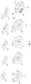
- FIG. 1shows an example of an additive manufacture process in which an implant is produced in layers from the anterior side ( 40 ) of the implant to the posterior side ( 50 ) of the implant.
- the top ( 10 ) and bottom ( 20 ) of the implantare bone-contacting surfaces.
- FIG. 2shows an example of an additive manufacture process in which an implant is produced in layers from the posterior side ( 50 ) of the implant to the anterior side ( 40 ) of the implant.
- the top ( 10 ) and bottom ( 20 ) of the implantare bone-contacting surfaces.
- FIG. 3shows an example of an additive manufacture process in which an implant is produced in layers from the bottom ( 20 ) of the implant to the top of the implant ( 10 ), which each are bone-contacting surfaces.
- the anterior ( 40 ) and posterior ( 50 ) sidesare also indicated.
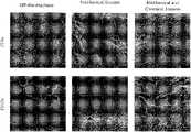
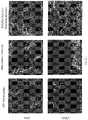
- FIG. 4shows electron micrographs of test disc surfaces, in which the discs were prepared by laser sintering are compared: Left-most column, laser sintering-assembled disc prepared by layering from the bottom to the top (horizontal build), followed by heat treatment; Left-center column, laser-sintering-assembled disc prepared by layering from the bottom to the top (horizontal build), without subsequent stress-relieving heat treatment; Right-center column, laser-sintering-assembled disc prepared by layering from the anterior to the posterior (vertical build), followed by stress-relieving heat treatment; Right-most column, laser-sintering-assembled disc prepared by layering from the anterior to the posterior (vertical build), without subsequent stress-relieving heat treatment.
- FIG. 5shows electron micrographs of test disc surfaces, in which the discs were prepared by Electron beam melting (EBM) are compared: Left-most column, EBM-assembled disc prepared by layering from the bottom to the top (horizontal build), followed by hot isostatic pressing (HIP); Left-center column, EBM-assembled disc prepared by layering from the bottom to the top (horizontal build), without subsequent HIP; Right-center column, EBM-assembled disc prepared by layering from the anterior to the posterior (vertical build), followed by HIP; Right-most column, EBM-assembled disc prepared by layering from the anterior to the posterior (vertical build), without subsequent HIP.
- EBMElectron beam melting
- FIG. 6shows electron micrographs of test disc surfaces, in which the discs were prepared by laser sintering, layering from the bottom to the top (horizontal build), followed by surface eroding, are compared.
- Top rowlaser sintering-assembled disc, horizontal build, followed by heat treatment, followed by surface eroding;
- Bottom rowlaser sintering-assembled disc, horizontal build, without heat treatment, followed by surface eroding.
- FIG. 7shows electron micrographs of test disc surfaces, in which the discs were prepared by laser sintering, layering from the anterior to the posterior (vertical build), followed by surface eroding, are compared.
- Top rowlaser sintering-assembled disc, vertical build, followed by heat treatment, followed by surface eroding;
- Bottom rowlaser sintering-assembled disc, vertical build, without heat treatment, followed by surface eroding.
- FIG. 8shows electron micrographs of test disc surfaces, in which the discs were prepared by EBM, layering from the bottom to the top (horizontal build), followed by surface eroding, are compared.
- Top rowEBM-assembled disc, horizontal build, followed by HIP, followed by surface eroding;
- Bottom rowEBM-assembled disc, horizontal build, without HIP, followed by surface eroding.
- FIG. 9shows electron micrographs of test disc surfaces, in which the discs were prepared by EBM, layering from the anterior to the posterior (vertical build), followed by surface eroding, are compared.
- Top rowEBM-assembled disc, vertical build, followed by HIP, followed by surface eroding;
- Bottom rowEBM-assembled disc, vertical build, without HIP, followed by surface eroding.
- FIG. 10graphically represents the total peak-to-valley of waviness of profile macro-, micro-, or nano-scale surface features and structure.
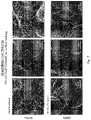
- FIG. 11shows how mechanical erosion and the combination of mechanical and chemical erosion can remove unsintered powder from the additive build.
- the figureshows SEM images of a surface of a sintered titanium alloy particles at 250 ⁇ magnification (top row) and at 1500 ⁇ magnification (bottom row).
- the left column imagesshow the magnified surface off the machine (as additively built) without any follow-up erosion processing.
- the center column imagesshow the magnified surface following mechanical erosion after the additive build.
- the right column imagesshow the magnified surface following sequential mechanical erosion and chemical erosion after the additive build.
- a “patient”may be any animal, including mammals such as companion animals, laboratory animals, and non-human primates. Human beings are preferred.
- “Vertically” additively building an orthopedic implantmeans that during the additive manufacture process, the build begins with a surface of the implant that does not contact bone such that the bone-contacting surfaces result from one or more of the edges of the additively-laid layers.
- the buildbegins with one of the sides of the implant, and the bone-contacting top and bottom arise as the layers are deposited.
- Vertical additive manufacturestands in contrast “horizontally” additively building an orthopedic implant.
- FIG. 1 and FIG. 2show an additive process in which the implant is produced in an anterior to posterior ( FIG. 1 ) or posterior to anterior ( FIG. 2 ) direction, whereby the bone-contacting surfaces ( 10 , 20 ) are the “sides” as the implant is additively manufactured, though the anterior ( 40 ) and posterior ( 50 ) surfaces are not bone-contacting surfaces.
- FIG. 3shows an additive process in which the implant is produced in a top to bottom direction, whereby the bone-contacting surfaces ( 10 , 20 ) are the bottom as the additive manufacture begins, and are also the top when the additive manufacture concludes, and the anterior ( 40 ) and posterior ( 50 ) surfaces, which are not bone-contacting surfaces, are the “sides” as the implant is additively manufactured.
- osteoinductionand “osteoinducting” refers to the induction or initiation of osteogenesis, and includes the recruitment of immature mesenchymal stem cells to a processed (e.g., mechanically and/or chemically eroded) bone-contacting surface and/or to a processed (e.g., mechanically and/or chemically eroded) free surface of an orthopedic implant, followed by the phenotype progression and differentiation of these stem cells to a preosteoblast and the further phenotype progression and differentiation of a preosteoblast to an osteoblast.
- a processede.g., mechanically and/or chemically eroded
- Ostogenesisincludes the formation and development of bone matrix.
- Implant surfaces produced additively, followed by subtractive processing (e.g., erosion)facilitate osteoinduction and, ultimately, support and facilitate integration of the implant with adjacent bone.
- subtractive processinge.g., erosion
- orthopedic implant surfaces produced in this waysupport greater mesenchymal stem cell differentiation and progression to a preosteoblast, and further differentiation and progression of a preosteoblast to an osteoblast. Such differentiation is characterized, for example, by greater production of growth factors associated with osteogenesis in vivo.
- Orthopedic implant surfaces produced by additive building followed by mechanical and/or chemical (e.g., acid) erosionare believed to support bone growth out from the surfaces, even in the absence of direct contact with bone or bone graft materials.
- the combination of additive manufacture and erosionin accordance with the inventive methods, produces macro-scale structural features, micro-scale structural features, and nano-scale structural features. It is believed that the macro-scale structural features facilitate and improve initial stability of the implant upon implantation, and that micro- and nano-scale structural features improve and facilitate the cellular and molecular response.
- additive manufacturingproduces a surface that, at the cellular level, does not induce a cellular and molecular response insofar as the structural features of the surface are too large in scale to be recognized by a cell sufficiently to induce the cell to activate, differentiate, or alter its phenotype. It is believed that this is due, in part, to the limitations in particle size and layer thickness.
- Erosion of the additively-produced surfaceswhich creates the micro- and nano-scale structural features, is believed to establish a microstructure that can be recognized by cells (e.g., mesenchymal stem cells, preosteoblasts, etc.) sufficient to activate a bone growth response. It is believed that this microstructure is influenced by build orientation (e.g., horizontal versus vertical building).
- cellse.g., mesenchymal stem cells, preosteoblasts, etc.
- implant manufacturecomprises the basic steps of producing the implant body through an additive manufacturing process, and then refining one or more surfaces of the implant body to produce a bone growth-stimulating surface topography comprising micro-scale structural features and nano-scale structural features.
- this surface topographyis irregular, including irregularities in the height, spacing, orientation, thickness, and other structural features between and among the micro-scale and/or nano-scale structures that make up the topography.
- implant fabricationbegins with engineering and designing the implant, including its geometry, dimensions, and structural features.
- the implantmay comprise, for example, a top surface, a bottom surface, at least one posterior side surface, at least one anterior side surface, and at least one lateral side surface.
- the implantmay comprise flat, round, regular, and/or irregular surfaces about these top, bottom, or side surfaces.
- the implantmay comprise any suitable shape, which shape may depend, for example, on the intended implantation location. In highly preferred aspects, the implant is intended for integration with the surrounding bone.
- Implant engineering and designmay be computer assisted.
- the implantmay comprise any implant that, when implanted, is in contact with at least one or is in between two or more bones, and which is intended to induce fusion or physical joining of the separate bones, or to facilitate rejoinder of broken bones.
- the implantmay be used to replace, repair, brace, or supplement any bone in the body.
- the implantmay comprise a long or short bone (or portion thereof) replacement, a skull or jaw bone replacement, an implant intended to induce fusion or physical joining of separate bones (e.g., finger joints, ankle joints, vertebrae, or spinal motion segment), an implant intended to fasten another implant to a bone (e.g., bone screws, pedicle screws, and fixation elements), an implant to facilitate rejoinder of broken bones, including bone screws, intramedullary nail, rods, and plates, etc., or any implant to replace, repair, brace, or supplement any bone in the body.
- the implantcomprises an implant for replacing an intervertebral disc, or for replacing a spinal motion segment.
- the implantmay comprise a joint implant, for example, an implant for the hip, knee, shoulder, elbow, ankle, wrist, jaw, etc.
- implant fabricationcomprises an additive manufacturing process.
- a form of 3-D printingmay be part of the additive manufacturing process.
- the processcomprises first additively building an orthopedic implant, e.g., the implant body having the desired basic shape, configuration, and structural orientation for the particular location within the body where the implant is to be implanted and for the particular corrective application intended for the implant, and then treating one or more surfaces of the implant, for example, with an erosion process.
- the erosionmay comprise mechanical erosion, chemical erosion, or a combination of mechanical and chemical erosion.
- the implant surfaces treated with such erosioncomprise a bone growth-enhancing bioactive surface topography comprising micro-scale structural features and nano-scale structural features.
- the implantsmay be prepared from any suitable material, including a metal, a polymer, a ceramic, bone, or any combination or composite thereof.
- Metal implantsmay comprise an alloy.
- Preferred metalsinclude titanium and titanium alloys such as nitinol, aluminum and vanadium (e.g., 6-4) alloys of titanium, cobalt chromium alloys, as well as surgical grade steel.
- Preferred polymeric materialsinclude polyetherether ketone (PEEK) and ultra-high molecular weight polyethylene (UHMWPE). Composites of metal and polymeric materials are also preferred in some aspects. Thus, the additive process may be used to fabricate implants comprised of such materials. Metal implants are highly preferred.
- Additive processesmay comprise successively layering by depositing solid material onto a substrate, then sintering or melting the deposited solid material into a layer of the implant, then depositing more solid material onto the previous layer, then sintering or melting the newly deposited layer to both fuse with the previous layer and establish the next layer, and repeating these steps until the implant is completed.
- the solid materialpreferably comprises a bulk material in the form of a wire, powder, particles, granules, fragments, or combinations thereof, which is/are sintered or melted by an energy source.
- the powder, particles, granules, fragments, or combinations thereofpreferably are substantially spherical in shape. It is preferred that the powder, particles, granules, fragments, or combinations thereof do not comprise irregular shapes or edges, or jagged edges.
- the spheresmay comprise different sizes, or may be substantially the same size.
- the additive processmay comprise sintering and/or melting of the powder, particles, granules, wires, fragments, or combinations thereof.
- the processpreferably achieves substantially complete melting of the powder, particles, granules, fragments, or combinations thereof such that the layer being deposited is comprised of substantially fully molten material, the material preferably being metal.
- Suitable additive processesinclude, without limitation, selective laser sintering, including, for example, direct metal laser sintering (DMLS) (DMLS® is a service mark of EOS GmbH), selective laser melting, including, for example, laserCUSINGTM (Concept Laser Schutzrechtsrios GmbH), electron beam melting (EBM), fused deposition modeling (FDM), direct metal deposition, laser Engineered Net Shaping (LENS), and wire-based directed energy deposition.
- DMLSdirect metal laser sintering
- selective laser meltingincluding, for example, laserCUSINGTM (Concept Laser SchutzrechtsSDs GmbH), electron beam melting (EBM), fused deposition modeling (FDM), direct metal deposition, laser Engineered Net Shaping (LENS), and wire-based directed energy deposition.
- the energy sourcemay comprise a laser or an electron beam, although any suitable technique for melting the material may be used.
- Deposition and/or sintering or meltingpreferably takes place in an inert environment, for example, with low oxygen and/or in the presence of nitrogen and/or argon.
- a preceding layerhas not substantially solidified prior to the successive layer being deposited thereon.
- a preceding layerhas at least partially solidified prior to the successive layer being deposited thereon.
- the additive buildingcomprises vertically additively building (e.g., from the anterior to the posterior, from the posterior to the anterior, or from one lateral side to the other lateral side) the orthopedic implant.
- the additive buildingcomprises horizontally additively building (e.g., from the top to the bottom or the bottom to the top) the orthopedic implant. Illustration of an example of an anterior to posterior vertical build is shown in FIG. 1 , illustration of a posterior to anterior vertical build is shown in FIG. 2 . Illustration of an example of a bottom to top horizontal build is shown in FIG. 3 . Layers may first be deposited onto a build plate or a support material, the latter which may include a plurality of the first deposited layers.
- the first deposited layer after a support materialconstitutes a non-bone-contacting surface such as the anterior face or posterior face of the implant.
- a non-bone-contacting surfacesuch as the anterior face or posterior face of the implant.
- Successive layersare deposited, then sintered or melted, through the middle of the implant, and until the opposing face (posterior or anterior face) is completed.
- Bone-contacting surfacesarise from the edges of the layers laid in a vertical build scheme. Bone-contacting surfaces arise from the layers themselves in a horizontal build scheme.
- the orthopedic implantsmay comprise one or more apertures into and/or through one or more of the top, bottom, sides, or other surfaces.
- the aperturesthus may be surrounded by internal surfaces of the implant, of any desired shape or geometry.
- the internal surfacesmay comprise lattice structures. Internal surfaces may be placed in contact with a bone graft material upon implantation within the body.
- the additive processmay be used to impart at least macro-scale structural features on surfaces of the implant.
- the macro-scale featuresmay be created via the additive manufacturing, and may be part of the initial design.
- the implant bodymay be subject to stress-relieving processing, including a reheat of the formed implant body. Stress relief may be carried out under vacuum and/or an inert gas. The heating may be followed by a cooling step. In some aspects, the reheat may also be accompanied by pressure. The pressure may be either uniaxial (e.g., applied from one direction) or isostatic (e.g., applied evenly from all directions). Hot isostatic pressing (HIP) is highly preferred.
- HIPis conducted by placing the implant body in a sealed container which can be heated and pressure controlled by adding and removing gases.
- a sealed containerwhich can be heated and pressure controlled by adding and removing gases.
- the containeris evacuated to remove any contaminating gasses.
- the containeris then heated while introduce an inert gas (for example, Argon) into the chamber to increase the pressure.
- the containeris then held at the elevated temperature and pressure for a period of time, after which the container is rapidly cooled and depressurized.
- Hot isostatic pressingis conducted at a temperature below the melting point of the material from which the implant body is made, but at a sufficiently high temperature.
- the temperatureis typically less than 80% of the melting temperature.
- HIPmay proceed according to standard conditions, such as ASTM Standard Specification F3001.
- HIPresults in changes to the implant body.
- the combination of temperature and pressureresults in the collapse of any inclusions present within the implant body.
- the density of the implant bodymay be substantially near or equal to 100% following HIP, meaning that the implant may be substantially free of inclusion bodies (internal pores). Removing inter-layer boundaries and removing inclusions improves the mechanical strength of the implant body and reduces the likelihood of failure once implanted.
- HIPmay increase at least the grain size, particularly when coupled to an electron beam melting additive build. HIP may change the grain structure and changes the intergranular boundaries on the implant surfaces.
- the additive processis preferably coupled to a refining process that imparts and/or enhances the micro-scale structures and the nano-structures on external and internal surfaces of the implant.
- the combination of the additive and refining processesestablishes the desired balance of macro-structures, micro-structures, and nano-structures on desired surfaces of the implant for facilitating bone in-growth, bone out-growth, osteoinduction, and osseointegration.
- the refining processfollows completion of the implant production by the additive process.
- the refining processmay include, for example, a form of a subtractive process that may include erosion, for example, mechanical eroding, chemical eroding, and/or electrochemical eroding of implant surfaces.
- Mechanical erodingincludes, but is not limited to, exposure of select surfaces or the entire implant to photo eroding, energy bombardment, abrasive blasting, plasma eroding, laser eroding, machining, drilling, grinding, peening, abrasive blasting (e.g., sand or grit blasting), or any combinations of such processes.
- Chemical erodingmay include, for example, exposure of select surfaces or the entire implant to a chemical such as an acid or base, with the acid or base eroding the metal surfaces that come in contact with the acid or base.
- the refining processpreferably does not impart pores into the surface of the implant, but preferably imparts micro-scale structures and nano-scale structures into one or more desired surfaces of the implant, including one or more internal surfaces. These desired surfaces (e.g., those receiving the refining process treatments) typically will be those that contact bone or a bone graft material when the implant is implanted in the body.
- the subtractive refinement processincludes mechanical eroding, but not chemical eroding, of one or more additively produced surfaces of the implant. In some aspects, the subtractive refinement process includes chemical eroding, but not mechanical eroding, of one or more additively produced surfaces of the implant. In preferred aspects, the subtractive refinement process includes two subparts—mechanical eroding and chemical eroding. The chemical eroding preferably follows the mechanical eroding. The subtractive refinement process imparts micro-scale structures and nano-scale structures into refined surfaces.
- Mechanical erodingmay include particle blasting, for example, using an organic or inorganic eroding media.
- the mediapreferably are dissolvable, for example, in an aqueous or acidic medium.
- the surfacesmay be mechanically eroded by tumble finishing (e.g., tumbling the implant in the presence of such media). The tumbling process may be wet (e.g., with a lubricant) or dry.
- Mechanical erodingpreferably imparts micro-scale structural features in eroded surfaces.
- Chemical erodingis a preferred subtractive refinement process.
- Acid erodingcomprises one preferred chemical eroding process.
- Base erodingcomprises another preferred chemical eroding process. It is believed that the acids and bases erode the grain structures and grain boundaries in a way that enhances the bioactivity (e.g., bone growth-promoting properties) of the implant surface.
- chemical erodingproduces nano-scale structural features into the chemically eroded surfaces of the implant. Chemical erosion also can impart micro-scale structural features into the surfaces. Chemical eroding may be done on the mechanically eroded surfaces, such that the chemical-eroded nano-scale structures may overlap with the mechanical-eroded micro-scale structures.
- one or more surfaces of the implantmay be masked to protect those surfaces from the chemical or acid, and exposed, unmasked surfaces that remain can then be eroded.
- the chemical erodingpreferably follows a mechanical eroding step, although in some aspects, only chemical eroding of the implant surfaces is used (no mechanical eroding step is employed).
- the chemical eroding processmay repeated a number of times as necessitated by the amount and nature of the irregularities required for any particular application, or by the desired pattern and erode depth to be produced. Control of the strength of the acid or base, the temperature at which the eroding process takes place, and the time allotted for the eroding process allow fine control over the resulting surface produced by the process.
- the number of repetitions of the eroding processcan also be used to control the surface features.
- Chemical erodingis preferably accomplished by immersing the implant into the acid solution or in a base solution, but immersion is not required such that the surfaces to be chemically eroded can be brought in contact with the acid or base according to any suitable process.
- the maskmay be removed and the part may be cleaned.
- the surfacemay also be passivated, for example, using an aqueous solution comprising nitric acid.
- the surfacemay be cleaned and rinsed with water.
- the implantmay be washed in an aqueous environment under agitation and heat with or without a detergent. Following washing, the implant may be dried, for example with hot air, heating in a dry oven, or both
- Chemical eroding alone of the titanium implant surfacehas the potential to greatly enhance osseointegration without adding particulate matter (e.g., hydroxyapatite) or embedding surface contaminants (e.g., grit particles).
- particulate mattere.g., hydroxyapatite
- embedding surface contaminantse.g., grit particles
- the refining processing stepscan be adjusted to create a mixture of depths, diameters, feature sizes, and other geometries suitable for a particular implant application.
- the orientation of the pattern of featurescan also be adjusted. Such flexibility may be desired, for example, in aspects where the surface structural features should be oriented in opposition to the biologic forces that may be applied against the implant upon implantation, and to the insertion direction.
- Mechanical erodingin addition to imparting micro-scale structural features, may also remove or reduce debris from the implant surfaces.
- Acid eroding, in addition to imparting nano-scale structural features into implant surfaces,may also remove or reduce debris from the implant surfaces.
- Debrismay include external debris such as dirt or other artifacts of handling. External debris may also include particles or components of the media from the mechanical eroding/blasting step, which particles may have become lodged into the implant surface.
- Debrismay also include intrinsic debris, such as artifacts of the additive build process, for example, powder, particles, granules, etc. that were not completely melted or completely sintered during the additive building.
- FIG. 11shows electron micrographs of a titanium surface created from additive building, with the images in the left column (at two different magnifications) illustrating that some particles have not fully integrated from the additive build.
- the erosion processthus may be used to remove unsintered/unmelted or incompletely sintered or melted particles from the surfaces, thereby reducing the risk of particle dislodgement.
- mechanical erosioncan significantly reduce the amount of un-integrated or partially integrated particles from the surface of the additively built structure.
- addition of chemical erosioncan further reduce the amount of un-integrated or partially integrated particles from the surface of the additively built structure.
- the subtractive refining processproduces micro-scale structural features and nano-scale structural features. These features preferably overlap with macro-scale structural features that are produced from the additive building process.
- Macro structural featuresinclude relatively large dimensions, for example, dimensions measured in millimeters (mm) or microns ( ⁇ m).
- Micro structural featuresinclude dimensions that are measured in microns ( ⁇ m).
- Nano structural featuresinclude dimensions that are measured in nanometers (nm) or microns ( ⁇ m). Patterns of macro structural features, micro structural features, and/or nano structural features may be organized in regular and/or repeating patterns and optionally may overlap each other, or such features may be in irregular or random patterns, or repeating irregular patterns.
- the topography of implant surfaces prepared by additive building, followed by mechanical and/or chemical erodingpreferably is roughened, preferably irregular, and comprises macro scale structural features, micro scale structural features, and nano scale structural features, and is also distinct from super-macro scale structural features such as teeth, spikes, grooves, and ridges, and other bone-gripping super-macro scale structures that are typically present on the surface of bone-contacting implants, the latter of which are intended to dig into or score bone.
- the surface topography produced according to the inventive methodspreferably does not damage or score bone, though it may support a friction-type grip of bone surfaces. This surface topography preferably also facilitates and/or enhances osteoinduction and bone growth, and may also facilitate osseointegration of the implant.
- the surface topographymay be considered bioactive, and induces and/or supports and/or enhances mesenchymal stem cell differentiation and progression, preosteoblast differentiation and progression, and/or osteoblast differentiation and progression. Such differentiation and progression may be characterized by a greater amount or a greater rate of the production growth factors associated with osteoinduction or osteogenesis, for example, following implantation into the body.
- Differentiation markersinclude, without limitation, enhanced expression of various forms of bone morphogenic protein and integrin on the cell surface, as well as enhanced expression and/or secretion of growth factors such as osteocalcin (OCN), osterix (OSX), osteoprotegerin, VEGF, and FGF, as well as enhanced expression and/or secretion of alkaline phosphatase (ALP).
- the mature osteoblast stateis characterized by a decrease in ALP, and once the osteoblast differentiates to an osteocyte the expression of both OSX and OCN is decreased as well (Baek W-Y, et al. (2009) J. Bone Miner. Res. 24:1055-65; Zhang C. (2010) J. Orthopaedic Surg. and Res. 5:1; and Tu Q, et al. (2007) Tissue Eng'g. 1:2431-40).
- both ALP and OCNare present during fracture healing. In these evaluations both ALP and OCN production is highest in healing bone fractures at 8 weeks post fracture (Leung K S et al. (1993) Bone & Joint Journal.
- ALP and OCNhave been used for in vitro evaluation of the potential for a synthetic material to promote bone formation in vivo. It has been further demonstrated that increased ALP and OCN in vitro associate with synthetic graft success in vivo (Borden M, et al. (2002) J. Biomed. Mater. Res. 61:421-9; Borden M, et al. (2002) Biomaterials. 23:551-9; and Borden M et al. (2004) J. Bone Joint Surg. Br. 86:1200-8).
- the surfacesultimately facilitate osseointegration (e.g., formation of a direct structural and functional interface between the artificial implant and living bone or soft tissue) with the surrounding living bone.
- the surfaces produced according to the inventionare believed to support new bone growth in the absence of direct contact with bone or a bone graft material, though the surfaces also support new bone growth when placed in direct contact with bone or a bone graft material.
- new bone growthmay initiate on the surfaces of implants produced according to the invention, as distinct from growth of bone from surrounding tissue of the body into the implant surfaces.
- implant fixationmay depend, at least in part, on the stimulation and proliferation of bone modeling and forming cells, such as osteoclasts and osteoblasts and like-functioning cells upon the implant surface.
- microscopically rough surfacese.g., those having micro-scale and nano-scale structural features
- smooth surfacesincluding surfaces with macro-scale structural features that are too large to be recognized by cells.
- a surfacemay be bioactive due to its ability to stimulate cellular attachment and bone growth.
- the refined surfacesare composed of various sizes of features that, at the microscopic level, interact with the tissues and stimulate their natural remodeling and growth.
- implant surface structuresperform the function of generating non-stressful friction with tissue in the body (e.g., with adjacent bone) that, when combined with a surgical technique that retains the most rigid cortical bone structures in the disc space, allow for a friction fit that does not abrade, chip, perforate, or compromise the bone surface.
- micro-scale and nano-scale structural features of the implant surfacese.g., external and internal surfaces.
- Mechanical erodingis believed to primarily form or enhance the micro-scale structural features.
- Chemical erodingis believed to primarily form or enhance the nano-scale structural features, but can also form or enhance the micro-scale structural features.
- Macro-scale structure-forming mechanical and/or acid erodingmay be used in addition to the additive manufacture process that produces macro-scale features or, in some aspects, may be used instead of additive manufacturing.
- the additive manufacturingmay produce substantially featureless surfaces, with mechanical and/or chemical eroding then applied to such surfaces to produce all three of the macro-scale, micro-scale, and nano-scale structures on the surfaces.
- Each of the macro-scale structures, the micro-scale structures, and the nano-scale structuresboth individually and in combination and in sub-combination establish a roughness on the implant surface.
- the roughnessmay be measured according to one or more of the roughness parameters established by the International Organization for Standardization (ISO), e.g., ISO 468:1982. Several separate parameters can be used to characterize the surface roughness.
- ISOInternational Organization for Standardization
- Such parametersinclude, but are not limited to, Rp (max height profile), Rv (max profile valley depth), Rz (max height of the profile), Rc (mean height of the profile), Rt (total height of the profile), Ra (arithmetic mean deviation of the profile), Rq (root mean square deviation of the profile), Rsk (skewness of the profile), Rku (kurtosis of the profile), RSm (mean width of the profile), R ⁇ q (Root mean square slope of the profile), Rmr (material ratio of the profile), R ⁇ c (profile section height difference), Ip (sampling length ⁇ primary profile), Iw (sampling length ⁇ waviness profile), Ir (sampling length ⁇ roughness profile), In (evaluation length), Z(x) (ordinate value), dZ/dX (local slope), Zp (profile peak height), Zv (profile valley depth), Zt (profile element height), Xs (profile element width), and MI (material length of profile).
- Rsasurface area increase
- Rpcpeak counts
- HSedish height
- ISO flatnessareal flatness deviation
- Pt ISOpeak-to-valley profile height
- Rtmmean peak-to-valley roughness
- Rvlowest value
- Rvmmean valley profile depth
- Rymaximum peak-to-valley roughness
- Rpmmean peak areal height
- Saverage spacing between local peaks
- SMaverage spacing between peaks at the mean line
- Racomprises an arithmetic average height.
- Ramay be computed as the average distance between each roughness profile point and the mean line.
- the average peak-to-valley roughness, Rzis defined by the ISO and ASME 1995 and later. Rz is based on one peak and one valley per sampling length. The RzDIN value is based on the determination of the peak-to-valley distance in each sampling length. These individual peak-to-valley distances are averaged, resulting in the RzDIN value.
- the maximum peak-to-valley height, Rmaxcomprises the maximum peak-to-valley distance in a single sampling.
- Total Peak-to-Valley of Waviness Profile WtThe total peak-to-valley of waviness profile (over the entire assessment length) is illustrated in FIG. 10 .
- the mean spacing, Smcomprises the average spacing between positive mean line crossings. The distance between each positive (upward) mean line crossing is determined and the average value is calculated.
- the micro peak-to-valley height, Rmaxis from about 1 to about 200 micrometers. In some aspects, the micro peak-to-valley height is less than 100 micrometers and greater than 1 micrometer, less than about 95 micrometers and greater than 1 micrometer, less than about 90 micrometers and greater than 1 micrometer, or less than about 80 micrometers and greater than 1 micrometer. In some aspects, the micro peak-to-valley height is from about 5 to about 25 micrometers, from about 6 to about 16 micrometers, from about 10 to about 125 micrometers, from about 10 to about 100 micrometers, from about 10 to about 90 micrometers, from about 10 to about 150 micrometers.
- the micro mean peak-to valley heightis from about 1 to about 150 micrometers, from about 1 to about 100 micrometers, from about 1 to about 125 micrometers, from about 1 to about 95 micrometers, from about 1 to about 90 micrometers, from about 1 to about 80 micrometers, from about 1 to about 70 micrometers, from about 1 to about 50 micrometers, from about 1 to about 25 micrometers, from about 2 to about 100 micrometers, from about 2 to about 90 micrometers, from about 2 to about 80 micrometers, from about 2 to about 25 micrometers, from about 3 to about 40 micrometers, from about 3 to about 30 micrometers, from about 4 to about 120 micrometers, from about 4 to about 40 micrometers, from about 4 to about 30 micrometers, from about 5 to about 40 micrometers, from about 5 to about 30 micrometers, from about 7 to about 20 micrometers, from about 7 to about 15 micrometers, from about 8 to about 14 micrometers, or from about 9 to about 13 micrometers.
- micro-scale structural featuresmay comprise a skewness of from about ⁇ 2 to about 2, from about ⁇ 2 to about 1.5, from about ⁇ 2 to about 1, from about 2 to about ⁇ 1, from about ⁇ 2 to about 0, or from about 0 to about 2.
- the micro-scale skewnessis from about ⁇ 1.5 to about 1.5, from about ⁇ 1.5 to about 1, from about ⁇ 1.5 to about 0, from about ⁇ 1 to about 1.5, from about ⁇ 1 to about 1, from about ⁇ 1 to about 0, from about from about ⁇ 0.5 to about 2, from about ⁇ 0.5 to about 1.5, from about ⁇ 0.5 to about 1, from about ⁇ 0.5 to about 0.5, from about ⁇ 0.4 to about 0.4, from about ⁇ 0.4 to about 0, from about 0 to about 0.4, from about ⁇ 0.3 to about 0.3, from about ⁇ 0.3 to about 0, from about 0 to about 0.3, from about ⁇ 0.25 to about 0.25, from about ⁇ 0.25 to about 0, from about 0 to about 0.25, from about ⁇ 0.2 to about 0.2, from about ⁇ 0.2 to about 0, from about 0 to about 0.2, from about ⁇ 0.15 to about 0.15, from about ⁇ 0.15 to about 0, from about 0 to about 0.15, from about ⁇ 0.1 to about 0.1, from about ⁇ 0.1 to about 0.1
- the micro-scale structural featuresmay comprise a kurtosis of from about 1 to about 9.
- the micro-scale kurtosismay be from about 1 to about 8.5, from about 1 to about 8, from about 1 to about 7.5, from about 1 to about 7, from about 1 to about 6.5, from about 1 to about 6, from about 1 to about 5.5, from about 1 to about 5, from about 1 to about 4.5, from about 1 to about 4, from about 1 to about 3.5, from about 1 to about 3, from about 1 to about 2.5, from about 1 to about 2, from about 2 to about 5, from about 2 to about 4.5, from about 2 to about 4, from about 2 to about 3.5, from about 3 to about 5, from about 3 to about 4.5, from about 3 to about 4, from about 2.5 to about 4.5, from about 2.5 to about 4.4, from about 2.5 to about 4.2, from about 2.5 to about 4, from about 2 to about 4.4, from about 2 to about 4.3, from about 2 to about 4.2, from about 2 to about 4.1, from about 2 to about 3.9, from about 2 to
- the nano peak-to-valley height, Rmaxis from about 0.001 to about 20 micrometers. In some aspects, the nano peak-to-valley height, Rmax, is from about 0.001 to about 10 micrometers. In some aspects, the nano peak-to-valley height, Rmax, is from about 0.001 to about 50 micrometers, from about 0.001 to about 20 micrometers, from about 0.001 to about 10 micrometers, from about 0.001 to about 5 micrometers, from about 0.001 to about 3 micrometers, from about 0.001 to about 2 micrometers, or from about 0.001 to about 1 micrometers.
- the nano peak-to-valley heightis from about 0.5 to about 1.5 micrometers, or from about 0.8 to about 1.4 micrometers.
- the nano peak-to valley heightis from about 0.01 to about 20 micrometers, from about 0.01 to about 10 micrometers, from about 0.01 to about 5 micrometers, from about 0.05 to about 25 micrometers, from about 0.05 to about 10 micrometers, from about 0.05 to about 5 micrometers, from about 0.1 to about 10 micrometers, from about 0.1 to about 5 micrometers, from about 0.1 to about 1.5 micrometers, from about 0.001 to about 0.5 micrometers, from about 0.005 to about 5 micrometers, from about 0.005 to about 20 micrometers, from about 0.005 to about 2.5 micrometers, from about 0.006 to about 1.6 micrometers, from about 0.007 to about 1.5 micrometers, from about 0.009 to about 1.3 micrometers, from about 0.02 to about 10 micrometers, from about 1 to about 15 micrometer
- the nano peak-to-valley height, Rmaxis from about 0.001 to about 0.6 micrometers, from about 0.001 to about 0.5 micrometers, from about 0.001 to about 0.4 micrometers, from about 0.001 to about 0.3 micrometers, from about 0.001 to about 0.2 micrometers, from about 0.001 to about 0.1 micrometers, from about 0.001 to about 0.09 micrometers, from about 0.001 to about 0.08 micrometers, from about 0.001 to about 0.07 micrometers, from about 0.001 to about 0.06 micrometers, from about 0.001 to about 0.05 micrometers, from about 0.001 to about 0.04 micrometers, from about 0.001 to about 0.03 micrometers, or from about 0.001 to about 0.02 micrometers.
- test discs of a titanium alloy including 6% aluminum and 4% vanadiumwere fabricated using either laser sintering or electron beam melting (EBM) by either layering from the bottom surface to the top surface (horizontal) or by layering from the anterior surface to the posterior surface (vertical).
- EBMelectron beam melting
- the titanium alloy particleswere deposited, first onto a platform surface of the additive manufacturing device, and then successively onto melt-assembly of each layer. The particles were melted together by laser sintering or EBM. Accordingly, the top surface of a test disc fabricated in a horizontal build direction is parallel to the deposited layers, and the top surface of a test disc fabricated in a vertical build direction is perpendicular to the deposited layers.
- test discswere divided into two groups. The first group was further subject to heat treatment and the second group was not.
- the test discswere heat treated according to ASTM F3001.
- test discswere then subject to surface refinement by blasting and eroding.
- the blasted surfaceswere immersed in an acid solution. After acid eroding, the discs were immersed in water to quench the eroding reaction.
- the refined surfacewas then inspected by scanning electron beam microscopy, scans of which are included as FIGS. 4-9 .
- FIGS. 4-5includes electron micrographs of test discs prior to surface refinement.
- FIG. 4compares discs produced by laser sintering in both horizontal and vertical build directions, as well as the effect of heat treatment prior to surface refinement.
- FIG. 5compares discs produced by EBM in both horizontal and vertical build directions, as well as the effect of heat treatment prior to surface refinement.
- Each of FIGS. 4 and 5includes a grid of twelve electron micrographs. In each figure, the top row includes micrographs taken with 250 ⁇ magnification, the middle row includes micrographs taken with 1500 ⁇ magnification, and the bottom row includes micrographs taken with 6500 ⁇ magnification.
- Each rowincludes, from left to right, (1) a horizontally built disc subject to heat treatment, (2) a horizontally built disc not subject to heat treatment, (3) a vertically built disc subject to heat treatment, and (4) a vertically built disc not subject to heat treatment.
- micro scale structuresfeatures generally sized from 1 ⁇ m to 100 ⁇ m
- essentially no nano scale structuresfeatures generally sized from 1 to 100 nm
- the test discs produced by EBMare rough on a macro (include macro scale features generally sized greater than 100 ⁇ m) and micro scale, the test discs produced by laser sintering are smooth even at a macro and micro scale, each in the absence of secondary processing. It is believed that the micro scale of the EBM discs is a result of the layers and partially sintered powder.
- FIGS. 6-9include electron micrographs of test discs following surface refinement.
- FIG. 6compares the effect of heat treatment on discs produced by laser sintering in a horizontal build direction.
- FIG. 7compares the effect of heat treatment on discs produced by laser sintering in a vertical build direction.
- FIG. 8compares the effect of heat treatment on discs produced by EBM in a horizontal build direction.
- FIG. 9compares the effect of heat treatment on discs produced by EBM in a vertical build direction.
- Each of FIGS. 6-9includes a grid of six electron micrographs. Each micrograph is taken with a magnification of 6500 ⁇ .
- the top row of each of FIGS. 6-9includes electron micrographs of test discs which were subject to heat treatment.
- the bottom row of each of FIGS. 6-9includes electron micrographs of test discs which were not subject to heat treatment.
- the density of micro-scale and nano-scale structuresis increased by heat treating the test disc after additive fabrication but before surface refinement. Without being bound to any particular theory, it is believed that the heat treatment enhances the surface of the test disc and makes the surface of the test disc more receptive to the surface refining by changing the grain structures on the surface of the test disc.
- the density of micro-scale and nano-scale structuresis increased by building the test disc in a vertical rather than horizontal orientation. Without being bound to any particular theory, it is believed that building the test disc in a vertical direction aligns the metal grains in a direction which results in a greater number of grain boundaries being present on the top surface of the test disc. Accordingly, the eroding processes are able to affect a greater area of the surface and produce a greater density of micro-scale and nano-scale structures.
Landscapes
- Engineering & Computer Science (AREA)
- Chemical & Material Sciences (AREA)
- Manufacturing & Machinery (AREA)
- Health & Medical Sciences (AREA)
- Materials Engineering (AREA)
- Mechanical Engineering (AREA)
- General Health & Medical Sciences (AREA)
- Veterinary Medicine (AREA)
- Dermatology (AREA)
- Medicinal Chemistry (AREA)
- Oral & Maxillofacial Surgery (AREA)
- Transplantation (AREA)
- Epidemiology (AREA)
- Life Sciences & Earth Sciences (AREA)
- Animal Behavior & Ethology (AREA)
- Inorganic Chemistry (AREA)
- Public Health (AREA)
- Metallurgy (AREA)
- Organic Chemistry (AREA)
- Physics & Mathematics (AREA)
- Plasma & Fusion (AREA)
- Prostheses (AREA)
- Materials For Medical Uses (AREA)
Abstract
Description
| TABLE 1 |
| Density of Micro Scale and Nano Scale Features |
| Build | Build | Heat | Micro Scale | Nano Scale |
| Method | Direction | Treatment | Structures | Structures |
| laser sintering | Horizontal | Yes | ++ | + |
| laser sintering | Horizontal | No | + | − |
| laser sintering | Vertical | Yes | +++ | +++ |
| laser sintering | Vertical | No | ++ | + |
| EBM | Horizontal | Yes | ++ | + |
| EBM | Horizontal | No | ++ | + |
| EBM | Vertical | Yes | +++ | +++ |
| EBM | Vertical | No | ++ | + |
| − = no or minimal additional structures, | ||||
| + = low density of additional structures, | ||||
| ++ = moderate density of additional structures, but less than the desired amount, | ||||
| +++ = high density of additional structures | ||||
Claims (20)
Priority Applications (1)
| Application Number | Priority Date | Filing Date | Title |
|---|---|---|---|
| US15/777,345US11370025B2 (en) | 2015-11-20 | 2016-11-21 | Processes for additively manufacturing orthopedic implants followed by eroding |
Applications Claiming Priority (3)
| Application Number | Priority Date | Filing Date | Title |
|---|---|---|---|
| US201562258239P | 2015-11-20 | 2015-11-20 | |
| PCT/US2016/062999WO2017087927A1 (en) | 2015-11-20 | 2016-11-21 | Processes for additively manufacturing orthopedic implants |
| US15/777,345US11370025B2 (en) | 2015-11-20 | 2016-11-21 | Processes for additively manufacturing orthopedic implants followed by eroding |
Publications (2)
| Publication Number | Publication Date |
|---|---|
| US20180333782A1 US20180333782A1 (en) | 2018-11-22 |
| US11370025B2true US11370025B2 (en) | 2022-06-28 |
Family
ID=57544527
Family Applications (1)
| Application Number | Title | Priority Date | Filing Date |
|---|---|---|---|
| US15/777,345ActiveUS11370025B2 (en) | 2015-11-20 | 2016-11-21 | Processes for additively manufacturing orthopedic implants followed by eroding |
Country Status (9)
| Country | Link |
|---|---|
| US (1) | US11370025B2 (en) |
| EP (1) | EP3377123B1 (en) |
| JP (1) | JP2018535811A (en) |
| CN (1) | CN108472407A (en) |
| AU (1) | AU2016355577B2 (en) |
| CA (1) | CA3005757A1 (en) |
| TW (1) | TWI726940B (en) |
| WO (1) | WO2017087927A1 (en) |
| ZA (1) | ZA201804093B (en) |
Cited By (2)
| Publication number | Priority date | Publication date | Assignee | Title |
|---|---|---|---|---|
| US20220355375A1 (en)* | 2015-11-20 | 2022-11-10 | Titan Spine, Inc. | Processes for additively manufacturing orthopedic implants |
| US11712339B2 (en) | 2016-08-03 | 2023-08-01 | Titan Spine, Inc. | Titanium implant surfaces free from alpha case and with enhanced osteoinduction |
Families Citing this family (12)
| Publication number | Priority date | Publication date | Assignee | Title |
|---|---|---|---|---|
| US10687956B2 (en) | 2014-06-17 | 2020-06-23 | Titan Spine, Inc. | Corpectomy implants with roughened bioactive lateral surfaces |
| TWI726940B (en) | 2015-11-20 | 2021-05-11 | 美商泰坦脊柱股份有限公司 | Processes for additively manufacturing orthopedic implants |
| DE102018000814A1 (en) | 2018-02-01 | 2019-08-01 | Harald Eckstein | Apparatus for treating and method of use |
| FR3081375B1 (en)* | 2018-05-25 | 2021-12-24 | Addup | METHOD FOR PREPARING THE UPPER SURFACE OF AN ADDITIVE MANUFACTURING TRAY BY POWDER BED DEPOSIT |
| CN109675097A (en)* | 2019-02-22 | 2019-04-26 | 梁品东 | Planting body Nanoscale Surface preparation method |
| DE102019104827B4 (en)* | 2019-02-26 | 2020-12-17 | Acandis Gmbh | Intravascular functional element, system with one functional element and method |
| US11213403B2 (en) | 2019-03-14 | 2022-01-04 | Medos International Sarl | Devices and methods for optimized spinal fixation |
| US12220863B2 (en)* | 2019-04-11 | 2025-02-11 | Smith & Nephew, Inc. | Medical devices and methods for forming medical devices containing a build plate |
| CN112276109B (en)* | 2020-09-10 | 2021-12-17 | 华中科技大学 | Forming method and product of polyetheretherketone biophilic metal porous bone implant |
| JP7635579B2 (en)* | 2021-02-26 | 2025-02-26 | 新東工業株式会社 | Surface treatment method and surface treatment system |
| CN113634765A (en)* | 2021-08-06 | 2021-11-12 | 北京航空航天大学 | Medical titanium alloy implant manufactured by additive manufacturing and surface impact strengthening method |
| JP7404566B1 (en) | 2023-01-06 | 2023-12-25 | 株式会社スギノマシン | Surgical implant surface treatment method and surgical implant |
Citations (206)
| Publication number | Priority date | Publication date | Assignee | Title |
|---|---|---|---|---|
| US3650861A (en) | 1965-07-01 | 1972-03-21 | Imp Metal Ind Kynoch Ltd | Surface treatment of titanium |
| US3891456A (en) | 1973-10-17 | 1975-06-24 | Us Air Force | Surface treatment of titanium and titanium alloys |
| US3933961A (en) | 1974-12-13 | 1976-01-20 | Pennwalt Corporation | Tabletting spherical dental amalgam alloy |
| US4116755A (en) | 1977-09-06 | 1978-09-26 | Mcdonnell Douglas Corporation | Chem-milling of titanium and refractory metals |
| US4314876A (en) | 1980-03-17 | 1982-02-09 | The Diversey Corporation | Titanium etching solution |
| US4414039A (en) | 1981-08-21 | 1983-11-08 | Motoren-Und Turbinen-Union Munchen Gmbh | Method of activating titanium surfaces |
| US4540465A (en) | 1984-06-11 | 1985-09-10 | Mcdonnell Douglas Corporation | Process for continuous recovery of nitric acid/hydrofluoric acid titanium etchant |
| US4588480A (en) | 1983-06-11 | 1986-05-13 | Mtu Motoren-Und Turbinen-Union Munchen Gmbh | Method of producing wear-protection layers on surfaces of structural parts of titanium or titanium-base alloys |
| US4634603A (en) | 1985-04-22 | 1987-01-06 | United Technologies Corporation | Method of abrasive cleaning and spray coating |
| US4644942A (en) | 1981-07-27 | 1987-02-24 | Battelle Development Corporation | Production of porous coating on a prosthesis |
| US4673409A (en) | 1984-04-25 | 1987-06-16 | Minnesota Mining And Manufacturing Company | Implant with attachment surface |
| US4803098A (en) | 1985-11-19 | 1989-02-07 | Commissariat A L'energie Atomique | Process for the preparation of the surface of a uranium and titanium alloy member, particularly with a view to chemical nickel plating |
| US4818559A (en) | 1985-08-08 | 1989-04-04 | Sumitomo Chemical Company, Limited | Method for producing endosseous implants |
| US4818572A (en) | 1986-10-17 | 1989-04-04 | Permelec Electrode Ltd. | Process for production of calcium phosphate compound-coated composite material |
| US4834756A (en) | 1982-02-18 | 1989-05-30 | Pfizer Hospital Products Group, Inc. | Bone prosthesis with porous coating |
| US4846837A (en) | 1986-02-12 | 1989-07-11 | Technische Universitaet Karl-Marx-Stradt | Ceramic-coated metal implants |
| US4863475A (en) | 1984-08-31 | 1989-09-05 | Zimmer, Inc. | Implant and method for production thereof |
| US4900398A (en) | 1989-06-19 | 1990-02-13 | General Motors Corporation | Chemical milling of titanium |
| US5100508A (en) | 1989-10-25 | 1992-03-31 | Kabushiki Kaisha Toshiba | Method of forming fine patterns |
| US5108432A (en) | 1990-06-24 | 1992-04-28 | Pfizer Hospital Products Group, Inc. | Porous fixation surface |
| US5201766A (en) | 1985-09-11 | 1993-04-13 | Smith & Nephew Richards Inc. | Prosthetic device with porous matrix and method of manufacture |
| US5246530A (en) | 1990-04-20 | 1993-09-21 | Dynamet Incorporated | Method of producing porous metal surface |
| US5258098A (en) | 1991-06-17 | 1993-11-02 | Cycam, Inc. | Method of production of a surface adapted to promote adhesion |
| US5411629A (en) | 1992-02-03 | 1995-05-02 | Motorola, Inc. | Method for roughening surface of halocarbon film |
| US5456723A (en)* | 1989-03-23 | 1995-10-10 | Institut Straumann Ag | Metallic implant anchorable to bone tissue for replacing a broken or diseased bone |
| US5571188A (en) | 1992-12-04 | 1996-11-05 | Astra Aktiebolag | Process for treating a metallic surgical implant |
| US5603338A (en) | 1994-11-30 | 1997-02-18 | Innovative Implants, Inc. | Implant surface preparation utilizing acid treatment |
| US5639536A (en) | 1989-12-01 | 1997-06-17 | Nissha Printing Co., Ltd. | Method of forming improved matted surface-finished article by use of transfer member, and article formed thereby |
| US5705082A (en) | 1995-01-26 | 1998-01-06 | Chromalloy Gas Turbine Corporation | Roughening of metal surfaces |
| JPH10130757A (en) | 1996-10-25 | 1998-05-19 | Daido Steel Co Ltd | Ti alloy implant material |
| US5787965A (en) | 1995-09-08 | 1998-08-04 | Aeroquip Corporation | Apparatus for creating a free-form metal three-dimensional article using a layer-by-layer deposition of a molten metal in an evacuation chamber with inert environment |
| EP0947605A1 (en) | 1998-03-31 | 1999-10-06 | Firma Otto Fuchs | Process for increasing the corrosion resistance of a metallic workpiece and workpiece |
| US6033582A (en) | 1996-01-22 | 2000-03-07 | Etex Corporation | Surface modification of medical implants |
| US6068043A (en) | 1995-12-26 | 2000-05-30 | Hot Metal Technologies, Inc. | Method and apparatus for nucleated forming of semi-solid metallic alloys from molten metals |
| US6096107A (en) | 2000-01-03 | 2000-08-01 | Norton Company | Superabrasive products |
| JP2001000452A (en) | 1999-06-17 | 2001-01-09 | Agency Of Ind Science & Technol | Implant of high affinity with living body and method of manufacturing the same |
| US20020156529A1 (en) | 1998-03-11 | 2002-10-24 | Panjian Li | Surface-mineralized spinal implants |
| US20020173854A1 (en) | 2001-01-25 | 2002-11-21 | Tecomet, Inc. | Method for making a mesh-and-plate surgical implant |
| US6491723B1 (en) | 1996-02-27 | 2002-12-10 | Implant Innovations, Inc. | Implant surface preparation method |
| CN1392799A (en) | 2000-09-19 | 2003-01-22 | 爱德华多·阿尼图亚·阿尔德科亚 | Surface treatment of implants and prostheses made of titanium and other materials |
| US20030125739A1 (en) | 2001-12-12 | 2003-07-03 | Bagga Charanpreet S. | Bioactive spinal implants and method of manufacture thereof |
| JP2003521973A (en) | 1999-11-30 | 2003-07-22 | ビオンクス インプランツ オサケユイチア | Bioabsorbable bone promoting fixation plate |
| US6652765B1 (en) | 1994-11-30 | 2003-11-25 | Implant Innovations, Inc. | Implant surface preparation |
| WO2004008983A1 (en) | 2002-07-19 | 2004-01-29 | Astra Tech Ab | An implant and a method for treating an implant surface |
| US20040153154A1 (en) | 2003-01-23 | 2004-08-05 | Wolfgang Dinkelacker | Bone implant and method for manufacturing same |
| US20040167633A1 (en) | 2003-02-24 | 2004-08-26 | Depuy Products, Inc. | Metallic implants having roughened surfaces and methods for producing the same |
| US6810939B2 (en) | 2003-02-04 | 2004-11-02 | Ford Motor Company | Spray formed articles made of boron steel and method for making the same |
| US20040265780A1 (en) | 2003-05-16 | 2004-12-30 | Robb T. Tait | Surface treatment process for implants made of titanium alloy |
| US20050062033A1 (en) | 2003-08-08 | 2005-03-24 | Canon Kabushiki Kaisha | Structure and method for production of the same |
| US20050147942A1 (en) | 2001-12-21 | 2005-07-07 | Jan Hall | Method for producing a surface structure on an implant, and such an implant |
| CN1638820A (en) | 2001-12-06 | 2005-07-13 | 史密夫和内修有限公司 | In-situ oxidized textured surfaces for prosthetic devices and method of making same |
| US20050161120A1 (en) | 2003-06-13 | 2005-07-28 | Yukiharu Hasegawa | Orthopedic and dental endosseous implants and their preparation method |
| US20050221258A1 (en) | 2001-07-04 | 2005-10-06 | Nobel Biocare Ab | Implant for example dental implant |
| US20060004466A1 (en) | 2004-06-28 | 2006-01-05 | Glocker David A | Porous coatings for biomedical implants |
| US20060100716A1 (en) | 2002-06-27 | 2006-05-11 | Reto Lerf | Open-pored metal coating for joint replacement implants and method for production thereof |
| US7048870B1 (en) | 1993-12-20 | 2006-05-23 | Astrazeneca Ab | Metallic implant and process for treating a metallic implant |
| US7067169B2 (en) | 2003-06-04 | 2006-06-27 | Chemat Technology Inc. | Coated implants and methods of coating |
| US7079914B2 (en) | 2001-12-28 | 2006-07-18 | Nobel Biocare Ab | System and method for producing a three-dimensional body comprising bone or tissue-compatible material |
| US7087085B2 (en) | 2000-07-26 | 2006-08-08 | Straumann Holding Ag | Surface-modified implants |
| US20060190079A1 (en) | 2005-01-21 | 2006-08-24 | Naim Istephanous | Articulating spinal disc implants with amorphous metal elements |
| CA2597249A1 (en) | 2005-02-25 | 2006-08-31 | Waldemar Link Gmbh & Co. Kg | Method for producing a medical implant made of a beta-titanium alloy, and a corresponding implant |
| WO2006102347A2 (en) | 2005-03-21 | 2006-09-28 | The Regents Of The University Of California | Controllable nanostructuring on micro-structured surfaces |
| US20060219661A1 (en) | 2005-02-24 | 2006-10-05 | Towse Ross W | Surface treatment methods for implants made of titanium or titanium alloy |
| US20060229715A1 (en) | 2005-03-29 | 2006-10-12 | Sdgi Holdings, Inc. | Implants incorporating nanotubes and methods for producing the same |
| US20060235534A1 (en) | 2005-04-15 | 2006-10-19 | Gertzman Arthur A | Vertebral disc repair |
| US20060241760A1 (en) | 2005-04-26 | 2006-10-26 | Brandon Randall | Spinal implant |
| US7166129B2 (en) | 1999-12-08 | 2007-01-23 | Warsaw Orthopedic, Inc. | Method for forming a spinal implant surface configuration |
| WO2007045471A1 (en) | 2005-10-20 | 2007-04-26 | Bego Medical Gmbh | Particle size-influencing layer-by-layer manufacturing method |
| US7241313B2 (en) | 2001-08-11 | 2007-07-10 | Stanmore Implants Worldwide Limited | Surgical implant |
| US20070166349A1 (en) | 2006-01-13 | 2007-07-19 | Dawn White | Orthopaedic implants fabricated from amorphous or partially amorphous calcium-based metal alloys |
| US20070203584A1 (en) | 2006-02-14 | 2007-08-30 | Amit Bandyopadhyay | Bone replacement materials |
| US20070213832A1 (en) | 2005-09-28 | 2007-09-13 | Wen Hai B | Surface treatments for calcium phosphate-based implants |
| US20070233248A1 (en) | 2005-09-26 | 2007-10-04 | Schwab Frank J | Anterior hybrid implant |
| US20070259427A1 (en) | 2006-03-27 | 2007-11-08 | Storey Daniel M | Modified surfaces for attachment of biological materials |
| US7368065B2 (en) | 2005-06-23 | 2008-05-06 | Depuy Products, Inc. | Implants with textured surface and methods for producing the same |
| US7374642B2 (en) | 2004-01-30 | 2008-05-20 | Deutchman Arnold H | Treatment process for improving the mechanical, catalytic, chemical, and biological activity of surfaces and articles treated therewith |
| US20080154378A1 (en) | 2006-12-22 | 2008-06-26 | Warsaw Orthopedic, Inc. | Bone implant having engineered surfaces |
| US20080160259A1 (en) | 2006-12-28 | 2008-07-03 | Boston Scientific Scimed, Inc. | Medical devices and methods of making the same |
| EP1947217A1 (en) | 2007-01-17 | 2008-07-23 | United Technologies Corporation | Method of removing an alpha-case titanium layer from a beta-phase titanium alloy |
| US20080195218A1 (en) | 2007-02-14 | 2008-08-14 | Benoist Girard Sas | Prosthetic implant for use without bone cement |
| US20080261178A1 (en)* | 2007-04-19 | 2008-10-23 | Straumann Holding Ag | Process for providing a topography to the surface of a dental implant |
| US7445640B2 (en) | 1998-05-14 | 2008-11-04 | Hayes Medical, Inc. | Implant with composite coating |
| CN101340934A (en) | 2005-12-21 | 2009-01-07 | 弗兰霍菲尔运输应用研究公司 | immune RNA construct |
| US7497876B2 (en) | 2003-11-03 | 2009-03-03 | Finsbury (Development) Limited | Prosthetic implant |
| US20090076613A1 (en) | 2007-07-26 | 2009-03-19 | Lutz Biedermann | Intervertebral disc prosthesis |
| US20090088853A1 (en) | 2007-09-27 | 2009-04-02 | Nexgen Spine, Inc. | Orthopedic device assembly with elements coupled by a retaining structure |
| US20090132048A1 (en) | 2006-04-13 | 2009-05-21 | Camlog Biotechnologies Ag | Biodegrading Coatings of Salt for Protecting Implants Against Organic Contaminants |
| US7537664B2 (en) | 2002-11-08 | 2009-05-26 | Howmedica Osteonics Corp. | Laser-produced porous surface |
| JP2009526614A (en) | 2006-02-17 | 2009-07-23 | バイオメト マニファクチャリング コーポレイション | Method and apparatus for forming porous metal implant |
| JP2009189817A (en) | 2008-02-13 | 2009-08-27 | Depuy Products Inc | Metallic implant |
| US7615078B2 (en) | 2002-03-21 | 2009-11-10 | Warsaw Orthopedic, Inc. | Vertebral body and disc space replacement devices |
| US20090283701A1 (en) | 2005-03-07 | 2009-11-19 | Takahiro Ogawa | Medical Implants |
| US20090312842A1 (en) | 2008-06-16 | 2009-12-17 | Predrag Bursac | Assembled Cartilage Repair Graft |
| US7648727B2 (en) | 2004-08-26 | 2010-01-19 | Advanced Cardiovascular Systems, Inc. | Methods for manufacturing a coated stent-balloon assembly |
| CN101634025A (en) | 2008-06-30 | 2010-01-27 | 德普伊产品公司 | Open-porous metal implant with rough surface and method for roughening open-porous metal implant |
| US20100021865A1 (en) | 2003-04-05 | 2010-01-28 | Bego Medical Gmbh | Method for manufacturing implant abutments for dental implants, and an implant abutment for a dental implant |
| CN101686862A (en) | 2007-07-09 | 2010-03-31 | 艾斯特勒科技公司 | Nano-surface |
| EP1449544B1 (en) | 2003-02-24 | 2010-04-14 | DePuy Products, Inc. | Metallic implants having roughened surfaces and methods for producing the same |
| US20100094426A1 (en) | 2008-10-14 | 2010-04-15 | Grohowski Jr Joseph A | Hybrid intervertebral spinal implant |
| US20100114303A1 (en)* | 2008-11-06 | 2010-05-06 | Biosensors International Group, Ltd. | Surface Textured Implants |
| CN101720209A (en) | 2007-06-01 | 2010-06-02 | 弗朗西斯科·J.·加西亚塞班 | Novel surface for titanium-based metal implants for insertion into bone tissue |
| US20100137990A1 (en) | 2007-02-20 | 2010-06-03 | National University Of Ireland, Galway | Porous Substrates for Implantation |
| US20100167020A1 (en) | 2006-03-20 | 2010-07-01 | Ronald Jones | Casting Process |
| US20100168798A1 (en) | 2008-12-30 | 2010-07-01 | Clineff Theodore D | Bioactive composites of polymer and glass and method for making same |
| US20100174382A1 (en) | 2007-07-09 | 2010-07-08 | Astra Tech Ab | Bone tissue implant comprising strontium ions |
| US7771774B2 (en) | 2005-11-14 | 2010-08-10 | Biomet 3l, LLC | Deposition of discrete nanoparticles on an implant surface |
| US20100204777A1 (en) | 2007-05-03 | 2010-08-12 | Chameleon Scientific Corporation | Inhibitory cell adhesion surfaces |
| US20100218854A1 (en) | 2007-09-10 | 2010-09-02 | Garcia Saban Francisco J | Method for obtaining a surface of titanium-based metal implant to be inserted into bone tissue |
| US20100268227A1 (en) | 2009-04-15 | 2010-10-21 | Depuy Products, Inc. | Methods and Devices for Bone Attachment |
| US7824462B2 (en) | 2003-03-27 | 2010-11-02 | Purdue Research Foundation | Metallic nanoparticles as orthopedic biomaterial |
| US20100303722A1 (en) | 2006-06-23 | 2010-12-02 | Sungho Jin | Articles comprising large-surface-area bio-compatible materials and methods for making and using them |
| US20110009965A1 (en) | 2009-04-03 | 2011-01-13 | Ankem Sreeramamurthy | Biomedical implantable material and methods of producing the same |
| US20110014081A1 (en)* | 2004-12-30 | 2011-01-20 | Howmedica Osteonics Corp. | Laser-produced porous structure |
| US20110035020A1 (en) | 2009-08-10 | 2011-02-10 | Laughner Lisa M | Prosthetic implant and method for forming a prosthetic implant |
| US7901462B2 (en) | 2005-06-23 | 2011-03-08 | Depuy Products, Inc. | Implants with textured surface and methods for producing the same |
| US20110089041A1 (en) | 2009-10-19 | 2011-04-21 | Biomet Manufacturing Corp. | Methods of depositing discrete hydroxyapatite regions on medical implants |
| JP2011092736A (en) | 2009-10-30 | 2011-05-12 | Depuy Products Inc | Joint prosthesis with surfaces having different textures and method of making the joint prosthesis |
| US7951285B2 (en) | 2006-01-31 | 2011-05-31 | Holger Zipprish | Process for producing a metal body and metal bodies |
| US20110151026A1 (en) | 2007-07-09 | 2011-06-23 | Astra Tech Ab | Bone tissue implant comprising lithium ions |
| US7972648B2 (en) | 2006-10-24 | 2011-07-05 | Biomet 3I, Llc | Deposition of discrete nanoparticles on a nanostructured surface of an implant |
| WO2011094748A1 (en) | 2010-02-01 | 2011-08-04 | Sb Technologies, Llc | Composite interbody device and method of manufacture |
| US20110190902A1 (en) | 2010-01-29 | 2011-08-04 | Depuy Products, Inc. | Methods and devices for implants with improved cement adhesion |
| US20110190904A1 (en) | 2009-12-30 | 2011-08-04 | Beat Lechmann | Integrated multi-material implants and methods of manufacture |
| WO2011094604A1 (en) | 2010-01-29 | 2011-08-04 | Georgia Tech Research Corporation | Surface modification of implant devices |
| US20110233169A1 (en) | 2010-03-29 | 2011-09-29 | Biomet 3I, Llc | Titanium nano-scale etching on an implant surface |
| JP2011194099A (en) | 2010-03-23 | 2011-10-06 | Japan Medical Materials Corp | Metal material for bioimplant |
| US8052743B2 (en) | 2006-08-02 | 2011-11-08 | Boston Scientific Scimed, Inc. | Endoprosthesis with three-dimensional disintegration control |
| EP2386274A1 (en) | 2010-05-14 | 2011-11-16 | Titan Spine, LLC | Interbody spinal implant having internally textured surfaces |
| US20110287223A1 (en) | 2010-05-24 | 2011-11-24 | Integran Technologies Inc. | Metallic articles with hydrophobic surfaces |
| US20110318835A1 (en) | 2010-06-24 | 2011-12-29 | Kaohsiung Medical University | Implant Surface Treatment Method Having Tissues Integrated |
| US20120009341A1 (en) | 2009-02-12 | 2012-01-12 | Snu R&Db Foundation | Method for modifying the surface of a bioinert material |
| US20120022650A1 (en) | 2006-02-10 | 2012-01-26 | Syracuse University | Method for preparing biomedical surfaces |
| US20120064290A1 (en) | 2008-12-01 | 2012-03-15 | The Furlong Research Charitable Foundation | Article and method of surface treatment of an article |
| US20120136396A1 (en) | 2009-05-15 | 2012-05-31 | Smith & Nephew, Inc. | Polyaxial fastener systems and methods |
| US20120276336A1 (en) | 2009-08-21 | 2012-11-01 | Malshe Ajay P | Nanostructured Hydroxyapatite Coating for Dental and Orthopedic Implants |
| US8309162B2 (en) | 2008-01-28 | 2012-11-13 | Biomet 3I, Llc | Implant surface with increased hydrophilicity |
| US20120303127A1 (en) | 2005-05-06 | 2012-11-29 | Titan Spine, Llc | Implants having internal features for graft retention and load transfer between implant and vertebrae |
| US20120308837A1 (en) | 2011-05-31 | 2012-12-06 | Ivoclar Vivadent Ag | Process for the generative preparation of ceramic shaped bodies by 3D inkjet printing |
| US20120310365A1 (en) | 2011-05-30 | 2012-12-06 | 3Dceram | Reinforced biocompatible ceramic implant and manufacturing method thereof |
| US20120312778A1 (en)* | 2005-05-06 | 2012-12-13 | Titan Spine, Llc | Processes for producing regular repeating patterns on surfaces of interbody devices |
| US20120316651A1 (en) | 2005-05-06 | 2012-12-13 | Titan Spine, Llc | Composite implants having integration surfaces composed of a regular repeating pattern |
| US20120312779A1 (en) | 2005-05-06 | 2012-12-13 | Titian Spine, LLC | Methods for manufacturing implants having integration surfaces |
| US20120316650A1 (en) | 2005-05-06 | 2012-12-13 | Titan Spine, Llc | Implants having three distinct surfaces |
| US8334044B2 (en) | 2007-02-06 | 2012-12-18 | The Board Of Trustees Of The Leland Stanford Junior University | Hydrogel-metal assembly |
| US20130006363A1 (en) | 2005-05-06 | 2013-01-03 | Titan Spine, Llc | Implants with integration surfaces having regular repeating surface patterns |
| US8350186B2 (en) | 2005-12-30 | 2013-01-08 | Howmedica Osteonics Corp. | Laser-produced implants |
| US20130030544A1 (en) | 2010-04-15 | 2013-01-31 | Advanced Medical Technologies Ag | Implant and method for producing an implant |
| US20130059946A1 (en) | 2011-04-25 | 2013-03-07 | Jingxu Zhu | Biocompatible polymer nanoparticle coating composition and method of production thereof |
| US8409655B2 (en) | 2006-03-31 | 2013-04-02 | Horst Fischer | Process and apparatus for producing three-dimensional shaped ceramic bodies |
| US20130110243A1 (en) | 2011-11-01 | 2013-05-02 | Titan Spine Llc | Microstructured implant surfaces |
| US8444914B2 (en) | 2007-03-19 | 2013-05-21 | Degudent | Process for the polishing of metallic dental prostheses |
| US8486319B2 (en) | 2010-05-24 | 2013-07-16 | Integran Technologies Inc. | Articles with super-hydrophobic and/or self-cleaning surfaces and method of making same |
| US20130204384A1 (en) | 2012-02-02 | 2013-08-08 | Biomet Manufacturing Corporation | Implant With Patient-Specific Porous Structure |
| WO2013126407A1 (en) | 2012-02-20 | 2013-08-29 | Smith & Nephew, Inc. | Porous structures and methods of making same |
| US20130244003A1 (en) | 2010-11-26 | 2013-09-19 | Research & Business Foundation Sungkyunkwan University | Organic/inorganic hybrid hierarchical structure and method for manufacturing superhydrophobic or superhydrophilic surface using same |
| US20130248487A1 (en) | 2012-03-20 | 2013-09-26 | Biomet 3I, Llc | Surface treatment for an implant surface |
| US20130261764A1 (en) | 2010-11-30 | 2013-10-03 | Paolo Guerra | Multifunctional prostheses with multilayer covering and methods of production thereof |
| US20130264749A1 (en) | 2012-04-06 | 2013-10-10 | Stryker Ireland Ltd. | Surface modified unit cell lattice structures for optimized secure freeform fabrication |
| WO2013167904A1 (en) | 2012-05-10 | 2013-11-14 | Renishaw Plc | Method of manufacturing an article |
| US20130302509A1 (en) | 2012-05-09 | 2013-11-14 | Amedica Corporation | Antibacterial biomedical implants and associated materials, apparatus, and methods |
| US20130302427A1 (en) | 2012-05-11 | 2013-11-14 | Dentsply International Inc. | Medical device having a surface comprising nanoparticles |
| US20130310938A1 (en) | 2011-02-03 | 2013-11-21 | Medicrea International | Corporectomy implant |
| US8590157B2 (en) | 2005-01-25 | 2013-11-26 | Layerwise N.V. | Procedure for design and production of implant-based frameworks for complex dental prostheses |
| US20130330688A1 (en) | 2010-06-25 | 2013-12-12 | Nanovis, Inc. | Method for producing nanosurfaces with nano, micron, and/or submicron structures on a polymer |
| US8632843B2 (en) | 2008-11-24 | 2014-01-21 | Promimic Ab | Methods and systems of controlled coating of nanoparticles onto micro-rough implant surfaces and associated implants |
| US20140025181A1 (en) | 2012-07-20 | 2014-01-23 | Tom Vanasse | Metallic structures having porous regions from imaged bone at pre-defined anatomic locations |
| WO2014018325A1 (en) | 2012-07-25 | 2014-01-30 | Titan Spine, Llc | Implants having three distinct surfaces |
| US20140034368A1 (en) | 2005-03-01 | 2014-02-06 | At & S Austria Technologie & Systemtechnik Aktiengesellschaft | Multi-layered printed circuit board with conductive test areas as well as method for determining a misalignment of an inner layer |
| WO2014028505A1 (en) | 2012-08-13 | 2014-02-20 | University Of Louisville Research Foundation, Inc. | Methods for fabricating dental prostheses |
| US20140048981A1 (en) | 2012-08-16 | 2014-02-20 | Stratasys, Inc. | Additive manufacturing system with extended printing volume, and methods of use thereof |
| US8679517B2 (en) | 2002-09-26 | 2014-03-25 | Palmaz Scientific, Inc. | Implantable materials having engineered surfaces made by vacuum deposition and method of making same |
| US8696759B2 (en) | 2009-04-15 | 2014-04-15 | DePuy Synthes Products, LLC | Methods and devices for implants with calcium phosphate |
| US20140106144A1 (en) | 2012-10-11 | 2014-04-17 | Composite Materials Technology, Inc. | System and method for fabrication of 3-d parts |
| US20140172111A1 (en) | 2012-09-20 | 2014-06-19 | Conformis, Inc. | Solid freeform fabrication of implant components |
| US20140195005A1 (en) | 2013-01-08 | 2014-07-10 | Warsaw Orthopedic, Inc. | Osteograft implant |
| US20140195001A1 (en) | 2013-01-08 | 2014-07-10 | Praxis Power Technology, Inc. | High Strength Injection Molded Orthopedic Devices |
| US8808385B1 (en) | 2013-01-06 | 2014-08-19 | Medshape, Inc. | Mechanically-activated shape memory polymer spinal cage |
| US20140277517A1 (en) | 2013-03-13 | 2014-09-18 | Biomet Manufacturing Corporation | Porous metal glenoid and associated method for molding the same |
| WO2014154901A1 (en) | 2013-03-29 | 2014-10-02 | Osseomatrix | Selective laser melting process |
| US20140343687A1 (en) | 2011-12-16 | 2014-11-20 | Herbert JENNISSEN | Substrate with a Structured Surface and Methods for the Production Thereof, and Methods for Determining the Wetting Properties Thereof |
| US20150012109A1 (en) | 2012-02-20 | 2015-01-08 | Galactic | Cup for an orthopaedic implant, orthopaedic implant comprising such a cup and method for producing such a cup |
| US20150033543A1 (en) | 2013-07-30 | 2015-02-05 | GM Global Technology Operations LLC | Propshaft holding tool |
| US20150045903A1 (en) | 2013-08-09 | 2015-02-12 | David J. Neal | Orthopedic implants and methods of manufacturing orthopedic implants |
| JP2015512762A (en) | 2012-04-13 | 2015-04-30 | コンフォーミス・インコーポレイテッドConforMIS, Inc. | Devices and methods for additive manufacturing of implant components |
| US20150209094A1 (en) | 2014-01-27 | 2015-07-30 | Biomet Trauma, LLC | Porous bone screw |
| GB2523814A (en) | 2014-03-07 | 2015-09-09 | Nobel Biocare Services Ag | Implant surface composition |
| WO2015157703A2 (en) | 2014-04-11 | 2015-10-15 | Smith & Nephew, Inc. | Dmls orthopedic intramedullary device and method of manufacture |
| WO2015164982A1 (en) | 2014-05-02 | 2015-11-05 | The Royal Institution For The Advancement Of Learning/Mcgill University | Structural porous biomaterial and implant formed of same |
| US20150320466A1 (en) | 2014-05-08 | 2015-11-12 | Titan Spine, Llc | Implant fixation assemblies having a screw and c-shaped fixation collar |
| US20150335434A1 (en) | 2014-05-23 | 2015-11-26 | Titan Spine, Llc | Additive and Subtractive Manufacturing Process for Producing Implants with Homogeneous Body Substantially Free of Pores and Inclusions |
| US20170071744A1 (en) | 2015-09-15 | 2017-03-16 | Sulzhan Bali | Composition of orthopedic knee implant and the method for manufacture thereof |
| WO2017053480A1 (en) | 2015-09-21 | 2017-03-30 | Confluent Medical Technologies, Inc. | Superelastic devices made from nitihf alloys using powder metallurgical techniques |
| WO2017062397A1 (en) | 2015-10-05 | 2017-04-13 | Formae, Inc. | Medical implant and anchoring system for a medical implant |
| WO2017087927A1 (en) | 2015-11-20 | 2017-05-26 | Titan Spine, Llc | Processes for additively manufacturing orthopedic implants |
| WO2017091657A1 (en) | 2015-11-25 | 2017-06-01 | Subchondral Solutions, Inc. | Methods, systems and devices for repairing anatomical joint conditions |
| US20170165790A1 (en) | 2015-12-15 | 2017-06-15 | Howmedica Osteonics Corp. | Porous structures produced by additive layer manufacturing |
| US20170173225A1 (en) | 2014-04-16 | 2017-06-22 | Biomet Manufacturing, Llc | Methods for coating implant surfaces to treat surgical infections |
| US20170182222A1 (en) | 2015-05-18 | 2017-06-29 | Stryker European Holdings I, Llc | Partially resorbable implants and methods |
| US9775711B2 (en) | 2011-07-13 | 2017-10-03 | Zimmer, Inc. | Rapid manufacturing of porous metal prostheses |
| US20170281827A1 (en) | 2016-03-18 | 2017-10-05 | Dean Baker | Material compositions, apparatus and method of manufacturing composites for medical implants or manufacturing of implant product, and products of the same |
| US20170290667A1 (en) | 2016-04-07 | 2017-10-12 | Kambiz Behzadi | Mechanical assembly including exterior surface preparation |
| US20170290666A1 (en) | 2016-04-07 | 2017-10-12 | Kambiz Behzadi | Mechanical assembly including exterior surface preparation |
| US9848995B2 (en) | 2012-03-20 | 2017-12-26 | Titan Spine Llc | Process for fabricating bioactive vertebral endplate bone-contacting surfaces on a spinal implant |
| US20180326493A1 (en)* | 2015-11-20 | 2018-11-15 | Titan Spine, Inc. | Processes for additively manufacturing orthopedic implants |
| US20190142574A1 (en) | 2016-05-11 | 2019-05-16 | Establishment Labs S.A. | Medical implants and methods of preparation thereof |
| US20190231535A1 (en)* | 2016-08-03 | 2019-08-01 | Titan Spine, Inc. | Titanium implant surfaces free from alpha case and with enhanced osteoinduction |
Family Cites Families (4)
| Publication number | Priority date | Publication date | Assignee | Title |
|---|---|---|---|---|
| CN102178573A (en)* | 2011-04-07 | 2011-09-14 | 北京畅想天行医疗技术有限公司 | Manufacturing method and product of intra-head femur stent |
| TW201320985A (en)* | 2011-08-16 | 2013-06-01 | Synthes Gmbh | Thermoplastic multilayer article |
| CN104173123B (en)* | 2014-08-22 | 2016-06-08 | 国家康复辅具研究中心 | Quickly, reliable artificial bone prosthese preparation method |
| CN104645419B (en)* | 2014-12-02 | 2017-04-12 | 中国人民解放军第四军医大学 | Preparation method of porous titanium-alloy femoral head support rod in bionic bone trabecula structure |
- 2016
- 2016-11-18TWTW105137984Apatent/TWI726940B/ennot_activeIP Right Cessation
- 2016-11-21AUAU2016355577Apatent/AU2016355577B2/enactiveActive
- 2016-11-21CACA3005757Apatent/CA3005757A1/enactivePending
- 2016-11-21CNCN201680079126.XApatent/CN108472407A/enactivePending
- 2016-11-21EPEP16810533.6Apatent/EP3377123B1/enactiveActive
- 2016-11-21USUS15/777,345patent/US11370025B2/enactiveActive
- 2016-11-21WOPCT/US2016/062999patent/WO2017087927A1/ennot_activeCeased
- 2016-11-21JPJP2018545566Apatent/JP2018535811A/enactivePending
- 2018
- 2018-06-19ZAZA201804093Apatent/ZA201804093B/enunknown
Patent Citations (250)
| Publication number | Priority date | Publication date | Assignee | Title |
|---|---|---|---|---|
| US3650861A (en) | 1965-07-01 | 1972-03-21 | Imp Metal Ind Kynoch Ltd | Surface treatment of titanium |
| US3891456A (en) | 1973-10-17 | 1975-06-24 | Us Air Force | Surface treatment of titanium and titanium alloys |
| US3933961A (en) | 1974-12-13 | 1976-01-20 | Pennwalt Corporation | Tabletting spherical dental amalgam alloy |
| US4116755A (en) | 1977-09-06 | 1978-09-26 | Mcdonnell Douglas Corporation | Chem-milling of titanium and refractory metals |
| US4314876A (en) | 1980-03-17 | 1982-02-09 | The Diversey Corporation | Titanium etching solution |
| US4644942A (en) | 1981-07-27 | 1987-02-24 | Battelle Development Corporation | Production of porous coating on a prosthesis |
| US4414039A (en) | 1981-08-21 | 1983-11-08 | Motoren-Und Turbinen-Union Munchen Gmbh | Method of activating titanium surfaces |
| US4834756A (en) | 1982-02-18 | 1989-05-30 | Pfizer Hospital Products Group, Inc. | Bone prosthesis with porous coating |
| US4588480A (en) | 1983-06-11 | 1986-05-13 | Mtu Motoren-Und Turbinen-Union Munchen Gmbh | Method of producing wear-protection layers on surfaces of structural parts of titanium or titanium-base alloys |
| US4673409A (en) | 1984-04-25 | 1987-06-16 | Minnesota Mining And Manufacturing Company | Implant with attachment surface |
| US4540465A (en) | 1984-06-11 | 1985-09-10 | Mcdonnell Douglas Corporation | Process for continuous recovery of nitric acid/hydrofluoric acid titanium etchant |
| US4863475A (en) | 1984-08-31 | 1989-09-05 | Zimmer, Inc. | Implant and method for production thereof |
| US4634603A (en) | 1985-04-22 | 1987-01-06 | United Technologies Corporation | Method of abrasive cleaning and spray coating |
| US4818559A (en) | 1985-08-08 | 1989-04-04 | Sumitomo Chemical Company, Limited | Method for producing endosseous implants |
| US5201766A (en) | 1985-09-11 | 1993-04-13 | Smith & Nephew Richards Inc. | Prosthetic device with porous matrix and method of manufacture |
| US4803098A (en) | 1985-11-19 | 1989-02-07 | Commissariat A L'energie Atomique | Process for the preparation of the surface of a uranium and titanium alloy member, particularly with a view to chemical nickel plating |
| US4846837A (en) | 1986-02-12 | 1989-07-11 | Technische Universitaet Karl-Marx-Stradt | Ceramic-coated metal implants |
| US4818572A (en) | 1986-10-17 | 1989-04-04 | Permelec Electrode Ltd. | Process for production of calcium phosphate compound-coated composite material |
| US5456723A (en)* | 1989-03-23 | 1995-10-10 | Institut Straumann Ag | Metallic implant anchorable to bone tissue for replacing a broken or diseased bone |
| US4900398A (en) | 1989-06-19 | 1990-02-13 | General Motors Corporation | Chemical milling of titanium |
| US5100508A (en) | 1989-10-25 | 1992-03-31 | Kabushiki Kaisha Toshiba | Method of forming fine patterns |
| US5639536A (en) | 1989-12-01 | 1997-06-17 | Nissha Printing Co., Ltd. | Method of forming improved matted surface-finished article by use of transfer member, and article formed thereby |
| US5246530A (en) | 1990-04-20 | 1993-09-21 | Dynamet Incorporated | Method of producing porous metal surface |
| US5108432A (en) | 1990-06-24 | 1992-04-28 | Pfizer Hospital Products Group, Inc. | Porous fixation surface |
| US5258098A (en) | 1991-06-17 | 1993-11-02 | Cycam, Inc. | Method of production of a surface adapted to promote adhesion |
| US6911249B2 (en) | 1991-06-17 | 2005-06-28 | Medsource Technologies Pittsburgh, Inc. | Surface for use on implantable device |
| US6193762B1 (en) | 1991-06-17 | 2001-02-27 | Cycam, Inc. | Surface for use on an implantable device |
| US20040134886A1 (en) | 1991-06-17 | 2004-07-15 | Wagner Donald J. | Surface for use on implantable device |
| US5922029A (en) | 1991-06-17 | 1999-07-13 | Cycam, Inc. | Surface for use on an implantable device and method of production therefor |
| US5411629A (en) | 1992-02-03 | 1995-05-02 | Motorola, Inc. | Method for roughening surface of halocarbon film |
| US5571188A (en) | 1992-12-04 | 1996-11-05 | Astra Aktiebolag | Process for treating a metallic surgical implant |
| US20080014243A1 (en) | 1993-12-20 | 2008-01-17 | Astrazeneca, A Sweden Corporation | Metallic implant and process for treating a metallic implant |
| US7048870B1 (en) | 1993-12-20 | 2006-05-23 | Astrazeneca Ab | Metallic implant and process for treating a metallic implant |
| US5603338A (en) | 1994-11-30 | 1997-02-18 | Innovative Implants, Inc. | Implant surface preparation utilizing acid treatment |
| US6652765B1 (en) | 1994-11-30 | 2003-11-25 | Implant Innovations, Inc. | Implant surface preparation |
| US5705082A (en) | 1995-01-26 | 1998-01-06 | Chromalloy Gas Turbine Corporation | Roughening of metal surfaces |
| US5787965A (en) | 1995-09-08 | 1998-08-04 | Aeroquip Corporation | Apparatus for creating a free-form metal three-dimensional article using a layer-by-layer deposition of a molten metal in an evacuation chamber with inert environment |
| US6068043A (en) | 1995-12-26 | 2000-05-30 | Hot Metal Technologies, Inc. | Method and apparatus for nucleated forming of semi-solid metallic alloys from molten metals |
| US6033582A (en) | 1996-01-22 | 2000-03-07 | Etex Corporation | Surface modification of medical implants |
| US6491723B1 (en) | 1996-02-27 | 2002-12-10 | Implant Innovations, Inc. | Implant surface preparation method |
| JPH10130757A (en) | 1996-10-25 | 1998-05-19 | Daido Steel Co Ltd | Ti alloy implant material |
| US20020156529A1 (en) | 1998-03-11 | 2002-10-24 | Panjian Li | Surface-mineralized spinal implants |
| EP0947605A1 (en) | 1998-03-31 | 1999-10-06 | Firma Otto Fuchs | Process for increasing the corrosion resistance of a metallic workpiece and workpiece |
| US7445640B2 (en) | 1998-05-14 | 2008-11-04 | Hayes Medical, Inc. | Implant with composite coating |
| JP2001000452A (en) | 1999-06-17 | 2001-01-09 | Agency Of Ind Science & Technol | Implant of high affinity with living body and method of manufacturing the same |
| JP2003521973A (en) | 1999-11-30 | 2003-07-22 | ビオンクス インプランツ オサケユイチア | Bioabsorbable bone promoting fixation plate |
| US7166129B2 (en) | 1999-12-08 | 2007-01-23 | Warsaw Orthopedic, Inc. | Method for forming a spinal implant surface configuration |
| US6096107A (en) | 2000-01-03 | 2000-08-01 | Norton Company | Superabrasive products |
| US7087085B2 (en) | 2000-07-26 | 2006-08-08 | Straumann Holding Ag | Surface-modified implants |
| US7662190B2 (en) | 2000-07-26 | 2010-02-16 | Straumann Holding Ag | Surface-modified implants |
| CN1392799A (en) | 2000-09-19 | 2003-01-22 | 爱德华多·阿尼图亚·阿尔德科亚 | Surface treatment of implants and prostheses made of titanium and other materials |
| US7144428B2 (en) | 2000-09-19 | 2006-12-05 | Eduardo Aldecoa Anitua | Method for surface treatment of implants or prosthesis made of titanium or other materials |
| US6620332B2 (en) | 2001-01-25 | 2003-09-16 | Tecomet, Inc. | Method for making a mesh-and-plate surgical implant |
| US20020173854A1 (en) | 2001-01-25 | 2002-11-21 | Tecomet, Inc. | Method for making a mesh-and-plate surgical implant |
| US20050221258A1 (en) | 2001-07-04 | 2005-10-06 | Nobel Biocare Ab | Implant for example dental implant |
| US7241313B2 (en) | 2001-08-11 | 2007-07-10 | Stanmore Implants Worldwide Limited | Surgical implant |
| CN1638820A (en) | 2001-12-06 | 2005-07-13 | 史密夫和内修有限公司 | In-situ oxidized textured surfaces for prosthetic devices and method of making same |
| US20030125739A1 (en) | 2001-12-12 | 2003-07-03 | Bagga Charanpreet S. | Bioactive spinal implants and method of manufacture thereof |
| US20050147942A1 (en) | 2001-12-21 | 2005-07-07 | Jan Hall | Method for producing a surface structure on an implant, and such an implant |
| US7079914B2 (en) | 2001-12-28 | 2006-07-18 | Nobel Biocare Ab | System and method for producing a three-dimensional body comprising bone or tissue-compatible material |
| US7615078B2 (en) | 2002-03-21 | 2009-11-10 | Warsaw Orthopedic, Inc. | Vertebral body and disc space replacement devices |
| US20060100716A1 (en) | 2002-06-27 | 2006-05-11 | Reto Lerf | Open-pored metal coating for joint replacement implants and method for production thereof |
| WO2004008983A1 (en) | 2002-07-19 | 2004-01-29 | Astra Tech Ab | An implant and a method for treating an implant surface |
| US8679517B2 (en) | 2002-09-26 | 2014-03-25 | Palmaz Scientific, Inc. | Implantable materials having engineered surfaces made by vacuum deposition and method of making same |
| US7537664B2 (en) | 2002-11-08 | 2009-05-26 | Howmedica Osteonics Corp. | Laser-produced porous surface |
| US20130056912A1 (en) | 2002-11-08 | 2013-03-07 | Howmedica Osteonics Corp. | Laser-produced porous surface |
| US20040153154A1 (en) | 2003-01-23 | 2004-08-05 | Wolfgang Dinkelacker | Bone implant and method for manufacturing same |
| EP1440669B1 (en) | 2003-01-23 | 2006-11-22 | Dinkelacker, Wolfgang, Dr. med. dent. | Bone implant and process for its manufacture |
| US6810939B2 (en) | 2003-02-04 | 2004-11-02 | Ford Motor Company | Spray formed articles made of boron steel and method for making the same |
| EP1449544B1 (en) | 2003-02-24 | 2010-04-14 | DePuy Products, Inc. | Metallic implants having roughened surfaces and methods for producing the same |
| US20040167633A1 (en) | 2003-02-24 | 2004-08-26 | Depuy Products, Inc. | Metallic implants having roughened surfaces and methods for producing the same |
| US20040167632A1 (en) | 2003-02-24 | 2004-08-26 | Depuy Products, Inc. | Metallic implants having roughened surfaces and methods for producing the same |
| US7501073B2 (en) | 2003-02-24 | 2009-03-10 | Depuy Products, Inc. | Methods for producing metallic implants having roughened surfaces |
| US7824462B2 (en) | 2003-03-27 | 2010-11-02 | Purdue Research Foundation | Metallic nanoparticles as orthopedic biomaterial |
| US20100021865A1 (en) | 2003-04-05 | 2010-01-28 | Bego Medical Gmbh | Method for manufacturing implant abutments for dental implants, and an implant abutment for a dental implant |
| US8778443B2 (en) | 2003-04-05 | 2014-07-15 | Bego Medical Gmbh | Method for manufacturing implant abutments for dental implants, and an implant abutment for a dental implant |
| US20040265780A1 (en) | 2003-05-16 | 2004-12-30 | Robb T. Tait | Surface treatment process for implants made of titanium alloy |
| US7067169B2 (en) | 2003-06-04 | 2006-06-27 | Chemat Technology Inc. | Coated implants and methods of coating |
| US20050161120A1 (en) | 2003-06-13 | 2005-07-28 | Yukiharu Hasegawa | Orthopedic and dental endosseous implants and their preparation method |
| US20050062033A1 (en) | 2003-08-08 | 2005-03-24 | Canon Kabushiki Kaisha | Structure and method for production of the same |
| US7497876B2 (en) | 2003-11-03 | 2009-03-03 | Finsbury (Development) Limited | Prosthetic implant |
| US7374642B2 (en) | 2004-01-30 | 2008-05-20 | Deutchman Arnold H | Treatment process for improving the mechanical, catalytic, chemical, and biological activity of surfaces and articles treated therewith |
| US20060004466A1 (en) | 2004-06-28 | 2006-01-05 | Glocker David A | Porous coatings for biomedical implants |
| US7648727B2 (en) | 2004-08-26 | 2010-01-19 | Advanced Cardiovascular Systems, Inc. | Methods for manufacturing a coated stent-balloon assembly |
| US20110014081A1 (en)* | 2004-12-30 | 2011-01-20 | Howmedica Osteonics Corp. | Laser-produced porous structure |
| US20060190079A1 (en) | 2005-01-21 | 2006-08-24 | Naim Istephanous | Articulating spinal disc implants with amorphous metal elements |
| US8590157B2 (en) | 2005-01-25 | 2013-11-26 | Layerwise N.V. | Procedure for design and production of implant-based frameworks for complex dental prostheses |
| US20060219661A1 (en) | 2005-02-24 | 2006-10-05 | Towse Ross W | Surface treatment methods for implants made of titanium or titanium alloy |
| CA2597249A1 (en) | 2005-02-25 | 2006-08-31 | Waldemar Link Gmbh & Co. Kg | Method for producing a medical implant made of a beta-titanium alloy, and a corresponding implant |
| US20140034368A1 (en) | 2005-03-01 | 2014-02-06 | At & S Austria Technologie & Systemtechnik Aktiengesellschaft | Multi-layered printed circuit board with conductive test areas as well as method for determining a misalignment of an inner layer |
| US20090283701A1 (en) | 2005-03-07 | 2009-11-19 | Takahiro Ogawa | Medical Implants |
| US20110033661A1 (en) | 2005-03-21 | 2011-02-10 | The Regents Of The University Of California | Controllable nanostructuring on micro-structured surfaces |
| WO2006102347A2 (en) | 2005-03-21 | 2006-09-28 | The Regents Of The University Of California | Controllable nanostructuring on micro-structured surfaces |
| US20060229715A1 (en) | 2005-03-29 | 2006-10-12 | Sdgi Holdings, Inc. | Implants incorporating nanotubes and methods for producing the same |
| US20060235534A1 (en) | 2005-04-15 | 2006-10-19 | Gertzman Arthur A | Vertebral disc repair |
| US20060241760A1 (en) | 2005-04-26 | 2006-10-26 | Brandon Randall | Spinal implant |
| US20120316650A1 (en) | 2005-05-06 | 2012-12-13 | Titan Spine, Llc | Implants having three distinct surfaces |
| US20120316651A1 (en) | 2005-05-06 | 2012-12-13 | Titan Spine, Llc | Composite implants having integration surfaces composed of a regular repeating pattern |
| US20130306591A1 (en) | 2005-05-06 | 2013-11-21 | Titan Spine, Llc | Process of fabricating composite implants having integration surfaces composed of a regular repeating pattern |
| US20120303127A1 (en) | 2005-05-06 | 2012-11-29 | Titan Spine, Llc | Implants having internal features for graft retention and load transfer between implant and vertebrae |
| US20120312778A1 (en)* | 2005-05-06 | 2012-12-13 | Titan Spine, Llc | Processes for producing regular repeating patterns on surfaces of interbody devices |
| US20130292357A1 (en) | 2005-05-06 | 2013-11-07 | Titan Spine, Llc | Process of fabricating implants having three distinct surfaces |
| US20130006363A1 (en) | 2005-05-06 | 2013-01-03 | Titan Spine, Llc | Implants with integration surfaces having regular repeating surface patterns |
| US20120312779A1 (en) | 2005-05-06 | 2012-12-13 | Titian Spine, LLC | Methods for manufacturing implants having integration surfaces |
| US8814939B2 (en) | 2005-05-06 | 2014-08-26 | Titan Spine, Llc | Implants having three distinct surfaces |
| US9125756B2 (en)* | 2005-05-06 | 2015-09-08 | Titan Spine, Llc | Processes for producing regular repeating patterns on surfaces of interbody devices |
| US7368065B2 (en) | 2005-06-23 | 2008-05-06 | Depuy Products, Inc. | Implants with textured surface and methods for producing the same |
| US7901462B2 (en) | 2005-06-23 | 2011-03-08 | Depuy Products, Inc. | Implants with textured surface and methods for producing the same |
| US20070233248A1 (en) | 2005-09-26 | 2007-10-04 | Schwab Frank J | Anterior hybrid implant |
| US20070213832A1 (en) | 2005-09-28 | 2007-09-13 | Wen Hai B | Surface treatments for calcium phosphate-based implants |
| US9149989B2 (en) | 2005-10-20 | 2015-10-06 | Bego Medical Gmbh | Particle size influencing layer-by-layer manufacturing method |
| WO2007045471A1 (en) | 2005-10-20 | 2007-04-26 | Bego Medical Gmbh | Particle size-influencing layer-by-layer manufacturing method |
| US7771774B2 (en) | 2005-11-14 | 2010-08-10 | Biomet 3l, LLC | Deposition of discrete nanoparticles on an implant surface |
| CN101340934A (en) | 2005-12-21 | 2009-01-07 | 弗兰霍菲尔运输应用研究公司 | immune RNA construct |
| US8350186B2 (en) | 2005-12-30 | 2013-01-08 | Howmedica Osteonics Corp. | Laser-produced implants |
| US20070166349A1 (en) | 2006-01-13 | 2007-07-19 | Dawn White | Orthopaedic implants fabricated from amorphous or partially amorphous calcium-based metal alloys |
| US7951285B2 (en) | 2006-01-31 | 2011-05-31 | Holger Zipprish | Process for producing a metal body and metal bodies |
| US20120022650A1 (en) | 2006-02-10 | 2012-01-26 | Syracuse University | Method for preparing biomedical surfaces |
| US20070203584A1 (en) | 2006-02-14 | 2007-08-30 | Amit Bandyopadhyay | Bone replacement materials |
| JP2009526614A (en) | 2006-02-17 | 2009-07-23 | バイオメト マニファクチャリング コーポレイション | Method and apparatus for forming porous metal implant |
| US20100167020A1 (en) | 2006-03-20 | 2010-07-01 | Ronald Jones | Casting Process |
| US20070259427A1 (en) | 2006-03-27 | 2007-11-08 | Storey Daniel M | Modified surfaces for attachment of biological materials |
| US8409655B2 (en) | 2006-03-31 | 2013-04-02 | Horst Fischer | Process and apparatus for producing three-dimensional shaped ceramic bodies |
| US20090132048A1 (en) | 2006-04-13 | 2009-05-21 | Camlog Biotechnologies Ag | Biodegrading Coatings of Salt for Protecting Implants Against Organic Contaminants |
| US20100303722A1 (en) | 2006-06-23 | 2010-12-02 | Sungho Jin | Articles comprising large-surface-area bio-compatible materials and methods for making and using them |
| US8052743B2 (en) | 2006-08-02 | 2011-11-08 | Boston Scientific Scimed, Inc. | Endoprosthesis with three-dimensional disintegration control |
| US7972648B2 (en) | 2006-10-24 | 2011-07-05 | Biomet 3I, Llc | Deposition of discrete nanoparticles on a nanostructured surface of an implant |
| US20080154378A1 (en) | 2006-12-22 | 2008-06-26 | Warsaw Orthopedic, Inc. | Bone implant having engineered surfaces |
| US20080160259A1 (en) | 2006-12-28 | 2008-07-03 | Boston Scientific Scimed, Inc. | Medical devices and methods of making the same |
| EP1947217A1 (en) | 2007-01-17 | 2008-07-23 | United Technologies Corporation | Method of removing an alpha-case titanium layer from a beta-phase titanium alloy |
| EP1947217B1 (en) | 2007-01-17 | 2012-05-23 | United Technologies Corporation | Method of removing an alpha-case titanium layer from a beta-phase titanium alloy |
| US8334044B2 (en) | 2007-02-06 | 2012-12-18 | The Board Of Trustees Of The Leland Stanford Junior University | Hydrogel-metal assembly |
| US20080195218A1 (en) | 2007-02-14 | 2008-08-14 | Benoist Girard Sas | Prosthetic implant for use without bone cement |
| US20100137990A1 (en) | 2007-02-20 | 2010-06-03 | National University Of Ireland, Galway | Porous Substrates for Implantation |
| US8444914B2 (en) | 2007-03-19 | 2013-05-21 | Degudent | Process for the polishing of metallic dental prostheses |
| US20080261178A1 (en)* | 2007-04-19 | 2008-10-23 | Straumann Holding Ag | Process for providing a topography to the surface of a dental implant |
| US20100204777A1 (en) | 2007-05-03 | 2010-08-12 | Chameleon Scientific Corporation | Inhibitory cell adhesion surfaces |
| CN101720209A (en) | 2007-06-01 | 2010-06-02 | 弗朗西斯科·J.·加西亚塞班 | Novel surface for titanium-based metal implants for insertion into bone tissue |
| CN101686862A (en) | 2007-07-09 | 2010-03-31 | 艾斯特勒科技公司 | Nano-surface |
| CN101686862B (en) | 2007-07-09 | 2014-08-06 | 艾斯特勒科技公司 | nano surface |
| US20100174382A1 (en) | 2007-07-09 | 2010-07-08 | Astra Tech Ab | Bone tissue implant comprising strontium ions |
| US20110151026A1 (en) | 2007-07-09 | 2011-06-23 | Astra Tech Ab | Bone tissue implant comprising lithium ions |
| US8632836B2 (en) | 2007-07-09 | 2014-01-21 | Astra Tech Ab | Nanosurface |
| US20100173264A1 (en) | 2007-07-09 | 2010-07-08 | Astra Tech Ab | Nanosurface |
| US20090076613A1 (en) | 2007-07-26 | 2009-03-19 | Lutz Biedermann | Intervertebral disc prosthesis |
| US8277577B2 (en) | 2007-09-10 | 2012-10-02 | Garcia Saban Francisco J | Method for obtaining a surface of titanium-based metal implant to be inserted into bone tissue |
| CN101848683A (en) | 2007-09-10 | 2010-09-29 | 弗朗西斯科·J·加西亚塞班 | Method for preparing surface of titanium-based metal implant for insertion into bone tissue |
| US20100218854A1 (en) | 2007-09-10 | 2010-09-02 | Garcia Saban Francisco J | Method for obtaining a surface of titanium-based metal implant to be inserted into bone tissue |
| US20090088853A1 (en) | 2007-09-27 | 2009-04-02 | Nexgen Spine, Inc. | Orthopedic device assembly with elements coupled by a retaining structure |
| US8309162B2 (en) | 2008-01-28 | 2012-11-13 | Biomet 3I, Llc | Implant surface with increased hydrophilicity |
| JP2009189817A (en) | 2008-02-13 | 2009-08-27 | Depuy Products Inc | Metallic implant |
| US20090312842A1 (en) | 2008-06-16 | 2009-12-17 | Predrag Bursac | Assembled Cartilage Repair Graft |
| CN101634025A (en) | 2008-06-30 | 2010-01-27 | 德普伊产品公司 | Open-porous metal implant with rough surface and method for roughening open-porous metal implant |
| US20100094426A1 (en) | 2008-10-14 | 2010-04-15 | Grohowski Jr Joseph A | Hybrid intervertebral spinal implant |
| US20100114303A1 (en)* | 2008-11-06 | 2010-05-06 | Biosensors International Group, Ltd. | Surface Textured Implants |
| CN102300518A (en) | 2008-11-06 | 2011-12-28 | 生物传感器国际集团有限公司 | Surface Textured Implants |
| US8632843B2 (en) | 2008-11-24 | 2014-01-21 | Promimic Ab | Methods and systems of controlled coating of nanoparticles onto micro-rough implant surfaces and associated implants |
| US9044528B2 (en) | 2008-12-01 | 2015-06-02 | Ucl Business Plc | Article and method of surface treatment of an article |
| US20120064290A1 (en) | 2008-12-01 | 2012-03-15 | The Furlong Research Charitable Foundation | Article and method of surface treatment of an article |
| US20100168798A1 (en) | 2008-12-30 | 2010-07-01 | Clineff Theodore D | Bioactive composites of polymer and glass and method for making same |
| US20120009341A1 (en) | 2009-02-12 | 2012-01-12 | Snu R&Db Foundation | Method for modifying the surface of a bioinert material |
| US20110009965A1 (en) | 2009-04-03 | 2011-01-13 | Ankem Sreeramamurthy | Biomedical implantable material and methods of producing the same |
| US20100268227A1 (en) | 2009-04-15 | 2010-10-21 | Depuy Products, Inc. | Methods and Devices for Bone Attachment |
| US8696759B2 (en) | 2009-04-15 | 2014-04-15 | DePuy Synthes Products, LLC | Methods and devices for implants with calcium phosphate |
| US20120136396A1 (en) | 2009-05-15 | 2012-05-31 | Smith & Nephew, Inc. | Polyaxial fastener systems and methods |
| US9249055B2 (en) | 2009-08-10 | 2016-02-02 | Rolls-Royce Corporation | Prosthetic implant and method for forming a prosthetic implant |
| US20110035020A1 (en) | 2009-08-10 | 2011-02-10 | Laughner Lisa M | Prosthetic implant and method for forming a prosthetic implant |
| US20120276336A1 (en) | 2009-08-21 | 2012-11-01 | Malshe Ajay P | Nanostructured Hydroxyapatite Coating for Dental and Orthopedic Implants |
| US20110089041A1 (en) | 2009-10-19 | 2011-04-21 | Biomet Manufacturing Corp. | Methods of depositing discrete hydroxyapatite regions on medical implants |
| JP2011092736A (en) | 2009-10-30 | 2011-05-12 | Depuy Products Inc | Joint prosthesis with surfaces having different textures and method of making the joint prosthesis |
| US9174390B2 (en) | 2009-12-30 | 2015-11-03 | DePuy Synthes Products, Inc. | Integrated multi-material implants and methods of manufacture |
| US20110190904A1 (en) | 2009-12-30 | 2011-08-04 | Beat Lechmann | Integrated multi-material implants and methods of manufacture |
| US20130045360A1 (en) | 2010-01-29 | 2013-02-21 | Georgia Tech Research Corporation | Surface modification of implant devices |
| US20110190902A1 (en) | 2010-01-29 | 2011-08-04 | Depuy Products, Inc. | Methods and devices for implants with improved cement adhesion |
| WO2011094604A1 (en) | 2010-01-29 | 2011-08-04 | Georgia Tech Research Corporation | Surface modification of implant devices |
| WO2011094748A1 (en) | 2010-02-01 | 2011-08-04 | Sb Technologies, Llc | Composite interbody device and method of manufacture |
| US20110190888A1 (en) | 2010-02-01 | 2011-08-04 | Bertele Theodore P | Composite Interbody Device And Method of Manufacture |
| JP2011194099A (en) | 2010-03-23 | 2011-10-06 | Japan Medical Materials Corp | Metal material for bioimplant |
| US8641418B2 (en) | 2010-03-29 | 2014-02-04 | Biomet 3I, Llc | Titanium nano-scale etching on an implant surface |
| US20110233169A1 (en) | 2010-03-29 | 2011-09-29 | Biomet 3I, Llc | Titanium nano-scale etching on an implant surface |
| US20130030544A1 (en) | 2010-04-15 | 2013-01-31 | Advanced Medical Technologies Ag | Implant and method for producing an implant |
| EP2386274A1 (en) | 2010-05-14 | 2011-11-16 | Titan Spine, LLC | Interbody spinal implant having internally textured surfaces |
| US20110282454A1 (en) | 2010-05-14 | 2011-11-17 | Titan Spine, Llc | Interbody Spinal Implant Having Internally Textured Surfaces |
| US8486319B2 (en) | 2010-05-24 | 2013-07-16 | Integran Technologies Inc. | Articles with super-hydrophobic and/or self-cleaning surfaces and method of making same |
| US20110287223A1 (en) | 2010-05-24 | 2011-11-24 | Integran Technologies Inc. | Metallic articles with hydrophobic surfaces |
| US20110318835A1 (en) | 2010-06-24 | 2011-12-29 | Kaohsiung Medical University | Implant Surface Treatment Method Having Tissues Integrated |
| US20130330688A1 (en) | 2010-06-25 | 2013-12-12 | Nanovis, Inc. | Method for producing nanosurfaces with nano, micron, and/or submicron structures on a polymer |
| US20130244003A1 (en) | 2010-11-26 | 2013-09-19 | Research & Business Foundation Sungkyunkwan University | Organic/inorganic hybrid hierarchical structure and method for manufacturing superhydrophobic or superhydrophilic surface using same |
| US20130261764A1 (en) | 2010-11-30 | 2013-10-03 | Paolo Guerra | Multifunctional prostheses with multilayer covering and methods of production thereof |
| US20130310938A1 (en) | 2011-02-03 | 2013-11-21 | Medicrea International | Corporectomy implant |
| US20130059946A1 (en) | 2011-04-25 | 2013-03-07 | Jingxu Zhu | Biocompatible polymer nanoparticle coating composition and method of production thereof |
| US20120310365A1 (en) | 2011-05-30 | 2012-12-06 | 3Dceram | Reinforced biocompatible ceramic implant and manufacturing method thereof |
| US9192475B2 (en) | 2011-05-30 | 2015-11-24 | 3Dceram | Reinforced biocompatible ceramic implant and manufacturing method thereof |
| US20120308837A1 (en) | 2011-05-31 | 2012-12-06 | Ivoclar Vivadent Ag | Process for the generative preparation of ceramic shaped bodies by 3D inkjet printing |
| US9775711B2 (en) | 2011-07-13 | 2017-10-03 | Zimmer, Inc. | Rapid manufacturing of porous metal prostheses |
| US20130110243A1 (en) | 2011-11-01 | 2013-05-02 | Titan Spine Llc | Microstructured implant surfaces |
| US20140343687A1 (en) | 2011-12-16 | 2014-11-20 | Herbert JENNISSEN | Substrate with a Structured Surface and Methods for the Production Thereof, and Methods for Determining the Wetting Properties Thereof |
| US20130204384A1 (en) | 2012-02-02 | 2013-08-08 | Biomet Manufacturing Corporation | Implant With Patient-Specific Porous Structure |
| US9237950B2 (en) | 2012-02-02 | 2016-01-19 | Biomet Manufacturing, Llc | Implant with patient-specific porous structure |
| WO2013126407A1 (en) | 2012-02-20 | 2013-08-29 | Smith & Nephew, Inc. | Porous structures and methods of making same |
| US20150030493A1 (en) | 2012-02-20 | 2015-01-29 | Smith & Nephew, Inc. | Porous structures and methods of making same |
| US20150012109A1 (en) | 2012-02-20 | 2015-01-08 | Galactic | Cup for an orthopaedic implant, orthopaedic implant comprising such a cup and method for producing such a cup |
| US9848995B2 (en) | 2012-03-20 | 2017-12-26 | Titan Spine Llc | Process for fabricating bioactive vertebral endplate bone-contacting surfaces on a spinal implant |
| US20130248487A1 (en) | 2012-03-20 | 2013-09-26 | Biomet 3I, Llc | Surface treatment for an implant surface |
| US9135374B2 (en) | 2012-04-06 | 2015-09-15 | Howmedica Osteonics Corp. | Surface modified unit cell lattice structures for optimized secure freeform fabrication |
| US20130264749A1 (en) | 2012-04-06 | 2013-10-10 | Stryker Ireland Ltd. | Surface modified unit cell lattice structures for optimized secure freeform fabrication |
| JP2015512762A (en) | 2012-04-13 | 2015-04-30 | コンフォーミス・インコーポレイテッドConforMIS, Inc. | Devices and methods for additive manufacturing of implant components |
| US20130302509A1 (en) | 2012-05-09 | 2013-11-14 | Amedica Corporation | Antibacterial biomedical implants and associated materials, apparatus, and methods |
| US20150093719A1 (en) | 2012-05-10 | 2015-04-02 | Renishaw Plc | Method of manufacturing an article |
| WO2013167904A1 (en) | 2012-05-10 | 2013-11-14 | Renishaw Plc | Method of manufacturing an article |
| US20130302427A1 (en) | 2012-05-11 | 2013-11-14 | Dentsply International Inc. | Medical device having a surface comprising nanoparticles |
| US20140025181A1 (en) | 2012-07-20 | 2014-01-23 | Tom Vanasse | Metallic structures having porous regions from imaged bone at pre-defined anatomic locations |
| US8843229B2 (en) | 2012-07-20 | 2014-09-23 | Biomet Manufacturing, Llc | Metallic structures having porous regions from imaged bone at pre-defined anatomic locations |
| WO2014018325A1 (en) | 2012-07-25 | 2014-01-30 | Titan Spine, Llc | Implants having three distinct surfaces |
| WO2014028505A1 (en) | 2012-08-13 | 2014-02-20 | University Of Louisville Research Foundation, Inc. | Methods for fabricating dental prostheses |
| US20150320525A1 (en) | 2012-08-13 | 2015-11-12 | University Of Louisville Research Foundation, Inc. | Methods for fabricating dental prostheses |
| US20140048981A1 (en) | 2012-08-16 | 2014-02-20 | Stratasys, Inc. | Additive manufacturing system with extended printing volume, and methods of use thereof |
| US20140172111A1 (en) | 2012-09-20 | 2014-06-19 | Conformis, Inc. | Solid freeform fabrication of implant components |
| US9028584B2 (en) | 2012-10-11 | 2015-05-12 | Composite Materials Technology, Inc. | System and method for fabrication of 3-D parts |
| US20140106144A1 (en) | 2012-10-11 | 2014-04-17 | Composite Materials Technology, Inc. | System and method for fabrication of 3-d parts |
| US8808385B1 (en) | 2013-01-06 | 2014-08-19 | Medshape, Inc. | Mechanically-activated shape memory polymer spinal cage |
| US20140195001A1 (en) | 2013-01-08 | 2014-07-10 | Praxis Power Technology, Inc. | High Strength Injection Molded Orthopedic Devices |
| US20140195005A1 (en) | 2013-01-08 | 2014-07-10 | Warsaw Orthopedic, Inc. | Osteograft implant |
| US20140277517A1 (en) | 2013-03-13 | 2014-09-18 | Biomet Manufacturing Corporation | Porous metal glenoid and associated method for molding the same |
| WO2014154901A1 (en) | 2013-03-29 | 2014-10-02 | Osseomatrix | Selective laser melting process |
| US20150033543A1 (en) | 2013-07-30 | 2015-02-05 | GM Global Technology Operations LLC | Propshaft holding tool |
| US20150045903A1 (en) | 2013-08-09 | 2015-02-12 | David J. Neal | Orthopedic implants and methods of manufacturing orthopedic implants |
| US20150209094A1 (en) | 2014-01-27 | 2015-07-30 | Biomet Trauma, LLC | Porous bone screw |
| GB2523814A (en) | 2014-03-07 | 2015-09-09 | Nobel Biocare Services Ag | Implant surface composition |
| WO2015132325A1 (en) | 2014-03-07 | 2015-09-11 | Nobel Biocare Services Ag | Implant surface composition |
| WO2015157703A3 (en) | 2014-04-11 | 2015-12-17 | Smith & Nephew, Inc. | Dmls orthopedic intramedullary device and method of manufacture |
| WO2015157703A2 (en) | 2014-04-11 | 2015-10-15 | Smith & Nephew, Inc. | Dmls orthopedic intramedullary device and method of manufacture |
| US20170173225A1 (en) | 2014-04-16 | 2017-06-22 | Biomet Manufacturing, Llc | Methods for coating implant surfaces to treat surgical infections |
| WO2015164982A1 (en) | 2014-05-02 | 2015-11-05 | The Royal Institution For The Advancement Of Learning/Mcgill University | Structural porous biomaterial and implant formed of same |
| US20150320466A1 (en) | 2014-05-08 | 2015-11-12 | Titan Spine, Llc | Implant fixation assemblies having a screw and c-shaped fixation collar |
| US20150335434A1 (en) | 2014-05-23 | 2015-11-26 | Titan Spine, Llc | Additive and Subtractive Manufacturing Process for Producing Implants with Homogeneous Body Substantially Free of Pores and Inclusions |
| US20170182222A1 (en) | 2015-05-18 | 2017-06-29 | Stryker European Holdings I, Llc | Partially resorbable implants and methods |
| US20170071744A1 (en) | 2015-09-15 | 2017-03-16 | Sulzhan Bali | Composition of orthopedic knee implant and the method for manufacture thereof |
| WO2017053480A1 (en) | 2015-09-21 | 2017-03-30 | Confluent Medical Technologies, Inc. | Superelastic devices made from nitihf alloys using powder metallurgical techniques |
| WO2017062397A1 (en) | 2015-10-05 | 2017-04-13 | Formae, Inc. | Medical implant and anchoring system for a medical implant |
| WO2017087927A1 (en) | 2015-11-20 | 2017-05-26 | Titan Spine, Llc | Processes for additively manufacturing orthopedic implants |
| US20180326493A1 (en)* | 2015-11-20 | 2018-11-15 | Titan Spine, Inc. | Processes for additively manufacturing orthopedic implants |
| WO2017091657A1 (en) | 2015-11-25 | 2017-06-01 | Subchondral Solutions, Inc. | Methods, systems and devices for repairing anatomical joint conditions |
| US20170165790A1 (en) | 2015-12-15 | 2017-06-15 | Howmedica Osteonics Corp. | Porous structures produced by additive layer manufacturing |
| US20170281827A1 (en) | 2016-03-18 | 2017-10-05 | Dean Baker | Material compositions, apparatus and method of manufacturing composites for medical implants or manufacturing of implant product, and products of the same |
| US20170290667A1 (en) | 2016-04-07 | 2017-10-12 | Kambiz Behzadi | Mechanical assembly including exterior surface preparation |
| WO2017177046A1 (en) | 2016-04-07 | 2017-10-12 | Behzadi Kambiz | Mechanical assembly including exterior surface preparation |
| US20170290666A1 (en) | 2016-04-07 | 2017-10-12 | Kambiz Behzadi | Mechanical assembly including exterior surface preparation |
| US20190142574A1 (en) | 2016-05-11 | 2019-05-16 | Establishment Labs S.A. | Medical implants and methods of preparation thereof |
| US20190231535A1 (en)* | 2016-08-03 | 2019-08-01 | Titan Spine, Inc. | Titanium implant surfaces free from alpha case and with enhanced osteoinduction |
Non-Patent Citations (58)
| Title |
|---|
| "The Effects of Hot Isostatic Pressing of Platinum Alloy Castings on Mechanical Properties and Microstructures" Frye T, Johnson Matthey Technology Review, 2015, vol. 59, No. 3, pp. 207-217. |
| Anonymous: "Hot isostatic pressing—Wikipedia", Mar. 19, 2019 (Mar. 19, 2019), XP55571109; Retrieved from the internet: URL:https://en.wikipedia.org/wiki/Hot_isostatic-pressing [retrieved on Mar. 19, 2019]. |
| Astra Tech Dental "Nanolevel topographic modifications on the OsseoSpeed surface", http://shop.dentsplyimplants.us, Mar. 8, 2001. |
| Baek, W-Y, et al. "Positive Regulation of Adult Bone Formation by Osteoblast-Specific Transcription Factor Osterix", Journal of Bone Mineral Research, Dec. 29, 2008, vol. 24, No. 6, pp. 1055-1065. |
| Bancroft et al., "Fluid flow increases mineralized matrix deposition in 3D perfusion culture of marrow stromal osteoblasts in a dose-dependent manner", Proceedings of the National Academy of the Sciences of the U.S.A., Oct. 1, 2002, vol. 99, No. 20, pp. 12600-12605. |
| Borden M, et al., "The sintered microsphere matrix for bone tissue engineering: In vitro osteoconductivity studies", Journal of Biomedical Materials Research, Dec. 2001, vol. 61, No. 3, pp. 421-429. |
| Borden M, et al., "Tissue engineered microsphere-based matrices for bone repair: design and evaluation", Biomaterials, Apr. 3, 2001, vol. 23, pp. 551-559. |
| Borden M, et al., "Tissue-engineered bone formation in vivo using a novel sintered polymeric microsphere matrix", Journal of Bone and Joint Surgery, Jan. 15, 2004, vol. 86, pp. 1200-1208. |
| Boyan et al., "Implant Surface Design Regulates Mesenchymal Stem Cell Differentiation and Maturation", Advances in Dental Research, 2016, 28(1), pp. 10-17. |
| Cheng et al., "Additively Manufactured 3D Porous Ti—6Al—4V Constructs Mimic Trabecular Bone Structure and Regulate Osteoblast Proliferation, Differentiation and Local Factor Production in a Porosity and Surface Roughness Dependent Manner", Biofabrication, 6(4), 045007. |
| Cheng et al., "Laser-Sintered Constructs with Bio-inspired Porosity and Surface Micro/Nano-Roughness Enhance Mesenchymal Stem Cell Differentiation and Matrix Mineralization In Vitro", Calcif Tissue Int, 2016, 99(6), pp. 625-637. |
| Cohen et al., "Novel Osteogenic Ti—6Al—4V Device For Restoration Of Dental Function In Patients With Large Bone Deficiencies: Design, Development, And Implementation", Scientific Reports, 2016, 6(20493), pp. 1-12. |
| Communication pursuant to Article 94(3) EPC dated May 21, 2021, from European Application. No. 16810533.6. |
| Datta et al., "Effect of bone extracellular matrix synthesized in vitro on the osteoblastic differentiation of marrow stromal cells", Biomaterials, Jul. 21, 2004, vol. 26, No. 9, pp. 971-977. |
| Dong Cong et al., "Research on the surface morphology and biocompatibility of laser rapid forming titanium implants", Chinese Journal of Oral Implantology, 2013, vol. 18, No. 4, pp. 215-218 (Year: 2013).* |
| Dong Cong et al., "Research on the surface morphology and biocompatibility of laser rapid forming titanium implants", Chinese Journal of Oral Implantology, 2013, vol. 18, No. 4, pp. 215-218. |
| E-Manufacturing Solutions, "Additive Manufacturing in the Medical Field", Medical, Mar. 2013, e-Manufacturing Solutions, Krailing/Munich Germany, www.eos.info. |
| EPO Form 2906 Addendum to Communication Pursuant to Article 94(3) EPC dated Mar. 22, 2019. |
| Eurocoating, "Additive Manufacturing: long-term specialist expertise in manufacturing implantable devices", Additive Manufacturing, 2008, Eurocoating spa, Trento Italy, www.eurocoating.it. |
| Fernandez-Zelaia et al. "Crystallographic texture control in electron beam additive manufacturing via conductive manipulation" Materials and Design, vol. 195, Jul. 31, 2020, pp. 1-10. |
| First Exam Report dated Jun. 30, 2020 issued by IP Australia for Australian Patent Application No. 2016355577. |
| First office action dated Sep. 2, 2020 issued by the National Intellectual Property Administration of China for Patent Application No. 201680079126.X. |
| Guo, et al., "The effect of hydrofluoric acid treatment of TiO2 grit blasted titanium implants on adherent osteoblast gene expression in vitro and in vivo", Biomaterials 28, Sep. 14, 2007, 5418-5425. |
| He, et al., "Mechanical and Histomorphometric Evaluations of Rough Titanium Implants Treated with Hydrofluoric Acid/Nitric Acid Solution in Rabbit Tibia", Int J. Oral Maxillofac., Implants, Nov. 1, 2011; 26; 115-122. |
| Herrmann et al., "Different Kinetics of Bone Markers in Normal and Delayed Fracture Healing of Long Bones", Clinical Chemistry, Dec. 2002, vol. 48, Issue 12, pp. 2263-2266. |
| Hot Isostatic Pressing (HIP), Isostatic Pressing Association, http://ipa-web.org/about-ip/hip.html, Oct. 16, 2016 (IPA). |
| Hot Isostatic Pressing (HIP), Isostatic Pressing Association, http://ipa-web.org/about-ip/hip.html, Oct. 16, 2016 (Year: 2016).* |
| Hyzy et al., "Novel Hydrophilic Nanostructured Microtexture on Direct Metal Laser Sintered Ti—6Al—4V Surfaces Enhances Osteoblast Response in Vitro and Osseointegration in a Rabbit Model", J Biomed Mater Res A, 2016, 104 (8), pp. 2086-2098. |
| International Preliminary Report on Patentability dated May 22, 2018 for International Application No. PCT/US2016/062999. |
| International Search Report by the European Patent Office for International Application No. PCT/US2017/039977 dated Sep. 26, 2017. |
| International Search Report by the European Patent Office for International Application No. PCT/US2017/039989 dated Sep. 6, 2017. |
| International Search Report issued in related application PCT/US2016/062999 dated Feb. 28, 2017. |
| ipmd.net, "Powder Metallurgy Review", 2012, ipmd.net, pp. 1-32, www.ipmd.net. |
| Isa, et al., "Effects of Fluoride-Modified Titanium Surfaces on Osteoblast Proliferation and Gene Expression", Int. J. Oral Maxillofac, Implants, 2006, 21:203-211. |
| Koch, Carl C . (2007). Nanostructured Materials—Processing, Properties, and Applications (2nd Edition)—5.3.4.1 Hot Pressing. (pp. 210-211). William Andrew Publishing. |
| Koch, Carl C., (2007). Nanostructured Materials—Processing, Properties, and Applications (2nd Edition)—5.3.4.1 Hot Pressing. (pp. 210-211). William Andrew Publishing (Year: 2007).* |
| Lamolle et al., "The effect of hydrofluoric acid treatment of titanium surface on nanostructural and chemical changes and the growth of MC3T3-E1 cells", Biomaterials 30 (Nov. 20, 2008) 736-742. |
| Layerwise, "Medical Applications", Layerwise, 2012, Belgium, www.layerwise.com,www.dentwise.eu. |
| Leung, K.S et al. "Plasma Bone-Specific Alkaline Phosphatase as an Indicator of Osteoblastic Activity", Journal of Bone & Joint Surgery, Jul. 14, 1992, vol. 75, No. 2, pp. 288-292. |
| M. Thone et al: "Influence of heat-treatment on selective laser melting products—e.g. Ti6A 14V", SFF Symposium, Aug. 22, 2012, pp. 492-498, Retrieved from the Internet: URL:https://sffsymposium.engr.utexas.edu/Manuscripts/2012/2012-38-Thoene.pdf. |
| Matteson et al., "Assessing the hierarchical structure of titanium implant surfaces", May 7, 2015, Journal of Biomedical Materials Research B: Applied Biomaterials, vol. 00b, Issue 00. |
| Meirelles, et al., "The Effect of Chemical and Nanotopographical Modifications on the Early Stages of Osseointegration", Int. J. Oral Maxillofac, Implants 2008, 23, 641-647. |
| Notification of Reasons for Rejection, dated Mar. 30, 2021, for Japanese patent application No. 2018-545566. |
| Notification of Reasons for Rejection, dated Nov. 9, 2020, for Japanese patent application No. 2018-545566. |
| Office Action and Search Report dated Jul. 3, 2020 for Taiwan Patent Application No. 105137984. |
| Sikavitsas et al., "Influence of the in vitro culture period on the in vivo performance of cell/titanium bone tissue-engineered constructs using a rat cranial critical size defect model", Journal of Biomedical Materials Research, Mar. 31, 2003, vol. 67, No. 3, pp. 944-951. |
| Tammas-Williams Samuel et al: "The Effectiveness of Hot Isostatic Pressing for Closing Porosity in Titanium Parts Manufactured by Selective Electron Beam Melting", Metallurgical and Materials Transactions A: Physical Metallurgy & Materials Science, ASM International, Materials Park, OH, US, Mar. 16, 2016, vol. 47, No. 5, pp. 1939-1946. |
| The National Institute for Occupational Safety and Health (NIOSH) Preventing Silicosis and Deaths From Sandblasting, Aug. 1992 (NIOSH) (Year: 1992).* |
| Thijs et al. "A study of the microstructural evolution during selective laser melting of Ti—6Al—4V" Acta Materialia, vol. 58, Issue 9, Mar. 16, 2010, pp. 3303-3312. |
| Third office action dated May 28, 2021 issued by the National Intellectual Property Administration of China for Patent Application No. 201680079126.X. |
| Tu et al., "Osterix Overexpression in Mesenchymal Stem cells Stimulates Healing of Critical-Sized Defects in Murine Calvarial Bone", Tissue Engineering, Oct. 2007, vol. 13, No. 10, pp. 2431-2440. |
| Variola et al., "Nanoscale surface modifications of medically relevant metals; state-of-the-art and perspectives", Nanoscale, 2011, 3, 335-353. |
| Wennerberg, A., et al., "Effects of titanium surface topography on bone integration: a systematic review", Clin. Oral. Impl. Res. 20, (Suppl. 4), 2009, pp. 172-184. |
| Wennerberg, et al., "Spontaneously formed nanostructures on titanium surfaces", Clin Oral Impl Res, 2012, 1-7. |
| Westfall, Kurtosis as Peakedness, 1905-2014. R.I.P., Am Stat. 2014 ; 68(3): 191-195 (Year: 2014).* |
| Yan, Fuyao, et al., "Grain Structure Control of Additively Manufactured Metallic Materials," Materials 2017, 10, 1260, Nov. 2, 2017, 11 pages. |
| Yavari et al., "Bone regeneration performance of surface-treated porous titanium", Biomaterials vol. 35, Issue 24, Aug. 2014, pp. 6172-6181. |
| Zhang, C., "Transcriptional regulation of bone formation by the osteoblast-specific transcription factor Osx", Journal of Orthopaedic Surgery and Research, Jun. 15, 2010, vol. 5, No. 37. |
Cited By (2)
| Publication number | Priority date | Publication date | Assignee | Title |
|---|---|---|---|---|
| US20220355375A1 (en)* | 2015-11-20 | 2022-11-10 | Titan Spine, Inc. | Processes for additively manufacturing orthopedic implants |
| US11712339B2 (en) | 2016-08-03 | 2023-08-01 | Titan Spine, Inc. | Titanium implant surfaces free from alpha case and with enhanced osteoinduction |
Also Published As
| Publication number | Publication date |
|---|---|
| AU2016355577B2 (en) | 2021-03-11 |
| JP2018535811A (en) | 2018-12-06 |
| TW201739476A (en) | 2017-11-16 |
| TWI726940B (en) | 2021-05-11 |
| US20180333782A1 (en) | 2018-11-22 |
| CN108472407A (en) | 2018-08-31 |
| WO2017087927A1 (en) | 2017-05-26 |
| EP3377123A1 (en) | 2018-09-26 |
| AU2016355577A1 (en) | 2018-05-24 |
| ZA201804093B (en) | 2020-11-25 |
| CA3005757A1 (en) | 2017-05-26 |
| EP3377123B1 (en) | 2024-03-06 |
Similar Documents
| Publication | Publication Date | Title |
|---|---|---|
| US20220355375A1 (en) | Processes for additively manufacturing orthopedic implants | |
| US11370025B2 (en) | Processes for additively manufacturing orthopedic implants followed by eroding | |
| US11690723B2 (en) | Implant surfaces that enhance osteoinduction | |
| US10111753B2 (en) | Additive and subtractive manufacturing process for producing implants with homogeneous body substantially free of pores and inclusions | |
| US7537664B2 (en) | Laser-produced porous surface |
Legal Events
| Date | Code | Title | Description |
|---|---|---|---|
| AS | Assignment | Owner name:TITAN SPINE, INC., WISCONSIN Free format text:CERTIFICATE OF CONVERSION;ASSIGNOR:TITAN SPINE, LLC;REEL/FRAME:046100/0953 Effective date:20180430 | |
| FEPP | Fee payment procedure | Free format text:ENTITY STATUS SET TO UNDISCOUNTED (ORIGINAL EVENT CODE: BIG.); ENTITY STATUS OF PATENT OWNER: LARGE ENTITY | |
| FEPP | Fee payment procedure | Free format text:ENTITY STATUS SET TO SMALL (ORIGINAL EVENT CODE: SMAL); ENTITY STATUS OF PATENT OWNER: LARGE ENTITY | |
| AS | Assignment | Owner name:TITAN SPINE, INC., WISCONSIN Free format text:ASSIGNMENT OF ASSIGNORS INTEREST;ASSIGNORS:GALLAGHER, MICHELLE B.;SCHNEIDER, JENNIFER M.;BERG, MARK E.;REEL/FRAME:047209/0142 Effective date:20180906 | |
| STPP | Information on status: patent application and granting procedure in general | Free format text:DOCKETED NEW CASE - READY FOR EXAMINATION | |
| STPP | Information on status: patent application and granting procedure in general | Free format text:NON FINAL ACTION MAILED | |
| FEPP | Fee payment procedure | Free format text:ENTITY STATUS SET TO UNDISCOUNTED (ORIGINAL EVENT CODE: BIG.); ENTITY STATUS OF PATENT OWNER: LARGE ENTITY | |
| STPP | Information on status: patent application and granting procedure in general | Free format text:RESPONSE TO NON-FINAL OFFICE ACTION ENTERED AND FORWARDED TO EXAMINER | |
| STPP | Information on status: patent application and granting procedure in general | Free format text:RESPONSE AFTER FINAL ACTION FORWARDED TO EXAMINER | |
| STPP | Information on status: patent application and granting procedure in general | Free format text:NON FINAL ACTION MAILED | |
| STPP | Information on status: patent application and granting procedure in general | Free format text:RESPONSE TO NON-FINAL OFFICE ACTION ENTERED AND FORWARDED TO EXAMINER | |
| STPP | Information on status: patent application and granting procedure in general | Free format text:FINAL REJECTION MAILED | |
| STPP | Information on status: patent application and granting procedure in general | Free format text:ADVISORY ACTION MAILED | |
| STPP | Information on status: patent application and granting procedure in general | Free format text:DOCKETED NEW CASE - READY FOR EXAMINATION | |
| STPP | Information on status: patent application and granting procedure in general | Free format text:NOTICE OF ALLOWANCE MAILED -- APPLICATION RECEIVED IN OFFICE OF PUBLICATIONS | |
| STPP | Information on status: patent application and granting procedure in general | Free format text:NOTICE OF ALLOWANCE MAILED -- APPLICATION RECEIVED IN OFFICE OF PUBLICATIONS | |
| STPP | Information on status: patent application and granting procedure in general | Free format text:PUBLICATIONS -- ISSUE FEE PAYMENT VERIFIED | |
| STCF | Information on status: patent grant | Free format text:PATENTED CASE |