US11369739B2 - Method to provide injection system parameters for injecting fluid into patient - Google Patents
Method to provide injection system parameters for injecting fluid into patientDownload PDFInfo
- Publication number
- US11369739B2 US11369739B2US14/159,777US201414159777AUS11369739B2US 11369739 B2US11369739 B2US 11369739B2US 201414159777 AUS201414159777 AUS 201414159777AUS 11369739 B2US11369739 B2US 11369739B2
- Authority
- US
- United States
- Prior art keywords
- user
- fluid
- contrast
- barrel
- injection
- Prior art date
- Legal status (The legal status is an assumption and is not a legal conclusion. Google has not performed a legal analysis and makes no representation as to the accuracy of the status listed.)
- Active, expires
Links
Images


Classifications
- A—HUMAN NECESSITIES
- A61—MEDICAL OR VETERINARY SCIENCE; HYGIENE
- A61M—DEVICES FOR INTRODUCING MEDIA INTO, OR ONTO, THE BODY; DEVICES FOR TRANSDUCING BODY MEDIA OR FOR TAKING MEDIA FROM THE BODY; DEVICES FOR PRODUCING OR ENDING SLEEP OR STUPOR
- A61M5/00—Devices for bringing media into the body in a subcutaneous, intra-vascular or intramuscular way; Accessories therefor, e.g. filling or cleaning devices, arm-rests
- A61M5/007—Devices for bringing media into the body in a subcutaneous, intra-vascular or intramuscular way; Accessories therefor, e.g. filling or cleaning devices, arm-rests for contrast media
- A—HUMAN NECESSITIES
- A61—MEDICAL OR VETERINARY SCIENCE; HYGIENE
- A61M—DEVICES FOR INTRODUCING MEDIA INTO, OR ONTO, THE BODY; DEVICES FOR TRANSDUCING BODY MEDIA OR FOR TAKING MEDIA FROM THE BODY; DEVICES FOR PRODUCING OR ENDING SLEEP OR STUPOR
- A61M5/00—Devices for bringing media into the body in a subcutaneous, intra-vascular or intramuscular way; Accessories therefor, e.g. filling or cleaning devices, arm-rests
- A61M5/14—Infusion devices, e.g. infusing by gravity; Blood infusion; Accessories therefor
- A61M5/1407—Infusion of two or more substances
- A61M5/1408—Infusion of two or more substances in parallel, e.g. manifolds, sequencing valves
- A—HUMAN NECESSITIES
- A61—MEDICAL OR VETERINARY SCIENCE; HYGIENE
- A61M—DEVICES FOR INTRODUCING MEDIA INTO, OR ONTO, THE BODY; DEVICES FOR TRANSDUCING BODY MEDIA OR FOR TAKING MEDIA FROM THE BODY; DEVICES FOR PRODUCING OR ENDING SLEEP OR STUPOR
- A61M5/00—Devices for bringing media into the body in a subcutaneous, intra-vascular or intramuscular way; Accessories therefor, e.g. filling or cleaning devices, arm-rests
- A61M5/14—Infusion devices, e.g. infusing by gravity; Blood infusion; Accessories therefor
- A61M5/142—Pressure infusion, e.g. using pumps
- A61M5/145—Pressure infusion, e.g. using pumps using pressurised reservoirs, e.g. pressurised by means of pistons
- A61M5/1452—Pressure infusion, e.g. using pumps using pressurised reservoirs, e.g. pressurised by means of pistons pressurised by means of pistons
- A61M5/14546—Front-loading type injectors
- A—HUMAN NECESSITIES
- A61—MEDICAL OR VETERINARY SCIENCE; HYGIENE
- A61M—DEVICES FOR INTRODUCING MEDIA INTO, OR ONTO, THE BODY; DEVICES FOR TRANSDUCING BODY MEDIA OR FOR TAKING MEDIA FROM THE BODY; DEVICES FOR PRODUCING OR ENDING SLEEP OR STUPOR
- A61M5/00—Devices for bringing media into the body in a subcutaneous, intra-vascular or intramuscular way; Accessories therefor, e.g. filling or cleaning devices, arm-rests
- A61M5/14—Infusion devices, e.g. infusing by gravity; Blood infusion; Accessories therefor
- A61M5/168—Means for controlling media flow to the body or for metering media to the body, e.g. drip meters, counters ; Monitoring media flow to the body
- A61M5/16804—Flow controllers
- A61M5/16827—Flow controllers controlling delivery of multiple fluids, e.g. sequencing, mixing or via separate flow-paths
- A—HUMAN NECESSITIES
- A61—MEDICAL OR VETERINARY SCIENCE; HYGIENE
- A61M—DEVICES FOR INTRODUCING MEDIA INTO, OR ONTO, THE BODY; DEVICES FOR TRANSDUCING BODY MEDIA OR FOR TAKING MEDIA FROM THE BODY; DEVICES FOR PRODUCING OR ENDING SLEEP OR STUPOR
- A61M5/00—Devices for bringing media into the body in a subcutaneous, intra-vascular or intramuscular way; Accessories therefor, e.g. filling or cleaning devices, arm-rests
- A61M5/14—Infusion devices, e.g. infusing by gravity; Blood infusion; Accessories therefor
- A61M5/168—Means for controlling media flow to the body or for metering media to the body, e.g. drip meters, counters ; Monitoring media flow to the body
- A61M5/172—Means for controlling media flow to the body or for metering media to the body, e.g. drip meters, counters ; Monitoring media flow to the body electrical or electronic
- A—HUMAN NECESSITIES
- A61—MEDICAL OR VETERINARY SCIENCE; HYGIENE
- A61M—DEVICES FOR INTRODUCING MEDIA INTO, OR ONTO, THE BODY; DEVICES FOR TRANSDUCING BODY MEDIA OR FOR TAKING MEDIA FROM THE BODY; DEVICES FOR PRODUCING OR ENDING SLEEP OR STUPOR
- A61M5/00—Devices for bringing media into the body in a subcutaneous, intra-vascular or intramuscular way; Accessories therefor, e.g. filling or cleaning devices, arm-rests
- A61M5/178—Syringes
- A61M5/20—Automatic syringes, e.g. with automatically actuated piston rod, with automatic needle injection, filling automatically
- A61M5/2066—Automatic syringes, e.g. with automatically actuated piston rod, with automatic needle injection, filling automatically comprising means for injection of two or more media, e.g. by mixing
- A—HUMAN NECESSITIES
- A61—MEDICAL OR VETERINARY SCIENCE; HYGIENE
- A61M—DEVICES FOR INTRODUCING MEDIA INTO, OR ONTO, THE BODY; DEVICES FOR TRANSDUCING BODY MEDIA OR FOR TAKING MEDIA FROM THE BODY; DEVICES FOR PRODUCING OR ENDING SLEEP OR STUPOR
- A61M5/00—Devices for bringing media into the body in a subcutaneous, intra-vascular or intramuscular way; Accessories therefor, e.g. filling or cleaning devices, arm-rests
- A61M5/178—Syringes
- A61M5/31—Details
- A61M5/315—Pistons; Piston-rods; Guiding, blocking or restricting the movement of the rod or piston; Appliances on the rod for facilitating dosing ; Dosing mechanisms
- A61M5/31533—Dosing mechanisms, i.e. setting a dose
- A61M5/31545—Setting modes for dosing
- A61M5/31546—Electrically operated dose setting, e.g. input via touch screen or plus/minus buttons
- A—HUMAN NECESSITIES
- A61—MEDICAL OR VETERINARY SCIENCE; HYGIENE
- A61M—DEVICES FOR INTRODUCING MEDIA INTO, OR ONTO, THE BODY; DEVICES FOR TRANSDUCING BODY MEDIA OR FOR TAKING MEDIA FROM THE BODY; DEVICES FOR PRODUCING OR ENDING SLEEP OR STUPOR
- A61M39/00—Tubes, tube connectors, tube couplings, valves, access sites or the like, specially adapted for medical use
- A61M2039/0009—Assemblies therefor designed for particular applications, e.g. contrast or saline injection, suction or irrigation
- A61M2039/0027—Assemblies therefor designed for particular applications, e.g. contrast or saline injection, suction or irrigation for mixing several substances from different containers
- A—HUMAN NECESSITIES
- A61—MEDICAL OR VETERINARY SCIENCE; HYGIENE
- A61M—DEVICES FOR INTRODUCING MEDIA INTO, OR ONTO, THE BODY; DEVICES FOR TRANSDUCING BODY MEDIA OR FOR TAKING MEDIA FROM THE BODY; DEVICES FOR PRODUCING OR ENDING SLEEP OR STUPOR
- A61M2205/00—General characteristics of the apparatus
- A61M2205/50—General characteristics of the apparatus with microprocessors or computers
- A61M2205/502—User interfaces, e.g. screens or keyboards
- A61M2205/505—Touch-screens; Virtual keyboard or keypads; Virtual buttons; Soft keys; Mouse touches
Definitions
- the disclosuregenerally relates to fluid dispensing machines and, more particularly, relates to fluid injection systems and methods used to automatically inject various fluids, such as saline, contrast, or a mixture of both, into a patient.
- a radiographic image of a vascular structureto be obtained by injecting radiographic contrast material through a procedure catheter into a hollow anatomical structure, such as a blood vessel, artery, vein, or heart chamber.
- X-raysare then passed through the region of the body in which the contrast material was injected.
- the X-raysare absorbed by the contrast material causing a radiographic outline or image of the hollow anatomical structure containing the contrast material.
- the x-ray images of the hollow anatomical structures filled with the contrast materialare usually recorded on memory, such as on film or videotape, and displayed on a fluoroscope monitor.
- the injection of the contrast or other fluidscan be performed either manually or automatically.
- a procedure catheteris inserted into a hollow anatomical structure, which in turn is connected to a fluid line leading to a valve or manifold which is in fluid communication with an injector or syringe.
- the plunger of the injector or syringeis then either manually or automatically depressed to inject fluid through the fluid line, through the procedure catheter, and into the patient.
- the most commonly used apparatus for these types of proceduresinvolves the connection of a catheter to a valve or manifold having a number of stopcock valves. Movement of fluids between selected fluid sources, other apparatus, and to the procedure catheter and patient is typically accomplished with a syringe or other manual injection device.
- the physicianis typically required to selectively open and close the valves or manifold to control the source, path and direction of the fluid flow during a procedure.
- the physicianmay also be required to draw fluid, take a blood sample, remove waste, inject medication, or flush fluid out of the injection device repeatedly during a procedure.
- a physicianis required to manipulate a number of stopcock valves during a procedure to achieve a desired flow path to or from the procedure catheter, it takes training to learn how to properly operate one of the prior art manifolds. Further, because it may not be immediately evident from looking at the manifold which way the fluid is flowing, it is easy to make an improper connection resulting in no unintended fluid delivery into the patient. Because a number of stopcock valves are involved in the prior art manifolds, the handles must be small so as to not cause interference with one another. However, the small handles can be difficult to grasp and manipulate.
- Automated injection system disclosed in this applicationadvantageously provide physicians with a simplified process for selecting fluid sources to inject into hollow anatomical structures at high pressures up to 1400, and typically between 900-1200 psi.
- an injection systemmay comprise of a multi-use subassembly, a single-use subassembly, a fitting to fluidly connect the multi-use and single-use subassemblies, a hand held controller, a user interface, and an injector.
- the multi-use subassemblymay comprise a protective shell, at least one power actuated syringe, and at least one automated rotary valve, a venting system, and high pressure tubing.
- the single-use subassemblymay comprise high pressure tubing, pressure protection valve, pressure transducer, and a catheter connection.
- the multi-patient subassemblymay be capable of multiple injections for a single patient, multiple patients, whereas the single-use subassembly may be capable of multiple injections for a single patient.
- an injection systemmay also comprise a portable cart and a mounting system.
- the mounting systemcomprises different mounting subassemblies, including but not limited to, a cart mounting option, a rail or bed mounting option, and a ceiling or wall mounting option.
- the injection systemmay comprise a multi-use subassembly, a single-use subassembly, a hand held controller, a user interface, an injector housing, and a fitting to fluidly connect the multi-use and single-use subassemblies for single patient use only.
- the multi-use subassembly and single-use subassemblymay both be capable of multiple injections but for only a single patient use. The purpose of this embodiment is so the injection system may be used in combination with a contrast source intended for single patient use only.
- Key advantages of this inventioninclude an improved monitor/user interface system to facilitate automated and preset and/or customizable injections; ability to simultaneously inject a mixture of fluids (such as a mixture of saline and contrast) in line and in real time; interchangeable multi-use disposables to facilitate setup and preparation of injection system; an automated purge system; a special rotary valve for automated fill and injection; convex faced syringe barrel; enhanced rear barrel support means, hand controller providing user with a tactile or haptic feel during injections, and a side exit port syringe barrel used to shorten the shell and decrease overall injector footprint.
- a mixture of fluidssuch as a mixture of saline and contrast
- interchangeable multi-use disposablesto facilitate setup and preparation of injection system
- an automated purge systema special rotary valve for automated fill and injection
- convex faced syringe barrelconvex faced syringe barrel
- enhanced rear barrel support meanshand controller providing user with a tactile or haptic feel during injections, and a
- FIG. 1is a schematic drawing of one embodiment of the injection system.
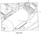
- FIG. 2is a side perspective view of the injection system.
- FIG. 4is a side perspective view of the injector after the multi-use subassembly has been placed.
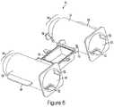
- FIG. 5is a side perspective view of the syringe barrel.
- FIG. 6is a rear perspective view of the outer protective shell.
- FIG. 7is a side top perspective view of the outer protective shell.
- FIG. 8is a top cross-section view of the multi-use subassembly.
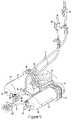
- FIG. 9is a side perspective view of the multi-use subassembly.
- FIG. 10is a rear perspective view of the multi-use subassembly.
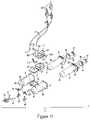
- FIG. 11is an exploded perspective view of the multi-use subassembly.
- FIG. 12is a partial top cross-sectional view of the multi-use subassembly.
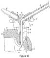
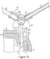
- FIG. 13is a partial top cross-sectional view of the automated valve in the inject position.
- FIG. 14is a partial top cross-sectional view of the automated valve in fill or purge position.
- FIG. 15is a partial top cross-sectional view of the automated valve in a closed position.
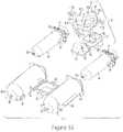
- FIG. 16is an exploded view of the multi-use subassembly highlighting the venting system.
- FIG. 17is a cross-sectional view of the multi-use subassembly highlighting the venting system.
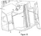
- FIG. 18is a partial perspective cross-sectional view of the venting system.
- FIG. 19are partial side cross-sectional views of syringe barrel and plunger position during venting.
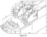
- FIG. 20is a side perspective view of the injector housing, specifically the syringe support means.
- FIG. 21is a top perspective view of the injector housing, specifically the syringe support means.
- FIG. 22is a side perspective view of the injector housing, specifically the syringe support means and the multi-use subassembly.
- FIG. 23Ais a side perspective view of the injector housing, specifically the syringe support means and the multi-use subassembly.
- FIG. 23Bis a side perspective view of the injector housing, specifically the syringe support means and the multi-use subassembly with lift support.
- FIG. 24 ais a side perspective view of the quick connect fitting
- FIG. 24 bis a top perspective view of the quick connect fitting
- FIG. 24 cis an additional side perspective view of the quick connect fitting.
- FIG. 25is a side perspective view of the fitting housing in an open position.
- FIG. 26is a side perspective view of the fitting housing in a closed position.
- FIG. 27is a side perspective view of the fitting housing in a locked position.
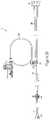
- FIG. 28is a side view of the single-use subassembly.
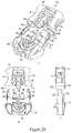
- FIG. 29is an exploded perspective view of the single-use subassembly.
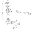
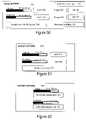
- FIG. 30is an exploded perspective view of the pressure protection valve.
- FIG. 31is a side cross-sectional view of the pressure protection valve.
- FIG. 32is a side perspective view of the hand controller.
- FIG. 33is a rear perspective view of the hand controller.
- FIG. 34is an exploded perspective view of the hand controller.
- FIG. 35is a side perspective view of the mounting system.
- FIG. 36is a side perspective view of the mounting system securely attached to a bed.
- FIG. 37is a partial side perspective view of the mounting system.
- FIG. 38is a partial side perspective view of the mounting system being attached to the injector housing.
- FIG. 39is a partial side perspective view of the mounting system being attached to the injector housing.
- FIG. 40is a partial side perspective view of the mounting system securely attached the injector housing.
- FIG. 41Ais a schematic of the interface system of the system of FIG. 2 .
- FIG. 41Bis an illustration of a Start Screen of the display of the system of FIG. 2 .
- FIG. 42is an illustration of a Setup Screen of the display of the system of FIG. 2 .
- FIG. 43is a diagrammatic flow chart illustrating the process used to attach the multiple-use subassembly to the injection housing of the system of FIG. 2 .
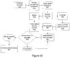
- FIG. 44is a diagrammatic flow chart illustrating the process used to fill and vent the syringes of the multiple-use subassembly of the system of FIG. 2 .
- FIG. 45is a diagrammatic flow chart illustrating the process used to fill and prime the tubing and transducer of the single-use subassembly of the system of FIG. 2 .
- FIG. 46is a diagrammatic flow chart illustrating the process used to select the procedure type for the system of FIG. 2 .
- FIG. 47is a diagrammatic flow chart illustrating the process to automatically fill the syringes of the multiple-use subassembly of the system of FIG. 2 .
- FIG. 48is an illustration of a Dashboard Screen of the display of the system of FIG. 2 .
- FIG. 49is an illustration of an Armed Dashboard Screen of the display of the system of FIG. 2 .
- FIG. 50is an illustration of a Shell Option Screen of the display of the system of FIG. 2 .
- FIG. 51is an illustration of a Source Options Screen of the display of the system of FIG. 2 .
- FIG. 52is an illustration of a Patient Options Screen of the display of the system of FIG. 2 .
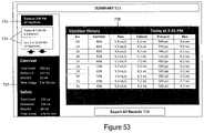
- FIG. 53is an illustration of a Summary Screen of the display of the system of FIG. 2 .
- FIG. 54is a diagrammatic flow chart illustrating the process to remove the multiple-use subassembly of the system of FIG. 2 .
- FIG. 55is an illustration of a Settings Screen of the display of the system of FIG. 2 .
- FIG. 56is an illustration of a Help Screen of the display of the system of FIG. 2 .
- the injector system 1is comprised of various components or subassemblies that may be combined together to form the overall system 1 .
- the injector system 1may allow the user to monitor invasive pressures or vascular blood pressure monitoring and perform dual injections of contrast, saline, a mixture of contrast and saline, or any other fluid, with the ability for variable mixing during medical procedures.
- the injection system 1is capable of injecting fluids from the barrel 35 at both low and high pressures, for example any pressure up to 1,400 PSI or the pressure required by maximum catheter specifications as currently known in the art.
- the injector system 1may include, but is not limited to, the user interface 7 , a hand controller 9 , at least one injector ram 15 , at least one fluid source 23 , a multi-use subassembly 3 , a fitting housing 4 , and a single-use subassembly 5 .
- the hand controller 9may further comprise, but is not limited to, a selector 303 , an actuator 301 , a sensor 313 , and a feedback means 311 .
- the multi-use subassembly 3may further comprise, but is not limited to, at least one syringe barrel 35 , an air purge or venting system 43 , at least one automated valve 45 .
- the fitting housing 4may further comprise, but is not limited to, a fitting 133 and an air sensor 155 .
- the single-use subassembly 5may further comprise, but is not limited to, a dual lumen high pressure line 209 , a tubing junction 211 , a pressure protection valve 207 , a disposable pressure transducer 203 , a single lumen high pressure line 213 , a stopcock 215 and a catheter connection 219 .
- the single-use subassembly 5may be in fluid connection with a procedure catheter (not shown). As described in more detail below, the various components and subassemblies shown in the schematic of FIG. 1 may change depending on the needs of the user.
- FIGS. 2-4depicts one embodiment of the injector system 1 .
- the injector system 1may comprise of various components or subassemblies including, but not limited to, a multi-use subassembly 3 , a single-use subassembly 5 , a user interface 7 , a hand controller 9 , an injector housing 13 , fluid source 23 , a foot pedal 10 , cover 6 , locking handles 31 , and a cart 19 .
- the injector system 1may also comprise a mount finger 14 , a mounting plate 407 , a connection arm 17 , and a motorized base 409 .
- connection arm 17is used to securely attach the injector housing 13 to a mount plate 407 .
- a key feature of the injector system 1is the interchangeable mounting system, described in more detail below, that allows the injector to be secured to various securement structures including, but not limited to, a cart 19 , a bed rail 411 (as seen FIGS. 35-40 ), or a ceiling or wall mount (not shown).
- the fluid sources 23 containing either saline or contrastmay be secured to the housing 13 with a source arm 25 .
- the arm 25may be hinged or pivotally connected to the housing 13 .
- the arm 25may be collapsible or foldable to allow the user to reduce the footprint of the injector housing 13 when not in use.
- the user interface 7may be securely attached to the housing 13 by an interface arm 11 that pivotally extends or retracts. It is advantageous that the user interface 7 is able to swing, pivot, or otherwise be manipulated in multiple directions during a procedure. It is common for the injector housing 13 to be placed away from the user during a procedure due to limited space, for example on the opposite side of the bed, so having the ability to manipulate the interface 7 in various directions is an advantage over injectors currently known in the art.
- the interfacemay have an identification card swipe 8 .
- the hand controller 9may be connected to the user interface 7 using various techniques, as described below, including a control cable 305 .
- the foot pedal 10may be connected to user interface 7 using various techniques including a control cable 18 .
- the interface 7is intended to control and display various aspects of operating the injector including, but not limited to, setting injection parameters, automated purging of system, automated injection, displaying real time injection status, and providing a user friendly interface for injector.
- Various selection tabs on the interface 7may become highlighted, flash, grayed out, or have a visual indicator in order to depict and verify to the user that tab has been selected.
- An advantage of user interface 7is that it reduces the user learning curve by programming the interface 7 to make it easier for users to navigate the system and simplify or automate the purging and injection sequences so to reduce possible user error.
- the interface 7may be interactive via a touch screen so that user can select an option simply by pressing a visual aid on the screen.
- interface 7may be voice activated or controlled via voice commands so instead of physically pressing a screen or tablet computer a user may control interface 7 using a head set or other similar voice command device.
- the interface 7may be software based and incorporated onto a touch screen tablet, PC, or a digital application used on a smart phone. Additionally, interface 7 may provide a shorter or faster setup time allowing for more time to conduct procedures. Interface 7 may provide for automatic syringe refill and air purging. The automatic refill option minimizes waste by allowing user to input a required amount of contrast, saline, or other fluid to be used per case. User may also be able to define a maximum limit for total contrast or saline that can be injected into the patient with integrated warning signals to notify user when maximum has been reached.
- the interface 7may have a card swipe 8 or identification card reader as known in the art, as seen in FIG. 2 .
- the purpose of the card swipe 8is to allow the user to simply swipe their hospital identification card and the interface will automatically bring up preset settings. These settings may be changed at any time but having the ability to automatically call up preset settings may save the user time.
- housing 13has a loading area 12 that the multi-use subassembly 3 may be placed or inserted into during setup.
- FIG. 3 ashows the loading area 12 without the multi-use subassembly 3 in place.
- the loading area 12has at least one valve actuator 16 .
- the valve actuator 16is designed so that the tab 46 of the automated valve 45 (see FIG. 4 ) may fit securely within the valve actuator 16 .
- the movement of the valve actuator 16is controlled by the interface 7 or hand controller 9 . As described in more detail below, when the valve actuator 16 moves or rotates it simultaneously moves or rotates the valve tab 46 thereby controlling the position automated valve 45 .
- the loading area 12also may comprise a fitting housing 4 used to securely enclose the fitting that connects the multi-use assembly 3 to the single-use assembly 5 .
- the loading area 12may also comprise visual identifiers (not shown).
- the visual identifiersmay include at least one light or LED (not shown) used to provide visual identification to the user of the current status of the injector.
- the loading area 12may have two visual identifiers in the form of different colored LEDs (not shown), one color to represent contrast and one color to represent saline. Each LED may be placed adjacent to the automated valve 16 . Each LED may light up and provide user notice during injection of fluid or filing, purging, or venting of a barrel.
- Multi-use subassembly 3may be inserted into loading area 12 and secured to the injector via a locking means such as a cover 6 .
- a locking meanssuch as a cover 6 .
- the userTo load the multi-use subassembly 3 into the loading area 12 the user must unlock the cover 6 by rotating the locking handles 31 and lifting the cover 6 away from the loading area 12 , as seen in FIG. 3 b .
- the usermay place the multi-use subassembly 3 on the loading area 12 of the injector housing 13 .
- the multi-use subassembly 3is secured to the loading area 12 and injector housing 13 by placing the securement ridge 59 of barrels 35 into the rear barrel support means 79 , as described in more detail below.
- the usermay close the cover 6 and rotate the locking handles 31 to securely enclose the multi-use subassembly 3 to the injector housing, as seen in FIG. 4 .
- the multi-use subassembly 3may comprise of at least one syringe barrel 35 as seen in FIG. 5 .
- Barrel 35may further comprise a front end 51 , back end 53 , a first port 55 , a second port 57 , a securement ridge 59 , an alignment nub 63 , and anti-rotation means.
- the front end section 51 of syringe barrel 35and similarly the front end section 64 of protective shell 61 as seen in FIG. 6-7 , may be a semi-spherical convex, rounded, or bullet shape.
- An advantage of front end sections 51 having a semi-spherical or convex front profileis a reduction in stress points or risers.
- Syringe barrel 35may be made from various materials able to withstand high temperatures or pressures including, but not limited to, clear polycarbonate, clear abs, or ultem.
- the securement ridge 59may be located towards the back end 53 of the barrel and extend radially a selected distance around the barrel 35 .
- the securement ridge 59may be injection molded together with barrel 35 to create a single piece component.
- Securement ridge 59is shaped to fit within the rear barrel support means, as described in more detail below.
- the purpose of the securement ridge 59is to provide additional support to the barrel 35 and also a means for securely connecting or attaching the barrel 35 to the injector housing 13 .
- the barrel 35may come under high forces so it is important that the securement ridge 59 can withstand such forces because the ridge 59 may be the connection point for securely attaching barrel 35 to injector.
- the first port 55is used to fill and inject fluids from the syringe barrel 35 .
- the first port 55can be located along the front end 51 of syringe barrel 35 and provides a fluid communication channel between the automated valve and interior of barrel body. In one embodiment, as shown in FIGS. 5 and 8 , the first port 55 is positioned towards the front end 51 and bottom wall 54 and below the center axis of barrel 35 .
- First port 55may be positioned on the front face 51 near the transition zone 65 between the barrel body and the front face 51 .
- An advantage of positioning the first port 55 along the side wall of syringe barrel 35is shortening the overall barrel length, thereby allowing for a smaller multi-use subassembly 3 . Additionally, when the first port 55 is positioned along the side wall of barrel 35 the port 55 may be located a selected distance proximal to the tapering zone 65 , an area along front end 51 of syringe where barrel 35 transitions from straight side wall to shaped end face, thereby reducing the risk of barrel cracking or fatigue.
- First port 55 of syringe barrel 35may be inverted into the barrel 35 , as seen in FIG. 12 . An advantage of this design allows barrel 35 to be front loaded into the shell 61 , as will be described in detail later.
- the second port 57 located on top surface of securement ridge 59is used for purging or venting the barrel 35 of unwanted air, as described in more detail below.
- the second port 57may be located along the top of the securement ridge 59 as seen in FIG. 5 .
- the second port 57may provide fluid communication between inside the barrel chamber and a one-way check valve 113 a , 113 b of the venting system, as described in more detail below.
- the second port 57may be located on the top wall 56 of the barrel 35 towards the back end 53 of the syringe barrel 35 .
- the systemmay include an outer protective shell 61 as a means of additional support intended to prevent syringe barrel 35 from over expansion, cracking, leaking or bursting during use.
- the protective shell 61may include, but not limited to, a convex shaped front end 64 , port holes 58 , anti-rotation grooves 52 along the inner wall 60 , alignment holes 62 , placement tabs 68 , connection arms 70 , and the bottom half 92 of the fill chamber.
- Shell 61may comprise two separate enclosure containers 66 .
- the shell 61is designed so each barrel 35 may be independently placed inside an enclosure container 66 .
- Each container 66has a port hole 58 that aligns with the first port 55 of the barrel 35 .
- At least one connection arm 70 extending off each container 66may securely attach to the bottom half 92 of the fill chamber, thereby connecting both containers 66 to form a single shell 61 .
- the fill chamber 92is part of the venting system 43 and is described in more detail below.
- Each container 66may have a placement tab 68 so user may grip or hold the shell 61 during insertion or removal from injection housing 13 .
- Shell 61may be made from various materials able to withstand high temperatures or pressures including, but not limited to, clear polycarbonate or ultem.
- the multi-use subassembly 3may contain anti-rotation means to prevent the barrel 35 from twisting or rotating out of alignment during an injection or manufacture/assembly of the multi-use subassembly 3 .
- the barrel 35 and shell 61are separate components and the anti-rotation means is used to ensure that the barrel 35 remains aligned within the shell 61 during use.
- the anti-rotation means on the barrel 35may include an alignment nub 63 along the front end 51 and raised notches 50 along the outer surface of the barrel 35 .
- the anti-rotation means of the shell 61may include an alignment hole 62 along the front end 64 and groove 52 on inner wall 60 , as seen in FIG. 6-7 .
- the alignment nub 63is designed to align with and abut or be received into a corresponding alignment hole 62 of the shell 61 .
- the raised notch 50 along barrel 35 outer surfacealigns and fits within grooves 52 of shells 61 inner wall 60 , thus properly aligning the outer surface of barrel 35 and inner wall 60 of shell 61 .
- an expansion gapmay exist between the outer diameter of the barrel 35 and inner wall 60 of the shell 61 to permit certain expansion that may occur during use. For example, as seen in FIG. 8 an expansion gap 72 may exist towards front end of barrel.
- an expansion gap 72The purpose for an expansion gap 72 is to allow the barrel 35 to expand or stretch a predetermined amount during injections but prevent the barrel 35 from overexpansion or overstretching to the point of failure. Therefore the size of expansion gap 72 may vary depending on how much room the syringe barrel 35 needs to expand or stretch but yet still be reinforced by shell 61 to prevent failure.
- the multi-use subassembly 3 of this embodimentmay comprise two syringe barrels 35 securely enclosed within an outer protective shell 61 , a venting system 43 , automated valves 45 , and tubing lines 47 , 41 .
- the ridges 59are not enclosed by the shell 61 because the ridges 59 may attach to the rear securement means 79 , as described in more detail below.
- the automated valves 45fluidly connect the barrels 35 to the fill tubing 41 or connection tube 107 and injection tubing 47 .
- the fill tubing 41 , connection tube 107 and injection tubing 47may incorporate flexible, large inner diameter high pressure tubing to enable user to visualize any trapped air in tubing sets and achieve desired high pressure flow rates while maintaining flexibility.
- the fill tube 41may contain bag spikes 40 as known in the art to fluidly connect the fill tubes 41 with the fluid sources.
- Injection tubing 47may be fluidly connect the barrels 35 to the fitting 133 .
- Dedicated fluid linesmay minimize fluid waste and injection fluid lag.
- the tubing lines 41 , 47may be either clear or have a specific color to represent the type of fluid present. For example, the tube carrying saline may have a blue line or tint along its length so the user may easily visualize the tubing line corresponding to the delivery of saline.
- plunger 36may comprise of a plunger body 37 , cover 39 and securement nub 34 .
- securement nub 34 along the rear wall of body 37may be used when securing the multi-use subassembly 3 to the injector housing 13 .
- Plunger cover 39may be sized so it can freely slide along inner wall of barrel 35 while all sides of cover 39 converge on or abut against the inner wall of barrel 35 .
- the multi-use subassembly 3may include specially designed automated valves 45 .
- Automated valve 45may be a Y-shaped rotary valve.
- the automated valves 45may include a valve stem 42 , valve tab 46 , and may be comprised of three different channel elements: a fill channel 44 , an injection channel 38 , and a barrel channel 48 .
- Valve stem 42is inserted and securely attached to first port 55 of the barrel 35 .
- Stem 42may be secured by adhesive or other known methods in the art.
- the barrel channel 48connects to first port 55 of barrel 35 via valve stem 42 .
- the fill channel 44 of one barrel 35may be connected to tubing line 41 which may be in fluid connection to fluid source 23 (saline, contrast, and other fluid being injected) or a fill chamber 90 .
- fluid source 23saline, contrast, and other fluid being injected
- barrel 35 containing salinemay have fill channel 44 fluidly connected to tubing line 41 which is in direct fluid communication with saline source.
- the fill channel 44 of other barrel 35such as barrel 35 containing contrast fluid, may be in fluid communication with connection tube 107 which in turn is in fluid communication with fill chamber outlet port 97 , as described in more detail below.
- the injection channel 39may be connected to injection tubing 47 .
- the valve 45must be able to withstand high pressures during injection of fluids.
- the Y-shaped valve 45 as shownmay have angles up to one hundred and twenty degrees between the fill channel 44 , injection channel 38 , and barrel channel 48 .
- This valve 45 designis an improvement upon valves commonly used in the art, which may be known as “T-valves” or “90 degree valves” which have ports separated by only ninety degrees.
- An advantage of valve 45is to maximize the ceiling surface area between fluid paths over a traditional ninety degree valve.
- the Y-shaped valve 45is an increase of the ceiling surface area between first port barrel channel 48 and injection channel 38 and between fill channel 44 and barrel channel 48 because each port is separated by at least one hundred and twenty degrees.
- This greater ceiling surfaceprovides superior protection against valve 45 failure during high pressure injections because stress on the valve may be more evenly dispersed.
- the Y-shaped valve 45may provide for a less severe and smoother transition or turn for fluid to travel.
- Y-shaped valve 45has less of a chance for leaking, cracking, or failure during high pressure fluid flow because stress on valve 45 is more evenly distributed and flow of fluid is less turbulent.
- the valve 45has an injection setting, a fill setting, or a closed setting.
- the movement of the tab 46controls changing between the settings.
- the tab 46is controlled by the valve actuator 16 (see FIG. 3 a ), which in turn is controlled by the user interface 7 .
- the valve actuator 16As the user selects a certain function on the interface 7 this causes the valve actuator 16 to automatically rotate. As the actuator 16 rotates this causes the tab 46 to simultaneously rotate, thereby changing the valve setting.
- the valve 45is shown in the injection position with open fluid communication between the barrel channel 48 and the injection channel 38 .
- the injection positionallows for fluid to be injected into the patient by establishing a flow path from the barrel 35 through the injection channel 48 to the injection tubing 47 which is in fluid communication with fitting and single-use subassembly.
- the valve 45is in the fill position with open fluid communication between the fill channel 44 and barrel chamber.
- the fill positionis used to fill the barrel chamber by allowing fluid to travel from the fluid source 23 or fill chamber 90 into the barrel 35 and may also be used during venting.
- the valve 45is in a closed position with no open fluid communication between any of the ports. A closed position may be used when the single-use subassembly needs to be changed or when injector is shut down for an extended time.
- the multi-use subassemblyalso includes a venting system 43 used to purge barrel 35 of trapped or unwanted air.
- the injection systemmust be primed before use to avoid any air being injected into the patient.
- the priming stageincludes filling the syringe barrel 35 of the multi-use subassembly 3 with fluid from the fluid reservoirs and then filling the single-use subassembly with fluid. During priming air may become trapped within the syringe barrel 35 or in any the fluid lines, therefore it is important to remove this air through the venting system 43 prior to injecting fluid into the patient.
- the venting system 43comprises a fill chamber having a top half 91 and bottom half 92 , the fill chamber may have several ports including: an inlet port 99 , an outlet port 97 , and an overflow port 95 . Venting system may also include a waste chamber 96 having a top half 94 and bottom half 93 , and several ports including a first inlet port 101 , a second inlet port 103 , a third inlet port 105 , and an outlet port 117 .
- the fill chambermay be used to fill one of the syringe barrels 35 with fluid, such as contrast, and prevent back pressure buildup within the fluid source.
- fluidsuch as contrast
- contrast fluid sourcesit is common for contrast fluid sources to be packaged in hard glass medical grade containers that may be susceptible to a buildup of reverse or negative pressure leading to leaks or cracking in the fluid connection. For example, if the barrel 35 containing contrast was in direct fluid communication with contrast source then during the purging sequence pressure from the syringe barrel 35 may build and travel back up stream towards the contrast fluid source. Since the contrast fluid source may be a hard glass container that does not allow for expansion, any buildup of negative pressure may lead to leaks or damaging the fluid connection between the injector and contrast source.
- the fill chamber 91acts as a pressure release or pressure buffer to prevent the unwanted pressure buildup within the contrast fluid source.
- the saline fluid sourceis commonly packaged in a flexible medical grade pouch or bag that is expandable and able to withstand reverse or negative pressure without causing leakage or failure in fluid connections. Therefore, it is possible for the barrel 35 containing saline to be in direct fluid communication with saline source because any negative pressure during purging will simply expand the flexible saline bag and not impact the connections between saline source and injector.
- the fill line 41 for fluid sourcepreferably contrast
- the fill chamber inlet port 99having a one-way check valve 116 .
- negative pressureis created within the barrel 35 .
- the negative pressuredraws and pulls the contrast from its source along the fill tubing 41 before passing through the fill one-way check valve 116 and into the fill chamber 92 .
- the inlet port 99may have a standard one-way check valve 116 preventing air from exiting the inlet port 99 and traveling back up line towards the contrast source, thereby preventing the unwanted buildup of negative pressure within the contrast fluid source.
- any excess contrast in the fill chamber 92may be forced through the fill chamber overflow port 95 and one-way check valve 115 then along the overflow connection tube 109 and into the first inlet port 101 of waste chamber 96 .
- the waste chamber 96is intended to allow air to escape from the barrel while also collecting any saline, contrast, or other fluid that is removed during the purging process. If the injector 1 is tilted at a range of 5-40 degrees relative to the horizontal axis of the base, as shown in FIG. 2 , any air remaining within barrel will be forced to the top rear of the syringe barrel 35 , near the location of the second port 57 . Referring to FIG. 16 , air is forced through the second port 57 of barrel 35 , through a waste one-way check valve 113 ( a ), 113 ( b ) along waste connection tubing 111 ( a ), 111 ( b ) and then into either the second 103 or third 105 waste chamber inlet ports.
- the waste chamber outlet port 117may have a standard one-way check valve 118 , as shown in FIG. 17 , to only allow air to escape from the waste chamber 96 and prevent unwanted air from entering the system through the outlet port 117 .
- the waste chamber 96may contain multiple fluid columns 119 to increase the total surface area of the waste chamber 96 , as seen in FIG. 18 .
- the purpose of the multiple fluid columns 119is to increase the overall surface area of the waste chamber 96 while thereby increasing the amount of fluid the waste chamber 96 is able to hold without increasing the overall size of the waste chamber 96 .
- the fluid columns 119increase overall distance the fluid must travel before it enters the waste chamber 96 , thereby increasing total waste capacity without increasing the size of the waste chamber 96 . As fluid enters the waste chamber it must travel up and down each fluid column 119 before it actually enters the chamber and collects along the bottom surface 93 .
- the systemmay stop plunger before it reaches the front end 51 of barrel 35 , thereby leaving a reservoir of predetermined volume of fluid (5-10 mL) within barrel chamber captured between the plunger and the front end 51 of the barrel 35 , as seen in step 123 of FIG. 19 .
- the purpose of this reservoir of predetermined volume of fluidis if any excess air is trapped inside barrel chamber after purging the air will be forced along the top wall 56 of the barrel 35 because injector housing 13 may be tilted at a 5-40 degree angle along the horizontal axis.
- the method of injecting fluid into a hollow anatomical structure using the injector system disclosed hereinmay include several steps.
- the movement of air or fluid inside the barrel 35 chamberis controlled by the movement of the plunger 36 .
- the movement of the plunger 36may be controlled by the injector ram.
- the plunger securement nub 34may be securely attached to the rear support means and in turn the injector ram, as described in more detail below, so plunger movement is controlled as injector ram advances forward or retracts back.
- the purging sequence 121may start with plunger 36 at proximal most end of barrel 35 and the valve 45 is rotated into the inject position, as seen in FIG. 13 , so the barrel channel 48 is in fluid communication with the injection channel 38 .
- the barrels 35may be purged prior to being connected to the procedure catheter.
- plunger 36is pushed forward 123 towards front of barrel 35 causing any trapped air in barrel 35 to be expelled through first port 55 and through valve 45 and tubing 47 and then fitting 133 , as also seen in FIG. 12 , which is open to atmosphere.
- the valve 45is rotated to fill position, as seen in FIG. 14 , so the barrel channel 48 is in fluid communication with the fill channel 44 .
- Plunger 36is then retracted to a first purge position 127 which is a first selected distance proximal from the second port 57 . While plunger 36 is in first purge position 127 fluid may be filling the syringe barrel 35 through port 55 .
- the rate at which fluid fills syringe barrel 35depends on the fluid's viscosity, for example contrast may take a longer time to fill syringe barrel 35 than saline due to contrast's higher viscosity.
- plunger 36is advanced distally causing fluid to be advanced through port 55 into lines 47 , as show in FIG. 12 .
- the usermay select to either refill the barrel 35 or put the injector in standby mode. If the user elects to refill the barrel 35 then the valve 45 may be rotated to fill position, as seen in FIG. 14 , and injector would repeat fill and purge steps 123 , 127 , 129 and 130 . Alternatively, if user elects to put injector in standby mode then valve 45 may be moved to closed or off position, as seen in FIG. 15 . Standby mode may be used between procedures of multiple patients or if the injector is not going to be used for an extended period of time.
- the injector system 1may comprise a rear barrel support means 79 .
- the purpose of the rear barrel support means 79is to securely attach and hold the securement ridge 59 of barrel 35 to the injector housing 13 .
- the rear barrel support means 79may comprise multiple support flanges 85 , 83 , a plunger lock means 88 , and a top flange (not shown).
- the rear barrel support means 79may be part of the injector housing 13 and adjacent to the injector rams 15 .
- the injector rams 15may be a mechanism capable of advancing and withdrawing the plunger inside the barrel chamber.
- the injector rams 15may be mechanical arms or pistons that push and retract the plunger 36 of barrel 35 .
- the injector rams 15may be motorized pistons that are advanced forward toward the front face of the barrel during an injection and are withdrawn back towards rear support means 79 during a fill or purge sequence.
- the movement of the injector rams 15may be controlled by electronic signals sent from either the user interface or the hand controller. For example, the user may input injection parameters into the user interface or choose different selections on hand controller and then an electronic signal is sent from user interface or hand controller to the injector rams 15 .
- the injector rams 15may be either forward or rearward.
- the injector rams 15may include a sensor 87 to measure how much force or pressure is being transferred to the plunger 36 as the plunger 36 is moved forward and rearward.
- the ram sensor 87may measure the amount of force exerted onto the barrel 35 by the rams 15 .
- the ram sensor 87may be comprised of a known sensor in the art. This sensor 87 is in electronic communication with the user interface 7 .
- the interface 7uses the information from sensor 87 to measure at what pressure or force the injector is operating and ensuring this is correctly correlated with the user inputs.
- the support flangesmay include, but not limited to, a top flange (not shown), at least one bottom flange 83 , and at least two side flanges 85 . If a top flange (not shown) is used, it may be connected to support means 79 via a hinge so during setup the top flange is able to be lifted up and away from the side flanges 85 and bottom flange 83 .
- the flanges 83 , 85are intended to be shaped and size to securely enclose the securement ridge 59 of barrel 35 , as shown in FIG. 20 .
- the flanges 83 , 85may have a barrel groove 86 and a shell groove 82 .
- Grooves 82 , 86may consist of an indent or step along the ends of the flanges 83 , 85 .
- the sides of the securement ridge 59may align with and be slid into the ridge grooves 86 of the side flanges 85 .
- the shell 61may have a rear ridge 28 that securely fits within shell groove 82 .
- the bottom flange 83may also have a groove 80 that aligns with the bottom of the securement ridge 59 .
- the rear barrel support means 79may also include a plunger lock means 88 .
- the plunger lock means 88is intended to securely attach to the plunger securement nub 34 on the rear end of the plunger body 37 .
- the lock means 88may have a notch 84 that is shaped to receive the securement nub 34 .
- the rear support means 79is intended to simplify system setup.
- the systemallows the user to simply align the securement ridge 59 over the rear barrel support means 79 and then push the multi-use subassembly 3 in place.
- the usermay hold onto the side tabs 68 of shell 61 and align the securement ridge 59 with ridge grooved 86 and shell ridge 28 with shell groove 82 of side flanges 85 .
- the multi-use subassemblymay be push downward to align the plunger securement nub 34 with the notch 84 of the plunger lock means 88 .
- the usermay continue to push down on the multi-use subassembly 3 until the bottom side of the securement ridge 59 is aligned with the grooved 80 of bottom flange 83 .
- An advantage of the rear support meansis that once the user aligns the securement ridge 59 with the rear barrel support means 79 all of the other components of the multi-use subassembly 3 are automatically align into proper position making the setup process faster and overall injector more user friendly. For example, once the securement ridge 59 is over the rear barrel support means 79 the valve tabs 46 will also be aligned over the valve actuator 16 .
- the usermay hear an audio feedback, such as a sound or a “click”, or have a tactile feedback response.
- an audio feedbacksuch as a sound or a “click”
- the usermay push down or close the top flange (not shown) or the cover 6 , thereby locking and securing the multi-use subassembly 3 to the injector.
- the shell ridge 28may further comprise a lift support 29 .
- the lift support 29provides the user with a means for lifting the shell 61 from the injector housing. For example, after a high powered injection the shell 61 may be difficult to remove and replace. Therefore, the life support 29 may provide the user with an additional area to grasp onto and assist the user with faster removal of the shell.
- the lift support 29may be a separate piece of material that is securely attached to the shell ridge 28 by ordinary means known in the art.
- the lift support 29may take the form of a ring, key hole, circle, or other shape that allows a user to easily grasp onto.
- the multi-use subassembly 3 and single-use subassembly 5may be connected by a specially designed fitting 133 .
- a specially designed fitting 133It is known in the art to use standard luer type connectors for injection systems. Such standard luer connections require the user to twist or rotate a luer at each connection point.
- the purpose of the fitting 133 for this injection systemis to allow the user to quickly connect the multi-use assembly to the single-use assembly. The connection makes the setup simpler, more reliable, and decreases overall setup time.
- the injection systemmay use a specially designed “snap fit” or “quick connect” fitting 133 to connect the multi-use subassembly 3 and the single-use subassembly 5 .
- the fitting 133may also comprise a dust cap or other protective means for preventing contamination of the fluid lines.
- the fitting 133may comprise of a multi-use connector 137 and a single-use connector 139 .
- the multi-use connector 137may be attached to the multi-use connector 137 which is in fluid communication with the barrel, as seen in FIG. 12 .
- the single-use connector 139may be attached to the single use tubing set 209 , as seen in FIG. 28 .
- the multi-use connector 137may have securement grooves 141 , alignment ridge 143 , and female tubing connections 145 .
- the single-use connector 139may have securement tabs 147 , alignment ridge 148 , male tubing connections 149 , tubing seals 153 , and an anti-rotation means 151 .
- the alignment ridges 143 , 148are designed to provide the user with tactile surface when grasping the fitting 133 .
- the alignment ridges 143 of multi-use connector 137 and the alignment ridge 148 of the single-use connector 139may both have convex, concave, or other mirrored shapes so the user knows by touch or feel that the connectors 137 , 139 are properly aligned when connected.
- the male tubing connections 149may comprise a tubing seals 153 , such as a standard O-ring, to prevent leaking and ensure a fluid tight seals within the fitting 133 .
- the anti-rotation means 151may be comprised of an additional protrusion or flange extending from the single-use connector 139 that aligns with a slot (not shown) in the multi-use connector 137 .
- the purpose of the anti-rotation means 151is to provide additional connective support or structure to fitting 133 and prevent unwanted twisting or rotation during high pressure injections.
- the usermay use the curvature of the alignment ridges 143 , 148 to provide tactile feedback that the single-use connector 139 and multi-use connector 137 are properly aligned.
- the male tubing connection 149will automatically align with the female tubing connection 145 creating a tactile and audio feedback; similarly the anti-rotation means 151 automatically slides within corresponding slot in multi-use connector 137 .
- the securement tabs 147 of the single-use connector 139slide along the securement grooves 144 of the multi-use connector 137 until the user hears a “click” sound and feels a haptic response that the fitting 133 has been properly connected.
- the securely tabs 147may comprise a foot 142 having a notch (not shown).
- the notchmay align with a corresponding tab or extension (not shown) protruding within securement grooves 141 of the multi-use connector 137 .
- securement tabs 147are aligned with securement grooves 141 and are pushed together the notch on foot 142 may fit within the protruding tab or extension.
- This notch and groove fittingmay provide additional connective support or structure to fitting by eliminating twisting or rotational movement of the foot 142 and tab 147 .
- FIG. 25-27illustrates the placement of the connection 133 within the housing base 153 .
- House base 153extends from the injector housing and is used to securely hold the fitting 133 and air sensor 155 .
- Housing base 153may comprise a seat for the fitting 133 , a seat for an air sensor 155 , a housing door 157 , a viewing window 159 , and a locking clamp 161 .
- the purpose of the viewing window 159is to provide user with visibility of the fitting 133 connection during use.
- the air sensor 155may be standard bubble detectors as known in the art and may use ultrasound to detect small amounts of air trapped in tubing 209 of single-use subassembly.
- interface 7may automatically stop injection to prevent air from being injected into patient.
- the sensors 155may include tubing channels 144 to permit proper placement of the single use tubing 209 .
- the housing door 157may include raised bumps 158 along the inside wall of the door 157 . These bumps 158 are designed to align with the tubing channels of the sensor 155 so when the door 157 is closed and in a locked position the bumps 158 ensure the single use tubing 209 remain securely inside slots 144 ensuring the sensors 155 obtain an accurate reading.
- the housing door 157may be connected to housing base 153 via a hinged connector 163 that allows the door 157 to swing open and close.
- the fitting 133When door 157 is in an open position the fitting 133 may be placed into base 153 and single patient tubing 209 may be placed into air sensor 155 slots 144 . After fitting 133 is properly in place the door 157 may be closed and securely locked to base 153 using the clamp 161 .
- the clamp 161may also be connected to base 153 via a hinged connection 165 .
- the clamp 161may include a locking means 167 that is connected to the clamp 161 via another hinged connection 169 . When the clamp 161 is hinged or pulled upwards into an open position, as seen in FIG.
- the locking means 167may align with a notch 171 on the top surface of the housing door 157 . As the clamp 161 is pushed downwards the locking means 167 grasps along the door notch 171 and securely locks the door 157 to the base 153 , as seen in FIG. 27 .
- the injector systemincludes a single-use disposable subassembly 5 .
- This single-use subassembly 5is intended to connect the multi-use subassembly 3 with the procedure catheter (not shown) via fitting 133 .
- the single-use subassembly 5may comprise a single-use connection 139 , pressure transducer 203 , pressure monitoring line 205 , pressure protection valve 207 , co-extruded high pressure tubing 209 , a tubing junction 211 , high pressure tubing 213 , a distal high pressure stopcock 215 , catheter connection tubing 217 , and a procedure catheter connection 219 .
- An advantage of using the single-use subassembly 5is to eliminate the risk of infection or contamination of the multi-use subassembly 3 .
- An advantage of single-use 5 subassemblyis it may be detached and discarded after each patient, whereas multi-use subassembly may be used for multiple patients, saving user both time and money.
- the single-use connection 139is connected to and in fluid communication with co-extruded high pressure tubing 209 which is able to withstand injection pressure of at least 1,400 psi.
- Tubing 209may be a co-extruded dual lumen fused component designed to avoid tangling of individual lines. Proximal end of tubing 209 may be aligned with air sensor 155 to prevent unwanted air being injected into patient.
- Distal end of tubing 209is connected to and in fluid communication with a tubing junction 211 .
- the tubing junction 211is connected to and in fluid communication with both a pressure protection valve 207 and single lumen high pressure braided tubing 213 rated up to at least 1,400 psi.
- the high pressure braided tubing 213is connected to and in fluid communication with a distal high pressure stopcock 215 .
- the stopcock 215may be used to deliver fluids to the catheter, draw blood samples, or remove waste from the system.
- the single-use 5 subassemblyis able to mix contrast and saline in-line.
- the co-extruded dual lumen tubing 209may have separate lumens for contrast fluid and saline fluid. When the co-extruded dual lumen tubing 209 reaches the tubing junction 211 it is at this point that the saline fluid and contrast fluid may be mixed together into the single lumen high pressure braided tubing 213 to form a diluted or mixed solution.
- a solution having the ratio of 50% contrast and 50% salinethen equal amounts of contrast and saline will be injected from the barrels of multi-use subassembly and travel along the co-extruded dual lumen tubing 209 until the fluids reach tubing junction 211 at which point the two fluids may mix together to form a diluted solution.
- the usermay inject a highly diluted contrast solution, such as 20% contrast and 80% saline, and still be able to achieve high quality images.
- An advantage of this systemis providing the user the able to dilute contrast fluid and still achieve high quality images. Therefore, diluting contrast being injected into the patient with a mixture of saline means less contrast solution may be used during a procedure, and over time this can lead to huge savings in both wasted contrast and money spent on contrast.
- the pressure protection valve 207pressure monitoring line 205 and pressure transducer 203 , are described in U.S. Pat. No. 6,896,002, entitled PRESSURE TRANSDUCER PROTECTION VALVE, and U.S. Pat. No. 6,986,742, entitled PRESSURE TRANSDUCER PROTECTION VALVE, and both are incorporated herein by reference.
- the pressure protection valve 207is intended for a two-way connection and fluid communication between tubing junction 211 and a disposable pressure transducer 203 . Pressure transducer measures the patient's blood pressure.
- the pressure protection valve 207includes a cap 221 , a flexible diaphragm 223 , a stem 225 , a sealing surface 227 , a body 229 , a housing 231 , source fluid channel 233 and a pressure transducer tubing connection.
- the pressure protection valve 207is activated when a pressure fluctuation exists between source fluid channel 233 and a pressure transducer tubing connection 235 causing the compliant flexible diaphragm 223 to deflect away from its original position towards the channel 233 .
- the top of the integrated stem 225is connected to the diaphragm 223 and the bottom of the stem 225 is connected to the body 229 .
- the deflection of the diaphragm 223moves the integrated stem 225 away from the channel 233 , causing the body 229 to engage a sealing surface 227 and create pressure isolation between channel 233 and disposable transducer 203 .
- This sealprotects the disposable transducer 203 from excessive pressure which may damage or impact the transducer 203 .
- the pressure protection valve 207may create a seal to protect transducer 203 before fluid pressure in channel reaches a pressure sufficient to damage the transducer. Once pressure of fluid flow through channel 223 is lowered the diaphragm 223 moves back to its original position, thereby separating the body 229 from the sealing surface 227 and re-establishing or opening fluid communication between the transducer 203 and channel 223 .
- both the single-use subassembly 5 and multi-use subassembly 3may be single patient use only.
- the fluid source 23such as the contrast container
- each component of the injector that contacts the fluidmay need to be changed after each use.
- the components of both the single-use subassembly 5 and multi-use subassembly 5may remain the same as above except for the fitting 133 .
- this embodimentmay use a standard luer type connection as known in the art or be directly bonded together. The standard fitting connection would fluidly connect the injector tubing 47 of the multi-use subassembly and the proximal end of tubing 210 of the single-use subassembly 5 .
- a controller 9 of the inventionmay include a handle 300 , a front actuator 301 , rear flush button 302 , a selector 303 for selecting a fluid source from which to inject fluid within a patient, a puff button 307 for injection of a small controlled amount of fluid, and a visual identifier 309 to notify user of the type of fluid selected to inject.
- Controller 9may also include various internal components including, but not limited to, a tactile feedback means 311 for providing a tactile or haptic response, and a sensor 313 for measuring position of actuator 301 .
- the rear flush button 302may be used to inject a predetermined amount of fluid, such as saline, to flush the system or procedure catheter. Controller 9 may be used to control the start and stop of injections, flush the tubing lines, deliver a “puff” or selected amount of contrast, select the type of fluid to be injected into the patient, and warn the user when an injection may be dangerous to the patient or system.
- FIG. 32depicts a controller 9 according to certain embodiments of the invention.
- the controller 9communicates with the user interface 7 via control cable 305 .
- the controller 9can be connected and disconnected from the control cable 305 via a first connector (not shown) that matches up to a second connector (not shown) on the cable 305 .
- the connection between the first and second connectorscan be made using any suitable connection means known in the art, for example male and female mini-DIN connectors.
- the controller 9communicates wirelessly with user interface 7 . Any suitable wireless protocol may be used in the invention, including 802.11(a, b, g, or n) and any other suitable protocols used in the art.
- the controller 9may be connected to user interface 7 via a network connection, including over the internet. Accordingly, in certain embodiments, controller 9 includes hardware and/or software for transmitting and receiving signals over a network, including wirelessly.
- Controller 9is, in certain embodiments, composed of materials that can be sterilized once or more than once, for example by autoclaving, irradiation, or alcohol swab or immersion, or may be kept sterile during the procedure by placing a protective disposable sleeve over controller 9 during use.
- the front actuator 301may have a finite distance to travel within the controller 9 .
- the usermay move or press down on the front actuator 301 in order to cause a corresponding movement of fluid between the injection system and a patient.
- the depression of the actuator 301may send an electronic signal to either the user interface or the injector.
- the relationship between how much the user moves the front actuator 301 and the quantity of fluid that is infused into a patientmay be any useful or advantageous relationship, and may depend upon, among other things, the application for which the automated fluid management system is used, the injection mechanism employed by the automated fluid management system, the inputs user selected on the user interface 7 , or the preference or selection of the user.
- the mapping between the amount a user moves the front actuator 301 and the quantity of fluid infusedis linear (i.e. the transfer function is linear), advantageously permitting the controller to function similarly to an infusion syringe and in a manner that is familiar to physicians and easier to learn.
- the mapping between the amount of movement of the front actuator 301 and the quantity infusedis non-linear (i.e. the transfer function is nonlinear), permitting the tailoring of fluid delivery to specific uses. For example, if a high power injection of contrast agent is desired, the mapping may be linear over a portion of the travel of the front actuator 301 , then exponential over another portion, then linear again.
- the controller 9also includes a selector 303 for selecting one of a plurality of fluid reservoirs within the automated fluid management system from which to infuse fluid into a patient or into which to deposit fluid from a patient.
- the injector systemincludes reservoirs for saline and contrast, and the selector permits users to select one of these reservoirs or a mixture of both reservoirs that are mixed inline during fluid delivery.
- Controller 9may provide the user with feedback as to the status of a patient or the automated fluid management system.
- Feedbackmay be sent to and received by user in various forms including, but not limited to, audio feedback, visual feedback 309 , such as LEDs or flashing lights, tactile or haptic such as resistance in front actuator 301 or vibrations.
- front actuator 301provides the user with position-based feedback as to the level of fluid in the barrel 35 of the multi-use subassembly 3 selected with the selector.
- the front actuator 301has a finite travel within the controller, and the position of the actuator along its travel corresponds to the fluid level within the selected barrel 35 .
- the fluid levelcan be measured in absolute terms, for example in mL, or in relative terms, e.g. percent fullness.
- the fluid level in the barrel 35maps linearly to the position of the front actuator 301 along its travel, i.e. the transfer function is a linear function.
- the transfer functionis a linear function.
- the position of the front actuator 301 and the degree of movementmap to fluid level and fluid displacement, respectively, in the same way.
- the controller 9may be configured to behave as a 10 cc syringe, so that movement of the actuator 301 along 10% of its total travel results in the infusion of 1 cc of fluid into or out of a patient, and when the actuator 301 is positioned at the midpoint of its travel, the selected barrel 35 will contain 5 ml of fluid.
- the front actuator 301after a user moves the front actuator 301 to cause fluid to be infused into a patient, the user may let go of the front actuator 301 and the it will remain in the position in which the user left it.
- the mapping of the fluid level in the selected reservoir to the position of the front actuator 301 for the provision of feedbackmay be different than the mapping of the position of the front actuator 301 to the amount of fluid that is infused into a patient.
- the actuator 301changes position based on the fluid level within the selected barrel to provide position-based feedback of fluid levels.
- the position of the front actuator 301 and the degree of movement map to velocity based controlmay be configured so that at rest and no movement equals zero velocity and full depression on front actuator 301 equates to full velocity of injection. The velocity is based off of flow rates, so if the maximum flow rate is set at 5 mL/sec when front actuator 301 is completely depressed fluid is delivered at the maximum flow rate of 5 mL/sec.
- the front actuator 301 of the controllermay provide feedback in other ways and for other parameters.
- the front actuator 301in addition to providing position-based feedback to users, the front actuator 301 also provides resistance-based feedback to users.
- the resistance-based feedbackmay in the form of vibrations, resistance in movement of the front actuator 301 , or providing the user with a haptic response such as shaking or jarring of the controller 9 .
- the haptic or tactile feedback, such as vibrations, shaking, or jarring of controller 9may be generated by the tactile feedback means 311 as seen in FIG. 34 .
- resistance based feedbackis provided based on a level of fluid pressure within the injector system.
- the font actuator 301may resist movement from rest to a relatively high degree, or the controller 9 may begin to vibrate, if the fluid pressure is relatively high within the injector system. For example, if injection begins to approach max pressure limits, the vibrations may increase in frequency and/or intensity. Similarly, front actuator 301 may resist movement from rest very little or not at all, or the controller 9 may begin to vibrate, if the fluid pressure is relatively low.
- the degree of resistancemay be determined by the controller based on relative pressure values or absolute pressure values and, as discussed above, the mapping between pressure and resistance applied may be linear or non-linear.
- the resistancemay be set to a maximum when the pressure reaches or exceeds a certain value, and may be set to zero when the pressure reaches or drops below another value, advantageously mimicking the kind of resistance provided by a standard infusion syringe and catheter set-up, which is familiar to physicians and easy to learn.
- the resistancemay be zero below a particular threshold value, then maximum above that threshold value.
- the controller 9provides additional or secondary feedback via other mechanisms, including visual identifiers 309 including LEDs or display screens, and audio feedback including audible alerts.
- Controller 9 of the inventioncan be made any suitable size or shape, and have any suitable actuator mechanism. Controllers 9 , actuator 301 , and selector 303 may have any suitable form factors.
- actuators 301may be made in form factors including plungers, joysticks, rocker switches, toggle switches, paired buttons, scissor handles, trackballs, computer mice, touch wheels, scroll wheels, etc.
- the controller 9may have a form factor resembling infusion syringes generally used in the art. It includes multiple ergonomic finger holes into which a user can place fingers or thumbs to advantageously achieve comfortable leverage over the actuator 301 .
- the actuator 301may be shaped like a syringe plunger, and is operated in a manner similar to the plunger of an infusion syringe: the actuator 301 is pushed inward to cause the system in infuses fluid from a reservoir into a patient.
- the front actuator 301may be a depressible button.
- Controller 9once again includes a handle 300 optionally ergonomically shaped, permitting users to grip the handle 300 with their fingers and palm while operating the actuator 301 , 302 and the selector 303 .
- the front actuator 301may include a depressible button that may be operatively moveable by the user's thumb. For example, the user may depress or press down on front actuator 301 to cause infusion.
- the controller 9may also have a finger-operated rear button actuator 302 , as seen in FIG. 33 .
- the rear button actuator 302may be used in place or in conjunction with front actuator 301 , and may cause infusion when depressed by user.
- the selector 303preferably includes a button allowing user to choose various options for selecting saline, contrast, or mixture of both. Additionally, the controller 9 may have a puff button 307 that allows the user to inject a defined pre-set amount of fluid, contrast, saline or a mixture of both, every time it is pressed to help visualize where the catheter tip is located in the body.
- the actuators 301 , 302 of this embodimentmay provide position-based feedback or resistance-based feedback as disclosed above. The feedback may be created by a motor or spring in the controller body that provides resistance to the actuator. For example, the actuator 301 , 302 of this embodiment may be spring loaded so that after being depressed by user the actuator is forced in an upward motion returning to its original state.
- the injector systemmay also include a mounting system.
- the purpose of the mounting systemis to assist the user when transferring the injector housing 13 from a body unit 409 to another surface.
- an advantage of the mounting systemis to assist the user in securing the injector housing 13 to a stationary surface, such as a bed 410 , wall mount, or ceiling mount, without obstructing the movement of the medical personnel in the room.
- the bed mount 403may include, but not limited to, rail connectors 413 , mounting support 415 , mount locks 417 , mount brace 419 , bed support 421 , and adjustment means 423 .
- the rail connectors 413are designed to securely attach the bed mount 403 to the bed rails 411 . It is understood that there are many different types or brands of hospital beds 410 and each many have different sized rails 411 , therefore it is an advantage of this invention that the rail connectors 413 may be adjustable and able to change sizes to fit various sized bed rails 411 . Alternatively, rails connectors 413 may interchangeably fit with the same mounting supports 415 allowing specialized rail connectors 413 to fit a single bed mount 403 .
- the mounting supports 415are bars or arms that securely connect the rail connectors 413 with the actual bed support 421 .
- the bed support 421may be comprised of at least one flat bar or arm that extends the width of the bed 410 .
- the bed support 421may also need to be customized in order to fit various brands or sizes of hospital beds 410 , therefore the bed support 421 may have an adjustment means 423 allowing the support to extend or retract for proper fitting.
- the adjustment means 423may be a series of screws or bolts that unlock to allow for the bed support 421 to either be extended or retracted and then lock back in place thereby securing the bed support 421 .
- the bed mount 403may be securely attached to the bed 410 by using the mount locks 417 .
- Mount locks 417may include, but not limited to, levers, screw locks, or other tightening locks known in the art.
- the mount brace 419is used to securely hold and embrace the mounting finger 14 , as described in more detail below.
- the usermay use the adjustment means 423 to extend or retract the bed support 421 so it is properly sized to the bed 410 .
- the rail connectors 413may be adjusted and slid onto the bed rails 411 .
- the usermay use the mounting locks 417 on the rail connector 417 to securely attach the mount 403 to bed 410 .
- the mounting locks 417may include a knob 419 and a locking plate 420 .
- the knob 419may be turned or rotated which forces the locking plate 420 to move closer to the rail 411 , thereby securing the rail connector 413 to the rail 411 .
- the top of the connection arm 17may be securely attached to the bottom of the injector housing 13 (see FIG. 2 ) and the bottom of the connection arm 17 may be securely attached to the top of the mounting plate 407 .
- the bottom of the mounting plate 407may be connected to the top of the housing base 405 .
- the mounting plate 407may have a mounting finger 14 extending off its side.
- the mounting finger 14is intended to be sized to securely fit within slot 427 of the mounting brace 419 .
- the mounting finger 14may have supports 433 extending from the housing base 405 to provide lateral support to finger 14 .
- the cart 19may have a motorized body 409 or telescoping body, as known in the art, that can extends up and down.
- the top wall 408 of the motorized body 409may have a base finger 431 that extends into a slot (not shown) of the housing base 405 .
- the base finger 431may be securely attached to base housing 405 via base locks 429 , which may include, but not limited to, levers, screw locks, or other tightening locks known in the art.
- the usermay use the motorized body 409 of the cart 19 to raise the injector housing 13 so the mounting finger 14 is above the mount brace 419 .
- the usermay easily push the cart close to the bed 410 and effortlessly position the mounting finger 14 in place so the tip of the finger 14 is aligned with slot 427 of mounting brace 419 , as seen in FIG. 38 .
- the usermay lower the motorized body 409 of cart 19 thereby lowering the finger 14 into position so the entire finger 14 is captured within the mounting brace 419 , as seen in FIG. 39 .
- the usermay use the injector locks 425 to securely fasten the finger in place, thereby securing the injector housing 13 to the bed mount 403 .
- the usermay unlock or loosen the base lock 429 so the motorized body 409 of cart 19 may be lowered down even further, as seen in FIG. 40 , completely removing the base finger 431 from the housing base 405 .
- the cart 19may be moved and stored away providing more free space around the injector for doctors and nurses to walk and work.
- the cart 19may be positioned so the base finger 431 aligns with slot (not shown) of housing base 405 .
- the motorized body 409may be raised and base finger 431 extends fully into slot.
- Usermay secure housing base 405 to body 409 by using the base locks 429 .
- usermay unlock the injector locks 425 freeing the mounting plate 407 from the bed mount 403 .
- usermay continue to raise the motorized body 409 until the mounting finger 14 is completely free of mount brace 419 , allowing the cart 19 and injector housing 13 to be moved.
- the injector systemmay comprise of an interactive user interface 7 .
- the interface 7is intended to control and display various aspects of the injector including, but not limited to, setting injection parameters, automated purging of system, automated injection, displaying real time injection status, and providing a user friendly interface.
- An advantage of user interface 7may include a simplified setup procedure or simplified injection procedure.
- the interface 7may provide step-by-step prompts or notices that are intended to guide the user through the simplified setup procedures or simplified injection procedures.
- This simplified setup and injection proceduremay decrease the learning curve compared to manual injection systems with manifolds or currently known automated systems.
- the purpose of the simplified setup procedure or simplified injection procedureis to minimize user interaction with system and automate as many features as possible.
- the simplified setup proceduremay include, but is not limited to, priming the system, steps for attaching the multi-use and single-use subassemblies, and venting the system.
- the simplified injection proceduremay include, but it not limited to, steps for injection of fluids into a patient, auto refill of syringes, and changing system sub-assemblies for the next patient case.
- An advantage of minimizing user interaction and automation of system featuresis to save the user time and also reduce possible user error. Also, by automating certain features, such as priming the system, venting the system, and adjusting contrast to saline ratio, this may minimize the amount of contrast or saline used, thereby decreasing overall contrast waste.
- the interface 7may be capable of full automation for certain features, however for safety concerns the interface 7 may require user to confirm certain tasks have in fact been completed.
- the interface 7may be capable of fully automating the venting and air purging process, as described below in more detail; however interface 7 may still require user to confirm they have visually inspected all fluid lines and syringes to ensure that no air is present.
- the purpose of the user confirmationis to provide an additional level of patient safety but still saving user time by automating the process.
- interface 7Another advantage of interface 7 is to help user be able to adjust contrast to saline mix ratio based on individual patient requirements in order to minimize amount of contrast injected into the patient while achieving clinically acceptable images. Reduction in amount of contrast injected into a patient may help minimize potential for contrast included nephropathy (CIN).
- CINcontrast included nephropathy
- the interface 7is intended to help user reduce the total contrast used during injection procedures, thereby resulting in total cost savings of over 25% in contrast related expenses for the hospital or user.
- Another advantage of the interface 7 systemis the user has the ability to set patient specific injection parameters, as described in more detail below, which may trigger warning mechanisms when fluid injection maximums have been reached.
- the interface 7may provide the user with multiple mounting options.
- the interface 7may be a touchscreen computer housed in a display unit 510 (see FIG. 2 ).
- the display unit 510may be mounted on the injector assembly housing 13 (as seen in FIG. 2 ) or attached to a hospital bed used for imaging.
- the display unit 510may also be attached to a movable arm 11 that folds onto itself to reduce injector footprint when being stored or not in use.
- the moveable arm 11may be attached to the injector assembly housing 13 (as seen in FIG. 2 ) or attached to a hospital bed used for imaging.
- the display unit 510may be attached to a moveable arm 11 this may allow interface to be pulled across the patient bed or closer to the user for ease of use and be able to manipulate display unit 510 at varying angles.
- the display unit 510may be made of plastics, metals, or various other materials known in the art.
- the display unit 510may be capable of contacting various fluids, such as water, saline, contrast, blood, and will withstand high temperatures, resist cracking or damage during normal usage.
- the display unit 510may be capable of being cleaned or disinfected with commonly used hospital practices.
- codeFor purposes of this application, the terms “code”, “software”, “program”, “application”, “software code”, “software module”, “module”, and “software program” are used interchangeably to mean software instructions that are executable by a computer processor as known in the art.
- the “user”can be a physician or other medical professional.
- the interface 7may be in the form of software that is preloaded onto a touchscreen computer, an application that may be compatible with a smartphone or other portable device, or software that may be transferred onto a touchscreen computer, hospital network, PC or desktop computer.
- the interface 7may have backlights that change in brightness so the user can see the interface 7 in a dark room with little or no lighting. The brightness of the backlights may be changed manually by the user or may automatically change depending on the amount of light in the room.
- the interface 7may be powered by the injection system and also have a battery backup.
- the interface 7may also have an electrical port (such as a USB port as known in the art) or be connected to the internet (either wirelessly or being connected to an Ethernet cable) so that information on the interface 7 may be exported or transferred to another system.
- the interface 7may keep a history or summary of injections, as described in more detail below, and user may have ability to copy this injection summary to a portable memory storage unit (such as a USB) or transfer the injection summary over the internet or intranet.
- the interface 7is on a touchscreen computer with a display screen.
- the usermay control the interface 7 by manually pressing tabs or buttons on the display screen, by remote control, by an application that is compatible with a smartphone or other portable electronic device, or by voice commands.
- Tabs or buttonsmay change or alter its appearance to indicate to user that the tab or button has been selected, for example the tabs or buttons upon selection may become highlighted, greyed out, blinking, flashing, or become a visual icon as known in the art.
- the usermay be able to calibrate the interface 7 to change sensitivity levels of the touchscreen display so that system is able to detect the user's touch when wearing gloves, fluids (such as contrast, saline, or blood) is on the screen, or user's hands have become wet.
- interface 7may be voice activated or controlled via voice commands so instead of physically pressing a screen or tablet computer user may control interface 7 using a head set.
- the interface 7may further comprise of an internal memory 502 , data storage 504 , and a processor 506 or CPU.
- the internal memory 502may be used to store user's inputs 500 or selections and transfer this data to the processor 506 . Additionally, the user's inputs 500 may also be save in the data storage 504 .
- the data storage 504may be exported or transferred via an external storage device, such as a USB device, or through an Ethernet cable. After the user's input 500 has been entered and stored a processor 506 may then control the injection parameters 508 of the injection system, as described in more detail below.
- the interface 7may also provide user with visual notifications.
- the interface 7 softwaremay have integrated visual status notifications that alert user when a change to the system has occurred.
- the integrated visual status notificationmay include flashing visual elements on the interface 7 screen, icons or pictures on the interface 7 screen, an LED mounted on the interface 7 housing, or audio notifications.
- the visual notificationsmay be used to inform user that the disposable sub-assembly has been properly installed, visualization of the syringes being filled or injected, the system has been armed, the system is injecting, the system has been disarmed, the system has been armed for high flow rate or high volume injections, or that the system is approaching preset maximum flow rate or volume injections based on specific patient criteria.
- the start screen 501is shown having a start tab 503 , recent cases tab 505 , and a system status tab 507 .
- the recent case tab 505may include additional text or information about the previous injections performed by the injector.
- the recent cases tab 505may include statistics about the previous injections on the start screen 501 and provide user with short summary of the previous injections, such as time of each previous case and number of injections. If the user selects the recent cases tab 505 the display screen may transition the interface 7 to a summary page, as described in more detail below and seen on FIG. 53 .
- the system status tab 507may include information about which part of the injection system is ready for the procedure.
- the text in the system status tab 507may be highlighted or bold to indicate that the particular subassembly has been properly setup. Additionally, the user may be able to select the particular subassembly listed on the status tab 507 to move directly to the setup screen controlling that particular subassembly. Selecting the start tab 503 may transition the interface to the setup screen 509 , as seen in FIG. 42 .
- the setup screen 509may comprise several functional tabs, including but not limited to, a setup tab 511 , a case tab 513 , a summary tab 515 , a settings tab 517 , and a help tab 719 .
- the setup tab 511When the setup tab 511 is selected, as shown in FIG. 42 , the tab 511 may become highlighted, greyed out, blink, or otherwise visually indicate to the user that the setup tab 511 has been selected.
- the interface 7begins a series of prompts to help guide the user in setting up the injector system for use. The prompts may be listed in the check list box 521 containing the individual steps required for properly setting up the injector system for a procedure.
- the check list box 521may include, but is not limited to; the following setup prompts, load shell and connect controls 523 , connect fluid sources 525 , and connect patient tubing 527 .
- each individual stepmay have a corresponding image box 513 .
- the image box 513may contain a picture, graphic, illustration, or other visual aid to help the user associate the particular step with the injector subassembly or component requiring setup.
- the interfacewill next guide the user through a series of steps as described in the flow chart.
- Each step in the flow chartmay be a separate notice screen, popup window, or other visual aid that is intended to guide the user through various steps in the correct sequence.
- the interfacewill prompt user to perform step or will notify user of a step automatically being performed by interface 7 .
- the interfacemay indicate the user to perform is open the cover 529 . After use has correctly opened the cover, the interface will instruct with the injector system to retract the pistons 531 thereby simultaneously retracting the plungers which are connected to the pistons.
- the interfacemay inform user to place shell 533 on the injector (as seen in FIG. 22-23A ).
- the systemwill check to determine if the shell sensor has been activated 535 .
- the shell sensor(not shown) may be located on the injector housing and ensures that the user has correctly aligned and placed the shell or detect if any fluid is in the shell. If the sensor fails to detect the presence of the shell the interface will notify user and inform user to remove and replace shell 539 . Alternatively, if the sensor detects the presence of fluid in the shell the interface will notify user and inform user to remove and replace shell 539 .
- the interface 7may notify user to close cover 537 and trigger injector to begin purging or removing air from shells 541 .
- a sensormay detect closing the cover or securement of the latch.
- the interfacemay guide the user through a series of steps as described in the flow chart. Each step in the flow chart may be a separate notice screen, popup window, or other visual aid that is intended to guide the user through various steps.
- the interfacemay notify user to access source fluid containers 545 , then open spike stopcocks 547 , and then specify sources 551 .
- the sourcesmay be either saline 549 , contrast 553 , or any other source (not shown).
- Once the type of source is selectedthe user will be prompted to enter either a saline source volume 555 or contrast source volume 559 . User may enter volume based on presets or patient specific parameters.
- the usermay select to fill syringe 557 .
- the interfacewill automatically fill each syringe with the user selected volume. After syringes have been filled to selected volumes the interface may trigger automatic venting of syringes 561 or alternatively the user may manually select to vent syringes on interface (not shown).
- the systemwill check for air in syringes and if air is present 559 the system may repeat venting 561 until no air is present 656 at which time interface may notify user to connect patient tubing 557 .
- the interfacemay guide the user through a series of steps as described in the flow chart. Each step in the flow chart may be a separate notice screen, popup window, or other visual aid that is intended to guide the user through various steps.
- First the interfacemay notify the user to open the quick connect cover 563 , then connect patient tubing set to shell and depress tubing into bubble sensor 565 , then close quick connect cover and secure latch 567 . Once the system has detected the latch has been secured, for example detection by a sensor, the interface may prompt the user to indicate if the transducer is used with the tubing set 569 .
- the interfacemay then prompt user or system to prime transducer 571 , open the stopcock on transducer 573 , close the three-way stopcock on the injector 575 , prime transducer line with saline 577 , and check for air in the transducer line 579 . If air is present in the transducer line 581 the interface may prompt user to manually re-prime transducer line until it is free of air 583 .
- the interfacemay then prompt system to prime the patient line 585 , zero balance the transducer with hemodynamics system 587 , close the stopcock on transducer 589 , close the three-way stopcock to transducer line 591 , prime patient tubing line with saline 593 , and determine if there is any air in the patient tubing set 595 . If air is present in tubing set 597 , interface will prompt system to remove air from appropriate tubing line(s) by flushing saline and/or contrast 598 . Once no air is present in tubing line 596 the case is ready to start 599 upon users command.
- the interfacemay be prompted to help user select the details on the case 600 .
- Usermay select to start case 599 and interface may prompt to set fluid maximums for patient 601 .
- Usermay input contrast maximum 603 and saline maximum 605 .
- contrast maximum 603 and saline maximum 605For example, if the patient suffers from contrast included nephropathy and can only safely withstand a 50 mL of contrast fluid in a 24 hour period then the interface 7 provides user with ability to set the maximum total volume of contrast the system will inject during the procedure to be no more than 50 mL.
- Usermay input volume with an onscreen keyboard that indicates.
- interfacemay prompt user to select initial procedure type 607 by choosing a procedure 609 .
- the interfacemay be preloaded with various types of common procedures the injection system may be used for.
- the interfacemay provide user with an option of peripheral cases 611 , cardiac cases 615 , physician case list 613 or other 617 cases.
- Cardiac cases 615may include various preset injection parameters depending on the specific type of case, for example interface may prompt user to select from aortagram presets 619 , coronary presets 621 , and a left ventriculography presets 623 .
- peripheral cases 611may include, but not limited to, intravascular ultrasound (IVUS), peripheral angiogram, endovascular aneurism repair, Y-90 mapping, CT cone beam studies, interventions, and any other procedure requiring X-ray imaging of the peripheral.
- IVUSintravascular ultrasound
- peripheral angiogramperipheral angiogram
- endovascular aneurism repairY-90 mapping
- CT cone beam studiesinterventions, and any other procedure requiring X-ray imaging of the peripheral.
- the preset parameter optionsis intended to be guide for setting up the injection system; each case is unique and may require specific injection parameters so as described in more detail below the user will have the option to change the preset parameters on the dashboard screen prior to starting the case.
- the physician list 613may include preset parameters for various physicians using the injector system. Each physician may have unique preset case parameters that they wish to use as defaults. The physician list 613 presets may be changed or updated frequently. Alternatively, interface 7 may provide user an option to skip select case 609 and go directly to dashboard and manually enter injection parameters.
- the systemmay also include an auto refill option.
- the purpose of the auto refill optionis to provide user with the ability to input minimum syringe barrel volumes at which the system will automatically replenish the syringes with fluid from the sources.
- the auto refill optionmay provide user with ability to set maximum fluid volumes.
- the auto refill optionmay also provide user with ability to set minimum volumes for each syringe.
- each syringehas a minimum volume of 25 mL and after 5 injections the contrast syringe volume falls to 15 mL the system will detect that the total volume in contrast syringe has dropped below 25 mL and automatically refill the contrast syringe to either the total possible volume syringe is capable of holding, such as 100 mL, or with 10 mL of fluid.
- the interface 7may notify user that the auto refill is taking place but because the user has preprogrammed the auto refill option the contrast syringe will be filled automatically.
- An advantage to the auto refill featureis to save the user time between injections and provide the user with the ability quickly do additional injections that may not have been planned at end of the procedure if needed. Also, if user is performing multiple large volume injections the auto refill option pervades user with ability to continue performing such injections without stopping the case to manually fill syringes. Another advantage of the auto refill option is to provide the ability to continue performing injections once the desired volume in syringe has been met.
- the interfacemay first check auto refill 625 has been selected by user. If user does intend to use auto refill option, the interface may prompt system to determine if syringe is filled enough to perform the intended operation 627 . If so, the procedure may continue 629 and there is no need for refill. If not, the interface may prompt system to confirm auto refill has been enabled 631 . If auto fill has not been enabled the interface may notify user 633 . If auto fill has been enabled the system may determine which syringe is not full 635 . If contrast is not full 637 the system may be prompted to fill contrast syringe from contrast source 643 until proper volume has been reached.
- the systemmay be prompted to fill saline syringe from saline source 641 .
- the interfacemay then prompt user to determine if user wants to abort auto fill 645 , if so the system will stop filing syringe 647 , if not system will continue to fill syringes from source until complete 649 .
- dashboard screen 651As shown in FIG. 48 .
- the parameters on the dashboard screen 651may be preset depending on the type of procedure user selects 609 during injection setup (as seen in flowchart of FIG. 46 ).
- the dashboard screen 651provides user with the option to change all of the injection parameters previously described above and additional parameters including, but not limited to, fixed 657 or variable 659 injection speeds, the type of procedure 655 , the contrast ratio 661 , the flow rate 663 , the volume 665 , the pressure 667 , the rise time 669 , source options 683 , shell options 685 , patient options 687 , summary 515 , help 689 , puff injection 693 , end case 691 , or arm 671 the system for injection.
- the dashboard screen 652may also provide a parameter summary box 675 that provides user with clarification on the currently set injection parameters.
- the dashboard screen 651may include the type of case, for example if user selected a cardiac case and specifically a coronary procedure then the case type 653 may be depicted as a coronary procedure. Also included may be a specific case type tab 655 indicating the type of case about to be performed, for example if user is going to perform a left coronary artery injection. User may have the option to perform either fixed 657 or variable 659 speed injections.
- the dashboard screen 651may provide user with visualization and accessibility to control various injection parameters, including but not limited to, contrast ratio 661 , flow rate 663 , volume 665 , pressure 667 , and rise time 669 .
- Each injection parametermay include arrows or other markers indicating the user's ability to easily change the preset or previously set parameter. For example, if the preset parameter for a coronary procedure of contrast ratio is 50% contrast and 50% saline, but a patient is susceptible to complications arising from excess contrast, such as contrast included nephropathy (CIN) as described above, the user may decide to change the contrast ratio 661 to 20% contrast and 80% saline thereby decreasing amount of contrast needed during the injection but enough contrast to still provide a clear medical image.
- CINcontrast included nephropathy
- the usermay press the arrows or markers contained within the contrast ratio 661 tab and interface may prompt user with a pop-up window that will allow user to change the contrast to saline ration from 50/50 to the desired ratio.
- the injection systemis capable of injecting 100% contrast and 0% saline, 100% saline and 0% contrast, or any other conceivable ratio of contrast and saline therebetween.
- the dashboard screen 651may include a tab detailing the sources 667 and options 683 to change the source ranges, shell 679 and options 685 to change the shell ranges, and patient 681 and options to change the patient ranges, as described in more detail below and seen in FIG. 50-52 .
- Dashboard screen 651may also include a help tab 689 , an end case tab 691 , a puff tab 693 , and an inject tab 695 .
- the systemprovides for a hand controller, as previously described above, to control puff and fluid injections, however the user may also use the puff tab 693 or inject tab 695 in place of the hand controller.
- the dashboardmay also include an arm tab 671 that the user may press once the injection parameters have been properly set and the system is now ready to start the procedure.
- the armed dashboard screen 699may have many of the same features and tabs as the previously described unarmed dashboard screen 651 ; however the armed screen 699 may include a notification bar 697 upon the top portion of the screen.
- the notification bar 697 and inject button 695may be highlighted, blinking, flashing, include flashing text or visual indications, or otherwise indicate the system has been armed and is ready for injection.
- the armed dashboard screen 669may also include a disarm tab 701 when selected would cause interface to switch back to the unarmed dashboard screen 651 of FIG. 48 .
- the shell option screen 685may include an information tab 703 indicating how long ago the current shell of the multiple-use subassembly was installed or the number of cases the shell has performed. For example, if each shell is intended to be used for either up to 100 hours or a total of 5 patient cases, the information tab 703 may be changed or customized to indicate the appropriate indicator.
- the shell of the multi-use subassemblymay include a limit on number of uses, for example up to five patients, or limit on total usage time, for example up to 12 hours.
- the limit on shell usagemay be preset from the manufacturer or changed by the user.
- Other shell optionsinclude changing the saline vent 705 , purge 707 , or fill 709 parameters, and changing the contrast vent 711 , purge 713 , or fill 715 parameters.
- the saline vent 705 , contrast vent 711include retracting the plunger in the saline or contrast syringe to various positions in order to vent each syringe of air, as described in more detail above and seen in FIG. 19 .
- the purge 707 , 713 optionsmay flush system with fluid to remove any trapped air in-line and fill lines with desired fluid.
- the fill 709 , 715 optionsincludes filling either the contrast syringe or saline syringe with fluid from the fluid source.
- Shell option screen 685may also allow user to change the status of the auto refill option 719 , which was previously discussed, or indicate to the system that the shell is to be removed 721 .
- Source option screen 683provide user with ability to edit parameters 723 of saline source or edit parameters 725 of the contrast source, such as the volume of new contrast or saline source, or indicate sources need to be replaced 727 .
- Patient option screen 687allows user to change parameters for amount of maximum saline volume 729 or maximum contrast volume 731 the system can inject into the patient.
- the summary screen 515may include a current injection summary 733 , past injections summary 735 , fluid summary 737 and an injection history 738 .
- the current injection summary 733may include time/date and number of injections for the current case
- the past injection summary 735may include time/date and number of injections for previous cases.
- the fluid summary 737may include details about the saline and contrast for either the current injection summary 733 or past injection summary 735 ; such details may include as total amount of fluid used, total amount of fluid delivered to patient, total amount of fluid wasted (i.e., not delivered to patient but still used), and total usage time.
- the injection history 738may include a table or chart depicting the injection parameters compared with what the injection system actually performed, the table may be sortable and include, but is not limited to, the number of injection performed, ratio of contrast, flow, volume, date of injection, time of injection, name of procedure type, patient characteristics, and pressure and rise time for each injection.
- the injection history 739may also be exported 739 to any computer readable format or mobile application.
- the summary screen 515may be access from the setup screen 509 , the dashboard screen 651 , or the armed dashboard screen 699 .
- the usermay select to end case 691 from either dashboard 651 or armed dashboard 699 screen.
- the interface 7will then the user through the sequence of post procedure steps, in which in which the interface 7 may guide the user to first disconnect the tubing set from the patient 741 .
- open quick connect cover and disconnect patient tubing set from shell 743dispose patient tubing set in proper manner 745 , place a sterile end-cap on the shell fitting 747 , press end case button 691 (as seen in FIG. 48-49 ) 749 , and switch to connect patient tubing screen 751 to prepare for next case.
- the sequence to end case 691may include removal of the patient tubing and multi-use subassembly. Additionally, the interface 7 may notify user that after a certain number of patient uses, injections or total usage time the multi-use subassembly needs to be replaced.
- the setting screen 517is shown having a category tab 752 and a detailed information tab 761 .
- the purpose of the setting screen 517is to provide user with access to the current injector setting information and the ability to modify the settings.
- Possible system settings that may be modified through setting screen 517may include auto fill status, minimum auto fill volumes, volume level, and system interface settings such as screen brightness, voice command, and default language.
- the setting screen 517may have a category tab 752 which may include a general information selection tab 753 (which when selected prompts the generation information tab 761 as shown); a rates and volume tab 755 , a physical content tab 757 , and a procedure preset tab 759 .
- setting screen 517 optionsmay be password protected to prevent unintended changes to presets.
- systemmay prevent selected users from changing settings including, but not limited to, fill rate, priming volumes, procedure types, preset injection parameters for individual physicians, or any other preset injection parameter.
- the help screen 518is shown having a topics tab 763 and a detailed information tab 765 .
- the topics tab 763may include various topics or aspects of the injector that user may need help with.
- the detailed information tab 765may contain a user manual, or other helpful hints, tips and help information to walk user through general issues or troubleshooting topics.
- Detailed informationmay include videos, audio step-by-step instructions, or live user support.
- a reference to “A and/or B,” when used in conjunction with open-ended language such as “comprising”can refer, in one embodiment, to A without B (optionally including elements other than B); in another embodiment, to B without A (optionally including elements other than A); in yet another embodiment, to both A and B (optionally including other elements); etc.
Landscapes
- Health & Medical Sciences (AREA)
- Vascular Medicine (AREA)
- Engineering & Computer Science (AREA)
- Anesthesiology (AREA)
- Biomedical Technology (AREA)
- Heart & Thoracic Surgery (AREA)
- Hematology (AREA)
- Life Sciences & Earth Sciences (AREA)
- Animal Behavior & Ethology (AREA)
- General Health & Medical Sciences (AREA)
- Public Health (AREA)
- Veterinary Medicine (AREA)
- Infusion, Injection, And Reservoir Apparatuses (AREA)
Abstract
Description
Claims (11)
Priority Applications (2)
| Application Number | Priority Date | Filing Date | Title |
|---|---|---|---|
| US14/159,777US11369739B2 (en) | 2013-01-21 | 2014-01-21 | Method to provide injection system parameters for injecting fluid into patient |
| US17/752,089US20220280717A1 (en) | 2013-01-21 | 2022-05-24 | Power injector device and method of use |
Applications Claiming Priority (3)
| Application Number | Priority Date | Filing Date | Title |
|---|---|---|---|
| US201361754687P | 2013-01-21 | 2013-01-21 | |
| PCT/US2013/061397WO2014047626A2 (en) | 2012-09-24 | 2013-09-24 | Power injector device and method of use |
| US14/159,777US11369739B2 (en) | 2013-01-21 | 2014-01-21 | Method to provide injection system parameters for injecting fluid into patient |
Related Parent Applications (1)
| Application Number | Title | Priority Date | Filing Date |
|---|---|---|---|
| PCT/US2013/061397Continuation-In-PartWO2014047626A2 (en) | 2012-09-24 | 2013-09-24 | Power injector device and method of use |
Related Child Applications (1)
| Application Number | Title | Priority Date | Filing Date |
|---|---|---|---|
| US17/752,089ContinuationUS20220280717A1 (en) | 2013-01-21 | 2022-05-24 | Power injector device and method of use |
Publications (2)
| Publication Number | Publication Date |
|---|---|
| US20140208251A1 US20140208251A1 (en) | 2014-07-24 |
| US11369739B2true US11369739B2 (en) | 2022-06-28 |
Family
ID=51208774
Family Applications (2)
| Application Number | Title | Priority Date | Filing Date |
|---|---|---|---|
| US14/159,777Active2036-01-22US11369739B2 (en) | 2013-01-21 | 2014-01-21 | Method to provide injection system parameters for injecting fluid into patient |
| US17/752,089PendingUS20220280717A1 (en) | 2013-01-21 | 2022-05-24 | Power injector device and method of use |
Family Applications After (1)
| Application Number | Title | Priority Date | Filing Date |
|---|---|---|---|
| US17/752,089PendingUS20220280717A1 (en) | 2013-01-21 | 2022-05-24 | Power injector device and method of use |
Country Status (1)
| Country | Link |
|---|---|
| US (2) | US11369739B2 (en) |
Families Citing this family (11)
| Publication number | Priority date | Publication date | Assignee | Title |
|---|---|---|---|---|
| US9375180B2 (en)* | 2012-04-29 | 2016-06-28 | Acist Medical Systems, Inc. | Universal pressure transducer mounting device |
| US20140263406A1 (en)* | 2013-03-14 | 2014-09-18 | The Coca-Cola Company | Beverage Dispenser with Integrated Carbonator and a Potable Water/Ice Slurry Refrigeration System |
| WO2016098743A1 (en)* | 2014-12-15 | 2016-06-23 | オリンパス株式会社 | Endoscopic apparatus |
| JP7051076B2 (en)* | 2016-08-26 | 2022-04-11 | 株式会社根本杏林堂 | Chemical injection device |
| PL3826698T3 (en) | 2018-07-25 | 2024-07-08 | Acist Medical Systems, Inc. | Improved injection system and day set assembly therefor |
| WO2020046929A1 (en)* | 2018-08-28 | 2020-03-05 | Bayer Healthcare Llc | Utilizing pressure measurements to detect reuse of patient lines |
| US11314375B2 (en)* | 2018-10-01 | 2022-04-26 | Precigenome, LLC | Multichannel pressure control system with user friendly interface |
| CN113164672A (en) | 2018-10-19 | 2021-07-23 | 费森尤斯维尔公司 | Medical device comprising an actuating element |
| CN109602970A (en)* | 2019-01-10 | 2019-04-12 | 南京感控通化工产品经营部 | A kind of high-pressure injection system for computed tomography angiography |
| CN113050546B (en)* | 2021-02-04 | 2022-03-08 | 安徽江淮朗格电气有限公司 | High-performance four-axis servo driver |
| CN120676916A (en)* | 2023-02-28 | 2025-09-19 | Uab远程医疗公司 | Devices for controlling the intravascular system |
Citations (312)
| Publication number | Priority date | Publication date | Assignee | Title |
|---|---|---|---|---|
| US264911A (en) | 1882-09-26 | William h | ||
| US315720A (en) | 1885-04-14 | campbell | ||
| US317770A (en) | 1885-05-12 | Machine | ||
| US320717A (en) | 1885-06-23 | Induction-coil | ||
| US338437A (en) | 1886-03-23 | Foot-power machine | ||
| US370134A (en) | 1887-09-20 | flick | ||
| US2649115A (en) | 1948-01-26 | 1953-08-18 | Bendix Aviat Corp | Pressure-responsive mechanism |
| US3157201A (en) | 1962-04-12 | 1964-11-17 | Cardiosonics Medical Instr Com | Fluid exchange valve |
| US3177707A (en) | 1961-04-19 | 1965-04-13 | Nina W Tetsios | Testing equipment for fuel injection engines |
| US3207179A (en) | 1962-11-23 | 1965-09-21 | Schulz Tool & Mfg Co | Gauge saver |
| US3384372A (en) | 1965-08-24 | 1968-05-21 | Indiana University Foundation | Football dummy with protective handgrips |
| US3674009A (en) | 1970-07-13 | 1972-07-04 | Cordis Corp | Angiographic injector with pump motor starting control |
| US3701345A (en) | 1970-09-29 | 1972-10-31 | Medrad Inc | Angiographic injector equipment |
| US3749285A (en) | 1971-09-13 | 1973-07-31 | Haemonetics Corp | Programmed liquid delivery system |
| US3774604A (en) | 1971-01-28 | 1973-11-27 | Demeco Medical Products Ab | Infusion cannula assembly |
| US3812843A (en) | 1973-03-12 | 1974-05-28 | Lear Siegler Inc | Method and apparatus for injecting contrast media into the vascular system |
| US3834372A (en) | 1973-01-12 | 1974-09-10 | S Turney | Disposable manifold with atmospheric vent |
| US3939832A (en) | 1973-03-09 | 1976-02-24 | Med-Pak Corporation | Liquid flow regulator and monitor for infusion system |
| US3957082A (en)* | 1974-09-26 | 1976-05-18 | Arbrook, Inc. | Six-way stopcock |
| US4006736A (en) | 1974-11-27 | 1977-02-08 | Medrad, Inc. | Angiographic injector |
| US4024864A (en) | 1975-09-05 | 1977-05-24 | Cordis Corporation | Injector with overspeed protector |
| US4059017A (en) | 1976-07-02 | 1977-11-22 | General Cable Corporation | Detecting apparatus with excess pressure protectors |
| US4072292A (en) | 1975-04-29 | 1978-02-07 | Societe Industrielle D'etudes Et De Realisations Scientifiques S.I.E.R.S. | Diaphragm valve |
| US4084606A (en) | 1974-04-23 | 1978-04-18 | Baxter Travenol Laboratories, Inc. | Fluid transfer device |
| US4085749A (en) | 1976-01-14 | 1978-04-25 | Compagnie Generale De Radiologie | Method and apparatus for controlling the movement of fluid to and from a syringe |
| US4204535A (en) | 1977-12-12 | 1980-05-27 | Charles Pohlmann | Lightweight resuscitator assembly |
| US4250887A (en) | 1979-04-18 | 1981-02-17 | Dardik Surgical Associates, P.A. | Remote manual injecting apparatus |
| US4342315A (en) | 1979-05-10 | 1982-08-03 | Mallinckrodt, Inc. | Suction catheters with improved suction control valve |
| US4370982A (en) | 1980-09-10 | 1983-02-01 | Medrad, Inc. | Method and apparatus for injecting and for controlling the pressure of fluid being injected into a catheter |
| US4430074A (en) | 1981-07-02 | 1984-02-07 | Samuel Ernest Douglass | Method for the intravenous administration of plural solutions through a common flow monitoring station |
| US4435171A (en) | 1979-06-04 | 1984-03-06 | Goldberg Edward M | Apparatus to be worn and method for removing fluid from a living subject |
| US4447230A (en) | 1981-08-05 | 1984-05-08 | Quest Medical, Inc. | Intravenous administration set assembly |
| US4447236A (en) | 1982-02-05 | 1984-05-08 | Cordis Corporation | Infusion catheter system |
| US4502488A (en) | 1983-01-13 | 1985-03-05 | Allied Corporation | Injection system |
| US4512764A (en) | 1982-09-27 | 1985-04-23 | Wunsch Richard E | Manifold for controlling administration of multiple intravenous solutions and medications |
| US4533346A (en) | 1979-06-26 | 1985-08-06 | Pharmacontrol Corporation | System for automatic feedback-controlled administration of drugs |
| US4540027A (en) | 1982-09-17 | 1985-09-10 | Transcodan, Sven Husted-Andersen Gmbh & Co. Kg | Check valve for infusion and transfusion apparatus |
| US4551133A (en) | 1984-04-16 | 1985-11-05 | American Hospital Supply Corporation | Patient controlled medication infusion system |
| US4559036A (en) | 1983-12-14 | 1985-12-17 | Wunsch Richard E | Apparatus for controlling administration of multiple intravenous solutions and medications |
| US4604093A (en) | 1984-06-12 | 1986-08-05 | I-Flow Corporation | Apparatus and method for administering multiple fluid infusions |
| US4604090A (en) | 1983-11-22 | 1986-08-05 | Consolidated Controls Corporation | Compact implantable medication infusion device |
| US4620846A (en) | 1979-06-04 | 1986-11-04 | Goldberg Edward M | Apparatus and method for introducing fluid into and removing fluid from a living subject |
| US4621647A (en) | 1982-08-10 | 1986-11-11 | Medex, Inc. | Intracranial pressure regulating system |
| US4634431A (en) | 1976-11-12 | 1987-01-06 | Whitney Douglass G | Syringe injector |
| US4648870A (en) | 1980-09-05 | 1987-03-10 | Goldberg Edward M | Device for evacuating body fluids |
| US4653539A (en) | 1984-06-12 | 1987-03-31 | Mallinckrodt, Inc. | Self-sealing check valve |
| US4666429A (en) | 1986-02-26 | 1987-05-19 | Intelligent Medicine, Inc. | Infusion device having improved valving apparatus |
| US4669465A (en) | 1984-12-10 | 1987-06-02 | Gv Medical, Inc. | Laser catheter control and connecting apparatus |
| US4677980A (en) | 1984-06-06 | 1987-07-07 | Medrad, Inc. | Angiographic injector and angiographic syringe for use therewith |
| US4690165A (en) | 1984-11-29 | 1987-09-01 | Beckman Instruments, Inc. | Mixing tee check valve and method |
| US4695271A (en) | 1986-02-03 | 1987-09-22 | Liebel-Flarsheim Company | Angiographic injector |
| US4699615A (en) | 1984-06-21 | 1987-10-13 | Fischell David R | Finger actuated medication infusion system |
| US4705501A (en) | 1982-04-12 | 1987-11-10 | Regents Of The University Of Minnesota | Bi-directional, anti-reflux vascular access system |
| US4767406A (en) | 1985-10-11 | 1988-08-30 | Vickers Plc. | Syringe pumps |
| US4769017A (en) | 1985-04-04 | 1988-09-06 | Fath John J | Self-sealing infusion manifold and catheter connector |
| US4789000A (en) | 1984-07-13 | 1988-12-06 | Aslanian Jerry L | Flow control device for administration |
| US4790193A (en) | 1985-08-30 | 1988-12-13 | Terumo Kabushiki Kaisha | Pressure transducer apparatus |
| US4812724A (en) | 1984-11-13 | 1989-03-14 | Liebel-Flarsheim Corporation | Injector control |
| US4813927A (en) | 1987-09-22 | 1989-03-21 | Vitreoretinal Development, Inc. | Parallel infusion apparatus and method |
| US4819653A (en) | 1986-04-11 | 1989-04-11 | Lloyd A. Marks | Multi-function fluid communication control system |
| US4819684A (en) | 1986-04-11 | 1989-04-11 | Intermedicat Gmbh | Injection shut-off valve |
| US4838269A (en) | 1988-03-24 | 1989-06-13 | Scimed Life Systems, Inc. | Manifold for angioplasty balloon catheter |
| US4846806A (en) | 1987-10-06 | 1989-07-11 | 501 Regents Of University Of Minnesota | Implantable intravascular access system |
| US4854324A (en) | 1984-01-31 | 1989-08-08 | Medrad, Inc. | Processor-controlled angiographic injector device |
| US4861340A (en) | 1988-10-17 | 1989-08-29 | Cordis Corporation | Hand-held pneumatic power assisted syringe |
| US4871353A (en) | 1987-06-24 | 1989-10-03 | John Thomsen | Method and apparatus for injecting fluids into IV line |
| US4877956A (en) | 1988-06-23 | 1989-10-31 | Halliburton Company | Closed feedback injection system for radioactive materials using a high pressure radioactive slurry injector |
| EP0345396A1 (en) | 1987-12-04 | 1989-12-13 | Imed Corporation | IV pump cassette |
| US4892524A (en) | 1987-10-30 | 1990-01-09 | Gordon Smith | Intravenous administration system |
| US4908018A (en) | 1987-06-24 | 1990-03-13 | John Thomsen | Method and apparatus for injecting fluids into an IV line |
| US4915688A (en) | 1987-12-03 | 1990-04-10 | Baxter International Inc. | Apparatus for administering solution to a patient |
| US4919650A (en) | 1987-03-30 | 1990-04-24 | Bionica Pty. Limited | Infusion pump |
| US4927411A (en) | 1987-05-01 | 1990-05-22 | Abbott Laboratories | Drive mechanism for disposable fluid infusion pumping cassette |
| US4934375A (en) | 1988-03-04 | 1990-06-19 | Spectramed, Inc. | Flush-valve assembly for blood pressure measurement catheter |
| US4936542A (en) | 1989-03-27 | 1990-06-26 | Abbott Laboratories | Catheter flow control valve |
| US4952205A (en) | 1987-04-04 | 1990-08-28 | B. Braun Melsungen Ag | Pressure infusion device |
| US5014715A (en) | 1988-11-22 | 1991-05-14 | Chapolini Robert J | Device for measuring the impedance to flow of a natural or prosthetic vessel in a living body |
| US5020562A (en) | 1989-11-28 | 1991-06-04 | Imed Corporation | Multiline check valve assembly |
| US5034004A (en) | 1987-06-19 | 1991-07-23 | The University Of Melbourne | Infusion pump and drive systems therefor |
| US5053002A (en) | 1988-01-11 | 1991-10-01 | Olympus Corporation | Irrigation system for angioscope |
| US5057120A (en) | 1988-10-27 | 1991-10-15 | Farcot Jean Christian | Apparatus for the performance of an angioplasty of long duration |
| US5074334A (en) | 1989-07-27 | 1991-12-24 | Terumo Kabushiki Kaisha | Multi-way cock |
| US5084031A (en) | 1989-09-12 | 1992-01-28 | Research Medical, Inc. | Cardioplegia three-way double stopcock |
| US5104387A (en) | 1990-05-25 | 1992-04-14 | St. Jude Medical, Inc. | Bi-planar fluid control valve |
| US5105820A (en) | 1988-09-22 | 1992-04-21 | Terumo Kabushiki Kaisha | Disposable pressure transducer apparatus |
| US5112301A (en) | 1991-06-19 | 1992-05-12 | Strato Medical Corporation | Bidirectional check valve catheter |
| US5114423A (en) | 1989-05-15 | 1992-05-19 | Advanced Cardiovascular Systems, Inc. | Dilatation catheter assembly with heated balloon |
| US5127904A (en) | 1988-08-11 | 1992-07-07 | Loo George D H | Improved needle-less parenteral fluid injector |
| US5129887A (en) | 1988-12-07 | 1992-07-14 | Scimed Life Systems, Inc. | Adjustable manifold for dilatation catheter |
| US5134079A (en) | 1989-03-27 | 1992-07-28 | International Technidyne Corp. | Fluid sample collection and delivery system and methods particularly adapted for body fluid sampling |
| US5135502A (en) | 1987-12-03 | 1992-08-04 | Medfusion Inc. | Solid introducer for catheter to a port and method of use |
| US5135026A (en) | 1989-08-16 | 1992-08-04 | Manska Wayne E | Medical valve having fluid flow indicia |
| US5137514A (en) | 1990-11-01 | 1992-08-11 | Accumed Systems, Inc. | Inflation syringe assembly for percutaneous transluminal angioplasty |
| US5139484A (en) | 1988-01-07 | 1992-08-18 | Bernard Hazon | Ambulatory syringe-pusher device for parenteral injections with output servo-controlled by the contents of the syringe |
| US5148811A (en) | 1990-05-15 | 1992-09-22 | Medex, Inc. | Method and apparatus for sampling blood and for monitoring blood pressure |
| US5163904A (en) | 1991-11-12 | 1992-11-17 | Merit Medical Systems, Inc. | Syringe apparatus with attached pressure gauge |
| US5163902A (en) | 1990-09-13 | 1992-11-17 | James R. Longacre | Patient fluid manifold |
| US5168901A (en) | 1991-05-23 | 1992-12-08 | Marks Lloyd A | Fluid communication manifold and control system |
| US5171216A (en) | 1989-08-28 | 1992-12-15 | Thermedics, Inc. | Multi-lumen catheter coupling |
| US5171230A (en) | 1991-11-29 | 1992-12-15 | Medex, Inc. | Fast flush catheter valve |
| US5190067A (en) | 1990-05-29 | 1993-03-02 | Nypro, Inc. | Directional flow control |
| US5190525A (en) | 1990-12-21 | 1993-03-02 | Abbott Laboratories | Drug infusion manifold |
| US5207642A (en) | 1987-08-07 | 1993-05-04 | Baxter International Inc. | Closed multi-fluid delivery system and method |
| US5217432A (en) | 1991-12-31 | 1993-06-08 | Abbott Laboratories | Automated drug infusion manifold |
| US5232024A (en) | 1991-05-30 | 1993-08-03 | Eli Williams | Slide-valve manifold |
| US5232449A (en) | 1992-04-29 | 1993-08-03 | Becton, Dickinson And Company | Syringe pump pusher |
| US5236416A (en) | 1991-05-23 | 1993-08-17 | Ivac Corporation | Syringe plunger position detection and alarm generation |
| US5236417A (en) | 1992-09-22 | 1993-08-17 | Utah Pioneer Medical, Inc. | Cholangiography catheter apparatus and method |
| US5238026A (en) | 1989-11-14 | 1993-08-24 | Chisso Corporation | Liquid outflow control unit |
| US5246011A (en) | 1992-01-30 | 1993-09-21 | Caillouette James C | Fine needle aspiration syringe |
| US5254092A (en) | 1992-09-15 | 1993-10-19 | American Medical Systems, Inc. | Fluid flow check valve |
| US5288290A (en) | 1991-09-25 | 1994-02-22 | Alcon Surgical, Inc. | Multi-ported valve assembly |
| US5290263A (en) | 1989-02-02 | 1994-03-01 | Regents Of The University Of Minnesota | Bidirectional check valve catheter |
| US5300029A (en) | 1992-07-01 | 1994-04-05 | Raymond Denance | Electromechanical injection apparatus for medical and veterinary use actuated by a trigger |
| US5322511A (en) | 1992-04-21 | 1994-06-21 | Sterling Winthrop Inc. | Portable hand-held power injector |
| US5324274A (en) | 1992-03-30 | 1994-06-28 | Med-Pro Design, Inc. | Catheter having rotary valves |
| US5328463A (en) | 1992-09-18 | 1994-07-12 | Namic U.S.A. Corporation | Contrast media and fluid introduction system |
| GB2274148A (en) | 1993-01-07 | 1994-07-13 | Man Fai Shiu | Fluid supply manifold |
| US5334170A (en) | 1993-07-14 | 1994-08-02 | Abbott Laboratories | Dye management system including an administration set with an in-line burette |
| US5333607A (en) | 1992-10-19 | 1994-08-02 | Sherwood Medical Company | Ventilator manifold with accessory access port |
| US5354284A (en) | 1992-06-09 | 1994-10-11 | Habley Medical Technology Corporation | Multiple injection syringe system |
| US5356375A (en) | 1992-04-06 | 1994-10-18 | Namic U.S.A. Corporation | Positive pressure fluid delivery and waste removal system |
| US5357946A (en) | 1992-10-19 | 1994-10-25 | Sherwood Medical Company | Ventilator manifold with accessory access port and adaptors therefore |
| US5378229A (en) | 1994-01-25 | 1995-01-03 | Cordis Corporation | Check valve manifold assembly for use in angioplasty |
| US5380665A (en) | 1989-03-27 | 1995-01-10 | International Technidyne Corporation | Fluid sample collection and delivery system and methods particularly adapted for body fluid sampling |
| US5399172A (en) | 1994-06-21 | 1995-03-21 | Med-Pro Design, Inc. | Catheter having ganged rotary valves |
| US5407424A (en) | 1993-02-24 | 1995-04-18 | Scimed Life Systems, Inc. | Angioplasty perfusion pump |
| US5417689A (en) | 1994-01-18 | 1995-05-23 | Cordis Corporation | Thermal balloon catheter and method |
| US5423751A (en) | 1993-02-18 | 1995-06-13 | Harrison; Samuel W. | Contrast media dispensing apparatus |
| US5431185A (en) | 1992-08-21 | 1995-07-11 | Pacific Device Inc. | Manifold for infusing medical fluids |
| US5443450A (en) | 1994-04-29 | 1995-08-22 | Medtronic, Inc. | Medication delivery device and method of construction |
| US5445141A (en) | 1992-10-19 | 1995-08-29 | Sherwood Medical Company | Respiratory support system |
| US5445616A (en) | 1994-04-29 | 1995-08-29 | Medtronic, Inc. | Medication delivery device and method of construction |
| US5451208A (en) | 1991-05-03 | 1995-09-19 | Goldrath; Milton H. | Endometrium coagulating apparatus and surgical method for thermal destruction of the endometrium |
| US5454792A (en) | 1993-04-19 | 1995-10-03 | Hyproteck, Inc. | Linear slide valve for CVC access |
| US5466227A (en) | 1994-01-10 | 1995-11-14 | Abbott Laboratories | Patient controlled analgesic injector assembly and method of assembling same to an infuser unit |
| US5485831A (en) | 1992-11-30 | 1996-01-23 | University Hospital (London) Development Corporation | Pulse-injector for quantitative angiographic blood-flow measurements |
| US5490837A (en) | 1991-07-05 | 1996-02-13 | Scimed Life Systems, Inc. | Single operator exchange catheter having a distal catheter shaft section |
| US5496273A (en) | 1991-12-20 | 1996-03-05 | Abbott Laboratories | Automated drug infusion system with autopriming |
| US5496311A (en) | 1988-10-28 | 1996-03-05 | Boston Scientific Corporation | Physiologic low stress angioplasty |
| US5501674A (en) | 1994-03-07 | 1996-03-26 | Medrad, Inc. | Intravenous catheter with needle cover and blood collection tube |
| EP0702966A2 (en) | 1994-09-21 | 1996-03-27 | Medrad Inc. | Patient specific dosing contrast delivery systems and methods |
| US5515851A (en) | 1993-07-30 | 1996-05-14 | Goldstein; James A. | Angiographic fluid control system |
| US5520666A (en) | 1994-12-06 | 1996-05-28 | Abbott Laboratories | Valved intravenous fluid line connector |
| US5533978A (en) | 1994-11-07 | 1996-07-09 | Teirstein; Paul S. | Method and apparatus for uninterrupted delivery of radiographic dye |
| US5536247A (en) | 1993-06-10 | 1996-07-16 | Scimed Life Systems, Inc. | Method of treating cardiac conduction defects |
| US5545141A (en) | 1993-05-28 | 1996-08-13 | Eld; Larry A. | Percutaneous gastrostomy feeding tube applicator and method. |
| US5551849A (en) | 1994-04-29 | 1996-09-03 | Medtronic, Inc. | Medication delivery device and method of construction |
| US5562614A (en) | 1993-11-22 | 1996-10-08 | Advanced Cardiovascular Systems, Inc. | Programmable manifold system for automatic fluid delivery |
| US5569208A (en) | 1995-08-01 | 1996-10-29 | Merit Medical Systems, Inc. | System for managing delivery of contrast media |
| US5573515A (en) | 1995-04-20 | 1996-11-12 | Invasatec, Inc. | Self purging angiographic injector |
| US5575767A (en) | 1994-09-16 | 1996-11-19 | Stevens; Robert C. | Method and apparatus for high pressure one-way fluid valving in angiography |
| US5575779A (en) | 1994-12-30 | 1996-11-19 | Namic U.S.A. Corporation | Liquid regulator and method of use |
| US5578059A (en) | 1993-11-30 | 1996-11-26 | Medex, Inc. | Anti-reflux valve with environmental barrier |
| US5586579A (en) | 1995-11-15 | 1996-12-24 | Martin Marietta Corporation | Combination ball valve and pressure relief valve assembly |
| US5593385A (en) | 1993-02-18 | 1997-01-14 | Harrison; Samuel W. | Contrast media dispensing apparatus |
| US5601651A (en)* | 1992-09-17 | 1997-02-11 | Fujitsu Limited | Flow control valve for use in fabrication of semiconductor devices |
| US5611340A (en) | 1995-10-02 | 1997-03-18 | General Electric Company | Apparatus and methods for magnetic resonance (MR) angiography using hydrogen polarized at low temperatures |
| US5611784A (en) | 1993-06-30 | 1997-03-18 | Hamilton Company | Manual dispensing aid for a syringe |
| US5618268A (en) | 1995-06-06 | 1997-04-08 | B. Braun Medical Inc. | Medical infusion devices and medicine delivery systems employing the same |
| US5628306A (en) | 1992-10-19 | 1997-05-13 | Kee; Kok-Hiong | Respiratory manifold with accessory access port |
| US5640995A (en) | 1995-03-14 | 1997-06-24 | Baxter International Inc. | Electrofluidic standard module and custom circuit board assembly |
| US5662612A (en) | 1993-11-24 | 1997-09-02 | Liebel Flarsheim Company | Controlling plunger drives for fluid injections in animals |
| US5665074A (en) | 1995-09-28 | 1997-09-09 | Liebel Flarsheim Company | Limited backflow reflux valve |
| US5681339A (en) | 1996-08-12 | 1997-10-28 | Mcewen; James A. | Apparatus and method for monitoring the patency of tubing in a pneumatic medical device |
| US5697899A (en) | 1995-02-07 | 1997-12-16 | Gensia | Feedback controlled drug delivery system |
| US5730731A (en) | 1988-04-28 | 1998-03-24 | Thomas J. Fogarty | Pressure-based irrigation accumulator |
| US5733259A (en) | 1992-01-31 | 1998-03-31 | Gensia Pharmaceuticals, Inc. | Method and apparatus for closed loop drug delivery |
| US5738662A (en) | 1996-02-21 | 1998-04-14 | Pacific Device/Avail Medical Products, Inc. | Retrograde flow checked manifold for infusing medical fluids |
| US5739508A (en)* | 1994-07-12 | 1998-04-14 | Medrad, Inc. | Closed loop information path for medical fluid delivery systems |
| US5752918A (en) | 1993-06-30 | 1998-05-19 | Medex, Inc. | Modular medical pressure transducer |
| FR2757772A1 (en) | 1996-12-31 | 1998-07-03 | Karcher Gilles | Remotely controlled injector for medical use |
| US5788215A (en) | 1995-12-29 | 1998-08-04 | Rymed Technologies | Medical intravenous administration line connectors having a luer or pressure activated valve |
| US5792102A (en) | 1994-01-28 | 1998-08-11 | Mallinckrodt Medical, Inc. | Conversion kit for a machine for automatic intravascular injection of solutions |
| US5800397A (en) | 1995-04-20 | 1998-09-01 | Invasatec, Inc. | Angiographic system with automatic high/low pressure switching |
| US5800383A (en) | 1996-07-17 | 1998-09-01 | Aquarius Medical Corporation | Fluid management system for arthroscopic surgery |
| US5800408A (en) | 1996-11-08 | 1998-09-01 | Micro Therapeutics, Inc. | Infusion device for distributing infusate along an elongated infusion segment |
| US5806519A (en) | 1993-10-28 | 1998-09-15 | Medrad, Inc. | Total system for contrast delivery |
| US5827219A (en) | 1993-10-28 | 1998-10-27 | Medrad, Inc. | Injection system and pumping system for use therein |
| US5830180A (en) | 1996-07-17 | 1998-11-03 | Aquarius Medical Corporation | Fluid management system for arthroscopic surgery |
| US5830194A (en) | 1996-09-20 | 1998-11-03 | Azam Anwar | Power syringe |
| US5833706A (en) | 1991-07-05 | 1998-11-10 | Scimed Life Systems, Inc. | Single operator exchange perfusion catheter having a distal catheter shaft section |
| US5842468A (en) | 1994-10-27 | 1998-12-01 | Medic-Aid Limited | Dosimetric spacer for calculating dosage administered |
| US5843051A (en) | 1990-10-29 | 1998-12-01 | Scimed Life Systems, Inc. | Intravascular device for coronary heart treatment |
| US5860938A (en) | 1996-03-07 | 1999-01-19 | Scimed Life Systems, Inc. | Medical pressure sensing guide wire |
| USD404717S (en) | 1997-11-06 | 1999-01-26 | Invasatec, Inc. | Hand-held pneumatic control device |
| US5865805A (en) | 1997-07-16 | 1999-02-02 | Liebel-Flarsheim Company | Power injector and side loadable syringe support therefor for plunger pushrod type syringes |
| US5868710A (en) | 1996-11-22 | 1999-02-09 | Liebel Flarsheim Company | Medical fluid injector |
| US5879627A (en) | 1996-01-30 | 1999-03-09 | Shimadzu Corporation | Automatic sample injector |
| US5882343A (en) | 1995-04-20 | 1999-03-16 | Invasatec, Inc. | Dual port syringe |
| US5882348A (en) | 1997-02-03 | 1999-03-16 | Sorenson Critical Care, Inc. | Valved manifold |
| US5894093A (en) | 1995-05-12 | 1999-04-13 | Dresser Industries, Inc. | Dual mode vent plug for a pressure gauge |
| WO1999024094A1 (en) | 1997-11-06 | 1999-05-20 | Invasatec, Inc. | Pneumatic controller and method |
| WO1999024095A2 (en) | 1997-11-07 | 1999-05-20 | Invasatec, Inc. | Angiographic injector system with multiple processor redundancy |
| US5913844A (en) | 1997-06-17 | 1999-06-22 | Liebel-Flarsheim Company | Power injector and method providing removal of used disposable syringe |
| US5925016A (en) | 1995-09-27 | 1999-07-20 | Xrt Corp. | Systems and methods for drug delivery including treating thrombosis by driving a drug or lytic agent through the thrombus by pressure |
| US5934888A (en) | 1996-04-27 | 1999-08-10 | Heraeus Med Gmbh | Aspirator pump |
| US5964714A (en) | 1996-03-07 | 1999-10-12 | Scimed Life Systems, Inc. | Pressure sensing guide wire |
| US5976112A (en) | 1997-11-07 | 1999-11-02 | Lyza Weiss Jennings & Shea | Injector syringe |
| US5988587A (en) | 1997-10-10 | 1999-11-23 | Invasatec, Inc. | Control device for providing a variable control signal to a fluid-supplying machine |
| US5993779A (en) | 1996-10-14 | 1999-11-30 | Mori; Atsuo | Method for producing non-human animal having spinal cord injury |
| US6001112A (en) | 1998-04-10 | 1999-12-14 | Endicor Medical, Inc. | Rotational atherectomy device |
| US6017318A (en) | 1995-02-07 | 2000-01-25 | Gensia Automedics, Inc. | Feedback controlled drug delivery system |
| WO2000006233A1 (en) | 1998-07-31 | 2000-02-10 | Medrad, Inc. | Pressure control systems for medical injectors and syringes used therewith |
| US6030368A (en) | 1996-09-20 | 2000-02-29 | Azam Anwar | Power syringe having a base and a lever |
| WO2000016849A1 (en) | 1998-09-23 | 2000-03-30 | Mayo Foundation For Medical Education And Research | Automatic manifold for vascular catheter |
| US6083205A (en) | 1998-01-28 | 2000-07-04 | Intella Interventional Systems | Multiple valve single port manifold |
| US6099502A (en) | 1995-04-20 | 2000-08-08 | Acist Medical Systems, Inc. | Dual port syringe |
| US6099511A (en) | 1999-03-19 | 2000-08-08 | Merit Medical Systems, Inc. | Manifold with check valve positioned within manifold body |
| US6110144A (en) | 1998-01-15 | 2000-08-29 | Medtronic Ave, Inc. | Method and apparatus for regulating the fluid flow rate to and preventing over-pressurization of a balloon catheter |
| US6117102A (en) | 1998-09-23 | 2000-09-12 | Mayo Foundation For Medical Education And Research | Apparatus for flushing a vascular catheter |
| WO2000059569A2 (en) | 1999-04-05 | 2000-10-12 | Acist Medical Systems, Inc. | Dynamically compliant catheter |
| US6135153A (en) | 1998-01-02 | 2000-10-24 | Cleland, Sr. John | Anesthesia delivery systems and methods |
| US6139571A (en) | 1997-07-09 | 2000-10-31 | Fuller Research Corporation | Heated fluid surgical instrument |
| US6139570A (en) | 1997-05-19 | 2000-10-31 | Gynelab Products, Inc. | Disposable bladder for intrauterine use |
| US6146360A (en) | 1998-01-16 | 2000-11-14 | Tandem Medical, Inc. | Medication delivery apparatus |
| US6158467A (en) | 1998-01-08 | 2000-12-12 | George Loo | Four-port, four-way, stopcock for intravenous injections and infusions and direction of flow of fluids and gasses |
| US6171276B1 (en) | 1997-08-06 | 2001-01-09 | Pharmacia & Upjohn Ab | Automated delivery device and method for its operation |
| US6176843B1 (en) | 1998-12-09 | 2001-01-23 | Scimed Life Systems, Inc. | Catheter with distal manifold prep valve/manifold |
| US6209568B1 (en) | 1998-07-17 | 2001-04-03 | L'air Liquide, Societe Anonyme Pour L'etude Et L'exploitation Des Procedes Georges Claude | Gas supply system including a pressure-regulating device and installation for dispensing working liquid |
| EP1090650A1 (en) | 1999-10-05 | 2001-04-11 | Nemoto Kyorindo Co., Ltd. | Contrast media injection apparatus |
| EP1091164A1 (en) | 1998-06-29 | 2001-04-11 | Sugan Co., Ltd. | Channel switching apparatus |
| US6221045B1 (en) | 1995-04-20 | 2001-04-24 | Acist Medical Systems, Inc. | Angiographic injector system with automatic high/low pressure switching |
| US6238372B1 (en) | 1995-03-20 | 2001-05-29 | Medimop Medical Projects Ltd. | Fluid control device |
| US6242472B1 (en) | 1989-08-28 | 2001-06-05 | Alliance Pharmaceutical Corp. | Methods for the pulmonary delivery of biological agents |
| FR2804609A1 (en) | 2000-02-08 | 2001-08-10 | Sedat | Medical fluid distributor, comprises four tubes with central connector and manually-controlled mobile component to vary connection between tubes |
| US6295990B1 (en) | 1998-02-03 | 2001-10-02 | Salient Interventional Systems, Inc. | Methods and systems for treating ischemia |
| US6315762B1 (en) | 1996-11-14 | 2001-11-13 | Angiodynamics, Inc. | Contrast medium delivery system and associated method |
| US6325778B1 (en) | 1996-05-20 | 2001-12-04 | Medtronic Percusurge, Inc. | Low profile catheter valve and inflation adaptor |
| US6325777B1 (en) | 1996-05-20 | 2001-12-04 | Medtronic Percusurge, Inc. | Low profile catheter valve and inflation adaptor |
| US20020022807A1 (en) | 2000-07-20 | 2002-02-21 | Douglas Duchon | Syringe plunger locking mechanism |
| US6355014B1 (en) | 1996-05-20 | 2002-03-12 | Medtronic Percusurge, Inc. | Low profile catheter valve |
| US6397098B1 (en)* | 1994-09-21 | 2002-05-28 | Medrad, Inc. | Data communication and control for medical imaging systems |
| US20020065467A1 (en)* | 1997-05-30 | 2002-05-30 | Schutt Ernest G. | Methods and apparatus for monitoring and quantifying the movement of fluid |
| US20020123716A1 (en)* | 2001-03-01 | 2002-09-05 | Vandiver Mark H. | Fluid injection system for coronary intervention |
| US6457488B2 (en) | 1998-01-08 | 2002-10-01 | George Loo | Stopcock having axial port for syringe twist actuation |
| US20020143294A1 (en) | 2001-02-14 | 2002-10-03 | Duchon Douglas J. | Catheter fluid control system |
| US6471674B1 (en) | 2000-04-21 | 2002-10-29 | Medrad, Inc. | Fluid delivery systems, injector systems and methods of fluid delivery |
| US6488659B1 (en) | 1999-08-05 | 2002-12-03 | Biocardia, Inc. | System and method for delivering thermally sensitive and reverse-thermal gelation materials |
| US20020183616A1 (en) | 2001-05-30 | 2002-12-05 | Acist Medical System, Inc. | Medical injection system |
| US20020198496A1 (en)* | 1995-04-20 | 2002-12-26 | Duchon Douglas J. | System and method for multiple injection procedures on heart vessels |
| US20030028145A1 (en)* | 1995-04-20 | 2003-02-06 | Duchon Douglas J. | Angiographic injector system with multiple processor redundancy |
| US6520937B2 (en) | 2000-12-18 | 2003-02-18 | Scimed Life Systems, Inc. | Fluid injection device |
| US20030052787A1 (en)* | 2001-08-03 | 2003-03-20 | Zerhusen Robert Mark | Patient point-of-care computer system |
| US6537268B1 (en) | 1998-06-18 | 2003-03-25 | Medtronic Minimed, Inc. | Medical infusion device with a source of controlled compliance |
| US6544232B1 (en) | 2000-07-18 | 2003-04-08 | Mcdaniel Gladys P. | Cystostomy catheter belt |
| WO2003039646A1 (en) | 2001-10-04 | 2003-05-15 | Scimed Life Systems, Inc. | Multiple port fluid control valves |
| US20030125618A1 (en)* | 2001-10-04 | 2003-07-03 | Scimed Life Systems, Inc. | Angiographic fluid control system |
| US20040010229A1 (en)* | 2002-07-11 | 2004-01-15 | Eric Houde | Fluid management system for coronary intervention |
| US20040064041A1 (en)* | 2002-05-30 | 2004-04-01 | Lazzaro Frank A. | Front-loading medical injector and syringes, syringe interfaces, syringe adapters and syringe plungers for use therewith |
| US20040082904A1 (en)* | 2002-10-23 | 2004-04-29 | Eric Houde | Rotary manifold syringe |
| JP2004194721A (en)* | 2002-12-16 | 2004-07-15 | Nemoto Kyorindo:Kk | Liquid chemical injecting apparatus |
| US20040143225A1 (en) | 2000-10-18 | 2004-07-22 | Callan Gerald W. | Pressure isolation mechanisms, method of use thereof and fluid delivery systems including pressure isolation mechanisms |
| US20040162484A1 (en)* | 2003-02-18 | 2004-08-19 | Nemoto Kyorindo Co., Ltd. | Liquid injector with appropriate operating conditions set by selecting displayed image |
| US20040199076A1 (en)* | 2003-04-01 | 2004-10-07 | Nemoto Kyorindo Co., Ltd. | Liquid injector for controlling injection of liquid in real-time according to injection graph |
| US20040254525A1 (en)* | 2003-04-08 | 2004-12-16 | Uber Arthur E. | Fluid delivery systems, devices and methods for delivery of hazardous fluids |
| US20050059924A1 (en)* | 2003-03-04 | 2005-03-17 | Katz Hal H. | Patient monitoring and drug delivery system and method of use |
| US20050070848A1 (en)* | 2003-05-28 | 2005-03-31 | Ducksoo Kim | Self-contained power-assisted syringe |
| US20050230575A1 (en)* | 2004-04-16 | 2005-10-20 | Zelenski Karen M | Mobile fluid delivery system with detachable pedestal |
| US20050234428A1 (en)* | 2004-04-16 | 2005-10-20 | Spohn Michael A | Fluid delivery system, fluid path set, sterile connector and improved drip chamber and pressure isolation mechanism |
| US20060079768A1 (en) | 2004-10-13 | 2006-04-13 | Liebel-Flarsheim Company | Powerhead control in a power injection system |
| WO2006058280A2 (en) | 2004-11-24 | 2006-06-01 | Medrad, Inc. | Devices, systems and methods for fluid delivery |
| US7172572B2 (en) | 2001-10-04 | 2007-02-06 | Boston Scientific Scimed, Inc. | Manifold system for a medical device |
| US20070083152A1 (en)* | 2004-05-04 | 2007-04-12 | E-Z-Em, Inc. | Method and System for Implementing a Graphical User Interface for a Multi-Fluid Injection Device |
| US20070100282A1 (en)* | 2004-10-13 | 2007-05-03 | Mallinckrodt Inc. | Powerhead Control in a Power Injection System |
| WO2007062315A2 (en) | 2005-11-21 | 2007-05-31 | Acist Medical Systems, Inc. | Medical fluid injection system |
| US20070129705A1 (en) | 2005-12-01 | 2007-06-07 | Medrad, Inc. | Fluid delivery system, fluid path, and medical connector for use with the fluid delivery system and fluid path |
| US20070161970A1 (en)* | 2004-04-16 | 2007-07-12 | Medrad, Inc. | Fluid Delivery System, Fluid Path Set, and Pressure Isolation Mechanism with Hemodynamic Pressure Dampening Correction |
| US20070197963A1 (en)* | 2005-06-21 | 2007-08-23 | Griffiths David M | Medical fluid injection and inflation system |
| US20070225661A1 (en) | 2006-03-24 | 2007-09-27 | Ash Access Technology, Inc. | Indwelling catheter with anti-clotting features |
| WO2007116865A1 (en) | 2006-04-04 | 2007-10-18 | Nemoto Kyorindo Co., Ltd. | Medical liquid injecting device |
| US20080021371A1 (en)* | 2005-06-24 | 2008-01-24 | Boris Rubinsky | Methods and systems for treating restenosis using electroporation |
| US20080086087A1 (en)* | 2004-04-16 | 2008-04-10 | Spohn Michael A | Fluid delivery system including a fluid path set with sterile check valve connector |
| WO2008085421A2 (en) | 2006-12-29 | 2008-07-17 | Medrad, Inc. | Patient-based parameter generation systems for medical injection procedures |
| US20080172006A1 (en)* | 2007-01-15 | 2008-07-17 | Medrad, Inc. | Patency Check Compatible Check Valve And Fluid Delivery System Including The Patency Check Compatible Check Valve |
| US20080177126A1 (en)* | 2007-01-01 | 2008-07-24 | Tate Leon J | Radiopharmaceutical administration methods, fluid delivery systems and components thereof |
| WO2009041004A1 (en) | 2007-09-27 | 2009-04-02 | Nemoto Kyorindo Co., Ltd. | Chemical dosing device, radiographic system and computer program |
| US20090112164A1 (en)* | 2007-10-30 | 2009-04-30 | Medrad, Inc. | System and method for proportional mixing and continuous delivery of fluids |
| US20090163860A1 (en) | 2007-12-21 | 2009-06-25 | Carticept Medical Inc. | Handpiece assembly for articular injection systems |
| US20090208385A1 (en)* | 2004-12-13 | 2009-08-20 | 3M Innovative Properties Company | Mounting mats and pollution control devices using same |
| US20090221914A1 (en)* | 2005-09-14 | 2009-09-03 | Acist Medical Systems, Inc. | Medical Fluid Injection System |
| CA2713221A1 (en) | 2008-03-11 | 2009-09-17 | Mallinckrodt Inc. | Power injector with help functionality |
| US20090275829A1 (en)* | 2008-04-30 | 2009-11-05 | Mahesh Agarwal | Contrast media injector kit |
| US20090312740A1 (en)* | 2005-12-27 | 2009-12-17 | Acist Medical Systems, Inc. | Balloon Inflation Device |
| US20100114064A1 (en)* | 2008-11-03 | 2010-05-06 | Medrad, Inc. | Mitigation of contrast-induced nephropathy |
| US20100114040A1 (en)* | 2008-11-05 | 2010-05-06 | Medrad, Inc. | Fluid mixing control device for a multi-fluid delivery system |
| US20100130935A1 (en) | 2008-11-26 | 2010-05-27 | Acist Medical Systems, Inc. | Apparatus and methods for fluid pressurizing units of injection systems |
| US20100174183A1 (en)* | 2006-11-28 | 2010-07-08 | Medrad, Inc. | Multiple lumen diffusion catheter |
| US20100204574A1 (en)* | 1995-04-20 | 2010-08-12 | Duchon Douglas J | System and method for multiple injection procedures on heart vessels |
| WO2010110429A1 (en) | 2009-03-27 | 2010-09-30 | 株式会社根本杏林堂 | Syringe holding structure |
| WO2010117922A1 (en) | 2009-04-08 | 2010-10-14 | Mallinckrodt Inc. | Multi-dose medical fluid injection system having patient-specific tubing set with use indicator |
| US20100293496A1 (en)* | 2007-11-19 | 2010-11-18 | Lafferty Sean B | Power Injector with Status Messaging |
| US20110130745A1 (en) | 2008-04-22 | 2011-06-02 | Becton, Dickinson And Company | Catheter hole having an inclined trailing edge |
| US7975922B2 (en) | 2005-04-06 | 2011-07-12 | Mallinckrodt Inc. | Systems and methods for managing information relating to medical fluids and containers therefor |
| US20110208047A1 (en) | 2008-10-31 | 2011-08-25 | Fago Frank M | Multi-Dose Injection System |
| US20120022502A1 (en) | 2008-04-22 | 2012-01-26 | Becton, Dickinson And Company | Systems and methods for improving catheter hole array efficiency |
| US20120029433A1 (en)* | 2009-07-30 | 2012-02-02 | Tandem Diabetes Care, Inc. | Infusion pump system with disposable cartridge having pressure venting and pressure feedback |
| US20120035471A1 (en)* | 2008-10-03 | 2012-02-09 | Kathy Lee-Sepsick | Method and Devices for Sonographic Imaging |
| WO2012040249A2 (en) | 2010-09-24 | 2012-03-29 | Carefusion 303, Inc. | Modular pumping system |
| US20120123257A1 (en)* | 2009-07-24 | 2012-05-17 | Stokes Jr Jerry A | Multi-Fluid Medical Injector System and Methods of Operation |
| US20120130236A1 (en) | 2010-11-24 | 2012-05-24 | Acist Medical Systems, Inc. | Contrast media injector syringe inlet valve system |
| US8197466B2 (en) | 2006-11-24 | 2012-06-12 | Terumo Kabushiki Kaisha | Connector and infusion tube set |
| US20120204997A1 (en) | 2011-02-15 | 2012-08-16 | Acist Medical Systems, Inc. | Monitoring injector operation |
| US20130030290A1 (en)* | 2010-04-06 | 2013-01-31 | Nemoto Kyorindo Co., Ltd. | Medical fluid injector device |
| WO2014028103A1 (en) | 2012-08-15 | 2014-02-20 | Acist Medical Systems, Inc. | Pressure sensor and tubing kit for monitoring blood pressure during medical contrast agent injection procedure |
| US20140088494A1 (en)* | 2011-05-12 | 2014-03-27 | Medrad, Inc. | Fluid injection system having various systems for controlling an injection procedure |
| WO2014099985A1 (en) | 2012-12-20 | 2014-06-26 | Acist Medical Systems, Inc. | Pressure sensing in medical injection systems |
| US20140224829A1 (en)* | 2011-09-21 | 2014-08-14 | Bayer Medical Care Inc. | Continuous Multi-Fluid Delivery System and Method |
| US20140276040A1 (en)* | 2013-03-14 | 2014-09-18 | Medrad, Inc. | Fluid Mixing Control Device for a Multi-Fluid Delivery System |
| US20150202362A1 (en)* | 2012-07-20 | 2015-07-23 | Fresenius Vial Sas | Syringe pump with pivotable display |
| US9949704B2 (en)* | 2012-05-14 | 2018-04-24 | Bayer Healthcare Llc | Systems and methods for determination of pharmaceutical fluid injection protocols based on x-ray tube voltage |
| US10279112B2 (en)* | 2012-09-24 | 2019-05-07 | Angiodynamics, Inc. | Power injector device and method of use |
- 2014
- 2014-01-21USUS14/159,777patent/US11369739B2/enactiveActive
- 2022
- 2022-05-24USUS17/752,089patent/US20220280717A1/enactivePending
Patent Citations (491)
| Publication number | Priority date | Publication date | Assignee | Title |
|---|---|---|---|---|
| US264911A (en) | 1882-09-26 | William h | ||
| US315720A (en) | 1885-04-14 | campbell | ||
| US317770A (en) | 1885-05-12 | Machine | ||
| US320717A (en) | 1885-06-23 | Induction-coil | ||
| US338437A (en) | 1886-03-23 | Foot-power machine | ||
| US370134A (en) | 1887-09-20 | flick | ||
| US2649115A (en) | 1948-01-26 | 1953-08-18 | Bendix Aviat Corp | Pressure-responsive mechanism |
| US3177707A (en) | 1961-04-19 | 1965-04-13 | Nina W Tetsios | Testing equipment for fuel injection engines |
| US3157201A (en) | 1962-04-12 | 1964-11-17 | Cardiosonics Medical Instr Com | Fluid exchange valve |
| US3207179A (en) | 1962-11-23 | 1965-09-21 | Schulz Tool & Mfg Co | Gauge saver |
| US3384372A (en) | 1965-08-24 | 1968-05-21 | Indiana University Foundation | Football dummy with protective handgrips |
| US3674009A (en) | 1970-07-13 | 1972-07-04 | Cordis Corp | Angiographic injector with pump motor starting control |
| US3701345A (en) | 1970-09-29 | 1972-10-31 | Medrad Inc | Angiographic injector equipment |
| US3774604A (en) | 1971-01-28 | 1973-11-27 | Demeco Medical Products Ab | Infusion cannula assembly |
| US3749285A (en) | 1971-09-13 | 1973-07-31 | Haemonetics Corp | Programmed liquid delivery system |
| US3834372A (en) | 1973-01-12 | 1974-09-10 | S Turney | Disposable manifold with atmospheric vent |
| US3939832A (en) | 1973-03-09 | 1976-02-24 | Med-Pak Corporation | Liquid flow regulator and monitor for infusion system |
| US3812843A (en) | 1973-03-12 | 1974-05-28 | Lear Siegler Inc | Method and apparatus for injecting contrast media into the vascular system |
| US4084606A (en) | 1974-04-23 | 1978-04-18 | Baxter Travenol Laboratories, Inc. | Fluid transfer device |
| US3957082A (en)* | 1974-09-26 | 1976-05-18 | Arbrook, Inc. | Six-way stopcock |
| US4006736A (en) | 1974-11-27 | 1977-02-08 | Medrad, Inc. | Angiographic injector |
| US4072292A (en) | 1975-04-29 | 1978-02-07 | Societe Industrielle D'etudes Et De Realisations Scientifiques S.I.E.R.S. | Diaphragm valve |
| US4024864A (en) | 1975-09-05 | 1977-05-24 | Cordis Corporation | Injector with overspeed protector |
| US4085749A (en) | 1976-01-14 | 1978-04-25 | Compagnie Generale De Radiologie | Method and apparatus for controlling the movement of fluid to and from a syringe |
| US4059017A (en) | 1976-07-02 | 1977-11-22 | General Cable Corporation | Detecting apparatus with excess pressure protectors |
| US4634431A (en) | 1976-11-12 | 1987-01-06 | Whitney Douglass G | Syringe injector |
| US4204535A (en) | 1977-12-12 | 1980-05-27 | Charles Pohlmann | Lightweight resuscitator assembly |
| US4250887A (en) | 1979-04-18 | 1981-02-17 | Dardik Surgical Associates, P.A. | Remote manual injecting apparatus |
| US4342315A (en) | 1979-05-10 | 1982-08-03 | Mallinckrodt, Inc. | Suction catheters with improved suction control valve |
| US4620846A (en) | 1979-06-04 | 1986-11-04 | Goldberg Edward M | Apparatus and method for introducing fluid into and removing fluid from a living subject |
| US4435171A (en) | 1979-06-04 | 1984-03-06 | Goldberg Edward M | Apparatus to be worn and method for removing fluid from a living subject |
| US4533346A (en) | 1979-06-26 | 1985-08-06 | Pharmacontrol Corporation | System for automatic feedback-controlled administration of drugs |
| US4648870A (en) | 1980-09-05 | 1987-03-10 | Goldberg Edward M | Device for evacuating body fluids |
| US4370982A (en) | 1980-09-10 | 1983-02-01 | Medrad, Inc. | Method and apparatus for injecting and for controlling the pressure of fluid being injected into a catheter |
| US4430074A (en) | 1981-07-02 | 1984-02-07 | Samuel Ernest Douglass | Method for the intravenous administration of plural solutions through a common flow monitoring station |
| US4447230A (en) | 1981-08-05 | 1984-05-08 | Quest Medical, Inc. | Intravenous administration set assembly |
| US4447236A (en) | 1982-02-05 | 1984-05-08 | Cordis Corporation | Infusion catheter system |
| US4705501A (en) | 1982-04-12 | 1987-11-10 | Regents Of The University Of Minnesota | Bi-directional, anti-reflux vascular access system |
| US4621647A (en) | 1982-08-10 | 1986-11-11 | Medex, Inc. | Intracranial pressure regulating system |
| US4540027A (en) | 1982-09-17 | 1985-09-10 | Transcodan, Sven Husted-Andersen Gmbh & Co. Kg | Check valve for infusion and transfusion apparatus |
| US4512764A (en) | 1982-09-27 | 1985-04-23 | Wunsch Richard E | Manifold for controlling administration of multiple intravenous solutions and medications |
| US4502488A (en) | 1983-01-13 | 1985-03-05 | Allied Corporation | Injection system |
| US4604090A (en) | 1983-11-22 | 1986-08-05 | Consolidated Controls Corporation | Compact implantable medication infusion device |
| US4559036A (en) | 1983-12-14 | 1985-12-17 | Wunsch Richard E | Apparatus for controlling administration of multiple intravenous solutions and medications |
| US4854324A (en) | 1984-01-31 | 1989-08-08 | Medrad, Inc. | Processor-controlled angiographic injector device |
| US4551133A (en) | 1984-04-16 | 1985-11-05 | American Hospital Supply Corporation | Patient controlled medication infusion system |
| EP0346950A2 (en) | 1984-06-06 | 1989-12-20 | Medrad Incorporated | Angiographic syringe for use with an angiographic injector |
| US4677980A (en) | 1984-06-06 | 1987-07-07 | Medrad, Inc. | Angiographic injector and angiographic syringe for use therewith |
| US4604093A (en) | 1984-06-12 | 1986-08-05 | I-Flow Corporation | Apparatus and method for administering multiple fluid infusions |
| US4653539A (en) | 1984-06-12 | 1987-03-31 | Mallinckrodt, Inc. | Self-sealing check valve |
| US4699615A (en) | 1984-06-21 | 1987-10-13 | Fischell David R | Finger actuated medication infusion system |
| US4789000A (en) | 1984-07-13 | 1988-12-06 | Aslanian Jerry L | Flow control device for administration |
| US4812724A (en) | 1984-11-13 | 1989-03-14 | Liebel-Flarsheim Corporation | Injector control |
| US4690165A (en) | 1984-11-29 | 1987-09-01 | Beckman Instruments, Inc. | Mixing tee check valve and method |
| US4669465A (en) | 1984-12-10 | 1987-06-02 | Gv Medical, Inc. | Laser catheter control and connecting apparatus |
| US4769017A (en) | 1985-04-04 | 1988-09-06 | Fath John J | Self-sealing infusion manifold and catheter connector |
| US4790193A (en) | 1985-08-30 | 1988-12-13 | Terumo Kabushiki Kaisha | Pressure transducer apparatus |
| US4767406A (en) | 1985-10-11 | 1988-08-30 | Vickers Plc. | Syringe pumps |
| US4695271A (en) | 1986-02-03 | 1987-09-22 | Liebel-Flarsheim Company | Angiographic injector |
| US4666429A (en) | 1986-02-26 | 1987-05-19 | Intelligent Medicine, Inc. | Infusion device having improved valving apparatus |
| US4819684A (en) | 1986-04-11 | 1989-04-11 | Intermedicat Gmbh | Injection shut-off valve |
| US4819653A (en) | 1986-04-11 | 1989-04-11 | Lloyd A. Marks | Multi-function fluid communication control system |
| US4919650A (en) | 1987-03-30 | 1990-04-24 | Bionica Pty. Limited | Infusion pump |
| US4952205A (en) | 1987-04-04 | 1990-08-28 | B. Braun Melsungen Ag | Pressure infusion device |
| US4927411A (en) | 1987-05-01 | 1990-05-22 | Abbott Laboratories | Drive mechanism for disposable fluid infusion pumping cassette |
| US5034004A (en) | 1987-06-19 | 1991-07-23 | The University Of Melbourne | Infusion pump and drive systems therefor |
| US4871353A (en) | 1987-06-24 | 1989-10-03 | John Thomsen | Method and apparatus for injecting fluids into IV line |
| US4908018A (en) | 1987-06-24 | 1990-03-13 | John Thomsen | Method and apparatus for injecting fluids into an IV line |
| US5207642A (en) | 1987-08-07 | 1993-05-04 | Baxter International Inc. | Closed multi-fluid delivery system and method |
| US4813927A (en) | 1987-09-22 | 1989-03-21 | Vitreoretinal Development, Inc. | Parallel infusion apparatus and method |
| US4846806A (en) | 1987-10-06 | 1989-07-11 | 501 Regents Of University Of Minnesota | Implantable intravascular access system |
| US4892524A (en) | 1987-10-30 | 1990-01-09 | Gordon Smith | Intravenous administration system |
| US5135502A (en) | 1987-12-03 | 1992-08-04 | Medfusion Inc. | Solid introducer for catheter to a port and method of use |
| US4915688A (en) | 1987-12-03 | 1990-04-10 | Baxter International Inc. | Apparatus for administering solution to a patient |
| EP0345396A1 (en) | 1987-12-04 | 1989-12-13 | Imed Corporation | IV pump cassette |
| US5139484A (en) | 1988-01-07 | 1992-08-18 | Bernard Hazon | Ambulatory syringe-pusher device for parenteral injections with output servo-controlled by the contents of the syringe |
| US5053002A (en) | 1988-01-11 | 1991-10-01 | Olympus Corporation | Irrigation system for angioscope |
| US4934375A (en) | 1988-03-04 | 1990-06-19 | Spectramed, Inc. | Flush-valve assembly for blood pressure measurement catheter |
| US4838269A (en) | 1988-03-24 | 1989-06-13 | Scimed Life Systems, Inc. | Manifold for angioplasty balloon catheter |
| US5730731A (en) | 1988-04-28 | 1998-03-24 | Thomas J. Fogarty | Pressure-based irrigation accumulator |
| US4877956A (en) | 1988-06-23 | 1989-10-31 | Halliburton Company | Closed feedback injection system for radioactive materials using a high pressure radioactive slurry injector |
| US5127904A (en) | 1988-08-11 | 1992-07-07 | Loo George D H | Improved needle-less parenteral fluid injector |
| US5105820A (en) | 1988-09-22 | 1992-04-21 | Terumo Kabushiki Kaisha | Disposable pressure transducer apparatus |
| US4861340A (en) | 1988-10-17 | 1989-08-29 | Cordis Corporation | Hand-held pneumatic power assisted syringe |
| US5057120A (en) | 1988-10-27 | 1991-10-15 | Farcot Jean Christian | Apparatus for the performance of an angioplasty of long duration |
| US5496311A (en) | 1988-10-28 | 1996-03-05 | Boston Scientific Corporation | Physiologic low stress angioplasty |
| US5014715A (en) | 1988-11-22 | 1991-05-14 | Chapolini Robert J | Device for measuring the impedance to flow of a natural or prosthetic vessel in a living body |
| US5129887A (en) | 1988-12-07 | 1992-07-14 | Scimed Life Systems, Inc. | Adjustable manifold for dilatation catheter |
| US5290263A (en) | 1989-02-02 | 1994-03-01 | Regents Of The University Of Minnesota | Bidirectional check valve catheter |
| US5134079A (en) | 1989-03-27 | 1992-07-28 | International Technidyne Corp. | Fluid sample collection and delivery system and methods particularly adapted for body fluid sampling |
| US4936542A (en) | 1989-03-27 | 1990-06-26 | Abbott Laboratories | Catheter flow control valve |
| US5380665A (en) | 1989-03-27 | 1995-01-10 | International Technidyne Corporation | Fluid sample collection and delivery system and methods particularly adapted for body fluid sampling |
| US5114423A (en) | 1989-05-15 | 1992-05-19 | Advanced Cardiovascular Systems, Inc. | Dilatation catheter assembly with heated balloon |
| US5074334A (en) | 1989-07-27 | 1991-12-24 | Terumo Kabushiki Kaisha | Multi-way cock |
| US5135026A (en) | 1989-08-16 | 1992-08-04 | Manska Wayne E | Medical valve having fluid flow indicia |
| US6242472B1 (en) | 1989-08-28 | 2001-06-05 | Alliance Pharmaceutical Corp. | Methods for the pulmonary delivery of biological agents |
| US5171216A (en) | 1989-08-28 | 1992-12-15 | Thermedics, Inc. | Multi-lumen catheter coupling |
| US5084031A (en) | 1989-09-12 | 1992-01-28 | Research Medical, Inc. | Cardioplegia three-way double stopcock |
| US5238026A (en) | 1989-11-14 | 1993-08-24 | Chisso Corporation | Liquid outflow control unit |
| US5020562A (en) | 1989-11-28 | 1991-06-04 | Imed Corporation | Multiline check valve assembly |
| US5148811A (en) | 1990-05-15 | 1992-09-22 | Medex, Inc. | Method and apparatus for sampling blood and for monitoring blood pressure |
| US5104387A (en) | 1990-05-25 | 1992-04-14 | St. Jude Medical, Inc. | Bi-planar fluid control valve |
| US5190067A (en) | 1990-05-29 | 1993-03-02 | Nypro, Inc. | Directional flow control |
| US5163902A (en) | 1990-09-13 | 1992-11-17 | James R. Longacre | Patient fluid manifold |
| US5843051A (en) | 1990-10-29 | 1998-12-01 | Scimed Life Systems, Inc. | Intravascular device for coronary heart treatment |
| US5137514A (en) | 1990-11-01 | 1992-08-11 | Accumed Systems, Inc. | Inflation syringe assembly for percutaneous transluminal angioplasty |
| US5190525A (en) | 1990-12-21 | 1993-03-02 | Abbott Laboratories | Drug infusion manifold |
| US5451208A (en) | 1991-05-03 | 1995-09-19 | Goldrath; Milton H. | Endometrium coagulating apparatus and surgical method for thermal destruction of the endometrium |
| US5168901A (en) | 1991-05-23 | 1992-12-08 | Marks Lloyd A | Fluid communication manifold and control system |
| US5236416A (en) | 1991-05-23 | 1993-08-17 | Ivac Corporation | Syringe plunger position detection and alarm generation |
| US5232024A (en) | 1991-05-30 | 1993-08-03 | Eli Williams | Slide-valve manifold |
| US5112301A (en) | 1991-06-19 | 1992-05-12 | Strato Medical Corporation | Bidirectional check valve catheter |
| US5833706A (en) | 1991-07-05 | 1998-11-10 | Scimed Life Systems, Inc. | Single operator exchange perfusion catheter having a distal catheter shaft section |
| US5490837A (en) | 1991-07-05 | 1996-02-13 | Scimed Life Systems, Inc. | Single operator exchange catheter having a distal catheter shaft section |
| US5288290A (en) | 1991-09-25 | 1994-02-22 | Alcon Surgical, Inc. | Multi-ported valve assembly |
| US5163904A (en) | 1991-11-12 | 1992-11-17 | Merit Medical Systems, Inc. | Syringe apparatus with attached pressure gauge |
| US5171230A (en) | 1991-11-29 | 1992-12-15 | Medex, Inc. | Fast flush catheter valve |
| US5496273A (en) | 1991-12-20 | 1996-03-05 | Abbott Laboratories | Automated drug infusion system with autopriming |
| US5217432A (en) | 1991-12-31 | 1993-06-08 | Abbott Laboratories | Automated drug infusion manifold |
| US5246011A (en) | 1992-01-30 | 1993-09-21 | Caillouette James C | Fine needle aspiration syringe |
| US5733259A (en) | 1992-01-31 | 1998-03-31 | Gensia Pharmaceuticals, Inc. | Method and apparatus for closed loop drug delivery |
| US5324274A (en) | 1992-03-30 | 1994-06-28 | Med-Pro Design, Inc. | Catheter having rotary valves |
| US5356375A (en) | 1992-04-06 | 1994-10-18 | Namic U.S.A. Corporation | Positive pressure fluid delivery and waste removal system |
| US5322511A (en) | 1992-04-21 | 1994-06-21 | Sterling Winthrop Inc. | Portable hand-held power injector |
| US5232449A (en) | 1992-04-29 | 1993-08-03 | Becton, Dickinson And Company | Syringe pump pusher |
| US5354284A (en) | 1992-06-09 | 1994-10-11 | Habley Medical Technology Corporation | Multiple injection syringe system |
| US5300029A (en) | 1992-07-01 | 1994-04-05 | Raymond Denance | Electromechanical injection apparatus for medical and veterinary use actuated by a trigger |
| US5431185A (en) | 1992-08-21 | 1995-07-11 | Pacific Device Inc. | Manifold for infusing medical fluids |
| US5254092A (en) | 1992-09-15 | 1993-10-19 | American Medical Systems, Inc. | Fluid flow check valve |
| US5601651A (en)* | 1992-09-17 | 1997-02-11 | Fujitsu Limited | Flow control valve for use in fabrication of semiconductor devices |
| US5328463A (en) | 1992-09-18 | 1994-07-12 | Namic U.S.A. Corporation | Contrast media and fluid introduction system |
| US5236417A (en) | 1992-09-22 | 1993-08-17 | Utah Pioneer Medical, Inc. | Cholangiography catheter apparatus and method |
| US5445141A (en) | 1992-10-19 | 1995-08-29 | Sherwood Medical Company | Respiratory support system |
| US5628306A (en) | 1992-10-19 | 1997-05-13 | Kee; Kok-Hiong | Respiratory manifold with accessory access port |
| US5357946A (en) | 1992-10-19 | 1994-10-25 | Sherwood Medical Company | Ventilator manifold with accessory access port and adaptors therefore |
| US5333607A (en) | 1992-10-19 | 1994-08-02 | Sherwood Medical Company | Ventilator manifold with accessory access port |
| US5485831A (en) | 1992-11-30 | 1996-01-23 | University Hospital (London) Development Corporation | Pulse-injector for quantitative angiographic blood-flow measurements |
| GB2274148A (en) | 1993-01-07 | 1994-07-13 | Man Fai Shiu | Fluid supply manifold |
| US5423751A (en) | 1993-02-18 | 1995-06-13 | Harrison; Samuel W. | Contrast media dispensing apparatus |
| US5593385A (en) | 1993-02-18 | 1997-01-14 | Harrison; Samuel W. | Contrast media dispensing apparatus |
| US5407424A (en) | 1993-02-24 | 1995-04-18 | Scimed Life Systems, Inc. | Angioplasty perfusion pump |
| US5454792A (en) | 1993-04-19 | 1995-10-03 | Hyproteck, Inc. | Linear slide valve for CVC access |
| US5545141A (en) | 1993-05-28 | 1996-08-13 | Eld; Larry A. | Percutaneous gastrostomy feeding tube applicator and method. |
| US5536247A (en) | 1993-06-10 | 1996-07-16 | Scimed Life Systems, Inc. | Method of treating cardiac conduction defects |
| US5611784A (en) | 1993-06-30 | 1997-03-18 | Hamilton Company | Manual dispensing aid for a syringe |
| US5752918A (en) | 1993-06-30 | 1998-05-19 | Medex, Inc. | Modular medical pressure transducer |
| US5334170A (en) | 1993-07-14 | 1994-08-02 | Abbott Laboratories | Dye management system including an administration set with an in-line burette |
| US5515851A (en) | 1993-07-30 | 1996-05-14 | Goldstein; James A. | Angiographic fluid control system |
| US5827219A (en) | 1993-10-28 | 1998-10-27 | Medrad, Inc. | Injection system and pumping system for use therein |
| US5806519A (en) | 1993-10-28 | 1998-09-15 | Medrad, Inc. | Total system for contrast delivery |
| US6063052A (en) | 1993-10-28 | 2000-05-16 | Medrad, Inc. | Injection system and pumping system for use therein |
| US5885216A (en) | 1993-10-28 | 1999-03-23 | Medrad, Inc. | Total system for contrast delivery |
| US5562614A (en) | 1993-11-22 | 1996-10-08 | Advanced Cardiovascular Systems, Inc. | Programmable manifold system for automatic fluid delivery |
| US5928197A (en) | 1993-11-24 | 1999-07-27 | Liebel-Flarsheim Company | Controlling plunger drives for fluid injections in animals |
| US5662612A (en) | 1993-11-24 | 1997-09-02 | Liebel Flarsheim Company | Controlling plunger drives for fluid injections in animals |
| US5578059A (en) | 1993-11-30 | 1996-11-26 | Medex, Inc. | Anti-reflux valve with environmental barrier |
| US5466227A (en) | 1994-01-10 | 1995-11-14 | Abbott Laboratories | Patient controlled analgesic injector assembly and method of assembling same to an infuser unit |
| US5417689A (en) | 1994-01-18 | 1995-05-23 | Cordis Corporation | Thermal balloon catheter and method |
| US5378229A (en) | 1994-01-25 | 1995-01-03 | Cordis Corporation | Check valve manifold assembly for use in angioplasty |
| US5792102A (en) | 1994-01-28 | 1998-08-11 | Mallinckrodt Medical, Inc. | Conversion kit for a machine for automatic intravascular injection of solutions |
| US5501674A (en) | 1994-03-07 | 1996-03-26 | Medrad, Inc. | Intravenous catheter with needle cover and blood collection tube |
| US5443450A (en) | 1994-04-29 | 1995-08-22 | Medtronic, Inc. | Medication delivery device and method of construction |
| US5445616A (en) | 1994-04-29 | 1995-08-29 | Medtronic, Inc. | Medication delivery device and method of construction |
| US5551849A (en) | 1994-04-29 | 1996-09-03 | Medtronic, Inc. | Medication delivery device and method of construction |
| US5399172A (en) | 1994-06-21 | 1995-03-21 | Med-Pro Design, Inc. | Catheter having ganged rotary valves |
| US5739508A (en)* | 1994-07-12 | 1998-04-14 | Medrad, Inc. | Closed loop information path for medical fluid delivery systems |
| US5575767A (en) | 1994-09-16 | 1996-11-19 | Stevens; Robert C. | Method and apparatus for high pressure one-way fluid valving in angiography |
| EP0702966A2 (en) | 1994-09-21 | 1996-03-27 | Medrad Inc. | Patient specific dosing contrast delivery systems and methods |
| US6397098B1 (en)* | 1994-09-21 | 2002-05-28 | Medrad, Inc. | Data communication and control for medical imaging systems |
| US5840026A (en)* | 1994-09-21 | 1998-11-24 | Medrad, Inc. | Patient specific dosing contrast delivery systems and methods |
| US5842468A (en) | 1994-10-27 | 1998-12-01 | Medic-Aid Limited | Dosimetric spacer for calculating dosage administered |
| US5911708A (en) | 1994-11-07 | 1999-06-15 | Teirstein; Paul S. | Method and apparatus for uninterrupted delivery of radiographic dye |
| US5533978A (en) | 1994-11-07 | 1996-07-09 | Teirstein; Paul S. | Method and apparatus for uninterrupted delivery of radiographic dye |
| US5779666A (en) | 1994-11-07 | 1998-07-14 | Teirstein; Paul S. | Method and apparatus for uninterrupted delivery of radiographic dye |
| US5520666A (en) | 1994-12-06 | 1996-05-28 | Abbott Laboratories | Valved intravenous fluid line connector |
| US5575779A (en) | 1994-12-30 | 1996-11-19 | Namic U.S.A. Corporation | Liquid regulator and method of use |
| US6017318A (en) | 1995-02-07 | 2000-01-25 | Gensia Automedics, Inc. | Feedback controlled drug delivery system |
| US5697899A (en) | 1995-02-07 | 1997-12-16 | Gensia | Feedback controlled drug delivery system |
| US5640995A (en) | 1995-03-14 | 1997-06-24 | Baxter International Inc. | Electrofluidic standard module and custom circuit board assembly |
| US6238372B1 (en) | 1995-03-20 | 2001-05-29 | Medimop Medical Projects Ltd. | Fluid control device |
| US5573515A (en) | 1995-04-20 | 1996-11-12 | Invasatec, Inc. | Self purging angiographic injector |
| US20030028145A1 (en)* | 1995-04-20 | 2003-02-06 | Duchon Douglas J. | Angiographic injector system with multiple processor redundancy |
| US5800397A (en) | 1995-04-20 | 1998-09-01 | Invasatec, Inc. | Angiographic system with automatic high/low pressure switching |
| US6099502A (en) | 1995-04-20 | 2000-08-08 | Acist Medical Systems, Inc. | Dual port syringe |
| US6344030B1 (en) | 1995-04-20 | 2002-02-05 | Acist Medical Systems, Inc. | Random speed change injector |
| US20020198496A1 (en)* | 1995-04-20 | 2002-12-26 | Duchon Douglas J. | System and method for multiple injection procedures on heart vessels |
| US20130066201A1 (en) | 1995-04-20 | 2013-03-14 | Acist Medical Systems, Inc. | Angiographic injector system with multiple processor redundancy |
| US20100204574A1 (en)* | 1995-04-20 | 2010-08-12 | Duchon Douglas J | System and method for multiple injection procedures on heart vessels |
| US8082018B2 (en) | 1995-04-20 | 2011-12-20 | Acist Medical Systems, Inc. | System and method for multiple injection procedures on heart vessels |
| US6221045B1 (en) | 1995-04-20 | 2001-04-24 | Acist Medical Systems, Inc. | Angiographic injector system with automatic high/low pressure switching |
| US20020151854A1 (en) | 1995-04-20 | 2002-10-17 | Doug Duchon | System for detecting air |
| US20030018252A1 (en)* | 1995-04-20 | 2003-01-23 | Duchon Douglas J. | Angiographic injector system and method of use |
| US5882343A (en) | 1995-04-20 | 1999-03-16 | Invasatec, Inc. | Dual port syringe |
| US6447481B1 (en) | 1995-04-20 | 2002-09-10 | Acist Medical Systems, Inc. | System for detecting air |
| US5894093A (en) | 1995-05-12 | 1999-04-13 | Dresser Industries, Inc. | Dual mode vent plug for a pressure gauge |
| US5697904A (en) | 1995-06-06 | 1997-12-16 | B. Braun Medical Inc. | Medical infusion devices and medicine delivery systems employing the same |
| US5618268A (en) | 1995-06-06 | 1997-04-08 | B. Braun Medical Inc. | Medical infusion devices and medicine delivery systems employing the same |
| US5569208A (en) | 1995-08-01 | 1996-10-29 | Merit Medical Systems, Inc. | System for managing delivery of contrast media |
| US5925016A (en) | 1995-09-27 | 1999-07-20 | Xrt Corp. | Systems and methods for drug delivery including treating thrombosis by driving a drug or lytic agent through the thrombus by pressure |
| US5665074A (en) | 1995-09-28 | 1997-09-09 | Liebel Flarsheim Company | Limited backflow reflux valve |
| US5743872A (en) | 1995-09-28 | 1998-04-28 | Liebel-Flarsheim Company | Limited backflow reflux valve and method |
| US5611340A (en) | 1995-10-02 | 1997-03-18 | General Electric Company | Apparatus and methods for magnetic resonance (MR) angiography using hydrogen polarized at low temperatures |
| US5586579A (en) | 1995-11-15 | 1996-12-24 | Martin Marietta Corporation | Combination ball valve and pressure relief valve assembly |
| US5788215A (en) | 1995-12-29 | 1998-08-04 | Rymed Technologies | Medical intravenous administration line connectors having a luer or pressure activated valve |
| US5879627A (en) | 1996-01-30 | 1999-03-09 | Shimadzu Corporation | Automatic sample injector |
| US5738662A (en) | 1996-02-21 | 1998-04-14 | Pacific Device/Avail Medical Products, Inc. | Retrograde flow checked manifold for infusing medical fluids |
| US5964714A (en) | 1996-03-07 | 1999-10-12 | Scimed Life Systems, Inc. | Pressure sensing guide wire |
| US5860938A (en) | 1996-03-07 | 1999-01-19 | Scimed Life Systems, Inc. | Medical pressure sensing guide wire |
| US5934888A (en) | 1996-04-27 | 1999-08-10 | Heraeus Med Gmbh | Aspirator pump |
| US6355014B1 (en) | 1996-05-20 | 2002-03-12 | Medtronic Percusurge, Inc. | Low profile catheter valve |
| US6325778B1 (en) | 1996-05-20 | 2001-12-04 | Medtronic Percusurge, Inc. | Low profile catheter valve and inflation adaptor |
| US6325777B1 (en) | 1996-05-20 | 2001-12-04 | Medtronic Percusurge, Inc. | Low profile catheter valve and inflation adaptor |
| US5800383A (en) | 1996-07-17 | 1998-09-01 | Aquarius Medical Corporation | Fluid management system for arthroscopic surgery |
| US5830180A (en) | 1996-07-17 | 1998-11-03 | Aquarius Medical Corporation | Fluid management system for arthroscopic surgery |
| US5681339A (en) | 1996-08-12 | 1997-10-28 | Mcewen; James A. | Apparatus and method for monitoring the patency of tubing in a pneumatic medical device |
| US5830194A (en) | 1996-09-20 | 1998-11-03 | Azam Anwar | Power syringe |
| US6030368A (en) | 1996-09-20 | 2000-02-29 | Azam Anwar | Power syringe having a base and a lever |
| US5993779A (en) | 1996-10-14 | 1999-11-30 | Mori; Atsuo | Method for producing non-human animal having spinal cord injury |
| US5800408A (en) | 1996-11-08 | 1998-09-01 | Micro Therapeutics, Inc. | Infusion device for distributing infusate along an elongated infusion segment |
| USRE38074E1 (en) | 1996-11-14 | 2003-04-08 | Angiodynamics, Inc. | Contrast medium delivery system and associated method |
| US20010044618A1 (en) | 1996-11-14 | 2001-11-22 | Recinella Daniel K. | Contrast medium delivery system and associated method |
| US6315762B1 (en) | 1996-11-14 | 2001-11-13 | Angiodynamics, Inc. | Contrast medium delivery system and associated method |
| US5868710A (en) | 1996-11-22 | 1999-02-09 | Liebel Flarsheim Company | Medical fluid injector |
| US5925022A (en) | 1996-11-22 | 1999-07-20 | Liebel-Flarsheim Company | Medical fluid injector |
| FR2757772A1 (en) | 1996-12-31 | 1998-07-03 | Karcher Gilles | Remotely controlled injector for medical use |
| US5882348A (en) | 1997-02-03 | 1999-03-16 | Sorenson Critical Care, Inc. | Valved manifold |
| US6139570A (en) | 1997-05-19 | 2000-10-31 | Gynelab Products, Inc. | Disposable bladder for intrauterine use |
| US20020065467A1 (en)* | 1997-05-30 | 2002-05-30 | Schutt Ernest G. | Methods and apparatus for monitoring and quantifying the movement of fluid |
| US5913844A (en) | 1997-06-17 | 1999-06-22 | Liebel-Flarsheim Company | Power injector and method providing removal of used disposable syringe |
| US6139571A (en) | 1997-07-09 | 2000-10-31 | Fuller Research Corporation | Heated fluid surgical instrument |
| US5865805A (en) | 1997-07-16 | 1999-02-02 | Liebel-Flarsheim Company | Power injector and side loadable syringe support therefor for plunger pushrod type syringes |
| US6171276B1 (en) | 1997-08-06 | 2001-01-09 | Pharmacia & Upjohn Ab | Automated delivery device and method for its operation |
| US5988587A (en) | 1997-10-10 | 1999-11-23 | Invasatec, Inc. | Control device for providing a variable control signal to a fluid-supplying machine |
| WO1999024094A1 (en) | 1997-11-06 | 1999-05-20 | Invasatec, Inc. | Pneumatic controller and method |
| USD404717S (en) | 1997-11-06 | 1999-01-26 | Invasatec, Inc. | Hand-held pneumatic control device |
| US5916165A (en) | 1997-11-06 | 1999-06-29 | Invasatec, Inc. | Pneumatic controller and method |
| US5976112A (en) | 1997-11-07 | 1999-11-02 | Lyza Weiss Jennings & Shea | Injector syringe |
| WO1999024095A2 (en) | 1997-11-07 | 1999-05-20 | Invasatec, Inc. | Angiographic injector system with multiple processor redundancy |
| US6135153A (en) | 1998-01-02 | 2000-10-24 | Cleland, Sr. John | Anesthesia delivery systems and methods |
| US6457488B2 (en) | 1998-01-08 | 2002-10-01 | George Loo | Stopcock having axial port for syringe twist actuation |
| US6158467A (en) | 1998-01-08 | 2000-12-12 | George Loo | Four-port, four-way, stopcock for intravenous injections and infusions and direction of flow of fluids and gasses |
| US6110144A (en) | 1998-01-15 | 2000-08-29 | Medtronic Ave, Inc. | Method and apparatus for regulating the fluid flow rate to and preventing over-pressurization of a balloon catheter |
| US6416496B1 (en) | 1998-01-16 | 2002-07-09 | Tandem Medical, Inc. | Medication delivery apparatus |
| US6146360A (en) | 1998-01-16 | 2000-11-14 | Tandem Medical, Inc. | Medication delivery apparatus |
| US6083205A (en) | 1998-01-28 | 2000-07-04 | Intella Interventional Systems | Multiple valve single port manifold |
| US6295990B1 (en) | 1998-02-03 | 2001-10-02 | Salient Interventional Systems, Inc. | Methods and systems for treating ischemia |
| US6454779B1 (en) | 1998-04-10 | 2002-09-24 | Endicor Medical, Inc. | Rotational atherectomy device |
| US6001112A (en) | 1998-04-10 | 1999-12-14 | Endicor Medical, Inc. | Rotational atherectomy device |
| US6537268B1 (en) | 1998-06-18 | 2003-03-25 | Medtronic Minimed, Inc. | Medical infusion device with a source of controlled compliance |
| EP1091164A1 (en) | 1998-06-29 | 2001-04-11 | Sugan Co., Ltd. | Channel switching apparatus |
| US6209568B1 (en) | 1998-07-17 | 2001-04-03 | L'air Liquide, Societe Anonyme Pour L'etude Et L'exploitation Des Procedes Georges Claude | Gas supply system including a pressure-regulating device and installation for dispensing working liquid |
| WO2000006233A1 (en) | 1998-07-31 | 2000-02-10 | Medrad, Inc. | Pressure control systems for medical injectors and syringes used therewith |
| US6371942B1 (en) | 1998-09-23 | 2002-04-16 | Mayo Foundation For Medical Education And Research | Automatic manifold for vascular catheter |
| US20020038105A1 (en) | 1998-09-23 | 2002-03-28 | Mayo Foundation For Medical Education And Research | Automatic manifold for vascular catheter |
| WO2000016849A1 (en) | 1998-09-23 | 2000-03-30 | Mayo Foundation For Medical Education And Research | Automatic manifold for vascular catheter |
| US6117102A (en) | 1998-09-23 | 2000-09-12 | Mayo Foundation For Medical Education And Research | Apparatus for flushing a vascular catheter |
| US6176843B1 (en) | 1998-12-09 | 2001-01-23 | Scimed Life Systems, Inc. | Catheter with distal manifold prep valve/manifold |
| US6099511A (en) | 1999-03-19 | 2000-08-08 | Merit Medical Systems, Inc. | Manifold with check valve positioned within manifold body |
| US6361528B1 (en) | 1999-04-05 | 2002-03-26 | Acist Medical Systems, Inc. | Dynamically compliant catheter |
| US20020095117A1 (en) | 1999-04-05 | 2002-07-18 | Wilson Robert F. | Dynamically compliant catheter |
| WO2000059569A2 (en) | 1999-04-05 | 2000-10-12 | Acist Medical Systems, Inc. | Dynamically compliant catheter |
| US6488659B1 (en) | 1999-08-05 | 2002-12-03 | Biocardia, Inc. | System and method for delivering thermally sensitive and reverse-thermal gelation materials |
| EP1090650A1 (en) | 1999-10-05 | 2001-04-11 | Nemoto Kyorindo Co., Ltd. | Contrast media injection apparatus |
| FR2804609A1 (en) | 2000-02-08 | 2001-08-10 | Sedat | Medical fluid distributor, comprises four tubes with central connector and manually-controlled mobile component to vary connection between tubes |
| US6471674B1 (en) | 2000-04-21 | 2002-10-29 | Medrad, Inc. | Fluid delivery systems, injector systems and methods of fluid delivery |
| US6544232B1 (en) | 2000-07-18 | 2003-04-08 | Mcdaniel Gladys P. | Cystostomy catheter belt |
| US20020022807A1 (en) | 2000-07-20 | 2002-02-21 | Douglas Duchon | Syringe plunger locking mechanism |
| US6866654B2 (en) | 2000-10-18 | 2005-03-15 | Medrad, Inc. | Pressure isolation mechanisms and fluid delivery systems including pressure isolation mechanisms |
| US7326186B2 (en) | 2000-10-18 | 2008-02-05 | Medrad, Inc. | Injector system and fluid control device providing sharp bolus injection |
| US20050104444A1 (en) | 2000-10-18 | 2005-05-19 | Callan Gerald W. | Pressure isolation mechanisms, method of use thereof and fluid delivery systems including pressure isolation mechanisms |
| US20080091142A1 (en) | 2000-10-18 | 2008-04-17 | Medrad, Inc. | Injector system and fluid control device providing air purging and sharp bolus injection |
| US20060178632A1 (en) | 2000-10-18 | 2006-08-10 | Trombley Frederick W Iii | Injector system with a manual control device |
| US7094216B2 (en) | 2000-10-18 | 2006-08-22 | Medrad, Inc. | Injection system having a pressure isolation mechanism and/or a handheld controller |
| US20040242996A1 (en) | 2000-10-18 | 2004-12-02 | Trombley Frederick W. | Injector system and fluid control device providing air purging and sharp bolus injection |
| US20140249485A1 (en) | 2000-10-18 | 2014-09-04 | Bayer Medical Care, Inc. | Injector System With A Manual Control Device |
| US20040143225A1 (en) | 2000-10-18 | 2004-07-22 | Callan Gerald W. | Pressure isolation mechanisms, method of use thereof and fluid delivery systems including pressure isolation mechanisms |
| US20040143212A1 (en) | 2000-10-18 | 2004-07-22 | Trombley Frederick W. | Powered injector systems and injector control |
| US6520937B2 (en) | 2000-12-18 | 2003-02-18 | Scimed Life Systems, Inc. | Fluid injection device |
| US20020143294A1 (en) | 2001-02-14 | 2002-10-03 | Duchon Douglas J. | Catheter fluid control system |
| US20020123716A1 (en)* | 2001-03-01 | 2002-09-05 | Vandiver Mark H. | Fluid injection system for coronary intervention |
| US20090076383A1 (en) | 2001-05-30 | 2009-03-19 | Acist Medical Systems, Inc. | Medical injection system |
| US20020183616A1 (en) | 2001-05-30 | 2002-12-05 | Acist Medical System, Inc. | Medical injection system |
| WO2002096487A1 (en) | 2001-05-30 | 2002-12-05 | Acist Medical Systems, Inc. | Medical injection system |
| JP2004538052A (en) | 2001-05-30 | 2004-12-24 | アシスト メディカル システムズ,インク. | Medical infusion system |
| EP1401519A1 (en) | 2001-05-30 | 2004-03-31 | ACIST Medical Systems, Inc. | Medical injection system |
| US20030052787A1 (en)* | 2001-08-03 | 2003-03-20 | Zerhusen Robert Mark | Patient point-of-care computer system |
| US20030125673A1 (en)* | 2001-10-04 | 2003-07-03 | Scimed Life Systems, Inc. | Multiple port fluid control valves |
| US20030125618A1 (en)* | 2001-10-04 | 2003-07-03 | Scimed Life Systems, Inc. | Angiographic fluid control system |
| WO2003039646A1 (en) | 2001-10-04 | 2003-05-15 | Scimed Life Systems, Inc. | Multiple port fluid control valves |
| US7172572B2 (en) | 2001-10-04 | 2007-02-06 | Boston Scientific Scimed, Inc. | Manifold system for a medical device |
| US20040064041A1 (en)* | 2002-05-30 | 2004-04-01 | Lazzaro Frank A. | Front-loading medical injector and syringes, syringe interfaces, syringe adapters and syringe plungers for use therewith |
| EP1521606A1 (en) | 2002-07-11 | 2005-04-13 | SciMed Life Systems, Inc. | Fluid management system for coronary intervention |
| US20040010229A1 (en)* | 2002-07-11 | 2004-01-15 | Eric Houde | Fluid management system for coronary intervention |
| US7267667B2 (en) | 2002-07-11 | 2007-09-11 | Boston Scientific Scimed, Inc. | Fluid management system for coronary intervention |
| US20040082904A1 (en)* | 2002-10-23 | 2004-04-29 | Eric Houde | Rotary manifold syringe |
| JP2004194721A (en)* | 2002-12-16 | 2004-07-15 | Nemoto Kyorindo:Kk | Liquid chemical injecting apparatus |
| US20040162484A1 (en)* | 2003-02-18 | 2004-08-19 | Nemoto Kyorindo Co., Ltd. | Liquid injector with appropriate operating conditions set by selecting displayed image |
| US20050059924A1 (en)* | 2003-03-04 | 2005-03-17 | Katz Hal H. | Patient monitoring and drug delivery system and method of use |
| US20040199076A1 (en)* | 2003-04-01 | 2004-10-07 | Nemoto Kyorindo Co., Ltd. | Liquid injector for controlling injection of liquid in real-time according to injection graph |
| US20040254525A1 (en)* | 2003-04-08 | 2004-12-16 | Uber Arthur E. | Fluid delivery systems, devices and methods for delivery of hazardous fluids |
| US20050070848A1 (en)* | 2003-05-28 | 2005-03-31 | Ducksoo Kim | Self-contained power-assisted syringe |
| US8992489B2 (en)* | 2004-04-16 | 2015-03-31 | Bayer Medical Care Inc. | Fluid delivery system, fluid path set, and pressure isolation mechanism with hemodynamic pressure dampening correction |
| US20080086087A1 (en)* | 2004-04-16 | 2008-04-10 | Spohn Michael A | Fluid delivery system including a fluid path set with sterile check valve connector |
| US20050230575A1 (en)* | 2004-04-16 | 2005-10-20 | Zelenski Karen M | Mobile fluid delivery system with detachable pedestal |
| US20050234428A1 (en)* | 2004-04-16 | 2005-10-20 | Spohn Michael A | Fluid delivery system, fluid path set, sterile connector and improved drip chamber and pressure isolation mechanism |
| US20050234407A1 (en)* | 2004-04-16 | 2005-10-20 | Spohn Michael A | Fluid delivery system, fluid control device, and methods associated with the fluid delivery system and fluid control device |
| US20070161970A1 (en)* | 2004-04-16 | 2007-07-12 | Medrad, Inc. | Fluid Delivery System, Fluid Path Set, and Pressure Isolation Mechanism with Hemodynamic Pressure Dampening Correction |
| US20070083152A1 (en)* | 2004-05-04 | 2007-04-12 | E-Z-Em, Inc. | Method and System for Implementing a Graphical User Interface for a Multi-Fluid Injection Device |
| EP2301608A1 (en) | 2004-10-13 | 2011-03-30 | Mallinckrodt Inc. | Power injection system with powerhead having a display |
| JP2009061284A (en) | 2004-10-13 | 2009-03-26 | Mallinckrodt Inc | Improvement of powerhead control in automatic injection system |
| CN101612426A (en) | 2004-10-13 | 2009-12-30 | 马林克罗特公司 | Power injected system with the unit head that has display |
| CN101039711A (en) | 2004-10-13 | 2007-09-19 | 马林克罗特公司 | Power injection system with power head with display |
| EP2301606A1 (en) | 2004-10-13 | 2011-03-30 | Mallinckrodt Inc. | Power injection system with powerhead having a remote control |
| EP2314335A1 (en) | 2004-10-13 | 2011-04-27 | Mallinckrodt Inc. | Power injection system with powerhead having a display |
| CN101612046A (en) | 2004-10-13 | 2009-12-30 | 马林克罗特公司 | Power injected system with the unit head that has display |
| CN101612427A (en) | 2004-10-13 | 2009-12-30 | 马林克罗特公司 | Power injected system with the unit head that has display |
| US20110060219A1 (en) | 2004-10-13 | 2011-03-10 | Small James R | Powerhead control in a power injection system |
| JP2009011856A (en) | 2004-10-13 | 2009-01-22 | Mallinckrodt Inc | Improvement for power head control of automatic injection system |
| EP2301605A1 (en) | 2004-10-13 | 2011-03-30 | Mallinckrodt Inc. | Power injection system having a display |
| US20060079768A1 (en) | 2004-10-13 | 2006-04-13 | Liebel-Flarsheim Company | Powerhead control in a power injection system |
| US20070100282A1 (en)* | 2004-10-13 | 2007-05-03 | Mallinckrodt Inc. | Powerhead Control in a Power Injection System |
| US20060079843A1 (en) | 2004-10-13 | 2006-04-13 | Liebel-Flarsheim Company | Powerhead control in a power injection system |
| US20060079842A1 (en) | 2004-10-13 | 2006-04-13 | Liebel-Flarsheim Company | Powerhead control in a power injection system |
| JP2008515603A (en) | 2004-10-13 | 2008-05-15 | マリンクロッド・インコーポレイテッド | Improved powerhead control for automatic injection systems. |
| WO2006044409A2 (en) | 2004-10-13 | 2006-04-27 | Mallinckrodt Inc. | Power injection system with powerhead having a display |
| JP2012148145A (en) | 2004-10-13 | 2012-08-09 | Mallinckrodt Inc | Improvement to powerhead control in power injection system |
| CA2583726A1 (en) | 2004-10-13 | 2006-04-27 | Mallinckrodt Inc. | Improvements to powerhead control in a power injection system |
| US9101708B2 (en) | 2004-10-13 | 2015-08-11 | Liebel-Flarsheim Company Llc | Powerhead control in a power injection system |
| JP2011218194A (en) | 2004-10-13 | 2011-11-04 | Mallinckrodt Inc | Improvement in powerhead control of automatic power injection system |
| EP2392379A2 (en) | 2004-11-24 | 2011-12-07 | Medrad, Inc. | Devices, systems and methods for fluid delivery |
| JP2011147796A (en) | 2004-11-24 | 2011-08-04 | Medrad Inc | Device, system and method for determining parameters of one or more phases of injection procedure |
| JP2008521506A (en) | 2004-11-24 | 2008-06-26 | メドラッド インコーポレーテッド | Apparatus, system and method for delivering fluid |
| WO2006058280A2 (en) | 2004-11-24 | 2006-06-01 | Medrad, Inc. | Devices, systems and methods for fluid delivery |
| US20070282263A1 (en) | 2004-11-24 | 2007-12-06 | Medrad, Inc. | Devices, systems and methods for determining parameters of one or more phases of an injection procedure |
| US20120016233A1 (en) | 2004-11-24 | 2012-01-19 | Kalafut John F | Systems and methods for managing workflow for injection procedures |
| US9238099B2 (en) | 2004-11-24 | 2016-01-19 | Bayer Healthcare Llc | System and apparatus for modeling pressures generated during an injection procedure |
| EP1835959A2 (en) | 2004-11-24 | 2007-09-26 | Medrad, Inc. | Devices, systems and methods for fluid delivery |
| US20070213662A1 (en)* | 2004-11-24 | 2007-09-13 | Medrad, Inc. | System And Apparatus For Modeling Pressures Generated During An Injection Procedure |
| US20090208385A1 (en)* | 2004-12-13 | 2009-08-20 | 3M Innovative Properties Company | Mounting mats and pollution control devices using same |
| US7975922B2 (en) | 2005-04-06 | 2011-07-12 | Mallinckrodt Inc. | Systems and methods for managing information relating to medical fluids and containers therefor |
| US8192397B2 (en) | 2005-06-21 | 2012-06-05 | Medrad, Inc. | Medical fluid injection and inflation system |
| US20070197963A1 (en)* | 2005-06-21 | 2007-08-23 | Griffiths David M | Medical fluid injection and inflation system |
| US20080021371A1 (en)* | 2005-06-24 | 2008-01-24 | Boris Rubinsky | Methods and systems for treating restenosis using electroporation |
| US20090221914A1 (en)* | 2005-09-14 | 2009-09-03 | Acist Medical Systems, Inc. | Medical Fluid Injection System |
| US9566381B2 (en) | 2005-11-21 | 2017-02-14 | Acist Medical Systems, Inc. | Disposable fluid connector having multiple tubing components and an electrical connector |
| CN101355975A (en) | 2005-11-21 | 2009-01-28 | 阿西斯特医疗系统有限公司 | Medical Fluid Injection System |
| WO2007062315A2 (en) | 2005-11-21 | 2007-05-31 | Acist Medical Systems, Inc. | Medical fluid injection system |
| US20130053692A1 (en) | 2005-11-21 | 2013-02-28 | Acist Medical Systems, Inc. | Medical fluid injection system |
| US20130067416A1 (en) | 2005-11-21 | 2013-03-14 | Acist Medical Systems, Inc. | Medical fluid injection system |
| EP2468350A1 (en) | 2005-11-21 | 2012-06-27 | ACIST Medical Systems, Inc. | Medical fluid injection system |
| EP2469437A1 (en) | 2005-11-21 | 2012-06-27 | ACIST Medical Systems, Inc. | Medical fluid injection system with stored injection parameters |
| US9457140B2 (en) | 2005-11-21 | 2016-10-04 | Acist Medical Systems, Inc. | Medical fluid injection system |
| KR20130101594A (en) | 2005-11-21 | 2013-09-13 | 어시스트 메디칼 시스템즈, 인크. | Medical fluid injection system |
| CN103550845A (en) | 2005-11-21 | 2014-02-05 | 阿西斯特医疗系统有限公司 | Medical fluid injection system |
| US20090149743A1 (en)* | 2005-11-21 | 2009-06-11 | Acist Medical Systems, Inc. | Medical Fluid Injection System |
| JP2014204999A (en) | 2005-11-21 | 2014-10-30 | アシスト・メディカル・システムズ・インコーポレーテッド | Method of providing setup information to user of powered medical fluid injection system |
| JP2012091014A (en) | 2005-11-21 | 2012-05-17 | Acist Medical Systems Inc | Method for providing setting information to user of motor-driven chemical solution injection system |
| JP2012091012A (en) | 2005-11-21 | 2012-05-17 | Acist Medical Systems Inc | Fluid connector |
| JP2012091013A (en) | 2005-11-21 | 2012-05-17 | Acist Medical Systems Inc | Computer program product |
| JP2012091010A (en) | 2005-11-21 | 2012-05-17 | Acist Medical Systems Inc | Motor-driven system for sending chemical solution to patient |
| JP2009516577A (en) | 2005-11-21 | 2009-04-23 | アシスト・メディカル・システムズ・インコーポレーテッド | Medical fluid injection system |
| US9259526B2 (en) | 2005-11-21 | 2016-02-16 | Acist Medical Systems, Inc. | Medical fluid injection system and method for guided setup |
| KR20080081286A (en) | 2005-11-21 | 2008-09-09 | 어시스트 메디칼 시스템즈, 인크. | Medical Fluid Infusion System |
| US20130066202A1 (en) | 2005-11-21 | 2013-03-14 | Acist Medical Systems, Inc. | Medical fluid injection system |
| US20150005715A1 (en) | 2005-12-01 | 2015-01-01 | Bayer Medical Care Inc. | Medical Connector For Use With The Fluid Delivery System and Fluid Path |
| WO2007100396A2 (en) | 2005-12-01 | 2007-09-07 | Medrad, Inc. | Fluid delivery system, fluid path, and medical connector for use with the fluid delivery system and fluid path |
| US20070129705A1 (en) | 2005-12-01 | 2007-06-07 | Medrad, Inc. | Fluid delivery system, fluid path, and medical connector for use with the fluid delivery system and fluid path |
| US20090312740A1 (en)* | 2005-12-27 | 2009-12-17 | Acist Medical Systems, Inc. | Balloon Inflation Device |
| US20110313401A1 (en) | 2006-03-24 | 2011-12-22 | Ash Stephen R | Indwelling catheter with anti-clotting features |
| US20070225661A1 (en) | 2006-03-24 | 2007-09-27 | Ash Access Technology, Inc. | Indwelling catheter with anti-clotting features |
| WO2007116865A1 (en) | 2006-04-04 | 2007-10-18 | Nemoto Kyorindo Co., Ltd. | Medical liquid injecting device |
| US20090234226A1 (en) | 2006-04-04 | 2009-09-17 | Nemoto Kyorindo Co., Ltd. | Chemical liquid injector |
| CA2657479A1 (en) | 2006-07-11 | 2008-01-17 | Ash Access Technology, Inc. | Indwelling catheter with anti-clotting features |
| WO2008008221A2 (en) | 2006-07-11 | 2008-01-17 | Ash Access Technology, Inc. | Indwelling catheter with anti-clotting features |
| AU2007273087A1 (en) | 2006-07-11 | 2008-01-17 | Ash Access Technology, Inc. | Indwelling catheter with anti-clotting features |
| JP2009542414A (en) | 2006-07-11 | 2009-12-03 | アッシュ・アクセス・テクノロジー・インコーポレーテッド | Internal catheter with anticoagulant characteristics |
| EP2037982A2 (en) | 2006-07-11 | 2009-03-25 | Ash Access Technology, Inc. | Indwelling catheter with anti-clotting features |
| US8197466B2 (en) | 2006-11-24 | 2012-06-12 | Terumo Kabushiki Kaisha | Connector and infusion tube set |
| US20100174183A1 (en)* | 2006-11-28 | 2010-07-08 | Medrad, Inc. | Multiple lumen diffusion catheter |
| JP2014144348A (en) | 2006-12-29 | 2014-08-14 | Bayer Medical Care Inc | System for generating patient-based parameters for medical infusion procedures |
| JP2010514502A (en) | 2006-12-29 | 2010-05-06 | メドラッド インコーポレーテッド | System for generating patient-based parameters for medical infusion procedures |
| US20100113887A1 (en)* | 2006-12-29 | 2010-05-06 | Medrad, Inc. | Patient-based parameter generation systems for medical injection procedures |
| WO2008085421A2 (en) | 2006-12-29 | 2008-07-17 | Medrad, Inc. | Patient-based parameter generation systems for medical injection procedures |
| US9302044B2 (en) | 2006-12-29 | 2016-04-05 | Bayer Healthcare Llc | Patient-based parameter generation systems for medical injection procedures |
| JP2016032764A (en) | 2006-12-29 | 2016-03-10 | バイエル メディカル ケア インコーポレーテッド | System for generating patient-based parameters for medical infusion procedures |
| JP2014138871A (en) | 2006-12-29 | 2014-07-31 | Bayer Medical Care Inc | Patient-based parameter generation systems for medical injection procedures |
| JP2014138870A (en) | 2006-12-29 | 2014-07-31 | Bayer Medical Care Inc | Patient-based parameter generation systems for medical injection procedures |
| JP2014176645A (en) | 2006-12-29 | 2014-09-25 | Bayer Medical Care Inc | Patient-based parameter generation systems for medical injection procedures |
| US20080177126A1 (en)* | 2007-01-01 | 2008-07-24 | Tate Leon J | Radiopharmaceutical administration methods, fluid delivery systems and components thereof |
| US20080172006A1 (en)* | 2007-01-15 | 2008-07-17 | Medrad, Inc. | Patency Check Compatible Check Valve And Fluid Delivery System Including The Patency Check Compatible Check Valve |
| WO2009041004A1 (en) | 2007-09-27 | 2009-04-02 | Nemoto Kyorindo Co., Ltd. | Chemical dosing device, radiographic system and computer program |
| US20100217121A1 (en)* | 2007-09-27 | 2010-08-26 | Nemoto Kyorindo Co., Ltd. | Liquid injector, fluoroscopic imaging system, and computer program |
| US20090112164A1 (en)* | 2007-10-30 | 2009-04-30 | Medrad, Inc. | System and method for proportional mixing and continuous delivery of fluids |
| US20100293496A1 (en)* | 2007-11-19 | 2010-11-18 | Lafferty Sean B | Power Injector with Status Messaging |
| US20090171191A1 (en) | 2007-12-21 | 2009-07-02 | Carticept Medical, Inc. | Articular injection system |
| US20090171193A1 (en) | 2007-12-21 | 2009-07-02 | Carticept Medical, Inc. | Imaging-assisted articular injection system and method |
| US20120253269A1 (en) | 2007-12-21 | 2012-10-04 | Carticept Medical, Inc. | Anesthetic injection system |
| WO2009086182A1 (en) | 2007-12-21 | 2009-07-09 | Carticept Medical, Inc. | Articular injection system |
| US20110306932A1 (en) | 2007-12-21 | 2011-12-15 | Carticept Medical, Inc. | Removable cassette for articular injection system |
| US20120253182A1 (en) | 2007-12-21 | 2012-10-04 | Carticept Medical, Inc. | Imaging-guided anesthetic injection method |
| US20090171316A1 (en) | 2007-12-21 | 2009-07-02 | Carticept Medical, Inc. | Method of treating a joint using an articular injection system |
| US20090171194A1 (en) | 2007-12-21 | 2009-07-02 | Carticept Medical, Inc. | Methods of injecting fluids into joints using a handpiece assembly |
| US9398894B2 (en) | 2007-12-21 | 2016-07-26 | Carticept Medical, Inc. | Removable cassette for articular injection system |
| US20090163860A1 (en) | 2007-12-21 | 2009-06-25 | Carticept Medical Inc. | Handpiece assembly for articular injection systems |
| EP2231230A1 (en) | 2007-12-21 | 2010-09-29 | Carticept Medical, Inc. | Articular injection system |
| JP2013240720A (en) | 2008-03-11 | 2013-12-05 | Mallinckrodt Llc | Power injector with help functionality |
| JP2016093697A (en) | 2008-03-11 | 2016-05-26 | リーベル−フラーシャイム カンパニー エルエルシー | Power injector with help functionality |
| JP2011516111A (en) | 2008-03-11 | 2011-05-26 | マリンクロッド・インコーポレイテッド | Power injector with help functionality |
| CA2713221A1 (en) | 2008-03-11 | 2009-09-17 | Mallinckrodt Inc. | Power injector with help functionality |
| US20110016392A1 (en)* | 2008-03-11 | 2011-01-20 | Humeniuk David P | Power Injector with Help Functionality |
| WO2009114285A1 (en) | 2008-03-11 | 2009-09-17 | Mallinckrodt Inc. | Power injector with help functionality |
| JP2014195743A (en) | 2008-03-11 | 2014-10-16 | マリンクロッド エルエルシー | Power injector with help functionality |
| CN101960458A (en) | 2008-03-11 | 2011-01-26 | 马林克罗特公司 | Power injector with help function |
| US9336352B2 (en) | 2008-03-11 | 2016-05-10 | Liebel-Flarsheim Company Llc | Power injector with help functionality |
| US9399112B2 (en) | 2008-04-22 | 2016-07-26 | Becton, Dickinson And Company | Catheter hole having an inclined trailing edge |
| US9364634B2 (en) | 2008-04-22 | 2016-06-14 | Becton, Dickinson And Company | Systems and methods for improving catheter hole array efficiency |
| US20110130745A1 (en) | 2008-04-22 | 2011-06-02 | Becton, Dickinson And Company | Catheter hole having an inclined trailing edge |
| US20120022502A1 (en) | 2008-04-22 | 2012-01-26 | Becton, Dickinson And Company | Systems and methods for improving catheter hole array efficiency |
| US20090275829A1 (en)* | 2008-04-30 | 2009-11-05 | Mahesh Agarwal | Contrast media injector kit |
| US9554826B2 (en) | 2008-10-03 | 2017-01-31 | Femasys, Inc. | Contrast agent injection system for sonographic imaging |
| US20120035471A1 (en)* | 2008-10-03 | 2012-02-09 | Kathy Lee-Sepsick | Method and Devices for Sonographic Imaging |
| US20110208047A1 (en) | 2008-10-31 | 2011-08-25 | Fago Frank M | Multi-Dose Injection System |
| US9421330B2 (en) | 2008-11-03 | 2016-08-23 | Bayer Healthcare Llc | Mitigation of contrast-induced nephropathy |
| US20100114064A1 (en)* | 2008-11-03 | 2010-05-06 | Medrad, Inc. | Mitigation of contrast-induced nephropathy |
| US20150217042A1 (en)* | 2008-11-05 | 2015-08-06 | Bayer Medical Care Inc. | Fluid mixing control device for a multi-fluid delivery system |
| US9011377B2 (en) | 2008-11-05 | 2015-04-21 | Bayer Medical Care Inc. | Fluid mixing control device for a multi-fluid delivery system |
| US9861742B2 (en)* | 2008-11-05 | 2018-01-09 | Bayer Healthcare Llc | Fluid mixing control device for a multi-fluid delivery system |
| US20100114040A1 (en)* | 2008-11-05 | 2010-05-06 | Medrad, Inc. | Fluid mixing control device for a multi-fluid delivery system |
| JP2012509741A (en) | 2008-11-26 | 2012-04-26 | アシスト・メディカル・システムズ,インコーポレイテッド | Apparatus and method for fluid pressurization unit of injection system |
| RU2011126168A (en) | 2008-11-26 | 2013-01-10 | Эсист Медикал Системз, Инк. | DEVICE AND METHOD FOR INJECTION SYSTEMS OF LIQUID DISCHARGE SYSTEMS |
| RU2011126169A (en) | 2008-11-26 | 2013-01-10 | Эсист Медикал Системз, Инк. | DEVICE AND METHODS FOR INJECTION SYSTEMS FOR INJECTION LIQUID |
| CA2744693A1 (en) | 2008-11-26 | 2010-06-03 | Acist Medical Systems, Inc. | Apparatus and methods for fluid pressurizing units of injection systems |
| AU2009319939A1 (en) | 2008-11-26 | 2010-06-03 | Acist Medical Systems, Inc. | Apparatus and methods for fluid pressurizing units of injection systems |
| KR101658900B1 (en) | 2008-11-26 | 2016-09-30 | 어시스트 메디칼 시스템즈, 인크. | Apparatus and methods for fluid pressurizing units of injection systems |
| US9352105B2 (en) | 2008-11-26 | 2016-05-31 | Acist Medical Systems, Inc. | Apparatus and methods for fluid pressurizing units of injection systems |
| JP2012509739A (en) | 2008-11-26 | 2012-04-26 | アシスト・メディカル・システムズ,インコーポレイテッド | Apparatus and method for fluid pressurization unit of injection system |
| CN102264414A (en) | 2008-11-26 | 2011-11-30 | 阿西斯特医疗系统有限公司 | Apparatus and method for a fluid pressurization unit for an injection system |
| WO2010062804A1 (en) | 2008-11-26 | 2010-06-03 | Acist Medical Systems, Inc. | Apparatus and methods for fluid pressurizing units of injection systems |
| US20100130935A1 (en) | 2008-11-26 | 2010-05-27 | Acist Medical Systems, Inc. | Apparatus and methods for fluid pressurizing units of injection systems |
| WO2010062807A1 (en) | 2008-11-26 | 2010-06-03 | Acist Medical Systems, Inc. | Apparatus and methods for fluid pressurizing units of injection systems |
| JP2014111185A (en) | 2008-11-26 | 2014-06-19 | Acist Medical Systems Inc | Apparatus and method for fluid pressurizing unit of injection system |
| EP2370128A1 (en) | 2008-11-26 | 2011-10-05 | Acist Medical Systems, Inc. | Apparatus and methods for fluid pressurizing units of injection systems |
| KR20110110110A (en) | 2008-11-26 | 2011-10-06 | 어시스트 메디칼 시스템즈, 인크. | Apparatus and method for fluid pressurization unit of injection system |
| KR20110110109A (en) | 2008-11-26 | 2011-10-06 | 어시스트 메디칼 시스템즈, 인크. | Apparatus and method for fluid pressurization unit of injection system |
| CN104307067A (en) | 2008-11-26 | 2015-01-28 | 阿西斯特医疗系统有限公司 | Apparatus and methods for fluid pressurizing units of injection systems |
| US20140081214A1 (en) | 2008-11-26 | 2014-03-20 | Acist Medical Systems, Inc. | Apparatus and methods for fluid pressurizing units of injection systems |
| AU2009319936A1 (en) | 2008-11-26 | 2010-06-03 | Acist Medical Systems, Inc. | Apparatus and methods for fluid pressurizing units of injection systems |
| CN102264413A (en) | 2008-11-26 | 2011-11-30 | 阿西斯特医疗系统有限公司 | Apparatus and method for a fluid pressurization unit for an injection system |
| US20120016234A1 (en) | 2009-03-27 | 2012-01-19 | Shigeru Nemoto | Syringe Holding Structure |
| WO2010110429A1 (en) | 2009-03-27 | 2010-09-30 | 株式会社根本杏林堂 | Syringe holding structure |
| JP2012523276A (en) | 2009-04-08 | 2012-10-04 | マリンクロッド エルエルシー | Multi-dose medical fluid infusion system having patient-specific tubing set with usage indicator |
| US20140088559A1 (en) | 2009-04-08 | 2014-03-27 | Mallinckrodt Llc | Multi-Dose Medical Fluid Injection System Having Patient-Specific Tubing Set with Use Indicator |
| EP2416821A1 (en) | 2009-04-08 | 2012-02-15 | Mallinckrodt LLC | Multi-dose medical fluid injection system having patient-specific tubing set with use indicator |
| WO2010117922A1 (en) | 2009-04-08 | 2010-10-14 | Mallinckrodt Inc. | Multi-dose medical fluid injection system having patient-specific tubing set with use indicator |
| CN102365106A (en) | 2009-04-08 | 2012-02-29 | 马林克罗特有限公司 | Multi-drug medical fluid injection system with patient-specific tubing set with usage indicator |
| US20120053457A1 (en) | 2009-04-08 | 2012-03-01 | Fago Frank M | Multi-Dose Medical Fluid Injection System Having Patient-Specific Tubing Set with Use Indicator |
| JP2015027578A (en) | 2009-04-08 | 2015-02-12 | マリンクロッド エルエルシー | Multi-dose medical fluid injection system having patient-specific tubing set with use indicator |
| US20120123257A1 (en)* | 2009-07-24 | 2012-05-17 | Stokes Jr Jerry A | Multi-Fluid Medical Injector System and Methods of Operation |
| US20120029433A1 (en)* | 2009-07-30 | 2012-02-02 | Tandem Diabetes Care, Inc. | Infusion pump system with disposable cartridge having pressure venting and pressure feedback |
| US20130030290A1 (en)* | 2010-04-06 | 2013-01-31 | Nemoto Kyorindo Co., Ltd. | Medical fluid injector device |
| US20160051753A1 (en) | 2010-09-24 | 2016-02-25 | Carefusion 303, Inc. | Modular infusion system |
| US9192711B2 (en) | 2010-09-24 | 2015-11-24 | Carefusion 303, Inc. | Modular infusion system |
| US20120078218A1 (en) | 2010-09-24 | 2012-03-29 | Carefusion 303, Inc. | Modular infusion system |
| WO2012040249A2 (en) | 2010-09-24 | 2012-03-29 | Carefusion 303, Inc. | Modular pumping system |
| WO2012044897A1 (en) | 2010-10-01 | 2012-04-05 | Becton, Dickinson And Company | Systems and methods for improving catheter hole array efficiency |
| CN103209729A (en) | 2010-10-01 | 2013-07-17 | 贝克顿·迪金森公司 | Systems and methods for improving catheter hole array efficiency |
| EP2621577A1 (en) | 2010-10-01 | 2013-08-07 | Becton, Dickinson and Company | Systems and methods for improving catheter hole array efficiency |
| AU2011308664A1 (en) | 2010-10-01 | 2013-05-02 | Becton, Dickinson And Company | Systems and methods for improving catheter hole array efficiency |
| WO2012064866A1 (en) | 2010-11-09 | 2012-05-18 | Femasys Inc. | Methods and devices for sonographic imaging |
| JP2012101069A (en) | 2010-11-09 | 2012-05-31 | Femasys Inc | Method and device for sonographic imaging |
| JP2013545547A (en) | 2010-11-24 | 2013-12-26 | アシスト・メディカル・システムズ,インコーポレイテッド | Contrast injection syringe inlet valve system |
| US20120130236A1 (en) | 2010-11-24 | 2012-05-24 | Acist Medical Systems, Inc. | Contrast media injector syringe inlet valve system |
| WO2012071314A1 (en) | 2010-11-24 | 2012-05-31 | Acist Medical Systems, Inc. | Contrast media injector syringe inlet valve system |
| CN103313753A (en) | 2010-11-24 | 2013-09-18 | 阿西斯特医疗系统有限公司 | Contrast media injector syringe inlet valve system |
| EP2675497A1 (en) | 2011-02-15 | 2013-12-25 | Acist Medical Systems, Inc. | Monitoring operation of a power injector via motor current measurement |
| US20120204997A1 (en) | 2011-02-15 | 2012-08-16 | Acist Medical Systems, Inc. | Monitoring injector operation |
| WO2012112347A1 (en) | 2011-02-15 | 2012-08-23 | Acist Medical Systems, Inc. | Monitoring operation of a power injector via motor current measurement |
| CN103379928A (en) | 2011-02-15 | 2013-10-30 | 爱思特医疗系统公司 | Monitoring operation of a power injector via motor current measurement |
| US20140088494A1 (en)* | 2011-05-12 | 2014-03-27 | Medrad, Inc. | Fluid injection system having various systems for controlling an injection procedure |
| US20140224829A1 (en)* | 2011-09-21 | 2014-08-14 | Bayer Medical Care Inc. | Continuous Multi-Fluid Delivery System and Method |
| US9949704B2 (en)* | 2012-05-14 | 2018-04-24 | Bayer Healthcare Llc | Systems and methods for determination of pharmaceutical fluid injection protocols based on x-ray tube voltage |
| US20150202362A1 (en)* | 2012-07-20 | 2015-07-23 | Fresenius Vial Sas | Syringe pump with pivotable display |
| WO2014028103A1 (en) | 2012-08-15 | 2014-02-20 | Acist Medical Systems, Inc. | Pressure sensor and tubing kit for monitoring blood pressure during medical contrast agent injection procedure |
| US20140052009A1 (en) | 2012-08-15 | 2014-02-20 | Acist Medical Systems, Inc. | Monitoring blood pressure in a medical injection system |
| US10279112B2 (en)* | 2012-09-24 | 2019-05-07 | Angiodynamics, Inc. | Power injector device and method of use |
| EP2934623A1 (en) | 2012-12-20 | 2015-10-28 | Acist Medical Systems, Inc. | Pressure sensing in medical injection systems |
| US9220834B2 (en) | 2012-12-20 | 2015-12-29 | Acist Medical Systems, Inc. | Pressure sensing in medical injection systems |
| WO2014099985A1 (en) | 2012-12-20 | 2014-06-26 | Acist Medical Systems, Inc. | Pressure sensing in medical injection systems |
| US20140180084A1 (en) | 2012-12-20 | 2014-06-26 | Acist Medical Systems, Inc. | Pressure sensing in medical injection systems |
| US9433730B2 (en)* | 2013-03-14 | 2016-09-06 | Bayer Healthcare Llc | Fluid mixing control device for a multi-fluid delivery system |
| US20140276040A1 (en)* | 2013-03-14 | 2014-09-18 | Medrad, Inc. | Fluid Mixing Control Device for a Multi-Fluid Delivery System |
Non-Patent Citations (17)
| Title |
|---|
| Buerke et al., Automatic MDCT Injectors: Hygiene and Efficiency of Disposable, Prefilled, and Multidosing Roller Pump Systems in Clinical Routine, American Journal of Roentgenology, vol. 197, Aug. 2011, pp. W226-W232. |
| Costa, More Than Skin Deep: An Overview of Iodinated Contrast Media, The Journal of the Association of Vascular Access, vol. 8, No. 4, 2003, pp. 34-39. |
| Dec. 11, 2013 PCT-US-13-061397 IPRP. |
| Dec. 17, 2013 PCT-US-13-061397 ISR. |
| Dec. 17, 2013 PCT-US-13-061397 WOSA. |
| Goldstein et al., A Novel Automated Injection System for Angiography, Journal of Interventional Cardiology, vol. 14, No. 2, 2001, pp. 147-152. |
| Herts et al., Power Injection of Contrast Media Using Central Venous Catheters: Feasibility, Safety and Efficacy, American Journal of Roentgenology, vol. 176, Feb. 2001. |
| Kaluski et al., Automated Contrast Injectors for Angiography: Devices, Methodology, and Safety, Catheterization and Cardiovascular Interventions, vol. 74, Apr. 29, 2009, pp. 459-464. |
| Leslie et al., A New Simple Power Injector, American Journal of Roentgenology, vol. 128, Mar. 1977, pp. 381-384. |
| McCarthy et al., The Use of a Flow Rate Injector for Contrast-Enhanced Computed Tomography, Radiology, vol. 151, Jun. 1984, p. 800. |
| Mueller et al., Prevention of Contrast Media-Associated Nephropathy: Randomized Comparison of 2 Hydration Regimens in 1620 Patients Undergoing Coronary Angioplasty, Arch Internal Medicine, vol. 162, 2002, pp. 329-336. |
| Prince et al., 3D Contrast MR Angiography, 1997 pp. 18-21. |
| Schoellnast et al., Aortoiliac Enhancement During Computed Tomography Angiography with Reduced Contrast Material Does and Saline Solution Flush: Influence on Magnitude and Uniformity of the Contrast Column, Investigative Radiology, vol. 39, No. 1, Jan. 2004, pp. 20-26. |
| Thompson, A Practical Approach to Modern Imaging Equipment, 1985, pp. 142-153. |
| Tortorici et al., Advanced Radiographic and Angiographic Procedures With an Introduction to Specialized Imaging, 1995, pp. 123-127. |
| Utsunomiya et al., Cardiac 16-MDCT for Anatomic and Functional Analysis: Assessment of a Biphasic Contrast Injection Protocol, American Journal of Roentgenology, vol. 187, Sep. 2006. |
| Written Opinion of the Internation Searching Authority for PCT/US13/61397 (dated 2013). |
Also Published As
| Publication number | Publication date |
|---|---|
| US20140208251A1 (en) | 2014-07-24 |
| US20220280717A1 (en) | 2022-09-08 |
Similar Documents
| Publication | Publication Date | Title |
|---|---|---|
| US20220280717A1 (en) | Power injector device and method of use | |
| EP2897673B1 (en) | Power injector device and method of use | |
| US10226568B2 (en) | Customizable medical fluid injection system and method | |
| JP5997229B2 (en) | Power head control in power injection system | |
| CN101389372B (en) | Fluid delivery system including a fluid path set with a sterile check valve connector | |
| GOLDSTEIN et al. | A novel automated injection system for angiography | |
| HK1172574A (en) | Medical fluid injection system | |
| HK1172708A (en) | Method to provide graphical setup information to a user of a powered medical fluid injection system | |
| HK1172709A (en) | Medical fluid injection system with stored injection parameters | |
| HK1172574B (en) | Medical fluid injection system | |
| HK1172573B (en) | Medical fluid injection system |
Legal Events
| Date | Code | Title | Description |
|---|---|---|---|
| AS | Assignment | Owner name:ANGIODYNAMICS, INC., NEW YORK Free format text:ASSIGNMENT OF ASSIGNORS INTEREST;ASSIGNORS:HOUDE, ERIC;CLEVELAND, KIRSTEN;REEL/FRAME:032008/0980 Effective date:20140121 | |
| AS | Assignment | Owner name:JPMORGAN CHASE BANK, N.A., AS ADMINISTRATIVE AGENT, ILLINOIS Free format text:SECURITY INTEREST;ASSIGNOR:ANGIODYNAMICS, INC.;REEL/FRAME:040613/0049 Effective date:20161107 Owner name:JPMORGAN CHASE BANK, N.A., AS ADMINISTRATIVE AGENT Free format text:SECURITY INTEREST;ASSIGNOR:ANGIODYNAMICS, INC.;REEL/FRAME:040613/0049 Effective date:20161107 | |
| AS | Assignment | Owner name:ANGIODYNAMICS, INC., NEW YORK Free format text:ASSIGNMENT OF ASSIGNORS INTEREST;ASSIGNOR:NAVILYST MEDICAL, INC.;REEL/FRAME:047336/0558 Effective date:20180726 | |
| STCV | Information on status: appeal procedure | Free format text:APPEAL BRIEF (OR SUPPLEMENTAL BRIEF) ENTERED AND FORWARDED TO EXAMINER | |
| STCV | Information on status: appeal procedure | Free format text:EXAMINER'S ANSWER TO APPEAL BRIEF MAILED | |
| AS | Assignment | Owner name:ANGIODYNAMICS, INC., NEW YORK Free format text:RELEASE OF SECURITY INTEREST IN PATENT COLLATERAL AT REEL/FRAME NO. 40613/0049;ASSIGNOR:JPMORGAN CHASE BANK, N.A., AS ADMINISTRATIVE AGENT;REEL/FRAME:049354/0559 Effective date:20190531 | |
| AS | Assignment | Owner name:MEDLINE INDUSTRIES, INC., ILLINOIS Free format text:ASSIGNMENT OF ASSIGNORS INTEREST;ASSIGNORS:ANGIODYNAMICS, INC.;NM HOLDING COMPANY, INC.;NAVILYST MEDICAL HOLDINGS, INC.;AND OTHERS;REEL/FRAME:049443/0302 Effective date:20190531 | |
| STCV | Information on status: appeal procedure | Free format text:ON APPEAL -- AWAITING DECISION BY THE BOARD OF APPEALS | |
| STCV | Information on status: appeal procedure | Free format text:BOARD OF APPEALS DECISION RENDERED | |
| STPP | Information on status: patent application and granting procedure in general | Free format text:NON FINAL ACTION MAILED | |
| AS | Assignment | Owner name:MEDLINE INDUSTRIES, LP, ILLINOIS Free format text:CHANGE OF NAME;ASSIGNOR:MEDLINE INDUSTRIES, INC.;REEL/FRAME:057970/0098 Effective date:20210907 | |
| AS | Assignment | Owner name:MEDLINE INDUSTRIES, LP, ILLINOIS Free format text:ASSIGNMENT OF ASSIGNORS INTEREST;ASSIGNOR:ANGIODYNAMICS, INC.;REEL/FRAME:057806/0831 Effective date:20211015 | |
| AS | Assignment | Owner name:BANK OF AMERICA, N.A., TEXAS Free format text:SECURITY INTEREST;ASSIGNOR:MEDLINE INDUSTRIES, LP;REEL/FRAME:058040/0001 Effective date:20211021 Owner name:WILMINGTON TRUST, NATIONAL ASSOCIATION, MINNESOTA Free format text:SECURITY INTEREST;ASSIGNOR:MEDLINE INDUSTRIES, LP;REEL/FRAME:057927/0091 Effective date:20211021 | |
| STPP | Information on status: patent application and granting procedure in general | Free format text:RESPONSE TO NON-FINAL OFFICE ACTION ENTERED AND FORWARDED TO EXAMINER | |
| STPP | Information on status: patent application and granting procedure in general | Free format text:NOTICE OF ALLOWANCE MAILED -- APPLICATION RECEIVED IN OFFICE OF PUBLICATIONS | |
| STPP | Information on status: patent application and granting procedure in general | Free format text:DOCKETED NEW CASE - READY FOR EXAMINATION | |
| STPP | Information on status: patent application and granting procedure in general | Free format text:NOTICE OF ALLOWANCE MAILED -- APPLICATION RECEIVED IN OFFICE OF PUBLICATIONS | |
| STPP | Information on status: patent application and granting procedure in general | Free format text:PUBLICATIONS -- ISSUE FEE PAYMENT VERIFIED | |
| STCF | Information on status: patent grant | Free format text:PATENTED CASE | |
| AS | Assignment | Owner name:WILMINGTON TRUST, NATIONAL ASSOCIATION, AS NOTES COLLATERAL AGENT, MINNESOTA Free format text:PATENT SECURITY AGREEMENT;ASSIGNOR:MEDLINE INDUSTRIES, LP;REEL/FRAME:071672/0100 Effective date:20240327 |