US11369488B2 - Unicompartmental knee arthroplasty - Google Patents
Unicompartmental knee arthroplastyDownload PDFInfo
- Publication number
- US11369488B2 US11369488B2US16/664,154US201916664154AUS11369488B2US 11369488 B2US11369488 B2US 11369488B2US 201916664154 AUS201916664154 AUS 201916664154AUS 11369488 B2US11369488 B2US 11369488B2
- Authority
- US
- United States
- Prior art keywords
- bone
- facing side
- tibial
- drill guide
- cutting section
- Prior art date
- Legal status (The legal status is an assumption and is not a legal conclusion. Google has not performed a legal analysis and makes no representation as to the accuracy of the status listed.)
- Active, expires
Links
Images


Classifications
- A—HUMAN NECESSITIES
- A61—MEDICAL OR VETERINARY SCIENCE; HYGIENE
- A61F—FILTERS IMPLANTABLE INTO BLOOD VESSELS; PROSTHESES; DEVICES PROVIDING PATENCY TO, OR PREVENTING COLLAPSING OF, TUBULAR STRUCTURES OF THE BODY, e.g. STENTS; ORTHOPAEDIC, NURSING OR CONTRACEPTIVE DEVICES; FOMENTATION; TREATMENT OR PROTECTION OF EYES OR EARS; BANDAGES, DRESSINGS OR ABSORBENT PADS; FIRST-AID KITS
- A61F2/00—Filters implantable into blood vessels; Prostheses, i.e. artificial substitutes or replacements for parts of the body; Appliances for connecting them with the body; Devices providing patency to, or preventing collapsing of, tubular structures of the body, e.g. stents
- A61F2/02—Prostheses implantable into the body
- A61F2/30—Joints
- A61F2/38—Joints for elbows or knees
- A61F2/389—Tibial components
- A—HUMAN NECESSITIES
- A61—MEDICAL OR VETERINARY SCIENCE; HYGIENE
- A61F—FILTERS IMPLANTABLE INTO BLOOD VESSELS; PROSTHESES; DEVICES PROVIDING PATENCY TO, OR PREVENTING COLLAPSING OF, TUBULAR STRUCTURES OF THE BODY, e.g. STENTS; ORTHOPAEDIC, NURSING OR CONTRACEPTIVE DEVICES; FOMENTATION; TREATMENT OR PROTECTION OF EYES OR EARS; BANDAGES, DRESSINGS OR ABSORBENT PADS; FIRST-AID KITS
- A61F2/00—Filters implantable into blood vessels; Prostheses, i.e. artificial substitutes or replacements for parts of the body; Appliances for connecting them with the body; Devices providing patency to, or preventing collapsing of, tubular structures of the body, e.g. stents
- A61F2/02—Prostheses implantable into the body
- A61F2/30—Joints
- A61F2/46—Special tools for implanting artificial joints
- A61F2/4603—Special tools for implanting artificial joints for insertion or extraction of endoprosthetic joints or of accessories thereof
- A61F2/461—Special tools for implanting artificial joints for insertion or extraction of endoprosthetic joints or of accessories thereof of knees
- A—HUMAN NECESSITIES
- A61—MEDICAL OR VETERINARY SCIENCE; HYGIENE
- A61B—DIAGNOSIS; SURGERY; IDENTIFICATION
- A61B17/00—Surgical instruments, devices or methods
- A61B17/16—Instruments for performing osteoclasis; Drills or chisels for bones; Trepans
- A61B17/1613—Component parts
- A61B17/1615—Drill bits, i.e. rotating tools extending from a handpiece to contact the worked material
- A—HUMAN NECESSITIES
- A61—MEDICAL OR VETERINARY SCIENCE; HYGIENE
- A61B—DIAGNOSIS; SURGERY; IDENTIFICATION
- A61B17/00—Surgical instruments, devices or methods
- A61B17/16—Instruments for performing osteoclasis; Drills or chisels for bones; Trepans
- A61B17/1659—Surgical rasps, files, planes, or scrapers
- A—HUMAN NECESSITIES
- A61—MEDICAL OR VETERINARY SCIENCE; HYGIENE
- A61B—DIAGNOSIS; SURGERY; IDENTIFICATION
- A61B17/00—Surgical instruments, devices or methods
- A61B17/16—Instruments for performing osteoclasis; Drills or chisels for bones; Trepans
- A61B17/17—Guides or aligning means for drills, mills, pins or wires
- A61B17/1739—Guides or aligning means for drills, mills, pins or wires specially adapted for particular parts of the body
- A61B17/1764—Guides or aligning means for drills, mills, pins or wires specially adapted for particular parts of the body for the knee
- A—HUMAN NECESSITIES
- A61—MEDICAL OR VETERINARY SCIENCE; HYGIENE
- A61B—DIAGNOSIS; SURGERY; IDENTIFICATION
- A61B17/00—Surgical instruments, devices or methods
- A61B17/16—Instruments for performing osteoclasis; Drills or chisels for bones; Trepans
- A61B17/1662—Instruments for performing osteoclasis; Drills or chisels for bones; Trepans for particular parts of the body
- A61B17/1675—Instruments for performing osteoclasis; Drills or chisels for bones; Trepans for particular parts of the body for the knee
- A—HUMAN NECESSITIES
- A61—MEDICAL OR VETERINARY SCIENCE; HYGIENE
- A61B—DIAGNOSIS; SURGERY; IDENTIFICATION
- A61B90/00—Instruments, implements or accessories specially adapted for surgery or diagnosis and not covered by any of the groups A61B1/00 - A61B50/00, e.g. for luxation treatment or for protecting wound edges
- A61B90/03—Automatic limiting or abutting means, e.g. for safety
- A61B2090/033—Abutting means, stops, e.g. abutting on tissue or skin
- A—HUMAN NECESSITIES
- A61—MEDICAL OR VETERINARY SCIENCE; HYGIENE
- A61F—FILTERS IMPLANTABLE INTO BLOOD VESSELS; PROSTHESES; DEVICES PROVIDING PATENCY TO, OR PREVENTING COLLAPSING OF, TUBULAR STRUCTURES OF THE BODY, e.g. STENTS; ORTHOPAEDIC, NURSING OR CONTRACEPTIVE DEVICES; FOMENTATION; TREATMENT OR PROTECTION OF EYES OR EARS; BANDAGES, DRESSINGS OR ABSORBENT PADS; FIRST-AID KITS
- A61F2/00—Filters implantable into blood vessels; Prostheses, i.e. artificial substitutes or replacements for parts of the body; Appliances for connecting them with the body; Devices providing patency to, or preventing collapsing of, tubular structures of the body, e.g. stents
- A61F2/02—Prostheses implantable into the body
- A61F2/30—Joints
- A61F2/30721—Accessories
- A61F2/30749—Fixation appliances for connecting prostheses to the body
- A—HUMAN NECESSITIES
- A61—MEDICAL OR VETERINARY SCIENCE; HYGIENE
- A61F—FILTERS IMPLANTABLE INTO BLOOD VESSELS; PROSTHESES; DEVICES PROVIDING PATENCY TO, OR PREVENTING COLLAPSING OF, TUBULAR STRUCTURES OF THE BODY, e.g. STENTS; ORTHOPAEDIC, NURSING OR CONTRACEPTIVE DEVICES; FOMENTATION; TREATMENT OR PROTECTION OF EYES OR EARS; BANDAGES, DRESSINGS OR ABSORBENT PADS; FIRST-AID KITS
- A61F2/00—Filters implantable into blood vessels; Prostheses, i.e. artificial substitutes or replacements for parts of the body; Appliances for connecting them with the body; Devices providing patency to, or preventing collapsing of, tubular structures of the body, e.g. stents
- A61F2/02—Prostheses implantable into the body
- A61F2/30—Joints
- A61F2002/30001—Additional features of subject-matter classified in A61F2/28, A61F2/30 and subgroups thereof
- A61F2002/30316—The prosthesis having different structural features at different locations within the same prosthesis; Connections between prosthetic parts; Special structural features of bone or joint prostheses not otherwise provided for
- A61F2002/30329—Connections or couplings between prosthetic parts, e.g. between modular parts; Connecting elements
- A61F2002/30383—Connections or couplings between prosthetic parts, e.g. between modular parts; Connecting elements made by laterally inserting a protrusion, e.g. a rib into a complementarily-shaped groove
- A61F2002/30387—Dovetail connection
- A—HUMAN NECESSITIES
- A61—MEDICAL OR VETERINARY SCIENCE; HYGIENE
- A61F—FILTERS IMPLANTABLE INTO BLOOD VESSELS; PROSTHESES; DEVICES PROVIDING PATENCY TO, OR PREVENTING COLLAPSING OF, TUBULAR STRUCTURES OF THE BODY, e.g. STENTS; ORTHOPAEDIC, NURSING OR CONTRACEPTIVE DEVICES; FOMENTATION; TREATMENT OR PROTECTION OF EYES OR EARS; BANDAGES, DRESSINGS OR ABSORBENT PADS; FIRST-AID KITS
- A61F2/00—Filters implantable into blood vessels; Prostheses, i.e. artificial substitutes or replacements for parts of the body; Appliances for connecting them with the body; Devices providing patency to, or preventing collapsing of, tubular structures of the body, e.g. stents
- A61F2/02—Prostheses implantable into the body
- A61F2/30—Joints
- A61F2002/30001—Additional features of subject-matter classified in A61F2/28, A61F2/30 and subgroups thereof
- A61F2002/30667—Features concerning an interaction with the environment or a particular use of the prosthesis
- A61F2002/3071—Identification means; Administration of patients
- A—HUMAN NECESSITIES
- A61—MEDICAL OR VETERINARY SCIENCE; HYGIENE
- A61F—FILTERS IMPLANTABLE INTO BLOOD VESSELS; PROSTHESES; DEVICES PROVIDING PATENCY TO, OR PREVENTING COLLAPSING OF, TUBULAR STRUCTURES OF THE BODY, e.g. STENTS; ORTHOPAEDIC, NURSING OR CONTRACEPTIVE DEVICES; FOMENTATION; TREATMENT OR PROTECTION OF EYES OR EARS; BANDAGES, DRESSINGS OR ABSORBENT PADS; FIRST-AID KITS
- A61F2/00—Filters implantable into blood vessels; Prostheses, i.e. artificial substitutes or replacements for parts of the body; Appliances for connecting them with the body; Devices providing patency to, or preventing collapsing of, tubular structures of the body, e.g. stents
- A61F2/02—Prostheses implantable into the body
- A61F2/30—Joints
- A61F2/30767—Special external or bone-contacting surface, e.g. coating for improving bone ingrowth
- A61F2/30771—Special external or bone-contacting surface, e.g. coating for improving bone ingrowth applied in original prostheses, e.g. holes or grooves
- A61F2002/30878—Special external or bone-contacting surface, e.g. coating for improving bone ingrowth applied in original prostheses, e.g. holes or grooves with non-sharp protrusions, for instance contacting the bone for anchoring, e.g. keels, pegs, pins, posts, shanks, stems, struts
- A61F2002/30884—Fins or wings, e.g. longitudinal wings for preventing rotation within the bone cavity
- A—HUMAN NECESSITIES
- A61—MEDICAL OR VETERINARY SCIENCE; HYGIENE
- A61F—FILTERS IMPLANTABLE INTO BLOOD VESSELS; PROSTHESES; DEVICES PROVIDING PATENCY TO, OR PREVENTING COLLAPSING OF, TUBULAR STRUCTURES OF THE BODY, e.g. STENTS; ORTHOPAEDIC, NURSING OR CONTRACEPTIVE DEVICES; FOMENTATION; TREATMENT OR PROTECTION OF EYES OR EARS; BANDAGES, DRESSINGS OR ABSORBENT PADS; FIRST-AID KITS
- A61F2/00—Filters implantable into blood vessels; Prostheses, i.e. artificial substitutes or replacements for parts of the body; Appliances for connecting them with the body; Devices providing patency to, or preventing collapsing of, tubular structures of the body, e.g. stents
- A61F2/02—Prostheses implantable into the body
- A61F2/30—Joints
- A61F2/30767—Special external or bone-contacting surface, e.g. coating for improving bone ingrowth
- A61F2/30771—Special external or bone-contacting surface, e.g. coating for improving bone ingrowth applied in original prostheses, e.g. holes or grooves
- A61F2002/30878—Special external or bone-contacting surface, e.g. coating for improving bone ingrowth applied in original prostheses, e.g. holes or grooves with non-sharp protrusions, for instance contacting the bone for anchoring, e.g. keels, pegs, pins, posts, shanks, stems, struts
- A61F2002/30891—Plurality of protrusions
- A61F2002/30894—Plurality of protrusions inclined obliquely with respect to each other
- A—HUMAN NECESSITIES
- A61—MEDICAL OR VETERINARY SCIENCE; HYGIENE
- A61F—FILTERS IMPLANTABLE INTO BLOOD VESSELS; PROSTHESES; DEVICES PROVIDING PATENCY TO, OR PREVENTING COLLAPSING OF, TUBULAR STRUCTURES OF THE BODY, e.g. STENTS; ORTHOPAEDIC, NURSING OR CONTRACEPTIVE DEVICES; FOMENTATION; TREATMENT OR PROTECTION OF EYES OR EARS; BANDAGES, DRESSINGS OR ABSORBENT PADS; FIRST-AID KITS
- A61F2/00—Filters implantable into blood vessels; Prostheses, i.e. artificial substitutes or replacements for parts of the body; Appliances for connecting them with the body; Devices providing patency to, or preventing collapsing of, tubular structures of the body, e.g. stents
- A61F2/02—Prostheses implantable into the body
- A61F2/30—Joints
- A61F2/38—Joints for elbows or knees
- A61F2002/3895—Joints for elbows or knees unicompartimental
- A—HUMAN NECESSITIES
- A61—MEDICAL OR VETERINARY SCIENCE; HYGIENE
- A61F—FILTERS IMPLANTABLE INTO BLOOD VESSELS; PROSTHESES; DEVICES PROVIDING PATENCY TO, OR PREVENTING COLLAPSING OF, TUBULAR STRUCTURES OF THE BODY, e.g. STENTS; ORTHOPAEDIC, NURSING OR CONTRACEPTIVE DEVICES; FOMENTATION; TREATMENT OR PROTECTION OF EYES OR EARS; BANDAGES, DRESSINGS OR ABSORBENT PADS; FIRST-AID KITS
- A61F2/00—Filters implantable into blood vessels; Prostheses, i.e. artificial substitutes or replacements for parts of the body; Appliances for connecting them with the body; Devices providing patency to, or preventing collapsing of, tubular structures of the body, e.g. stents
- A61F2/02—Prostheses implantable into the body
- A61F2/30—Joints
- A61F2/46—Special tools for implanting artificial joints
- A61F2002/4687—Mechanical guides for implantation instruments
Definitions
- the present disclosurerelates to arthroplasty. More specifically, the present disclosure is made in the context of unicompartmental knee arthroplasty. Those of skill in the art will appreciate that the disclosed technology is applicable to other types of arthroplasty.
- Joint resurfacingtypically involves removal of at least a portion of a natural articular surface of a bone in order to replace the removed tissue with a prosthesis having an articular surface that replicates at least the removed portion of the natural articular surface.
- Joint replacementmay involve more extensive bone removal and subsequent replacement with a more substantial prosthesis.
- remarks about resurfacingare to be considered equally relevant to replacement, and vice versa.
- Arthroplasty proceduresmay involve one or more articular surfaces of a joint.
- the medial femoral condyle, the lateral femoral condyle, the medial tibial condyle, the lateral tibial condyle, the trochlear groove, and/or the patellamay be resurfaced or replaced.
- a proceduremay be described as unicondylar if one condyle of the joint is treated, such as the medial tibial condyle.
- Bicondylar proceduresmay treat two condyles of a bone, such as the medial and lateral tibial condyles.
- a proceduremay be described as unicompartmental if one compartment of the joint is treated, such as the medial compartment of the knee. Bicompartmental procedures may treat two compartments, such as the medial and lateral compartments of the knee.
- a proceduremay be described as a total joint procedure if most or all opposing articular surfaces of the joint are resurfaced or replaced.
- a proceduremay be described as a hemiarthroplasty procedure if the prosthetic component articulates against an opposing natural articular surface, such as the prosthetic medial tibial component articulating against the natural medial femoral condyle.
- FIG. 2is another perspective view of the tibial tray and fixation element of FIG. 1 from a different direction;
- FIG. 3is a top view of the tibial tray of FIG. 1 ;
- FIG. 7is a left view of the tibial tray and fixation element of FIG. 1 ;
- FIG. 8is a right view of the tibial tray and fixation element of FIG. 1 ;
- FIG. 9is an auxiliary view of the tibial tray and fixation element of FIG. 1 perpendicular to a plane of symmetry along the length of the fixation element, the tibial tray shown in cross section taken through the plane of symmetry of the fixation element;
- FIG. 10is another auxiliary view of the tibial tray and fixation element of FIG. 1 taken along line 10 - 10 of FIG. 9 parallel to the plane of symmetry of the fixation element;
- FIG. 11is a cross sectional view of the tibial tray and fixation element of FIG. 1 taken along line 11 - 11 of FIG. 9 ;
- FIG. 12is a cross sectional view of the tibial tray and fixation element of FIG. 1 taken along line 12 - 12 of FIG. 9 ;
- FIG. 13is a cross sectional view of the tibial tray and fixation element of FIG. 1 taken along line 13 - 13 of FIG. 9 ;
- FIG. 14is a cross sectional view of the tibial tray and fixation element of FIG. 1 taken along line 14 - 14 of FIG. 9 ;
- FIG. 15is a cross sectional view of the tibial tray and fixation element of FIG. 1 taken along line 15 - 15 of FIG. 9 ;
- FIG. 16is a cross sectional view of the tibial tray and fixation element of FIG. 1 taken along line 16 - 16 of FIG. 9 ;
- FIG. 17is a cross sectional view of the tibial tray and fixation element of FIG. 1 taken along line 17 - 17 of FIG. 9 ;
- FIG. 18is a bottom view of the tibial tray of FIG. 1 ;
- FIG. 19is a perspective view of the tibial tray of FIG. 1 ;
- FIG. 20is left view of the tibial tray of FIG. 1 ;
- FIG. 21is a right view of the tibial tray of FIG. 1 ;
- FIG. 22is another auxiliary view of the tibial tray of FIG. 1 taken along line 10 - 10 of FIG. 9 parallel to the plane of symmetry of the fixation element;
- FIG. 23is a cross sectional view of the tibial tray of FIG. 1 taken along line 11 - 11 of FIG. 9 ;
- FIG. 24is a cross sectional view of the tibial tray of FIG. 1 taken along line 12 - 12 of FIG. 9 ;
- FIG. 25is a cross sectional view of the tibial tray of FIG. 1 taken along line 17 - 17 of FIG. 9 ;
- FIG. 26is a perspective view of the fixation element of FIG. 1 ;
- FIG. 27is a front view of the fixation element of FIG. 1 ;
- FIG. 28is a bottom view of the fixation element of FIG. 1 ;
- FIG. 29is a right view of the fixation element of FIG. 1 ;
- FIG. 30is a cross sectional view of the fixation element of FIG. 1 taken along line 11 - 11 of FIG. 9 ;
- FIG. 31is a cross sectional view of the fixation element of FIG. 1 taken along line 12 - 12 of FIG. 9 ;
- FIG. 32is a cross sectional view of the fixation element of FIG. 1 taken along line 13 - 13 of FIG. 9 ;
- FIG. 33is a cross sectional view of the fixation element of FIG. 1 taken along line 14 - 14 of FIG. 9 ;
- FIG. 34is a cross sectional view of the fixation element of FIG. 1 taken along line 15 - 15 of FIG. 9 ;
- FIG. 35is a cross sectional view of the fixation element of FIG. 1 taken along line 16 - 16 of FIG. 9 ;
- FIG. 36is a cross sectional view of the fixation element of FIG. 1 taken along line 17 - 17 of FIG. 9 ;
- FIG. 37is a perspective view of a unicondylar drill guide and a drill
- FIG. 38is another perspective view of the drill guide and drill of FIG. 37 ;
- FIG. 39is a top view of the drill guide and drill of FIG. 37 ;
- FIG. 40is a bottom view of the drill guide and drill of FIG. 37 ;
- FIG. 41is a front view of the drill guide and drill of FIG. 37 ;
- FIG. 42is a back view of the drill guide and drill of FIG. 37 ;
- FIG. 43is a left view of the drill guide and drill of FIG. 37 ;
- FIG. 44is a right view of the drill guide and drill of FIG. 37 ;
- FIG. 45is a perspective view of the drill guide of FIG. 37 ;
- FIG. 46is a perspective view of the drill of FIG. 37 ;
- FIG. 47is a top view of the drill of FIG. 37 ;
- FIG. 48is a left view of various embodiments of trays.
- FIG. 49is a right view of various embodiments of trays.
- phrases “connected to,” “coupled to” and “in communication with”refer to any form of interaction between two or more entities, including mechanical, electrical, magnetic, electromagnetic, fluid, and thermal interaction. Two components may be functionally coupled to each other even though they are not in direct contact with each other.
- the term “abutting”refers to items that are in direct physical contact with each other, although the items may not necessarily be attached together.
- the phrase “fluid communication”refers to two features that are connected such that a fluid within one feature is able to pass into the other feature.
- a standard system of three mutually perpendicular reference planesis employed.
- a sagittal planedivides a body into right and left portions.
- a coronal planedivides a body into anterior and posterior portions.
- a transverse planedivides a body into superior and inferior portions.
- a mid-sagittal, mid-coronal, or mid-transverse planedivides a body into equal portions, which may be bilaterally symmetric.
- the intersection of the sagittal and coronal planesdefines a superior-inferior or cephalad-caudal axis.
- the intersection of the sagittal and transverse planesdefines an anterior-posterior axis.
- the intersection of the coronal and transverse planesdefines a medial-lateral axis.
- the superior-inferior or cephalad-caudal axis, the anterior-posterior axis, and the medial-lateral axisare mutually perpendicular.
- Anteriormeans toward the front of a body. Posterior means toward the back of a body. Superior or cephalad means toward the head. Inferior or caudal means toward the feet or tail.
- Medialmeans toward the midline of a body, particularly toward a plane of bilateral symmetry of the body. Lateral means away from the midline of a body or away from a plane of bilateral symmetry of the body.
- Axialmeans toward a central axis of a body.
- Abaxialmeans away from a central axis of a body.
- Ipsilateralmeans on the same side of the body. Contralateral means on the opposite side of the body.
- Proximalmeans toward the trunk of the body. Proximal may also mean toward a user or operator. Distal means away from the trunk. Distal may also mean away from a user or operator.
- Dorsalmeans toward the top of the foot. Plantar means toward the sole of the foot.
- Varusmeans deviation of the distal part of the leg below the knee inward, resulting in a bowlegged appearance.
- Valgusmeans deviation of the distal part of the leg below the knee outward, resulting in a knock-kneed appearance.
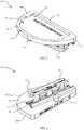
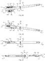
- a knee tibial prosthesis 10includes a tibial component 50 and at least one fixation element 20 .
- the tibial component 50may be referred to as a tibial tray 50 .
- the illustrated tibial component 50is a unicompartmental tibial component.
- the tibial prosthesis 10 of FIG. 1includes one fixation element 20 , which may be referred to as an anchor 20 . Multiple anchors may be present.
- the anchor 20may be inserted from an anterior edge 54 of the tibial tray 50 and may be oriented roughly anterior-posterior, as shown.
- the anchor 20may be parallel or angled relative to another anchor (if present) and/or the tray 50 .
- the anchormay also be tilted with respect to the tray 50 , for example, tilted medially or laterally.
- the anchor 20is inserted into a channel 52 in the tibial tray 50 ( FIG. 18 ).
- Multiple channelsmay be present.
- the channelmay be dovetailed as shown; other undercut channel geometries are contemplated, such as T-slots.
- the channel 52is shown extending between anterior and posterior edges 54 , 66 of the tray 50 .
- the channelmay only open at one of the anterior and posterior edges 54 , 66 , and may terminate in the main body of the tray 50 .
- the channel 52may be oriented exactly anterior-posterior, exactly medial-lateral, generally medial-lateral, or in another orientation.
- a channel 52may open through any perimeter edge of a bone-contacting side 56 of the tray 50 .
- the anchors in the present disclosuremay share some or all of the features of the anchors disclosed in U.S. patent application Ser. No. 12/640,892 to Bae, et al. or U.S. patent application Ser. No. 13/328,592 to Bae, et al., which are incorporated by reference herein in their entirety.
- each fixation element or anchor 20comprises a blade 22 and a rail 24 .
- the blade and railextend between a leading end 70 and a trailing end 68 of the anchor.
- the leading end 70may also be referred to as a distal end 70 ; the trailing end 68 may also be referred to as a proximal end 68 .
- Supports 26connect the blade 22 to the rail 24 .
- FIG. 26illustrates an anchor 20 with three supports 26 , although other examples may include any number of supports.
- the supports 26define apertures 27 through the anchor 20 . In use, the blade 22 and at least a portion of the supports 26 may be inserted into bone which is adjacent to the bone-contacting side 56 of the tray 50 .
- the blade 22may be pointed, sharpened, and/or serrated, for ease of insertion into bone.
- the supports 26may also be sharpened and/or obliquely profiled for ease of insertion into bone.
- the blade edgesmay be beveled.
- the blade 22may be pierced by one or more apertures 36 .
- Longitudinal edges 28 of the railmay be sized and shaped for complementary engagement with the dovetail channels 52 of the tray 50 . In other examples, the rail may be of a complementary size and shape to engage another undercut channel geometry.
- FIGS. 32 and 36illustrate bilateral tabs.
- the tabmay be said to protrude laterally or transversely from the rail 24 .
- the tabdeforms as the anchor is driven into the tibial tray 50 , creating an interference fit.
- This material deformationserves to take up any relative motion between the anchor and the tibial tray as well as to lock the anchor 20 into the tray 50 .
- the deformationmay be characterized as plastic deformation, which may be at least partially irreversible. The deformation may cause galling, spot welding, and/or seizing to occur between the tab and the channel 52 . Any of these adhesive phenomena may lock the anchor to the tray.
- a distal tip 34 of the anchor railmay be tapered for ease of insertion into, and movement along, the channels 52 .
- physical stops 32are located on each side of the rail 24 and extend distally from the proximal end 68 .
- Tabs 30are located on each side of the rail 24 near the proximal end 68 , spaced apart distally from the physical stops 32 .
- Another examplemay include a tab 30 on only one side of the rail.
- the illustrated exampleincludes a second pair of bilateral interference tabs 31 located on each side of the rail 24 and spaced apart distally from the tabs 30 .
- the tabs 31are shown adjacent to a middle support 26 , although they can be located anywhere along the rail 24 between the tabs 30 and the distal end 70 . This arrangement may provide even greater fixation along the length of the anchor in the channel 52 . Also, in other embodiments the length, height, or other dimensions of the anchor may vary.
- the anchor blade 22may be angled divergent from the rail 24 .
- the divergence angle 72may be less than about 90 degrees. In some examples, the divergence angle may be less than about 15 degrees, less than about 5 degrees, or less than about 2 degrees. In the embodiment shown, the divergence angle between the blade 22 and the rail 24 is 1 degree. Divergence angles of less than 1 degree are also contemplated.
- the anchor blade 22may diverge from an inferior or bone-contacting side 56 of the tray 50 at the same angle 72 .
- the blade 22may diverge from the inferior or bone-contacting side of the tray 50 at another angle, which may be greater than or less than the blade-to-rail divergence angle 72 .
- the blade-to-tray divergence anglemay open in the same or opposite direction as the blade-to-rail divergence angle 72 .
- the angle 72 between the blade 22 and the rail 24 , and/or the angle between the blade and the bone-contacting side 56may correlate to the mechanical properties of the bone into which the anchor 20 will be inserted, the desired amount of compression between the bone and the bone-contacting side, the compliance of the bone-contacting side, and/or other factors.
- larger divergence anglesmay be appropriate for conditions such as: softer bone, greater compression, and/or a compliant bone-contacting side; smaller divergence angles may be appropriate for conditions such as harder or stiffer bone, less compression, and/or an unyielding bone-contacting side.
- the divergence anglemay also correlate to the length of the anchor 20 , with greater divergence angles possible with shorter anchors and smaller divergence angles suitable for longer anchors.
- the tibial tray 50includes a bone-contacting, or inferior side 56 across which the channel 52 extends.
- a ridge 76extends across the bone-contacting side 56 to provide material within which to form the channel 52 .
- the entire channel 52is outside the main body of the tibial tray 50 , as seen best in FIGS. 22-24 .
- the most proximal surface 53 within the channelis flush with or distal to the inferior side 56 .
- Surface 53may be referred to as the bottom surface of the channel.
- the channel 52is thus defined between first and second walls 77 , 78 . At one end of each channel 52 , shoulders 59 are formed in the edges of the channels 52 .
- the shoulders 59are illustrated as being formed in interior edges of the channel near the anterior edge 54 of the tibial tray 50 . As seen in FIG. 4 , when the anchor rail 24 is inserted through the channel, the shoulders 59 deform the tabs 30 and engage with the stops 32 to provide the interference fit between the anchors 20 and the tray 50 , and to properly position the anchors at the correct depth relative to the tray.
- a peg 58 or postprovides further fixation of the tray 50 in the tibia.
- the illustrated exampleincludes a second peg 57 or post; any number of pegs may be present. The pegs 57 , 58 protrude from the bone-contacting side 56 and form an angle 74 with the bone-contacting side.
- the angle 74may be up to 90 degrees; a 75 degree angle 74 is illustrated for both pegs 57 , 58 .
- the pegsextend in an inferior-posterior direction from the bone-contacting side 56 , although the pegs may extend in other directions as a matter of design choice.
- the tibial tray 50further includes a joint-facing, or superior side 60 to which an articular insert (not shown) may be mounted, or the joint-facing side 60 may include a prosthetic articular surface integrally formed with the tibial tray 50 .
- a raised rim 62encompasses the superior side 60 , and overhangs 64 are formed on a portion of the rim 62 for engagement with an articular insert and/or instruments.
- the rim 62 and overhangs 64together define a recess 63 that may receive an articular insert, and may also engage an anchor guide instrument (not shown).
- the articular insert or instrumentmay engage under the overhangs 64 to be held rigidly in the tray 50 , for example by a snap fit.
- Tibial tray 50may be described as a unicondylar tibial component because it is adapted to extend across a single resected tibial condyle to replace the medial or lateral condyle.
- the features of the tibial tray 50may vary.
- the peg 58 or other fixation featuresmay vary; the size and thickness of the tray 50 may vary, the outer peripheral size and shape may vary.
- Different connection features for engagement with an articular insertmay be incorporated.
- Other features of tibial trays known in the artmay be included as desired.
- the articular insertmay carry the prosthetic articular surface.
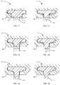
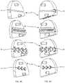
- Tibial tray 94includes a continuous channel 88 that is recessed entirely within the body of the tibial tray. Tibial tray 94 may share some or all of the features of the tibial tray 310 disclosed in U.S. patent application Ser. No. 13/328,592 to Bae, et al.
- Tibial tray 96includes a channel 90 that includes a series of discrete channel elements within discrete ridges, or between discrete wall sections. A linear array of ridges or walls is shown. Channel 90 extends along the bone-contacting surface outside the main body of the tibial tray like channel 52 .
- Tibial tray 98is an example in which the negative feature of the channel is replaced by a positive connection feature 92 that includes a series of discrete connection elements, which may be referred to as posts or buttons.
- the fixation element corresponding to tray 98carries a negative feature, a channel, that is complementary to the positive connection feature 92 .
- the posts and channelmay be complementary undercut shapes.
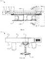
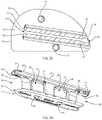
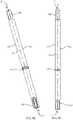
- a guide and drill assembly 100includes a tibial drill guide 110 and a reamer 150 .
- the tibial drill guide 110corresponds to the tibial tray 50 .
- the reamer 150is sized to correspond to the ridge 76 .
- the tibial drill guide 110includes a shaft 112 and a body 114 .
- the shaft 112extends between a proximal end 116 and a distal end 118 and includes a central longitudinal axis 121 and a central longitudinal hole 120 that extends entirely through the tibial drill guide 110 .
- the body 114corresponds to the main body of the tibial tray 50 , and may be said to mimic or replicate the main body of the tibial tray 50 , the perimeter of the main body, or the bone-contacting side 56 .
- the body 114is coupled to the distal end 118 of the shaft 112 so that the axis 121 and hole 120 are located to correspond to the height and width of the ridge 76 as viewed in FIG. 10 .
- the body 114includes holes 122 , 124 which correspond to the pegs 58 , 57 , respectively, of the tibial tray 50 .
- the holes 122 , 124may be defined by optional bosses 126 , 128 , respectively, to extend the length of the holes 122 , 124 and/or to provide depth stops for greater accuracy in drilling holes for the pegs 58 , 57 .
- the holes 122 , 124receive a drill (not shown) sized according to the outer diameter of the pegs 58 , 57 .
- the body 114also includes holes 130 , 132 which receive bone pins (not shown) or other fasteners to secure the tibial drill guide 110 to the tibia in use.
- the tibial reamer 150includes a shaft 152 that extends between a proximal end 154 and a distal end 156 and includes a central longitudinal axis 158 about which the reamer 150 rotates in use.
- the proximal end 154includes a torque drive feature 160 , such as a hex key or three equilateral flats.
- the distal end 156includes a cutting section 162 that may be side-cutting, end-cutting, or both.
- an optional flange 164encircles the shaft 152 to serve as a depth stop against the proximal end 116 of the shaft 112 of the tibial drill guide 110 .
- the distance between the cutting section 162 and the flange 164may be related to the overall length of the tibial drill guide along the axis 121 so that the cutting section 162 is prevented from extending distally across the body 114 past the end of the ridge 76 .
- the outer diameter of the cutting section 162as well as the outer diameter of the shaft 152 distal to the flange 164 , are sized to fit in the hole 120 of the shaft 112 of the tibial drill guide 110 .
- the outer diameter of the flange 164is larger than the hole 120 .
- the cutting section 162When the cutting section 162 is inserted into the hole 120 and advanced to be adjacent to the body 114 , a portion of the cutting section 162 is exposed on the bone-contacting side of the body 114 and protrudes outwardly from the bone-contacting side of the body 114 .
- the reamer 150When the bone-contacting side of the body 114 is placed against a resected bone surface, the reamer 150 is actuated (rotated about axis 158 ), and the reamer 150 is moved distally and proximally within the hole 120 , the cutting section 162 cuts a groove across the resected bone surface that is deep enough, wide enough, and long enough to receive the ridge 76 of the tibial tray 50 .
- the groovemay receive the ridge 76 with clearance, with a line-to-line fit, or with interference (a press fit).
- a tibia proximal endis prepared to receive the tibial tray 50 .
- a transverse resectionmay be made to remove the medial or lateral proximal tibial articular cartilage.
- Recesses for a tray peg 58 and/or 57may be reamed, drilled, broached, cut or otherwise prepared.
- the tibial tray 50is fit onto the prepared tibia, and may be implanted with or without cement.
- An anchor 20is inserted into the channel on the tray. The blade may cut into the bone as the anchor is inserted.
- the angled configuration of the anchorcauses compression of the tray toward the tibia; i.e., the tray is pulled toward the tibia.
- the tabs, stops, and shoulders on the tray and the anchorcooperate to seat the anchor at the proper depth relative to the tray, and prevent unintentional withdrawal of the anchor.
- An articular insert(not shown) may be coupled to the superior surface of the tray 50 , and may include an articular surface.
- the leading end 70is configured so that the rail 24 and the blade 22 are the leading features, and are thus the first features to engage the channel or bone.
- the leading point of the blade 22penetrates the bone.
- the leading support 26is the next feature to engage, as it enters the channel and the bone.
- the supportmay be said to protrude through the bone-contacting surface, since the support extends through the open side of the channel. All leading edges of the support and blade are sharpened and obliquely oriented to reduce the effort necessary to cut through the bone.
- Any methods disclosed hereinincludes one or more steps or actions for performing the described method.
- the method steps and/or actionsmay be interchanged with one another.
- the order and/or use of specific steps and/or actionsmay be modified.
Landscapes
- Health & Medical Sciences (AREA)
- Life Sciences & Earth Sciences (AREA)
- Orthopedic Medicine & Surgery (AREA)
- Surgery (AREA)
- Veterinary Medicine (AREA)
- General Health & Medical Sciences (AREA)
- Oral & Maxillofacial Surgery (AREA)
- Engineering & Computer Science (AREA)
- Biomedical Technology (AREA)
- Heart & Thoracic Surgery (AREA)
- Public Health (AREA)
- Animal Behavior & Ethology (AREA)
- Molecular Biology (AREA)
- Nuclear Medicine, Radiotherapy & Molecular Imaging (AREA)
- Medical Informatics (AREA)
- Dentistry (AREA)
- Transplantation (AREA)
- Physical Education & Sports Medicine (AREA)
- Cardiology (AREA)
- Vascular Medicine (AREA)
- Prostheses (AREA)
Abstract
Description
Claims (15)
Priority Applications (6)
| Application Number | Priority Date | Filing Date | Title |
|---|---|---|---|
| US16/664,154US11369488B2 (en) | 2017-03-03 | 2019-10-25 | Unicompartmental knee arthroplasty |
| US17/024,669US11540928B2 (en) | 2017-03-03 | 2020-09-17 | Unicompartmental knee arthroplasty |
| US17/337,575US20210290410A1 (en) | 2017-03-03 | 2021-06-03 | Unicompartmental knee arthroplasty |
| US17/840,062US20220304826A1 (en) | 2017-03-03 | 2022-06-14 | Unicompartmental knee arthroplasty |
| US17/840,028US20220304825A1 (en) | 2017-03-03 | 2022-06-14 | Unicompartmental knee arthroplasty |
| US17/860,363US20220339004A1 (en) | 2017-03-03 | 2022-07-08 | Unicompartmental knee arthroplasty |
Applications Claiming Priority (3)
| Application Number | Priority Date | Filing Date | Title |
|---|---|---|---|
| US201762467083P | 2017-03-03 | 2017-03-03 | |
| US15/910,962US10456272B2 (en) | 2017-03-03 | 2018-03-02 | Unicompartmental knee arthroplasty |
| US16/664,154US11369488B2 (en) | 2017-03-03 | 2019-10-25 | Unicompartmental knee arthroplasty |
Related Parent Applications (1)
| Application Number | Title | Priority Date | Filing Date |
|---|---|---|---|
| US15/910,962ContinuationUS10456272B2 (en) | 2017-03-03 | 2018-03-02 | Unicompartmental knee arthroplasty |
Related Child Applications (1)
| Application Number | Title | Priority Date | Filing Date |
|---|---|---|---|
| US17/024,669Continuation-In-PartUS11540928B2 (en) | 2017-03-03 | 2020-09-17 | Unicompartmental knee arthroplasty |
Publications (2)
| Publication Number | Publication Date |
|---|---|
| US20200054462A1 US20200054462A1 (en) | 2020-02-20 |
| US11369488B2true US11369488B2 (en) | 2022-06-28 |
Family
ID=63357485
Family Applications (2)
| Application Number | Title | Priority Date | Filing Date |
|---|---|---|---|
| US15/910,962Active2038-04-25US10456272B2 (en) | 2017-03-03 | 2018-03-02 | Unicompartmental knee arthroplasty |
| US16/664,154Active2039-03-04US11369488B2 (en) | 2017-03-03 | 2019-10-25 | Unicompartmental knee arthroplasty |
Family Applications Before (1)
| Application Number | Title | Priority Date | Filing Date |
|---|---|---|---|
| US15/910,962Active2038-04-25US10456272B2 (en) | 2017-03-03 | 2018-03-02 | Unicompartmental knee arthroplasty |
Country Status (1)
| Country | Link |
|---|---|
| US (2) | US10456272B2 (en) |
Cited By (1)
| Publication number | Priority date | Publication date | Assignee | Title |
|---|---|---|---|---|
| US20220304826A1 (en)* | 2017-03-03 | 2022-09-29 | Engage Uni Llc | Unicompartmental knee arthroplasty |
Families Citing this family (6)
| Publication number | Priority date | Publication date | Assignee | Title |
|---|---|---|---|---|
| EP2651341B1 (en) | 2010-12-16 | 2017-01-04 | Engage Medical Holdings, LLC | Arthroplasty systems and methods |
| US10390955B2 (en) | 2016-09-22 | 2019-08-27 | Engage Medical Holdings, Llc | Bone implants |
| US11540928B2 (en) | 2017-03-03 | 2023-01-03 | Engage Uni Llc | Unicompartmental knee arthroplasty |
| US10456272B2 (en) | 2017-03-03 | 2019-10-29 | Engage Uni Llc | Unicompartmental knee arthroplasty |
| CN112220591A (en)* | 2020-11-05 | 2021-01-15 | 嘉思特华剑医疗器材(天津)有限公司 | A wedge-shaped compression biotype single-compartment knee tibial plateau |
| CN112220592A (en)* | 2020-11-05 | 2021-01-15 | 嘉思特华剑医疗器材(天津)有限公司 | Biological single-compartment knee joint mechanical pressurization tibial platform |
Citations (309)
| Publication number | Priority date | Publication date | Assignee | Title |
|---|---|---|---|---|
| US3486505A (en) | 1967-05-22 | 1969-12-30 | Gordon M Morrison | Orthopedic surgical instrument |
| US3641590A (en) | 1970-01-16 | 1972-02-15 | Arthur A Michele | Acetabular replacement prosthesis and method of assembling |
| US3650309A (en) | 1969-02-12 | 1972-03-21 | Robert Neuschotz | Structure and use of fasteners having locking keys |
| US3842825A (en) | 1973-11-12 | 1974-10-22 | R Wagner | Hip fixation device |
| US3848276A (en) | 1973-05-03 | 1974-11-19 | Y Martinez | Knee implant device |
| US3882917A (en) | 1970-04-03 | 1975-05-13 | Litton Industrial Products | Self-locking thread |
| US3896504A (en) | 1972-10-14 | 1975-07-29 | Artur Fischer | Hip joint prosthesis |
| US3907017A (en) | 1974-09-30 | 1975-09-23 | Glenn W Stanwick | Interfering thread form |
| US3927503A (en) | 1973-12-26 | 1975-12-23 | Standard Pressed Steel Co | Prevailing torque fastener |
| US4011602A (en) | 1975-10-06 | 1977-03-15 | Battelle Memorial Institute | Porous expandable device for attachment to bone tissue |
| US4047524A (en) | 1975-04-28 | 1977-09-13 | Downs Surgical Limited | Surgical implant spinal staple |
| US4260005A (en) | 1977-11-09 | 1981-04-07 | Vsi Corporation | Self-locking fastener, fastener system, and process |
| US4349955A (en) | 1976-05-07 | 1982-09-21 | Taper Line, Inc. | Method of locking a male member to a female member |
| US4355429A (en) | 1979-01-26 | 1982-10-26 | Osteo Ag | Slide prosthesis for the knee joint |
| US4454875A (en) | 1982-04-15 | 1984-06-19 | Techmedica, Inc. | Osteal medical staple |
| US4484570A (en) | 1980-05-28 | 1984-11-27 | Synthes Ltd. | Device comprising an implant and screws for fastening said implant to a bone, and a device for connecting two separated pieces of bone |
| US4501269A (en) | 1981-12-11 | 1985-02-26 | Washington State University Research Foundation, Inc. | Process for fusing bone joints |
| USD281814S (en) | 1983-07-13 | 1985-12-17 | Techmedica, Inc. | Osteotomy staple |
| US4570623A (en) | 1983-06-02 | 1986-02-18 | Pfizer Hospital Products Group Inc. | Arched bridge staple |
| EP0179695A1 (en) | 1984-09-26 | 1986-04-30 | Pierre Kehr | Vertebral prosthesis, in particular for cervical vertebrae |
| US4611581A (en) | 1983-12-16 | 1986-09-16 | Acromed Corporation | Apparatus for straightening spinal columns |
| US4642869A (en) | 1984-02-07 | 1987-02-17 | Multifastener Corporation | Process of attaching a nut to a plate-shaped workpiece |
| US4681589A (en) | 1984-06-01 | 1987-07-21 | Tronzo Raymond G | Adjustable acetabular cup prosthesis as part of a total cup replacement system |
| US4716893A (en) | 1985-03-11 | 1988-01-05 | Artur Fischer | Bone fastener |
| US4743256A (en) | 1985-10-04 | 1988-05-10 | Brantigan John W | Surgical prosthetic implant facilitating vertebral interbody fusion and method |
| US4764067A (en) | 1985-11-22 | 1988-08-16 | Jsm Screw Co., Ltd. | Screw with groove for self-lock and method and rolling flat die for manufacturing the same |
| US4820305A (en) | 1986-11-03 | 1989-04-11 | Harms Juergen | Place holder, in particular for a vertebra body |
| US4834757A (en) | 1987-01-22 | 1989-05-30 | Brantigan John W | Prosthetic implant |
| US4838891A (en) | 1984-11-28 | 1989-06-13 | Branemark Per Ingvar | Joint prothesis |
| US4848328A (en) | 1986-05-20 | 1989-07-18 | Laboureau Jacques P | Agraffe for osteosynthesis |
| US4865607A (en) | 1985-10-02 | 1989-09-12 | Ulrich Witzel | Tibial plate for a knee-joint endoprosthesis |
| US4874389A (en) | 1987-12-07 | 1989-10-17 | Downey Ernest L | Replacement disc |
| US4930962A (en) | 1988-12-01 | 1990-06-05 | Pac-Fasteners, An Affiliate Of Peterson American Corp. | Nut and stud assembly |
| US4946378A (en) | 1987-11-24 | 1990-08-07 | Asahi Kogaku Kogyo Kabushiki Kaisha | Artificial intervertebral disc |
| US4957496A (en) | 1988-11-11 | 1990-09-18 | Mecron Medizinische Produkte Gmbh | Slotted slide plate assembly for osteosynthesis |
| US5002576A (en) | 1988-06-06 | 1991-03-26 | Mecron Medizinische Produkte Gmbh | Intervertebral disk endoprosthesis |
| US5019103A (en) | 1990-02-05 | 1991-05-28 | Boehringer Mannheim Corporation | Tibial wedge system |
| US5053038A (en) | 1989-08-17 | 1991-10-01 | Tenstaple, Inc. | Compression bone staple |
| US5074880A (en) | 1988-12-20 | 1991-12-24 | S.P.O.R.T. | Anchoring device for knee prosthesis |
| US5147361A (en) | 1989-11-29 | 1992-09-15 | Asahi Kogaku Kogyo Kabushiki Kaisha | Vertebral connecting plate |
| US5163960A (en) | 1990-06-28 | 1992-11-17 | Bonutti Peter M | Surgical devices assembled using heat bondable materials |
| US5192327A (en) | 1991-03-22 | 1993-03-09 | Brantigan John W | Surgical prosthetic implant for vertebrae |
| US5192324A (en) | 1982-02-18 | 1993-03-09 | Howmedica Inc. | Bone prosthesis with porous coating |
| US5306309A (en) | 1992-05-04 | 1994-04-26 | Calcitek, Inc. | Spinal disk implant and implantation kit |
| US5314477A (en) | 1990-03-07 | 1994-05-24 | J.B.S. Limited Company | Prosthesis for intervertebral discs and instruments for implanting it |
| US5352229A (en) | 1993-05-12 | 1994-10-04 | Marlowe Goble E | Arbor press staple and washer and method for its use |
| US5366479A (en) | 1991-10-18 | 1994-11-22 | United States Surgical Corporation | Surgical staple for attaching an object to body tissue |
| US5431658A (en) | 1994-02-14 | 1995-07-11 | Moskovich; Ronald | Facilitator for vertebrae grafts and prostheses |
| US5443515A (en) | 1994-01-26 | 1995-08-22 | Implex Corporation | Vertebral body prosthetic implant with slidably positionable stabilizing member |
| US5449359A (en) | 1991-09-05 | 1995-09-12 | Groiso; Jorge A. | Elastic clip for osteosynthesis |
| US5454814A (en) | 1992-09-02 | 1995-10-03 | Orthomed Sarl | Surgical clamp and clamp driving device |
| USD364462S (en) | 1994-03-28 | 1995-11-21 | Michelson Gary K | Spinal fixation staple |
| US5507816A (en) | 1991-12-04 | 1996-04-16 | Customflex Limited | Spinal vertebrae implants |
| US5514180A (en) | 1994-01-14 | 1996-05-07 | Heggeness; Michael H. | Prosthetic intervertebral devices |
| USD378409S (en) | 1995-10-30 | 1997-03-11 | Michelson Gary K | Spinal fixation staple |
| US5609635A (en) | 1988-06-28 | 1997-03-11 | Michelson; Gary K. | Lordotic interbody spinal fusion implants |
| US5658337A (en) | 1994-05-23 | 1997-08-19 | Spine-Tech, Inc. | Intervertebral fusion implant |
| US5683394A (en) | 1995-09-29 | 1997-11-04 | Advanced Spine Fixation Systems, Inc. | Fusion mass constrainer |
| US5702449A (en) | 1995-06-07 | 1997-12-30 | Danek Medical, Inc. | Reinforced porous spinal implants |
| US5709683A (en) | 1995-12-19 | 1998-01-20 | Spine-Tech, Inc. | Interbody bone implant having conjoining stabilization features for bony fusion |
| US5713899A (en) | 1995-04-27 | 1998-02-03 | Societe Jbs Sa | Cervical cage designed for the performance of intersomatic arthrodesis |
| US5769852A (en) | 1993-04-27 | 1998-06-23 | Medevelop Ab | Implantable anchoring element and anchoring assembly for prostheses |
| US5772661A (en) | 1988-06-13 | 1998-06-30 | Michelson; Gary Karlin | Methods and instrumentation for the surgical correction of human thoracic and lumbar spinal disease from the antero-lateral aspect of the spine |
| US5776202A (en) | 1993-09-07 | 1998-07-07 | Copf; Franz | Joint prosthesis |
| US5776199A (en) | 1988-06-28 | 1998-07-07 | Sofamor Danek Properties | Artificial spinal fusion implants |
| US5788701A (en) | 1995-12-21 | 1998-08-04 | Johnson & Johnson Professional, Inc. | Instrument system for knee prothesis implantation with universal handle or slap hammer |
| US5800550A (en) | 1996-03-13 | 1998-09-01 | Sertich; Mario M. | Interbody fusion cage |
| US5860973A (en) | 1995-02-27 | 1999-01-19 | Michelson; Gary Karlin | Translateral spinal implant |
| US5893890A (en) | 1994-03-18 | 1999-04-13 | Perumala Corporation | Rotating, locking intervertebral disk stabilizer and applicator |
| US5893889A (en) | 1997-06-20 | 1999-04-13 | Harrington; Michael | Artificial disc |
| US5947999A (en) | 1996-12-03 | 1999-09-07 | Groiso; Jorge A. | Surgical clip and method |
| US6039762A (en) | 1995-06-07 | 2000-03-21 | Sdgi Holdings, Inc. | Reinforced bone graft substitutes |
| US6059787A (en) | 1999-04-26 | 2000-05-09 | Allen; Drew | Compression bone staple apparatus and method |
| US6063121A (en) | 1998-07-29 | 2000-05-16 | Xavier; Ravi | Vertebral body prosthesis |
| US6080155A (en) | 1988-06-13 | 2000-06-27 | Michelson; Gary Karlin | Method of inserting and preloading spinal implants |
| US6096080A (en) | 1998-05-06 | 2000-08-01 | Cortek, Inc. | Apparatus for spinal fusion using implanted devices |
| US6102949A (en) | 1997-12-03 | 2000-08-15 | Biedermann Motech Gmbh | Intervertebrae implant |
| US6102954A (en) | 1992-05-18 | 2000-08-15 | Astra Aktiebolag | Joint prosthesis and apparatus for preparing the bone prior to fitting of the prosthesis |
| US6113638A (en) | 1999-02-26 | 2000-09-05 | Williams; Lytton A. | Method and apparatus for intervertebral implant anchorage |
| US6120503A (en) | 1994-03-28 | 2000-09-19 | Michelson; Gary Karlin | Apparatus instrumentation, and method for spinal fixation |
| US6159214A (en) | 1996-07-31 | 2000-12-12 | Michelson; Gary K. | Milling instrumentation and method for preparing a space between adjacent vertebral bodies |
| US6224607B1 (en) | 1999-01-25 | 2001-05-01 | Gary K. Michelson | Instrumentation and method for creating an intervertebral space for receiving an implant |
| US6235059B1 (en) | 1996-04-03 | 2001-05-22 | Scient'x (Societe A Responsabilite Limitee) | Intersomatic setting and fusion system |
| US6241770B1 (en) | 1999-03-05 | 2001-06-05 | Gary K. Michelson | Interbody spinal fusion implant having an anatomically conformed trailing end |
| US6299613B1 (en) | 1999-04-23 | 2001-10-09 | Sdgi Holdings, Inc. | Method for the correction of spinal deformities through vertebral body tethering without fusion |
| US6309421B1 (en) | 1994-03-18 | 2001-10-30 | Madhavan Pisharodi | Rotating, locking intervertebral disk stabilizer and applicator |
| US20010037154A1 (en) | 2000-04-10 | 2001-11-01 | Martin Christopher Harris | Modular radial head prostheses |
| US20010047208A1 (en) | 1999-12-08 | 2001-11-29 | Michelson Gary K. | Spinal implant surface configuration |
| US20010047207A1 (en) | 1998-10-30 | 2001-11-29 | Michelson Gary K. | Self-broaching, rotatable, push-in interbody spinal fusion implant and method for deployment thereof |
| US6325805B1 (en) | 1999-04-23 | 2001-12-04 | Sdgi Holdings, Inc. | Shape memory alloy staple |
| US6336928B1 (en) | 1996-10-18 | 2002-01-08 | Depuy France | Device for securing at least two vertebrae |
| US20020004683A1 (en) | 2000-07-10 | 2002-01-10 | Michelson Gary K. | Flanged interbody spinal fusion implants |
| US20020035400A1 (en) | 2000-08-08 | 2002-03-21 | Vincent Bryan | Implantable joint prosthesis |
| US20020049447A1 (en) | 2000-08-29 | 2002-04-25 | Li Medical Technologies, Inc. | Expandable surgical fastener and method |
| US6402785B1 (en) | 1999-06-04 | 2002-06-11 | Sdgi Holdings, Inc. | Artificial disc implant |
| US6413278B1 (en) | 1998-03-30 | 2002-07-02 | J. Alexander Marchosky | Prosthetic system |
| US20020099376A1 (en) | 2001-01-23 | 2002-07-25 | Michelson Gary K. | Interbody spinal implant with trailing end adapted to receive bone screws |
| US6432107B1 (en) | 2000-01-15 | 2002-08-13 | Bret A. Ferree | Enhanced surface area spinal fusion devices |
| US6436098B1 (en) | 1993-06-10 | 2002-08-20 | Sofamor Danek Holdings, Inc. | Method for inserting spinal implants and for securing a guard to the spine |
| US20020116165A1 (en) | 2001-02-13 | 2002-08-22 | El-Ghoroury Hussein S. | Matched instruction set processor systems and method, system, and apparatus to efficiently design and implement matched instruction set processor systems by mapping system designs to re-configurable hardware platforms |
| US20020116065A1 (en) | 1998-10-21 | 2002-08-22 | Jackson Roger P. | Spinal fusion apparatus and method |
| US6447524B1 (en) | 2000-10-19 | 2002-09-10 | Ethicon Endo-Surgery, Inc. | Fastener for hernia mesh fixation |
| US6447546B1 (en) | 2000-08-11 | 2002-09-10 | Dale G. Bramlet | Apparatus and method for fusing opposing spinal vertebrae |
| US6458159B1 (en) | 2000-08-15 | 2002-10-01 | John S. Thalgott | Disc prosthesis |
| US20020147454A1 (en) | 2001-04-10 | 2002-10-10 | Neto Aziz Rassi | Building configuration introduced in a surgical-use screw |
| US20020147499A1 (en) | 2001-02-26 | 2002-10-10 | Shea Jeffrey J. | Locking systems for implants |
| US20020161443A1 (en) | 2001-04-02 | 2002-10-31 | Michelson Gary K. | Artificial contoured spinal fusion implants made of a material other than bone |
| US20020165613A1 (en) | 2001-05-04 | 2002-11-07 | Chih-I Lin | Intervertebral fixation device having one or more bracing elements |
| US6478800B1 (en) | 2000-05-08 | 2002-11-12 | Depuy Acromed, Inc. | Medical installation tool |
| US6485517B1 (en) | 1999-05-05 | 2002-11-26 | Gary K. Michelson | Nested interbody spinal fusion implants |
| US6506216B1 (en) | 1998-05-13 | 2003-01-14 | Depuy Products, Inc. | Tibial tray with adjustable keel |
| US20030045940A1 (en) | 2001-08-24 | 2003-03-06 | Robert Eberlein | Artificial intervertebral disc |
| US20030060884A1 (en) | 1999-05-10 | 2003-03-27 | Fell Barry M. | Surgically implantable knee prosthesis having keels |
| US6558424B2 (en) | 2001-06-28 | 2003-05-06 | Depuy Acromed | Modular anatomic fusion device |
| US6558423B1 (en) | 1999-05-05 | 2003-05-06 | Gary K. Michelson | Interbody spinal fusion implants with multi-lock for locking opposed screws |
| US6582468B1 (en) | 1998-12-11 | 2003-06-24 | Spryker Spine | Intervertebral disc prosthesis with compressible body |
| US20030120344A1 (en) | 2001-04-02 | 2003-06-26 | Michelson Gary K. | Contoured spinal fusion implants made of bone or a bone composite material |
| US6599294B2 (en) | 1999-01-30 | 2003-07-29 | Aesculap Ag & Co. Kg | Surgical instrument for introducing intervertebral implants |
| US20030158553A1 (en) | 1988-06-13 | 2003-08-21 | Michelson Gary Karlin | Instrumentation for the surgical correction of spinal disease |
| US6610093B1 (en) | 2000-07-28 | 2003-08-26 | Perumala Corporation | Method and apparatus for stabilizing adjacent vertebrae |
| US6620198B2 (en) | 1999-10-07 | 2003-09-16 | Exactech, Inc. | Composite bearing inserts for total knee joints |
| US20030195561A1 (en) | 2000-12-07 | 2003-10-16 | Carley Michael T. | Closure device and methods for making and using them |
| US20030195632A1 (en) | 2001-02-06 | 2003-10-16 | Foley Kevin T. | Spinal implant with attached ligament |
| US6652533B2 (en) | 2001-09-20 | 2003-11-25 | Depuy Acromed, Inc. | Medical inserter tool with slaphammer |
| US20040030339A1 (en) | 2001-04-20 | 2004-02-12 | Wack Michael A. | Dual locking plate and associated method |
| US20040030336A1 (en) | 2002-08-06 | 2004-02-12 | Khanna Rohit Kumar | Anterior cervical spine stabilization method and system |
| US6716245B2 (en) | 2000-07-12 | 2004-04-06 | Spine Next | Intersomatic implant |
| US20040073315A1 (en) | 2002-04-25 | 2004-04-15 | Justin Daniel F. | Modular bone implant, tools, and method |
| US6726720B2 (en) | 2002-03-27 | 2004-04-27 | Depuy Spine, Inc. | Modular disc prosthesis |
| US20040083005A1 (en) | 1998-12-22 | 2004-04-29 | Magnus Jacobsson | Method of anchoring a prosthesis structure |
| US6740118B2 (en) | 2002-01-09 | 2004-05-25 | Sdgi Holdings, Inc. | Intervertebral prosthetic joint |
| US6743256B2 (en) | 2000-10-11 | 2004-06-01 | Michael D. Mason | Graftless spinal fusion device |
| US6746450B1 (en) | 1999-07-07 | 2004-06-08 | Children's Hospital Medical Center | Spinal correction system |
| US20040122518A1 (en) | 2002-12-19 | 2004-06-24 | Rhoda William S. | Intervertebral implant |
| US20040133203A1 (en) | 2002-10-28 | 2004-07-08 | Young J Stewart | Multi-axial, cross-link connector system for spinal implants |
| US6767356B2 (en) | 2000-09-01 | 2004-07-27 | Angiolink Corporation | Advanced wound site management systems and methods |
| US6767367B1 (en) | 2002-02-02 | 2004-07-27 | Gary K. Michelson | Spinal fusion implant having deployable bone engaging projections |
| US20040148028A1 (en) | 2002-12-19 | 2004-07-29 | Ferree Bret A. | Artificial disc replacement (ADR) extraction methods and apparatus |
| US6770096B2 (en) | 1999-07-01 | 2004-08-03 | Spinevision S.A. | Interbody spinal stabilization cage and spinal stabilization method |
| US6770074B2 (en) | 1988-06-13 | 2004-08-03 | Gary Karlin Michelson | Apparatus for use in inserting spinal implants |
| US20040176853A1 (en) | 2003-03-05 | 2004-09-09 | Sennett Andrew R. | Apparatus and method for spinal fusion using posteriorly implanted devices |
| US6800093B2 (en) | 1998-05-06 | 2004-10-05 | Cortek, Inc. | Device for spinal fusion |
| US6802863B2 (en) | 2002-03-13 | 2004-10-12 | Cross Medical Products, Inc. | Keeled prosthetic nucleus |
| US20040220670A1 (en) | 2003-02-12 | 2004-11-04 | Sdgi Holdings, Inc. | Articular disc prosthesis and method for treating spondylolisthesis |
| US20040225295A1 (en) | 2001-07-16 | 2004-11-11 | Rafail Zubok | Wedge ramp distractor and related methods for use in implanting artificial intervertebral discs |
| US20040254581A1 (en) | 2003-02-04 | 2004-12-16 | Leclair Walter J. | Furcated bone screw |
| US20040254644A1 (en) | 2002-10-21 | 2004-12-16 | Taylor Brett Allison | Intervertebral disk prosthesis |
| US20040260286A1 (en) | 1999-10-08 | 2004-12-23 | Ferree Bret A. | Intradiscal devices with anti-extrusion keels |
| US6835208B2 (en) | 1998-03-30 | 2004-12-28 | J. Alexander Marchosky | Prosthetic system |
| US20050004672A1 (en) | 1995-10-16 | 2005-01-06 | John Pafford | Bone grafts |
| US20050014919A1 (en) | 2001-06-15 | 2005-01-20 | Hyoe Hatakeyama | Lignin-based polyurethane and process for producing the same |
| US6849093B2 (en) | 2001-03-09 | 2005-02-01 | Gary K. Michelson | Expansion constraining member adapted for use with an expandable interbody spinal fusion implant and method for use thereof |
| US20050027300A1 (en) | 2003-03-31 | 2005-02-03 | Depuy Spine, Inc. | Method and apparatus for artificial disc insertion |
| US20050049600A1 (en) | 2003-08-05 | 2005-03-03 | Groiso Jorge A. | Osteosynthesis clip and insertion tool for inserting an osteosynthesis clip into bone tissue fragments |
| US20050055031A1 (en) | 2003-09-10 | 2005-03-10 | Roy Lim | Devices and methods for inserting spinal implants |
| US20050113842A1 (en) | 2002-05-06 | 2005-05-26 | Rudolf Bertagnoli | Instrumentation and methods for preparation of an intervertebral space |
| US20050125065A1 (en) | 2003-11-05 | 2005-06-09 | St. Francis Medical Technologies Inc. | Laterally insertable artificial vertebral disk replacement implant with crossbar spacer |
| US20050131545A1 (en) | 2003-12-10 | 2005-06-16 | Alan Chervitz | Spinal facet implant with spherical implant apposition surface and bone bed and methods of use |
| US20050149192A1 (en) | 2003-11-20 | 2005-07-07 | St. Francis Medical Technologies, Inc. | Intervertebral body fusion cage with keels and implantation method |
| US20050165408A1 (en) | 2004-01-26 | 2005-07-28 | Puno Rolando M. | Methods and instrumentation for inserting intervertebral grafts and devices |
| US6923810B1 (en) | 1988-06-13 | 2005-08-02 | Gary Karlin Michelson | Frusto-conical interbody spinal fusion implants |
| US20050171550A1 (en) | 2004-01-30 | 2005-08-04 | Sdgi Holdings, Inc. | Anatomic implants designed to minimize instruments and surgical techniques |
| US20050171607A1 (en) | 2000-06-13 | 2005-08-04 | Michelson Gary K. | Manufactured bone composite implant shaped to conform to a prepared implantation space |
| US6926718B1 (en) | 1997-02-11 | 2005-08-09 | Gary K. Michelson | Multilock anterior cervical plating system |
| US20050177239A1 (en) | 1995-09-04 | 2005-08-11 | Amiram Steinberg | Method and apparatus for computerized surgery |
| US20050192586A1 (en) | 2002-10-29 | 2005-09-01 | St. Francis Medical Technologies, Inc. | Method of preparing for an artificial intervertebral implant using tool |
| US6942698B1 (en) | 2004-04-23 | 2005-09-13 | Roger P. Jackson | Spinal fusion interbody spacer |
| US20050234555A1 (en) | 2004-04-16 | 2005-10-20 | Depuy Spine, Inc. | Intervertebral disc with monitoring and adjusting capabilities |
| US6972035B2 (en) | 2000-04-19 | 2005-12-06 | Michelson Gary K | Expandable threaded arcuate interbody spinal fusion implant with cylindrical configuration during insertion |
| US20060004453A1 (en) | 2004-06-30 | 2006-01-05 | Depuy Spine, Inc. | Ceramic disc prosthesis |
| US6989031B2 (en) | 2001-04-02 | 2006-01-24 | Sdgi Holdings, Inc. | Hemi-interbody spinal implant manufactured from a major long bone ring or a bone composite |
| US20060058802A1 (en) | 2004-09-06 | 2006-03-16 | Hakon Kofoed | Fixation implant for a bone graft within a joint for the purpose of ensuring arthrodesis of the joint |
| US20060074421A1 (en) | 2003-05-08 | 2006-04-06 | Bickley Barry T | Fixation augmentation device and related techniques |
| US20060085071A1 (en) | 2003-02-06 | 2006-04-20 | Beat Lechmann | Intervertebral implant |
| US20060095136A1 (en) | 2004-11-03 | 2006-05-04 | Mcluen Design, Inc. | Bone fusion device |
| US7044972B2 (en) | 2001-01-30 | 2006-05-16 | Synthes Ag Chur | Bone implant, in particular, an inter-vertebral implant |
| US7048766B2 (en) | 2003-06-06 | 2006-05-23 | Ferree Bret A | Methods and apparatus for total disc replacements with oblique keels |
| US20060111787A1 (en) | 2004-11-05 | 2006-05-25 | Bailie David S | Glenoid prosthesis and method of implanting same |
| US20060116769A1 (en) | 2004-11-26 | 2006-06-01 | Theirry Marnay | Intervertebral implant |
| US7056344B2 (en) | 2001-11-06 | 2006-06-06 | Ldr Medical | Osseous anchoring device for a prosthesis |
| US7056345B2 (en) | 2000-12-15 | 2006-06-06 | Spineology, Inc. | Annulus-reinforcing band |
| US7060097B2 (en) | 2003-03-31 | 2006-06-13 | Depuy Spine, Inc. | Method and apparatus for implant stability |
| US20060129238A1 (en) | 2004-10-26 | 2006-06-15 | Adam Paltzer | Spinal stabilization device and methods |
| US20060136061A1 (en) | 2003-04-04 | 2006-06-22 | Theken Disc, Llc | Artificial disc prosthesis |
| US7087082B2 (en) | 1998-08-03 | 2006-08-08 | Synthes (Usa) | Bone implants with central chambers |
| US20060178745A1 (en) | 2005-02-10 | 2006-08-10 | Depuy Spine, Inc. | Intervertebral prosthetic disc |
| US20060195191A1 (en) | 2005-01-08 | 2006-08-31 | Alphaspine Inc. | Modular disc device |
| US20060195097A1 (en) | 2005-02-25 | 2006-08-31 | Evans David E | Implant insertion apparatus and method of use |
| US20060212123A1 (en) | 2003-07-22 | 2006-09-21 | Beat Lechmann | Articulated endoprosthesis |
| US7115146B2 (en) | 2000-03-22 | 2006-10-03 | Boyer Ii Michael L | Multipiece implants formed of bone material |
| US7118580B1 (en) | 1999-09-14 | 2006-10-10 | Spine Solutions Inc. | Instrument for inserting intervertebral implants |
| US20060241641A1 (en) | 2005-04-22 | 2006-10-26 | Sdgi Holdings, Inc. | Methods and instrumentation for distraction and insertion of implants in a spinal disc space |
| US7128761B2 (en) | 2003-12-10 | 2006-10-31 | Axiomed Spine Corporation | Method and apparatus for replacing a damaged spinal disc |
| US20070010822A1 (en) | 2005-07-08 | 2007-01-11 | Edward Zalenski | Bone removal tool |
| US20070010890A1 (en) | 2005-07-08 | 2007-01-11 | Howmedica Osteonics Corp. | Modular tibial baseplate |
| US7166110B2 (en) | 2004-01-09 | 2007-01-23 | Yundt Kent D | Method, system and apparatus for interbody fusion |
| US7169182B2 (en) | 2001-07-16 | 2007-01-30 | Spinecore, Inc. | Implanting an artificial intervertebral disc |
| US20070050033A1 (en) | 2005-09-01 | 2007-03-01 | Reo Michael L | Prosthetic intervertebral discs |
| US20070050032A1 (en) | 2005-09-01 | 2007-03-01 | Spinal Kinetics, Inc. | Prosthetic intervertebral discs |
| US20070055381A1 (en) | 2002-10-24 | 2007-03-08 | Berelsman Brian K | Method and apparatus for wrist arthroplasty |
| US20070073404A1 (en) | 2005-09-23 | 2007-03-29 | Ralph Rashbaum | Intervertebral disc prosthesis |
| US7204852B2 (en) | 2002-12-13 | 2007-04-17 | Spine Solutions, Inc. | Intervertebral implant, insertion tool and method of inserting same |
| US20070093839A1 (en) | 2005-09-12 | 2007-04-26 | Beckendorf Brandon G | Compression staple |
| US20070118132A1 (en) | 2002-07-19 | 2007-05-24 | Triage Medical, Inc. | Method and apparatus for spinal fixation |
| US20070123903A1 (en) | 2005-10-31 | 2007-05-31 | Depuy Spine, Inc. | Medical Device installation tool and methods of use |
| US20070142922A1 (en) | 2005-12-21 | 2007-06-21 | Lewis Paul P P | Modular hip cup assembly, fastener assembly & fastener |
| US7235101B2 (en) | 2003-09-15 | 2007-06-26 | Warsaw Orthopedic, Inc. | Revisable prosthetic device |
| US7235105B2 (en) | 2003-09-18 | 2007-06-26 | Jackson Roger P | Threaded center line cage with winged end gap |
| US7238203B2 (en) | 2001-12-12 | 2007-07-03 | Vita Special Purpose Corporation | Bioactive spinal implants and method of manufacture thereof |
| US20070179621A1 (en) | 2006-01-25 | 2007-08-02 | Spinemedica Corporation | Spinal disc implants with flexible keels and methods of fabricating implants |
| US20070185375A1 (en) | 2006-02-06 | 2007-08-09 | Depuy Spine, Inc. | Medical device installation tool |
| US20070225812A1 (en) | 2003-10-30 | 2007-09-27 | Gill Steven S | Intervertebral Prosthesis |
| US20070233244A1 (en) | 2006-03-28 | 2007-10-04 | Depuy Spine, Inc. | Artificial Disc Replacement Using Posterior Approach |
| US20070239278A1 (en) | 2006-04-06 | 2007-10-11 | Sdgi Holdings, Inc. | Intervertebral prosthetic devices and methods |
| US20070288005A1 (en) | 2006-04-05 | 2007-12-13 | Uri Arnin | Fixation of spinal prosthesis |
| US20070288021A1 (en) | 2006-06-07 | 2007-12-13 | Howmedica Osteonics Corp. | Flexible joint implant |
| US20070299529A1 (en) | 2006-06-22 | 2007-12-27 | Depuy Products, Inc. | Tibial insert having multiple keels |
| US20080051901A1 (en) | 2006-07-28 | 2008-02-28 | Spinalmotion, Inc. | Spinal Prosthesis with Multiple Pillar Anchors |
| US20080051902A1 (en) | 2006-08-10 | 2008-02-28 | James Dwyer | Modular intervertebral disc prosthesis and method of replacing an intervertebral disc |
| US7357817B2 (en) | 2005-05-19 | 2008-04-15 | Howmedica Osteonics Corp. | Modular keel tibial component |
| US20080103598A1 (en) | 2006-09-15 | 2008-05-01 | Trudeau Jeffrey L | System and Method for Sizing, Inserting and Securing Artificial Disc in Intervertebral Space |
| US20080108997A1 (en) | 2006-09-12 | 2008-05-08 | Pioneer Surgical Technology, Inc. | Mounting Devices for Fixation Devices and Insertion Instruments Used Therewith |
| US20080132949A1 (en) | 2005-12-29 | 2008-06-05 | Joseph Aferzon | Apparatus and method for anterior intervertebral spinal fixation and fusion |
| US20080133017A1 (en) | 2004-11-15 | 2008-06-05 | Disc-O- Tech Medical Technology | Assembled Prosthesis Such as a Disc |
| US20080147203A1 (en) | 2006-12-15 | 2008-06-19 | Zimmer Technology, Inc. | Modular plate and keel provisionals |
| US20080154377A1 (en) | 2006-12-22 | 2008-06-26 | Voellmicke John C | Composite vertebral spacers and instrument |
| US20080167721A1 (en) | 2006-12-22 | 2008-07-10 | Qi-Bin Bao | Implant retention device and method |
| US20080177275A1 (en) | 2006-12-01 | 2008-07-24 | Charles Wing | Interbody distractor |
| US20080208345A1 (en) | 2005-10-27 | 2008-08-28 | Kinetic Spine Technologies, Inc. | Intervertebral implant |
| US20080249575A1 (en) | 2007-04-03 | 2008-10-09 | Warsaw Orthopedic, Inc. | Anchor Member Locking Features |
| US20080269764A1 (en) | 2007-04-25 | 2008-10-30 | Spinal Elements, Inc. | Spinal implant distractor/inserter |
| US20080275455A1 (en) | 2006-08-16 | 2008-11-06 | Amicus, Llc | Apparatus and Methods for Inserting an Implant |
| US20080287957A1 (en) | 2007-05-18 | 2008-11-20 | Depuy Spine, Inc. | Insertion blade assembly and method of use |
| US20090005870A1 (en) | 2007-06-26 | 2009-01-01 | John Riley Hawkins | Highly Lordosed Fusion Cage |
| US20090005784A1 (en) | 2007-04-25 | 2009-01-01 | Spinal Elements, Inc. | Spinal implant distractor/inserter |
| US20090018560A1 (en) | 2007-04-20 | 2009-01-15 | Woodwelding Ag | Method for fastening an implant to bone tissue and corresponding implant system |
| US7481832B1 (en) | 2003-09-09 | 2009-01-27 | Biomet Sports Medicine, Llc | Method and apparatus for use of a self-tapping resorbable screw |
| USD586915S1 (en) | 2007-06-28 | 2009-02-17 | Biomedical Enterprises, Inc. | Soft tissue staple |
| US20090048604A1 (en) | 2007-08-13 | 2009-02-19 | Stryker Spine | Insertion instrument for intervertebral implants |
| US7503935B2 (en) | 2003-12-02 | 2009-03-17 | Kyphon Sarl | Method of laterally inserting an artificial vertebral disk replacement with translating pivot point |
| US20090088849A1 (en) | 2007-09-27 | 2009-04-02 | Warsaw Orthopedic, Inc. | Intervertebral Implant |
| US20090099601A1 (en) | 2007-10-11 | 2009-04-16 | International Spinal Innovations, Llc | Minimally invasive lateral intervertbral fixation system, device and method |
| US20090099602A1 (en) | 2007-09-11 | 2009-04-16 | Kamran Aflatoon | Method of lateral facet approach, decompression and fusion using screws and staples as well as arthroplasty |
| USD594986S1 (en) | 2005-03-29 | 2009-06-23 | Nuvasive, Inc. | Intervertebral implant |
| US20090164020A1 (en) | 2007-11-28 | 2009-06-25 | Pioneer Surgical Technology, Inc. | Device for Securing an Implant to Tissue |
| US7556650B2 (en) | 2004-06-29 | 2009-07-07 | Spine Wave, Inc. | Methods for injecting a curable biomaterial into an intervertebral space |
| US7572293B2 (en) | 2005-06-30 | 2009-08-11 | Depuy Products, Inc. | Tibial insert and associated surgical method |
| US20090240333A1 (en) | 2007-09-17 | 2009-09-24 | Trudeau Jeffrey L | Motion Preserving Artificial Intervertebral Disc Device |
| US7594931B2 (en) | 2001-07-13 | 2009-09-29 | Ldr Medical | Vertebral cage device with modular fixation |
| US7611538B2 (en) | 2003-08-04 | 2009-11-03 | Zimmer Spine S.A.S. | Intervertebral disk prosthesis |
| US20100004747A1 (en) | 2008-07-07 | 2010-01-07 | Jin-Fu Lin | Trans-Vertebral and Intra-Vertebral Plate and Fusion Cage Device for Spinal Interbody Fusion and Method of Operation |
| US7658766B2 (en) | 2006-05-01 | 2010-02-09 | Warsaw Orthopedic, Inc. | Intervertebral implants with covered inner chamber and methods of use |
| US20100069958A1 (en) | 2008-09-18 | 2010-03-18 | Smith & Nephew, Inc. | Tenodesis Implant |
| US20100076441A1 (en) | 2008-09-19 | 2010-03-25 | Zimmer, Inc. | Patello-femoral milling system |
| WO2010039026A1 (en) | 2008-09-30 | 2010-04-08 | J. Van Straten Beheer B.V. | Ankle prosthesis and a tibial component therefor |
| US7695516B2 (en) | 2004-12-22 | 2010-04-13 | Ldr Medical | Intervertebral disc prosthesis |
| US7749271B2 (en) | 2005-11-24 | 2010-07-06 | Aesculap Ag & Co Kg | Surgical guiding instrument |
| US20100185287A1 (en) | 2009-01-21 | 2010-07-22 | Warsaw Orthopedic, Inc. | Spinal nucleus replacement implants |
| US20100201739A1 (en) | 2009-02-12 | 2010-08-12 | Sony Corporation | Liquid ejection apparatus |
| US20100204739A1 (en) | 2009-02-11 | 2010-08-12 | IMDS, Inc. | Intervertebral implant with integrated fixation |
| US7780676B2 (en) | 2006-07-11 | 2010-08-24 | Ebi, Llc | Intervertebral implantation apparatus |
| US20100217395A1 (en) | 2006-07-24 | 2010-08-26 | Rudolf Bertagnoli | Intervertebral implant with keel |
| US20100268238A1 (en) | 2009-04-17 | 2010-10-21 | Arthrosurface Incorporated | Glenoid Resurfacing System and Method |
| US7837732B2 (en) | 2003-11-20 | 2010-11-23 | Warsaw Orthopedic, Inc. | Intervertebral body fusion cage with keels and implantation methods |
| US7850791B2 (en) | 2004-01-21 | 2010-12-14 | Forschungszentrum Julich Gmbh | Protective layer for an aluminum-containing alloy for high-temperature use |
| US7883510B2 (en) | 2004-08-27 | 2011-02-08 | Depuy Spine, Inc. | Vertebral staples and insertion tools |
| US7887563B2 (en) | 2001-06-07 | 2011-02-15 | Abbott Vascular Inc. | Surgical staple |
| US7909871B2 (en) | 2005-10-03 | 2011-03-22 | Samy Abdou | Devices and methods for inter-vertebral orthopedic device placement |
| US7918891B1 (en) | 2004-03-29 | 2011-04-05 | Nuvasive Inc. | Systems and methods for spinal fusion |
| WO2011044879A1 (en) | 2009-10-12 | 2011-04-21 | Aap Implantate Ag | Modular system for anchoring and positioning components of implants |
| US20110106260A1 (en) | 2009-04-15 | 2011-05-05 | Lawton Laurence | Flexible Vertebral Spacer |
| US7966799B2 (en) | 2006-09-29 | 2011-06-28 | Ethicon Endo-Surgery, Inc. | Method of manufacturing staples |
| US20110160866A1 (en) | 2008-09-02 | 2011-06-30 | Synthes Usa, Llc | Intervertebral implant with blades for connecting to adjacent vertebral bodies |
| US20110160766A1 (en) | 2005-11-02 | 2011-06-30 | Hendren Ronald D | Medical Affixation Device |
| US20110166608A1 (en) | 2009-07-14 | 2011-07-07 | Neil Duggal | Joint Arthrodesis and Arthroplasty |
| US8034076B2 (en) | 2000-10-23 | 2011-10-11 | Tyco Healthcare Group Lp | Absorbable fastener and applying apparatus |
| US8062297B2 (en) | 2008-07-24 | 2011-11-22 | Biopro, Inc. | Bone fixation apparatus and method of manufacture |
| US8100974B2 (en) | 2004-06-30 | 2012-01-24 | Synergy Disc Replacement, Inc. | Artificial spinal disc |
| US8100972B1 (en) | 2007-07-02 | 2012-01-24 | Theken Spine, Llc | Spinal cage having deployable member |
| US8105389B2 (en) | 2002-10-24 | 2012-01-31 | Biomet Manufacturing Corp. | Method and apparatus for wrist arthroplasty |
| US8123757B2 (en) | 2003-12-31 | 2012-02-28 | Depuy Spine, Inc. | Inserter instrument and implant clip |
| US8133283B2 (en) | 2007-06-06 | 2012-03-13 | Kenneth Mitchell Wilson | Scapho-lunate fixation implants and methods of use |
| US20120083788A1 (en) | 2010-10-01 | 2012-04-05 | Vot, Llc | Bur guide attachment and method of use |
| US8157865B2 (en) | 2009-01-22 | 2012-04-17 | Stephen Hochschuler | Apparatus and method for stabilizing adjacent bone portions |
| US20120215315A1 (en) | 2010-01-22 | 2012-08-23 | Stephen Hochschuler | Apparatus and method for stabilizing adjacent bone portions |
| US20120253406A1 (en) | 2009-11-03 | 2012-10-04 | Howmedica Osteonics Corp. | Intervertebral implant with integrated fixation |
| US20120259335A1 (en) | 2005-05-20 | 2012-10-11 | Smith & Nephew, Inc. | Patello-femoral joint implant and instrumentation |
| US20120265259A1 (en) | 2011-04-15 | 2012-10-18 | Laposta Marie | Fixation assembly |
| US20120283837A1 (en) | 2009-08-10 | 2012-11-08 | Howmedica Osteonics Corp. | Intervertebral implant with integrated fixation |
| US20130013006A1 (en) | 2005-11-30 | 2013-01-10 | Ralph Rashbaum | Intervertebral disc prosthesis and instrumentation for insertion of the prosthesis between the vertebrae |
| US8491598B2 (en) | 2008-03-03 | 2013-07-23 | Us Spine, Inc. | Surgical positioning assembly and associated spinal implant device and surgical methods |
| US8500747B2 (en) | 2006-09-19 | 2013-08-06 | Warsaw Orthopedic, Inc. | Instruments and methods for spinal implant revision |
| US8636191B2 (en) | 2003-05-09 | 2014-01-28 | Covidien Lp | Anastomotic staple with capillary which expels a bonding agent upon deformation |
| US20140039632A1 (en) | 2012-01-23 | 2014-02-06 | Imds Corporation | Glenoid vault fixation system |
| US8747412B2 (en) | 2011-02-14 | 2014-06-10 | Imds Corporation | System and method for bone anchor removal |
| US20140171952A1 (en) | 2012-12-19 | 2014-06-19 | Biomet Sports Medicine, Llc | External Tibial Mill Guide and Method of Use |
| US8808294B2 (en) | 2008-09-09 | 2014-08-19 | William Casey Fox | Method and apparatus for a multiple transition temperature implant |
| US20160008012A1 (en) | 2013-03-05 | 2016-01-14 | Waldemar Link Gmbh & Co. Kg | Medical tool system |
| US9254130B2 (en) | 2011-11-01 | 2016-02-09 | Hyun Bae | Blade anchor systems for bone fusion |
| US9480511B2 (en) | 2009-12-17 | 2016-11-01 | Engage Medical Holdings, Llc | Blade fixation for ankle fusion and arthroplasty |
| US9592131B2 (en) | 2010-01-22 | 2017-03-14 | Frontier Medical Devices, Inc. | Apparatus and method for stabilizing adjacent bone portions |
| US9615856B2 (en) | 2011-11-01 | 2017-04-11 | Imds Llc | Sacroiliac fusion cage |
| US20170367837A1 (en) | 2015-01-07 | 2017-12-28 | Wright Medical Technology, Inc. | Fixation mechanism for an implant |
| US9925051B2 (en) | 2010-12-16 | 2018-03-27 | Engage Medical Holdings, Llc | Arthroplasty systems and methods |
| US9968464B2 (en) | 2014-01-17 | 2018-05-15 | Spine Wave, Inc. | Spinal fusion system |
| US20190038298A1 (en) | 2001-05-25 | 2019-02-07 | Conformis, Inc. | Patient Selectable Joint Arthroplasty Devices and Surgical Tools |
| US10238382B2 (en) | 2012-03-26 | 2019-03-26 | Engage Medical Holdings, Llc | Blade anchor for foot and ankle |
| US10390955B2 (en) | 2016-09-22 | 2019-08-27 | Engage Medical Holdings, Llc | Bone implants |
| US10456272B2 (en) | 2017-03-03 | 2019-10-29 | Engage Uni Llc | Unicompartmental knee arthroplasty |
Family Cites Families (4)
| Publication number | Priority date | Publication date | Assignee | Title |
|---|---|---|---|---|
| SE9201557D0 (en) | 1992-05-18 | 1992-05-18 | Astra Ab | JOINT PROSTHESIS AND APPARATUS FOR PREPARING THE BONE PRIOR TO FITTING OF THE PROSTHESIS |
| ATE321510T1 (en) | 2002-01-11 | 2006-04-15 | Zimmer Gmbh | IMPLANTABLE KNEE PROSTHESIS WITH KEELS |
| KR101272242B1 (en) | 2005-05-11 | 2013-06-11 | 스피네폼 엘엘씨 | Spinal correction system |
| WO2011090508A1 (en) | 2010-01-22 | 2011-07-28 | Stephen Hochschuler | Apparatus and method for stabilizing adjacent bone portions |
- 2018
- 2018-03-02USUS15/910,962patent/US10456272B2/enactiveActive
- 2019
- 2019-10-25USUS16/664,154patent/US11369488B2/enactiveActive
Patent Citations (404)
| Publication number | Priority date | Publication date | Assignee | Title |
|---|---|---|---|---|
| US3486505A (en) | 1967-05-22 | 1969-12-30 | Gordon M Morrison | Orthopedic surgical instrument |
| US3650309A (en) | 1969-02-12 | 1972-03-21 | Robert Neuschotz | Structure and use of fasteners having locking keys |
| US3641590A (en) | 1970-01-16 | 1972-02-15 | Arthur A Michele | Acetabular replacement prosthesis and method of assembling |
| US3882917A (en) | 1970-04-03 | 1975-05-13 | Litton Industrial Products | Self-locking thread |
| US3896504A (en) | 1972-10-14 | 1975-07-29 | Artur Fischer | Hip joint prosthesis |
| US3848276A (en) | 1973-05-03 | 1974-11-19 | Y Martinez | Knee implant device |
| US3842825A (en) | 1973-11-12 | 1974-10-22 | R Wagner | Hip fixation device |
| US3927503A (en) | 1973-12-26 | 1975-12-23 | Standard Pressed Steel Co | Prevailing torque fastener |
| US3907017A (en) | 1974-09-30 | 1975-09-23 | Glenn W Stanwick | Interfering thread form |
| US4047524A (en) | 1975-04-28 | 1977-09-13 | Downs Surgical Limited | Surgical implant spinal staple |
| US4011602A (en) | 1975-10-06 | 1977-03-15 | Battelle Memorial Institute | Porous expandable device for attachment to bone tissue |
| US4349955A (en) | 1976-05-07 | 1982-09-21 | Taper Line, Inc. | Method of locking a male member to a female member |
| US4260005A (en) | 1977-11-09 | 1981-04-07 | Vsi Corporation | Self-locking fastener, fastener system, and process |
| US4260005B1 (en) | 1977-11-09 | 1992-09-22 | Vsi Corp | |
| US4355429A (en) | 1979-01-26 | 1982-10-26 | Osteo Ag | Slide prosthesis for the knee joint |
| US4484570A (en) | 1980-05-28 | 1984-11-27 | Synthes Ltd. | Device comprising an implant and screws for fastening said implant to a bone, and a device for connecting two separated pieces of bone |
| US4501269A (en) | 1981-12-11 | 1985-02-26 | Washington State University Research Foundation, Inc. | Process for fusing bone joints |
| US5192324A (en) | 1982-02-18 | 1993-03-09 | Howmedica Inc. | Bone prosthesis with porous coating |
| US4454875A (en) | 1982-04-15 | 1984-06-19 | Techmedica, Inc. | Osteal medical staple |
| US4570623A (en) | 1983-06-02 | 1986-02-18 | Pfizer Hospital Products Group Inc. | Arched bridge staple |
| USD281814S (en) | 1983-07-13 | 1985-12-17 | Techmedica, Inc. | Osteotomy staple |
| US4611581A (en) | 1983-12-16 | 1986-09-16 | Acromed Corporation | Apparatus for straightening spinal columns |
| US4642869A (en) | 1984-02-07 | 1987-02-17 | Multifastener Corporation | Process of attaching a nut to a plate-shaped workpiece |
| US4681589A (en) | 1984-06-01 | 1987-07-21 | Tronzo Raymond G | Adjustable acetabular cup prosthesis as part of a total cup replacement system |
| US4743262B1 (en) | 1984-06-01 | 1994-05-17 | Raymond G Tronzo | Acetabular cup prosthesis |
| US4743262A (en) | 1984-06-01 | 1988-05-10 | Tronzo Raymond G | Acetabular cup prosthesis |
| EP0179695A1 (en) | 1984-09-26 | 1986-04-30 | Pierre Kehr | Vertebral prosthesis, in particular for cervical vertebrae |
| US4838891A (en) | 1984-11-28 | 1989-06-13 | Branemark Per Ingvar | Joint prothesis |
| US4716893A (en) | 1985-03-11 | 1988-01-05 | Artur Fischer | Bone fastener |
| US4865607A (en) | 1985-10-02 | 1989-09-12 | Ulrich Witzel | Tibial plate for a knee-joint endoprosthesis |
| US4743256A (en) | 1985-10-04 | 1988-05-10 | Brantigan John W | Surgical prosthetic implant facilitating vertebral interbody fusion and method |
| US4764067A (en) | 1985-11-22 | 1988-08-16 | Jsm Screw Co., Ltd. | Screw with groove for self-lock and method and rolling flat die for manufacturing the same |
| US4848328A (en) | 1986-05-20 | 1989-07-18 | Laboureau Jacques P | Agraffe for osteosynthesis |
| US4820305A (en) | 1986-11-03 | 1989-04-11 | Harms Juergen | Place holder, in particular for a vertebra body |
| US4834757A (en) | 1987-01-22 | 1989-05-30 | Brantigan John W | Prosthetic implant |
| US4946378A (en) | 1987-11-24 | 1990-08-07 | Asahi Kogaku Kogyo Kabushiki Kaisha | Artificial intervertebral disc |
| US4874389A (en) | 1987-12-07 | 1989-10-17 | Downey Ernest L | Replacement disc |
| US5002576A (en) | 1988-06-06 | 1991-03-26 | Mecron Medizinische Produkte Gmbh | Intervertebral disk endoprosthesis |
| US5772661A (en) | 1988-06-13 | 1998-06-30 | Michelson; Gary Karlin | Methods and instrumentation for the surgical correction of human thoracic and lumbar spinal disease from the antero-lateral aspect of the spine |
| US6080155A (en) | 1988-06-13 | 2000-06-27 | Michelson; Gary Karlin | Method of inserting and preloading spinal implants |
| US6923810B1 (en) | 1988-06-13 | 2005-08-02 | Gary Karlin Michelson | Frusto-conical interbody spinal fusion implants |
| US20030158553A1 (en) | 1988-06-13 | 2003-08-21 | Michelson Gary Karlin | Instrumentation for the surgical correction of spinal disease |
| US6270498B1 (en) | 1988-06-13 | 2001-08-07 | Gary Karlin Michelson | Apparatus for inserting spinal implants |
| US6770074B2 (en) | 1988-06-13 | 2004-08-03 | Gary Karlin Michelson | Apparatus for use in inserting spinal implants |
| US7491205B1 (en) | 1988-06-13 | 2009-02-17 | Warsaw Orthopedic, Inc. | Instrumentation for the surgical correction of human thoracic and lumbar spinal disease from the lateral aspect of the spine |
| US5776199A (en) | 1988-06-28 | 1998-07-07 | Sofamor Danek Properties | Artificial spinal fusion implants |
| US7066961B2 (en) | 1988-06-28 | 2006-06-27 | Gary Karlin Michelson | Spinal implant |
| US5609635A (en) | 1988-06-28 | 1997-03-11 | Michelson; Gary K. | Lordotic interbody spinal fusion implants |
| US4957496A (en) | 1988-11-11 | 1990-09-18 | Mecron Medizinische Produkte Gmbh | Slotted slide plate assembly for osteosynthesis |
| US4930962A (en) | 1988-12-01 | 1990-06-05 | Pac-Fasteners, An Affiliate Of Peterson American Corp. | Nut and stud assembly |
| US5074880A (en) | 1988-12-20 | 1991-12-24 | S.P.O.R.T. | Anchoring device for knee prosthesis |
| US5053038A (en) | 1989-08-17 | 1991-10-01 | Tenstaple, Inc. | Compression bone staple |
| US5147361A (en) | 1989-11-29 | 1992-09-15 | Asahi Kogaku Kogyo Kabushiki Kaisha | Vertebral connecting plate |
| US5019103A (en) | 1990-02-05 | 1991-05-28 | Boehringer Mannheim Corporation | Tibial wedge system |
| US5314477A (en) | 1990-03-07 | 1994-05-24 | J.B.S. Limited Company | Prosthesis for intervertebral discs and instruments for implanting it |
| US5163960A (en) | 1990-06-28 | 1992-11-17 | Bonutti Peter M | Surgical devices assembled using heat bondable materials |
| US5192327A (en) | 1991-03-22 | 1993-03-09 | Brantigan John W | Surgical prosthetic implant for vertebrae |
| US5660188A (en) | 1991-05-09 | 1997-08-26 | Groiso; Jorge A. | Procedure for applying an elastic clip |
| US5853414A (en) | 1991-05-09 | 1998-12-29 | Groiso; Jorge A. | Elastic clip for osteosynthesis |
| US5449359A (en) | 1991-09-05 | 1995-09-12 | Groiso; Jorge A. | Elastic clip for osteosynthesis |
| US5366479A (en) | 1991-10-18 | 1994-11-22 | United States Surgical Corporation | Surgical staple for attaching an object to body tissue |
| US5507816A (en) | 1991-12-04 | 1996-04-16 | Customflex Limited | Spinal vertebrae implants |
| US5306309A (en) | 1992-05-04 | 1994-04-26 | Calcitek, Inc. | Spinal disk implant and implantation kit |
| US6102954A (en) | 1992-05-18 | 2000-08-15 | Astra Aktiebolag | Joint prosthesis and apparatus for preparing the bone prior to fitting of the prosthesis |
| US5454814A (en) | 1992-09-02 | 1995-10-03 | Orthomed Sarl | Surgical clamp and clamp driving device |
| US5769852A (en) | 1993-04-27 | 1998-06-23 | Medevelop Ab | Implantable anchoring element and anchoring assembly for prostheses |
| US5352229A (en) | 1993-05-12 | 1994-10-04 | Marlowe Goble E | Arbor press staple and washer and method for its use |
| US6875213B2 (en) | 1993-06-10 | 2005-04-05 | Sdgi Holdings, Inc. | Method of inserting spinal implants with the use of imaging |
| US6436098B1 (en) | 1993-06-10 | 2002-08-20 | Sofamor Danek Holdings, Inc. | Method for inserting spinal implants and for securing a guard to the spine |
| US5776202A (en) | 1993-09-07 | 1998-07-07 | Copf; Franz | Joint prosthesis |
| US5514180A (en) | 1994-01-14 | 1996-05-07 | Heggeness; Michael H. | Prosthetic intervertebral devices |
| US5443515A (en) | 1994-01-26 | 1995-08-22 | Implex Corporation | Vertebral body prosthetic implant with slidably positionable stabilizing member |
| US5431658A (en) | 1994-02-14 | 1995-07-11 | Moskovich; Ronald | Facilitator for vertebrae grafts and prostheses |
| US6309421B1 (en) | 1994-03-18 | 2001-10-30 | Madhavan Pisharodi | Rotating, locking intervertebral disk stabilizer and applicator |
| US5893890A (en) | 1994-03-18 | 1999-04-13 | Perumala Corporation | Rotating, locking intervertebral disk stabilizer and applicator |
| US20020099378A1 (en) | 1994-03-28 | 2002-07-25 | Michelson Gary Karlin | Apparatus, instrumentation and method for spinal fixation |
| USD364462S (en) | 1994-03-28 | 1995-11-21 | Michelson Gary K | Spinal fixation staple |
| US7255698B2 (en) | 1994-03-28 | 2007-08-14 | Warsaw Orthopedic, Inc. | Apparatus and method for anterior spinal stabilization |
| US6364880B1 (en) | 1994-03-28 | 2002-04-02 | Gary Karlin Michelson | Spinal implant with bone screws |
| US20020095155A1 (en) | 1994-03-28 | 2002-07-18 | Michelson Gary Karlin | Spinal implant containing bone morphogenetic protein |
| US6136001A (en) | 1994-03-28 | 2000-10-24 | Michelson; Gary Karlin | Apparatus and method for linking spinal implants |
| US6120503A (en) | 1994-03-28 | 2000-09-19 | Michelson; Gary Karlin | Apparatus instrumentation, and method for spinal fixation |
| US5658337A (en) | 1994-05-23 | 1997-08-19 | Spine-Tech, Inc. | Intervertebral fusion implant |
| US5860973A (en) | 1995-02-27 | 1999-01-19 | Michelson; Gary Karlin | Translateral spinal implant |
| US20020091390A1 (en) | 1995-02-27 | 2002-07-11 | Michelson Gary Karlin | Methods and instrumentation for the surgical correction of human thoracic and lumbar spinal disease from the lateral aspect of the spine |
| US5713899A (en) | 1995-04-27 | 1998-02-03 | Societe Jbs Sa | Cervical cage designed for the performance of intersomatic arthrodesis |
| US20050038512A1 (en) | 1995-06-07 | 2005-02-17 | Michelson Gary Karlin | Implant having arcuate upper and lower bearing surfaces along a longitudinal axis |
| US6302914B1 (en) | 1995-06-07 | 2001-10-16 | Gary Karlin Michelson | Lordotic interbody spinal fusion implants |
| US5702449A (en) | 1995-06-07 | 1997-12-30 | Danek Medical, Inc. | Reinforced porous spinal implants |
| US7503933B2 (en) | 1995-06-07 | 2009-03-17 | Warsaw Orthopedic, Inc. | Lordotic interbody spinal fusion implants |
| US6039762A (en) | 1995-06-07 | 2000-03-21 | Sdgi Holdings, Inc. | Reinforced bone graft substitutes |
| US6447544B1 (en) | 1995-06-07 | 2002-09-10 | Gary Karlin Michelson | Lordotic interbody spinal fusion implants |
| US20050177239A1 (en) | 1995-09-04 | 2005-08-11 | Amiram Steinberg | Method and apparatus for computerized surgery |
| US5683394A (en) | 1995-09-29 | 1997-11-04 | Advanced Spine Fixation Systems, Inc. | Fusion mass constrainer |
| US20050004672A1 (en) | 1995-10-16 | 2005-01-06 | John Pafford | Bone grafts |
| USD378409S (en) | 1995-10-30 | 1997-03-11 | Michelson Gary K | Spinal fixation staple |
| US5709683A (en) | 1995-12-19 | 1998-01-20 | Spine-Tech, Inc. | Interbody bone implant having conjoining stabilization features for bony fusion |
| US5885287A (en) | 1995-12-19 | 1999-03-23 | Spine-Tech, Inc. | Self-tapping interbody bone implant |
| US5788701A (en) | 1995-12-21 | 1998-08-04 | Johnson & Johnson Professional, Inc. | Instrument system for knee prothesis implantation with universal handle or slap hammer |
| US5800550A (en) | 1996-03-13 | 1998-09-01 | Sertich; Mario M. | Interbody fusion cage |
| US6235059B1 (en) | 1996-04-03 | 2001-05-22 | Scient'x (Societe A Responsabilite Limitee) | Intersomatic setting and fusion system |
| US20040215203A1 (en) | 1996-07-31 | 2004-10-28 | Michelson Gary K. | Bone removal device |
| US7083623B2 (en) | 1996-07-31 | 2006-08-01 | Sdgi Holdings, Inc. | Milling instrumentation and method for preparing a space between adjacent vertebral bodies |
| US20040249388A1 (en) | 1996-07-31 | 2004-12-09 | Michelson Gary K. | Distractor with opening |
| US6159214A (en) | 1996-07-31 | 2000-12-12 | Michelson; Gary K. | Milling instrumentation and method for preparing a space between adjacent vertebral bodies |
| US20010000532A1 (en) | 1996-07-31 | 2001-04-26 | Michelson Gary K. | Milling instrumentation and method for preparing a space between adjacent vertebral bodies |
| US6336928B1 (en) | 1996-10-18 | 2002-01-08 | Depuy France | Device for securing at least two vertebrae |
| US5947999A (en) | 1996-12-03 | 1999-09-07 | Groiso; Jorge A. | Surgical clip and method |
| US5993476A (en) | 1996-12-03 | 1999-11-30 | Groiso; Jorge A. | Surgical clip and method |
| US6969390B2 (en) | 1997-02-11 | 2005-11-29 | Michelson Gary K | Anterior cervical plating system and bone screw |
| US6926718B1 (en) | 1997-02-11 | 2005-08-09 | Gary K. Michelson | Multilock anterior cervical plating system |
| US5893889A (en) | 1997-06-20 | 1999-04-13 | Harrington; Michael | Artificial disc |
| US6102949A (en) | 1997-12-03 | 2000-08-15 | Biedermann Motech Gmbh | Intervertebrae implant |
| US6413278B1 (en) | 1998-03-30 | 2002-07-02 | J. Alexander Marchosky | Prosthetic system |
| US6835208B2 (en) | 1998-03-30 | 2004-12-28 | J. Alexander Marchosky | Prosthetic system |
| US6241769B1 (en) | 1998-05-06 | 2001-06-05 | Cortek, Inc. | Implant for spinal fusion |
| US6679887B2 (en) | 1998-05-06 | 2004-01-20 | Cortek, Inc. | Surgical procedure for implanting spinal fusion device |
| US6096080A (en) | 1998-05-06 | 2000-08-01 | Cortek, Inc. | Apparatus for spinal fusion using implanted devices |
| US6800093B2 (en) | 1998-05-06 | 2004-10-05 | Cortek, Inc. | Device for spinal fusion |
| US7083652B2 (en) | 1998-05-13 | 2006-08-01 | Depuy Products, Inc. | Tibial tray with adjustable keel |
| US6506216B1 (en) | 1998-05-13 | 2003-01-14 | Depuy Products, Inc. | Tibial tray with adjustable keel |
| US6063121A (en) | 1998-07-29 | 2000-05-16 | Xavier; Ravi | Vertebral body prosthesis |
| US7087082B2 (en) | 1998-08-03 | 2006-08-08 | Synthes (Usa) | Bone implants with central chambers |
| US20020116065A1 (en) | 1998-10-21 | 2002-08-22 | Jackson Roger P. | Spinal fusion apparatus and method |
| US6537320B1 (en) | 1998-10-30 | 2003-03-25 | Gary K. Michelson | Self-broaching, rotatable, push-in interbody spinal fusion implant and method for deployment thereof |
| US20010047207A1 (en) | 1998-10-30 | 2001-11-29 | Michelson Gary K. | Self-broaching, rotatable, push-in interbody spinal fusion implant and method for deployment thereof |
| US20030149483A1 (en) | 1998-10-30 | 2003-08-07 | Michelson Gary K. | Self-broaching, rotatable, push-in interbody spinal fusion implant and method for deployment thereof |
| US7396365B2 (en) | 1998-10-30 | 2008-07-08 | Warsaw Orthopedic, Inc. | Method for inserting a fusion cage having a height substantially the same as the height between adjacent vertebral endplates |
| US6582468B1 (en) | 1998-12-11 | 2003-06-24 | Spryker Spine | Intervertebral disc prosthesis with compressible body |
| US20040083005A1 (en) | 1998-12-22 | 2004-04-29 | Magnus Jacobsson | Method of anchoring a prosthesis structure |
| US6224607B1 (en) | 1999-01-25 | 2001-05-01 | Gary K. Michelson | Instrumentation and method for creating an intervertebral space for receiving an implant |
| US20030195517A1 (en) | 1999-01-25 | 2003-10-16 | Michelson Gary K. | Instrumentation for creating an intervertebral space for receiving an implant |
| US20010010001A1 (en) | 1999-01-25 | 2001-07-26 | Michelson Gary K. | Instrumentation and method for creating an intervertebral space for receiving an implant |
| US20010010002A1 (en) | 1999-01-25 | 2001-07-26 | Michelson Gary K. | Instrumentation and method for creating an intervertebral space for receiving an implant |
| US6599294B2 (en) | 1999-01-30 | 2003-07-29 | Aesculap Ag & Co. Kg | Surgical instrument for introducing intervertebral implants |
| US6113638A (en) | 1999-02-26 | 2000-09-05 | Williams; Lytton A. | Method and apparatus for intervertebral implant anchorage |
| US20050216089A1 (en) | 1999-03-05 | 2005-09-29 | Michelson Gary K | Arcuate interbody spinal fusion implant having a reduced width and an anatomically conformed trailing end |
| US20040064185A1 (en) | 1999-03-05 | 2004-04-01 | Michelson Gary K. | Interbody spinal fusion implant having a reduced width and an anatomically conformed trailing end |
| US6241770B1 (en) | 1999-03-05 | 2001-06-05 | Gary K. Michelson | Interbody spinal fusion implant having an anatomically conformed trailing end |
| US20010010020A1 (en) | 1999-03-05 | 2001-07-26 | Michelson Gary K. | Interbody spinal fusion implant having an anatomically conformed trailing end |
| US6325805B1 (en) | 1999-04-23 | 2001-12-04 | Sdgi Holdings, Inc. | Shape memory alloy staple |
| US6299613B1 (en) | 1999-04-23 | 2001-10-09 | Sdgi Holdings, Inc. | Method for the correction of spinal deformities through vertebral body tethering without fusion |
| US6773437B2 (en) | 1999-04-23 | 2004-08-10 | Sdgi Holdings, Inc. | Shape memory alloy staple |
| US6059787A (en) | 1999-04-26 | 2000-05-09 | Allen; Drew | Compression bone staple apparatus and method |
| US20030023307A1 (en) | 1999-05-05 | 2003-01-30 | Michelson Gary K. | Nested interbody spinal fusion implants |
| US20040210313A1 (en) | 1999-05-05 | 2004-10-21 | Michelson Gary K. | Method for inserting nested interbody spinal fusion implants |
| US6558423B1 (en) | 1999-05-05 | 2003-05-06 | Gary K. Michelson | Interbody spinal fusion implants with multi-lock for locking opposed screws |
| US7033394B2 (en) | 1999-05-05 | 2006-04-25 | Sdgi Holdings, Inc. | Interbody spinal fusion implants with end cap for locking vertebral body penetrating members |
| US7041135B2 (en) | 1999-05-05 | 2006-05-09 | Sdgi Holdings, Inc. | Interbody spinal fusion implants with single-lock for locking opposed screws |
| US20050038513A1 (en) | 1999-05-05 | 2005-02-17 | Michelson Gary K. | Apparatus for inserting nested interbody spinal fusion implants |
| US6485517B1 (en) | 1999-05-05 | 2002-11-26 | Gary K. Michelson | Nested interbody spinal fusion implants |
| US20030060884A1 (en) | 1999-05-10 | 2003-03-27 | Fell Barry M. | Surgically implantable knee prosthesis having keels |
| US6402785B1 (en) | 1999-06-04 | 2002-06-11 | Sdgi Holdings, Inc. | Artificial disc implant |
| US6770096B2 (en) | 1999-07-01 | 2004-08-03 | Spinevision S.A. | Interbody spinal stabilization cage and spinal stabilization method |
| US8021403B2 (en) | 1999-07-07 | 2011-09-20 | Children's Hospital Medical Center | Spinal staple system |
| US6746450B1 (en) | 1999-07-07 | 2004-06-08 | Children's Hospital Medical Center | Spinal correction system |
| US7481830B2 (en) | 1999-07-07 | 2009-01-27 | Children's Hospital Medical Center | Spinal correction system |
| US7118580B1 (en) | 1999-09-14 | 2006-10-10 | Spine Solutions Inc. | Instrument for inserting intervertebral implants |
| US6620198B2 (en) | 1999-10-07 | 2003-09-16 | Exactech, Inc. | Composite bearing inserts for total knee joints |
| US20040260286A1 (en) | 1999-10-08 | 2004-12-23 | Ferree Bret A. | Intradiscal devices with anti-extrusion keels |
| US6827740B1 (en) | 1999-12-08 | 2004-12-07 | Gary K. Michelson | Spinal implant surface configuration |
| US20040117018A1 (en) | 1999-12-08 | 2004-06-17 | Michelson Gary K. | Spinal implant surface configuration with a projection having a back cut |
| US20010047208A1 (en) | 1999-12-08 | 2001-11-29 | Michelson Gary K. | Spinal implant surface configuration |
| US7166129B2 (en) | 1999-12-08 | 2007-01-23 | Warsaw Orthopedic, Inc. | Method for forming a spinal implant surface configuration |
| US6432107B1 (en) | 2000-01-15 | 2002-08-13 | Bret A. Ferree | Enhanced surface area spinal fusion devices |
| US7115146B2 (en) | 2000-03-22 | 2006-10-03 | Boyer Ii Michael L | Multipiece implants formed of bone material |
| US20010037154A1 (en) | 2000-04-10 | 2001-11-01 | Martin Christopher Harris | Modular radial head prostheses |
| US6972035B2 (en) | 2000-04-19 | 2005-12-06 | Michelson Gary K | Expandable threaded arcuate interbody spinal fusion implant with cylindrical configuration during insertion |
| US6755841B2 (en) | 2000-05-08 | 2004-06-29 | Depuy Acromed, Inc. | Medical installation tool |
| US6478800B1 (en) | 2000-05-08 | 2002-11-12 | Depuy Acromed, Inc. | Medical installation tool |
| US20050171606A1 (en) | 2000-06-13 | 2005-08-04 | Michelson Gary K. | Method for installation of manufactured implants shaped to conform to a prepared implantation space |
| US20050171607A1 (en) | 2000-06-13 | 2005-08-04 | Michelson Gary K. | Manufactured bone composite implant shaped to conform to a prepared implantation space |
| US20040210314A1 (en) | 2000-07-10 | 2004-10-21 | Michelson Gary K. | Flanged interbody spinal fusion implants |
| US20070106388A1 (en) | 2000-07-10 | 2007-05-10 | Sdgi Holdings, Inc. | Flanged interbody spinal fusion implants |
| US20020004683A1 (en) | 2000-07-10 | 2002-01-10 | Michelson Gary K. | Flanged interbody spinal fusion implants |
| US6716245B2 (en) | 2000-07-12 | 2004-04-06 | Spine Next | Intersomatic implant |
| US6610093B1 (en) | 2000-07-28 | 2003-08-26 | Perumala Corporation | Method and apparatus for stabilizing adjacent vertebrae |
| US20020035400A1 (en) | 2000-08-08 | 2002-03-21 | Vincent Bryan | Implantable joint prosthesis |
| US6447546B1 (en) | 2000-08-11 | 2002-09-10 | Dale G. Bramlet | Apparatus and method for fusing opposing spinal vertebrae |
| US6458159B1 (en) | 2000-08-15 | 2002-10-01 | John S. Thalgott | Disc prosthesis |
| US20020049447A1 (en) | 2000-08-29 | 2002-04-25 | Li Medical Technologies, Inc. | Expandable surgical fastener and method |
| US6767356B2 (en) | 2000-09-01 | 2004-07-27 | Angiolink Corporation | Advanced wound site management systems and methods |
| US6743256B2 (en) | 2000-10-11 | 2004-06-01 | Michael D. Mason | Graftless spinal fusion device |
| US7163560B2 (en) | 2000-10-11 | 2007-01-16 | Mason Michael D | Method for graftless spinal fusion |
| US6447524B1 (en) | 2000-10-19 | 2002-09-10 | Ethicon Endo-Surgery, Inc. | Fastener for hernia mesh fixation |
| US8034076B2 (en) | 2000-10-23 | 2011-10-11 | Tyco Healthcare Group Lp | Absorbable fastener and applying apparatus |
| US20030195561A1 (en) | 2000-12-07 | 2003-10-16 | Carley Michael T. | Closure device and methods for making and using them |
| US7056345B2 (en) | 2000-12-15 | 2006-06-06 | Spineology, Inc. | Annulus-reinforcing band |
| US20020099376A1 (en) | 2001-01-23 | 2002-07-25 | Michelson Gary K. | Interbody spinal implant with trailing end adapted to receive bone screws |
| US20060079961A1 (en) | 2001-01-23 | 2006-04-13 | Michelson Gary K | Implant with trailing end adapted to receive bone screws |
| US20090062921A1 (en) | 2001-01-23 | 2009-03-05 | Michelson Gary K | Implant with openings adapted to receive bone screws |
| US7044972B2 (en) | 2001-01-30 | 2006-05-16 | Synthes Ag Chur | Bone implant, in particular, an inter-vertebral implant |
| US20030195632A1 (en) | 2001-02-06 | 2003-10-16 | Foley Kevin T. | Spinal implant with attached ligament |
| US20020116165A1 (en) | 2001-02-13 | 2002-08-22 | El-Ghoroury Hussein S. | Matched instruction set processor systems and method, system, and apparatus to efficiently design and implement matched instruction set processor systems by mapping system designs to re-configurable hardware platforms |
| US20020147499A1 (en) | 2001-02-26 | 2002-10-10 | Shea Jeffrey J. | Locking systems for implants |
| US6849093B2 (en) | 2001-03-09 | 2005-02-01 | Gary K. Michelson | Expansion constraining member adapted for use with an expandable interbody spinal fusion implant and method for use thereof |
| US7326248B2 (en) | 2001-03-09 | 2008-02-05 | Warsaw Orthopedic, Inc. | Expandable interbody spinal fusion implant with expansion constraining member and method for use thereof |
| US20020161443A1 (en) | 2001-04-02 | 2002-10-31 | Michelson Gary K. | Artificial contoured spinal fusion implants made of a material other than bone |
| US6989031B2 (en) | 2001-04-02 | 2006-01-24 | Sdgi Holdings, Inc. | Hemi-interbody spinal implant manufactured from a major long bone ring or a bone composite |
| US20030120344A1 (en) | 2001-04-02 | 2003-06-26 | Michelson Gary K. | Contoured spinal fusion implants made of bone or a bone composite material |
| US20040230308A1 (en) | 2001-04-02 | 2004-11-18 | Michelson Gary K. | Contoured cortical bone implants |
| US20050187629A1 (en) | 2001-04-02 | 2005-08-25 | Michelson Gary K. | Hemi-artificial contoured spinal fusion implants made of a material other than bone |
| US20060122702A1 (en) | 2001-04-02 | 2006-06-08 | Michelson Gary K | Hemi-interbody spinal fusion implants manufactured from a major long bone ring |
| US7540882B2 (en) | 2001-04-02 | 2009-06-02 | Warsaw Orthopedic, Inc. | Artificial spinal fusion implant with asymmetrical leading end |
| US20020147454A1 (en) | 2001-04-10 | 2002-10-10 | Neto Aziz Rassi | Building configuration introduced in a surgical-use screw |
| US20040030339A1 (en) | 2001-04-20 | 2004-02-12 | Wack Michael A. | Dual locking plate and associated method |
| US20020165613A1 (en) | 2001-05-04 | 2002-11-07 | Chih-I Lin | Intervertebral fixation device having one or more bracing elements |
| US20190038298A1 (en) | 2001-05-25 | 2019-02-07 | Conformis, Inc. | Patient Selectable Joint Arthroplasty Devices and Surgical Tools |
| US7887563B2 (en) | 2001-06-07 | 2011-02-15 | Abbott Vascular Inc. | Surgical staple |
| US20050014919A1 (en) | 2001-06-15 | 2005-01-20 | Hyoe Hatakeyama | Lignin-based polyurethane and process for producing the same |
| US6558424B2 (en) | 2001-06-28 | 2003-05-06 | Depuy Acromed | Modular anatomic fusion device |
| US7594931B2 (en) | 2001-07-13 | 2009-09-29 | Ldr Medical | Vertebral cage device with modular fixation |
| US20040225295A1 (en) | 2001-07-16 | 2004-11-11 | Rafail Zubok | Wedge ramp distractor and related methods for use in implanting artificial intervertebral discs |
| US7169182B2 (en) | 2001-07-16 | 2007-01-30 | Spinecore, Inc. | Implanting an artificial intervertebral disc |
| US20050143747A1 (en) | 2001-07-16 | 2005-06-30 | Rafail Zubok | Parallel distractor and related methods for use in implanting an artificial intervertebral disc |
| US20030045940A1 (en) | 2001-08-24 | 2003-03-06 | Robert Eberlein | Artificial intervertebral disc |
| US6652533B2 (en) | 2001-09-20 | 2003-11-25 | Depuy Acromed, Inc. | Medical inserter tool with slaphammer |
| US7056344B2 (en) | 2001-11-06 | 2006-06-06 | Ldr Medical | Osseous anchoring device for a prosthesis |
| US7238203B2 (en) | 2001-12-12 | 2007-07-03 | Vita Special Purpose Corporation | Bioactive spinal implants and method of manufacture thereof |
| US6740118B2 (en) | 2002-01-09 | 2004-05-25 | Sdgi Holdings, Inc. | Intervertebral prosthetic joint |
| US6923830B2 (en) | 2002-02-02 | 2005-08-02 | Gary K. Michelson | Spinal fusion implant having deployable bone engaging projections |
| US7112206B2 (en) | 2002-02-02 | 2006-09-26 | Warsaw Orthopedic, Inc. | Instrumentation for inserting a spinal fusion implant having deployable bone engaging projections |
| US6767367B1 (en) | 2002-02-02 | 2004-07-27 | Gary K. Michelson | Spinal fusion implant having deployable bone engaging projections |
| US20070055376A1 (en) | 2002-02-02 | 2007-03-08 | Michelson Gary K | Spinal fusion implant having deployable bone engaging projections |
| US6981975B2 (en) | 2002-02-02 | 2006-01-03 | Sdgi Holdings, Inc. | Method for inserting a spinal fusion implant having deployable bone engaging projections |
| US6802863B2 (en) | 2002-03-13 | 2004-10-12 | Cross Medical Products, Inc. | Keeled prosthetic nucleus |
| US6726720B2 (en) | 2002-03-27 | 2004-04-27 | Depuy Spine, Inc. | Modular disc prosthesis |
| US20040073315A1 (en) | 2002-04-25 | 2004-04-15 | Justin Daniel F. | Modular bone implant, tools, and method |
| US20050113842A1 (en) | 2002-05-06 | 2005-05-26 | Rudolf Bertagnoli | Instrumentation and methods for preparation of an intervertebral space |
| US20070118132A1 (en) | 2002-07-19 | 2007-05-24 | Triage Medical, Inc. | Method and apparatus for spinal fixation |
| US20040030336A1 (en) | 2002-08-06 | 2004-02-12 | Khanna Rohit Kumar | Anterior cervical spine stabilization method and system |
| US20040254644A1 (en) | 2002-10-21 | 2004-12-16 | Taylor Brett Allison | Intervertebral disk prosthesis |
| US8105389B2 (en) | 2002-10-24 | 2012-01-31 | Biomet Manufacturing Corp. | Method and apparatus for wrist arthroplasty |
| US20070055381A1 (en) | 2002-10-24 | 2007-03-08 | Berelsman Brian K | Method and apparatus for wrist arthroplasty |
| US20040133203A1 (en) | 2002-10-28 | 2004-07-08 | Young J Stewart | Multi-axial, cross-link connector system for spinal implants |
| US20050192586A1 (en) | 2002-10-29 | 2005-09-01 | St. Francis Medical Technologies, Inc. | Method of preparing for an artificial intervertebral implant using tool |
| US7204852B2 (en) | 2002-12-13 | 2007-04-17 | Spine Solutions, Inc. | Intervertebral implant, insertion tool and method of inserting same |
| US20040122518A1 (en) | 2002-12-19 | 2004-06-24 | Rhoda William S. | Intervertebral implant |
| US20040148028A1 (en) | 2002-12-19 | 2004-07-29 | Ferree Bret A. | Artificial disc replacement (ADR) extraction methods and apparatus |
| US20040254581A1 (en) | 2003-02-04 | 2004-12-16 | Leclair Walter J. | Furcated bone screw |
| US20060085071A1 (en) | 2003-02-06 | 2006-04-20 | Beat Lechmann | Intervertebral implant |
| US20040220670A1 (en) | 2003-02-12 | 2004-11-04 | Sdgi Holdings, Inc. | Articular disc prosthesis and method for treating spondylolisthesis |
| US7503934B2 (en) | 2003-02-12 | 2009-03-17 | Warsaw Orthopedic, Inc. | Articular disc prosthesis for anterior-oblique insertion |
| US7364589B2 (en) | 2003-02-12 | 2008-04-29 | Warsaw Orthopedic, Inc. | Mobile bearing articulating disc |
| US20050043802A1 (en) | 2003-02-12 | 2005-02-24 | Sdgi Holdings, Inc. | Articular disc prosthesis for lateral insertion |
| US20110098819A1 (en) | 2003-02-12 | 2011-04-28 | Warsaw Orthopedic, Inc. | Spinal Disc Prosthesis and Associated Methods |
| US20040220668A1 (en) | 2003-02-12 | 2004-11-04 | Sdgi Holdings, Inc. | Method and device for correcting spondylolisthesis from the lateral approach |
| US7331995B2 (en) | 2003-02-12 | 2008-02-19 | Sdgi Holdings, Inc. | Method for inserting an articular disc prosthesis via the transforaminal approach |
| US20040176853A1 (en) | 2003-03-05 | 2004-09-09 | Sennett Andrew R. | Apparatus and method for spinal fusion using posteriorly implanted devices |
| US20050027300A1 (en) | 2003-03-31 | 2005-02-03 | Depuy Spine, Inc. | Method and apparatus for artificial disc insertion |
| US7060097B2 (en) | 2003-03-31 | 2006-06-13 | Depuy Spine, Inc. | Method and apparatus for implant stability |
| US7462196B2 (en) | 2003-03-31 | 2008-12-09 | Depuy Spine, Inc. | Method and apparatus for implant stability |
| US20060167461A1 (en) | 2003-03-31 | 2006-07-27 | Hawkins John R | Method and apparatus for artificial disc insertion |
| US20060142860A1 (en) | 2003-04-04 | 2006-06-29 | Theken Disc, Llc | Artificial disc prosthesis |
| US20060149377A1 (en) | 2003-04-04 | 2006-07-06 | Theken Disc, Llc | Artificial disc prosthesis |
| US7763076B2 (en) | 2003-04-04 | 2010-07-27 | Theken Spine, Llc | Artificial disc prosthesis |
| US20060259145A1 (en) | 2003-04-04 | 2006-11-16 | Theken Disc, Llc | Artificial disc prosthesis |
| US20060136061A1 (en) | 2003-04-04 | 2006-06-22 | Theken Disc, Llc | Artificial disc prosthesis |
| US20060259143A1 (en) | 2003-04-04 | 2006-11-16 | Theken Disc, Llc | Artificial disc prosthesis |
| US20060149384A1 (en) | 2003-04-04 | 2006-07-06 | Theken Disc, Llc | Artificial disc prosthesis |
| US20060074421A1 (en) | 2003-05-08 | 2006-04-06 | Bickley Barry T | Fixation augmentation device and related techniques |
| US8636191B2 (en) | 2003-05-09 | 2014-01-28 | Covidien Lp | Anastomotic staple with capillary which expels a bonding agent upon deformation |
| US7048766B2 (en) | 2003-06-06 | 2006-05-23 | Ferree Bret A | Methods and apparatus for total disc replacements with oblique keels |
| US20060212123A1 (en) | 2003-07-22 | 2006-09-21 | Beat Lechmann | Articulated endoprosthesis |
| US7896919B2 (en) | 2003-08-04 | 2011-03-01 | Zimmer Spine S.A.S. | Method of implanting intervertebral disk prosthesis |
| US7611538B2 (en) | 2003-08-04 | 2009-11-03 | Zimmer Spine S.A.S. | Intervertebral disk prosthesis |
| US20050273108A1 (en) | 2003-08-05 | 2005-12-08 | Groiso Jorge A | Osteosynthesis clip and insertion tool for inserting an osteosynthesis clip into bone tissue fragments |
| US20050049600A1 (en) | 2003-08-05 | 2005-03-03 | Groiso Jorge A. | Osteosynthesis clip and insertion tool for inserting an osteosynthesis clip into bone tissue fragments |
| US7481832B1 (en) | 2003-09-09 | 2009-01-27 | Biomet Sports Medicine, Llc | Method and apparatus for use of a self-tapping resorbable screw |
| US20050055031A1 (en) | 2003-09-10 | 2005-03-10 | Roy Lim | Devices and methods for inserting spinal implants |
| US7235101B2 (en) | 2003-09-15 | 2007-06-26 | Warsaw Orthopedic, Inc. | Revisable prosthetic device |
| US7235105B2 (en) | 2003-09-18 | 2007-06-26 | Jackson Roger P | Threaded center line cage with winged end gap |
| US20070225812A1 (en) | 2003-10-30 | 2007-09-27 | Gill Steven S | Intervertebral Prosthesis |
| US20050125065A1 (en) | 2003-11-05 | 2005-06-09 | St. Francis Medical Technologies Inc. | Laterally insertable artificial vertebral disk replacement implant with crossbar spacer |
| US7320707B2 (en) | 2003-11-05 | 2008-01-22 | St. Francis Medical Technologies, Inc. | Method of laterally inserting an artificial vertebral disk replacement implant with crossbar spacer |
| US20080140208A1 (en) | 2003-11-05 | 2008-06-12 | Zucherman James F | Method of laterally inserting an artificial vertebral disk replacement implant with crossbar spacer |
| US20050149192A1 (en) | 2003-11-20 | 2005-07-07 | St. Francis Medical Technologies, Inc. | Intervertebral body fusion cage with keels and implantation method |
| US20110022176A1 (en) | 2003-11-20 | 2011-01-27 | Zucherman James F | Intervertebral body fusion cage with keels and implantation methods |
| US7837732B2 (en) | 2003-11-20 | 2010-11-23 | Warsaw Orthopedic, Inc. | Intervertebral body fusion cage with keels and implantation methods |
| US7503935B2 (en) | 2003-12-02 | 2009-03-17 | Kyphon Sarl | Method of laterally inserting an artificial vertebral disk replacement with translating pivot point |
| US20050131545A1 (en) | 2003-12-10 | 2005-06-16 | Alan Chervitz | Spinal facet implant with spherical implant apposition surface and bone bed and methods of use |
| US7588600B2 (en) | 2003-12-10 | 2009-09-15 | Axiomed Spine Corporation | Method for replacing a damaged spinal disc |
| US7128761B2 (en) | 2003-12-10 | 2006-10-31 | Axiomed Spine Corporation | Method and apparatus for replacing a damaged spinal disc |
| US8123757B2 (en) | 2003-12-31 | 2012-02-28 | Depuy Spine, Inc. | Inserter instrument and implant clip |
| US7166110B2 (en) | 2004-01-09 | 2007-01-23 | Yundt Kent D | Method, system and apparatus for interbody fusion |
| US7850791B2 (en) | 2004-01-21 | 2010-12-14 | Forschungszentrum Julich Gmbh | Protective layer for an aluminum-containing alloy for high-temperature use |
| US20050165408A1 (en) | 2004-01-26 | 2005-07-28 | Puno Rolando M. | Methods and instrumentation for inserting intervertebral grafts and devices |
| US20050171550A1 (en) | 2004-01-30 | 2005-08-04 | Sdgi Holdings, Inc. | Anatomic implants designed to minimize instruments and surgical techniques |
| US7918891B1 (en) | 2004-03-29 | 2011-04-05 | Nuvasive Inc. | Systems and methods for spinal fusion |
| US20050234555A1 (en) | 2004-04-16 | 2005-10-20 | Depuy Spine, Inc. | Intervertebral disc with monitoring and adjusting capabilities |
| US6942698B1 (en) | 2004-04-23 | 2005-09-13 | Roger P. Jackson | Spinal fusion interbody spacer |
| US7556650B2 (en) | 2004-06-29 | 2009-07-07 | Spine Wave, Inc. | Methods for injecting a curable biomaterial into an intervertebral space |
| US8100974B2 (en) | 2004-06-30 | 2012-01-24 | Synergy Disc Replacement, Inc. | Artificial spinal disc |
| US20060004453A1 (en) | 2004-06-30 | 2006-01-05 | Depuy Spine, Inc. | Ceramic disc prosthesis |
| US7883510B2 (en) | 2004-08-27 | 2011-02-08 | Depuy Spine, Inc. | Vertebral staples and insertion tools |
| US20060058802A1 (en) | 2004-09-06 | 2006-03-16 | Hakon Kofoed | Fixation implant for a bone graft within a joint for the purpose of ensuring arthrodesis of the joint |
| US20060129238A1 (en) | 2004-10-26 | 2006-06-15 | Adam Paltzer | Spinal stabilization device and methods |
| US20060095136A1 (en) | 2004-11-03 | 2006-05-04 | Mcluen Design, Inc. | Bone fusion device |
| US20060111787A1 (en) | 2004-11-05 | 2006-05-25 | Bailie David S | Glenoid prosthesis and method of implanting same |
| US20080133017A1 (en) | 2004-11-15 | 2008-06-05 | Disc-O- Tech Medical Technology | Assembled Prosthesis Such as a Disc |
| US20060116769A1 (en) | 2004-11-26 | 2006-06-01 | Theirry Marnay | Intervertebral implant |
| US7695516B2 (en) | 2004-12-22 | 2010-04-13 | Ldr Medical | Intervertebral disc prosthesis |
| US20060195191A1 (en) | 2005-01-08 | 2006-08-31 | Alphaspine Inc. | Modular disc device |
| US20060178745A1 (en) | 2005-02-10 | 2006-08-10 | Depuy Spine, Inc. | Intervertebral prosthetic disc |
| US20060195097A1 (en) | 2005-02-25 | 2006-08-31 | Evans David E | Implant insertion apparatus and method of use |
| US20090209967A1 (en) | 2005-02-25 | 2009-08-20 | Evans David E | Implant insertion apparatus and method of use |
| USD594986S1 (en) | 2005-03-29 | 2009-06-23 | Nuvasive, Inc. | Intervertebral implant |
| US20060241641A1 (en) | 2005-04-22 | 2006-10-26 | Sdgi Holdings, Inc. | Methods and instrumentation for distraction and insertion of implants in a spinal disc space |
| US7357817B2 (en) | 2005-05-19 | 2008-04-15 | Howmedica Osteonics Corp. | Modular keel tibial component |
| US20120259335A1 (en) | 2005-05-20 | 2012-10-11 | Smith & Nephew, Inc. | Patello-femoral joint implant and instrumentation |
| US7572293B2 (en) | 2005-06-30 | 2009-08-11 | Depuy Products, Inc. | Tibial insert and associated surgical method |
| US20070010822A1 (en) | 2005-07-08 | 2007-01-11 | Edward Zalenski | Bone removal tool |
| US20070010890A1 (en) | 2005-07-08 | 2007-01-11 | Howmedica Osteonics Corp. | Modular tibial baseplate |
| US20070050033A1 (en) | 2005-09-01 | 2007-03-01 | Reo Michael L | Prosthetic intervertebral discs |
| US20070050032A1 (en) | 2005-09-01 | 2007-03-01 | Spinal Kinetics, Inc. | Prosthetic intervertebral discs |
| US20110054620A1 (en) | 2005-09-01 | 2011-03-03 | Reo Michael L | Prosthetic Intervertebral Discs |
| US20070093839A1 (en) | 2005-09-12 | 2007-04-26 | Beckendorf Brandon G | Compression staple |
| US20070073404A1 (en) | 2005-09-23 | 2007-03-29 | Ralph Rashbaum | Intervertebral disc prosthesis |
| US7909871B2 (en) | 2005-10-03 | 2011-03-22 | Samy Abdou | Devices and methods for inter-vertebral orthopedic device placement |
| US20080208345A1 (en) | 2005-10-27 | 2008-08-28 | Kinetic Spine Technologies, Inc. | Intervertebral implant |
| US20070123903A1 (en) | 2005-10-31 | 2007-05-31 | Depuy Spine, Inc. | Medical Device installation tool and methods of use |
| US20110160766A1 (en) | 2005-11-02 | 2011-06-30 | Hendren Ronald D | Medical Affixation Device |
| US7749271B2 (en) | 2005-11-24 | 2010-07-06 | Aesculap Ag & Co Kg | Surgical guiding instrument |
| US20130013006A1 (en) | 2005-11-30 | 2013-01-10 | Ralph Rashbaum | Intervertebral disc prosthesis and instrumentation for insertion of the prosthesis between the vertebrae |
| US20070142922A1 (en) | 2005-12-21 | 2007-06-21 | Lewis Paul P P | Modular hip cup assembly, fastener assembly & fastener |
| US20080132949A1 (en) | 2005-12-29 | 2008-06-05 | Joseph Aferzon | Apparatus and method for anterior intervertebral spinal fixation and fusion |
| US20070179621A1 (en) | 2006-01-25 | 2007-08-02 | Spinemedica Corporation | Spinal disc implants with flexible keels and methods of fabricating implants |
| US20070185375A1 (en) | 2006-02-06 | 2007-08-09 | Depuy Spine, Inc. | Medical device installation tool |
| US20070233244A1 (en) | 2006-03-28 | 2007-10-04 | Depuy Spine, Inc. | Artificial Disc Replacement Using Posterior Approach |
| US20070288005A1 (en) | 2006-04-05 | 2007-12-13 | Uri Arnin | Fixation of spinal prosthesis |
| US20070239278A1 (en) | 2006-04-06 | 2007-10-11 | Sdgi Holdings, Inc. | Intervertebral prosthetic devices and methods |
| US7658766B2 (en) | 2006-05-01 | 2010-02-09 | Warsaw Orthopedic, Inc. | Intervertebral implants with covered inner chamber and methods of use |
| US20070288021A1 (en) | 2006-06-07 | 2007-12-13 | Howmedica Osteonics Corp. | Flexible joint implant |
| US20070299529A1 (en) | 2006-06-22 | 2007-12-27 | Depuy Products, Inc. | Tibial insert having multiple keels |
| US7780676B2 (en) | 2006-07-11 | 2010-08-24 | Ebi, Llc | Intervertebral implantation apparatus |
| US20100217395A1 (en) | 2006-07-24 | 2010-08-26 | Rudolf Bertagnoli | Intervertebral implant with keel |
| US20080051901A1 (en) | 2006-07-28 | 2008-02-28 | Spinalmotion, Inc. | Spinal Prosthesis with Multiple Pillar Anchors |
| US20080051902A1 (en) | 2006-08-10 | 2008-02-28 | James Dwyer | Modular intervertebral disc prosthesis and method of replacing an intervertebral disc |
| US20080275455A1 (en) | 2006-08-16 | 2008-11-06 | Amicus, Llc | Apparatus and Methods for Inserting an Implant |
| US20080108997A1 (en) | 2006-09-12 | 2008-05-08 | Pioneer Surgical Technology, Inc. | Mounting Devices for Fixation Devices and Insertion Instruments Used Therewith |
| US20080103598A1 (en) | 2006-09-15 | 2008-05-01 | Trudeau Jeffrey L | System and Method for Sizing, Inserting and Securing Artificial Disc in Intervertebral Space |
| US8500747B2 (en) | 2006-09-19 | 2013-08-06 | Warsaw Orthopedic, Inc. | Instruments and methods for spinal implant revision |
| US7966799B2 (en) | 2006-09-29 | 2011-06-28 | Ethicon Endo-Surgery, Inc. | Method of manufacturing staples |
| US20080177275A1 (en) | 2006-12-01 | 2008-07-24 | Charles Wing | Interbody distractor |
| US20080147203A1 (en) | 2006-12-15 | 2008-06-19 | Zimmer Technology, Inc. | Modular plate and keel provisionals |
| US20080154377A1 (en) | 2006-12-22 | 2008-06-26 | Voellmicke John C | Composite vertebral spacers and instrument |
| US20080167721A1 (en) | 2006-12-22 | 2008-07-10 | Qi-Bin Bao | Implant retention device and method |
| US20080249623A1 (en) | 2006-12-22 | 2008-10-09 | Qi-Bin Bao | Implant Restraint Device and Methods |
| US20080249575A1 (en) | 2007-04-03 | 2008-10-09 | Warsaw Orthopedic, Inc. | Anchor Member Locking Features |
| US20090018560A1 (en) | 2007-04-20 | 2009-01-15 | Woodwelding Ag | Method for fastening an implant to bone tissue and corresponding implant system |
| US20080269764A1 (en) | 2007-04-25 | 2008-10-30 | Spinal Elements, Inc. | Spinal implant distractor/inserter |
| US20090005784A1 (en) | 2007-04-25 | 2009-01-01 | Spinal Elements, Inc. | Spinal implant distractor/inserter |
| US20080287957A1 (en) | 2007-05-18 | 2008-11-20 | Depuy Spine, Inc. | Insertion blade assembly and method of use |
| US8133283B2 (en) | 2007-06-06 | 2012-03-13 | Kenneth Mitchell Wilson | Scapho-lunate fixation implants and methods of use |
| US20090005870A1 (en) | 2007-06-26 | 2009-01-01 | John Riley Hawkins | Highly Lordosed Fusion Cage |
| USD586915S1 (en) | 2007-06-28 | 2009-02-17 | Biomedical Enterprises, Inc. | Soft tissue staple |
| US8100972B1 (en) | 2007-07-02 | 2012-01-24 | Theken Spine, Llc | Spinal cage having deployable member |
| US20090048604A1 (en) | 2007-08-13 | 2009-02-19 | Stryker Spine | Insertion instrument for intervertebral implants |
| US20090099602A1 (en) | 2007-09-11 | 2009-04-16 | Kamran Aflatoon | Method of lateral facet approach, decompression and fusion using screws and staples as well as arthroplasty |
| US20090240333A1 (en) | 2007-09-17 | 2009-09-24 | Trudeau Jeffrey L | Motion Preserving Artificial Intervertebral Disc Device |
| US20090088849A1 (en) | 2007-09-27 | 2009-04-02 | Warsaw Orthopedic, Inc. | Intervertebral Implant |
| US20090099601A1 (en) | 2007-10-11 | 2009-04-16 | International Spinal Innovations, Llc | Minimally invasive lateral intervertbral fixation system, device and method |
| US20090164020A1 (en) | 2007-11-28 | 2009-06-25 | Pioneer Surgical Technology, Inc. | Device for Securing an Implant to Tissue |
| US8491598B2 (en) | 2008-03-03 | 2013-07-23 | Us Spine, Inc. | Surgical positioning assembly and associated spinal implant device and surgical methods |
| US20100004747A1 (en) | 2008-07-07 | 2010-01-07 | Jin-Fu Lin | Trans-Vertebral and Intra-Vertebral Plate and Fusion Cage Device for Spinal Interbody Fusion and Method of Operation |
| US8062297B2 (en) | 2008-07-24 | 2011-11-22 | Biopro, Inc. | Bone fixation apparatus and method of manufacture |
| US20110160866A1 (en) | 2008-09-02 | 2011-06-30 | Synthes Usa, Llc | Intervertebral implant with blades for connecting to adjacent vertebral bodies |
| US8808294B2 (en) | 2008-09-09 | 2014-08-19 | William Casey Fox | Method and apparatus for a multiple transition temperature implant |
| US20100069958A1 (en) | 2008-09-18 | 2010-03-18 | Smith & Nephew, Inc. | Tenodesis Implant |
| US20100076441A1 (en) | 2008-09-19 | 2010-03-25 | Zimmer, Inc. | Patello-femoral milling system |
| WO2010039026A1 (en) | 2008-09-30 | 2010-04-08 | J. Van Straten Beheer B.V. | Ankle prosthesis and a tibial component therefor |
| US20100185287A1 (en) | 2009-01-21 | 2010-07-22 | Warsaw Orthopedic, Inc. | Spinal nucleus replacement implants |
| US8157865B2 (en) | 2009-01-22 | 2012-04-17 | Stephen Hochschuler | Apparatus and method for stabilizing adjacent bone portions |
| US9788968B2 (en) | 2009-02-11 | 2017-10-17 | Howmedica Osteonics Corp. | Intervertebral implant with integrated fixation |
| US20100204739A1 (en) | 2009-02-11 | 2010-08-12 | IMDS, Inc. | Intervertebral implant with integrated fixation |
| US8287572B2 (en) | 2009-02-11 | 2012-10-16 | Howmedica Osteonics Corp. | Intervertebral implant with integrated fixation |
| US20100201739A1 (en) | 2009-02-12 | 2010-08-12 | Sony Corporation | Liquid ejection apparatus |
| US20110106260A1 (en) | 2009-04-15 | 2011-05-05 | Lawton Laurence | Flexible Vertebral Spacer |
| US20100268238A1 (en) | 2009-04-17 | 2010-10-21 | Arthrosurface Incorporated | Glenoid Resurfacing System and Method |
| US20110166608A1 (en) | 2009-07-14 | 2011-07-07 | Neil Duggal | Joint Arthrodesis and Arthroplasty |
| US20120283837A1 (en) | 2009-08-10 | 2012-11-08 | Howmedica Osteonics Corp. | Intervertebral implant with integrated fixation |
| WO2011044879A1 (en) | 2009-10-12 | 2011-04-21 | Aap Implantate Ag | Modular system for anchoring and positioning components of implants |
| US20120253406A1 (en) | 2009-11-03 | 2012-10-04 | Howmedica Osteonics Corp. | Intervertebral implant with integrated fixation |
| US9480511B2 (en) | 2009-12-17 | 2016-11-01 | Engage Medical Holdings, Llc | Blade fixation for ankle fusion and arthroplasty |
| US10238426B2 (en) | 2009-12-17 | 2019-03-26 | Engage Medical Holdings, Llc | Blade fixation for ankle fusion and arthroplasty |
| US20120215315A1 (en) | 2010-01-22 | 2012-08-23 | Stephen Hochschuler | Apparatus and method for stabilizing adjacent bone portions |
| US9592131B2 (en) | 2010-01-22 | 2017-03-14 | Frontier Medical Devices, Inc. | Apparatus and method for stabilizing adjacent bone portions |
| US20120083788A1 (en) | 2010-10-01 | 2012-04-05 | Vot, Llc | Bur guide attachment and method of use |
| US9925051B2 (en) | 2010-12-16 | 2018-03-27 | Engage Medical Holdings, Llc | Arthroplasty systems and methods |
| US20190321187A1 (en) | 2010-12-16 | 2019-10-24 | Engage Medical Holdings, Llc | Arthroplasty systems and methods |
| US10342667B2 (en) | 2010-12-16 | 2019-07-09 | Engage Medical Holdings, Llc | Arthroplasty systems and methods |
| US8747412B2 (en) | 2011-02-14 | 2014-06-10 | Imds Corporation | System and method for bone anchor removal |
| US20120265259A1 (en) | 2011-04-15 | 2012-10-18 | Laposta Marie | Fixation assembly |
| US10245090B2 (en) | 2011-11-01 | 2019-04-02 | Engage Medical Holdings, Llc | Blade anchor systems for bone fusion |
| US9254130B2 (en) | 2011-11-01 | 2016-02-09 | Hyun Bae | Blade anchor systems for bone fusion |
| US9615856B2 (en) | 2011-11-01 | 2017-04-11 | Imds Llc | Sacroiliac fusion cage |
| US20140039632A1 (en) | 2012-01-23 | 2014-02-06 | Imds Corporation | Glenoid vault fixation system |
| US10238382B2 (en) | 2012-03-26 | 2019-03-26 | Engage Medical Holdings, Llc | Blade anchor for foot and ankle |
| US20140171952A1 (en) | 2012-12-19 | 2014-06-19 | Biomet Sports Medicine, Llc | External Tibial Mill Guide and Method of Use |
| US20160008012A1 (en) | 2013-03-05 | 2016-01-14 | Waldemar Link Gmbh & Co. Kg | Medical tool system |
| US9968464B2 (en) | 2014-01-17 | 2018-05-15 | Spine Wave, Inc. | Spinal fusion system |
| US20170367837A1 (en) | 2015-01-07 | 2017-12-28 | Wright Medical Technology, Inc. | Fixation mechanism for an implant |
| US10390955B2 (en) | 2016-09-22 | 2019-08-27 | Engage Medical Holdings, Llc | Bone implants |
| US10456272B2 (en) | 2017-03-03 | 2019-10-29 | Engage Uni Llc | Unicompartmental knee arthroplasty |
Cited By (3)
| Publication number | Priority date | Publication date | Assignee | Title |
|---|---|---|---|---|
| US20220304826A1 (en)* | 2017-03-03 | 2022-09-29 | Engage Uni Llc | Unicompartmental knee arthroplasty |
| US20220304825A1 (en)* | 2017-03-03 | 2022-09-29 | Engage Uni Llc | Unicompartmental knee arthroplasty |
| US20220339004A1 (en)* | 2017-03-03 | 2022-10-27 | Engage Uni Llc | Unicompartmental knee arthroplasty |
Also Published As
| Publication number | Publication date |
|---|---|
| US10456272B2 (en) | 2019-10-29 |
| US20200054462A1 (en) | 2020-02-20 |
| US20180250143A1 (en) | 2018-09-06 |
Similar Documents
| Publication | Publication Date | Title |
|---|---|---|
| US11369488B2 (en) | Unicompartmental knee arthroplasty | |
| US11197763B2 (en) | Arthroplasty systems and methods | |
| US10322004B2 (en) | Femoral prosthesis with lateralized patellar groove | |
| EP1955676B1 (en) | Femoral trochlea prostheses | |
| JP4193177B2 (en) | Prosthesis and tibial implant device for knee arthroplasty | |
| US11540928B2 (en) | Unicompartmental knee arthroplasty | |
| EP1703867B1 (en) | Systems for compartmental replacement in a knee | |
| US20220304826A1 (en) | Unicompartmental knee arthroplasty | |
| US20040153087A1 (en) | Provisional orthopedic implant with removable guide | |
| CA2873224A1 (en) | Advanced methods, techniques, devices, and systems for cruciate retaining knee implants | |
| EP3801303B1 (en) | Customized patient-specific orthopaedic surgical instruments | |
| AU2020348391A1 (en) | Unicompartmental knee arthroplasty | |
| US10271954B2 (en) | Methods and techniques for tibial implant placement | |
| US20250302489A1 (en) | Devices and methods for unicondylar tibial implants | |
| EP4098211A1 (en) | Unicompartmental knee arthroplasty |
Legal Events
| Date | Code | Title | Description |
|---|---|---|---|
| FEPP | Fee payment procedure | Free format text:ENTITY STATUS SET TO UNDISCOUNTED (ORIGINAL EVENT CODE: BIG.); ENTITY STATUS OF PATENT OWNER: LARGE ENTITY | |
| FEPP | Fee payment procedure | Free format text:ENTITY STATUS SET TO SMALL (ORIGINAL EVENT CODE: SMAL); ENTITY STATUS OF PATENT OWNER: LARGE ENTITY | |
| STPP | Information on status: patent application and granting procedure in general | Free format text:APPLICATION DISPATCHED FROM PREEXAM, NOT YET DOCKETED | |
| AS | Assignment | Owner name:ENGAGE UNI LLC, FLORIDA Free format text:ASSIGNMENT OF ASSIGNORS INTEREST;ASSIGNORS:SU, EDWIN P.;PEARLE, ANDREW D.;JUSTIN, DANIEL F.;AND OTHERS;SIGNING DATES FROM 20170515 TO 20180520;REEL/FRAME:051043/0258 | |
| STPP | Information on status: patent application and granting procedure in general | Free format text:DOCKETED NEW CASE - READY FOR EXAMINATION | |
| STPP | Information on status: patent application and granting procedure in general | Free format text:NON FINAL ACTION MAILED | |
| FEPP | Fee payment procedure | Free format text:ENTITY STATUS SET TO UNDISCOUNTED (ORIGINAL EVENT CODE: BIG.); ENTITY STATUS OF PATENT OWNER: LARGE ENTITY | |
| STPP | Information on status: patent application and granting procedure in general | Free format text:RESPONSE TO NON-FINAL OFFICE ACTION ENTERED AND FORWARDED TO EXAMINER | |
| STPP | Information on status: patent application and granting procedure in general | Free format text:NOTICE OF ALLOWANCE MAILED -- APPLICATION RECEIVED IN OFFICE OF PUBLICATIONS | |
| STPP | Information on status: patent application and granting procedure in general | Free format text:PUBLICATIONS -- ISSUE FEE PAYMENT VERIFIED | |
| STCF | Information on status: patent grant | Free format text:PATENTED CASE |