US11368076B2 - Multi-bar linkage electric drive system - Google Patents
Multi-bar linkage electric drive systemDownload PDFInfo
- Publication number
- US11368076B2 US11368076B2US17/176,308US202117176308AUS11368076B2US 11368076 B2US11368076 B2US 11368076B2US 202117176308 AUS202117176308 AUS 202117176308AUS 11368076 B2US11368076 B2US 11368076B2
- Authority
- US
- United States
- Prior art keywords
- assembly
- coil stator
- drive system
- magnetic rotor
- rotational axis
- Prior art date
- Legal status (The legal status is an assumption and is not a legal conclusion. Google has not performed a legal analysis and makes no representation as to the accuracy of the status listed.)
- Active
Links
Images


Classifications
- H—ELECTRICITY
- H02—GENERATION; CONVERSION OR DISTRIBUTION OF ELECTRIC POWER
- H02K—DYNAMO-ELECTRIC MACHINES
- H02K7/00—Arrangements for handling mechanical energy structurally associated with dynamo-electric machines, e.g. structural association with mechanical driving motors or auxiliary dynamo-electric machines
- H02K7/006—Structural association of a motor or generator with the drive train of a motor vehicle
- B—PERFORMING OPERATIONS; TRANSPORTING
- B60—VEHICLES IN GENERAL
- B60G—VEHICLE SUSPENSION ARRANGEMENTS
- B60G1/00—Suspensions with rigid connection between axle and frame
- B—PERFORMING OPERATIONS; TRANSPORTING
- B60—VEHICLES IN GENERAL
- B60G—VEHICLE SUSPENSION ARRANGEMENTS
- B60G17/00—Resilient suspensions having means for adjusting the spring or vibration-damper characteristics, for regulating the distance between a supporting surface and a sprung part of vehicle or for locking suspension during use to meet varying vehicular or surface conditions, e.g. due to speed or load
- B60G17/015—Resilient suspensions having means for adjusting the spring or vibration-damper characteristics, for regulating the distance between a supporting surface and a sprung part of vehicle or for locking suspension during use to meet varying vehicular or surface conditions, e.g. due to speed or load the regulating means comprising electric or electronic elements
- B—PERFORMING OPERATIONS; TRANSPORTING
- B60—VEHICLES IN GENERAL
- B60G—VEHICLE SUSPENSION ARRANGEMENTS
- B60G3/00—Resilient suspensions for a single wheel
- B60G3/01—Resilient suspensions for a single wheel the wheel being mounted for sliding movement, e.g. in or on a vertical guide
- B—PERFORMING OPERATIONS; TRANSPORTING
- B60—VEHICLES IN GENERAL
- B60G—VEHICLE SUSPENSION ARRANGEMENTS
- B60G3/00—Resilient suspensions for a single wheel
- B60G3/18—Resilient suspensions for a single wheel with two or more pivoted arms, e.g. parallelogram
- B60G3/20—Resilient suspensions for a single wheel with two or more pivoted arms, e.g. parallelogram all arms being rigid
- B—PERFORMING OPERATIONS; TRANSPORTING
- B60—VEHICLES IN GENERAL
- B60G—VEHICLE SUSPENSION ARRANGEMENTS
- B60G7/00—Pivoted suspension arms; Accessories thereof
- B60G7/001—Suspension arms, e.g. constructional features
- B—PERFORMING OPERATIONS; TRANSPORTING
- B60—VEHICLES IN GENERAL
- B60K—ARRANGEMENT OR MOUNTING OF PROPULSION UNITS OR OF TRANSMISSIONS IN VEHICLES; ARRANGEMENT OR MOUNTING OF PLURAL DIVERSE PRIME-MOVERS IN VEHICLES; AUXILIARY DRIVES FOR VEHICLES; INSTRUMENTATION OR DASHBOARDS FOR VEHICLES; ARRANGEMENTS IN CONNECTION WITH COOLING, AIR INTAKE, GAS EXHAUST OR FUEL SUPPLY OF PROPULSION UNITS IN VEHICLES
- B60K17/00—Arrangement or mounting of transmissions in vehicles
- B60K17/04—Arrangement or mounting of transmissions in vehicles characterised by arrangement, location or kind of gearing
- B60K17/043—Transmission unit disposed in on near the vehicle wheel, or between the differential gear unit and the wheel
- B—PERFORMING OPERATIONS; TRANSPORTING
- B60—VEHICLES IN GENERAL
- B60K—ARRANGEMENT OR MOUNTING OF PROPULSION UNITS OR OF TRANSMISSIONS IN VEHICLES; ARRANGEMENT OR MOUNTING OF PLURAL DIVERSE PRIME-MOVERS IN VEHICLES; AUXILIARY DRIVES FOR VEHICLES; INSTRUMENTATION OR DASHBOARDS FOR VEHICLES; ARRANGEMENTS IN CONNECTION WITH COOLING, AIR INTAKE, GAS EXHAUST OR FUEL SUPPLY OF PROPULSION UNITS IN VEHICLES
- B60K7/00—Disposition of motor in, or adjacent to, traction wheel
- B60K7/0007—Disposition of motor in, or adjacent to, traction wheel the motor being electric
- H—ELECTRICITY
- H02—GENERATION; CONVERSION OR DISTRIBUTION OF ELECTRIC POWER
- H02K—DYNAMO-ELECTRIC MACHINES
- H02K1/00—Details of the magnetic circuit
- H02K1/06—Details of the magnetic circuit characterised by the shape, form or construction
- H02K1/22—Rotating parts of the magnetic circuit
- H02K1/27—Rotor cores with permanent magnets
- H02K1/2793—Rotors axially facing stators
- H02K1/2795—Rotors axially facing stators the rotor consisting of two or more circumferentially positioned magnets
- H02K1/2796—Rotors axially facing stators the rotor consisting of two or more circumferentially positioned magnets where both axial sides of the rotor face a stator
- H—ELECTRICITY
- H02—GENERATION; CONVERSION OR DISTRIBUTION OF ELECTRIC POWER
- H02K—DYNAMO-ELECTRIC MACHINES
- H02K1/00—Details of the magnetic circuit
- H02K1/06—Details of the magnetic circuit characterised by the shape, form or construction
- H02K1/22—Rotating parts of the magnetic circuit
- H02K1/28—Means for mounting or fastening rotating magnetic parts on to, or to, the rotor structures
- H—ELECTRICITY
- H02—GENERATION; CONVERSION OR DISTRIBUTION OF ELECTRIC POWER
- H02K—DYNAMO-ELECTRIC MACHINES
- H02K16/00—Machines with more than one rotor or stator
- H02K16/04—Machines with one rotor and two stators
- H—ELECTRICITY
- H02—GENERATION; CONVERSION OR DISTRIBUTION OF ELECTRIC POWER
- H02K—DYNAMO-ELECTRIC MACHINES
- H02K7/00—Arrangements for handling mechanical energy structurally associated with dynamo-electric machines, e.g. structural association with mechanical driving motors or auxiliary dynamo-electric machines
- H02K7/06—Means for converting reciprocating motion into rotary motion or vice versa
- H02K7/075—Means for converting reciprocating motion into rotary motion or vice versa using crankshafts or eccentrics
- H—ELECTRICITY
- H02—GENERATION; CONVERSION OR DISTRIBUTION OF ELECTRIC POWER
- H02K—DYNAMO-ELECTRIC MACHINES
- H02K7/00—Arrangements for handling mechanical energy structurally associated with dynamo-electric machines, e.g. structural association with mechanical driving motors or auxiliary dynamo-electric machines
- H02K7/08—Structural association with bearings
- H02K7/085—Structural association with bearings radially supporting the rotary shaft at only one end of the rotor
- H—ELECTRICITY
- H02—GENERATION; CONVERSION OR DISTRIBUTION OF ELECTRIC POWER
- H02K—DYNAMO-ELECTRIC MACHINES
- H02K7/00—Arrangements for handling mechanical energy structurally associated with dynamo-electric machines, e.g. structural association with mechanical driving motors or auxiliary dynamo-electric machines
- H02K7/08—Structural association with bearings
- H02K7/086—Structural association with bearings radially supporting the rotor around a fixed spindle; radially supporting the rotor directly
- H—ELECTRICITY
- H02—GENERATION; CONVERSION OR DISTRIBUTION OF ELECTRIC POWER
- H02K—DYNAMO-ELECTRIC MACHINES
- H02K7/00—Arrangements for handling mechanical energy structurally associated with dynamo-electric machines, e.g. structural association with mechanical driving motors or auxiliary dynamo-electric machines
- H02K7/10—Structural association with clutches, brakes, gears, pulleys or mechanical starters
- H02K7/116—Structural association with clutches, brakes, gears, pulleys or mechanical starters with gears
- B—PERFORMING OPERATIONS; TRANSPORTING
- B60—VEHICLES IN GENERAL
- B60G—VEHICLE SUSPENSION ARRANGEMENTS
- B60G2202/00—Indexing codes relating to the type of spring, damper or actuator
- B60G2202/40—Type of actuator
- B60G2202/42—Electric actuator
- B—PERFORMING OPERATIONS; TRANSPORTING
- B60—VEHICLES IN GENERAL
- B60G—VEHICLE SUSPENSION ARRANGEMENTS
- B60G2204/00—Indexing codes related to suspensions per se or to auxiliary parts
- B60G2204/10—Mounting of suspension elements
- B60G2204/18—Mounting of vehicle engines
- B60G2204/182—Electric motor on wheel support
- B—PERFORMING OPERATIONS; TRANSPORTING
- B60—VEHICLES IN GENERAL
- B60G—VEHICLE SUSPENSION ARRANGEMENTS
- B60G2204/00—Indexing codes related to suspensions per se or to auxiliary parts
- B60G2204/10—Mounting of suspension elements
- B60G2204/30—In-wheel mountings
- B—PERFORMING OPERATIONS; TRANSPORTING
- B60—VEHICLES IN GENERAL
- B60G—VEHICLE SUSPENSION ARRANGEMENTS
- B60G2204/00—Indexing codes related to suspensions per se or to auxiliary parts
- B60G2204/40—Auxiliary suspension parts; Adjustment of suspensions
- B60G2204/421—Pivoted lever mechanisms for mounting suspension elements, e.g. Watt linkage
- B—PERFORMING OPERATIONS; TRANSPORTING
- B60—VEHICLES IN GENERAL
- B60G—VEHICLE SUSPENSION ARRANGEMENTS
- B60G2300/00—Indexing codes relating to the type of vehicle
- B60G2300/50—Electric vehicles; Hybrid vehicles
- B—PERFORMING OPERATIONS; TRANSPORTING
- B60—VEHICLES IN GENERAL
- B60G—VEHICLE SUSPENSION ARRANGEMENTS
- B60G2500/00—Indexing codes relating to the regulated action or device
- B60G2500/30—Height or ground clearance
- B—PERFORMING OPERATIONS; TRANSPORTING
- B60—VEHICLES IN GENERAL
- B60G—VEHICLE SUSPENSION ARRANGEMENTS
- B60G3/00—Resilient suspensions for a single wheel
- B60G3/18—Resilient suspensions for a single wheel with two or more pivoted arms, e.g. parallelogram
- B60G3/20—Resilient suspensions for a single wheel with two or more pivoted arms, e.g. parallelogram all arms being rigid
- B60G3/207—Resilient suspensions for a single wheel with two or more pivoted arms, e.g. parallelogram all arms being rigid the arms being essentially parallel to the longitudinal axis of the vehicle
- B—PERFORMING OPERATIONS; TRANSPORTING
- B60—VEHICLES IN GENERAL
- B60K—ARRANGEMENT OR MOUNTING OF PROPULSION UNITS OR OF TRANSMISSIONS IN VEHICLES; ARRANGEMENT OR MOUNTING OF PLURAL DIVERSE PRIME-MOVERS IN VEHICLES; AUXILIARY DRIVES FOR VEHICLES; INSTRUMENTATION OR DASHBOARDS FOR VEHICLES; ARRANGEMENTS IN CONNECTION WITH COOLING, AIR INTAKE, GAS EXHAUST OR FUEL SUPPLY OF PROPULSION UNITS IN VEHICLES
- B60K7/00—Disposition of motor in, or adjacent to, traction wheel
- B60K2007/003—Disposition of motor in, or adjacent to, traction wheel with two or more motors driving a single wheel
- B—PERFORMING OPERATIONS; TRANSPORTING
- B60—VEHICLES IN GENERAL
- B60K—ARRANGEMENT OR MOUNTING OF PROPULSION UNITS OR OF TRANSMISSIONS IN VEHICLES; ARRANGEMENT OR MOUNTING OF PLURAL DIVERSE PRIME-MOVERS IN VEHICLES; AUXILIARY DRIVES FOR VEHICLES; INSTRUMENTATION OR DASHBOARDS FOR VEHICLES; ARRANGEMENTS IN CONNECTION WITH COOLING, AIR INTAKE, GAS EXHAUST OR FUEL SUPPLY OF PROPULSION UNITS IN VEHICLES
- B60K7/00—Disposition of motor in, or adjacent to, traction wheel
- B60K2007/0038—Disposition of motor in, or adjacent to, traction wheel the motor moving together with the wheel axle
- B—PERFORMING OPERATIONS; TRANSPORTING
- B60—VEHICLES IN GENERAL
- B60K—ARRANGEMENT OR MOUNTING OF PROPULSION UNITS OR OF TRANSMISSIONS IN VEHICLES; ARRANGEMENT OR MOUNTING OF PLURAL DIVERSE PRIME-MOVERS IN VEHICLES; AUXILIARY DRIVES FOR VEHICLES; INSTRUMENTATION OR DASHBOARDS FOR VEHICLES; ARRANGEMENTS IN CONNECTION WITH COOLING, AIR INTAKE, GAS EXHAUST OR FUEL SUPPLY OF PROPULSION UNITS IN VEHICLES
- B60K7/00—Disposition of motor in, or adjacent to, traction wheel
- B60K2007/0092—Disposition of motor in, or adjacent to, traction wheel the motor axle being coaxial to the wheel axle
- B—PERFORMING OPERATIONS; TRANSPORTING
- B60—VEHICLES IN GENERAL
- B60L—PROPULSION OF ELECTRICALLY-PROPELLED VEHICLES; SUPPLYING ELECTRIC POWER FOR AUXILIARY EQUIPMENT OF ELECTRICALLY-PROPELLED VEHICLES; ELECTRODYNAMIC BRAKE SYSTEMS FOR VEHICLES IN GENERAL; MAGNETIC SUSPENSION OR LEVITATION FOR VEHICLES; MONITORING OPERATING VARIABLES OF ELECTRICALLY-PROPELLED VEHICLES; ELECTRIC SAFETY DEVICES FOR ELECTRICALLY-PROPELLED VEHICLES
- B60L2220/00—Electrical machine types; Structures or applications thereof
- B60L2220/40—Electrical machine applications
- B60L2220/44—Wheel Hub motors, i.e. integrated in the wheel hub
- B—PERFORMING OPERATIONS; TRANSPORTING
- B60—VEHICLES IN GENERAL
- B60L—PROPULSION OF ELECTRICALLY-PROPELLED VEHICLES; SUPPLYING ELECTRIC POWER FOR AUXILIARY EQUIPMENT OF ELECTRICALLY-PROPELLED VEHICLES; ELECTRODYNAMIC BRAKE SYSTEMS FOR VEHICLES IN GENERAL; MAGNETIC SUSPENSION OR LEVITATION FOR VEHICLES; MONITORING OPERATING VARIABLES OF ELECTRICALLY-PROPELLED VEHICLES; ELECTRIC SAFETY DEVICES FOR ELECTRICALLY-PROPELLED VEHICLES
- B60L2220/00—Electrical machine types; Structures or applications thereof
- B60L2220/40—Electrical machine applications
- B60L2220/46—Wheel motors, i.e. motor connected to only one wheel
- B—PERFORMING OPERATIONS; TRANSPORTING
- B60—VEHICLES IN GENERAL
- B60Y—INDEXING SCHEME RELATING TO ASPECTS CROSS-CUTTING VEHICLE TECHNOLOGY
- B60Y2200/00—Type of vehicle
- B60Y2200/90—Vehicles comprising electric prime movers
- B60Y2200/91—Electric vehicles
- H—ELECTRICITY
- H02—GENERATION; CONVERSION OR DISTRIBUTION OF ELECTRIC POWER
- H02K—DYNAMO-ELECTRIC MACHINES
- H02K21/00—Synchronous motors having permanent magnets; Synchronous generators having permanent magnets
- H02K21/12—Synchronous motors having permanent magnets; Synchronous generators having permanent magnets with stationary armatures and rotating magnets
- H02K21/24—Synchronous motors having permanent magnets; Synchronous generators having permanent magnets with stationary armatures and rotating magnets with magnets axially facing the armatures, e.g. hub-type cycle dynamos
- H—ELECTRICITY
- H02—GENERATION; CONVERSION OR DISTRIBUTION OF ELECTRIC POWER
- H02K—DYNAMO-ELECTRIC MACHINES
- H02K2201/00—Specific aspects not provided for in the other groups of this subclass relating to the magnetic circuits
- H02K2201/18—Machines moving with multiple degrees of freedom
- H—ELECTRICITY
- H02—GENERATION; CONVERSION OR DISTRIBUTION OF ELECTRIC POWER
- H02K—DYNAMO-ELECTRIC MACHINES
- H02K7/00—Arrangements for handling mechanical energy structurally associated with dynamo-electric machines, e.g. structural association with mechanical driving motors or auxiliary dynamo-electric machines
- H02K7/10—Structural association with clutches, brakes, gears, pulleys or mechanical starters
- H02K7/12—Structural association with clutches, brakes, gears, pulleys or mechanical starters with auxiliary limited movement of stators, rotors or core parts, e.g. rotors axially movable for the purpose of clutching or braking
- H02K7/125—Structural association with clutches, brakes, gears, pulleys or mechanical starters with auxiliary limited movement of stators, rotors or core parts, e.g. rotors axially movable for the purpose of clutching or braking magnetically influenced
Definitions
- Embodimentsgenerally relate to an electric motor drive assembly and more specifically to an electric motor drive assembly that is capable of producing movement of a wheel that has two-degrees of freedom, e.g., rotational movement of the wheel and translational movement of the wheel in a direction that is transverse to the rotational axis of the wheel.
- a growing number of companiesare developing vehicles that use electric motors as the means for propelling the vehicles. And because electric motors can be designed to be very compact and efficient, especially as compared to combustion engines, they are also being used as in-wheel or hub motors, with an electric motor mounted in or very close to each of the wheels of the vehicle.
- Some of the newer, more innovative designs for vehicle drive systemsare not only capable of rotating the wheel but are also capable of moving the wheel in directions that are transverse to the rotational axis. That is, they are capable of producing movement with two degrees of freedom, namely, rotation to propel the vehicle along the road and translation to provide an active suspension for the vehicle.
- an example embodiment of the inventionfeatures an electric drive system including a rotary motor system and a multi-bar linkage mechanism.
- the rotary systemincludes a hub assembly, a first rotating assembly, a second rotating assembly, and a third rotating assembly, wherein the hub assembly defines a rotational axis and wherein each of the first rotating assembly, the second rotating assembly, and the third rotating assembly is coaxially aligned with the rotational axis and is capable of rotational movement about the rotational axis independent of the other two.
- the multi-bar linkage mechanismis connected to each of the first and third rotating assemblies and connected to the hub assembly and constrains movement of the hub assembly so that the rotational axis of the hub assembly moves along a defined path that is in a transverse direction relative to the rotational axis.
- the multi-bar linkage mechanismcauses the rotational axis of the hub assembly to translate along the defined path in response to relative rotation of the first rotating assembly and the third rotating assembly with respect to each other.
- an example embodiment of the inventionfeatures an electric drive system including a rotary motor system and a multi-bar linkage system.
- the rotary motor systemincludes a hub assembly, a magnetic rotor assembly, a first coil stator assembly, and a second coil stator assembly, wherein the hub assembly defines a rotational axis, and wherein each of the magnetic rotor assembly, the first coil stator assembly, and the second coil stator assembly is coaxially aligned with the rotational axis and is capable of rotational movement about the rotational axis independent of each other.
- the multi-bar linkage mechanismis connected to each of the first and second coil stator assemblies and is connected to the hub assembly.
- the multi-bar linkage mechanismconstrains movement of the hub assembly so that the rotational axis of the hub assembly moves along a defined path that is in a transverse direction relative to the rotational axis and it causes the rotational axis of the hub assembly to translate along the defined path in response to relative rotation of the first coil stator assembly and second coil stator assembly with respect to each other.
- the multi-bar linkage mechanismis a four-bar linkage mechanism, e.g., a Watt's linkage mechanism.
- the multi-bar linkage mechanismincludes a support structure, a crankshaft assembly, a first swing arm, and a second swing arm, wherein the first swing arm has a first end rotatably connected to the crankshaft assembly and a second end rotatably connected to the support structure at a first location on the support structure, and wherein the second swing arm has a first end rotatably connected to the crankshaft assembly and a second end rotatably connected to the support structure at a second location on the support structure that is different from the first location on the support structure.
- the crankshaft assemblyincludes the hub assembly.
- the crankshaft assemblyincludes a crankshaft, a first crank arm extending in a first radial direction away from the crankshaft, and a second crank arm extending in a second radial direction away from the crankshaft.
- the first crank arm and the second crank armare located at opposite ends of the crankshaft.
- the first radial directionis opposite to the second radial direction.
- the electric drive systemfurther includes a first torque link connecting the first coil stator assembly to the first swing arm and a second torque link connecting the second coil stator assembly to the second swing arm. And it includes a wheel rim circumscribing the rotational axis and wherein the magnetic rotor assembly is coupled to the wheel rim so that the wheel rim rotates about the rotational axis along with the magnetic rotor assembly.
- the wheel rimalso circumscribes the rotary motor system.
- the rotary motor systemincludes: a first electric motor including a first magnetic rotor, the first coil stator assembly, a rotor bearing assembly enabling the first magnetic rotor to rotate about the rotational axis, and a first coil bearing assembly enabling the first coil stator assembly to rotate about the rotational axis independent of the first magnetic rotor; and a second electric motor including a second magnetic rotor, the second coil stator assembly, and a second coil bearing assembly enabling the second coil stator assembly to rotate about the rotational axis independent of the first magnetic rotor and independent of the first coil stator assembly, wherein the magnetic rotor assembly comprises the first and second magnetic rotors coupled to each other to rotate together about the rotational axis.
- the first and second electric motorsare axial flux motors.
- an example embodiment of the inventionfeatures a vehicle including a chassis, and a plurality of wheel assemblies.
- At least one of the wheel assembliesincludes a rotary motor system including a hub assembly, a magnetic rotor assembly, a first coil stator assembly, and a second coil stator assembly, wherein the hub assembly defines a rotational axis and wherein each of the magnetic rotor assembly, the first coil stator assembly, and the second coil stator assembly is coaxially aligned with the rotational axis and is capable of rotational movement about the rotational axis independent of each other.
- itincludes a multi-bar linkage mechanism connected to each of the first and second coil stator assemblies and connected to the hub assembly.
- the multi-bar linkage mechanismconstrains movement of the hub assembly so that the rotational axis of the hub assembly moves along a defined path that is in a transverse direction relative to the rotational axis and it causes the rotational axis of the hub assembly to translate along the defined path in response to relative rotation of the first coil stator assembly and second coil stator assembly with respect to each other.
- the wheel assemblyalso includes a wheel rim circumscribing the rotational axis and wherein the magnetic rotor assembly is coupled to the wheel rim so that the wheel rim rotates about the rotational axis along with the magnetic rotor assembly.
- the multi-bar linkage mechanismis a four-bar linkage mechanism, e.g., a Watt's linkage mechanism.
- the multi-bar linkage mechanismincludes a support structure, a crankshaft assembly, a first swing arm, and a second swing arm, wherein the first swing arm has a first end rotatably connected to the crankshaft assembly and a second end rotatably connected to the support structure at a first location on the support structure, and wherein the second swing arm has a first end rotatably connected to the crankshaft assembly and a second end rotatably connected to the support structure at a second location on the support structure that is different from the first location on the support structure.
- the crankshaft assemblyincludes the hub assembly.
- the crankshaft assemblyincludes a crankshaft, a first crank arm extending in a first radial direction away from the crankshaft, and a second crank arm extending in a second radial direction away from the crankshaft.
- the first crank arm and the second crank armare located at opposite ends of the crankshaft.
- the first radial directionis opposite to the second radial direction.
- the at least one wheel assemblyalso includes a first torque link connecting the first coil stator assembly to the first swing arm and a second torque link connecting the second coil stator assembly to the second swing arm.
- the rotary motor systemincludes: a first electric motor including a first magnetic rotor, the first coil stator assembly, a rotor bearing assembly enabling the first magnetic rotor to rotate about the rotational axis, and a first coil bearing assembly enabling the first coil stator assembly to rotate about the rotational axis independent of the first magnetic rotor.
- the rotary motor systemincludes a second electric motor including a second magnetic rotor, the second coil stator assembly, and a second coil bearing assembly enabling the second coil stator assembly to rotate about the rotational axis independent of the first magnetic rotor and independent of the first coil stator assembly, wherein the magnetic rotor assembly includes the first and second magnetic rotors coupled to each other to rotate together about the rotational axis.
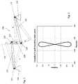
- FIG. 1is a schematic diagram illustrating a Watt's linkage.
- FIG. 2is a graph illustrating an example translational path of the center point of the Watt's linkage of FIG. 1 .
- FIG. 3is a schematic representation of one embodiment of a Watt's linkage drive system.
- FIGS. 4A-4Dis a sequence of schematic diagrams illustrating translational movement of components of the Watt's linkage drive system of FIG. 3 .
- FIG. 5Ashows in schematic form another embodiment of the multi-bar linkage drive system.
- FIG. 5Bshows the multi-bar linkage drive system of FIG. 5A with the sections of the rotor and one of the stators removed to make the other stator visible.
- FIGS. 6A-6Fis a sequence of schematic representations illustrating the translational movement of the multi-bar linkage drive system shown in FIGS. 5A and 5B .
- FIG. 7shows the components of a two-motor axial flux drive such as might be used in the multi-bar linkage drive system shown in FIGS. 5A and 5B .
- FIG. 8is a perspective view of a multi-bar linkage drive system for use in a vehicle.
- FIG. 9is a perspective view of the multi-bar linkage drive system shown in FIG. 8 , with some components removed to reveal internal structure.
- FIG. 10is a perspective view of the multi-bar linkage structure that is used in the multi-bar linkage drive system of FIG. 8 .
- FIGS. 11A and 11Bare orthogonal and perspective cross-sectional views of the two-motor axial flux drive that is used in the multi-bar linkage drive system shown in FIG. 8 , with the coil stator assemblies removed.
- FIGS. 12A and 12Bare orthogonal and perspective cross-sectional views of one of the axial flux motors shown in FIGS. 11A-B , with the coil stator assembly included.
- FIG. 13is a schematic diagram illustrating a vehicle using the multi-bar linkage drive system shown in FIG. 8 .
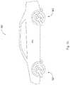
- FIG. 14illustrates another embodiment of an integrated wheel and suspension assembly.
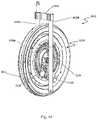
- FIG. 15is a cross-sectional view of a schematic representation of the axial flux motor employed in the integrated wheel and suspension assembly of FIG. 14 .
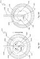
- FIG. 16is a front view of a schematic representation of the axial flux motor employed in the integrated wheel and suspension assembly of FIG. 14 .
- FIG. 17is a cross-sectional view of a schematic representation of the integrated wheel and suspension assembly of FIG. 14 .
- FIGS. 18A and 18Bare side views of schematic representations of the integrated wheel and suspension assembly of FIG. 14 which illustrate the operation of the linkage arrangement during a common mode of operation.
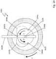
- FIG. 19is a side view of a schematic representation of the integrated wheel and suspension assembly of FIG. 14 , which illustrates the operation of the linkage arrangement during a differential mode of operation.
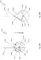
- FIGS. 20A and 20Bpresents the arrangement illustrated by FIGS. 18A and 18B in terms of interconnected linkages.
- FIG. 21shows an alternative arrangement for the links between the coil stator assemblies and the suspension arms.
- FIG. 22shows details of the linear bearing in the suspension arm and to which the spindle is connected.
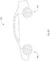
- FIG. 23shows a vehicle that employs the drive system illustrated in FIG. 19 .
- FIG. 24shows an alternative arrangement of bearings for the electric motor depicted in FIG. 15 .
- FIGS. 25A-Cshow an alternative guide mechanism which employs swing arms to define the path over which the rotational axis is permitted to move in a transverse direction.
- FIG. 1is a schematic diagram illustrating a Watt's linkage 100 .
- a Watt's linkageis a mechanical linkage arrangement in which a central point 105 of one of the linkages is constrained, by virtue of the linkages, to travel along a pre-defined path, a significant portion of which is substantially-straight, as indicated by line 110 .
- a Watt's linkageincludes three movable rods, in this particular example, two longer rods 115 and 120 of equal length connected together by a shorter rod 125 , the mid-point of which is point 105 . The ends of the three rods are hinged so that they can rotate about the hinge point.
- rod 115On end of rod 115 is connected to stationary mount 126 at hinge point 127 and the other end of rod 115 is connected to one end of shorter rod 125 at hinge point 128 .
- One end of rod 120is connected to another end of shorter rod 125 at hinge point 129 and the other end of rod 120 is connected to a second stationary mount 130 at another hinge point 131 .
- the stationary mounts 126 and 130are fixed in place relative to each other by, for example, being coupled to a common base or common structure. Though there are only three movable rods in this example, the Watt's linkage is also generally referred to as a four-bar linkage because of the fact that the connection between the two stationary mounts is considered to be the fourth bar.
- rod 115is rotated in a clockwise direction to another position, indicated in the figure by the dashed lines labeled B, that will cause rod 120 to rotate in a counterclockwise direction and will cause short rod 125 to also rotate relative to its center point in a counter clockwise direction.
- a characteristic of the Watt's linkageis that as the orientation of the rods are changed in this manner to cover all possible orientations that are permitted by the linkage arrangement, the center point 105 of the short rod 125 will trace out a defined path and the Watt's linkage arrangement will constrain that center point to always lie on that defined path. As illustrated by FIG. 2 , the shape of that defined path is a figure eight of which significant portion is substantially linear.
- FIG. 3uses the Watt's linkage in combination with two electric motors to construct a drive system 300 that is capable of both driving a wheel (not shown) rotationally and controllably translating the wheel in a direction that is transverse to the wheel's axis of rotation. In other words, it is a drive system that has two degrees of freedom.
- the drive system 300includes two electric motors 340 and 345 fixed in position relative to each other (illustrated by the two triangular-shaped objects). It also includes a linkage arrangement made up of two equal-length swing arms 315 and 320 and a shorter crank arm 325 . These correspond, respectively, to the previously discussed rods 115 , 120 and 125 , shown in FIG. 1 . There is a pulley 350 at one end of swing arm 315 that is driven by electric motor 340 and there is another pulley 355 at the far end of swing arm 320 that is driven by electric motor 345 . At the other end of swing arm 315 , opposite the end with pulley 350 , there is a second pulley 358 .
- a coaxially aligned elbow gear 360Attached to that pulley 358 is a coaxially aligned elbow gear 360 .
- a pulley 363with another attached, coaxially aligned elbow gear 365 , which is the same size as elbow gear 360 and 365 .
- a drive belt 375couples pulley 350 to pulley 358 and on swing arm 320
- another drive belt 380couples pulley 355 to pulley 363 .
- Pulleys 350 and 358have the same drive ratio as pulleys 355 and 363 .
- belt 375will also drive pulley 360 in a clockwise direction and at a speed that is determined by the ratio of the sizes of the two pulleys 350 and 358 .
- belt 380will drive pulley 365 in a clockwise direction and at a speed that is determined by the ratio of the sizes of those two pulleys 355 and 363 .
- pulleys 350 and 358 and pulleys 355 and 363have a ratio of 1:2
- motor 340drives pulley 350 in a clockwise direction at a rotational speed of 2 ⁇
- pulley 358will turn in a clockwise direction at half that speed, namely, w.
- gears 360 , 365 , and 370are of the same ratio, gear 370 and the drive shaft 373 to which it is attached will want to turn in a counterclockwise direction at a speed of w.
- thiswill cause the drive shaft 372 to move or translate in a direction that is transverse to the axis of the drive shaft.
- the linkageswill continue to change orientation and the axis of drive shaft will continue to move along that predefined path.
- changing the position of the drive shaft from one point to another pointis accomplished by changing the phase relationship of the two motors.
- the speed at which that change in phase is accomplisheddetermines the speed at which the drive shaft translates to its new location as determined by the Watt's linkage.
- the motors 340 and 345would, for example, be attached to the frame or chassis of the vehicle and the wheel rim and tire would be attached to the drive shaft 372 .
- Such an arrangementbecause it is capable of two degrees of freedom, could be used to both propel the vehicle as well as actively control the height of the chassis above the road surface (which capability could serve to provide a active shock absorber function).
- FIGS. 5A and 5BAnother embodiment of the multi-bar linkage drive system combines the two motors of FIG. 3 into a single electric motor with a rotational axis located at the center of the crank.
- a schematic representation of this other embodiment of multi-bar linkage drive system 500is shown in FIGS. 5A and 5B .
- the drive system 500includes two swing arms 515 and 520 and crank assembly 534 that connects between corresponding ends of the two swing arms 515 and 520 .
- Crank assembly 534includes a crankshaft 535 c with two crank arms 535 a and 535 b , one at each end of the crankshaft 535 c , each extending transversely with respect to the rotational axis of the crankshaft 535 c and oriented 180° with respect to each other.
- One end of swing arm 520pivotably connects to crank arm 535 a through a bearing while the other end of swing arm 520 pivotably connects to a mount structure 570 a through another bearing.
- swing arm 515pivotably connects to crank arm 535 b (not visible in the figures) through its own bearing while the other end of swing arm 515 pivotably connects to a mount structure 570 b through yet another bearing.
- This combination of elementsconstitutes a four-bar linkage arrangement similar to that shown in FIG. 3 and it constrains the rotational axis of the crankshaft to follow a defined path as the orientations of the linkages changes.
- the electric motor in drive system 500includes two stator assemblies 540 and 545 and a rotor assembly 530 , each of which is mounted on the crankshaft 535 c using bearings so that it can rotate independently of the other two components.
- Rotor assembly 530includes a ring of bolts 550 around its periphery for mounting a wheel rim and a tire (not shown) onto the rotor assembly 530 .
- the bearingsare not shown in FIGS. 5A and 5B so as to simplify the drawings. They are, however, explicitly shown in FIG. 7 , which is discussed later.
- the motors in the described embodimentare electric, axial-flux motors, in which the stator assemblies are coil stator assemblies, and the rotor assembly is a magnetic rotor assembly.
- stator assembliesare capable of rotating about a rotational axis, which may or may not be the same as the rotational axis of the rotor assembly. This capability is an important feature because, at least in some embodiments, it enables the drive system to produce two degrees of freedom, namely, rotation and translation.
- each swing arm 515 and 520is mechanically connected to its corresponding stator assembly 530 and 540 .
- Swing arm 520has two wing extensions 536 a and 536 b .
- Torque links 539 a and 539 bconnect wing extensions 536 a and 536 b , respectively, to stator assembly 545 .
- swing arm 515also has two wing extensions 537 a and 537 b (not visible in the figures).
- torque links 538 a and 538 bconnect wing extensions 537 a and 537 b , respectively, to stator assembly 540 .
- the torque links 539 a and 539 bare for transferring the torque generated by the stator assembly 545 to the swing arm 520
- the torque links 538 a and 538 bare for transferring a torque generated by the stator assembly 540 to the swing arm 515 .
- each the stator assembly 515 and 520is free to rotate about the axis of the crankshaft 535 c by virtue of being mounted on the crankshaft with bearings, the torque links connecting them to the multi-bar linkage constrain that motion, preventing them from freely rotating without limit.
- the torque linkslimit the rotation of the stator assemblies to within a narrow range of permitted rotations. This limitation range of rotation enables one to use a wire harness to connect the drive signals to the coils in the stator assemblies rather than having to use commutation or some other means to provide drive signals to the coils on the coil stator assembly.
- points A, B, C, and Dthere are four points labeled points A, B, C, and D. These points define four distances, namely: AB, AC, CD, and BD.
- ABrepresents the length of the torque link
- CDrepresents the length of the crank arm
- ACrepresents a radial distance between the axis of the crankshaft and the attachment point of the torque link to the stator assembly
- BDrepresents the distance between the point at which the crank arm connects to the swing arm and the point at which the torque link connects to the extension wing of the swing arm.
- stator assembly 545rotates in a clockwise direction, this will urge swing arm 520 in an upward direction, which also corresponds to a rotation of swing arm 520 about the mounting structure 570 a in a clockwise direction.
- the multi-bar linkage drive system of FIGS. 5A and Bworks in a manner similar to the way the embodiment shown in FIG. 3 works.
- a drive signalis applied to each of the stator assemblies 540 and 545 so that both drive signals produce the same torque and urge the rotor assembly 530 to rotate in a clockwise direction, then pure rotational motion of the rotor assembly 530 results.
- the direction of rotationis viewed from the perspective of one side of the motor, in this case, the side on which stator assembly 545 is located. This will be the convention used throughout the rest of the description.
- the orientation of the swing arms 515 and 520will remain fixed and the crankshaft 535 c will not move in a transverse direction.
- FIGS. 6A through 6Fshow the various relative positions of the drive system elements as the crankshaft 535 c and the rotor assembly 530 (on which a wheel would be mounted) are moved (or translated) from an up position ( FIG. 6A ) to a down position ( FIG. 6F ).
- the downward pointing arrow in each of the figuresindicates the direction in which the rotor assembly and crank assembly is being moved.
- the rotor assembly 540moves downward from the location depicted in FIG.
- the crank assembly and the swing arms 515 and 520will follow it down.
- the torque links 538 and 539will cause the stator assemblies 540 and 545 to rotate in the same direction as the swing arm 515 and 420 are rotating about their respective mounts 570 a and 570 b .
- the downward movement of swing arm 520represents a counterclockwise rotation about its mount 570 b .
- stator assembly 545will be forced to rotate in a counterclockwise direction about the crankshaft 535 c by an equal amount.
- the downward movement of swing arm 515represents a clockwise rotation about its mount 570 a . So, stator assembly 540 will be forced to rotate in a clockwise direction about the crankshaft 535 c.
- FIGS. 6C-Fthis relative movement of the elements continues as the axis of the rotor assembly 530 is moved further down the path defined by the multi-bar linkage for the axis of the crankshaft 535 c .
- the stator assemblies 540 and 545 depicted in the drawingshave reference slots which should be helpful in visualizing the rotation of these elements as the rotor assembly 530 is moved towards its down position indicated by FIG. 6F . Also note that there are arrows identifying the direction of rotation of the stator assemblies.
- FIGS. 6A-Fcan be produced by applying the appropriate drive signals to the stator assemblies 540 and 545 .
- the drive signalsneed to be such that they apply a net torque on the rotor assembly 530 that is zero, resulting on no rotation of the rotor assembly 530 , while at the same time urging the stator assemblies 540 and 545 to rotate in opposite directions of rotation relative to each other.
- stator 545applies torque (via electromagnetic force on the rotor assembly 530 ) to turn itself counterclockwise (and in turn, urging the rotor assembly to rotate in a clockwise direction), it also exerts force on swing arm 520 via the torque links 539 a and 539 b that pushes up on the swing arm 520 .
- torque links 539 a and 539 bthat pushes up on the swing arm 520 .
- the crank assembly 534pushes down on the swing arm 520 .
- the swing arm 520has a force pushing it down where it connects to the crank assembly 534 and up where it connects to the torque links 539 a and 539 b .
- a rotating torqueis applied to swing arm 520 causing the swing arm 520 to start to rotate in a counterclockwise direction, i.e., the same direction in which the stator assembly 545 is rotating.
- a similar actionoccurs on the other side of the rotor assembly 530 at stator assembly 540 and swing arm 515 .
- both stator assemblies 540 and 545are rotated in a way that rotates the corresponding swing arms 515 and 520 in an upward direction, then the swing arms 515 and 520 (and drive shaft 530 ) move up. If both stator assemblies 540 and 545 rotate the swing arms 515 and 520 in a downward direction, the swing arms 515 and 520 (and wheel 530 ) move down. If one swing arm is being rotated down while the other swing arm is being rotated up, and if the torques are balanced, the swing arms 515 and 520 do not move.
- both rotation of the rotor assembly 530 and translational movement of the crankshaft 535 c (and rotor assembly 530 )can be achieved by adding the signals that are required to produce each type of motion separately.
- the rotor assemblycan be made to rotate while at the same time it is also caused to translate up or down.
- inertial effectsare ignored. When inertial effects are added in, they change the magnitudes of the torques and forces needed but they do not change the general principles of how the multi-bar linkage drive system operates.
- rotationsoccurs when the torques are equal with the same sign and motion (or translation) occurs when the torques are equal but of opposite signs. This is true at some but not all points along the defined path of translational movement (see FIG. 2 ). In general, at other locations, there is some small amount of “cross-talk” or “non-orthogonality.”
- FIG. 7An example of the structure of an electric drive motor 600 that can be used in the previously described embodiment is shown in FIG. 7 . It includes two, coaxially arranged axial flux motors that are coupled together along a common rotational axis. In this case, they are mounted on a crank assembly 602 which corresponds to the crank assembly 534 discussed in connection with the multi-bar linkage drive system depicted in FIG. 5 .
- the crank assembly 602includes a crankshaft 603 a with crank arms 603 b and 603 c located at opposite ends of the crankshaft 603 a and oriented 180° with respect to each other.
- the two motorsare identified as Motor #1 and Motor #2.
- each of the axial flux motorshas a coil stator assembly 606 sandwiched between two magnetic rotor assemblies 608 .
- Each coil stator assembly 606is a circular disk 610 that is rotatably mounted on the crankshaft 603 a , with an array of coils 612 arranged around and within an annular region of the disk.
- Each of the magnetic rotor assemblies 608is also a circular disk that is rotatably mounted on the crankshaft 603 a .
- Mounted on each disk of each magnetic rotor assembly 608is an array of radially-oriented bar-shaped permanent magnets 614 distributed about an annular region of the disk. The array of magnets 614 on the magnetic rotor assemblies 608 is aligned with the array of coils 612 on the coil stator assemblies 606 .
- the magnetic rotor assemblies 608 of the two coaxially aligned motorsare rigidly affixed to a common hub assembly 616 that, in turn, rides on bearings 618 located between the hub assembly 616 and the crankshaft 603 a . So, the multiple magnetic rotor assemblies 608 freely rotate together about the crankshaft 603 a as one unit.
- the disks of the coil stator assemblies 606 sandwiched between the magnetic rotor assemblies 608have circularly-shaped central openings 620 through which the hub assembly 616 passes without making contact with the disks. So, the coil stator assemblies 606 and the hub assembly 616 can rotate independent of each other.
- Each coil stator assembly 606is supported around its periphery by a housing 622 that is, in turn, rotatably mounted on and rides on the crankshaft 603 a via a set of bearings 624 .
- the bearings 624permit the housings 622 , as well as their supported coil stator assemblies 606 , to also freely rotate on the crankshaft 603 a just as the magnetic rotor assemblies 608 are able to do.
- each of the coil stator assemblies 606rotates on the crankshaft 603 a independently of the other coil stator assembly and independently of the hub assembly 616 .
- the magnets within the two arrays of permanent magnetsare arranged with respect to each other so as to generate axially-directed magnetic fields that reverse direction at regular intervals as one moves around the annular region of the disk. These axially-directed magnetic fields produced by the arrays of magnets intersect radially-oriented windings of the coils 612 on the coil assembly 608 . When currents are passed through the coil windings, the interaction of the currents with the magnetic fields produces a Lorentz force on the magnetic rotor assembly 608 and the coil stator assembly 606 .
- That forcewhich is tangentially-directed, applies a torque to the disks causing them to rotate, with the disk of the magnetic rotor assembly 608 urged to rotate in one direction about the crankshaft 603 a and the disk of the coil stator assemblies urged to rotate in the opposite direction about the crankshaft 603 a.
- each coil stator assemblyis limited by the linkages to operate only within a limited range of rotation.
- the magnetic rotor assemblies 608are primarily used to apply torque to a wheel to which they are coupled; while the coil stator assemblies 606 are primarily used to apply torque to the linkages to thereby alter their orientation with respect to each other, as previously described.
- FIGS. 8-12BAn embodiment that incorporates the multi-bar linkage drive system into a wheel, such as might be used in a vehicle, is shown in FIGS. 8-12B .
- the motorized wheel assembly 800includes a tire 804 that is mounted on a rim 806 .
- the dual axial flux motoris housed within the space surrounded by the rim 806 and is coupled to a multi-bar linkage system 801 that is similar in design to what has already been described.
- the multi-bar linkage system 801includes a support structure 807 that is attached to the suspension of the vehicle by means of a coupling 809 . At one end of the support structure 807 there is a swing arm 815 that is attached to the support structure 807 by a spring-loaded bearing mechanism 816 . At the other end of the support structure 807 there is another swing arm 820 that is attached to the support structure by another spring-loaded bearing mechanism 817 .
- the drive systemwill physically settle to a position in which the chassis or vehicle to which the drive system is attached is closest to the ground (i.e., the swing arms 815 and 820 will by in their uppermost position) when no electrical power is being applied to the drive system.
- the springs in the spring-loaded bearing assemblies 816 and 817will hold the drive system at an intermediate or normal position without having to constantly supply power to the drive motor to accomplish that task.
- crank assembly 834is made up of a crankshaft 803 a with two crank arms 803 b and 803 c , one at each end of the crankshaft 803 a .
- the crankshaft 803 asupports two sets of bearing 818 and 824 .
- Bearings 818rotatably support a hub assembly 810 (see FIGS. 11A and 11B ) on which magnetic rotor assemblies 812 are mounted and bearings 824 rotatably support housings 822 (see FIGS. 8 and 9 ) which hold coil stator assemblies 814 between the magnetic rotor assemblies 812 .
- the bearings 818enable the hub assembly 810 , to which all of the magnetic rotor assemblies 812 are attached, to rotate about the crankshaft 803 a . While the bearings 824 enable the support housings 822 along with their respective coil stator assemblies 814 to also rotate about the crankshaft 803 a and independently of each other. Each housing 822 has a cover 842 through which cables pass to make connections to and supply dive signals to the supported coil stator assemblies 814 .
- Each magnetic rotor assembly 812is made up of two disks 813 that are mechanically connected together.
- Each disk 813holds an array of permanent magnets 826 arranged around an annular region of the disk 813 .
- the magnetic moments of the permanent magnetsare aligned axially and they periodically reverse direction as one moves around the circumference of the rotor assembly.
- the magnets 826 on one disk 813are aligned with the magnets 826 on the other disk within the pair of disks and their magnetic moments point in the same direction to enhance the fields that the coils in the coil stator assembly sees.
- hub assembly 810is made of three parts: a rim support disk 890 sandwiched between a pair of rotor support assemblies 819 and fastened together by a ring of bolts 821 .
- Each rotor support assembly 819supports a pair of magnetic rotor assemblies 812 .
- the coil stator assemblies 814(see FIGS. 12A and 12B ) are positioned between each pair of magnetic rotor assemblies 812 .
- the hub assembly 810defines a bore 811 through which the crankshaft 803 a , along with bearing 818 and 824 , passes.
- Each swing arm 815 and 820includes a wing extension plate 830 bolted to the end of the swing arm that is coupled to the crankshaft assembly 834 .
- the wing extension plates 830provide two points at which torque links 832 are connected to the swing arms.
- the other ends of the torque linksare connected to the housing 822 .
- the torque links 832provide a way by which torque generated by the coil stator assemblies 814 is transferred to the swing arms 815 and 820 .
- FIG. 13is a schematic diagram of a vehicle 900 that includes four multi-bar linkage drive systems 920 , such as were described earlier, mounted on a passenger-carrying body or chassis 910 .
- each drive system 920occupies the space that would normally be occupied by a typical vehicle wheel assembly.
- this particular exampleis characterized as having four multi-bar linkage drive systems 920 , it could have only two such drives, either in the front or in the back.
- other types of vehicles that utilize the multi-linkage drive systemcan be envisioned. For example, vehicles with one, two, three or more wheels can be envisioned in which one or more of the wheels is implemented using the multi-bar linkage drive system.
- FIG. 14shows another embodiment of an integrated wheel and suspension assembly 1010 that is capable of producing both rotational movement of a tire 1012 to propel a vehicle forward and translational (i.e., up and down) movement of the tire to provide part of an active suspension for the vehicle on which the wheel and suspension assembly 1010 is mounted.
- Itincludes an axial flux electric motor assembly 1100 supported by a suspension fork that has two suspension arms 1020 a and 1020 b in which the motor assembly 1100 is slidably mounted so that it can slide up and down under control of the motor assembly.
- a pair of crescent-shaped linkages 1030 a and 1030 bonly one of which is visible in FIG.
- a connecting bracket 1036 near the upper end of the suspension arms 1020 a and 1020 bclamps onto each of the arms 1020 a and 1020 b and rigidly holds them in a fixed position relative to each other.
- motor assembly 1100includes two coil stator assemblies 1102 a and 1102 b and a magnetic rotor assembly made up of three magnetic rotors including outer magnetic rotors 1104 a and 1104 b and a central magnetic rotor 1104 c .
- One coil stator assembly 1102 ais sandwiched between and spaced apart from magnetic rotors 1104 a and 1104 c
- the other coil stator assembly 1102 bsandwiched between and spaced apart from magnetic rotors 1104 c and 1104 b .
- Each of the outer magnetic rotors 1104 a and 1104 bis a generally circular, ring-shaped structure that is arranged along a hub assembly or central cylindrical spindle 1106 with its axis aligned with the axis of the spindle 1106 .
- the central magnetic rotor 1104 cis mounted on the spindle 1106 through a bearing assembly 1108 so that it can freely rotate about a rotational axis 1107 that in this case defined by the axis of the spindle 1106 .
- the central magnetic rotor 1104 cthere is a cylindrically shaped collar 1110 to which the other two magnetic rotors 1104 a and 1104 b are attached, with one magnetic rotor 1104 a on one side of the collar 1110 and the other magnetic rotor 1104 b on the other side of the collar 1110 .
- the two outer magnetic rotors 1104 a and 1104 brotate with the central magnetic rotor 1104 c about the rotational axis and the spindle 1106 .
- Each of the coil stator assemblies 1102 a and 1102 bwhich are also generally disc-shaped structures, is also mounted on the spindle 1106 by bearing assemblies 1109 a and 1109 b , respectively, so that they too can rotate about the rotational axis defined by the axis of the spindle 1106 independent of each other and independent of the magnetic rotor assembly.
- Each coil stator assembly 1102 a and 1102 bhas an annular region 1112 and within that annular region 1112 there is an array of coils 1114 distributed around the disk.
- the coilsare fabricated or wound to produce generally radially oriented current paths through which drive currents are passed to operate the motor.
- Each outer magnetic rotor 1104 a and 1104 cis ring-shaped and has an annular region 1118
- central magnetic rotor 1104 cis disk-shaped and has an annular region 1120 .
- these annular regions 1118 and 1120are generally aligned with the annular regions 1112 of the coil stator assemblies 1102 a and 1102 b .
- the magnets 1122are arranged to produce an axially directed magnetic field that intersects the coil windings of the coil stator assemblies and that alternates from one axial direction to the opposite axial direction as one moves around the rotor.
- the described embodimentalso includes a spoke assembly 1124 circumscribing and extending away from the collar 1110 and supporting a rim 1126 onto which a tire (not shown) could be mounted.
- a spoke assemblyis used instead of a solid ring of material as a weight savings measure.
- brake disk 1128attached to the spoke assembly 1124 as well as a brake calipers 1129 mounted on the suspension arm 1020 b.
- the motor assemblycan be viewed as two, coaxially arranged axial flux motors that are coupled together along a common rotational axis. This is indicated in FIG. 15 as Motor #1 on the left and Motor #2 on the right.
- Motor #1is represented by coil stator assembly 1102 a sandwiched between magnetic rotor 1104 a and the left half of magnetic rotor 1104 c and Motor #2 is represented by coil stator assembly 1102 b sandwiched between the right half of magnetic rotor 1104 c and magnetic rotor 1104 b .
- the magnetic rotorsare all connected together so that they rotate together.
- the linear bearings 1140 a and 1140 bcan slide up and down within their respective suspension arms 1020 a and 1020 b , thereby enabling the spindle 1106 to also move up and down.
- the linear bearing 1140 b of the described embodimentis shown in greater detail in FIG. 22 . It includes two blocks 1150 a and 1150 b that are fixed within the hollow space inside of the arm 1020 b . Between and rigidly connected to the two blocks 1150 a and 1150 b there is a cylindrical guide 1152 .
- a collar bearing 1154circumscribes the guide 1152 and is able to ride up and down the guide 1152 .
- the spindle 1106which supports the motor and the wheel is connected to the collar bearing 1154 .
- the crescent-shaped linkage 1030 aconnects between fixed locations on the suspension arm 1020 a and coil stator assembly 1102 a .
- the connection to the suspension arm 1020 ais through a bearing mount 1142 a and to the coil stator assembly 1102 a through another bearing mount 1144 a .
- the crescent-shaped linkage 1030 bconnects between fixed locations on the suspension arm 1020 b and coil stator assembly 1102 b .
- the connection to the suspension arm 1020 bis through a bearing mount 1142 b and to the coil stator assembly 1102 b through another bearing mount 1144 b.
- the crescent-shaped linkagesare attached to the suspension arms and the coil stator assemblies so that there is rotational symmetry between them about a vertical axis 1146 that intersects the axis of the spindle 1106 . That is, if the wheel and suspension assembly 1010 is rotated 180° about that axis 1146 , the position of the linkages and their attachment points will appear the same.
- the torque produced on the magnetic rotor assembly by the coil stator assembly 1102 awill be exactly counterbalanced by the torque produced on the magnetic rotor assembly by the coil stator assembly 1102 b .
- the magnetic rotor assemblywill experience a net torque of zero and it along with the attached wheel will not rotate but will remain stationary.
- the coil stator assemblies 1102 a and 1102 bwill be caused to rotate in opposite directions from each other as indicated by the arrows. This will, by virtue of the linkages 1030 a and 1030 b , push the spindle 1106 , and the attached tire, downward or conversely; it will push the vehicle, to which the suspension arms are attached, upward.
- the drive currents applied to the coil stator assemblies 1102 a and 1102 bare such that they both urge the magnetic rotor assembly to rotate in the same direction. More specifically, the drive currents applied to coil stator assembly 1102 a urge the magnetic rotor assembly to rotate in a clockwise direction while they also urge the coil stator assembly 1102 a to rotate in a counterclockwise direction (as illustrated by the arrow identified by letter E).
- the drive currents applied to the coil stator assembly 1102 burge the magnetic rotor assembly to rotate in a clockwise direction while they also urge the coil stator assembly 1102 b to rotate in a counterclockwise direction (as illustrated by the arrow identified by letter E).
- the linkage 1030 awill transfer the torque applied by coil stator assembly 1102 a to the spindle 1106 urging it to move downward; while the linkage 1030 b will transfer the torque applied by coil stator assembly 1102 b to the spindle 1106 urging it to move upward.
- a common mode of operationthere are two modes of operation: one that will be called a common mode of operation and another that be called a differential mode of operation.
- the common modethe drive signals applied to the two coil stator assemblies produce torques on the magnetic rotor assembly that are equal and have the same sign.
- the wheelrotates but there is no translational (up and down) movement of the wheel.
- the differential modethe drive signals applied to the two coil stator assemblies produce torques on the magnetic rotor assembly that are equal and have opposite signs.
- the wheeldoes not rotate but there is a translational (up and down) movement of the wheel.
- the system of linkages just describedcan be viewed as two mechanical systems that work together to produce the translational movement of the wheel.
- One systemis formed by the suspension fork and internal linear bearings that constrain the spindle to move along a predefined path, which in this case is a linear path.
- the other systemis formed by an arrangement of linkages which converts the relative rotational movement of the two coil stator assemblies with respect to each other into translational movement of the spindle (or rotational element) along the predefined path defined by the suspension fork.
- the arrangement of linkagescorresponds to a four-bar linkage arrangement.
- FIGS. 20A and 20BThe two mechanical systems are illustrated by FIGS. 20A and 20B .
- the linear bearing 1140 b inside arm 1020 bconstrains the axis of the spindle 1106 to move up and down along a linear path defined by the guide within the linear bearing.
- the arrangement of linkages that moves the spindle along that path in response to torques generated by the electric motoris a multi-bar linkage mechanism that includes four bars or links 1180 a , 1180 b , 1182 a , and 1182 b .
- Two of the four linksare represented by the elements connecting the coil stator assemblies to fixed locations on the suspension arms.
- the remaining two links 1182 a and 1182 bare represented by the connections between the spindle 1106 and the bearing mounts 1144 b and 1144 a on the coil stator assemblies 1102 b and 1102 a , respectively.
- these two linksare represented by the elements 1182 b and 1182 a .
- the coil stator assemblies 1102 a and 1102 bchange the physical arrangement of the four links by applying appropriate torques to the links 1182 a and 1182 b , causing them to rotate thereby reconfiguring the links.
- the reconfiguration of the linksforces the spindle to move along the linear path defined by the linear bearing.
- FIG. 23depicts a vehicle 1200 that includes four electric motor drive systems 1202 , one driving each of the four wheels (only two drive systems are shown in the side view).
- Each electric motor drive system 1202occupies the space that would normally be occupied by a typical wheel and suspension assembly and is attached to the frame or body of the vehicle.
- the described embodimentincludes four drive systems 1202 , one for each wheel, the vehicle could employ the drive systems on only the front wheels (or on the rear wheels).
- Other embodimentsinclude one, two and three-wheeled vehicles or personal transport systems with one or more wheels being driven by the electric motor drive system described herein.
- the linkageshad a crescent shape and were anchored to points on suspension arms that aligned with each other. But the shape of the linkages and their anchor points are not particularly important. In the described embodiment, the crescent shape was chosen to satisfy certain physical constraints imposed by the illustrated design. Other shapes and/or arrangements are certainly possible. For example, referring to FIG. 21 , straight bar linkages 1160 a and 1160 b are used and each of the linkages is anchored on a tab 1162 a and 1162 b , respectively, that extends away from the fork suspension member.
- each of the coil stator assembliesis connected to an anchor point on the support structure (i.e., suspension arms) by a corresponding linkage and the axle of the wheel is constrained to only move along a path defined by the linear bearing that slides within the suspension arm.
- the linear bearingis a specific example of a slide mechanism other embodiments of which could also be used.
- slide mechanismsThere are other ways that could be used besides slide mechanisms to constrain the movement of the axle to be along a predefined transverse path.
- a simple swing arm or arrangement of swing armscould be used between the frame of the vehicle and the axel of the wheel. In that case, the up and down movement of the wheel would not be along a strictly linear path but rather the path would be curved with a radius defined by the length of the swing arm.
- FIGS. 25A-Cshow an example of an embodiment that employs swing arms 1194 to define the path over which the axle 1106 is able to move, namely, an arc the radius of which is determined by the length of the swing arms 1194 a and 1194 b (which is visually obstructed by swing arm 1194 a in the figures).
- the frame of the vehicle or the support to which the drive system is connectedis represented by block 1188 .
- the arrangement of linkages that moves the spindle 1106 along that path in response to torques generated by the electric motoris a multi-bar linkage mechanism that includes four bars or links 1190 a , 1190 b , 1192 a , and 1192 b .
- Two of the four linksare represented by the elements connecting the coil stator assemblies to fixed locations on the frame 1188 .
- these two linksare represented by the elements 1192 b and 1192 a .
- the coil stator assemblies 1102 a and 1102 bchange the physical arrangement of the four links by applying appropriate torques to the links 1192 a and 1192 b , causing them to rotate thereby reconfiguring the links.
- the reconfiguration of the linksforces the spindle to move along the curved path defined by the swing arms 1194 a and 1194 b.
- statoras for example in the case of the coil stator assembly, is not meant to imply that the element is stationary and incapable of rotation or movement. Often the word may be given this more limited meaning but that is not the intention when it is used herein. This should be apparent from the above description in which the coil stator assemblies also rotate about the rotational axis of the motor assembly.
- FIG. 24shows an alternative arrangement in which bearings 1209 a and 1209 b rotatably mount the coil stator assemblies on the magnetic rotor assembly.
- the hub assemblywas represented by the spindle 1106 but it could be another arrangement that supports the two motors along their rotational axes.
- the described embodimentreferred specifically to using the second degree of freedom that is available from the drive system to provide an active suspension for a vehicle, that second degree of freedom could be used for other purposes depending on the application in which the drive system is used.
- the drive systemcould be used as the motor for an airplane or other aircraft in which case the second degree of freedom could be used, for example, to control the pitch of the blades.
- the second degree of freedomcould be used for other purposes requiring linear or translational movement of a part.
- electric motors other than axial flux motorscould be used including, for example, other types of electrical motors that have magnetic rotors and coil stator assemblies, or coil rotors and magnetic stator assemblies, or electric motors that are based on switched reluctance technology, or commutators, or single or multi-phased drives, or DC drives, etc.
Landscapes
- Engineering & Computer Science (AREA)
- Power Engineering (AREA)
- Mechanical Engineering (AREA)
- Chemical & Material Sciences (AREA)
- Combustion & Propulsion (AREA)
- Transportation (AREA)
- Connection Of Motors, Electrical Generators, Mechanical Devices, And The Like (AREA)
- Arrangement Or Mounting Of Propulsion Units For Vehicles (AREA)
- Electric Propulsion And Braking For Vehicles (AREA)
- Vehicle Body Suspensions (AREA)
- Permanent Magnet Type Synchronous Machine (AREA)
Abstract
Description
Claims (5)
Priority Applications (3)
| Application Number | Priority Date | Filing Date | Title |
|---|---|---|---|
| US17/176,308US11368076B2 (en) | 2016-09-13 | 2021-02-16 | Multi-bar linkage electric drive system |
| US17/838,464US12170468B2 (en) | 2016-09-13 | 2022-06-13 | Multi-bar linkage electric drive system |
| US18/983,858US20250192654A1 (en) | 2016-09-13 | 2024-12-17 | Multi-Bar Linkage Electric Drive System |
Applications Claiming Priority (5)
| Application Number | Priority Date | Filing Date | Title |
|---|---|---|---|
| US201662393982P | 2016-09-13 | 2016-09-13 | |
| US201762512469P | 2017-05-30 | 2017-05-30 | |
| US15/701,766US10483832B2 (en) | 2016-09-13 | 2017-09-12 | Multi-bar linkage electric drive system |
| US16/575,512US10938285B2 (en) | 2016-09-13 | 2019-09-19 | Multi-bar linkage electric drive system |
| US17/176,308US11368076B2 (en) | 2016-09-13 | 2021-02-16 | Multi-bar linkage electric drive system |
Related Parent Applications (1)
| Application Number | Title | Priority Date | Filing Date |
|---|---|---|---|
| US16/575,512DivisionUS10938285B2 (en) | 2016-09-13 | 2019-09-19 | Multi-bar linkage electric drive system |
Related Child Applications (1)
| Application Number | Title | Priority Date | Filing Date |
|---|---|---|---|
| US17/838,464ContinuationUS12170468B2 (en) | 2016-09-13 | 2022-06-13 | Multi-bar linkage electric drive system |
Publications (2)
| Publication Number | Publication Date |
|---|---|
| US20210167675A1 US20210167675A1 (en) | 2021-06-03 |
| US11368076B2true US11368076B2 (en) | 2022-06-21 |
Family
ID=59955674
Family Applications (7)
| Application Number | Title | Priority Date | Filing Date |
|---|---|---|---|
| US15/701,885ActiveUS10644578B2 (en) | 2016-09-13 | 2017-09-12 | Guided multi-bar linkage electric drive system |
| US15/701,766ActiveUS10483832B2 (en) | 2016-09-13 | 2017-09-12 | Multi-bar linkage electric drive system |
| US15/701,731Active2038-06-18US10476360B2 (en) | 2016-09-13 | 2017-09-12 | Axial flux motor having rotatably coupled coil stator assemblies and methods of using same |
| US16/575,512ActiveUS10938285B2 (en) | 2016-09-13 | 2019-09-19 | Multi-bar linkage electric drive system |
| US17/176,308ActiveUS11368076B2 (en) | 2016-09-13 | 2021-02-16 | Multi-bar linkage electric drive system |
| US17/838,464ActiveUS12170468B2 (en) | 2016-09-13 | 2022-06-13 | Multi-bar linkage electric drive system |
| US18/983,858PendingUS20250192654A1 (en) | 2016-09-13 | 2024-12-17 | Multi-Bar Linkage Electric Drive System |
Family Applications Before (4)
| Application Number | Title | Priority Date | Filing Date |
|---|---|---|---|
| US15/701,885ActiveUS10644578B2 (en) | 2016-09-13 | 2017-09-12 | Guided multi-bar linkage electric drive system |
| US15/701,766ActiveUS10483832B2 (en) | 2016-09-13 | 2017-09-12 | Multi-bar linkage electric drive system |
| US15/701,731Active2038-06-18US10476360B2 (en) | 2016-09-13 | 2017-09-12 | Axial flux motor having rotatably coupled coil stator assemblies and methods of using same |
| US16/575,512ActiveUS10938285B2 (en) | 2016-09-13 | 2019-09-19 | Multi-bar linkage electric drive system |
Family Applications After (2)
| Application Number | Title | Priority Date | Filing Date |
|---|---|---|---|
| US17/838,464ActiveUS12170468B2 (en) | 2016-09-13 | 2022-06-13 | Multi-bar linkage electric drive system |
| US18/983,858PendingUS20250192654A1 (en) | 2016-09-13 | 2024-12-17 | Multi-Bar Linkage Electric Drive System |
Country Status (8)
| Country | Link |
|---|---|
| US (7) | US10644578B2 (en) |
| EP (2) | EP3513484B1 (en) |
| JP (3) | JP7211625B2 (en) |
| KR (3) | KR102807608B1 (en) |
| CN (3) | CN109716630B (en) |
| CA (1) | CA3035928A1 (en) |
| MX (1) | MX394967B (en) |
| WO (3) | WO2018052876A1 (en) |
Cited By (3)
| Publication number | Priority date | Publication date | Assignee | Title |
|---|---|---|---|---|
| US12054021B2 (en) | 2018-12-03 | 2024-08-06 | Indigo Technologies, Inc. | Multi-input, multi-output actuator and assemblies using same |
| US12126222B2 (en) | 2018-06-15 | 2024-10-22 | Indigo Technologies, Inc. | Sealed axial flux motor with integrated cooling |
| US12170468B2 (en) | 2016-09-13 | 2024-12-17 | Indigo Technologies, Inc. | Multi-bar linkage electric drive system |
Families Citing this family (28)
| Publication number | Priority date | Publication date | Assignee | Title |
|---|---|---|---|---|
| US10141827B2 (en)* | 2015-04-03 | 2018-11-27 | Benjamin Ishak | Electromagnetic toroidal motor |
| US10811943B2 (en)* | 2016-12-05 | 2020-10-20 | Maxwell Jordan Blankenship | Electromagnetic rotary motor |
| CN115347697A (en)* | 2017-05-26 | 2022-11-15 | 靛蓝技术股份有限公司 | Magnetic Rotor Assembly |
| IT201700070192A1 (en)* | 2017-06-23 | 2018-12-23 | Texa Dynamics S R L | "Traction and suspension system" |
| CN107618356B (en)* | 2017-10-23 | 2020-01-21 | 山东理工大学 | Electric automobile wheel limit motor |
| LU100555B1 (en)* | 2017-12-13 | 2019-06-28 | Luxembourg Inst Science & Tech List | Compact halbach electrical generator with coils arranged circumferentially |
| US20210387573A1 (en)* | 2018-04-30 | 2021-12-16 | Indigo Technologies, Inc. | Methods and apparatus to adjust a reactive system based on a sensory input and vehicles incorporating same |
| US10801583B2 (en)* | 2018-07-01 | 2020-10-13 | Softwheel Ltd. | Device and method for transferring rotational power and method of using same |
| US10723191B1 (en)* | 2018-07-01 | 2020-07-28 | Softwheel Ltd. | In-wheel three-arm suspension for vehicles |
| US11524538B2 (en)* | 2018-07-01 | 2022-12-13 | Ree Automotive Ltd | Wheel suspension and transmission gear assembly |
| EP3817940B1 (en)* | 2018-07-03 | 2022-04-27 | KA Group AG | Electrical vehicle axle |
| US11437898B2 (en) | 2018-07-31 | 2022-09-06 | Dana Automotive Systems Group, Llc | Brushless direct current motor with dual stators |
| CN113382885B (en)* | 2019-02-04 | 2024-04-12 | DRiV汽车公司 | Electric propulsion, suspension and steering system |
| JP7235227B2 (en)* | 2019-02-15 | 2023-03-08 | 日本電産シンポ株式会社 | Braked motors, braked drives and braked wheel drives |
| US11025133B2 (en) | 2019-02-20 | 2021-06-01 | Dana Automotive Systems Group, Llc | Electric motor brake |
| CN110182013B (en)* | 2019-05-20 | 2021-10-12 | 江苏大学 | Two-degree-of-freedom electromagnetic energy-feedback suspension based on double-winding mixed magnetic circuit linear rotating permanent magnet motor actuator |
| CN114025972B (en) | 2019-06-28 | 2023-04-21 | 瑞翼汽车有限公司 | Apparatus and method for dual arm suspension and in-wheel steering |
| EP4045358A4 (en)* | 2019-10-14 | 2023-12-06 | OMRON Corporation | Mobile robot drive system |
| CN114728677B (en) | 2020-01-02 | 2023-11-17 | 瑞翼汽车有限公司 | Vehicle corner module and vehicle comprising same |
| EP4096942A4 (en)* | 2020-01-28 | 2024-04-17 | Ree Automotive Ltd | WHEEL SUSPENSION SYSTEM WITH ECCENTRIC ARM IN RELATION TO THE WHEEL |
| EP3882133A1 (en) | 2020-03-16 | 2021-09-22 | Ratier-Figeac SAS | Blade pitch actuation mechanism |
| IL278056B (en)* | 2020-10-14 | 2022-01-01 | Ree Automotive Ltd | Vehicle suspension system |
| JP2024515767A (en) | 2021-04-26 | 2024-04-10 | リー・オートモーティブ・リミテッド | Dual Axle Vehicle Corner Assembly |
| US11845347B2 (en) | 2021-05-12 | 2023-12-19 | David Alan Copeland | Precision charging control of an untethered vehicle with a modular vehicle charging roadway |
| CN113700797B (en)* | 2021-08-04 | 2022-08-23 | 江苏大学 | Rotary inerter with stepless and adjustable inerter coefficient |
| JP2024530228A (en) | 2021-08-16 | 2024-08-16 | リー・オートモーティブ・リミテッド | Dual wheel corner system with lateral suspension |
| US12119720B2 (en)* | 2021-09-23 | 2024-10-15 | Pure Energy Llc | Tri-motor |
| CN119519329A (en)* | 2024-12-05 | 2025-02-25 | 苏州厚盟电子科技有限公司 | A limited-angle energy-saving motor with automatic speed regulation mechanism |
Citations (285)
| Publication number | Priority date | Publication date | Assignee | Title |
|---|---|---|---|---|
| US1886040A (en) | 1930-08-28 | 1932-11-01 | W S Hunt | Electric motor |
| DE1017273B (en) | 1952-11-17 | 1957-10-10 | Ernst Toedten | Arrangement for converting a rotary movement into a voltage with a frequency proportional to the speed |
| US2991377A (en) | 1957-01-28 | 1961-07-04 | Vickers Electrical Co Ltd | Cooling of flame proof motors |
| US3118432A (en) | 1960-08-05 | 1964-01-21 | Horace Tomasello | Rotary internal combustion engine |
| US3289886A (en) | 1964-02-24 | 1966-12-06 | Goldsholl Morton | Timing device and method |
| GB1051591A (en) | 1963-07-12 | 1966-12-14 | Alternating current generator | |
| US3479541A (en) | 1962-09-11 | 1969-11-18 | Allis Louis Co | High speed liquid cooled motors |
| US3575341A (en) | 1967-08-28 | 1971-04-20 | Guaranteed Financial Services | Ratchet driving mechansim |
| US3799035A (en) | 1970-06-21 | 1974-03-26 | A Lamm | Rotating piston engine |
| US3964450A (en) | 1973-11-19 | 1976-06-22 | Lockshaw John E | Rotary cam internal combustion radial engine |
| US4179630A (en) | 1976-11-04 | 1979-12-18 | Tecumseh Products Company | Linear compressor |
| US4228373A (en) | 1979-09-10 | 1980-10-14 | Funderburg William S | Electromagnetic motor |
| US4253079A (en) | 1979-04-11 | 1981-02-24 | Amnon Brosh | Displacement transducers employing printed coil structures |
| GB2065983A (en) | 1979-11-26 | 1981-07-01 | Machakaire T S | Apparatus for Generating Electricity |
| JPS5686048A (en) | 1979-12-14 | 1981-07-13 | Asahina Shozo | Electromagnetic rotary driving device |
| US4300067A (en) | 1980-03-17 | 1981-11-10 | Schumann Albert A | Permanent magnet motion conversion device |
| US4345174A (en) | 1981-06-01 | 1982-08-17 | Angus Motor Corporation | Electromagnetic engine |
| US4384221A (en) | 1981-03-19 | 1983-05-17 | Brandly Ernest B | Motor |
| US4404503A (en) | 1981-11-02 | 1983-09-13 | Ward William L | Reciprocating electric motor |
| US4473763A (en) | 1980-01-21 | 1984-09-25 | Mcfarland Douglas F | Solenoid motor |
| US4486667A (en) | 1981-10-26 | 1984-12-04 | Srogi Ladislaw G | Drive system for an electric generator |
| US4503751A (en) | 1982-07-12 | 1985-03-12 | The Boeing Company | Digital fluid stepping motor |
| US4507579A (en) | 1983-09-29 | 1985-03-26 | Turner Jack C | Reciprocating piston electric motor |
| US4554989A (en) | 1983-01-20 | 1985-11-26 | Peter Gruich | Multimotor modular electric drive powertrain system for turbine powered vehicles |
| US4618808A (en) | 1985-01-30 | 1986-10-21 | International Business Machines Corporation | Electromagnetic actuator system using stepper motor with closed loop position sensing, electronic commutation and dynamic position and anomaly correction |
| US4675563A (en) | 1982-10-29 | 1987-06-23 | The United States Of America As Represented By The Administrator Of The National Aeronautics & Space Administration | Reciprocating linear motor |
| US4684834A (en) | 1986-01-02 | 1987-08-04 | Robert W. Delong | Electromagnetic motor |
| US4698608A (en) | 1986-04-29 | 1987-10-06 | Bei Electronics, Inc. | Variable force linear actuator |
| US4749898A (en) | 1986-10-02 | 1988-06-07 | National Aerospace Laboratory Of Science & Technology Agency | Superprecision positioning device |
| US4796511A (en) | 1985-08-21 | 1989-01-10 | Wisconsin Alumni Research Foundation | Electromagnetic projectile launching system |
| US4823039A (en) | 1985-12-18 | 1989-04-18 | Cedric Lynch | Electrical machines |
| US4920295A (en) | 1987-08-10 | 1990-04-24 | Karel Holden | Alternator |
| JPH0253273B2 (en) | 1985-10-03 | 1990-11-16 | Bridgestone Cycle Co | |
| US4981309A (en) | 1989-08-31 | 1991-01-01 | Bose Corporation | Electromechanical transducing along a path |
| EP0435461A2 (en) | 1989-12-29 | 1991-07-03 | AT&T Corp. | Multiple turn low profile magnetic component using sheet windings |
| US5036930A (en) | 1990-05-17 | 1991-08-06 | Bisel Charley W | Electromagnetically powered engine apparatus and method |
| JPH04175530A (en) | 1990-11-06 | 1992-06-23 | Kayaba Ind Co Ltd | gas spring mechanism |
| US5164623A (en) | 1989-09-01 | 1992-11-17 | Shkondin Vasily V | Independent-drive wheel for a wheel-mounted vehicle |
| US5204621A (en) | 1990-02-08 | 1993-04-20 | Papst-Motoren Gmbh & Co. Kg | Position sensor employing a soft magnetic core |
| US5276372A (en) | 1992-06-22 | 1994-01-04 | Hammer Charles F | Reciprocating electric motor |
| US5301111A (en) | 1989-11-29 | 1994-04-05 | Mitsubishi Denki Kabushiki Kaisha | Suspension apparatus for a vehicle |
| US5345206A (en) | 1992-11-24 | 1994-09-06 | Bei Electronics, Inc. | Moving coil actuator utilizing flux-focused interleaved magnetic circuit |
| US5383680A (en) | 1992-12-21 | 1995-01-24 | Cadillac Gage Textron Inc. | Anti-roll system for wheeled vehicles |
| CN1028337C (en) | 1990-12-26 | 1995-05-03 | 华西里·华西里维奇·斯科廷 | Riding wheel on wheel type transport tool |
| US5440183A (en) | 1991-07-12 | 1995-08-08 | Denne Developments, Ltd. | Electromagnetic apparatus for producing linear motion |
| JPH084550A (en) | 1994-06-17 | 1996-01-09 | Sankyo Seisakusho:Kk | Cam type engine |
| US5535853A (en) | 1994-11-14 | 1996-07-16 | Otis Elevator Company | Actuator having a two ended actuator rod movable longitudinally and transversely |
| DE4311973A1 (en) | 1993-04-14 | 1997-02-13 | Pepperl & Fuchs | Magneto-inductive sensor array for determining position and/or travel - has magnets which move over and saturate magnetic panel, provided with pairs of coils forming transmitter/receiver systems, voltages induced in coils being measured |
| US5631507A (en) | 1996-01-19 | 1997-05-20 | Berent Light Limited | Electric power generator |
| US5680201A (en) | 1992-10-15 | 1997-10-21 | Carrier Corporation | Apparatus for including tank circuit with shielded, single turn coil, detecting passage of end of workpiece |
| US5685798A (en) | 1994-06-18 | 1997-11-11 | Fichtel & Sachs Ag | Planetary transmission for a motor of a drive system of a wheel of a motor vehicle |
| US5696413A (en) | 1994-10-24 | 1997-12-09 | Aqua Magnetics, Inc. | Reciprocating electric generator |
| US5701039A (en) | 1995-07-20 | 1997-12-23 | Bose Corporation | Electromechanical transducing |
| US5723917A (en) | 1994-11-30 | 1998-03-03 | Anorad Corporation | Flat linear motor |
| US5794966A (en) | 1996-02-05 | 1998-08-18 | Macleod; Kenneth J. | Vehicular suspension system |
| US5959374A (en) | 1995-06-07 | 1999-09-28 | Mts Systems Corporation | Electromagnetic actuator |
| JP2000152558A (en) | 1998-11-04 | 2000-05-30 | Hideo Irisa | Motor |
| GB2344223A (en) | 1998-11-28 | 2000-05-31 | Impaq Limited | Solenoid type electric motor with rotary output |
| WO2000038939A1 (en) | 1998-12-29 | 2000-07-06 | Volvo Personvagnar Ab | Wheel suspension arrangement in a vehicle |
| US6114781A (en) | 1999-02-26 | 2000-09-05 | Nikon Corporation | Cooling system for a linear or planar motor |
| US6113119A (en) | 1997-05-16 | 2000-09-05 | Conception Et Developpement Michelin S.A. | Assembly comprising a wheel and a suspension integrated into the wheel |
| US6137195A (en) | 1996-03-28 | 2000-10-24 | Anorad Corporation | Rotary-linear actuator |
| US6194802B1 (en) | 1999-09-08 | 2001-02-27 | Dantam K. Rao | Axial gap motor with radially movable magnets to increase speed capablity |
| US6201329B1 (en) | 1997-10-27 | 2001-03-13 | Mohawk Innovative Technology, Inc. | Pump having magnetic bearing for pumping blood and the like |
| US6208920B1 (en) | 1997-03-19 | 2001-03-27 | Honda Giken Kogyo Kabushiki Kaisha | Tire contact load control system |
| US6211767B1 (en) | 1999-05-21 | 2001-04-03 | Rompower Inc. | High power planar transformer |
| US6218925B1 (en) | 1998-01-08 | 2001-04-17 | Taiyo Yuden Co., Ltd. | Electronic components |
| EP1098429A2 (en) | 1999-11-03 | 2001-05-09 | Siemens Aktiengesellschaft | Electromechanical motor |
| US6239683B1 (en) | 1995-05-04 | 2001-05-29 | Tyco Electronics Logistics A.G. | Post-mountable planar magnetic device and method of manufacture thereof |
| US6278204B1 (en) | 1999-06-18 | 2001-08-21 | Eugene Roland Frenette | Method of converting internal combustion engine into electrically driven engine |
| US20010017497A1 (en) | 2000-02-25 | 2001-08-30 | Dobson Simon Blair | Linear displacement actuator |
| US6291901B1 (en) | 2000-06-13 | 2001-09-18 | ćEFO NEVRES | Electrical power generating tire system |
| US6294891B1 (en) | 1997-08-15 | 2001-09-25 | Iowa State University Research Foundation, Inc. | Systems and methods for robust vibration suppression in a motion control system |
| US6293561B1 (en) | 1998-12-12 | 2001-09-25 | Daimlerchrysler Ag | Controllable wheel suspension system for an active running gear of a motor vehicle |
| DE10007658A1 (en) | 2000-02-19 | 2001-10-25 | Daimler Chrysler Ag | Regulated suspension system for active vehicle running gear has bi-directional auxiliary actuator activated by control unit to completely replace defective actuator, which is deactivated |
| US6321863B1 (en) | 2000-06-26 | 2001-11-27 | Mac Brushless Motor Company | Hub motor for a wheeled vehicle |
| US6328123B1 (en) | 1997-07-29 | 2001-12-11 | Daimlerchrysler Ag | Electrical drive for a wheel hub |
| US6356005B1 (en) | 2001-06-27 | 2002-03-12 | Chun-Pu Hsu | Wheel drum structure of inner stator portion with an inbuilt driving control circuit |
| US6385522B1 (en) | 1997-07-11 | 2002-05-07 | Elliott Industries Limited | Brake control apparatus and method |
| US6420953B1 (en) | 2000-05-19 | 2002-07-16 | Pulse Engineering. Inc. | Multi-layer, multi-functioning printed circuit board |
| US20020149161A1 (en) | 2001-04-11 | 2002-10-17 | Smith Donald Wayne | System and method for reducing risk of vehicle rollover |
| US20020171528A1 (en) | 1998-02-27 | 2002-11-21 | Shinya Uchibori | Process for producing resonant tag |
| WO2002095912A1 (en) | 2001-05-21 | 2002-11-28 | Peter Cecil Joseph Parsonage | Radial electric motor and control thereof |
| US20030006653A1 (en) | 2001-07-06 | 2003-01-09 | Samsung Electronics Co., Ltd. | Linear actuator using two rotors |
| US20030034697A1 (en)* | 2001-05-07 | 2003-02-20 | Goldner Ronald B. | Electromagnetic linear generator and shock absorber |
| CN1399402A (en) | 2001-07-19 | 2003-02-26 | 松下电器产业株式会社 | Motor driver for washing machine |
| JP2003116260A (en) | 2001-10-05 | 2003-04-18 | Canon Inc | Linear motor, stage device and exposure device |
| JP2003116261A (en) | 2001-10-05 | 2003-04-18 | Canon Inc | Linear motor, stage device and exposure device |
| US6552450B2 (en) | 2001-06-12 | 2003-04-22 | William Thomas Harty | Reciprocating engine |
| US20030102723A1 (en) | 2001-10-05 | 2003-06-05 | Canon Kabushiki Kaisha | Linear motor, stage apparatus, and exposure apparatus |
| US6575078B1 (en) | 1998-07-30 | 2003-06-10 | Motorvation International Limited | Fluid motor having fluid actuated advancing elements to advance an advanceable part of the fluid motor relative to a stator part of the fluid motor |
| DE10161227A1 (en) | 2001-12-13 | 2003-07-03 | Heidenhain Gmbh Dr Johannes | Synchronous motor position/speed measurement device has primary part with drive coils, secondary part with magnets, two position measurement systems, two evaluation units and a comparator |
| US6605939B1 (en) | 1999-09-08 | 2003-08-12 | Siemens Vdo Automotive Corporation | Inductive magnetic saturation displacement sensor |
| US20030193250A1 (en) | 2001-10-01 | 2003-10-16 | Wavecrest Laboratories, Llc | Rotary electric motor having controller and power supply integrated therein |
| US20030222751A1 (en) | 2002-05-27 | 2003-12-04 | Toshikazu Fujiyoshi | Coil |
| CN1461195A (en) | 2000-09-21 | 2003-12-10 | 奇莫塞斯有限公司 | Furniture drive in form of dual drive |
| US20030234585A1 (en) | 2002-06-14 | 2003-12-25 | Sunyen Co., Ltd. | Linear electric generator having an improved magnet and coil structure, and method of manufacture |
| US6675462B1 (en) | 1998-05-01 | 2004-01-13 | Taiyo Yuden Co., Ltd. | Method of manufacturing a multi-laminated inductor |
| US20040080124A1 (en) | 2001-01-10 | 2004-04-29 | Munday Raymond Andrew | Vehicule suspension roll control system |
| US6737778B2 (en) | 2000-12-27 | 2004-05-18 | Mitsubishi Denki Kabushiki Kaisha | Pulley driving system |
| US20040100100A1 (en) | 2002-07-25 | 2004-05-27 | Wilson Kitchener Clark | Apparatus and method for energy generation within a tire |
| JP2004153898A (en) | 2002-10-29 | 2004-05-27 | Yaskawa Electric Corp | Voice coil type actuator |
| JP2004175530A (en) | 2002-11-28 | 2004-06-24 | Kyocera Mita Corp | Finisher, image formation device |
| US20040141861A1 (en) | 2001-11-13 | 2004-07-22 | Davis William D. | Pump with electrodynamically supported impeller |
| US20040198170A1 (en) | 2003-03-17 | 2004-10-07 | Neil Tilbor | Toy vehicle with dynamic transformation capability |
| US20040245861A1 (en) | 2003-06-03 | 2004-12-09 | Canon Kabushiki Kaisha | Linear motor, stage device having this linear motor, exposure device, and device manufacturing method |
| US6836036B2 (en) | 2002-06-14 | 2004-12-28 | Dube Jean-Yves | Electric motor with modular stator ring and improved heat dissipation |
| US20040263001A1 (en) | 2003-06-26 | 2004-12-30 | Tanashin Denki Co., Ltd. | Coil wiring member for movable magnet type linear motor |
| US6852061B2 (en) | 2002-09-30 | 2005-02-08 | Benjamin Warren Schoon | Planetary gearbox with integral electric motor and steering means. |
| US6909223B2 (en) | 2002-03-11 | 2005-06-21 | Seiko Epson Corporation | Rotation/displacement converting actuator |
| US20050164528A1 (en) | 2003-12-17 | 2005-07-28 | Werner Furguth | Molded parts winding manufacture |
| US20050173851A1 (en) | 2004-02-05 | 2005-08-11 | Jeffrey Lloyd | Dual airbag airspring |
| US20050200828A1 (en) | 2004-03-15 | 2005-09-15 | Canon Kabushiki Kaisha | Driving apparatus and exposure apparatus |
| US6948578B2 (en) | 2001-05-24 | 2005-09-27 | Prucher Bryan P | Motor in wheel electric drive system |
| US20050212640A1 (en) | 2004-03-24 | 2005-09-29 | Chiang Man-Ho | Multi-layer printed circuit board transformer winding |
| EP1587135A1 (en) | 2004-04-13 | 2005-10-19 | TDK Corporation | Helical inductor |
| JP2005294830A (en) | 2004-03-26 | 2005-10-20 | Bose Corp | Electromagnetic actuator and controlling method of the same |
| US20050252706A1 (en) | 2003-08-04 | 2005-11-17 | Thomas Ralph M | An All-Terrain Electronically Powered Vehicle And Temperature Sensing Motor Controller For Use Therein |
| JP2005329817A (en) | 2004-05-20 | 2005-12-02 | Honda Motor Co Ltd | Wheel drive device for vehicle |
| US6974399B2 (en) | 2004-02-11 | 2005-12-13 | Chiu-Hsiang Lo | Hub motor mechanism |
| US20050275359A1 (en) | 2004-05-18 | 2005-12-15 | Kesatoshi Takeuchi | Relative drive device |
| EP1607251A1 (en) | 2004-06-18 | 2005-12-21 | Bose Corporation | Active vehicle suspension |
| JP2006000480A (en) | 2004-06-18 | 2006-01-05 | Olympus Corp | Medical apparatus |
| JP2006050853A (en) | 2004-08-06 | 2006-02-16 | Yaskawa Electric Corp | motor |
| US20060049701A1 (en) | 2004-09-07 | 2006-03-09 | Nippon Pulse Motor Co., Ltd. | Linear actuator |
| US20060071561A1 (en) | 2004-10-04 | 2006-04-06 | Chi-Ming Chiu | Electromagnetic power device |
| US20060091635A1 (en) | 2004-10-29 | 2006-05-04 | Travis Cook | Closed pneumatic synchronization system for independent suspensions |
| US20060108878A1 (en) | 2004-11-22 | 2006-05-25 | Lindberg Paul M | Linear motor and stator core therefor |
| US7055831B2 (en) | 2001-03-12 | 2006-06-06 | Carl Freudenberg Kg | Hydropneumatic, level-regulated axle suspension on vehicles, in particular for full-suspension vehicles |
| US7059437B2 (en) | 2000-01-26 | 2006-06-13 | E-Traction Europe, B.V. | Wheel provided with driving means |
| US20060125325A1 (en) | 2003-12-12 | 2006-06-15 | Gerald Beaulieu | Linear generator apparatus |
| US20060138733A1 (en) | 2004-08-11 | 2006-06-29 | Luke Clauson | Suspension adjustment system |
| US7108090B2 (en) | 2001-11-06 | 2006-09-19 | Assembled Products Corporation | Motorized cart with hub gear motor system |
| US20060208600A1 (en) | 2005-03-21 | 2006-09-21 | Sahyoun Joseph Y | Electromagnetic motor to create a desired low frequency vibration or to cancel an undesired low frequency vibration |
| US7126233B2 (en) | 2003-09-15 | 2006-10-24 | Set Industries Corporation | Methods and apparatuses for generating electrical power in a rotating reference frame |
| US7150340B2 (en) | 2003-02-21 | 2006-12-19 | Lockheed Martin Corporation | Hub drive and method of using same |
| US20060290346A1 (en) | 2004-12-17 | 2006-12-28 | Cherry Gmbh | Sensor unit with staggered actuation faces |
| US7156196B2 (en) | 2004-11-12 | 2007-01-02 | Stephen Basil Katsaros | Hub motor formed in a wheel |
| US20070090697A1 (en) | 2005-10-25 | 2007-04-26 | Bittner George E | Radially-activated engine |
| US20070120432A1 (en) | 2005-11-25 | 2007-05-31 | Vaden David R | Axial magnetic cam |
| CN1976211A (en) | 2006-12-12 | 2007-06-06 | 浙江大学 | Mixed speed regulating method for permanent magnetic synchronous motor |
| US7229079B2 (en) | 2004-02-24 | 2007-06-12 | Arvinemeritor Technology, Llc | Center seeking suspension system |
| US7249643B2 (en) | 2002-05-23 | 2007-07-31 | Tzora Active Systems Ltd. | Hub motor |
| US20070176722A1 (en) | 2006-01-30 | 2007-08-02 | Nemic-Lambda Ltd. | High-current electrical coil, and transformer construction including same |
| US20070216252A1 (en) | 2006-03-16 | 2007-09-20 | Nissan Motor Co., Ltd. | Motor/generator |
| JP2007269209A (en) | 2006-03-31 | 2007-10-18 | Toyota Motor Corp | Drive wheel structure for vehicle |
| EP1848014A1 (en) | 2005-10-14 | 2007-10-24 | Murata Manufacturing Co., Ltd. | Multilayer coil component |
| US20080012432A1 (en) | 2006-06-12 | 2008-01-17 | Togare Radhakrishna S I | Magnetic pistons engine |
| WO2008010669A1 (en) | 2006-07-18 | 2008-01-24 | Kye Jung Park | Generatror assembly for charging using deformation of tire |
| US20080023237A1 (en) | 2005-09-01 | 2008-01-31 | Martin Houle | Hybrid Drive Train Provided with Hub Motors |
| US7327054B2 (en) | 2005-03-25 | 2008-02-05 | Asm Technology Singapore Pte. Ltd. | Linear actuator comprising velocity sensor |
| US20080067968A1 (en) | 2006-09-12 | 2008-03-20 | Nikon Corporation | Identifying and compensating force-ripple and side-forces produced by linear actuators |
| US7357743B2 (en) | 2005-06-17 | 2008-04-15 | Fengxiang Mao | Hub motor |
| US20080093913A1 (en) | 2004-08-25 | 2008-04-24 | Katsaros Stephen B | Hub Motor Formed in a Wheel and Associated Methods |
| JP2008114745A (en) | 2006-11-06 | 2008-05-22 | Toyota Motor Corp | Vehicle suspension system |
| US7384054B2 (en) | 1999-04-12 | 2008-06-10 | Kinetic Pty. Ltd. | Passive ride control for a vehicle suspension system |
| EP1935679A1 (en) | 2006-12-21 | 2008-06-25 | Ford Global Technologies, LLC | Method and arrangement for controlling a suspension of a vehicle wheel |
| US20080152463A1 (en) | 2006-09-27 | 2008-06-26 | Mahendran Chidambaram | Wafer processing system with dual wafer robots capable of asynchronous motion |
| CN101275857A (en) | 2006-11-22 | 2008-10-01 | 切瑞有限公司 | Inductive position or angle measurement device |
| US20080265690A1 (en) | 2007-04-05 | 2008-10-30 | Wako Giken Co., Ltd. | Linear Motor |
| US20080265687A1 (en) | 2007-04-27 | 2008-10-30 | Elek Engine Corporation | Linear electromagnetic driving module and linear electromagnetic driving device |
| FR2917709A1 (en) | 2007-06-19 | 2008-12-26 | Univ Compiegne Tech | DEVICE FOR CONTROLLING HELICOPTER BLADES OR THE LIKE |
| JP2009038869A (en) | 2007-07-31 | 2009-02-19 | Hitachi Ltd | Linear motor |
| CN101388589A (en) | 2007-09-12 | 2009-03-18 | 精工爱普生株式会社 | Brushless Electric Machinery |
| WO2009041185A1 (en) | 2007-09-25 | 2009-04-02 | Kabushiki Kaisha Yaskawa Denki | Cylindrical linear motor, and its stator manufacturing method |
| US20090090334A1 (en) | 2007-10-09 | 2009-04-09 | Searete Llc, A Limited Liability Corporation Of The State Of Delaware | Opposed piston electromagnetic engine |
| US20090091196A1 (en) | 2007-02-26 | 2009-04-09 | Phillip Cooper | Magnetic Power Supply Engine |
| US20090140095A1 (en) | 2007-11-30 | 2009-06-04 | Jayant Sirohi | Electric powered rotary-wing aircraft |
| US20090146507A1 (en) | 2005-03-30 | 2009-06-11 | Thk Co., Ltd. | Linear Motor Actuator |
| US7557473B2 (en) | 2007-11-19 | 2009-07-07 | Kala Butler | Electromagnetic reciprocating engine |
| US7579722B1 (en) | 2005-08-16 | 2009-08-25 | Sean Borchert | Torque harnessing electric engine |
| US7586217B1 (en) | 2002-02-21 | 2009-09-08 | Anorad Corporation | High performance motor and magnet assembly therefor |
| US7621167B2 (en) | 2004-05-20 | 2009-11-24 | Gilbert Staffend | Method of forming a rotary device |
| US20090308571A1 (en) | 2008-05-09 | 2009-12-17 | Thermal Centric Corporation | Heat transfer assembly and methods therefor |
| US20100033032A1 (en) | 2008-08-08 | 2010-02-11 | Sanyo Denki Co., Ltd | Linear synchronous motor |
| US7679234B1 (en) | 2000-09-22 | 2010-03-16 | Isothermal Systems Research, Inc. | Spray cool means for cooling a modular inverter electric motor system |
| US20100138127A1 (en) | 2006-07-13 | 2010-06-03 | Qed Group Limited | Electric motors |
| US20100139600A1 (en) | 2009-02-16 | 2010-06-10 | Russell Robert L | Stationary block rotary engine/generator |
| JP2010154688A (en) | 2008-12-25 | 2010-07-08 | Toshiba Corp | Linear motor |
| US20100176668A1 (en) | 2009-01-15 | 2010-07-15 | Aisin Aw Co., Ltd. | Stator |
| US20100253465A1 (en) | 2009-04-06 | 2010-10-07 | Acbel Polytech Inc. | Compact electromagnetic component and multilayer winding thereof |
| US20100253930A1 (en) | 2009-04-01 | 2010-10-07 | Canon Kabushiki Kaisha | Linear motor, and stage apparatus, exposure apparatus, and method for manufacturing device using the same |
| JP2010241183A (en) | 2009-04-01 | 2010-10-28 | Toyota Motor Corp | Vehicle height adjustment mechanism for vehicles equipped with in-wheel motors |
| CN101883912A (en) | 2007-10-04 | 2010-11-10 | 希尔莱特有限责任公司 | Electromagnetic engine |
| WO2010136049A1 (en) | 2009-05-26 | 2010-12-02 | Skf B.V. | Electromagnetic actuator with integrated passive damper |
| JP2011024379A (en) | 2009-07-17 | 2011-02-03 | Yaskawa Electric Corp | Periodic magnetic field generation device, and linear motor and rotary motor using the same |
| US20110050138A1 (en) | 2009-09-03 | 2011-03-03 | Yi Li | Electric Motor and Electric Generator |
| US7902703B2 (en) | 2004-07-21 | 2011-03-08 | Ucer Mustafa O | Apparatus and method for producing mechanical work |
| US20110082388A1 (en) | 2008-07-09 | 2011-04-07 | Massachusetts Institute Of Technology | Bi-directional motion of a lorentz-force actuated needle-free injector (nfi) |
| US20110080060A1 (en) | 2009-10-02 | 2011-04-07 | Schlumberger Technology Corporation | Electric motors and related systems for deployment in a downhole well environment |
| JP2011078151A (en) | 2009-09-29 | 2011-04-14 | Nidec Sankyo Corp | Linear drive device and optical element drive device |
| WO2011057071A1 (en) | 2009-11-09 | 2011-05-12 | Nucleus Scientific, Llc | Tunable pneumatic suspension |
| US20110109413A1 (en) | 2009-11-09 | 2011-05-12 | Nucleus Scientific | Electric coil and method of manufacture |
| WO2011057070A2 (en) | 2009-11-09 | 2011-05-12 | Nucleus Scientific, Llc | Electric motor |
| WO2011057051A1 (en) | 2009-11-09 | 2011-05-12 | Nucleus Scientific, Llc | Electric generator |
| US7962261B2 (en) | 2007-11-12 | 2011-06-14 | Bose Corporation | Vehicle suspension |
| US7965010B2 (en) | 2008-09-03 | 2011-06-21 | Bose Corporation | Linear motor with patterned magnet arrays |
| US20110193425A1 (en) | 2008-11-05 | 2011-08-11 | Mitsubishi Heavy Industries, Ltd. | Linear actuator |
| US8006988B1 (en) | 2008-02-06 | 2011-08-30 | Turner Roy A | Self-leveling air spring suspension system |
| JP2011178151A (en) | 2010-03-03 | 2011-09-15 | Kin Yo | Method and apparatus for artificial marble press molding |
| US20110233364A1 (en) | 2010-03-26 | 2011-09-29 | Breen John J | Actuator including mechanism for converting rotary motion to linear motion |
| JP2011216575A (en) | 2010-03-31 | 2011-10-27 | Kobe Steel Ltd | Rotating magnetic field generating device |
| US20110316358A1 (en) | 2009-03-05 | 2011-12-29 | Sanyo Denki Co., Ltd. | Armature for linear motor |
| US20120186775A1 (en) | 2009-07-29 | 2012-07-26 | Protean Electric | Cooling system |
| US20120206073A1 (en) | 2009-10-15 | 2012-08-16 | Protean Electric | Method and System for Measuring a Characteristic of an Electric Motor |
| DE102011004348A1 (en) | 2011-02-17 | 2012-08-23 | Beckhoff Automation Gmbh | Method and position detection device for detecting a position of a movable element of a drive device |
| US20120283904A1 (en) | 2010-01-05 | 2012-11-08 | Protean Electric | Control Device for Vehicle |
| US20120330484A1 (en) | 2009-07-29 | 2012-12-27 | Protean Electric | Torque control system |
| US20130002052A1 (en) | 2011-07-01 | 2013-01-03 | Nucleus Scientific, Inc. | Magnetic stator assembly |
| US20130069467A1 (en) | 2010-03-22 | 2013-03-21 | Regal Beloit Corporation | Axial flux electric machine and methods of assembling the same |
| US20130069462A1 (en) | 2009-10-12 | 2013-03-21 | Protean Electric | Electric Motor or Generator |
| US20130093265A1 (en) | 2011-08-16 | 2013-04-18 | Nucleus Scientific, Inc. | Minimization of torque ripple |
| US20130153311A1 (en) | 2010-09-01 | 2013-06-20 | Timothy Huntzinger | Personal mobility device |
| WO2013112158A1 (en) | 2012-01-26 | 2013-08-01 | Magna E-Car Systems Of America Inc. | Wheel assembly for vehicle |
| CN103231959A (en) | 2013-04-11 | 2013-08-07 | 中国特种设备检测研究院 | Permanent magnet eddy current linear braking system for elevator testing |
| US20130200746A1 (en) | 2009-11-27 | 2013-08-08 | Protean Electric Limited | Coil tooth assembly |
| US20130218436A1 (en) | 2010-05-07 | 2013-08-22 | Protean Electric | Electric motor |
| US8538615B2 (en) | 2009-02-06 | 2013-09-17 | Belon Engineering Inc. | Smart electrical wheel for electrical bikes |
| US20130313930A1 (en) | 2011-01-28 | 2013-11-28 | Swissmove | Electromechanical converter system for electric vehicles |
| WO2014001355A2 (en) | 2012-06-27 | 2014-01-03 | Pandion Haliaetus Ab | Electric machine having integrated bearing arrangement |
| US20140008964A1 (en) | 2011-03-16 | 2014-01-09 | C.R.D. Centro Ricerche Ducati Trento S.R.L. | Wheel for pedal-assisted bikes |
| US20140048345A1 (en) | 2010-12-06 | 2014-02-20 | Protean Electric | Electric hybrid vehicle |
| US20140058606A1 (en) | 2011-03-01 | 2014-02-27 | Protean Electric | Suspension control system |
| US20140117806A1 (en) | 2010-08-05 | 2014-05-01 | Protean Electric Limited | Interlocking arrangement for electric motor |
| US20140132102A1 (en) | 2012-11-09 | 2014-05-15 | Industrial Technology Research Institute | Axial flux halbach rotor |
| US20140159628A1 (en) | 2011-01-27 | 2014-06-12 | Protean Electric | Switch arrangement |
| US20140203624A1 (en) | 2011-06-17 | 2014-07-24 | Protean Electric | Brake system |
| US20140217837A1 (en) | 2010-02-04 | 2014-08-07 | Protean Electric | Stator with Radially Mounted Teeth |
| US20140265738A1 (en) | 2013-03-13 | 2014-09-18 | Hub City, Inc. | Electrical machines and methods of assembling the same |
| US20140265970A1 (en) | 2011-10-19 | 2014-09-18 | Protean Electric Limited | Electric motor or generator |
| US20140285041A1 (en) | 2011-10-26 | 2014-09-25 | Accelerated Systems Inc. | Apparatus for switching between wye and delta configurations in an electric motor |
| WO2014172401A2 (en) | 2013-04-18 | 2014-10-23 | Nucleus Scientific, Inc. | Permanent magnet linear actuators |
| US20140326525A1 (en) | 2013-05-06 | 2014-11-06 | Future Motion, Inc. | Self-stabilizing skateboard |
| EP2803865A1 (en) | 2011-12-21 | 2014-11-19 | Valeo Japan Co., Ltd. | Electric-powered compressor |
| US20140340013A1 (en) | 2009-09-03 | 2014-11-20 | Protean Electric Ltd. | Electric motor and electric generator |
| US20150083508A1 (en) | 2013-09-20 | 2015-03-26 | The U.S.A As Represented By The Administrator Of The National Aeronautics And Space Administration | Multi-functional electric module for a vehicle |
| US20150129327A1 (en) | 2013-11-14 | 2015-05-14 | Honda Motor Co., Ltd. | Wheel, wheel device and inverted pendulum type vehicle |
| US20150144410A1 (en) | 2012-05-09 | 2015-05-28 | Protean Electric Limited | Electric motor or generator system |
| US20150185288A1 (en) | 2012-06-18 | 2015-07-02 | Protean Electric Limited | Method and control unit for an electric motor or generator |
| US9073601B2 (en) | 2012-05-31 | 2015-07-07 | Paradigm, LLC | Electric motor assisted bicycle and systems and components thereof |
| US20150228411A1 (en) | 2012-09-10 | 2015-08-13 | Protean Electric Limited | Capacitor Component |
| US20150229194A1 (en) | 2012-08-27 | 2015-08-13 | Albus Technologies Ltd. | Rotor with magnet pattern |
| US20150270756A1 (en) | 2012-10-15 | 2015-09-24 | Protean Electric Limited | Tooth for an electric motor or generator |
| US20150288230A1 (en) | 2012-10-17 | 2015-10-08 | Protean Electric Limited | Stator or rotor |
| WO2015155670A1 (en) | 2014-04-09 | 2015-10-15 | Girotto Brevetti Srl | Traction and suspension system |
| US20150303857A1 (en) | 2012-11-23 | 2015-10-22 | Protean Electric Limited | Control system for an electric motor |
| US9172287B2 (en) | 2013-03-14 | 2015-10-27 | Nucleus Scientific, Inc. | Actuator configuration for a rotary drive |
| US9233603B2 (en) | 2000-01-26 | 2016-01-12 | E-Traction Europe B.V. | Wheel provided with driving means |
| US20160011003A1 (en) | 2014-04-04 | 2016-01-14 | Superpedestrian, Inc. | User interface for an electrically motorized vehicle |
| US20160049894A1 (en) | 2013-04-12 | 2016-02-18 | Protean Electric Limited | A control system for an electric motor |
| US20160068056A1 (en) | 2014-09-03 | 2016-03-10 | GeoOrbital Inc. | Self-powered planetary orbital wheel assemblies |
| US9291300B2 (en) | 2013-03-15 | 2016-03-22 | Bose Corporation | Rotary actuator driven vibration isolation |
| US20160149525A1 (en) | 2013-06-19 | 2016-05-26 | Protean Electric Limited | Inverter for an electric motor or generator |
| US20160156253A1 (en) | 2013-06-26 | 2016-06-02 | Protean Electric Limited | An electric motor or generator |
| US20160226346A1 (en) | 2013-09-10 | 2016-08-04 | Protean Electric Limited | Electric motor or generator |
| US20160276884A1 (en) | 2013-06-11 | 2016-09-22 | Protean Electric Limited | Electric motor or generator |
| US20160329795A1 (en) | 2015-05-04 | 2016-11-10 | Launchpoint Technologies, Inc. | Axial flux brushless permanent magnet electrical machine rotor |
| US20160325801A1 (en) | 2014-05-02 | 2016-11-10 | Timur ARTEMEV | Powered unicycle device |
| US20160344246A1 (en) | 2014-01-08 | 2016-11-24 | Protean Electric Limited | A rotor for an electric motor or generator |
| US20170008594A1 (en) | 2014-02-04 | 2017-01-12 | Timur ARTEMEV | Powered unicycle device |
| US9598141B1 (en) | 2016-03-07 | 2017-03-21 | Future Motion, Inc. | Thermally enhanced hub motor |
| US20170133891A1 (en) | 2015-08-11 | 2017-05-11 | Genesis Robotics Llp | Electric machine |
| WO2017123441A1 (en) | 2016-01-11 | 2017-07-20 | Laitram, L.L.C. | Motorized pulley and belt drive system |
| US20170305681A1 (en) | 2016-04-26 | 2017-10-26 | Kramble Industries Inc. | Powered wheel assebmly for an auger assembly |
| US9810552B2 (en) | 2014-04-21 | 2017-11-07 | Nucleus Scientific Inc. | Inductive position sensing in linear actuators |
| US20170324307A1 (en) | 2014-10-31 | 2017-11-09 | Protean Electric Limited | Stator for an electric motor or generator |
| US20170327207A1 (en) | 2016-05-13 | 2017-11-16 | Luis Sierra | Retractable wheel assembly |
| US20170353063A1 (en) | 2014-12-12 | 2017-12-07 | Protean Electric Limited | A coil winding arrangement |
| US9843249B2 (en) | 2014-04-16 | 2017-12-12 | Nucleus Scientific Inc. | Magnetic position coupling and valve mechanism |
| US20170361900A1 (en) | 2016-03-07 | 2017-12-21 | Future Motion, Inc. | Thermally enhanced hub motor |
| US20180013323A1 (en) | 2015-01-16 | 2018-01-11 | Yasa Limited | Axial Flux Machine |
| US20180019636A1 (en) | 2015-02-04 | 2018-01-18 | Protean Electric Limited | A bearing arrangement for an electric motor or generator |
| US20180056767A1 (en) | 2016-08-24 | 2018-03-01 | "Polymagnet NW" LLC | In-wheel motor for a vehicle and a vehicle comprising the motor |
| US20180072120A1 (en) | 2016-09-13 | 2018-03-15 | Nucleus Scientific, Inc. | Multi-bar linkage electric drive system |
| US20180152085A1 (en) | 2015-04-21 | 2018-05-31 | Protean Electric Limited | An arrangement for mounting a magnet to an electric machine |
| US20180154761A1 (en) | 2015-05-29 | 2018-06-07 | Timur ARTEMEV | Hub motor design |
| US20180272892A1 (en) | 2015-09-24 | 2018-09-27 | Protean Electric Limited | Control system for a vehicle |
| US20180342917A1 (en) | 2017-05-26 | 2018-11-29 | Nucleus Scientific Inc. | Magnetic rotor assembly |
| US20190001990A1 (en) | 2015-12-23 | 2019-01-03 | Protean Electric Limited | A control system for a vehicle |
| US20190020230A1 (en) | 2015-12-23 | 2019-01-17 | Protean Electric Limited | A stator for an electric motor and a method of manufacturing a stator |
| US20190074736A1 (en) | 2017-09-05 | 2019-03-07 | Nucleus Scientific Inc. | Permanent magnet motor with passively controlled variable rotor/stator alignment |
| WO2019241765A1 (en) | 2018-06-15 | 2019-12-19 | Indigo Technologies, Inc. | A sealed axial flux motor with integrated cooling |
| WO2020117826A1 (en) | 2018-12-03 | 2020-06-11 | Indigo Technologies, Inc. | A multi-input, multi-output actuator and assemblies using same |
| US10906370B1 (en)* | 2017-09-15 | 2021-02-02 | Apple Inc. | Active suspension system |
| US11124035B1 (en)* | 2017-09-25 | 2021-09-21 | Apple Inc. | Multi-stage active suspension actuator |
Family Cites Families (9)
| Publication number | Priority date | Publication date | Assignee | Title |
|---|---|---|---|---|
| US3290574A (en)* | 1962-07-06 | 1966-12-06 | Warner Electric Brake & Clutch | Induction motor control with plural wound rotors which are axially relatively movable for torque control |
| KR970076685A (en)* | 1996-05-29 | 1997-12-12 | 이형도 | Motor hub with labyrinth seal |
| JP2005239080A (en) | 2004-02-27 | 2005-09-08 | Toyota Motor Corp | Vehicle height adjustment device |
| JP4604977B2 (en) | 2005-11-24 | 2011-01-05 | トヨタ自動車株式会社 | Drive wheel structure for vehicle |
| CN101114783A (en)* | 2007-08-13 | 2008-01-30 | 任海 | Hub motor formed of plane ring shaped rotary motor for electric car |
| US9061576B2 (en)* | 2012-02-27 | 2015-06-23 | Lit Motors Corporation | Hub motor and steering solution |
| US9496667B2 (en) | 2012-07-23 | 2016-11-15 | Molex, Llc | Electrical harness connector system with differential pair connection link |
| US10411532B2 (en)* | 2013-10-27 | 2019-09-10 | Moovee Innovations Inc. | Software-defined electric motor |
| IT201700070192A1 (en) | 2017-06-23 | 2018-12-23 | Texa Dynamics S R L | "Traction and suspension system" |
- 2017
- 2017-09-12WOPCT/US2017/051073patent/WO2018052876A1/ennot_activeCeased
- 2017-09-12WOPCT/US2017/051117patent/WO2018052886A1/ennot_activeCeased
- 2017-09-12USUS15/701,885patent/US10644578B2/enactiveActive
- 2017-09-12KRKR1020237004168Apatent/KR102807608B1/enactiveActive
- 2017-09-12KRKR1020257015277Apatent/KR20250073523A/enactivePending
- 2017-09-12JPJP2019512910Apatent/JP7211625B2/enactiveActive
- 2017-09-12KRKR1020197008223Apatent/KR102497841B1/enactiveActive
- 2017-09-12USUS15/701,766patent/US10483832B2/enactiveActive
- 2017-09-12EPEP17772198.2Apatent/EP3513484B1/enactiveActive
- 2017-09-12CACA3035928Apatent/CA3035928A1/enactivePending
- 2017-09-12WOPCT/US2017/051104patent/WO2018052884A1/ennot_activeCeased
- 2017-09-12EPEP24175532.1Apatent/EP4427953A3/enactivePending
- 2017-09-12USUS15/701,731patent/US10476360B2/enactiveActive
- 2017-09-12MXMX2019002882Apatent/MX394967B/enunknown
- 2017-09-12CNCN201780056161.4Apatent/CN109716630B/enactiveActive
- 2017-09-12CNCN202011611397.XApatent/CN112713739B/enactiveActive
- 2017-09-12CNCN202410185573.XApatent/CN118117839A/enactivePending
- 2019
- 2019-09-19USUS16/575,512patent/US10938285B2/enactiveActive
- 2021
- 2021-02-16USUS17/176,308patent/US11368076B2/enactiveActive
- 2022
- 2022-06-13USUS17/838,464patent/US12170468B2/enactiveActive
- 2023
- 2023-01-04JPJP2023000182Apatent/JP2023040141A/enactivePending
- 2024
- 2024-12-17USUS18/983,858patent/US20250192654A1/enactivePending
- 2025
- 2025-05-08JPJP2025077879Apatent/JP2025118810A/enactivePending
Patent Citations (355)
| Publication number | Priority date | Publication date | Assignee | Title |
|---|---|---|---|---|
| US1886040A (en) | 1930-08-28 | 1932-11-01 | W S Hunt | Electric motor |
| DE1017273B (en) | 1952-11-17 | 1957-10-10 | Ernst Toedten | Arrangement for converting a rotary movement into a voltage with a frequency proportional to the speed |
| US2991377A (en) | 1957-01-28 | 1961-07-04 | Vickers Electrical Co Ltd | Cooling of flame proof motors |
| US3118432A (en) | 1960-08-05 | 1964-01-21 | Horace Tomasello | Rotary internal combustion engine |
| US3479541A (en) | 1962-09-11 | 1969-11-18 | Allis Louis Co | High speed liquid cooled motors |
| GB1051591A (en) | 1963-07-12 | 1966-12-14 | Alternating current generator | |
| US3289886A (en) | 1964-02-24 | 1966-12-06 | Goldsholl Morton | Timing device and method |
| US3575341A (en) | 1967-08-28 | 1971-04-20 | Guaranteed Financial Services | Ratchet driving mechansim |
| US3799035A (en) | 1970-06-21 | 1974-03-26 | A Lamm | Rotating piston engine |
| US3964450A (en) | 1973-11-19 | 1976-06-22 | Lockshaw John E | Rotary cam internal combustion radial engine |
| US4179630A (en) | 1976-11-04 | 1979-12-18 | Tecumseh Products Company | Linear compressor |
| US4253079A (en) | 1979-04-11 | 1981-02-24 | Amnon Brosh | Displacement transducers employing printed coil structures |
| US4228373A (en) | 1979-09-10 | 1980-10-14 | Funderburg William S | Electromagnetic motor |
| GB2065983A (en) | 1979-11-26 | 1981-07-01 | Machakaire T S | Apparatus for Generating Electricity |
| JPS5686048A (en) | 1979-12-14 | 1981-07-13 | Asahina Shozo | Electromagnetic rotary driving device |
| US4473763A (en) | 1980-01-21 | 1984-09-25 | Mcfarland Douglas F | Solenoid motor |
| US4300067A (en) | 1980-03-17 | 1981-11-10 | Schumann Albert A | Permanent magnet motion conversion device |
| US4384221A (en) | 1981-03-19 | 1983-05-17 | Brandly Ernest B | Motor |
| US4345174A (en) | 1981-06-01 | 1982-08-17 | Angus Motor Corporation | Electromagnetic engine |
| US4486667A (en) | 1981-10-26 | 1984-12-04 | Srogi Ladislaw G | Drive system for an electric generator |
| US4404503A (en) | 1981-11-02 | 1983-09-13 | Ward William L | Reciprocating electric motor |
| US4503751A (en) | 1982-07-12 | 1985-03-12 | The Boeing Company | Digital fluid stepping motor |
| US4675563A (en) | 1982-10-29 | 1987-06-23 | The United States Of America As Represented By The Administrator Of The National Aeronautics & Space Administration | Reciprocating linear motor |
| US4554989A (en) | 1983-01-20 | 1985-11-26 | Peter Gruich | Multimotor modular electric drive powertrain system for turbine powered vehicles |
| US4507579A (en) | 1983-09-29 | 1985-03-26 | Turner Jack C | Reciprocating piston electric motor |
| US4618808A (en) | 1985-01-30 | 1986-10-21 | International Business Machines Corporation | Electromagnetic actuator system using stepper motor with closed loop position sensing, electronic commutation and dynamic position and anomaly correction |
| US4796511A (en) | 1985-08-21 | 1989-01-10 | Wisconsin Alumni Research Foundation | Electromagnetic projectile launching system |
| JPH0253273B2 (en) | 1985-10-03 | 1990-11-16 | Bridgestone Cycle Co | |
| US4823039A (en) | 1985-12-18 | 1989-04-18 | Cedric Lynch | Electrical machines |
| US4684834A (en) | 1986-01-02 | 1987-08-04 | Robert W. Delong | Electromagnetic motor |
| US4698608A (en) | 1986-04-29 | 1987-10-06 | Bei Electronics, Inc. | Variable force linear actuator |
| US4749898A (en) | 1986-10-02 | 1988-06-07 | National Aerospace Laboratory Of Science & Technology Agency | Superprecision positioning device |
| US4920295A (en) | 1987-08-10 | 1990-04-24 | Karel Holden | Alternator |
| US4981309A (en) | 1989-08-31 | 1991-01-01 | Bose Corporation | Electromechanical transducing along a path |
| EP0616412A1 (en) | 1989-08-31 | 1994-09-21 | Bose Corporation | Electromechanical transducer for vehicle suspension |
| US5164623A (en) | 1989-09-01 | 1992-11-17 | Shkondin Vasily V | Independent-drive wheel for a wheel-mounted vehicle |
| US5301111A (en) | 1989-11-29 | 1994-04-05 | Mitsubishi Denki Kabushiki Kaisha | Suspension apparatus for a vehicle |
| US5179365A (en) | 1989-12-29 | 1993-01-12 | At&T Bell Laboratories | Multiple turn low profile magnetic component using sheet windings |
| EP0435461A2 (en) | 1989-12-29 | 1991-07-03 | AT&T Corp. | Multiple turn low profile magnetic component using sheet windings |
| US5204621A (en) | 1990-02-08 | 1993-04-20 | Papst-Motoren Gmbh & Co. Kg | Position sensor employing a soft magnetic core |
| US5036930A (en) | 1990-05-17 | 1991-08-06 | Bisel Charley W | Electromagnetically powered engine apparatus and method |
| JPH04175530A (en) | 1990-11-06 | 1992-06-23 | Kayaba Ind Co Ltd | gas spring mechanism |
| CN1028337C (en) | 1990-12-26 | 1995-05-03 | 华西里·华西里维奇·斯科廷 | Riding wheel on wheel type transport tool |
| US5440183A (en) | 1991-07-12 | 1995-08-08 | Denne Developments, Ltd. | Electromagnetic apparatus for producing linear motion |
| US5276372A (en) | 1992-06-22 | 1994-01-04 | Hammer Charles F | Reciprocating electric motor |
| US5680201A (en) | 1992-10-15 | 1997-10-21 | Carrier Corporation | Apparatus for including tank circuit with shielded, single turn coil, detecting passage of end of workpiece |
| US5345206A (en) | 1992-11-24 | 1994-09-06 | Bei Electronics, Inc. | Moving coil actuator utilizing flux-focused interleaved magnetic circuit |
| US5383680A (en) | 1992-12-21 | 1995-01-24 | Cadillac Gage Textron Inc. | Anti-roll system for wheeled vehicles |
| DE4311973A1 (en) | 1993-04-14 | 1997-02-13 | Pepperl & Fuchs | Magneto-inductive sensor array for determining position and/or travel - has magnets which move over and saturate magnetic panel, provided with pairs of coils forming transmitter/receiver systems, voltages induced in coils being measured |
| JPH084550A (en) | 1994-06-17 | 1996-01-09 | Sankyo Seisakusho:Kk | Cam type engine |
| US5685798A (en) | 1994-06-18 | 1997-11-11 | Fichtel & Sachs Ag | Planetary transmission for a motor of a drive system of a wheel of a motor vehicle |
| US5696413A (en) | 1994-10-24 | 1997-12-09 | Aqua Magnetics, Inc. | Reciprocating electric generator |
| US5535853A (en) | 1994-11-14 | 1996-07-16 | Otis Elevator Company | Actuator having a two ended actuator rod movable longitudinally and transversely |
| US5723917A (en) | 1994-11-30 | 1998-03-03 | Anorad Corporation | Flat linear motor |
| US6239683B1 (en) | 1995-05-04 | 2001-05-29 | Tyco Electronics Logistics A.G. | Post-mountable planar magnetic device and method of manufacture thereof |
| US5959374A (en) | 1995-06-07 | 1999-09-28 | Mts Systems Corporation | Electromagnetic actuator |
| US5701039A (en) | 1995-07-20 | 1997-12-23 | Bose Corporation | Electromechanical transducing |
| US5631507A (en) | 1996-01-19 | 1997-05-20 | Berent Light Limited | Electric power generator |
| US5794966A (en) | 1996-02-05 | 1998-08-18 | Macleod; Kenneth J. | Vehicular suspension system |
| US6137195A (en) | 1996-03-28 | 2000-10-24 | Anorad Corporation | Rotary-linear actuator |
| US6208920B1 (en) | 1997-03-19 | 2001-03-27 | Honda Giken Kogyo Kabushiki Kaisha | Tire contact load control system |
| US6113119A (en) | 1997-05-16 | 2000-09-05 | Conception Et Developpement Michelin S.A. | Assembly comprising a wheel and a suspension integrated into the wheel |
| US6385522B1 (en) | 1997-07-11 | 2002-05-07 | Elliott Industries Limited | Brake control apparatus and method |
| US6328123B1 (en) | 1997-07-29 | 2001-12-11 | Daimlerchrysler Ag | Electrical drive for a wheel hub |
| US6294891B1 (en) | 1997-08-15 | 2001-09-25 | Iowa State University Research Foundation, Inc. | Systems and methods for robust vibration suppression in a motion control system |
| US6201329B1 (en) | 1997-10-27 | 2001-03-13 | Mohawk Innovative Technology, Inc. | Pump having magnetic bearing for pumping blood and the like |
| US6218925B1 (en) | 1998-01-08 | 2001-04-17 | Taiyo Yuden Co., Ltd. | Electronic components |
| US20020171528A1 (en) | 1998-02-27 | 2002-11-21 | Shinya Uchibori | Process for producing resonant tag |
| US6675462B1 (en) | 1998-05-01 | 2004-01-13 | Taiyo Yuden Co., Ltd. | Method of manufacturing a multi-laminated inductor |
| US6575078B1 (en) | 1998-07-30 | 2003-06-10 | Motorvation International Limited | Fluid motor having fluid actuated advancing elements to advance an advanceable part of the fluid motor relative to a stator part of the fluid motor |
| JP2000152558A (en) | 1998-11-04 | 2000-05-30 | Hideo Irisa | Motor |
| GB2344223A (en) | 1998-11-28 | 2000-05-31 | Impaq Limited | Solenoid type electric motor with rotary output |
| US6293561B1 (en) | 1998-12-12 | 2001-09-25 | Daimlerchrysler Ag | Controllable wheel suspension system for an active running gear of a motor vehicle |
| WO2000038939A1 (en) | 1998-12-29 | 2000-07-06 | Volvo Personvagnar Ab | Wheel suspension arrangement in a vehicle |
| US6114781A (en) | 1999-02-26 | 2000-09-05 | Nikon Corporation | Cooling system for a linear or planar motor |
| US7384054B2 (en) | 1999-04-12 | 2008-06-10 | Kinetic Pty. Ltd. | Passive ride control for a vehicle suspension system |
| US6211767B1 (en) | 1999-05-21 | 2001-04-03 | Rompower Inc. | High power planar transformer |
| US6278204B1 (en) | 1999-06-18 | 2001-08-21 | Eugene Roland Frenette | Method of converting internal combustion engine into electrically driven engine |
| US6605939B1 (en) | 1999-09-08 | 2003-08-12 | Siemens Vdo Automotive Corporation | Inductive magnetic saturation displacement sensor |
| US6194802B1 (en) | 1999-09-08 | 2001-02-27 | Dantam K. Rao | Axial gap motor with radially movable magnets to increase speed capablity |
| EP1098429A2 (en) | 1999-11-03 | 2001-05-09 | Siemens Aktiengesellschaft | Electromechanical motor |
| US7059437B2 (en) | 2000-01-26 | 2006-06-13 | E-Traction Europe, B.V. | Wheel provided with driving means |
| US7347427B2 (en) | 2000-01-26 | 2008-03-25 | E-Traction Europe, B.V. | Wheel provided with driving means |
| US9233603B2 (en) | 2000-01-26 | 2016-01-12 | E-Traction Europe B.V. | Wheel provided with driving means |
| DE10007658A1 (en) | 2000-02-19 | 2001-10-25 | Daimler Chrysler Ag | Regulated suspension system for active vehicle running gear has bi-directional auxiliary actuator activated by control unit to completely replace defective actuator, which is deactivated |
| US20010017497A1 (en) | 2000-02-25 | 2001-08-30 | Dobson Simon Blair | Linear displacement actuator |
| US6420953B1 (en) | 2000-05-19 | 2002-07-16 | Pulse Engineering. Inc. | Multi-layer, multi-functioning printed circuit board |
| US6291901B1 (en) | 2000-06-13 | 2001-09-18 | ćEFO NEVRES | Electrical power generating tire system |
| US6321863B1 (en) | 2000-06-26 | 2001-11-27 | Mac Brushless Motor Company | Hub motor for a wheeled vehicle |
| CN1461195A (en) | 2000-09-21 | 2003-12-10 | 奇莫塞斯有限公司 | Furniture drive in form of dual drive |
| US7679234B1 (en) | 2000-09-22 | 2010-03-16 | Isothermal Systems Research, Inc. | Spray cool means for cooling a modular inverter electric motor system |
| US6737778B2 (en) | 2000-12-27 | 2004-05-18 | Mitsubishi Denki Kabushiki Kaisha | Pulley driving system |
| US20040080124A1 (en) | 2001-01-10 | 2004-04-29 | Munday Raymond Andrew | Vehicule suspension roll control system |
| US7055831B2 (en) | 2001-03-12 | 2006-06-06 | Carl Freudenberg Kg | Hydropneumatic, level-regulated axle suspension on vehicles, in particular for full-suspension vehicles |
| US20020149161A1 (en) | 2001-04-11 | 2002-10-17 | Smith Donald Wayne | System and method for reducing risk of vehicle rollover |
| US20030034697A1 (en)* | 2001-05-07 | 2003-02-20 | Goldner Ronald B. | Electromagnetic linear generator and shock absorber |
| WO2002095912A1 (en) | 2001-05-21 | 2002-11-28 | Peter Cecil Joseph Parsonage | Radial electric motor and control thereof |
| US6948578B2 (en) | 2001-05-24 | 2005-09-27 | Prucher Bryan P | Motor in wheel electric drive system |
| US6552450B2 (en) | 2001-06-12 | 2003-04-22 | William Thomas Harty | Reciprocating engine |
| US6356005B1 (en) | 2001-06-27 | 2002-03-12 | Chun-Pu Hsu | Wheel drum structure of inner stator portion with an inbuilt driving control circuit |
| US20030006653A1 (en) | 2001-07-06 | 2003-01-09 | Samsung Electronics Co., Ltd. | Linear actuator using two rotors |
| CN1399402A (en) | 2001-07-19 | 2003-02-26 | 松下电器产业株式会社 | Motor driver for washing machine |
| US20030193250A1 (en) | 2001-10-01 | 2003-10-16 | Wavecrest Laboratories, Llc | Rotary electric motor having controller and power supply integrated therein |
| JP2003116260A (en) | 2001-10-05 | 2003-04-18 | Canon Inc | Linear motor, stage device and exposure device |
| US20030102723A1 (en) | 2001-10-05 | 2003-06-05 | Canon Kabushiki Kaisha | Linear motor, stage apparatus, and exposure apparatus |
| JP2003116261A (en) | 2001-10-05 | 2003-04-18 | Canon Inc | Linear motor, stage device and exposure device |
| US7108090B2 (en) | 2001-11-06 | 2006-09-19 | Assembled Products Corporation | Motorized cart with hub gear motor system |
| US20040141861A1 (en) | 2001-11-13 | 2004-07-22 | Davis William D. | Pump with electrodynamically supported impeller |
| DE10161227A1 (en) | 2001-12-13 | 2003-07-03 | Heidenhain Gmbh Dr Johannes | Synchronous motor position/speed measurement device has primary part with drive coils, secondary part with magnets, two position measurement systems, two evaluation units and a comparator |
| US7586217B1 (en) | 2002-02-21 | 2009-09-08 | Anorad Corporation | High performance motor and magnet assembly therefor |
| US6909223B2 (en) | 2002-03-11 | 2005-06-21 | Seiko Epson Corporation | Rotation/displacement converting actuator |
| US7249643B2 (en) | 2002-05-23 | 2007-07-31 | Tzora Active Systems Ltd. | Hub motor |
| US20030222751A1 (en) | 2002-05-27 | 2003-12-04 | Toshikazu Fujiyoshi | Coil |
| US20030234585A1 (en) | 2002-06-14 | 2003-12-25 | Sunyen Co., Ltd. | Linear electric generator having an improved magnet and coil structure, and method of manufacture |
| US20100289347A1 (en) | 2002-06-14 | 2010-11-18 | Yu-Ta Tu | Linear electric generator having an improved magnet and coil structure, and method of manufacture |
| US6836036B2 (en) | 2002-06-14 | 2004-12-28 | Dube Jean-Yves | Electric motor with modular stator ring and improved heat dissipation |
| US20040100100A1 (en) | 2002-07-25 | 2004-05-27 | Wilson Kitchener Clark | Apparatus and method for energy generation within a tire |
| US6852061B2 (en) | 2002-09-30 | 2005-02-08 | Benjamin Warren Schoon | Planetary gearbox with integral electric motor and steering means. |
| JP2004153898A (en) | 2002-10-29 | 2004-05-27 | Yaskawa Electric Corp | Voice coil type actuator |
| JP2004175530A (en) | 2002-11-28 | 2004-06-24 | Kyocera Mita Corp | Finisher, image formation device |
| US7150340B2 (en) | 2003-02-21 | 2006-12-19 | Lockheed Martin Corporation | Hub drive and method of using same |
| US20040198170A1 (en) | 2003-03-17 | 2004-10-07 | Neil Tilbor | Toy vehicle with dynamic transformation capability |
| JP2004364392A (en) | 2003-06-03 | 2004-12-24 | Canon Inc | Linear motor, stage apparatus including the same, exposure apparatus, and device manufacturing method |
| US20040245861A1 (en) | 2003-06-03 | 2004-12-09 | Canon Kabushiki Kaisha | Linear motor, stage device having this linear motor, exposure device, and device manufacturing method |
| US20040263001A1 (en) | 2003-06-26 | 2004-12-30 | Tanashin Denki Co., Ltd. | Coil wiring member for movable magnet type linear motor |
| US20050252706A1 (en) | 2003-08-04 | 2005-11-17 | Thomas Ralph M | An All-Terrain Electronically Powered Vehicle And Temperature Sensing Motor Controller For Use Therein |
| US7126233B2 (en) | 2003-09-15 | 2006-10-24 | Set Industries Corporation | Methods and apparatuses for generating electrical power in a rotating reference frame |
| US20060125325A1 (en) | 2003-12-12 | 2006-06-15 | Gerald Beaulieu | Linear generator apparatus |
| US20050164528A1 (en) | 2003-12-17 | 2005-07-28 | Werner Furguth | Molded parts winding manufacture |
| US20050173851A1 (en) | 2004-02-05 | 2005-08-11 | Jeffrey Lloyd | Dual airbag airspring |
| US6974399B2 (en) | 2004-02-11 | 2005-12-13 | Chiu-Hsiang Lo | Hub motor mechanism |
| US7229079B2 (en) | 2004-02-24 | 2007-06-12 | Arvinemeritor Technology, Llc | Center seeking suspension system |
| US20050200828A1 (en) | 2004-03-15 | 2005-09-15 | Canon Kabushiki Kaisha | Driving apparatus and exposure apparatus |
| US20050212640A1 (en) | 2004-03-24 | 2005-09-29 | Chiang Man-Ho | Multi-layer printed circuit board transformer winding |
| US7252053B2 (en) | 2004-03-26 | 2007-08-07 | Bose Corporation | Electromagnetic actuator and control |
| JP2005294830A (en) | 2004-03-26 | 2005-10-20 | Bose Corp | Electromagnetic actuator and controlling method of the same |
| EP1587135A1 (en) | 2004-04-13 | 2005-10-19 | TDK Corporation | Helical inductor |
| US20050275359A1 (en) | 2004-05-18 | 2005-12-15 | Kesatoshi Takeuchi | Relative drive device |
| JP2005329817A (en) | 2004-05-20 | 2005-12-02 | Honda Motor Co Ltd | Wheel drive device for vehicle |
| US7621167B2 (en) | 2004-05-20 | 2009-11-24 | Gilbert Staffend | Method of forming a rotary device |
| JP2006000480A (en) | 2004-06-18 | 2006-01-05 | Olympus Corp | Medical apparatus |
| US20080272869A1 (en) | 2004-06-18 | 2008-11-06 | Masaki Takayama | Medical Apparatus |
| EP1607251A1 (en) | 2004-06-18 | 2005-12-21 | Bose Corporation | Active vehicle suspension |
| US7902703B2 (en) | 2004-07-21 | 2011-03-08 | Ucer Mustafa O | Apparatus and method for producing mechanical work |
| JP2006050853A (en) | 2004-08-06 | 2006-02-16 | Yaskawa Electric Corp | motor |
| US20060138733A1 (en) | 2004-08-11 | 2006-06-29 | Luke Clauson | Suspension adjustment system |
| US20080093913A1 (en) | 2004-08-25 | 2008-04-24 | Katsaros Stephen B | Hub Motor Formed in a Wheel and Associated Methods |
| US20060049701A1 (en) | 2004-09-07 | 2006-03-09 | Nippon Pulse Motor Co., Ltd. | Linear actuator |
| CN1747079A (en) | 2004-09-07 | 2006-03-15 | 日本脉冲马达株式会社 | Linear actuator |
| US20060071561A1 (en) | 2004-10-04 | 2006-04-06 | Chi-Ming Chiu | Electromagnetic power device |
| US20060091635A1 (en) | 2004-10-29 | 2006-05-04 | Travis Cook | Closed pneumatic synchronization system for independent suspensions |
| US7156196B2 (en) | 2004-11-12 | 2007-01-02 | Stephen Basil Katsaros | Hub motor formed in a wheel |
| US20060108878A1 (en) | 2004-11-22 | 2006-05-25 | Lindberg Paul M | Linear motor and stator core therefor |
| US20060290346A1 (en) | 2004-12-17 | 2006-12-28 | Cherry Gmbh | Sensor unit with staggered actuation faces |
| US20060208600A1 (en) | 2005-03-21 | 2006-09-21 | Sahyoun Joseph Y | Electromagnetic motor to create a desired low frequency vibration or to cancel an undesired low frequency vibration |
| US7327054B2 (en) | 2005-03-25 | 2008-02-05 | Asm Technology Singapore Pte. Ltd. | Linear actuator comprising velocity sensor |
| US20090146507A1 (en) | 2005-03-30 | 2009-06-11 | Thk Co., Ltd. | Linear Motor Actuator |
| US7357743B2 (en) | 2005-06-17 | 2008-04-15 | Fengxiang Mao | Hub motor |
| US7579722B1 (en) | 2005-08-16 | 2009-08-25 | Sean Borchert | Torque harnessing electric engine |
| US20080023237A1 (en) | 2005-09-01 | 2008-01-31 | Martin Houle | Hybrid Drive Train Provided with Hub Motors |
| EP1848014A1 (en) | 2005-10-14 | 2007-10-24 | Murata Manufacturing Co., Ltd. | Multilayer coil component |
| US20070090697A1 (en) | 2005-10-25 | 2007-04-26 | Bittner George E | Radially-activated engine |
| US20070120432A1 (en) | 2005-11-25 | 2007-05-31 | Vaden David R | Axial magnetic cam |
| US20070176722A1 (en) | 2006-01-30 | 2007-08-02 | Nemic-Lambda Ltd. | High-current electrical coil, and transformer construction including same |
| US7439839B2 (en) | 2006-01-30 | 2008-10-21 | Nemic-Lambda Ltd. | High-current electrical coil, and transformer construction including same |
| US20070216252A1 (en) | 2006-03-16 | 2007-09-20 | Nissan Motor Co., Ltd. | Motor/generator |
| JP2007269209A (en) | 2006-03-31 | 2007-10-18 | Toyota Motor Corp | Drive wheel structure for vehicle |
| US20080012432A1 (en) | 2006-06-12 | 2008-01-17 | Togare Radhakrishna S I | Magnetic pistons engine |
| US20100138127A1 (en) | 2006-07-13 | 2010-06-03 | Qed Group Limited | Electric motors |
| US9065304B2 (en) | 2006-07-13 | 2015-06-23 | Protean Electric Limited | Electric motors |
| US8688346B2 (en) | 2006-07-13 | 2014-04-01 | Protean Electric Limited | Electric motors |
| US8688345B2 (en) | 2006-07-13 | 2014-04-01 | Protean Electric Limited | Electric motors |
| US20130134839A1 (en) | 2006-07-13 | 2013-05-30 | Protean Electric Limited | Electric Motors |
| US20130049498A1 (en) | 2006-07-13 | 2013-02-28 | Protean Electric Limited | Electric Motors |
| WO2008010669A1 (en) | 2006-07-18 | 2008-01-24 | Kye Jung Park | Generatror assembly for charging using deformation of tire |
| US20080067968A1 (en) | 2006-09-12 | 2008-03-20 | Nikon Corporation | Identifying and compensating force-ripple and side-forces produced by linear actuators |
| US20080152463A1 (en) | 2006-09-27 | 2008-06-26 | Mahendran Chidambaram | Wafer processing system with dual wafer robots capable of asynchronous motion |
| JP2008114745A (en) | 2006-11-06 | 2008-05-22 | Toyota Motor Corp | Vehicle suspension system |
| CN101275857A (en) | 2006-11-22 | 2008-10-01 | 切瑞有限公司 | Inductive position or angle measurement device |
| CN1976211A (en) | 2006-12-12 | 2007-06-06 | 浙江大学 | Mixed speed regulating method for permanent magnetic synchronous motor |
| EP1935679B1 (en) | 2006-12-21 | 2010-04-07 | Ford Global Technologies, LLC | Method and arrangement for controlling a suspension of a vehicle wheel |
| EP1935679A1 (en) | 2006-12-21 | 2008-06-25 | Ford Global Technologies, LLC | Method and arrangement for controlling a suspension of a vehicle wheel |
| US20090091196A1 (en) | 2007-02-26 | 2009-04-09 | Phillip Cooper | Magnetic Power Supply Engine |
| US20080265690A1 (en) | 2007-04-05 | 2008-10-30 | Wako Giken Co., Ltd. | Linear Motor |
| US20080265687A1 (en) | 2007-04-27 | 2008-10-30 | Elek Engine Corporation | Linear electromagnetic driving module and linear electromagnetic driving device |
| FR2917709A1 (en) | 2007-06-19 | 2008-12-26 | Univ Compiegne Tech | DEVICE FOR CONTROLLING HELICOPTER BLADES OR THE LIKE |
| JP2009038869A (en) | 2007-07-31 | 2009-02-19 | Hitachi Ltd | Linear motor |
| CN101388589A (en) | 2007-09-12 | 2009-03-18 | 精工爱普生株式会社 | Brushless Electric Machinery |
| WO2009041185A1 (en) | 2007-09-25 | 2009-04-02 | Kabushiki Kaisha Yaskawa Denki | Cylindrical linear motor, and its stator manufacturing method |
| CN101883912A (en) | 2007-10-04 | 2010-11-10 | 希尔莱特有限责任公司 | Electromagnetic engine |
| US7950356B2 (en) | 2007-10-09 | 2011-05-31 | The Invention Science Fund I, Llc | Opposed piston electromagnetic engine |
| US20090090334A1 (en) | 2007-10-09 | 2009-04-09 | Searete Llc, A Limited Liability Corporation Of The State Of Delaware | Opposed piston electromagnetic engine |
| US7962261B2 (en) | 2007-11-12 | 2011-06-14 | Bose Corporation | Vehicle suspension |
| US7557473B2 (en) | 2007-11-19 | 2009-07-07 | Kala Butler | Electromagnetic reciprocating engine |
| US20090140095A1 (en) | 2007-11-30 | 2009-06-04 | Jayant Sirohi | Electric powered rotary-wing aircraft |
| US8006988B1 (en) | 2008-02-06 | 2011-08-30 | Turner Roy A | Self-leveling air spring suspension system |
| US20090308571A1 (en) | 2008-05-09 | 2009-12-17 | Thermal Centric Corporation | Heat transfer assembly and methods therefor |
| US20110082388A1 (en) | 2008-07-09 | 2011-04-07 | Massachusetts Institute Of Technology | Bi-directional motion of a lorentz-force actuated needle-free injector (nfi) |
| US20100033032A1 (en) | 2008-08-08 | 2010-02-11 | Sanyo Denki Co., Ltd | Linear synchronous motor |
| US7965010B2 (en) | 2008-09-03 | 2011-06-21 | Bose Corporation | Linear motor with patterned magnet arrays |
| CN102187556A (en) | 2008-11-05 | 2011-09-14 | 三菱重工业株式会社 | Linear actuator |
| US20110193425A1 (en) | 2008-11-05 | 2011-08-11 | Mitsubishi Heavy Industries, Ltd. | Linear actuator |
| JP2010154688A (en) | 2008-12-25 | 2010-07-08 | Toshiba Corp | Linear motor |
| US20100176668A1 (en) | 2009-01-15 | 2010-07-15 | Aisin Aw Co., Ltd. | Stator |
| US8538615B2 (en) | 2009-02-06 | 2013-09-17 | Belon Engineering Inc. | Smart electrical wheel for electrical bikes |
| US20100139600A1 (en) | 2009-02-16 | 2010-06-10 | Russell Robert L | Stationary block rotary engine/generator |
| US20110316358A1 (en) | 2009-03-05 | 2011-12-29 | Sanyo Denki Co., Ltd. | Armature for linear motor |
| US20100253930A1 (en) | 2009-04-01 | 2010-10-07 | Canon Kabushiki Kaisha | Linear motor, and stage apparatus, exposure apparatus, and method for manufacturing device using the same |
| JP2010241183A (en) | 2009-04-01 | 2010-10-28 | Toyota Motor Corp | Vehicle height adjustment mechanism for vehicles equipped with in-wheel motors |
| US20100253465A1 (en) | 2009-04-06 | 2010-10-07 | Acbel Polytech Inc. | Compact electromagnetic component and multilayer winding thereof |
| WO2010136049A1 (en) | 2009-05-26 | 2010-12-02 | Skf B.V. | Electromagnetic actuator with integrated passive damper |
| JP2011024379A (en) | 2009-07-17 | 2011-02-03 | Yaskawa Electric Corp | Periodic magnetic field generation device, and linear motor and rotary motor using the same |
| US20120186775A1 (en) | 2009-07-29 | 2012-07-26 | Protean Electric | Cooling system |
| US20120330484A1 (en) | 2009-07-29 | 2012-12-27 | Protean Electric | Torque control system |
| US9975431B2 (en) | 2009-07-29 | 2018-05-22 | Protean Electric Limited | Torque control system |
| US20110050138A1 (en) | 2009-09-03 | 2011-03-03 | Yi Li | Electric Motor and Electric Generator |
| US8749192B2 (en) | 2009-09-03 | 2014-06-10 | Protean Electric Limited | Electric motor and electric generator |
| US20140340013A1 (en) | 2009-09-03 | 2014-11-20 | Protean Electric Ltd. | Electric motor and electric generator |
| JP2011078151A (en) | 2009-09-29 | 2011-04-14 | Nidec Sankyo Corp | Linear drive device and optical element drive device |
| US20110080060A1 (en) | 2009-10-02 | 2011-04-07 | Schlumberger Technology Corporation | Electric motors and related systems for deployment in a downhole well environment |
| US20130069462A1 (en) | 2009-10-12 | 2013-03-21 | Protean Electric | Electric Motor or Generator |
| US8664818B2 (en) | 2009-10-12 | 2014-03-04 | Protean Electric Ltd. | Electric motor or generator with a low friction touch-down area |
| US20120206073A1 (en) | 2009-10-15 | 2012-08-16 | Protean Electric | Method and System for Measuring a Characteristic of an Electric Motor |
| US9059659B2 (en) | 2009-10-15 | 2015-06-16 | Protean Electric Limited | Method and system for measuring a characteristic of an electric motor |
| US20110108339A1 (en) | 2009-11-09 | 2011-05-12 | Nucleus Scientific | Electric motor |
| US8742633B2 (en) | 2009-11-09 | 2014-06-03 | Nucleus Scientific, Inc. | Rotary drive with linear actuators having two degrees of linear movements |
| US8362660B2 (en) | 2009-11-09 | 2013-01-29 | Nucleus Scientific, Inc. | Electric generator |
| US8624699B2 (en) | 2009-11-09 | 2014-01-07 | Nucleus Scientific, Inc. | Electric coil and method of manufacture |
| WO2011057071A1 (en) | 2009-11-09 | 2011-05-12 | Nucleus Scientific, Llc | Tunable pneumatic suspension |
| US20110109174A1 (en) | 2009-11-09 | 2011-05-12 | Nucleus Scientific | Electric generator |
| US9934904B2 (en) | 2009-11-09 | 2018-04-03 | Nucleus Scientific, Inc. | Method and manufacturing an electric coil assembly |
| WO2011057051A1 (en) | 2009-11-09 | 2011-05-12 | Nucleus Scientific, Llc | Electric generator |
| WO2011057070A2 (en) | 2009-11-09 | 2011-05-12 | Nucleus Scientific, Llc | Electric motor |
| US20110109413A1 (en) | 2009-11-09 | 2011-05-12 | Nucleus Scientific | Electric coil and method of manufacture |
| US20180226188A1 (en) | 2009-11-09 | 2018-08-09 | Nucleus Scientific, Inc. | Electric Rotary Motor with Two Degrees of Movement |
| US8585062B2 (en) | 2009-11-09 | 2013-11-19 | Nucleus Scientific, Inc. | Tunable pneumatic suspension |
| WO2011057052A1 (en) | 2009-11-09 | 2011-05-12 | Nucleus Scientific, Llc | Electric coil and method of manufacture |
| US8519575B2 (en) | 2009-11-09 | 2013-08-27 | Nucleus Scientific, Inc. | Linear electric machine with linear-to-rotary converter |
| US20110109051A1 (en) | 2009-11-09 | 2011-05-12 | Nucleus Scientific | Tunable pneumatic suspension |
| US20130200746A1 (en) | 2009-11-27 | 2013-08-08 | Protean Electric Limited | Coil tooth assembly |
| US9525313B2 (en) | 2009-11-27 | 2016-12-20 | Protean Electric Limited | Coil tooth assembly |
| US9914445B2 (en) | 2010-01-05 | 2018-03-13 | Protean Electric Limited | Control device for vehicle |
| US20120283904A1 (en) | 2010-01-05 | 2012-11-08 | Protean Electric | Control Device for Vehicle |
| US20140217837A1 (en) | 2010-02-04 | 2014-08-07 | Protean Electric | Stator with Radially Mounted Teeth |
| US9325208B2 (en) | 2010-02-04 | 2016-04-26 | Protean Electric Limited | Stator with radially mounted teeth |
| JP2011178151A (en) | 2010-03-03 | 2011-09-15 | Kin Yo | Method and apparatus for artificial marble press molding |
| US20130069467A1 (en) | 2010-03-22 | 2013-03-21 | Regal Beloit Corporation | Axial flux electric machine and methods of assembling the same |
| CN102822560A (en) | 2010-03-26 | 2012-12-12 | 伯斯有限公司 | Actuator including mechanism for converting rotary motion to linear motion |
| US20110233364A1 (en) | 2010-03-26 | 2011-09-29 | Breen John J | Actuator including mechanism for converting rotary motion to linear motion |
| JP2011216575A (en) | 2010-03-31 | 2011-10-27 | Kobe Steel Ltd | Rotating magnetic field generating device |
| US9150202B2 (en) | 2010-05-07 | 2015-10-06 | Protean Electric Limited | Electric motor |
| US20130218436A1 (en) | 2010-05-07 | 2013-08-22 | Protean Electric | Electric motor |
| US20140117806A1 (en) | 2010-08-05 | 2014-05-01 | Protean Electric Limited | Interlocking arrangement for electric motor |
| US20130153311A1 (en) | 2010-09-01 | 2013-06-20 | Timothy Huntzinger | Personal mobility device |
| US20140048345A1 (en) | 2010-12-06 | 2014-02-20 | Protean Electric | Electric hybrid vehicle |
| US8955626B2 (en) | 2010-12-06 | 2015-02-17 | Protean Electric Limited | Electric hybrid vehicle |
| US9203341B2 (en) | 2011-01-27 | 2015-12-01 | Protean Electric Limited | Switch arrangement |
| US20140159628A1 (en) | 2011-01-27 | 2014-06-12 | Protean Electric | Switch arrangement |
| US20130313930A1 (en) | 2011-01-28 | 2013-11-28 | Swissmove | Electromechanical converter system for electric vehicles |
| DE102011004348A1 (en) | 2011-02-17 | 2012-08-23 | Beckhoff Automation Gmbh | Method and position detection device for detecting a position of a movable element of a drive device |
| US9434229B2 (en) | 2011-03-01 | 2016-09-06 | Protean Electric Limited | Suspension control system |
| US20140058606A1 (en) | 2011-03-01 | 2014-02-27 | Protean Electric | Suspension control system |
| US20140008964A1 (en) | 2011-03-16 | 2014-01-09 | C.R.D. Centro Ricerche Ducati Trento S.R.L. | Wheel for pedal-assisted bikes |
| US20140203624A1 (en) | 2011-06-17 | 2014-07-24 | Protean Electric | Brake system |
| US20130002052A1 (en) | 2011-07-01 | 2013-01-03 | Nucleus Scientific, Inc. | Magnetic stator assembly |
| US8766493B2 (en) | 2011-07-01 | 2014-07-01 | Nucleus Scientific, Inc. | Magnetic stator assembly |
| US20130093265A1 (en) | 2011-08-16 | 2013-04-18 | Nucleus Scientific, Inc. | Minimization of torque ripple |
| US20160111987A1 (en) | 2011-08-16 | 2016-04-21 | Nucleus Scientific, Inc. | Minimization of torque ripple |
| US9231462B2 (en) | 2011-08-16 | 2016-01-05 | Nucleus Scientific, Inc. | Minimization of torque ripple |
| US20140265970A1 (en) | 2011-10-19 | 2014-09-18 | Protean Electric Limited | Electric motor or generator |
| US9431939B2 (en) | 2011-10-19 | 2016-08-30 | Protean Electric Limited | Electric motor or generator |
| US20140285041A1 (en) | 2011-10-26 | 2014-09-25 | Accelerated Systems Inc. | Apparatus for switching between wye and delta configurations in an electric motor |
| EP2803865A1 (en) | 2011-12-21 | 2014-11-19 | Valeo Japan Co., Ltd. | Electric-powered compressor |
| WO2013112158A1 (en) | 2012-01-26 | 2013-08-01 | Magna E-Car Systems Of America Inc. | Wheel assembly for vehicle |
| US9358874B2 (en) | 2012-05-09 | 2016-06-07 | Protean Electric Limited | Electric motor or generator system |
| US20150144410A1 (en) | 2012-05-09 | 2015-05-28 | Protean Electric Limited | Electric motor or generator system |
| US9073601B2 (en) | 2012-05-31 | 2015-07-07 | Paradigm, LLC | Electric motor assisted bicycle and systems and components thereof |
| US9423463B2 (en) | 2012-06-18 | 2016-08-23 | Protean Electric Limited | Method and control unit for an electric motor or generator |
| US20150185288A1 (en) | 2012-06-18 | 2015-07-02 | Protean Electric Limited | Method and control unit for an electric motor or generator |
| WO2014001355A2 (en) | 2012-06-27 | 2014-01-03 | Pandion Haliaetus Ab | Electric machine having integrated bearing arrangement |
| US20150229194A1 (en) | 2012-08-27 | 2015-08-13 | Albus Technologies Ltd. | Rotor with magnet pattern |
| US20150249371A1 (en) | 2012-09-10 | 2015-09-03 | Protean Electric Limited | Electric Motor or Generator |
| US20150228411A1 (en) | 2012-09-10 | 2015-08-13 | Protean Electric Limited | Capacitor Component |
| US9985490B2 (en) | 2012-09-10 | 2018-05-29 | Protean Electric Limited | Electric motor or generator |
| US20150270756A1 (en) | 2012-10-15 | 2015-09-24 | Protean Electric Limited | Tooth for an electric motor or generator |
| US9954407B2 (en) | 2012-10-15 | 2018-04-24 | Protean Electric Limited | Tooth for an electric motor or generator |
| US20150288230A1 (en) | 2012-10-17 | 2015-10-08 | Protean Electric Limited | Stator or rotor |
| US20140132102A1 (en) | 2012-11-09 | 2014-05-15 | Industrial Technology Research Institute | Axial flux halbach rotor |
| US20150303857A1 (en) | 2012-11-23 | 2015-10-22 | Protean Electric Limited | Control system for an electric motor |
| US9509246B2 (en) | 2012-11-23 | 2016-11-29 | Protean Electric Limited | Control system for an electric motor |
| US20140265738A1 (en) | 2013-03-13 | 2014-09-18 | Hub City, Inc. | Electrical machines and methods of assembling the same |
| CN105284039A (en) | 2013-03-14 | 2016-01-27 | 核科学股份有限公司 | Actuator configuration for a rotary drive |
| US9172287B2 (en) | 2013-03-14 | 2015-10-27 | Nucleus Scientific, Inc. | Actuator configuration for a rotary drive |
| US9291300B2 (en) | 2013-03-15 | 2016-03-22 | Bose Corporation | Rotary actuator driven vibration isolation |
| CN103231959A (en) | 2013-04-11 | 2013-08-07 | 中国特种设备检测研究院 | Permanent magnet eddy current linear braking system for elevator testing |
| US9813007B2 (en) | 2013-04-12 | 2017-11-07 | Protean Electric Limited | Control system for an electric motor |
| US20160049894A1 (en) | 2013-04-12 | 2016-02-18 | Protean Electric Limited | A control system for an electric motor |
| US9473009B2 (en) | 2013-04-18 | 2016-10-18 | Nucleus Scientific, Inc. | Permanent magnet linear actuators |
| WO2014172401A2 (en) | 2013-04-18 | 2014-10-23 | Nucleus Scientific, Inc. | Permanent magnet linear actuators |
| US20160380523A1 (en) | 2013-04-18 | 2016-12-29 | Nucleus Scientific, Inc. | Permanent magnet linear actuators |
| US20140326525A1 (en) | 2013-05-06 | 2014-11-06 | Future Motion, Inc. | Self-stabilizing skateboard |
| US20160276884A1 (en) | 2013-06-11 | 2016-09-22 | Protean Electric Limited | Electric motor or generator |
| US10263481B2 (en) | 2013-06-11 | 2019-04-16 | Protean Electric Limited | Electric motor or generator |
| US20160149525A1 (en) | 2013-06-19 | 2016-05-26 | Protean Electric Limited | Inverter for an electric motor or generator |
| US9729092B2 (en) | 2013-06-19 | 2017-08-08 | Protean Electric Limited | Inverter for an electric motor or generator |
| US20160172939A1 (en) | 2013-06-26 | 2016-06-16 | Protean Electric Limited | A control module for an electric motor or generator |
| US20160156253A1 (en) | 2013-06-26 | 2016-06-02 | Protean Electric Limited | An electric motor or generator |
| US10186933B2 (en) | 2013-09-10 | 2019-01-22 | Protean Electric Limited | Electric motor or generator |
| US20160226346A1 (en) | 2013-09-10 | 2016-08-04 | Protean Electric Limited | Electric motor or generator |
| US20150083508A1 (en) | 2013-09-20 | 2015-03-26 | The U.S.A As Represented By The Administrator Of The National Aeronautics And Space Administration | Multi-functional electric module for a vehicle |
| US20150129327A1 (en) | 2013-11-14 | 2015-05-14 | Honda Motor Co., Ltd. | Wheel, wheel device and inverted pendulum type vehicle |
| US20160344246A1 (en) | 2014-01-08 | 2016-11-24 | Protean Electric Limited | A rotor for an electric motor or generator |
| US20170008594A1 (en) | 2014-02-04 | 2017-01-12 | Timur ARTEMEV | Powered unicycle device |
| US20160011003A1 (en) | 2014-04-04 | 2016-01-14 | Superpedestrian, Inc. | User interface for an electrically motorized vehicle |
| WO2015155670A1 (en) | 2014-04-09 | 2015-10-15 | Girotto Brevetti Srl | Traction and suspension system |
| US20170182879A1 (en)* | 2014-04-09 | 2017-06-29 | Girotto Brevetti Srl | Traction and suspension system |
| US9843249B2 (en) | 2014-04-16 | 2017-12-12 | Nucleus Scientific Inc. | Magnetic position coupling and valve mechanism |
| US9810552B2 (en) | 2014-04-21 | 2017-11-07 | Nucleus Scientific Inc. | Inductive position sensing in linear actuators |
| US20160325801A1 (en) | 2014-05-02 | 2016-11-10 | Timur ARTEMEV | Powered unicycle device |
| US20160068056A1 (en) | 2014-09-03 | 2016-03-10 | GeoOrbital Inc. | Self-powered planetary orbital wheel assemblies |
| US20170324307A1 (en) | 2014-10-31 | 2017-11-09 | Protean Electric Limited | Stator for an electric motor or generator |
| US20170353063A1 (en) | 2014-12-12 | 2017-12-07 | Protean Electric Limited | A coil winding arrangement |
| US20180013323A1 (en) | 2015-01-16 | 2018-01-11 | Yasa Limited | Axial Flux Machine |
| US20180019636A1 (en) | 2015-02-04 | 2018-01-18 | Protean Electric Limited | A bearing arrangement for an electric motor or generator |
| US20180152085A1 (en) | 2015-04-21 | 2018-05-31 | Protean Electric Limited | An arrangement for mounting a magnet to an electric machine |
| US20160329795A1 (en) | 2015-05-04 | 2016-11-10 | Launchpoint Technologies, Inc. | Axial flux brushless permanent magnet electrical machine rotor |
| US20180154761A1 (en) | 2015-05-29 | 2018-06-07 | Timur ARTEMEV | Hub motor design |
| US20170133891A1 (en) | 2015-08-11 | 2017-05-11 | Genesis Robotics Llp | Electric machine |
| US20180272892A1 (en) | 2015-09-24 | 2018-09-27 | Protean Electric Limited | Control system for a vehicle |
| US20190020230A1 (en) | 2015-12-23 | 2019-01-17 | Protean Electric Limited | A stator for an electric motor and a method of manufacturing a stator |
| US20190001990A1 (en) | 2015-12-23 | 2019-01-03 | Protean Electric Limited | A control system for a vehicle |
| WO2017123441A1 (en) | 2016-01-11 | 2017-07-20 | Laitram, L.L.C. | Motorized pulley and belt drive system |
| US9598141B1 (en) | 2016-03-07 | 2017-03-21 | Future Motion, Inc. | Thermally enhanced hub motor |
| US20170361900A1 (en) | 2016-03-07 | 2017-12-21 | Future Motion, Inc. | Thermally enhanced hub motor |
| US20170305681A1 (en) | 2016-04-26 | 2017-10-26 | Kramble Industries Inc. | Powered wheel assebmly for an auger assembly |
| US20170327207A1 (en) | 2016-05-13 | 2017-11-16 | Luis Sierra | Retractable wheel assembly |
| US20180056767A1 (en) | 2016-08-24 | 2018-03-01 | "Polymagnet NW" LLC | In-wheel motor for a vehicle and a vehicle comprising the motor |
| US20180076701A1 (en) | 2016-09-13 | 2018-03-15 | Nucleus Scientific, Inc. | Axial flux motor |
| US20180072125A1 (en) | 2016-09-13 | 2018-03-15 | Nucleus Scientific, Inc. | Guided multi-bar linkage electric drive system |
| US20180072120A1 (en) | 2016-09-13 | 2018-03-15 | Nucleus Scientific, Inc. | Multi-bar linkage electric drive system |
| US10476360B2 (en) | 2016-09-13 | 2019-11-12 | Indigo Technologies, Inc. | Axial flux motor having rotatably coupled coil stator assemblies and methods of using same |
| US10483832B2 (en) | 2016-09-13 | 2019-11-19 | Indigo Technologies, Inc. | Multi-bar linkage electric drive system |
| US10938285B2 (en) | 2016-09-13 | 2021-03-02 | Indigo Technologies, Inc. | Multi-bar linkage electric drive system |
| US10644578B2 (en) | 2016-09-13 | 2020-05-05 | Indigo Technologies, Inc. | Guided multi-bar linkage electric drive system |
| US10742083B2 (en) | 2017-05-26 | 2020-08-11 | Indigo Technologies, Inc. | Magnetic rotor assembly |
| US20180342917A1 (en) | 2017-05-26 | 2018-11-29 | Nucleus Scientific Inc. | Magnetic rotor assembly |
| US20190074736A1 (en) | 2017-09-05 | 2019-03-07 | Nucleus Scientific Inc. | Permanent magnet motor with passively controlled variable rotor/stator alignment |
| US10763713B2 (en) | 2017-09-05 | 2020-09-01 | Indigo Technologies, Inc. | Permanent magnet motor with passively controlled variable rotor/stator alignment |
| US20210044165A1 (en) | 2017-09-05 | 2021-02-11 | Indigo Technologies, Inc. | Permanent Magnet Motor with Passively Controlled Variable Rotor/Stator Alignment |
| US10906370B1 (en)* | 2017-09-15 | 2021-02-02 | Apple Inc. | Active suspension system |
| US11124035B1 (en)* | 2017-09-25 | 2021-09-21 | Apple Inc. | Multi-stage active suspension actuator |
| WO2019241765A1 (en) | 2018-06-15 | 2019-12-19 | Indigo Technologies, Inc. | A sealed axial flux motor with integrated cooling |
| US20210194302A1 (en)* | 2018-06-15 | 2021-06-24 | Indigo Technologies, Inc. | A sealed axial flux motor with integrated cooling |
| WO2020117826A1 (en) | 2018-12-03 | 2020-06-11 | Indigo Technologies, Inc. | A multi-input, multi-output actuator and assemblies using same |
| US20210283970A1 (en)* | 2018-12-03 | 2021-09-16 | Indigo Technologies, Inc. | Multi-input, multi-output actuator and assemblies using same |
Non-Patent Citations (79)
| Title |
|---|
| Ahmed et al., "An optimal design of coreless direct-drive axial flux permanent magnet generator for wind turbine." Journal of Physics: Conference Series. vol. 439. No. 1. IOP Publishing, 2013. 17 pages. |
| Ashari et al., "Design and Implementation of Axial Flux Induction Motor Single Stator-Single Rotor for Electric Vehicle Application." IPTEK Journal of Proceedings Series 1.1 (2015). 6 pages. |
| Aspen Systems, Inc., "Preliminary Design of Linear Alternator Dynamometer for Free Piston Stirling Engines: Final Report." for the U.S. Department of Energy, National Technical Information Service, U.S. Department of Commerce, Springfield, VA, Jun. 1985, 162 pages. |
| Barakat, Design of Permanent Magnet Axial Flux High Power Wind Turbines Generators (MW range). ATCx Paris Nov. 9, 2017. 30 pages. |
| Bicek et al., "Mechanical failure mode causes of in-wheel motors." Strojni{hacek over (s)}ki vestnik—Journal of Mechanical Engineering 61.1 (2015): 74-85. |
| Boldea et al., The Induction Machine Handbook. CRC Press 2002. 946 pages. |
| Camilleri et al., "Thermal limitations in air-cooled axial flux in-wheel motors for urban mobility vehicles: A preliminary analysis." 2012 Electrical Systems for Aircraft, Railway and Ship Propulsion. IEEE, 2012. 8 pages. |
| Chanpeng et al., "Design of efficient in-wheel motor for electric vehicles." Energy Procedia 56 (2014): 525-531. |
| Chinese Office Action and Translation Thereof in Chinese Patent Application No. 201780056161.4 dated May 15, 2020, 19 pages. |
| Corrected Notice of Allowance, U.S. Appl. No. 12/590,493, dated Dec. 5, 2013. |
| Electric Motors Design with Flux®. Application Sheet Altair HyperWorks. Dec. 2016. Accessed at altairhyperworks.com/Flux. 2 pages. |
| European Search Report issued on EP12807528, dated Oct. 16 2015 (7 pages). |
| Final Office Action for U.S. Appl. No. 14/144,929, dated Apr. 20, 2017. |
| Final Office Action for U.S. Appl. No. 14/144,929, dated Feb. 19, 2016. |
| Final Office Action issued by the U.S. Patent and Trademark Office in U.S. Appl. No. 12/590,496 dated Jul. 19, 2012 (26 pgs.). |
| Final Office Action, U.S. Appl. No. 12/590,493, dated Mar. 27, 2013. |
| Fitzgerald et al., Electric machinery. vol. 5. New York: McGraw-Hill, 2003. 703 pages. |
| Frost & Sullivan, "Overview of Electric Vehicles Market and Opportunities for Supply of Electric Motors," 13 pages (Jul. 26, 2009). |
| Gieras et al., Axial flux permanent magnet brushless machines. Springer Science & Business Media, 2008. 364 pages. |
| Hey et al., "Transient thermal modelling of an Axial Flux Permanent Magnet (AFPM) machine with model parameter optimisation using a Monte Carlo method." (2011). 11 pages. |
| Hilton, "Wheel torque and speed in a vehicle with in-wheel motors." EE Publishers Sep. 14, 2017. Accessed at https://www.ee.co.za/articie/wheel-torque-speed-vehicles-wheel-motors.html. 8 pages. |
| International Preliminary Report on Patentability for International Application No. PCT/US2010/055582, titled: "Electric Coil and Method of Manufacture," dated May 15, 2012, 9 pages. |
| International Search Report and Written Opinion in International Patent Application No. PCT/US14/22951 dated Aug. 18, 2015, 13 pages. |
| International Search Report and Written Opinion in International Patent Application No. PCT/US2014/034262 dated Oct. 20, 2015, 24 pages. |
| International Search Report and Written Opinion in International Patent Application No. PCT/US2015/025240 dated Aug. 31, 2015, 10 pages. |
| International Search Report and Written Opinion in International Patent Application No. PCT/US2015/026068 dated Jul. 13, 2015, 10 pages. |
| International Search Report and Written Opinion in International Patent Application No. PCT/US2017/051073 dated Nov. 30, 2017, 16 pages. |
| International Search Report and Written Opinion in International Patent Application No. PCT/US2017/051104 dated Nov. 30, 2017, 13 pages. |
| International Search Report and Written Opinion in International Patent Application No. PCT/US2017/051117 dated Nov. 29, 2017. 16 pages. |
| International Search Report and Written Opinion in International Patent Application No. PCT/US2019/037438 dated Sep. 9, 2019, 11 pages. |
| International Search Report and Written Opinion in PCT/US2018/031773 dated Aug. 28, 2018. 12 pages. |
| International Search Report and Written Opinion in PCT/US2018/044955 dated Oct. 5, 2018. 16 pages. |
| International Search Report and Written Opinion issued by the European Patent Office as International Searching Authority for International Application No. PCT/US10/55581 dated Feb. 22, 2011 (10 pgs.). |
| International Search Report and Written Opinion issued by the European Patent Office as International Searching Authority for International Application No. PCT/US10/55582 dated Feb. 21, 2011 (11 pgs.). |
| International Search Report and Written Opinion issued by the European Patent Office as International Searching Authority for International Application No. PCT/US10/55616 dated May 27, 2011 (17 pgs.). |
| International Search Report and Written Opinion issued by the European Patent Office as International Searching Authority for International Application No. PCT/US10/55619 dated Jan. 31, 2011 (7 pgs.). |
| International Search Report and Written Opinion issued by the European Patent Office as the International Searching Authority in corresponding International Application No. PCT/US12/51131, dated Sep. 4, 2013 (14 pgs.). |
| International Search Report and Written Opinion issued in International Application PCT/US12/44684, dated Sep. 19, 2012, 7 pages. |
| Itoh et al., "In-wheel motor system." NTN technical Review 79 (2011). 7 pages. |
| Kahourzade et al., "Design optimization and analysis of AFPM synchronous machine incorporating power density, thermal analysis, and back-EMF THD." Progress in Electromagnetics Research 136 (2013): 327-367. |
| Kasgen et al., "Product development & testing requirements for electric wheel hub motors." Fraunhofer Systemforschung Elektromobilität (2011). 10 pages. |
| Kim et al., "Integrated design of in-wheel motor system on rear wheels for small electric vehicle." World Electric Vehicle Journal 4.3 (2010): 597-602. |
| Kirtley, 6.685 Electric Machines Class Notes. Massachusetts Institute of Technology Department of Electrical Engineering and Computer Science 2003. 219 pages. |
| Kirtley, Traction Motor Design Considerations. A concept paper in response to the FOA #DE-FOA-0000472 entitled Rare Earth Alternatives in Critical Technologies for Energy (REACT). May 2011. 11 pages. |
| Lamperth et al., Axial Flux Motor Technology—Ideal Topology for hybrid powertrain integration. EVS28 International Electric Vehicle Symposium and Exhibition 2015. 8 pages. |
| Lazari et al., Design optimization of traction motors for EV applications. CEDRAT News Jun. 2014. 2 pages. |
| Lejerskog et al., "Detailed study of closed stator slots for a direct-driven synchronous permanent magnet linear wave energy converter." Machines 2.1 (2014): 73-86. |
| Libert et al., "Investigation on pole-slot combinations for permanent-magnet machines with concentrated windings." Proc. ICEM. 2004. 6 pages. |
| Lombard, Analysis of thermal stress on motors. Thermal analysis Altair. Magnetics Technology International 2017. 2 pages. |
| Long, A high power density, high efficiency axial flux Halbach array motor/generator. Electric Aircraft Symposium Apr. 2010. 22 pages. |
| Lovatt et al., "Design procedure for low cost, low mass, direct drive, in-wheel motor drivetrains for electric and hybrid vehicles." IECON 2011—37th Annual Conference of the IEEE Industrial Electronics Society. IEEE, 2011. 5 pages. |
| Luo et al., "Study on the dynamics of the in-wheel motor system." IEEE transactions on vehicular technology 61.8 (2012): 3510-3518. |
| Mirimani et al., "Study the influence of air-gap variation on axial forces in axial flux permanent magnet motor using 3d-fem." University of Cassino and Southern Latium (2012). 9 pages. |
| Muetze, et al. Performance Evaluation of Electric Bicycles, Fourth IAS Annual Meeting, Conference Record of the 2005. Retrieved on Jul. 8, 2009 from: http://www.ieeexplore.ieee.org. pp. 2865-2872. |
| Non-Final Office Action for U.S. Appl. No. 14/144,929, dated Aug. 11, 2016. |
| Non-Final Office Action for U.S. Appl. No. 14/144,929, dated Jul. 23, 2015. |
| Non-Final Office Action U.S. Appl. No. 15/701,885, entitled "Guided Multi-Bar Linkage Electric Drive System", 6 pages, dated Jul. 20, 2018. |
| Notice of Allowance for U.S. Appl. No. 14/144,929, dated Dec. 7, 2017. |
| Notice of Allowance issued by the U.S. Patent and Trademark Office in U.S. Appl. No. 12/590,496 dated Sep. 26, 2012 (9 pgs.). |
| Notice of Allowance, U.S. Appl. No. 12/590,493, dated Sep. 4, 2013. |
| Notification of Refusal with Eng trans in Japanese Application No. (2019-512910) dated Mar. 28, 2022 7 pages. |
| Office Action issued by the U.S. Patent and Trademark Office in U.S. Appl. No. 12/590,493 dated Mar. 27, 2012 (32 pgs.). |
| Office Action issued by the U.S. Patent and Trademark Office in U.S. Appl. No. 12/590,496 dated Jan. 18, 2012 (34 pgs.). |
| Parviainen, "Design of axial-flux permanent-magnet low-speed machines and performance comparison between radial-flux and axial-flux machines." (2005). 155 pages. |
| Patterson et al., "A comparison of radial and axial flux structures in electrical machines." 2009 IEEE International Electric Machines and Drives Conference. IEEE, 2009. 7 pages. |
| Pd18 Datasheet. Protean Electric, May 2018. Accessed at https://www.proteanelectric.com/f/2018/05/Pd18-Datasheet-Master.pdf. 2 pages. |
| Perez, Cogging torque computation and mesh for non-radial electrical motors in Flux®. Flux News Jun. 2014. 2 pages. |
| Rahman et al., "Application of direct-drive wheel motor for fuel cell electric and hybrid electric vehicle propulsion system." IEEE Transactions on Industry Applications 42.5 (2006): 1185-1192. |
| Restriction Requirement for U.S. Appl. No. 15/701,885, entitled "Guided Multi-Bar Linkage Electric Drive System", 6 pages, dated May 4, 2018. |
| Staunton, PM Motor Parametric Design Analyses for a Hybrid Electric Vehicle Traction Drive Application—Interim Report. Oak Ridge National Laboratory Engineering Science and Technology Division. Jul. 2004. 110 pages. |
| The Technology Next-Gen Axial Flux Machines. Magnax. Accessed at https://www.magnax.com/technology on May 29, 2019. 11 pages. |
| Tong et al., "Vertical vibration analysis on electric vehicle with suspended in-wheel motor drives." 2013 World Electric Vehicle Symposium and Exhibition (EVS27). IEEE, 2013. 9 pages. |
| U.S. Office Action dated May 2, 2012 for U.S. Appl. No. 12/590,495. |
| Vadaszffy, Power Play. Electric and Hybrid Vehicle Technology International Jul. 2015. 11 pages. |
| Watts et al., "The technology and economics of in-wheel motors." SAE International Journal of Passenger Cars—Electronic and Electrical Systems 3.2010-01-2307 (2010): 37-55. |
| Woolmer et al., "Analysis of the yokeless and segmented armature machine." 2007 IEEE international Electric Machines & Drives Conference. vol. 1. IEEE, 2007. 7 pages. |
| Yang et al., "Optimal design of an axial-flux permanent-magnet motor for an electric vehicle based on driving scenarios." Energies 9.4 (2016): 285. 18 pages. |
| YASA P400 R Series and Product Sheet. YASA. Accessed at https://www.yasa.com/yasa-p400/ on May 29, 2019. 7 pages. |
| Zapworld, ZAPPY3 Takes Scooters to the Next Dimension. Retrieved from http://www.zapworld.com/node/93. Jun. 2, 2004 (1 pg.). |
Cited By (3)
| Publication number | Priority date | Publication date | Assignee | Title |
|---|---|---|---|---|
| US12170468B2 (en) | 2016-09-13 | 2024-12-17 | Indigo Technologies, Inc. | Multi-bar linkage electric drive system |
| US12126222B2 (en) | 2018-06-15 | 2024-10-22 | Indigo Technologies, Inc. | Sealed axial flux motor with integrated cooling |
| US12054021B2 (en) | 2018-12-03 | 2024-08-06 | Indigo Technologies, Inc. | Multi-input, multi-output actuator and assemblies using same |
Also Published As
Similar Documents
| Publication | Publication Date | Title |
|---|---|---|
| US11368076B2 (en) | Multi-bar linkage electric drive system | |
| KR101324954B1 (en) | An apparatus for transferring torque magnetically | |
| CN105351450A (en) | Three point harmonic drive | |
| JP2015142454A (en) | Actuator and multi-joint robot arm | |
| CN109229424B (en) | A multi-degree-of-freedom spherical electric magnetic levitation momentum wheel | |
| ES2706521T3 (en) | Traction and suspension system | |
| WO2015100630A1 (en) | Hub driving device having planetary motor and wheel power system using same | |
| US20140066248A1 (en) | Drive device for vehicle with electric motor | |
| CN113460157A (en) | Four-wheel steering robot | |
| JP2011063214A (en) | Friction type drive device and inverted pendulum type moving body | |
| CN110481257B (en) | A Steering Feedback Suspension Based on Switched Reluctance Linear Rotary Motor | |
| CN112042083A (en) | Electric motor with air core stator coil for rotational balancing | |
| CN119435658A (en) | Speed change system, wheel hub motor and agricultural unmanned vehicle | |
| CN113016127A (en) | Permanent magnet motor | |
| TWM369585U (en) | Multi-disc motor |
Legal Events
| Date | Code | Title | Description |
|---|---|---|---|
| FEPP | Fee payment procedure | Free format text:ENTITY STATUS SET TO UNDISCOUNTED (ORIGINAL EVENT CODE: BIG.); ENTITY STATUS OF PATENT OWNER: SMALL ENTITY | |
| FEPP | Fee payment procedure | Free format text:ENTITY STATUS SET TO SMALL (ORIGINAL EVENT CODE: SMAL); ENTITY STATUS OF PATENT OWNER: SMALL ENTITY | |
| STPP | Information on status: patent application and granting procedure in general | Free format text:APPLICATION DISPATCHED FROM PREEXAM, NOT YET DOCKETED | |
| AS | Assignment | Owner name:INDIGO TECHNOLOGIES, INC., MASSACHUSETTS Free format text:ASSIGNMENT OF ASSIGNORS INTEREST;ASSIGNORS:MORIARTY, THOMAS;PURCHASE, SCOTT T.;REEL/FRAME:055605/0284 Effective date:20190717 Owner name:NUCLEUS SCIENTIFIC, INC., MASSACHUSETTS Free format text:ASSIGNMENT OF ASSIGNORS INTEREST;ASSIGNORS:HUNTER, IAN W.;FOFONOFF, TIMOTHY A.;MADDEN, PETER G.;AND OTHERS;SIGNING DATES FROM 20170925 TO 20171004;REEL/FRAME:055605/0228 | |
| STPP | Information on status: patent application and granting procedure in general | Free format text:DOCKETED NEW CASE - READY FOR EXAMINATION | |
| AS | Assignment | Owner name:INDIGO TECHNOLOGIES, INC., MASSACHUSETTS Free format text:CHANGE OF NAME;ASSIGNOR:NUCLEUS SCIENTIFIC, INC.;REEL/FRAME:057616/0795 Effective date:20190311 | |
| STPP | Information on status: patent application and granting procedure in general | Free format text:NON FINAL ACTION MAILED | |
| STPP | Information on status: patent application and granting procedure in general | Free format text:NOTICE OF ALLOWANCE MAILED -- APPLICATION RECEIVED IN OFFICE OF PUBLICATIONS | |
| STPP | Information on status: patent application and granting procedure in general | Free format text:AWAITING TC RESP., ISSUE FEE NOT PAID | |
| STPP | Information on status: patent application and granting procedure in general | Free format text:NOTICE OF ALLOWANCE MAILED -- APPLICATION RECEIVED IN OFFICE OF PUBLICATIONS | |
| STPP | Information on status: patent application and granting procedure in general | Free format text:PUBLICATIONS -- ISSUE FEE PAYMENT VERIFIED | |
| STCF | Information on status: patent grant | Free format text:PATENTED CASE |