US11367648B2 - Multi-layer tethers for micro-transfer printing - Google Patents
Multi-layer tethers for micro-transfer printingDownload PDFInfo
- Publication number
- US11367648B2 US11367648B2US17/063,681US202017063681AUS11367648B2US 11367648 B2US11367648 B2US 11367648B2US 202017063681 AUS202017063681 AUS 202017063681AUS 11367648 B2US11367648 B2US 11367648B2
- Authority
- US
- United States
- Prior art keywords
- micro
- tether
- layer
- devices
- tether layer
- Prior art date
- Legal status (The legal status is an assumption and is not a legal conclusion. Google has not performed a legal analysis and makes no representation as to the accuracy of the status listed.)
- Active, expires
Links
Images


Classifications
- H—ELECTRICITY
- H01—ELECTRIC ELEMENTS
- H01L—SEMICONDUCTOR DEVICES NOT COVERED BY CLASS H10
- H01L21/00—Processes or apparatus adapted for the manufacture or treatment of semiconductor or solid state devices or of parts thereof
- H01L21/67—Apparatus specially adapted for handling semiconductor or electric solid state devices during manufacture or treatment thereof; Apparatus specially adapted for handling wafers during manufacture or treatment of semiconductor or electric solid state devices or components ; Apparatus not specifically provided for elsewhere
- H01L21/683—Apparatus specially adapted for handling semiconductor or electric solid state devices during manufacture or treatment thereof; Apparatus specially adapted for handling wafers during manufacture or treatment of semiconductor or electric solid state devices or components ; Apparatus not specifically provided for elsewhere for supporting or gripping
- H01L21/6835—Apparatus specially adapted for handling semiconductor or electric solid state devices during manufacture or treatment thereof; Apparatus specially adapted for handling wafers during manufacture or treatment of semiconductor or electric solid state devices or components ; Apparatus not specifically provided for elsewhere for supporting or gripping using temporarily an auxiliary support
- B—PERFORMING OPERATIONS; TRANSPORTING
- B41—PRINTING; LINING MACHINES; TYPEWRITERS; STAMPS
- B41F—PRINTING MACHINES OR PRESSES
- B41F16/00—Transfer printing apparatus
- B41F16/0006—Transfer printing apparatus for printing from an inked or preprinted foil or band
- B41F16/004—Presses of the reciprocating type
- B41F16/0046—Presses of the reciprocating type with means for applying print under heat and pressure, e.g. using heat activable adhesive
- H—ELECTRICITY
- H01—ELECTRIC ELEMENTS
- H01L—SEMICONDUCTOR DEVICES NOT COVERED BY CLASS H10
- H01L21/00—Processes or apparatus adapted for the manufacture or treatment of semiconductor or solid state devices or of parts thereof
- H01L21/02—Manufacture or treatment of semiconductor devices or of parts thereof
- H01L21/04—Manufacture or treatment of semiconductor devices or of parts thereof the devices having potential barriers, e.g. a PN junction, depletion layer or carrier concentration layer
- H01L21/50—Assembly of semiconductor devices using processes or apparatus not provided for in a single one of the groups H01L21/18 - H01L21/326 or H10D48/04 - H10D48/07 e.g. sealing of a cap to a base of a container
- H01L21/56—Encapsulations, e.g. encapsulation layers, coatings
- H01L21/561—Batch processing
- H—ELECTRICITY
- H01—ELECTRIC ELEMENTS
- H01L—SEMICONDUCTOR DEVICES NOT COVERED BY CLASS H10
- H01L24/00—Arrangements for connecting or disconnecting semiconductor or solid-state bodies; Methods or apparatus related thereto
- H01L24/93—Batch processes
- H01L24/95—Batch processes at chip-level, i.e. with connecting carried out on a plurality of singulated devices, i.e. on diced chips
- H01L24/97—Batch processes at chip-level, i.e. with connecting carried out on a plurality of singulated devices, i.e. on diced chips the devices being connected to a common substrate, e.g. interposer, said common substrate being separable into individual assemblies after connecting
- H—ELECTRICITY
- H01—ELECTRIC ELEMENTS
- H01L—SEMICONDUCTOR DEVICES NOT COVERED BY CLASS H10
- H01L25/00—Assemblies consisting of a plurality of semiconductor or other solid state devices
- H01L25/03—Assemblies consisting of a plurality of semiconductor or other solid state devices all the devices being of a type provided for in a single subclass of subclasses H10B, H10D, H10F, H10H, H10K or H10N, e.g. assemblies of rectifier diodes
- H01L25/04—Assemblies consisting of a plurality of semiconductor or other solid state devices all the devices being of a type provided for in a single subclass of subclasses H10B, H10D, H10F, H10H, H10K or H10N, e.g. assemblies of rectifier diodes the devices not having separate containers
- H01L25/075—Assemblies consisting of a plurality of semiconductor or other solid state devices all the devices being of a type provided for in a single subclass of subclasses H10B, H10D, H10F, H10H, H10K or H10N, e.g. assemblies of rectifier diodes the devices not having separate containers the devices being of a type provided for in group H10H20/00
- H01L25/0753—Assemblies consisting of a plurality of semiconductor or other solid state devices all the devices being of a type provided for in a single subclass of subclasses H10B, H10D, H10F, H10H, H10K or H10N, e.g. assemblies of rectifier diodes the devices not having separate containers the devices being of a type provided for in group H10H20/00 the devices being arranged next to each other
- H—ELECTRICITY
- H01—ELECTRIC ELEMENTS
- H01L—SEMICONDUCTOR DEVICES NOT COVERED BY CLASS H10
- H01L2221/00—Processes or apparatus adapted for the manufacture or treatment of semiconductor or solid state devices or of parts thereof covered by H01L21/00
- H01L2221/67—Apparatus for handling semiconductor or electric solid state devices during manufacture or treatment thereof; Apparatus for handling wafers during manufacture or treatment of semiconductor or electric solid state devices or components; Apparatus not specifically provided for elsewhere
- H01L2221/683—Apparatus for handling semiconductor or electric solid state devices during manufacture or treatment thereof; Apparatus for handling wafers during manufacture or treatment of semiconductor or electric solid state devices or components; Apparatus not specifically provided for elsewhere for supporting or gripping
- H01L2221/68304—Apparatus for handling semiconductor or electric solid state devices during manufacture or treatment thereof; Apparatus for handling wafers during manufacture or treatment of semiconductor or electric solid state devices or components; Apparatus not specifically provided for elsewhere for supporting or gripping using temporarily an auxiliary support
- H01L2221/68318—Auxiliary support including means facilitating the separation of a device or wafer from the auxiliary support
- H01L2221/68322—Auxiliary support including means facilitating the selective separation of some of a plurality of devices from the auxiliary support
- H—ELECTRICITY
- H01—ELECTRIC ELEMENTS
- H01L—SEMICONDUCTOR DEVICES NOT COVERED BY CLASS H10
- H01L2221/00—Processes or apparatus adapted for the manufacture or treatment of semiconductor or solid state devices or of parts thereof covered by H01L21/00
- H01L2221/67—Apparatus for handling semiconductor or electric solid state devices during manufacture or treatment thereof; Apparatus for handling wafers during manufacture or treatment of semiconductor or electric solid state devices or components; Apparatus not specifically provided for elsewhere
- H01L2221/683—Apparatus for handling semiconductor or electric solid state devices during manufacture or treatment thereof; Apparatus for handling wafers during manufacture or treatment of semiconductor or electric solid state devices or components; Apparatus not specifically provided for elsewhere for supporting or gripping
- H01L2221/68304—Apparatus for handling semiconductor or electric solid state devices during manufacture or treatment thereof; Apparatus for handling wafers during manufacture or treatment of semiconductor or electric solid state devices or components; Apparatus not specifically provided for elsewhere for supporting or gripping using temporarily an auxiliary support
- H01L2221/68354—Apparatus for handling semiconductor or electric solid state devices during manufacture or treatment thereof; Apparatus for handling wafers during manufacture or treatment of semiconductor or electric solid state devices or components; Apparatus not specifically provided for elsewhere for supporting or gripping using temporarily an auxiliary support used to support diced chips prior to mounting
- H—ELECTRICITY
- H01—ELECTRIC ELEMENTS
- H01L—SEMICONDUCTOR DEVICES NOT COVERED BY CLASS H10
- H01L2221/00—Processes or apparatus adapted for the manufacture or treatment of semiconductor or solid state devices or of parts thereof covered by H01L21/00
- H01L2221/67—Apparatus for handling semiconductor or electric solid state devices during manufacture or treatment thereof; Apparatus for handling wafers during manufacture or treatment of semiconductor or electric solid state devices or components; Apparatus not specifically provided for elsewhere
- H01L2221/683—Apparatus for handling semiconductor or electric solid state devices during manufacture or treatment thereof; Apparatus for handling wafers during manufacture or treatment of semiconductor or electric solid state devices or components; Apparatus not specifically provided for elsewhere for supporting or gripping
- H01L2221/68304—Apparatus for handling semiconductor or electric solid state devices during manufacture or treatment thereof; Apparatus for handling wafers during manufacture or treatment of semiconductor or electric solid state devices or components; Apparatus not specifically provided for elsewhere for supporting or gripping using temporarily an auxiliary support
- H01L2221/68363—Apparatus for handling semiconductor or electric solid state devices during manufacture or treatment thereof; Apparatus for handling wafers during manufacture or treatment of semiconductor or electric solid state devices or components; Apparatus not specifically provided for elsewhere for supporting or gripping using temporarily an auxiliary support used in a transfer process involving transfer directly from an origin substrate to a target substrate without use of an intermediate handle substrate
- H—ELECTRICITY
- H01—ELECTRIC ELEMENTS
- H01L—SEMICONDUCTOR DEVICES NOT COVERED BY CLASS H10
- H01L2221/00—Processes or apparatus adapted for the manufacture or treatment of semiconductor or solid state devices or of parts thereof covered by H01L21/00
- H01L2221/67—Apparatus for handling semiconductor or electric solid state devices during manufacture or treatment thereof; Apparatus for handling wafers during manufacture or treatment of semiconductor or electric solid state devices or components; Apparatus not specifically provided for elsewhere
- H01L2221/683—Apparatus for handling semiconductor or electric solid state devices during manufacture or treatment thereof; Apparatus for handling wafers during manufacture or treatment of semiconductor or electric solid state devices or components; Apparatus not specifically provided for elsewhere for supporting or gripping
- H01L2221/68304—Apparatus for handling semiconductor or electric solid state devices during manufacture or treatment thereof; Apparatus for handling wafers during manufacture or treatment of semiconductor or electric solid state devices or components; Apparatus not specifically provided for elsewhere for supporting or gripping using temporarily an auxiliary support
- H01L2221/68381—Details of chemical or physical process used for separating the auxiliary support from a device or wafer
- H—ELECTRICITY
- H01—ELECTRIC ELEMENTS
- H01L—SEMICONDUCTOR DEVICES NOT COVERED BY CLASS H10
- H01L2224/00—Indexing scheme for arrangements for connecting or disconnecting semiconductor or solid-state bodies and methods related thereto as covered by H01L24/00
- H01L2224/93—Batch processes
- H01L2224/95—Batch processes at chip-level, i.e. with connecting carried out on a plurality of singulated devices, i.e. on diced chips
- H01L2224/95001—Batch processes at chip-level, i.e. with connecting carried out on a plurality of singulated devices, i.e. on diced chips involving a temporary auxiliary member not forming part of the bonding apparatus, e.g. removable or sacrificial coating, film or substrate
- H—ELECTRICITY
- H10—SEMICONDUCTOR DEVICES; ELECTRIC SOLID-STATE DEVICES NOT OTHERWISE PROVIDED FOR
- H10H—INORGANIC LIGHT-EMITTING SEMICONDUCTOR DEVICES HAVING POTENTIAL BARRIERS
- H10H20/00—Individual inorganic light-emitting semiconductor devices having potential barriers, e.g. light-emitting diodes [LED]
- H10H20/01—Manufacture or treatment
- H10H20/036—Manufacture or treatment of packages
- Y—GENERAL TAGGING OF NEW TECHNOLOGICAL DEVELOPMENTS; GENERAL TAGGING OF CROSS-SECTIONAL TECHNOLOGIES SPANNING OVER SEVERAL SECTIONS OF THE IPC; TECHNICAL SUBJECTS COVERED BY FORMER USPC CROSS-REFERENCE ART COLLECTIONS [XRACs] AND DIGESTS
- Y02—TECHNOLOGIES OR APPLICATIONS FOR MITIGATION OR ADAPTATION AGAINST CLIMATE CHANGE
- Y02P—CLIMATE CHANGE MITIGATION TECHNOLOGIES IN THE PRODUCTION OR PROCESSING OF GOODS
- Y02P70/00—Climate change mitigation technologies in the production process for final industrial or consumer products
- Y02P70/50—Manufacturing or production processes characterised by the final manufactured product
Definitions
- the present disclosurerelates generally to micro-transfer printing micro-devices from source wafers and, in particular, to tethers physically connecting micro-devices to source wafers.
- Substrates with components such as electronically active devices or other structures distributed over the extent of the substratecan be used in a variety of electronic systems, for example, flat-panel imaging devices such as flat-panel liquid crystal or organic light emitting diode (OLED) display devices and in flat-panel solar cells.
- flat-panel imaging devicessuch as flat-panel liquid crystal or organic light emitting diode (OLED) display devices and in flat-panel solar cells.
- OLEDorganic light emitting diode
- a variety of methodsmay be used to distribute components over a substrate, including forming the components on the substrate, for example forming thin-film transistors made using photolithographic methods and materials on the substrate, and forming the components on separate wafers using integrated circuit techniques and transferring the components to a substrate, for example using pick-and-place tools or micro-transfer printing.
- the small integrated circuits, or chipletsare released from the wafer by etching the patterned sacrificial layer beneath the circuits.
- a PDMS stampis pressed against the wafer and the process side of the chiplets is adhered to the stamp.
- the chipletsare removed from the wafer by the stamp and are pressed against a destination substrate or backplane coated with an adhesive and thereby adhered to the destination substrate.
- the adhesiveis subsequently cured.
- U.S. Pat. No. 8,722,458 entitled Optical Systems Fabricated by Printing-Based Assemblyteaches transferring light-emitting, light-sensing, or light-collecting semiconductor elements from a wafer substrate to a destination substrate or backplane.
- the chipletsare attached by tethers to anchors in the wafer so that their physical, spatial relationship to the wafer is maintained and the chiplets can be printed accurately and precisely. It is important that the tether maintain the position of the chiplet with respect to the wafer and allow the stamp to fracture or separate the chiplet from the anchor during the micro-transfer printing process. If the tether is too fragile, the chiplets can detach entirely from the wafer prior to printing and if the tether is too robust, the stamp cannot detach the chiplets from the wafer. In either case, the result is that the chiplet is not properly transferred from the source wafer to the destination substrate.
- the micro-deviceis disposed exclusively in direct contact with each sacrificial portion and is laterally attached to an anchor by a multi-layer tether.
- a multi-layer tetheris a bilayer tether consisting essentially of two tether layers. In some embodiments of the present invention, a multi-layer tether has more than two tether layers, for example three, four, or more tether layers.
- a multi-layer tethercan comprise a first tether layer adjacent to a source substrate and a second tether layer on a side of the first tether layer opposite the source substrate.
- the first tether layercan extend over at least a portion of a micro-device, the second tether layer can extend over at least a portion of the micro-device, or the first tether layer can extend over at least a first portion of the micro-device and the second tether layer can extend over at least a second portion of the micro-device.
- the first and second portionscan be the same portion of the micro-device or different portions.
- a multi-layer tethercomprises an oxide, a nitride, or both an oxide and a nitride.
- the multi-layer tethercomprises a first tether layer comprising silicon dioxide and a second tether layer comprising silicon nitride.
- the first tether layer of silicon dioxideis disposed between the second tether layer of silicon nitride and the sacrificial portion.
- the first tether layer, the second tether layer, or both the first tether layer and the second tether layerencapsulate the micro-device.
- a first tether layeris thicker than a second tether layer.
- the first tether layeris 1.5 to 3 times as thick as the second tether layer, for example twice as thick.
- each micro-devicecomprises one or more contact pads and a first tether layer encapsulates each micro-device except for one or more contact pads and a second tether layer encapsulates each micro-device including the one or more contact pads.
- sacrificial portionscomprise a sacrificial material that is a same material as a material of a source substrate, and the same sacrificial material is an anisotropically etchable material.
- sacrificial portionscomprise a sacrificial material that is a different material from a material of the source substrate, and the sacrificial material is differentially etchable from the material of the source substrate.
- micro-deviceshave a thickness greater than or equal to 5 ⁇ m, 10 ⁇ m, 15 ⁇ m, 20 ⁇ m, or 50 ⁇ m. In some embodiments of the present invention, the micro-devices have a thickness in the range of 16-17 ⁇ m. In some embodiments of the present invention, micro-devices have one or more of a length greater than or equal to 250 ⁇ m, 500 ⁇ m, or 1000 ⁇ m and a width greater than or equal to 250 ⁇ m, 500 ⁇ m, or 1000 ⁇ m.
- micro-deviceshave at least one of a length and a width that is two to four times a length of the multi-layer tether, where a length of the micro-devices and tethers is longer than the width and is taken in a direction substantially parallel to an extent or surface of the source substrate.
- micro-devicesare laterally attached to the one of the anchors only by a single multi-layer tether.
- the micro-devicesare laterally attached to a second one of the anchors by a second tether.
- the second tethercan be disposed on an opposite side of the micro-device from the first multi-layer tether.
- the second tethercan be a multi-layer tether.
- the present inventionis directed to a method of making a micro-device structure comprising: providing a source substrate comprising sacrificial portions spaced apart by anchors, disposing micro-devices in association with the source substrate such that each micro-device is disposed exclusively on, in, or over a sacrificial portion, depositing a first tether layer over at least a portion of the source substrate and the micro-devices, depositing a second tether layer over the first tether layer, and patterning the first tether layer and the second tether layer to form (i) a multi-layer tether for each micro-device such that the multi-layer tether laterally attaches the micro-device to an anchor, and (ii) an opening exposing each sacrificial portion.
- the first tether layer and the second tether layerare each patterned to expose contact pads provided in each micro-device in separate steps.
- the methodcomprises etching sacrificial portions to release micro-devices from a source substrate.
- each micro-devicecomprises one or more contact pads
- deposition of the first tether layeris an unpatterned blanket deposition
- the methodcomprises removing the first tether layer at least from the one or more contact pads of each micro-device before depositing the second tether layer over the first layer.
- the second tether layer depositionis an unpatterned blanket deposition.
- Some embodiments of the present inventioncomprise removing the second tether layer after patterning the first tether layer and the second tether layer, for example after etching the sacrificial portions and before micro-transfer printing the micro-devices.
- the methodcomprises contacting micro-devices on a source substrate with a stamp to adhere the micro-devices to the stamp, removing the stamp and the micro-devices from the source substrate, adhering the micro-devices to a destination substrate, and removing the stamp from the destination substrate, to micro-transfer print the micro-devices from the source substrate to the destination substrate.
- the multi-layer tethercomprises a first tether layer comprising silicon dioxide and a second tether layer comprising silicon nitride.
- the multi-layer tethercomprises a first tether layer adjacent to the source substrate and a second tether layer on a side of the first tether layer opposite the source substrate, wherein the first tether layer extends over at least a portion of the micro-device, wherein the second tether layer extends over at least a portion of the micro-device, or wherein the first tether layer extends over at least a first portion of the micro-device and the second tether layer extends over at least a second portion of the micro-device.
- the micro-devicecomprises one or more contact pads and the first tether layer encapsulates the micro-device except for the one or more contact pads and the second tether layer encapsulates the micro-device including the one or more contact pads.
- the micro-devicehas at least one of a length greater than or equal to 250 ⁇ m, 500 ⁇ m, or 1000 ⁇ m, a width greater than or equal to 250 ⁇ m, 500 ⁇ m, or 1000 ⁇ m, and a thickness greater than or equal to 5 ⁇ m, 10 ⁇ m, 15 ⁇ m, 20 ⁇ m, or 50 ⁇ m.
- Certain embodiments of the present inventionprovide tether structures and micro-transfer printing methods that efficiently, accurately, and precisely enable the transfer of a wide variety of micro-devices from a source wafer to a destination substrate with high yields.
- FIG. 1is a schematic cross section illustrating an exemplary micro-device structure, according to illustrative embodiments of the present invention
- FIG. 2is a flow diagram of exemplary methods, according to illustrative embodiments of the present invention.
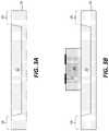
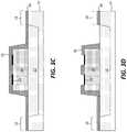
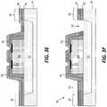
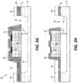
- FIGS. 3A-3Iare successive cross sections illustrating an exemplary method and micro-device structures, according to illustrative embodiments of the present invention.
- FIG. 4is a perspective micrograph illustrating an anchor and a detached tether useful in understanding certain embodiments of the present invention
- FIG. 5is a perspective micrograph illustrating a source wafer having missing micro-devices useful in understanding certain embodiments of the present invention
- FIG. 6is a perspective micrograph illustrating an anchor and a tether, according to illustrative embodiments of the present invention.
- FIG. 7is a perspective micrograph illustrating a source wafer with micro-devices, according to illustrative embodiments of the present invention.
- Certain embodiments of the present inventionprovide tether structures and micro-transfer printing methods that efficiently, accurately, and precisely enable the transfer of a wide variety of micro-devices from a source wafer to a destination substrate with high yields.
- certain embodiments of the present inventionprovide tether structures useful for micro-transfer printing relatively large micro-devices, for example devices having a width or length, or both, equal to or greater than 250 ⁇ m, 400 ⁇ m, 500 ⁇ m, 600 ⁇ m, 800 ⁇ m, 1 mm, 2 mm, or 5 mm.
- micro-deviceshave a thickness greater than or equal to 5 ⁇ m, 10 ⁇ m, 15 ⁇ m, 20 ⁇ m, or 50 ⁇ m.
- micro-deviceshave a thickness that is in the range of about 16-17 ⁇ m.
- a micro-device structure 99comprises a source substrate 10 comprising sacrificial portions 12 laterally spaced apart by anchors 18 .
- a portion (e.g., part or segment) of each sacrificial portion 12is exposed through an opening 14 so that process gases or liquids can be introduced through the opening 14 to the sacrificial portions 12 to process the sacrificial portions 12 , for example to etch the sacrificial portions 12 .
- a micro-device 20is disposed exclusively in direct contact with each sacrificial portion 12 and is laterally attached to an anchor 18 by a multi-layer tether 16 .
- a micro-device 20 disposed exclusively in direct contact with each sacrificial portion 12is in contact only with a sacrificial portion 12 and not with any other portion of the source substrate 12 or structure except for one or more tethers 16 (e.g., including at least one multi-layer tether 16 ).
- Sacrificial portions 12can be a solid material.
- a sacrificial portion 12has been etched such that the volume that was occupied by the sacrificial portion defines a gap separating micro-devices 20 from a source substrate 10 such that micro-devices 20 are disposed exclusively over recessed portions 15 of the source substrate 10 between anchors 18 .
- a source wafer 10can also be a source substrate 10 and can be any of a wide variety of relatively flat, stable materials suitable for photolithographic or integrated circuit processing, for example glass, plastic, a crystalline semiconductor such as silicon, a compound semiconductor that comprises materials such as gallium nitride or gallium arsenide, quartz, or sapphire, or any suitable substrate or wafer material.
- sacrificial portions 12are anisotropically etchable designated portions of a source wafer 10 , for example portions of a crystalline semiconductor material on a process side of the source wafer 10 .
- sacrificial portions 12comprise a sacrificial material that is a same material as a source substrate material.
- a source wafer 10comprises a multi-layer structure including a layer of material on a process side of the source wafer 10 that is differentially etchable from a remainder of the source substrate 10 .
- sacrificial portions 12can comprise a sacrificial material that is a different material from another material of a source substrate 10 .
- the differentially etchable layercan be a patterned layer defining sacrificial portions 12 and can comprise a material that is differentially etchable from other layers of a source wafer 10 and from a micro-device 20 .
- a source wafer 10can be a semiconductor, glass, quartz, or sapphire source wafer 10 and sacrificial portions 12 can comprise an oxide such as silicon dioxide or a nitride.
- Sacrificial portions 12are laterally distributed over a process side of a source wafer 10 and are separated by anchors 18 .
- Anchors 18can simply be portions of the source wafer 10 that are not etched or otherwise removed from the source wafer 10 during processing.
- the processingcan be photolithographic or integrated circuit processing using, for example, methods and materials known in the art.
- a sacrificial portion 12can be etched, thereby defining a gap 13 between a micro-device 20 and a source substrate 10 , particularly after the sacrificial portion 12 is etched to remove material from the sacrificial portion 12 .
- micro-devices 20are disposed exclusively over recessed portions 15 of the source substrate 10 (e.g., between anchors 18 ).
- Micro-devices 20can be any useful structure intended for micro-transfer printing and comprise any material or structure useful for the intended purpose of the micro-devices 20 .
- Micro-devices 20can be electronic, mechanical, or optical structures, can be passive or active, or can be integrated circuits, electronic devices, or opto-electronic devices. It is contemplated that there is no inherent limit to the type, function, or materials of micro-devices 20 .
- Micro-devices 20can comprise a same material as a material of a source substrate 10 .
- Each micro-device 20is disposed exclusively in direct contact with a sacrificial portion 12 of a source substrate 10 so that, when the sacrificial portion 12 is etched, the volume that was occupied by the sacrificial portion 12 defines a gap 13 between the micro-device 20 and the source substrate 10 and the micro-device 20 is suspended over the gap 13 by one or more tethers 16 (e.g., as shown in FIGS. 3G and 3H ).
- a material of the sacrificial portion 12is differentially or anisotropically etchable not only with respect to the remaining portion of the source wafer 10 and anchors 18 but is also differentially or anisotropically etchable with respect to any or all of the micro-device 20 , a substrate of a micro-device 20 , and an encapsulating layer of a micro-device 20 .
- micro-devices 20can comprise a support layer or substrate, for example comprising a material relatively inert with respect to etchants of sacrificial portions 12 , on which an active material is disposed for example a semiconductor or other structure.
- Micro-devices 20can comprise semiconductor materials such as silicon or gallium or indium or compound semiconductor materials including such elements or other elements (e.g., III-V, II-VI, or both III-V and II-VI semiconductor compounds) and can comprise structures such as electrically conductive contact pads 22 for making electrical contact to the micro-devices 20 , doped semiconductor portions, wires, resistors, capacitors, or electrical or optical structures, or any combination of these, and any materials useful in such structures.
- semiconductor materialssuch as silicon or gallium or indium or compound semiconductor materials including such elements or other elements (e.g., III-V, II-VI, or both III-V and II-VI semiconductor compounds) and can comprise structures such as electrically conductive contact pads 22 for making electrical contact to the micro-devices 20 , doped semiconductor portions, wires, resistors, capacitors, or electrical or optical structures, or any combination of these, and any materials useful in such structures.
- Tethers 16are structures physically connecting each micro-device 20 to an anchor 18 .
- a tether 16can refer to a multi-layer tether 16 , a bi-layer tether 16 , or a tether 16 comprising a single layer.
- Each micro-device 20can be physically connected, for example laterally attached, by one or more, for example two, multi-layer tethers 16 to anchors 18 .
- Multi-layer tethers 16can comprise materials that are part of an anchor 18 , part of a micro-device 20 , or can be other materials, including materials that permanently or temporarily encapsulate a micro-device 20 .
- micro-devices 20are laterally attached to anchors 18 and a source substrate 10 only by a multi-layer tether 16 after the semiconductor portions are etched to define a gap 13 (e.g., such that etching defines the multi-layer tether 16 ).
- a desired ratio of a length of a multi-layer tether 16 along a side of a micro-device 20can depend on a size of the micro-device 20 .
- a micro-device 20has at least one of a length and a width that is two to four times (or more) a length of a multi-layer tether 16 that is attached to the micro-device 20 .
- a micro-device 20has a length that is substantially three times a length of the multi-layer tether 16 , where a length of a multi-layer tether 16 and a micro-device 20 is taken in a direction L orthogonal to the direction W of an anchor 18 from a micro-device 20 (as shown in FIGS. 4-7 and discussed below).
- a multi-layer tether 16comprises a plurality of layers.
- a multi-layer tether 16is a bi-layer tether 16 comprising only two layers.
- a multi-layer tether 16consists essentially of only two layers, for example a first tether layer 30 adjacent to a source wafer 10 and a second tether layer 40 on a side of the first tether layer 30 opposite to the source wafer 10 , as shown in FIG. 1 .
- a first tether layer 30 and a second tether layer 40can have the same or substantially similar thickness.
- a first tether layer 30 and a second tether layer 40have different thicknesses, for example the first tether layer 30 can be 1.5 to 3 times thicker than the second tether layer 40 . In some embodiments, a first tether layer 30 is substantially two times thicker than a second tether layer 40 . In some embodiments, a multi-layer tether 16 comprises more than two layers. For example, a multi-layer tether 16 can consist essentially of only three layers or consist essentially of only four layers.
- a multi-layer tether 16comprises an oxide, a nitride, or both an oxide and a nitride.
- the multi-layer tether 16can comprise a first tether layer 30 comprising silicon dioxide and a second tether layer 40 comprising silicon nitride.
- the silicon dioxide first tether layer 30can be adjacent to a source wafer 10 or sacrificial portion 12 and the silicon nitride second tether layer 40 can be on a side of the silicon dioxide first tether layer 30 opposite the source wafer 10 or sacrificial portion 12 .
- the first tether layer 30 of silicon dioxideis disposed between the second tether layer 40 of silicon nitride and the sacrificial portion 12 or sacrificial portion 12 .
- a first tether layer 30extends over at least a portion of a micro-device 20
- a second tether layer 40extends over at least a portion of a micro-device 20
- a first tether layer 30extends over at least a first portion of a micro-device 20
- a second tether layer 40extends over at least a second portion of the micro-device 20 .
- the first and second portionscan be the same portion or different portions.
- a first tether layer 30 , a second tether layer 40 , or both the first tether layer 30 and the second tether layer 40encapsulate a micro-device 20 .
- An encapsulation layercan protect a micro-device 20 (e.g., the process side thereof, other portion thereof, or the entirety thereof) from the environment, for example from photolithographic processing gases or liquids or from environmental gases such as air, oxygen, nitrogen, and ozone, environmental liquids such as water, or particulate contamination such as dust or other airborne particles.
- a micro-device 20e.g., the process side thereof, other portion thereof, or the entirety thereof
- environmental gasessuch as air, oxygen, nitrogen, and ozone
- environmental liquidssuch as water
- particulate contaminationsuch as dust or other airborne particles.
- a first tether layer 30can encapsulate the micro-devices 20 except for the one or more contact pads 22 and a second tether layer 40 can encapsulate the micro-device 20 including the one or more contact pads 22 .
- a method of making a micro-device structure 99comprises providing a source substrate 10 comprising sacrificial portions 12 laterally spaced apart by anchors 18 in step 100 and as shown in FIG. 3A .
- a micro-device 20is disposed in association with the source substrate 10 on, in or over each sacrificial portion 12 .
- Each micro-device 20can be located entirely and exclusively over a sacrificial portion 12 so that each micro-device 20 is disposed exclusively on, in, or over one of the sacrificial portions 12 and none of the micro-devices 20 are disposed over or in contact with the anchors 18 or other portions of the source substrate 10 .
- Micro-devices 20can comprise a contact pad 22 for making electrical contact to each micro-device 20 to operate the micro-device 20 .
- Micro-devices 20can be formed using photolithographic methods and materials found in semiconductor fabrication facilities such as integrated circuit foundries and can be, for example, electronic or opto-electronic integrated circuits.
- a first tether layer 30is disposed over at least a portion of anchors 18 and micro-devices 20 and a source substrate 10 using a first deposition method.
- a first deposition methodsuch as continuous, single-frequency plasma-enhanced chemical vapor deposition (PECVD).
- PECVDplasma-enhanced chemical vapor deposition
- the first tether layer 30is patterned, for example by using photolithographic processes, masks, and etchants to remove portions of the first tether layer 30 , to expose the contact pads 22 and an opening 14 to the sacrificial portion 12 , and to form a tether 16 so that the tether 16 is the only portion of the first tether layer 30 that physically connects the micro-devices 20 to an anchor 18 .
- a second tether layer 40is deposited over a first tether layer 30 using a second deposition method, for example a second deposition method such as a pulsed, multi-frequency plasma-enhanced chemical vapor deposition (PECVD).
- a second deposition methodsuch as a pulsed, multi-frequency plasma-enhanced chemical vapor deposition (PECVD).
- PECVDpulsed, multi-frequency plasma-enhanced chemical vapor deposition
- Deposition of the second tether layer 40can be a blanket (unpatterned) deposition and can employ a second deposition method that has at least some different attributes from the first deposition method of the first tether layer 30 , thus forming a multi-layer tether 16 for each micro-device 20 such that the multi-layer tether 16 laterally attaches each micro-device 20 to an anchor 18 .
- a second depositioncan be, but does not need to be, made using a second deposition method.
- deposition of a first tether layer 30 and deposition of a second tether layer 40are done using at least partially different deposition methods or the second deposition method deposits a different material that has a different deposited structure from the first deposition method.
- a first tether layer 30can be deposited using PECVD with a continuous plasma generation method having one frequency to deposit silicon dioxide and a second tether layer 40 can be deposited using PECVD using a pulsed plasma generation method with two different frequencies to deposit silicon nitride.
- first and second tether layers 30 , 40Two different deposition methods of two different materials can form first and second tether layers 30 , 40 with different attributes and structures.
- the second tether layer 40is patterned to form an opening 14 exposing each sacrificial portion 12 .
- One or more depositionscan be used to form a second tether 16 that connects a micro-device to the same or a different anchor 18 as a multi-layer tether 16 .
- the one or more depositionscan, but do not necessarily, include one or more depositions used to make the multi-layer tether 16 .
- sacrificial portions 12are etched to release micro-devices 20 from a source substrate 10 , so that micro-devices 20 are suspended over gaps 13 (and thus over recessed portions 15 of the source substrate 10 ) separating micro-devices 20 from the source substrate 10 and are attached to anchors 18 and the source wafer 10 with multi-layer tethers 16 (e.g., with only multi-layer tethers 16 ), for example by introducing an etchant into an opening 14 .
- the etchantselectively etches each sacrificial portion 12 while leaving micro-devices 20 and the remainder of the source substrate 10 substantially undisturbed.
- a micro-device 20is physically connected to one or more anchors 18 with one or more tethers 16 and suspended over a recessed portion 15 of a source wafer 10 , wherein at least one of the one or more tethers 16 is a multi-layer tether 16 (e.g., all are multi-layer tethers 16 ) and each of the one or more tethers 16 connects the micro-device 20 to only one of the one or more anchors 18 .
- a multi-layer tether 16e.g., all are multi-layer tethers 16
- a second tether layer 40can be removed by an unpatterned blanket etch, exposing contact pads 22 .
- Such a processcan essentially reduce the number of layers in a tether 16 (e.g., such that a bilayer tether 16 becomes a single layer tether 16 ).
- a layere.g., second tether layer 40
- an etching processe.g., etching of sacrificial portions 12
- Micro-devices 20are then physically connected to a source wafer 10 with a tether 16 that physically holds micro-devices 20 in place with respect to the source wafer 10 so that micro-devices 20 can be micro-transfer printed in step 140 from the source wafer 10 .
- micro-devices 20can be micro-transfer printed in step 140 by contacting each of the micro-devices 20 with a respective stamp post 52 of a transfer stamp 50 to adhere the micro-devices 20 to the stamp posts 52 , and then removing the transfer stamp 50 from the source wafer 10 , thereby fracturing or separating the tethers 16 ( FIG. 3I ).
- the stamp 50is then relocated to a destination substrate, micro-devices 20 are pressed against the destination substrate to adhere micro-devices 20 to the destination substrate, and the stamp 50 is removed from micro-devices 20 and the destination substrate.
- the destination substratecan comprise an adhesive layer to assist in adhering micro-devices 20 to the destination substrate. After micro-devices 20 are adhered to the adhesive layer, the adhesive layer can be cured to permanently affix micro-devices 20 to the destination substrate.
- Micro-transfer printing micro-devices 20comprising different materials from different source wafers 10 to a common destination substrate with one or more stamps 50 enables the construction of heterogeneous micro-systems useful in applications for which a small size and a variety of device structures and materials are desirable.
- the use of a multi-layer tether 16enables micro-transfer printing with a wider variety of micro-devices 20 sizes, types, and materials, (in particular, larger micro-devices 20 ) thereby realizing a wider variety of micro-systems.
- Certain embodiments of the present inventionprovide advantages in forming micro-transfer printable micro-devices 20 that are relatively thicker (for example greater than or equal to 10 ⁇ m thick, greater than or equal to 15 ⁇ m thick, or greater than or equal to 20 ⁇ m thick, for example about 16-17 ⁇ m thick) than other micro-devices 20 (for example less than or equal to 10 ⁇ m thick). Because of the increased thickness of the micro-devices 20 , the deposition of selectively etchable materials, such as silicon dioxide, useful in constructing tethers 16 can be problematic.
- micro-devices 20form taller micro-device sidewalls 25 that can obscure portions of the source substrate 10 , especially between micro-devices 20 and anchors 18 , inhibiting a conformal and consistent deposition of a first tether layer 30 , thus preventing a continuous tether-to-device interface structure.
- silicon semiconductor micro-devices 20having a length of 1000 ⁇ m, a width of 200 ⁇ m, and a thickness of 17 ⁇ m, the interface between the anchors 18 and the first tether layer 30 is discontinuous and the first tether layer 30 is not well adhered to the micro-device sidewall 25 .
- FIG. 5is a micro-graph of an array of micro-devices 20 disposed on a source wafer 10 with a single layer tether 16 (comprising only a first tether layer 30 ).
- the absent micro-device locations 23 in the arrayare locations in which the micro-devices 20 became detached or dislodged and floated away from the source wafer 10 and are absent or removed and not available in place for micro-transfer printing; mis-located micro-devices 21 are mis-located with respect to the source wafer 10 , inhibiting accurate and precise transfer despite remaining present on the source wafer 10 .
- a second tether layer 40is deposited using different materials or different deposition methods or parameters from the first tether layer 30 . Because the deposition process and materials are different, the second tether layer 40 fills in areas of the source wafer 10 that can be discontinuous and were not adequately coated with the first deposition method, as shown in FIG. 6 .
- FIG. 6illustrates a source wafer 10 with a bilayer tether 16 attached to an anchor 18 and comprising a first tether layer 30 , and a second tether layer 40 .
- An opening 14exposes a part of the sacrificial portion 12 , and contact pads 22 covered with the second tether layer 40 . This structure corresponds to that of FIG.
- FIG. 6is a micro-graph of an array of micro-devices 20 attached to a source wafer 10 (as in FIG. 5 ) but comprising both a first tether layer 30 and a second tether layer 40 according to some embodiments of the present invention.
- a micro-device 20is found in all of the locations in the array, demonstrating the improvement in tether structures for micro-devices 20 according to certain embodiments of the present invention, and enabling micro-transfer printing with improved accuracy, precision, and consistency for all micro-devices 20 disposed on the source wafer 10 .
- Photolithographic patterningtypically requires coating a rather viscous photoresist liquid over the surface to be patterned, exposing the liquid to a patterned mask to form a patterned layer, etching the patterned layer and an underlying layer, and then stripping (removing) the patterned layer.
- micro-devices 20are poorly attached to a source substrate 10 (for example with a single layer tether 16 consisting essentially of only a first tether layer 30 ) and the micro-devices 20 have been released by etching the sacrificial portion 12 , the photolithographic patterning process (especially a coating process or any contact masking process) can remove or disturb the micro-devices 20 attached to the source substrate 10 . Hence, patterning the first tether layer 30 to open the contact pads 22 after the micro-devices 20 have been released is problematic, as shown in FIG. 5 .
- contact pads 22are opened (e.g., exposed) before micro-devices 20 are released, an etchant used to etch sacrificial portions 12 can attack a contact pad 22 material, damaging contact pads 22 and degrading any subsequent electrical contact to micro-devices 20 .
- contact pads 22are opened (e.g., exposed) after micro-devices 20 have been micro-transfer printed to a destination substrate, but this requires an additional process step and a much greater quantity of expensive patterning materials and more expensive photolithographic equipment (because a destination substrate is typically much larger than a source substrate 10 ).
- removing a first or second tether layer 30 , 40 after micro-devices 20 are micro-transfer printed onto the destination substratecan damage other devices on the destination substrate that are susceptible to the layer removal process (e.g., an etchant removing a first or second tether layer 30 , 40 on the destination substrate could undesirably etch other devices or structures on the destination substrate or the destination substrate itself).
- an etchant removing a first or second tether layer 30 , 40 on the destination substratecould undesirably etch other devices or structures on the destination substrate or the destination substrate itself.
- selective removing of the blanket-coated second tether layer 40 after the etch step ( 130 )does not require photolithographic patterning and so avoids the problems of photo-resist deposition, any contact masks, and additional etching required. Therefore, some embodiments of the present invention require fewer process steps and may utilize steps less likely to possibly cause damage.
- micro-devices 20can be any one or more of integrated circuits, sensors, and organic or inorganic light-emitting diodes.
- U.S. Pat. No. 6,825,559describes methods of making micro-transfer-printable inorganic micro-devices 20 , the disclosure of which is hereby incorporated by reference.
- micro-devices 20are prepared on a native source wafer 10 , for example a sapphire wafer with compound semiconductors such as GaN or silicon wafers with CMOS circuits thereon, each type of micro-device 20 prepared on a different source wafer 10 and released for micro-transfer printing with one or more micro-device multi-layer tethers 16 physically connecting the micro-device sidewall 25 of each micro-device 20 to an anchor 18 of the source wafer 10 .
- a native source wafer 10for example a sapphire wafer with compound semiconductors such as GaN or silicon wafers with CMOS circuits thereon
- each type of micro-device 20prepared on a different source wafer 10 and released for micro-transfer printing with one or more micro-device multi-layer tethers 16 physically connecting the micro-device sidewall 25 of each micro-device 20 to an anchor 18 of the source wafer 10 .
- micro-devices 20are then contacted with a micro-transfer printing stamp 50 to fracture, separate, or otherwise break micro-device tethers 16 and adhere micro-devices 20 to a transfer stamp 50 .
- the transfer stamp 50then contacts micro-devices 20 to a destination substrate, to which micro-devices 20 are then adhered.
- micro-transfer printing techniquessee, U.S. Pat. Nos. 8,722,458, 7,622,367 and 8,506,867, the disclosure of each of which are hereby incorporated by reference.
- Methods of forming micro-transfer printable structuresare described, for example, in the paper AMOLED Displays using Transfer - Printed Integrated Circuits (Journal of the Society for Information Display, 2011, DOI #10.1889/JSID19.4.335, 1071-0922/11/1904-0335, pages 335-341) and U.S. Pat. No. 8,889,485.
- Micro-transfer printing using compound micro-assembly structures and methodscan also be used with certain embodiments of the present invention, for example, as described in U.S. patent application Ser.
- a first layer on a second layerin some embodiments means a first layer directly on and in contact with a second layer. In other embodiments, a first layer on a second layer can include another layer there between.
Landscapes
- Engineering & Computer Science (AREA)
- Microelectronics & Electronic Packaging (AREA)
- Power Engineering (AREA)
- Computer Hardware Design (AREA)
- Physics & Mathematics (AREA)
- Condensed Matter Physics & Semiconductors (AREA)
- General Physics & Mathematics (AREA)
- Manufacturing & Machinery (AREA)
- Mechanical Engineering (AREA)
- Micromachines (AREA)
Abstract
Description
- L length direction
- W width direction
- 10 source substrate/source wafer
- 12 sacrificial portion
- 13 gap
- 14 opening
- 15 recessed portion
- 16 tether/multi-layer tether/bilayer tether
- 18 anchor
- 20 micro-device
- 21 mis-located micro-device
- 22 contact pad
- 23 absent micro-device location
- 25 micro-device sidewall
- 30 first tether layer
- 40 second tether layer
- 50 stamp
- 52 post
- 99 micro-device structure
- 100 provide source substrate step
- 105 dispose micro-device step
- 110 deposit first layer step
- 115 open contact pads and sacrificial layer opening step
- 120 deposit second layer step
- 125 pattern second layer to form sacrificial layer opening step
- 130 release micro-devices step
- 135 strip second layer step
- 140 micro-transfer print micro-device step
Claims (20)
Priority Applications (1)
| Application Number | Priority Date | Filing Date | Title |
|---|---|---|---|
| US17/063,681US11367648B2 (en) | 2018-06-14 | 2020-10-05 | Multi-layer tethers for micro-transfer printing |
Applications Claiming Priority (2)
| Application Number | Priority Date | Filing Date | Title |
|---|---|---|---|
| US16/008,945US10832934B2 (en) | 2018-06-14 | 2018-06-14 | Multi-layer tethers for micro-transfer printing |
| US17/063,681US11367648B2 (en) | 2018-06-14 | 2020-10-05 | Multi-layer tethers for micro-transfer printing |
Related Parent Applications (1)
| Application Number | Title | Priority Date | Filing Date |
|---|---|---|---|
| US16/008,945DivisionUS10832934B2 (en) | 2018-06-14 | 2018-06-14 | Multi-layer tethers for micro-transfer printing |
Publications (2)
| Publication Number | Publication Date |
|---|---|
| US20210020491A1 US20210020491A1 (en) | 2021-01-21 |
| US11367648B2true US11367648B2 (en) | 2022-06-21 |
Family
ID=68840326
Family Applications (2)
| Application Number | Title | Priority Date | Filing Date |
|---|---|---|---|
| US16/008,945ActiveUS10832934B2 (en) | 2018-06-14 | 2018-06-14 | Multi-layer tethers for micro-transfer printing |
| US17/063,681Active2038-10-07US11367648B2 (en) | 2018-06-14 | 2020-10-05 | Multi-layer tethers for micro-transfer printing |
Family Applications Before (1)
| Application Number | Title | Priority Date | Filing Date |
|---|---|---|---|
| US16/008,945ActiveUS10832934B2 (en) | 2018-06-14 | 2018-06-14 | Multi-layer tethers for micro-transfer printing |
Country Status (1)
| Country | Link |
|---|---|
| US (2) | US10832934B2 (en) |
Families Citing this family (11)
| Publication number | Priority date | Publication date | Assignee | Title |
|---|---|---|---|---|
| US11626856B2 (en)* | 2019-10-30 | 2023-04-11 | X-Celeprint Limited | Non-linear tethers for suspended devices |
| US11637540B2 (en) | 2019-10-30 | 2023-04-25 | X-Celeprint Limited | Non-linear tethers for suspended devices |
| EP4088324A1 (en)* | 2020-01-10 | 2022-11-16 | Rockley Photonics Limited | Source wafer and method of preparation thereof |
| GB2593260B (en)* | 2020-03-17 | 2024-06-26 | Rockley Photonics Ltd | Coupon wafer and method of preparation thereof |
| US11088007B1 (en) | 2020-05-07 | 2021-08-10 | X-Celeprint Limited | Component tethers with spacers |
| US12057340B2 (en) | 2020-12-04 | 2024-08-06 | X-Celeprint Limited | Hybrid tethers for micro-transfer printing |
| US11490519B2 (en) | 2021-01-11 | 2022-11-01 | X-Celeprint Limited | Printed stacked micro-devices |
| WO2022174358A1 (en)* | 2021-02-22 | 2022-08-25 | Vuereal Inc. | Cartridge interference |
| TWI795790B (en) | 2021-05-26 | 2023-03-11 | 隆達電子股份有限公司 | Light emitting element and display device using the same |
| US20240304748A1 (en)* | 2023-03-12 | 2024-09-12 | X-Celeprint Limited | Vertical tethers for micro-transfer printing |
| WO2025080984A1 (en)* | 2023-10-13 | 2025-04-17 | The Government Of The United States Of America, As Represented By The Secretary Of The Navy | Wafer-scale separation and transfer of gan material |
Citations (92)
| Publication number | Priority date | Publication date | Assignee | Title |
|---|---|---|---|---|
| US3673471A (en) | 1970-10-08 | 1972-06-27 | Fairchild Camera Instr Co | Doped semiconductor electrodes for mos type devices |
| US5475224A (en) | 1994-08-26 | 1995-12-12 | Grumman Aerospace Corporation | Infrared detector substrate with breakaway test tabs |
| US5621555A (en) | 1993-12-31 | 1997-04-15 | Goldstar Co., Ltd. | Liquid crystal display having redundant pixel electrodes and thin film transistors and a manufacturing method thereof |
| US5815303A (en) | 1997-06-26 | 1998-09-29 | Xerox Corporation | Fault tolerant projective display having redundant light modulators |
| US5882532A (en) | 1996-05-31 | 1999-03-16 | Hewlett-Packard Company | Fabrication of single-crystal silicon structures using sacrificial-layer wafer bonding |
| US6051472A (en) | 1996-09-26 | 2000-04-18 | Nec Corporation | Semiconductor device and method of producing the same |
| US6142358A (en) | 1997-05-31 | 2000-11-07 | The Regents Of The University Of California | Wafer-to-wafer transfer of microstructures using break-away tethers |
| US6278242B1 (en) | 2000-03-20 | 2001-08-21 | Eastman Kodak Company | Solid state emissive display with on-demand refresh |
| US20030062580A1 (en) | 2000-06-30 | 2003-04-03 | Rie Sato | Spin-valve transistor |
| US6577367B2 (en) | 2000-01-12 | 2003-06-10 | Lg. Philips Lcd Co., Ltd | Array substrate for a liquid crystal display device and method for fabricating the same |
| US20030141570A1 (en) | 2002-01-28 | 2003-07-31 | Chen Shiuh-Hui Steven | Semiconductor wafer having a thin die and tethers and methods of making the same |
| US6717560B2 (en) | 2000-05-15 | 2004-04-06 | Eastman Kodak Company | Self-illuminating imaging device |
| US6756576B1 (en) | 2000-08-30 | 2004-06-29 | Micron Technology, Inc. | Imaging system having redundant pixel groupings |
| JP2005108943A (en) | 2003-09-29 | 2005-04-21 | Oki Data Corp | Semiconductor wafer and method of manufacturing semiconductor device using the same |
| US6933532B2 (en) | 2003-03-28 | 2005-08-23 | Eastman Kodak Company | OLED display with photosensor |
| JP2005259912A (en) | 2004-03-10 | 2005-09-22 | Shin Etsu Handotai Co Ltd | Manufacturing method of light emitting element |
| US20060063309A1 (en) | 2004-09-21 | 2006-03-23 | Eiji Sugiyama | Method for manufacturing semiconductor device |
| US20060079010A1 (en) | 2004-09-30 | 2006-04-13 | Seiko Epson Corporation | Transfer base substrate and method of semiconductor device |
| JP2006108441A (en) | 2004-10-06 | 2006-04-20 | Mitsubishi Chemicals Corp | Etching method of compound semiconductor |
| US20060145177A1 (en) | 2003-02-28 | 2006-07-06 | Kazunori Hagimoto | Light emitting device and process for fabricating the same |
| US20070032089A1 (en) | 2004-06-04 | 2007-02-08 | The Board Of Trustees Of The University Of Illinois | Printable Semiconductor Structures and Related Methods of Making and Assembling |
| US7195733B2 (en) | 2004-04-27 | 2007-03-27 | The Board Of Trustees Of The University Of Illinois | Composite patterning devices for soft lithography |
| US20070173034A1 (en) | 2004-03-22 | 2007-07-26 | Semiconductor Energy Laboratory Co., Ltd. | Method for manufacturing integrated circuit |
| US7288753B2 (en) | 2004-05-05 | 2007-10-30 | Eastman Kodak Company | OLED display with composite photosensor |
| US20070281556A1 (en) | 2006-06-05 | 2007-12-06 | Homac Mfg. Company | Electrical connector with plug tether assembly and related methods |
| WO2008036837A2 (en) | 2006-09-20 | 2008-03-27 | The Board Of Trustees Of The University Of Illinois | Release strategies for making transferable semiconductor structures, devices and device components |
| US7399693B2 (en) | 2004-06-23 | 2008-07-15 | Canon Kabushiki Kaisha | Semiconductor film manufacturing method and substrate manufacturing method |
| WO2008103931A2 (en) | 2007-02-23 | 2008-08-28 | Strategic Patent Acquisitions Llc | Techniques for three dimensional displays |
| US7521292B2 (en) | 2004-06-04 | 2009-04-21 | The Board Of Trustees Of The University Of Illinois | Stretchable form of single crystal silicon for high performance electronics on rubber substrates |
| JP2009105450A (en) | 2009-02-09 | 2009-05-14 | Oki Data Corp | Laminate |
| US7557367B2 (en) | 2004-06-04 | 2009-07-07 | The Board Of Trustees Of The University Of Illinois | Stretchable semiconductor elements and stretchable electrical circuits |
| US7586497B2 (en) | 2005-12-20 | 2009-09-08 | Eastman Kodak Company | OLED display with improved power performance |
| US7662545B2 (en) | 2004-10-14 | 2010-02-16 | The Board Of Trustees Of The University Of Illinois | Decal transfer lithography |
| US7704684B2 (en) | 2003-12-01 | 2010-04-27 | The Board Of Trustees Of The University Of Illinois | Methods and devices for fabricating three-dimensional nanoscale structures |
| US20100139368A1 (en) | 2008-12-01 | 2010-06-10 | Jack Kotovsky | Micro-optical-mechanical system photoacoustic spectrometer |
| US20100248484A1 (en) | 2009-03-26 | 2010-09-30 | Christopher Bower | Methods of Forming Printable Integrated Circuit Devices and Devices Formed Thereby |
| US7816856B2 (en) | 2009-02-25 | 2010-10-19 | Global Oled Technology Llc | Flexible oled display with chiplets |
| US20100306993A1 (en) | 2007-11-20 | 2010-12-09 | Board Of Regents, The University Of Texas System | Method and Apparatus for Detethering Mesoscale, Microscale, and Nanoscale Components and Devices |
| US20100317132A1 (en) | 2009-05-12 | 2010-12-16 | Rogers John A | Printed Assemblies of Ultrathin, Microscale Inorganic Light Emitting Diodes for Deformable and Semitransparent Displays |
| US20100326518A1 (en) | 2008-02-21 | 2010-12-30 | Hiroyuki Juso | Solar cell and method of manufacturing solar cell |
| US7893612B2 (en) | 2008-02-27 | 2011-02-22 | Global Oled Technology Llc | LED device having improved light output |
| JP2011066130A (en) | 2009-09-16 | 2011-03-31 | Seiko Epson Corp | Method of manufacturing semiconductor circuit device, semiconductor circuit device, and electronic apparatus |
| US7927976B2 (en) | 2008-07-23 | 2011-04-19 | Semprius, Inc. | Reinforced composite stamp for dry transfer printing of semiconductor elements |
| US7943491B2 (en) | 2004-06-04 | 2011-05-17 | The Board Of Trustees Of The University Of Illinois | Pattern transfer printing by kinetic control of adhesion to an elastomeric stamp |
| US7972875B2 (en) | 2007-01-17 | 2011-07-05 | The Board Of Trustees Of The University Of Illinois | Optical systems fabricated by printing-based assembly |
| US7999454B2 (en) | 2008-08-14 | 2011-08-16 | Global Oled Technology Llc | OLED device with embedded chip driving |
| US8029139B2 (en) | 2008-01-29 | 2011-10-04 | Eastman Kodak Company | 2D/3D switchable color display apparatus with narrow band emitters |
| WO2011123285A1 (en) | 2010-03-29 | 2011-10-06 | Semprius, Inc. | Selective transfer of active components |
| US8207547B2 (en) | 2009-06-10 | 2012-06-26 | Brudgelux, Inc. | Thin-film LED with P and N contacts electrically isolated from the substrate |
| US8261660B2 (en) | 2009-07-22 | 2012-09-11 | Semprius, Inc. | Vacuum coupled tool apparatus for dry transfer printing semiconductor elements |
| US20120228669A1 (en) | 2009-09-16 | 2012-09-13 | Christopher Bower | High-yield fabrication of large-format substrates with distributed, independent control elements |
| US20120314388A1 (en) | 2011-06-08 | 2012-12-13 | Semprius, Inc. | Substrates with transferable chiplets |
| US8334545B2 (en) | 2010-03-24 | 2012-12-18 | Universal Display Corporation | OLED display architecture |
| US8333860B1 (en) | 2011-11-18 | 2012-12-18 | LuxVue Technology Corporation | Method of transferring a micro device |
| US20130069275A1 (en) | 2011-09-20 | 2013-03-21 | Etienne Menard | Printing transferable components using microstructured elastomeric surfaces with pressure modulated reversible adhesion |
| US20130088416A1 (en) | 2011-10-11 | 2013-04-11 | Cambridge Display Technology Limited | OLED Display Driver Circuits and Techniques |
| US8470701B2 (en) | 2008-04-03 | 2013-06-25 | Advanced Diamond Technologies, Inc. | Printable, flexible and stretchable diamond for thermal management |
| US20130196474A1 (en) | 2010-08-06 | 2013-08-01 | Matthew Meitl | Materials and processes for releasing printable compound semiconductor devices |
| US8502192B2 (en) | 2010-01-12 | 2013-08-06 | Varian Semiconductor Equipment Associates, Inc. | LED with uniform current spreading and method of fabrication |
| US8506867B2 (en) | 2008-11-19 | 2013-08-13 | Semprius, Inc. | Printing semiconductor elements by shear-assisted elastomeric stamp transfer |
| US20130207964A1 (en) | 2012-02-15 | 2013-08-15 | Rod G. Fleck | Imaging structure with embedded light sources |
| US20130221355A1 (en) | 2010-08-26 | 2013-08-29 | Christopher Bower | Structures and methods for testing printable integrated circuits |
| US8686447B2 (en) | 2011-03-01 | 2014-04-01 | Sony Corporation | Light emitting unit and display device |
| US20140104243A1 (en) | 2012-10-15 | 2014-04-17 | Kapil V. Sakariya | Content-Based Adaptive Refresh Schemes For Low-Power Displays |
| US8766970B2 (en) | 2008-05-05 | 2014-07-01 | Au Optronics Corporation | Pixel circuit, display panel, and driving method thereof |
| US8779484B2 (en) | 2012-11-29 | 2014-07-15 | United Microelectronics Corp. | Image sensor and process thereof |
| US8791474B1 (en) | 2013-03-15 | 2014-07-29 | LuxVue Technology Corporation | Light emitting diode display with redundancy scheme |
| US8794501B2 (en) | 2011-11-18 | 2014-08-05 | LuxVue Technology Corporation | Method of transferring a light emitting diode |
| US8803857B2 (en) | 2011-02-10 | 2014-08-12 | Ronald S. Cok | Chiplet display device with serial control |
| US8817369B2 (en) | 2009-08-31 | 2014-08-26 | Samsung Display Co., Ltd. | Three dimensional display device and method of controlling parallax barrier |
| US8835940B2 (en) | 2012-09-24 | 2014-09-16 | LuxVue Technology Corporation | Micro device stabilization post |
| US20140267683A1 (en) | 2013-03-15 | 2014-09-18 | LuxVue Technology Corporation | Method of fabricating a light emitting diode display with integrated defect detection test |
| US20140264763A1 (en) | 2013-03-15 | 2014-09-18 | Semprius, Inc. | Engineered substrates for semiconductor epitaxy and methods of fabricating the same |
| US8854294B2 (en) | 2009-03-06 | 2014-10-07 | Apple Inc. | Circuitry for independent gamma adjustment points |
| US20140340900A1 (en) | 2013-05-14 | 2014-11-20 | LuxVue Technology Corporation | Stabilization structure including shear release posts |
| US20140367633A1 (en) | 2013-06-18 | 2014-12-18 | LuxVue Technology Corporation | Led display with wavelength conversion layer |
| US20150028362A1 (en) | 2013-07-26 | 2015-01-29 | LuxVue Technology Corporation | Adhesive wafer bonding with controlled thickness variation |
| US8987765B2 (en) | 2013-06-17 | 2015-03-24 | LuxVue Technology Corporation | Reflective bank structure and method for integrating a light emitting device |
| US20150137187A1 (en) | 2012-07-24 | 2015-05-21 | Sumitomo Chemical Company, Limited | Semiconductor wafer, manufacturing method of semiconductor wafer and method for maunfacturing composite wafer |
| US9161448B2 (en) | 2010-03-29 | 2015-10-13 | Semprius, Inc. | Laser assisted transfer welding process |
| WO2015193435A1 (en) | 2014-06-18 | 2015-12-23 | X-Celeprint Limited | Systems and methods for controlling release of transferable semiconductor structures |
| US20150372053A1 (en) | 2014-06-18 | 2015-12-24 | X-Celeprint Limited | Micro assembled led displays and lighting elements |
| US20160020131A1 (en) | 2014-07-20 | 2016-01-21 | X-Celeprint Limited | Apparatus and methods for micro-transfer-printing |
| US20160086855A1 (en) | 2014-06-18 | 2016-03-24 | X-Celeprint Limited | Systems and methods for controlling release of transferable semiconductor structures |
| US20160093600A1 (en) | 2014-09-25 | 2016-03-31 | X-Celeprint Limited | Compound micro-assembly strategies and devices |
| US9368683B1 (en) | 2015-05-15 | 2016-06-14 | X-Celeprint Limited | Printable inorganic semiconductor method |
| US20170047306A1 (en) | 2015-08-11 | 2017-02-16 | X-Celeprint Limited | Stamp with structured posts |
| US9589944B2 (en) | 2012-07-30 | 2017-03-07 | Apple Inc. | Method and structure for receiving a micro device |
| US20170256521A1 (en) | 2016-03-03 | 2017-09-07 | X-Celeprint Limited | Micro-transfer printable electronic component |
| US9761754B2 (en)* | 2014-06-18 | 2017-09-12 | X-Celeprint Limited | Systems and methods for preparing GaN and related materials for micro assembly |
| US20180096964A1 (en) | 2016-10-03 | 2018-04-05 | X-Celeprint Limited | Micro-transfer printing with volatile adhesive layer |
| US20190051552A1 (en) | 2017-08-14 | 2019-02-14 | X-Celeprint Limited | Multi-level micro-device tethers |
- 2018
- 2018-06-14USUS16/008,945patent/US10832934B2/enactiveActive
- 2020
- 2020-10-05USUS17/063,681patent/US11367648B2/enactiveActive
Patent Citations (124)
| Publication number | Priority date | Publication date | Assignee | Title |
|---|---|---|---|---|
| US3673471A (en) | 1970-10-08 | 1972-06-27 | Fairchild Camera Instr Co | Doped semiconductor electrodes for mos type devices |
| US5621555A (en) | 1993-12-31 | 1997-04-15 | Goldstar Co., Ltd. | Liquid crystal display having redundant pixel electrodes and thin film transistors and a manufacturing method thereof |
| US5475224A (en) | 1994-08-26 | 1995-12-12 | Grumman Aerospace Corporation | Infrared detector substrate with breakaway test tabs |
| US5882532A (en) | 1996-05-31 | 1999-03-16 | Hewlett-Packard Company | Fabrication of single-crystal silicon structures using sacrificial-layer wafer bonding |
| US6051472A (en) | 1996-09-26 | 2000-04-18 | Nec Corporation | Semiconductor device and method of producing the same |
| US6142358A (en) | 1997-05-31 | 2000-11-07 | The Regents Of The University Of California | Wafer-to-wafer transfer of microstructures using break-away tethers |
| US5815303A (en) | 1997-06-26 | 1998-09-29 | Xerox Corporation | Fault tolerant projective display having redundant light modulators |
| US6577367B2 (en) | 2000-01-12 | 2003-06-10 | Lg. Philips Lcd Co., Ltd | Array substrate for a liquid crystal display device and method for fabricating the same |
| US6278242B1 (en) | 2000-03-20 | 2001-08-21 | Eastman Kodak Company | Solid state emissive display with on-demand refresh |
| US6717560B2 (en) | 2000-05-15 | 2004-04-06 | Eastman Kodak Company | Self-illuminating imaging device |
| US20030062580A1 (en) | 2000-06-30 | 2003-04-03 | Rie Sato | Spin-valve transistor |
| US7129457B2 (en) | 2000-08-30 | 2006-10-31 | Micron Technology, Inc. | Redundant imaging systems |
| US6756576B1 (en) | 2000-08-30 | 2004-06-29 | Micron Technology, Inc. | Imaging system having redundant pixel groupings |
| US20030141570A1 (en) | 2002-01-28 | 2003-07-31 | Chen Shiuh-Hui Steven | Semiconductor wafer having a thin die and tethers and methods of making the same |
| US20060145177A1 (en) | 2003-02-28 | 2006-07-06 | Kazunori Hagimoto | Light emitting device and process for fabricating the same |
| US6933532B2 (en) | 2003-03-28 | 2005-08-23 | Eastman Kodak Company | OLED display with photosensor |
| JP2005108943A (en) | 2003-09-29 | 2005-04-21 | Oki Data Corp | Semiconductor wafer and method of manufacturing semiconductor device using the same |
| US7704684B2 (en) | 2003-12-01 | 2010-04-27 | The Board Of Trustees Of The University Of Illinois | Methods and devices for fabricating three-dimensional nanoscale structures |
| JP2005259912A (en) | 2004-03-10 | 2005-09-22 | Shin Etsu Handotai Co Ltd | Manufacturing method of light emitting element |
| US20070173034A1 (en) | 2004-03-22 | 2007-07-26 | Semiconductor Energy Laboratory Co., Ltd. | Method for manufacturing integrated circuit |
| US7195733B2 (en) | 2004-04-27 | 2007-03-27 | The Board Of Trustees Of The University Of Illinois | Composite patterning devices for soft lithography |
| US7288753B2 (en) | 2004-05-05 | 2007-10-30 | Eastman Kodak Company | OLED display with composite photosensor |
| US8754396B2 (en) | 2004-06-04 | 2014-06-17 | The Board Of Trustees Of The University Of Illinois | Stretchable form of single crystal silicon for high performance electronics on rubber substrates |
| US8039847B2 (en) | 2004-06-04 | 2011-10-18 | The Board Of Trustees Of The University Of Illinois | Printable semiconductor structures and related methods of making and assembling |
| US7799699B2 (en) | 2004-06-04 | 2010-09-21 | The Board Of Trustees Of The University Of Illinois | Printable semiconductor structures and related methods of making and assembling |
| US8440546B2 (en) | 2004-06-04 | 2013-05-14 | The Board Of Trustees Of The University Of Illinois | Methods and devices for fabricating and assembling printable semiconductor elements |
| US8394706B2 (en) | 2004-06-04 | 2013-03-12 | The Board Of Trustees Of The University Of Illinois | Printable semiconductor structures and related methods of making and assembling |
| US7943491B2 (en) | 2004-06-04 | 2011-05-17 | The Board Of Trustees Of The University Of Illinois | Pattern transfer printing by kinetic control of adhesion to an elastomeric stamp |
| US8664699B2 (en) | 2004-06-04 | 2014-03-04 | The Board Of Trustees Of The University Of Illinois | Methods and devices for fabricating and assembling printable semiconductor elements |
| US7622367B1 (en) | 2004-06-04 | 2009-11-24 | The Board Of Trustees Of The University Of Illinois | Methods and devices for fabricating and assembling printable semiconductor elements |
| US8198621B2 (en) | 2004-06-04 | 2012-06-12 | The Board Of Trustees Of The University Of Illinois | Stretchable form of single crystal silicon for high performance electronics on rubber substrates |
| US7521292B2 (en) | 2004-06-04 | 2009-04-21 | The Board Of Trustees Of The University Of Illinois | Stretchable form of single crystal silicon for high performance electronics on rubber substrates |
| US20070032089A1 (en) | 2004-06-04 | 2007-02-08 | The Board Of Trustees Of The University Of Illinois | Printable Semiconductor Structures and Related Methods of Making and Assembling |
| US7557367B2 (en) | 2004-06-04 | 2009-07-07 | The Board Of Trustees Of The University Of Illinois | Stretchable semiconductor elements and stretchable electrical circuits |
| US7982296B2 (en) | 2004-06-04 | 2011-07-19 | The Board Of Trustees Of The University Of Illinois | Methods and devices for fabricating and assembling printable semiconductor elements |
| US7399693B2 (en) | 2004-06-23 | 2008-07-15 | Canon Kabushiki Kaisha | Semiconductor film manufacturing method and substrate manufacturing method |
| US7354801B2 (en) | 2004-09-21 | 2008-04-08 | Semiconductor Energy Laboratory Co., Ltd. | Method for manufacturing semiconductor device |
| US20060063309A1 (en) | 2004-09-21 | 2006-03-23 | Eiji Sugiyama | Method for manufacturing semiconductor device |
| US20060079010A1 (en) | 2004-09-30 | 2006-04-13 | Seiko Epson Corporation | Transfer base substrate and method of semiconductor device |
| JP2006108441A (en) | 2004-10-06 | 2006-04-20 | Mitsubishi Chemicals Corp | Etching method of compound semiconductor |
| US7662545B2 (en) | 2004-10-14 | 2010-02-16 | The Board Of Trustees Of The University Of Illinois | Decal transfer lithography |
| US7586497B2 (en) | 2005-12-20 | 2009-09-08 | Eastman Kodak Company | OLED display with improved power performance |
| US20070281556A1 (en) | 2006-06-05 | 2007-12-06 | Homac Mfg. Company | Electrical connector with plug tether assembly and related methods |
| US8895406B2 (en) | 2006-09-20 | 2014-11-25 | The Board Of Trustees Of The University Of Illinois | Release strategies for making transferable semiconductor structures, devices and device components |
| WO2008036837A2 (en) | 2006-09-20 | 2008-03-27 | The Board Of Trustees Of The University Of Illinois | Release strategies for making transferable semiconductor structures, devices and device components |
| US20080108171A1 (en) | 2006-09-20 | 2008-05-08 | Rogers John A | Release strategies for making transferable semiconductor structures, devices and device components |
| US7932123B2 (en) | 2006-09-20 | 2011-04-26 | The Board Of Trustees Of The University Of Illinois | Release strategies for making transferable semiconductor structures, devices and device components |
| US7972875B2 (en) | 2007-01-17 | 2011-07-05 | The Board Of Trustees Of The University Of Illinois | Optical systems fabricated by printing-based assembly |
| US8722458B2 (en) | 2007-01-17 | 2014-05-13 | The Board Of Trustees Of The University Of Illinois | Optical systems fabricated by printing-based assembly |
| WO2008103931A2 (en) | 2007-02-23 | 2008-08-28 | Strategic Patent Acquisitions Llc | Techniques for three dimensional displays |
| US20100306993A1 (en) | 2007-11-20 | 2010-12-09 | Board Of Regents, The University Of Texas System | Method and Apparatus for Detethering Mesoscale, Microscale, and Nanoscale Components and Devices |
| US8029139B2 (en) | 2008-01-29 | 2011-10-04 | Eastman Kodak Company | 2D/3D switchable color display apparatus with narrow band emitters |
| US20100326518A1 (en) | 2008-02-21 | 2010-12-30 | Hiroyuki Juso | Solar cell and method of manufacturing solar cell |
| US7893612B2 (en) | 2008-02-27 | 2011-02-22 | Global Oled Technology Llc | LED device having improved light output |
| US8470701B2 (en) | 2008-04-03 | 2013-06-25 | Advanced Diamond Technologies, Inc. | Printable, flexible and stretchable diamond for thermal management |
| US8766970B2 (en) | 2008-05-05 | 2014-07-01 | Au Optronics Corporation | Pixel circuit, display panel, and driving method thereof |
| US7927976B2 (en) | 2008-07-23 | 2011-04-19 | Semprius, Inc. | Reinforced composite stamp for dry transfer printing of semiconductor elements |
| US7999454B2 (en) | 2008-08-14 | 2011-08-16 | Global Oled Technology Llc | OLED device with embedded chip driving |
| US8506867B2 (en) | 2008-11-19 | 2013-08-13 | Semprius, Inc. | Printing semiconductor elements by shear-assisted elastomeric stamp transfer |
| US20100139368A1 (en) | 2008-12-01 | 2010-06-10 | Jack Kotovsky | Micro-optical-mechanical system photoacoustic spectrometer |
| JP2009105450A (en) | 2009-02-09 | 2009-05-14 | Oki Data Corp | Laminate |
| US7816856B2 (en) | 2009-02-25 | 2010-10-19 | Global Oled Technology Llc | Flexible oled display with chiplets |
| US8854294B2 (en) | 2009-03-06 | 2014-10-07 | Apple Inc. | Circuitry for independent gamma adjustment points |
| US8877648B2 (en) | 2009-03-26 | 2014-11-04 | Semprius, Inc. | Methods of forming printable integrated circuit devices by selective etching to suspend the devices from a handling substrate and devices formed thereby |
| US20100248484A1 (en) | 2009-03-26 | 2010-09-30 | Christopher Bower | Methods of Forming Printable Integrated Circuit Devices and Devices Formed Thereby |
| US20100317132A1 (en) | 2009-05-12 | 2010-12-16 | Rogers John A | Printed Assemblies of Ultrathin, Microscale Inorganic Light Emitting Diodes for Deformable and Semitransparent Displays |
| US8207547B2 (en) | 2009-06-10 | 2012-06-26 | Brudgelux, Inc. | Thin-film LED with P and N contacts electrically isolated from the substrate |
| US8261660B2 (en) | 2009-07-22 | 2012-09-11 | Semprius, Inc. | Vacuum coupled tool apparatus for dry transfer printing semiconductor elements |
| US8817369B2 (en) | 2009-08-31 | 2014-08-26 | Samsung Display Co., Ltd. | Three dimensional display device and method of controlling parallax barrier |
| JP2011066130A (en) | 2009-09-16 | 2011-03-31 | Seiko Epson Corp | Method of manufacturing semiconductor circuit device, semiconductor circuit device, and electronic apparatus |
| US20120228669A1 (en) | 2009-09-16 | 2012-09-13 | Christopher Bower | High-yield fabrication of large-format substrates with distributed, independent control elements |
| US8502192B2 (en) | 2010-01-12 | 2013-08-06 | Varian Semiconductor Equipment Associates, Inc. | LED with uniform current spreading and method of fabrication |
| US8334545B2 (en) | 2010-03-24 | 2012-12-18 | Universal Display Corporation | OLED display architecture |
| WO2011123285A1 (en) | 2010-03-29 | 2011-10-06 | Semprius, Inc. | Selective transfer of active components |
| US9161448B2 (en) | 2010-03-29 | 2015-10-13 | Semprius, Inc. | Laser assisted transfer welding process |
| US20130273695A1 (en) | 2010-03-29 | 2013-10-17 | Semprius, Inc. | Selective transfer of active components |
| US9355854B2 (en) | 2010-08-06 | 2016-05-31 | Semprius, Inc. | Methods of fabricating printable compound semiconductor devices on release layers |
| US20130196474A1 (en) | 2010-08-06 | 2013-08-01 | Matthew Meitl | Materials and processes for releasing printable compound semiconductor devices |
| US20130221355A1 (en) | 2010-08-26 | 2013-08-29 | Christopher Bower | Structures and methods for testing printable integrated circuits |
| US9923133B2 (en) | 2010-08-26 | 2018-03-20 | X-Celeprint Limited | Structures and methods for testing printable integrated circuits |
| US9142468B2 (en) | 2010-08-26 | 2015-09-22 | Semprius, Inc. | Structures and methods for testing printable integrated circuits |
| US8803857B2 (en) | 2011-02-10 | 2014-08-12 | Ronald S. Cok | Chiplet display device with serial control |
| US8686447B2 (en) | 2011-03-01 | 2014-04-01 | Sony Corporation | Light emitting unit and display device |
| US8934259B2 (en) | 2011-06-08 | 2015-01-13 | Semprius, Inc. | Substrates with transferable chiplets |
| US20120314388A1 (en) | 2011-06-08 | 2012-12-13 | Semprius, Inc. | Substrates with transferable chiplets |
| US8889485B2 (en) | 2011-06-08 | 2014-11-18 | Semprius, Inc. | Methods for surface attachment of flipped active componenets |
| US20150135525A1 (en) | 2011-06-08 | 2015-05-21 | Semprius, Inc. | Methods for surface attachment of flipped active components |
| US20130069275A1 (en) | 2011-09-20 | 2013-03-21 | Etienne Menard | Printing transferable components using microstructured elastomeric surfaces with pressure modulated reversible adhesion |
| US20130088416A1 (en) | 2011-10-11 | 2013-04-11 | Cambridge Display Technology Limited | OLED Display Driver Circuits and Techniques |
| US8794501B2 (en) | 2011-11-18 | 2014-08-05 | LuxVue Technology Corporation | Method of transferring a light emitting diode |
| US8333860B1 (en) | 2011-11-18 | 2012-12-18 | LuxVue Technology Corporation | Method of transferring a micro device |
| US20130207964A1 (en) | 2012-02-15 | 2013-08-15 | Rod G. Fleck | Imaging structure with embedded light sources |
| US20150137187A1 (en) | 2012-07-24 | 2015-05-21 | Sumitomo Chemical Company, Limited | Semiconductor wafer, manufacturing method of semiconductor wafer and method for maunfacturing composite wafer |
| US9589944B2 (en) | 2012-07-30 | 2017-03-07 | Apple Inc. | Method and structure for receiving a micro device |
| US8835940B2 (en) | 2012-09-24 | 2014-09-16 | LuxVue Technology Corporation | Micro device stabilization post |
| US20140104243A1 (en) | 2012-10-15 | 2014-04-17 | Kapil V. Sakariya | Content-Based Adaptive Refresh Schemes For Low-Power Displays |
| US8779484B2 (en) | 2012-11-29 | 2014-07-15 | United Microelectronics Corp. | Image sensor and process thereof |
| US20140264763A1 (en) | 2013-03-15 | 2014-09-18 | Semprius, Inc. | Engineered substrates for semiconductor epitaxy and methods of fabricating the same |
| US20140267683A1 (en) | 2013-03-15 | 2014-09-18 | LuxVue Technology Corporation | Method of fabricating a light emitting diode display with integrated defect detection test |
| US8791474B1 (en) | 2013-03-15 | 2014-07-29 | LuxVue Technology Corporation | Light emitting diode display with redundancy scheme |
| US20140340900A1 (en) | 2013-05-14 | 2014-11-20 | LuxVue Technology Corporation | Stabilization structure including shear release posts |
| US8987765B2 (en) | 2013-06-17 | 2015-03-24 | LuxVue Technology Corporation | Reflective bank structure and method for integrating a light emitting device |
| US20150137153A1 (en) | 2013-06-17 | 2015-05-21 | LuxVue Technology Corporation | Method for integrating a light emitting device |
| US20140367633A1 (en) | 2013-06-18 | 2014-12-18 | LuxVue Technology Corporation | Led display with wavelength conversion layer |
| US20150028362A1 (en) | 2013-07-26 | 2015-01-29 | LuxVue Technology Corporation | Adhesive wafer bonding with controlled thickness variation |
| US9761754B2 (en)* | 2014-06-18 | 2017-09-12 | X-Celeprint Limited | Systems and methods for preparing GaN and related materials for micro assembly |
| US20160086855A1 (en) | 2014-06-18 | 2016-03-24 | X-Celeprint Limited | Systems and methods for controlling release of transferable semiconductor structures |
| US20170154819A1 (en) | 2014-06-18 | 2017-06-01 | X-Celeprint Limited | Systems and methods for controlling release of transferable semiconductor structures |
| US20150372053A1 (en) | 2014-06-18 | 2015-12-24 | X-Celeprint Limited | Micro assembled led displays and lighting elements |
| US20150371874A1 (en) | 2014-06-18 | 2015-12-24 | X-Celeprint Limited | Systems and methods for controlling release of transferable semiconductor structures |
| US9929053B2 (en) | 2014-06-18 | 2018-03-27 | X-Celeprint Limited | Systems and methods for controlling release of transferable semiconductor structures |
| US9520537B2 (en) | 2014-06-18 | 2016-12-13 | X-Celeprint Limited | Micro assembled LED displays and lighting elements |
| US9947584B2 (en) | 2014-06-18 | 2018-04-17 | X-Celeprint Limited | Systems and methods for controlling release of transferable semiconductor structures |
| WO2015193435A1 (en) | 2014-06-18 | 2015-12-23 | X-Celeprint Limited | Systems and methods for controlling release of transferable semiconductor structures |
| US9601356B2 (en) | 2014-06-18 | 2017-03-21 | X-Celeprint Limited | Systems and methods for controlling release of transferable semiconductor structures |
| US20160020131A1 (en) | 2014-07-20 | 2016-01-21 | X-Celeprint Limited | Apparatus and methods for micro-transfer-printing |
| US9434150B2 (en) | 2014-07-20 | 2016-09-06 | X-Celeprint Limited | Apparatus and methods for micro-transfer-printing |
| US20160093600A1 (en) | 2014-09-25 | 2016-03-31 | X-Celeprint Limited | Compound micro-assembly strategies and devices |
| US9368683B1 (en) | 2015-05-15 | 2016-06-14 | X-Celeprint Limited | Printable inorganic semiconductor method |
| US20170173852A1 (en) | 2015-07-20 | 2017-06-22 | X-Celeprint Limited | Multi-layer stamp |
| US20170047306A1 (en) | 2015-08-11 | 2017-02-16 | X-Celeprint Limited | Stamp with structured posts |
| US20170256521A1 (en) | 2016-03-03 | 2017-09-07 | X-Celeprint Limited | Micro-transfer printable electronic component |
| US20180096964A1 (en) | 2016-10-03 | 2018-04-05 | X-Celeprint Limited | Micro-transfer printing with volatile adhesive layer |
| US20190051552A1 (en) | 2017-08-14 | 2019-02-14 | X-Celeprint Limited | Multi-level micro-device tethers |
Non-Patent Citations (3)
| Title |
|---|
| Cok, R. S. et al., AMOLED displays with transfer-printed integrated circuits, Journal of the SID, 19(4):335-341, (2011). |
| Cok, R. S. et al., Inorganic light-emitting diode displays using micro-transfer printing, Journal of the SID, 25(10):589-609, (2017). |
| Delmdahl, R. et al., Large-area laser-lift-off processing in microelectronics, Physics Procedia 41:241-248 (2013). |
Also Published As
| Publication number | Publication date |
|---|---|
| US20190385885A1 (en) | 2019-12-19 |
| US20210020491A1 (en) | 2021-01-21 |
| US10832934B2 (en) | 2020-11-10 |
Similar Documents
| Publication | Publication Date | Title |
|---|---|---|
| US11367648B2 (en) | Multi-layer tethers for micro-transfer printing | |
| US11670533B2 (en) | Multi-level micro-device tethers | |
| US10297502B2 (en) | Isolation structure for micro-transfer-printable devices | |
| US10396137B2 (en) | Testing transfer-print micro-devices on wafer | |
| US10522710B2 (en) | Printable inorganic semiconductor structures | |
| US10468398B2 (en) | Efficiently micro-transfer printing micro-scale devices onto large-format substrates | |
| US12057340B2 (en) | Hybrid tethers for micro-transfer printing | |
| US10505079B2 (en) | Flexible devices and methods using laser lift-off | |
| US20150380619A1 (en) | Structures and methods for testing printable integrated circuits | |
| US11952266B2 (en) | Micro-device structures with etch holes | |
| CN112968107B (en) | Manufacturing method of weakening structure and transfer method of micro device | |
| US20220285291A1 (en) | Printable component modules with flexible, polymer, or organic module substrates | |
| US20210343903A1 (en) | Connection-post structures | |
| US20230058681A1 (en) | Printed devices in cavities | |
| US20240071801A1 (en) | Print-ready wafers with bottom-anchored components | |
| US20230290663A1 (en) | Printing components suspended by frames |
Legal Events
| Date | Code | Title | Description |
|---|---|---|---|
| FEPP | Fee payment procedure | Free format text:ENTITY STATUS SET TO UNDISCOUNTED (ORIGINAL EVENT CODE: BIG.); ENTITY STATUS OF PATENT OWNER: LARGE ENTITY | |
| STPP | Information on status: patent application and granting procedure in general | Free format text:APPLICATION DISPATCHED FROM PREEXAM, NOT YET DOCKETED | |
| STPP | Information on status: patent application and granting procedure in general | Free format text:DOCKETED NEW CASE - READY FOR EXAMINATION | |
| AS | Assignment | Owner name:X-CELEPRINT LIMITED, IRELAND Free format text:ASSIGNMENT OF ASSIGNORS INTEREST;ASSIGNOR:TRINDADE, ANTONIO JOSE MARQUES;REEL/FRAME:057276/0112 Effective date:20180703 Owner name:X DISPLAY COMPANY TECHNOLOGY LIMITED, IRELAND Free format text:CHANGE OF NAME;ASSIGNOR:X-CELEPRINT LIMITED;REEL/FRAME:057276/0126 Effective date:20191223 Owner name:X DISPLAY COMPANY TECHNOLOGY LIMITED, IRELAND Free format text:ASSIGNMENT OF ASSIGNORS INTEREST;ASSIGNOR:BOWER, CHRISTOPHER ANDREW;REEL/FRAME:057276/0168 Effective date:20200611 | |
| STPP | Information on status: patent application and granting procedure in general | Free format text:NOTICE OF ALLOWANCE MAILED -- APPLICATION RECEIVED IN OFFICE OF PUBLICATIONS | |
| STPP | Information on status: patent application and granting procedure in general | Free format text:PUBLICATIONS -- ISSUE FEE PAYMENT VERIFIED | |
| STCF | Information on status: patent grant | Free format text:PATENTED CASE |