US11365589B2 - Cutting element with non-planar cutting edges - Google Patents
Cutting element with non-planar cutting edgesDownload PDFInfo
- Publication number
- US11365589B2 US11365589B2US16/918,842US202016918842AUS11365589B2US 11365589 B2US11365589 B2US 11365589B2US 202016918842 AUS202016918842 AUS 202016918842AUS 11365589 B2US11365589 B2US 11365589B2
- Authority
- US
- United States
- Prior art keywords
- cutting element
- working surface
- cutting
- teeth
- center
- Prior art date
- Legal status (The legal status is an assumption and is not a legal conclusion. Google has not performed a legal analysis and makes no representation as to the accuracy of the status listed.)
- Active
Links
- 238000005520cutting processMethods0.000titleclaimsabstractdescription93
- 239000000758substrateSubstances0.000claimsabstractdescription13
- 239000011435rockSubstances0.000abstractdescription14
- 230000015572biosynthetic processEffects0.000description14
- 238000005553drillingMethods0.000description14
- 238000005755formation reactionMethods0.000description14
- 238000000034methodMethods0.000description9
- 239000000463materialSubstances0.000description7
- 229910003460diamondInorganic materials0.000description5
- 239000010432diamondSubstances0.000description5
- 239000002245particleSubstances0.000description4
- UONOETXJSWQNOL-UHFFFAOYSA-Ntungsten carbideChemical compound[W+]#[C-]UONOETXJSWQNOL-UHFFFAOYSA-N0.000description4
- 229910052582BNInorganic materials0.000description3
- PZNSFCLAULLKQX-UHFFFAOYSA-NBoron nitrideChemical compoundN#BPZNSFCLAULLKQX-UHFFFAOYSA-N0.000description3
- 238000010276constructionMethods0.000description3
- 239000000203mixtureSubstances0.000description3
- 230000008569processEffects0.000description3
- 230000035882stressEffects0.000description3
- 230000008901benefitEffects0.000description2
- 239000003795chemical substances by applicationSubstances0.000description2
- 230000004048modificationEffects0.000description2
- 238000012986modificationMethods0.000description2
- 238000011084recoveryMethods0.000description2
- 238000005299abrasionMethods0.000description1
- 239000003082abrasive agentSubstances0.000description1
- 230000009471actionEffects0.000description1
- 230000004075alterationEffects0.000description1
- 230000008859changeEffects0.000description1
- 239000010941cobaltSubstances0.000description1
- 229910017052cobaltInorganic materials0.000description1
- GUTLYIVDDKVIGB-UHFFFAOYSA-Ncobalt atomChemical compound[Co]GUTLYIVDDKVIGB-UHFFFAOYSA-N0.000description1
- 239000002131composite materialSubstances0.000description1
- 229930195733hydrocarbonNatural products0.000description1
- 150000002430hydrocarbonsChemical class0.000description1
- 230000000977initiatory effectEffects0.000description1
- 238000003754machiningMethods0.000description1
- 238000004519manufacturing processMethods0.000description1
- 239000003208petroleumSubstances0.000description1
- 238000001953recrystallisationMethods0.000description1
- 238000009877renderingMethods0.000description1
- 238000000926separation methodMethods0.000description1
- 238000010008shearingMethods0.000description1
- 230000008646thermal stressEffects0.000description1
Images


Classifications
- E—FIXED CONSTRUCTIONS
- E21—EARTH OR ROCK DRILLING; MINING
- E21B—EARTH OR ROCK DRILLING; OBTAINING OIL, GAS, WATER, SOLUBLE OR MELTABLE MATERIALS OR A SLURRY OF MINERALS FROM WELLS
- E21B10/00—Drill bits
- E21B10/46—Drill bits characterised by wear resisting parts, e.g. diamond inserts
- E21B10/56—Button-type inserts
- E21B10/567—Button-type inserts with preformed cutting elements mounted on a distinct support, e.g. polycrystalline inserts
- E21B10/5673—Button-type inserts with preformed cutting elements mounted on a distinct support, e.g. polycrystalline inserts having a non planar or non circular cutting face
- E—FIXED CONSTRUCTIONS
- E21—EARTH OR ROCK DRILLING; MINING
- E21B—EARTH OR ROCK DRILLING; OBTAINING OIL, GAS, WATER, SOLUBLE OR MELTABLE MATERIALS OR A SLURRY OF MINERALS FROM WELLS
- E21B10/00—Drill bits
- E21B10/46—Drill bits characterised by wear resisting parts, e.g. diamond inserts
- E21B10/54—Drill bits characterised by wear resisting parts, e.g. diamond inserts the bit being of the rotary drag type, e.g. fork-type bits
- E21B10/55—Drill bits characterised by wear resisting parts, e.g. diamond inserts the bit being of the rotary drag type, e.g. fork-type bits with preformed cutting elements
Definitions
- the disclosurerelates generally to cutting elements and drill bits.
- the disclosurerelates specifically to cutting elements in the field of drill bits used in petroleum exploration and drilling operation.
- drill bitIn drilling a borehole for the recovery of hydrocarbons or for other applications, it is conventional practice to connect a drill bit on the lower end of an assembly of drill pipe sections that are connected end-to-end so as to form a drill string.
- the bitis rotated by rotating the drill string at the surface and engaging the earthen formation, thereby causing the bit to cut through the formation material by either abrasion, fracturing, or shearing action to form a borehole along a predetermined path toward a target zone.
- Many different types of drill bitshave been developed and found useful in drilling such boreholes.
- each cutting element disposed on the blades of a drill bitis typically formed of extremely hard materials.
- each cutting elementincludes an elongate and generally cylindrical tungsten carbide substrate that is received and secured in a pocket formed in the surface of one of the blades.
- a conventional cutting elementtypically includes a hard-cutting layer of polycrystalline diamond (“PCD”) or other super-abrasive materials such as thermally stable diamond or polycrystalline cubic boron nitride.
- Cutting elementsare desired that can better withstand high loading during drilling so as to have an enhanced operating life. Cutters that cut efficiently at designed speed and loading conditions and that regulate the amount of contact area in changing formations are also desired. In addition, cutting elements that have chip breaking feature are further desired.
- the present disclosureis directed to a cutting element that can penetrate into hard formation more easily and a concave surface feature that can break-up more plastic chips.
- An embodiment of the disclosureis a cutting element comprising a cylindrical substrate; a table bonded to the cylindrical substrate; one or more teeth with a reduced projected cutting area on a periphery of the table; and a plurality of undulating cutting ridges on a top of the table.
- the cutting elementfurther comprises at least two recessions formed into the periphery of the table, wherein the one or more teeth are formed in between the at least two recessions.
- the at least two recessionsare equally spaced around a circumference of the table and extend through a full depth of the table.
- the one or more teethare rounded, sharp, or serrated.
- the number of one or more teethis ten.
- the cutting elementfurther comprises a working surface, at least one lateral surface, and a chamfer formed between the at least one lateral surface and the working surface.
- the at least two recessionsare formed into an outer circumference of the table, wherein the at least two recessions begin at a working surface, extend perpendicular to the working surface, and slope gradually toward a lateral surface.
- the depth of the at least two recessionsrange from 0.006′′ to 1 ⁇ 4 of the diameter of the working surface and the length of the at least two recessions range from 1 ⁇ 2 to 2 times the thickness of the table.
- an angle between the lateral surface and the chamferis about 30-60 degrees.
- the working surfaceis a non-planar working surface and the non-planar working surface includes a plurality of regional surfaces. A center of the non-planar working surface is higher than or equal to an edge of the non-planar working surface.
- a number of the plurality of regional surfacesis equal to that of the at least two recessions.
- the non-planar working surfaceincludes a first ridge between two adjacent regional surfaces, the first ridge is a straight or curved line connecting the center of the non-planar working surface and a symmetric center of a tooth.
- the regional surfaceis a planar structure or a curved structure.
- the regional surfaceincludes a second ridge, the second ridge is a straight or curved line connecting the center of the working surface and the symmetric center of an adjacent tooth.
- the first ridgeis higher than the second ridge such that the regional surface slopes gradually downwards from the first ridge to the second ridge.
- an angle between the two adjacent regional surfaces intersecting at the first ridgeis in a range from 100 to 179.5 degrees.
- An angle between the two adjacent regional surfaces intersecting at the second ridgeis in a range from 180.5 to 260 degrees.
- a radius of the at least one toothis in a range of 10%-100% of a radius of the cutting element.
- FIG. 1is a perspective view of the arrangement of a drill bit
- FIG. 2is a perspective view of the arrangement of a conventional cutting element
- FIG. 3is an illustration showing a conventional cutting element cutting a rock
- FIG. 4is an illustration showing debris cut by the cutting element of FIG. 3 ;
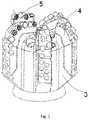
- FIG. 5is a perspective view of a cutting element in accordance with an embodiment disclosed herein;
- FIG. 6is a top view of the cutting element of FIG. 5 ;
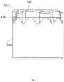
- FIG. 7is a front view of the cutting element of FIG. 5 ;
- FIG. 8is a sectional view of the cutting element of FIG. 5 showing an angle between two adjacent regional surfaces intersecting at the first ridge;
- FIG. 9is a sectional view of the cutting element of FIG. 5 showing an angle between two adjacent regional surfaces intersecting at the second ridge;
- FIG. 10is an illustration showing a cutting element of the present disclosure cutting a rock.
- FIG. 11is an illustration showing debris cut by the cutting element of FIG. 8 .
- a drill bitcomprises a drill bit body 3 and a plurality of blades 4 , the blades project radially outward from the bit body 3 and form flow channels therebetween.
- Cutting elements 5are grouped and mounted on the blades 4 in radially extending rows.
- the configuration or layout of the cutting elements 5 on the blades 4may vary widely, depending on a variety of factors, such as the formation to be drilled.
- an example cutting element 5includes a PCD table 502 and a cemented carbide substrate 504 .
- the PCD table 502includes an upper exterior working surface 503 and may include an optional chamfer 507 formed between the working surface 503 and the substrate 504 . It is noted that at least a portion of the chamfer 507 may also function as a working surface that contacts a subterranean formation during drilling operations.
- Flat top cutting elements as shown in FIG. 2are generally the most common and convenient to manufacture with an ultra-hard layer according to known techniques.
- the working surfacemakes contact with the earth formations during drilling, it is subjected to the generation of peak (high magnitude) stresses form normal loading, shear force loading, and impact loading imposed on the table 502 during drilling.
- peak stresses at the working surfacealone or in combination with other factors, such as residual thermal stresses, can result in the initiation and growth of cracks across the table 502 of the cutting element 5 . Cracks of sufficient length may cause the separation of a sufficiently large piece of ultra-hard material, rendering the cutting element 5 ineffective or resulting in the failure of the cutting element 5 . When this happens, drilling operations may have to be ceased to allow for recovery of the drag bit and replacement of the ineffective or failed cutting element.
- the conventional cutting elementcuts the formation 410 with planar cutting edge, the contact area is 412 and the cut depth is L.
- the PCD table 502cuts rock and withstands great impact from the rock at the same time. Since the working surface of the PCD table 502 lacks the flexibility of reduced contact area, it is prone to impact damage when drilling into a high gravel content formation or a hard formation, resulting in damage to the cutting faces. On the other hand, when drilling in shale, mudstone and other formations, the debris produced by cutting through diamond composite sheet can easily form a long strip shape debris 413 .
- FIG. 5 , FIG. 6 , and FIG. 7illustrate a cutting element 5 according to an embodiment of the disclosure.
- the cutting element 5is substantially the form of a cylinder. It includes a table 502 bond to a substrate 504 .
- the process for making a cutting element 5may employ a body of cemented tungsten carbide as the substrate 504 where the tungsten carbide particles are cemented together with cobalt.
- the carbide bodyis placed adjacent to a layer of ultra-hard material particles such as diamond or cubic boron nitride particles and the combination is subjected to high temperature at a pressure where the ultra-hard material particles are thermodynamically stable.
- the table 502has a working surface 503 and at least one lateral surface 505 , and a chamfer 507 formed therebetween.
- the angle between the side wall of the substrate 504 and the chamferis about 45 degrees. At least a portion of the lateral surface 505 and/or the chamfer 507 may also function as a working surface.
- the cutting element 5is provided with multiple cutting points or edges.
- the cutting element 5may be produced to incorporate two or more cutting edges into the outer circumference of the table 502 .
- the two or more cutting edgesmay be formed into the outer circumference by any machining method, as known in the art. If at least one recession is machined into the table 502 , two or more cutting edges may be formed into the outer circumference of the table 502 .
- a toothmay thus be formed in between two recessions.
- the teethmay be flattened elongated triangular ridges that protrude from the outer circumference of the table 502 .
- the teethmay also be rounded, sharp, serrated, or of some other desired shape.
- recessionsmay be formed into the periphery or edge of a traditional cutting element. recessions may extend along the entire side of the cutting element, or the recessions may partially extend along the height of the cutting element, or the cutting element may extend fully or partially down the table of the cutter.
- axial recessions 517are formed around the substantially side wall of the table 502 , between each adjacent pair of recessions 517 a radial tooth 516 is defined.
- the recessions 517can be equally spaced around the circumference of the table 502 and extend through the full depth of the table 502 with no change in their geometry.
- ten recessions 517 in totaldefining an equal number of teeth 516 .
- the teeth 516may be of different sizes and shapes.
- the radius of teeth 516can be from 10%-100% of the radius of the cutting element 5 .
- the recessions 517may be formed into the outer circumference of the table 502 at an inwardly sloping angle.
- the recessions 517may be formed into the table 502 such they are non-parallel to the central axis of the cutting element 5 ,
- the angle of the recessions 517may from about 15° to about 45° as relative to the central axis of the cutting element 5 .
- the cutting element 5 of the present disclosurefurther provides a non-planar exterior working surface 503 .
- the working surface 503includes a plurality of regional surfaces 523 and the center of the working surface 503 is higher or lower than the edge of the working surface 503 .
- the number of the regional surfaces 523are equal to that of the recessions 517 or the teeth 516 .
- the regional surfaces 523include a first ridge 530 and a second ridge 534 and further, the first ridge 530 can be a straight line slopes up or down from the center apex to the periphery, connecting the center of the working surface 503 and the symmetric center of a tooth 516 , such that each regional surface 523 has an approximate triangle shape.
- the first ridge 530is higher than the second ridge 534 such that the regional surface slopes gradually downwards from the first ridge to the second ridge.
- the regional surfaces 523can either be planar or curved.
- the angle ⁇ between two regional flat surfaces 523 intersecting at the first ridge 530can be from 100 to 179.5 degrees.
- the second ridge 534slopes down from the center apex to the periphery, the angle ⁇ between the adjacent regional flat surfaces 523 intersecting at the second ridge 534 can be from 180.5 to 260 degrees.
- the first ridge 530is a straight or curved line connecting the center of the non-planar working surface and a symmetric center of a tooth
- the second ridge 534is a straight or curved line connecting the center of the working surface and the symmetric center of an adjacent tooth.
- the first ridgeis higher than the second ridge such that the regional surface slopes gradually downwards from the first ridge to the second ridge.
- one, two, or more of cutting points or edgesmay engage the material to be cut, such as rock.
- the cutting element 5cuts the formation 410 with non-planar cutting edge, the contact area is 412 and the cut depth is L.
- the cutting element 5 of the present disclosurereduced the overall contact area at the cutting edge when cutting at the same depth of cut, reduced contact area leads to reduced friction and heat generated. For a given weight on bit, the cutter will sink into the rock deeper which can lead to better stability and more effective rock removal.
- the cutting area in FIG. 8is reduced in comparison to that of the standard cutter in FIG. 3 . This provides higher stress in the rock which results in improved cutting efficiency for hard formations.
- the teeth 516 and recessions 517 of the table 502cut the rock alternately, the discontinuous cutting of the rock will produce debris 413 being shorter than debris produced by continuous cutting by conventional cutting elements.
- the ridges 530separate the strip debris that are cut by cutting element 5 into smaller size debris.
- Both first ridge 530 and second ridge 534can be utilized for rock cutting, and the configurations depend on the rock properties and drilling conditions.
- compositions and methods disclosed and claimed hereincan be made and executed without undue experimentation in light of the present disclosure. While the compositions and methods of this disclosure have been described in terms of preferred embodiments, it will be apparent to those of skill in the art that variations may be applied to the compositions and methods and in the steps or in the sequence of steps of the methods described herein without departing from the concept, spirit and scope of the disclosure. More specifically, it will be apparent that certain agents which are both chemically related may be substituted for the agents described herein while the same or similar results would be achieved. All such similar substitutes and modifications apparent to those skilled in the art are deemed to be within the spirit, scope and concept of the disclosure as defined by the appended claims.
Landscapes
- Engineering & Computer Science (AREA)
- Life Sciences & Earth Sciences (AREA)
- Mining & Mineral Resources (AREA)
- Geology (AREA)
- Mechanical Engineering (AREA)
- Physics & Mathematics (AREA)
- Environmental & Geological Engineering (AREA)
- Fluid Mechanics (AREA)
- Chemical & Material Sciences (AREA)
- Crystallography & Structural Chemistry (AREA)
- General Life Sciences & Earth Sciences (AREA)
- Geochemistry & Mineralogy (AREA)
- Processing Of Stones Or Stones Resemblance Materials (AREA)
- Earth Drilling (AREA)
Abstract
Description
Claims (12)
Priority Applications (1)
| Application Number | Priority Date | Filing Date | Title |
|---|---|---|---|
| US16/918,842US11365589B2 (en) | 2019-07-03 | 2020-07-01 | Cutting element with non-planar cutting edges |
Applications Claiming Priority (2)
| Application Number | Priority Date | Filing Date | Title |
|---|---|---|---|
| US201962870166P | 2019-07-03 | 2019-07-03 | |
| US16/918,842US11365589B2 (en) | 2019-07-03 | 2020-07-01 | Cutting element with non-planar cutting edges |
Publications (2)
| Publication Number | Publication Date |
|---|---|
| US20210002962A1 US20210002962A1 (en) | 2021-01-07 |
| US11365589B2true US11365589B2 (en) | 2022-06-21 |
Family
ID=74065645
Family Applications (1)
| Application Number | Title | Priority Date | Filing Date |
|---|---|---|---|
| US16/918,842ActiveUS11365589B2 (en) | 2019-07-03 | 2020-07-01 | Cutting element with non-planar cutting edges |
Country Status (1)
| Country | Link |
|---|---|
| US (1) | US11365589B2 (en) |
Cited By (2)
| Publication number | Priority date | Publication date | Assignee | Title |
|---|---|---|---|---|
| US20220403706A1 (en)* | 2021-06-18 | 2022-12-22 | Suzhou Superior Industrial Technology Co. Ltd | Drill bit cutters with stepped surfaces |
| US20230151697A1 (en)* | 2020-03-02 | 2023-05-18 | Schlumberger Technology Corporation | Ridge shaped element |
Families Citing this family (2)
| Publication number | Priority date | Publication date | Assignee | Title |
|---|---|---|---|---|
| US11649681B2 (en)* | 2018-11-07 | 2023-05-16 | Halliburton Energy Services, Inc. | Fixed-cutter drill bits with reduced cutting arc length on innermost cutter |
| US11920408B2 (en)* | 2019-10-21 | 2024-03-05 | Schlumberger Technology Corporation | Cutter with geometric cutting edges |
Citations (33)
| Publication number | Priority date | Publication date | Assignee | Title |
|---|---|---|---|---|
| US5351772A (en)* | 1993-02-10 | 1994-10-04 | Baker Hughes, Incorporated | Polycrystalline diamond cutting element |
| US5890552A (en)* | 1992-01-31 | 1999-04-06 | Baker Hughes Incorporated | Superabrasive-tipped inserts for earth-boring drill bits |
| US6065554A (en)* | 1996-10-11 | 2000-05-23 | Camco Drilling Group Limited | Preform cutting elements for rotary drill bits |
| US6244365B1 (en)* | 1998-07-07 | 2001-06-12 | Smith International, Inc. | Unplanar non-axisymmetric inserts |
| US20010004946A1 (en)* | 1997-11-28 | 2001-06-28 | Kenneth M. Jensen | Enhanced non-planar drill insert |
| US20020071729A1 (en)* | 2000-12-07 | 2002-06-13 | Stewart Middlemiss | Ultra hard material cutter with shaped cutting surface |
| US20040163851A1 (en)* | 2003-02-21 | 2004-08-26 | Smith International, Inc. | Drill bit cutter element having multiple cusps |
| US20060102389A1 (en)* | 2004-10-28 | 2006-05-18 | Henry Wiseman | Polycrystalline cutter with multiple cutting edges |
| US20060283639A1 (en)* | 2005-06-21 | 2006-12-21 | Zhou Yong | Drill bit and insert having bladed interface between substrate and coating |
| US20070278017A1 (en)* | 2006-05-30 | 2007-12-06 | Smith International, Inc. | Rolling cutter |
| US20090057031A1 (en)* | 2007-08-27 | 2009-03-05 | Patel Suresh G | Chamfered edge gage cutters, drill bits so equipped, and methods of cutter manufacture |
| US20100059287A1 (en)* | 2008-09-05 | 2010-03-11 | Smith International, Inc. | Cutter geometry for high rop applications |
| US20110266070A1 (en)* | 2010-05-03 | 2011-11-03 | Baker Hughes Incorporated | Cutting elements, earth-boring tools, and methods of forming such cutting elements and tools |
| US20120193152A1 (en)* | 2009-10-09 | 2012-08-02 | Mark Russell | Cutting tool inserts |
| US8739904B2 (en)* | 2009-08-07 | 2014-06-03 | Baker Hughes Incorporated | Superabrasive cutters with grooves on the cutting face, and drill bits and drilling tools so equipped |
| US20150259988A1 (en)* | 2014-03-11 | 2015-09-17 | Smith International, Inc. | Cutting elements having non-planar surfaces and downhole cutting tools using such cutting elements |
| US20160032657A1 (en)* | 2004-04-30 | 2016-02-04 | Smith International, Inc. | Modified cutters and a method of drilling with modified cutters |
| US20170058615A1 (en)* | 2015-08-27 | 2017-03-02 | Cnpc Usa Corporation | Convex ridge type non-planar cutting tooth and diamond drill bit |
| US20180291689A1 (en)* | 2017-04-08 | 2018-10-11 | Epiroc Drilling Tools Llc | Hybrid plug drill-out bit |
| US20180291690A1 (en)* | 2015-09-21 | 2018-10-11 | National Oilwell DHT, L.P. | Downhole drill bit with balanced cutting elements and method for making and using same |
| US20180334860A1 (en)* | 2015-11-19 | 2018-11-22 | Smith International, Inc. | Fixed cutter bits and other downhole tools having non-planar cutting elements thereon |
| US20190010763A1 (en)* | 2016-01-13 | 2019-01-10 | Schlumberger Technology Corporation | Angled chisel insert |
| US20190063160A1 (en)* | 2017-08-23 | 2019-02-28 | Varel International Ind., L.L.C. | Drill bit having shaped leading cutter and impregnated backup cutter |
| US20190071932A1 (en)* | 2017-09-06 | 2019-03-07 | Varel International Ind., L.L.C. | Superhard cutter having shielded substrate |
| US20190106943A1 (en)* | 2017-10-10 | 2019-04-11 | Varel International Ind., L.L.C. | Drill bit having shaped impregnated shock studs and/or intermediate shaped cutter |
| US20190330928A1 (en)* | 2018-04-25 | 2019-10-31 | National Oilwell Varco, L.P. | Extrudate-producing ridged cutting element |
| US20190390520A1 (en)* | 2018-06-21 | 2019-12-26 | Varel International Ind., L.L.C. | Superhard gouging cutter or shock stud for fixed cutter drill bit |
| US20200032588A1 (en)* | 2018-07-27 | 2020-01-30 | Baker Hughes, A Ge Company, Llc | Cutting elements configured to reduce impact damage related tools and methods - alternate configurations |
| US20200087758A1 (en)* | 2017-05-04 | 2020-03-19 | Sf Diamond Co., Ltd. | Method for making polycrystalline diamond compacts having curved surface |
| US20200157890A1 (en)* | 2017-06-13 | 2020-05-21 | Varel International Ind., L.L.C. | Superabrasive Cutters for Earth Boring Bits with Multiple Raised Cutting Surfaces |
| US10753157B2 (en)* | 2014-04-16 | 2020-08-25 | National Oilwell DHT, L.P. | Downhole drill bit cutting element with chamfered ridge |
| US20200347680A1 (en)* | 2017-12-26 | 2020-11-05 | Kingdream Public Limited Company | Polycrystalline Diamond Compact and Drilling Bit |
| US11035177B2 (en)* | 2019-01-16 | 2021-06-15 | Ulterra Drilling Technologies L.P. | Shaped cutters |
- 2020
- 2020-07-01USUS16/918,842patent/US11365589B2/enactiveActive
Patent Citations (33)
| Publication number | Priority date | Publication date | Assignee | Title |
|---|---|---|---|---|
| US5890552A (en)* | 1992-01-31 | 1999-04-06 | Baker Hughes Incorporated | Superabrasive-tipped inserts for earth-boring drill bits |
| US5351772A (en)* | 1993-02-10 | 1994-10-04 | Baker Hughes, Incorporated | Polycrystalline diamond cutting element |
| US6065554A (en)* | 1996-10-11 | 2000-05-23 | Camco Drilling Group Limited | Preform cutting elements for rotary drill bits |
| US20010004946A1 (en)* | 1997-11-28 | 2001-06-28 | Kenneth M. Jensen | Enhanced non-planar drill insert |
| US6244365B1 (en)* | 1998-07-07 | 2001-06-12 | Smith International, Inc. | Unplanar non-axisymmetric inserts |
| US20020071729A1 (en)* | 2000-12-07 | 2002-06-13 | Stewart Middlemiss | Ultra hard material cutter with shaped cutting surface |
| US20040163851A1 (en)* | 2003-02-21 | 2004-08-26 | Smith International, Inc. | Drill bit cutter element having multiple cusps |
| US20160032657A1 (en)* | 2004-04-30 | 2016-02-04 | Smith International, Inc. | Modified cutters and a method of drilling with modified cutters |
| US20060102389A1 (en)* | 2004-10-28 | 2006-05-18 | Henry Wiseman | Polycrystalline cutter with multiple cutting edges |
| US20060283639A1 (en)* | 2005-06-21 | 2006-12-21 | Zhou Yong | Drill bit and insert having bladed interface between substrate and coating |
| US20070278017A1 (en)* | 2006-05-30 | 2007-12-06 | Smith International, Inc. | Rolling cutter |
| US20090057031A1 (en)* | 2007-08-27 | 2009-03-05 | Patel Suresh G | Chamfered edge gage cutters, drill bits so equipped, and methods of cutter manufacture |
| US20100059287A1 (en)* | 2008-09-05 | 2010-03-11 | Smith International, Inc. | Cutter geometry for high rop applications |
| US8739904B2 (en)* | 2009-08-07 | 2014-06-03 | Baker Hughes Incorporated | Superabrasive cutters with grooves on the cutting face, and drill bits and drilling tools so equipped |
| US20120193152A1 (en)* | 2009-10-09 | 2012-08-02 | Mark Russell | Cutting tool inserts |
| US20110266070A1 (en)* | 2010-05-03 | 2011-11-03 | Baker Hughes Incorporated | Cutting elements, earth-boring tools, and methods of forming such cutting elements and tools |
| US20150259988A1 (en)* | 2014-03-11 | 2015-09-17 | Smith International, Inc. | Cutting elements having non-planar surfaces and downhole cutting tools using such cutting elements |
| US10753157B2 (en)* | 2014-04-16 | 2020-08-25 | National Oilwell DHT, L.P. | Downhole drill bit cutting element with chamfered ridge |
| US20170058615A1 (en)* | 2015-08-27 | 2017-03-02 | Cnpc Usa Corporation | Convex ridge type non-planar cutting tooth and diamond drill bit |
| US20180291690A1 (en)* | 2015-09-21 | 2018-10-11 | National Oilwell DHT, L.P. | Downhole drill bit with balanced cutting elements and method for making and using same |
| US20180334860A1 (en)* | 2015-11-19 | 2018-11-22 | Smith International, Inc. | Fixed cutter bits and other downhole tools having non-planar cutting elements thereon |
| US20190010763A1 (en)* | 2016-01-13 | 2019-01-10 | Schlumberger Technology Corporation | Angled chisel insert |
| US20180291689A1 (en)* | 2017-04-08 | 2018-10-11 | Epiroc Drilling Tools Llc | Hybrid plug drill-out bit |
| US20200087758A1 (en)* | 2017-05-04 | 2020-03-19 | Sf Diamond Co., Ltd. | Method for making polycrystalline diamond compacts having curved surface |
| US20200157890A1 (en)* | 2017-06-13 | 2020-05-21 | Varel International Ind., L.L.C. | Superabrasive Cutters for Earth Boring Bits with Multiple Raised Cutting Surfaces |
| US20190063160A1 (en)* | 2017-08-23 | 2019-02-28 | Varel International Ind., L.L.C. | Drill bit having shaped leading cutter and impregnated backup cutter |
| US20190071932A1 (en)* | 2017-09-06 | 2019-03-07 | Varel International Ind., L.L.C. | Superhard cutter having shielded substrate |
| US20190106943A1 (en)* | 2017-10-10 | 2019-04-11 | Varel International Ind., L.L.C. | Drill bit having shaped impregnated shock studs and/or intermediate shaped cutter |
| US20200347680A1 (en)* | 2017-12-26 | 2020-11-05 | Kingdream Public Limited Company | Polycrystalline Diamond Compact and Drilling Bit |
| US20190330928A1 (en)* | 2018-04-25 | 2019-10-31 | National Oilwell Varco, L.P. | Extrudate-producing ridged cutting element |
| US20190390520A1 (en)* | 2018-06-21 | 2019-12-26 | Varel International Ind., L.L.C. | Superhard gouging cutter or shock stud for fixed cutter drill bit |
| US20200032588A1 (en)* | 2018-07-27 | 2020-01-30 | Baker Hughes, A Ge Company, Llc | Cutting elements configured to reduce impact damage related tools and methods - alternate configurations |
| US11035177B2 (en)* | 2019-01-16 | 2021-06-15 | Ulterra Drilling Technologies L.P. | Shaped cutters |
Cited By (3)
| Publication number | Priority date | Publication date | Assignee | Title |
|---|---|---|---|---|
| US20230151697A1 (en)* | 2020-03-02 | 2023-05-18 | Schlumberger Technology Corporation | Ridge shaped element |
| US11976519B2 (en)* | 2020-03-02 | 2024-05-07 | Schlumberger Technology Corporation | Ridge shaped element |
| US20220403706A1 (en)* | 2021-06-18 | 2022-12-22 | Suzhou Superior Industrial Technology Co. Ltd | Drill bit cutters with stepped surfaces |
Also Published As
| Publication number | Publication date |
|---|---|
| US20210002962A1 (en) | 2021-01-07 |
Similar Documents
| Publication | Publication Date | Title |
|---|---|---|
| US11365589B2 (en) | Cutting element with non-planar cutting edges | |
| US11255129B2 (en) | Shaped cutters | |
| US20240093556A1 (en) | Cutting Elements with Ridged and Inclined Cutting Face | |
| US10844667B2 (en) | Drill bit having shaped impregnated shock studs and/or intermediate shaped cutter | |
| US11035177B2 (en) | Shaped cutters | |
| US6164394A (en) | Drill bit with rows of cutters mounted to present a serrated cutting edge | |
| US6904984B1 (en) | Stepped polycrystalline diamond compact insert | |
| US12011773B2 (en) | Cutting elements with reduced variable back rake angle | |
| CN112437827B (en) | Cutting elements configured to reduce impact damage and related tools and methods-alternative configurations | |
| RU2628359C2 (en) | Cutting structures for a drill bit with fixed cutting tools | |
| US9145740B2 (en) | Stabilizing members for fixed cutter drill bit | |
| US5655612A (en) | Earth-boring bit with shear cutting gage | |
| US6401844B1 (en) | Cutter with complex superabrasive geometry and drill bits so equipped | |
| US5346026A (en) | Rolling cone bit with shear cutting gage | |
| US12134938B2 (en) | Cutting elements for earth-boring tools, methods of manufacturing earth-boring tools, and related earth-boring tools | |
| US11591858B2 (en) | Cutting elements with increased curvature cutting edges | |
| US11401749B2 (en) | Cutting element with reduced friction | |
| CN114763734B (en) | Cutting elements and drill bits | |
| US9617794B2 (en) | Feature to eliminate shale packing/shale evacuation channel | |
| US20200362640A1 (en) | Drill bit with cutting gauge pad | |
| GB2353551A (en) | Drill bit | |
| US20250163762A1 (en) | Subterranean drill bits having shank bypaths | |
| JP6543297B2 (en) | PDC bit | |
| CN120211629A (en) | A composite rock-breaking configuration PDC drill bit |
Legal Events
| Date | Code | Title | Description |
|---|---|---|---|
| FEPP | Fee payment procedure | Free format text:ENTITY STATUS SET TO UNDISCOUNTED (ORIGINAL EVENT CODE: BIG.); ENTITY STATUS OF PATENT OWNER: LARGE ENTITY | |
| STPP | Information on status: patent application and granting procedure in general | Free format text:DOCKETED NEW CASE - READY FOR EXAMINATION | |
| STPP | Information on status: patent application and granting procedure in general | Free format text:NON FINAL ACTION MAILED | |
| STPP | Information on status: patent application and granting procedure in general | Free format text:RESPONSE TO NON-FINAL OFFICE ACTION ENTERED AND FORWARDED TO EXAMINER | |
| STPP | Information on status: patent application and granting procedure in general | Free format text:NOTICE OF ALLOWANCE MAILED -- APPLICATION RECEIVED IN OFFICE OF PUBLICATIONS | |
| AS | Assignment | Owner name:CHINA NATIONAL PETROLEUM CORPORATION, CHINA Free format text:ASSIGNMENT OF ASSIGNORS INTEREST;ASSIGNORS:CHENG, CHRIS X.;YU, JIAQING;WANG, XU;AND OTHERS;SIGNING DATES FROM 20220505 TO 20220513;REEL/FRAME:059917/0194 Owner name:BEIJING HUAMEI INC., CHINA Free format text:ASSIGNMENT OF ASSIGNORS INTEREST;ASSIGNORS:CHENG, CHRIS X.;YU, JIAQING;WANG, XU;AND OTHERS;SIGNING DATES FROM 20220505 TO 20220513;REEL/FRAME:059917/0194 Owner name:CNPC USA CORPORATION, TEXAS Free format text:ASSIGNMENT OF ASSIGNORS INTEREST;ASSIGNORS:CHENG, CHRIS X.;YU, JIAQING;WANG, XU;AND OTHERS;SIGNING DATES FROM 20220505 TO 20220513;REEL/FRAME:059917/0194 | |
| STPP | Information on status: patent application and granting procedure in general | Free format text:PUBLICATIONS -- ISSUE FEE PAYMENT VERIFIED | |
| STCF | Information on status: patent grant | Free format text:PATENTED CASE |